KR102777541B1 - Optical device and system having a dichroic beam splitter color combiner - Google Patents
Optical device and system having a dichroic beam splitter color combinerDownload PDFInfo
- Publication number
- KR102777541B1 KR102777541B1KR1020217013350AKR20217013350AKR102777541B1KR 102777541 B1KR102777541 B1KR 102777541B1KR 1020217013350 AKR1020217013350 AKR 1020217013350AKR 20217013350 AKR20217013350 AKR 20217013350AKR 102777541 B1KR102777541 B1KR 102777541B1
- Authority
- KR
- South Korea
- Prior art keywords
- light
- prism
- beam splitter
- polarization
- dichroic beam
- Prior art date
- Legal status (The legal status is an assumption and is not a legal conclusion. Google has not performed a legal analysis and makes no representation as to the accuracy of the status listed.)
- Active
Links
- 230000003287optical effectEffects0.000titleclaimsdescription138
- 230000010287polarizationEffects0.000claimsabstractdescription186
- 239000000758substrateSubstances0.000claimsdescription19
- 238000010168coupling processMethods0.000claimsdescription13
- 238000005859coupling reactionMethods0.000claimsdescription13
- 230000008878couplingEffects0.000claimsdescription11
- 230000008859changeEffects0.000claimsdescription4
- 239000004973liquid crystal related substanceSubstances0.000claimsdescription4
- XUIMIQQOPSSXEZ-UHFFFAOYSA-NSiliconChemical compound[Si]XUIMIQQOPSSXEZ-UHFFFAOYSA-N0.000claimsdescription3
- 229910052710siliconInorganic materials0.000claimsdescription3
- 239000010703siliconSubstances0.000claimsdescription3
- 239000004568cementSubstances0.000claimsdescription2
- 230000004044responseEffects0.000claimsdescription2
- 238000000576coating methodMethods0.000description51
- 239000011248coating agentSubstances0.000description36
- 239000000463materialSubstances0.000description11
- 238000013461designMethods0.000description9
- 239000000470constituentSubstances0.000description8
- 238000005286illuminationMethods0.000description8
- 238000002310reflectometryMethods0.000description7
- 230000008901benefitEffects0.000description4
- 238000000034methodMethods0.000description4
- 239000000203mixtureSubstances0.000description4
- 238000002834transmittanceMethods0.000description4
- 230000005540biological transmissionEffects0.000description3
- 230000001419dependent effectEffects0.000description3
- 238000012986modificationMethods0.000description3
- 230000004048modificationEffects0.000description3
- 230000003595spectral effectEffects0.000description3
- 238000001228spectrumMethods0.000description3
- 239000003086colorantSubstances0.000description2
- 230000001934delayEffects0.000description2
- 238000003384imaging methodMethods0.000description2
- 230000001902propagating effectEffects0.000description2
- 238000001429visible spectrumMethods0.000description2
- 238000010521absorption reactionMethods0.000description1
- 230000000712assemblyEffects0.000description1
- 238000000429assemblyMethods0.000description1
- 238000010276constructionMethods0.000description1
- 230000000694effectsEffects0.000description1
- 238000005516engineering processMethods0.000description1
- 239000000835fiberSubstances0.000description1
- 239000011888foilSubstances0.000description1
- 239000011521glassSubstances0.000description1
- 238000010348incorporationMethods0.000description1
- 239000011159matrix materialSubstances0.000description1
- 238000012856packingMethods0.000description1
- 230000005855radiationEffects0.000description1
- 239000007787solidSubstances0.000description1
- -1such as a sheetSubstances0.000description1
- 238000012360testing methodMethods0.000description1
Images


Classifications
- G—PHYSICS
- G02—OPTICS
- G02B—OPTICAL ELEMENTS, SYSTEMS OR APPARATUS
- G02B27/00—Optical systems or apparatus not provided for by any of the groups G02B1/00 - G02B26/00, G02B30/00
- G02B27/10—Beam splitting or combining systems
- G02B27/12—Beam splitting or combining systems operating by refraction only
- G02B27/126—The splitting element being a prism or prismatic array, including systems based on total internal reflection
- G—PHYSICS
- G02—OPTICS
- G02B—OPTICAL ELEMENTS, SYSTEMS OR APPARATUS
- G02B27/00—Optical systems or apparatus not provided for by any of the groups G02B1/00 - G02B26/00, G02B30/00
- G02B27/10—Beam splitting or combining systems
- G02B27/14—Beam splitting or combining systems operating by reflection only
- G02B27/141—Beam splitting or combining systems operating by reflection only using dichroic mirrors
- G—PHYSICS
- G02—OPTICS
- G02B—OPTICAL ELEMENTS, SYSTEMS OR APPARATUS
- G02B27/00—Optical systems or apparatus not provided for by any of the groups G02B1/00 - G02B26/00, G02B30/00
- G02B27/28—Optical systems or apparatus not provided for by any of the groups G02B1/00 - G02B26/00, G02B30/00 for polarising
- G02B27/283—Optical systems or apparatus not provided for by any of the groups G02B1/00 - G02B26/00, G02B30/00 for polarising used for beam splitting or combining
- G—PHYSICS
- G02—OPTICS
- G02B—OPTICAL ELEMENTS, SYSTEMS OR APPARATUS
- G02B27/00—Optical systems or apparatus not provided for by any of the groups G02B1/00 - G02B26/00, G02B30/00
- G02B27/28—Optical systems or apparatus not provided for by any of the groups G02B1/00 - G02B26/00, G02B30/00 for polarising
- G02B27/286—Optical systems or apparatus not provided for by any of the groups G02B1/00 - G02B26/00, G02B30/00 for polarising for controlling or changing the state of polarisation, e.g. transforming one polarisation state into another
Landscapes
- Physics & Mathematics (AREA)
- General Physics & Mathematics (AREA)
- Optics & Photonics (AREA)
- Optical Elements Other Than Lenses (AREA)
- Projection Apparatus (AREA)
- Polarising Elements (AREA)
Abstract
Translated fromKoreanDescription
Translated fromKorean관련 출원 상호 참조Cross-reference to related applications
본 출원은 2018년 11월 8일에 출원된 미국 가 특허 출원 제62/757, 199호의 우선권을 주장하며, 이의 개시 내용 전문이 참조로 본 명세서에 포함된다.This application claims the benefit of U.S. Provisional Patent Application No. 62/757,199, filed November 8, 2018, the entire disclosure of which is incorporated herein by reference.
기술분야Technical field
본 발명은 광학 디바이스들 및 시스템들에 관한 것이다.The present invention relates to optical devices and systems.
소형 광학 디바이스들은 특히 머리에 착용하는 디스플레이(HMD, head-mounted display) 분야에서 필요하며, 이때 광학 모듈이 보는 사람의 눈에 전달하기 위해, 이미지 생성 및 이미지의 무한대 시준 기능들을 수행한다. 이미지는 공간 광 변조기(SLM, spatial light modulator), 이를테면 음극선 관(CRT, cathode ray tube), 액정 디스플레이(LCD, liquid crystal display), 실리콘 액정(LCoS, liquid crystal on silicon), 디지털 마이크로 미러 디바이스(DMD, digital micro-mirror device), OLED 디스플레이, 스캐닝 소스 또는 유사한 디바이스들로부터 직접, 또는 간접적으로 릴레이 렌즈 또는 광섬유 번들을 써서, 디바이스 디바이스로부터 획득될 수 있다. 픽셀 어레이로 구성된 이미지는 통상적으로 각각, 비투시 애플리케이션들 및 투시 애플리케이션들에 대해, 조합기로서의 역할을 하는 반사 표면 또는 부분적 반사 표면에 의해, 시준 배열체에 의해 무한대에 포커싱되고 보는 사람의 눈으로 투과된다. 통상적으로, 기존의 자유 공간 광학 모듈은 이러한 목적들로 사용된다.Miniature optical devices are required, particularly in the field of head-mounted displays (HMDs), whereby the optical module performs the functions of image generation and image collimation to infinity for transmission to the viewer's eye. The image can be acquired from the device device directly, or indirectly, by means of relay lenses or fiber optic bundles, from a spatial light modulator (SLM), such as a cathode ray tube (CRT), a liquid crystal display (LCD), liquid crystal on silicon (LCoS), a digital micro-mirror device (DMD), an OLED display, a scanning source or similar devices. The image, consisting of an array of pixels, is typically focused to infinity by a collimating array, typically by means of a reflective surface or a partially reflective surface, which acts as a combiner, for non-see-through applications and see-through applications, respectively, and transmitted to the viewer's eye. Conventional free-space optical modules are typically used for these purposes.
특히 HMD들 및 근안 디스플레이들(NED들, near-eye displays)에 유리한 솔루션군은 통상적으로 사용자의 눈에 이미지를 전달하기 위한; 부분적 반사 표면들 또는 다른 적용 가능한 광학 요소들을 갖는 도광 기판들(light-guiding substrates)(도파관들)을 채용함으로써, Lumus Ltd. (이스라엘)에서 시판되고 있다.A particularly advantageous solution for HMDs and near-eye displays (NEDs) is commercially available from Lumus Ltd. (Israel), which typically employs light-guiding substrates (waveguides) with partially reflective surfaces or other applicable optical elements to transmit the image to the user's eye.
이미지 픽셀들을 생성하는 데 디스플레이 디바이스로서 SLM들, 특히 LCoS 또는 LCD들을 이용하는 특정 광학 아키텍처들에서, 디스플레이 디바이스의 활성 영역들은 이미지 픽셀들을 생성하는 데 상이한 유색 조명원들로부터 발생하는 구성 유색 빔들로 구성된 조합 유색 빔으로부터의 조명을 필요로 한다. 색상 조합기들에 대한 다양한 광학 아키텍처 개념들이 제안되었다. 세 개의 조명원들로부터의 광을 조합하기 위한 하나의 개념에서, 두 개의 이색성 미러들(dichroic mirrors)이 배치되며, 이때 각 이색성 미러들 각각은 특정 색상의 광은 투과시키고 또 다른 색상의 광은 반사시킨다. 그러나, SLM이 양호한 이미지를 투사할 수 있게 하는 데 충분히 높은 품질의 조합된 색상의 빔을 생성하는 것은 조명원으로부터의 광이 시준되지 않을 때 달성하기 어려우며, 이는 통상적으로 HMD들 및 NED들에서 사용되는 것들과 같은 소형 광학 디바이스들 및 시스템들에서 그러하다.In certain optical architectures that utilize SLMs, particularly LCoS or LCDs, as display devices to generate image pixels, the active areas of the display device require illumination from a combined colored beam composed of component colored beams from different colored illumination sources to generate the image pixels. Various optical architecture concepts for color combiners have been proposed. In one concept for combining light from three illumination sources, two dichroic mirrors are arranged, each of which transmits light of a particular color and reflects light of a different color. However, generating a combined colored beam of sufficiently high quality to enable the SLM to project a good image is difficult to achieve when the light from the illumination sources is not collimated, which is typically the case in compact optical devices and systems such as those used in HMDs and NEDs.
세 개의 조명원들로부터의 광을 조합하기 위한 또 다른 개념에서, 세 개의 조명원들은 조합된 광을 투과시키는 광 파이프 앞에, 밀집한 어레이로, 일반적으로 2x2 매트릭스로 배치된다. 그러나, 색상 균일성을 얻기 위해서는 더 긴 광 파이프들이 필요하며, 이는 소형 광학 디바이스들 및 시스템들에서 문제가된다. 뿐만 아니라, 밀집으로 인해 발생하는 열적 제한으로 인해 조명원들의 에너지가 제한되어야 하며, 이는 SLM에 의해 생성된 이미지의 밝기 및 세기에 제한을 둔다.In another concept for combining light from three sources, the three sources are arranged in a close array, typically a 2x2 matrix, in front of a light pipe that transmits the combined light. However, longer light pipes are required to achieve color uniformity, which is problematic for compact optical devices and systems. In addition, the energy of the sources must be limited due to thermal limitations caused by the close packing, which limits the brightness and intensity of the image produced by the SLM.
본 발명은 색상 조합기로서 작용하기 위해 협력하는 각각의 프리즘들에 배치되는 두 개의 이색성 빔스플리터들을 갖는 광학 디바이스이다.The present invention is an optical device having two dichroic beamsplitters arranged in respective prisms that cooperate to act as a color combiner.
본 발명의 일 실시 예의 교시에 따르면, 광학 디바이스가 제공된다. 상기 광학 디바이스는: 제1 프리즘으로서: 제1 광파 입사면, 제2 광파 입사면, 및 광파 출사면, 및 상기 제1 프리즘 내에, 상기 광파 입사면들 중 적어도 하나에 대해 비스듬한 평면 상에 배치되는 제1 이색성 빔스플리터 구성을 포함하는, 상기 제1 프리즘; 및 제2 프리즘으로서: 상기 제1 프리즘의 상기 광파 출사면과 연관된 제1 광파 입사면, 및 제2 광파 입사면, 및 상기 제2 프리즘 내에, 상기 제2 프리즘의 상기 광파 입사면들 중 적어도 하나에 대해 비스듬한 평면 상에 그리고 상기 제1 이색성 빔스플리터 구성에 관해 제1 편광 상태인 광이 상기 제2 이색성 빔스플리터 구성에 관해 제2 편광 상태에 있도록 배치되는 제2 이색성 빔스플리터 구성을 포함하는, 상기 제2 프리즘을 포함하며, 상기 제1 이색성 빔스플리터 구성은 상기 제1 이색성 빔스플리터 구성에 관해 상기 제1 편광 상태로 편광된, 제1 색상의 파장에서 광을 투과시키고, 상기 제1 이색성 빔스플리터 구성에 관해 상기 제1 편광 상태로 편광된, 제2 색상의 파장에서 광을 반사시키며, 상기 제2 이색성 빔스플리터 구성은 상기 제2 이색성 빔스플리터 구성에 관해 상기 제2 편광 상태로 편광된, 상기 제1 색상의 파장에서 광을 그리고 상기 제2 색상의 파장에서 광을 투과시키고, 상기 제2 이색성 빔스플리터 구성에 관해 상기 제1 편광 상태로 편광된, 제3 색상의 파장에서 광을 반사시킨다.According to the teachings of one embodiment of the present invention, an optical device is provided. The optical device comprises: a first prism, comprising: a first light wave incident face, a second light wave incident face, and a light wave exit face, and a first dichroic beamsplitter configuration disposed within the first prism on a plane oblique to at least one of the light wave incident faces; and a second prism, comprising: a first light wave incident surface associated with the light wave exit surface of the first prism, and a second light wave incident surface, and a second dichroic beamsplitter configuration positioned within the second prism in a plane oblique to at least one of the light wave incident surfaces of the second prism and such that light in a first polarization state with respect to the first dichroic beamsplitter configuration is in a second polarization state with respect to the second dichroic beamsplitter configuration, wherein the first dichroic beamsplitter configuration transmits light at a first color wavelength, polarized in the first polarization state with respect to the first dichroic beamsplitter configuration, and reflects light at a second color wavelength, polarized in the first polarization state with respect to the first dichroic beamsplitter configuration, and wherein the second dichroic beamsplitter configuration reflects light in the second polarization state with respect to the second dichroic beamsplitter configuration. A polarized beam splitter configuration that transmits light at a wavelength of the first color and light at a wavelength of the second color, and reflects light at a wavelength of the third color, polarized in the first polarization state, with respect to the second dichroic beam splitter configuration.
선택 사항으로, 상기 광학 디바이스는: 상기 제1 이색성 빔스플리터 구성에 관해 상기 제1 편광 상태로 상기 제1 색상의 광을 생성하는 상기 제1 프리즘의 상기 제1 광파 입사면과 연관된 제1 편광원; 상기 제1 이색성 빔스플리터 구성에 관해 상기 제1 편광 상태로 상기 제2 색상의 광을 생성하는 상기 제1 프리즘의 상기 제2 광파 입사면과 연관된 제2 편광원; 및 상기 제2 이색성 빔스플리터 구성에 관해 상기 제1 편광 상태로 상기 제3 색상의 광을 생성하는 상기 제2 프리즘의 상기 제1 광파 입사면과 연관된 제3 편광원을 더 포함한다.Optionally, the optical device further comprises: a first polarization source associated with the first light wave incident face of the first prism for generating light of the first color in the first polarization state with respect to the first dichroic beamsplitter configuration; a second polarization source associated with the second light wave incident face of the first prism for generating light of the second color in the first polarization state with respect to the first dichroic beamsplitter configuration; and a third polarization source associated with the first light wave incident face of the second prism for generating light of the third color in the first polarization state with respect to the second dichroic beamsplitter configuration.
선택 사항으로, 상기 제1 편광원 및 상기 제2 편광원에 의해 생성된 광은 상기 제2 이색성 빔스플리터 구성에 관한 상기 제2 편광 상태로 상기 제2 프리즘의 광파 출사면에 도달하고, 상기 제3 편광원에 의해 생성된 광은 상기 제2 이색성 스플리터 구성에 관한 상기 제1 편광 상태로 상기 제2 프리즘의 상기 광파 출사면에 도달한다.Optionally, light generated by the first polarization source and the second polarization source reaches the light wave exit surface of the second prism in the second polarization state with respect to the second dichroic beam splitter configuration, and light generated by the third polarization source reaches the light wave exit surface of the second prism in the first polarization state with respect to the second dichroic beam splitter configuration.
선택 사항으로, 상기 제1 편광원 및 상기 제2 편광원에 의해 생성되는 광 및 상기 제3 편광원에 의해 생성되는 광은 각각, 비시준된 광으로서 상기 제1 프리즘 및 상기 제2 프리즘에 입사한다.Optionally, light generated by the first polarizing source and the second polarizing source and light generated by the third polarizing source are incident on the first prism and the second prism as non-collimated light, respectively.
선택 사항으로, 상기 제1 편광원은 상기 제1 이색성 빔스플리터 구성에 관해 s-편광된 적색광을 생성하도록 구성되고, 상기 제2 편광원은 상기 제1 이색성 빔스플리터 구성에 관해 s-편광된 청색광을 생성하도록 구성되며, 상기 제3 편광원은 상기 제2 이색성 빔스플리터 구성에 관해 s-편광된 녹색광을 생성하도록 구성된다.Optionally, the first polarization source is configured to generate s-polarized red light with respect to the first dichroic beamsplitter configuration, the second polarization source is configured to generate s-polarized blue light with respect to the first dichroic beamsplitter configuration, and the third polarization source is configured to generate s-polarized green light with respect to the second dichroic beamsplitter configuration.
선택 사항으로, 상기 제1 편광원은 상기 제1 이색성 빔스플리터 구성에 관해 s-편광된 적색광을 생성하도록 구성고, 상기 제2 편광원은 상기 제1 이색성 빔스플리터 구성에 관해 s-편광된 녹색광을 생성하도록 구성되며, 상기 제3 편광원은 상기 제2 이색성 빔스플리터 구성에 관해 s-편광된 청색광을 생성하도록 구성된다.Optionally, the first polarization source is configured to generate s-polarized red light with respect to the first dichroic beamsplitter configuration, the second polarization source is configured to generate s-polarized green light with respect to the first dichroic beamsplitter configuration, and the third polarization source is configured to generate s-polarized blue light with respect to the second dichroic beamsplitter configuration.
선택 사항으로, 상기 제1 편광원은 상기 제1 이색성 빔스플리터 구성에 관해 s-편광된 녹색광을 생성하도록 구성되고, 상기 제2 편광원은 상기 제1 이색성 빔스플리터 구성에 관해 s-편광된 청색광을 생성하도록 구성되며, 상기 제3 편광원은 상기 제2 이색성 빔스플리터 구성에 관해 s-편광된 적색광을 생성하도록 구성된다.Optionally, the first polarization source is configured to generate s-polarized green light with respect to the first dichroic beamsplitter configuration, the second polarization source is configured to generate s-polarized blue light with respect to the first dichroic beamsplitter configuration, and the third polarization source is configured to generate s-polarized red light with respect to the second dichroic beamsplitter configuration.
선택 사항으로, 상기 편광원들은 발광 다이오드들을 포함한다.Optionally, the polarizing sources include light emitting diodes.
선택 사항으로, 상기 편광원들은 레이저들을 포함한다.Optionally, the polarizing sources include lasers.
선택 사항으로, 상기 광학 디바이스는: 상기 제2 프리즘의 광파 출사면과 연관된 색위상 지연기(chromatic retarder)를 더 포함하며, 상기 색위상 지연기는 상기 제1 편광원 및 상기 제2 편광원으로부터의 광의 편광 상태를 상기 제2 이색성 빔스플리터 구성에 관해 상기 제2 편광 상태로부터 상기 제1 편광 상태로 변경하도록 배향된다.Optionally, the optical device further comprises: a chromatic retarder associated with the light exit surface of the second prism, the chromatic retarder being oriented to change the polarization state of light from the first polarization source and the second polarization source from the second polarization state to the first polarization state with respect to the second dichroic beamsplitter configuration.
선택 사항으로, 상기 광학 디바이스는: 상기 제2 프리즘의 광파 출사면으로부터 출력되는 광에 의해 조명되는 것에 반응하여 편광된 광을 생성하는 반사형 디스플레이 디바이스(reflective-display device)를 더 포함한다.Optionally, the optical device further comprises: a reflective-display device that generates polarized light in response to being illuminated by light output from the light-emitting surface of the second prism.
선택 사항으로, 상기 광학 디바이스는: 서로 평행한 적어도 두 개의 주요면들을 갖는 도광 기판을 더 포함하며, 상기 반사형 디스플레이 디바이스에 의해 생성되는 광이 상기 도광 기판으로 커플링된다.Optionally, the optical device further comprises: a light guide substrate having at least two major faces that are parallel to each other, wherein light generated by the reflective display device is coupled into the light guide substrate.
선택 사항으로, 상기 반사형 디스플레이 디바이스는 액정 실리콘 디스플레이를 포함한다.Optionally, the reflective display device comprises a liquid crystal silicon display.
선택 사항으로, 상기 제1 이색성 빔스플리터 구성에 관한 상기 제1 편광 상태는 s-편광이다.Optionally, the first polarization state of the first dichroic beamsplitter configuration is s-polarization.
선택 사항으로, 상기 제1 프리즘의 상기 광파 입사면들은 서로 직교한다.Optionally, the light wave incident faces of the first prism are orthogonal to each other.
선택 사항으로, 상기 제2 프리즘의 상기 광파 입사면들은 서로 직교한다.Optionally, the light wave incident faces of the second prism are orthogonal to each other.
선택 사항으로, 상기 제2 프리즘은 상기 제1 프리즘의 상기 광파 출사면과 평행한 광파 출사면을 더 포함한다.Optionally, the second prism further includes a light emitting surface parallel to the light emitting surface of the first prism.
선택 사항으로, 상기 제1 프리즘 및 상기 제2 프리즘은 상기 제1 프리즘의 상기 광파 출사면 및 상기 제2 프리즘의 상기 제2 광파 입사면에서 서로 광학적으로 커플링된다.Optionally, the first prism and the second prism are optically coupled to each other at the light wave exit surface of the first prism and the second light wave incident surface of the second prism.
선택 사항으로, 상기 광학적 커플링은 광학적 합착(optical cement)을 포함한다.Optionally, the optical coupling comprises an optical cement.
선택 사항으로, 상기 광학적 커플링은 기계적 배열(mechanical arragement)을 포함한다.Optionally, the optical coupling comprises a mechanical arrangement.
선택 사항으로, 상기 제1 프리즘 또는 제2 프리즘 중 적어도 하나는 정육면체 프리즘이다.Optionally, at least one of the first prism or the second prism is a hexahedral prism.
또한, 본 발명의 교시의 일 실시 예에 따르면, 광학 디바이스가 제공된다. 상기 광학 디바이스는: 제1 프리즘으로서: 제1 광파 입사면 및 제2 광파 입사면, 및 상기 제1 프리즘 내에, 상기 광파 입사면들 중 적어도 하나에 대해 비스듬한 평면 상에 배치되는 제1 이색성 빔스플리터 구성을 포함하는, 상기 제1 프리즘; 제2 프리즘으로서: 광파 출사면, 및 상기 제2 프리즘 내에, 상기 제2 프리즘의 상기 제1 광파 입사면에 대해 비스듬한 평면 상에 그리고 상기 제1 이색성 빔스플리터 구성에 관해 제1 편광 상태인 광이 상기 제2 이색성 빔스플리터 구성에 관해 제2 편광 상태에 있도록 배치되는 제2 이색성 빔스플리터 구성을 포함하는, 상기 제2 프리즘; 상기 제1 이색성 빔스플리터 구성에 관해 제1 편광 상태로 제1 색상의 광을 생성하는, 상기 제1 프리즘의 상기 제1 광파 입사면과 연관된, 제1 편광원; 상기 제1 이색성 빔스플리터 구성에 관해 상기 제1 편광 상태로 제2 색상의 광을 생성하는, 상기 제1 프리즘의 상기 제2 광파 입사면과 연관된, 제2 편광원; 및 상기 제2 이색성 빔스플리터 구성에 관해 상기 제1 편광 상태로 제3 색상의 광을 생성하는, 상기 제2 프리즘의 상기 제1 광파 입사면과 연관된, 제3 편광원을 포함하며, 상기 제1 편광원에 의해 생성된 광은 상기 제1 이색성 빔스플리터 구성에 의해 투과되고 상기 제2 이색성 빔스플리터 구성에 의해 투과되고, 상기 제2 편광원에 의해 생성된 광은 상기 제1 이색성 빔스플리터 구성에 의해 반사되고 상기 제2 이색성 빔스플리터 구성에 의해 투과되며, 상기 제3 편광원에 의해 생성된 광은 상기 제2 이색성 빔스플리터 구성에 의해 반사된다.Also, according to one embodiment of the teachings of the present invention, an optical device is provided. The optical device comprises: a first prism, comprising: a first optical wave incident face and a second optical wave incident face, and a first dichroic beamsplitter configuration disposed within the first prism in a plane oblique to at least one of the optical wave incident faces; a second prism, comprising: a light wave exit face, and a second dichroic beamsplitter configuration disposed within the second prism in a plane oblique to the first optical wave incident face of the second prism and such that light in a first polarization state with respect to the first dichroic beamsplitter configuration is in a second polarization state with respect to the second dichroic beamsplitter configuration; a first polarization source associated with the first optical wave incident face of the first prism, the first polarization source generating light of a first color in the first polarization state with respect to the first dichroic beamsplitter configuration; A second polarization source associated with the second light wave incident face of the first prism, the second polarization source generating a second color of light with the first polarization state with respect to the first dichroic beamsplitter configuration; and a third polarization source associated with the first light wave incident face of the second prism, the third polarization source generating a third color of light with the first polarization state with respect to the second dichroic beamsplitter configuration, wherein light generated by the first polarization source is transmitted by the first dichroic beamsplitter configuration and transmitted by the second dichroic beamsplitter configuration, light generated by the second polarization source is reflected by the first dichroic beamsplitter configuration and transmitted by the second dichroic beamsplitter configuration, and light generated by the third polarization source is reflected by the second dichroic beamsplitter configuration.
선택 사항으로, 상기 제1 편광원 및 상기 제2 편광원에 의해 생성되는 광 및 상기 제3 편광원에 의해 생성되는 광은 각각, 비시준된 광으로서 상기 제1 프리즘 및 상기 제2 프리즘에 입사한다.Optionally, light generated by the first polarizing source and the second polarizing source and light generated by the third polarizing source are incident on the first prism and the second prism as non-collimated light, respectively.
또한, 본 발명의 교시의 일 실시 예에 따르면, 광학 디바이스가 제공된다. 상기 광학 디바이스는: 프리즘 어셈블리로서: 제1 출사면, 제2 출사면, 및 제3 출사면으로서, 서로 직교하는, 상기 제1 출사면, 상기 제2 출사면 및 상기 제3 출사면, 및 상기 제1 출사면의 적어도 일 부분 상에 형성되는 제1 광파 입사면, 상기 제2 출사면의 적어도 일 부분 상에 형성되는 제2 광파 입사면, 및 상기 제3 출사면의 적어도 일 부분 상에 형성되는 제3 광파 입사면, 및 상기 프리즘 어셈블리의 제1 부분 내에, 상기 제1 광파 입사면 또는 상기 제2 광파 입사면 중 적어도 하나에 대해 비스듬한 평면 상에 배치되는 제1 이색성 빔스플리터 구성, 상기 제1 이색성 빔스플리터 구성에 관해 제1 편광 상태인 광이 상기 제2 이색성 빔스플리터 구성에 관해 제2 편광 상태에 있도록 상기 프리즘 어셈블리의 제2 부분 내에, 상기 제3 광파 입사면에 대해 비스듬한 평면 상에 배치되는 제2 이색성 빔스플리터 구성을 포함하는, 상기 프리즘 어셈블리; 상기 제1 이색성 빔스플리터 구성에 관해 제1 편광 상태로 제1 색상의 광을 생성하는, 상기 제1 광파 입사면과 연관된, 제1 편광원; 상기 제1 이색성 빔스플리터 구성에 관해 상기 제1 편광 상태로 제2 색상의 광을 생성하는, 상기 제2 광파 입사면과 연관된, 제2 편광원; 및 상기 제2 이색성 빔스플리터 구성에 관해 상기 제1 편광 상태로 제3 색상의 광을 생성하는, 상기 제3 광파 입사면과 연관된, 제3 편광원을 포함하며, 상기 제1 이색성 빔스플리터 구성은 상기 제1 이색성 빔스플리터 구성에 관해 상기 제1 편광 상태로 편광되는, 상기 제1 색상의 파장에서, 광을 투과시키고, 상기 제1 이색성 빔스플리터 구성에 관해 상기 제1 편광 상태로 편광되는, 상기 제2 색상의 파장에서, 광을 반사시키도록 구성되고, 상기 제2 이색성 빔스플리터 구성은 상기 제2 이색성 빔스플리터 구성에 관해 상기 제2 편광 상태로 편광되는, 상기 제1 색상 또는 상기 제2 색상의 파장에서, 광을 투과시키고, 상기 제2 이색성 빔스플리터 구성에 관해 상기 제1 편광 상태로 편광되는, 상기 제3 색상의 파장에서, 광을 반사시키도록 구성된다.Additionally, according to one embodiment of the teachings of the present invention, an optical device is provided. The optical device comprises: a prism assembly, comprising: a first exit surface, a second exit surface, and a third exit surface, the first exit surface, the second exit surface, and the third exit surface being orthogonal to each other, and a first light wave incident surface formed on at least a portion of the first exit surface, a second light wave incident surface formed on at least a portion of the second exit surface, and a third light wave incident surface formed on at least a portion of the third exit surface; and a first dichroic beamsplitter configuration disposed within the first portion of the prism assembly on a plane oblique to at least one of the first light wave incident surface or the second light wave incident surface; and a second dichroic beamsplitter configuration disposed within the second portion of the prism assembly on a plane oblique to the third light wave incident surface such that light in a first polarization state with respect to the first dichroic beamsplitter configuration becomes a second polarization state with respect to the second dichroic beamsplitter configuration. comprising: said prism assembly; a first polarization source associated with said first light wave incident face, said first polarization source generating light of a first color in a first polarization state with respect to said first dichroic beamsplitter configuration; a second polarization source associated with said second light wave incident face, said second polarization source generating light of a second color in the first polarization state with respect to said first dichroic beamsplitter configuration; And a third polarization source associated with the third light wave incident face, the third polarization source generating light of a third color in the first polarization state with respect to the second dichroic beamsplitter configuration, wherein the first dichroic beamsplitter configuration is configured to transmit light at a wavelength of the first color, which is polarized in the first polarization state with respect to the first dichroic beamsplitter configuration, and to reflect light at a wavelength of the second color, which is polarized in the first polarization state with respect to the first dichroic beamsplitter configuration, and the second dichroic beamsplitter configuration is configured to transmit light at a wavelength of the first color or the second color, which is polarized in the second polarization state with respect to the second dichroic beamsplitter configuration, and to reflect light at a wavelength of the third color, which is polarized in the first polarization state with respect to the second dichroic beamsplitter configuration.
선택 사항으로, 상기 제1 편광원, 상기 제2 편광원 및 상기 제3 편광원에 의해 생성되는 광은 비시준된 광으로서 상기 프리즘 어셈블리에 입사한다.Optionally, light generated by the first polarizing source, the second polarizing source and the third polarizing source is incident on the prism assembly as non-collimated light.
또한, 본 발명의 교시의 일 실시 예에 따르면, 광학 디바이스가 제공된다. 상기 광학 디바이스는: 제1 프리즘으로서: 제1 광파 입사면, 제2 광파 입사면, 및 광파 출사면, 및 상기 제1 프리즘 되는 상기 광파 입사면들 중 적어도 하나에 대해 비스듬한 평면 상에 제1 이색성 빔스플리터 구성을 포함하는, 상기 제1 프리즘; 제2 프리즘으로서: 제1 광파 입사면, 제2 광파 입사면, 및 광파 출사면, 및 상기 제1 이색성 빔스플리터 구성에 관해 제1 편광 상태인 광이 상기 제2 이색성 빔스플리터 구성에 관해 제2 편광 상태에 있도록 상기 제2 프리즘 내에, 상기 제2 프리즘의 상기 광파 입사면들 중 적어도 하나에 대해 비스듬한 평면 상에 배치되는 제2 이색성 빔스플리터 구성을 포함하는, 상기 제2 프리즘; 상기 제1 이색성 빔스플리터 구성에 관해 s-편광된 적색광을 생성하는 제1 편광원; 상기 제1 이색성 빔스플리터 구성에 관해 s-편광된 청색광을 생성하는 제2 편광원; 상기 제1 이색성 빔스플리터 구성에 관해 s-편광된 녹색광을 생성하는 제3 편광원을 포함하며, 상기 제1 이색성 빔스플리터 구성은 상기 제1 프리즘의 상기 파장 출사면을 통해 편광된 혼합 광을 출력하기 위해 상기 편광된 적색광은 투과시키고 상기 편광된 청색광을 반사시키며, 상기 편광된 혼합 광은 상기 편광된 적색광과 상기 편광된 청색광의 혼합이고, 상기 제2 이색성 빔스플리터 구성은 상기 제2 프리즘의 상기 파장 출사면을 통해 혼합 광을 출력하기 위해 편광된 상기 혼합광은 투과시키고 상기 편광된 녹색광을 반사시키며, 상기 혼합 광은 상기 편광된 적색광, 편광된 청색광 및 편광된 녹색광의 혼합이다.Also, according to one embodiment of the teachings of the present invention, an optical device is provided. The optical device comprises: a first prism, comprising: a first optical wave incident face, a second optical wave incident face, and a light wave exit face, and a first dichroic beamsplitter configuration arranged on a plane oblique to at least one of the optical wave incident faces of the first prism; a second prism, comprising: a first optical wave incident face, a second optical wave incident face, and a light wave exit face, and a second dichroic beamsplitter configuration disposed within the second prism on a plane oblique to at least one of the optical wave incident faces of the second prism such that light in a first polarization state with respect to the first dichroic beamsplitter configuration is in a second polarization state with respect to the second dichroic beamsplitter configuration; a first polarization source that generates red light that is s-polarized with respect to the first dichroic beamsplitter configuration; A second polarization source generating s-polarized blue light with respect to the first dichroic beamsplitter configuration; A third polarization source generating s-polarized green light with respect to the first dichroic beamsplitter configuration, wherein the first dichroic beamsplitter configuration transmits the polarized red light and reflects the polarized blue light to output polarized mixed light through the wavelength exit face of the first prism, the polarized mixed light being a mixture of the polarized red light and the polarized blue light, and the second dichroic beamsplitter configuration transmits the polarized mixed light and reflects the polarized green light to output mixed light through the wavelength exit face of the second prism, the mixed light being a mixture of the polarized red light, the polarized blue light, and the polarized green light.
"색상 조합(color combining)" 및 "조합 색상(유색)(combined color(ed))"이라는 용어는 본 명세서에 사용될 때 각각, "색상 혼합(color mixing)" 및 "혼합 색상(유색)(mixed color(ed))", 그리고 각각, "색상 다중화(color multiplexing) "및 "다중 색상(유색)(multiplexed color(ed)"와 호환하여 사용될 수 있다.The terms "color combining" and "combined color(ed)", when used herein, may be used interchangeably with "color mixing" and "mixed color(ed)", and "color multiplexing" and "multiplexed color(ed)", respectively.
이색성 빔스플리터 구성, 예를 들어 "광을 투과하는 이색성 빔스플리터 구성"에 의해 수행되는 파장 및 편광 종속 투과 기능을 설명하는 맥락 내에서 사용되는 "투과하는(transmitting)", "투과되는(transmitted)", "투과한다(transmits)", 및 이의 어미 변형들은 본 명세서에서 사용될 때 일반적으로 이색성 빔스플리터 구성이 이색성 빔스플리터 구성의 표면에 입사하는 파장 및 편광 특정 광의 대부분을 투과하고, 더 바람직하게는 이색성 빔스플리터 구성의 표면에 입사하는 파장 및 편광 특정 광의 적어도 70%를 투과하며, 가장 바람직하게는 이색성 빔스플리터 구성의 표면에 입사하는 파장 및 편광 특정 광의 적어도 80%를 투과한다는 것을 의미한다는 것이 이해되어야 한다.It should be understood that the terms "transmitting," "transmitted," "transmits," and variants thereof, when used in the context of describing wavelength- and polarization-dependent transmission functionality performed by a dichroic beamsplitter configuration, e.g., a "dichroic beamsplitter configuration that is transparent to light," when used herein, generally mean that the dichroic beamsplitter configuration transmits most of the wavelength- and polarization-specific light incident on a surface of the dichroic beamsplitter configuration, more preferably at least 70% of the wavelength- and polarization-specific light incident on the surface of the dichroic beamsplitter configuration, and most preferably at least 80% of the wavelength- and polarization-specific light incident on the surface of the dichroic beamsplitter configuration.
"반사하는(reflecting)", "반사되는(reflected)", "반사한다(reflects)", 및 이의 어미 변형들은 본 명세서에서 이색성 빔스플리터 구성, 예를 들어 "광을 반사하는 이색성 빔스플리터 구성"에 의해 수행되는 파장 및 편광 종속 반사 기능을 설명하는 맥락 내에서 사용될 때 일반적으로 이색성 빔스플리터 구성이 이색성 빔스플리터 구성의 표면에 입사하는 파장 및 편광 특정 광의 대부분을 반사하고, 더 바람직하게는 이색성 빔스플리터 구성의 표면에 입사하는 파장 및 편광 특정 광의 적어도 70%를 반사하며, 가장 바람직하게는 이색성 빔스플리터 구성의 표면에 입사하는 파장 및 편광 특정 광의 적어도 80%를 반사한다는 것을 의미한다는 것이 이해되어야 한다.It should be understood that the terms "reflecting", "reflected", "reflects", and variants thereof, when used herein in the context of describing a wavelength- and polarization-dependent reflective function performed by a dichroic beamsplitter configuration, e.g., a "dichroic beamsplitter configuration that reflects light", generally mean that the dichroic beamsplitter configuration reflects a majority of wavelength- and polarization-specific light incident on a surface of the dichroic beamsplitter configuration, more preferably reflects at least 70% of wavelength- and polarization-specific light incident on the surface of the dichroic beamsplitter configuration, and most preferably reflects at least 80% of wavelength- and polarization-specific light incident on the surface of the dichroic beamsplitter configuration.
본 명세서에서 사용될 때, "도광(light-guide)"이라는 용어는 임의의 광파 투과체, 바람직하게는 "광학 기판들"이라고도 지칭될 수 있는 광파 투과 고체를 지칭한다.As used herein, the term "light-guide" refers to any light-transmitting body, preferably a light-transmitting solid, which may also be referred to as "optical substrates".
본 명세서에서 달리 정의되지 않는 한, 본 명세서에서 사용되는 모든 기술적 및/또는 과학적 용어들은 본 발명이 속하는 기술분야의 통상의 기술자에 의해 통상적으로 이해되는 바와 동일한 의미를 가진다. 본 명세서에서 설명된 것들과 유사하거나 동등한 방법들 및 소재들이 본 발명의 실시 예들의 실시 또는 시험에 사용될 수 있지만, 대표적인 방법들 및/또는 소재들이 후술된다. 상충되는 경우, 정의들을 포함하는 특허 명세서가 우선할 것이다. 또한, 재료들, 방법들 및 예들은 단지 예시일 뿐이고, 반드시 제한적인 것으로 의도되지는 않는다.Unless otherwise defined herein, all technical and/or scientific terms used herein have the same meaning as commonly understood by one of ordinary skill in the art to which this invention belongs. Although methods and materials similar or equivalent to those described herein can be used in the practice or testing of embodiments of the present invention, representative methods and/or materials are described below. In case of conflict, the patent specification, including definitions, will control. In addition, the materials, methods, and examples are illustrative only and are not necessarily intended to be limiting.
본 발명의 일부 실시 예들이 본 명세서에서 단지 예로서, 첨부 도면들을 참조하여 설명된다. 구체적으로 도면들을 상세하히 참조하면, 도시된 특정 사항들은 본 발명의 실시 예들에 대한 예시적인 논의를 위한 예임을 강조한다. 이와 관련하여, 도면들과 취해지는 설명은 해당 기술분야의 통상의 기술자에게 본 발명의 실시 예들이 어떻게 실시될 수 있는지 명백하게 만든다.
이제 같은 참조 부호들 또는 문자들이 대응하는 또는 같은 구성요소들을 나타내는 도면들에 주의를 기울인다. 도면들에서:
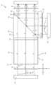
도 1은 본 발명의 일 실시 예에 따라 구성되고 동작하는, 색상 조합기를 제공하기 위해 각각의 프리즘들에 배치되는 두 개의 이색성 빔스플리터들을 갖는 광학 디바이스의 개략적인 등각 투상도이다;
도 2는 광원들을 도시하도록 수정된, 도 1의 광학 디바이스의 분해 평면도이다;
도 3은 다양한 구성요소들을 단일 구조로 조립한 후 도 2의 광학 디바이스의 평면도이다;
도 4는 도 2의 광학 디바이스의 분해 정면도이다;
도 5는 다양한 구성요소들을 단일 구조로 조립한 후 도 4의 광학 디바이스의 정면도이다;
도 6은 도 2 및 도 3의 광학 디바이스의 제1 프리즘의 세부 사항들을 도시하는 개략적인 분해 평면도이다;
도 7은 도 4 및 도 5의 광학 디바이스의 제2 프리즘의 세부 사항들을 도시하는 개략적인 분해 정면도이다;
도 8a 및 도 8b는 각각, 서로 분리되고, 광학적으로 부속된 도 1의 광학 디바이스의 두 개의 프리즘들 도시하는 개략적인 등각 투상도들이다;
도 9는 도 1의 광학 디바이스의 색위상 지연기의 배향의 표현이다;
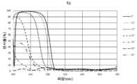
도 10은 도 1의 광학 디바이스의 제2 이색성 빔스플리터에 대해 설계된 가능한 이색성 코팅에 대한 s-편광에 대한 파장의 함수로서 반사율 곡선들을 도시한다;
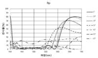
도 11은 제2 이색성 빔스플리터에 대해 설계된 가능한 이색성 코팅의 p-편광에 대한 파장의 함수로서 반사율 곡선들을 도시한다;
도 12는 도 11의 설계된 이색성 코팅에 대해, 세 개의 특정 파장들에 대한, 입사각의 함수로서 반사율 곡선들을 도시한다;
도 13은 도 1의 광학 디바이스의 제1 이색성 빔스플리터에 대해 설계된 가능한 이색성 코팅의 s-편광에 대한 파장의 함수로서 반사율 곡선들을 도시한다;
도 14는 도 13의 설계된 이색성 코팅에 대한 입사각의 함수로서 반사율 곡선들을 도시한다;
도 15는 도 1의 광학 디바이스와 유사하나, 프리즘들 내로 광을 주입하는 광원들의 순서가 상이한 광학 디바이스의 제2 이색성 빔스플리터에 대해 설계된 가능한 이색성 코팅의 s-편광에 대한 파장의 함수로서 반사율 곡선들을 도시한다;
도 16은 도 15를 참조하여 논의된 광학 디바이스의 제2 이색성 빔스플리터에 대해 설계된 가능한 이색성 코팅의 p-편광에 대한 파장의 함수로서 반사율 곡선들을 도시한다;
도 17은 도 1의 광학 디바이스 및 도 15를 참조하여 논의된 광학 디바이스와 유사하나, 프리즘들 내로 광을 주입하는 광원들의 순서가 상이한 광학 디바이스의 제2 이색성 빔스플리터에 대해 설계된 가능한 이색성 코팅의 s-편광에 대한 파장의 함수로서 반사율 곡선들을 도시한다;
도 18은 도 17을 참조하여 논의된 광학 디바이스의 제2 이색성 빔스플리터에 대해 설계된 가능한 이색성 코팅의 p-편광에 대한 파장의 함수로서 반사율 곡선들을 도시한다; 그리고
도 19는 발명의 일 실시 예에 따른, 이미지 프로젝터 디바이스 및 광파 투과 기판에 커플링된 도 1 내지 도 7의 광학 디바이스를 포함하는 광학 시스템의 개략적인 평면도이다.Some embodiments of the present invention are described herein by way of example only, with reference to the accompanying drawings. Referring specifically to the drawings, it is emphasized that the specific details depicted are examples for illustrative discussion of embodiments of the present invention. In this regard, the drawings and the description taken together make it apparent to those skilled in the art how the embodiments of the present invention may be practiced.
Now, attention is drawn to the drawings in which like reference symbols or letters represent corresponding or identical components. In the drawings:
FIG. 1 is a schematic isometric drawing of an optical device having two dichroic beamsplitters arranged in respective prisms to provide a color combiner, constructed and operative according to one embodiment of the present invention;
FIG. 2 is an exploded plan view of the optical device of FIG. 1, modified to illustrate light sources;
FIG. 3 is a plan view of the optical device of FIG. 2 after assembling various components into a single structure;
Figure 4 is an exploded front view of the optical device of Figure 2;
FIG. 5 is a front view of the optical device of FIG. 4 after assembling various components into a single structure;
FIG. 6 is a schematic exploded plan view illustrating details of the first prism of the optical device of FIGS. 2 and 3;
FIG. 7 is a schematic exploded front view showing details of the second prism of the optical device of FIGS. 4 and 5;
FIGS. 8a and 8b are schematic isometric projections showing two prisms of the optical device of FIG. 1, respectively, separate from each other and optically attached;
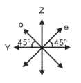
Fig. 9 is a representation of the orientation of the color phase delay unit of the optical device of Fig. 1;
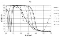
FIG. 10 shows reflectance curves as a function of wavelength for s-polarization for possible dichroic coatings designed for the second dichroic beamsplitter of the optical device of FIG. 1;
Figure 11 shows reflectance curves as a function of wavelength for p-polarization for possible dichroic coatings designed for a second dichroic beamsplitter;
Figure 12 shows reflectance curves as a function of incidence angle for three specific wavelengths for the designed dichroic coating of Figure 11;
Figure 13 shows reflectance curves as a function of wavelength for s-polarization for possible dichroic coatings designed for the first dichroic beamsplitter of the optical device of Figure 1;
Figure 14 shows reflectance curves as a function of incident angle for the designed dichroic coating of Figure 13;
FIG. 15 shows reflectance curves as a function of wavelength for s-polarization for a possible dichroic coating designed for a second dichroic beamsplitter of an optical device similar to the optical device of FIG. 1, but with a different order of the light sources injecting light into the prisms;
FIG. 16 shows reflectance curves as a function of wavelength for p-polarization of a possible dichroic coating designed for the second dichroic beamsplitter of the optical device discussed with reference to FIG. 15;
FIG. 17 illustrates reflectance curves as a function of wavelength for s-polarization for a possible dichroic coating designed for a second dichroic beamsplitter of an optical device similar to the optical device of FIG. 1 and the optical device discussed with reference to FIG. 15, but having a different order of light sources injecting light into the prisms;
FIG. 18 illustrates reflectance curves as a function of wavelength for p-polarization of a possible dichroic coating designed for a second dichroic beamsplitter of the optical device discussed with reference to FIG. 17; and
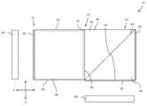
FIG. 19 is a schematic plan view of an optical system including an image projector device and an optical device of FIGS. 1 to 7 coupled to a light transmitting substrate, according to one embodiment of the invention.
본 발명은 단일 조합 유색 빔을 형성하기 위해 세 개의 별개의 유색 광 빔들을 조합하기 위해 협력하는 각각의 프리즘들에 배치되는 두 개의 이색성 빔스플리터들을 갖는 광학 디바이스이다.The present invention is an optical device having two dichroic beamsplitters arranged on respective prisms that cooperate to combine three separate colored light beams to form a single combined colored beam.
본 발명에 따른 광학 디바이스들 및 시스템들의 원리들 및 동작은 설명을 수반하는 도면들을 참조하면 더 잘 이해될 수 있다.The principles and operation of the optical devices and systems according to the present invention may be better understood by reference to the drawings accompanying the description.
본 발명의 적어도 일 실시 예를 상세히 설명하기 전에, 본 발명은 반드시 이의 적용이 이하의 설명에 제시되고/거나 도면들 및/또는 예들에 예시된 구성요소들 및/또는 방법들의 구성 및 배열의 세부 사항들로 제한되는 것은 아니라는 것이 이해되어야 한다. 본 발명은 다른 실시 예들이 가능하고 다양한 방식들로 실시되거나 수행될 수 있다. 처음에, 이 문서 전체에서, 예를 들어, 좌두, 전후(또는 이), 상하, 위아래 등과 같은 방향들을 참조한다. 이러한 방향 참조는 단지 본 발명 및 이의 실시 예들을 설명하기 위한 예시일 뿐이다.Before explaining at least one embodiment of the present invention in detail, it is to be understood that the present invention is not necessarily limited in its application to the details of construction and arrangement of components and/or methods set forth in the description below and/or illustrated in the drawings and/or examples. The present invention is capable of other embodiments and of being practiced or carried out in various ways. Initially, throughout this document, reference is made to directions such as, for example, left-right, front-back (or back), up-down, above-and-below, etc. Such directional references are merely examples for the purpose of describing the present invention and embodiments thereof.
이제 도면들을 참조하면, 도 1 내지 도 7은 본 개시의 다양한 양태들에 따라 구성되고 동작하는, 광학 디바이스(10으로 총칭됨), 및 이의 대응하는 구성요소들의 다양한 도면들을 도시한다. 일반적인 표현으로, 광학 디바이스(10)는 각각 광파 투과 재료로 형성되고, 각각 각각의 이색성 빔스플리터 구성(20, 40)이 내부에 배치된 제1 프리즘(12) 및 제2 프리즘(32)을 포함하며, 이들은 색상 조합 기능을 제공하기 위해 협력한다.Referring now to the drawings, FIGS. 1 through 7 illustrate various views of an optical device (collectively referred to as 10), and corresponding components thereof, constructed and operative in accordance with various aspects of the present disclosure. In general terms, the optical device (10) includes a first prism (12) and a second prism (32), each formed of a light-transmitting material and each having a respective dichroic beamsplitter configuration (20, 40) disposed therein, which cooperate to provide a color combining function.
제1 프리즘(12)은 제1 광파 입사면(14), 제2 광파 입사면(16), 및 광파 출사면(18)을 포함하는, 다수의 평평한 외부면들을 가진다. 이색성 빔스플리터 구성(20)(간략히 "DBS(dichroic beamsplitter)(20)"라고 지칭될 수 있음)은 제1 프리즘(12) 내에 제1 광파 입사면(14)에 대해 비스듬한 평면 상에 배치된다. 바람직한 구현에서, 이 평면은 또한 제2 광파 투과 표면(16)에 대해 비스듬하다. 광학 디바이스(10)의 구성요소들의 배향들을 보다 명확히 설명하기 위해, 임의로 라벨링된 직교 좌표계(즉, XYZ 좌표계)가 도면들에 포함된다(적절한 곳에). 이 임의로 라벨링된 XYZ 좌표계에서, 도 1에서 볼 때, y-축은 일반적으로 종이의 평면에서 나오는 축이다.The first prism (12) has a plurality of flat external surfaces, including a first optical wave incident surface (14), a second optical wave incident surface (16), and a optical wave exit surface (18). A dichroic beamsplitter configuration (20) (which may be briefly referred to as a "dichroic beamsplitter (DBS) (20)") is disposed within the first prism (12) on a plane oblique to the first optical wave incident surface (14). In a preferred embodiment, this plane is also oblique to the second optical wave transmitting surface (16). To more clearly illustrate the orientations of the components of the optical device (10), an arbitrarily labeled Cartesian coordinate system (i.e., an XYZ coordinate system) is included in the drawings (where appropriate). In this arbitrarily labeled XYZ coordinate system, the y-axis is generally the axis emerging from the plane of the paper when viewed in FIG. 1.
이를 염두에 두고, 제1 광파 입사면(14)은 YZ 평면에 있고, DBS(20)는 YZ 평면에 대해 비스듬한 평면 상에 배치된다. 바람직한 구현에서, DBS(20)는 DBS(20)가 광파 입사면들(14, 16) 사이의 중간(예를 들어, YZ 평면과 XZ 평면 사이의 중간)에 있는 평면에 놓이도록 제1 광파 입사면(14)에 대해 45도인 평면 상에 배치된다.With this in mind, the first incident plane (14) is in the YZ plane and the DBS (20) is positioned on a plane oblique to the YZ plane. In a preferred implementation, the DBS (20) is positioned on a plane that is 45 degrees to the first incident plane (14) such that the DBS (20) lies in a plane that is midway between the incident planes (14, 16) (e.g., midway between the YZ plane and the XZ plane).
제1 프리즘(12)은 또한 제2 광파 입사면(16)과 평행하고 반대편에 있는 제1 표면(26), 표면들(14, 16, 18, 26)에 직교하는 제2 표면(28), 및 제2 표면(28)과 평행하고 반대편에 있는 제3 표면(30)을 포함하는, 추가 외부면들을 포함할 수 있다. 도면들에 도시된 비제한적인 임의의 방향 기준 프레임에서, 제1 프리즘(12)의 다양한 표면들(14, 16, 18, 26, 28, 30)은 대안적으로 다음의 방향 용어들로 지칭될 수 있다: 좌면(14), 이(또는 후)면(16), 우면(18), 전면(26), 윗(또는 상)면(28), 및 아랫(또는 저)면(30).The first prism (12) may also include additional exterior surfaces, including a first surface (26) parallel and opposite the second light wave incident surface (16), a second surface (28) orthogonal to the surfaces (14, 16, 18, 26), and a third surface (30) parallel and opposite the second surface (28). In any non-limiting directional reference frame depicted in the drawings, the various surfaces (14, 16, 18, 26, 28, 30) of the first prism (12) may alternatively be referred to by the following directional terms: left surface (14), right (or rear) surface (16), right surface (18), front (26), top (or upper) surface (28), and bottom (or lower) surface (30).
제2 프리즘(32)은 제1 광파 입사면(34), 제2 광파 입사면(36), 및 광파 출사면(38)을 포함하는, 다수의 평평한 외부면들을 가진다. 이색성 빔스플리터 구성(40)(간략히 "DBS(40)"라고 지칭될 수 있음)은 제2 프리즘(32) 내에 제1 광파 입사면(34)에 대해 비스듬한 평면 상에 배치된다. 바람직한 구현에서, 이 평면은 또한 제2 광파 투과 표면(36)에 대해 비스듬하다. 도 1에서의 임의로 라벨링된 XYZ 좌표계에서, 제1 광파 입사면(34)은 XY 평면에 있고, DBS(40)는 XY 평면에 대해 비스듬한 평면 상에 배치된다. 바람직한 구현에서, DBS(40)는 DBS(40)가 광파 입사면들(34, 36) 사이의 중간(예를 들어, XY 평면과 YZ 평면 사이의 중간)에 있는 평면에 놓이도록 제1 광파 입사면(34)에 대해 45도인 평면 상에 배치된다.The second prism (32) has a plurality of flat external surfaces, including a first optical wave incident surface (34), a second optical wave incident surface (36), and a optical wave exit surface (38). A dichroic beam splitter configuration (40) (which may be briefly referred to as “DBS (40)”) is disposed within the second prism (32) on a plane oblique to the first optical wave incident surface (34). In a preferred embodiment, this plane is also oblique to the second optical wave transmitting surface (36). In the arbitrarily labeled XYZ coordinate system in FIG. 1, the first optical wave incident surface (34) is in the XY plane, and the DBS (40) is disposed on a plane oblique to the XY plane. In a preferred implementation, the DBS (40) is positioned on a plane that is 45 degrees to the first optical wave incidence plane (34) such that the DBS (40) lies in a plane that is midway between the optical wave incidence planes (34, 36) (e.g., midway between the XY plane and the YZ plane).
제2 프리즘(32)은 또한 제1 광파 입사면(34)과 평행하고 반대편에 있는 제1 표면(46), 표면들(34, 36, 38, 46)에 직교하는 제2 표면(48), 및 제2 표면(48)과 평행하고 반대편에 있는 제3 표면(50)을 포함하는, 추가의 평평한 외부면들을 포함할 수 있다.The second prism (32) may also include additional flat external surfaces, including a first surface (46) parallel and opposite the first light wave incident surface (34), a second surface (48) orthogonal to the surfaces (34, 36, 38, 46), and a third surface (50) parallel and opposite the second surface (48).
도면들에 도시된 비제한적인 임의의 방향 기준 프레임에서, 제2 프리즘(32)의 다양한 표면들(34, 36, 38, 46, 48, 50)은 대안적으로 다음의 방향 용어들로 지칭될 수 있다: 아랫(또는 저)면(34), 좌면(36), 우면(38), 윗(또는 상)면(46), 후또는 이)면(48), 및 전면(50).In the non-limiting arbitrary directional reference frame illustrated in the drawings, the various surfaces (34, 36, 38, 46, 48, 50) of the second prism (32) may alternatively be referred to by the following directional terms: lower (or bottom) surface (34), left surface (36), right surface (38), upper (or top) surface (46), back or front surface (48), and front surface (50).
광학 디바이스(10)를 형성하기 위해 단일 광학 구조로서 완전히 조립될 때, 두 개의 프리즘들(12, 32)의 표면들(18, 36)은 평행하고 서로 정렬되며, 바람직하지만 비제한적인 구현들에서 표면들(18, 36)이 제1 프리즘(12)의 광파 출사면과 제2 프리즘(32)의 제2 광파 입사면으로서의 이중 역할을 하는 단일 유효면을 형성하도록 실질적으로 일치한다. 바람직한 구현에서, 두 개의 프리즘들(12, 32)은 표면들(18, 36)에서 서로 부착되어 단일 프리즘 어셈블리(70)를 형성한다. 도 8a 및 도 8b는 각각, 일체형 프리즘 어셈블리(70)를 형성하기 위한 부착 전에 및 부착 후에 서로 분리된 프리즘들(12, 32)을 도시한다. 부착은 표면들(18, 36)을 직접(또는 에어 갭을 통해 간접적으로) 표면들(18, 36) 사이에 접합이 형성되도록 서로 광학적으로 합착하는 것 및 두 개의 프리즘들(12, 32)을 제 위치에 고정식으로 홀딩하도록 구성된 기계적 홀딩 배열을 포함하나, 이에 제한되지 않는, 다양한 광학적 부속 수단들을 통해 구현될 수 있다.When fully assembled as a single optical structure to form the optical device (10), the surfaces (18, 36) of the two prisms (12, 32) are parallel and aligned with one another, and in preferred but non-limiting implementations the surfaces (18, 36) substantially coincide to form a single effective surface that serves dually as the light-emitting surface of the first prism (12) and the second light-incident surface of the second prism (32). In a preferred implementation, the two prisms (12, 32) are attached to one another at the surfaces (18, 36) to form a single prism assembly (70). FIGS. 8A and 8B illustrate the prisms (12, 32) separated from one another prior to and after attachment to form the integral prism assembly (70), respectively. Attachment can be accomplished through a variety of optical attachment means, including but not limited to optically bonding the surfaces (18, 36) together directly (or indirectly via an air gap) to form a bond between the surfaces (18, 36) and a mechanical holding arrangement configured to fixedly hold the two prisms (12, 32) in place.
제1 프리즘(12)은 도 1 내지 도 3 및 도 6에서 22 및 24로 라벨링된 두 개의 프리즘들에 기초하며(즉, 이것들로 형성됨), 여기서 프리즘들(22, 24) 중 적어도 하나(도 6의 프리즘(24))가 이색성 코팅된 빗변 상에 제공되어 DBS(20)의 적어도 일부를 형성하는 이색성 빔스플리터를 형성하며, 이는 특정 파장들에서 s-편광된 광을 투과시키고, 다른 파장들에서 s-편광된 광을 반사시킨다. 두 개의 프리즘들(22, 24)의 빗변들은 서로 합착되어, 프리즘(12)을 형성하는 합착된 프리즘 어셈블리를 형성한다.The first prism (12) is based on (i.e. formed of) two prisms labeled 22 and 24 in FIGS. 1 to 3 and 6, wherein at least one of the prisms (22, 24) (prism (24) in FIG. 6) is provided on a dichroic-coated hypotenuse to form a dichroic beamsplitter forming at least a portion of the DBS (20), which transmits s-polarized light at certain wavelengths and reflects s-polarized light at other wavelengths. The hypotenuses of the two prisms (22, 24) are joined to each other to form a joined prism assembly forming the prism (12).
제2 프리즘(32)은 도 1, 도 4, 도 5 및 도 7에서 42 및 44로 라벨링된 두 개의 프리즘들에 기초하며, 여기서 프리즘들(42, 44) 중 적어도 하나(도 7의 프리즘(44))가 이색성 코팅된 빗변 상에 제공되어 DBS(40)의 적어도 일부를 형성하는 이색성 빔스플리터를 형성하며, 이는 특정 파장들에서 p-편광된 광을 투과시키고, 다른 파장들에서 s-편광된 광을 반사시킨다. 두 개의 프리즘들(42, 44)의 빗변들은 서로 합착되어, 프리즘(32)을 형성하는 합착된 프리즘 어셈블리를 형성한다.The second prism (32) is based on two prisms labeled 42 and 44 in FIGS. 1, 4, 5 and 7, wherein at least one of the prisms (42, 44) (prism (44) in FIG. 7) is provided on a dichroic coated hypotenuse to form a dichroic beamsplitter that forms at least a portion of the DBS (40), which transmits p-polarized light at certain wavelengths and reflects s-polarized light at other wavelengths. The hypotenuses of the two prisms (42, 44) are joined to each other to form a joined prism assembly that forms the prism (32).
DBS(20) 및 DBS(40)을 형성하는 데 사용되는 이색성 코팅들은 파장(즉, 색상) 및 편광에 민감한 속성들을 나타내므로, DBS(20) 및 DBS(40)은 DBS의 표면에 입사되는 광을 입사광의 파장 및 편광 상태 양자에 따라 반사 또는 투과시킨다. DBS(20) 및 DBS(40)를 형성하는 이색성 코팅의 설계들은 본 개시의 후속 섹션들에서 논의될 것이다.The dichroic coatings used to form DBS (20) and DBS (40) exhibit wavelength (i.e., color) and polarization-sensitive properties, such that DBS (20) and DBS (40) reflect or transmit light incident on the surface of DBS depending on both the wavelength and polarization state of the incident light. The designs of the dichroic coatings forming DBS (20) and DBS (40) will be discussed in subsequent sections of the present disclosure.
본 문서의 맥락 내에서, 이색성 코팅은 프리즘들(22, 24 및 42, 44) 중 적어도 하나의 빗변 상에 다양한 방식들로 제공될 수 있다. 비 제한적인 일례에서, 이색성 코팅은 두 개의 구성 프리즘들 중 하나 또는 양자의 빗변 상에 직접 도포될 수 있다. 또 다른 비제한적인 예에서, 바람직하게는 두 개의 구성 프리즘들의 빗변들의 전체를 따라 연장되고 이색성 코팅이 위에 침적된, 예를 들어, 시트, 호일, 또는 유리판과 같은 얇은 재료 조각이 두 개의 구성 프리즘들의 빗변들 사이에 합착 전에 배치할 수 있다.Within the context of the present document, the dichroic coating may be provided on the hypotenuse of at least one of the prisms (22, 24 and 42, 44) in a variety of ways. In one non-limiting example, the dichroic coating may be applied directly on the hypotenuse of one or both of the two constituent prisms. In another non-limiting example, a thin piece of material, such as a sheet, foil, or plate of glass, preferably extending along the entirety of the hypotenuses of the two constituent prisms and having the dichroic coating deposited thereon, may be placed between the hypotenuses of the two constituent prisms prior to bonding.
DBS(20) 및 DBS(40)는 DBS(20)의 표면 및 표면들(14, 16, 18)에 관해(즉, 상대적인) 제1 편광 상태에 있는(s-편광된 또는 p-편광된) 광이 DBS(40)의 표면 및 표면들(34, 36, 38)에 관해(즉, 상대적인) 제2 편광 상태에 있도록(p-편광된 또는 s-편광된) 서로에 관해 배향된다. DBS(20)와 DBS(40) 사이의 상대적인 배향은 DBS(20) 및 DBS(40)를 두 개의 기본 직교 축들(이들은 임의로 라벨링된 XYZ 좌표계에서 x-축 및 z-축이다)에 대해 서로로부터 회전 오프셋하여 제공된다. DBS(20)가 YZ 평면에 대해 45도 각도에 있는 평면 상에 배치되고 DBS(40)가 XY 평면에 대해 45도 각도에 있는 평면 상에 배치되는 바람직한 구현에서, DBS(20) 및 DBS(40)는 x-축을 중심으로 45도 그리고 z-축을 중심으로 45도 회전 오프셋되어 있다.DBS (20) and DBS (40) are oriented with respect to each other such that light in a first polarization state (i.e., s-polarized or p-polarized) with respect to the surface and surfaces (14, 16, 18) of DBS (20) is in a second polarization state (i.e., p-polarized or s-polarized) with respect to the surface and surfaces (34, 36, 38) of DBS (40). The relative orientation between DBS (20) and DBS (40) is provided by rotationally offsetting DBS (20) and DBS (40) from each other about two cardinal orthogonal axes (which are the x-axis and the z-axis in an arbitrarily labeled XYZ coordinate system). In a preferred implementation where DBS (20) is positioned on a plane at a 45 degree angle with respect to the YZ plane and DBS (40) is positioned on a plane at a 45 degree angle with respect to the XY plane, DBS (20) and DBS (40) are rotationally offset 45 degrees about the x-axis and 45 degrees about the z-axis.
다음 단락들은 프리즘들(12, 32)의 기하학적 구성들을 설명한다. 바람직한 구현에서, 제1 프리즘(12)의 광파 입사면들(14, 16)은 서로 직교하고, 제1 프리즘(12)의 제1 광파 입사면(14) 및 광파 출사면(18)은 서로 평행하다. 바람직한 구현에서, 제2 프리즘(32)의 광파 입사면들(34, 36)은 또한 서로 직교하고, 제2 프리즘(32)의 제1 광파 입사면(34) 및 광파 출사면(38)은 서로 평행하다. 특히 바람직한 구현에서, 프리즘들(12, 32) 각각은 정육면체 프리즘으로서 구현되며, 여기서 구성 프리즘들(22, 24, 42, 44) 각각은 45도 직각 단면 형상을 가진다.The following paragraphs describe geometric configurations of the prisms (12, 32). In a preferred embodiment, the light incident faces (14, 16) of the first prism (12) are orthogonal to one another, and the first light incident face (14) and the light exit face (18) of the first prism (12) are parallel to one another. In a preferred embodiment, the light incident faces (34, 36) of the second prism (32) are also orthogonal to one another, and the first light incident face (34) and the light exit face (38) of the second prism (32) are parallel to one another. In a particularly preferred embodiment, each of the prisms (12, 32) is implemented as a hexahedral prism, wherein each of the constituent prisms (22, 24, 42, 44) has a 45 degree right-angled cross-sectional shape.
바람직한 기하학적 구성에서, 프리즘들(12, 32)은 동일한 기하학적 구조를 갖고, 가장 바람직하게는 프리즘들(12, 32)은 둘 다 각각의 프리즘들(12, 32)을 양분하는 각각의 광파 입사면들(14, 34)에 대해 45도 각도들에 있는 평면들에 배치된 DBS(20) 및 DBS(40)를 갖는 정육면체 프리즘들이다.In a preferred geometric configuration, the prisms (12, 32) have the same geometry, most preferably the prisms (12, 32) are both cubic prisms having the DBS (20) and DBS (40) arranged in planes at 45 degree angles to the respective light wave incident planes (14, 34) bisecting each of the prisms (12, 32).
정육면체 프리즘들로서 구현될 때, 표면들(18, 36)에서 두 개의 프리즘들(12, 32)을 광학적으로 부속하여 형성된 프리즘 어셈블리(70)는 가늘고 긴 직육면체 프리즘으로서 형성된다. 이러한 특히 바람직한 구현에서, 제1 프리즘(12)의 표면들(14, 16, 18, 26, 28, 30)은 동일한 크기를 갖고 인접한 표면들이 직교하며 제2 프리즘(32)의 표면들(34, 36, 38, 46, 48, 50)은 동일한 크기를 갖고 인접한 표면들이 직교한다. 뿐만 아니라, 이러한 특정 구현에서, 다음의 표면들의 쌍들은 동일 평면 상에 있다(그리고 바람직하게는 단일 연접 평면 표면들을 형성하도록 이어진다): 제1 프리즘(12)의 제2 광파 입사면(16)과 제2 프리즘(32)의 제2 표면(48), 제1 프리즘(12)의 제1 표면(26)과 제2 프리즘(32)의 제3 표면(50), 제1 프리즘(12)의 제2 표면(28)과 제2 프리즘(32)의 제1 표면(46), 및 제1 프리즘(12)의 제3 표면(30)과 제2 프리즘(32)의 제1 광파 입사면(34).When implemented as cuboid prisms, the prism assembly (70) formed by optically attaching two prisms (12, 32) at surfaces (18, 36) is formed as an elongated cuboid prism. In this particularly preferred implementation, the surfaces (14, 16, 18, 26, 28, 30) of the first prism (12) have the same size and the adjacent surfaces are orthogonal, and the surfaces (34, 36, 38, 46, 48, 50) of the second prism (32) have the same size and the adjacent surfaces are orthogonal. Moreover, in this particular implementation, the following pairs of surfaces are coplanar (and preferably connected to form single contiguous planar surfaces): the second light incident surface (16) of the first prism (12) and the second surface (48) of the second prism (32), the first surface (26) of the first prism (12) and the third surface (50) of the second prism (32), the second surface (28) of the first prism (12) and the first surface (46) of the second prism (32), and the third surface (30) of the first prism (12) and the first light incident surface (34) of the second prism (32).
구성 프리즘들(12, 32)과 유사한 프리즘 어셈블리(70)는 다수의 평평한 외부면들을 포함하고, 특히 바람직하지만 비제한적인 구현들은 여섯 개의 평평한 외부면들을 포함한다. 제1 광파 입사면(14)은 프리즘 어셈블리(70)의 제1 외부면(이는 프리즘 어셈블리(70)의 제1 광파 입사면이기도 하다)으로서의 역할을 한다. 광파 출사면(38)은 프리즘 어셈블리(70)의 제4 외부면으로서의 역할을 하며, 이는 또한 프리즘 어셈블리(70)의 광파 출사면으로서의 역할도 한다.A prism assembly (70), similar to the component prisms (12, 32), includes a plurality of flat outer surfaces, and particularly preferred but non-limiting implementations include six flat outer surfaces. The first optical wave incident surface (14) serves as the first outer surface of the prism assembly (70), which is also the first optical wave incident surface of the prism assembly (70). The optical wave exit surface (38) serves as the fourth outer surface of the prism assembly (70), which also serves as the optical wave exit surface of the prism assembly (70).
프리즘 어셈블리(70)의 외부면들 중 네 개는 프리즘들(12, 32)의 표면들의 쌍들을 이어 형성되어 연접 표면들을 형성한다. 프리즘 어셈블리(70)의 제2 외부면은 제1 프리즘(12)의 제2 광파 입사면(16)과 제2 프리즘(32)의 제2 표면(48)을 이어 형성된다. 프리즘 어셈블리(70)의 제2 외부면의 일 부분(즉, 제1 프리즘(12)의 제2 광파 입사면(16)으로 형성된 부분)은 프리즘 어셈블리(70)의 제2 광파 입사면으로서의 역할을 한다. 프리즘 어셈블리(70)의 제3 외부면은 제1 프리즘(12)의 제3 표면(30)과 제2 프리즘(32)의 제1 광파 입사면(34)을 이어 형성된다. 프리즘 어셈블리(70)의 제3 외부면의 일 부분(즉, 제2 프리즘(32)의 제1 광파 입사면(34)으로 형성된 부분)은 프리즘 어셈블리(70)의 제3 광파 입사면으로서의 역할을 한다. 프리즘 어셈블리(70)의 제1, 제2 및 제3 출사면들은 서로 직교하다.Four of the outer surfaces of the prism assembly (70) are formed by connecting pairs of surfaces of the prisms (12, 32) to form connecting surfaces. The second outer surface of the prism assembly (70) is formed by connecting the second light wave incident surface (16) of the first prism (12) and the second surface (48) of the second prism (32). A portion of the second outer surface of the prism assembly (70) (i.e., the portion formed by the second light wave incident surface (16) of the first prism (12)) serves as the second light wave incident surface of the prism assembly (70). The third outer surface of the prism assembly (70) is formed by connecting the third surface (30) of the first prism (12) and the first light wave incident surface (34) of the second prism (32). A portion of the third outer surface of the prism assembly (70) (i.e., the portion formed by the first light wave incident surface (34) of the second prism (32)) serves as the third light wave incident surface of the prism assembly (70). The first, second, and third exit surfaces of the prism assembly (70) are orthogonal to each other.
프리즘 어셈블리(70)의 제5 외부면은 제1 프리즘(12)의 제1 표면(26)과 제2 프리즘(32)의 제3 표면(50)을 이어 형성된다. 프리즘 어셈블리(70)의 제6 외부면은 제1 프리즘(12)의 제2 표면(28)과 제2 프리즘(32)의 제1 표면(46)을 이어 형성된다.The fifth outer surface of the prism assembly (70) is formed by connecting the first surface (26) of the first prism (12) and the third surface (50) of the second prism (32). The sixth outer surface of the prism assembly (70) is formed by connecting the second surface (28) of the first prism (12) and the first surface (46) of the second prism (32).
특히 도 2 내지 도 5를 참조하면, 광학 디바이스(10)는 세 개의 편광원들을 가진다. 본 명세서에서 제1 선형 편광판(55)과 제1 광원(54)으로서 도시된 제1 편광원은 제1 프리즘(12)의 제1 광파 입사면(14)(특정 실시 예들에서 이는 또한 프리즘 어셈블리(70)의 제1 외부면이다)과 연관된다. 제1 편광원은 제1 색상(예를 들어, 적색)에 대응하는 전자기 스펙트럼의 제1 특정 파장 범위 내의 파장을 갖는 편광된 광을 생성(즉, 방출)하도록 구성된다. 본 명세서에서 제2 선형 편광판(59)과 제2 광원(58)으로서 도시된(도 4 및 도 5에서 점선으로 도시됨) 제2 편광원은 제1 프리즘(12)의 제2 광파 입사면(16)(특정 실시 예들에서 이는 또한 프리즘 어셈블리(70)의 제2 외부면이다)과 연관된다. 제2 편광원은 제2 색상(예를 들어, 청색)에 대응하는 전자기 스펙트럼의 제2 특정 파장 범위 내의 파장을 갖는 편광된 광을 생성하도록 구성된다. 본 명세서에서 제3 선형 편광판(63)과 제3 광원(62)으로서 도시된(도 2 및 도 3에서 점선으로 도시됨) 제3 편광원은 제2 프리즘(32)의 제1 광파 입사면(34)(특정 실시 예들에서 이는 또한 프리즘 어셈블리(70)의 제3 외부면이다)과 연관된다. 제3 편광원은 제3 색상(예를 들어, 녹색)에 대응하는 전자기 스펙트럼의 제3 특정 파장 범위 내의 파장을 갖는 편광된 광을 생성하도록 구성된다. 세 가지 특정 파장 범위들은 겹치지 않는 파장 범위들이므로, 세 개의 편광원들이 세 개의 별개의 색상들 각각의 광, 예를 들어, 적색, 청색 및 녹색을 생성하게 된다.With particular reference to FIGS. 2-5 , the optical device (10) has three polarizing sources. A first polarizing source, illustrated herein as a first linear polarizing plate (55) and a first light source (54), is associated with a first light incident surface (14) of a first prism (12) (which in certain embodiments is also a first outer surface of a prism assembly (70). The first polarizing source is configured to generate (i.e., emit) polarized light having a wavelength within a first particular wavelength range of the electromagnetic spectrum corresponding to a first color (e.g., red). A second polarizing source, illustrated herein as a second linear polarizing plate (59) and a second light source (58) (illustrated in dashed lines in FIGS. 4 and 5 ), is associated with a second light incident surface (16) of the first prism (12) (which in certain embodiments is also a second outer surface of the prism assembly (70). The second polarizing source is configured to generate polarized light having a wavelength within a second specific wavelength range of the electromagnetic spectrum corresponding to a second color (e.g., blue). The third polarizing source, illustrated herein as a third linear polarizer (63) and a third light source (62) (illustrated in dashed lines in FIGS. 2 and 3 ), is associated with the first light wave incident face (34) of the second prism (32) (which in certain embodiments is also the third outer surface of the prism assembly (70). The third polarizing source is configured to generate polarized light having a wavelength within a third specific wavelength range of the electromagnetic spectrum corresponding to a third color (e.g., green). Since the three specific wavelength ranges are non-overlapping wavelength ranges, the three polarizing sources generate light of three separate colors, e.g., red, blue, and green.
바람직하지만 비제한적인 구현에서, 제1 편광원은 중심 파장이 638 나노미터(nm) - 또는 대략 638 nm -인 편광된 광을 생성하도록 구성되어 편광된 적색광을 생성하고, 제2 편광원은 중심 파장이 456 nm - 또는 대략 456 nm -인 편광된 광을 생성하도록 구성되어 편광된 청색광을 생성하며, 제3 편광원은 중심 파장이 532 nm - 또는 대략 532 nm -인 편광된 광을 생성하도록 구성되어 편광된 녹색광을 생성한다.In a preferred, but non-limiting implementation, the first polarization source is configured to generate polarized light having a center wavelength of 638 nanometers (nm) - or about 638 nm - to generate polarized red light, the second polarization source is configured to generate polarized light having a center wavelength of 456 nm - or about 456 nm - to generate polarized blue light, and the third polarization source is configured to generate polarized light having a center wavelength of 532 nm - or about 532 nm - to generate polarized green light.
도 2 및 도 4에 도시된 바와 같이, 입사광 빔(56)은 선형 편광판(55)을 통과하고, 입사 광선 빔(60)은 선형 편광판(59)을 통과하며, 입사 광선 밤(64)은 선형 편광판(63)을 통과한다. 광 빔들(56, 60, 64)은 각각의 LED들, 레이저들, 레이저 다이오드들 또는 임의의 다른 각각의 광원들(54, 58, 62)으로부터 나올 수 있다. 선형 편광판들(55, 59, 63)은 광원들(54, 58, 62) 자체가 편광되는 경우에 반드시 필요한 것은 아니지만, 고품질의 편광 조명을 보장하기 위해 여전히 바람직할 수 있다는 점에 유념한다. 특히 바람직한 구현에서, 입사광 빔들(56, 60)은 도 2에 도시된 바와 같이, DBS(20)의 표면에 관해 s-편광되고, 입사광 빔(64)은 도 4에 도시된 바와 같이, DBS(40)의 표면에 관해 s-편광된다.As illustrated in FIGS. 2 and 4, an incident light beam (56) passes through a linear polarizer (55), an incident light beam (60) passes through a linear polarizer (59), and an incident light beam (64) passes through a linear polarizer (63). The light beams (56, 60, 64) may each be from LEDs, lasers, laser diodes, or any other respective light sources (54, 58, 62). Note that the linear polarizers (55, 59, 63) are not necessarily required if the light sources (54, 58, 62) themselves are polarized, but may still be desirable to ensure high quality polarized illumination. In a particularly preferred implementation, the incident light beams (56, 60) are s-polarized with respect to the surface of the DBS (20), as illustrated in FIG. 2, and the incident light beam (64) is s-polarized with respect to the surface of the DBS (40), as illustrated in FIG. 4.
광원들(54, 58, 62)은 바람직하게는 편광원들에 의해 생성된 입사광 빔들(56, 60, 64)이 비시준된 광으로서 프리즘 어셈블리(70)로 커플링되는 발산(또는 수렴) 빔들이도록 비간섭원들(예를 들어, LED, 레이저들 등)로서 구현된다는 점에 유념한다. 뿐만 아니라, 편광원들은 바람직하게는 ±25도 범위 내의, 비교적 빔 광각을 갖는 빔들을 생성하도록 구성된다. 편광원들로부터의 입사광은 프리즘들(12, 32)에 입사시 굴절된다. 프리즘들(12, 32)을 통해 전파하는 빔들은 빔에 의해 접하게 되는 DBS의 표면에 대한 법선에 관해 측정된 대응 입사각들을 가진다. 해당 기술분야에 알려져 있는 바와 같이, 빔들의 굴절각(프리즘들에 입사시)은 프리즘들이 구성되는 재료의 굴절률의 함수이다. 예를 들어, 굴절률이 1. 7인 재료로 프리즘들(12, 32)을 구성할 때, 편광원들로부터의 입사 빔들은 대략 ±15도 범위 내의 각도들로 굴절되며, 이는 입사 빔에 의해 접하게 되는 제1 DBS의 표면에 대한 법선에 관해 측정된 대략 30 - 60도의 각도 범위에 대응한다(예를 들어, 제1 편광원은 바람직하게는 DBS(20)의 표면에 대한 법선에 대해 30 - 60도 범위 내의 입사각들에 대응하는 빔 각도를 가진다). 프리즘 어셈블리(70)에 대한 입력에서의 빔 광각은 광학 디바이스(10)의 출력에서의 빔 광각에 대응하며, 이는 출력 빔이 LCoS와 같은 반사형 디스플레이 디바이스를 조명하는 데 사용될 때 바람직할 수 있다.Note that the light sources (54, 58, 62) are preferably implemented as incoherent sources (e.g., LEDs, lasers, etc.) such that the incident light beams (56, 60, 64) generated by the polarizers are divergent (or convergent) beams that are coupled into the prism assembly (70) as non-collimated light. Furthermore, the polarizers are configured to generate beams having relatively wide beam angles, preferably within the range of ±25 degrees. The incident light from the polarizers is refracted upon incident on the prisms (12, 32). The beams propagating through the prisms (12, 32) have corresponding angles of incidence measured with respect to a normal to the surface of the DBS encountered by the beams. As is known in the art, the angles of refraction of the beams (upon incident on the prisms) are a function of the refractive index of the material from which the prisms are constructed. For example, when the prisms (12, 32) are constructed of a material having a refractive index of 1.7, incident beams from the polarizers are refracted at angles within a range of approximately ±15 degrees, which corresponds to an angular range of approximately 30 to 60 degrees measured with respect to a normal to the surface of the first DBS encountered by the incident beam (e.g., the first polarizer preferably has a beam angle corresponding to incident angles within a range of 30 to 60 degrees with respect to the normal to the surface of the DBS (20)). The beam angle at the input to the prism assembly (70) corresponds to the beam angle at the output of the optical device (10), which may be desirable when the output beam is used to illuminate a reflective display device such as an LCoS.
또한, 프리즘들(12, 32)의 바람직한 기하학적 구성은 입사광이 DBS(20) 및 DBS(40)에 의해 반사되는 입사각 범위에 걸쳐 균일성을 촉진할 수 있다는 점에 유념한다. 그렇지만, 프리즘들(12, 32) 중 하나 또는 둘 다가 가늘고 긴 직육면체 프리즘으로서 구현되는 구성들과 같은 다른 기하학적 구성들이 고려된다. 그러나, 이러한 구성들은 DBS(20) 및 DBS(40) 중 하나 또는 둘 다에 의해 광이 반사되는 입사각 범위를 감소시킬 수 있다.Additionally, it is noted that a desirable geometric configuration of the prisms (12, 32) can promote uniformity over the range of incident angles over which the incident light is reflected by the DBS (20) and DBS (40). However, other geometric configurations are contemplated, such as configurations in which one or both of the prisms (12, 32) are implemented as elongated rectangular prisms. However, such configurations can reduce the range of incident angles over which light is reflected by one or both of the DBS (20) and DBS (40).
이하의 단락들은 세 개의 편광원들로부터 프리즘 어셈블리(70)를 통한 광의 횡단을 설명한다. 도시된 바와 같이, 제1 광원(54)(즉, 입사 빔(56))으로부터의 s-편광된 입력 광파들은 제1 광파 입사면(14)을 통해, 광파 투과 물질로 구성된, 프리즘(12)(이는 DBS(20)를 개재하는 프리즘들(22, 24)로 구성된 "도광(light-guide)" 광학 디바이스로 고려될 수 있음)으로 커플링된다. s-편광된 광파들(중심 파장이 -638 nm, 즉 s-편광된 적색광)은 DBS(20)에 의해 투과되고(DBS(20)를 형성하는 이색성 코팅의 속성들로 인해), 광파 출사면(18)을 통해 프리즘(12)에서 커플링 아웃된다. 프리즘(12)에서 커플링 아웃시, s-편광된 광파들은 제2 광파 입사면(36)을 통해, 광파 투과 물질로 구성된, 프리즘(32)(이는 DBS(40)를 개재하는 프리즘들(42, 44)로 구성된 "도광" 광학 디바이스로 고려될 수 있음)으로 커플링된다. 프리즘들(12, 32)이 공극 없이 표면들(18, 36)에서 부착되는 구현들에서, 프리즘(12)으로부터의 커플링 아웃 및 프리즘(32)으로의 커플링 인은 동일하다. 프리즘(32)으로 커플링된 (입사 빔(56)으로부터의) s-편광된 광파들은 DBS(20)와 DBS(40) 사이의 상호 배향으로 인해, 이제 DBS(40)의 표면에 관해 p-편광된다(도 4에 도시된 바와 같이). 이제 p-편광된 광파들은 DBS(40)에 의해 투과되고(DBS(40)를 형성하는 이색성 코팅의 속성들로 인해), 광파 출사면(38)을 통해 프리즘(32)에서 커플링 아웃된다. 결과적으로, (입사 빔(56)으로부터의) s-편광된 광파들은 프리즘 어셈블리(70)의 두 프리즘들(12, 32)을 통해 반사 없이 횡단한다.The following paragraphs describe the traversal of light from three polarizing sources through the prism assembly (70). As illustrated, s-polarized input light waves from a first light source (54) (i.e., the incident beam (56)) are coupled through a first light-incident face (14) into a prism (12) made of a light-transmitting material (which may be considered a “light-guide” optical device comprised of prisms (22, 24) interposing a DBS (20)). The s-polarized light waves (center wavelength of -638 nm, i.e., s-polarized red light) are transmitted by the DBS (20) (due to the properties of the dichroic coating forming the DBS (20)) and coupled out of the prism (12) through the light-outgoing face (18). Upon coupling out from the prism (12), the s-polarized light waves are coupled through the second light incident surface (36) into the prism (32) (which may be considered a “light guiding” optical device comprised of prisms (42, 44) interposing the DBS (40)) made of a light-transmitting material. In implementations where the prisms (12, 32) are attached at the surfaces (18, 36) without an air gap, the coupling out from the prism (12) and the coupling in to the prism (32) are the same. The s-polarized light waves (from the incident beam (56)) coupled into the prism (32) are now p-polarized with respect to the surface of the DBS (40) due to the mutual orientation between the DBS (20) and the DBS (40) (as illustrated in FIG. 4). Now, the p-polarized light waves are transmitted by the DBS (40) (due to the properties of the dichroic coating forming the DBS (40)) and coupled out of the prism (32) through the light exit surface (38). As a result, the s-polarized light waves (from the incident beam (56)) traverse without reflection through the two prisms (12, 32) of the prism assembly (70).
제2 광원(58)(즉, 입사 빔(60))으로부터의 s-편광된 입력 광파들은 제2 광파 입사면(16)을 통해, 프리즘(12)으로 커플링된다. s-편광된 광파들(중심 파장이 -456 nm, 즉 s-편광된 청색광)은 DBS(20)에 의해 반사되고(DBS(20)를 형성하는 이색성 코팅의 속성들로 인해), 광파 출사면(18)을 통해 프리즘(12)에서 커플링 아웃된다. 프리즘(12)에서 커플링 아웃시, s-편광된 광파들은 제2 광파 입사면(36)을 통해 프리즘(32)으로 커플링된다. 프리즘(32)으로 커플링된 (입사 빔(60)으로부터의) s-편광된 광파들은 DBS(20)와 DBS(40) 사이의 상호 배향으로 인해, 이제 DBS(40)의 표면에 관해 p-편광된다(도 4에 도시된 바와 같이). 이제 p-편광된 광파들은 DBS(40)에 의해 투과되고(DBS(40)를 형성하는 이색성 코팅의 속성들로 인해), 광파 출사면(38)을 통해 프리즘(32)에서 커플링 아웃된다. 결과적으로, (입사 빔(60)으로부터의) s-편광된 광파들은 프리즘 어셈블리(70)의 두 프리즘들(12, 32)을 통해 단일 반사로 횡단한다.S-polarized input light waves from the second light source (58) (i.e., the incident beam (60)) are coupled into the prism (12) through the second light wave incidence face (16). The s-polarized light waves (center wavelength of -456 nm, i.e., s-polarized blue light) are reflected by the DBS (20) (due to the properties of the dichroic coating forming the DBS (20)) and coupled out of the prism (12) through the light wave exit face (18). Upon coupling out of the prism (12), the s-polarized light waves are coupled into the prism (32) through the second light wave incidence face (36). The s-polarized light waves (from the incident beam (60)) coupled into the prism (32) are now p-polarized with respect to the surface of the DBS (40) due to the mutual alignment between the DBS (20) and the DBS (40) (as illustrated in FIG. 4). The p-polarized light waves are now transmitted by the DBS (40) (due to the properties of the dichroic coating forming the DBS (40)) and coupled out of the prism (32) through the light exit surface (38). As a result, the s-polarized light waves (from the incident beam (60)) traverse through the two prisms (12, 32) of the prism assembly (70) in a single reflection.
제3 광원(62)(즉, 입사 빔(64))으로부터의 s-편광된 입력 광파들은 제1 광파 입사면(34)을 통해, 프리즘(32)으로 커플링된다. s-편광된 광파들(중심 파장이 -532 nm, 즉 s-편광된 녹색광)은 DBS(40)에 의해 반사되고(DBS(40)를 형성하는 이색성 코팅의 속성들로 인해), 광파 출사면(38)을 통해 프리즘(32)에서 커플링 아웃된다. 결과적으로, (입사 빔(64)으로부터의) s-편광된 광파들은 단지 프리즘 어셈블리(70)의 프리즘들 중 하나(프리즘(32))를 통해 편광의 변화 없이 단일 반사로 횡단한다.S-polarized input light waves from a third light source (62) (i.e., the incident beam (64)) are coupled into the prism (32) through the first light wave incidence face (34). The s-polarized light waves (center wavelength of -532 nm, i.e., s-polarized green light) are reflected by the DBS (40) (due to the properties of the dichroic coating forming the DBS (40)) and coupled out of the prism (32) through the light wave exit face (38). As a result, the s-polarized light waves (from the incident beam (64)) traverse only one of the prisms of the prism assembly (70) (the prism (32)) in a single reflection without a change in polarization.
도 1, 도 2 및 도 4에 도시된 바와 같이, 그리고 위의 논의에 또한, DBS(20)를 형성하는 이색성 코팅은 제1 프리즘(12)이 제1 및 제2 편광원들로부터의 광을 함께 혼합하고, 2색 혼합 광을 광파 출사면(18)을 통해 출력할 수 있게 한다. 본 명세서에서 설명된 바람직하지만 비제한적인 구현에서, 제1 프리즘(12)의 출력에서의 혼합 광은 각각, 제1 및 제2 편광원에 의해 생성된, 적색및 청색광(둘 다 동일한 편광 상태로 편광됨, 예를 들어 s-편광됨)의 혼합이다. DBS(40)는 제2 프리즘(32)이 제3 편광원으로부터의 광과 제1 프리즘(12)에 의해 출력된 2색 혼합 광을 함께 혼합하고 3색 혼합 광을 광파 출사면(38)을 통해 출력할 수 있게 한다. 본 명세서에서 설명된 바람직하지만 비제한적인 구현에서, 제2 프리즘(32)의 출력에서의 3색 혼합 광은 제1 프리즘(12)에 의해 출력된 혼합 적색광 및 청색광(이제 DBS(40)의 표면 및 광파 출사면(38)에 관해 p-편광됨) 및 제3 편광원에 의해 생성된 s-편광된 녹색광의 혼합이다.As illustrated in FIGS. 1, 2 and 4, and further discussed above, the dichroic coating forming the DBS (20) enables the first prism (12) to mix together light from the first and second polarization sources and output the two-color mixed light through the light wave exit surface (18). In the preferred, but non-limiting, implementation described herein, the mixed light at the output of the first prism (12) is a mixture of red and blue light (both polarized to the same polarization state, e.g., s-polarized) generated by the first and second polarization sources, respectively. The DBS (40) enables the second prism (32) to mix together light from the third polarization source and the two-color mixed light output by the first prism (12) and output the three-color mixed light through the light wave exit surface (38). In a preferred but non-limiting implementation described herein, the three-color mixed light at the output of the second prism (32) is a mixture of mixed red and blue light output by the first prism (12) (now p-polarized with respect to the surface of the DBS (40) and the light wave exit surface (38)) and s-polarized green light generated by the third polarizing source.
삽화적으로, 단순화를 위해, 도면들에서 입사 빔들(56, 60, 64) 및 이들의 프리즘 어셈블리(70)를 통한 각각의 횡단을 나타내기 위해 단지 적은 수(세 개)의 광선들이 사용된다. 이해되어야 하는 바와 같이, 도면들에 도시된 대표적인 광선들은 입사 빔들을 구성하는 광선둘의 적은 샘플일 뿐이고, 각 입사 빔들은 각각의 편광원들로부터 발생하는 다수의 광선들로 형성된다.For illustrative purposes and for simplicity, only a small number (three) of rays are used in the drawings to represent the incident beams (56, 60, 64) and their respective traverses through the prism assembly (70). As should be appreciated, the representative rays depicted in the drawings are only a small sample of the rays that make up the incident beams, and each of the incident beams is formed from multiple rays originating from their respective polarizing sources.
이 단계에서, 본 발명은 특히 바람직한 광학 디바이스를 제공한다는 것이 이해될 것이다. 특히, 프리즘 어셈블리(70)의 서로 직교하는 세 개의 광파 입사면들과 연관되고 프리즘 어셈블리(70)로 커플링되기 전에 시준되지 않은 광 빔들을 생성하는 세 개의 편광원들을 채용함으로써, 고에너지 광각 입력 빔들, 및 프리즘 어셈블리(70)(이는 프리즘(32)의 광파 출사면(38)과 동등함)의 출력(즉, 광파 출사면)에 고에너지 광각 색상 혼합 출력 빔(즉, ±25도 범위 내의 광원들에 의해 출력되는 각도들, 이는 차례로 전술된 바와 같이 30 - 60도의 범위 내의 입사각들에 대응한다)을 갖는 소형 광학 디바이스를 달성하는 것이 가능하며, 이는 NED 또는 HMD 시스템들의 마이크로 디스플레이들을 조명하는 데 사용되는 조명 부품들의 일부로서 광학 디바이스(10)를 구현할 때 바람직할 수 있다.At this stage, it will be appreciated that the present invention provides a particularly desirable optical device. In particular, by employing three polarizing sources which are associated with three orthogonal light wave incident faces of the prism assembly (70) and generate non-collimated light beams prior to coupling into the prism assembly (70), it is possible to achieve a compact optical device having high-energy wide-angle input beams, and high-energy wide-angle color mixed output beams (i.e., angles output by the light sources within a range of ±25 degrees, which in turn corresponds to incident angles within a range of 30 to 60 degrees as described above) at the output (i.e., the light wave exit face) of the prism assembly (70) (which is equivalent to the light wave exit face (38) of the prism (32), which may be desirable when implementing the optical device (10) as part of lighting components used to illuminate micro-displays of NED or HMD systems.
특히 바람직한 다양한 마이크로 디스플레이들은 특히 HMD들 및 NED들에 사용되는, LCD들 또는 LCoS 디스플레이들과 같은, 몇몇 SLM 마이크로 디스플레이 소스에서 SLM의 동작은 마이크로 디스플레이 디바이스 상에 입사되는 편광된 광(이는 이어서 상이한 편광 상태로 반사된다)에 기초한다. 광학 디바이스(10)의 소형 구성의 한 가지 결과는 제2 프리즘(32)의 출력에서의 혼합 광이 상이한 편광들의 구성 유색 광파들로 구성된다는 것이다. 구체적으로, 제2 프리즘(32)의 출력에서, 제3 편광원에 대응하는 구성 유색 광파들은 제1 및 제2 편광원들에 대응하는 구성 유색 광파들에 직교하여 편광된다. 도 2 및 도 4에 도시된 예에서, 제1 및 제2 편광원들(즉, 입사 빔들(56, 60))에 대응하는, 제2 프리즘(32)의 출력에서의 광파들은 p-편광되는 반면, 제3 편광원(즉, 입사 빔(64))에 대응하는, 제2 프리즘(32)의 출력에서의 광파들은 s-편광된다. 상술된 마이크로 디스플레이 디바이스들은 편광에 민감하므로, 마이크로 디스플레이 디바이스에 입사되는 모든 광에 걸쳐 편광 균일성을 유지하는 것이 가장 중요하다. 이하에 설명되는 다양한 실시 예들은 마이크로 디스플레이 디바이스에 입사되는 광의 편광 균일성을 유지하기 위해 요소들이 제공되는 구현들을 개시한다.Particularly desirable are various micro-displays, such as LCDs or LCoS displays, which are particularly useful in HMDs and NEDs, in which the operation of the SLM in some SLM micro-display sources is based on polarized light incident on the micro-display device (which is then reflected with a different polarization state). One consequence of the compact configuration of the optical device (10) is that the mixed light at the output of the second prism (32) is composed of constituent colored light waves of different polarizations. Specifically, at the output of the second prism (32), the constituent colored light waves corresponding to the third polarization source are polarized orthogonally to the constituent colored light waves corresponding to the first and second polarization sources. In the examples illustrated in FIGS. 2 and 4, light waves at the output of the second prism (32) corresponding to the first and second polarization sources (i.e., the incident beams (56, 60)) are p-polarized, whereas light waves at the output of the second prism (32) corresponding to the third polarization source (i.e., the incident beam (64)) are s-polarized. Since the micro-display devices described above are sensitive to polarization, it is of utmost importance to maintain polarization uniformity across all light incident on the micro-display device. The various embodiments described below disclose implementations in which elements are provided to maintain polarization uniformity of light incident on the micro-display device.
특히 도 1 내지 도 5를 참조하면, 색위상 지연기(52)는 프리즘 어셈블리(70)의 출력에 배치되고, 프리즘(32)의 광파 출사면(38)과 연관되어, 제2 프리즘(32)에서 커플링 아웃되는 세 개의 편광원들로부터의(즉, 입사 빔들(56, 60, 64)로부터의) 모든 광파들은 프리즘(32)에서 커플링 아웃된 후 마이크로 디스플레이 디바이스 상에 충돌하기 전에 색위상 지연기(52)를 통과한다. 색위상 지연기(52)는 입사 빔들(56, 60)에 대응하는 광파들과 같은, 특정 파장들에서의 광에 대한 반파장판 역할을 함으로써, 이러한 광파들의 편광 상태를 p-편광으로부터 s-편광으로 회전시키는 한편, 입사 빔들(64)에 대응하는 광파들과 같은, 특정 파장들에서의 s-편광된 광에 대한 편광 상태는 유지시킨다. 결과적으로, 색위상 지연기(52)의 출력에서의, 입사 빔들(56, 60, 64)로부터의 모든 광파들은 동일한 편광 상태(s-편광된)에 있다.With particular reference to FIGS. 1 to 5, a chromatic phase retarder (52) is disposed at the output of the prism assembly (70) and is associated with the light wave exit surface (38) of the prism (32), such that all light waves from three polarization sources coupled out of the second prism (32) (i.e., from the incident beams (56, 60, 64)) pass through the chromatic phase retarder (52) after being coupled out of the prism (32) and before impinging on the microdisplay device. The chromatic phase retarder (52) acts as a half-wave plate for light at specific wavelengths, such as light waves corresponding to the incident beams (56, 60), thereby rotating the polarization state of these light waves from p-polarization to s-polarization, while maintaining the polarization state of s-polarized light at specific wavelengths, such as light waves corresponding to the incident beams (64). As a result, at the output of the color phase delay unit (52), all light waves from the incident beams (56, 60, 64) are in the same polarization state (s-polarized).
비제한적인 예에서, 색위상 지연기(52)는 여러 차수들의 1λ3(여기서 λ3는 제3 편광원에 의해 생성되는 광의 파장임) 파장판들로서 구현된다. 전술된 바와 같이, 특히 바람직한 구현에서, 제1 편광원은 중심 파장(λ1)이 638 나노미터(nm) - 또는 대략 638 nm -인 편광된 녹색광을 생성하도록 구성되고, 제2 편광원은 중심 파장(λ2)이 456 nm - 또는 대략 456 nm -인 편광된 청색광을 생성하도록 구성되며, 제3 편광원은 중심 파장(λ3)이 532 nm - 또는 대략 532 nm -인 편광된 녹색광을 생성하도록 구성된다.In a non-limiting example, the chromatic phase retarder (52) is implemented as waveplates of several orders of 1λ3 (wherein λ3 is the wavelength of light generated by the third polarization source). As described above, in a particularly preferred implementation, the first polarization source is configured to generate polarized green light having a center wavelength (λ1 ) of 638 nanometers (nm) - or approximately 638 nm -, the second polarization source is configured to generate polarized blue light having a center wavelength (λ2 ) of 456 nm - or approximately 456 nm -, and the third polarization source is configured to generate polarized green light having a center wavelength (λ3 ) of 532 nm - or approximately 532 nm -.
색위상 지연기(52)는 N*λ3(특정 정수 값들 N에 대해서는 아래에서 추가로 설명된다)과 동일한 정상 축(ordinary axis)(o-축)과 비정상 축(extraordinary axis)(e-축) 사이의 차이를 가진다. o 편광과 e 편광 사이에 45도의 규정된 각도로 색위상 지연기(52)를 배치하면 세 색상의 광에 필요한 적절한 파장 지연이 보장된다. 도면들에 사용된 임의로 라벨링된 XYZ 좌표계에서, 색위상 지연기(52)는 도 9에 도시된 바와 같이, o-축 및 e-축이 y-축(및 z-축)으로부터 45도의 축 방향 오프셋으로 배치된다.The chromatic phase retarder (52) has a difference between its ordinary axis (o-axis) and its extraordinary axis (e-axis) equal to N* λ3 (for specific integer values of N, which are further described below). Placing the chromatic phase retarder (52) at a prescribed angle of 45 degrees between the o and e polarizations ensures proper wavelength retardation for the three colors of light. In the arbitrarily labeled XYZ coordinate system used in the drawings, the chromatic phase retarder (52) is positioned with the o and e axes axially offset by 45 degrees from the y-axis (and z-axis), as illustrated in FIG. 9 .
색위상 지연기(52)는 필요한 파장 지연을 제공하는 임의의 비분산성 복굴절 요소로서 구현될 수 있다. 예를 들어, 색위상 지연기(52)를 형성하는 데 N*λ3(여기서 N = 6* (n + 0. 5)) 지연되는 임의의 비분산성 복굴절 요소는 사용될 수 있다.The chromatic phase retarder (52) may be implemented as any non-dispersive birefringent element that provides the required wavelength retardation. For example, any non-dispersive birefringent element that provides a retardation of N* λ3 (where N = 6* (
아래 표 1은 n = 0, 1 및 2이고 λ1 = 638. 4 nm, λ2 = 456 nm, 그리고 λ3 = 532 nm인 경우들의 파장 지연을 제시한다.Table 1 below presents the wavelength delays for n = 0, 1, and 2, and λ1 = 638.4 nm, λ2 = 456 nm, and λ3 = 532 nm.
표 1에서 볼 수 있듯이, λ1 및 λ2에 대한 지연은 반파장들의 홀수 정수배들인 반면, λ3에 대한 지연은 반파장들의 짝수 정수배들이다. 이에 따라, 색위상 지연기(52)에 의해 제공되는 지연은 λ1 및 λ2에 대한 반파장판으로서의 역할을 함으로써, λ1 및 λ2에 대한 편광을 p-편광으로부터 s-편광으로 변경하면서 λ3에 대한 편광은 유지시킨다.As can be seen in Table 1, the delays for λ1 and λ2 are odd integer multiples of half wavelengths, while the delay for λ3 is even integer multiples of half wavelengths. Accordingly, the delay provided by the color phase retarder (52) acts as a half-wave plate for λ1 and λ2 , thereby changing the polarization for λ1 and λ2 from p-polarization to s-polarization while maintaining the polarization for λ3 .
위에서 언급한 바와 같이, 목적하는 색상 조합(즉, 혼합 색상) 광파 효과를 생성하기 위해 프리즘 어셈블리(70)를 통한 광의 횡단은 부분적으로 DBS(20) 및 DBS(40)를 형성하는 이색성 코팅의 속성들의 결과이다. 이하의 단락들은 이들 이색성 코팅들에 대한 설계 고려 사항을 논의한다. 명백한 바와 같이, DBS(20) 및 DBS(40)의 필요한 반사 및 투과 특성들은 편광원들에 의해 프리즘 어셈블리(70)로 주입되는 유색 광의 순서와, 이 주입된 광의 편광 상태에 직접적으로 결부된다. 이를 위해, 이하의 이색성 코팅 논의는 제1 편광원이 s-편광된 적색광을 생성하고, 제2 편광원이 s-편광된 청색광을 생성하며, 제3 편광원이 s-편광된 녹색광을 생성하는 도 1 내지 도 7에 도시된 광학 디바이스(10)의 바람직한 구현을 참조하여 이루어진다. 이색성 코팅들은 바람직하게는 저흡수 재료들로 설계되어, 반사율이 높으면 투과율이 낮고, 그 반대의 경우도 마찬가지이다.As noted above, the traversal of light through the prism assembly (70) to produce the desired color combination (i.e., mixed color) light wave effect is in part a result of the properties of the dichroic coatings forming the DBS (20) and DBS (40). The following paragraphs discuss design considerations for these dichroic coatings. As will be apparent, the required reflection and transmission characteristics of the DBS (20) and DBS (40) are directly tied to the order of the colored light injected into the prism assembly (70) by the polarizing sources, and the polarization state of that injected light. To this end, the following discussion of the dichroic coatings is made with reference to a preferred implementation of the optical device (10) illustrated in FIGS. 1 through 7, wherein a first polarizing source produces s-polarized red light, a second polarizing source produces s-polarized blue light, and a third polarizing source produces s-polarized green light. Dichromatic coatings are preferably designed with low-absorption materials, so that high reflectivity corresponds to low transmittance and vice versa.
상기한 내용을 염두에 두면, 프리즘 어셈블리(70)는 DBS(20)를 형성하는 이색성 코팅이 s-편광된 적색광에 대해 낮은 반사율 및 높은 투과율(즉, 낮은 Rs, 높은 Ts)을 갖고, 높은 반사율의 청색광(즉, 높은 Rs, 낮은 Ts)을 갖도록, 그리고 DBS(40)를 형성하는 이색성 코팅이 p-편광된 적색광 및 청색광에 대해 낮은 반사율 및 높은 투과율(즉, 낮은 Rp, 높은 Tp)을 갖고, s-편광된 녹색광에 대해 높은 반사율 및 낮은 투과율(즉, 높은 Rs, 낮은 Ts)을 갖도록 설계된다. 결과적으로, 제1 편광원에 의해 생성되는 적색광은 DBS(20) 및 DBS(40)에 의해 투과되고, 제2 편광원에 의해 생성되는 청색광은 DBS(20)에 의해 반사되고 DBS(40)에 의해 투과되며, 제3 편광원에 의해 생성되는 녹색광은 DBS(20)에 의해 반사된다.With the above in mind, the prism assembly (70) is designed such that the dichroic coating forming the DBS (20) has low reflectivity and high transmittance (i.e., low Rs, high Ts) for s-polarized red light and high reflectivity for blue light (i.e., high Rs, low Ts), and the dichroic coating forming the DBS (40) has low reflectivity and high transmittance (i.e., low Rp, high Tp) for p-polarized red and blue light, and high reflectivity and low transmittance (i.e., high Rs, low Ts) for s-polarized green light. As a result, red light generated by the first polarization source is transmitted by DBS (20) and DBS (40), blue light generated by the second polarization source is reflected by DBS (20) and transmitted by DBS (40), and green light generated by the third polarization source is reflected by DBS (20).
이하의 단락들은 두 s 및 p 편광들에 대한 다양한 반사율 곡선들을 참조하여 DBS(20) 및 DBS(40)의 이색성 코팅들에 대한 상이한 설계 옵션들을 설명하고, 또한 색상 조합 기능을 제공하기 위해 DBS(20)를 DBS(40)로부터 순서대로 회전 오프셋한 뒷받침하는 근거를 설명한다. 반사율 곡선들은 프리즘들(12, 32)이 1. 7의 굴절률을 갖는 재료로 구성되는 비제한적인 구성에서 프리즘들(12, 32)의 DBS들에 입사되는 광의 반사 거동을 제시한다. 따라서, 이하의 단락들에서 고려되는 입사각들은 30 - 60도 범위 내이다. 완전함을 위해, 0 - 60도 범위 내의 넓어진 입사각 범위가 반사율 곡선들에 제시된다. 전술된 바와 같이, 입사각들은 빔에 의해 접하게 되는 DBS의 표면에 대한 법선에 관해 측정된다.The following paragraphs describe different design options for the dichroic coatings of DBS (20) and DBS (40) with reference to various reflectance curves for both s and p polarizations, and also describe the rationale for sequentially rotationally offsetting DBS (20) from DBS (40) to provide color mixing functionality. The reflectance curves present the reflection behavior of light incident on the DBSs of the prisms (12, 32) in an unrestricted configuration where the prisms (12, 32) are composed of a material having a refractive index of 1.7. Accordingly, the incident angles considered in the following paragraphs are in the range of 30 - 60 degrees. For completeness, a wider range of incident angles in the range of 0 - 60 degrees is presented in the reflectance curves. As described above, the incident angles are measured with respect to the normal to the surface of the DBS encountered by the beam.
도 10은 DBS(40)의 표면에 대해 측정되는, 다양한 입사각들에 대한 s-편광을 위해 DBS(40)에 대해 설계된 가능한 이색성 코팅의 s-편광에 대한 파장의 함수로서 반사율 곡선들을 도시한다. 도시된 바와 같이, s-편광된 녹색광이 0 - 60도 입사각 범위 내의 모든 각도들에 대해 높은 반사율을 갖지만, s-편광된 적색광 및 청색광도 특정 입사각들, 특히 30도를 초과하는 입사각들에 대해 높은 반사율을 가진다. 결과적으로, DBS(20)를 DBS(40)로부터 적절하게 회전 오프셋하지 않고 DBS(40)에 대해 이렇게 설계된 이색성 코팅을 사용하면 30도를 초과하는 입사각들에 대해 DBS(40)에 의해 적색광 및 청색광이 반사된다. 따라서, 0 - 60도 입사각 범위 중 특히 중요한 하위 범위들(예를 들어, 30 - 60도)에 대해, 적색광 및 청색광이 DBS(40)에 의해 반사되어, 임의의 나머지 적색광 및 청색광이 DBS(40)에 의해 투과되고 녹색광과 조합되면 세기가 크게 저하될 것이다.FIG. 10 shows reflectance curves as a function of wavelength for s-polarization for a possible dichroic coating designed for DBS (40) for various incident angles, measured on the surface of DBS (40). As shown, while s-polarized green light has high reflectance for all angles within the incident angle range of 0 - 60 degrees, s-polarized red and blue light also have high reflectance for certain incident angles, particularly those greater than 30 degrees. Consequently, using a dichroic coating designed for DBS (40) without appropriately rotationally offsetting the DBS (20) from the DBS (40) results in red and blue light being reflected by the DBS (40) for incident angles greater than 30 degrees. Therefore, for particularly important sub-ranges (e.g., 30 - 60 degrees) of the 0 - 60 degree incident angle range, red and blue light will be reflected by the DBS (40), and any remaining red and blue light will be transmitted by the DBS (40) and significantly reduced in intensity when combined with green light.
도 11은 도 10에 대해 논의된 0 - 60도 입사각 범위에 대한 p-편광을 위해 DBS(40)에 대해 설계된 가능한 이색성 코팅의 p-편광에 대한 파장의 함수로서 반사율 곡선들을 도시한다. 볼 수 있듯이, p-편광된 적색광 및 청색광은 0 - 60도 입사각 범위 내의 모든 각도들에 대해 낮은 반사율을 가진다. 결과적으로, DBS(20)를 DBS(40)로부터 적절하게 회전 오프셋하면서 DBS(40)에 대해 이렇게 설계된 이색성 코팅을 사용하면 0 - 60도 입사각 범위 내의 모든 각도들에 대해 DBS(40)에 의해 적색광 및 청색광이 투과된다. 따라서, DBS(40)에 대해 이렇게 설계된 이색성 코팅은 0 - 60도 범위 내의 모든 입사각들에 대해 p-편광된 적색광 및 청색광이 DBS(40)에 의해 투과될 것이므로, 목적하는 광 빔 색상 조합 기능을 제공하는 데 도움이 된다.FIG. 11 shows the reflectance curves as a function of wavelength for p-polarization for a possible dichroic coating designed for DBS (40) for p-polarization over the 0 - 60 degree incident angle range discussed for FIG. 10. As can be seen, p-polarized red and blue light have low reflectance for all angles within the 0 - 60 degree incident angle range. Consequently, using the dichroic coating designed thus for DBS (40) while appropriately rotationally offsetting DBS (20) from DBS (40), red and blue light are transmitted by DBS (40) for all angles within the 0 - 60 degree incident angle range. Therefore, the dichroic coating designed thus for DBS (40) helps in providing the desired light beam color mixing capability since p-polarized red and blue light will be transmitted by DBS (40) for all incident angles within the 0 - 60 degree range.
도 12는 다음 세 개의 특정 편광 파장 세트들: 파장 456 nm(청색광)에서 p-편광된 광, 파장 532 nm(녹색광)에서 s-편광된 광, 및 파장 638 nm(적색광)에서 p-편광된 광에서, 도 11에 대해 논의된 설계된 이색성 코팅에 대한 입사각의 함수로서 반사율 곡선들을 도시한다. 볼 수 있듯이, p-편광된 광(즉, 456 nm 및 638 nm)에 대한 반사율은 638 nm 광이 대략 24 - 30도 범위에서 15%를 능가하고, 최대 반사율이 약 28도에서 대략 16%인 것을 제외하고는, 0 - 60도 범위의 거의 전체에 걸쳐 상대적으로 낮다(대략 15% 미만). 또한, s-편광된 광(즉, 532 nm)에 대한 반사율은 47 - 53도 사이에서 대략 77% 아래로 떨어지고, 최소 반사율이 약 50도에서 대략 70%인 것을 제외하고는, 0 - 60도 범위의 거의 전체에 걸쳐 상대적으로 높다(대략 77%를 초과함).Figure 12 shows reflectance curves as a function of incident angle for the designed dichroic coating discussed with respect to Figure 11 for three specific sets of polarization wavelengths: p-polarized light at wavelength 456 nm (blue light), s-polarized light at wavelength 532 nm (green light), and p-polarized light at wavelength 638 nm (red light). As can be seen, the reflectance for p-polarized light (i.e., 456 nm and 638 nm) is relatively low (approximately less than 15%) over almost the entire range of 0 to 60 degrees, except that 638 nm light surpasses it by about 15% in the range of about 24 to 30 degrees and has a maximum reflectance of about 16% at about 28 degrees. Additionally, the reflectivity for s-polarized light (i.e., 532 nm) is relatively high (exceeding 77%) almost throughout the range from 0 to 60 degrees, except that the minimum reflectivity is approximately 70% at about 50 degrees, dropping below approximately 77% between 47 and 53 degrees.
도 13은 DBS(20)의 표면에 대해 측정되는, 0 - 60도 사이의 다양한 입사각들에 대한 s-편광을 위해 DBS(20)에 대해 설계된 가능한 이색성 코팅의 s-편광에 대한 파장의 함수로서 반사율 곡선들을 도시한다. 볼 수 있듯이, s-편광된 적색광은 0 - 60도 입사각 범위 내의 모든 각도들에 대해 낮은 반사율을 갖는 반면, s-편광된 청색광은 0 - 60도 입사각 범위 내의 모든 각도들에 대해 높은 반사율을 가진다. 결과적으로, DBS(20)에 대해 이렇게 설계된 이색성 코팅을 사용하면 0 - 60도 입사각 범위 내의 모든 각도들에 대해, DBS(20)에 의해 적색광이 투과되고 DBS(20)에 의해 청색광은 반사된다.FIG. 13 shows reflectance curves as a function of wavelength for s-polarization for various incident angles between 0 and 60 degrees, measured on the surface of DBS (20). As can be seen, s-polarized red light has low reflectance for all angles within the 0 - 60 degree incident angle range, whereas s-polarized blue light has high reflectance for all angles within the 0 - 60 degree incident angle range. Consequently, using such designed dichroic coating for DBS (20), red light is transmitted by DBS (20) and blue light is reflected by DBS (20) for all angles within the 0 - 60 degree incident angle range.
도 14는 다음 두 개의 특정 파장들: 456 nm(청색광) 및 638 nm(적색광)에서, 도 13을 참조하여 논의된 설계된 이색성 코팅에 대한 입사각의 함수로서 반사율 곡선들을 도시한다(s-편광된 광에 대해). 볼 수 있듯이, 638 nm 광에 대한 반사율은 전체 0 - 60도 범위에 걸쳐 낮게 유지되고(대략 7% 미만), 456 nm 광에 대한 반사율은 0 - 60도 범위의 거의 전체에 걸쳐 높게 유지된다(대략 93%를 초과).Figure 14 shows reflectance curves as a function of incident angle for the designed dichroic coating discussed with reference to Figure 13 at two specific wavelengths: 456 nm (blue light) and 638 nm (red light) (for s-polarized light). As can be seen, the reflectance for 638 nm light remains low (approximately less than 7%) over the entire range from 0 to 60 degrees, while the reflectance for 456 nm light remains high (approximately greater than 93%) over almost the entire range from 0 to 60 degrees.
광학 디바이스(10)에 대한 앞에서의 설명으로부터 명백한 바와 같이, DBS(20) 및 DBS(40) 중 어느 하나 또는 둘 다는 DBS(20)의 표면에 관한 제1 편광 상태(s-편광된 또는 p-편광된)가 DBS(40)의 표면에 관한 제2 편광 상태(p-편광된 또는 s-편광된)에 있도록 DBS(20)와 DBS(40) 사이의 배향이 유지되는 한, 하나 이상의 주요 축에 대해 회전되면서 여전히 색상 조합 기능을 유지할 수 있다.As is apparent from the foregoing description of the optical device (10), either or both of the DBS (20) and DBS (40) can be rotated about one or more major axes while still maintaining color mixing functionality, as long as the orientation between the DBS (20) and DBS (40) is maintained such that the first polarization state (s-polarized or p-polarized) with respect to the surface of the DBS (20) is in the second polarization state (p-polarized or s-polarized) with respect to the surface of the DBS (40).
예를 들어, DBS(20)는 z-축을 중심으로 90도 회전될 수 있고/있거나, DBS(40)는 y-축을 중심으로 90도 회전될 수 있다. 이러한 회전들은 본질적으로 프리즘들(12, 32)의 광파 입사면들을 변화시킬 것이다. 예를 들어, z-축을 중심으로 DBS(20)의 90도 회전 후에 표면(26)은 프리즘(12)의 제2 광파 입사면이 될 것이고, y-축을 중심으로 DBS(40)의 90도 회전 후에 표면(46)은 프리즘(32)의 제1 광파 입사면이 될 것이다.For example, DBS (20) may be rotated 90 degrees about the z-axis and/or DBS (40) may be rotated 90 degrees about the y-axis. These rotations will essentially change the light incident faces of the prisms (12, 32). For example, after a 90 degree rotation of DBS (20) about the z-axis, surface (26) will become the second light incident face of prism (12), and after a 90 degree rotation of DBS (40) about the y-axis, surface (46) will become the first light incident face of prism (32).
하나 이상의 주요 축을 중심으로 DBS(20) 및 DBS(40) 중 하나 또는 둘 다(그리고 동등하게 프리즘들(12, 32) 중 어느 하나 또는 둘 다)의 다른 회전이 광파 입사면들의 적절하게 대응하는 변화와 함께 본 명세서에서 고려된다는 것이 이해되어야 하고, 전술한 개시 내용을 고려하여 해당 기술분야의 통상의 기술자들에게 명백하게 되어야 한다.It should be understood that other rotations of one or both of the DBS (20) and DBS (40) (and equivalently one or both of the prisms (12, 32)) about one or more major axes are contemplated herein, with appropriate corresponding changes in the light incident planes, and should be apparent to those skilled in the art in view of the foregoing disclosure.
제1 편광원이 편광된 적색광을 생성하고, 제2 편광원이 편광된 청색광을 생성하며, 제3 편광원이 편광된 녹색광을 생성하는 바람직한 구현은 광학 디바이스(10)의 설계시 여러 이점들을 제공한다는 점에 유념한다. 이러한 이점 중 하나는 특정 관심 파장들이 필요한 파장 지연을 위한 좋은 솔루션들을 찾는 데 적합하지 않기 때문에 색위상 지연기(52)의 설계이다. 또 다른 이점은 바람직한 구현이 프리즘 어셈블리(70)를 통해 전파되는 녹색광의 더 높은 효율에 적합하다는 점이다. 녹색광을 생성하는 광원들은 통상적으로 청색광 또는 적색광을 생성하는 광원들보다 효율성이 떨어진다. 이는 특히 이들 광원들이 LED들로서 구현될 때 그러하다. 따라서, 프리즘 어셈블리(70)를 횡단할 때 녹색광의 에너지 손실을 가능한 많이 감소시키는 것이 바람직하다. 위에서 예시된 바와 같이, 바람직한 구현에서, 녹색광은 프리즘(32)만을 횡단하고, 프리즘(12)에는 입사하지 않는다. 이에 따라, 녹색광은 적색광 및 청색광(두 프리즘들(12, 32)을 횡단해야 하는)과 비교할 때 적은 에너지 손실로 프리즘 어셈블리(70)를 통해 전파된다.It is noted that a preferred implementation in which a first polarizing source generates polarized red light, a second polarizing source generates polarized blue light, and a third polarizing source generates polarized green light provides several advantages in the design of the optical device (10). One such advantage is the design of the chromatic phase retarder (52), since certain wavelengths of interest are not well suited for finding good solutions for the required wavelength retardation. Another advantage is that the preferred implementation is suited for higher efficiency of the green light propagating through the prism assembly (70). Light sources that generate green light are typically less efficient than light sources that generate blue or red light. This is especially true when these light sources are implemented as LEDs. Therefore, it is desirable to reduce the energy loss of the green light as it traverses the prism assembly (70) as much as possible. As illustrated above, in the preferred implementation, the green light traverses only the prism (32) and does not enter the prism (12). Accordingly, green light propagates through the prism assembly (70) with less energy loss compared to red and blue light (which must traverse the two prisms (12, 32)).
지금까지 설명된 바와 같은 광학 디바이스(10)의 동작은 편광원들이 도 1에서 좌측으로부터 우측으로, 적색(R), 청색(B), 녹색(G)으로서 정렬되는, 즉, 제1 편광원이 s-편광된 적색광을 생성하고, 제2 편광원이 s-편광된 청색광을 생성하며, 제3 편광원이 s-편광된 녹색광을 생성하는 바람직한 구현에 속했지만, 편광원들의 모든 가능한 순서들이 본 명세서에서 고려되고 본 발명의 범위 내에 속한다.The operation of the optical device (10) as described so far belongs to a preferred implementation where the polarization sources are arranged from left to right in FIG. 1 as red (R), blue (B), and green (G), i.e., a first polarization source generates s-polarized red light, a second polarization source generates s-polarized blue light, and a third polarization source generates s-polarized green light, but all possible orderings of the polarization sources are contemplated herein and fall within the scope of the present invention.
이하의 단락들은 광학 디바이스(10)의 추가 구현들에 따른 두 개의 광원 순서들을 설명한다. 제1 추가 구현에서, 제1 편광원은 s-편광된 적색광을 생성하고, 제2 편광원은 s-편광된 녹색광을 생성하며, 제3 편광원은 s-편광된 청색광을 생성한다. 도 15는 DBS(40)의 표면에 관해 측정되는, 다양한 입사각들에 대한 s-편광을 위해 DBS(40)에 대해 설계된 가능한 이색성 코팅의 s-편광에 대한 파장의 함수로서 반사율 곡선들을 도시한다. 도시된 바와 같이, s-편광된 청색광이 0 - 60도 입사각 범위 내의 모든 각도들에 대해(특히 420 - 450 nm 범위 내의 파장들에 대해) 높은 반사율을 갖지만, s-편광된 녹색광 및 적색광도 특정 입사각들, 특히 30도를 초과하는 입사각들에 대해 높은 반사율을 가진다. 결과적으로, DBS(20)를 DBS(40)로부터 적절하게 회전 오프셋하지 않고 DBS(40)에 대해 이렇게 설계된 이색성 코팅을 사용하면 각각, 30도 및 20도를 초과하는 입사각들에 대해 DBS(40)에 의해 적색광 및 녹색광이 반사될 것이다. 따라서, 0 - 60도 입사각 범위 중 특히 하위 범위들(예를 들어, 20/30 - 60도)에 대해, 적색광 및 녹색광이 DBS(40)에 의해 반사되어, 임의의 나머지 적색광 및 녹색광이 DBS(40)에 의해 투과되고 청색광과 조합되면 세기가 크게 저하될 것이다.The following paragraphs describe two light source sequences according to additional implementations of the optical device (10). In a first additional implementation, a first polarization source generates s-polarized red light, a second polarization source generates s-polarized green light, and a third polarization source generates s-polarized blue light. FIG. 15 shows reflectance curves as a function of wavelength for s-polarization of a possible dichroic coating designed for a DBS (40) for various angles of incidence, measured with respect to the surface of the DBS (40). As shown, while s-polarized blue light has high reflectance for all angles in the range of 0 - 60 degrees of incidence (in particular for wavelengths in the range of 420 - 450 nm), s-polarized green and red light also have high reflectance for certain angles of incidence, in particular for angles of incidence greater than 30 degrees. Consequently, using the designed dichroic coating for DBS (40) without properly rotationally offsetting DBS (20) from DBS (40) will result in red and green light being reflected by DBS (40) for incident angles exceeding 30 degrees and 20 degrees, respectively. Thus, for the incident angle range of 0 - 60 degrees, especially in the lower ranges (e.g., 20/30 - 60 degrees), red and green light will be reflected by DBS (40), and any remaining red and green light will be transmitted by DBS (40) and significantly reduced in intensity when combined with blue light.
도 16은 0 - 60도 입사각 범위에 대한 p-편광을 위해 DBS(40)에 대해 설계된 가능한 이색성 코팅의 p-편광에 대한 파장의 함수로서 반사율 곡선들을 도시한다. 볼 수 있듯이, p-편광된 적색광 및 녹색광은 0 - 60도 입사각 범위 내의 모든 각도들에 대해 낮은 반사율을 가진다. 결과적으로, DBS(20)를 DBS(40)로부터 적절하게 회전 오프셋하면서 DBS(40)에 대해 이렇게 설계된 이색성 코팅을 사용하면 0 - 60도 입사각 범위 내의 모든 각도들에 대해 DBS(40)에 의해 적색광 및 녹색광이 투과된다. 따라서, DBS(40)에 대해 이렇게 설계된 이색성 코팅은 0 - 60도 범위 내의 모든 입사각들에 대해 p-편광된 적색광 및 녹색광이 DBS(40)에 의해 투과될 것이므로, 목적하는 광 빔 색상 조합 기능을 제공하는 데 도움이 된다.FIG. 16 shows reflectance curves as a function of wavelength for p-polarization for a possible dichroic coating designed for DBS (40) for p-polarization over the range of 0 - 60 degrees incident angle. As can be seen, p-polarized red and green light have low reflectance for all angles within the range of 0 - 60 degrees incident angle. Consequently, using the dichroic coating designed thus for DBS (40) while appropriately rotationally offsetting DBS (20) from DBS (40), red and green light are transmitted by DBS (40) for all angles within the range of 0 - 60 degrees incident angle. Therefore, the dichroic coating designed thus for DBS (40) helps in providing the desired light beam color combination function since p-polarized red and green light will be transmitted by DBS (40) for all angles of incidence within the range of 0 - 60 degrees.
DBS(20)가 s-편광된 적색광을 투과시키고 s-편광된 녹색광을 반사하도록 하는 이색성 코팅의 설계는 여기서 상세히 논의되지 않을 것이다. s-편광된 적색광 및 녹색광에 대해 반사 및 투과를 각각 수행하기 위한 이러한 이색성 코팅들의 설계는 본 명세서에서의 이색성 코팅들에 대한 이전 논의에 기초하여 해당 기술분야의 통상의 기술자들에게 명백해야 한다.The design of the dichroic coating that allows DBS(20) to transmit s-polarized red light and reflect s-polarized green light will not be discussed in detail here. The design of such dichroic coatings to reflect and transmit s-polarized red and green light, respectively, should be apparent to those skilled in the art based on the previous discussion of dichroic coatings herein.
제2 추가 구현에서, 제1 편광원은 s-편광된 녹색광을 생성하고, 제2 편광원은 s-편광된 청색광을 생성하며, 제3 편광원은 s-편광된 적색광을 생성한다. 도 17은 DBS(40)의 표면에 관해 측정되는, 다양한 입사각들에 대한 s-편광을 위해 DBS(40)에 대해 설계된 가능한 이색성 코팅의 s-편광에 대한 파장의 함수로서 반사율 곡선들을 도시한다. 도시된 바와 같이, s-편광된 적색광이 0 - 60도 입사각 범위 내의 모든 각도들에 대해(특히 625 - 660 nm 범위 내의 파장들에 대해) 높은 반사율을 갖지만, s-편광된 청색광 및 녹색광도 특정 입사각들, 특히 30도를 초과하는 입사각들에 대해 높은 반사율을 가진다. 결과적으로, DBS(20)를 DBS(40)로부터 적절하게 회전 오프셋하지 않고 DBS(40)에 대해 이렇게 설계된 이색성 코팅을 사용하면 30도를 초과하는 입사각들에 대해 DBS(40)에 의해 청색광 및 녹색광이 반사된다. 따라서, 0 - 60도 입사각 범위 중 특히 중요한 하위 범위들(예를 들어, 30 - 60도)에 대해, 청색광 및 녹색광이 DBS(40)에 의해 반사되어, 임의의 나머지 청색광 및 녹색광이 DBS(40)에 의해 투과되고 적색광과 조합되면 세기가 크게 저하될 것이다.In a second additional implementation, the first polarization source generates s-polarized green light, the second polarization source generates s-polarized blue light, and the third polarization source generates s-polarized red light. FIG. 17 shows reflectance curves as a function of wavelength for s-polarization of possible dichroic coatings designed for DBS (40) for various incident angles, measured with respect to the surface of DBS (40). As shown, while s-polarized red light has high reflectance for all angles within the incident angle range of 0 - 60 degrees (in particular for wavelengths within the range of 625 - 660 nm), s-polarized blue and green light also have high reflectance for certain incident angles, in particular for incident angles greater than 30 degrees. As a result, using the dichroic coating thus designed for DBS (40) without properly rotationally offsetting DBS (20) from DBS (40) results in blue and green light being reflected by DBS (40) for incident angles exceeding 30 degrees. Thus, for particularly important sub-ranges of the 0 - 60 degree incident angle range (e.g., 30 - 60 degrees), blue and green light will be reflected by DBS (40), and any remaining blue and green light will be transmitted by DBS (40) and significantly reduced in intensity when combined with red light.
도 18은 0 - 60도 입사각 범위에 대한 p-편광을 위해 DBS(40)에 대해 설계된 가능한 이색성 코팅의 p-편광에 대한 파장의 함수로서 반사율 곡선들을 도시한다. 볼 수 있듯이, p-편광된 청색광 및 녹색광은 0 - 60도 입사각 범위 내의 모든 각도들에 대해 낮은 반사율을 가진다. 결과적으로, DBS(20)를 DBS(40)로부터 적절하게 회전 오프셋하면서 DBS(40)에 대해 이렇게 설계된 이색성 코팅을 사용하면 0 - 60도 입사각 범위 내의 모든 각도들에 대해 DBS(40)에 의해 청색광 및 녹색광이 투과된다. 따라서, DBS(40)에 대해 이렇게 설계된 이색성 코팅은 0 - 60도 범위 내의 모든 입사각들에 대해 p-편광된 청색광 및 녹색광이 DBS(40)에 의해 투과될 것이므로, 목적하는 광 빔 색상 조합 기능을 제공하는 데 도움이 된다.FIG. 18 shows reflectance curves as a function of wavelength for p-polarization for a possible dichroic coating designed for DBS (40) for p-polarization over the range of 0 - 60 degrees incident angle. As can be seen, p-polarized blue and green light have low reflectance for all angles within the range of 0 - 60 degrees incident angle. Consequently, using the dichroic coating designed thus for DBS (40) while appropriately rotationally offsetting DBS (20) from DBS (40), blue and green light are transmitted by DBS (40) for all angles within the range of 0 - 60 degrees incident angle. Therefore, the dichroic coating designed thus for DBS (40) helps in providing the desired light beam color combination function since p-polarized blue and green light will be transmitted by DBS (40) for all angles of incidence within the range of 0 - 60 degrees.
DBS(20)가 s-편광된 녹색광을 투과시키고 s-편광된 청색광을 반사하도록 하는 이색성 코팅의 설계는 여기서 상세히 논의되지 않을 것이다. s-편광된 녹색광 및 청색광에 대해 반사 및 투과를 각각 수행하기 위한 이러한 이색성 코팅들의 설계는 본 명세서에서의 이색성 코팅들에 대한 이전 논의에 기초하여 해당 기술분야의 통상의 기술자들에게 명백해야 한다.The design of the dichroic coating that allows DBS(20) to transmit s-polarized green light and reflect s-polarized blue light will not be discussed in detail herein. The design of such dichroic coatings to reflect and transmit s-polarized green and blue light, respectively, should be apparent to those skilled in the art based on the previous discussion of dichroic coatings herein.
지금까지 설명된 광학 디바이스(10)는 소형 색상 조합기가 필요한 광범위한 응용 분야들에서 사용될 수 있다. 적합한 응용의 예들은 이미지들을 근안 디스플레이(NED), 머리에 착용하는 디스플레이(HMD), 및 헤드 업 디스플레이(HMD), 휴대폰, 소형 디스플레이, 3-D 디스플레이, 소형 빔 익스팬더, 뿐만 아니라 평판 표시기들 및 스캐너들과 같은 비이미징 응용 예들로 투사하는이미지 프로젝터들을 이용하는 NED, HMD 및 HUD와 같은 다양한 이미징 응용 예들을 포함하나, 이에 제한되지는 않는다. 본 실시 예들의 광학 디바이스(10)는 이미지 픽셀들을 생성하는 데 편광된 광에 의한 조명을 필요로 하는 SLM 마이크로 디스플레이들을 채용하는, 이러한 이미지 프로젝터들의 조명 부품으로서 사용될 때 특별한 가치를 가질 수 있다. NED, HMD, 및 HUD 응용 예들에 적합한 다양한 유형들의 이미지 프로젝터들은 Lumus Ltd. (이스라엘)에서 시판되고 있다. 이러한 이미지 프로젝터들은 반사형 디스플레이 디바이스(예를 들어, LCoS)와 함께, 조명 프리즘들 및 시준 프리즘들을 포함하여, 다양한 프리즘 어셈블리들을 채용할 수 있다.The optical device (10) described thus far may be used in a wide range of applications requiring a compact color combiner. Suitable examples of applications include, but are not limited to, various imaging applications such as NEDs, HMDs, and HUDs that utilize image projectors to project images onto near-eye displays (NEDs), head-mounted displays (HMDs), and head-up displays (HMDs), cell phones, small displays, 3-D displays, small beam expanders, as well as non-imaging applications such as flat panel displays and scanners. The optical device (10) of the present embodiments may be of particular value when used as an illumination component of such image projectors that employ SLM microdisplays that require illumination by polarized light to generate image pixels. Various types of image projectors suitable for NED, HMD, and HUD applications are commercially available from Lumus Ltd. (Israel). Such image projectors may employ various prism assemblies, including illumination prisms and collimating prisms, along with a reflective display device (e.g., LCoS).
특히 바람직하지만 비제한적인 응용 예들의 하위 집합의 예시로서, 도 19는 시준된 이미지를 생성하는 이미지 프로젝터 디바이스(110), 및 이미지 프로젝터 디바이스(110)로부터 주입된 이미지들을 수신하는 도광 기판(124)과 조합되어, 광학 시스템을 형성하는, 도 1 내지 도 7에 대해 설명된 구조에 대응하는 광학 디바이스(100)를 도시한다. 이제 이미지 프로젝터 디바이스(110) 및 기판(124)의 일반적인 구조가 설명될 것이지만, 이미지 프로젝터 디바이스(110) 및 기판(124)에 대한보다 상세한 설명은 다음 PCT 특허 공보들에서 찾아볼 수 있으며, 이의 개시 내용은 각 전문이 참조로 포함된다: WO 2018/100582, WO 01/95027, 및 WO 2008/023367. 본 명세서에서 설명된 이미지 프로젝터 디바이스(110) 및 기판(124)은 바람직하게 광학 디바이스(100)가 사용될 수 있는 이미지 투사 디바이스들 및 도광 광학 요소들의 예일 뿐이라는 점에 유념한다.As an example of a particularly preferred, but non-limiting subset of applications, FIG. 19 illustrates an optical device (100) corresponding to the structure described with respect to FIGS. 1-7, in combination with an image projector device (110) for generating a collimated image, and a light guide substrate (124) for receiving images projected from the image projector device (110), to form an optical system. While the general structure of the image projector device (110) and substrate (124) will now be described, a more detailed description of the image projector device (110) and substrate (124) can be found in the following PCT patent publications, the disclosures of which are each incorporated by reference in their entireties: WO 2018/100582, WO 01/95027, and WO 2008/023367. It is to be noted that the image projector device (110) and substrate (124) described herein are merely examples of image projection devices and light guide optical elements in which the optical device (100) may preferably be used.
이미지 프로젝터 디바이스(110)는 이미지 시준 프리즘을 형성하는 두 개의 구성 프리즘들(112, 114)을 포함한다. 편광 선택적 빔스플리터 구성(118)(PBS(polarization selective beamsplitter)(118))이 이미지 시준 프리즘 내에 배치된다. 광학 디바이스(100)로부터 출력된 광파들(122)은 바람직하게는 s-편광된 광파들로서 프리즘(112)에 입사한다. s-편광된 광파들은 PBS(118)에 의해 이미지 디스플레이 표면을 향해 반사되어 반사형 디스플레이 디바이스(120)(바람직하게는 LCoS로서 구현됨) 상에 충돌한다. 이미지의 밝은 영역들에 대응하는 픽셀들은 밝은 픽셀들로부터의 방사가 PBS(118)를 통해 투과되고 지연판(도시되지 않음)의 적어도 일부 위에 놓이는 적어도 하나의 광파 시준 구성요소(116)에 입사하기 전에, 적어도 하나의 지연판, 바람직하게는 1/4 파장판을 통과하도록 변조 회전된 편광으로 반사되어 광파들을 s-편광으로부터 p-편광으로 변환하고, 다시 1/4 파장판을 통해 반사되어 광파들을 다시 s-편광으로 변환한다. 이어서 s-편광된 광파들은 PBS(118)에 의해 프리즘(114)에서 반사되어, 기판(124)에 입사한다.An image projector device (110) includes two constituent prisms (112, 114) forming an image collimating prism. A polarization selective beamsplitter (PBS) configuration (118) is positioned within the image collimating prism. Light waves (122) output from the optical device (100) are preferably s-polarized light waves and are incident on the prism (112). The s-polarized light waves are reflected by the PBS (118) toward an image display surface and impinge on a reflective display device (120) (preferably implemented as an LCoS). Pixels corresponding to bright areas of the image are reflected with a modulated polarization such that the radiation from the bright pixels is transmitted through the PBS (118) and incident on at least one light-collimating element (116) positioned at least partially over a retardation plate (not shown), before passing through at least one retardation plate, preferably a quarter wave plate, to convert the light waves from s-polarization to p-polarization, and then reflected back through the quarter wave plate to convert the light waves back to s-polarization. The s-polarized light waves are then reflected by the PBS (118) off the prism (114) and incident on the substrate (124).
기판(124)은 통상적으로 서로 평행한 적어도 두 개의 주요면들(126 및 128), 하나 이상의 부분적 반사면들(132), 및 광을 기판(124)으로 커플링하기 위한 광학 웨지 요소(130)를 포함한다. 이미지 프로젝터 디바이스(110)로부터의 출력 광파들(122)은 광학 웨지 요소(130)를 통해 기판(124에 입사한다. 유입 광파들(기판(124)에 대한)은 도 19에 도시된 바와 같이 내부 전반사(TIR)에 의해 기판(124)에 포획된다. 기판(124)으로부터 포획된 광파들의 아웃 커플링은 부분적 반사면들(132) 또는 회절 요소들, 또는 임의의 다른 적절한 아웃 커플링 배열체에 의해 적용될 수 있다. 광학 웨지 요소(130)는 단지 하나의 비제한적인 광학 커플링 구성을 예시할 뿐이고, 다른 요소들 및 구성들이 이미지 프로젝터 디바이스(110)로부터의 광을 기판(124)으로 커플링하는 데 사용될 수 있다.The substrate (124) typically includes at least two major faces (126 and 128) that are parallel to each other, one or more partially reflective faces (132), and an optical wedge element (130) for coupling light to the substrate (124). Output light waves (122) from the image projector device (110) are incident on the substrate (124) through the optical wedge element (130). The incoming light waves (with respect to the substrate (124)) are captured by total internal reflection (TIR) on the substrate (124) as illustrated in FIG. 19. Out-coupling of the light waves captured from the substrate (124) can be applied by partially reflective surfaces (132) or diffractive elements, or any other suitable out-coupling arrangement. The optical wedge element (130) is only one non-limiting example of an optical coupling configuration, and other elements and configurations may be used to couple light from the image projector device (110) to the substrate (124).
이 문서 전반에 걸쳐, 바람직하게는 중심 파장이 특정 파장 범위 내의 파장인 광에 대해 언급했다. 이러한 광은 일반적으로 가시 스펙트럼의 특정 스펙트럼 영역에 있는, 바람직하게는 중심 파장이 특정 스펙트럼 영역에 있는 파장을 갖는 "유색 광"이라고 지칭될 수 있다. 본 개시의 실 시 예들이 중심 파장이 456 nm - 또는 대략 456 nm인 청색광, 중심 파장이 532 nm - 또는 대략 532 nm인 녹색광, 및 중심 파장이 638 nm - 또는 대략 638 nm인 적색광과 관련하여 설명되었지만, 이러한 특정 파장들은 단지 예시일 뿐이고, 가시 스펙트럼의 관련 스펙트럼 영역 어디에서나 상이한 유형들의 유색 광의 특정 파장이 선택할 수 있으며, 이는 청색광의 경우 대략 450 nm - 485 nm 범위 내이고(그러나 특정 경우들에서는 이 범위를 벗어나 연장될 수 있음), 녹색광의 경우 대략 500 nm - 565 nm 범위 내이며(그러나 특정 경우들에서는 이 범위를 벗어나 연장될 수 있음), 적색광의 경우 대략 625 nm - 740 nm 범위 내이다(그러나 특정 경우들에서는 이 범위를 벗어나 연장될 수 있음).Throughout this document, reference is made to light having a center wavelength within a particular wavelength range. Such light may generally be referred to as "colored light" having a wavelength within a particular spectral region of the visible spectrum, preferably having a center wavelength within a particular spectral region. Although the embodiments of the present disclosure have been described with respect to blue light having a center wavelength of - or about - 456 nm, green light having a center wavelength of - or about 532 nm, and red light having a center wavelength of - or about 638 nm, these particular wavelengths are merely exemplary, and particular wavelengths of different types of colored light may be selected anywhere in the relevant spectral region of the visible spectrum, including for blue light within the range of - or about 450 nm (but may in certain cases extend beyond this range), for green light within the range of - or about 500 nm (but may in certain cases extend beyond this range), and for red light within the range of - or about 625 nm (but may in certain cases extend beyond this range).
본 개시의 다양한 실시 예들에 대한 설명이 예시를 위해 제시되었지만, 완전한 것으로 또는 개시된 실시 예들로 제한되도록 의도되지는 않는다. 많은 변형들 및 변경들이 설명된 실시 예들의 범위 및 사상으로부터 벗어나지 않고 해당 기술분야의 통상의 기술자들에게 명백해질 것이다. 본 명세서에서 사용된 용어는 시장에서 찾아지는 기술들에 비한 실시 예들의 원리들, 실제 적용 예 또는 기술적 개선점을 가장 잘 설명하도록, 또는 해당 기술분야의 다른 통상의 기술자들이 본 명세서에서 개시된 실시 예들을 이해할 수 있게 하도록 선택되었다.While the description of various embodiments of the present disclosure has been presented for illustrative purposes, it is not intended to be exhaustive or limited to the disclosed embodiments. Many modifications and variations will become apparent to those skilled in the art without departing from the scope and spirit of the described embodiments. The terminology used herein has been chosen so as to best describe the principles, practical applications, or technical improvements of the embodiments compared to technologies found in the market, or to enable others skilled in the art to understand the embodiments disclosed herein.
본 명세서에서 사용될 때, 단수 형태의 표현들은 문맥상 명확히 달리 지시되지 않는 한 복수 대상들을 포함할 수 있다.As used herein, singular forms may include plural referents unless the context clearly indicates otherwise.
본 명세서에서 사용된 "대표적인"이라는 단어는 "예, 사례 또는 예시로서의 역할을 하는"을 의미하다. "대표적인" 것으로서 설명된 임의의 실시 예가 반드시 다른 실시 예들에 비해 바람직하거나 유리한 것으로 간주되고/되거나 다른 실시 예들로부터의 특징들의 통합을 배제하는 것은 아니다.The word “exemplary,” as used herein, means “serving as an example, instance, or illustration.” Any embodiment described as “exemplary” is not necessarily considered preferred or advantageous over other embodiments and/or excludes the incorporation of features from other embodiments.
명확성을 위해 별개의 실시 예들의 맥락에서 설명된 본 발명의 특정 특징들은 또한 단일 실시 예에서 조합되어 제공될 수도 있다는 것이 이해된다. 반대로, 간결함을 위해 단일 실시 예의 맥락에서 설명된 본 발명의 다양한 특징들은 또한 개별적으로 또는 임의의 적절한 하위 조합으로 또는 본 발명의 임의의 다른 설명된 실시 예에서 적절하게 제공될 수도 있다. 다양한 실시 예들의 맥락에서 설명된 특정 특징들은 실시 예가 이러한 요소들 없이 동작 불가능하지 않는한, 이러한 실시 예들의 필수적인 특징들인 것으로 고려되지 않는다.It is to be understood that certain features of the invention which are, for clarity, described in the context of separate embodiments, may also be provided in combination in a single embodiment. Conversely, various features of the invention which are, for brevity, described in the context of a single embodiment, may also be provided separately or in any suitable subcombination or combination, as appropriate, in any other described embodiment of the invention. Certain features described in the context of various embodiments are not to be considered essential features of those embodiments, unless the embodiment is inoperable without those elements.
첨부된 청구항들이 다중 종속성 없이 초안이 작성되는 한, 이는 이러한 다중 종속성을 허용하지 않는 관할권의 방식 요건들을 수용하기 위해서만 수행되었다. 청구항들을 다중 종속으로 만들어 암시될 모든 가능한 특징들의 조합들은 명시적으로 구상되고 본 발명의 일부인 것으로 고려되어야 한다는 점에 유념해야 한다While the appended claims were drafted without multiple dependencies, this was done solely to accommodate the style requirements of jurisdictions that do not allow such multiple dependencies. It should be noted that all possible combinations of features that would be implied by making the claims multiple dependent should be explicitly contemplated and considered part of the invention.
본 발명은 이의 구체적인 실시 예들과 관련하여 설명되었지만, 해당 기술분야의 통상의 기술자들에게 많은 대안들, 수정들 및 변경들이 명백할 것이라는 것이 분명하다. 따라서, 첨부된 청구항들의 사상 및 넓은 범위 내에 속하는 모든 이러한 대안들, 수정들 및 변경들을 포괄하도록 의도된다.While the invention has been described with reference to specific embodiments thereof, it will be apparent that many alternatives, modifications and variations will be apparent to those skilled in the art. Accordingly, it is intended to embrace all such alternatives, modifications and variations that fall within the spirit and broad scope of the appended claims.
Claims (27)
Translated fromKorean제1 프리즘(12)으로서:
제1 광파 입사면(14), 제2 광파 입사면(16), 및 광파 출사면(18), 및
상기 제1 프리즘(12) 내에, 상기 광파 입사면들 중 적어도 하나에 대해 비스듬한 평면 상에 배치되는 제1 이색성 빔스플리터 구성(dichroic beamsplitter configuration, 20)을 포함하는, 상기 제1 프리즘(12); 및
제2 프리즘(32)으로서:
상기 제1 프리즘(12)의 상기 광파 출사면(18)과 연관된 제2 광파 입사면(36), 및 제1 광파 입사면(34), 및
상기 제2 프리즘(32) 내에, 상기 제2 프리즘(32)의 상기 광파 입사면들(34, 36) 중 적어도 하나에 대해 비스듬한 평면 상에 그리고 상기 제1 이색성 빔스플리터 구성(20)을 통해 제1 편광 상태인 광이 제2 이색성 빔스플리터 구성(40)을 통해 제2 편광 상태에 있도록 배치되는 제2 이색성 빔스플리터 구성(40)을 포함하는, 상기 제2 프리즘(32)을 포함하며,
상기 제1 이색성 빔스플리터 구성(20)은 상기 제1 이색성 빔스플리터 구성(20)을 통해 상기 제1 편광 상태로 편광된, 제1 색상의 파장에서 광을 투과시키고, 상기 제1 이색성 빔스플리터 구성(20)을 통해 상기 제1 편광 상태로 편광된, 제2 색상의 파장에서 광을 반사시키며,
상기 제2 이색성 빔스플리터 구성(40)은 상기 제2 이색성 빔스플리터 구성(40)을 통해 상기 제2 편광 상태로 편광된, 상기 제1 색상의 파장에서의 광과 제2 색상의 파장에서의 광을 투과시키고, 상기 제2 이색성 빔스플리터 구성(40)을 통해 상기 제1 편광 상태로 편광된, 제3 색상의 파장에서 광을 반사시키는 것인, 광학 디바이스.In an optical device (10),
As the first prism (12):
The first light wave incident surface (14), the second light wave incident surface (16), and the light wave exit surface (18), and
The first prism (12), comprising a first dichroic beamsplitter configuration (20) arranged on a plane oblique to at least one of the light wave incident faces within the first prism (12); and
As the second prism (32):
A second light wave incident surface (36) associated with the light wave emission surface (18) of the first prism (12), and a first light wave incident surface (34), and
The second prism (32) comprises a second dichroic beam splitter configuration (40) arranged on a plane oblique to at least one of the light wave incident faces (34, 36) of the second prism (32) and such that light in a first polarization state through the first dichroic beam splitter configuration (20) is in a second polarization state through the second dichroic beam splitter configuration (40).
The first dichroic beam splitter configuration (20) transmits light at a wavelength of a first color, polarized in the first polarization state, through the first dichroic beam splitter configuration (20), and reflects light at a wavelength of a second color, polarized in the first polarization state, through the first dichroic beam splitter configuration (20).
An optical device in which the second dichroic beam splitter configuration (40) transmits light at a wavelength of the first color and light at a wavelength of the second color, polarized in the second polarization state, through the second dichroic beam splitter configuration (40), and reflects light at a wavelength of the third color, polarized in the first polarization state, through the second dichroic beam splitter configuration (40).
상기 제1 이색성 빔스플리터 구성(20)을 통해 상기 제1 편광 상태로 상기 제1 색상의 광을 생성하는 상기 제1 프리즘(12)의 상기 제1 광파 입사면(14)과 연관된 제1 편광원(54);
상기 제1 이색성 빔스플리터 구성(20)을 통해 상기 제1 편광 상태로 상기 제2 색상의 광을 생성하는 상기 제1 프리즘(12)의 상기 제2 광파 입사면(16)과 연관된 제2 편광원(58); 및
상기 제2 이색성 빔스플리터 구성(40)을 통해 상기 제1 편광 상태로 상기 제3 색상의 광을 생성하는 상기 제2 프리즘(32)의 상기 제1 광파 입사면(34)과 연관된 제3 편광원(62)을 더 포함하는, 광학 디바이스.In the first paragraph,
A first polarizing source (54) associated with the first light wave incident surface (14) of the first prism (12) that generates light of the first color in the first polarization state through the first dichroic beam splitter configuration (20);
A second polarization source (58) associated with the second light wave incident surface (16) of the first prism (12) that generates light of the second color in the first polarization state through the first dichroic beam splitter configuration (20); and
An optical device further comprising a third polarization source (62) associated with the first light wave incident surface (34) of the second prism (32) for generating light of the third color in the first polarization state through the second dichroic beam splitter configuration (40).
상기 제2 프리즘(32)의 광파 출사면(38)과 연관된 색위상 지연기(chromatic retarder, 52)를 더 포함하며, 상기 색위상 지연기(52)는 제1 및 제2 프리즘(12, 32)을 통해 투과된 상기 제1 편광원(54) 및 상기 제2 편광원(58)으로부터의 광의 편광 상태를, 상기 제2 이색성 빔스플리터 구성(40)을 통해 상기 제2 편광 상태로부터 상기 제1 편광 상태로 변경하도록 배향되는 것인, 광학 디바이스.In the second paragraph,
An optical device further comprising a chromatic retarder (52) associated with the light emission surface (38) of the second prism (32), wherein the chromatic retarder (52) is oriented to change the polarization state of light from the first polarization source (54) and the second polarization source (58) transmitted through the first and second prisms (12, 32) from the second polarization state to the first polarization state via the second dichroic beam splitter configuration (40).
상기 제2 프리즘(32)의 광파 출사면(38)으로부터 출력되는 광에 의해 조명되는 것에 반응하여 편광된 광을 생성하는 반사형 디스플레이 디바이스(reflective-display device, 120)를 더 포함하는, 광학 디바이스.In the first paragraph,
An optical device further comprising a reflective display device (120) that generates polarized light in response to being illuminated by light output from the light emission surface (38) of the second prism (32).
서로 평행한 적어도 두 개의 주요면들을 갖는 도광 기판(light-guiding substrate, 124)을 더 포함하며, 상기 반사형 디스플레이 디바이스(120)에 의해 생성되는 광이 상기 도광 기판(124)에 커플링되는, 광학 디바이스.In Article 11,
An optical device further comprising a light-guiding substrate (124) having at least two major faces that are parallel to each other, wherein light generated by the reflective display device (120) is coupled to the light-guiding substrate (124).
제1 프리즘(12)으로서:
제1 광파 입사면(14) 및 제2 광파 입사면(16), 및
상기 제1 프리즘(12) 내에, 상기 광파 입사면들(14, 16) 중 적어도 하나에 대해 비스듬한 평면 상에 배치되는 제1 이색성 빔스플리터 구성(20)을 포함하는, 상기 제1 프리즘(12);
제2 프리즘(32)으로서:
제1 광파 입사면(34), 및
상기 제2 프리즘(32) 내에, 상기 제2 프리즘(32)의 제1 광파 입사면(34)에 대해 비스듬한 평면 상에 그리고 상기 제1 이색성 빔스플리터 구성(20)을 통해 제1 편광 상태인 광이 제2 이색성 빔스플리터 구성(40)을 통해 제2 편광 상태에 있도록 배치되는 제2 이색성 빔스플리터 구성(40)을 포함하는, 상기 제2 프리즘(32),
상기 제1 이색성 빔스플리터 구성(20)을 통해 제1 편광 상태로 제1 색상의 광을 생성하는, 상기 제1 프리즘(12)의 상기 제1 광파 입사면(14)과 연관된, 제1 편광원(54);
상기 제1 이색성 빔스플리터 구성(20)을 통해 상기 제1 편광 상태로 제2 색상의 광을 생성하는, 상기 제1 프리즘(12)의 상기 제2 광파 입사면(16)과 연관된, 제2 편광원(58);
상기 제2 이색성 빔스플리터 구성(40)을 통해 상기 제1 편광 상태로 제3 색상의 광을 생성하는, 상기 제2 프리즘(32)의 상기 제1 광파 입사면(34)과 연관된, 제3 편광원(62)을 포함하되,
상기 제1 편광원(54)에 의해 생성된 광은 상기 제1 이색성 빔스플리터 구성(20)에 의해 투과되고 상기 제2 이색성 빔스플리터 구성(40)에 의해 투과되며, 상기 제2 편광원(58)에 의해 생성된 광은 상기 제1 이색성 빔스플리터 구성(20)에 의해 반사되고 상기 제2 이색성 빔스플리터 구성(40)에 의해 투과되며, 상기 제3 편광원(62)에 의해 생성된 광은 상기 제2 이색성 빔스플리터 구성(40)에 의해 반사되는 것인, 광학 디바이스.In an optical device (10),
As the first prism (12):
The first light wave incident surface (14) and the second light wave incident surface (16), and
A first prism (12) comprising a first dichroic beam splitter configuration (20) arranged on a plane oblique to at least one of the light wave incident faces (14, 16) within the first prism (12);
As the second prism (32):
The first light wave incident surface (34), and
The second prism (32) includes a second dichroic beam splitter configuration (40) arranged on a plane oblique to the first light wave incident surface (34) of the second prism (32) and such that light in a first polarization state through the first dichroic beam splitter configuration (20) is in a second polarization state through the second dichroic beam splitter configuration (40).
A first polarizing source (54) associated with the first light wave incident surface (14) of the first prism (12), which generates light of a first color in a first polarization state through the first dichroic beam splitter configuration (20);
A second polarizing source (58) associated with the second light wave incident surface (16) of the first prism (12), which generates light of a second color in the first polarization state through the first dichroic beam splitter configuration (20);
A third polarization source (62) associated with the first light wave incident surface (34) of the second prism (32) for generating light of a third color in the first polarization state through the second dichroic beam splitter configuration (40),
An optical device, wherein light generated by the first polarization source (54) is transmitted by the first dichroic beam splitter configuration (20) and transmitted by the second dichroic beam splitter configuration (40), light generated by the second polarization source (58) is reflected by the first dichroic beam splitter configuration (20) and transmitted by the second dichroic beam splitter configuration (40), and light generated by the third polarization source (62) is reflected by the second dichroic beam splitter configuration (40).
프리즘 어셈블리(70)로서:
제1 외부면, 제2 외부면, 및 제3 외부면으로서, 상기 제1 외부면, 상기 제2 외부면 및 상기 제3 외부면은 서로 직교하고, 제1 광파 입사면(14)이 상기 제1 외부면의 적어도 일 부분 상에 형성되고, 제2 광파 입사면(16)이 상기 제2 외부면의 적어도 일 부분 상에 형성되며, 제3 광파 입사면(34)이 상기 제3 외부면의 적어도 일 부분 상에 형성되는, 제1 외부면, 제2 외부면, 및 제3 외부면,
상기 프리즘 어셈블리(70)의 제1 부분 내에, 상기 제1 광파 입사면(14) 또는 상기 제2 광파 입사면(16) 중 적어도 하나에 대해 비스듬한 평면 상에 배치되는 제1 이색성 빔스플리터 구성(20), 및
상기 제1 이색성 빔스플리터 구성(20)을 통해 제1 편광 상태인 광이 제2 이색성 빔스플리터 구성(40)을 통해 제2 편광 상태에 있도록 상기 프리즘 어셈블리(70)의 제2 부분 내에, 상기 제3 광파 입사면(34)에 대해 비스듬한 평면 상에 배치되는 제2 이색성 빔스플리터 구성(40)을 포함하는, 프리즘 어셈블리(70);
상기 제1 이색성 빔스플리터 구성(20)을 통해 제1 편광 상태로 제1 색상의 광을 생성하는, 상기 제1 광파 입사면(14)과 연관된, 제1 편광원(54);
상기 제1 이색성 빔스플리터 구성(20)을 통해 상기 제1 편광 상태로 제2 색상의 광을 생성하는, 상기 제2 광파 입사면(16)과 연관된, 제2 편광원(58); 및
상기 제2 이색성 빔스플리터 구성(40)을 통해 상기 제1 편광 상태로 제3 색상의 광을 생성하는, 상기 제3 광파 입사면(34)과 연관된, 제3 편광원(62)을 포함하되,
상기 제1 이색성 빔스플리터 구성(20)은 상기 제1 이색성 빔스플리터 구성(20)을 통해 상기 제1 편광 상태로 편광되는, 상기 제1 색상의 파장에서, 광을 투과시키고, 상기 제1 이색성 빔스플리터 구성(20)을 통해 상기 제1 편광 상태로 편광되는, 상기 제2 색상의 파장에서, 광을 반사시키도록 구성되고,
상기 제2 이색성 빔스플리터 구성(40)은 상기 제2 이색성 빔스플리터 구성(40)을 통해 상기 제2 편광 상태로 편광되는, 상기 제1 색상 또는 상기 제2 색상의 파장에서, 광을 투과시키고, 상기 제2 이색성 빔스플리터 구성(40)을 통해 상기 제1 편광 상태로 편광되는, 상기 제3 색상의 파장에서, 광을 반사시키도록 구성된 것인, 광학 디바이스.In an optical device (10),
As a prism assembly (70):
A first outer surface, a second outer surface, and a third outer surface, wherein the first outer surface, the second outer surface, and the third outer surface are orthogonal to each other, a first light wave incident surface (14) is formed on at least a portion of the first outer surface, a second light wave incident surface (16) is formed on at least a portion of the second outer surface, and a third light wave incident surface (34) is formed on at least a portion of the third outer surface, a first outer surface, a second outer surface, and a third outer surface,
A first dichroic beam splitter configuration (20) arranged on a plane oblique to at least one of the first light wave incident surface (14) or the second light wave incident surface (16) within the first part of the prism assembly (70), and
A prism assembly (70) including a second dichroic beam splitter configuration (40) arranged on a plane oblique to the third light wave incident surface (34) within a second portion of the prism assembly (70) so that light in a first polarization state through the first dichroic beam splitter configuration (20) is in a second polarization state through the second dichroic beam splitter configuration (40);
A first polarizing source (54) associated with the first light wave incident surface (14) that generates light of a first color in a first polarization state through the first dichroic beam splitter configuration (20);
A second polarizing source (58) associated with the second light wave incident surface (16) that generates light of a second color in the first polarization state through the first dichroic beam splitter configuration (20); and
Including a third polarization source (62) associated with the third light wave incident surface (34) that generates light of a third color in the first polarization state through the second dichroic beam splitter configuration (40),
The first dichroic beam splitter configuration (20) is configured to transmit light at a wavelength of the first color, which is polarized in the first polarization state through the first dichroic beam splitter configuration (20), and to reflect light at a wavelength of the second color, which is polarized in the first polarization state through the first dichroic beam splitter configuration (20).
An optical device wherein the second dichroic beam splitter configuration (40) is configured to transmit light at a wavelength of the first color or the second color, which is polarized in the second polarization state through the second dichroic beam splitter configuration (40), and to reflect light at a wavelength of the third color, which is polarized in the first polarization state through the second dichroic beam splitter configuration (40).
Priority Applications (1)
| Application Number | Priority Date | Filing Date | Title |
|---|---|---|---|
| KR1020257006995AKR20250036957A (en) | 2018-11-08 | 2019-11-07 | Optical device and systems with dichroic beamsplitter color combiner |
Applications Claiming Priority (3)
| Application Number | Priority Date | Filing Date | Title |
|---|---|---|---|
| US201862757199P | 2018-11-08 | 2018-11-08 | |
| US62/757,199 | 2018-11-08 | ||
| PCT/IB2019/059579WO2020095245A1 (en) | 2018-11-08 | 2019-11-07 | Optical Devices and Systems with Dichroic Beamsplitter Color Combiner |
Related Child Applications (1)
| Application Number | Title | Priority Date | Filing Date |
|---|---|---|---|
| KR1020257006995ADivisionKR20250036957A (en) | 2018-11-08 | 2019-11-07 | Optical device and systems with dichroic beamsplitter color combiner |
Publications (2)
| Publication Number | Publication Date |
|---|---|
| KR20210090622A KR20210090622A (en) | 2021-07-20 |
| KR102777541B1true KR102777541B1 (en) | 2025-03-06 |
Family
ID=70610824
Family Applications (2)
| Application Number | Title | Priority Date | Filing Date |
|---|---|---|---|
| KR1020217013350AActiveKR102777541B1 (en) | 2018-11-08 | 2019-11-07 | Optical device and system having a dichroic beam splitter color combiner |
| KR1020257006995APendingKR20250036957A (en) | 2018-11-08 | 2019-11-07 | Optical device and systems with dichroic beamsplitter color combiner |
Family Applications After (1)
| Application Number | Title | Priority Date | Filing Date |
|---|---|---|---|
| KR1020257006995APendingKR20250036957A (en) | 2018-11-08 | 2019-11-07 | Optical device and systems with dichroic beamsplitter color combiner |
Country Status (8)
| Country | Link |
|---|---|
| US (3) | US11947130B2 (en) |
| EP (1) | EP3867696B1 (en) |
| JP (1) | JP7402543B2 (en) |
| KR (2) | KR102777541B1 (en) |
| CN (1) | CN112969955B (en) |
| IL (1) | IL282799B (en) |
| TW (1) | TWI841624B (en) |
| WO (1) | WO2020095245A1 (en) |
Families Citing this family (23)
| Publication number | Priority date | Publication date | Assignee | Title |
|---|---|---|---|---|
| IL237337B (en) | 2015-02-19 | 2020-03-31 | Amitai Yaakov | Compact head-mounted display system having uniform image |
| KR102296369B1 (en) | 2016-12-31 | 2021-09-01 | 루머스 리미티드 | Retinal Imaging-Based Eye Tracker with Light-Guiding Optics |
| CN111417883B (en) | 2017-12-03 | 2022-06-17 | 鲁姆斯有限公司 | Optical equipment alignment method |
| MX2020012512A (en) | 2018-05-23 | 2021-02-16 | Lumus Ltd | Optical system including light-guide optical element with partially-reflective internal surfaces. |
| CN116184666A (en) | 2018-09-09 | 2023-05-30 | 鲁姆斯有限公司 | Optical system comprising a light-guiding optical element with two-dimensional expansion |
| US11947130B2 (en) | 2018-11-08 | 2024-04-02 | Lumus Ltd. | Optical devices and systems with dichroic beamsplitter color combiner |
| TWM642752U (en) | 2018-11-08 | 2023-06-21 | 以色列商魯姆斯有限公司 | Light-guide display with reflector |
| WO2020174433A1 (en) | 2019-02-28 | 2020-09-03 | Lumus Ltd. | Compact collimated image projector |
| TWI800657B (en) | 2019-03-12 | 2023-05-01 | 以色列商魯姆斯有限公司 | Image projector |
| TWI845670B (en) | 2019-05-06 | 2024-06-21 | 以色列商魯姆斯有限公司 | Transparent lightguide for viewing a scene and a near-eye display |
| WO2021105982A1 (en) | 2019-11-25 | 2021-06-03 | Lumus Ltd. | Method of polishing a surface of a waveguide |
| IL270991B (en) | 2019-11-27 | 2020-07-30 | Lumus Ltd | Lightguide optical element for polarization scrambling |
| TWI884834B (en) | 2019-12-05 | 2025-05-21 | 以色列商魯姆斯有限公司 | Optical device and method of fabricating optical device |
| WO2021220267A1 (en) | 2020-04-30 | 2021-11-04 | Lumus Ltd. | Optical sample characterization |
| CN218848473U (en) | 2020-05-12 | 2023-04-11 | 鲁姆斯有限公司 | Equipment including projection optics and light guides |
| WO2022044006A1 (en) | 2020-08-26 | 2022-03-03 | Lumus Ltd. | Generation of color images using white light as source |
| KR20240154688A (en) | 2020-11-18 | 2024-10-25 | 루머스 리미티드 | Optical-based validation of orientations of internal facets |
| KR20230148324A (en) | 2021-03-01 | 2023-10-24 | 루머스 리미티드 | Optical system with compact coupling from projector to waveguide |
| TW202300988A (en) | 2021-05-19 | 2023-01-01 | 以色列商魯姆斯有限公司 | Active optical engine |
| KR20240046489A (en) | 2021-08-23 | 2024-04-09 | 루머스 리미티드 | Method for manufacturing composite light guiding optical elements with embedded coupling-in reflector |
| TWI813099B (en)* | 2021-11-05 | 2023-08-21 | 中強光電股份有限公司 | Wearable display device and projection device |
| KR20250043403A (en) | 2022-08-01 | 2025-03-28 | 루머스 리미티드 | A novel technique for the inspection of optical elements |
| WO2024038458A1 (en) | 2022-08-18 | 2024-02-22 | Lumus Ltd. | Image projector with polarizing catadioptric collimator |
Citations (2)
| Publication number | Priority date | Publication date | Assignee | Title |
|---|---|---|---|---|
| JP2002202488A (en)* | 2000-12-15 | 2002-07-19 | Delta Electronics Inc | Optical path structure of reflecting liquid crystal projector |
| JP2003255271A (en)* | 2002-03-04 | 2003-09-10 | Hitachi Ltd | Color separation / synthesis optical system and projection type liquid crystal display device using the same |
Family Cites Families (98)
| Publication number | Priority date | Publication date | Assignee | Title |
|---|---|---|---|---|
| US5096520A (en) | 1990-08-01 | 1992-03-17 | Faris Sades M | Method for producing high efficiency polarizing filters |
| JPH08114765A (en)* | 1994-10-15 | 1996-05-07 | Fujitsu Ltd | Polarization separation / conversion device, polarized illumination device and projection type display device using the same |
| US6227670B1 (en)* | 1995-03-06 | 2001-05-08 | Nikon Corporation | Projection type display apparatus |
| US5852693A (en) | 1996-11-26 | 1998-12-22 | Ultratech Stepper, Inc. | Low-loss light redirection apparatus |
| US5905837A (en) | 1997-07-22 | 1999-05-18 | Nec Usa, Inc. | Side emitting optical fiber |
| JP2000227578A (en)* | 1998-11-12 | 2000-08-15 | Fujitsu Ltd | Projection display device |
| ATE473464T1 (en) | 2000-06-05 | 2010-07-15 | Lumus Ltd | OPTICAL BEAM EXPANDER WITH SUBSTRATE LIGHT WAVE GUIDE |
| IL136849A (en) | 2000-06-18 | 2004-09-27 | Beamus Ltd | Optical dynamic devices particularly for beam steering and optical communication |
| IL138895A (en) | 2000-10-05 | 2005-08-31 | Elop Electrooptics Ind Ltd | Optical switching devices |
| EP1289311A1 (en)* | 2001-08-08 | 2003-03-05 | Prokia Technology Co., Ltd. | Projection display with dichroic beam splitters |
| IL148804A (en) | 2002-03-21 | 2007-02-11 | Yaacov Amitai | Optical device |
| EP1395049A1 (en)* | 2002-09-02 | 2004-03-03 | Sony International (Europe) GmbH | Illumination unit for a projection system |
| IL157838A (en) | 2003-09-10 | 2013-05-30 | Yaakov Amitai | High brightness optical device |
| IL157837A (en) | 2003-09-10 | 2012-12-31 | Yaakov Amitai | Substrate-guided optical device particularly for three-dimensional displays |
| IL157836A (en) | 2003-09-10 | 2009-08-03 | Yaakov Amitai | Optical devices particularly for remote viewing applications |
| IL162573A (en) | 2004-06-17 | 2013-05-30 | Lumus Ltd | Substrate-guided optical device with very wide aperture |
| JP4530743B2 (en)* | 2004-07-02 | 2010-08-25 | オリンパス株式会社 | Color composition element and projection apparatus using the same |
| IL163361A (en) | 2004-08-05 | 2011-06-30 | Lumus Ltd | Optical device for light coupling into a guiding substrate |
| US7724443B2 (en) | 2005-02-10 | 2010-05-25 | Lumus Ltd. | Substrate-guided optical device utilizing thin transparent layer |
| JP2008533507A (en) | 2005-02-10 | 2008-08-21 | ラマス リミテッド | Substrate guiding optical device especially for vision enhancement optical system |
| IL166799A (en) | 2005-02-10 | 2014-09-30 | Lumus Ltd | Substrate-guided optical device utilizing beam splitters |
| US10073264B2 (en) | 2007-08-03 | 2018-09-11 | Lumus Ltd. | Substrate-guide optical device |
| EP1848966A1 (en) | 2005-02-17 | 2007-10-31 | Lumus Ltd | Personal navigation system |
| EP2046066A1 (en) | 2005-03-31 | 2009-04-08 | Sony Deutschland Gmbh | Image generation unit with four primary colors |
| US20070155277A1 (en) | 2005-07-25 | 2007-07-05 | Avi Amitai | Mobile/portable and personal pre-recorded sound effects electronic amplifier device/gadget |
| JP4716823B2 (en)* | 2005-08-31 | 2011-07-06 | 三洋電機株式会社 | Optical element, illumination device, and projection-type image display device |
| US10261321B2 (en) | 2005-11-08 | 2019-04-16 | Lumus Ltd. | Polarizing optical system |
| IL171820A (en) | 2005-11-08 | 2014-04-30 | Lumus Ltd | Polarizing optical device for light coupling |
| IL173715A0 (en) | 2006-02-14 | 2007-03-08 | Lumus Ltd | Substrate-guided imaging lens |
| IL174170A (en) | 2006-03-08 | 2015-02-26 | Abraham Aharoni | Device and method for binocular alignment |
| DE102006021564B3 (en) | 2006-05-08 | 2007-03-29 | Ccc Udo Suffa Gmbh | Self-closing valve for supplying a fluid from a volume has cover with guide seat with pressure sensitive membrane and air channel |
| IL177618A (en) | 2006-08-22 | 2015-02-26 | Lumus Ltd | Substrate- guided optical device |
| US8643948B2 (en) | 2007-04-22 | 2014-02-04 | Lumus Ltd. | Collimating optical device and system |
| IL183637A (en) | 2007-06-04 | 2013-06-27 | Zvi Lapidot | Distributed head-mounted display |
| KR20100099747A (en)* | 2007-12-28 | 2010-09-13 | 쓰리엠 이노베이티브 프로퍼티즈 컴파니 | Light combiner |
| US8870384B2 (en)* | 2009-09-28 | 2014-10-28 | Nec Corporation | Projection display device having light source device with color synthesis unit |
| US8547025B2 (en) | 2010-04-15 | 2013-10-01 | Iml International | Two-terminal current controller and related LED lighting device |
| KR20130108359A (en)* | 2010-09-22 | 2013-10-02 | 쓰리엠 이노베이티브 프로퍼티즈 컴파니 | Tilted dichroic color combiner iii |
| CN103460089B (en) | 2010-12-29 | 2016-07-06 | 3M创新有限公司 | Refractive polarization converter and polarization color combiner |
| TWI519824B (en)* | 2011-03-25 | 2016-02-01 | 銘異科技股份有限公司 | Color light mixing method, color light mixing device and the application in mini-projector |
| US9784985B2 (en)* | 2011-10-24 | 2017-10-10 | 3M Innovative Properties Company | Titled dichroic polarizing beamsplitter |
| CN103162832B (en)* | 2011-12-19 | 2014-12-10 | 中国科学院微电子研究所 | Vertical incidence broadband polarization spectrometer containing reference beam and optical measurement system |
| JP5867721B2 (en)* | 2012-04-02 | 2016-02-24 | ソニー株式会社 | Illumination device and display device |
| IL219907A (en) | 2012-05-21 | 2017-08-31 | Lumus Ltd | Head-mounted display eyeball tracker integrated system |
| JP2015099323A (en) | 2013-11-20 | 2015-05-28 | セイコーエプソン株式会社 | projector |
| CN104977722A (en) | 2014-04-03 | 2015-10-14 | 光宝科技股份有限公司 | projection device |
| IL232197B (en) | 2014-04-23 | 2018-04-30 | Lumus Ltd | Compact head-mounted display system |
| JP2015210488A (en) | 2014-04-30 | 2015-11-24 | キヤノン株式会社 | Illumination optical system and image display apparatus using the same |
| EP3180652A4 (en) | 2014-08-14 | 2018-04-04 | Mtt Innovation Incorporated | Multiple-laser light source |
| IL235642B (en) | 2014-11-11 | 2021-08-31 | Lumus Ltd | Compact head-mounted display system protected by a hyperfine structure |
| IL236490B (en) | 2014-12-25 | 2021-10-31 | Lumus Ltd | Optical component on a conductive substrate |
| IL236491B (en) | 2014-12-25 | 2020-11-30 | Lumus Ltd | A method for fabricating substrate-guided optical device |
| IL237337B (en) | 2015-02-19 | 2020-03-31 | Amitai Yaakov | Compact head-mounted display system having uniform image |
| US10007046B2 (en) | 2015-08-14 | 2018-06-26 | Radiant Opto-Electronics (Suzhou) Co., Ltd. | Light guide film, backlight module and display device having the same |
| US10162181B2 (en) | 2015-12-03 | 2018-12-25 | Microsoft Technology Licensing, Llc | Display device with optics for brightness uniformity tuning having DOE optically coupled to receive light at central and peripheral regions |
| US10473933B2 (en) | 2016-02-19 | 2019-11-12 | Microsoft Technology Licensing, Llc | Waveguide pupil relay |
| JP6740366B2 (en) | 2016-05-18 | 2020-08-12 | ルーマス リミテッドLumus Ltd. | Head mount imaging device |
| WO2018065975A1 (en) | 2016-10-09 | 2018-04-12 | Lumus Ltd | Aperture multiplier using a rectangular waveguide |
| KR20240160657A (en) | 2016-11-08 | 2024-11-11 | 루머스 리미티드 | Light-guide device with optical cutoff edge and corresponding production methods |
| DE212017000261U1 (en) | 2016-12-02 | 2019-08-05 | Lumus Ltd. | Optical system with compact collimator image projector |
| KR102296369B1 (en) | 2016-12-31 | 2021-09-01 | 루머스 리미티드 | Retinal Imaging-Based Eye Tracker with Light-Guiding Optics |
| WO2018127913A1 (en) | 2017-01-04 | 2018-07-12 | Lumus Ltd. | Optical system for near-eye displays |
| CN108738358B (en) | 2017-02-22 | 2021-03-26 | 鲁姆斯有限公司 | Light guide optics |
| CN109416433B (en) | 2017-03-22 | 2021-06-01 | 鲁姆斯有限公司 | Overlapping Reflector Construction |
| IL251645B (en) | 2017-04-06 | 2018-08-30 | Lumus Ltd | Light-guide optical element and method of its manufacture |
| EP4215980A1 (en) | 2017-07-19 | 2023-07-26 | Lumus Ltd. | Lcos illumination via loe |
| US11513352B2 (en) | 2017-09-29 | 2022-11-29 | Lumus Ltd. | Augmented reality display |
| WO2019077614A1 (en) | 2017-10-22 | 2019-04-25 | Lumus Ltd. | ENHANCED REALITY DEVICE MOUNTED ON THE HEAD AND USING AN OPTICAL BENCH |
| WO2019102366A1 (en) | 2017-11-21 | 2019-05-31 | Lumus Ltd. | Optical aperture expansion arrangement for near-eye displays |
| CN111417883B (en) | 2017-12-03 | 2022-06-17 | 鲁姆斯有限公司 | Optical equipment alignment method |
| IL275013B (en) | 2017-12-03 | 2022-08-01 | Lumus Ltd | Method and device for testing an optics device |
| US20190170327A1 (en) | 2017-12-03 | 2019-06-06 | Lumus Ltd. | Optical illuminator device |
| KR102704523B1 (en) | 2017-12-10 | 2024-09-06 | 루머스 리미티드 | Image projector |
| US10506220B2 (en) | 2018-01-02 | 2019-12-10 | Lumus Ltd. | Augmented reality displays with active alignment and corresponding methods |
| KR20200102408A (en) | 2018-01-02 | 2020-08-31 | 루머스 리미티드 | Augmented Reality Display with Active Alignment and Corresponding Method |
| US10551544B2 (en) | 2018-01-21 | 2020-02-04 | Lumus Ltd. | Light-guide optical element with multiple-axis internal aperture expansion |
| MY203244A (en) | 2018-04-08 | 2024-06-19 | Lumus Ltd | Optical sample characterization |
| KR102752134B1 (en) | 2018-05-14 | 2025-01-08 | 루머스 리미티드 | Projector configuration with sub-optical aperture for near-eye display and corresponding optical system |
| IL278511B2 (en) | 2018-05-17 | 2025-01-01 | Lumus Ltd | Near-eye display having overlapping projector assemblies |
| IL259518B2 (en) | 2018-05-22 | 2023-04-01 | Lumus Ltd | Optical system and method for improvement of light field uniformity |
| MX2020012512A (en) | 2018-05-23 | 2021-02-16 | Lumus Ltd | Optical system including light-guide optical element with partially-reflective internal surfaces. |
| TWM587757U (en) | 2018-05-27 | 2019-12-11 | 以色列商魯姆斯有限公司 | Substrate-guide based optical systems with field curvature effect |
| CN119595595A (en) | 2018-06-21 | 2025-03-11 | 鲁姆斯有限公司 | Technique for measuring refractive index non-uniformity between plates of light-guiding optical element (LOE) |
| US11415812B2 (en) | 2018-06-26 | 2022-08-16 | Lumus Ltd. | Compact collimating optical device and system |
| EP3824335B1 (en) | 2018-07-16 | 2023-10-18 | Lumus Ltd. | Light-guide optical element employing polarized internal reflectors |
| CN112601993A (en) | 2018-08-26 | 2021-04-02 | 鲁姆斯有限公司 | Reflection suppression in near-eye displays |
| TWI827663B (en) | 2018-09-06 | 2024-01-01 | 以色列商魯姆斯有限公司 | Near-eye display with laser diode illumination |
| CN116184666A (en) | 2018-09-09 | 2023-05-30 | 鲁姆斯有限公司 | Optical system comprising a light-guiding optical element with two-dimensional expansion |
| TWM642752U (en) | 2018-11-08 | 2023-06-21 | 以色列商魯姆斯有限公司 | Light-guide display with reflector |
| US11947130B2 (en) | 2018-11-08 | 2024-04-02 | Lumus Ltd. | Optical devices and systems with dichroic beamsplitter color combiner |
| JP3226277U (en) | 2018-11-11 | 2020-05-14 | ルムス エルティーディー. | Near eye display with intermediate window |
| KR102816729B1 (en) | 2019-01-15 | 2025-06-04 | 루머스 리미티드 | Method for fabricating symmetrical light guide optical elements |
| MX2021008808A (en) | 2019-01-24 | 2021-08-24 | Lumus Ltd | Optical systems including loe with three stage expansion. |
| TWI800657B (en) | 2019-03-12 | 2023-05-01 | 以色列商魯姆斯有限公司 | Image projector |
| TWI845670B (en) | 2019-05-06 | 2024-06-21 | 以色列商魯姆斯有限公司 | Transparent lightguide for viewing a scene and a near-eye display |
| US12111479B2 (en) | 2019-09-16 | 2024-10-08 | Lumus Ltd. | Image display system with beam multiplication |
| IL270991B (en) | 2019-11-27 | 2020-07-30 | Lumus Ltd | Lightguide optical element for polarization scrambling |
| US11892761B2 (en) | 2019-12-19 | 2024-02-06 | Lumus Ltd. | Image projector using a phase image generator |
- 2019
- 2019-11-07USUS17/290,764patent/US11947130B2/enactiveActive
- 2019-11-07EPEP19881496.4Apatent/EP3867696B1/enactiveActive
- 2019-11-07CNCN201980072985.XApatent/CN112969955B/enactiveActive
- 2019-11-07KRKR1020217013350Apatent/KR102777541B1/enactiveActive
- 2019-11-07KRKR1020257006995Apatent/KR20250036957A/enactivePending
- 2019-11-07WOPCT/IB2019/059579patent/WO2020095245A1/ennot_activeCeased
- 2019-11-07JPJP2021524258Apatent/JP7402543B2/enactiveActive
- 2019-11-08TWTW108140645Apatent/TWI841624B/enactive
- 2021
- 2021-04-29ILIL282799Apatent/IL282799B/enunknown
- 2024
- 2024-02-26USUS18/586,678patent/US12181687B2/enactiveActive
- 2024-12-24USUS19/000,925patent/US20250130434A1/enactivePending
Patent Citations (2)
| Publication number | Priority date | Publication date | Assignee | Title |
|---|---|---|---|---|
| JP2002202488A (en)* | 2000-12-15 | 2002-07-19 | Delta Electronics Inc | Optical path structure of reflecting liquid crystal projector |
| JP2003255271A (en)* | 2002-03-04 | 2003-09-10 | Hitachi Ltd | Color separation / synthesis optical system and projection type liquid crystal display device using the same |
Also Published As
| Publication number | Publication date |
|---|---|
| KR20250036957A (en) | 2025-03-14 |
| US20220004014A1 (en) | 2022-01-06 |
| US11947130B2 (en) | 2024-04-02 |
| WO2020095245A1 (en) | 2020-05-14 |
| IL282799A (en) | 2021-06-30 |
| CN112969955B (en) | 2023-05-26 |
| JP2022506705A (en) | 2022-01-17 |
| US12181687B2 (en) | 2024-12-31 |
| EP3867696A1 (en) | 2021-08-25 |
| IL282799B (en) | 2022-01-01 |
| CN112969955A (en) | 2021-06-15 |
| KR20210090622A (en) | 2021-07-20 |
| EP3867696B1 (en) | 2022-08-03 |
| TWI841624B (en) | 2024-05-11 |
| US20240192516A1 (en) | 2024-06-13 |
| JP7402543B2 (en) | 2023-12-21 |
| TW202036092A (en) | 2020-10-01 |
| US20250130434A1 (en) | 2025-04-24 |
| EP3867696A4 (en) | 2021-12-29 |
Similar Documents
| Publication | Publication Date | Title |
|---|---|---|
| KR102777541B1 (en) | Optical device and system having a dichroic beam splitter color combiner | |
| US11415812B2 (en) | Compact collimating optical device and system | |
| TWI791049B (en) | Augmented reality display | |
| CN208953803U (en) | Has the optical system of compact collimated image projector | |
| JP2022160457A (en) | Lighting device for wearable display | |
| US12253686B2 (en) | Optical devices having dichroic beam combiners, optical devices for use with dichroic beam combiners, and methods of manufacture therefor | |
| US7736006B2 (en) | Substrate-guided display with improved image quality | |
| US8000020B2 (en) | Substrate-guided imaging lens | |
| TWI839640B (en) | Optical systems including light-guide optical elements for two-dimensional expansion with retarder element | |
| CN116540484B (en) | Projection display module and wearable equipment | |
| CN111983806A (en) | Lighting systems for wearable displays |
Legal Events
| Date | Code | Title | Description |
|---|---|---|---|
| PA0105 | International application | Patent event date:20210503 Patent event code:PA01051R01D Comment text:International Patent Application | |
| PG1501 | Laying open of application | ||
| A201 | Request for examination | ||
| PA0201 | Request for examination | Patent event code:PA02012R01D Patent event date:20221004 Comment text:Request for Examination of Application | |
| E902 | Notification of reason for refusal | ||
| PE0902 | Notice of grounds for rejection | Comment text:Notification of reason for refusal Patent event date:20240722 Patent event code:PE09021S01D | |
| E701 | Decision to grant or registration of patent right | ||
| PE0701 | Decision of registration | Patent event code:PE07011S01D Comment text:Decision to Grant Registration Patent event date:20250120 | |
| GRNT | Written decision to grant | ||
| PR0701 | Registration of establishment | Comment text:Registration of Establishment Patent event date:20250304 Patent event code:PR07011E01D | |
| PR1002 | Payment of registration fee | Payment date:20250304 End annual number:3 Start annual number:1 | |
| PG1601 | Publication of registration |