KR102774524B1 - Mesh type chair with wooden frame - Google Patents
Mesh type chair with wooden frameDownload PDFInfo
- Publication number
- KR102774524B1 KR102774524B1KR1020220160805AKR20220160805AKR102774524B1KR 102774524 B1KR102774524 B1KR 102774524B1KR 1020220160805 AKR1020220160805 AKR 1020220160805AKR 20220160805 AKR20220160805 AKR 20220160805AKR 102774524 B1KR102774524 B1KR 102774524B1
- Authority
- KR
- South Korea
- Prior art keywords
- mounting groove
- mesh
- mentioned
- catch
- frame
- Prior art date
- Legal status (The legal status is an assumption and is not a legal conclusion. Google has not performed a legal analysis and makes no representation as to the accuracy of the status listed.)
- Active
Links
- 239000002023woodSubstances0.000claimsabstractdescription37
- 239000000463materialSubstances0.000claimsdescription5
- 229920003002synthetic resinPolymers0.000claimsdescription3
- 239000000057synthetic resinSubstances0.000claimsdescription3
- 238000000034methodMethods0.000description8
- 238000001746injection mouldingMethods0.000description4
- 238000012545processingMethods0.000description4
- 239000004033plasticSubstances0.000description3
- 229920003023plasticPolymers0.000description3
- 238000004519manufacturing processMethods0.000description2
- 238000012986modificationMethods0.000description2
- 230000004048modificationEffects0.000description2
- 239000000853adhesiveSubstances0.000description1
- 230000001070adhesive effectEffects0.000description1
- 238000013459approachMethods0.000description1
- 238000013461designMethods0.000description1
- 238000001035dryingMethods0.000description1
- 238000005470impregnationMethods0.000description1
- 238000003780insertionMethods0.000description1
- 230000037431insertionEffects0.000description1
- 238000002955isolationMethods0.000description1
- 238000003754machiningMethods0.000description1
- 238000003801millingMethods0.000description1
- 230000001151other effectEffects0.000description1
- 238000003825pressingMethods0.000description1
- 238000009958sewingMethods0.000description1
- 239000000126substanceSubstances0.000description1
- 238000009423ventilationMethods0.000description1
Images


Classifications
- A—HUMAN NECESSITIES
- A47—FURNITURE; DOMESTIC ARTICLES OR APPLIANCES; COFFEE MILLS; SPICE MILLS; SUCTION CLEANERS IN GENERAL
- A47C—CHAIRS; SOFAS; BEDS
- A47C31/00—Details or accessories for chairs, beds, or the like, not provided for in other groups of this subclass, e.g. upholstery fasteners, mattress protectors, stretching devices for mattress nets
- A47C31/006—Use of three-dimensional fabrics
- A—HUMAN NECESSITIES
- A47—FURNITURE; DOMESTIC ARTICLES OR APPLIANCES; COFFEE MILLS; SPICE MILLS; SUCTION CLEANERS IN GENERAL
- A47C—CHAIRS; SOFAS; BEDS
- A47C5/00—Chairs of special materials
- A47C5/14—Chairs of special materials characterised by the use of laminated wood
Landscapes
- Chair Legs, Seat Parts, And Backrests (AREA)
Abstract
Translated fromKoreanDescription
Translated fromKorean본 발명은 테두리 프레임이 나무로 이루어진 메시 의자에 대한 것으로, 특히 조립 가공 수를 줄여 조립 작업의 편의성과 생산성을 향상시킨 메시 의자와 관련된다.The present invention relates to a mesh chair having a frame made of wood, and more particularly to a mesh chair that reduces the number of assembly processes, thereby improving the convenience and productivity of assembly work.
메시 의자는 등받이나 좌판에 기존의 쿠션을 대체하여 촘촘한 그물눈을 가진 그물망을 설치한 것으로, 그물망 소재가 가진 탄성으로 쿠션감을 제공하면서 그물눈을 통해 통풍에 유리하여 여름 날씨에 시원하게 사용할 수 있는 장점이 있어 널리 유행하고 있다.Mesh chairs are widely popular because they have a mesh mesh with fine mesh mesh installed in the backrest or seat instead of the existing cushions, providing a cushioned feel due to the elasticity of the mesh material, while the mesh mesh allows ventilation, making them cool to use in summer weather.
메시 의자는 그물망을 거치할 수 있는 테두리 프레임을 형성하고, 이에 그물망을 걸친 후 적정한 장력을 형성하면서 프레임에 그물망을 고정하는 방식으로 제작된다.Mesh chairs are made by forming a frame around which mesh can be placed, then hanging the mesh over it and fixing the mesh to the frame while creating an appropriate amount of tension.
그물망을 프레임에 고정하는 방식 중 하나로 그물망이 박음질로 고정된 졸대를 사용한다. 프레임에는 졸대가 끼워질 홈을 갖추고 있으며, 홈에 끼워진 졸대를 고정하기 위해 태커 침을 추가로 박을 수 있다.One way to secure the net to the frame is to use a sling with the net attached by stitching. The frame has a groove into which the sling can be inserted, and additional tacker pins can be inserted to secure the sling inserted into the groove.
이러한 프레임은 길이 방향에 따라 충분한 깊이의 홈이 형성되어야 하는 것으로, 통상 질긴 재질의 플라스틱으로 제작된다. 그러나 플라스틱 재질의 프레임은 금형을 갖춘 사출로 제작되어야 하므로 제작 비용이 상당히 높은 단점이 있다. 또한 질긴 플라스틱은 외부에서 보이는 광택이 저조하여 미적 감각이 떨어져 소비자들이 그리 선호하지 않는 문제도 있다.These frames must have grooves of sufficient depth formed along the length, and are usually made of tough plastic. However, plastic frames must be manufactured by injection molding, so they have the disadvantage of being quite expensive to manufacture. In addition, tough plastics have a low glossiness visible from the outside, which makes them less aesthetically pleasing, and are therefore not preferred by consumers.
본 발명은 소비자를 만족시키는 고급화 방안으로 그물망이 장착되는 프레임이 목재로 제작된 메시 의자를 제시하고자 한다. 또한 작업자의 편의성을 고려하여 가급적 적은 공수로 신속하게 조립할 수 있도록 하고자 한다.The present invention proposes a mesh chair with a frame made of wood and equipped with a net as a high-end method to satisfy consumers. In addition, it is intended to enable rapid assembly with as little labor as possible, considering the convenience of workers.
그 외 본 발명의 세부적인 목적은 이하에 기재되는 구체적인 내용을 통하여 이 기술분야의 전문가나 연구자에게 자명하게 파악되고 이해될 것이다.Other detailed purposes of the present invention will be clearly understood and determined by experts or researchers in this technical field through the specific contents described below.
위 과제를 해결하기 위하여 본 발명은 실시예로, 등받이 또는 좌판의 둘레를 따라 형성된 장착홈이 구비되는 우드프레임과, 그물망과 결합된 상태로 상기 장착홈에 삽입되는 졸대를 구비하는 메시 의자에 있어서, 상기 장착홈의 내벽 중간 높이에 단턱이 있어 상기 장착홈의 입구보다 상기 단턱 아래의 폭이 더 넓으며, 상기 졸대는 상기 그물망이 결합되며 상기 장착홈에 삽입되는 지지부와, 상기 지지부의 선단부로부터 미늘 형태로 비스듬하게 연장되어 있으며, 끝단부가 상기 단턱에 걸리는 걸림부를 포함하는 우드프레임을 구비한 메시 의자를 제시한다.In order to solve the above problem, the present invention, as an embodiment, provides a mesh chair having a wood frame having a mounting groove formed along the periphery of a backrest or a seat, and a step inserted into the mounting groove in a state of being combined with a mesh, wherein a step is formed at the middle height of the inner wall of the step so that the width under the step is wider than the entrance of the mounting groove, and the step includes a support portion inserted into the mounting groove while the mesh is combined, and a hook portion extending obliquely in the shape of a hook from a tip of the support portion and having an end portion caught on the step.
나아가 상기 졸대는 연질의 합성수지 재지로 상기 지지부와 상기 걸림부는 일체로 사출되어 제작되고, 상기 걸림부는 탄성 변형되면서 상기 장착홈의 입구를 통과한 후 벌어져 상기 단턱에 걸릴 수 있다.Furthermore, the above-mentioned bolt is manufactured by integrally injection-molding the support part and the catch part using a soft synthetic resin material, and the catch part is elastically deformed so that it passes through the entrance of the mounting groove and then opens to catch on the step.
다른 실시예로 상기 단턱은 상기 장착홈의 양측 내벽 모두에 형성되어 있고, 상기 걸림부도 상기 지지부의 양측 모두에 형성될 수 있다.In another embodiment, the step may be formed on both inner walls of the mounting groove, and the catch may also be formed on both inner walls of the support portion.
한편 상기 우드프레임은 완만한 곡선 형상 또는 직선 형상으로 가공된 단위프레임들의 양단부를 상하좌우로 연결하여 사각틀로 제작될 수 있다.Meanwhile, the above wood frame can be manufactured into a square frame by connecting the two ends of unit frames processed into a gentle curved shape or a straight shape in the up, down, left, and right directions.
본 발명의 실시예에 따르면, 그물망을 졸대에 박음질하여 고정하고, 이 졸대를 장착홈에 밀어 넣는 작업만으로, 그물망을 프레임에 빠지지 않게 고정할 수 있어서 조립의 편의성과 생산성이 향상된다.According to an embodiment of the present invention, the net is secured to the frame without falling out by simply sewing the net to the bolt and pushing the bolt into the mounting groove, thereby improving the convenience of assembly and productivity.
그 외 본 발명의 효과들은 이하에 기재되는 구체적인 내용을 통하여, 또는 본 발명을 실시하는 과정 중에 이 기술분야의 전문가나 연구자에게 자명하게 파악되고 이해될 것이다.Other effects of the present invention will be clearly understood and determined by experts or researchers in this technical field through the specific contents described below or during the process of implementing the present invention.
도 1은 본 발명의 실시예에 따른 우드프레임을 구비한 메시 의자에 적용된 우드프레임의 개략적인 사시도.
도 2는 도 1에 도시된 실시예를 분리하여 나타낸 정면도.
도 3은 도 1에 도시된 AA 단면과 이에 결합되는 졸대의 단면도.
도 4는 도 3에 도시된 졸대의 삽입 과정을 순차적으로 나타낸 단면도.
도 5는 본 발명의 다른 실시예에 따른 메시 의자의 우드프레임 일부분과 졸대의 단면도.FIG. 1 is a schematic perspective view of a wood frame applied to a mesh chair equipped with a wood frame according to an embodiment of the present invention.
Fig. 2 is a front view showing the embodiment illustrated in Fig. 1 in isolation.
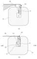
Figure 3 is a cross-sectional view of the AA section shown in Figure 1 and a cross-sectional view of a bolt connected thereto.
Figure 4 is a cross-sectional view sequentially showing the insertion process of the screw shown in Figure 3.
FIG. 5 is a cross-sectional view of a portion of a wood frame and a base of a mesh chair according to another embodiment of the present invention.
이하 첨부된 도면을 참고하여 본 발명에 따른 우드프레임을 구비한 메시 의자의 구성, 기능 및 작용을 설명한다. 단, 도면들에 걸쳐 동일하거나 유사한 구성요소에 대한 도면번호는 통일하여 사용하기로 한다.The configuration, function, and operation of a mesh chair equipped with a wood frame according to the present invention will be described with reference to the attached drawings below. However, drawing numbers for identical or similar components throughout the drawings will be used consistently.
첨부된 도면은 본 발명의 적용된 실시예를 나타낸 것으로, 본 발명의 기술적 사상을 첨부된 도면을 통하여 제한 해석해서는 아니된다. 이 기술분야에 속하는 전문가의 견지에서 도면에 도시된 일부 또는 전부가 발명의 실시를 위하여 필연적으로 요구되는 형상, 모양, 순서가 아니라고 해석될 수 있다면, 이는 청구범위에 기재된 발명을 한정하지 아니한다.The attached drawings illustrate applied embodiments of the present invention, and the technical idea of the present invention should not be interpreted as limited by the attached drawings. If, from the perspective of a specialist in this technical field, it can be interpreted that some or all of the shapes, shapes, or sequences depicted in the drawings are not necessarily required for the implementation of the invention, this does not limit the invention described in the claims.
본 발명의 실시예에 따른 메시 의자는 등받이 또는 좌판이 그물망으로 이루어진 것으로, 등받이와 좌판은 도시하지 아니한 연결 프레임 구조물에 의해 서로 연결될 수 있다. 나아가 연결 프레임에 의다 다리, 손잡이 등이 더 결합될 수 있다. 이하에서는 등받이가 그물망으로 구성되는 것을 위주로 설명하기로 한다.According to an embodiment of the present invention, a mesh chair has a backrest or seat made of mesh, and the backrest and seat can be connected to each other by a connecting frame structure (not shown). Furthermore, legs, handles, etc. can be further connected to the connecting frame. Hereinafter, a description will be given mainly of a backrest made of mesh.
도 1에는 본 발명의 실시예에 따른 메시 의자에 사용되는 등받이용 우드프레임이 개략적으로 도시되어 있다.FIG. 1 schematically illustrates a wood frame for a backrest used in a mesh chair according to an embodiment of the present invention.
등받이용 우드프레임(10)은 나무를 가공하여 제작된다. 나무 재질로 이루어진 우드프레임(10)은 적절한 수종을 선택하고, 건조, 공작 기계 가공, 약품 함침, 표면 마감 등의 여러 가공을 거치면서 필요한 탄성과 강성을 얻을 수 있다.The wood frame (10) for the backrest is manufactured by processing wood. The wood frame (10) made of wood material can obtain the necessary elasticity and rigidity by selecting an appropriate tree species and going through various processes such as drying, machine tool processing, chemical impregnation, and surface finishing.
구체적으로 도시하지 아니하였으나 우드프레임(10)의 배면에는 힌지 등 의자 프레임과 연결되는 추가 구조물이 결합된다.Although not specifically shown, an additional structure, such as a hinge, that is connected to the chair frame is attached to the back of the wood frame (10).
우드프레임(10)은 등받이 형상에 따라 대략 사각형의 둘레를 형성하고 있으며, 가운데 부분은 앞뒤로 개방되어 뚫려 있다. 도시하지 아니한 다른 실시예에서 우드프레임은 가운데 부분이 함몰되게 형성됨으로써 테두리 부분이 전방으로 더 돌출된 용기의 형상이 될 수도 있다.The wood frame (10) forms a roughly rectangular perimeter according to the shape of the backrest, and the central portion is open and perforated in the front and back. In another embodiment not shown, the wood frame may be formed so that the central portion is sunken, thereby forming a container shape in which the rim portion protrudes further forward.
도 2는 우드프레임을 분리하여 도시한 정면도이고, 도 3에는 우드프레임의 단면이 도시되어 있다.Figure 2 is a front view showing the wood frame separated, and Figure 3 shows a cross-section of the wood frame.
우드프레임(10)은 대략 사각형의 단면을 가진 긴 막대 형상의 단위프레임들(11)이 조립되어 완성되는 것으로, 단위프레임(11)은 등받이 또는 좌판의 디자인 설계에 따라 완만한 곡선으로 휘어진 형상이거나 각목과 같이 곧은 직선 형상으로 제작된다.The wood frame (10) is completed by assembling long bar-shaped unit frames (11) with a cross section of approximately square shape. The unit frames (11) are manufactured in a shape that is curved in a gentle curve or in a straight, straight shape like a piece of lumber, depending on the design of the backrest or seat.
단위프레임(11)의 전면에는 졸대가 끼워지는 장착홈(12)이 형성되어 있는데, 밀링 머신을 이용한 가공으로 단위프레임(11)의 길이 방향에 따라 장착홈(12)이 형성된다. 도시한 실시예에서 상하좌우로 배치된 4개의 단위프레임들(11)은 서로 만나는 접촉면에 발라진 본드와 나사못에 의해 견고하게 조립되어, 대략 사각틀을 형성하게 된다. 이때 각 단위프레임(11)의 장착홈(12)은 하나로 이어짐으로써, 완성된 사각틀을 따라 연속적으로 이어진 장착홈(12)이 하나의 루프를 형성하고 있다.A mounting groove (12) into which a shackle is inserted is formed on the front surface of the unit frame (11). The mounting groove (12) is formed along the longitudinal direction of the unit frame (11) by machining using a milling machine. In the illustrated embodiment, four unit frames (11) arranged up, down, left, and right are firmly assembled by bonds and screws applied to the contact surfaces where they meet each other, thereby forming an approximately square frame. At this time, the mounting grooves (12) of each unit frame (11) are connected as one, so that the mounting grooves (12) that are continuously connected along the completed square frame form one loop.
도시하지 아니하였으나 우드프레임은 하나의 원목을 가공하여 일체로 형성하거나, 좌우 또는 상하로 맞춰지는 2 피스 이상으로 제작될 수 있다.Although not urban, the wood frame can be formed as a single piece of wood, or it can be manufactured as two or more pieces that fit side-to-side or top-to-bottom.
장착홈(12)까지 가공된 단위프레임(11)을 제작한 후 이들을 조립하여 사각틀의 우드프레임(10)을 완성하는 분할 제작 구조는, 장착홈(12)을 가공하는 가공 툴이 단위프레임(11)의 단부에서 접근할 수 있게 하는 것으로, 후술하는 단턱을 형성하기 위한 목재 가공이 용이해지는 장점이 있다.The split manufacturing structure, which manufactures unit frames (11) processed up to the mounting groove (12) and then assembles them to complete a square wood frame (10), has the advantage of making it easier to process wood to form the step described later, as the processing tool for processing the mounting groove (12) can approach the end of the unit frame (11).
한편 도시하지는 않았으나 장착홈(12)은 우드프레임의 측면부나 후면부를 향하여 개방된 형태를 가질 수도 있고 이러한 장착홈(12)에 졸대가 삽입되어 고정될 수도 있다.Meanwhile, although not shown, the mounting groove (12) may have an open shape toward the side or rear of the wood frame, and a bolt may be inserted and fixed into this mounting groove (12).
도 3을 참고하면, 장착홈(12)에 그물망(30)과 결합된 졸대(20)가 삽입, 고정된다.Referring to Fig. 3, a bolt (20) combined with a net (30) is inserted and fixed into the mounting groove (12).
우드프레임(10)에서 사용자의 신체가 놓이는 가운데를 기준으로, 사용자의 등이 위치하는 방향을 '내측'이라 하고, 그 반대쪽을 '외측'으로 한다.Based on the center of the wood frame (10) where the user's body is placed, the direction in which the user's back is located is called the 'inner side', and the opposite side is called the 'outer side'.
장착홈(12)은 좁고 깊게 형성된다. 이때 장착홈(12)의 내벽 중간 높이에 단턱(121)이 형성되면서, 장착홈(12)의 바닥(122) 부근에서의 양 내벽 사이의 폭 길이가 입구(12a) 측의 폭 길이보다 더 길게 형성되어 있다. 이때 단턱(121)은 사용자가 기대는 내측 방향의 장착홈(12) 내벽에 형성된다.The mounting groove (12) is formed narrow and deep. At this time, a step (121) is formed at the middle height of the inner wall of the mounting groove (12), so that the width between the two inner walls near the bottom (122) of the mounting groove (12) is formed longer than the width on the inlet (12a) side. At this time, the step (121) is formed on the inner wall of the mounting groove (12) in the direction where the user leans.
한편 졸대(20)는 동일한 단면을 가지면서 긴 띠 타입 제작되는 것으로, 연질의 합성수지를 사출하여 제작할 수 있다. 그물망(30)은 졸대(20)의 중간 높이에서 박음질 등으로 견고하게 고정된다.Meanwhile, the sling (20) is manufactured as a long belt type with the same cross section, and can be manufactured by injection molding soft synthetic resin. The net (30) is firmly fixed at the middle height of the sling (20) by stitching, etc.
도 3에 도시된 졸대의 단면을 살펴보면, 졸대(20)는 그물망(30)이 중간 부분에 결합되는 지지부(21)와, 지지부(21)의 선단부(도면에서 하단부)로부터 비스듬하게 상부로 연장된 미늘 형태의 걸림부(22)를 포함한다.Looking at the cross-section of the bolt shown in Fig. 3, the bolt (20) includes a support part (21) to which a mesh (30) is joined in the middle, and a hook part (22) in the shape of a scale extending obliquely upward from the tip (lower part in the drawing) of the support part (21).
도시하지 않았으나 지지부의 측면에 결합되는 그물망과, 그물망을 결속시키는 박음실(도면에서 점선)의 두께를 고려하여, 지지부에 미리 함몰된 얕은 홈 자리를 형성할 수 있다. 즉 얕은 홈 자리에 그물망이 들어가 고정되도록 함으로써, 그물망 두께에 따라 졸대의 두께가 늘어나지 않게 할 수 있다. 이로써 장착홈에 가급적 꽉 차는 사이즈로 제작된 졸대를, 그물망에 의한 두께 증가에 대한 끼임 염려 없이 사용할 수 있게 된다.Although not shown, considering the thickness of the mesh that is connected to the side of the support and the thickness of the tassel (dotted line in the drawing) that binds the mesh, a shallow groove that is pre-sunk in the support can be formed. That is, by fixing the mesh into the shallow groove, the thickness of the saddle can be prevented from increasing according to the thickness of the mesh. This allows the saddle, which is manufactured to fit as tightly as possible into the mounting groove, to be used without worrying about being caught due to the increase in thickness caused by the mesh.
걸림부(22)의 끝단부는 지지부(21)로부터 벌어진 형태로, 지지부(21)와 걸림부(22)는 졸대(20)를 사출 성형하면서 일체로 제작될 수 있다.The end of the catch (22) is in a form that extends from the support (21), and the support (21) and catch (22) can be manufactured as one piece while injection molding the bolt (20).
또는 지지부와 걸림부는 서로 다른 재질로 별도로 제작된 후 접착제 등으로 결속시킬 수도 있다.Alternatively, the support and the catch can be manufactured separately from different materials and then joined together using adhesive, etc.
걸림부(22)는 지지부(21)로부터 벌어진 각도가 좁아지는 방향으로 탄성 변형될 수 있다. 걸림부(22)와 지지부(21)가 겹쳐진 최소 두께는 장착홈(12)의 입구(12a) 폭 길이보다 작게 형성됨으로써, 도 4의 (a)에 도시한 바와 같이, 졸대(20)를 장착홈(12)의 입구측에 대고 누르는 것만으로도 졸대(20)를 장착홈(12)에 삽입할 수 있다.The catch (22) can be elastically deformed in a direction in which the angle from the support (21) becomes narrower. The minimum thickness of the overlap between the catch (22) and the support (21) is formed to be smaller than the width of the entrance (12a) of the mounting groove (12), so that the catch (20) can be inserted into the mounting groove (12) simply by pressing the catch (20) against the entrance side of the mounting groove (12), as shown in (a) of Fig. 4.
이때 졸대(20)의 선단부가 장착홈(12)에 보다 용이하게 진입하도록 졸대(20)의 선단부를 뾰족하게 형성할 수 있다.At this time, the tip of the screw (20) can be formed sharply so that the tip of the screw (20) can enter the mounting groove (12) more easily.
도 4의 (b)는 장착홈에 졸대 장착이 완료된 상태를 단면도로 도시하고 있다.Figure 4 (b) is a cross-sectional view showing the state in which the bolt has been completely installed in the mounting groove.
장착홈(12)에 삽입된 졸대(20)의 걸림부(22)는, 장착홈(12)의 입구(12a)를 통과하면서 눌렸다가, 단턱(121)을 통과하면서 복원되어 벌어지게 된다. 미늘 형태로 벌어진 걸림부(22)의 끝단부가 단턱(121)에 걸리면서 졸대(20)가 장착홈(12) 안에 고정된다.The catch (22) of the bolt (20) inserted into the mounting groove (12) is pressed as it passes through the entrance (12a) of the mounting groove (12), and then is restored and spread apart as it passes through the step (121). When the end of the catch (22) spread in the shape of a scale is caught on the step (121), the bolt (20) is fixed inside the mounting groove (12).
이후 사용자가 신체를 그물망에 기대어 이로 인해 그물망(30)이 당겨지면서 졸대(20)가 장착홈(12)에서 이탈되려 해도, 단턱(121)과 걸림부(22)에 의해 졸대(20)는 빠질 수 없게 된다.Afterwards, even if the user leans his/her body against the net and the net (30) is pulled, causing the strap (20) to come off the mounting groove (12), the strap (20) cannot come off due to the step (121) and the catch (22).
한편 도 5는 본 발명의 다른 실시예에 따른 우드프레임과 졸대의 단면을 도시하고 있다.Meanwhile, FIG. 5 illustrates a cross-section of a wood frame and a brace according to another embodiment of the present invention.
도 5에 도시된 실시예는 우드프레임(10)과, 그물망(30)이 결합된 졸대(20)를 구비하는 것으로, 이들 구성요소는 이후 설명하는 내용과 저촉하지 아니하는 범위에서 도 1 내지 도 4에 도시한 실시예의 기술적 특징을 그대로 포함하는 것이다.The embodiment illustrated in Fig. 5 comprises a wooden frame (10) and a sling (20) combined with a net (30), and these components include the technical features of the embodiments illustrated in Figs. 1 to 4 as long as they do not conflict with the contents described below.
우드프레임(10)에 형성된 장착홈(12)에는 마주보는 양측 내벽 모두에 단턱(121)이 형성되어 있다. 이러한 T 형 단면은 단면 중심에서 대칭을 이루는 것으로, 도 3에 도시한 비대칭형 단면을 가진 장착홈에 대비하여 가공이 용이한 장점이 있다.The mounting groove (12) formed in the wood frame (10) has a step (121) formed on both inner walls facing each other. This T-shaped cross-section is symmetrical at the center of the cross-section, and has the advantage of being easy to process compared to the mounting groove having an asymmetrical cross-section as shown in Fig. 3.
또한 졸대(20)는 지지부(21)와, 지지부(21)를 중심으로 양측 모두에 걸림부(22)가 형성되어 있다. 좌우의 걸림부(22)는 지지부(21)와 가깝게 모아지면서 장착홈(12)의 입구를 통과한다. 이후 단턱(121)을 지나서는 원래대로 벌어져 단턱을 지지하며, 졸대를 장착홈에서 빠지지 않게 한다.In addition, the bolt (20) is formed with a support (21) and a catch (22) on both sides centered on the support (21). The catch (22) on the left and right come close to the support (21) and pass through the entrance of the mounting groove (12). After passing the step (121), it spreads back to its original position to support the step and prevent the bolt from falling out of the mounting groove.
도 5에 도시된 실시예의 장착홈(12)과 졸대(20)는 단면 중심에서 대칭적이므로 조립 방향을 오인할 우려가 없다. 또한 좌우의 걸림부들(22)이 벌어지면서 각기 단턱(121)에 걸리는 구조로써, 졸대(20)를 당기는 힘을 분산 지지하게 된다. 이로써 졸대의 이탈이 더욱 효과적으로 방지된다.The mounting groove (12) and the bolt (20) of the embodiment shown in Fig. 5 are symmetrical at the center of the cross section, so there is no concern about mistaking the assembly direction. In addition, the left and right catches (22) are structured to be caught on each step (121) as they spread apart, thereby dispersing and supporting the force that pulls the bolt (20). This prevents the bolt from detaching more effectively.
본 발명의 실시예들에 따른 메시 의자는 목재를 등받이 또는 좌판의 우드프레임으로 사용할 때에, 졸대를 장착홈에 삽입하는 것만으로도 설치가 완료되므로 작업성이 향상된다.Mesh chairs according to embodiments of the present invention, when using wood as a wood frame for a backrest or seat, can be installed simply by inserting a bolt into a mounting groove, thereby improving workability.
상기와 같은 메시 의자는 상기 설명된 실시예들의 구성과 방법이 한정되게 적용될 수 있는 것이 아니라, 상기 실시예들은 다양한 변형이 이루어질 수 있도록 각 실시예들의 전부 또는 일부가 선택적으로 조합되어 구성될 수도 있다.The mesh chair as described above is not limited to the configuration and method of the embodiments described above, and the embodiments may be configured by selectively combining all or part of the embodiments so that various modifications can be made.
앞서 설명한 본 발명의 상세한 설명에서는 본 발명의 바람직한 실시예를 참조하여 설명하였지만, 해당 기술분야의 숙련된 당업자 또는 해당 기술분야에 통상의 지식을 갖는 자라면 후술될 특허청구범위에 기재된 본 발명의 사상 및 기술 영역으로부터 벗어나지 않는 범위 내에서 본 발명을 다양하게 수정 및 변경시킬 수 있음을 이해할 수 있을 것이다.Although the detailed description of the present invention described above has been described with reference to preferred embodiments of the present invention, it will be understood by those skilled in the art or having common knowledge in the art that various modifications and changes can be made to the present invention without departing from the spirit and technical scope of the present invention as set forth in the claims to be described later.
10 : 우드프레임
11 : 단위프레임
12 : 장착홈 121 : 단턱 122 : 바닥 12a : 입구
20 : 졸대 21 : 지지부 22 : 걸림부
30 : 그물망10: Wood Frame
11: Unit Frame
12: Mounting groove 121: Step 122:
20: base 21: support 22: catch
30 : Net
Claims (4)
Translated fromKorean상기 장착홈의 내벽 중간 높이에 단턱이 있어 상기 장착홈의 입구보다 상기 단턱 아래의 폭이 더 넓으며,
상기 졸대는
상기 그물망이 결합되며 상기 장착홈에 삽입되는 지지부와,
상기 지지부의 선단부로부터 미늘 형태로 비스듬하게 연장되어 있으며, 끝단부가 상기 단턱에 걸리는 걸림부를 포함하고,
상기 장착홈은 등받이 또는 좌판의 둘레를 따라 외측으로 개방되도록 형성되고,
상기 걸림부는 상기 지지부로부터 벌어진 각도가 좁아지는 방향으로 탄성 변형될 수 있고, 상기 걸림부와 상기 지지부가 겹쳐진 최소 두께는 상기 장착홈의 입구 폭 길이보다 작게 형성되며,
상기 졸대는 연질의 합성수지 재질로 상기 지지부와 상기 걸림부는 일체로 사출되어 제작되고, 상기 걸림부는 탄성 변형되면서 상기 장착홈의 입구를 통과한 후 벌어져 상기 단턱에 걸리는 것을 특징으로 하는
우드 프레임을 구비한 메시 의자.
A mesh chair having a wood frame with a mounting groove formed along the perimeter of a backrest or seat, and a strap that is inserted into the mounting groove while being combined with a mesh net.
There is a step at the middle height of the inner wall of the above-mentioned mounting groove, and the width below the step is wider than the entrance of the above-mentioned mounting groove.
The above is the slogan
The above mesh is combined and a support part is inserted into the above mounting groove,
It extends obliquely in a blade-like shape from the tip of the above support member and includes a catch that catches the end of the catch on the step.
The above mounting groove is formed to open outwardly along the perimeter of the backrest or seat,
The above-mentioned catch portion can be elastically deformed in a direction in which the angle from the above-mentioned support portion becomes narrower, and the minimum thickness of the overlap between the above-mentioned catch portion and the above-mentioned support portion is formed to be smaller than the width of the entrance of the above-mentioned mounting groove.
The above-mentioned bolt is made of a soft synthetic resin material, and the support part and the catch part are integrally injection-molded and manufactured, and the catch part is characterized in that it passes through the entrance of the mounting groove while elastically deforming and then opens to catch on the step.
Mesh chair with wood frame.
상기 단턱은 상기 장착홈의 양측 내벽 모두에 형성되어 있고,
상기 걸림부도 상기 지지부의 양측 모두에 형성되어 있는 것을 특징으로 하는
우드프레임을 구비한 메시 의자.
In paragraph 1,
The above step is formed on both inner walls of the above mounting groove,
The above-mentioned hanging part is characterized in that it is formed on both sides of the above-mentioned supporting part.
Mesh chair with wood frame.
상기 우드프레임은
완만한 곡선 형상 또는 직선 형상으로 가공된 단위프레임들의 양단부를 상하좌우로 연결하여 사각틀로 제작되는 것을 특징으로 하는
우드프레임을 구비한 메시 의자.
In paragraph 1 or paragraph 3,
The above wood frame
It is characterized by being manufactured into a square frame by connecting the two ends of unit frames processed into a gentle curved shape or a straight shape in the up, down, left, and right directions.
Mesh chair with wood frame.
Priority Applications (1)
| Application Number | Priority Date | Filing Date | Title |
|---|---|---|---|
| KR1020220160805AKR102774524B1 (en) | 2022-11-25 | 2022-11-25 | Mesh type chair with wooden frame |
Applications Claiming Priority (1)
| Application Number | Priority Date | Filing Date | Title |
|---|---|---|---|
| KR1020220160805AKR102774524B1 (en) | 2022-11-25 | 2022-11-25 | Mesh type chair with wooden frame |
Publications (2)
| Publication Number | Publication Date |
|---|---|
| KR20240078148A KR20240078148A (en) | 2024-06-03 |
| KR102774524B1true KR102774524B1 (en) | 2025-02-27 |
Family
ID=91496129
Family Applications (1)
| Application Number | Title | Priority Date | Filing Date |
|---|---|---|---|
| KR1020220160805AActiveKR102774524B1 (en) | 2022-11-25 | 2022-11-25 | Mesh type chair with wooden frame |
Country Status (1)
| Country | Link |
|---|---|
| KR (1) | KR102774524B1 (en) |
Citations (3)
| Publication number | Priority date | Publication date | Assignee | Title |
|---|---|---|---|---|
| US20060006715A1 (en)* | 2004-07-08 | 2006-01-12 | Chadwick Donald T | Office chair |
| CN209252118U (en)* | 2018-07-30 | 2019-08-16 | 上海凯橙家具有限公司 | A kind of wooden single chair |
| US11089880B1 (en)* | 2019-11-11 | 2021-08-17 | B/E Aerospace, Inc. | Upholstery cover retention assembly |
Family Cites Families (1)
| Publication number | Priority date | Publication date | Assignee | Title |
|---|---|---|---|---|
| KR102517040B1 (en) | 2021-03-12 | 2023-03-31 | 한의경 | Mesh holder and chair having the same |
- 2022
- 2022-11-25KRKR1020220160805Apatent/KR102774524B1/enactiveActive
Patent Citations (3)
| Publication number | Priority date | Publication date | Assignee | Title |
|---|---|---|---|---|
| US20060006715A1 (en)* | 2004-07-08 | 2006-01-12 | Chadwick Donald T | Office chair |
| CN209252118U (en)* | 2018-07-30 | 2019-08-16 | 上海凯橙家具有限公司 | A kind of wooden single chair |
| US11089880B1 (en)* | 2019-11-11 | 2021-08-17 | B/E Aerospace, Inc. | Upholstery cover retention assembly |
Also Published As
| Publication number | Publication date |
|---|---|
| KR20240078148A (en) | 2024-06-03 |
Similar Documents
| Publication | Publication Date | Title |
|---|---|---|
| US5529373A (en) | Apparatus and method for covering a chair form with fabric | |
| KR910005201B1 (en) | Hybrid product molding method | |
| US7871131B2 (en) | Panel | |
| US8152235B2 (en) | Method of upholstering chair element | |
| US10259353B2 (en) | School bus seat | |
| US20210353067A1 (en) | Seat comprising suspension fabric with compression limiters | |
| JP2013094581A (en) | Spreading method of spreading material and spreading structure of spreading material | |
| WO2016170687A1 (en) | Female clip, foam molding, and foam molding manufacturing method | |
| KR102774524B1 (en) | Mesh type chair with wooden frame | |
| KR101163376B1 (en) | Seat and/or Backrest with Elastic Fiber Membrane and Manutacturing Method thereof | |
| JP2000500670A (en) | Upholstery element with fixed cover and method of manufacturing the same | |
| KR200489363Y1 (en) | Mesh holder and chair having it | |
| KR102746128B1 (en) | Mesh type chair with wooden frame | |
| FR2690610A1 (en) | Process for fixing fabric to frame of furniture - has studs with lateral projections fixed to fabric and clipping into C-shaped section fixed to frame | |
| KR101019015B1 (en) | Seat Cover Bracket | |
| KR20240045668A (en) | Mesh type chair with wooden frame | |
| JP2003033260A (en) | Attaching structure for spread material of chair | |
| JP7261534B2 (en) | Installation structure of chair upholstery | |
| US20060192420A1 (en) | Furniture item and a method for attaching webbing thereto | |
| KR102517051B1 (en) | Mesh holder and chair having the same | |
| US20050052068A1 (en) | Spring support for seating area of furniture | |
| JPH11244103A (en) | Surface skin extending device in chair or the like | |
| US7905818B1 (en) | Molded cushions for exercise equipment | |
| JPH08206376A (en) | Resin wire for pad insert | |
| JP7116656B2 (en) | Load bearing member and chair with same |
Legal Events
| Date | Code | Title | Description |
|---|---|---|---|
| PA0109 | Patent application | Patent event code:PA01091R01D Comment text:Patent Application Patent event date:20221125 | |
| PA0201 | Request for examination | ||
| PE0902 | Notice of grounds for rejection | Comment text:Notification of reason for refusal Patent event date:20240318 Patent event code:PE09021S01D | |
| PG1501 | Laying open of application | ||
| E701 | Decision to grant or registration of patent right | ||
| PE0701 | Decision of registration | Patent event code:PE07011S01D Comment text:Decision to Grant Registration Patent event date:20241125 | |
| GRNT | Written decision to grant | ||
| PR0701 | Registration of establishment | Comment text:Registration of Establishment Patent event date:20250225 Patent event code:PR07011E01D | |
| PR1002 | Payment of registration fee | Payment date:20250225 End annual number:3 Start annual number:1 | |
| PG1601 | Publication of registration |