KR102772102B1 - System for chemical transformation of 3D state materials - Google Patents
System for chemical transformation of 3D state materialsDownload PDFInfo
- Publication number
- KR102772102B1 KR102772102B1KR1020217006647AKR20217006647AKR102772102B1KR 102772102 B1KR102772102 B1KR 102772102B1KR 1020217006647 AKR1020217006647 AKR 1020217006647AKR 20217006647 AKR20217006647 AKR 20217006647AKR 102772102 B1KR102772102 B1KR 102772102B1
- Authority
- KR
- South Korea
- Prior art keywords
- sample
- gas
- reaction chamber
- initial structure
- group
- Prior art date
- Legal status (The legal status is an assumption and is not a legal conclusion. Google has not performed a legal analysis and makes no representation as to the accuracy of the status listed.)
- Active
Links
- 238000006243chemical reactionMethods0.000titleclaimsabstractdescription111
- 239000000463materialSubstances0.000titleclaimsabstractdescription51
- 238000000034methodMethods0.000claimsabstractdescription38
- CURLTUGMZLYLDI-UHFFFAOYSA-NCarbon dioxideChemical compoundO=C=OCURLTUGMZLYLDI-UHFFFAOYSA-N0.000claimsdescription40
- VTYYLEPIZMXCLO-UHFFFAOYSA-LCalcium carbonateChemical compound[Ca+2].[O-]C([O-])=OVTYYLEPIZMXCLO-UHFFFAOYSA-L0.000claimsdescription36
- ODINCKMPIJJUCX-UHFFFAOYSA-NCalcium oxideChemical compound[Ca]=OODINCKMPIJJUCX-UHFFFAOYSA-N0.000claimsdescription21
- 229910002092carbon dioxideInorganic materials0.000claimsdescription21
- 229910000019calcium carbonateInorganic materials0.000claimsdescription18
- 239000001569carbon dioxideSubstances0.000claimsdescription13
- QGZKDVFQNNGYKY-UHFFFAOYSA-NAmmoniaChemical compoundNQGZKDVFQNNGYKY-UHFFFAOYSA-N0.000claimsdescription12
- 229910052751metalInorganic materials0.000claimsdescription11
- 239000002184metalSubstances0.000claimsdescription11
- 239000000126substanceSubstances0.000claimsdescription11
- BRPQOXSCLDDYGP-UHFFFAOYSA-Ncalcium oxideChemical compound[O-2].[Ca+2]BRPQOXSCLDDYGP-UHFFFAOYSA-N0.000claimsdescription9
- 239000000292calcium oxideSubstances0.000claimsdescription9
- 239000013043chemical agentSubstances0.000claimsdescription8
- 239000007787solidSubstances0.000claimsdescription8
- 229910021529ammoniaInorganic materials0.000claimsdescription6
- 229910044991metal oxideInorganic materials0.000claimsdescription6
- 150000004767nitridesChemical class0.000claimsdescription6
- 150000004706metal oxidesChemical class0.000claimsdescription5
- 150000003839saltsChemical class0.000claimsdescription5
- BVKZGUZCCUSVTD-UHFFFAOYSA-LCarbonateChemical compound[O-]C([O-])=OBVKZGUZCCUSVTD-UHFFFAOYSA-L0.000claims2
- 239000007789gasSubstances0.000abstractdescription41
- 230000008569processEffects0.000description22
- XLYOFNOQVPJJNP-UHFFFAOYSA-NwaterSubstancesOXLYOFNOQVPJJNP-UHFFFAOYSA-N0.000description9
- IJGRMHOSHXDMSA-UHFFFAOYSA-NAtomic nitrogenChemical compoundN#NIJGRMHOSHXDMSA-UHFFFAOYSA-N0.000description8
- 235000010216calcium carbonateNutrition0.000description8
- 239000000203mixtureSubstances0.000description7
- 239000011575calciumSubstances0.000description5
- UQSXHKLRYXJYBZ-UHFFFAOYSA-NIron oxideChemical compound[Fe]=OUQSXHKLRYXJYBZ-UHFFFAOYSA-N0.000description4
- 150000004649carbonic acid derivativesChemical class0.000description4
- 230000036571hydrationEffects0.000description4
- 238000006703hydration reactionMethods0.000description4
- -1CaSiO 3 )Chemical class0.000description3
- 230000008859changeEffects0.000description3
- 229910052757nitrogenInorganic materials0.000description3
- 230000001590oxidative effectEffects0.000description3
- 239000002243precursorSubstances0.000description3
- 230000009466transformationEffects0.000description3
- 230000015572biosynthetic processEffects0.000description2
- AXCZMVOFGPJBDE-UHFFFAOYSA-Lcalcium dihydroxideChemical compound[OH-].[OH-].[Ca+2]AXCZMVOFGPJBDE-UHFFFAOYSA-L0.000description2
- OSGAYBCDTDRGGQ-UHFFFAOYSA-Lcalcium sulfateChemical compound[Ca+2].[O-]S([O-])(=O)=OOSGAYBCDTDRGGQ-UHFFFAOYSA-L0.000description2
- 238000001514detection methodMethods0.000description2
- 238000010586diagramMethods0.000description2
- 238000004519manufacturing processMethods0.000description2
- 230000004048modificationEffects0.000description2
- 238000012986modificationMethods0.000description2
- 239000000376reactantSubstances0.000description2
- 239000012495reaction gasSubstances0.000description2
- PIGFYZPCRLYGLF-UHFFFAOYSA-NAluminum nitrideChemical compound[Al]#NPIGFYZPCRLYGLF-UHFFFAOYSA-N0.000description1
- PZNSFCLAULLKQX-UHFFFAOYSA-NBoron nitrideChemical compoundN#BPZNSFCLAULLKQX-UHFFFAOYSA-N0.000description1
- 229910004762CaSiOInorganic materials0.000description1
- OYPRJOBELJOOCE-UHFFFAOYSA-NCalciumChemical compound[Ca]OYPRJOBELJOOCE-UHFFFAOYSA-N0.000description1
- FYYHWMGAXLPEAU-UHFFFAOYSA-NMagnesiumChemical compound[Mg]FYYHWMGAXLPEAU-UHFFFAOYSA-N0.000description1
- 229910020068MgAlInorganic materials0.000description1
- 229910052581Si3N4Inorganic materials0.000description1
- 229910004298SiO 2Inorganic materials0.000description1
- VYPSYNLAJGMNEJ-UHFFFAOYSA-NSilicium dioxideChemical compoundO=[Si]=OVYPSYNLAJGMNEJ-UHFFFAOYSA-N0.000description1
- GWEVSGVZZGPLCZ-UHFFFAOYSA-NTitan oxideChemical compoundO=[Ti]=OGWEVSGVZZGPLCZ-UHFFFAOYSA-N0.000description1
- NRTOMJZYCJJWKI-UHFFFAOYSA-NTitanium nitrideChemical compound[Ti]#NNRTOMJZYCJJWKI-UHFFFAOYSA-N0.000description1
- XLOMVQKBTHCTTD-UHFFFAOYSA-NZinc monoxideChemical compound[Zn]=OXLOMVQKBTHCTTD-UHFFFAOYSA-N0.000description1
- 150000004645aluminatesChemical class0.000description1
- 210000000988bone and boneAnatomy0.000description1
- 229910052791calciumInorganic materials0.000description1
- 239000000920calcium hydroxideSubstances0.000description1
- 229910001861calcium hydroxideInorganic materials0.000description1
- 239000001506calcium phosphateSubstances0.000description1
- 229910000389calcium phosphateInorganic materials0.000description1
- 235000011010calcium phosphatesNutrition0.000description1
- WEUCVIBPSSMHJG-UHFFFAOYSA-Ncalcium titanateChemical compound[O-2].[O-2].[O-2].[Ca+2].[Ti+4]WEUCVIBPSSMHJG-UHFFFAOYSA-N0.000description1
- 229910052799carbonInorganic materials0.000description1
- 239000002131composite materialSubstances0.000description1
- 238000010276constructionMethods0.000description1
- 230000006866deteriorationEffects0.000description1
- NKZSPGSOXYXWQA-UHFFFAOYSA-Ndioxido(oxo)titanium;lead(2+)Chemical compound[Pb+2].[O-][Ti]([O-])=ONKZSPGSOXYXWQA-UHFFFAOYSA-N0.000description1
- 238000010438heat treatmentMethods0.000description1
- XLYOFNOQVPJJNP-UHFFFAOYSA-MhydroxideChemical compound[OH-]XLYOFNOQVPJJNP-UHFFFAOYSA-M0.000description1
- 229910052588hydroxylapatiteInorganic materials0.000description1
- 229910010272inorganic materialInorganic materials0.000description1
- 239000011147inorganic materialSubstances0.000description1
- XEEYBQQBJWHFJM-UHFFFAOYSA-NironSubstances[Fe]XEEYBQQBJWHFJM-UHFFFAOYSA-N0.000description1
- 229910052749magnesiumInorganic materials0.000description1
- 239000011777magnesiumSubstances0.000description1
- ZLNQQNXFFQJAID-UHFFFAOYSA-Lmagnesium carbonateChemical compound[Mg+2].[O-]C([O-])=OZLNQQNXFFQJAID-UHFFFAOYSA-L0.000description1
- 229910003455mixed metal oxideInorganic materials0.000description1
- 238000012544monitoring processMethods0.000description1
- 229910052755nonmetalInorganic materials0.000description1
- 230000035515penetrationEffects0.000description1
- XYJRXVWERLGGKC-UHFFFAOYSA-Dpentacalcium;hydroxide;triphosphateChemical compound[OH-].[Ca+2].[Ca+2].[Ca+2].[Ca+2].[Ca+2].[O-]P([O-])([O-])=O.[O-]P([O-])([O-])=O.[O-]P([O-])([O-])=OXYJRXVWERLGGKC-UHFFFAOYSA-D0.000description1
- 229910052698phosphorusInorganic materials0.000description1
- 239000000843powderSubstances0.000description1
- 230000008929regenerationEffects0.000description1
- 238000011069regeneration methodMethods0.000description1
- 238000007789sealingMethods0.000description1
- 150000004760silicatesChemical class0.000description1
- HQVNEWCFYHHQES-UHFFFAOYSA-Nsilicon nitrideChemical compoundN12[Si]34N5[Si]62N3[Si]51N64HQVNEWCFYHHQES-UHFFFAOYSA-N0.000description1
- 229910052814silicon oxideInorganic materials0.000description1
- 238000003756stirringMethods0.000description1
- UUCCCPNEFXQJEL-UHFFFAOYSA-Lstrontium dihydroxideChemical compound[OH-].[OH-].[Sr+2]UUCCCPNEFXQJEL-UHFFFAOYSA-L0.000description1
- 229910001866strontium hydroxideInorganic materials0.000description1
- AKEJUJNQAAGONA-UHFFFAOYSA-Nsulfur trioxideChemical compoundO=S(=O)=OAKEJUJNQAAGONA-UHFFFAOYSA-N0.000description1
- 239000002344surface layerSubstances0.000description1
- 238000003786synthesis reactionMethods0.000description1
- 230000001131transforming effectEffects0.000description1
- QORWJWZARLRLPR-UHFFFAOYSA-Htricalcium bis(phosphate)Chemical compound[Ca+2].[Ca+2].[Ca+2].[O-]P([O-])([O-])=O.[O-]P([O-])([O-])=OQORWJWZARLRLPR-UHFFFAOYSA-H0.000description1
Images


Classifications
- B—PERFORMING OPERATIONS; TRANSPORTING
- B01—PHYSICAL OR CHEMICAL PROCESSES OR APPARATUS IN GENERAL
- B01J—CHEMICAL OR PHYSICAL PROCESSES, e.g. CATALYSIS OR COLLOID CHEMISTRY; THEIR RELEVANT APPARATUS
- B01J19/00—Chemical, physical or physico-chemical processes in general; Their relevant apparatus
- B01J19/0053—Details of the reactor
- B01J19/0066—Stirrers
- B—PERFORMING OPERATIONS; TRANSPORTING
- B01—PHYSICAL OR CHEMICAL PROCESSES OR APPARATUS IN GENERAL
- B01J—CHEMICAL OR PHYSICAL PROCESSES, e.g. CATALYSIS OR COLLOID CHEMISTRY; THEIR RELEVANT APPARATUS
- B01J19/00—Chemical, physical or physico-chemical processes in general; Their relevant apparatus
- B01J19/0053—Details of the reactor
- B01J19/0073—Sealings
- B—PERFORMING OPERATIONS; TRANSPORTING
- B01—PHYSICAL OR CHEMICAL PROCESSES OR APPARATUS IN GENERAL
- B01J—CHEMICAL OR PHYSICAL PROCESSES, e.g. CATALYSIS OR COLLOID CHEMISTRY; THEIR RELEVANT APPARATUS
- B01J19/00—Chemical, physical or physico-chemical processes in general; Their relevant apparatus
- B01J19/18—Stationary reactors having moving elements inside
- B—PERFORMING OPERATIONS; TRANSPORTING
- B01—PHYSICAL OR CHEMICAL PROCESSES OR APPARATUS IN GENERAL
- B01J—CHEMICAL OR PHYSICAL PROCESSES, e.g. CATALYSIS OR COLLOID CHEMISTRY; THEIR RELEVANT APPARATUS
- B01J3/00—Processes of utilising sub-atmospheric or super-atmospheric pressure to effect chemical or physical change of matter; Apparatus therefor
- B01J3/002—Component parts of these vessels not mentioned in B01J3/004, B01J3/006, B01J3/02 - B01J3/08; Measures taken in conjunction with the process to be carried out, e.g. safety measures
- B—PERFORMING OPERATIONS; TRANSPORTING
- B01—PHYSICAL OR CHEMICAL PROCESSES OR APPARATUS IN GENERAL
- B01J—CHEMICAL OR PHYSICAL PROCESSES, e.g. CATALYSIS OR COLLOID CHEMISTRY; THEIR RELEVANT APPARATUS
- B01J3/00—Processes of utilising sub-atmospheric or super-atmospheric pressure to effect chemical or physical change of matter; Apparatus therefor
- B01J3/008—Processes carried out under supercritical conditions
- B—PERFORMING OPERATIONS; TRANSPORTING
- B01—PHYSICAL OR CHEMICAL PROCESSES OR APPARATUS IN GENERAL
- B01J—CHEMICAL OR PHYSICAL PROCESSES, e.g. CATALYSIS OR COLLOID CHEMISTRY; THEIR RELEVANT APPARATUS
- B01J3/00—Processes of utilising sub-atmospheric or super-atmospheric pressure to effect chemical or physical change of matter; Apparatus therefor
- B01J3/02—Feed or outlet devices therefor
- B—PERFORMING OPERATIONS; TRANSPORTING
- B01—PHYSICAL OR CHEMICAL PROCESSES OR APPARATUS IN GENERAL
- B01J—CHEMICAL OR PHYSICAL PROCESSES, e.g. CATALYSIS OR COLLOID CHEMISTRY; THEIR RELEVANT APPARATUS
- B01J3/00—Processes of utilising sub-atmospheric or super-atmospheric pressure to effect chemical or physical change of matter; Apparatus therefor
- B01J3/03—Pressure vessels, or vacuum vessels, having closure members or seals specially adapted therefor
- B—PERFORMING OPERATIONS; TRANSPORTING
- B01—PHYSICAL OR CHEMICAL PROCESSES OR APPARATUS IN GENERAL
- B01J—CHEMICAL OR PHYSICAL PROCESSES, e.g. CATALYSIS OR COLLOID CHEMISTRY; THEIR RELEVANT APPARATUS
- B01J3/00—Processes of utilising sub-atmospheric or super-atmospheric pressure to effect chemical or physical change of matter; Apparatus therefor
- B01J3/04—Pressure vessels, e.g. autoclaves
- B01J3/042—Pressure vessels, e.g. autoclaves in the form of a tube
- B—PERFORMING OPERATIONS; TRANSPORTING
- B01—PHYSICAL OR CHEMICAL PROCESSES OR APPARATUS IN GENERAL
- B01J—CHEMICAL OR PHYSICAL PROCESSES, e.g. CATALYSIS OR COLLOID CHEMISTRY; THEIR RELEVANT APPARATUS
- B01J4/00—Feed or outlet devices; Feed or outlet control devices
- B01J4/001—Feed or outlet devices as such, e.g. feeding tubes
- B01J4/007—Feed or outlet devices as such, e.g. feeding tubes provided with moving parts
- C—CHEMISTRY; METALLURGY
- C01—INORGANIC CHEMISTRY
- C01B—NON-METALLIC ELEMENTS; COMPOUNDS THEREOF; METALLOIDS OR COMPOUNDS THEREOF NOT COVERED BY SUBCLASS C01C
- C01B21/00—Nitrogen; Compounds thereof
- C01B21/06—Binary compounds of nitrogen with metals, with silicon, or with boron, or with carbon, i.e. nitrides; Compounds of nitrogen with more than one metal, silicon or boron
- C01B21/064—Binary compounds of nitrogen with metals, with silicon, or with boron, or with carbon, i.e. nitrides; Compounds of nitrogen with more than one metal, silicon or boron with boron
- C—CHEMISTRY; METALLURGY
- C01—INORGANIC CHEMISTRY
- C01B—NON-METALLIC ELEMENTS; COMPOUNDS THEREOF; METALLOIDS OR COMPOUNDS THEREOF NOT COVERED BY SUBCLASS C01C
- C01B21/00—Nitrogen; Compounds thereof
- C01B21/06—Binary compounds of nitrogen with metals, with silicon, or with boron, or with carbon, i.e. nitrides; Compounds of nitrogen with more than one metal, silicon or boron
- C01B21/068—Binary compounds of nitrogen with metals, with silicon, or with boron, or with carbon, i.e. nitrides; Compounds of nitrogen with more than one metal, silicon or boron with silicon
- C—CHEMISTRY; METALLURGY
- C01—INORGANIC CHEMISTRY
- C01B—NON-METALLIC ELEMENTS; COMPOUNDS THEREOF; METALLOIDS OR COMPOUNDS THEREOF NOT COVERED BY SUBCLASS C01C
- C01B21/00—Nitrogen; Compounds thereof
- C01B21/06—Binary compounds of nitrogen with metals, with silicon, or with boron, or with carbon, i.e. nitrides; Compounds of nitrogen with more than one metal, silicon or boron
- C01B21/072—Binary compounds of nitrogen with metals, with silicon, or with boron, or with carbon, i.e. nitrides; Compounds of nitrogen with more than one metal, silicon or boron with aluminium
- C—CHEMISTRY; METALLURGY
- C01—INORGANIC CHEMISTRY
- C01B—NON-METALLIC ELEMENTS; COMPOUNDS THEREOF; METALLOIDS OR COMPOUNDS THEREOF NOT COVERED BY SUBCLASS C01C
- C01B21/00—Nitrogen; Compounds thereof
- C01B21/06—Binary compounds of nitrogen with metals, with silicon, or with boron, or with carbon, i.e. nitrides; Compounds of nitrogen with more than one metal, silicon or boron
- C01B21/076—Binary compounds of nitrogen with metals, with silicon, or with boron, or with carbon, i.e. nitrides; Compounds of nitrogen with more than one metal, silicon or boron with titanium or zirconium or hafnium
- C—CHEMISTRY; METALLURGY
- C01—INORGANIC CHEMISTRY
- C01F—COMPOUNDS OF THE METALS BERYLLIUM, MAGNESIUM, ALUMINIUM, CALCIUM, STRONTIUM, BARIUM, RADIUM, THORIUM, OR OF THE RARE-EARTH METALS
- C01F11/00—Compounds of calcium, strontium, or barium
- C01F11/18—Carbonates
- C—CHEMISTRY; METALLURGY
- C01—INORGANIC CHEMISTRY
- C01G—COMPOUNDS CONTAINING METALS NOT COVERED BY SUBCLASSES C01D OR C01F
- C01G23/00—Compounds of titanium
- C01G23/003—Titanates
- C01G23/006—Alkaline earth titanates
- F—MECHANICAL ENGINEERING; LIGHTING; HEATING; WEAPONS; BLASTING
- F27—FURNACES; KILNS; OVENS; RETORTS
- F27B—FURNACES, KILNS, OVENS OR RETORTS IN GENERAL; OPEN SINTERING OR LIKE APPARATUS
- F27B5/00—Muffle furnaces; Retort furnaces; Other furnaces in which the charge is held completely isolated
- F27B5/04—Muffle furnaces; Retort furnaces; Other furnaces in which the charge is held completely isolated adapted for treating the charge in vacuum or special atmosphere
- F—MECHANICAL ENGINEERING; LIGHTING; HEATING; WEAPONS; BLASTING
- F27—FURNACES; KILNS; OVENS; RETORTS
- F27D—DETAILS OR ACCESSORIES OF FURNACES, KILNS, OVENS OR RETORTS, IN SO FAR AS THEY ARE OF KINDS OCCURRING IN MORE THAN ONE KIND OF FURNACE
- F27D5/00—Supports, screens or the like for the charge within the furnace
- F27D5/0056—Hangers
- F—MECHANICAL ENGINEERING; LIGHTING; HEATING; WEAPONS; BLASTING
- F27—FURNACES; KILNS; OVENS; RETORTS
- F27D—DETAILS OR ACCESSORIES OF FURNACES, KILNS, OVENS OR RETORTS, IN SO FAR AS THEY ARE OF KINDS OCCURRING IN MORE THAN ONE KIND OF FURNACE
- F27D7/00—Forming, maintaining or circulating atmospheres in heating chambers
- F27D7/02—Supplying steam, vapour, gases or liquids
- F—MECHANICAL ENGINEERING; LIGHTING; HEATING; WEAPONS; BLASTING
- F27—FURNACES; KILNS; OVENS; RETORTS
- F27D—DETAILS OR ACCESSORIES OF FURNACES, KILNS, OVENS OR RETORTS, IN SO FAR AS THEY ARE OF KINDS OCCURRING IN MORE THAN ONE KIND OF FURNACE
- F27D7/00—Forming, maintaining or circulating atmospheres in heating chambers
- F27D7/04—Circulating atmospheres by mechanical means
- B—PERFORMING OPERATIONS; TRANSPORTING
- B01—PHYSICAL OR CHEMICAL PROCESSES OR APPARATUS IN GENERAL
- B01J—CHEMICAL OR PHYSICAL PROCESSES, e.g. CATALYSIS OR COLLOID CHEMISTRY; THEIR RELEVANT APPARATUS
- B01J2203/00—Processes utilising sub- or super atmospheric pressure
- B01J2203/06—High pressure synthesis
- B01J2203/0605—Composition of the material to be processed
- B01J2203/064—Carbonates
- F—MECHANICAL ENGINEERING; LIGHTING; HEATING; WEAPONS; BLASTING
- F27—FURNACES; KILNS; OVENS; RETORTS
- F27B—FURNACES, KILNS, OVENS OR RETORTS IN GENERAL; OPEN SINTERING OR LIKE APPARATUS
- F27B5/00—Muffle furnaces; Retort furnaces; Other furnaces in which the charge is held completely isolated
- F27B5/06—Details, accessories or equipment specially adapted for furnaces of these types
- F27B5/16—Arrangements of air or gas supply devices
- F27B2005/161—Gas inflow or outflow
- F—MECHANICAL ENGINEERING; LIGHTING; HEATING; WEAPONS; BLASTING
- F27—FURNACES; KILNS; OVENS; RETORTS
- F27B—FURNACES, KILNS, OVENS OR RETORTS IN GENERAL; OPEN SINTERING OR LIKE APPARATUS
- F27B5/00—Muffle furnaces; Retort furnaces; Other furnaces in which the charge is held completely isolated
- F27B5/06—Details, accessories or equipment specially adapted for furnaces of these types
- F27B5/16—Arrangements of air or gas supply devices
- F27B2005/166—Means to circulate the atmosphere
- F27B2005/167—Means to circulate the atmosphere the atmosphere being recirculated through the treatment chamber by a turbine
- F27B2005/168—Means to circulate the atmosphere the atmosphere being recirculated through the treatment chamber by a turbine by more than one turbine
- F—MECHANICAL ENGINEERING; LIGHTING; HEATING; WEAPONS; BLASTING
- F27—FURNACES; KILNS; OVENS; RETORTS
- F27D—DETAILS OR ACCESSORIES OF FURNACES, KILNS, OVENS OR RETORTS, IN SO FAR AS THEY ARE OF KINDS OCCURRING IN MORE THAN ONE KIND OF FURNACE
- F27D7/00—Forming, maintaining or circulating atmospheres in heating chambers
- F27D7/04—Circulating atmospheres by mechanical means
- F27D2007/045—Fans
- F—MECHANICAL ENGINEERING; LIGHTING; HEATING; WEAPONS; BLASTING
- F27—FURNACES; KILNS; OVENS; RETORTS
- F27D—DETAILS OR ACCESSORIES OF FURNACES, KILNS, OVENS OR RETORTS, IN SO FAR AS THEY ARE OF KINDS OCCURRING IN MORE THAN ONE KIND OF FURNACE
- F27D7/00—Forming, maintaining or circulating atmospheres in heating chambers
- F27D7/06—Forming or maintaining special atmospheres or vacuum within heating chambers
- F27D2007/063—Special atmospheres, e.g. high pressure atmospheres
- Y—GENERAL TAGGING OF NEW TECHNOLOGICAL DEVELOPMENTS; GENERAL TAGGING OF CROSS-SECTIONAL TECHNOLOGIES SPANNING OVER SEVERAL SECTIONS OF THE IPC; TECHNICAL SUBJECTS COVERED BY FORMER USPC CROSS-REFERENCE ART COLLECTIONS [XRACs] AND DIGESTS
- Y02—TECHNOLOGIES OR APPLICATIONS FOR MITIGATION OR ADAPTATION AGAINST CLIMATE CHANGE
- Y02P—CLIMATE CHANGE MITIGATION TECHNOLOGIES IN THE PRODUCTION OR PROCESSING OF GOODS
- Y02P20/00—Technologies relating to chemical industry
- Y02P20/50—Improvements relating to the production of bulk chemicals
- Y02P20/54—Improvements relating to the production of bulk chemicals using solvents, e.g. supercritical solvents or ionic liquids
Landscapes
- Chemical & Material Sciences (AREA)
- Organic Chemistry (AREA)
- Chemical Kinetics & Catalysis (AREA)
- Engineering & Computer Science (AREA)
- Inorganic Chemistry (AREA)
- Mechanical Engineering (AREA)
- General Engineering & Computer Science (AREA)
- Geology (AREA)
- Life Sciences & Earth Sciences (AREA)
- General Life Sciences & Earth Sciences (AREA)
- Environmental & Geological Engineering (AREA)
- Physical Or Chemical Processes And Apparatus (AREA)
- Compounds Of Alkaline-Earth Elements, Aluminum Or Rare-Earth Metals (AREA)
- Investigating Or Analyzing Non-Biological Materials By The Use Of Chemical Means (AREA)
- Sampling And Sample Adjustment (AREA)
- Cultivation Of Plants (AREA)
- Organic Low-Molecular-Weight Compounds And Preparation Thereof (AREA)
- Steroid Compounds (AREA)
- Investigating Or Analyzing Materials Using Thermal Means (AREA)
Abstract
Translated fromKoreanDescription
Translated fromKorean본 발명은 일반적으로 예를 들어 3D 상태 재료를 실현하기 위한 화학적 변환 시스템(chemical transformation system)에 관한 것이다.The present invention generally relates to a chemical transformation system for realizing, for example, a 3D state material.
특히, 본 발명은 초임계 및/또는 임계 조건에서도 고반응성의 3D 무기 재료를 실현하기 위한 시스템에 관한 것이다.In particular, the present invention relates to a system for realizing highly reactive 3D inorganic materials even under supercritical and/or critical conditions.
훨씬 더 특별하게는, 본 발명은, 예를 들어 고온 및/또는 고압에서 고체 3D 전구체와 고반응성의 균질한 가스 또는 가스 혼합물 사이의 이종 반응을 통해, 구조적 계층(structural hierarchy)의 변경 없이 3D 재료를 화학적으로 변환하기 위한 시스템에 관한 것이다.Even more particularly, the present invention relates to a system for chemically transforming 3D materials without altering their structural hierarchy, for example via a heterogeneous reaction between a solid 3D precursor and a highly reactive homogeneous gas or gas mixture at high temperatures and/or pressures.
일반적으로, 인산칼슘계 재료의 합성을 위한 전구체로서 사용되는 고반응성의 탄산칼슘(CaCO3)을 기반으로 하는 3D 재료의 준비 프로세스가 알려져 있다.In general, a process for preparing 3D materials based on highly reactive calcium carbonate (CaCO3 ), which is used as a precursor for the synthesis of calcium phosphate-based materials, is known.
예를 들어, 이러한 유형의 프로세스는 특허 공개 WO2017/021894_A1로부터 알려져 있다.For example, this type of process is known from patent publication WO2017/021894_A1.
공지된 프로세스에서 발견된 문제는 산화칼슘(CaO)으로부터 탄산칼슘(CaCO3)으로의 3D 재료의 변환이 일반적으로 반응물 균질성의 결여 때문에 특히 중요하다는 것이다.A problem found in known processes is that the transformation of 3D materials from calcium oxide (CaO) to calcium carbonate (CaCO3 ) is particularly critical due to the general lack of reactant homogeneity.
특히, 출원인은 공지된 프로세스에서 물(H2O)이 풍부한 이산화탄소(CO2)의 가능한 사용이 초기 구조가 보존되고 그리고/또는 산화칼슘(CaO)으로부터 탄산칼슘(CaCO3)으로 완전히 변환된 3D 재료를 얻는 것을 항상 보장하지는 않는다는 것을 관찰했다.In particular, the applicant observed that the possible use of carbon dioxide (CO2 ) enriched with water (H2O ) in the known processes does not always ensure obtaining a 3D material with the initial structure preserved and/or completely converted from calcium oxide (CaO) to calcium carbonate (CaCO3 ).
출원인은 또한, 일반적으로 공지된 시스템이 질화물, 금속 산화물, 탄산염 등을 기반으로 하는 3D 재료의 경우에도 초기 구조가 완전히 보존되고 그리고/또는 적어도 부분적으로 변환된 3D 재료를 얻는 것을 항상 보장하지는 않는다는 것을 관찰했다.The applicant also observed that generally known systems do not always guarantee to obtain 3D materials with a fully preserved and/or at least partially transformed initial structure, even for 3D materials based on nitrides, metal oxides, carbonates, etc.
일반적으로, 출원인은 공지된 변환 시스템이 3D 재료의 화학적 변환을 항상 보장하도록, 그에 따라 구조와 관련하여 상기 재료가 완전히 보존되고 그리고/또는 적어도 부분적으로 화학적으로 변환되도록, 최적화되어 있지 않다는 것을 관찰했다.In general, the applicant observed that the known transformation systems are not optimized to always ensure a chemical transformation of a 3D material, such that the material is completely preserved and/or at least partially chemically transformed with respect to its structure.
본 발명의 목적은 상기에 언급된 종래 기술의 문제점을 최적화된 방식으로 해결하는 것이다.The purpose of the present invention is to solve the problems of the prior art mentioned above in an optimized manner.
그러한 목적은 하기의 청구범위에 기재된 특징을 갖는 3D 재료의 화학적 변환을 위한 시스템에 의해 달성된다.Such an object is achieved by a system for chemical transformation of a 3D material having the features described in the claims below.
본 발명은 또한 3D 재료 상에, 가변 두께를 갖고 화학적으로 변환된 고반응성 표면 층을 실현하기 위한 방법에 관한 것이다.The present invention also relates to a method for realizing a chemically converted highly reactive surface layer having variable thickness on a 3D material.
본 발명의 하기의 종합적인 설명은 본 발명의 일부 양태에 대한 기본적인 이해를 제공할 목적으로 제공된다.The following comprehensive description of the present invention is provided for the purpose of providing a basic understanding of some aspects of the present invention.
이러한 종합적인 설명은 확장된 설명이 아니므로, 본 발명의 핵심 또는 중요 요소를 식별하기에 적합하거나 본 발명의 범위를 기술하기에 적합한 것으로 의도되지 않는다. 그것의 유일한 목적은 하기의 상세한 설명의 개요로서 단순화된 형태로 본 발명의 일부 내용을 소개하는 것이다.This comprehensive description is not intended to be an extensive description and is not intended to be adequate to identify key or critical elements of the invention or to describe the scope of the invention. Its sole purpose is to introduce some of the invention in a simplified form as an overview of the more detailed description that follows.
바람직한 실시예의 특징에 따르면, 상기 시스템은 하나 이상의 가스가 방출되는 반응 챔버, 및 사용 시에 반응 챔버 내에서, 화학적으로 변환될 3D 상태 재료 샘플 상에 하나 이상의 가스를 수렴시키도록 마련된 적어도 2 개의 터빈을 포함하는 본체를 포함한다.In accordance with a feature of a preferred embodiment, the system comprises a body including a reaction chamber through which one or more gases are released, and at least two turbines arranged to, when in use, converge the one or more gases within the reaction chamber onto a 3D state material sample to be chemically converted.
다른 특징에 따르면, 상기 시스템은, 초기 구조가 보존되고 그리고/또는 완전히 또는 부분적으로 변환된 3D 재료를 얻기 위해 3D 상태 재료 샘플을 화학적으로 변환하도록 마련된다.According to another feature, the system is arranged to chemically transform a 3D state material sample to obtain a 3D material in which the initial structure is preserved and/or completely or partially transformed.
본 발명의 다른 특징에 따르면, 반응 챔버는 하나 이상의 고에너지 가스의 방출을 허용하도록 실현된다.According to another feature of the present invention, the reaction chamber is realized so as to allow the emission of one or more high-energy gases.
본 발명의 이들 및 다른 특징 및 이점은 첨부 도면의 도움으로 비제한적인 예로서 제공된 바람직한 실시예의 하기의 설명으로부터 보다 명확하게 나타날 것이며, 도면에서 동일하거나 유사한 참조 번호로 지시된 구성요소는 동일하거나 유사한 기능 및 구성을 갖는 요소를 나타낸다:
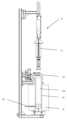
도 1은 3D 물체의 화학적 변환을 위한 시스템의 일반적인 도면을 도시하고;
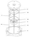
도 2는 도 1의 시스템의 반응기 그룹의 도면을 도시하고;
도 3은 도 2의 반응기 그룹의 단면을 개략적으로 도시하고;
도 4는 도 2의 반응기 그룹의 상세를 개략적으로 도시하며;
도 5는 제1 실시예에 따른 변환 시스템에 있어서의 온도 및 압력 경향의 합성 그래프를 나타낸다.These and other features and advantages of the present invention will become more apparent from the following description of preferred embodiments, given by way of non-limiting examples, with the aid of the accompanying drawings, in which components designated by the same or similar reference numerals represent elements having the same or similar function and configuration:
Figure 1 illustrates a general schematic of a system for chemical transformation of a 3D object;
Figure 2 depicts a diagram of a reactor group of the system of Figure 1;
Figure 3 schematically illustrates a cross-section of the reactor group of Figure 2;
Figure 4 schematically illustrates the details of the reactor group of Figure 2;
Figure 5 shows a composite graph of temperature and pressure trends in a conversion system according to the first embodiment.
여기서는, 본 설명의 맥락에서 용어: 시스템의 다양한 구성요소의 기하학적 배열과 관련된 상부, 하부, 수직 및 가능한 다른 용어가 통상적인 의미로 사용되는 것으로 지정된다.Here, in the context of this description, the terms: top, bottom, vertical and possibly other terms relating to the geometric arrangement of the various components of the system are designated as being used in their usual sense.
도 1을 참조하면, 예를 들어 뼈 조직의 재생을 위해 제공된 샘플(11)의 화학적 변환을 위한 시스템(시스템)(10)은 반응 그룹 또는 반응기 그룹(12), 및 반응기 그룹(12) 내로 가스를 공급하거나 방출하도록 마련된 GAS 공급 그룹(GAS 그룹)(14)을 포함한다.Referring to FIG. 1, a system (system) (10) for chemical transformation of a sample (11) provided for regeneration of bone tissue, for example, includes a reaction group or reactor group (12), and a GAS supply group (GAS group) (14) arranged to supply or release gas into the reactor group (12).
바람직한 실시예에 따르면, GAS 그룹(14)은 압력 하에서 반응 가스, 예를 들어 이산화탄소(CO2)를 포함하는 하나 이상의 가스 실린더(41), 및 공지된 진공 펌프를 통해 반응기 그룹(12)으로부터 공기를 흡입하고 하나 이상의 가스 실린더(41)로부터 나오는 가스를 반응기 그룹(12) 내로 제어된 방식으로 제공하도록 마련된 가스 제어 유닛(42)을 포함한다.According to a preferred embodiment, the GAS group (14) comprises one or more gas cylinders (41) containing a reaction gas, for example carbon dioxide (CO2 ), under pressure, and a gas control unit (42) arranged to draw air from the reactor group (12) via a known vacuum pump and to provide gas from the one or more gas cylinders (41) in a controlled manner into the reactor group (12).
바람직한 실시예에 따르면, 가스 제어 유닛(42)은 반응기 그룹(12)을 향한 반응 가스의 유동을 관리하도록 마련된다.In a preferred embodiment, the gas control unit (42) is arranged to manage the flow of reaction gas toward the reactor group (12).
바람직하게는, 가스 제어 유닛(42)은 자동화된 방식으로, 예를 들어 적절하게 프로그래밍된 PLC(Programmable Logic Controller; 프로그래밍 가능한 로직 컨트롤러)에 의해 공지된 방식으로 제어되는 전자 압력 조절기 또는 질량 유동 조절기를 통해, 반응기 그룹(12) 내로의 가스 유동을 제어하도록 마련된다.Preferably, the gas control unit (42) is arranged to control the gas flow into the reactor group (12) in an automated manner, for example via an electronic pressure regulator or mass flow regulator controlled in a known manner by a suitably programmed PLC (Programmable Logic Controller).
바람직하게는, 가스 제어 유닛(42)은 압력 센서 장치(45)를 포함하고, 반응기 그룹(12)에 포함된 공지된 유형의 장치, 예컨대 온도 센서 장치(44)에 연결된다(도 1 내지 도 4). 상기 시스템은 상기 장치(44 및 45)를 통해 획득하고, 예를 들어 시간 경과에 따라 시스템(10)으로부터 나오는 온도 및/또는 압력의 데이터 기록을 보여주도록 마련된다.Preferably, the gas control unit (42) comprises a pressure sensor device (45) and is connected to a known type of device included in the reactor group (12), for example a temperature sensor device (44) (FIGS. 1 to 4). The system is arranged to obtain via the devices (44 and 45) data of temperature and/or pressure coming from the system (10) over time, for example.
예를 들어 금속 유형이고 고온 및 고압에서 작동하기에 적합한 반응기 그룹(12)은 3D 샘플을 산화칼슘(CaO)으로부터 탄산칼슘(CaCO3)으로 완전하고 균일한 방식으로 변환하도록 마련된다.For example, a group of reactors (12) of metallic type and suitable for operation at high temperature and pressure are arranged to completely and uniformly convert the 3D sample from calcium oxide (CaO) to calcium carbonate (CaCO3 ).
바람직한 실시예에서, 반응기 그룹(12)은 챔버(반응 챔버)(12a)를 형성하도록 구성된, 바람직하게는 원통형의 본체(20), 및 반응기 그룹(12)의 베이스에 배치되고 바람직하게는 공지된 방식으로 가스 제어 유닛(42)을 통해 가스 실린더(41), 진공 펌프, 및 온도 센서 장치(44) 및/또는 압력 센서 장치(45)에 연결되도록 마련된 바닥부(22), 예를 들어 편평한 바닥부를 포함한다.In a preferred embodiment, the reactor group (12) comprises a body (20), preferably cylindrical, configured to form a chamber (reaction chamber) (12a), and a bottom part (22), for example a flat bottom part, arranged at the base of the reactor group (12) and preferably arranged to be connected to a gas cylinder (41), a vacuum pump, and a temperature sensor device (44) and/or a pressure sensor device (45) via a gas control unit (42) in a known manner.
본체(20)는 바람직하게는 상단부에, 하나 이상의 공지된 유형의 시일(seal)을 통해 반응 챔버(12a)를 밀봉하는 데 협력하도록 마련된 폴더(folder)(20a)를 포함한다.The body (20) preferably comprises, at its upper end, a folder (20a) adapted to cooperate in sealing the reaction chamber (12a) via one or more known types of seals.
본체(20)는 바람직하게는 구멍(21a), 예를 들어 중앙 구멍을 포함하는 상부 구성요소(21), 예를 들어 상부 캡(top cap)을 더 포함한다. 상부 구성요소(21)는 바람직하게는 사용 시에 반응 챔버(12a)를 밀봉하여 샘플(11)을 지지하고, 본 실시예에 따르면 축(23)에 고정된 모터, 예를 들어 2 개의 그룹의 고정 블레이드 또는 터빈(25)을 통해, 사용 시에 제어된 방식으로 시계 방향 또는 반시계 방향으로 회전하도록 마련된 축(23)이 중앙 구멍(21a)을 통과할 수 있게 하도록 마련된다.The body (20) preferably further comprises an upper component (21), for example a top cap, which comprises a hole (21a), for example a central hole. The upper component (21) preferably seals the reaction chamber (12a) during use to support the sample (11), and according to the present embodiment is arranged such that a shaft (23), which is arranged to rotate in a controlled manner clockwise or counterclockwise during use, via a motor fixed to the shaft (23), for example two groups of fixed blades or a turbine (25), can pass through the central hole (21a).
터빈(25), 바람직하게는 적어도 2 개의 터빈(25)은, 예를 들어 축(23)에 고정되고, 서로 이격되어 있으며, 반응 챔버(12a) 내에 존재하는 화학 물질(가스)을 터빈(25) 사이의 샘플(11) 상에 수렴시키도록 마련된다.Turbines (25), preferably at least two turbines (25), are, for example, fixed to a shaft (23), spaced apart from each other, and arranged to converge the chemical substance (gas) present in the reaction chamber (12a) onto the sample (11) between the turbines (25).
바람직한 실시예에 따르면, 본체(20)는 또한 화학 작용제, 예를 들어 수산화칼슘(Ca(OH)2)을 수용하도록 마련되고 사용 시에 반응 챔버(12a) 내로 증기를 방출하도록 마련된 하부 구성요소(26), 예를 들어 케이싱 구성요소를 포함한다. 하부 구성요소 또는 케이싱 구성요소(26)는 예를 들어, 바람직한 실시예에서 화학적으로 변환될 샘플(11)을 지지하도록 마련된 연결 요소 또는 후크 요소(connection or hooking element)(26b)를 포함하는 복수의 바아(bar)(26a)를 통해 상부 구성요소(21)에 연결된다.According to a preferred embodiment, the body (20) also includes a lower component (26), for example a casing component, adapted to receive a chemical agent, for example calcium hydroxide (Ca(OH)2 ) and adapted to release vapor into the reaction chamber (12a) when in use. The lower component or casing component (26) is connected to the upper component (21) via a plurality of bars (26a), for example including connection or hooking elements (26b) adapted to support a sample (11) to be chemically converted in a preferred embodiment.
반응기 그룹(12)의 본체(20)는, 바람직하게는 사용 시에 제어된 방식으로, 예를 들어 본체(20)에 대응하여 배치된 전기 저항을 통해 반응기 그룹(12)의 반응 챔버(12a)를 가열하도록 마련된 오븐(15) 내부에 구성된다.The body (20) of the reactor group (12) is preferably configured inside an oven (15) arranged to heat the reaction chamber (12a) of the reactor group (12) in a controlled manner during use, for example, through an electric resistance arranged corresponding to the body (20).
바람직하게는, 전기 저항 근처에는 시간 경과에 따라 오븐(15) 내부로부터 나오는 온도의 데이터 기록을 획득하여 오븐 제어 유닛(52), 예를 들어 공지된 유형의 컴퓨터로 전송하도록 마련된 오븐 온도 센서(54)가 배치된다.Preferably, an oven temperature sensor (54) is placed near the electrical resistor, which is arranged to obtain data recordings of the temperature coming from inside the oven (15) over time and transmit them to an oven control unit (52), for example a computer of a known type.
사용 시에, 본체(20)는 본체(20)의 폴더(20a) 및 상부 구성요소(21)를 밀봉하도록 마련된 조오(jaw)(29), 예를 들어 2 개의 조오에 의해 밀봉될 수 있는 것으로 예상된다.In use, it is expected that the main body (20) can be sealed by jaws (29), for example two jaws, provided to seal the folder (20a) and the upper component (21) of the main body (20).
본 실시예에 따르면, 본체(20)는, 그 내부에 포함된 구성요소, 예컨대 상부 구성요소(21), 하부 구성요소(26), 바아(26a) 및 후크 요소(26b)와 함께, 오븐(15)으로부터, 예를 들어 수직으로 추출되어, 산화칼슘(CaO)으로부터 탄산칼슘(CaCO3)으로의 화학적 변환 반응이 적용될 샘플(11)이 후크 요소(26b)에 후킹(hooking)되게 할 수 있는 것으로 예상된다.According to the present embodiment, the body (20), together with components included therein, such as the upper component (21), the lower component (26), the bar (26a) and the hook element (26b), is expected to be able to be extracted, for example, vertically from the oven (15), so that a sample (11) to which a chemical conversion reaction from calcium oxide (CaO) to calcium carbonate (CaCO3 ) is to be applied is hooked to the hook element (26b).
전술한 바와 같은 시스템의 작동은 하기와 같다.The operation of the system described above is as follows.
일반적으로, 상기 시스템(10)은 제1 실시예에 따르면, 초임계 상태에서, 반응을 촉매하기에 적합한 증기(H2O)의 존재 하에서 이산화탄소(CO2)의 화학적 변환 또는 이산화탄소(CO2)와의 반응을 통해 산화칼슘(CaO)으로 이루어진 재료 샘플(11)에 대해 고온 및 고압에서 탄산화 프로세스를 수행하도록 실현되었다. 상기 시스템에 의해 구현된 프로세스의 최종 결과는 CaO로 이루어진 샘플(11)과 동일한 초기 거시구조 및 미세구조를 갖는, 탄산칼슘(CaCO)으로 이루어진 샘플을 얻는 것이다.In general, the system (10) is realized, according to the first embodiment, to perform a carbonation process at high temperature and high pressure on a material sample (11) made of calcium oxide (CaO) through chemical conversion of carbon dioxide (CO2 ) or reaction with carbon dioxide (CO2 ) in the presence of steam (H2 O) suitable for catalyzing the reaction in a supercritical state. The final result of the process realized by the system is to obtain a sample made of calcium carbonate (CaCO) having the same initial macrostructure and microstructure as the sample (11) made of CaO.
다시 말해서, 탄산화 반응은 하기의 반응식 1에 따라 요약될 수 있다:In other words, the carbonation reaction can be summarized according to the following reaction scheme 1:
(반응식 1)(Reaction Formula 1)
여기서:Here:
(sc) = 초임계 상태;(sc) = supercritical state;
(s) = 고체 상태;(s) = solid state;
(g) = 가스 상태.(g) = gaseous state.
시작 절차Getting started procedure
상기 시스템(10)의 시작 절차는 예를 들어 하기 단계를, 또한 여기에 나열된 것과 상이한 순서로 포함한다:The startup procedure of the above system (10) includes, for example, the following steps, also in a different order than listed herein:
- 조오(29)가 개방된 상태로 유지되고 본체(20) 및 본체(20) 내에 포함된 구성요소가 오븐(15) 외부에 유지되는 단계(110);- A step (110) in which the oven (29) is kept open and the body (20) and the components contained within the body (20) are kept outside the oven (15);
- 예를 들어 약 50 내지 500 g 범위에 포함된 총 중량을 갖는, CaO로 이루어진 가변 개수의 샘플이 반응 챔버(12a) 내부에 마련되고 후크 요소(26b)에 고정되는 단계(120). 바람직하게는, 샘플은 다공성(예를 들어, 50 체적%)이고, 3D이며, 형상이 가변적이다(예를 들어, 중공 원통체, 평행육면체 등);- A step (120) in which a variable number of samples made of CaO, for example having a total weight in the range of about 50 to 500 g, are provided inside the reaction chamber (12a) and secured to a hook element (26b). Preferably, the samples are porous (for example, 50 volume %), 3D and have a variable shape (for example, a hollow cylinder, a parallelepiped, etc.);
- 반응 챔버(12a)의 하부 구성요소(26) 상에, H2O 공급원이 되도록 마련된 화학적 구성요소, 예를 들어 Ca(OH)2를 기반으로 하는 구성요소가 배치되는 단계(130);- A step (130) in which a chemical component, for example a component based on Ca(OH)2 , which is designed to be a source ofH2O , is placed on the lower component (26) of the reaction chamber (12a);
- 터빈(25), 예를 들어 45°의 블레이드를 갖는 2 개의 터빈이 반응 챔버(12a) 내부에 축(23)을 따라 배치되는 단계(140). 바람직하게는, 샘플(11)이 사용 시에 터빈(25) 사이의 영역에 마련되도록, 터빈(25)은 대향 위치에 블레이드를 갖도록 장착되는 것으로 예상된다;- A step (140) in which two turbines (25), for example two turbines having blades of 45°, are arranged along the axis (23) inside the reaction chamber (12a). Preferably, it is expected that the turbines (25) are mounted with blades in opposite positions so that the sample (11) is provided in the area between the turbines (25) when in use;
- 본체(20) 및 본체(20)에 포함된 구성요소가 하강되어 오븐(15) 내로 삽입되고, 조오(29)가 반응 챔버(12a)를 밀봉하도록 폐쇄 및 로킹되는 단계(150);- A step (150) in which the main body (20) and the components included in the main body (20) are lowered and inserted into the oven (15), and the jaw (29) is closed and locked to seal the reaction chamber (12a);
- 반응 챔버(12a)에 존재하는 공기가 가스 제어 유닛(42)을 통해 제어되는 진공 펌프를 통해 흡입되는 단계(160);- A step (160) in which air present in the reaction chamber (12a) is sucked in through a vacuum pump controlled by a gas control unit (42);
- 반응 챔버(12a) 내부에서, GAS 그룹(14)으로부터 나오는 사전결정된 양의 CO2가 가스 제어 유닛(42)을 통해 시간 경과에 따라 제어된 방식으로 충전되거나, 방출되거나 주입되는 단계(170). 바람직하게는, 반응 챔버(12a)에 충전된 가스의 양은, 예를 들어 하나 이상의 가스 실린더(41) 아래에 배치된 저울에 의해 칭량된다. 특히, 가스의 양은 화학적 변환 프로세스 동안의 샘플에 의한 CO2의 예상 소비량, 원하는 최종 압력 및 반응 챔버(12a)의 체적을 고려하여 화학 양론적으로 계산된다.- A step (170) in which a predetermined amount of CO2 from the GAS group (14) is charged, discharged or injected in a controlled manner over time inside the reaction chamber (12a) via the gas control unit (42). Preferably, the amount of gas charged into the reaction chamber (12a) is weighed, for example by a scale arranged below one or more gas cylinders (41). In particular, the amount of gas is stoichiometrically calculated taking into account the expected consumption of CO2 by the sample during the chemical conversion process, the desired final pressure and the volume of the reaction chamber (12a).
- 예상된 CO2 양의 로딩 종료 시에, 오븐(15)의 가열이 사전결정된 열 사이클에 따라 시작되고, 온도 검출 센서(44 및 54) 및 압력 검출 센서(45)가 활성화되는 단계(180).- At the end of loading the expected amount ofCO2 , heating of the oven (15) is started according to a predetermined thermal cycle, and the temperature detection sensors (44 and 54) and the pressure detection sensor (45) are activated (step 180).
변환 절차Conversion procedure
변환 절차는 반응기 그룹(12) 내부, 즉 반응 챔버(12a) 내부에 포함된 온도 센서(44), 및 바람직하게는 GAS 그룹(14)에 포함된 압력 센서(45) 및 오븐(15)에 포함된 온도 센서(45)에 의해 측정된 압력 및 온도의 경향을 시간 경과에 따라 확인함으로써 수행된다. 바람직하게는, 압력 센서(45)는 반응 챔버 자체 내부의 온도에 의해 영향을 받는 것이 회피되도록 반응 챔버 외부에 위치된다.The conversion procedure is performed by monitoring over time the trends in pressure and temperature measured by a temperature sensor (44) included within the reactor group (12), i.e. within the reaction chamber (12a), and preferably by a pressure sensor (45) included in the GAS group (14) and a temperature sensor (45) included in the oven (15). Preferably, the pressure sensor (45) is located outside the reaction chamber so as to avoid being influenced by the temperature inside the reaction chamber itself.
다른 실시예에 따르면, 오븐에 포함되는 온도 센서(54)가 존재하지 않고, 반응 챔버에 포함되는 온도 센서(44)를 통해 온도를 제어하기에 충분한 것으로 예상된다.In another embodiment, there is no temperature sensor (54) included in the oven, and it is expected that it is sufficient to control the temperature through the temperature sensor (44) included in the reaction chamber.
바람직하게는, 온도 및 압력 경향은 컴퓨터 상에, 예를 들어 가스 제어 유닛(42)에 또한 공지된 방식으로 연결된 오븐 제어 유닛(52) 상에 표시된다.Preferably, the temperature and pressure trends are displayed on a computer, for example on an oven control unit (52) which is also connected in a known manner to the gas control unit (42).
본 설명에서, 온도 및 압력 경향이 도 5에 표시되어 있다.In this description, temperature and pressure trends are shown in Fig. 5.
도 5에 예시된 바와 같이, 충전 초기 단계 후에, 압력 경향(61)(연속선-이차 축)이 예를 들어 실온에서 시작하여 상승한 후에, 온도 상승(압력 증가를 유발함)과 샘플(11)을 이루는 CaO에 의한 CO2 소비(압력 감소를 유발함) 사이의 절충으로 인해 거의 선형 경향으로 진행된다는 것이 실험적으로 검증되었다.As illustrated in Fig. 5, it was experimentally verified that after the initial stage of charging, the pressure trend (61) (continuous line-second axis) starts from, for example, room temperature and then increases, and then proceeds in a nearly linear trend due to a compromise between the temperature increase (which causes an increase in pressure) and theCO2 consumption by CaO forming the sample (11) (which causes a decrease in pressure).
출원인은 샘플이 없는 경우에, 곡선의 경향이 이전보다 큰 기울기를 갖는 선형으로 된다는 것을 실험적으로 검증했다.The applicant experimentally verified that in the absence of samples, the trend of the curve becomes linear with a larger slope than before.
또한, CO2가 파선(63)으로 한정된 다이어그램 영역에서, 예를 들어 온도 T > 약 310 ℃ 및 P > 72.9 atm인, 초임계 상태에 있다는 것이 실험적으로 검증되었다.Additionally, it has been experimentally verified thatCO2 is in a supercritical state in the diagram region limited by the dashed line (63), for example, at temperatures T > about 310°C and P > 72.9 atm.
훨씬 더 특별하게는, 초임계 상태를 시작하는 온도는 충전된 가스의 양, 시간에 따른 온도 램프(ramp) 및 샘플의 수의 함수로서 T > 250 ℃보다 적어도 높은 온도 값을 갖는다는 것이 실험적으로 검증되었다.Even more specifically, it has been experimentally verified that the temperature at which the supercritical state starts has a temperature value at least higher than T > 250 °C as a function of the amount of charged gas, the temperature ramp over time, and the number of samples.
반응과 관련된 열역학적 이유 때문에, 약 300 ℃에서 시작하고 CO2의 존재 하에서만, 수산화칼슘은 반응 챔버에서 H2O를 유리시킬 수 있다. H2O는 바람직하게는 서로 대향하여 있는 터빈(25)을 통해 CO2와 혼합될 것이고, CaO로 이루어진 샘플의 탄산화 프로세스를 시작하며, 이 프로세스는 각각의 반응에 대응하는 하기의 반응식 2 및 3으로 나타낼 수 있다:Due to thermodynamic reasons associated with the reaction, starting at about 300°C and only in the presence ofCO2 , calcium hydroxide can liberateH2O in the reaction chamber. TheH2O will preferably be mixed withCO2 via turbines (25) which are opposite each other and initiate the carbonation process of the sample consisting of CaO, which process can be represented by the following reaction equations 2 and 3 corresponding to the respective reactions:
(반응식 2)(Reaction formula 2)
(반응식 3)(Reaction Formula 3)
또는, 반응식 2 및 3의 요약 반응식에 의해 또한 나타낼 수 있다:Alternatively, it can also be represented by the summary reaction schemes of Schemes 2 and 3:
(반응식 4)(Reaction Formula 4)
여기서:Here:
(sc) = 초임계 상태;(sc) = supercritical state;
(s) = 분말(p) 또는 3D(3D) 형태의 고체 상태;(s) = solid state in powder (p) or 3D (3D) form;
(g) = 가스 상태.(g) = gaseous state.
반응식 4는 반응기 그룹(12), 즉 반응 챔버(12a)에서, CO2가 예비 수화 프로세스를 거칠 필요가 없는 혼합물 CO2/H2O와의 직접 반응이 일어나는 것을 보여준다.Reaction scheme 4 shows that in the reactor group (12), i.e., the reaction chamber (12a), a direct reaction with the mixture CO2 /H2 O occurs without the need for CO2 to go through a pre-hydration process.
유리하게는, 설명된 바와 같은 시스템(10) 덕분에, 맥락적 수화 + 탄산화의 이상적인 조건이 생성된다.Advantageously, thanks to the system (10) as described, ideal conditions for contextual hydration + carbonation are created.
사실상, 설명된 실시예에서, 그리고 수반되는 탄산화 프로세스에서, Ca(OH)2의 형성은 프로세스의 모든 순간에서 국부적으로 제한되며; 사실상, 새롭게 생성된 Ca(OH)2는 즉시 CO2와 반응하여 CaCO3을 생성한다.In fact, in the described embodiments and in the accompanying carbonation process, the formation of Ca(OH)2 is locally limited at every moment of the process; in fact, the newly formed Ca(OH)2 immediately reacts with CO2 to form CaCO3 .
상기 시스템(10), 및 특히 반응 챔버(12a)에 존재하는 물질을 샘플(11) 근처에서 교반 및 수용하도록 마련된 복수의 블레이드 또는 터빈(25)을 포함하는 반응기 그룹(12)의 도입에 의해, 출원인은 탄산화 프로세스 이전의 CO2의 수화 프로세스에 대한 필요 없이, 탄산화 동안에 동일한 반응 챔버(12a) 내부에서 균질하고 제어된 고반응성의 CO2/H2O 혼합물을 생성하는 것이 가능하다는 것을 실험적으로 검증했다.By means of the above system (10), and in particular the introduction of a reactor group (12) comprising a plurality of blades or turbines (25) arranged to stir and receive the material present in the reaction chamber (12a) in the vicinity of the sample (11), the applicant has experimentally verified that it is possible to produce a homogeneous and controlled highly reactiveCO2 /H2 O mixture inside the same reaction chamber (12a) during carbonation, without the need for a hydration process of CO 2 prior to the carbonation process.
요약하면, 상기 시스템 및 특히 설명된 반응기 그룹(12)은 탄산화 프로세스 이전의 CO2의 수화 프로세스에 대한 필요 없이, 산화칼슘(CaO)으로부터 탄산칼슘(CaCO3)으로 완전히 변환된 샘플을 항상 보장하도록 마련된다.In summary, the above system and in particular the described reactor group (12) is arranged to always ensure a completely converted sample from calcium oxide (CaO) to calcium carbonate (CaCO3 ) without the need for a hydration process of CO2 prior to the carbonation process.
상기 시스템은 다양한 형상의 다공성 CaO 샘플을 제공함으로써 설명되었다.The above system was illustrated by providing porous CaO samples of various geometries.
출원인이 바람직하게는 직경이 Φ = 30 ㎜ 내지 10 ㎜이고 길이가 60 ㎜ 내지 10 ㎜이고 중량이 35 g 내지 2 g인 원통 형상의 샘플의 탄산화를 실현한 한에서는, 당업자라면, 설명 및 청구된 것의 범위로부터 벗어남이 없이, 샘플이 상이한 형상을 가질 수 있고, 반응 챔버의 크기의 함수로서 나타낸 것보다 훨씬 더 큰 크기 및 중량을 가질 수 있다는 것을 쉽게 이해할 수 있다.As long as the applicant has realized the carbonation of a cylindrical sample, preferably with a diameter of Φ = 30 mm to 10 mm, a length of 60 mm to 10 mm and a weight of 35 g to 2 g, it will be readily apparent to a person skilled in the art that, without departing from the scope of what is described and claimed, the sample may have different shapes and may have sizes and weights much larger than those indicated as a function of the size of the reaction chamber.
유사하게는, 샘플은 설명 및 청구된 것의 범위로부터 벗어남이 없이, 비다공성이거나 조밀할 수도 있다.Similarly, the sample may be nonporous or dense without departing from the scope of what is described and claimed.
다른 실시예에 따르면, 특히 샘플의 배치, 형상, 크기, 중량, 다공도 또는 밀도의 함수로서, 반응 챔버 내부의 가스 난류의 유형을 변경하기 위해, 축을 따라 터빈의 수 또는 배열을 변경하거나, 또한 터빈의 형상을 변경하는 것이 예상된다.In other embodiments, it is envisaged to change the number or arrangement of turbines along the axis, or also to change the shape of the turbines, in order to change the type of gas turbulence inside the reaction chamber, particularly as a function of the arrangement, shape, size, weight, porosity or density of the samples.
고밀도 샘플의 경우에, CaO로부터 CaCO3으로의 변환 프로세스의 침투 깊이는 샘플 밀도의 함수인 것이 예상된다.For high density samples, the penetration depth of the transformation process from CaO to CaCO3 is expected to be a function of sample density.
일부 추가 실시예에 따르면, 예를 들어, CaO의 탄산화 시작을 예측하기 위해, 칼슘에 대해 대안적인 수산화물, 예를 들어 수산화스트론튬(T > 100 ℃에서 H2O 방출) 또는 마그네슘(T > 200 ℃에서 H2O 방출)을 반응 챔버에 도입하는 것이 예상된다.According to some additional embodiments, it is envisaged that an alternative hydroxide to calcium, for example strontium hydroxide (which releases H2 O at T > 100 °C) or magnesium (which releases H2 O at T > 200 °C), is introduced into the reaction chamber, for example, to predict the onset of carbonation of CaO.
다른 실시예에 따르면, 설명된 시스템 및 방법이 예를 들어 질화물을 기반으로 하는 3D 재료의 생성에 사용되는 것이 예상된다:According to another embodiment, it is envisaged that the described systems and methods are used for the creation of 3D materials, for example, nitride-based:
- 예를 들어 질소를 함유하는 가스 또는 가스 혼합물(예를 들어, 암모니아(NH3), 질소(N2) 등)과 산화 및 비산화 3D 재료의 반응 후의, 질화물(예를 들어, 질화붕소(BN), 질화규소(Si3N4), 질화티타늄(TiN), 질화알루미늄(AlN) 등).- For example, after reaction of oxidizing and non-oxidizing 3D materials with gases or gas mixtures containing nitrogen (e.g., ammonia (NH3 ), nitrogen (N2 ), etc.), nitrides (e.g., boron nitride (BN), silicon nitride (Si3 N4 ), titanium nitride (TiN), aluminum nitride (AlN), etc.).
이러한 경우에, GAS 그룹(14)은 압력 하의 반응 가스로서 질소(예를 들어, 암모니아(NH3), 질소(N2) 등)를 수용하는 하나 이상의 가스 실린더를 포함하며, 반응기 그룹(12)은 하부 구성요소(26)가 증기를 방출하기에 적합한 화학 작용제를 포함하지 않지만, 존재하는 경우, 샘플(11)을 후킹할 수 있게 하도록 상부 구성요소(21)에 연결되는 가능한 변형만을 제외하고는, 바람직한 실시예에서 설명된 것과 실질적으로 동일하다. 하부 구성요소(26)가 없는 경우에, 상부 구성요소만이 샘플이 반응기 그룹(12)에 후킹될 수 있게 한다.In this case, the GAS group (14) comprises one or more gas cylinders containing nitrogen (e.g., ammonia (NH3 ), nitrogen (N2 ), etc.) as a reactant gas under pressure, and the reactor group (12) is substantially the same as described in the preferred embodiment, except for the possible modification that the lower component (26) does not contain a chemical agent suitable for releasing vapors, but is connected to the upper component (21) to enable hooking the sample (11), if present. In the absence of the lower component (26), only the upper component enables the sample to be hooked to the reactor group (12).
질화물의 경우에 상기 시스템(10)의 작동은 (예를 들어 질소를 함유하는 열화 염(deterioration salt)에서 시작하는 반응성 NH3의 생성을 통해) 예를 들어 GAS 그룹(14) 또는 하부 구성요소(26)로부터 나오는 NH3의 존재 하에서 3D 고체 산화물 및/또는 NH3-H2O 혼합물 사이에 화학 반응이 일어나는 것을 필요로 한다.In the case of nitrides, operation of the system (10) requires a chemical reaction between the 3D solid oxide and/or the NH3 -H2 O mixture in the presence of NH3 , for example from the GAS group (14) or the lower component (26), via generation of reactive NH3 starting from a deterioration salt containing nitrogen.
화학적 변환은 예를 들어 각각 하기의 방식으로 나타낼 수 있다:Chemical transformations can be represented, for example, in the following ways:
여기서:Here:
...은 당업자가 쉽게 이해할 수 있는 바와 같은 부차적인 생성물을 나타낸다.... represents a secondary product that can be easily understood by those skilled in the art.
질화 프로세스에 추가하여, 예를 들어 NH3 + CO2 혼합물의 존재 하에서의 금속 질탄화(nitrocarbonization) 프로세스, 또는 NH3 + H2O 혼합물의 존재 하에서의 금속 옥시-탄산화(oxycarbonation) 프로세스는 설명된 바와 같은 시스템(10)의 목적에 포함되는 것으로 예상될 수도 있다.In addition to the nitridation process, metal nitrocarbonization process, for example in the presence of a mixture of NH3 + CO2 , or metal oxycarbonation process in the presence of a mixture of NH3 + H2 O may also be expected to be included in the purpose of the system (10) as described.
추가 실시예에 따르면, 설명된 시스템 및 방법은 예를 들어 금속 산화물을 기반으로 하는 3D 재료의 생성에 사용되는 것으로 예상된다:According to a further embodiment, the described system and method are expected to be used for the creation of 3D materials based on, for example, metal oxides:
- 예를 들어 물(H2O)과 금속 및 비금속 3D 재료의 반응 후의, 산화티타늄(TiO2), 산화규소(SiO2), 산화아연(ZnO), 산화철(FeO, Fe2O3 등) 등과 같은 금속 산화물;- Metal oxides such as titanium oxide (TiO2 ), silicon oxide (SiO2 ), zinc oxide (ZnO), iron oxide (FeO, Fe2 O3 , etc.) after the reaction of water (H2 O) with metal and non-metal 3D materials;
- 예를 들어 상이한 특성의 전구체의 가능한 존재 하에서 물(H2O)과 산화 및 비산화 3D 재료의 반응 후의, 티탄산염(예를 들어, 티탄산납(PbTiO3), 티탄산칼슘(CaTiO3) 등), 지르코산염(예를 들어, SrZrO3 등), 규산염(예를 들어, CaSiO3 등), 알루민산염(예를 들어, MgAl2O3 등) 등과 같은 혼합 금속 산화물.- Mixed metal oxides such as titanates (e.g., lead titanate (PbTiO3 ), calcium titanate (CaTiO 3 ), etc.), zirconates (e.g., SrZrO 3 ), silicates (e.g., CaSiO3 ), aluminates (e.g., MgAl2O 3) , etc., after reaction of water (H2 O ) with oxidizing andnon -oxidizing 3D materials in the possible presence of precursors with different properties.
이러한 경우에, GAS 그룹(14)은 존재하지 않을 수 있고, 반응기 그룹(12)은 바람직한 실시예에서 설명된 것과 실질적으로 동일하다.In this case, the GAS group (14) may not exist and the reactor group (12) is substantially identical to that described in the preferred embodiment.
금속 산화물의 경우에 상기 시스템(10)의 작동은 화학 반응이 하기에 나타낸 바와 같이 실현되는 것을 제공한다:In the case of metal oxides, the operation of the system (10) provides that the chemical reaction is realized as shown below:
여기서:Here:
...은 당업자가 쉽게 이해할 수 있는 바와 같은 부차적인 생성물을 나타낸다.... represents a secondary product that can be easily understood by those skilled in the art.
다른 추가 실시예에 따르면, 설명된 시스템 및 방법이 예를 들어 탄산염을 기반으로 하는 3D 재료의 생성에 사용되는 것이 제공된다:According to another additional embodiment, it is provided that the described system and method is used for the production of 3D materials, for example based on carbonates:
- 예를 들어 물(H2O) 및 이산화탄소(CO2)와 산화 및 비산화 3D 재료의 반응 후의, 탄산마그네슘(MgCO3)과 같은 탄산염, 혼합 탄산염(예를 들어, CaMg(CO3)2, Co2(OH)2CO3);- Carbonates such as magnesium carbonate (MgCO3 ), mixed carbonates (e.g., CaMg(CO3 ) 2 , Co2 (OH)2 CO3 ), after reaction of oxidized and non-oxidized 3D materials with water (H2 O) andcarbon dioxide (CO2 );
- 예를 들어 물(H2O) 및 산화황(SO3)과 산화 및 비산화 3D 재료의 반응 후의, 황산칼슘(CaSO4)과 같은 황산염.- Sulfates such as calcium sulfate (CaSO4 ) after reaction of oxidized and non-oxidized 3D materials with water (H2 O) and sulfur oxide (SO3 ).
이러한 경우에, 반응기 그룹(12)은 바람직한 제1 실시예에 대해 설명된 것과 실질적으로 동일하다.In this case, the reactor group (12) is substantially identical to that described for the first preferred embodiment.
탄산염의 경우에 상기 시스템(10)의 작동은 화학 반응이 하기에 나타낸 바와 같이 실현되는 것을 제공한다:In the case of carbonates, the operation of the system (10) provides that the chemical reaction is realized as shown below:
여기서:Here:
...은 당업자가 쉽게 이해할 수 있는 바와 같은 부차적인 생성물을 나타낸다.... represents a secondary product that can be easily understood by those skilled in the art.
유리하게는, 모든 실시예에서, 예를 들어 고정 블레이드 또는 터빈(25)의 적어도 2 개의 그룹의 존재가 예시적인 실시예에 따라 축(23)에 제공된다는 것이 인식될 것이다.Advantageously, it will be appreciated that in all embodiments, the presence of at least two groups of fixed blades or turbines (25) is provided on the shaft (23) according to an exemplary embodiment.
블레이드 또는 터빈(25)의 그룹은 바람직하게는 축(23)에 고정되고, 샘플이 포함된 반응 챔버(12a) 내부에 존재하는 물질을 블레이드 또는 터빈(25)의 그룹 사이에서 수렴시키도록 마련된다.A group of blades or turbines (25) is preferably fixed to the shaft (23) and arranged to converge the material present inside the reaction chamber (12a) containing the sample between the group of blades or turbines (25).
탄산화 프로세스의 예Example of carbonation process
설명의 완전성을 위해, 천연 다공성 구조에서 시작하여 수산화인회석(hydroxyapatite)으로 이루어진 3D 샘플을 생성하도록 마련된 보다 복잡한 프로세스의 중간 단계를 실현하는 데 사용되는 탄산화 프로세스의 예가 하기에 나타나 있다:For completeness of the description, an example of the carbonation process used to realize an intermediate step in a more complex process designed to create a 3D sample made of hydroxyapatite starting from a natural porous structure is given below:
- 반응 챔버(12a) 내에 CaO로 이루어진 샘플(11) 도입: 약 100 g;- Introduction of a sample (11) made of CaO into the reaction chamber (12a): about 100 g;
- 반응 챔버 내에 Ca(OH)2 도입: 약 100 g;- Introduction of Ca(OH)2 into the reaction chamber: approx. 100 g;
- CO2충전: 약 15 리터의 반응 챔버 내로의 이용 가능한 체적에서 약 1300 g;- CO2 charging: approx. 1300 g in the available volume into the reaction chamber of approx. 15 liters;
- 300 ℃에서 몰비 CO2:H2O = 10:1;- Molar ratio CO2 :H2 O = 10:1 at 300 ℃;
- 반응 동안의 CO2 몰 소비량: 초기 충전된 모든 CO2의 약 10%-CO2 mole consumption during the reaction: approximately 10% of allCO2 initially charged
- 열 사이클: 735 분에 약 20 내지 620 ℃;- Thermal cycle: about 20 to 620 ℃ in 735 minutes;
- 최종 압력: 약 120 내지 130 bar 범위.- Ultimate pressure: in the range of approximately 120 to 130 bar.
물론, 치수, 형상, 재료, 구성요소 및 연결뿐만 아니라, 설명된 구성 및 작동 방법의 세부사항과 관련하여, 하기의 청구범위에 명시된 바와 같은 본 발명의 범위로부터 벗어남이 없이, 상기 개시에 대한 명백한 변경 및/또는 변형이 가능하다.Of course, obvious changes and/or modifications to the above disclosure are possible without departing from the scope of the present invention as set forth in the claims below, with respect to the details of the described construction and method of operation, as well as the dimensions, shape, materials, components and connections.
Claims (11)
Translated fromKorean- 반응 챔버(12a) 내로 제1 가스를 방출하도록 마련된 GAS 공급 그룹(14),
- 반응 챔버(12a)를 형성하도록 구성된 본체(20)를 포함하는 반응 그룹(12)으로서, 상기 본체(20)는,
화학적으로 변환되도록 마련된 3D 상태의 하나 이상의 샘플(11)을 지지하도록 구성된 적어도 하나의 구성요소(21), 또는
상기 반응 챔버(12a) 내로 제2 가스를 방출하도록 마련된 화학 작용제를 포함하는 케이싱 구성요소(26), 또는
양자 모두
를 포함하는 것인, 반응 그룹(12),
- 상기 반응 그룹(12)을 포함하고 상기 반응 챔버(12a)를 사전결정된 온도로 가열하도록 마련된 오븐(15)
을 포함하는 시스템에 있어서,
상기 본체(20)는,
- 사용 시에 상기 반응 챔버(12a) 내에서 상기 샘플(11) 상에 상기 제1 가스, 상기 제2 가스 또는 양자 모두를 수렴시키도록 마련된 적어도 2 개의 터빈(25)
을 포함하는 것을 특징으로 하는 시스템.As a system for chemical transformation of 3D state materials,
- GAS supply group (14) arranged to release the first gas into the reaction chamber (12a);
- A reaction group (12) including a body (20) configured to form a reaction chamber (12a), wherein the body (20) comprises:
At least one component (21) configured to support one or more samples (11) in a 3D state prepared to be chemically transformed, or
A casing component (26) comprising a chemical agent arranged to release a second gas into the reaction chamber (12a), or
both
A reaction group (12) comprising
- An oven (15) provided to heat the reaction chamber (12a) to a predetermined temperature and include the reaction group (12).
In a system including:
The above main body (20) is
- At least two turbines (25) arranged to converge the first gas, the second gas, or both, on the sample (11) within the reaction chamber (12a) when in use.
A system characterized by including:
존재하는 경우, 상기 케이싱 구성요소(26)에 포함되는 상기 화학 작용제는 증기를 방출하도록 마련되는 것인 시스템.In the first paragraph,
A system wherein the chemical agent contained in the casing component (26), if present, is arranged to release vapor.
- 상기 샘플(11)은 산화칼슘(CaO)으로 이루어지고,
- 상기 GAS 공급 그룹(14)은 이산화탄소(CO2)를 방출하도록 구성되고,
- 상기 화학 작용제는 증기(H2O)를 방출하도록 마련되며,
상기 화학적 변환은 초임계 상태에서 증기(H2O)의 존재 하에서 이산화탄소(CO2)를 통해 수행되는 것인 시스템.In the first paragraph,
- The above sample (11) is made of calcium oxide (CaO),
- The above GAS supply group (14) is configured to emit carbon dioxide (CO2 ),
- The above chemical agent is designed to release vapor (H2O ),
A system wherein the above chemical conversion is performed through carbon dioxide (CO2 ) in the presence of steam (H2 O) in a supercritical state.
- 상기 샘플(11)은 3D 고체 산화물을 포함하는 그룹으로부터 선택된 재료로 이루어지고,
- 상기 GAS 공급 그룹(14) 또는 상기 화학 작용제는 암모니아(NH3)를 방출하도록 마련되며,
상기 화학적 변환은 암모니아(NH3)의 존재 하에서 수행되는 것인 시스템.In paragraph 1 or 2,
- The above sample (11) is made of a material selected from a group including 3D solid oxides,
- The above GAS supply group (14) or the chemical agent is arranged to release ammonia (NH3 ),
A system wherein the above chemical transformation is performed in the presence of ammonia (NH3 ).
- 상기 샘플(11)은 금속 또는 금속 염을 포함하는 그룹으로부터 선택된 재료로 이루어지고,
- 상기 GAS 공급 그룹(14) 또는 상기 화학 작용제는 증기(H2O)를 방출하도록 마련되며,
상기 화학적 변환은 증기(H2O)의 존재 하에서 수행되는 것인 시스템.In paragraph 1 or 2,
- The above sample (11) is made of a material selected from a group containing a metal or a metal salt,
- The above GAS supply group (14) or the chemical agent is arranged to emit vapor (H2 O),
A system wherein the above chemical transformation is performed in the presence of steam (H2 O).
- 상기 샘플(11)은 산화물을 포함하는 그룹으로부터 선택된 재료로 이루어지고,
- 상기 GAS 공급 그룹(14)은 이산화탄소(CO2)를 방출하도록 구성되고,
- 상기 화학 작용제는 증기(H2O)를 방출하도록 되어 있으며,
상기 화학적 변환은 이산화탄소(CO2) 및 증기(H2O)의 존재 하에서 수행되는 것인 시스템.In paragraph 1 or 2,
- The above sample (11) is made of a material selected from a group containing oxides,
- The above GAS supply group (14) is configured to emit carbon dioxide (CO2 ),
- The above chemical agent is designed to release vapor (H2O ),
A system wherein the above chemical conversion is performed in the presence of carbon dioxide (CO2 ) and steam (H2 O).
- 상기 3D 상태 재료로 이루어진 샘플(11)의 화학적 변환을 허용하도록 구성된 반응 챔버(12a)를 제공하는 단계,
- 상기 샘플(11)을 지지하도록 구성된 구성요소(21)를 상기 반응 챔버(12a) 내부에 제공하는 단계,
- 상기 반응 챔버(12a)를 사전결정된 온도로 가열하도록 마련된 오븐(15)을 제공하는 단계,
- 반응 챔버(12a) 내에 사전결정된 압력으로 제1 가스, 제2 가스 또는 양자 모두를 방출하는 단계,
- 적어도 2 개의 터빈(25)을 통해 상기 반응 챔버(12a) 내에서 상기 샘플(11) 상에 상기 제1 가스, 상기 제2 가스 또는 양자 모두를 수렴시키는 단계,
- 상기 사전결정된 온도 및 상기 사전결정된 압력에서 상기 3D 상태 재료로 이루어진 상기 샘플(11)에 대해 상기 화학적 변환을 수행하는 단계
를 포함하며,
상기 화학적 변환은, 초기 구조가 유지되거나, 또는 초기 구조가 완전히 혹은 부분적으로 변환되거나, 또는 초기 구조가 유지되고 완전히 혹은 부분적으로 변환된, 3D 재료 샘플을 얻을 수 있게 하는 것인 방법.A method for chemical transformation of a 3D state material,
- A step of providing a reaction chamber (12a) configured to allow chemical transformation of a sample (11) made of the above 3D state material;
- A step of providing a component (21) configured to support the above sample (11) inside the reaction chamber (12a);
- A step of providing an oven (15) arranged to heat the above reaction chamber (12a) to a predetermined temperature;
- A step of releasing a first gas, a second gas, or both at a predetermined pressure within the reaction chamber (12a);
- a step of converging the first gas, the second gas, or both, onto the sample (11) within the reaction chamber (12a) through at least two turbines (25);
- A step of performing the chemical transformation on the sample (11) made of the 3D state material at the predetermined temperature and the predetermined pressure.
Including,
The above chemical transformation is a method for obtaining a 3D material sample in which the initial structure is maintained, or the initial structure is completely or partially converted, or the initial structure is maintained and completely or partially converted.
- 상기 샘플(11)을 지지하도록 구성된 구성요소(21)를 상기 반응 챔버(12a) 내부에 제공하는 상기 단계는 산화칼슘(CaO)으로 이루어진 3D 샘플을 제공하는 단계를 포함하고,
- 제1 가스를 방출하는 상기 단계는 이산화탄소(CO2)를 방출하는 단계를 포함하고,
- 제2 가스를 방출하는 상기 단계는 증기(H2O)를 방출하는 단계를 포함하고,
- 상기 화학적 변환을 수행하는 상기 단계는
- 초임계 상태에서 증기(H2O)의 존재 하에서 이산화탄소(CO2)를 통해 상기 화학적 변환을 수행하는 단계,
- 초기 구조가 유지되거나, 또는 초기 구조가 산화칼슘(CaO)으로부터 탄산칼슘(CaCO3)으로 완전히 혹은 부분적으로 변환되거나, 또는 초기 구조가 유지되고 산화칼슘(CaO)으로부터 탄산칼슘(CaCO3)으로 완전히 혹은 부분적으로 변환된, 3D 재료 샘플을 얻는 단계
를 포함하는 것인 방법.In Article 7,
- The step of providing a component (21) configured to support the sample (11) inside the reaction chamber (12a) includes a step of providing a 3D sample made of calcium oxide (CaO),
- The step of emitting the first gas includes a step of emitting carbon dioxide (CO2 ),
- The step of releasing the second gas includes a step of releasing steam (H2 O),
- The step of performing the above chemical transformation is
- A step of performing the chemical conversion through carbon dioxide (CO2 ) in the presence of steam (H2 O) in a supercritical state;
- A step of obtaining a 3D material sample in which the initial structure is maintained, or the initial structure is completely or partially converted from calcium oxide (CaO) to calcium carbonate (CaCO3 ), or the initial structure is maintained and completely or partially converted from calcium oxide (CaO) to calcium carbonate (CaCO3 ).
A method comprising:
- 상기 샘플(11)을 지지하도록 구성된 구성요소(21)를 상기 반응 챔버(12a) 내부에 제공하는 상기 단계는 3D 고체 산화물을 포함하는 그룹으로부터 선택된 재료로 이루어진 3D 샘플을 제공하는 단계를 포함하고,
- 제1 가스 또는 제2 가스를 방출하는 상기 단계는 암모니아(NH3)를 방출하는 단계를 포함하고,
- 상기 화학적 변환을 수행하는 상기 단계는
- 암모니아(NH3)의 존재 하에서 상기 화학적 변환을 수행하는 단계, 및
- 초기 구조가 유지되거나, 또는 초기 구조가 고체 산화물로부터 질화물을 기반으로 하는 3D 재료로 완전히 혹은 부분적으로 변환되거나, 또는 초기 구조가 유지되고 고체 산화물로부터 질화물을 기반으로 하는 3D 재료로 완전히 혹은 부분적으로 변환된, 3D 재료 샘플을 얻는 단계
를 포함하는 것인 방법.In Article 7,
- The step of providing a component (21) configured to support the sample (11) inside the reaction chamber (12a) includes a step of providing a 3D sample made of a material selected from a group including 3D solid oxides,
- The step of releasing the first gas or the second gas includes a step of releasing ammonia (NH3 ),
- The step of performing the above chemical transformation is
- a step of performing the chemical conversion in the presence of ammonia (NH3 ), and
- A step of obtaining a 3D material sample, wherein the initial structure is maintained, or the initial structure is completely or partially converted from a solid oxide to a nitride-based 3D material, or the initial structure is maintained and completely or partially converted from a solid oxide to a nitride-based 3D material.
A method comprising:
- 상기 샘플(11)을 지지하도록 구성된 구성요소(21)를 상기 반응 챔버(12a) 내부에 제공하는 상기 단계는 금속 또는 금속 염을 포함하는 그룹으로부터 선택된 재료로 이루어진 3D 샘플을 제공하는 단계를 포함하고,
- 제1 가스 또는 제2 가스를 방출하는 상기 단계는 증기(H2O)를 방출하는 단계를 포함하고,
- 상기 화학적 변환을 수행하는 상기 단계는
- 증기(H2O)의 존재 하에서 상기 화학적 변환을 수행하는 단계, 및
- 초기 구조가 유지되거나, 또는 초기 구조가 금속 또는 금속 염으로부터 금속 산화물을 기반으로 하는 3D 재료로 완전히 혹은 부분적으로 변환되거나, 또는 초기 구조가 유지되고 금속 또는 금속 염으로부터 금속 산화물을 기반으로 하는 3D 재료로 완전히 혹은 부분적으로 변환된, 3D 재료 샘플을 얻는 단계
를 포함하는 것인 방법.In Article 7,
- The step of providing a component (21) configured to support the sample (11) inside the reaction chamber (12a) includes a step of providing a 3D sample made of a material selected from a group including a metal or a metal salt,
- The step of emitting the first gas or the second gas includes a step of emitting steam (H2 O),
- The step of performing the above chemical transformation is
- a step of performing the chemical conversion in the presence of steam (H2 O), and
- A step of obtaining a 3D material sample, wherein the initial structure is maintained, or the initial structure is completely or partially converted from a metal or metal salt to a 3D material based on a metal oxide, or the initial structure is maintained and completely or partially converted from a metal or metal salt to a 3D material based on a metal oxide.
A method comprising:
- 하나 이상의 상기 샘플(11)을 지지하도록 구성된 구성요소(21)를 상기 반응 챔버(12a) 내부에 제공하는 상기 단계는 산화칼슘을 포함하는 그룹으로부터 선택된 재료로 이루어진 3D 샘플을 제공하는 단계를 포함하고,
- 제1 가스를 방출하는 상기 단계는 이산화탄소(CO2)를 방출하는 단계를 포함하고,
- 제2 가스를 방출하는 상기 단계는 증기(H2O)를 방출하는 단계를 포함하고,
- 상기 화학적 변환을 수행하는 상기 단계는
- 이산화탄소(CO2) 및 증기(H2O)의 존재 하에서 상기 화학적 변환을 수행하는 단계,
- 초기 구조가 유지되거나, 또는 초기 구조가 산화칼슘(CaO)으로부터 탄산염을 기반으로 하는 3D 재료로 완전히 혹은 부분적으로 변환되거나, 또는 초기 구조가 유지되고 산화칼슘(CaO)으로부터 탄산염을 기반으로 하는 3D 재료로 완전히 혹은 부분적으로 변환된, 3D 재료 샘플을 얻는 단계
를 포함하는 것인 방법.In Article 7,
- The step of providing a component (21) configured to support one or more of the above samples (11) inside the reaction chamber (12a) comprises the step of providing a 3D sample made of a material selected from the group including calcium oxide,
- The step of emitting the first gas includes a step of emitting carbon dioxide (CO2 ),
- The step of releasing the second gas includes a step of releasing steam (H2 O),
- The step of performing the above chemical transformation is
- A step of performing the chemical conversion in the presence of carbon dioxide (CO2 ) and steam (H2 O),
- A step of obtaining a 3D material sample, wherein the initial structure is maintained, or the initial structure is completely or partially converted from calcium oxide (CaO) to a carbonate-based 3D material, or the initial structure is maintained and completely or partially converted from calcium oxide (CaO) to a carbonate-based 3D material.
A method comprising:
Applications Claiming Priority (3)
| Application Number | Priority Date | Filing Date | Title |
|---|---|---|---|
| IT102018000007993 | 2018-08-09 | ||
| IT102018000007993AIT201800007993A1 (en) | 2018-08-09 | 2018-08-09 | PLANT AIMED AT THE CHEMICAL TRANSFORMATION OF MATERIALS IN THE 3D STATE |
| PCT/EP2019/070155WO2020030442A1 (en) | 2018-08-09 | 2019-07-26 | System for chemical transformation of 3d state materials |
Publications (2)
| Publication Number | Publication Date |
|---|---|
| KR20210036395A KR20210036395A (en) | 2021-04-02 |
| KR102772102B1true KR102772102B1 (en) | 2025-02-21 |
Family
ID=64049580
Family Applications (1)
| Application Number | Title | Priority Date | Filing Date |
|---|---|---|---|
| KR1020217006647AActiveKR102772102B1 (en) | 2018-08-09 | 2019-07-26 | System for chemical transformation of 3D state materials |
Country Status (27)
| Country | Link |
|---|---|
| US (1) | US12157103B2 (en) |
| EP (1) | EP3833469B1 (en) |
| JP (1) | JP7344953B2 (en) |
| KR (1) | KR102772102B1 (en) |
| CN (1) | CN113164903B (en) |
| AU (1) | AU2019320452A1 (en) |
| BR (1) | BR112021002274A2 (en) |
| CA (1) | CA3108367A1 (en) |
| DK (1) | DK3833469T3 (en) |
| EA (1) | EA202190307A1 (en) |
| ES (1) | ES2971824T3 (en) |
| FI (1) | FI3833469T3 (en) |
| HR (1) | HRP20240592T1 (en) |
| HU (1) | HUE066056T2 (en) |
| IL (1) | IL280635A (en) |
| IT (1) | IT201800007993A1 (en) |
| LT (1) | LT3833469T (en) |
| MX (1) | MX2021001464A (en) |
| PH (1) | PH12021550247A1 (en) |
| PL (1) | PL3833469T3 (en) |
| PT (1) | PT3833469T (en) |
| RS (1) | RS65465B1 (en) |
| SG (1) | SG11202101318TA (en) |
| SI (1) | SI3833469T1 (en) |
| SM (1) | SMT202400156T1 (en) |
| WO (1) | WO2020030442A1 (en) |
| ZA (1) | ZA202101501B (en) |
Citations (3)
| Publication number | Priority date | Publication date | Assignee | Title |
|---|---|---|---|---|
| JP2005502642A (en) | 2001-05-30 | 2005-01-27 | シーエスアイアール | Active substance encapsulation method |
| WO2008128545A1 (en) | 2007-04-20 | 2008-10-30 | Omya Development Ag | Process for production of pcc |
| US20130064752A1 (en) | 2011-09-14 | 2013-03-14 | Hyundai Motor Company | Method for fixing carbon dioxide |
Family Cites Families (19)
| Publication number | Priority date | Publication date | Assignee | Title |
|---|---|---|---|---|
| US1923145A (en)* | 1931-01-28 | 1933-08-22 | Leeds & Northrup Co | Method and apparatus for heat treating |
| GB521661A (en)* | 1938-11-24 | 1940-05-28 | James Macdonald | Improvements in or relating to furnaces |
| FR1068247A (en)* | 1951-12-31 | 1954-06-23 | Degussa | Method and device for carburizing iron and ferrous alloys |
| CH322729A (en)* | 1954-11-18 | 1957-06-30 | Four Electr Delemont Sa Du | Closed cycle gas carburizing process and installation for implementing the process |
| JPS6133865U (en)* | 1984-07-30 | 1986-03-01 | 川崎製鉄株式会社 | Stirring fan device |
| JPS63215582A (en)* | 1987-03-03 | 1988-09-08 | 鈴木 貞夫 | Manufacture of fine natural lime-base fertilizer |
| DE4421937C1 (en)* | 1994-06-23 | 1995-12-21 | Bosch Gmbh Robert | Method for treating at least one part made of soft magnetic wear-resistant part and its use |
| FI105179B (en)* | 1997-03-19 | 2000-06-30 | Fp Pigments Oy | Process and apparatus for producing precipitated calcium carbonate |
| JP4241908B2 (en) | 2000-07-14 | 2009-03-18 | 興 永井 | Solid material crushing equipment |
| FR2814967B1 (en) | 2000-10-10 | 2003-11-14 | Commissariat Energie Atomique | METHOD AND DEVICE FOR SUPERCRITICAL WATER OXIDATION OF MATERIALS |
| AT414239B (en)* | 2004-07-29 | 2006-10-15 | Ami Agrolinz Melamine Int Gmbh | HIGH PRESSURE PROCESS FOR THE PREPARATION OF PURE MELAMINE |
| BRPI0601717A (en)* | 2006-05-04 | 2007-12-18 | Du Pont Brasil | process for the manufacture of calcium carbonate |
| CN100420631C (en)* | 2006-10-11 | 2008-09-24 | 上海东升新材料有限公司 | Method and reactor for preparing fibrous light calcium carbonate |
| ES2602988T3 (en)* | 2012-10-16 | 2017-02-23 | General Electric Technology Gmbh | Desulfurization in a regenerative calcium cycle system |
| PL3331580T4 (en) | 2015-08-06 | 2020-03-31 | GreenBone Ortho S.r.l. | Large 3d porous scaffolds made of active hydroxyapatite obtained by biomorphic transformation of natural structures and process for obtaining them |
| CN205761119U (en)* | 2016-05-13 | 2016-12-07 | 象山家园纺织助剂厂 | Retort |
| US20180126460A1 (en) | 2016-11-07 | 2018-05-10 | Velo3D, Inc. | Gas flow in three-dimensional printing |
| CN206492489U (en)* | 2017-02-14 | 2017-09-15 | 江苏克胜作物科技有限公司 | A kind of band is distributed the high titanium slag chlorination reactor of blade |
| CN107694340A (en)* | 2017-04-28 | 2018-02-16 | 安徽建筑大学 | A method for active regeneration of calcium-based absorbent and cyclic removal of CO2 |
- 2018
- 2018-08-09ITIT102018000007993Apatent/IT201800007993A1/enunknown
- 2019
- 2019-07-26LTLTEPPCT/EP2019/070155Tpatent/LT3833469T/enunknown
- 2019-07-26USUS17/267,301patent/US12157103B2/enactiveActive
- 2019-07-26HUHUE19745136Apatent/HUE066056T2/enunknown
- 2019-07-26PTPT197451362Tpatent/PT3833469T/enunknown
- 2019-07-26SMSM20240156Tpatent/SMT202400156T1/enunknown
- 2019-07-26AUAU2019320452Apatent/AU2019320452A1/ennot_activeAbandoned
- 2019-07-26SGSG11202101318TApatent/SG11202101318TA/enunknown
- 2019-07-26PLPL19745136.2Tpatent/PL3833469T3/enunknown
- 2019-07-26DKDK19745136.2Tpatent/DK3833469T3/enactive
- 2019-07-26ESES19745136Tpatent/ES2971824T3/enactiveActive
- 2019-07-26KRKR1020217006647Apatent/KR102772102B1/enactiveActive
- 2019-07-26MXMX2021001464Apatent/MX2021001464A/enunknown
- 2019-07-26JPJP2021507082Apatent/JP7344953B2/enactiveActive
- 2019-07-26EPEP19745136.2Apatent/EP3833469B1/enactiveActive
- 2019-07-26RSRS20240503Apatent/RS65465B1/enunknown
- 2019-07-26SISI201930742Tpatent/SI3833469T1/enunknown
- 2019-07-26HRHRP20240592TTpatent/HRP20240592T1/enunknown
- 2019-07-26CACA3108367Apatent/CA3108367A1/enactivePending
- 2019-07-26WOPCT/EP2019/070155patent/WO2020030442A1/ennot_activeCeased
- 2019-07-26BRBR112021002274-0Apatent/BR112021002274A2/ennot_activeApplication Discontinuation
- 2019-07-26CNCN201980061486.0Apatent/CN113164903B/ennot_activeExpired - Fee Related
- 2019-07-26FIFIEP19745136.2Tpatent/FI3833469T3/enactive
- 2019-07-26EAEA202190307Apatent/EA202190307A1/enunknown
- 2021
- 2021-02-02PHPH12021550247Apatent/PH12021550247A1/enunknown
- 2021-02-04ILIL280635Apatent/IL280635A/enunknown
- 2021-03-04ZAZA2021/01501Apatent/ZA202101501B/enunknown
Patent Citations (3)
| Publication number | Priority date | Publication date | Assignee | Title |
|---|---|---|---|---|
| JP2005502642A (en) | 2001-05-30 | 2005-01-27 | シーエスアイアール | Active substance encapsulation method |
| WO2008128545A1 (en) | 2007-04-20 | 2008-10-30 | Omya Development Ag | Process for production of pcc |
| US20130064752A1 (en) | 2011-09-14 | 2013-03-14 | Hyundai Motor Company | Method for fixing carbon dioxide |
Also Published As
| Publication number | Publication date |
|---|---|
| HUE066056T2 (en) | 2024-07-28 |
| EP3833469A1 (en) | 2021-06-16 |
| LT3833469T (en) | 2024-04-25 |
| IT201800007993A1 (en) | 2020-02-09 |
| SG11202101318TA (en) | 2021-03-30 |
| US20210316263A1 (en) | 2021-10-14 |
| IL280635A (en) | 2021-03-25 |
| CA3108367A1 (en) | 2020-02-13 |
| PH12021550247A1 (en) | 2021-11-03 |
| JP2021533981A (en) | 2021-12-09 |
| EP3833469B1 (en) | 2024-02-07 |
| ES2971824T3 (en) | 2024-06-07 |
| AU2019320452A1 (en) | 2021-03-11 |
| PL3833469T3 (en) | 2024-06-10 |
| DK3833469T3 (en) | 2024-02-26 |
| US12157103B2 (en) | 2024-12-03 |
| SI3833469T1 (en) | 2024-06-28 |
| EA202190307A1 (en) | 2021-07-06 |
| CN113164903A (en) | 2021-07-23 |
| KR20210036395A (en) | 2021-04-02 |
| PT3833469T (en) | 2024-02-28 |
| CN113164903B (en) | 2022-12-02 |
| JP7344953B2 (en) | 2023-09-14 |
| BR112021002274A2 (en) | 2021-05-04 |
| ZA202101501B (en) | 2022-07-27 |
| MX2021001464A (en) | 2021-07-15 |
| WO2020030442A1 (en) | 2020-02-13 |
| FI3833469T3 (en) | 2024-02-16 |
| RS65465B1 (en) | 2024-05-31 |
| HRP20240592T1 (en) | 2024-07-19 |
| SMT202400156T1 (en) | 2024-05-14 |
Similar Documents
| Publication | Publication Date | Title |
|---|---|---|
| Irabien et al. | Thermal dehydration of calcium hydroxide. 1. Kinetic model and parameters | |
| US20110108514A1 (en) | Method for Producing a Packing Structure with Control Over the Drying Step | |
| JP2006124831A (en) | Vapor growth reactor and vapor growth method | |
| JP2011520739A5 (en) | ||
| US10640426B2 (en) | Method for producing a shaped body and molding | |
| KR102772102B1 (en) | System for chemical transformation of 3D state materials | |
| JP5369123B2 (en) | Method for producing aluminum nitride | |
| Krnel et al. | Degradation of AlN powder in aqueous environments | |
| JP2003212521A (en) | Method of manufacturing aluminum nitride, aluminum nitride, nitriding furnace and tray for reaction | |
| EP1117366A1 (en) | Bioactive composite materials and method of producing the same | |
| JP2001213609A (en) | Hydrogen production method and apparatus | |
| AU2004323089B8 (en) | Reactive working material for use in hydrogen production by decomposition of water | |
| HK40050838A (en) | System for chemical transformation of 3d state materials | |
| US20110207596A1 (en) | Method for Producing a Packing Structure with Control Over Hydrothermal Synthesis Parameters | |
| JP6366038B2 (en) | Method for producing metal nitride | |
| JP5352909B2 (en) | Sialon synthesis method and sialon | |
| Björnwall | Impact of calcination temperature and time on quicklime slaking reactivity | |
| JP2018203560A (en) | Metal nitride generation apparatus and metal nitride generation method | |
| US20110303320A1 (en) | High-Performance Lining Structure with Controlled Lateral Clearances | |
| JPH03257026A (en) | Production of oxygen-deficient magnetite | |
| JPH1121113A (en) | Production of aluminum nitride having low concentration of oxygen | |
| Wang et al. | Insights into the Impact of Hydrogen on the Microstructure and Corrosion Kinetics of Al-Si-O Ceramics | |
| Sōmiya | Hydrothermal reaction sintering of oxides | |
| JPS59111980A (en) | Reformation of sintered body containing silicon oxide component | |
| Sōmiya | Reactions for Hydrothermal Reaction Sintering |
Legal Events
| Date | Code | Title | Description |
|---|---|---|---|
| PA0105 | International application | Patent event date:20210304 Patent event code:PA01051R01D Comment text:International Patent Application | |
| PG1501 | Laying open of application | ||
| PA0201 | Request for examination | Patent event code:PA02012R01D Patent event date:20220714 Comment text:Request for Examination of Application | |
| E701 | Decision to grant or registration of patent right | ||
| PE0701 | Decision of registration | Patent event code:PE07011S01D Comment text:Decision to Grant Registration Patent event date:20241121 | |
| GRNT | Written decision to grant | ||
| PR0701 | Registration of establishment | Comment text:Registration of Establishment Patent event date:20250219 Patent event code:PR07011E01D | |
| PR1002 | Payment of registration fee | Payment date:20250219 End annual number:3 Start annual number:1 | |
| PG1601 | Publication of registration |