KR102771821B1 - Apparatus for manufacturing implant surgical guide and method thereof - Google Patents
Apparatus for manufacturing implant surgical guide and method thereofDownload PDFInfo
- Publication number
- KR102771821B1 KR102771821B1KR1020220107588AKR20220107588AKR102771821B1KR 102771821 B1KR102771821 B1KR 102771821B1KR 1020220107588 AKR1020220107588 AKR 1020220107588AKR 20220107588 AKR20220107588 AKR 20220107588AKR 102771821 B1KR102771821 B1KR 102771821B1
- Authority
- KR
- South Korea
- Prior art keywords
- abutment
- guide
- jig
- jig object
- implant surgery
- Prior art date
- Legal status (The legal status is an assumption and is not a legal conclusion. Google has not performed a legal analysis and makes no representation as to the accuracy of the status listed.)
- Active
Links
Images


Classifications
- A—HUMAN NECESSITIES
- A61—MEDICAL OR VETERINARY SCIENCE; HYGIENE
- A61C—DENTISTRY; APPARATUS OR METHODS FOR ORAL OR DENTAL HYGIENE
- A61C1/00—Dental machines for boring or cutting ; General features of dental machines or apparatus, e.g. hand-piece design
- A61C1/08—Machine parts specially adapted for dentistry
- A61C1/082—Positioning or guiding, e.g. of drills
- A61C1/084—Positioning or guiding, e.g. of drills of implanting tools
- A—HUMAN NECESSITIES
- A61—MEDICAL OR VETERINARY SCIENCE; HYGIENE
- A61B—DIAGNOSIS; SURGERY; IDENTIFICATION
- A61B5/00—Measuring for diagnostic purposes; Identification of persons
- A61B5/0059—Measuring for diagnostic purposes; Identification of persons using light, e.g. diagnosis by transillumination, diascopy, fluorescence
- A61B5/0082—Measuring for diagnostic purposes; Identification of persons using light, e.g. diagnosis by transillumination, diascopy, fluorescence adapted for particular medical purposes
- A61B5/0088—Measuring for diagnostic purposes; Identification of persons using light, e.g. diagnosis by transillumination, diascopy, fluorescence adapted for particular medical purposes for oral or dental tissue
- A—HUMAN NECESSITIES
- A61—MEDICAL OR VETERINARY SCIENCE; HYGIENE
- A61C—DENTISTRY; APPARATUS OR METHODS FOR ORAL OR DENTAL HYGIENE
- A61C13/00—Dental prostheses; Making same
- A61C13/0003—Making bridge-work, inlays, implants or the like
- A61C13/0004—Computer-assisted sizing or machining of dental prostheses
- A—HUMAN NECESSITIES
- A61—MEDICAL OR VETERINARY SCIENCE; HYGIENE
- A61C—DENTISTRY; APPARATUS OR METHODS FOR ORAL OR DENTAL HYGIENE
- A61C9/00—Impression cups, i.e. impression trays; Impression methods
- A61C9/004—Means or methods for taking digitized impressions
- A61C9/0046—Data acquisition means or methods
- G—PHYSICS
- G06—COMPUTING OR CALCULATING; COUNTING
- G06T—IMAGE DATA PROCESSING OR GENERATION, IN GENERAL
- G06T1/00—General purpose image data processing
- G06T1/0007—Image acquisition
- G—PHYSICS
- G06—COMPUTING OR CALCULATING; COUNTING
- G06T—IMAGE DATA PROCESSING OR GENERATION, IN GENERAL
- G06T19/00—Manipulating 3D models or images for computer graphics
- G06T19/20—Editing of 3D images, e.g. changing shapes or colours, aligning objects or positioning parts
- G—PHYSICS
- G16—INFORMATION AND COMMUNICATION TECHNOLOGY [ICT] SPECIALLY ADAPTED FOR SPECIFIC APPLICATION FIELDS
- G16H—HEALTHCARE INFORMATICS, i.e. INFORMATION AND COMMUNICATION TECHNOLOGY [ICT] SPECIALLY ADAPTED FOR THE HANDLING OR PROCESSING OF MEDICAL OR HEALTHCARE DATA
- G16H30/00—ICT specially adapted for the handling or processing of medical images
- A—HUMAN NECESSITIES
- A61—MEDICAL OR VETERINARY SCIENCE; HYGIENE
- A61B—DIAGNOSIS; SURGERY; IDENTIFICATION
- A61B18/00—Surgical instruments, devices or methods for transferring non-mechanical forms of energy to or from the body
- A61B18/18—Surgical instruments, devices or methods for transferring non-mechanical forms of energy to or from the body by applying electromagnetic radiation, e.g. microwaves
- A61B18/20—Surgical instruments, devices or methods for transferring non-mechanical forms of energy to or from the body by applying electromagnetic radiation, e.g. microwaves using laser
- A61B2018/2035—Beam shaping or redirecting; Optical components therefor
- A61B2018/20351—Scanning mechanisms
- A61B2018/20353—Scanning in three dimensions [3D]
- A—HUMAN NECESSITIES
- A61—MEDICAL OR VETERINARY SCIENCE; HYGIENE
- A61C—DENTISTRY; APPARATUS OR METHODS FOR ORAL OR DENTAL HYGIENE
- A61C8/00—Means to be fixed to the jaw-bone for consolidating natural teeth or for fixing dental prostheses thereon; Dental implants; Implanting tools
- A61C8/0048—Connecting the upper structure to the implant, e.g. bridging bars
- A61C8/005—Connecting devices for joining an upper structure with an implant member, e.g. spacers
- A—HUMAN NECESSITIES
- A61—MEDICAL OR VETERINARY SCIENCE; HYGIENE
- A61C—DENTISTRY; APPARATUS OR METHODS FOR ORAL OR DENTAL HYGIENE
- A61C8/00—Means to be fixed to the jaw-bone for consolidating natural teeth or for fixing dental prostheses thereon; Dental implants; Implanting tools
- A61C8/0089—Implanting tools or instruments
- B—PERFORMING OPERATIONS; TRANSPORTING
- B33—ADDITIVE MANUFACTURING TECHNOLOGY
- B33Y—ADDITIVE MANUFACTURING, i.e. MANUFACTURING OF THREE-DIMENSIONAL [3-D] OBJECTS BY ADDITIVE DEPOSITION, ADDITIVE AGGLOMERATION OR ADDITIVE LAYERING, e.g. BY 3-D PRINTING, STEREOLITHOGRAPHY OR SELECTIVE LASER SINTERING
- B33Y80/00—Products made by additive manufacturing
- G—PHYSICS
- G06—COMPUTING OR CALCULATING; COUNTING
- G06T—IMAGE DATA PROCESSING OR GENERATION, IN GENERAL
- G06T2207/00—Indexing scheme for image analysis or image enhancement
- G06T2207/30—Subject of image; Context of image processing
- G06T2207/30004—Biomedical image processing
- G06T2207/30036—Dental; Teeth
Landscapes
- Health & Medical Sciences (AREA)
- Engineering & Computer Science (AREA)
- Life Sciences & Earth Sciences (AREA)
- Oral & Maxillofacial Surgery (AREA)
- General Health & Medical Sciences (AREA)
- Public Health (AREA)
- Dentistry (AREA)
- Epidemiology (AREA)
- Animal Behavior & Ethology (AREA)
- Veterinary Medicine (AREA)
- Physics & Mathematics (AREA)
- Medical Informatics (AREA)
- General Physics & Mathematics (AREA)
- Theoretical Computer Science (AREA)
- Computer Hardware Design (AREA)
- Pathology (AREA)
- Audiology, Speech & Language Pathology (AREA)
- Molecular Biology (AREA)
- Surgery (AREA)
- Primary Health Care (AREA)
- Radiology & Medical Imaging (AREA)
- Nuclear Medicine, Radiotherapy & Molecular Imaging (AREA)
- Software Systems (AREA)
- Biomedical Technology (AREA)
- Biophysics (AREA)
- Architecture (AREA)
- Computer Graphics (AREA)
- Heart & Thoracic Surgery (AREA)
- General Engineering & Computer Science (AREA)
- Materials Engineering (AREA)
- Manufacturing & Machinery (AREA)
- Chemical & Material Sciences (AREA)
- Orthopedic Medicine & Surgery (AREA)
- Dental Prosthetics (AREA)
Abstract
Translated fromKoreanDescription
Translated fromKorean본 개시는 임플란트 시술용 가이드 생성 방법 및 시스템에 관한 것이다. 보다 자세하게는, 어버트먼트가 포함된 스캔 데이터에 기초하여 임플란트 시술용 가이드 구조물을 생성하는 방법 및 그 방법이 적용된 시스템에 관한 것이다.The present disclosure relates to a method and system for generating a guide for implant surgery. More specifically, the present disclosure relates to a method for generating a guide structure for implant surgery based on scan data including an abutment and a system to which the method is applied.
치과 임플란트 시술을 수행하는 경우, 임플란트 시술을 용이하게 수행하기 위하여, 임플란트 시술용 가이드의 일종인 지그 오브젝트(jig object)가 제작된다.When performing a dental implant procedure, a jig object, a type of implant procedure guide, is produced to facilitate the implant procedure.
여기서, 지그 오브젝트는 실제 임플란트 어버트먼트를 환자의 환부에 직접적으로 체결하기 전, 환자의 구강을 본 뜬 모형 위에 제작하여 환부에 임플란트 어버트먼트가 오차 없이 체결되게 하기 위해 이용되는 임플란트 시술용 가이드의 일종이다.Here, the jig object is a type of implant surgery guide that is manufactured on a model of the patient's oral cavity before directly attaching the actual implant abutment to the patient's affected area to ensure that the implant abutment is attached to the affected area without error.
종래 추천되는 지그 오브젝트의 제작 방법은 다음과 같다. 먼저, 치과 임플란트 시술 수행자가 패턴 레진을 수작업을 통해 환자의 시술 대상 영역을 포함하는 모형 주변에 적층시켜 수행될 시술에 적합한 지그 오브젝트의 형태를 생성한다. 다음으로, 치과 임플란트 시술 수행자는 상기 지그 오브젝트 형태를 갖도록 적층시킨 패턴 레진을 응고시킴으로써 지그 오브젝트를 제작한다.The conventionally recommended method of producing a jig object is as follows. First, a dental implant practitioner manually laminates a pattern resin around a model including the patient's surgical target area to create a jig object in the shape of the procedure to be performed. Next, the dental implant practitioner solidifies the laminated pattern resin to have the jig object shape, thereby producing a jig object.
그런데, 석고 모형내 어버트먼트 체결이 정확하게 되지 않았을 경우 치과 임플란트 시술 수행자가 지그 오브젝트를 제작하는 과정에서 오차를 발생시키거나, 지그 오브젝트를 응고시키는 과정에서 변형이 일어날 수 있다.However, if the abutment in the plaster model is not accurately attached, errors may occur during the process of the dental implant surgeon creating the jig object, or deformation may occur during the process of solidifying the jig object.
또한, 치과 임플란트 시술 수행자가 직접 점성을 포함하는 패턴 레진을 수작업으로 적층시켜 제작하므로 완성된 최종 지그 오브젝트 형상에 대한 수정이 용이하지 않다. 아울러, 치과 시술 수행자가 수작업으로 제작하는 탓에, 시간적 비용 낭비가 크다는 문제점이 있었다.In addition, since the dental implant practitioner manually laminates the pattern resin containing the viscosity, it is not easy to modify the shape of the completed final jig object. In addition, since the dental implant practitioner manually produces it, there was a problem of a large waste of time and cost.
따라서, 임플란트 시술용 가이드인 지그 오브젝트의 가상 형상을 자동으로 생성함으로써 시간적 비용 소모 및 제작 오차를 최소화하는 기능의 제공이 요구되나, 기존의 치과용 소프트웨어는 이러한 기능을 제공하지 못하고 있다.Therefore, there is a need to provide a function that minimizes time consumption and manufacturing errors by automatically generating a virtual shape of a jig object, which is a guide for implant surgery. However, existing dental software does not provide this function.
본 개시의 몇몇 실시예들을 통하여 달성하고자 하는 기술적 과제는, 임플란트 시술용 가이드의 형상을 자동으로 생성하는 방법을 제공하는 것이다.A technical problem to be achieved through several embodiments of the present disclosure is to provide a method for automatically generating a shape of a guide for implant surgery.
본 개시의 몇몇 실시예들을 통하여 달성하고자 하는 다른 기술적 과제는, 임플란트 시술용 가이드를 수작업으로 제작하는 과정에서 발생될 수 있는 석고 모형 내 임플란트 어버트먼트 위치 오류에 의한 임플란트 시술용 가이드 제작 오차를 해결하는 임플란트 시술용 가이드 생성 방법을 제공하는 것이다.Another technical problem to be achieved through some embodiments of the present disclosure is to provide a method for producing an implant surgery guide that resolves errors in manufacturing an implant surgery guide due to errors in the position of an implant abutment in a plaster model that may occur during the process of manually manufacturing an implant surgery guide.
본 개시의 몇몇 실시예들을 통하여 달성하고자 하는 또 다른 기술적 과제는, 임플란트 시술용 가이드를 수작업으로 제작 후 응고시키는 과정에서 발생될 수 있는 지그 오브젝트의 모양 변형을 해결하는 임플란트 시술용 가이드 생성 방법을 제공하는 것이다.Another technical problem to be achieved through several embodiments of the present disclosure is to provide a method for producing an implant surgery guide that resolves shape deformation of a jig object that may occur during the process of manually manufacturing and then solidifying the implant surgery guide.
본 개시의 몇몇 실시예들을 통하여 달성하고자 하는 또 다른 기술적 과제는, 컴퓨팅 시스템이 사용자의 입력을 받아 자동으로 생성된 지그 오브젝트를 수정하는 임플란트 시술용 가이드 생성 방법을 제공하는 것이다.Another technical problem to be achieved through some embodiments of the present disclosure is to provide a method for generating a guide for implant surgery, in which a computing system automatically generates a jig object by receiving input from a user.
본 개시의 몇몇 실시예들을 통하여 달성하고자 하는 또 다른 기술적 과제는, 임플란트 시술용 가이드를 수작업으로 제작하는 과정에서 발생될 수 있는 과도한 시간적 비용 및 인력 비용 소모를 효과적으로 절감하는 임플란트 시술용 가이드 생성 방법을 제공하는 것이다.Another technical problem to be achieved through several embodiments of the present disclosure is to provide a method for producing an implant surgery guide that effectively reduces excessive time and manpower costs that may occur in the process of manually producing an implant surgery guide.
본 개시의 몇몇 실시예들을 통하여 달성하고자 하는 또 다른 기술적 과제는, 임플란트 시술 대상 영역 기준 인접치를 기준으로 임플란트 시술용 가이드의 형상을 자동으로 생성하는 방법을 제공하는 것이다.Another technical problem to be achieved through some embodiments of the present disclosure is to provide a method for automatically generating the shape of a guide for implant surgery based on adjacent teeth in an implant surgery target area.
본 발명의 기술적 과제들은 이상에서 언급한 기술적 과제들로 제한되지 않으며, 언급되지 않은 또 다른 기술적 과제들은 아래의 기재로부터 당업자에게 명확하게 이해될 수 있을 것이다.The technical problems of the present invention are not limited to the technical problems mentioned above, and other technical problems not mentioned will be clearly understood by those skilled in the art from the description below.
상기 기술적 과제를 해결하기 위한, 본 개시의 일 실시예에 따른 임플란트 시술용 가이드 생성 방법은, 스캔 데이터에서 추출된 어버트먼트(abutment)의 형상을 이용하여 생성한 지그 오브젝트(jig object)를 제공하는 단계와, 상기 지그 오브젝트의 형상을 수정할 수 있는 UI를 제공하는 단계를 포함할 수 있고, 상기 지그 오브젝트는 상기 어버트먼트 옆면을 감싸는 슬리브, 상기 어버트먼트 상면을 덮고 상기 어버트먼트의 체결공에 연통되는 관통공을 가지는 상단부, 상기 슬리브에서 인접치까지 연장되고 상기 인접치의 풍융부 아래에서 언더컷을 가지는 지지부를 포함하는 형태일 수 있다.In order to solve the above technical problem, a method for generating a guide for implant surgery according to one embodiment of the present disclosure may include a step of providing a jig object generated using a shape of an abutment extracted from scan data, and a step of providing a UI capable of modifying the shape of the jig object, wherein the jig object may have a form including a sleeve wrapping a side surface of the abutment, an upper portion having a through hole covering an upper surface of the abutment and communicating with a fastening hole of the abutment, and a support portion extending from the sleeve to an adjacent tooth and having an undercut below a concave portion of the adjacent tooth.
몇몇 실시예에서, 상기 어버트먼트의 체결공에 연통되는 관통공은 상기 어버트먼트의 체결공의 직경과 동일한 직경을 가질 수 있다.In some embodiments, the through hole communicating with the fastening hole of the abutment may have a diameter the same as the diameter of the fastening hole of the abutment.
몇몇 실시예에서, 상기 슬리브는 0.5mm 내지 2mm의 두께를 가질 수 있다.In some embodiments, the sleeve may have a thickness of 0.5 mm to 2 mm.
몇몇 실시예에서, 상기 지지부는 상기 상단부보다 낮은 치관 방향 높이를 가질 수 있다.In some embodiments, the support portion may have a lower crown-wise height than the upper portion.
상기 기술적 과제를 해결하기 위한, 본 개시의 다른 실시예에 따른 임플란트 시술용 가이드 생성 방법은, 스캔 데이터에서 추출된 어버트먼트(abutment)의 형상을 이용하여 지그 오브젝트(jig object)를 생성하는 단계와, 상기 지그 오브젝트가 상기 어버트먼트의 치관 방향 면을 감쌀 수 있도록, 상기 지그 오브젝트를 치관 방향으로 확대하는 단계와, 상기 확대된 지그 오브젝트를 상기 어버트먼트의 인접치들에 접하도록 근심 방향 및 원심 방향으로 측면 확대하는 단계와, 상기 어버트먼트의 중심 축과 상기 측면 확대된 지그 오브젝트가 만나는 지점의 최상부가 상기 어버트먼트의 치관 방향 면에서 기 정의된 거리만큼 이격된 지점에 기초하여, 상기 측면 확대된 지그 오브젝트의 치관 방향 면 형상을 조정함으로써, 상기 확대된 지그 오브젝트의 치관 방향 면 형상을 오목하게(concave) 조정하는 단계 및 상기 어버트먼트의 인접치의 최대 풍융부를 기준으로, 상기 오목하게 조정된 지그 오브젝트의 측면을 확대하는 단계를 포함할 수 있다.In order to solve the above technical problem, according to another embodiment of the present disclosure, a method for generating a guide for implant surgery may include the steps of: generating a jig object using the shape of an abutment extracted from scan data; enlarging the jig object in the coronal direction so that the jig object can surround the coronal surface of the abutment; enlarging the enlarged jig object laterally in the mesial and distal directions so as to contact adjacent teeth of the abutment; adjusting the coronal surface shape of the laterally enlarged jig object based on a point where the uppermost part of a point where the central axis of the abutment and the laterally enlarged jig object meet is spaced apart from the coronal surface of the abutment by a predefined distance, thereby adjusting the coronal surface shape of the enlarged jig object to be concave; and enlarging the side surface of the concavely adjusted jig object based on the maximum concave portion of the adjacent teeth of the abutment.
몇몇 실시예에서, 상기 스캔 데이터에서 추출된 어버트먼트의 형상을 이용하여 지그 오브젝트를 생성하는 단계는, 상기 어버트먼트와 잇몸 사이의 경계선에서 치관 방향으로 기 정의된 거리만큼 이격된 지점에 상기 어버트먼트를 둘러싸는 링 형상을 생성하는 단계를 포함할 수 있다.In some embodiments, the step of generating a jig object using the shape of the abutment extracted from the scan data may include the step of generating a ring shape surrounding the abutment at a point spaced apart from the boundary line between the abutment and the gums in the direction of the crown by a predefined distance.
몇몇 실시예에서, 상기 링 형상은 0.5mm 내지 2mm의 폭을 가지는 것일 수 있다.In some embodiments, the ring shape may have a width of 0.5 mm to 2 mm.
몇몇 실시예에서, 상기 지그 오브젝트가 상기 어버트먼트의 치관 방향 면을 감쌀 수 있도록, 상기 지그 오브젝트를 치관 방향으로 확대하는 단계는, 상기 어버트먼트의 인접치들의 교합면을 기준으로 설정된 기준 높이까지, 상기 확대된 지그 오브젝트를 치관 방향으로 추가 확대 하는 단계를 포함할 수 있다.In some embodiments, the step of enlarging the jig object in the coronal direction so that the jig object can wrap around the coronal surface of the abutment may include the step of further enlarging the enlarged jig object in the coronal direction to a reference height set based on the occlusal surface of adjacent teeth of the abutment.
몇몇 실시예에서, 상기 기준 높이는, 상기 어버트먼트의 근심측 인접치의 교합면에서 상방으로 이격되도록 설정된 제1 높이와, 상기 어버트먼트의 원심측 인접치의 교합면에서 상방으로 이격되도록 설정된 제2 높이 중 상기 어버트먼트의 축 방향으로 더 높은 지점인 것일 수 있다.In some embodiments, the reference height may be a point that is higher in the axial direction of the abutment among a first height set to be spaced upwardly from the occlusal surface of a mesial adjacent tooth of the abutment and a second height set to be spaced upwardly from the occlusal surface of a distal adjacent tooth of the abutment.
몇몇 실시예에서, 상기 확대된 지그 오브젝트를 상기 어버트먼트의 인접치들에 접하도록 근심 방향 및 원심 방향으로 측면 확대하는 단계는, 상기 추가 확대된 지그 오브젝트의 치관 방향 확대 영역 만을 상기 어버트먼트의 인접치들에 접하도록 근심 방향 및 원심 방향으로 측면 확대하는 단계를 포함할 수 있되, 상기 치관 방향 확대영역은, 상기 확대된 지그 오브젝트를 치관 방향으로 추가 확대하는 단계를 통하여 추가로 확대된 영역인 것일 수 있다.In some embodiments, the step of laterally expanding the enlarged jig object in the mesial and distal directions to contact adjacent teeth of the abutment may include the step of laterally expanding only a coronal direction enlarged area of the additionally enlarged jig object in the mesial and distal directions to contact adjacent teeth of the abutment, wherein the coronal direction enlarged area may be an area additionally enlarged through the step of further expanding the enlarged jig object in the coronal direction.
몇몇 실시예에서, 상기 어버트먼트의 인접치의 최대 풍융부를 기준으로, 상기 오목하게 조정된 지그 오브젝트의 측면을 확대하는 단계는, 상기 어버트먼트의 근심측 인접치의 원심면측 최대 풍융부와, 상기 오목하게 조정된 지그 오브젝트의 근심측 측면의 제1 지점의 연결 선을 기준으로 상기 확대된 지그 오브젝트의 근심측을 확대하는 단계 및 상기 어버트먼트의 원심측 인접치의 근심면측 최대 풍융부와, 상기 오목하게 조정된 지그 오브젝트의 원심측 측면의 제2 지점의 연결 선을 기준으로 상기 확대된 지그 오브젝트의 원심측을 확대하는 단계를 포함할 수 있다.In some embodiments, the step of enlarging the side surface of the concavely-adjusted jig object based on the maximum eccentricity of the adjacent tooth of the abutment may include the step of enlarging the mesial side of the enlarged jig object based on a line connecting the maximum eccentricity of the distal adjacent tooth of the abutment and a first point on the mesial side surface of the concavely-adjusted jig object, and the step of enlarging the distal side of the enlarged jig object based on a line connecting the maximum eccentricity of the distal adjacent tooth of the abutment and a second point on the distal side surface of the concavely-adjusted jig object.
몇몇 실시예에서, 상기 제1 지점 및 상기 제2 지점은 상기 어버트먼트와 잇몸 사이의 경계선에서 치관 방향으로 기 정의된 거리만큼 이격된 지점일 수 있다.In some embodiments, the first point and the second point may be points spaced apart from the boundary line between the abutment and the gum in the crown direction by a predefined distance.
상기한 기술적 과제를 해결하기 위한, 본 개시의 또 다른 실시예에 다른 임플란트 시술용 가이드 생성 시스템은, 복수의 치과 스캔 데이터를 수신하는 네트워크 인터페이스와, 임플란트 시술용 가이드 제작 프로그램이 로드되는 메모리 및 상기 메모리에 로드된 임플란트 시술용 가이드 제작 프로그램을 실행하는 하나 이상의 프로세서를 포함할 수 있되, 상기 임플란트 시술용 가이드 생성 프로그램은, 스캔 데이터에서 추출된 어버트먼트(abutment)의 형상을 이용하여 생성한 지그 오브젝트(jig object)를 제공하는 인스트럭션 및 상기 지그 오브젝트의 형상을 수정할 수 있는 UI를 제공하는 인스트럭션을 포함할 수 있고, 상기 지그 오브젝트는, 상기 어버트먼트 옆면을 감싸는 슬리브, 상기 어버트먼트 상면을 덮고 상기 어버트먼트의 체결공에 연통되는 관통공을 가지는 상단부, 상기 슬리브에서 인접치까지 연장되고 상기 인접치의 풍융부 아래에서 언더컷을 가지는 지지부를 포함하는 형태일 수 있다.In order to solve the above technical problem, another embodiment of the present disclosure provides a system for generating an implant surgery guide, which may include a network interface for receiving a plurality of dental scan data, a memory in which an implant surgery guide generating program is loaded, and one or more processors for executing the implant surgery guide generating program loaded in the memory, wherein the implant surgery guide generating program may include an instruction for providing a jig object generated using a shape of an abutment extracted from scan data and an instruction for providing a UI for modifying a shape of the jig object, and the jig object may be in the form of a sleeve that wraps around a side surface of the abutment, an upper portion having a through hole covering an upper surface of the abutment and communicating with a fastening hole of the abutment, and a support portion that extends from the sleeve to an adjacent tooth and has an undercut below a concave portion of the adjacent tooth.
상기한 기술적 과제를 해결하기 위한, 본 개시의 또 다른 실시예에 따른 임플란트 시술용 가이드 생성 시스템은, 복수의 치과 스캔 데이터를 수신하는 네트워크 인터페이스와, 임플란트 시술용 가이드 제작 프로그램이 로드되는 메모리 및 상기 메모리에 로드된 임플란트 시술용 가이드 제작 프로그램을 실행하는 하나 이상의 프로세서를 포함할 수 있되, 상기 임플란트 시술용 가이드 생성 프로그램은, 스캔 데이터에서 추출된 어버트먼트의 형상을 이용하여 지그 오브젝트를 생성하는 인스트럭션(instruction)과, 상기 지그 오브젝트가 상기 어버트먼트의 치관 방향 면을 감쌀 수 있도록, 상기 지그 오브젝트를 치관 방향으로 확대하는 인스트럭션과, 상기 확대된 지그 오브젝트를 상기 어버트먼트의 인접치들에 접하도록 근심 방향 및 원심 방향으로 측면 확대하는 인스트럭션과, 상기 어버트먼트의 중심 축과 상기 측면 확대된 지그 오브젝트가 만나는 지점의 최상부가 상기 어버트먼트의 치관 방향 면에서 기 정의된 거리만큼 이격된 지점에 기초하여, 상기 측면 확대된 지그 오브젝트의 치관 방향 면 형상을 조정함으로써, 상기 측면 확대된 지그 오브젝트의 치관 방향 면 형상을 오목하게(concave) 조정하는 인스트럭션 및 상기 어버트먼트의 인접치의 최대 풍융부를 기준으로, 상기 오목하게 조정된 지그 오브젝트의 측면을 확대하는 인스트럭션을 포함할 수 있다.In order to solve the above-mentioned technical problem, according to another embodiment of the present disclosure, a system for generating a guide for implant surgery may include a network interface for receiving a plurality of dental scan data, a memory in which an implant surgery guide production program is loaded, and one or more processors for executing the implant surgery guide production program loaded in the memory, wherein the implant surgery guide production program includes an instruction for generating a jig object using the shape of an abutment extracted from the scan data, an instruction for enlarging the jig object in the coronal direction so that the jig object can surround the coronal surface of the abutment, an instruction for laterally enlarging the enlarged jig object in the mesial and distal directions so as to contact adjacent teeth of the abutment, and an instruction for adjusting the coronal surface shape of the laterally enlarged jig object based on a point where the uppermost part of a point where the central axis of the abutment and the laterally enlarged jig object meet is spaced apart from the coronal surface of the abutment by a predefined distance, thereby adjusting the coronal surface shape of the laterally enlarged jig object. It may include an instruction for adjusting the concave shape and an instruction for enlarging a side surface of the concavely adjusted jig object based on the maximum fusion area of adjacent teeth of the abutment.
본 개시의 몇몇 실시예들에 따르면, 임플란트 시술용 가이드 생성 시스템에서 임플란트 시술용 가이드의 형상이 자동으로 생성될 수 있다.According to some embodiments of the present disclosure, a shape of a guide for implant surgery can be automatically generated in a system for generating a guide for implant surgery.
본 개시의 몇몇 실시예들에 따르면, 임플란트 시술용 가이드를 수작업으로 제작하는 과정에서 발생될 수 있는 석고 모형 내 임플란트 어버트먼트 위치 오류에 의한 임플란트 시술용 가이드 제작 오차를 해결할 수 있다.According to some embodiments of the present disclosure, it is possible to resolve manufacturing errors in an implant surgery guide due to errors in the position of an implant abutment in a plaster model that may occur during the process of manually manufacturing an implant surgery guide.
본 개시의 몇몇 실시예들에 따르면, 임플란트 시술용 가이드를 수작업으로 제작 후 응고시키는 과정에서 발생될 수 있는 지그 오브젝트의 모양 변형 문제를 해결할 수 있다.According to some embodiments of the present disclosure, it is possible to solve the problem of shape deformation of a jig object that may occur during the process of manually manufacturing and then solidifying a guide for implant surgery.
본 개시의 몇몇 실시예들에 따르면, 컴퓨팅 시스템이 사용자의 입력을 받아 자동으로 생성된 지그 오브젝트를 수정할 수 있다.According to some embodiments of the present disclosure, a computing system can receive user input and modify an automatically generated jig object.
본 개시의 몇몇 실시예들에 따르면, 임플란트 시술용 가이드 제작 시 발생되는 시간적 비용 및 인력 비용을 저감할 수 있다.According to some embodiments of the present disclosure, time and manpower costs incurred when producing a guide for implant surgery can be reduced.
본 발명의 효과들은 이상에서 언급한 효과들로 제한되지 않으며, 언급되지 않은 또 다른 효과들은 아래의 기재로부터 당업자에게 명확하게 이해될 수 있을 것이다.The effects of the present invention are not limited to the effects mentioned above, and other effects not mentioned will be clearly understood by those skilled in the art from the description below.
도 1은 본 개시의 일 실시예에 따른 임플란트 시술용 가이드 생성 시스템이 적용될 수 있는 예시적인 환경을 도시한다.
도 2a는 본 개시의 일 실시예에 따른, 임플란트 시술용 가이드 생성 방법의 순서도이다.
도 2b는 본 개시의 다른 실시예에 따른, 임플란트 시술용 가이드 생성 방법의 순서도이다.
도 3 내지 도 4는 도 2b를 참조하여 설명되는 지그 오브젝트 생성 단계의 수행 결과를 예시적으로 설명하기 위한 도면들이다.
도 5는 도 3을 참조하여 설명한 일부 동작을 자세하게 설명하기 위한 순서도이다.
도 6 내지 도 9는 도 2b를 참조하여 설명되는 지그 오브젝트 확대 단계의 수행 결과를 예시적으로 설명하기 위한 도면들이다.
도 10은 도 3을 참조하여 설명한 일부 동작을 자세하게 설명하기 위한 순서도이다.
도 11 내지 도 14는 도 2b를 참조하여 설명되는 지그 오브젝트 조정 단계의 수행 결과를 예시적으로 설명하기 위한 도면들이다.
도 15a는 본 개시의 몇몇 실시예들에서 수행될 수 있는 사용자 입력에 따라 지그 오브젝트 형상을 조정하는 방법을 설명하기 위한 도면이다.
도 15b는 본 개시의 몇몇 실시예들의 수행 결과 나타날 수 있는 미세 조정된 지그 오브젝트 형상을 예시하는 도면이다.
도 16은 본 개시의 몇몇 실시예들에서 구성요소로서 사용될 수 있는 임플란트 시술용 가이드 생성 시스템의 하드웨어 구성도이다.FIG. 1 illustrates an exemplary environment in which a guide generation system for implant surgery according to one embodiment of the present disclosure can be applied.
FIG. 2a is a flowchart of a method for generating a guide for implant surgery according to one embodiment of the present disclosure.
FIG. 2b is a flowchart of a method for generating a guide for implant surgery according to another embodiment of the present disclosure.
Figures 3 and 4 are drawings for exemplarily explaining the results of performing the jig object creation step described with reference to Figure 2b.
Figure 5 is a flowchart for explaining in detail some of the operations described with reference to Figure 3.
FIGS. 6 to 9 are drawings for exemplarily explaining the results of performing the jig object enlargement step described with reference to FIG. 2b.
Figure 10 is a flowchart for explaining in detail some of the operations described with reference to Figure 3.
FIGS. 11 to 14 are drawings for exemplarily explaining the results of performing the jig object adjustment step described with reference to FIG. 2b.
FIG. 15A is a diagram illustrating a method of adjusting a jig object shape according to user input that can be performed in some embodiments of the present disclosure.
FIG. 15b is a diagram illustrating a finely tuned jig object shape that may result from the execution of some embodiments of the present disclosure.
FIG. 16 is a hardware configuration diagram of a guide generation system for implant surgery that can be used as a component in some embodiments of the present disclosure.

본 개시를 설명함에 있어, 관련된 공지 구성 또는 기능에 대한 구체적인 설명이 본 발명의 요지를 흐릴 수 있다고 판단되는 경우에는 그 상세한 설명은 생략한다.In describing the present disclosure, if it is determined that a detailed description of a related known configuration or function may obscure the gist of the present invention, the detailed description will be omitted.
본 명세서에서 도면을 참고하여 설명한 흐름도에서, 동작 순서는 변경될 수 있고, 여러 동작들이 병합되거나, 어느 동작이 분할될 수 있고, 특정 동작은 수행되지 않을 수 있다.In the flowcharts described with reference to the drawings in this specification, the order of operations may be changed, several operations may be merged, some operations may be split, and certain operations may not be performed.
이하, 도면들을 참조하여 본 개시의 몇몇 실시예들을 설명한다.Hereinafter, some embodiments of the present disclosure will be described with reference to the drawings.
도 1은 본 개시의 일 실시예에 따른 임플란트 시술용 가이드 생성 시스템이 적용될 수 있는 예시적인 환경을 도시한다. 도 1에 도시된 바와 같이 본 실시예에 따른 임플란트 시술용 가이드 생성 시스템(100)은 환자 관리 시스템(200), 사용자 단말(300) 및 3D 프린팅 시스템(400)과 상호 작용하여 임플란트 시술용 가이드 생성 방법을 실시할 수 있다.FIG. 1 illustrates an exemplary environment in which an implant surgery guide generation system according to one embodiment of the present disclosure can be applied. As illustrated in FIG. 1, an implant surgery guide generation system (100) according to the present embodiment can interact with a patient management system (200), a user terminal (300), and a 3D printing system (400) to perform a method for generating an implant surgery guide.
도 1에는 임플란트 시술용 가이드 생성 시스템(100)과 3D 프린팅 시스템(400), 그리고 환자 관리 시스템(200)이 별개의 시스템인 것으로 도시되어 있으나, 몇몇 실시예들에서, 임플란트 시술용 가이드 생성 시스템(100)과 환자 관리 시스템(200), 그리고 3D 프린팅 시스템(400)은 단일 시스템에 포함된 소프트웨어 모듈들의 형태로 구현될 수도 있음은 물론이다. 여기서, 상기 시스템들은 각각 독립적으로 구현될 수도 있으며, 복수의 시스템들이 함께 구현될 수도 있다.Although the implant surgery guide generation system (100), the 3D printing system (400), and the patient management system (200) are illustrated as separate systems in FIG. 1, it should be understood that in some embodiments, the implant surgery guide generation system (100), the patient management system (200), and the 3D printing system (400) may be implemented in the form of software modules included in a single system. Here, the systems may be implemented independently, or a plurality of systems may be implemented together.
또한, 임플란트 시술용 가이드 생성 시스템(100), 환자 관리 시스템(200) 및 3D 프린팅 시스템(400) 각각은 가상 머신 등 클라우드 기술에 기반하여 서버 팜(server farm)에 포함된 하나 이상의 물리 서버(physical server)를 이용하여 구성될 수도 있다.Additionally, each of the implant surgery guide generation system (100), the patient management system (200), and the 3D printing system (400) may be configured using one or more physical servers included in a server farm based on cloud technology such as a virtual machine.
한편, 임플란트 시술용 가이드 생성 시스템(100)은 임플란트 시술용 가이드 생성 프로그램이 로드되는 메모리를 포함할 수 있다. 상기 임플란트 시술용 가이드 생성 프로그램은, CAD, Maya, Rhino, Blender, AutoCAD 중 어느 하나일 수 있으나, 치과용 임플란트 구조물 설계에 이용될 수 있는 3 차원 형상 설계 프로그램이라면 어느 것이든 포함될 수 있음에 유의해야 한다.Meanwhile, the implant surgery guide generation system (100) may include a memory in which an implant surgery guide generation program is loaded. The implant surgery guide generation program may be any one of CAD, Maya, Rhino, Blender, and AutoCAD, but it should be noted that any three-dimensional shape design program that can be used for designing dental implant structures may be included.
이하, 도 1을 참조하여 도시된 각 구성요소에 대해 보다 구체적으로 설명하기로 한다.Hereinafter, each component illustrated in Fig. 1 will be described in more detail.
환자 관리 시스템(200)은 본 개시의 일 실시예에 따라 사용자 단말(300) 또는 임플란트 시술용 가이드 생성 시스템(100)으로부터 입력 정보를 수신하여 특정 환자의 치과 스캔 데이터를 검색하고, 상기 스캔 데이터를 임플란트 시술용 가이드 생성 시스템(100)으로 송신할 수 있다.The patient management system (200) may receive input information from a user terminal (300) or an implant procedure guide generation system (100) according to one embodiment of the present disclosure, search for dental scan data of a specific patient, and transmit the scan data to the implant procedure guide generation system (100).
사용자 단말(300)은 네트워크를 통하여 환자 관리 시스템(200)으로부터 수신된 전자 차트를 출력할 수 있다. 또한, 사용자 단말(300)은 상기 전자 차트를 출력하기 위하여 특정 디스플레이 장치를 구비한 것일 수 있다. 그리고, 사용자 단말(300)은 임플란트 시술용 가이드 생성 시스템(100)으로부터 수신한 임플란트 시술용 가이드의 가상 형상을 상기 디스플레이 장치를 통하여 사용자에게 표시할 수 있다.The user terminal (300) can output an electronic chart received from the patient management system (200) via a network. In addition, the user terminal (300) may be equipped with a specific display device to output the electronic chart. In addition, the user terminal (300) can display a virtual shape of an implant procedure guide received from an implant procedure guide generation system (100) to the user via the display device.
상기 사용자 단말(300)은 상기 전자 차트 또는 임플란트 시술용 가이드의 가상 형상을 입력 받아 사용자에게 표시할 수 있는 장치라면, 어떠한 장치라도 허용될 수 있다.The above user terminal (300) may be any device that can input a virtual shape of the electronic chart or implant surgery guide and display it to the user.
사용자 단말(300)은 특정 환자의 임플란트 시술에 필요한 임플란트 시술용 가이드의 가상 형상을 생성할 것을 요청하는 입력을 사용자로부터 입력받아 임플란트 시술용 가이드 생성 시스템(100)에 송신할 수 있다. 또한, 사용자 단말(300)은 상기 임플란트 시술용 가이드 생성 시스템(100)에 의해 생성된 임플란트 시술용 가이드의 가상 형상을 실제 형상으로 출력할 것을 요청하는 입력을 사용자로부터 입력받아 3D 프린팅 시스템(400)에 송신할 수 있다.The user terminal (300) can receive an input from a user requesting to create a virtual shape of an implant procedure guide required for implant procedure of a specific patient, and transmit the input to the implant procedure guide creation system (100). In addition, the user terminal (300) can receive an input from a user requesting to output the virtual shape of the implant procedure guide created by the implant procedure guide creation system (100) as an actual shape, and transmit the input to the 3D printing system (400).
3D 프린팅 시스템(400)은 사용자 단말(300)의 입력에 의하여, 임플란트 시술용 가이드 생성 시스템(100)으로부터 임플란트 시술용 가이드의 가상 형상을 입력 받아 임플란트 시술용 가이드의 실제 형상을 출력할 수 있다.The 3D printing system (400) can receive a virtual shape of an implant surgery guide from an implant surgery guide generation system (100) by input from a user terminal (300) and output an actual shape of the implant surgery guide.
3D 프린팅 시스템(400)은 상기 입력 받은 임플란트 시술용 가이드의 가상 형상을 실제 형상으로 출력할 수 있는 3D 프린팅 장치를 포함할 수 있다. 상기 3D 프린팅 장치는 상기 입력 받은 임플란트 시술용 가이드의 가상 형상을 실제 형상으로 출력할 수 있는 장치라면, 어떠한 장치라도 허용될 수 있다.The 3D printing system (400) may include a 3D printing device capable of outputting the virtual shape of the input implant surgery guide into an actual shape. Any device may be permitted as the 3D printing device as long as it is a device capable of outputting the virtual shape of the input implant surgery guide into an actual shape.
임플란트 시술용 가이드 생성 시스템(100)은 임플란트 시술용 가이드의 일종인 지그 오브젝트를 자동으로 생성하는 시스템이다. 상기 임플란트 시술용 가이드 생성 시스템(100)은 사용자 단말(300)의 입력에 따라 환자 관리 시스템(200)으로부터 임플란트 시술 대상 환자의 치과 스캔 데이터를 수신할 수 있다. 여기서, 상기 사용자 단말(300)의 입력은 사용자가 사용자 단말(300)을 조작하여 임플란트 시술용 가이드 생성 시스템(100)에 특정 환자의 지그 오브젝트 생성을 요청하는 것일 수 있다.The implant surgery guide generation system (100) is a system that automatically generates a jig object, which is a type of implant surgery guide. The implant surgery guide generation system (100) can receive dental scan data of a patient subject to implant surgery from a patient management system (200) according to an input of a user terminal (300). Here, the input of the user terminal (300) may be a request by the user to the implant surgery guide generation system (100) to generate a jig object for a specific patient by manipulating the user terminal (300).
임플란트 시술용 가이드 생성 시스템(100)은 상기 수신한 임플란트 시술 대상 환자의 치과 스캔 이미지 데이터에서 임플란트 어버트먼트 구조물을 식별할 수 있다. 다음으로, 상기 어버트먼트를 발견하였다는 것에 응답하여, 임플란트 시술용 가이드 생성을 수행할 수 있다.The implant surgery guide generation system (100) can identify an implant abutment structure from the dental scan image data of the implant surgery target patient received above. Next, in response to finding the abutment, generation of an implant surgery guide can be performed.
따라서, 임플란트 시술용 가이드 생성 시스템(100)은 환자 관리 시스템(200)으로부터 복수의 무작위 스캔 이미지 데이터를 수신하더라도, 지그 오브젝트 생성이 필요한 스캔 데이터를 식별하여 알맞은 작업을 자동으로 수행할 수 있는 것이다.Accordingly, the implant surgery guide generation system (100) can automatically perform an appropriate task by identifying scan data requiring jig object generation even if it receives multiple random scan image data from the patient management system (200).
임플란트 시술용 가이드 생성 시스템(100)은 특정 환자의 지그 오브젝트 생성을 지시하는 인스트럭션이 수신 또는 실행된 것에 기초하여, 상기 특정 환자의 임플란트 대상 환부에 적합한 시술용 가이드로 사용될 지그 오브젝트를 사용자 단말(300)의 디스플레이 장치에 표시될 수 있는 가상의 형상을 생성할 수 있다.The implant surgery guide generation system (100) can generate a virtual shape that can be displayed on a display device of a user terminal (300) of a jig object to be used as a surgery guide suitable for an implant target area of a specific patient based on the receipt or execution of an instruction instructing the generation of a jig object for a specific patient.
임플란트 시술용 가이드 생성 시스템(100)은 상기 수신한 스캔 이미지 데이터에서 추출된 어버트먼트의 형상을 이용하여 지그 오브젝트의 초기 형상을 생성하고, 상기 초기 형상을 인접치 기준으로 확대시키고, 상기 확대된 지그 오브젝트의 형상을 인접치 기준으로 조정하여 최종 지그 오브젝트 형상을 획득할 수 있다.The implant surgery guide generation system (100) can generate an initial shape of a jig object using the shape of an abutment extracted from the received scan image data, enlarge the initial shape based on adjacent teeth, and adjust the shape of the enlarged jig object based on adjacent teeth to obtain a final jig object shape.
임플란트 시술용 가이드 생성 시스템(100)은 상기 가상의 형상으로 생성된 지그 오브젝트를 3D 프린팅 시스템(400)에 송신하고, 상기 지그 오브젝트를 실제 형상으로 출력할 것을 요청할 수 있다.The implant surgery guide generation system (100) can transmit a jig object generated in the virtual shape to a 3D printing system (400) and request that the jig object be output in an actual shape.
이하, 도 2a 내지 도 15b를 참조하여, 본 개시의 다른 실시예에 따른 임플란트 시술용 가이드 생성 방법에 대해 보다 구체적으로 설명한다. 이하, 몇몇 순서도에서 설명될 단계는 특별한 언급이 없는 한 임플란트 시술용 가이드 생성 시스템에 의해 수행되는 것으로 이해될 수 있다.Hereinafter, with reference to FIGS. 2A to 15B, a method for generating a guide for implant surgery according to another embodiment of the present disclosure will be described in more detail. It can be understood that steps to be described in several flowcharts below are performed by a system for generating a guide for implant surgery unless otherwise specified.
또한, 하기될 본 개시의 몇몇 실시예에 대한 설명에 있어, 지그 오브젝트, 트랜스퍼 지그, 지그 등의 용어가 혼용되어 기재될 수 있을 것이나, 상기 용어들은 모두 동일한 기능을 제공할 수 있는 임플란트 시술용 가이드의 일종으로 이해해야 함에 유의해야 한다.In addition, in the description of some embodiments of the present disclosure to be described below, terms such as jig object, transfer jig, jig, etc. may be used interchangeably, but it should be noted that all of the above terms should be understood as a type of implant surgery guide that can provide the same function.
도 2a는 본 개시의 일 실시예에 따른 임플란트 시술용 가이드 생성 방법의 순서도이다. 이하 몇몇 순서도에서 설명될 단계는 별도의 명시가 없을 시 상기 임플란트 시술용 가이드 생성 시스템에 의하여 수행되는 것으로 이해되어야 한다.FIG. 2a is a flowchart of a method for generating a guide for implant surgery according to one embodiment of the present disclosure. It should be understood that steps described in several flowcharts below are performed by the implant surgery guide generating system unless otherwise specified.
단계 S100에서, 임플란트 시술용 가이드 생성 시스템은 임플란트 시술에 사용될 일종의 수술용 가이드인 지그 오브젝트(jig object)를 생성하고, 제공할 수 있다. 상기 지그 오브젝트를 생성하는 방법에 관하여는 자세하게 후술한다.In step S100, the implant surgery guide generation system can generate and provide a jig object, which is a type of surgical guide to be used in the implant surgery. A method for generating the jig object will be described in detail later.
본 개시의 몇몇 실시예에서, 상기 지그 오브젝트는 어버트먼트 옆면을 감싸는 슬리브를 포함할 수 있다. 여기서, 상기 슬리브는 0.5mm 내지 2mm의 두께를 갖는 것일 수 있다.In some embodiments of the present disclosure, the jig object may include a sleeve surrounding the side of the abutment, wherein the sleeve may have a thickness of 0.5 mm to 2 mm.
본 개시의 몇몇 다른 실시예에서, 상기 지그 오브젝트는 상기 어버트먼트의 상면을 덮고 상기 어버트먼트의 체결공에 연결되는 관통공을 가지는 상단부를 포함할 수 있다. 여기서, 상기 관통공은 상기 어버트먼트의 체결공의 직경과 동일한 직경을 갖는 것일 수 있다.In some other embodiments of the present disclosure, the jig object may include an upper portion covering an upper surface of the abutment and having a through hole connected to a fastening hole of the abutment, wherein the through hole may have a diameter equal to a diameter of the fastening hole of the abutment.
본 개시의 몇몇 또 다른 실시예에서, 상기 슬리브에서 인접치까지 연장되고 상기 인접치의 풍융부 아래에서 언더컷을 가지는 지지부를 포함할 수 있다. 이하의 도면을 참조하여 설명될 본 개시의 몇몇 실시예들에서, 상기 지지부는 인접치의 윗면을 덮는 형태인 것으로 이해될 수 있다. 그러나, 또 다른 몇몇 실시예들에서 상기 지지부는 인접치의 옆면을 감싸는 형태로 생성되어 상기 지그 오브젝트를 지지하는 구조물일 수도 있다.In some further embodiments of the present disclosure, the sleeve may include a support member extending from the sleeve to the adjacent tooth and having an undercut below the bulged portion of the adjacent tooth. In some embodiments of the present disclosure, which will be described with reference to the drawings below, the support member may be understood to be in a form covering an upper surface of the adjacent tooth. However, in some further embodiments, the support member may be a structure that supports the jig object by being generated in a form that surrounds a side surface of the adjacent tooth.
이하에서는 도 2b 내지 도 14를 이용하여 임플란트 시술용 가이드 생성 시스템이 제공하는 지그 오브젝트를 생성하는 과정을 상세하게 서술한다.Below, the process of creating a jig object provided by the implant surgery guide creation system is described in detail using FIGS. 2b to 14.
도 2b는 본 개시의 일 실시예에 따른 임플란트 시술용 가이드 생성 방법의 순서도이다.FIG. 2b is a flowchart of a method for generating a guide for implant surgery according to one embodiment of the present disclosure.
단계 S310에서, 임플란트 시술용 가이드 생성 시스템은 임플란트 대상 환자의 치과 스캔 데이터를 수신할 수 있다. 상기 스캔 데이터는, 환자의 구강을 스캔한 데이터를 3D 영상으로 치환할 수 있는 데이터로, 치과에서 이용되는 구강 스캐너에 의해 획득된 3D 영상일 수 있다. 또한, 상기 스캔 데이터는 환자 관리 시스템에 저장될 수도 있을 것이다.In step S310, the implant procedure guide generation system can receive dental scan data of a patient to be implanted. The scan data can be data that can replace data scanned of the patient's oral cavity with a 3D image, and can be a 3D image acquired by an oral scanner used in a dental clinic. In addition, the scan data can also be stored in a patient management system.
단계 S310과 관련된 몇몇 실시예에서, 상기 스캔 데이터는 환자의 임플란트 시술 대상 영역을 포함할 수 있다. 또한 상기 스캔 데이터는 3차원적 데이터로 환자의 구강을 본 뜬 모형을 스캐닝하여 획득될 수도 있다.In some embodiments related to step S310, the scan data may include an area of the patient's mouth where the implant procedure is to be performed. Additionally, the scan data may be obtained by scanning a model of the patient's oral cavity as three-dimensional data.
다음으로, S320에서 임플란트 시술용 가이드 시스템은 스캔 데이터에서 추출된 어버트먼트의 형상을 이용하여 지그 오브젝트를 생성할 수 있다. 지그 오브젝트를 생성하는 단계를 보다 구체적으로 설명하기 위해 도 3 내지 도 4를 참조하여 설명하기로 한다.Next, the implant surgery guide system in S320 can create a jig object using the shape of the abutment extracted from the scan data. The step of creating the jig object will be described in more detail with reference to FIGS. 3 and 4.
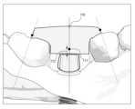
단계 S320과 관련된 몇몇 실시예에서, 도 3을 참조하면, 임플란트 시술용 가이드 생성 시스템은 어버트먼트(41)와 잇몸 사이의 경계선(43)에서 치관 방향으로 기 정의된 거리(40)만큼 이격된 지점들을 연결한 라인을 지그 오브젝트 생성을 위한 특정 기준선(42)으로 설정할 수 있다.In some embodiments related to step S320, referring to FIG. 3, the system for generating a guide for implant surgery can set a line connecting points spaced apart from a boundary line (43) between an abutment (41) and a gum in the direction of the crown by a predefined distance (40) as a specific reference line (42) for generating a jig object.
여기서, 기 정의된 거리(40)는 약 0.5 ~ 2mm에 해당하는 거리를 나타내며, 이에 한정하는 것은 아니고, 추후에 사용자에 의해 용이하게 변경 및 설정이 가능하다.Here, the predefined distance (40) represents a distance corresponding to about 0.5 to 2 mm, but is not limited thereto, and can be easily changed and set by the user in the future.
그리고 어버트먼트(41)와 잇몸 사이의 경계선(43)을 기준으로 설명하였지만, 마진 종류에 기초하여 해당 기준을 달리 설정할 수 있다. 여기서, 마진은 어버트먼트의 마진이 잇몸(치은)보다 상방에 위치한 Supra 마진, 어버트먼트의 마진이 치은과 동일선상에 위치한 EQ 마진, 어버트먼트의 마진이 치은보다 하방에 위치하는 Sub 마진으로 구분될 수 있다.And although the description was made based on the boundary line (43) between the abutment (41) and the gums, the corresponding standard can be set differently based on the type of margin. Here, the margin can be classified into a Supra margin in which the margin of the abutment is located above the gums (gingiva), an EQ margin in which the margin of the abutment is located on the same line as the gingiva, and a Sub margin in which the margin of the abutment is located below the gingiva.
구체적으로, Supra 마진과 EQ 마진의 경우 앞서 설명한 어버트먼트(41)와 잇몸 사이의 경계선(43)을 기준으로 특정 기준선(42)을 설정할 수 있고, sub 마진의 경우 어버트먼트(41)와 잇몸 사이의 경계선(43)이 아닌 치은이 끝나는 지점을 기준으로 특정 기준선(42)을 설정할 수 있다.Specifically, in the case of the Supra margin and the EQ margin, a specific reference line (42) can be set based on the boundary line (43) between the abutment (41) and the gums described above, and in the case of the sub margin, a specific reference line (42) can be set based on the point where the gingiva ends, not the boundary line (43) between the abutment (41) and the gums.
단계 S320과 관련된 다른 몇몇 실시예에서, 도 4를 참조하면, 임플란트 시술용 가이드 생성 시스템은 특정 기준선(42)의 높이에서 예를 들어 약 1~3mm의 가로 폭(51)으로 어버트먼트(41)를 감싸는 링 형태의 지그 오브젝트(50)를 생성할 수 있다. 단, 약 1~3mm의 가로 폭(51)은 본 개시에서 몇몇 실시예를 보다 명확하게 설명하기 위하여 기 지정된 예시일 뿐이며, 사용자의 설정에 따라 얼마든지 변경 가능함에 유의하여야 한다.In some other embodiments related to step S320, referring to FIG. 4, the implant surgery guide generation system can generate a ring-shaped jig object (50) that surrounds the abutment (41) with a horizontal width (51) of, for example, about 1 to 3 mm at a height of a specific reference line (42). However, it should be noted that the horizontal width (51) of about 1 to 3 mm is only a pre-specified example to more clearly explain some embodiments in the present disclosure, and may be changed at any time according to a user's settings.
여기서, 링 형태로 어버트먼트(41)를 둘러싸는 지그 오브젝트(50)는 지그 오브젝트 형상을 확대하는 단계 및 조정하는 단계를 통해 최종 지그 오브젝트 형상을 획득하기 위한 초기 형상으로 이해되어야 할 것이다.Here, the jig object (50) surrounding the abutment (41) in a ring shape should be understood as an initial shape for obtaining the final jig object shape through the steps of enlarging and adjusting the jig object shape.
단계 S330에서 임플란트 시술용 가이드 생성 시스템은 상기 생성된 지그 오브젝트 형상을 어버트먼트의 인접치 기준으로 확대할 수 있다. 이하, 상기 어버트먼트의 인접치 기준으로 확대된 지그 오브젝트는, 확대된 지그 오브젝트로 기재토록 한다.In step S330, the system for generating a guide for implant surgery can enlarge the generated jig object shape based on the adjacent teeth of the abutment. Hereinafter, the jig object enlarged based on the adjacent teeth of the abutment is described as an enlarged jig object.
이하, 단계 S330과 관련된 몇몇 실시예에서, 임플란트 시술용 가이드 생성 시스템이 상기 지그 오브젝트 형상을 어버트먼트의 인접치 기준으로 확대하는 방법을 도 5 내지 도 9를 참조하여 설명하도록 한다.Hereinafter, in some embodiments related to step S330, a method of the implant surgery guide generation system enlarging the shape of the jig object based on the adjacent teeth of the abutment will be described with reference to FIGS. 5 to 9.
도 5의 단계 S331에서, 임플란트 시술용 가이드 생성 시스템은 지그 오브젝트를 치관 방향으로 확대할 수 있다. 지그 오브젝트를 치관 방향으로 확대하는 단계를 보다 구체적으로 설명하기 위해 도 6을 참조하기로 한다.In step S331 of FIG. 5, the system for generating a guide for implant surgery can enlarge the jig object in the direction of the crown. To more specifically explain the step of enlarging the jig object in the direction of the crown, reference will be made to FIG. 6.
단계 S331과 관련된 몇몇 실시예에서, 임플란트 시술용 가이드 생성 시스템은 상기 단계 S320에서 형성된 링 형상의 지그 오브젝트가 어버트먼트 옆면을 감싸는 슬리브(60)를 형성하도록 확대할 수 있다.In some embodiments related to step S331, the implant surgery guide generation system can enlarge the ring-shaped jig object formed in step S320 to form a sleeve (60) that surrounds the side surface of the abutment.
다음으로, 단계 S332에서, 임플란트 시술용 가이드 생성 시스템은 확대된 지그 오브젝트를 추가 확대하기 위하여, 어버트먼트의 인접치들을 이용해 기준 높이를 설정할 수 있다. 여기서, 상기 기준 높이를 설정하기 위하여 복수의 기준점(확대 지점)들이 정의될 수 있다. 상기 기준 높이를 설정하는 단계를 보다 구체적으로 설명하기 위하여, 도 7 내지 도 8을 참조하여 설명하기로 한다.Next, in step S332, the implant surgery guide generation system can set a reference height using adjacent teeth of the abutment to further enlarge the enlarged jig object. Here, a plurality of reference points (enlargement points) can be defined to set the reference height. In order to explain the step of setting the reference height in more detail, it will be explained with reference to FIGS. 7 and 8.
단계 S332와 관련된 몇몇 실시예에서, 도 7을 참조하면, 임플란트 시술용 가이드 생성 시스템은 근심측 인접치의 치관 방향에 설정되는 근심측 기준점(72), 원심측 인접치의 치관 방향에 설정되는 원심측 기준점(71)을 정의할 수 있다.In some embodiments related to step S332, referring to FIG. 7, the system for generating a guide for implant surgery can define a mesial reference point (72) set in the crown direction of a mesial adjacent tooth, and a distal reference point (71) set in the crown direction of a distal adjacent tooth.
여기서, 근심측 기준점(72)은 상기 어버트먼트의 근심측 인접치의 중심부에서 치관 방향으로 가상의 장축(73)을 생성했을 때, 상기 근심측 인접치의 교합면에서 치관 방향으로 기 정의된 거리(77)만큼 이격된 지점들 중 장축(73)과 만나는 지점(72)으로 정의될 수 있다.Here, the mesial reference point (72) can be defined as the point (72) that intersects the long axis (73) among the points spaced apart from the occlusal surface of the mesial adjacent tooth in the crown direction by a predefined distance (77) when a virtual long axis (73) is created in the crown direction from the center of the mesial adjacent tooth of the abutment.
그리고 원심측 기준점(71)은, 상기 어버트먼트의 원심측 인접치의 중심부에서 치관 방향으로 가상의 장축(74)을 생성했을 때, 상기 원심측 인접치의 교합면에서 치관 방향으로 기 정의된 거리(76)만큼 이격된 지점들 중 장축(74)과 만나는 지점(71)으로 정의될 수 있다.And the centrifugal reference point (71) can be defined as the point (71) that intersects the long axis (74) among the points spaced apart from the occlusal surface of the distal adjacent tooth in the crown direction by a predefined distance (76) when a virtual long axis (74) is created in the crown direction from the center of the distal adjacent tooth of the abutment.
단계 S332와 관련된 또 다른 몇몇 실시예에서, 도 8을 참조하면, 임플란트 시술용 가이드 생성 시스템은 앞서 정의된 근심측 기준점(72)에서 원심측 장축(74)으로 최단 거리를 가지는 제1 직선(83)을 생성하고, 원심측 기준점(71)에서 근심측 장축(73)으로 최단 거리를 가지는 제2 직선(84)을 생성할 수 있다.In some other embodiments related to step S332, referring to FIG. 8, the implant surgery guide generation system can generate a first straight line (83) having the shortest distance from the previously defined mesial reference point (72) to the distal long axis (74), and can generate a second straight line (84) having the shortest distance from the distal reference point (71) to the mesial long axis (73).
그리고 임플란트 시술용 가이드 생성 시스템은 제1 직선(83)과 제2 직선(84) 중에서 상기 지그 오브젝트의 상단과의 거리가 상대적으로 긴 직선을 선택하고, 상기 지그 오브젝트의 상단에서부터 선택한 직선까지의 높이를 기준 높이(86)로 설정할 수 있다.And the system for generating a guide for implant surgery can select a straight line having a relatively long distance from the top of the jig object among the first straight line (83) and the second straight line (84), and set the height from the top of the jig object to the selected straight line as the reference height (86).
단계 S332와 관련된 또 다른 몇몇 실시예에서, 임플란트 시술용 가이드 생성 시스템은 어버트먼트의 인접치가 하나 밖에 존재하지 않는다는 것에 응답하여, 해당 인접치의 중심부에서 치관 방향으로 가상의 장축을 생성했을 때, 상기 인접치의 교합면에서 치관 방향으로 기 정의된 거리만큼 이격된 지점들 중 장축과 만나는 지점을 기준 높이로 설정할 수 있다.In some further embodiments related to step S332, the system for generating a guide for implant surgery may, in response to there being only one adjacent tooth of the abutment, generate a virtual long axis in the direction of the crown from the center of the adjacent tooth, and set a point where the long axis intersects with points spaced apart from the occlusal surface of the adjacent tooth in the direction of the crown by a predefined distance as a reference height.
다음으로, 단계 S333에서, 임플란트 시술용 가이드 생성 시스템은 상기 설정된 기준 높이까지 확대된 지그 오브젝트를 치관 방향(교합 방향)으로 추가 확대할 수 있다. 이처럼 확대된 지그 오브젝트를 치관 방향으로 추가 확대하는 단계를 보다 자세하게 설명하기 위하여는 도 8을 참조하도록 한다.Next, in step S333, the implant procedure guide generation system can further enlarge the jig object enlarged to the set reference height in the crown direction (occlusion direction). For a more detailed explanation of the step of further enlarging the enlarged jig object in the crown direction, refer to FIG. 8.
단계 S333과 관련된 몇몇 실시예에서, 임플란트 시술용 가이드 생성 시스템은 상기 어버트먼트의 인접치들의 교합면을 기준으로 설정된 기준 높이(86)까지, 확대된 지그 오브젝트를 추가 확대할 수 있다.In some embodiments related to step S333, the implant procedure guide generation system can further enlarge the enlarged jig object to a reference height (86) set based on the occlusal surface of adjacent teeth of the abutment.
다시 말해, 임플란트 시술용 가이드 생성 시스템은 어버트먼트의 옆면을 감싸는 형상인 지그 오브젝트의 슬리브(82)에 이어 설정된 기준 높이(86)만큼 추가 확대된 지그 오브젝트의 상단부(81)를 형성할 수 있다.In other words, the system for generating a guide for implant surgery can form an upper part (81) of a jig object that is further enlarged by a set reference height (86) following a sleeve (82) of a jig object that has a shape that wraps around the side of an abutment.
여기서, 추가 확대된 지그 오브젝트의 상단부(81)는, 어버트먼트의 교합면 최상부를 기준으로 확대된 지그 오브젝트를 절단하였을 때, 분리되는 상부 영역인 것으로 이해되어야 할 것이다.Here, the upper part (81) of the additionally enlarged jig object should be understood as the upper area that is separated when the enlarged jig object is cut based on the uppermost part of the occlusal surface of the abutment.
또한, 본 개시의 설명을 명확하게 하기 위하여, 어버트먼트의 옆면을 감싸는 형상으로 확대된 지그 오브젝트의 슬리브(82)는 지그 오브젝트 하단 영역(82)으로 기재하도록 한다. 아울러 지그 오브젝트의 상단부(81) 및 지그 오브젝트의 슬리브(82)를 합하여 추가 확대된 지그 오브젝트로 기재토록 한다.In addition, in order to clarify the description of the present disclosure, the sleeve (82) of the jig object enlarged to a shape that wraps around the side of the abutment is described as the lower region (82) of the jig object. In addition, the upper part (81) of the jig object and the sleeve (82) of the jig object are combined and described as an additionally enlarged jig object.
단계 S334에서, 임플란트 시술용 가이드 생성 시스템은 지그 오브젝트의 상단부(81)를 인접치들과 접하도록 기준점(확대 지점)들에 기초하여 측면 방향으로 확대된 지지부를 형성할 수 있다. 여기서, 측면 방향은 구강 내 근심 방향 및 원심 방향 양 방향 모두를 지칭하는 것으로 이해되어야 한다. 지그 오브젝트의 지지부를 형성하는 단계에 관하여는, 도 9를 참조하여 설명하기로 한다.In step S334, the implant procedure guide generation system can form a support portion that is enlarged laterally based on reference points (enlargement points) so that the upper portion (81) of the jig object comes into contact with adjacent teeth. Here, the lateral direction should be understood to refer to both the mesial direction and the distal direction within the oral cavity. The step of forming the support portion of the jig object will be described with reference to FIG. 9.
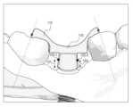
단계 S334과 관련된 몇몇 실시예에서, 도 9를 참조하면, 임플란트 시술용 가이드 생성 시스템은 상기 확대 영역(81a)과 같이, 상기 어버트먼트의 인접치들에 접하도록 근심 방향 및 원심 방향으로 측면 확대하여 최종 확대된 지그 오브젝트를 생성할 수 있다.In some embodiments related to step S334, referring to FIG. 9, the implant surgery guide generation system can generate a final enlarged jig object by laterally expanding in the mesial and distal directions to contact adjacent teeth of the abutment, such as the enlarged area (81a).
임플란트 시술용 가이드 생성 시스템은 앞서 설정한 기준점들인 근심측 기준점과 원심측 기준점까지 확대하거나, 근심측 기준점과 원심측 기준점에서 일정 거리까지 인접하도록 확대된 지지부를 형성할 수 있다.The system for generating a guide for implant surgery can expand to previously set reference points, such as the mesial reference point and the distal reference point, or form an expanded support part adjacent to the mesial reference point and the distal reference point at a certain distance.
여기서, 지그 오브젝트 하단 영역인 슬리브(82)는 확대되지 않음에 유의하여야 한다. 따라서, 근심측 인접치의 원심 방향 최대 풍융부 하단 영역(103), 원심측 인접치의 근심 방향 최대 풍융부 하단 영역(102) 그리고 지그 오브젝트 하단 영역(82) 사이의 공간은 지그 오브젝트가 형성되지 않는 것이다.Here, it should be noted that the sleeve (82), which is the lower area of the jig object, is not enlarged. Therefore, the space between the lower area (103) of the maximum fusion part in the centrifugal direction of the adjacent tooth on the proximal side, the lower area (102) of the maximum fusion part in the centrifugal direction of the adjacent tooth on the proximal side, and the lower area (82) of the jig object is not where a jig object is formed.
본 실시예에 따르면, 임플란트 시술용 가이드 생성 시스템은 어버트먼트 체결을 위하여 이용될 지그 오브젝트를 자동 생성하는 유용한 기준점들을 제공할 수도 있으며, 상기 기준점을 바탕으로 지그 오브젝트를 확대하여 각 환자의 잇몸에 체결될 어버트먼트의 위치 및 형태에 알맞은 임플란트 시술용 가이드의 초기 형상을 생성하는 방법을 제공할 수도 있다.According to the present embodiment, the system for generating a guide for implant surgery can provide useful reference points for automatically generating a jig object to be used for abutment attachment, and can also provide a method for generating an initial shape of an implant surgery guide suitable for the position and shape of an abutment to be attached to the gums of each patient by enlarging the jig object based on the reference points.
지금까지 임플란트 시술용 가이드 생성 시스템이 지그 오브젝트 형상을 인접치 기준으로 확대하는 방법에 대하여 설명하였다. 이에 본 개시의 범위가 한정되는 것은 아니고, 어버트먼트 인접치의 상실 여부에 따라 지그 오브젝트 확대를 위하여 설정되는 기준 높이는 유연하게 변경될 수도 있다.So far, the method for generating a guide for implant surgery to enlarge a jig object shape based on adjacent teeth has been described. The scope of the present disclosure is not limited thereto, and the reference height set for enlarging a jig object may be flexibly changed depending on whether or not an abutment adjacent tooth is lost.
이하, 도 2b를 참조하여 계속 설명하도록 한다.Below, the explanation will continue with reference to Fig. 2b.
단계 S340에서, 임플란트 시술용 가이드 생성 시스템은 최종 확대된 지그 오브젝트의 형상을 조정할 수 있다. 상기 최종 확대된 지그 오브젝트를 조정하는 단계를 보다 상세하게 설명하기 위하여 도 10 내지 도 14를 참조하도록 한다. 또한, 상기 최종 확대된 지그 오브젝트를 조정하는 단계는, 지그 오브젝트의 최종 형태를 생성하기 위하여 상기 최종 확대된 지그 오브젝트가 임플란트 시술용 가이드 생성 시스템에 의해 확대 및 축소되는 경우 모두를 포함할 수 있다.In step S340, the implant surgery guide generation system can adjust the shape of the final enlarged jig object. In order to describe the step of adjusting the final enlarged jig object in more detail, reference is made to FIGS. 10 to 14. In addition, the step of adjusting the final enlarged jig object can include all cases where the final enlarged jig object is enlarged and reduced by the implant surgery guide generation system to generate the final shape of the jig object.
도 10을 참조하면, 단계 S341에서, 임플란트 시술용 가이드 생성 시스템은 최종 확대된 지그 오브젝트의 상단부 형상을 조정할 수 있다. 상기 최종 확대된 지그 오브젝트의 상단부 형상을 조정하는 단계를 보다 상세하게 설명하기 위하여 도 11을 참조하여 설명하기로 한다.Referring to FIG. 10, in step S341, the implant surgery guide generation system can adjust the shape of the upper part of the final enlarged jig object. In order to explain the step of adjusting the shape of the upper part of the final enlarged jig object in more detail, a description will be made with reference to FIG. 11.
도 11을 참조하면, 단계 S341과 관련된 몇몇 실시예에서 임플란트 시술용 가이드 생성 시스템은 최종 확대된 지그 오브젝트의 상단부 형상을 조정하기 위한 기준점을 정의하기 위하여 어버트먼트의 중심부를 가로지르는 가상의 중심축을 생성할 수 있다.Referring to FIG. 11, in some embodiments related to step S341, the implant surgery guide generation system can generate a virtual central axis crossing the center of the abutment to define a reference point for adjusting the top shape of the final enlarged jig object.
단계 S341과 관련된 다른 몇몇 실시예에서 임플란트 시술용 가이드 생성 시스템은 어버트먼트의 상단 2mm 지점 중 상기 어버트먼트 중심축과 접하는 지점을 최종 확대된 지그 오브젝트의 치관 방향 면 형상 조정 기준점(111)으로 정의할 수 있다. 또한, 상기 임플란트 시술용 가이드 생성 시스템은 지그 오브젝트의 상단부와 상기 어버트먼트 중심축이 만나는 지점 중 최상부를 형상 조정 대상점(110)으로 정의할 수 있다.In some other embodiments related to step S341, the implant surgery guide generation system may define a point that is in contact with the abutment central axis among the upper 2 mm points of the abutment as a crown direction surface shape adjustment reference point (111) of the final enlarged jig object. In addition, the implant surgery guide generation system may define the uppermost point among the points where the upper part of the jig object and the abutment central axis meet as a shape adjustment target point (110).
단계 S341과 관련된 또 다른 몇몇 실시예에서 임플란트 시술용 가이드 생성 시스템은 형상 조정 대상점(110)을 형상 조정 기준점(111)으로 이동시키면서, 지그 오브젝트의 상단부 형상을 상기 형상 조정 대상점(110)을 중심점으로 하는 오목한 형상으로 조정함으로써, 상부 조정된 지그 오브젝트를 생성할 수 있다. 상기 상부 조정된 지그 오브젝트 형상에 대하여는, 도 12의 상부 조정된 구성 요소(112)를 참조하면 명확히 이해될 수 있다.In some further embodiments related to step S341, the implant procedure guide generation system can generate an upper-adjusted jig object by moving a shape adjustment target point (110) to a shape adjustment reference point (111) and adjusting the shape of the upper portion of the jig object to a concave shape with the shape adjustment target point (110) as the center point. The shape of the upper-adjusted jig object can be clearly understood with reference to the upper-adjusted component (112) of FIG. 12.
단계 S342에서, 임플란트 시술용 가이드 생성 시스템은 지그 오브젝트의 지지대 형상을 조정하기 위한, 지그 오브젝트 특정 지점들을 설정할 수 있다. 상기 특정 지점들은 지그 오브젝트의 슬리브 근심측 측면에 존재하는 제1 지점과 지그 오브젝트의 슬리브 원심측 측면에 존재하는 제2 지점이 포함될 수 있다. 상기 특정 지점들을 설정하는 방법을 보다 구체적으로 설명하기 위하여, 도 12를 참조하기로 한다.In step S342, the implant surgery guide generation system can set specific points of the jig object for adjusting the support shape of the jig object. The specific points may include a first point existing on the sleeve proximal side of the jig object and a second point existing on the sleeve distal side of the jig object. To more specifically explain a method for setting the specific points, reference will be made to FIG. 12.
단계 S342과 관련된 몇몇 실시예에서, 상기 특정 지점 중 제1 지점(122-2)은 어버트먼트와 잇몸 사이의 경계선에서 어버트먼트의 치관 방향 높이로 3 분의 2 지점(123)만큼 이격된, 지그 오브젝트의 슬리브 근심측 면에 포함된 점일 수 있다. 또한, 상기 특정 지점 중 제2 지점(122-1)은 어버트먼트와 잇몸 사이의 경계선에서 어버트먼트의 치관 방향 높이로 3 분의 2 지점(121)만큼 이격된, 지그 오브젝트의 슬리브 원심측 면에 포함된 점일 수 있다.In some embodiments related to step S342, the first point (122-2) of the specific points may be a point included in the sleeve mesial side of the jig object, spaced apart by two-thirds of the point (123) in the coronal direction height of the abutment from the boundary line between the abutment and the gum. In addition, the second point (122-1) of the specific points may be a point included in the sleeve distal side of the jig object, spaced apart by two-thirds of the point (121) in the coronal direction height of the abutment from the boundary line between the abutment and the gum.
단계 S343에서, 임플란트 시술용 가이드 생성 시스템은 지그 오브젝트의 지지부가 상기 지그 오브젝트의 슬리브상의 기 정의된 제1 지점 및 제2 지점과 각각 인접치의 최대 풍융부 지점(130, 131)과 연결되도록 확대 및 조정하여 최종 지그 오브젝트를 생성할 수 있다. 여기서, 최대 풍융부 지점은 본래 치아의 단면에서 특정 방향으로 가장 융기된 지점을 의미한다. 예를 들어 본 개시에서 도 13을 참조하면, 근심측 인접치에 표시된 지점은 근심측 인접치의 최대 풍융부들 중 하나이며, 원심 방향에서 가장 융기된 지점이므로 근심측 인접치의 원심면측 최대 풍융부(131)로 명명할 수도 있다. 이와 동일하게 원심측 인접치에 표시된 지점은 원심측 인접치의 근심면측 최대 풍융부(130)로 명명할 수도 있다.In step S343, the implant procedure guide generation system can generate a final jig object by enlarging and adjusting the support portion of the jig object so that the first point and the second point defined on the sleeve of the jig object are connected to the maximum fusion point (130, 131) of the adjacent tooth, respectively. Here, the maximum fusion point means the point that is most bulged in a specific direction in the cross-section of the original tooth. For example, referring to FIG. 13 in the present disclosure, the point indicated on the mesial adjacent tooth is one of the maximum bulges of the mesial adjacent tooth, and since it is the point that is most bulged in the distal direction, it may be named as the maximum bulge (131) on the distal surface of the mesial adjacent tooth. Similarly, the point indicated on the distal adjacent tooth may be named as the maximum bulge (130) on the mesial surface of the distal adjacent tooth.
이하, 도 12 및 도 13을 참조하여 단계 S343과 관련된 몇몇 실시예들을 설명하도록 한다.Hereinafter, some embodiments related to step S343 will be described with reference to FIGS. 12 and 13.
단계 S343과 관련된 몇몇 실시예에서, 임플란트 시술용 가이드 생성 시스템은 상부 조정된 지그 오브젝트에 기 지정된 제1 지점(122-2)을 어버트먼트의 근심측 인접치의 원심면측 최대 풍융부(131) 지점과 최단 거리로 연결되는 형상을 이루도록 상기 상부 조정된 지그 오브젝트의 근심측 면을 확대할 수 있다.In some embodiments related to step S343, the implant procedure guide generation system can enlarge the mesial surface of the upper adjusted jig object to form a shape that connects the first point (122-2) designated on the upper adjusted jig object to the point of the maximum fusion part (131) on the distal surface of the mesial adjacent tooth of the abutment with the shortest distance.
단계 S343과 관련된 다른 몇몇 실시예에서, 임플란트 시술용 가이드 생성 시스템은 상부 조정된 지그 오브젝트에 기 지정된 제2 지점(122-1)을 어버트먼트의 원심측 인접치의 근심면측 최대 풍융부(130) 지점과 최단 거리로 연결되는 형상을 이루도록 상기 상부 조정된 지그 오브젝트의 원심측 면을 확대할 수 있다.In some other embodiments related to step S343, the implant surgery guide generation system can enlarge the distal side surface of the upper adjusted jig object so as to form a shape that connects the second point (122-1) designated on the upper adjusted jig object with the point of the maximum fusion part (130) on the mesial side of the distal adjacent tooth of the abutment by the shortest distance.
단계 S343과 관련된 또 다른 몇몇 실시예에서, 임플란트 시술용 가이드 생성 시스템은 사용자에 의해 기 설정된 지그 오브젝트의 최소 폭 값에 기초하여 상기 상부 조정된 지그 오브젝트를 확대시킬 수 있다. 예를 들어, 사용자가 11mm 두께의 지그 오브젝트 폭 최소값을 설정한 경우, 상기 임플란트 시술용 가이드 생성 시스템은 인접치들의 최대 풍융부 지점(130, 131)과 상부 조정된 지그 오브젝트의 양측 지점(122-1, 122-2)을 연결하여 확대하는 단계를 수행할 때 11mm 미만으로 형상을 변환시키지 않을 수 있다.In some further embodiments related to step S343, the implant surgery guide generation system may enlarge the upper adjusted jig object based on a minimum width value of the jig object preset by the user. For example, if the user sets a minimum width value of the jig object to be 11 mm thick, the implant surgery guide generation system may not transform the shape to less than 11 mm when performing the step of enlarging by connecting the maximum fusion points (130, 131) of adjacent teeth and the points (122-1, 122-2) on both sides of the upper adjusted jig object.
본 실시예에 따르면, 임플란트 시술용 가이드가 자동으로 생성되는 과정 중 발생할 수 있는 지그 오브젝트의 과도한 형상 변환을 예방함으로써 환자의 어버트먼트 체결을 오차없이 수행하는 데 기여할 수도 있는 것이다.According to this embodiment, it is possible to prevent excessive shape transformation of a jig object that may occur during the process of automatically generating a guide for implant surgery, thereby contributing to performing abutment fastening of a patient without error.
단계 S344에서, 임플란트 시술용 가이드 생성 시스템은 지그 오브젝트의 상단부에 지그 오브젝트 홀을 생성함으로써, 최종 지그 오브젝트를 생성할 수 있다. 도 14를 참조하면, 상기 임플란트 시술용 가이드 생성 시스템은 어버트먼트 중심축에 기초하여, 현재 어버트먼트 홀의 직경 사이즈(143)를 기준으로 어버트먼트 홀과 연결되도록 지그 오브젝트의 상단부 내 직경 사이즈(142)를 가지는 지그 오브젝트 홀(140)을 생성할 수 있다.In step S344, the implant surgery guide generation system can generate a final jig object by generating a jig object hole at the upper end of the jig object. Referring to FIG. 14, the implant surgery guide generation system can generate a jig object hole (140) having a diameter size (142) in the upper end of the jig object so as to be connected to the abutment hole based on the diameter size (143) of the current abutment hole based on the abutment central axis.
지금까지 임플란트 시술용 가이드 생성 시스템이 확대된 지그 오브젝트 형상을 인접치 기준으로 조정하는 방법에 대하여 설명하였다. 상기 확대된 지그 오브젝트 형상을 인접치 기준으로 조정하는 방법과 관련된 동작들은 각각 독립적으로 이용될 수 있으나, 이에 본 개시의 범위가 한정되는 것은 아니고, 복수의 동작들이 함께 이용될 수도 있다.So far, a method for adjusting an enlarged jig object shape based on adjacent teeth in a guide generation system for implant surgery has been described. The operations related to the method for adjusting the enlarged jig object shape based on adjacent teeth may be used independently, but the scope of the present disclosure is not limited thereto, and a plurality of operations may be used together.
이하, 도 2a를 참조하여 임플란트 시술용 가이드 생성 방법의 상세한 단계를 계속 설명한다.Hereinafter, detailed steps of a method for creating a guide for implant surgery will be continuously described with reference to FIG. 2a.
단계 S200에서 임플란트 시술용 가이드 생성 시스템은 사용자 단말을 통한 사용자 입력에 따라 상기 생성한 최종 지그 오브젝트의 형상을 수정할 수 있다. 상기 사용자 입력은 마우스, 키보드, 조이스틱 등 임플란트 시술용 가이드 생성 시스템이 사용자 단말을 통해 제공한 최종 지그 오브젝트의 최종 형상을 수정하는 유저 인터페이스를 조작할 수 있는 것이라면 무엇이든 허용될 수 있다. 이하, 도 15a 및 도 15b를 참조하여 상기 최종 지그 오브젝트의 최종 형상이 수정되는 단계에 관하여 상세하게 설명하도록 한다.In step S200, the implant surgery guide generation system can modify the shape of the generated final jig object according to user input via a user terminal. The user input may be anything that can operate a user interface for modifying the final shape of the final jig object provided by the implant surgery guide generation system via the user terminal, such as a mouse, a keyboard, a joystick, etc. Hereinafter, a step of modifying the final shape of the final jig object will be described in detail with reference to FIGS. 15a and 15b.
단계 S200과 관련된 몇몇 실시예에서, 임플란트 시술용 가이드 생성 시스템은 사용자 단말을 통해 형상 조정 입력을 받기 위한 인터페이스(151) 및 생성된 최종 지그 오브젝트의 형상을 표시할 수 있다. 상기 최종 지그 오브젝트의 형상은 우측, 좌측, 중심부에 각각 마련된 수정 포인트를 기준으로 자유롭게 수정될 수 있음은 도 15a를 참조하면 명확히 이해될 수 있다. 여기서, 수정 포인트는 미리 지정된 지점으로 설정되거나 실시간으로 사용자로부터 입력받은 지점으로 설정될 수 있다.In some embodiments related to step S200, the implant surgery guide generation system can display an interface (151) for receiving a shape adjustment input through a user terminal and a shape of a generated final jig object. It can be clearly understood with reference to Fig. 15a that the shape of the final jig object can be freely modified based on modification points provided on the right, left, and center, respectively. Here, the modification points can be set to points designated in advance or points input by the user in real time.
단계 S200과 관련된 다른 몇몇 실시예에서 임플란트 시술용 가이드 생성 시스템은 최종 지그 오브젝트의 좌측 수정 포인트(152)를 우측으로 이동시키는 입력을 사용자로부터 전달받아 좌측 수정 포인트(152)를 중심점으로 하여금 상기 최종 지그 오브젝트의 좌측 영역 형상을 변환시킬 수 있다. 변환 전 최종 지그 오브젝트와 변환 후 최종 지그 오브젝트의 형태 차이는 도 15a 및 도 15b를 참조하면 명확히 이해될 수 있다.In some other embodiments related to step S200, the implant surgery guide generation system may receive an input from a user to move a left modification point (152) of a final jig object to the right, and transform the shape of a left area of the final jig object by making the left modification point (152) a center point. The difference in shape between the final jig object before transformation and the final jig object after transformation can be clearly understood with reference to FIGS. 15a and 15b.
본 실시예에 따르면, 임플란트 시술용 가이드 생성 시스템은, 외부 요인 또는 환자 스캔 데이터 형상의 오차로 인해 상기 임플란트 시술용 가이드 생성 시스템이 생성한 지그 오브젝트의 최종 형상에 오류가 발생한다고 할지라도, 사용자로부터 수정안을 입력 받아 3D 프린팅 시스템을 통해 출력되기 전 정확한 지그 오브젝트 형상 생성을 완료할 수 있는 것이다.According to the present embodiment, even if an error occurs in the final shape of a jig object generated by the implant surgery guide generation system due to external factors or errors in the shape of patient scan data, the system for generating a guide for implant surgery can complete the generation of an accurate jig object shape before outputting it through a 3D printing system by receiving a correction from a user.
지금까지 본 개시의 일 실시예에 따른, 임플란트 시술용 가이드 생성 방법에 대하여 설명하였다. 상기 시술용 가이드를 생성하는 방법과 관련된 동작들은 각각 독립적으로 이용될 수 있으나, 이에 본 개시의 범위가 한정되는 것은 아니고, 복수의 동작들이 함께 이용될 수도 있다.So far, a method for generating a guide for implant surgery according to one embodiment of the present disclosure has been described. The operations related to the method for generating the guide for the procedure may be used independently, but the scope of the present disclosure is not limited thereto, and a plurality of operations may be used together.
도 16은 본 개시의 몇몇 실시예들에 따른 임플란트 시술용 가이드 생성 시스템의 하드웨어 구성도이다. 도 16에 임플란트 시술용 가이드 생성 시스템(1000)은, 예를 들어 도 1을 참조하여 설명한 임플란트 시술용 가이드 생성 시스템(100)을 가리키는 것일 수 있다. 임플란트 시술용 가이드 생성 시스템(1000)은 하나 이상의 프로세서(1100), 시스템 버스(1600), 통신 인터페이스(1200), 프로세서(1100)에 의하여 수행되는 컴퓨터 프로그램(1500)을 로드(load)하는 메모리(1400)와, 컴퓨터 프로그램(1500)을 저장하는 스토리지(1300)를 포함할 수 있다.FIG. 16 is a hardware configuration diagram of a guide generation system for implant surgery according to some embodiments of the present disclosure. The guide generation system for implant surgery (1000) in FIG. 16 may refer to, for example, the guide generation system for implant surgery (100) described with reference to FIG. 1. The guide generation system for implant surgery (1000) may include one or more processors (1100), a system bus (1600), a communication interface (1200), a memory (1400) for loading a computer program (1500) executed by the processor (1100), and a storage (1300) for storing the computer program (1500).
프로세서(1100)는 임플란트 시술용 가이드 생성 시스템(1000)의 각 구성의 전반적인 동작을 제어한다. 프로세서(1100)는 본 개시의 다양한 실시예들에 따른 방법/동작을 실행하기 위한 적어도 하나의 애플리케이션 또는 프로그램에 대한 연산을 수행할 수 있다. 메모리(1400)는 각종 데이터, 명령 및/또는 정보를 저장한다. 메모리(1400)는 본 개시의 다양한 실시예들에 따른 방법/동작들을 실행하기 위하여 스토리지(1300)로부터 하나 이상의 컴퓨터 프로그램(1500)을 로드(load) 할 수 있다. 버스(1600)는 임플란트 시술용 가이드 생성 시스템(1000)의 구성 요소 간 통신 기능을 제공한다. 통신 인터페이스(1200)는 임플란트 시술용 가이드 생성 시스템(1000)의 인터넷 통신을 지원한다. 스토리지(1300)는 하나 이상의 컴퓨터 프로그램(1500)을 비임시적으로 저장할 수 있다. 컴퓨터 프로그램(1500)은 본 개시의 다양한 실시예들에 따른 방법/동작들이 구현된 하나 이상의 인스트럭션들(instructions)을 포함할 수 있다. 컴퓨터 프로그램(1500)이 메모리(1400)에 로드 되면, 프로세서(1100)는 상기 하나 이상의 인스트럭션들을 실행시킴으로써 본 개시의 다양한 실시예들에 따른 방법/동작들을 수행할 수 있다.The processor (1100) controls the overall operation of each component of the implant surgery guide generation system (1000). The processor (1100) can perform operations for at least one application or program for executing methods/operations according to various embodiments of the present disclosure. The memory (1400) stores various data, commands, and/or information. The memory (1400) can load one or more computer programs (1500) from the storage (1300) to execute methods/operations according to various embodiments of the present disclosure. The bus (1600) provides a communication function between components of the implant surgery guide generation system (1000). The communication interface (1200) supports Internet communication of the implant surgery guide generation system (1000). The storage (1300) can non-temporarily store one or more computer programs (1500). The computer program (1500) may include one or more instructions implementing methods/operations according to various embodiments of the present disclosure. When the computer program (1500) is loaded into the memory (1400), the processor (1100) may perform the methods/operations according to various embodiments of the present disclosure by executing the one or more instructions.
몇몇 실시예들에서, 도 16을 참조하여 설명된 임플란트 시술용 가이드 생성 시스템은 가상 머신 등 클라우드 기술에 기반하여 서버 팜(server farm)에 포함된 하나 이상의 물리 서버(physical server)를 이용하여 구성될 수 있다. 이 경우, 도 6에 도시된 구성 요소 중 프로세서(1100), 메모리(1400) 및 스토리지(1300) 중 적어도 일부는 가상 하드웨어(virtual hardware)일 수 있을 것이며, 통신 인터페이스(1200) 또한 가상 스위치(virtual switch) 등 가상화된 네트워킹 요소로 구성될 수 있을 것이다.In some embodiments, the implant surgery guide generation system described with reference to FIG. 16 may be configured using one or more physical servers included in a server farm based on cloud technology such as a virtual machine. In this case, at least some of the processor (1100), memory (1400), and storage (1300) among the components illustrated in FIG. 6 may be virtual hardware, and the communication interface (1200) may also be configured as a virtualized networking element such as a virtual switch.
컴퓨터 프로그램(1500)은 스캔 데이터에서 추출된 어버트먼트의 형상을 이용하여 지그 오브젝트를 생성하는 동작, 상기 지그 오브젝트를 인접치 기준으로 확대하는 동작 및 상기 확대된 지그 오브젝트의 형상을 인접치 기준으로 조정함으로써 최종 지그 오브젝트를 생성하는 동작을 수행하기 위한 인스트럭션들(instructions)을 포함할 수 있다.The computer program (1500) may include instructions for performing an operation of generating a jig object using the shape of an abutment extracted from scan data, an operation of enlarging the jig object based on adjacent teeth, and an operation of generating a final jig object by adjusting the shape of the enlarged jig object based on the adjacent teeth.
지금까지 도 1 내지 도 16을 참조하여 본 개시의 다양한 실시예들 및 그 실시예들에 따른 효과들을 언급하였다. 본 개시의 기술적 사상에 따른 효과들은 이상에서 언급한 효과들로 제한되지 않으며, 언급되지 않은 또 다른 효과들은 아래의 기재로부터 통상의 기술자에게 명확하게 이해될 수 있을 것이다.Various embodiments of the present disclosure and effects according to the embodiments have been described with reference to FIGS. 1 to 16 so far. The effects according to the technical idea of the present disclosure are not limited to the effects mentioned above, and other effects not mentioned will be clearly understood by those skilled in the art from the description below.
지금까지 설명된 본 개시의 기술적 사상은 컴퓨터가 읽을 수 있는 매체 상에 컴퓨터가 읽을 수 있는 코드로 구현될 수 있다. 상기 컴퓨터로 읽을 수 있는 기록 매체에 기록된 상기 컴퓨터 프로그램은 인터넷 등의 네트워크를 통하여 다른 컴퓨팅 장치에 전송되어 상기 다른 컴퓨팅 장치에 설치될 수 있고, 이로써 상기 다른 컴퓨팅 장치에서 사용될 수 있다.The technical idea of the present disclosure described so far can be implemented as a computer-readable code on a computer-readable medium. The computer program recorded on the computer-readable recording medium can be transmitted to another computing device through a network such as the Internet and installed on the other computing device, thereby allowing it to be used on the other computing device.
도면에서 동작들이 특정한 순서로 도시되어 있지만, 반드시 동작들이 도시된 특정한 순서로 또는 순차적 순서로 실행되어야만 하거나 또는 모든 도시 된 동작들이 실행되어야만 원하는 결과를 얻을 수 있는 것으로 이해되어서는 안 된다. 특정 상황에서는, 멀티태스킹 및 병렬 처리가 유리할 수도 있다. 이상 첨부된 도면을 참조하여 본 개시의 실시예들을 설명하였지만, 본 개시가 속하는 기술분야에서 통상의 지식을 가진 자는 그 기술적 사상이나 필수적인 특징을 변경하지 않고서 본 발명이 다른 구체적인 형태로도 실시될 수 있다는 것을 이해할 수 있다. 그러므로 이상에서 기술한 실시예들은 모든 면에서 예시적인 것이며 한정적인 것이 아닌 것으로 이해해야만 한다. 본 발명의 보호 범위는 아래의 청구범위에 의하여 해석되어야 하며, 그와 동등한 범위 내에 있는 모든 기술 사상은 본 개시에 의해 정의되는 기술적 사상의 권리범위에 포함되는 것으로 해석되어야 할 것이다.Although the operations are depicted in the drawings in a particular order, it should not be understood that the operations must be performed in the particular order depicted or in a sequential order, or that all depicted operations must be performed to achieve the desired results. In certain circumstances, multitasking and parallel processing may be advantageous. While the embodiments of the present disclosure have been described above with reference to the accompanying drawings, those skilled in the art will appreciate that the present disclosure can be implemented in other specific forms without changing the technical spirit or essential characteristics thereof. Therefore, it should be understood that the embodiments described above are illustrative in all respects and not restrictive. The scope of protection of the present invention should be interpreted by the claims below, and all technical ideas within a scope equivalent thereto should be interpreted as being included in the scope of the technical ideas defined by the present disclosure.
Claims (12)
Translated fromKorean스캔 데이터에서 추출된 어버트먼트(abutment)의 형상을 이용하여 생성한 지그 오브젝트(jig object)를 제공하는 단계; 및
상기 지그 오브젝트의 형상을 수정할 수 있는 UI를 제공하는 단계를 포함하고,
상기 지그 오브젝트는,
상기 어버트먼트 옆면을 감싸는 슬리브, 상기 어버트먼트 상면을 덮고 상기 어버트먼트의 체결공에 연결되는 관통공을 가지는 상단부, 그리고 상기 상단부에서 인접치까지 연장되고 상기 인접치의 풍융부 아래에서 언더컷을 가지는 지지부를 포함하는 형태인 임플란트 시술용 가이드 생성 방법.A method for generating a guide for implant surgery performed by a computing system,
A step of providing a jig object created using the shape of an abutment extracted from scan data; and
Including a step of providing a UI that can modify the shape of the above jig object,
The above jig object is,
A method for producing a guide for implant surgery, comprising: a sleeve covering a side surface of the abutment; an upper portion having a through hole covering an upper surface of the abutment and connected to a fastening hole of the abutment; and a support portion extending from the upper portion to an adjacent tooth and having an undercut below a concave portion of the adjacent tooth.
상기 어버트먼트의 체결공에 연결되는 관통공은,
상기 어버트먼트의 체결공의 직경과 동일한 직경을 가지는 것인,
임플란트 시술용 가이드 생성 방법.In the first paragraph,
The through hole connected to the fastening hole of the above abutment is
Having a diameter identical to the diameter of the fastening hole of the above abutment,
Method for creating a guide for implant surgery.
상기 지지부는,
상기 상단부 영역에 기초하여 상기 인접치 상단면의 장축 지점까지 연장되고, 상기 슬리브의 일부 영역에서 인접치들의 최대 풍융부 지점까지 연결되는 라인으로 연장되는 임플란트 시술용 가이드 생성 방법.In the first paragraph,
The above support member,
A method for producing an implant surgery guide, the guide extending to a long axis point of the upper surface of the adjacent teeth based on the upper region and extending as a line connecting to the maximum fusion point of the adjacent teeth in a portion of the sleeve.
상기 지지부는,
상기 상단부보다 높은 치관 방향 높이를 갖는 것인,
임플란트 시술용 가이드 생성 방법.In the first paragraph,
The above support member,
Having a crown direction height higher than the upper part,
Method for creating a guide for implant surgery.
스캔 데이터에서 추출된 어버트먼트(abutment)의 형상을 이용하여 지그 오브젝트(jig object)를 생성하는 단계;
상기 지그 오브젝트가 상기 어버트먼트의 옆 면을 감쌀 수 있도록, 상기 지그 오브젝트를 치관 방향으로 확대하는 단계;
상기 확대된 지그 오브젝트를 상기 어버트먼트의 인접치들에 접하도록 근심 방향 및 원심 방향으로 상기 확대된 지그 오브젝트의 측면 확대하는 단계;
상기 측면 확대된 지그 오브젝트의 최상부의 중심 지점을 상기 어버트먼트의 치관 방향 면에서 기 정의된 거리만큼 이격된 지점으로 위치를 변경하여 상기 측면 확대된 지그 오브젝트의 최상부 면 형상이 오목하게(concave) 조정하는 단계; 및
상기 어버트먼트의 인접치의 최대 풍융부를 기준으로 상기 지그 오브젝트의 측면에서 언더컷을 가지도록 조정하는 단계를 포함하는
임플란트 시술용 가이드 생성 방법.In a method for generating a guide for implant surgery performed by a computing system,
A step of creating a jig object using the shape of an abutment extracted from scan data;
A step of enlarging the jig object in the crown direction so that the jig object can wrap around the side surface of the abutment;
A step of laterally enlarging the enlarged jig object in the mesial and distal directions so that the enlarged jig object contacts adjacent teeth of the abutment;
A step of adjusting the shape of the top surface of the side-enlarged jig object to be concave by changing the position of the center point of the top surface of the side-enlarged jig object to a point spaced apart from the crown direction of the abutment by a predefined distance; and
A step of adjusting the side of the jig object to have an undercut based on the maximum fusion area of the adjacent teeth of the abutment.
Method for creating a guide for implant surgery.
상기 스캔 데이터에서 추출된 어버트먼트의 형상을 이용하여 지그 오브젝트를 생성하는 단계는,
상기 어버트먼트와 잇몸 사이의 경계선에서 치관 방향으로 기 정의된 거리만큼 이격된 지점을 연결하는 특정 기준선을 생성하는 단계, 그리고
상기 특정 기준선의 높이에서 상기 어버트먼트와 0.5mm 내지 2mm의 가로 폭을 가지는 링 형상인 지그 오브젝트를 생성하는 단계
를 포함하는,
임플란트 시술용 가이드 생성 방법.In clause 5,
The step of creating a jig object using the shape of the abutment extracted from the above scan data is as follows.
A step of creating a specific reference line connecting points spaced a predefined distance from the boundary line between the abutment and the gums in the direction of the crown, and
A step of creating a jig object having a ring shape with a width of 0.5 mm to 2 mm and the abutment at the height of the specific reference line.
Including,
Method for creating a guide for implant surgery.
상기 지그 오브젝트를 치관 방향으로 확대하는 단계는,
상기 어버트먼트의 인접치들의 교합면을 기준으로 설정된 기준 높이까지, 상기 지그 오브젝트를 치관 방향으로 추가 확대하는 단계를 더 포함하는 임플란트 시술용 가이드 생성 방법.In paragraph 5,
The step of enlarging the above jig object in the direction of the crown is:
A method for generating a guide for implant surgery, further comprising the step of further enlarging the jig object in the crown direction to a reference height set based on the occlusal surface of adjacent teeth of the abutment.
상기 기준 높이는,
상기 어버트먼트의 근심측 인접치의 교합면에서 상방으로 이격된 근심측 기준점에 기초하여 생성된 제1 직선과 상기 어버트먼트의 원심측 인접치의 교합면에서 상방으로 이격된 원심측 기준점에 기초하여 생성된 제2 직선 중에서, 상기 지그 오브젝트의 상단과의 거리가 더 긴 값을 나타내는
임플란트 시술용 가이드 생성 방법.In Article 7,
The above standard height is,
Among the first straight line generated based on the mesial reference point spaced upward from the occlusal surface of the mesial adjacent tooth of the abutment and the second straight line generated based on the distal reference point spaced upward from the occlusal surface of the distal adjacent tooth of the abutment, the value indicating the longer distance from the top of the jig object
Method for creating a guide for implant surgery.
상기 지그 오브젝트의 측면에서 언더컷을 가지도록 조정하는 단계는,
상기 어버트먼트의 근심측 인접치의 원심면측 최대 풍융부와, 상기 지그 오브젝트의 근심면 측면에 설정된 제1 지점을 연결한 라인까지 상기 지그 오브젝트의 근심면 측면을 조정하고,
상기 어버트먼트의 원심측 인접치의 근심면측 최대 풍융부와, 상기 지그 오브젝트의 원심면 측면에 설정된 제2 지점을 연결한 라인까지 상기 지그 오브젝트의 원심면 측면을 조정하는
임플란트 시술용 가이드 생성 방법.In paragraph 5,
The step of adjusting the side of the above jig object to have an undercut is:
Adjust the mesial side of the jig object to the line connecting the maximum fusion area of the distal side of the mesial adjacent tooth of the abutment and the first point set on the mesial side of the jig object,
Adjust the distal surface side of the jig object to the line connecting the maximum fusion area of the distal adjacent tooth of the abutment and the second point set on the distal surface side of the jig object.
Method for creating a guide for implant surgery.
상기 제1 지점 및 상기 제2 지점은 상기 어버트먼트와 잇몸 사이의 경계선에서 치관 방향으로 기 정의된 거리만큼 이격된 지점인,
임플란트 시술용 가이드 생성 방법.In Article 9,
The above first point and the above second point are points spaced apart from the boundary line between the abutment and the gums in the direction of the crown by a predefined distance.
Method for creating a guide for implant surgery.
임플란트 시술용 가이드 생성 프로그램이 로드되는 메모리; 및
상기 메모리에 로드된 임플란트 시술용 가이드 제작 프로그램을 실행하는 하나 이상의 프로세서를 포함하되,
상기 임플란트 시술용 가이드 생성 프로그램은,
스캔 데이터에서 추출된 어버트먼트(abutment)의 형상을 이용하여 생성한 지그 오브젝트(jig object)를 제공하는 인스트럭션; 및
상기 지그 오브젝트의 형상을 수정할 수 있는 UI를 제공하는 인스트럭션을 포함하고,
상기 지그 오브젝트는,
상기 어버트먼트 옆면을 감싸는 슬리브, 상기 어버트먼트 상면을 덮고 상기 어버트먼트의 체결공에 연결되는 관통공을 가지는 상단부, 그리고 상기 슬리브에서 인접치까지 연장되고 상기 인접치의 풍융부 아래에서 언더컷을 가지는 지지부를 포함하는 형태인,
임플란트 시술용 가이드 생성 시스템.A network interface for receiving multiple dental scan data;
Memory into which the implant procedure guide creation program is loaded; and
Including one or more processors for executing a guide production program for implant surgery loaded into the above memory,
The above implant surgery guide creation program is:
An instruction for providing a jig object created using the shape of an abutment extracted from scan data; and
Includes instructions that provide a UI that can modify the shape of the above jig object,
The above jig object is,
A form including a sleeve that wraps around the side surface of the abutment, an upper portion that covers the upper surface of the abutment and has a through hole that is connected to the fastening hole of the abutment, and a support portion that extends from the sleeve to the adjacent tooth and has an undercut below the fusion portion of the adjacent tooth.
A guide generation system for implant surgery.
임플란트 시술용 가이드 생성 프로그램이 로드되는 메모리; 및
상기 메모리에 로드된 임플란트 시술용 가이드 제작 프로그램을 실행하는 하나 이상의 프로세서를 포함하되,
상기 임플란트 시술용 가이드 생성 프로그램은,
스캔 데이터에서 추출된 어버트먼트의 형상을 이용하여 지그 오브젝트를 생성하는 인스트럭션(instruction);
상기 지그 오브젝트가 상기 어버트먼트의 치관 방향 면을 감쌀 수 있도록, 상기 지그 오브젝트를 치관 방향으로 확대하는 인스트럭션;
상기 확대된 지그 오브젝트를 상기 어버트먼트의 인접치들에 접하도록 근심 방향 및 원심 방향으로 측면 확대하는 인스트럭션;
상기 어버트먼트의 중심 축과 상기 측면 확대된 지그 오브젝트가 만나는 지점의 최상부가 상기 어버트먼트의 치관 방향 면에서 기 정의된 거리만큼 이격된 지점에 기초하여, 상기 측면 확대된 지그 오브젝트의 치관 방향 면 형상을 조정함으로써, 상기 측면 확대된 지그 오브젝트의 치관 방향 면 형상을 오목하게(concave) 조정하는 인스트럭션; 및
상기 어버트먼트의 인접치의 최대 풍융부를 기준으로, 상기 치관 방향 면 형상이 조정된 지그 오브젝트의 측면을 조정하는 인스트럭션을 포함하는,
임플란트 시술용 가이드 생성 시스템.A network interface for receiving multiple dental scan data;
Memory into which the implant procedure guide creation program is loaded; and
Including one or more processors for executing a guide production program for implant surgery loaded into the above memory,
The above implant surgery guide creation program is:
An instruction to create a jig object using the shape of an abutment extracted from scan data;
An instruction for enlarging the jig object in the crown direction so that the jig object can wrap around the crown direction surface of the abutment;
An instruction for laterally expanding the enlarged jig object in the mesial and distal directions to contact adjacent teeth of the abutment;
An instruction for adjusting the coronal direction surface shape of the laterally enlarged jig object to be concave by adjusting the coronal direction surface shape of the laterally enlarged jig object based on a point where the uppermost point of the point where the central axis of the abutment and the laterally enlarged jig object meet is spaced apart from the crown direction surface of the abutment by a predefined distance; and
An instruction for adjusting the side surface of a jig object whose crown direction surface shape is adjusted based on the maximum fusion area of the adjacent teeth of the abutment,
A guide generation system for implant surgery.
Priority Applications (1)
| Application Number | Priority Date | Filing Date | Title |
|---|---|---|---|
| KR1020220107588AKR102771821B1 (en) | 2022-08-26 | 2022-08-26 | Apparatus for manufacturing implant surgical guide and method thereof |
Applications Claiming Priority (1)
| Application Number | Priority Date | Filing Date | Title |
|---|---|---|---|
| KR1020220107588AKR102771821B1 (en) | 2022-08-26 | 2022-08-26 | Apparatus for manufacturing implant surgical guide and method thereof |
Publications (2)
| Publication Number | Publication Date |
|---|---|
| KR20240029667A KR20240029667A (en) | 2024-03-06 |
| KR102771821B1true KR102771821B1 (en) | 2025-02-26 |
Family
ID=90239892
Family Applications (1)
| Application Number | Title | Priority Date | Filing Date |
|---|---|---|---|
| KR1020220107588AActiveKR102771821B1 (en) | 2022-08-26 | 2022-08-26 | Apparatus for manufacturing implant surgical guide and method thereof |
Country Status (1)
| Country | Link |
|---|---|
| KR (1) | KR102771821B1 (en) |
Families Citing this family (1)
| Publication number | Priority date | Publication date | Assignee | Title |
|---|---|---|---|---|
| KR102730397B1 (en)* | 2023-12-29 | 2024-11-14 | 주식회사 덴티움 | A crown guide apparatus that functions as both a surgical guide and a prosthesis, a device for creating a model thereof, and a method therefor |
Citations (5)
| Publication number | Priority date | Publication date | Assignee | Title |
|---|---|---|---|---|
| KR101769332B1 (en) | 2016-10-06 | 2017-08-18 | 오스템임플란트 주식회사 | Method for designing dental surgical guide, apparatus, and recording medium thereof |
| KR102237957B1 (en) | 2020-08-03 | 2021-04-07 | 배종홍 | CAD/CAM system and Method for making implant using the same |
| KR102314144B1 (en) | 2020-03-26 | 2021-10-18 | 주식회사 디오 | image data processing method for design of surgical guide |
| KR102351322B1 (en) | 2020-04-24 | 2022-01-14 | 주식회사 디오 | Apparatus and method for generating reference point of surgical guide |
| KR102670676B1 (en) | 2022-04-26 | 2024-05-30 | 주식회사 디오 | method for manufacturing surgical guide |
Family Cites Families (3)
| Publication number | Priority date | Publication date | Assignee | Title |
|---|---|---|---|---|
| FR2825614B1 (en)* | 2001-06-11 | 2004-04-02 | Vincent Bennani | METHOD FOR DEVELOPING AN IMPLANT MOUNTED FRAME FOR SUPPORTING A DENTAL PROSTHESIS |
| US7887327B2 (en)* | 2001-08-31 | 2011-02-15 | Leonard Marotta | Accurate analogs for prostheses using computer generated anatomical models |
| JP6262179B2 (en)* | 2014-12-05 | 2018-01-17 | ディオ コーポレーションDio Corporation | Surgical guide for dental implant operation and method for manufacturing planted plant |
- 2022
- 2022-08-26KRKR1020220107588Apatent/KR102771821B1/enactiveActive
Patent Citations (5)
| Publication number | Priority date | Publication date | Assignee | Title |
|---|---|---|---|---|
| KR101769332B1 (en) | 2016-10-06 | 2017-08-18 | 오스템임플란트 주식회사 | Method for designing dental surgical guide, apparatus, and recording medium thereof |
| KR102314144B1 (en) | 2020-03-26 | 2021-10-18 | 주식회사 디오 | image data processing method for design of surgical guide |
| KR102351322B1 (en) | 2020-04-24 | 2022-01-14 | 주식회사 디오 | Apparatus and method for generating reference point of surgical guide |
| KR102237957B1 (en) | 2020-08-03 | 2021-04-07 | 배종홍 | CAD/CAM system and Method for making implant using the same |
| KR102670676B1 (en) | 2022-04-26 | 2024-05-30 | 주식회사 디오 | method for manufacturing surgical guide |
Also Published As
| Publication number | Publication date |
|---|---|
| KR20240029667A (en) | 2024-03-06 |
Similar Documents
| Publication | Publication Date | Title |
|---|---|---|
| KR102426979B1 (en) | Registration method and electronic equipment for visual navigation of dental implant surgery | |
| EP3524139B1 (en) | Mobile apparatus-linked implant evaluation system | |
| KR102292872B1 (en) | Method for designing prosthetic material and apparatus thereof | |
| KR102013667B1 (en) | Method for designing a dental surgical guide, apparatus, and recording medium thereof | |
| JP2015533607A (en) | Implant image generation method and implant image generation system | |
| KR102771821B1 (en) | Apparatus for manufacturing implant surgical guide and method thereof | |
| JP2017018264A (en) | Denture base, base denture, method of manufacturing denture base and method of manufacturing base denture | |
| KR102350098B1 (en) | Method for generating arch line and dental image processing apparatus therefor | |
| KR102413696B1 (en) | Method and apparatus for designing margin line of abutment model | |
| KR102410408B1 (en) | Method for designing implant surgical guide to suggest optimized abutment and apparatus thereof | |
| EP3216419A1 (en) | Method for digital designing a dental restoration | |
| CN118615034A (en) | A method and terminal device for generating a surgical guide model | |
| KR102404189B1 (en) | Method for designing prosthetic insertion path and prosthesis design apparatus therefor | |
| KR102383955B1 (en) | Method and apparatus for detecting missing tooth in oral image, and method of positioning crown in oral image using the same | |
| KR102237711B1 (en) | Neural tube line generation method and medical image processing apparatus therefor | |
| KR20220087874A (en) | Method and apparatus for superimposition of medical images | |
| CN116585055A (en) | Method, system and equipment for analyzing effects of invisible tooth sockets with different elastic moduli | |
| KR102549576B1 (en) | Apparatus for designing dental prosthesis and method thereof | |
| EP3937840B1 (en) | Generation of transformation matrices associated with upper and lower dental arches | |
| KR102304436B1 (en) | Method for guide design for implant surgery and apparatus thereof | |
| KR20220024350A (en) | Method for guide design for implant surgery and apparatus thereof | |
| KR102138922B1 (en) | Method for calculating contact distance to peripheral teeth of prosthesis using contact direction interface in designing prosthesis and prosthetic CAD apparatus therefor | |
| KR102728890B1 (en) | Surgical guide for flapless implant surgery and method for manufacturing the guide and system thereof | |
| KR102854727B1 (en) | A data processing apparatus, a data processing method | |
| KR102721309B1 (en) | Method and apparatus for generating neural tube geometry inside a tooth image |
Legal Events
| Date | Code | Title | Description |
|---|---|---|---|
| PA0109 | Patent application | Patent event code:PA01091R01D Comment text:Patent Application Patent event date:20220826 | |
| PA0201 | Request for examination | ||
| PG1501 | Laying open of application | ||
| E902 | Notification of reason for refusal | ||
| PE0902 | Notice of grounds for rejection | Comment text:Notification of reason for refusal Patent event date:20240620 Patent event code:PE09021S01D | |
| E701 | Decision to grant or registration of patent right | ||
| PE0701 | Decision of registration | Patent event code:PE07011S01D Comment text:Decision to Grant Registration Patent event date:20250218 | |
| GRNT | Written decision to grant | ||
| PR0701 | Registration of establishment | Comment text:Registration of Establishment Patent event date:20250219 Patent event code:PR07011E01D | |
| PR1002 | Payment of registration fee | Payment date:20250219 End annual number:3 Start annual number:1 | |
| PG1601 | Publication of registration |