KR102770884B1 - Apparatus RF communication in vehicle - Google Patents
Apparatus RF communication in vehicleDownload PDFInfo
- Publication number
- KR102770884B1 KR102770884B1KR1020190146952AKR20190146952AKR102770884B1KR 102770884 B1KR102770884 B1KR 102770884B1KR 1020190146952 AKR1020190146952 AKR 1020190146952AKR 20190146952 AKR20190146952 AKR 20190146952AKR 102770884 B1KR102770884 B1KR 102770884B1
- Authority
- KR
- South Korea
- Prior art keywords
- signal
- communication
- module
- serial communication
- frequency
- Prior art date
- Legal status (The legal status is an assumption and is not a legal conclusion. Google has not performed a legal analysis and makes no representation as to the accuracy of the status listed.)
- Active
Links
Images


Classifications
- H—ELECTRICITY
- H04—ELECTRIC COMMUNICATION TECHNIQUE
- H04B—TRANSMISSION
- H04B1/00—Details of transmission systems, not covered by a single one of groups H04B3/00 - H04B13/00; Details of transmission systems not characterised by the medium used for transmission
- H04B1/38—Transceivers, i.e. devices in which transmitter and receiver form a structural unit and in which at least one part is used for functions of transmitting and receiving
- H04B1/40—Circuits
- B—PERFORMING OPERATIONS; TRANSPORTING
- B60—VEHICLES IN GENERAL
- B60R—VEHICLES, VEHICLE FITTINGS, OR VEHICLE PARTS, NOT OTHERWISE PROVIDED FOR
- B60R16/00—Electric or fluid circuits specially adapted for vehicles and not otherwise provided for; Arrangement of elements of electric or fluid circuits specially adapted for vehicles and not otherwise provided for
- B60R16/02—Electric or fluid circuits specially adapted for vehicles and not otherwise provided for; Arrangement of elements of electric or fluid circuits specially adapted for vehicles and not otherwise provided for electric constitutive elements
- B60R16/023—Electric or fluid circuits specially adapted for vehicles and not otherwise provided for; Arrangement of elements of electric or fluid circuits specially adapted for vehicles and not otherwise provided for electric constitutive elements for transmission of signals between vehicle parts or subsystems
- H—ELECTRICITY
- H04—ELECTRIC COMMUNICATION TECHNIQUE
- H04B—TRANSMISSION
- H04B1/00—Details of transmission systems, not covered by a single one of groups H04B3/00 - H04B13/00; Details of transmission systems not characterised by the medium used for transmission
- H04B1/005—Details of transmission systems, not covered by a single one of groups H04B3/00 - H04B13/00; Details of transmission systems not characterised by the medium used for transmission adapting radio receivers, transmitters andtransceivers for operation on two or more bands, i.e. frequency ranges
- H04B1/0064—Details of transmission systems, not covered by a single one of groups H04B3/00 - H04B13/00; Details of transmission systems not characterised by the medium used for transmission adapting radio receivers, transmitters andtransceivers for operation on two or more bands, i.e. frequency ranges with separate antennas for the more than one band
- H—ELECTRICITY
- H04—ELECTRIC COMMUNICATION TECHNIQUE
- H04B—TRANSMISSION
- H04B1/00—Details of transmission systems, not covered by a single one of groups H04B3/00 - H04B13/00; Details of transmission systems not characterised by the medium used for transmission
- H04B1/02—Transmitters
- H04B1/04—Circuits
- H—ELECTRICITY
- H04—ELECTRIC COMMUNICATION TECHNIQUE
- H04B—TRANSMISSION
- H04B1/00—Details of transmission systems, not covered by a single one of groups H04B3/00 - H04B13/00; Details of transmission systems not characterised by the medium used for transmission
- H04B1/06—Receivers
- H04B1/16—Circuits
- H04B1/1607—Supply circuits
- H—ELECTRICITY
- H04—ELECTRIC COMMUNICATION TECHNIQUE
- H04B—TRANSMISSION
- H04B1/00—Details of transmission systems, not covered by a single one of groups H04B3/00 - H04B13/00; Details of transmission systems not characterised by the medium used for transmission
- H04B1/38—Transceivers, i.e. devices in which transmitter and receiver form a structural unit and in which at least one part is used for functions of transmitting and receiving
- H04B1/3822—Transceivers, i.e. devices in which transmitter and receiver form a structural unit and in which at least one part is used for functions of transmitting and receiving specially adapted for use in vehicles
- H—ELECTRICITY
- H04—ELECTRIC COMMUNICATION TECHNIQUE
- H04B—TRANSMISSION
- H04B1/00—Details of transmission systems, not covered by a single one of groups H04B3/00 - H04B13/00; Details of transmission systems not characterised by the medium used for transmission
- H04B1/38—Transceivers, i.e. devices in which transmitter and receiver form a structural unit and in which at least one part is used for functions of transmitting and receiving
- H04B1/40—Circuits
- H04B1/44—Transmit/receive switching
- H—ELECTRICITY
- H04—ELECTRIC COMMUNICATION TECHNIQUE
- H04L—TRANSMISSION OF DIGITAL INFORMATION, e.g. TELEGRAPHIC COMMUNICATION
- H04L27/00—Modulated-carrier systems
- H04L27/0002—Modulated-carrier systems analog front ends; means for connecting modulators, demodulators or transceivers to a transmission line
- H—ELECTRICITY
- H04—ELECTRIC COMMUNICATION TECHNIQUE
- H04L—TRANSMISSION OF DIGITAL INFORMATION, e.g. TELEGRAPHIC COMMUNICATION
- H04L5/00—Arrangements affording multiple use of the transmission path
- H04L5/14—Two-way operation using the same type of signal, i.e. duplex
- H04L5/143—Two-way operation using the same type of signal, i.e. duplex for modulated signals
- H—ELECTRICITY
- H04—ELECTRIC COMMUNICATION TECHNIQUE
- H04W—WIRELESS COMMUNICATION NETWORKS
- H04W4/00—Services specially adapted for wireless communication networks; Facilities therefor
- H04W4/30—Services specially adapted for particular environments, situations or purposes
- H04W4/40—Services specially adapted for particular environments, situations or purposes for vehicles, e.g. vehicle-to-pedestrians [V2P]
- H—ELECTRICITY
- H04—ELECTRIC COMMUNICATION TECHNIQUE
- H04W—WIRELESS COMMUNICATION NETWORKS
- H04W4/00—Services specially adapted for wireless communication networks; Facilities therefor
- H04W4/80—Services using short range communication, e.g. near-field communication [NFC], radio-frequency identification [RFID] or low energy communication
- B—PERFORMING OPERATIONS; TRANSPORTING
- B60—VEHICLES IN GENERAL
- B60R—VEHICLES, VEHICLE FITTINGS, OR VEHICLE PARTS, NOT OTHERWISE PROVIDED FOR
- B60R1/00—Optical viewing arrangements; Real-time viewing arrangements for drivers or passengers using optical image capturing systems, e.g. cameras or video systems specially adapted for use in or on vehicles
- B60R1/12—Mirror assemblies combined with other articles, e.g. clocks
- B60R2001/1261—Mirror assemblies combined with other articles, e.g. clocks with antennae
Landscapes
- Engineering & Computer Science (AREA)
- Signal Processing (AREA)
- Computer Networks & Wireless Communication (AREA)
- Mechanical Engineering (AREA)
- Transceivers (AREA)
Abstract
Translated fromKoreanDescription
Translated fromKorean본 개시는 차량용 고주파 통신 장치에 관한다.The present disclosure relates to a high-frequency communication device for a vehicle.
차량은 사람이나 짐승의 힘이 아닌 인공적인 동력으로 차체에 달린 바퀴를 노면과 마찰시켜 그 반작용으로 움직이는 교통수단이다. 이와 같은 차량으로는, 예를 들어, 삼륜 또는 사륜 자동차나, 모터사이클 등의 이륜 자동차나, 건설기계나, 자전거나 또는 선로 상에 배치된 레일 위에서 주행하는 열차 등이 있다.A vehicle is a means of transportation that moves by friction between wheels attached to the body and the road surface and the reaction of friction with the road surface by artificial power rather than human or animal power. Examples of such vehicles include three-wheeled or four-wheeled vehicles, two-wheeled vehicles such as motorcycles, construction equipment, bicycles, or trains that run on rails laid on tracks.
차량 내부에는, 사용자(운전자 및/또는 동승자를 포함한다)의 편의 및 즐거움을 위하여, 외부의 신호를 수신하고 수신한 정보를 그대로 또는 가공하여 사용자에게 다양한 정보를 제공하는 장치들이 설치되어 있으며, 나아가 자율 주행을 위한 각종 차량용 전자 장치들이 개발되어 있다. 이들 장치의 동작에 필요한 신호는 차량용 통신 장치를 통하여 수신될 수 있다. 차량 및 사용자에게 제공하는 통신 정보량이 늘어날수록 5G나 V2X와 같은 고주파 통신이 요구된다. V2X 통신은 차대 차, 차대 인프라, 차대 보행자 등의 연결 및 통신을 통해 안전과 자율 주행 등을 가능케 하는 통신 방식으로 일 예로 5.9Ghz 주파수를 사용하며 5G 통신은 높은 데이터 속도와 낮은 지연 속도를 가지며 주파수는 일 예로 3.5GHz 이상의 높은 주파수를 사용한다. 차량 안에서 공간과 디자인 등의 문제로 통신 모듈과 안테나 모듈 사이의 거리는 수 미터 내외로 떨어져서 설치될 수 있는데, 높은 주파수로 말미암아 케이블에서 신호 손실이 많이 발생할 수 있다.Inside a vehicle, for the convenience and enjoyment of users (including drivers and/or passengers), devices are installed that receive external signals and provide various information to users by processing or directly receiving the received information. In addition, various electronic devices for vehicles have been developed for autonomous driving. The signals required for the operation of these devices can be received through vehicle communication devices. As the amount of communication information provided to vehicles and users increases, high-frequency communication such as 5G or V2X is required. V2X communication is a communication method that enables safety and autonomous driving through connection and communication between vehicles, vehicles, infrastructure, and pedestrians. For example, it uses a frequency of 5.9 GHz, and 5G communication has a high data rate and low delay and uses a high frequency of 3.5 GHz or higher. Due to issues such as space and design in a vehicle, the distance between the communication module and the antenna module can be installed within a few meters, but due to the high frequency, a lot of signal loss can occur in the cable.
해결하고자 하는 과제는 하나의 케이블과 안테나 모듈을 통하여 안테나 모듈 내의 안테나 동작이 제어 가능한 차량용 고주파 통신 장치를 제공하는데 있다.The problem to be solved is to provide a vehicle high-frequency communication device in which the antenna operation within the antenna module can be controlled through a single cable and antenna module.
해결하고자 하는 과제는 하나의 케이블과 안테나 모듈을 통하여 다른 디바이스의 제어가 가능한 차량용 고주파 통신 장치를 제공하는데 있다.The challenge to be solved is to provide a vehicle high-frequency communication device capable of controlling other devices through a single cable and antenna module.
해결하려는 기술적 과제는 상기된 바와 같은 기술적 과제들로 한정되지 않으며, 또 다른 기술적 과제들이 존재할 수 있다.The technical challenges to be solved are not limited to the technical challenges described above, and other technical challenges may exist.
일 측면에 있어서, 하나의 케이블을 이용한 차량용 고주파 통신 장치는, 하나의 케이블; 상기 케이블의 일단에 연결되며, 상기 케이블에 알에프(RF) 신호와, 송신 시리얼 통신 신호를 전송하도록 구성되되, 송신 시리얼 통신 신호를 디지털 신호에서 상기 알에프 신호의 주파수 대역과 다른 주파수 대역의 교류 신호로 변조하는 송신 시리얼 통신 변조 회로와, 상기 케이블을 통해 수신되는 변조된 수신 시리얼 통신 신호를 디지털 신호로 복조하는 수신 시리얼 통신 복조 회로를 포함하는 통신 모듈; 및 상기 단일 케이블의 타단에 연결되며, 상기 알에프 신호와, 상기 송신 시리얼 통신 신호를 전송받아 주파수 대역별로 분기되도록 구성되되, 상기 알에프 신호를 처리하는 프론트 엔드 모듈과, 상기 송신 시리얼 통신 신호를 교류 신호에서 디지털 신호로 복조하는 송신 시리얼 통신 복조 회로와, 복조된 송신 시리얼 통신 신호를 전달받아 상기 프론트 엔드 모듈을 제어하고 수신 시리얼 통신 신호를 출력하는 제어기와, 수신 시리얼 통신 신호를 상기 알에프 신호의 주파수 대역 및 상기 송신 시리얼 통신 신호의 주파수 대역과 서로 다른 주파수 대역의 교류 신호로 변조하는 수신 시리얼 통신 변조 회로를 포함하는 안테나 모듈;을 포함할 수 있다.In one aspect, a vehicle high-frequency communication device using a single cable comprises: a communication module including: a single cable; a transmission serial communication modulation circuit connected to one end of the cable and configured to transmit an RF signal and a transmission serial communication signal to the cable, the communication module comprising: a transmission serial communication modulation circuit that modulates the transmission serial communication signal from a digital signal to an AC signal of a frequency band different from the frequency band of the RF signal; and a reception serial communication demodulation circuit that demodulates a modulated reception serial communication signal received through the cable into a digital signal; And an antenna module connected to the other end of the single cable, configured to receive the RF signal and the transmission serial communication signal and branch them by frequency band, the antenna module including a front-end module for processing the RF signal, a transmission serial communication demodulation circuit for demodulating the transmission serial communication signal from an AC signal into a digital signal, a controller for receiving the demodulated transmission serial communication signal, controlling the front-end module, and outputting a reception serial communication signal, and a reception serial communication modulation circuit for modulating the reception serial communication signal into an AC signal of a frequency band different from the frequency band of the RF signal and the frequency band of the transmission serial communication signal.
예시적인 실시예들에서, 상기 알에프 신호는 시간 분할 이중화 방식 또는 주파수 분할 이중화 방식으로 송수신될 수 있다.In exemplary embodiments, the RF signal can be transmitted and received in a time division duplexing manner or a frequency division duplexing manner.
예시적인 실시예들에서, 상기 통신 모듈은 알에프 신호의 송수신 모드를 제어하는 TX/RX 제어 신호를 디지털 신호에서 교류 신호로 변조하되, 상기 TX/RX 제어 신호의 교류 신호 주파수 대역은 상기 알에프 신호의 주파수 대역, 상기 송신 시리얼 통신 신호의 주파수 대역 및 상기 수신 시리얼 통신 신호의 주파수 대역과 다른 TX/RX 제어 신호 변조 회로를 더 포함하며, 상기 안테나 모듈은 전송된 TX/RX 제어 신호를 교류 신호에서 직류 신호로 복조하는 TX/RX 제어 신호 복조 회로를 더 포함할 수 있다.In exemplary embodiments, the communication module further includes a TX/RX control signal modulation circuit that modulates a TX/RX control signal for controlling a transmission/reception mode of an RF signal from a digital signal to an AC signal, wherein an AC signal frequency band of the TX/RX control signal is different from a frequency band of the RF signal, a frequency band of the transmit serial communication signal, and a frequency band of the receive serial communication signal, and the antenna module may further include a TX/RX control signal demodulation circuit that demodulates the transmitted TX/RX control signal from an AC signal to a DC signal.
예시적인 실시예들에서, 상기 통신 모듈은 상기 케이블을 통해 상기 안테나 모듈에 전원을 공급하는 전원 회로를 더 포함할 수 있다.In exemplary embodiments, the communication module may further include a power circuit that supplies power to the antenna module via the cable.
예시적인 실시예들에서, 상기 안테나 모듈은 무선 통신 외의 다른 기능을 수행하는 디바이스를 더 포함하거나, 상기 디바이스의 제어를 위한 시리얼 통신 인터페이스를 포함하며, 상기 송수신되는 시리얼 통신 신호는 상기 디비이스에 대한 제어 명령이나 데이터를 포함할 수 있다.In exemplary embodiments, the antenna module further includes a device performing a function other than wireless communication, or includes a serial communication interface for controlling the device, and the serial communication signal transmitted and received may include a control command or data for the device.
예시적인 실시예들에서, 상기 안테나 모듈은 사이드 미러에 장착되며, 상기 디바이스는 방향 지시등일 수 있다.In exemplary embodiments, the antenna module is mounted on a side mirror, and the device may be a turn signal.
예시적인 실시예들에서, 상기 안테나 모듈은 프론트 윈도우에 장착되며, 상기 디바이스는 레인 센서, 하이패스 단말기 모듈, 레이더 모듈, 및 근접 센서 중 적어도 어느 하나를 포함할 수 있다.In exemplary embodiments, the antenna module is mounted on the front window, and the device may include at least one of a rain sensor, a high-pass terminal module, a radar module, and a proximity sensor.
예시적인 실시예들에서, 상기 통신 모듈은 서로 다른 주파수나 또는 통신 방식이 서로 다른 복수의 RF 신호들을 송수신하며, 상기 안테나 모듈은 상기 복수의 RF 신호들에 대응되는 복수의 안테나 및 복수의 프론트 엔드 회로들을 포함하며, 상기 제어기는 상기 복수의 안테나 및 상기 복수의 프론트 엔드 회로들을 제어할 수 있다.In exemplary embodiments, the communication module transmits and receives a plurality of RF signals having different frequencies or different communication methods, the antenna module includes a plurality of antennas and a plurality of front-end circuits corresponding to the plurality of RF signals, and the controller can control the plurality of antennas and the plurality of front-end circuits.
예시적인 실시예들에서, 상기 복수의 RF 신호들은 V2X 통신 신호, 이동통신 신호, 근거리 통신 신호, 위성 디지털 라디오 서비스(SDARS) 신호, 및 GPS 신호 중 적어도 어느 하나를 포함할 수 있다.In exemplary embodiments, the plurality of RF signals may include at least one of a vehicle-to-everything (V2X) communication signal, a mobile communication signal, a short-range communication signal, a satellite digital radio service (SDARS) signal, and a GPS signal.
예시적인 실시예들에서, 상기 케이블은 하나의 동축 케이블일 수 있다.In exemplary embodiments, the cable may be a coaxial cable.
본 개시에 따르면, 차량용 고주파 통신 장치는 하나의 케이블과 안테나 모듈을 통하여 시리얼 통신을 구현할 수 있다.According to the present disclosure, a vehicle high-frequency communication device can implement serial communication through one cable and antenna module.
본 개시에 따르면, 차량용 고주파 통신 장치는 하나의 케이블과 안테나 모듈을 통하여 안테나 모듈 내의 안테나 동작이 제어 가능하다.According to the present disclosure, a vehicle high-frequency communication device can control the operation of an antenna within an antenna module through one cable and an antenna module.
본 개시에 따르면, 차량용 고주파 통신 장치는 하나의 케이블과 안테나 모듈을 통하여 다른 디바이스의 제어가 가능하다.According to the present disclosure, a high-frequency communication device for a vehicle can control another device through one cable and antenna module.
도 1은 일 실시예에 의한 차량의 차체를 도시한다.
도 2는 일 실시예에 의한 차량용 고주파 통신 장치의 블록도를 도시한다.
도 3은 일 실시예에 의한 안테나 모듈이 장착되는 예를 도시한다.
도 4는 도 3의 안테나 모듈을 포함한 차량용 고주파 통신 장치의 블록도를 도시한다.
도 5는 일 실시예에 의한 안테나 모듈이 장착되는 예를 도시한다.
도 6은 도 5의 안테나 모듈을 포함한 차량용 고주파 통신 장치의 블록도를 도시한다.
도 7은 일 실시예에 의한 고주파 통신 장치의 블록도를 도시한다.Figure 1 illustrates a body of a vehicle according to one embodiment.
FIG. 2 illustrates a block diagram of a vehicle high-frequency communication device according to one embodiment.
Figure 3 illustrates an example in which an antenna module is mounted according to one embodiment.
FIG. 4 illustrates a block diagram of a vehicle high-frequency communication device including the antenna module of FIG. 3.
Figure 5 illustrates an example in which an antenna module is mounted according to one embodiment.
FIG. 6 illustrates a block diagram of a vehicle high-frequency communication device including the antenna module of FIG. 5.
Fig. 7 illustrates a block diagram of a high-frequency communication device according to one embodiment.
이하, 첨부된 도면을 참조하여 본 발명의 실시예들에 대해 상세히 설명하기로 한다. 이하의 도면들에서 동일한 참조부호는 동일한 구성요소를 지칭하며, 도면상에서 각 구성요소의 크기는 설명의 명료성과 편의상 과장되어 있을 수 있다. 한편, 이하에 설명되는 실시예는 단지 예시적인 것에 불과하며, 이러한 실시예들로부터 다양한 변형이 가능하다.Hereinafter, embodiments of the present invention will be described in detail with reference to the attached drawings. In the drawings below, the same reference numerals refer to the same components, and the size of each component in the drawings may be exaggerated for clarity and convenience of explanation. Meanwhile, the embodiments described below are merely exemplary, and various modifications are possible from these embodiments.
본 명세서의 실시예들에서 사용되는 용어는 본 개시의 기능을 고려하면서 가능한 현재 널리 사용되는 일반적인 용어들을 선택하였으나, 이는 당 분야에 종사하는 기술자의 의도 또는 판례, 새로운 기술의 출현 등에 따라 달라질 수 있다. 또한, 특정한 경우는 출원인이 임의로 선정한 용어도 있으며, 이 경우 해당되는 실시예의 설명 부분에서 상세히 그 의미를 기재할 것이다. 따라서 본 명세서에서 사용되는 용어는 단순한 용어의 명칭이 아닌, 그 용어가 가지는 의미와 본 개시의 전반에 걸친 내용을 토대로 정의되어야 한다.The terms used in the embodiments of this specification are selected from the most widely used general terms possible while considering the functions of the present disclosure, but this may vary depending on the intention of engineers working in the field, precedents, the emergence of new technologies, etc. In addition, in certain cases, there are terms arbitrarily selected by the applicant, and in this case, the meanings thereof will be described in detail in the description of the relevant embodiments. Therefore, the terms used in this specification should be defined based on the meanings of the terms and the overall contents of the present disclosure, rather than simply the names of the terms.
단수의 표현은 문맥상 명백하게 다르게 뜻하지 않는 한, 복수의 표현을 포함한다. 또한 어떤 부분이 어떤 구성요소를 "포함"한다고 할 때, 이는 특별히 반대되는 기재가 없는 한 다른 구성요소를 제외하는 것이 아니라 다른 구성요소를 더 포함할 수 있는 것을 의미한다.Singular expressions include plural expressions unless the context clearly indicates otherwise. Also, when a part is said to "include" a certain component, this does not mean that it excludes other components, but rather that it may include other components, unless the contrary is specifically stated.
또한, 명세서에 기재된 "...부", "…모듈" 등의 용어는 적어도 하나의 기능이나 동작을 처리하는 단위를 의미하며, 이는 하드웨어 또는 소프트웨어로 구현되거나 하드웨어와 소프트웨어의 결합으로 구현될 수 있다.Additionally, terms such as “…unit”, “…module”, etc., described in the specification mean a unit that processes at least one function or operation, which may be implemented by hardware or software, or a combination of hardware and software.
본 명세서에서 사용된 표현 "~하도록 구성된(또는 설정된)(configured to)"은 상황에 따라, 예를 들면, "~에 적합한(suitable for)", "~하는 능력을 가지는(having the capacity to)", "~하도록 설계된(designed to)", "~하도록 변경된(adapted to)", "~하도록 만들어진(made to)", 또는 "~를 할 수 있는(capable of)"과 바꾸어 사용될 수 있다. 용어 "~하도록 구성된(또는 설정된)"은 하드웨어적으로 "특별히 설계된(specifically designed to)" 것만을 반드시 의미하지 않을 수 있다. 대신, 어떤 상황에서는, "~하도록 구성된 시스템"이라는 표현은, 그 시스템이 다른 장치 또는 부품들과 함께 "~할 수 있는" 것을 의미할 수 있다. 예를 들면, 문구 "A, B, 및 C를 수행하도록 구성된(또는 설정된) 프로세서"는 해당 동작을 수행하기 위한 전용 프로세서(예: 임베디드 프로세서), 또는 메모리에 저장된 하나 이상의 소프트웨어 프로그램들을 실행함으로써, 해당 동작들을 수행할 수 있는 범용 프로세서(generic-purpose processor)(예: CPU 또는 application processor)를 의미할 수 있다.The expression "configured to" as used herein can be used interchangeably with, for example, "suitable for", "having the capacity to", "designed to", "adapted to", "made to", or "capable of". The term "configured to" does not necessarily mean that something is "specifically designed to" in terms of hardware. Instead, in some contexts, the expression "a system configured to" can mean that the system is "capable of" in conjunction with other devices or components. For example, the phrase "a processor configured to perform A, B, and C" can mean a dedicated processor (e.g., an embedded processor) for performing the operations, or a generic-purpose processor (e.g., a CPU or application processor) that can perform the operations by executing one or more software programs stored in memory.
본 명세서상에서 통신 모듈은 무선 통신하는 차량용 고주파 통신 장치에서 안테나 모듈과 분리되어 케이블로 연결된 회로를 의미한다.In this specification, a communication module means a circuit that is separated from an antenna module and connected to a cable in a high-frequency communication device for a vehicle that performs wireless communication.
본 명세서상에서 안테나 모듈은 안테나가 회로기판에 직접 설치되거나, 안테나와 매우 짧은 케이블로 연결된 회로를 의미한다. 여기서 케이블이 매우 짧다는 것은 케이블을 통한 고주파 신호의 손실을 무시할 수 있을 정도로 짧은 거리로서, 수 밀리미터, 수 센티미터 혹은 수십 센티미터의 길이 의미할 수 있다.In this specification, an antenna module means a circuit in which an antenna is directly installed on a circuit board or connected to an antenna by a very short cable. Here, a very short cable means a distance short enough to ignore loss of high-frequency signals through the cable, and may mean a length of several millimeters, several centimeters, or several tens of centimeters.
본 명세서상의 차량용 고주파 통신 장치는 예를 들어 V2X(vehicle-to-Everything), 4G, 5G와 같은 다양한 통식 방식에 사용될 수 있다. 예시적으로, V2X 통신에는 차량 간(V2V), 차량과 인프라 간(V2I), 차량과 보행자 간(V2P, Vehicle-to-Pedestrian), 차량과 클라우드 네트워크 간(V2N, Vehicle-to-Network) 등을 포함할 수 있다.The vehicle high-frequency communication device of this specification can be used in various communication methods such as, for example, vehicle-to-everything (V2X), 4G, and 5G. For example, V2X communication can include vehicle-to-vehicle (V2V), vehicle-to-infrastructure (V2I), vehicle-to-pedestrian (V2P), vehicle-to-network (V2N), etc.
본 명세서에서 "송신"이라 함은 통신 모듈을 기준으로 케이블을 통해 안테나 모듈로 신호를 전달하는 것을 의미하며, "수신"이라 함은 통신 모듈을 기준으로 케이블을 통해 안테나 모듈로부터 신호를 전달받는 것을 의미한다. 예시적으로 송신 RF 신호는 통신 모듈에서 케이블을 거쳐 안테나 모듈로 전달되고 안테나을 통해 송신된다. 예시적으로 수신 RF 신호는 안테나에서 수신되고 안테나 모듈에서 케이블을 거쳐 통신 모듈로 전달된다.In this specification, "transmitting" means transmitting a signal to an antenna module through a cable based on a communication module, and "receiving" means receiving a signal from an antenna module through a cable based on a communication module. For example, a transmitting RF signal is transmitted from a communication module to an antenna module through a cable and transmitted through the antenna. For example, a receiving RF signal is received at an antenna and transmitted from an antenna module to a communication module through a cable.
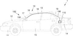
도 1은 일 실시예에 의한 차량의 차체를 도시한다.Figure 1 illustrates a body of a vehicle according to one embodiment.
도 1을 참조하면, 차량(1)은 사람 또는 화물을 운송할 목적으로 차륜을 구동시켜 주행하는 기기로, 도로 위를 이동한다. 차량(1)은 차량(1)의 외관을 형성하는 차체(10)와, 차체를 제외한 나머지 부분으로 주행에 필요한 기계 장치가 설치되는 차대(chassis)(미도시)와, 운전자를 보호하고 운전자에게 편의를 제공하는 전자 제어 장치를 포함한다.Referring to Fig. 1, a vehicle (1) is a machine that drives wheels for the purpose of transporting people or cargo and moves on a road. The vehicle (1) includes a body (10) that forms the exterior of the vehicle (1), a chassis (not shown) on which mechanical devices necessary for driving are installed as the remaining parts excluding the body, and an electronic control device that protects the driver and provides convenience to the driver.
도 1 에 도시된 바와 같이 차체(10)의 외장은 프론트 패널(11), 본네트(12), 루프 패널(13), 리어 패널(14), 전후좌우 도어(15) 등을 포함할 수 있다. 또한, 운전자의 시야를 확보하기 위하여, 차체(10)의 전방에는 프런트 윈도우(16)가 설치되고, 차체(10)의 측면에 사이드 윈도우(17)와 사이드 미러(wing mirror)(18)가 설치되고, 차체의 후방에는 리어 윈도우 (19)가 마련될 수 있다.As illustrated in FIG. 1, the exterior of the vehicle body (10) may include a front panel (11), a bonnet (12), a roof panel (13), a rear panel (14), front, left, and right doors (15), etc. In addition, in order to secure a driver's field of vision, a front window (16) may be installed at the front of the vehicle body (10), a side window (17) and a side mirror (18) may be installed at the side of the vehicle body (10), and a rear window (19) may be provided at the rear of the vehicle body.
차량(1)의 전자 제어 장치는 차량(1)의 각종 장치를 제어하고 운전자에게 편의를 제공하거나 운전자의 안전을 보장하는 것으로서, 예시적으로 엔진 관리 시스템(Engine Management System)과, 변속기 제어 유닛(Transmission Control Unit)과, 전자 제동 시스템(Electronic Braking System)과, 전동 조향 장치(Electric Power Steering)와, 차체 제어 모듈(body control module)과, 디스플레이 장치(display)와, 공기 조화 장치(heating/ventilation/air conditioning)와, 오디오 장치(audio), 텔레매틱스 장치(telematics unit) 중 적어도 어느 하나를 포함할 수 있다. 또한, 차량(1)의 전자 제어 장치는 무선 통신을 수행할 수 있는 차량용 고주파 통신 장치(100)를 포함할 수 있다. 이러한 차량용 고주파 통신 장치(100)는 텔레매틱스 장치의 일부로 이해될 수 있으나, 이에 한정되는 것은 아니다. 또한, 차량용 고주파 통신 장치(100)는 차량 출시전 장착되어 있는 장치일 수도 있고, 차량 출시 후 장착한 장치일 수도 있다.The electronic control unit of the vehicle (1) controls various devices of the vehicle (1) and provides convenience to the driver or ensures the safety of the driver, and may include at least one of an engine management system, a transmission control unit, an electronic braking system, an electric power steering, a body control module, a display device, a heating/ventilation/air conditioning device, an audio device, and a telematics unit, for example. In addition, the electronic control unit of the vehicle (1) may include a vehicle high-frequency communication device (100) capable of performing wireless communication. This vehicle high-frequency communication device (100) may be understood as a part of a telematics device, but is not limited thereto. In addition, the vehicle high-frequency communication device (100) may be a device installed before the vehicle is released, or may be a device installed after the vehicle is released.
일 실시예의 차량용 고주파 통신 장치(100)는 통신 모듈(communication module)(110)과, 안테나 모듈(antenna module)(190)과, 하나의 케이블(single cable)(190)을 포함할 수 있다.A vehicle high-frequency communication device (100) of one embodiment may include a communication module (110), an antenna module (190), and a single cable (190).
일 실시예의 통신 모듈(110)은 차체(10)의 뒷좌석 뒤쪽 공간에 배치될 수 있으나, 이에 제한되는 것은 아니다. 다른 예로, 통신 모듈(110)은 본네트(12)의 하부, 운전석 근방, 루프 패널(13) 근방 등에 배치될 수도 있다.In one embodiment, the communication module (110) may be placed in the space behind the rear seat of the vehicle body (10), but is not limited thereto. As another example, the communication module (110) may be placed in the lower part of the bonnet (12), near the driver's seat, near the roof panel (13), etc.
안테나 모듈(190)은 루프 패널(13), 프론트 윈도우(16), 사이드 미러(18), 리어 윈도우(190) 등에 배치될 수도 있다. 안테나 모듈(190)은 케이블(190)에 커넥터를 통하여 탈착가능하게 결합될 수 있다.The antenna module (190) may be placed on the roof panel (13), front window (16), side mirror (18), rear window (190), etc. The antenna module (190) may be detachably connected to the cable (190) through a connector.
일 실시예의 케이블(190)은 단일 케이블일 수 있다. 이러한 케이블(190)은 통신 모듈(110)과 안테나 모듈(190)를 전기적으로 연결하는 것으로서, 동축 케이블(coaxial cable)일 수 있다. 차량(1) 안에서 공간과 디자인 등의 문제로 통신 모듈(110)과 안테나 모듈(150) 사이의 거리는 수 미터 내외로 떨어져서 설치될 수 있으므로, 케이블(190)은 수 미터의 길이를 가질 수 있으나, 이에 제한되는 것은 아니다.The cable (190) of one embodiment may be a single cable. This cable (190) electrically connects the communication module (110) and the antenna module (190) and may be a coaxial cable. Since the distance between the communication module (110) and the antenna module (150) may be installed within several meters due to space and design issues within the vehicle (1), the cable (190) may have a length of several meters, but is not limited thereto.
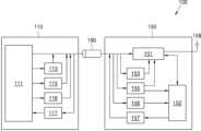
도 2는 일 실시예에 의한 차량용 고주파 통신 장치(100)의 블록도를 도시한다.FIG. 2 illustrates a block diagram of a vehicle high-frequency communication device (100) according to one embodiment.
도 2를 참조하면, 일 실시예의 차량용 고주파 통신 장치(100)는 통신 모듈(110)과 안테나 모듈(190)과, 하나의 케이블(190)을 포함할 수 있다.Referring to FIG. 2, a vehicle high-frequency communication device (100) of one embodiment may include a communication module (110), an antenna module (190), and one cable (190).
일 실시예의 통신 모듈(110)은 RF 회로(111)를 포함할 수 있다. RF 회로(111)는 RF 신호(112)를 처리하는 회로로서, 모뎀 회로와 RFIC, RFFE 등을 포함할 수 있다. 모뎀 회로는 예를 들어 5G, V2X 등의 통신을 하기 위한 회로일 수 있다. 통신 모듈(110)은 차량 내의 전자 제어 장치(예를 들어 텔레매틱 컨트롤 유닛(Telematic Control Unit, TCU))의 일부이거나, 전자 제어 장치의 프로세서(예를 들어 TCU의 어플리케이션 프로세서(Application Processor, AP))로부터 제어될 수 있다.The communication module (110) of one embodiment may include an RF circuit (111). The RF circuit (111) is a circuit that processes an RF signal (112) and may include a modem circuit, an RFIC, an RFFE, etc. The modem circuit may be a circuit for communication such as 5G, V2X, etc. The communication module (110) may be a part of an electronic control unit (e.g., a telematic control unit (TCU)) in a vehicle, or may be controlled from a processor of the electronic control unit (e.g., an application processor (AP) of the TCU).
일 실시예의 통신 모듈(110)에서 처리되는 RF 신호는 서로 다른 주파수나 또는 통신 방식이 서로 다른 RF 신호를 포함할 수도 있다.The RF signals processed in the communication module (110) of one embodiment may include RF signals with different frequencies or different communication methods.
일 실시예의 통신 모듈(110)은 RF 신호(112)의 송수신을 시간 분할 이중화(Time Division Duplexing, TDD) 방법으로 구분할 수 있다. RF 회로(111)는 송수신(TX/RX)을 구분하기 위하여 TX/RX 제어 신호를 출력할 수 있다. 가령, TX/RX 제어 신호 "1"은 송신 모드를 가르키며, TX/RX 제어 신호 "0"은 수신 모드를 가르킬 수 있다. TX/RX 제어 신호는 TX/RX 제어 신호 변조 회로(이하, 제1 변조 회로)(113)를 거쳐 소정 주파수의 교류(Alternating Current, AC) 신호로 변조되어 케이블(190)에 실린다. 제1 변조 회로(113)는 DC to AC 회로, 주파수 진동자(oscillator), 대역 통과 필터 등을 포함할 수 있다. 일 예로, DC to AC 회로는 TX/RX 제어 신호 "1"을 AC 신호로 변조한다. TX/RX 제어 신호 "0"은 DC to AC 회로를 거쳐 변조되더라도 AC 신호를 포함하지 않을 수 있다. 대역 통과 필터는 LC 필터등으로 구성될 수 있다. 변조된 TX/RX 제어 신호의 주파수는 송수신되는 RF 신호의 주파수와 다를 수 있다. 일 실시예에서 TX/RX 제어 신호의 변조는 RF 회로(111)에서 수행될 수도 있다.The communication module (110) of one embodiment can distinguish transmission and reception of an RF signal (112) by a time division duplexing (TDD) method. The RF circuit (111) can output a TX/RX control signal to distinguish transmission and reception (TX/RX). For example, the TX/RX control signal “1” can indicate a transmission mode, and the TX/RX control signal “0” can indicate a reception mode. The TX/RX control signal is modulated into an alternating current (AC) signal of a predetermined frequency through a TX/RX control signal modulation circuit (hereinafter, “first modulation circuit”) (113) and is then carried on a cable (190). The first modulation circuit (113) can include a DC to AC circuit, a frequency oscillator, a bandpass filter, and the like. As an example, the DC to AC circuit modulates the TX/RX control signal “1” into an AC signal. The TX/RX control signal "0" may not include an AC signal even if it is modulated through a DC to AC circuit. The bandpass filter may be composed of an LC filter, etc. The frequency of the modulated TX/RX control signal may be different from the frequency of the RF signal being transmitted and received. In one embodiment, the modulation of the TX/RX control signal may be performed in the RF circuit (111).
일 실시예의 통신 모듈(110)은 RF 신호(112)의 송수신을 주파수 분할 이중화(Frequency-Division Duplex, FDD) 방식을 이용하여 구분할 수도 있다. FDD 방식을 이용하는 경우, RF 신호(112)의 송신 주파수와 수신 주파수를 다르게 하며, 별도의 TX/RX 제어 신호를 사용하지 않을 수 있다.The communication module (110) of one embodiment may distinguish transmission and reception of RF signals (112) using a frequency division duplex (FDD) method. When using the FDD method, the transmission frequency and reception frequency of the RF signal (112) may be made different, and a separate TX/RX control signal may not be used.
일 실시예의 통신 모듈(110)은 전원 회로(115)을 더 포함할 수 있다. 일 실시예의 전원 회로(115)은 DC 전원을 공급할 수 있다. 전원 회로(115)은 차량(1)으로부터의 전원을 차량용 고주파 통신 장치(100)에서 요구되는 전압(예를 들어, 5V)으로 변환할 수 있다. 전원 회로(115)은 안테나 모듈(150)과 통신 모듈(110) 내의 각종 회로에 전력을 공급할 수 있다. 일 실시예의 전원 회로(115)는 일 예로 저손실 타입 리니어 레귤레이터(Low Dropout Linear Regulator, LDO)를 포함할 수 있다. RF 회로(111)에서 전원 회로(115)로 인에이블 신호를 전달하면 전원 회로(115)는 DC 전원을 공급한다.The communication module (110) of one embodiment may further include a power circuit (115). The power circuit (115) of one embodiment may supply DC power. The power circuit (115) may convert power from the vehicle (1) into a voltage (e.g., 5 V) required by the vehicle high-frequency communication device (100). The power circuit (115) may supply power to the antenna module (150) and various circuits within the communication module (110). The power circuit (115) of one embodiment may include, for example, a low dropout linear regulator (LDO). When an enable signal is transmitted from the RF circuit (111) to the power circuit (115), the power circuit (115) supplies DC power.
일 실시예에서 전원 회로(115)의 출력단에는 RF 신호가 전원 회로(115)에 유입되지 않도록 하는 RF 블록 필터가 더 마련될 수 있다. 이러한 RF 블록 필터는 일 예로 LC 필터등으로 이루어질 수 있다.In one embodiment, an RF block filter may be further provided at the output terminal of the power circuit (115) to prevent RF signals from being introduced into the power circuit (115). This RF block filter may be formed of, for example, an LC filter.
일 실시예에서 안테나 모듈(150)에 전원을 공급하는 전원 회로(115)은 통신 모듈(110)과 별도로 마련될 수도 있다.In one embodiment, the power circuit (115) that supplies power to the antenna module (150) may be provided separately from the communication module (110).
일 실시예의 통신 모듈(110)은 시리얼 통신 신호를 송수신하는 시리얼 통신 모듈을 포함할 수 있다. 시리얼 통신 모듈은 RF회로(211) 내에 마련되거나 또는 별도로 마련될 수 있다.A communication module (110) of one embodiment may include a serial communication module that transmits and receives serial communication signals. The serial communication module may be provided within the RF circuit (211) or may be provided separately.
일 실시예의 통신 모듈(110)은 UART(Universal asynchronous receiver/transmitter) 방식의 시리얼 통신 모듈을 사용할 수 있다. 예시적으로 RF 회로(111)에서 출력된 송신 시리얼 통신 신호(예를 들어, UART TXD)은 "0"과 "1"로 이루어진 디지털 신호일 수 있다. UART 방식은 송신을 위한 데이터선과 수신을 위한 데이터 선이 구분될 수 있다. 일 실시예의 통신 모듈(210)은 송신 시리얼 통신을 위한 송신 시리얼 통신 변조 회로(이하, 제2 변조 회로)(116)와, 수신 시리얼 통신을 위한 수신 시리얼 통신 복조 회로(이하, 제1 복조 회로)(117)를 포함할 수 있다.The communication module (110) of one embodiment may use a serial communication module of the UART (Universal asynchronous receiver/transmitter) method. For example, a transmission serial communication signal (e.g., UART TXD) output from the RF circuit (111) may be a digital signal consisting of “0” and “1”. In the UART method, a data line for transmission and a data line for reception may be distinguished. The communication module (210) of one embodiment may include a transmission serial communication modulation circuit (hereinafter, “second modulation circuit”) (116) for transmission serial communication, and a reception serial communication demodulation circuit (hereinafter, “first demodulation circuit”) (117) for reception serial communication.
일 실시예의 제2 변조 회로(116)는 DC to AC 회로, 주파수 진동자, 대역 통과 필터 등을 포함할 수 있다. 시리얼 통신 모듈에서 출력된 송신 시리얼 통신 신호(디지털 신호)는 제2 변조 회로(116)를 거쳐 AC 신호로 변조되고, 대역 통과 필터를 거쳐 케이블(190)에 실릴 수 있다. 송신 시리얼 통신 신호가 변조된 AC 신호의 주파수는 후술하는 수신 시리얼 통신 신호의 변조된 AC 신호의 주파수와 다를 수 있다. 즉, 제2 변조 회로(116)의 DC to AC 회로에 공급되는 주파수 진동자의 주파수 신호는 수신 시리얼 통신 신호의 변조된 AC 신호의 주파수와 다를 수 있다.The second modulation circuit (116) of one embodiment may include a DC to AC circuit, a frequency oscillator, a band-pass filter, etc. A transmission serial communication signal (digital signal) output from a serial communication module may be modulated into an AC signal through the second modulation circuit (116), and may be transmitted to a cable (190) through a band-pass filter. The frequency of the modulated AC signal of the transmission serial communication signal may be different from the frequency of the modulated AC signal of the reception serial communication signal described below. That is, the frequency signal of the frequency oscillator supplied to the DC to AC circuit of the second modulation circuit (116) may be different from the frequency of the modulated AC signal of the reception serial communication signal.
일 실시예의 제1 복조 회로(117)는 대역 통과 필터, AC to DC 회로, 등를 포함할 수 있다. 안테나 모듈(150)로부터 전송된 수신 시리얼 통신 신호는, 후술하는 바와 같이, 안테나 모듈(150)에서 AC 신호로 변조된 신호일 수 있다. 변조된 수신 시리얼 통신 신호는 대역 통과 필터(225)를 거쳐 AC to DC 회로에서 디지털 신호로 변환된다.The first demodulation circuit (117) of one embodiment may include a bandpass filter, an AC to DC circuit, etc. The received serial communication signal transmitted from the antenna module (150) may be a signal modulated into an AC signal in the antenna module (150), as described below. The modulated received serial communication signal passes through the bandpass filter (225) and is converted into a digital signal in the AC to DC circuit.
일 실시예의 통신 모듈(110)은 PCIE나 그밖의 공지의 시리얼 통신 방식의 모듈을 사용할 수도 있다.The communication module (110) of one embodiment may use a module of PCIE or other known serial communication method.
일 실시예의 송신 시리얼 통신 신호는 안테나 모듈(150)로 하여금 케이블(190)에서의 손실에 대한 보상 동작이나 셀프-캘리브레이션 동작을 수행하도록 하는 제어 명령을 포함할 수 있다.The transmit serial communication signal of one embodiment may include a control command that causes the antenna module (150) to perform a compensation operation for loss in the cable (190) or a self-calibration operation.
일 실시예의 송신 시리얼 통신 신호는 안테나 모듈(150)에서 구현되는 안테나 스위칭, 안테나 임피던스 변경, RF 파워 백오프(power back off), 안테나 진단 동작 등을 위한 제어 명령이나 데이터를 포함할 수 있다. 가령, 수신 시리얼 통신 신호는 안테나 모듈(150)의 보상 동작의 개시나 셀프-캘리브레이션 동작의 개시를 알리는 정보나 셀프-캘리브레이션을 수행한 결과에 대한 진단 메시지(diagnosis message)를 포함할 수 있다.The transmission serial communication signal of one embodiment may include control commands or data for antenna switching, antenna impedance change, RF power back off, antenna diagnostic operations, etc. implemented in the antenna module (150). For example, the reception serial communication signal may include information notifying the start of a compensation operation or a self-calibration operation of the antenna module (150), or a diagnosis message regarding the result of performing self-calibration.
안테나 모듈(150)은 무선 통신 외의 다른 기능을 수행하는 디바이스(예를 들어, 각종 센서, 램프, 하이패스 단말기, 등)의 시리얼 통신 인터페이스로 기능할 수도 있는바, 송신 시리얼 통신 신호는 상기 디바이스의 동작을 위한 제어 명령이나 데이터를 포함할 수 있다.The antenna module (150) may also function as a serial communication interface for devices that perform functions other than wireless communication (e.g., various sensors, lamps, high-pass terminals, etc.), and the transmitted serial communication signal may include a control command or data for the operation of the device.
일 실시예의 안테나 모듈(150)은 프로트 엔드 모듈(Front End Modue, FEM)(151)과, 제어기(152)과, 안테나(159)를 포함할 수 있다. 안테나(159)는 안테나 모듈(150)의 인쇄회로기판에 직접 설치되거나, 인쇄회로기판과 매우 짧은 케이블로 연결되어 있을 수 있다.An antenna module (150) of one embodiment may include a front end module (FEM) (151), a controller (152), and an antenna (159). The antenna (159) may be directly installed on a printed circuit board of the antenna module (150) or may be connected to the printed circuit board with a very short cable.
FEM(151)은 송수신되는 RF 신호를 증폭하거나 잡음을 제거하는 회로로서, 전치증폭기(Pre-Amplifier, PA), 저잡음 증폭기(Low Noise Amplifier, LNA)와 같은 증폭기를 포함할 수 있다.FEM (151) is a circuit that amplifies or removes noise from a transmitted and received RF signal, and may include an amplifier such as a pre-amplifier (PA) or a low noise amplifier (LNA).
일 실시예의 FEM(151)은 통신 모듈(110)의 제어에 의해 선택될 수 있는 복수의 게인 모드(gain mode)를 가지고 있을 수 있다. 예시적으로 복수의 게인 모드는 저출력 모드(low power mode)와 고출력 모드(high power mode)를 포함할 수 있다.The FEM (151) of one embodiment may have multiple gain modes that can be selected under the control of the communication module (110). For example, the multiple gain modes may include a low power mode and a high power mode.
일 실시예의 FEM(151)은 불량 검출이나 신호 보상을 위해 입력 또는 출력되는 RF 신호의 파워를 검출하는 검출회로를 더 포함할 수도 있다.The FEM (151) of one embodiment may further include a detection circuit for detecting the power of an input or output RF signal for defect detection or signal compensation.
송수신(TX/RX)의 구분을 위해 TDD 방식을 사용하는 경우, FEM(151)은 TX/RX 스위치를 포함할 수 있다. TX/RX 스위치는 예를 들어, SPDT (Single Pole Double Throw) 회로일 수 있다. TX/RX 스위치는 케이블(190)을 통해 전송된 TX/RX 제어 신호에 기초하여 송신 모드와 수신 모드를 전환한다.When using the TDD method for distinguishing transmission and reception (TX/RX), the FEM (151) may include a TX/RX switch. The TX/RX switch may be, for example, a Single Pole Double Throw (SPDT) circuit. The TX/RX switch switches between a transmission mode and a reception mode based on a TX/RX control signal transmitted through the cable (190).
일 실시예의 안테나 모듈(150)에서 송수신되는 RF 신호는 서로 다른 주파수나 또는 통신 방식이 서로 다른 RF 신호를 포함할 수 있는바, FEM(151)은 각각의 RF 신호마다 별도의 회로를 포함하거나, 또는 2종 이상의 RF 신호를 통합적으로 지원하는 회로를 포함할 수 있다.The RF signals transmitted and received from the antenna module (150) of one embodiment may include RF signals with different frequencies or different communication methods, and the FEM (151) may include a separate circuit for each RF signal, or may include a circuit that comprehensively supports two or more types of RF signals.
안테나 모듈(150)은 TX/RX 제어 신호의 복조를 위하여 통과 대역 필터, AC to DC 회로 등으로 구성된 TX/RX 제어 복조 회로(이하, 제2 복조 회로)(153)을 포함할 수 있다. 제2 복조 회로(153)의 통과 대역 필터는 통신 모듈(110)의 제1 변조 회로(113)에서 변조된 TX/RX 제어 신호의 주파수를 통과 대역으로 할 수 있다.The antenna module (150) may include a TX/RX control demodulation circuit (hereinafter, referred to as a second demodulation circuit) (153) composed of a pass band filter, an AC to DC circuit, etc., for demodulation of a TX/RX control signal. The pass band filter of the second demodulation circuit (153) may use the frequency of the TX/RX control signal modulated by the first modulation circuit (113) of the communication module (110) as a pass band.
케이블(190)을 통해 전송된 TX/RX 제어 신호는 소정 주파수의 AC 신호로 변조된 신호이므로, 제2 복조 회로(153)를 이용하여 원래의 디지털 신호로 복조한다.The TX/RX control signal transmitted through the cable (190) is a signal modulated into an AC signal of a predetermined frequency, so it is demodulated into the original digital signal using a second demodulation circuit (153).
송수신(TX/RX)의 구분을 위해 FDD 방식을 사용하는 경우, 일 실시예에서 TX/RX 스위치를 대신하여 듀플렉서(duplexer)가 사용될 수 있다.When using the FDD method to distinguish between transmission and reception (TX/RX), a duplexer may be used instead of a TX/RX switch in one embodiment.
일 실시예의 안테나 모듈(150)은 전원회로(155)를 포함할 수 있다. 전원 회로(155)는 캐퍼시터(capacitor)등을 포함하는 회로를 이용하여 케이블(190)을 통해 통신 모듈(110)로부터 전달되는 DC 전원을 RF 신호 및 송수신 시리얼 통신 신호와 분리할 수 있다. 전원 회로(155)는 케이블(190)을 통해 전달되는 DC 전원을 안테나 모듈(150)에서 요구되는 전압(예를 들어, 3.3V)으로 변환하여 안테나 모듈(150) 내의 각종 회로 및 소자에 공급할 수 있다. 일 실시예의 전원 회로(155)는 일 예로 저손실 타입 리니어 레귤레이터(LDO)를 포함할 수 있다. 케이블(190)과 전원 회로(155) 사이에는 RF 신호가 전원 회로(155)로 유입되지 않도록 하는 RF 블록 필터가 개재될 수 있다.An antenna module (150) of one embodiment may include a power circuit (155). The power circuit (155) may separate DC power transmitted from a communication module (110) through a cable (190) from an RF signal and a transmission/reception serial communication signal by using a circuit including a capacitor or the like. The power circuit (155) may convert the DC power transmitted through the cable (190) into a voltage (e.g., 3.3 V) required by the antenna module (150) and supply it to various circuits and elements within the antenna module (150). The power circuit (155) of one embodiment may include, for example, a low-loss type linear regulator (LDO). An RF block filter may be interposed between the cable (190) and the power circuit (155) to prevent an RF signal from being introduced into the power circuit (155).
일 실시예의 안테나 모듈(150)은 무선 통신 외의 다른 기능을 수행하는 디바이스를 포함하고 있을 수 있는바, 이러한 경우 전원 회로(155)는 무선 통신 외의 다른 기능을 수행하는 디바이스의 전원을 공급할 수도 있다.The antenna module (150) of one embodiment may include a device that performs functions other than wireless communication, in which case the power circuit (155) may supply power to the device that performs functions other than wireless communication.
제어기(152)는 마이크로 제어 유닛(Micro-Controller Unit, MCU)일 수 있다. 제어기(152)는 FEM(151)을 포함한 안테나 유닛(150)의 전반적인 동작을 제어한다. 일 실시예에서, 제어기(152)는 통신 모듈(270)의 제어나, 또는 자체적으로 불량 검출이나 신호 보상을 수행하도록 구성될 수도 있다.The controller (152) may be a micro-controller unit (MCU). The controller (152) controls the overall operation of the antenna unit (150) including the FEM (151). In one embodiment, the controller (152) may be configured to control the communication module (270) or to perform fault detection or signal compensation on its own.
일 실시예에서 통신 모듈(270)에서 케이블(290)을 통해 전송된 송신 시리얼 통신 신호는 송신 시리얼 통신 복조 회로(이하, 제3 복조 회로)(156)을 디지털 신호로 복조된다. 신호는 제3 복조 회로(156)는 송신 시리얼 통신 신호의 복조를 위하여 통과 대역 필터, AC to DC 회로 등으로 구성될 수 있다. 제3 복조 회로(156)의 통과 대역 필터는 통신 모듈(110)의 제2 변조 회로(116)에서 변조된 송신 시리얼 통신 신호의 주파수를 통과 대역으로 할 수 있다. 제3 복조 회로(156)에서 복조된 송신 시리얼 통신 신호는 제어기(152)로 입력된다.In one embodiment, a transmission serial communication signal transmitted from a communication module (270) through a cable (290) is demodulated into a digital signal by a transmission serial communication demodulation circuit (hereinafter, a third demodulation circuit) (156). The signal may be configured as a pass band filter, an AC to DC circuit, etc., for demodulation of the transmission serial communication signal. The pass band filter of the third demodulation circuit (156) may use the frequency of the transmission serial communication signal modulated by the second modulation circuit (116) of the communication module (110) as a pass band. The transmission serial communication signal demodulated by the third demodulation circuit (156) is input to the controller (152).
일 실시예의 제어기(152)는 통신 모듈(110)에서 전송한 송신 시리얼 통신 신호를 전달 받아 소정의 동작(예를 들어, 안테나 스위칭, 안테나 임피던스 변경, RF 파워 백오프, 안테나 진단 동작, 등)을 수행하도록 구성될 수 있다. 이를 위해 송신 시리얼 통신 신호는 안테나 스위칭, 안테나 임피던스 변경, RF 파워 백오프, 안테나 진단 동작 등을 위한 제어 명령이나 데이터를 포함할 수 있다. 예를 들어, 본 실시예의 고주파 통신 장치(100)가 블루투스 통신을 하는 경우, 블루투스 안테나를 차량(1)의 외부와 내부 사이에서 스위치 제어하는 등의 복잡한 동작이 요구되는 바, 제어기(152)가 통신 모듈(110)로부터 전송받은 송신 시리얼 통신 신호에 포함된 제어 명령에 따라 이러한 제어를 수행할 수 있을 것이다.The controller (152) of one embodiment may be configured to receive a transmission serial communication signal transmitted from the communication module (110) and perform a predetermined operation (e.g., antenna switching, antenna impedance change, RF power back-off, antenna diagnostic operation, etc.). To this end, the transmission serial communication signal may include a control command or data for antenna switching, antenna impedance change, RF power back-off, antenna diagnostic operation, etc. For example, when the high-frequency communication device (100) of the present embodiment performs Bluetooth communication, a complex operation such as switching control of a Bluetooth antenna between the outside and the inside of a vehicle (1) is required, and the controller (152) may perform such control according to a control command included in the transmission serial communication signal transmitted from the communication module (110).
일 실시예의 제어기(152)는 수신 시리얼 통신 신호를 출력하여 통신 모듈(110)로 전달할 수 있다. 수신 시리얼 통신 신호는 "0"과 "1"로 이루어진 디지털 신호이며, 수신 시리얼 통신 변조 회로(이하, 제3 변조 회로)(157)를 거쳐 소정 주파수의 AC 신호로 변조된다.The controller (152) of one embodiment can output a reception serial communication signal and transmit it to the communication module (110). The reception serial communication signal is a digital signal consisting of “0” and “1” and is modulated into an AC signal of a predetermined frequency through a reception serial communication modulation circuit (hereinafter, “third modulation circuit”) (157).
제3 변조 회로(157)는 DC to AC 회로, 주파수 진동자, 대역 통과 필터 등을 포함할 수 있다. 제어기(152)에서 출력된 수신 시리얼 통신 신호(디지털 신호)는 제3 변조 회로(157)를 거쳐 AC 신호로 변조되고, 대역 통과 필터를 거쳐 케이블(190)에 실릴 수 있다. 수신 시리얼 통신 신호가 변조된 AC 신호의 주파수는 전술한 송신 시리얼 통신 신호의 변조된 AC 신호의 주파수와 다를 수 있다. 즉, 제3 변조 회로(157)의 DC to AC 회로에 공급되는 주파수 진동자의 주파수 신호는 송신 시리얼 통신 신호의 변조된 AC 신호의 주파수와 다를 수 있다.The third modulation circuit (157) may include a DC to AC circuit, a frequency oscillator, a band-pass filter, etc. The reception serial communication signal (digital signal) output from the controller (152) is modulated into an AC signal through the third modulation circuit (157), and may be transmitted to a cable (190) through the band-pass filter. The frequency of the AC signal into which the reception serial communication signal is modulated may be different from the frequency of the modulated AC signal of the aforementioned transmission serial communication signal. That is, the frequency signal of the frequency oscillator supplied to the DC to AC circuit of the third modulation circuit (157) may be different from the frequency of the modulated AC signal of the transmission serial communication signal.
수신 시리얼 통신 신호(276)는 안테나 모듈(150)의 안테나 임피던스 정보, FEM(151)의 게인 정보, 안테나 진단 정보 등을 포함할 수 있다.The received serial communication signal (276) may include antenna impedance information of the antenna module (150), gain information of the FEM (151), antenna diagnostic information, etc.
일 실시예의 안테나 모듈(150)은 메모리(미도시)를 더 포함할 수 있다. 메모리는 안테나 동작과 관련된 데이터뿐만 아니라, 무선 통신 외의 다른 기능을 수행하는 디바이스의 제어와 관련된 데이터들을 저장할 수도 있다.The antenna module (150) of one embodiment may further include a memory (not shown). The memory may store data related to antenna operation as well as data related to control of a device performing other functions than wireless communication.
일 실시예의 케이블(190)은 동축 케이블일 수 있다. 동축 케이블은 단면이 동심원형 동축형인 전송 선로로서, 내부 도체와 외부 도체가 있으며 고주파 전압, 전류를 적은 손실로 전송한다. 내부 도체와 외부 도체의 위치를 기계적으로 바르게 하며 감쇠량을 적게 하기 위하여 폴리에틸렌이나 스테아타이트(steatite) 등의 절연물이 내부 도체와 외부 도체 사이에 개재될 수 있다.The cable (190) of one embodiment may be a coaxial cable. A coaxial cable is a transmission line with a concentric coaxial cross-section, has an inner conductor and an outer conductor, and transmits high-frequency voltage and current with little loss. In order to mechanically correct the positions of the inner conductor and the outer conductor and reduce the amount of attenuation, an insulating material such as polyethylene or steatite may be interposed between the inner conductor and the outer conductor.
케이블(190)을 통하여 송신 RF 신호, TX/RX 신호, 및 송신 시리얼 통신 신호가 통신 모듈(110)에서 안테나 모듈(150)로 전송될 수 있다. 또한 케이블(190)을 통하여 DC 전원이 통신 모듈(110)에서 안테나 모듈(150)로 전송될 수 있다. 케이블(190)을 통하여 수신 RF 신호와 수신 시리얼 통신 신호가 안테나 모듈(150)에서 통신 모듈(110)로 전송될 수 있다. 송수신되는 신호들은 모두 다른 주파수로 변조되어 케이블(190)에 실어 보내고 수신단에서 각 주파수에 맞는 대역 통과 필터(Band Pass Filter)를 이용하여 원하는 주파수의 신호만 받을 수 있도록 구성할 수 있다. 즉, 송수신되는 RF 신호의 주파수와, 변조된 TX/RX 제어 신호의 주파수와, 변조된 송신 시리얼 통신 신호의 주파수와, 변조된 수신 시리얼 통신 신호의 주파수는 모두 서로 다른 주파수 대역일 수 있다. 예시적으로, RF 신호의 주파수는 5.9GHHz 대역일 수 있다. 예시적으로 변조된 TX/RX 제어 신호의 주파수는 110MHz일 수 있다. 예시적으로 변조된 송신 시리얼 통신 신호의 주파수는 65MHz일 수 있다. 예시적으로 변조된 수신 시리얼 통신 신호의 주파수는 2MHz일 수 있다.Through the cable (190), a transmission RF signal, a TX/RX signal, and a transmission serial communication signal can be transmitted from the communication module (110) to the antenna module (150). In addition, DC power can be transmitted from the communication module (110) to the antenna module (150) through the cable (190). A reception RF signal and a reception serial communication signal can be transmitted from the antenna module (150) to the communication module (110) through the cable (190). All of the transmitted and received signals can be modulated to different frequencies and sent on the cable (190), and a band pass filter suitable for each frequency can be used at the receiving end to receive only signals of a desired frequency. That is, the frequency of the transmitted and received RF signal, the frequency of the modulated TX/RX control signal, the frequency of the modulated transmission serial communication signal, and the frequency of the modulated reception serial communication signal can all be different frequency bands. For example, the frequency of the RF signal can be a 5.9 GHz band. For example, the frequency of the modulated TX/RX control signal can be 110 MHz. For example, the frequency of the modulated transmit serial communication signal can be 65 MHz. For example, the frequency of the modulated receive serial communication signal can be 2 MHz.
일 실시예의 송신 시리얼 통신 신호는 무선 통신 외의 다른 기능을 수행하는 디바이스(예를 들어, 각종 센서, 램프, 하이패스 단말기, 등)의 동작을 위한 제어 명령이나 데이터를 포함하며, 수신 시리얼 통신 신호는 상기 디바이스 제어에 따른 각종 데이터를 포함할 수 있다. 제어기(152)는 상기 디바이스를 제어할 수 있으며, 이와 관련된 제어 명령이나 각종 데이터를 송수신 시리얼 통신 신호를 통해 통신 모듈(110)과 통신할 수 있다. 달리 말하면, 본 실시예의 안테나 모듈(150)은 무선 통신 외의 다른 기능을 수행하는 디바이스에 대한 시리얼 통신 인터페이스로 기능할 수도 있다.In one embodiment, a transmission serial communication signal includes a control command or data for the operation of a device (e.g., various sensors, lamps, Hi-pass terminals, etc.) that performs a function other than wireless communication, and a reception serial communication signal may include various data according to the control of the device. The controller (152) may control the device, and may communicate control commands or various data related thereto with the communication module (110) through the transmission/reception serial communication signals. In other words, the antenna module (150) of the present embodiment may also function as a serial communication interface for a device that performs a function other than wireless communication.
차량(1)에는 무선 통신 외에도 안정적인 주행을 위해 수 많은 차량용 디바이스들이 존재한다. 이러한 차량용 디바이스들의 안정적인 제어와 이들간의 통신을 위해서, RF 신호 및 디지털 신호 전달이 중요하다. 차량 내부의 케이블(190)을 이용해서 RF 신호를 수신 받는 안테나 모듈(150) 쪽과 다른 디바이스간의 RF 신호 및 디지털 신호의 전달이 필요한데, 1개의 케이블(190)로 RF 신호, DC 전원, 및 디바이스의 제어부(예를 들어, MCU, IC 등)의 제어를 위한 다양한 인터페이스(예를 들어, UART, PCIE 등)의 신호를 실어서 안테나 모듈(150)에서 독립적인 기능을 수행하게끔 할 수 있다.In addition to wireless communication, a vehicle (1) has numerous vehicle devices for stable driving. For stable control of these vehicle devices and communication between them, RF signal and digital signal transmission is important. It is necessary to transmit RF signals and digital signals between the antenna module (150) that receives RF signals using a cable (190) inside the vehicle and other devices. By carrying RF signals, DC power, and signals of various interfaces (e.g., UART, PCIE, etc.) for controlling the control unit (e.g., MCU, IC, etc.) of the device through a single cable (190), the antenna module (150) can perform independent functions.
다음으로, 고주파 통신 장치의 안테나 모듈이 설치되는 구체적인 예들을 가지고 설명하기로 한다.Next, we will explain specific examples of installing antenna modules of high-frequency communication devices.
도 3은 일 실시예에 의한 안테나 모듈(250)이 장착되는 예를 도시하며, 도 4는 도 3의 안테나 모듈을 포함한 차량용 고주파 통신 장치(200)의 블록도를 도시한다.FIG. 3 illustrates an example in which an antenna module (250) according to one embodiment is mounted, and FIG. 4 illustrates a block diagram of a vehicle high-frequency communication device (200) including the antenna module of FIG. 3.
도 3 및 도 4를 참조하면, 본 실시예의 차량용 고주파 통신 장치(200)는 통신 모듈(210)과, 안테나 모듈(250)과, 통신 모듈(210)과 안테나 모듈(250)을 연결하는 케이블(290)을 포함한다. 케이블(290)은 하나의 동축 케이블일 수 있다. 통신 모듈(210)과 안테나 모듈(250)의 구체적인 구성요소들 중 전술한 실시예와 중복되는 구성요소들에 대한 설명은 생략하기로 한다. 안테나 모듈(250)은 차량(1)의 사이드 윈도우(17)의 일측(A)에 장착될 수 있다.Referring to FIGS. 3 and 4, the vehicle high-frequency communication device (200) of the present embodiment includes a communication module (210), an antenna module (250), and a cable (290) connecting the communication module (210) and the antenna module (250). The cable (290) may be a single coaxial cable. Descriptions of specific components of the communication module (210) and the antenna module (250) that overlap with those of the above-described embodiment will be omitted. The antenna module (250) may be mounted on one side (A) of the side window (17) of the vehicle (1).
일 실시예에서 사이드 윈도우(17)에는 방향 지시등(광원 모듈)(258)이 마련되어 있다. 방향 지시등(광원 모듈)(258)은 LED(light emitting diode)나 램프와 같은 광원과, 상기 광원을 구동하는 광원 구동회로를 포함할 수 있다.In one embodiment, a side window (17) is provided with a turn signal light (light source module) (258). The turn signal light (light source module) (258) may include a light source such as an LED (light emitting diode) or a lamp, and a light source driving circuit for driving the light source.
안테나 모듈(250)은 무선 통신 기능을 수행할 뿐만 아니라, 방향 지시등(광원 모듈)에 대한 제어 인터페이스의 기능까지 수행할 수 있다. 안테나 모듈(250)은 방향 지시등(광원 모듈)(또는 방향 지시등의 구동회로)를 포함할 수 있다.The antenna module (250) may not only perform a wireless communication function, but may also perform the function of a control interface for a turn signal light (light source module). The antenna module (250) may include a turn signal light (light source module) (or a driving circuit for the turn signal light).
통신 모듈(210)은 차량(1)의 전자 제어 장치로부터 방향 지시등 제어 명령을 전달 받아, 안테나 모듈(250)로 전송한다. 방향 지시등 제어 명령은 도 2를 참조하여 설명한 바와 같이, 시리얼 통신을 AC 신호로 변조함으로써 통해 전달될 수 있다. 달리 말하면, 송신 시리얼 통신 신호는 방향 지시등 제어 명령을 포함할 수 있다.The communication module (210) receives a turn signal control command from the electronic control unit of the vehicle (1) and transmits it to the antenna module (250). The turn signal control command can be transmitted by modulating serial communication into an AC signal, as described with reference to FIG. 2. In other words, the transmitted serial communication signal can include the turn signal control command.
본 실시예의 사이드 윈도우(17)는 방향 지시등(258)을 포함하는 경우이나, 사이드 윈도우(17)에는 후방 카메라 및/또는 측면 카메라를 포함할 수도 있다. 이러한 경우, 안테나 모듈(250)은 후방 카메라 및/또는 측면 카메라를 포함하거나, 후방 카메라 및/또는 측면 카메라의 제어를 위한 시리얼 통신 인터페이스로 기능하도록 구성될 수도 있을 것이다.The side window (17) of the present embodiment includes a turn signal lamp (258), but the side window (17) may also include a rear camera and/or a side camera. In such a case, the antenna module (250) may include the rear camera and/or the side camera, or may be configured to function as a serial communication interface for controlling the rear camera and/or the side camera.
도 5는 일 실시예에 의한 안테나 모듈(350)이 장착되는 예를 도시하며, 도 6은 도 5의 안테나 모듈(350)을 포함한 차량용 고주파 통신 장치(300)의 블록도를 도시한다.FIG. 5 illustrates an example in which an antenna module (350) according to one embodiment is mounted, and FIG. 6 illustrates a block diagram of a vehicle high-frequency communication device (300) including the antenna module (350) of FIG. 5.
도 5 및 도 6을 참조하면, 본 실시예의 차량용 고주파 통신 장치(300)는 통신 모듈(310)과, 안테나 모듈(350)과, 통신 모듈(310)과 안테나 모듈(350)을 연결하는 케이블(390)을 포함한다. 케이블(390)은 하나의 동축 케이블일 수 있다.Referring to FIGS. 5 and 6, the vehicle high-frequency communication device (300) of the present embodiment includes a communication module (310), an antenna module (350), and a cable (390) connecting the communication module (310) and the antenna module (350). The cable (390) may be a single coaxial cable.
안테나 모듈(350)은 차량(1)의 프런트 윈도우(16)의 상단 영역(B)에 장착될 수 있다. 일 실시예에서 안테나 모듈(350)은 FEM(351)과, 제어기(352)과, 안테나(359)를 포함하여 무선 통신 기능을 수행할 수 있다. 나아가, 안테나 모듈(350)은 레인 센서(354), 하이패스 단말기 모듈(355), 레이더(radar) 모듈(357), 및 근접 센서(358) 중 적어도 어느 하나를 포함하거나, 이들에 대한 제어 인터페이스의 기능까지 수행할 수도 있다.The antenna module (350) may be mounted on the upper area (B) of the front window (16) of the vehicle (1). In one embodiment, the antenna module (350) may include a FEM (351), a controller (352), and an antenna (359) to perform a wireless communication function. Furthermore, the antenna module (350) may include at least one of a rain sensor (354), a high-pass terminal module (355), a radar module (357), and a proximity sensor (358), or may perform the function of a control interface for these.
일 실시예에서 레인 센서(354)는 프런트 윈도우(16)에 떨어지는 빗방울을 감지할 수 있다. 안테나 모듈(350)의 제어기(352)는 레인 센서(354)를 제어하며, 레인 센서(354)에서 감지된 빗방울에 대한 감지 정보를 통신 모듈(310)로 전달한다. 레인 센서(354)에 대한 제어 명령이나 빗방울에 대한 감지 정보는 도 2를 참조하여 설명한 바와 같이, 시리얼 통신을 AC 신호로 변조함으로써 하나의 케이블(390)을 통해 송수신될 수 있다. 달리 말하면, 송신 시리얼 통신 신호는 레인 센서(354)에 대한 제어 명령을 포함할 수 있으며, 수신 시리얼 통신 신호는 레인 센서(354)의 상태 정보와 빗방울 감지 정보를 포함할 수 있다.In one embodiment, the rain sensor (354) can detect raindrops falling on the front window (16). The controller (352) of the antenna module (350) controls the rain sensor (354) and transmits detection information on raindrops detected by the rain sensor (354) to the communication module (310). The control command for the rain sensor (354) or the detection information on raindrops can be transmitted and received through a single cable (390) by modulating serial communication into an AC signal, as described with reference to FIG. 2. In other words, the transmitted serial communication signal can include the control command for the rain sensor (354), and the received serial communication signal can include status information of the rain sensor (354) and raindrop detection information.
일 실시예에서 하이패스 단말기 모듈(355)은 적외선이나 RF 신호를 이용하여 요금소에 설치된 안테나와 무선 통신을 하여 요금을 전자 결제할 수 있는 장치이다. 하이패스 단말기 모듈(355)에 대한 제어명령이나 데이터는 시리얼 통신을 AC 신호로 변조함으로써 하나의 케이블(390)을 통해 통신 모듈(310)에 송수신될 수 있다. 달리 말하면, 송신 시리얼 통신 신호는 하이패스 단말기 모듈(355)의 제어명령을 포함할 수 있다. 수신 시리얼 통신 신호는 하이패스 단말기 모듈(355)의 상태 정보나 하이패스 결재 정보를 포함할 수 있다.In one embodiment, the Hi-pass terminal module (355) is a device that can electronically pay tolls by wirelessly communicating with an antenna installed at a toll booth using infrared or RF signals. Control commands or data for the Hi-pass terminal module (355) can be transmitted and received to and from the communication module (310) through a single cable (390) by modulating serial communication into an AC signal. In other words, the transmitted serial communication signal can include a control command of the Hi-pass terminal module (355). The received serial communication signal can include status information or Hi-pass payment information of the Hi-pass terminal module (355).
일 실시예에서 레이더 모듈(357)은 전자파를 방출하고 반사된 전자기파를 검출하는 센서를 포함하며, 센서에서 검출되는 신호로부터 도로상의 물체들을 감지하는 장치이다. 이러한 레이더 모듈(357)은 펄스 도플러 레이더, CW(continuous wave) 레이더, FMCW(frequency modulated continuous wave) 레이더, 다중 주파수 CW 레이더, 및 펄스 압축 레이더 중 어느 하나를 포함할 수 있다. 레이더 모듈(357)에 대한 제어명령이나 레이더 모듈(357)로부터 획득된 정보는 시리얼 통신을 AC 신호로 변조함으로써 하나의 케이블(390)을 통해 통신 모듈(310)에 송수신될 수 있다. 달리 말하면, 송신 시리얼 통신 신호는 레이더 모듈(357)에 대한 제어명령을 포함할 수 있다. 수신 시리얼 통신 신호는 레이더 모듈(357)의 상태 정보나 레이더 모듈(357)로부터 획득된 정보를 포함할 수 있다. 일 실시예의 안테나 모듈(250)은 레이더 모듈(357) 외에도 주행 중 도로 상황을 감지하는 장치로서, 소나(Sonar), 비전(Vision), 라이더(Lidar), 레이더(Radar) 센서 시스템 등을 더 포함할 수도 있다.In one embodiment, the radar module (357) includes a sensor that emits electromagnetic waves and detects reflected electromagnetic waves, and is a device that detects objects on the road from signals detected by the sensor. The radar module (357) may include any one of a pulse Doppler radar, a CW (continuous wave) radar, an FMCW (frequency modulated continuous wave) radar, a multi-frequency CW radar, and a pulse compression radar. A control command for the radar module (357) or information obtained from the radar module (357) may be transmitted and received to and from the communication module (310) through a single cable (390) by modulating serial communication into an AC signal. In other words, a transmitted serial communication signal may include a control command for the radar module (357). A received serial communication signal may include status information of the radar module (357) or information obtained from the radar module (357). The antenna module (250) of one embodiment may further include, in addition to the radar module (357), a sonar, vision, lidar, radar sensor system, etc., as a device for detecting road conditions during driving.
일 실시예에서 근접 센서(358)은 적외선이나 RF 신호를 이용하여 사람이나 물체가 차량(1)에 접근하는 것을 감지할 수 있는 장치이다. 근접 센서(358)에 대한 제어명령이나 근접 센서(358)로부터 획득된 정보는 시리얼 통신을 AC 신호로 변조함으로써 하나의 케이블(390)을 통해 통신 모듈(310)에 송수신될 수 있다. 달리 말하면, 송신 시리얼 통신 신호는 근접 센서(358)에 대한 제어명령을 포함할 수 있다. 수신 시리얼 통신 신호는 근접 센서(358)의 상태 정보나 근접 센서(358)로부터 획득된 정보를 포함할 수 있다.In one embodiment, the proximity sensor (358) is a device that can detect a person or an object approaching the vehicle (1) using an infrared or RF signal. A control command for the proximity sensor (358) or information obtained from the proximity sensor (358) can be transmitted and received to and from the communication module (310) through a single cable (390) by modulating serial communication into an AC signal. In other words, the transmitted serial communication signal can include a control command for the proximity sensor (358). The received serial communication signal can include status information of the proximity sensor (358) or information obtained from the proximity sensor (358).
상기와 같은 레인 센서(354), 하이패스 단말기 모듈(355), 레이더(radar) 모듈(357), 및 근접 센서(358)들은 차량(1)의 제어나 운전자의 편의를 위해 사용되는 디바이스들로서, 통신 모듈(310)은 차량(1) 내의 각종 전자 제어 장치와 통신하면서 전자 제어 장치로부터 제어정보를 전달받고 상기 디바이스들로부터 전달받은 데이터들을 전달할 수 있을 것이다.The above-described rain sensor (354), high-pass terminal module (355), radar module (357), and proximity sensor (358) are devices used for controlling the vehicle (1) or for the convenience of the driver. The communication module (310) may communicate with various electronic control devices within the vehicle (1), receive control information from the electronic control devices, and transmit data received from the devices.
도 3 내지 도 6을 참조한 실시예들은 안테나 모듈(250, 350)이 설치되는 예들로서, 이에 제한되는 것은 아니다. 가령, 안테나 모듈은 차량(1)의 프론트 패널(11)이나, 루프 패널(13)이나, 리어 패널(14)이나, 리어 윈도우 (19)에 설칠될 수도 있다.The embodiments referring to FIGS. 3 to 6 are examples in which the antenna module (250, 350) is installed, but are not limited thereto. For example, the antenna module may be installed on the front panel (11), the roof panel (13), the rear panel (14), or the rear window (19) of the vehicle (1).
도 7은 일 실시예에 의한 고주파 통신 장치(400)의 블록도를 도시한다.Figure 7 illustrates a block diagram of a high-frequency communication device (400) according to one embodiment.
도 7을 참조하면, 고주파 통신 장치(400)는 복수의 RF 신호들을 송수신하는 장치로서, 통신 모듈(410)과, 안테나 모듈(450)과, 하나의 케이블(490)을 포함한다. 본 실시예의 고주파 통신 장치(400)에서 도 2에서 참조한 고주파 통신 장치(100)와 중복되는 부분에 대한 상세한 설명은 생략하기로 한다.Referring to FIG. 7, a high-frequency communication device (400) is a device that transmits and receives a plurality of RF signals, and includes a communication module (410), an antenna module (450), and a cable (490). A detailed description of the overlapping portions of the high-frequency communication device (400) of the present embodiment with the high-frequency communication device (100) referenced in FIG. 2 will be omitted.
통신 모듈(410)은 송수신되는 복수의 RF 신호들을 처리한다.The communication module (410) processes multiple RF signals to be transmitted and received.
일 실시예의 통신 모듈(410)에서 처리되는 RF 신호는 V2X 통신을 위한 신호, 4G, 5G 등의 이동통신에서 사용되는 신호, 블루투스, WIfi 등의 근거리 통신에서 사용되는 신호, 위성 디지털 라디오 서비스(Satellite Digital Audio Radio Service, SDARS)에서 사용되는 신호, GPS(Global Positioning System) 신호 등을 포함할 수 있다.The RF signal processed in the communication module (410) of one embodiment may include a signal for V2X communication, a signal used in mobile communications such as 4G and 5G, a signal used in short-distance communications such as Bluetooth and Wi-Fi, a signal used in Satellite Digital Audio Radio Service (SDARS), a GPS (Global Positioning System) signal, etc.
일 실시예의 통신 모듈(410)에서는 서로 다른 주파수나 또는 통신 방식이 서로 다른 RF 신호를 송수신하기 위하여, 각각의 RF 신호 또는 둘 이상의 RF 신호를 통합적으로 지원하는 FE(Front End) 회로들을 포함할 수 있다.In one embodiment, the communication module (410) may include FE (Front End) circuits that comprehensively support each RF signal or two or more RF signals in order to transmit and receive RF signals having different frequencies or different communication methods.
일 실시예의 안테나 모듈(450)의 FE 회로는 LET 모듈(452), BLE 모듈(455), WiFi/BT 모듈(457), V2X 모듈(459), GPS 모듈(462), SDARS 모듈(463)을 포함할 수 있다.The FE circuit of the antenna module (450) of one embodiment may include an LET module (452), a BLE module (455), a WiFi/BT module (457), a V2X module (459), a GPS module (462), and an SDARS module (463).
일 실시예의 안테나 모듈(450)은 서로 다른 주파수나 또는 통신 방식이 서로 다른 RF 신호에 대응되는 복수의 안테나들(V2X1, V2X2, GPS, SDARS, LET1, LTE2, LTE3, LTE4, BLE1, BLE2, BT, WiFi1, WiFi2)를 포함할 수 있다. 이들 안테나들 중 일부(BLE2)는 안테나 모듈(450)의 회로기판(464)에 직접 설치되고, 다른 일부(V2X1, V2X2, GPS, SDARS, LET1, LTE2, LTE3, LTE4, BLE1, BT, WiFi1, WiFi2)는 별도의 안테나 하우징(465)에 설치되거나 기타 다른 곳에 설치되어 회로기판(464)에 매우 짧은 안테나 케이블로 연결될 수 있다. 여기서 안테나 케이블이 매우 짧다는 것은 안테나 케이블을 통한 고주파 신호의 손실을 무시할 수 있을 정도로 짧은 거리로서, 수 밀리미터, 수 센티미터 혹은 수십 센티미터의 길이 의미할 수 있다. 복수의 안테나들 중 일부(가령, BLE2, BT, WiFi1)는 차체 내부에서의 무선 통신에 사용될 수도 있다.An antenna module (450) of one embodiment may include a plurality of antennas (V2X1, V2X2, GPS, SDARS, LET1, LTE2, LTE3, LTE4, BLE1, BLE2, BT, WiFi1, WiFi2) corresponding to RF signals having different frequencies or different communication methods. Some of these antennas (BLE2) are directly installed on a circuit board (464) of the antenna module (450), and other some (V2X1, V2X2, GPS, SDARS, LET1, LTE2, LTE3, LTE4, BLE1, BT, WiFi1, WiFi2) may be installed in a separate antenna housing (465) or installed elsewhere and connected to the circuit board (464) with a very short antenna cable. Here, a very short antenna cable means a short distance that is short enough to ignore loss of a high-frequency signal through the antenna cable, and may mean a length of several millimeters, several centimeters, or several tens of centimeters. Some of the multiple antennas (e.g. BLE2, BT, WiFi1) may also be used for wireless communications inside the vehicle.
일 실시예의 안테나 모듈(450)은 서로 다른 주파수나 또는 통신 방식이 서로 다른 RF 신호를 분리하기 위하여 듀플렉서 필터(460)나, SPDT 스위치(454, 456, 458)나, DPDT(Double Pole Double Throw) 스위치(453)나, 다이-플렉서(Di-Plexer)를 포함할 수 있다.An antenna module (450) of one embodiment may include a duplexer filter (460), an SPDT switch (454, 456, 458), a DPDT (Double Pole Double Throw) switch (453), or a diplexer to separate RF signals having different frequencies or different communication methods.
일 실시예의 안테나 모듈(450)은 LTE(Long-Term Evolution) 모듈(452)을 포함할 수 있다. LTE 모듈(452)은 이동통신 모듈을 나타내기 위한 예시적인 것으로서, 4G나 5G 모듈이 더 있을 수 있다. LTE 통신에는 하나 혹은 복수의 안테나가 사용될 수 있다. 도 7은 4개의 안테나들(LET1, LTE2, LTE3, LTE4)이 LTE 통신을 위해 사용되는 예가 도시되어 있다.An antenna module (450) of one embodiment may include an LTE (Long-Term Evolution) module (452). The LTE module (452) is an example for representing a mobile communication module, and there may be additional 4G or 5G modules. One or more antennas may be used for LTE communication. FIG. 7 illustrates an example in which four antennas (LET1, LTE2, LTE3, LTE4) are used for LTE communication.
일 실시예의 안테나 모듈(450)은 BLE 모듈(455)을 포함할 수 있다. BLE 모듈(455)는 블루투스 저전력(Bluetooth Low Energy, BLE) 통신을 수행하며, 하나 혹은 복수의 안테나가 사용될 수 있다. 도 7은 2개의 안테나들(BLE1, BLE2)이 BLE 통신을 위해 사용되는 예가 도시되어 있다.An antenna module (450) of one embodiment may include a BLE module (455). The BLE module (455) performs Bluetooth Low Energy (BLE) communication, and one or more antennas may be used. FIG. 7 illustrates an example in which two antennas (BLE1, BLE2) are used for BLE communication.
일 실시예의 안테나 모듈(450)은 WiFi/BT 모듈(451)을 포함할 수 있다. WiFi/BT 모듈(451)은 WiFi 통신과 블루투스(Bluetooth, BT) 통신을 지원하는 통합 모듈로서, 예시적으로 BT용의 안테나(BT)와 WiFi용의 2개의 안테나(WiFi1, WiFi2)와 연결될 수 있다.An antenna module (450) of one embodiment may include a WiFi/BT module (451). The WiFi/BT module (451) is an integrated module that supports WiFi communication and Bluetooth (BT) communication, and may be connected to, for example, an antenna for BT (BT) and two antennas for WiFi (WiFi1, WiFi2).
일 실시예의 안테나 모듈(450)은 V2X 모듈(459)을 포함할 수 있다. V2X 모듈(459)은 은 하나 혹은 복수의 안테나가 사용될 수 있다. 도 7은 2개의 안테나들(V2X1, V2X2)이 V2X 통신을 위해 사용되는 예가 도시되어 있다.An antenna module (450) of one embodiment may include a V2X module (459). The V2X module (459) may use one or more antennas. FIG. 7 illustrates an example in which two antennas (V2X1, V2X2) are used for V2X communication.
일 실시예의 안테나 모듈(450)은 GPS 모듈(462)과 SDARS 모듈(463)을 포함할 수 있다. GPS 모듈(462)과 SDARS 모듈(463)은 각각 GPS용 안테나(GPS)와, SDARS용 안테나와 연결될 수 있다.An antenna module (450) of one embodiment may include a GPS module (462) and an SDARS module (463). The GPS module (462) and the SDARS module (463) may be connected to an antenna for GPS (GPS) and an antenna for SDARS, respectively.
일 실시예에서, 일부 통신은 다른 방식들의 통신과 결합되어 사용될 수 있다. 가령, 통신망의 상태에 따라서 LTE 통신과 BLE 통신과 WiFi 통신은 서로 전환될 수 있다. 이를 위해, LTE 통신을 위해 사용되는 안테나들(LTE1, LTE2, LTE3, LTE4) 중 일부(LTE 3, LTE4)의 선로들과 다른 통신용 안테나(가령, BLE1, BLE2)의 선로들은 제어기(451)의 제어에 따른 DPDT 스위치(453)와 SPDT 스위치(454, 458)의 스위칭 동작에 의해 선택적으로 연결되도록 구성될 수 있다.In one embodiment, some of the communications may be combined with other types of communications. For example, depending on the state of the communication network, LTE communications, BLE communications, and WiFi communications may be switched among each other. To this end, some of the antennas (LTE 3, LTE4) used for LTE communications and the lines of other communication antennas (e.g., BLE1, BLE2) may be configured to be selectively connected by the switching operation of the DPDT switch (453) and the SPDT switches (454, 458) under the control of the controller (451).
일 실시예에서, 차량(1)의 내부에서도 무선 통신이 이루어질 수 있다. 가령, BLE/BT 통신에서 안테나 BLE1, BLE2, BT는 차량(1)의 외부와 내부 사이에서 제어기(451)의 제어에 따라 스위칭될 수 있다.In one embodiment, wireless communication can also be performed inside the vehicle (1). For example, in BLE/BT communication, antennas BLE1, BLE2, and BT can be switched between the outside and inside of the vehicle (1) under the control of the controller (451).
일 실시예에서, 일부 안테나(가령, GPS, SDARS)는 공용의 안테나 케이블을 통해 회로기판(464)에 연결되고, 듀플렉서 필터(460)에 의해 GPS 모듈(462)과 SDARS 모듈(463)로 분기될 수 있다.In one embodiment, some antennas (e.g., GPS, SDARS) may be connected to the circuit board (464) via a common antenna cable and branched to the GPS module (462) and the SDARS module (463) by a duplexer filter (460).
상기와 같이 안테나 모듈(450)은 서로 다른 주파수나 또는 통신 방식이 서로 다른 RF 신호를 송수신하기 위하여 복수의 안테나들과 이들을 지원하는 FE 회로들을 제어하는 제어기(451)를 포함할 수 있다. 제어기(451)는, 복수의 안테나들 및 FE 회로들 사이의 복잡한 스위칭 뿐만 아니라, 긴급 호출 시스템(E-Call) 용 백업 안테나 스위칭(Backup Antenna switching)이나 및 SAR (Specific Absorption Rate) 백-오프와 같은 복잡한 기능도 수행하도록 구성될 수 있다.As described above, the antenna module (450) may include a controller (451) that controls a plurality of antennas and FE circuits supporting them in order to transmit and receive RF signals having different frequencies or different communication methods. The controller (451) may be configured to perform not only complex switching between the plurality of antennas and FE circuits, but also complex functions such as backup antenna switching for an emergency call system (E-Call) and SAR (Specific Absorption Rate) back-off.
개시된 고주파 통신 장치(100, 200, 300, 400)는 하나의 케이블(190)만을 사용하면서 안테나 모듈(150) 자체의 각종 제어나 무선 통신 외의 다른 기능을 수행하는 디바이스의 제어를 가능하게 하므로, 차량 제조사는 추가되는 케이블에 의한 비용 발생을 줄이며 케이블 추가로 인한 디자인이나 공간 설계의 제약 문제를 해결할 수 있다.The disclosed high-frequency communication device (100, 200, 300, 400) enables control of various functions of the antenna module (150) itself or of a device performing other functions than wireless communication by using only one cable (190), so that vehicle manufacturers can reduce costs incurred due to additional cables and resolve design or space design constraints due to additional cables.
전술한 본 발명인 차량용 고주파 통신 장치는 이해를 돕기 위하여 도면에 도시된 실시예를 참고로 설명되었으나, 이는 예시적인 것에 불과하며, 당해 분야에서 통상적 지식을 가진 자라면 이로부터 다양한 변형 및 균등한 타 실시예가 가능하다는 점을 이해할 것이다. 따라서, 본 발명의 진정한 기술적 보호 범위는 첨부된 특허청구범위에 의해 정해져야 할 것이다.The above-described vehicle high-frequency communication device of the present invention has been described with reference to the embodiments illustrated in the drawings to help understanding, but these are merely exemplary, and those with ordinary knowledge in the relevant field will understand that various modifications and equivalent other embodiments are possible from this. Therefore, the true technical protection scope of the present invention should be determined by the appended patent claims.
1: 차량10: 차체
100, 200, 300, 400: 고주파 통신 장치
110, 210, 310, 410: 통신 모듈
111: RF 회로113, 116, 157: 변조 회로
115, 155: 전원 회로117, 153, 156: 복조 회로
150, 250, 350, 450: 안테나 모듈
151, 251, 351, 452, 455, 457, 459, 462, 463: FEM
152, 252, 352,452: 제어기
159, 259, 359, , V2X2, GPS, SDARS, LET1, LTE2, LTE3, LTE4, BLE1, BLE2, BT, WiFi1, WiFi2: 안테나
258: 방향 지시등(광원 모듈)190, 290, 390, 490: 케이블1: Vehicle 10: Body
100, 200, 300, 400: High frequency communication devices
110, 210, 310, 410: Communication Module
111:
115, 155:
150, 250, 350, 450: Antenna Module
151, 251, 351, 452, 455, 457, 459, 462, 463: FEM
152, 252, 352,452: Controller
159, 259, 359, , V2X2, GPS, SDARS, LET1, LTE2, LTE3, LTE4, BLE1, BLE2, BT, WiFi1, WiFi2: Antennas
258: Turn signal light (light source module) 190, 290, 390, 490: Cable
Claims (10)
Translated fromKorean하나의 케이블;
상기 케이블의 일단에 연결되며, 상기 케이블에 제1 주파수 대역의 알에프(RF) 신호와, 송신 시리얼 통신 신호를 전송하도록 구성되되, 송신 시리얼 통신 신호를 제1 디지털 신호에서 상기 제1 주파수 대역과 다른 제2 주파수 대역의 제1 교류 신호로 변조하는 송신 시리얼 통신 변조 회로와, 상기 케이블을 통해 수신되는 변조된 수신 시리얼 통신 신호를 제2 디지털 신호로 복조하는 수신 시리얼 통신 복조 회로를 포함하는 통신 모듈; 및
상기 단일 케이블의 타단에 연결되며, 상기 알에프 신호와, 상기 송신 시리얼 통신 신호를 전송받아 주파수 대역별로 분기되도록 구성되되, 상기 알에프 신호를 처리하는 프론트 엔드 모듈과, 상기 송신 시리얼 통신 신호를 상기 제1 교류 신호에서 상기 제1 디지털 신호로 복조하는 송신 시리얼 통신 복조 회로와, 복조된 송신 시리얼 통신 신호를 전달받아 상기 프론트 엔드 모듈을 제어하고 수신 시리얼 통신 신호를 출력하는 제어기와, 수신 시리얼 통신 신호를 상기 제1 주파수 대역 및 상기 제2 주파수 대역과 다른 제3 주파수 대역의 제2 교류 신호로 변조하는 수신 시리얼 통신 변조 회로를 포함하는 안테나 모듈;을 포함하는 차량용 고주파 통신 장치.In a vehicle high-frequency communication device using a single cable,
one cable;
A communication module connected to one end of the cable and configured to transmit an RF signal of a first frequency band and a transmission serial communication signal to the cable, the communication module including a transmission serial communication modulation circuit that modulates the transmission serial communication signal from a first digital signal to a first AC signal of a second frequency band different from the first frequency band, and a reception serial communication demodulation circuit that demodulates the modulated reception serial communication signal received through the cable into a second digital signal; and
A vehicle high-frequency communication device comprising: an antenna module connected to the other end of the single cable and configured to receive the RF signal and the transmission serial communication signal and branch them by frequency band, the antenna module comprising: a front-end module for processing the RF signal; a transmission serial communication demodulation circuit for demodulating the transmission serial communication signal from the first AC signal to the first digital signal; a controller for receiving the demodulated transmission serial communication signal, controlling the front-end module, and outputting a reception serial communication signal; and a reception serial communication modulation circuit for modulating the reception serial communication signal into a second AC signal of a third frequency band different from the first frequency band and the second frequency band.
상기 알에프 신호는 시간 분할 이중화 방식 또는 주파수 분할 이중화 방식으로 송수신되는 차량용 고주파 통신 장치.In the first paragraph,
The above RF signal is a vehicle high-frequency communication device that transmits and receives in a time division duplex method or a frequency division duplex method.
상기 통신 모듈은 알에프 신호의 송수신 모드를 제어하는 TX/RX 제어 신호를 제3 디지털 신호에서 제3 교류 신호로 변조하되, 상기 제3 교류 신호 주파수 대역인 제4 주파수 대역은 상기 제1 주파수 대역, 상기 제2 주파수 대역 및 상기 제3 주파수 대역과 다른 TX/RX 제어 신호 변조 회로를 더 포함하며,
상기 안테나 모듈은 전송된 TX/RX 제어 신호를 상기 제3 교류 신호에서 상기 제3 디지털 신호로 복조하는 TX/RX 제어 신호 복조 회로를 더 포함하는 차량용 고주파 통신 장치.In the first paragraph,
The above communication module further includes a TX/RX control signal modulation circuit that modulates a TX/RX control signal controlling a transmission/reception mode of an RF signal from a third digital signal to a third AC signal, wherein a fourth frequency band, which is a frequency band of the third AC signal, is different from the first frequency band, the second frequency band, and the third frequency band.
A vehicle high-frequency communication device, wherein the antenna module further includes a TX/RX control signal demodulation circuit that demodulates the transmitted TX/RX control signal from the third AC signal to the third digital signal.
상기 통신 모듈은 상기 케이블을 통해 상기 안테나 모듈에 전원을 공급하는 전원 회로를 더 포함하는 차량용 고주파 통신 장치.In the first paragraph,
A vehicle high-frequency communication device, wherein the communication module further includes a power circuit that supplies power to the antenna module through the cable.
상기 안테나 모듈은 무선 통신 외의 다른 기능을 수행하는 디바이스 및 상기 디바이스의 제어를 위한 시리얼 통신 인터페이스를 포함하며, 상기 송수신되는 시리얼 통신 신호는 상기 디바이스에 대한 제어 명령이나 데이터를 포함하는 차량용 고주파 통신 장치.In the first paragraph,
A vehicle high-frequency communication device, wherein the antenna module includes a device performing a function other than wireless communication and a serial communication interface for controlling the device, and the serial communication signals transmitted and received include control commands or data for the device.
상기 안테나 모듈은 사이드 미러에 장착되며, 상기 디바이스는 방향 지시등인 차량용 고주파 통신 장치.In clause 5,
The above antenna module is mounted on a side mirror, and the device is a vehicle high-frequency communication device that is a turn signal.
상기 안테나 모듈은 프론트 윈도우에 장착되며, 상기 디바이스는 레인 센서, 하이패스 단말기 모듈, 레이더 모듈, 및 근접 센서 중 적어도 어느 하나를 포함하는 차량용 고주파 통신 장치.In clause 5,
The above antenna module is mounted on the front window, and the device is a vehicle high-frequency communication device including at least one of a rain sensor, a high-pass terminal module, a radar module, and a proximity sensor.
상기 통신 모듈은 서로 다른 주파수나 또는 통신 방식이 서로 다른 복수의 RF 신호들을 송수신하며,
상기 안테나 모듈은 상기 복수의 RF 신호들에 대응되는 복수의 안테나 및 복수의 프론트 엔드 회로들을 포함하며, 상기 제어기는 상기 복수의 안테나 및 상기 복수의 프론트 엔드 회로들을 제어하는 차량용 고주파 통신 장치.In the first paragraph,
The above communication module transmits and receives multiple RF signals having different frequencies or different communication methods.
A vehicle high-frequency communication device, wherein the antenna module includes a plurality of antennas and a plurality of front-end circuits corresponding to the plurality of RF signals, and the controller controls the plurality of antennas and the plurality of front-end circuits.
상기 복수의 RF 신호들은 V2X 통신 신호, 이동통신 신호, 근거리 통신 신호, 위성 디지털 라디오 서비스(SDARS) 신호, 및 GPS 신호 중 적어도 어느 하나를 포함하는 차량용 고주파 통신 장치.In Article 8,
A vehicle radio frequency communication device, wherein the plurality of RF signals include at least one of a V2X communication signal, a mobile communication signal, a short-range communication signal, a satellite digital radio service (SDARS) signal, and a GPS signal.
상기 케이블은 하나의 동축 케이블인 차량용 고주파 통신 장치.In the first paragraph,
The above cable is a high-frequency communication device for vehicles, which is a single coaxial cable.
Priority Applications (5)
| Application Number | Priority Date | Filing Date | Title |
|---|---|---|---|
| KR1020190146952AKR102770884B1 (en) | 2019-11-15 | 2019-11-15 | Apparatus RF communication in vehicle |
| CN202080079202.3ACN114731172B (en) | 2019-11-15 | 2020-11-16 | High-frequency communication device for vehicle |
| PCT/KR2020/016061WO2021096321A1 (en) | 2019-11-15 | 2020-11-16 | High frequency communication apparatus for vehicle |
| US17/098,515US11336322B2 (en) | 2019-11-15 | 2020-11-16 | High frequency communication apparatus for vehicle |
| EP20207828.3AEP3823172B1 (en) | 2019-11-15 | 2020-11-16 | High frequency communication apparatus for vehicle |
Applications Claiming Priority (1)
| Application Number | Priority Date | Filing Date | Title |
|---|---|---|---|
| KR1020190146952AKR102770884B1 (en) | 2019-11-15 | 2019-11-15 | Apparatus RF communication in vehicle |
Publications (2)
| Publication Number | Publication Date |
|---|---|
| KR20210059465A KR20210059465A (en) | 2021-05-25 |
| KR102770884B1true KR102770884B1 (en) | 2025-02-24 |
Family
ID=73452091
Family Applications (1)
| Application Number | Title | Priority Date | Filing Date |
|---|---|---|---|
| KR1020190146952AActiveKR102770884B1 (en) | 2019-11-15 | 2019-11-15 | Apparatus RF communication in vehicle |
Country Status (5)
| Country | Link |
|---|---|
| US (1) | US11336322B2 (en) |
| EP (1) | EP3823172B1 (en) |
| KR (1) | KR102770884B1 (en) |
| CN (1) | CN114731172B (en) |
| WO (1) | WO2021096321A1 (en) |
Families Citing this family (5)
| Publication number | Priority date | Publication date | Assignee | Title |
|---|---|---|---|---|
| US12095522B2 (en) | 2021-06-25 | 2024-09-17 | Molex Cvs Hildesheim Gmbh | Modulation of supply current in active antenna systems |
| US12294400B2 (en)* | 2021-12-03 | 2025-05-06 | Qualcomm Incorporated | Controlling remote antenna systems |
| US12132529B2 (en) | 2021-12-03 | 2024-10-29 | Qualcomm Incorporated | Remote device control |
| US12266865B2 (en)* | 2022-09-08 | 2025-04-01 | Motional Ad Llc | Wavelength based V2X antenna |
| CN116054871A (en)* | 2022-09-27 | 2023-05-02 | 锐凌无线有限责任公司 | Wireless communication module, antenna switching system and method |
Citations (3)
| Publication number | Priority date | Publication date | Assignee | Title |
|---|---|---|---|---|
| US20120328057A1 (en) | 2011-06-21 | 2012-12-27 | Ibiquity Digital Corporation | Method and apparatus for implementing signal quality metrics and antenna diversity switching control |
| US20150038185A1 (en)* | 2012-03-23 | 2015-02-05 | Corning Optical Communications Wireless Ltd | Radio-frequency integrated circuit (rfic) chip(s) for providing distributed antenna system functionalities, and related components, systems, and methods |
| WO2016131053A1 (en)* | 2015-02-13 | 2016-08-18 | Sirius Xm Radio Inc. | Digital antenna with multiple integrated transceivers |
Family Cites Families (11)
| Publication number | Priority date | Publication date | Assignee | Title |
|---|---|---|---|---|
| KR101360506B1 (en)* | 2008-11-20 | 2014-02-10 | 현대자동차주식회사 | Unity Antenna for car |
| KR101686432B1 (en)* | 2010-06-29 | 2016-12-15 | 삼성전자주식회사 | Method and apparatus for controlling multi band antenna in mobile communication temianl |
| WO2013030633A2 (en) | 2011-09-02 | 2013-03-07 | Autotalks Ltd. | Remote antenna unit with external power control using a single control line |
| WO2013088393A1 (en)* | 2011-12-14 | 2013-06-20 | Redline Communications Inc. | Single channel full duplex wireless communication |
| WO2013121241A1 (en)* | 2012-02-17 | 2013-08-22 | Sony Ericsson Mobile Communications Ab | Wireless communications devices configured for multiple radio access technologies and related methods and systems |
| US9838069B2 (en)* | 2013-10-30 | 2017-12-05 | Netgear, Inc. | Radio frequency front end module with high band selectivity |
| DE102014113456B4 (en)* | 2014-09-18 | 2019-03-14 | Infineon Technologies Ag | SENSOR DEVICE AND SENSOR ARRANGEMENT |
| KR102139764B1 (en)* | 2015-09-21 | 2020-07-31 | 삼성전기주식회사 | Communication module and front-end module included thereof |
| KR20180042744A (en)* | 2016-10-18 | 2018-04-26 | 인팩일렉스 주식회사 | Module Integrated Antenna System For Vehicle |
| KR20190124382A (en)* | 2018-04-26 | 2019-11-05 | 바이지에텅 테크놀로지 코포레이션 | Vehicle-to-vehicle identification and detection methods and apparatus |
| US11075441B2 (en)* | 2018-09-10 | 2021-07-27 | CACI, Inc.—Federal | Deployable radio units |
- 2019
- 2019-11-15KRKR1020190146952Apatent/KR102770884B1/enactiveActive
- 2020
- 2020-11-16USUS17/098,515patent/US11336322B2/enactiveActive
- 2020-11-16WOPCT/KR2020/016061patent/WO2021096321A1/ennot_activeCeased
- 2020-11-16EPEP20207828.3Apatent/EP3823172B1/enactiveActive
- 2020-11-16CNCN202080079202.3Apatent/CN114731172B/enactiveActive
Patent Citations (3)
| Publication number | Priority date | Publication date | Assignee | Title |
|---|---|---|---|---|
| US20120328057A1 (en) | 2011-06-21 | 2012-12-27 | Ibiquity Digital Corporation | Method and apparatus for implementing signal quality metrics and antenna diversity switching control |
| US20150038185A1 (en)* | 2012-03-23 | 2015-02-05 | Corning Optical Communications Wireless Ltd | Radio-frequency integrated circuit (rfic) chip(s) for providing distributed antenna system functionalities, and related components, systems, and methods |
| WO2016131053A1 (en)* | 2015-02-13 | 2016-08-18 | Sirius Xm Radio Inc. | Digital antenna with multiple integrated transceivers |
Also Published As
| Publication number | Publication date |
|---|---|
| US20210152209A1 (en) | 2021-05-20 |
| EP3823172B1 (en) | 2024-10-09 |
| EP3823172A1 (en) | 2021-05-19 |
| KR20210059465A (en) | 2021-05-25 |
| US11336322B2 (en) | 2022-05-17 |
| CN114731172B (en) | 2024-07-23 |
| CN114731172A (en) | 2022-07-08 |
| WO2021096321A1 (en) | 2021-05-20 |
Similar Documents
| Publication | Publication Date | Title |
|---|---|---|
| KR102770884B1 (en) | Apparatus RF communication in vehicle | |
| US10374653B2 (en) | V2X antenna systems | |
| US11626896B2 (en) | High frequency communication apparatus and method for vehicle | |
| US8957770B2 (en) | Automatic networking apparatus and system for vehicles | |
| CN109795273B (en) | Connection system for connecting a vehicle to a trailer | |
| JPH01220919A (en) | wireless telephone equipment | |
| EP2965294B1 (en) | Communication system for a vehicle and method for training the communication system | |
| US20050281213A1 (en) | Wireless network bridge with remote indicator circuit | |
| CN115483943B (en) | Vehicle-mounted antenna system, antenna compensator and compensation method thereof | |
| CN114421991B (en) | A V2X active antenna circuit and control method thereof | |
| US9246531B2 (en) | Wireless communication device | |
| US20040207260A1 (en) | On-vehicle device network system and power supply control apparatus | |
| CN103342117A (en) | Wireless car body control module | |
| US20050184859A1 (en) | Ultrasonic detector installable on a truck trailer | |
| JP6167951B2 (en) | In-vehicle image monitor system and communication connection method in in-vehicle image monitor system | |
| JP2008311697A (en) | In-vehicle communication device | |
| WO2017108508A1 (en) | Method for capturing an environmental region of a vehicle/trailer combination with a motor vehicle and a trailer as well as camera system | |
| CN205622626U (en) | On -vehicle linking module device of LTE4G (5G) | |
| CN210016458U (en) | Vehicle-mounted signal transmitting and receiving device | |
| EP3353009B1 (en) | Reversing safety system | |
| US20140112666A1 (en) | Multi-channel and feedback-controlled light apparatus | |
| CN103760832A (en) | Wireless vehicle-body control module | |
| CN202615195U (en) | Wireless vehicle body control module | |
| JP2008311728A (en) | Narrow area communication system, on-vehicle narrow area communication unit, transmitter and mobile receiver | |
| JPH0567469B2 (en) |
Legal Events
| Date | Code | Title | Description |
|---|---|---|---|
| PA0109 | Patent application | Patent event code:PA01091R01D Comment text:Patent Application Patent event date:20191115 | |
| PG1501 | Laying open of application | ||
| A201 | Request for examination | ||
| PA0201 | Request for examination | Patent event code:PA02012R01D Patent event date:20221114 Comment text:Request for Examination of Application Patent event code:PA02011R01I Patent event date:20191115 Comment text:Patent Application | |
| E902 | Notification of reason for refusal | ||
| PE0902 | Notice of grounds for rejection | Comment text:Notification of reason for refusal Patent event date:20240429 Patent event code:PE09021S01D | |
| E701 | Decision to grant or registration of patent right | ||
| PE0701 | Decision of registration | Patent event code:PE07011S01D Comment text:Decision to Grant Registration Patent event date:20250114 | |
| GRNT | Written decision to grant | ||
| PR0701 | Registration of establishment | Comment text:Registration of Establishment Patent event date:20250217 Patent event code:PR07011E01D | |
| PR1002 | Payment of registration fee | Payment date:20250218 End annual number:3 Start annual number:1 | |
| PG1601 | Publication of registration |