KR102770764B1 - Wearable electronic device and method for detecting contact of living body in wearable electronic device - Google Patents
Wearable electronic device and method for detecting contact of living body in wearable electronic deviceDownload PDFInfo
- Publication number
- KR102770764B1 KR102770764B1KR1020190163919AKR20190163919AKR102770764B1KR 102770764 B1KR102770764 B1KR 102770764B1KR 1020190163919 AKR1020190163919 AKR 1020190163919AKR 20190163919 AKR20190163919 AKR 20190163919AKR 102770764 B1KR102770764 B1KR 102770764B1
- Authority
- KR
- South Korea
- Prior art keywords
- electrode
- electronic device
- wearable electronic
- contact
- living body
- Prior art date
- Legal status (The legal status is an assumption and is not a legal conclusion. Google has not performed a legal analysis and makes no representation as to the accuracy of the status listed.)
- Active
Links
Images


Classifications
- A—HUMAN NECESSITIES
- A61—MEDICAL OR VETERINARY SCIENCE; HYGIENE
- A61B—DIAGNOSIS; SURGERY; IDENTIFICATION
- A61B5/00—Measuring for diagnostic purposes; Identification of persons
- A61B5/02—Detecting, measuring or recording for evaluating the cardiovascular system, e.g. pulse, heart rate, blood pressure or blood flow
- A61B5/0205—Simultaneously evaluating both cardiovascular conditions and different types of body conditions, e.g. heart and respiratory condition
- A—HUMAN NECESSITIES
- A61—MEDICAL OR VETERINARY SCIENCE; HYGIENE
- A61B—DIAGNOSIS; SURGERY; IDENTIFICATION
- A61B5/00—Measuring for diagnostic purposes; Identification of persons
- A61B5/117—Identification of persons
- A—HUMAN NECESSITIES
- A61—MEDICAL OR VETERINARY SCIENCE; HYGIENE
- A61B—DIAGNOSIS; SURGERY; IDENTIFICATION
- A61B5/00—Measuring for diagnostic purposes; Identification of persons
- A61B5/24—Detecting, measuring or recording bioelectric or biomagnetic signals of the body or parts thereof
- A—HUMAN NECESSITIES
- A61—MEDICAL OR VETERINARY SCIENCE; HYGIENE
- A61B—DIAGNOSIS; SURGERY; IDENTIFICATION
- A61B5/00—Measuring for diagnostic purposes; Identification of persons
- A61B5/24—Detecting, measuring or recording bioelectric or biomagnetic signals of the body or parts thereof
- A61B5/25—Bioelectric electrodes therefor
- A61B5/276—Protection against electrode failure
- A—HUMAN NECESSITIES
- A61—MEDICAL OR VETERINARY SCIENCE; HYGIENE
- A61B—DIAGNOSIS; SURGERY; IDENTIFICATION
- A61B5/00—Measuring for diagnostic purposes; Identification of persons
- A61B5/24—Detecting, measuring or recording bioelectric or biomagnetic signals of the body or parts thereof
- A61B5/30—Input circuits therefor
- A61B5/307—Input circuits therefor specially adapted for particular uses
- A61B5/308—Input circuits therefor specially adapted for particular uses for electrocardiography [ECG]
- A—HUMAN NECESSITIES
- A61—MEDICAL OR VETERINARY SCIENCE; HYGIENE
- A61B—DIAGNOSIS; SURGERY; IDENTIFICATION
- A61B5/00—Measuring for diagnostic purposes; Identification of persons
- A61B5/24—Detecting, measuring or recording bioelectric or biomagnetic signals of the body or parts thereof
- A61B5/316—Modalities, i.e. specific diagnostic methods
- A61B5/318—Heart-related electrical modalities, e.g. electrocardiography [ECG]
- A61B5/332—Portable devices specially adapted therefor
- A—HUMAN NECESSITIES
- A61—MEDICAL OR VETERINARY SCIENCE; HYGIENE
- A61B—DIAGNOSIS; SURGERY; IDENTIFICATION
- A61B5/00—Measuring for diagnostic purposes; Identification of persons
- A61B5/24—Detecting, measuring or recording bioelectric or biomagnetic signals of the body or parts thereof
- A61B5/316—Modalities, i.e. specific diagnostic methods
- A61B5/318—Heart-related electrical modalities, e.g. electrocardiography [ECG]
- A61B5/346—Analysis of electrocardiograms
- A61B5/349—Detecting specific parameters of the electrocardiograph cycle
- A—HUMAN NECESSITIES
- A61—MEDICAL OR VETERINARY SCIENCE; HYGIENE
- A61B—DIAGNOSIS; SURGERY; IDENTIFICATION
- A61B5/00—Measuring for diagnostic purposes; Identification of persons
- A61B5/68—Arrangements of detecting, measuring or recording means, e.g. sensors, in relation to patient
- A61B5/6801—Arrangements of detecting, measuring or recording means, e.g. sensors, in relation to patient specially adapted to be attached to or worn on the body surface
- A61B5/6802—Sensor mounted on worn items
- A61B5/681—Wristwatch-type devices
- A—HUMAN NECESSITIES
- A61—MEDICAL OR VETERINARY SCIENCE; HYGIENE
- A61B—DIAGNOSIS; SURGERY; IDENTIFICATION
- A61B5/00—Measuring for diagnostic purposes; Identification of persons
- A61B5/68—Arrangements of detecting, measuring or recording means, e.g. sensors, in relation to patient
- A61B5/6801—Arrangements of detecting, measuring or recording means, e.g. sensors, in relation to patient specially adapted to be attached to or worn on the body surface
- A61B5/6843—Monitoring or controlling sensor contact pressure
- A—HUMAN NECESSITIES
- A61—MEDICAL OR VETERINARY SCIENCE; HYGIENE
- A61B—DIAGNOSIS; SURGERY; IDENTIFICATION
- A61B5/00—Measuring for diagnostic purposes; Identification of persons
- A61B5/68—Arrangements of detecting, measuring or recording means, e.g. sensors, in relation to patient
- A61B5/6801—Arrangements of detecting, measuring or recording means, e.g. sensors, in relation to patient specially adapted to be attached to or worn on the body surface
- A61B5/6844—Monitoring or controlling distance between sensor and tissue
- A—HUMAN NECESSITIES
- A61—MEDICAL OR VETERINARY SCIENCE; HYGIENE
- A61B—DIAGNOSIS; SURGERY; IDENTIFICATION
- A61B5/00—Measuring for diagnostic purposes; Identification of persons
- A61B5/74—Details of notification to user or communication with user or patient; User input means
- A61B5/742—Details of notification to user or communication with user or patient; User input means using visual displays
- A61B5/7445—Display arrangements, e.g. multiple display units
- A—HUMAN NECESSITIES
- A61—MEDICAL OR VETERINARY SCIENCE; HYGIENE
- A61B—DIAGNOSIS; SURGERY; IDENTIFICATION
- A61B5/00—Measuring for diagnostic purposes; Identification of persons
- A61B5/74—Details of notification to user or communication with user or patient; User input means
- A61B5/7475—User input or interface means, e.g. keyboard, pointing device, joystick
- A—HUMAN NECESSITIES
- A61—MEDICAL OR VETERINARY SCIENCE; HYGIENE
- A61B—DIAGNOSIS; SURGERY; IDENTIFICATION
- A61B5/00—Measuring for diagnostic purposes; Identification of persons
- A61B5/02—Detecting, measuring or recording for evaluating the cardiovascular system, e.g. pulse, heart rate, blood pressure or blood flow
- A61B5/024—Measuring pulse rate or heart rate
- A61B5/02416—Measuring pulse rate or heart rate using photoplethysmograph signals, e.g. generated by infrared radiation
- A—HUMAN NECESSITIES
- A61—MEDICAL OR VETERINARY SCIENCE; HYGIENE
- A61B—DIAGNOSIS; SURGERY; IDENTIFICATION
- A61B5/00—Measuring for diagnostic purposes; Identification of persons
- A61B5/24—Detecting, measuring or recording bioelectric or biomagnetic signals of the body or parts thereof
- A61B5/316—Modalities, i.e. specific diagnostic methods
- A61B5/318—Heart-related electrical modalities, e.g. electrocardiography [ECG]
Landscapes
- Health & Medical Sciences (AREA)
- Life Sciences & Earth Sciences (AREA)
- Surgery (AREA)
- Biophysics (AREA)
- Pathology (AREA)
- Engineering & Computer Science (AREA)
- Biomedical Technology (AREA)
- Heart & Thoracic Surgery (AREA)
- Medical Informatics (AREA)
- Molecular Biology (AREA)
- Physics & Mathematics (AREA)
- Animal Behavior & Ethology (AREA)
- General Health & Medical Sciences (AREA)
- Public Health (AREA)
- Veterinary Medicine (AREA)
- Cardiology (AREA)
- Physiology (AREA)
- Pulmonology (AREA)
- Measurement And Recording Of Electrical Phenomena And Electrical Characteristics Of The Living Body (AREA)
- User Interface Of Digital Computer (AREA)
Abstract
Translated fromKoreanDescription
Translated fromKorean다양한 실시 예들은, 전극을 이용하여 웨어러블 전자 장치에 생체 부위의 접촉을 검출할 수 있는 웨어러블 전자 장치 및 웨어러블 전자 장치에서 생체 접촉 검출 방법에 관한 것이다.Various embodiments relate to a wearable electronic device capable of detecting contact of a biological part on the wearable electronic device using an electrode, and a method for detecting biological contact in the wearable electronic device.
전자 장치는 하드웨어 및 소프트웨어 기술의 발달을 기반으로 다양한 기능들을 복합적으로 운용할 수 있도록 지원하고 있다. 최근 건강에 대한 사회적인 인식이 확대되면서 자신의 건강 상태를 측정, 관리하고자 하는 욕구가 많아지고 있다. 이에 대한 반응으로, 자신의 건강 상태를 측정할 수 있는 다양한 생체 센서들이 탑재된 전자 장치와 더불어 건강과 관련된 서비스를 제공하는 시장이 형성되고 있다.Electronic devices are supporting the complex operation of various functions based on the development of hardware and software technology. Recently, as social awareness of health has expanded, the desire to measure and manage one's health status has increased. In response to this, a market has been formed that provides health-related services along with electronic devices equipped with various bio-sensors that can measure one's health status.
생체 센서는 혈당계, 혈압계, 온도계, 심박 측정 센서(HRM:Heart Rate Monitor), 심전도(ECG: electrocardiogram) 센서, 광 혈류량(PPG: Photoplethysmography) 센서, 지문 인식기, 홍채 인식기 등을 포함할 수 있다.Biometric sensors may include a blood glucose meter, a blood pressure meter, a thermometer, a heart rate monitor (HRM), an electrocardiogram (ECG) sensor, a photoplethysmography (PPG) sensor, a fingerprint reader, an iris reader, and the like.
특히, 심전도 센서는 심장 근육이 수축 이완할 때 발생하는 전위차를 생체 피부와 접촉되는 심전도 전극을 통해 검출할 수 있다. 심장박동에 따라 발생된 활동 전위는 심장으로부터 온몸으로 퍼지는 전류를 일으키고, 이러한 전류는 몸의 상태에 따라 전위차를 발생시키게 된다. 심전도 센서는 심장의 전기적 활동을 감지하여 심장박동의 비율과 일정함을 측정하여 사용자의 심장의 크기 및 심장의 손상 여부를 파악하는데 이용되고 있다. 또한, 심전도 센서는, 심전도 측정 이외에 사용자의 감정 정보를 인식하거나, 유니크한 심전도 값을 이용하여 사용자 인증을 수행하기 위한 용도로 다양하게 활용되고 있다.In particular, the electrocardiogram sensor can detect the potential difference that occurs when the heart muscle contracts and relaxes through the electrocardiogram electrode that comes into contact with the living skin. The action potential generated by the heartbeat causes an electric current that spreads from the heart to the entire body, and this electric current generates an electric potential difference depending on the condition of the body. The electrocardiogram sensor detects the electrical activity of the heart and measures the rate and regularity of the heartbeat to determine the size of the user's heart and whether the heart is damaged. In addition, the electrocardiogram sensor is utilized in various ways, such as recognizing the user's emotional information in addition to measuring the electrocardiogram, or performing user authentication using unique electrocardiogram values.
또한 다양한 생체 센서들이 사용자에게 착용 가능한 웨어러블 전자 장치에 탑재될 수 있다. 웨어러블 전자 장치는 사용자의 착용을 감지하는 경우 생체 신호를 획득하여 사용자의 건강 상태 등을 확인할 수 있다.In addition, various bio-sensors can be mounted on wearable electronic devices that can be worn by the user. When the wearable electronic device detects the user wearing it, it can obtain bio-signals and check the user's health status, etc.
다양한 생체 센서들이 탑재된 웨어러블 전자 장치의 경우, 상기 장치에 장착된 두 개의 전극들에 전류를 인가하고, 상기 전류가 인가된 두 개의 전극들간의 전위를 이용하여 상기 웨어러블 전자 장치가 사용자의 생체 부위에 착용되었는지 여부를 검출할 수 있다. 상기 전류가 인가된 두 개의 전극들간의 전위를 이용하여 상기 웨어러블 전자 장치가 사용자의 생체 부위에 착용되었는지 여부를 검출하는 방법은 상기 두 개의 전극간 전위를 변화시키기 때문에 생체신호의 획득을 제한한다. 또는 상기 두 개의 전극들에게 교류 전류를 인가하는 경우 불필요하게 높은 주파수의 샘플링(sampling)이 필요하거나 복조기(demodulator)등 임피던스 성분을 추출하기 위한 추가적인 아날로그 회로가 필요하다.In the case of a wearable electronic device equipped with various bio-sensors, it is possible to detect whether the wearable electronic device is worn on a user's living body part by applying current to two electrodes mounted on the device and using the potential between the two electrodes to which the current is applied. The method of detecting whether the wearable electronic device is worn on a user's living body part by using the potential between the two electrodes to which the current is applied limits the acquisition of bio-signals because the potential between the two electrodes changes. In addition, when an AC current is applied to the two electrodes, unnecessarily high-frequency sampling is required or an additional analog circuit for extracting an impedance component, such as a demodulator, is required.
다양한 실시 예들에 따르면, 두 개의 전극들을 이용하여 웨어러블 전자 장치에 접촉되는 생체 부위의 검출과 생체 신호를 측정할 수 있는 웨어러블 전자 장치 및 웨어러블 전자 장치에서 생체 접촉 검출 방법에 관한 것이다.According to various embodiments, the present invention relates to a wearable electronic device capable of detecting a biological part coming into contact with the wearable electronic device and measuring a biological signal using two electrodes, and a method for detecting biological contact in the wearable electronic device.
다양한 실시 예들에 따르면, 웨어러블 전자 장치는, 생체 신호 측정을 위한 적어도 두 개의 전극들, 상기 적어도 두 개의 전극들 중 생체와 접촉된 적어도 하나의 전극에 전압을 인가하고, 상기 적어도 하나의 전극에서 출력되는 전압을 기반으로 상기 웨어러블 전자 장치의 생체 신호 측정을 위한 동작 상태를 알리는 정보를 출력하도록 설정된 생체 접촉 검출부; 및 상기 생체 접촉 검출부로부터 수신된 상기 정보를 기반으로, 상기 웨어러블 전자 장치의 생체 신호 측정을 위한 동작 상태를 결정하도록 설정된 프로세서를 포함할 수 있다.According to various embodiments, a wearable electronic device may include at least two electrodes for measuring a biosignal, a biocontact detection unit configured to apply a voltage to at least one electrode in contact with a living body among the at least two electrodes, and output information indicating an operating state for measuring a biosignal of the wearable electronic device based on a voltage output from the at least one electrode; and a processor configured to determine the operating state for measuring a biosignal of the wearable electronic device based on the information received from the biocontact detection unit.
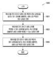
다양한 실시 예들에 따르면, 웨어러블 전자 장치의 생체 접촉 검출 방법은, 생체 신호 측정을 위한 적어도 두 개의 전극들 중 생체와 접촉된 적어도 하나의 전극에 전압을 인가하는 동작; 상기 적어도 하나의 전극에서 출력되는 전압을 기반으로 상기 웨어러블 전자 장치의 생체 신호 측정을 위한 동작 상태를 알리는 정보를 출력하는 동작; 및 상기 웨어러블 전자 장치의 생체 신호 측정의 동작 상태를 알리는 정보를 기반으로, 상기 웨어러블 전자 장치의 생체 신호 측정의 동작 상태를 결정하는 동작을 포함할 수 있다.According to various embodiments, a method for detecting a biological contact of a wearable electronic device may include: an operation of applying a voltage to at least one electrode in contact with a biological body among at least two electrodes for measuring a biological signal; an operation of outputting information indicating an operating state for measuring a biological signal of the wearable electronic device based on a voltage output from the at least one electrode; and an operation of determining an operating state for measuring a biological signal of the wearable electronic device based on the information indicating the operating state for measuring a biological signal of the wearable electronic device.
다양한 실시 예들에 따르면, 높은 입력임피던스를 가지는 버퍼를 사용하기 때문에 전압 소스(source)인 바이어스부는 아주 낮은 출력전류로 동작할 수 있으며, 기존의 전류를 인가하여 전압을 측정하는 동작방식에 비해 배터리로 동작하는 웨어러블 전자 장치의 작동시간을 향상 시킬 수 있다. 상기 두 개의 전극들 사이로 전류를 인가하지 않기 때문에 추가적인 잡음(전류*접촉 저항에 의한 IR voltage drop)이 발생하지 않을 수 있다. 또한 상기 두 개의 전극들을 이용하여 웨어러블 전자 장치에 생체의 부위의 접촉을 검출하는 동시에 생체 신호를 측정할 수 있다.According to various embodiments, since a buffer having a high input impedance is used, a bias part, which is a voltage source, can operate with a very low output current, and compared to an existing operation method of measuring voltage by applying current, the operating time of a wearable electronic device operating on a battery can be improved. Since no current is applied between the two electrodes, additional noise (IR voltage drop due to current*contact resistance) may not occur. In addition, by using the two electrodes, it is possible to detect contact of a living part of the wearable electronic device and measure a biosignal at the same time.
도 1a는 다양한 실시 예들에 따른 네트워크 환경 내의 전자 장치의 블록도 이다.
도 1b는 다양한 실시 예들에 따른 전자 장치의 전면의 사시도 이다.
도 1c는 도 1b의 전자 장치의 후면의 사시도 이다.
도 1d는 도 1b의 전자 장치의 분리 사시도 이다.
도 2는 다양한 실시 예에 따른 웨어러블 전자 장치의 개략적인 블록도 이다.
도 3은 다양한 실시 예들에 따른 웨어러블 전자 장치의 생체 접촉 검출부의 계략적인 블록도 이다.
도 4a 내지 도 4d는 다양한 실시 예들에 따른 웨어러블 전자 장치의 전극들을 설명하기 위한 도면 이다.
도 5는 다양한 실시 예들에 따른 웨어러블 전자 장치의 생체 접촉 검출부의 회로도 이다.
도 6은 다양한 실시 예들에 따른 웨어러블 전자 장치에서 생체 접촉 검출을 설명하기 위한 도면 이다.
도 7a 내지 도 7d는 다양한 실시 예들에 따른 웨어러블 전자 장치에서 생체 접촉 검출을 설명하기 위한 도면 이다.
도 8a 내지 도 8c는 다양한 실시 예들에 따른 웨어러블 전자 장치에서 생체 접촉 검출을 설명하기 위한 도면 이다.
도 9는 다양한 실시 예들에 따른 웨어러블 전자 장치에서 생체 접촉 검출 동작을 설명하기 위한 예시적인 흐름도 이다.
도 10은 다양한 실시 예들에 따른 웨어러블 전자 장치에서 생체 접촉 검출 동작을 설명하기 위한 예시적인 흐름도 이다.
도 11은 다양한 실시 예들에 따른 웨어러블 전자 장치에서 생체 신호의 검출 동작을 설명하기 위한 예시적인 흐름도 이다.
도 12a는 다양한 실시 예들에 따른 웨어러블 전자 장치에서 전면의 사시도이다.
도 12b는 도 12a의 웨어러블 전자 장치의 후면의 사시도 이다.FIG. 1A is a block diagram of an electronic device within a network environment according to various embodiments.
FIG. 1b is a perspective view of the front of an electronic device according to various embodiments.
Figure 1c is a perspective view of the rear of the electronic device of Figure 1b.
Figure 1d is an exploded perspective view of the electronic device of Figure 1b.
FIG. 2 is a schematic block diagram of a wearable electronic device according to various embodiments.
FIG. 3 is a schematic block diagram of a biometric contact detection unit of a wearable electronic device according to various embodiments.
FIGS. 4A to 4D are drawings for explaining electrodes of a wearable electronic device according to various embodiments.
FIG. 5 is a circuit diagram of a bio-contact detection unit of a wearable electronic device according to various embodiments.
FIG. 6 is a diagram for explaining biometric contact detection in a wearable electronic device according to various embodiments.
FIGS. 7A to 7D are diagrams for explaining biometric contact detection in a wearable electronic device according to various embodiments.
FIGS. 8A to 8C are diagrams for explaining biometric contact detection in a wearable electronic device according to various embodiments.
FIG. 9 is an exemplary flowchart for explaining a biometric contact detection operation in a wearable electronic device according to various embodiments.
FIG. 10 is an exemplary flowchart for explaining a biometric contact detection operation in a wearable electronic device according to various embodiments.
FIG. 11 is an exemplary flowchart for explaining a biosignal detection operation in a wearable electronic device according to various embodiments.
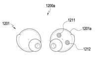
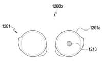
FIG. 12A is a front perspective view of a wearable electronic device according to various embodiments.
FIG. 12b is a perspective view of the rear side of the wearable electronic device of FIG. 12a.
도 1a는, 다양한 실시예들에 따른, 네트워크 환경(100a) 내의 전자 장치(101)의 블록도이다. 도 1a를 참조하면, 네트워크 환경(100a)에서 전자 장치(101)는 제 1 네트워크(198)(예: 근거리 무선 통신 네트워크)를 통하여 전자 장치(102)와 통신하거나, 또는 제 2 네트워크(199)(예: 원거리 무선 통신 네트워크)를 통하여 전자 장치(104) 또는 서버(108)와 통신할 수 있다. 일실시예에 따르면, 전자 장치(101)는 서버(108)를 통하여 전자 장치(104)와 통신할 수 있다. 일실시예에 따르면, 전자 장치(101)는 프로세서(120), 메모리(130), 입력 장치(150), 음향 출력 장치(155), 표시 장치(160), 오디오 모듈(170), 센서 모듈(176), 인터페이스(177), 햅틱 모듈(179), 카메라 모듈(180), 전력 관리 모듈(188), 배터리(189), 통신 모듈(190), 가입자 식별 모듈(196), 또는 안테나 모듈(197)을 포함할 수 있다. 어떤 실시예에서는, 전자 장치(101)에는, 이 구성요소들 중 적어도 하나(예: 표시 장치(160) 또는 카메라 모듈(180))가 생략되거나, 하나 이상의 다른 구성 요소가 추가될 수 있다. 어떤 실시예에서는, 이 구성요소들 중 일부들은 하나의 통합된 회로로 구현될 수 있다. 예를 들면, 센서 모듈(176)(예: 지문 센서, 홍채 센서, 또는 조도 센서)은 표시 장치(160)(예: 디스플레이)에 임베디드된 채 구현될 수 있다FIG. 1A is a block diagram of an electronic device (101) in a network environment (100a) according to various embodiments. Referring to FIG. 1A, in the network environment (100a), the electronic device (101) may communicate with the electronic device (102) via a first network (198) (e.g., a short-range wireless communication network), or may communicate with the electronic device (104) or a server (108) via a second network (199) (e.g., a long-range wireless communication network). According to one embodiment, the electronic device (101) may communicate with the electronic device (104) via the server (108). According to one embodiment, the electronic device (101) may include a processor (120), a memory (130), an input device (150), an audio output device (155), a display device (160), an audio module (170), a sensor module (176), an interface (177), a haptic module (179), a camera module (180), a power management module (188), a battery (189), a communication module (190), a subscriber identification module (196), or an antenna module (197). In some embodiments, the electronic device (101) may omit at least one of these components (e.g., the display device (160) or the camera module (180)), or may include one or more other components. In some embodiments, some of these components may be implemented as a single integrated circuit. For example, a sensor module (176) (e.g., a fingerprint sensor, an iris sensor, or a light sensor) may be implemented embedded in a display device (160) (e.g., a display).
프로세서(120)는, 예를 들면, 소프트웨어(예: 프로그램(140))를 실행하여 프로세서(120)에 연결된 전자 장치(101)의 적어도 하나의 다른 구성요소(예: 하드웨어 또는 소프트웨어 구성요소)를 제어할 수 있고, 다양한 데이터 처리 또는 연산을 수행할 수 있다. 일실시예에 따르면, 데이터 처리 또는 연산의 적어도 일부로서, 프로세서(120)는 다른 구성요소(예: 센서 모듈(176) 또는 통신 모듈(190))로부터 수신된 명령 또는 데이터를 휘발성 메모리(132)에 로드하고, 휘발성 메모리(132)에 저장된 명령 또는 데이터를 처리하고, 결과 데이터를 비휘발성 메모리(134)에 저장할 수 있다. 일실시예에 따르면, 프로세서(120)는 메인 프로세서(121)(예: 중앙 처리 장치 또는 어플리케이션 프로세서), 및 이와는 독립적으로 또는 함께 운영 가능한 보조 프로세서(123)(예: 그래픽 처리 장치, 이미지 시그널 프로세서, 센서 허브 프로세서, 또는 커뮤니케이션 프로세서)를 포함할 수 있다. 추가적으로 또는 대체적으로, 보조 프로세서(123)는 메인 프로세서(121)보다 저전력을 사용하거나, 또는 지정된 기능에 특화되도록 설정될 수 있다. 보조 프로세서(123)는 메인 프로세서(121)와 별개로, 또는 그 일부로서 구현될 수 있다.The processor (120) may control at least one other component (e.g., a hardware or software component) of the electronic device (101) connected to the processor (120) by executing, for example, software (e.g., a program (140)), and may perform various data processing or calculations. According to one embodiment, as at least a part of the data processing or calculations, the processor (120) may load a command or data received from another component (e.g., a sensor module (176) or a communication module (190)) into the volatile memory (132), process the command or data stored in the volatile memory (132), and store the resulting data in the nonvolatile memory (134). According to one embodiment, the processor (120) may include a main processor (121) (e.g., a central processing unit or an application processor), and a secondary processor (123) (e.g., a graphics processing unit, an image signal processor, a sensor hub processor, or a communication processor) that may operate independently or together therewith. Additionally or alternatively, the auxiliary processor (123) may be configured to use less power than the main processor (121), or to be specialized for a given function. The auxiliary processor (123) may be implemented separately from the main processor (121), or as a part thereof.
보조 프로세서(123)는, 예를 들면, 메인 프로세서(121)가 인액티브(예: 슬립) 상태에 있는 동안 메인 프로세서(121)를 대신하여, 또는 메인 프로세서(121)가 액티브(예: 어플리케이션 실행) 상태에 있는 동안 메인 프로세서(121)와 함께, 전자 장치(101)의 구성요소들 중 적어도 하나의 구성요소(예: 표시 장치(160), 센서 모듈(176), 또는 통신 모듈(190))와 관련된 기능 또는 상태들의 적어도 일부를 제어할 수 있다. 일실시예에 따르면, 보조 프로세서(123)(예: 이미지 시그널 프로세서 또는 커뮤니케이션 프로세서)는 기능적으로 관련 있는 다른 구성 요소(예: 카메라 모듈(180) 또는 통신 모듈(190))의 일부로서 구현될 수 있다.The auxiliary processor (123) may control at least a portion of functions or states associated with at least one of the components of the electronic device (101) (e.g., the display device (160), the sensor module (176), or the communication module (190)), for example, on behalf of the main processor (121) while the main processor (121) is in an inactive (e.g., sleep) state, or together with the main processor (121) while the main processor (121) is in an active (e.g., application execution) state. In one embodiment, the auxiliary processor (123) (e.g., an image signal processor or a communication processor) may be implemented as a part of another functionally related component (e.g., a camera module (180) or a communication module (190)).
메모리(130)는, 전자 장치(101)의 적어도 하나의 구성요소(예: 프로세서(120) 또는 센서모듈(176))에 의해 사용되는 다양한 데이터를 저장할 수 있다. 데이터는, 예를 들어, 소프트웨어(예: 프로그램(140)) 및, 이와 관련된 명령에 대한 입력 데이터 또는 출력 데이터를 포함할 수 있다. 메모리(130)는, 휘발성 메모리(132) 또는 비휘발성 메모리(134)를 포함할 수 있다.The memory (130) can store various data used by at least one component (e.g., processor (120) or sensor module (176)) of the electronic device (101). The data can include, for example, software (e.g., program (140)) and input data or output data for commands related thereto. The memory (130) can include volatile memory (132) or nonvolatile memory (134).
프로그램(140)은 메모리(130)에 소프트웨어로서 저장될 수 있으며, 예를 들면, 운영 체제(142), 미들 웨어(144) 또는 어플리케이션(146)을 포함할 수 있다.The program (140) may be stored as software in memory (130) and may include, for example, an operating system (142), middleware (144), or an application (146).
입력 장치(150)는, 전자 장치(101)의 구성요소(예: 프로세서(120))에 사용될 명령 또는 데이터를 전자 장치(101)의 외부(예: 사용자)로부터 수신할 수 있다. 입력 장치(150)는, 예를 들면, 마이크, 마우스, 키보드, 또는 디지털 펜(예: 스타일러스 펜)을 포함할 수 있다.The input device (150) can receive commands or data to be used in a component of the electronic device (101) (e.g., a processor (120)) from an external source (e.g., a user) of the electronic device (101). The input device (150) can include, for example, a microphone, a mouse, a keyboard, or a digital pen (e.g., a stylus pen).
음향 출력 장치(155)는 음향 신호를 전자 장치(101)의 외부로 출력할 수 있다. 음향 출력 장치(155)는, 예를 들면, 스피커 또는 리시버를 포함할 수 있다. 스피커는 멀티미디어 재생 또는 녹음 재생과 같이 일반적인 용도로 사용될 수 있고, 리시버는 착신 전화를 수신하기 위해 사용될 수 있다. 일실시예에 따르면, 리시버는 스피커와 별개로, 또는 그 일부로서 구현될 수 있다.The audio output device (155) can output an audio signal to the outside of the electronic device (101). The audio output device (155) can include, for example, a speaker or a receiver. The speaker can be used for general purposes such as multimedia playback or recording playback, and the receiver can be used to receive an incoming call. According to one embodiment, the receiver can be implemented separately from the speaker or as a part thereof.
표시 장치(160)는 전자 장치(101)의 외부(예: 사용자)로 정보를 시각적으로 제공할 수 있다. 표시 장치(160)는, 예를 들면, 디스플레이, 홀로그램 장치, 또는 프로젝터 및 해당 장치를 제어하기 위한 제어 회로를 포함할 수 있다. 일실시예에 따르면, 표시 장치(160)는 터치를 감지하도록 설정된 터치 회로(touch circuitry), 또는 상기 터치에 의해 발생되는 힘의 세기를 측정하도록 설정된 센서 회로(예: 압력 센서)를 포함할 수 있다.The display device (160) can visually provide information to an external party (e.g., a user) of the electronic device (101). The display device (160) can include, for example, a display, a holographic device, or a projector and a control circuit for controlling the device. According to one embodiment, the display device (160) can include touch circuitry configured to detect a touch, or a sensor circuitry configured to measure a strength of a force generated by the touch (e.g., a pressure sensor).
오디오 모듈(170)은 소리를 전기 신호로 변환시키거나, 반대로 전기 신호를 소리로 변환시킬 수 있다. 일실시예에 따르면, 오디오 모듈(170)은, 입력 장치(150)를 통해 소리를 획득하거나, 음향 출력 장치(155), 또는 전자 장치(101)와 직접 또는 무선으로 연결된 외부 전자 장치(예: 전자 장치(102))(예: 스피커 또는 헤드폰)를 통해 소리를 출력할 수 있다.The audio module (170) can convert sound into an electrical signal, or vice versa, convert an electrical signal into sound. According to one embodiment, the audio module (170) can obtain sound through an input device (150), or output sound through an audio output device (155), or an external electronic device (e.g., an electronic device (102)) (e.g., a speaker or a headphone) directly or wirelessly connected to the electronic device (101).
센서 모듈(176)은 전자 장치(101)의 작동 상태(예: 전력 또는 온도), 또는 외부의 환경 상태(예: 사용자 상태)를 감지하고, 감지된 상태에 대응하는 전기 신호 또는 데이터 값을 생성할 수 있다. 일실시예에 따르면, 센서 모듈(176)은, 예를 들면, 제스처 센서, 자이로 센서, 기압 센서, 마그네틱 센서, 가속도 센서, 그립 센서, 근접 센서, 컬러 센서, IR(infrared) 센서, 생체 센서, 온도 센서, 습도 센서, 또는 조도 센서를 포함할 수 있다.The sensor module (176) can detect an operating state (e.g., power or temperature) of the electronic device (101) or an external environmental state (e.g., user state) and generate an electric signal or data value corresponding to the detected state. According to one embodiment, the sensor module (176) can include, for example, a gesture sensor, a gyro sensor, a barometric pressure sensor, a magnetic sensor, an acceleration sensor, a grip sensor, a proximity sensor, a color sensor, an IR (infrared) sensor, a biometric sensor, a temperature sensor, a humidity sensor, or an illuminance sensor.
인터페이스(177)는 전자 장치(101)가 외부 전자 장치(예: 전자 장치(102))와 직접 또는 무선으로 연결되기 위해 사용될 수 있는 하나 이상의 지정된 프로토콜들을 지원할 수 있다. 일실시예에 따르면, 인터페이스(177)는, 예를 들면, HDMI(high definition multimedia interface), USB(universal serial bus) 인터페이스, SD카드 인터페이스, 또는 오디오 인터페이스를 포함할 수 있다.The interface (177) may support one or more designated protocols that may be used to directly or wirelessly connect the electronic device (101) with an external electronic device (e.g., the electronic device (102)). In one embodiment, the interface (177) may include, for example, a high definition multimedia interface (HDMI), a universal serial bus (USB) interface, an SD card interface, or an audio interface.
연결 단자(178)는, 그를 통해서 전자 장치(101)가 외부 전자 장치(예: 전자 장치(102))와 물리적으로 연결될 수 있는 커넥터를 포함할 수 있다. 일실시예에 따르면, 연결 단자(178)은, 예를 들면, HDMI 커넥터, USB 커넥터, SD 카드 커넥터, 또는 오디오 커넥터(예: 헤드폰 커넥터)를 포함할 수 있다.The connection terminal (178) may include a connector through which the electronic device (101) may be physically connected to an external electronic device (e.g., the electronic device (102)). According to one embodiment, the connection terminal (178) may include, for example, an HDMI connector, a USB connector, an SD card connector, or an audio connector (e.g., a headphone connector).
햅틱 모듈(179)은 전기적 신호를 사용자가 촉각 또는 운동 감각을 통해서 인지할 수 있는 기계적인 자극(예: 진동 또는 움직임) 또는 전기적인 자극으로 변환할 수 있다. 일실시예에 따르면, 햅틱 모듈(179)은, 예를 들면, 모터, 압전 소자, 또는 전기 자극 장치를 포함할 수 있다.The haptic module (179) can convert an electrical signal into a mechanical stimulus (e.g., vibration or movement) or an electrical stimulus that a user can perceive through a tactile or kinesthetic sense. According to one embodiment, the haptic module (179) can include, for example, a motor, a piezoelectric element, or an electrical stimulation device.
카메라 모듈(180)은 정지 영상 및 동영상을 촬영할 수 있다. 일실시예에 따르면, 카메라 모듈(180)은 하나 이상의 렌즈들, 이미지 센서들, 이미지 시그널 프로세서들, 또는 플래시들을 포함할 수 있다.The camera module (180) can capture still images and moving images. According to one embodiment, the camera module (180) can include one or more lenses, image sensors, image signal processors, or flashes.
전력 관리 모듈(188)은 전자 장치(101)에 공급되는 전력을 관리할 수 있다. 일실시예에 따르면, 전력 관리 모듈(188)은, 예를 들면, PMIC(power management integrated circuit)의 적어도 일부로서 구현될 수 있다.The power management module (188) can manage power supplied to the electronic device (101). According to one embodiment, the power management module (188) can be implemented as, for example, at least a part of a power management integrated circuit (PMIC).
배터리(189)는 전자 장치(101)의 적어도 하나의 구성 요소에 전력을 공급할 수 있다. 일실시예에 따르면, 배터리(189)는, 예를 들면, 재충전 불가능한 1차 전지, 재충전 가능한 2차 전지 또는 연료 전지를 포함할 수 있다.A battery (189) may power at least one component of the electronic device (101). In one embodiment, the battery (189) may include, for example, a non-rechargeable primary battery, a rechargeable secondary battery, or a fuel cell.
통신 모듈(190)은 전자 장치(101)와 외부 전자 장치(예: 전자 장치(102), 전자 장치(104), 또는 서버(108))간의 직접(예: 유선) 통신 채널 또는 무선 통신 채널의 수립, 및 수립된 통신 채널을 통한 통신 수행을 지원할 수 있다. 통신 모듈(190)은 프로세서(120)(예: 어플리케이션 프로세서)와 독립적으로 운영되고, 직접(예: 유선) 통신 또는 무선 통신을 지원하는 하나 이상의 커뮤니케이션 프로세서를 포함할 수 있다. 일실시예에 따르면, 통신 모듈(190)은 무선 통신 모듈(192)(예: 셀룰러 통신 모듈, 근거리 무선 통신 모듈, 또는 GNSS(global navigation satellite system) 통신 모듈) 또는 유선 통신 모듈(194)(예: LAN(local area network) 통신 모듈, 또는 전력선 통신 모듈)을 포함할 수 있다. 이들 통신 모듈 중 해당하는 통신 모듈은 제 1 네트워크(198)(예: 블루투스, WiFi direct 또는 IrDA(infrared data association)와 같은 근거리 통신 네트워크) 또는 제 2 네트워크(199)(예: 셀룰러 네트워크, 인터넷, 또는 컴퓨터 네트워크(예: LAN 또는 WAN)와 같은 원거리 통신 네트워크)를 통하여 외부 전자 장치와 통신할 수 있다. 이런 여러 종류의 통신 모듈들은 하나의 구성 요소(예: 단일 칩)로 통합되거나, 또는 서로 별도의 복수의 구성 요소들(예: 복수 칩들)로 구현될 수 있다. 무선 통신 모듈(192)은 가입자 식별 모듈(196)에 저장된 가입자 정보(예: 국제 모바일 가입자 식별자(IMSI))를 이용하여 제 1 네트워크(198) 또는 제 2 네트워크(199)와 같은 통신 네트워크 내에서 전자 장치(101)를 확인 및 인증할 수 있다.The communication module (190) may support establishment of a direct (e.g., wired) communication channel or a wireless communication channel between the electronic device (101) and an external electronic device (e.g., the electronic device (102), the electronic device (104), or the server (108)), and performance of communication through the established communication channel. The communication module (190) may operate independently from the processor (120) (e.g., the application processor) and may include one or more communication processors that support direct (e.g., wired) communication or wireless communication. According to one embodiment, the communication module (190) may include a wireless communication module (192) (e.g., a cellular communication module, a short-range wireless communication module, or a GNSS (global navigation satellite system) communication module) or a wired communication module (194) (e.g., a local area network (LAN) communication module, or a power line communication module). A corresponding communication module among these communication modules can communicate with an external electronic device via a first network (198) (e.g., a short-range communication network such as Bluetooth, WiFi direct, or IrDA (infrared data association)) or a second network (199) (e.g., a long-range communication network such as a cellular network, the Internet, or a computer network (e.g., a LAN or WAN)). These various types of communication modules can be integrated into a single component (e.g., a single chip) or implemented as multiple separate components (e.g., multiple chips). The wireless communication module (192) can identify and authenticate the electronic device (101) within a communication network such as the first network (198) or the second network (199) by using subscriber information (e.g., an international mobile subscriber identity (IMSI)) stored in the subscriber identification module (196).
안테나 모듈(197)은 신호 또는 전력을 외부(예: 외부 전자 장치)로 송신하거나 외부로부터 수신할 수 있다. 일실시예에 따르면, 안테나 모듈은 서브스트레이트(예: PCB) 위에 형성된 도전체 또는 도전성 패턴으로 이루어진 방사체를 포함하는 하나의 안테나를 포함할 수 있다. 일실시예에 따르면, 안테나 모듈(197)은 복수의 안테나들을 포함할 수 있다. 이런 경우, 제 1 네트워크(198) 또는 제 2 네트워크(199)와 같은 통신 네트워크에서 사용되는 통신 방식에 적합한 적어도 하나의 안테나가, 예를 들면, 통신 모듈(190)에 의하여 상기 복수의 안테나들로부터 선택될 수 있다. 신호 또는 전력은 상기 선택된 적어도 하나의 안테나를 통하여 통신 모듈(190)과 외부 전자 장치 간에 송신되거나 수신될 수 있다. 어떤 실시예에 따르면, 방사체 이외에 다른 부품(예: RFIC)이 추가로 안테나 모듈(197)의 일부로 형성될 수 있다.The antenna module (197) can transmit or receive signals or power to or from an external device (e.g., an external electronic device). According to one embodiment, the antenna module can include one antenna including a radiator formed of a conductor or a conductive pattern formed on a substrate (e.g., a PCB). According to one embodiment, the antenna module (197) can include a plurality of antennas. In this case, at least one antenna suitable for a communication method used in a communication network, such as the first network (198) or the second network (199), can be selected from the plurality of antennas by, for example, the communication module (190). A signal or power can be transmitted or received between the communication module (190) and the external electronic device through the selected at least one antenna. According to some embodiments, in addition to the radiator, another component (e.g., an RFIC) can be additionally formed as a part of the antenna module (197).
상기 구성요소들 중 적어도 일부는 주변 기기들간 통신 방식(예: 버스, GPIO(general purpose input and output), SPI(serial peripheral interface), 또는 MIPI(mobile industry processor interface))을 통해 서로 연결되고 신호(예: 명령 또는 데이터)를 상호간에 교환할 수 있다.At least some of the above components may be interconnected and exchange signals (e.g., commands or data) with each other via a communication method between peripheral devices (e.g., a bus, a general purpose input and output (GPIO), a serial peripheral interface (SPI), or a mobile industry processor interface (MIPI)).
일실시예에 따르면, 명령 또는 데이터는 제 2 네트워크(199)에 연결된 서버(108)를 통해서 전자 장치(101)와 외부의 전자 장치(104)간에 송신 또는 수신될 수 있다. 외부 전자 장치(102, 104) 각각은 전자 장치(101)와 동일한 또는 다른 종류의 장치일 수 있다. 일실시예에 따르면, 전자 장치(101)에서 실행되는 동작들의 전부 또는 일부는 외부 전자 장치들(102, 104, 또는 108) 중 하나 이상의 외부 장치들에서 실행될 수 있다. 예를 들면, 전자 장치(101)가 어떤 기능이나 서비스를 자동으로, 또는 사용자 또는 다른 장치로부터의 요청에 반응하여 수행해야 할 경우에, 전자 장치(101)는 기능 또는 서비스를 자체적으로 실행시키는 대신에 또는 추가적으로, 하나 이상의 외부 전자 장치들에게 그 기능 또는 그 서비스의 적어도 일부를 수행하라고 요청할 수 있다. 상기 요청을 수신한 하나 이상의 외부 전자 장치들은 요청된 기능 또는 서비스의 적어도 일부, 또는 상기 요청과 관련된 추가 기능 또는 서비스를 실행하고, 그 실행의 결과를 전자 장치(101)로 전달할 수 있다. 전자 장치(101)는 상기 결과를, 그대로 또는 추가적으로 처리하여, 상기 요청에 대한 응답의 적어도 일부로서 제공할 수 있다. 이를 위하여, 예를 들면, 클라우드 컴퓨팅, 분산 컴퓨팅, 또는 클라이언트-서버 컴퓨팅 기술이 이용될 수 있다.In one embodiment, a command or data may be transmitted or received between the electronic device (101) and an external electronic device (104) via a server (108) connected to a second network (199). Each of the external electronic devices (102, 104) may be the same or a different type of device as the electronic device (101). In one embodiment, all or part of the operations executed in the electronic device (101) may be executed in one or more of the external electronic devices (102, 104, or 108). For example, when the electronic device (101) is to perform a certain function or service automatically or in response to a request from a user or another device, the electronic device (101) may, instead of executing the function or service itself or in addition, request one or more external electronic devices to perform at least a part of the function or service. One or more external electronic devices that have received the request may execute at least a part of the requested function or service, or an additional function or service related to the request, and transmit the result of the execution to the electronic device (101). The electronic device (101) may process the result as is or additionally and provide it as at least a part of a response to the request. For this purpose, for example, cloud computing, distributed computing, or client-server computing technology may be used.
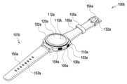
도 1b는 다양한 실시 예들에 따른 전자 장치의 전면의 사시도(100b) 이고, 도 1c는 도 1b의 전자 장치의 후면의 사시도(100c)이다.FIG. 1b is a perspective view (100b) of the front of an electronic device according to various embodiments, and FIG. 1c is a perspective view (100c) of the rear of the electronic device of FIG. 1b.
도 1b 및 도 1c를 참조하면, 일 실시예에 따른 전자 장치(101b, 예: 도 1a의 전자 장치(101))는, 제1 면(또는 전면)(110A), 제2 면(또는 후면)(110B), 및 제1 면(110A) 및 제2 면(110B) 사이의 공간을 둘러싸는 측면(110C)을 포함하는 하우징(110a)과, 상기 하우징(110a)의 적어도 일부에 연결되고 상기 전자 장치(101b)를 사용자의 신체 일부(예: 손목, 발목 등)에 탈착 가능하게 결착하도록 구성된 착용 부재(150a, 160a)를 포함할 수 있다. 다른 실시예(미도시)에서는, 하우징은, 도 1의 제1 면(110A), 제2 면(110B) 및 측면(110C)들 중 일부를 형성하는 구조를 지칭할 수도 있다. 일 실시예에 따르면, 제1 면(110A)은 적어도 일부분이 실질적으로 투명한 전면 플레이트(112a)(예: 다양한 코팅 레이어들을 포함하는 글라스 플레이트, 또는 폴리머 플레이트)에 의하여 형성될 수 있다. 제2 면(110B)은 실질적으로 불투명한 후면 플레이트(107a)에 의하여 형성될 수 있다. 어떤 실시예에서, 전자 장치(101b)가 제2 면(110B)에 배치된 센서 모듈(165)을 포함할 때, 후면 플레이트(107a)는 적어도 부분적으로 투명한 영역을 포함할 수 있다. 상기 후면 플레이트(107a)는, 예를 들어, 코팅 또는 착색된 유리, 세라믹, 폴리머, 금속(예: 알루미늄, 스테인레스 스틸(STS), 또는 마그네슘), 또는 상기 물질들 중 적어도 둘의 조합에 의하여 형성될 수 있다. 상기 측면(110C)은, 전면 플레이트(112a) 및 후면 플레이트(107a)와 결합하며, 금속 및/또는 폴리머를 포함하는 측면 베젤 구조(또는 “측면 부재”)(106a)에 의하여 형성될 수 있다. 어떤 실시예에서는, 후면 플레이트(107a) 및 측면 베젤 구조(106a)는 일체로 형성되고 동일한 물질(예: 알루미늄과 같은 금속 물질)을 포함할 수 있다. 상기 착용 부재(150a, 160a)는 다양한 재질 및 형태로 형성될 수 있다. 직조물, 가죽, 러버, 우레탄, 금속, 세라믹, 또는 상기 물질들 중 적어도 둘의 조합에 의하여 일체형 및 복수의 단위 링크가 서로 유동 가능하도록 형성될 수 있다.Referring to FIGS. 1b and 1c , an electronic device (101b, for example, the electronic device (101) of FIG. 1a ) according to one embodiment may include a housing (110a) including a first side (or front side) (110A), a second side (or back side) (110B), and a side surface (110C) surrounding a space between the first side (110A) and the second side (110B), and a wearing member (150a, 160a) connected to at least a portion of the housing (110a) and configured to releasably attach the electronic device (101b) to a portion of a user's body (e.g., a wrist, an ankle, etc.). In another embodiment (not shown), the housing may also refer to a structure forming a portion of the first side (110A), the second side (110B), and the side surface (110C) of FIG. 1 . In one embodiment, the first side (110A) may be formed by a front plate (112a) that is at least partially transparent (e.g., a glass plate including various coating layers, or a polymer plate). The second side (110B) may be formed by a substantially opaque back plate (107a). In some embodiments, when the electronic device (101b) includes a sensor module (165) disposed on the second side (110B), the back plate (107a) may include at least a partially transparent region. The back plate (107a) may be formed by, for example, coated or colored glass, ceramic, polymer, metal (e.g., aluminum, stainless steel (STS), or magnesium), or a combination of at least two of the foregoing materials. The side (110C) is coupled with the front plate (112a) and the back plate (107a) and may be formed by a side bezel structure (or “side member”) (106a) comprising metal and/or polymer. In some embodiments, the back plate (107a) and the side bezel structure (106a) may be formed integrally and may comprise the same material (e.g., a metal material such as aluminum). The wearing members (150a, 160a) may be formed of various materials and shapes. The integral and multiple unit links may be formed to be movable with each other by a woven material, leather, rubber, urethane, metal, ceramic, or a combination of at least two of the above materials.
일 실시예에 따르면, 전자 장치(101b)는, 디스플레이(120a, 도 1d 참조), 오디오 모듈(105a, 108a), 센서 모듈(165), 키 입력 장치(102a, 103a, 104a) 및 커넥터 홀(109a) 중 적어도 하나 이상을 포함할 수 있다. 어떤 실시예에서는, 전자 장치(101b)는, 구성요소들 중 적어도 하나(예: 키 입력 장치(102a, 103a, 104a), 커넥터 홀(109a), 또는 센서 모듈(165))를 생략하거나 다른 구성요소를 추가적으로 포함할 수 있다.According to one embodiment, the electronic device (101b) may include at least one of a display (120a, see FIG. 1d), an audio module (105a, 108a), a sensor module (165), a key input device (102a, 103a, 104a), and a connector hole (109a). In some embodiments, the electronic device (101b) may omit at least one of the components (e.g., the key input device (102a, 103a, 104a), the connector hole (109a), or the sensor module (165)) or may additionally include other components.
일 실시 예에 따르면, 전자 장치(101b)는 생체 신호 측정을 위한 복수의 전극들을 포함할 수 있으며, 상기 복수의 전극들 중 적어도 하나의 전극은 키 입력 장치(102a, 103a 또는 104a)의 위치, 베젤(106a)의 위치, 디스플레이(120a), 또는 하우징(110a)의 위치 중 적어도 하나의 위치에 배치될 수 있다. 상기 키 입력 장치 중 휠 키(102a)는 로터리 베젤을 포함할 수 있다.디스플레이(120a)는, 예를 들어, 전면 플레이트(112a)의 상당 부분을 통하여 노출될 수 있다. 디스플레이(120a)의 형태는, 상기 전면 플레이트(112a)의 형태에 대응하는 형태일 수 있으며, 원형, 타원형, 또는 다각형 등 다양한 형태일 수 있다. 디스플레이(120a)는, 터치 감지 회로, 터치의 세기(압력)를 측정할 수 있는 압력 센서, 및/또는 지문 센서와 결합되거나 인접하여 배치될 수 있다.According to one embodiment, the electronic device (101b) may include a plurality of electrodes for measuring a biosignal, and at least one of the plurality of electrodes may be disposed at at least one of a position of a key input device (102a, 103a, or 104a), a position of a bezel (106a), a display (120a), or a position of a housing (110a). Among the key input devices, the wheel key (102a) may include a rotary bezel. The display (120a) may be exposed through, for example, a significant portion of the front plate (112a). The shape of the display (120a) may correspond to the shape of the front plate (112a), and may have various shapes such as a circle, an oval, or a polygon. The display (120a) may be combined with or disposed adjacent to a touch detection circuit, a pressure sensor capable of measuring the intensity (pressure) of a touch, and/or a fingerprint sensor.
일 실시 예에 따르면 디스플레이(120a)는 생체 신호 측정을 위한 복수의 전극들 중 생체 신호 측정을 위한 적어도 하나의 투명 전극을 포함할 수 있다.According to one embodiment, the display (120a) may include at least one transparent electrode for measuring a biosignal among a plurality of electrodes for measuring a biosignal.
오디오 모듈(105a, 108a)은, 마이크 홀(105a) 및 스피커 홀(108a)을 포함할 수 있다. 마이크 홀(105a)은 외부의 소리를 획득하기 위한 마이크가 내부에 배치될 수 있고, 어떤 실시예에서는 소리의 방향을 감지할 수 있도록 복수개의 마이크가 배치될 수 있다. 스피커 홀(108a)은, 외부 스피커 및 통화용 리시버로 사용할 수 있다. 어떤 실시예에서는 스피커 홀 없이 스피커가 포함될 수 있다(예: 피에조 스피커).The audio module (105a, 108a) may include a microphone hole (105a) and a speaker hole (108a). A microphone for acquiring external sound may be placed inside the microphone hole (105a), and in some embodiments, multiple microphones may be placed to detect the direction of the sound. The speaker hole (108a) may be used as an external speaker and a receiver for calls. In some embodiments, a speaker may be included without a speaker hole (e.g., a piezo speaker).
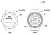
센서 모듈(165)은, 전자 장치(101b)의 내부의 작동 상태, 또는 외부의 환경 상태에 대응하는 전기 신호 또는 데이터 값을 생성할 수 있다. 센서 모듈(165)은, 예를 들어, 상기 하우징(110a)의 제2 면(110B)에 배치된 생체 센서 모듈(165)은 심전도 측정을 위해 적어도 두 개의 전극들(a1, a2)을 포함하는 ECG센서(165a) 및 심박수 측정을 위한 PPG 센서(165b)를 포함할 수 있다. 전자 장치(101b)는, 도시되지 않은 센서 모듈, 예를 들어, 제스처 센서, 자이로 센서, 기압 센서, 마그네틱 센서, 가속도 센서, 그립 센서, 컬러 센서, IR(infrared) 센서, 생체 센서, 온도 센서, 습도 센서, 또는 조도 센서 중 적어도 하나를 더 포함할 수 있다.The sensor module (165) can generate an electric signal or data value corresponding to an internal operating state of the electronic device (101b) or an external environmental state. The sensor module (165) can include, for example, a biometric sensor module (165) disposed on the second surface (110B) of the housing (110a), an ECG sensor (165a) including at least two electrodes (a1, a2) for electrocardiogram measurement, and a PPG sensor (165b) for heart rate measurement. The electronic device (101b) can further include at least one of a sensor module not shown, for example, a gesture sensor, a gyro sensor, a barometric pressure sensor, a magnetic sensor, an acceleration sensor, a grip sensor, a color sensor, an IR (infrared) sensor, a biometric sensor, a temperature sensor, a humidity sensor, or an illuminance sensor.
키 입력 장치(102a, 103a, 104a)는, 하우징(110a)의 제1 면(110A)에 배치되고 적어도 하나의 방향으로 회전 가능한 휠 키(102a), 및/또는 하우징(110a)의 측면(110C)에 배치된 사이드 키 버튼(103a, 104a)을 포함할 수 있다. 휠 키(102a)는 전면 플레이트(112a)의 형태에 대응하는 형태일 수 있다. 다른 실시예에서는, 전자 장치(101b)는 상기 언급된 키 입력 장치(102a, 103a, 104a)들 중 일부 또는 전부를 포함하지 않을 수 있고 포함 되지 않은 키 입력 장치(102a, 103a, 104a)는 디스플레이(120a) 상에 소프트 키 등 다른 형태로 구현될 수 있다. 커넥터 홀(109a)은, 외부 전자 장치와 전력 및/또는 데이터를 송수신하기 위한 커넥터(예를 들어, USB 커넥터)를 수용할 수 있고, 외부 전자 장치와 오디오 신호를 송수신하기 위한 커넥터를 수용할 수 있는 다른 커넥터 홀(미도시))을 포함할 수 있다. 전자 장치(101b)는, 예를 들면, 커넥터 홀(109a)의 적어도 일부를 덮고, 커넥터 홀에 대한 외부 이물질의 유입을 차단하는 커넥터 커버(미도시)를 더 포함할 수 있다.The key input devices (102a, 103a, 104a) may include a wheel key (102a) disposed on a first side (110A) of the housing (110a) and rotatable in at least one direction, and/or a side key button (103a, 104a) disposed on a side surface (110C) of the housing (110a). The wheel key (102a) may have a shape corresponding to the shape of the front plate (112a). In other embodiments, the electronic device (101b) may not include some or all of the above-mentioned key input devices (102a, 103a, 104a), and the key input devices (102a, 103a, 104a) that are not included may be implemented in another form, such as a soft key, on the display (120a). The connector hole (109a) may accommodate a connector (e.g., a USB connector) for transmitting and receiving power and/or data with an external electronic device, and may include another connector hole (not shown) for receiving a connector for transmitting and receiving audio signals with the external electronic device. The electronic device (101b) may further include, for example, a connector cover (not shown) that covers at least a portion of the connector hole (109a) and blocks the inflow of external foreign substances into the connector hole.
착용 부재(150a, 160a)는 락킹 부재(151a, 161a)를 이용하여 하우징(110a)의 적어도 일부 영역에 탈착 가능하도록 결착될 수 있다. 락킹 부재(151a, 161a)는 예를 들면, 포고 핀(pogo pin)과 같은 결속용 부품을 포함할 수 있으며, 실시예에 따라 착용 부재(150a, 160a)에 형성된 돌기 또는 홈(protrusion(s) or recess(es))으로 대체될 수 있다. 예를 들어, 착용 부재(150a, 160a)는 하우징(110)에 형성된 홈 또는 돌기에 맞물리는 방식으로 결합할 수 있다. 착용 부재(150a, 160a)는 고정 부재(152a), 고정 부재 체결 홀(153a), 밴드 가이드 부재(154a), 밴드 고정 고리(155a) 중 하나 또는 그 이상을 포함할 수 있다.The wearing member (150a, 160a) can be releasably fastened to at least a portion of the housing (110a) using a locking member (151a, 161a). The locking member (151a, 161a) can include a fastening component such as a pogo pin, and can be replaced with a protrusion(s) or recess(es) formed in the wearing member (150a, 160a) according to an embodiment. For example, the wearing member (150a, 160a) can be coupled in a manner of engaging with the recess(s) or recess(es) formed in the housing (110). The wearing member (150a, 160a) can include one or more of a fixing member (152a), a fixing member fastening hole (153a), a band guide member (154a), and a band fixing ring (155a).
고정 부재(152a)는 하우징(110a)과 착용 부재(150a, 160a)를 사용자의 신체 일부(예: 손목, 발목 등)에 고정시키도록 구성될 수 있다. 고정 부재 체결 홀(153a)은 고정 부재(152a)에 대응하여 하우징(110a)과 착용 부재(150a, 160a)를 사용자의 신체 일부에 고정시킬 수 있다. 밴드 가이드 부재(154a)는 고정 부재(152a)가 고정 부재 체결 홀(153a)과 체결 시 고정 부재(152a)의 움직임 범위를 제한하도록 구성됨으로써, 착용 부재(150a, 160a)가 사용자의 신체 일부에 밀착하여 결착되도록 할 수 있다. 밴드 고정 고리(155a)는 고정 부재(152a)와 고정 부재 체결 홀(153a)이 체결된 상태에서, 착용 부재(150a,160a)의 움직임 범위를 제한할 수 있다.The fixing member (152a) may be configured to fix the housing (110a) and the wearing member (150a, 160a) to a part of the user's body (e.g., wrist, ankle, etc.). The fixing member fastening hole (153a) may fix the housing (110a) and the wearing member (150a, 160a) to a part of the user's body in response to the fixing member (152a). The band guide member (154a) may be configured to limit the range of movement of the fixing member (152a) when the fixing member (152a) is fastened to the fixing member fastening hole (153a), thereby allowing the wearing member (150a, 160a) to be closely fastened to a part of the user's body. The band fixing ring (155a) may limit the range of movement of the wearing member (150a, 160a) when the fixing member (152a) and the fixing member fastening hole (153a) are fastened.
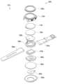
도 1d는 도 1b의 전자 장치(101b)를 나타내는 분리 사시도(100c)이다.Figure 1d is an exploded perspective view (100c) showing the electronic device (101b) of Figure 1b.
도 1d를 참조하면, 전자 장치(101b, 예: 도 1a의 전자 장치(101))는, 측면 베젤 구조(210a), 휠 키(220a), 전면 플레이트(112a), 디스플레이(120a), 제1 안테나(250a), 제2 안테나(255a), 지지 부재(260a)(예: 브라켓), 배터리(270a), 인쇄 회로 기판(280a), 실링 부재(290a), 후면 플레이트(293a), 및 착용 부재(295a, 297a)를 포함할 수 있다. 전자 장치(101b)의 구성요소들 중 적어도 하나는, 도 1b, 또는 도 1c의 전자 장치(101b)의 구성요소들 중 적어도 하나와 동일, 또는 유사할 수 있으며, 중복되는 설명은 이하 생략한다. 지지 부재(260a)는, 전자 장치(101b) 내부에 배치되어 측면 베젤 구조(210a)와 연결될 수 있거나, 상기 측면 베젤 구조(210a)와 일체로 형성될 수 있다. 지지 부재(260a)는, 예를 들어, 금속 재질 및/또는 비금속 (예: 폴리머) 재질로 형성될 수 있다. 지지 부재(260a)는, 일면에 디스플레이(120a)가 결합되고 타면에 인쇄 회로 기판(280a)이 결합될 수 있다. 인쇄 회로 기판(280a)에는, 프로세서, 메모리, 및/또는 인터페이스가 장착될 수 있다. 프로세서는, 예를 들어, 중앙처리장치, 어플리케이션 프로세서, GPU(graphic processing unit), 어플리케이션 프로세서 센서 프로세서, 또는 커뮤니케이션 프로세서 중 하나 또는 그 이상을 포함할 수 있다.Referring to FIG. 1d, an electronic device (101b, for example, the electronic device (101) of FIG. 1a) may include a side bezel structure (210a), a wheel key (220a), a front plate (112a), a display (120a), a first antenna (250a), a second antenna (255a), a support member (260a) (for example, a bracket), a battery (270a), a printed circuit board (280a), a sealing member (290a), a rear plate (293a), and wearing members (295a, 297a). At least one of the components of the electronic device (101b) may be identical to or similar to at least one of the components of the electronic device (101b) of FIG. 1b or FIG. 1c, and a redundant description thereof will be omitted below. The support member (260a) may be disposed inside the electronic device (101b) and connected to the side bezel structure (210a), or may be formed integrally with the side bezel structure (210a). The support member (260a) may be formed of, for example, a metal material and/or a non-metallic (e.g., polymer) material. The support member (260a) may have a display (120a) coupled to one surface and a printed circuit board (280a) coupled to the other surface. A processor, a memory, and/or an interface may be mounted on the printed circuit board (280a). The processor may include, for example, one or more of a central processing unit, an application processor, a graphic processing unit (GPU), an application processor sensor processor, or a communication processor.
메모리는, 예를 들어, 휘발성 메모리 또는 비휘발성 메모리를 포함할 수 있다. 인터페이스는, 예를 들어, HDMI(high definition multimedia interface), USB(universal serial bus) 인터페이스), SD카드 인터페이스, 및/또는 오디오 인터페이스를 포함할 수 있다. 인터페이스는, 예를 들어, 전자 장치(101b)를 외부 전자 장치와 전기적 또는 물리적으로 연결시킬 수 있으며, USB 커넥터, SD 카드/MMC 커넥터, 또는 오디오 커넥터를 포함할 수 있다.The memory may include, for example, volatile memory or nonvolatile memory. The interface may include, for example, a high definition multimedia interface (HDMI), a universal serial bus (USB) interface, an SD card interface, and/or an audio interface. The interface may electrically or physically connect the electronic device (101b) to an external electronic device, for example, and may include a USB connector, an SD card/MMC connector, or an audio connector.
배터리(270a)는, 전자 장치(101b)의 적어도 하나의 구성 요소에 전력을 공급하기 위한 장치로서, 예를 들면, 재충전 불가능한 1차 전지, 또는 재충전 가능한 2차 전지, 또는 연료 전지를 포함할 수 있다. 배터리(270a)의 적어도 일부는, 예를 들어, 인쇄 회로 기판(280a)과 실질적으로 동일 평면 상에 배치될 수 있다. 배터리(270a)는 전자 장치(101b) 내부에 일체로 배치될 수 있고, 전자 장치(101b)와 탈부착 가능하게 배치될 수도 있다.The battery (270a) is a device for supplying power to at least one component of the electronic device (101b), and may include, for example, a non-rechargeable primary battery, a rechargeable secondary battery, or a fuel cell. At least a portion of the battery (270a) may be arranged substantially on the same plane as, for example, the printed circuit board (280a). The battery (270a) may be arranged integrally within the electronic device (101b), and may also be arranged to be detachably attached to the electronic device (101b).
제1 안테나(250a)는 디스플레이(120a)와 지지 부재(260a) 사이에 배치될 수 있다. 제1 안테나(250a)는, 예를 들어, NFC(near field communication) 안테나, 무선 충전 안테나, 및/또는 MST(magnetic secure transmission) 안테나를 포함할 수 있다. 제1 안테나(250a)는, 예를 들어, 외부 장치와 근거리 통신을 하거나, 충전에 필요한 전력을 무선으로 송수신 할 수 있고, 근거리 통신 신호 또는 결제 데이터를 포함하는 자기-기반 신호를 송출할 수 있다. 다른 실시예에서는, 측면 베젤 구조(210a) 및/또는 상기 지지 부재(260a)의 일부 또는 그 조합에 의하여 안테나 구조가 형성될 수 있다.The first antenna (250a) may be positioned between the display (120a) and the support member (260a). The first antenna (250a) may include, for example, a near field communication (NFC) antenna, a wireless charging antenna, and/or a magnetic secure transmission (MST) antenna. The first antenna (250a) may, for example, perform short-range communication with an external device, wirelessly transmit and receive power required for charging, and transmit a magnetic-based signal including a short-range communication signal or payment data. In another embodiment, the antenna structure may be formed by a part or a combination of the side bezel structure (210a) and/or the support member (260a).
제2 회로 기판(255a)은 회로 기판(280a)과 후면 플레이트(293a) 사이에 배치될 수 있다. 제2 회로 기판(255a)은 안테나, 예를 들어, NFC(near field communication) 안테나, 무선 충전 안테나, 및/또는 MST(magnetic secure transmission) 안테나를 포함할 수 있다. 제2 회로 기판(255a)은, 예를 들어, 외부 장치와 근거리 통신을 하거나, 충전에 필요한 전력을 무선으로 송수신 할 수 있고, 근거리 통신 신호 또는 결제 데이터를 포함하는 자기-기반 신호를 송출할 수 있다. 다른 실시예에서는, 측면 베젤 구조(210a) 및/또는 상기 후면 플레이트(293a)의 일부 또는 그 조합에 의하여 안테나 구조가 형성될 수 있다. 다양한 실시예에서, 전자 장치(101b)(예: 도 1b 및 도 1c의 전자 장치(101b))가 센서 모듈(예: 도 1b의 센서 모듈(165))을 포함할 때, 제2 회로 기판(255a)에 배치된 센서 회로 또는 제2 회로 기판(255a)과는 별도의 센서 소자(예: 광전 변환 소자(photoelectric conversion element)나 전극 패드)가 배치될 수 있다. 예를 들어, 센서 모듈(165)로서 제공되는 전자 부품이 회로 기판(280a)과 후면 플레이트(293a) 사이에 배치될 수 있다.A second circuit board (255a) may be disposed between the circuit board (280a) and the back plate (293a). The second circuit board (255a) may include an antenna, for example, a near field communication (NFC) antenna, a wireless charging antenna, and/or a magnetic secure transmission (MST) antenna. The second circuit board (255a) may, for example, perform near-field communication with an external device, wirelessly transmit and receive power required for charging, and transmit a magnetic-based signal including a near-field communication signal or payment data. In another embodiment, the antenna structure may be formed by a portion or a combination of the side bezel structure (210a) and/or the back plate (293a). In various embodiments, when the electronic device (101b) (e.g., the electronic device (101b) of FIGS. 1b and 1c) includes a sensor module (e.g., the sensor module (165) of FIG. 1b), a sensor circuit disposed on the second circuit board (255a) or a sensor element (e.g., a photoelectric conversion element or an electrode pad) separate from the second circuit board (255a) may be disposed. For example, an electronic component provided as the sensor module (165) may be disposed between the circuit board (280a) and the back plate (293a).
실링 부재(290a)는 측면 베젤 구조(210a)와 후면 플레이트(293a) 사이에 위치할 수 있다. 실링 부재(290a)는, 외부로부터 측면 베젤 구조(210a)와 후면 플레이트(293a)에 의해 둘러싸인 공간으로 유입되는 습기와 이물질을 차단하도록 구성될 수 있다.A sealing member (290a) may be positioned between the side bezel structure (210a) and the rear plate (293a). The sealing member (290a) may be configured to block moisture and foreign substances from flowing into the space surrounded by the side bezel structure (210a) and the rear plate (293a) from the outside.
도 2는 다양한 실시 예에 따른 웨어러블 전자 장치의 개략적인 블럭도(200)이다.FIG. 2 is a schematic block diagram (200) of a wearable electronic device according to various embodiments.
상기 도 2를 참조하면, 상기 웨어러블 전자 장치(201, 예: 도 1a 내지 도 1d의 전자 장치(101a 내지 101d)는, 생체 측정부(210), 프로세서(220), 메모리(230), 및 디스플레이(260)를 포함할 수 있다.Referring to the above FIG. 2, the wearable electronic device (201, for example, the electronic device (101a to 101d) of FIGS. 1a to 1d) may include a biometric measurement unit (210), a processor (220), a memory (230), and a display (260).
다양한 실시 예에 따르면, 생체 측정부(210)는, 전자 장치에 생체 부위의 접촉을 검출하고, 생체 신호를 측정할 수 있으며, 생체 인터페이스부(211), 생체 테이터 수집부(213) 및 생체 접촉 검출부(215)를 포함할 수 있다.According to various embodiments, the biometric measurement unit (210) can detect contact of a biological part with an electronic device and measure a biological signal, and may include a biometric interface unit (211), a biometric data collection unit (213), and a biometric contact detection unit (215).
다양한 실시 예에 따르면, 생체 인터페이스부(211)는, 생체와 직접적으로 접촉하는 적어도 한 개의 전극을 포함하고, 상기 생체 인터페이스부(211)는 상기 생체와 상기 생체 데이터 수집부(213) 또는 상기 생체 접촉 검출부(215) 사이에서 전기적 신호를 주고 받을 수 있도록 상기 생체와 전기적으로 접촉할 수 있다.According to various embodiments, the biometric interface unit (211) includes at least one electrode that directly contacts a living body, and the biometric interface unit (211) can electrically contact the living body so as to exchange electrical signals between the living body and the biometric data collection unit (213) or the biometric contact detection unit (215).
다양한 실시 예에 따르면, 생체 데이터 수집부(213)는, 상기 적어도 한 개의 전극을 통해 수신되는 전기적인 신호를 감지하여 생체 신호를 생성할 수 있다. 상기 생체 신호는 ADC를 통해 생체 신호의 분석을 위해 프로세서(220)에 전달될 수 있다.According to various embodiments, the bio-data collection unit (213) may detect an electrical signal received through at least one electrode to generate a bio-signal. The bio-signal may be transmitted to a processor (220) for analysis of the bio-signal through an ADC.
다양한 실시 예에 따르면, 생체 접촉 검출부(215)는, 생체 인터페이스부(211)에 포함된 두 전극들을 이용하여 상기 웨어러블 전자 장치(201)의 생체 신호 측정을 위한 동작 상태를 검출하고, 생체 측정부(210)의 생체 데이터 수집부(213)에서 생성된 생체 신호를 분석하여 생체 신호를 측정할 수 있다.According to various embodiments, the bio-contact detection unit (215) can detect an operation state for measuring a bio-signal of the wearable electronic device (201) by using two electrodes included in the bio-interface unit (211), and measure a bio-signal by analyzing a bio-signal generated by the bio-data collection unit (213) of the bio-measurement unit (210).
일 실시 예에 따르면, 생체 접촉 검출부(215)는, 생체 신호 측정을 위한 적어도 두 개의 전극들 중 생체에 접촉되는 적어도 하나의 전극을 기반으로 상기 적어도 두 개의 전극들에 서로 다른 전압을 인가할 수 있다. 상기 생체 접촉 검출부(215)는 상기 적어도 두 개의 전극들에서 출력되는 전압을 기반으로 상기 웨어러블 전자 장치(201)의 생체 신호 측정을 위한 동작 상태를 알리는 정보를 출력할 수 있다.According to one embodiment, the bio-contact detection unit (215) may apply different voltages to at least two electrodes for measuring a bio-signal based on at least one electrode that comes into contact with a living body among the at least two electrodes. The bio-contact detection unit (215) may output information indicating an operating state for measuring a bio-signal of the wearable electronic device (201) based on the voltage output from the at least two electrodes.
일 실시 예에 따르면, 생체 접촉 검출부(215)는, 생체 신호 측정을 위한 적어도 두 개의 전극들 중 제1 전극에 생체의 제1 부위(예: 손목)가 접촉되면 상기 제 1 전극에 제1 전압을 인가할 수 있다. 상기 생체 접촉 검출부(215)는 상기 제1 전극에 인가된 상기 제1 전압을 기반으로 상기 웨어러블 전자 장치(201)의 상기 동작 상태가 생체 신호 측정의 준비 상태임을 알리는 정보를 출력할 수 있다. 상기 생체 접촉 검출부(215)는, 상기 적어도 두 개의 전극들 중 제1 전극과 제3 전극 각각에 생체의 제1 부위(예: 손목)와 생체의 제2부위(예: 손가락)가 접촉되면, 상기 제 1 전극과 상기 제3 전극 각각에 상기 제1 전압과 다른 제2 전압을 인가할 수 있다. 상기 생체 접촉 검출부(215)는 상기 제1 전극과 상기 제3 전극 각각에 인가된 상기 제 1 전압과 상기 제2 전압을 기반으로 상기 웨어러블 전자 장치(201)의 상기 동작 상태가 생체 신호를 측정할 수 있는 상태임을 알리는 정보를 출력할 수 있다.According to one embodiment, the bio-contact detection unit (215) may apply a first voltage to the first electrode when a first part of a living body (e.g., a wrist) comes into contact with the first electrode among the at least two electrodes for measuring a bio-signal. The bio-contact detection unit (215) may output information indicating that the operation state of the wearable electronic device (201) is a state ready for bio-signal measurement based on the first voltage applied to the first electrode. The bio-contact detection unit (215) may apply a second voltage, different from the first voltage, to the first electrode and the third electrode, respectively, when a first part of a living body (e.g., a wrist) and a second part of a living body (e.g., a finger) come into contact with the first electrode and the third electrode, respectively, among the at least two electrodes. The above-described bio-contact detection unit (215) can output information indicating that the operating state of the wearable electronic device (201) is a state in which a bio-signal can be measured based on the first voltage and the second voltage applied to each of the first electrode and the third electrode.
일 실시 예에 따르면, 생체 접촉 검출부(215)는, 생체 신호를 측정하는 제1전극과 전압을 인가하는 제2 전극이 생체의 제1 부위(예: 손목)에 접촉되면, 상기 생체 제1부위(예: 손목)을 통해 상기 제1 전극과 상기 제2 전극 간에 생성된 패쇄 루프(closed loop)로 상기 제1 전극과 상기 제2 전극 간에 패스가 형성될 수 있다. 생체 접촉 검출부(215)는, 상기 제1 전극과 상기 제2 전극 간에 패스가 형성됨에 따라 상기 제2 전극에서 상기 제1 전극에게 인가하는 제1 전압을 기반으로, 상기 웨어러블 전자 장치(201)의 상기 동작 상태가 생체 신호 측정의 준비 상태임을 알리는 제1정보를 출력할 수 있다. 생체 접촉 검출부(215)는, 상기 제1 정보를 출력하는 동안 생체 신호를 측정하는 제3전극이 생체의 제2 부위(예: 손가락)에 접촉되면, 상기 제2 전극과 상기 제3 전극 간에 추가 패스가 형성될 수 있다. 생체 접촉 검출부(215)는, 상기 제2 전극에서 상기 제1 전극 및 상기 제3 전극 각각에게 인가하는 상기 제1 전압과는 상이한 제2 전압을 기반으로, 상기 웨어러블 전자 장치(201)의 상기 동작 상태가 생체 신호를 측정할 수 있는 상태임을 알리는 제2 정보를 출력할 수 있다.According to one embodiment, when a first electrode for measuring a biosignal and a second electrode for applying a voltage come into contact with a first part of a living body (e.g., a wrist), a path may be formed between the first electrode and the second electrode through a closed loop generated between the first electrode and the second electrode via the first part of the living body (e.g., the wrist). The biosignal contact detection unit (215) may output first information notifying that the operating state of the wearable electronic device (201) is a state of readiness for biosignal measurement based on a first voltage applied from the second electrode to the first electrode as a path is formed between the first electrode and the second electrode. When a third electrode for measuring a biosignal comes into contact with a second part of a living body (e.g., a finger) while the biosignal contact detection unit (215) is outputting the first information, an additional path may be formed between the second electrode and the third electrode. The bio-contact detection unit (215) can output second information indicating that the operating state of the wearable electronic device (201) is a state in which a bio-signal can be measured, based on a second voltage that is different from the first voltage applied from the second electrode to each of the first electrode and the third electrode.
일 실시 예에 따르면, 생체 접촉 검출부(215)는, 상기 제2 정보를 출력하는 동안, 상기 제1 전극과 상기 제3 전극이 상기 생체의 어느 부위와도 접촉되지 않으면, 상기 제2 전극으로부터 전압이 인가되지 않은 상기 제1 전극 및 상기 제3 전극에서 출력되는 전압(예: 0V)을 기반으로, 상기 웨어러블 전자 장치(201)의 상기 동작 상태가 생체 신호 측정의 중지 상태임을 알리는 제3 정보를 출력할 수 있다.According to one embodiment, the bio-contact detection unit (215) may output third information indicating that the operating state of the wearable electronic device (201) is a state of stopping bio-signal measurement, based on a voltage (e.g., 0 V) output from the first electrode and the third electrode to which no voltage is applied from the second electrode, if the first electrode and the third electrode do not come into contact with any part of the living body while outputting the second information.
일 실시 예에 따르면, 생체 접촉 검출부(215)는, 생체 신호 측정을 위한 적어도 두 개의 전극들 각각에서 측정된 전위 값들의 차를 이용하여 생체 신호를 측정할 수 있다.According to one embodiment, the bio-contact detection unit (215) can measure a bio-signal by using the difference between potential values measured from each of at least two electrodes for measuring a bio-signal.
상기 생체 접촉 검출부(215)는, 하기 도 3에서 상세히 설명할 수 있다.The above bio-contact detection unit (215) can be described in detail in Fig. 3 below.
다양한 실시 예들에 따르면, 프로세서(220)(예: 도 1a의 프로세서(120))는, 웨어러블 전자 장치(201)의 전반적인 동작을 제어할 수 있다.According to various embodiments, the processor (220) (e.g., the processor (120) of FIG. 1A) may control the overall operation of the wearable electronic device (201).
다양한 실시 예들에 따르면, 프로세서(220, 예: 도 1a의 프로세서(120))는, 상기 생체 접촉 검출부(215)에서 출력되는 정보를 기반으로, 상기 웨어러블 전자 장치(201)의 생체 신호 측정을 위한 동작 상태를 결정할 수 있다.According to various embodiments, the processor (220, for example, the processor (120) of FIG. 1A) may determine an operating state for measuring a biosignal of the wearable electronic device (201) based on information output from the biocontact detection unit (215).
일 실시 예에 따르면, 프로세서(220)는, 상기 웨어러블 전자 장치(201)의 상기 동작 상태가 생체 신호 측정의 준비 상태임을 알리는 제1정보를 수신하면, 생체 신호 측정(예: 심전도 측정)의 준비 상태로 전환할 수 있다. 예를 들어, 프로세서(220)는, 생체 신호를 측정할 수 있는 어플리케이션을 검출하여 실행을 준비할 수 있다. 또는 프로세서(220)는, 상기 생체 신호 측정의 준비 상태에서 상기 웨어러블 전자 장치(201)의 후면에 장착된 PPG(photoplethysmography) 센서(도 4 a의 415)를 통해 수신되는 신호를 기반으로 심박 수를 측정할 수 있다.According to one embodiment, when the processor (220) receives first information indicating that the operating state of the wearable electronic device (201) is a state ready for bio-signal measurement, the processor (220) may switch to a state ready for bio-signal measurement (e.g., electrocardiogram measurement). For example, the processor (220) may detect an application capable of measuring a bio-signal and prepare for execution. Alternatively, the processor (220) may measure a heart rate based on a signal received through a photoplethysmography (PPG) sensor (415 of FIG. 4 a) mounted on the rear of the wearable electronic device (201) in the state ready for bio-signal measurement.
일 실시 예에 따르면, 프로세서(220)는, 상기 웨어러블 전자 장치(201)의 상기 동작 상태가 생체 신호를 측정할 수 있는 상태임을 알리는 제2정보를 수신하면, 생체 신호를 측정할 수 있는 상태(예: 심전도 측정 상태)로 전환할 수 있다.According to one embodiment, when the processor (220) receives second information indicating that the operating state of the wearable electronic device (201) is a state capable of measuring a biosignal, the processor (220) may switch to a state capable of measuring a biosignal (e.g., an electrocardiogram measurement state).
일 실시 예에 따르면, 프로세서(220)는, 상기 생체 신호를 측정할 수 있는 상태에서 상기 웨어러블 전자 장치(201)의 상기 동작 상태가 생체 신호 측정의 중지 상태임을 알리는 제3 정보를 수신하면, 상기 생체 신호 측정의 중지 상태로 전환할 수 있다.According to one embodiment, when the processor (220) receives third information indicating that the operating state of the wearable electronic device (201) is a state in which the biosignal measurement is stopped while the biosignal measurement is possible, the processor (220) may switch to a state in which the biosignal measurement is stopped.
일 실시 예에 따르면, 프로세서(220)는, 상기 웨어러블 전자 장치(201)의 상기 동작 상태가 생체 신호 측정의 준비 상태임을 알리는 제1정보를 수신하면, 생체 신호 측정의 준비 상태로 전환한 후 상기 생체 신호 측정의 준비 상태에 대한 세션을 유지할 수 있다. 상기 프로세서(220)는, 상기 생체 신호 측정의 준비 상태에 대한 세션을 유지하는 동안, 상기 웨어러블 전자 장치(201)의 상기 동작 상태가 생체 신호를 측정할 수 있는 상태를 알리는 제2정보를 수신하면, 상기 생체 신호를 측정할 수 있는 상태로 자동 전환 하여 상기 생체 신호를 측정할 수 있다.According to one embodiment, when the processor (220) receives first information indicating that the operating state of the wearable electronic device (201) is a state ready for biosignal measurement, the processor (220) may switch to a state ready for biosignal measurement and then maintain a session for the state ready for biosignal measurement. While maintaining the session for the state ready for biosignal measurement, when the processor (220) receives second information indicating that the operating state of the wearable electronic device (201) is a state capable of measuring a biosignal, the processor (220) may automatically switch to a state capable of measuring the biosignal and measure the biosignal.
일 실시 예에 따르면, 프로세서(220)는, 상기 웨어러블 전자 장치(201)의 상기 동작 상태가 생체 신호 측정의 준비 상태임을 알리는 제1정보를 수신하면, 상기 웨어러블 전자 장치(201)가 현재 생체 신호 측정의 준비 상태임을 상기 디스플레이(260)에 UI로 표시할 수 있다. 상기 프로세서(220)는, 상기 웨어러블 전자 장치(201)가 현재 생체 신호 측정의 준비 상태임을 UI로 표시하는 동안, 상기 웨어러블 전자 장치(201)의 상기 동작 상태가 생체 신호를 측정할 수 있는 상태임을 알리는 제2정보를 수신하면, 상기 웨어러블 전자 장치(201)가 현재 생체 신호를 측정하고 있는 상태임을 상기 디스플레이(260)에 UI 로 표시할 수 있다.According to one embodiment, when the processor (220) receives first information indicating that the operation state of the wearable electronic device (201) is a state ready for bio-signal measurement, the processor (220) may display on the display (260) as a UI that the wearable electronic device (201) is currently in a state ready for bio-signal measurement. When the processor (220) receives second information indicating that the operation state of the wearable electronic device (201) is a state capable of measuring a bio-signal while displaying on the UI that the wearable electronic device (201) is currently in a state ready for bio-signal measurement, the processor (220) may display on the display (260) as a UI that the wearable electronic device (201) is currently in a state of measuring a bio-signal.
다양한 실시 예에 따르면, 메모리(230)는, 웨어러블 전자 장치(201)의 데이터(예: 생체 신호 데이터)를 저장할 수 있다. 상기 메모리(230)는 도 1a에서 설명한 메모리(130)와 실질적으로 동일하거나 유사하게 구현될 수 있다. 상기 메모리(230)는 비휘발성 메모리로 구현될 수 있다.According to various embodiments, the memory (230) may store data (e.g., biosignal data) of the wearable electronic device (201). The memory (230) may be implemented substantially the same as or similar to the memory (130) described in FIG. 1A. The memory (230) may be implemented as a nonvolatile memory.
다양한 실시 예에 따르면, 디스플레이(260)는, 도 1a에서 설명한 표시 장치(160)와 실질적으로 동일하거나 유사하게 구현될 수 있다. 상기 디스플레이(260)는 생체 신호 측정의 준비 상태로로 동작하고 있음을 알리는 정보를 UI로 표시하거나 또는 생체 신호의 측정 상태로 동작하고 있음을 알리는 정보를 UI로 표시할 수 있다. 상기 디스플레이(260)는 생체 신호의 측정 상태에서 웨어러블 전자 장치가 생체 어느 부위와도 전극들이 접촉되지 않음에 따라 생체 신호 측정의 중지 상태를 알리는 정보를 UI로 표시할 수 있다.According to various embodiments, the display (260) may be implemented substantially identically or similarly to the display device (160) described in FIG. 1A. The display (260) may display information as a UI indicating that it is operating in a state ready for biosignal measurement, or may display information as a UI indicating that it is operating in a state of measuring a biosignal. The display (260) may display information as a UI indicating that the biosignal measurement is stopped when the electrodes of the wearable electronic device do not come into contact with any part of the body in the state of measuring a biosignal.
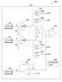
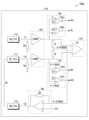
도 3 은 다양한 실시 예들에 따른 웨어러블 전자 장치의 생체 접촉 검출부의 계략적인 블록도(300)이다.FIG. 3 is a schematic block diagram (300) of a biometric contact detection unit of a wearable electronic device according to various embodiments.
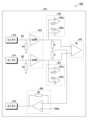
상기 도 3을 참조하면, 생체 접촉 검출부(310, 예: 도 2의 생체 접촉 검출부(215))는, 복수의 전극들(311, 312, 및 313), 전극 연결 검출부(330), 바이어스부(350) 및 계측부(370)를 포함할 수 있다.Referring to the above FIG. 3, the biocontact detection unit (310, for example, the biocontact detection unit (215) of FIG. 2) may include a plurality of electrodes (311, 312, and 313), an electrode connection detection unit (330), a bias unit (350), and a measurement unit (370).
다양한 실시 예들에 따르면, 복수의 전극들은 생체 신호 측정을 위한 제1 전극(311) 및 제3 전극(313)과, 상기 제1 전극(311) 및/또는 상기 제3 전극(313)에게 전압을 인가하는 제2 전극(312)을 포함할 수 있다.According to various embodiments, the plurality of electrodes may include a first electrode (311) and a third electrode (313) for measuring a biosignal, and a second electrode (312) for applying a voltage to the first electrode (311) and/or the third electrode (313).
일 실시 예에 따르면, 제1 전극(311)과 제3 전극(313)은, 생체의 양단(예: 오른손 및/또는 왼손)에서 생체 신호를 측정할 수 있는 센싱 전극을 포함할 수 있다.According to one embodiment, the first electrode (311) and the third electrode (313) may include sensing electrodes capable of measuring biosignals from both ends of a living body (e.g., the right hand and/or the left hand).
일 실시 예에 따르면, 제1 전극(311)은 생체의 제1 부위(예: 손목)가 접촉될 수 있는 위치에 장착되고, 제3 전극(313)은 생체의 제2 부위(예: 손가락)가 접촉될 수 있는 위치에 장착될 수 있다. 상기 제3 전극(313)은 상기 제1 전극(311) 및 상기 제2 전극(312)이 장착된 위치와는 상이한 위치에 장착되어 상기 생체의 제2 부위(예: 손가락)가 접촉될 수 있다.According to one embodiment, the first electrode (311) may be mounted at a location where a first part of a living body (e.g., a wrist) may be contacted, and the third electrode (313) may be mounted at a location where a second part of a living body (e.g., a finger) may be contacted. The third electrode (313) may be mounted at a location different from the locations where the first electrode (311) and the second electrode (312) are mounted, so that the second part of the living body (e.g., a finger) may be contacted.
일 실시 예에 따르면, 제2 전극(312)은 제1 전극(311) 또는 제3 전극(313)과 동일한 면에 위치할 수 있다. 예를 들어 제2 전극(312)은 상기 제1 전극(311)과 동일한 면에 위치하여 상기 제1 전극(311)과 동시에 생체의 제1 부위(예: 손목)에 접촉될 수 있다.According to one embodiment, the second electrode (312) may be positioned on the same side as the first electrode (311) or the third electrode (313). For example, the second electrode (312) may be positioned on the same side as the first electrode (311) and may be brought into contact with a first part of the living body (e.g., wrist) at the same time as the first electrode (311).
일 실시 예에 따르면, 제2 전극(312)은, 상기 제1 전극(311)과 동시에 생체의 제1 부위(예: 손목)에 접촉되면, 상기 생체 제1 부위(예: 손목)을 통해 상기 제2 전극(312)과 상기 제1 전극(311)간에 생성된 패쇄 루프(closed loop)로, 상기 제2 전극(312)과 상기 제1 전극(311)간에 패스가 형성되고, 상기 패스를 통해 상기 제1 전극(311)에게 제1 전압을 인가할 수 있다.According to one embodiment, when the second electrode (312) is brought into contact with a first portion of a living body (e.g., a wrist) at the same time as the first electrode (311), a closed loop is created between the second electrode (312) and the first electrode (311) through the first portion of the living body (e.g., a wrist), and a path is formed between the second electrode (312) and the first electrode (311), and a first voltage can be applied to the first electrode (311) through the path.
일 실시 예에 따르면, 제2 전극(312)은, 제1 전극(311)에 제1 전압을 인가하는 동안, 제3 전극(313)에 생체의 제2 부위(예: 손가락)가 접촉되어 상기 제2 전극(312)과 상기 제3 전극(313)간에 추가 패스가 형성되면, 상기 제2 전극(312)은 상기 제1 전극(311)과 상기 제3 전극(313) 각각에게 동일한 제2 전압을 인가할 수 있다. 상기 제2 전압은 상기 제1 전압 보다 낮은 전압일 수 있다.According to one embodiment, when a second part of a living body (e.g., a finger) comes into contact with a third electrode (313) while applying a first voltage to the first electrode (311) and an additional path is formed between the second electrode (312) and the third electrode (313), the second electrode (312) may apply the same second voltage to each of the first electrode (311) and the third electrode (313). The second voltage may be a lower voltage than the first voltage.
다양한 실시 예에 따르면, 전극 연결 검출부(330)는 제1 전극(311) 및/또는 제3 전극(313)에서 출력되는 전압을 기반으로, 웨어러블 전자 장치(예: 도 2의 웨어러블 전자 장치(201))의 생체 신호 측정을 위한 동작 상태를 알리는 정보를 출력할 수 있다.According to various embodiments, the electrode connection detection unit (330) may output information indicating an operating state for measuring a biosignal of a wearable electronic device (e.g., the wearable electronic device (201) of FIG. 2) based on a voltage output from the first electrode (311) and/or the third electrode (313).
일 실시 예에 따르면, 전극 연결 검출부(330)는, 제1 전극(311)에서 출력되는 전압(예: 제1 전압 또는 제2 전압)을 기반으로 상기 웨어러블 전자 장치의 상기 동작 상태가 생체 신호 측정의 준비 상태임을 알리는 제1 정보를 출력할 수 있다.According to one embodiment, the electrode connection detection unit (330) may output first information indicating that the operating state of the wearable electronic device is a state of readiness for biosignal measurement based on a voltage (e.g., a first voltage or a second voltage) output from the first electrode (311).
일 실시 예에 따르면, 전극 연결 검출부(330)는, 제1 전극(311)과 제3 전극(313)에서 출력되는 제2 전압을 기반으로 상기 웨어러블 전자 장치의 상기 동작 상태가 생체 신호를 측정할 수 있는 상태임을 알리는 제2 정보를 출력할 수 있다.According to one embodiment, the electrode connection detection unit (330) can output second information indicating that the operating state of the wearable electronic device is a state in which a biosignal can be measured based on the second voltage output from the first electrode (311) and the third electrode (313).
일 실시 예에 따르면, 전극 연결 검출부(330)는, 제1 전극(311)과 제3 전극(313)이 생체의 어느 부위와도 접촉되지 않으면, 제2 전극(312)으로부터 전압이 인가되지 않은 상기 제1 전극(311) 및 상기 제3 전극(313)에서 출력되는 전압(예: 0V)을 기반으로, 상기 웨어러블 전자 장치의 상기 동작 상태가 생체 신호 측정의 중지 상태임을 알리는 제3 정보를 출력할 수 있다.According to one embodiment, if the first electrode (311) and the third electrode (313) do not come into contact with any part of the living body, the electrode connection detection unit (330) may output third information indicating that the operating state of the wearable electronic device is a state of stopping biosignal measurement based on a voltage (e.g., 0 V) output from the first electrode (311) and the third electrode (313) to which no voltage is applied from the second electrode (312).
일 실시 예에 따르면, 전극 연결 검출부(330)는 제1 전극(311)에서 출력되는 제1 전압 및/또는 제2 전압과 제1 기준 전압을 비교한 제1 비교 값을 출력하는 제1 연결 검출부(331)와, 제3 전극(313)에서 출력되는 제2 전압과 제2 기준 전압을 비교한 제2 비교 값을 출력하는 제2 연결 검출부(332)를 포함할 수 있다. 상기 전극 연결 검출부(330)는 상기 제1 연결 검출부(331)에서 출력된 제1 비교 값과 상기 제2 연결 검출부(332)에서 출력된 제2 비교 값을 합하여 상기 웨어러블 전자 장치의 생체 신호 측정을 위한 동작 상태를 알리는 정보로 출력할 수 있다.According to one embodiment, the electrode connection detection unit (330) may include a first connection detection unit (331) that outputs a first comparison value by comparing a first voltage and/or a second voltage output from a first electrode (311) with a first reference voltage, and a second connection detection unit (332) that outputs a second comparison value by comparing a second voltage output from a third electrode (313) with a second reference voltage. The electrode connection detection unit (330) may add the first comparison value output from the first connection detection unit (331) and the second comparison value output from the second connection detection unit (332) to output information indicating an operating state for measuring a biosignal of the wearable electronic device.
다양한 실시 예에 따르면, 바이어스부(350)는, 제2 전극(312)에서 패스가 형성된 제1 전극(311) 및/또는 제3 전극(313)에게 인가하기 위한 전압을 제1 전압 및/또는 상기 제2 전압으로 조정할 수 있다.According to various embodiments, the bias unit (350) can adjust the voltage to be applied to the first electrode (311) and/or the third electrode (313) in which a pass is formed in the second electrode (312) to the first voltage and/or the second voltage.
일 실시 예에 따르면, 바이어스부(350)는 반전 가산 증폭기(Inverting summing amplifier)로 구성될 수 있다.According to one embodiment, the bias unit (350) may be configured as an inverting summing amplifier.
다양한 실시 예에 따르면, 계측부(370)는, 제1 전극(311)과 제3 전극(313) 각각에서 측정된 전위 값들의 차를 이용하여 생체 신호를 측정할 수 있다.According to various embodiments, the measuring unit (370) can measure a biosignal by using the difference between potential values measured from each of the first electrode (311) and the third electrode (313).
일 실시예에 따르면, 계측부(370)는, 차동 증폭기(differential amplifier) 또는 입력 임피던스가 매우 높은 계측용 증폭기(instrumentation amplifier; IA)를 포함할 수 있다.In one embodiment, the instrumentation unit (370) may include a differential amplifier or an instrumentation amplifier (IA) having a very high input impedance.
도 4a 내지 도 4d는 다양한 실시 예들에 따른 웨어러블 전자 장치의 전극들을 설명하기 위한 도면(400a 내지 400d)이다.FIGS. 4A to 4D are drawings (400a to 400d) for explaining electrodes of a wearable electronic device according to various embodiments.
상기 도 4a에서는 웨어러블 전자 장치(401)의 전면(401a)과 후면(401b)을 도시하고 있다.The above FIG. 4a illustrates the front (401a) and the back (401b) of the wearable electronic device (401).
상기 도 4a와 같이 웨어러블 전자 장치(401)의 후면(401b)에 생체 신호 측정을 위한 제1 전극(411, 예: 도 3의 제1 전극(311))을 배치하고, 상기 제1 전극(411)과 동일한 면에 제1 전극(411)과 제3 전극(413, 예: 도 3의 제3 전극(313)))에 전압을 인가하는 제2 전극(412, 예: 도 3의 제2 전극(312))을 배치할 수 있다. 그리고, 웨어러블 전자 장치(401)가 착용된 손과 반대되는 손이 접촉될 수 있는 웨어러블 전자 장치(401)의 측면에 생체 신호 측정을 위한 상기 제3 전극(413)을 배치할 수 있다. 또한 웨어러블 전자 장치(401)의 후면(401b)의 중앙의 위치에 심박수 측정을 위한PPG(photoplethysmography)센서(415)가 장착될 수 있다.As shown in the above FIG. 4A, a first electrode (411, for example, the first electrode (311) of FIG. 3) for measuring a biosignal may be placed on the rear surface (401b) of a wearable electronic device (401), and a second electrode (412, for example, the second electrode (312) of FIG. 3) for applying voltage to the first electrode (411) and the third electrode (413, for example, the third electrode (313) of FIG. 3)) may be placed on the same surface as the first electrode (411). In addition, the third electrode (413) for measuring a biosignal may be placed on a side of the wearable electronic device (401) that may be in contact with a hand opposite to the hand on which the wearable electronic device (401) is worn. Additionally, aPPG (photoplethysmography)sensor (415) for heart rate measurement may be mounted at the center of the rear (401b) of the wearable electronic device (401).
상기 도 4b와 같이, 사용자의 손목에 웨어러블 전자 장치(401)가 착용되어 제1 전극(411)과 제2 전극(412)에 사용자의 생체의 제1부위(예: 손목)가 접촉되고, 상기 웨어러블 전자 장치(401)의 우측 측면에 배치된 제 3 전극(413)에 사용자의 생체의 제2 부위(예: 손가락)가 접촉될 수 있다.As shown in the above FIG. 4b, a wearable electronic device (401) is worn on the user's wrist, and a first part of the user's body (e.g., wrist) may be in contact with the first electrode (411) and the second electrode (412), and a second part of the user's body (e.g., finger) may be in contact with the third electrode (413) arranged on the right side of the wearable electronic device (401).
사용자의 손목에 웨어러블 전자 장치(401)가 착용되어 제1 전극(411)과 제2 전극(412)에 사용자의 생체의 제1부위(예: 손목)가 접촉된 상태에서, 사용자의 생체의 제2 부위(예: 손가락)가 접촉될 수 있는 제3 전극은 다양한 위치에 배치될 수 있다. 예를 들어, 제3 전극(413)은 웨어러블 전자 장치(401)의 좌측 측면 또는 도 4b와 같이 우측 측면에 배치될 수 있다.When a wearable electronic device (401) is worn on a user's wrist and a first part of the user's body (e.g., wrist) is in contact with the first electrode (411) and the second electrode (412), a third electrode that can be in contact with a second part of the user's body (e.g., finger) can be placed at various locations. For example, the third electrode (413) can be placed on the left side of the wearable electronic device (401) or on the right side as shown in FIG. 4B.
또는 도 4c와 같이, 제3 전극(413)은 웨어러블 전자 장치(401)의 디스플레이(460, 예: 도 1d의 디스플레이(120a) 또는 도 2의 디스플레이(260))에 투명 전극으로 포함되어, 사용자의 생체의 제2 부위(예: 손가락)가 접촉될 수 있다.Alternatively, as in FIG. 4c, the third electrode (413) may be included as a transparent electrode in the display (460, e.g., display (120a) of FIG. 1d or display (260) of FIG. 2) of the wearable electronic device (401), so that a second part of the user's body (e.g., finger) may come into contact with it.
또는 도 4d와 같이, 제3 전극(413)은 웨어러블 전자 장치(401)의 베젤(402, 예: 도 1b의 106a)에 배치되어, 사용자의 생체의 제2 부위(예: 손가락)가 접촉될 수 있다. 상기 웨어러블 전자 장치(401)에 베젤이 없는 경우 웨어러블 전자 장치(401)의 하우징(예: 도 1b의 110a)에 배치되어, 사용자의 생체의 제2 부위(예: 손가락)가 접촉될 수 있다.Or, as in FIG. 4d, the third electrode (413) may be placed on a bezel (402, for example, 106a of FIG. 1b) of the wearable electronic device (401) so that a second part of the user's body (for example, a finger) may be brought into contact with it. If the wearable electronic device (401) does not have a bezel, it may be placed on a housing (for example, 110a of FIG. 1b) of the wearable electronic device (401) so that a second part of the user's body (for example, a finger) may be brought into contact with it.
도 5는 다양한 실시 예들에 따른 웨어러블 전자 장치의 생체 접촉 검출부의 회로도(500)이다. 상기 도 5는 상기 도 3의 웨어러블 전자 장치의 생체 접촉 검출부(310)에 대한 회로도를 도시하고 있다.Fig. 5 is a circuit diagram (500) of a bio-contact detection unit of a wearable electronic device according to various embodiments. The Fig. 5 illustrates a circuit diagram of a bio-contact detection unit (310) of the wearable electronic device of Fig. 3.
상기 도 5와 같이, 생체 접촉 검출부(510)는, 복수의 전극들(511, 512, 및 513), 복수의 전극들 중 생체 신호 측정을 위한 제1 전극(511) 및 제3 전극(513)에서 출력되는 전압을 처리하는 높은 입력 임피던스를 가지는 복수의 버퍼들(523), 전극 연결 검출부(531, 532), 바이어스부(550), 및 상기 복수의 전극들 중 생체 신호 측정을 위한 제1 전극(511) 및 제3 전극(513)을 기반으로 생체 신호를 측정하는 계측부(570)를 포함할 수 있다.As shown in the above drawing 5, the bio-contact detection unit (510) may include a plurality of electrodes (511, 512, and 513), a plurality of buffers (523) having high input impedance for processing voltages output from the first electrode (511) and the third electrode (513) for measuring a bio-signal among the plurality of electrodes, an electrode connection detection unit (531, 532), a bias unit (550), and a measurement unit (570) for measuring a bio-signal based on the first electrode (511) and the third electrode (513) for measuring a bio-signal among the plurality of electrodes.
상기 복수의 전극들은, 생체 신호 측정을 위한 제1 전극(511) 및 제3 전극(513)과, 상기 제1 전극(511) 및 상기 제3 전극(513)에 일정 전압을 인가할 수 있는 제2 전극(512)을 포함할 수 있다.The above plurality of electrodes may include a first electrode (511) and a third electrode (513) for measuring biosignals, and a second electrode (512) capable of applying a constant voltage to the first electrode (511) and the third electrode (513).
상기 전극 연결 검출부(531, 532)는 제1 전극(511)에서 출력되는 제1 전압 및/또는 제2 전압과 제1 기준 전압을 비교하는 제1 연결 검출부(531)와 제3 전극(513)에서 출력되는 제2 전압과 제2 기준 전압을 비교하는 제2 연결 검출부(532)를 포함할 수 있다.The above electrode connection detection unit (531, 532) may include a first connection detection unit (531) that compares a first voltage and/or a second voltage output from a first electrode (511) with a first reference voltage, and a second connection detection unit (532) that compares a second voltage output from a third electrode (513) with a second reference voltage.
상기 제1 연결 검출부(531)는 제1 비교기(531a)와 제2 비교기(531b)를 포함하고, 상기 제1 비교기(531a)의 제1 기준 전압(TH_L)을 "0.4V"로 설정하고, 상기 제2 비교기(531b)의 제1 기준 전압(TH_H)을 "1.4V"로 설정할 수 있다.The first connection detection unit (531) includes a first comparator (531a) and a second comparator (531b), and the first reference voltage (TH_L) of the first comparator (531a) can be set to “0.4 V” and the first reference voltage (TH_H) of the second comparator (531b) can be set to “1.4 V”.
일 실시예에 따르면, 제1 비교기(531a)의 제1 기준 전압(TH_L)과 제2 비교기(531b)의 제1 기준 전압(TH_H)은 검출력 향상을 위해 프로세서(예: 도 2의 프로세서(220))에 의해 조정될 수 있다. 상기 프로세서는 상기 웨어러블 전자 장치의 생체 신호 측정을 위한 동작 상태에 따라, 상기 제1 비교기(531a)의 제1 기준 전압(TH_L)과 상기 제2 비교기(531b)의 제1 기준 전압(TH_H)을 조정할 수 있다. 상기 프로세서는 상기 웨어러블 전자 장치의 생체 신호 측정을 위한 동작 상태가 생체 신호 측정의 준비 상태이면, 상기 제1 비교기(531a)의 제1 기준 전압(TH_L)과 상기 제2 비교기(531b)의 제1 기준 전압(TH_H)의 범위를 제1 범위로 조정하고, 상기 웨어러블 전자 장치의 생체 신호 측정을 위한 동작 상태가 생체 신호의 측정 상태이면, 상기 제1 비교기(531a)의 제1 기준 전압(TH_L)과 상기 제2 비교기(531b)의 제1 기준 전압(TH_H)간의 범위를 제1 범위로 보다 작거나 또는 큰 제2 범위로 조정할 수 있다.According to one embodiment, the first reference voltage (TH_L) of the first comparator (531a) and the first reference voltage (TH_H) of the second comparator (531b) may be adjusted by a processor (e.g., the processor (220) of FIG. 2) to improve detection power. The processor may adjust the first reference voltage (TH_L) of the first comparator (531a) and the first reference voltage (TH_H) of the second comparator (531b) according to an operating state for measuring a biosignal of the wearable electronic device. If the operating state of the wearable electronic device for measuring a biosignal is a state ready for measuring a biosignal, the processor can adjust the range of the first reference voltage (TH_L) of the first comparator (531a) and the first reference voltage (TH_H) of the second comparator (531b) to a first range, and if the operating state of the wearable electronic device for measuring a biosignal is a state of measuring a biosignal, the processor can adjust the range between the first reference voltage (TH_L) of the first comparator (531a) and the first reference voltage (TH_H) of the second comparator (531b) to a second range that is smaller than or larger than the first range.
상기 제2 연결 검출부(532)는 제1 비교기(532a)와 제2 비교기(532b)를 포함하고, 상기 제1 비교기(532a)의 제2 기준 전압(TH_H)을 "1.4V"로 설정하고, 상기 제2 비교기(532b)의 제2 기준 전압(TH_L)을 "0.4V"로 설정할 수 있다.The second connection detection unit (532) includes a first comparator (532a) and a second comparator (532b), and the second reference voltage (TH_H) of the first comparator (532a) can be set to “1.4 V” and the second reference voltage (TH_L) of the second comparator (532b) can be set to “0.4 V”.
일 실시예에 따르면, 제1 비교기(532a)의 제2 기준 전압(TH_H)과 제2 비교기(532b)의 제2 기준 전압(TH_L)은 검출력 향상을 위해 프로세서(예: 도 2의 프로세서(220))에 의해 조정될 수 있다. 상기 프로세서는 상기 웨어러블 전자 장치의 생체 신호 측정을 위한 동작 상태에 따라, 상기 제1 비교기(532a)의 상기 제2 기준 전압(TH_H)과 상기 제2 비교기(532b)의 상기 제2 기준 전압(TH_L)을 조정할 수 있다. 상기 프로세서는 상기 웨어러블 전자 장치의 생체 신호 측정을 위한 동작 상태가 생체 신호 측정의 준비 상태이면, 제1 비교기(532a)의 제2 기준 전압(TH_H)과 제2 비교기(532b)의 제2 기준 전압(TH_L)간의 범위를 제3 범위로 조정하고, 상기 웨어러블 전자 장치의 생체 신호 측정을 위한 동작 상태가 생체 신호의 측정 상태이면, 제1 비교기(532a)의 제2 기준 전압(TH_H)과 제2 비교기(532b)의 제2 기준 전압(TH_L)간의 범위를 제3 범위로 보다 작거나 또는 큰 제4 범위로 조정할 수 있다.According to one embodiment, the second reference voltage (TH_H) of the first comparator (532a) and the second reference voltage (TH_L) of the second comparator (532b) may be adjusted by a processor (e.g., the processor (220) of FIG. 2) to improve detection power. The processor may adjust the second reference voltage (TH_H) of the first comparator (532a) and the second reference voltage (TH_L) of the second comparator (532b) according to an operating state for measuring a biosignal of the wearable electronic device. If the operating state of the wearable electronic device for measuring a biosignal is a state ready for measuring a biosignal, the processor can adjust the range between the second reference voltage (TH_H) of the first comparator (532a) and the second reference voltage (TH_L) of the second comparator (532b) to a third range, and if the operating state of the wearable electronic device for measuring a biosignal is a state of measuring a biosignal, the processor can adjust the range between the second reference voltage (TH_H) of the first comparator (532a) and the second reference voltage (TH_L) of the second comparator (532b) to a fourth range that is smaller than or larger than the third range.
일 실시 예에 따르면, 비교기(예: 제1 연결 검출부(531)의 제1 비교기(531a) 및 제2 비교기(531b) 및/또는 제2 연결 검출부(532)의 제1 비교기(532a) 및 제2 비교기(532b))는, 비 반전(+)입력단과 반전(-) 입력 단으로 인가되는 전압을 비교하고 상기 비교 결과를 출력할 수 있으며, 예를 들어, 비 반전(+)입력 단으로 인가되는 전압이 반전(-)입력 단으로 인가되는 전압보다 높으면 "1" 값을 출력하고, 비 반전(+)신호로 인가되는 전압이 반전(-) 입력 단으로 인가되는 전압과 동일하거나 낮으면 "0" 값을 출력할 수 있다. 상기 비교기(예: 제1 연결 검출부(531)의 제1 비교기(531a) 및 제2 비교기(531b) 및/또는 제2 연결 검출부(532)의 제1 비교기(532a) 및 제2 비교기(532b))는, 그 외 다양한 비교 조건을 기반으로 비 반전(+) 입력단과 반전(-) 입력 단에 인가되는 전압을 비교하여 그 결과를 출력할 수 있다.According to one embodiment, a comparator (e.g., a first comparator (531a) and a second comparator (531b) of the first connection detection unit (531) and/or a first comparator (532a) and a second comparator (532b) of the second connection detection unit (532)) can compare voltages applied to a non-inverting (+) input terminal and an inverting (-) input terminal and output a result of the comparison. For example, if the voltage applied to the non-inverting (+) input terminal is higher than the voltage applied to the inverting (-) input terminal, a value of "1" can be output, and if the voltage applied as a non-inverting (+) signal is equal to or lower than the voltage applied to the inverting (-) input terminal, a value of "0" can be output. The above comparator (e.g., the first comparator (531a) and the second comparator (531b) of the first connection detection unit (531) and/or the first comparator (532a) and the second comparator (532b) of the second connection detection unit (532)) can compare the voltages applied to the non-inverting (+) input terminal and the inverting (-) input terminal based on various other comparison conditions and output the result.
일 실시 예에 따르면, 상기 전극 연결 검출부(531, 532)의 속성은, 외부 요인(예: 사용자의 특성(예: 손의 건조도) 및/또는 주변환경(예: 기온))에 따라 조정될 수 있다.According to one embodiment, the properties of the electrode connection detection unit (531, 532) may be adjusted according to external factors (e.g., user characteristics (e.g., dryness of hands) and/or surrounding environment (e.g., temperature)).
일 실시 예에 따르면, 상기 전극 연결 검출부(531, 532)의 속성은, 버퍼(523) 앞 단의 입력 저항(Rin)을 높이거나, 또는 비교기(예: 제1 연결 검출부(531)의 제1 비교기(531a) 및 제2 비교기(531b) 및/또는 제2 연결 검출부(532)의 제1 비교기(532a) 및 제2 비교기(532b))에 기본으로 설정된 동작 전압(예: 0.4V)을 변경함으로써 조정될 수 있다.According to one embodiment, the properties of the electrode connection detection units (531, 532) can be adjusted by increasing the input resistance (Rin) in front of the buffer (523), or by changing the operating voltage (e.g., 0.4 V) set as the default for the comparators (e.g., the first comparator (531a) and the second comparator (531b) of the first connection detection unit (531) and/or the first comparator (532a) and the second comparator (532b) of the second connection detection unit (532).
일 실시 예에 따르면, 사용자의 선택으로 또는 외부 요인(예: 사용자의 특성(예: 손의 건조도) 및/또는 주변환경(예: 기온))을 검출할 수 있는 검출 부의 검출 결과에 따라, 자동으로 상기 전극 연결 검출부(531, 532)의 속성을 변경할 수 있다.According to one embodiment, the properties of the electrode connection detection unit (531, 532) can be automatically changed based on the detection results of a detection unit capable of detecting user selection or external factors (e.g., user characteristics (e.g., dryness of hands) and/or surrounding environment (e.g., temperature)).
상기 전극 연결 검출부(531, 532)는, 제1 연결 검출부(531)에서 출력되는 정보와, 제2 연결 검출부(532)에서 출력되는 정보를 합하여 순서적으로 나열한 정보를, 웨어러블 전자 장치(예: 도 2의 웨어러블 전자 장치(201))의 생체 신호 측정을 위한 동작 상태를 알리는 정보(예: 제1 정보 또는 제2 정보)로서 출력할 수 있다The above electrode connection detection unit (531, 532) can output information that sequentially lists information by combining information output from the first connection detection unit (531) and information output from the second connection detection unit (532) as information (e.g., first information or second information) that informs of the operating status for measuring a biosignal of a wearable electronic device (e.g., wearable electronic device (201) of FIG. 2).
상기 바이어스부(550)는 반전 가산 증폭기(Inverting summing amplifier)를 포함하고, 상기 증폭기의 inverting(-)에는 제1 전극(511)과 제3 전극(513)의 평균 전압이 입력되고, noninverting(+)에 입력되는 Vbias는 0.9V로 설정할 수 있다. 또한 상기 증폭기는 0V 내지 최대 1.8V를 출력할 수 있도록 설정할 수 있다.The above bias unit (550) includes an inverting summing amplifier, and the average voltage of the first electrode (511) and the third electrode (513) is input to the inverting (-) of the amplifier, and Vbias input to the noninverting (+) can be set to 0.9 V. In addition, the amplifier can be set to output 0 V to a maximum of 1.8 V.
상기 복수의 버퍼들(523)은, 높은 임피던스를 가지는 소자로써, 제1 전극(511)과 제 3전극(513) 각각의 앞 단 노드들(B1, B2)에 높은 전압이 걸릴 수 있게 하는 역할을 수행할 수 있다.The above-mentioned plurality of buffers (523) are elements having high impedance and can perform the role of allowing a high voltage to be applied to the nodes (B1, B2) in front of each of the first electrode (511) and the third electrode (513).
상기 복수의 버퍼들(523)은, 제1 전극(511)과 제3 전극(513) 각각의 앞 단 노드들(B1, B2)에 흐르는 전류가 상기 복수의 버퍼들(523)이 위치된 방향으로 흐르는 것을 막아줌으로써, 제1 전극(511)과 제3 전극(513) 각각의 앞 단 노드들(B1, B2)에 걸리는 전압의 저하로 인해 생체 측정(예: ECG 측정) 신호가 약해질 수 있는 것을 방지할 수 있다.The above plurality of buffers (523) prevent current flowing in the front nodes (B1, B2) of each of the first electrode (511) and the third electrode (513) from flowing in the direction in which the plurality of buffers (523) are positioned, thereby preventing a biometric measurement (e.g., ECG measurement) signal from being weakened due to a decrease in voltage applied to the front nodes (B1, B2) of each of the first electrode (511) and the third electrode (513).
상기 복수의 버퍼들(523)은, 웨어러블 전자 장치와 같이 전극의 면적이 좁거나, 사용자의 피부가 건조(dry)해서 접촉 저항이 커지는 경우에, 정확한 생체 측정(예: ECG 측정)신호를 위해 사용될 수 있다.The above plurality of buffers (523) can be used for accurate biometric measurement (e.g., ECG measurement) signals in cases where the electrode area is narrow, such as in a wearable electronic device, or the user's skin is dry, increasing the contact resistance.
상기 복수의 버퍼들(523)은, 웨어러블 전자 장치에서 전극 임피던스가 일정 기준 보다 낮게 유지되는 경우, 생체 접촉 검출부(510)에 포함되지 않을 수 있다. 상기 복수의 버퍼들(523)은 전극 임피던스에 의해 영향을 최소화 하기 위한 소자임으로, 전극 임피던스가 일정 기준 보다 낮게 유지되는 시스템에서는 상기 복수의 버퍼들(523)가 포함되지 않을 수 있다.The above plurality of buffers (523) may not be included in the bio-contact detection unit (510) if the electrode impedance in the wearable electronic device is maintained below a certain standard. Since the above plurality of buffers (523) are elements for minimizing the influence by electrode impedance, the above plurality of buffers (523) may not be included in a system in which the electrode impedance is maintained below a certain standard.
도 6은 다양한 실시 예들에 따른 웨어러블 전자 장치에서 생체 접촉 검출을 설명하기 위한 도면(600)이다. 상기 도 6은 웨어러블 전자 장치에서 생체 접촉이 없는 상태인 생체 신호 측정의 중지 상태를 설명하기 위한 도면이다. 도 6은 도면부호만 상이할 뿐 도 5와 동일한 생체 접촉 검출부(610)를 나타내고 있다.FIG. 6 is a drawing (600) for explaining biocontact detection in a wearable electronic device according to various embodiments. FIG. 6 is a drawing for explaining a state of stopping biosignal measurement in which there is no biocontact in a wearable electronic device. FIG. 6 shows the same biocontact detection unit (610) as FIG. 5, except for the different drawing symbols.
상기 도 6을 참조하면, 생체 측정을 위한 제1 전극(611)과 제3 전극(613) 모두에 생체가 접촉되지 않은 상태에서, 상기 제1 전극(611)과 상기 제3 전극(613) 각각은 0V의 전압을 출력할 수 있다. 제1 연결 검출부(631)에 포함된 제1 비교기(631a)와 제2 비교기(631b)는 제1 전극(611)으로부터 출력된 0V의 전압과 제1 기준 전압(TH_L=0.4, TH_H=1.4)을 비교하고 상기 비교 결과에 따른 정보로서 "NL=1, NH = 0"를 출력할 수 있다. 또한 제2 연결 검출부(632)에 포함된 제1 비교기(632a)와 제2 비교기(632b)는 제3 전극(613)으로부터 출력된 0V의 전압과 제2 기준 전압(TH_H=1.4, TH_L=1.4)을 비교하고, 상기 비교 결과에 따른 정보로서 "PL=1, PH = 0"를 출력할 수 있다. 상기 제2 연결 검출부(632)에서 출력되는 정보(PL, PH)와, 제1 연결 검출부(631)에서 출력되는 정보(NL, NH)를 합하여 순서적 나열한 "PL, PH, NL, NH = 1010"(690)를 제3 정보로서 프로세서(예: 도 2의 프로세서(220))에게 출력할 수 있다. 상기 프로세서는 상기 생체 접촉 검출부(610)에서 출력되는 제3 정보인 "PL, PH, NL, NH = 1010"(690)를 기반으로, 웨어러블 전자 장치의 생체 신호 측정을 위한 동작 상태가 생체 신호 측정의 중지 상태임을 검출할 수 있다.Referring to the above Fig. 6, when a living body is not in contact with the first electrode (611) and the third electrode (613) for biometric measurement, each of the first electrode (611) and the third electrode (613) can output a voltage of 0 V. The first comparator (631a) and the second comparator (631b) included in the first connection detection unit (631) can compare the voltage of 0 V output from the first electrode (611) with the first reference voltage (TH_L = 0.4, TH_H = 1.4) and output "NL = 1, NH = 0" as information based on the comparison result. In addition, the first comparator (632a) and the second comparator (632b) included in the second connection detection unit (632) can compare the voltage of 0 V output from the third electrode (613) with the second reference voltage (TH_H=1.4, TH_L=1.4) and output “PL=1, PH=0” as information according to the comparison result. The information (PL, PH) output from the second connection detection unit (632) and the information (NL, NH) output from the first connection detection unit (631) can be combined and sequentially listed to output “PL, PH, NL, NH = 1010” (690) as third information to a processor (e.g., processor (220) of FIG. 2). The above processor can detect that the operating state for measuring biosignals of the wearable electronic device is a state of stopping biosignal measurement based on the third information “PL, PH, NL, NH = 1010” (690) output from the biocontact detection unit (610).
도 7a 내지 도 7d는 다양한 실시 예들에 따른 웨어러블 전자 장치에서 생체 접촉 검출을 설명하기 위한 도면(700a 내지 700d)이다. 상기 도 7a 내지 도 7d는 웨어러블 전자 장치에서 생체 신호 측정의 준비 상태를 나타내는 도면으로, 웨어러블 전자 장치에 생체의 제1 부위(예: 손목)가 접촉된 시점부터 웨어러블 전자 장치에 생체의 제1 부위(예: 손목)의 접촉을 알리는 정보를 출력할 수 있는 최종 안정상태까지의 과정을 설명하기 위한 도면이다. 도 7a 내지 도 7d는 도면부호만 상이할 뿐 도 5 내지 도 6과 동일한 생체 접촉 검출부(710)를 도시하고 있다.FIGS. 7A to 7D are drawings (700a to 700d) for explaining biometric contact detection in a wearable electronic device according to various embodiments. FIGS. 7A to 7D are drawings showing a state of preparation for biometric signal measurement in a wearable electronic device, and are drawings for explaining a process from a point in time when a first part of a living body (e.g., a wrist) comes into contact with the wearable electronic device to a final stable state in which information notifying the contact of the first part of a living body (e.g., a wrist) with the wearable electronic device can be output. FIGS. 7A to 7D illustrate a biometric contact detection unit (710) that is the same as that of FIGS. 5 to 6, except that only the drawing symbols are different.
상기 도 7a와 같이, 웨어러블 전자 장치가 사용자의 손목에 착용되는 경우, 동일한 면에 위치된 제1 전극(711)과 제2 전극(712)이 생체의 제1 부위(예: 손목)에 접촉될 수 있다. 상기 제1 전극(711)과 상기 제2 전극(712)이 생체의 제1 부위(예: 손목)에 접촉되어 상기 제1 전극(711)과 상기 제2 전극(712) 간에 패스(A1)가 형성되면, 제2 전극(712)은 상기 제1 전극(711)에 제1 전압 예를 들어, 최대 전압(Vsat)인 1.8V를 인가할 수 있다(a1).As shown in the above FIG. 7A, when the wearable electronic device is worn on the user's wrist, the first electrode (711) and the second electrode (712) positioned on the same surface may come into contact with a first part of the body (e.g., the wrist). When the first electrode (711) and the second electrode (712) come into contact with the first part of the body (e.g., the wrist) and a pass (A1) is formed between the first electrode (711) and the second electrode (712), the second electrode (712) may apply a first voltage, for example, a maximum voltage (Vsat) of 1.8 V, to the first electrode (711) (a1).
상기 도 7b와 같이, 제2 전극(712)에서 제1 전극(711)에게 최대 전압인 1.8V를 인가하면, 제1 연결 검출부(731)에 포함된 제1 비교기(731a)와 제2 비교기(731b) 각각에 제1 전극(711)으로부터 출력된 1.8V의 전압이 입력될 수 있다(a2). 그리고, 생체가 접촉되지 않은 제3 전극(713)은 0V 전압을 출력함으로, 제2 연결 검출부(732)에 포함된 제1 비교기(732a)와 제2 비교기(732b)는 제3 전극(713)으로부터 출력된 0V의 전압의 입력이 유지될 수 있다. 상기 바이어스부(760)의 inverting(-)에는 제1 전극(711)과 제3 전극(713)의 평균 전압인 0.9V가 입력될 수 있다(a3).As shown in the above Fig. 7b, when the maximum voltage of 1.8 V is applied from the second electrode (712) to the first electrode (711), the voltage of 1.8 V output from the first electrode (711) can be input to each of the first comparator (731a) and the second comparator (731b) included in the first connection detection unit (731) (a2). In addition, since the third electrode (713) that does not come into contact with the living body outputs a voltage of 0 V, the input of the voltage of 0 V output from the third electrode (713) can be maintained to the first comparator (732a) and the second comparator (732b) included in the second connection detection unit (732). The average voltage of 0.9 V, which is the voltage of the first electrode (711) and the third electrode (713), can be input to the inverting (-) of the bias unit (760) (a3).
상기 도 7c와 같이, 제1 연결 검출부(731)에 포함된 제1 비교기(731a)와 제2 비교기(731b) 각각에 입력된 1.8V의 전압과 제1 기준 전압(TH_L=0.4, TH_H=1.4)을 비교하고, 상기 비교 결과에 따른 정보로서 "NL=0, NH = 1" 정보를 출력할 수 있다(a4). 또한 제2 연결 검출부(732)에 포함된 제1 비교기(732a)와 제2 비교기(732b)는 제3 전극(713)으로부터 출력된 0V의 전압과 제2 기준 전압(TH_H=1.4, TH_L=0.4)을 비교하고 상기 비교 결과에 따른 정보인 "PL=1, PH = 0"정보의 출력을 유지할 수 있다.As shown in the above Fig. 7c, the voltage of 1.8 V input to the first comparator (731a) and the second comparator (731b) included in the first connection detection unit (731) can be compared with the first reference voltage (TH_L=0.4, TH_H=1.4), and information such as "NL=0, NH=1" can be output as information according to the comparison result (a4). In addition, the first comparator (732a) and the second comparator (732b) included in the second connection detection unit (732) can compare the voltage of 0 V output from the third electrode (713) with the second reference voltage (TH_H=1.4, TH_L=0.4), and the output of information such as "PL=1, PH=0" can be maintained as information according to the comparison result.
상기 도 7a 내지 도 7c 과정들을 통해, 상기 도 7d와 같이 최종 안정 상태로 진입하면, 제2 연결 검출부(732)에서 출력되는 정보(PL, PH)와, 제1 연결 검출부(731)에서 출력되는 정보(NL, NH)를 합하여 순서적으로 나열한 "PL, PH, NL, NH = 1001"(790)를 제1 정보로서 프로세서(예: 도 2의 프로세서(220))에게 출력할 수 있다. 상기 프로세서는 상기 생체 접촉 검출부(710)에서 출력되는 제1 정보인 "PL, PH, NL, NH = 1001" 정보(790)를 기반으로, 웨어러블 전자 장치의 생체 신호 측정을 위한 동작 상태가 생체 신호 측정의 준비 상태임을 검출할 수 있다.Through the processes of FIGS. 7a to 7c, when entering the final stable state as in FIG. 7d, the information (PL, PH) output from the second connection detection unit (732) and the information (NL, NH) output from the first connection detection unit (731) may be combined and sequentially listed to output "PL, PH, NL, NH = 1001" (790) as first information to a processor (e.g., processor (220) of FIG. 2). Based on the information (790) "PL, PH, NL, NH = 1001" as the first information output from the bio-contact detection unit (710), the processor may detect that the operating state of the wearable electronic device for bio-signal measurement is a state ready for bio-signal measurement.
도 8a 내지 도 8c는 다양한 실시 예들에 따른 웨어러블 전자 장치에서 생체 접촉 검출을 설명하기 위한 도면(800a 내지 800c)이다. 상기 도 8a 내지 도 8c는 웨어러블 전자 장치에서 생체 신호를 측정 할 수 있는 상태를 나타내는 도면으로,웨어러블 전자 장치에 생체의 제1 부위(예: 손목)가 접촉된 상태에서 상기 웨어러블 전자 장치에 생체의 제2 부위(예: 손가락)가 접촉된 시점부터 상기 웨어러블 전자 장치에 생체의 제1 부위(예: 손목)와 제2 부위(예: 손가락) 모두의 접촉을 알리는 정보를 출력할 수 있는 최종 안정상태까지의 과정을 설명하기 위한 도면이다. 도 8a 내지 도 8c는 도면부호만 상이할 뿐 도 5 내지 도 7과 동일한 생체 접촉 검출부(810)를 나타내고 있다.FIGS. 8A to 8C are drawings (800a to 800c) for explaining bio-contact detection in a wearable electronic device according to various embodiments. FIGS. 8A to 8C are drawings showing a state in which a bio-signal can be measured in a wearable electronic device, and are drawings for explaining a process from a point in time when a first part (e.g., a wrist) of a living body is in contact with the wearable electronic device and a second part (e.g., a finger) of a living body is in contact with the wearable electronic device to a final stable state in which information notifying contact of both the first part (e.g., a wrist) and the second part (e.g., a finger) of a living body can be output to the wearable electronic device. FIGS. 8A to 8C show a bio-contact detection unit (810) that is the same as that in FIGS. 5 to 7, except for different drawing reference numerals.
상기 도 8a에서와 같이, 생체 접촉 검출부(810)에서 웨어러블 전자 장치에 생체의 제1 부위(예: 손목)가 접촉되고 있음을 알리는 제1 정보인 "PL, PH, NL, NH = 1001"(790)을 출력하는 동안, 제3 전극(813)에 생체의 제2 부위(예: 손가락)가 접촉되면, 제2 전극(812)과 상기 제3 전극(813)간에 패스(A2)가 추가로 형성될 수 있다. 상기 제2 전극(812)과 상기 제3 전극(813)간에 패스(A2)가 추가로 형성되면, 제3 전극(813)의 전압이 상승하고(b1), 그에 따라 제2 연결 검출부(832)에 출력되는 전압이 상승되며(b2), 상기 바이어스부(860)의 inverting(-)에는 제1 전극(811)과 제3 전극(813)의 평균 전압이 상승하여(b3), 상기 바이어스부(860)의 출력 전압이 하락할 수 있다(b4).As shown in the above FIG. 8A, while the biometric contact detection unit (810) outputs the first information “PL, PH, NL, NH = 1001” (790) notifying that a first part of a living body (e.g., a wrist) is in contact with the wearable electronic device, if a second part of a living body (e.g., a finger) is in contact with the third electrode (813), a pass (A2) may be additionally formed between the second electrode (812) and the third electrode (813). When a pass (A2) is additionally formed between the second electrode (812) and the third electrode (813), the voltage of the third electrode (813) increases (b1), and accordingly, the voltage output to the second connection detection unit (832) increases (b2), and when the bias unit (860) is inverted (-), the average voltage of the first electrode (811) and the third electrode (813) increases (b3), and the output voltage of the bias unit (860) may decrease (b4).
상기 도 8b와 같이 상기 바이어스부(860)의 inverting(-)에 입력되는 상기 평균 전압이 상승됨에 따라 상기 바이어스부(860)의 출력 전압이 하락하면, 제2 전극(812)에서 제1 전극(811)에 인가하는 전압이 하락하고(b5) 그에 따라 제1 연결 검출부(831)에서 출력되는 전압이 하락할 수 있다(b6).As shown in the above drawing 8b, when the average voltage input to the inverting (-) of the bias unit (860) increases and the output voltage of the bias unit (860) decreases, the voltage applied from the second electrode (812) to the first electrode (811) decreases (b5), and accordingly, the voltage output from the first connection detection unit (831) may decrease (b6).
상기 도 8a 내지 도 8b와 같이, 제1 전극(811)과 제2 전극(812)에 동시에 생체의 제1 부위(예: 손목)가 접촉된 상태에서 제3 전극(813)에 생체의 제2 부위(예: 손가락)의 접촉으로, 바이어스부(860)의 출력 값이 변화되는 경우, 상기 도 8c와 같이, 상기 제2 전극(812)이 상기 제1 전극(811)과 상기 제3 전극(813) 각각에 동일한 제2 전압이 인가되도록, 상기 바이어스부(860)의 inverting(-)에 입력되는 상기 제1 전극(811)과 상기 제3 전극(813)간의 평균 전압을 일정 전압(예: 0.9V)으로 조정할 수 있다. 상기 평균 전압을 상기 일정 전압(예: 0.9V)으로 조정하는 경우, 상기 제1 전극(811)과 상기 제3 전극(813)에 인가되는 제2 전압은 0.4V 내지 1.4V가 될 수 있다.As shown in the above FIGS. 8a and 8b, when the output value of the bias unit (860) changes due to the contact of the second part of the living body (e.g., a finger) to the third electrode (813) while the first part of the living body (e.g., a wrist) is simultaneously contacted with the first electrode (811) and the second electrode (812), as shown in the above FIG. 8c, the average voltage between the first electrode (811) and the third electrode (813) input to the inverting (-) of the bias unit (860) can be adjusted to a constant voltage (e.g., 0.9 V) so that the same second voltage is applied to each of the first electrode (811) and the third electrode (813). When the above average voltage is adjusted to the above constant voltage (e.g., 0.9 V), the second voltage applied to the first electrode (811) and the third electrode (813) can be 0.4 V to 1.4 V.
상기 도 8c에서와 같이, 상기 평균 전압을 상기 일정 전압(예: 0.9V)으로 조정하기 위해 제1 전극(811)의 전압을 목표 전압 값(예: 0.9V)으로 하락시키고, 제3 전극(813)의 전압을 목표 전압 값(예: 0.9V)으로 상승시켜서(b7), 상기 평균 전압을 상기 일정 전압(예: 0.9V)으로 조정할 수 있다(b8). 상기 바이어스부(860)의 inverting(-)에 일정 전압으로 조정된 평균 전압(예: 0.9V)이 입력되면, 상기 바이어스부(860)는 목표 전압 값(예: 0.9V)을 출력할 수 있다(b9). 상기 제2 전극(812)이 상기 제1 전극(811)과 상기 제3 전극(813) 각각에 제2 전압(예: 0.9V)을 인가함에 따라, 제1 연결 검출부(831)와 제2 연결 검출부(832)에 제2 전압(예: 0.9V)을 출력할 수 있다.As in the above FIG. 8c, in order to adjust the average voltage to the constant voltage (e.g., 0.9 V), the voltage of the first electrode (811) is lowered to the target voltage value (e.g., 0.9 V) and the voltage of the third electrode (813) is raised to the target voltage value (e.g., 0.9 V) (b7), so that the average voltage can be adjusted to the constant voltage (e.g., 0.9 V) (b8). When the average voltage (e.g., 0.9 V) adjusted to the constant voltage is input to the inverting (-) of the bias unit (860), the bias unit (860) can output the target voltage value (e.g., 0.9 V) (b9). As the second electrode (812) applies a second voltage (e.g., 0.9 V) to each of the first electrode (811) and the third electrode (813), the second voltage (e.g., 0.9 V) can be output to the first connection detection unit (831) and the second connection detection unit (832).
상기 제1 연결 검출부(831)에 포함된 제1 비교기(831a)와 제2 비교기(831b) 각각에 입력된 제2 전압(예: 0.9V)과 제1 기준 전압(TH_L=0.4, TH_H=1.4)을 비교하고, 상기 비교 결과에 따른 정보로서 "NL=0, NH = 0" 정보를 출력할 수 있다(b10). 또한 제2 연결 검출부(832)에 포함된 제1 비교기(832a)와 제2 비교기(832b)에 각각 입력된 제2 전압(예: 0.9V)과 제2 기준 전압(TH_H=1.4, TH_L=0.4)을 비교하고 상기 비교 결과에 따른 정보인 "PL=0, PH = 0"정보의 출력을 유지할 수 있다. 상기 제2 연결 검출부(832)에서 출력되는 정보(PL, PH)와, 제1 연결 검출부(831)에서 출력되는 정보(NL, NH)를 합하여 순서적으로 나열한 제2 정보인 "PL, PH, NL, NH = 0000"(890)를 프로세서(예: 도 2의 프로세서(220))에게 출력할 수 있다. 상기 프로세서는 상기 생체 접촉 검출부(810)에서 출력되는 제2 정보인 "PL, PH, NL, NH = 0000"(890)를 기반으로, 웨어러블 전자 장치의 생체 신호 측정을 위한 동작 상태가 생체 신호를 측정할 수 있는 상태임을 검출할 수 있다.The second voltage (e.g., 0.9 V) input to each of the first comparator (831a) and the second comparator (831b) included in the first connection detection unit (831) is compared with the first reference voltage (TH_L=0.4, TH_H=1.4), and information "NL=0, NH=0" can be output as information according to the comparison result (b10). In addition, the second voltage (e.g., 0.9 V) input to each of the first comparator (832a) and the second comparator (832b) included in the second connection detection unit (832) is compared with the second reference voltage (TH_H=1.4, TH_L=0.4), and the output of information "PL=0, PH=0", which is information according to the comparison result, can be maintained. The second information "PL, PH, NL, NH = 0000" (890) can be sequentially listed by combining the information (PL, PH) output from the second connection detection unit (832) and the information (NL, NH) output from the first connection detection unit (831), and outputting it to a processor (e.g., processor (220) of FIG. 2). Based on the second information "PL, PH, NL, NH = 0000" (890) output from the biocontact detection unit (810), the processor can detect that the operating state for biosignal measurement of the wearable electronic device is a state in which biosignals can be measured.
다양한 실시 예들에 따르면, 웨어러블 전자 장치(예: 도 2의 웨어러블 전자 장치(201))는, 생체 신호 측정을 위한 적어도 두 개의 전극들(예: 도 3의 제1 전극(312) 및 제3 전극(313)), 상기 적어도 두 개의 전극들 중 생체와 접촉된 적어도 하나의 전극에 전압을 인가하고,상기 적어도 하나의 전극에서 출력되는 전압을 기반으로 상기 웨어러블 전자 장치의 생체 신호 측정을 위한 동작 상태를 알리는 정보를 출력하도록 설정된 생체 접촉 검출부(예: 도 2의 생체 접촉 검출부(215) 또는 도 3의 생체 접촉 검출부(310)), 및 상기 생체 접촉 검출부로부터 수신된 상기 정보를 기반으로, 상기 웨어러블 전자 장치의 생체 신호 측정을 위한 동작 상태를 결정하도록 설정된 프로세서(예: 도 1a의 프로세서(120) 또는 도 2의 프로세서(220))를 포함할 수 있다.According to various embodiments, a wearable electronic device (e.g., a wearable electronic device (201) of FIG. 2) may include at least two electrodes for measuring a biosignal (e.g., a first electrode (312) and a third electrode (313) of FIG. 3), a biocontact detection unit configured to apply a voltage to at least one electrode in contact with a living body among the at least two electrodes, and output information indicating an operating state for measuring a biosignal of the wearable electronic device based on a voltage output from the at least one electrode (e.g., a biocontact detection unit (215) of FIG. 2 or a biocontact detection unit (310) of FIG. 3), and a processor configured to determine an operating state for measuring a biosignal of the wearable electronic device based on the information received from the biocontact detection unit (e.g., a processor (120) of FIG. 1A or a processor (220) of FIG. 2).
다양한 실시 예들에 따르면, 상기 생체 접촉 검출부(예: 도 3의 생체 접촉 검출부(310))는, 상기 생체 신호 측정을 위한 상기 적어도 두 개의 전극들 중 제1 전극(예: 도 3의 제1 전극(311))에 상기 생체의 제1 부위가 접촉되면 상기 제 1 전극에 제1 전압을 인가하고, 상기 적어도 두 개의 전극들 중 상기 제1 전극과 제3 전극(예: 도 3의 제3 전극(313)) 각각에 생체의 제1 부위와 상기 생체의 제2부위가 접촉되면 상기 제 1 전극과 상기 제3 전극 각각에 상기 제1 전압과 다른 제2 전압을 인가하도록 설정될 수 있다.According to various embodiments, the bio-contact detection unit (e.g., the bio-contact detection unit (310) of FIG. 3) may be configured to apply a first voltage to a first electrode (e.g., the first electrode (311) of FIG. 3) of the at least two electrodes for measuring the bio-signal when a first part of the bio-signal comes into contact with the first electrode, and to apply a second voltage, different from the first voltage, to each of the first electrode and the third electrode (e.g., the third electrode (313) of FIG. 3) of the at least two electrodes when the first part of the bio-signal and the second part of the bio-signal come into contact with each of the first electrode and the third electrode.
다양한 실시 예들에 따르면, 상기 생체 접촉 검출부(예: 도 3의 생체 접촉 검출부(310))는, 상기 생체 신호를 측정하는 제1전극과 전압을 인가하는 제2 전극이 상기 생체의 제1 부위에 접촉되면, 상기 제2 전극에서 상기 제1 전극에게 인가하는 제1 전압을 기반으로, 상기 웨어러블 전자 장치의 상기 동작 상태가 생체 신호 측정의 준비 상태임을 알리는 제1정보를 출력하고, 상기 제1 정보를 출력하는 동안 상기 생체 신호를 측정하는 제3전극이 상기 생체의 제2 부위에 접촉되면, 상기 제2 전극에서 상기 제1 전극 및 상기 제3 전극 각각에게 인가하는 제2 전압을 기반으로, 상기 웨어러블 전자 장치의 상기 동작 상태가 생체 신호를 측정할 수 있는 상태임을 알리는 제2 정보를 출력하도록 설정될 수 있다.According to various embodiments, the bio-contact detection unit (e.g., the bio-contact detection unit (310) of FIG. 3) may be configured to output first information notifying that the operating state of the wearable electronic device is a state ready for bio-signal measurement based on a first voltage applied from the second electrode to the first electrode when a first electrode for measuring the bio-signal and a second electrode for applying a voltage come into contact with a first part of the living body, and to output second information notifying that the operating state of the wearable electronic device is a state capable of measuring a bio-signal based on a second voltage applied from the second electrode to each of the first electrode and the third electrode while the first information is being output.
다양한 실시 예들에 따르면, 상기 생체 접촉 검출부(예: 도 3의 생체 접촉 검출부(310))는, 상기 제1 전극과 상기 제3 전극이 상기 생체의 어느 부위와도 접촉되지 않으면, 상기 제2 전극으로부터 전압이 인가되지 않은 상기 제1 전극 및 상기 제3 전극에서 출력되는 전압을 기반으로, 상기 웨어러블 전자 장치의 상기 동작 상태가 생체 신호 측정의 중지 상태임을 알리는 제3 정보를 출력하도록 설정될 수 있다.According to various embodiments, the bio-contact detection unit (e.g., the bio-contact detection unit (310) of FIG. 3) may be configured to output third information indicating that the operating state of the wearable electronic device is a state of stopping bio-signal measurement, based on voltages output from the first electrode and the third electrode to which no voltage is applied from the second electrode, if the first electrode and the third electrode do not come into contact with any part of the living body.
다양한 실시 예들에 따르면, 상기 생체 접촉 검출부(예: 도 3의 생체 접촉 검출부(310))는, 상기 생체 신호 측정을 위한 제1 전극(예: 도 3의 제1 전극(311) 및 제3 전극(예: 도 3의 제3 전극(313)과, 상기 제1 전극 및 상기 제3 전극에게 전압을 인가하는 제2 전극(예: 도 2의 제2 전극))을 포함하는 복수의 전극들, 상기 제1 전극에서 출력되는 제1 전압을 기반으로 상기 웨어러블 전자 장치의 상기 동작 상태가 생체 신호 측정의 준비 상태임을 알리는 제1 정보를 출력하고, 상기 제1 전극과 상기 제3 전극에서 출력되는 제2 전압을 기반으로 상기 웨어러블 전자 장치의 상기 동작 상태가 생체 신호를 측정할 수 있는 상태임을 알리는 제2 정보를 출력하는 전극 연결 검출부(예: 도 3의 전극 연결 검출부(330)), 상기 제2 전극에서 상기 제1 전극 및/또는 상기 제3 전극에게 인가하기 위한 전압을 상기 제1 전압 및/또는 상기 제2 전압으로 조정하는 바이어스 부(예: 도 3의 바이어스부(예: 도 3의 바이어스부(350)), 및 상기 제1 전극과 상기 제3 전극 각각에서 측정된 전위 값들의 차를 이용하여 상기 생체 신호를 측정하는 계측부(예: 도 3의 계측부(370))를 포함할 수 있다.According to various embodiments, the bio-contact detection unit (e.g., the bio-contact detection unit (310) of FIG. 3) includes a plurality of electrodes including a first electrode for measuring the bio-signal (e.g., the first electrode (311) of FIG. 3 and a third electrode (e.g., the third electrode (313) of FIG. 3, and a second electrode (e.g., the second electrode of FIG. 2)) for applying voltage to the first electrode and the third electrode, an electrode connection detection unit (e.g., the electrode connection detection unit (330) of FIG. 3) for outputting first information indicating that the operating state of the wearable electronic device is a state ready for bio-signal measurement based on a first voltage output from the first electrode and second information indicating that the operating state of the wearable electronic device is a state capable of measuring a bio-signal based on a second voltage output from the first electrode and the third electrode), and a voltage to be applied from the second electrode to the first electrode and/or the third electrode is the first voltage and/or the second voltage. It may include a bias unit that adjusts with voltage (e.g., the bias unit of FIG. 3 (e.g., the bias unit (350) of FIG. 3), and a measuring unit (e.g., the measuring unit (370) of FIG. 3) that measures the biosignal using the difference between the potential values measured at each of the first electrode and the third electrode).
다양한 실시 예들에 따르면, 상기 전극 연결 검출부(예: 도 3의 전극 연결 검출부(330))는, 상기 제1 전극에서 출력되는 상기 제1 전압 및/또는 상기 제2 전압과 제1 기준 전압을 비교하는 제1 연결 검출부(예: 도 3의 제1 연결 검출부(331)), 및 상기 제3 전극에서 출력되는 상기 제2 전압과 제2 기준 전압을 비교하는 제2 연결 검출부(예: 도 3의 제2 연결 검출부(332))를 포함할 수 있다.According to various embodiments, the electrode connection detection unit (e.g., the electrode connection detection unit (330) of FIG. 3) may include a first connection detection unit (e.g., the first connection detection unit (331) of FIG. 3) that compares the first voltage and/or the second voltage output from the first electrode with a first reference voltage, and a second connection detection unit (e.g., the second connection detection unit (332) of FIG. 3) that compares the second voltage output from the third electrode with a second reference voltage.
다양한 실시 예들에 따르면, 상기 적어도 두 개의 전극들 중 제1 전극과 제2 전극은 상기 생체의 제1 부위에 접촉될 수 있는 상기 웨어러블 전자 장치의 위치에 장착되고, 상기 적어도 두 개의 전극들 중 제3 전극은 상기 제1 전극 및 상기 제2 전극이 장착된 위치와 상이한 상기 생체의 제2 부위에 접촉될 수 있는 상기 웨어러블 전자 장치의 위치에 장착될 수 있다.다양한 실시 예들에 따르면, 생체 정보를 포함하는 메모리, 및 상기 생체 정보를 표시하는 디스플레이를 더 포함할 수 있다.According to various embodiments, the first electrode and the second electrode of the at least two electrodes may be mounted at a location of the wearable electronic device that can come into contact with a first part of the living body, and the third electrode of the at least two electrodes may be mounted at a location of the wearable electronic device that can come into contact with a second part of the living body different from the location at which the first electrode and the second electrode are mounted. According to various embodiments, the wearable electronic device may further include a memory including biometric information, and a display that displays the biometric information.
다양한 실시 예들에 따르면, 상기 프로세서는, 상기 웨어러블 전자 장치의 상기 동작 상태가 생체 신호 측정의 준비 상태임을 알리는 제1정보를 수신하면, 생체 신호 측정의 준비 상태로 전환하고, 상기 생체 신호 측정의 준비 상태에 대한 세션을 유지하며,상기 생체 신호 측정의 준비 상태에 대한 세션을 유지하는 동안, 상기 웨어러블 전자 장치의 상기 동작 상태가 생체 신호를 측정할 수 있는 상태임을 알리는 제2 정보를 수신하면, 상기 생체 신호를 측정할 수 있는 상태로 자동 전환하여 상기 생체 신호를 측정하도록 설정될 수 있다.According to various embodiments, the processor may be configured to, when receiving first information indicating that the operating state of the wearable electronic device is a state ready for bio-signal measurement, switch to a state ready for bio-signal measurement and maintain a session for the state ready for bio-signal measurement; and, while maintaining the session for the state ready for bio-signal measurement, when receiving second information indicating that the operating state of the wearable electronic device is a state capable of measuring a bio-signal, automatically switch to a state capable of measuring the bio-signal and measure the bio-signal.
다양한 실시 예들에 따르면, 상기 프로세서는, 상기 웨어러블 전자 장치의 상기 동작 상태가 생체 신호 측정의 준비 상태임을 알리는 제1정보를 수신하면, 상기 웨어러블 전자 장치가 생체 신호 측정의 준비 상태임을 UI로 표시하고, 상기 생체 신호 측정의 준비 상태를 UI로 표시하는 동안, 상기 웨어러블 전자 장치의 상기 동작 상태가 생체 신호를 측정할 수 있는 상태임을 알리는 제2 정보를 수신하면, 상기 웨어러블 전자 장치가 생체 신호의 측정 상태임을 UI로 표시하도록 설정될 수 있다.According to various embodiments, the processor may be configured to, when receiving first information indicating that the operating state of the wearable electronic device is a state ready for bio-signal measurement, display on a UI that the wearable electronic device is in a state ready for bio-signal measurement, and while displaying the state ready for bio-signal measurement on the UI, when receiving second information indicating that the operating state of the wearable electronic device is a state capable of measuring a bio-signal, display on a UI that the wearable electronic device is in a state of measuring a bio-signal.
다양한 실시 예들에 따르면, 상기 웨어러블 전자 장치의 상기 동작 상태가 생체 신호 측정의 중지 상태임을 알리는 제3 정보를 수신하면, 상기 생체 신호 측정의 중지 상태로 전환하도록 설정될 수 있다.According to various embodiments, when third information indicating that the operating state of the wearable electronic device is a state of stopping the measurement of the bio-signal is received, it may be set to switch to a state of stopping the measurement of the bio-signal.
도 9는 다양한 실시 예들에 따른 웨어러블 전자 장치에서 생체 접촉 검출 동작을 설명하기 위한 예시적인 흐름도(900)이다. 상기 생체 접촉 검출 동작들은 901동작 내지 905동작들을 포함할 수 있다. 상기 생체 접촉 검출 동작들은 웨어러블 전자 장치(예: 도 1a의 전자 장치(101), 상기 전자 장치의 적어도 하나의 프로세서(예: 도 1a의 프로세서(120)), 도 2의 웨어러블 전자 장치(201), 또는 상기 웨어러블 전자 장치의 프로세서(예: 도 2의 프로세서(220)) 및/또는 생체 접촉 검출부(215))에 의해 수행될 수 있다. 일 실시 예에 따르면, 901동작 내지 905동작들 중 적어도 하나가 생략되거나, 일부 동작들의 순서가 바뀌거나, 다른 동작이 추가될 수 있다.FIG. 9 is an exemplary flowchart (900) for explaining a biometric contact detection operation in a wearable electronic device according to various embodiments. The biometric contact detection operations may include
상기 도 9를 참조하면, 901동작에서, 상기 웨어러블 전자 장치는 생체 신호 측정을 위한 적어도 두 개의 전극들 중 생체와 접촉된 적어도 하나의 전극을 기반으로 상기 적어도 두 개의 전극들에 서로 다른 전압을 인가할 수 있다.Referring to the above FIG. 9, in
일 실시 예에 따르면, 상기 생체 접촉 검출부(예: 도 3의 생체 접촉 검출부(310))에서, 생체 신호 측정을 위한 제1 전극(예: 도 3의 제1 전극(311))과 전압을 인가하는 2 전극(예: 도 3의 제2 전극(312))에 생체의 제1 부위(예: 손목)가 접촉되면, 상기 제2 전극은 상기 제1 전극에게 제1 전압(예: 최대 전압인 1.8V)을 인가할 수 있다.According to one embodiment, in the biocontact detection unit (e.g., the biocontact detection unit (310) of FIG. 3), when a first part of a living body (e.g., a wrist) comes into contact with a first electrode for measuring a biosignal (e.g., a first electrode (311) of FIG. 3) and a second electrode for applying voltage (e.g., a second electrode (312) of FIG. 3), the second electrode may apply a first voltage (e.g., a maximum voltage of 1.8 V) to the first electrode.
일 실시 예에 따르면, 상기 생체 접촉 검출부(예: 도 3의 생체 접촉 검출부(310))에서, 상기 제1 전극(예: 도 3의 제1 전극(311))과 상기 제2 전극(예: 도 3의 제2 전극(312))에 생체의 제1 부위(예: 손목)가 접촉되는 동안, 생체 신호 측정을 위한 제3 전극(예: 도 3의 제3 전극(313))에 생체의 제2 부위(예: 손가락)가 접촉되면, 상기 제2 전극은 상기 제1 전극과 상기 제3 전극 각각에 상기 제1 전압 보다 낮은 제2 전압(예: 0.9V)을 인가할 수 있다.According to one embodiment, in the bio-contact detection unit (e.g., the bio-contact detection unit (310) of FIG. 3), when a first part of a living body (e.g., a wrist) comes into contact with the first electrode (e.g., the first electrode (311) of FIG. 3) and the second electrode (e.g., the second electrode (312) of FIG. 3), and a second part of a living body (e.g., a finger) comes into contact with a third electrode for measuring a bio-signal (e.g., the third electrode (313) of FIG. 3), the second electrode may apply a second voltage (e.g., 0.9 V) lower than the first voltage to each of the first electrode and the third electrode.
903동작에서, 상기 웨어러블 전자 장치는, 상기 적어도 두 개의 전극들에서 출력되는 전압을 기반으로 상기 웨어러블 전자 장치의 생체 신호 측정을 위한 동작 상태를 알리는 정보를 출력할 수 있다.In
일 실시 예에 따르면, 상기 생체 접촉 검출부(예: 도 3의 생체 접촉 검출부(315))에서, 생체 신호 측정을 위한 제1 전극(예: 도 3의 제1 전극(311))과 전압을 인가하는 2 전극(예: 도 3의 제2 전극(312))에 생체의 제1 부위(예: 손목)가 접촉되어, 상기 제2 전극에서 상기 제1 전극에게 제1 전압(예: 최대 전압인 1.8V)을 인가하면, 상기 제1 전압을 기반으로 상기 웨어러블 전자 장치의 상기 동작 상태가 생체 신호 측정의 준비 상태임을 알리는 제1정보를 출력할 수 있다.According to one embodiment, in the bio-contact detection unit (e.g., the bio-contact detection unit (315) of FIG. 3), when a first part of a living body (e.g., a wrist) is brought into contact with a first electrode for measuring a bio-signal (e.g., a first electrode (311) of FIG. 3) and a second electrode for applying voltage (e.g., a second electrode (312) of FIG. 3), and a first voltage (e.g., a maximum voltage of 1.8 V) is applied from the second electrode to the first electrode, first information indicating that the operating state of the wearable electronic device is a state ready for measuring a bio-signal can be output based on the first voltage.
일 실시 예에 따르면, 상기 생체 접촉 검출부(예: 도 3의 생체 접촉 검출부(310))에서, 상기 제1 전극(예: 도 3의 제1 전극(311))과 상기 2 전극(예: 도 3의 제2 전극(312))에 생체의 제1 부위(예: 손목)가 접촉되는 동안, 생체 신호 측정을 위한 제3 전극(예: 도 3의 제3 전극(313))에 생체의 제2 부위(예: 손가락)가 접촉되어, 상기 제2 전극에서 상기 제1 전극과 상기 제3 전극 각각에 상기 제2 전압(예: 0.9V)을 인가하면, 상기 제2 전압을 기반으로 상기 웨어러블 전자 장치의 상기 동작 상태가 생체 신호를 측정할 수 있는 상태임을 알리는 제2 정보를 출력할 수 있다.According to one embodiment, in the bio-contact detection unit (e.g., the bio-contact detection unit (310) of FIG. 3), when a first part of a living body (e.g., a wrist) is in contact with the first electrode (e.g., the first electrode (311) of FIG. 3) and the second electrode (e.g., the second electrode (312) of FIG. 3), and a second part of a living body (e.g., a finger) is in contact with a third electrode (e.g., the third electrode (313) of FIG. 3) for measuring a bio-signal, and the second voltage (e.g., 0.9 V) is applied from the second electrode to each of the first electrode and the third electrode, second information indicating that the operating state of the wearable electronic device is a state in which a bio-signal can be measured can be output based on the second voltage.
일 실시 예에 따르면, 상기 생체 접촉 검출부(예: 도 3의 생체 접촉 검출부(310))에서, 상기 제2 정보를 출력하는 동안, 상기 제1 전극과 상기 제2 전극이 상기 생체의 어느 부위와도 접촉되지 않으면, 상기 제2 전극으로부터 전압이 인가되지 않은 상기 제1 전극 및 상기 제3 전극에서 출력되는 전압(예: 0V)을 기반으로, 상기 웨어러블 전자 장치가 상기 생체의 어느 부위와도 접촉되지 않음을 알리는 제3 정보를 출력할 수 있다.According to one embodiment, in the biometric contact detection unit (e.g., the biometric contact detection unit (310) of FIG. 3), while outputting the second information, if the first electrode and the second electrode do not come into contact with any part of the biometric body, the wearable electronic device may output third information notifying that it does not come into contact with any part of the biometric body based on the voltage (e.g., 0 V) output from the first electrode and the third electrode to which no voltage is applied from the second electrode.
905동작에서, 상기 웨어러블 전자 장치는, 상기 웨어러블 전자 장치의 생체 신호 측정을 위한 동작 상태를 알리는 정보를 기반으로, 상기 웨어러블 전자 장치의 생체 신호 측정을 위한 동작 상태를 결정할 수 있다.In
일 실시예에 따르면, 상기 생체 접촉 검출부(예: 도 3의 생체 접촉 검출부(310))에서 출력되는 제1 정보를 기반으로 상기 웨어러블 전자 장치의 상기 동작 상태가 생체 신호 측정을 위한 준비 상태임을 결정할 수 있다.According to one embodiment, it is possible to determine that the operating state of the wearable electronic device is a state of readiness for measuring a biosignal based on first information output from the biocontact detection unit (e.g., the biocontact detection unit (310) of FIG. 3).
일 실시예에 따르면, 상기 생체 접촉 검출부(예: 도 3의 생체 접촉 검출부(310))에서 출력되는 제2 정보를 기반으로 상기 웨어러블 전자 장치의 동작 상태가 생체 신호를 측정할 수 있는 상태임을 결정할 수 있다.According to one embodiment, it is possible to determine that the operating state of the wearable electronic device is a state in which a biosignal can be measured based on second information output from the biocontact detection unit (e.g., the biocontact detection unit (310) of FIG. 3).
일 실시예에 따르면, 상기 생체 접촉 검출부(예: 도 3의 생체 접촉 검출부(310))에서 출력되는 제3 정보를 기반으로 상기 웨어러블 전자 장치의 동작 상태가 생체 신호 측정의 중지 상태임을 결정할 수 있다.According to one embodiment, it is possible to determine that the operating state of the wearable electronic device is a state of stopping biosignal measurement based on third information output from the biosignal contact detection unit (e.g., the biosignal contact detection unit (310) of FIG. 3).
도 10은 다양한 실시 예들에 따른 웨어러블 전자 장치에서 생체 접촉 검출 동작을 설명하기 위한 예시적인 흐름도(1000)이다. 상기 생체 접촉 검출 동작들은 1001동작 내지 1005동작들을 포함할 수 있다. 상기 생체 접촉 검출 동작들은 웨어러블 전자 장치(예: 도 1a의 전자 장치(101), 상기 전자 장치의 적어도 하나의 프로세서(예: 도 1a의 프로세서(120)), 도 2의 웨어러블 전자 장치(201), 또는 상기 웨어러블 전자 장치의 프로세서(예: 도 2의 프로세서(220)) 및/또는 생체 접촉 검출부(215))에 의해 수행될 수 있다. 일 실시 예에 따르면, 1001동작 내지 1005동작들 중 적어도 하나가 생략되거나, 일부 동작들의 순서가 바뀌거나, 다른 동작이 추가될 수 있다.FIG. 10 is an exemplary flowchart (1000) for explaining a biometric contact detection operation in a wearable electronic device according to various embodiments. The biometric contact detection operations may include
상기 도 10을 참조하면, 1001동작에서, 상기 웨어러블 전자 장치는, 상기 웨어러블 전자 장치에 상기 생체의 제1 부위(예: 손목)의 접촉됨에 따라 상기 웨어러블 전자 장치의 생체 신호 측정을 위한 동작 상태가 생체 신호 측정의 준비 상태임을 알리는 제1 정보를 검출하면, 생체 신호 측정의 준비 상태로 전환할 수 있다.일 실시 예에 따르면, 상기 웨어러블 전자 장치는, 상기 제1 정보(예: 도 7d의 제1 정보(PL, PH, NL, NH = 1001)(790))를 수신하면, 생체 신호 측정을 위한 어플리케이션(예: 심전도 어플리케이션)을 검색하고 실행을 준비할 수 있다.Referring to FIG. 10, in
일 실시 예에 따르면, 상기 웨어러블 전자 장치는, 상기 제1 정보(예: 도 7d의 제1 정보(PL, PH, NL, NH = 1001)(790))의 수신에 응답하여 생체 신호 측정의 준비 상태로 전환하면, 상기 준비 상태에서 상기 웨어러블 전자 장치의 후면에 장착된 PPG(photoplethysmography) 센서(예: 도 4 a의 415)를 통해 수신되는 신호를 기반으로 심박수, 산소포화도, 혈압, 스트레스 또는 수면 정보 중 적어도 하나를 측정하고, 상기 측정된 심박수, 산소포화도, 혈압, 스트레스 또는 수면 정보 중 적어도 하나에 대한 정보를 디스플레이(예: 도 2의 디스플레이(260))에 표시할 수 있다.According to one embodiment, when the wearable electronic device switches to a state ready for bio-signal measurement in response to receiving the first information (e.g., the first information (PL, PH, NL, NH = 1001) (790) of FIG. 7d), the wearable electronic device may measure at least one of heart rate, oxygen saturation, blood pressure, stress, or sleep information based on a signal received through a photoplethysmography (PPG) sensor (e.g., 415 of FIG. 4a) mounted on a rear surface of the wearable electronic device in the state ready, and display information on at least one of the measured heart rate, oxygen saturation, blood pressure, stress, or sleep information on a display (e.g., the display (260) of FIG. 2).
일 실사 예에 따르면, 상기 웨어러블 전자 장치는, 전극을 이용하여 검출된 정보(예: 도 7d의 제1 정보(PL, PH, NL, NH = 1001)(790))와 PPG 센서를 이용하여 검출되는 생체의 근접 정보를 기반으로, 생체 신호 측정의 준비 상태로 전환할 수 있다. 상기 PPG 센서만을 이용하여 생체의 근접 정보를 검출하는 경우, 일정 이상 샘플이 필요함에 따라 상기 생체 신호 측정의 준비 상태를 결정하는데 시간이 소요됨으로, 상기 전극을 함께 사용하여 상기 생체 신호 측정의 준비 상태 여부를 빠르게 결정할 수 있다. 또한 옷 위에 웨어러블 전자 장치를 착용하거나, 사용자의 피부가 건조하거나, 주변 온도가 낮거나, 팔에 털이 많거나 등과 같이 웨어러블 전자 장치에서 생체의 접촉에 대한 판단이 어려운 경우에 상기 PPG센서를 함께 사용하여 상기 생체 신호 측정의 준비 상태 여부를 빠르고 정확하게 결정할 수 있다.According to an example, the wearable electronic device can switch to a state ready for biosignal measurement based on information detected using electrodes (e.g., first information (PL, PH, NL, NH = 1001)(790) of FIG. 7d) and proximity information of a living body detected using a PPG sensor. In the case of detecting proximity information of a living body using only the PPG sensor, it takes time to determine the state ready for biosignal measurement since a certain number of samples are required, and thus the electrodes can be used together to quickly determine whether or not the state ready for biosignal measurement is present. In addition, in cases where it is difficult to determine contact between the wearable electronic device and a living body, such as when the wearable electronic device is worn over clothes, the user's skin is dry, the ambient temperature is low, or the user has a lot of arm hair, the PPG sensor can be used together to quickly and accurately determine whether or not the state ready for biosignal measurement is present.
1003동작에서, 상기 웨어러블 전자 장치는, 상기 웨어러블 전자 장치에 상기 생체의 제1 부위(예: 손목)와 제2 부위(예: 손가락)가 접촉됨에 따라, 상기 웨어러블 전자 장치의 생체 신호 측정을 위한 동작 상태가 생체 신호를 측정할 수 있는 상태임을 알리는 제2 정보를 검출하면, 생체 신호를 측정할 수 있는 상태로 전환할 수 있다.In
일 실시 예에 따르면, 상기 웨어러블 전자 장치는, 상기 제2 정보 (예: 도 8c의 제2 정보(PL, PH, NL, NH = 0000)(890))를 수신하면, 생체 신호 측정을 위한 어플리케이션(예: 심전도 어플리케이션)을 실행하고, 생체 접촉 검출부(예: 도 3의 생체 접촉 검출부(310))의 계측부(예: 도 3의 계측부(370))로부터 측정된 생체 신호를 수신하며, 상기 생체 신호에 대한 정보를 디스플레이(예: 도 2의 디스플레이(260))에 표시할 수 있다.According to one embodiment, when the wearable electronic device receives the second information (e.g., the second information (PL, PH, NL, NH = 0000) (890) of FIG. 8c), it executes an application for measuring a biosignal (e.g., an electrocardiogram application), receives a biosignal measured from a measuring unit (e.g., a measuring unit (370) of FIG. 3) of a biocontact detection unit (e.g., a biocontact detection unit (310) of FIG. 3), and displays information about the biosignal on a display (e.g., a display (260) of FIG. 2).
1005동작에서, 상기 웨어러블 전자 장치는, 상기 웨어러블 전자 장치가 상기 생체의 어느 부위와도 접촉되지 않음에 따라, 상기 웨어러블 전자 장치의 생체 신호 측정을 위한 동작 상태가 생체 신호 측정의 중지 상태를 알리는 제3 정보 (예: 도 6의 제3 정보(PL, PH, NL, NH = 1010)(690))를 검출하면, 생체 신호 측정의 중지 상태로 전환할 수 있다. 일 실시 예에 따르면, 웨어러블 전자 장치에 생체의 제1 부위(예: 손목)와 제2 부위(예: 손가락)가 접촉된 상태에서 상기 웨어러블 전자 장치에 상기 생체의 제1 부위(예: 손목)와 제2 부위(예: 손가락)에 대한 접촉이 해제된 상태임으로, 상기 제3 정보는 상기 생체의 제1 부위(예: 손목)와 제2 부위(예: 손가락)에 대한 접촉 해제를 나타내는 정보가 될 수 있다.In
일 실시 예에 따르면, 상기 웨어러블 전자 장치는, 전극을 이용하여 검출된 정보(예: 도 6의 제3 정보(PL, PH, NL, NH = (PL, PH, NL, NH = 1010)(690))와 PPG 센서를 이용하여 검출되는 생체의 근접 정보를 기반으로, 생체 신호 측정의 중지 상태로 전환할 수 있다.According to one embodiment, the wearable electronic device may switch to a state of stopping biosignal measurement based on information detected using electrodes (e.g., third information (PL, PH, NL, NH = (PL, PH, NL, NH = 1010)(690) of FIG. 6) and proximity information of a living body detected using a PPG sensor.
상기 PPG 센서만을 이용하여 생체의 근접 정보를 검출하는 경우, 일정 이상 샘플이 필요함에 따라 상기 생체 신호 측정의 중지 상태를 결정하는데 시간이 소요됨으로, 생체의 접촉 및/또는 비 접촉을 즉각적으로 검출할 수 있는 상기 전극을 함께 사용하여 상기 생체 신호 측정의 중지 상태 여부를 빠르게 결정할 수 있다. 또한 상기 전극을 이용하는 경우, 전기 적으로 절연되어 있는 두 전극들 간에 패스가 생겨서 웨어러블 전자 장치에 생체의 제1 부위와 제2 부위에 대한 접촉 또는 비 접촉 여부를 검출하는 검출력이 떨어지는 AC 기반이 아닌, DC 기반으로 사용하고 있다. 상기 DC 기반으로 전극을 이용하는 경우 전류를 인가하는 AC 기반하는 방식과는 다르게 추가적인 노이즈가 발생되지 않을 수 있다In the case of detecting proximity information of a living body using only the PPG sensor, since a certain number of samples are required, it takes time to determine the stop status of the biosignal measurement, so by using the electrodes capable of immediately detecting contact and/or non-contact with the living body, it is possible to quickly determine whether the biosignal measurement is stopped. In addition, in the case of using the electrodes, a path is created between the two electrically insulated electrodes, so that the detection ability for detecting whether the first and second parts of the living body are in contact or not in the wearable electronic device is lower than the AC-based, DC-based. In the case of using the DC-based electrodes, additional noise may not be generated, unlike the AC-based method of applying current.
상기 도 10에서와 같이, 웨어러블 전자 장치가 생체의 부위(예: 제1 부위 및 제2 부위)에 접촉 및 비 접촉을 정확히 판단함에 따라 정확한 사용자 컨텍스트를 판단할 수 있도록 도와줄 수 있고, 이를 통해 사용자 인증, 결제 서비스의 신뢰도를 높일 수 있다. 또한, 전극을 이용한 정보와 PPG센서의 근접 정보를 기반으로, 웨어러블 전자 장치가 생체의 부위(예: 제1 부위 및 제2 부위)에 접촉 및 비 접촉을 빠르게 판단함에 따라 웨어러블 전자 장치가 생체의 부위(예: 제1 부위 및 제2 부위)에 대해 일시적인 비 접촉상황에서도 상보적인 상황판단이 가능하여 사용성을 개선할 수 있다.As shown in the above drawing 10, since the wearable electronic device accurately determines contact and non-contact with a living body part (e.g., the first part and the second part), it can help determine an accurate user context, thereby increasing the reliability of user authentication and payment services. In addition, since the wearable electronic device quickly determines contact and non-contact with a living body part (e.g., the first part and the second part) based on the information using the electrode and the proximity information of the PPG sensor, the wearable electronic device can improve usability by making complementary situation judgments even in a temporary non-contact situation with respect to the living body part (e.g., the first part and the second part) by making complementary situation judgments.
도 11은 다양한 실시 예들에 따른 웨어러블 전자 장치에서 생체 신호의 검출 동작을 설명하기 위한 예시적인 흐름도(1110)이다.FIG. 11 is an exemplary flowchart (1110) for explaining a detection operation of a biosignal in a wearable electronic device according to various embodiments.
상기 도 11에서는, 웨어러블 전자 장치(예: 도 2의 웨어러블 전자 장치(200))가 사용자의 손목에 착용되어 생체 신호 측정의 준비 상태를 나타내는 제1 구간(A), 상기 제1 구간(A)를 유지하는 동안 상기 웨어러블 전자 장치의 제3 전극에 손가락이 접촉되어 자동으로 생체 신호를 측정하는 제2 구간(B) 및 상기 웨어러블 전자 장치의 제3 전극에 손가락의 접촉이 검출되지 않은 제3 구간(C )을 도시하고 있다.In the above FIG. 11, a first section (A) is shown in which a wearable electronic device (e.g., the wearable electronic device (200) of FIG. 2) is worn on a user's wrist and indicates a state of readiness for measuring a biosignal, a second section (B) is shown in which a finger touches a third electrode of the wearable electronic device while maintaining the first section (A) to automatically measure a biosignal, and a third section (C) is shown in which no finger contact is detected with the third electrode of the wearable electronic device.
상기 제1 구간(A)은, 웨어러블 전자 장치(예: 도 2의 웨어러블 전자 장치(200))가 생체의 제1 부위(예: 손목)에 착용된 상태로써, 상기 웨어러블 전자 장치가 현재 생체 신호 측정의 준비 상태임을 나타내는 구간이다. 상기 제1 구간(A)에서는 제1 전극(1111, 예: 도 7a - 도 7d의 제1 전극(711))에 생체의 제1 부위(예: 손목)가 접촉됨에 따라 제1 전극(1111)는 제1 전극(1111)과 패스가 형성된 제2 전극(예: 도 7a - 도 7d의 제2 전극(712))으로부터 인가된 최대 전압인 1.8V를 출력하고, 생체가 접촉되지 않은 제3 전극(1113, 도 7a - 도 7d의 제3 전극(713))은 0V 전압을 출력할 수 있다. 상기 제1 구간(A)에서 제1 전극(1111)가 최대 전압인 1.8V를 출력하고, 제3 전극(1113)에서 0V을 출력함에 따라, 상기 웨어러블 전자 장치(예: 도 3의 생체 접촉 검출부(215))는 생체 신호 측정의 준비 상태임을 알리는 제1 정보(예: PL, PH, NL, NH = 1001)를 출력할 수 있다.The first section (A) above is a section indicating that a wearable electronic device (e.g., the wearable electronic device (200) of FIG. 2) is worn on a first part of a living body (e.g., the wrist), and that the wearable electronic device is currently in a state of preparing for biosignal measurement. In the first section (A), when the first part of a living body (e.g., the wrist) comes into contact with the first electrode (1111, e.g., the first electrode (711) of FIGS. 7A to 7D), the first electrode (1111) outputs a maximum voltage of 1.8 V applied from a second electrode (e.g., the second electrode (712) of FIGS. 7A to 7D) with which a pass is formed with the first electrode (1111), and a third electrode (1113, the third electrode (713) of FIGS. 7A to 7D) that is not in contact with the living body can output a voltage of 0 V. As the first electrode (1111) outputs the maximum voltage of 1.8 V and the third electrode (1113) outputs 0 V in the first section (A), the wearable electronic device (e.g., the bio-contact detection unit (215) of FIG. 3) can output first information (e.g., PL, PH, NL, NH = 1001) indicating that it is ready for bio-signal measurement.
상기 제2 구간(B)은 상기 웨어러블 전자 장치가 생체의 제1 부위(예: 손목)에 착용되는 상기 제1 구간(A)을 유지하는 동안, 제3 전극(1113, 도 8a - 도 8c의 제3 전극(813))에 생체의 제2 부위(예: 손가락)가 접촉된 상태로써, 상기 제3 전극(1113)에 생체의 제2 부위(예: 손가락)의 접촉에 대한 응답으로, 자동으로 상기 웨어러블 전자 장치가 생체 신호를 측정하고 있는 상태임을 나타내는 구간이다.The second section (B) above is a section indicating that the wearable electronic device is in a state where a second part of the living body (e.g., a finger) is in contact with a third electrode (1113, the third electrode (813) of FIGS. 8A to 8C) while maintaining the first section (A) in which the wearable electronic device is worn on a first part of the living body (e.g., a wrist), and that the wearable electronic device is automatically measuring a biosignal in response to the contact of the second part of the living body (e.g., a finger) with the third electrode (1113).
상기 제2 구간(B)은 초기 안정화 구간(B1), 생체 신호 측정 구간(B2) 및 생체 신호 측정의 종료 구간(B3)을 포함할 수 있다.The above second section (B) may include an initial stabilization section (B1), a biosignal measurement section (B2), and an end section of biosignal measurement (B3).
상기 초기 안정화 구간(B1)은 제1 시점(b1), 제2 시점(b2), 제3 시점(b3) 및 제4 시점(b4)을 포함하며, 일정 시간(예: 1초) 이하 구간을 포함할 수 있다/The above initial stabilization period (B1) includes a first time point (b1), a second time point (b2), a third time point (b3), and a fourth time point (b4), and may include a period of a certain time (e.g., 1 second) or less.
상기 제1 시점(b1)은, 상기 웨어러블 전자 장치가 생체의 제1 부위(예: 손목)에 착용된 상태에서 사익 제3 전극(1113)에 생체의 제2 부위(예: 손가락)가 실제 접촉상 시점을 나타내고 있다.The above first time point (b1) represents the time point when the second part of the living body (e.g., a finger) actually comes into contact with the third electrode (1113) while the wearable electronic device is worn on the first part of the living body (e.g., a wrist).
상기 제1 시점(b1)에서 일정 시간(예: 10ms이하)이 경과된 상기 제2 시점(b2)은, 상기 웨어러블 전자 장치가 생체의 제1 부위(예: 손목)에 착용된 상태에서 상기 제3 전극(1113)에 생체의 제2 부위(예: 손가락)의 접촉을 상기 웨어러블 전자 장치에서 검출한 시점을 나타내고 있다. 상기 제1 전극(1111, 예: 도 8a - 도 8c의 제1 전극(811))에 생체의 제1 부위(예: 손목)가 접촉되고, 상기 제3 전극(1113)에 생체의 제2 부위(예: 손가락)가 접촉됨에 따라, 상기 제1 전극(1111)과 상기 제3 전극(1113)은 상기 제1 전극(1111) 및 상기 제3 전극(1113) 각각과 패스가 형성된 제2 전극으로부터 인가된 전압을 출력할 수 있다. 상기 제1 시점(b1)과 상기 제2 시점(b2)간의 구간은, 상기 제2 전극에서 상기 제1 전극(1111) 및 상기 제3 전극(1113) 각각에게 목표 전압(예: 0.9V)을 출력하기 위한 안정화 구간을 나타내고 있다. 따라서, 상기 제2 시점(b2)에서는 상기 제2 전극에서 상기 제1 전극(1111) 및 상기 제3 전극(1113) 각각에게 목표 전압(예: 0.9V)을 출력함에 따라 상기 웨어러블 전자 장치가 생체 신호를 측정할 수 있는 상태임을 알리는 제2 정보(예: PL, PH, NL, NH = 0000)를 출력할 수 있다. 상기 제2 시점(b2)에서 생체 신호를 측정하는 생체 신호 검출부의 계측부(예: 도 3의 계측부(370))에게 생체 신호 측정을 위한 준비 신호가 전달될 수 있다.The second time point (b2) at which a predetermined time (e.g., 10 ms or less) has elapsed from the first time point (b1) indicates a time point at which the wearable electronic device detects contact of a second part of the living body (e.g., a finger) with the third electrode (1113) while the wearable electronic device is worn on a first part of the living body (e.g., a wrist). As the first part of the living body (e.g., a wrist) comes into contact with the first electrode (1111, e.g., the first electrode (811) of FIGS. 8A to 8C) and the second part of the living body (e.g., a finger) comes into contact with the third electrode (1113), the first electrode (1111) and the third electrode (1113) can output a voltage applied from a second electrode having a pass formed with each of the first electrode (1111) and the third electrode (1113). The section between the first time point (b1) and the second time point (b2) represents a stabilization section for outputting a target voltage (e.g., 0.9 V) from the second electrode to each of the first electrode (1111) and the third electrode (1113). Accordingly, at the second time point (b2), by outputting the target voltage (e.g., 0.9 V) from the second electrode to each of the first electrode (1111) and the third electrode (1113), the wearable electronic device may output second information (e.g., PL, PH, NL, NH = 0000) notifying that it is in a state where it can measure a biosignal. At the second time point (b2), a preparation signal for measuring a biosignal may be transmitted to a measuring unit of a biosignal detection unit that measures a biosignal (e.g., a measuring unit (370) of FIG. 3).
상기 제3 시점(b3)은, 생체 신호의 측정 가능한 시점으로, 상기 제2 시점(b2)과 상기 제3 시점(b3)간의 구간은 신호 포화 구간을 나타내고 있다.The third time point (b3) above is a measurable time point of a biosignal, and the interval between the second time point (b2) and the third time point (b3) represents a signal saturation interval.
상기 제4 시점(b4)은, 생체 신호 측정을 위한 유효한 신호 값들을 수집할 수 있는 시점으로, 상기 제3 시점(b3)과 상기 제4 시점(b4)간의 구간 동안(예: 10ms 이하) 전압 값의 변화에 따라 수신되는 과도한 응답 신호 값들을 무시하고, 상기 제4 시점(b4)이후부터 생체 신호의 측정을 위한 안정적이고 유효한 신호 값들을 획득할 수 있다.The fourth time point (b4) above is a time point at which valid signal values for measuring a biosignal can be collected. Excessive response signal values received according to changes in voltage values during the period between the third time point (b3) and the fourth time point (b4) (e.g., 10 ms or less) are ignored, and stable and valid signal values for measuring a biosignal can be obtained from the fourth time point (b4).
상기 생체 신호 측정을 위한 신호를 수집하는 구간(B2)에서, 일정 시간 동안(예: 30ms) 동안 생체 신호의 측정을 위한 안정적이고 유효한 신호 값들(b7)을 수신하여 생체 신호를 측정할 수 있다. 상기 생체 신호 측정을 위한 신호를 수집하는 구간(B2) 동안, 계측부(예: 도 3의 계측부(370)는 상기 일정 시간 동안(예: 30ms) 동안 수신되는 생체 신호의 측정을 위한 유효한 신호 값들을 기반으로, 상기 제1 전극(1111)의 전압과 상기 제3 전극(1113)의 전압 간의 차를 이용하여 생체 신호를 측정할 수 있다.In the section (B2) for collecting signals for measuring the biosignal, stable and valid signal values (b7) for measuring the biosignal can be received for a certain period of time (e.g., 30 ms) to measure the biosignal. During the section (B2) for collecting signals for measuring the biosignal, the measuring unit (e.g., the measuring unit (370) of FIG. 3) can measure the biosignal by utilizing the difference between the voltage of the first electrode (1111) and the voltage of the third electrode (1113) based on valid signal values for measuring the biosignal received for the certain period of time (e.g., 30 ms).
상기 생체 신호 측정의 종료 구간(B3)은, 상기 웨어러블 전자 장치가 생체의 제1 부위(예: 손목)에 착용된 상태에서 제3 전극(1113)에 생체의 제2 부위(예: 손가락)의 접촉이 실질적으로 해제된 시점을 나타내는 제5 시점(b5)과, 상기 웨어러블 전자 장치가 생체의 제1 부위(예: 손목)에 착용된 상태에서 제3 전극(1113)에 생체의 제2 부위(예: 손가락)에 대한 접촉이 해제되어 있음으로 상기 웨어러블 전자 장치가 검출한 시점을 나타내는 제6 시점(b6)을 포함할 수 있다.The end section (B3) of the above biosignal measurement may include a fifth time point (b5) indicating a time point when the wearable electronic device is worn on a first part of the living body (e.g., a wrist) and the contact between the second part of the living body (e.g., a finger) and the third electrode (1113) is substantially released, and a sixth time point (b6) indicating a time point when the wearable electronic device detects that the contact between the second part of the living body (e.g., a finger) and the third electrode (1113) is released while the wearable electronic device is worn on a first part of the living body (e.g., a wrist).
제3 구간(C)은, 상기 웨어러블 전자 장치가 생체의 제1 부위(예: 손목)에 착용된 상태에서 상기 제3 전극(1113, 도 7a - 도 7d의 제3 전극(713))에 생체의 제2 부위(예: 손가락)에 대한 접촉이 해제되어, 상기 웨어러블 전자 장치가 현재 생체 신호 측정의 준비 상태임을 나타내는 구간이다. 상기 제3 구간(C)은 상기 제1 구간(A)과 같이 상기 웨어러블 전자 장치(예: 도 3의 생체 접촉 검출부(215))는 생체 신호 측정의 준비 상태임을 알리는 제1 정보(예: PL, PH, NL, NH = 1001)를 출력할 수 있다.The third section (C) is a section in which the wearable electronic device is worn on a first part of a living body (e.g., a wrist) and the third electrode (1113, the third electrode (713) of FIGS. 7A to 7D) is released from contact with a second part of a living body (e.g., a finger), thereby indicating that the wearable electronic device is currently in a state of readiness for biosignal measurement. In the third section (C), like the first section (A), the wearable electronic device (e.g., the biosignal contact detection unit (215) of FIG. 3) can output first information (e.g., PL, PH, NL, NH = 1001) indicating that it is in a state of readiness for biosignal measurement.
도 12a는다양한 실시 예들에 따른 웨어러블 전자 장치에서 전면의 사시도(1200a)이고, 도 12b는 도 12a의 웨어러블 전자 장치의 후면의 사시도(1200b)이다.FIG. 12a is a front perspective view (1200a) of a wearable electronic device according to various embodiments, and FIG. 12b is a rear perspective view (1200b) of the wearable electronic device of FIG. 12a.
도 12a 내지 도 12b와 같이, 웨어러블 전자 장치인 이어버드 한 쌍(1201) 중 하나의 이어 버드(1201a)에 생체 신호 검출을 위한 복수의 전극들(1211, 1212 및 1213)이 포함될 수 있다. 상기 복수의 전극들은 생체 신호 측정을 위한 제1 전극(1211, 예; 도 3의 제1 전극(311)) 및 제3 전극(1213, 예: 도 3의 제3 전극(131))과, 상기 제1 전극(1211) 및/또는 상기 제3 전극(1213)에게 전압을 인가하는 제2 전극(1212, 예: 도 3의 제2 전극(312))을 포함할 수 있다. 상기 이어버드(1201)는 도 2 내지 도 3의 구성을 포함할 수 있다.As shown in FIGS. 12A and 12B, a plurality of electrodes (1211, 1212, and 1213) for detecting a biosignal may be included in one earbud (1201a) of a pair of earbuds (1201), which are wearable electronic devices. The plurality of electrodes may include a first electrode (1211, for example, the first electrode (311) of FIG. 3) and a third electrode (1213, for example, the third electrode (131) of FIG. 3) for measuring a biosignal, and a second electrode (1212, for example, the second electrode (312) of FIG. 3) for applying a voltage to the first electrode (1211) and/or the third electrode (1213). The earbud (1201) may include the configurations of FIGS. 2 and 3.
상기 이어버드 한 쌍(1201) 또는 상기 이어버드 한 쌍(1201) 중 하나의 이어버드(1201a)가 사용자의 귀에 장착되면, 이어 버드(1201a)의 동일한 면에 위치된 제1 전극(1211)과 제2 전극(1212)이 생체의 제1 부위(예: 귀)에 접촉됨에 따라 제1 전극(1211)과 제2 전극(1212)간 패스가 형성되고, 제1 전극(1211)이 제2 전극(1212)에서 인가된 전압을 출력함에 따라 상기 이어버드 한 쌍(1201)는 생체 신호 측정의 준비 상태가 될 수 있다. 상기 이어버드 한 쌍(1201)이 생체 신호 측정의 준비 상태를 유지하는 동안, 제3 전극(1213)에 생체의 제2 부위(예: 손가락)가 접촉되면, 제2 전극(1212)과 제3 전극(1213)간에 추가 패스가 형성되고, 제1 전극(1211)과 제3전극(1213) 각각이 제2 전극(1212)에서 인가된 전압을 출력함에 따라 상기 이어버드 한 쌍(1201)는 자동으로 생체 신호 측정을 측정할 수 있다. 상기 생체 신호의 측정 결과는 상기 이어버드 한 쌍(1210)와 통신 연결된 전자 장치를 통해 출력될 수 있다.When the pair of earbuds (1201) or one earbud (1201a) of the pair of earbuds (1201) is mounted on a user's ear, the first electrode (1211) and the second electrode (1212) positioned on the same side of the earbud (1201a) come into contact with a first part of a living body (e.g., an ear), thereby forming a path between the first electrode (1211) and the second electrode (1212), and the pair of earbuds (1201) can be ready for measuring a living body signal as the first electrode (1211) outputs the voltage applied from the second electrode (1212). While the pair of earbuds (1201) is in a state of readiness for biosignal measurement, when a second part of a living body (e.g., a finger) comes into contact with the third electrode (1213), an additional path is formed between the second electrode (1212) and the third electrode (1213), and as each of the first electrode (1211) and the third electrode (1213) outputs the voltage applied from the second electrode (1212), the pair of earbuds (1201) can automatically measure biosignal measurement. The measurement result of the biosignal can be output through an electronic device that is connected to the pair of earbuds (1210) for communication.
다양한 실시 예들에서는 웨어러블 전자 장치로써 도 1b 내지 도 1d 및 도 4a 내지 도 4d와 같이 와치와 도 12a 내지 도 12b와 같이 이어버드를 예를 설명하고 있으나, 사용자의 얼굴에 착용되어 생체에 접촉되는 글래스 에도 동일하게 적용하여 생체 접촉을 검출하고 생체 신호를 측정할 수 있다.In various embodiments, watches as shown in FIGS. 1B to 1D and FIGS. 4A to 4D and earbuds as shown in FIGS. 12A to 12B are described as wearable electronic devices, but the same can be applied to glasses worn on a user's face and in contact with a living body to detect biocontact and measure biosignals.
또한 웨어러블 전자 장치로써 워치가 사용자의 손목 뿐만 아니라 발목에 착용되어 동일하게 생체 접촉을 검출하고 생체 신호를 측정할 수 있다.Additionally, as a wearable electronic device, the watch can be worn on the user's wrist as well as ankle to detect bio-contact and measure bio-signals in the same way.
다양한 실시 예들에 따르면, 웨어러블 전자 장치(예: 도 2의 웨어러블 전자 장치(201))의 생체 접촉 검출 방법은, 생체 신호 측정을 위한 적어도 두 개의 전극들 중 생체와 접촉된 적어도 하나의 전극에 전압을 인가하는 동작, 상기 적어도 하나의 전극에서 출력되는 전압을 기반으로 상기 웨어러블 전자 장치의 생체 신호 측정을 위한 동작 상태를 알리는 정보를 출력하는 동작, 및 상기 웨어러블 전자 장치의 생체 신호 측정의 동작 상태를 알리는 정보를 기반으로, 상기 웨어러블 전자 장치의 생체 신호 측정의 동작 상태를 결정하는 동작을 포함할 수 있다.According to various embodiments, a method for detecting a biological contact of a wearable electronic device (e.g., the wearable electronic device (201) of FIG. 2) may include an operation of applying a voltage to at least one electrode in contact with a biological body among at least two electrodes for measuring a biological signal, an operation of outputting information indicating an operating state for measuring a biological signal of the wearable electronic device based on a voltage output from the at least one electrode, and an operation of determining an operating state of measuring a biological signal of the wearable electronic device based on the information indicating the operating state of measuring a biological signal of the wearable electronic device.
다양한 실시 예들에 따르면, 상기 전압을 인가하는 동작은, 상기 생체 신호 측정을 위한 상기 적어도 두 개의 전극들 중 제1 전극에 상기 생체의 제1 부위가 접촉되면 상기 제 1 전극에 제1 전압을 인가하는 동작, 및 상기 적어도 두 개의 전극들 중 상기 제1 전극과 제3 전극 각각에 상기 생체의 제1 부위와 상기 생체의 제2부위가 접촉되면 상기 제 1 전극과 상기 제3 전극 각각에 상기 제1 전압과 다른 제2 전압을 인가하는 동작을 포함할 수 있다.According to various embodiments, the operation of applying the voltage may include an operation of applying a first voltage to a first electrode when a first part of the living body comes into contact with the first electrode among the at least two electrodes for measuring the biological signal, and an operation of applying a second voltage, different from the first voltage, to each of the first electrode and the third electrode when the first part of the living body and the second part of the living body come into contact with each of the first electrode and the third electrode among the at least two electrodes.
다양한 실시 예들에 따르면, 상기 정보를 출력하는 동작은, 상기 생체 신호를 측정하는 제1전극과 전압을 인가하는 제2 전극이 상기 생체의 제1 부위에 접촉되면, 상기 제2 전극에서 상기 제1 전극에게 인가하는 제1 전압을 기반으로, 상기 웨어러블 전자 장치의 상기 동작 상태가 생체 신호 측정의 준비 상태임을 알리는 제1정보를 출력하는 동작. 및 상기 제1 정보를 출력하는 동안, 상기 생체 신호를 측정하는 제3전극이 상기 생체의 제2 부위에 접촉되면, 상기 제2 전극에서 상기 제1 전극 및 상기 제3 전극 각각에게 인가하는 제2 전압을 기반으로, 상기 웨어러블 전자 장치의 상기 동작 상태가 생체 신호를 측정할 수 있는 상태임을 알리는 제2 정보를 출력하는 동작을 포함할 수 있다.According to various embodiments, the operation of outputting the information may include: an operation of outputting first information notifying that the operating state of the wearable electronic device is a state ready for measuring a biosignal based on a first voltage applied from the second electrode to the first electrode when a first electrode measuring the biosignal and a second electrode applying a voltage are in contact with a first part of the living body; and an operation of outputting second information notifying that the operating state of the wearable electronic device is a state capable of measuring a biosignal based on a second voltage applied from the second electrode to each of the first electrode and the third electrode when a third electrode measuring the biosignal is in contact with a second part of the living body while outputting the first information.
다양한 실시 예들에 따르면, 상기 제1 전극과 상기 제3 전극이 상기 생체의 어느 부위와도 접촉되지 않으면, 상기 제2 전극으로부터 전압이 인가되지 않은 상기 제1 전극 및 상기 제3 전극에서 출력되는 전압을 기반으로, 상기 웨어러블 전자 장치의 상기 동작 상태가 생체 신호 측정의 중지 상태임을 알리는 제3 정보를 출력하는 동작을 더 포함할 수 있다.According to various embodiments, if the first electrode and the third electrode do not come into contact with any part of the living body, the wearable electronic device may further include an operation of outputting third information notifying that the operating state of the wearable electronic device is a state of stopping biosignal measurement, based on voltages output from the first electrode and the third electrode to which no voltage is applied from the second electrode.
다양한 실시 예들에 따르면, 상기 적어도 두 개의 전극들 중 제1 전극과 제2 전극은 상기 생체의 제1 부위에 접촉될 수 있는 상기 웨어러블 전자 장치의 위치에 장착될 수 있다.According to various embodiments, the first electrode and the second electrode of the at least two electrodes can be mounted at a location on the wearable electronic device that can come into contact with the first part of the living body.
다양한 실시 예들에 따르면, 상기 적어도 두 개의 전극들 중 제3 전극은 제1 전극 및 제2 전극이 장착된 위치와는 상이한 상기 생체의 제2 부위에 접촉될 수 있는 상기 웨어러블 전자 장치의 위치에 장착될 수 있다.According to various embodiments, the third electrode of the at least two electrodes can be mounted at a location on the wearable electronic device that can come into contact with a second part of the living body that is different from the locations at which the first electrode and the second electrode are mounted.
다양한 실시 예들에 따르면, 상기 웨어러블 전자 장치의 상기 동작 상태가 생체 신호 측정의 준비 상태임을 알리는 제1정보를 수신하면, 생체 신호 측정의 준비 상태로 전환하는 동작, 상기 생체 신호 측정의 준비 상태에 대한 세션을 유지는 동작, 및 상기 생체 신호 측정의 준비 상태에 대한 세션을 유지하는 동안, 상기 웨어러블 전자 장치의 상기 동작 상태가 생체 신호를 측정할 수 있는 상태임을 알리는 제2 정보를 수신하면, 상기 생체 신호 측정의 동작 상태로 자동 전환하여 생체 신호를 측정하는 동작을 더 포함할 수 있다.According to various embodiments, when receiving first information indicating that the operating state of the wearable electronic device is a state ready for bio-signal measurement, the method may further include: an operation of switching to a state ready for bio-signal measurement; an operation of maintaining a session for the state ready for bio-signal measurement; and an operation of automatically switching to the operating state of bio-signal measurement and measuring a bio-signal while maintaining the session for the state ready for bio-signal measurement and receiving second information indicating that the operating state of the wearable electronic device is a state capable of measuring a bio-signal.
다양한 실시 예들에 따르면, 상기 웨어러블 전자 장치의 상기 동작 상태가 생체 신호 측정의 준비 상태임을 알리는 제1정보를 수신하면, 상기 웨어러블 전자 장치가 생체 신호 측정의 준비 상태임을 UI로 표시하는 동작, 및 상기 생체 신호 측정의 준비 상태를 UI로 표시하는 동안, 상기 웨어러블 전자 장치의 상기 동작 상태가 생체 신호를 측정할 수 있는 상태임을 알리는 제2 정보를 수신하면, 상기 웨어러블 전자 장치가 생체 신호의 측정 상태임을 UI로 표시하는 동작을 더 포함할 수 있다.According to various embodiments, when receiving first information indicating that the operating state of the wearable electronic device is a state ready for measuring a biosignal, the wearable electronic device may further include an operation of displaying on a UI that the wearable electronic device is in a state ready for measuring a biosignal, and while displaying on the UI the state ready for measuring a biosignal, when receiving second information indicating that the operating state of the wearable electronic device is a state capable of measuring a biosignal, the wearable electronic device may further include an operation of displaying on a UI that the wearable electronic device is in a state of measuring a biosignal.
다양한 실시 예들에 따르면, 상기 웨어러블 전자 장치의 상기 동작 상태가 생체 신호 측정의 중지 상태임을 알리는 제3 정보를 수신하면, 상기 생체 신호 측정의 중지 상태로 전환하는 동작을 더 포함할 수 있다.According to various embodiments, when receiving third information indicating that the operating state of the wearable electronic device is a state of stopping bio-signal measurement, the method may further include an operation of switching to a state of stopping bio-signal measurement.
본 문서에 개시된 다양한 실시 예에 따른 전자 장치는 다양한 형태의 장치가 될 수 있다. 전자 장치는, 예를 들면, 휴대용 통신 장치(예: 스마트폰), 컴퓨터 장치, 휴대용 멀티미디어 장치, 휴대용 의료 기기, 카메라, 웨어러블 장치, 또는 가전 장치를 포함할 수 있다. 본 문서의 실시 예에 따른 전자 장치는 전술한 기기들에 한정되지 않는다.Electronic devices according to various embodiments disclosed in this document may be devices of various forms. The electronic devices may include, for example, portable communication devices (e.g., smartphones), computer devices, portable multimedia devices, portable medical devices, cameras, wearable devices, or home appliance devices. Electronic devices according to embodiments of this document are not limited to the above-described devices.
본 문서의 다양한 실시 예 및 이에 사용된 용어들은 본 문서에 기재된 기술적 특징들을 특정한 실시 예들로 한정하려는 것이 아니며, 해당 실시 예의 다양한 변경, 균등물, 또는 대체물을 포함하는 것으로 이해되어야 한다. 도면의 설명과 관련하여, 유사한 또는 관련된 구성요소에 대해서는 유사한 참조 부호가 사용될 수 있다. 아이템에 대응하는 명사의 단수 형은 관련된 문맥상 명백하게 다르게 지시하지 않는 한, 상기 아이템 한 개 또는 복수 개를 포함할 수 있다. 본 문서에서, "A 또는 B", "A 및 B 중 적어도 하나", "A 또는 B 중 적어도 하나", "A, B 또는 C", "A, B 및 C 중 적어도 하나", 및 "A, B, 또는 C 중 적어도 하나"와 같은 문구들 각각은 그 문구들 중 해당하는 문구에 함께 나열된 항목들 중 어느 하나, 또는 그들의 모든 가능한 조합을 포함할 수 있다. "제 1", "제 2", 또는 "첫째" 또는 "둘째"와 같은 용어들은 단순히 해당 구성요소를 다른 해당 구성요소와 구분하기 위해 사용될 수 있으며, 해당 구성요소들을 다른 측면(예: 중요성 또는 순서)에서 한정하지 않는다. 어떤(예: 제 1) 구성요소가 다른(예: 제 2) 구성요소에, "기능적으로" 또는 "통신적으로"라는 용어와 함께 또는 이런 용어 없이, "커플드" 또는 "커넥티드"라고 언급된 경우, 그것은 상기 어떤 구성요소가 상기 다른 구성요소에 직접적으로(예: 유선으로), 무선으로, 또는 제 3 구성요소를 통하여 연결될 수 있다는 것을 의미한다.It should be understood that the various embodiments of this document and the terminology used herein are not intended to limit the technical features described in this document to specific embodiments, but rather to include various modifications, equivalents, or substitutes of the embodiments. In connection with the description of the drawings, similar reference numerals may be used for similar or related components. The singular form of a noun corresponding to an item may include one or more of the items, unless the context clearly indicates otherwise. In this document, each of the phrases "A or B", "at least one of A and B", "at least one of A or B", "A, B, or C", "at least one of A, B, and C", and "at least one of A, B, or C" can include any one of the items listed together in the corresponding phrase among the phrases, or all possible combinations thereof. Terms such as "first", "second", or "first" or "second" may be used merely to distinguish one component from another, and do not limit the components in any other respect (e.g., importance or order). When a component (e.g., a first) is referred to as "coupled" or "connected" to another (e.g., a second) component, with or without the terms "functionally" or "communicatively," it means that the component can be connected to the other component directly (e.g., wired), wirelessly, or through a third component.
본 문서에서 사용된 용어 "모듈"은 하드웨어, 소프트웨어 또는 펌웨어로 구현된 유닛을 포함할 수 있으며, 예를 들면, 로직, 논리 블록, 부품, 또는 회로 등의 용어와 상호 호환적으로 사용될 수 있다. 모듈은, 일체로 구성된 부품 또는 하나 또는 그 이상의 기능을 수행하는, 상기 부품의 최소 단위 또는 그 일부가 될 수 있다. 예를 들면, 일 실시 예에 따르면, 모듈은 ASIC(application-specific integrated circuit)의 형태로 구현될 수 있다.The term "module" as used in this document may include a unit implemented in hardware, software or firmware, and may be used interchangeably with terms such as logic, logic block, component, or circuit. A module may be an integrally configured component or a minimum unit of the component or a part thereof that performs one or more functions. For example, according to one embodiment, a module may be implemented in the form of an application-specific integrated circuit (ASIC).
본 문서의 다양한 실시 예는 기기(machine)(예: 전자 장치(101)) 의해 읽을 수 있는 저장 매체(storage medium)(예: 내장 메모리(136) 또는 외장 메모리(138))에 저장된 하나 이상의 명령어들을 포함하는 소프트웨어(예: 프로그램(140))로서 구현될 수 있다. 예를 들면, 기기(예: 전자 장치(101))의 프로세서(예: 프로세서(120))는, 저장 매체로부터 저장된 하나 이상의 명령어들 중 적어도 하나의 명령을 호출하고, 그것을 실행할 수 있다. 이것은 기기가 상기 호출된 적어도 하나의 명령어에 따라 적어도 하나의 기능을 수행하도록 운영되는 것을 가능하게 한다. 상기 하나 이상의 명령어들은 컴파일러에 의해 생성된 코드 또는 인터프리터에 의해 실행될 수 있는 코드를 포함할 수 있다. 기기로 읽을 수 있는 저장매체는, 비일시적(non-transitory) 저장매체의 형태로 제공될 수 있다. 여기서, ‘비일시적’은 저장매체가 실재(tangible)하는 장치이고, 신호(signal)(예: 전자기파)를 포함하지 않는다는 것을 의미할 뿐이며, 이 용어는 데이터가 저장매체에 반영구적으로 저장되는 경우와 임시적으로 저장되는 경우를 구분하지 않는다.Various embodiments of the present document may be implemented as software (e.g., a program (140)) including one or more commands stored in a storage medium (e.g., an internal memory (136) or an external memory (138)) readable by a machine (e.g., an electronic device (101)). For example, a processor (e.g., a processor (120)) of the machine (e.g., an electronic device (101)) may call at least one command among the one or more commands stored from the storage medium and execute it. This enables the machine to operate to perform at least one function according to the at least one command called. The one or more commands may include code generated by a compiler or code executable by an interpreter. The machine-readable storage medium may be provided in the form of a non-transitory storage medium. Here, ‘non-transitory’ simply means that the storage medium is a tangible device and does not contain signals (e.g. electromagnetic waves), and the term does not distinguish between cases where data is stored semi-permanently or temporarily on the storage medium.
일 실시 예에 따르면, 본 문서에 개시된 다양한 실시 예에 따른 방법은 컴퓨터 프로그램 제품(computer program product)에 포함되어 제공될 수 있다. 컴퓨터 프로그램 제품은 상품으로서 판매자 및 구매자 간에 거래될 수 있다. 컴퓨터 프로그램 제품은 기기로 읽을 수 있는 저장 매체(예: compact disc read only memory (CD-ROM))의 형태로 배포되거나, 또는 어플리케이션 스토어(예: 플레이 스토어TM)를 통해 또는 두 개의 사용자 장치들(예: 스마트폰들) 간에 직접, 온라인으로 배포(예: 다운로드 또는 업로드)될 수 있다. 온라인 배포의 경우에, 컴퓨터 프로그램 제품의 적어도 일부는 제조사의 서버, 어플리케이션 스토어의 서버, 또는 중계 서버의 메모리와 같은 기기로 읽을 수 있는 저장 매체에 적어도 일시 저장되거나, 임시적으로 생성될 수 있다.According to one embodiment, the method according to the various embodiments disclosed in the present document may be provided as included in a computer program product. The computer program product may be traded between a seller and a buyer as a commodity. The computer program product may be distributed in the form of a machine-readable storage medium (e.g., a compact disc read only memory (CD-ROM)), or may be distributed online (e.g., downloaded or uploaded) via an application store (e.g., Play StoreTM ) or directly between two user devices (e.g., smartphones). In the case of online distribution, at least a part of the computer program product may be at least temporarily stored or temporarily generated in a machine-readable storage medium, such as a memory of a manufacturer's server, a server of an application store, or an intermediary server.
다양한 실시 예에 따르면, 상기 기술한 구성요소들의 각각의 구성요소(예: 모듈 또는 프로그램)는 단수 또는 복수의 개체를 포함할 수 있다. 다양한 실시 예에 따르면, 전술한 해당 구성요소들 중 하나 이상의 구성요소들 또는 동작들이 생략되거나, 또는 하나 이상의 다른 구성요소들 또는 동작들이 추가될 수 있다. 대체적으로 또는 추가적으로, 복수의 구성요소들(예: 모듈 또는 프로그램)은 하나의 구성요소로 통합될 수 있다. 이런 경우, 통합된 구성요소는 상기 복수의 구성요소들 각각의 구성요소의 하나 이상의 기능들을 상기 통합 이전에 상기 복수의 구성요소들 중 해당 구성요소에 의해 수행되는 것과 동일 또는 유사하게 수행할 수 있다. 다양한 실시 예에 따르면, 모듈, 프로그램 또는 다른 구성요소에 의해 수행되는 동작들은 순차적으로, 병렬적으로, 반복적으로, 또는 휴리스틱하게 실행되거나, 상기 동작들 중 하나 이상이 다른 순서로 실행되거나, 생략되거나, 또는 하나 이상의 다른 동작들이 추가될 수 있다.According to various embodiments, each of the components (e.g., modules or programs) described above may include a single or multiple entities. According to various embodiments, one or more of the components or operations of the aforementioned components may be omitted, or one or more other components or operations may be added. Alternatively or additionally, a plurality of components (e.g., modules or programs) may be integrated into a single component. In such a case, the integrated component may perform one or more functions of each of the components of the plurality of components identically or similarly to those performed by the corresponding component of the plurality of components prior to the integration. According to various embodiments, the operations performed by the modules, programs or other components may be executed sequentially, in parallel, repeatedly, or heuristically, or one or more of the operations may be executed in a different order, omitted, or one or more other operations may be added.
명령들을 저장하고 있는 저장 매체에 있어서, 상기 명령들은 적어도 하나의 프로세서에 의하여 실행될 때에 상기 적어도 하나의 프로세서로 하여금 적어도 하나의 동작을 수행하도록 설정된 것으로서, 상기 적어도 하나의 동작은, 생체 신호 측정을 위한 적어도 두 개의 전극들 중 생체와 접촉된 적어도 하나의 전극에 전압을 인가하는 동작, 상기 적어도 하나의 전극에서 출력되는 전압을 기반으로 상기 웨어러블 전자 장치의 생체 신호 측정을 위한 동작 상태를 알리는 정보를 출력하는 동작, 및 상기 웨어러블 전자 장치의 생체 신호 측정의 동작 상태를 알리는 정보를 기반으로, 상기 웨어러블 전자 장치의 생체 신호 측정의 동작 상태를 결정하는 동작을 포함할 수 있다.In a storage medium storing commands, the commands are set to cause the at least one processor to perform at least one operation when executed by the at least one processor, wherein the at least one operation may include an operation of applying a voltage to at least one electrode in contact with a living body among at least two electrodes for measuring a biological signal, an operation of outputting information indicating an operating state for measuring a biological signal of the wearable electronic device based on a voltage output from the at least one electrode, and an operation of determining an operating state for measuring a biological signal of the wearable electronic device based on the information indicating the operating state for measuring a biological signal of the wearable electronic device.
그리고 본 명세서와 도면에 발명된 본 발명의 실시 예들은 본 발명의 실시 예에 따른 기술 내용을 쉽게 설명하고 본 발명의 실시 예의 이해를 돕기 위해 특정 예를 제시한 것일 뿐이며, 본 발명의 실시 예의 범위를 한정하고자 하는 것은 아니다. 따라서 본 발명의 다양한 실시 예의 범위는 여기에 발명된 실시 예들 이외에도 본 발명의 다양한 실시 예의 기술적 사상을 바탕으로 도출되는 모든 변경 또는 변형된 형태가 본 발명의 다양한 실시 예의 범위에 포함되는 것으로 해석되어야 한다.And the embodiments of the present invention disclosed in this specification and drawings are merely specific examples presented to easily explain the technical contents according to the embodiments of the present invention and to help understand the embodiments of the present invention, and are not intended to limit the scope of the embodiments of the present invention. Therefore, the scope of the various embodiments of the present invention should be interpreted as including all changes or modified forms derived based on the technical ideas of the various embodiments of the present invention in addition to the embodiments invented herein.
Claims (20)
Translated fromKorean생체 신호 측정을 위한 제1, 제2 및 제3 전극들;
상기 제1 전극이 생체의 제1 부위와 접촉됨을 검출하기 위하여, 상기 제2 전극을 통해 상기 제1 전극에 제1 전압을 인가하고, 상기 제1 전극이 상기 생체의 제1 부위에 접촉하고 상기 제3 전극이 상기 생체의 제2 부위와 접촉됨을 검출하기 위하여, 상기 제2 전극을 통해 상기 제1 전극과 상기 제3 전극 각각에 상기 제1 전압과 다른 제2 전압을 인가하도록 설정된 생체 접촉 검출부; 및
상기 생체 접촉 검출부로부터 수신된 정보를 기반으로, 상기 웨어러블 전자 장치의 생체 신호 측정을 위한 동작 상태를 결정하도록 설정된 프로세서를 포함하는 장치.
In wearable electronic devices,
First, second and third electrodes for measuring biosignals;
A biological contact detection unit configured to apply a first voltage to the first electrode through the second electrode to detect that the first electrode is in contact with a first part of a living body, and to apply a second voltage, different from the first voltage, to each of the first electrode and the third electrode through the second electrode to detect that the first electrode is in contact with the first part of the living body and the third electrode is in contact with the second part of the living body; and
A device including a processor configured to determine an operational state for measuring a biosignal of the wearable electronic device based on information received from the biocontact detection unit.
상기 제1 전극이 상기 생체의 제1 부위와 접촉됨을 검출하기 위하여, 상기 제 1 전극으로부터 출력된 제1 전압을 제1 기준 전압과 비교함으로써 제1 비교 결과를 출력하고,
상기 제1 전극이 상기 생체의 제1 부위에 접촉하고 상기 제3 전극이 상기 생체의 제2 부위와 접촉됨을 검출하기 위하여, 상기 제1 전극으로부터 출력된 제2 전압을 상기 제1 기준 전압과 비교함으로써 제2 비교 결과를 출력하고, 상기 제3 전극으로부터 출력된 제2 전압을 제2 기준 전압과 비교함으로써 제3 비교 결과를 출력하도록 설정된 장치.In the first paragraph, the bio-contact detection unit,
In order to detect that the first electrode is in contact with the first part of the living body, a first comparison result is output by comparing the first voltage output from the first electrode with the first reference voltage,
A device configured to output a second comparison result by comparing a second voltage output from the first electrode with the first reference voltage, and to output a third comparison result by comparing the second voltage output from the third electrode with the second reference voltage, in order to detect that the first electrode is in contact with a first part of the living body and the third electrode is in contact with a second part of the living body.
상기 제1 전극이 상기 생체의 제1 부위와 접촉됨을 검출하기 위하여, 상기 제1 비교 결과를 기반으로, 상기 제1 전극이 상기 생체의 제1 부위와 접촉됨을 알리는 제1 동작 상태 정보를 출력하고,
상기 제1 전극이 상기 생체의 제1 부위에 접촉하고 상기 제3 전극이 상기 생체의 제2 부위와 접촉됨을 검출하기 위하여, 상기 제2 비교 결과 및 상기 제3 비교 결과를 기반으로, 상기 제1 전극이 상기 생체의 제1 부위에 접촉하고 상기 제3 전극이 상기 생체의 제2 부위와 접촉됨을 알리는 제2 동작 상태 정보를 출력하도록 설정된 장치.
In the second paragraph, the bio-contact detection unit,
In order to detect that the first electrode is in contact with the first part of the living body, based on the first comparison result, first operation state information is output that notifies that the first electrode is in contact with the first part of the living body,
A device configured to output second operation state information notifying that the first electrode contacts the first part of the living body and the third electrode contacts the second part of the living body based on the second comparison result and the third comparison result, in order to detect that the first electrode contacts the first part of the living body and the third electrode contacts the second part of the living body.
상기 제1 전극과 상기 제3 전극이 상기 생체의 어느 부위와도 접촉되지 않으면, 상기 제2 전극으로부터 전압이 인가되지 않은 상기 제1 전극 및 상기 제3 전극에서 출력되는 전압을 기반으로, 상기 웨어러블 전자 장치의 상기 동작 상태가 생체 신호 측정의 중지 상태임을 알리는 제3 동작 상태 정보를 출력하도록 설정된 장치.
In the third paragraph, the bio-contact detection unit,
A device configured to output third operation state information indicating that the operation state of the wearable electronic device is a state of stopping measurement of a biological signal, based on voltages output from the first electrode and the third electrode to which no voltage is applied from the second electrode, when the first electrode and the third electrode do not come into contact with any part of the biological body.
상기 제1 동작 상태 정보 또는 상기 제2 동작 상태 정보를 출력하는 전극 연결 검출부;
상기 제2 전극을 통해 상기 제1 전극 및/또는 상기 제3 전극에게 상기 제1 전압 또는 상기 제2 전압을 인가하기 위한 바이어스 부; 및
상기 제1 전극과 상기 제3 전극 각각에서 측정된 전위 값들의 차를 이용하여 생체 신호를 측정하는 계측부를 포함하는 장치.
In the third paragraph, the bio-contact detection unit,
An electrode connection detection unit that outputs the first operation state information or the second operation state information;
A bias unit for applying the first voltage or the second voltage to the first electrode and/or the third electrode through the second electrode; and
A device including a measuring unit that measures a biosignal by using the difference between potential values measured from each of the first electrode and the third electrode.
상기 제1 비교 결과 또는 상기 제2 비교 결과를 출력하도록 설정된 제1 연결 검출부; 및
상기 제3 비교 결과를 출력하도록 설정된 제2 연결 검출부를 포함하는 장치.
In the fifth paragraph, the electrode connection detection unit,
A first connection detection unit set to output the first comparison result or the second comparison result; and
A device comprising a second connection detection unit set to output the third comparison result.
상기 제1 전극 및 상기 제2 전극은 상기 생체의 제1 부위에 접촉될 수 있는 상기 웨어러블 전자 장치의 위치에 장착되고,
상기 제3 전극은 상기 제1 전극 및 상기 제2 전극이 장착된 위치와는 상이한 상기 생체의 제2 부위에 접촉될 수 있는 상기 웨어러블 전자 장치의 위치에 장착되도록 설정된 장치.
In the third paragraph,
The first electrode and the second electrode are mounted at a location on the wearable electronic device that can come into contact with the first part of the living body,
A device wherein the third electrode is set to be mounted on the wearable electronic device at a location that can come into contact with a second part of the living body different from the locations at which the first electrode and the second electrode are mounted.
생체 정보를 포함하는 메모리 및
상기 생체 정보를 표시하는 디스플레이를 더 포함하는 장치.
In the third paragraph,
Memory containing biometric information and
A device further comprising a display for displaying said biometric information.
상기 제1 동작 상태 정보를 수신하면, 생체 신호 측정의 준비 상태로 전환하고,
상기 생체 신호 측정의 준비 상태에 대한 세션을 유지하며,
상기 생체 신호 측정의 준비 상태에 대한 세션을 유지하는 동안, 상기 제2 동작 상태 정보를 수신하면, 생체 신호를 측정할 수 있는 상태로 자동 전환하여 상기 생체 신호를 측정하도록 설정된 전자 장치.
In the third paragraph, the processor,
When the above first operation state information is received, it switches to a state ready for biosignal measurement,
Maintaining a session on the readiness status of the above biosignal measurement,
An electronic device configured to automatically switch to a state capable of measuring a biosignal and measure the biosignal when receiving the second operation state information while maintaining a session for the readiness state for measuring the biosignal.
상기 제1 동작 상태 정보를 수신하면, 상기 웨어러블 전자 장치가 생체 신호 측정의 준비 상태임을 UI로 표시하고,
상기 생체 신호 측정의 준비 상태를 UI로 표시하는 동안, 상기 제2 동작 상태 정보를 수신하면, 상기 웨어러블 전자 장치가 생체 신호의 측정 상태임을 UI로 표시하도록 설정된 전자 장치.
In the third paragraph, the processor,
When the above first operation state information is received, the wearable electronic device displays on the UI that it is ready for biosignal measurement,
An electronic device set to display on a UI that the wearable electronic device is in a state of measuring a biosignal when the second operation state information is received while displaying on a UI a state of preparation for measuring the biosignal.
상기 웨어러블 전자 장치의 동작 상태가 생체 신호 측정의 중지 상태임을 알리는 제3 동작 상태 정보를 수신하면, 상기 생체 신호 측정의 중지 상태로 전환하도록 설정된 전자 장치.
In the third paragraph, the processor,
An electronic device set to switch to a stop state of bio-signal measurement when receiving third operation state information notifying that the operation state of the wearable electronic device is a stop state of bio-signal measurement.
상기 제1 전극이 생체의 제1 부위와 접촉됨을 검출하기 위하여, 상기 제2 전극을 통해 상기 제1 전극에 제1 전압을 인가하는 동작;
상기 제1 전극이 상기 생체의 제1 부위에 접촉하고 상기 제3 전극이 상기 생체의 제2 부위와 접촉됨을 검출하기 위하여, 상기 제2 전극을 통해 상기 제1 전극과 상기 제3 전극 각각에 상기 제1 전압과 다른 제2 전압을 인가하는 동작; 및
상기 제1 전극 및 상기 제3 전극으로부터 출력되는 전압들을 기반으로, 상기 웨어러블 전자 장치의 생체 신호 측정의 동작 상태를 결정하는 동작을 포함하는 방법.
A method for detecting a bio-contact of a wearable electronic device including first, second and third electrodes for measuring a bio-signal,
An operation of applying a first voltage to the first electrode via the second electrode to detect that the first electrode is in contact with a first part of a living body;
An operation of applying a second voltage, different from the first voltage, to each of the first electrode and the third electrode through the second electrode to detect that the first electrode is in contact with the first part of the living body and the third electrode is in contact with the second part of the living body; and
A method including an operation of determining an operational state of bio-signal measurement of the wearable electronic device based on voltages output from the first electrode and the third electrode.
상기 제1 전극이 상기 생체의 제1 부위와 접촉됨을 검출하기 위하여, 상기 제 1 전극으로부터 출력된 제1 전압을 제1 기준 전압과 비교함으로써 제1 비교 결과를 출력하는 동작; 및
상기 제1 전극이 상기 생체의 제1 부위에 접촉하고 상기 제3 전극이 상기 생체의 제2 부위와 접촉됨을 검출하기 위하여, 상기 제1 전극으로부터 출력된 제2 전압을 상기 제1 기준 전압과 비교함으로써 제2 비교 결과를 출력하고, 상기 제3 전극으로부터 출력된 제2 전압을 제2 기준 전압과 비교함으로써 제3 비교 결과를 출력하는 동작을 더 포함하는 방법.
In Article 12,
An operation of outputting a first comparison result by comparing a first voltage output from the first electrode with a first reference voltage to detect that the first electrode is in contact with a first part of the living body; and
A method further comprising: an operation of comparing a second voltage output from the first electrode with the first reference voltage to output a second comparison result, and an operation of comparing the second voltage output from the third electrode with the second reference voltage to output a third comparison result, in order to detect that the first electrode is in contact with the first part of the living body and the third electrode is in contact with the second part of the living body.
상기 제1 전극이 상기 생체의 제1 부위와 접촉됨을 검출하기 위하여, 상기 제1 비교 결과를 기반으로, 상기 제1 전극이 상기 생체의 제1 부위와 접촉됨을 알리는 제1 동작 상태 정보를 출력하는 동작; 또는
상기 제1 전극이 상기 생체의 제1 부위에 접촉하고 상기 제3 전극이 상기 생체의 제2 부위와 접촉됨을 검출하기 위하여, 상기 제2 비교 결과 및 상기 제3 비교 결과를 기반으로, 상기 제1 전극이 상기 생체의 제1 부위에 접촉하고 상기 제3 전극이 상기 생체의 제2 부위와 접촉됨을 알리는 제2 동작 상태 정보를 출력하는 동작을 더 포함하는 방법.
In Article 13,
An operation of outputting first operation state information indicating that the first electrode is in contact with the first part of the living body, based on the first comparison result, to detect that the first electrode is in contact with the first part of the living body; or
A method further comprising: an operation of outputting second operation state information notifying that the first electrode contacts the first part of the living body and the third electrode contacts the second part of the living body, based on the second comparison result and the third comparison result, to detect that the first electrode contacts the first part of the living body and the third electrode contacts the second part of the living body.
상기 제1 전극과 상기 제3 전극이 상기 생체의 어느 부위와도 접촉되지 않으면, 상기 제2 전극으로부터 전압이 인가되지 않은 상기 제1 전극 및 상기 제3 전극에서 출력되는 전압을 기반으로, 상기 웨어러블 전자 장치의 상기 동작 상태가 생체 신호 측정의 중지 상태임을 알리는 제3 동작 상태 정보를 출력하는 동작을 더 포함하는 방법.
In Article 14,
A method further comprising an action of outputting third operation state information indicating that the operation state of the wearable electronic device is a state of stopping measurement of a biological signal, based on voltages output from the first electrode and the third electrode to which no voltage is applied from the second electrode, when the first electrode and the third electrode do not come into contact with any part of the biological body.
상기 제1 전극 및 상기 제2 전극은 상기 생체의 제1 부위에 접촉될 수 있는 상기 웨어러블 전자 장치의 위치에 장착된 방법.
In Article 14,
A method wherein the first electrode and the second electrode are mounted at a location of the wearable electronic device that can come into contact with a first part of the living body.
상기 제3 전극은 제1 전극 및 제2 전극이 장착된 위치와는 상이한 상기 생체의 제2 부위에 접촉될 수 있는 상기 웨어러블 전자 장치의 위치에 장착된 방법.
In Article 16,
A method wherein the third electrode is mounted at a location of the wearable electronic device that can come into contact with a second part of the living body different from the locations at which the first electrode and the second electrode are mounted.
상기 제1 동작 상태 정보를 수신하면, 생체 신호 측정의 준비 상태로 전환하는 동작;
상기 생체 신호 측정의 준비 상태에 대한 세션을 유지는 동작; 및
상기 생체 신호 측정의 준비 상태에 대한 세션을 유지하는 동안, 상기 제2 동작 상태 정보를 수신하면, 상기 생체 신호 측정의 동작 상태로 자동 전환하여 생체 신호를 측정하는 동작을 더 포함하는 방법.
In Article 14,
An operation of switching to a state ready for biosignal measurement when the first operation state information is received;
An operation for maintaining a session for the readiness status of the above bio-signal measurement; and
A method further comprising: while maintaining a session for the preparation state of the bio-signal measurement, when the second operation state information is received, automatically switching to the operation state of the bio-signal measurement to measure the bio-signal.
상기 제1 동작 상태 정보를 수신하면, 상기 웨어러블 전자 장치가 생체 신호 측정의 준비 상태임을 UI로 표시하는 동작; 및
상기 생체 신호 측정의 준비 상태를 UI로 표시하는 동안, 상기 제2 동작 상태 정보를 수신하면, 상기 웨어러블 전자 장치가 생체 신호의 측정 상태임을 UI로 표시하는 동작을 더 포함하는 방법.
In Article 14,
When receiving the first operation state information, an operation of displaying on the UI that the wearable electronic device is in a state of readiness for biosignal measurement; and
A method further comprising: when the second operation state information is received while displaying the readiness state of the bio-signal measurement on the UI, the wearable electronic device further comprises an operation of displaying on the UI that the bio-signal measurement state is displayed.
상기 웨어러블 전자 장치의 상기 동작 상태가 생체 신호 측정의 중지 상태임을 알리는 제3 동작 상태 정보를 수신하면, 상기 생체 신호 측정의 중지 상태로 전환하는 동작을 더 포함하는 방법.
In Article 14,
A method further comprising an operation of switching to a stop state of the bio-signal measurement when receiving third operation state information indicating that the operation state of the wearable electronic device is a stop state of the bio-signal measurement.
Priority Applications (5)
| Application Number | Priority Date | Filing Date | Title |
|---|---|---|---|
| KR1020190163919AKR102770764B1 (en) | 2019-12-10 | 2019-12-10 | Wearable electronic device and method for detecting contact of living body in wearable electronic device |
| CN202080086166.3ACN114786580B (en) | 2019-12-10 | 2020-11-19 | Wearable electronic device and method for detecting contact between living body and wearable electronic device |
| EP20898543.2AEP4054419A4 (en) | 2019-12-10 | 2020-11-19 | WEARABLE ELECTRONIC DEVICE AND METHOD OF DETECTING CONTACT OF THE LIVING BODY WITH A WEARABLE ELECTRONIC DEVICE |
| US16/952,168US11980479B2 (en) | 2019-12-10 | 2020-11-19 | Wearable electronic device and method for detecting contact of living body to wearable electronic device |
| PCT/KR2020/016323WO2021118095A1 (en) | 2019-12-10 | 2020-11-19 | Wearable electronic device and method for detecting contact of living body to wearable electronic device |
Applications Claiming Priority (1)
| Application Number | Priority Date | Filing Date | Title |
|---|---|---|---|
| KR1020190163919AKR102770764B1 (en) | 2019-12-10 | 2019-12-10 | Wearable electronic device and method for detecting contact of living body in wearable electronic device |
Publications (2)
| Publication Number | Publication Date |
|---|---|
| KR20210073274A KR20210073274A (en) | 2021-06-18 |
| KR102770764B1true KR102770764B1 (en) | 2025-02-24 |
Family
ID=76209990
Family Applications (1)
| Application Number | Title | Priority Date | Filing Date |
|---|---|---|---|
| KR1020190163919AActiveKR102770764B1 (en) | 2019-12-10 | 2019-12-10 | Wearable electronic device and method for detecting contact of living body in wearable electronic device |
Country Status (5)
| Country | Link |
|---|---|
| US (1) | US11980479B2 (en) |
| EP (1) | EP4054419A4 (en) |
| KR (1) | KR102770764B1 (en) |
| CN (1) | CN114786580B (en) |
| WO (1) | WO2021118095A1 (en) |
Families Citing this family (14)
| Publication number | Priority date | Publication date | Assignee | Title |
|---|---|---|---|---|
| JP7404951B2 (en)* | 2020-03-17 | 2023-12-26 | オムロンヘルスケア株式会社 | Biological information measuring device, control method and program for biological information measuring device |
| EP4243693A1 (en)* | 2021-01-08 | 2023-09-20 | Huawei Technologies Co., Ltd. | Earbud having biometric sensing capacities and a method for performing a biometric measurement |
| WO2023038274A1 (en)* | 2021-09-13 | 2023-03-16 | 삼성전자 주식회사 | Wearable device for sensing wearing by user |
| KR102596009B1 (en)* | 2021-10-05 | 2023-11-01 | (주)디트리플 | Smart wristband for fall detection and nerve stimulation according to the patient's condition |
| WO2023096256A1 (en)* | 2021-11-29 | 2023-06-01 | 삼성전자 주식회사 | Wearable electronic device comprising antenna and electrode |
| US12019820B2 (en) | 2021-11-29 | 2024-06-25 | Samsung Electronics Co., Ltd. | Wearable electronic device comprising antenna and electrode |
| CN114224349B (en)* | 2021-12-10 | 2023-12-19 | 深圳市汇顶科技股份有限公司 | Contact state detection device and wearable equipment |
| KR102754775B1 (en)* | 2022-02-25 | 2025-01-21 | (주)디트리플 | Smart wearable wristband with electrical electrodes for non-invasive neurostimulation |
| KR102726613B1 (en)* | 2022-06-24 | 2024-11-07 | 삼성전자주식회사 | Wearable apparatus and electronic apparatus providing feedback to user |
| EP4468135A4 (en)* | 2022-06-24 | 2025-07-16 | Samsung Electronics Co Ltd | Portable device and electronic device for providing feedback to a user |
| FR3141055A1 (en)* | 2022-10-24 | 2024-04-26 | Withings | Simplified connected ECG watch |
| WO2024117748A1 (en)* | 2022-11-29 | 2024-06-06 | 삼성전자 주식회사 | Wearable electronic device and method for operating same |
| WO2025037761A1 (en)* | 2023-08-11 | 2025-02-20 | 삼성전자 주식회사 | Electronic device and method for measuring temperature by using same |
| WO2025146951A1 (en)* | 2024-01-05 | 2025-07-10 | 삼성전자 주식회사 | Wearable device, electronic device, and method for brain wave analysis |
Citations (2)
| Publication number | Priority date | Publication date | Assignee | Title |
|---|---|---|---|---|
| US20090024017A1 (en)* | 2006-07-19 | 2009-01-22 | Starlab Barcelona, Sl | Electrophysiological sensor, weak electrical signal conditioning circuit and method for controlling said circuit |
| US20190320981A1 (en)* | 2016-12-08 | 2019-10-24 | Asahi Kasei Kabushiki Kaisha | Contact state estimating device, and biological signal measuring device |
Family Cites Families (21)
| Publication number | Priority date | Publication date | Assignee | Title |
|---|---|---|---|---|
| US8706215B2 (en)* | 2010-05-18 | 2014-04-22 | Zoll Medical Corporation | Wearable ambulatory medical device with multiple sensing electrodes |
| EP2868264A3 (en)* | 2013-10-31 | 2015-06-17 | Imec | System and method for acquisition of biopotential signals with electrode-tissue impedance measurement. |
| CN105979854B (en)* | 2014-01-31 | 2019-08-16 | 苹果公司 | Operation of wearable devices depending on the wearing situation |
| EP2995244A3 (en)* | 2014-08-18 | 2016-07-06 | Samsung Electronics Co., Ltd. | Wearable biometric information measurement device |
| CN107249448B (en)* | 2014-12-08 | 2020-03-06 | 日本电信电话株式会社 | Bioelectrodes and Apparel |
| KR102313220B1 (en)* | 2015-01-09 | 2021-10-15 | 삼성전자주식회사 | Wearable device and method for controlling thereof |
| KR102516797B1 (en)* | 2015-02-05 | 2023-04-03 | 삼성전자주식회사 | Method and Electronic Device for arranging electrodes |
| KR102463383B1 (en)* | 2015-02-27 | 2022-11-04 | 삼성전자주식회사 | Method for measuring bio-signal and wearable electronic device |
| KR102420009B1 (en)* | 2015-04-08 | 2022-07-12 | 삼성전자주식회사 | apparatus for measuring biological information |
| US9766370B2 (en) | 2015-05-18 | 2017-09-19 | Apple Inc. | Wrist-detection algorithm |
| KR20170001490A (en)* | 2015-06-26 | 2017-01-04 | 삼성전자주식회사 | The electronic apparatus and method for controlling function in the electronic apparatus using the bio-metric sensor |
| US10092203B2 (en) | 2015-08-21 | 2018-10-09 | Verily Life Sciences Llc | Using skin resistance measurements to determine timing of bio-telemetry measurements |
| KR20170038359A (en) | 2015-09-30 | 2017-04-07 | 엘지이노텍 주식회사 | Sensor for wearing of wearable device and wearable device having the same |
| KR101739542B1 (en) | 2015-10-07 | 2017-06-08 | 주식회사 헬스리안 | Wearable and wireless 12 channel electrocardiograph system |
| KR102638312B1 (en)* | 2015-12-17 | 2024-02-19 | 삼성전자주식회사 | Apparatus and method for measuring bioelectric impedance using 3-electrode |
| KR102420853B1 (en)* | 2015-12-21 | 2022-07-15 | 삼성전자주식회사 | Bio-processor for measuring each of biological signals and wearable device having the same |
| JP2017228132A (en)* | 2016-06-23 | 2017-12-28 | ソニー株式会社 | Information processing device, information processing method, and program |
| US11672484B2 (en)* | 2016-12-16 | 2023-06-13 | Zoll Medical Corporation | Electrode falloff detection |
| KR102717009B1 (en)* | 2017-02-21 | 2024-10-15 | 삼성전자주식회사 | Electronic device for measuring biometric information |
| KR101952691B1 (en) | 2017-03-16 | 2019-02-27 | 주식회사 레드서브마린 | System for monitoring biometric data |
| EP4252632A3 (en)* | 2017-09-05 | 2024-05-01 | Apple Inc. | Wearable electronic device with electrodes for sensing biological parameters |
- 2019
- 2019-12-10KRKR1020190163919Apatent/KR102770764B1/enactiveActive
- 2020
- 2020-11-19CNCN202080086166.3Apatent/CN114786580B/enactiveActive
- 2020-11-19EPEP20898543.2Apatent/EP4054419A4/enactivePending
- 2020-11-19WOPCT/KR2020/016323patent/WO2021118095A1/ennot_activeCeased
- 2020-11-19USUS16/952,168patent/US11980479B2/enactiveActive
Patent Citations (2)
| Publication number | Priority date | Publication date | Assignee | Title |
|---|---|---|---|---|
| US20090024017A1 (en)* | 2006-07-19 | 2009-01-22 | Starlab Barcelona, Sl | Electrophysiological sensor, weak electrical signal conditioning circuit and method for controlling said circuit |
| US20190320981A1 (en)* | 2016-12-08 | 2019-10-24 | Asahi Kasei Kabushiki Kaisha | Contact state estimating device, and biological signal measuring device |
Also Published As
| Publication number | Publication date |
|---|---|
| US11980479B2 (en) | 2024-05-14 |
| WO2021118095A1 (en) | 2021-06-17 |
| CN114786580B (en) | 2025-08-26 |
| CN114786580A (en) | 2022-07-22 |
| US20210169420A1 (en) | 2021-06-10 |
| KR20210073274A (en) | 2021-06-18 |
| EP4054419A1 (en) | 2022-09-14 |
| EP4054419A4 (en) | 2022-12-21 |
Similar Documents
| Publication | Publication Date | Title |
|---|---|---|
| KR102770764B1 (en) | Wearable electronic device and method for detecting contact of living body in wearable electronic device | |
| KR102810566B1 (en) | Method for processing biometric signal, detachable wearable electronic device and storage medium therefor | |
| US11379009B2 (en) | Electronic device having conductive exterior member and method for detecting leak current regarding same | |
| KR102780302B1 (en) | Electronic device for measuring bio-signals | |
| KR102511670B1 (en) | Electric device for sensing biometric information and controlling method thereof | |
| KR102457325B1 (en) | Optical communication with optical sensors | |
| KR102737294B1 (en) | An electronic apparatus comprinsing a meditation application | |
| US20190239769A1 (en) | Electronic device including detachable measurement module and attachment pad | |
| US11779254B2 (en) | Method for processing biometric signal and electronic device and storage medium for the same | |
| KR20190097474A (en) | Electronic device for obtaining biometric signal and method of operating the same | |
| US11490847B2 (en) | Electronic device for detecting biometric information | |
| US20230010168A1 (en) | Wearable electronic device for detecting biometric information | |
| KR102720653B1 (en) | Electronic device for measuring biometric information and method of operating the same | |
| US11759137B2 (en) | Electronic device for providing guide information | |
| US20210275102A1 (en) | Wearable electronic device | |
| KR20190043319A (en) | Electronic device and method for providing stress index corresponding to activity of user | |
| KR102758636B1 (en) | An electronic device for user verification using electrocardiogram data and method thereof | |
| KR102711957B1 (en) | Apparatus and method for measuring bio signal using electrode | |
| EP4393375A1 (en) | Electronic device for sensing moisture | |
| KR20220133010A (en) | Wearable device for measuring biometric signals | |
| KR102861542B1 (en) | Electronic device and method for monitoring blood pressure | |
| EP4316357A1 (en) | Method for detecting biometric information, and electronic device supporting same | |
| KR20250038559A (en) | Wearable device and method for identifying wearing state of other wearable device | |
| KR20230080255A (en) | Wearable electronic device comprising antenna and electrode |
Legal Events
| Date | Code | Title | Description |
|---|---|---|---|
| PA0109 | Patent application | Patent event code:PA01091R01D Comment text:Patent Application Patent event date:20191210 | |
| PG1501 | Laying open of application | ||
| A201 | Request for examination | ||
| PA0201 | Request for examination | Patent event code:PA02012R01D Patent event date:20221012 Comment text:Request for Examination of Application Patent event code:PA02011R01I Patent event date:20191210 Comment text:Patent Application | |
| E902 | Notification of reason for refusal | ||
| PE0902 | Notice of grounds for rejection | Comment text:Notification of reason for refusal Patent event date:20240828 Patent event code:PE09021S01D | |
| E701 | Decision to grant or registration of patent right | ||
| PE0701 | Decision of registration | Patent event code:PE07011S01D Comment text:Decision to Grant Registration Patent event date:20250126 | |
| GRNT | Written decision to grant | ||
| PR0701 | Registration of establishment | Comment text:Registration of Establishment Patent event date:20250217 Patent event code:PR07011E01D | |
| PR1002 | Payment of registration fee | Payment date:20250218 End annual number:3 Start annual number:1 | |
| PG1601 | Publication of registration |