KR102770485B1 - Planar variable focal length lens - Google Patents
Planar variable focal length lensDownload PDFInfo
- Publication number
- KR102770485B1 KR102770485B1KR1020160119553AKR20160119553AKR102770485B1KR 102770485 B1KR102770485 B1KR 102770485B1KR 1020160119553 AKR1020160119553 AKR 1020160119553AKR 20160119553 AKR20160119553 AKR 20160119553AKR 102770485 B1KR102770485 B1KR 102770485B1
- Authority
- KR
- South Korea
- Prior art keywords
- phase
- phase plate
- elements
- plate
- variable focus
- Prior art date
- Legal status (The legal status is an assumption and is not a legal conclusion. Google has not performed a legal analysis and makes no representation as to the accuracy of the status listed.)
- Active
Links
Images


Classifications
- G—PHYSICS
- G02—OPTICS
- G02B—OPTICAL ELEMENTS, SYSTEMS OR APPARATUS
- G02B7/00—Mountings, adjusting means, or light-tight connections, for optical elements
- G02B7/28—Systems for automatic generation of focusing signals
- G02B7/282—Autofocusing of zoom lenses
- G—PHYSICS
- G02—OPTICS
- G02B—OPTICAL ELEMENTS, SYSTEMS OR APPARATUS
- G02B15/00—Optical objectives with means for varying the magnification
- G02B15/14—Optical objectives with means for varying the magnification by axial movement of one or more lenses or groups of lenses relative to the image plane for continuously varying the equivalent focal length of the objective
- G—PHYSICS
- G02—OPTICS
- G02B—OPTICAL ELEMENTS, SYSTEMS OR APPARATUS
- G02B13/00—Optical objectives specially designed for the purposes specified below
- G02B13/001—Miniaturised objectives for electronic devices, e.g. portable telephones, webcams, PDAs, small digital cameras
- G02B13/0015—Miniaturised objectives for electronic devices, e.g. portable telephones, webcams, PDAs, small digital cameras characterised by the lens design
- G—PHYSICS
- G02—OPTICS
- G02B—OPTICAL ELEMENTS, SYSTEMS OR APPARATUS
- G02B1/00—Optical elements characterised by the material of which they are made; Optical coatings for optical elements
- G02B1/002—Optical elements characterised by the material of which they are made; Optical coatings for optical elements made of materials engineered to provide properties not available in nature, e.g. metamaterials
- G—PHYSICS
- G02—OPTICS
- G02B—OPTICAL ELEMENTS, SYSTEMS OR APPARATUS
- G02B3/00—Simple or compound lenses
- G02B3/0081—Simple or compound lenses having one or more elements with analytic function to create variable power
- G—PHYSICS
- G02—OPTICS
- G02B—OPTICAL ELEMENTS, SYSTEMS OR APPARATUS
- G02B5/00—Optical elements other than lenses
- G02B5/32—Holograms used as optical elements
- G—PHYSICS
- G02—OPTICS
- G02B—OPTICAL ELEMENTS, SYSTEMS OR APPARATUS
- G02B7/00—Mountings, adjusting means, or light-tight connections, for optical elements
- G02B7/02—Mountings, adjusting means, or light-tight connections, for optical elements for lenses
- G02B7/04—Mountings, adjusting means, or light-tight connections, for optical elements for lenses with mechanism for focusing or varying magnification
- G02B7/09—Mountings, adjusting means, or light-tight connections, for optical elements for lenses with mechanism for focusing or varying magnification adapted for automatic focusing or varying magnification
- G—PHYSICS
- G02—OPTICS
- G02B—OPTICAL ELEMENTS, SYSTEMS OR APPARATUS
- G02B7/00—Mountings, adjusting means, or light-tight connections, for optical elements
- G02B7/02—Mountings, adjusting means, or light-tight connections, for optical elements for lenses
- G02B7/04—Mountings, adjusting means, or light-tight connections, for optical elements for lenses with mechanism for focusing or varying magnification
- G02B7/10—Mountings, adjusting means, or light-tight connections, for optical elements for lenses with mechanism for focusing or varying magnification by relative axial movement of several lenses, e.g. of varifocal objective lens
- G—PHYSICS
- G02—OPTICS
- G02F—OPTICAL DEVICES OR ARRANGEMENTS FOR THE CONTROL OF LIGHT BY MODIFICATION OF THE OPTICAL PROPERTIES OF THE MEDIA OF THE ELEMENTS INVOLVED THEREIN; NON-LINEAR OPTICS; FREQUENCY-CHANGING OF LIGHT; OPTICAL LOGIC ELEMENTS; OPTICAL ANALOGUE/DIGITAL CONVERTERS
- G02F1/00—Devices or arrangements for the control of the intensity, colour, phase, polarisation or direction of light arriving from an independent light source, e.g. switching, gating or modulating; Non-linear optics
- G02F1/01—Devices or arrangements for the control of the intensity, colour, phase, polarisation or direction of light arriving from an independent light source, e.g. switching, gating or modulating; Non-linear optics for the control of the intensity, phase, polarisation or colour
- G02F1/03—Devices or arrangements for the control of the intensity, colour, phase, polarisation or direction of light arriving from an independent light source, e.g. switching, gating or modulating; Non-linear optics for the control of the intensity, phase, polarisation or colour based on ceramics or electro-optical crystals, e.g. exhibiting Pockels effect or Kerr effect
- G02F1/0305—Constructional arrangements
- G02F1/0311—Structural association of optical elements, e.g. lenses, polarizers, phase plates, with the crystal
- G—PHYSICS
- G02—OPTICS
- G02B—OPTICAL ELEMENTS, SYSTEMS OR APPARATUS
- G02B2207/00—Coding scheme for general features or characteristics of optical elements and systems of subclass G02B, but not including elements and systems which would be classified in G02B6/00 and subgroups
- G02B2207/107—Porous materials, e.g. for reducing the refractive index
- G—PHYSICS
- G02—OPTICS
- G02B—OPTICAL ELEMENTS, SYSTEMS OR APPARATUS
- G02B5/00—Optical elements other than lenses
- G02B5/18—Diffraction gratings
- G02B5/1809—Diffraction gratings with pitch less than or comparable to the wavelength
Landscapes
- Physics & Mathematics (AREA)
- General Physics & Mathematics (AREA)
- Optics & Photonics (AREA)
- Nonlinear Science (AREA)
- Chemical & Material Sciences (AREA)
- Engineering & Computer Science (AREA)
- Ceramic Engineering (AREA)
- Crystallography & Structural Chemistry (AREA)
- Mechanical Light Control Or Optical Switches (AREA)
- Lenses (AREA)
Abstract
Translated fromKoreanDescription
Translated fromKorean개시된 실시예들은 초점 거리를 조절할 수 있는 가변 초점 렌즈에 관한 것으로, 특히 얇은 두께를 갖는 평면형으로 제작될 수 있는 가변 초점 렌즈에 관한 것이다.The disclosed embodiments relate to a variable focus lens capable of adjusting a focal length, and more particularly to a variable focus lens capable of being manufactured in a planar shape with a thin thickness.
컴팩트 카메라와 모바일 장치용 카메라뿐만 아니라 미러리스 카메라와 일안반사식 카메라 등도 점차 소형화되는 추세이다. 이에 따라, 소형 카메라 렌즈의 개발이 요구되고 있다. 지금까지 소형 카메라를 위한 렌즈는 대부분 초점 거리가 고정된 고정 초점 렌즈로 설계되었다. 그러나 고정 초점 렌즈는 화각이 고정되어 있어서 다양한 효과를 주어 촬영하는 것이 어렵다. 특히, 컴팩트 카메라나 모바일 장치용 카메라는 대체로 근거리 촬영에 적합하게 설계되었기 때문에, 원거리 촬영에는 적합하지 않을 수 있다.Not only compact cameras and cameras for mobile devices, but also mirrorless cameras and single-lens reflex cameras are gradually becoming smaller. Accordingly, the development of compact camera lenses is required. Up to now, most lenses for compact cameras have been designed as fixed-focus lenses with fixed focal lengths. However, fixed-focus lenses have a fixed angle of view, making it difficult to shoot with various effects. In particular, compact cameras and cameras for mobile devices are generally designed for close-range shooting, so they may not be suitable for long-range shooting.
근거리에서 원거리까지 촬영이 가능한 렌즈로서 다수의 초점 거리를 갖는 다중 초점 렌즈 또는 가변의 초점 거리를 갖는 줌 렌즈가 많이 사용된다. 그러나 줌 렌즈는 통상적으로 다수의 렌즈 소자들로 구성되기 때문에 카메라가 길고 무거워지는 원인이 된다.As lenses that can shoot from close to long distances, multi-focus lenses with multiple focal lengths or zoom lenses with variable focal lengths are often used. However, since zoom lenses are usually composed of multiple lens elements, they cause the camera to become long and heavy.
얇은 두께를 갖는 평면형으로 제작될 수 있는 가변 초점 렌즈를 제공한다.A variable focus lens that can be manufactured in a flat shape with a thin thickness is provided.
개시된 가변 초점 렌즈는, 상이한 크기들을 갖는 다수의 제 1 위상 변환 요소를 포함하는 제 1 위상판; 및 상이한 크기들을 갖는 다수의 제 2 위상 변환 요소를 포함하는 제 2 위상판;을 포함할 수 있다. 여기서, 상기 제 1 위상판과 상기 제 2 위상판은 광축을 따라 서로 대향하도록 배치되어 있으며 광축에 수직한 방향으로 서로에 대해 이동 가능하도록 구성되고, 상기 다수의 제 1 위상 변환 요소와 상기 다수의 제 2 위상 변환 요소는 상기 제 1 위상판과 제 2 위상판 사이의 변위에 따라 상기 제 1 위상판과 제 2 위상판을 투과한 빛이 광축 상의 서로 다른 위치에 포커싱 되도록 배열될 수 있다.The disclosed variable focus lens may include a first phase plate including a plurality of first phase shift elements having different sizes; and a second phase plate including a plurality of second phase shift elements having different sizes. Here, the first phase plate and the second phase plate are arranged to face each other along an optical axis and are configured to be movable relative to each other in a direction perpendicular to the optical axis, and the plurality of first phase shift elements and the plurality of second phase shift elements may be arranged such that light transmitted through the first phase plate and the second phase plate is focused at different positions on the optical axis according to a displacement between the first phase plate and the second phase plate.
상기 제 1 위상판은 투명한 제 1 기판을 더 포함하고 상기 다수의 제 1 위상 변환 요소는 상기 제 1 기판 위에 2차원 배열되어 있으며, 상기 제 2 위상판은 투명한 제 2 기판을 더 포함하고 상기 다수의 제 2 위상 변환 요소는 상기 제 2 기판 위에 2차원 배열되어 있다.The first phase plate further includes a transparent first substrate, and the plurality of first phase shift elements are two-dimensionally arranged on the first substrate, and the second phase plate further includes a transparent second substrate, and the plurality of second phase shift elements are two-dimensionally arranged on the second substrate.
상기 제 1 및 제 2 위상 변환 요소는 상기 제 1 및 제 2 기판의 굴절률보다 높은 굴절률을 갖는 재료로 이루어질 수 있다.The first and second phase shift elements may be made of a material having a refractive index higher than the refractive index of the first and second substrates.
상기 제 1 및 제 2 기판은 평판의 형태를 가지며, 상기 제 1 위상 변환 요소와 제 2 위상 변환 요소가 서로 마주 보도록 상기 제 1 위상판과 제 2 위상판이 배치될 수 있다.The first and second substrates have a flat plate shape, and the first phase plate and the second phase plate can be arranged so that the first phase conversion element and the second phase conversion element face each other.
상기 제 1 위상판은 상기 다수의 제 1 위상 변환 요소 사이에 채워진 투명한 제 1 유전체층을 더 포함하며, 상기 제 2 위상판은 상기 다수의 제 2 위상 변환 요소 사이에 채워진 투명한 제 2 유전체층을 더 포함할 수 있다.The first phase plate may further include a transparent first dielectric layer filled between the plurality of first phase shift elements, and the second phase plate may further include a transparent second dielectric layer filled between the plurality of second phase shift elements.
상기 제 1 유전체층의 두께는 상기 다수의 제 1 위상 변환 요소를 완전히 덮도록 상기 다수의 제 1 위상 변환 요소의 두께보다 크고, 상기 제 2 유전체층의 두께는 상기 다수의 제 2 위상 변환 요소를 완전히 덮도록 상기 다수의 제 2 위상 변환 요소의 두께보다 클 수 있다.The thickness of the first dielectric layer may be greater than the thickness of the plurality of first phase conversion elements so as to completely cover the plurality of first phase conversion elements, and the thickness of the second dielectric layer may be greater than the thickness of the plurality of second phase conversion elements so as to completely cover the plurality of second phase conversion elements.
상기 제 1 유전체층과 상기 제 2 유전체층이 서로 접촉하도록 상기 제 1 위상판과 제 2 위상판이 배치될 수 있다.The first phase plate and the second phase plate can be arranged so that the first dielectric layer and the second dielectric layer are in contact with each other.
예를 들어, 상기 다수의 제 1 및 제 2 위상 변환 요소들은 원통형의 형태를 가질 수 있다.For example, the plurality of first and second phase transformation elements may have a cylindrical shape.
상기 제 1 위상판을 투과한 빛의 위상이 상기 제 1 위상판 상에서의 위치에 따라 상이하게 변화하도록, 상기 다수의 제 1 위상 변환 요소는 상기 제 1 위상판 상에서의 위치에 따라 상이한 직경을 가질 수 있다.The plurality of first phase conversion elements may have different diameters depending on their positions on the first phase plate, so that the phase of light transmitted through the first phase plate changes differently depending on their positions on the first phase plate.
상기 제 2 위상판을 투과한 빛의 위상이 상기 제 2 위상판 상에서의 위치에 따라 상이하게 변화하도록, 상기 다수의 제 2 위상 변환 요소는 상기 제 2 위상판 상에서의 위치에 따라 상이한 직경을 가질 수 있다.The plurality of second phase conversion elements may have different diameters depending on their positions on the second phase plate, so that the phase of light transmitted through the second phase plate changes differently depending on their positions on the second phase plate.
상기 제 1 위상판과 제 2 위상판을 투과한 빛의 위상이 Alvarez-Lohmann 조건을 만족하도록, 상기 제 1 위상판 상에서의 위치에 따른 상기 다수의 제 1 위상 변환 요소의 직경들 및 상기 제 2 위상판 상에서의 위치에 따른 상기 다수의 제 2 위상 변환 요소의 직경들이 선택될 수 있다.The diameters of the plurality of first phase transformation elements according to their positions on the first phase plate and the diameters of the plurality of second phase transformation elements according to their positions on the second phase plate can be selected so that the phases of light transmitted through the first phase plate and the second phase plate satisfy the Alvarez-Lohmann condition.
상기 제 2 위상 변환 요소의 배열은 상기 제 1 위상 변환 요소의 배열과 거울 대칭 관계에 있다.The arrangement of the second phase transformation elements is mirror-symmetrical with respect to the arrangement of the first phase transformation elements.
상기 제 1 위상판과 제 2 위상판은 상기 제 1 위상 변환 요소와 상기 제 2 위상 변환 요소 사이의 대칭축에 수직한 방향으로 서로에 대해 이동 가능하도록 구성될 수 있다.The first phase plate and the second phase plate may be configured to be movable relative to each other in a direction perpendicular to the axis of symmetry between the first phase transformation element and the second phase transformation element.
상기 다수의 제 1 위상 변환 요소 및 상기 다수의 제 2 위상 변환 요소의 두께가 서로 동일할 수 있다.The thicknesses of the plurality of first phase transformation elements and the plurality of second phase transformation elements may be the same.
상기 가변 초점 렌즈는, 상이한 크기들을 갖는 다수의 제 3 위상 변환 요소를 포함하는 제 3 위상판; 및 상이한 크기들을 갖는 다수의 제 4 위상 변환 요소를 포함하는 제 4 위상판;을 더 포함할 수 있다.The variable focus lens may further include a third phase plate including a plurality of third phase shift elements having different sizes; and a fourth phase plate including a plurality of fourth phase shift elements having different sizes.
상기 제 1 위상판과 제 2 위상판의 쌍이 하나의 제 1 렌즈 요소로서 기능하도록 상기 다수의 제 1 위상 변환 요소와 상기 다수의 제 2 위상 변환 요소가 배열되고 상기 3 위상판과 제 4 위상판의 쌍이 하나의 제 2 렌즈 요소로서 기능하도록 상기 다수의 제 3 위상 변환 요소와 상기 다수의 제 4 위상 변환 요소가 배열될 수 있다.The plurality of first phase conversion elements and the plurality of second phase conversion elements may be arranged such that a pair of the first phase plate and the second phase plate functions as one first lens element, and the plurality of third phase conversion elements and the plurality of fourth phase conversion elements may be arranged such that a pair of the third phase plate and the fourth phase plate functions as one second lens element.
상기 제 1 위상판 내지 상기 제 4 위상판은 광축을 따라 차례로 배치되어 있으며, 상기 제 3 위상판 및 상기 제 4 위상판은 광축에 수직한 방향으로 서로에 대해 이동 가능하도록 구성될 수 있다.The first to fourth phase plates are arranged sequentially along the optical axis, and the third and fourth phase plates can be configured to move relative to each other in a direction perpendicular to the optical axis.
상기 다수의 제 3 위상 변환 요소와 상기 다수의 제 4 위상 변환 요소는 상기 제 3 위상판과 제 4 위상판 사이의 변위에 따라 상기 제 1 위상판과 제 2 위상판을 투과한 빛이 광축 상의 서로 다른 위치에 포커싱 되도록 배열될 수 있다.The plurality of third phase conversion elements and the plurality of fourth phase conversion elements can be arranged so that light transmitted through the first phase plate and the second phase plate is focused at different positions on the optical axis depending on the displacement between the third phase plate and the fourth phase plate.
예를 들어, 상기 다수의 제 3 및 제 4 위상 변환 요소들은 원통형의 형태를 가지며, 상기 제 3 위상판을 투과한 빛의 위상이 상기 제 3 위상판 상에서의 위치에 따라 상이하게 변화하도록, 상기 다수의 제 3 위상 변환 요소는 상기 제 3 위상판 상에서의 위치에 따라 상이한 직경을 갖고, 상기 제 4 위상판을 투과한 빛의 위상이 상기 제 4 위상판 상에서의 위치에 따라 상이하게 변화하도록, 상기 다수의 제 4 위상 변환 요소는 상기 제 4 위상판 상에서의 위치에 따라 상이한 직경을 가질 수 있다.For example, the plurality of third and fourth phase conversion elements may have a cylindrical shape, and the plurality of third phase conversion elements may have different diameters depending on their positions on the third phase plate, such that the phase of light transmitted through the third phase plate changes differently depending on its position on the third phase plate, and the plurality of fourth phase conversion elements may have different diameters depending on their positions on the fourth phase plate, such that the phase of light transmitted through the fourth phase plate changes differently depending on its position on the fourth phase plate.
상기 제 1 위상판은 상기 다수의 제 1 위상 변환 요소가 국소적으로 배열되어 있는 제 1 영역 및 상기 다수의 제 1 위상 변환 요소가 국소적으로 배열되어 있는 제 2 영역을 포함할 수 있으며, 상기 제 2 위상판은 상기 다수의 제 2 위상 변환 요소가 국소적으로 배열되어 있는 제 3 영역 및 상기 다수의 제 2 위상 변환 요소가 국소적으로 배열되어 있는 제 4 영역을 포함할 수 있다.The first phase plate may include a first region in which the plurality of first phase shift elements are locally arranged and a second region in which the plurality of first phase shift elements are locally arranged, and the second phase plate may include a third region in which the plurality of second phase shift elements are locally arranged and a fourth region in which the plurality of second phase shift elements are locally arranged.
상기 제 1 영역과 제 3 영역이 서로 대향하고 상기 제 2 영역과 제 4 영역이 서로 대향하도록 상기 제 1 위상판과 제 2 위상판이 배치될 수 있다.The first phase plate and the second phase plate can be arranged so that the first region and the third region face each other and the second region and the fourth region face each other.
상기 제 1 영역과 제 2 영역의 쌍이 하나의 제 1 렌즈 요소로서 기능하고 상기 3 영역과 제 4 영역의 쌍이 하나의 제 2 렌즈 요소로서 기능하도록 상기 다수의 제 1 위상 변환 요소와 상기 다수의 제 2 위상 변환 요소가 배열될 수 있다.The plurality of first phase transformation elements and the plurality of second phase transformation elements can be arranged such that the pair of the first region and the second region functions as one first lens element and the pair of the third region and the fourth region functions as one second lens element.
상기 제 1 영역 내에서의 상기 다수의 제 1 위상 변환 요소의 배열과 상기 제 2 영역 내에서의 상기 다수의 제 1 위상 변환 요소의 배열이 서로 동일하고, 상기 제 3 영역 내에서의 상기 다수의 제 2 위상 변환 요소의 배열과 상기 제 4 영역 내에서의 상기 다수의 제 2 위상 변환 요소의 배열이 서로 동일할 수 있다.The arrangement of the plurality of first phase transformation elements within the first region and the arrangement of the plurality of first phase transformation elements within the second region may be identical to each other, and the arrangement of the plurality of second phase transformation elements within the third region and the arrangement of the plurality of second phase transformation elements within the fourth region may be identical to each other.
상기 제 3 위상판과 제 4 위상판 사이의 특정 변위에서 상기 제 1 렌즈 요소와 상기 제 2 렌즈 요소가 동일한 초점 거리를 가질 수 있다.At a specific displacement between the third phase plate and the fourth phase plate, the first lens element and the second lens element can have the same focal length.
상기 제 1 영역 내에서의 상기 다수의 제 1 위상 변환 요소의 배열과 상기 제 2 영역 내에서의 상기 다수의 제 1 위상 변환 요소의 배열이 상이하고, 상기 제 3 영역 내에서의 상기 다수의 제 2 위상 변환 요소의 배열과 상기 제 4 영역 내에서의 상기 다수의 제 2 위상 변환 요소의 배열이 상이할 수 있다.The arrangement of the plurality of first phase transformation elements within the first region may be different from the arrangement of the plurality of first phase transformation elements within the second region, and the arrangement of the plurality of second phase transformation elements within the third region may be different from the arrangement of the plurality of second phase transformation elements within the fourth region.
상기 제 3 위상판과 제 4 위상판 사이의 특정 변위에서 상기 제 1 렌즈 요소와 상기 제 2 렌즈 요소가 상이한 초점 거리를 가질 수 있다.At a specific displacement between the third phase plate and the fourth phase plate, the first lens element and the second lens element can have different focal lengths.
또한, 다른 실시예에 따른 영상 획득 장치는, 상술한 구조를 갖는 가변 초점 렌즈; 상기 제 1 위상판과 제 2 위상판을 이동시키기 위한 액추에이터; 상기 제 1 위상판과 제 2 위상판 사이의 변위를 제어하기 위한 제어부; 및 촬상 소자;를 포함할 수 있다.In addition, an image acquisition device according to another embodiment may include: a variable focus lens having the structure described above; an actuator for moving the first phase plate and the second phase plate; a control unit for controlling a displacement between the first phase plate and the second phase plate; and an imaging element.
또한 영상 획득 장치는 적어도 하나의 광학 렌즈 요소를 더 포함할 수 있다.Additionally, the image acquisition device may further include at least one optical lens element.
개시된 실시예에 따른 가변 초점 렌즈는 평면형으로 제작될 수 있기 때문에 얇은 두께를 가질 수 있다. 따라서, 개시된 실시예에 따른 가변 초점 렌즈는 컴팩트 카메라나 모바일 장치용 카메라에 줌 기능을 제공할 수 있다. 또한, 개시된 실시예에 따른 가변 초점 렌즈는 포토리소그래피 공정을 이용한 패터닝 방식으로 제작될 수 있기 때문에, 렌즈 소자의 복잡한 곡면을 형성하기 위한 복잡한 가공 공정이 요구되지 않는다. 따라서 개시된 실시예에 따른 가변 초점 렌즈는 제작이 쉽고 공정 오차에 의한 품질 열화가 적으므로 영상 품질을 향상시킬 수 있다.The variable focus lens according to the disclosed embodiment can have a thin thickness because it can be manufactured in a planar shape. Therefore, the variable focus lens according to the disclosed embodiment can provide a zoom function to a compact camera or a camera for a mobile device. In addition, since the variable focus lens according to the disclosed embodiment can be manufactured by a patterning method using a photolithography process, a complex processing process for forming a complex curved surface of the lens element is not required. Therefore, the variable focus lens according to the disclosed embodiment can be manufactured easily and has less quality deterioration due to process error, thereby improving image quality.
도 1은 일 실시예에 따른 가변 초점 렌즈의 구성을 개략적으로 보이는 단면도이다.
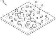
도 2는 도 1에 도시된 가변 초점 렌즈의 하나의 위상판을 예시적으로 보이는 사시도이다.
도 3은 위상판에 배열된 하나의 위상 변환 요소의 직경과 투과광의 위상 변화 사이의 관계를 예시적으로 보이는 그래프이다.
도 4a는 일 실시예에 따른 제 1 위상판의 다수의 제 1 위상 변환 요소들의 배열을 예시적으로 보이는 평면도이고, 도 4b는 일 실시예에 따른 제 2 위상판의 다수의 제 2 위상 변환 요소들의 배열을 예시적으로 보이는 평면도이다.
도 5a 내지 도 5c는 변위가 0.6 mm일 때 제 1 위상판을 투과한 투과광의 위상맵, 제 2 위상판을 투과한 투과광의 위상맵, 가변 초점 렌즈의 투과광의 결과적인 위상맵을 각각 예시적으로 보이는 그래프이다.
도 6a 내지 도 6c는 변위가 0.3 mm일 때 제 1 위상판을 투과한 투과광의 위상맵, 제 2 위상판을 투과한 투과광의 위상맵, 가변 초점 렌즈의 투과광의 결과적인 위상맵을 각각 예시적으로 보이는 그래프이다.
도 7a 내지 도 7c는 변위가 0 mm일 때 제 1 위상판을 투과한 투과광의 위상맵, 제 2 위상판을 투과한 투과광의 위상맵, 가변 초점 렌즈의 투과광의 결과적인 위상맵을 각각 예시적으로 보이는 그래프이다.
도 8a 내지 도 8c는 변위가 -0.3 mm일 때 제 1 위상판을 투과한 투과광의 위상맵, 제 2 위상판을 투과한 투과광의 위상맵, 가변 초점 렌즈의 투과광의 결과적인 위상맵을 각각 예시적으로 보이는 그래프이다.
도 9a 내지 도 9c는 변위가 -0.6 mm일 때 제 1 위상판을 투과한 투과광의 위상맵, 제 2 위상판을 투과한 투과광의 위상맵, 가변 초점 렌즈의 투과광의 결과적인 위상맵을 각각 예시적으로 보이는 그래프이다.
도 10은 제 1 위상판과 제 2 위상판 사이의 변위와 가변 초점 렌즈의 초점 거리 사이의 관계를 보이는 그래프이다.
도 11은 제 1 위상판과 제 2 위상판 사이의 변위와 가변 초점 렌즈의 굴절력 사이의 관계를 보이는 그래프이다.
도 12는 다른 실시예에 따른 가변 초점 렌즈의 구성을 개략적으로 보이는 단면도이다.
도 13은 또 다른 실시예에 따른 가변 초점 렌즈의 구성을 개략적으로 보이는 단면도이다.
도 14a 내지 도 14c는 또 다른 실시예에 따른 가변 초점 렌즈의 구성을 개략적으로 보이는 평면도이다.
도 15는 일 실시예에 따른 영상 획득 장치의 구성을 개략적으로 보이는 개념도이다.FIG. 1 is a cross-sectional view schematically showing the configuration of a variable focus lens according to one embodiment.
FIG. 2 is a perspective view exemplarily showing one phase plate of the variable focus lens illustrated in FIG. 1.
Figure 3 is a graph exemplarily showing the relationship between the diameter of one phase shift element arranged on a phase plate and the phase shift of transmitted light.
FIG. 4a is a plan view exemplarily showing an arrangement of a plurality of first phase transformation elements of a first phase plate according to one embodiment, and FIG. 4b is a plan view exemplarily showing an arrangement of a plurality of second phase transformation elements of a second phase plate according to one embodiment.
FIGS. 5A to 5C are graphs exemplarily showing a phase map of transmitted light transmitted through a first phase plate when the displacement is 0.6 mm, a phase map of transmitted light transmitted through a second phase plate, and a resulting phase map of transmitted light of a variable focus lens, respectively.
Figures 6a to 6c are graphs exemplarily showing a phase map of transmitted light transmitted through a first phase plate when the displacement is 0.3 mm, a phase map of transmitted light transmitted through a second phase plate, and a resulting phase map of transmitted light of a variable focus lens, respectively.
Figures 7a to 7c are graphs exemplarily showing a phase map of transmitted light transmitted through the first phase plate when the displacement is 0 mm, a phase map of transmitted light transmitted through the second phase plate, and a resulting phase map of transmitted light of a variable focus lens, respectively.
Figures 8a to 8c are graphs exemplarily showing a phase map of transmitted light transmitted through the first phase plate when the displacement is -0.3 mm, a phase map of transmitted light transmitted through the second phase plate, and a resulting phase map of transmitted light of a variable focus lens, respectively.
Figures 9a to 9c are graphs exemplarily showing a phase map of transmitted light transmitted through the first phase plate when the displacement is -0.6 mm, a phase map of transmitted light transmitted through the second phase plate, and a resulting phase map of transmitted light of a variable focus lens, respectively.
Figure 10 is a graph showing the relationship between the displacement between the first phase plate and the second phase plate and the focal length of the variable focus lens.
Figure 11 is a graph showing the relationship between the displacement between the first phase plate and the second phase plate and the refractive power of the variable focus lens.
Fig. 12 is a cross-sectional view schematically showing the configuration of a variable focus lens according to another embodiment.
Fig. 13 is a cross-sectional view schematically showing the configuration of a variable focus lens according to another embodiment.
FIGS. 14A to 14C are plan views schematically showing the configuration of a variable focus lens according to another embodiment.
Figure 15 is a conceptual diagram schematically showing the configuration of an image acquisition device according to one embodiment.
이하, 첨부된 도면들을 참조하여, 평면형 가변 초점 렌즈에 대해 상세하게 설명한다. 이하의 도면들에서 동일한 참조부호는 동일한 구성요소를 지칭하며, 도면상에서 각 구성요소의 크기는 설명의 명료성과 편의상 과장되어 있을 수 있다. 또한, 이하에 설명되는 실시예는 단지 예시적인 것에 불과하며, 이러한 실시예들로부터 다양한 변형이 가능하다. 또한 이하에서 설명하는 층 구조에서, "상부" 또는 "상"이라고 기재된 표현은 접촉하여 바로 위/아래/좌/우에 있는 것뿐만 아니라 비접촉으로 위/아래/좌/우에 있는 것도 포함할 수 있다.Hereinafter, a planar variable focus lens will be described in detail with reference to the attached drawings. In the drawings below, the same reference numerals denote the same components, and the sizes of each component in the drawings may be exaggerated for clarity and convenience of explanation. In addition, the embodiments described below are merely exemplary, and various modifications are possible from these embodiments. In addition, in the layer structure described below, the expression "upper" or "upper" may include not only those directly above/below/left/right in contact, but also those non-contacting those above/below/left/right.
도 1은 일 실시예에 따른 가변 초점 렌즈의 구성을 개략적으로 보이는 단면도이다. 도 1을 참조하면, 일 실시예에 따른 가변 초점 렌즈(100)는 광축(OX)을 따라 서로 대향하여 배치되며 광축(OX)에 수직한 방향으로 서로에 대해 이동 가능하도록 구성된 제 1 위상판(110)과 제 2 위상판(120)을 포함할 수 있다. 제 1 위상판(110)은 투명한 제 1 기판(111) 및 상기 제 1 기판(111)의 한 표면 위에 2차원 배열된 다수의 제 1 위상 변환 요소(112)를 포함할 수 있다. 제 2 위상판(120)은 투명한 제 2 기판(121) 및 상기 제 2 기판(121)의 한 표면 위에 2차원 배열된 다수의 제 2 위상 변환 요소(122)를 포함할 수 있다. 여기서, 제 1 위상 변환 요소(112)와 제 2 위상 변환 요소(122)가 서로 마주보도록 제 1 위상판(110)과 제 2 위상판(120)이 배치될 수 있다. 제 1 위상판(110)과 제 2 위상판(120)이 서로에 대해 이동할 때 손상이 일어나지 않도록 제 1 위상 변환 요소(112)와 제 2 위상 변환 요소(122)는 서로 완전히 접촉할 필요가 없으며 단지 약간의 간격(g)만큼 이격될 수 있다.FIG. 1 is a cross-sectional view schematically showing a configuration of a variable focus lens according to one embodiment. Referring to FIG. 1, a variable focus lens (100) according to one embodiment may include a first phase plate (110) and a second phase plate (120) which are arranged to face each other along an optical axis (OX) and are configured to move relative to each other in a direction perpendicular to the optical axis (OX). The first phase plate (110) may include a transparent first substrate (111) and a plurality of first phase shift elements (112) two-dimensionally arranged on one surface of the first substrate (111). The second phase plate (120) may include a transparent second substrate (121) and a plurality of second phase shift elements (122) two-dimensionally arranged on one surface of the second substrate (121). Here, the first phase plate (110) and the second phase plate (120) can be arranged so that the first phase conversion element (112) and the second phase conversion element (122) face each other. In order to prevent damage from occurring when the first phase plate (110) and the second phase plate (120) move relative to each other, the first phase conversion element (112) and the second phase conversion element (122) do not need to completely contact each other and can be spaced apart by only a slight gap (g).
제 1 및 제 2 위상 변환 요소(112, 122)는 각각 제 1 및 제 2 기판(111, 121)의 한 표면 위로 돌출하도록 배치될 수 있다. 예를 들어, 도 2는 도 1에 도시된 가변 초점 렌즈(100)의 제 1 위상판(110)을 예시적으로 보이는 사시도이다. 도 2에 도시된 바와 같이, 제 1 기판(111) 위에 제 1 위상 변환 요소(112)들이 소정의 패턴을 형성하도록 2차원 배열될 수 있다. 각각의 제 1 위상 변환 요소(112)는, 예를 들어, 원통형의 형태를 가질 수 있다. 각각의 제 2 위상 변환 요소(122)도 원통형의 형태를 가질 수 있다. 그러나 제 1 및 제 2 위상 변환 요소(112, 122)의 형태가 반드시 원통형일 필요는 없다. 이러한 제 1 및 제 2 위상 변환 요소(112, 122)는 일반적인 반도체 패터닝 공정을 이용하여 형성될 수 있다. 예를 들어, 제 1 및 제 2 기판(111, 121)의 표면 위에 제 1 및 제 2 위상 변환 요소(112, 122)의 재료층을 적층한 후에, 포토리소그래피 공정를 이용하여 제 1 및 제 2 위상 변환 상기 재료층을 패터닝함으로써 간단하게 제 1 및 제 2 위상 변환 요소(112, 122)가 형성될 수 있다.The first and second phase shift elements (112, 122) may be arranged to protrude above one surface of the first and second substrates (111, 121), respectively. For example, FIG. 2 is a perspective view exemplarily showing the first phase plate (110) of the variable focus lens (100) illustrated in FIG. 1. As illustrated in FIG. 2, the first phase shift elements (112) may be two-dimensionally arranged to form a predetermined pattern on the first substrate (111). Each of the first phase shift elements (112) may have, for example, a cylindrical shape. Each of the second phase shift elements (122) may also have a cylindrical shape. However, the shapes of the first and second phase shift elements (112, 122) do not necessarily have to be cylindrical. These first and second phase shift elements (112, 122) can be formed using a general semiconductor patterning process. For example, after the material layers of the first and second phase shift elements (112, 122) are laminated on the surfaces of the first and second substrates (111, 121), the first and second phase shift elements (112, 122) can be simply formed by patterning the first and second phase shift material layers using a photolithography process.
제 1 기판(111)과 제 2 기판(121)은, 예를 들어, 평판 형태의 투명한 유리나 투명한 플라스틱 재료로 이루어질 수 있다. 제 1 및 제 2 위상 변환 요소(112, 122)는 제 1 및 제 2 기판(111, 121)보다 높은 굴절률을 갖는 재료로 이루어질 수 있다. 예를 들어, 제 1 및 위상 변환 요소(112, 122)는 게르마늄(Ge), 비정질 실리콘(a-Si), 다결정 실리콘(p-Si), 단결정 실리콘(c-Si), III-V족 화합물, TiO2 및 SiNx 등과 같은 고굴절률 재료로 이루어질 수 있다. 제 1 및 제 2 위상 변환 요소(112, 122)의 굴절률은, 예를 들어, 가시광 파장에서 3.5보다 클 수 있다.The first substrate (111) and the second substrate (121) may be made of, for example, a transparent glass or transparent plastic material in a flat shape. The first and second phase shift elements (112, 122) may be made of a material having a higher refractive index than the first and second substrates (111, 121). For example, the first and phase shift elements (112, 122) may be made of a high refractive index material such as germanium (Ge), amorphous silicon (a-Si), polycrystalline silicon (p-Si), single crystal silicon (c-Si), III-V compound, TiO2 , and SiNx. The refractive index of the first and second phase shift elements (112, 122) may be, for example, greater than 3.5 at a visible light wavelength.
입사광이 이러한 고굴절률의 제 1 및 제 2 위상 변환 요소(112, 122)를 투과하게 되면, 제 1 및 제 2 위상 변환 요소(112, 122)에 의해 위상이 지연되면서 제 1 및 제 2 위상 변환 요소(112, 122)를 투과한 투과광의 위상이 입사광의 위상과 달라지게 된다. 위상이 변화하는 정도는 제 1 및 제 2 위상 변환 요소(112, 122)의 크기와 두께(t)에 따라 결정될 수 있다. 제 1 및 제 2 위상 변환 요소(112, 122)가 예컨대 원통형인 경우, 제 1 및 제 2 위상 변환 요소(112, 122)의 직경(d)과 두께에 따라 제 1 및 제 2 위상 변환 요소(112, 122)를 투과한 투과광의 위상이 달라지게 된다.When incident light passes through the first and second phase conversion elements (112, 122) having such a high refractive index, the phase is delayed by the first and second phase conversion elements (112, 122), so that the phase of the transmitted light passing through the first and second phase conversion elements (112, 122) becomes different from the phase of the incident light. The degree to which the phase changes can be determined according to the size and thickness (t) of the first and second phase conversion elements (112, 122). When the first and second phase conversion elements (112, 122) are cylindrical, for example, the phase of the transmitted light passing through the first and second phase conversion elements (112, 122) becomes different depending on the diameter (d) and thickness of the first and second phase conversion elements (112, 122).
예를 들어, 도 3은 제 1 및 제 2 위상판(110, 120)에서 배열된 하나의 제 1 및 제 2 위상 변환 요소(112, 122)의 직경과 투과광의 위상 변화 사이의 관계를 예시적으로 보이는 그래프이다. 도 3의 그래프에서, 각각의 제 1 및 제 2 위상 변환 요소(112, 122)는 600 nm의 격자 상수(lattice constant)를 갖는 비정질 실리콘으로 이루어지고, 750 nm의 두께를 갖는 것으로 가정하였다. 도 3을 참조하면, 제 1 및 제 2 위상 변환 요소(112, 122)의 직경과 위상 변화는 선형적인 관계는 아니고 비선형적인 관계를 갖지만, 대체로 제 1 및 제 2 위상 변환 요소(112, 122)의 직경이 커질수록 위상 변화가 증가한다는 것을 알 수 있다.For example, FIG. 3 is a graph exemplarily showing the relationship between the diameter of one first and second phase shift element (112, 122) arranged in the first and second phase plates (110, 120) and the phase shift of transmitted light. In the graph of FIG. 3, it is assumed that each of the first and second phase shift elements (112, 122) is made of amorphous silicon having a lattice constant of 600 nm and has a thickness of 750 nm. Referring to FIG. 3, the diameter and the phase shift of the first and second phase shift elements (112, 122) have a nonlinear relationship rather than a linear relationship, but it can be seen that, in general, as the diameter of the first and second phase shift elements (112, 122) increases, the phase shift increases.
따라서 다수의 제 1 및 제 2 위상 변환 요소(112, 122)들이 서로 다른 크기 또는 서로 다른 두께를 가지면, 제 1 및 제 2 위상판(110, 120)을 투과한 투과광은 제 1 및 제 2 위상판(110, 120) 상에서의 위치에 따라 서로 다른 위상을 갖게 될 수 있다. 즉, 제 1 및 제 2 위상판(110, 120) 상에서의 위치에 따라 투과광의 위상이 국소적으로 변화하게 된다. 이러한 상이한 크기 또는 상이한 두께들을 갖는 다수의 제 1 및 제 2 위상 변환 요소(112, 122)들을 적절히 배열하면, 제 1 및 제 2 위상판(110, 120)을 투과한 투과광의 파면을 원하는 대로 제어할 수 있게 된다. 예를 들어, 제 1 및 제 2 위상 변환 요소(112, 122)들의 배열에 따라 제 1 및 제 2 위상판(110, 120)이 렌즈와 같은 굴절 방식의 광학 소자의 역할을 할 수 있다.Therefore, if the plurality of first and second phase conversion elements (112, 122) have different sizes or different thicknesses, the transmitted light passing through the first and second phase plates (110, 120) may have different phases depending on the positions on the first and second phase plates (110, 120). That is, the phase of the transmitted light locally changes depending on the positions on the first and second phase plates (110, 120). If the plurality of first and second phase conversion elements (112, 122) having such different sizes or different thicknesses are appropriately arranged, the wavefront of the transmitted light passing through the first and second phase plates (110, 120) can be controlled as desired. For example, depending on the arrangement of the first and second phase conversion elements (112, 122), the first and second phase plates (110, 120) can act as refractive optical elements such as lenses.
본 실시예에 따르면, 투과광의 위상 특성이 Alvarez-Lohmann 렌즈 조건을 만족하는 3차 함수를 갖도록 제 1 및 제 2 위상 변환 요소(112, 122)들의 배열을 설계하고, 제 1 위상판(110)과 제 2 위상판(120)을 대향하여 배치할 수 있다. 그런 후, 제 1 위상판(110)과 제 2 위상판(120)을 광축(OX)에 수직한 방향으로 서로에 대해 상대적으로 변위시키면, 제 1 위상판(110)과 제 2 위상판(120)의 조합에 의한 가변 초점 렌즈(100)의 전체적인 위상 변화는 제 1 위상판(110)과 제 2 위상판(120)의 상대적인 변위에 따라 달라지게 된다. 예를 들어, 제 1 위상판(110)과 제 2 위상판(120)의 상대적인 변위 정도 및 변위 방향에 따라 가변 초점 렌즈(100)의 굴절력이 변화하게 되어 가변 초점 렌즈(100)의 초점 거리게 변하게 될 수 있다. 이를 위해, 제 1 및 제 2 위상 변환 요소(111, 122)들은 제 1 위상판(110)과 제 2 위상판(120) 사이의 변위에 따라 제 1 위상판(110)과 제 2 위상판(120)을 투과한 빛이 광축(OX) 상의 서로 다른 위치에 포커싱 되도록 배열될 수 있다.According to the present embodiment, the arrangement of the first and second phase transformation elements (112, 122) is designed so that the phase characteristic of the transmitted light has a third-order function satisfying the Alvarez-Lohmann lens condition, and the first phase plate (110) and the second phase plate (120) can be arranged to face each other. Then, when the first phase plate (110) and the second phase plate (120) are relatively displaced with respect to each other in a direction perpendicular to the optical axis (OX), the overall phase change of the variable focus lens (100) by the combination of the first phase plate (110) and the second phase plate (120) varies depending on the relative displacement of the first phase plate (110) and the second phase plate (120). For example, depending on the relative displacement degree and displacement direction of the first phase plate (110) and the second phase plate (120), the refractive power of the variable focus lens (100) may change, thereby changing the focal length of the variable focus lens (100). To this end, the first and second phase conversion elements (111, 122) may be arranged so that light transmitted through the first phase plate (110) and the second phase plate (120) is focused at different positions on the optical axis (OX) depending on the displacement between the first phase plate (110) and the second phase plate (120).
예를 들어, 도 4a는 일 실시예에 따른 제 1 위상판(110)의 다수의 제 1 위상 변환 요소(112)의 배열을 예시적으로 보이는 평면도이고, 도 4b는 일 실시예에 따른 제 2 위상판(120)의 다수의 제 2 위상 변환 요소(122)의 배열을 예시적으로 보이는 평면도이다. 도 4a 및 도 4b를 참조하면, 제 1 위상판(110)을 투과한 빛의 위상이 제 1 위상판(110) 상에서의 위치에 따라 상이하게 변화하도록 다수의 제 1 위상 변환 요소(112)는 제 1 위상판(110) 상에서의 위치에 따라 상이한 직경을 갖는다. 마찬가지로, 제 2 위상판(120)을 투과한 빛의 위상이 제 2 위상판(120) 상에서의 위치에 따라 상이하게 변화하도록, 다수의 제 2 위상 변환 요소(122)는 제 2 위상판(120) 상에서의 위치에 따라 상이한 직경을 갖는다. 도 4a 및 도 4b에는 각각의 제 1 및 제 2 위상 변환 요소(112, 122)의 직경들이 예시적으로 표시되어 있다. 제 1 위상판(110) 상에서의 위치에 따른 다수의 제 1 위상 변환 요소(112)의 직경들 및 제 2 위상판(120) 상에서의 위치에 따른 다수의 제 2 위상 변환 요소(122)의 직경들은 제 1 위상판(110)과 제 2 위상판(120)을 투과한 빛의 위상이 아래의 수학식 1과 같은 Alvarez-Lohmann 조건을 만족하도록 선택될 수 있다.For example, FIG. 4A is a plan view exemplarily showing an arrangement of a plurality of first phase conversion elements (112) of a first phase plate (110) according to one embodiment, and FIG. 4B is a plan view exemplarily showing an arrangement of a plurality of second phase conversion elements (122) of a second phase plate (120) according to one embodiment. Referring to FIGS. 4A and 4B, the plurality of first phase conversion elements (112) have different diameters depending on their positions on the first phase plate (110) so that the phase of light transmitted through the first phase plate (110) changes differently depending on its position on the first phase plate (110). Similarly, the plurality of second phase conversion elements (122) have different diameters depending on their positions on the second phase plate (120) so that the phase of light transmitted through the second phase plate (120) changes differently depending on its position on the second phase plate (120). Diameters of each of the first and second phase conversion elements (112, 122) are exemplarily shown in FIGS. 4A and 4B. The diameters of the plurality of first phase conversion elements (112) according to their positions on the first phase plate (110) and the diameters of the plurality of second phase conversion elements (122) according to their positions on the second phase plate (120) can be selected so that the phases of light transmitted through the first phase plate (110) and the second phase plate (120) satisfy the Alvarez-Lohmann condition as expressed in the following

위의 수학식 1에서, φ는 투과광의 위상 변화를 나태나며, x, y는 가변 초점 렌즈(100)의 중심을 원점으로 할 때의 좌표를 나타내고, A, D, E는 임의의 상수이다.In the
제 1 및 제 2 위상판(110, 120)의 각각의 위치에서의 위상 변화 φ가 결정되면, 도 3에 도시된 제 1 및 제 2 위상 변환 요소(112, 122)의 직경과 투과광의 위상 변화 사이의 관계를 이용하여, 제 1 및 제 2 위상판(110, 120)의 각각의 위치에서의 제 1 및 제 2 위상 변환 요소(112, 122)의 직경을 선택할 수 있다. 투과광의 위상 변화는 제 1 및 제 2 위상 변환 요소(112, 122)의 두께에 의해서도 영향을 받을 수 있지만, 다수의 제 1 및 제 2 위상 변환 요소(112, 122)의 두께를 다르게 형성할 경우, 제 1 및 제 2 위상판(110, 120)의 제조 공정이 복잡해질 수 있기 때문에, 도 4a 및 도 4b의 예에서는 제 1 및 제 2 위상 변환 요소(112, 122)의 두께를 모두 750 nm로 고정하였다.Once the phase shift φ at each position of the first and second phase plates (110, 120) is determined, the diameters of the first and second phase shift elements (112, 122) at each position of the first and second phase plates (110, 120) can be selected using the relationship between the diameters of the first and second phase shift elements (112, 122) and the phase shift of the transmitted light as shown in FIG. 3. The phase shift of the transmitted light can also be affected by the thickness of the first and second phase shift elements (112, 122). However, if a plurality of first and second phase shift elements (112, 122) are formed with different thicknesses, the manufacturing process of the first and second phase plates (110, 120) may become complicated. Therefore, in the examples of FIGS. 4A and 4B, the thicknesses of the first and second phase shift elements (112, 122) are both fixed to 750 nm.
또한, 도 4a 및 도 4b의 예에서 각각의 제 1 및 제 2 위상판(110, 120)의 가로 방향 중심선을 기준으로 다수의 제 1 및 제 2 위상 변환 요소(112, 122)가 상하 대칭이 되도록 설계되었다. 또한, 제 1 위상판(110)의 제 1 위상 변환 요소(112)의 배열과 제 2 위상판(120)의 제 2 위상 변환 요소(122)의 배열은 좌우 방향으로 서로에 대해 거울 대칭이 되도록 설계되었다. 따라서, 제 1 위상판(110)에 의한 위상 변화와 제 2 위상판(120)에 의한 위상 변화는 서로 좌우 반전된 형태가 될 수 있다. 이 경우, 제 1 위상판(110)과 제 2 위상판(120)은 제 1 위상 변환 요소(112)와 제 2 위상 변환 요소(122) 사이의 대칭축에 수직한 방향, 즉 좌우 방향으로 변위될 수 있다.In addition, in the examples of FIGS. 4A and 4B, a plurality of first and second phase conversion elements (112, 122) are designed to be symmetrical in the vertical direction with respect to the horizontal center lines of the first and second phase plates (110, 120), respectively. In addition, the arrangement of the first phase conversion element (112) of the first phase plate (110) and the arrangement of the second phase conversion element (122) of the second phase plate (120) are designed to be mirror-symmetrical with respect to each other in the left-right direction. Therefore, the phase change by the first phase plate (110) and the phase change by the second phase plate (120) can be inverted in the left-right direction with respect to each other. In this case, the first phase plate (110) and the second phase plate (120) can be displaced in the direction perpendicular to the axis of symmetry between the first phase conversion element (112) and the second phase conversion element (122), that is, in the left-right direction.
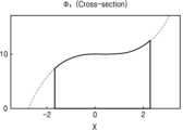
도 5a 내지 도 5c는 변위가 0.6 mm일 때 제 1 위상판(110)을 투과한 투과광의 위상맵, 제 2 위상판(120)을 투과한 투과광의 위상맵, 가변 초점 렌즈(100)의 투과광의 결과적인 위상맵을 각각 예시적으로 보이는 그래프이다. 도 5a 내지 도 5c의 예에서, 제 1 위상 변환 요소(112)와 제 2 위상 변환 요소(122)는 도 4a 및 도 4b에 도시된 배열을 갖는 것으로 가정하였다. 또한, 제 1 기판(111)과 제 2 기판(121)은 유리로 이루어지고, 제 1 및 제 2 위상 변환 요소(112, 122)는 비정질 실리콘(a-Si)으로 이루어지는 것으로 가정하였다. 또한 제 1 및 제 2 위상 변환 요소(112, 122)의 높이는 750 nm이며, 입사광은 850 nm의 파장을 갖는 적외선 광으로 가정하였다. 또한 도 5a 내지 도 5c의 그래프에서, 가로축은 변위를 나타내며 단위가 mm 이고, 세로축은 위상을 나타내며 단위는 라디안이다.FIGS. 5A to 5C are graphs exemplarily showing a phase map of transmitted light transmitted through a first phase plate (110), a phase map of transmitted light transmitted through a second phase plate (120), and a resulting phase map of transmitted light of a variable focus lens (100) when the displacement is 0.6 mm, respectively. In the examples of FIGS. 5A to 5C, it is assumed that the first phase conversion element (112) and the second phase conversion element (122) have the arrangements shown in FIGS. 4A and 4B. In addition, it is assumed that the first substrate (111) and the second substrate (121) are made of glass, and the first and second phase conversion elements (112, 122) are made of amorphous silicon (a-Si). In addition, the heights of the first and second phase conversion elements (112, 122) are 750 nm, and the incident light is assumed to be infrared light having a wavelength of 850 nm. In addition, in the graphs of FIGS. 5a to 5c, the horizontal axis represents displacement in mm, and the vertical axis represents phase in radians.
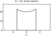
여기서 변위는 제 1 위상판(110)과 제 2 위상판(120)의 상대적으로 시프트된 거리로서, 제 1 위상판(110)이 제 2 위상판(120)에 대해 우측 방향으로 이동할 경우를 양(+)의 방향으로 선택하고, 좌측 방향으로 이동할 경우를 음(-)의 방향으로 선택하였다. 도 5a 및 도 5b를 참조하면, 앞서 설명한 바와 같이, 제 1 위상판(110)을 투과한 투과광의 위상맵과 제 2 위상판(120)을 투과한 투과광의 위상맵의 서로에 대해 좌우 대칭이다. 그리고, 제 1 위상판(110)을 투과한 투과광의 위상맵이 제 2 위상판(120)을 투과한 투과광의 위상맵보다 우측으로 0.6 mm이 변위되어 있다. 그러면, 제 1 위상판(110)에 의한 위상맵과 제 2 위상판(120)에 의한 위상맵을 조합한 결과적인 가변 초점 렌즈(100)의 위상맵은 도 5c에 도시된 바와 같이 양의 굴절력을 갖는 볼록한 모양이 된다. 따라서, 이 경우에 가변 초점 렌즈(100)는 약 25 mm의 초점 거리를 갖는 볼록 렌즈의 역할을 할 수 있다.Here, the displacement is a relative shift distance between the first phase plate (110) and the second phase plate (120), and when the first phase plate (110) moves to the right with respect to the second phase plate (120), it is selected as a positive (+) direction, and when it moves to the left, it is selected as a negative (-) direction. Referring to FIGS. 5A and 5B, as described above, the phase map of the transmitted light transmitted through the first phase plate (110) and the phase map of the transmitted light transmitted through the second phase plate (120) are symmetrical to each other. In addition, the phase map of the transmitted light transmitted through the first phase plate (110) is shifted to the right by 0.6 mm compared to the phase map of the transmitted light transmitted through the second phase plate (120). Then, the resulting phase map of the variable focus lens (100) that combines the phase map by the first phase plate (110) and the phase map by the second phase plate (120) becomes a convex shape with positive refractive power, as shown in Fig. 5c. Therefore, in this case, the variable focus lens (100) can function as a convex lens with a focal length of about 25 mm.
도 6a 내지 도 6c는 변위가 0.3 mm일 때 제 1 위상판(110)을 투과한 투과광의 위상맵, 제 2 위상판(120)을 투과한 투과광의 위상맵, 가변 초점 렌즈(100)의 투과광의 결과적인 위상맵을 각각 예시적으로 보이는 그래프이다. 도 6a 내지 도 6c에 도시된 바와 같이, 제 1 위상판(110)을 투과한 투과광의 위상맵과 제 2 위상판(120)을 투과한 투과광의 위상맵이 점차 가까워지면 가변 초점 렌즈(100)의 굴절력이 점점 작아질 수 있다. 예를 들어, 가변 초점 렌즈(100)는 약 50 mm의 초점 거리를 갖는 볼록 렌즈의 역할을 할 수 있다.FIGS. 6A to 6C are graphs exemplarily showing a phase map of transmitted light transmitted through a first phase plate (110), a phase map of transmitted light transmitted through a second phase plate (120), and a resulting phase map of transmitted light of a variable focus lens (100) when the displacement is 0.3 mm. As shown in FIGS. 6A to 6C, when the phase map of transmitted light transmitted through the first phase plate (110) and the phase map of transmitted light transmitted through the second phase plate (120) gradually get closer, the refractive power of the variable focus lens (100) may gradually decrease. For example, the variable focus lens (100) may function as a convex lens having a focal length of about 50 mm.
도 7a 내지 도 7c는 변위가 0 mm일 때 제 1 위상판(110)을 투과한 투과광의 위상맵, 제 2 위상판(120)을 투과한 투과광의 위상맵, 가변 초점 렌즈(100)의 투과광의 결과적인 위상맵을 각각 예시적으로 보이는 그래프이다. 제 1 위상판(110)과 제 2 위상판(120)이 완전히 겹쳐지게 되면, 제 1 위상판(110)에 의한 위상 변화와 제 2 위상판(120)에 의한 위상 변화가 완전히 상쇄된다. 그러면, 도 7c에 도시된 바와 같이, 결과적인 가변 초점 렌즈(100)의 굴절력은 평판과 같은 0이 된다. 이 경우, 가변 초점 렌즈(100)의 초점 거리는 무한대(∞)가 된다.FIGS. 7A to 7C are graphs exemplarily showing a phase map of transmitted light transmitted through a first phase plate (110) when the displacement is 0 mm, a phase map of transmitted light transmitted through a second phase plate (120), and a resulting phase map of transmitted light of a variable focus lens (100), respectively. When the first phase plate (110) and the second phase plate (120) completely overlap, the phase change caused by the first phase plate (110) and the phase change caused by the second phase plate (120) are completely canceled out. Then, as shown in FIG. 7C, the resulting refractive power of the variable focus lens (100) becomes 0, like a flat plate. In this case, the focal length of the variable focus lens (100) becomes infinity (∞).
도 8a 내지 도 8c는 변위가 -0.3 mm일 때 제 1 위상판(110)을 투과한 투과광의 위상맵, 제 2 위상판(120)을 투과한 투과광의 위상맵, 가변 초점 렌즈(100)의 투과광의 결과적인 위상맵을 각각 예시적으로 보이는 그래프이다. 도 8a 및 도 8b를 참조하면, 음의 변위가 될 때 제 1 위상판(110)의 위상맵은 제 2 위상판(120)의 위상맵보다 상대적으로 좌측에 위치하게 된다. 이 경우, 도 8c에 도시된 바와 같이, 결과적인 가변 초점 렌즈(100)는 음의 굴절력을 갖는 오목한 모양이 된다. 따라서, 이 경우에 가변 초점 렌즈(100)는 약 -50 mm의 초점 거리를 갖는 오목 렌즈의 역할을 할 수 있다.FIGS. 8A to 8C are graphs exemplarily showing a phase map of transmitted light transmitted through a first phase plate (110), a phase map of transmitted light transmitted through a second phase plate (120), and a resulting phase map of transmitted light of a variable focus lens (100) when the displacement is -0.3 mm. Referring to FIGS. 8A and 8B, when the displacement is negative, the phase map of the first phase plate (110) is located relatively to the left of the phase map of the second phase plate (120). In this case, as shown in FIG. 8C, the resulting variable focus lens (100) has a concave shape having negative refractive power. Therefore, in this case, the variable focus lens (100) can function as a concave lens having a focal length of about -50 mm.
도 9a 내지 도 9c는 변위가 -0.6 mm일 때 제 1 위상판(110)을 투과한 투과광의 위상맵, 제 2 위상판(120)을 투과한 투과광의 위상맵, 가변 초점 렌즈(100)의 투과광의 결과적인 위상맵을 각각 예시적으로 보이는 그래프이다. 도 9a 내지 도 9c에 도시된 바와 같이, 제 1 위상판(110)이 좌측으로 점점 더 이동하게 되면 가변 초점 렌즈(100)의 음의 굴절력이 점점 더 커질 수 있다. 예를 들어, 가변 초점 렌즈(100)는 약 -25 mm의 초점 거리를 갖는 오목 렌즈의 역할을 할 수 있다.FIGS. 9A to 9C are graphs exemplarily showing a phase map of transmitted light transmitted through a first phase plate (110), a phase map of transmitted light transmitted through a second phase plate (120), and a resulting phase map of transmitted light of a variable focus lens (100) when the displacement is -0.6 mm. As shown in FIGS. 9A to 9C, as the first phase plate (110) moves further to the left, the negative refractive power of the variable focus lens (100) may become increasingly larger. For example, the variable focus lens (100) may function as a concave lens having a focal length of about -25 mm.
상술한 바와 같이, 제 1 위상판(110)과 제 2 위상판(120) 사이의 상대적인 변위에 따라, 가변 초점 렌즈(100)의 굴절력 및 초점 거리가 변화할 수 있다. 예를 들어, 도 10은 제 1 위상판(110)과 제 2 위상판(120) 사이의 변위와 가변 초점 렌즈(100)의 초점 거리 사이의 관계를 보이는 그래프이다. 도 10을 참조하면, 양의 변위에서는 가변 초점 렌즈(100)가 볼록 렌즈의 역할을 하며 변위가 커질수록 초점 거리가 짧아지고 변위가 작아질수록 초점 거리가 길어진다. 특히, 변위가 0일 때 초점 거리는 무한대가 된다. 음의 변위에서는 가변 초점 렌즈(100)가 오목 렌즈의 역할을 하며 변위가 커질수록 초점거리가 초점 거리가 짧아지고 변위가 작아질수록 초점 거리가 길어진다. 또한, 도 11은 제 1 위상판(110)과 제 2 위상판(120) 사이의 변위와 가변 초점 렌즈(100)의 굴절력 사이의 관계를 보이는 그래프이다. 도 11에 도시된 바와 같이, 가변 초점 렌즈(100)의 굴절력은 변위에 대해 선형적인 비례 관계를 갖는다는 것을 알 수 있다. 예를 들어, 변위가 0일 때 가변 초점 렌즈(100)가 0의 굴절력을 가지며, 변위가 증가 또는 감소함에 따라 가변 초점 렌즈(100)의 굴절력도 그에 비례하여 증가 또는 감소할 수 있다.As described above, depending on the relative displacement between the first phase plate (110) and the second phase plate (120), the refractive power and focal length of the variable focus lens (100) can change. For example, FIG. 10 is a graph showing the relationship between the displacement between the first phase plate (110) and the second phase plate (120) and the focal length of the variable focus lens (100). Referring to FIG. 10, in the case of positive displacement, the variable focus lens (100) acts as a convex lens, and as the displacement increases, the focal length becomes shorter, and as the displacement decreases, the focal length becomes longer. In particular, when the displacement is 0, the focal length becomes infinite. In the case of negative displacement, the variable focus lens (100) acts as a concave lens, and as the displacement increases, the focal length becomes shorter, and as the displacement decreases, the focal length becomes longer. In addition, FIG. 11 is a graph showing the relationship between the displacement between the first phase plate (110) and the second phase plate (120) and the refractive power of the variable focus lens (100). As shown in FIG. 11, it can be seen that the refractive power of the variable focus lens (100) has a linearly proportional relationship to the displacement. For example, when the displacement is 0, the variable focus lens (100) has a refractive power of 0, and as the displacement increases or decreases, the refractive power of the variable focus lens (100) can also increase or decrease proportionally.
이러한 본 실시예에 따른 가변 초점 렌즈(100)는 평면형으로 제작될 수 있기 때문에 얇은 두께를 가질 수 있다. 예를 들어, 가변 초점 렌즈(100)는 수 um 내지 수 mm의 얇은 두께로 제작이 가능하다. 따라서 가변 초점 렌즈(100)는 컴팩트 카메라나 모바일 장치용 카메라에 줌 기능을 제공할 수 있다. 또한, 본 실시예에 따른 가변 초점 렌즈(100)는 포토리소그래피 공정을 이용한 패터닝 방식으로 제작될 수 있기 때문에, 광학적 렌즈 소자의 복잡한 곡면을 형성하기 위한 복잡한 가공 공정이 요구되지 않는다. 따라서 가변 초점 렌즈(100)는 제작이 쉽고 공정 오차에 의한 품질 열화가 적을 수 있어서, 영상 품질을 향상시킬 수 있다.The variable focus lens (100) according to this embodiment can have a thin thickness because it can be manufactured in a flat shape. For example, the variable focus lens (100) can be manufactured with a thin thickness of several um to several mm. Therefore, the variable focus lens (100) can provide a zoom function to a compact camera or a camera for a mobile device. In addition, since the variable focus lens (100) according to this embodiment can be manufactured by a patterning method using a photolithography process, a complex processing process for forming a complex curved surface of an optical lens element is not required. Therefore, the variable focus lens (100) is easy to manufacture and can have less quality deterioration due to process errors, so that the image quality can be improved.
도 12는 다른 실시예에 따른 가변 초점 렌즈의 구성을 개략적으로 보이는 단면도이다. 도 12를 참조하면, 가변 초점 렌즈(200)는 제 1 및 제 2 위상 변환 요소(112, 122)를 둘러싸서 보호하는 투명한 유전체층(113, 123)을 더 포함할 수 있다. 예를 들어, 제 1 위상판(110)은 다수의 제 1 위상 변환 요소(112) 사이에 채워진 투명한 제 1 유전체층(113)을 포함할 수 있으며, 제 2 위상판(120)은 다수의 제 2 위상 변환 요소(122) 사이에 채워진 투명한 제 2 유전체층(123)을 포함할 수 있다. 제 1 및 제 2 유전체층(113, 123)은 예를 들어 실란올계 유리(SOG; siloxane-based spin on glass), 투명 폴리머 재료, SiO2 등과 같은 재료로 이루어질 수 있다.FIG. 12 is a cross-sectional view schematically showing a configuration of a variable focus lens according to another embodiment. Referring to FIG. 12, the variable focus lens (200) may further include a transparent dielectric layer (113, 123) surrounding and protecting the first and second phase shift elements (112, 122). For example, the first phase plate (110) may include a transparent first dielectric layer (113) filled between a plurality of first phase shift elements (112), and the second phase plate (120) may include a transparent second dielectric layer (123) filled between a plurality of second phase shift elements (122). The first and second dielectric layers (113, 123) may be made of a material such as, for example, a siloxane-based spin on glass (SOG), a transparent polymer material, SiO2 , etc.
제 1 및 제 2 위상 변환 요소(112, 122)를 충분히 보호하기 위하여, 제 1 유전체층(113)의 두께는 제 1 위상 변환 요소(112)를 완전히 덮도록 제 1 위상 변환 요소(112)의 두께보다 클 수 있으며, 제 2 유전체층(123)의 두께는 제 2 위상 변환 요소(122)를 완전히 덮도록 제 2 위상 변환 요소(122)의 두께보다 클 수 있다. 이 경우, 제 1 위상판(110)과 제 2 위상판(120)의 상대적인 이동시에 제 1 및 제 2 위상 변환 요소(112, 122)이 손상되지 않을 수 있다. 따라서, 도 12에 도시된 바와 같이, 제 1 위상판(110)과 제 2 위상판(120)은 제 1 유전체층(113)과 제 2 유전체층(123)이 서로 접촉하도록 배치될 수 있다.In order to sufficiently protect the first and second phase shift elements (112, 122), the thickness of the first dielectric layer (113) may be greater than the thickness of the first phase shift element (112) so as to completely cover the first phase shift element (112), and the thickness of the second dielectric layer (123) may be greater than the thickness of the second phase shift element (122) so as to completely cover the second phase shift element (122). In this case, the first and second phase shift elements (112, 122) may not be damaged when the first phase plate (110) and the second phase plate (120) move relative to each other. Therefore, as illustrated in FIG. 12, the first phase plate (110) and the second phase plate (120) may be arranged so that the first dielectric layer (113) and the second dielectric layer (123) come into contact with each other.
도 13은 또 다른 실시예에 따른 가변 초점 렌즈의 구성을 개략적으로 보이는 단면도이다. 도 13을 참조하면, 가변 초점 렌즈(300)는 제 1 위상판(110)과 제 2 위상판(120)에 추가하여 제 3 위상판(130)과 제 4 위상판(140)을 더 포함할 수 있다. 예를 들어, 제 1 위상판(110) 내지 제 4 위상판(140)은 광축을 따라 차례로 배치될 수 있다. 제 3 위상판(130)은 제 3 기판(131), 상이한 크기들을 갖는 다수의 제 3 위상 변환 요소(132) 및 제 3 유전체층(133)을 포함할 수 있다. 또한 제 4 위상판(140)은 제 4 기판(141), 상이한 크기들을 갖는 다수의 제 4 위상 변환 요소(142) 및 제 4 유전체층(143)을 포함할 수 있다.FIG. 13 is a cross-sectional view schematically showing a configuration of a variable focus lens according to another embodiment. Referring to FIG. 13, the variable focus lens (300) may further include a third phase plate (130) and a fourth phase plate (140) in addition to the first phase plate (110) and the second phase plate (120). For example, the first phase plate (110) to the fourth phase plate (140) may be sequentially arranged along the optical axis. The third phase plate (130) may include a third substrate (131), a plurality of third phase shift elements (132) having different sizes, and a third dielectric layer (133). In addition, the fourth phase plate (140) may include a fourth substrate (141), a plurality of fourth phase shift elements (142) having different sizes, and a fourth dielectric layer (143).
여기서, 제 1 위상판(110)과 제 2 위상판(120)의 쌍이 하나의 제 1 렌즈 요소로서 기능하도록 다수의 제 1 위상 변환 요소(112)와 다수의 제 2 위상 변환 요소(122)가 배열될 수 있으며, 제 3 위상판(130)과 제 4 위상판(140)의 쌍이 하나의 제 2 렌즈 요소로서 기능하도록 다수의 제 3 위상 변환 요소(132)와 다수의 제 4 위상 변환 요소(142)가 배열될 수 있다. 그리고, 제 1 위상판(110)과 제 2 위상판(120)이 광축에 수직한 방향으로 서로에 대해 이동 가능하도록 구성되며, 제 3 위상판(130)과 제 4 위상판(140)이 광축에 수직한 방향으로 서로에 대해 이동 가능하도록 구성될 수 있다. 제 1 및 제 2 위상 변환 요소(112, 122)들은 제 1 위상판(110)과 제 2 위상판(120) 사이의 변위에 따라 제 1 위상판(110)과 제 2 위상판(120)을 투과한 빛이 광축 상의 서로 다른 위치에 포커싱 되도록 배열될 수 있다. 또한, 제 3 및 제 4 위상 변환 요소(132, 142)들은 제 3 위상판(130)과 제 4 위상판(140) 사이의 변위에 따라 제 3 위상판(130)과 제 4 위상판(140)을 투과한 빛이 광축 상의 서로 다른 위치에 포커싱 되도록 배열될 수 있다. 따라서, 제 1 위상판(110)과 제 2 위상판(120)의 상대적인 변위 및 제 3 위상판(130)과 제 4 위상판(140)의 상대적 변위에 따라 가변 초점 렌즈(300)의 초점 거리게 변하게 될 수 있다.Here, a plurality of first phase conversion elements (112) and a plurality of second phase conversion elements (122) may be arranged so that a pair of a first phase plate (110) and a second phase plate (120) function as one first lens element, and a plurality of third phase conversion elements (132) and a plurality of fourth phase conversion elements (142) may be arranged so that a pair of a third phase plate (130) and a fourth phase plate (140) function as one second lens element. In addition, the first phase plate (110) and the second phase plate (120) may be configured to be movable relative to each other in a direction perpendicular to the optical axis, and the third phase plate (130) and the fourth phase plate (140) may be configured to be movable relative to each other in a direction perpendicular to the optical axis. The first and second phase conversion elements (112, 122) can be arranged so that light transmitted through the first phase plate (110) and the second phase plate (120) is focused at different positions on the optical axis according to the displacement between the first phase plate (110) and the second phase plate (120). In addition, the third and fourth phase conversion elements (132, 142) can be arranged so that light transmitted through the third phase plate (130) and the fourth phase plate (140) is focused at different positions on the optical axis according to the displacement between the third phase plate (130) and the fourth phase plate (140). Accordingly, the focal length of the variable focus lens (300) can be changed depending on the relative displacement of the first phase plate (110) and the second phase plate (120) and the relative displacement of the third phase plate (130) and the fourth phase plate (140).
도 2 및 도 3을 참조하여 이미 설명한 바와 같이, 제 1 내지 제 4 위상 변환 요소(112, 122, 132, 142)들은 원통형의 형태를 가질 수 있다. 그리고, 제 1 내지 제 4 위상판(110, 120, 130, 140)을 투과한 빛의 위상이 제 1 내지 제 4 위상판(110, 120, 130, 140) 상에서의 위치에 따라 상이하게 변화하도록 제 1 내지 제 4 위상 변환 요소(112, 122, 132, 142)들은 각각 제 1 내지 제 4 위상판(110, 120, 130, 140) 상에서의 위치에 따라 상이한 직경을 가질 수 있다. 여기서, 제 1 위상 변환 요소(112)의 배열과 제 2 위상 변환 요소(122)의 배열이 좌우 방향으로 서로에 대해 거울 대칭이 되고, 제 3 위상 변환 요소(132)의 배열과 제 4 위상 변환 요소(142)의 배열이 좌우 방향으로 서로에 대해 거울 대칭되도록 설계될 수 있다.As already described with reference to FIGS. 2 and 3, the first to fourth phase conversion elements (112, 122, 132, 142) may have a cylindrical shape. In addition, the first to fourth phase conversion elements (112, 122, 132, 142) may have different diameters depending on their positions on the first to fourth phase plates (110, 120, 130, 140) so that the phase of light transmitted through the first to fourth phase plates (110, 120, 130, 140) changes differently depending on their positions on the first to fourth phase plates (110, 120, 130, 140). Here, the arrangement of the first phase conversion element (112) and the arrangement of the second phase conversion element (122) can be designed to be mirror-symmetrical with respect to each other in the left-right direction, and the arrangement of the third phase conversion element (132) and the arrangement of the fourth phase conversion element (142) can be designed to be mirror-symmetrical with respect to each other in the left-right direction.
본 실시예에 따른 가변 초점 렌즈(300)에서, 제 1 및 제 2 위상판(110, 120)의 쌍으로 이루어진 제 1 렌즈 요소와 제 3 및 제 4 위상판(130, 140)의 쌍으로 이루어진 제 2 렌즈 요소가 서로 다른 광학적 특성을 갖도록 설계될 수 있다. 예를 들어, 제 1 및 제 2 위상판(110, 120)의 변위와 제 3 및 제 4 위상판(130, 140)의 변위가 동일할 때, 제 1 렌즈 요소는 양의 굴절력을 갖고 제 2 렌즈 요소는 음의 굴절력을 가질 수 있다. 또는, 제 1 및 제 2 위상판(110, 120)의 변위와 제 3 및 제 4 위상판(130, 140)의 변위가 독립적으로 구동되어 제 1 렌즈 요소와 제 2 렌즈 요소의 굴절력을 임의로 선택할 수 있다. 도 13에는 가변 초점 렌즈(300)가 2개의 위상판 쌍(110, 120; 130, 140)을 갖는 것으로 도시되었지만, 이에 한정되지 않고 3개 이상의 위상판 쌍을 가질 수도 있다.In the variable focus lens (300) according to the present embodiment, the first lens element formed of a pair of first and second phase plates (110, 120) and the second lens element formed of a pair of third and fourth phase plates (130, 140) can be designed to have different optical characteristics. For example, when the displacements of the first and second phase plates (110, 120) and the displacements of the third and fourth phase plates (130, 140) are the same, the first lens element can have positive refractive power and the second lens element can have negative refractive power. Alternatively, the displacements of the first and second phase plates (110, 120) and the displacements of the third and fourth phase plates (130, 140) can be independently driven so that the refractive powers of the first lens element and the second lens element can be arbitrarily selected. Although the variable focus lens (300) in FIG. 13 is illustrated as having two phase plate pairs (110, 120; 130, 140), it is not limited thereto and may have three or more phase plate pairs.
본 실시예에 따른 가변 초점 렌즈(300)는 제 1 내지 제 4 위상판(110~140)에 의한 위상 변화가 누적되어 적은 변위로도 더 큰 굴절력 변화 효과를 얻을 수 있다. 또한, 이러한 가변 초점 렌즈(300)는 복수의 렌즈 요소를 갖는 줌 렌즈로서 기능할 수도 있다. 필요에 따라서는, 제 1 및 제 2 위상판(110, 120)에 대해 제 3 및 제 4 위상판(130, 140)을 광축 방향으로 이동시킬 수도 있다. 즉, 제 1 및 제 2 위상판(110, 120)으로 이루어진 제 1 렌즈 요소와 제 4 위상판(130, 140)으로 이루어진 제 2 렌즈 요소 사이의 광축 방향 거리를 변화시켜 초점을 조절할 수도 있다.The variable focus lens (300) according to the present embodiment can obtain a greater refractive power change effect even with a small displacement by accumulating phase changes by the first to fourth phase plates (110 to 140). In addition, the variable focus lens (300) can also function as a zoom lens having a plurality of lens elements. If necessary, the third and fourth phase plates (130, 140) can be moved in the optical axis direction with respect to the first and second phase plates (110, 120). That is, the focus can be adjusted by changing the optical axis distance between the first lens element composed of the first and second phase plates (110, 120) and the second lens element composed of the fourth phase plate (130, 140).
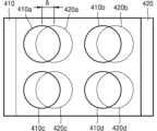
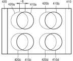
도 14a 내지 도 14c는 또 다른 실시예에 따른 가변 초점 렌즈의 구성을 개략적으로 보이는 평면도이다. 도 14a를 참조하면, 가변 초점 렌즈(400)는 제 1 및 제 2 위상 변환 요소(112, 122)들이 국소적으로 배열되어 있는 다수의 영역(400a, 400b, 400c, 400d)을 포함할 수 있다. 제 1 및 제 2 위상 변환 요소(112, 122)들은 이러한 다수의 영역(400a, 400b, 400c, 400d) 내에만 배열될 수 있다. 그리고 다수의 영역(400a, 400b, 400c, 400d)이 규칙적으로 2차원 배열될 수 있다. 그러면 가변 초점 렌즈(400)는 다수의 렌즈 요소들이 2차원 배열되어 있는 렌즈 어레이의 기능을 수행할 수 있다.FIGS. 14A to 14C are schematic plan views showing a configuration of a variable focus lens according to another embodiment. Referring to FIG. 14A, the variable focus lens (400) may include a plurality of regions (400a, 400b, 400c, 400d) in which first and second phase shift elements (112, 122) are locally arranged. The first and second phase shift elements (112, 122) may be arranged only within these plurality of regions (400a, 400b, 400c, 400d). In addition, the plurality of regions (400a, 400b, 400c, 400d) may be regularly arranged two-dimensionally. Then, the variable focus lens (400) may perform a function of a lens array in which a plurality of lens elements are arranged two-dimensionally.
도 14b 및 도 14c를 참조하면, 가변 초점 렌즈(400)는 제 1 위상판(410)과 제 2 위상판(420)을 포함할 수 있다. 제 1 위상판(410)은 2차원 배열된 제 1 내지 제 4 영역(410a, 410b, 410c, 410d)을 포함하며, 제 1 위상 변환 요소(112)들은 제 1 내지 제 4 영역(410a, 410b, 410c, 410d) 내에만 국소적으로 배열될 수 있다. 또한, 제 2 위상판(420)은 제 5 내지 제 8 영역(420a, 420b, 420c, 420d)을 포함하며, 제 2 위상 변환 요소(122)들은 제 5 내지 제 8 영역(420a, 420b, 420c, 420d) 내에만 국소적으로 배열될 수 있다. 제 1 및 제 2 위상판(410, 420)은 제 1 내지 제 4 영역(410a, 410b, 410c, 410d)과 제 5 내지 제 8 영역(420a, 420b, 420c, 420d)이 각각 서로 대향하도록 배치될 수 있다. 예를 들어, 제 1 영역(410a)과 제 5 영역(420a)이 서로 대향하고 제 2 영역(410b)과 제 6 영역(420b)이 서로 대향하고 제 3 영역(410c)과 제 7 영역(420c)이 서로 대향하고 제 4 영역(410d)과 제 8 영역(420d)이 서로 대향하도록 제 1 위상판(410)과 제 2 위상판(420)이 배치될 수 있다.Referring to FIGS. 14b and 14c, the variable focus lens (400) may include a first phase plate (410) and a second phase plate (420). The first phase plate (410) includes first to fourth regions (410a, 410b, 410c, 410d) that are two-dimensionally arranged, and the first phase shift elements (112) may be locally arranged only within the first to fourth regions (410a, 410b, 410c, 410d). In addition, the second phase plate (420) includes fifth to eighth regions (420a, 420b, 420c, 420d), and the second phase conversion elements (122) can be locally arranged only within the fifth to eighth regions (420a, 420b, 420c, 420d). The first and second phase plates (410, 420) can be arranged such that the first to fourth regions (410a, 410b, 410c, 410d) and the fifth to eighth regions (420a, 420b, 420c, 420d) face each other, respectively. For example, the first phase plate (410) and the second phase plate (420) may be arranged so that the first region (410a) and the fifth region (420a) face each other, the second region (410b) and the sixth region (420b) face each other, the third region (410c) and the seventh region (420c) face each other, and the fourth region (410d) and the eighth region (420d) face each other.
그러면 제 1 영역(410a)과 제 5 영역(420a)의 쌍이 하나의 제 1 렌즈 요소로서 기능을 하고, 제 2 영역(410b)과 제 6 영역(420b)의 쌍이 하나의 제 2 렌즈 요소로서 기능을 하며, 제 3 영역(410c)과 제 7 영역(420c)의 쌍이 하나의 제 3 렌즈 요소로서 기능을 하고, 제 4 영역(410d)과 제 8 영역(420d)의 쌍이 하나의 제 4 렌즈 요소로서 기능을 할 수 있다. 이렇게 구성된 제 1 내지 제 4 렌즈 요소가 동일한 광학적 특성을 갖도록 제 1 내지 제 4 영역(410a, 410b, 410c, 410d) 내의 제 1 위상 변환 요소(112)들의 배열들 및 제 5 내지 제 8 영역(420a, 420b, 420c, 420d) 내의 제 2 위상 변환 요소(122)들의 배열들을 동일하게 설계할 수 있다. 또는, 제 1 내지 제 4 렌즈 요소가 각각 상이한 광학적 특성을 갖도록 제 1 내지 제 4 영역(410a, 410b, 410c, 410d) 내의 제 1 위상 변환 요소(112)들의 배열들 및 제 5 내지 제 8 영역(420a, 420b, 420c, 420d) 내의 제 2 위상 변환 요소(122)들의 배열들을 상이하게 설계할 수도 있다. 그러면, 제 1 위상판(410)과 제 2 위상판(420)의 특정 변위에서 제 1 내지 제 4 렌즈 요소가 서로 다른 초점 거리를 가질 수 있다.Then, the pair of the first region (410a) and the fifth region (420a) can function as one first lens element, the pair of the second region (410b) and the sixth region (420b) can function as one second lens element, the pair of the third region (410c) and the seventh region (420c) can function as one third lens element, and the pair of the fourth region (410d) and the eighth region (420d) can function as one fourth lens element. The arrangements of the first phase conversion elements (112) in the first to fourth regions (410a, 410b, 410c, 410d) and the arrangements of the second phase conversion elements (122) in the fifth to eighth regions (420a, 420b, 420c, 420d) can be designed to be identical so that the first to fourth lens elements configured in this way have the same optical characteristics. Alternatively, the arrangements of the first phase conversion elements (112) in the first to fourth regions (410a, 410b, 410c, 410d) and the arrangements of the second phase conversion elements (122) in the fifth to eighth regions (420a, 420b, 420c, 420d) can be designed differently so that the first to fourth lens elements have different optical characteristics, respectively. Then, the first to fourth lens elements can have different focal lengths at specific displacements of the first phase plate (410) and the second phase plate (420).
상술한 가변 초점 렌즈(100, 200, 300, 400)들은 컴팩트 카메라나 모바일 장치용 카메라와 같은 영상 획득 장치에서 사용될 수 있다. 예를 들어, 도 15는 일 실시예에 따른 영상 획득 장치(500)의 구성을 개략적으로 보이는 개념도이다. 도 15를 참조하면, 일 실시예에 따른 영상 획득 장치(500)는, 가변 초점 렌즈(200), 가변 초점 렌즈(200)의 제 1 위상판(110)을 이동시키는 제 1 액추에이터(531), 가변 초점 렌즈(200)의 제 2 위상판(120)을 이동시키는 제 2 액추에이터(532), 제 1 및 제 2 액추에이터(531, 532)를 각각 구동하여 제 1 위상판(110)과 제 2 위상판(120) 사이의 변위를 제어하는 제어부(520), 및 빛을 감지하는 다수의 화소들을 갖는 촬상 소자(510)를 포함할 수 있다.The above-described variable focus lenses (100, 200, 300, 400) can be used in an image acquisition device such as a compact camera or a camera for a mobile device. For example, FIG. 15 is a conceptual diagram schematically showing the configuration of an image acquisition device (500) according to one embodiment. Referring to FIG. 15, an image acquisition device (500) according to one embodiment may include a variable focus lens (200), a first actuator (531) for moving a first phase plate (110) of the variable focus lens (200), a second actuator (532) for moving a second phase plate (120) of the variable focus lens (200), a control unit (520) for controlling a displacement between the first phase plate (110) and the second phase plate (120) by driving the first and second actuators (531, 532), respectively, and an imaging element (510) having a plurality of pixels for detecting light.
도 15에는 도 2에 도시된 가변 초점 렌즈(200)가 예시적으로 도시되었지만, 영상 획득 장치(500)는 다른 가변 초점 렌즈(100, 300, 400)들을 포함할 수도 있다. 또한, 도 15에서 제 1 및 제 2 액추에이터(531, 532) 중 하나는 생략될 수도 있다. 다시 말해, 제 1 및 제 2 액추에이터(531, 532)를 모두 이용하여 제 1 및 제 위상판(110, 120)을 모두 변위시킬 수도 있고, 또는 어느 하나의 액추에이터(531 또는 532)만을 사용하여 제 1 및 제 위상판(110, 120) 중 하나만을 변위시킬 수도 있다. 제 1 및 제 2 액추에이터(531, 532)는 정전기력 또는 자기력을 이용한 전기적 장치일 수도 있으며 또는 기계적 장치일 수도 있다. 제어부(520)는 미리 입력된 프로그램에 따라 또는 사용자의 선택에 따라 가변 초점 렌즈(200)의 원하는 초점 거리를 얻기 위한 변위를 계산하고 제 1 및 제 2 액추에이터(531, 532)를 제어하여 제 1 및 제 위상판(110, 120)를 계산된 변위만큼 이동시킬 수 있다.Although the variable focus lens (200) illustrated in FIG. 2 is exemplarily illustrated in FIG. 15, the image acquisition device (500) may include other variable focus lenses (100, 300, 400). In addition, one of the first and second actuators (531, 532) in FIG. 15 may be omitted. In other words, both the first and second actuators (531, 532) may be used to displace both the first and second phase plates (110, 120), or only one of the actuators (531 or 532) may be used to displace only one of the first and second phase plates (110, 120). The first and second actuators (531, 532) may be electrical devices utilizing electrostatic force or magnetic force, or may be mechanical devices. The control unit (520) can calculate a displacement to obtain a desired focal length of the variable focus lens (200) according to a pre-entered program or according to a user's selection, and control the first and second actuators (531, 532) to move the first and second phase plates (110, 120) by the calculated displacement.
또한 영상 획득 장치(500)는 가변 초점 렌즈(200)만을 단독으로 사용할 수도 있지만 추가적인 광학 렌즈 요소(550)를 더 포함할 수 있다. 도 15에는 하나의 광학 렌즈 요소(550)만이 예시적으로 도시되었지만, 영상 획득 장치(500)는 2개 이상의 광학 렌즈 요소(550)와 가변 초점 렌즈(200)를 함께 사용할 수도 있다.Additionally, the image capture device (500) may use only the variable focus lens (200), but may also include additional optical lens elements (550). Although only one optical lens element (550) is illustrated as an example in FIG. 15, the image capture device (500) may use two or more optical lens elements (550) together with the variable focus lens (200).
이러한 영상 획득 장치(500)는 가변 초점 렌즈(200)의 초점 거리를 연속적으로 조절하면서 촬영을 함으로서 깊이 센서(depth sensor)의 기능을 수행할 수도 있다. 예를 들어, 가변 초점 렌즈(200)의 초점 거리에 따라 상이 맺히는 피사체의 거리가 달라지므로, 최소 초점 거리부터 최대 초점 거리까지 연속적으로 초점 거리를 변화시키면서 촬영을 수행하여 얻은 다수의 영상들을 이용하여 깊이 맵을 생성할 수 있다.This image acquisition device (500) can also perform the function of a depth sensor by taking pictures while continuously adjusting the focal length of the variable focus lens (200). For example, since the distance of the subject on which the image is formed changes depending on the focal length of the variable focus lens (200), a depth map can be generated by using a plurality of images obtained by taking pictures while continuously changing the focal length from the minimum focal length to the maximum focal length.
상술한 평면형 가변 초점 렌즈는 도면에 도시된 실시예를 참고로 설명되었으나, 이는 예시적인 것에 불과하며, 당해 분야에서 통상적 지식을 가진 자라면 이로부터 다양한 변형 및 균등한 타 실시예가 가능하다는 점을 이해할 것이다. 그러므로 개시된 실시예들은 한정적인 관점이 아니라 설명적인 관점에서 고려되어야 한다. 본 발명의 범위는 전술한 설명이 아니라 특허청구범위에 나타나 있으며, 그와 동등한 범위 내에 있는 모든 차이점은 본 발명에 포함된 것으로 해석되어야 할 것이다.The above-described planar variable focus lens has been described with reference to the embodiments shown in the drawings, but this is only exemplary, and those skilled in the art will understand that various modifications and equivalent other embodiments are possible from this. Therefore, the disclosed embodiments should be considered from an illustrative rather than a restrictive viewpoint. The scope of the present invention is indicated by the claims, not the above description, and all differences within the scope equivalent thereto should be construed as being included in the present invention.
100, 200, 300, 400.....가변 초점 렌즈
110, 120, 130, 140.....위상판
111, 121, 131, 141.....기판
112, 122, 132, 142.....위상 변환 요소
113, 123, 133, 143.....유전체층
500.....영상 획득 장치
510.....촬상 소자
520.....제어부
531, 532.....액추에이터100, 200, 300, 400.....variable focal lens
110, 120, 130, 140.....Phase plate
111, 121, 131, 141.....board
112, 122, 132, 142.....phase shift elements
113, 123, 133, 143.....genetic layer
500.....Image acquisition device
510.....Image element
520.....Control Unit
531, 532.....Actuator
Claims (25)
Translated fromKorean상이한 크기들을 갖는 다수의 제 2 위상 변환 요소 및 상기 다수의 제 2 위상 변환 요소 사이에 채워진 투명한 제 2 유전체층을 포함하는 제 2 위상판;을 포함하고,
상기 제 1 위상판과 상기 제 2 위상판은 광축을 따라 서로 대향하도록 배치되어 있으며 광축에 수직한 방향으로 서로에 대해 이동 가능하도록 구성되고,
상기 다수의 제 1 위상 변환 요소와 상기 다수의 제 2 위상 변환 요소는 상기 제 1 위상판과 제 2 위상판 사이의 변위에 따라 상기 제 1 위상판과 제 2 위상판을 투과한 빛이 광축 상의 서로 다른 위치에 포커싱 되도록 배열되며,
상기 제 1 유전체층의 두께는 상기 다수의 제 1 위상 변환 요소를 완전히 덮도록 상기 다수의 제 1 위상 변환 요소의 두께보다 크고, 상기 제 2 유전체층의 두께는 상기 다수의 제 2 위상 변환 요소를 완전히 덮도록 상기 다수의 제 2 위상 변환 요소의 두께보다 크고,
상기 제 1 유전체층과 상기 제 2 유전체층이 서로 접촉하도록 상기 제 1 위상판과 제 2 위상판이 배치되어 있는 가변 초점 렌즈.A first phase plate comprising a plurality of first phase shift elements having different sizes and a transparent first dielectric layer filled between the plurality of first phase shift elements; and
A second phase plate comprising a plurality of second phase shift elements having different sizes and a transparent second dielectric layer filled between the plurality of second phase shift elements;
The first phase plate and the second phase plate are arranged to face each other along the optical axis and are configured to move relative to each other in a direction perpendicular to the optical axis.
The above plurality of first phase conversion elements and the above plurality of second phase conversion elements are arranged so that light transmitted through the first phase plate and the second phase plate is focused at different positions on the optical axis according to the displacement between the first phase plate and the second phase plate.
The thickness of the first dielectric layer is greater than the thickness of the plurality of first phase conversion elements so as to completely cover the plurality of first phase conversion elements, and the thickness of the second dielectric layer is greater than the thickness of the plurality of second phase conversion elements so as to completely cover the plurality of second phase conversion elements.
A variable focus lens in which the first phase plate and the second phase plate are arranged so that the first dielectric layer and the second dielectric layer are in contact with each other.
상기 제 1 위상판은 투명한 제 1 기판을 더 포함하고 상기 다수의 제 1 위상 변환 요소는 상기 제 1 기판 위에 2차원 배열되어 있으며,
상기 제 2 위상판은 투명한 제 2 기판을 더 포함하고 상기 다수의 제 2 위상 변환 요소는 상기 제 2 기판 위에 2차원 배열되어 있는 가변 초점 렌즈.In paragraph 1,
The first phase plate further includes a transparent first substrate, and the plurality of first phase transformation elements are two-dimensionally arranged on the first substrate,
A variable focus lens, wherein the second phase plate further includes a transparent second substrate, and the plurality of second phase shift elements are two-dimensionally arranged on the second substrate.
상기 제 1 및 제 2 위상 변환 요소는 상기 제 1 및 제 2 기판의 굴절률보다 높은 굴절률을 갖는 재료로 이루어지는 가변 초점 렌즈.In the second paragraph,
A variable focus lens, wherein the first and second phase shift elements are made of a material having a higher refractive index than the refractive indices of the first and second substrates.
상기 제 1 및 제 2 기판은 평판의 형태를 가지며, 상기 제 1 위상 변환 요소와 제 2 위상 변환 요소가 서로 마주 보도록 상기 제 1 위상판과 제 2 위상판이 배치되어 있는 가변 초점 렌즈.In the second paragraph,
A variable focus lens in which the first and second substrates have a flat plate shape, and the first phase plate and the second phase plate are arranged so that the first phase conversion element and the second phase conversion element face each other.
상기 다수의 제 1 및 제 2 위상 변환 요소들은 원통형의 형태를 갖는 가변 초점 렌즈.In paragraph 1,
A variable focus lens wherein the above plurality of first and second phase transformation elements have a cylindrical shape.
상기 제 1 위상판을 투과한 빛의 위상이 상기 제 1 위상판 상에서의 위치에 따라 상이하게 변화하도록, 상기 다수의 제 1 위상 변환 요소는 상기 제 1 위상판 상에서의 위치에 따라 상이한 직경을 갖고,
상기 제 2 위상판을 투과한 빛의 위상이 상기 제 2 위상판 상에서의 위치에 따라 상이하게 변화하도록, 상기 다수의 제 2 위상 변환 요소는 상기 제 2 위상판 상에서의 위치에 따라 상이한 직경을 갖는 가변 초점 렌즈.In Article 8,
In order to allow the phase of light transmitted through the first phase plate to change differently depending on the position on the first phase plate, the plurality of first phase conversion elements have different diameters depending on the position on the first phase plate.
A variable focus lens in which the plurality of second phase conversion elements have different diameters depending on their positions on the second phase plate, so that the phase of light transmitted through the second phase plate changes differently depending on its position on the second phase plate.
상기 제 1 위상판과 제 2 위상판을 투과한 빛의 위상이 Alvarez-Lohmann 조건을 만족하도록, 상기 제 1 위상판 상에서의 위치에 따른 상기 다수의 제 1 위상 변환 요소의 직경들 및 상기 제 2 위상판 상에서의 위치에 따른 상기 다수의 제 2 위상 변환 요소의 직경들이 선택되는 가변 초점 렌즈.In Article 9,
A variable focus lens, wherein the diameters of the plurality of first phase transformation elements are selected according to their positions on the first phase plate and the diameters of the plurality of second phase transformation elements are selected according to their positions on the second phase plate so that the phases of light transmitted through the first phase plate and the second phase plate satisfy the Alvarez-Lohmann condition.
상기 제 2 위상 변환 요소의 배열은 상기 제 1 위상 변환 요소의 배열과 거울 대칭 관계에 있는 가변 초점 렌즈.In Article 9,
A variable focus lens wherein the arrangement of the second phase transformation elements is in a mirror-symmetrical relationship with the arrangement of the first phase transformation elements.
상기 제 1 위상판과 제 2 위상판은 상기 제 1 위상 변환 요소와 상기 제 2 위상 변환 요소 사이의 대칭축에 수직한 방향으로 서로에 대해 이동 가능하도록 구성된 가변 초점 렌즈.In Article 11,
A variable focus lens, wherein the first phase plate and the second phase plate are configured to be movable relative to each other in a direction perpendicular to the axis of symmetry between the first phase conversion element and the second phase conversion element.
상기 다수의 제 1 위상 변환 요소 및 상기 다수의 제 2 위상 변환 요소의 두께가 서로 동일한 가변 초점 렌즈.In Article 9,
A variable focus lens wherein the thicknesses of the plurality of first phase transformation elements and the plurality of second phase transformation elements are the same.
상이한 크기들을 갖는 다수의 제 3 위상 변환 요소를 포함하는 제 3 위상판; 및
상이한 크기들을 갖는 다수의 제 4 위상 변환 요소를 포함하는 제 4 위상판;을 더 포함하며,
상기 제 1 위상판과 제 2 위상판의 쌍이 하나의 제 1 렌즈 요소로서 기능하도록 상기 다수의 제 1 위상 변환 요소와 상기 다수의 제 2 위상 변환 요소가 배열되고 상기 3 위상판과 제 4 위상판의 쌍이 하나의 제 2 렌즈 요소로서 기능하도록 상기 다수의 제 3 위상 변환 요소와 상기 다수의 제 4 위상 변환 요소가 배열된 가변 초점 렌즈.In paragraph 1,
a third phase plate comprising a plurality of third phase transforming elements having different sizes; and
Further comprising a fourth phase plate comprising a plurality of fourth phase transformation elements having different sizes;
A variable focus lens in which the plurality of first phase conversion elements and the plurality of second phase conversion elements are arranged such that a pair of the first phase plate and the second phase plate functions as a single first lens element, and the plurality of third phase conversion elements and the plurality of fourth phase conversion elements are arranged such that a pair of the third phase plate and the fourth phase plate functions as a single second lens element.
상기 제 1 위상판 내지 상기 제 4 위상판은 광축을 따라 차례로 배치되어 있으며, 상기 제 3 위상판 및 상기 제 4 위상판은 광축에 수직한 방향으로 서로에 대해 이동 가능하도록 구성되고,
상기 다수의 제 3 위상 변환 요소와 상기 다수의 제 4 위상 변환 요소는 상기 제 3 위상판과 제 4 위상판 사이의 변위에 따라 상기 제 1 위상판과 제 2 위상판을 투과한 빛이 광축 상의 서로 다른 위치에 포커싱 되도록 배열되어 있는 가변 초점 렌즈.In Article 14,
The first to fourth phase plates are arranged sequentially along the optical axis, and the third and fourth phase plates are configured to be movable relative to each other in a direction perpendicular to the optical axis.
A variable focus lens in which the plurality of third phase conversion elements and the plurality of fourth phase conversion elements are arranged so that light transmitted through the first phase plate and the second phase plate is focused at different positions on the optical axis according to the displacement between the third phase plate and the fourth phase plate.
상기 다수의 제 3 및 제 4 위상 변환 요소들은 원통형의 형태를 가지며,
상기 제 3 위상판을 투과한 빛의 위상이 상기 제 3 위상판 상에서의 위치에 따라 상이하게 변화하도록, 상기 다수의 제 3 위상 변환 요소는 상기 제 3 위상판 상에서의 위치에 따라 상이한 직경을 갖고,
상기 제 4 위상판을 투과한 빛의 위상이 상기 제 4 위상판 상에서의 위치에 따라 상이하게 변화하도록, 상기 다수의 제 4 위상 변환 요소는 상기 제 4 위상판 상에서의 위치에 따라 상이한 직경을 갖는 가변 초점 렌즈.In Article 15,
The above-mentioned plurality of third and fourth phase transformation elements have a cylindrical shape,
In order to allow the phase of light transmitted through the third phase plate to change differently depending on the position on the third phase plate, the plurality of third phase conversion elements have different diameters depending on the position on the third phase plate.
A variable focus lens in which the plurality of fourth phase conversion elements have different diameters depending on their positions on the fourth phase plate, so that the phase of light transmitted through the fourth phase plate changes differently depending on its position on the fourth phase plate.
상기 제 1 위상판은 상기 다수의 제 1 위상 변환 요소가 국소적으로 배열되어 있는 제 1 영역 및 상기 다수의 제 1 위상 변환 요소가 국소적으로 배열되어 있는 제 2 영역을 포함하며,
상기 제 2 위상판은 상기 다수의 제 2 위상 변환 요소가 국소적으로 배열되어 있는 제 3 영역 및 상기 다수의 제 2 위상 변환 요소가 국소적으로 배열되어 있는 제 4 영역을 포함하는 가변 초점 렌즈.In paragraph 1,
The first phase plate includes a first region in which the plurality of first phase transformation elements are locally arranged and a second region in which the plurality of first phase transformation elements are locally arranged,
A variable focus lens, wherein the second phase plate includes a third region in which the plurality of second phase conversion elements are locally arranged and a fourth region in which the plurality of second phase conversion elements are locally arranged.
상기 제 1 영역과 제 3 영역이 서로 대향하고 상기 제 2 영역과 제 4 영역이 서로 대향하도록 상기 제 1 위상판과 제 2 위상판이 배치되어 있는 가변 초점 렌즈.In Article 17,
A variable focus lens in which the first phase plate and the second phase plate are arranged so that the first region and the third region face each other and the second region and the fourth region face each other.
상기 제 1 영역과 제 3 영역의 쌍이 하나의 제 1 렌즈 요소로서 기능하고 상기 제 2 영역과 제 4 영역의 쌍이 하나의 제 2 렌즈 요소로서 기능하도록 상기 다수의 제 1 위상 변환 요소와 상기 다수의 제 2 위상 변환 요소가 배열된 가변 초점 렌즈.In Article 18,
A variable focus lens in which the plurality of first phase shift elements and the plurality of second phase shift elements are arranged such that the pair of the first and third regions function as one first lens element and the pair of the second and fourth regions function as one second lens element.
상기 제 1 영역 내에서의 상기 다수의 제 1 위상 변환 요소의 배열과 상기 제 2 영역 내에서의 상기 다수의 제 1 위상 변환 요소의 배열이 서로 동일하고, 상기 제 3 영역 내에서의 상기 다수의 제 2 위상 변환 요소의 배열과 상기 제 4 영역 내에서의 상기 다수의 제 2 위상 변환 요소의 배열이 서로 동일한 가변 초점 렌즈.In Article 19,
A variable focus lens, wherein the arrangement of the plurality of first phase transformation elements within the first region and the arrangement of the plurality of first phase transformation elements within the second region are identical to each other, and the arrangement of the plurality of second phase transformation elements within the third region and the arrangement of the plurality of second phase transformation elements within the fourth region are identical to each other.
상기 제 1 위상판과 제 2 위상판 사이의 특정 변위에서 상기 제 1 렌즈 요소와 상기 제 2 렌즈 요소가 동일한 초점 거리를 갖는 가변 초점 렌즈.In Article 20,
A variable focus lens wherein the first lens element and the second lens element have the same focal length at a specific displacement between the first phase plate and the second phase plate.
상기 제 1 영역 내에서의 상기 다수의 제 1 위상 변환 요소의 배열과 상기 제 2 영역 내에서의 상기 다수의 제 1 위상 변환 요소의 배열이 상이하고, 상기 제 3 영역 내에서의 상기 다수의 제 2 위상 변환 요소의 배열과 상기 제 4 영역 내에서의 상기 다수의 제 2 위상 변환 요소의 배열이 상이한 가변 초점 렌즈.In Article 19,
A variable focus lens, wherein the arrangement of the plurality of first phase transformation elements within the first region is different from the arrangement of the plurality of first phase transformation elements within the second region, and the arrangement of the plurality of second phase transformation elements within the third region is different from the arrangement of the plurality of second phase transformation elements within the fourth region.
상기 제 1 위상판과 제 2 위상판 사이의 특정 변위에서 상기 제 1 렌즈 요소와 상기 제 2 렌즈 요소가 상이한 초점 거리를 갖는 가변 초점 렌즈.In paragraph 22,
A variable focus lens, wherein the first lens element and the second lens element have different focal lengths at a specific displacement between the first phase plate and the second phase plate.
상기 제 1 위상판과 제 2 위상판을 이동시키기 위한 액추에이터;
상기 제 1 위상판과 제 2 위상판 사이의 변위를 제어하기 위한 제어부; 및
촬상 소자;를 포함하는 영상 획득 장치.Variable focus lens according to claim 1;
An actuator for moving the first phase plate and the second phase plate;
A control unit for controlling the displacement between the first phase plate and the second phase plate; and
An image acquisition device comprising an imaging element.
적어도 하나의 광학 렌즈 요소를 더 포함하는 영상 획득 장치.In paragraph 24,
An image acquisition device further comprising at least one optical lens element.
Priority Applications (4)
| Application Number | Priority Date | Filing Date | Title |
|---|---|---|---|
| KR1020160119553AKR102770485B1 (en) | 2016-09-19 | 2016-09-19 | Planar variable focal length lens |
| US15/677,670US10330889B2 (en) | 2016-09-19 | 2017-08-15 | Planar varifocal lens |
| EP17189006.4AEP3312642B1 (en) | 2016-09-19 | 2017-09-01 | Planar varifocal lens |
| CN201710846292.4ACN107843978B (en) | 2016-09-19 | 2017-09-19 | Zoom lens, image pickup apparatus, and lens |
Applications Claiming Priority (1)
| Application Number | Priority Date | Filing Date | Title |
|---|---|---|---|
| KR1020160119553AKR102770485B1 (en) | 2016-09-19 | 2016-09-19 | Planar variable focal length lens |
Publications (2)
| Publication Number | Publication Date |
|---|---|
| KR20180031285A KR20180031285A (en) | 2018-03-28 |
| KR102770485B1true KR102770485B1 (en) | 2025-02-20 |
Family
ID=59799234
Family Applications (1)
| Application Number | Title | Priority Date | Filing Date |
|---|---|---|---|
| KR1020160119553AActiveKR102770485B1 (en) | 2016-09-19 | 2016-09-19 | Planar variable focal length lens |
Country Status (4)
| Country | Link |
|---|---|
| US (1) | US10330889B2 (en) |
| EP (1) | EP3312642B1 (en) |
| KR (1) | KR102770485B1 (en) |
| CN (1) | CN107843978B (en) |
Families Citing this family (5)
| Publication number | Priority date | Publication date | Assignee | Title |
|---|---|---|---|---|
| WO2020062903A1 (en)* | 2018-09-26 | 2020-04-02 | Shenzhen GOODIX Technology Co., Ltd. | Elecronic apparatus, and light field imaging system and method with optical metasurface |
| CN110431461B (en)* | 2018-09-26 | 2022-06-10 | 深圳市汇顶科技股份有限公司 | Electronic device, optical field imaging system and method using optical super-surface |
| US12066592B2 (en)* | 2020-02-28 | 2024-08-20 | Samsung Electronics Co., Ltd. | Meta-optical device and electronic apparatus including the same |
| EP3968059B1 (en)* | 2020-09-11 | 2025-02-19 | Samsung Electronics Co., Ltd. | Meta lens assembly and electronic device including the same |
| EP4020066A1 (en)* | 2020-12-23 | 2022-06-29 | Essilor International | Optical device forming an electrochromic ophthalmic lens, spectacle glasses incorporating it and method for manufacturing the same |
Citations (4)
| Publication number | Priority date | Publication date | Assignee | Title |
|---|---|---|---|---|
| JP2010533895A (en)* | 2007-07-20 | 2010-10-28 | メディツィーニシェ・ウニヴェルジテート・インスブルック | Optical device comprising a pair of diffractive optical elements |
| US20150009583A1 (en)* | 2012-09-21 | 2015-01-08 | University Of North Carolina At Charlotte | Dynamic laser beam shaping methods and systems |
| US20150219806A1 (en)* | 2014-02-04 | 2015-08-06 | California Institute Of Technology | Controllable planar optical focusing system |
| US20160266387A1 (en)* | 2013-11-27 | 2016-09-15 | Magic Leap, Inc. | Virtual and augmented reality systems and methods having improved diffractive grating structures |
Family Cites Families (17)
| Publication number | Priority date | Publication date | Assignee | Title |
|---|---|---|---|---|
| US3305294A (en) | 1964-12-03 | 1967-02-21 | Optical Res & Dev Corp | Two-element variable-power spherical lens |
| US3507565A (en)* | 1967-02-21 | 1970-04-21 | Optical Res & Dev Corp | Variable-power lens and system |
| JPH079483B2 (en)* | 1985-10-22 | 1995-02-01 | 株式会社クラレ | Morphological index bimodulation phase grating |
| JPH06324298A (en)* | 1993-03-31 | 1994-11-25 | Citizen Watch Co Ltd | Optical device |
| JP4669170B2 (en)* | 2001-08-10 | 2011-04-13 | キヤノン株式会社 | Zoom lens control device, zoom lens control method, and program |
| NL1025622C2 (en) | 2004-03-03 | 2005-09-07 | Accolens Internat B V | Two optical elements with variable optical power together forming a lens for use as an intraocular lens. |
| KR100550898B1 (en)* | 2004-03-04 | 2006-02-13 | 삼성전기주식회사 | Micro Lens Module |
| US8885139B2 (en) | 2005-01-21 | 2014-11-11 | Johnson & Johnson Vision Care | Adaptive electro-active lens with variable focal length |
| KR101301448B1 (en)* | 2006-03-06 | 2013-08-28 | 옴니비젼 씨디엠 옵틱스 인코퍼레이티드 | ZOOM LENS SYSTEMS and METHOD FOR USE THEREOF |
| JP2009080152A (en) | 2007-09-25 | 2009-04-16 | Citizen Holdings Co Ltd | Variable-focus liquid crystal lens and its manufacturing method |
| US8400555B1 (en)* | 2009-12-01 | 2013-03-19 | Adobe Systems Incorporated | Focused plenoptic camera employing microlenses with different focal lengths |
| WO2013052014A1 (en)* | 2011-10-07 | 2013-04-11 | National University Of Singapore | Mems-based zoom lens system |
| GB201302719D0 (en) | 2013-02-15 | 2013-04-03 | Adlens Ltd | Variable-power lens |
| KR101465028B1 (en) | 2013-02-27 | 2014-11-26 | 호서대학교 산학협력단 | Variable focusing liquid cystal lens and manufacturing method thereof |
| TWI499807B (en)* | 2013-06-06 | 2015-09-11 | Au Optronics Corp | Fresnel liquid crystal lens and two dimension/three dimension display apparatus |
| CN114019596A (en)* | 2015-09-08 | 2022-02-08 | 华盛顿大学 | Low contrast silicon nitride based metasurfaces |
| CN105892028A (en)* | 2016-06-29 | 2016-08-24 | 联想(北京)有限公司 | Optical system |
- 2016
- 2016-09-19KRKR1020160119553Apatent/KR102770485B1/enactiveActive
- 2017
- 2017-08-15USUS15/677,670patent/US10330889B2/enactiveActive
- 2017-09-01EPEP17189006.4Apatent/EP3312642B1/enactiveActive
- 2017-09-19CNCN201710846292.4Apatent/CN107843978B/enactiveActive
Patent Citations (4)
| Publication number | Priority date | Publication date | Assignee | Title |
|---|---|---|---|---|
| JP2010533895A (en)* | 2007-07-20 | 2010-10-28 | メディツィーニシェ・ウニヴェルジテート・インスブルック | Optical device comprising a pair of diffractive optical elements |
| US20150009583A1 (en)* | 2012-09-21 | 2015-01-08 | University Of North Carolina At Charlotte | Dynamic laser beam shaping methods and systems |
| US20160266387A1 (en)* | 2013-11-27 | 2016-09-15 | Magic Leap, Inc. | Virtual and augmented reality systems and methods having improved diffractive grating structures |
| US20150219806A1 (en)* | 2014-02-04 | 2015-08-06 | California Institute Of Technology | Controllable planar optical focusing system |
Also Published As
| Publication number | Publication date |
|---|---|
| US10330889B2 (en) | 2019-06-25 |
| CN107843978B (en) | 2021-08-27 |
| EP3312642B1 (en) | 2020-02-12 |
| EP3312642A1 (en) | 2018-04-25 |
| US20180081150A1 (en) | 2018-03-22 |
| CN107843978A (en) | 2018-03-27 |
| KR20180031285A (en) | 2018-03-28 |
Similar Documents
| Publication | Publication Date | Title |
|---|---|---|
| KR102770485B1 (en) | Planar variable focal length lens | |
| KR102771610B1 (en) | Rotational variable focal length planar lens | |
| US10440300B2 (en) | Nanophotonic hyperspectral/lightfield superpixel imager | |
| TWI662298B (en) | Photonic apparatus with periodic structures | |
| KR101468270B1 (en) | Electro-active focus and zoom systems | |
| WO2018073426A1 (en) | Device for forming at least one tilted focused beam in the near zone, from incident electromagnetic waves | |
| JP2015061193A5 (en) | ||
| CN113867070B (en) | Electrozoomable ultralens and preparation method and modulation method thereof | |
| KR20160101539A (en) | Light field camera | |
| CN115997142A (en) | Imaging optical system, imaging apparatus, and electronic apparatus | |
| CN113176695A (en) | Camera with phase-controlled superlens | |
| EP4502662A1 (en) | Optical lens, optical system, and imaging device | |
| US9541741B2 (en) | Zoom lens and image pickup apparatus including a deformable mirror | |
| CN104898269A (en) | Optical device | |
| CN113504678A (en) | Lens, depth of field sensor, depth of field measuring system and manufacturing method of lens | |
| JP2018041810A (en) | Image pick-up device and imaging apparatus | |
| KR102745349B1 (en) | Meta-lens, image capturing lens including the meta-lens, image capturing device including the image capturing lens and electronical apparatus including the image capturing device | |
| US8848276B2 (en) | Optical-path conversion device and imaging apparatus | |
| US20250123426A1 (en) | Microlens array for obtaining multi-focus plenoptic image and method of manufacturing the same | |
| Pätz et al. | Imaging systems with aspherically tunable micro-optical elements | |
| US8238032B2 (en) | Variable focus point lens | |
| WO2025158987A1 (en) | Optical element | |
| CN115236773A (en) | Super-surface device, manufacturing method thereof and optical imaging system | |
| CN120178394A (en) | Optical lenses, cameras and electronic devices | |
| Ottevaere et al. | Photonics-enhanced smart imaging systems |
Legal Events
| Date | Code | Title | Description |
|---|---|---|---|
| PA0109 | Patent application | Patent event code:PA01091R01D Comment text:Patent Application Patent event date:20160919 | |
| PG1501 | Laying open of application | ||
| A201 | Request for examination | ||
| PA0201 | Request for examination | Patent event code:PA02012R01D Patent event date:20210923 Comment text:Request for Examination of Application Patent event code:PA02011R01I Patent event date:20160919 Comment text:Patent Application | |
| E902 | Notification of reason for refusal | ||
| PE0902 | Notice of grounds for rejection | Comment text:Notification of reason for refusal Patent event date:20240307 Patent event code:PE09021S01D | |
| E701 | Decision to grant or registration of patent right | ||
| PE0701 | Decision of registration | Patent event code:PE07011S01D Comment text:Decision to Grant Registration Patent event date:20241120 | |
| PG1601 | Publication of registration |