KR102770148B1 - Method and apparatus for grant free data transmission in wireless communication system - Google Patents
Method and apparatus for grant free data transmission in wireless communication systemDownload PDFInfo
- Publication number
- KR102770148B1 KR102770148B1KR1020190158361AKR20190158361AKR102770148B1KR 102770148 B1KR102770148 B1KR 102770148B1KR 1020190158361 AKR1020190158361 AKR 1020190158361AKR 20190158361 AKR20190158361 AKR 20190158361AKR 102770148 B1KR102770148 B1KR 102770148B1
- Authority
- KR
- South Korea
- Prior art keywords
- harq
- sps
- ack
- terminal
- dci
- Prior art date
- Legal status (The legal status is an assumption and is not a legal conclusion. Google has not performed a legal analysis and makes no representation as to the accuracy of the status listed.)
- Active
Links
- 238000000034methodMethods0.000titleclaimsabstractdescription238
- 238000004891communicationMethods0.000titleclaimsabstractdescription45
- 230000005540biological transmissionEffects0.000titleabstractdescription146
- 230000008569processEffects0.000claimsdescription74
- 230000011664signalingEffects0.000claimsdescription25
- 230000003213activating effectEffects0.000claimsdescription20
- 230000001174ascending effectEffects0.000claims4
- 238000005516engineering processMethods0.000abstractdescription23
- 238000013468resource allocationMethods0.000description42
- 230000004913activationEffects0.000description37
- 238000010586diagramMethods0.000description34
- 238000012545processingMethods0.000description22
- 238000013507mappingMethods0.000description16
- 230000006870functionEffects0.000description14
- 238000012795verificationMethods0.000description13
- 101000741965Homo sapiens Inactive tyrosine-protein kinase PRAG1Proteins0.000description12
- 102100038659Inactive tyrosine-protein kinase PRAG1Human genes0.000description12
- 208000034188Stiff person spectrum diseaseDiseases0.000description11
- 229920010524Syndiotactic polystyrenePolymers0.000description11
- 208000012112ischiocoxopodopatellar syndromeDiseases0.000description11
- 238000002490spark plasma sinteringMethods0.000description11
- 230000008054signal transmissionEffects0.000description7
- 238000004590computer programMethods0.000description4
- 125000004122cyclic groupChemical group0.000description3
- 238000001514detection methodMethods0.000description3
- 238000012544monitoring processMethods0.000description3
- 239000000969carrierSubstances0.000description2
- 230000008859changeEffects0.000description2
- 230000009849deactivationEffects0.000description2
- 238000005259measurementMethods0.000description2
- 230000010363phase shiftEffects0.000description2
- VZSRBBMJRBPUNF-UHFFFAOYSA-N2-(2,3-dihydro-1H-inden-2-ylamino)-N-[3-oxo-3-(2,4,6,7-tetrahydrotriazolo[4,5-c]pyridin-5-yl)propyl]pyrimidine-5-carboxamideChemical compoundC1C(CC2=CC=CC=C12)NC1=NC=C(C=N1)C(=O)NCCC(N1CC2=C(CC1)NN=N2)=OVZSRBBMJRBPUNF-UHFFFAOYSA-N0.000description1
- 241000760358EnodesSpecies0.000description1
- NIPNSKYNPDTRPC-UHFFFAOYSA-NN-[2-oxo-2-(2,4,6,7-tetrahydrotriazolo[4,5-c]pyridin-5-yl)ethyl]-2-[[3-(trifluoromethoxy)phenyl]methylamino]pyrimidine-5-carboxamideChemical compoundO=C(CNC(=O)C=1C=NC(=NC=1)NCC1=CC(=CC=C1)OC(F)(F)F)N1CC2=C(CC1)NN=N2NIPNSKYNPDTRPC-UHFFFAOYSA-N0.000description1
- AFCARXCZXQIEQB-UHFFFAOYSA-NN-[3-oxo-3-(2,4,6,7-tetrahydrotriazolo[4,5-c]pyridin-5-yl)propyl]-2-[[3-(trifluoromethoxy)phenyl]methylamino]pyrimidine-5-carboxamideChemical compoundO=C(CCNC(=O)C=1C=NC(=NC=1)NCC1=CC(=CC=C1)OC(F)(F)F)N1CC2=C(CC1)NN=N2AFCARXCZXQIEQB-UHFFFAOYSA-N0.000description1
- 230000002776aggregationEffects0.000description1
- 238000004220aggregationMethods0.000description1
- 238000003491arrayMethods0.000description1
- 230000001413cellular effectEffects0.000description1
- 238000012937correctionMethods0.000description1
- 238000013461designMethods0.000description1
- 230000007774longtermEffects0.000description1
- 238000004519manufacturing processMethods0.000description1
- 238000012986modificationMethods0.000description1
- 230000004048modificationEffects0.000description1
- 230000000737periodic effectEffects0.000description1
- 230000007480spreadingEffects0.000description1
- 238000003892spreadingMethods0.000description1
- 238000003860storageMethods0.000description1
Images


Classifications
- H—ELECTRICITY
- H04—ELECTRIC COMMUNICATION TECHNIQUE
- H04L—TRANSMISSION OF DIGITAL INFORMATION, e.g. TELEGRAPHIC COMMUNICATION
- H04L1/00—Arrangements for detecting or preventing errors in the information received
- H04L1/12—Arrangements for detecting or preventing errors in the information received by using return channel
- H04L1/16—Arrangements for detecting or preventing errors in the information received by using return channel in which the return channel carries supervisory signals, e.g. repetition request signals
- H04L1/18—Automatic repetition systems, e.g. Van Duuren systems
- H04L1/1812—Hybrid protocols; Hybrid automatic repeat request [HARQ]
- H—ELECTRICITY
- H04—ELECTRIC COMMUNICATION TECHNIQUE
- H04L—TRANSMISSION OF DIGITAL INFORMATION, e.g. TELEGRAPHIC COMMUNICATION
- H04L1/00—Arrangements for detecting or preventing errors in the information received
- H04L1/12—Arrangements for detecting or preventing errors in the information received by using return channel
- H04L1/16—Arrangements for detecting or preventing errors in the information received by using return channel in which the return channel carries supervisory signals, e.g. repetition request signals
- H04L1/1607—Details of the supervisory signal
- H04L1/1614—Details of the supervisory signal using bitmaps
- H—ELECTRICITY
- H04—ELECTRIC COMMUNICATION TECHNIQUE
- H04L—TRANSMISSION OF DIGITAL INFORMATION, e.g. TELEGRAPHIC COMMUNICATION
- H04L1/00—Arrangements for detecting or preventing errors in the information received
- H04L1/12—Arrangements for detecting or preventing errors in the information received by using return channel
- H04L1/16—Arrangements for detecting or preventing errors in the information received by using return channel in which the return channel carries supervisory signals, e.g. repetition request signals
- H04L1/18—Automatic repetition systems, e.g. Van Duuren systems
- H04L1/1822—Automatic repetition systems, e.g. Van Duuren systems involving configuration of automatic repeat request [ARQ] with parallel processes
- H—ELECTRICITY
- H04—ELECTRIC COMMUNICATION TECHNIQUE
- H04L—TRANSMISSION OF DIGITAL INFORMATION, e.g. TELEGRAPHIC COMMUNICATION
- H04L1/00—Arrangements for detecting or preventing errors in the information received
- H04L1/12—Arrangements for detecting or preventing errors in the information received by using return channel
- H04L1/16—Arrangements for detecting or preventing errors in the information received by using return channel in which the return channel carries supervisory signals, e.g. repetition request signals
- H04L1/18—Automatic repetition systems, e.g. Van Duuren systems
- H04L1/1829—Arrangements specially adapted for the receiver end
- H04L1/1861—Physical mapping arrangements
- H—ELECTRICITY
- H04—ELECTRIC COMMUNICATION TECHNIQUE
- H04L—TRANSMISSION OF DIGITAL INFORMATION, e.g. TELEGRAPHIC COMMUNICATION
- H04L1/00—Arrangements for detecting or preventing errors in the information received
- H04L1/12—Arrangements for detecting or preventing errors in the information received by using return channel
- H04L1/16—Arrangements for detecting or preventing errors in the information received by using return channel in which the return channel carries supervisory signals, e.g. repetition request signals
- H04L1/18—Automatic repetition systems, e.g. Van Duuren systems
- H04L1/1829—Arrangements specially adapted for the receiver end
- H04L1/1864—ARQ related signaling
- H—ELECTRICITY
- H04—ELECTRIC COMMUNICATION TECHNIQUE
- H04L—TRANSMISSION OF DIGITAL INFORMATION, e.g. TELEGRAPHIC COMMUNICATION
- H04L1/00—Arrangements for detecting or preventing errors in the information received
- H04L1/12—Arrangements for detecting or preventing errors in the information received by using return channel
- H04L1/16—Arrangements for detecting or preventing errors in the information received by using return channel in which the return channel carries supervisory signals, e.g. repetition request signals
- H04L1/18—Automatic repetition systems, e.g. Van Duuren systems
- H04L1/1867—Arrangements specially adapted for the transmitter end
- H04L1/1887—Scheduling and prioritising arrangements
- H—ELECTRICITY
- H04—ELECTRIC COMMUNICATION TECHNIQUE
- H04L—TRANSMISSION OF DIGITAL INFORMATION, e.g. TELEGRAPHIC COMMUNICATION
- H04L1/00—Arrangements for detecting or preventing errors in the information received
- H04L1/12—Arrangements for detecting or preventing errors in the information received by using return channel
- H04L1/16—Arrangements for detecting or preventing errors in the information received by using return channel in which the return channel carries supervisory signals, e.g. repetition request signals
- H04L1/18—Automatic repetition systems, e.g. Van Duuren systems
- H04L1/1867—Arrangements specially adapted for the transmitter end
- H04L1/1896—ARQ related signaling
- H—ELECTRICITY
- H04—ELECTRIC COMMUNICATION TECHNIQUE
- H04L—TRANSMISSION OF DIGITAL INFORMATION, e.g. TELEGRAPHIC COMMUNICATION
- H04L5/00—Arrangements affording multiple use of the transmission path
- H04L5/003—Arrangements for allocating sub-channels of the transmission path
- H04L5/0044—Allocation of payload; Allocation of data channels, e.g. PDSCH or PUSCH
- H—ELECTRICITY
- H04—ELECTRIC COMMUNICATION TECHNIQUE
- H04L—TRANSMISSION OF DIGITAL INFORMATION, e.g. TELEGRAPHIC COMMUNICATION
- H04L5/00—Arrangements affording multiple use of the transmission path
- H04L5/003—Arrangements for allocating sub-channels of the transmission path
- H04L5/0053—Allocation of signalling, i.e. of overhead other than pilot signals
- H—ELECTRICITY
- H04—ELECTRIC COMMUNICATION TECHNIQUE
- H04W—WIRELESS COMMUNICATION NETWORKS
- H04W72/00—Local resource management
- H04W72/04—Wireless resource allocation
- H04W72/11—Semi-persistent scheduling
- H—ELECTRICITY
- H04—ELECTRIC COMMUNICATION TECHNIQUE
- H04W—WIRELESS COMMUNICATION NETWORKS
- H04W72/00—Local resource management
- H04W72/04—Wireless resource allocation
- H04W72/115—Grant-free or autonomous transmission
- H—ELECTRICITY
- H04—ELECTRIC COMMUNICATION TECHNIQUE
- H04W—WIRELESS COMMUNICATION NETWORKS
- H04W72/00—Local resource management
- H04W72/12—Wireless traffic scheduling
- H04W72/1263—Mapping of traffic onto schedule, e.g. scheduled allocation or multiplexing of flows
- H—ELECTRICITY
- H04—ELECTRIC COMMUNICATION TECHNIQUE
- H04W—WIRELESS COMMUNICATION NETWORKS
- H04W72/00—Local resource management
- H04W72/12—Wireless traffic scheduling
- H04W72/1263—Mapping of traffic onto schedule, e.g. scheduled allocation or multiplexing of flows
- H04W72/1273—Mapping of traffic onto schedule, e.g. scheduled allocation or multiplexing of flows of downlink data flows
- H—ELECTRICITY
- H04—ELECTRIC COMMUNICATION TECHNIQUE
- H04W—WIRELESS COMMUNICATION NETWORKS
- H04W72/00—Local resource management
- H04W72/20—Control channels or signalling for resource management
- H04W72/21—Control channels or signalling for resource management in the uplink direction of a wireless link, i.e. towards the network
- H—ELECTRICITY
- H04—ELECTRIC COMMUNICATION TECHNIQUE
- H04W—WIRELESS COMMUNICATION NETWORKS
- H04W72/00—Local resource management
- H04W72/20—Control channels or signalling for resource management
- H04W72/23—Control channels or signalling for resource management in the downlink direction of a wireless link, i.e. towards a terminal
- H—ELECTRICITY
- H04—ELECTRIC COMMUNICATION TECHNIQUE
- H04W—WIRELESS COMMUNICATION NETWORKS
- H04W72/00—Local resource management
- H04W72/50—Allocation or scheduling criteria for wireless resources
- H04W72/53—Allocation or scheduling criteria for wireless resources based on regulatory allocation policies
Landscapes
- Engineering & Computer Science (AREA)
- Signal Processing (AREA)
- Computer Networks & Wireless Communication (AREA)
- Mobile Radio Communication Systems (AREA)
Abstract
Translated fromKoreanDescription
Translated fromKorean본 발명은 무선 통신 시스템에서 비승인(Grant-free) 기반 데이터 전송 방법에 관한 것이다.The present invention relates to a grant-free based data transmission method in a wireless communication system.
4G 통신 시스템 상용화 이후 증가 추세에 있는 무선 데이터 트래픽 수요를 충족시키기 위해, 개선된 5G 통신 시스템 또는 pre-5G 통신 시스템을 개발하기 위한 노력이 이루어지고 있다. 이러한 이유로, 5G 통신 시스템 또는 pre-5G 통신 시스템은 4G 네트워크 이후 (Beyond 4G Network) 통신 시스템 또는 LTE 시스템 이후 (Post LTE) 이후의 시스템이라 불리어지고 있다. 3GPP에서 정한 5G 통신 시스템은 New Radio(NR) 시스템이라고 불리고 있다. 높은 데이터 전송률을 달성하기 위해, 5G 통신 시스템은 초고주파(mmWave) 대역 (예를 들어, 60기가(60GHz) 대역과 같은)에서의 구현이 고려되고 있다. 초고주파 대역에서의 전파의 경로손실 완화 및 전파의 전달 거리를 증가시키기 위해, 5G 통신 시스템에서는 빔포밍(beamforming), 거대 배열 다중 입출력(massive MIMO), 전차원 다중입출력(Full Dimensional MIMO: FD-MIMO), 어레이 안테나(array antenna), 아날로그 빔형성(analog beam-forming), 및 대규모 안테나 (large scale antenna) 기술들이 논의되었고, NR 시스템에 적용되었다. 또한 시스템의 네트워크 개선을 위해, 5G 통신 시스템에서는 진화된 소형 셀, 개선된 소형 셀 (advanced small cell), 클라우드 무선 액세스 네트워크 (cloud radio access network: cloud RAN), 초고밀도 네트워크 (ultra-dense network), 기기 간 통신 (Device to Device communication: D2D), 무선 백홀 (wireless backhaul), 이동 네트워크 (moving network), 협력 통신 (cooperative communication), CoMP (Coordinated Multi-Points), 및 수신 간섭제거 (interference cancellation) 등의 기술 개발이 이루어지고 있다. 이 밖에도, 5G 시스템에서는 진보된 코딩 변조(Advanced Coding Modulation: ACM) 방식인 FQAM (Hybrid FSK and QAM Modulation) 및 SWSC (Sliding Window Superposition Coding)과, 진보된 접속 기술인 FBMC(Filter Bank Multi Carrier), NOMA(non-orthogonal multiple access), 및 SCMA(sparse code multiple access) 등이 개발되고 있다.In order to meet the increasing demand for wireless data traffic since the commercialization of 4G communication systems, efforts are being made to develop improved 5G communication systems or pre-5G communication systems. For this reason, 5G communication systems or pre-5G communication systems are also called Beyond 4G Network communication systems or Post LTE systems. The 5G communication system specified by 3GPP is called New Radio (NR) system. In order to achieve high data transmission rates, 5G communication systems are being considered for implementation in ultra-high frequency (mmWave) bands (e.g., 60 gigahertz (60 GHz) bands). To mitigate radio path loss and increase the transmission range of radio waves in ultra-high frequency bands, beamforming, massive MIMO, full-dimensional MIMO (FD-MIMO), array antenna, analog beam-forming, and large scale antenna technologies have been discussed and applied to NR systems in 5G communication systems. In addition, to improve the network of the system, technologies such as evolved small cell, advanced small cell, cloud radio access network (cloud RAN), ultra-dense network, device to device communication (D2D), wireless backhaul, moving network, cooperative communication, Coordinated Multi-Points (CoMP), and interference cancellation are being developed in 5G communication systems. In addition, advanced coding modulation (ACM) methods such as Hybrid FSK and QAM Modulation (FQAM) and Sliding Window Superposition Coding (SWSC), as well as advanced access technologies such as Filter Bank Multi Carrier (FBMC), Non-Orthogonal Multiple Access (NOMA), and Sparse Code Multiple Access (SCMA) are being developed in 5G systems.
한편, 인터넷은 인간이 정보를 생성하고 소비하는 인간 중심의 연결 망에서, 사물 등 분산된 구성 요소들 간에 정보를 주고 받아 처리하는 IoT(Internet of Things, 사물인터넷) 망으로 진화하고 있다. 클라우드 서버 등과의 연결을 통한 빅데이터(Big data) 처리 기술 등이 IoT 기술에 결합된 IoE (Internet of Everything) 기술도 대두되고 있다. IoT를 구현하기 위해서, 센싱 기술, 유무선 통신 및 네트워크 인프라, 서비스 인터페이스 기술, 및 보안 기술과 같은 기술 요소 들이 요구되어, 최근에는 사물간의 연결을 위한 센서 네트워크(sensor network), 사물 통신(Machine to Machine, M2M), MTC(Machine Type Communication)등의 기술이 연구되고 있다. IoT 환경에서는 연결된 사물들에서 생성된 데이터를 수집, 분석하여 인간의 삶에 새로운 가치를 창출하는 지능형 IT(Internet Technology) 서비스가 제공될 수 있다. IoT는 기존의 IT(Information Technology)기술과 다양한 산업 간의 융합 및 복합을 통하여 스마트홈, 스마트 빌딩, 스마트 시티, 스마트 카 또는 커넥티드 카, 스마트 그리드, 헬스 케어, 스마트 가전, 첨단의료서비스 등의 분야에 응용될 수 있다.Meanwhile, the Internet is evolving from a human-centered network where humans create and consume information to an Internet of Things (IoT) network where information is exchanged and processed between distributed components such as objects. IoE (Internet of Everything) technology, which combines IoT technology with big data processing technology through connection to cloud servers, is also emerging. In order to implement IoT, technological elements such as sensing technology, wireless communication and network infrastructure, service interface technology, and security technology are required, and recently, technologies such as sensor networks for connection between objects, machine-to-machine (M2M), and machine type communication (MTC) are being studied. In the IoT environment, intelligent IT (Internet Technology) services can be provided that collect and analyze data generated from connected objects to create new values for human life. IoT can be applied to fields such as smart homes, smart buildings, smart cities, smart cars or connected cars, smart grids, healthcare, smart home appliances, and advanced medical services through convergence and combination between existing IT (Information Technology) technologies and various industries.
이에, 5G 통신 시스템을 IoT 망에 적용하기 위한 다양한 시도들이 이루어지고 있다. 예를 들어, 센서 네트워크(sensor network), 사물 통신(Machine to Machine, M2M), MTC(Machine Type Communication)등의 기술이 5G 통신 기술인 빔 포밍, MIMO 및 어레이 안테나 등의 기법에 의해 구현되고 있는 것이다. 앞서 설명한 빅데이터 처리 기술로써 클라우드 무선 액세스 네트워크(cloud RAN)가 적용되는 것도 5G 기술과 IoT 기술 융합의 일 예라고 할 수 있을 것이다.Accordingly, various attempts are being made to apply 5G communication systems to IoT networks. For example, technologies such as sensor networks, machine-to-machine (M2M), and machine-type communication (MTC) are being implemented by 5G communication technologies such as beam forming, MIMO, and array antennas. The application of cloud radio access networks (cloud RAN) as a big data processing technology described above can also be said to be an example of the convergence of 5G and IoT technologies.
5G 통신 시스템에서는 다양한 사용자의 요구에 따른 서비스를 제공하기 위해 발전되고 있으며, 이러한 다양한 서비스를 제공하기 위한 방법으로 동적 스케줄링을 기반으로 한 데이터 전송 뿐만 아니라 비승인(grant-free) 기반의 데이터 전송이 연구되고 있다.5G communication systems are being developed to provide services according to the needs of various users, and data transmission based on dynamic scheduling as well as grant-free data transmission are being studied as a method for providing these various services.
본 발명은 데이터 전송을 효과적으로 수행하기 위해 다양한 서비스를 위한 복수개의 데이터 전송을 제어하는 방법을 제공한다.The present invention provides a method for controlling multiple data transmissions for various services to effectively perform data transmission.
상기와 같은 문제점을 해결하기 위한 본 발명은 무선 통신 시스템에서 제어 신호 처리 방법에 있어서, 기지국으로부터 전송되는 제1 제어 신호를 수신하는 단계; 상기 수신된 제1 제어 신호를 처리하는 단계; 및 상기 처리에 기반하여 생성된 제2 제어 신호를 상기 기지국으로 전송하는 단계를 포함하는 것을 특징으로 한다.The present invention for solving the above problems is characterized by a method for processing a control signal in a wireless communication system, comprising: a step of receiving a first control signal transmitted from a base station; a step of processing the received first control signal; and a step of transmitting a second control signal generated based on the processing to the base station.
본 발명에 따르면 복수개의 데이터 전송을 효과적으로 제어하고 복수개의 데이터 전송에 대한 피드백 정보를 효과적으로 보고할 수 있다.According to the present invention, it is possible to effectively control multiple data transmissions and effectively report feedback information for multiple data transmissions.
도 1은 5G 또는 NR 시스템의 무선 자원 영역인 시간-주파수 영역의 전송 구조를 나타낸 도면이다.
도 2는 5G 또는 NR 시스템에서 eMBB, URLLC, mMTC용 데이터들을 시간-주파수 자원 영역에서 할당하는 방법을 설명하기 위한 도면이다.
도 3는 grant-free 송수신 동작을 설명하는 도면이다.
도 4는 일 실시예에 따른 다수의 grant-free 자원(DL SPS 또는 UL 그랜트 타입 2)들이 설정된 상황에서 DCI activation/release 방법을 나타낸 도면이다.
도 5는 일 실시예에 따른 다수의 grant-free (DL SPS 또는 UL 그랜트 타입 2) 자원 들이 설정된 상황에서 DCI activation/release 방법을 나타낸 도면이다.
도 6은 단말의 UL 그랜트 타입 2 기반 상향 데이터 송신 동작을 도시하는 블록도이다.
도 7는 일 실시예에 따른 단말의 동작 절차를 도시하는 블록도이다.
도 8은 NR 시스템에서 준정적(semi-static) HARQ-ACK 코드북 설정 방법을 나타낸 도면이다.
도 9는 NR 시스템에서 동적(dynamic) HARQ-ACK 코드북 설정 방법을 나타낸 도면이다.
도 10은 단말이 다수 개의 PDSCH를 수신하는 상황에서 피드백을 보고하는 일례를 도시한 도면이다.
도 11은 단말의 다수 개의 DL SPS PDSCH를 수신하는 일례를 도시한 도면이다.
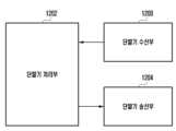
도 12는 실시예들에 따른 단말의 구조를 도시하는 블록도이다.
도 13은 실시예들에 따른 기지국의 구조를 도시하는 블록도이다.Figure 1 is a diagram showing the transmission structure in the time-frequency domain, which is a radio resource domain of a 5G or NR system.
FIG. 2 is a diagram for explaining a method of allocating data for eMBB, URLLC, and mMTC in the time-frequency resource domain in a 5G or NR system.
Figure 3 is a diagram explaining grant-free transmission and reception operation.
FIG. 4 is a diagram illustrating a DCI activation/release method in a situation where a plurality of grant-free resources (DL SPS or UL grant type 2) are set according to one embodiment.
FIG. 5 is a diagram illustrating a DCI activation/release method in a situation where a plurality of grant-free (DL SPS or UL grant type 2) resources are set according to one embodiment.
Figure 6 is a block diagram illustrating an uplink data transmission operation based on
Figure 7 is a block diagram illustrating an operation procedure of a terminal according to one embodiment.
Figure 8 is a diagram illustrating a semi-static HARQ-ACK codebook setting method in an NR system.
Figure 9 is a diagram illustrating a method for setting a dynamic HARQ-ACK codebook in an NR system.
Figure 10 is a diagram illustrating an example of reporting feedback in a situation where a terminal receives multiple PDSCHs.
FIG. 11 is a diagram illustrating an example of a terminal receiving multiple DL SPS PDSCHs.
Fig. 12 is a block diagram illustrating the structure of a terminal according to embodiments.
FIG. 13 is a block diagram illustrating the structure of a base station according to embodiments.
이하, 첨부된 도면을 참조하여 실시예를 상세하게 설명한다.Hereinafter, an embodiment will be described in detail with reference to the attached drawings.
실시예를 설명함에 있어서 본 발명이 속하는 기술 분야에 익히 알려져 있고 본 발명과 직접적으로 관련이 없는 기술 내용에 대해서는 설명을 생략한다. 이는 불필요한 설명을 생략함으로써 본 발명의 요지를 흐리지 않고 더욱 명확히 전달하기 위함이다.In describing the embodiments, descriptions of technical contents that are well known in the technical field to which the present invention belongs and are not directly related to the present invention will be omitted. This is to convey the gist of the present invention more clearly without obscuring it by omitting unnecessary descriptions.
마찬가지 이유로 첨부된 도면에 있어서 일부 구성요소는 과장되거나 생략되거나 개략적으로 도시되었다. 또한, 각 구성요소의 크기는 실제 크기를 전적으로 반영하는 것이 아니다. 각 도면에서 동일한 또는 대응하는 구성 요소에는 동일한 참조 번호를 부여하였다.For the same reason, some components in the attached drawings are exaggerated, omitted, or schematically illustrated. In addition, the size of each component does not entirely reflect the actual size. The same or corresponding components in each drawing are given the same reference numbers.
본 발명의 이점 및 특징, 그리고 그것들을 달성하는 방법은 첨부되는 도면과 함께 상세하게 후술되어 있는 실시예들을 참조하면 명확해질 것이다. 그러나 본 발명은 이하에서 발명되는 실시예들에 한정되는 것이 아니라 서로 다른 다양한 형태로 구현될 수 있으며, 단지 실시예들은 본 발명이 완전하도록 하고, 본 발명이 속하는 기술분야에서 통상의 지식을 가진 자에게 발명의 범주를 완전하게 알려주기 위해 제공되는 것이며, 본 발명은 청구항의 범주에 의해 정의될 뿐이다. 명세서 전체에 걸쳐 동일 참조 부호는 동일 구성 요소를 지칭한다.The advantages and features of the present invention, and the methods for achieving them, will become clearer with reference to the embodiments described in detail below together with the accompanying drawings. However, the present invention is not limited to the embodiments invented below, but can be implemented in various different forms, and the embodiments are provided only to make the present invention complete and to fully inform those skilled in the art of the scope of the invention, and the present invention is defined only by the scope of the claims. Like reference numerals refer to like elements throughout the specification.
이때, 처리 흐름도 도면들의 각 블록과 흐름도 도면들의 조합들은 컴퓨터 프로그램 인스트럭션들에 의해 수행될 수 있음을 이해할 수 있을 것이다. 이들 컴퓨터 프로그램 인스트럭션들은 범용 컴퓨터, 특수용 컴퓨터 또는 기타 프로그램 가능한 데이터 프로세싱 장비의 프로세서에 탑재될 수 있으므로, 컴퓨터 또는 기타 프로그램 가능한 데이터 프로세싱 장비의 프로세서를 통해 수행되는 그 인스트럭션들이 흐름도 블록(들)에서 설명된 기능들을 수행하는 수단을 생성하게 된다. 이들 컴퓨터 프로그램 인스트럭션들은 특정 방식으로 기능을 구현하기 위해 컴퓨터 또는 기타 프로그램 가능한 데이터 프로세싱 장비를 지향할 수 있는 컴퓨터 이용 가능 또는 컴퓨터 판독 가능 메모리에 저장되는 것도 가능하므로, 그 컴퓨터 이용가능 또는 컴퓨터 판독 가능 메모리에 저장된 인스트럭션들은 흐름도 블록(들)에서 설명된 기능을 수행하는 인스트럭션 수단을 내포하는 제조 품목을 생산하는 것도 가능하다. 컴퓨터 프로그램 인스트럭션들은 컴퓨터 또는 기타 프로그램 가능한 데이터 프로세싱 장비 상에 탑재되는 것도 가능하므로, 컴퓨터 또는 기타 프로그램 가능한 데이터 프로세싱 장비 상에서 일련의 동작 단계들이 수행되어 컴퓨터로 실행되는 프로세스를 생성해서 컴퓨터 또는 기타 프로그램 가능한 데이터 프로세싱 장비를 수행하는 인스트럭션들은 흐름도 블록(들)에서 설명된 기능들을 실행하기 위한 단계들을 제공하는 것도 가능하다.At this time, it will be understood that each block of the processing flow diagrams and combinations of the flow diagrams can be performed by computer program instructions. These computer program instructions can be loaded onto a processor of a general-purpose computer, a special-purpose computer, or other programmable data processing equipment, so that the instructions executed by the processor of the computer or other programmable data processing equipment create a means for performing the functions described in the flow diagram block(s). These computer program instructions can also be stored in a computer-available or computer-readable memory that can be directed to a computer or other programmable data processing equipment to implement the functions in a specific manner, so that the instructions stored in the computer-available or computer-readable memory can also produce an article of manufacture that includes an instruction means for performing the functions described in the flow diagram block(s). Since the computer program instructions may be installed on a computer or other programmable data processing apparatus, a series of operational steps may be performed on the computer or other programmable data processing apparatus to produce a computer-executable process, so that the instructions executing the computer or other programmable data processing apparatus may also provide steps for executing the functions described in the flowchart block(s).
또한, 각 블록은 특정된 논리적 기능(들)을 실행하기 위한 하나 이상의 실행 가능한 인스트럭션들을 포함하는 모듈, 세그먼트 또는 코드의 일부를 나타낼 수 있다. 또, 몇 가지 대체 실행 예들에서는 블록들에서 언급된 기능들이 순서를 벗어나서 발생하는 것도 가능함을 주목해야 한다. 예컨대, 잇달아 도시되어 있는 두 개의 블록들은 사실 실질적으로 동시에 수행되는 것도 가능하고 또는 그 블록들이 때때로 해당하는 기능에 따라 역순으로 수행되는 것도 가능하다.Additionally, each block may represent a module, segment, or portion of code that contains one or more executable instructions for performing a particular logical function(s). It should also be noted that in some alternative implementation examples, the functions mentioned in the blocks may occur out of order. For example, two blocks shown in succession may in fact be performed substantially concurrently, or the blocks may sometimes be performed in reverse order, depending on the functionality they perform.
이때, 본 실시예에서 사용되는 '~부'라는 용어는 소프트웨어 또는 FPGA(Field Programmable Gate Array) 또는 ASIC(Application Specific Integrated Circuit)과 같은 하드웨어 구성요소를 의미하며, '~부'는 어떤 역할들을 수행한다. 그렇지만 '~부'는 소프트웨어 또는 하드웨어에 한정되는 의미는 아니다. '~부'는 어드레싱할 수 있는 저장 매체에 있도록 구성될 수도 있고 하나 또는 그 이상의 프로세서들을 재생시키도록 구성될 수도 있다. 따라서, 일 예로서 '~부'는 소프트웨어 구성요소들, 객체지향 소프트웨어 구성요소들, 클래스 구성요소들 및 태스크 구성요소들과 같은 구성요소들과, 프로세스들, 함수들, 속성들, 프로시저들, 서브루틴들, 프로그램 코드의 세그먼트들, 드라이버들, 펌웨어, 마이크로코드, 회로, 데이터, 데이터베이스, 데이터 구조들, 테이블들, 어레이들, 및 변수들을 포함한다. 구성요소들과 '~부'들 안에서 제공되는 기능은 더 작은 수의 구성요소들 및 '~부'들로 결합되거나 추가적인 구성요소들과 '~부'들로 더 분리될 수 있다. 뿐만 아니라, 구성요소들 및 '~부'들은 디바이스 또는 보안 멀티미디어카드 내의 하나 또는 그 이상의 CPU들을 재생시키도록 구현될 수도 있다. 또한 실시예에서 '~부'는 하나 이상의 프로세서를 포함할 수 있다.Here, the term '~ part' used in the present embodiment means software or hardware components such as FPGA (Field Programmable Gate Array) or ASIC (Application Specific Integrated Circuit), and the '~ part' performs certain roles. However, the '~ part' is not limited to software or hardware. The '~ part' may be configured to be in an addressable storage medium and may be configured to reproduce one or more processors. Accordingly, as an example, the '~ part' includes components such as software components, object-oriented software components, class components, and task components, and processes, functions, properties, procedures, subroutines, segments of program code, drivers, firmware, microcode, circuits, data, databases, data structures, tables, arrays, and variables. The functions provided in the components and '~ parts' may be combined into a smaller number of components and '~ parts' or further separated into additional components and '~ parts'. In addition, the components and '~parts' may be implemented to play one or more CPUs within the device or secure multimedia card. Also, in an embodiment, the '~part' may include one or more processors.
무선 통신 시스템은 초기의 음성 위주의 서비스를 제공하던 것에서 벗어나 예를 들어, 3GPP의 HSPA(High Speed Packet Access), LTE(Long Term Evolution 또는 E-UTRA(Evolved Universal Terrestrial Radio Access), LTE-Advanced(LTE-A), 3GPP2의 HRPD(High Rate Packet Data), UMB(Ultra Mobile Broadband), 및 IEEE의 802.16e 등의 통신 표준과 같이 고속, 고품질의 패킷 데이터 서비스를 제공하는 광대역 무선 통신 시스템으로 발전하고 있다. 또한, 5세대 무선 통신 시스템으로 5G 또는 NR(New Radio)의 통신 표준이 만들어지고 있다.Wireless communication systems are evolving from the initial voice-oriented services to broadband wireless communication systems that provide high-speed, high-quality packet data services, such as 3GPP's HSPA (High Speed Packet Access), LTE (Long Term Evolution or E-UTRA (Evolved Universal Terrestrial Radio Access), LTE-Advanced (LTE-A), 3GPP2's HRPD (High Rate Packet Data), UMB (Ultra Mobile Broadband), and IEEE's 802.16e. In addition, communication standards for 5G or NR (New Radio) are being created as the 5th generation wireless communication system.
광대역 무선 통신 시스템의 대표적인 예인 5G 또는 NR 시스템에서는 하향링크(Downlink, DL) 및 상향링크에서는 OFDM(Orthogonal Frequency Division Multiplexing) 방식을 채용하고 있다. 구체적으로는 하향링크에서는 CP-OFDM(Cyclic-Prefix OFDM) 방식이 채용되었고, 상향링크에서는 CP-OFDM과 더불어 DFT-S-OFDM(Discrete Fourier Transform Spreading OFDM) 방식이 채용되었다. 상향링크는 단말이 기지국으로 데이터 또는 제어 신호를 전송하는 무선 링크를 뜻하고, 하향링크는 기지국이 단말로 데이터 또는 제어 신호를 전송하는 무선 링크를 뜻한다. 이와 같은 다중 접속 방식은, 통상 각 사용자 별로 데이터 또는 제어정보를 실어 보낼 시간-주파수 자원을 서로 겹치지 않도록, 즉, 직교성(Orthogonality)이 성립하도록, 할당 및 운용함으로써 각 사용자의 데이터 또는 제어 정보가 구분되도록 한다.In 5G or NR systems, which are representative examples of broadband wireless communication systems, the downlink (DL) and uplink adopt the OFDM (Orthogonal Frequency Division Multiplexing) method. Specifically, the CP-OFDM (Cyclic-Prefix OFDM) method is adopted in the downlink, and the DFT-S-OFDM (Discrete Fourier Transform Spreading OFDM) method is adopted in the uplink along with the CP-OFDM. The uplink refers to a wireless link in which a terminal transmits data or control signals to a base station, and the downlink refers to a wireless link in which a base station transmits data or control signals to a terminal. This multiple access method typically allocates and operates the time-frequency resources for transmitting data or control information to each user so that they do not overlap with each other, that is, so that orthogonality is established, thereby distinguishing the data or control information of each user.
5G 또는 NR 시스템은 초기 전송에서 복호 실패가 발생된 경우, 물리 계층에서 해당 데이터를 재전송하는 HARQ Hybrid Automatic Repeat reQuest) 방식을 채용하고 있다. HARQ 방식이란 수신기가 데이터를 정확하게 복호화(decoding, 디코딩)하지 못한 경우, 수신기가 송신기에게 디코딩 실패를 알리는 정보(Negative Acknowledgement, NACK)를 전송하여 송신기가 물리 계층에서 해당 데이터를 재전송할 수 있도록 한다. 수신기는 송신기가 재전송한 데이터를 이전에 디코딩 실패한 데이터와 결합하여 데이터 수신 성능을 높이게 된다. 또한, 수신기가 데이터를 정확하게 복호한 경우 송신기에게 디코딩 성공을 알리는 정보(Acknowledgement, ACK)를 전송하여 송신기가 새로운 데이터를 전송할 수 있도록 할 수 있다.5G or NR systems adopt the HARQ (Hybrid Automatic Repeat reQuest) method to retransmit the data at the physical layer if a decoding failure occurs in the initial transmission. The HARQ method means that if the receiver fails to correctly decode the data, the receiver transmits information (Negative Acknowledgement, NACK) to the transmitter to notify the decoding failure so that the transmitter can retransmit the data at the physical layer. The receiver combines the data retransmitted by the transmitter with data that previously failed to be decoded to improve data reception performance. In addition, if the receiver correctly decodes the data, it can transmit information (Acknowledgement, ACK) to the transmitter to notify the transmitter of the decoding success so that the transmitter can transmit new data.
한편, 새로운 5G 통신인 NR(New Radio access technology) 시스템은 시간 및 주파수 자원에서 다양한 서비스들이 자유롭게 다중화되도록 디자인 되고 있으며, 이에 따라 파형(waveform), 뉴머롤로지(numerology) 등과 기준 신호 등이 해당 서비스의 필요에 따라 동적으로 또는 자유롭게 할당될 수 있다. 또한 무선 통신에서 단말에게 최적의 서비스를 제공하기 위해서는 채널의 질과 간섭량의 측정을 통한 최적화 데이터 송신이 중요하며, 이에 따라 정확한 채널 상태 측정은 필수적이다. 하지만 주파수 자원에 따라 채널 및 간섭 특성이 크게 변화하지 않는 4G 통신과는 달리 5G 또는 NR 채널의 경우 서비스에 따라 채널 및 간섭 특성이 크게 변화하기 때문에 이를 나누어 측정할 수 있도록 하는 FRG(Frequency Resource Group) 차원의 서브셋(subset)의 지원이 필요하다. 한편, 5G 또는 NR 시스템에서는 지원되는 서비스의 종류를 eMBB(Enhanced Mobile BroadBand), mMTC(massive Machine Type Communications), URLLC(Ultra-Reliable and Low-Latency Communications) 등의 카테고리로 나눌 수 있다. eMBB는 고용량 데이터의 고속 전송, mMTC는 단말 전력 최소화와 다수 단말의 접속, URLLC는 고신뢰도와 저지연을 목표로 하는 서비스이다. 단말에게 적용되는 서비스의 종류에 따라 서로 다른 요구사항들이 적용될 수 있다.Meanwhile, the new 5G communication NR (New Radio access technology) system is designed to allow various services to be freely multiplexed in time and frequency resources, and thus, waveforms, numerologies, and reference signals can be dynamically or freely allocated according to the needs of the corresponding services. In addition, in order to provide optimal services to terminals in wireless communications, optimized data transmission through measurement of channel quality and interference is important, and therefore accurate channel status measurement is essential. However, unlike 4G communications where channel and interference characteristics do not change significantly depending on frequency resources, in the case of 5G or NR channels, channel and interference characteristics change significantly depending on services, and therefore support for subsets at the FRG (Frequency Resource Group) level is required to allow for dividing and measuring them. Meanwhile, the types of services supported in 5G or NR systems can be divided into categories such as eMBB (Enhanced Mobile BroadBand), mMTC (massive Machine Type Communications), and URLLC (Ultra-Reliable and Low-Latency Communications). eMBB is a service that aims for high-speed transmission of large-capacity data, mMTC is a service that aims for minimizing terminal power and connecting multiple terminals, and URLLC is a service that aims for high reliability and low delay. Different requirements may be applied depending on the type of service applied to the terminal.
상술된 서비스들 중 URLLC 서비스는 고신뢰도 및 저지연을 목표로 하기 때문에 물리 채널로 전송될 수 있는 제어 정보 및 데이터 정보가 낮은 코딩 레이트로 전송될 필요성이 존재할 수 있다. 제어 정보의 경우, LTE의 MTC(Machine Type Communications) 또는 NB-IoT(Narrow Band Internet-of-Things) 서비스에서 이미 제어 정보의 반복 전송 기능이 도입되었다. 제어 정보 반복 전송의 도입 목적은 작은 대역폭을 가지는 단말들을 위해 높은 커버리지를 제공하기 위함으로써, 이 때 지연시간이 충분히 고려되지가 않았다. 그리고 제어 정보 반복 전송 최소 단위가 LTE 기준으로 서브프레임 단위로 고정되어 있다. NR 또는 5G 시스템에서 URLLC 서비스를 지원하기 위해서 적은 지연 시간을 요구하면서 신뢰도를 향상시킬 수 있는 제어 정보 반복 전송 모드 도입이 필요하다. 따라서, 본 발명에서는 슬롯 내에서 제어 정보가 반복 전송되는 상황을 기본적으로 고려한다. 추가적으로 슬롯 경계를 넘어서 전송될 수 있는 제어 정보 반복 전송되는 상황 또한 고려할 수 있다. 발명Among the above-described services, since the URLLC service aims for high reliability and low delay, there may be a need for control information and data information that can be transmitted through a physical channel to be transmitted at a low coding rate. In the case of control information, the repeat transmission function of control information has already been introduced in LTE's MTC (Machine Type Communications) or NB-IoT (Narrow Band Internet-of-Things) service. The purpose of introducing the repeat transmission of control information is to provide high coverage for terminals with small bandwidth, so the delay time was not sufficiently considered at this time. In addition, the minimum unit of repeat transmission of control information is fixed to a subframe unit based on LTE. In order to support the URLLC service in NR or 5G systems, it is necessary to introduce a repeat transmission mode of control information that can improve reliability while requiring a low delay time. Therefore, the present invention basically considers a situation in which control information is repeatedly transmitted within a slot. Additionally, a situation in which control information that can be transmitted across a slot boundary is repeatedly transmitted can also be considered. Invention
본 발명에서, 각 용어들은 각각의 기능을 고려하여 정의된 용어들로서 이는 사용자, 운용자의 의도 또는 관례 등에 따라 달라질 수 있다. 그러므로 그 정의는 본 명세서 전반에 걸친 내용을 토대로 내려져야 할 것이다. 이하, 기지국은 단말의 자원 할당을 수행하는 주체로서, gNode B(gNB), eNode B(eNB), Node B, BS(Base Station), 무선 접속 유닛, 기지국 제어기, 또는 네트워크 상의 노드 중 적어도 하나일 수 있다. 단말은 UE(User Equipment), MS(Mobile Station), 셀룰러폰, 스마트폰, 컴퓨터 또는 통신 기능을 수행할 수 있는 멀티미디어 시스템을 포함할 수 있다. 발명또한 이하에서 본 발명에서는 NR 시스템을 예로 들어 설명하나, 이에 한정되지 않고, 유사한 기술적 배경 또는 채널 형태를 가지는 다양한 통신 시스템에도 본 발명의 실시예들이 적용될 수 있다. 또한 본 발명의 실시예는 숙련된 기술적 지식을 가진 자의 판단으로써 본 발명의 범위를 크게 벗어나지 아니하는 범위에서 일부 변형을 통해 다른 통신시스템에도 적용될 수 있다.In the present invention, each term is defined in consideration of its respective function, and this may vary depending on the intention or custom of the user or operator. Therefore, the definition should be made based on the contents throughout this specification. Hereinafter, a base station is a subject that performs resource allocation of a terminal, and may be at least one of a gNode B (gNB), an eNode B (eNB), a Node B, a BS (Base Station), a wireless access unit, a base station controller, or a node on a network. The terminal may include a UE (User Equipment), an MS (Mobile Station), a cellular phone, a smartphone, a computer, or a multimedia system capable of performing a communication function. InventionAlso, the present invention is described below using an NR system as an example, but is not limited thereto, and embodiments of the present invention may be applied to various communication systems having similar technical backgrounds or channel types. In addition, embodiments of the present invention may be applied to other communication systems through some modifications without significantly departing from the scope of the present invention at the discretion of a person having skilled technical knowledge.
본 발명에서 종래의 물리 채널(physical channel)과 신호(signal)라는 용어를 데이터 또는 제어 신호와 혼용하여 사용할 수 있다. 예를 들어, PDSCH(Physical Downlink Shared Channel)는 데이터가 전송되는 물리 채널이지만, 본 발명에서는 PDSCH를 데이터라 할 수도 있다.In the present invention, the conventional terms physical channel and signal may be used interchangeably with data or control signals. For example, PDSCH (Physical Downlink Shared Channel) is a physical channel through which data is transmitted, but in the present invention, PDSCH may be referred to as data.
본 발명에서 상위 시그널링(또는 상위 계층 시그널링, 상위 신호, 상위 계층 신호와 혼용될 수 있다)은 기지국에서 물리계층의 하향링크 데이터 채널을 이용하여 단말로, 또는 단말에서 물리계층의 상향링크 데이터 채널을 이용하여 기지국으로 전달되는 신호 전달 방법이며, RRC 시그널링 또는 MAC 제어요소(control element, CE)라고 언급될 수도 있다. 또한 L1(layer 1) 시그널링이란 물리 계층을 통해 상하향링크로 전달되는 신호 전달 방법으로, 이는 하향링크 제어 정보(downlink control information, DCI) 또는 상향링크 제어 정보(uplink control information, UCI)를 의미할 수 있다.In the present invention, upper signaling (or upper layer signaling, upper signal, it can be used interchangeably with upper layer signaling) is a signal transmission method in which a base station transmits a signal to a terminal using a downlink data channel of a physical layer, or from a terminal to a base station using an uplink data channel of a physical layer, and may also be referred to as RRC signaling or a MAC control element (CE). In addition, L1 (layer 1) signaling is a signal transmission method in which a signal is transmitted through a physical layer in uplink and downlink, and this may mean downlink control information (DCI) or uplink control information (UCI).
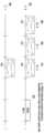
도 1은 5G 또는 NR 시스템의 무선 자원 영역인 시간-주파수 영역의 전송 구조를 나타낸 도면이다.Figure 1 is a diagram showing the transmission structure in the time-frequency domain, which is a radio resource domain of a 5G or NR system.
도 1을 참조하면, 무선 자원 영역에서, 가로 축은 시간 영역을, 세로 축은 주파수 영역을 나타낸다. 시간 영역에서의 최소 전송 단위는 OFDM 심볼로서, Nsymb 개의 OFDM 심볼(102)이 모여 하나의 슬롯(106)을 구성한다. 서브프레임의 길이는 1.0ms으로 정의될 수 있으며, 라디오 프레임(Radio frame, 114)은 10 ms로 정의될 수 있다. 주파수 영역에서의 최소 전송단위는 서브캐리어(subcarrier)로서, 전체 시스템 전송 대역(Transmission bandwidth)의 대역폭은 총 NBW 개의 서브캐리어(104)로 구성될 수 있다. 다만, 이러한 구체적인 수치는 시스템에 따라 가변적으로 적용될 수 있다.Referring to FIG. 1, in the wireless resource domain, the horizontal axis represents the time domain, and the vertical axis represents the frequency domain. The minimum transmission unit in the time domain is an OFDM symbol, and Nsymb OFDM symbols (102) are gathered to form one slot (106). The length of a subframe can be defined as 1.0 ms, and a radio frame (114) can be defined as 10 ms. The minimum transmission unit in the frequency domain is a subcarrier, and the bandwidth of the entire system transmission bandwidth can be composed of a total of NBW subcarriers (104). However, these specific figures can be applied variably depending on the system.
시간-주파수 자원 영역의 기본 단위는 자원 요소(112, Resource Element, 이하 RE)로서 OFDM 심볼 인덱스 및 서브캐리어 인덱스로 나타낼 수 있다. 자원 블록(108, Resource Block, 이하 RB) 또는 Physical Resource Block(이하, PRB)은 시간 영역에서 Nsymb 개의 연속된 OFDM 심볼(102)과 주파수 영역에서 NRB 개의 연속된 서브캐리어(110)로 정의될 수 있다. 따라서, 하나의 RB(108)는 Nsymb x NRB 개의 RE(112)로 구성될 수 있다.The basic unit of the time-frequency resource domain is a resource element (112, Resource Element, hereinafter referred to as RE), which can be represented by an OFDM symbol index and a subcarrier index. A resource block (108, Resource Block, hereinafter referred to as RB) or Physical Resource Block (hereinafter referred to as PRB) can be defined by Nsymb consecutive OFDM symbols (102) in the time domain and NRB consecutive subcarriers (110) in the frequency domain. Accordingly, one RB (108) can be composed of Nsymb x NRB REs (112).
일반적으로 데이터의 최소 전송 단위는 RB 단위이다. 5G 또는 NR 시스템에서 일반적으로 Nsymb = 14, NRB = 12 이고, NBW 는 시스템 전송 대역의 대역폭에 비례할 수 있다. 단말에게 스케줄링 되는 RB 개수에 비례하여 데이터 레이트가 증가하게 된다. 5G 또는 NR 시스템에서는 하향링크와 상향링크를 주파수로 구분하여 운영하는 FDD 시스템의 경우, 하향링크 전송 대역폭과 상향링크 전송 대역폭이 서로 다를 수 있다. 채널 대역폭은 시스템 전송 대역폭에 대응되는 RF(radio frequency) 대역폭을 나타낸다. 아래의 표 1은 5G 또는 NR 시스템 이전에 4 세대 무선 통신인 LTE 시스템에 정의된 시스템 전송 대역폭과 채널 대역폭(Channel bandwidth)의 대응 관계를 나타낸다. 예를 들어 10MHz 채널 대역폭을 갖는 LTE 시스템은 전송 대역폭이 50 개의 RB로 구성된다.In general, the minimum transmission unit of data is RB unit. In 5G or NR system, Nsymb = 14, NRB = 12, and NBW can be proportional to the bandwidth of the system transmission band. The data rate increases in proportion to the number of RBs scheduled to the terminal. In the 5G or NR system, in the case of the FDD system that operates the downlink and uplink by distinguishing them by frequency, the downlink transmission bandwidth and the uplink transmission bandwidth may be different. The channel bandwidth represents the RF (radio frequency) bandwidth corresponding to the system transmission bandwidth. Table 1 below shows the correspondence between the system transmission bandwidth and the channel bandwidth defined in the LTE system, which is the 4th generation wireless communication before the 5G or NR system. For example, an LTE system with a 10 MHz channel bandwidth consists of 50 RBs in the transmission bandwidth.
[표 1][Table 1]

5G 또는 NR 시스템에서는 표 1에서 제시된 LTE의 채널 대역폭보다 더 넓은 채널 대역폭에서 동작할 수 있다. 표 2는 5G 또는 NR 시스템에서 시스템 전송 대역폭과 채널 대역폭(Channel bandwidth) 및 부반송파 간격(Subcarrier spacing, SCS)의 대응관계를 나타낸다.5G or NR systems can operate in wider channel bandwidths than the LTE channel bandwidths presented in Table 1. Table 2 shows the correspondence between system transmission bandwidth, channel bandwidth, and subcarrier spacing (SCS) in 5G or NR systems.
[표 2][Table 2]

5G 또는 NR 시스템에서 하향링크 데이터 또는 상향링크 데이터에 대한 스케줄링 정보는 DCI를 통해 기지국으로부터 단말에게 전달된다. DCI는 여러 가지 포맷에 따라 정의되며, 각 포맷에 따라 상향링크 데이터에 대한 스케줄링 정보(UL grant) 인지 하향링크 데이터에 대한 스케줄링 정보(DL grant) 인지 여부, 제어정보의 크기가 작은 컴팩트 DCI인지 여부, 전력 제어용 DCI인지 여부 등을 나타낼 수 있다. 예컨대 하향링크 데이터에 대한 스케줄링 제어정보(DL grant)인 DCI 포맷 1_1은 적어도 다음과 같은 제어 정보들 중 하나를 포함할 수 있다.In a 5G or NR system, scheduling information for downlink data or uplink data is transmitted from a base station to a terminal via DCI. DCI is defined according to various formats, and each format can indicate whether it is scheduling information for uplink data (UL grant) or scheduling information for downlink data (DL grant), whether it is compact DCI with small control information size, and whether it is DCI for power control. For example, DCI format 1_1, which is scheduling control information for downlink data (DL grant), can include at least one of the following control information.
- 캐리어 지시자: 어떠한 주파수 캐리어에서 전송되는지를 지시한다.- Carrier indicator: Indicates on which frequency carrier the transmission is being made.
- DCI 포맷 지시자: 해당 DCI가 하향링크용인지 상향링크용인지 구분하는 지시자이다.- DCI format indicator: This is an indicator that distinguishes whether the DCI is for downlink or uplink.
- 대역폭 파트(BandWidth Part, BWP) 지시자: 하향링크 데이터가 어떠한 BWP에서 전송되는지를 지시한다.- BandWidth Part (BWP) indicator: Indicates in which BWP the downlink data is transmitted.
- 주파수 영역 자원 할당: 데이터 전송에 할당된 주파수 영역의 RB를 지시한다. BWP 및 자원 할당 방식에 따라 표현하는 자원이 결정된다.- Frequency domain resource allocation: Indicates the RB of the frequency domain allocated for data transmission. The resources expressed are determined according to the BWP and resource allocation method.
- 시간 영역 자원 할당: 어느 슬롯의 어느 OFDM 심볼에서 데이터 관련 채널이 전송될지를 지시한다.- Time domain resource allocation: Indicates in which OFDM symbol of which slot the data-related channel will be transmitted.
- VRB-to-PRB 매핑: 가상 RB(Virtual RB, VRB) 인덱스와 물리 RB(Physical RB, PRB) 인덱스를 어떤 방식으로 매핑할 것인지를 지시한다.- VRB-to-PRB mapping: Indicates how to map the virtual RB (VRB) index and the physical RB (PRB) index.
- 변조 및 코딩 방식(Modulation and coding scheme, MCS): 데이터 전송에 사용된 변조 방식과 코딩 레이트를 지시한다. 즉, QPSK(Quadrature Phase Shift Keying)인지, 16QAM(Quadrature Amplitude Modulation)인지, 64QAM인지, 256QAM인지에 대한 정보와 함께 TBS(Transport Block Size) 및 채널 코딩 정보를 알려줄 수 있는 코딩 레이트 값을 지시할 수 있다.- Modulation and coding scheme (MCS): Indicates the modulation method and coding rate used for data transmission. That is, it can indicate a coding rate value that can provide TBS (Transport Block Size) and channel coding information along with information on whether it is QPSK (Quadrature Phase Shift Keying), 16QAM (Quadrature Amplitude Modulation), 64QAM, or 256QAM.
- CBG 전송 정보(CodeBlock Group transmission information): CBG 재전송이 설정되었을 때, 어느 CBG가 전송되는지에 대한 정보를 지시한다.- CBG transmission information (CodeBlock Group transmission information): When CBG retransmission is set, indicates information about which CBG is transmitted.
- HARQ 프로세스 번호(HARQ process number): HARQ 의 프로세스 번호를 지시한다.- HARQ process number: Indicates the HARQ process number.
- 새로운 데이터 지시자(New data indicator): HARQ 초기전송인지 재전송인지를 지시한다.- New data indicator: Indicates whether it is a HARQ initial transmission or a retransmission.
- 중복 버전(Redundancy version): HARQ 의 중복 버전(redundancy version)을 지시한다.- Redundancy version: Indicates the redundancy version of HARQ.
- PUCCH를 위한 전송 전력 제어 명령(Transmit Power Control(TPC) command for PUCCH(Physical Uplink Control CHannel)): 상향링크 제어 채널인 PUCCH 에 대한 전송 전력 제어 명령을 지시한다.- Transmit Power Control (TPC) command for PUCCH (Physical Uplink Control CHannel): Indicates a transmit power control command for PUCCH, which is an uplink control channel.
5G 또는 NR 시스템에서는 PUSCH 매핑 타입은 타입 A(type A)와 타입 B(type B)가 정의되었다. PUSCH 매핑 타입 A는 슬롯에서 두 번째 또는 세 번째 심볼에서 복조 기준 신호(demodulation reference signal, DMRS) 심볼 중 첫 번째 심볼이 위치해 있다. PUSCH 매핑 타입 B는 PUSCH 전송을 위해 할당받은 시간 영역 자원에서의 첫 번째 심볼에서 DMRS 심볼 중 첫 번째 심볼이 위치해 있다. 전술한 PUSCH 시간 영역 자원 할당 방법은 PDSCH 시간 영역 자원 할당에 동일하게 적용 가능할 수 있다.In 5G or NR systems, PUSCH mapping types are defined as type A and type B. In PUSCH mapping type A, the first symbol of the demodulation reference signal (DMRS) symbol is located in the second or third symbol in a slot. In PUSCH mapping type B, the first symbol of the DMRS symbol is located in the first symbol of the time domain resource allocated for PUSCH transmission. The aforementioned PUSCH time domain resource allocation method can be equally applied to PDSCH time domain resource allocation.
DCI는 채널코딩 및 변조 과정을 거쳐 하향링크 물리 제어 채널인 PDCCH(Physical downlink control channel) 상에서 전송될 수 있다. 이하 PDCCH 송수신은 PDCCH 상의 DCI 송수신과 혼용될 수 있으며, 이러한 기술은 다른 채널에도 적용될 수 있다.DCI can be transmitted on the PDCCH (Physical downlink control channel), which is a downlink physical control channel, after going through the channel coding and modulation process. Hereinafter, PDCCH transmission and reception can be mixed with DCI transmission and reception on the PDCCH, and this technology can be applied to other channels as well.
일반적으로 DCI는 각 단말에 대해 독립적으로 특정 RNTI(Radio Network Temporary Identifier, 또는 단말 식별자)로 스크램블링되어 CRC(Cyclic Redundancy Check)가 추가되고, 채널 코딩된 후, 각각 독립적인 PDCCH로 구성되어 전송된다. PDCCH는 단말에게 설정된 제어 자원 집합(control resource set, CORESET)에 매핑되어 전송된다.Typically, DCI is scrambled independently for each terminal with a specific RNTI (Radio Network Temporary Identifier, or terminal identifier), a CRC (Cyclic Redundancy Check) is added, channel coded, and then transmitted as an independent PDCCH. The PDCCH is mapped to a control resource set (CORESET) set for the terminal and transmitted.
하향링크 데이터는 하향링크 데이터 전송용 물리 채널인 PDSCH(Physical Downlink Shared Channel) 상에서 전송될 수 있다. PDSCH는 제어 채널 전송 구간 이후부터 전송될 수 있으며, 주파수 영역에서의 구체적인 매핑 위치, 변조 방식 등의 스케줄링 정보는 PDCCH 를 통해 전송되는 DCI를 기반으로 결정된다.Downlink data can be transmitted on the Physical Downlink Shared Channel (PDSCH), which is a physical channel for downlink data transmission. The PDSCH can be transmitted after the control channel transmission period, and scheduling information such as specific mapping locations and modulation methods in the frequency domain are determined based on the DCI transmitted through the PDCCH.
DCI를 구성하는 제어 정보 중에서 MCS를 통해서, 기지국은 단말에게 전송하고자 하는 PDSCH에 적용된 변조 방식과 전송하고자 하는 데이터의 크기(Transport Block Size, TBS)를 통지한다. 일 실시예에서 MCS는 5 비트 또는 그보다 더 많거나 적은 비트로 구성될 수 있다. TBS는 기지국이 전송하고자 하는 데이터(Transport Block, TB)에 오류정정을 위한 채널코딩이 적용되기 이전의 크기에 해당한다.Among the control information configuring DCI, through MCS, the base station notifies the terminal of the modulation method applied to the PDSCH to be transmitted and the size of the data to be transmitted (Transport Block Size, TBS). In one embodiment, the MCS may be composed of 5 bits or more or fewer bits. TBS corresponds to the size of the data (Transport Block, TB) to be transmitted by the base station before channel coding for error correction is applied.
본 발명에서 트랜스포트 블록(Transport Block)라 함은, MAC(Medium Access Control) 헤더, MAC 제어 요소, 1 개 이상의 MAC SDU(Service Data Unit), 패딩(padding) 비트들을 포함할 수 있다. 또는 TB는 MAC 계층에서 물리 계층(physical layer)으로 내려주는 데이터의 단위 또는 MAC PDU(Protocol Data Unit)를 의미할 수 있다.In the present invention, a transport block may include a MAC (Medium Access Control) header, a MAC control element, one or more MAC SDUs (Service Data Units), and padding bits. Alternatively, TB may mean a unit of data transmitted from a MAC layer to a physical layer or a MAC PDU (Protocol Data Unit).
5G 또는 NR 시스템에서 지원하는 변조 방식은 QPSK(Quadrature Phase Shift Keying), 16QAM(Quadrature Amplitude Modulation), 64QAM, 및 256QAM으로서, 각각의 변조 차수(Modulation order, Qm)는 2, 4, 6, 8에 해당한다. 즉 QPSK 변조의 경우 심볼 당 2 비트, 16QAM 변조의 경우 OFDM 심볼 당 4 비트, 64QAM 변조의 경우 심볼당 6 비트를 전송할 수 있으며, 256QAM 변조의 경우 심볼당 8 비트를 전송할 수 있다.The modulation methods supported in 5G or NR systems are Quadrature Phase Shift Keying (QPSK), Quadrature Amplitude Modulation (16QAM), 64QAM, and 256QAM, where the modulation orders (Qm ) are 2, 4, 6, and 8, respectively. That is, QPSK modulation can transmit 2 bits per symbol, 16QAM modulation can transmit 4 bits per OFDM symbol, 64QAM modulation can transmit 6 bits per symbol, and 256QAM modulation can transmit 8 bits per symbol.
PUSCH 전송의 경우 시간 영역 자원 할당(time domain resource assignment)은 PUSCH가 전송되는 슬롯에 관한 정보 및, 해당 슬롯에서의 시작 OFDM 심볼 위치 S 와 PUSCH가 매핑되는 OFDM 심볼 개수 L 에 의해 전달될 수 있다. 전술한 S 는 슬롯의 시작으로부터 상대적인 위치일 수 있고, L 은 연속된 OFDM 심볼 개수일 수 있으며, S 와 L 은 아래와 같이 정의되는 시작 및 길이 지시자 값(Start and Length Indicator Value, SLIV)으로부터 결정될 수 있다.For PUSCH transmission, time domain resource assignment can be conveyed by information about a slot in which a PUSCH is transmitted, a start OFDM symbol position S in the slot, and the number of OFDM symbols L to which the PUSCH is mapped. The aforementioned S can be a relative position from the start of a slot, L can be a number of consecutive OFDM symbols, and S and L can be determined from a Start and Length Indicator Value (SLIV) defined as follows.
If (L-1) ≤ 7 thenIf (L-1) ≤ 7 then
SLIV = 14·(L-1)+SSLIV = 14·(L-1)+S
elseelse
SLIV = 14·(14-L+1)+(14-1-S)SLIV = 14·(14-L+1)+(14-1-S)
where 0 < L ≤ 14-Swhere 0 < L ≤ 14-S
5G 또는 NR 시스템에서는 단말은 일반적으로 RRC 설정을 통해서, 하나의 행에 SLIV 값과 PUSCH 매핑 타입 및 PUSCH가 전송되는 슬롯에 대한 정보가 포함된 표를 설정받을 수 있다. 이후, DCI의 시간 영역 자원 할당에서는 설정된 표에서의 인덱스(index) 값을 지시함으로써 기지국이 단말에게 SLIV 값, PUSCH 매핑 타입, PUSCH가 전송되는 슬롯에 대한 정보를 전달할 수 있다.In a 5G or NR system, a terminal can generally receive a table including SLIV values, PUSCH mapping types, and information about slots in which PUSCH is transmitted in one row through RRC configuration. Thereafter, in time domain resource allocation of DCI, the base station can transmit information about SLIV values, PUSCH mapping types, and slots in which PUSCH is transmitted to the terminal by indicating an index value in the configured table.
구체적으로 PDSCH를 스케줄링하는 DCI에 포함된 시간 자원 할당 필드 인덱스가 m을 지시할 경우, 이는 시간 영역 자원 할당 정보를 나타내는 표에서 m+1에 해당하는 DMRS 타입 A 위치 정보(dmrs-TypeA-Position), PDSCH 매핑 타입(PDSCH mapping type) 정보, 슬롯 인덱스 K0, 데이터 자원 시작 심볼 S, 데이터 자원 할당 길이 L의 조합을 알려준다. 일례로, 표 3은 시간 영역 자원 할당 정보들을 포함하는 표이다.Specifically, when the time resource allocation field index included in the DCI for scheduling the PDSCH indicates m, this indicates a combination of DMRS Type A position information (dmrs-TypeA-Position), PDSCH mapping type information, slot index K0 , data resource start symbol S, and data resource allocation length L corresponding to m+1 in a table representing time domain resource allocation information. As an example, Table 3 is a table including time domain resource allocation information.
[표 3][Table 3]

표 3에서 dmrs-typeA-Position은 단말 공통 제어 정보 중에 하나인 SIB(System Information Block)에서 지시하는 한 슬롯 안에서 DMRS가 전송되는 심볼 위치를 알려주는 필드이다. 해당 필드가 가능한 값은 2 또는 3이다. 한 슬롯을 구성하는 심볼 개수가 총 14개 이고 첫 번째 심볼 인덱스를 0이라 할 때, 2는 세 번째 심볼을 의미하고 3은 네 번째 심볼을 의미한다. 표 3에서 PDSCH 매핑 타입은 스케줄링된 데이터 자원 영역에서 DMRS의 위치를 알려주는 정보이다. PDSCH 매핑 타입이 A 일 경우, 할당된 데이터 시간 영역 자원과 관계없이 항상 dmrs-typeA-Position에서 결정된 심볼 위치에 DMRS가 송수신된다. PDSCH 매핑 타입이 B 일 경우, DMRS의 위치는 항상 할당된 데이터 시간 영역 자원 중 첫번째 심볼이 된다. 다시 말하면, PDSCH 매핑 타입 B는 dmrs-typeA-Position 정보를 사용하지 않는다. 표 3에서 K0는 DCI가 전송되는 PDCCH가 속한 슬롯 인덱스와 해당 DCI에서 스케줄링된 PDSCH 또는 PUSCH가 속한 슬롯 인덱스의 오프셋을 의미한다. 일례로, PDCCH의 슬롯 인덱스가 n 일 경우, PDCCH의 DCI가 스케줄링 한 PDSCH 또는 PUSCH의 슬롯 인덱스는 n+K0 이다. 표 3에서 S는 한 슬롯 내에서 데이터 시간 영역 자원의 시작 심볼 인덱스를 의미한다. 가능한 S 값의 범위는 보통 순환 전치(Normal Cyclic Prefix) 기준으로 0 내지 13이다. 표 3에서 L은 한 슬롯 내에서 데이터 시간 영역 자원 구간 길이를 의미한다. 가능한 L의 값의 범위는 1 내지 14이다.In Table 3, dmrs-typeA-Position is a field that indicates the symbol position where DMRS is transmitted within a slot indicated by SIB (System Information Block), which is one of the terminal common control information. The possible values for this field are 2 or 3. When the total number of symbols constituting one slot is 14 and the first symbol index is 0, 2 means the third symbol, 3 means the fourth symbol, and so on. In Table 3, PDSCH mapping type is information that indicates the position of DMRS in the scheduled data resource area. When PDSCH mapping type is A, DMRS is always transmitted and received at the symbol position determined by dmrs-typeA-Position regardless of the allocated data time domain resources. When PDSCH mapping type is B, the position of DMRS is always the first symbol among the allocated data time domain resources. In other words, PDSCH mapping type B does not use dmrs-typeA-Position information. In Table 3, K0 means the offset of the slot index to which the PDCCH to which the DCI is transmitted belongs and the slot index to which the PDSCH or PUSCH scheduled in the corresponding DCI belongs. For example, if the slot index of the PDCCH is n, the slot index of the PDSCH or PUSCH scheduled by the DCI of the PDCCH is n+K0. In Table 3, S means the start symbol index of the data time domain resource within one slot. The possible range of S values is usually 0 to 13 based on the Normal Cyclic Prefix. In Table 3, L means the length of the data time domain resource section within one slot. The possible range of L values is 1 to 14.
도 2는 5G 또는 NR 시스템에서 eMBB, URLLC, mMTC용 데이터들을 시간-주파수 자원 영역에서 할당하는 일례를 도시한 도면이다.FIG. 2 is a diagram illustrating an example of allocating data for eMBB, URLLC, and mMTC in the time-frequency resource domain in a 5G or NR system.
도 2를 참조하면, 전체 시스템 주파수 대역(200)에서 eMBB, URLLC, mMTC용 데이터가 할당될 수 있다. eMBB 데이터(201)와 mMTC 데이터(209)가 특정 주파수 대역에서 할당되어 전송되는 도중에 URLLC 데이터(203, 205, 207)가 발생하여 전송이 필요한 경우, eMBB(201) 및 mMTC 데이터(209)가 이미 할당된 부분을 비우거나, 전송을 하지 않고 URLLC 데이터(203, 205, 207)를 전송할 수 있다. 상술한 서비스들 중에서 URLLC는 지연 시간을 줄이는 것이 필요하기 때문에, eMBB 또는 mMTC가 할당된 자원의 일부분에 URLLC 데이터가 할당되어 전송될 수 있다. eMBB가 할당된 자원에서 URLLC가 추가로 할당되어 전송되는 경우, 중복되는 시간-주파수 자원에서는 eMBB 데이터가 전송되지 않을 수 있으며, 따라서 eMBB 데이터의 전송 성능이 낮아질 수 있다. 즉, URLLC 할당으로 인한 eMBB 데이터 전송 실패가 발생할 수 있다.Referring to FIG. 2, data for eMBB, URLLC, and mMTC can be allocated in the entire system frequency band (200). If URLLC data (203, 205, 207) is generated and needs to be transmitted while eMBB data (201) and mMTC data (209) are allocated and transmitted in a specific frequency band, the portion where eMBB (201) and mMTC data (209) have already been allocated can be emptied, or the URLLC data (203, 205, 207) can be transmitted without transmission. Since URLLC among the above-described services needs to reduce delay time, URLLC data can be allocated and transmitted to a part of the resources to which eMBB or mMTC is allocated. If URLLC is additionally allocated and transmitted in the resources to which eMBB is allocated, eMBB data may not be transmitted in the overlapping time-frequency resources, and thus the transmission performance of eMBB data may be reduced. That is, eMBB data transmission failure may occur due to URLLC allocation.
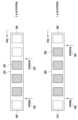
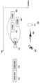
도 3는 비승인(grant-free) 송수신 동작을 설명하는 도면이다.Figure 3 is a diagram explaining grant-free transmission and reception operations.
단말은 데이터를 기지국으로 송신 또는 수신하기 위해서 별도의 제어 정보를 기지국으로부터 수신하여야 한다. 하지만 주기적으로 발생되는 트래픽 또는 저지연 및/또는 고신뢰도를 요구하는 서비스 타입의 경우, 상기 별도 제어 정보 없이 데이터를 송신 또는 수신하는 것이 가능할 수 있다. 이런 전송 방식을 본 발명에서는 설정된 그랜트(configured grant 또는 비승인(grant-free)) 기반 데이터 전송 방법이라 부른다. 전송 방식으로는, 단말이 기지국으로부터 DCI를 수신하고 해당 DCI에서 가리키는 전송 설정 정보에 따라 하향링크 데이터 수신 또는 상향링크 데이터 송신을 수행하는 제1 신호 송수신 유형과 DCI 수신 없이 사전에 상위 신호로 설정된 정보에 따라 하향링크 데이터 수신 또는 상향링크 데이터 송신을 수행하는 제2 신호 송수신 유형이 있다.In order to transmit or receive data to or from a base station, a terminal must receive separate control information from the base station. However, in the case of traffic that occurs periodically or a service type that requires low delay and/or high reliability, it may be possible to transmit or receive data without the separate control information. This transmission method is called a configured grant (or grant-free)-based data transmission method in the present invention. As a transmission method, there are a first signal transmission/reception type in which a terminal receives DCI from a base station and performs downlink data reception or uplink data transmission according to transmission configuration information indicated by the corresponding DCI, and a second signal transmission/reception type in which downlink data reception or uplink data transmission is performed according to information previously set as an upper signal without receiving DCI.
본 발명에서는 하향링크 데이터 수신을 위한 제2 신호 송수신 유형인 반영속적 스케줄링(semi-persistent scheduling, SPS)는 하향링크에서의 비승인 기반 PDSCH 전송을 의미하며, 상향링크 데이터 송신을 위한 제2 신호 송수신 유형인 UL 그랜트 타입(UL grant type)은 상향링크에서 비승인 기반 PUSCH 전송을 의미한다. UL 그랜트 타입의 경우, 상위 신호로만 비승인 기반 PUSCH 관련 설정 정보를 모두 수신하는 UL 그랜트 타입 1과 상위 신호 및 DCI 신호를 통해 비승인 기반 PUSCH 관련 설정 정보를 모두 수신하는 UL 그랜트 타입 2가 존재한다. 구체적으로 UL 그랜트 타입 1의 경우 DCI 수신 없이 상위 신호 설정으로만 비승인 기반 PUSCH 전송을 단말이 수행할 수 있는 반면에, UL 그랜트 타입 2의 경우 상위 신호 설정을 받은 이후, DCI 수신을 통해서 비승인 기반 PUSCH 전송을 단말이 수행할 수 있다. UL 그랜트 타입 2의 경우, 일부의 설정 정보는 상위 신호로 설정되며 그 이외의 설정 정보와 실제 데이터 전송 여부는 L1 신호에 의해서 결정된다. 여기서 L1 신호는 크게 상위로 설정된 자원의 활성화를 지시하는 신호와 활성화된 자원을 다시 해제를 지시하는 신호로 구분할 수 있다. 참고로 DL SPS는 UL 그랜트 타입 2와 유사하게 상위 신호 설정 및 DCI에서 지시하는 추가 설정 정보를 통해 설정되며, 비승인 기반 PDSCH 전송을 단말이 수신할 수 있다.In the present invention, semi-persistent scheduling (SPS), which is a second signal transmission/reception type for downlink data reception, means non-grant-based PDSCH transmission in downlink, and UL grant type, which is a second signal transmission/reception type for uplink data transmission, means non-grant-based PUSCH transmission in uplink. In the case of the UL grant type, there is a
DL SPS는 기지국이 단말에게 특정 하향링크 제어 정보 스케줄링 없이 상위 시그널링으로 설정된 정보를 기반으로 기지국과 단말이 주기적으로 하향링크 데이터 정보를 송수신하는 방법이다. 이는 VoIP(voice over IP) 또는 주기적으로 발생되는 트래픽 상황에서 적용이 가능하다. DL SPS를 위한 자원 설정은 주기적이지만 실제 발생되는 데이터는 비주기적일 수도 있다. 이와 같은 경우, 단말은 상기 주기적으로 설정된 자원에서 실제 데이터가 발생되는지 여부를 모르기 때문에 다음 3 가지 유형의 동작을 수행하는 것이 가능할 수 있다.DL SPS is a method in which a base station and a terminal periodically transmit and receive downlink data information based on information set by upper signaling without scheduling specific downlink control information to the terminal. This can be applied to VoIP (voice over IP) or periodically occurring traffic situations. Resources set for DL SPS are periodic, but the actual data that is generated may be aperiodic. In this case, the terminal may be able to perform the following three types of operations because it does not know whether actual data is generated from the periodically set resources.
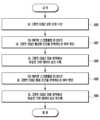
-방법 1-1: 주기적으로 설정된 DL SPS 자원 영역에 대해서 단말은 수신한 데이터에 대한 복조 또는/및 복호 결과에 대한 해당 자원 영역에 대응되는 상향링크 자원 영역 상에서 HARQ-ACK 정보를 기지국으로 송신- Method 1-1: For the DL SPS resource area set periodically, the terminal transmits HARQ-ACK information to the base station on the uplink resource area corresponding to the corresponding resource area for the demodulation or/and decoding result of the received data.
-방법 1-2: 주기적으로 설정된 DL SPS 자원 영역에 대해서 단말은 적어도 DMRS 또는 데이터에 대한 신호 검출이 성공적으로 수행된 경우, 수신한 데이터에 대한 복조 및/또는 복호 결과에 대한 해당 자원 영역에 대응되는 상향링크 자원 영역 상에서 HARQ-ACK 정보를 기지국으로 송신- Method 1-2: For the DL SPS resource area set periodically, if signal detection for DMRS or data is successfully performed at least, the terminal transmits HARQ-ACK information to the base station on the uplink resource area corresponding to the corresponding resource area for the demodulation and/or decoding result for the received data.
-방법 1-3: 주기적으로 설정된 DL SPS 자원 영역에 대해서 단말은 복호 및/또는 복조를 성공한 경우(즉 ACK 발생), 수신한 데이터에 대한 복조 및/또는복호 결과에 대한 해당 자원 영역에 대응되는 상향링크 자원 영역 상에서 HARQ-ACK 정보를 기지국으로 송신- Method 1-3: When the terminal succeeds in decoding and/or demodulation (i.e., ACK occurs) for the periodically set DL SPS resource area, it transmits HARQ-ACK information to the base station on the uplink resource area corresponding to the demodulation and/or decoding result for the received data.
방법 1-1에 따르면, 실제 기지국이 DL SPS 자원 영역에 대해서 하향링크 데이터를 송신하지 않더라도 단말은 항상 해당 DL SPS 자원 영역에 대응되는 상향링크 자원 영역에서 HARQ-ACK 정보를 송신한다. 방법 1-2에 따르면, 기지국이 언제 DL SPS 자원 영역으로 데이터를 송신할지 모르기 때문에 단말이 DMRS 검출을 성공하거나 또는 CRC 검출이 성공하는 등과 같이 단말이 데이터의 송수신 여부를 아는 상황에서는 HARQ-ACK 정보를 송신하는 것이 가능할 수 있다. 방법 1-3에 따르면, 단말이 데이터 복조 및/또는 복호를 성공한 경우에만 단말은 해당 DL SPS 자원 영역에 대응되는 상향링크 자원 영역에서 HARQ-ACK 정보를 송신한다.According to Method 1-1, even if the actual base station does not transmit downlink data for the DL SPS resource region, the terminal always transmits HARQ-ACK information in the uplink resource region corresponding to the DL SPS resource region. According to Method 1-2, since the base station does not know when to transmit data to the DL SPS resource region, it may be possible to transmit HARQ-ACK information in a situation where the terminal knows whether data is transmitted or received, such as when the DMRS detection is successful or the CRC detection is successful. According to Method 1-3, the terminal transmits HARQ-ACK information in the uplink resource region corresponding to the DL SPS resource region only when the terminal succeeds in data demodulation and/or decoding.
상기 서술된 방법들 중 단말은 항상 하나만 지원 가능하거나 두 개 이상을 지원하는 것이 가능할 수 있다. 규격 또는 상위 신호로 상기 방법들 중 하나를 선택하는 것이 가능할 수 있다. 일례로, 상위 신호로 방법 1-1을 사용하도록 지시한 경우, 단말은 해당 DL SPS에 대한 HARQ-ACK 정보를 방법 1-1에 기반하여 전송하는 것이 가능할 수 있다. 또는 DL SPS 상위 설정 정보에 따라 하나의 방법이 선택되는 것도 가능할 수 있다. 일례로, DL SPS 상위 설정 정보에서 전송 주기가 n 슬롯 이상일 경우 단말은 방법 1-1을 적용하며, 그 반대 일 경우 단말은 방법 1-3을 적용하는 것이 가능할 수 있다. 본 예시에서는 전송 주기를 그 예시로 들었지만, 적용된 MCS 테이블, DMRS 설정 정보, 자원 설정 정보 등에 의해 특정 방법이 적용되는 것이 충분히 가능할 수 있다.Among the above-described methods, the terminal may always support only one or may be able to support two or more. It may be possible to select one of the above methods by a standard or an upper signal. For example, if a higher signal instructs to use method 1-1, the terminal may be able to transmit HARQ-ACK information for the corresponding DL SPS based on method 1-1. Alternatively, one method may be selected according to DL SPS upper configuration information. For example, if the transmission period in the DL SPS upper configuration information is n slots or more, the terminal may apply method 1-1, and vice versa, the terminal may be able to apply method 1-3. In this example, the transmission period is mentioned as an example, but it may be sufficiently possible for a specific method to be applied by the applied MCS table, DMRS configuration information, resource configuration information, etc.
단말은 상위 시그널링으로 설정된 하향링크 자원 영역에서 하향링크 데이터 수신을 수행한다. 상기 상위 시그널링으로 설정된 하향링크 자원 영역의 활성화(activation) 또는 해제(release)를 L1 시그널링으로 수행하는 것이 가능할 수 있다.The terminal performs downlink data reception in a downlink resource area set by upper signaling. It may be possible to perform activation or release of the downlink resource area set by the upper signaling by L1 signaling.
도 3은 DL SPS 또는 UL 그랜트 타입 2에 대한 동작을 도시한다. 단말은 기지국으로부터 상위 신호로 다음과 같은 비승인 기반 UL 그랜트 타입 2 설정 정보 중 적어도 하나를 수신한다.Figure 3 illustrates the operation for DL SPS or
-frequencyHopping: 슬롯 내 호핑(intra-slot hopping)인지 슬롯간 호핑(inter-slot hopping)인지를 알려주는 필드, 이 필드가 없으면 주파수 호핑(frequency hopping) 이 비활성화된다.- frequencyHopping: A field that indicates whether it is intra-slot hopping or inter-slot hopping. If this field is absent, frequency hopping is disabled.
-cg-DMRS-Configuration: DMRS 설정 정보- cg-DMRS-Configuration: DMRS configuration information
-mcs-Table: 트랜스폼 프리코딩(Transform precoding)이 적용되지 않은 PUSCH 전송시, 256QAM MCS 테이블 또는 새로운 64QAM MCS 테이블이 사용되는지를 알려주는 필드, 이 필드가 없으면 64QAM MCS 테이블이 사용된다.- mcs-Table: A field that indicates whether the 256QAM MCS table or the new 64QAM MCS table is used when transmitting PUSCH without transform precoding applied. If this field is absent, the 64QAM MCS table is used.
-mcs-TableTransformPrecoder: 트랜스폼 프리코딩 기반 PUSCH 전송 시, 단말이 사용하는 MCS 테이블을 알려주는 필드, 이 필드가 없으면 64QAM MCS 테이블이 사용된다.- mcs-TableTransformPrecoder: A field that indicates the MCS table used by the terminal when transmitting PUSCH based on transform precoding. If this field is not present, the 64QAM MCS table is used.
-uci-OnPUSCH: 동적 또는 준정적 방식 중 하나로 베타 오프셋(betta-offset)을 적용- uci-OnPUSCH: Apply beta-offset either dynamically or semi-statically.
-resourceAllocation: 자원 할당 타입이 1인지 2인지를 설정 -rbg-Size: 2개의 설정 가능한 RBG(resource block group) 크기 중 하나를 결정- resourceAllocation: Sets whether the resource allocation type is 1 or 2 - rbg-Size: Determines one of two configurable RBG (resource block group) sizes
-powerControlLoopToUse: 폐루프 전력 제어(closed loop power control) 적용 유무 결정- powerControlLoopToUse: Determines whether closed loop power control is applied.
-p0-PUSCH-Alpha: PUSCH 전력 제어 파라미터인 Po, PUSCH alpha 값 적용- p0-PUSCH-Alpha: Applying the PUSCH power control parameter Po, PUSCH alpha value
-transformPrecoder: 트랜스폼 프리코딩 적용 유무 설정, 이 필드가 없으면, msg3 설정 정보를 따름- transformPrecoder: Set whether to apply transform precoding. If this field is not present, the msg3 setting information is followed.
-nrofHARQ-Processes: 설정된 HARQ 프로세스의 수- nrofHARQ-Processes: Number of configured HARQ processes.
-repK: 반복 전송 횟수- repK: Number of repeated transmissions
-repK-RV: 반복 전송 시, 각 반복 전송에 적용된 RV(redundancy version) 패턴, 반복 전송 횟수가 1일 경우, 이 필드는 비활성화- repK-RV: When repeating transmission, the RV (redundancy version) pattern applied to each repeating transmission. If the number of repeating transmissions is 1, this field is disabled.
-periodicity: 전송 주기, 최소 2 심볼부터, 최대 부반송파 간격에 따른 640 내지 5120 슬롯 단위까지 존재- Periodicity: Transmission period, from a minimum of 2 symbols to a maximum of 640 to 5120 slot units depending on the subcarrier spacing.
단말은 상기 UL 그랜트 타입 2 상위 설정 정보 이외에 UL 그랜트 타입 2를 활성화(activation)하는 DCI에 포함될 수 있는 다음 정보 중 적어도 하나를 추가적으로 고려하여 UL 그랜트 타입 2 설정 정보를 판단한다.In addition to the above
-timeDomainAllocation: PUSCH의 전송 시간 자원 영역을 알려주는 필드, K2 값은 상기 DCI가 전송된 슬롯을 기준으로 UL 그랜트 타입 2 전송이 시작하는 slot offset 정보를 지시- timeDomainAllocation: A field that indicates the transmission time resource area of PUSCH. TheK2 value indicates the slot offset information where
-frequencyDomainAllocation: PUSCH의 전송 주파수 자원 영역을 알려주는 필드- frequencyDomainAllocation: A field that indicates the transmission frequency resource area of PUSCH.
-antennaPort: 비승인 PUSCH 전송에 적용된 안테나 포트(antenna port) 설정 정보- antennaPort: Antenna port setting information applied to unauthorized PUSCH transmission
-dmrs-SeqInitialization: 트랜스폼 프리코더가 비활성화되어 있을 때, 설정되는 필드- dmrs-SeqInitialization: Field set when the transform precoder is disabled.
-precodingAndNumberOfLayers: 레이어의 수와 PUSCH 전송에 적용되는 프리코더를 지시하는 필드- precodingAndNumberOfLayers: A field indicating the number of layers and the precoder applied to the PUSCH transmission.
-srs-ResourceIndicator: SRS 자원 설정 정보를 알려주는 필드- srs-ResourceIndicator: Field that provides SRS resource setting information.
-mcsAndTBS: PUSCH 전송에 적용된 MCS 및 TBS- mcsAndTBS: MCS and TBS applied to PUSCH transmission
-frequencyHoppingOffset: 주파수 호핑 오프셋 값- frequencyHoppingOffset: Frequency hopping offset value
SRS resource indicator: SRS 자원과 연계된 P0, Alpha 값을 통해 전력을 제어하는 필드SRS resource indicator: A field that controls power through the P0 and Alpha values associated with SRS resources.
상기 설정 정보들은 UL 그랜트 타입 2에서는 DCI를 통해 지시되지만, DCI 활성화 없이 비승인 PUSCH를 지원하는 UL 그랜트 타입 1의 경우, 상기 정보들 및 timeDomainOffset 정보가 상위 신호로 설정된다.The above configuration information is indicated through DCI in
단말은 상위 신호로부터 다음 DL SPS 설정 정보를 설정한다.The terminal sets the following DL SPS configuration information from the upper signal.
-Periodicity: DL SPS 전송 주기- Periodicity: DL SPS transmission period
-nrofHARQ-Processes: DL SPS를 위해 설정된 HARQ 프로세스 수- nrofHARQ-Processes: Number of HARQ processes set for DL SPS.
-n1PUCCH-AN: DL SPS를 위한 PUCCH HARQ 자원 설정 정보로 기지국은 PUCCH 포맷 0 또는 1로 자원을 설정한다- n1PUCCH-AN: PUCCH HARQ resource configuration information for DL SPS. The base station configures resources in
-mcs-Table: DL SPS에 적용된 MCS 테이블 설정 정보- mcs-Table: MCS table setting information applied to DL SPS
본 발명에서 DL SPS 및 UL 그랜트 타입 설정 정보들은 모두 프라이머리 셀(primary cell, Pcell) 또는 세컨더리 셀(secondary cell, Scell) 별로 설정이 가능하며, 또한 대역폭 구간(BWP) 별로도 설정이 가능할 수 있다. 또한, 특정 셀 별 BWP 별로 하나 이상의 DL SPS 또는 UL 그랜트 타입들이 설정되는 것이 가능할 수 있다.In the present invention, DL SPS and UL grant type setting information can be set for each primary cell (Pcell) or secondary cell (Scell), and can also be set for each bandwidth section (BWP). In addition, it may be possible to set one or more DL SPS or UL grant types for each BWP for each specific cell.
도 3에서 단말은 DL SPS 또는 UL 그랜트 타입에 대한 상위 신호 수신을 통해 비승인 송수신 설정 정보(300)를 판단한다. UL 그랜트 타입 1에 따르면, 단말은 별도의 DCI 기반 활성화/해제 없이 해당 자원으로 상향링크 데이터 송신 또는 하향링크 데이터 수신을 수행한다. DL SPS 또는 UL 그랜트 타입 2에 따르면, 단말은 활성화를 지시하는 DCI를 수신(302)한 이후 설정된 자원 영역 (308)에 대한 데이터 송수신이 가능할 수 있으며, 해당 DCI를 수신하기 전 자원 영역(306)에 대해서는 데이터 송수신을 수행할 수 없다. 또한 해제를 지시하는 DCI를 수신(304)한 이후의 자원 영역(310)에 대해서 단말은 데이터 송수신을 수행할 수 없다.In Fig. 3, the terminal determines the non-authorized transmission/reception setting information (300) through the upper signal reception for the DL SPS or UL grant type. According to
단말은 SPS 또는 UL 그랜트 타입 2 스케줄링 활성화 또는 해제를 위해 다음 2가지 조건들이 모두 만족될 경우, DL SPS 할당(assignment) PDCCH 또는 설정된 UL 그랜트 타입 2 PDCCH를 검증한다.The terminal verifies the DL SPS assignment PDCCH or the configured
-조건 1: 상기 PDCCH에서 전송되는 DCI 포맷의 CRC 비트가 상위 시그널링으로 설정 받은 CS-RNTI(configured scheduling RNTI)로 스크램블링된 경우- Condition 1: When the CRC bits of the DCI format transmitted in the above PDCCH are scrambled with the CS-RNTI (configured scheduling RNTI) set by the upper signaling.
-조건 2: 활성화된 전송 블록을 위한 NDI(New Data Indicator) 필드가 0으로 설정된 경우- Condition 2: When the New Data Indicator (NDI) field for the activated transport block is set to 0.
상기 DL SPS 할당 PDCCH 또는 설정된 UL 그랜트 타입 2 PDCCH로 전송되는 DCI 포맷을 구성하는 필드 중 일부가 표 4 또는 표 5에 제시된 것과 동일한 경우, 단말은 상기 DCI 포맷 내의 정보가 DL SPS 또는 UL 그랜트 타입 2의 유효한 활성화거나 또는 유효한 해제라고 판단한다. 일례로, 단말은 표 4에 제시된 정보를 포함하는 DCI 포맷을 검출할 경우, 단말은 DL SPS 또는 UL 그랜트 타입 2가 활성화되었다고 판단한다. 또 다른 일례로, 단말은 표 5에 제시된 정보를 포함하는 DCI 포맷을 검출할 경우, 단말은 DL SPS 또는 UL 그랜트 타입 2가 해제되었다고 판단한다.If some of the fields constituting the DCI format transmitted through the above DL SPS allocation PDCCH or the configured
상기 DL SPS 할당 PDCCH 또는 설정된 UL 그랜트 타입 2 PDCCH로 전송되는 DCI 포맷을 구성하는 필드 중 일부가 아래 표 4 또는 표 5에 제시된 것과 동일하지 않을 경우, 단말은 상기 DCI 포맷이 매칭되지 않는 CRC로 검출된 것으로 판단한다.If some of the fields configuring the DCI format transmitted through the above DL SPS allocation PDCCH or the configured
[표 4][Table 4]

[표 5][Table 5]

단말은 PDCCH 수신 없이 PDSCH를 수신하거나 SPS PDSCH 해제를 지시하는 PDCCH를 수신할 경우, 이에 대응되는 HARQ-ACK 정보 비트를 생성한다. 또한 단말은 하나의 PUCCH 자원에 두 개 이상의 SPS PDSCH 수신에 대한 HARQ-ACK 정보(들)을 전송하는 것을 기대하지 않는다. 다시 말하면, 단말은 하나의 PUCCH 자원에 하나의 SPS PDSCH 수신에 대한 HARQ-ACK 정보만을 포함시킨다.When the UE receives a PDSCH without receiving a PDCCH or receives a PDCCH indicating SPS PDSCH release, it generates the corresponding HARQ-ACK information bit. In addition, the UE does not expect to transmit HARQ-ACK information(s) for two or more SPS PDSCH receptions on one PUCCH resource. In other words, the UE includes only HARQ-ACK information for one SPS PDSCH reception on one PUCCH resource.
상술한 표 4 내지 표 5는 DL SPS 또는 UL 그랜트 타입 2가 셀 별, BWP 별로 하나만 설정이 가능한 상황에서 가능한 필드일 것이다. 셀 별 및 BWP 별로 다수의 DL SPS 또는 UL 그랜트 타입 2가 설정된 상황에서 각각의 DL SPS 자원 또는 UL 그랜트 타입 2 자원을 활성화 (또는 해제)를 시키기 위한 DCI 필드는 달라질 수 있다. 본 발명에서는 이와 같은 상황을 해결하는 방법을 제공한다.The above-described Tables 4 and 5 may be possible fields in a situation where only one DL SPS or
본 개시에서 표 4와 표 5에서 서술한 모든 DCI 포맷들이 각각 DL SPS 또는 UL 그랜트 타입 2 자원을 활성화하거나 해제하는 것에 이용되는 것은 아니다. 예를 들어 PUSCH를 스케줄링하기 위해 사용되는 DCI 포맷 0_0과 DCI 포맷 0_1은 UL 그랜트 타입 2 자원을 활성화하는 용도로 활용되며, PDSCH를 스케줄링하기 위해 사용되는 DCI 포맷 1_0과 DCI 포맷 1_1은 DL SPS 자원을 활성화하는 용도로 활용된다. 또한 PUSCH를 스케줄링하기 위해 사용되는 DCI 포맷 0_0 은 UL 그랜트 타입 2 자원을 해제하는 용도로 활용되며, PDSCH를 스케줄링하기 위해 사용되는 DCI 포맷 1_0은 DL SPS 자원을 해제하는 용도로 활용된다.Not all DCI formats described in Tables 4 and 5 in the present disclosure are used to activate or release DL SPS or
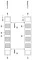
도 4는 일 실시예에 따른 다수의 비승인 자원(DL SPS 또는 UL 그랜트 타입 2)들이 설정된 상황에서 DCI 활성화 및 해제 방법을 도시한 도면이다.FIG. 4 is a diagram illustrating a method of activating and releasing DCI in a situation where a plurality of unauthorized resources (DL SPS or UL grant type 2) are set according to one embodiment.
도 4는 기지국이 상위 신호로 하나의 셀, BWP 별로 두 개의 DL SPS 자원 (또는 UL 그랜트 타입 2 자원)을 설정한 일례를 도시한 것이다. 첫 번째 DL SPS 자원(또는 UL 그랜트 타입 2 자원)을 자원 ID#1 (400)이라 하고, 두 번째 DL SPS 자원 (또는 UL 그랜트 타입 2 자원)을 자원 ID#2 (420)라 할 때, 각각의 자원을 활성화(activation) 또는 해제(release)를 하기 위해서 특정 DCI 필드가 이용되는 것이 가능할 수 있다. 특히 HARQ 프로세스 번호를 이용하여 각각의 DL SPS 자원(또는 UL 그랜트 타입 2 자원)을 활성화 또는 해제하는 것이 가능할 수 있다.Fig. 4 illustrates an example in which a base station sets two DL SPS resources (or
예를 들어 첫 번째 DL SPS 자원(또는 UL 그랜트 타입 2 자원)인 Resource ID#1은 HARQ 프로세스 번호가 1을 가리키는 DCI에 의해서 활성화 또는 해제가 가능할 수 있다. 구체적으로 단말은 특정 DL SPS 자원(또는 UL 그랜트 타입 2 자원) ID에 대해서 DL SPS 할당 PDCCH (또는 설정된 UL 그랜트 타입 2 PDCCH)로 전송되는 DCI 포맷을 구성하는 필드들이 다음 표 6와 동일할 경우, 해당 ID에 대응되는 DL SPS (또는 UL 그랜트 타입 2) 자원을 활성화하며, 표 7와 동일할 경우, 해당 ID에 대응되는 DL SPS (또는 UL 그랜트 타입 2) 자원을 해제한다.For example, the first DL SPS resource (or
[표 6][Table 6]

[표 7][Table 7]

일례로, 상기 DL SPS ID 또는 UL 그랜트 타입 2 ID는 상위 신호 설정 정보로써 설정 될 수 있다. ID가 5인 경우는, HARQ 프로세스 번호가 5를 지시하는 DCI에 의해서만 활성화 또는 해제가 수행될 수 있다. 또 다른 일례로는 상기 DL SPS ID 또는 UL 그랜트 타입 2 ID는 HARQ 프로세스 번호로 직접 설정되는 것도 가능할 수 있다. 예를 들어, 특정 DL SPS 또는 UL 그랜트 타입 2의 상위 설정 정보 중에 HARQ 프로세스 번호 5가 있는 경우, 해당 HARQ 프로세스 번호 5(를 포함하는 DCI)에 의해 활성화 또는 해제가 수행될 수 있다. 또 다른 일례로 특정 DL SPS 또는 UL 그랜트 타입 2의 상위 설정 정보 중에 HARQ 프로세스 번호 5와 10이 있는 경우, 해당 HARQ 프로세스 번호 5 또는 10(을 포함하는 DCI)에 의해 활성화 또는 해제가 수행될 수 있다.For example, the DL SPS ID or
도 4는 HARQ 프로세스 번호에 따라 개별적으로 DL SPS 자원(또는 UL 그랜트 타입 2)자원을 활성화 및 해제하는 동작의 일례를 도시한 도면이다. 단말은 상위 신호로 ID가 1인 DL SPS (또는 UL 그랜트 타입 2) 자원(400)에 대해서, HARQ 프로세스 번호가 1이며 표 6과 같은 정보를 포함한 DCI 수신(402)을 통해 해당 자원을 활성화하고, 단말은 활성화를 지시하는 DCI 수신 이후 자원(408) 상에서 비승인 기반 데이터를 송신 또는 수신할 수 있다. 이후 단말은 상위 신호로 ID가 1인 DL SPS(또는 UL 그랜트 타입 2) 자원(400)에 대해서, HARQ 프로세스 번호가 1이며 표 7과 같은 정보를 포함한 DCI 수신(404)을 통해 해당 자원을 해제한다. 단말은 해제를 지시하는 DCI 수신 이후 자원(410) 상에서 비승인 기반 데이터를 송신 또는 수신할 수 없다.FIG. 4 is a diagram illustrating an example of an operation for individually activating and releasing DL SPS resources (or UL grant type 2) resources according to HARQ process numbers. A terminal activates a DL SPS (or UL grant type 2) resource (400) having an ID of 1 through DCI reception (402) including information such as Table 6 and a HARQ process number of 1 for the resource as an upper signal, and the terminal can transmit or receive non-grant-based data on the resource (408) after receiving the DCI indicating activation. Thereafter, the terminal releases the resource as an upper signal by DCI reception (404) including information such as Table 7 and a HARQ process number of 1 for the DL SPS (or UL grant type 2) resource (400) having an ID of 1. The terminal cannot transmit or receive non-grant-based data on the resource (410) after receiving the DCI indicating release.
또한 단말은 상위 신호로 ID가 2인 DL SPS (또는 UL 그랜트 타입 2) 자원(420)에 대해서, HARQ 프로세스 번호가 2이며 표 6과 같은 정보를 포함한 DCI 수신(422)을 통해 해당 자원을 활성화하고, 단말은 활성화를 지시하는 DCI 수신 이후 자원(428) 상에서 비승인 기반 데이터를 송신 또는 수신할 수 있다. 그리고 단말은 상위 신호로 ID가 1인 DL SPS (또는 UL 그랜트 타입 2) 자원(420)에 대해서, HARQ 프로세스 번호가 2이며 표 7과 같은 정보를 포함한 DCI 수신(424)을 통해 해당 자원을 해제한다. 단말은 해제를 지시하는 DCI 수신 이후 자원(430) 상에서 비승인 기반 데이터를 송신 또는 수신할 수 없다. 즉 단말은 개별적인 비승인 기반 데이터 송수신을 위한 자원 영역을 활성화 또는 해제하기 위해서 개별적인 DCI를 필요로 한다.In addition, the terminal activates the corresponding resource through DCI reception (422) including information such as Table 6 and a HARQ process number of 2 for a DL SPS (or UL grant type 2) resource (420) having an ID of 2 as a higher signal, and the terminal can transmit or receive non-grant-based data on the resource (428) after receiving the DCI indicating the activation. Then, the terminal releases the corresponding resource through DCI reception (424) including information such as Table 7 and a HARQ process number of 2 for a DL SPS (or UL grant type 2) resource (420) having an ID of 1 as a higher signal. The terminal cannot transmit or receive non-grant-based data on the resource (430) after receiving the DCI indicating the release. That is, the terminal requires individual DCI to activate or release a resource region for individual non-grant-based data transmission and reception.
상기 예시에서는 HARQ 프로세스 번호를 통해 개별 DL SPS(또는 UL 그랜트 타입 2)를 활성화 또는 해제하는 것을 서술했지만, HARQ 프로세스 번호 이외의 다른 DCI 필드 (들)이 이용되는 것도 가능할 수 있다. 그 해당되는 예로는 RV 값, 주파수 할당 정보, 시간 할당 정보, NDI 값, 브로드캐스트/멀티캐스트/유니캐스트 등과 같은 전송 타입 등이 있을 수 있다.Although the above example describes activating or deactivating individual DL SPS (or UL grant type 2) via HARQ process number, it may also be possible to utilize other DCI field(s) other than HARQ process number. Examples of such may include RV value, frequency allocation information, time allocation information, NDI value, transmission type such as broadcast/multicast/unicast, etc.
도 5는 일 실시예에 따른 다수의 비승인(DL SPS 또는 UL 그랜트 타입 2) 자원들이 설정된 상황에서 DCI 활성화 및 해제 방법을 도시한 도면이다.FIG. 5 is a diagram illustrating a method of activating and releasing DCI in a situation where a plurality of unauthorized (DL SPS or UL grant type 2) resources are set according to one embodiment.
도 4와 유사하게 단말은 셀 별, BWP 별로 2개 이상의 DL SPS (또는 UL 그랜트 타입 2) 자원들을 설정받고 운영하는 것이 가능할 수 있다. 도 4에서는 각각의 DL SPS (또는 UL 그랜트 타입 2) 자원들을 활성화 또는 해제하기 위해서 DCI 필드 내의 각 HARQ 프로세스 번호를 이용하는 경우를 일례로 들었으나, 도 5의 일례에서는 단말이 하나의 DCI 정보로 하나 이상의 DL SPS(또는 UL 그랜트 타입 2) 자원들을 동시에 활성화 또는 해제하는 것이 가능할 수 있다. 예를 들어, ID가 1인 DL SPS(또는 UL 그랜트 타입 2) 자원(500)과 ID가 2인 DL SPS (또는 UL 그랜트 타입 2) 자원(520)이 있는 상황에서 단말이 표 4과 같이 DL SPS(또는 UL 그랜트 타입 2)를 활성화 하는 DCI를 수신(502)할 경우, 단말은 해당 DCI를 통해 사전에 상위 신호로 설정받았던 DL SPS (또는 UL 그랜트 타입 2) 자원 설정들을 모두 활성화한다. 그리고 단말은 활성화를 지시하는 DCI를 수신(502)한 이후 DL SPS(또는 UL 그랜트 타입 2) 자원 508 및 528 상에서 비승인 기반 데이터를 송수신할 수 있다. 그리고 단말은 해제를 지시하는 DCI를 수신(504)한 이후 DL SPS(또는 UL 그랜트 타입 2) 자원 510 및 532 상에서는 비승인 기반 데이터를 송수신할 수 없다.Similarly to FIG. 4, the terminal may be able to set and operate two or more DL SPS (or UL grant type 2) resources per cell and per BWP. In FIG. 4, an example is given of using each HARQ process number in the DCI field to activate or release each DL SPS (or UL grant type 2) resource, but in the example of FIG. 5, the terminal may be able to simultaneously activate or release one or more DL SPS (or UL grant type 2) resources with one DCI information. For example, in a situation where there is a DL SPS (or UL grant type 2) resource (500) with an ID of 1 and a DL SPS (or UL grant type 2) resource (520) with an ID of 2, if the terminal receives (502) a DCI for activating the DL SPS (or UL grant type 2) as shown in Table 4, the terminal activates all DL SPS (or UL grant type 2) resource settings that were previously set as upper-level signals through the DCI. Then, the terminal can transmit and receive non-authorized data on the DL SPS (or UL grant type 2)
하나의 DCI를 통해서 2개 이상의 DL SPS(또는 UL 그랜트 타입 2) 자원들을 활성화시키기 위해서는 종래와 같이 상위 신호로 알려준 정보와 더불어 다음 정보들 일부가 상위 신호로 전달되어야 한다. 왜냐하면 하기 정보들이 DCI를 통해서 설정된다면 2개 이상의 DL SPS(또는 UL 그랜트 타입 2)는 공통의 시간 및 주파수 할당 정보, 안테나 포트, DMRS 시퀀스 정보 등을 가지기 때문이다.In order to activate two or more DL SPS (or UL grant type 2) resources through one DCI, some of the following information must be transmitted as upper signaling in addition to the information previously notified as upper signaling. This is because if the following information is set through DCI, two or more DL SPS (or UL grant type 2) resources have common time and frequency allocation information, antenna ports, DMRS sequence information, etc.
-timeDomainAllocation: PUSCH의 전송 시간 자원 영역을 알려주는 필드, K2 값은 상기 DCI가 전송된 슬롯을 기준으로 UL 그랜트 타입 2 전송이 시작하는 슬롯 오프셋 정보를 지시- timeDomainAllocation: A field that indicates the transmission time resource area of PUSCH, and theK2 value indicates the slot offset information where
-frequencyDomainAllocation: PUSCH의 전송 주파수 자원 영역을 알려주는 필드- frequencyDomainAllocation: A field that indicates the transmission frequency resource area of PUSCH.
-antennaPort: 비승인 PUSCH 전송에 적용된 안테나 포트 설정 정보- antennaPort: Antenna port configuration information applied to unauthorized PUSCH transmission
-dmrs-SeqInitialization: 트랜스폼 프리코더가 비활성화 되어 있을 때, 설정되는 필드- dmrs-SeqInitialization: Field set when the transform precoder is disabled.
-precodingAndNumberOfLayers: 레이어의 수와 PUSCH에 적용되는 프리코더를 지시하는 필드- precodingAndNumberOfLayers: A field indicating the number of layers and the precoder applied to PUSCH.
-srs-ResourceIndicator: SRS 자원 설정 정보를 알려주는 필드- srs-ResourceIndicator: Field that provides SRS resource setting information.
-mcsAndTBS: PUSCH 전송에 적용된 MCS 및 TBS- mcsAndTBS: MCS and TBS applied to PUSCH transmission
-frequencyHoppingOffset: 주파수 호핑 오프셋 값- frequencyHoppingOffset: Frequency hopping offset value
-pathlossReferenceIndex: 경로 손실(pathloss)의 기준이 되는 기준 신호를 지시하는 필드- pathlossReferenceIndex: A field that indicates the reference signal that serves as the basis for path loss.
-timedomainoffset- timedomainoffset
상기와 같은 정보들이 DL SPS(또는 UL 그랜트 타입 2)를 위한 상위 신호로 설정된다면, 단말은 활성화 또는 해제를 지시하는 DCI에 의해서 2개 이상의 DL SPS (또는 UL 그랜트 타입 2) 자원들을 동시에 활성화 또는 해제하는 것이 가능할 수 있다. 그리고 각 DL SPS(또는 UL 그랜트 타입 2) 자원들은 각 상위 신호 설정에 의해서 다른 정보들을 가지는 것이 가능할 수 있다.If the above information is set as an upper signal for DL SPS (or UL grant type 2), the terminal may be able to activate or release two or more DL SPS (or UL grant type 2) resources simultaneously by DCI indicating activation or release. And each DL SPS (or UL grant type 2) resource may be able to have different information by each upper signal setting.
참고로 timedomainoffset 정보는 DCI 수신 없이 비승인 기반 데이터를 송수신할 수 있는 UL 그랜트 타입 1을 위해서 사용되었고, 해당 timedomainoffeset의 값은 SFN 번호를 의미하였다. 이러한 정보는 그대로 사용되거나 또는 SFN 번호가 아닌 활성화를 지시하는 DCI를 수신한 슬롯 번호 기준 이후에 비승인 기반 데이터를 송수신할 수 있는 자원 오프셋 정보로 재해석하는 것이 가능할 수 있다. 또는 timedomainoffset 정보 대신에 timedomainresourceallocation에 존재하는 K0 또는 K2에 의해 오프셋 정보를 알려주는 것이 가능할 수 있다. 여기서 K0는 활성화 정보를 포함한 DCI가 전송되는 슬롯과 비승인 기반 PDSCH 전송(DL SPS)을 시작할 수 있는 슬롯 사이의 오프셋 값을 의미한다. 여기서 K2는 활성화 정보를 포함한 DCI가 전송되는 슬롯과 비승인 기반 PUSCH 전송(UL 그랜트 타입 2)을 시작할 수 있는 슬롯 사이의 오프셋 값을 의미한다.For reference, the timedomainoffset information was used for
이런 정보를 활용할 경우, 도 5에서 ID가 2인 DL SPS (또는 UL 그랜트 타입 2) 자원 설정 정보에서 활성화 신호(502)를 수신한 이후, 상기 오프셋 정보에 따라 단말은 528 또는 530부터 비승인 기반 데이터를 송신 또는 수신할 수 있다. 본 발명에서 오프셋 단위는 슬롯으로 설명하였지만 슬롯 단위 이외에 심볼 단위 또는 서브 슬롯(또는 심볼 그룹) 단위가 될 수 있다. 해당 단위는 사전에 규격에서 정해지거나 별도로 상위 신호로 설정 가능할 수 있다.When utilizing such information, after receiving an activation signal (502) in the DL SPS (or UL grant type 2) resource configuration information with
단말이 셀 별, BWP 별로 다수의 DL SPS (또는 UL 그랜트 타입 2) 자원을 설정받을 수 있는 상황에서 도 4에서는 각 DCI에 대응되는 하나의 DL SPS(또는 UL 그랜트 타입 2) 자원들을 활성화 또는 해제하는 일례에 대해서 주로 설명하고, 도 5에서는 하나의 DCI를 통해서 다수의 DL SPS(또는 UL 그랜트 타입 2) 자원들을 활성화 또는 해제하는 일례에 대해서 설명하였다. 설명의 편의를 위해 도 4는 개별 설정 방법, 도 5는 동시 설정 방법으로 칭한다.In a situation where a terminal can be configured with multiple DL SPS (or UL grant type 2) resources per cell and per BWP, FIG. 4 mainly describes an example of activating or releasing one DL SPS (or UL grant type 2) resource corresponding to each DCI, and FIG. 5 describes an example of activating or releasing multiple DL SPS (or UL grant type 2) resources through one DCI. For convenience of explanation, FIG. 4 is referred to as an individual configuration method, and FIG. 5 is referred to as a simultaneous configuration method.
단말은 도 4 및 도 5에서 서술한 동작들을 모두 지원하는 것이 가능할 수 있으며, 다음과 같은 방법들이 있을 수 있다.The terminal may be capable of supporting all of the operations described in FIGS. 4 and 5, and may include the following methods:
- 방법 2-1: 상위 신호로 설정- Method 2-1: Set as upper signal
상위 신호로 DL SPS(또는 UL 그랜트 타입 2) 자원 설정 시, 해당 자원이 개별 설정 방법으로 활성화(또는 해제)가 수행되는지 또는 동시 설정 방법으로 활성화(또는 해제)가 수행되는지를 같이 알려준다. 또 다른 방법으로는 DL SPS(또는 UL 그랜트 타입 2) 자원 설정을 위한 상위 신호 수신 시, 특정 정보가 true이거나 값이 존재하면 단말은 해당 자원을 동시 설정 방법 자원으로 간주하고 반면에 해당 정보가 false이거나 값이 존재하지 않으면 해당 자원을 개별 설정 방법 자원으로 간주한다. 여기서 상술된 정보의 일례로는 timeDomainAllocation, FrequencyDomainAllocation, AntennaPort, dmrs-SeqInitialization, precodingAndNumberOfLayers, srs-ResourceIndicator, mcsAndTBS, frequencyHoppingOffset, pathlossReferenceIndex, timedomainoffset 들이 해당될 수 있다.When configuring a DL SPS (or UL grant type 2) resource with an upper layer signal, it also indicates whether activation (or deactivation) of the resource is performed using the individual configuration method or the simultaneous configuration method. Alternatively, when receiving an upper layer signal for configuring a DL SPS (or UL grant type 2) resource, if specific information is true or a value exists, the terminal regards the resource as a simultaneous configuration method resource, whereas if the information is false or a value does not exist, the terminal regards the resource as an individual configuration method resource. Examples of the information described herein may include timeDomainAllocation, FrequencyDomainAllocation, AntennaPort, dmrs-SeqInitialization, precodingAndNumberOfLayers, srs-ResourceIndicator, mcsAndTBS, frequencyHoppingOffset, pathlossReferenceIndex, and timedomainoffset.
-방법 2-2: L1 신호로 설정- Method 2-2: Set to L1 signal
상위 신호로 다수의 DL SPS(또는 UL 그랜트 타입 2) 자원들이 설정되고, L1 신호로 해당 자원들이 개별 설정 방법으로 활성화(또는 해제)되는지 또는 동시 설정 방법으로 활성화(또는 해제)되는지를 알려준다. 예를 들면, 다음 표 8과 같은 HARQ 프로세스 필드를 통해 상기 방법들이 적용되는 것이 가능할 수 있다.Multiple DL SPS (or UL Grant Type 2) resources are configured by upper signaling, and L1 signaling indicates whether the resources are activated (or deactivated) in an individual configuration method or in a simultaneous configuration method. For example, it may be possible to apply the above methods through the HARQ process field as shown in Table 8 below.
[표 8][Table 8]

표 8을 일례로 설명하면, DL SPS를 활성화하는 DCI 포맷 1_0 또는 DCI 포맷 1_1를 단말이 수신하고 해당 DCI 내의 HARQ 프로세스 번호가 0을 지시할 경우, ID가 0인 DL SPS 자원이 활성화된 것으로 단말이 판단할 수 있다. 또는 UL 그랜트 타입 2를 활성화하는 DCI 포맷 0_0 또는 DCI 포맷 0_1를 단말이 수신하고 해당 DCI 내의 HARQ 프로세스 번호가 0을 지시할 경우, ID가 0인 UL 그랜트 타입 2 자원이 활성화된 것으로 단말이 판단할 수 있다. DL SPS를 해제하는 DCI 포맷 1_0 또는 DCI 포맷 1_1를 단말이 수신하고 해당 DCI 내의 HARQ 프로세스 번호가 0을 지시할 경우, ID가 0인 DL SPS 자원이 해제된 것으로 단말이 판단할 수 있다. 또는, UL 그랜트 타입 2를 해제하는 DCI 포맷 0_0 또는 DCI 포맷 0_1를 단말이 수신하고 해당 DCI 내의 HARQ 프로세스 번호가 0을 지시할 경우, ID가 0인 UL 그랜트 타입 2 자원이 해제된 것으로 단말이 판단할 수 있다.As an example of Table 8, if a terminal receives DCI format 1_0 or DCI format 1_1 for activating DL SPS and the HARQ process number in the corresponding DCI indicates 0, the terminal can determine that the DL SPS resource with
또 다른 일례를 설명하면, DL SPS를 활성화하는 DCI 포맷 1_0 또는 DCI 포맷 1_1를 단말이 수신하고 해당 DCI 내의 HARQ 프로세스 번호가 15을 지시할 경우, 단말은 현재까지 상위 신호로 설정되고 비활성화된 모든 DL SPS 자원들이 활성화된 것으로 판단한다. UL 그랜트 타입 2를 활성화하는 DCI 포맷 0_0 또는 DCI 포맷 0_1를 단말이 수신하고 해당 DCI 내의 HARQ 프로세스 번호가 15을 지시할 경우, 단말은 현재까지 상위 신호로 설정되고 비활성화된 모든 UL 그랜트 타입 2 자원들이 활성화된 것으로 판단한다. DL SPS를 해제하는 DCI 포맷 1_0 또는 DCI 포맷 1_1를 단말이 수신하고 해당 DCI 내의 HARQ 프로세스 번호가 15를 지시할 경우, 단말은 현재까지 활성화된 모든 DL SPS 자원들이 해제된 것으로 판단한다. UL 그랜트 타입 2를 해제하는 DCI 포맷 0_0 또는 DCI 포맷 0_1를 단말이 수신하고 해당 DCI 내의 HARQ 프로세스 번호가 15을 지시할 경우, 단말은 현재까지 활성화된 모든 UL 그랜트 타입 2 자원들이 해제된 것으로 판단한다.As another example, if the terminal receives DCI format 1_0 or DCI format 1_1 for activating DL SPS and the HARQ process number in the corresponding DCI indicates 15, the terminal determines that all DL SPS resources which have been set as upper layer signals and deactivated up to now are activated. If the terminal receives DCI format 0_0 or DCI format 0_1 for activating
여기서 UL 그랜트 타입 2를 활성화하는 DCI 포맷 0_0 또는 DCI 포맷 0_1은 HARQ 프로세스 필드를 제외한 나머지가 표 4과 동일할 수 있다. DL SPS를 활성화하는 DCI 포맷 1_0 또는 DCI 포맷 1_1은 HARQ 프로세스 필드를 제외한 나머지가 표 4과 동일할 수 있다. UL 그랜트 타입 2를 해제하는 DCI 포맷 0_0은 HARQ 프로세스 필드를 제외한 나머지가 표 5과 동일할 수 있다. DL SPS를 해제하는 DCI 포맷 1_0은 HARQ 프로세스 필드를 제외한 나머지가 표 5과 동일할 수 있다.Here, the DCI format 0_0 or DCI format 0_1 for enabling
또 다른 일례로, 표 8은 DL SPS(또는 UL 그랜트 타입 2) 자원을 해제하는 용도로만 사용되는 것이 가능할 수 있다. 이럴 경우, DL SPS(또는 UL 그랜트 타입 2) 자원의 해제를 지시하는 DCI 포맷 1_0(또는 DCI 포맷 0_0)에만 표 8이 적용되는 것이 가능할 수 있다. 상기 표 8에서는 하나의 HARQ 프로세스 번호가 하나의 DL SPS (또는 UL 그랜트 타입 2) 자원 ID와 매핑되는 것을 가정하였지만, 하나의 DL SPS(또는 UL 그랜트 타입 2) 자원 ID가 여러 개의 HARQ 프로세스 번호와 매핑되는 것도 가능할 수 있다. 일례로 기지국은 DL SPS(또는 UL 그랜트 타입 2) 자원을 상위 신호로 설정 시 해당 자원 ID에 연계된 HARQ 프로세스 번호(들)을 하나 또는 2개 이상 같이 설정하는 것이 가능할 수 있다. 따라서 단말은 특정 HARQ 프로세스 번호로 DL SPS (또는 UL 그랜트 타입 2)를 활성화 시킬 경우, 해당 번호와 연계된 하나 이상의 DL SPS(또는 UL 그랜트 타입 2)를 동시에 활성화시키는 것이 가능할 수 있다. 표 9는 해당 설명을 일례로 설명하는 표이다.As another example, Table 8 may be used only for the purpose of releasing DL SPS (or UL Grant Type 2) resources. In this case, Table 8 may be applied only to DCI format 1_0 (or DCI format 0_0) indicating the release of DL SPS (or UL Grant Type 2) resources. Although Table 8 assumes that one HARQ process number is mapped to one DL SPS (or UL Grant Type 2) resource ID, it may also be possible that one DL SPS (or UL Grant Type 2) resource ID is mapped to multiple HARQ process numbers. For example, when the base station sets a DL SPS (or UL Grant Type 2) resource as an upper signal, it may be possible to set one or more HARQ process number(s) associated with the corresponding resource ID. Therefore, when a terminal activates a DL SPS (or UL grant type 2) with a specific HARQ process number, it may be possible to simultaneously activate one or more DL SPSs (or UL grant type 2) associated with the number. Table 9 is a table illustrating the description as an example.
예를 들어, 표 9에 따르면 DL SPS를 활성화하는 DCI 포맷 1_0 또는 DCI 포맷 1_1를 단말이 수신하고 해당 DCI 내의 HARQ 프로세스 번호가 0을 지시할 경우, ID가 0과 5인 DL SPS 자원들이 활성화된 것으로 단말은 판단할 수 있다. 또는 UL 그랜트 타입 2를 활성화하는 DCI 포맷 0_0 또는 DCI 포맷 0_1를 단말이 수신하고 해당 DCI 내의 HARQ 프로세스 번호가 0을 지시할 경우, ID가 0과 5인 UL 그랜트 타입 2 자원이 활성화된 것으로 단말은 판단할 수 있다. DL SPS를 해제하는 DCI 포맷 1_0 또는 DCI 포맷 1_1를 단말이 수신하고 해당 DCI 내의 HARQ 프로세스 번호가 0을 지시할 경우, ID가 0과 5인 DL SPS 자원이 해제된 것으로 단말은 판단할 수 있다. 또는 UL 그랜트 타입 2를 해제하는 DCI 포맷 0_0 또는 DCI 포맷 0_1를 단말이 수신하고 해당 DCI 내의 HARQ 프로세스 번호가 0을 지시할 경우, ID가 0과 5인 UL 그랜트 타입 2 자원이 해제된 것으로 단말은 판단할 수 있다.For example, according to Table 9, if the terminal receives DCI format 1_0 or DCI format 1_1 for activating DL SPS and the HARQ process number in the corresponding DCI indicates 0, the terminal can determine that DL SPS resources with
[표 9][Table 9]

상술된 L1 신호를 기반으로 DL SPS(UL 그랜트 타입 2) 자원을 구분하는 방법으로는 HARQ 프로세스 번호를 일례로 기술하였으나, 그 이외 다른 DCI 필드(RV, MCS 등)들로 각 자원을 구분하는 것도 가능할 수 있다. 또한 브로드캐스트/멀티캐스트/유니캐스트 용으로 각기 설정된 비승인 기반 데이터 송수신 자원이 설정될 경우, HARQ 프로세스 번호와 연계된 정보가 (비승인 기반 자원 정보 ID가 아닌) DL SPS(또는 UL 그랜트 타입 2) 자원을 상위 신호 설정 시 해당 자원 정보가 브로드캐스트인지 멀티캐스트인지 유니캐스트를 가리키는 필드일 수 있다. 따라서 표 8 내지 표 9에서 2열에서 서술한 자원 번호 대신 전송 방법이란 명칭으로 브로드캐스트용 또는 멀티캐스트 용 또는 유니캐스트 용이라고 표시되는 것도 가능할 수 있다. 다시 말하면, 해당 비승인 자원이 브로드캐스트, 멀티캐스트, 유니캐스트 중 적어도 하나와 연계되는 것으로 설정이 가능할 때, HARQ 프로세스 번호는 전송 방식(브로드캐스트, 멀티캐스트, 유니캐스트)들 중 적어도 하나를 지시함으로써 특정 비승인 자원의 활성화 또는 해제 여부를 지시할 수 있다. 표 10은 이에 대한 예시를 포함한 표이다. 표 10에서 전송 방식(브로드캐스트, 유니캐스트, 멀티캐스트)은 이외에 패킷 우선 순위 정보(priority) 또는 HARQ-ACK 피드백 지원 여부 등의 정보들로 대체되어 사용될 수 있다.As an example of a method for distinguishing DL SPS (UL Grant Type 2) resources based on the above-described L1 signal, the HARQ process number is described, but it may also be possible to distinguish each resource with other DCI fields (RV, MCS, etc.). In addition, when non-grant-based data transmission and reception resources respectively set for broadcast/multicast/unicast are set, the information associated with the HARQ process number (not the non-grant-based resource information ID) may be a field indicating whether the corresponding resource information is broadcast, multicast, or unicast when setting the upper signal for the DL SPS (or UL Grant Type 2) resource. Accordingly, instead of the resource number described in
[표 10][Table 10]

도 6은 단말의 UL 그랜트 타입 2 기반 상향링크 데이터 송신 동작을 도시하는 블록도이다.Figure 6 is a block diagram illustrating an uplink data transmission operation based on
도 6에서 단말은 기지국으로부터 UL 그랜트 타입 2 기반 PUSCH 전송을 위한 상위 신호를 수신(600)한다. 이 때, 단말은 셀 별 그리고 BWP 별로 두 개 이상의 비승인 자원들을 설정 받는 것이 가능할 수 있다. 단말은 CS-RNTI로 스크램블링된 CRC를 포함한 DCI를 검출하고, 해당 DCI 필드 중 특정 필드가 UL 그랜트 타입 2의 활성화(602) 또는 해제(606) 조건을 만족하는지 판단한다. 상기 필드의 일례로는 표 4 내지 표 5에서 서술한 RV, MCS, 주파수 자원 할당 필드 등이 해당될 수 있다. 단말은 상기 DCI의 필드가 특정 값을 지시하고 해당 값이 UL 그랜트 타입 2의 활성화 또는 해제 조건을 만족할 경우, 이를 검증을 통과했다고 판단한다. 그리고 검증이 완료된 DCI를 이용하여 단말은 다음과 같은 방법들을 통해 상위 신호로 설정된 다수의 UL 그랜트 타입 2 자원들을 활성화하거나 또는 해제할 수 있다.In Fig. 6, the terminal receives (600) an upper signal for UL grant type 2-based PUSCH transmission from the base station. At this time, the terminal may be able to set two or more unauthorized resources for each cell and each BWP. The terminal detects a DCI including a CRC scrambled with CS-RNTI, and determines whether a specific field among the corresponding DCI fields satisfies the activation (602) or release (606) condition of
- 방법 3-1: 개별 활성화 또는 개별 해제- Method 3-1: Individual activation or individual deactivation
단말은 UL 그랜트 타입 2의 활성화 또는 해제 검증을 통과한 DCI 내의 HARQ 프로세스 번호 필드의 LSB 3비트 또는 전체 비트에 의해 지시된 특정 UL 그랜트 타입 2 자원만이 활성화 또는 해제된다고 판단한다.The terminal determines that only specific
- 방법 3-2: 개별 활성화 또는 그룹 해제- Method 3-2: Activate individually or deactivate a group
단말은 UL 그랜트 타입 2의 활성화 검증을 통과한 DCI 내의 HARQ 프로세스 번호 필드의 LSB 3비트 또는 전체 비트에 의해 지시된 특정 UL 그랜트 타입 2 자원만이 활성화된다고 판단한다. UL 그랜트 타입 2의 해제 검증을 통과한 DCI를 통해 단말은 현재 활성화된 모든 UL 그랜트 타입 2 자원들을 해제하는 것으로 판단한다.The terminal determines that only specific
- 방법 3-3: 그룹 활성화 또는 개별 해제- Method 3-3: Activate group or deactivate individually
단말은 UL 그랜트 타입 2의 활성화 검증을 통과한 DCI를 통해 현재 비활성화된 모든 UL 그랜트 타입 2 자원들을 활성화하는 것으로 판단한다. 단말은 UL 그랜트 타입 2의 해제 검증을 통과한 DCI 내의 HARQ 프로세스 번호 필드의 LSB 3비트 또는 전체 비트에 의해 지시된 특정 UL 그랜트 타입 2 자원만이 해제된다고 판단한다.The terminal determines that all currently deactivated
- 방법 3-4: 그룹 활성화 또는 그룹 해제- Method 3-4: Activate or deactivate a group
단말은 UL 그랜트 타입 2의 활성화 검증을 통과한 DCI를 통해 현재 비활성화된 모든 UL 그랜트 타입 2 자원들을 활성화하는 것으로 판단한다. 단말은 UL 그랜트 타입 2의 해제 검증을 통과한 DCI를 통해 현재 활성화된 모든 UL 그랜트 타입 2 자원들을 해제하는 것으로 판단한다.The terminal determines to activate all currently deactivated
- 방법 3-5: 상기 방법들의 조합- Method 3-5: Combination of the above methods
단말은 UL 그랜트 타입 2의 활성화 또는 해제 검증을 통과한 DCI 내의 HARQ 프로세스 번호 필드의 LSB 3비트 또는 전체 비트에 의해 지시된 특정 UL 그랜트 타입 2 자원만이 활성화 또는 해제된다고 판단한다. 상기 HARQ 프로세스 번호 필드 중 특정 비트 값(예를 들면, 4 비트의 HARQ 프로세스 번호가 1111일 경우)인 경우, UL 그랜트 타입 2의 활성화 검증을 통과한 DCI를 통해 단말은 현재 비활성화된 모든 UL 그랜트 타입 2 자원들을 활성화하는 것으로 판단하거나, UL 그랜트 타입 2의 해제 검증을 통과한 DCI를 통해 단말은 현재 활성화된 모든 UL 그랜트 타입 2 자원들을 해제하는 것으로 판단할 수 있다.The terminal determines that only specific
단말은 상기 방법들 중 하나를 이용하여 CS-RNTI로 스크램블링된 CRC를 포함한 DCI 검출을 성공하고, 해당 DCI가 상위 신호로 설정된 적어도 하나의 비승인 기반 자원에 대한 활성화를 지시할 경우 단말은 해당 자원 영역을 통해 비승인 기반 데이터를 송신할 수 있다(604). 단말은 상기 방법들 중 하나를 이용하여 CS-RNTI로 스크램블링된 CRC를 포함한 DCI 검출을 성공하고, 해당 DCI가 상위 신호로 설정되고 이미 활성화된 적어도 하나의 비승인 기반 자원 영역에 대한 해제를 지시할 경우 단말은 해당 자원 영역을 통해 비승인 기반 데이터를 더 이상 송신할 수 없음을 기대한다(608).If the terminal succeeds in detecting the DCI including the CRC scrambled with CS-RNTI by using one of the above methods and the DCI indicates activation of at least one non-granted-based resource set as a higher-order signal, the terminal can transmit non-granted-based data through the corresponding resource region (604). If the terminal succeeds in detecting the DCI including the CRC scrambled with CS-RNTI by using one of the above methods and the DCI indicates activation of at least one non-granted-based resource region set as a higher-order signal and the DCI indicates release of at least one non-granted-based resource region that has already been activated, the terminal expects that it can no longer transmit non-granted-based data through the corresponding resource region (608).
CS-RNTI로 스크램블링된 CRC를 포함한 DCI 정보를 단말이 수신하였지만 비승인 기반 데이터 전송 자원 활성화 또는 해제 조건을 만족하지 못하는 경우(또는 검증에 실패한 경우), 단말은 수신한 DCI 포맷 정보가 매칭되지 않는(non-matching) CRC에 의해서 수신된 것으로 간주한다.If a terminal receives DCI information including CRC scrambled with CS-RNTI but does not satisfy the conditions for enabling or releasing non-authorized data transmission resources (or fails verification), the terminal considers the received DCI format information as having been received with a non-matching CRC.
도 6에서는 UL 그랜트 타입 2의 경우에 대해서 설명하였지만, 같은 설명이 DL SPS에도 충분히 적용 가능할 수 있다.Although Figure 6 describes the case of
도 7는 본 발명의 일 실시예에 따른 단말의 동작 절차를 도시하는 블록도이다.Figure 7 is a block diagram illustrating an operation procedure of a terminal according to one embodiment of the present invention.
도 7에서는 단말은 기지국으로부터 DCI를 수신하고 해당 DCI에서 가리키는 전송 설정 정보에 따라 하향링크 데이터 수신 또는 상향링크 데이터 송신을 수행하는 제1 신호 송수신 유형을 고려한다. 구체적으로 기지국에서 하향링크 데이터 스케줄링을 지시하는 제1 DCI를 수신한 이후에 하향링크 데이터 정보를 수신하고 이에 대한 HARQ-ACK 정보를 기지국으로 송신하는 절차까지 고려한다. 상기 HARQ-ACK 정보는 단말이 하향링크 데이터 정보의 복조 및/또는 복호의 성공 여부를 알려주는 정보를 포함하며, 일례로 하향링크 데이터 정보 복조 및/또는 복호가 성공하면 1, 그렇지 않으면 0을 매핑하여 기지국으로 송신한다. 기지국은 HARQ-ACK 정보 수신을 통해 해당 하향링크 데이터 정보의 재전송 여부를 결정하며, 상기 HARQ-ACK 절차를 통해 기지국과 단말은 좀 더 신뢰있는 무선 데이터 통신을 수행할 수 있다. 5G 또는 NR 시스템에서는 상기 HARQ-ACK 정보 송신이 하기와 같은 이유들로 취소되는 경우가 발생할 수 있다.In FIG. 7, a first signal transmission/reception type is considered in which a terminal receives DCI from a base station and performs downlink data reception or uplink data transmission according to transmission configuration information indicated by the corresponding DCI. Specifically, a procedure is considered in which, after receiving a first DCI indicating downlink data scheduling from a base station, downlink data information is received and HARQ-ACK information therefor is transmitted to the base station. The HARQ-ACK information includes information indicating whether the terminal successfully demodulates and/or decodes downlink data information, and for example, if the downlink data information demodulation and/or decoding is successful, 1 is mapped and transmitted to the base station, and if not, 0 is mapped. The base station determines whether to retransmit the corresponding downlink data information through the reception of the HARQ-ACK information, and the base station and the terminal can perform more reliable wireless data communication through the HARQ-ACK procedure. In a 5G or NR system, the transmission of the HARQ-ACK information may be canceled for the following reasons.
1.상기 HARQ-ACK 자원이 제2 DCI에 의해서 하향링크 자원으로 바뀐 경우1. When the above HARQ-ACK resource is changed to a downlink resource by the 2nd DCI
2.상기 HARQ-ACK 자원보다 우선 순위가 높은 다른 UCI에 의해서 전송이 드랍된 경우2. If the transmission is dropped by another UCI with a higher priority than the above HARQ-ACK resource.
3.상기 HARQ-ACK 자원이 제2 DCI에 의해서 지시된 상향링크 전송 자원과 시간 또는 주파수 자원과 적어도 일부 중첩되며, 해당 HARQ-ACK 자원의 우선 순위가 중첩된 상향링크 전송 자원을 통해 전송되는 UCI보다 우선 순위가 낮은 경우3. If the above HARQ-ACK resource overlaps at least partly with the uplink transmission resource and time or frequency resource indicated by the second DCI, and the priority of the HARQ-ACK resource is lower than the UCI transmitted through the overlapping uplink transmission resource.
4.기지국이 제2 DCI로 상기 HARQ-ACK 자원 전송 취소를 단말에게 지시한 경우4. When the base station instructs the terminal to cancel the transmission of the HARQ-ACK resource using the second DCI.
5.기지국이 같은 HARQ 프로세스 번호를 가진 하향링크 데이터 자원을 제2 DCI로 상기 HARQ-ACK 자원 송신 전에 스케줄링 한 경우5. If the base station schedules downlink data resources with the same HARQ process number as the second DCI before transmitting the HARQ-ACK resources.
상기에 든 예들은 일례일 뿐이며, 그 이외 다양한 경우에 대해서 단말이 제1 DCI로 지시 받은 HARQ-ACK 전송 자원을 드랍하는 경우가 존재하는 것이 가능할 수 있다. 또한 상기 서술된 일례들은 단말이 상기 제1 DCI로 설정된 HARQ-ACK 전송 자원으로 HARQ-ACK 정보를 송신하기 전에 기지국으로부터 제2 DCI를 수신하는 상황을 고려한 것이다. 일반적으로 기지국으로부터 단말로 제1 DCI가 먼저 송신되고 그 이후에 제2 DCI가 송신되는 상황이 발생할 수 있으며 HARQ-ACK 정보를 송신한 이후에 받은 DCI로 단말이 상기 HARQ-ACK 정보 송신을 취소하는 일은 발생하지 않을 것이다. 또한 단말은 제2 DCI를 블라인드 디코딩하는 시간이 필요하기 때문에 기지국은 이와 같은 프로세싱 시간을 고려하여 상기 HARQ-ACK 정보 송신 전에 단말이 제2 DCI를 복호하고 이를 판단하는데 필요한 프로세싱 시간을 고려하여 제2 DCI를 송신해야만 한다. 그렇지 않을 경우 단말은 제1 DCI로 스케줄링된 HARQ-ACK 송신 드랍을 기대할 수 없을 것이다.The above examples are only examples, and it may be possible for a terminal to drop the HARQ-ACK transmission resource indicated by the first DCI in various other cases. In addition, the above-described examples consider a situation in which the terminal receives the second DCI from the base station before transmitting HARQ-ACK information with the HARQ-ACK transmission resource set by the first DCI. In general, a situation may occur in which the first DCI is transmitted from the base station to the terminal first, and the second DCI is transmitted thereafter, and the terminal will not cancel the transmission of the HARQ-ACK information with the DCI received after transmitting the HARQ-ACK information. In addition, since the terminal needs time to blind decode the second DCI, the base station must consider this processing time and transmit the second DCI before transmitting the HARQ-ACK information, taking into account the processing time required for the terminal to decode and determine the second DCI. Otherwise, the terminal will not be able to expect the HARQ-ACK transmission drop scheduled by the first DCI.
도 7에서는 이에 대한 단말 절차를 도시한 블록도이다. 일례로, 단말이 HARQ 프로세스 번호 n을 포함한 제1 DCI를 수신(700)하고, 제1 DCI의 설정 정보에 따라 하향링크 데이터 정보를 수신(702)한다. 단말은 하향링크 데이터 복조 및/또는 복호 결과에 대한 HARQ-ACK 정보를 생성하고, 송신을 수행하기 전에 상기 서술된 이유들 중 적어도 하나로 실제 HARQ-ACK 정보 송신을 취소 또는 드랍(704)한다. 이 상황에서 기지국은 단말로부터 HARQ 프로세스 번호 n과 관련된 하향링크 데이터 정보 송신 성공 여부 정보를 포함한 HARQ-ACK을 피드백 받지 못한 상황이기 때문에 별도의 지시자를 통해 이를 받을 필요가 있다. 만약 기존의 방법처럼 기지국이 비록 해당 HARQ-ACK 수신에 대한 결과를 NACK으로 판단하고 다시 재전송을 스케줄링 할 경우, 하향링크 데이터 자원 낭비가 발생할 수 있다. 보통의 LTE 또는 NR 시스템에서 HARQ-ACK에서 NACK이 발생할 확률은 10% 미만이기 때문에 상기와 같이 제1 DCI에 의해 지시된 HARQ-ACK 정보 드랍 상황을 무조건 NACK이라고 판단하는 것은 시스템 무선 자원 사용 관점에서 낭비일 수 있다. 따라서 이에 대하여 하기와 같은 방법들 중 적어도 하나가 고려될 수 있다.FIG. 7 is a block diagram illustrating a terminal procedure for this. For example, the terminal receives (700) a first DCI including a HARQ process number n, and receives (702) downlink data information according to the configuration information of the first DCI. The terminal generates HARQ-ACK information for the result of downlink data demodulation and/or decoding, and cancels or drops (704) actual HARQ-ACK information transmission for at least one of the reasons described above before performing transmission. In this situation, the base station needs to receive this through a separate indicator because it has not received feedback HARQ-ACK including information on whether downlink data information transmission related to HARQ process number n was successful from the terminal. If the base station determines the result of receiving the corresponding HARQ-ACK as NACK and schedules retransmission again as in the existing method, downlink data resources may be wasted. Since the probability of NACK occurring in HARQ-ACK in a typical LTE or NR system is less than 10%, it may be wasteful from the perspective of system radio resource usage to unconditionally determine the HARQ-ACK information drop situation indicated by the first DCI as NACK. Therefore, at least one of the following methods may be considered for this purpose.
-방법 4-1: 같은 HARQ 프로세스 번호 n을 포함한 DCI로 스케줄링- Method 4-1: Scheduling with DCI including the same HARQ process number n
제1 DCI로 스케줄링 된 HARQ-ACK 정보 전송이 드랍된 이후, 기지국으로부터 송신된 제3 DCI 정보(706)가 제1 DCI와 같은 HARQ 프로세스 번호 n을 포함할 경우, 단말은 해당 제3 DCI 정보는 기존에 드랍된 HARQ-ACK 정보를 다시 송신하기 위한 정보로 판단한다. 따라서 단말은 제3 DCI 정보를 구성하는 필드 중 HARQ-ACK 정보 자원만 유효한 것으로 판단하고 그 이외 하향링크 또는 상향링크 데이터 스케줄링과 관련된 다른 필드들은 유효하지 않은 것으로 판단할 수 있다.After the HARQ-ACK information transmission scheduled with the first DCI is dropped, if the third DCI information (706) transmitted from the base station includes the same HARQ process number n as the first DCI, the terminal determines that the third DCI information is information for retransmitting the previously dropped HARQ-ACK information. Accordingly, the terminal may determine that only the HARQ-ACK information resource among the fields constituting the third DCI information is valid, and determine that other fields related to downlink or uplink data scheduling are invalid.
-방법 4-2: 같은 HARQ 프로세스 번호 n을 포함하고 그 이외 특정 DCI 필드가 특정 값으로 고정된 DCI를 스케줄링- Method 4-2: Scheduling DCIs that include the same HARQ process number n and other specific DCI fields fixed to specific values.
제1 DCI로 스케줄링 된 HARQ-ACK 정보 전송이 드랍된 이후, 기지국으로부터 송신된 제3 DCI 정보(706)가 제1 DCI와 같은 HARQ 프로세스 번호 n을 포함하며 특정 DCI 필드의 값이 특정한 값을 가리킬 경우, 단말은 해당 제3 DCI 정보는 기존에 드랍된 HARQ-ACK 정보를 다시 송신하기 위한 정보로 판단한다. 상기 특정 DCI 필드의 값이 특정한 값의 일례로는 주파수 자원 할당 필드 비트맵이 모두 0을 가리키거나 또는 1을 가리킬 경우가 그 일례가 될 수 있다. 또는 그 이외 MCS 정보가 특정 값을 가리키는 경우도 또다른 일례가 될 수 있다. 따라서 단말은 제3 DCI 정보를 구성하는 필드 중 HARQ-ACK 정보 자원만 유효한 것으로 판단하고 그 이외 하향링크 또는 상향링크 데이터 스케줄링과 관련된 다른 필드들은 유효하지 않은 것으로 판단할 수 있다.After the HARQ-ACK information transmission scheduled with the first DCI is dropped, if the third DCI information (706) transmitted from the base station includes the same HARQ process number n as the first DCI and the value of a specific DCI field indicates a specific value, the terminal determines that the third DCI information is information for retransmitting the previously dropped HARQ-ACK information. An example of the specific value of the specific DCI field may be a case where all frequency resource allocation field bitmaps indicate 0 or 1. Or, a case where other MCS information indicates a specific value may be another example. Accordingly, the terminal may determine that only the HARQ-ACK information resource among the fields constituting the third DCI information is valid, and may determine that other fields related to downlink or uplink data scheduling are invalid.
단말은 상기와 같은 방법들 중 적어도 하나에 의해서 지시된 HARQ-ACK 자원 영역으로 드랍된 HARQ 프로세스 n과 관련된 하향링크 데이터에 대한 HARQ-ACK 정보를 송신(708)한다.The terminal transmits (708) HARQ-ACK information for downlink data related to HARQ process n dropped into the HARQ-ACK resource region indicated by at least one of the above methods.
도 8은 NR 시스템에서 준정적(semi-static) HARQ-ACK 코드북 설정 방법을 나타낸 도면이다.Figure 8 is a diagram illustrating a semi-static HARQ-ACK codebook setting method in an NR system.
한 슬롯 내에서 단말이 전송할 수 있는 HARQ-ACK PUCCH가 하나로 제한되는 상황에서, 단말은 준정적 HARQ-ACK 코드북 상위 설정을 수신하면, 단말은 DCI 포맷 1_0 또는 DCI 포맷 1_1 내의 PDSCH-to-HARQ_feedback timing indicator의 값에 의해 지시되는 슬롯에서 HARQ-ACK 코드북 내에 PDSCH 수신 또는 SPS PDSCH 해제에 대한 HARQ-ACK 정보를 보고한다. 단말은 DCI 포맷 1_0 또는 DCI 포맷 1_1 내의 PDSCH-to-HARQ_feedback timing indicator 필드에 의해 지시되지 않은 슬롯에서 HARQ-ACK 코드북 내에 HARQ-ACK 정보 비트 값을 NACK으로 보고한다. 만약, 단말이 후보 PDSCH 수신을 위한 MA,C 경우들에서 하나의 SPS PDSCH 해제 또는 하나의 PDSCH 수신에 대한 HARQ-ACK 정보만 보고하고, 그 보고는 PCell에서 카운터(counter) DAI 필드가 1을 지시하는 정보를 포함한 DCI 포맷 1_0에 의해 스케줄링된 경우, 단말은 해당 SPS PDSCH 해제 또는 해당 PDSCH 수신에 대한 하나의 HARQ-ACK 코드북을 결정한다.In a situation where the number of HARQ-ACK PUCCHs that a UE can transmit in a slot is limited to one, when the UE receives a semi-static HARQ-ACK codebook upper configuration, the UE reports HARQ-ACK information for PDSCH reception or SPS PDSCH release in the HARQ-ACK codebook in a slot indicated by the value of the PDSCH-to-HARQ_feedback timing indicator field in DCI format 1_0 or DCI format 1_1. The UE reports HARQ-ACK information bit values as NACK in the HARQ-ACK codebook in a slot not indicated by the PDSCH-to-HARQ_feedback timing indicator field in DCI format 1_0 or DCI format 1_1. If the UE reports only HARQ-ACK information for one SPS PDSCH release or one PDSCH reception in the MA,C cases for candidate PDSCH reception, and the report is scheduled by DCI format 1_0 including information that the counter DAI field in the PCell indicates 1, the UE determines one HARQ-ACK codebook for the corresponding SPS PDSCH release or the corresponding PDSCH reception.
상기 PDSCH-to-HARQ_feedback timing indicator 는 K1의 값을 설정하며, PDSCH가 전송되고 K1 슬롯 이후에 HARQ-ACK 피드백이 단말로부터 기지국으로 전송된다. 상위 시그널링으로 가능한 K1 값의 후보 집합이 전달되고 DCI에서 후보 집합 중 하나의 값로 정해질 수 있다. 또한 PDSCH에 대한 HARQ-ACK 피드백 타이밍 정보인 K1 후보값들은 디폴트 값으로 예를 들어 {1,2,3,4,5,6,7,8}이 정해져 있을 수 있으며, 기지국 또는 송신단이 상위 시그널링으로 상기 K1 후보값들의 집합을 설정해줄 수 있다. 예를 들어, K1 후보값들의 집합이 {2,4,6,8,10,12,14,16}으로 설정될 수 있으며, 이 중 하나의 값이 DCI로 지시될 수 있다.The above PDSCH-to-HARQ_feedback timing indicator sets the value of K1 , and the PDSCH is transmitted and the HARQ-ACK feedback is transmitted from the terminal to the base station after K1 slots. A candidate set of possible K1 values may be transmitted through upper signaling, and may be determined as one of the values of the candidate set in the DCI. In addition, the K1 candidate values, which are HARQ-ACK feedback timing information for the PDSCH, may be set as default values, for example, {1,2,3,4,5,6,7,8}, and the base station or the transmitter may set the set of K1 candidate values through upper signaling. For example, the set of K1 candidate values may be set to {2,4,6,8,10,12,14,16}, and one of the values may be indicated in the DCI.
그 이외는 하기 기술된 방법에 따른 HARQ-ACK 코드북 결정 방법을 따른다.Otherwise, the HARQ-ACK codebook determination method is followed according to the method described below.
서빙셀 c에서 PDSCH 수신 후보 경우의 집합을 MA,c라고 하면 하기와 같은 [pseudo-code 1] 단계들로 MA,c를 구할 수 있다.If the set of PDSCH reception candidate cases in serving cell c is called MA,c, MA,c can be obtained through the following [pseudo-code 1] steps.
[pseudo-code 1 시작][
단계 1: j를 0으로, MA,c를 공집합으로 초기화. HARQ-ACK 전송 타이밍 인덱스인 k를 0으로 초기화.Step 1: Initialize j to 0 and MA,c to the empty set. Initialize k, the HARQ-ACK transmission timing index, to 0.
- 단계 2: R을 PDSCH가 매핑되는 슬롯 정보, 시작 심볼 정보, 심볼 수 또는 길이 정보를 포함하는 표에서 각 행들의 집합으로 설정. 상위에서 설정된 DL 및 UL 설정에 따라서 R의 각 값이 가리키는 PDSCH 가능한 매핑 심볼이 UL 심볼로 설정되었다면 해당 행을 R에서 삭제.- Step 2: Set R as a set of rows in a table including slot information, start symbol information, number of symbols, or length information to which PDSCH is mapped. If the PDSCH-capable mapping symbol indicated by each value of R is set to a UL symbol according to the DL and UL settings set from above, delete the corresponding row from R.
- 단계 3-1: 단말이 한 슬롯에 하나의 유니캐스트(unicast)용 PDSCH를 수신받을 수 있고, R이 공집합이 아니면 집합 MA,c에 1개 추가.- Step 3-1: If the terminal can receive one unicast PDSCH in one slot and R is not an empty set, add one to the set MA,c .
- 단계 3-2: 단말이 한 슬롯에 하나보다 많은 유니캐스트용 PDSCH를 수신받을 수 있다면, 상기 계산된 R에서 서로 다른 심볼에 할당 가능한 PDSCH 수를 카운트하여 해당 개수 만큼을 MA,c에 추가.- Step 3-2: If the terminal can receive more than one unicast PDSCH in one slot, count the number of PDSCHs that can be allocated to different symbols in the calculated R and add that number to MA,c .
- 단계 4: k를 1 증가시켜 단계 2부터 다시 시작.- Step 4: Increase k by 1 and start again from
[pseudo-code 1 끝][end of pseudo-code 1]
상술된 psudo-code 1을 도 8을 예시로 들면, 슬롯 #k(808)에서 HARQ-ACK PUCCH 전송을 수행하기 위해, 슬롯 #k(808)을 지시할 수 있는 PDSCH-to-HARQ-ACK 타이밍이 가능한 슬롯 후보들을 모두 고려한다. 도 8에서는 슬롯 #n(802), 슬롯 #n+1(804) 그리고 슬롯 #n+2(806)에서 스케줄링된 PDSCH들만 가능한 PDSCH-to-HARQ-ACK 타이밍 조합에 의해 슬롯 #k(808)에서 HARQ-ACK 전송이 가능함을 가정한다. 그리고 슬롯 802, 804, 806에서 각각 스케줄링 가능한 PDSCH의 시간 영역 자원 설정 정보 및 슬롯 내의 심볼이 하향링크인지 상향링크인지를 알려주는 정보를 고려하여 슬롯 별로 최대 스케줄링 가능한 PDSCH 개수를 도출한다. 예를 들어, 슬롯 802에서는 PDSCH 2개, 슬롯 804에서는 PDSCH 3개, 슬롯 806에서는 PDSCH 2개가 각각 최대 스케줄링이 가능하다고 할 때, 슬롯 808에서 전송된 HARQ-ACK 코드북이 포함하는 최대 PDSCH 개수는 총 7개이다. 이를 HARQ-ACK 코드북의 크기(cardinality)라고 한다.Taking the above-described psudo-
특정 슬롯 내에서 상기 단계 3-2는 다음 표 11을 참고해 상세히 기술한다.Step 3-2 above within a specific slot is described in detail with reference to Table 11 below.
[표 11][Table 11]

표 11은 단말이 일반 CP(cyclic prefix)의 경우 별도의 RRC 신호로 시간 자원 할당을 받기 전에 디폴트(default)로 설정되어 단말이 동작하도록 하는 시간 자원 할당 표이다. 참고로 행 인덱스(row index) 값을 별도로 RRC로 지시하는 것 이외에 단말 공통 RRC 신호인 dmrs-TypeA-Position에 의해서 PDSCH 시간 자원 할당 값이 결정된다. 상기 표 11에서 ending 열과 order 열은 설명의 편의를 위해 별도로 추가된 값이며, 실제로는 존재하지 않는 것이 가능할 수 있다. Ending 열의 의미는 스케줄링된 PDSCH의 종료 심볼을 의미하며, order 열은 준정적 HARQ-ACK 코드북에서 특정 코드북 내에 위치한 코드의 위치 값을 의미한다. 해당 표는 PDCCH의 공통 탐색 영역의 DCI 포맷 1_0에서 적용되는 시간 자원 할당에 적용된다.Table 11 is a time resource allocation table that allows a terminal to operate by default before receiving time resource allocation with a separate RRC signal in case of a general CP (cyclic prefix). For reference, in addition to separately indicating a row index value to RRC, the PDSCH time resource allocation value is determined by dmrs-TypeA-Position, which is a terminal common RRC signal. In Table 11 above, the ending column and the order column are values added separately for convenience of explanation, and it may be possible that they do not actually exist. The meaning of the ending column means the end symbol of the scheduled PDSCH, and the order column means the position value of a code located within a specific codebook in the semi-static HARQ-ACK codebook. The table is applied to the time resource allocation applied in DCI format 1_0 of the common search area of the PDCCH.
단말은 특정 슬롯 내에서 중첩되지 않는 PDSCH의 최대 수를 계산하여 HARQ-ACK 코드북을 결정하기 위해 단말은 다음과 같은 단계를 수행한다.To determine the HARQ-ACK codebook by calculating the maximum number of non-overlapping PDSCHs within a specific slot, the terminal performs the following steps.
단계 1: PDSCH 시간 자원 할당 표의 모든 행들 중에 슬롯 내에서 가장 먼저 종료되는 PDSCH 할당 값을 탐색한다. 해당 표 11에서는 행 인덱스가 14가 가장 먼저 종료됨을 볼 수 있다. 이를 order 열에서 1이라고 표시한다. 그리고 해당 행 인덱스 14와 적어도 한 심볼 이상 중첩되는 다른 행 인덱스들은 order 열에서 1x라고 표시한다.Step 1: Find the PDSCH allocation value that ends earliest within the slot among all rows of the PDSCH time resource allocation table. In Table 11, we can see that the row index 14 ends earliest. This is marked as 1 in the order column. In addition, other row indices that overlap with the row index 14 by at least one symbol are marked as 1x in the order column.
단계 2: 그리고 order 열에서 표시되지 않은 나머지 행 인덱스들 중에서 가장 먼저 종료되는 PDSCH 할당 값을 탐색한다. 표 11에서는 행 인덱스가 7이고 dmrs-TypeA-Position 값이 3인 행이 이에 해당한다. 그리고 해당 행 인덱스와 적어도 한 심볼 이상 중첩되는 다른 행 인덱스들은 order 열에서 2x라고 표시한다.Step 2: Then, search for the PDSCH allocation value that ends first among the remaining row indices that are not indicated in the order column. In Table 11, this corresponds to the row whose row index is 7 and whose dmrs-TypeA-Position value is 3. And other row indices that overlap with the row index by at least one symbol are indicated as 2x in the order column.
단계 3: 단계 2를 반복하며 order 값을 증가하여 표시한다. 일례로 표 11에서 order 열에서 표시되지 않은 행 인덱스 들 중에서 가장 먼저 종료되는 PDSCH 할당 값을 탐색한다. 표 11에서는 행 인덱스가 6이고 dmrs-TypeA-Position 값이 3인 행이 이에 해당한다. 그리고 해당 행 인덱스와 적어도 한 심볼 이상 중첩되는 다른 행 인덱스들은 order 열에서 3x라고 표시한다.Step 3:
단계 4: 모든 행 인덱스들에 order가 표시될 경우, 종료한다. 그리고 해당 order의 크기만큼이 해당 슬롯 내에서 시간 중첩 없이 스케줄링이 가능한 PDSCH의 최대 개수이다. 시간 중첩 없이 스케줄링된다는 의미는 서로 다른 PDSCH들이 시간 분할 다중화(time division multiplexing, TDM)으로 스케줄링 된 것을 의미한다.Step 4: If all row indices display an order, it ends. And the size of the order is the maximum number of PDSCHs that can be scheduled without time overlap within the slot. Scheduling without time overlap means that different PDSCHs are scheduled with time division multiplexing (TDM).
표 11의 order 열에서 order의 최대 값은 해당 슬롯의 HARQ-ACK 코드북 사이즈를 의미하며, order 값은 해당 스케줄링된 PDSCH에 대한 HARQ-ACK 피드백 비트가 위치하는 HARQ-ACK 코드북 포인트를 의미한다. 예를 들어, 표 11의 행 인덱스 16은 크기가 3인 준정적 HARQ-ACK 코드북에서 2번째 코드 위치에 존재함을 의미한다. HARQ-ACK 피드백을 전송하는 단말은 서빙셀 c에서 PDSCH 수신 후보 경우(occasion for candidates PDSCH receptions)의 집합을 MA,c라고 하면 pseudo-code 1 또는 pseudo-code 2 단계들로 MA,c를 구할 수 있다. MA,c는 단말이 전송하여야 할 HARQ-ACK 비트의 수를 결정하는데 사용될 수 있다. 구체적으로, MA,c 집합의 크기(cardinality)를 이용해 HARQ-ACK 코드북이 구성될 수 있다.In the order column of Table 11, the maximum value of order means the HARQ-ACK codebook size of the corresponding slot, and the order value means the HARQ-ACK codebook point where the HARQ-ACK feedback bit for the corresponding scheduled PDSCH is located. For example, row index 16 in Table 11 means that it exists in the 2nd code position in the semi-static HARQ-ACK codebook whose size is 3. A UE transmitting HARQ-ACK feedback can obtain MA,c using pseudo-code 1 or
또 다른 일례로, 준정적 HARQ-ACK 코드북 (또는 type 1 HARQ-ACK 코드북) 결정을 위해 고려해야 할 사항들은 다음과 같을 수 있다.As another example, considerations for deciding a semi-static HARQ-ACK codebook (or

또 다른 일례로, HARQ-ACK 코드북 결정을 위한 pseudo-code는 다음과 같을 수 있다.As another example, the pseudo-code for HARQ-ACK codebook determination could be as follows.
[pseudo-code 2 시작][start pseudo-code 2]


[pseudo-code 2 종료][
도 9는 NR 시스템에서 동적(dynamic) HARQ-ACK 코드북 설정 방법을 나타낸 도면이다.Figure 9 is a diagram illustrating a method for setting a dynamic HARQ-ACK codebook in an NR system.
단말은 PDSCH 수신 또는 SPS PDSCH 해제에 대한 슬롯 n에서 HARQ-ACK 정보의 PUCCH 전송을 위한 PDSCH-to-HARQ_feedback timing 값과 DCI 포맷 1_0 또는 1_1에서 스케줄링하는 PDSCH의 전송 슬롯 위치 정보인 K0를 기반으로 해당 슬롯 n 에서 한 PUCCH 내에 전송되는 HARQ-ACK 정보를 전송한다. 구체적으로 상술된 HARQ-ACK 정보 전송을 위해 단말은 PDSCH 또는 SPS PDSCH 해제를 지시하는 DCI에 포함된 DAI(downlink assignment index)를 기반으로 PDSCH-to-HARQ_feedback timing 및 K0에 의해 결정된 슬롯에서 전송된 PUCCH의 HARQ-ACK 코드북을 결정한다.The UE transmits HARQ-ACK information to be transmitted within a PUCCH in slot n based on the PDSCH-to-HARQ_feedback timing value for PUCCH transmission of HARQ-ACK information in slot n for PDSCH reception or SPS PDSCH release and K0 , which is a transmission slot location information of a PDSCH scheduled in DCI format 1_0 or 1_1. Specifically, for the above-described HARQ-ACK information transmission, the UE determines the PDSCH-to-HARQ_feedback timing based on the DAI (downlink assignment index) included in the DCI indicating PDSCH or SPS PDSCH release and the HARQ-ACK codebook of the PUCCH transmitted in the slot determined by K0 .
상기 DAI는 카운터(counter) DAI와 총(total) DAI로 구성된다. 카운터 DAI는 DCI 포맷 1_0 또는 DCI 포맷 1_1에서 스케줄링된 PDSCH에 대응되는 HARQ-ACK 정보가 HARQ-ACK 코드북 내의 위치를 알려주는 정보이다. 구체적으로 DCI 포맷 1_0 또는 1_1 내의 카운터 DAI의 값은 특정 셀 c에서 DCI 포맷 1_0 또는 DCI 포맷 1_1에 의해 스케줄링된 PDSCH 수신 또는 SPS PDSCH 해제의 누적 값을 알려준다. 상술된 누적 값은 상기 스케줄링된 DCI가 존재하는 PDCCH 모니터링 시점(PDCCH monitoring occasion) 및 서빙 셀을 기준으로 값이 설정된다.The above DAI is composed of a counter DAI and a total DAI. The counter DAI is information that indicates the position of HARQ-ACK information corresponding to a PDSCH scheduled in DCI format 1_0 or DCI format 1_1 in a HARQ-ACK codebook. Specifically, the value of the counter DAI in DCI format 1_0 or 1_1 indicates the accumulated value of PDSCH reception or SPS PDSCH release scheduled by DCI format 1_0 or DCI format 1_1 in a specific cell c. The above-described accumulated value is set based on the PDCCH monitoring occasion and the serving cell where the scheduled DCI exists.
총 DAI는 HARQ-ACK 코드북 크기를 알려주는 값이다. 구체적으로 총 DAI의 값은 DCI가 스케줄링된 시점을 포함한 이전에 스케줄링된 PDSCH 또는 SPS PDSCH 해제의 총 수를 의미한다. 그리고 총 DAI는 반송파 집성(Carrier Aggregation, CA) 상황에서 서빙 셀 c에서 HARQ-ACK 정보가 서빙 셀 c를 포함한 다른 셀에서 스케줄링된 PDSCH에 대한 HARQ-ACK 정보도 포함할 경우 사용되는 파라미터이다. 다시 말하면 하나의 셀로 동작하는 시스템에서 총 DAI 파라미터는 존재하지 않는다.Total DAI is a value indicating the HARQ-ACK codebook size. Specifically, the value of total DAI means the total number of previously scheduled PDSCH or SPS PDSCH releases including the time when DCI is scheduled. In addition, total DAI is a parameter used when HARQ-ACK information in serving cell c includes HARQ-ACK information for PDSCHs scheduled in other cells including serving cell c in a carrier aggregation (CA) situation. In other words, the total DAI parameter does not exist in a system that operates with one cell.
도 9는 상기 DAI에 대한 동작의 일례를 도시한 도면이다. 도 9에서 단말은 2개의 캐리어(Carrier)를 설정받은 상황에서 캐리어 0(902)의 n번째 슬롯에서 DAI를 기반으로 선택된 HARQ-ACK 코드북을 PUCCH(920) 상으로 전송하며, 각 캐리어 별로 설정된 PDCCH 모니터링 시점 별로 탐색된 DCI가 지시하는 카운터 DAI(C-DAI)와 총 DAI(T-DAI)의 값의 변화가 도시되었다. 먼저, m=0(906)에서 탐색된 DCI에서 C-DAI와 T-DAI는 각각 1의 값(912)을 지시한다. m=1(908)에서 탐색된 DCI에서 C-DAI와 T-DAI는 각각 2의 값(914)을 지시한다. m=2(910)의 캐리어 0(c=0, 902)에서 탐색된 DCI에서 C-DAI는 3의 값(916)을 지시한다. m=2(910)의 캐리어 1(c=1, 904)에서 탐색된 DCI에서 C-DAI는 4의 값(918)을 지시한다. 이 때, 캐리어 0과 1이 같은 모니터링 시점에서 스케줄링 된 경우, T-DAI는 모두 4로 지시된다.FIG. 9 is a diagram illustrating an example of an operation for the above DAI. In FIG. 9, when a terminal is set to two carriers, the terminal transmits a HARQ-ACK codebook selected based on DAI in the nth slot of carrier 0 (902) on the PUCCH (920), and the changes in the values of the counter DAI (C-DAI) and the total DAI (T-DAI) indicated by the DCI searched for each PDCCH monitoring time point set for each carrier are illustrated. First, in the DCI searched for m = 0 (906), the C-DAI and T-DAI each indicate a value of 1 (912). In the DCI searched for m = 1 (908), the C-DAI and T-DAI each indicate a value of 2 (914). In the DCI searched for carrier 0 (c = 0, 902) of m = 2 (910), the C-DAI indicates a value of 3 (916). In the DCI searched in carrier 1 (c=1, 904) of m=2 (910), C-DAI indicates the value of 4 (918). At this time, if
도 8과 도 9에서 HARQ-ACK 코드북 결정은 HARQ-ACK 정보가 담긴 PUCCH가 하나의 슬롯 내에서는 하나만 전송되는 상황에서 수행되는 것이다. 이를 모드 1이라고 한다. 하나의 PUCCH 전송 자원이 한 슬롯 내에서 결정되는 방법의 일례로써 서로 다른 DCI에서 스케줄링된 PDSCH들이 같은 슬롯 내에서 하나의 HARQ-ACK 코드북으로 다중화되어 전송될 때, HARQ-ACK 전송을 위해 선택된 PUCCH 자원은 마지막으로 PDSCH를 스케줄링한 DCI에서 지시된 PUCCH 자원 필드에 의해 지시된다. 즉, 상기 DCI 이전에 스케줄링된 DCI에서 지시된 PUCCH 자원 필드에 의해 지시된 PUCCH 자원은 무시된다.In FIGS. 8 and 9, HARQ-ACK codebook determination is performed in a situation where only one PUCCH containing HARQ-ACK information is transmitted in one slot. This is called
하기 후술되는 설명은 HARQ-ACK 정보가 담긴 PUCCH가 하나의 슬롯 내에서 2개 이상 전송될 수 있는 상황에서 HARQ-ACK 코드북 결정 방법 및 장치들을 기술한다. 이를 모드 2 이라고 한다. 단말은 모드 1(한 슬롯 내에 한 HARQ-ACK PUCCH만 전송)로만 동작하거나 또는 모드 2(한 슬롯 내에 하나 이상의 HARQ-ACK PUCCH 전송)로만 동작하는 것이 가능할 수 있다. 또는 모드 1과 모드 2를 모두 지원하는 단말은 기지국이 상위 시그널링에 의해 하나의 모드로만 동작하도록 설정하거나, 또는 DCI 포맷, RNTI, DCI 특정 필드 값, 스크램블링 등에 의해 암묵적으로 동작될 모드가 모드 1 또는 모드 2로 결정되는 것이 가능하다. 예를 들어, DCI 포맷 A로 스케줄링된 PDSCH 및 이와 연계된 HARQ-ACK 정보들은 모드 1에 기반하고, DCI 포맷 B로 스케줄링된 PDSCH 및 이와 연계된 HARQ-ACK 정보들은 모드 2에 기반할 수 있다.The following description describes a method and apparatus for determining a HARQ-ACK codebook in a situation where two or more PUCCHs containing HARQ-ACK information can be transmitted in one slot. This is called
상기 서술한 HARQ-ACK 코드북이 준정적인지 동적인지는 RRC 신호에 의해서 결정된다.Whether the HARQ-ACK codebook described above is semi-static or dynamic is determined by the RRC signal.
[제1 실시예][Example 1]
도 10은 단말이 다수 개의 PDSCH를 수신하는 상황에서 피드백을 보고하는 일례를 도시한 도면이다.Figure 10 is a diagram illustrating an example of reporting feedback in a situation where a terminal receives multiple PDSCHs.
5G 또는 NR 시스템에서 eMBB 또는 URLLC와 같은 서비스를 동시 지원하는 단말(1002)이 존재하는 것이 가능할 수 있다. 이러한 단말은 능력(capability)으로 정의되어 기지국(1000)으로 자신의 능력을 보고하는 것이 가능할 수 있다. 예컨데, 별도의 능력 보고가 없으면 기지국은 eMBB 단말로 판단할 수 있으며, 또는 단말이 능력을 보고하면 해당 단말이 eMBB만을 지원하는 단말인지 또는 URLLC만을 지원하는 단말인지 또는 eMBB와 URLLC를 모두 지원하는 단말인지 기지국이 판단할 수 있다. 또는 별도의 eMBB와 URLLC에 대한 기술 없이 다른 기능으로 어떤 서비스를 지원하는지 보고하는 것이 가능할 수 있다. 일례로 슬롯 내에서 TDM 방식으로 수신 가능한 최대 PDSCH 수 또는 송신 가능한 최대 PUSCH 수가 그 일례가 될 수 있다. 또는 한 셀 내에서 한 슬롯 안에서 주파수 분할 다중화(frequency division multiplexing, FDM) 방식으로 수신 가능한 최대 PDSCH 수 또는 송신 가능한 최대 PUSCH 수가 이러한 기능에 해당될 수 있다. 상기 이외의 다양한 방법으로 단말은 기지국에게 자신의 능력을 보고할 수 있다. 상기 보고 이후 단말(1002)과 기지국(1000)은 URLLC 서비스와 eMBB 서비스를 위한 데이터를 송수신(1004)할 수 있다.It may be possible for a terminal (1002) to support services such as eMBB or URLLC simultaneously in a 5G or NR system. Such a terminal may be defined by its capability and may be able to report its capability to the base station (1000). For example, if there is no separate capability report, the base station may determine that it is an eMBB terminal, or if the terminal reports its capability, the base station may determine whether the terminal supports only eMBB, only URLLC, or both eMBB and URLLC. Alternatively, it may be possible to report which services are supported by other functions without separate descriptions of eMBB and URLLC. For example, the maximum number of PDSCHs that can be received in a TDM manner within a slot or the maximum number of PUSCHs that can be transmitted may be examples of such functions. Alternatively, the maximum number of PDSCHs that can be received in a frequency division multiplexing (FDM) manner within a slot in a cell or the maximum number of PUSCHs that can be transmitted may correspond to such functions. In addition to the above, a terminal may report its capability to the base station in various other ways. After the above report, the terminal (1002) and the base station (1000) can transmit and receive data (1004) for URLLC service and eMBB service.
단말이 FDM 방식으로 다수 개의 PDSCH 수신이 가능할 경우, 도 10에서 기술된 바와 같이 PDSCH A(1008)와 PDSCH B(1006) 또는 PDSCH B(1006)와 PDSCH C(1010)을 FDM 방식으로 동시 수신하는 것이 가능할 수 있다. 해당 PDSCH는 모두 eMBB 서비스를 위한 것이거나 또는 URLLC 서비스를 위한 것일 수도 있고, 또는 일부 PDSCH는 eMBB 서비스를 위한 것이고 나머지 PDSCH들은 URLLC 서비스를 위한 것일 수 있다. 여기서 특정 PDSCH가 eMBB 또는 URLLC와 같은 서비스 방식과 연관되었는지 판단하는 방법으로는 다음과 같은 방법이 있을 수 있다.When a terminal is capable of receiving multiple PDSCHs in the FDM mode, it may be possible to simultaneously receive PDSCH A (1008) and PDSCH B (1006) or PDSCH B (1006) and PDSCH C (1010) in the FDM mode as described in FIG. 10. The PDSCHs may all be for eMBB service or URLLC service, or some PDSCHs may be for eMBB service and the remaining PDSCHs may be for URLLC service. Here, the following methods may be used to determine whether a specific PDSCH is associated with a service mode such as eMBB or URLLC.
방법 1: DCI 포맷Method 1: DCI Format
일례로 단말은 DCI 포맷 A로 스케줄링된 PDSCH 또는 PUSCH는 eMBB 용으로 판단하고, DCI 포맷 B로 스케줄링된 PDSCH 또는 PUSCH는 URLLC 용으로 판단하는 것이 가능하다.For example, a terminal can determine that a PDSCH or PUSCH scheduled in DCI format A is for eMBB, and a PDSCH or PUSCH scheduled in DCI format B is for URLLC.
방법 2: RNTIMethod 2: RNTI
일례로, 단말은 A RNTI로 스크램블링된 CRC를 포함한 DCI 포맷으로 스케줄링된 PDSCH 또는 PUSCH는 eMBB 용으로 판단하고, B RNTI로 스크램블링된 CRC를 포함한 DCI 포맷으로 스케줄링된 PDSCH 또는 PUSCH는 URLLC 용으로 판단하는 것이 가능하다.For example, a terminal may determine that a PDSCH or PUSCH scheduled in a DCI format including a CRC scrambled with A RNTI is for eMBB, and a PDSCH or PUSCH scheduled in a DCI format including a CRC scrambled with B RNTI is for URLLC.
방법 3: 제어 자원 셋(control resource set, CORESET) / 검색 공간(Search space)Method 3: Control resource set (CORESET) / Search space
단말이 PDCCH를 탐색하기 위해 수신하는 CORESET 관련 RRC 설정 정보 또는 검색 공간 관련 RRC 설정 정보 수신에 eMBB 또는 URLLC와 같은 서비스 관련 설정 정보가 포함되는 것이 가능할 수 있다. 따라서, RRC 설정 정보로 eMBB 서비스로 지칭된 CORESET 또는 검색 공간에서 검출된 DCI 포맷은 eMBB 서비스를 위한 PDSCH 또는 PUSCH를 지시하는 것이 가능할 수 있다.It may be possible that the CORESET-related RRC configuration information or the search space-related RRC configuration information received by the terminal to search for the PDCCH includes service-related configuration information such as eMBB or URLLC. Accordingly, the DCI format detected in the CORESET or search space referred to as the eMBB service by the RRC configuration information may be able to indicate the PDSCH or PUSCH for the eMBB service.
방법 4: 특정 DCI 필드 또는 RRC 신호Method 4: Specific DCI fields or RRC signals
특정 DCI 필드 값이 암묵적으로 eMBB 또는 URLLC 서비스를 가리키는 것이 가능하거나 또는 별도의 DCI 필드로 eMBB 또는 URLLC 서비스를 가리키는 것이 가능할 수 있다. 해당 방법은 동적으로 서비스를 지시하는 용도로 활용될 수 있다. 일례로 특정 PDSCH 또는 PUSCH를 스케줄링한 DCI 포맷의 특정 필드 값을 통해 해당 PDSCH 또는 PUSCH가 eMBB 또는 URLLC에 해당하는지 단말이 판단할 수 있다. 또는 RRC 신호에 의해서 RRC 설정 이후 스케줄링된 해당 PDSCH 또는 PUSCH가 eMBB 또는 URLLC에 해당하는지 단말이 판단할 수 있다.It is possible that a specific DCI field value implicitly indicates an eMBB or URLLC service, or it is possible that a separate DCI field indicates an eMBB or URLLC service. This method can be utilized for the purpose of dynamically indicating a service. For example, a terminal can determine whether a specific PDSCH or PUSCH corresponds to eMBB or URLLC through a specific field value of a DCI format that schedules a specific PDSCH or PUSCH. Or, the terminal can determine whether a corresponding PDSCH or PUSCH scheduled after RRC configuration corresponds to eMBB or URLLC through an RRC signal.
상기 방법들 중에 일부의 조합으로 스케줄링된 PDSCH 또는 PUSCH 또는 PDSCH에 대한 HARQ-ACK 정보의 우선 순위가 eMBB와 같이 낮은 건지 아니면, URLLC와 같이 높은 건지를 구분되는 것이 가능할 수 있다. 일례로, 단말이 fallback DCI인 DCI format 0_0/1_0을 제외한 DCI format 0_1/1_1 과 DCI format 0_2/1_2 중 하나만 기지국으로부터 설정 받을 경우, 단말은 상기 DCI format 0_1/1_1 또는 0_2/1_2 중에 하나의 DCI format에 대해서 상기 우선순위를 구분하는 필드로 스케줄링된 PDSCH 또는 PUSCH 또는 PDSCH에 대한 HARQ-ACK 정보의 우선 순위가 eMBB와 같이 낮은 건지 아니면, URLLC와 같이 높은 건지를 구분한다. 또 다른 일례로, 단말이 fallback DCI인 DCI format 0_0/1_0을 제외한 DCI format 0_1/1_1 과 DCI format 0_2/1_2을 모두 기지국으로부터 설정 받을 경우, 단말은 DCI format으로 상기 우선순위를 구분하는 필드로 스케줄링된 PDSCH 또는 PUSCH 또는 PDSCH에 대한 HARQ-ACK 정보의 우선 순위가 eMBB와 같이 낮은 건지 아니면, URLLC와 같이 높은 건지를 구분한다. 예를 들어, DCI format 0_2/1_2로 스케줄링된 PDSCH 또는 PUSCH 또는 PDSCH에 대한 HARQ-ACK 정보들은 순위가 높은 것으로 단말이 판단하고, 반면에, DCI format 0_1/1_1로 스케줄링된 PDSCH 또는 PUSCH 또는 PDSCH에 대한 HARQ-ACK 정보들은 순위가 낮은 것으로 단말이 판단한다.It may be possible to distinguish whether the priority of HARQ-ACK information for a scheduled PDSCH or PUSCH or PDSCH is low, like eMBB, or high, like URLLC, by some combination of the above methods. For example, if a terminal receives from a base station only one of DCI formats 0_1/1_1 and DCI formats 0_2/1_2 excluding DCI format 0_0/1_0, which is a fallback DCI, the terminal distinguishes whether the priority of HARQ-ACK information for a scheduled PDSCH or PUSCH or PDSCH is low, like eMBB, or high, like URLLC, for one of the DCI formats 0_1/1_1 or 0_2/1_2. As another example, if the terminal receives both DCI format 0_1/1_1 and DCI format 0_2/1_2 from the base station, except for DCI format 0_0/1_0, which is a fallback DCI, the terminal distinguishes whether the priority of HARQ-ACK information for a scheduled PDSCH or PUSCH or PDSCH is low, such as eMBB, or high, such as URLLC, by using the priority distinguishing field in the DCI format. For example, the terminal determines that HARQ-ACK information for a PDSCH or PUSCH or PDSCH scheduled with DCI format 0_2/1_2 has a high priority, whereas the terminal determines that HARQ-ACK information for a PDSCH or PUSCH or PDSCH scheduled with DCI format 0_1/1_1 has a low priority.
[제1-1 실시예][Example 1-1]
상기 기술된 예는 특정 PDSCH가 eMBB 또는 URLLC에 해당하는지를 물리 계층에서 구분할 수 있는 상황에서 대해서 기술한 것이며, 실제로는 단말이 물리 계층이 아닌 MAC 이상의 상위 계층에서 이를 구분하는 것이 가능할 수 있다. 이와 같은 경우, 물리 계층 단에서는 해당 PDSCH가 eMBB 또는 URLLC에 해당하는지 판단하는 것이 가능하지 않을 수 있다. 상술된 설명 및 후술될 설명은 eMBB와 URLLC에 대해서 주로 설명하지만 이는 유니캐스트와 그룹캐스트 또는 브로드캐스트로 바꾸어 적용할 수 있다.The above-described example describes a situation where it is possible to distinguish whether a specific PDSCH corresponds to eMBB or URLLC at the physical layer. In reality, it may be possible for the terminal to distinguish this at a higher layer than the MAC layer rather than the physical layer. In such a case, it may not be possible for the physical layer to determine whether the corresponding PDSCH corresponds to eMBB or URLLC. The above-described description and the description to be described below mainly describe eMBB and URLLC, but this can be applied to unicast, groupcast, or broadcast.
일례로 도 10에서 PDSCH A와 PDSCH C가 eMBB이고, PDSCH B가 URLLC에 해당하는 상황에서 단말이 적어도 일부 중첩된 심볼에서 하나 이상의 PDSCH를 수신하는 일례가 도시되었다. 그리고 RRC 또는 DCI로 해당 PDSCH에 대한 HARQ-ACK 피드백 정보가 전송될 PUCCH 자원이 지시될 수 있는 상황에서 해당 PDSCH A, B 및 C에 대응되는 HARQ-ACK 피드백 정보가 동일 PUCCH 자원에서 전송될 경우, 해당 PUCCH에서 전송될 HARQ-ACK 코드북은 각 서비스 타입 별로 구성된 HARQ-ACK 코드북의 결합으로 구성되는 것이 가능하다.For example, in FIG. 10, in a situation where PDSCH A and PDSCH C are eMBB and PDSCH B corresponds to URLLC, an example is illustrated where a terminal receives one or more PDSCHs in at least some overlapping symbols. In a situation where a PUCCH resource to which HARQ-ACK feedback information for the corresponding PDSCH is to be transmitted can be indicated by RRC or DCI, if HARQ-ACK feedback information corresponding to the corresponding PDSCHs A, B, and C are transmitted on the same PUCCH resource, the HARQ-ACK codebook to be transmitted on the corresponding PUCCH can be configured by combining HARQ-ACK codebooks configured for each service type.
구체적으로 eMBB용 스케줄링을 위한 DCI 포맷 내의 PDSCH 자원 할당 테이블로 구성될 수 있는 HARQ-ACK 코드북(1014)과 URLLC용 스케줄링을 위한 DCI 포맷 내의 PDSCH 자원 할당 테이블로 구성될 수 있는 HARQ-ACK 코드북(1016)들이 서로 결합하는 것이 가능할 수 있다. 여기서 HARQ-ACK 코드북 연접 방식 또는 순서는 서비스와 상관없이 결합되는 것이 가능할 수 있으나 HARQ-ACK 코드북 또는 비트(시퀀스)가 전송되는 PUCCH 포맷이 폴라 코드(Polar code)를 사용하여 전송될 경우, 후순위로 배치되는 비트가 선순위로 배치되는 비트보다 좀 더 신뢰성이 높게 전송될 수 있으므로 (URLLC 전송의 신뢰성을 위해) URLLC 코드북 필드(1016)가 eMBB 코드북 필드(1014)보다 뒤에 배치되는 것이 HARQ-ACK 코드북 전송 관점에서 유리할 수 있다.Specifically, it may be possible for the HARQ-ACK codebook (1014) that may be configured with the PDSCH resource allocation table in the DCI format for scheduling for eMBB and the HARQ-ACK codebook (1016) that may be configured with the PDSCH resource allocation table in the DCI format for scheduling for URLLC to be combined with each other. Here, the HARQ-ACK codebook concatenation method or order may be combined regardless of the service, but if the PUCCH format in which the HARQ-ACK codebook or bits (sequence) are transmitted is transmitted using a polar code, since the bits arranged in a lower priority can be transmitted with higher reliability than the bits arranged in a higher priority (for the reliability of URLLC transmission), it may be advantageous from the perspective of HARQ-ACK codebook transmission for the URLLC codebook field (1016) to be arranged after the eMBB codebook field (1014).
준정적(semi-static) HARQ-ACK 코드북을 사용하는 경우, 단말은 URLLC PDSCH 스케줄링이 가능한 모든 DCI 포맷들에 구성된 시간 자원 할당 정보 필드들의 합집합을 기반으로 심볼(또는 시간) 관점에서 겹치지 않게 스케줄링이 가능한 최대 PDSCH 수 및 PDSCH가 전송된 슬롯과 HARQ-ACK 정보가 전송된 슬롯 간의 차이 값(슬롯 오프셋)을 기반으로 HARQ-ACK 코드북 크기를 결정한다. eMBB PDSCH에 대한 HARQ-ACK 코드북도 URLLC PDSCH와 유사하게 설정할 수 있다. 따라서, 상술한 pseudo-code 1 또는 pseudo-code 2가 eMBB 및 URLLC 서비스 별로 적용되는 것이 가능하다. 그리고 각각 적용된 HARQ-ACK 코드북은 최종적으로 상술한 것처럼 URLLC 코드북이 eMBB 코드북에 뒤이어 연접된 형태로 구성되어 기지국으로 전송될 수 있다.In case of using a semi-static HARQ-ACK codebook, the UE determines the maximum number of PDSCHs that can be scheduled without overlapping in terms of symbol (or time) based on the union of time resource allocation information fields configured in all DCI formats capable of URLLC PDSCH scheduling and the HARQ-ACK codebook size based on the difference value (slot offset) between the slot in which the PDSCH is transmitted and the slot in which the HARQ-ACK information is transmitted. The HARQ-ACK codebook for the eMBB PDSCH can also be set similarly to the URLLC PDSCH. Accordingly, the above-described
또 다른 일례로, HARQ-ACK 피드백 전송 자원은 RRC 시그널링 또는/및 DCI를 이용해 각 단말에게 설정될 수 있다. 단말은 URLLC용 PDSCH 매핑 할당 테이블 및 eMBB용 PDSCH 매핑 할당 테이블의 합집합으로부터 HARQ-ACK 비트 수를 결정할 수 있다. 일례로 하기 표 12는 특정 단말로의 eMBB PDSCH 자원 할당을 위한 표일 수 있으며, URLLC PDSCH 자원 할당을 위해서는 별도의 표, 예를 들어 하기 표 13와 같은 표가 사용될 수 있다.As another example, HARQ-ACK feedback transmission resources can be configured for each UE using RRC signaling and/or DCI. The UE can determine the number of HARQ-ACK bits from the union of the PDSCH mapping allocation table for URLLC and the PDSCH mapping allocation table for eMBB. As an example, Table 12 below can be a table for eMBB PDSCH resource allocation to a specific UE, and a separate table, for example, a table such as Table 13 below, can be used for URLLC PDSCH resource allocation.
[표 12][Table 12]

[표 13][Table 13]

두 개의 PDSCH들이 동일한 OFDM 심볼에 매핑될 수 없다는 가정 하에서는, 상기 표 12와 13에 따르면, 한 슬롯에 최대 3개의 PDSCH가 할당될 수 있다.Assuming that no two PDSCHs can be mapped to the same OFDM symbol, up to three PDSCHs can be allocated to one slot according to Tables 12 and 13 above.
특정 단말이 URLLC PDSCH와 eMBB PDSCH를 수신하도록 기지국으로부터 설정받고, HARQ-ACK 피드백 전송을 위해 준정적 HARQ-ACK 코드북을 사용하도록 설정받은 경우 HARQ-ACK 코드북을 구성하는 방법을 하기에서 제공한다.A method for configuring a HARQ-ACK codebook when a specific terminal is configured by a base station to receive URLLC PDSCH and eMBB PDSCH and is configured to use a semi-static HARQ-ACK codebook for HARQ-ACK feedback transmission is provided below.
URLLC PDSCH와 eMBB PDSCH가 같은 OFDM 심볼에 매핑되어 전송될 수 있는 경우에는, 단말은 URLLC PDSCH에 대한 HARQ-ACK 코드북을 구성하고(이를 HARQ-ACK_codebook_URLLC 라고 부를 수 있다), eMBB PDSCH에 대한 HARQ-ACK 코드북을 별도로 구성한다(이를 HARQ-ACK_codebook_ eMBB라고 부를 수 있다). 이러한 URLLC PDSCH HARQ-ACK 코드북과 eMBB PDSCH HARQ-ACK 코드북은 서로 다른 표에 기반해 구성될 수 있으며, 일례로 각각 표 12및 13에 기반해 구성될 수 있다. 단말은 상기와 같이 각각의 HARQ-ACK 코드북을 구성하여 두 코드북을 이어 붙여 연결한 후 인코딩하여 전송한다. 이 때 연결 방식은 eMBB PDSCH HARQ-ACK 코드북 이후 URLLC PDSCH HARQ-ACK 코드북을 연접하는 것을 특징으로 한다. 폴라 코딩으로 HARQ-ACK 코드북이 인코딩 될 경우, 후순위로 연접되는 코드북에 대해서 전송 신뢰도가 향상되는 특징을 가지며, URLLC는 eMBB보다 좀 더 높은 신뢰도를 가지는 서비스이기 때문에 상기의 방식이 두 코드북을 동시 전송하는 상황에서는 합리적인 방법이 될 수 있다. 또는, eMBB PDSCH HARQ-ACK 코드북과 URLLC PDSCH HARQ-ACK 코드북은 신뢰도와 같은 요구조건이 다르기 때문에 따로 구성하고 서로 다른 PUCCH 자원을 통해서 전송될 수 있으며, 만약, 두 개의 코드북이 포함된 PUCCH 자원들이 적어도 시간 자원 관점에서 중첩될 경우, 단말은 URLLC PDSCH HARQ-ACK 코드북이 포함된 PUCCH는 전송하고, eMBB PDSCH HARQ-ACK 코드북이 포함된 PUCCH는 전송하지 않는다. 비단 PUCCH 충돌 뿐만 아니라 eMBB PDSCH HARQ-ACK 코드북이 포함된 PUCCH가 높은 신뢰도를 가지는 다른 UL 전송 자원 (PUSCH, SR, CSI 정보가 포함된 PUCCH) 들과 적어도 하나의 심볼에서 중첩될 경우, 단말은 eMBB PDSCH HARQ-ACK 코드북이 포함된 PUCCH는 전송하지 않는다.When URLLC PDSCH and eMBB PDSCH can be transmitted by being mapped to the same OFDM symbol, the UE configures a HARQ-ACK codebook for URLLC PDSCH (which can be called HARQ-ACK_codebook_URLLC) and separately configures a HARQ-ACK codebook for eMBB PDSCH (which can be called HARQ-ACK_codebook_ eMBB). The URLLC PDSCH HARQ-ACK codebook and eMBB PDSCH HARQ-ACK codebook can be configured based on different tables, and for example, can be configured based on Tables 12 and 13, respectively. The UE configures each HARQ-ACK codebook as described above, connects the two codebooks, encodes them, and transmits them. At this time, the connection method is characterized by connecting the URLLC PDSCH HARQ-ACK codebook after the eMBB PDSCH HARQ-ACK codebook. When HARQ-ACK codebook is encoded with polar coding, it has the characteristic of improved transmission reliability for codebooks that are concatenated in a later order, and since URLLC is a service with slightly higher reliability than eMBB, the above method can be a reasonable method in a situation where two codebooks are transmitted simultaneously. Alternatively, since the eMBB PDSCH HARQ-ACK codebook and the URLLC PDSCH HARQ-ACK codebook have different requirements such as reliability, they can be configured separately and transmitted through different PUCCH resources, and if the PUCCH resources including the two codebooks overlap at least in terms of time resources, the UE transmits the PUCCH including the URLLC PDSCH HARQ-ACK codebook and does not transmit the PUCCH including the eMBB PDSCH HARQ-ACK codebook. In addition to a PUCCH collision, if the PUCCH containing the eMBB PDSCH HARQ-ACK codebook overlaps with other UL transmission resources (PUSCH, SR, PUCCH containing CSI information) with high reliability in at least one symbol, the UE does not transmit the PUCCH containing the eMBB PDSCH HARQ-ACK codebook.
단말은 아래와 같은 과정을 통해 HARQ-ACK 코드북을 구성할 수 있다. 단말은 송신단으로부터 상위 시그널링으로 PDSCH가 매핑되는 슬롯 정보, 시작 심볼 정보, 심볼 수 또는 길이 정보를 포함하는 표 및 HARQ 피드백 타이밍 정보인 K1 후보값을 설정받는다. 이 때 상기 표는 eMBB PDSCH를 위한 표와 URLLC PDSCH를 위한 표가 서로 다르게 설정될 수 있다. 이후 단말은 송신단으로부터 eMBB PDSCH전송을 위한 스케줄링 정보와 URLLC PDSCH전송을 위한 스케줄링 정보를 수신한다. 이 때 스케줄링 정보가 eMBB 또는 URLLC 와 관련되었는지 여부는 상술한 방법 1 내지 방법 4에 의해서 결정될 수 있다. 다시 말하면, eMBB PDSCH와 URLLC PDSCH는 방법 1 내지 방법 4에 의해서 판단 및 적용되는 것이 가능하다. 상기 스케줄링 정보는 DCI로 칭해질 수 있으며, 상기 DCI는 자원 할당 정보를 전달하기 위해 상기 표 중 하나의 인덱스 값을 지시하는 비트 필드와 HARQ-ACK 피드백 타이밍 정보를 전달하기 위해 K1 후보값 중 하나를 지시하는 비트 필드를 포함할 수 있다. 또는 상위 시그널링이나 미리 결정되는 등의 다른 방법으로 상기 인덱스 값 또는/및 K1 후보값 중 하나가 단말에게 지시될 수 있다.The terminal can configure the HARQ-ACK codebook through the following process. The terminal receives from the transmitter a table including slot information, start symbol information, number of symbols or length information to which the PDSCH is mapped, and a K1 candidate value which is HARQ feedback timing information through upper signaling. At this time, the table for the eMBB PDSCH and the table for the URLLC PDSCH may be set differently. Thereafter, the terminal receives scheduling information for eMBB PDSCH transmission and scheduling information for URLLC PDSCH transmission from the transmitter. At this time, whether the scheduling information is related to the eMBB or URLLC can be determined by the
상기 스케줄링 정보에 따라 eMBB PDSCH와 URLLC PDSCH를 수신한 단말은 상기 eMBB PDSCH와 URLLC PDSCH수신 결과를 확인해 HARQ-ACK 코드북을 구성한다. 단말은 이 때 상기 pseudo-code 1 또는 pseudo-code 2를 이용해 MA,c를 구할 수 있으며 또는 eMBB PDSCH HARQ-ACK 코드북과 URLLC PDSCH HARQ-ACK 코드북을 순차적으로 연접해 전체 HARQ-ACK 코드북을 구성할 수 있다. 단말은 상기 구성된 HARQ-ACK 코드북을 인코딩한 후 설정된 자원 상에서 상기 송신단으로 전송한다. 단말은 상기 HARQ-ACK 코드북 신호의 송신 이후, HARQ-ACK 코드북이 데이터의 미수신(예를 들면, NACK을 지시하는 경우)을 지시할 경우 재전송된 URLLC PDSCH데이터 또는/및 eMBB PDSCH데이터를 송신단으로부터 수신할 수 있다.According to the above scheduling information, the terminal receiving the eMBB PDSCH and URLLC PDSCH checks the eMBB PDSCH and URLLC PDSCH reception results and configures a HARQ-ACK codebook. At this time, the terminal can obtain MA,c using the
다시 말하면, 특정 슬롯에서 결정되는 HARQ-ACK 코드북 크기는 [eMBB PDSCH HARQ-ACK 코드북 크기 + URLLC PDSCH HARQ-ACK 코드북 크기]이며, HARQ-ACK 코드북 순서는 [eMBB PDSCH HARQ-ACK 코드북(1014), URLLC PDSCH HARQ-ACK 코드북(1016)]과 같다. 구체적으로 eMBB PDSCH HARQ-ACK 코드북은 eMBB PDSCH를 스케줄링 할 수 있는 RRC 신호로 설정된 시간 자원 할당 표를 기반으로 구성될 수 있으며, URLLC PDSCH HARQ-ACK 코드북은 URLLC PDSCH를 스케줄링 할 수 있는 RRC 신호로 설정된 시간 자원 할당 표를 기반으로 구성될 수 있다. 또한, 본 발명에서는 설명의 편의를 위해 eMBB PDSCH HARQ-ACK 코드북 및 URLLC PDSCH HARQ-ACK 코드북으로 설명하였지만, 대신에, DCI 포맷 A로 스케줄링 한 PDSCH HARQ-ACK 코드북 (또는 DCI 포맷 A로 스케줄링된 PDSCH에 관련된 HARQ-ACK 코드북) 또는 DCI 포맷 with A-RNTI로 스케줄링 한 PDSCH HARQ-ACK 코드북 (또는 DCI 포맷 with A-RNTI로 스케줄링된 PDSCH에 관련된 HARQ-ACK 코드북) 등의 기술로 충분히 대체가 가능할 수 있다.In other words, the HARQ-ACK codebook size determined in a specific slot is [eMBB PDSCH HARQ-ACK codebook size + URLLC PDSCH HARQ-ACK codebook size], and the HARQ-ACK codebook order is [eMBB PDSCH HARQ-ACK codebook (1014), URLLC PDSCH HARQ-ACK codebook (1016)]. Specifically, the eMBB PDSCH HARQ-ACK codebook can be configured based on a time resource allocation table set by an RRC signal capable of scheduling the eMBB PDSCH, and the URLLC PDSCH HARQ-ACK codebook can be configured based on a time resource allocation table set by an RRC signal capable of scheduling the URLLC PDSCH. In addition, although the present invention has been described using an eMBB PDSCH HARQ-ACK codebook and a URLLC PDSCH HARQ-ACK codebook for convenience of explanation, it may be sufficiently replaced with technologies such as a PDSCH HARQ-ACK codebook scheduled with DCI format A (or a HARQ-ACK codebook related to a PDSCH scheduled with DCI format A) or a PDSCH HARQ-ACK codebook scheduled with DCI format with A-RNTI (or a HARQ-ACK codebook related to a PDSCH scheduled with DCI format with A-RNTI).
[제1-2 실시예][Example 1-2]
상술한 eMBB PDSCH와 URLLC PDSCH를 수신한 단말이 동시에 두 개의 PDSCH에 대한 HARQ-ACK 코드북 전송 방법은 기본적으로 eMBB와 URLLC가 물리 계층 단에서 구분이 가능한 것을 가정했다. 또한, 하나의 eMBB PDSCH와 하나의 URLLC PDSCH가 적어도 일부 심볼에서 중첩된 상황을 가정했다. 다시 말하면, 두 개 이상의 eMBB PDSCH 또는/및 URLLC PDSCH에 대해서는 새로운 단말의 동작 정의가 필요하다. 더불어, 물리 계층에서 eMBB와 URLLC가 구분이 되지 않는다면 이와 같은 방법이 적용 가능하지 않을 수도 있다. 다시 말하면 eMBB와 URLLC와 같은 서비스의 구분 없이 두 개 이상의 PDSCH들을 적어도 일부 동일 OFDM 심볼에서 단말이 수신하는 상황에서 (즉 PDSCH들이 FDM 된 경우) HARQ-ACK 코드북 설계 방법이 고려될 필요가 있다.The method for transmitting HARQ-ACK codebooks for two PDSCHs simultaneously by a UE receiving the above-described eMBB PDSCH and URLLC PDSCH basically assumes that eMBB and URLLC can be distinguished at the physical layer level. In addition, it assumes a situation where one eMBB PDSCH and one URLLC PDSCH overlap at least some symbols. In other words, a new UE operation definition is required for two or more eMBB PDSCHs or/and URLLC PDSCHs. In addition, if eMBB and URLLC are not distinguished at the physical layer, this method may not be applicable. In other words, a HARQ-ACK codebook design method needs to be considered in a situation where a UE receives two or more PDSCHs in at least some of the same OFDM symbols (i.e., when the PDSCHs are FDMed) without distinguishing between services such as eMBB and URLLC.
적어도 일부 동일한 OFDM 심볼에서 최대로 수신할 수 있는 PDSCH 수가 단말 별로 다를 경우, 단말은 이에 대한 능력을 기지국으로 보고할 수 있다. 그리고 기지국은 이를 고려하여 기지국이 동일 OFDM 심볼에서 한 단말에게 전송할 수 있는 최대 PDSCH 수를 RRC 신호로 설정하는 것이 가능할 수 있다. 이런 상황에서 단말이 준정적 HARQ-ACK 코드북을 사용하도록 설정 받았을 때, 단말은 PDSCH가 매핑되는 슬롯 정보, 시작 심볼 정보, 심볼 수 또는 길이 정보를 포함하는 표(또는 상기 표에 의한 슬롯 정보, 시작 심볼 정보 및 심볼 수 또는 길이 정보)와, PDSCH에 대한 HARQ-ACK 피드백 타이밍 정보인 K1 후보 값들에 의하여 전송해야 할 피드백 비트를 결정한다. 상기에서 PDSCH가 매핑되는 슬롯 정보, 시작 심볼 정보, 심볼 수 또는 길이 정보 포함하는 표는 디폴트 값에 따른 표가 있을 수 있고, 또한 기지국이 단말에게 설정해줄 수 있는 표가 있을 수 있다. 상술한 바와 같이 두 개의 PDSCH들이 동일한 OFDM 심볼에 매핑될 수 없다는 가정 하에서는, 상기 표들에 따르면, 한 슬롯에 최대 3개의 PDSCH가 할당될 수 있다. 하지만, 두 개 이상의 PDSCH들이 동일 OFDM 심볼에 매핑(또는 스케줄링) 될 수 있는 상황에서는 다음과 같은 방법들에 의해 해당 슬롯에 대한 HARQ-ACK 코드북 크기가 결정될 수 있다.When the maximum number of PDSCHs that can be received in at least some identical OFDM symbols is different for each terminal, the terminal can report its capability to the base station. Then, the base station may be able to set the maximum number of PDSCHs that the base station can transmit to one terminal in the same OFDM symbol by taking this into consideration, as an RRC signal. In this situation, when the terminal is set to use a semi-static HARQ-ACK codebook, the terminal determines the feedback bit to be transmitted based on a table including slot information, start symbol information, number of symbols or length information to which the PDSCH is mapped (or slot information, start symbol information and number of symbols or length information according to the table) and candidate values of K1 , which is HARQ-ACK feedback timing information for the PDSCH. The table including slot information, start symbol information, number of symbols or length information to which the PDSCH is mapped may be a table according to a default value, and may also be a table that the base station can set for the terminal. Assuming that two PDSCHs cannot be mapped to the same OFDM symbol as described above, according to the above tables, up to three PDSCHs can be allocated to one slot. However, in a situation where two or more PDSCHs can be mapped (or scheduled) to the same OFDM symbol, the HARQ-ACK codebook size for the corresponding slot can be determined by the following methods.
방법 1: HARQ-ACK 코드북의 크기를 [단말이 기지국으로 보고한 동일한 OFDM 심볼에서 최대로 수신할 수 있는 PDSCH 수] X [동일 OFDM 심볼에 서로 다른 PDSCH 들이 매핑될 수 없다는 가정하에 스케줄링 될 수 있는 최대 PDSCH 수]를 기반으로 결정Method 1: Determine the size of the HARQ-ACK codebook based on [the maximum number of PDSCHs that can be received in the same OFDM symbol reported by the terminal to the base station] X [the maximum number of PDSCHs that can be scheduled under the assumption that different PDSCHs cannot be mapped to the same OFDM symbol].
방법 2: HARQ-ACK 코드북의 크기를 [기지국에서 설정한 단말이 동일한 OFDM 심볼에서 최대로 수신할 수 있는 PDSCH 수] X [동일 OFDM 심볼에 서로 다른 PDSCH 들이 매핑될 수 없다는 가정하에 스케줄링 될 수 있는 최대 PDSCH 수]를 기반으로 결정Method 2: The size of the HARQ-ACK codebook is determined based on [the maximum number of PDSCHs that a terminal can receive in the same OFDM symbol set by the base station] X [the maximum number of PDSCHs that can be scheduled under the assumption that different PDSCHs cannot be mapped to the same OFDM symbol].
상술한 방법 1과 2의 차이점은 방법 1은 단말이 보고한 능력(단말이 동일한 OFDM 심볼에서 최대로 수신할 수 있는 PDSCH 수)에 의해서 해당 슬롯의 준정적 HARQ-ACK 코드북 크기가 결정되며, 방법 2는 단말이 보고한 능력 내에서 기지국이 따로 설정한 값으로 해당 슬롯의 준정적 HARQ-ACK 코드북 크기가 결정된다는 것이다. 일례로, [동일 OFDM 심볼에 서로 다른 PDSCH 들이 매핑될 수 없다는 가정하에 스케줄링 될 수 있는 최대 PDSCH 수]가 3이고, [단말이 기지국으로 보고한 동일한 OFDM 심볼에서 최대로 수신할 수 있는 PDSCH 수]가 5일 경우, 방법 1에 따르면 해당 슬롯에서의 HARQ-ACK 코드북 크기가 15이며, 방법 2에 따르면 [기지국에서 설정한 단말이 동일한 OFDM 심볼에서 최대로 수신할 수 있는 PDSCH 수]으로 3보다 작은 값을 기지국이 설정 가능하며, 이 값이 2일 경우 해당 슬롯에서의 HARQ-ACK 코드북 크기는 10이 된다. 본 발명에서는 설명의 편의를 위해 [단말이 기지국으로 보고한 동일한 OFDM 심볼에서 최대로 수신할 수 있는 PDSCH 수] 또는 [기지국에서 설정한 단말이 동일한 OFDM 심볼에서 최대로 수신할 수 있는 PDSCH 수]를 Nj라고 표기한다.The difference between
또 다른 일례로, 슬롯 타이밍 값 K1의 집합에 대해서 하기 pseudo-code에 따라 후보 SPS PDSCH 해제나 후보 PDSCH 수신을 위한 HARQ-ACK 코드북 후보 위치 MA,C의 집합이 결정될 수 있다.As another example, for a set of slot timing values K1 , a set of HARQ-ACK codebook candidate locations MA,C for candidate SPS PDSCH release or candidate PDSCH reception can be determined according to the following pseudo-code.
[pseudo-code 3 시작][start pseudo-code 3]


[pseudo-code 3 종료][
상술된 방법과 같이 HARQ-ACK 코드북이 결정된 이후, 스케줄링된 PDSCH에 대한 HARQ-ACK 피드백 정보가 위치할 HARQ-ACK 코드북 위치 정보는 다음과 같은 방법들에 의해 결정될 수 있다.After the HARQ-ACK codebook is determined as described above, the HARQ-ACK codebook location information where the HARQ-ACK feedback information for the scheduled PDSCH is located can be determined by the following methods.
방법 1: pseudo-code에 의해 정의Method 1: Defined by pseudo-code
방법 1은 슬롯 타이밍 값 K1의 집합에 대해서 하기 pseudo-code에 따라 후보 SPS PDSCH 해제나 후보 PDSCH 수신을 위한 HARQ-ACK 코드북 후보 위치 MA,C의 집합 결정 시, 특정 PDSCH 별로 코드북 후보 위치가 정해지는 방법이다. 이 방법은 하기 pseudo-code에 의해서 결정될 수 있다.
[pseudo-code 4 시작][start pseudo-code 4]


[pseudo-code 4 종료][
상술한 [pseudo-code 3]과 [pseudo-code 4]은 유니캐스트(unicast) PDSCH에 대한 일례일 뿐이며, unicast PDSCH 이외에 그룹캐스트(groupcast) PDSCH, 브로드캐스트(broadcast) PDSCH에도 충분히 적용할 수 있다. 또한, 유니캐스트, 그룹캐스트, 브로드캐스트 중 적어도 하나의 PDSCH들 간의 조합에 대해서도 충분히 적용 가능할 수 있다. 또한, 유니캐스트, 그룹캐스트 또는 브로드캐스트 PDSCH에 대한 명시적 설명 없이 HARQ-ACK 피드백을 요구하는 모든 PDSCH들에 대해서 적용 가능할 수 있다. 또한 이러한 기술은 단지 pseudo-code 3 내지 pseudo-code 4에 국한하지 않고, 본 발명에서 서술한 모든 pseudo-code에 적용이 가능하다.The above-described [pseudo-code 3] and [pseudo-code 4] are only examples for unicast PDSCH, and can be sufficiently applied to groupcast PDSCH and broadcast PDSCH in addition to unicast PDSCH. In addition, it can be sufficiently applied to a combination of at least one of unicast, groupcast, and broadcast PDSCH. In addition, it can be applied to all PDSCHs requiring HARQ-ACK feedback without explicit description of unicast, groupcast, or broadcast PDSCH. In addition, this technique is not limited to
방법 2: DCI에 HARQ-ACK 코드북 위치 정보 지시Method 2: Indicate HARQ-ACK codebook location information to DCI
이 방법은 [pseudo-code 3]을 기반으로 PDSCH를 스케줄링 하는 DCI에서 별도로 HARQ-ACK 코드북 정보를 알려주는 것이다. 해당 HARQ-ACK 코드북 정보가 지시하는 필드는 개별 HARQ-ACK 코드북 서브 그룹 내에서 결정되는 값일 것이다. 일례로 [동일 OFDM 심볼에 서로 다른 PDSCH 들이 매핑될 수 없다는 가정하에 스케줄링 될 수 있는 최대 PDSCH 수]가 3개일 경우, 해당 슬롯에서 HARQ-ACK 코드북 서브 그룹은 총 3개 이고, 각 서브 그룹 별로 HARQ-ACK 코드북 크기는 Nj의 값을 가진다. 따라서 해당 슬롯의 HARQ-ACK 코드북 그룹은 [Nj NjNj]의 형태로 구성된다. 또한, 표 11을 예로 들면, 각 PDSCH 자원 할당 인덱스 별로 표시된 order는 본 방법에 따르면 HARQ-ACK 코드북 서브 그룹을 지시하는 것으로 판단되는 것이 가능할 수 있다. 그리고 HARQ-ACK 코드북 서브 그룹 내에서 특정 HARQ-ACK 피드백 정보의 위치를 알려주는 DCI 크기는
방법 3: 기존 DCI 필드에 의해 암묵적으로 HARQ-ACK 코드북 위치 정보 지시Method 3: Implicitly indicating HARQ-ACK codebook location information by existing DCI field
이 방법은 방법 2와 유사하지만 HARQ-ACK 코드북 서브 그룹에서 특정 HARQ-ACK 코드북 위치를 알려주는 정보가 (DCI에 별도로 존재하는 필드가 아닌) 종래의 DCI 필드의 값에 의해 유도되는 방법이다. 일례로, HARQ 프로세스 번호를 알려주는 DCI 필드를 통해서 특정 HARQ-ACK 코드북 위치를 알려주는 것이 가능할 수 있으며, 구체적으로 mod(HARQ 프로세스 번호, Nj)+1 값이 HARQ-ACK 코드북 위치 정보가 될 수 있다. 또 다른 일례로, 주파수 자원 할당 필드, NDI, MCS 등이 이용될 수 있다.This method is similar to
서술한 PDSCH는 DCI로 스케줄링된 PDSCH를 의미하거나 DL SPS와 같이 별도의 DCI 지시 없이 전송되는 PDSCH를 의미한다.The described PDSCH refers to a PDSCH scheduled with DCI or a PDSCH transmitted without a separate DCI instruction, such as DL SPS.
또 다른 일례로, [pseudo-code 3], [pseudo-code 4] 이외에 동일 심볼에서 두 개 이상의 unicast PDSCH 수신이 가능한 단말의 경우에 한하여 다음과 같은 [pseudo-code 5] 또는 [pseudo-code 6]이 적용될 수 있다.As another example, in addition to [pseudo-code 3] and [pseudo-code 4], [pseudo-code 5] or [pseudo-code 6] may be applied only for terminals capable of receiving two or more unicast PDSCHs in the same symbol.
[pseudo-code 5 시작][start pseudo-code 5]


[pseudo-code 5 종료][pseudo-code 5 end]
[pseudo-code 6 시작][start pseudo-code 6]


[pseudo-code 6 종료][pseudo-code 6 end]
[제1-3 실시예][Example 1-3]
아래에서는 DL SPS가 미니 슬롯(mini-slot) 레벨로 설정된 경우(즉 전송 주기가 1 슬롯보다 작은 경우) 준정적 HARQ-ACK 코드북 사용 설정시 단말의 준정적 HARQ-ACK 코드북 결정 방법을 기술한다. 단말이 동일 OFDM 심볼에서 두 개 이상의 PDSCH를 수신할 수 있거나 없을 경우, 단말은 준정적 HARQ-ACK 코드북 결정을 위해 시간 자원 할당 테이블을 고려한다. 단말은 DL SPS 설정을 받을 때, 상위 신호로 DL SPS 전송 주기 정보를 수신하고 활성화를 지시하는 L1 신호로 전송 주기 별 시간 자원 할당 정보를 수신한다. 이 때, DL SPS 전송 주기가 14개의 OFDM 심볼들로 구성된 슬롯보다 작을 경우, 단말은 준정적 HARQ-ACK 코드북 결정을 위해 L1 신호로 지시된 시간 자원 할당 정보 이외에 상위 신호로 설정된 전송 주기 정보도 같이 고려해야 한다.Below, we describe a method for determining a semi-static HARQ-ACK codebook of a terminal when a semi-static HARQ-ACK codebook is enabled when DL SPS is set to a mini-slot level (i.e., a transmission period is less than 1 slot). When the terminal can or cannot receive two or more PDSCHs in the same OFDM symbol, the terminal considers a time resource allocation table to determine a semi-static HARQ-ACK codebook. When the terminal receives a DL SPS configuration, the terminal receives DL SPS transmission period information as a higher-order signal and time resource allocation information per transmission period as an L1 signal indicating activation. In this case, when the DL SPS transmission period is less than a slot consisting of 14 OFDM symbols, the terminal must consider not only the time resource allocation information indicated by the L1 signal but also the transmission period information set by the higher-order signal for determining a semi-static HARQ-ACK codebook.
예를 들어, 슬롯이 심볼 0부터 심볼 13까지 구성된다고 할 때, 기지국이 전송 주기가 7심볼 단위이고, 시간 자원 할당 정보에 의해 심볼 0부터 2까지 DL SPS PDSCH가 스케줄링 됨을 지시할 때, 한 슬롯 내에서 실제로 DL SPS PDSCH로 심볼 0부터 2까지 첫 번째 TB가 전송되고, 심볼 7부터 9까지 두 번째 TB가 전송되게 된다. 따라서 전송 주기가 슬롯 보다 작을 경우, 특정 슬롯에서 HARQ-ACK 코드북 결정을 위해 단말은 시간 자원 할당 테이블 이외에 전송 주기도 같이 고려해야 한다. 또는 전송 주기를 고려한 변형된 시간 자원 할당 테이블을 단말이 고려하여 해당 테이블 기반으로 준정적 HARQ-ACK 코드북을 결정하는 것도 가능할 수 있다. 해당 방법은 기존 시간 자원 할당 테이블에서 전송 주기를 고려한 행 인덱스를 추가하는 방법이다. 구체적으로 시간 자원 할당 테이블에서 S 값에 "전송 주기 X 자연수"를 더한 값이 슬롯 내에 존재하는 경우, 해당 값을 테이블에 추가하는 방법이다. (단 상기 S + 전송 주기 X 자연수의 값을 기반으로 시간 자원 할당 정보에 의해 판단된 PDSCH 할당 자원이 해당 슬롯을 넘어가게 될 경우 이를 제외한다) 예를 들어, PDSCH 시작 심볼 S가 1이고, PDSCH 길이 L이 2인 PDSCH 스케줄링이 테이블에 있을 때, DL SPS PDSCH 전송 주기가 3일 경우, 슬롯 내에서 스케줄링이 가능한 S 값은 4, 7, 10, 13이 있을 것이다. 하지만 S가 13인 것은 2의 값을 가지는 PDSCH 길이 L을 고려할 때, 해당 슬롯을 넘어서는 스케줄링 값이기에 이를 제외한다. 따라서, {S, L} = {4, 2}, {7, 2}, {10, 2}를 해당 시간 자원 할당 테이블에 추가하고 단말은 이 테이블 기반으로 준정적 HARQ-ACK 코드북을 결정한다.For example, when a slot is composed of
또한, 상기와 같은 방법에 따라 전송 주기가 한 슬롯 이하인 DL SPS PDSCH에 대한 해제를 지시하는 DCI를 단말이 수신할 경우, 해당 DCI에 대한 HARQ-ACK 정보 송신은 DL SPS PDSCH 해제를 지시한 시간 자원 할당 정보에 대응되는 HARQ-ACK 비트 인덱스와 동일한 것으로 간주할 수 있다. 또는 DL SPS PDSCH에 대응되는 모든 HARQ-ACK 비트 인덱스들에 상기 DL SPS PDSCH에 대한 해제를 지시하는 DCI에 대한 HARQ-ACK 정보를 모두 매핑하여 전송하는 것이 가능할 수 있다.In addition, when a terminal receives a DCI indicating release for a DL SPS PDSCH whose transmission cycle is one slot or less according to the above method, the transmission of HARQ-ACK information for the DCI may be regarded as being identical to the HARQ-ACK bit index corresponding to the time resource allocation information indicating release of the DL SPS PDSCH. Alternatively, it may be possible to map and transmit all HARQ-ACK information for the DCI indicating release of the DL SPS PDSCH to all HARQ-ACK bit indices corresponding to the DL SPS PDSCH.
[제2 실시예][Example 2]
도 11은 단말의 다수 개의 DL SPS를 수신하는 일례를 도시한 도면이다.Figure 11 is a diagram illustrating an example of a terminal receiving multiple DL SPSs.
단말은 2개 이상의 PDSCH를 동시 수신 가능하다는 능력을 기지국에게 보고하거나 기지국이 상위 설정으로 2개 이상의 PDSCH 동시 전송을 단말에게 지시한 경우, 단말은 2개 이상의 DL SPS에 따른 하향링크 데이터 전송을 동시 수신하는 것이 가능할 수 있다. 상기 동시 수신의 의미는 적어도 한 심볼에서 2개 이상의 DL SPS 전송 자원 영역이 스케줄링되는 것을 의미할 수도 있다. 도 11에서 1100은 한 단말이 슬롯 1에서 X개의 SPS PDSCH(1102, 1104, 1106)를 동시 수신하고 이를 슬롯 2의 PUCCH(1108)로 X개의 SPS PDSCH에 대한 HARQ-ACK 정보를 송신하는 도면이다. HARQ-ACK 정보는 개별 SPS PDSCH에 대한 HARQ-ACK 정보들을 의미하거나 또는 전체 SPS PDSCH 수신에 대한 HARQ-ACK 정보를 의미할 수 있다. 구체적으로 전자는 X개의 SPS PDSCH를 단말이 수신할 경우, X개의 HARQ-ACK 피드백 정보를 단말이 보고함을 의미하고, 후자는 X개의 SPS PDSCH에 단말이 수신할 경우, 1개의 HARQ-ACK 피드백 정보를 단말이 보고하는 것을 의미한다. 일례로 후자는 HARQ-ACK 번들링(bundling) 방식으로 X개의 SPS PDSCH 중 적어도 하나에 대해 복조 및/또는 복호 실패로 인해 HARQ-ACK 피드백 정보가 NACK일 경우 NACK으로 보고하는 방법일 수 있다.When a terminal reports to a base station the capability of simultaneous reception of two or more PDSCHs or when the base station instructs the terminal to simultaneously transmit two or more PDSCHs as a higher setting, the terminal may be able to simultaneously receive downlink data transmission according to two or more DL SPSs. The meaning of the simultaneous reception may mean that two or more DL SPS transmission resource regions are scheduled in at least one symbol. In Fig. 11, 1100 is a diagram in which a terminal simultaneously receives X SPS PDSCHs (1102, 1104, 1106) in
전자의 경우, 개별 SPS PDSCH에 대한 HARQ-ACK 정보를 송신하기 위해 해당 HARQ-ACK 정보를 HARQ-ACK 코드북 내에 설정하는 방법은 다음과 같다.In the former case, the method of setting the HARQ-ACK information in the HARQ-ACK codebook to transmit HARQ-ACK information for individual SPS PDSCH is as follows.
방법 1: SPS 상위 설정 정보에 포함Method 1: Include in SPS upper settings information
단말은 기지국으로부터 DL SPS 상위 설정 정보 수신 시, DL SPS 상위 설정 정보에 DL SPS에 대한 인덱스 정보가 포함될 수 있다. 그리고 상기 인덱스를 기반으로 HARQ-ACK 코드북 위치가 결정된다. 구체적으로 활성화 DCI에 의해 활성화된 DL SPS들에 대해서 가장 낮은(또는 높은) 값을 가지는 DL SPS 자원에 대한 HARQ-ACK 피드백 정보부터 차례대로 매핑되는 것이 가능할 수 있다. (비활성화된 DL SPS에 대한 HARQ-ACK 피드백 정보는 보고되지 않을 수 있다) 일례로 3개의 DL SPS 상위 설정 정보를 단말이 수신할 경우 각각의 DL SPS는 각기 다른 인덱스를 가질 수 있고 1, 2, 3과 같은 번호가 매겨질 수 있다. 이를 편의상 DL SPS 1, DL SPS 2, DL SPS 3이라 할 때, 3개의 DL SPS가 모두 활성화 DCI(들)에 의해 활성화된 경우, 특정 슬롯에서 해당 DL SPS에 대한 HARQ-ACK 코드북 크기는 3이고, 각 DL SPS에 대한 HARQ-ACK 코드북 내의 HARQ-ACK 피드백 정보의 위치는 [HARQ-ACK for DL SPS 1, HARQ-ACK for DL SPS 2, HARQ-ACK for DL SPS 3]과 같을 수 있다.When the terminal receives DL SPS upper configuration information from the base station, the DL SPS upper configuration information may include index information for the DL SPS. And the HARQ-ACK codebook position is determined based on the index. Specifically, for DL SPSs activated by activation DCI, it may be possible to sequentially map HARQ-ACK feedback information for DL SPS resources having the lowest (or highest) value. (HARQ-ACK feedback information for deactivated DL SPSs may not be reported.) For example, when the terminal receives three DL SPS upper configuration information, each DL SPS may have a different index and may be numbered 1, 2, and 3. For convenience, when these are called
또한, DL SPS 1과 DL SPS 3만 활성화된 경우, 해당 DL SPS에 대한 HARQ-ACK 코드북 크기는 2이며, 낮은 인덱스 값을 가진 DL SPS부터 차례대로 HARQ-ACK 코드북에 HARQ-ACK 피드백 정보가 매핑된다고 할 때, HARQ-ACK 코드북은 [HARQ-ACK for DL SPS 1, HARQ-ACK for DL SPS 3]과 같이 구성될 수 있다. 본 방법 1에서는 인덱스 정보가 DL SPS 상위 신호 정보에 포함되는 경우를 기술하였으나 인덱스 정보가 L1 시그널링에 포함되는 것도 가능하다.In addition, when only
또 다른 일례로, DL SPS 해제 정보를 포함한 DCI에 대한 HARQ-ACK 정보는 DL SPS에 대한 HARQ-ACK 정보와 동일하게 해당 DL SPS 인덱스에 의해서 결정되는 것이 가능할 수 있다. 그림 1110에서 총 X개의 SPS PDSCH들이 활성화된 상황(1112, 1114, ..., 1116)에서 1116에 대한 SPS 해제 정보를 포함한 DCI를 수신 시, 해당 DCI에 대한 HARQ-ACK 정보는 PUCCH(1118)에서 다른 DL SPS에 대한 HARQ-ACK 정보와 번들링되서 전송되거나 또는 개별적으로 전송되는 것이 가능할 수 있다. 이 때, DCI에 대한 HARQ-ACK 정보가 개별적으로 전송되고, 번호가 인덱스를 의미할 때, HARQ-ACK 코드북에서 [HARQ-ACK for SPS PDSCH 1, HARQ-ACK for SPS PDSCH 2, ..., SPS release for SPS PDSCH X] 순서로 HARQ-ACK 비트 정보가 매핑되는 것이 가능하다.As another example, HARQ-ACK information for a DCI including DL SPS release information may be determined by the corresponding DL SPS index in the same way as HARQ-ACK information for DL SPS. In Fig. 1110, when a total of X SPS PDSCHs are activated (1112, 1114, ..., 1116), when a DCI including SPS release information for 1116 is received, HARQ-ACK information for the corresponding DCI may be transmitted bundled with HARQ-ACK information for other DL SPS on PUCCH (1118) or transmitted individually. At this time, when HARQ-ACK information for DCI is transmitted individually and the number represents an index, it is possible for HARQ-ACK bit information to be mapped in the order of [HARQ-ACK for
만약 1120와 같이 하나의 DCI에 의해 2개 이상의 활성화된 DL SPS가 해제(1126)되는 경우, 해당 DCI에 대한 HARQ-ACK 정보는 해당 DCI에 의해 해제되는 DL SPS 인덱스와 관련된 모든 HARQ-ACK 코드북 위치에서 동일한 정보로 매핑되는 것이 가능할 수 있다. 일례로, 1120에서 4개의 SPS PDSCH(SPS PDSCH 1, SPS PDSCH 2, SPS PDSCH 3, SPS PDSCH 4)들이 활성화된 상황에서 SPS PDSCH 3 및 4가 하나의 DCI에 의해 해제되는 경우, 해당 해제에 대한 HARQ-ACK 정보(즉 DCI에 대한 ACK 또는 NACK)는 SPS PDSCH 3과 SPS PDSCH 4에 대한 HARQ-ACK 코드북 내의 정보에 반복 매핑되는 것이 가능할 수 있다. 따라서 단말은 이런 상황에서 HARQ-ACK 코드북을 [HARQ-ACK for SPS PDSCH 1, HARQ-ACK for SPS PDSCH 2, HARQ-ACK for SPS PDSCH 3&4 release, HARQ-ACK for SPS PDSCH 3&4 release]와 같이 구성할 수 있다.If two or more activated DL SPSs are released (1126) by one DCI, such as 1120, HARQ-ACK information for the corresponding DCI may be mapped to the same information at all HARQ-ACK codebook positions related to the DL SPS indices released by the corresponding DCI. For example, in a situation where four SPS PDSCHs (
한 DCI에 대한 HARQ-ACK 정보를 중복해서 전송하는 이유는 HARQ-ACK 코드북 크기를 2개 이상의 SPS 자원들을 해제할 수 있는 DCI 수신과 상관없이 고정시키기 위함이다. 만약, 2개 이상의 SPS 자원들을 해제할 수 있는 DCI에 대한 HARQ-ACK 정보를 1개만 전송할 할 경우, 상기 예제에서 HARQ-ACK 코드북은 [HARQ-ACK for SPS PDSCH 1, HARQ-ACK for SPS PDSCH 2, HARQ-ACK for SPS PDSCH 3&4 release]와 같이 구성될 수 있지만, 만약 단말이 해당 DCI를 수신하지 못하는 경우, 기지국과 단말이 이해하는 HARQ-ACK 코드북 크기 정보가 서로 달라질 수 있기 때문에 기지국에서 HARQ-ACK 코드북 수신이 제대로 되지 않을 수 있다. 따라서 DCI 수신 여부와 상관없이 HARQ-ACK 코드북 크기를 고정하는 것이 유리할 수 있다.The reason for transmitting HARQ-ACK information for a DCI repeatedly is to fix the HARQ-ACK codebook size regardless of whether a DCI is received that can release two or more SPS resources. If only one HARQ-ACK information for a DCI that can release two or more SPS resources is transmitted, the HARQ-ACK codebook in the above example can be configured as [HARQ-ACK for
그러므로 실제 HARQ-ACK 코드북 크기는 활성화된 DL SPS 수에 의해서 결정될 수 있다. 또한 DL SPS 해제의 경우, 해당 DL SPS 해제에 대한 ACK을 기지국에게 단말이 보고한 이후에 남은 활성화된 DL SPS 수에 의해서 HARQ-ACK 코드북 크기 및 비트 인덱스 매핑이 달라질 수 있다. 또 다른 일례로 SPS PDSCH 해제에 대한 HARQ-ACK 정보의 준정적 HARQ-ACK 코드북 내의 위치는 해당 SPS PDSCH 수신과 관련된 HARQ-ACK 정보를 위한 준정적 HARQ-ACK 코드북 위치와 동일할 수 있다.Therefore, the actual HARQ-ACK codebook size can be determined by the number of activated DL SPS. Also, in case of DL SPS release, the HARQ-ACK codebook size and bit index mapping can be different by the number of remaining activated DL SPS after the UE reports an ACK for the corresponding DL SPS release to the base station. As another example, the position of the HARQ-ACK information for SPS PDSCH release in the semi-static HARQ-ACK codebook can be the same as the position of the semi-static HARQ-ACK codebook for HARQ-ACK information related to the corresponding SPS PDSCH reception.
방법 2: 활성화 순서Method 2: Activation Order
방법 2는 HARQ-ACK 코드북의 비트 인덱스 순서를 DL SPS가 활성화된 순서에 의해서 결정하는 방법이다. 예를 들어, 3개의 DL SPS가 상위 신호로 설정된 상황에서 순차적으로 DL SPS가 DCI에 의해 활성화될 경우, 활성 DCI를 수신한 순서에 따라 각 DL SPS가 DL SPS 1, DL SPS 2, DL SPS 3으로 설정되는 방법이다. 해당 DL SPS PDSCH 및 DL SPS 해제에 대한 HARQ-ACK 코드북 구성 방법은 방법 1과 동일할 수 있으며, 만약 상기 예제에서 DL SPS 2에 대한 해제가 수행된 이후에는 DL SPS 3이 DL SPS 2로 암묵적으로 변경되는 것을 본 발명의 특징으로 한다. 그리고 그 이후 활성화된 DL SPS가 DL SPS 3으로 설정될 수 있다. DL SPS 활성화를 지시하는 DCI가 동시에 같은 CORESET에서 전송 될 경우, DL SPS의 인덱스는 해당 DCI가 전송된 가장 작은 CCE 인덱스를 기준으로 정하거나 DCI가 전송된 PDCCH 후보 인덱스(PDCCH candidate index)로부터 정하거나 DCI가 전송된 주파수 자원 중 작은 주파수 자원 값을 기준으로 정하는 것이 가능할 수 있다.
방법 3: 주파수 자원 순서/PRB 순서Method 3: Frequency resource order/PRB order
방법 3은 활성화된 DL SPS가 위치한 주파수 자원 값을 기준으로 HARQ-ACK 코드북 비트 인덱스 위치를 결정하는 방법이다. 구체적으로 주파수 자원 값은 DL SPS (PDSCH)가 전송되는 주파수 자원 영역 중 가장 작은 값 또는 중간 값 또는 큰 값이 될 수 있으며, 단위는 RB 또는 RE가 될 수 있다. 예를 들어, DL SPS 1의 주파수 자원 값이 5 RB이고, DL SPS 2의 주파수 자원 값은 20 RB일 경우, 해당 HARQ-ACK 코드북은 [HARQ-ACK for DL SPS 1, HARQ-ACK for DL SPS 2] 순서로 매핑될 수 있다. 해당 DL SPS PDSCH 및 해제를 위한 DCI에 대한 HARQ-ACK 코드북 구성 방법은 방법 1과 동일할 수 있다.
방법 4: DCI 필드Method 4: DCI Field
방법 4는 SPS를 활성화시키는 DCI 내에 존재하는 특정 DCI 필드를 통해 준정적 HARQ-ACK 코드북을 구성하는 방법이다. 일례로, SLIV 및 PDSCH-to-HARQ 타이밍 그리고 PUCCH 자원 지시자(PUCCH resource indicator)를 통해 단말은 해당 SPS 수신에 대한 HARQ-ACK 정보를 전송할 코드북 내에서의 위치를 판단할 수 있다. 또는 DCI 내에 해당 SPS 수신에 대한 HARQ-ACK 정보를 전송할 코드북 내에서의 위치를 알려주는 별도의 지시자를 포함시키는 것도 가능하다. 이럴 경우, 단말은 해당 SPS 수신에 대한 HARQ-ACK 정보를 전송할 HARQ-ACK 코드북 내에서의 위치를 해당 지시자 정보를 통해 판단하는 것이 가능할 수 있다. 또 다른 일례로 시간 자원 할당 정보 표에 HARQ-ACK 정보가 전송될 HARQ-ACK 코드북 위치가 명시된 경우, 단말은 DCI를 통해 지시받은 SLIV 인덱스에 따라 HARQ-ACK 코드북 위치 정보를 판단할 수 있다. 또 다른 일례로 단말은 [pseudo-code 3] 내지 [pseudo-code 6]에서 서술한 방법을 통해 해당 SPS PDSCH 수신 또는 SPS 해제를 지시하는 DCI에 대한 HARQ-ACK 정보를 송신할 HARQ-ACK 코드북 내에서의 위치를 판단할 수 있다.
12는 본 발명의 실시예들에 따른 단말의 구조를 도시하는 블록도이다.12 is a block diagram illustrating the structure of a terminal according to embodiments of the present invention.
도 12를 참조하면 본 발명의 단말은 단말기 수신부(1200), 단말기 송신부(1204), 단말기 처리부(1202)를 포함할 수 있다. 단말기 수신부(1200)와 단말이 송신부(1204)를 통칭하여 실시예에서는 송수신부라 칭할 수 있다. 송수신부는 기지국과 신호를 송수신할 수 있다. 상기 신호는 제어 정보와, 데이터를 포함할 수 있다. 이를 위해, 송수신부는 송신되는 신호의 주파수를 상승 변환 및 증폭하는 RF 송신기와, 수신되는 신호를 저 잡음 증폭하고 주파수를 하강 변환하는 RF 수신기 등으로 구성될 수 있다. 또한, 송수신부는 무선 채널을 통해 신호를 수신하여 단말기 처리부(1202)로 출력하고, 단말기 처리부(1202)로부터 출력된 신호를 무선 채널을 통해 전송할 수 있다. 단말기 처리부(1202)는 상술한 실시예에 따라 단말이 동작할 수 있도록 일련의 과정을 제어할 수 있다.Referring to FIG. 12, the terminal of the present invention may include a terminal receiving unit (1200), a terminal transmitting unit (1204), and a terminal processing unit (1202). The terminal receiving unit (1200) and the terminal transmitting unit (1204) may be collectively referred to as a transceiver in the embodiment. The transceiver unit may transmit and receive signals with a base station. The signals may include control information and data. To this end, the transceiver unit may be composed of an RF transmitter that up-converts and amplifies the frequency of a transmitted signal, and an RF receiver that low-noise amplifies and down-converts the frequency of a received signal. In addition, the transceiver unit may receive a signal through a wireless channel and output it to the terminal processing unit (1202), and transmit a signal output from the terminal processing unit (1202) through the wireless channel. The terminal processing unit (1202) may control a series of processes so that the terminal may operate according to the above-described embodiment.
도 13은 본 발명의 실시예들에 따른 기지국의 구조를 도시하는 블록도이다.FIG. 13 is a block diagram illustrating the structure of a base station according to embodiments of the present invention.
도 13을 참조하면, 실시예에서 기지국은 기지국 수신부(1301), 기지국 송신부(1305) 및 기지국 처리부(1303) 중 적어도 하나를 포함할 수 있다. 기지국 수신부(1301)와 기지국 송신부(1305)를 통칭하여 본 발명의 실시예에서는 송수신부라 칭할 수 있다. 송수신부는 단말과 신호를 송수신할 수 있다. 상기 신호는 제어 정보와, 데이터를 포함할 수 있다. 이를 위해, 송수신부는 송신되는 신호의 주파수를 상승 변환 및 증폭하는 RF 송신기와, 수신되는 신호를 저 잡음 증폭하고 주파수를 하강 변환하는 RF 수신기 등으로 구성될 수 있다. 또한, 송수신부는 무선 채널을 통해 신호를 수신하여 기지국 처리부(1303)로 출력하고, 단말기 처리부(1303)로부터 출력된 신호를 무선 채널을 통해 전송할 수 있다. 기지국 처리부(1303)는 상술한 본 발명의 실시예에 따라 기지국이 동작할 수 있도록 일련의 과정을 제어할 수 있다.Referring to FIG. 13, in the embodiment, the base station may include at least one of a base station receiving unit (1301), a base station transmitting unit (1305), and a base station processing unit (1303). The base station receiving unit (1301) and the base station transmitting unit (1305) may be collectively referred to as a transceiver in the embodiment of the present invention. The transceiver unit may transmit and receive signals with a terminal. The signals may include control information and data. To this end, the transceiver unit may be configured with an RF transmitter that up-converts and amplifies the frequency of a transmitted signal, and an RF receiver that low-noise amplifies and down-converts the frequency of a received signal. In addition, the transceiver unit may receive a signal through a wireless channel and output it to the base station processing unit (1303), and transmit a signal output from the terminal processing unit (1303) through the wireless channel. The base station processing unit (1303) may control a series of processes so that the base station may operate according to the embodiment of the present invention described above.
한편, 본 명세서와 도면에 개시된 본 발명의 실시예들은 본 발명의 기술 내용을 쉽게 설명하고 본 발명의 이해를 돕기 위해 특정 예를 제시한 것일 뿐이며, 본 발명의 범위를 한정하고자 하는 것은 아니다. 즉 본 발명의 기술적 사상에 바탕을 둔 다른 변형 예들이 실시 가능하다는 것은 본 발명의 속하는 기술 분야에서 통상의 지식을 가진 자에게 자명한 것이다. 또한 상기 각각의 실시예는 필요에 따라 서로 조합되어 운용할 수 있다. 예컨대, 본 발명의 실시예 1와 실시예 2, 그리고 실시예 3의 일부분들이 서로 조합되어 기지국과 단말이 운용될 수 있다. 또한 상기 실시예들은 NR 시스템을 기준으로 제시되었지만, FDD 또는 TDD LTE 시스템 등 다른 시스템에도 상기 실시예의 기술적 사상에 바탕을 둔 다른 변형 예들이 실시 가능할 것이다.Meanwhile, the embodiments of the present invention disclosed in this specification and the drawings are only specific examples to easily explain the technical contents of the present invention and to help the understanding of the present invention, and are not intended to limit the scope of the present invention. That is, it will be apparent to a person having ordinary skill in the art to which the present invention pertains that other modified examples based on the technical idea of the present invention can be implemented. In addition, each of the above embodiments can be combined and operated with each other as needed. For example, parts of
또한, 본 명세서와 도면에는 본 발명의 바람직한 실시예에 대하여 개시하였으며, 비록 특정 용어들이 사용되었으나, 이는 단지 본 발명의 기술 내용을 쉽게 설명하고 발명의 이해를 돕기 위한 일반적인 의미에서 사용된 것이지, 본 발명의 범위를 한정하고자 하는 것은 아니다. 여기에 개시된 실시예 외에도 본 발명의 기술적 사상에 바탕을 둔 다른 변형 예들이 실시 가능하다는 것은 본 발명이 속하는 기술 분야에서 통상의 지식을 가진 자에게 자명한 것이다.In addition, the present specification and drawings have disclosed preferred embodiments of the present invention, and although specific terms have been used, they have been used only in a general sense to easily explain the technical contents of the present invention and to help understand the invention, and are not intended to limit the scope of the present invention. It will be apparent to those skilled in the art that other modified examples based on the technical idea of the present invention can be implemented in addition to the embodiments disclosed herein.
Claims (16)
Translated fromKorean기지국으로부터 상위 계층 시그널링을 통해 복수의 SPS (semi-persistent scheduling) 설정을 수신하는 단계로, 각 SPS 설정은 SPS 인덱스를 포함하고;
상기 기지국으로부터 복수의 SPS PDSCH (physical downlink shared channel) 상으로 하향링크 데이터를 수신하는 단계;
상기 복수의 SPS PDSCH에 대응하는 복수의 HARQ-ACK(hybrid automatic repeat request-acknowledgement) 비트를 포함하는 준정적 HARQ-ACK 코드북을 획득하는 단계; 및
상기 기지국으로 상기 준정적 HARQ-ACK 코드북을 상향링크 채널 상으로 전송하는 단계를 포함하고,
상기 준정적 HARQ-ACK 코드북 내에서 상기 복수의 HARQ-ACK 비트는 각 HARQ-ACK 비트에 대응하는 SPS PDSCH의 SPS 인덱스의 오름차순으로 배열되는 것을 특징으로 하는 방법.In a method performed by a terminal of a communication system,
A step of receiving multiple SPS (semi-persistent scheduling) configurations from a base station via upper layer signaling, each SPS configuration including an SPS index;
A step of receiving downlink data on multiple SPS PDSCHs (physical downlink shared channels) from the base station;
A step of obtaining a semi-static HARQ-ACK codebook including a plurality of HARQ-ACK (hybrid automatic repeat request-acknowledgement) bits corresponding to the plurality of SPS PDSCHs; and
Including a step of transmitting the semi-static HARQ-ACK codebook to the base station on an uplink channel,
A method characterized in that the plurality of HARQ-ACK bits in the semi-static HARQ-ACK codebook are arranged in ascending order of the SPS index of the SPS PDSCH corresponding to each HARQ-ACK bit.
상기 기지국으로부터 상기 복수의 SPS 설정 중 하나의 SPS 설정을 활성화하기 위한 하향링크 제어 정보를 수신하는 단계를 포함하고,
상기 하향링크 제어 정보에 포함된 HARQ 프로세스 식별자는 상기 활성화될 SPS 설정의 SPS 인덱스를 지시하는 것을 특징으로 하는 방법.In the first paragraph,
A step of receiving downlink control information for activating one of the plurality of SPS settings from the base station,
A method characterized in that the HARQ process identifier included in the above downlink control information indicates the SPS index of the SPS setting to be activated.
상기 기지국으로부터 상기 복수의 SPS 설정 중 하나의 SPS 설정을 비활성화하기 위한 하향링크 제어 정보를 수신하는 단계를 포함하고,
상기 하향링크 제어 정보에 포함된 HARQ 프로세스 식별자는 상기 활성화될 SPS 설정의 SPS 인덱스를 지시하는 것을 특징으로 하는 방법.In the first paragraph,
A step of receiving downlink control information for deactivating one of the plurality of SPS settings from the base station,
A method characterized in that the HARQ process identifier included in the above downlink control information indicates the SPS index of the SPS setting to be activated.
단말로 상위 계층 시그널링을 통해 복수의 SPS (semi-persistent scheduling) 설정을 전송하는 단계로, 각 SPS 설정은 SPS 인덱스를 포함하고;
상기 단말로 복수의 SPS PDSCH (physical downlink shared channel) 상으로 하향링크 데이터를 전송하는 단계; 및
상기 단말로부터 준정적 HARQ-ACK(hybrid automatic repeat request-acknowledgement) 코드북을 수신하는 단계를 포함하고,
상기 준정적 HARQ-ACK 코드북은 복수의 SPS PDSCH에 대응하는 복수의 HARQ-ACK(hybrid automatic repeat request-acknowledgement) 비트를 포함하고,
상기 준정적 HARQ-ACK 코드북 내에서 상기 복수의 HARQ-ACK 비트는 각 HARQ-ACK 비트에 대응하는 SPS PDSCH의 SPS 인덱스의 오름차순으로 배열되는 것을 특징으로 하는 방법.In a method performed by a base station of a communication system,
A step for transmitting multiple SPS (semi-persistent scheduling) settings to a terminal via upper layer signaling, wherein each SPS setting includes an SPS index;
A step of transmitting downlink data on a plurality of SPS PDSCHs (physical downlink shared channels) to the terminal; and
A step of receiving a semi-static HARQ-ACK (hybrid automatic repeat request-acknowledgement) codebook from the terminal,
The above semi-static HARQ-ACK codebook includes multiple HARQ-ACK (hybrid automatic repeat request-acknowledgement) bits corresponding to multiple SPS PDSCHs,
A method characterized in that the plurality of HARQ-ACK bits in the semi-static HARQ-ACK codebook are arranged in ascending order of the SPS index of the SPS PDSCH corresponding to each HARQ-ACK bit.
상기 단말로 상기 복수의 SPS 설정 중 하나의 SPS 설정을 활성화하기 위한 하향링크 제어 정보를 전송하는 단계를 포함하고,
상기 하향링크 제어 정보에 포함된 HARQ 프로세스 식별자는 상기 활성화될 SPS 설정의 SPS 인덱스를 지시하는 것을 특징으로 하는 방법.In paragraph 5,
Comprising a step of transmitting downlink control information for activating one of the plurality of SPS settings to the terminal,
A method characterized in that the HARQ process identifier included in the above downlink control information indicates the SPS index of the SPS setting to be activated.
상기 단말로 상기 복수의 SPS 설정 중 하나의 SPS 설정을 비활성화하기 위한 하향링크 제어 정보를 전송하는 단계를 포함하고,
상기 하향링크 제어 정보에 포함된 HARQ 프로세스 식별자는 상기 활성화될 SPS 설정의 SPS 인덱스를 지시하는 것을 특징으로 하는 방법.In paragraph 5,
Comprising a step of transmitting downlink control information for deactivating one of the plurality of SPS settings to the terminal,
A method characterized in that the HARQ process identifier included in the above downlink control information indicates the SPS index of the SPS setting to be activated.
송수신부; 및
기지국으로부터 상위 계층 시그널링을 통해 복수의 SPS (semi-persistent scheduling) 설정을 수신하고, 각 SPS 설정은 SPS 인덱스를 포함하고,
상기 기지국으로부터 복수의 SPS PDSCH (physical downlink shared channel) 상으로 하향링크 데이터를 수신하고,
상기 복수의 SPS PDSCH에 대응하는 복수의 HARQ-ACK(hybrid automatic repeat request-acknowledgement) 비트를 포함하는 준정적 HARQ-ACK 코드북을 획득하고, 및
상기 기지국으로 상기 준정적 HARQ-ACK 코드북을 상향링크 채널 상으로 전송하도록 제어하는 제어부를 포함하고,
상기 준정적 HARQ-ACK 코드북 내에서 상기 복수의 HARQ-ACK 비트는 각 HARQ-ACK 비트에 대응하는 SPS PDSCH의 SPS 인덱스의 오름차순으로 배열되는 것을 특징으로 하는 단말.At the terminal of the communication system,
Transmitter and receiver; and
Receive multiple SPS (semi-persistent scheduling) configurations from a base station via upper layer signaling, each SPS configuration including an SPS index,
Receive downlink data from the base station on multiple SPS PDSCHs (physical downlink shared channels),
Obtaining a semi-static HARQ-ACK codebook including a plurality of HARQ-ACK (hybrid automatic repeat request-acknowledgement) bits corresponding to the plurality of SPS PDSCHs, and
A control unit configured to control the base station to transmit the semi-static HARQ-ACK codebook over an uplink channel,
A terminal characterized in that the plurality of HARQ-ACK bits in the semi-static HARQ-ACK codebook are arranged in ascending order of the SPS index of the SPS PDSCH corresponding to each HARQ-ACK bit.
상기 제어부는 상기 기지국으로부터 상기 복수의 SPS 설정 중 하나의 SPS 설정을 활성화하기 위한 하향링크 제어 정보를 수신하도록 더 제어하고,
상기 하향링크 제어 정보에 포함된 HARQ 프로세스 식별자는 상기 활성화될 SPS 설정의 SPS 인덱스를 지시하는 것을 특징으로 하는 단말.In Article 9,
The control unit further controls to receive downlink control information for activating one of the plurality of SPS settings from the base station,
A terminal characterized in that the HARQ process identifier included in the above downlink control information indicates the SPS index of the SPS setting to be activated.
상기 제어부는 상기 기지국으로부터 상기 복수의 SPS 설정 중 하나의 SPS 설정을 비활성화하기 위한 하향링크 제어 정보를 수신하도록 더 제어하고,
상기 하향링크 제어 정보에 포함된 HARQ 프로세스 식별자는 상기 활성화될 SPS 설정의 SPS 인덱스를 지시하는 것을 특징으로 하는 단말.In Article 9,
The control unit further controls to receive downlink control information for deactivating one of the plurality of SPS settings from the base station,
A terminal characterized in that the HARQ process identifier included in the above downlink control information indicates the SPS index of the SPS setting to be activated.
송수신부; 및
단말로 상위 계층 시그널링을 통해 복수의 SPS (semi-persistent scheduling) 설정을 전송하고, 각 SPS 설정은 SPS 인덱스를 포함하고,
상기 단말로 복수의 SPS PDSCH (physical downlink shared channel) 상으로 하향링크 데이터를 전송하고, 및
상기 단말로부터 준정적 HARQ-ACK(hybrid automatic repeat request-acknowledgement) 코드북을 수신하도록 제어하는 제어부를 포함하고,
상기 준정적 HARQ-ACK 코드북은 복수의 SPS PDSCH에 대응하는 복수의 HARQ-ACK(hybrid automatic repeat request-acknowledgement) 비트를 포함하고,
상기 준정적 HARQ-ACK 코드북 내에서 상기 복수의 HARQ-ACK 비트는 각 HARQ-ACK 비트에 대응하는 SPS PDSCH의 SPS 인덱스의 오름차순으로 배열되는 것을 특징으로 하는 기지국.In a base station of a communication system,
Transmitter and receiver; and
Transmit multiple SPS (semi-persistent scheduling) settings to the terminal via upper layer signaling, each SPS setting including an SPS index,
Transmitting downlink data on multiple SPS PDSCHs (physical downlink shared channels) to the above terminal, and
A control unit configured to control receiving a semi-static HARQ-ACK (hybrid automatic repeat request-acknowledgement) codebook from the terminal,
The above semi-static HARQ-ACK codebook includes multiple HARQ-ACK (hybrid automatic repeat request-acknowledgement) bits corresponding to multiple SPS PDSCHs,
A base station, characterized in that the plurality of HARQ-ACK bits in the semi-static HARQ-ACK codebook are arranged in ascending order of the SPS index of the SPS PDSCH corresponding to each HARQ-ACK bit.
상기 제어부는 상기 단말로 상기 복수의 SPS 설정 중 하나의 SPS 설정을 활성화하기 위한 하향링크 제어 정보를 전송하도록 더 제어하고,
상기 하향링크 제어 정보에 포함된 HARQ 프로세스 식별자는 상기 활성화될 SPS 설정의 SPS 인덱스를 지시하는 것을 특징으로 하는 기지국.In Article 13,
The above control unit further controls to transmit downlink control information for activating one of the plurality of SPS settings to the terminal,
A base station, characterized in that the HARQ process identifier included in the above downlink control information indicates the SPS index of the SPS setting to be activated.
상기 제어부는 상기 단말로 상기 복수의 SPS 설정 중 하나의 SPS 설정을 비활성화하기 위한 하향링크 제어 정보를 전송하도록 더 제어하고,
상기 하향링크 제어 정보에 포함된 HARQ 프로세스 식별자는 상기 활성화될 SPS 설정의 SPS 인덱스를 지시하는 것을 특징으로 하는 기지국.In Article 13,
The control unit further controls to transmit downlink control information for deactivating one of the plurality of SPS settings to the terminal,
A base station, characterized in that the HARQ process identifier included in the above downlink control information indicates the SPS index of the SPS setting to be activated.
Priority Applications (5)
| Application Number | Priority Date | Filing Date | Title |
|---|---|---|---|
| US16/728,438US11405907B2 (en) | 2018-12-28 | 2019-12-27 | Method and device for grant-free data transmission in wireless communication system |
| PCT/KR2019/018679WO2020139050A1 (en) | 2018-12-28 | 2019-12-30 | Method and device for grant-free data transmission in wireless communication system |
| EP19905861.1AEP3888404A4 (en) | 2018-12-28 | 2019-12-30 | METHOD AND DEVICE FOR RIGHTS-FREE DATA TRANSMISSION IN A WIRELESS COMMUNICATION SYSTEM |
| US17/878,420US12022488B2 (en) | 2018-12-28 | 2022-08-01 | Method and device for grant-free data transmission in wireless communication system |
| US18/467,298US20240023118A1 (en) | 2018-12-28 | 2023-09-14 | Method and device for grant-free data transmission in wireless communication system |
Applications Claiming Priority (2)
| Application Number | Priority Date | Filing Date | Title |
|---|---|---|---|
| KR20180172552 | 2018-12-28 | ||
| KR1020180172552 | 2018-12-28 |
Publications (2)
| Publication Number | Publication Date |
|---|---|
| KR20200083217A KR20200083217A (en) | 2020-07-08 |
| KR102770148B1true KR102770148B1 (en) | 2025-02-21 |
Family
ID=71600992
Family Applications (1)
| Application Number | Title | Priority Date | Filing Date |
|---|---|---|---|
| KR1020190158361AActiveKR102770148B1 (en) | 2018-12-28 | 2019-12-02 | Method and apparatus for grant free data transmission in wireless communication system |
Country Status (3)
| Country | Link |
|---|---|
| US (2) | US12022488B2 (en) |
| EP (1) | EP3888404A4 (en) |
| KR (1) | KR102770148B1 (en) |
Families Citing this family (15)
| Publication number | Priority date | Publication date | Assignee | Title |
|---|---|---|---|---|
| KR102770148B1 (en)* | 2018-12-28 | 2025-02-21 | 삼성전자 주식회사 | Method and apparatus for grant free data transmission in wireless communication system |
| CN111405662B (en)* | 2019-01-02 | 2023-07-14 | 大唐移动通信设备有限公司 | Data transmission method, network side equipment and user equipment |
| CN119544159A (en)* | 2019-07-16 | 2025-02-28 | 北京小米移动软件有限公司 | Feedback information transmission method and device, user equipment, base station and storage medium |
| US20230050066A1 (en)* | 2020-02-10 | 2023-02-16 | Sony Group Corporation | Telecommunications apparatus and methods |
| US11490414B2 (en) | 2020-02-14 | 2022-11-01 | Qualcomm Incorporated | Techniques for intra-user equipment and inter-user equipment cancelation of overlapping communications |
| CN114071767B (en)* | 2020-08-06 | 2025-05-27 | 维沃移动通信有限公司 | SPS PDSCH type indication method, device, terminal and network side equipment |
| WO2022080928A1 (en)* | 2020-10-15 | 2022-04-21 | 엘지전자 주식회사 | Method and device for transmitting and receiving signal in wireless communication system |
| CN119421240A (en)* | 2020-11-19 | 2025-02-11 | 欧芬诺有限责任公司 | Semi-persistent scheduling of multicast and broadcast services |
| CN114760705A (en)* | 2021-01-08 | 2022-07-15 | 大唐移动通信设备有限公司 | Method, device and processor readable storage medium for receiving PDSCH |
| WO2022212725A1 (en)* | 2021-03-31 | 2022-10-06 | Ofinno, Llc | Priorities in multiple downlink and uplink scheduling |
| US12225537B2 (en)* | 2021-05-07 | 2025-02-11 | Qualcomm Incorporated | HARQ acknowledgment for semi-persistent scheduling release downlink control information |
| WO2022240180A1 (en)* | 2021-05-11 | 2022-11-17 | 엘지전자 주식회사 | Method and device for performing uplink transmission and reception in wireless communication system |
| CN115915428A (en)* | 2021-09-30 | 2023-04-04 | 大唐移动通信设备有限公司 | SPS PDSCH determining method, terminal, electronic device and storage medium |
| US20240155597A1 (en)* | 2022-01-10 | 2024-05-09 | Lg Electronics Inc. | Method and apparatus for performing uplink transmission and reception in wireless communication system |
| CN118075168B (en)* | 2024-04-18 | 2024-06-21 | 四川省大数据中心 | Personal health information code data link performance optimization method |
Family Cites Families (56)
| Publication number | Priority date | Publication date | Assignee | Title |
|---|---|---|---|---|
| US8649320B2 (en)* | 2008-09-22 | 2014-02-11 | Htc Corporation | Method and related device of scheduling request behavior in a wireless communication system |
| RU2557164C2 (en)* | 2009-10-01 | 2015-07-20 | Интердиджитал Пэйтент Холдингз, Инк. | Uplink control data transmission |
| US9042327B2 (en)* | 2010-11-18 | 2015-05-26 | Lg Electronics Inc. | Method for transmitting control information and a device therefor |
| US9277533B2 (en)* | 2012-05-17 | 2016-03-01 | Vid Scale, Inc. | Scalable video coding over simultaneous unicast/multicast LTE DL shared channel |
| US9973303B2 (en)* | 2013-12-20 | 2018-05-15 | Samsung Electronics Co., Ltd. | Determining timing for transmission or reception of signaling in a coverage enhanced operating mode |
| US9674727B2 (en)* | 2014-01-17 | 2017-06-06 | Qualcomm Incorporated | Indication of cell mode and CSI feedback rules for cell on-off procedure |
| ES2935264T3 (en)* | 2015-01-29 | 2023-03-03 | Samsung Electronics Co Ltd | HARQ-ACK Information Feedback Apparatus and Procedure |
| KR102288231B1 (en)* | 2015-08-14 | 2021-08-09 | 레노보 이노베이션스 리미티드 (홍콩) | Determination of HRA-QK response codebook in wireless communication system |
| EP3345322A4 (en)* | 2015-09-03 | 2018-09-26 | Telefonaktiebolaget LM Ericsson (PUBL) | A wireless device, a network node and methods therein for harq feedback prioritization |
| WO2017044066A1 (en)* | 2015-09-11 | 2017-03-16 | Intel IP Corporation | Transmission of uplink control information in wireless systems |
| US10841911B2 (en)* | 2015-10-02 | 2020-11-17 | Lg Electronics Inc. | Method for transmitting downlink control information in wireless communication system |
| KR102511925B1 (en)* | 2015-11-06 | 2023-03-20 | 주식회사 아이티엘 | Apparatus and method for performing hybrid automatic repeat request operation in wireless communication system supporting carrier aggregation |
| US10568081B2 (en)* | 2016-03-21 | 2020-02-18 | Samsung Electronics Co., Ltd. | Scheduling uplink transmissions |
| WO2017161541A1 (en)* | 2016-03-24 | 2017-09-28 | 华为技术有限公司 | Method and apparatus for hybrid automatic repeat request feedback of downlink data |
| CN107347002B (en) | 2016-05-06 | 2021-11-12 | 北京三星通信技术研究有限公司 | Method and device for transmitting HARQ-ACK feedback information |
| WO2018030766A1 (en)* | 2016-08-08 | 2018-02-15 | 엘지전자 주식회사 | Method for transmitting and receiving wireless signal and device for same |
| WO2018080151A1 (en)* | 2016-10-25 | 2018-05-03 | 엘지전자 주식회사 | Method for performing harq for v2x communication in wireless communication system and apparatus therefor |
| US10492107B2 (en)* | 2016-11-03 | 2019-11-26 | Ofinno, Llc | SPS configuration during handover |
| KR102210265B1 (en)* | 2016-11-04 | 2021-01-29 | 엘지전자 주식회사 | Method for transmitting and receiving data in wireless communication system and apparatus therefor |
| EP3566361A4 (en)* | 2017-01-05 | 2020-08-26 | Nokia Technologies Oy | Scalable feedback reporting |
| US11006425B2 (en)* | 2017-02-03 | 2021-05-11 | Apple Inc. | Mechanisms to handle DL (downlink) control and data channels with different numerologies in NR (new radio) |
| US11071130B2 (en)* | 2017-02-05 | 2021-07-20 | Lg Electronics Inc. | Method for supporting plurality of transmission time intervals, plurality of subcarrier intervals or plurality of processing times in wireless communication system, and device therefor |
| EP3577823B1 (en)* | 2017-02-06 | 2023-02-01 | Samsung Electronics Co., Ltd. | Method and user equipment (ue) for managing harq procedure for multiple numerologies |
| CN110447190B (en)* | 2017-03-23 | 2022-08-30 | 摩托罗拉移动有限责任公司 | Indication for HARQ-ACK feedback |
| US11337182B2 (en)* | 2017-03-24 | 2022-05-17 | Motorola Mobility Llc | Indication for a portion of a time interval |
| US10548096B2 (en)* | 2017-04-21 | 2020-01-28 | Samsung Electronics Co., Ltd. | Information type multiplexing and power control |
| MY201096A (en)* | 2017-05-04 | 2024-02-05 | Sharp Kk | Systems and methods for supporting multiple allocations in ul/dl grant for a 5g nr ue and gnb |
| US10602502B2 (en)* | 2017-05-04 | 2020-03-24 | Ofinno, Llc | HARQ process in a wireless network |
| CN109474391B (en)* | 2017-09-08 | 2021-06-25 | 大唐移动通信设备有限公司 | Feedback information transmission method, device, terminal, base station and storage medium |
| US10750488B2 (en)* | 2017-09-11 | 2020-08-18 | Apple Inc. | Hybrid automatic repeat request (HARQ) based on codeblock groups in new radio systems |
| CN109639398B (en)* | 2017-10-09 | 2021-12-31 | 华为技术有限公司 | Method, device and equipment for sending HARQ-ACK feedback codebook |
| US10873966B2 (en)* | 2018-01-02 | 2020-12-22 | Samsung Electronics Co., Ltd. | Signaling of control information in a communication system |
| EP3738215B1 (en)* | 2018-01-11 | 2025-08-13 | Sharp Kabushiki Kaisha | Codebook determination of harq-ack multiplexing with fallback downlink control information (dci) and code block group (cbg) configurations |
| US11476980B2 (en)* | 2018-01-12 | 2022-10-18 | Lenovo (Beijing) Limited | Method and apparatus for determining a HARQ-ACK codebook for carrier aggregation |
| CN110138514B (en)* | 2018-02-08 | 2020-10-20 | 电信科学技术研究院有限公司 | Method and terminal for performing hybrid automatic repeat request feedback |
| CN110324126B (en)* | 2018-03-30 | 2020-12-04 | 电信科学技术研究院有限公司 | Data transmission method, terminal equipment and network equipment |
| CN112219432A (en)* | 2018-04-04 | 2021-01-12 | 株式会社Ntt都科摩 | User terminal and wireless communication method |
| KR102838980B1 (en)* | 2018-04-05 | 2025-07-25 | 한국전자통신연구원 | Method for uplink transmission in communication system and apparatus for the same |
| CN110474735B (en)* | 2018-05-11 | 2021-03-23 | 华为技术有限公司 | Communication method and communication device |
| US10880895B2 (en)* | 2018-05-27 | 2020-12-29 | Brian Gordaychik | Variable length downlink control information formats for next generation radio technologies |
| CN110635870B (en)* | 2018-06-22 | 2021-05-18 | 华为技术有限公司 | Method and device for generating hybrid automatic repeat request (HARQ) information |
| WO2020022522A1 (en)* | 2018-07-26 | 2020-01-30 | Sharp Kabushiki Kaisha | Base stations and methods |
| CN116094659B (en)* | 2018-08-09 | 2025-02-11 | 北京三星通信技术研究有限公司 | Block transmission method, downlink transmission method, NRS receiving method, UE, base station and medium |
| KR102656606B1 (en)* | 2018-08-10 | 2024-04-12 | 삼성전자주식회사 | Method and apparatus for transmission and reception of harq-ack feedback in wireless communication system |
| CN112567677B (en)* | 2018-08-10 | 2023-06-30 | Lg电子株式会社 | Method for transmitting and receiving HARQ information in wireless communication system and apparatus therefor |
| CN119853872A (en)* | 2018-09-25 | 2025-04-18 | 交互数字专利控股公司 | Method, device and system for supporting HARQ on V2X |
| US20200106569A1 (en)* | 2018-09-27 | 2020-04-02 | Mediatek Inc. | Mechanisms for postponing hybrid automatic repeat request acknowledgement (harq-ack) feedback |
| WO2020067782A1 (en)* | 2018-09-28 | 2020-04-02 | Samsung Electronics Co., Ltd. | Method and device for transmitting or receiving groupcast feedback in wireless cellular communication system |
| CN112913172A (en)* | 2018-09-28 | 2021-06-04 | 联想(北京)有限公司 | Triggering HARQ-ACK reporting on unlicensed spectrum |
| US11296849B2 (en)* | 2018-11-02 | 2022-04-05 | Lenovo (Singapore) Pte. Ltd. | Method and apparatus for transmitting HARQ-ACK information |
| KR20230005437A (en)* | 2018-11-11 | 2023-01-09 | 주식회사 윌러스표준기술연구소 | Method for generating harq-ack codebook in wireless communication system and device using same |
| KR20200063008A (en)* | 2018-11-27 | 2020-06-04 | 삼성전자주식회사 | Method and apparatus for transmission and reception of harq-ack feedback in wireless communication systems |
| CN113396598A (en)* | 2018-12-11 | 2021-09-14 | 株式会社Ntt都科摩 | User terminal and wireless communication method |
| US11503587B2 (en)* | 2018-12-20 | 2022-11-15 | Qualcomm Incorporated | Semi-persistent scheduling with multiple transmit-receive points |
| US11405907B2 (en)* | 2018-12-28 | 2022-08-02 | Samsung Electronics Co., Ltd. | Method and device for grant-free data transmission in wireless communication system |
| KR102770148B1 (en)* | 2018-12-28 | 2025-02-21 | 삼성전자 주식회사 | Method and apparatus for grant free data transmission in wireless communication system |
- 2019
- 2019-12-02KRKR1020190158361Apatent/KR102770148B1/enactiveActive
- 2019-12-30EPEP19905861.1Apatent/EP3888404A4/enactivePending
- 2022
- 2022-08-01USUS17/878,420patent/US12022488B2/enactiveActive
- 2023
- 2023-09-14USUS18/467,298patent/US20240023118A1/enactivePending
Non-Patent Citations (1)
| Title |
|---|
| 3GPP R1-1802697* |
Also Published As
| Publication number | Publication date |
|---|---|
| US12022488B2 (en) | 2024-06-25 |
| EP3888404A4 (en) | 2022-07-27 |
| US20220377717A1 (en) | 2022-11-24 |
| KR20200083217A (en) | 2020-07-08 |
| US20240023118A1 (en) | 2024-01-18 |
| EP3888404A1 (en) | 2021-10-06 |
Similar Documents
| Publication | Publication Date | Title |
|---|---|---|
| KR102770148B1 (en) | Method and apparatus for grant free data transmission in wireless communication system | |
| US11405907B2 (en) | Method and device for grant-free data transmission in wireless communication system | |
| CN113841348B (en) | Method and device for sending control information in wireless communication system | |
| US11696295B2 (en) | Method and apparatus for grant-free data transmission in wireless communication system | |
| KR102711862B1 (en) | Method and apparatus for transmission and reception of control information in wireless communication system | |
| CN114128189B (en) | Method and apparatus for transmitting/receiving uplink control information in a wireless communication system | |
| KR102671797B1 (en) | Method and apparatus for determining timing of transmission in wireless communication system | |
| KR102278389B1 (en) | Method and apparatus for transmission and reception with reduced transmission time interval in wirelss cellular communication system | |
| KR102748333B1 (en) | Method and apparatus for coexisting different services in wirelss cellular communication system | |
| KR20200109857A (en) | A method and apparatus for priority based control and data information transmission in a wireless communication system | |
| US11956798B2 (en) | Method and apparatus for grant-free data transmission in wireless communication system | |
| US11387950B2 (en) | Method and apparatus for transmitting data based on grant free in wireless communication system | |
| US12120713B2 (en) | Data communication method and device using multiple MCS in wireless communication system | |
| US12250083B2 (en) | Method and apparatus for transmitting data based on grant free in wireless communication system | |
| US11303391B2 (en) | Method and apparatus for transmitting uplink channels in wireless communication system | |
| KR20210105551A (en) | Method and apparatus for control and data channel transmission and reception in wireless communication system | |
| KR20200035790A (en) | Method and apparatus for transmisison of harq-ack in wireless communication system | |
| KR20220101603A (en) | Method and apparatus for repetitive transmission of an uplink control channel in a wireless cellular communication system | |
| KR20210062932A (en) | Method and apparatus for transmission of control and data information in wireless communication system | |
| KR102439542B1 (en) | Method and apparatus for transmitting and receiving an uplink control channel in a wireless communication system | |
| KR20220047056A (en) | Method and apparatus for transmission of harq-ack in wireless communication system | |
| KR20200036702A (en) | A METHOD AND APPARATUS FOR Transmission and reception of feedback for groupcast IN A WIRELSS CELLULAR COMMUNICATION SYSTEM | |
| KR20200036693A (en) | A METHOD AND APPARATUS FOR Transmission and reception of feedback for groupcast IN A WIRELSS CELLULAR COMMUNICATION SYSTEM | |
| KR20220051798A (en) | Method and apparatus for data transmission based on grant free in wireless communication system | |
| KR102279483B1 (en) | Method and apparatus for decoding of downlink control signal in wirelss communication system |
Legal Events
| Date | Code | Title | Description |
|---|---|---|---|
| PA0109 | Patent application | Patent event code:PA01091R01D Comment text:Patent Application Patent event date:20191202 | |
| PG1501 | Laying open of application | ||
| E701 | Decision to grant or registration of patent right | ||
| PE0701 | Decision of registration | Patent event code:PE07011S01D Comment text:Decision to Grant Registration Patent event date:20241114 | |
| PG1601 | Publication of registration |