KR102769110B1 - Input device and vehicle comrpising the same - Google Patents
Input device and vehicle comrpising the sameDownload PDFInfo
- Publication number
- KR102769110B1 KR102769110B1KR1020200062247AKR20200062247AKR102769110B1KR 102769110 B1KR102769110 B1KR 102769110B1KR 1020200062247 AKR1020200062247 AKR 1020200062247AKR 20200062247 AKR20200062247 AKR 20200062247AKR 102769110 B1KR102769110 B1KR 102769110B1
- Authority
- KR
- South Korea
- Prior art keywords
- dial knob
- light
- vehicle
- input device
- input
- Prior art date
- Legal status (The legal status is an assumption and is not a legal conclusion. Google has not performed a legal analysis and makes no representation as to the accuracy of the status listed.)
- Active
Links
Images


Classifications
- G—PHYSICS
- G06—COMPUTING OR CALCULATING; COUNTING
- G06F—ELECTRIC DIGITAL DATA PROCESSING
- G06F3/00—Input arrangements for transferring data to be processed into a form capable of being handled by the computer; Output arrangements for transferring data from processing unit to output unit, e.g. interface arrangements
- G06F3/01—Input arrangements or combined input and output arrangements for interaction between user and computer
- G06F3/03—Arrangements for converting the position or the displacement of a member into a coded form
- G06F3/033—Pointing devices displaced or positioned by the user, e.g. mice, trackballs, pens or joysticks; Accessories therefor
- G06F3/0362—Pointing devices displaced or positioned by the user, e.g. mice, trackballs, pens or joysticks; Accessories therefor with detection of 1D translations or rotations of an operating part of the device, e.g. scroll wheels, sliders, knobs, rollers or belts
- B—PERFORMING OPERATIONS; TRANSPORTING
- B60—VEHICLES IN GENERAL
- B60K—ARRANGEMENT OR MOUNTING OF PROPULSION UNITS OR OF TRANSMISSIONS IN VEHICLES; ARRANGEMENT OR MOUNTING OF PLURAL DIVERSE PRIME-MOVERS IN VEHICLES; AUXILIARY DRIVES FOR VEHICLES; INSTRUMENTATION OR DASHBOARDS FOR VEHICLES; ARRANGEMENTS IN CONNECTION WITH COOLING, AIR INTAKE, GAS EXHAUST OR FUEL SUPPLY OF PROPULSION UNITS IN VEHICLES
- B60K35/00—Instruments specially adapted for vehicles; Arrangement of instruments in or on vehicles
- B60K35/10—Input arrangements, i.e. from user to vehicle, associated with vehicle functions or specially adapted therefor
- B—PERFORMING OPERATIONS; TRANSPORTING
- B60—VEHICLES IN GENERAL
- B60K—ARRANGEMENT OR MOUNTING OF PROPULSION UNITS OR OF TRANSMISSIONS IN VEHICLES; ARRANGEMENT OR MOUNTING OF PLURAL DIVERSE PRIME-MOVERS IN VEHICLES; AUXILIARY DRIVES FOR VEHICLES; INSTRUMENTATION OR DASHBOARDS FOR VEHICLES; ARRANGEMENTS IN CONNECTION WITH COOLING, AIR INTAKE, GAS EXHAUST OR FUEL SUPPLY OF PROPULSION UNITS IN VEHICLES
- B60K35/00—Instruments specially adapted for vehicles; Arrangement of instruments in or on vehicles
- B60K35/20—Output arrangements, i.e. from vehicle to user, associated with vehicle functions or specially adapted therefor
- B—PERFORMING OPERATIONS; TRANSPORTING
- B60—VEHICLES IN GENERAL
- B60K—ARRANGEMENT OR MOUNTING OF PROPULSION UNITS OR OF TRANSMISSIONS IN VEHICLES; ARRANGEMENT OR MOUNTING OF PLURAL DIVERSE PRIME-MOVERS IN VEHICLES; AUXILIARY DRIVES FOR VEHICLES; INSTRUMENTATION OR DASHBOARDS FOR VEHICLES; ARRANGEMENTS IN CONNECTION WITH COOLING, AIR INTAKE, GAS EXHAUST OR FUEL SUPPLY OF PROPULSION UNITS IN VEHICLES
- B60K35/00—Instruments specially adapted for vehicles; Arrangement of instruments in or on vehicles
- B60K35/60—Instruments characterised by their location or relative disposition in or on vehicles
- B—PERFORMING OPERATIONS; TRANSPORTING
- B60—VEHICLES IN GENERAL
- B60R—VEHICLES, VEHICLE FITTINGS, OR VEHICLE PARTS, NOT OTHERWISE PROVIDED FOR
- B60R16/00—Electric or fluid circuits specially adapted for vehicles and not otherwise provided for; Arrangement of elements of electric or fluid circuits specially adapted for vehicles and not otherwise provided for
- B60R16/02—Electric or fluid circuits specially adapted for vehicles and not otherwise provided for; Arrangement of elements of electric or fluid circuits specially adapted for vehicles and not otherwise provided for electric constitutive elements
- F—MECHANICAL ENGINEERING; LIGHTING; HEATING; WEAPONS; BLASTING
- F16—ENGINEERING ELEMENTS AND UNITS; GENERAL MEASURES FOR PRODUCING AND MAINTAINING EFFECTIVE FUNCTIONING OF MACHINES OR INSTALLATIONS; THERMAL INSULATION IN GENERAL
- F16H—GEARING
- F16H59/00—Control inputs to control units of change-speed- or reversing-gearings for conveying rotary motion
- F16H59/02—Selector apparatus
- F16H59/08—Range selector apparatus
- G—PHYSICS
- G06—COMPUTING OR CALCULATING; COUNTING
- G06F—ELECTRIC DIGITAL DATA PROCESSING
- G06F3/00—Input arrangements for transferring data to be processed into a form capable of being handled by the computer; Output arrangements for transferring data from processing unit to output unit, e.g. interface arrangements
- G06F3/01—Input arrangements or combined input and output arrangements for interaction between user and computer
- G06F3/02—Input arrangements using manually operated switches, e.g. using keyboards or dials
- H—ELECTRICITY
- H01—ELECTRIC ELEMENTS
- H01H—ELECTRIC SWITCHES; RELAYS; SELECTORS; EMERGENCY PROTECTIVE DEVICES
- H01H19/00—Switches operated by an operating part which is rotatable about a longitudinal axis thereof and which is acted upon directly by a solid body external to the switch, e.g. by a hand
- H01H19/02—Details
- H01H19/025—Light-emitting indicators
- H—ELECTRICITY
- H01—ELECTRIC ELEMENTS
- H01H—ELECTRIC SWITCHES; RELAYS; SELECTORS; EMERGENCY PROTECTIVE DEVICES
- H01H19/00—Switches operated by an operating part which is rotatable about a longitudinal axis thereof and which is acted upon directly by a solid body external to the switch, e.g. by a hand
- H01H19/02—Details
- H01H19/10—Movable parts; Contacts mounted thereon
- H01H19/14—Operating parts, e.g. turn knob
- B—PERFORMING OPERATIONS; TRANSPORTING
- B60—VEHICLES IN GENERAL
- B60K—ARRANGEMENT OR MOUNTING OF PROPULSION UNITS OR OF TRANSMISSIONS IN VEHICLES; ARRANGEMENT OR MOUNTING OF PLURAL DIVERSE PRIME-MOVERS IN VEHICLES; AUXILIARY DRIVES FOR VEHICLES; INSTRUMENTATION OR DASHBOARDS FOR VEHICLES; ARRANGEMENTS IN CONNECTION WITH COOLING, AIR INTAKE, GAS EXHAUST OR FUEL SUPPLY OF PROPULSION UNITS IN VEHICLES
- B60K2360/00—Indexing scheme associated with groups B60K35/00 or B60K37/00 relating to details of instruments or dashboards
- B60K2360/126—Rotatable input devices for instruments
- B—PERFORMING OPERATIONS; TRANSPORTING
- B60—VEHICLES IN GENERAL
- B60K—ARRANGEMENT OR MOUNTING OF PROPULSION UNITS OR OF TRANSMISSIONS IN VEHICLES; ARRANGEMENT OR MOUNTING OF PLURAL DIVERSE PRIME-MOVERS IN VEHICLES; AUXILIARY DRIVES FOR VEHICLES; INSTRUMENTATION OR DASHBOARDS FOR VEHICLES; ARRANGEMENTS IN CONNECTION WITH COOLING, AIR INTAKE, GAS EXHAUST OR FUEL SUPPLY OF PROPULSION UNITS IN VEHICLES
- B60K2360/00—Indexing scheme associated with groups B60K35/00 or B60K37/00 relating to details of instruments or dashboards
- B60K2360/128—Axially displaceable input devices for instruments
- B—PERFORMING OPERATIONS; TRANSPORTING
- B60—VEHICLES IN GENERAL
- B60K—ARRANGEMENT OR MOUNTING OF PROPULSION UNITS OR OF TRANSMISSIONS IN VEHICLES; ARRANGEMENT OR MOUNTING OF PLURAL DIVERSE PRIME-MOVERS IN VEHICLES; AUXILIARY DRIVES FOR VEHICLES; INSTRUMENTATION OR DASHBOARDS FOR VEHICLES; ARRANGEMENTS IN CONNECTION WITH COOLING, AIR INTAKE, GAS EXHAUST OR FUEL SUPPLY OF PROPULSION UNITS IN VEHICLES
- B60K2360/00—Indexing scheme associated with groups B60K35/00 or B60K37/00 relating to details of instruments or dashboards
- B60K2360/20—Optical features of instruments
- B60K2360/33—Illumination features
- B60K2360/332—Light emitting diodes
- B—PERFORMING OPERATIONS; TRANSPORTING
- B60—VEHICLES IN GENERAL
- B60K—ARRANGEMENT OR MOUNTING OF PROPULSION UNITS OR OF TRANSMISSIONS IN VEHICLES; ARRANGEMENT OR MOUNTING OF PLURAL DIVERSE PRIME-MOVERS IN VEHICLES; AUXILIARY DRIVES FOR VEHICLES; INSTRUMENTATION OR DASHBOARDS FOR VEHICLES; ARRANGEMENTS IN CONNECTION WITH COOLING, AIR INTAKE, GAS EXHAUST OR FUEL SUPPLY OF PROPULSION UNITS IN VEHICLES
- B60K2360/00—Indexing scheme associated with groups B60K35/00 or B60K37/00 relating to details of instruments or dashboards
- B60K2360/40—Hardware adaptations for dashboards or instruments
- B60K2360/48—Sensors
- B—PERFORMING OPERATIONS; TRANSPORTING
- B60—VEHICLES IN GENERAL
- B60K—ARRANGEMENT OR MOUNTING OF PROPULSION UNITS OR OF TRANSMISSIONS IN VEHICLES; ARRANGEMENT OR MOUNTING OF PLURAL DIVERSE PRIME-MOVERS IN VEHICLES; AUXILIARY DRIVES FOR VEHICLES; INSTRUMENTATION OR DASHBOARDS FOR VEHICLES; ARRANGEMENTS IN CONNECTION WITH COOLING, AIR INTAKE, GAS EXHAUST OR FUEL SUPPLY OF PROPULSION UNITS IN VEHICLES
- B60K2360/00—Indexing scheme associated with groups B60K35/00 or B60K37/00 relating to details of instruments or dashboards
- B60K2360/77—Instrument locations other than the dashboard
- B60K2360/774—Instrument locations other than the dashboard on or in the centre console
- F—MECHANICAL ENGINEERING; LIGHTING; HEATING; WEAPONS; BLASTING
- F16—ENGINEERING ELEMENTS AND UNITS; GENERAL MEASURES FOR PRODUCING AND MAINTAINING EFFECTIVE FUNCTIONING OF MACHINES OR INSTALLATIONS; THERMAL INSULATION IN GENERAL
- F16H—GEARING
- F16H59/00—Control inputs to control units of change-speed- or reversing-gearings for conveying rotary motion
- F16H59/02—Selector apparatus
- F16H59/08—Range selector apparatus
- F16H2059/081—Range selector apparatus using knops or discs for rotary range selection
- H—ELECTRICITY
- H01—ELECTRIC ELEMENTS
- H01H—ELECTRIC SWITCHES; RELAYS; SELECTORS; EMERGENCY PROTECTIVE DEVICES
- H01H2231/00—Applications
- H01H2231/026—Car
- H—ELECTRICITY
- H01—ELECTRIC ELEMENTS
- H01H—ELECTRIC SWITCHES; RELAYS; SELECTORS; EMERGENCY PROTECTIVE DEVICES
- H01H25/00—Switches with compound movement of handle or other operating part
- H01H25/06—Operating part movable both angularly and rectilinearly, the rectilinear movement being along the axis of angular movement
Landscapes
- Engineering & Computer Science (AREA)
- Mechanical Engineering (AREA)
- Chemical & Material Sciences (AREA)
- Combustion & Propulsion (AREA)
- Transportation (AREA)
- General Engineering & Computer Science (AREA)
- Theoretical Computer Science (AREA)
- Physics & Mathematics (AREA)
- General Physics & Mathematics (AREA)
- Human Computer Interaction (AREA)
- Switches With Compound Operations (AREA)
- Fittings On The Vehicle Exterior For Carrying Loads, And Devices For Holding Or Mounting Articles (AREA)
- Mechanical Control Devices (AREA)
Abstract
Translated fromKoreanDescription
Translated fromKorean본 개시는 입력 장치 및 이를 포함하는 차량에 관한 것으로, 더욱 상세하게는 회전 가능하도록 마련된 다이얼 노브를 미리 정해진 기준 위치로 회전시킬 수 있는 입력 장치 및 이를 포함하는 차량에 관한 것이다.The present disclosure relates to an input device and a vehicle including the same, and more particularly, to an input device capable of rotating a dial knob provided to be rotatable to a predetermined reference position, and a vehicle including the same.
차량(vehicle)이란 도로나 선로를 따라 주행하면서 인간, 물건 또는 동물 등을 하나의 위치에서 다른 위치로 이동시킬 수 있는 운송 수단의 일종이다. 차량의 일례로는 삼륜 또는 사륜 자동차, 모터사이클 등의 이륜 자동차, 건설 기계, 원동기장치자전거, 자전거 및 선로를 주행하는 열차 등이 있을 수 있다.A vehicle is a type of transportation that can move people, goods, or animals from one location to another by traveling along a road or track. Examples of vehicles include three- or four-wheeled automobiles, two-wheeled automobiles such as motorcycles, construction equipment, motorized bicycles, bicycles, and trains that travel on tracks.
일반적으로 전자통신 기술의 발전을 통해 다양한 전자기기들이 만들어지고 있으며, 이러한 전자기기들은 점차 사용자의 조작 편의성과 더불어 디자인의 수려함을 강조하는 추세에 있다. 이러한 추세에 따라 강조되는 것은 키보드 혹은 키패드로 대표되던 입력장치의 다변화이다.In general, various electronic devices are being created through the development of electronic communication technology, and these electronic devices are increasingly emphasizing the beauty of design along with the convenience of user operation. What is emphasized in accordance with this trend is the diversification of input devices, which were represented by keyboards or keypads.
차량에 사용되는 입력 장치는 AVN 장치 등 사용자에게 정보를 제공하는 다양한 종류의 디스플레이 시스템에 사용되고 있다. 차량에 사용되는 입력 장치의 경우 운전자가 전방을 주시하며 용이하게 조작할 수 있도록 디자인되어야 하므로, 다이얼 노브를 사용하는 입력 장치에 대한 연구가 활발하다.Input devices used in vehicles are used in various types of display systems that provide information to users, such as AVN devices. Input devices used in vehicles must be designed so that drivers can easily operate them while looking ahead, so research on input devices using dial knobs is active.
최근에는, 수요자의 요구에 따라 다이얼 노브 형태의 입력 장치가 커스터마이징되어 생산되는 추세에 있다. 예를 들어, 다이얼 노브 형태의 입력 장치 상에 차량 브랜드의 로고가 형성되어 차량의 고급화를 도모하고 있다.Recently, there is a trend of customizing and producing dial knob-type input devices according to the needs of consumers. For example, a vehicle brand logo is formed on a dial knob-type input device to promote vehicle luxury.
본 개시는 사용자가 차량의 사용을 종료한 경우 다이얼 노브의 위치를 미리 설정된 위치로 원복시킬 수 있는 입력 장치 및 이를 포함하는 차량을 제공하고자 한다.The present disclosure provides an input device and a vehicle including the same that can restore the position of a dial knob to a preset position when a user has finished using the vehicle.
상술한 목적을 달성하기 위한 일 실시예에 따른 입력 장치는, 차량에 마련되는 입력 장치에 있어서, 바디부; 상기 바디부의 상단에 마련된 발광부; 상기 바디부의 상단에 상기 발광부와 이격되어 마련되고, 상기 발광부에서 조사된 빛을 수신하여 동작하는 수광부; 상기 바디부에 의해 지지되고, 사용자의 조작에 따라 미리 정해진 기준 위치로부터 회전축을 중심으로 회전하는 다이얼 노브; 상기 다이얼 노브의 저면에서 상기 발광부와 상기 수광부 사이로 돌출 형성되어 상기 다이얼 노브의 회전에 따라 상기 발광부에서 조사된 빛을 상기 수광부를 향해 선택적으로 투과시키는 돌출부; 상기 다이얼 노브를 회전시키는 모터; 및 상기 수광부의 동작 여부에 기초하여 상기 모터를 제어하는 제어부;를 포함할 수 있다.According to one embodiment of the present invention for achieving the above-described purpose, an input device is provided in a vehicle, the input device including: a body; a light-emitting unit provided on an upper portion of the body; a light-receiving unit provided on an upper portion of the body and spaced apart from the light-emitting unit, the light-receiving unit receiving light emitted from the light-emitting unit and operating; a dial knob supported by the body and rotating around a rotational axis from a predetermined reference position according to a user's operation; a protrusion formed to protrude between the light-emitting unit and the light-receiving unit on a lower surface of the dial knob and selectively transmitting light emitted from the light-emitting unit toward the light-receiving unit according to the rotation of the dial knob; a motor that rotates the dial knob; and a control unit that controls the motor based on whether the light-receiving unit is operating.
또한, 상기 돌출부는, 상기 다이얼 노브가 상기 미리 정해진 기준 위치에 위치할 때 상기 발광부에서 조사된 빛을 상기 수광부를 향해 투과시킬 수 있다.Additionally, the protrusion can transmit light emitted from the light emitting portion toward the light receiving portion when the dial knob is positioned at the predetermined reference position.
또한, 상기 돌출부는, 상기 다이얼 노브가 상기 미리 정해진 기준 위치에 위치하지 않을 때 상기 발광부에서 상기 수광부를 향해 조사된 빛을 차단할 수 있다.Additionally, the protrusion can block light emitted from the light emitting portion toward the light receiving portion when the dial knob is not positioned at the predetermined reference position.
또한, 상기 제어부는, 상기 수광부가 동작하지 않으면 상기 모터를 동작시켜 상기 다이얼 노브를 회전시킬 수 있다.Additionally, the control unit can operate the motor to rotate the dial knob when the light receiving unit is not operating.
또한, 상기 제어부는, 상기 수광부가 동작하면 상기 모터의 동작을 중지시킬 수 있다.Additionally, the control unit can stop the operation of the motor when the light receiving unit operates.
또한, 상기 제어부는, 상기 차량의 시동이 꺼진 경우에 상기 수광부의 동작 여부에 기초하여 상기 모터를 제어할 수 있다.Additionally, the control unit can control the motor based on whether the light receiving unit is operating when the engine of the vehicle is turned off.
또한, 상기 제어부는, 미리 설정된 시간 동안 상기 다이얼 노브가 상기 사용자의 조작에 의해 회전되지 않은 경우에 상기 수광부의 동작 여부에 기초하여 상기 모터를 제어할 수 있다.Additionally, the control unit can control the motor based on whether the light receiving unit is operating when the dial knob is not rotated by the user's operation for a preset period of time.
또한, 상기 다이얼 노브는, 상기 모터와 연결되는 연결부; 및 상기 연결부의 외측에서 오목하게 형성된 오목부;를 포함할 수 있다.In addition, the dial knob may include a connecting portion connected to the motor; and a concave portion formed concavely on the outside of the connecting portion.
또한, 상기 돌출부는, 상기 다이얼 노브의 오목부에 형성될 수 있다.Additionally, the protrusion may be formed in a concave portion of the dial knob.
또한, 상기 발광부와 상기 수광부는 상기 바디부의 상단에 마련된 제1 인쇄회로기판 상에 마련되고, 상기 제어부와 상기 모터는 상기 바디부의 내부에 마련된 제2 인쇄회로기판 상에 마련되고, 상기 제1 인쇄회로기판과 상기 제2 인쇄회로기판은 전기적으로 연결될 수 있다.In addition, the light emitting unit and the light receiving unit are provided on a first printed circuit board provided on an upper portion of the body portion, the control unit and the motor are provided on a second printed circuit board provided inside the body portion, and the first printed circuit board and the second printed circuit board can be electrically connected.
또한, 상기 발광부는, 상기 차량의 AVN 장치가 켜진 상태일 때 빛을 조사할 수 있다.Additionally, the light emitting unit can emit light when the AVN device of the vehicle is turned on.
또한, 상술한 목적을 달성하기 위한 일 실시예에 따른 차량은, 상기 입력 장치와 AVN 장치를 포함할 수 있다.In addition, a vehicle according to one embodiment of the present invention for achieving the above-described purpose may include the input device and the AVN device.
또한, 상기 AVN 장치는, 사용자로부터 설정된 목적지와 차량의 현재 위치에 기초하여 주행 경로를 설정하고, 상기 설정된 주행 경로에 기초하여 TBT(Turn by Turn) 정보를 생성하고, 상기 입력 장치는, 상기 AVN 장치에서 생성된 TBT 정보에 기초하여 상기 다이얼 노브를 회전시킬 수 있다.In addition, the AVN device sets a driving route based on a destination set by a user and the current location of the vehicle, generates TBT (Turn by Turn) information based on the set driving route, and the input device can rotate the dial knob based on the TBT information generated by the AVN device.
또한, 상기 입력 장치는, 상기 TBT 정보에 포함된 상기 차량의 회전 방향에 기초하여 상기 다이얼 노브의 회전 방향을 결정하고, 상기 다이얼 노브를 상기 결정된 회전 방향으로 회전시킬 수 있다.Additionally, the input device can determine a rotation direction of the dial knob based on a rotation direction of the vehicle included in the TBT information, and rotate the dial knob in the determined rotation direction.
또한, 상기 입력 장치는, 상기 AVN 장치에 의한 주행 경로 안내가 종료되면 상기 수광부의 동작 여부에 기초하여 상기 다이얼 노브를 상기 미리 정해진 기준 위치로 회전시킬 수 있다.In addition, the input device can rotate the dial knob to the predetermined reference position based on whether the light receiving unit is operating when the driving route guidance by the AVN device is terminated.
또한, 상기 입력 장치는, 상기 다이얼 노브의 상단에 마련되고, 푸쉬 입력을 수신하는 푸쉬 버튼을 더 포함할 수 있다.Additionally, the input device may further include a push button provided on the top of the dial knob and configured to receive a push input.
또한, 상기 AVN 장치는, 사용자로부터 목적지의 명칭을 입력 받고, 상기 입력된 목적지의 명칭과 매칭되는 장소의 리스트를 표시하고, 상기 다이얼 노브로부터 수신된 회전 입력에 기초하여 상기 리스트 상의 커서의 위치를 변경하고, 상기 푸쉬 버튼으로부터 수신된 푸쉬 입력에 기초하여 상기 커서가 위치하는 장소를 상기 차량의 목적지로 설정할 수 있다.In addition, the AVN device can receive a destination name from a user, display a list of places matching the entered destination name, change the position of a cursor on the list based on a rotation input received from the dial knob, and set the place where the cursor is located as the destination of the vehicle based on a push input received from the push button.
또한, 상기 AVN 장치는, 미리 설정된 시간 동안 상기 푸쉬 입력이 수신되고 상기 푸쉬 입력이 수신되는 중에 상기 회전 입력이 수신되면, 상기 리스트 상의 커서의 위치를 지속적으로 자동 변경시킬 수 있다.In addition, the AVN device can automatically and continuously change the position of the cursor on the list when the push input is received for a preset period of time and the rotation input is received while the push input is being received.
또한, 상기 AVN 장치는, 상기 리스트 상의 커서의 위치를 지속적으로 자동 변경시키는 중에 상기 푸쉬 입력 또는 상기 회전 입력이 수신되면 상기 커서의 자동 위치 변경을 중지시킬 수 있다.In addition, the AVN device can stop the automatic position change of the cursor when the push input or the rotation input is received while continuously automatically changing the position of the cursor on the list.
또한, 상기 입력 장치는, 상기 커서의 자동 위치 변경이 중지되면, 상기 수광부의 동작 여부에 기초하여 상기 다이얼 노브를 상기 미리 정해진 기준 위치로 회전시킬 수 있다.Additionally, the input device can rotate the dial knob to the predetermined reference position based on whether the light receiving unit is operating when the automatic position change of the cursor is stopped.
본 개시에 따르면 사용자가 차량의 사용을 종료한 경우 다이얼 노브의 위치를 미리 설정된 위치로 원복시킴으로써 차량에 형성되는 이미지의 고급화를 도모할 수 있다.According to the present disclosure, when a user has finished using the vehicle, the position of the dial knob can be restored to a preset position, thereby improving the image formed in the vehicle.
또한, 운전자가 주행 중 촉각으로 차량의 주행 방향을 인지할 수 있다.Additionally, the driver can sense the vehicle's driving direction through touch while driving.
또한, 운전자가 간단한 조작을 통해 AVN 장치 상의 커서의 위치를 용이하게 변경할 수 있다.Additionally, the driver can easily change the position of the cursor on the AVN device through simple operations.
도 1은 일 실시예에 따른 차량의 내부를 도시한 도면이다.
도 2는 일 실시예에 따른 차량의 내부에 마련된 입력 장치를 도시한 도면이다.
도 3은 일 실시예에 따른 입력 장치의 측방향 단면도를 도시한 도면이다.
도 4a는 일 실시예에 따른 다이얼 노브가 정방향에 위치할 때의 입력 장치의 측방향 단면도를 도시한 도면이다.
도 4b는 일 실시예에 따른 다이얼 노브가 정방향에 위치하지 않을 때의 입력 장치의 측방향 단면도를 도시한 도면이다.
도 5는 일 실시예에 따른 차량의 제어 블록도이다.
도 6은 제1 실시예에 따른 차량의 제어 순서도이다.
도 7은 제2 실시예에 따른 차량의 제어 순서도이다.
도 8은 TBT 정보에 따른 다이얼 노브의 회전 방향을 나타낸 도면이다.
도 9는 제3 실시예에 따른 차량의 제어 순서도이다.
도 10은 일 실시예에 따른 AVN 장치에 표시된 이미지를 나타낸 도면이다.FIG. 1 is a drawing illustrating the interior of a vehicle according to one embodiment.
FIG. 2 is a drawing illustrating an input device provided inside a vehicle according to one embodiment.
FIG. 3 is a diagram illustrating a lateral cross-sectional view of an input device according to one embodiment.
FIG. 4A is a lateral cross-sectional view of an input device when the dial knob is positioned in the forward direction according to one embodiment.
FIG. 4b is a lateral cross-sectional view of an input device when the dial knob is not positioned in the positive direction according to one embodiment.
Figure 5 is a control block diagram of a vehicle according to one embodiment.
Figure 6 is a control flow chart of a vehicle according to the first embodiment.
Figure 7 is a control flow chart of a vehicle according to the second embodiment.
Figure 8 is a drawing showing the rotation direction of the dial knob according to TBT information.
Figure 9 is a control flow chart of a vehicle according to the third embodiment.
FIG. 10 is a drawing showing an image displayed on an AVN device according to one embodiment.
개시된 발명의 이점 및 특징, 그리고 그것들을 달성하는 방법 및 장치는 첨부되는 도면과 함께 후술되어 있는 실시예들을 참조하면 명확해질 것이다. 그러나 개시된 발명은 이하에서 개시되는 실시예들에 한정되는 것이 아니라 서로 다른 다양한 형태로 구현될 수 있으며, 단지 개시된 실시예들은 개시된 발명의 개시가 완전하도록 하고, 개시된 발명이 속하는 기술분야에서 통상의 지식을 가진 자에게 발명의 범주를 완전하게 알려주기 위해 제공되는 것이며, 개시된 발명은 청구항의 범주에 의해 정의될 뿐이다.The advantages and features of the disclosed invention, and the methods and devices for achieving them, will become apparent with reference to the embodiments described below together with the accompanying drawings. However, the disclosed invention is not limited to the embodiments disclosed below, but may be implemented in various different forms, and the disclosed embodiments are provided only to make the disclosure of the disclosed invention complete and to fully inform a person having ordinary skill in the art to which the disclosed invention belongs of the scope of the invention, and the disclosed invention is defined only by the scope of the claims.
개시된 명세서에서 사용되는 용어에 대해 간략히 설명하고, 개시된 발명에 대해 구체적으로 설명하기로 한다.The terms used in the disclosed specification will be briefly explained, and the disclosed invention will be described in detail.
개시된 발명에서 사용되는 용어는 개시된 발명에서의 기능을 고려하면서 가능한 현재 널리 사용되는 일반적인 용어들을 선택하였으나, 이는 당 분야에 종사하는 기술자의 의도 또는 판례, 새로운 기술의 출현 등에 따라 달라질 수 있다. 또한, 특정한 경우는 출원인이 임의로 선정한 용어도 있으며, 이 경우 해당되는 발명의 설명 부분에서 상세히 그 의미를 기재할 것이다. 따라서 개시된 발명에서 사용되는 용어는 단순한 용어의 명칭이 아닌, 그 용어가 가지는 의미와 개시된 발명의 전반에 걸친 내용을 토대로 정의되어야 한다.The terms used in the disclosed invention are selected from commonly used terms that are as much as possible while considering the functions of the disclosed invention, but this may vary depending on the intention of the engineer working in the relevant field, precedents, the emergence of new technologies, etc. In addition, in certain cases, there are terms that the applicant has arbitrarily selected, and in this case, the meanings thereof will be described in detail in the description of the relevant invention. Therefore, the terms used in the disclosed invention should be defined based on the meanings of the terms and the overall contents of the disclosed invention, rather than simply the names of the terms.
명세서 전체에서 어떤 부분이 어떤 구성요소를 "포함"한다고 할 때, 이는 특별히 반대되는 기재가 없는 한 다른 구성요소를 제외하는 것이 아니라 다른 구성요소를 더 포함할 수 있음을 의미한다. 또한, 명세서에서 사용되는 "부"라는 용어는 소프트웨어, FPGA 또는 ASIC과 같은 하드웨어 구성요소를 의미하며, "부"는 어떤 역할들을 수행한다. 그렇지만 "부"는 소프트웨어 또는 하드웨어에 한정되는 의미는 아니다. "부"는 어드레싱 할 수 있는 저장 매체에 있도록 구성될 수도 있고 하나 또는 그 이상의 프로세서들을 재생시키도록 구성될 수도 있다. 따라서, 일 예로서 "부"는 소프트웨어 구성요소들, 객체지향 소프트웨어 구성요소들, 클래스 구성요소들 및 태스크 구성요소들과 같은 구성요소들과, 프로세스들, 함수들, 속성들, 프로시저들, 서브루틴들, 프로그램 코드의 세그먼트들, 드라이버들, 펌웨어, 마이크로 코드, 회로, 데이터, 데이터베이스, 데이터 구조들, 테이블들, 어레이들 및 변수들을 포함한다. 구성요소들과 "부"들 안에서 제공되는 기능은 더 작은 수의 구성요소들 및 "부"들로 결합되거나 추가적인 구성요소들과 "부"들로 더 분리될 수 있다.When a part of the specification is said to "include" a component, unless otherwise specifically stated, this does not exclude other components, but rather may include other components. Also, the term "part" as used in the specification means a software or hardware component such as an FPGA or an ASIC, and the "part" performs certain functions. However, the "part" is not limited to software or hardware. The "part" may be configured to reside on an addressable storage medium or may be configured to execute one or more processors. Thus, by way of example, the "part" may include components such as software components, object-oriented software components, class components, and task components, processes, functions, attributes, procedures, subroutines, segments of program code, drivers, firmware, microcode, circuitry, data, databases, data structures, tables, arrays, and variables. The functionality provided in the components and "parts" may be combined into a smaller number of components and "parts" or further separated into additional components and "parts."
아래에서는 첨부한 도면을 참고하여 터치 입력장치, 이를 포함하는 차량(10), 및 제어방법의 실시예에 대하여 개시된 발명이 속하는 기술 분야에서 통상의 지식을 가진 자가 용이하게 실시할 수 있도록 상세히 설명한다. 그리고 도면에서 개시된 발명을 명확하게 설명하기 위해서 설명과 관계없는 부분은 생략한다. 또한, 도면에서 동일한 도면 부호는 동일한 구성요소를 나타내며, 이에 대한 중복되는 설명은 생략하기로 한다.Below, with reference to the attached drawings, a touch input device, a vehicle (10) including the same, and a control method are described in detail so that a person having ordinary skill in the art can easily practice the disclosed invention. In addition, in order to clearly explain the disclosed invention in the drawings, parts that are not related to the description are omitted. In addition, the same drawing symbols in the drawings represent the same components, and redundant descriptions thereof will be omitted.
도 1은 일 실시예에 따른 차량의 내부를 도시한 도면이고, 도 2는 일 실시예에 따른 차량의 내부에 마련된 입력 장치를 도시한 도면이다.FIG. 1 is a drawing illustrating the interior of a vehicle according to one embodiment, and FIG. 2 is a drawing illustrating an input device provided in the interior of a vehicle according to one embodiment.
도 1 내지 도 2를 참조하면, 일 실시예에 따른 차량(10)은 AVN(Audio Video Navigation) 장치 및 AVN 장치(200) 및/또는 각종 차량(10)의 구성을 제어할 수 있는 입력 장치(100, 101, 102)를 포함할 수 있다.Referring to FIGS. 1 and 2, a vehicle (10) according to one embodiment may include an AVN (Audio Video Navigation) device and an AVN device (200) and/or an input device (100, 101, 102) capable of controlling the configuration of various vehicles (10).
일 실시예에 따른 AVN 장치(200)는 오디오(Audio), 비디오(Video), 네비게이션(Navigation), 텔레매틱스 단말 등이 하나로 통합된 멀티미디어 장치를 의미할 수 있다.An AVN device (200) according to one embodiment may mean a multimedia device that integrates audio, video, navigation, and telematics terminals.
AVN 장치(200)는 사용자로부터 목적지를 설정 받고, 목적지와 차량(10)의 현재 위치에 기초하여 주행 경로를 설정하고, 설정된 주행 경로를 표시함으로써 사용자에게 주행 경로를 안내할 수 있다.The AVN device (200) can receive a destination from a user, set a driving route based on the destination and the current location of the vehicle (10), and guide the user through the driving route by displaying the set driving route.
구체적으로, AVN 장치(200)는 터치 입력 또는 음성 입력을 통해 사용자로부터 목적지의 명칭을 입력 받고 입력된 목적지의 명칭과 매칭되는 장소의 리스트를 표시함으로써, 사용자로 하여금 목적지의 선택을 요구할 수 있다.Specifically, the AVN device (200) can request the user to select a destination by receiving a destination name from the user through touch input or voice input and displaying a list of places matching the entered destination name.
또한, AVN 장치(200)는 사용자로부터 선택된 목적지에 따라 설정된 주행 경로에 기초하여 TBT(Turn by Turn) 정보를 생성하고, 생성된 TBT 정보를 표시함으로써 차량(10)의 주행 방향을 안내할 수 있다.In addition, the AVN device (200) can generate TBT (Turn by Turn) information based on a driving route set according to a destination selected by a user, and guide the driving direction of the vehicle (10) by displaying the generated TBT information.
예를 들어, TBT 정보는 11시 방향, 1시 방향, 우회전, 5시 방향, 유턴, 8시 방향, 좌회전 등의 방향 정보를 의미할 수 있다.For example, TBT information can mean direction information such as 11 o'clock, 1 o'clock, right turn, 5 o'clock, U-turn, 8 o'clock, left turn, etc.
AVN 장치(200)는 차량(10)의 시동이 꺼진 상태에서도 배터리로부터 전원을 공급 받아 켜질 수 있다.The AVN device (200) can be turned on by receiving power from the battery even when the vehicle (10) is turned off.
예를 들어, 사용자가 시동이 꺼져 있는 상태의 차량(10)의 도어를 개폐한 후 미리 설정된 시간 동안(예를 들어, 30초 동안), 또는 사용자가 차량(10)의 시동을 끈 직후 미리 설정된 시간 동안(예를 들어, 30초 동안) AVN 장치(200)는 전원을 공급 받을 수 있다.For example, the AVN device (200) may be powered for a preset period of time (e.g., 30 seconds) after a user opens and closes a door of a vehicle (10) with the ignition turned off, or for a preset period of time (e.g., 30 seconds) immediately after the user turns off the ignition of the vehicle (10).
일 실시예에 따른 입력 장치(100, 101, 102)는 AVN 장치(200)를 제어하는 입력을 수신하는 모든 장치를 의미할 수 있다.An input device (100, 101, 102) according to one embodiment may mean any device that receives an input for controlling an AVN device (200).
예를 들어, 입력 장치(100, 101, 102)는 제어 노브(Control knob)를 포함할 수 있으며, 사용자로부터 회전 입력을 수신할 수 있다.For example, the input device (100, 101, 102) may include a control knob and may receive a rotation input from a user.
입력 장치(100, 101, 102)는 차량(10)의 센터페시아에 마련될 수 있으나, 이에 한정되는 것은 아니다. 예를 들어, 입력 장치(100)는 차량(10)의 운전석과 조수석 사이에 마련될 수 있다.The input device (100, 101, 102) may be provided in the center fascia of the vehicle (10), but is not limited thereto. For example, the input device (100) may be provided between the driver's seat and the passenger's seat of the vehicle (10).
입력 장치(100, 101, 102)는 AVN 장치(200)를 제어하는 입력을 수신할 뿐 아니라, 차량(10)의 변속단을 변경하기 위한 입력을 수신할 수도 있다.The input device (100, 101, 102) not only receives input for controlling the AVN device (200), but can also receive input for changing the gear of the vehicle (10).
이하에서는 설명의 편의를 위하여 입력 장치(100)가 운전석과 조수석 사이에 마련되어 AVN 장치(200)를 제어하는 입력을 수신하는 제어 노브 형태의 장치인 것을 전제하나, 차량(10)의 각종 구성 중 어느 하나를 제어하는 입력을 수신하는 제어 노브는 본 개시에 따른 입력 장치의 범주에 속할 수 있음은 물론이다.In the following, for convenience of explanation, it is assumed that the input device (100) is a device in the form of a control knob that is installed between the driver's seat and the passenger's seat and receives an input to control the AVN device (200). However, it is of course understood that a control knob that receives an input to control any one of the various components of the vehicle (10) may fall into the category of an input device according to the present disclosure.
도 3은 일 실시예에 따른 입력 장치의 측방향 단면도를 도시한 도면이다.FIG. 3 is a diagram illustrating a lateral cross-sectional view of an input device according to one embodiment.
도 3을 참조하면, 일 실시예에 따른 입력 장치(100)는 바디부(120)와 다이얼 노브(110)를 포함할 수 있다.Referring to FIG. 3, an input device (100) according to one embodiment may include a body (120) and a dial knob (110).
바디부(120)의 내부 공간에는 메인 인쇄회로기판(121; 이하 "제1 인쇄회로기판")이 마련될 수 있으며, 제1 인쇄회로기판(121) 상에는 제어부(122)와 모터(123)가 마련될 수 있다.A main printed circuit board (121; hereinafter referred to as “first printed circuit board”) may be provided in the internal space of the body (120), and a control unit (122) and a motor (123) may be provided on the first printed circuit board (121).
제어부(122)는 입력 장치(100)의 각종 구성을 제어할 수 있으며, 예를 들어, 모터(123)를 제어하여 다이얼 노브(110)를 회전시킬 수 있다.The control unit (122) can control various configurations of the input device (100), and for example, can control the motor (123) to rotate the dial knob (110).
바디부(120)의 상단에는 서브 인쇄회로기판(125; 이하 "제2 인쇄회로기판")이 마련될 수 있으며, 제2 인쇄회로기판(125) 상에는 발광부(126)와 수광부(127)가 서로 이격되어 마련될 수 있다.A sub-printed circuit board (125; hereinafter referred to as “second printed circuit board”) may be provided on the upper part of the body (120), and a light-emitting unit (126) and a light-receiving unit (127) may be provided spaced apart from each other on the second printed circuit board (125).
이 때, 제1 인쇄회로기판(121)과 제2 인쇄회로기판(125)은 플렉서블 와이어(124)를 통해 서로 전기적으로 연결될 수 있다.At this time, the first printed circuit board (121) and the second printed circuit board (125) can be electrically connected to each other through a flexible wire (124).
다이얼 노브(110)는 바디부(120)에 의해 지지될 수 있으며, 사용자의 조작에 따라 미리 정해진 기준 위치로부터 회전축을 중심으로 회전할 수 있다.The dial knob (110) can be supported by the body part (120) and can rotate around the rotation axis from a predetermined reference position according to the user's operation.
또한, 다이얼 노브(110)는 모터(123)와 연결되는 연결부(111)와 연결부(111)의 외측에서 오목하게 형성된 오목부(112)를 포함할 수 있으며, 모터(123)가 연결부(111)와 연결된 축은 다이얼 노브(110)의 회전축에 해당할 수 있다.In addition, the dial knob (110) may include a connecting portion (111) connected to a motor (123) and a concave portion (112) formed concavely on the outside of the connecting portion (111), and the axis along which the motor (123) is connected to the connecting portion (111) may correspond to the rotation axis of the dial knob (110).
다이얼 노브(110)는 사용자의 조작에 따라 미리 정해진 기준 위치로부터 회전축을 중심으로 회전됨으로써 AVN 장치(200)를 제어하기 위한 제어 신호를 생성할 수 있다.The dial knob (110) can generate a control signal for controlling the AVN device (200) by rotating around a rotation axis from a predetermined reference position according to the user's operation.
또한, 다이얼 노브(110)는 모터(123)의 동작에 따라 사용자의 조작과 관계 없이 회전될 수 있다. 다시 말해서, 제어부(122)는 모터(123)를 제어하여 다이얼 노브(110)의 회전을 제어할 수 있다.In addition, the dial knob (110) can be rotated regardless of the user's operation according to the operation of the motor (123). In other words, the control unit (122) can control the rotation of the dial knob (110) by controlling the motor (123).
다이얼 노브(110)의 상단에는 하방으로 푸쉬가 가능하도록 구성된 푸쉬 버튼(114)이 배치될 수 있다. 푸쉬 버튼(114)은 사용자로부터 푸쉬 입력을 수신할 수 있다.A push button (114) configured to be pushed downward may be placed on the top of the dial knob (110). The push button (114) may receive a push input from a user.
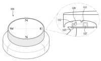
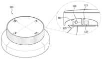
다이얼 노브(110)의 저면에는 발광부(126)와 수광부(127) 사이로 돌출 형성되어 다이얼 노브(110)의 회전에 따라 발광부(126)에서 조사된 빛을 수광부(127)를 향해 선택적으로 투과시키는 돌출부(113)가 형성될 수 있다.A protrusion (113) may be formed on the bottom surface of the dial knob (110) so as to protrude between the light emitting portion (126) and the light receiving portion (127) and selectively transmit light emitted from the light emitting portion (126) toward the light receiving portion (127) according to the rotation of the dial knob (110).
이러한 돌출부(113)는, 다이얼 노브(110)의 오목부(112) 상에 마련될 수 있으며, 서로 이격되어 마련된 발광부(126)와 수광부(127) 사이를 향해 돌출될 수 있다.This protrusion (113) may be provided on the concave portion (112) of the dial knob (110) and may protrude between the light-emitting portion (126) and the light-receiving portion (127) which are provided spaced apart from each other.
다이얼 노브(110)가 미리 정해진 기준 위치에 위치할 때 발광부(126)와 수광부(127) 사이로 돌출된 돌출부(113) 상에 홀(hole)이 형성되어 발광부(126)에서 조사된 빛을 수광부(127)를 향해 투과시킬 수 있다.When the dial knob (110) is positioned at a predetermined reference position, a hole is formed on the protrusion (113) protruding between the light emitting portion (126) and the light receiving portion (127), so that light emitted from the light emitting portion (126) can be transmitted toward the light receiving portion (127).
또는, 다이얼 노브(110)가 미리 정해진 기준 위치에 위치할 때 발광부(126)와 수광부(127) 사이로 돌출부(113)가 돌출 형성되지 않음으로써, 발광부(126)에서 조사된 빛을 수광부(127)를 향해 투과시킬 수 있다.Alternatively, when the dial knob (110) is positioned at a predetermined reference position, the protrusion (113) is not formed protruding between the light emitting portion (126) and the light receiving portion (127), so that light emitted from the light emitting portion (126) can be transmitted toward the light receiving portion (127).
이하에서는 도 4a 내지 도 4b를 참조하여 돌출부(113)를 자세하게 설명한다.Below, the protrusion (113) is described in detail with reference to FIGS. 4a and 4b.
도 4a는 일 실시예에 따른 다이얼 노브가 정방향에 위치할 때의 입력 장치의 측방향 단면도를 도시한 도면이고, 도 4b는 일 실시예에 따른 다이얼 노브가 정방향에 위치하지 않을 때의 입력 장치의 측방향 단면도를 도시한 도면이다.FIG. 4a is a side cross-sectional view of an input device when the dial knob is positioned in the forward direction according to one embodiment, and FIG. 4b is a side cross-sectional view of an input device when the dial knob is not positioned in the forward direction according to one embodiment.
도 4a를 참조하면, 다이얼 노브(110)가 미리 정해진 기준 위치에 위치할 때 발광부(126)와 수광부(127) 사이 위치하는 돌출부(113)는 돌출 형성되지 않을 수 있다. 도 4b를 참조하면 다이얼 노브(110)가 미리 정해진 기준 위치에서 벗어난 경우 발광부(126)와 수광부(127) 사이에 위치하는 돌출부(113)는 돌출 형성되어 발광부(126)에서 조사된 빛을 차단시킬 수 있다.Referring to Fig. 4a, when the dial knob (110) is positioned at a predetermined reference position, the protrusion (113) positioned between the light emitting unit (126) and the light receiving unit (127) may not be formed to protrude. Referring to Fig. 4b, when the dial knob (110) is out of the predetermined reference position, the protrusion (113) positioned between the light emitting unit (126) and the light receiving unit (127) may be formed to protrude and block the light emitted from the light emitting unit (126).
즉, 다이얼 노브(110)가 미리 정해진 기준 위치에 위치하면 수광부(127)가 발광부(126)에서 조사된 빛을 수신하여 동작할 수 있으며, 다이얼 노브(110)가 미리 정해진 기준 위치에 위치하지 않으면 수광부(127)가 발광부(126)에서 조사된 빛을 수신할 수 없다.That is, when the dial knob (110) is positioned at a predetermined reference position, the light receiving unit (127) can operate by receiving light irradiated from the light emitting unit (126), and when the dial knob (110) is not positioned at a predetermined reference position, the light receiving unit (127) cannot receive light irradiated from the light emitting unit (126).
이를 위한 돌출부(113)는 돌출 형성되지 않은 부분 또는 홀이 형성된 부분을 포함하고 다이얼 노브(110)와 함께 회전할 수 있으며, 다이얼 노브(110)가 회전하여 미리 정해진 기준 위치에 위치하게 되면 돌출 형성되지 않은 부분 또는 홀이 형성된 부분이 발광부(126)와 수광부(127) 사이에 위치하도록 다이얼 노브(110) 하단에 부착될 수 있다.The protrusion (113) for this purpose includes a non-protruding portion or a portion in which a hole is formed and can rotate together with the dial knob (110), and when the dial knob (110) is rotated and positioned at a predetermined reference position, the non-protruding portion or the portion in which the hole is formed can be attached to the bottom of the dial knob (110) so that it is positioned between the light-emitting portion (126) and the light-receiving portion (127).
이 때, 미리 정해진 기준 위치는 입력 장치(100)의 상단에 부착된 커스터마이징 로고가 정방향일 때의 다이얼 노브(110)의 위치를 의미할 수 있으나, 이에 한정되는 것은 아니다.At this time, the predetermined reference position may mean the position of the dial knob (110) when the customizing logo attached to the top of the input device (100) is in the correct direction, but is not limited thereto.
위와 같이, 돌출부(113)는 다이얼 노브(110)의 회전에 따라 발광부(126)에서 수광부(127)를 향해 조사된 빛을 투과시키거나 차단시킬 수 있다.As above, the protrusion (113) can transmit or block light irradiated from the light emitting portion (126) toward the light receiving portion (127) depending on the rotation of the dial knob (110).
이상에서는 도 3 내지 도 4를 참조하여 입력 장치(100)의 구성을 살펴보았다.In the above, the configuration of the input device (100) was examined with reference to FIGS. 3 and 4.
이하에서는 도 5를 참조하여 일 실시예에 따른 차량(10)의 제어 블록도를 설명한다.Below, a control block diagram of a vehicle (10) according to one embodiment is described with reference to FIG. 5.
도 5는 일 실시예에 따른 차량의 제어 블록도이다.Figure 5 is a control block diagram of a vehicle according to one embodiment.
도 5를 참조하면, 일 실시예에 따른 차량(10)은 입력 장치(100)와 AVN 장치(200)를 포함할 수 있다.Referring to FIG. 5, a vehicle (10) according to one embodiment may include an input device (100) and an AVN device (200).
일 실시예에 따른 입력 장치(100)는 입력 장치(100)의 각종 구성을 제어하는 제어부(122), 빛을 조사하는 발광부(126), 발광부(126)에서 조사된 빛을 수신하여 동작하는 수광부(127), 및 제어부(122)의 제어에 따라 동작하여 다이얼 노브(110)를 회전시키는 모터(123)를 포함할 수 있다.An input device (100) according to one embodiment may include a control unit (122) that controls various components of the input device (100), a light emitting unit (126) that radiates light, a light receiving unit (127) that operates by receiving light radiated from the light emitting unit (126), and a motor (123) that operates according to the control of the control unit (122) to rotate a dial knob (110).
발광부(126)는 발광 다이오드와 같이 빛을 조사할 수 있는 모든 구성을 의미할 수 있으며, 차량(10)의 배터리로부터 전원을 공급 받아 발광할 수 있다.The light-emitting unit (126) may mean any configuration capable of emitting light, such as a light-emitting diode, and may emit light by receiving power from the battery of the vehicle (10).
발광부(126)는 제어부(122)의 제어에 따라 특정 상황에서 빛을 조사할 수 있으며, 예를 들어, AVN 장치(200)가 켜진 상태일 때 빛을 조사할 수 있다.The light emitting unit (126) can emit light in a specific situation under the control of the control unit (122), and for example, can emit light when the AVN device (200) is turned on.
수광부(127)는 빛이 조사되면 동작하는 모든 구성을 의미할 수 있으며, 예를 들어, 수광부(127)는 포토 트랜지스터를 포함할 수 있다.The light receiving unit (127) may mean any component that operates when light is irradiated, and for example, the light receiving unit (127) may include a phototransistor.
수광부(127)는 발광부(126)로부터 조사된 빛을 수신하면 동작될 수 있으며, 동작 신호를 제어부(122)에 전달할 수 있다. 예를 들어, 수광부(127)가 포토 트랜지스터인 경우, 발광부(126)로부터 빛을 수신하면 로직 HIGH 신호를 제어부(122)로 전달할 수 있다.The light receiving unit (127) can be operated when it receives light emitted from the light emitting unit (126) and can transmit an operation signal to the control unit (122). For example, if the light receiving unit (127) is a phototransistor, it can transmit a logic HIGH signal to the control unit (122) when it receives light from the light emitting unit (126).
제어부(122)는 수광부(127)의 동작 여부에 기초하여 모터(123)를 제어할 수 있다.The control unit (122) can control the motor (123) based on whether the light receiving unit (127) is operating.
구체적으로, 제어부(122)는 수광부(127)가 동작하지 않으면 모터(123)를 동작시켜 다이얼 노브(110)를 회전시킬 수 있으며, 수광부(127)가 동작하면 모터(123)의 동작을 중지시켜 다이얼 노브(110)의 위치를 고정시킬 수 있다.Specifically, the control unit (122) can operate the motor (123) to rotate the dial knob (110) when the light receiving unit (127) does not operate, and can stop the operation of the motor (123) to fix the position of the dial knob (110) when the light receiving unit (127) operates.
이를 위한 제어부(122)는, 모터(123)의 동작을 제어하기 위한 알고리즘 또는 알고리즘을 재현한 프로그램에 대한 데이터를 저장하는 메모리, 및 메모리에 저장된 데이터를 이용하여 전술한 동작을 수행하는 프로세서로 구현될 수 있다.The control unit (122) for this purpose may be implemented as a memory that stores data on an algorithm for controlling the operation of the motor (123) or a program that reproduces the algorithm, and a processor that performs the above-described operation using the data stored in the memory.
이때, 메모리와 프로세서는 각각 별개의 칩으로 구현될 수 있다. 또는, 메모리와 프로세서는 단일 칩으로 구현될 수도 있다. 또한, 제어부(122)는 CAN(Controller Area Network) 통신 방식을 이용하여 차량(10)의 각종 구성으로부터 다양한 신호를 수신할 수 있다.At this time, the memory and the processor may be implemented as separate chips. Alternatively, the memory and the processor may be implemented as a single chip. In addition, the control unit (122) may receive various signals from various components of the vehicle (10) using the CAN (Controller Area Network) communication method.
일 실시예에 따른 AVN 장치(200)는 입력 장치(100)에서 수신된 입력에 기초하여 제어될 수 있다. 예를 들어, AVN 장치(200)는 다이얼 노브(110)의 회전 입력이나 푸쉬 버튼(114)의 푸쉬 입력에 기초하여 제어될 수 있다.The AVN device (200) according to one embodiment can be controlled based on an input received from the input device (100). For example, the AVN device (200) can be controlled based on a rotation input of a dial knob (110) or a push input of a push button (114).
이상으로 일 실시예에 따른 차량(10)의 제어 블록도를 설명하였다. 이하에서는 앞서 설명한 차량(10)의 각종 구성을 이용한 다양한 실시예를 설명한다.The control block diagram of a vehicle (10) according to one embodiment has been described above. Below, various embodiments using various configurations of the vehicle (10) described above will be described.
도 6은 제1 실시예에 따른 차량(10)의 제어 순서도이다.Figure 6 is a control flow chart of a vehicle (10) according to the first embodiment.
도 6을 참조하면, 제어부(122)는 AVN 장치(200)가 켜져 있는 경우 AVN 장치(200)와 연동되어 사용자로부터 입력된 회전 입력 및/또는 푸쉬 입력을 AVN 장치(200)로 전달할 수 있다(1000).Referring to FIG. 6, the control unit (122) can be linked with the AVN device (200) when the AVN device (200) is turned on to transmit a rotation input and/or a push input input from a user to the AVN device (200) (1000).
차량(10)의 시동이 꺼진 경우(1100의 예) 및/또는 미리 설정된 시간 동안 다이얼 노브(110)가 사용자의 조작에 의해 회전되지 않은 경우(1200의 예)에 다이얼 노브(110)를 정위치로 회전시킬 수 있다(1300).If the vehicle (10) is turned off (example of 1100) and/or the dial knob (110) has not been rotated by the user's operation for a preset time (example of 1200), the dial knob (110) can be rotated to the original position (1300).
구체적으로, 제어부(122)는 차량(10)의 시동이 꺼진 경우 및/또는 미리 설정된 시간 동안 다이얼 노브(110)가 사용자의 조작에 의해 회전되지 않은 경우에 수광부(127)의 동작 여부에 기초하여 모터(123)를 제어함으로써 다이얼 노브(110)를 회전시킬 수 있다.Specifically, the control unit (122) can rotate the dial knob (110) by controlling the motor (123) based on whether the light receiving unit (127) is operating when the vehicle (10) is turned off and/or when the dial knob (110) has not been rotated by the user's operation for a preset period of time.
도 4a 및 도 4b에서 설명한 바와 같이, 다이얼 노브(110)가 미리 정해진 기준 위치에 위치하면 다이얼 노브(110)의 저면에 형성된 돌출부(113)의 돌출 형성되지 않은 부분 또는 홀이 형성된 부분이 발광부(126)와 수광부(127) 사이에 위치된다.As described in FIGS. 4a and 4b, when the dial knob (110) is positioned at a predetermined reference position, the non-protruding portion or hole-formed portion of the protrusion (113) formed on the lower surface of the dial knob (110) is positioned between the light-emitting portion (126) and the light-receiving portion (127).
즉, 다이얼 노브(110)가 미리 정해진 기준 위치에 위치하면 수광부(127)는 발광부(126)에서 조사된 빛을 수신할 수 있다.That is, when the dial knob (110) is positioned at a predetermined reference position, the light receiving unit (127) can receive light emitted from the light emitting unit (126).
이러한 원리를 이용하여, 제어부(122)는, 수광부(127)가 동작하지 않으면 모터(123)를 동작시켜 다이얼 노브(110)를 회전시키고 수광부(127)가 동작하면 모터(123)의 동작을 중지시킴으로써 다이얼 노브(110)를 미리 정해진 기준 위치로 회전시킬 수 있다.Using this principle, the control unit (122) can rotate the dial knob (110) by operating the motor (123) when the light receiving unit (127) does not operate, and can stop the operation of the motor (123) when the light receiving unit (127) operates, thereby rotating the dial knob (110) to a predetermined reference position.
본 개시의 제1 실시예에 따르면, 시동이 꺼지거나 사용자로부터 미리 설정된 시간 동안 회전 입력을 받지 않은 경우 다이얼 노브(110) 상에 마련된 커스터마이징 로고의 방향을 정위치로 변경시킴으로써 차량(10) 이미지의 고급화를 도모할 수 있다.According to the first embodiment of the present disclosure, the image of the vehicle (10) can be enhanced by changing the direction of the customized logo provided on the dial knob (110) to the original position when the ignition is turned off or no rotation input is received from the user for a preset time.
도 7은 제2 실시예에 따른 차량의 제어 순서도이고, 도 8은 TBT 정보에 따른 다이얼 노브의 회전 방향을 나타낸 도면이다.Fig. 7 is a control flowchart of a vehicle according to the second embodiment, and Fig. 8 is a drawing showing the rotation direction of a dial knob according to TBT information.
도 7을 참조하면, AVN 장치(200)는 사용자로부터 목적지를 설정 받을 수 있다(2000).Referring to FIG. 7, the AVN device (200) can receive a destination set by the user (2000).
AVN 장치(200)는 사용자로부터 설정된 목적지와 차량(10)의 현재 위치에 기초하여 주행 경로를 설정하고(2100), 설정된 주행 경로에 기초하여 TBT 정보를 생성할 수 있다(2200).The AVN device (200) can set a driving route based on a destination set by a user and the current location of the vehicle (10) (2100) and generate TBT information based on the set driving route (2200).
입력 장치(100)에 포함된 제어부(122)는 AVN 장치(200)에서 생성된 TBT 정보를 수신할 수 있으며, TBT 정보에 기초하여 다이얼 노브(110)를 회전시킬 수 있다(2300).The control unit (122) included in the input device (100) can receive TBT information generated from the AVN device (200) and rotate the dial knob (110) based on the TBT information (2300).
구체적으로, 제어부(122)는 TBT 정보에 포함된 차량(10)의 회전 방향에 기초하여 다이얼 노브(110)의 회전 방향을 결정하고, 모터(123)를 제어하여 다이얼 노브(110)를 결정된 회전 방향으로 회전시킬 수 있다.Specifically, the control unit (122) can determine the rotation direction of the dial knob (110) based on the rotation direction of the vehicle (10) included in the TBT information, and control the motor (123) to rotate the dial knob (110) in the determined rotation direction.
예를 들어, 도 8을 참조하면, 제어부(122)는 TBT 정보에 포함된 차량(10)의 회전 방향이 1시 방향인 경우에는 다이얼 노브(110)를 시계 방향으로 30도 회전시킬 수 있고, TBT 정보에 포함된 차량(10)의 회전 방향이 우회전 방향인 경우에는 다이얼 노브(110)를 시계 방향으로 90도 회전시킬 수 있고, TBT 정보에 포함된 차량(10)의 회전 방향이 4시 방향인 경우에는 다이얼 노브(110)를 시계 방향으로 120도 회전시킬 수 있고, TBT 정보에 포함된 차량(10)의 회전 방향이 유턴 방향인 경우에는 다이얼 노브(110)를 시계 방향 또는 반시계 방향으로 360도 회전시킬 수 있고, TBT 정보에 포함된 차량(10)의 회전 방향이 8시 방향인 경우에는 다이얼 노브(110)를 반시계 방향으로 120도 회전시킬 수 있고, TBT 정보에 포함된 차량(10)의 회전 방향이 좌회전 방향인 경우에는 다이얼 노브(110)를 반시계 방향으로 90도 회전시킬 수 있고, TBT 정보에 포함된 차량(10)의 회전 방향이 11시 방향인 경우에는 다이얼 노브(110)를 반시계 방향으로 30도 회전시킬 수 있다.For example, referring to FIG. 8, if the rotation direction of the vehicle (10) included in the TBT information is 1 o'clock, the control unit (122) can rotate the dial knob (110) 30 degrees clockwise, if the rotation direction of the vehicle (10) included in the TBT information is a right turn, the control unit (122) can rotate the dial knob (110) 90 degrees clockwise, if the rotation direction of the vehicle (10) included in the TBT information is 4 o'clock, the control unit (122) can rotate the dial knob (110) 120 degrees clockwise, if the rotation direction of the vehicle (10) included in the TBT information is a U-turn, the control unit (122) can rotate the dial knob (110) 360 degrees clockwise or counterclockwise, if the rotation direction of the vehicle (10) included in the TBT information is 8 o'clock, the control unit (122) can rotate the dial knob (110) 120 degrees counterclockwise, and if the rotation direction of the vehicle (10) included in the TBT information is a left turn, the control unit (122) can rotate the dial knob (110) 360 degrees clockwise or counterclockwise. The knob (110) can be rotated 90 degrees counterclockwise, and when the rotation direction of the vehicle (10) included in the TBT information is 11 o'clock, the dial knob (110) can be rotated 30 degrees counterclockwise.
AVN 장치(200)에 의한 주행 경로 안내가 종료되면(2400의 예), 제어부(122)는 수광부(127)에 동작 여부에 기초하여 다이얼 노브(110)를 미리 정해진 기준 위치로 회전시킬 수 있다(2500).When the driving route guidance by the AVN device (200) is terminated (example of 2400), the control unit (122) can rotate the dial knob (110) to a predetermined reference position based on whether the light receiving unit (127) is operating (2500).
AVN 장치(200)에 의한 주행 경로 안내는 차량(10)이 목적지에 도착한 경우나 사용자가 주행 경로 안내를 취소하는 명령을 입력한 경우에 종료될 수 있다.Driving route guidance by the AVN device (200) can be terminated when the vehicle (10) arrives at the destination or when the user inputs a command to cancel driving route guidance.
본 개시의 제2 실시예에 따르면, AVN 장치(200)의 주행 경로 안내가 종료되는 경우 다이얼 노브(110) 상에 마련된 커스터마이징 로고의 방향을 정위치로 변경시킴으로써 차량(10) 이미지의 고급화를 도모할 수 있다. 또한, 본 개시의 제2 실시예에 따르면 운전자가 손을 입력 장치(100)에 올려 놓은 경우, 주행 중 전방을 주시하더라도 TBT 정보를 촉각으로 전달 받을 수 있다.According to the second embodiment of the present disclosure, when the driving route guidance of the AVN device (200) is terminated, the direction of the customized logo provided on the dial knob (110) is changed to the fixed position, thereby improving the image of the vehicle (10). In addition, according to the second embodiment of the present disclosure, when the driver places his/her hand on the input device (100), TBT information can be transmitted tactilely even when looking ahead while driving.
도 9는 제3 실시예에 따른 차량의 제어 순서도이고, 도 10은 일 실시예에 따른 AVN 장치에 표시된 이미지를 나타낸 도면이다.FIG. 9 is a control flowchart of a vehicle according to a third embodiment, and FIG. 10 is a drawing showing an image displayed on an AVN device according to one embodiment.
도 9 내지 도 10을 참조하면, AVN 장치(200)는 음성 입력 또는 터치 입력 등을 통하여 사용자로부터 목적지의 명칭(N)을 입력 받을 수 있다(3000).Referring to FIGS. 9 and 10, the AVN device (200) can receive a destination name (N) from a user through voice input or touch input (3000).
AVN 장치(200)는 목적지의 명칭(N)이 입력 되면, 목적지의 명칭(N)과 매칭되는 장소의 리스트(L)를 표시할 수 있다(3100).When a destination name (N) is entered, the AVN device (200) can display a list (L) of locations matching the destination name (N) (3100).
이후, 사용자는 입력 장치(100)를 통하여 표시된 리스트(L) 상의 장소들 중에서 어느 하나의 장소를 목적지로 설정할 수 있다.Thereafter, the user can set any one of the locations on the displayed list (L) as a destination through the input device (100).
구체적으로, 사용자는 입력 장치(100)의 다이얼 노브(110)를 회전시켜 리스트 상의 커서(C)의 위치를 변경시키고 입력 장치(100)의 푸쉬 버튼(114)을 푸쉬하여 커서(C)가 위치하는 장소를 목적지로 설정할 수 있다.Specifically, the user can change the position of the cursor (C) on the list by rotating the dial knob (110) of the input device (100) and set the location where the cursor (C) is located as the destination by pushing the push button (114) of the input device (100).
이를 위해, AVN 장치(200)는 다이얼 노브(110)로부터 수신된 회전 입력에 기초하여 리스트(L) 상의 커서(C)의 위치를 변경하고, 푸쉬 버튼(114)으로부터 수신된 푸쉬 입력에 기초하여 커서(C)가 위치하는 장소를 차량(10)의 목적지로 설정할 수 있다.To this end, the AVN device (200) can change the position of the cursor (C) on the list (L) based on the rotation input received from the dial knob (110), and set the location where the cursor (C) is located as the destination of the vehicle (10) based on the push input received from the push button (114).
구체적으로, AVN 장치(200)는 입력 장치(100)로부터 회전 입력을 수신하면(3200의 예), 커서(C)의 위치를 변경할 수 있다(3250). 이 때, AVN 장치(200)는 수신된 입력이 시계 방향의 회전 입력이면 커서(C)의 위치를 아래쪽으로 변경시키고, 반시계 방향의 회전 입력이면 커서(C)의 위치를 위쪽으로 변경시킬 수 있다.Specifically, when the AVN device (200) receives a rotation input from the input device (100) (example of 3200), it can change the position of the cursor (C) (3250). At this time, the AVN device (200) can change the position of the cursor (C) downward if the received input is a clockwise rotation input, and can change the position of the cursor (C) upward if the received input is a counterclockwise rotation input.
AVN 장치(200)는 입력 장치(100)로부터 미리 설정된 시간(예를 들어, 2초)보다 짧은 기간 동안 푸쉬 입력을 수신하면(3300, 3400의 아니오) 커서(C)가 위치하는 장소를 목적지로 설정할 수 있다(3500).The AVN device (200) can set the location where the cursor (C) is located as the destination (3500) when it receives a push input from the input device (100) for a period shorter than a preset time (e.g., 2 seconds) (No of 3300, 3400).
또한, AVN 장치(200)는 입력 장치(100)로부터 미리 설정된 시간 동안 푸쉬 입력이 수신되더라도, 푸시 입력이 수신되는 중에 회전 입력이 수신되지 않으면(3410의 아니오) 커서(C)가 위치하는 장소를 목적지로 설정할 수 있다(3500).In addition, the AVN device (200) can set the location where the cursor (C) is located as the destination (3500) if a rotation input is not received while a push input is being received (NO of 3410), even if a push input is received from the input device (100) for a preset time.
반면에, AVN 장치(200)는 입력 장치(100)로부터 미리 설정된 시간 동안 푸쉬 입력이 수신되고 푸쉬 입력이 수신되는 중에 회전 입력이 수신되면(3410의 예), 커서(C)의 위치를 지속적으로 자동 변경시킬 수 있다(3420).On the other hand, the AVN device (200) can continuously and automatically change the position of the cursor (C) (3420) when a push input is received from the input device (100) for a preset time and a rotation input is received while the push input is being received (example of 3410).
예를 들어, 사용자가 푸쉬 버튼(114)을 2초 동안 누르면서 다이얼 노브(110)를 시계 방향으로 회전시키면, AVN 장치(200)는 추가적인 회전 입력이 없더라도 커서(C)의 위치를 지속적으로 아래쪽으로 변경시킬 수 있다.For example, if a user rotates the dial knob (110) clockwise while pressing the push button (114) for 2 seconds, the AVN device (200) can continuously change the position of the cursor (C) downward even without additional rotation input.
또한, 사용자가 푸쉬 버튼(114)을 2초 동안 누르면서 다이얼 노브(110)를 반시계 방향으로 회전시키면, AVN 장치(200)는 추가적인 회전 입력이 없더라도 커서(C)의 위치를 지속적으로 위쪽으로 변경시킬 수 있다.Additionally, when the user rotates the dial knob (110) counterclockwise while pressing the push button (114) for 2 seconds, the AVN device (200) can continuously change the position of the cursor (C) upward even without additional rotation input.
AVN 장치(200)는 리스트 상의 커서(C)의 위치를 지속적으로 자동 변경시키는 중에 입력 장치(100)로부터 회전 입력 또는 푸쉬 입력이 수신되면(3430의 예), 커서(C)의 자동 위치 변경을 중지시킬 수 있다(3440).When a rotation input or push input is received from the input device (100) while the AVN device (200) is continuously and automatically changing the position of the cursor (C) on the list (example of 3430), the AVN device (200) can stop the automatic position change of the cursor (C) (3440).
즉, 리스트(L) 상의 커서(C)는 회전 입력 또는 푸쉬 입력이 수신된 시점의 위치에 고정될 수 있다.That is, the cursor (C) on the list (L) can be fixed at the position at the time when the rotation input or push input is received.
입력 장치(100)의 제어부(122)는 커서(C)의 자동 위치 변경이 중지되면, 수광부(127)의 동작 여부에 기초하여 다이얼 노브(110)를 미리 정해진 기준 위치로 회전시킬 수 있다(3450).The control unit (122) of the input device (100) can rotate the dial knob (110) to a predetermined reference position based on whether the light receiving unit (127) is operating when the automatic position change of the cursor (C) is stopped (3450).
본 개시의 제3 실시예에 따르면, 사용자가 간단한 조작을 통해(푸쉬 조작과 회전 조작) AVN 장치(200)에 표시되는 커서(C)의 위치를 지속적으로 자동 변경시킬 수 있어서, 커서(C) 이동을 위한 조작의 편의성이 향상될 수 있다.According to the third embodiment of the present disclosure, the user can continuously and automatically change the position of the cursor (C) displayed on the AVN device (200) through simple operations (push operations and rotation operations), so that the convenience of operations for moving the cursor (C) can be improved.
또한, 커서(C)의 자동 위치 변경이 중지되는 경우 다이얼 노브(110) 상에 마련된 커스터마이징 로고의 방향을 정위치로 변경시킴으로써 차량(10) 이미지의 고급화를 도모할 수 있다.In addition, when the automatic position change of the cursor (C) is stopped, the direction of the customized logo provided on the dial knob (110) can be changed to the original position, thereby improving the image of the vehicle (10).
한편, 차량(10) 또는 입력 장치(100)의 일부 구성요소는 소프트웨어 및/또는 Field Programmable Gate Array(FPGA) 및 주문형 반도체(ASIC, Application Specific Integrated Circuit)와 같은 하드웨어 구성요소일 수 있다.Meanwhile, some components of the vehicle (10) or the input device (100) may be software and/or hardware components such as a Field Programmable Gate Array (FPGA) and an Application Specific Integrated Circuit (ASIC).
한편, 개시된 실시예들은 컴퓨터에 의해 실행 가능한 명령어를 저장하는 기록매체의 형태로 구현될 수 있다. 명령어는 프로그램 코드의 형태로 저장될 수 있으며, 프로세서에 의해 실행되었을 때, 프로그램 모듈을 생성하여 개시된 실시예들의 동작을 수행할 수 있다. 기록매체는 컴퓨터로 읽을 수 있는 기록매체로 구현될 수 있다.Meanwhile, the disclosed embodiments may be implemented in the form of a recording medium storing instructions executable by a computer. The instructions may be stored in the form of program codes, and when executed by a processor, may generate program modules to perform the operations of the disclosed embodiments. The recording medium may be implemented as a computer-readable recording medium.
컴퓨터가 읽을 수 있는 기록매체로는 컴퓨터에 의하여 해독될 수 있는 명령어가 저장된 모든 종류의 기록 매체를 포함한다. 예를 들어, ROM(Read Only Memory), RAM(Random Access Memory), 자기 테이프, 자기 디스크, 플래시 메모리, 광 데이터 저장장치 등이 있을 수 있다.Computer-readable storage media include all types of storage media that store instructions that can be deciphered by a computer. Examples include ROM (Read Only Memory), RAM (Random Access Memory), magnetic tape, magnetic disk, flash memory, and optical data storage devices.
이상에서와 같이 첨부된 도면을 참조하여 개시된 실시예들을 설명하였다. 본 발명이 속하는 기술분야에서 통상의 지식을 가진 자는 본 발명의 기술적 사상이나 필수적인 특징을 변경하지 않고도, 개시된 실시예들과 다른 형태로 본 발명이 실시될 수 있음을 이해할 것이다. 개시된 실시예들은 예시적인 것이며, 한정적으로 해석되어서는 안 된다.As described above, the disclosed embodiments have been described with reference to the attached drawings. Those skilled in the art to which the present invention pertains will understand that the present invention can be implemented in forms other than the disclosed embodiments without changing the technical idea or essential features of the present invention. The disclosed embodiments are exemplary and should not be construed as limiting.
100 : 입력 장치110 : 다이얼 노브
111 : 연결부112 : 오목부
113 : 돌출부114 : 푸쉬 버튼
120: 바디부121: 메인 인쇄회로기판
122: 제어부123: 모터
124: 플렉서블 와이어125: 서브 인쇄회로기판
126: 발광부127: 수광부
200: AVN 장치100 : Input device 110 : Dial knob
111 : Connection 112 : Recessed part
113 : Protrusion 114 : Push button
120: Body 121: Main printed circuit board
122: Control unit 123: Motor
124: Flexible wire 125: Sub printed circuit board
126: Light emitter 127: Light receiver
200: AVN device
Claims (18)
Translated fromKorean바디부;
상기 바디부의 상단에 마련된 발광부;
상기 바디부의 상단에 상기 발광부와 이격되어 마련되고, 상기 발광부에서 조사된 빛을 수신하여 동작하는 수광부;
상기 바디부에 의해 지지되고, 사용자의 조작에 따라 회전축을 중심으로 회전하는 다이얼 노브;
상기 다이얼 노브의 저면에서 상기 발광부와 상기 수광부 사이로 돌출 형성되어 상기 다이얼 노브의 회전에 따라 상기 발광부에서 조사된 빛을 상기 수광부를 향해 선택적으로 투과시키는 돌출부;
상기 다이얼 노브를 회전시키는 모터; 및
상기 수광부의 동작 여부에 기초하여 상기 모터를 제어하는 제어부;를 포함하고,
차량의 시동이 꺼진 경우나, 미리 설정된 시간 동안 다이얼 노브가 사용자의 조작에 의해 회전되지 않은 경우, 상기 제어부는 상기 돌출부가 없는 부분이 상기 수광부와 정렬되어 상기 수광부가 작동하면, 상기 모터의 동작을 중지하는 방법으로, 상기 다이얼 노브의 위치를 원복시키고, 상기 수광부가 상기 돌출부와 정렬되어 상기 돌출부에 의해 빛이 차단되어 상기 수광부가 작동하지 않으면, 상기 모터를 회전시켜 상기 다이얼 노브의 위치를 원복시키는 입력 장치.In the input device provided in the vehicle,
body part;
A light emitting part provided at the upper part of the above body part;
A light receiving unit provided at the upper end of the body portion and spaced apart from the light emitting unit, and operating by receiving light irradiated from the light emitting unit;
A dial knob supported by the above body part and rotating around a rotation axis according to the user's operation;
A protrusion formed between the light emitting part and the light receiving part on the bottom surface of the dial knob to selectively transmit light emitted from the light emitting part toward the light receiving part according to the rotation of the dial knob;
a motor for rotating the above dial knob; and
A control unit that controls the motor based on whether the light receiving unit is operating;
An input device in which, when the vehicle ignition is turned off or the dial knob is not rotated by the user's operation for a preset period of time, the control unit restores the position of the dial knob by stopping the operation of the motor when the part without the protrusion is aligned with the light-receiving unit and the light-receiving unit operates, and when the light-receiving unit is aligned with the protrusion and the light is blocked by the protrusion and the light-receiving unit does not operate, the control unit rotates the motor to restore the position of the dial knob.
상기 다이얼 노브는,
상기 모터와 연결되는 연결부; 및
상기 연결부의 외측에서 오목하게 형성된 오목부;를 포함하는 입력 장치.In the first paragraph,
The above dial knob,
a connection part connected to the above motor; and
An input device including a concave portion formed concavely on the outer side of the above connecting portion.
상기 돌출부는,
상기 다이얼 노브의 오목부에 형성된 입력 장치.In Article 8,
The above protrusion is,
An input device formed in the concave portion of the above dial knob.
상기 발광부와 상기 수광부는 상기 바디부의 상단에 마련된 제1 인쇄회로기판 상에 마련되고,
상기 제어부와 상기 모터는 상기 바디부의 내부에 마련된 제2 인쇄회로기판 상에 마련되고,
상기 제1 인쇄회로기판과 상기 제2 인쇄회로기판은 전기적으로 연결된 입력 장치.In the first paragraph,
The above light emitting unit and the light receiving unit are provided on the first printed circuit board provided on the upper part of the body unit,
The above control unit and the above motor are provided on a second printed circuit board provided inside the body unit,
The above first printed circuit board and the above second printed circuit board are an input device electrically connected.
상기 발광부는,
상기 차량의 AVN 장치가 켜진 상태일 때 빛을 조사하는 입력 장치.In the first paragraph,
The above light emitting part,
An input device that emits light when the AVN device of the above vehicle is turned on.
상기 AVN 장치는,
사용자로부터 설정된 목적지와 차량의 현재 위치에 기초하여 주행 경로를 설정하고, 상기 설정된 주행 경로에 기초하여 TBT(Turn by Turn) 정보를 생성하고,
상기 입력 장치는,
상기 AVN 장치에서 생성된 TBT 정보에 기초하여 상기 다이얼 노브를 회전시키는 차량.In Article 12,
The above AVN device,
Set a driving route based on a destination set by the user and the current location of the vehicle, and generate TBT (Turn by Turn) information based on the set driving route.
The above input device,
A vehicle that rotates the dial knob based on TBT information generated in the AVN device.
상기 입력 장치는,
상기 TBT 정보에 포함된 상기 차량의 회전 방향에 기초하여 상기 다이얼 노브의 회전 방향을 결정하고, 상기 다이얼 노브를 상기 결정된 회전 방향으로 회전시키는 차량.In Article 13,
The above input device,
A vehicle that determines the rotation direction of the dial knob based on the rotation direction of the vehicle included in the TBT information, and rotates the dial knob in the determined rotation direction.
상기 입력 장치는,
상기 AVN 장치에 의한 주행 경로 안내가 종료되면 상기 수광부의 동작 여부에 기초하여 상기 다이얼 노브를 미리 정해진 기준 위치로 회전시키는 차량.In Article 13,
The above input device,
A vehicle that rotates the dial knob to a predetermined reference position based on whether the light receiving unit is operating when the driving route guidance by the AVN device is terminated.
상기 입력 장치는,
상기 다이얼 노브의 상단에 마련되고, 푸쉬 입력을 수신하는 푸쉬 버튼을 더 포함하고,
상기 AVN 장치는,
사용자로부터 목적지의 명칭을 입력 받고, 상기 입력된 목적지의 명칭과 매칭되는 장소의 리스트를 표시하고, 상기 다이얼 노브로부터 수신된 회전 입력에 기초하여 상기 리스트 상의 커서의 위치를 변경하고, 상기 푸쉬 버튼으로부터 수신된 푸쉬 입력에 기초하여 상기 커서가 위치하는 장소를 상기 차량의 목적지로 설정하되,
미리 설정된 시간 동안 상기 푸쉬 입력이 수신되고 상기 푸쉬 입력이 수신되는 중에 상기 회전 입력이 수신되면, 상기 리스트 상의 커서의 위치를 지속적으로 자동 변경시키는 차량.In Article 12,
The above input device,
Further comprising a push button provided on the top of the above dial knob and receiving a push input,
The above AVN device,
Receiving a destination name from a user, displaying a list of places matching the entered destination name, changing the position of a cursor on the list based on a rotation input received from the dial knob, and setting the place where the cursor is located as the destination of the vehicle based on a push input received from the push button.
A vehicle that automatically and continuously changes the position of the cursor on the list when the push input is received for a preset period of time and the rotation input is received while the push input is being received.
상기 AVN 장치는,
상기 리스트 상의 커서의 위치를 지속적으로 자동 변경시키는 중에 상기 푸쉬 입력 또는 상기 회전 입력이 수신되면 상기 커서의 자동 위치 변경을 중지시키는 차량.In Article 16,
The above AVN device,
A vehicle that stops the automatic position change of the cursor when the push input or the rotation input is received while continuously automatically changing the position of the cursor on the above list.
상기 입력 장치는,
상기 커서의 자동 위치 변경이 중지되면, 상기 수광부의 동작 여부에 기초하여 상기 다이얼 노브를 미리 정해진 기준 위치로 회전시키는 차량.In Article 17,
The above input device,
A vehicle that rotates the dial knob to a predetermined reference position based on whether the light receiving unit is operating when the automatic position change of the cursor is stopped.
Priority Applications (3)
| Application Number | Priority Date | Filing Date | Title |
|---|---|---|---|
| KR1020200062247AKR102769110B1 (en) | 2020-05-25 | 2020-05-25 | Input device and vehicle comrpising the same |
| US17/066,783US11241964B2 (en) | 2020-05-25 | 2020-10-09 | Input device and vehicle comprising the same |
| CN202011152144.0ACN113715621A (en) | 2020-05-25 | 2020-10-23 | Input device and vehicle including the same |
Applications Claiming Priority (1)
| Application Number | Priority Date | Filing Date | Title |
|---|---|---|---|
| KR1020200062247AKR102769110B1 (en) | 2020-05-25 | 2020-05-25 | Input device and vehicle comrpising the same |
Publications (2)
| Publication Number | Publication Date |
|---|---|
| KR20210145410A KR20210145410A (en) | 2021-12-02 |
| KR102769110B1true KR102769110B1 (en) | 2025-02-18 |
Family
ID=78607790
Family Applications (1)
| Application Number | Title | Priority Date | Filing Date |
|---|---|---|---|
| KR1020200062247AActiveKR102769110B1 (en) | 2020-05-25 | 2020-05-25 | Input device and vehicle comrpising the same |
Country Status (3)
| Country | Link |
|---|---|
| US (1) | US11241964B2 (en) |
| KR (1) | KR102769110B1 (en) |
| CN (1) | CN113715621A (en) |
Families Citing this family (6)
| Publication number | Priority date | Publication date | Assignee | Title |
|---|---|---|---|---|
| US12287962B2 (en) | 2013-09-03 | 2025-04-29 | Apple Inc. | User interface for manipulating user interface objects |
| EP3147747A1 (en) | 2014-06-27 | 2017-03-29 | Apple Inc. | Manipulation of calendar application in device with touch screen |
| CN106797493A (en) | 2014-09-02 | 2017-05-31 | 苹果公司 | Music user interface |
| US11435830B2 (en) | 2018-09-11 | 2022-09-06 | Apple Inc. | Content-based tactile outputs |
| EP4227138B1 (en)* | 2022-02-15 | 2024-10-16 | Marelli Europe S.p.A. | Display assembly, in particular for a motor vehicle dashboard, and assembling method for assembling such an assembly |
| CN120770017A (en)* | 2022-09-24 | 2025-10-10 | 苹果公司 | Techniques for providing an input mechanism |
Citations (7)
| Publication number | Priority date | Publication date | Assignee | Title |
|---|---|---|---|---|
| JP3008588B2 (en)* | 1991-08-30 | 2000-02-14 | 松下電器産業株式会社 | Device with sliding front |
| JP2006293601A (en)* | 2005-04-08 | 2006-10-26 | Nissan Motor Co Ltd | Information operation device |
| KR100765974B1 (en)* | 2006-08-30 | 2007-10-10 | 씨멘스브이디오한라 주식회사 | Rotary knob drive structure of car rotary switch |
| JP2009289677A (en)* | 2008-05-30 | 2009-12-10 | Autonetworks Technologies Ltd | Operation device |
| KR101406190B1 (en)* | 2012-12-20 | 2014-06-12 | 현대오트론 주식회사 | Method for controlling navigation using start button and control apparatus thereof |
| US20170162347A1 (en)* | 2015-12-02 | 2017-06-08 | Tram, Inc. | Rotary-type switch |
| US20180010932A1 (en)* | 2016-07-07 | 2018-01-11 | Haier Us Appliance Solutions, Inc. | Control knob with optical shaft encoder and visual feedback of angular position |
Family Cites Families (8)
| Publication number | Priority date | Publication date | Assignee | Title |
|---|---|---|---|---|
| US7732756B2 (en)* | 2006-11-01 | 2010-06-08 | Avago Technologies Ecbu Ip (Singapore) Pte. Ltd. | User navigation device with a code wheel and an encoder |
| DE102009034913A1 (en)* | 2009-07-28 | 2011-02-03 | GM Global Technology Operations, Inc., Detroit | Operating and display device for a vehicle |
| US8972109B2 (en)* | 2011-04-19 | 2015-03-03 | Ford Global Technologies | Rotatable driver interface for trailer backup assist |
| CN202586935U (en)* | 2012-05-31 | 2012-12-05 | 温州长江汽车电子有限公司 | Rotary coding structure for navigation switch |
| US9334949B2 (en)* | 2013-12-13 | 2016-05-10 | Ghsp, Inc. | Rotary shifting device with motorized knob |
| KR102559681B1 (en)* | 2016-03-02 | 2023-07-27 | 현대자동차주식회사 | Avn apparatus and vehicle comprising the same, control method for the avn apparatus |
| CN209560389U (en)* | 2019-03-25 | 2019-10-29 | 东莞信商实业有限公司 | Rotary dial switch with driver plate adjustment function |
| CA3081385A1 (en)* | 2019-05-28 | 2020-11-28 | Nadia J. Williams | Safety apparatus including sensor and remote controlled stove knob |
- 2020
- 2020-05-25KRKR1020200062247Apatent/KR102769110B1/enactiveActive
- 2020-10-09USUS17/066,783patent/US11241964B2/enactiveActive
- 2020-10-23CNCN202011152144.0Apatent/CN113715621A/enactivePending
Patent Citations (7)
| Publication number | Priority date | Publication date | Assignee | Title |
|---|---|---|---|---|
| JP3008588B2 (en)* | 1991-08-30 | 2000-02-14 | 松下電器産業株式会社 | Device with sliding front |
| JP2006293601A (en)* | 2005-04-08 | 2006-10-26 | Nissan Motor Co Ltd | Information operation device |
| KR100765974B1 (en)* | 2006-08-30 | 2007-10-10 | 씨멘스브이디오한라 주식회사 | Rotary knob drive structure of car rotary switch |
| JP2009289677A (en)* | 2008-05-30 | 2009-12-10 | Autonetworks Technologies Ltd | Operation device |
| KR101406190B1 (en)* | 2012-12-20 | 2014-06-12 | 현대오트론 주식회사 | Method for controlling navigation using start button and control apparatus thereof |
| US20170162347A1 (en)* | 2015-12-02 | 2017-06-08 | Tram, Inc. | Rotary-type switch |
| US20180010932A1 (en)* | 2016-07-07 | 2018-01-11 | Haier Us Appliance Solutions, Inc. | Control knob with optical shaft encoder and visual feedback of angular position |
Also Published As
| Publication number | Publication date |
|---|---|
| US11241964B2 (en) | 2022-02-08 |
| KR20210145410A (en) | 2021-12-02 |
| US20210362603A1 (en) | 2021-11-25 |
| CN113715621A (en) | 2021-11-30 |
Similar Documents
| Publication | Publication Date | Title |
|---|---|---|
| KR102769110B1 (en) | Input device and vehicle comrpising the same | |
| US7636633B2 (en) | Car navigation system | |
| EP2952376B1 (en) | Input system disposable in steering wheel and vehicle including the same | |
| US20170274958A1 (en) | Motorcycle hand control with optical sensor | |
| KR101994012B1 (en) | Transportation means, user interface and method for overlapping the display of display contents over two display devices | |
| JP6304885B2 (en) | Vehicle remote control system | |
| US10983691B2 (en) | Terminal, vehicle having the terminal, and method for controlling the vehicle | |
| KR101621369B1 (en) | Apparatus for gesture recognition, vehicle comprising the same, and mothod for gesture recognition | |
| US20070008189A1 (en) | Image display device and image display method | |
| US20190009773A1 (en) | Driving assistance device | |
| WO2007052487A1 (en) | Display device and navigation device | |
| US10416665B2 (en) | Vehicle remote control method, and vehicle and mobile communication terminal therefor | |
| US20220415321A1 (en) | Electronic device mounted in vehicle, and method of operating the same | |
| JP2008535726A (en) | Human-machine interface system for vehicle application | |
| JP5618887B2 (en) | Vehicle control device | |
| US10996068B2 (en) | Vehicle and vehicle system | |
| KR20210025368A (en) | Vehicle and controlling method thereof | |
| US7020289B1 (en) | Remote control interface for replacement vehicle stereos | |
| KR101882198B1 (en) | Vehicle and method for controlling thereof | |
| JP2015162019A (en) | Vehicle display controller | |
| US11977809B2 (en) | Console display interlocking method and vehicle system using the same | |
| US20130035074A1 (en) | System for the recording and retrieval of voice messages | |
| JP2020168901A (en) | Viewpoint position sensing type vehicle automatic control system | |
| US9573471B2 (en) | Terminal, vehicle having the same, and control method thereof | |
| JP2020131830A (en) | Driving support device |
Legal Events
| Date | Code | Title | Description |
|---|---|---|---|
| PA0109 | Patent application | Patent event code:PA01091R01D Comment text:Patent Application Patent event date:20200525 | |
| PG1501 | Laying open of application | ||
| A201 | Request for examination | ||
| PA0201 | Request for examination | Patent event code:PA02012R01D Patent event date:20230509 Comment text:Request for Examination of Application Patent event code:PA02011R01I Patent event date:20200525 Comment text:Patent Application | |
| E902 | Notification of reason for refusal | ||
| PE0902 | Notice of grounds for rejection | Comment text:Notification of reason for refusal Patent event date:20240725 Patent event code:PE09021S01D | |
| E701 | Decision to grant or registration of patent right | ||
| PE0701 | Decision of registration | Patent event code:PE07011S01D Comment text:Decision to Grant Registration Patent event date:20250103 | |
| GRNT | Written decision to grant | ||
| PR0701 | Registration of establishment | Comment text:Registration of Establishment Patent event date:20250212 Patent event code:PR07011E01D | |
| PR1002 | Payment of registration fee | Payment date:20250213 End annual number:3 Start annual number:1 | |
| PG1601 | Publication of registration |