KR102764934B1 - Display device and method of driving the same - Google Patents
Display device and method of driving the sameDownload PDFInfo
- Publication number
- KR102764934B1 KR102764934B1KR1020200075230AKR20200075230AKR102764934B1KR 102764934 B1KR102764934 B1KR 102764934B1KR 1020200075230 AKR1020200075230 AKR 1020200075230AKR 20200075230 AKR20200075230 AKR 20200075230AKR 102764934 B1KR102764934 B1KR 102764934B1
- Authority
- KR
- South Korea
- Prior art keywords
- map data
- logo
- image
- display device
- value
- Prior art date
- Legal status (The legal status is an assumption and is not a legal conclusion. Google has not performed a legal analysis and makes no representation as to the accuracy of the status listed.)
- Active
Links
- 238000000034methodMethods0.000titleclaimsdescription12
- 238000006243chemical reactionMethods0.000claimsabstractdescription44
- 238000001514detection methodMethods0.000claimsdescription43
- 238000013075data extractionMethods0.000claimsdescription18
- 230000009466transformationEffects0.000claimsdescription6
- 101001038335Homo sapiens Serine/threonine-protein kinase LMTK2Proteins0.000description14
- 102100040292Serine/threonine-protein kinase LMTK2Human genes0.000description14
- 239000000284extractSubstances0.000description10
- 238000010586diagramMethods0.000description8
- 239000003990capacitorSubstances0.000description6
- 206010047571Visual impairmentDiseases0.000description5
- 238000002347injectionMethods0.000description5
- 239000007924injectionSubstances0.000description5
- 238000002474experimental methodMethods0.000description3
- 230000015556catabolic processEffects0.000description2
- 238000006731degradation reactionMethods0.000description2
- 230000000694effectsEffects0.000description2
- 238000012986modificationMethods0.000description2
- 230000004048modificationEffects0.000description2
- 241001270131Agaricus moelleriSpecies0.000description1
- 239000002131composite materialSubstances0.000description1
- 230000006866deteriorationEffects0.000description1
- 238000000605extractionMethods0.000description1
- 239000011147inorganic materialSubstances0.000description1
- 229910010272inorganic materialInorganic materials0.000description1
- 239000004973liquid crystal related substanceSubstances0.000description1
- 239000011368organic materialSubstances0.000description1
- 239000002096quantum dotSubstances0.000description1
Images


Classifications
- G—PHYSICS
- G09—EDUCATION; CRYPTOGRAPHY; DISPLAY; ADVERTISING; SEALS
- G09G—ARRANGEMENTS OR CIRCUITS FOR CONTROL OF INDICATING DEVICES USING STATIC MEANS TO PRESENT VARIABLE INFORMATION
- G09G3/00—Control arrangements or circuits, of interest only in connection with visual indicators other than cathode-ray tubes
- G09G3/20—Control arrangements or circuits, of interest only in connection with visual indicators other than cathode-ray tubes for presentation of an assembly of a number of characters, e.g. a page, by composing the assembly by combination of individual elements arranged in a matrix no fixed position being assigned to or needed to be assigned to the individual characters or partial characters
- G09G3/22—Control arrangements or circuits, of interest only in connection with visual indicators other than cathode-ray tubes for presentation of an assembly of a number of characters, e.g. a page, by composing the assembly by combination of individual elements arranged in a matrix no fixed position being assigned to or needed to be assigned to the individual characters or partial characters using controlled light sources
- G09G3/30—Control arrangements or circuits, of interest only in connection with visual indicators other than cathode-ray tubes for presentation of an assembly of a number of characters, e.g. a page, by composing the assembly by combination of individual elements arranged in a matrix no fixed position being assigned to or needed to be assigned to the individual characters or partial characters using controlled light sources using electroluminescent panels
- G09G3/32—Control arrangements or circuits, of interest only in connection with visual indicators other than cathode-ray tubes for presentation of an assembly of a number of characters, e.g. a page, by composing the assembly by combination of individual elements arranged in a matrix no fixed position being assigned to or needed to be assigned to the individual characters or partial characters using controlled light sources using electroluminescent panels semiconductive, e.g. using light-emitting diodes [LED]
- G09G3/3208—Control arrangements or circuits, of interest only in connection with visual indicators other than cathode-ray tubes for presentation of an assembly of a number of characters, e.g. a page, by composing the assembly by combination of individual elements arranged in a matrix no fixed position being assigned to or needed to be assigned to the individual characters or partial characters using controlled light sources using electroluminescent panels semiconductive, e.g. using light-emitting diodes [LED] organic, e.g. using organic light-emitting diodes [OLED]
- G09G3/3275—Details of drivers for data electrodes
- G—PHYSICS
- G09—EDUCATION; CRYPTOGRAPHY; DISPLAY; ADVERTISING; SEALS
- G09G—ARRANGEMENTS OR CIRCUITS FOR CONTROL OF INDICATING DEVICES USING STATIC MEANS TO PRESENT VARIABLE INFORMATION
- G09G3/00—Control arrangements or circuits, of interest only in connection with visual indicators other than cathode-ray tubes
- G09G3/20—Control arrangements or circuits, of interest only in connection with visual indicators other than cathode-ray tubes for presentation of an assembly of a number of characters, e.g. a page, by composing the assembly by combination of individual elements arranged in a matrix no fixed position being assigned to or needed to be assigned to the individual characters or partial characters
- G09G3/22—Control arrangements or circuits, of interest only in connection with visual indicators other than cathode-ray tubes for presentation of an assembly of a number of characters, e.g. a page, by composing the assembly by combination of individual elements arranged in a matrix no fixed position being assigned to or needed to be assigned to the individual characters or partial characters using controlled light sources
- G09G3/30—Control arrangements or circuits, of interest only in connection with visual indicators other than cathode-ray tubes for presentation of an assembly of a number of characters, e.g. a page, by composing the assembly by combination of individual elements arranged in a matrix no fixed position being assigned to or needed to be assigned to the individual characters or partial characters using controlled light sources using electroluminescent panels
- G09G3/32—Control arrangements or circuits, of interest only in connection with visual indicators other than cathode-ray tubes for presentation of an assembly of a number of characters, e.g. a page, by composing the assembly by combination of individual elements arranged in a matrix no fixed position being assigned to or needed to be assigned to the individual characters or partial characters using controlled light sources using electroluminescent panels semiconductive, e.g. using light-emitting diodes [LED]
- G09G3/3208—Control arrangements or circuits, of interest only in connection with visual indicators other than cathode-ray tubes for presentation of an assembly of a number of characters, e.g. a page, by composing the assembly by combination of individual elements arranged in a matrix no fixed position being assigned to or needed to be assigned to the individual characters or partial characters using controlled light sources using electroluminescent panels semiconductive, e.g. using light-emitting diodes [LED] organic, e.g. using organic light-emitting diodes [OLED]
- G09G3/3225—Control arrangements or circuits, of interest only in connection with visual indicators other than cathode-ray tubes for presentation of an assembly of a number of characters, e.g. a page, by composing the assembly by combination of individual elements arranged in a matrix no fixed position being assigned to or needed to be assigned to the individual characters or partial characters using controlled light sources using electroluminescent panels semiconductive, e.g. using light-emitting diodes [LED] organic, e.g. using organic light-emitting diodes [OLED] using an active matrix
- G—PHYSICS
- G09—EDUCATION; CRYPTOGRAPHY; DISPLAY; ADVERTISING; SEALS
- G09G—ARRANGEMENTS OR CIRCUITS FOR CONTROL OF INDICATING DEVICES USING STATIC MEANS TO PRESENT VARIABLE INFORMATION
- G09G3/00—Control arrangements or circuits, of interest only in connection with visual indicators other than cathode-ray tubes
- G09G3/20—Control arrangements or circuits, of interest only in connection with visual indicators other than cathode-ray tubes for presentation of an assembly of a number of characters, e.g. a page, by composing the assembly by combination of individual elements arranged in a matrix no fixed position being assigned to or needed to be assigned to the individual characters or partial characters
- G09G3/22—Control arrangements or circuits, of interest only in connection with visual indicators other than cathode-ray tubes for presentation of an assembly of a number of characters, e.g. a page, by composing the assembly by combination of individual elements arranged in a matrix no fixed position being assigned to or needed to be assigned to the individual characters or partial characters using controlled light sources
- G09G3/30—Control arrangements or circuits, of interest only in connection with visual indicators other than cathode-ray tubes for presentation of an assembly of a number of characters, e.g. a page, by composing the assembly by combination of individual elements arranged in a matrix no fixed position being assigned to or needed to be assigned to the individual characters or partial characters using controlled light sources using electroluminescent panels
- G09G3/32—Control arrangements or circuits, of interest only in connection with visual indicators other than cathode-ray tubes for presentation of an assembly of a number of characters, e.g. a page, by composing the assembly by combination of individual elements arranged in a matrix no fixed position being assigned to or needed to be assigned to the individual characters or partial characters using controlled light sources using electroluminescent panels semiconductive, e.g. using light-emitting diodes [LED]
- G—PHYSICS
- G09—EDUCATION; CRYPTOGRAPHY; DISPLAY; ADVERTISING; SEALS
- G09G—ARRANGEMENTS OR CIRCUITS FOR CONTROL OF INDICATING DEVICES USING STATIC MEANS TO PRESENT VARIABLE INFORMATION
- G09G3/00—Control arrangements or circuits, of interest only in connection with visual indicators other than cathode-ray tubes
- G09G3/20—Control arrangements or circuits, of interest only in connection with visual indicators other than cathode-ray tubes for presentation of an assembly of a number of characters, e.g. a page, by composing the assembly by combination of individual elements arranged in a matrix no fixed position being assigned to or needed to be assigned to the individual characters or partial characters
- G09G3/2007—Display of intermediate tones
- G—PHYSICS
- G09—EDUCATION; CRYPTOGRAPHY; DISPLAY; ADVERTISING; SEALS
- G09G—ARRANGEMENTS OR CIRCUITS FOR CONTROL OF INDICATING DEVICES USING STATIC MEANS TO PRESENT VARIABLE INFORMATION
- G09G3/00—Control arrangements or circuits, of interest only in connection with visual indicators other than cathode-ray tubes
- G09G3/20—Control arrangements or circuits, of interest only in connection with visual indicators other than cathode-ray tubes for presentation of an assembly of a number of characters, e.g. a page, by composing the assembly by combination of individual elements arranged in a matrix no fixed position being assigned to or needed to be assigned to the individual characters or partial characters
- G09G3/2092—Details of a display terminals using a flat panel, the details relating to the control arrangement of the display terminal and to the interfaces thereto
- G09G3/2096—Details of the interface to the display terminal specific for a flat panel
- G—PHYSICS
- G09—EDUCATION; CRYPTOGRAPHY; DISPLAY; ADVERTISING; SEALS
- G09G—ARRANGEMENTS OR CIRCUITS FOR CONTROL OF INDICATING DEVICES USING STATIC MEANS TO PRESENT VARIABLE INFORMATION
- G09G3/00—Control arrangements or circuits, of interest only in connection with visual indicators other than cathode-ray tubes
- G09G3/20—Control arrangements or circuits, of interest only in connection with visual indicators other than cathode-ray tubes for presentation of an assembly of a number of characters, e.g. a page, by composing the assembly by combination of individual elements arranged in a matrix no fixed position being assigned to or needed to be assigned to the individual characters or partial characters
- G09G3/22—Control arrangements or circuits, of interest only in connection with visual indicators other than cathode-ray tubes for presentation of an assembly of a number of characters, e.g. a page, by composing the assembly by combination of individual elements arranged in a matrix no fixed position being assigned to or needed to be assigned to the individual characters or partial characters using controlled light sources
- G09G3/30—Control arrangements or circuits, of interest only in connection with visual indicators other than cathode-ray tubes for presentation of an assembly of a number of characters, e.g. a page, by composing the assembly by combination of individual elements arranged in a matrix no fixed position being assigned to or needed to be assigned to the individual characters or partial characters using controlled light sources using electroluminescent panels
- G09G3/32—Control arrangements or circuits, of interest only in connection with visual indicators other than cathode-ray tubes for presentation of an assembly of a number of characters, e.g. a page, by composing the assembly by combination of individual elements arranged in a matrix no fixed position being assigned to or needed to be assigned to the individual characters or partial characters using controlled light sources using electroluminescent panels semiconductive, e.g. using light-emitting diodes [LED]
- G09G3/3208—Control arrangements or circuits, of interest only in connection with visual indicators other than cathode-ray tubes for presentation of an assembly of a number of characters, e.g. a page, by composing the assembly by combination of individual elements arranged in a matrix no fixed position being assigned to or needed to be assigned to the individual characters or partial characters using controlled light sources using electroluminescent panels semiconductive, e.g. using light-emitting diodes [LED] organic, e.g. using organic light-emitting diodes [OLED]
- G09G3/3225—Control arrangements or circuits, of interest only in connection with visual indicators other than cathode-ray tubes for presentation of an assembly of a number of characters, e.g. a page, by composing the assembly by combination of individual elements arranged in a matrix no fixed position being assigned to or needed to be assigned to the individual characters or partial characters using controlled light sources using electroluminescent panels semiconductive, e.g. using light-emitting diodes [LED] organic, e.g. using organic light-emitting diodes [OLED] using an active matrix
- G09G3/3233—Control arrangements or circuits, of interest only in connection with visual indicators other than cathode-ray tubes for presentation of an assembly of a number of characters, e.g. a page, by composing the assembly by combination of individual elements arranged in a matrix no fixed position being assigned to or needed to be assigned to the individual characters or partial characters using controlled light sources using electroluminescent panels semiconductive, e.g. using light-emitting diodes [LED] organic, e.g. using organic light-emitting diodes [OLED] using an active matrix with pixel circuitry controlling the current through the light-emitting element
- H—ELECTRICITY
- H10—SEMICONDUCTOR DEVICES; ELECTRIC SOLID-STATE DEVICES NOT OTHERWISE PROVIDED FOR
- H10K—ORGANIC ELECTRIC SOLID-STATE DEVICES
- H10K59/00—Integrated devices, or assemblies of multiple devices, comprising at least one organic light-emitting element covered by group H10K50/00
- H10K59/10—OLED displays
- H10K59/221—Static displays, e.g. displaying permanent logos
- G—PHYSICS
- G09—EDUCATION; CRYPTOGRAPHY; DISPLAY; ADVERTISING; SEALS
- G09G—ARRANGEMENTS OR CIRCUITS FOR CONTROL OF INDICATING DEVICES USING STATIC MEANS TO PRESENT VARIABLE INFORMATION
- G09G2300/00—Aspects of the constitution of display devices
- G09G2300/04—Structural and physical details of display devices
- G09G2300/0439—Pixel structures
- G09G2300/0452—Details of colour pixel setup, e.g. pixel composed of a red, a blue and two green components
- G—PHYSICS
- G09—EDUCATION; CRYPTOGRAPHY; DISPLAY; ADVERTISING; SEALS
- G09G—ARRANGEMENTS OR CIRCUITS FOR CONTROL OF INDICATING DEVICES USING STATIC MEANS TO PRESENT VARIABLE INFORMATION
- G09G2300/00—Aspects of the constitution of display devices
- G09G2300/08—Active matrix structure, i.e. with use of active elements, inclusive of non-linear two terminal elements, in the pixels together with light emitting or modulating elements
- G09G2300/0809—Several active elements per pixel in active matrix panels
- G09G2300/0842—Several active elements per pixel in active matrix panels forming a memory circuit, e.g. a dynamic memory with one capacitor
- G—PHYSICS
- G09—EDUCATION; CRYPTOGRAPHY; DISPLAY; ADVERTISING; SEALS
- G09G—ARRANGEMENTS OR CIRCUITS FOR CONTROL OF INDICATING DEVICES USING STATIC MEANS TO PRESENT VARIABLE INFORMATION
- G09G2310/00—Command of the display device
- G09G2310/02—Addressing, scanning or driving the display screen or processing steps related thereto
- G09G2310/0264—Details of driving circuits
- G09G2310/027—Details of drivers for data electrodes, the drivers handling digital grey scale data, e.g. use of D/A converters
- G—PHYSICS
- G09—EDUCATION; CRYPTOGRAPHY; DISPLAY; ADVERTISING; SEALS
- G09G—ARRANGEMENTS OR CIRCUITS FOR CONTROL OF INDICATING DEVICES USING STATIC MEANS TO PRESENT VARIABLE INFORMATION
- G09G2320/00—Control of display operating conditions
- G09G2320/02—Improving the quality of display appearance
- G09G2320/0233—Improving the luminance or brightness uniformity across the screen
- G—PHYSICS
- G09—EDUCATION; CRYPTOGRAPHY; DISPLAY; ADVERTISING; SEALS
- G09G—ARRANGEMENTS OR CIRCUITS FOR CONTROL OF INDICATING DEVICES USING STATIC MEANS TO PRESENT VARIABLE INFORMATION
- G09G2320/00—Control of display operating conditions
- G09G2320/02—Improving the quality of display appearance
- G09G2320/0257—Reduction of after-image effects
- G—PHYSICS
- G09—EDUCATION; CRYPTOGRAPHY; DISPLAY; ADVERTISING; SEALS
- G09G—ARRANGEMENTS OR CIRCUITS FOR CONTROL OF INDICATING DEVICES USING STATIC MEANS TO PRESENT VARIABLE INFORMATION
- G09G2320/00—Control of display operating conditions
- G09G2320/04—Maintaining the quality of display appearance
- G09G2320/043—Preventing or counteracting the effects of ageing
- G09G2320/045—Compensation of drifts in the characteristics of light emitting or modulating elements
- G—PHYSICS
- G09—EDUCATION; CRYPTOGRAPHY; DISPLAY; ADVERTISING; SEALS
- G09G—ARRANGEMENTS OR CIRCUITS FOR CONTROL OF INDICATING DEVICES USING STATIC MEANS TO PRESENT VARIABLE INFORMATION
- G09G2340/00—Aspects of display data processing
- G09G2340/06—Colour space transformation
Landscapes
- Engineering & Computer Science (AREA)
- Physics & Mathematics (AREA)
- Computer Hardware Design (AREA)
- General Physics & Mathematics (AREA)
- Theoretical Computer Science (AREA)
- Control Of Indicators Other Than Cathode Ray Tubes (AREA)
Abstract
Translated fromKoreanDescription
Translated fromKorean본 발명은 표시 장치 및 이의 구동 방법에 관한 것이다.The present invention relates to a display device and a method for driving the same.
정보화 기술이 발달함에 따라 사용자와 정보간의 연결매체인 표시 장치의 중요성이 부각되고 있다. 이에 부응하여 액정 표시 장치(Liquid Crystal Display Device), 유기 발광 표시 장치(Organic Light Emitting Display Device), 플라즈마 표시 장치(Plasma Display Device) 등과 같은 표시 장치의 사용이 증가하고 있다.As information technology develops, the importance of display devices as a connecting medium between users and information is increasing. In response, the use of display devices such as liquid crystal display devices, organic light emitting display devices, and plasma display devices is increasing.
표시 장치는 복수의 화소들을 포함할 수 있고, 화소들의 발광 조합을 통해서 이미지(프레임)를 표시할 수 있다. 서로 다른 복수의 이미지들이 연속적으로 표시되면, 사용자는 이를 동영상으로 인식할 수 있다. 또한, 서로 동일한 복수의 이미지들이 연속적으로 표시되면, 사용자는 이를 정지영상으로 인식할 수 있다.The display device may include a plurality of pixels and may display an image (frame) through a combination of the pixels' light emission. When a plurality of different images are displayed in succession, the user may recognize them as a moving image. Also, when a plurality of identical images are displayed in succession, the user may recognize them as a still image.
이때, 정지 영상이 오래 표시되거나, 로고와 같이 동영상 중 일부분이 고정된 휘도로 오래 표시되는 경우, 화소 열화 및 잔상이 발생할 수 있다. 이때, 잔상을 방지하기 위해서, 로고의 계조들을 보정할 수 있다.At this time, if a still image is displayed for a long time or a part of a video, such as a logo, is displayed for a long time at a fixed brightness, pixel degradation and afterimages may occur. At this time, to prevent afterimages, the gradations of the logo can be corrected.
본 발명의 일 목적은 로고 영역에 표시되는 백색 로고와 컬러 로고를 정확히 추출하고, 추출된 로고의 계조들을 보정할 수 있는 표시 장치를 제공하는 데 있다.One purpose of the present invention is to provide a display device capable of accurately extracting a white logo and a color logo displayed in a logo area and correcting the gradations of the extracted logo.
본 발명의 실시예들에 의한 표시 장치는, 화소들, 상기 화소들에 대한 제1 이미지 중 제1 로고의 계조들을 보정하여 제2 이미지를 생성하는 이미지 변환부, 및 상기 제2 이미지에 대응하는 데이터 신호들을 상기 화소들로 제공하는 데이터 구동부를 포함할 수 있다. 상기 이미지 변환부는, 상기 제1 이미지의 명도(value) 값과 채도(saturation) 값에 기초하여 상기 제1 로고를 검출하고, 검출된 상기 제1 로고에 대응하는 제1 맵 데이터를 생성하며, 상기 제1 맵 데이터에 기초하여 상기 제1 로고에 대응하는 화소들을 특정할 수 있다.A display device according to embodiments of the present invention may include pixels, an image conversion unit which generates a second image by correcting gradations of a first logo among a first image for the pixels, and a data driving unit which provides data signals corresponding to the second image to the pixels. The image conversion unit may detect the first logo based on a brightness (value) value and a saturation value of the first image, generate first map data corresponding to the detected first logo, and specify pixels corresponding to the first logo based on the first map data.
일 실시예에서, 상기 이미지 변환부는 상기 제1 이미지 중 제2 로고를 검출하고, 검출된 상기 제2 로고에 대응하는 제2 맵 데이터를 생성하며, 상기 제2 맵 데이터에 기초하여 상기 제2 로고에 대응하는 화소들을 특정하고, 상기 제2 로고의 계조들을 더 보정하여 상기 제2 이미지를 생성할 수 있다.In one embodiment, the image conversion unit can detect a second logo from the first image, generate second map data corresponding to the detected second logo, specify pixels corresponding to the second logo based on the second map data, and further correct gradations of the second logo to generate the second image.
일 실시예에서, 상기 이미지 변환부는, 상기 제1 이미지의 상기 명도 값에 기초하여 제1 서브 맵 데이터를 생성하고, 상기 제1 이미지의 상기 채도 값에 기초하여 제2 서브 맵 데이터를 생성하며, 상기 제1 서브 맵 데이터 및 상기 제2 서브 맵 데이터를 조합하여 상기 제1 맵 데이터를 생성하는 제1 로고 검출부, 상기 제1 이미지의 백색 성분 값에 기초하여 상기 제2 맵 데이터를 생성하는 제2 로고 검출부, 상기 제1 맵 데이터와 상기 제2 맵 데이터를 이용하여 제3 맵 데이터를 생성하는 로고 결정부, 및 상기 제3 맵 데이터에 기초하여 상기 제1 로고에 대응하는 화소들과 상기 제2 로고에 대응하는 화소들을 특정하고, 상기 제1 이미지 중 특정된 화소들의 계조들을 변환하여 상기 제2 이미지를 생성하는 계조 변환부를 포함할 수 있다.In one embodiment, the image conversion unit may include a first logo detection unit that generates first sub-map data based on the brightness value of the first image, generates second sub-map data based on the saturation value of the first image, and generates the first map data by combining the first sub-map data and the second sub-map data, a second logo detection unit that generates the second map data based on a white component value of the first image, a logo determination unit that generates third map data using the first map data and the second map data, and a gradation conversion unit that specifies pixels corresponding to the first logo and pixels corresponding to the second logo based on the third map data, and converts gradations of the specified pixels in the first image to generate the second image.
일 실시예에서, 상기 제1 로고 검출부는, RGB 색공간 좌표의 상기 제1 이미지를 HSV 색공간 좌표의 제3 이미지로 변환하는 좌표 변환부를 포함할 수 있다.In one embodiment, the first logo detection unit may include a coordinate transformation unit that transforms the first image in RGB color space coordinates into a third image in HSV color space coordinates.
일 실시예에서, 상기 제1 로고 검출부는, 상기 제3 이미지 중 기준 명도 값 이상의 명도 값을 가지는 영역에 대응하여 상기 제1 서브 맵 데이터를 생성하는 제1 맵 데이터 추출부, 및 상기 제3 이미지 중 기준 채도 값 이상의 채도 값을 가지는 영역에 대응하여 상기 제2 서브 맵 데이터를 생성하는 제2 맵 데이터 추출부를 더 포함할 수 있다.In one embodiment, the first logo detection unit may further include a first map data extraction unit that generates the first sub-map data corresponding to an area having a brightness value higher than a reference brightness value among the third image, and a second map data extraction unit that generates the second sub-map data corresponding to an area having a saturation value higher than a reference saturation value among the third image.
일 실시예에서, 상기 제1 맵 데이터는 상기 제1 서브 맵 데이터와 상기 제2 서브 맵 데이터의 교집합 형태로 생성될 수 있다.In one embodiment, the first map data may be generated in the form of an intersection of the first sub map data and the second sub map data.
일 실시예에서, 상기 제2 로고 검출부는, 상기 제1 이미지 중 기준 백색 성분 값 이상의 백색 성분 값을 가지는 영역에 대응하여 상기 제2 맵 데이터를 생성할 수 있다.In one embodiment, the second logo detection unit can generate the second map data corresponding to an area having a white component value greater than or equal to a reference white component value among the first image.
일 실시예에서, 상기 백색 성분 값은 상기 제1 이미지의 계조 값일 수 있다.In one embodiment, the white component value may be a grayscale value of the first image.
일 실시예에서, 상기 제2 로고 검출부는, 상기 제1 이미지의 상기 명도 값에 기초하여 상기 제2 맵 데이터를 생성할 수 있다.In one embodiment, the second logo detection unit can generate the second map data based on the brightness value of the first image.
일 실시예에서, 상기 제3 맵 데이터는 상기 제1 맵 데이터와 상기 제2 맵 데이터의 합집합 형태로 생성될 수 있다.In one embodiment, the third map data may be generated in the form of a union of the first map data and the second map data.
일 실시예에서, 상기 제1 로고는 컬러 성분을 포함하며, 상기 제2 로고는 백색 성분을 포함할 수 있다.In one embodiment, the first logo may include a color component and the second logo may include a white component.
일 실시예에서, 상기 제1 로고 검출부와 상기 제2 로고 검출부는 오츠 이진화(Otsu binarization) 방식에 기초하여 상기 제1 맵 데이터와 상기 제2 맵 데이터를 생성할 수 있다.In one embodiment, the first logo detection unit and the second logo detection unit can generate the first map data and the second map data based on an Otsu binarization method.
본 발명의 실시예들에 의한 표시 장치의 구동 방법은, 제1 이미지의 명도(value) 값과 채도(saturation) 값에 기초하여 상기 제1 이미지 중 제1 로고를 검출하는 단계, 상기 제1 로고에 대응하는 제1 맵 데이터를 생성하는 단계, 상기 제1 이미지의 백색 성분 값에 기초하여 상기 제1 이미지 중 제2 로고를 검출하는 단계, 상기 제2 로고에 대응하는 제2 맵 데이터를 생성하는 단계, 상기 제1 맵 데이터와 상기 제2 맵 데이터를 이용하여 제3 맵 데이터를 생성하는 단계, 상기 제3 맵 데이터에 기초하여 상기 제1 로고에 대응하는 화소들과 상기 제2 로고에 대응하는 화소들을 특정하는 단계, 및 상기 제1 이미지 중 상기 제1 로고에 대응하여 특정된 화소들과 상기 제2 로고에 대응하여 특정된 화소들의 계조들을 보정하여 제2 이미지를 생성하는 단계를 포함할 수 있다.A method for driving a display device according to embodiments of the present invention may include a step of detecting a first logo from a first image based on a brightness (value) value and a saturation (saturation) value of the first image, a step of generating first map data corresponding to the first logo, a step of detecting a second logo from the first image based on a white component value of the first image, a step of generating second map data corresponding to the second logo, a step of generating third map data using the first map data and the second map data, a step of specifying pixels corresponding to the first logo and pixels corresponding to the second logo based on the third map data, and a step of correcting gradations of the pixels specified corresponding to the first logo and the pixels specified corresponding to the second logo in the first image to generate a second image.
일 실시예에서, 상기 제1 맵 데이터를 생성하는 단계는, RGB 색공간 좌표의 상기 제1 이미지를 HSV 색공간 좌표의 제3 이미지로 변환하는 단계, 상기 제3 이미지 중 기준 명도 값 이상의 명도 값을 가지는 영역에 대응하여 제1 서브 맵 데이터를 생성하는 단계, 상기 제3 이미지 중 기준 채도 값 이상의 채도 값을 가지는 영역에 대응하여 제2 서브 맵 데이터를 생성하는 단계, 및 상기 제1 서브 맵 데이터 및 상기 제2 서브 맵 데이터를 조합하여 상기 제1 맵 데이터를 생성하는 단계를 포함할 수 있다.In one embodiment, the step of generating the first map data may include the step of converting the first image in RGB color space coordinates into a third image in HSV color space coordinates, the step of generating first sub map data corresponding to an area having a brightness value greater than or equal to a reference brightness value among the third image, the step of generating second sub map data corresponding to an area having a saturation value greater than or equal to a reference saturation value among the third image, and the step of generating the first map data by combining the first sub map data and the second sub map data.
일 실시예에서, 상기 제1 맵 데이터는 상기 제1 서브 맵 데이터와 상기 제2 서브 맵 데이터의 교집합 형태로 생성될 수 있다.In one embodiment, the first map data may be generated in the form of an intersection of the first sub map data and the second sub map data.
일 실시예에서, 상기 제2 맵 데이터는, 상기 제1 이미지 중 기준 백색 성분 값 이상의 백색 성분 값을 가지는 영역에 대응하여 생성될 수 있다.In one embodiment, the second map data may be generated corresponding to an area of the first image having a white component value greater than or equal to a reference white component value.
일 실시예에서, 상기 백색 성분 값은 상기 제1 이미지의 계조 값일 수 있다.In one embodiment, the white component value may be a grayscale value of the first image.
일 실시예에서, 상기 제2 맵 데이터는 상기 제1 이미지의 상기 백색 성분 값과 상기 명도 값에 기초하여 생성될 수 있다.In one embodiment, the second map data may be generated based on the white component value and the brightness value of the first image.
일 실시예에서, 상기 제3 맵 데이터는 상기 제1 맵 데이터와 상기 제2 맵 데이터의 합집합 형태로 생성될 수 있다.In one embodiment, the third map data may be generated in the form of a union of the first map data and the second map data.
본 발명의 실시예들에 의한 표시 장치는, 로고 영역에 표시되는 백색 로고뿐만 아니라 컬러 로고를 정확히 추출하고, 추출된 로고의 계조들을 보정할 수 있다. 이에 따라, 로고 영역에서의 화소 열화 및 잔상 발생이 제거(또는, 저감)될 수 있다.The display device according to the embodiments of the present invention can accurately extract a color logo as well as a white logo displayed in a logo area, and correct the gradations of the extracted logo. Accordingly, pixel deterioration and afterimage occurrence in the logo area can be eliminated (or reduced).
다만, 본 발명의 효과는 상술한 효과에 한정되는 것이 아니며, 본 발명의 사상 및 영역으로부터 벗어나지 않는 범위에서 다양하게 확장될 수 있을 것이다.However, the effects of the present invention are not limited to the effects described above, and may be expanded in various ways without departing from the spirit and scope of the present invention.
도 1은 본 발명의 실시예들에 따른 표시 장치를 나타내는 블록도이다.
도 2는 도 1의 표시 장치에 포함되는 화소의 일 예를 나타내는 회로도이다.
도 3은 제1 이미지, 로고 영역, 제1 로고, 및 제2 로고를 설명하기 위한 도면이다.
도 4는 도 1의 표시 장치에 포함되는 이미지 변환부의 일 예를 나타내는 블록도이다.
도 5는 도 4의 이미지 변환부에 포함되는 제1 로고 검출부의 일 예를 나타내는 블록도이다.
도 6a 및 도 6b는 도 5의 제1 로고 검출부에 포함되는 제1 맵 데이터 추출부에 의해 생성된 제1 서브 맵 데이터의 일 예를 설명하기 위한 도면들이다.
도 7a 및 도 7b는 도 5의 제1 로고 검출부에 포함되는 제2 맵 데이터 추출부에 의해 생성된 제2 서브 맵 데이터의 일 예를 설명하기 위한 도면들이다.
도 8은 도 5의 제1 로고 검출부에 포함되는 맵 데이터 생성부에 의해 생성된 제1 맵 데이터의 일 예를 설명하기 위한 도면들이다.
도 9a 및 도 9b는 도 4의 이미지 변환부에 포함되는 제2 로고 검출부에 의해 생성된 제2 맵 데이터의 일 예를 설명하기 위한 도면들이다.
도 10은 도 4의 이미지 변환부에 포함되는 로고 결정부에 의해 생성된 제3 맵 데이터의 일 예를 설명하기 위한 도면이다.FIG. 1 is a block diagram showing a display device according to embodiments of the present invention.
FIG. 2 is a circuit diagram showing an example of pixels included in the display device of FIG. 1.
Figure 3 is a drawing for explaining the first image, the logo area, the first logo, and the second logo.
FIG. 4 is a block diagram showing an example of an image conversion unit included in the display device of FIG. 1.
FIG. 5 is a block diagram showing an example of a first logo detection unit included in the image conversion unit of FIG. 4.
FIGS. 6A and 6B are drawings for explaining an example of first sub-map data generated by the first map data extraction unit included in the first logo detection unit of FIG. 5.
FIGS. 7A and 7B are drawings for explaining an example of second sub-map data generated by a second map data extraction unit included in the first logo detection unit of FIG. 5.
FIG. 8 is a drawing for explaining an example of first map data generated by a map data generation unit included in the first logo detection unit of FIG. 5.
FIGS. 9A and 9B are drawings for explaining an example of second map data generated by the second logo detection unit included in the image conversion unit of FIG. 4.
FIG. 10 is a drawing for explaining an example of third map data generated by a logo determination unit included in the image conversion unit of FIG. 4.
본 발명은 다양한 변경을 가할 수 있고 여러 가지 형태를 가질 수 있는 바, 특정 실시예들을 도면에 예시하고 본문에 상세하게 설명하고자 한다. 그러나, 이는 본 발명을 특정한 개시 형태에 대해 한정하려는 것이 아니며, 본 발명의 사상 및 기술 범위에 포함되는 모든 변경, 균등물 내지 대체물을 포함하는 것으로 이해되어야 한다.The present invention can be modified in various ways and can take various forms, and specific embodiments are illustrated in the drawings and described in detail in the text. However, this is not intended to limit the present invention to specific disclosed forms, but should be understood to include all modifications, equivalents, or substitutes included in the spirit and technical scope of the present invention.
각 도면을 설명하면서 유사한 참조부호를 유사한 구성요소에 대해 사용하였다. 첨부된 도면에 있어서, 구조물들의 치수는 본 발명의 명확성을 위하여 실제보다 확대하여 도시한 것이다. 제1, 제2 등의 용어는 다양한 구성요소들을 설명하는데 사용될 수 있지만, 상기 구성요소들은 상기 용어들에 의해 한정되어서는 안 된다. 상기 용어들은 하나의 구성요소를 다른 구성요소로부터 구별하는 목적으로만 사용된다. 예를 들어, 본 발명의 권리 범위를 벗어나지 않으면서 제1 구성요소는 제2 구성요소로 명명될 수 있고, 유사하게 제2 구성요소도 제1 구성요소로 명명될 수 있다. 단수의 표현은 문맥상 명백하게 다르게 뜻하지 않는 한, 복수의 표현을 포함한다.In describing each drawing, similar reference numerals are used for similar components. In the attached drawings, the dimensions of the structures are drawn larger than actual for the clarity of the present invention. The terms first, second, etc. may be used to describe various components, but the components should not be limited by the terms. The terms are used only for the purpose of distinguishing one component from another. For example, without departing from the scope of the present invention, the first component may be referred to as the second component, and similarly, the second component may also be referred to as the first component. The singular expression includes the plural expression unless the context clearly indicates otherwise.
본 출원에서, "포함하다" 또는 "가지다" 등의 용어는 명세서 상에 기재된 특징, 숫자, 단계, 동작, 구성요소, 부품 또는 이들을 조합한 것이 존재함을 지정하려는 것이지, 하나 또는 그 이상의 다른 특징들이나 숫자, 단계, 동작, 구성요소, 부분품 또는 이들을 조합한 것들의 존재 또는 부가 가능성을 미리 배제하지 않는 것으로 이해되어야 한다.In this application, it should be understood that terms such as “include” or “have” are intended to specify the presence of a feature, number, step, operation, component, part or combination thereof described in the specification, but do not exclude in advance the possibility of the presence or addition of one or more other features, numbers, steps, operations, components, parts or combinations thereof.
또한, 어떤 부분이 다른 부분과 "연결된다"고 할 때, 이는 직접적으로 연결되어 있는 경우뿐 아니라 그 중간에 다른 소자를 사이에 두고 연결되어 있는 경우도 포함한다.Also, when we say that a part is "connected" to another part, this includes not only cases where they are directly connected, but also cases where they are connected through other elements in between.
이하, 첨부한 도면들을 참조하여 본 발명의 실시예들을 보다 상세하게 설명한다.Hereinafter, embodiments of the present invention will be described in more detail with reference to the attached drawings.
도 1은 본 발명의 실시예들에 따른 표시 장치를 나타내는 블록도이다.FIG. 1 is a block diagram showing a display device according to embodiments of the present invention.
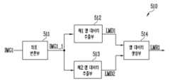
도 1을 참조하면, 본 발명의 실시예들에 따른 표시 장치(1000)는 타이밍 제어부(100), 데이터 구동부(200), 주사 구동부(300), 화소부(400), 및 이미지 변환부(500)를 포함할 수 있다.Referring to FIG. 1, a display device (1000) according to embodiments of the present invention may include a timing control unit (100), a data driving unit (200), a scan driving unit (300), a pixel unit (400), and an image conversion unit (500).
타이밍 제어부(100)는 외부 프로세서로부터 각각의 제1 이미지(프레임)에 대한 계조들 및 제어 신호들을 수신할 수 있다. 예를 들어, 정지 영상의 경우, 연속된 제1 이미지들의 계조들이 실질적으로 동일할 수 있다. 예를 들어, 동영상의 경우, 연속된 제1 이미지들의 계조들이 실질적으로 다를 수 있다. 한편, 동영상 중 일부분이 로고(logo)와 같은 정지 영역일 수도 있다.The timing control unit (100) can receive gradations and control signals for each first image (frame) from an external processor. For example, in the case of a still image, gradations of consecutive first images can be substantially the same. For example, in the case of a video, gradations of consecutive first images can be substantially different. Meanwhile, a part of the video can be a still area such as a logo.
이미지 변환부(500)는 제1 이미지 중 로고의 계조들을 보정하여 제2 이미지를 생성할 수 있다.The image conversion unit (500) can generate a second image by correcting the gradations of the logo in the first image.
일 실시예에서, 이미지 변환부(500)는 제1 이미지 중 로고 보다 큰 로고 영역에 대응하는 맵 데이터(map data)들을 생성(또는, 추출)하고, 생성된 맵 데이터들을 이용하여 로고의 계조들을 보정할 수 있다.In one embodiment, the image conversion unit (500) can generate (or extract) map data corresponding to a logo area larger than the logo in the first image, and correct the gradations of the logo using the generated map data.
예를 들어, 이미지 변환부(500)는 제1 이미지 중 컬러(color) 성분을 포함하는 제1 로고에 대응하는 제1 맵 데이터를 생성할 수 있다. 또한, 이미지 변환부(500)는 제1 이미지 중 백색(white) 성분을 포함하는 제2 로고에 대응하는 제2 맵 데이터를 생성할 수 있다. 또한, 이미지 변환부(500)는 제1 맵 데이터와 제2 맵 데이터를 이용하여, 제3 맵 데이터를 생성할 수 있다. 또한, 이미지 변환부(500)는 제3 맵 데이터에 기초하여 로고(예를 들어, 제1 로고 및/또는 제2 로고)에 대응하는 화소들을 특정할 수 있다. 또한, 이미지 변환부(500)는 로고로 특정된 화소들의 계조들을 보정하여 제2 이미지를 생성할 수 있다.For example, the image conversion unit (500) can generate first map data corresponding to a first logo including a color component among the first image. In addition, the image conversion unit (500) can generate second map data corresponding to a second logo including a white component among the first image. In addition, the image conversion unit (500) can generate third map data using the first map data and the second map data. In addition, the image conversion unit (500) can specify pixels corresponding to a logo (e.g., the first logo and/or the second logo) based on the third map data. In addition, the image conversion unit (500) can correct the gradations of pixels specified as a logo to generate a second image.
타이밍 제어부(100)는 제2 이미지의 계조들을 데이터 구동부(200)로 제공할 수 있다. 또한, 타이밍 제어부(100)는 제2 이미지의 표시를 위하여 데이터 구동부(200), 주사 구동부(300) 등에 각각의 사양에 적합한 제어 신호들을 제공할 수 있다.The timing control unit (100) can provide the gradations of the second image to the data driving unit (200). In addition, the timing control unit (100) can provide control signals suitable for each specification to the data driving unit (200), the scan driving unit (300), etc., for displaying the second image.
한편, 도 1에서는 타이밍 제어부(100)와 이미지 변환부(500)가 별도의 구성인 것으로 도시되었으나, 이는 설명의 편의를 위한 예시적인 것으로서, 타이밍 제어부(100)와 이미지 변환부(500)는 일체로 구성될 수 있다. 예를 들어, 이미지 변환부(500)는 타이밍 제어부(100)에 내장된 형태로 구현될 수 있다.Meanwhile, in Fig. 1, the timing control unit (100) and the image conversion unit (500) are illustrated as separate components, but this is an example for convenience of explanation, and the timing control unit (100) and the image conversion unit (500) may be configured as one unit. For example, the image conversion unit (500) may be implemented in a form built into the timing control unit (100).
데이터 구동부(200)는 제2 이미지에 대응하는 데이터 신호들을 화소들로 제공할 수 있다. 예를 들어, 데이터 구동부(200)는 제2 이미지의 계조들 및 제어 신호들을 이용하여 데이터 라인들(DL1, DL2, DL3, ..., DLn)로 제공할 데이터 신호들을 생성할 수 있다. 예를 들어, 데이터 구동부(200)는 클록 신호를 이용하여 계조들을 샘플링하고, 계조들에 대응하는 데이터 신호들을 화소행 단위로 데이터 라인들(DL1~DLn)에 인가할 수 있다. 화소행은 동일한 주사 라인에 연결된 화소들을 의미할 수 있다. n은 0보다 큰 정수일 수 있다.The data driving unit (200) can provide data signals corresponding to the second image to pixels. For example, the data driving unit (200) can generate data signals to be provided to data lines (DL1, DL2, DL3, ..., DLn) using gradations and control signals of the second image. For example, the data driving unit (200) can sample gradations using a clock signal and apply data signals corresponding to the gradations to the data lines (DL1 to DLn) in pixel row units. A pixel row can mean pixels connected to the same scan line. n can be an integer greater than 0.
주사 구동부(300)는 타이밍 제어부(100)로부터 클록 신호, 주사 시작 신호 등을 수신하여, 주사 라인들(SL1, SL2, SL3, ..., SLm)에 제공할 주사 신호들을 생성할 수 있다. m은 0보다 큰 정수일 수 있다.The injection driving unit (300) can receive a clock signal, an injection start signal, etc. from the timing control unit (100) and generate injection signals to be provided to the injection lines (SL1, SL2, SL3, ..., SLm). m can be an integer greater than 0.
주사 구동부(300)는 주사 라인들(SL1~SLm)에 턴-온 레벨의 펄스를 갖는 주사 신호들을 순차적으로 공급할 수 있다. 예를 들어, 주사 구동부(300)는 시프트 레지스터(shift register) 형태로 구성된 주사 스테이지들을 포함할 수 있다. 주사 구동부(300)는 클록 신호의 제어에 따라 턴-온 레벨의 펄스 형태인 주사 시작 신호를 다음 주사 스테이지로 순차적으로 전달하는 방식으로 주사 신호들을 생성할 수 있다.The scan driver (300) can sequentially supply scan signals having pulses of a turn-on level to the scan lines (SL1 to SLm). For example, the scan driver (300) can include scan stages configured in the form of a shift register. The scan driver (300) can generate scan signals by sequentially transmitting scan start signals in the form of pulses of a turn-on level to the next scan stage under the control of a clock signal.
화소부(400)는 화소들을 포함할 수 있다. 각각의 화소(PXij)는 대응하는 데이터 라인 및 주사 라인에 연결될 수 있다. i 및 j는 0보다 큰 정수일 수 있다. 화소(PXij)는 스캔 트랜지스터가 i 번째 주사 라인 및 j 번째 데이터 라인과 연결된 화소를 의미할 수 있다. 한편, 각각의 화소(PXij)는 외부로부터 제1 전원(VDD) 및 제2 전원(VSS)의 전압들을 공급받을 수 있다. 여기서, 제1 전원(VDD)과 제2 전원(VSS)은 화소들의 동작에 필요한 전압들이다. 예를 들어, 제1 전원(VDD)은 제2 전원(VSS)의 전압 레벨보다 높은 전압 레벨을 가질 수 있다.The pixel unit (400) may include pixels. Each pixel (PXij) may be connected to a corresponding data line and a scan line. i and j may be integers greater than 0. The pixel (PXij) may mean a pixel in which a scan transistor is connected to an i-th scan line and a j-th data line. Meanwhile, each pixel (PXij) may receive voltages of a first power supply (VDD) and a second power supply (VSS) from the outside. Here, the first power supply (VDD) and the second power supply (VSS) are voltages required for the operation of the pixels. For example, the first power supply (VDD) may have a voltage level higher than the voltage level of the second power supply (VSS).
도 2는 도 1의 표시 장치에 포함되는 화소의 일 예를 나타내는 회로도이다.FIG. 2 is a circuit diagram showing an example of pixels included in the display device of FIG. 1.
도 2를 참조하면, 화소(PXij)는 발광 소자(LD) 및 이에 연결되어 발광 소자(LD)를 구동하는 구동 회로(DC)를 포함할 수 있다.Referring to FIG. 2, a pixel (PXij) may include a light-emitting element (LD) and a driving circuit (DC) connected thereto to drive the light-emitting element (LD).
발광 소자(LD)의 제1 전극(예컨대, 애노드 전극)은 구동 회로(DC)를 경유하여 제1 전원(VDD)에 연결될 수 있고, 발광 소자(LD)의 제2 전극(예컨대, 캐소드 전극)은 제2 전원(VSS)에 연결될 수 있다. 발광 소자(LD)는 구동 회로(DC)에 의해 제어되는 구동 전류량에 상응하는 휘도로 발광할 수 있다.A first electrode (e.g., an anode electrode) of a light-emitting element (LD) can be connected to a first power supply (VDD) via a driving circuit (DC), and a second electrode (e.g., a cathode electrode) of the light-emitting element (LD) can be connected to a second power supply (VSS). The light-emitting element (LD) can emit light with a brightness corresponding to an amount of driving current controlled by the driving circuit (DC).
발광 소자(LD)는 유기 발광 다이오드(organic light emitting diode)로 선택될 수 있다. 또한, 발광 소자(LD)는 마이크로 LED(light emitting diode), 양자점 발광 다이오드(quantum dot light emitting diode)와 같은 무기 발광 다이오드(inorganic light emitting diode)로 선택될 수 있다. 또한, 발광 소자(LD)는 유기물과 무기물이 복합적으로 구성된 소자일 수도 있다. 도 2에서는 화소(PXij)가 단일(single) 발광 소자(LD)를 포함하는 것을 도시되어 있으나, 다른 실시예에서 화소(PXij)는 복수의 발광 소자들을 포함하며, 복수의 발광 소자들은 상호 직렬, 병렬, 또는, 직병렬로 연결될 수 있다.The light emitting element (LD) may be selected as an organic light emitting diode. In addition, the light emitting element (LD) may be selected as an inorganic light emitting diode such as a micro LED (light emitting diode) or a quantum dot light emitting diode. In addition, the light emitting element (LD) may be a device composed of a composite of an organic material and an inorganic material. Although FIG. 2 illustrates that the pixel (PXij) includes a single light emitting element (LD), in another embodiment, the pixel (PXij) includes a plurality of light emitting elements, and the plurality of light emitting elements may be connected to each other in series, in parallel, or in series-parallel.
제1 전원(VDD) 및 제2 전원(VSS)은 서로 다른 전위를 가질 수 있다. 예를 들어, 제1 전원(VDD)을 통해 인가되는 전압은 제2 전원(VSS)을 통해 인가되는 전압보다 클 수 있다.The first power supply (VDD) and the second power supply (VSS) can have different potentials. For example, the voltage applied through the first power supply (VDD) can be greater than the voltage applied through the second power supply (VSS).
구동 회로(DC)는 제1 트랜지스터(T1), 제2 트랜지스터(T2) 및 스토리지 커패시터(Cst)를 포함할 수 있다.The driving circuit (DC) may include a first transistor (T1), a second transistor (T2), and a storage capacitor (Cst).
제1 트랜지스터(T1, 구동 트랜지스터)의 제1 전극은 제1 전원(VDD)에 연결될 수 있고, 제2 전극은 발광 소자(LD)의 제1 전극(예컨대, 애노드 전극)에 전기적으로 연결될 수 있다. 제1 트랜지스터(T1)의 게이트 전극은 제1 노드(N1)에 연결될 수 있다. 제1 트랜지스터(T1)는 데이터 라인(DLj)을 통해 제1 노드(N1)로 공급되는 데이터 신호에 대응하여 발광 소자(LD)로 공급되는 구동 전류량을 제어할 수 있다.A first electrode of a first transistor (T1, driving transistor) may be connected to a first power source (VDD), and a second electrode may be electrically connected to a first electrode (e.g., an anode electrode) of a light-emitting element (LD). A gate electrode of the first transistor (T1) may be connected to a first node (N1). The first transistor (T1) may control an amount of driving current supplied to the light-emitting element (LD) in response to a data signal supplied to the first node (N1) through a data line (DLj).
제2 트랜지스터(T2, 스위칭 트랜지스터)의 제1 전극은 데이터 라인(DLj)에 연결되고, 제2 전극은 제1 노드(N1)에 연결될 수 있다. 제2 트랜지스터(T2)의 게이트 전극은 주사 라인(SLi)에 연결될 수 있다.A first electrode of a second transistor (T2, switching transistor) may be connected to a data line (DLj), and a second electrode may be connected to a first node (N1). A gate electrode of the second transistor (T2) may be connected to a scan line (SLi).
제2 트랜지스터(T2)는 주사 라인(SLi)으로부터 제2 트랜지스터(T2)가 턴-온될 수 있는 전압(예컨대, 게이트 온 전압)의 주사 신호가 공급될 때 턴-온되어, 데이터 라인(DLj)과 제1 노드(N1)를 전기적으로 연결할 수 있다. 이때, 데이터 라인(DLj)으로는 해당 프레임의 데이터 신호가 공급되고, 이에 따라 제1 노드(N1)로 데이터 신호가 전달될 수 있다. 제1 노드(N1)로 전달된 데이터 신호에 대응하는 전압이 스토리지 커패시터(Cst)에 저장될 수 있다.The second transistor (T2) is turned on when a scan signal of a voltage (e.g., a gate-on voltage) that can turn on the second transistor (T2) is supplied from the scan line (SLi), thereby electrically connecting the data line (DLj) and the first node (N1). At this time, a data signal of a corresponding frame is supplied to the data line (DLj), and thus the data signal can be transmitted to the first node (N1). A voltage corresponding to the data signal transmitted to the first node (N1) can be stored in the storage capacitor (Cst).
스토리지 커패시터(Cst)의 일 전극은 제1 노드(N1)에 연결될 수 있고, 다른 전극은 발광 소자(LD)의 제1 전극에 연결될 수 있다. 이와 같은 스토리지 커패시터(Cst)는 제1 노드(N1)로 공급되는 데이터 신호에 대응하는 전압으로 충전될 수 있고, 다음 프레임의 데이터 신호가 공급될 때까지 충전된 전압을 유지할 수 있다.One electrode of the storage capacitor (Cst) may be connected to the first node (N1), and the other electrode may be connected to the first electrode of the light emitting element (LD). Such a storage capacitor (Cst) may be charged with a voltage corresponding to a data signal supplied to the first node (N1), and may maintain the charged voltage until the data signal of the next frame is supplied.
한편, 도 2에서는 설명의 편의를 위해 비교적 단순한 형태의 화소(PXij)를 도시한 것이며, 구동 회로(DC)의 구조는 다양하게 변경 실시될 수 있다. 일 예로, 구동 회로(DC)는 제1 트랜지스터(T1)의 문턱전압을 보상하기 위한 보상 트랜지스터, 제1 노드(N1)를 초기화하기 위한 초기화 트랜지스터, 및/또는 발광 소자(LD)의 발광 시간을 제어하기 위한 발광 제어 트랜지스터 등과 같은 각종 트랜지스터나, 제1 노드(N1)의 전압을 부스팅하기 위한 부스팅 커패시터 등과 같은 다른 회로 소자들을 추가적으로 더 포함할 수도 있다.Meanwhile, in Fig. 2, a relatively simple pixel (PXij) is illustrated for convenience of explanation, and the structure of the driving circuit (DC) may be variously changed. For example, the driving circuit (DC) may additionally include various transistors, such as a compensation transistor for compensating for the threshold voltage of the first transistor (T1), an initialization transistor for initializing the first node (N1), and/or a light-emitting control transistor for controlling the light-emitting time of the light-emitting element (LD), or other circuit elements, such as a boosting capacitor for boosting the voltage of the first node (N1).
또한, 도 2에서는 구동 회로(DC)에 포함되는 트랜지스터들, 예컨대 제1 및 제2 트랜지스터들(T1, T2)이 모두 N타입의 트랜지스터들인 것으로 도시되었으나, 본 발명이 이에 한정되지는 않는다. 즉, 구동 회로(DC)에 포함되는 제1 및 제2 트랜지스터들(T1, T2) 중 적어도 하나는 P타입의 트랜지스터로 변경될 수도 있다.In addition, although in Fig. 2, the transistors included in the driving circuit (DC), for example, the first and second transistors (T1, T2), are all illustrated as being N-type transistors, the present invention is not limited thereto. That is, at least one of the first and second transistors (T1, T2) included in the driving circuit (DC) may be changed to a P-type transistor.
도 3은 제1 이미지, 로고 영역, 제1 로고, 및 제2 로고를 설명하기 위한 도면이다.Figure 3 is a drawing for explaining the first image, the logo area, the first logo, and the second logo.
도 1 및 도 3을 참조하면, 도 3에는 화소부(400)가 예시적인 제1 이미지(IMG1)를 표시하는 경우가 도시된다. 제1 이미지(IMG1)는 화소부(400)의 화소들 각각에 대한 계조들을 포함하는 데이터일 수 있다. 여기서, 하나의 제1 이미지(IMG1)는 하나의 프레임에 대응할 수 있다. 또한, 하나의 제1 이미지(IMG1)가 표시되는 기간을 한 프레임 기간이라고 할 수 있다. 이때, 프레임 기간의 시작 시점 및 종료 시점은 화소행마다 다를 수 있다. 예를 들어, 화소행의 스캔 트랜지스터들이 턴-온되어 현재 제1 이미지(IMG1)에 대응하는 데이터 신호들을 수신하는 시점이 해당 화소행의 프레임 기간의 시작 시점이고, 스캔 트랜지스터들이 다시 턴-온되어 다음 제1 이미지(IMG1)에 대응하는 데이터 신호들을 수신하는 시점이 해당 화소행의 프레임 기간의 종료 시점일 수 있다.Referring to FIGS. 1 and 3, FIG. 3 illustrates a case where a pixel unit (400) displays an exemplary first image (IMG1). The first image (IMG1) may be data including grayscales for each pixel of the pixel unit (400). Here, one first image (IMG1) may correspond to one frame. In addition, a period during which one first image (IMG1) is displayed may be referred to as one frame period. At this time, the start and end times of the frame period may be different for each pixel row. For example, a point in time when the scan transistors of a pixel row are turned on and receive data signals corresponding to the current first image (IMG1) may be the start time of the frame period of the corresponding pixel row, and a point in time when the scan transistors are turned on again and receive data signals corresponding to the next first image (IMG1) may be the end time of the frame period of the corresponding pixel row.
로고(예를 들어, 제1 로고(LG1) 및/또는 제2 로고(LG2))는 연속된 제1 이미지들(IMG1)에서 위치 및 계조가 유지되는 정지 영역일 수 있다. 예를 들어, 제1 로고(LG1)는 컬러 성분을 포함하는 로고일 수 있으며, 제2 로고(LG2)는 백색 성분을 포함하는 로고일 수 있다. 한편, 제1 로고(LG1)는 제2 로고(LG2)의 일부(도 3의 "S" 자)를 둘러싸는 형태로 표시될 수 있다.The logo (e.g., the first logo (LG1) and/or the second logo (LG2)) may be a still area whose position and gradation are maintained in the successive first images (IMG1). For example, the first logo (LG1) may be a logo including a color component, and the second logo (LG2) may be a logo including a white component. Meanwhile, the first logo (LG1) may be displayed in a form that surrounds a part of the second logo (LG2) (the letter "S" in FIG. 3).
로고 영역(LGA)은 로고들(LG1, LG2)을 포함하고, 로고들(LG1, LG2) 보다 큰 영역일 수 있다. 예를 들어, 로고 영역(LGA)은 사각형의 영역일 수 있다. 다만, 사각형은 x/y 축 기준의 좌표 값들로 로고 영역(LGA)을 보다 쉽게 정의하기 위한 것일 뿐, 다른 실시예에서 로고 영역(LGA)은 원형, 타원형 등 다른 형상으로 정의될 수도 있다. 로고 영역(LGA) 중 로고들(LG1, LG2)가 아닌 영역을 배경이라고 정의할 수 있다.The logo area (LGA) includes the logos (LG1, LG2) and may be a larger area than the logos (LG1, LG2). For example, the logo area (LGA) may be a rectangular area. However, the rectangular area is merely for more easily defining the logo area (LGA) with coordinate values based on the x/y axes, and in other embodiments, the logo area (LGA) may be defined as another shape such as a circle or an oval. An area of the logo area (LGA) other than the logos (LG1, LG2) may be defined as a background.
도 4는 도 1의 표시 장치에 포함되는 이미지 변환부의 일 예를 나타내는 블록도이고, 도 5는 도 4의 이미지 변환부에 포함되는 제1 로고 검출부의 일 예를 나타내는 블록도이다. 도 6a 및 도 6b는 도 5의 제1 로고 검출부에 포함되는 제1 맵 데이터 추출부에 의해 생성된 제1 서브 맵 데이터의 일 예를 설명하기 위한 도면들이다. 도 7a 및 도 7b는 도 5의 제1 로고 검출부에 포함되는 제2 맵 데이터 추출부에 의해 생성된 제2 서브 맵 데이터의 일 예를 설명하기 위한 도면들이다. 도 8은 도 5의 제1 로고 검출부에 포함되는 맵 데이터 생성부에 의해 생성된 제1 맵 데이터의 일 예를 설명하기 위한 도면들이다. 도 9a 및 도 9b는 도 4의 이미지 변환부에 포함되는 제2 로고 검출부에 의해 생성된 제2 맵 데이터의 일 예를 설명하기 위한 도면들이다. 도 10은 도 4의 이미지 변환부에 포함되는 로고 결정부에 의해 생성된 제3 맵 데이터의 일 예를 설명하기 위한 도면이다.FIG. 4 is a block diagram showing an example of an image conversion unit included in the display device of FIG. 1, and FIG. 5 is a block diagram showing an example of a first logo detection unit included in the image conversion unit of FIG. 4. FIGS. 6A and 6B are drawings for explaining an example of first sub-map data generated by a first map data extraction unit included in the first logo detection unit of FIG. 5. FIGS. 7A and 7B are drawings for explaining an example of second sub-map data generated by a second map data extraction unit included in the first logo detection unit of FIG. 5. FIG. 8 is a drawing for explaining an example of first map data generated by a map data generation unit included in the first logo detection unit of FIG. 5. FIGS. 9A and 9B are drawings for explaining an example of second map data generated by a second logo detection unit included in the image conversion unit of FIG. 4. FIG. 10 is a drawing for explaining an example of third map data generated by a logo determination unit included in the image conversion unit of FIG. 4.
도 3 및 도 4를 참조하면, 본 발명의 실시예들에 따른 이미지 변환부(500)는 제1 로고 검출부(510), 제2 로고 검출부(520), 로고 결정부(530), 및 계조 변환부(540)를 포함할 수 있다.Referring to FIGS. 3 and 4, the image conversion unit (500) according to embodiments of the present invention may include a first logo detection unit (510), a second logo detection unit (520), a logo determination unit (530), and a grayscale conversion unit (540).
일 실시예에서, 이미지 변환부(500)는 제1 이미지(IMG1) 중 로고 영역(LGA)에 대응하는 맵 데이터들(제1 내지 제3 맵 데이터들(LMR1, LMR2, LMF))을 생성(또는, 추출)하고, 생성된 맵 데이터들(LMR1, LMR2, LMF)을 이용하여 제1 로고(LG1) 및/또는 제2 로고(LG2)의 계조들을 보정할 수 있다.In one embodiment, the image conversion unit (500) generates (or extracts) map data (first to third map data (LMR1, LMR2, LMF)) corresponding to the logo area (LGA) of the first image (IMG1), and can correct the gradations of the first logo (LG1) and/or the second logo (LG2) using the generated map data (LMR1, LMR2, LMF).
예를 들어, 이미지 변환부(500)는 제1 이미지(IMG1) 중 컬러 성분을 포함하는 제1 로고(LG1)에 대응하는 제1 맵 데이터(LMR1)를 생성할 수 있다. 또한, 이미지 변환부(500)는 제1 이미지(IMG1) 중 백색 성분을 포함하는 제2 로고(LG2)에 대응하는 제2 맵 데이터(LMR2)를 생성할 수 있다. 또한, 이미지 변환부(500)는 제1 맵 데이터(LMR1)와 제2 맵 데이터(LMR2)를 이용하여, 제3 맵 데이터(LMF)를 생성할 수 있다. 또한, 이미지 변환부(500)는 제3 맵 데이터(LMF)에 기초하여 제1 로고(LG1) 및/또는 제2 로고(LG2)에 대응하는 화소들을 특정할 수 있다. 또한, 이미지 변환부(500)는 제1 로고(LG1) 및/또는 제2 로고(LG2)로 특정된 화소들의 계조들을 보정하여 제2 이미지(IMG2)를 생성할 수 있다.For example, the image conversion unit (500) can generate first map data (LMR1) corresponding to the first logo (LG1) including the color component among the first image (IMG1). In addition, the image conversion unit (500) can generate second map data (LMR2) corresponding to the second logo (LG2) including the white component among the first image (IMG1). In addition, the image conversion unit (500) can generate third map data (LMF) using the first map data (LMR1) and the second map data (LMR2). In addition, the image conversion unit (500) can specify pixels corresponding to the first logo (LG1) and/or the second logo (LG2) based on the third map data (LMF). Additionally, the image conversion unit (500) can generate a second image (IMG2) by correcting the gradations of pixels specified as the first logo (LG1) and/or the second logo (LG2).
제1 로고 검출부(510)는 제1 이미지(IMG1) 중 제1 로고(LG1)를 검출하여 제1 로고(LG1)에 대응하는 제1 맵 데이터(LMR1)를 생성할 수 있다.The first logo detection unit (510) can detect the first logo (LG1) among the first image (IMG1) and generate first map data (LMR1) corresponding to the first logo (LG1).
일 실시예에서, 제1 로고 검출부(510)는 컬러 성분을 포함하는 제1 로고(LG1)를 검출하기 위하여, 제1 이미지(IMG1)를 RGB 색공간 좌표에서 HSV 색공간 좌표로 변환하고, 변환된 제1 이미지(IMG1)(이하, 제3 이미지라고 함) 중 로고 영역(LGA)에서의 명도(Value)와 채도(Saturation)에 기초하여 제1 로고(LG1)를 검출할 수 있다.In one embodiment, the first logo detection unit (510) may detect a first logo (LG1) including a color component by converting the first image (IMG1) from RGB color space coordinates to HSV color space coordinates, and detecting the first logo (LG1) based on brightness (Value) and saturation (Saturation) in a logo area (LGA) of the converted first image (IMG1) (hereinafter, referred to as a third image).
제1 로고 검출부(510)의 구성 및 동작에 대해 구체적으로 설명하기 위하여 도 5를 더 참조하면, 제1 로고 검출부(510)는 좌표 변환부(511), 제1 맵 데이터 추출부(512), 제2 맵 데이터 추출부(513), 및 맵 데이터 생성부(514)를 포함할 수 있다.Referring further to FIG. 5 to specifically explain the configuration and operation of the first logo detection unit (510), the first logo detection unit (510) may include a coordinate transformation unit (511), a first map data extraction unit (512), a second map data extraction unit (513), and a map data generation unit (514).
좌표 변환부(511)는 RGB 색공간 좌표의 제1 이미지(IMG1)를 HSV 색공간 좌표의 제3 이미지(IMG1_1)로 변환할 수 있다. 표시 장치(예를 들어, 도 1의 표시 장치(1000))의 각각의 화소(예를 들어, 도 2의 화소(PXij))는 적색(Red)의 광을 방출하는 서브 화소, 녹색(Green)의 광을 방출하는 서브 화소, 및 청색(Blue)의 광을 방출하는 서브 화소로 구성되므로, 제1 이미지(IMG1)는 적색, 녹색, 및 청색의 RGB 색공간 좌표로 표현될 수 있다. 컬러 성분의 제1 로고(LG1) 검출을 위하여, 좌표 변환부(511)는 RGB 색공간 좌표의 제1 이미지(IMG1)를 변환하여, 색상(Hue), 채도(Saturation), 및 명도(Value)의 HSV 색공간 좌표의 제3 이미지(IMG1_1)를 생성할 수 있다.The coordinate transformation unit (511) can transform the first image (IMG1) of the RGB color space coordinates into the third image (IMG1_1) of the HSV color space coordinates. Since each pixel (for example, the pixel (PXij) of FIG. 2) of the display device (for example, the display device (1000) of FIG. 1) is composed of a sub-pixel that emits red light, a sub-pixel that emits green light, and a sub-pixel that emits blue light, the first image (IMG1) can be expressed in the RGB color space coordinates of red, green, and blue. In order to detect the first logo (LG1) of the color component, the coordinate transformation unit (511) can transform the first image (IMG1) of the RGB color space coordinates to generate the third image (IMG1_1) of the HSV color space coordinates of hue, saturation, and value.
제1 맵 데이터 추출부(512)는 HSV 색공간 좌표의 제3 이미지(IMG1_1)에 기초하여, 제1 서브 맵 데이터(LMD1)를 생성(또는, 추출)할 수 있다.The first map data extraction unit (512) can generate (or extract) the first sub-map data (LMD1) based on the third image (IMG1_1) of HSV color space coordinates.
일 실시예에서, 제1 맵 데이터 추출부(512)는 로고 영역(LGA)에서 기설정된 기준 명도(threshold value) 값 이상의 명도 값을 가지는 영역에 기초하여 제1 서브 맵 데이터(LMD1)를 생성할 수 있다.In one embodiment, the first map data extraction unit (512) can generate first sub-map data (LMD1) based on an area having a brightness value higher than a preset threshold value in the logo area (LGA).
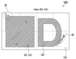
예를 들어, 도 6a 및 도 6b에 도시된 바와 같이, 제1 맵 데이터 추출부(512)는 로고 영역(LGA) 중 기준 명도 값(Vth)인 714 이상의 명도 값을 가지는 화소들을 추출하여 도 6b에 도시된 제1 서브 맵 데이터(LMD1)를 생성할 수 있다. 여기서, 기준 명도 값(Vth)은 실험 등에 의하여 기설정된 값일 수 있으며, 714의 값은 예시적인 것으로 기준 명도 값(Vth)이 이에 한정되는 것은 아니다.For example, as illustrated in FIGS. 6A and 6B, the first map data extraction unit (512) may extract pixels having a brightness value of 714 or higher, which is a reference brightness value (Vth), from among the logo area (LGA), to generate the first sub-map data (LMD1) illustrated in FIG. 6B. Here, the reference brightness value (Vth) may be a value preset by experiment, etc., and the value of 714 is exemplary and the reference brightness value (Vth) is not limited thereto.
한편, 컬러 성분을 포함하는 제1 로고(LG1)뿐만 아니라, 백색 성분을 포함하는 제2 로고(LG2) 또한 명도 값이 높을 수 있으며, 제1 이미지(IMG1)에 의해 표시되는 영상에 따라 로고 영역(LGA) 중 제1 및 제2 로고들(LG1, LG2)을 제외한 영역(또는, 배경)에서 비교적 밝은 이미지가 표시되는 경우 해당 영역에서의 명도 값이 높을 수 있다. 이 경우, 제1 서브 맵 데이터(LMD1) 상에서는 기준 명도 값(Vth) 이상의 화소들로 제1 로고(LG1)에 대응하는 화소들뿐만 아니라 제2 로고(LG2) 및/또는 밝은 이미지가 표시되는 영역(또는, 노이즈 영역(NS))에 대응하는 화소들이 추출될 수 있다.Meanwhile, not only the first logo (LG1) including the color component, but also the second logo (LG2) including the white component may have a high brightness value, and when a relatively bright image is displayed in an area (or background) excluding the first and second logos (LG1, LG2) among the logo areas (LGA) depending on the image displayed by the first image (IMG1), the brightness value in the area may be high. In this case, on the first sub map data (LMD1), not only pixels corresponding to the first logo (LG1) but also pixels corresponding to the second logo (LG2) and/or the area (or noise area (NS)) where the bright image is displayed may be extracted as pixels having a brightness value higher than or equal to the reference brightness value (Vth).
제2 맵 데이터 추출부(513)는 HSV 색공간 좌표의 제3 이미지(IMG1_1)에 기초하여, 제2 서브 맵 데이터(LMD2)를 생성(또는, 추출)할 수 있다.The second map data extraction unit (513) can generate (or extract) second sub-map data (LMD2) based on the third image (IMG1_1) of HSV color space coordinates.
일 실시예에서, 제2 맵 데이터 추출부(513)는 로고 영역(LGA)에서 기설정된 기준 채도(threshold saturation) 값 이상의 채도 값을 가지는 영역에 기초하여 제2 서브 맵 데이터(LMD2)를 생성할 수 있다.In one embodiment, the second map data extraction unit (513) can generate second sub-map data (LMD2) based on an area having a saturation value higher than a preset threshold saturation value in the logo area (LGA).
예를 들어, 도 7a 및 도 7b에 도시된 바와 같이, 제2 맵 데이터 추출부(513)는 로고 영역(LGA) 중 기준 채도 값(Sth)인 0.5 이상의 명도 값을 가지는 화소들을 추출하여 도 7b에 도시된 제2 서브 맵 데이터(LMD2)를 생성할 수 있다. 여기서, 기준 채도 값(Sth)은 실험 등에 의하여 기설정된 값일 수 있으며, 0.5의 값은 예시적인 것으로 기준 채도 값(Sth)이 이에 한정되는 것은 아니다.For example, as illustrated in FIGS. 7A and 7B, the second map data extraction unit (513) may extract pixels having a brightness value of 0.5 or higher, which is a reference saturation value (Sth), from among the logo area (LGA), to generate the second sub-map data (LMD2) illustrated in FIG. 7B. Here, the reference saturation value (Sth) may be a value preset by experiment, etc., and the value of 0.5 is exemplary, and the reference saturation value (Sth) is not limited thereto.
한편, 컬러 성분을 포함하는 제1 로고(LG1)뿐만 아니라, 제1 이미지(IMG1)에 의해 표시되는 영상에 따라 로고 영역(LGA) 중 제1 및 제2 로고들(LG1, LG2)을 제외한 영역(또는, 배경)에서 높은 채도의 이미지가 표시되는 경우가 있을 수 있다. 이 경우, 제2 서브 맵 데이터(LMD2) 상에서는 기준 채도 값(Sth) 이상의 화소들로 제1 로고(LG1)에 대응하는 화소들뿐만 아니라 높은 채도의 이미지가 표시되는 영역(또는, 노이즈 영역(NS))에 대응하는 화소들이 추출될 수 있다.Meanwhile, there may be cases where a high-saturation image is displayed in an area (or background) excluding the first and second logos (LG1, LG2) among the logo area (LGA) according to an image displayed by the first image (IMG1) as well as the first logo (LG1) including a color component. In this case, on the second sub-map data (LMD2), pixels corresponding to the area (or noise area (NS)) where a high-saturation image is displayed as well as pixels corresponding to the first logo (LG1) with pixels higher than the reference saturation value (Sth) can be extracted.
맵 데이터 생성부(514)는 컬러 성분을 포함하는 제1 로고(LG1)를 검출하여 제1 로고(LG1)에 대응하는 제1 맵 데이터(LMR1)를 생성할 수 있다.The map data generation unit (514) can detect a first logo (LG1) including a color component and generate first map data (LMR1) corresponding to the first logo (LG1).
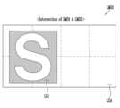
일 실시예에서, 맵 데이터 생성부(514)는 제1 서브 맵 데이터(LMD1)와 제2 서브 맵 데이터(LMD2)를 이용하여 제1 맵 데이터(LMR1)를 생성할 수 있다. 예를 들어, 로고 영역(LGA)에서 표시되는 제1 로고(LG1)는 컬러 성분을 포함하기 때문에, 제1 로고(LG1)의 명도 값과 채도 값은 상대적으로 높을 수 있다. 맵 데이터 생성부(514)는 제1 서브 맵 데이터(LMD1)와 제2 서브 맵 데이터(LMD2)를 조합 내지 결합(Combination)하여, 도 8의 제1 맵 데이터(LMR1)를 생성할 수 있다. 예를 들어, 제1 맵 데이터(LMR1)는 도 8에 도시된 바와 같이 제1 서브 맵 데이터(LMD1)와 제2 서브 맵 데이터(LMD2)의 교집합(Intersection) 형태로 생성될 수 있다. 이에 따라, 제1 맵 데이터(LMR1) 상에서는 기준 명도 값(Vth) 이상이며 기준 채도 값(Sth) 이상인 제1 로고(LG1)에 대응하는 화소들이 추출될 수 있다. 이때, 제1 서브 맵 데이터(LMD1)와 제2 서브 맵 데이터(LMD2)가 교집합 형태로 결합되어 제1 맵 데이터(LMR1)가 생성되므로, 제1 맵 데이터(LMR1) 상에서는 노이즈 영역(예를 들어, 도 6a 및/또는 도 7a의 노이즈 영역(NS))을 제외하고 제1 로고(LG1)에 대응하는 화소들만이 정확히 추출될 수 있다.In one embodiment, the map data generation unit (514) may generate the first map data (LMR1) using the first sub-map data (LMD1) and the second sub-map data (LMD2). For example, since the first logo (LG1) displayed in the logo area (LGA) includes a color component, the brightness value and saturation value of the first logo (LG1) may be relatively high. The map data generation unit (514) may generate the first map data (LMR1) of FIG. 8 by combining or combining the first sub-map data (LMD1) and the second sub-map data (LMD2). For example, the first map data (LMR1) may be generated in the form of an intersection of the first sub-map data (LMD1) and the second sub-map data (LMD2), as illustrated in FIG. 8. Accordingly, pixels corresponding to the first logo (LG1) that are equal to or greater than the reference brightness value (Vth) and equal to or greater than the reference saturation value (Sth) can be extracted on the first map data (LMR1). At this time, since the first sub map data (LMD1) and the second sub map data (LMD2) are combined in an intersection form to generate the first map data (LMR1), only pixels corresponding to the first logo (LG1) can be accurately extracted on the first map data (LMR1) excluding a noise area (for example, a noise area (NS) of FIG. 6A and/or FIG. 7A).
다시 도 4를 참조하면, 제2 로고 검출부(520)는 제1 이미지(IMG1) 중 제2 로고(LG2)를 검출하여 제2 로고(LG2)에 대응하는 제2 맵 데이터(LMR2)를 생성할 수 있다.Referring again to FIG. 4, the second logo detection unit (520) can detect the second logo (LG2) among the first image (IMG1) and generate second map data (LMR2) corresponding to the second logo (LG2).
일 실시예에서, 제2 로고 검출부(520)는 백색 성분을 포함하는 제2 로고(LG2)를 검출하기 위하여, 기설정된 기준 백색 성분(threshold white mark) 값 이상의 백색 성분 값을 가지는 영역에 기초하여 제2 맵 데이터(LMR2)를 생성할 수 있다.In one embodiment, the second logo detection unit (520) may generate second map data (LMR2) based on an area having a white component value higher than a preset threshold white mark value in order to detect a second logo (LG2) including a white component.
예를 들어, 도 9a 및 도 9b에 도시된 바와 같이, 제2 로고 검출부(520)는 로고 영역(LGA) 중 기준 백색 성분 값(Wth)인 714 이상의 백색 성분 값을 가지는 화소들을 추출하여 도 9b에 도시된 제2 맵 데이터(LMR2)를 생성할 수 있다. 여기서, 기준 백색 성분 값(Wth)은 실험 등에 의하여 기설정된 값일 수 있으며, 714의 값은 예시적인 것으로 기준 백색 성분 값(Wth)이 이에 한정되는 것은 아니다.For example, as illustrated in FIGS. 9A and 9B, the second logo detection unit (520) may extract pixels having a white component value of 714 or higher, which is a reference white component value (Wth), among the logo area (LGA), to generate the second map data (LMR2) illustrated in FIG. 9B. Here, the reference white component value (Wth) may be a value preset by experiment, etc., and the value of 714 is exemplary and the reference white component value (Wth) is not limited thereto.
일 실시예에서, 백색 성분 값은 제1 이미지(IMG1)의 계조(gray-scale) 값일 수 있다.In one embodiment, the white component value may be a gray-scale value of the first image (IMG1).
일 실시예에서, 제2 로고 검출부(520)는 백색 성분 값뿐만 아니라 명도 값을 이용하여 제2 맵 데이터(LMR2)를 생성할 수도 있다. 예를 들어, 제2 로고 검출부(520)는 로고 영역(LGA) 중 기준 백색 성분 값(Wth)인 714 이상의 백색 성분 값을 가지며, 기준 명도 값(Vth)인 714 이상의 명도 값을 가지는 화소들을 추출하여 제2 맵 데이터(LMR2)를 생성할 수 있다. 백색 성분을 포함하는 제2 로고(LG2)의 경우 상대적으로 밝은 이미지로 표시되므로, 제2 로고 검출부(520)가 백색 성분 값뿐만 아니라 명도 값을 이용하여 제2 맵 데이터(LMR2)를 생성하는 경우, 제2 로고(LG2) 추출의 정확성이 보다 향상될 수 있다.In one embodiment, the second logo detection unit (520) may generate the second map data (LMR2) using not only the white component value but also the brightness value. For example, the second logo detection unit (520) may extract pixels having a white component value of 714 or higher, which is a reference white component value (Wth), and a brightness value of 714 or higher, which is a reference brightness value (Vth), among the logo area (LGA) to generate the second map data (LMR2). Since the second logo (LG2) including the white component is displayed as a relatively bright image, when the second logo detection unit (520) generates the second map data (LMR2) using not only the white component value but also the brightness value, the accuracy of the extraction of the second logo (LG2) can be further improved.
한편, 제1 및 제2 로고 검출부들(510, 520)은 제1 및 제2 로고들(LG1, LG2)을 추출하기 위하여 종래의 로고 검출 알고리즘을 이용할 수 있다. 예를 들어, 오츠 이진화(Otsu binarization)를 이용한 로고 검출 알고리즘이 수행될 수 있다.Meanwhile, the first and second logo detection units (510, 520) may use a conventional logo detection algorithm to extract the first and second logos (LG1, LG2). For example, a logo detection algorithm using Otsu binarization may be performed.
로고 결정부(530)는 제1 맵 데이터(LMR1)와 제2 맵 데이터(LMR2)를 이용하여 제3 맵 데이터(LMF)를 생성할 수 있다. 예를 들어, 로고 결정부(530)는 제1 맵 데이터(LMR1) 상에서 제1 로고(LG1)에 대응하여 추출된 화소들과 제2 맵 데이터(LMR2) 상에서 제2 로고(LG2)에 대응하여 추출된 화소들을 로고에 대응하는 화소들로 추출하여 제3 맵 데이터(LMF)를 생성할 수 있다. 예를 들어, 제3 맵 데이터(LMF)는 도 10에 도시된 바와 같이 제1 맵 데이터(LMR1)와 제2 맵 데이터(LMR2)의 합집합(union) 형태로 생성될 수 있다. 이때, 제1 맵 데이터(LMR1)와 제2 맵 데이터(LMR2)가 합집합 형태로 결합되어 제3 맵 데이터(LMF)가 생성되므로, 제3 맵 데이터(LMF) 상에서는 제1 로고(LG1)와 제2 로고(LG2)에 대응하는 화소들이 모두 추출될 수 있다.The logo determination unit (530) can generate the third map data (LMF) using the first map data (LMR1) and the second map data (LMR2). For example, the logo determination unit (530) can generate the third map data (LMF) by extracting pixels corresponding to the first logo (LG1) from the first map data (LMR1) and pixels corresponding to the second logo (LG2) from the second map data (LMR2) as pixels corresponding to the logos. For example, the third map data (LMF) can be generated in the form of a union of the first map data (LMR1) and the second map data (LMR2), as illustrated in FIG. 10. At this time, since the first map data (LMR1) and the second map data (LMR2) are combined in a union form to generate the third map data (LMF), all pixels corresponding to the first logo (LG1) and the second logo (LG2) can be extracted from the third map data (LMF).
계조 변환부(540)는 제3 맵 데이터(LMF)에 기초하여 제1 및 제2 로고들(LG1, LG2)에 대응하는 화소들을 특정하고, 제1 이미지(IMG1) 중 특정된 화소들의 계조들을 변환하여 제2 이미지(IMG2)를 생성할 수 있다.The tone conversion unit (540) can specify pixels corresponding to the first and second logos (LG1, LG2) based on the third map data (LMF) and convert the tone of the specified pixels in the first image (IMG1) to generate a second image (IMG2).
계조 변환부(540)는 제1 이미지(IMG1) 중 제1 및 제2 로고들(LG1, LG2)에 대응하는 화소들의 계조들을 감소시켜 제2 이미지(IMG2)를 생성할 수 있다. 이에 따라, 연속된 프레임 기간들 중 제1 및 제2 로고들(LG1, LG2)에 대응하는 화소들의 발광 휘도가 감소하여 잔상이 방지될 수 있다.The gradation conversion unit (540) can generate a second image (IMG2) by reducing the gradations of pixels corresponding to the first and second logos (LG1, LG2) among the first image (IMG1). Accordingly, the light emission brightness of pixels corresponding to the first and second logos (LG1, LG2) during consecutive frame periods can be reduced, thereby preventing afterimages.
도 4 및 도 5를 참조하여 설명한 바와 같이, 이미지 변환부(500)는 로고 영역(LGA)의 제1 로고(LG1)와 제2 로고(LG2)를 정확히 추출하고, 로고 영역(LGA) 중 백색 성분을 포함하는 제2 로고(LG2)뿐만 아니라 컬러 성분을 포함하는 제1 로고(LG1)에 대응하는 화소들의 계조들을 보정함으로써, 로고 영역(LGA)에서의 화소 열화 및 잔상 발생이 제거(또는, 저감)될 수 있다.As described with reference to FIGS. 4 and 5, the image conversion unit (500) accurately extracts the first logo (LG1) and the second logo (LG2) of the logo area (LGA), and corrects the gradations of pixels corresponding to the first logo (LG1) including a color component as well as the second logo (LG2) including a white component in the logo area (LGA), thereby eliminating (or reducing) pixel degradation and afterimage occurrence in the logo area (LGA).
이상의 상세한 설명은 본 발명을 예시하고 설명하는 것이다. 또한, 전술한 내용은 본 발명의 바람직한 실시 형태를 나타내고 설명하는 것에 불과하며, 전술한 바와 같이 본 발명은 다양한 다른 조합, 변경 및 환경에서 사용할 수 있으며, 본 명세서에 개시된 발명의 개념의 범위, 저술한 개시 내용과 균등한 범위 및/또는 당업계의 기술 또는 지식의 범위 내에서 변경 또는 수정이 가능하다. 따라서, 이상의 발명의 상세한 설명은 개시된 실시 상태로 본 발명을 제한하려는 의도가 아니다. 또한, 첨부된 청구범위는 다른 실시 상태도 포함하는 것으로 해석되어야 한다.The above detailed description is intended to illustrate and explain the present invention. In addition, the above description merely illustrates and describes preferred embodiments of the present invention, and as described above, the present invention can be used in various other combinations, modifications, and environments, and can be changed or modified within the scope of the inventive concept disclosed herein, the scope equivalent to the written disclosure, and/or the scope of technology or knowledge in the art. Therefore, the above detailed description of the invention is not intended to limit the present invention to the disclosed embodiments. In addition, the appended claims should be construed to include other embodiments.
100: 타이밍 제어부200: 데이터 구동부
300: 주사 구동부400: 화소부
500: 이미지 변환부510: 제1 로고 검출부
511: 좌표 변환부512: 제1 맵 데이터 추출부
513: 제2 맵 데이터 추출부514: 맵 데이터 생성부
520: 제2 로고 검출부530: 로고 결정부
540: 계조 변환부1000: 표시 장치
Cst: 스토리지 커패시터LD: 발광 소자
T1: 제1 트랜지스터T2: 제2 트랜지스터
PXij: 화소100: Timing control unit 200: Data driving unit
300: Injection driver 400: Pixel unit
500: Image conversion unit 510: First logo detection unit
511: Coordinate transformation section 512: First map data extraction section
513: Second map data extraction unit 514: Map data generation unit
520: 2nd logo detection unit 530: Logo determination unit
540: Gradation conversion unit 1000: Display device
Cst: storage capacitor LD: light emitting element
T1: first transistor T2: second transistor
PXij: Pixel
Claims (19)
Translated fromKorean상기 화소들에 대한 제1 이미지 중 제1 로고의 계조들을 보정하여 제2 이미지를 생성하는 이미지 변환부; 및
상기 제2 이미지에 대응하는 데이터 신호들을 상기 화소들로 제공하는 데이터 구동부를 포함하고,
상기 이미지 변환부는, 상기 제1 이미지의 명도(value) 값과 채도(saturation) 값에 기초하여 상기 제1 로고를 검출하고, 검출된 상기 제1 로고에 대응하는 제1 맵 데이터를 생성하며, 상기 제1 맵 데이터에 기초하여 상기 제1 로고에 대응하는 화소들을 특정하고, 상기 제1 이미지 중 상기 제1 로고에 대응하여 특정된 화소들의 계조들을 변환하여 상기 제2 이미지를 생성하되,
상기 제1 이미지의 상기 명도 값에 기초하여 제1 서브 맵 데이터를 생성하고, 상기 제1 이미지의 상기 채도 값에 기초하여 제2 서브 맵 데이터를 생성하며, 상기 제1 서브 맵 데이터 및 상기 제2 서브 맵 데이터를 조합하여 상기 제1 맵 데이터를 생성하는 제1 로고 검출부를 포함하는, 표시 장치.pixels;
An image conversion unit that generates a second image by correcting the gradations of the first logo among the first images for the above pixels; and
A data driver for providing data signals corresponding to the second image to the pixels,
The image conversion unit detects the first logo based on the brightness (value) value and saturation value of the first image, generates first map data corresponding to the detected first logo, specifies pixels corresponding to the first logo based on the first map data, and converts the gradations of the pixels specified corresponding to the first logo among the first image to generate the second image.
A display device comprising a first logo detection unit which generates first sub-map data based on the brightness value of the first image, generates second sub-map data based on the saturation value of the first image, and generates the first map data by combining the first sub-map data and the second sub-map data.
상기 제1 이미지의 백색 성분 값에 기초하여 상기 제2 맵 데이터를 생성하는 제2 로고 검출부;
상기 제1 맵 데이터와 상기 제2 맵 데이터를 이용하여 제3 맵 데이터를 생성하는 로고 결정부; 및
상기 제3 맵 데이터에 기초하여 상기 제1 로고에 대응하는 화소들과 상기 제2 로고에 대응하는 화소들을 특정하고, 상기 제1 이미지 중 특정된 화소들의 계조들을 변환하여 상기 제2 이미지를 생성하는 계조 변환부를 포함하는, 표시 장치.In the second paragraph, the image conversion unit,
A second logo detection unit that generates the second map data based on the white component value of the first image;
A logo determination unit that generates third map data using the first map data and the second map data; and
A display device including a gradation conversion unit that specifies pixels corresponding to the first logo and pixels corresponding to the second logo based on the third map data, and converts gradations of the specified pixels in the first image to generate the second image.
RGB 색공간 좌표의 상기 제1 이미지를 HSV 색공간 좌표의 제3 이미지로 변환하는 좌표 변환부를 포함하는, 표시 장치.In the third paragraph, the first logo detection unit,
A display device including a coordinate transformation unit that transforms the first image in RGB color space coordinates into a third image in HSV color space coordinates.
상기 제3 이미지 중 기준 명도 값 이상의 명도 값을 가지는 영역에 대응하여 상기 제1 서브 맵 데이터를 생성하는 제1 맵 데이터 추출부; 및
상기 제3 이미지 중 기준 채도 값 이상의 채도 값을 가지는 영역에 대응하여 상기 제2 서브 맵 데이터를 생성하는 제2 맵 데이터 추출부를 더 포함하는, 표시 장치.In the fourth paragraph, the first logo detection unit,
A first map data extraction unit that generates the first sub-map data corresponding to an area having a brightness value higher than a reference brightness value among the third images; and
A display device further comprising a second map data extraction unit that generates the second sub map data corresponding to an area having a saturation value higher than a reference saturation value among the third images.
상기 제1 로고에 대응하는 제1 맵 데이터를 생성하는 단계;
상기 제1 이미지의 백색 성분 값에 기초하여 상기 제1 이미지 중 제2 로고를 검출하는 단계;
상기 제2 로고에 대응하는 제2 맵 데이터를 생성하는 단계;
상기 제1 맵 데이터와 상기 제2 맵 데이터를 이용하여 제3 맵 데이터를 생성하는 단계;
상기 제3 맵 데이터에 기초하여 상기 제1 로고에 대응하는 화소들과 상기 제2 로고에 대응하는 화소들을 특정하는 단계; 및
상기 제1 이미지 중 상기 제1 로고에 대응하여 특정된 화소들과 상기 제2 로고에 대응하여 특정된 화소들의 계조들을 보정하여 제2 이미지를 생성하는 단계를 포함하되,
상기 제1 맵 데이터를 생성하는 단계는,
상기 제1 이미지를 제3 이미지로 변환하는 단계;
상기 제3 이미지 중 기준 명도 값 이상의 명도 값을 가지는 영역에 대응하여 제1 서브 맵 데이터를 생성하는 단계;
상기 제3 이미지 중 기준 채도 값 이상의 채도 값을 가지는 영역에 대응하여 제2 서브 맵 데이터를 생성하는 단계; 및
상기 제1 서브 맵 데이터 및 상기 제2 서브 맵 데이터를 조합하여 상기 제1 맵 데이터를 생성하는 단계를 포함하는, 표시 장치의 구동 방법.A step of detecting a first logo among the first image based on the brightness (value) value and saturation value of the first image;
A step of generating first map data corresponding to the first logo;
A step of detecting a second logo among the first image based on the white component value of the first image;
A step of generating second map data corresponding to the second logo;
A step of generating third map data using the first map data and the second map data;
A step of specifying pixels corresponding to the first logo and pixels corresponding to the second logo based on the third map data; and
Including a step of generating a second image by correcting the gradations of pixels specified corresponding to the first logo and pixels specified corresponding to the second logo among the first image,
The step of generating the above first map data is:
A step of converting the first image into a third image;
A step of generating first sub-map data corresponding to an area having a brightness value higher than a reference brightness value among the third images;
A step of generating second sub-map data corresponding to an area having a saturation value higher than a reference saturation value among the third images; and
A method for driving a display device, comprising the step of generating the first map data by combining the first sub map data and the second sub map data.
RGB 색공간 좌표의 상기 제1 이미지를 HSV 색공간 좌표의 상기 제3 이미지로 변환하는 단계를 포함하는, 표시 장치의 구동 방법.In the 13th paragraph, the step of generating the first map data comprises:
A method for driving a display device, comprising the step of converting the first image in RGB color space coordinates into the third image in HSV color space coordinates.
A method for driving a display device in claim 13, wherein the third map data is generated in the form of a union of the first map data and the second map data.
Priority Applications (3)
| Application Number | Priority Date | Filing Date | Title |
|---|---|---|---|
| KR1020200075230AKR102764934B1 (en) | 2020-06-19 | 2020-06-19 | Display device and method of driving the same |
| US17/338,961US12008964B2 (en) | 2020-06-19 | 2021-06-04 | Display device and method of driving the same |
| CN202110651694.5ACN113903293A (en) | 2020-06-19 | 2021-06-11 | Display device and method of driving the same |
Applications Claiming Priority (1)
| Application Number | Priority Date | Filing Date | Title |
|---|---|---|---|
| KR1020200075230AKR102764934B1 (en) | 2020-06-19 | 2020-06-19 | Display device and method of driving the same |
Publications (2)
| Publication Number | Publication Date |
|---|---|
| KR20210157525A KR20210157525A (en) | 2021-12-29 |
| KR102764934B1true KR102764934B1 (en) | 2025-02-12 |
Family
ID=79022417
Family Applications (1)
| Application Number | Title | Priority Date | Filing Date |
|---|---|---|---|
| KR1020200075230AActiveKR102764934B1 (en) | 2020-06-19 | 2020-06-19 | Display device and method of driving the same |
Country Status (3)
| Country | Link |
|---|---|
| US (1) | US12008964B2 (en) |
| KR (1) | KR102764934B1 (en) |
| CN (1) | CN113903293A (en) |
Families Citing this family (2)
| Publication number | Priority date | Publication date | Assignee | Title |
|---|---|---|---|---|
| KR102780850B1 (en) | 2020-10-14 | 2025-03-13 | 삼성디스플레이 주식회사 | Afterimage compensating device and display device including the same |
| US12183244B2 (en) | 2022-07-05 | 2024-12-31 | Samsung Electronics Co., Ltd. | Display apparatus and control method thereof |
Citations (1)
| Publication number | Priority date | Publication date | Assignee | Title |
|---|---|---|---|---|
| US20150030247A1 (en)* | 2013-07-26 | 2015-01-29 | Qualcomm Incorporated | System and method of correcting image artifacts |
Family Cites Families (11)
| Publication number | Priority date | Publication date | Assignee | Title |
|---|---|---|---|---|
| US8638858B2 (en)* | 2008-07-08 | 2014-01-28 | Intellectual Ventures Fund 83 Llc | Method, apparatus and system for converging images encoded using different standards |
| KR101441307B1 (en)* | 2008-10-10 | 2014-09-17 | 삼성전자주식회사 | Image processing method and apparatus for reducing power consumption |
| CN102495998B (en)* | 2011-11-10 | 2013-11-06 | 西安电子科技大学 | Static object detection method based on visual selective attention computation module |
| US9785852B2 (en)* | 2013-11-06 | 2017-10-10 | Xiaomi Inc. | Method, TV set and system for recognizing TV station logo |
| KR101645136B1 (en) | 2015-07-28 | 2016-08-02 | 성균관대학교산학협력단 | Color code displaying method for data communication in display screen and data transferring method using color code |
| KR102315691B1 (en)* | 2015-08-31 | 2021-10-20 | 엘지디스플레이 주식회사 | Organic Light Emitting Diode Display Device and Driving Method of the same |
| KR20170030720A (en)* | 2015-09-09 | 2017-03-20 | 삼성디스플레이 주식회사 | Display panel |
| KR102385628B1 (en)* | 2015-10-28 | 2022-04-11 | 엘지디스플레이 주식회사 | Display device and method for driving the same |
| US10269311B2 (en)* | 2016-12-19 | 2019-04-23 | Amazon Technologies, Inc. | Control system for an electrowetting display device with memory controller |
| KR102530014B1 (en)* | 2018-09-04 | 2023-05-10 | 삼성디스플레이 주식회사 | Logo contoller and logo control method |
| CN109800698B (en)* | 2019-01-11 | 2021-02-19 | 北京邮电大学 | Icon detection method based on deep learning, icon detection system and storage medium |
- 2020
- 2020-06-19KRKR1020200075230Apatent/KR102764934B1/enactiveActive
- 2021
- 2021-06-04USUS17/338,961patent/US12008964B2/enactiveActive
- 2021-06-11CNCN202110651694.5Apatent/CN113903293A/enactivePending
Patent Citations (1)
| Publication number | Priority date | Publication date | Assignee | Title |
|---|---|---|---|---|
| US20150030247A1 (en)* | 2013-07-26 | 2015-01-29 | Qualcomm Incorporated | System and method of correcting image artifacts |
Also Published As
| Publication number | Publication date |
|---|---|
| US12008964B2 (en) | 2024-06-11 |
| US20210398493A1 (en) | 2021-12-23 |
| KR20210157525A (en) | 2021-12-29 |
| CN113903293A (en) | 2022-01-07 |
Similar Documents
| Publication | Publication Date | Title |
|---|---|---|
| KR102593537B1 (en) | Driving controller, display device having the same and driving method of display device | |
| KR102582551B1 (en) | Pixel driving circuit and driving method thereof, and display panel | |
| KR102482335B1 (en) | Display apparatus, method of driving display panel using the same | |
| CN112992049B (en) | Electroluminescent display device with pixel driving circuit | |
| KR102643806B1 (en) | Organic Light-Emitting Diode driving characteristic detection circuit AND ORGANIC LIGHT-EMMITTING DISPLAY | |
| US9842546B2 (en) | Organic light emitting display device for improving a contrast ratio | |
| KR102016614B1 (en) | Organic light emitting display device and method for driving the same | |
| CN111883053B (en) | Display device and method of driving the same | |
| CN112750398B (en) | Display device driving method and display device operated by the same | |
| KR20170060219A (en) | Organic light emitting display | |
| KR20210027577A (en) | Display device and method thereof | |
| KR102765756B1 (en) | Display device | |
| US11881178B2 (en) | Light emitting display device and method of driving same | |
| KR102780670B1 (en) | Display apparatus and method of driving display panel using the same | |
| KR102764934B1 (en) | Display device and method of driving the same | |
| US11996040B2 (en) | Display device to compensate image data based on sensing voltages | |
| KR102770723B1 (en) | Display device | |
| KR102760613B1 (en) | Display device | |
| KR102772708B1 (en) | Display device and driving method thereof | |
| KR102805323B1 (en) | Display device and method of driving the same | |
| KR20240025106A (en) | Display device and driving method thereof | |
| KR20230118222A (en) | Display device and electronic apparatus including the same | |
| KR20220051086A (en) | Display device and method of driving the same | |
| KR102657141B1 (en) | Display device and driving method thereof | |
| KR102744777B1 (en) | Display device and driving method of the same |
Legal Events
| Date | Code | Title | Description |
|---|---|---|---|
| PA0109 | Patent application | Patent event code:PA01091R01D Comment text:Patent Application Patent event date:20200619 | |
| PG1501 | Laying open of application | ||
| E902 | Notification of reason for refusal | ||
| PE0902 | Notice of grounds for rejection | Comment text:Notification of reason for refusal Patent event date:20240620 Patent event code:PE09021S01D | |
| E701 | Decision to grant or registration of patent right | ||
| PE0701 | Decision of registration | Patent event code:PE07011S01D Comment text:Decision to Grant Registration Patent event date:20241112 | |
| GRNT | Written decision to grant | ||
| PR0701 | Registration of establishment | Comment text:Registration of Establishment Patent event date:20250204 Patent event code:PR07011E01D | |
| PR1002 | Payment of registration fee | Payment date:20250205 End annual number:3 Start annual number:1 | |
| PG1601 | Publication of registration |