KR102764421B1 - Device for generating aerosol - Google Patents
Device for generating aerosolDownload PDFInfo
- Publication number
- KR102764421B1 KR102764421B1KR1020210162170AKR20210162170AKR102764421B1KR 102764421 B1KR102764421 B1KR 102764421B1KR 1020210162170 AKR1020210162170 AKR 1020210162170AKR 20210162170 AKR20210162170 AKR 20210162170AKR 102764421 B1KR102764421 B1KR 102764421B1
- Authority
- KR
- South Korea
- Prior art keywords
- aerosol generating
- housing part
- generating device
- aerosol
- coupling portion
- Prior art date
- Legal status (The legal status is an assumption and is not a legal conclusion. Google has not performed a legal analysis and makes no representation as to the accuracy of the status listed.)
- Active
Links
- 239000000443aerosolSubstances0.000titleclaimsdescription232
- 230000008878couplingEffects0.000claimsdescription58
- 238000010168coupling processMethods0.000claimsdescription58
- 238000005859coupling reactionMethods0.000claimsdescription58
- 238000013461designMethods0.000claimsdescription11
- 241000208125NicotianaSpecies0.000description44
- 235000002637Nicotiana tabacumNutrition0.000description44
- 238000010438heat treatmentMethods0.000description37
- 239000007788liquidSubstances0.000description35
- 239000000463materialSubstances0.000description31
- 238000004891communicationMethods0.000description28
- 239000000126substanceSubstances0.000description22
- 239000000796flavoring agentSubstances0.000description18
- 238000003780insertionMethods0.000description18
- 230000037431insertionEffects0.000description18
- 235000019504cigarettesNutrition0.000description17
- 239000000203mixtureSubstances0.000description16
- 239000006200vaporizerSubstances0.000description16
- 229920002301cellulose acetatePolymers0.000description12
- 230000006870functionEffects0.000description12
- 229910052751metalInorganic materials0.000description12
- 239000002184metalSubstances0.000description12
- 235000019634flavorsNutrition0.000description10
- 239000002775capsuleSubstances0.000description9
- 238000001514detection methodMethods0.000description8
- 239000011888foilSubstances0.000description8
- 235000013355food flavoring agentNutrition0.000description8
- 230000006698inductionEffects0.000description8
- 230000008859changeEffects0.000description7
- 239000004020conductorSubstances0.000description7
- 238000000034methodMethods0.000description7
- 229920000642polymerPolymers0.000description7
- DNIAPMSPPWPWGF-UHFFFAOYSA-NPropylene glycolChemical compoundCC(O)CODNIAPMSPPWPWGF-UHFFFAOYSA-N0.000description6
- 239000007789gasSubstances0.000description6
- 229910052710siliconInorganic materials0.000description6
- 239000010703siliconSubstances0.000description6
- NOOLISFMXDJSKH-UTLUCORTSA-N(+)-NeomentholChemical compoundCC(C)[C@@H]1CC[C@@H](C)C[C@@H]1ONOOLISFMXDJSKH-UTLUCORTSA-N0.000description5
- NOOLISFMXDJSKH-UHFFFAOYSA-NDL-mentholNatural productsCC(C)C1CCC(C)CC1ONOOLISFMXDJSKH-UHFFFAOYSA-N0.000description5
- 229910052782aluminiumInorganic materials0.000description5
- XAGFODPZIPBFFR-UHFFFAOYSA-NaluminiumChemical compound[Al]XAGFODPZIPBFFR-UHFFFAOYSA-N0.000description5
- 239000000835fiberSubstances0.000description5
- 229940041616mentholDrugs0.000description5
- 238000012546transferMethods0.000description5
- XLYOFNOQVPJJNP-UHFFFAOYSA-NwaterSubstancesOXLYOFNOQVPJJNP-UHFFFAOYSA-N0.000description5
- PEDCQBHIVMGVHV-UHFFFAOYSA-NGlycerineChemical compoundOCC(O)COPEDCQBHIVMGVHV-UHFFFAOYSA-N0.000description4
- -1but not limited toChemical class0.000description4
- 239000000919ceramicSubstances0.000description4
- 230000000694effectsEffects0.000description4
- 239000012530fluidSubstances0.000description4
- 239000004626polylactic acidSubstances0.000description4
- 230000000391smoking effectEffects0.000description4
- URAYPUMNDPQOKB-UHFFFAOYSA-NtriacetinChemical compoundCC(=O)OCC(OC(C)=O)COC(C)=OURAYPUMNDPQOKB-UHFFFAOYSA-N0.000description4
- LYCAIKOWRPUZTN-UHFFFAOYSA-NEthylene glycolChemical compoundOCCOLYCAIKOWRPUZTN-UHFFFAOYSA-N0.000description3
- 238000001816coolingMethods0.000description3
- MTHSVFCYNBDYFN-UHFFFAOYSA-Ndiethylene glycolChemical compoundOCCOCCOMTHSVFCYNBDYFN-UHFFFAOYSA-N0.000description3
- 238000005516engineering processMethods0.000description3
- 239000011796hollow space materialSubstances0.000description3
- 238000004519manufacturing processMethods0.000description3
- 239000004014plasticizerSubstances0.000description3
- 229920000747poly(lactic acid)Polymers0.000description3
- 230000008569processEffects0.000description3
- GVJHHUAWPYXKBD-UHFFFAOYSA-N(±)-α-TocopherolChemical compoundOC1=C(C)C(C)=C2OC(CCCC(C)CCCC(C)CCCC(C)C)(C)CCC2=C1CGVJHHUAWPYXKBD-UHFFFAOYSA-N0.000description2
- CIWBSHSKHKDKBQ-JLAZNSOCSA-NAscorbic acidChemical compoundOC[C@H](O)[C@H]1OC(=O)C(O)=C1OCIWBSHSKHKDKBQ-JLAZNSOCSA-N0.000description2
- LFQSCWFLJHTTHZ-UHFFFAOYSA-NEthanolChemical compoundCCOLFQSCWFLJHTTHZ-UHFFFAOYSA-N0.000description2
- XEEYBQQBJWHFJM-UHFFFAOYSA-NIronChemical compound[Fe]XEEYBQQBJWHFJM-UHFFFAOYSA-N0.000description2
- PXHVJJICTQNCMI-UHFFFAOYSA-NNickelChemical compound[Ni]PXHVJJICTQNCMI-UHFFFAOYSA-N0.000description2
- 239000004698PolyethyleneSubstances0.000description2
- 239000004743PolypropyleneSubstances0.000description2
- 238000006243chemical reactionMethods0.000description2
- 238000010292electrical insulationMethods0.000description2
- 235000011187glycerolNutrition0.000description2
- 239000001087glyceryl triacetateSubstances0.000description2
- 235000013773glyceryl triacetateNutrition0.000description2
- 239000003906humectantSubstances0.000description2
- 239000004615ingredientSubstances0.000description2
- 229910001120nichromeInorganic materials0.000description2
- 239000003921oilSubstances0.000description2
- 235000019198oilsNutrition0.000description2
- 230000003287optical effectEffects0.000description2
- 230000003647oxidationEffects0.000description2
- 238000007254oxidation reactionMethods0.000description2
- 239000012071phaseSubstances0.000description2
- BASFCYQUMIYNBI-UHFFFAOYSA-NplatinumChemical compound[Pt]BASFCYQUMIYNBI-UHFFFAOYSA-N0.000description2
- 229920000573polyethylenePolymers0.000description2
- 239000005020polyethylene terephthalateSubstances0.000description2
- 229920000139polyethylene terephthalatePolymers0.000description2
- 229920005594polymer fiberPolymers0.000description2
- 229920001155polypropylenePolymers0.000description2
- 238000005507sprayingMethods0.000description2
- 235000019640tasteNutrition0.000description2
- 229960002622triacetinDrugs0.000description2
- 229930003231vitaminNatural products0.000description2
- 239000011782vitaminSubstances0.000description2
- 235000013343vitaminNutrition0.000description2
- 229940088594vitaminDrugs0.000description2
- 150000003722vitamin derivativesChemical class0.000description2
- ALSTYHKOOCGGFT-KTKRTIGZSA-N(9Z)-octadecen-1-olChemical compoundCCCCCCCC\C=C/CCCCCCCCOALSTYHKOOCGGFT-KTKRTIGZSA-N0.000description1
- FPIPGXGPPPQFEQ-UHFFFAOYSA-N13-cis retinolNatural productsOCC=C(C)C=CC=C(C)C=CC1=C(C)CCCC1(C)CFPIPGXGPPPQFEQ-UHFFFAOYSA-N0.000description1
- VYZAMTAEIAYCRO-UHFFFAOYSA-NChromiumChemical compound[Cr]VYZAMTAEIAYCRO-UHFFFAOYSA-N0.000description1
- RYGMFSIKBFXOCR-UHFFFAOYSA-NCopperChemical compound[Cu]RYGMFSIKBFXOCR-UHFFFAOYSA-N0.000description1
- 229920000742CottonPolymers0.000description1
- ZZZCUOFIHGPKAK-UHFFFAOYSA-ND-erythro-ascorbic acidNatural productsOCC1OC(=O)C(O)=C1OZZZCUOFIHGPKAK-UHFFFAOYSA-N0.000description1
- GYHNNYVSQQEPJS-UHFFFAOYSA-NGalliumChemical compound[Ga]GYHNNYVSQQEPJS-UHFFFAOYSA-N0.000description1
- WHXSMMKQMYFTQS-UHFFFAOYSA-NLithiumChemical compound[Li]WHXSMMKQMYFTQS-UHFFFAOYSA-N0.000description1
- 244000246386Mentha pulegiumSpecies0.000description1
- 235000016257Mentha pulegiumNutrition0.000description1
- 235000004357Mentha x piperitaNutrition0.000description1
- ZOKXTWBITQBERF-UHFFFAOYSA-NMolybdenumChemical compound[Mo]ZOKXTWBITQBERF-UHFFFAOYSA-N0.000description1
- 229910000831SteelInorganic materials0.000description1
- UWHCKJMYHZGTIT-UHFFFAOYSA-NTetraethylene glycol,Natural productsOCCOCCOCCOCCOUWHCKJMYHZGTIT-UHFFFAOYSA-N0.000description1
- ATJFFYVFTNAWJD-UHFFFAOYSA-NTinChemical compound[Sn]ATJFFYVFTNAWJD-UHFFFAOYSA-N0.000description1
- RTAQQCXQSZGOHL-UHFFFAOYSA-NTitaniumChemical compound[Ti]RTAQQCXQSZGOHL-UHFFFAOYSA-N0.000description1
- FPIPGXGPPPQFEQ-BOOMUCAASA-NVitamin ANatural productsOC/C=C(/C)\C=C\C=C(\C)/C=C/C1=C(C)CCCC1(C)CFPIPGXGPPPQFEQ-BOOMUCAASA-N0.000description1
- 229930003270Vitamin BNatural products0.000description1
- 229930003268Vitamin CNatural products0.000description1
- 229930003427Vitamin ENatural products0.000description1
- QCWXUUIWCKQGHC-UHFFFAOYSA-NZirconiumChemical compound[Zr]QCWXUUIWCKQGHC-UHFFFAOYSA-N0.000description1
- 230000002159abnormal effectEffects0.000description1
- 230000001133accelerationEffects0.000description1
- 239000000654additiveSubstances0.000description1
- FPIPGXGPPPQFEQ-OVSJKPMPSA-Nall-trans-retinolChemical compoundOC\C=C(/C)\C=C\C=C(/C)\C=C\C1=C(C)CCCC1(C)CFPIPGXGPPPQFEQ-OVSJKPMPSA-N0.000description1
- 238000000889atomisationMethods0.000description1
- 230000001413cellular effectEffects0.000description1
- 239000003795chemical substances by applicationSubstances0.000description1
- 229910052804chromiumInorganic materials0.000description1
- 239000011651chromiumSubstances0.000description1
- 229910017052cobaltInorganic materials0.000description1
- 239000010941cobaltSubstances0.000description1
- GUTLYIVDDKVIGB-UHFFFAOYSA-Ncobalt atomChemical compound[Co]GUTLYIVDDKVIGB-UHFFFAOYSA-N0.000description1
- 239000011091composite packaging materialSubstances0.000description1
- 229910052802copperInorganic materials0.000description1
- 239000010949copperSubstances0.000description1
- 238000010586diagramMethods0.000description1
- SZXQTJUDPRGNJN-UHFFFAOYSA-Ndipropylene glycolChemical compoundOCCCOCCCOSZXQTJUDPRGNJN-UHFFFAOYSA-N0.000description1
- 238000007599dischargingMethods0.000description1
- 238000001914filtrationMethods0.000description1
- 239000010419fine particleSubstances0.000description1
- 229910052733galliumInorganic materials0.000description1
- WIGCFUFOHFEKBI-UHFFFAOYSA-Ngamma-tocopherolNatural productsCC(C)CCCC(C)CCCC(C)CCCC1CCC2C(C)C(O)C(C)C(C)C2O1WIGCFUFOHFEKBI-UHFFFAOYSA-N0.000description1
- 239000007792gaseous phaseSubstances0.000description1
- 239000003365glass fiberSubstances0.000description1
- 239000008187granular materialSubstances0.000description1
- 229910052735hafniumInorganic materials0.000description1
- VBJZVLUMGGDVMO-UHFFFAOYSA-Nhafnium atomChemical compound[Hf]VBJZVLUMGGDVMO-UHFFFAOYSA-N0.000description1
- 235000001050hortel pimentaNutrition0.000description1
- 230000001939inductive effectEffects0.000description1
- 229910052742ironInorganic materials0.000description1
- 239000004973liquid crystal related substanceSubstances0.000description1
- 229910052744lithiumInorganic materials0.000description1
- 239000000696magnetic materialSubstances0.000description1
- WPBNNNQJVZRUHP-UHFFFAOYSA-Lmanganese(2+);methyl n-[[2-(methoxycarbonylcarbamothioylamino)phenyl]carbamothioyl]carbamate;n-[2-(sulfidocarbothioylamino)ethyl]carbamodithioateChemical compound[Mn+2].[S-]C(=S)NCCNC([S-])=S.COC(=O)NC(=S)NC1=CC=CC=C1NC(=S)NC(=O)OCWPBNNNQJVZRUHP-UHFFFAOYSA-L0.000description1
- 238000005259measurementMethods0.000description1
- 239000001683mentha spicata herb oilSubstances0.000description1
- 229910001092metal group alloyInorganic materials0.000description1
- 150000002739metalsChemical class0.000description1
- 238000012986modificationMethods0.000description1
- 230000004048modificationEffects0.000description1
- 229910052750molybdenumInorganic materials0.000description1
- 239000011733molybdenumSubstances0.000description1
- 229910052759nickelInorganic materials0.000description1
- 229910052758niobiumInorganic materials0.000description1
- 239000010955niobiumSubstances0.000description1
- GUCVJGMIXFAOAE-UHFFFAOYSA-Nniobium atomChemical compound[Nb]GUCVJGMIXFAOAE-UHFFFAOYSA-N0.000description1
- 229940055577oleyl alcoholDrugs0.000description1
- XMLQWXUVTXCDDL-UHFFFAOYSA-Noleyl alcoholNatural productsCCCCCCC=CCCCCCCCCCCOXMLQWXUVTXCDDL-UHFFFAOYSA-N0.000description1
- 150000007524organic acidsChemical class0.000description1
- 230000001151other effectEffects0.000description1
- 239000002245particleSubstances0.000description1
- 230000002688persistenceEffects0.000description1
- 239000000419plant extractSubstances0.000description1
- 229910052697platinumInorganic materials0.000description1
- 239000004800polyvinyl chlorideSubstances0.000description1
- 230000008439repair processEffects0.000description1
- 230000035807sensationEffects0.000description1
- 235000019615sensationsNutrition0.000description1
- 239000007787solidSubstances0.000description1
- 239000002904solventSubstances0.000description1
- 235000019721spearmint oilNutrition0.000description1
- 229910001220stainless steelInorganic materials0.000description1
- 239000010935stainless steelSubstances0.000description1
- 230000003068static effectEffects0.000description1
- 239000010959steelSubstances0.000description1
- 230000000638stimulationEffects0.000description1
- 229910052715tantalumInorganic materials0.000description1
- GUVRBAGPIYLISA-UHFFFAOYSA-Ntantalum atomChemical compound[Ta]GUVRBAGPIYLISA-UHFFFAOYSA-N0.000description1
- 229910052718tinInorganic materials0.000description1
- 239000011135tinSubstances0.000description1
- 229910052719titaniumInorganic materials0.000description1
- 239000010936titaniumSubstances0.000description1
- 230000007723transport mechanismEffects0.000description1
- ZIBGPFATKBEMQZ-UHFFFAOYSA-Ntriethylene glycolChemical compoundOCCOCCOCCOZIBGPFATKBEMQZ-UHFFFAOYSA-N0.000description1
- WFKWXMTUELFFGS-UHFFFAOYSA-NtungstenChemical compound[W]WFKWXMTUELFFGS-UHFFFAOYSA-N0.000description1
- 229910052721tungstenInorganic materials0.000description1
- 239000010937tungstenSubstances0.000description1
- 230000000007visual effectEffects0.000description1
- 235000019155vitamin ANutrition0.000description1
- 239000011719vitamin ASubstances0.000description1
- 235000019156vitamin BNutrition0.000description1
- 239000011720vitamin BSubstances0.000description1
- 235000019154vitamin CNutrition0.000description1
- 239000011718vitamin CSubstances0.000description1
- 235000019165vitamin ENutrition0.000description1
- 229940046009vitamin EDrugs0.000description1
- 239000011709vitamin ESubstances0.000description1
- 229940045997vitamin aDrugs0.000description1
- 238000009941weavingMethods0.000description1
- 229910052726zirconiumInorganic materials0.000description1
Images


Classifications
- A—HUMAN NECESSITIES
- A24—TOBACCO; CIGARS; CIGARETTES; SIMULATED SMOKING DEVICES; SMOKERS' REQUISITES
- A24F—SMOKERS' REQUISITES; MATCH BOXES; SIMULATED SMOKING DEVICES
- A24F40/00—Electrically operated smoking devices; Component parts thereof; Manufacture thereof; Maintenance or testing thereof; Charging means specially adapted therefor
- A24F40/40—Constructional details, e.g. connection of cartridges and battery parts
- A—HUMAN NECESSITIES
- A24—TOBACCO; CIGARS; CIGARETTES; SIMULATED SMOKING DEVICES; SMOKERS' REQUISITES
- A24F—SMOKERS' REQUISITES; MATCH BOXES; SIMULATED SMOKING DEVICES
- A24F40/00—Electrically operated smoking devices; Component parts thereof; Manufacture thereof; Maintenance or testing thereof; Charging means specially adapted therefor
- A24F40/20—Devices using solid inhalable precursors
- A—HUMAN NECESSITIES
- A24—TOBACCO; CIGARS; CIGARETTES; SIMULATED SMOKING DEVICES; SMOKERS' REQUISITES
- A24F—SMOKERS' REQUISITES; MATCH BOXES; SIMULATED SMOKING DEVICES
- A24F40/00—Electrically operated smoking devices; Component parts thereof; Manufacture thereof; Maintenance or testing thereof; Charging means specially adapted therefor
- A24F40/40—Constructional details, e.g. connection of cartridges and battery parts
- A24F40/46—Shape or structure of electric heating means
- A24F40/465—Shape or structure of electric heating means specially adapted for induction heating
- A—HUMAN NECESSITIES
- A24—TOBACCO; CIGARS; CIGARETTES; SIMULATED SMOKING DEVICES; SMOKERS' REQUISITES
- A24F—SMOKERS' REQUISITES; MATCH BOXES; SIMULATED SMOKING DEVICES
- A24F40/00—Electrically operated smoking devices; Component parts thereof; Manufacture thereof; Maintenance or testing thereof; Charging means specially adapted therefor
- A24F40/40—Constructional details, e.g. connection of cartridges and battery parts
- A24F40/48—Fluid transfer means, e.g. pumps
- A24F40/485—Valves; Apertures
- A—HUMAN NECESSITIES
- A24—TOBACCO; CIGARS; CIGARETTES; SIMULATED SMOKING DEVICES; SMOKERS' REQUISITES
- A24F—SMOKERS' REQUISITES; MATCH BOXES; SIMULATED SMOKING DEVICES
- A24F40/00—Electrically operated smoking devices; Component parts thereof; Manufacture thereof; Maintenance or testing thereof; Charging means specially adapted therefor
- A24F40/85—Maintenance, e.g. cleaning
- H—ELECTRICITY
- H01—ELECTRIC ELEMENTS
- H01F—MAGNETS; INDUCTANCES; TRANSFORMERS; SELECTION OF MATERIALS FOR THEIR MAGNETIC PROPERTIES
- H01F7/00—Magnets
- H—ELECTRICITY
- H05—ELECTRIC TECHNIQUES NOT OTHERWISE PROVIDED FOR
- H05B—ELECTRIC HEATING; ELECTRIC LIGHT SOURCES NOT OTHERWISE PROVIDED FOR; CIRCUIT ARRANGEMENTS FOR ELECTRIC LIGHT SOURCES, IN GENERAL
- H05B6/00—Heating by electric, magnetic or electromagnetic fields
- H05B6/02—Induction heating
- H05B6/10—Induction heating apparatus, other than furnaces, for specific applications
- H05B6/105—Induction heating apparatus, other than furnaces, for specific applications using a susceptor
- A—HUMAN NECESSITIES
- A24—TOBACCO; CIGARS; CIGARETTES; SIMULATED SMOKING DEVICES; SMOKERS' REQUISITES
- A24F—SMOKERS' REQUISITES; MATCH BOXES; SIMULATED SMOKING DEVICES
- A24F40/00—Electrically operated smoking devices; Component parts thereof; Manufacture thereof; Maintenance or testing thereof; Charging means specially adapted therefor
- A24F40/50—Control or monitoring
- A24F40/51—Arrangement of sensors
- A—HUMAN NECESSITIES
- A24—TOBACCO; CIGARS; CIGARETTES; SIMULATED SMOKING DEVICES; SMOKERS' REQUISITES
- A24F—SMOKERS' REQUISITES; MATCH BOXES; SIMULATED SMOKING DEVICES
- A24F40/00—Electrically operated smoking devices; Component parts thereof; Manufacture thereof; Maintenance or testing thereof; Charging means specially adapted therefor
- A24F40/65—Devices with integrated communication means, e.g. wireless communication means
- A—HUMAN NECESSITIES
- A24—TOBACCO; CIGARS; CIGARETTES; SIMULATED SMOKING DEVICES; SMOKERS' REQUISITES
- A24F—SMOKERS' REQUISITES; MATCH BOXES; SIMULATED SMOKING DEVICES
- A24F40/00—Electrically operated smoking devices; Component parts thereof; Manufacture thereof; Maintenance or testing thereof; Charging means specially adapted therefor
- A24F40/90—Arrangements or methods specially adapted for charging batteries thereof
- A24F40/95—Arrangements or methods specially adapted for charging batteries thereof structurally associated with cases
Landscapes
- Physics & Mathematics (AREA)
- Electromagnetism (AREA)
- Containers And Packaging Bodies Having A Special Means To Remove Contents (AREA)
- Catching Or Destruction (AREA)
- Battery Mounting, Suspending (AREA)
- Engineering & Computer Science (AREA)
- Power Engineering (AREA)
- Nozzles (AREA)
Abstract
Translated fromKorean
Description
Translated fromKorean아래의 다양한 실시 예들은 에어로졸 발생 장치에 관한 것이다.The various embodiments below relate to aerosol generating devices.
무화 성능을 구현하기 위해 에어로졸 발생 물품 안으로 기류를 유입시키기 위한 기술이 개발되고 있다. 예를 들면, 비연소 방식으로 에어로졸 발생 물품으로부터 에어로졸을 발생시키는 타입의 에어로졸 발생 장치가 개발되고 있다.Technologies are being developed to introduce airflow into aerosol-generating articles to achieve atomization performance. For example, a type of aerosol-generating device that generates aerosol from an aerosol-generating article in a non-combustible manner is being developed.
다양한 실시 예들에 따른 에어로졸 발생 장치는 장치 내 축적된 물질(예: 에어로졸)을 제거할 수 있다.Aerosol generating devices according to various embodiments can remove accumulated substances (e.g., aerosols) within the device.
다양한 실시 예들에 따른 에어로졸 발생 장치는, 제 1 면, 상기 제 1 면에 반대되는 제 2 면, 상기 제 1 면 및 상기 제 2 면 사이의 제 1 사이드 면, 및 상기 제 1 사이드 면에 반대되는 상기 제 1 면 및 상기 제 2 면 사이의 제 2 사이드 면을 포함하는 하우징을 포함하고, 상기 하우징은, 상기 제 1 면을 형성하는 제 1 커버 부분, 및 상기 제 1 커버 부분에 형성된 제 1 결합부를 포함하는 제 1 하우징 파트, 상기 제 2 면을 형성하는 제 2 커버 부분, 및 상기 제 2 커버 부분에 형성된 제 2 결합부를 포함하는 제 2 하우징 파트, 상기 제 1 사이드 면을 형성하고, 상기 제 1 결합부와 결합하도록 구성된 제 3 결합부, 및 상기 제 2 결합부와 결합하도록 구성된 제 4 결합부를 포함하는 제 3 하우징 파트, 및 상기 제 2 사이드 면을 형성하고, 상기 제 1 하우징 파트에 결합되고, 에어로졸 생성 물품을 적어도 부분적으로 수용하도록 구성된 물품 삽입부를 포함하는 제 4 하우징 파트를 포함할 수 있다.An aerosol-generating device according to various embodiments may include a housing including a first surface, a second surface opposite the first surface, a first side surface between the first surface and the second surface, and a second side surface between the first surface and the second surface opposite the first side surface, wherein the housing may include a first housing part including a first cover portion forming the first surface and a first engaging portion formed on the first cover portion, a second housing part including a second cover portion forming the second surface and a second engaging portion formed on the second cover portion, a third housing part forming the first side surface, the third engaging portion configured to engage with the first engaging portion, and a fourth engaging portion configured to engage with the second engaging portion, and a fourth housing part forming the second side surface, the fourth housing part including an article insert configured to at least partially receive an aerosol-generating article.
일 실시 예에서, 상기 제 1 결합부는, 상기 제 1 커버 부분에 연결되고 탄성적으로 변형하도록 구성된 제 1 플렉서블 플랜지, 및 상기 제 1 플렉서블 플랜지에 형성된 제 1 탭을 포함하고, 상기 제 2 결합부는, 상기 제 2 커버 부분에 연결되고 탄성적으로 변형하도록 구성된 제 2 플렉서블 플랜지, 및 상기 제 2 플렉서블 플랜지에 형성된 제 2 탭을 포함할 수 있다.In one embodiment, the first coupling portion may include a first flexible flange connected to the first cover portion and configured to be elastically deformable, and a first tab formed on the first flexible flange, and the second coupling portion may include a second flexible flange connected to the second cover portion and configured to be elastically deformable, and a second tab formed on the second flexible flange.
일 실시 예에서, 상기 제 3 결합부는 제 1 홈을 포함하고, 상기 제 4 결합부는 제 2 홈을 포함할 수 있다.In one embodiment, the third coupling portion may include a first groove, and the fourth coupling portion may include a second groove.
일 실시 예에서, 상기 제 3 하우징 파트는, 상기 제 3 결합부가 위치되고 상기 제 1 커버 부분을 대면하도록 구성된 제 1 리세스 부분, 및 상기 제 4 결합부가 위치되고 상기 제 2 커버 부분을 대면하도록 구성된 제 2 리세스 부분을 포함할 수 있다.In one embodiment, the third housing part may include a first recessed portion configured to face the first cover portion and wherein the third coupling portion is positioned, and a second recessed portion configured to face the second cover portion and wherein the fourth coupling portion is positioned.
일 실시 예에서, 상기 제 1 리세스 부분은 상기 물품 삽입부의 적어도 일부와 결합하도록 구성된 수용 개구를 포함할 수 있다.In one embodiment, the first recessed portion may include a receiving opening configured to engage at least a portion of the article insert.
일 실시 예에서, 상기 제 2 리세스 부분은 코드, 마크, 시리얼 넘버, 스티커 및 각인을 포함하는 군으로부터 선택된 하나 이상의 디자인 요소를 포함할 수 있다.In one embodiment, the second recessed portion may include one or more design elements selected from the group consisting of a code, a mark, a serial number, a sticker, and an engraving.
일 실시 예에서, 상기 제 1 결합부는 제 1 자기 요소를 포함하고, 상기 제 2 결합부는 제 2 자기 요소를 포함하고, 상기 제 3 결합부는 상기 제 1 자기 요소와 자기적으로 커플링하도록 구성된 제 3 자기 요소를 포함하고, 상기 제 4 결합부는 상기 제 2 자기 요소와 자기적으로 커플링하도록 구성된 제 4 자기 요소를 포함할 수 있다.In one embodiment, the first coupling portion may include a first magnetic element, the second coupling portion may include a second magnetic element, the third coupling portion may include a third magnetic element configured to magnetically couple with the first magnetic element, and the fourth coupling portion may include a fourth magnetic element configured to magnetically couple with the second magnetic element.
일 실시 예에서, 상기 제 1 자기 요소 및 상기 제 2 자기 요소는 자석 및 STS 플레이트 중 어느 하나를 각각 포함하고, 상기 제 3 자기 요소 및 상기 제 4 자기 요소는 자석 및 STS 플레이트 중 다른 하나를 각각 포함할 수 있다.In one embodiment, the first magnetic element and the second magnetic element may each include one of a magnet and a STS plate, and the third magnetic element and the fourth magnetic element may each include the other of a magnet and a STS plate.
일 실시 예에서, 상기 제 3 하우징 파트는 제 5 결합부를 포함하고, 상기 제 4 하우징 파트는 상기 제 5 결합부와 결합하도록 구성된 제 6 결합부를 포함할 수 있다.In one embodiment, the third housing part may include a fifth coupling portion, and the fourth housing part may include a sixth coupling portion configured to couple with the fifth coupling portion.
일 실시 예에서, 상기 제 5 결합부는 리브를 포함하고, 상기 제 6 결합부는 슬롯을 포함할 수 있다.In one embodiment, the fifth connecting portion may include a rib, and the sixth connecting portion may include a slot.
다양한 실시 예들에 따르면, 분해 및 조립이 용이한 에어로졸 발생 장치를 제공할 수 있다. 다양한 실시 예들에 따르면, 장치 내 컴포넌트(들)의 교체 및/또는 수리가 용이할 수 있다. 다양한 실시 예들에 따른 에어로졸 발생 장치의 효과는 이상에서 언급된 것들에 한정되지 않으며, 언급되지 아니한 다른 효과들은 아래의 기재로부터 통상의 기술자에게 명확하게 이해될 수 있을 것이다.According to various embodiments, an aerosol generating device that is easy to disassemble and assemble can be provided. According to various embodiments, replacement and/or repair of component(s) within the device can be made easy. The effects of the aerosol generating device according to various embodiments are not limited to those mentioned above, and other effects not mentioned will be clearly understood by those skilled in the art from the description below.
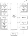
도 1은 다양한 실시 예들에 따른 에어로졸 발생 장치의 블록도이다.
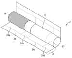
도 2는 일 실시 예에 따른 에어로졸 발생 시스템의 사시도이다.
도 3은 도 2의 에어로졸 발생 시스템을 3-3라인을 따라 바라본 단면도이다.
도 4는 일 실시 예에 따른 에어로졸 발생 장치의 분해 사시도이다.
도 5는 일 실시 예에 따른 하우징 파트들 사이의 결합 구조를 나타낸 도면이다.
도 6은 일 실시 예에 따른 다른 하우징 파트들 사이의 결합 구조를 나타낸 도면이다.
도 7은 다른 실시 예에 따른 하우징 파트들 사이의 결합 구조를 나타낸 도면이다.
도 8 내지 도 10은 일 실시 예에 따른 에어로졸 발생 장치에 에어로졸 생성 물품(예: 궐련)이 삽입된 예들을 도시한 도면들이다.
도 11 및 도 12는 일 실시 예에 따른 에어로졸 생성 물품(예: 궐련)의 예들을 도시한 도면들이다.FIG. 1 is a block diagram of an aerosol generating device according to various embodiments.
FIG. 2 is a perspective view of an aerosol generating system according to one embodiment.
Figure 3 is a cross-sectional view of the aerosol generating system of Figure 2 taken along line 3-3.
Figure 4 is an exploded perspective view of an aerosol generating device according to one embodiment.
FIG. 5 is a drawing showing a joint structure between housing parts according to one embodiment.
FIG. 6 is a drawing showing a joint structure between different housing parts according to one embodiment.
FIG. 7 is a drawing showing a joint structure between housing parts according to another embodiment.
FIGS. 8 to 10 are drawings illustrating examples of an aerosol generating article (e.g., a cigarette) inserted into an aerosol generating device according to one embodiment.
FIGS. 11 and 12 are drawings illustrating examples of aerosol generating articles (e.g., cigarettes) according to one embodiment.
실시 예들에서 사용되는 용어는 실시 예들에서의 기능을 고려하면서 가능한 현재 널리 사용되는 일반적인 용어들을 선택하였으나, 이는 당 분야에 종사하는 기술자의 의도 또는 판례, 새로운 기술의 출현 등에 따라 달라질 수 있다. 또한, 특정한 경우는 출원인이 임의로 선정한 용어도 있으며, 이 경우 해당되는 발명의 설명 부분에서 상세히 그 의미를 기재할 것이다. 따라서 본 발명에서 사용되는 용어는 단순한 용어의 명칭이 아닌, 그 용어가 가지는 의미와 본 발명의 전반에 걸친 내용을 토대로 정의되어야 한다.The terms used in the embodiments are selected from commonly used terms that are as much as possible while considering the functions in the embodiments, but this may vary depending on the intention of engineers working in the field, precedents, the emergence of new technologies, etc. In addition, in certain cases, there are terms arbitrarily selected by the applicant, and in this case, the meanings thereof will be described in detail in the description of the relevant invention. Therefore, the terms used in the present invention should be defined based on the meanings of the terms and the overall contents of the present invention, rather than simply the names of the terms.
명세서 전체에서 어떤 부분이 어떤 구성요소를 "포함"한다고 할 때, 이는 특별히 반대되는 기재가 없는 한 다른 구성요소를 제외하는 것이 아니라 다른 구성요소를 더 포함할 수 있음을 의미한다. 또한, 명세서에 기재된 "-부", "-모듈" 등의 용어는 적어도 하나의 기능이나 동작을 처리하는 단위를 의미하며, 이는 하드웨어 또는 소프트웨어로 구현되거나 하드웨어와 소프트웨어의 결합으로 구현될 수 있다.When a part of the specification is said to "include" a component, this does not mean that it excludes other components, but rather that it may include other components, unless otherwise specifically stated. In addition, terms such as "-unit", "-module", etc. described in the specification mean a unit that processes at least one function or operation, which may be implemented by hardware or software, or a combination of hardware and software.
본 명세서에서 사용된 바와 같이, "적어도 어느 하나의"와 같은 표현이 배열된 구성요소들 앞에 있을 때, 배열된 각각의 구성이 아닌 전체 구성 요소들을 수식한다. 예를 들면, "a, b, 및 c 중 적어도 어느 하나"라는 표현은 a, b, c, 또는 a와 b, a와 c, b와 c, 또는 a와 b와 c를 포함하는 것으로 해석하여야 한다.As used herein, when an expression such as "at least one" precedes an array of elements, it modifies the entire array of elements rather than each individual element. For example, the expression "at least one of a, b, and c" should be interpreted to include a, b, c, or a and b, a and c, b and c, or a and b and c.
일 실시 예에서, 에어로졸 발생 장치는 내부 공간에 수용되는 궐련을 전기적으로 가열하여 에어로졸을 생성하는 장치일 수 있다.In one embodiment, the aerosol generating device may be a device that electrically heats a cigarette accommodated in an internal space to generate an aerosol.
에어로졸 발생 장치는 히터를 포함할 수 있다. 일 실시 예에서, 히터는 전기 저항성 히터일 수 있다. 예를 들면, 히터는 전기 전도성 트랙(track)을 포함할 수 있고, 전기 전도성 트랙에 전류가 흐르면 히터가 가열될 수 있다.The aerosol generating device may include a heater. In one embodiment, the heater may be an electrically resistive heater. For example, the heater may include electrically conductive tracks, and when current flows through the electrically conductive tracks, the heater may be heated.
히터는 관 형 가열 요소, 판 형 가열 요소, 침 형 가열 요소 또는 봉 형의 가열 요소를 포함할 수 있고, 가열 요소의 모양에 따라 궐련의 내부 또는 외부를 가열할 수 있다.The heater may include a tubular heating element, a plate-shaped heating element, a needle-shaped heating element or a rod-shaped heating element, and depending on the shape of the heating element, may heat the interior or exterior of the cigarette.
궐련은 담배 로드 및 필터 로드를 포함할 수 있다. 담배 로드는 시트(sheet)로 제작될 수 있고, 가닥(strand)으로 제작될 수 있고, 담배 시트가 잘게 잘린 각초로 제작될 수 있다. 또한, 담배 로드는 열 전도 물질에 의하여 둘러싸일 수 있다. 예를 들면, 열 전도 물질은 알루미늄 호일과 같은 금속 호일일 수 있으나, 이에 제한되는 것은 아니다.The cigarette may include a tobacco rod and a filter rod. The tobacco rod may be made of a sheet, may be made of a strand, or may be made of chopped tobacco sheets. Additionally, the tobacco rod may be surrounded by a heat-conducting material. For example, the heat-conducting material may be, but is not limited to, a metal foil such as aluminum foil.
필터 로드는 셀룰로오스 아세테이트 필터일 수 있다. 필터 로드는 적어도 하나 이상의 세그먼트로 구성될 수 있다. 예를 들면, 필터 로드는 에어로졸을 냉각하는 제 1 세그먼트 및 에어로졸 내에 포함된 소정의 성분을 필터링하는 제 2 세그먼트를 포함할 수 있다.The filter load may be a cellulose acetate filter. The filter load may be comprised of at least one segment. For example, the filter load may include a first segment that cools the aerosol and a second segment that filters a predetermined component contained within the aerosol.
다른 실시 예에서, 에어로졸 발생 장치는 에어로졸 생성 물질을 보유하는 카트리지를 이용하여 에어로졸을 생성하는 장치일 수 있다.In another embodiment, the aerosol generating device may be a device that generates an aerosol using a cartridge containing an aerosol generating material.
에어로졸 발생 장치는 에어로졸 생성 물질을 보유하는 카트리지 및 카트리지를 지지하는 본체를 포함할 수 있다. 카트리지는 본체와 착탈 가능하게 결합될 수 있으나, 이에 제한되는 것은 아니다. 카트리지는 본체와 일체로 형성되거나 조립될 수 있고, 사용자에 의해 탈착되지 않도록 고정될 수도 있다. 카트리지는 내부에 에어로졸 생성 물질을 수용한 상태에서 본체에 장착될 수 있다. 다만, 이에 제한되는 것은 아니며, 카트리지가 본체에 결합된 상태에서 카트리지 내부에 에어로졸 생성 물질이 주입될 수도 있다.An aerosol generating device may include a cartridge containing an aerosol generating substance and a body supporting the cartridge. The cartridge may be detachably coupled to the body, but is not limited thereto. The cartridge may be formed integrally with or assembled to the body, and may be fixed so as not to be detached by a user. The cartridge may be mounted to the body while containing an aerosol generating substance therein. However, the present invention is not limited thereto, and the aerosol generating substance may be injected into the cartridge while the cartridge is coupled to the body.
카트리지는 액체 상태, 고체 상태, 기체 상태, 겔(gel) 상태 등의 다양한 상태들 중 어느 하나의 상태를 갖는 에어로졸 생성 물질을 보유할 수 있다. 에어로졸 생성 물질은 액상 조성물을 포함할 수 있다. 예를 들면, 액상 조성물은 휘발성 담배 향 성분을 포함하는 담배 함유 물질을 포함하는 액체일 수 있고, 비 담배 물질을 포함하는 액체일 수도 있다.The cartridge can contain an aerosol generating material in any one of a variety of states, such as a liquid state, a solid state, a gaseous state, a gel state, etc. The aerosol generating material can comprise a liquid composition. For example, the liquid composition can be a liquid comprising a tobacco-containing material including a volatile tobacco flavoring component, or it can be a liquid comprising a non-tobacco material.
카트리지는 본체로부터 전달되는 전기 신호 또는 무선 신호 등에 의해 작동함으로써, 카트리지 내부의 에어로졸 생성 물질의 상(phase)을 기체의 상으로 변환하여 에어로졸을 발생시키는 기능을 수행할 수 있다. 에어로졸은 에어로졸 생성 물질로부터 발생한 증기화된 입자 및 공기가 혼합된 상태의 기체를 의미할 수 있다.The cartridge can perform the function of generating an aerosol by converting the phase of an aerosol generating substance inside the cartridge into a gas phase by operating with an electric signal or wireless signal transmitted from the main body. The aerosol can mean a gas in a mixed state of vaporized particles and air generated from the aerosol generating substance.
또 다른 실시 예에서, 에어로졸 발생 장치는 액상 조성물을 가열하여 에어로졸을 생성할 수 있고, 생성된 에어로졸은 궐련을 통과하여 사용자에게 전달될 수 있다. 즉, 액상 조성물로부터 생성된 에어로졸은 에어로졸 발생 장치의 기류 통로를 따라 이동할 수 있고, 기류 통로는 에어로졸이 궐련을 통과하여 사용자에게 전달될 수 있도록 구성될 수 있다.In another embodiment, the aerosol generating device can generate an aerosol by heating a liquid composition, and the generated aerosol can be delivered to a user through a cigarette. That is, the aerosol generated from the liquid composition can travel along an airflow passage of the aerosol generating device, and the airflow passage can be configured such that the aerosol can pass through the cigarette and be delivered to a user.
또 다른 실시 예에서, 에어로졸 발생 장치는 초음파 진동 방식을 이용하여 에어로졸 생성 물질로부터 에어로졸을 생성하는 장치일 수 있다. 이때, 초음파 진동 방식은 진동자에 의해 발생되는 초음파 진동으로 에어로졸 생성 물질을 무화시킴으로써 에어로졸을 발생시키는 방식을 의미할 수 있다.In another embodiment, the aerosol generating device may be a device that generates an aerosol from an aerosol generating material using an ultrasonic vibration method. In this case, the ultrasonic vibration method may mean a method of generating an aerosol by atomizing an aerosol generating material using ultrasonic vibration generated by a vibrator.
에어로졸 발생 장치는 진동자를 포함할 수 있고, 진동자를 통해 짧은 주기의 진동을 발생시켜 에어로졸 생성 물질을 무화시킬 수 있다. 진동자에서 발생되는 진동은 초음파 진동일 수 있고, 초음파 진동의 주파수 대역은 약 100 kHz 내지 약 3.5 MHz 주파수 대역일 수 있으나, 이에 제한되는 것은 아니다.The aerosol generating device may include a vibrator, and may generate short-cycle vibrations through the vibrator to atomize the aerosol generating material. The vibrations generated from the vibrator may be ultrasonic vibrations, and the frequency band of the ultrasonic vibrations may be, but is not limited to, a frequency band of about 100 kHz to about 3.5 MHz.
에어로졸 발생 장치는 에어로졸 생성 물질을 흡수하는 심지를 더 포함할 수 있다. 예를 들면, 심지는 진동자의 적어도 일 영역을 감싸도록 배치되거나 또는 진동자의 적어도 일 영역과 접촉하도록 배치될 수 있다.The aerosol generating device may further include a wick that absorbs the aerosol generating material. For example, the wick may be positioned to surround at least a portion of the vibrator or may be positioned to contact at least a portion of the vibrator.
진동자에 전압(예: 교류 전압)이 인가됨에 따라, 진동자로부터 열 및/또는 초음파 진동이 발생할 수 있으며, 진동자로부터 발생된 열 및/또는 초음파 진동은 심지에 흡수된 에어로졸 생성 물질에 전달될 수 있다. 심지에 흡수된 에어로졸 생성 물질은 진동자로부터 전달되는 열 및/또는 초음파 진동에 의해 기체의 상(phase)으로 변환될 수 있으며, 그 결과 에어로졸이 생성될 수 있다.As voltage (e.g., alternating current) is applied to the vibrator, heat and/or ultrasonic vibrations may be generated from the vibrator, and the heat and/or ultrasonic vibrations generated from the vibrator may be transmitted to the aerosol-generating substance absorbed in the wick. The aerosol-generating substance absorbed in the wick may be converted into a gaseous phase by the heat and/or ultrasonic vibrations transmitted from the vibrator, and as a result, an aerosol may be generated.
예를 들면, 진동자로부터 발생된 열에 의해 심지에 흡수된 에어로졸 생성 물질의 점도가 낮아질 수 있으며, 진동자로부터 발생된 초음파 진동에 의해 점도가 낮아진 에어로졸 생성 물질이 미세 입자화됨으로써, 에어로졸이 생성될 수 있으나, 이에 제한되는 것은 아니다.For example, the viscosity of an aerosol generating substance absorbed into a wick may be lowered by heat generated from a vibrator, and an aerosol may be generated by the aerosol generating substance having a lowered viscosity being broken down into fine particles by ultrasonic vibration generated from the vibrator, but is not limited thereto.
또 다른 실시 예에서, 에어로졸 발생 장치는 유도 가열(induction heating) 방식으로 에어로졸 발생 장치에 수용되는 에어로졸 생성 물품을 가열함으로써, 에어로졸을 생성하는 장치일 수 있다.In another embodiment, the aerosol generating device may be a device that generates an aerosol by heating an aerosol generating article accommodated in the aerosol generating device by induction heating.
에어로졸 발생 장치는 서셉터(susceptor) 및 코일을 포함할 수 있다. 일 실시 예에서, 코일은 서셉터에 자기장을 인가할 수 있다. 에어로졸 발생 장치로부터 코일에 전력이 공급됨에 따라, 코일의 내부에는 자기장이 형성될 수 있다. 일 실시 예에서, 서셉터는 외부 자기장에 의해 발열하는 자성체일 수 있다. 서셉터가 코일의 내부에 위치하여 자기장이 인가됨에 따라, 발열함으로써 에어로졸 생성 물품이 가열될 수 있다. 또한, 선택적으로, 서셉터는 에어로졸 생성 물품 내에 위치할 수 있다.An aerosol generating device may include a susceptor and a coil. In one embodiment, the coil may apply a magnetic field to the susceptor. As power is supplied to the coil from the aerosol generating device, a magnetic field may be formed inside the coil. In one embodiment, the susceptor may be a magnetic material that generates heat by an external magnetic field. When the susceptor is positioned inside the coil and a magnetic field is applied, the susceptor generates heat, thereby heating the aerosol generating article. Additionally, optionally, the susceptor may be positioned within the aerosol generating article.
또 다른 실시 예에서, 에어로졸 발생 장치는 크래들(cradle)을 더 포함할 수 있다.In another embodiment, the aerosol generating device may further comprise a cradle.
에어로졸 발생 장치는 별도의 크래들과 함께 시스템을 구성할 수 있다. 예를 들면, 크래들은 에어로졸 발생 장치의 배터리를 충전할 수 있다. 또는 크래들과 에어로졸 발생 장치가 결합된 상태에서 히터가 가열될 수 있다.The aerosol generating device may be configured as a system with a separate cradle. For example, the cradle may charge the battery of the aerosol generating device. Alternatively, the heater may be heated while the cradle and aerosol generating device are combined.
아래에서는 첨부한 도면을 참고하여 본 개시의 실시 예에 대하여 당해 기술 분야에서 통상의 지식을 가진 자가 용이하게 실시할 수 있도록 상세히 설명한다. 본 개시는 앞서 설명된 다양한 실시 예들의 에어로졸 발생 장치들에서 구현 가능한 형태로 실시되거나 또는 여러 가지 상이한 형태로 구현되어 실시될 수 있으며 여기에서 설명하는 실시 예에 제한되지 않는다.Hereinafter, embodiments of the present disclosure will be described in detail with reference to the attached drawings so that those skilled in the art can easily implement them. The present disclosure may be implemented in a form that can be implemented in the aerosol generating devices of the various embodiments described above, or may be implemented in various different forms and is not limited to the embodiments described herein.
이하에서는 도면을 참조하여 본 개시의 실시 예들을 상세히 설명한다.Hereinafter, embodiments of the present disclosure will be described in detail with reference to the drawings.
도 1을 참조하면, 에어로졸 발생 장치(100)는 제어부(110), 센싱부(120), 출력부(130), 배터리(140), 히터(150), 사용자 입력부(160), 메모리(170) 및 통신부(180)를 포함할 수 있다. 다만, 에어로졸 발생 장치(100)의 내부 구조는 도 1에 도시된 것에 제한되지 않는다. 즉, 에어로졸 발생 장치(100)의 설계에 따라, 도 1에 도시된 구성 중 일부가 생략되거나 새로운 구성이 더 추가될 수 있음을 본 실시 예와 관련된 기술 분야에서 통상의 지식을 가진 자라면 이해할 수 있다.Referring to FIG. 1, the aerosol generating device (100) may include a control unit (110), a sensing unit (120), an output unit (130), a battery (140), a heater (150), a user input unit (160), a memory (170), and a communication unit (180). However, the internal structure of the aerosol generating device (100) is not limited to that illustrated in FIG. 1. That is, a person having ordinary skill in the art related to the present embodiment will understand that some of the components illustrated in FIG. 1 may be omitted or new components may be added depending on the design of the aerosol generating device (100).
센싱부(120)는 에어로졸 발생 장치(100)의 상태 또는 에어로졸 발생 장치(100) 주변의 상태를 감지하고, 감지된 정보를 제어부(110)에 전달할 수 있다. 제어부(110)는 상기 감지된 정보에 기초하여, 히터(150)의 동작 제어, 흡연의 제한, 에어로졸 생성 물품(예: 궐련, 카트리지 등)의 삽입 여부 판단, 알림 표시 등과 같은 다양한 기능들이 수행되도록 에어로졸 발생 장치(100)를 제어할 수 있다.The sensing unit (120) can detect the status of the aerosol generating device (100) or the status around the aerosol generating device (100) and transmit the detected information to the control unit (110). Based on the detected information, the control unit (110) can control the aerosol generating device (100) so that various functions such as controlling the operation of the heater (150), restricting smoking, determining whether an aerosol generating article (e.g., cigarette, cartridge, etc.) is inserted, and displaying a notification are performed.
센싱부(120)는 온도 센서(122), 삽입 감지 센서(124) 및 퍼프 센서(126) 중 적어도 하나를 포함할 수 있으나, 이에 제한되지 않는다.The sensing unit (120) may include at least one of a temperature sensor (122), an insertion detection sensor (124), and a puff sensor (126), but is not limited thereto.
온도 센서(122)는 히터(150)(또는, 에어로졸 생성 물질)가 가열되는 온도를 감지할 수 있다. 에어로졸 발생 장치(100)는 히터(150)의 온도를 감지하는 별도의 온도 센서를 포함하거나, 히터(150) 자체가 온도 센서의 역할을 수행할 수 있다. 또는, 온도 센서(122)는 배터리(140)의 온도를 모니터링하도록 배터리(140)의 주위에 배치된 것일 수도 있다.The temperature sensor (122) can detect the temperature at which the heater (150) (or the aerosol generating material) is heated. The aerosol generating device (100) may include a separate temperature sensor that detects the temperature of the heater (150), or the heater (150) itself may act as a temperature sensor. Alternatively, the temperature sensor (122) may be placed around the battery (140) to monitor the temperature of the battery (140).
삽입 감지 센서(124)는 에어로졸 생성 물품의 삽입 및/또는 제거를 감지할 수 있다. 예를 들면, 삽입 감지 센서(124)는 필름 센서, 압력 센서, 광 센서, 저항성 센서, 용량성 센서, 유도성 센서 및 적외선 센서 중 적어도 하나를 포함할 수 있고, 에어로졸 생성 물품이 삽입 및/또는 제거됨에 따른 신호 변화를 감지할 수 있다.The insertion detection sensor (124) can detect insertion and/or removal of an aerosol generating article. For example, the insertion detection sensor (124) can include at least one of a film sensor, a pressure sensor, an optical sensor, a resistive sensor, a capacitive sensor, an inductive sensor, and an infrared sensor, and can detect a signal change as an aerosol generating article is inserted and/or removed.
퍼프 센서(126)는 기류 통로 또는 기류 채널의 다양한 물리적 변화에 기초하여 사용자의 퍼프를 감지할 수 있다. 예를 들면, 퍼프 센서(126)는 온도 변화, 유량(flow) 변화, 전압 변화 및 압력 변화 중 어느 하나에 기초하여 사용자의 퍼프를 감지할 수 있다.The puff sensor (126) can detect the user's puff based on various physical changes in the airflow passage or airflow channel. For example, the puff sensor (126) can detect the user's puff based on any one of temperature change, flow change, voltage change, and pressure change.
센싱부(1120)는 전술한 센서(122 내지 926) 외에, 온/습도 센서, 기압 센서, 지자기 센서(magnetic sensor), 가속도 센서(acceleration sensor), 자이로스코프 센서, 위치 센서(예컨대, GPS), 근접 센서, 및 RGB 센서(illuminance sensor) 중 적어도 하나를 더 포함할 수 있다. 각 센서들의 기능은 그 명칭으로부터 통상의 기술자가 직관적으로 추론할 수 있으므로, 구체적인 설명은 생략될 수 있다.In addition to the sensors (122 to 926) described above, the sensing unit (1120) may further include at least one of a temperature/humidity sensor, a pressure sensor, a magnetic sensor, an acceleration sensor, a gyroscope sensor, a position sensor (e.g., GPS), a proximity sensor, and an RGB sensor (illuminance sensor). Since the function of each sensor can be intuitively inferred from its name by a person skilled in the art, a detailed description thereof may be omitted.
출력부(130)는 에어로졸 발생 장치(100)의 상태에 대한 정보를 출력하여 사용자에게 제공할 수 있다. 출력부(130)는 디스플레이부(132), 햅틱부(134) 및 음향 출력부(136) 중 적어도 하나를 포함할 수 있으나, 이에 제한되는 것은 아니다. 디스플레이부(132)와 터치 패드가 레이어 구조를 이루어 터치 스크린으로 구성되는 경우, 디스플레이부(132)는 출력 장치 이외에 입력 장치로도 사용될 수 있다.The output unit (130) can output information on the status of the aerosol generating device (100) and provide it to the user. The output unit (130) can include at least one of the display unit (132), the haptic unit (134), and the sound output unit (136), but is not limited thereto. When the display unit (132) and the touch pad form a layer structure to form a touch screen, the display unit (132) can be used as an input device in addition to an output device.
디스플레이부(132)는 에어로졸 발생 장치(100)에 대한 정보를 사용자에게 시각적으로 제공할 수 있다. 예를 들면, 에어로졸 발생 장치(100)에 대한 정보는 에어로졸 발생 장치(100)의 배터리(140)의 충/방전 상태, 히터(150)의 예열 상태, 에어로졸 생성 물품의 삽입/제거 상태 또는 에어로졸 발생 장치(100)의 사용이 제한되는 상태(예: 이상 물품 감지) 등의 다양한 정보를 의미할 수 있고, 디스플레이부(132)는 상기 정보를 외부로 출력할 수 있다. 디스플레이부(132)는 예를 들면, 액정 디스플레이 패널(LCD), 유기 발광 디스플레이 패널(OLED) 등일 수 있다. 또한, 디스플레이부(132)는 LED 발광 소자 형태일 수도 있다.The display unit (132) can visually provide information about the aerosol generating device (100) to the user. For example, the information about the aerosol generating device (100) can mean various information such as the charging/discharging status of the battery (140) of the aerosol generating device (100), the preheating status of the heater (150), the insertion/removal status of an aerosol generating article, or the status in which the use of the aerosol generating device (100) is restricted (e.g., detection of an abnormal article), and the display unit (132) can output the information to the outside. The display unit (132) can be, for example, a liquid crystal display panel (LCD), an organic light-emitting display panel (OLED), or the like. In addition, the display unit (132) can also be in the form of an LED light-emitting element.
햅틱부(134)는 전기적 신호를 기계적인 자극 또는 전기적인 자극으로 변환하여 에어로졸 발생 장치(100)에 대한 정보를 사용자에게 촉각적으로 제공할 수 있다. 예를 들면, 햅틱부(134)는 모터, 압전 소자, 또는 전기 자극 장치를 포함할 수 있다.The haptic unit (134) can convert an electrical signal into a mechanical stimulus or an electrical stimulus to provide tactile information about the aerosol generating device (100) to the user. For example, the haptic unit (134) can include a motor, a piezoelectric element, or an electrical stimulation device.
음향 출력부(136)는 에어로졸 발생 장치(100)에 대한 정보를 사용자에게 청각적으로 제공할 수 있다. 예를 들면, 음향 출력부(136)는 전기 신호를 음향 신호로 변환하여 외부로 출력할 수 있다.The acoustic output unit (136) can provide information about the aerosol generating device (100) to the user audibly. For example, the acoustic output unit (136) can convert an electrical signal into an acoustic signal and output it to the outside.
배터리(140)는 에어로졸 발생 장치(100)가 동작하는데 이용되는 전력을 공급할 수 있다. 배터리(140)는 히터(150)가 가열될 수 있도록 전력을 공급할 수 있다. 또한, 배터리(140)는 에어로졸 발생 장치(100) 내에 구비된 다른 구성들(예: 센싱부(120), 출력부(130), 사용자 입력부(160), 메모리(170) 및 통신부(180))의 동작에 필요한 전력을 공급할 수 있다. 배터리(140)는 충전이 가능한 배터리이거나 일회용 배터리일 수 있다. 예를 들면, 배터리(140)는 리튬폴리머(LiPoly) 배터리일 수 있으나, 이에 제한되지 않는다.The battery (140) can supply power used to operate the aerosol generating device (100). The battery (140) can supply power so that the heater (150) can be heated. In addition, the battery (140) can supply power required for the operation of other components (e.g., the sensing unit (120), the output unit (130), the user input unit (160), the memory (170), and the communication unit (180)) provided in the aerosol generating device (100). The battery (140) can be a rechargeable battery or a disposable battery. For example, the battery (140) can be a lithium polymer (LiPoly) battery, but is not limited thereto.
히터(150)는 배터리(140)로부터 전력을 공급받아 에어로졸 생성 물질을 가열할 수 있다. 도 1에 도시되지는 않았으나, 에어로졸 발생 장치(100)는 배터리(140)의 전력을 변환하여 히터(150)에 공급하는 전력 변환 회로(예: DC/DC 컨버터)를 더 포함할 수 있다. 또한, 에어로졸 발생 장치(100)가 유도 가열 방식으로 에어로졸을 생성하는 경우, 에어로졸 발생 장치(100)는 배터리(140)의 직류 전원을 교류 전원으로 변환하는 DC/AC 컨버터를 더 포함할 수 있다.The heater (150) can receive power from the battery (140) to heat the aerosol generating material. Although not shown in FIG. 1, the aerosol generating device (100) may further include a power conversion circuit (e.g., a DC/DC converter) that converts the power of the battery (140) and supplies it to the heater (150). In addition, when the aerosol generating device (100) generates the aerosol by induction heating, the aerosol generating device (100) may further include a DC/AC converter that converts the direct current power of the battery (140) into alternating current power.
제어부(110), 센싱부(120), 출력부(130), 사용자 입력부(160), 메모리(170) 및 통신부(180)는 배터리(140)로부터 전력을 공급받아 기능을 수행할 수 있다. 도 1에 도시되지는 않았으나, 배터리(140)의 전력을 변환하여 각각의 구성요소들에 공급하는 전력 변환 회로, 예를 들면 LDO(low dropout) 회로 또는 전압 레귤레이터 회로를 더 포함할 수 있다.The control unit (110), sensing unit (120), output unit (130), user input unit (160), memory (170), and communication unit (180) can perform functions by receiving power from the battery (140). Although not shown in FIG. 1, a power conversion circuit that converts power from the battery (140) and supplies it to each component, for example, an LDO (low dropout) circuit or a voltage regulator circuit, may be further included.
일 실시 예에서, 히터(150)는 임의의 적합한 전기 저항성 물질로 형성될 수 있다. 예를 들면, 적합한 전기 저항성 물질은 타이타늄, 지르코늄, 탄탈럼, 백금, 니켈, 코발트, 크로뮴, 하프늄, 나이오븀, 몰리브데넘, 텅스텐, 주석, 갈륨, 망간, 철, 구리, 스테인리스강, 니크롬 등을 포함하는 금속 또는 금속 합금일 수 있으나, 이에 제한되지 않는다. 또한, 히터(150)는 금속 열선(wire), 전기 전도성 트랙(track)이 배치된 금속 열판(plate), 세라믹 발열체 등으로 구현될 수 있으나, 이에 제한되지 않는다.In one embodiment, the heater (150) may be formed of any suitable electrically resistive material. For example, suitable electrically resistive materials may be metals or metal alloys including, but not limited to, titanium, zirconium, tantalum, platinum, nickel, cobalt, chromium, hafnium, niobium, molybdenum, tungsten, tin, gallium, manganese, iron, copper, stainless steel, nichrome, and the like. In addition, the heater (150) may be implemented as, but not limited to, a metal heating wire, a metal heating plate having electrically conductive tracks arranged thereon, a ceramic heating element, and the like.
다른 실시 예에서, 히터(150)는 유도 가열 방식의 히터일 수 있다. 예를 들면, 히터(150)는 코일에 의해 인가된 자기장을 통해 발열하여, 에어로졸 생성 물질을 가열하는 서셉터를 포함할 수 있다.In another embodiment, the heater (150) may be an induction heating type heater. For example, the heater (150) may include a susceptor that heats the aerosol generating material by generating heat through a magnetic field applied by the coil.
사용자 입력부(160)는 사용자로부터 입력된 정보를 수신하거나, 사용자에게 정보를 출력할 수 있다. 예를 들면, 사용자 입력부(160)는 키 패드(key pad), 돔 스위치 (dome switch), 터치 패드(접촉식 정전 용량 방식, 압력식 저항막 방식, 적외선 감지 방식, 표면 초음파 전도 방식, 적분식 장력 측정 방식, 피에조 효과 방식 등), 조그 휠, 조그 스위치 등이 있을 수 있으나 이에 제한되는 것은 아니다. 또한, 도 1에 도시되지는 않았으나, 에어로졸 발생 장치(100)는 USB(universal serial bus) 인터페이스 등과 같은 연결 인터페이스(connection interface)를 더 포함하고, USB 인터페이스 등과 같은 연결 인터페이스를 통해 다른 외부 장치와 연결하여 정보를 송수신하거나, 배터리(140)를 충전할 수 있다.The user input unit (160) can receive information input by the user or output information to the user. For example, the user input unit (160) may include, but is not limited to, a key pad, a dome switch, a touch pad (contact electrostatic capacitance type, pressure resistive film type, infrared detection type, surface ultrasonic conduction type, integral tension measurement type, piezo effect type, etc.), a jog wheel, a jog switch, etc. In addition, although not shown in FIG. 1, the aerosol generating device (100) further includes a connection interface such as a USB (universal serial bus) interface, and can transmit and receive information or charge a battery (140) by connecting to another external device through a connection interface such as a USB interface.
메모리(170)는 에어로졸 발생 장치(100) 내에서 처리되는 각종 데이터들을 저장하는 하드웨어로서, 제어부(110)에서 처리된 데이터들 및 처리될 데이터들을 저장할 수 있다. 메모리(170)는 플래시 메모리 타입(flash memory type), 하드디스크 타입(hard disk type), 멀티미디어 카드 마이크로 타입(multimedia card micro type), 카드 타입의 메모리(예를 들면 SD 또는 XD 메모리 등), 램(RAM, random access memory) SRAM(static random access memory), 롬(ROM, read-only memory), EEPROM(electrically erasable programmable read-only memory), PROM(programmable read-only memory), 자기 메모리, 자기 디스크, 광디스크 중 적어도 하나의 타입의 저장매체를 포함할 수 있다. 메모리(170)는 에어로졸 발생 장치(100)의 동작 시간, 최대 퍼프 횟수, 현재 퍼프 횟수, 적어도 하나의 온도 프로 파일 및 사용자의 흡연 패턴에 대한 데이터 등을 저장할 수 있다.The memory (170) is a hardware that stores various data processed in the aerosol generating device (100), and can store data processed and data to be processed in the control unit (110). The memory (170) may include at least one type of storage medium among a flash memory type, a hard disk type, a multimedia card micro type, a card type memory (for example, an SD or XD memory, etc.), a RAM (random access memory), a SRAM (static random access memory), a ROM (read-only memory), an EEPROM (electrically erasable programmable read-only memory), a PROM (programmable read-only memory), a magnetic memory, a magnetic disk, and an optical disk. The memory (170) may store data on the operation time of the aerosol generating device (100), the maximum number of puffs, the current number of puffs, at least one temperature profile, and a user's smoking pattern.
통신부(180)는 다른 전자 장치와의 통신을 위한 적어도 하나의 구성 요소를 포함할 수 있다. 예를 들면, 통신부(180)는 근거리 통신부(182) 및 무선 통신부(184)를 포함할 수 있다.The communication unit (180) may include at least one component for communicating with another electronic device. For example, the communication unit (180) may include a short-range communication unit (182) and a wireless communication unit (184).
근거리 통신부(short-range wireless communication unit)(182)는 블루투스 통신부, BLE(Bluetooth Low Energy) 통신부, 근거리 무선 통신부(Near Field Communication unit), WLAN(와이파이) 통신부, 지그비(Zigbee) 통신부, 적외선(IrDA, infrared Data Association) 통신부, WFD(Wi-Fi Direct) 통신부, UWB(ultra wideband) 통신부, Ant+ 통신부 등을 포함할 수 있으나, 이에 제한되지 않는다.The short-range wireless communication unit (182) may include, but is not limited to, a Bluetooth communication unit, a BLE (Bluetooth Low Energy) communication unit, a near field communication unit, a WLAN (Wi-Fi) communication unit, a Zigbee communication unit, an infrared (IrDA, infrared Data Association) communication unit, a WFD (Wi-Fi Direct) communication unit, a UWB (ultra wideband) communication unit, an Ant+ communication unit, etc.
무선 통신부(184)는 셀룰러 네트워크 통신부, 인터넷 통신부, 컴퓨터 네트워크(예: LAN 또는 WAN) 통신부 등을 포함할 수 있으나, 이에 제한되지 않는다. 무선 통신부(184)는 가입자 정보(예: 국제 모바일 가입자 식별자(IMSI)를 이용하여 통신 네트워크 내에서 에어로졸 발생 장치(100)를 확인 및 인증할 수도 있다.The wireless communication unit (184) may include, but is not limited to, a cellular network communication unit, an Internet communication unit, a computer network (e.g., a LAN or WAN) communication unit, etc. The wireless communication unit (184) may also identify and authenticate the aerosol generating device (100) within the communication network using subscriber information (e.g., an international mobile subscriber identity (IMSI).
제어부(110)는 에어로졸 발생 장치(100)의 전반적인 동작을 제어할 수 있다. 일 실시 예에서, 제어부(110)는 적어도 하나의 프로세서를 포함할 수 있다. 프로세서는 다수의 논리 게이트들의 어레이로 구현될 수도 있고, 범용적인 마이크로 프로세서와 이 마이크로 프로세서에서 실행될 수 있는 프로그램이 저장된 메모리의 조합으로 구현될 수도 있다. 또한, 다른 형태의 하드웨어로 구현될 수도 있음을 본 실시 예가 속하는 기술 분야에서 통상의 지식을 가진 자라면 이해할 수 있다.The control unit (110) can control the overall operation of the aerosol generating device (100). In one embodiment, the control unit (110) can include at least one processor. The processor can be implemented as an array of a plurality of logic gates, or can be implemented as a combination of a general-purpose microprocessor and a memory storing a program that can be executed in the microprocessor. In addition, it will be understood by those skilled in the art to which the present embodiment belongs that the processor can be implemented as other types of hardware.
제어부(110)는 배터리(140)의 전력을 히터(150)에 공급하는 것을 제어함으로써 히터(150)의 온도를 제어할 수 있다. 예를 들면, 제어부(110)는 배터리(140)와 히터(150) 사이의 스위칭 소자의 스위칭을 제어함으로써 전력 공급을 제어할 수 있다. 다른 예에서, 제어부(110)의 제어 명령에 따라 가열직접회로가 히터(150)에 대한 전력 공급을 제어할 수도 있다.The control unit (110) can control the temperature of the heater (150) by controlling the supply of power from the battery (140) to the heater (150). For example, the control unit (110) can control the power supply by controlling the switching of the switching element between the battery (140) and the heater (150). In another example, the heating direct circuit can control the power supply to the heater (150) according to the control command of the control unit (110).
제어부(110)는 센싱부(120)에 의해 감지된 결과를 분석하고, 이후 수행될 처리들을 제어할 수 있다. 예를 들면, 제어부(110)는 센싱부(120)에 의해 감지된 결과에 기초하여, 히터(150)의 동작이 개시 또는 종료되도록 히터(150)에 공급되는 전력을 제어할 수 있다. 다른 예를 들면, 제어부(110)는 센싱부(120)에 의해 감지된 결과에 기초하여, 히터(150)가 소정의 온도까지 가열되거나 적절한 온도를 유지할 수 있도록 히터(150)에 공급되는 전력의 양 및 전력이 공급되는 시간을 제어할 수 있다.The control unit (110) can analyze the results detected by the sensing unit (120) and control the processes to be performed thereafter. For example, the control unit (110) can control the power supplied to the heater (150) so that the operation of the heater (150) is started or ended based on the results detected by the sensing unit (120). As another example, the control unit (110) can control the amount of power supplied to the heater (150) and the time for which the power is supplied so that the heater (150) can be heated to a predetermined temperature or maintain an appropriate temperature based on the results detected by the sensing unit (120).
제어부(110)는 센싱부(120)에 의해 감지된 결과에 기초하여, 출력부(130)를 제어할 수 있다. 예를 들면, 퍼프 센서(126)를 통해 카운트 된 퍼프 횟수가 기 설정된 횟수에 도달하면, 제어부(110)는 디스플레이부(132), 햅틱부(134) 및 음향 출력부(136) 중 적어도 하나를 통해 사용자에게 에어로졸 발생 장치(100)가 곧 종료될 것을 예고할 수 있다.The control unit (110) can control the output unit (130) based on the result detected by the sensing unit (120). For example, when the number of puffs counted through the puff sensor (126) reaches a preset number, the control unit (110) can notify the user that the aerosol generating device (100) will soon be terminated through at least one of the display unit (132), the haptic unit (134), and the sound output unit (136).
일 실시 예에서, 제어부(110)는 센싱부(120)에 의해 감지된 에어로졸 생성 물품의 상태에 따라 히터(150)에 대한 전력 공급 시간 및/또는 전력 공급량을 제어할 수 있다. 예를 들면, 에어로졸 생성 물품(예: 에어로졸 생성 물품(201))이 과습 상태인 경우에, 제어부(110)는 유도 코일에 대한 전력 공급 시간을 제어하여, 에어로졸 생성 물품(예: 에어로졸 생성 물품(201))이 일반적인 상태인 경우보다 예열 시간을 증가시킬 수 있다.In one embodiment, the control unit (110) can control the power supply time and/or power supply amount to the heater (150) according to the state of the aerosol generating article detected by the sensing unit (120). For example, when the aerosol generating article (e.g., the aerosol generating article (201)) is in a hyper-humidified state, the control unit (110) can control the power supply time to the induction coil to increase the preheating time compared to when the aerosol generating article (e.g., the aerosol generating article (201)) is in a normal state.
도 2 내지 도 6을 참조하면, 에어로졸 발생 시스템(20)은, 에어로졸 발생 장치(200), 및 에어로졸 생성 물품(201)을 포함할 수 있다. 에어로졸 발생 장치(200)는 내부 공간에 에어로졸 생성 물품(201)을 수용하고 이를 전기적으로 가열하여 에어로졸을 생성할 수 있다.Referring to FIGS. 2 to 6, the aerosol generating system (20) may include an aerosol generating device (200) and an aerosol generating article (201). The aerosol generating device (200) may accommodate an aerosol generating article (201) in an internal space and electrically heat it to generate an aerosol.
에어로졸 발생 장치(200)는 에어로졸 생성 물품(201)을 적어도 부분적으로 수용하고 다양한 전자/기계 컴포넌트들을 수용하도록 구성된 제 1 하우징(210)을 포함할 수 있다. 제 1 하우징(210)은, 예를 들면, 제 1 면(210A)(예: 전면), 제 1 면(210A)에 반대되는 제 2 면(210B)(예: 후면), 제 1 면(210A) 및 제 2 면(210B) 사이의 제 1 사이드 면(210C), 및 제 1 사이드 면(210C)에 반대되는 제 1 면(210A) 및 제 2 면(210B) 사이의 제 2 사이드 면(210D)을 포함할 수 있다.An aerosol generating device (200) can include a first housing (210) configured to at least partially accommodate an aerosol generating article (201) and accommodate various electronic/mechanical components. The first housing (210) can include, for example, a first face (210A) (e.g., a front face), a second face (210B) (e.g., a back face) opposite the first face (210A), a first side face (210C) between the first face (210A) and the second face (210B), and a second side face (210D) between the first face (210A) and the second face (210B) opposite the first side face (210C).
일 실시 예에서, 제 1 하우징(210)은 제 1 면(210A)을 적어도 부분적으로 커버하며 에어로졸 생성 물품(201)이 삽입 또는 제거되는 통로(예: 물품 삽입부(220))를 개방 또는 폐쇄하도록 구성된 플랩(212)을 포함할 수 있다. 플랩(212)은, 예를 들면, 제 1 사이드 면(210C) 또는 제 2 사이드 면(210D)에 회동 가능하게 연결될 수 있다.In one embodiment, the first housing (210) can include a flap (212) configured to at least partially cover the first side (210A) and open or close a passage (e.g., an article insertion portion (220)) through which an aerosol generating article (201) is inserted or removed. The flap (212) can be rotatably connected to, for example, the first side side (210C) or the second side side (210D).
일 실시 예에서, 제 1 하우징(210)은 제 2 면(210B)에 형성된 연결 단자(214)를 포함할 수 있다. 연결 단자(214)는 연결 단자(214)를 통해 에어로졸 발생 장치(200)가 외부 장치와 물리적으로 연결되도록 구성된 커넥터를 포함할 수 있다. 연결 단자(214)는, 예를 들면, HDMI 커넥터, USB 커넥터, SD 카드 커넥터, 또는 오디오 커넥터(예: 헤드폰 커넥터)를 포함할 수 있다.In one embodiment, the first housing (210) may include a connection terminal (214) formed on the second surface (210B). The connection terminal (214) may include a connector configured to physically connect the aerosol generating device (200) to an external device via the connection terminal (214). The connection terminal (214) may include, for example, an HDMI connector, a USB connector, an SD card connector, or an audio connector (e.g., a headphone connector).
일 실시 예에서, 제 1 하우징(210)은 서로 분리 가능하게 결합된 복수 개의 하우징 파트(211, 213, 215, 217)들을 포함할 수 있다. 예를 들면, 제 1 하우징(210)은, 제 1 하우징 파트(211), 제 2 하우징 파트(213), 제 3 하우징 파트(215), 및 제 4 하우징 파트(217)를 포함할 수 있다.In one embodiment, the first housing (210) may include a plurality of housing parts (211, 213, 215, 217) that are detachably coupled to each other. For example, the first housing (210) may include a first housing part (211), a second housing part (213), a third housing part (215), and a fourth housing part (217).
제 1 하우징 파트(211)는, 제 1 외부 커버 면(211-1), 및 제 1 외부 커버 면(211-1)에 반대되는 제 1 내부 커버 면(211-2)을 포함하는 제 1 커버 부분(211A)을 포함할 수 있다. 제 1 커버 부분(211A)의 제 1 외부 커버 면(211-1)은 제 1 하우징(210)의 제 1 면(210A)을 적어도 부분적으로 형성할 수 있다.The first housing part (211) may include a first cover portion (211A) including a first outer cover face (211-1) and a first inner cover face (211-2) opposite the first outer cover face (211-1). The first outer cover face (211-1) of the first cover portion (211A) may at least partially form the first face (210A) of the first housing (210).
일 실시 예에서, 제 1 하우징 파트(211)는, 제 1 내부 커버 면(211-2)에 형성되고 제 3 하우징 파트(215)와 결합하도록 구성된 적어도 하나의 제 1 결합부(211B)를 포함할 수 있다. 어떤 실시 예에서, 제 1 하우징 파트(211)는 제 1 내부 커버 면(211-2)의 가장자리를 따라 배열된 복수 개의 제 1 결합부(211B)들을 포함할 수 있다. 어떤 실시 예에서, 제 1 하우징 파트(211)는 서로 대면하는 한 쌍의 제 1 결합부(211B)들을 포함할 수 있다.In one embodiment, the first housing part (211) may include at least one first coupling portion (211B) formed on the first inner cover face (211-2) and configured to couple with the third housing part (215). In some embodiments, the first housing part (211) may include a plurality of first coupling portions (211B) arranged along an edge of the first inner cover face (211-2). In some embodiments, the first housing part (211) may include a pair of first coupling portions (211B) facing each other.
일 실시 예에서, 제 1 결합부(211B)는, 제 1 커버 부분(211A)에 연결되고 탄성적으로 변형하도록 구성된 제 1 플렉서블 플랜지(211B-1), 및 제 1 플렉서블 플랜지(211B-1)에 형성되고 제 3 하우징 파트(215)와 맞물리도록 구성된 제 1 탭(211B-2)을 포함할 수 있다. 어떤 실시 예에서, 제 1 플렉서블 플랜지(211B-1)는 제 1 내부 커버 면(211-2)으로부터 돌출할 수 있다. 어떤 실시 예에서, 제 1 탭(211B-2)은 제 1 플렉서블 플랜지(211B-1)의 단부 부분으로부터 제 1 플렉서블 플랜지(211B-1)의 돌출 방향에 교차하는 외측 방향으로 돌출할 수 있다.In one embodiment, the first coupling portion (211B) may include a first flexible flange (211B-1) configured to be connected to the first cover portion (211A) and to be elastically deformable, and a first tab (211B-2) formed on the first flexible flange (211B-1) and configured to engage the third housing part (215). In some embodiments, the first flexible flange (211B-1) may protrude from the first inner cover face (211-2). In some embodiments, the first tab (211B-2) may protrude outwardly from an end portion of the first flexible flange (211B-1) intersecting a protruding direction of the first flexible flange (211B-1).
일 실시 예에서, 제 1 하우징 파트(211)는, 제 1 외부 커버 면(211-1) 및 제 1 내부 커버 면(211-2) 사이에 형성된 제 1 접근 개구(211C)를 포함할 수 있다. 어떤 실시 예에서, 제 1 접근 개구(211C)는 제 1 커버 부분(211A)의 중심 부분에 형성될 수 있다.In one embodiment, the first housing part (211) may include a first access opening (211C) formed between the first outer cover face (211-1) and the first inner cover face (211-2). In some embodiments, the first access opening (211C) may be formed in a central portion of the first cover part (211A).
제 2 하우징 파트(213)는, 제 2 외부 커버 면(213-1), 및 제 2 외부 커버 면(213-1)에 반대되는 제 2 내부 커버 면(213-2)을 포함하는 제 2 커버 부분(213A)을 포함할 수 있다. 제 2 커버 부분(213A)의 제 2 외부 커버 면(213-1)은 제 1 하우징(210)의 제 2 면(210B)을 적어도 부분적으로 형성할 수 있다.The second housing part (213) may include a second cover portion (213A) including a second outer cover face (213-1) and a second inner cover face (213-2) opposite the second outer cover face (213-1). The second outer cover face (213-1) of the second cover portion (213A) may at least partially form the second face (210B) of the first housing (210).
일 실시 예에서, 제 2 하우징 파트(213)는, 제 2 내부 커버 면(213-2)에 형성되고 제 3 하우징 파트(215)와 결합하도록 구성된 적어도 하나의 제 2 결합부(213B)를 포함할 수 있다. 어떤 실시 예에서, 제 2 하우징 파트(213)는 제 2 내부 커버 면(213-2)의 가장자리를 따라 배열된 복수 개의 제 2 결합부(213B)들을 포함할 수 있다. 어떤 실시 예에서, 제 2 하우징 파트(213)는 서로 대면하는 복수 쌍의 제 2 결합부(213B)들을 포함할 수 있다.In one embodiment, the second housing part (213) may include at least one second coupling portion (213B) formed on the second inner cover face (213-2) and configured to couple with the third housing part (215). In some embodiments, the second housing part (213) may include a plurality of second coupling portions (213B) arranged along an edge of the second inner cover face (213-2). In some embodiments, the second housing part (213) may include a plurality of pairs of second coupling portions (213B) facing each other.
일 실시 예에서, 제 2 하우징 파트(213)는, 제 2 커버 부분(213A)에 연결되고 탄성적으로 변형하도록 구성된 제 2 플렉서블 플랜지(213B-1), 및 제 2 플렉서블 플랜지(213B-1)에 형성되고 제 3 하우징 파트(215)와 맞물리도록 구성된 제 2 탭(213B-2)을 포함할 수 있다. 어떤 실시 예에서, 제 2 플렉서블 플랜지(213B-1)는 제 2 내부 커버 면(213-2)으로부터 돌출할 수 있다. 어떤 실시 예에서, 제 2 탭(213B-2)은 제 2 플렉서블 플랜지(213B-1)의 단부 부분으로부터 제 2 플렉서블 플랜지(213B-1)의 돌출 방향에 교차하는 외측 방향으로 돌출할 수 있다.In one embodiment, the second housing part (213) may include a second flexible flange (213B-1) configured to be connected to the second cover part (213A) and to be elastically deformable, and a second tab (213B-2) formed on the second flexible flange (213B-1) and configured to engage the third housing part (215). In some embodiments, the second flexible flange (213B-1) may protrude from the second inner cover face (213-2). In some embodiments, the second tab (213B-2) may protrude outwardly from an end portion of the second flexible flange (213B-1) intersecting a protruding direction of the second flexible flange (213B-1).
일 실시 예에서, 제 2 하우징 파트(213)는, 제 2 외부 커버 면(213-1) 및 제 2 내부 커버 면(213-2) 사이에 형성된 제 2 접근 개구(213C)를 포함할 수 있다. 어떤 실시 예에서, 제 2 접근 개구(213C)는 제 2 커버 부분(213A)의 중심 부분에 형성될 수 있다.In one embodiment, the second housing part (213) may include a second access opening (213C) formed between the second outer cover face (213-1) and the second inner cover face (213-2). In some embodiments, the second access opening (213C) may be formed in a central portion of the second cover part (213A).
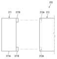
제 3 하우징 파트(215)는, 제 1 내부 커버 면(211-2)을 대면하는 제 1 단부 부분(215-1), 제 1 단부 부분(215-1)에 반대되게 위치되고 제 2 내부 커버 면(213-2)을 대면하는 제 2 단부 부분(215-2), 및 제 1 단부 부분(215-1) 및 제 2 단부 부분(215-2) 사이의 제 1 사이드 부분(215-3)을 포함할 수 있다. 제 3 하우징 파트(215)의 제 1 사이드 부분(215-3)은 제 1 하우징(210)의 제 1 사이드 면(210C)을 적어도 부분적으로 형성할 수 있다.The third housing part (215) may include a first end portion (215-1) facing the first inner cover face (211-2), a second end portion (215-2) positioned opposite the first end portion (215-1) and facing the second inner cover face (213-2), and a first side portion (215-3) between the first end portion (215-1) and the second end portion (215-2). The first side portion (215-3) of the third housing part (215) may at least partially form the first side face (210C) of the first housing (210).
일 실시 예에서, 제 3 하우징 파트(215)는 제 1 단부 부분(215-1)에 형성된 제 1 수용 개구(O1)를 포함할 수 있다. 제 1 수용 개구(O1)는, 예를 들면, 실질적으로 원형 또는 타원형일 수 있다. 제 1 수용 개구(O1)는 제 1 단부 부분(215-1)의 중심 부분에 형성될 수 있다. 제 1 수용 개구(O1)는, 제 1 하우징 파트(211) 및 제 3 하우징 파트(215) 결합 시, 제 1 접근 개구(211C)와 실질적으로 정렬될 수 있다.In one embodiment, the third housing part (215) can include a first receiving opening (O1) formed in the first end part (215-1). The first receiving opening (O1) can be, for example, substantially circular or oval. The first receiving opening (O1) can be formed in a central portion of the first end part (215-1). The first receiving opening (O1) can be substantially aligned with the first access opening (211C) when the first housing part (211) and the third housing part (215) are coupled.
일 실시 예에서, 제 3 하우징 파트(215)는, 제 1 단부 부분(215-1)에 형성된 제 1 리세스 부분(R1)을 포함할 수 있다. 제 1 리세스 부분(R1)은, 예를 들면, 제 3 하우징 파트(215)의 가장자리 및 제 4 하우징 파트(217)의 가장자리에 의해 둘러싸이고, 제 1 단부 부분(215-1)이 적어도 부분적으로 리세스됨으로써 형성될 수 있다. 제 1 리세스 부분(R1)에는 제 1 수용 개구(O1)가 형성될 수 있다.In one embodiment, the third housing part (215) may include a first recessed part (R1) formed in the first end part (215-1). The first recessed part (R1) may be formed by, for example, being surrounded by an edge of the third housing part (215) and an edge of the fourth housing part (217), and the first end part (215-1) being at least partially recessed. A first receiving opening (O1) may be formed in the first recessed part (R1).
일 실시 예에서, 제 3 하우징 파트(215)는, 제 1 리세스 부분(R1)에 형성되고 제 1 결합부(211B)와 결합하도록 구성된 적어도 하나의 제 3 결합부(215A)를 포함할 수 있다. 어떤 실시 예에서, 제 3 하우징 파트(215)는 제 1 리세스 부분(R1) 중 제 3 하우징 파트(215)의 가장자리에 인접한 영역에 형성된 복수 개의 제 3 결합부(215A)들을 포함할 수 있다.In one embodiment, the third housing part (215) may include at least one third coupling portion (215A) formed in the first recessed portion (R1) and configured to couple with the first coupling portion (211B). In some embodiments, the third housing part (215) may include a plurality of third coupling portions (215A) formed in an area adjacent to an edge of the third housing part (215) of the first recessed portion (R1).
일 실시 예에서, 제 3 결합부(215A)는 제 1 탭(211B-2)과 맞물리도록 구성된 제 1 홈을 포함할 수 있다. 어떤 실시 예에서, 제 1 홈은 제 1 플렉서블 플랜지(211B-1)의 적어도 일부를 수용할 수 있다.In one embodiment, the third coupling portion (215A) may include a first groove configured to engage the first tab (211B-2). In some embodiments, the first groove may accommodate at least a portion of the first flexible flange (211B-1).
일 실시 예에서, 제 3 하우징 파트(215)는 제 2 단부 부분(215-2)에 형성된 제 2 수용 개구(O2)를 포함할 수 있다. 제 2 수용 개구(O2)는, 예를 들면, 실질적으로 다각형(예: 사각형)일 수 있다. 제 2 수용 개구(O2)는 제 2 단부 부분(215-2)의 중심 부분에 형성될 수 있다. 제 2 수용 개구(O2)는, 제 2 하우징 파트(213) 및 제 3 하우징 파트(215) 결합 시, 제 2 접근 개구(213C)와 실질적으로 정렬될 수 있다. 제 2 수용 개구(O2)는 연결 단자(214)를 적어도 부분적으로 수용하도록 구성될 수 있다.In one embodiment, the third housing part (215) can include a second receiving opening (O2) formed in the second end portion (215-2). The second receiving opening (O2) can be, for example, substantially polygonal (e.g., rectangular). The second receiving opening (O2) can be formed in a central portion of the second end portion (215-2). The second receiving opening (O2) can be substantially aligned with the second access opening (213C) when the second housing part (213) and the third housing part (215) are coupled. The second receiving opening (O2) can be configured to at least partially receive the connection terminal (214).
일 실시 예에서, 제 3 하우징 파트(215)는, 제 2 단부 부분(215-2)에 형성된 제 2 리세스 부분(R2)을 포함할 수 있다. 제 2 리세스 부분(R2)은, 예를 들면, 제 3 하우징 파트(215)의 가장자리 및 제 4 하우징 파트(217)의 가장자리에 의해 둘러싸이고, 제 2 단부 부분(215-2)이 적어도 부분적으로 리세스됨으로써 형성될 수 있다. 제 2 리세스 부분(R2)에는 제 2 수용 개구(O2)가 형성될 수 있다.In one embodiment, the third housing part (215) may include a second recessed part (R2) formed in the second end part (215-2). The second recessed part (R2) may be formed, for example, by being surrounded by an edge of the third housing part (215) and an edge of the fourth housing part (217), and by the second end part (215-2) being at least partially recessed. A second receiving opening (O2) may be formed in the second recessed part (R2).
일 실시 예에서, 제 3 하우징 파트(215)는, 제 2 리세스 부분(R2)에 형성되고 제 2 결합부(213B)와 결합하도록 구성된 적어도 하나의 제 4 결합부(215B)를 포함할 수 있다. 어떤 실시 예에서, 제 3 하우징 파트(215)는 제 2 리세스 부분(R2) 중 제 3 하우징 파트(215)의 가장자리에 인접한 영역 및/또는 제 4 하우징 파트(217)의 가장자리에 인접한 영역에 형성된 복수 개의 제 4 결합부(215B)들을 포함할 수 있다.In one embodiment, the third housing part (215) may include at least one fourth coupling portion (215B) formed in the second recessed portion (R2) and configured to couple with the second coupling portion (213B). In some embodiments, the third housing part (215) may include a plurality of fourth coupling portions (215B) formed in an area adjacent to an edge of the third housing part (215) and/or an area adjacent to an edge of the fourth housing part (217) of the second recessed portion (R2).
일 실시 예에서, 제 4 결합부(215B)는 제 2 탭(213B-2)과 맞물리도록 구성된 제 2 홈을 포함할 수 있다. 어떤 실시 예에서, 제 2 홈은 제 2 플렉서블 플랜지(213B-1)의 적어도 일부를 수용할 수 있다.In one embodiment, the fourth coupling portion (215B) may include a second groove configured to engage the second tab (213B-2). In some embodiments, the second groove may accommodate at least a portion of the second flexible flange (213B-1).
일 실시 예에서, 제 3 하우징 파트(215)는, 제 2 리세스 부분(R2)에 형성된 디자인 요소를 포함하는 적어도 하나의 영역(A1, A2)을 포함할 수 있다. 예를 들면, 디자인 요소는, QR 코드, 인증 마크, 시리얼 넘버, 스티커, 각인 및/또는 기타 디자인 요소를 포함할 수 있다. 어떤 실시 예에서, 제 3 하우징 파트(215)는, 서로 다른 디자인 요소를 각각 포함하는 복수 개의 영역(A1, A2)들을 포함할 수 있다. 어떤 실시 예에서, 제 3 하우징 파트(215)는, 제 1 디자인 요소를 포함하고 연결 단자(214)의 제 1 측(예: 도 6에서 좌측)에 위치된 제 1 영역(A1), 및 제 2 디자인 요소를 포함하고 연결 단자(214)의 제 1 측에 반대되는 제 2 측(예: 도 6에서 우측)에 위치된 제 2 영역(A2)을 포함할 수 있다. 디자인 요소는, 예를 들면, 제 2 커버 부분(213B)이 제 3 하우징 파트(215) 및/또는 제 4 하우징 파트(217)와 결합할 때, 제 2 커버 부분(213B)에 의해 가시적으로 가려질 수 있다.In one embodiment, the third housing part (215) can include at least one area (A1, A2) including a design element formed in the second recessed portion (R2). For example, the design element can include a QR code, an authentication mark, a serial number, a sticker, an engraving, and/or other design elements. In some embodiments, the third housing part (215) can include a plurality of areas (A1, A2) each including different design elements. In some embodiments, the third housing part (215) can include a first area (A1) including a first design element and positioned on a first side (e.g., the left side in FIG. 6 ) of the connection terminal (214), and a second area (A2) including a second design element and positioned on a second side (e.g., the right side in FIG. 6 ) of the connection terminal (214) opposite the first side. The design elements may be visibly obscured by the second cover part (213B), for example, when the second cover part (213B) is coupled with the third housing part (215) and/or the fourth housing part (217).
일 실시 예에서, 제 3 하우징 파트(215)는 제 1 사이드 부분(215-3)의 내부 면에 형성된 적어도 하나의 제 5 결합부(C1)를 포함할 수 있다. 제 5 결합부(C1)는, 예를 들면, 제 1 단부 부분(215-1) 및 제 2 단부 부분(215-2) 사이에서 적어도 부분적으로 연장하고 제 1 사이드 부분(215-3)의 내부 면으로부터 돌출하는 리브를 포함할 수 있다.In one embodiment, the third housing part (215) may include at least one fifth coupling portion (C1) formed on an inner surface of the first side portion (215-3). The fifth coupling portion (C1) may include, for example, a rib extending at least partially between the first end portion (215-1) and the second end portion (215-2) and protruding from the inner surface of the first side portion (215-3).
제 4 하우징 파트(217)는, 제 1 단부 부분(215-1)을 대면하는 제 3 단부 부분(217-1), 제 3 단부 부분(217-1)에 반대되게 위치되고 제 2 단부 부분(215-2)을 대면하는 제 4 단부 부분(217-2), 제 1 하우징(210)의 제 2 사이드 면(210D)을 적어도 부분적으로 형성하는 제 3 단부 부분(217-1) 및 제 4 단부 부분(217-2) 사이의 제 2 사이드 부분(217-3), 및 제 2 사이드 부분(217-3)에 연결되고 제 1 사이드 부분(215-3)의 내부 면을 대면하는 제 3 단부 부분(217-1) 및 제 4 단부 부분(217-2) 사이의 제 3 사이드 부분(217-4)을 포함할 수 있다. 제 4 단부 부분(217-2)에는 연결 단자(214)가 형성될 수 있다.The fourth housing part (217) may include a third end part (217-1) facing the first end part (215-1), a fourth end part (217-2) positioned opposite the third end part (217-1) and facing the second end part (215-2), a second side part (217-3) between the third end part (217-1) and the fourth end part (217-2) that at least partially forms a second side surface (210D) of the first housing (210), and a third side part (217-4) between the third end part (217-1) and the fourth end part (217-2) that is connected to the second side part (217-3) and faces an inner surface of the first side part (215-3). A connecting terminal (214) can be formed in the fourth section (217-2).
일 실시 예에서, 제 4 하우징 파트(217)는 제 3 사이드 부분(217-4)에 형성되고 제 5 결합부(C1)와 결합하도록 구성된 적어도 하나의 제 6 결합부(C2)를 포함할 수 있다. 제 6 결합부(C2)는, 예를 들면, 제 3 단부 부분(217-1) 및 제 4 단부 부분(217-2) 사이에서 연장하고 제 3 사이드 부분(217-4)의 외부 면으로부터 내측으로 리세스 된 슬롯을 포함할 수 있다.In one embodiment, the fourth housing part (217) may include at least one sixth coupling portion (C2) formed on the third side portion (217-4) and configured to couple with the fifth coupling portion (C1). The sixth coupling portion (C2) may include, for example, a slot extending between the third end portion (217-1) and the fourth end portion (217-2) and recessed inwardly from an outer surface of the third side portion (217-4).
일 실시 예에서, 제 3 하우징 파트(215) 및/또는 제 4 하우징 파트(217)는 적어도 부분적으로 탄성적으로 변형하도록 구성될 수 있다. 예를 들면, 제 5 결합부(C1) 및 제 6 결합부(C2)는, 제 1 사이드 부분(215-3), 제 2 사이드 부분(217-1) 및/또는 제 3 사이드 부분(217-2)이 적어도 부분적으로 탄성적으로 변형함으로써, 결합 및 결합 해제될 수 있다.In one embodiment, the third housing part (215) and/or the fourth housing part (217) can be configured to be at least partially elastically deformable. For example, the fifth coupling portion (C1) and the sixth coupling portion (C2) can be coupled and decoupled by the first side portion (215-3), the second side portion (217-1) and/or the third side portion (217-2) being at least partially elastically deformable.
에어로졸 발생 장치(200)는, 에어로졸 생성 물품(201)이 삽입되고 에어로졸 생성 물품(201)이 제거되는 삽입 공간을 포함하는 물품 삽입부(220)를 포함할 수 있다. 일 실시 예에서, 물품 삽입부(220)는, 에어로졸 생성 물품(201)을 고정하도록 구성된 복수 개의 고정부들, 및 복수 개의 고정부들 사이에 형성된 복수 개의 삽입부 기류 통로들을 포함할 수 있다. 일 실시 예에서, 삽입부 기류 통로들은 오로지 삽입부 기류 통로들을 통해서만 제 1 하우징(210) 안으로(예를 들면, 제 2 하우징(230) 안으로) 공기를 유입시킬 수 있다. 제 1 하우징(210)은 삽입부 기류 통로들을 제외한 나머지 부분에서 제 1 하우징(210)의 외부 및 내부 사이에 기류의 유동이 발생하지 않도록 밀폐될 수 있다. 일 실시 예에서, 물품 삽입부(220)는 제 1 단부 부분(215-1)에 형성된 제 1 수용 개구(O1) 내 적어도 부분적으로 위치될 수 있다.The aerosol generating device (200) may include an article insertion portion (220) including an insertion space into which an aerosol generating article (201) is inserted and from which the aerosol generating article (201) is removed. In one embodiment, the article insertion portion (220) may include a plurality of fixing portions configured to fix the aerosol generating article (201), and a plurality of insertion portion airflow passages formed between the plurality of fixing portions. In one embodiment, the insertion portion airflow passages may allow air to be introduced into the first housing (210) (e.g., into the second housing (230)) only through the insertion portion airflow passages. The first housing (210) may be sealed such that no airflow occurs between the exterior and interior of the first housing (210) except for the insertion portion airflow passages. In one embodiment, the article insertion portion (220) may be at least partially positioned within a first receiving opening (O1) formed in the first end portion (215-1).
에어로졸 발생 장치(200)는, 에어로졸 생성 물품(201)을 적어도 부분적으로 수용하고 에어로졸 생성 물품(201)을 가열하도록 구성된 제 2 하우징(230)을 포함할 수 있다. 제 2 하우징(230)은 제 1 하우징(210) 내 위치될 수 있다. 제 2 하우징(230)은 물품 삽입부(220)와 유체 연결될 수 있다.The aerosol generating device (200) may include a second housing (230) configured to at least partially accommodate an aerosol generating article (201) and heat the aerosol generating article (201). The second housing (230) may be positioned within the first housing (210). The second housing (230) may be in fluid connection with the article insert (220).
일 실시 예에서, 제 2 하우징(230)은, 복수 개의 기류 통로들을 포함하는 복수 개의 레이어들(232, 234, 236)을 포함할 수 있다. 예를 들면, 제 2 하우징(230)은, 물품 삽입부(220)와 유체 연결된 적어도 하나의 기류 통로를 갖는 제 1 레이어(232), 제 1 레이어(232)에 연결되고 제 1 레이어(232)의 적어도 하나의 기류 통로와 유체 연결된 적어도 하나의 기류 통로를 갖는 제 2 레이어(234), 및 제 2 레이어(234) 내 위치되고 제 2 레이어(234)의 적어도 하나의 기류 통로와 유체 연결된 적어도 하나의 기류 통로를 갖는 제 3 레이어(236)를 포함할 수 있다.In one embodiment, the second housing (230) can include a plurality of layers (232, 234, 236) including a plurality of airflow passages. For example, the second housing (230) can include a first layer (232) having at least one airflow passage in fluid communication with the article insert (220), a second layer (234) connected to the first layer (232) and having at least one airflow passage in fluid communication with at least one airflow passage of the first layer (232), and a third layer (236) positioned within the second layer (234) and having at least one airflow passage in fluid communication with at least one airflow passage of the second layer (234).
일 실시 예에서, 제 1 레이어(232)의 치수(예: 직경)는 제 2 레이어(234)의 치수(예: 직경)와 실질적으로 동일하거나 그보다 작을 수 있다. 일 실시 예에서, 제 2 레이어(234)의 치수(예: 직경)는 제 3 레이어(236)의 치수(예: 직경)와 실질적으로 동일하거나 그보다 클 수 있다.In one embodiment, the dimension (e.g., diameter) of the first layer (232) can be substantially the same as or smaller than the dimension (e.g., diameter) of the second layer (234). In one embodiment, the dimension (e.g., diameter) of the second layer (234) can be substantially the same as or larger than the dimension (e.g., diameter) of the third layer (236).
일 실시 예에서, 제 2 레이어(234)는, 사이드 부분(234A), 및 사이드 부분(234A)에 연결되고 제 3 레이어(236) 및/또는 에어로졸 생성 물품(201)의 일 면(예: 바닥 면)을 지지하도록 구성된 제 1 바닥 부분(234B)을 포함할 수 있다. 어떤 실시 예에서, 제 2 레이어(234)는, 제 1 바닥 부분(234B)으로부터 이격된 제 2 바닥 부분(234C), 및 제 1 바닥 부분(234B) 및 제 2 바닥 부분(234C)을 연결하는 벽 부분(234D)을 포함할 수 있다. 제 2 바닥 부분(234C) 및 벽 부분(234D)은 에어로졸 생성 물품(201)의 일 면(예: 바닥 면)으로 기류를 가이드하는 통로를 형성할 수 있다. 어떤 실시 예에서, 사이드 부분(234A)의 치수(예: 직경)는 벽 부분(234D)의 치수(예: 직경)보다 실질적으로 동일하거나 그보다 클 수 있다.In one embodiment, the second layer (234) can include a side portion (234A), and a first bottom portion (234B) connected to the side portion (234A) and configured to support the third layer (236) and/or one side (e.g., the bottom surface) of the aerosol generating article (201). In some embodiments, the second layer (234) can include a second bottom portion (234C) spaced from the first bottom portion (234B), and a wall portion (234D) connecting the first bottom portion (234B) and the second bottom portion (234C). The second bottom portion (234C) and the wall portion (234D) can form a passage that guides airflow to one side (e.g., the bottom surface) of the aerosol generating article (201). In some embodiments, the dimension (e.g., diameter) of the side portion (234A) may be substantially equal to or greater than the dimension (e.g., diameter) of the wall portion (234D).
일 실시 예에서, 제 1 바닥 부분(234B)은 제 3 레이어(236)의 적어도 하나의 기류 통로와 유체 연결된 적어도 하나의 기류 홀을 가지고, 벽 부분(234D)은 제 1 바닥 부분(234B)의 적어도 하나의 기류 홀을 통과하는 기류가 유입되는 적어도 하나의 기류 홀을 가질 수 있다.In one embodiment, the first bottom portion (234B) can have at least one airflow hole fluidly connected to at least one airflow passage of the third layer (236), and the wall portion (234D) can have at least one airflow hole through which airflow passing through the at least one airflow hole of the first bottom portion (234B) is introduced.
일 실시 예에서, 제 2 하우징(230)은, 에어로졸 생성 물품(201)을 적어도 부분적으로 수용하고 에어로졸 생성 물품(201)의 일 면(예: 측면)을 지지하도록 구성된 서셉터(238)를 포함할 수 있다. 서셉터(238)는 제 3 레이어(236) 상에 위치되고 제 2 레이어(234)의 사이드 부분(234A)을 따라 연장할 수 있다.In one embodiment, the second housing (230) can include a susceptor (238) configured to at least partially accommodate the aerosol generating article (201) and support one side (e.g., a side) of the aerosol generating article (201). The susceptor (238) can be positioned on the third layer (236) and extend along a side portion (234A) of the second layer (234).
에어로졸 발생 장치(200)는 물품 삽입부(220) 및 제 2 하우징(230) 사이의 기류의 압력을 감지하도록 구성된 압력 센서(240)를 포함할 수 있다. 압력 센서(240)는, 예를 들면, 물품 삽입부(220)를 통해 기류가 유입되면 기류의 속도 변화에 따른 기류의 압력 변화를 감지할 수 있다. 일 실시 예에서, 압력 센서(240)는 물품 삽입부(220) 및 제 2 하우징(230) 사이의 유동 스트림 상에 그리고 제 1 하우징(210) 내 위치될 수 있다. 어떤 실시 예에서, 압력 센서(240)는 제 1 면(210A)에 인접하게 위치될 수 있다. 어떤 실시 예에서, 에어로졸 발생 장치(200)는 복수 개의 압력 센서(240)들을 포함할 수 있다.The aerosol generating device (200) may include a pressure sensor (240) configured to detect a pressure of an airflow between the article insertion portion (220) and the second housing (230). The pressure sensor (240) may detect, for example, a change in pressure of an airflow according to a change in the speed of the airflow when the airflow is introduced through the article insertion portion (220). In one embodiment, the pressure sensor (240) may be positioned on a flow stream between the article insertion portion (220) and the second housing (230) and within the first housing (210). In some embodiments, the pressure sensor (240) may be positioned adjacent to the first surface (210A). In some embodiments, the aerosol generating device (200) may include a plurality of pressure sensors (240).
일 실시 예에 따른 에어로졸 발생 장치(200)의 분해 동작을 설명하면, 먼저 사용자는 제 1 하우징 파트(211) 및/또는 제 2 하우징 파트(213)를 제 3 하우징 파트(215)로부터 분리할 수 있다. 이후 사용자는 제 3 하우징 파트(215) 및 제 4 하우징 파트(217)를 분리할 수 있다. 이후 사용자는 제 1 하우징 파트(211), 제 2 하우징 파트(213), 제 3 하우징 파트(215) 및/또는 제 4 하우징 파트(217) 내 축적된 물질(예: 에어로졸)을 제거할 수 있다. 일 실시 예에 따른 에어로졸 발생 장치(200)의 조립 동작을 설명하면, 사용자는 제 3 하우징 파트(215) 및 제 4 하우징 파트(217)를 조립할 수 있다. 이후 사용자는 제 1 하우징 파트(211) 및/또는 제 2 하우징 파트(213)를 제 3 하우징 파트(215)와 조립할 수 있다.Describing a disassembly operation of an aerosol generating device (200) according to an embodiment, first, a user can separate the first housing part (211) and/or the second housing part (213) from the third housing part (215). Thereafter, the user can separate the third housing part (215) and the fourth housing part (217). Thereafter, the user can remove accumulated substances (e.g., aerosol) within the first housing part (211), the second housing part (213), the third housing part (215), and/or the fourth housing part (217). Describing an assembly operation of an aerosol generating device (200) according to an embodiment, a user can assemble the third housing part (215) and the fourth housing part (217). The user can then assemble the first housing part (211) and/or the second housing part (213) with the third housing part (215).
도 7을 참조하면, 일 실시 예에 따른 하우징(310)(예: 제 1 하우징(210))은, 서로 분리 가능하게 결합되도록 구성된 제 1 하우징 파트(311)(예: 제 1 하우징 파트(211) 및/또는 제 2 하우징 파트(213)), 및 제 2 하우징 파트(312)(예: 제 3 하우징 파트(215))를 포함할 수 있다. 제 1 하우징 파트(311)는, 커버 부분(311A)(예: 제 1 커버 부분(211A) 및/또는 제 2 커버 부분(211B)), 및 제 1 결합부(311B)(예: 제 1 결합부(211B) 및/또는 제 2 결합부(213B))를 포함할 수 있다. 제 2 하우징 파트(312)는 제 2 결합부(313A)(예: 제 3 결합부(215A) 및/또는 제 4 결합부(217A))를 포함할 수 있다. 일 실시 예에서, 제 1 결합부(311B)는 제 1 자기 요소를 포함하고, 제 2 결합부(313A)는 제 1 자기 요소와 자기적으로 커플링되도록 구성된 제 2 자기 요소를 포함할 수 있다. 일 실시 예에서, 제 1 자기 요소는 자석 및 금속 플레이트 중 어느 하나를 포함하고, 제 2 자기 요소는 자석 및 금속 플레이트 중 다른 하나를 포함할 수 있다. 금속 플레이트는, 예를 들면, STS(special treatment steel) 재질로 적어도 부분적으로 형성될 수 있다. 다른 실시 예에서, 제 1 자기 요소 및 제 2 자기 요소는 각각 서로 다른 극성을 갖는 자석을 포함할 수도 있다.Referring to FIG. 7, a housing (310) (e.g., a first housing (210)) according to one embodiment may include a first housing part (311) (e.g., the first housing part (211) and/or the second housing part (213)) and a second housing part (312) (e.g., the third housing part (215)) configured to be detachably coupled to each other. The first housing part (311) may include a cover part (311A) (e.g., the first cover part (211A) and/or the second cover part (211B)) and a first coupling portion (311B) (e.g., the first coupling portion (211B) and/or the second coupling portion (213B)). The second housing part (312) can include a second coupling portion (313A) (e.g., the third coupling portion (215A) and/or the fourth coupling portion (217A)). In one embodiment, the first coupling portion (311B) can include a first magnetic element, and the second coupling portion (313A) can include a second magnetic element configured to be magnetically coupled with the first magnetic element. In one embodiment, the first magnetic element can include one of a magnet and a metal plate, and the second magnetic element can include the other of the magnet and the metal plate. The metal plate can be at least partially formed of, for example, a special treatment steel (STS) material. In another embodiment, the first magnetic element and the second magnetic element may each include magnets having different polarities.
도 8을 참조하면, 에어로졸 발생 장치(1)는 배터리(11), 제어부(12) 및 히터(13)를 포함한다. 도 9 및 도 10을 참조하면, 에어로졸 발생 장치(1)는 증기화기(14)를 더 포함한다. 또한, 에어로졸 발생 장치(1)의 내부 공간에는 에어로졸 생성 물품(2)(예: 궐련)이 삽입될 수 있다.Referring to FIG. 8, the aerosol generating device (1) includes a battery (11), a control unit (12), and a heater (13). Referring to FIGS. 9 and 10, the aerosol generating device (1) further includes a vaporizer (14). In addition, an aerosol generating article (2) (e.g., a cigarette) can be inserted into the internal space of the aerosol generating device (1).
도 8 내지 도 10에 도시된 에어로졸 발생 장치(1)에는 본 실시 예와 관련된 구성요소들이 도시되어 있다. 따라서, 도 8 내지 도 10에 도시된 구성요소들 외에 다른 범용적인 구성요소들이 에어로졸 발생 장치(1)에 더 포함될 수 있음을 본 실시 예와 관련된 기술분야에서 통상의 지식을 가진 자라면 이해할 수 있다.The aerosol generating device (1) illustrated in FIGS. 8 to 10 illustrates components related to the present embodiment. Accordingly, a person having ordinary skill in the art related to the present embodiment will understand that, in addition to the components illustrated in FIGS. 8 to 10, other general-purpose components may be further included in the aerosol generating device (1).
또한, 도 9 및 도 10에는 에어로졸 발생 장치(1)에 히터(13)가 포함되어 있는 것으로 도시되어 있으나, 필요에 따라, 히터(13)는 생략될 수도 있다.In addition, although FIGS. 9 and 10 illustrate that the aerosol generating device (1) includes a heater (13), the heater (13) may be omitted if necessary.
도 8에는 배터리(11), 제어부(12) 및 히터(13)가 일렬로 배치된 것으로 도시되어 있다. 또한, 도 9에는 배터리(11), 제어부(12), 증기화기(14) 및 히터(13)가 일렬로 배치된 것으로 도시되어 있다. 또한, 도 10에는 증기화기(14) 및 히터(13)가 병렬로 배치된 것으로 도시되어 있다. 그러나, 에어로졸 발생 장치(1)의 내부 구조는 도 8 내지 도 10에 도시된 것에 한정되지 않는다. 다시 말해, 에어로졸 발생 장치(1)의 설계에 따라, 배터리(11), 제어부(12), 히터(13) 및 증기화기(14)의 배치는 변경될 수 있다.In Fig. 8, the battery (11), the control unit (12), and the heater (13) are illustrated as being arranged in a row. In addition, in Fig. 9, the battery (11), the control unit (12), the vaporizer (14), and the heater (13) are illustrated as being arranged in a row. In addition, in Fig. 10, the vaporizer (14) and the heater (13) are illustrated as being arranged in parallel. However, the internal structure of the aerosol generating device (1) is not limited to that illustrated in Figs. 8 to 10. In other words, depending on the design of the aerosol generating device (1), the arrangement of the battery (11), the control unit (12), the heater (13), and the vaporizer (14) may be changed.
에어로졸 생성 물품(2)이 에어로졸 발생 장치(1)에 삽입되면, 에어로졸 발생 장치(1)는 히터(13) 및/또는 증기화기(14)를 작동시켜, 에어로졸을 발생시킬 수 있다. 히터(13) 및/또는 증기화기(14)에 의하여 발생된 에어로졸은 에어로졸 생성 물품(2)을 통과하여 사용자에게 전달된다.When an aerosol generating article (2) is inserted into an aerosol generating device (1), the aerosol generating device (1) can generate an aerosol by operating a heater (13) and/or a vaporizer (14). The aerosol generated by the heater (13) and/or the vaporizer (14) passes through the aerosol generating article (2) and is delivered to the user.
필요에 따라, 에어로졸 생성 물품(2)이 에어로졸 발생 장치(1)에 삽입되지 않은 경우에도 에어로졸 발생 장치(1)는 히터(13)를 가열할 수 있다.If necessary, the aerosol generating device (1) can heat the heater (13) even when the aerosol generating article (2) is not inserted into the aerosol generating device (1).
배터리(11)는 에어로졸 발생 장치(1)가 동작하는데 이용되는 전력을 공급한다. 예를 들면, 배터리(11)는 히터(13) 또는 증기화기(14)가 가열될 수 있도록 전력을 공급할 수 있고, 제어부(12)가 동작하는데 필요한 전력을 공급할 수 있다. 또한, 배터리(11)는 에어로졸 발생 장치(1)에 설치된 디스플레이, 센서, 모터 등이 동작하는데 필요한 전력을 공급할 수 있다.The battery (11) supplies power used to operate the aerosol generating device (1). For example, the battery (11) can supply power so that the heater (13) or the vaporizer (14) can be heated, and can supply power required for the control unit (12) to operate. In addition, the battery (11) can supply power required for the display, sensor, motor, etc. installed in the aerosol generating device (1) to operate.
제어부(12)는 에어로졸 발생 장치(1)의 동작을 전반적으로 제어한다. 구체적으로, 제어부(12)는 배터리(11), 히터(13) 및 증기화기(14) 뿐만 아니라 에어로졸 발생 장치(1)에 포함된 다른 구성들의 동작을 제어한다. 또한, 제어부(12)는 에어로졸 발생 장치(1)의 구성들 각각의 상태를 확인하여, 에어로졸 발생 장치(1)가 동작 가능한 상태인지 여부를 판단할 수도 있다.The control unit (12) controls the overall operation of the aerosol generating device (1). Specifically, the control unit (12) controls the operation of the battery (11), the heater (13), and the vaporizer (14) as well as other components included in the aerosol generating device (1). In addition, the control unit (12) can check the status of each component of the aerosol generating device (1) to determine whether the aerosol generating device (1) is in an operable state.
제어부(12)는 적어도 하나의 프로세서를 포함한다. 프로세서는 다수의 논리 게이트들의 어레이로 구현될 수도 있고, 범용적인 마이크로 프로세서와 이 마이크로 프로세서에서 실행될 수 있는 프로그램이 저장된 메모리의 조합으로 구현될 수도 있다. 또한, 다른 형태의 하드웨어로 구현될 수도 있음을 본 실시 예가 속하는 기술분야에서 통상의 지식을 가진 자라면 이해할 수 있다.The control unit (12) includes at least one processor. The processor may be implemented as an array of a plurality of logic gates, or may be implemented as a combination of a general-purpose microprocessor and a memory storing a program that can be executed by the microprocessor. In addition, it will be understood by those skilled in the art to which the present embodiment belongs that the processor may be implemented as other types of hardware.
히터(13)는 배터리(11)로부터 공급된 전력에 의하여 가열될 수 있다. 예를 들면, 궐련이 에어로졸 발생 장치(1)에 삽입되면, 히터(13)는 궐련의 외부에 위치할 수 있다. 따라서, 가열된 히터(13)는 궐련 내의 에어로졸 생성 물질의 온도를 상승시킬 수 있다.The heater (13) can be heated by power supplied from the battery (11). For example, when a cigarette is inserted into the aerosol generating device (1), the heater (13) can be located outside the cigarette. Accordingly, the heated heater (13) can increase the temperature of the aerosol generating material inside the cigarette.
히터(13)는 전기 저항성 히터일 수 있다. 예를 들면, 히터(13)에는 전기 전도성 트랙(track)을 포함하고, 전기 전도성 트랙에 전류가 흐름에 따라 히터(13)가 가열될 수 있다. 그러나, 히터(13)는 상술한 예에 한정되지 않으며, 희망 온도까지 가열될 수 있는 것이라면 제한 없이 해당될 수 있다. 여기에서, 희망 온도는 에어로졸 발생 장치(1)에 기 설정되어 있을 수도 있고, 사용자에 의하여 원하는 온도로 설정될 수도 있다.The heater (13) may be an electrical resistance heater. For example, the heater (13) may include an electrically conductive track, and the heater (13) may be heated as current flows through the electrically conductive track. However, the heater (13) is not limited to the above-described example, and may be applied without limitation as long as it can be heated to a desired temperature. Here, the desired temperature may be preset in the aerosol generating device (1), or may be set to a desired temperature by the user.
한편, 다른 예로, 히터(13)는 유도 가열식 히터일 수 있다. 구체적으로, 히터(13)에는 궐련을 유도 가열 방식으로 가열하기 위한 전기 전도성 코일을 포함할 수 있으며, 궐련은 유도 가열식 히터에 의해 가열될 수 있는 서셉터를 포함할 수 있다.Meanwhile, as another example, the heater (13) may be an induction heating heater. Specifically, the heater (13) may include an electrically conductive coil for heating the cigarette in an induction heating manner, and the cigarette may include a susceptor that can be heated by the induction heating heater.
예를 들면, 히터(13)는 관 형 가열 요소, 판 형 가열 요소, 침 형 가열 요소 또는 봉 형의 가열 요소를 포함할 수 있으며, 가열 요소의 모양에 따라 에어로졸 생성 물품(2)의 내부 또는 외부를 가열할 수 있다.For example, the heater (13) may include a tubular heating element, a plate-shaped heating element, a needle-shaped heating element, or a rod-shaped heating element, and may heat the inside or the outside of the aerosol generating article (2) depending on the shape of the heating element.
또한, 에어로졸 발생 장치(1)에는 히터(13)가 복수 개 배치될 수도 있다. 이때, 복수 개의 히터(13)들은 에어로졸 생성 물품(2)의 내부에 삽입되도록 배치될 수도 있고, 에어로졸 생성 물품(2)의 외부에 배치될 수도 있다. 또한, 복수 개의 히터(13)들 중 일부는 에어로졸 생성 물품(2)의 내부에 삽입되도록 배치되고, 나머지는 에어로졸 생성 물품(2)의 외부에 배치될 수 있다. 또한, 히터(13)의 형상은 도 8 내지 도 10에 도시된 형상에 한정되지 않고, 다양한 형상으로 제작될 수 있다.In addition, a plurality of heaters (13) may be arranged in the aerosol generating device (1). At this time, the plurality of heaters (13) may be arranged to be inserted into the interior of the aerosol generating article (2), or may be arranged on the exterior of the aerosol generating article (2). In addition, some of the plurality of heaters (13) may be arranged to be inserted into the interior of the aerosol generating article (2), and the rest may be arranged on the exterior of the aerosol generating article (2). In addition, the shape of the heater (13) is not limited to the shape illustrated in FIGS. 8 to 10, and may be manufactured in various shapes.
증기화기(14)는 액상 조성물을 가열하여 에어로졸을 생성할 수 있으며, 생성된 에어로졸은 에어로졸 생성 물품(2)을 통과하여 사용자에게 전달될 수 있다. 다시 말해, 증기화기(14)에 의하여 생성된 에어로졸은 에어로졸 발생 장치(1)의 기류 통로를 따라 이동할 수 있고, 기류 통로는 증기화기(14)에 의하여 생성된 에어로졸이 궐련을 통과하여 사용자에게 전달될 수 있도록 구성될 수 있다.The vaporizer (14) can heat the liquid composition to generate an aerosol, and the generated aerosol can be delivered to the user by passing through the aerosol generating article (2). In other words, the aerosol generated by the vaporizer (14) can travel along the airflow passage of the aerosol generating device (1), and the airflow passage can be configured so that the aerosol generated by the vaporizer (14) can pass through the cigarette and be delivered to the user.
예를 들면, 증기화기(14)는 액체 저장부, 액체 전달 수단 및 가열 요소를 포함할 수 있으나, 이에 한정되지 않는다. 예를 들면, 액체 저장부, 액체 전달 수단 및 가열 요소는 독립적인 모듈로서 에어로졸 발생 장치(1)에 포함될 수도 있다.For example, the vaporizer (14) may include, but is not limited to, a liquid reservoir, a liquid delivery means, and a heating element. For example, the liquid reservoir, the liquid delivery means, and the heating element may be included in the aerosol generating device (1) as independent modules.
액체 저장부는 액상 조성물을 저장할 수 있다. 예를 들면, 액상 조성물은 휘발성 담배 향 성분을 포함하는 담배 함유 물질을 포함하는 액체일 수 있고, 비 담배 물질을 포함하는 액체일 수도 있다. 액체 저장부는 증기화기(14)로부터 탈/부착될 수 있도록 제작될 수도 있고, 증기화기(14)와 일체로서 제작될 수도 있다.The liquid reservoir can store a liquid composition. For example, the liquid composition can be a liquid containing a tobacco-containing material including a volatile tobacco flavoring component, or can be a liquid containing a non-tobacco material. The liquid reservoir can be constructed to be detachable from/attachable to the vaporizer (14), or can be constructed integrally with the vaporizer (14).
예를 들면, 액상 조성물은 물, 솔벤트, 에탄올, 식물 추출물, 향료, 향미제, 또는 비타민 혼합물을 포함할 수 있다. 향료는 멘솔, 페퍼민트, 스피아민트 오일, 각종 과일향 성분 등을 포함할 수 있으나, 이에 제한되지 않는다. 향미제는 사용자에게 다양한 향미 또는 풍미를 제공할 수 있는 성분을 포함할 수 있다. 비타민 혼합물은 비타민 A, 비타민 B, 비타민 C 및 비타민 E 중 적어도 하나가 혼합된 것일 수 있으나, 이에 제한되지 않는다. 또한, 액상 조성물은 글리세린 및 프로필렌 글리콜과 같은 에어로졸 형성제를 포함할 수 있다.For example, the liquid composition may include water, a solvent, ethanol, a plant extract, a flavor, a flavoring agent, or a vitamin mixture. The flavoring agent may include, but is not limited to, menthol, peppermint, spearmint oil, various fruit-flavored ingredients, and the like. The flavoring agent may include ingredients that can provide a variety of flavors or tastes to the user. The vitamin mixture may include, but is not limited to, a mixture of at least one of vitamin A, vitamin B, vitamin C, and vitamin E. In addition, the liquid composition may include an aerosol forming agent, such as glycerin and propylene glycol.
액체 전달 수단은 액체 저장부의 액상 조성물을 가열 요소로 전달할 수 있다. 예를 들면, 액체 전달 수단은 면 섬유, 세라믹 섬유, 유리 섬유, 다공성 세라믹과 같은 심지(wick)가 될 수 있으나, 이에 한정되지 않는다.The liquid transfer means can transfer the liquid composition from the liquid storage to the heating element. For example, the liquid transfer means can be a wick such as, but not limited to, cotton fibers, ceramic fibers, glass fibers, or porous ceramics.
가열 요소는 액체 전달 수단에 의해 전달되는 액상 조성물을 가열하기 위한 요소이다. 예를 들면, 가열 요소는 금속 열선, 금속 열판, 세라믹 히터 등이 될 수 있으나, 이에 한정되지 않는다. 또한, 가열 요소는 니크롬선과 같은 전도성 필라멘트로 구성될 수 있고, 액체 전달 수단에 감기는 구조로 배치될 수 있다. 가열 요소는, 전류 공급에 의해 가열될 수 있으며, 가열 요소와 접촉된 액체 조성물에 열을 전달하여, 액체 조성물을 가열할 수 있다. 그 결과, 에어로졸이 생성될 수 있다.The heating element is an element for heating a liquid composition delivered by a liquid delivery means. For example, the heating element may be, but is not limited to, a metal heating wire, a metal heating plate, a ceramic heater, etc. In addition, the heating element may be composed of a conductive filament such as a nichrome wire, and may be arranged in a structure that is wound around the liquid delivery means. The heating element may be heated by supplying current, and may transfer heat to the liquid composition in contact with the heating element, thereby heating the liquid composition. As a result, an aerosol may be generated.
예를 들면, 증기화기(14)는 카토마이저(cartomizer) 또는 무화기(atomizer)로 지칭될 수 있으나, 이에 한정되지 않는다.For example, the vaporizer (14) may be referred to as a cartomizer or an atomizer, but is not limited thereto.
한편, 에어로졸 발생 장치(1)는 배터리(11), 제어부(12), 히터(13) 및 증기화기(14) 외에 범용적인 구성들을 더 포함할 수 있다. 예를 들면, 에어로졸 발생 장치(1)는 시각 정보의 출력이 가능한 디스플레이 및/또는 촉각 정보의 출력을 위한 모터를 포함할 수 있다. 또한, 에어로졸 발생 장치(1)는 적어도 하나의 센서(퍼프 감지 센서, 온도 감지 센서, 궐련 삽입 감지 센서 등)를 포함할 수 있다. 또한, 에어로졸 발생 장치(1)는 에어로졸 생성 물품(2)이 삽입된 상태에서도 외부 공기가 유입되거나, 내부 기체가 유출 될 수 있는 구조로 제작될 수 있다.Meanwhile, the aerosol generating device (1) may further include general-purpose components in addition to the battery (11), the control unit (12), the heater (13), and the vaporizer (14). For example, the aerosol generating device (1) may include a display capable of outputting visual information and/or a motor for outputting tactile information. In addition, the aerosol generating device (1) may include at least one sensor (a puff detection sensor, a temperature detection sensor, a cigarette insertion detection sensor, etc.). In addition, the aerosol generating device (1) may be manufactured in a structure in which external air may be introduced or internal gas may be discharged even when the aerosol generating article (2) is inserted.
도 8 내지 도 10에는 도시되지 않았으나, 에어로졸 발생 장치(1)는 별도의 크래들과 함께 시스템을 구성할 수도 있다. 예를 들면, 크래들은 에어로졸 발생 장치(1)의 배터리(11)의 충전에 이용될 수 있다. 또는, 크래들과 에어로졸 발생 장치(1)가 결합된 상태에서 히터(13)가 가열될 수도 있다.Although not shown in FIGS. 8 to 10, the aerosol generating device (1) may also be configured as a system with a separate cradle. For example, the cradle may be used to charge the battery (11) of the aerosol generating device (1). Alternatively, the heater (13) may be heated while the cradle and the aerosol generating device (1) are combined.
에어로졸 생성 물품(2)은 일반적인 연소형 궐련과 유사할 수 있다. 예를 들면, 에어로졸 생성 물품(2)은 에어로졸 생성 물질을 포함하는 제 1 부분과 필터 등을 포함하는 제 2 부분으로 구분될 수 있다. 또는, 에어로졸 생성 물품(2)의 제 2 부분에도 에어로졸 생성 물질이 포함될 수도 있다. 예를 들면, 과립 또는 캡슐의 형태로 만들어진 에어로졸 생성 물질이 제 2 부분에 삽입될 수도 있다.The aerosol generating article (2) may be similar to a typical combustible cigarette. For example, the aerosol generating article (2) may be divided into a first part containing an aerosol generating substance and a second part containing a filter or the like. Alternatively, the second part of the aerosol generating article (2) may also contain an aerosol generating substance. For example, an aerosol generating substance in the form of granules or capsules may be inserted into the second part.
에어로졸 발생 장치(1)의 내부에는 제 1 부분의 전체가 삽입되고, 제 2 부분은 외부에 노출될 수 있다. 또는, 에어로졸 발생 장치(1)의 내부에 제 1 부분의 일부만 삽입될 수도 있고, 제 1 부분의 전체 및 제 2 부분의 일부가 삽입될 수도 있다. 사용자는 제 2 부분을 입으로 문 상태에서 에어로졸을 흡입할 수 있다. 이때, 에어로졸은 외부 공기가 제 1 부분을 통과함으로써 생성되고, 생성된 에어로졸은 제 2 부분을 통과하여 사용자의 입으로 전달된다.The entire first part may be inserted into the interior of the aerosol generating device (1), and the second part may be exposed to the outside. Alternatively, only a part of the first part may be inserted into the interior of the aerosol generating device (1), or the entire first part and a part of the second part may be inserted. The user may inhale the aerosol while holding the second part in his mouth. At this time, the aerosol is generated by the outside air passing through the first part, and the generated aerosol is delivered to the user's mouth through the second part.
일 예로서, 외부 공기는 에어로졸 발생 장치(1)에 형성된 적어도 하나의 공기 통로를 통하여 유입될 수 있다. 예를 들면, 에어로졸 발생 장치(1)에 형성된 공기 통로의 개폐 및/또는 공기 통로의 크기는 사용자에 의하여 조절될 수 있다. 이에 따라, 무화량, 끽연감 등이 사용자에 의하여 조절될 수 있다. 다른 예로서, 외부 공기는 에어로졸 생성 물품(2)의 표면에 형성된 적어도 하나의 구멍(hole)을 통하여 에어로졸 생성 물품(2)의 내부로 유입될 수도 있다.As an example, outside air may be introduced through at least one air passage formed in the aerosol generating device (1). For example, the opening and closing of the air passage formed in the aerosol generating device (1) and/or the size of the air passage may be controlled by the user. Accordingly, the amount of vapor, the smoking sensation, etc. may be controlled by the user. As another example, outside air may be introduced into the interior of the aerosol generating article (2) through at least one hole formed in the surface of the aerosol generating article (2).
도 11을 참조하면, 에어로졸 생성 물품(2)은 담배 로드(21) 및 필터 로드(22)를 포함한다. 도 8 내지 도 10을 참조하며 상술한 제 1 부분(21)은 담배 로드(21)를 포함하고, 제 2 부분(22)은 필터 로드(22)를 포함한다.Referring to FIG. 11, the aerosol generating article (2) includes a tobacco rod (21) and a filter rod (22). Referring to FIGS. 8 to 10, the first portion (21) described above includes the tobacco rod (21), and the second portion (22) includes the filter rod (22).
도 11에는 필터 로드(22)가 단일 세그먼트로 도시되어 있으나, 이에 한정되지 않는다. 다시 말해, 필터 로드(22)는 복수의 세그먼트들로 구성될 수도 있다. 예를 들면, 필터 로드(22)는 에어로졸을 냉각하는 세그먼트 및 에어로졸 내에 포함된 소정의 성분을 필터링하는 세그먼트를 포함할 수 있다. 또한, 필요에 따라, 필터 로드(22)에는 다른 기능을 수행하는 적어도 하나의 세그먼트를 더 포함할 수 있다.In Fig. 11, the filter load (22) is illustrated as a single segment, but is not limited thereto. In other words, the filter load (22) may be composed of a plurality of segments. For example, the filter load (22) may include a segment for cooling the aerosol and a segment for filtering a predetermined component contained in the aerosol. In addition, if necessary, the filter load (22) may further include at least one segment for performing another function.
에어로졸 생성 물품(2)의 직경은 5 mm 내지 9 mm의 범위 이내이고, 길이는 약 48 mm일 수 있으나, 이에 한정되지 않는다. 예를 들면, 담배 로드(21)의 길이는 약 12 mm, 필터 로드(22)의 제 1 세그먼트의 길이는 약 10 mm, 필터 로드(22)의 제 2 세그먼트의 길이는 약 14 mm, 필터 로드(22)의 제 3 세그먼트의 길이는 약 12 mm일 수 있으나, 이에 한정되지 않는다.The diameter of the aerosol generating article (2) is within a range of 5 mm to 9 mm, and the length may be about 48 mm, but is not limited thereto. For example, the length of the tobacco rod (21) may be about 12 mm, the length of the first segment of the filter rod (22) may be about 10 mm, the length of the second segment of the filter rod (22) may be about 14 mm, and the length of the third segment of the filter rod (22) may be about 12 mm, but is not limited thereto.
에어로졸 생성 물품(2)은 적어도 하나의 래퍼(24)에 의하여 포장될 수 있다. 래퍼(24)에는 외부 공기가 유입되거나 내부 기체가 유출되는 적어도 하나의 구멍(hole)이 형성될 수 있다. 일 예로서, 에어로졸 생성 물품(2)은 하나의 래퍼(24)에 의하여 포장될 수 있다. 다른 예로서, 에어로졸 생성 물품(2)은 2 이상의 래퍼(24)들에 의하여 중첩적으로 포장될 수도 있다. 예를 들면, 제 1 래퍼(241)에 의하여 담배 로드(21)가 포장되고, 래퍼들(242, 243, 244)에 의하여 필터 로드(22)가 포장될 수 있다. 그리고, 단일 래퍼(245)에 의하여 에어로졸 생성 물품(2) 전체가 재포장될 수 있다. 만약, 필터 로드(22)가 복수의 세그먼트들로 구성되어 있다면, 각각의 세그먼트가 래퍼들(242, 243, 244)에 의하여 포장될 수 있다.The aerosol-generating article (2) may be wrapped by at least one wrapper (24). The wrapper (24) may have at least one hole formed therein through which outside air is introduced or internal gas is discharged. As an example, the aerosol-generating article (2) may be wrapped by one wrapper (24). As another example, the aerosol-generating article (2) may be wrapped by two or more wrappers (24) in an overlapping manner. For example, the tobacco rod (21) may be wrapped by a first wrapper (241), and the filter rod (22) may be wrapped by wrappers (242, 243, 244). Then, the entire aerosol-generating article (2) may be repackaged by a single wrapper (245). If the filter rod (22) is composed of a plurality of segments, each segment may be wrapped by wrappers (242, 243, 244).
제 1 래퍼(241) 및 제 2 래퍼(242)는 일반적인 필터 권지로 제작될 수 있다. 예를 들면, 제 1 래퍼(241) 및 제 2 래퍼(242)는 다공질 권지 또는 무다공질 권지일 수 있다. 또한, 제 1 래퍼(241) 및 제 2 래퍼(242)는 내유성을 갖는 종이류 및/또는 알루미늄 합지 포장제로 제작될 수 있다.The first wrapper (241) and the second wrapper (242) can be made of general filter paper. For example, the first wrapper (241) and the second wrapper (242) can be porous paper or non-porous paper. In addition, the first wrapper (241) and the second wrapper (242) can be made of oil-resistant paper and/or aluminum composite packaging material.
제 3 래퍼(243)는 하드 권지로 제작될 수 있다. 예를 들면, 제 3 래퍼(243)의 평량은 88g/m2 내지 96g/m2의 범위 내에 포함될 수 있고, 바람직하게는 90g/m2 내지 94g/m2의 범위 내에 포함될 수 있다. 또한, 제 3 래퍼(243)의 두께는 120 ㎛ 내지 130 ㎛의 범위 내에 포함될 수 있고, 바람직하게는 125 ㎛일 수 있다.The third wrapper (243) may be made of hard paper. For example, the weight of the third wrapper (243) may be within a range of 88 g/m2 to 96 g/m2 , and preferably within a range of 90 g/m2 to 94 g/m2 . In addition, the thickness of the third wrapper (243) may be within a range of 120 ㎛ to 130 ㎛, and preferably 125 ㎛.
제 4 래퍼(244)는 내유성 하드 권지로 제작될 수 있다. 예를 들면, 제 4 래퍼(244)의 평량은 88 g/m2 내지 96 g/m2의 범위 내에 포함될 수 있고, 바람직하게는 90 g/m2 내지 94 g/m2의 범위 내에 포함될 수 있다. 또한, 제 4 래퍼(244)의 두께는 120 ㎛ 내지 130 ㎛의 범위 내에 포함될 수 있고, 바람직하게는 125 ㎛일 수 있다.The fourth wrapper (244) can be made of a hard paper having a high oil resistance. For example, the weight of the fourth wrapper (244) can be included in a range of 88 g/m2 to 96 g/m2 , and preferably can be included in a range of 90 g/m2 to 94 g/m2 . In addition, the thickness of the fourth wrapper (244) can be included in a range of 120 μm to 130 μm, and preferably can be 125 μm.
제 5 래퍼(245)는 멸균지(MFW)로 제작될 수 있다. 여기에서, 멸균지(MFW)는 인장 강도, 내수도, 평활도 등이 일반 종이보다 증진되도록 특수하게 제조된 종이를 의미한다. 예를 들면, 제 5 래퍼(245)의 평량은 57 g/m2 내지 63 g/m2의 범위 내에 포함될 수 있고, 바람직하게는 60 g/m2일 수 있다. 또한, 제 5 래퍼(245)의 두께는 64 ㎛ 내지 70 ㎛의 범위 내에 포함될 수 있고, 바람직하게는 67 ㎛일 수 있다.The fifth wrapper (245) can be made of sterilized paper (MFW). Here, the sterilized paper (MFW) means paper specially manufactured to have improved tensile strength, water resistance, smoothness, etc. compared to general paper. For example, the basis weight of the fifth wrapper (245) can be within a range of 57 g/m2 to 63 g/m2 , and preferably 60 g/m2 . In addition, the thickness of the fifth wrapper (245) can be within a range of 64 ㎛ to 70 ㎛, and preferably 67 ㎛.
제 5 래퍼(245)는 소정의 물질이 내첨될 수 있다. 여기에서, 소정의 물질의 예로서는 실리콘이 해당될 수 있으나, 이에 한정되지 않는다. 예를 들면, 실리콘은 온도에 따른 변화가 적은 내열성, 산화되지 않는 내산화성, 각종 약품에 대한 저항성, 물에 대한 발수성, 또는 전기 절연성 등의 특성을 갖는다. 다만, 실리콘이 아니더라도, 상술한 특성들을 갖는 물질이라면 제한 없이 제 5 래퍼(245)에 도포(또는, 코팅)될 수 있다.The fifth wrapper (245) may have a predetermined material added thereto. Here, an example of the predetermined material may be silicon, but is not limited thereto. For example, silicon has properties such as heat resistance that is less affected by temperature, oxidation resistance that does not oxidize, resistance to various chemicals, water repellency, or electrical insulation. However, even if it is not silicon, any material having the above-described properties may be applied (or coated) to the fifth wrapper (245) without limitation.
제 5 래퍼(245)는 에어로졸 생성 물품(2)이 연소되는 현상을 방지할 수 있다. 예를 들면, 담배 로드(210)가 히터(13)에 의하여 가열되면, 에어로졸 생성 물품(2)이 연소될 가능성이 있다. 구체적으로, 담배 로드(310)에 포함된 물질들 중 어느 하나의 발화점 이상으로 온도가 상승될 경우, 에어로졸 생성 물품(2)이 연소될 수 있다. 이러한 경우에도, 제 5 래퍼(245)는 불연성 물질을 포함하므로, 에어로졸 생성 물품(2)이 연소되는 현상이 방지될 수 있다.The fifth wrapper (245) can prevent the aerosol generating article (2) from burning. For example, when the tobacco rod (210) is heated by the heater (13), there is a possibility that the aerosol generating article (2) will burn. Specifically, when the temperature rises above the ignition point of any one of the materials included in the tobacco rod (310), the aerosol generating article (2) may burn. Even in this case, since the fifth wrapper (245) includes a non-combustible material, the phenomenon of the aerosol generating article (2) burning can be prevented.
또한, 제 5 래퍼(245)는 에어로졸 생성 물품(2)에서 생성되는 물질들에 의하여 홀더(1)가 오염되는 것을 방지할 수 있다. 사용자의 퍼프에 의하여, 에어로졸 생성 물품(2) 내에서 액체 물질들이 생성될 수 있다. 예를 들면, 에어로졸 생성 물품(2)에서 생성된 에어로졸이 외부 공기에 의하여 냉각됨으로써, 액체 물질들(예를 들면, 수분 등)이 생성될 수 있다. 제 5 래퍼(245)가 에어로졸 생성 물품(2)을 포장함에 따라, 에어로졸 생성 물품(2) 내에서 생성된 액체 물질들이 에어로졸 생성 물품(2)의 외부로 새어 나가는 것이 방지될 수 있다.In addition, the fifth wrapper (245) can prevent the holder (1) from being contaminated by substances generated from the aerosol generating article (2). Liquid substances may be generated within the aerosol generating article (2) by a user's puff. For example, liquid substances (e.g., moisture, etc.) may be generated when the aerosol generated from the aerosol generating article (2) is cooled by external air. As the fifth wrapper (245) wraps the aerosol generating article (2), liquid substances generated within the aerosol generating article (2) can be prevented from leaking outside the aerosol generating article (2).
담배 로드(21)는 에어로졸 생성 물질을 포함한다. 예를 들면, 에어로졸 생성 물질은 글리세린, 프로필렌 글리콜, 에틸렌 글리콜, 디프로필렌 글리콜, 디에틸렌 글리콜, 트리에틸렌 글리콜, 테트라에틸렌 글리콜 및 올레일 알코올 중 적어도 하나를 포함할 수 있으나, 이에 한정되지 않는다. 또한, 담배 로드(21)는 풍미제, 습윤제 및/또는 유기산(organic acid)과 같은 다른 첨가 물질을 함유할 수 있다. 또한, 담배 로드(21)에는, 멘솔 또는 보습제 등의 가향액이, 담배 로드(21)에 분사됨으로써 첨가할 수 있다.The tobacco rod (21) contains an aerosol generating substance. For example, the aerosol generating substance may include, but is not limited to, at least one of glycerin, propylene glycol, ethylene glycol, dipropylene glycol, diethylene glycol, triethylene glycol, tetraethylene glycol, and oleyl alcohol. In addition, the tobacco rod (21) may contain other additives such as a flavoring agent, a humectant, and/or an organic acid. In addition, a flavoring liquid such as menthol or a humectant may be added to the tobacco rod (21) by spraying it onto the tobacco rod (21).
담배 로드(21)는 다양하게 제작될 수 있다. 예를 들면, 담배 로드(21)는 시트(sheet)로 제작될 수도 있고, 가닥(strand)으로 제작될 수도 있다. 또한, 담배 로드(21)는 담배 시트가 잘게 잘린 각초로 제작될 수도 있다. 또한, 담배 로드(21)는 열 전도 물질에 의하여 둘러싸일 수 있다. 예를 들면, 열 전도 물질은 알루미늄 호일과 같은 금속 호일일 수 있으나, 이에 한정되지 않는다. 일 예로, 담배 로드(21)를 둘러싸는 열 전도 물질은 담배 로드(21)에 전달되는 열을 고르게 분산시켜 담배 로드에 가해지는 열 전도율을 향상시킬 수 있으며, 이로 인해 담배 맛을 향상시킬 수 있다. 또한, 담배 로드(21)를 둘러싸는 열 전도 물질은 유도 가열식 히터에 의해 가열되는 서셉터로서의 기능을 할 수 있다. 이때, 도면에 도시되지는 않았으나, 담배 로드(21)는 외부를 둘러싸는 열 전도 물질 이외에도 추가의 서셉터를 더 포함할 수 있다.The tobacco rod (21) can be manufactured in various ways. For example, the tobacco rod (21) can be manufactured as a sheet or as a strand. In addition, the tobacco rod (21) can be manufactured as a cut tobacco sheet. In addition, the tobacco rod (21) can be surrounded by a heat-conducting material. For example, the heat-conducting material can be a metal foil such as aluminum foil, but is not limited thereto. For example, the heat-conducting material surrounding the tobacco rod (21) can evenly distribute the heat transferred to the tobacco rod (21) to improve the heat conductivity applied to the tobacco rod, thereby improving the taste of the tobacco. In addition, the heat-conducting material surrounding the tobacco rod (21) can function as a susceptor heated by an induction heater. At this time, although not shown in the drawing, the tobacco rod (21) can further include an additional susceptor in addition to the heat-conducting material surrounding the outside.
필터 로드(22)는 셀룰로오스 아세테이트 필터일 수 있다. 한편, 필터 로드(22)의 형상에는 제한이 없다. 예를 들면, 필터 로드(22)는 원기둥 형(type) 로드일 수도 있고, 내부에 중공을 포함하는 튜브 형(type) 로드일 수도 있다. 또한, 필터 로드(22)는 리세스 형(type) 로드일 수도 있다. 만약, 필터 로드(22)가 복수의 세그먼트들로 구성된 경우, 복수의 세그먼트들 중 적어도 하나가 다른 형상으로 제작될 수도 있다.The filter rod (22) may be a cellulose acetate filter. Meanwhile, there is no limitation on the shape of the filter rod (22). For example, the filter rod (22) may be a cylindrical rod or a tube-shaped rod having a hollow portion therein. In addition, the filter rod (22) may be a recessed rod. If the filter rod (22) is composed of a plurality of segments, at least one of the plurality of segments may be manufactured in a different shape.
필터 로드(22)의 제 1 세그먼트는 셀룰로오스 아세테이트 필터일 수 있다. 예를 들면, 제 1 세그먼트는 내부에 중공을 포함하는 튜브 형태의 구조물일 수 있다. 제 1 세그먼트에 의하여 히터(13)가 삽입되는 경우에 담배 로드(210)의 내부 물질이 뒤로 밀리는 현상을 방지할 수도 있고, 에어로졸의 냉각 효과도 발생될 수 있다. 제 1 세그먼트에 포함된 중공의 직경은 2 mm 내지 4.5 mm의 범위 내에서 적절한 직경이 채용될 수 있으나, 이에 한정되지 않는다.The first segment of the filter rod (22) may be a cellulose acetate filter. For example, the first segment may be a tube-shaped structure including a hollow space therein. When the heater (13) is inserted by the first segment, the phenomenon of the internal material of the tobacco rod (210) being pushed back may be prevented, and a cooling effect of the aerosol may also be generated. The diameter of the hollow space included in the first segment may be adopted as an appropriate diameter within a range of 2 mm to 4.5 mm, but is not limited thereto.
제 1 세그먼트의 길이는 4 mm 내지 30 mm의 범위 내에서 적절한 길이가 채용될 수 있으나, 이에 한정되지 않는다. 바람직하게는, 제 1 세그먼트의 길이는 10 mm가 될 수 있으나, 이에 한정되지 않는다.The length of the first segment may be adopted as an appropriate length within the range of 4 mm to 30 mm, but is not limited thereto. Preferably, the length of the first segment may be 10 mm, but is not limited thereto.
제 1 세그먼트의 제조 시에 가소제의 함량을 조절함으로써 제 1 세그먼트의 경도가 조정될 수 있다. 또한, 제 1 세그먼트는 내부(예를 들면, 중공)에 동일 혹은 이형의 재질의 필름, 튜브 등의 구조물을 삽입하여 제조될 수 있다.The hardness of the first segment can be adjusted by controlling the content of the plasticizer during the manufacture of the first segment. In addition, the first segment can be manufactured by inserting a structure such as a film or tube of the same or different material into the interior (e.g., hollow).
필터 로드(22)의 제 2 세그먼트는 히터(13)가 담배 로드(21)를 가열함으로써 생성된 에어로졸을 냉각시킨다. 따라서, 사용자는 적당한 온도로 냉각된 에어로졸을 흡입할 수 있다.The second segment of the filter rod (22) cools the aerosol generated by the heater (13) heating the tobacco rod (21). Accordingly, the user can inhale the aerosol cooled to an appropriate temperature.
제 2 세그먼트의 길이 또는 직경은 에어로졸 생성 물품(2)의 형태에 따라 다양하게 결정될 수 있다. 예를 들면, 제 2 세그먼트의 길이는 7 mm 내지 20 mm의 범위 내에서 적절하게 채용될 수 있다. 바람직하게는, 제 2 세그먼트의 길이는 약 14 mm가 될 수 있으나, 이에 한정되지 않는다.The length or diameter of the second segment can be variously determined depending on the shape of the aerosol generating article (2). For example, the length of the second segment can be appropriately employed within a range of 7 mm to 20 mm. Preferably, the length of the second segment can be about 14 mm, but is not limited thereto.
제 2 세그먼트는 폴리머 섬유를 직조하여 제작될 수 있다. 이 경우, 폴리머로 제조된 섬유에 가향액을 도포할 수도 있다. 또는, 가향액이 도포된 별도의 섬유와 폴리머로 제조된 섬유를 함께 직조하여 제 2 세그먼트를 제작할 수도 있다. 또는, 제 2 세그먼트는 권축된 폴리머 시트에 의하여 형성될 수 있다.The second segment can be manufactured by weaving polymer fibers. In this case, a flavoring agent can be applied to the fibers manufactured from the polymer. Alternatively, a separate fiber to which a flavoring agent has been applied and a fiber manufactured from the polymer can be woven together to manufacture the second segment. Alternatively, the second segment can be formed by a crimped polymer sheet.
예를 들면, 폴리머는 폴리에틸렌(PE), 폴리프로필렌(PP), 폴리염화비닐(PVC), 폴리에틸렌 테레프탈레이트(PET), 폴리젖산(PLA), 셀룰로오스 아세테이트(CA) 및 알루미늄 호일으로 이루어진 군으로부터 선택된 재료로 제작될 수 있다.For example, the polymer can be made of a material selected from the group consisting of polyethylene (PE), polypropylene (PP), polyvinyl chloride (PVC), polyethylene terephthalate (PET), polylactic acid (PLA), cellulose acetate (CA), and aluminum foil.
제 2 세그먼트가 직조된 폴리머 섬유 또는 권축된 폴리머 시트에 의하여 형성됨에 따라, 제 2 세그먼트는 종 방향으로 연장되는 단수 또는 복수의 채널들을 포함할 수 있다. 여기에서, 채널은 기체(예를 들면, 공기 또는 에어로졸)가 통과하는 통로를 의미한다.As the second segment is formed by a woven polymer fiber or a crimped polymer sheet, the second segment may include a single or multiple longitudinally extending channels. Here, a channel means a passage through which a gas (e.g., air or an aerosol) passes.
예를 들면, 권축된 폴리머 시트로 이루어진 제 2 세그먼트는 약 5 ㎛와 약 300 ㎛ 사이, 예를 들면 약 10 ㎛와 약 250 ㎛ 사이의 두께를 가지는 재료로부터 형성될 수 있다. 또한, 제 2 세그먼트의 전 표면적은 약 300 mm2/mm와 약 1000 mm2/mm 사이가 될 수 있다. 또한, 에어로졸 냉각 요소는 비표면적이 약 10 mm2/mg와 약 100 mm2/mg 사이의 재료로부터 형성될 수 있다.For example, the second segment comprised of the compressed polymer sheet can be formed from a material having a thickness of between about 5 μm and about 300 μm, for example between about 10 μm and about 250 μm. Furthermore, the total surface area of the second segment can be between about 300 mm2 /mm and about 1000 mm2 /mm. Furthermore, the aerosol-cooling element can be formed from a material having a specific surface area of between about 10 mm2 /mg and about 100 mm2 /mg.
한편, 제 2 세그먼트에는 휘발성 향미 성분을 함유하는 스레드(thread)가 포함될 수 있다. 여기에서, 휘발성 향미 성분은 멘톨일 수 있으나, 이에 제한되지 않는다. 예를 들면, 스레드에는, 1.5 mg 이상의 멘톨을 제 2 세그먼트에 제공하기 위해서, 충분한 양의 멘톨이 충진될 수 있다.Meanwhile, the second segment may include a thread containing a volatile flavor component. Here, the volatile flavor component may be, but is not limited to, menthol. For example, the thread may be filled with a sufficient amount of menthol to provide 1.5 mg or more of menthol to the second segment.
필터 로드(22)의 제 3 세그먼트는 셀룰로오스 아세테이트 필터일 수 있다. 제 3 세그먼트의 길이는 4 mm 내지 20 mm의 범위 내에서 적절하게 채용될 수 있다. 예를 들면, 제 3 세그먼트의 길이는 약 12 mm가 될 수 있으나, 이에 한정되지 않는다.The third segment of the filter load (22) may be a cellulose acetate filter. The length of the third segment may be suitably adopted within a range of 4 mm to 20 mm. For example, the length of the third segment may be about 12 mm, but is not limited thereto.
제 3 세그먼트를 제작하는 과정에서, 제 3 세그먼트에 가향액을 분사함으로써 향미가 발생되도록 제작될 수도 있다. 또는, 가향액이 도포된 별도의 섬유를 제 3 세그먼트의 내부에 삽입할 수도 있다. 담배 로드(21)에서 생성된 에어로졸은 필터 로드(22)의 제 2 세그먼트를 통과함에 따라 냉각되고, 냉각된 에어로졸이 제 3 세그먼트를 통하여 사용자에게 전달된다. 따라서, 제 3 세그먼트에 가향 요소가 첨가되는 경우, 사용자에게 전달되는 향미의 지속성이 증진되는 효과가 발생될 수 있다.In the process of manufacturing the third segment, it may be manufactured so that flavor is generated by spraying a flavoring agent into the third segment. Alternatively, a separate fiber coated with a flavoring agent may be inserted into the interior of the third segment. The aerosol generated from the tobacco rod (21) is cooled as it passes through the second segment of the filter rod (22), and the cooled aerosol is delivered to the user through the third segment. Therefore, when a flavoring element is added to the third segment, the effect of increasing the persistence of flavor delivered to the user can be generated.
또한, 필터 로드(22)에는 적어도 하나의 캡슐(23)이 포함될 수 있다. 여기에서, 캡슐(23)은 향미를 발생시키는 기능을 수행할 수도 있고, 에어로졸을 발생시키는 기능을 수행할 수도 있다. 예를 들면, 캡슐(23)은 향료를 포함하는 액체를 피막으로 감싼 구조일 수 있다. 캡슐(23)은 구형 또는 원통형의 형상을 가질 수 있으나, 이에 제한되지 않는다.In addition, the filter rod (22) may include at least one capsule (23). Here, the capsule (23) may perform a function of generating a flavor or a function of generating an aerosol. For example, the capsule (23) may be a structure in which a liquid containing a flavor is wrapped with a film. The capsule (23) may have a spherical or cylindrical shape, but is not limited thereto.
도 12를 참조하면, 에어로졸 생성 물품(3)은 전단 플러그(33)를 더 포함할 수 있다. 전단 플러그(33)는 담배 로드(31)에 있어서, 필터 로드(32)에 대향하는 일 측에 위치할 수 있다. 전단 플러그(33)는 담배 로드(31)가 외부로 이탈하는 것을 방지할 수 있으며, 흡연 중에 담배 로드(31)로부터 액상화된 에어로졸이 에어로졸 발생 장치(도 8 내지 도 10)로 흘러 들어가는 것을 방지할 수 있다.Referring to FIG. 12, the aerosol generating article (3) may further include a shear plug (33). The shear plug (33) may be located on one side of the tobacco rod (31) facing the filter rod (32). The shear plug (33) may prevent the tobacco rod (31) from escaping to the outside, and may prevent liquefied aerosol from the tobacco rod (31) from flowing into the aerosol generating device (FIGS. 8 to 10) during smoking.
필터 로드(32)는 제 1 세그먼트(321) 및 제 2 세그먼트(322)를 포함할 수 있다. 여기에서, 제 1 세그먼트(321)은 도 11의 필터 로드(22)의 제 1 세그먼트에 대응될 수 있고, 제 2 세그먼트(322)는 도 11의 필터 로드(22)의 제 3 세그먼트에 대응될 수 있다.The filter load (32) may include a first segment (321) and a second segment (322). Here, the first segment (321) may correspond to the first segment of the filter load (22) of FIG. 11, and the second segment (322) may correspond to the third segment of the filter load (22) of FIG. 11.
에어로졸 생성 물품(3)의 직경 및 전체 길이는 도 11의 에어로졸 생성 물품(2)의 직경 및 전체 길이에 대응될 수 있다. 예를 들면, 전단 플러그(33)의 길이는 약 7 mm, 담배 로드(31)의 길이는 약 15 mm, 제 1 세그먼트(321)의 길이는 약 12 mm, 제 2 세그먼트(322)의 길이는 약 14 mm일 수 있으나, 이에 한정되지 않는다.The diameter and overall length of the aerosol generating article (3) may correspond to the diameter and overall length of the aerosol generating article (2) of Fig. 11. For example, the length of the shear plug (33) may be about 7 mm, the length of the tobacco rod (31) may be about 15 mm, the length of the first segment (321) may be about 12 mm, and the length of the second segment (322) may be about 14 mm, but is not limited thereto.
에어로졸 생성 물품(3)은 적어도 하나의 래퍼(35)에 의하여 포장될 수 있다. 래퍼(35)에는 외부 공기가 유입되거나 내부 기체가 유출되는 적어도 하나의 구멍(hole)이 형성될 수 있다. 예를 들면, 제 1 래퍼(351)에 의하여 전단 플러그(33)이 포장되고, 제 2 래퍼(352)에 의하여 담배 로드(31)가 포장되고, 제 3 래퍼(353)에 의하여 제 1 세그먼트(321)이 포장되고, 제 4 래퍼(354)에 의하여 제 2 세그먼트(322)가 포장될 수 있다. 그리고, 제 5 래퍼(355)에 의하여 에어로졸 생성 물품(3) 전체가 재포장될 수 있다.The aerosol generating article (3) can be wrapped by at least one wrapper (35). The wrapper (35) can have at least one hole formed through which outside air is introduced or internal gas is discharged. For example, the shear plug (33) can be wrapped by the first wrapper (351), the tobacco rod (31) can be wrapped by the second wrapper (352), the first segment (321) can be wrapped by the third wrapper (353), and the second segment (322) can be wrapped by the fourth wrapper (354). Then, the entire aerosol generating article (3) can be repackaged by the fifth wrapper (355).
또한, 제 5 래퍼(355)에는 적어도 하나의 천공(36)이 형성될 수 있다. 예를 들면, 천공(36)은 담배 로드(31)를 둘러싸는 영역에 형성될 수 있으나, 이에 제한되지 않는다. 천공(36)은 도 9 및 도 10에 도시된 히터(13)에 의하여 형성된 열을 담배 로드(31)의 내부로 전달하는 역할을 수행할 수 있다.In addition, at least one perforation (36) may be formed in the fifth wrapper (355). For example, the perforation (36) may be formed in an area surrounding the tobacco rod (31), but is not limited thereto. The perforation (36) may serve to transfer heat formed by the heater (13) illustrated in FIGS. 9 and 10 to the interior of the tobacco rod (31).
또한, 제 2 세그먼트(322)에는 적어도 하나의 캡슐(34)이 포함될 수 있다. 여기에서, 캡슐(34)은 향미를 발생시키는 기능을 수행할 수도 있고, 에어로졸을 발생시키는 기능을 수행할 수도 있다. 예를 들면, 캡슐(34)은 향료를 포함하는 액체를 피막으로 감싼 구조일 수 있다. 캡슐(34)은 구형 또는 원통형의 형상을 가질 수 있으나, 이에 제한되지 않는다.In addition, the second segment (322) may include at least one capsule (34). Here, the capsule (34) may perform a function of generating a flavor or a function of generating an aerosol. For example, the capsule (34) may be a structure in which a liquid including a flavor is wrapped with a film. The capsule (34) may have a spherical or cylindrical shape, but is not limited thereto.
제 1 래퍼(351)는 일반적인 필터 권지에 알루미늄 호일과 같은 금속 호일이 결합된 것일 수 있다. 예를 들면, 제 1 래퍼(351)의 전체 두께는 45 ㎛ 내지 55 ㎛의 범위 내에 포함될 수 있고, 바람직하게는 50.3 ㎛일 수 있다. 또한, 제 1 래퍼(351)의 금속 호일의 두께는 6 ㎛ 내지 7 ㎛의 범위 내에 포함될 수 있고, 바람직하게는 6.3 ㎛일 수 있다. 또한, 제 1 래퍼(351)의 평량은 50 g/m2 내지 55 g/m2의 범위 내에 포함될 수 있고, 바람직하게는 53 g/m2일 수 있다.The first wrapper (351) may be a general filter paper combined with a metal foil such as aluminum foil. For example, the overall thickness of the first wrapper (351) may be included in a range of 45 ㎛ to 55 ㎛, preferably 50.3 ㎛. In addition, the thickness of the metal foil of the first wrapper (351) may be included in a range of 6 ㎛ to 7 ㎛, preferably 6.3 ㎛. In addition, the basis weight of the first wrapper (351) may be included in a range of 50 g/m2 to 55 g/m2 , preferably 53 g/m2 .
제 2 래퍼(352) 및 제 3 래퍼(353)는 일반적인 필터 권지로 제작될 수 있다. 예를 들면, 제 2 래퍼(352) 및 제 3 래퍼(353)는 다공질 권지 또는 무다공질 권지일 수 있다.The second wrapper (352) and the third wrapper (353) can be made of general filter paper. For example, the second wrapper (352) and the third wrapper (353) can be porous paper or non-porous paper.
예를 들면, 제 2 래퍼(352)의 다공도는 35000 CU일 수 있으나, 이에 제한되지 않는다. 또한, 제 2 래퍼(352)의 두께는 70 ㎛ 내지 80 ㎛의 범위 내에 포함될 수 있고, 바람직하게는 78 ㎛일 수 있다. 또한, 제 2 래퍼(352)의 평량은 20 g/m2 내지 25 g/m2의 범위 내에 포함될 수 있고, 바람직하게는 23.5g/m2일 수 있다.For example, the porosity of the second wrapper (352) may be, but is not limited to, 35000 CU. In addition, the thickness of the second wrapper (352) may be included in a range of 70 ㎛ to 80 ㎛, and preferably may be 78 ㎛. In addition, the basis weight of the second wrapper (352) may be included in a range of 20 g/m2 to 25 g/m2 , and preferably may be 23.5 g/m2 .
예를 들면, 제 3 래퍼(353)의 다공도는 24000 CU일 수 있으나, 이에 제한되지 않는다. 또한, 제 3 래퍼(353)의 두께는 60 ㎛ 내지 70 ㎛의 범위 내에 포함될 수 있고, 바람직하게는 68 ㎛일 수 있다. 또한, 제 3 래퍼(353)의 평량은 20 g/m2 내지 25 g/m2의 범위 내에 포함될 수 있고, 바람직하게는 21g/m2일 수 있다.For example, the porosity of the third wrapper (353) may be, but is not limited to, 24000 CU. In addition, the thickness of the third wrapper (353) may be within a range of 60 ㎛ to 70 ㎛, and preferably may be 68 ㎛. In addition, the basis weight of the third wrapper (353) may be within a range of 20 g/m2 to 25 g/m2 , and preferably may be 21 g/m2 .
제 4 래퍼(354)는 PLA 합지로 제작될 수 있다. 여기에서, PLA 합지는 종이 층, PLA 층 및 종이 층을 포함하는 3겹의 종이를 의미한다. 예를 들면 제 4 래퍼(354)의 두께는 100 ㎛ 내지 120 ㎛의 범위 내에 포함될 수 있고, 바람직하게는 110 ㎛일 수 있다. 또한, 제 4 래퍼(354)의 평량은 80 g/m2 내지 100 g/m2의 범위 내에 포함될 수 있고, 바람직하게는 88 g/m2일 수 있다.The fourth wrapper (354) can be made of PLA laminate. Here, the PLA laminate means three-ply paper including a paper layer, a PLA layer, and a paper layer. For example, the thickness of the fourth wrapper (354) can be included in a range of 100 ㎛ to 120 ㎛, and preferably can be 110 ㎛. In addition, the basis weight of the fourth wrapper (354) can be included in a range of 80 g/m2 to 100 g/m2 , and preferably can be 88 g/m2 .
제 5 래퍼(355)는 멸균지(MFW)로 제작될 수 있다. 여기에서, 멸균지(MFW)는 인장 강도, 내수도, 평활도 등이 일반 종이보다 증진되도록 특수하게 제조된 종이를 의미한다. 예를 들면, 제 5 래퍼(355)의 평량은 57 g/m2 내지 63 g/m2의 범위 내에 포함될 수 있고, 바람직하게는 60 g/m2일 수 있다. 또한, 제 5 래퍼(355)의 두께는 64 ㎛ 내지 70 ㎛의 범위 내에 포함될 수 있고, 바람직하게는 67 ㎛일 수 있다.The fifth wrapper (355) can be made of sterilized paper (MFW). Here, the sterilized paper (MFW) means paper specially manufactured to have improved tensile strength, water resistance, smoothness, etc. compared to general paper. For example, the basis weight of the fifth wrapper (355) can be within a range of 57 g/m2 to 63 g/m2 , and preferably 60 g/m2 . In addition, the thickness of the fifth wrapper (355) can be within a range of 64 ㎛ to 70 ㎛, and preferably 67 ㎛.
제 5 래퍼(355)는 소정의 물질이 내첨될 수 있다. 여기에서, 소정의 물질의 예로서는 실리콘이 해당될 수 있으나, 이에 한정되지 않는다. 예를 들면, 실리콘은 온도에 따른 변화가 적은 내열성, 산화되지 않는 내산화성, 각종 약품에 대한 저항성, 물에 대한 발수성, 또는 전기 절연성 등의 특성을 갖는다. 다만, 실리콘이 아니더라도, 상술한 특성들을 갖는 물질이라면 제한 없이 제 5 래퍼(355)에 도포(또는, 코팅)될 수 있다.The fifth wrapper (355) may have a predetermined material added thereto. Here, an example of the predetermined material may be silicon, but is not limited thereto. For example, silicon has properties such as heat resistance that is less affected by temperature, oxidation resistance that does not oxidize, resistance to various chemicals, water repellency, or electrical insulation. However, even if it is not silicon, any material having the above-described properties may be applied (or coated) to the fifth wrapper (355) without limitation.
전단 플러그(33)는 셀룰로오스 아세테이트로 제작될 수 있다. 일 예로서, 전단 플러그(33)는 셀룰로오스 아세테이트 토우에 가소제(예를 들면, 트리아세틴)을 가하여 제작될 수 있다. 셀룰로오스 아세테이트 토우를 구성하는 필라멘트의 모노 데니어(mono denier)는 1.0 내지 10.0의 범위 내에 포함될 수 있고, 바람직하게는 4.0 내지 6.0의 범위 내에 포함될 수 있다. 더 바람직하게는, 전단 플러그(33)의 필라멘트의 모노 데니어는 5.0일 수 있다. 또한, 전단 플러그(33)를 구성하는 필라멘트의 단면은 Y자 형일 수 있다. 전단 플러그(33)의 토탈 데니어(total denier)는 20000 내지 30000의 범위 내에 포함될 수 있고, 바람직하게는 25000 내지 30000의 범위 내에 포함될 수 있다. 더 바람직하게는, 전단 플러그(33)의 토탈 데니어는 28000일 수 있다.The shear plug (33) can be made of cellulose acetate. For example, the shear plug (33) can be made by adding a plasticizer (e.g., triacetin) to cellulose acetate tow. The mono denier of the filaments constituting the cellulose acetate tow can be included in a range of 1.0 to 10.0, preferably within a range of 4.0 to 6.0. More preferably, the mono denier of the filaments of the shear plug (33) can be 5.0. In addition, the cross section of the filaments constituting the shear plug (33) can be Y-shaped. The total denier of the shear plug (33) can be included in a range of 20,000 to 30,000, preferably within a range of 25,000 to 30,000. More preferably, the total denier of the shear plug (33) may be 28000.
또한, 필요에 따라, 전단 플러그(33)는 적어도 하나의 채널을 포함할 수 있고, 채널의 단면 형상은 다양하게 제작될 수 있다.Additionally, if necessary, the shear plug (33) may include at least one channel, and the cross-sectional shape of the channel may be manufactured in various ways.
담배 로드(31)는 도 11을 참조하며 상술한 담배 로드(21)와 대응될 수 있다. 따라서, 이하에서는 담배 로드(31)에 대한 구체적인 설명은 생략한다.The tobacco rod (31) can correspond to the tobacco rod (21) described above with reference to Fig. 11. Therefore, a detailed description of the tobacco rod (31) is omitted below.
제 1 세그먼트(321)는 셀룰로오스 아세테이트로 제작될 수 있다. 예를 들면, 제 1 세그먼트는 내부에 중공을 포함하는 튜브 형태의 구조물일 수 있다. 제 1 세그먼트(321)는 셀룰로오스 아세테이트 토우에 가소제(예를 들면, 트리아세틴)을 가하여 제작될 수 있다. 예를 들면, 제 1 세그먼트(321)의 모노 데니어 및 토탈 데니어는 전단 플러그(33)의 모노 데니어 및 토탈 데니어와 동일할 수 있다.The first segment (321) can be made of cellulose acetate. For example, the first segment can be a tube-shaped structure including a hollow space therein. The first segment (321) can be made by adding a plasticizer (e.g., triacetin) to cellulose acetate tow. For example, the mono denier and total denier of the first segment (321) can be the same as the mono denier and total denier of the shear plug (33).
제 2 세그먼트(322)는 셀룰로오스 아세테이트로 제작될 수 있다. 제 2 세그먼트(322)를 구성하는 필라멘트의 모노 데니어(mono denier)는 1.0 내지 10.0의 범위 내에 포함될 수 있고, 바람직하게는 8.0 내지 10.0의 범위 내에 포함될 수 있다. 더 바람직하게는, 제 2 세그먼트(322)의 필라멘트의 모노 데니어는 9.0일 수 있다. 또한, 제 2 세그먼트(322)의 필라멘트의 단면은 Y자 형일 수 있다. 제 2 세그먼트(322)의 토탈 데니어(total denier)는 20000 내지 30000의 범위 내에 포함될 수 있고, 바람직하게는 25000일 수 있다.The second segment (322) may be made of cellulose acetate. The mono denier of the filaments constituting the second segment (322) may be included in a range of 1.0 to 10.0, preferably may be included in a range of 8.0 to 10.0. More preferably, the mono denier of the filaments of the second segment (322) may be 9.0. In addition, the cross section of the filaments of the second segment (322) may be Y-shaped. The total denier of the second segment (322) may be included in a range of 20,000 to 30,000, preferably may be 25,000.
일 실시 예는 컴퓨터에 의해 실행되는 프로그램 모듈과 같은 컴퓨터에 의해 실행가능한 명령어를 포함하는 기록 매체의 형태로도 구현될 수 있다. 컴퓨터 판독 가능 매체는 컴퓨터에 의해 액세스될 수 있는 임의의 가용 매체일 수 있고, 휘발성 및 비휘발성 매체, 분리형 및 비분리형 매체를 모두 포함한다. 또한, 컴퓨터 판독가능 매체는 컴퓨터 저장 매체 및 통신 매체를 모두 포함할 수 있다. 컴퓨터 저장 매체는 컴퓨터 판독가능 명령어, 데이터 구조, 프로그램 모듈 또는 기타 데이터와 같은 정보의 저장을 위한 임의의 방법 또는 기술로 구현된 휘발성 및 비휘발성, 분리형 및 비분리형 매체를 모두 포함한다. 통신 매체는 전형적으로 컴퓨터 판독가능 명령어, 데이터 구조, 프로그램 모듈과 같은 변조된 데이터 신호의 기타 데이터, 또는 기타 전송 메커니즘을 포함하며, 임의의 정보 전달 매체를 포함한다.An embodiment may also be implemented in the form of a recording medium containing computer-executable instructions, such as program modules, executed by a computer. Computer-readable media can be any available media that can be accessed by a computer and includes both volatile and nonvolatile media, removable and non-removable media. Additionally, computer-readable media can include both computer storage media and communication media. Computer storage media includes both volatile and nonvolatile, removable and non-removable media implemented in any method or technology for storage of information, such as computer-readable instructions, data structures, program modules, or other data. Communication media typically includes computer-readable instructions, data structures, program modules, and other data in a modulated data signal, or other transport mechanism, and includes any information delivery media.
상술한 실시 예들에 대한 설명은 예시적인 것에 불과하며, 당해 기술 분야에서 통상의 지식을 가진 자라면 이로부터 다양한 변형 및 균등한 다른 실시 예가 가능하다는 점을 이해할 것이다. 따라서 발명의 진정한 보호 범위는 첨부된 청구범위에 의해 정해져야 할 것이며, 청구범위에 기재된 내용과 동등한 범위에 있는 모든 차이점은 청구범위에 의해 정해지는 보호 범위에 포함되는 것으로 해석되어야 할 것이다.The description of the above-described embodiments is merely exemplary, and those skilled in the art will understand that various modifications and equivalent other embodiments are possible from this. Therefore, the true protection scope of the invention should be defined by the appended claims, and all differences within the scope equivalent to the contents described in the claims should be interpreted as being included in the protection scope defined by the claims.
Claims (10)
Translated fromKorean제 2 커버 부분 및 상기 제 2 커버 부분에 형성된 제 2 결합부를 포함하는 제 2 하우징 파트로서, 상기 제 2 결합부는 제 2 자기 요소를 포함하는, 상기 제 2 하우징 파트; 및
상기 제 1 결합부와 결합하도록 구성된 제 3 결합부 및 상기 제 2 결합부와 결합하도록 구성된 제 4 결합부를 포함하는 제 3 하우징 파트로서, 상기 제 3 결합부는 상기 제 1 자기 요소와 자기적으로 결합하도록 구성된 제 3 자기 요소를 포함하고, 상기 제 4 결합부는 상기 제 2 자기 요소와 자기적으로 결합하도록 구성된 제 4 자기 요소를 포함하는, 상기 제 3 하우징 파트
를 포함하고,
상기 제 3 하우징 파트는, 상기 제 3 결합부가 위치되고 상기 제 1 커버 부분을 대면하도록 구성된 제 1 리세스 부분, 및 상기 제 4 결합부가 위치되고 상기 제 2 커버 부분을 대면하도록 구성된 제 2 리세스 부분을 더 포함하고,
상기 제 2 리세스 부분은 코드, 마크, 시리얼 넘버, 스티커 및 각인을 포함하는 군으로부터 선택된 하나 이상의 디자인 요소를 포함하는 에어로졸 발생 장치.A first housing part including a first cover portion and a first coupling portion formed on the first cover portion, wherein the first coupling portion includes a first magnetic element;
A second housing part including a second cover part and a second coupling part formed on the second cover part, the second coupling part including a second magnetic element; and
A third housing part comprising a third coupling portion configured to couple with the first coupling portion and a fourth coupling portion configured to couple with the second coupling portion, wherein the third coupling portion comprises a third magnetic element configured to magnetically couple with the first magnetic element, and the fourth coupling portion comprises a fourth magnetic element configured to magnetically couple with the second magnetic element.
Including,
The third housing part further includes a first recessed portion configured to face the first cover portion and where the third coupling portion is positioned, and a second recessed portion configured to face the second cover portion and where the fourth coupling portion is positioned,
An aerosol generating device wherein the second recessed portion comprises one or more design elements selected from the group consisting of codes, marks, serial numbers, stickers and engravings.
상기 제 1 리세스 부분은 수용 개구를 포함하는 에어로졸 발생 장치.In paragraph 1,
An aerosol generating device wherein the first recessed portion includes a receiving opening.
상기 제 1 자기 요소 및 상기 제 2 자기 요소는 자석 및 STS 플레이트 중 어느 하나를 각각 포함하고, 상기 제 3 자기 요소 및 상기 제 4 자기 요소는 자석 및 STS 플레이트 중 다른 하나를 각각 포함하는 에어로졸 발생 장치.In paragraph 1,
An aerosol generating device, wherein the first magnetic element and the second magnetic element each comprise one of a magnet and a STS plate, and the third magnetic element and the fourth magnetic element each comprise the other of a magnet and a STS plate.
상기 제 1 하우징 파트, 상기 제 2 하우징 파트 및 상기 제 3 하우징 파트와 결합하도록 구성된 제 4 하우징 파트를 더 포함하는 에어로졸 발생 장치.In paragraph 1,
An aerosol generating device further comprising a fourth housing part configured to be coupled with the first housing part, the second housing part, and the third housing part.
상기 제 3 하우징 파트는 제 5 결합부를 포함하고, 상기 제 4 하우징 파트는 상기 제 5 결합부와 결합하도록 구성된 제 6 결합부를 포함하는 에어로졸 발생 장치.In paragraph 6,
An aerosol generating device, wherein the third housing part comprises a fifth coupling portion, and the fourth housing part comprises a sixth coupling portion configured to couple with the fifth coupling portion.
상기 제 5 결합부는 리브를 포함하고, 상기 제 6 결합부는 슬롯을 포함하는 에어로졸 발생 장치.In paragraph 7,
An aerosol generating device, wherein the fifth connecting portion comprises a rib, and the sixth connecting portion comprises a slot.
Priority Applications (8)
| Application Number | Priority Date | Filing Date | Title |
|---|---|---|---|
| KR1020210162170AKR102764421B1 (en) | 2021-11-23 | 2021-11-23 | Device for generating aerosol |
| EP22898973.7AEP4436418A1 (en) | 2021-11-23 | 2022-11-22 | Aerosol generating device |
| CA3218179ACA3218179A1 (en) | 2021-11-23 | 2022-11-22 | Aerosol generating device |
| JP2023577783AJP2024524939A (en) | 2021-11-23 | 2022-11-22 | Aerosol Generator |
| US18/289,812US20240284973A1 (en) | 2021-11-23 | 2022-11-22 | Aerosol generating device |
| CN202280069189.2ACN118102909A (en) | 2021-11-23 | 2022-11-22 | Aerosol generating device |
| PCT/KR2022/018450WO2023096291A1 (en) | 2021-11-23 | 2022-11-22 | Aerosol generating device |
| KR1020230091423AKR102607271B1 (en) | 2021-11-23 | 2023-07-14 | Device for generating aerosol |
Applications Claiming Priority (1)
| Application Number | Priority Date | Filing Date | Title |
|---|---|---|---|
| KR1020210162170AKR102764421B1 (en) | 2021-11-23 | 2021-11-23 | Device for generating aerosol |
Related Child Applications (1)
| Application Number | Title | Priority Date | Filing Date |
|---|---|---|---|
| KR1020230091423ADivisionKR102607271B1 (en) | 2021-11-23 | 2023-07-14 | Device for generating aerosol |
Publications (2)
| Publication Number | Publication Date |
|---|---|
| KR20230075709A KR20230075709A (en) | 2023-05-31 |
| KR102764421B1true KR102764421B1 (en) | 2025-02-07 |
Family
ID=86540001
Family Applications (2)
| Application Number | Title | Priority Date | Filing Date |
|---|---|---|---|
| KR1020210162170AActiveKR102764421B1 (en) | 2021-11-23 | 2021-11-23 | Device for generating aerosol |
| KR1020230091423AActiveKR102607271B1 (en) | 2021-11-23 | 2023-07-14 | Device for generating aerosol |
Family Applications After (1)
| Application Number | Title | Priority Date | Filing Date |
|---|---|---|---|
| KR1020230091423AActiveKR102607271B1 (en) | 2021-11-23 | 2023-07-14 | Device for generating aerosol |
Country Status (7)
| Country | Link |
|---|---|
| US (1) | US20240284973A1 (en) |
| EP (1) | EP4436418A1 (en) |
| JP (1) | JP2024524939A (en) |
| KR (2) | KR102764421B1 (en) |
| CN (1) | CN118102909A (en) |
| CA (1) | CA3218179A1 (en) |
| WO (1) | WO2023096291A1 (en) |
Citations (3)
| Publication number | Priority date | Publication date | Assignee | Title |
|---|---|---|---|---|
| CN207821099U (en)* | 2018-01-02 | 2018-09-07 | 东莞市晨思意电子科技有限公司 | A kind of shell structure of electronic cigarette |
| WO2019113975A1 (en) | 2017-12-15 | 2019-06-20 | 深圳麦克韦尔股份有限公司 | Electronic cigarette, power supply device, power supply device kit and decorative cover |
| US20190230985A1 (en)* | 2018-01-26 | 2019-08-01 | Juul Labs, Inc. | Charging case assembly |
Family Cites Families (10)
| Publication number | Priority date | Publication date | Assignee | Title |
|---|---|---|---|---|
| CN1923068A (en)* | 2005-09-04 | 2007-03-07 | 汪祥卫 | Portable ash-tray |
| US8087540B2 (en)* | 2009-04-16 | 2012-01-03 | R.J. Reynolds Tabacco Company | Dispensing container for metered dispensing of product |
| KR101084651B1 (en)* | 2010-03-05 | 2011-11-17 | 엘지전자 주식회사 | Expansion module and portable electronic device having same |
| KR102065072B1 (en)* | 2016-12-16 | 2020-01-10 | 주식회사 케이티앤지 | Apparatus for generating aerosols |
| KR102339232B1 (en)* | 2017-04-13 | 2021-12-13 | 차이나 토바코 후난 인더스트리얼 코포레이션 리미티드 | Atomizer and its electronic cigarette |
| JP6959429B2 (en)* | 2017-09-06 | 2021-11-02 | ケーティー・アンド・ジー・コーポレーション | Aerosol generator |
| CN107752130A (en)* | 2017-10-26 | 2018-03-06 | 惠州市新泓威科技有限公司 | Heating non-combustible electronic smoking set with flip mechanism |
| CN111466619A (en)* | 2019-01-23 | 2020-07-31 | 湖南中烟工业有限责任公司 | Low-temperature smoking set |
| KR102253048B1 (en)* | 2019-04-25 | 2021-05-17 | 주식회사 케이티앤지 | Recharging system for aerosol generating apparatus |
| CN113598430B (en) | 2021-08-19 | 2024-08-23 | 浙江中烟工业有限责任公司 | Aerosol generating device and aerosol generating system convenient for power supply heat dissipation |
- 2021
- 2021-11-23KRKR1020210162170Apatent/KR102764421B1/enactiveActive
- 2022
- 2022-11-22JPJP2023577783Apatent/JP2024524939A/enactivePending
- 2022-11-22EPEP22898973.7Apatent/EP4436418A1/enactivePending
- 2022-11-22CACA3218179Apatent/CA3218179A1/enactivePending
- 2022-11-22CNCN202280069189.2Apatent/CN118102909A/enactivePending
- 2022-11-22WOPCT/KR2022/018450patent/WO2023096291A1/ennot_activeCeased
- 2022-11-22USUS18/289,812patent/US20240284973A1/enactivePending
- 2023
- 2023-07-14KRKR1020230091423Apatent/KR102607271B1/enactiveActive
Patent Citations (3)
| Publication number | Priority date | Publication date | Assignee | Title |
|---|---|---|---|---|
| WO2019113975A1 (en) | 2017-12-15 | 2019-06-20 | 深圳麦克韦尔股份有限公司 | Electronic cigarette, power supply device, power supply device kit and decorative cover |
| CN207821099U (en)* | 2018-01-02 | 2018-09-07 | 东莞市晨思意电子科技有限公司 | A kind of shell structure of electronic cigarette |
| US20190230985A1 (en)* | 2018-01-26 | 2019-08-01 | Juul Labs, Inc. | Charging case assembly |
Also Published As
| Publication number | Publication date |
|---|---|
| KR102607271B1 (en) | 2023-11-29 |
| EP4436418A1 (en) | 2024-10-02 |
| US20240284973A1 (en) | 2024-08-29 |
| CA3218179A1 (en) | 2023-06-01 |
| KR20230075709A (en) | 2023-05-31 |
| JP2024524939A (en) | 2024-07-09 |
| KR20230110471A (en) | 2023-07-24 |
| WO2023096291A1 (en) | 2023-06-01 |
| CN118102909A (en) | 2024-05-28 |
Similar Documents
| Publication | Publication Date | Title |
|---|---|---|
| JP7652941B2 (en) | Heating body and aerosol generating device and system including the same | |
| JP7690068B2 (en) | Aerosol Generator | |
| US20240341349A1 (en) | Aerosol generating article, system and method of manufacturing aerosol generating article | |
| KR102764421B1 (en) | Device for generating aerosol | |
| KR102603883B1 (en) | Device and system for generating aerosol | |
| KR102729820B1 (en) | Aerosol generating device comprising magnetic sensor | |
| KR102776886B1 (en) | Device and system for generating aerosol | |
| KR102843311B1 (en) | Aerosol generating device comprising shock absorber | |
| JP7681183B2 (en) | Aerosol generating device including a buffer structure | |
| KR102821057B1 (en) | Heating structure and aerosol generating device and system comprising the same | |
| KR102830124B1 (en) | Heating structure and aerosol generating device | |
| KR102600809B1 (en) | Device for generating aerosol | |
| KR20250141677A (en) | Aerosol generating device comprising pressure sensor | |
| KR20240094969A (en) | Aerosol generating device and method for operating the same | |
| KR20250027537A (en) | Aerosol generating device and system | |
| KR20240111679A (en) | Aerosol generation method and electronic device using the same | |
| KR20240163380A (en) | Aerosol generating device and control method thereof | |
| KR20250057368A (en) | Aerosol generating device | |
| KR20240016153A (en) | Aerosol generating device including heater module | |
| JP2024525014A (en) | Aerosol generating device including a heater and its manufacturing method | |
| KR20230163259A (en) | Aerosol generating device comprising a heater and manufacturing method of the same | |
| KR20240047888A (en) | Aerosol generating device comprising heater including airflow passage | |
| KR20250024275A (en) | Method for outputting notification and aerosol generating device performing the method | |
| KR20240021665A (en) | Aerosol generating device comprising heater |
Legal Events
| Date | Code | Title | Description |
|---|---|---|---|
| PA0109 | Patent application | Patent event code:PA01091R01D Comment text:Patent Application Patent event date:20211123 | |
| PA0201 | Request for examination | ||
| PG1501 | Laying open of application | ||
| E902 | Notification of reason for refusal | ||
| PE0902 | Notice of grounds for rejection | Comment text:Notification of reason for refusal Patent event date:20231030 Patent event code:PE09021S01D | |
| E902 | Notification of reason for refusal | ||
| PE0902 | Notice of grounds for rejection | Comment text:Notification of reason for refusal Patent event date:20240607 Patent event code:PE09021S01D | |
| E701 | Decision to grant or registration of patent right | ||
| PE0701 | Decision of registration | Patent event code:PE07011S01D Comment text:Decision to Grant Registration Patent event date:20250110 | |
| GRNT | Written decision to grant | ||
| PR0701 | Registration of establishment | Comment text:Registration of Establishment Patent event date:20250203 Patent event code:PR07011E01D | |
| PR1002 | Payment of registration fee | Payment date:20250204 End annual number:3 Start annual number:1 | |
| PG1601 | Publication of registration |