KR102764235B1 - Treatment device using magnetic field - Google Patents
Treatment device using magnetic fieldDownload PDFInfo
- Publication number
- KR102764235B1 KR102764235B1KR1020220031392AKR20220031392AKR102764235B1KR 102764235 B1KR102764235 B1KR 102764235B1KR 1020220031392 AKR1020220031392 AKR 1020220031392AKR 20220031392 AKR20220031392 AKR 20220031392AKR 102764235 B1KR102764235 B1KR 102764235B1
- Authority
- KR
- South Korea
- Prior art keywords
- blower
- generating coil
- magnetic generating
- magnetic
- magnetic field
- Prior art date
- Legal status (The legal status is an assumption and is not a legal conclusion. Google has not performed a legal analysis and makes no representation as to the accuracy of the status listed.)
- Active
Links
Images


Classifications
- A—HUMAN NECESSITIES
- A61—MEDICAL OR VETERINARY SCIENCE; HYGIENE
- A61N—ELECTROTHERAPY; MAGNETOTHERAPY; RADIATION THERAPY; ULTRASOUND THERAPY
- A61N2/00—Magnetotherapy
- A61N2/02—Magnetotherapy using magnetic fields produced by coils, including single turn loops or electromagnets
- A—HUMAN NECESSITIES
- A61—MEDICAL OR VETERINARY SCIENCE; HYGIENE
- A61N—ELECTROTHERAPY; MAGNETOTHERAPY; RADIATION THERAPY; ULTRASOUND THERAPY
- A61N2/00—Magnetotherapy
- A61N2/004—Magnetotherapy specially adapted for a specific therapy
Landscapes
- Health & Medical Sciences (AREA)
- Engineering & Computer Science (AREA)
- Biomedical Technology (AREA)
- Nuclear Medicine, Radiotherapy & Molecular Imaging (AREA)
- Radiology & Medical Imaging (AREA)
- Life Sciences & Earth Sciences (AREA)
- Animal Behavior & Ethology (AREA)
- General Health & Medical Sciences (AREA)
- Public Health (AREA)
- Veterinary Medicine (AREA)
- Magnetic Treatment Devices (AREA)
- Transformer Cooling (AREA)
Abstract
Translated fromKoreanDescription
Translated fromKorean본 발명은 자기장 인가 장치로서, 보다 구체적으로는 펄스 자기장을 발생시키는 코일과 복수의 냉각 구조를 구비한 자기장 인가 장치에 관한 것이다.The present invention relates to a magnetic field applying device, and more specifically, to a magnetic field applying device having a coil that generates a pulse magnetic field and a plurality of cooling structures.
일반적으로 자기장을 이용한 치료장치는 코일에 펄스형 전류를 인가하여 자기장을 유도하고, 발생된 자기장에 의한 전류가 인체 조직 내에 유도되어 환부를 자극하는 치료장치이다. 이러한 자기장 치료장치는 본체로부터 인가되는 전류에 의해 자기장을 발생시키는 코일을 구비하고, 코일에 수천 A정도의 전류를 짧은 시간(50~300μs)에 인가해 코일 주변에 원하는 강도의 자기장을 발생시킨다.In general, a treatment device using a magnetic field is a treatment device that induces a magnetic field by applying a pulsed current to a coil, and the current caused by the generated magnetic field is induced in human tissue to stimulate the affected area. This magnetic field treatment device is equipped with a coil that generates a magnetic field by a current applied from the main body, and generates a magnetic field of a desired strength around the coil by applying a current of several thousand A to the coil for a short time (50 to 300 μs).
코일에 전류가 흐르게 되면 필연적으로 열이 발생하게 되고, 열은 코일의 인덕턴스와 코일 내부저항을 증가시키기 때문에, 통상 자기장 치료장치는 코일을 냉각시킬 수 있는 냉각장치를 필수적으로 포함한다.When current flows through a coil, heat is inevitably generated, and since the heat increases the inductance and internal resistance of the coil, magnetic field therapy devices usually include a cooling device that can cool the coil.
냉각장치는 물을 이용하는 수냉 방식, 방열판 등을 이용하여 열을 배출한 후 팬 등을 통해 이를 냉각시키는 공냉 방식, 코일 외부에 오일을 통과시켜 열을 흡수한 오일을 냉각시키는 오일냉각 방식 등이 사용되고 있다.Cooling devices include a water-cooling method that uses water, an air-cooling method that uses a heat sink to dissipate heat and then cools it with a fan, and an oil-cooling method that cools the oil that has absorbed the heat by passing it through the outside of the coil.
종래 사용되고 있는 수냉 방식은 공냉 방식이나 오일냉각 방식에 비해 냉각효율이 높고 유지가 용이한 이점이 있지만, 고압 대전류가 흐르는 코일에 직접적인 접촉이 불가능하여 간접적으로 냉각수를 흘려 냉각시키는 구성이므로 냉각효율이 떨어지는 한계가 있다. 또한, 수냉 방식은 외부케이스의 파손 및 누수 우려가 있으며 절연을 완벽하게 수행하여야 하는 문제점이 있다.The conventional water-cooling method has the advantage of high cooling efficiency and easy maintenance compared to the air-cooling method or the oil-cooling method, but it has the limitation of low cooling efficiency because it is configured to cool by indirectly flowing cooling water since direct contact with the coil where high voltage and large current flow is impossible. In addition, the water-cooling method has the problem that there is a risk of damage and leakage of the external case and that insulation must be performed perfectly.
한편, 종래의 공냉 방식은 냉각효율이 낮은 한계가 있고, 오일냉각 방식은 누유의 위험이 높고 온도가 물에 비해 느리게 올라가고 느리게 식는 속성으로 인해 냉각효율이 떨어지는 문제점이 있다. 또한, 일부 치료장치에서는 냉각장치로서 컴프레서나 라디에이터 방식을 채용하고 있으나, 이들은 진동과 소음이 큰 문제점을 가지고 정교한 온도제어가 불가하여 한계가 있는 실정이다.Meanwhile, the conventional air-cooling method has the limitation of low cooling efficiency, and the oil-cooling method has the problem of low cooling efficiency due to the high risk of leakage and the slow temperature rise and slow cooling compared to water. In addition, some treatment devices use compressors or radiators as cooling devices, but these have the problem of large vibration and noise and are limited due to the impossibility of precise temperature control.
이에, 본 발명의 자기장 인가 장치는 복수의 냉각 구조를 가져 자기 발생 코일에서 발생되는 열을 효과적으로 냉각할 수 있는 장치를 제시함에 그 목적이 있다.Accordingly, the purpose of the present invention is to provide a magnetic field applying device having a plurality of cooling structures capable of effectively cooling the heat generated from a magnetic generating coil.
또한, 본 발명의 자기장 인가 장치는 코일에서 발생되는 열을 균일하게 냉각할 수 있는 집중 냉각 구조를 가지는 장치를 제시함에 그 목적이 있다.In addition, the purpose of the magnetic field applying device of the present invention is to present a device having a concentrated cooling structure capable of uniformly cooling the heat generated from a coil.
또한, 본 발명의 자기장 인가 장치는 덕트 구조를 효과적으로 설계하여 냉각 효율을 높일 뿐만 아니라, 콤팩트한 구조의 의자형 장치를 제시함에 그 목적이 있다.In addition, the purpose of the magnetic field applying device of the present invention is to effectively design a duct structure to increase cooling efficiency and to present a compact chair-type device.
상술한 과제를 해결하기 위한 본 발명의 일 실시예에 따른 자기장 인가 장치는 신체의 일부가 밀착되는 밀착면의 하측에 배치되는 자기 발생 코일; 상기 자기 발생 코일을 기준으로 서로 대칭되는 위치에 배치되고 상기 자기 발생 코일 측으로 유체를 공급하는 제1 송풍장치 및 제2 송풍장치; 및 상기 자기 발생 코일이 안착되는 안착면을 제공하고, 상기 제1 송풍장치 및 상기 제2 송풍장치로부터 공급된 유체를 상기 자기 발생 코일로 가이드하는 덕트; 를 포함하고, 상기 덕트는 상기 안착면을 이루는 영역 중 적어도 일부가 개방되어 형성되는 개구부를 포함한다.According to one embodiment of the present invention for solving the above-described problem, a magnetic field applying device includes: a magnetic generating coil arranged on the lower side of a contact surface with which a part of a body is in contact; a first blower and a second blower arranged at positions symmetrical to each other with respect to the magnetic generating coil and supplying fluid toward the magnetic generating coil; and a duct providing a mounting surface on which the magnetic generating coil is mounted and guiding fluid supplied from the first blower and the second blower to the magnetic generating coil; wherein the duct includes an opening formed by opening at least a portion of an area forming the mounting surface.
또한, 본 발명의 자기장 인가 장치는, 상기 자기 발생 코일에 인접하여 배치되는 내부 전자장치; 를 더 포함하고, 상기 개구부는 상기 제1 송풍장치 및 상기 제2 송풍장치로부터 공급된 유체가 상기 자기 발생 코일을 지나 상기 내부 전자장치 측으로 유입되도록 상기 유체를 가이드할 수 있다.In addition, the magnetic field applying device of the present invention further includes an internal electronic device arranged adjacent to the magnetic generating coil; and the opening can guide the fluid supplied from the first blower and the second blower so that the fluid passes through the magnetic generating coil and flows toward the internal electronic device.
또한, 본 발명의 자기장 인가 장치는, 상기 자기장 인가 장치의 내부에서 외부로 유체를 배출하는 제3 송풍장치; 를 더 포함하고, 상기 제3 송풍장치는 상기 제1 송풍장치 및 상기 제2 송풍장치로부터 공급된 유체가 상기 자기 발생 코일 및 상기 내부 전자장치를 경유하여 상기 자기장 인가 장치의 외부로 배출되도록 상기 유체를 가이드할 수 있다.In addition, the magnetic field applying device of the present invention further includes a third blower for discharging fluid from the inside of the magnetic field applying device to the outside; and the third blower can guide the fluid supplied from the first blower and the second blower so that the fluid is discharged to the outside of the magnetic field applying device via the magnetic generating coil and the internal electronic device.
또한, 본 발명의 자기장 인가 장치는, 상기 내부 전자장치는 상기 자기 발생 코일의 하측에 배치되고, 상기 개구부는 상기 자기 발생 코일 및 상기 내부 전자장치의 사이 영역에 형성되고, 상기 덕트는, 상기 제1 송풍장치 및 상기 제2 송풍장치로부터 공급된 유체가 상기 자기 발생 코일이 이루는 면과 나란한 방향으로 상기 자기 발생 코일을 통과하도록 상기 유체를 가이드하고, 상기 자기 발생 코일을 경유한 유체가 상기 자기 발생 코일이 이루는 면과 수직한 방향으로 상기 내부 전자장치로 공급되도록 상기 유체를 가이드할 수 있다.In addition, in the magnetic field applying device of the present invention, the internal electronic device is disposed below the magnetic generating coil, the opening is formed in a region between the magnetic generating coil and the internal electronic device, and the duct can guide the fluid supplied from the first blower and the second blower so that the fluid passes through the magnetic generating coil in a direction parallel to a surface formed by the magnetic generating coil, and guide the fluid so that the fluid passing through the magnetic generating coil is supplied to the internal electronic device in a direction perpendicular to the surface formed by the magnetic generating coil.
또한, 본 발명의 자기장 인가 장치는, 상기 덕트는 상기 제1 송풍장치 또는 제2 송풍장치와 상기 자기 발생 코일의 사이의 적어도 일부 영역에 상기 유입된 유체의 일부를 관통시키는 홀을 포함하고, 상기 홀은 상기 제1 송풍장치 또는 상기 제2 송풍장치로부터 공급된 유체 중 적어도 일부가 상기 자기 발생 코일에 도달하기 전 상기 내부 전자장치 측으로 유입되도록 상기 유체를 가이드할 수 있다.In addition, the magnetic field applying device of the present invention comprises a duct including a hole through which a portion of the introduced fluid passes through at least a portion of a region between the first blower or the second blower and the magnetic generating coil, and the hole can guide the fluid so that at least a portion of the fluid supplied from the first blower or the second blower flows toward the internal electronic device before reaching the magnetic generating coil.
본 발명의 자기장 인가 장치는 복수의 냉각 구조 즉, 자기 발생 코일로 유체를 공급하는 복수의 송풍장치를 포함함으로써 코일에서 발생되는 열을 효과적으로 냉각시킬 수 있다.The magnetic field applying device of the present invention can effectively cool the heat generated in the coil by including a plurality of cooling structures, that is, a plurality of blower devices that supply fluid to the magnetic generating coil.
특히, 자기 발생 코일을 관통하는 유체의 속도를 향상시킴으로써 사용자의 신체가 밀착되는 밀착면에서의 냉각 효율을 향상시킬 수 있다.In particular, by increasing the speed of the fluid passing through the magnetic generating coil, the cooling efficiency at the contact surface where the user's body is in contact can be improved.
또한, 본 발명의 자기장 인가 장치는 자기 발생 코일을 균일하게 냉각시킬 수 있는 냉각 구조를 포함함으로써 장치가 동작하는 기간 동안 코일의 특정 부위가 과열되는 문제를 예방할 수 있다.In addition, the magnetic field applying device of the present invention includes a cooling structure capable of uniformly cooling the magnetic generating coil, thereby preventing the problem of a specific portion of the coil being overheated during the period in which the device is operating.
또한, 본 발명의 자기장 인가 장치는 덕트 구조를 효과적으로 설계하여 냉각 효율을 높임과 동시에 콤팩트한 구조로 의자형의 장치를 제공할 수 있다.In addition, the magnetic field applying device of the present invention can effectively design a duct structure to increase cooling efficiency while providing a chair-shaped device with a compact structure.
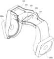
도 1은 본 발명의 일 실시예에 따른 자기장 인가 장치를 도시한 사시도이다.
도 2는 본 발명의 일 실시예에 따른 자기장 인가 장치의 A-A선에 따른 단면을 도시한 단면도이다.
도 3은 본 발명의 다른 실시예에 따른 자기장 인가 장치를 도시한 사시도이다.
도 4는 본 발명의 다른 실시예에 따른 자기장 인가 장치의 B-B선에 따른 단면을 도시한 단면도이다.
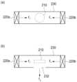
도 5 및 도 6은 본 발명의 다양한 실시예에 따른 자기장 인가 장치에서 복수 개의 송풍장치가 배치되는 다양한 예시를 설명하기 위한 개략도이다.
도 7은 본 발명의 일 실시예에 따른 자기장 인가 장치의 유입측 송풍장치가 배치되는 위치를 개략적으로 도시한 개념도이다.
도 8은 본 발명의 일 실시예에 따른 자기장 인가 장치의 유출측 송풍장치가 배치되는 위치를 개략적으로 도시한 개념도이다.
도 9는 본 발명의 냉각 구조를 비교하여 설명하기 위해 도시한 단면도이다.
도 10은 도 2 및 도 4의 A영역을 확대하여 도시한 단면도이다.
도 11은 본 발명의 또 다른 실시예에 따른 자기장 인가 장치의 A-A선에 따른 단면을 도시한 단면도이다.
도 12는 본 발명의 도 11의 실시예에 따른 자기장 인가 장치에 포함되는 송풍장치가 배치되는 예를 도시한 사시도이다.
도 13 및 도 14는 본 발명의 자기장 인가 장치에 포함되는 송풍장치 및 덕트의 구조를 도시한 사시도이다.
도 15 내지 도 17은 도 11의 실시예에 따른 자기장 인가 장치에서의 냉각 유체의 흐름을 설명하기 위한 개략도이다.FIG. 1 is a perspective view illustrating a magnetic field applying device according to one embodiment of the present invention.
FIG. 2 is a cross-sectional view illustrating a cross-section along line AA of a magnetic field applying device according to one embodiment of the present invention.
FIG. 3 is a perspective view illustrating a magnetic field applying device according to another embodiment of the present invention.
FIG. 4 is a cross-sectional view along line BB of a magnetic field applying device according to another embodiment of the present invention.
FIGS. 5 and 6 are schematic diagrams illustrating various examples of arranging multiple blowers in a magnetic field applying device according to various embodiments of the present invention.
Figure 7 is a conceptual diagram schematically illustrating the location where an inlet-side blower of a magnetic field applying device according to one embodiment of the present invention is placed.
Figure 8 is a conceptual diagram schematically illustrating the location where the outlet side blower of the magnetic field applying device according to one embodiment of the present invention is arranged.
Fig. 9 is a cross-sectional view illustrating the cooling structure of the present invention for comparison.
Figure 10 is an enlarged cross-sectional view of area A of Figures 2 and 4.
FIG. 11 is a cross-sectional view along line AA of a magnetic field applying device according to another embodiment of the present invention.
FIG. 12 is a perspective view showing an example of the arrangement of a blower included in a magnetic field applying device according to the embodiment of FIG. 11 of the present invention.
Figures 13 and 14 are perspective views showing the structure of a blower and a duct included in the magnetic field applying device of the present invention.
FIGS. 15 to 17 are schematic diagrams for explaining the flow of cooling fluid in the magnetic field applying device according to the embodiment of FIG. 11.
본 발명의 이점 및 특징, 그리고 그것들을 달성하는 방법은 첨부되는 도면과 함께 상세하게 후술되어 있는 실시예들을 참조하면 명확해질 것이다. 그러나 본 발명은 이하에서 개시되는 실시예들에 한정되는 것이 아니라 서로 다른 다양한 형태로 구현될 것이며, 단지 본 실시예들은 본 발명의 개시가 완전하도록 하며, 본 발명이 속하는 기술분야에서 통상의 지식을 가진 자에게 발명의 범주를 완전하게 알려주기 위해 제공되는 것이며, 본 발명은 청구항의 범주에 의해 정의될 뿐이다.The advantages and features of the present invention, and the method for achieving them, will become clear with reference to the embodiments described in detail below together with the accompanying drawings. However, the present invention is not limited to the embodiments disclosed below, but may be implemented in various different forms, and these embodiments are provided only to make the disclosure of the present invention complete and to fully inform a person having ordinary skill in the art to which the present invention belongs of the scope of the invention, and the present invention is defined only by the scope of the claims.
비록 제1, 제2 등이 다양한 구성요소들을 서술하기 위해서 사용되나, 이들 구성요소들은 이들 용어에 의해 제한되지 않음은 물론이다. 이들 용어들은 단지 하나의 구성요소를 다른 구성요소와 구별하기 위하여 사용하는 것이다. 따라서, 이하에서 언급되는 제1 구성요소는 본 발명의 기술적 사상 내에서 제2 구성요소일 수도 있음은 물론이다.Although the terms first, second, etc. are used to describe various components, it is to be understood that these components are not limited by these terms. These terms are merely used to distinguish one component from another. Accordingly, it is to be understood that the first component referred to below may also be the second component within the technical concept of the present invention.
이하의 실시예에서, 포함하다 또는 가지다 등의 용어는 명세서상에 기재된 특징, 또는 구성요소가 존재함을 의미하는 것이고, 하나 이상의 다른 특징들 또는 구성요소가 부가될 가능성을 미리 배제하는 것은 아니다.In the examples below, terms such as “include” or “have” mean that a feature or component described in the specification is present, and do not exclude in advance the possibility that one or more other features or components may be added.
도면에서는 설명의 편의를 위하여 구성 요소들이 그 크기가 과장 또는 축소될 수 있다. 예컨대, 도면에서 나타난 각 구성의 크기 및 형태는 설명의 편의를 위해 임의로 나타내었으므로, 본 발명이 반드시 도시된 바에 한정되지 않는다.In the drawings, the sizes of components may be exaggerated or reduced for convenience of explanation. For example, the sizes and shapes of each component shown in the drawings are arbitrarily shown for convenience of explanation, and therefore the present invention is not necessarily limited to what is shown.
명세서 전체에 걸쳐 동일 참조 부호는 동일 구성 요소를 지칭한다.Throughout the specification, identical reference numerals refer to identical components.
어떤 구성 요소가 다른 구성 요소에 "연결되어" 있다거나 "접속되어" 있다고 언급된 때에는, 그 다른 구성 요소에 직접적으로 연결되어 있거나 또는 접속되어 있을 수도 있지만, 중간에 다른 구성 요소가 존재할 수도 있다고 이해되어야 할 것이다. 반면에, 어떤 구성 요소가 다른 구성 요소에 "직접 연결되어" 있다거나 "직접 접속되어"있다고 언급된 때에는, 중간에 다른 구성 요소가 존재하지 않는 것으로 이해되어야 할 것이다.When it is said that a component is "connected" or "connected" to another component, it should be understood that it may be directly connected or connected to that other component, but that there may be other components in between. On the other hand, when it is said that a component is "directly connected" or "directly connected" to another component, it should be understood that there are no other components in between.
구성 요소(elements) 또는 층이 다른 구성 요소 또는 층의 "위(on)" 또는 "상([on)"으로 지칭되는 것은 다른 구성 요소 또는 층의 바로 위뿐만 아니라 중간에 다른 층 또는 다른 구성 요소를 개재한 경우를 모두 포함한다. 반면, 구성 요소가 "직접 위(directly on)" 또는 "바로 위"로 지칭되는 것은 중간에 다른 구성 요소 또는 층을 개재하지 않은 것을 나타낸다.When elements or layers are referred to as being "on" or "[on]" another element or layer, this includes not only directly on the other element or layer, but also whether or not there are other elements or layers intervening. Conversely, when elements or layers are referred to as being "directly on" or "directly above" another element or layer, this includes whether or not there are other elements or layers intervening.
공간적으로 상대적인 용어인 "아래(below)", "아래(beneath)", "하부(lower)", "위(above)", "상부(upper)" 등은 도면에 도시되어 있는 바와 같이 하나의 구성 요소 또는 다른 구성 요소들과의 상관관계를 용이하게 기술하기 위해 사용될 수 있다. 공간적으로 상대적인 용어는 도면에 도시되어 있는 방향에 더하여 사용시 또는 동작시소자의 서로 다른 방향을 포함하는 용어로 이해되어야 한다.The spatially relative terms "below," "beneath," "lower," "above," "upper," and the like may be used to easily describe a component or elements in relation to one another as depicted in the drawings. The spatially relative terms should be understood to include different directions of use or operation of the elements in addition to the directions depicted in the drawings.
본 발명의 여러 실시예들의 각각 특징들이 부분적으로 또는 전체적으로 서로 결합 또는 조합 가능하며, 당업자가 충분히 이해할 수 있듯이 기술적으로 다양한 연동 및 구동이 가능하며, 각 실시예들이 서로에 대하여 독립적으로 실시 가능할 수도 있고 연관 관계로 함께 실시 가능할 수도 있다.The individual features of the various embodiments of the present invention may be partially or wholly combined or combined with each other, and as can be fully understood by those skilled in the art, various technical connections and operations are possible, and each embodiment may be implemented independently of each other or may be implemented together in a related relationship.
이하, 첨부된 도면을 참고로 하여 본 발명의 자기장 인가 장치에 대하여 자세히 설명한다.Hereinafter, the magnetic field applying device of the present invention will be described in detail with reference to the attached drawings.
도 1은 본 발명의 일 실시예에 따른 자기장 인가 장치를 도시한 사시도이고, 도 2는 본 발명의 일 실시예에 따른 자기장 인가 장치의 A-A선에 따른 단면을 도시한 단면도이다.FIG. 1 is a perspective view illustrating a magnetic field applying device according to one embodiment of the present invention, and FIG. 2 is a cross-sectional view illustrating a cross-section along line A-A of the magnetic field applying device according to one embodiment of the present invention.
도 1 및 도 2를 참조하면, 본 발명의 자기장 인가 장치(100)는 자기 발생 코일(110), 송풍장치(120), 유체를 가이드하는 덕트(130), 하우징(140) 및 내부 전자장치(150)를 포함한다.Referring to FIGS. 1 and 2, the magnetic field applying device (100) of the present invention includes a magnetic generating coil (110), a blower (120), a duct (130) for guiding a fluid, a housing (140), and internal electronic devices (150).
자기 발생 코일(110)은 인가되는 전류를 통해 펄스 자기장을 생성한다. 자기 발생 코일(110)은 신체의 일부가 밀착되는 밀착면(141)의 하측에 배치된다.The magnetic generating coil (110) generates a pulse magnetic field through an applied current. The magnetic generating coil (110) is placed on the lower side of the contact surface (141) with which a part of the body is in contact.
본 실시예에서 자기 발생 코일(110)은 밀착면(141)에 수직한 중심축을 가지는 평면상의 원형 코일인 것으로 예시하고 있지만, 이에 한정되는 것은 아니다. 자기 발생 코일(110)은 자기장 인가 장치에 적용될 수 있는 다양한 공지의 형태의 코일일 수 있다.In this embodiment, the magnetic generating coil (110) is exemplified as a circular coil on a plane having a central axis perpendicular to the contact surface (141), but is not limited thereto. The magnetic generating coil (110) may be a coil of various known shapes that can be applied to a magnetic field applying device.
송풍장치(120)는 자기 발생 코일(110)을 냉각시키는 유체를 공급한다.The blower (120) supplies fluid to cool the magnetic generating coil (110).
송풍장치(120)는 자기 발생 코일(110) 측으로 유체를 공급하는 유입측 송풍장치(120a) 및 상기 자기 발생 코일(110)을 통과한 유체를 외부로 배기하는 유출측 송풍장치(120b)를 포함한다. 유입측 송풍장치(120a)와 유출측 송풍장치(120b)는 자기 발생 코일(110)을 기준으로 서로 대칭되는 위치에 배치될 수 있다.The blower (120) includes an inlet-side blower (120a) that supplies fluid toward the magnetic generating coil (110) and an outlet-side blower (120b) that exhausts fluid passing through the magnetic generating coil (110) to the outside. The inlet-side blower (120a) and the outlet-side blower (120b) can be arranged at positions symmetrical to each other with respect to the magnetic generating coil (110).
유입측 송풍장치(120a)는 외부에서 본 발명의 자기장 인가 장치(100)의 내부로 유체를 공급한다. 이때 유입측 송풍장치(120a)는 팬(fan), 블로워(blower), 콤프레셔(compressor) 및 펌프(pump) 중 선택된 것일 수 있다. 도 2를 참조하면, 유입측 송풍장치(120a)는 자기 발생 코일(110)의 하측에 배치된다. 유입측 송풍장치(120a)는 유입측 송풍장치(120a)로부터의 유체의 공급 방향(121)과 자기 발생 코일(110)의 중심축(111)이 이루는 각도(θ)가 수직 각도 이하가 되도록 배치된다.The inlet-side blower (120a) supplies fluid from the outside to the inside of the magnetic field applying device (100) of the present invention. At this time, the inlet-side blower (120a) may be selected from a fan, a blower, a compressor, and a pump. Referring to Fig. 2, the inlet-side blower (120a) is arranged below the magnetic generating coil (110). The inlet-side blower (120a) is arranged so that the angle (θ) formed by the supply direction (121) of the fluid from the inlet-side blower (120a) and the central axis (111) of the magnetic generating coil (110) is less than a vertical angle.
유출측 송풍장치(120b)는 자기장 인가 장치(100)의 내부에 유동하는 유체를 외부로 배기한다. 이때 유입측 송풍장치(120a)는 팬, 블로워, 콤프레셔 및 펌프 중 선택된 것일 수 있다. 도 3을 참조하면, 유출측 송풍장치(120b)는 자기 발생 코일(110)의 하측에 배치된다. 유출측 송풍장치(120b)는 유출측 송풍장치(120b)로부터의 유체의 공급 방향(121)과 자기 발생 코일(110)의 중심축(111)이 이루는 각도(θ)가 수직 각도 이하가 되도록 배치된다.The outlet-side blower (120b) exhausts the fluid flowing inside the magnetic field applying device (100) to the outside. At this time, the inlet-side blower (120a) may be selected from a fan, a blower, a compressor, and a pump. Referring to FIG. 3, the outlet-side blower (120b) is arranged below the magnetic generating coil (110). The outlet-side blower (120b) is arranged so that the angle (θ) formed by the supply direction (121) of the fluid from the outlet-side blower (120b) and the central axis (111) of the magnetic generating coil (110) is less than the vertical angle.
여기서, 유체의 공급 방향(121)과 자기 발생 코일(110)의 중심축(111)이 이루는 각도(θ)는 0도 초과 90도 미만의 각도일 수 있고, 바람직하게는 10도 이상 60도 이하의 각도일 수 있다. 이에 대해서는 이하의 도 7 내지 도 9를 참조하여 후술한다.Here, the angle (θ) formed by the fluid supply direction (121) and the central axis (111) of the magnetic generating coil (110) may be an angle greater than 0 degrees and less than 90 degrees, and preferably an angle greater than or equal to 10 degrees and less than or equal to 60 degrees. This will be described later with reference to FIGS. 7 to 9 below.
덕트(130)는 송풍장치(120)와 자기 발생 코일(110)의 사이에서 유체를 가이드한다.The duct (130) guides the fluid between the blower (120) and the magnetic generating coil (110).
구체적으로, 덕트(130)는 일단(131a)이 유입측 송풍장치(120a)로 개방되고 타단(131b)이 유출측 송풍장치(120b)로 개방되도록 형성된다. 덕트(130)는 유입측 송풍장치(120a)에서 유입된 유체가 자기 발생 코일(110)을 거쳐 유출측 송풍장치(120b)에서 배기되도록 유체를 가이드한다.Specifically, the duct (130) is formed so that one end (131a) is opened to the inlet-side blower (120a) and the other end (131b) is opened to the outlet-side blower (120b). The duct (130) guides the fluid introduced from the inlet-side blower (120a) through the magnetic generating coil (110) and exhausted from the outlet-side blower (120b).
덕트(130)는 자기 발생 코일(110)이 배치되는 영역의 내부 단면적이 일단(131a) 및 타단(131b)의 단면적 보다 작게 형성된다. 다시 말해, 덕트(130)는 안착면(132)이 형성된 영역에서의 단면적이 일단(131a) 및 타단(131b)의 단면적 보다 작게 형성된다. 내부 단면적이 작아진 영역에서 유체의 유속이 빨라지므로, 덕트(130)는 자기 발생 코일(110)이 배치되는 영역에서 유체의 유속이 빨라지는 구조로 형성된다.The duct (130) is formed so that the internal cross-sectional area of the region where the magnetic generating coil (110) is placed is smaller than the cross-sectional areas of one end (131a) and the other end (131b). In other words, the duct (130) is formed so that the cross-sectional area of the region where the mounting surface (132) is formed is smaller than the cross-sectional areas of one end (131a) and the other end (131b). Since the flow rate of the fluid increases in the region where the internal cross-sectional area is smaller, the duct (130) is formed so that the flow rate of the fluid increases in the region where the magnetic generating coil (110) is placed.
덕트(130)는 밀착면(141)과 대응되는 위치에 자기 발생 코일(110)이 안착되는 안착면(132)을 구비한다.The duct (130) has a mounting surface (132) on which a magnetic generating coil (110) is mounted at a position corresponding to the contact surface (141).
자기 발생 코일(110) 안착면(132) 상에 안착되고, 덕트(130)는 이 위치에 대응하여 자기 발생 코일(110)을 지지하는 지지부(133)를 포함한다. 지지부(133)는 자기 발생 코일(110)이 덕트(130)의 내주면으로부터 일정 간격 이격되어 위치될 수 있도록 한다. 지지부(133)에 의해 이격된 공간을 통하여 유입측 송풍장치(120a)로부터 공급된 유체가 유동한다.The magnetic generating coil (110) is mounted on a mounting surface (132), and the duct (130) includes a support member (133) that supports the magnetic generating coil (110) corresponding to this position. The support member (133) allows the magnetic generating coil (110) to be positioned at a predetermined distance from the inner surface of the duct (130). The fluid supplied from the inlet-side blower (120a) flows through the space separated by the support member (133).
지지부(133)는 러버(rubber)일 수 있다. 지지부(133)는 자기 발생 코일(110)이 작동되는 과정에서 발생되는 진동을 흡수하는 역할을 수행할 수 있다.The support member (133) may be rubber. The support member (133) may play a role in absorbing vibrations generated during the operation of the magnetic generating coil (110).
덕트(130)는 유입측 송풍장치(120a)와 자기 발생 코일(110)의 사이의 적어도 일부 영역에 홀(135)을 포함한다.The duct (130) includes a hole (135) in at least a portion of the area between the inlet side blower (120a) and the magnetic generating coil (110).
홀(135)은 덕트(130)에 유입된 유체의 일부를 관통시킨다. 홀(135)을 통해 관통된 유체는 내부 전자장치(150)를 냉각시킬 수 있다. 덕트(130)가 홀(135)의 구성을 포함함으로써, 유입측 송풍장치(120a)로부터 유입된 유체의 일부는 자기 발생 코일(110)에서 발생된 열을 냉각시키고, 나머지 일부는 내부 전자장치(150)에서 발생된 열을 냉각시키는데 사용될 수 있다. 이때, 홀(135)은 공급된 유체가 자기 발생 코일(110) 측으로 70%, 내부 전자장치(150) 측으로 30% 정도의 비율로 유동할 수 있도록 홀의 직경과 개수가 결정될 수 있다.The hole (135) allows a portion of the fluid introduced into the duct (130) to pass through it. The fluid introduced through the hole (135) can cool the internal electronic device (150). Since the duct (130) includes the configuration of the hole (135), a portion of the fluid introduced from the inlet-side blower (120a) can be used to cool the heat generated in the magnetic generating coil (110), and the remaining portion can be used to cool the heat generated in the internal electronic device (150). At this time, the diameter and number of the holes (135) can be determined so that the supplied fluid can flow at a ratio of about 70% toward the magnetic generating coil (110) and about 30% toward the internal electronic device (150).
덕트(130)는 홀(135)을 포함하여 자기 발생 코일(110)과 내부 전자장치(150)를 동시에 냉각시킬 수 있고, 이를 통해 본 발명의 자기장 인가 장치(100)는 내부 전자장치(150)를 위한 별도의 냉각 수단을 구비하지 않고 콤팩트한 구조로 냉각 효율을 높일 수 있다.The duct (130) can cool the magnetic generating coil (110) and the internal electronic device (150) simultaneously, including the hole (135), and through this, the magnetic field applying device (100) of the present invention can increase cooling efficiency with a compact structure without having a separate cooling means for the internal electronic device (150).
덕트(130)는 유입측 송풍장치(120a)와 자기 발생 코일(110)의 사이의 적어도 일부 내주면이 굴곡진 굴곡부(136)를 포함할 수 있다.The duct (130) may include a curved portion (136) with at least a portion of the inner circumference between the inlet-side blower (120a) and the magnetic generating coil (110).
본 발명에서 굴곡부(136)는 덕트(130)의 내주면의 일부가 굴곡된 것으로 예시하고 있지만 이에 한정되는 것은 아니고, 엠보싱 형상으로 형성될 수도 있고, 별도의 부재가 덕트(130)의 내주면의 일부에 부착되는 등의 다양한 방식으로 형성될 수 있음은 물론이다.In the present invention, the bent portion (136) is exemplified as a portion of the inner surface of the duct (130) being bent, but is not limited thereto, and may be formed in an embossed shape or may be formed in various ways, such as a separate member being attached to a portion of the inner surface of the duct (130).
덕트(130)가 굴곡부(136)의 구성을 포함함으로써, 팬이나 블로워 사용 시 발생하는 소음을 감소시킬 수 있다. 유입측 송풍장치(120a)로부터 유입된 유체가 덕트(130)가 굴곡부(136)에 닿는 경우 그렇지 않은 영역에 닿는 것 보다 소음이 저감될 수 있다.Since the duct (130) includes a configuration of a bent portion (136), noise generated when using a fan or blower can be reduced. When the fluid introduced from the inlet-side blower (120a) touches the bent portion (136) of the duct (130), noise can be reduced compared to when it touches an area that does not have such a configuration.
하우징(140)은 사용자의 신체를 지지하는 밀착면(141)을 포함한다. 밀착면(141)은 사용자가 착좌시 사용자의 신체의 일부 예컨대, 사용자의 둔부가 밀착되는 면이다. 밀착면(141)은 도시된 바와 같이 평평한 면으로 형성될 수도 있고, 소정의 굴곡을 가진 면으로 형성될 수도 있다.The housing (140) includes a contact surface (141) that supports the user's body. The contact surface (141) is a surface that a part of the user's body, such as the user's buttocks, contacts when the user sits. The contact surface (141) may be formed as a flat surface as illustrated, or may be formed as a surface having a predetermined curve.
또한 하우징(140)은 냉각을 위한 다수의 홀(143)을 포함할 수 있다. 홀(143)은 송풍장치(120)가 배치된 위치에 대응되는 곳에 형성될 수 있다.Additionally, the housing (140) may include a plurality of holes (143) for cooling. The holes (143) may be formed at locations corresponding to locations where the blower (120) is placed.
도 3은 본 발명의 다른 실시예에 따른 자기장 인가 장치를 도시한 사시도이고, 도 4는 본 발명의 다른 실시예에 따른 자기장 인가 장치의 B-B선에 따른 단면을 도시한 단면도이다.FIG. 3 is a perspective view illustrating a magnetic field applying device according to another embodiment of the present invention, and FIG. 4 is a cross-sectional view along line B-B of a magnetic field applying device according to another embodiment of the present invention.
본 실시예에 따른 자기장 인가 장치(100')는 도 1 및 도 2를 참조하여 설명한 자기장 인가 장치(100)와 전체적인 구성이 유사하나, 돌출면(142)과 관련된 구성요소에 있어 차이가 있다. 이하에서는 본 실시예에 따른 자기장 인가 장치(100')를 설명함에 있어 도 1 및 도 2와 공통된 구성에 대해서는 구체적인 설명을 생략하고, 차이가 있는 부분에 대하여 기술한다.The magnetic field applying device (100') according to the present embodiment has a similar overall configuration to the magnetic field applying device (100) described with reference to FIGS. 1 and 2, but differs in components related to the protruding surface (142). Hereinafter, when describing the magnetic field applying device (100') according to the present embodiment, a detailed description of the common configuration with FIGS. 1 and 2 will be omitted, and the parts where there are differences will be described.
본 발명의 자기장 인가 장치(100')는 사용자가 착좌하여 사용하도록 구성된 자기장 인가 장치이다.The magnetic field applying device (100') of the present invention is a magnetic field applying device configured to be used by a user while seated.
본 발명의 자기장 인가 장치(100')는 하우징(140)의 일 구성으로서 신체의 일부 예컨대, 사용자의 둔부가 밀착되는 밀착면(141)과, 신체의 일부 예컨대, 사용자의 허리, 골반 등을 지지하는 돌출면(142)을 포함한다. 본 발명의 자기장 인가 장치(100')는 사용자가 착좌시 신체를 지지하는 부재 즉, 돌출면(142)을 일체로 형성함으로써 별도의 부재의 결합 없이도 사용자가 정확한 위치에 안착할 수 있도록 하는 의자형 장치를 제시한다.The magnetic field applying device (100') of the present invention comprises a housing (140) as a component and a contact surface (141) that contacts a part of the body, for example, the user's buttocks, and a protruding surface (142) that supports a part of the body, for example, the user's waist, pelvis, etc. The magnetic field applying device (100') of the present invention presents a chair-type device that enables the user to sit in an accurate position without combining a separate member by forming the protruding surface (142), that is, the member that supports the body when the user sits, as one piece.
돌출면(142)은 도 3에 예시한 바와 같이 의자의 등받이 형상을 갖도록 형성될 수도 있고, 이와 달리 팔걸이 형상을 갖도록 형성될 수도 있다. 이에 한정되지 않고, 돌출면(142)은 사용자가 착좌시 사용자의 신체를 지지하면서도 사용자의 착좌 위치를 안내할 수 있는 형태라면 다양한 형태로 형성될 수 있음은 물론이다.The protruding surface (142) may be formed to have the shape of a chair backrest as illustrated in Fig. 3, or alternatively, may be formed to have the shape of an armrest. It is not limited thereto, and the protruding surface (142) may be formed in various shapes as long as it can support the user's body while guiding the user's seating position.
돌출면(142)은 밀착면(141)의 적어도 일부의 외측 둘레에서 밀착면(141)으로부터 상측으로 연장되어 형성된다. 돌출면(142)은 내부에 수용 공간을 갖도록 벽체 형상으로 형성된다. 상기 돌출면(142)의 수용 공간 내에는 송풍장치(120a, 120b)의 적어도 일부가 배치될 수 있다.The protruding surface (142) is formed by extending upward from the contact surface (141) along at least a portion of the outer periphery of the contact surface (141). The protruding surface (142) is formed in a wall shape so as to have an accommodation space inside. At least a portion of the blower (120a, 120b) can be placed within the accommodation space of the protruding surface (142).
송풍장치(120a, 120b)는 자기 발생 코일(110)의 외주의 연장선 상에 배치될 수 있으며, 송풍장치(120a, 120b)의 적어도 일부가 상기 돌출면(142)의 수용 공간 내에 배치될 수 있다. 송풍장치(120a, 120b)는 돌출면(142)의 수용 공간 내에서 자기 발생 코일(110)을 기준으로 서로 대칭되는 위치에 배치되는 것이 바람직하다.The blower (120a, 120b) may be arranged on an extension of the outer circumference of the magnetic generating coil (110), and at least a part of the blower (120a, 120b) may be arranged within the receiving space of the protruding surface (142). It is preferable that the blower (120a, 120b) be arranged at positions symmetrical to each other with respect to the magnetic generating coil (110) within the receiving space of the protruding surface (142).
냉각을 위한 다수의 홀(143)은 송풍장치(120)와 대응되는 위치에 형성될 수 있다. 본 실시예에 따르면, 냉각을 위한 다수의 홀(143)은 돌출면(142)의 외측면에 형성되는 것이 바람직하다.A plurality of holes (143) for cooling may be formed at positions corresponding to the blower (120). According to the present embodiment, it is preferable that the plurality of holes (143) for cooling be formed on the outer surface of the protruding surface (142).
도 5 및 도 6은 본 발명의 다양한 실시예에 따른 자기장 인가 장치에서 복수 개의 송풍장치가 배치되는 다양한 예시를 설명하기 위한 개략도이다.FIGS. 5 and 6 are schematic diagrams illustrating various examples of arranging multiple blowers in a magnetic field applying device according to various embodiments of the present invention.
도 5는 본 발명의 다양한 실시예에 따른 자기장 인가 장치(100, 100')를 상측에서 바라본 경우의 자기 발생 코일(110)과 송풍장치(120a, 120b)의 상대적인 위치 관계를 평면상에 도시한 것이다. 이는 자기 발생 코일(110)과 송풍장치(120a, 120b)가 평면상에 위치하는 것을 의미하는 것은 아니다. 자기 발생 코일(110)과 송풍장치(120a, 120b) 간의 단차나 밀착면(141)과 송풍장치(120a, 120b) 간의 거리 차이는 배제하고, 자기 발생 코일(110)과 송풍장치(120a, 120b)의 배치에 따른 냉각 유체 흐름을 자기 발생 코일(110)을 기준으로 설명하기 위하여 자기장 인가 장치(100, 100')를 상측에서 바라본 경우의 위치 관계를 이용하여 설명한다.FIG. 5 is a plan view illustrating the relative positional relationship between the magnetic generating coil (110) and the blower (120a, 120b) when viewed from above of the magnetic field applying device (100, 100') according to various embodiments of the present invention. This does not mean that the magnetic generating coil (110) and the blower (120a, 120b) are located on the plane. In order to explain the flow of cooling fluid according to the arrangement of the magnetic generating coil (110) and the blower (120a, 120b) by excluding the step between the magnetic generating coil (110) and the blower (120a, 120b) or the difference in distance between the contact surface (141) and the blower (120a, 120b), based on the magnetic generating coil (110), the positional relationship when the magnetic field applying device (100, 100') is used when viewed from above.
다시 말해, 도 5에서의 송풍장치(120a, 120b)는 도 2에 도시된 송풍장치(120a, 120b)와 같이 유체의 공급 방향과 자기 발생 코일(110)의 중심축(111)이 이루는 각도(θ)가 수직 각도 이하가 되도록 배치될 수도 있고, 도 4에 도시된 송풍장치(120a, 120b)와 같이 자기 발생 코일(110)의 외주의 연장선 상에 배치되며 송풍장치(120a, 120b)의 적어도 일부가 상기 돌출면(142)의 수용 공간 내에 배치된 형태일 수도 있다.In other words, the blower (120a, 120b) in FIG. 5 may be arranged so that the angle (θ) formed by the fluid supply direction and the central axis (111) of the magnetic generating coil (110) is less than the vertical angle, like the blower (120a, 120b) illustrated in FIG. 2, or may be arranged on an extension of the outer circumference of the magnetic generating coil (110) like the blower (120a, 120b) illustrated in FIG. 4, and at least a portion of the blower (120a, 120b) may be arranged within the receiving space of the protruding surface (142).
도 5를 참조하면, 송풍장치(120a, 120b)는 복수 개 구비되어 자기 발생 코일(110)을 통과하는 복수의 경로의 냉각 유체 흐름을 생성할 수 있다. 특히, 유입측 송풍장치(120a)는 복수 개 구비되어 자기 발생 코일(110)을 통과하는 복수의 경로의 냉각 유체 흐름(f1, f2)을 생성할 수 있다.Referring to FIG. 5, a plurality of blowers (120a, 120b) are provided to generate a plurality of paths of cooling fluid flow passing through the magnetic generating coil (110). In particular, a plurality of inlet-side blowers (120a) are provided to generate a plurality of paths of cooling fluid flow (f1, f2) passing through the magnetic generating coil (110).
자기장 인가 장치(100, 100')는 자기 발생 코일(110)로의 제1 냉각 유체 흐름(f1)과 제2 냉각 유체 흐름(f2)을 각각 생성하는 복수의 송풍장치(120a)를 포함할 수 있다. 즉, 자기장 인가 장치(100, 100')는 자기 발생 코일(110)이 이루는 면과 나란한 방향으로 제1 냉각 유체 흐름(f1)을 생성하는 제1 송풍장치(120a)와, 자기 발생 코일(110)이 이루는 면과 나란한 방향으로 상기 자기 발생 코일(110)을 통과하면서, 제1 냉각 유체 흐름(f1)과 상이한 방향의 제2 냉각 유체 흐름(f2)을 생성하는 제2 송풍장치(120a)를 포함할 수 있다.The magnetic field applying device (100, 100') may include a plurality of blowers (120a) which respectively generate a first cooling fluid flow (f1) and a second cooling fluid flow (f2) to the magnetic generating coil (110). That is, the magnetic field applying device (100, 100') may include a first blower (120a) which generates a first cooling fluid flow (f1) in a direction parallel to a surface formed by the magnetic generating coil (110), and a second blower (120a) which generates a second cooling fluid flow (f2) in a different direction from the first cooling fluid flow (f1) while passing through the magnetic generating coil (110) in a direction parallel to the surface formed by the magnetic generating coil (110).
이때 자기 발생 코일(110)은 제1 송풍장치(120a)로부터의 제1 냉각 유체 흐름(f1)과 제2 송풍장치(120a)로부터의 제2 냉각 유체 흐름(f2)이 중첩되는 경로 상에 배치된다.At this time, the self-generating coil (110) is placed on a path where the first cooling fluid flow (f1) from the first blower (120a) and the second cooling fluid flow (f2) from the second blower (120a) overlap.
도 5의 (a) 및 도 5의 (c)에 도시된 바와 같이 제1 냉각 유체 흐름(f1)과 제2 냉각 유체 흐름(f2)은 서로 수직 각도를 이루도록 배치될 수도 있고, 도 5의 (b)에 도시된 바와 같이 제1 냉각 유체 흐름(f1)과 제2 냉각 유체 흐름(f2)은 서로 둔각의 각도를 이루도록 배치될 수도 있다.As shown in (a) and (c) of FIG. 5, the first cooling fluid flow (f1) and the second cooling fluid flow (f2) may be arranged to form a perpendicular angle to each other, and as shown in (b) of FIG. 5, the first cooling fluid flow (f1) and the second cooling fluid flow (f2) may be arranged to form an obtuse angle to each other.
자기장 인가 장치(100, 100')는 자기 발생 코일(110)을 통과한 유체를 외부로 배기하는 유출측 송풍장치(120b)를 더 포함할 수 있다. 유출측 송풍장치(120b)는 유입측 송풍장치(120a)로부터 생성된 제1 냉각 유체 흐름(f1)과 제2 냉각 유체 흐름(f2)이 다시 유입측 송풍장치(120a)로 되돌아가지 않고 자기 발생 코일(110)을 통과하면서 자기 발생 코일(110)을 냉각시킬 수 있도록 유속과 유량이 적절히 조절되는 것이 바람직하다. 도 5의 (a)에 도시된 바와 같이 유출측 송풍장치(120b)가 복수 개 구비될 수도 있고, 도 5의 (b) 및 도 5의 (c)에 도시된 바와 같이 단일한 유출측 송풍장치(120b)가 구비될 수도 있다.The magnetic field applying device (100, 100') may further include an outlet-side blower (120b) for exhausting fluid passing through the magnetic generating coil (110) to the outside. It is preferable that the outlet-side blower (120b) has an appropriately controlled flow rate and volume so that the first cooling fluid flow (f1) and the second cooling fluid flow (f2) generated from the inlet-side blower (120a) can cool the magnetic generating coil (110) while passing through the magnetic generating coil (110) without returning to the inlet-side blower (120a). As illustrated in (a) of FIG. 5, a plurality of outlet-side blowers (120b) may be provided, or as illustrated in (b) and (c) of FIG. 5, a single outlet-side blower (120b) may be provided.
도 5의 (a)에 도시된 바와 같이 각각의 유출측 송풍장치(120b)는 각각의 유입측 송풍장치(120a)와 자기 발생 코일(110)을 기준으로 서로 대칭되는 위치에 배치될 수 있다.As shown in (a) of Fig. 5, each outlet-side blower (120b) can be placed at a position symmetrical to each inlet-side blower (120a) and the magnetic generating coil (110).
한편, 유출측 송풍장치(120b)가 하나 구비되어 복수의 유입측 송풍장치(120a)들로부터 유입된 유체를 한번에 배기할 수도 있다. 이때 유출측 송풍장치(120b)는 도 5의 (b)에 도시된 바와 같이 각각의 유입측 송풍장치(120a)와 소정의 각도를 이루며 배치될 수도 있고, 도 5의 (c)에 도시된 바와 같이, 어느 하나의 유입측 송풍장치(120a)와 자기 발생 코일(110)을 기준으로 서로 대칭되는 위치에 배치되고 다른 하나의 유입측 송풍장치(120a)와 수직 각도를 이루며 배치될 수도 있다.Meanwhile, one outlet-side blower (120b) may be provided to exhaust fluids introduced from multiple inlet-side blowers (120a) at once. At this time, the outlet-side blower (120b) may be arranged at a predetermined angle with respect to each inlet-side blower (120a) as illustrated in (b) of FIG. 5, or may be arranged at a position symmetrical to one inlet-side blower (120a) and the magnetic generating coil (110) as illustrated in (c) of FIG. 5, and may be arranged at a vertical angle with respect to another inlet-side blower (120a).
도 6은 본 발명의 다양한 실시예에 따른 자기장 인가 장치(100, 100')를 일 측면에서 바라본 경우의 자기 발생 코일(110)과 송풍장치(120a, 120b)의 상대적인 위치 관계를 평면상에 도시한 것이다. 이는 자기 발생 코일(110)과 송풍장치(120a, 120b)가 일직선상에 위치하는 것을 의미하는 것은 아니다. 자기 발생 코일(110)과 송풍장치(120a, 120b) 간의 단차나 측면 하우징(140)과 송풍장치(120a, 120b) 간의 거리 차이는 배제하고, 자기 발생 코일(110)과 송풍장치(120a, 120b)의 배치에 따른 냉각 유체 흐름을 자기 발생 코일(110)을 기준으로 설명하기 위하여 자기장 인가 장치(100, 100')를 일 측면에서 바라본 경우의 위치 관계를 이용하여 설명한다.FIG. 6 is a plan view illustrating the relative positional relationship between the magnetic generating coil (110) and the blower (120a, 120b) when viewed from one side of the magnetic field applying device (100, 100') according to various embodiments of the present invention. This does not mean that the magnetic generating coil (110) and the blower (120a, 120b) are positioned in a straight line. In order to explain the flow of cooling fluid according to the arrangement of the magnetic generating coil (110) and the blower (120a, 120b) by excluding the step between the magnetic generating coil (110) and the blower (120a, 120b) or the distance between the side housing (140) and the blower (120a, 120b), based on the magnetic generating coil (110), the positional relationship when the magnetic field applying device (100, 100') is used when viewed from one side.
다시 말해, 도 6에서의 송풍장치(120a, 120b)는 도 2에 도시된 송풍장치(120a, 120b)와 같이 유체의 공급 방향과 자기 발생 코일(110)의 중심축(111)이 이루는 각도(θ)가 수직 각도 이하가 되도록 배치될 수도 있고, 도 4에 도시된 송풍장치(120a, 120b)와 같이 자기 발생 코일(110)의 외주의 연장선 상에 배치되며 송풍장치(120a, 120b)의 적어도 일부가 상기 돌출면(142)의 수용 공간 내에 배치된 형태일 수도 있다.In other words, the blower (120a, 120b) in FIG. 6 may be arranged so that the angle (θ) formed by the fluid supply direction and the central axis (111) of the magnetic generating coil (110) is less than the vertical angle, like the blower (120a, 120b) illustrated in FIG. 2, or may be arranged on an extension of the outer circumference of the magnetic generating coil (110) like the blower (120a, 120b) illustrated in FIG. 4, and at least a portion of the blower (120a, 120b) may be arranged within the receiving space of the protruding surface (142).
도 6을 참조하면, 송풍장치(120a, 120b)는 복수 개 구비되어 자기 발생 코일(110)을 통과하는 복수의 경로의 냉각 유체 흐름을 생성할 수 있다. 특히, 유입측 송풍장치(120a)는 복수 개 구비되어 자기 발생 코일(110)을 통과하는 복수의 경로의 냉각 유체 흐름(f1, f2)을 생성할 수 있다.Referring to FIG. 6, a plurality of blowers (120a, 120b) are provided to generate a plurality of paths of cooling fluid flow passing through the magnetic generating coil (110). In particular, a plurality of inlet-side blowers (120a) are provided to generate a plurality of paths of cooling fluid flow (f1, f2) passing through the magnetic generating coil (110).
자기장 인가 장치(100, 100')는 자기 발생 코일(110)로의 제1 냉각 유체 흐름(f1)과 제2 냉각 유체 흐름(f2)을 각각 생성하는 복수의 송풍장치(120a)를 포함할 수 있다. 즉, 자기장 인가 장치(100, 100')는 자기 발생 코일(110)이 이루는 면과 나란한 방향으로 제1 냉각 유체 흐름(f1)을 생성하는 제1 송풍장치(120a)와, 자기 발생 코일(110)이 이루는 면과 수직한 방향으로 제2 냉각 유체 흐름(f2)을 생성하는 제2 송풍장치(120a)를 포함할 수 있다.The magnetic field applying device (100, 100') may include a plurality of blowers (120a) which respectively generate a first cooling fluid flow (f1) and a second cooling fluid flow (f2) to the magnetic generating coil (110). That is, the magnetic field applying device (100, 100') may include a first blower (120a) which generates a first cooling fluid flow (f1) in a direction parallel to a surface formed by the magnetic generating coil (110), and a second blower (120a) which generates a second cooling fluid flow (f2) in a direction perpendicular to the surface formed by the magnetic generating coil (110).
이때 자기 발생 코일(110)은 제1 송풍장치(120a)로부터의 제1 냉각 유체 흐름(f1)과 제2 송풍장치(120a)로부터의 제2 냉각 유체 흐름(f2)이 중첩되는 경로 상에 배치된다.At this time, the self-generating coil (110) is placed on a path where the first cooling fluid flow (f1) from the first blower (120a) and the second cooling fluid flow (f2) from the second blower (120a) overlap.
역시, 자기장 인가 장치(100, 100')는 자기 발생 코일(110)을 통과한 유체를 외부로 배기하는 유출측 송풍장치(120b)를 더 포함할 수 있다. 유출측 송풍장치(120b)는 유입측 송풍장치(120a)로부터 생성된 제1 냉각 유체 흐름(f1)과 제2 냉각 유체 흐름(f2)이 다시 유입측 송풍장치(120a)로 되돌아가지 않고 자기 발생 코일(110)을 통과하면서 자기 발생 코일(110)을 냉각시킬 수 있도록 유속과 유량이 적절히 조절되는 것이 바람직하다. 도 6의 (a) 및 도 6의 (b)에 도시된 바와 같이 단일한 유출측 송풍장치(120b)가 구비될 수도 있고, 이와 달리 복수 개의 유출측 송풍장치(120b)가 구비될 수도 있다.Likewise, the magnetic field applying device (100, 100') may further include an outlet-side blower (120b) for exhausting the fluid passing through the magnetic generating coil (110) to the outside. It is preferable that the outlet-side blower (120b) have the flow rate and the flow volume appropriately controlled so that the first cooling fluid flow (f1) and the second cooling fluid flow (f2) generated from the inlet-side blower (120a) can cool the magnetic generating coil (110) while passing through the magnetic generating coil (110) without returning to the inlet-side blower (120a). As shown in (a) and (b) of FIG. 6, a single outlet-side blower (120b) may be provided, or alternatively, a plurality of outlet-side blowers (120b) may be provided.
도 6의 (a) 및 도 6의 (b)에 도시된 바와 같이, 제1 냉각 유체 흐름(f1)을 생성하는 제1 송풍장치(120a)와 유출측 송풍장치(120b)는 자기 발생 코일(110)을 기준으로 서로 대칭되는 위치에 배치되고, 제2 냉각 유체 흐름(f2)을 생성하는 제2 송풍장치(120a)는 자기 발생 코일(110)의 하측에 배치될 수 있다.As shown in (a) and (b) of FIG. 6, the first blower (120a) and the outlet-side blower (120b) that generate the first cooling fluid flow (f1) are arranged at positions symmetrical to each other with respect to the magnetic generating coil (110), and the second blower (120a) that generates the second cooling fluid flow (f2) can be arranged below the magnetic generating coil (110).
이때, 유출측 송풍장치(120b)는 도 6의 (a)와 같이 자기 발생 코일(110)이 이루는 평면과 중첩되도록 자기 발생 코일(110)의 바로 하측에 배치될 수도 있고, 도 6의 (b)와 같이 자기 발생 코일(110)이 이루는 평면을 기준으로 제1 송풍장치(120a)측으로 편향되어 자기 발생 코일(110)의 하측에 배치될 수도 있다. 도 6의 (b)와 같이 배치되는 경우, 제1 냉각 유체 흐름(f1)과 제2 냉각 유체 흐름(f2)이 중첩되어 빨라진 유속으로 자기 발생 코일(110)을 지나게 되므로 냉각 효과가 향상되는 이점이 있다.At this time, the outlet-side blower (120b) may be arranged directly below the magnetic generating coil (110) so as to overlap with the plane formed by the magnetic generating coil (110) as shown in (a) of FIG. 6, or may be arranged below the magnetic generating coil (110) so as to be biased toward the first blower (120a) based on the plane formed by the magnetic generating coil (110) as shown in (b) of FIG. 6. In the case of arrangement as shown in (b) of FIG. 6, the first cooling fluid flow (f1) and the second cooling fluid flow (f2) overlap and pass through the magnetic generating coil (110) at an increased flow rate, so there is an advantage of improved cooling effect.
도 7은 본 발명의 일 실시예에 따른 자기장 인가 장치의 유입측 송풍장치가 배치되는 위치를 개략적으로 도시한 개념도이고, 도 8은 본 발명의 일 실시예에 따른 자기장 인가 장치의 유출측 송풍장치가 배치되는 위치를 개략적으로 도시한 개념도이고, 도 9는 본 발명의 냉각 구조를 비교하여 설명하기 위해 도시한 단면도이다.FIG. 7 is a conceptual diagram schematically illustrating a position where an inlet-side blower of a magnetic field applying device according to one embodiment of the present invention is arranged, FIG. 8 is a conceptual diagram schematically illustrating a position where an outlet-side blower of a magnetic field applying device according to one embodiment of the present invention is arranged, and FIG. 9 is a cross-sectional view illustrated to compare and explain the cooling structure of the present invention.
도 7를 참조하면, 유입측 송풍장치(120a)는 자기 발생 코일(110)의 하측에 배치된다. 유입측 송풍장치(120a)는 유입측 송풍장치(120a)로부터의 유체의 공급 방향(121)과 자기 발생 코일(110)의 중심축(111)이 이루는 각도(θ)가 수직 각도 이하가 되도록 배치된다. 도 8을 참조하면, 유출측 송풍장치(120b)는 자기 발생 코일(110)의 하측에 배치된다. 유출측 송풍장치(120b)는 유출측 송풍장치(120b)로부터의 유체의 공급 방향(121)과 자기 발생 코일(110)의 중심축(111)이 이루는 각도(θ)가 수직 각도 이하가 되도록 배치된다.Referring to FIG. 7, the inlet-side blower (120a) is arranged below the magnetic generating coil (110). The inlet-side blower (120a) is arranged so that the angle (θ) formed by the supply direction (121) of the fluid from the inlet-side blower (120a) and the central axis (111) of the magnetic generating coil (110) is less than or equal to the vertical angle. Referring to FIG. 8, the outlet-side blower (120b) is arranged below the magnetic generating coil (110). The outlet-side blower (120b) is arranged so that the angle (θ) formed by the supply direction (121) of the fluid from the outlet-side blower (120b) and the central axis (111) of the magnetic generating coil (110) is less than or equal to the vertical angle.
여기서, 유체의 공급 방향(121)과 자기 발생 코일(110)의 중심축(111)이 이루는 각도(θ)는 0도 초과 90도 미만의 각도일 수 있고, 바람직하게는 10도 이상 60도 이하의 각도일 수 있다.Here, the angle (θ) formed by the fluid supply direction (121) and the central axis (111) of the magnetic generating coil (110) may be an angle greater than 0 degrees and less than 90 degrees, and preferably an angle greater than or equal to 10 degrees and less than or equal to 60 degrees.
도 9의 (a) 및 (b)를 함께 참조하여, 유입측 송풍장치(120a)로부터의 유체의 공급 방향(121)이 자기 발생 코일(110)의 중심축(111)과 소정의 각도를 이루는 경우의 이점을 설명한다.Referring to (a) and (b) of FIG. 9 together, the advantage of a case where the supply direction (121) of the fluid from the inlet-side blower (120a) forms a predetermined angle with the central axis (111) of the magnetic generating coil (110) is explained.
본 발명의 자기장 인가 장치(100)는 유입측 송풍장치(120a) 및 유출측 송풍장치(120b)로부터의 유체의 공급 방향(121)과 자기 발생 코일(110)의 중심축(111)이 이루는 각도(θ)를 기설정된 각도로 설정함으로써, 송풍장치(120)를 자기 발생 코일(110)과 동일 평면상에 배치하지 않으면서도 자기 발생 코일(110)의 냉각 효율을 향상시킬 수 있도록 한다.The magnetic field applying device (100) of the present invention sets the angle (θ) formed by the supply direction (121) of the fluid from the inlet-side blower (120a) and the outlet-side blower (120b) and the central axis (111) of the magnetic generating coil (110) to a preset angle, thereby improving the cooling efficiency of the magnetic generating coil (110) without having to place the blower (120) on the same plane as the magnetic generating coil (110).
도 9의 (a)는 유입측 송풍장치(120a)로부터의 유체의 공급 방향(121)이 자기 발생 코일(110)의 중심축(111)과 90도 각도로 배치된 경우로, 이 경우 유입측 송풍장치(120a)로부터 공급된 유체가 자기 발생 코일(110) 측으로 향하지 못하고 덕트(130)의 내주면에 의해 유입측 송풍장치(120a)로 되돌아 나오는 경우가 발생하게 된다. 이러한 배치는 유입측 송풍장치(120a)로부터 공급된 유체가 자기 발생 코일(110) 측으로 효과적으로 이동하지 못하게 되어 본 발명의 자기장 인가 장치(100)의 냉각 효율이 저하된다. 반면, 도 9의 (b)는 유입측 송풍장치(120a)로부터의 유체의 공급 방향(121)이 자기 발생 코일(110)의 중심축(111)과 소정의 각도를 갖도록 배치된 경우로, 이 경우 유입측 송풍장치(120a)로부터 공급된 유체가 자기 발생 코일(110) 측으로 지향하게 되므로 유입측 송풍장치(120a)로부터 공급된 유체가 자기 발생 코일(110) 측으로 효과적으로 이동할 수 있게 되는 이점이 있다.Fig. 9 (a) shows a case where the supply direction (121) of the fluid from the inlet-side blower (120a) is arranged at a 90-degree angle with the central axis (111) of the magnetic generating coil (110). In this case, the fluid supplied from the inlet-side blower (120a) does not flow toward the magnetic generating coil (110) but instead returns to the inlet-side blower (120a) by the inner surface of the duct (130). This arrangement prevents the fluid supplied from the inlet-side blower (120a) from effectively moving toward the magnetic generating coil (110), thereby lowering the cooling efficiency of the magnetic field applying device (100) of the present invention. On the other hand, (b) of Fig. 9 is a case where the supply direction (121) of the fluid from the inlet-side blower (120a) is arranged to have a predetermined angle with the central axis (111) of the magnetic generating coil (110). In this case, the fluid supplied from the inlet-side blower (120a) is directed toward the magnetic generating coil (110), so there is an advantage in that the fluid supplied from the inlet-side blower (120a) can effectively move toward the magnetic generating coil (110).
나아가, 유입측 송풍장치(120a) 및 유출측 송풍장치(120b)로부터의 유체의 공급 방향(121)과 자기 발생 코일(110)의 중심축(111)이 이루는 각도(θ)를 기설정된 각도로 설정함으로써, 본 발명의 자기장 인가 장치(100)의 전체적인 부피를 줄일 수 있다. 도 1에 도시된 바와 같이 송풍장치(120)와 자기 발생 코일(110)의 사이 영역의 하우징(140)에 홈부를 마련하여 사용자가 손잡이로 사용할 수 있도록 함으로써 사용의 편의성을 향상시킬 수도 있다. 또한, 유입측 송풍장치(120a) 및 유출측 송풍장치(120b)로부터의 유체의 공급 방향(121)과 자기 발생 코일(110)의 중심축(111)이 이루는 각도(θ)를 기설정된 각도로 설정함으로써, 유입측 송풍장치(120a)를 팬, 블로워, 콤프레셔 및 펌프 중 어느 하나로 채용하더라도 바닥부에 있는 먼지가 유입되는 문제를 예방할 수 있다.Furthermore, by setting the angle (θ) formed by the supply direction (121) of the fluid from the inlet-side blower (120a) and the outlet-side blower (120b) and the central axis (111) of the magnetic generating coil (110) to a preset angle, the overall volume of the magnetic field applying device (100) of the present invention can be reduced. As illustrated in Fig. 1, a groove may be provided in the housing (140) between the blower (120) and the magnetic generating coil (110) so that the user can use it as a handle, thereby improving the convenience of use. In addition, by setting the angle (θ) formed by the supply direction (121) of the fluid from the inlet-side blower (120a) and the outlet-side blower (120b) and the central axis (111) of the magnetic generating coil (110) to a preset angle, the problem of dust from the bottom being drawn in can be prevented even when the inlet-side blower (120a) is employed as any one of a fan, a blower, a compressor, and a pump.
도 10은 도 2 및 도 4의 A영역을 확대하여 도시한 단면도이다.Figure 10 is an enlarged cross-sectional view of area A of Figures 2 and 4.
덕트(130)는 밀착면(141)과 대응되는 위치에 자기 발생 코일(110)이 안착되는 안착면(132)을 구비한다.The duct (130) has a mounting surface (132) on which a magnetic generating coil (110) is mounted at a position corresponding to the contact surface (141).
자기 발생 코일(110) 안착면(132) 상에 안착되고, 덕트(130)는 이 위치에 대응하여 자기 발생 코일(110)을 지지하는 지지부(133)를 포함한다. 지지부(133)는 자기 발생 코일(110)이 덕트(130)의 내주면으로부터 일정 간격 이격되어 위치될 수 있도록 한다. 지지부(133)에 의해 이격된 공간을 통하여 유입측 송풍장치(120a)로부터 공급된 유체가 유동한다.The magnetic generating coil (110) is mounted on a mounting surface (132), and the duct (130) includes a support member (133) that supports the magnetic generating coil (110) corresponding to this position. The support member (133) allows the magnetic generating coil (110) to be positioned at a predetermined distance from the inner surface of the duct (130). The fluid supplied from the inlet-side blower (120a) flows through the space separated by the support member (133).
지지부(133)는 러버(rubber)일 수 있다. 지지부(133)는 자기 발생 코일(110)이 작동되는 과정에서 발생되는 진동을 흡수하는 역할을 수행할 수 있다.The support member (133) may be rubber. The support member (133) may play a role in absorbing vibrations generated during the operation of the magnetic generating coil (110).
덕트(130)는 안착면(132)에서 자기 발생 코일 (110)측으로 돌출된 돌출부(134)를 포함한다. 돌출부(134)는 유입측 송풍장치(120a)와 자기 발생 코일(110)의 사이에 형성된 안착면(132)의 적어도 일부 영역에 형성된다.The duct (130) includes a protrusion (134) protruding from the mounting surface (132) toward the magnetic generating coil (110). The protrusion (134) is formed in at least a portion of the mounting surface (132) formed between the inlet-side blower (120a) and the magnetic generating coil (110).
돌출부(134)는 도 10에 도시된 바와 같이 유입측 송풍장치(120a)로부터 유입된 유체가 자기 발생 코일(110)의 상부로 향하도록 가이드한다. 다시 말해, 돌출부(134)는 유입측 송풍장치(120a)로부터 유입된 유체가 자기 발생 코일(110)과 밀착면(141)의 사이에 형성된 영역으로 향할 수 있도록 유체를 가이드한다. 돌출부(134)는 자기 발생 코일(110)과 밀착면(141)의 사이 영역에 공급되는 유량과 유속을 향상시킴으로써 사용자의 신체 부위가 밀착되는 부분의 냉각 효율을 향상시킬 수 있다.The protrusion (134) guides the fluid introduced from the inlet-side blower (120a) to the upper portion of the magnetic generating coil (110) as illustrated in FIG. 10. In other words, the protrusion (134) guides the fluid introduced from the inlet-side blower (120a) to the area formed between the magnetic generating coil (110) and the contact surface (141). The protrusion (134) can improve the cooling efficiency of the area where the user's body part is in contact by improving the flow rate and flow velocity supplied to the area between the magnetic generating coil (110) and the contact surface (141).
본 발명에서 돌출부(134)는 덕트(130)의 내주면의 일부가 굴곡된 것으로 예시하고 있지만 이에 한정되는 것은 아니고, 별도의 부재가 덕트(130)의 내주면의 일부에 부착되는 등의 다양한 방식으로 형성될 수 있음은 물론이다.In the present invention, the protrusion (134) is exemplified as a part of the inner surface of the duct (130) being bent, but is not limited thereto, and of course can be formed in various ways, such as a separate member being attached to a part of the inner surface of the duct (130).
한편, 밀착면(141)은 하면에 자기 발생 코일(110) 측으로 돌출된 지지부(144)를 포함한다. 여기서 밀착면(141)은 하우징(140)의 일부일 수도 있고, 덕트(130)의 일부로 형성될 수도 있다.Meanwhile, the contact surface (141) includes a support portion (144) protruding toward the magnetic generating coil (110) on the lower surface. Here, the contact surface (141) may be a part of the housing (140) or may be formed as a part of the duct (130).
지지부(144)는 자기 발생 코일(110)이 밀착면(141)으로부터 일정 간격 이격되어 위치될 수 있도록 한다. 지지부(144)에 의해 이격된 공간을 통하여 유입측 송풍장치(120a)로부터 공급된 유체가 유동한다. 지지부(144)는 안착면(132)에 형성된 지지부(133)와 같이, 러버(rubber)일 수 있다. 지지부(144)는 자기 발생 코일(110)이 작동되는 과정에서 발생되는 진동을 흡수하는 역할을 수행할 수 있다.The support member (144) allows the magnetic generating coil (110) to be positioned at a certain distance from the contact surface (141). The fluid supplied from the inlet-side blower (120a) flows through the space separated by the support member (144). The support member (144) may be rubber, like the support member (133) formed on the mounting surface (132). The support member (144) may play a role in absorbing vibrations generated during the operation of the magnetic generating coil (110).
도 11은 본 발명의 또 다른 실시예에 따른 자기장 인가 장치의 A-A선에 따른 단면을 도시한 단면도이고, 도 12는 본 발명의 도 11의 실시예에 따른 자기장 인가 장치에 포함되는 송풍장치가 배치되는 예를 도시한 사시도이다.FIG. 11 is a cross-sectional view taken along line A-A of a magnetic field applying device according to another embodiment of the present invention, and FIG. 12 is a perspective view showing an example of the arrangement of a blower included in the magnetic field applying device according to the embodiment of FIG. 11 of the present invention.
본 실시예에 따른 자기장 인가 장치(200)는 상술한 자기장 인가 장치(100)와 전반적인 구성이 유사하나, 복수의 송풍장치(220a, 220b, 220c)의 배치와 이에 따른 냉각 유체의 흐름(f1, f2, f3)에 차이가 있다.The magnetic field applying device (200) according to the present embodiment has a similar overall configuration to the magnetic field applying device (100) described above, but differs in the arrangement of the multiple blower devices (220a, 220b, 220c) and the flow of cooling fluid (f1, f2, f3) resulting therefrom.
본 발명의 자기장 인가 장치(200)는 자기 발생 코일(210), 송풍장치(220a, 220b, 220c), 유체를 가이드하는 덕트(230), 하우징(240) 및 내부 전자장치(250)를 포함한다. 이하, 대응되는 구성에 대한 중복된 설명은 생략하고, 송풍장치(220a, 220b, 220c) 및 덕트(230) 구성과 이에 따른 냉각 유체의 흐름(f1, f2, f3)에 대하여 상세히 기술한다.The magnetic field applying device (200) of the present invention includes a magnetic generating coil (210), a blower (220a, 220b, 220c), a duct (230) for guiding a fluid, a housing (240), and an internal electronic device (250). Hereinafter, redundant descriptions of corresponding components will be omitted, and the configurations of the blower (220a, 220b, 220c) and the duct (230) and the flow (f1, f2, f3) of the cooling fluid according to the configurations will be described in detail.
도 11 및 도 12를 참조하면, 자기장 인가 장치(200)는 제1 송풍장치(220a), 제2 송풍장치(220b) 및 제3 송풍장치(220c)를 포함한다.Referring to FIGS. 11 and 12, the magnetic field applying device (200) includes a first blower device (220a), a second blower device (220b), and a third blower device (220c).
제1 송풍장치(220a) 및 제2 송풍장치(220b)는 자기 발생 코일(210)을 기준으로 서로 대칭되는 위치에 배치될 수 있다. 제1 송풍장치(220a) 및 제2 송풍장치(220b)는 자기 발생 코일 측으로 유체를 공급하는 유입측 송풍장치로서, 팬(fan), 블로워(blower), 콤프레셔(compressor) 및 펌프(pump) 중 선택된 것일 수 있다.The first blower (220a) and the second blower (220b) may be positioned symmetrically with respect to the magnetic generating coil (210). The first blower (220a) and the second blower (220b) are inlet-side blower devices that supply fluid to the magnetic generating coil side, and may be selected from a fan, a blower, a compressor, and a pump.
제1 송풍장치(220a) 및 제2 송풍장치(220b)는 자기 발생 코일(210)의 하측에 배치되고, 도 7 및 도 8에 도시한 바와 같이 제1 송풍장치(220a) 및 제2 송풍장치(220b)는 송풍장치(220a, 220b)로부터의 유체의 공급 방향과 자기 발생 코일(210)의 중심축이 이루는 각도(θ)가 수직 각도 이하가 되도록 배치될 수 있다.The first blower (220a) and the second blower (220b) are arranged below the magnetic generating coil (210), and as shown in FIGS. 7 and 8, the first blower (220a) and the second blower (220b) can be arranged so that the angle (θ) formed by the supply direction of the fluid from the blower (220a, 220b) and the central axis of the magnetic generating coil (210) is less than the vertical angle.
본 발명의 실시예에 따른 자기장 인가 장치(200)는 제3 송풍장치(220c)를 더 포함한다.The magnetic field applying device (200) according to an embodiment of the present invention further includes a third blower device (220c).
제3 송풍장치(220c)는 자기장 인가 장치(200)의 내부에서 외부로 유체를 배출한다. 구체적으로 제3 송풍장치(220c)는 제1 송풍장치(220a) 및 제2 송풍장치(220b)로부터 공급된 유체가 자기 발생 코일(210) 및 내부 전자장치(250)를 경유하여 자기장 인가 장치(200)의 외부로 배출되도록 유체를 가이드한다.The third blower (220c) discharges fluid from the inside to the outside of the magnetic field applying device (200). Specifically, the third blower (220c) guides the fluid supplied from the first blower (220a) and the second blower (220b) to be discharged to the outside of the magnetic field applying device (200) via the magnetic generating coil (210) and the internal electronic device (250).
본 발명의 자기장 인가 장치(200)의 제1 송풍장치(220a), 제2 송풍장치(220b) 및 제3 송풍장치(220c)에 따른 냉각 유체의 흐름(f1, f2, f3)에 대해서는 이하의 도 15 내지 도 17을 참조하여 구체적으로 후술한다.The flow (f1, f2, f3) of cooling fluid according to the first blower (220a), second blower (220b), and third blower (220c) of the magnetic field applying device (200) of the present invention will be described in detail later with reference to FIGS. 15 to 17.
도 13 및 도 14는 본 발명의 자기장 인가 장치에 포함되는 덕트(230)의 구조를 도시하는 사시도이다.FIG. 13 and FIG. 14 are perspective views illustrating the structure of a duct (230) included in the magnetic field applying device of the present invention.
덕트(230)는 송풍장치(220a, 220b)와 자기 발생 코일(210)의 사이에서 유체를 가이드한다.The duct (230) guides the fluid between the blower (220a, 220b) and the magnetic generating coil (210).
도 13 및 도 14를 참조하면, 덕트(230)는 일단이 제1 송풍장치(220a)로 개방되고 타단이 제2 송풍장치(220b)로 개방되도록 형성된다. 덕트(230)는 제1 송풍장치(220a) 및 제2 송풍장치(220b)로부터 공급된 유체가 자기 발생 코일(210)을 향하도록 유체를 가이드한다.Referring to FIGS. 13 and 14, the duct (230) is formed so that one end is opened to the first blower (220a) and the other end is opened to the second blower (220b). The duct (230) guides the fluid supplied from the first blower (220a) and the second blower (220b) toward the magnetic generating coil (210).
덕트(230)는 자기 발생 코일(210)이 안착되는 안착면(231)을 제공하고, 안착면(231)은 밀착면(241)과 대응되는 위치에 형성될 수 있다. 자기 발생 코일(210) 안착면(231) 상에 안착되고, 덕트(230)는 이 위치에 대응하여 자기 발생 코일(210)을 지지하는 지지부(233)를 포함할 수 있다.The duct (230) provides a mounting surface (231) on which the magnetic generating coil (210) is mounted, and the mounting surface (231) can be formed at a position corresponding to the contact surface (241). The magnetic generating coil (210) is mounted on the mounting surface (231), and the duct (230) can include a support member (233) that supports the magnetic generating coil (210) corresponding to this position.
덕트(230)는 안착면(231)을 이루는 영역 중 적어도 일부가 개방되어 형성되는 개구부(232)를 포함한다. 개구부(232)는 제1 송풍장치(220a) 및 제2 송풍장치(220b)로부터 공급된 유체가 자기 발생 코일(210)을 지나 자기 발생 코일(210)과 인접하게 배치되는 내부 전자장치(250) 측으로 유입되도록 상기 유체를 가이드한다.The duct (230) includes an opening (232) formed by opening at least a portion of an area forming a mounting surface (231). The opening (232) guides the fluid supplied from the first blower (220a) and the second blower (220b) so that the fluid passes through the magnetic generating coil (210) and flows toward the internal electronic device (250) positioned adjacent to the magnetic generating coil (210).
도 11에 도시된 바와 같이, 같이 내부 전자장치(250)는 자기 발생 코일(210)의 하측에 배치될 수 있고, 개구부(232)는 자기 발생 코일(210) 및 내부 전자장치(250)의 사이 영역에 형성되는 것이 바람직하다.As illustrated in FIG. 11, the internal electronic device (250) may be placed below the magnetic generating coil (210), and it is preferable that the opening (232) be formed in an area between the magnetic generating coil (210) and the internal electronic device (250).
한편, 덕트(230)는 안착면(231)에서 자기 발생 코일 (210)측으로 돌출된 돌출부(234)를 포함할 수 있다. 자기장 인가 장치(100)에서 상술한 바와 같이, 돌출부(234)는 제1 송풍장치(220a) 또는 제2 송풍장치(220b)와 자기 발생 코일(210)의 사이에 형성된 안착면(231)의 적어도 일부 영역에 형성되어, 유입측 송풍장치(220a, 220b)로부터 유입된 유체가 자기 발생 코일(210)의 상부로 향하도록 가이드할 수 있다.Meanwhile, the duct (230) may include a protrusion (234) protruding from the mounting surface (231) toward the magnetic generating coil (210). As described above in the magnetic field applying device (100), the protrusion (234) may be formed in at least a portion of the mounting surface (231) formed between the first blower (220a) or the second blower (220b) and the magnetic generating coil (210), thereby guiding the fluid introduced from the inlet-side blower (220a, 220b) to the upper portion of the magnetic generating coil (210).
도 15 내지 도 17은 도 11의 실시예에 따른 자기장 인가 장치에서의 냉각 유체의 흐름을 설명하기 위한 개략도이다.FIGS. 15 to 17 are schematic diagrams for explaining the flow of cooling fluid in the magnetic field applying device according to the embodiment of FIG. 11.
구체적으로, 도 15의 (a) 및 (b)는 본 발명의 실시예에 따른 자기장 인가 장치(200)를 상부 및 측부에서 바라본 경우의 자기 발생 코일(210)과 송풍장치(220a, 220b)의 상대적인 위치 관계를 평면상에 도시한 것이다. 또한, 도 16은 복수의 송풍장치(220a, 220b, 220c)에 의해 생성된 냉각 유체 흐름(f1, f2, f3)을 자기 발생 코일(210)을 기준으로 입체적으로 도시한 도면이고, 도 17은 자기 발생 코일(210)에 인접한 영역에서의 냉각 유체의 흐름(f1, f2, f3)을 도시한 도면이다.Specifically, (a) and (b) of FIG. 15 are plan views illustrating the relative positional relationship between the magnetic generating coil (210) and the blower devices (220a, 220b) when viewed from the top and the side of the magnetic field applying device (200) according to an embodiment of the present invention. In addition, FIG. 16 is a drawing illustrating in three dimensions the cooling fluid flows (f1, f2, f3) generated by a plurality of blower devices (220a, 220b, 220c) based on the magnetic generating coil (210), and FIG. 17 is a drawing illustrating the flow (f1, f2, f3) of the cooling fluid in an area adjacent to the magnetic generating coil (210).
도 5 및 도 6을 설명하며 상술하였지만, 도 15의 (a) 및 (b)에 도시된 바에 따르면, 자기 발생 코일(210)과 송풍장치(220a, 220b)가 평면상에 위치하는 것으로 한정하는 것은 아니다. 자기 발생 코일(210)과 송풍장치(220a, 220b) 간의 단차나 밀착면(241)과 송풍장치(220a, 220b) 간의 거리 차이는 배제하고, 자기 발생 코일(210)과 송풍장치(220a, 220b)의 배치에 따른 냉각 유체 흐름(f1, f2)을 자기 발생 코일(210)을 기준으로 설명하기 위한 것이다.As described above with reference to FIGS. 5 and 6, the magnetic generation coil (210) and the blower (220a, 220b) are not limited to being positioned on a plane as shown in (a) and (b) of FIG. 15. The step difference between the magnetic generation coil (210) and the blower (220a, 220b) or the distance difference between the contact surface (241) and the blower (220a, 220b) is excluded, and the cooling fluid flow (f1, f2) according to the arrangement of the magnetic generation coil (210) and the blower (220a, 220b) is explained based on the magnetic generation coil (210).
도 15 내지 도 17을 참조하면, 제1 송풍장치(220a) 및 제2 송풍장치(220b)는 자기 발생 코일(210)을 통과하는 복수의 경로의 냉각 유체 흐름(f1)을 생성할 수 있다. 각각의 유입측 냉각 유체 흐름(f1)은 자기 발생 코일(210)이 이루는 면과 나란한 방향으로 상기 자기 발생 코일(210)을 통과하면서, 자기 발생 코일(210)을 복수 측면을 냉각시킬 수 있다. 예시적으로 제1 송풍장치(220a) 및 제2 송풍장치(220b)는 자기 발생 코일(210)을 기준으로 서로 대칭되는 위치에서 자기 발생 코일(210)로 유입되는 냉각 유체 흐름(f1)을 각각 생성할 수 있다.Referring to FIGS. 15 to 17, the first blower (220a) and the second blower (220b) can generate a plurality of paths of cooling fluid flows (f1) passing through the magnetic generating coil (210). Each of the inlet-side cooling fluid flows (f1) can cool a plurality of side surfaces of the magnetic generating coil (210) while passing through the magnetic generating coil (210) in a direction parallel to the surface formed by the magnetic generating coil (210). For example, the first blower (220a) and the second blower (220b) can each generate a cooling fluid flow (f1) flowing into the magnetic generating coil (210) at positions that are symmetrical to each other with respect to the magnetic generating coil (210).
여기서 냉각 유체 흐름(f1)은 펄스 자기장을 생성하며 발생하는 자기 발생 코일(210)의 열을 냉각시키는 역할을 수행한다. 제1 송풍장치(220a) 및 제2 송풍장치(220b)로부터 발생하는 복수의 경로의 냉각 유체 흐름(f1)을 통하여 자기 발생 코일(210)의 냉각을 보다 집중적이고 균일하게 수행할 수 있다.Here, the cooling fluid flow (f1) generates a pulse magnetic field and serves to cool the heat of the magnetic generating coil (210). Through the cooling fluid flow (f1) of multiple paths generated from the first blower (220a) and the second blower (220b), the cooling of the magnetic generating coil (210) can be performed more intensively and uniformly.
덕트(230)에 형성된 개구부(232)는 제1 송풍장치(220a) 및 제2 송풍장치(220b)로부터 공급된 냉각 유체의 흐름(f1)이 자기 발생 코일(210)을 지나 자기 발생 코일(210)에 인접하여 배치되는 내부 전자장치(250) 측으로 유입되도록 냉각 유체 흐름(f2)을 생성한다. 여기서 냉각 유체 흐름(f2)은 내부 전자장치(250)가 동작하는 과정에서 발생하는 열을 냉각시킬 수 있다.An opening (232) formed in the duct (230) generates a cooling fluid flow (f2) so that the flow (f1) of cooling fluid supplied from the first blower (220a) and the second blower (220b) passes through the magnetic generating coil (210) and flows toward the internal electronic device (250) positioned adjacent to the magnetic generating coil (210). Here, the cooling fluid flow (f2) can cool the heat generated during the operation of the internal electronic device (250).
한편 도시되지는 않았지만, 덕트(230)는 제1 송풍장치(220a) 또는 제2 송풍장치(220b)와 자기 발생 코일(210)의 사이의 적어도 일부 영역에 유입된 유체의 일부를 관통시키는 홀을 포함할 수 있으며, 상기 홀로부터 유입측 송풍장치로부터 공급된 유체 중 적어도 일부가 내부 전자장치(250) 측으로 유입될 수 있다. 여기서, 홀은 유입측 송풍장치로부터 공급된 유체 중 적어도 일부가 자기 발생 코일(210)에 도달하기 전 상기 내부 전자장치(250) 측으로 유입되도록 유체를 가이드한다. 냉각 유체의 흐름(f2)은 이러한 홀로부터 유입된 유체와 함께 본 발명의 자기장 인가 장치(200)의 내부 전자장치(250)의 열을 냉각시킬 수도 있다.Meanwhile, although not shown, the duct (230) may include a hole through which a portion of the fluid introduced into at least a portion of a region between the first blower (220a) or the second blower (220b) and the magnetic generating coil (210) passes, such that at least a portion of the fluid supplied from the inflow-side blower may flow into the internal electronic device (250) through the hole. Here, the hole guides the fluid so that at least a portion of the fluid supplied from the inflow-side blower flows into the internal electronic device (250) before reaching the magnetic generating coil (210). The flow (f2) of the cooling fluid may also cool the heat of the internal electronic device (250) of the magnetic field applying device (200) of the present invention together with the fluid introduced through the hole.
덕트(230)는 개구부(232) 및 선택적인 홀 구성을 포함하여, 자기 발생 코일(210)과 내부 전자장치(250)의 동시 냉각의 효과를 달성할 수 있다. 이를 통해 본 발명의 자기장 인가 장치(200)는 내부 전자장치(250)를 위한 별도의 냉각 수단을 구비하지 않고 콤팩트한 구조로 냉각 효율을 높일 수 있다.The duct (230) can achieve the effect of simultaneous cooling of the magnetic generating coil (210) and the internal electronic device (250) by including an opening (232) and an optional hole configuration. Through this, the magnetic field applying device (200) of the present invention can increase cooling efficiency with a compact structure without having a separate cooling means for the internal electronic device (250).
이후, 제3 송풍장치(220c)는 제1 송풍장치(220) 및 제2 송풍장치(220b)로부터 공급된 유체가 자기 발생 코일(210) 및 내부 전자장치(250)를 경유하여 자기장 인가 장치(200)의 외부로 배출되도록 냉각 유체의 흐름(f3)을 생성한다.Thereafter, the third blower (220c) generates a flow (f3) of cooling fluid so that the fluid supplied from the first blower (220) and the second blower (220b) is discharged to the outside of the magnetic field applying device (200) via the magnetic generating coil (210) and the internal electronic device (250).
냉각 유체의 흐름(f1, f2, f3)은 자기장 인가 장치(200)로 유입되어 배출될 때 까지 자기 발생 코일(210) 및 내부 전자장치(250)로부터 발생한 열을 흡수하여 유체 온도가 상승되는 흐름을 가지는 것이 바람직하다.It is desirable that the flow of cooling fluid (f1, f2, f3) has a flow that absorbs heat generated from the magnetic generating coil (210) and internal electronic device (250) until it flows into the magnetic field applying device (200) and is discharged, thereby increasing the fluid temperature.
제1 송풍장치(220a) 및 제2 송풍장치(220b)로부터 공급된 냉각 유체의 흐름(f1)과 개구부(232)에 의해 가이드되는 냉각 유체의 흐름(f2)은 도 15 내지 도 17에 예시된 바와 같이 대략 수직한 상대적인 흐름을 가질 수 있다. 또한, 개구부(232)를 통해 내부 전자장치(250)로 유입되는 냉각 유체의 흐름(f2)과 제3 송풍장치(220c)에 의해 자기장 인가 장치(200)의 외부로 배출되는 냉각 유체의 흐름(f3)은 도 16에 예시된 바와 같이 대략 수직한 상대적인 흐름을 가질 수 있다. 다만 이는 유체의 흐름을 표현하기 위한 예시일 뿐, 반드시 유체의 흐름이 수직함을 의미하는 것은 아니고, 본 발명의 범주가 이에 한정되는 것은 아님에 유의해야 한다.The flow (f1) of the cooling fluid supplied from the first blower (220a) and the second blower (220b) and the flow (f2) of the cooling fluid guided by the opening (232) may have approximately vertical relative flows as exemplified in FIGS. 15 to 17. In addition, the flow (f2) of the cooling fluid introduced into the internal electronic device (250) through the opening (232) and the flow (f3) of the cooling fluid discharged to the outside of the magnetic field applying device (200) by the third blower (220c) may have approximately vertical relative flows as exemplified in FIG. 16. However, it should be noted that this is merely an example for expressing the flow of the fluid and does not necessarily mean that the flow of the fluid is vertical, and the scope of the present invention is not limited thereto.
자기장 인가 장치(100, 100', 200)는 위에서 열거된 구성요소들 보다 많거나, 또는 적은 구성요소들을 가질 수 있다. 여기서, 각각의 구성 요소들은 별개의 칩이나 모듈이나 장치로 구성될 수 있고, 하나의 장치 내에 포함될 수도 있다.The magnetic field application device (100, 100', 200) may have more or fewer components than those listed above. Here, each component may be configured as a separate chip, module, or device, or may be included in a single device.
이상 첨부된 도면을 참조하여 본 발명의 실시예들을 설명하였지만, 본 발명이 속하는 기술분야에서 통상의 지식을 가진 자는 본 발명의 그 기술적 사상이나 필수적인 특징을 변경하지 않고서 다른 구체적인 형태로 실시될 수 있다는 것을 이해할 수 있을 것이다. 그러므로 이상에서 기술한 실시예들은 모든 면에서 예시적인 것이며 한정적이 아닌 것으로 이해해야만 한다.Although the embodiments of the present invention have been described with reference to the attached drawings, those skilled in the art will understand that the present invention can be implemented in other specific forms without changing the technical idea or essential features of the present invention. Therefore, it should be understood that the embodiments described above are exemplary in all respects and not restrictive.
200 … 자기장 인가 장치
210 … 자기 발생 코일
220 … 송풍장치
220a … 제1 송풍장치
220b … 제2 송풍장치
220c … 제3 송풍장치
230 … 덕트
231 … 안착면
232 … 개구부
233 … 지지부
234 … 돌출부
240 … 하우징
241 … 밀착면
250 … 내부 전자장치200 … magnetic field application device
210 … Self-generating coil
220 … blower
220a … 1st blower
220b … 2nd blower
220c … 3rd blower
230 … duct
231 … Settlement area
232 … opening
233 … support
234 … protrusion
240 … Housing
241 … close contact surface
250 … internal electronics
Claims (5)
Translated fromKorean상기 자기 발생 코일을 기준으로 서로 대칭되는 위치에 배치되고 상기 자기 발생 코일 측으로 유체를 공급하는 제1 송풍장치 및 제2 송풍장치;
상기 자기 발생 코일이 안착되는 안착면을 제공하고, 상기 제1 송풍장치 및 상기 제2 송풍장치로부터 공급된 유체를 상기 자기 발생 코일로 가이드하는 덕트; 및
상기 자기 발생 코일의 하측에 배치되는 내부 전자장치; 를 포함하고,
상기 덕트는 상기 안착면을 이루는 영역 중 적어도 일부가 개방되어 형성되는 개구부를 포함하고,
상기 개구부는 상기 자기 발생 코일 및 상기 내부 전자장치의 사이 영역에 형성되고,
상기 덕트는,
상기 제1 송풍장치 및 상기 제2 송풍장치로부터 공급된 유체가 상기 자기 발생 코일이 이루는 면과 나란한 방향으로 상기 자기 발생 코일을 통과하도록 상기 유체를 가이드하고, 상기 자기 발생 코일을 경유한 유체가 상기 자기 발생 코일이 이루는 면과 수직한 방향으로 상기 내부 전자장치로 공급되도록 상기 유체를 가이드하는, 자기장 인가 장치.A magnetic generating coil placed on the lower side of the contact surface with which a part of the body is in contact;
A first blower and a second blower arranged at symmetrical positions relative to the magnetic generating coil and supplying fluid toward the magnetic generating coil;
A duct providing a mounting surface on which the magnetic generating coil is mounted, and guiding the fluid supplied from the first blower and the second blower to the magnetic generating coil; and
An internal electronic device disposed on the lower side of the magnetic generating coil;
The above duct includes an opening formed by opening at least a portion of an area forming the above mounting surface,
The above opening is formed in the area between the magnetic generating coil and the internal electronic device,
The above duct,
A magnetic field applying device that guides the fluid supplied from the first blower and the second blower so that the fluid passes through the magnetic generating coil in a direction parallel to the surface formed by the magnetic generating coil, and guides the fluid so that the fluid passing through the magnetic generating coil is supplied to the internal electronic device in a direction perpendicular to the surface formed by the magnetic generating coil.
상기 자기장 인가 장치의 내부에서 외부로 유체를 배출하는 제3 송풍장치; 를 더 포함하고,
상기 제3 송풍장치는 상기 제1 송풍장치 및 상기 제2 송풍장치로부터 공급된 유체가 상기 자기 발생 코일 및 상기 내부 전자장치를 경유하여 상기 자기장 인가 장치의 외부로 배출되도록 상기 유체를 가이드하는, 자기장 인가 장치.In the first paragraph,
Further comprising a third blower device for discharging fluid from the inside to the outside of the magnetic field applying device;
The third blower is a magnetic field applying device that guides the fluid supplied from the first blower and the second blower so that the fluid is discharged to the outside of the magnetic field applying device via the magnetic generating coil and the internal electronic device.
상기 덕트는 상기 제1 송풍장치 또는 상기 제2 송풍장치와 상기 자기 발생 코일의 사이의 적어도 일부 영역에 상기 유입된 유체의 일부를 관통시키는 홀을 포함하고,
상기 홀은 상기 제1 송풍장치 또는 상기 제2 송풍장치로부터 공급된 유체 중 적어도 일부가 상기 자기 발생 코일에 도달하기 전 상기 내부 전자장치 측으로 유입되도록 상기 유체를 가이드하는, 자기장 인가 장치.In the first paragraph,
The duct includes a hole through which a portion of the introduced fluid passes through at least a portion of the area between the first blower or the second blower and the magnetic generating coil,
The above hole is a magnetic field applying device that guides the fluid supplied from the first blower or the second blower so that at least a portion of the fluid flows toward the internal electronic device before reaching the magnetic generating coil.
Priority Applications (3)
| Application Number | Priority Date | Filing Date | Title |
|---|---|---|---|
| KR1020220031392AKR102764235B1 (en) | 2022-03-14 | 2022-03-14 | Treatment device using magnetic field |
| US17/993,045US20230285767A1 (en) | 2022-03-14 | 2022-11-23 | Treatment device using magnetic field |
| PCT/KR2022/018819WO2023177040A1 (en) | 2022-03-14 | 2022-11-25 | Magnetic field-generating therapeutic device having plurality of cooling structures |
Applications Claiming Priority (1)
| Application Number | Priority Date | Filing Date | Title |
|---|---|---|---|
| KR1020220031392AKR102764235B1 (en) | 2022-03-14 | 2022-03-14 | Treatment device using magnetic field |
Publications (2)
| Publication Number | Publication Date |
|---|---|
| KR20230134278A KR20230134278A (en) | 2023-09-21 |
| KR102764235B1true KR102764235B1 (en) | 2025-02-07 |
Family
ID=87932976
Family Applications (1)
| Application Number | Title | Priority Date | Filing Date |
|---|---|---|---|
| KR1020220031392AActiveKR102764235B1 (en) | 2022-03-14 | 2022-03-14 | Treatment device using magnetic field |
Country Status (3)
| Country | Link |
|---|---|
| US (1) | US20230285767A1 (en) |
| KR (1) | KR102764235B1 (en) |
| WO (1) | WO2023177040A1 (en) |
Families Citing this family (9)
| Publication number | Priority date | Publication date | Assignee | Title |
|---|---|---|---|---|
| US20180001107A1 (en) | 2016-07-01 | 2018-01-04 | Btl Holdings Limited | Aesthetic method of biological structure treatment by magnetic field |
| US11534619B2 (en) | 2016-05-10 | 2022-12-27 | Btl Medical Solutions A.S. | Aesthetic method of biological structure treatment by magnetic field |
| US11141219B1 (en) | 2016-08-16 | 2021-10-12 | BTL Healthcare Technologies, a.s. | Self-operating belt |
| US12156689B2 (en) | 2019-04-11 | 2024-12-03 | Btl Medical Solutions A.S. | Methods and devices for aesthetic treatment of biological structures by radiofrequency and magnetic energy |
| ES2926904T3 (en) | 2019-04-11 | 2022-10-31 | Btl Medical Solutions A S | Device for the aesthetic treatment of biological structures using radiofrequency and magnetic energy |
| US11878167B2 (en) | 2020-05-04 | 2024-01-23 | Btl Healthcare Technologies A.S. | Device and method for unattended treatment of a patient |
| WO2021224678A1 (en) | 2020-05-04 | 2021-11-11 | Btl Medical Technologies S.R.O. | Device and method for unattended treatment of a patient |
| EP4415812A1 (en) | 2021-10-13 | 2024-08-21 | BTL Medical Solutions a.s. | Devices for aesthetic treatment of biological structures by radiofrequency and magnetic energy |
| US11896816B2 (en) | 2021-11-03 | 2024-02-13 | Btl Healthcare Technologies A.S. | Device and method for unattended treatment of a patient |
Citations (2)
| Publication number | Priority date | Publication date | Assignee | Title |
|---|---|---|---|---|
| KR100575541B1 (en)* | 2004-08-12 | 2006-05-03 | (주) 엠큐브테크놀로지 | Stimulation module with improved magnetic field formation efficiency and its stimulator |
| KR101898846B1 (en)* | 2018-07-18 | 2018-09-13 | 하태걸 | Composition of snail mucus and powder using the same |
Family Cites Families (8)
| Publication number | Priority date | Publication date | Assignee | Title |
|---|---|---|---|---|
| US9610459B2 (en)* | 2009-07-24 | 2017-04-04 | Emkinetics, Inc. | Cooling systems and methods for conductive coils |
| KR100841596B1 (en) | 2007-06-05 | 2008-06-26 | 한국전기연구원 | Cooling device of magnetic field therapy device |
| KR101146206B1 (en)* | 2010-06-09 | 2012-05-24 | (주) 존스킨코스메틱 | Cosmetic Composition And Composition of Skin External Application |
| AU2014250541B2 (en)* | 2013-04-02 | 2019-01-31 | Teijin Limited | Magnetic stimulation device |
| KR20170009164A (en)* | 2015-07-16 | 2017-01-25 | 주식회사 도로시코 | Mask pack composition for skin beauty and mask pack for skin beauty comprising the same |
| KR102174725B1 (en) | 2018-10-15 | 2020-11-05 | 전주대학교 산학협력단 | Hybrid cold device and magnetic stimulator having the same |
| JP6792276B1 (en)* | 2020-01-08 | 2020-11-25 | 株式会社Ifg | Magnetic stimulator |
| KR102510348B1 (en)* | 2020-07-31 | 2023-03-16 | 주식회사 리메드 | Treatment device using magnetic field |
- 2022
- 2022-03-14KRKR1020220031392Apatent/KR102764235B1/enactiveActive
- 2022-11-23USUS17/993,045patent/US20230285767A1/enactivePending
- 2022-11-25WOPCT/KR2022/018819patent/WO2023177040A1/ennot_activeCeased
Patent Citations (2)
| Publication number | Priority date | Publication date | Assignee | Title |
|---|---|---|---|---|
| KR100575541B1 (en)* | 2004-08-12 | 2006-05-03 | (주) 엠큐브테크놀로지 | Stimulation module with improved magnetic field formation efficiency and its stimulator |
| KR101898846B1 (en)* | 2018-07-18 | 2018-09-13 | 하태걸 | Composition of snail mucus and powder using the same |
Also Published As
| Publication number | Publication date |
|---|---|
| WO2023177040A1 (en) | 2023-09-21 |
| KR20230134278A (en) | 2023-09-21 |
| US20230285767A1 (en) | 2023-09-14 |
Similar Documents
| Publication | Publication Date | Title |
|---|---|---|
| KR102764235B1 (en) | Treatment device using magnetic field | |
| KR102703564B1 (en) | Magnetic field application device | |
| KR102730862B1 (en) | Apparatus for generating magnetic field with inclined type winding coil | |
| KR102818343B1 (en) | Apparatus for generating magnetic field with winding coil | |
| KR102713311B1 (en) | Treatment device using magnetic field | |
| KR102624102B1 (en) | Magnetic stimulation device with air cooled | |
| KR102707928B1 (en) | Mgnetic field application device including a support for supporting the body | |
| JP6114819B2 (en) | Magnetic stimulator | |
| KR20220040784A (en) | Treatment device using magnetic field | |
| KR102699704B1 (en) | Apparatus for generating magnetic field with round type winding coil | |
| KR102846787B1 (en) | Heat sink with multilayer channel structure | |
| JP6865117B2 (en) | Heat exchanger | |
| KR20230046654A (en) | Treatment device using magnetic field with core | |
| JP6121009B2 (en) | Induction heating cooker | |
| JP5030904B2 (en) | Induction heating cooker | |
| JP6395890B2 (en) | Induction heating cooker | |
| JP5302430B2 (en) | Induction heating cooker | |
| KR20250044253A (en) | Work coil for induction heating reduction device | |
| CN116145404A (en) | Steam generating device and garment steamer | |
| TWM522893U (en) | Bicycle saddle |
Legal Events
| Date | Code | Title | Description |
|---|---|---|---|
| PA0109 | Patent application | St.27 status event code:A-0-1-A10-A12-nap-PA0109 | |
| PA0201 | Request for examination | St.27 status event code:A-1-2-D10-D11-exm-PA0201 | |
| P11-X000 | Amendment of application requested | St.27 status event code:A-2-2-P10-P11-nap-X000 | |
| P13-X000 | Application amended | St.27 status event code:A-2-2-P10-P13-nap-X000 | |
| R15-X000 | Change to inventor requested | St.27 status event code:A-3-3-R10-R15-oth-X000 | |
| R16-X000 | Change to inventor recorded | St.27 status event code:A-3-3-R10-R16-oth-X000 | |
| R18-X000 | Changes to party contact information recorded | St.27 status event code:A-3-3-R10-R18-oth-X000 | |
| PG1501 | Laying open of application | St.27 status event code:A-1-1-Q10-Q12-nap-PG1501 | |
| E902 | Notification of reason for refusal | ||
| PE0902 | Notice of grounds for rejection | St.27 status event code:A-1-2-D10-D21-exm-PE0902 | |
| R18-X000 | Changes to party contact information recorded | St.27 status event code:A-3-3-R10-R18-oth-X000 | |
| T11-X000 | Administrative time limit extension requested | St.27 status event code:U-3-3-T10-T11-oth-X000 | |
| E13-X000 | Pre-grant limitation requested | St.27 status event code:A-2-3-E10-E13-lim-X000 | |
| P11-X000 | Amendment of application requested | St.27 status event code:A-2-2-P10-P11-nap-X000 | |
| P13-X000 | Application amended | St.27 status event code:A-2-2-P10-P13-nap-X000 | |
| E701 | Decision to grant or registration of patent right | ||
| PE0701 | Decision of registration | St.27 status event code:A-1-2-D10-D22-exm-PE0701 | |
| GRNT | Written decision to grant | ||
| PR0701 | Registration of establishment | St.27 status event code:A-2-4-F10-F11-exm-PR0701 | |
| PR1002 | Payment of registration fee | St.27 status event code:A-2-2-U10-U11-oth-PR1002 Fee payment year number:1 | |
| PG1601 | Publication of registration | St.27 status event code:A-4-4-Q10-Q13-nap-PG1601 | |
| R18-X000 | Changes to party contact information recorded | St.27 status event code:A-5-5-R10-R18-oth-X000 |