KR102761188B1 - Dose detection and drug identification for a medication delivery device - Google Patents
Dose detection and drug identification for a medication delivery deviceDownload PDFInfo
- Publication number
- KR102761188B1 KR102761188B1KR1020237018094AKR20237018094AKR102761188B1KR 102761188 B1KR102761188 B1KR 102761188B1KR 1020237018094 AKR1020237018094 AKR 1020237018094AKR 20237018094 AKR20237018094 AKR 20237018094AKR 102761188 B1KR102761188 B1KR 102761188B1
- Authority
- KR
- South Korea
- Prior art keywords
- delete delete
- dose
- delivery device
- skirt
- dosing
- Prior art date
- Legal status (The legal status is an assumption and is not a legal conclusion. Google has not performed a legal analysis and makes no representation as to the accuracy of the status listed.)
- Active
Links
- 239000003814drugSubstances0.000titleclaimsabstractdescription117
- 229940079593drugDrugs0.000titleclaimsabstractdescription115
- 238000001514detection methodMethods0.000titleclaimsabstractdescription97
- 238000012377drug deliveryMethods0.000claimsabstractdescription102
- 230000008859changeEffects0.000claimsdescription10
- 238000000034methodMethods0.000abstractdescription8
- 229910052751metalInorganic materials0.000description36
- 239000002184metalSubstances0.000description32
- 229940090048pen injectorDrugs0.000description26
- 238000002347injectionMethods0.000description21
- 239000007924injectionSubstances0.000description21
- NOESYZHRGYRDHS-UHFFFAOYSA-NinsulinChemical compoundN1C(=O)C(NC(=O)C(CCC(N)=O)NC(=O)C(CCC(O)=O)NC(=O)C(C(C)C)NC(=O)C(NC(=O)CN)C(C)CC)CSSCC(C(NC(CO)C(=O)NC(CC(C)C)C(=O)NC(CC=2C=CC(O)=CC=2)C(=O)NC(CCC(N)=O)C(=O)NC(CC(C)C)C(=O)NC(CCC(O)=O)C(=O)NC(CC(N)=O)C(=O)NC(CC=2C=CC(O)=CC=2)C(=O)NC(CSSCC(NC(=O)C(C(C)C)NC(=O)C(CC(C)C)NC(=O)C(CC=2C=CC(O)=CC=2)NC(=O)C(CC(C)C)NC(=O)C(C)NC(=O)C(CCC(O)=O)NC(=O)C(C(C)C)NC(=O)C(CC(C)C)NC(=O)C(CC=2NC=NC=2)NC(=O)C(CO)NC(=O)CNC2=O)C(=O)NCC(=O)NC(CCC(O)=O)C(=O)NC(CCCNC(N)=N)C(=O)NCC(=O)NC(CC=3C=CC=CC=3)C(=O)NC(CC=3C=CC=CC=3)C(=O)NC(CC=3C=CC(O)=CC=3)C(=O)NC(C(C)O)C(=O)N3C(CCC3)C(=O)NC(CCCCN)C(=O)NC(C)C(O)=O)C(=O)NC(CC(N)=O)C(O)=O)=O)NC(=O)C(C(C)CC)NC(=O)C(CO)NC(=O)C(C(C)O)NC(=O)C1CSSCC2NC(=O)C(CC(C)C)NC(=O)C(NC(=O)C(CCC(N)=O)NC(=O)C(CC(N)=O)NC(=O)C(NC(=O)C(N)CC=1C=CC=CC=1)C(C)C)CC1=CN=CN1NOESYZHRGYRDHS-UHFFFAOYSA-N0.000description18
- 102000004877InsulinHuman genes0.000description8
- 108090001061InsulinProteins0.000description8
- 229940125396insulinDrugs0.000description8
- 230000000875corresponding effectEffects0.000description7
- 230000001939inductive effectEffects0.000description7
- 230000008901benefitEffects0.000description6
- 230000002596correlated effectEffects0.000description6
- 230000007246mechanismEffects0.000description6
- 230000003287optical effectEffects0.000description6
- 230000004044responseEffects0.000description6
- 238000013459approachMethods0.000description5
- 230000008878couplingEffects0.000description5
- 238000010168coupling processMethods0.000description5
- 238000005859coupling reactionMethods0.000description5
- 238000006073displacement reactionMethods0.000description5
- 108010004460Gastric Inhibitory PolypeptideProteins0.000description4
- 102100039994Gastric inhibitory polypeptideHuman genes0.000description4
- 238000010586diagramMethods0.000description4
- 238000005516engineering processMethods0.000description4
- 238000009434installationMethods0.000description4
- 238000005259measurementMethods0.000description4
- 230000006870functionEffects0.000description3
- MASNOZXLGMXCHN-ZLPAWPGGSA-NglucagonChemical compoundC([C@@H](C(=O)N[C@H](C(=O)N[C@@H](CCC(N)=O)C(=O)N[C@@H](CC=1C2=CC=CC=C2NC=1)C(=O)N[C@@H](CC(C)C)C(=O)N[C@@H](CCSC)C(=O)N[C@@H](CC(N)=O)C(=O)N[C@@H]([C@@H](C)O)C(O)=O)C(C)C)NC(=O)[C@H](CC(O)=O)NC(=O)[C@H](CCC(N)=O)NC(=O)[C@H](C)NC(=O)[C@H](CCCNC(N)=N)NC(=O)[C@H](CCCNC(N)=N)NC(=O)[C@H](CO)NC(=O)[C@H](CC(O)=O)NC(=O)[C@H](CC(C)C)NC(=O)[C@H](CC=1C=CC(O)=CC=1)NC(=O)[C@H](CCCCN)NC(=O)[C@H](CO)NC(=O)[C@H](CC=1C=CC(O)=CC=1)NC(=O)[C@H](CC(O)=O)NC(=O)[C@H](CO)NC(=O)[C@@H](NC(=O)[C@H](CC=1C=CC=CC=1)NC(=O)[C@@H](NC(=O)CNC(=O)[C@H](CCC(N)=O)NC(=O)[C@H](CO)NC(=O)[C@@H](N)CC=1NC=NC=1)[C@@H](C)O)[C@@H](C)O)C1=CC=CC=C1MASNOZXLGMXCHN-ZLPAWPGGSA-N0.000description3
- 230000008569processEffects0.000description3
- 238000012545processingMethods0.000description3
- 229940123452Rapid-acting insulinDrugs0.000description2
- 108010026951Short-Acting InsulinProteins0.000description2
- 230000009471actionEffects0.000description2
- 230000004913activationEffects0.000description2
- 229940090047auto-injectorDrugs0.000description2
- 238000004891communicationMethods0.000description2
- 230000000295complement effectEffects0.000description2
- 238000013461designMethods0.000description2
- 230000005672electromagnetic fieldEffects0.000description2
- 230000004907fluxEffects0.000description2
- 230000001965increasing effectEffects0.000description2
- 238000001802infusionMethods0.000description2
- 239000004026insulin derivativeSubstances0.000description2
- 238000002483medicationMethods0.000description2
- 239000002923metal particleSubstances0.000description2
- 238000000465mouldingMethods0.000description2
- 230000002093peripheral effectEffects0.000description2
- 238000005070samplingMethods0.000description2
- 229940124597therapeutic agentDrugs0.000description2
- 102000051325GlucagonHuman genes0.000description1
- 108060003199GlucagonProteins0.000description1
- 229940089838Glucagon-like peptide 1 receptor agonistDrugs0.000description1
- 230000005355Hall effectEffects0.000description1
- 108010057186Insulin GlargineProteins0.000description1
- 108010065920Insulin LisproProteins0.000description1
- COCFEDIXXNGUNL-RFKWWTKHSA-NInsulin glargineChemical compoundC([C@@H](C(=O)N[C@@H](CC(C)C)C(=O)N[C@H]1CSSC[C@H]2C(=O)N[C@H](C(=O)N[C@@H](CO)C(=O)N[C@H](C(=O)N[C@H](C(N[C@@H](CO)C(=O)N[C@@H](CC(C)C)C(=O)N[C@@H](CC=3C=CC(O)=CC=3)C(=O)N[C@@H](CCC(N)=O)C(=O)N[C@@H](CC(C)C)C(=O)N[C@@H](CCC(O)=O)C(=O)N[C@@H](CC(N)=O)C(=O)N[C@@H](CC=3C=CC(O)=CC=3)C(=O)N[C@@H](CSSC[C@H](NC(=O)[C@H](C(C)C)NC(=O)[C@H](CC(C)C)NC(=O)[C@H](CC=3C=CC(O)=CC=3)NC(=O)[C@H](CC(C)C)NC(=O)[C@H](C)NC(=O)[C@H](CCC(O)=O)NC(=O)[C@H](C(C)C)NC(=O)[C@H](CC(C)C)NC(=O)[C@H](CC=3NC=NC=3)NC(=O)[C@H](CO)NC(=O)CNC1=O)C(=O)NCC(=O)N[C@@H](CCC(O)=O)C(=O)N[C@@H](CCCNC(N)=N)C(=O)NCC(=O)N[C@@H](CC=1C=CC=CC=1)C(=O)N[C@@H](CC=1C=CC=CC=1)C(=O)N[C@@H](CC=1C=CC(O)=CC=1)C(=O)N[C@@H]([C@@H](C)O)C(=O)N1[C@@H](CCC1)C(=O)N[C@@H](CCCCN)C(=O)N[C@@H]([C@@H](C)O)C(=O)N[C@@H](CCCNC(N)=N)C(=O)N[C@@H](CCCNC(N)=N)C(O)=O)C(=O)NCC(O)=O)=O)CSSC[C@@H](C(N2)=O)NC(=O)[C@H](CCC(N)=O)NC(=O)[C@H](CCC(O)=O)NC(=O)[C@H](C(C)C)NC(=O)[C@@H](NC(=O)CN)[C@@H](C)CC)[C@@H](C)CC)[C@@H](C)O)NC(=O)[C@H](CCC(N)=O)NC(=O)[C@H](CC(N)=O)NC(=O)[C@@H](NC(=O)[C@@H](N)CC=1C=CC=CC=1)C(C)C)C1=CN=CN1COCFEDIXXNGUNL-RFKWWTKHSA-N0.000description1
- YSDQQAXHVYUZIW-QCIJIYAXSA-NLiraglutideChemical compoundC([C@@H](C(=O)N[C@@H](CC(C)C)C(=O)N[C@@H](CCC(O)=O)C(=O)NCC(=O)N[C@@H](CCC(N)=O)C(=O)N[C@@H](C)C(=O)N[C@@H](C)C(=O)N[C@@H](CCCCNC(=O)CC[C@H](NC(=O)CCCCCCCCCCCCCCC)C(O)=O)C(=O)N[C@@H](CCC(O)=O)C(=O)N[C@@H](CC=1C=CC=CC=1)C(=O)N[C@@H]([C@@H](C)CC)C(=O)N[C@@H](C)C(=O)N[C@@H](CC=1C2=CC=CC=C2NC=1)C(=O)N[C@@H](CC(C)C)C(=O)N[C@@H](C(C)C)C(=O)N[C@@H](CCCNC(N)=N)C(=O)NCC(=O)N[C@@H](CCCNC(N)=N)C(=O)NCC(O)=O)NC(=O)[C@H](CO)NC(=O)[C@H](CO)NC(=O)[C@@H](NC(=O)[C@H](CC(O)=O)NC(=O)[C@H](CO)NC(=O)[C@@H](NC(=O)[C@H](CC=1C=CC=CC=1)NC(=O)[C@@H](NC(=O)CNC(=O)[C@H](CCC(O)=O)NC(=O)[C@H](C)NC(=O)[C@@H](N)CC=1NC=NC=1)[C@@H](C)O)[C@@H](C)O)C(C)C)C1=CC=C(O)C=C1YSDQQAXHVYUZIW-QCIJIYAXSA-N0.000description1
- 108010019598LiraglutideProteins0.000description1
- 230000003213activating effectEffects0.000description1
- 239000000853adhesiveSubstances0.000description1
- 230000001070adhesive effectEffects0.000description1
- 239000003795chemical substances by applicationSubstances0.000description1
- 201000010099diseaseDiseases0.000description1
- 208000037265diseases, disorders, signs and symptomsDiseases0.000description1
- 230000009977dual effectEffects0.000description1
- 229960005175dulaglutideDrugs0.000description1
- 108010005794dulaglutideProteins0.000description1
- 230000000694effectsEffects0.000description1
- 239000012530fluidSubstances0.000description1
- 229960004666glucagonDrugs0.000description1
- 239000003877glucagon like peptide 1 receptor agonistSubstances0.000description1
- 230000036541healthEffects0.000description1
- WNRQPCUGRUFHED-DETKDSODSA-NhumalogChemical compoundC([C@H](NC(=O)[C@H](CC(C)C)NC(=O)[C@H](CO)NC(=O)[C@H](CS)NC(=O)[C@H]([C@@H](C)CC)NC(=O)[C@H](CO)NC(=O)[C@H]([C@@H](C)O)NC(=O)[C@H](CS)NC(=O)[C@H](CS)NC(=O)[C@H](CCC(N)=O)NC(=O)[C@H](CCC(O)=O)NC(=O)[C@H](C(C)C)NC(=O)[C@@H](NC(=O)CN)[C@@H](C)CC)C(=O)N[C@@H](CCC(N)=O)C(=O)N[C@@H](CC(C)C)C(=O)N[C@@H](CCC(O)=O)C(=O)N[C@@H](CC(N)=O)C(=O)N[C@@H](CC=1C=CC(O)=CC=1)C(=O)N[C@@H](CS)C(=O)N[C@@H](CC(N)=O)C(O)=O)C1=CC=C(O)C=C1.C([C@@H](C(=O)N[C@@H](CC(C)C)C(=O)N[C@H](C(=O)N[C@@H](CCC(O)=O)C(=O)N[C@@H](C)C(=O)N[C@@H](CC(C)C)C(=O)N[C@@H](CC=1C=CC(O)=CC=1)C(=O)N[C@@H](CC(C)C)C(=O)N[C@@H](C(C)C)C(=O)N[C@@H](CS)C(=O)NCC(=O)N[C@@H](CCC(O)=O)C(=O)N[C@@H](CCCNC(N)=N)C(=O)NCC(=O)N[C@@H](CC=1C=CC=CC=1)C(=O)N[C@@H](CC=1C=CC=CC=1)C(=O)N[C@@H](CC=1C=CC(O)=CC=1)C(=O)N[C@@H]([C@@H](C)O)C(=O)N[C@@H](CCCCN)C(=O)N1[C@@H](CCC1)C(=O)N[C@@H]([C@@H](C)O)C(O)=O)C(C)C)NC(=O)[C@H](CO)NC(=O)CNC(=O)[C@H](CS)NC(=O)[C@H](CC(C)C)NC(=O)[C@H](CC=1NC=NC=1)NC(=O)[C@H](CCC(N)=O)NC(=O)[C@H](CC(N)=O)NC(=O)[C@@H](NC(=O)[C@@H](N)CC=1C=CC=CC=1)C(C)C)C1=CN=CN1WNRQPCUGRUFHED-DETKDSODSA-N0.000description1
- 229960002869insulin glargineDrugs0.000description1
- 229960002068insulin lisproDrugs0.000description1
- 238000002955isolationMethods0.000description1
- 239000007788liquidSubstances0.000description1
- 229960002701liraglutideDrugs0.000description1
- 239000012528membraneSubstances0.000description1
- 238000012544monitoring processMethods0.000description1
- 239000000546pharmaceutical excipientSubstances0.000description1
- 239000006187pillSubstances0.000description1
- 238000007789sealingMethods0.000description1
- 230000001225therapeutic effectEffects0.000description1
- 238000011269treatment regimenMethods0.000description1
- 238000003466weldingMethods0.000description1
Images


Classifications
- A—HUMAN NECESSITIES
- A61—MEDICAL OR VETERINARY SCIENCE; HYGIENE
- A61M—DEVICES FOR INTRODUCING MEDIA INTO, OR ONTO, THE BODY; DEVICES FOR TRANSDUCING BODY MEDIA OR FOR TAKING MEDIA FROM THE BODY; DEVICES FOR PRODUCING OR ENDING SLEEP OR STUPOR
- A61M5/00—Devices for bringing media into the body in a subcutaneous, intra-vascular or intramuscular way; Accessories therefor, e.g. filling or cleaning devices, arm-rests
- A61M5/178—Syringes
- A61M5/20—Automatic syringes, e.g. with automatically actuated piston rod, with automatic needle injection, filling automatically
- A—HUMAN NECESSITIES
- A61—MEDICAL OR VETERINARY SCIENCE; HYGIENE
- A61M—DEVICES FOR INTRODUCING MEDIA INTO, OR ONTO, THE BODY; DEVICES FOR TRANSDUCING BODY MEDIA OR FOR TAKING MEDIA FROM THE BODY; DEVICES FOR PRODUCING OR ENDING SLEEP OR STUPOR
- A61M5/00—Devices for bringing media into the body in a subcutaneous, intra-vascular or intramuscular way; Accessories therefor, e.g. filling or cleaning devices, arm-rests
- A61M5/178—Syringes
- A61M5/31—Details
- A61M5/315—Pistons; Piston-rods; Guiding, blocking or restricting the movement of the rod or piston; Appliances on the rod for facilitating dosing ; Dosing mechanisms
- A61M5/31533—Dosing mechanisms, i.e. setting a dose
- A61M5/31535—Means improving security or handling thereof, e.g. blocking means, means preventing insufficient dosing, means allowing correction of overset dose
- A—HUMAN NECESSITIES
- A61—MEDICAL OR VETERINARY SCIENCE; HYGIENE
- A61M—DEVICES FOR INTRODUCING MEDIA INTO, OR ONTO, THE BODY; DEVICES FOR TRANSDUCING BODY MEDIA OR FOR TAKING MEDIA FROM THE BODY; DEVICES FOR PRODUCING OR ENDING SLEEP OR STUPOR
- A61M5/00—Devices for bringing media into the body in a subcutaneous, intra-vascular or intramuscular way; Accessories therefor, e.g. filling or cleaning devices, arm-rests
- A61M5/178—Syringes
- A61M5/31—Details
- A61M5/315—Pistons; Piston-rods; Guiding, blocking or restricting the movement of the rod or piston; Appliances on the rod for facilitating dosing ; Dosing mechanisms
- A61M5/31533—Dosing mechanisms, i.e. setting a dose
- A61M5/31545—Setting modes for dosing
- A61M5/31548—Mechanically operated dose setting member
- A61M5/3155—Mechanically operated dose setting member by rotational movement of dose setting member, e.g. during setting or filling of a syringe
- A61M5/31551—Mechanically operated dose setting member by rotational movement of dose setting member, e.g. during setting or filling of a syringe including axial movement of dose setting member
- A—HUMAN NECESSITIES
- A61—MEDICAL OR VETERINARY SCIENCE; HYGIENE
- A61M—DEVICES FOR INTRODUCING MEDIA INTO, OR ONTO, THE BODY; DEVICES FOR TRANSDUCING BODY MEDIA OR FOR TAKING MEDIA FROM THE BODY; DEVICES FOR PRODUCING OR ENDING SLEEP OR STUPOR
- A61M5/00—Devices for bringing media into the body in a subcutaneous, intra-vascular or intramuscular way; Accessories therefor, e.g. filling or cleaning devices, arm-rests
- A61M5/178—Syringes
- A61M5/31—Details
- A61M5/315—Pistons; Piston-rods; Guiding, blocking or restricting the movement of the rod or piston; Appliances on the rod for facilitating dosing ; Dosing mechanisms
- A61M5/31565—Administration mechanisms, i.e. constructional features, modes of administering a dose
- A61M5/31566—Means improving security or handling thereof
- A61M5/31568—Means keeping track of the total dose administered, e.g. since the cartridge was inserted
- A—HUMAN NECESSITIES
- A61—MEDICAL OR VETERINARY SCIENCE; HYGIENE
- A61M—DEVICES FOR INTRODUCING MEDIA INTO, OR ONTO, THE BODY; DEVICES FOR TRANSDUCING BODY MEDIA OR FOR TAKING MEDIA FROM THE BODY; DEVICES FOR PRODUCING OR ENDING SLEEP OR STUPOR
- A61M5/00—Devices for bringing media into the body in a subcutaneous, intra-vascular or intramuscular way; Accessories therefor, e.g. filling or cleaning devices, arm-rests
- A61M5/178—Syringes
- A61M5/20—Automatic syringes, e.g. with automatically actuated piston rod, with automatic needle injection, filling automatically
- A61M2005/2006—Having specific accessories
- A—HUMAN NECESSITIES
- A61—MEDICAL OR VETERINARY SCIENCE; HYGIENE
- A61M—DEVICES FOR INTRODUCING MEDIA INTO, OR ONTO, THE BODY; DEVICES FOR TRANSDUCING BODY MEDIA OR FOR TAKING MEDIA FROM THE BODY; DEVICES FOR PRODUCING OR ENDING SLEEP OR STUPOR
- A61M5/00—Devices for bringing media into the body in a subcutaneous, intra-vascular or intramuscular way; Accessories therefor, e.g. filling or cleaning devices, arm-rests
- A61M5/178—Syringes
- A61M5/31—Details
- A61M2005/3125—Details specific display means, e.g. to indicate dose setting
- A61M2005/3126—Specific display means related to dosing
- A—HUMAN NECESSITIES
- A61—MEDICAL OR VETERINARY SCIENCE; HYGIENE
- A61M—DEVICES FOR INTRODUCING MEDIA INTO, OR ONTO, THE BODY; DEVICES FOR TRANSDUCING BODY MEDIA OR FOR TAKING MEDIA FROM THE BODY; DEVICES FOR PRODUCING OR ENDING SLEEP OR STUPOR
- A61M2205/00—General characteristics of the apparatus
- A61M2205/33—Controlling, regulating or measuring
- A61M2205/3306—Optical measuring means
- A—HUMAN NECESSITIES
- A61—MEDICAL OR VETERINARY SCIENCE; HYGIENE
- A61M—DEVICES FOR INTRODUCING MEDIA INTO, OR ONTO, THE BODY; DEVICES FOR TRANSDUCING BODY MEDIA OR FOR TAKING MEDIA FROM THE BODY; DEVICES FOR PRODUCING OR ENDING SLEEP OR STUPOR
- A61M2205/00—General characteristics of the apparatus
- A61M2205/33—Controlling, regulating or measuring
- A61M2205/3317—Electromagnetic, inductive or dielectric measuring means
- A—HUMAN NECESSITIES
- A61—MEDICAL OR VETERINARY SCIENCE; HYGIENE
- A61M—DEVICES FOR INTRODUCING MEDIA INTO, OR ONTO, THE BODY; DEVICES FOR TRANSDUCING BODY MEDIA OR FOR TAKING MEDIA FROM THE BODY; DEVICES FOR PRODUCING OR ENDING SLEEP OR STUPOR
- A61M2205/00—General characteristics of the apparatus
- A61M2205/35—Communication
- A61M2205/3546—Range
- A61M2205/3561—Range local, e.g. within room or hospital
- A—HUMAN NECESSITIES
- A61—MEDICAL OR VETERINARY SCIENCE; HYGIENE
- A61M—DEVICES FOR INTRODUCING MEDIA INTO, OR ONTO, THE BODY; DEVICES FOR TRANSDUCING BODY MEDIA OR FOR TAKING MEDIA FROM THE BODY; DEVICES FOR PRODUCING OR ENDING SLEEP OR STUPOR
- A61M2205/00—General characteristics of the apparatus
- A61M2205/35—Communication
- A61M2205/3576—Communication with non implanted data transmission devices, e.g. using external transmitter or receiver
- A61M2205/3584—Communication with non implanted data transmission devices, e.g. using external transmitter or receiver using modem, internet or bluetooth
- A—HUMAN NECESSITIES
- A61—MEDICAL OR VETERINARY SCIENCE; HYGIENE
- A61M—DEVICES FOR INTRODUCING MEDIA INTO, OR ONTO, THE BODY; DEVICES FOR TRANSDUCING BODY MEDIA OR FOR TAKING MEDIA FROM THE BODY; DEVICES FOR PRODUCING OR ENDING SLEEP OR STUPOR
- A61M2205/00—General characteristics of the apparatus
- A61M2205/50—General characteristics of the apparatus with microprocessors or computers
- A61M2205/52—General characteristics of the apparatus with microprocessors or computers with memories providing a history of measured variating parameters of apparatus or patient
- A—HUMAN NECESSITIES
- A61—MEDICAL OR VETERINARY SCIENCE; HYGIENE
- A61M—DEVICES FOR INTRODUCING MEDIA INTO, OR ONTO, THE BODY; DEVICES FOR TRANSDUCING BODY MEDIA OR FOR TAKING MEDIA FROM THE BODY; DEVICES FOR PRODUCING OR ENDING SLEEP OR STUPOR
- A61M2205/00—General characteristics of the apparatus
- A61M2205/60—General characteristics of the apparatus with identification means
- A61M2205/6054—Magnetic identification systems
Landscapes
- Health & Medical Sciences (AREA)
- Vascular Medicine (AREA)
- Engineering & Computer Science (AREA)
- Anesthesiology (AREA)
- Biomedical Technology (AREA)
- Heart & Thoracic Surgery (AREA)
- Hematology (AREA)
- Life Sciences & Earth Sciences (AREA)
- Animal Behavior & Ethology (AREA)
- General Health & Medical Sciences (AREA)
- Public Health (AREA)
- Veterinary Medicine (AREA)
- Infusion, Injection, And Reservoir Apparatuses (AREA)
- Medical Preparation Storing Or Oral Administration Devices (AREA)
- Nuclear Medicine (AREA)
- Investigating Or Analysing Materials By Optical Means (AREA)
Abstract
Translated fromKoreanDescription
Translated fromKorean본 개시 내용은 약제 전달 장치를 위한 전자 투여 검출 시스템에 관한 것이고, 예시적으로 약제 전달 장치의 근위 단부 부분에 제거 가능하게 부착되도록 구성된 전자 투여 검출 모듈에 관한 것이다. 대안적으로, 투여 검출 모듈이 약제 전달 장치에 통합될 수 있다. 투여 전달 검출 시스템은, 약제 전달 장치에 의해서 전달되는 약제의 투여량 및/또는 약제 전달 장치에 포함된 약물의 유형을 검출하도록 동작될 수 있다.The present disclosure relates to an electronic dose detection system for a drug delivery device, and by way of example, to an electronic dose detection module configured to be removably attached to a proximal end portion of the drug delivery device. Alternatively, the dose detection module may be integrated into the drug delivery device. The dose delivery detection system may be operable to detect a dose of drug delivered by the drug delivery device and/or a type of drug contained in the drug delivery device.
다양한 질병으로 고통받는 환자는 약제를 빈번하게 스스로 주입하여야 한다. 사람이 약을 편리하고 정확하게 자가-투약할 수 있게 하기 위해서, 펜 주입기 또는 주입 펜으로 널리 알려진 다양한 장치가 개발되었다. 일반적으로, 이러한 펜은, 피스톤을 포함하고 다수-투여량의 액체 약제를 수용하는 카트리지를 구비한다. 카트리지 내에서 피스톤을 전진시켜 수용 약제를 원위 카트리지 단부에 위치되는 배출구로부터, 전형적으로 바늘을 통해서, 분배하기 위해서, 구동 부재가 전방으로 이동될 수 있다. 일회용 또는 미리 충진된 펜에서, 펜이 사용되어 카트리지 내의 약제의 공급량을 소모한 후에, 사용자는 전체 펜을 폐기하고 새로운 교체 펜의 이용을 시작한다. 재사용 가능 펜에서, 펜이 사용되어 카트리지 내의 약제의 공급량을 소모한 후에, 소모된 카트리지를 새로운 카트리지로 교체할 수 있도록 펜이 분해되고, 이어서 펜이 그 후속 이용을 위해서 재조립된다.Patients suffering from various diseases frequently have to self-inject medications. In order to enable people to self-administer medications conveniently and accurately, various devices, commonly known as pen injectors or injection pens, have been developed. Typically, these pens have a cartridge containing a piston and containing a multi-dose liquid medication. An actuating member can be moved forward to advance the piston within the cartridge and dispense the medication contained therein, typically through a needle, from a discharge port located at the distal end of the cartridge. In disposable or prefilled pens, after the pen has been used and the supply of medication in the cartridge has been exhausted, the user discards the entire pen and begins using a new replacement pen. In reusable pens, after the pen has been used and the supply of medication in the cartridge has been exhausted, the pen is disassembled so that the exhausted cartridge can be replaced with a new cartridge, and the pen is then reassembled for subsequent use.
많은 펜 주입기 및 다른 약제 전달 장치가 기계적 시스템을 이용하고, 그러한 시스템에서 부재들은 장치의 동작에 의해서 전달되는 투여에 비례하는 방식으로 서로에 대해서 회전 및/또는 병진운동된다. 따라서, 당업계는, 전달된 투여를 평가하기 위해서 약제 전달 장치의 부재들의 상대적인 이동을 정확하게 측정하는 신뢰 가능한 시스템을 제공하기 위해 노력하였다. 그러한 시스템은, 약제 전달 장치의 제1 부재에 고정되고 장치의 제2 부재에 고정된 피감지 구성요소의 상대적인 이동을 검출하는 센서를 포함할 수 있다.Many pen injectors and other drug delivery devices utilize mechanical systems in which the components rotate and/or translate relative to one another in a manner proportional to the dose delivered by the motion of the device. Accordingly, the art has sought to provide a reliable system for accurately measuring the relative motion of the components of a drug delivery device in order to assess the delivered dose. Such a system may include a sensor that detects the relative motion of a sensed component affixed to a first component of the drug delivery device and affixed to a second component of the device.
적절한 양의 약제의 투약은, 약제 전달 장치에 의해서 전달되는 투여가 정확할 것을 요구한다. 많은 펜 주입기 및 다른 약제 전달 장치는 주입 이벤트 중에 장치에 의해서 전달된 약제의 양을 자동적으로 검출 및 기록하기 위한 기능을 포함하지 않는다. 자동화된 시스템이 없는 경우에, 환자는 각각의 주입의 양 및 시간을 수작업으로 계속 추적하여야 한다. 따라서, 주입 이벤트 중에 약제 전달 장치에 의해서 전달되는 투여를 자동적으로 검출하도록 동작될 수 있는 장치가 요구되고 있다. 또한, 그러한 투여 검출 장치가 제거 가능하고 다수의 전달 장치와 함께 재사용될 수 있는 것이 요구된다. 다른 실시예에서, 그러한 투여 검출 장치가 전달 장치와 일체일 것이 요구된다.Administering an appropriate amount of medication requires that the dose delivered by the medication delivery device be accurate. Many pen injectors and other medication delivery devices do not include the ability to automatically detect and record the amount of medication delivered by the device during an injection event. In the absence of an automated system, the patient must manually continue to track the amount and time of each injection. Accordingly, there is a need for a device that can be operated to automatically detect the dose delivered by the medication delivery device during an injection event. It is also desired that such a dose detection device be removable and reusable with multiple delivery devices. In another embodiment, it is desired that such a dose detection device be integral with the delivery device.
정확한 약물을 전달하는 것이 또한 중요하다. 상황에 따라, 상이한 약물, 또는 주어진 약물의 상이한 형태를 환자가 선택할 필요가 있을 수 있다. 어떠한 약물이 약제 전달 장치 내에 있는지에 관한 오류가 발생한 경우에, 환자는 적절하게 투여받지 못할 것이고, 투여 투약에 관한 기록이 부정확할 것이다. 약제 전달 장치에 수용된 약물의 유형을 자동적으로 확인하는 투여 검출 장치가 이용되는 경우에, 이러한 경우의 발생 가능성이 상당히 감소된다.It is also important to deliver the correct medication. Depending on the situation, the patient may need to select a different medication, or a different form of a given medication. If there is an error regarding which medication is in the medication delivery device, the patient will not receive the correct medication, and the record of the medication administration will be inaccurate. The possibility of this occurring is significantly reduced if a medication detection device is used that automatically identifies the type of medication received in the medication delivery device.
본 개시 내용은, 약제 전달 장치 내의 상대적인 회전의 감지를 기초로 약제 전달 장치로부터 전달되는 약제의 양을 결정하도록 구성된 투여 검출 시스템 및 연관 제어 시스템을 갖는 약제 전달 장치에 관한 것이다. 상대적인 회전은 투여 설정 부재와 작동기 및/또는 약제 전달 장치의 하우징 사이에서 발생될 수 있다. 투여 전달 검출 시스템은 작동기에 부착된 전자 조립체 및 투여 설정 부재에 부착된 또는 투여 설정 부재를 포함하는 피감지 구성요소를 포함한다. 전자 조립체는, 투여 전달 중에 작동기에 대한 투여 설정 부재의 회전을 검출하기 위해서 피감지 구성요소와 함께 동작될 수 있는 회전 센서를 포함한다. 전자 조립체는, 하나 이상의 다른 센서, 메모리, 프로세서, 제어기, 배터리 등과 같은 여러 가지 부가적인 구성요소를 더 포함할 수 있다. 투여 전달 검출 시스템 및 수반 전자 조립체가 펜과 완전히 일체일 수 있다.The present disclosure relates to a medication delivery device having a dose detection system and associated control system configured to determine an amount of medication delivered from the medication delivery device based on detection of relative rotation within the medication delivery device. The relative rotation can occur between a dose setting member and an actuator and/or a housing of the medication delivery device. The dose delivery detection system includes an electronic assembly attached to the actuator and a sensed component attached to or including the dose setting member. The electronic assembly includes a rotation sensor operable with the sensed component to detect rotation of the dose setting member relative to the actuator during dose delivery. The electronic assembly may further include various additional components, such as one or more other sensors, memory, a processor, a controller, a battery, and the like. The dose delivery detection system and associated electronic assembly may be integral with the pen.
다른 양태에서, 투여 전달 검출 시스템은, 약제 전달 장치에 제거 가능하게 부착될 수 있는 모듈을 포함한다. 다른 장점들 중에서, 부착 가능한 그리고 탈착 가능한 투여 전달 검출 모듈은, 그러한 모듈이 부착되는 약제 전달 장치의 기능 또는 동작을 변경하지 않고, 전달되는 약제량을 검출하도록 동작될 수 있다. 일부 실시예에서, 투여 감지 시스템에 견고성을 부여하기 위해서, 여분의 센서가 제공된다. 일부 실시예에서, 감지 시스템은 전달된 투여의 크기를 기록하고 그러한 정보를 외부 장치에 전달한다. 다른 장점이 당업자에 의해서 인지될 것이다.In another aspect, the dose delivery detection system comprises a module removably attachable to the drug delivery device. Among other advantages, the attachable and detachable dose delivery detection module can be operated to detect the amount of drug delivered without altering the function or operation of the drug delivery device to which such module is attached. In some embodiments, redundant sensors are provided to provide robustness to the dose detection system. In some embodiments, the detection system records the size of the delivered dose and transmits such information to an external device. Other advantages will be recognized by those skilled in the art.
추가적인 양태에서, 약제 전달 장치의 유형 및/또는 약제 전달 장치 내에 수용된 약물의 유형을 검출하도록 동작될 수 있는 투여 유형 검출 시스템이 제공된다. 투여 유형 검출 시스템은, 작동기 부재에 제거 가능하게 부착될 수 있는 모듈을 포함한다. 모듈은, 약제 전달 장치에 부착된 피감지 구성요소를 검출할 수 있는 센서 구성요소를 포함한다. 모듈은 미리 결정된 각도 위치에서 약제 전달 장치에 부착되도록 키-결합된다(keyed). 센서는 약제 전달 장치에 수용된 약물의 유형을 결정하기 위해서 센서에 대한 피감지 구성요소의 각도 위치를 검출하도록 동작될 수 있다.In a further aspect, a dosage type detection system is provided that is operable to detect a type of drug delivery device and/or a type of drug contained within the drug delivery device. The dosage type detection system includes a module removably attachable to an actuator member. The module includes a sensor component capable of detecting a sensed component attached to the drug delivery device. The module is keyed to be attached to the drug delivery device at a predetermined angular position. The sensor is operable to detect an angular position of the sensed component relative to the sensor to determine a type of drug contained within the drug delivery device.
다른 양태에서, 모듈은, 전달되는 약물의 양 및 약제 전달 장치에 수용된 약물의 유형 모두를 검출하기 위해서 약제 전달 및 약물 유형 검출 시스템 모두를 포함한다. 전달된 투여량 및/또는 약제 전달 장치에 수용된 약물의 유형을 결정하기 위한 방법이 더 포함된다.In another aspect, the module includes both a drug delivery and drug type detection system for detecting both the amount of drug delivered and the type of drug contained in the drug delivery device. Methods for determining the delivered dose and/or the type of drug contained in the drug delivery device are further included.
첨부 도면과 함께 작성된 이하의 구체적인 설명을 고려할 때, 본 개시 내용의 특징 및 장점이 당업자에게 더 명확해질 것이다.
도 1은 본 개시 내용의 투여 검출 시스템과 함께 동작될 수 있는 예시적인 약제 전달 장치의 사시도이다.
도 2는 도 1의 예시적인 약제 전달 장치의 횡단면 사시도이다.
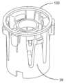
도 3은 도 1의 예시적인 약제 전달 장치의 근위 부분의 사시도이다.
도 4는 본 개시 내용의 투여 전달 검출 시스템과 함께, 도 1의 예시적인 약제 전달 장치의 근위 부분의 부분적으로 분해된 사시도이다.
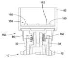
도 5는 약제 전달 장치의 근위 부분에 부착된 다른 예시적인 실시예에 따른 투여 검출 시스템 모듈의, 부분적인 횡단면의, 측면도이다.
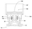
도 6은 약제 전달 장치의 근위 부분에 부착된 예시적인 실시예에 따른 투여 전달 검출 시스템의 모듈의 횡단면도이다.
도 7은 예시적인 실시예에 따른 투여 설정 부재에 부착된 자기적 피감지 요소를 검출하도록 배치된 회전 센서를 도시하는 상면도이다.
도 8은 자기적 피감지 요소를 포함하는 도 7의 투여 설정 부재의 사시도이다.
도 9는 자기적 투여 전달 검출 시스템의 대안적인 실시예의 사시도이다.
도 10a 및 도 10b 그리고 도 11a 및 도 11b는 자기적 감지를 이용하는 투여 전달 검출 시스템의 또 다른 예시적인 실시예를 도시한다.
도 12a 내지 도 12d 그리고 도 13a 내지 도 13g는 유도 감지를 이용하는 투여 검출 시스템의 예시적인 실시예를 도시한다.
도 14 내지 도 17은 투여 유형 전달 시스템과 함께 이용 가능한 키-결합 시스템의 예시적인 실시예를 도시한다.
도 18은 약제 전달 장치의 근위 부분에 부착되어 도시된, 다른 실시예에 따른 투여 검출 시스템의 모듈의 횡단면도이다.
도 19는 투여 검출 시스템의 예시적인 실시예에서 유용한 센서 및 피감지 구성요소의 배치를 도시한 도면이다.
도 20은 도 19의 투여 검출 시스템을 도시하는 개략도이다.
도 21은 도 19의 투여 검출 시스템을 위한 출력 응답을 도시하는 그래프이다.
도 22는 센서 및 피감지 요소가 약제 전달 장치 내로 통합된, 다른 실시예에 따른 투여 검출 시스템의 횡단면도이다.
도 23a 내지 도 23c는 센서 구성요소에 대한 스커트의 회전 및/또는 위치를 광학적으로 감지하는 것을 이용하는 투여 검출 시스템의 예시적인 실시예의 도면을 도시한다.
도 24a 및 도 24b는 센서 구성요소에 대한 플랜지의 회전 및/또는 위치를 광학적으로 감지하는 것을 이용하는 투여 검출 시스템의 다른 예시적인 실시예의 도면을 도시한다.
도 25a 내지 도 25c는 용량형 감지를 이용하는 투여 검출 시스템의 예시적인 실시예를 도시한다.
도 26은 본 개시 내용의 추가적인 예시적 약제 전달 장치의 횡단면도이다.The features and advantages of the present disclosure will become more apparent to those skilled in the art in light of the following detailed description taken in conjunction with the accompanying drawings.
FIG. 1 is a perspective view of an exemplary drug delivery device that can be operated with the administration detection system of the present disclosure.
Figure 2 is a cross-sectional perspective view of the exemplary drug delivery device of Figure 1.
FIG. 3 is a perspective view of the proximal portion of the exemplary drug delivery device of FIG. 1.
FIG. 4 is a partially exploded perspective view of the proximal portion of the exemplary drug delivery device of FIG. 1, together with the dose delivery detection system of the present disclosure.
FIG. 5 is a partial cross-sectional, side view of a dose detection system module according to another exemplary embodiment attached to a proximal portion of a drug delivery device.
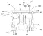
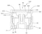
FIG. 6 is a cross-sectional view of a module of a dose delivery detection system according to an exemplary embodiment attached to a proximal portion of a drug delivery device.
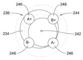
FIG. 7 is a top view illustrating a rotation sensor arranged to detect a magnetic sensing element attached to a dosing setting member according to an exemplary embodiment.
FIG. 8 is a perspective view of the dosing setup member of FIG. 7 including a magnetic sensing element.
Figure 9 is a perspective view of an alternative embodiment of a magnetic dose delivery detection system.
FIGS. 10A and 10B and FIGS. 11A and 11B illustrate further exemplary embodiments of a dose delivery detection system utilizing magnetic sensing.
FIGS. 12A through 12D and FIGS. 13A through 13G illustrate exemplary embodiments of a dosing detection system utilizing inductive sensing.
Figures 14 through 17 illustrate exemplary embodiments of a key-coupled system usable with a dosage type delivery system.
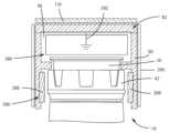
FIG. 18 is a cross-sectional view of a module of a dosing detection system according to another embodiment, shown attached to a proximal portion of a drug delivery device.
FIG. 19 is a diagram illustrating the arrangement of useful sensor and detection components in an exemplary embodiment of a dose detection system.
Figure 20 is a schematic diagram illustrating the administration detection system of Figure 19.
Figure 21 is a graph showing the output response for the dose detection system of Figure 19.
FIG. 22 is a cross-sectional view of a dosing detection system according to another embodiment, wherein the sensor and detection elements are integrated into the drug delivery device.
FIGS. 23A through 23C illustrate diagrams of exemplary embodiments of a dosing detection system that utilizes optical sensing of the rotation and/or position of a skirt relative to a sensor component.
FIGS. 24A and 24B illustrate drawings of another exemplary embodiment of a dose detection system that utilizes optical sensing of the rotation and/or position of a flange relative to a sensor component.
Figures 25a through 25c illustrate exemplary embodiments of a dose detection system utilizing capacitive sensing.
FIG. 26 is a cross-sectional view of an additional exemplary drug delivery device of the present disclosure.
본 개시 내용의 원리를 이해하는 것을 돕기 위한 목적으로, 이제 도면에 도시된 실시예를 참조할 것이고, 특정의 언어가 그러한 실시예를 설명하기 위해서 이용될 것이다. 그럼에도 불구하고, 본 발명의 범위에 대한 제한이 그에 의해서 의도되지 않는다는 것을 이해할 것이다.For the purpose of assisting in understanding the principles of the present disclosure, reference will now be made to embodiments illustrated in the drawings, and specific language will be used to describe such embodiments. Nevertheless, it will be understood that no limitation on the scope of the present invention is intended thereby.
본 개시 내용은 약제 전달 장치용 감지 시스템에 관한 것이다. 일 양태에서, 감지 시스템은, 약제 전달 장치의 투여 설정 부재와 작동기 사이의 상대적인 회전 이동의 감지를 기초로, 약제 전달 장치에 의해서 전달된 투여량을 결정하기 위한 것이다. 감지된 상대적 각도 위치 또는 이동은 전달된 투여량과 상호 관련된다. 제2 양태에서, 감지 시스템은 약제 전달 장치에 수용된 약물의 유형을 결정하기 위한 것이다. 예시로서, 약제 전달 장치는 펜 주입기의 형태로 설명된다. 그러나, 약제 전달 장치는, 주입 펌프, 환약 주입기 또는 자동 주입기 장치와 같이, 약제의 투여를 설정 및 전달하기 위해서 이용되는 임의의 장치일 수 있다. 약제는, 그러한 약제 전달 장치에 의해서 전달될 수 있는 임의의 유형일 수 있다.The present disclosure relates to a sensing system for a drug delivery device. In one aspect, the sensing system is for determining a dose delivered by the drug delivery device based on sensing a relative rotational movement between a dose setting member and an actuator of the drug delivery device. The sensed relative angular position or movement is correlated with the delivered dose. In a second aspect, the sensing system is for determining a type of drug contained in the drug delivery device. By way of example, the drug delivery device is illustrated as being in the form of a pen injector. However, the drug delivery device may be any device used to set and deliver a dose of a drug, such as an infusion pump, a pill injector, or an autoinjector device. The drug may be of any type that can be delivered by such a drug delivery device.
장치(10)와 같은, 본원에서 설명된 장치는, 예를 들어, 저장용기 또는 카트리지(20) 내에서, 약제를 더 포함할 수 있다. 다른 실시예에서, 시스템은 장치(10) 및 약제를 포함하는 하나 이상의 장치를 포함할 수 있다. "약제"라는 용어는, 비제한적으로 인슐린, 인슐린 리스프로 또는 인슐린 글라진과 같은 인슐린 유사체, 인슐린 유도체, 둘라글루티드 또는 리라글루티드와 같은 GLP-1 수용체 작용제, 글루카곤, 글루카곤 유사체, 글루카곤 유도체, 위 억제 폴리펩티드(GIP), GIP 유사체, GIP 유도체, 옥시토모듈린 유사체, 옥시토모둘린 유도체, 치료용 항체 및 전술한 장치에 의해서 전달될 수 있는 임의의 치료제를 포함하는 하나 이상의 치료제를 지칭한다. 장치에서 사용되는 바와 같은 약제는 하나 이상의 부형제(excipient)와 함께 제형화될 수 있다. 그러한 장치는 일반적으로 환자, 간병인 또는 건강 관리 전문가에 의해서 전술한 바와 같은 방식으로 동작되어 약제를 사람에게 전달한다.Devices described herein, such as device (10), may further comprise a medication, for example, within a reservoir or cartridge (20). In other embodiments, a system may comprise one or more devices comprising the device (10) and a medication. The term "medication" refers to one or more therapeutic agents, including but not limited to insulin, an insulin analogue such as insulin lispro or insulin glargine, an insulin derivative, a GLP-1 receptor agonist such as dulaglutide or liraglutide, glucagon, a glucagon analogue, a glucagon derivative, a gastric inhibitory polypeptide (GIP), a GIP analogue, a GIP derivative, an oxytomodulin analogue, an oxytomodulin derivative, a therapeutic antibody, and any therapeutic agent that can be delivered by the device described above. A medication, such as used in the device, may be formulated with one or more excipients. Such devices are typically operated by a patient, caregiver, or health care professional in the manner described above to deliver the medication to a person.
예시적인 약제 전달 장치(10)가, 도 1 내지 도 4에서, 바늘을 통해서 환자 내로 약제를 주입하도록 구성된 펜 주입기로서 도시되어 있다. 펜 주입기(10)는 본체(11)를 포함하고, 본체는 원위 부분(14) 및 근위 부분(16)을 포함하는 세장형의, 펜-형상의 하우징(12)을 포함한다. 원위 부분(14)은 펜 캡(18) 내에 수용된다. 도 2를 참조하면, 원위 부분(14)은, 분배 동작 중에 원위 배출구 단부를 통해서 분배되는 의료적 유체를 유지하도록 구성된 저장용기 또는 카트리지(20)를 수용한다. 원위 부분(14)의 배출구 단부는, 제거 가능한 커버(25)에 의해서 둘러싸이는 주입 바늘(24)을 포함하는 제거 가능한 바늘 조립체(22)를 구비한다. 피스톤(26)이 저장용기(20) 내에 배치된다. 근위 부분(16) 내에 배치된 주입 메커니즘은, 수용된 약을 바늘형 단부를 통해서 강제하기 위해서 투여 분배 동작 중에 저장용기(20)의 배출구를 향해서 피스톤(26)을 전진시키도록 동작될 수 있다. 주입 메커니즘은, 피스톤(26)을 저장용기(20)를 통해서 전진시키기 위해서 하우징(12)에 대해서 축방향으로 이동 가능한, 예시적으로 나사 형태의, 구동 부재(28)를 포함한다.An exemplary drug delivery device (10) is illustrated in FIGS. 1-4 as a pen injector configured to inject a medication into a patient via a needle. The pen injector (10) includes a body (11) that includes an elongated, pen-shaped housing (12) that includes a distal portion (14) and a proximal portion (16). The distal portion (14) is housed within a pen cap (18). Referring to FIG. 2, the distal portion (14) houses a reservoir or cartridge (20) configured to hold a medical fluid to be dispensed via a distal outlet end during a dispensing operation. The outlet end of the distal portion (14) has a removable needle assembly (22) including an injection needle (24) surrounded by a removable cover (25). A piston (26) is disposed within the reservoir (20). An injection mechanism disposed within the proximal portion (16) can be operated to advance a piston (26) toward the outlet of the reservoir (20) during a dispensing operation to force the received drug through the needle-shaped end. The injection mechanism includes a drive member (28), typically a screw-shaped member, axially movable with respect to the housing (12) to advance the piston (26) through the reservoir (20).
장치(10)에 의해서 분배되는 투여량을 설정하기 위해서, 투여 설정 부재(30)가 하우징(12)에 커플링된다. 예시된 실시예에서, 투여 설정 부재(30)는 투여 설정 및 투여 분배 중에 하우징(12)에 대해서 나선형으로 동작되는(즉, 축방향 및 회전방향으로 동시에 이동되는) 나사 요소 형태이다. 도 1 및 도 2는 홈(home) 또는 0(zero)의 투여 위치에서 하우징(12) 내로 완전히 나사작업된(fully screwed) 투여 설정 부재(30)를 도시한다. 투여 설정 부재(30)는, 단일 주입에서 장치(10)에 의해서 전달될 수 있는 최대 투여에 상응하는 완전 연장 위치에 도달할 때까지, 하우징(12)으로부터 근위 방향으로 외측으로 나사작업되도록 동작된다.To set the dose to be dispensed by the device (10), a dose setting member (30) is coupled to the housing (12). In the illustrated embodiment, the dose setting member (30) is in the form of a screw element that is helically operated (i.e., moves axially and rotationally simultaneously) with respect to the housing (12) during dose setting and dose dispensing. FIGS. 1 and 2 illustrate the dose setting member (30) fully screwed into the housing (12) in a home or zero dose position. The dose setting member (30) is operated to be screwed proximally outward from the housing (12) until it reaches a fully extended position corresponding to a maximum dose that can be delivered by the device (10) in a single injection.
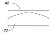
도 2 내지 도 4를 참조하면, 투여 설정 부재(30)는, 투여 설정 부재(30)가 하우징(12)에 대해서 나선운동될 수 있도록 하우징(12)의 상응하는 나사산형 내부 표면과 결합되는 나선형의 나사산형 외부 표면을 갖는 원통형 투여 다이알 부재(32)를 포함한다. 투여 다이알 부재(32)는, 장치(10)의 슬리브(34)(도 2)의 나사산형 외부 표면과 결합되는 나선형의 나사산형 내부 표면을 더 포함한다. 다이알 부재(32)의 외부 표면은, 설정된 투여량을 사용자에게 알리기 위해서 투여용량(dosage) 창(36)을 통해서 볼 수 있는 숫자와 같은, 투여 표시부 마킹을 포함한다. 투여 설정 부재(30)는, 다이알 부재(32)의 개방 근위 단부 내에 커플링되고 다이알 부재(32) 내의 개구부(41) 내에 수용된 멈춤부(40)에 의해서 다이알 부재(32)에 축방향 및 회전방향으로 록킹되는(locked) 관형 플랜지(38)를 더 포함한다. 투여 설정 부재(30)는, 근위 단부에서 다이알 부재(32)의 외부 주변부 주위에 배치되는 칼라 또는 스커트(42)를 더 포함한다. 스커트(42)는 슬롯(46) 내에 수용된 탭(44)에 의해서 다이알 부재(32)에 축방향 및 회전방향으로 록킹된다.Referring to FIGS. 2-4, the dose setting member (30) includes a cylindrical dose dial member (32) having a helical threaded outer surface that engages with a corresponding threaded inner surface of the housing (12) such that the dose setting member (30) can be spirally moved relative to the housing (12). The dose dial member (32) further includes a helical threaded inner surface that engages with a threaded outer surface of the sleeve (34) (FIG. 2) of the device (10). The outer surface of the dial member (32) includes dose indicator markings, such as numbers that are visible through a dosage window (36) to indicate to a user a set dosage. The dose setting member (30) further includes a tubular flange (38) coupled within the open proximal end of the dial member (32) and axially and rotatably locked to the dial member (32) by a stop (40) received within an opening (41) in the dial member (32). The dose setting member (30) further includes a collar or skirt (42) disposed around the outer periphery of the dial member (32) at the proximal end. The skirt (42) is axially and rotatably locked to the dial member (32) by a tab (44) received within a slot (46).
그에 따라, 투여 설정 부재(30)가 투여 다이알 부재(32), 플랜지(38), 및 스커트(42) 중 임의의 것 또는 모두를 포함하는 것으로 간주될 수 있는데, 이는 그들 모두가 회전적으로 및 축방향으로 함께 고정되기 때문이다. 투여 다이알 부재(32)는 투여의 설정 및 약제 전달의 구동에 직접적으로 관련된다. 플랜지(38)는 다이알 부재(32)에 부착되고, 후술되는 바와 같이, 클러치와 협력하여 다이알 부재(32)를 투여 버튼(56)과 선택적으로 커플링시킨다. 투여를 설정하기 위해서 사용자가 다이알 부재(32)를 회전시킬 수 있도록, 스커트(42)는 본체(11) 외부의 표면을 제공한다.Accordingly, the dose setting member (30) may be considered to include any or all of the dose dial member (32), the flange (38), and the skirt (42), since all of them are rotatably and axially secured together. The dose dial member (32) is directly involved in setting the dose and driving the drug delivery. The flange (38) is attached to the dial member (32) and, as described below, cooperates with the clutch to selectively couple the dial member (32) with the dose button (56). The skirt (42) provides a surface on the exterior of the body (11) to enable a user to rotate the dial member (32) to set the dose.
스커트(42)는 스커트(42)의 외부 표면 상에 형성된 복수의 표면 특징부(48) 및 환형 융기부(49)를 예시적으로 포함한다. 표면 특징부(48)는, 스커트(42)의 외부 표면 주위에서 원주방향으로 이격되고 사용자가 스커트를 파지하고 회전시키는 것을 돕는, 예시적으로 길이방향으로 연장되는 리브(rib) 및 홈이다. 대안적인 실시예에서, 스커트(42)가 제거되거나 다이알 부재(32)와 일체이고, 사용자는 투여 설정을 위해서 투여 버튼(56) 및/또는 투여 다이알 부재(32)를 파지하고 회전시킬 수 있다. 도 4의 실시예에서, 사용자는 투여 설정을 위해서, 복수의 표면 특징부를 또한 포함하는, 하나의-단편의 투여 버튼(56)의 반경방향 외부 표면을 파지하고 회전시킬 수 있다.The skirt (42) illustratively includes a plurality of surface features (48) and annular protrusions (49) formed on an outer surface of the skirt (42). The surface features (48) are, illustratively, ribs and grooves that are spaced circumferentially about the outer surface of the skirt (42) and extend longitudinally to assist a user in grasping and rotating the skirt. In alternative embodiments, the skirt (42) is removable or is integral with the dial member (32), and a user can grasp and rotate the dose button (56) and/or the dose dial member (32) for dose setting. In the embodiment of FIG. 4, a user can grasp and rotate a radially outer surface of a one-piece dose button (56), which also includes a plurality of surface features, for dose setting.
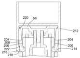
전달 장치(10)는, 다이알 부재(32) 내에 수용되는 클러치(52)를 갖는 작동기(50)를 포함한다. 클러치(52)는 그 근위 단부에서 축방향 연장 스템(stem)(54)을 포함한다. 작동기(50)는 투여 설정 부재(30)의 스커트(42)의 근위적으로 배치된 투여 버튼(56)을 더 포함한다. 대안적인 실시예에서, 투여 설정 부재(30)는 도 26에 도시된 하나의-단편의 투여 버튼(56)을 포함한다. 투여 버튼(56)은, 투여 버튼(56)의 원위 표면의 중앙에 위치된 장착 칼라(58)(도 2)를 포함한다. 투여 버튼(56) 및 클러치(52)를 축방향으로 그리고 회전적으로 함께 고정하기 위해서, 칼라(58)가, 예를 들어 억지끼워 맞춤 또는 초음파 용접으로, 클러치(52)의 스템(54)에 부착된다.The delivery device (10) includes an actuator (50) having a clutch (52) received within a dial member (32). The clutch (52) includes an axially extending stem (54) at its proximal end. The actuator (50) further includes a proximal distal dispensing button (56) of the skirt (42) of the dose setting member (30). In an alternative embodiment, the dose setting member (30) includes a single-piece dispensing button (56) as illustrated in FIG. 26. The dispensing button (56) includes a mounting collar (58) ( FIG. 2 ) positioned centrally on a distal surface of the distal distal surface of the dispensing button (56). The collar (58) is attached to the stem (54) of the clutch (52), for example, by a force fit or ultrasonic welding, to secure the dispensing button (56) and the clutch (52) axially and rotationally together.
투여 버튼(56)은 디스크-형상의 근위 단부 표면 또는 면(60), 및 원위적으로 연장되고 면(60)의 외부 주변 연부의 반경방향 내측으로 이격되어 환형 립(64)을 사이에 형성하는 환형 벽 부분(62)을 포함한다. 투여 버튼(56)의 근위 면(60)은 누름 표면으로서의 역할을 하고, 작동기(50)를 원위 방향으로 누르기 위해서, 그러한 누름 표면에 반하여(against) 힘이 수동적으로, 즉 사용자에 의해서 직접적으로 인가될 수 있다. 투여 버튼(56)은 예시적으로 근위 면(60)의 중심에 위치된 함몰 부분(66)을 포함하나, 근위 면(60)은 대안적으로 편평한 표면일 수 있다. 유사하게, 도 26에 도시된 하나의-단편의 투여 버튼(56)은 근위 면(60)의 중앙에 위치된 함몰 부분(66)을 포함할 수 있거나 대안적으로 편평한 표면일 수 있다. 편향 부재(68), 예시적으로 스프링이 버튼(56)의 원위 표면(70)과 관형 플랜지(38)의 근위 표면(72) 사이에 배치되어, 작동기(50) 및 투여 설정 부재(30)를 축방향으로 서로로부터 멀리 압박한다. 투여 분배 동작을 개시하기 위해서, 사용자는 투여 버튼(56)을 누를 수 있다.The dispensing button (56) includes a disc-shaped proximal end surface or face (60), and an annular wall portion (62) extending distally and spaced radially inwardly from the outer peripheral edge of the face (60) to form an annular lip (64) therebetween. The proximal face (60) of the dispensing button (56) serves as a push surface, against which force can be applied passively, i.e. directly by a user, to push the actuator (50) distally. The dispensing button (56) illustratively includes a recessed portion (66) located in the center of the proximal face (60), although the proximal face (60) may alternatively be a flat surface. Similarly, the one-piece dispensing button (56) illustrated in FIG. 26 may include a recessed portion (66) located in the center of the proximal face (60) or may alternatively be a flat surface. A biasing member (68), for example a spring, is positioned between the distal surface (70) of the button (56) and the proximal surface (72) of the tubular flange (38) to axially urge the actuator (50) and the dose setting member (30) away from each other. To initiate a dose dispensing action, a user may press the dose button (56).
전달 장치(10)는 투여 설정 모드 및 투여 분배 모드 모두로 동작될 수 있다. 동작의 투여 설정 모드에서, 장치(10)에 의해서 전달하고자 하는 희망 투여를 설정하기 위해서, 투여 설정 부재(30)가 하우징(12)에 대해서 다이알링(회전)된다. 근위 방향으로 다이알링하는 것은 설정 투여를 증가시키는 역할을 하고, 원위 방향으로 다이알링하는 것은 설정 투여를 감소시키는 역할을 한다. 투여 설정 부재(30)는 투여 설정 동작 중에 설정 투여의 최소 증분적(incremental) 증가 또는 감소에 상응하는 회전 증분(예를 들어, 클릭)으로 조정될 수 있다. 예를 들어, 하나의 증분 또는 "클릭"이 약제의 1/2 또는 1의 단위와 동일할 수 있다. 설정된 투여량은 투여용량 창(36)을 통해서 보이는 다이알 표시부 마킹을 통해서 사용자에게 보일 수 있다. 투여 버튼(56) 및 클러치(52)를 포함하는 작동기(50)는 투여 설정 모드에서 다이알링 중에 투여 설정 부재(30)와 함께 축방향 및 회전방향으로 이동된다.The delivery device (10) can be operated in both a dose setting mode and a dose dispensing mode. In the dose setting mode of operation, a dose setting member (30) is dialed (rotated) relative to the housing (12) to set a desired dose to be delivered by the device (10). Dialing in a proximal direction serves to increase the set dose, and dialing in a distal direction serves to decrease the set dose. The dose setting member (30) can be adjusted in rotational increments (e.g., clicks) corresponding to a minimum incremental increase or decrease in the set dose during the dose setting operation. For example, one increment or “click” can be equal to one-half or one unit of medication. The set dose can be displayed to the user via a dial indicator marking that is visible through the dose window (36). An actuator (50) including a dose button (56) and a clutch (52) moves axially and rotationally together with a dose setting member (30) during dialing in the dose setting mode.
투여 다이알 부재(32), 플랜지(38), 및 스커트(42) 모두가 서로에 대해서 회전적으로 고정되고, 다이알 부재(32)와 하우징(12)의 나사산형 연결로 인해서, 투여 설정 중에 약제 전달 장치(10)에 근위적으로 회전 및 연장된다. 이러한 투여 설정 운동 중에, 투여 버튼(56)은, 편향 부재(68)에 의해서 함께 압박되는, 플랜지(38) 및 클러치(52)(도 2)의 상보적인 스플라인들(74)에 의해서 스커트(42)에 대해서 회전적으로 고정된다. 투여 설정의 과정 중에, 스커트(42) 및 투여 버튼(56)은 "시작" 위치로부터 "종료" 위치까지 나선형 방식으로 하우징(12)에 대해서 이동된다. 하우징에 대한 이러한 회전은 약제 전달 장치(10)의 동작에 의해서 설정된 투여량에 비례한다.The dose dial member (32), the flange (38), and the skirt (42) are all rotationally fixed with respect to one another and, due to the threaded connection of the dial member (32) and the housing (12), rotate and extend proximally with respect to the drug delivery device (10) during the dose setting. During this dose setting movement, the dose button (56) is rotationally fixed with respect to the skirt (42) by complementary splines (74) of the flange (38) and the clutch (52) (FIG. 2), which are pressed together by the biasing member (68). During the course of the dose setting, the skirt (42) and the dose button (56) are moved with respect to the housing (12) in a helical manner from a “start” position to an “end” position. This rotation with respect to the housing is proportional to the dose set by the operation of the drug delivery device (10).
희망 투여가 설정되면, 장치(10)가 조작되고, 그에 따라 주입 바늘(24)이, 예를 들어, 사용자의 피부에 적절히 침투한다. 투여 버튼(56)의 근위 면(60)에 인가된 축방향 원위방향 힘에 응답하여, 동작의 투여 분배 모드가 개시된다. 축방향 힘은 사용자에 의해서 투여 버튼(56)에 직접적으로 인가된다. 이는, 원위 방향을 따른 하우징(12)에 대한 작동기(50)의 축방향 이동을 유발한다.Once the desired dose is set, the device (10) is operated, whereby the injection needle (24) appropriately penetrates, for example, the user's skin. In response to an axial distal force applied to the proximal face (60) of the administration button (56), the administration dispensing mode of operation is initiated. The axial force is applied directly to the administration button (56) by the user. This causes an axial movement of the actuator (50) relative to the housing (12) along the distal direction.
작동기(50)의 축방향 이동 운동은 편향 부재(68)를 압축하고 투여 버튼(56)과 관형 플랜지(38) 사이의 간극을 줄이거나 폐쇄한다. 이러한 상대적인 축방향 이동은 클러치(52) 및 플랜지(38) 상의 상보적인 스플라인들(74)을 분리하고, 그에 의해서 투여 설정 부재(30)에 회전적으로 고정되는 것으로부터 작동기(50), 예를 들어 투여 버튼(56)을 결합해제한다. 특히, 투여 설정 부재(30)가 작동기(50)로부터 회전적으로 언커플링되어, 작동기(50) 및 하우징(12)에 대한 투여 설정 부재(30)의 역방향-구동 회전을 허용한다. 동작의 투여 분배 모드가 또한 분리 스위치 또는 트리거 메커니즘의 활성화에 의해서 개시될 수 있다.The axial translational movement of the actuator (50) compresses the biasing member (68) and reduces or closes the gap between the dosing button (56) and the tubular flange (38). This relative axial movement disengages the complementary splines (74) on the clutch (52) and the flange (38), thereby disengaging the actuator (50), for example the dosing button (56), from being rotationally fixed to the dosing setting member (30). In particular, the dosing setting member (30) is rotationally uncoupled from the actuator (50), thereby allowing counter-driven rotation of the dosing setting member (30) with respect to the actuator (50) and the housing (12). The dosing dispensing mode of operation can also be initiated by activating a disconnect switch or a trigger mechanism.
하우징(12)에 대한 회전이 없이 작동기(50)가 축방향으로 계속 끼워질 수 있음에 따라, 다이알 부재(32)는, 투여 버튼(56)에 대해서 회전됨에 따라, 하우징(12) 내로 역으로 나사작업된다. 주입하여야 하는 양이 여전히 남았다는 것을 나타내는 투여 마킹을 창(36)을 통해서 볼 수 있다. 투여 설정 부재(30)가 원위적으로 하향 나사작업됨에 따라, 구동 부재(28)가 원위적으로 전진되어, 피스톤(26)을 저장용기(20)를 통해서 밀고 약제를 바늘(24)(도 2)을 통해서 방출한다.As the actuator (50) can continue to fit axially without rotation about the housing (12), the dial member (32) is screwed back into the housing (12) as it is rotated about the dose button (56). A dose marking indicating that there is still a quantity to be injected is visible through the window (36). As the dose setting member (30) is screwed distally downward, the drive member (28) is advanced distally, pushing the piston (26) through the reservoir (20) and expelling the drug through the needle (24) (FIG. 2).
투여 분배 동작 중에, 약제 전달 장치로부터 방출되는 약의 양은, 다이알 부재(32)가 하우징(12) 내로 역으로 나사작업될 때, 작동기(50)에 대한 투여 설정 부재(30)의 회전 이동량에 비례된다. 다이알 부재(32)의 내부 나사산결합(threading)이 슬리브(34)(도 2)의 상응 외부 나사산결합의 원위 단부에 도달하였을 때, 주입이 완료된다. 이어서, 장치(10)는 다시 한번, 도 2 및 도 3에 도시된 바와 같은, 준비 상태 또는 0의 투여 위치에서 정렬된다.During a dose dispensing operation, the amount of drug released from the drug delivery device is proportional to the rotational movement of the dose setting member (30) relative to the actuator (50) as the dial member (32) is screwed back into the housing (12). When the internal threading of the dial member (32) reaches the distal end of the corresponding external threading of the sleeve (34) (FIG. 2), the injection is complete. The device (10) is then aligned once again in the ready state or zero dose position, as illustrated in FIGS. 2 and 3.
투여 버튼(56)에 대한, 투여 다이알 부재(32)의, 그리고 그에 따라 회전적으로 고정된 플랜지(38) 및 스커트(42)의 시작 및 종료 각도 위치는 투여 전달 중에 각도 위치의 "절대적인" 변화를 제공한다. 상대적인 회전이 360°를 초과하였는지의 여부를 결정하는 것이 수 많은 방식으로 결정될 수 있다. 예로서, 감지 시스템에 의해서 임의의 수의 방식으로 측정될 수 있는 투여 설정 부재(30)의 증분적 이동을 또한 고려함으로써, 전체 회전이 결정될 수 있다.The start and end angular positions of the dose dial member (32), and thus the rotationally fixed flange (38) and skirt (42) relative to the dose button (56), provide an "absolute" change in angular position during dose delivery. Determining whether the relative rotation has exceeded 360° can be determined in a number of ways. For example, the total rotation can be determined by also taking into account incremental movement of the dose setting member (30), which can be measured in any number of ways by the detection system.
예시적인 전달 장치(10)의 설계 및 동작의 추가적인 상세 내용이, 전체 개시 내용이 참조로서 본원에 포함되는, "Medication Dispensing Apparatus with Triple Screw Threads for Mechanical Advantage"라는 명칭의 미국 특허 제7,291,132호에서 확인될 수 있다. 전달 장치의 다른 예는, 전체 개시 내용이 참조로서 본원에 포함되는, "Automatic Injection Device With Delay Mechanism Including Dual Functioning Biasing Member"라는 명칭의 미국 특허 제8,734,394호에서 확인될 수 있는 자동-주입기 장치이며, 여기에서 그러한 장치는, 약제 전달 장치 내의 상대적인 회전의 감지를 기초로 약제 전달 장치로부터 전달되는 약제의 양을 결정하기 위해서 여기에서 설명된 하나 이상의 여러 가지 센서 시스템으로 수정된다.Additional details of the design and operation of an exemplary delivery device (10) may be found in U.S. Pat. No. 7,291,132, entitled "Medication Dispensing Apparatus with Triple Screw Threads for Mechanical Advantage," the entire disclosure of which is incorporated herein by reference. Another example of a delivery device is an auto-injector device, which may be found in U.S. Pat. No. 8,734,394, entitled "Automatic Injection Device With Delay Mechanism Including Dual Functioning Biasing Member," the entire disclosure of which is incorporated herein by reference, wherein such device is modified with one or more of the various sensor systems described herein to determine an amount of medication to be delivered from the medication delivery device based on detection of relative rotation within the medication delivery device.
투여 검출 시스템은 약제 전달 장치의 부재들에 부착된 감지 구성요소 및 피감지 구성요소를 이용한다. "부착된"이라는 용어는, 본원에서 설명된 바와 같이 동작될 수 있도록, 다른 구성요소에 대한 또는 약제 전달 장치의 부재에 대한 구성요소의 위치를 고정하는 임의의 방식을 포함한다. 예를 들어, 감지 구성요소가, 부재 상에 직접적으로 배치되는 것, 부재 내에 수용되는 것, 부재와 일체인 것, 또는 부재에 달리 연결되는 것에 의해서, 약제 전달 장치의 부재에 부착될 수 있다. 연결은, 예를 들어, 마찰 결합, 스플라인, 스냅 또는 압입, 음파 용접 또는 접착제에 의해서 형성된 연결부를 포함할 수 있다.The dosing detection system utilizes sensing components and sensed components attached to members of the drug delivery device. The term "attached" includes any manner of securing the position of a component relative to another component or to a member of the drug delivery device such that it can be operated as described herein. For example, the sensing components can be attached to a member of the drug delivery device by being directly disposed on the member, housed within the member, integral with the member, or otherwise connected to the member. The connection can include, for example, a connection formed by a friction fit, a spline, a snap or press fit, an acoustic weld, or an adhesive.
"직접적으로 부착된"이라는 용어는, 2개의 구성요소, 또는 구성요소 및 부재가 부착 구성요소 이외의 중간 부재가 없이 함께 물리적으로 고정되는 부착을 설명하기 위해서 사용된다. 부착 구성요소는 체결부, 어댑터 또는 체결 시스템의 다른 부품, 예를 들어 부착을 돕기 위해서 2개의 구성요소 사이에 개재되는 압축 가능 멤브레인을 포함할 수 있다. "직접적인 부착"은, 다이알 부재(32)가 도 2에서 클러치(52)에 의해서 투여 버튼(56)에 커플링되는 것과 같이, 구성요소/부재가 하나 이상의 중간 기능 부재에 의해서 커플링되는 연결과 구별된다.The term "directly attached" is used to describe an attachment where two components, or a component and a member, are physically secured together without any intermediate member other than the attachment component. The attachment component may include a fastener, an adapter, or other component of the fastening system, such as a compressible membrane interposed between the two components to facilitate the attachment. A "direct attachment" is distinguished from a connection where the components/members are coupled by one or more intermediate functional members, such as the dial member (32) being coupled to the dispensing button (56) by the clutch (52) in FIG. 2.
"고정된"이라는 용어는, 표시된 이동이 발생될 수 있거나 발생될 수 없는 것을 나타내기 위해서 사용된다. 예를 들어, 2개의 부재가 함께 회전 이동될 것이 요구되는 경우에, 제1 부재가 제2 부재와 "회전적으로 고정"된다. 다른 양태에서, 부재는, 구조적이 아니라 기능적으로, 다른 부재에 대해서 "고정될" 수 있다. 예를 들어, 2개의 부재 사이의 마찰 결합이 그 부재들을 함께 회전적으로 고정하도록 부재가 다른 부재에 반하여 눌릴 수 있는 한편, 제1 부재의 누름이 없는 경우에 2개의 부재가 함께 고정되지 않을 수 있다.The term "fixed" is used to indicate that the indicated movement may or may not occur. For example, where two members are required to rotate together, a first member is "rotationally fixed" with respect to a second member. In other embodiments, a member may be "fixed" with respect to another member, but not structurally. For example, while a frictional fit between two members may cause one member to be pressed against the other such that the members are rotationally fixed together, in the absence of the first member's pressing, the two members may not be fixed together.
여러 가지 센서 시스템이 본원에서 고려된다. 일반적으로, 센서 시스템은 감지 구성요소 및 피감지 구성요소를 포함한다. "감지 구성요소"라는 용어는, 피감지 구성요소의 상대적인 위치를 검출할 수 있는 임의의 구성요소를 지칭한다. 감지 구성요소는, 감지 요소를 동작시키기 위한 연관 전기 구성요소와 함께, 감지 요소 또는 "센서"를 포함한다. "피감지 구성요소"는, 감지 구성요소가 감지 구성요소에 대한 피감지 구성요소의 위치 및/또는 이동을 검출할 수 있는, 임의의 구성요소이다. 투여 전달 검출 시스템에서, 피감지 구성요소는 감지 구성요소에 대해서 회전되고, 감지 구성요소는 피감지 구성요소의 각도 위치 및/또는 회전 이동을 검출할 수 있다. 투여 유형 검출 시스템에서, 감지 구성요소는 피감지 구성요소의 상대적 각도 위치를 검출한다. 감지 구성요소는 하나 이상의 감지 요소를 포함할 수 있고, 피감지 구성요소는 하나 이상의 피감지 요소를 포함할 수 있다. 센서 시스템은 피감지 구성요소(들)의 위치 또는 이동을 검출할 수 있고 피감지 구성요소(들)의 위치(들) 또는 이동(들)을 나타내는 출력을 제공할 수 있다.Several sensor systems are contemplated herein. In general, a sensor system includes a sensing component and a sensed component. The term "sensing component" refers to any component capable of detecting the relative position of a sensed component. The sensing component includes a sensing element or "sensor", together with associated electrical components for operating the sensing element. The "sensed component" is any component capable of detecting the position and/or movement of the sensed component relative to the sensing component. In a dose delivery detection system, the sensed component is rotated relative to the sensing component, and the sensing component can detect the angular position and/or rotational movement of the sensed component. In a dose type detection system, the sensing component detects the relative angular position of the sensed component. The sensing component can include one or more sensing elements, and the sensed component can include one or more sensed elements. The sensor system can detect the position or movement of the sensed component(s) and can provide an output indicative of the position(s) or movement(s) of the sensed component(s).
센서 시스템은 전형적으로, 피감지 지역 내의 하나 이상의 피감지 요소의 위치에 대한 연관성에 따라 달라지는 피감지 매개변수의 특성을 검출한다. 피감지 요소는, 피감지 매개변수의 특성에 직접적 또는 간접적으로 영향을 미치는 방식으로 피감지 지역 내로 연장되거나 피감지 지역에 달리 영향을 미친다. 센서 및 피감지 요소의 상대적인 위치들은 피감지 매개변수의 특성에 영향을 미치고, 그에 따라 센서 시스템의 제어기가 피감지 요소의 상이한 위치들을 결정할 수 있게 한다.A sensor system typically detects a characteristic of a sensed parameter that varies in relation to the location of one or more sensed elements within a sensed region. The sensed elements extend into the sensed region or otherwise affect the sensed region in a manner that directly or indirectly affects the characteristic of the sensed parameter. The relative locations of the sensor and the sensed elements affect the characteristic of the sensed parameter, thereby allowing a controller of the sensor system to determine different locations of the sensed elements.
적합한 센서 시스템이 능동적 구성요소 및 피동적 구성요소의 조합을 포함할 수 있다. 능동적 구성요소로서 동작되는 감지 구성요소에서, 양 구성요소들이 전원 또는 제어기와 같은 다른 시스템 요소와 연결될 필요성이 없다.A suitable sensor system may include a combination of active and passive components. In a sensing component that operates as an active component, there is no need for both components to be connected to other system elements, such as a power source or controller.
2개의 부재의 상대적인 위치들을 검출할 수 있는, 다양한 감지 기술 중 임의의 기술이 포함될 수 있다. 그러한 기술은, 예를 들어, 촉각적, 광학적, 유도적, 또는 전기적 측정을 기초로 하는 기술을 포함할 수 있다.Any of a variety of sensing technologies capable of detecting the relative positions of two absences may be included. Such technologies may include, for example, technologies based on tactile, optical, inductive, or electrical measurements.
그러한 기술은 자기장과 같은 필드(field)와 연관된 피감지 매개변수의 측정을 포함할 수 있다. 하나의 형태에서, 자기 센서는 자기적 구성요소가 센서에 대해서 이동될 때 피감지 자기장의 변화를 감지한다. 다른 실시예에서, 센서 시스템은 물체가 자기장 내에 배치될 때 및/또는 자기장을 통해서 이동될 때 자기장의 특성 및/또는 변화를 감지할 수 있다. 필드의 변경은 피감지 지역 내의 피감지 요소의 위치와 관련된 피감지 매개변수의 특성을 변화시킨다. 그러한 실시예에서, 피감지 매개변수는 커패시턴스, 전도도, 저항, 임피던스, 전압, 인덕턴스 등일 수 있다. 예를 들어, 자기-저항 유형의 센서가 인가 자기장의 왜곡을 검출하고, 이는 센서의 요소의 저항의 특성적 변화를 초래한다. 다른 예로서, 홀 효과(Hall effect) 센서가 인가 자기장의 왜곡으로부터 초래되는 전압의 변화를 검출한다.Such techniques may include the measurement of a sensed parameter associated with a field, such as a magnetic field. In one form, a magnetic sensor detects a change in a sensed magnetic field when a magnetic component is moved relative to the sensor. In another embodiment, the sensor system may detect a characteristic and/or change in a magnetic field when an object is placed in and/or moved through the magnetic field. The change in the field changes a characteristic of the sensed parameter associated with the location of the sensed element within the sensed region. In such an embodiment, the sensed parameter may be capacitance, conductivity, resistance, impedance, voltage, inductance, and the like. For example, a magneto-resistive type sensor detects a distortion of an applied magnetic field, which causes a characteristic change in the resistance of an element of the sensor. As another example, a Hall effect sensor detects a change in voltage resulting from a distortion of an applied magnetic field.
일 양태에서, 센서 시스템은 피감지 요소의, 그리고 그에 따라 약제 전달 장치의 연관된 부재의 상대적인 위치 또는 이동을 검출한다. 센서 시스템은 피감지 구성요소의 위치(들) 또는 이동량을 나타내는 출력을 생성한다. 예를 들어, 센서 시스템은 출력을 생성하도록 동작될 수 있고, 그러한 출력에 의해서 투여 전달 중에 투여 설정 부재의 회전이 결정될 수 있다. 제어기는 출력을 수신하기 위해서 각각의 센서에 동작 가능하게 연결된다. 일 양태에서, 제어기는 그러한 출력으로부터, 약제 전달 장치의 동작에 의해서 전달되는 투여량을 결정하도록 구성된다.In one aspect, the sensor system detects the relative position or movement of the sensed element and, accordingly, the associated member of the drug delivery device. The sensor system generates an output indicative of the position(s) or amount of movement of the sensed element. For example, the sensor system can be operative to generate an output, wherein the rotation of the dose setting member during the dose delivery can be determined by such output. A controller is operatively connected to each of the sensors to receive the output. In one aspect, the controller is configured to determine, from such output, the dose to be delivered by the operation of the drug delivery device.
투여 전달 검출 시스템은 2개의 부재들 사이의 상대적인 회전 이동을 검출하는 것을 포함한다. 전달 투여량에 대한 기지의(known) 연관성을 갖는 회전의 범위에서, 센서 시스템은 투여 주입의 시작으로부터 투여 주입의 종료까지 각운동의 양을 검출하도록 동작된다. 예를 들어, 펜 주입기에 대한 전형적인 연관성은, 18°의 투여 설정 부재의 각도 변위가 1의 투여의 단위와 동일할 수 있으나, 다른 각도 연관성도 또한 적합하다. 센서 시스템은 투여 전달 중에 투여 설정 부재의 총 각도 변위를 결정하도록 동작될 수 있다. 따라서, 각도 변위가 90°인 경우, 5 단위의 투여가 전달된 것이다.The dose delivery detection system comprises detecting relative rotational movement between two members. Over a range of rotations having a known relationship to the delivered dose, the sensor system is operative to detect the amount of angular motion from the start of the dose injection to the end of the dose injection. For example, a typical relationship for a pen injector may be that 18° of angular displacement of the dose setting member is equivalent to one unit of dose, although other angular relationships are also suitable. The sensor system is operative to determine the total angular displacement of the dose setting member during the dose delivery. Thus, if the angular displacement is 90°, then 5 units of dose have been delivered.
각도 변위의 검출을 위한 하나의 접근방식은 주입이 진행됨에 따른 투여량의 증분을 계수하는 것이다. 예를 들어, 각각의 반복이 각도적 회전의 미리 결정된 각도(degree)를 나타내도록, 센서 시스템이 피감지 요소의 반복 패턴을 이용할 수 있다. 편리하게, 각각의 반복이 약제 전달 장치로 설정될 수 있는 투여의 최소 증분에 상응하도록, 패턴이 확립될 수 있다.One approach to detecting angular displacement is to count increments of the dose as the injection progresses. For example, the sensor system could utilize a repeating pattern of the sensed element such that each repetition represents a predetermined degree of angular rotation. Conveniently, the pattern could be established such that each repetition corresponds to a minimum increment of dose that can be set by the drug delivery device.
대안적인 접근방식은 상대적으로 이동되는 부재의 시작 위치 및 정지 위치를 검출하고, 그러한 위치들 사이의 차이로서 전달 투여량을 결정하는 것이다. 이러한 접근방식에서, 센서 시스템이 투여 설정 부재의 전체 회전수를 검출하는 것이 결정의 일부일 수 있다. 이를 위한 여러 방법이 당업자에게 잘 알려져 있고, 전체 회전수를 평가하기 위해서 증분의 수를 "계수하는 것"을 포함할 수 있다.An alternative approach is to detect the start and stop positions of the relatively moving member and determine the delivery dose as the difference between those positions. In this approach, part of the determination may be that the sensor system detects the total number of rotations of the dose setting member. Several methods for this are well known to those skilled in the art and may include "counting" the number of increments to assess the total number of rotations.
센서 시스템 구성요소가 약제 전달 장치에 영구적으로 또는 제거 가능하게 부착될 수 있다. 예시적인 실시예에서, 투여 검출 시스템 구성요소의 적어도 일부가, 약제 전달 장치에 제거 가능하게 부착되는 모듈의 형태로 제공된다. 이는, 이러한 센서 구성요소가 하나 초과의 펜 주입기에서 이용될 수 있게 하는 장점을 갖는다.The sensor system components may be permanently or removably attached to the drug delivery device. In an exemplary embodiment, at least a portion of the dose detection system components are provided in the form of modules that are removably attached to the drug delivery device. This has the advantage of allowing such sensor components to be utilized in more than one pen injector.
일부 실시예에서, 감지 구성요소가 작동기에 장착되고, 피감지 구성요소가 투여 설정 부재에 부착된다. 피감지 구성요소는 또한 투여 설정 부재 또는 그 임의의 부분을 포함할 수 있다. 센서 시스템은 투여 전달 중에 피감지 구성요소의, 그리고 그에 따라 투여 설정 부재의 상대적인 회전을 검출하고, 이로부터 약제 전달 장치에 의해서 전달되는 투여량을 결정한다. 예시적인 실시예에서, 회전 센서가 작동기에 부착되고, 회전적으로 고정된다. 작동기는 투여 전달 중에 약제 전달 장치의 본체에 대해서 회전되지 않는다. 이러한 실시예에서, 피감지 구성요소는, 투여 전달 중에 작동기 및 장치 본체에 대해서 회전되는 투여 설정 부재에 부착되고, 회전적으로 고정된다. 피감지 구성요소는 또한 투여 설정 부재 또는 그 임의의 부분을 포함할 수 있다. 예시적인 실시예에서, 회전 센서는 투여 전달 중에 상대적으로 회전되는 투여 설정 부재에 직접 부착되지 않는다.In some embodiments, the sensing component is mounted on the actuator and the sensed component is attached to the dose setting member. The sensed component may also include the dose setting member or any portion thereof. The sensor system detects the relative rotation of the sensed component, and thus the dose setting member, during the dose delivery and determines the dose delivered by the drug delivery device from this. In an exemplary embodiment, the rotation sensor is attached to the actuator and is rotatably fixed. The actuator does not rotate with respect to the body of the drug delivery device during the dose delivery. In such embodiments, the sensed component is attached to the dose setting member and is rotatably fixed, which rotates with respect to the actuator and the device body during the dose delivery. The sensed component may also include the dose setting member or any portion thereof. In an exemplary embodiment, the rotation sensor is not directly attached to the dose setting member that rotates relative to the dose delivery.
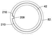
도 5를 참조하면, 장치(10)와 같은 약제 전달 장치와 함께 이용될 수 있는 모듈(82)을 포함하는 투여 전달 검출 시스템(80)이 도식적 형태로 도시되어 있다. 모듈(82)은 전반적으로 84로 도시된 센서 시스템을 포함하고, 그러한 센서 시스템은 회전 센서(86), 그리고 프로세서, 메모리, 배터리 등과 같은 다른 연관 구성요소를 포함한다. 모듈(82)은, 작동기에 제거 가능하게 부착될 수 있는 분리된 구성요소로서 제공된다.Referring to FIG. 5, a dosage delivery detection system (80) is schematically illustrated that includes a module (82) that can be utilized with a drug delivery device, such as the device (10). The module (82) includes a sensor system, generally illustrated at 84, that includes a rotation sensor (86) and other associated components, such as a processor, memory, a battery, and the like. The module (82) is provided as a separate component that is removably attachable to the actuator.
투여 검출 모듈(82)은 투여 버튼(56)에 부착된 본체(88)를 포함한다. 본체(88)는 예시적으로 원통형 측벽(90) 및 상단 벽(92)을 포함하고, 상단 벽은 측벽(90)에 걸쳐지고 그러한 측벽을 밀봉한다. 예로서, 도 5에서 상부 측벽(90)은 모듈(82)을 투여 버튼(56)에 부착하는 내향-연장 탭(94)을 갖는 것으로 도식적으로 도시되어 있다. 일 양태에서 모듈(82)이 제1 약제 전달 장치로부터 제거될 수 있고 그 후에 제2 약제 전달 장치에 부착되는 경우에, 투여 검출 모듈(82)이 대안적으로 스냅 피팅 또는 압입, 나사산형 인터페이스 등과 같은 임의의 적합한 체결 수단을 통해서 투여 버튼(56)에 부착될 수 있다. 본원에서 설명된 바와 같이, 투여 버튼(56)이 투여 설정 부재(30)에 대해서 축방향으로 임의의 요구량만큼 이동될 수 있기만 하다면, 그러한 부착은 투여 버튼(56) 상의 임의의 위치에 있을 수 있다.The dose detection module (82) includes a body (88) attached to the dose button (56). The body (88) illustratively includes a cylindrical side wall (90) and a top wall (92), the top wall spanning the side wall (90) and sealing said side wall. For example, in FIG. 5 the top side wall (90) is schematically illustrated as having an inwardly extending tab (94) that attaches the module (82) to the dose button (56). In one embodiment, where the module (82) is removable from the first medication delivery device and thereafter attached to the second medication delivery device, the dose detection module (82) may alternatively be attached to the dose button (56) via any suitable fastening means, such as a snap fit or press fit, a threaded interface, or the like. As described herein, such attachment may be at any location on the dose button (56) so long as the dose button (56) is axially movable with respect to the dose setting member (30) by any desired amount.
투여 전달 중에, 투여 설정 부재(30)가 투여 버튼(56) 및 모듈(82)에 대해서 자유롭게 회전된다. 예시적인 실시예에서, 모듈(82)은 투여 버튼(56)과 회전적으로 고정되고, 투여 전달 중에 회전되지 않는다. 이는, 예를 들어 도 5의 탭(94)으로, 또는 투여 버튼(56)에 대한 모듈(82)의 축방향 이동시에 모듈 본체(88) 및 투여 버튼(56) 상의 상호-대면 스플라인들 또는 다른 표면 특징부들을 결합시키는 것에 의해서, 구조적으로 제공될 수 있다. 다른 실시예에서, 모듈의 원위방향 누름은 모듈(82)과 투여 버튼(56) 사이의 충분한 마찰 결합을 제공하여, 기능적으로, 모듈(82) 및 투여 버튼(56)이 투여 전달 중에 함께 회전적으로 고정되어 유지되게 한다.During dose delivery, the dose setting member (30) is free to rotate relative to the dose button (56) and the module (82). In an exemplary embodiment, the module (82) is rotationally fixed with the dose button (56) and does not rotate during dose delivery. This may be provided structurally, for example, by the tab (94) of FIG. 5, or by engaging interfacing splines or other surface features on the module body (88) and the dose button (56) during axial movement of the module (82) relative to the dose button (56). In another embodiment, the distal push of the module provides sufficient frictional engagement between the module (82) and the dose button (56) to functionally maintain the module (82) and the dose button (56) rotationally fixed together during dose delivery.
상단 벽(92)은 투여 버튼(56)의 면(60)으로부터 이격되고 그에 의해서 공동(96)을 제공하고, 그러한 공동 내에 회전 센서 및 다른 구성요소의 일부 또는 전부가 수용될 수 있다. 공동(96)이 하단에서 개방될 수 있거나, 예를 들어 하단 벽(98)에 의해서 폐쇄될 수 있다. 투여 버튼(56)의 면(60)에 직접적으로 반하여 지탱되도록, 하단 벽(98)이 배치될 수 있다. 대안적으로, 하단 벽(98)(존재하는 경우)이 투여 버튼(56)으로부터 이격될 수 있고, 모듈(82)에 인가되는 축방향 힘이 투여 버튼(56)에 전달되도록, 모듈(82)과 투여 버튼(56) 사이의 다른 접촉이 이용될 수 있다. 다른 실시예에서, 모듈(82)은 도 26에 도시된 하나의-단편의 투여 버튼(56)에 회전적으로 고정될 수 있다.The top wall (92) is spaced from the face (60) of the dosing button (56) to thereby provide a cavity (96), within which some or all of the rotational sensor and other components may be accommodated. The cavity (96) may be open at the bottom, or may be closed, for example, by the bottom wall (98). The bottom wall (98) may be positioned so as to bear directly against the face (60) of the dosing button (56). Alternatively, the bottom wall (98) (if present) may be spaced from the dosing button (56), and other contact between the module (82) and the dosing button (56) may be utilized such that an axial force applied to the module (82) is transmitted to the dosing button (56). In another embodiment, the module (82) may be rotationally secured to the one-piece dosing button (56) illustrated in FIG. 26.
대안적인 실시예에서, 투여 설정 중에 모듈(82)이 투여 설정 부재(30)에 대안적으로 부착된다. 예를 들어, 측벽(90)은, 융기부(49) 아래의 위치에서 스커트(42)와 결합되는 내향 돌출부(102)를 갖는 하부 벽 부분(100)을 포함할 수 있다. 이러한 접근방식에서, 탭(94)이 제거될 수 있고, 모듈(82)이 투여 버튼(56)의 근위 면(60) 및 환형 융기부(49)의 원위 측면과 효과적으로 결합된다. 이러한 구성에서, 하부 벽 부분(100)은, 모듈(82)을 스커트(42)와 회전적으로 고정하기 위해서 스커트(42)의 표면 특징부와 결합되는 표면 특징부를 구비할 수 있다. 그에 의해서, 투여 설정 중에 하우징(82)에 인가되는 회전력이, 하부 벽 부분(100)과 스커트(42)의 커플링에 의해서, 스커트(42)에 전달된다.In an alternative embodiment, the module (82) is alternatively attached to the dose setting member (30) during the dose setting. For example, the side wall (90) may include a lower wall portion (100) having an inwardly directed projection (102) that engages the skirt (42) at a location below the protrusion (49). In this approach, the tab (94) may be removed, and the module (82) is effectively engaged with the proximal surface (60) of the dose button (56) and the distal side of the annular protrusion (49). In this configuration, the lower wall portion (100) may have surface features that engage with surface features of the skirt (42) to rotationally secure the module (82) to the skirt (42). As such, a rotational force applied to the housing (82) during the dose setting is transmitted to the skirt (42) by the coupling of the lower wall portion (100) and the skirt (42).
투여 전달을 진행시키기 위해서, 모듈(82)이 스커트(42)로부터 회전적으로 분리된다. 스커트(42)에 대한 모듈(82)의 원위 축방향 이동시에 분리되도록, 그에 의해서 투여 전달 중에 스커트(42)가 모듈(82)에 대해서 회전될 수 있도록, 하부 벽 부분(100)과 스커트(42)의 커플링이 구성된다.To effectuate the dose delivery, the module (82) is rotationally separated from the skirt (42). The coupling of the lower wall portion (100) and the skirt (42) is configured such that the distal axial movement of the module (82) relative to the skirt (42) causes the skirt (42) to rotate relative to the module (82) during the dose delivery.
유사한 방식으로, 모듈(82)은 투여 설정 중에 투여 버튼(56) 및 스커트(42) 모두와 커플링될 수 있다. 이는, 투여 설정에서의 모듈의 회전 중에 부가적인 커플링 표면을 제공하는 장점을 갖는다. 이어서, 예를 들어 투여 전달이 개시될 때 스커트(42)에 대한 모듈(82)의 축방향 이동에 의해서, 스커트(42)에 대한 모듈(82)의 커플링이 투여 주입 전에 해제되고, 그에 의해서 투여 전달 중에 투여 설정 부재(30)가 모듈(82)에 대해서 회전될 수 있게 한다.In a similar manner, the module (82) can be coupled with both the dose button (56) and the skirt (42) during the dose setting. This has the advantage of providing an additional coupling surface during rotation of the module in the dose setting. Then, for example, by axial movement of the module (82) relative to the skirt (42) when the dose delivery is initiated, the coupling of the module (82) to the skirt (42) is released prior to the dose injection, thereby allowing the dose setting member (30) to be rotated relative to the module (82) during the dose delivery.
특정 실시예에서, 피감지 구성요소를 검출하기 위해서 회전 센서(86)가 측벽(90)에 커플링된다. 하부 벽 부분(100)은 또한, 투여 전달 중에 투여 설정 부재가 모듈(82) 및 하우징(12)에 대해서 회전될 때 사용자의 손이 투여 설정 부재(30)에 항력(drag)을 우발적으로 인가할 수 있는 가능성을 줄이는 역할을 한다. 또한, 투여 설정 중에 투여 버튼(56)이 투여 설정 부재(30)에 회전적으로 고정되기 때문에, 하부 벽 부분(100)을 포함하는 측벽(90)은, 투여 설정 중에 사용자에 의해서 용이하게 파지되고 조작될 수 있는 하나의 연속적인 표면을 제공한다.In certain embodiments, a rotational sensor (86) is coupled to the sidewall (90) to detect the sensed component. The lower wall portion (100) also serves to reduce the possibility that a user's hand could accidentally apply drag to the dose setting member (30) when the dose setting member is rotated relative to the module (82) and housing (12) during dose delivery. Furthermore, since the dose button (56) is rotationally secured to the dose setting member (30) during dose setting, the sidewall (90), which includes the lower wall portion (100), provides a single continuous surface that can be easily grasped and manipulated by the user during dose setting.
주입 프로세스가 투여 검출 모듈(82)를 아래로 누르는 것에 의해서 개시될 때, 투여 버튼(56) 및 투여 설정 부재(30)가 함께 회전적으로 고정된다. 짧은 거리의, 예를 들어 2 mm 미만의, 모듈(82) 그리고 그에 따른 투여 버튼(56)의 이동은 회전적 결합을 해제하고, 투여가 전달될 때 투여 설정 부재(30)는 모듈(82)에 대해서 회전된다. 핑거 패드(finger pad) 또는 다른 트리거 메커니즘의 이용에 의해서, 투여 버튼(56)이 투여 버튼(56)과 투여 설정 부재(30)의 회전방향 록킹을 분리하기 위한 충분한 거리로 이동되기 전에, 투여 검출 시스템이 활성화된다.When the injection process is initiated by pressing down on the dose detection module (82), the dose button (56) and the dose setting member (30) are rotationally locked together. A short distance, for example less than 2 mm, of the module (82) and thus the dose button (56) disengages the rotational engagement, and the dose setting member (30) is rotated relative to the module (82) when the dose is to be delivered. The dose detection system is activated before the dose button (56) is moved a sufficient distance to disengage the rotational locking of the dose button (56) and the dose setting member (30), by use of a finger pad or other trigger mechanism.
예시적으로, 투여 전달 검출 시스템은 본원에서 설명된 바와 같은 센서 시스템의 동작에 적합한 전자 조립체를 포함한다. 제어기가 센서 시스템에 동작 가능하게 연결되어 하나 이상의 회전 센서로부터 출력을 수신한다. 제어기는, 예를 들어 모듈 본체(88)에 의해서 형성된 공동(96) 내에 수용된, 프로세서, 전원, 메모리, 마이크로제어기, 등과 같은 통상적인 구성요소를 포함할 수 있다. 대안적으로, 적어도 일부 구성요소가, 예를 들어 컴퓨터, 스마트폰 또는 다른 장치에 의해서, 별개로 제공될 수 있다. 이어서, 예를 들어 유선 또는 무선 연결에 의해서, 적절한 시간에 외부 제어기 구성요소와 센서 시스템을 동작 가능하게 연결하기 위한 수단이 제공된다.By way of example, the dose delivery detection system comprises an electronic assembly suitable for operation of a sensor system as described herein. A controller is operably connected to the sensor system and receives output from one or more rotational sensors. The controller may include conventional components such as a processor, a power supply, memory, a microcontroller, etc., housed within a cavity (96) formed by the module body (88). Alternatively, at least some of the components may be provided separately, such as by a computer, a smart phone, or other device. Means are then provided for operably connecting the external controller components and the sensor system at an appropriate time, such as by a wired or wireless connection.
예시적인 전자 조립체(120)가, 복수의 전자 구성요소를 갖는 가요성 인쇄회로기판(FPCB)을 포함한다. 전자 조립체는, 감지된 상대적인 회전을 나타내는 센서로부터의 신호를 수신하기 위해서 프로세서와 동작 가능하게 통신하는 하나 이상의 회전 센서(86)를 포함하는 센서 시스템을 포함한다. 전자 조립체는, 적어도 하나의 프로세싱 코어 및 내부 메모리를 포함하는 마이크로제어기 유닛(MCU)을 더 포함한다. 시스템은, 구성요소에 전력을 공급하기 위해서, 배터리, 예시적으로 동전형 배터리를 포함한다. MCU는, 작동기에 대한 투여 설정 부재의 검출된 회전을 기초로, 약제 전달 장치(10)에 의해서 전달되는 투여를 검출하는 것을 포함하는, 본원에서 설명된 동작을 실시하도록 동작될 수 있는 제어 로직을 포함한다. 일 실시예에서, 검출된 회전이 펜 주입기의 스커트(42)와 투여 버튼(56) 사이에서 검출된다.An exemplary electronic assembly (120) includes a flexible printed circuit board (FPCB) having a plurality of electronic components. The electronic assembly includes a sensor system including one or more rotation sensors (86) in operative communication with a processor to receive signals from the sensors indicative of sensed relative rotation. The electronic assembly further includes a microcontroller unit (MCU) including at least one processing core and internal memory. The system includes a battery, exemplarily a coin cell battery, to power the components. The MCU includes control logic operable to perform the operations described herein, including detecting a dose to be delivered by the drug delivery device (10) based on the detected rotation of the dose setting member relative to the actuator. In one embodiment, the detected rotation is detected between the skirt (42) of the pen injector and the dose button (56).
MCU는 검출된 투여를 자체 메모리(예를 들어, 내부 플래시 메모리 또는 온-보드 EEPROM) 내에 저장하도록 동작될 수 있다. MCU는 검출된 투여를 나타내는 신호를, 블루투스 로우 에너지(BLE) 또는 다른 적합한 근거리 또는 원거리 무선 통신 프로토콜을 통해서, 사용자의 스마트폰과 같은 페어링된 원격 전자 장치에 대해서 무선으로 전송 및/또는 수신하도록 더 동작될 수 있다. 예시적으로, BLE 제어 로직 및 MCU가 동일 회로에 통합된다.The MCU may be operable to store the detected dose within its own memory (e.g., internal flash memory or on-board EEPROM). The MCU may be further operable to wirelessly transmit and/or receive a signal indicative of the detected dose to a paired remote electronic device, such as a user's smartphone, via Bluetooth Low Energy (BLE) or other suitable short-range or long-range wireless communication protocol. By way of example, the BLE control logic and the MCU are integrated into the same circuit.
많은 감지 전자기기가 공동(96) 내에 수용된다. 그러나, 회전 센서는, 피감지 구성요소의 상대적인 이동을 감지하기 위해서 다양한 위치에 배치될 수 있다. 예를 들어, 회전 센서는 공동(96) 내에, 본체(88) 내에 그러나 공동(96)의 외측에, 또는 하부 벽 부분(100)과 같은 본체의 다른 위치에 배치될 수 있다. 유일한 요건은, 회전 센서가 투여 전달 중에 피감지 구성요소의 회전 이동을 효과적으로 검출하도록 배치되는 것이다. 일부 실시예에서, 회전 센서가 장치(10)에 일체화된다.Many sensing electronics are housed within the cavity (96). However, the rotation sensor may be positioned at various locations to detect relative movement of the sensing component. For example, the rotation sensor may be positioned within the cavity (96), within the body (88) but outside of the cavity (96), or at another location on the body, such as the lower wall portion (100). The only requirement is that the rotation sensor be positioned to effectively detect rotational movement of the sensing component during delivery. In some embodiments, the rotation sensor is integrated into the device (10).
하나 이상의 피감지 요소가 투여 설정 부재(30)에 부착된다. 일 양태에서, 피감지 요소가 투여 설정 부재의 스커트(42)에 직접 부착된다. 대안적으로, 피감지 요소가, 다이알 부재, 플랜지 및/또는 스커트를 포함하는, 투여 설정 구성요소 중 임의의 하나 이상에 부착될 수 있다. 유일한 요건은, 투여 전달 중의 상대적 회전 이동 동안 회전 센서에 의해서 감지되도록 피감지 요소(들)가 배치되는 것이다. 다른 실시예에서, 피감지 구성요소는 투여 설정 부재(30) 또는 그 임의의 부분을 포함한다.One or more sensing elements are attached to the dose setting member (30). In one embodiment, the sensing elements are attached directly to the skirt (42) of the dose setting member. Alternatively, the sensing elements may be attached to any one or more of the dose setting components, including the dial member, the flange, and/or the skirt. The only requirement is that the sensing element(s) be positioned so as to be detected by the rotational sensor during relative rotational movement during dose delivery. In another embodiment, the sensing elements comprise the dose setting member (30) or any portion thereof.
투여 전달 검출 시스템(80)의 추가적인 예시적 실시예가 도 6 내지 도 13에 제공되어 있다. 실시예가 다소 도식적인 방식으로 도시되어 있는데, 이는 도 1 내지 도 5와 관련하여 일반적인 상세 내용이 이미 제공되었기 때문이다. 일반적으로, 각각의 실시예는, 원통형 상부 벽(90) 및 상단 벽(92)을 갖는 본체(88)를 포함하는, 투여 검출 모듈(82)의 유사한 구성요소를 포함한다. 각각의 실시예가 또한 하부 벽(100)을 포함하나, 하부 벽(100)이 없는 것을 포함하여, 이러한 구성요소의 변형이 개시 내용의 범위에 포함된다는 것이 이해될 것이다. 본원의 전술한 설명과 공통되는 다른 부분은 모듈 본체(88)의 공동(96) 내에 수용된 전자 조립체(120), 투여 버튼(56), 투여 설정 부재(32) 및 장치 하우징(12)을 포함한다. 또한, 각각의 실시예에서, 투여 버튼(56)의 환형 측벽(62)에 부착된 것으로 투여 검출 모듈(82)이 도식적으로 도시되어 있으나, 대안적인 부착 형태 및 위치가 이용될 수 있다. 예를 들어, 투여 검출 모듈(82)이 투여 버튼(56)에 부착될 수 있고 일부 실시예에서 스커트(42)에 해제 가능하게 부착될 수 있다. 또한, 투여 검출 모듈(82)은, 도 26에 도시된 바와 같이, 하나의-단편의 투여 버튼(56)에 부착될 수 있다.Additional exemplary embodiments of the dose delivery detection system (80) are provided in FIGS. 6-13 . The embodiments are shown in a somewhat schematic manner, as general details have already been provided with respect to FIGS. 1-5 . In general, each embodiment includes similar components of a dose detection module (82), including a body (88) having a cylindrical upper wall (90) and a top wall (92). Each embodiment also includes a lower wall (100), although it will be appreciated that variations of these components, including those without a lower wall (100), are within the scope of the disclosure. Other components common to the foregoing description herein include an electronics assembly (120) housed within a cavity (96) of the module body (88), a dose button (56), a dose setting member (32), and a device housing (12). Additionally, while in each embodiment the dose detection module (82) is schematically depicted as being attached to the annular sidewall (62) of the dose button (56), alternative attachment configurations and locations may be utilized. For example, the dose detection module (82) may be attached to the dose button (56) and, in some embodiments, releasably attached to the skirt (42). Additionally, the dose detection module (82) may be attached to a single-piece dose button (56), as illustrated in FIG. 26.
각각의 예는 또한 센서 시스템의 특정 유형의 이용을 보여준다. 그러나, 일부 실시예에서, 투여 검출 시스템은 동일한 또는 상이한 감지 기술을 이용하는 다수의 감지 시스템을 포함한다. 이는 감지 시스템 중 하나의 고장의 경우에 여분의 시스템을 제공한다. 이는 또한, 제1 감지 시스템이 적절히 기능하는지를 주기적으로 검증하기 위해서 제2 감지 시스템을 이용할 수 있는 능력을 제공한다.Each example also demonstrates the use of a particular type of sensor system. However, in some embodiments, the dose detection system includes multiple detection systems utilizing the same or different detection technologies. This provides redundancy in the event of a failure of one of the detection systems. This also provides the ability to utilize a second detection system to periodically verify that the first detection system is functioning properly.
특정 실시예에서, 도 6에 도시된 바와 같이, 핑거 패드(110)가 모듈(82)의 상단 벽(92)에 부착된다. 핑거 패드(110)가 상단 벽(92)에 커플링되고, 이는 다시 상부 측벽(90)에 부착된다. 핑거 패드(110)는, 반경방향 내측으로 연장되고 벽 구성요소(92)의 원주방향 홈(116) 내에 수용되는 융기부(114)를 포함한다. 홈(116)은 핑거 패드(110)와 벽 구성요소(92) 사이의 약간의 축방향 이동을 허용한다. 스프링(미도시)은 정상 상태에서 핑거 패드(110)를 벽 구성요소(92)로부터 위쪽으로 멀리 압박한다. 핑거 패드(110)는 벽 구성요소(92)에 회전적으로 고정될 수 있다. 주입 프로세스가 개시될 때 원위 방향으로 모듈 본체(88)를 향하는 핑거 패드(110)의 축방향 이동은 선택된 이벤트를 트리거링하기 위해서 이용될 수 있다. 핑거 패드(110)의 하나의 용도는, 투여 주입이 개시될 때 핑거 패드(110)를 모듈 본체(88)에 대해서 초기에 누르고 축방향으로 이동시킬 때의 약제 전달 장치 전자기기의 활성화일 수 있다. 예를 들어, 이러한 초기 축방향 이동은 장치, 그리고 특히 투여 검출 시스템과 연관된 구성요소를 "기동(wake up)"하기 위해서 이용될 수 있다. 하나의 예에서, 모듈(82)은 정보를 사용자에게 보여주기 위한 디스플레이를 포함한다. 그러한 디스플레이는 핑거 패드(110)와 일체화될 수 있다. MCU는, 감지된 데이터를 수신하고 프로세스하도록 그리고, 예를 들어, 투여 설정, 투여된 분배, 주입의 상태, 주입의 완료, 날짜 및/또는 시간, 또는 다음 주입 시간과 같은 정보를 디스플레이 상에서 디스플레이하도록 작동될 수 있는 디스플레이 구동 소프트웨어 모듈 및 제어 로직을 포함한다.In a particular embodiment, as illustrated in FIG. 6, a finger pad (110) is attached to a top wall (92) of a module (82). The finger pad (110) is coupled to the top wall (92), which in turn is attached to the upper side wall (90). The finger pad (110) includes a protrusion (114) that extends radially inwardly and is received within a circumferential groove (116) of the wall component (92). The groove (116) allows for some axial movement between the finger pad (110) and the wall component (92). A spring (not shown) urges the finger pad (110) upwardly away from the wall component (92) in a normal state. The finger pad (110) may be rotationally secured to the wall component (92). Axial movement of the finger pad (110) toward the module body (88) in a distal direction when the injection process is initiated may be utilized to trigger a selected event. One use of the finger pad (110) may be activation of the medication delivery device electronics when the finger pad (110) is initially pressed against the module body (88) and axially moved when the administration injection is initiated. For example, this initial axial movement may be utilized to "wake up" the device, and particularly components associated with the administration detection system. In one example, the module (82) includes a display for presenting information to a user. Such a display may be integrated with the finger pad (110). The MCU includes a display driving software module and control logic that may be operative to receive and process the sensed data and display information on the display, such as, for example, a dose setting, a dispensed dose, a status of an injection, a completion of an injection, the date and/or time, or the time of the next injection.
핑거 패드가 없는 경우에, 시스템 전자기기가 다양한 다른 방식으로 활성화될 수 있다. 예를 들어, 예를 들어 접촉부의 폐쇄 또는 스위치의 물리적 결합에 의해서, 투여 전달의 시작에서 모듈(82)의 초기 축방향 이동이 직접적으로 검출될 수 있다. 여러 가지 다른 작용, 예를 들어 펜 캡의 제거, 가속도계를 이용한 펜 이동의 검출, 또는 투여의 설정을 기초로 약제 전달 장치를 활성화시키는 것이 또한 알려져 있다. 많은 접근 방식에서, 투여 검출 시스템은 투여 전달의 시작에 앞서서 활성화된다.In the absence of a finger pad, the system electronics may be activated in a variety of other ways. For example, the initial axial movement of the module (82) may be detected directly at the start of the dose delivery, for example by closing a contact or by physically engaging a switch. It is also known to activate the drug delivery device based on a variety of other actions, for example removal of the pen cap, detection of pen movement using an accelerometer, or setting of the dose. In many approaches, the dose detection system is activated prior to the start of the dose delivery.
도 6 내지 도 8을 참조하면, 투여 검출 모듈(82)은 자기적 감지 시스템(84)을 이용하여 동작된다. 2개의 자기 센서(130)가 투여 설정 부재(30)의 스커트(42)에 대향되는 하부 벽 부분(100)(예시적으로, 하부 벽 부분(100)의 내측 표면) 상에 배치된다. 모든 실시예에서, 회전 센서(들) 및 피감지 요소(들)의 수 및 위치가 변경될 수 있다. 예를 들어, 도 6 내지 도 8의 실시예는, 대안적으로, 스커트(42) 주위에서 균등하게 또는 불균등하게 이격된 임의의 수의 자기 센서(130)를 포함할 수 있다. 피감지 구성요소(132)(도 7 및 도 8)는, 예시적으로 스커트(42)의 내부 상에서, 스커트(42)에 고정된 자기 스트립(134)을 포함한다. 예시적인 실시예에서, 스트립은 5쌍의 남극-북극 자기적 구성요소(예를 들어, 136 및 138)를 포함하고, 그에 따라 각각의 자기적 부분은 36°로 연장된다. 자기 센서(130)는 18°로 분리되어 배치되고(도 7), 자기 스트립(132)의, 그리고 그에 따라 스커트(42)의 디지털 위치를 2-비트 그레이 코드 방식으로 판독한다. 예를 들어, 센서가 N-S 자기 쌍의 통과를 검출할 때, 스커트(42)가, 예를 들어, 2 단위의 투여가 부가된(또는 차감된) 것에 상응하는, 36° 회전된 것이 검출된다.Referring to FIGS. 6-8, the dose detection module (82) operates using a magnetic sensing system (84). Two magnetic sensors (130) are positioned on a lower wall portion (100) (for example, an inner surface of the lower wall portion (100)) opposite the skirt (42) of the dose setting member (30). In all embodiments, the number and location of the rotational sensor(s) and the sensed elements (s) may be varied. For example, the embodiments of FIGS. 6-8 may alternatively include any number of magnetic sensors (130) spaced evenly or unequally around the skirt (42). The sensed elements (132) (FIGS. 7 and 8) include, for example, a magnetic strip (134) affixed to the skirt (42), on the interior of the skirt (42). In an exemplary embodiment, the strip includes five pairs of south-north magnetic components (e.g., 136 and 138), such that each magnetic portion extends 36°. A magnetic sensor (130) is positioned 18° apart (FIG. 7) and reads the digital position of the magnetic strip (132), and thus of the skirt (42), in a 2-bit Gray code manner. For example, when the sensor detects the passage of a N-S magnetic pair, a 36° rotation of the skirt (42) is detected, corresponding to, for example, the addition (or subtraction) of two units of dosage.
자기 요소의 상이한 수 또는 위치를 포함하는, 다른 자기적 패턴이 또한 이용될 수 있다. 또한, 대안적인 실시예에서, 도 9에 도시된 바와 같이, 피감지 구성요소(133)가 투여 설정 부재(30)의 플랜지(38)에 부착되거나 그와 일체이다.Other magnetic patterns, including different numbers or positions of magnetic elements, may also be utilized. Also, in an alternative embodiment, the sensing element (133) is attached to or integral with the flange (38) of the dose setting member (30), as illustrated in FIG. 9.
전술한 바와 같이, 감지 시스템(84)은 자기 센서(130)에 대한 피감지 요소의 회전량을 검출하도록 구성된다. 이러한 회전량은 장치에 의해서 전달되는 투여량과 직접적으로 상호 관련된다. 투여 전달 중에 스커트(42)의 이동을 검출하는 것에 의해서, 예를 들어, 스커트(42)의 시작 위치와 정지 위치 사이의 차이를 식별하는 것에 의해서, 또는 약제의 전달 중에 스커트(42)의 증분적인 이동의 수를 "계수하는 것"에 의해서, 상대적인 회전이 결정된다.As described above, the detection system (84) is configured to detect the amount of rotation of the sensed element relative to the magnetic sensor (130). This amount of rotation is directly correlated to the dosage delivered by the device. The relative rotation is determined by detecting the movement of the skirt (42) during dosage delivery, for example, by identifying the difference between the start and stop positions of the skirt (42), or by "counting" the number of incremental movements of the skirt (42) during drug delivery.
도 10 내지 도 11을 참조하면, 북극(154) 및 남극(156)을 가지는 환형, 링-형상의, 2극성 자석(152)을 피감지 요소로서 포함하는 예시적인 자기 센서 시스템(150)이 도시되어 있다. 자석(152)은 플랜지(38)에 부착되고, 그에 따라 투여 전달 중에 플랜지와 함께 회전된다. 자석(152)은 대안적으로 투여 다이알(32) 또는 투여 설정 부재와 회전적으로 고정된 다른 부재에 부착될 수 있다.Referring to FIGS. 10 and 11, an exemplary magnetic sensor system (150) is illustrated that includes as a sensing element an annular, ring-shaped, bipolar magnet (152) having a north pole (154) and a south pole (156). The magnet (152) is attached to the flange (38) and thus rotates with the flange during dose delivery. The magnet (152) may alternatively be attached to the dose dial (32) or other member that is rotationally fixed with the dose setting member.
센서 시스템(150)은 모듈(82) 내에 수용된 센서 전자기기(미도시)와 동작 가능하게 연결된 하나 이상의 감지 요소(160)를 포함하는 센서(158)를 더 포함한다. 센서(158)의 감지 요소(160)가 인쇄회로기판(162)에 부착되어 도 11a에 도시되어 있고, 인쇄회로기판은 다시 모듈(82)에 부착되고, 모듈은 투여 버튼(56)에 회전적으로 고정된다. 결과적으로, 자석(152)은 투여 전달 중에 감지 요소(160)에 대해서 회전된다. 감지 요소(160)는 자석(152)의 상대적 각도 위치를 검출하도록 동작될 수 있다. 그에 의해서, 자기 센서 시스템(150)은 투여 버튼(56)에 대한 플랜지(38)의 전체 회전을, 그리고 그에 따라 투여 전달 중에 하우징(12)에 대한 회전을 검출하도록 동작한다.The sensor system (150) further includes a sensor (158) comprising one or more sensing elements (160) operatively connected to sensor electronics (not shown) housed within the module (82). The sensing elements (160) of the sensor (158) are attached to a printed circuit board (162) as shown in FIG. 11a, which is in turn attached to the module (82), and the module is rotationally secured to the dose button (56). As a result, the magnet (152) rotates with respect to the sensing elements (160) during dose delivery. The sensing elements (160) are operable to detect the relative angular position of the magnet (152). Thereby, the magnetic sensor system (150) is operable to detect the overall rotation of the flange (38) with respect to the dose button (56), and thus the rotation with respect to the housing (12) during dose delivery.
일 실시예에서, 자기 센서 시스템(150)은 모듈(82) 내에서 균일하게-반경방향으로 이격된 4개의 감지 요소(160)를 포함한다. 감지 요소의 다른 수 및 위치가 이용될 수 있다. 예를 들어, 도 11b에 도시된 다른 실시예에서, 단일 감지 요소(160)가 사용된다. 또한, 도 11b의 감지 요소(160)는 모듈(82) 내의 중심에서 도시되어 있지만, 다른 위치가 또한 이용될 수 있다. 전술한 실시예에서, 감지 요소(160)는 모듈(82) 내에 부착되어 도시되어 있다. 대안적으로, 감지 요소(160)가 투여 버튼(56)에 회전적으로 고정된 구성요소의 임의의 부분에 부착될 수 있고, 그에 따라 그러한 구성요소는 투여 전달 중에 하우징(12)에 대해서 회전되지 않는다.In one embodiment, the magnetic sensor system (150) includes four sensing elements (160) that are evenly-radially spaced within the module (82). Other numbers and locations of the sensing elements may be utilized. For example, in another embodiment illustrated in FIG. 11B, a single sensing element (160) is utilized. Additionally, while the sensing element (160) of FIG. 11B is illustrated centered within the module (82), other locations may also be utilized. In the embodiments described above, the sensing element (160) is illustrated attached within the module (82). Alternatively, the sensing element (160) may be attached to any portion of a component that is rotationally secured to the dosing button (56), such that such component does not rotate relative to the housing (12) during dosing delivery.
설명을 위해서, 자석(152)은, 플랜지(38)에 부착된 하나의, 환형, 2극 자석으로 도시되어 있다. 그러나, 자석(152)의 대안적인 구성 및 위치가 고려된다. 예를 들어, 자석이, 교번적인 북극 및 남극과 같은, 다수의 극을 포함할 수 있다. 일 실시예에서, 자석은 플랜지(38)의 구분된 회전적, 투여-설정 위치들의 수와 동일한 자극 쌍의 수를 포함한다. 자석(152)은 또한 많은 수의 분리된 자석 부재를 포함할 수 있다. 또한, 자석 구성요소는, 스커트(42) 또는 투여 다이알 부재(32)와 같은, 투여 전달 중에 플랜지(38)에 회전적으로 고정되는 부재의 임의의 부분에 부착될 수 있다.For purposes of illustration, the magnet (152) is illustrated as a single, annular, two-pole magnet attached to the flange (38). However, alternative configurations and positions of the magnet (152) are contemplated. For example, the magnet may include multiple poles, such as alternating north and south poles. In one embodiment, the magnet includes a number of pole pairs equal to the number of distinct rotational, dose-setting positions of the flange (38). The magnet (152) may also include a number of separate magnet elements. Additionally, the magnet elements may be attached to any portion of a member that is rotationally secured to the flange (38) during dose delivery, such as the skirt (42) or the dose dial member (32).
센서 시스템은 도 12 내지 도 13에서 유도 센서 시스템(170)으로서 대안적으로 예시되어 있다. 센서 시스템(170)은, 피감지 요소로서 스커트(42)에 부착된 금속 밴드(172)를 포함하는 피감지 요소(171)를 이용한다. 센서 시스템(170)은, 스커트(42)의 원주를 따라서 균일하게-반경방향으로 이격된 4개의 독립적인 안테나(178)와 같은, 하나 이상의 감지 요소(176)를 포함하는 센서(174)를 더 포함한다. 이러한 4개의 안테나는 180도로 분리되어 위치된 2개의 안테나 쌍을 형성하고, 스커트(42)의 각도 위치에 관한 무선-계측 측정을 제공한다.The sensor system is alternatively illustrated in FIGS. 12-13 as an inductive sensor system (170). The sensor system (170) utilizes a sensed element (171) comprising a metal band (172) attached to the skirt (42) as a sensed element. The sensor system (170) further includes a sensor (174) comprising one or more sensed elements (176), such as four independent antennas (178) spaced uniformly-radially along the circumference of the skirt (42). These four antennas form two antenna pairs positioned 180 degrees apart and provide wireless-measured measurements of the angular position of the skirt (42).
모듈(82)에 대한 스커트(42)의 하나 이상의 구분된 회전 위치가 검출될 수 있도록, 금속 밴드(172)가 성형된다. 금속 밴드(172)는, 안테나(178)에 대한 스커트(42)의 회전 시에 변동 신호를 생성하는 형상을 갖는다. 예시적으로, 도 13a 내지 도 13c는 밴드 패턴을 도시하며, 도 13b는 도 13a의 위치로부터의 90°의 회전을 도시하고, 도 13c는 부가적인 90°회전을 도시한다. 이러한 패턴은, 도 12d에 개략적으로 도식적으로 도시된 바와 같이, 모듈(82)에 대한 스커트(42)의 회전 시에 검출된 사인파 응답을 생성하고, 위치(a 내지 d)는 도 12a에 도시된 것과 상호 관련된다.A metal band (172) is formed such that one or more distinct rotational positions of the skirt (42) relative to the module (82) can be detected. The metal band (172) has a shape that generates a varying signal upon rotation of the skirt (42) relative to the antenna (178). For example, FIGS. 13a through 13c illustrate band patterns, with FIG. 13b illustrating a 90° rotation from the position of FIG. 13a and FIG. 13c illustrating an additional 90° rotation. This pattern produces a sinusoidal response that is detected upon rotation of the skirt (42) relative to the module (82), as schematically illustrated in FIG. 12d , with positions (a through d) being correlated to those illustrated in FIG. 12a .
도 13d는 펜(10)의 모듈(82) 및 스커트(42) 내로 통합된 유도 센서 시스템(170)을 보여주는 개략도를 제공한다. 금속 밴드(172)는 스커트(42)에 부착되어 도시되어 있다. 투여 전달 중에, 안테나가 모듈(82)에 대한, 그리고 그에 따라 펜(10)의 하우징(12)에 대한 스커트(42)의 위치를 검출하는 기능을 하도록, 안테나(178)가 전자기기(120)에 동작 가능하게 연결된다.FIG. 13d provides a schematic diagram showing an inductive sensor system (170) integrated into the module (82) and skirt (42) of the pen (10). A metal band (172) is shown attached to the skirt (42). An antenna (178) is operatively connected to an electronic device (120) such that, during a dose delivery, the antenna functions to detect the position of the skirt (42) relative to the module (82), and thus relative to the housing (12) of the pen (10).
도 12 내지 도 13에 도시된 실시예에서, 유도 센서 시스템(170)은 모듈(82) 내에서 균일하게-반경방향으로 이격된 안테나(178)를 포함하는 4개의 감지 요소(176)를 포함한다. 감지 요소의 다른 수 및 위치가 이용될 수 있다. 예를 들어, 다른 실시예는 단일 안테나를 이용한다. 예시적인 실시예에서, 안테나(178)는 모듈(82) 내에 부착되어 도시되어 있다. 대안적으로, 안테나(들)이 투여 버튼(56)에 회전적으로 고정된 구성요소의 임의의 부분에 부착될 수 있고, 그에 따라 그러한 구성요소는 투여 전달 중에 하우징(12)에 대해서 회전되지 않는다.In the embodiments illustrated in FIGS. 12-13, the inductive sensor system (170) includes four sensing elements (176) that include antennas (178) spaced evenly-radially within the module (82). Other numbers and locations of the sensing elements may be utilized. For example, other embodiments utilize a single antenna. In the exemplary embodiment, the antenna (178) is depicted attached within the module (82). Alternatively, the antenna(s) may be attached to any portion of a component that is rotationally secured to the dosing button (56), such that such component does not rotate with respect to the housing (12) during dosing delivery.
설명을 위해서, 금속 밴드(172)는, 스커트(42)의 외부에 부착된 단일, 원통형 밴드로서 도시되어 있다. 그러나, 금속 밴드(172)의 대안적인 구성 및 위치가 고려된다. 예를 들어, 금속 밴드는 다수의 구분된 금속 요소를 포함할 수 있다. 일 실시예에서, 금속 밴드는 스커트(42)의 구분된 회전적, 투여-설정 위치들의 수와 동일한 요소의 수를 포함한다. 대안예에서, 금속 밴드는, 플랜지(38) 또는 다이알 부재(32)와 같은, 투여 전달 중에 스커트(42)에 회전적으로 고정되는 구성요소의 임의의 부분에 부착될 수 있다. 금속 밴드는, 구성요소 내로 통합된 금속 입자에 의해서, 또는 구성요소를 금속 밴드와 함께 오버-몰딩하는 것에 의해서, 부재의 내측 또는 외측 상의 회전 부재에 부착된 금속 요소를 포함할 수 있거나, 그러한 부재 내로 통합될 수 있다.For purposes of illustration, the metal band (172) is shown as a single, cylindrical band attached to the exterior of the skirt (42). However, alternative configurations and locations of the metal band (172) are contemplated. For example, the metal band may include a number of distinct metal elements. In one embodiment, the metal band includes a number of elements equal to the number of distinct rotational, dose-setting positions of the skirt (42). In the alternative, the metal band may be attached to any portion of a component that is rotationally secured to the skirt (42) during dose delivery, such as the flange (38) or the dial member (32). The metal band may include metal elements attached to a rotational member on the interior or exterior of the member, such as by metal particles incorporated into the component, or by over-molding the component with the metal band.
안테나(178)는 도 12a에서 개략적으로 그리고 도 13d 및 도 13e에서 구조적으로 둥글게 도시되어 있다. 안테나의 대안적인 구성이 도 13f 및 도 13g에 개략적으로 도시되어 있다. 직사각형 중간 섹션(182) 및 반-원형 단부(184)를 갖는 "세장형 안테나"(180)가 도 13f에 도시되어 있다. 도 13f는 금속 밴드(186)에 대한 안테나(180)의 위치를 도시한다. 이러한 위치는, 투여 전달에서와 같은 모듈의 축방향 변위가 없는, 휴식 중의 펜 주입기에 상응한다. 도 13g에서, 안테나(180)는 투여의 전달을 유발하기 위해서 눌려진 모듈에 상응하는 위치에 있다. 모듈 및 그에 따른 안테나(180)는 금속 밴드(186)에 대해서, 도 13g에서 아래쪽으로, 변위되었다. 금속 밴드와 중첩되는 중간 섹션(182)의 더 일정한 면적이 존재함에 따라, 세장형 안테나(180)가 더 균일한 금속 밴드(186)의 감지를 제공할 수 있다는 것이 분명하다.The antenna (178) is schematically illustrated in FIG. 12a and structurally circular in FIGS. 13d and 13e. Alternative configurations for the antenna are schematically illustrated in FIGS. 13f and 13g. An "elongated antenna" (180) having a rectangular middle section (182) and semi-circular ends (184) is illustrated in FIG. 13f. FIG. 13f illustrates the position of the antenna (180) relative to the metal band (186). This position corresponds to a pen injector at rest, with no axial displacement of the module, such as during dose delivery. In FIG. 13g, the antenna (180) is in a position corresponding to the module being pressed to cause delivery of the dose. The module and thus the antenna (180) have been displaced downwards in FIG. 13g relative to the metal band (186). As there is a more uniform area of the middle section (182) overlapping the metal band, it is clear that the elongated antenna (180) can provide detection of a more uniform metal band (186).
일 양태에서, 투여 검출 시스템의 모듈형 형태가 개시된다. 제거 가능하게 부착된 모듈의 이용이 약제 전달 장치와 함께 이용되도록 특별히 구성되고, 작동기 및 투여 설정 부재 모두가 약제 장치 하우징 외부의 부분을 포함한다. 이러한 외부 부분은, 본원에서 설명된 바와 같이, 투여 버튼과 같은 작동기에 대한 감지 구성요소의, 그리고 투여 스커트, 플랜지, 또는 다이알 부재와 같은 투여 설정 부재에 대한 피감지 구성요소의 직접적인 부착을 가능하게 한다. 이와 관련하여, "투여 버튼"은 더 일반적으로, 장치 하우징의 외측에 위치된 부분을 포함하고 설정된 투여를 전달하기 위해서 사용자가 이용할 수 있는 노출 표면을 포함하는, 약제 전달 장치의 구성요소를 지칭하기 위해서 이용된다. 유사하게, 투여 "스커트"는 더 일반적으로, 장치 하우징의 외측에 위치되고 그에 의해서 투여를 설정하기 위해서 사용자가 구성요소를 파지하고 회전시키기 위해서 이용할 수 있는 노출 부분을 가지는, 약제 전달 장치의 구성요소를 지칭한다. 본원에서 개시된 바와 같이, 투여 스커트는 투여 전달 중에 투여 버튼에 대해서 회전된다. 또한, 투여 스커트는 투여 설정 중에 투여 버튼에 회전적으로 고정될 수 있고, 그에 따라 투여 스커트 또는 투여 버튼이 투여 설정을 위해서 회전될 수 있다. 대안적인 실시예에서, 전달 장치가 투여 스커트를 포함하지 않을 수 있고, 사용자는 투여 설정을 위해서 작동기(예를 들어, 투여 버튼)를 파지하고 회전시킬 수 있다. 일부 실시예에서, 작동기 및/또는 투여 스커트에 부착된 투여 검출 모듈에서, 투여 검출 모듈이 회전될 수 있고 그에 의해서 전달 장치의 투여 설정 부재를 회전시켜 전달하고자 하는 투여를 설정할 수 있다.In one aspect, a modular form of a dose detection system is disclosed. The use of a removably attached module is specifically configured for use with a drug delivery device, wherein both the actuator and the dose setting member comprise a portion outside the drug device housing. This external portion allows direct attachment of a sensing component to the actuator, such as a dose button, and a sensed component to the dose setting member, such as a dose skirt, flange, or dial member, as described herein. In this regard, a "dose button" is more generally used to refer to a component of a drug delivery device that comprises a portion located outside the device housing and has an exposed surface that is accessible to a user to deliver a set dose. Similarly, a dose "skirt" is more generally used to refer to a component of a drug delivery device that is located outside the device housing and has an exposed portion that is accessible to a user to grasp and rotate the component to set a dose. As disclosed herein, the dose skirt rotates relative to the dose button during dose delivery. Additionally, the dosing skirt may be rotatably secured to the dosing button during dosing, such that the dosing skirt or the dosing button may be rotated for dosing. In alternative embodiments, the delivery device may not include a dosing skirt, and the user may grasp and rotate the actuator (e.g., the dosing button) for dosing. In some embodiments, the dosing detection module is attached to the actuator and/or the dosing skirt, such that the dosing detection module is rotatable to thereby rotate the dosing setting member of the delivery device to set the dose to be delivered.
본 개시 내용의 추가적인 특징은, 투여 검출 시스템(80)의 감지 시스템이, 부가 모듈이 아니라 통합된 시스템으로써, 약제 전달 장치 내로 처음부터 통합될 수 있다는 것이다.An additional feature of the present disclosure is that the detection system of the dosing detection system (80) can be integrated into the drug delivery device from the beginning as an integrated system rather than as an add-on module.
전술한 내용은 투여 전달 중에 작동기에 대한 투여 설정 부재의 상대적인 회전을 감지하기 위한 다양한 구조 및 방법에 관한 설명을 제공한다. 약제 전달 장치의 특정 실시예에서, 작동기는 투여 설정 중에 펜 본체에 대해서 나선형 방식으로 이동된다. 예시를 위해서, 이러한 개시 내용은 그러한 나선형 작동기와 관련하여 투여 검출 시스템을 설명한다. 그러나, 당업자는, 개시된 투여 검출 시스템의 원리 및 물리적 동작이 또한, 투여 전달 중에 회전되나 병진운동되지는 않는 작동기와 함께 이용될 수 있다는 것을 이해할 것이다. 투여 주입 중에 투여 설정 부재에 대해서 회전되는 작동기를 장치가 포함하기만 한다면, 투여 검출 시스템이 약제 전달 장치의 다른 구성과 함께 동작될 수 있다는 것이 또한 이해될 것이다.The foregoing provides a description of various structures and methods for detecting relative rotation of a dose setting member with respect to an actuator during dose delivery. In certain embodiments of the drug delivery device, the actuator is translated helically with respect to the pen body during dose delivery. For purposes of illustration, this disclosure describes the dose detection system with respect to such a helical actuator. However, those skilled in the art will appreciate that the principles and physical operation of the disclosed dose detection system may also be utilized with an actuator that rotates but does not translate during dose delivery. It will also be appreciated that the dose detection system may be operated with other configurations of the drug delivery device, so long as the device includes an actuator that rotates with respect to the dose setting member during dose infusion.
검출 시스템은 또한 펜 주입기에 위해서 투약되는 약물의 특성을 식별하기 위한 모듈과 함께 이용될 수 있다. 펜 주입기가 매우 다양한 약물과 함께, 그리고 심지어 주어진 약물의 여러 가지 종류와 함께 이용된다. 예를 들어, 인슐린이 의도된 목적에 따라서 상이한 형태들로 이용될 수 있다. 인슐린 유형은 신속-작용, 단기-작용, 중간-작용, 및 장기-작용을 포함한다. 다른 양태에서, 약물의 유형은, 약물이 속하는 유형, 예를 들어 인슐린 대 비-인슐린 약제, 및/또는 약물의 농도를 지칭한다. 약물의 유형을 혼동하지 않는 것이 중요한데, 이는 심각한 영향이 초래될 수 있기 때문이다.The detection system may also be used with a module for identifying the characteristics of the drug being dispensed by the pen injector. Pen injectors are used with a wide variety of drugs, and even with different types of a given drug. For example, insulin may be used in different forms depending on the intended purpose. Types of insulin include rapid-acting, short-acting, intermediate-acting, and long-acting. In another embodiment, the type of drug refers to the type to which the drug belongs, e.g., insulin versus non-insulin agents, and/or the concentration of the drug. It is important not to confuse the types of drugs, as this can result in serious side effects.
약물의 유형을 기초로 특정 매개변수들을 상호 관련시킬 수 있다. 예로서 인슐린을 이용하면, 어떠한 유형의 인슐린이 포함되는지, 인슐린의 유형을 투여 타이밍과 어떻게 상호 관련시키는지, 등과 같은 인자를 기초로 하는 적절한 투여량에 관한 한계가 알려져 있다. 다른 양태에서, 치료 방법을 정확하게 모니터링하고 평가하기 위해서, 어떠한 유형의 약물이 투약되었는지를 알 필요가 있다. 하나의 양태에서, 투약되는 약물의 유형을 구별할 수 있는 센서 시스템이 제공된다.Certain parameters can be correlated based on the type of drug. For example, using insulin, there are known limits to the appropriate dosage based on factors such as what type of insulin is involved, how the type of insulin correlates with the timing of administration, etc. In another aspect, in order to accurately monitor and evaluate a treatment regimen, it is necessary to know what type of drug has been administered. In one aspect, a sensor system is provided that can distinguish the type of drug being administered.
약물 유형을 결정하기 위해서, 약제 전달 장치 내에 수용된 약물 유형의 특이적 식별을 검출하는, 모듈이 제공된다. 모듈을 약제 전달 장치, 예를 들어 펜 주입기에 장착할 때, 모듈은 약물의 유형을 검출하고 이를 메모리에 저장한다. 그 후에, 모듈은, 이전의 투여 이력 및 다른 정보뿐만 아니라, 펜 내의 약물의 유형을 고려하여 약물 설정 또는 전달을 평가할 수 있다.In order to determine the drug type, a module is provided that detects a specific identification of the drug type contained within the drug delivery device. When the module is mounted on the drug delivery device, for example, a pen injector, the module detects the type of drug and stores it in memory. Thereafter, the module can evaluate the drug setting or delivery by taking into account the type of drug within the pen, as well as previous administration history and other information.
도 14를 참조하면, 펜 주입기(10)는 피감지 구성요소(202) 및 감지 구성요소(204)를 포함하는 센서 시스템(200)을 포함한다. 센서 시스템(200)은 펜 주입기(10)에 대한 피감지 구성요소(202)의 구분된 각도 배향을 식별하도록 동작될 수 있다. 센서 시스템(200)은 전술한 것과 같은 임의의 유형일 수 있고, 그에 의해서 특정 각도 위치가 식별될 수 있다.Referring to FIG. 14, the pen injector (10) includes a sensor system (200) including a sensed component (202) and a sensing component (204). The sensor system (200) is operable to identify a distinct angular orientation of the sensed component (202) relative to the pen injector (10). The sensor system (200) may be of any type as described above, whereby a particular angular position may be identified.
도 14에서, 하우징(12), 투여 다이알 부재(32), 플랜지(38), 클러치(52), 투여 버튼(56) 및 모듈(82)을 포함하는 펜 주입기(10)가 도시되어 있다. 피감지 구성요소(202)는 특이적으로 식별될 수 있는 방식으로 펜 주입기(10)에 부착되는 하나 이상의 피감지 요소(206)를 포함한다. 예로서, 피감지 요소(206)는 스커트(42)에 부착되어 도시되어 있고, 스커트(42)에 대해서 동일한 배향을 항상 갖는다. 스커트(42)는 하우징(12)에 대해서 회전될 수 있으나, 임의의 약물이 펜 주입기로부터 분배되기 전에 "초기 0 위치"에 있을 때 하우징(12)에 대해서 특이적인 식별 가능 위치를 갖는다. 유사하게, 피감지 요소(206)는, 펜 주입기(10)에 모듈(82)을 장착하는 동안과 같은, 관련 시간에 특이적으로 식별 가능한 위치를 가지는 펜의 다른 회전 가능 부재에 부착될 수 있다. 이와 관련하여, 피감지 요소(206)는, 대안적으로, 예를 들어, 플랜지(38) 또는 다이알 부재(32)에 부착될 수 있다.In FIG. 14, a pen injector (10) is illustrated including a housing (12), a dosing dial member (32), a flange (38), a clutch (52), a dosing button (56), and a module (82). The sensed component (202) includes one or more sensed elements (206) attached to the pen injector (10) in a uniquely identifiable manner. For example, the sensed elements (206) are shown attached to the skirt (42) and always have the same orientation with respect to the skirt (42). The skirt (42) may be rotated with respect to the housing (12), but has a uniquely identifiable position with respect to the housing (12) when it is in an "initial zero position" prior to any drug being dispensed from the pen injector. Similarly, the sensed elements (206) may be attached to other rotatable members of the pen that have uniquely identifiable positions at relevant times, such as during mounting of the module (82) to the pen injector (10). In this regard, the sensing element (206) may alternatively be attached to, for example, a flange (38) or a dial member (32).
스커트(42)는 원통형 스커트 벽(210)의 외측에서 축방향으로 연장되는 슬롯(208)(도 15)을 포함한다. 피감지 요소(206)의 각도 위치에 대한 슬롯(208)의 각도 위치는, 선택된 약물의 유형과 상응하도록 미리 결정된다. 도 15를 참조하면, 슬롯(208)은 9시 위치에서 도시되어 있고, 여기에서 스커트(42)는 그 초기의 0의 투여 위치에 있다. 이러한 슬롯(208)의 위치는 특정 유형의 약물을 나타내는 것으로 할당된다. 대안적으로, 슬롯(208)은, 도 15에서의 3시 위치와 같은, 초기의 0의 투여 위치를 위한 상이한 각도 위치에 위치된다. 이어서, 이러한 위치는 제2 유형의 약물을 나타내는 것으로 할당된다. 그에 따라, 슬롯(208)에 대한 피감지 요소(206)의 위치의 검출은 펜 주입기(10)에 수용된 약물 유형을 식별하는데 있어서 유용하다.The skirt (42) includes a slot (208) (FIG. 15) extending axially from the outside of the cylindrical skirt wall (210). The angular position of the slot (208) relative to the angular position of the sensing element (206) is predetermined to correspond to the type of drug selected. Referring to FIG. 15, the slot (208) is illustrated at the 9 o'clock position, where the skirt (42) is in its initial zero dose position. This position of the slot (208) is assigned to represent a particular type of drug. Alternatively, the slot (208) is positioned at a different angular position for the initial zero dose position, such as the 3 o'clock position in FIG. 15. This position is then assigned to represent a second type of drug. Accordingly, detection of the position of the sensing element (206) relative to the slot (208) is useful in identifying the type of drug contained in the pen injector (10).
모듈(82)은 내부 표면(214)(도 16)을 포함하는 하부 벽(212)을 포함한다. 탭(216)이 내부 표면(214)의 반경방향-내측으로 연장되고, 슬롯(208) 내에 수용되도록 구성된다. 이러한 조건이 도 15에 도식적으로 도시되어 있다. 탭(216)은 내부 표면의 단순한 돌출부일 수 있거나, 반경방향-외측으로 휘어질 수 있는 아암으로서 제공될 수 있다. 모듈(82)을 장치(10)에 장착하기 위해서, 탭(216)이 슬롯(208)과 정렬되고, 이어서 모듈은 장치의 방향으로 전진된다. 탭(216)은, 무딘 전방 단부(218)를 갖는 것에 의해서, 슬롯(208)과의 적절한 정렬을 보장하도록 구성된다. 이는 탭(216)이, 스커트 상의 다른 위치에 부적절하게 놓이지 않고, 슬롯(208) 내에 수용되게 하기 위해서 제공된다.The module (82) includes a lower wall (212) including an inner surface (214) (FIG. 16). A tab (216) is configured to extend radially inwardly from the inner surface (214) and be received within a slot (208). This condition is schematically illustrated in FIG. 15. The tab (216) may be a simple protrusion of the inner surface, or may be provided as an arm that can bend radially outwardly. To mount the module (82) to the device (10), the tab (216) is aligned with the slot (208), and the module is then advanced toward the device. The tab (216) is configured to ensure proper alignment with the slot (208) by having a blunt forward end (218). This is provided to ensure that the tab (216) is received within the slot (208) without being improperly positioned elsewhere on the skirt.
도 14는 탭(216)이 슬롯(208) 내에 수용된 설치 중의 모듈을 도시한다. 도 17에서, 모듈(82)은 그 설치 위치까지 전진되었고, 탭(216)은 슬롯(208)의 외부로 이동되었다. 이러한 위치에서, 전술한 바와 같이, 예를 들어 돌출부(220)에 의해서, 모듈(82)이 투여 버튼(56)에 고정될 수 있다. 슬롯(208) 외측의 배치 탭(216)은 설치 후에 스커트(42)와 모듈(82) 사이의 상대적인 회전을 허용한다.FIG. 14 illustrates the module during installation with the tab (216) accommodated within the slot (208). In FIG. 17, the module (82) has been advanced to its installation position and the tab (216) has been moved out of the slot (208). In this position, the module (82) can be secured to the dispensing button (56), for example by the protrusion (220), as described above. The placement tab (216) outside the slot (208) allows relative rotation between the skirt (42) and the module (82) after installation.
약물 유형의 식별은, 슬롯(208)에 대한 피감지 요소의 미리 결정된 배향으로부터 초래된다. 도 14 내지 도 17의 실시예에서, 이는, 피감지 요소가 스커트(42) 상에서 선택적으로 배치되어 약물의 유형을 나타낸다는 것을 의미한다. 그러한 방식으로, 탭(216)이 슬롯(208)과 정렬될 때, 센서 시스템은 피감지 요소(들) 및 모듈의 상대적 각도 관계를 식별하도록, 그리고 그로부터 약물 유형을 유도하도록 동작될 수 있다. 이러한 검출은, 탭 및 슬롯이 정렬되는 임의의 시간에 이루어질 수 있다. 모듈을 스커트에 장착하는 시간에 이러한 정렬이 요구되기 때문에, 이때 위치를 검출하는 것이 편리하다. 이는, 예를 들어 근접도 센서, 활주 접촉, 스프링 편향형 스위치에 의해서, 또는 모듈의 설치 시작 시의 수동적인 활성화에 의해서, 임의의 적합한 방식으로 센서 시스템을 트리거링하는 것에 의해서 유발될 수 있다.Identification of the drug type is derived from a predetermined orientation of the sensed element relative to the slot (208). In the embodiments of FIGS. 14-17, this means that the sensed element is selectively positioned on the skirt (42) to indicate the type of drug. In that manner, when the tab (216) is aligned with the slot (208), the sensor system can be operative to identify the relative angular relationship of the sensed element(s) and the module, and to derive the drug type therefrom. This detection can be made at any time that the tab and slot are aligned. Since this alignment is required at the time of mounting the module to the skirt, it is convenient to detect the position at that time. This can be caused by triggering the sensor system in any suitable manner, for example, by a proximity sensor, a sliding contact, a spring-biased switch, or by manual activation at the start of installation of the module.
모듈이 일단 설치되고 약물의 유형이 식별되면, 펜 주입기는 사용 준비된다. 희망할 때, 모듈(82)이 펜 주입기로부터 제거되고 다른 펜 주입기에서 이용될 수 있다. 동작 중에, 투여의 전달은 스커트(42)를 모듈(82)에 대해서 회전시킬 것이고, 그에 따라 투여 전달의 종료에서 탭 및 슬롯이 정렬되지 않을 수 있다. 이러한 것은 펜 주입기의 동작에 어떠한 영향도 미치지 않는데, 이는 탭이 슬롯(208)으로부터 축방향으로 변위되고 그에 따라 스커트(42)에 대한 임의의 각도 위치에 있을 수 있기 때문이다. 그러나, 모듈(82)의 제거를 돕기 위해서, 탭(216)이 테이퍼링된 후방 단부(222)를 포함한다. 이는, 스커트의 각도 위치와 관계없이, 탭(216)이 스커트(42)의 외부 표면(210) 위로 용이하게 올라갈 수 있게 한다. 탭 및 슬롯 정렬 메커니즘을 이용하여 약물 유형의 식별을 설명하였다. 그러나, 다른 정렬 구조물 또는 시스템이 또한 고려된다.Once the module is installed and the drug type is identified, the pen injector is ready for use. When desired, the module (82) can be removed from the pen injector and used in another pen injector. During operation, delivery of the dose will rotate the skirt (42) relative to the module (82), so that the tabs and slots may not be aligned at the end of the dose delivery. This does not affect the operation of the pen injector in any way, since the tabs can be axially displaced from the slot (208) and thus be at any angular position relative to the skirt (42). However, to facilitate removal of the module (82), the tabs (216) include a tapered rear end (222). This allows the tabs (216) to be easily raised above the outer surface (210) of the skirt (42), regardless of the angular position of the skirt. Identification of drug type using the tab and slot alignment mechanism has been described. However, other alignment structures or systems are also contemplated.
이러한 약물 유형 검출은, 정렬 특징부에 대한 피감지 요소의 미리 결정된 각도 위치를 검출하기 위해서 동작될 수 있는 다양한 센서 시스템과 함께 이용될 수 있다. 이러한 센서 시스템은 본원에서 전술한 것들을 포함한다. 추가적인 양태에서, 이러한 약물 유형 결정이 투여 전달량을 검출하기 위한 센서 시스템과 용이하게 조합된다. 2개의 시스템은 서로 독립적으로 또는 서로 협력하여 동작될 수 있다.Such drug type detection can be utilized in conjunction with a variety of sensor systems that can be operated to detect a predetermined angular position of a sensing element relative to an alignment feature. Such sensor systems include those described herein above. In a further aspect, such drug type determination is readily combined with a sensor system for detecting a dosage delivery amount. The two systems can be operated independently of each other or in cooperation with each other.
특정 양태에서, 투여 전달을 검출하기 위해서 이용되는 센서 시스템이 또한 약물 유형을 식별하기 위해서 이용된다. 예를 들어, 도 10 내지 도 11 그리고 관련된 내용은, 전달된 투여량을 결정하기 위해서 감지 요소(160) 및 자석(152)을 포함하는 자기 센서 시스템을 설명한다. 센서 시스템이 감지 요소에 대한 자석(152)의 특정 각도 위치를 검출할 수 있도록, 자석(152)은 특이적 구성을 갖는다. 그에 따라, 이러한 동일한 센서 시스템은, 도 14 내지 도 17과 관련하여 설명된 바와 같이, 정렬 특징부와 함께 이용되어 펜 주입기에 수용된 약물 유형을 식별할 수 있다. 도 12 내지 도 13의 유도 센서 시스템은 약물 유형 및 투여 전달 모두를 결정하는데 있어서 유용한 센서 시스템의 다른 예이다.In certain embodiments, the sensor system utilized to detect the delivery of a dosage is also utilized to identify the type of drug. For example, FIGS. 10-11 and related disclosures describe a magnetic sensor system including a sensing element (160) and a magnet (152) for determining a delivered dosage. The magnet (152) has a specific configuration such that the sensor system can detect a specific angular position of the magnet (152) relative to the sensing element. Accordingly, this same sensor system can be utilized in conjunction with alignment features, as described with respect to FIGS. 14-17, to identify the type of drug received in the pen injector. The inductive sensor system of FIGS. 12-13 is another example of a sensor system useful for determining both the type of drug and the delivery of a dosage.
도 18 내지 도 21을 참조하면, 대안적인 약물 및/또는 펜 유형의 검출 시스템(230)이 제공된다. 이러한 실시예에서, 센서 시스템(230)은 모듈(232)과 관련하여 제공된다. 모듈(232)은, 도 14 내지 도 17의 실시예의 모듈(82)과 관련하여 설명된 것과 동일한 키-결합 방식으로 펜 주입기(10)에 제거 가능하게 부착된다. 센서 시스템(230)은 피감지 구성요소(234) 및 센서(236)를 포함한다. 센서 시스템(230)은 펜 주입기(10)에 대한 피감지 구성요소(234)의 구분된 각도 배향을 식별하도록 동작될 수 있다. 약물 및/또는 펜 유형의 식별은, 전술한 바와 같이, 피감지 요소(들)의 미리 결정된 배향으로부터 초래된다. 센서 시스템은 모듈에 대한 피감지 요소(들)의 상대적 각도 연관성을 식별하도록, 그리고 그로부터 약제 및/또는 펜 유형을 유도하도록 동작될 수 있다.Referring to FIGS. 18-21 , an alternative drug and/or pen type detection system (230) is provided. In this embodiment, the sensor system (230) is provided in conjunction with a module (232). The module (232) is removably attached to the pen injector (10) in the same key-engaging manner as described with respect to the module (82) of the embodiments of FIGS. 14-17 . The sensor system (230) includes a sensed component (234) and a sensor (236). The sensor system (230) is operable to identify a distinct angular orientation of the sensed component (234) relative to the pen injector (10). The identification of the drug and/or pen type is derived from the predetermined orientation of the sensed element(s), as described above. The sensor system is operable to identify the relative angular association of the sensed element(s) relative to the module, and thereby derive the drug and/or pen type.
피감지 구성요소(234)의 각도 위치는 피감지 구성요소의 특이적 각도 프로파일을 기초로 검출된다. "특이적 각도 프로파일"이라는 용어는 피감지 구성요소의 구성을 식별하기 위해서 이용되고, 여기에서 피감지 구성요소(234)를 포함하는 하나 이상의 피감지 요소(238)는 피감지 구성요소의 각도 위치가 시스템에 의해서 사용되는 임의의 미리 결정된 각도 위치에 대해서 특이적으로 식별될 수 있게 한다. 그러한 특이적 각도 프로파일을 갖는 피감지 구성요소가 도 19 내지 도 21에 도시되어 있다. 도 19는 피감지 구성요소(234)의 일 실시예와 센서(236) 사이의 연관성을 도식적으로 도시한다. 피감지 구성요소(234)는 일반적으로 원형 패턴으로 형성되는 단일 피감지 요소(238)를 포함한다.The angular position of a sensed component (234) is detected based on a unique angular profile of the sensed component. The term "unique angular profile" is used to identify a configuration of a sensed component, wherein one or more sensed elements (238) including the sensed component (234) enable the angular position of the sensed component to be uniquely identified with respect to any predetermined angular position used by the system. A sensed component having such a unique angular profile is illustrated in FIGS. 19 through 21. FIG. 19 schematically illustrates the relationship between one embodiment of a sensed component (234) and a sensor (236). The sensed component (234) generally comprises a single sensed element (238) formed in a circular pattern.
센서(236)는 도 20에서, 작동기(244)의 회전 축(242)을 중심으로 균일하게-반경방향으로 배치된, 유도 코일 안테나(246 및 248)의 대향되는 쌍을 포함하는 것으로 도시되어 있다. 안테나는 A+/A- 및 B+/B- 페어링을 나타낸다. 피감지 구성요소(234)는, 회전 축(242)을 중심으로 회전되도록 구성된 도 20에 도시된 바와 같이 배치된다. AC 전류가 페어링된 안테나(246 및 248)를 통해서 흘러, 4개의 분리되고 독립적인 AC 자기장을 생성한다.The sensor (236) is illustrated in FIG. 20 as comprising an opposed pair of inductive coil antennas (246 and 248) arranged uniformly-radially about the rotational axis (242) of the actuator (244). The antennas represent A+/A- and B+/B- pairings. The sensed component (234) is arranged as illustrated in FIG. 20 so as to be rotated about the rotational axis (242). An AC current flows through the paired antennas (246 and 248), generating four separate and independent AC magnetic fields.
피감지 요소(234)가 안테나 쌍을 통과함에 따라, 각각의 안테나의 자기장은 피감지 요소(234) 내의 금속의 표면 상에서 순환 전류(와전류)를 유도한다. 이러한 와전류는 그 자체의 자기장을 유발하고, 이는 안테나에 의해서 생성된 원래의 필드와 반대이다. 피감지 요소(234)의 금속이 안테나 코일에 더 가까이 이동할 때, 그러한 코일에 의해서 생성된 전자기장의 더 큰 부분이 차단되고, 다른 안테나의 전자기장의 더 작은 부분이 차단된다. 이는, 더 많은 자기장 플럭스 라인이 차단됨에 따라 와전류가 증가되고, 다른 코일의 더 적은 플럭스 라인이 차단됨에 따라 와전류가 감소된다는 것을 의미한다. 각각의 안테나 내의 와전류의 이러한 변화는 각각의 개별적인 안테나의 유효 인덕턴스를 변화시킨다. 시스템은 시간에 걸친 각각의 안테나(246 및 248)의 인덕턴스의 이러한 변화를 측정할 수 있고, 대향 코일(246 및 248)로부터의 해당 데이터를 이용하여 온도 또는 기계적 공차로 인한 원치 않는 변동을 상쇄시킬 수 있다. 결과는, 도 21에 도시된 바와 같은, 2개의 연속적으로 변화되는 파형의 90도 위상차이다.As the sensed elements (234) pass through the pair of antennas, the magnetic field of each antenna induces circulating currents (eddy currents) on the surface of the metal within the sensed elements (234). These eddy currents induce their own magnetic field, which opposes the original field generated by the antenna. As the metal of the sensed elements (234) moves closer to the antenna coils, a greater portion of the electromagnetic field generated by that coil is blocked, and a smaller portion of the electromagnetic field of the other antenna is blocked. This means that the eddy currents increase as more magnetic field flux lines are blocked, and decrease as fewer flux lines of the other coil are blocked. This change in the eddy currents within each antenna changes the effective inductance of each individual antenna. The system can measure this change in inductance of each antenna (246 and 248) over time and use that data from the opposing coils (246 and 248) to compensate for unwanted variations due to temperature or mechanical tolerances. The result is a 90 degree phase difference between two continuously varying waveforms, as illustrated in FIG. 21.
이어서, 2개의 출력 신호의 상응 레벨들이 센서(236)에 대한 피감지 구성요소(234)의 다양한 회전 위치에 상호 관련되고, 이는 구적법적(quadrature) 회전 감지를 가능하게 한다. 시스템은 A 및 B 안테나 페어링(246 및 248) 각각으로부터 응답 데이터 A 및 데이터 B를 제공한다. 센서 시스템(230)은 도 20에서 "0-위치"에서 도시되어 있다. 피감지 구성요소(234)의 형상으로부터 그리고 신호 출력으로부터, 피감지 구성요소(234)의 각각의 상대적인 회전 위치가 특이적 응답 사인을 갖는다는 것, 그리고 그에 따라 피감지 구성요소가 작동기(244)의 회전 축(242)을 중심으로 특이적 각도 프로파일을 갖는다는 것이 분명하다.Subsequently, the corresponding levels of the two output signals are correlated to different rotational positions of the sensed component (234) with respect to the sensor (236), which enables quadrature rotation detection. The system provides response data A and data B from each of the A and B antenna pairings (246 and 248). The sensor system (230) is illustrated in the “0-position” in FIG. 20 . From the geometry of the sensed component (234) and from the signal outputs, it is clear that each relative rotational position of the sensed component (234) has a unique response sign, and thus that the sensed component has a unique angular profile about the rotational axis (242) of the actuator (244).
출력 신호가 프로세스되고 디코딩되어, 피감지 요소(234)의 주어진 위치에 대한 특이적 사인을 생성한다. 그러한 프로세싱은, 출력을 반복적으로 샘플링하기 위한 또는 도 21에 도시된 아날로그 신호를 또한 90도 위상차의 분리된 디지털 방형파로 변환하기 위한 신호 프로세싱을 포함할 수 있다. 참조표를 이용하여 현재의 그리고 이전의 위치 정보를 비교하여 이동 방향을 디코딩할 수 있다. 예를 들어, 출력 신호 A 및 B에 대해서 마지막으로 디코딩된 값이 각각 00이고, 전류 값이 01인 경우에, 피감지 요소가 시계 방향으로 1/2 단계(step) 이동되었다고 할 수 있다. 주어진 "단계"에 대한 각도의 수는 아날로그 신호의 샘플링률에 의해서 결정된다. 샘플링률을 증가시키는 것은 증가된 회전 분해능을 초래하는데, 이는 더 작은 각도 위치 변화가 검출되기 때문이다. 그러나, 약물 또는 장치 유형을 검출하기 위해서, 피감지 구성요소가, 약물 또는 장치 유형에 상호 관련되는 임의의 각도 위치 또는 임의의 다른 정보가 검출되도록 특이적 신호 출력을 초래하는 것으로 충분한다.The output signal is processed and decoded to generate a unique signature for a given position of the sensed element (234). Such processing may include signal processing to repeatedly sample the output or to convert the analog signal, as shown in FIG. 21, into a separate digital square wave with a 90 degree phase difference. The direction of movement may be decoded by comparing the current and previous position information using a lookup table. For example, if the last decoded values for output signals A and B are 00 and the current value is 01, the sensed element may be said to have moved 1/2 step clockwise. The number of degrees for a given "step" is determined by the sampling rate of the analog signal. Increasing the sampling rate results in increased rotational resolution, since smaller angular position changes are detected. However, for detecting a drug or device type, it is sufficient for the sensed element to produce a unique signal output such that any angular position or any other information that correlates to the drug or device type is detected.
센서 시스템(230)은 센서(236)에 대한 피감지 구성요소(234)의 하나 이상의 각도 위치를 검출하도록 구성된다. 제어기(250)는 하나 이상의 검출된 각도 위치에 응답하고, 그에 의해서 약제 전달 장치(10)와 관련된 정보를 결정하도록 동작될 수 있다.The sensor system (230) is configured to detect one or more angular positions of the sensed component (234) relative to the sensor (236). The controller (250) can be operative to respond to the one or more detected angular positions and thereby determine information related to the drug delivery device (10).
이러한 예시적인 실시예에서, 모듈(232)은 키-결합 연관성으로 작동기(244)에 부착되어, 모듈(232), 그리고 그에 따라 센서(236)를 작동기(244)에 대한 미리 결정된 각도 위치에 배치한다. 이러한 키-결합 연관성은, 예를 들어, 모듈(232)(도 18)의 탭(216)을 수용하는 스커트(42)의 슬롯(208)을 가지는 것에 의해서, 도 14 내지 도 17의 실시예에서와 같은 방식으로 제공될 수 있다.In this exemplary embodiment, the module (232) is attached to the actuator (244) in a key-coupled manner to position the module (232), and thus the sensor (236), at a predetermined angular position relative to the actuator (244). This key-coupled association may be provided in the same manner as in the embodiments of FIGS. 14-17, for example, by having a slot (208) in the skirt (42) that receives a tab (216) of the module (232) ( FIG. 18 ).
모듈(232)의 미리 결정된 각도 위치는 약제 전달 장치(10)의 유형 및/또는 약제 전달 장치(10)에 수용된 약제의 유형과 상호 관련된다. 예를 들어, 도 20에 도시된 0°-위치는, 펜 주입기가 약제를 위한 특정 용량을 갖는 펜이라는 것을 나타낼 수 있고, 90°-위치는, 약제가 신속-작용 인슐린이라는 것을 나타낼 수 있다. 180° 위치는, 예를 들어, 약제 전달 장치가 특정 부피의 신속-작용 인슐린을 수용한 펜 주입기라는 것을 나타낼 수 있다. 그러한 상호 관련성이 모듈(232)에 수반된 메모리 내에 저장될 수 있다. 제어기는 모듈(232)에 수용된 센서(236)에 대한 피감지 구성요소(234)의 각도 위치를 결정하도록, 그리고 약제 전달 장치에 관한 상호 관련 정보를 유도하도록 구성된다.The predetermined angular position of the module (232) correlates with the type of drug delivery device (10) and/or the type of drug contained in the drug delivery device (10). For example, the 0° position, as shown in FIG. 20, may indicate that the pen injector is a pen having a particular volume for the drug, the 90° position may indicate that the drug is rapid-acting insulin, and so on. The 180° position may indicate, for example, that the drug delivery device is a pen injector containing a particular volume of rapid-acting insulin. Such correlations may be stored in a memory accompanying the module (232). The controller is configured to determine the angular position of the sensed component (234) relative to the sensor (236) contained in the module (232) and to derive correlation information about the drug delivery device.
다른 예시적인 실시예에서, 센서 시스템(230)은 약제 전달 장치에 의해서 전달되는 약제의 양을 결정하도록 동작될 수 있다. 이러한 실시예에 따라, 약제 전달 장치는, 투여 전달 중에 약제 전달 장치의 본체에 대해서 회전되는 투여 설정 부재를 포함한다. 작동기는 투여 설정 중에 제1 동작 모드에서 투여 설정 부재와 함께 축방향으로 그리고 회전적으로 고정된다. 작동기는 투여 전달 중에 제2 동작 모드에서 장치 본체에 대해서 회전될 수 없다. 센서 시스템(230)은 투여 전달 중에 모듈에 대한 피감지 구성요소의 회전을 검출하고, 제어기는 전달된 약제의 양을 유도한다.In another exemplary embodiment, the sensor system (230) may be operative to determine an amount of medication delivered by the medication delivery device. According to this embodiment, the medication delivery device includes a dose setting member that rotates relative to the body of the medication delivery device during the dose delivery. The actuator is axially and rotationally fixed with the dose setting member in a first mode of operation during the dose delivery. The actuator cannot be rotated relative to the device body in a second mode of operation during the dose delivery. The sensor system (230) detects the rotation of the sensed component relative to the module during the dose delivery, and the controller derives the amount of medication delivered.
추가적인 실시예에서, 약제 전달 장치의 센서 시스템은 약제 전달 장치 자체와 관련된 정보 및 약제 전달 장치에 의해서 전달되는 약제의 양 모두를 결정하도록 동작될 수 있다. 이러한 실시예에서, 모듈(232)은 약제 전달 장치에 부착되고, 센서 시스템(230)은 모듈(232)에 대한 피감지 구성요소(234)의 각도 위치를 검출한다. 이러한 위치는 약제 전달 장치의 유형, 약제 전달 장치에 수용된 약제의 유형, 또는 임의의 다른 희망 정보와 상호 관련된다. 이어서, 약제 전달 장치는 약제를 전달하기 위해서 이용된다. 전달 중에, 센서 시스템(230)은, 전달되는 약제의 양에 관한 표시로서, 센서(236)에 대한 피감지 구성요소(234)의 회전을 검출한다.In a further embodiment, the sensor system of the drug delivery device may be operative to determine both information related to the drug delivery device itself and an amount of drug delivered by the drug delivery device. In such an embodiment, the module (232) is attached to the drug delivery device, and the sensor system (230) detects an angular position of the sensed component (234) relative to the module (232). This position correlates with the type of drug delivery device, the type of drug contained in the drug delivery device, or any other desired information. The drug delivery device is then utilized to deliver the drug. During the delivery, the sensor system (230) detects a rotation of the sensed component (234) relative to the sensor (236) as an indication of the amount of drug delivered.
도 18을 참조하면, 약제 전달 시스템(252)의 추가적인 예시적 상세 내용이 제공된다. 도 18에서, 시스템(252)은 약제 전달 장치(10)를 포함하고, 약제 전달 장치는 장치 본체(11), 투여 다이알 부재(32), 플랜지(38), 스커트(42), 클러치(52) 및 투여 버튼(56)을 포함한다. 모듈(232)은 그러한 모듈(232)로부터 내측으로 연장되는 돌출부(220)에 의해서 투여 버튼(56)에 부착될 수 있다. 초기 부착에서, 모듈(232)은 슬롯(208) 내에 수용되는 탭(216)에 의해서 스커트(42)에 대해서 배향된다. 이러한 배향에서, 센서(236)에 대한 피감지 구성요소(234)의 위치는, 전술한 바와 같이, 약제의 유형 및/또는 약제 전달 장치의 유형과 상호 관련된다.Referring to FIG. 18 , additional exemplary details of a drug delivery system (252) are provided. In FIG. 18 , the system (252) includes a drug delivery device (10) that includes a device body (11), a dosing dial member (32), a flange (38), a skirt (42), a clutch (52), and a dosing button (56). A module (232) can be attached to the dosing button (56) by a protrusion (220) extending inwardly from the module (232). Upon initial attachment, the module (232) is oriented relative to the skirt (42) by a tab (216) received within a slot (208). In this orientation, the location of the sensed component (234) relative to the sensor (236) is correlated with the type of drug and/or the type of drug delivery device, as described above.
투여 전달을 위해서, 모듈(232) 및 투여 버튼(56)은, 도 21의 위치까지, 스커트(42)에 대해서 원위 방향으로 전진된다. 이러한 위치에서, 약제의 투여가 전달될 때, 스커트(42), 투여 다이알 부재(32), 및 플랜지(38)가 투여 버튼(56)에 대해서 함께 회전 이동된다.For the delivery of the dose, the module (232) and the dose button (56) are advanced distally relative to the skirt (42) to the position of FIG. 21. At this position, when the dose of the drug is delivered, the skirt (42), the dose dial member (32), and the flange (38) are rotated together relative to the dose button (56).
도시된 바와 같은 피감지 구성요소(234)는 금속 밴드(254)로서 제공된 단일 피감지 요소를 포함한다. 도 19 내지 도 21에 대해서 설명한 바와 같이, 금속 밴드(254)는 회전 축(242)을 둘러싸는 특이적 각도 프로파일을 갖는다. 예로서, 피감지 요소(238)는 투여 다이알 부재(32)에 부착되어 도시되어 있다. 투여 다이알 부재(32)는 장치 본체(11)에 대해서 회전될 수 있으나, 임의의 약물이 약제 전달 장치로부터 분배되기 전에 "초기 0 위치"에 있을 때 장치 본체(11)에 대해서 특이적인 식별 가능 위치를 갖는다. 유사하게, 피감지 요소(238)는, 약제 전달 장치(10)에 모듈(232)을 장착하는 동안과 같은, 관련 시간에 특이적으로 식별 가능한 위치를 가지는 약제 전달 장치의 다른 회전 가능 부재에 부착될 수 있다. 이와 관련하여, 피감지 구성요소(234)는, 대안적으로, 예를 들어, 플랜지(38) 또는 스커트(42)에 부착될 수 있다.The sensed component (234) as illustrated comprises a single sensed element provided as a metal band (254). As described with respect to FIGS. 19-21, the metal band (254) has a unique angular profile surrounding the rotational axis (242). As an example, the sensed element (238) is illustrated attached to the dosing dial member (32). The dosing dial member (32) is rotatable relative to the device body (11), but has a unique identifiable position relative to the device body (11) when it is in an "initial zero position" prior to any medication being dispensed from the medication delivery device. Similarly, the sensed element (238) may be attached to another rotatable member of the medication delivery device that has a unique identifiable position at a relevant time, such as during mounting of the module (232) to the medication delivery device (10). In this regard, the sensing component (234) may alternatively be attached to, for example, a flange (38) or a skirt (42).
예시적인 센서 시스템(230)이 또한, 제거 가능한 모듈로서 제공되지 않고, 약제 전달 장치 내로 통합되는 시스템으로서 이용될 수 있다. 도 22를 참조하면, 도 1 내지 도 4의 장치(10)와 실질적으로 동일한 약제 전달 장치(310)가 도시되어 있다. 약제 전달 장치(310)는 장치 본체(11) 및 투여 설정 부재(30)를 포함하고, 투여 설정 부재는 투여 다이알 부재(32), 플랜지(38), 및 스커트(42)를 포함한다. 이러한 구성요소는 전술한 바와 같이 기능하도록 구성된다. 작동기(50)는 그에 부착된 클러치(52) 및 투여 버튼(56)을 포함한다. 투여 버튼(56)은 투여 설정 중에 투여 설정 부재(30)와 회전적으로 고정된다. 투여 전달을 위해서, 이러한 회전적 고정이 결합 해제되고, 투여 설정 부재(30)는 전달되는 투여량에 비례하여 투여 버튼(56)에 대해서 회전된다.The exemplary sensor system (230) may also be utilized as a system that is integrated into a drug delivery device, rather than being provided as a removable module. Referring to FIG. 22, a drug delivery device (310) is illustrated that is substantially identical to the device (10) of FIGS. 1-4. The drug delivery device (310) includes a device body (11) and a dose setting member (30), the dose setting member including a dose dial member (32), a flange (38), and a skirt (42). These components are configured to function as described above. An actuator (50) includes a clutch (52) and a dose button (56) attached thereto. The dose button (56) is rotationally fixed with the dose setting member (30) during dose setting. For dose delivery, this rotational fixation is disengaged, and the dose setting member (30) is rotated relative to the dose button (56) in proportion to the dose to be delivered.
약제 전달 장치(310)는, 피감지 구성요소(314) 및 센서(316)를 포함하는 투여 검출 시스템(312)의 포함에 있어서, 도 1 내지 도 4의 장치(10)와 상이하다. 센서(316)는 투여 버튼(56) 내로 통합된다. 투여 버튼(56)은 기부 벽(318), 둘레 벽(320), 및 상단 벽(322)을 포함하고, 이들과 함께 격실(324)을 형성한다. 센서(316)는 격실(324) 내에서 지지되는 하나 이상의 센서 요소(326)를 포함한다. 유사하게, 도 26에 도시된 하나의-단편의 투여 버튼(56)이, 통합된 센서(316) 및 격실(324)을 수용할 수 있다.The drug delivery device (310) differs from the device (10) of FIGS. 1-4 in its inclusion of a dosing detection system (312) comprising a sensing element (314) and a sensor (316). The sensor (316) is integrated into the dosing button (56). The dosing button (56) comprises a base wall (318), a peripheral wall (320), and a top wall (322), which together form a compartment (324). The sensor (316) comprises one or more sensor elements (326) supported within the compartment (324). Similarly, the single-piece dosing button (56) illustrated in FIG. 26 can accommodate an integrated sensor (316) and compartment (324).
전자 조립체(328)가 또한 격실(324) 내에 수용되고 센서 요소(326)와 동작 가능하게 연결된다. 전자 조립체(328)는 제어기(330)를 더 포함한다. 제어기(328)가 센서 요소(320)와 커플링되어, 센서 출력을 수신하고 그에 의해서 약제 전달 장치 및/또는 그 내용물에 관한 정보를 결정한다.An electronic assembly (328) is also housed within the compartment (324) and operatively connected to the sensor element (326). The electronic assembly (328) further includes a controller (330). The controller (328) is coupled with the sensor element (320) to receive the sensor output and thereby determine information regarding the drug delivery device and/or its contents.
피감지 구성요소(314)는 투여 설정 부재(30)에 부착된다. 도 18 내지 도 21의 실시예에서와 같이, 피감지 구성요소(314)는, 특이적 각도 프로파일을 갖는 금속 밴드 또는 다른 피감지 요소를 포함한다. 피감지 구성요소(314)는 투여 다이알 부재(32)에 부착되어 도시되어 있으나, 이는 투여 설정 부재(30)의 다른 구성요소에 또한 부착될 수 있다. 센서(316)는 피감지 구성요소(314)의 상대적 각도 위치를 검출하도록 배치 및 구성된다.The sensing element (314) is attached to the dose setting member (30). As in the embodiments of FIGS. 18-21, the sensing element (314) comprises a metal band or other sensing element having a unique angular profile. The sensing element (314) is shown attached to the dose dial member (32), but it may also be attached to other components of the dose setting member (30). A sensor (316) is positioned and configured to detect the relative angular position of the sensing element (314).
이러한 실시예는, 투여 검출 시스템(312)의 구성요소가 약제 전달 장치(310) 내로 통합된다는 점에서, 도 18 내지 도 21과 상이하다. 다른 측면에서, 감지 동작은 전술한 바와 같이 진행되고, 투여 검출 시스템은 약제 전달 장치의 유형, 약제의 유형, 및/또는 약제 전달 장치에 의해서 전달되는 투여량 등을 검출하도록 동작된다. 또 다른 대안예에서, 피감지 구성요소(314)가 약제 전달 장치(310) 내로 통합되나, 센서(316)는 전술한 바와 같이 제거 가능한 모듈에 수용된다.This embodiment differs from FIGS. 18-21 in that components of the dose detection system (312) are integrated into the drug delivery device (310). In other aspects, the sensing operation proceeds as described above, and the dose detection system is operated to detect the type of drug delivery device, the type of drug, and/or the dosage delivered by the drug delivery device. In another alternative, the sensed component (314) is integrated into the drug delivery device (310), but the sensor (316) is housed in a removable module as described above.
도 23a 내지 도 23c를 참조하면, 광학적 감지를 이용하는 대안적인 실시예가 도시되어 있다. 전술한 바와 같이, 모듈(82)은 약제 전달 장치(10)에 부착되고, 이는 투여 버튼(56) 및 스커트(42)를 포함한다. 피감지 요소는 스커트(42)의 상부 표면(352)에 도포된 하나 이상의 검출 가능 마크(350)를 포함한다. 그러한 마크는, 예를 들어, 스커트(42)에 부착된 가시적 또는 비가시적 잉크의 스폿을 포함할 수 있다. 센서 시스템은 격실(96) 내에 장착된 카메라 조립체(354)를 포함한다. 카메라 조립체(354)가 배치되고, 모듈(82)에 대한 스커트(42)의 회전 전체를 통해서 검출 가능 마크(들)을 추적하는데 적합한 광학기기를 포함한다.Referring to FIGS. 23A-23C , an alternative embodiment utilizing optical sensing is illustrated. As described above, the module (82) is attached to the drug delivery device (10) and includes a dispensing button (56) and a skirt (42). The detectable element includes one or more detectable marks (350) applied to an upper surface (352) of the skirt (42). Such marks may include, for example, a spot of visible or invisible ink attached to the skirt (42). The sensor system includes a camera assembly (354) mounted within the compartment (96). The camera assembly (354) is positioned and includes optical devices suitable for tracking the detectable mark(s) throughout the entire rotation of the skirt (42) relative to the module (82).
도 24a 및 도 24b에 도시된, 광학적 감지를 또한 이용하는 유사한 실시예에서, 약제 전달 장치(10)에 부착된 모듈(82)이 다시 제공된다. 피감지 구성요소는 플랜지(38)의 상부 표면(368)에 도포된 하나 이상의 검출 가능 마크(360)를 포함한다. 카메라 조립체(364)가 배치되고, 모듈(82)에 대한 플랜지(38)의 회전 전체를 통해서 검출 가능 마크(들)(360)을 추적하는데 적합한 광학기기를 포함한다. 예를 들어, 카메라 조립체(364)는 투여 버튼(56)의 창(미도시)과 정렬되어 배치되는 렌즈(366), 그리고 선택적으로 측벽(90)의 탭(94) 내에 형성되는 노치(370)를 포함할 수 있다. 플랜지(38)의 회전을 모니터링하는 것을 돕도록, 검출 가능 마크(360)가 다양한 패턴으로 제공될 수 있다. 도 23 및 도 24의 실시예 모두가, 대안적으로 또는 부가적으로, 스커트 또는 플랜지의 둘레 주위의 특이적 검출 가능 마크의 포함을 기초로, 스커트 또는 플랜지의 절대적인 상대적 위치를 검출하기 위해서 이용될 수 있다는 것이 이해될 것이다.In a similar embodiment that also utilizes optical sensing, as shown in FIGS. 24A and 24B , a module (82) is again provided attached to the drug delivery device (10). The detectable component comprises one or more detectable marks (360) applied to an upper surface (368) of the flange (38). A camera assembly (364) is disposed and comprises optics suitable for tracking the detectable marks(s) (360) throughout the rotation of the flange (38) relative to the module (82). For example, the camera assembly (364) may include a lens (366) that is disposed in alignment with a window (not shown) of the administration button (56), and optionally a notch (370) formed within a tab (94) of the sidewall (90). The detectable marks (360) may be provided in various patterns to assist in monitoring the rotation of the flange (38). It will be appreciated that both the embodiments of FIGS. 23 and 24 may alternatively or additionally be utilized to detect the absolute relative position of the skirt or flange, based on the inclusion of a unique detectable mark around the perimeter of the skirt or flange.
센서 시스템은 도 25a 내지 도 25c에서 용량형 센서 시스템(380)으로서 대안적으로 예시되어 있다. 센서 시스템(380)은, 스커트(42)에 부착된 금속 밴드(384)를 포함하는 피감지 요소(382)를 이용한다. 센서 시스템(380)은 금속 밴드(384)에 대향되는 측벽(90)에 장착된 하나 이상의 감지 요소, 예를 들어 안테나 또는 전기자(388)를 포함하는 센서(386)를 더 포함한다. 금속 밴드는 예를 들어 스커트(42)의 원주의 절반을 덮고, Z 축을 중심으로 회전되는 동안, 전기자의 각각의 쌍 사이에서 용량형 커플링을 생성한다. 180°로 분리된 2개의 전기자는 구적법적으로 2개의 센서를 형성하고, 스커트의 각도 위치에 관한 무선-계측 측정을 제공한다.The sensor system is alternatively illustrated in FIGS. 25A-25C as a capacitive sensor system (380). The sensor system (380) utilizes a sensed element (382) comprising a metal band (384) attached to the skirt (42). The sensor system (380) further includes a sensor (386) comprising one or more sensing elements, for example, antennas or armatures (388), mounted on a sidewall (90) opposite the metal band (384). The metal band covers, for example, half the circumference of the skirt (42) and creates a capacitive coupling between each pair of armatures while rotating about the Z-axis. The two armatures separated by 180° form two sensors in quadrature, providing wireless-measured measurements of the angular position of the skirt.
모듈(82)에 대한 스커트(42)의 회전 위치가 검출될 수 있도록, 금속 밴드(384)가 성형된다. 금속 밴드(384)는, 안테나(384)에 대한 스커트(42)의 회전 시에 변동 신호를 생성하는 형상을 갖는다. 금속 밴드(384)의 형상 및 전기자의 위치는, 스커트(42)가 회전될 때, 사인파 응답을 생성한다. 모듈 벽(90) 외측의 차폐부(390)가 장치 접지(392)에 연결되고 동작 중에 센서의 격리를 제공한다.A metal band (384) is formed so that the rotational position of the skirt (42) relative to the module (82) can be detected. The metal band (384) has a shape that generates a changing signal when the skirt (42) rotates relative to the antenna (384). The shape of the metal band (384) and the position of the armature generate a sinusoidal response when the skirt (42) rotates. A shield (390) outside the module wall (90) is connected to the device ground (392) and provides isolation of the sensor during operation.
설명을 위해서, 금속 밴드(384)는, 스커트(42)의 내부 주위의 절반에 걸쳐 연장되는 단일, 원통형 밴드로서 도시되어 있다. 그러나, 금속 밴드(384)의 대안적인 구성 및 위치가 고려된다. 예를 들어, 금속 밴드는 다수의 구분된 금속 요소를 포함할 수 있다. 대안예에서, 금속 밴드는, 플랜지(38) 또는 다이알 부재(32)와 같은, 투여 전달 중에 스커트(42)에 회전적으로 고정되는 구성요소의 임의의 부분에 부착될 수 있다. 금속 밴드는, 구성요소 내로 통합된 금속 입자에 의해서, 또는 구성요소를 금속 밴드와 함께 오버-몰딩하는 것에 의해서, 부재의 내측 또는 외측 상의 회전 부재에 부착된 금속 요소를 포함할 수 있거나, 그러한 부재 내로 통합될 수 있다. 도 26에 도시된 실시예에서, 도시된 장치(10)의 투여 버튼(56)은, 도 1 내지 도 4의 스커트(42) 및 투여 버튼(56) 모두를 조합한 하나의 단편이다. 이러한 실시예에서, 플랜지(38)는 투여 다이알 부재(32)에 부착되고, 클러치(52)와 협력하여 투여 다이알 부재(32)를 하나의-단편의 투여 버튼(56)과 선택적으로 커플링시킨다. 하나의-단편의 투여 버튼(56)의 반경방향 외부 표면은 다이알 부재(32)의 회전에서 이용하기 위한 본체(11) 외부의 표면을 제공한다.For purposes of illustration, the metal band (384) is shown as a single, cylindrical band extending approximately halfway around the inner perimeter of the skirt (42). However, alternative configurations and locations of the metal band (384) are contemplated. For example, the metal band may comprise multiple distinct metal elements. In the alternative, the metal band may be attached to any portion of a component that is rotationally secured to the skirt (42) during dose delivery, such as the flange (38) or the dial member (32). The metal band may comprise metal elements attached to a rotatable member on the inner or outer side of the member, or may be incorporated into such a member, either by metal particles incorporated into the component, or by over-molding the component with the metal band. In the embodiment illustrated in FIG. 26, the dose button (56) of the illustrated device (10) is a single piece that combines both the skirt (42) and the dose button (56) of FIGS. 1-4. In this embodiment, the flange (38) is attached to the dosing dial member (32) and cooperates with the clutch (52) to selectively couple the dosing dial member (32) with the one-piece dosing button (56). The radially outer surface of the one-piece dosing button (56) provides a surface on the exterior of the body (11) for use in rotation of the dial member (32).
펜 주입기와 같은 약제 전달 장치의 특정 설계의 예를 이용하여, 투여 검출 시스템을 설명하였다. 그러나, 예시적인 투여 검출 시스템이 또한, 본원에서 설명된 방식으로 동작될 수 있는, 다른 약제 전달 장치와 함께, 그리고 다른 감지 구성과 함께 이용될 수 있다. 본원에서 설명된 장치 중 임의의 장치가, 예를 들어, 장치의 카트리지 내에서, 본원에서 설명된 임의의 하나 이상의 약제를 포함할 수 있다.The dosage detection system has been described using an example of a specific design of a drug delivery device, such as a pen injector. However, the exemplary dosage detection system may also be used with other drug delivery devices, and with other sensing configurations, that may be operated in the manner described herein. Any of the devices described herein may include, for example, one or more of the drugs described herein, within a cartridge of the device.
Claims (59)
Translated fromKorean상기 작동기 상에 동축으로 장착되고 상기 작동기와 동방향 회전으로 결합하며, 상기 작동기에 제거 가능하게 부착되도록 구성되고 공동을 형성하는 모듈 본체; 및
모듈 본체의 공동 내에 위치된 전자 조립체로서, 자기 구성요소의 자기장의 변화를 검출하도록 구성된 단일 자기 센서를 포함하고, 단일 자기 센서는 축 상에 위치되는, 전자 조립체를 포함하고,
단일 자기 센서 및 자기 구성요소는 투여 설정 중에 초기 상대 거리에서 이격되고, 투여 전달 중에, 단일 자기 센서는 투여 전달 중에 자기 구성요소에 대해서 축을 따라서 축방향으로 이동될 수 있는,
투여 전달 검출 시스템.A dose delivery detection system for detecting information regarding the operation of a drug delivery device, wherein the drug delivery device comprises a reservoir of a drug, an actuator at a proximal portion of the drug delivery device, the actuator being rotatable about a rotational axis of the drug delivery device for dose setting and/or dose delivery, the axis being centrally located along the drug delivery device, the information comprising a change in a magnetic field during relative rotation of magnetic components during dose setting and/or dose delivery, the system comprising:
A module body coaxially mounted on the actuator and co-rotatably coupled with the actuator, configured to be removably attached to the actuator and forming a cavity; and
An electronic assembly positioned within a cavity of a module body, comprising a single magnetic sensor configured to detect a change in a magnetic field of a magnetic component, wherein the single magnetic sensor is positioned on an axis,
The single magnetic sensor and magnetic component are initially spaced apart from each other during dose setup, and during dose delivery, the single magnetic sensor can be moved axially along the axis with respect to the magnetic component during dose delivery.
Dosage delivery detection system.
Priority Applications (1)
| Application Number | Priority Date | Filing Date | Title |
|---|---|---|---|
| KR1020257002435AKR20250016525A (en) | 2017-02-28 | 2018-02-22 | Dose detection and drug identification for a medication delivery device |
Applications Claiming Priority (8)
| Application Number | Priority Date | Filing Date | Title |
|---|---|---|---|
| US201762464662P | 2017-02-28 | 2017-02-28 | |
| US62/464,662 | 2017-02-28 | ||
| US201762539106P | 2017-07-31 | 2017-07-31 | |
| US62/539,106 | 2017-07-31 | ||
| US201762552556P | 2017-08-31 | 2017-08-31 | |
| US62/552,556 | 2017-08-31 | ||
| KR1020227017160AKR102539193B1 (en) | 2017-02-28 | 2018-02-22 | Dose detection and drug identification for a medication delivery device |
| PCT/US2018/019156WO2018160425A1 (en) | 2017-02-28 | 2018-02-22 | Dose detection and drug identification for a medication delivery device |
Related Parent Applications (1)
| Application Number | Title | Priority Date | Filing Date |
|---|---|---|---|
| KR1020227017160ADivisionKR102539193B1 (en) | 2017-02-28 | 2018-02-22 | Dose detection and drug identification for a medication delivery device |
Related Child Applications (1)
| Application Number | Title | Priority Date | Filing Date |
|---|---|---|---|
| KR1020257002435ADivisionKR20250016525A (en) | 2017-02-28 | 2018-02-22 | Dose detection and drug identification for a medication delivery device |
Publications (2)
| Publication Number | Publication Date |
|---|---|
| KR20230084596A KR20230084596A (en) | 2023-06-13 |
| KR102761188B1true KR102761188B1 (en) | 2025-02-03 |
Family
ID=61563548
Family Applications (4)
| Application Number | Title | Priority Date | Filing Date |
|---|---|---|---|
| KR1020197024741AActiveKR102402032B1 (en) | 2017-02-28 | 2018-02-22 | Dosage Detection and Drug Identification for Drug Delivery Devices |
| KR1020257002435APendingKR20250016525A (en) | 2017-02-28 | 2018-02-22 | Dose detection and drug identification for a medication delivery device |
| KR1020227017160AActiveKR102539193B1 (en) | 2017-02-28 | 2018-02-22 | Dose detection and drug identification for a medication delivery device |
| KR1020237018094AActiveKR102761188B1 (en) | 2017-02-28 | 2018-02-22 | Dose detection and drug identification for a medication delivery device |
Family Applications Before (3)
| Application Number | Title | Priority Date | Filing Date |
|---|---|---|---|
| KR1020197024741AActiveKR102402032B1 (en) | 2017-02-28 | 2018-02-22 | Dosage Detection and Drug Identification for Drug Delivery Devices |
| KR1020257002435APendingKR20250016525A (en) | 2017-02-28 | 2018-02-22 | Dose detection and drug identification for a medication delivery device |
| KR1020227017160AActiveKR102539193B1 (en) | 2017-02-28 | 2018-02-22 | Dose detection and drug identification for a medication delivery device |
Country Status (12)
| Country | Link |
|---|---|
| US (5) | US11541186B2 (en) |
| EP (2) | EP3589340B1 (en) |
| JP (3) | JP7084412B2 (en) |
| KR (4) | KR102402032B1 (en) |
| CN (2) | CN110337311B (en) |
| AU (1) | AU2018227384B2 (en) |
| CA (2) | CA3050752C (en) |
| IL (3) | IL298026B2 (en) |
| MA (1) | MA47679A (en) |
| MX (2) | MX2019010214A (en) |
| SA (1) | SA519402549B1 (en) |
| WO (1) | WO2018160425A1 (en) |
Families Citing this family (35)
| Publication number | Priority date | Publication date | Assignee | Title |
|---|---|---|---|---|
| CA3050752C (en)* | 2017-02-28 | 2022-09-06 | Eli Lilly And Company | Dose detection and drug identification for a medication delivery device |
| ES2985951T3 (en) | 2017-08-18 | 2024-11-07 | Lilly Co Eli | Dosing measurement module on injection pen |
| ES2996276T3 (en) | 2017-08-21 | 2025-02-12 | Lilly Co Eli | Dose detection module for a medication delivery device |
| CN115252969B (en) | 2017-08-21 | 2024-10-15 | 伊莱利利公司 | Dose detection module for a drug delivery device |
| PL3684447T3 (en) | 2017-09-22 | 2022-10-24 | Novo Nordisk A/S | Accessory device for drug delivery device |
| KR102654708B1 (en) | 2017-11-23 | 2024-04-03 | 사노피 | Pharmaceutical injection device with rotary encoder |
| JP7247191B2 (en)* | 2017-12-04 | 2023-03-28 | ノボ・ノルデイスク・エー/エス | Drug delivery system with multi-pole magnet and sensor system |
| US11660401B2 (en)* | 2017-12-21 | 2023-05-30 | Sanofi | Drug delivery device with non-contact sensor |
| US11071831B2 (en) | 2018-02-22 | 2021-07-27 | Eli Lilly And Company | Dose detection system module for medication delivery device |
| USD903858S1 (en) | 2018-08-29 | 2020-12-01 | Eli Lilly And Company | Drug delivery device |
| USD914199S1 (en) | 2018-08-29 | 2021-03-23 | Eli Lilly And Company | Component for a drug delivery device |
| USD903105S1 (en) | 2018-08-29 | 2020-11-24 | Eli Lilly And Company | Component for a drug delivery device |
| USD903857S1 (en) | 2018-08-29 | 2020-12-01 | Eli Lilly And Company | Component for a drug delivery device |
| EP3883627A1 (en)* | 2018-11-23 | 2021-09-29 | Sanofi | Supplementary device for an injection device |
| EP3890807A1 (en) | 2018-12-04 | 2021-10-13 | Novo Nordisk A/S | Drug delivery assembly with moving sensor system |
| IL293597B1 (en)* | 2019-02-27 | 2025-08-01 | Lilly Co Eli | Drug delivery device with sensing system |
| MX2021009853A (en)* | 2019-02-27 | 2021-09-10 | Lilly Co Eli | Medication delivery device with sensing system. |
| PT4017557T (en)* | 2019-08-21 | 2024-02-27 | Lilly Co Eli | Methods and apparatus for aspects of a dose detection system |
| AU2020336315A1 (en) | 2019-08-30 | 2022-03-10 | Eli Lilly And Company | Methods and apparatus for determining device dosage |
| TWI777138B (en)* | 2020-03-02 | 2022-09-11 | 廣達電腦股份有限公司 | Insulin dose detection device |
| US20230330345A1 (en)* | 2020-03-27 | 2023-10-19 | Sanofi | Drug delivery device with electronic system |
| JP2023526725A (en)* | 2020-03-27 | 2023-06-23 | サノフイ | Electronic system for drug delivery device |
| CN115427093A (en)* | 2020-04-23 | 2022-12-02 | 赛诺菲 | Electronic module and drug delivery device |
| CN115776904A (en)* | 2020-05-06 | 2023-03-10 | 赛诺菲 | Auxiliary devices for injection devices |
| US20230191038A1 (en)* | 2020-05-18 | 2023-06-22 | Sanofi | A dial grip for an injection device |
| DE102020206939B4 (en)* | 2020-06-03 | 2022-01-20 | Siemens Healthcare Gmbh | x-ray tube |
| CN116171172A (en)* | 2020-08-31 | 2023-05-26 | 欧弗洛有限公司 | Drug solution injection device, drug injection device, and method for determining drug residual amount in drug injection device |
| US20220395644A1 (en)* | 2021-06-09 | 2022-12-15 | Medtronic Minimed, Inc. | Injection pens for medicine administration |
| CN117597164A (en)* | 2021-07-01 | 2024-02-23 | 伊莱利利公司 | Drug delivery device with dose button |
| EP4122513A1 (en) | 2021-07-22 | 2023-01-25 | Ypsomed AG | Improved actuating arrangement for a pen |
| EP4124354A1 (en)* | 2021-07-26 | 2023-02-01 | Ypsomed AG | Drug administration with sensor system and remote coupling unit |
| JP2024542083A (en)* | 2021-11-03 | 2024-11-13 | サノフイ | Add-on device for injection devices |
| US20240424215A1 (en)* | 2021-11-03 | 2024-12-26 | Sanofi | Add-on device for an injection device |
| WO2025157885A1 (en) | 2024-01-24 | 2025-07-31 | Sanofi | Electronic add-on module and assembly of an electronic add-on module and a drug delivery device |
| US12144969B1 (en)* | 2024-02-28 | 2024-11-19 | Sanofi | Attachment mechanism, module and assembly herewith |
Citations (3)
| Publication number | Priority date | Publication date | Assignee | Title |
|---|---|---|---|---|
| JP2004526486A (en)* | 2001-02-14 | 2004-09-02 | ノボ ノルディスク アクティーゼルスカブ | Electronically controlled syringe or injection device |
| JP2015506771A (en)* | 2012-02-13 | 2015-03-05 | サノフィ−アベンティス・ドイチュラント・ゲゼルシャフト・ミット・ベシュレンクテル・ハフツング | Pen-type drug injection device and electronic add-on monitoring module for monitoring and logging dose setting and administration |
| WO2016014365A1 (en)* | 2014-07-21 | 2016-01-28 | Medtronic Minimed, Inc. | Smart connection interface |
Family Cites Families (136)
| Publication number | Priority date | Publication date | Assignee | Title |
|---|---|---|---|---|
| DK68789A (en) | 1989-02-14 | 1990-08-15 | Novo Nordisk As | injector |
| GB2256050A (en) | 1991-05-16 | 1992-11-25 | David Alick Burgoyne | Transducer using hall effect sensor |
| CA2129284C (en) | 1993-11-24 | 1999-03-09 | Kenneth J. Niehoff | Controlling plunger drives for fluid injection in animals |
| US5536249A (en) | 1994-03-09 | 1996-07-16 | Visionary Medical Products, Inc. | Pen-type injector with a microprocessor and blood characteristic monitor |
| JPH08164206A (en) | 1994-12-09 | 1996-06-25 | Material Eng Tech Lab Inc | Injection syringe protector |
| AU1860697A (en) | 1995-09-08 | 1997-07-28 | Visionary Medical Products Corporation | Pen-type injector drive mechanism |
| EP0959922B1 (en) | 1996-02-23 | 2003-05-21 | Novo Nordisk A/S | Syringe with electronic representation of parameters |
| WO1999002210A1 (en) | 1997-07-11 | 1999-01-21 | Novo Nordisk A/S | An apparatus for the registration of the setting of a medical device |
| CH692543A5 (en) | 1997-09-25 | 2002-07-31 | Disetronic Licensing Ag | Dispenser with auto switch. |
| US6277099B1 (en) | 1999-08-06 | 2001-08-21 | Becton, Dickinson And Company | Medication delivery pen |
| US6585698B1 (en) | 1999-11-01 | 2003-07-01 | Becton, Dickinson & Company | Electronic medical delivery pen having a multifunction actuator |
| WO2001088764A1 (en) | 2000-05-16 | 2001-11-22 | Arkray, Inc. | Measurement data processing system |
| IL156245A0 (en) | 2000-12-22 | 2004-01-04 | Dca Design Int Ltd | Drive mechanism for an injection device |
| ES2365807T3 (en) | 2001-05-16 | 2011-10-11 | ELI LILLY & COMPANY | MEDICATION INJECTOR DEVICE WITH MOTOR ASSEMBLY THAT FACILITATES REARME. |
| US20030065536A1 (en) | 2001-08-13 | 2003-04-03 | Hansen Henrik Egesborg | Portable device and method of communicating medical data information |
| WO2003047426A1 (en) | 2001-12-03 | 2003-06-12 | Eli Lilly And Company | Medication delivery device having communication capability with glucose monitor |
| US6929619B2 (en) | 2002-08-02 | 2005-08-16 | Liebel-Flarshiem Company | Injector |
| GB0304822D0 (en) | 2003-03-03 | 2003-04-09 | Dca Internat Ltd | Improvements in and relating to a pen-type injector |
| WO2005009231A1 (en) | 2003-06-25 | 2005-02-03 | Janko Schildt | Arrangement for monitoring, in particular, patients having diabetes mellitus |
| DE10330984B4 (en)* | 2003-07-09 | 2009-12-10 | Tecpharma Licensing Ag | Injection device with position sensor |
| DE10330986B4 (en) | 2003-07-09 | 2010-01-07 | Tecpharma Licensing Ag | Non-contact scanning with magnetoresistive sensor |
| US20050038407A1 (en) | 2003-08-11 | 2005-02-17 | Sumka James M. | Drug delivery warning system |
| CA2530263C (en) | 2003-08-12 | 2012-04-17 | Eli Lilly And Company | Medication dispensing apparatus with triple screw threads for mechanical advantage |
| SG179411A1 (en) | 2003-11-06 | 2012-04-27 | Lifescan Inc | Drug delivery pen with event notification means |
| ES2772853T3 (en) | 2004-04-30 | 2020-07-08 | Becton Dickinson Co | Systems and procedures for administering a medical regimen |
| JP5147407B2 (en) | 2004-10-21 | 2013-02-20 | ノボ・ノルデイスク・エー/エス | Infusion device with processor for collecting release information |
| DE102004063664A1 (en) | 2004-12-31 | 2006-07-20 | Tecpharma Licensing Ag | Real-time display of a device for metered administration of a product |
| EP1929248B1 (en) | 2005-09-22 | 2015-11-11 | Novo Nordisk A/S | Device and method for contact free absolute position determination |
| CN101405738B (en) | 2006-03-20 | 2011-11-23 | 诺沃-诺迪斯克有限公司 | Method and electronic module for wirelessly monitoring the operation of a mechanical drug delivery device |
| US8052655B2 (en) | 2006-09-29 | 2011-11-08 | Novo Nordisk A/S | Injection device with electronic detecting means |
| US20100152674A1 (en) | 2007-04-30 | 2010-06-17 | Medtronic Minimed, Inc | Needle inserting and fluid flow connection for infusion medium delivery system |
| EP2060284A1 (en) | 2007-11-13 | 2009-05-20 | F.Hoffmann-La Roche Ag | Medical injection device having data input means and a pivotable display |
| RU2496528C2 (en) | 2008-05-02 | 2013-10-27 | Санофи-Авентис Дойчланд Гмбх | Drug feeder |
| US7772835B2 (en) | 2008-06-16 | 2010-08-10 | Honeywell International Inc. | AMR array magnetic design for improved sensor flexibility and improved air gap performance |
| EP2328641B1 (en) | 2008-08-29 | 2014-12-31 | Novo Nordisk A/S | Medical injection device with time delay indicator |
| CN102170929B (en) | 2008-10-01 | 2014-03-26 | 诺沃—诺迪斯克有限公司 | Medical assembly with monitoring device |
| ES2713177T3 (en) | 2008-10-28 | 2019-05-20 | Hoffmann La Roche | A procedure for monitoring the operation of a medication delivery device, an electronic module and a medication delivery system |
| ES2673294T3 (en) | 2008-11-06 | 2018-06-21 | Novo Nordisk A/S | Electronically assisted drug delivery device |
| EP2359881B1 (en) | 2008-12-16 | 2022-07-20 | PHC Holdings Corporation | Medication administering device |
| US8181849B2 (en) | 2008-12-30 | 2012-05-22 | Medtronic Minimed, Inc. | Color detection system for detecting reservoir presence and content in device |
| CA2753138C (en) | 2009-02-27 | 2017-11-14 | Lifescan, Inc. | Medical module for drug delivery pen |
| DE102009003721A1 (en) | 2009-04-01 | 2010-10-07 | Medimatik Gmbh | applicator |
| CN102458514B (en) | 2009-06-03 | 2014-09-03 | 诺沃—诺迪斯克有限公司 | Electronically monitored injection device |
| US8394053B2 (en) | 2009-11-06 | 2013-03-12 | Crisi Medical Systems, Inc. | Medication injection site and data collection system |
| WO2011073806A1 (en) | 2009-12-16 | 2011-06-23 | Koninklijke Philips Electronics N.V. | Color identification for drug delivery system |
| ES2484266T3 (en) | 2010-03-01 | 2014-08-11 | Eli Lilly And Company | Automatic injection device with delay mechanism including a double function thrust element |
| TWI633902B (en) | 2010-03-22 | 2018-09-01 | 賽諾菲阿凡提斯德意志有限公司 | Device, method, system and computer program for determining information related to a medical device |
| US10010678B2 (en) | 2010-03-31 | 2018-07-03 | Emperra Gmbh E-Health Technologies | Assembly to administer insulin from a cartridge |
| US9022988B1 (en) | 2010-05-07 | 2015-05-05 | Kavan J. Shaban | System and method for controlling a self-injector device |
| US20120072236A1 (en) | 2010-08-06 | 2012-03-22 | Benjamin Atkin | Insulin pen data recording and transmission device |
| WO2012046199A1 (en) | 2010-10-05 | 2012-04-12 | Hendrik Meiring | Liquid dosage monitoring |
| WO2012127046A2 (en) | 2011-03-24 | 2012-09-27 | Sanofi-Aventis Deutschland Gmbh | Device and method for detecting an actuation action performable with a medical device |
| JP6106666B2 (en) | 2011-07-07 | 2017-04-05 | ノボ・ノルデイスク・エー/エス | Drug delivery injection pen with add-on medication acquisition / display module |
| US20140194826A1 (en) | 2011-07-07 | 2014-07-10 | Novo Nordisk A/S | Drug delivery injection pen with add-on dose capturing and display module |
| EP2732246B1 (en)* | 2011-07-15 | 2018-10-31 | Sanofi-Aventis Deutschland GmbH | A drug delivery device |
| CN106267472B (en)* | 2011-07-15 | 2019-08-30 | 赛诺菲-安万特德国有限公司 | Drug delivery device with electromechanical drive mechanism |
| CN104271184B (en)* | 2011-07-15 | 2017-09-08 | 赛诺菲-安万特德国有限公司 | drug delivery device |
| EP2763722B1 (en) | 2011-10-07 | 2016-08-10 | Novo Nordisk A/S | System for determining position of element based on three-axial magnetic sensors |
| EP2764882B1 (en) | 2011-10-07 | 2020-05-20 | PHC Holdings Corporation | Drug infusion device, method for controlling drug infusion device, program, and recording medium |
| HK1199847A1 (en) | 2012-02-13 | 2015-07-24 | Sanofi-Aventis Deutschland Gmbh | A supplementary device for a manually operable injection device |
| JP2013228313A (en) | 2012-04-26 | 2013-11-07 | Nikon Corp | Encoder and drive device |
| WO2014020008A1 (en) | 2012-08-03 | 2014-02-06 | Sanofi-Aventis Deutschland Gmbh | Pen-type drug injection device and electronic add-on monitoring module for monitoring and logging dose setting and administration |
| US10471213B2 (en) | 2012-08-10 | 2019-11-12 | Sanofi-Aventis Deutschland Gmbh | Pen-type drug injection device and electronic add-on monitoring module for|monitoring and logging dose setting and administration |
| WO2014037331A1 (en) | 2012-09-06 | 2014-03-13 | Sanofi-Aventis Deutschland Gmbh | Pen-type drug injection device and electronic add-on monitoring module for monitoring and logging dose setting and administration |
| WO2014064691A2 (en) | 2012-10-23 | 2014-05-01 | Insuline Medical Ltd. | Drug dispensing-tracking device, system and method |
| WO2014108494A1 (en) | 2013-01-10 | 2014-07-17 | Novo Nordisk A/S | Medical injection system with dose capturing |
| KR20140090763A (en) | 2013-01-10 | 2014-07-18 | 삼성전자주식회사 | Measuring device for measuring dose in drug delivery device |
| DK2945668T3 (en) | 2013-01-15 | 2018-09-03 | Sanofi Aventis Deutschland | ASSEMBLY ASSEMBLY FOR A MEDICAL INJECTION DEVICE FOR GENERATION OF USE REPORTS ON THE USE OF THE DIGITAL IMAGE INJECTION DEVICE |
| DK3308815T3 (en)* | 2013-01-15 | 2021-01-18 | Sanofi Aventis Deutschland | PENTYPE MEDICINE INJECTION DEVICE WITH ABSOLUTELY ANGLE DOSAGE ENCODER MECHANISM |
| JP6316312B2 (en) | 2013-01-15 | 2018-04-25 | サノフィ−アベンティス・ドイチュラント・ゲゼルシャフト・ミット・ベシュレンクテル・ハフツング | Pen-type drug injection device and optical dose value decoding system with additional sensor for distinguishing between dose dial setting mode and dose delivery mode |
| CN104981262B (en)* | 2013-02-19 | 2018-10-09 | 诺和诺德股份有限公司 | Rotary sensor module with axial switch |
| US20140276583A1 (en) | 2013-03-15 | 2014-09-18 | Bayer Healthcare Llc | Injection device with automatic data capture and transmission |
| WO2014161953A1 (en) | 2013-04-05 | 2014-10-09 | Novo Nordisk A/S | Drug delivery device and logging module assembly |
| ES2663334T3 (en) | 2013-04-05 | 2018-04-12 | Novo Nordisk A/S | Data recording device adapted to combine doses |
| US10376644B2 (en) | 2013-04-05 | 2019-08-13 | Novo Nordisk A/S | Dose logging device for a drug delivery device |
| US10105497B2 (en) | 2013-04-05 | 2018-10-23 | Novo Nordisk A/S | Drug delivery device with integrated magnetic movement indicator |
| EP2988806B1 (en) | 2013-04-22 | 2022-04-27 | Sanofi-Aventis Deutschland GmbH | Supplemental device for use with an injection device |
| DK3016699T3 (en) | 2013-07-05 | 2017-07-24 | Sanofi Aventis Deutschland | APPARATUS AND PROCEDURE FOR REGISTERING THE QUANTITY OF MEDICINE EQUIPPED FROM AN INJECTION DEVICE |
| US10398769B2 (en) | 2013-08-06 | 2019-09-03 | The Trustees Of The University Of Pennsylvania | Influenza nucleic acid molecules and vaccines made therefrom |
| EP3049132B1 (en) | 2013-09-26 | 2020-08-19 | Companion Medical, Inc. | System for administering a medicament |
| JP6534666B2 (en) | 2013-11-21 | 2019-06-26 | ノボ・ノルデイスク・エー/エス | Rotational sensor assembly with space efficient design |
| EP3092588A1 (en) | 2014-01-08 | 2016-11-16 | Medicom Innovation Partner a/s | Medical device system and method for establishing wireless communication |
| US20150246179A1 (en) | 2014-03-02 | 2015-09-03 | Nissim Zur | Device and method for drug dosing with administration monitoring, in particular for insulin pen integrated with smart phone apps. |
| CA2942036A1 (en) | 2014-03-12 | 2015-09-17 | Ascensia Diabetes Care Holdings Ag | Methods and apparatus for enhancing a medication delivery device |
| US10173020B2 (en) | 2014-05-16 | 2019-01-08 | Adherium (Nz) Limited | Devices and methods for identification of medicament delivery devices |
| CN106470717B (en) | 2014-06-03 | 2020-09-11 | 安姆根有限公司 | Drug delivery system and method of use |
| JP6639422B2 (en) | 2014-06-10 | 2020-02-05 | サノフィ−アベンティス・ドイチュラント・ゲゼルシャフト・ミット・ベシュレンクテル・ハフツング | Apparatus for determining information associated with a reflective property of a surface |
| USD770038S1 (en) | 2014-06-26 | 2016-10-25 | Eli Lilly And Company | Medication injection device |
| WO2016038498A1 (en) | 2014-09-08 | 2016-03-17 | Medaxor Pty Ltd | Injection system |
| US10971260B2 (en) | 2014-09-14 | 2021-04-06 | Becton, Dickinson And Company | System and method for capturing dose information |
| US10704944B2 (en) | 2014-09-14 | 2020-07-07 | Becton, Dickinson And Company | System and method for capturing dose information |
| JP6637038B2 (en)* | 2014-10-03 | 2020-01-29 | ノボ・ノルデイスク・エー/エス | Pen-type drug injector and add-on module with magnetic dose sensor system and error detection |
| EP3021245A1 (en) | 2014-10-06 | 2016-05-18 | Carebay Europe Ltd. | Information provider system |
| EP3215200A4 (en) | 2014-11-05 | 2018-12-05 | Insuline Medical Ltd. | Drug tracking device |
| EP3042676A1 (en) | 2015-01-12 | 2016-07-13 | Sanofi-Aventis Deutschland GmbH | Supplemental device for attachment to a pen injector and determination of a set dose amount using optical character recognition (ocr) |
| US9775957B2 (en) | 2015-01-16 | 2017-10-03 | Becton, Dickinson And Company | Smart module for injection devices |
| ES2898325T3 (en) | 2015-01-23 | 2022-03-07 | Becton Dickinson Co | Device for capturing a dose dialing action |
| US10737027B2 (en) | 2015-01-27 | 2020-08-11 | Shl Medical Ag | Medicament delivery device |
| US10625024B2 (en) | 2015-02-10 | 2020-04-21 | Sanofi-Aventis Deutschland Gmbh | Magnifying device for a medicament injection device |
| EP3058970A1 (en) | 2015-02-19 | 2016-08-24 | Sanofi-Aventis Deutschland GmbH | Data collection device for attachment to an injection device |
| CN107249670B (en) | 2015-02-27 | 2020-12-08 | 诺和诺德股份有限公司 | Accessory unit with mounting safety feature |
| WO2016140853A1 (en) | 2015-03-02 | 2016-09-09 | Biogen Ma Inc. | Drug delivery dose indicator |
| DK3265151T3 (en) | 2015-03-06 | 2022-02-14 | Sanofi Aventis Deutschland | SENSOR ARRANGEMENT FOR INJECTION DEVICE |
| EP3265152B1 (en) | 2015-03-06 | 2020-01-29 | Berey, Attila | Data acquisiton means, especially for a pen-type drug delivery devices |
| US20160263324A1 (en) | 2015-03-13 | 2016-09-15 | Yofimeter, Llc | Portable medicine injection device |
| EP3075404A1 (en) | 2015-03-30 | 2016-10-05 | Carebay Europe Ltd. | Information provider assembly to be used with a medicament delivery device |
| US10857303B2 (en) | 2015-05-29 | 2020-12-08 | Insulcloud, S.L. | Monitoring device for drug application with a drug pen, with logging, communication and alarms |
| EP3103492A1 (en) | 2015-06-09 | 2016-12-14 | Sanofi-Aventis Deutschland GmbH | Data collection apparatus for attachment to an injection device |
| CN113456946B (en) | 2015-06-09 | 2023-12-26 | 赛诺菲-安万特德国有限公司 | Data acquisition device for attachment to an injection device |
| ES2954088T3 (en) | 2015-07-21 | 2023-11-20 | Biocorp Production SA | Dose control system for injectable drug delivery devices and associated methods of use |
| BR112018001217B1 (en) | 2015-07-21 | 2023-01-17 | Biocorp Production S.A | DOSE CONTROL DEVICE FOR INJECT DRUG DELIVERY DEVICES |
| WO2017032586A1 (en) | 2015-08-24 | 2017-03-02 | Carebay Europe Ltd | Monitoring unit |
| EP3141275A1 (en) | 2015-09-14 | 2017-03-15 | Carebay Europe Ltd. | Medicament delivery device |
| DK3352818T3 (en) | 2015-09-23 | 2020-03-16 | Sanofi Aventis Deutschland | DEVICE FOR FIXING TO AN INJECTION DEVICE |
| CH711618A2 (en) | 2015-10-07 | 2017-04-13 | Tecpharma Licensing Ag | Administration device with activatable identification means. |
| EP3162396A1 (en) | 2015-10-28 | 2017-05-03 | Carebay Europe Ltd. | Medicament delivery device |
| EP3162398A1 (en) | 2015-10-30 | 2017-05-03 | Carebay Europe Ltd. | Medicament delivery device with vibration sensor |
| EP3178507A1 (en) | 2015-12-09 | 2017-06-14 | Carebay Europe Ltd. | Communication device for transmitting information from a medicament delivery device |
| EP3184137A1 (en) | 2015-12-23 | 2017-06-28 | Carebay Europe Ltd. | Medicament delivery device with user feedback capability |
| WO2017148855A1 (en) | 2016-03-01 | 2017-09-08 | Novo Nordisk A/S | Switch arrangement for drug delivery device with data capture |
| EP3216472A1 (en) | 2016-03-11 | 2017-09-13 | Carebay Europe Ltd. | Electrical information device for communicating information related to a medicament delivery |
| EP3458988B1 (en) | 2016-05-16 | 2023-10-18 | Amgen Inc. | Data encryption in medical devices with limited computational capability |
| PT3484547T (en) | 2016-07-15 | 2022-05-19 | Lilly Co Eli | Dose detection module for a medication delivery device |
| JP7036803B2 (en) | 2016-09-09 | 2022-03-15 | サノフィ-アベンティス・ドイチュラント・ゲゼルシャフト・ミット・ベシュレンクテル・ハフツング | Data acquisition device for attachment to injection devices |
| US10956538B2 (en) | 2016-12-03 | 2021-03-23 | Verily Life Sciences Llc | Low-power systems and methods for determining measurement times of values obtained by a measuring device |
| EP3548120B1 (en) | 2016-12-05 | 2022-06-22 | Novo Nordisk A/S | Accessory device with pairing feature |
| CN110248688B (en) | 2016-12-07 | 2022-03-11 | 赛诺菲 | Data collection device for attachment to injection device |
| US20180165422A1 (en) | 2016-12-08 | 2018-06-14 | Verily Life Sciences Llc | Systems and methods for controlling the operational state of a medical device |
| EP3573687A1 (en) | 2017-01-25 | 2019-12-04 | Biocorp Production S.A. | Dose control system for injectable-drug delivery devices and associated methods of use |
| CA3050752C (en)* | 2017-02-28 | 2022-09-06 | Eli Lilly And Company | Dose detection and drug identification for a medication delivery device |
| WO2019001919A1 (en) | 2017-06-27 | 2019-01-03 | Novo Nordisk A/S | Accessory device with pairing feature |
| US20190022328A1 (en) | 2017-07-21 | 2019-01-24 | Verily Life Sciences Llc | Dosage measurement system in a pen button |
| PL3684447T3 (en) | 2017-09-22 | 2022-10-24 | Novo Nordisk A/S | Accessory device for drug delivery device |
| JP7247191B2 (en) | 2017-12-04 | 2023-03-28 | ノボ・ノルデイスク・エー/エス | Drug delivery system with multi-pole magnet and sensor system |
| EP3517153A1 (en) | 2018-01-24 | 2019-07-31 | Insulcloud, S.L. | Monitoring device with universal adapter to drug injection pens |
| US11071831B2 (en) | 2018-02-22 | 2021-07-27 | Eli Lilly And Company | Dose detection system module for medication delivery device |
- 2018
- 2018-02-22CACA3050752Apatent/CA3050752C/enactiveActive
- 2018-02-22ILIL298026Apatent/IL298026B2/enunknown
- 2018-02-22KRKR1020197024741Apatent/KR102402032B1/enactiveActive
- 2018-02-22KRKR1020257002435Apatent/KR20250016525A/enactivePending
- 2018-02-22CNCN201880014625.XApatent/CN110337311B/enactiveActive
- 2018-02-22EPEP18708870.3Apatent/EP3589340B1/enactiveActive
- 2018-02-22AUAU2018227384Apatent/AU2018227384B2/enactiveActive
- 2018-02-22JPJP2019547097Apatent/JP7084412B2/enactiveActive
- 2018-02-22CACA3165224Apatent/CA3165224A1/enactivePending
- 2018-02-22EPEP25196464.9Apatent/EP4628126A2/enactivePending
- 2018-02-22KRKR1020227017160Apatent/KR102539193B1/enactiveActive
- 2018-02-22MXMX2019010214Apatent/MX2019010214A/enunknown
- 2018-02-22WOPCT/US2018/019156patent/WO2018160425A1/ennot_activeCeased
- 2018-02-22USUS16/488,721patent/US11541186B2/enactiveActive
- 2018-02-22ILIL304532Apatent/IL304532B2/enunknown
- 2018-02-22CNCN202111619446.9Apatent/CN114082048B/enactiveActive
- 2018-02-22KRKR1020237018094Apatent/KR102761188B1/enactiveActive
- 2018-02-22MAMA047679Apatent/MA47679A/enunknown
- 2019
- 2019-07-03ILIL267835Apatent/IL267835B2/enunknown
- 2019-08-27SASA519402549Apatent/SA519402549B1/enunknown
- 2019-08-27MXMX2023011798Apatent/MX2023011798A/enunknown
- 2020
- 2020-12-11USUS17/119,624patent/US10987472B2/enactiveActive
- 2021
- 2021-04-23USUS17/238,307patent/US12151088B2/enactiveActive
- 2021-08-12USUS17/400,784patent/US11426527B2/enactiveActive
- 2022
- 2022-03-14JPJP2022039445Apatent/JP7234435B2/enactiveActive
- 2022-12-20USUS18/068,719patent/US20230120277A1/enactivePending
- 2023
- 2023-02-22JPJP2023026540Apatent/JP7675120B2/enactiveActive
Patent Citations (3)
| Publication number | Priority date | Publication date | Assignee | Title |
|---|---|---|---|---|
| JP2004526486A (en)* | 2001-02-14 | 2004-09-02 | ノボ ノルディスク アクティーゼルスカブ | Electronically controlled syringe or injection device |
| JP2015506771A (en)* | 2012-02-13 | 2015-03-05 | サノフィ−アベンティス・ドイチュラント・ゲゼルシャフト・ミット・ベシュレンクテル・ハフツング | Pen-type drug injection device and electronic add-on monitoring module for monitoring and logging dose setting and administration |
| WO2016014365A1 (en)* | 2014-07-21 | 2016-01-28 | Medtronic Minimed, Inc. | Smart connection interface |
Also Published As
Similar Documents
| Publication | Publication Date | Title |
|---|---|---|
| KR102761188B1 (en) | Dose detection and drug identification for a medication delivery device | |
| EP3668568B1 (en) | Dosage measurement module on injection pen | |
| EP3672667B1 (en) | Dose detection module for a medication delivery device | |
| US20230001095A1 (en) | Medication delivery device with rotation sensor | |
| EA041110B1 (en) | DOSE DETERMINATION AND DRUG IDENTIFICATION FOR A DRUG DELIVERY DEVICE |
Legal Events
| Date | Code | Title | Description |
|---|---|---|---|
| A107 | Divisional application of patent | ||
| PA0104 | Divisional application for international application | Comment text:Divisional Application for International Patent Patent event code:PA01041R01D Patent event date:20230526 Application number text:1020227017160 Filing date:20220520 | |
| PG1501 | Laying open of application | ||
| E902 | Notification of reason for refusal | ||
| PE0902 | Notice of grounds for rejection | Comment text:Notification of reason for refusal Patent event date:20240221 Patent event code:PE09021S01D | |
| E701 | Decision to grant or registration of patent right | ||
| PE0701 | Decision of registration | Patent event code:PE07011S01D Comment text:Decision to Grant Registration Patent event date:20241029 | |
| A107 | Divisional application of patent | ||
| PA0104 | Divisional application for international application | Comment text:Divisional Application for International Patent Patent event code:PA01041R01D Patent event date:20250122 Application number text:1020227017160 Filing date:20220520 | |
| GRNT | Written decision to grant | ||
| PR0701 | Registration of establishment | Comment text:Registration of Establishment Patent event date:20250123 Patent event code:PR07011E01D | |
| PR1002 | Payment of registration fee | Payment date:20250124 End annual number:3 Start annual number:1 | |
| PG1601 | Publication of registration |