KR102761054B1 - Atmoic layer depositing apparatus and atmoic layer depositing method using the same - Google Patents
Atmoic layer depositing apparatus and atmoic layer depositing method using the sameDownload PDFInfo
- Publication number
- KR102761054B1 KR102761054B1KR1020210190716AKR20210190716AKR102761054B1KR 102761054 B1KR102761054 B1KR 102761054B1KR 1020210190716 AKR1020210190716 AKR 1020210190716AKR 20210190716 AKR20210190716 AKR 20210190716AKR 102761054 B1KR102761054 B1KR 102761054B1
- Authority
- KR
- South Korea
- Prior art keywords
- gas supply
- source gas
- module
- supply module
- purge gas
- Prior art date
- Legal status (The legal status is an assumption and is not a legal conclusion. Google has not performed a legal analysis and makes no representation as to the accuracy of the status listed.)
- Active
Links
Images


Classifications
- C—CHEMISTRY; METALLURGY
- C23—COATING METALLIC MATERIAL; COATING MATERIAL WITH METALLIC MATERIAL; CHEMICAL SURFACE TREATMENT; DIFFUSION TREATMENT OF METALLIC MATERIAL; COATING BY VACUUM EVAPORATION, BY SPUTTERING, BY ION IMPLANTATION OR BY CHEMICAL VAPOUR DEPOSITION, IN GENERAL; INHIBITING CORROSION OF METALLIC MATERIAL OR INCRUSTATION IN GENERAL
- C23C—COATING METALLIC MATERIAL; COATING MATERIAL WITH METALLIC MATERIAL; SURFACE TREATMENT OF METALLIC MATERIAL BY DIFFUSION INTO THE SURFACE, BY CHEMICAL CONVERSION OR SUBSTITUTION; COATING BY VACUUM EVAPORATION, BY SPUTTERING, BY ION IMPLANTATION OR BY CHEMICAL VAPOUR DEPOSITION, IN GENERAL
- C23C16/00—Chemical coating by decomposition of gaseous compounds, without leaving reaction products of surface material in the coating, i.e. chemical vapour deposition [CVD] processes
- C23C16/44—Chemical coating by decomposition of gaseous compounds, without leaving reaction products of surface material in the coating, i.e. chemical vapour deposition [CVD] processes characterised by the method of coating
- C23C16/455—Chemical coating by decomposition of gaseous compounds, without leaving reaction products of surface material in the coating, i.e. chemical vapour deposition [CVD] processes characterised by the method of coating characterised by the method used for introducing gases into reaction chamber or for modifying gas flows in reaction chamber
- C23C16/45523—Pulsed gas flow or change of composition over time
- C23C16/45525—Atomic layer deposition [ALD]
- C23C16/45544—Atomic layer deposition [ALD] characterized by the apparatus
- C—CHEMISTRY; METALLURGY
- C23—COATING METALLIC MATERIAL; COATING MATERIAL WITH METALLIC MATERIAL; CHEMICAL SURFACE TREATMENT; DIFFUSION TREATMENT OF METALLIC MATERIAL; COATING BY VACUUM EVAPORATION, BY SPUTTERING, BY ION IMPLANTATION OR BY CHEMICAL VAPOUR DEPOSITION, IN GENERAL; INHIBITING CORROSION OF METALLIC MATERIAL OR INCRUSTATION IN GENERAL
- C23C—COATING METALLIC MATERIAL; COATING MATERIAL WITH METALLIC MATERIAL; SURFACE TREATMENT OF METALLIC MATERIAL BY DIFFUSION INTO THE SURFACE, BY CHEMICAL CONVERSION OR SUBSTITUTION; COATING BY VACUUM EVAPORATION, BY SPUTTERING, BY ION IMPLANTATION OR BY CHEMICAL VAPOUR DEPOSITION, IN GENERAL
- C23C16/00—Chemical coating by decomposition of gaseous compounds, without leaving reaction products of surface material in the coating, i.e. chemical vapour deposition [CVD] processes
- C23C16/44—Chemical coating by decomposition of gaseous compounds, without leaving reaction products of surface material in the coating, i.e. chemical vapour deposition [CVD] processes characterised by the method of coating
- C23C16/4401—Means for minimising impurities, e.g. dust, moisture or residual gas, in the reaction chamber
- C23C16/4408—Means for minimising impurities, e.g. dust, moisture or residual gas, in the reaction chamber by purging residual gases from the reaction chamber or gas lines
- C—CHEMISTRY; METALLURGY
- C23—COATING METALLIC MATERIAL; COATING MATERIAL WITH METALLIC MATERIAL; CHEMICAL SURFACE TREATMENT; DIFFUSION TREATMENT OF METALLIC MATERIAL; COATING BY VACUUM EVAPORATION, BY SPUTTERING, BY ION IMPLANTATION OR BY CHEMICAL VAPOUR DEPOSITION, IN GENERAL; INHIBITING CORROSION OF METALLIC MATERIAL OR INCRUSTATION IN GENERAL
- C23C—COATING METALLIC MATERIAL; COATING MATERIAL WITH METALLIC MATERIAL; SURFACE TREATMENT OF METALLIC MATERIAL BY DIFFUSION INTO THE SURFACE, BY CHEMICAL CONVERSION OR SUBSTITUTION; COATING BY VACUUM EVAPORATION, BY SPUTTERING, BY ION IMPLANTATION OR BY CHEMICAL VAPOUR DEPOSITION, IN GENERAL
- C23C16/00—Chemical coating by decomposition of gaseous compounds, without leaving reaction products of surface material in the coating, i.e. chemical vapour deposition [CVD] processes
- C23C16/44—Chemical coating by decomposition of gaseous compounds, without leaving reaction products of surface material in the coating, i.e. chemical vapour deposition [CVD] processes characterised by the method of coating
- C23C16/455—Chemical coating by decomposition of gaseous compounds, without leaving reaction products of surface material in the coating, i.e. chemical vapour deposition [CVD] processes characterised by the method of coating characterised by the method used for introducing gases into reaction chamber or for modifying gas flows in reaction chamber
- C23C16/45523—Pulsed gas flow or change of composition over time
- C23C16/45525—Atomic layer deposition [ALD]
- C23C16/45527—Atomic layer deposition [ALD] characterized by the ALD cycle, e.g. different flows or temperatures during half-reactions, unusual pulsing sequence, use of precursor mixtures or auxiliary reactants or activations
- C23C16/45536—Use of plasma, radiation or electromagnetic fields
- C—CHEMISTRY; METALLURGY
- C23—COATING METALLIC MATERIAL; COATING MATERIAL WITH METALLIC MATERIAL; CHEMICAL SURFACE TREATMENT; DIFFUSION TREATMENT OF METALLIC MATERIAL; COATING BY VACUUM EVAPORATION, BY SPUTTERING, BY ION IMPLANTATION OR BY CHEMICAL VAPOUR DEPOSITION, IN GENERAL; INHIBITING CORROSION OF METALLIC MATERIAL OR INCRUSTATION IN GENERAL
- C23C—COATING METALLIC MATERIAL; COATING MATERIAL WITH METALLIC MATERIAL; SURFACE TREATMENT OF METALLIC MATERIAL BY DIFFUSION INTO THE SURFACE, BY CHEMICAL CONVERSION OR SUBSTITUTION; COATING BY VACUUM EVAPORATION, BY SPUTTERING, BY ION IMPLANTATION OR BY CHEMICAL VAPOUR DEPOSITION, IN GENERAL
- C23C16/00—Chemical coating by decomposition of gaseous compounds, without leaving reaction products of surface material in the coating, i.e. chemical vapour deposition [CVD] processes
- C23C16/44—Chemical coating by decomposition of gaseous compounds, without leaving reaction products of surface material in the coating, i.e. chemical vapour deposition [CVD] processes characterised by the method of coating
- C23C16/455—Chemical coating by decomposition of gaseous compounds, without leaving reaction products of surface material in the coating, i.e. chemical vapour deposition [CVD] processes characterised by the method of coating characterised by the method used for introducing gases into reaction chamber or for modifying gas flows in reaction chamber
- C23C16/45523—Pulsed gas flow or change of composition over time
- C23C16/45525—Atomic layer deposition [ALD]
- C23C16/45544—Atomic layer deposition [ALD] characterized by the apparatus
- C23C16/45548—Atomic layer deposition [ALD] characterized by the apparatus having arrangements for gas injection at different locations of the reactor for each ALD half-reaction
- C23C16/45551—Atomic layer deposition [ALD] characterized by the apparatus having arrangements for gas injection at different locations of the reactor for each ALD half-reaction for relative movement of the substrate and the gas injectors or half-reaction reactor compartments
- C—CHEMISTRY; METALLURGY
- C23—COATING METALLIC MATERIAL; COATING MATERIAL WITH METALLIC MATERIAL; CHEMICAL SURFACE TREATMENT; DIFFUSION TREATMENT OF METALLIC MATERIAL; COATING BY VACUUM EVAPORATION, BY SPUTTERING, BY ION IMPLANTATION OR BY CHEMICAL VAPOUR DEPOSITION, IN GENERAL; INHIBITING CORROSION OF METALLIC MATERIAL OR INCRUSTATION IN GENERAL
- C23C—COATING METALLIC MATERIAL; COATING MATERIAL WITH METALLIC MATERIAL; SURFACE TREATMENT OF METALLIC MATERIAL BY DIFFUSION INTO THE SURFACE, BY CHEMICAL CONVERSION OR SUBSTITUTION; COATING BY VACUUM EVAPORATION, BY SPUTTERING, BY ION IMPLANTATION OR BY CHEMICAL VAPOUR DEPOSITION, IN GENERAL
- C23C16/00—Chemical coating by decomposition of gaseous compounds, without leaving reaction products of surface material in the coating, i.e. chemical vapour deposition [CVD] processes
- C23C16/44—Chemical coating by decomposition of gaseous compounds, without leaving reaction products of surface material in the coating, i.e. chemical vapour deposition [CVD] processes characterised by the method of coating
- C23C16/455—Chemical coating by decomposition of gaseous compounds, without leaving reaction products of surface material in the coating, i.e. chemical vapour deposition [CVD] processes characterised by the method of coating characterised by the method used for introducing gases into reaction chamber or for modifying gas flows in reaction chamber
- C23C16/45557—Pulsed pressure or control pressure
- C—CHEMISTRY; METALLURGY
- C23—COATING METALLIC MATERIAL; COATING MATERIAL WITH METALLIC MATERIAL; CHEMICAL SURFACE TREATMENT; DIFFUSION TREATMENT OF METALLIC MATERIAL; COATING BY VACUUM EVAPORATION, BY SPUTTERING, BY ION IMPLANTATION OR BY CHEMICAL VAPOUR DEPOSITION, IN GENERAL; INHIBITING CORROSION OF METALLIC MATERIAL OR INCRUSTATION IN GENERAL
- C23C—COATING METALLIC MATERIAL; COATING MATERIAL WITH METALLIC MATERIAL; SURFACE TREATMENT OF METALLIC MATERIAL BY DIFFUSION INTO THE SURFACE, BY CHEMICAL CONVERSION OR SUBSTITUTION; COATING BY VACUUM EVAPORATION, BY SPUTTERING, BY ION IMPLANTATION OR BY CHEMICAL VAPOUR DEPOSITION, IN GENERAL
- C23C16/00—Chemical coating by decomposition of gaseous compounds, without leaving reaction products of surface material in the coating, i.e. chemical vapour deposition [CVD] processes
- C23C16/44—Chemical coating by decomposition of gaseous compounds, without leaving reaction products of surface material in the coating, i.e. chemical vapour deposition [CVD] processes characterised by the method of coating
- C23C16/455—Chemical coating by decomposition of gaseous compounds, without leaving reaction products of surface material in the coating, i.e. chemical vapour deposition [CVD] processes characterised by the method of coating characterised by the method used for introducing gases into reaction chamber or for modifying gas flows in reaction chamber
- C23C16/45561—Gas plumbing upstream of the reaction chamber
- C—CHEMISTRY; METALLURGY
- C23—COATING METALLIC MATERIAL; COATING MATERIAL WITH METALLIC MATERIAL; CHEMICAL SURFACE TREATMENT; DIFFUSION TREATMENT OF METALLIC MATERIAL; COATING BY VACUUM EVAPORATION, BY SPUTTERING, BY ION IMPLANTATION OR BY CHEMICAL VAPOUR DEPOSITION, IN GENERAL; INHIBITING CORROSION OF METALLIC MATERIAL OR INCRUSTATION IN GENERAL
- C23C—COATING METALLIC MATERIAL; COATING MATERIAL WITH METALLIC MATERIAL; SURFACE TREATMENT OF METALLIC MATERIAL BY DIFFUSION INTO THE SURFACE, BY CHEMICAL CONVERSION OR SUBSTITUTION; COATING BY VACUUM EVAPORATION, BY SPUTTERING, BY ION IMPLANTATION OR BY CHEMICAL VAPOUR DEPOSITION, IN GENERAL
- C23C16/00—Chemical coating by decomposition of gaseous compounds, without leaving reaction products of surface material in the coating, i.e. chemical vapour deposition [CVD] processes
- C23C16/44—Chemical coating by decomposition of gaseous compounds, without leaving reaction products of surface material in the coating, i.e. chemical vapour deposition [CVD] processes characterised by the method of coating
- C23C16/455—Chemical coating by decomposition of gaseous compounds, without leaving reaction products of surface material in the coating, i.e. chemical vapour deposition [CVD] processes characterised by the method of coating characterised by the method used for introducing gases into reaction chamber or for modifying gas flows in reaction chamber
- C23C16/45563—Gas nozzles
- C—CHEMISTRY; METALLURGY
- C23—COATING METALLIC MATERIAL; COATING MATERIAL WITH METALLIC MATERIAL; CHEMICAL SURFACE TREATMENT; DIFFUSION TREATMENT OF METALLIC MATERIAL; COATING BY VACUUM EVAPORATION, BY SPUTTERING, BY ION IMPLANTATION OR BY CHEMICAL VAPOUR DEPOSITION, IN GENERAL; INHIBITING CORROSION OF METALLIC MATERIAL OR INCRUSTATION IN GENERAL
- C23C—COATING METALLIC MATERIAL; COATING MATERIAL WITH METALLIC MATERIAL; SURFACE TREATMENT OF METALLIC MATERIAL BY DIFFUSION INTO THE SURFACE, BY CHEMICAL CONVERSION OR SUBSTITUTION; COATING BY VACUUM EVAPORATION, BY SPUTTERING, BY ION IMPLANTATION OR BY CHEMICAL VAPOUR DEPOSITION, IN GENERAL
- C23C16/00—Chemical coating by decomposition of gaseous compounds, without leaving reaction products of surface material in the coating, i.e. chemical vapour deposition [CVD] processes
- C23C16/44—Chemical coating by decomposition of gaseous compounds, without leaving reaction products of surface material in the coating, i.e. chemical vapour deposition [CVD] processes characterised by the method of coating
- C23C16/455—Chemical coating by decomposition of gaseous compounds, without leaving reaction products of surface material in the coating, i.e. chemical vapour deposition [CVD] processes characterised by the method of coating characterised by the method used for introducing gases into reaction chamber or for modifying gas flows in reaction chamber
- C23C16/45587—Mechanical means for changing the gas flow
- C23C16/45589—Movable means, e.g. fans
Landscapes
- Chemical & Material Sciences (AREA)
- Engineering & Computer Science (AREA)
- General Chemical & Material Sciences (AREA)
- Chemical Kinetics & Catalysis (AREA)
- Materials Engineering (AREA)
- Mechanical Engineering (AREA)
- Metallurgy (AREA)
- Organic Chemistry (AREA)
- Physics & Mathematics (AREA)
- Electromagnetism (AREA)
- Plasma & Fusion (AREA)
- Chemical Vapour Deposition (AREA)
Abstract
Translated fromKoreanDescription
Translated fromKorean본 발명은 원자층 증착 장치 및 이를 이용한 원자층 증착방법에 관한 것이다.The present invention relates to an atomic layer deposition device and an atomic layer deposition method using the same.
일반적으로, 반도체 기판이나 글라스 등의 기판 상에 소정 두께의 박막을 증착하는 방법으로는 스퍼터링(sputtering)과 같이 물리적인 충돌을 이용하는 물리 기상 증착법(physical vapor deposition, PVD)과, 화학반응을 이용하는 화학 기상 증착법(chemical vapor deposition, CVD) 등이 있다.In general, methods for depositing a thin film of a certain thickness on a substrate such as a semiconductor substrate or glass include physical vapor deposition (PVD) that utilizes physical collisions such as sputtering, and chemical vapor deposition (CVD) that utilizes chemical reactions.
최근 들어 반도체 소자의 디자인 룰(design rule)이 급격하게 미세해짐에 따라 미세 패턴의 박막이 요구되고 박막이 형성되는 영역의 단차 또한 매우 커지고 있어 원자층 두께의 미세 패턴을 매우 균일하게 형성할 수 있을 뿐만 아니라 스텝 커버리지(step coverage)가 우수한 원자층 증착 방법(atomic layer deposition: ALD)의 사용이 증대되고 있다.Recently, as the design rules of semiconductor devices have become rapidly refined, thin films with fine patterns are required, and the steps in the area where the thin films are formed have also become very large. Therefore, the use of atomic layer deposition (ALD), which can form very uniform fine patterns with atomic layer thickness and has excellent step coverage, is increasing.
본 발명의 실시예에 따른 원자층 증착 장치 및 이를 이용한 원자층 증착방법은 기판 상에 고품질의 원자층을 증착할 수 있는 원자층 증착 장치 및 이를 이용한 원자층 증착방법을 제공하고자 한다.An atomic layer deposition apparatus and an atomic layer deposition method using the same according to an embodiment of the present invention are intended to provide an atomic layer deposition apparatus capable of depositing a high-quality atomic layer on a substrate and an atomic layer deposition method using the same.
본 발명의 실시예의 일 측면에 따른 원자층 증착 장치는 소스가스, 반응 가스 및 퍼지 가스를 공급하는 가스 공급 어셈블리; 및 상기 가스 공급 어셈블리의 하측에 배치되며 선형으로 이동되며 상측에 기판이 안착되는 기판 이송 모듈;을 포함하고, 상기 퍼지가스가 유동되는 퍼지가스 공급라인과 연결되는 퍼지가스 공급 모듈과, 상기 반응가스가 유동되는 반응가스 공급 라인과 연결되는 반응가스 공급 모듈과, 상기 퍼지가스 공급 라인과, 상기 소스가스가 유동되는 소스가스 공급 라인 중 어느 하나와 선택적으로 연통되는 소스가스 공급 모듈과, 상기 퍼지가스 공급모듈, 상기 반응가스 공급모듈 및 상기 소스가스 공급모듈 사이에 각각 배치되며 음압을 제공하는 펌핑 모듈과, 상기 소스가스 공급 모듈이 상기 퍼지가스 공급라인과 상기 소스가스 공급라인 중 어느 하나와 접속되도록 하고 다른 하나와 차단되도록 하는 밸브모듈을 포함하고, 상기 밸브모듈은, (1) 상기 기판이 상기 소스가스 공급모듈 측에 배치되는 경우에는 상기 소스가스 공급모듈과 상기 소스가스 공급라인을 접속시키며, (2) 상기 기판이 상기 소스가스 공급모듈 측에 배치되지 않는 경우 상기 소스가스 공급모듈과 상기 퍼지가스 공급라인을 접속시킨다.An atomic layer deposition apparatus according to one aspect of an embodiment of the present invention comprises: a gas supply assembly for supplying a source gas, a reaction gas, and a purge gas; And a substrate transfer module disposed on the lower side of the gas supply assembly and moving linearly, and having a substrate placed on the upper side; a purge gas supply module connected to a purge gas supply line through which the purge gas flows, a reaction gas supply module connected to a reaction gas supply line through which the reaction gas flows, a source gas supply module selectively communicating with either the purge gas supply line or the source gas supply line through which the source gas flows, a pumping module respectively disposed between the purge gas supply module, the reaction gas supply module, and the source gas supply module and providing negative pressure, and a valve module that allows the source gas supply module to be connected to either the purge gas supply line or the source gas supply line and to be blocked from the other, wherein the valve module (1) connects the source gas supply module and the source gas supply line when the substrate is disposed on the source gas supply module side, and (2) connects the source gas supply module and the source gas supply line when the substrate is not disposed on the source gas supply module side. Connect the source gas supply module and the purge gas supply line.
또한, 상기 퍼지가스 공급모듈은, 상기 기판의 이송 방향인 제1 방향을 기준으로 상기 가스공급 어셈블리의 일측 및 타측에 각각 배치되는 제1 사이드 퍼지가스 공급모듈 및 제2 사이드 퍼지가스 공급모듈과, 상기 반응가스 공급모듈과 상기 소스가스 공급모듈 사이에 배치되는 메인 퍼지가스 공급모듈들을 포함하고, 상기 소스가스 공급모듈과 상기 반응가스 공급모듈은 복수개로 마련되며, 상호 교번하여 배치될 수 있다.In addition, the purge gas supply module includes a first side purge gas supply module and a second side purge gas supply module which are respectively arranged on one side and the other side of the gas supply assembly with respect to the first direction which is the transfer direction of the substrate, and main purge gas supply modules which are arranged between the reaction gas supply module and the source gas supply module, and the source gas supply modules and the reaction gas supply modules are provided in plural and can be arranged alternately.
또한, 상기 메인 퍼지가스 공급모듈은, 상기 퍼지가스 공급라인과 각각 연결되는 제1 메인 퍼지가스 공급유닛과 제2 메인 퍼지가스 공급유닛을 포함하고, 상기 제1 메인 퍼지가스 공급유닛과 상기 제2 메인 퍼지가스 공급유닛은 상기 제1 방향을 기준으로 상호 이격되며, 상기 제1 메인 퍼지가스 공급유닛과 상기 제2 메인 퍼지가스 공급유닛 사이에는 상기 펌핑 모듈이 배치될 수 있다.In addition, the main purge gas supply module includes a first main purge gas supply unit and a second main purge gas supply unit, each of which is connected to the purge gas supply line, and the first main purge gas supply unit and the second main purge gas supply unit are spaced apart from each other based on the first direction, and the pumping module can be arranged between the first main purge gas supply unit and the second main purge gas supply unit.
또한, 상기 사이드 퍼지 모듈은 상기 퍼지가스가 배출되는 사이드 퍼지가스 공급유닛을 포함하고, 상기 사이드 퍼지가스 공급유닛에서 공급되는 상기 퍼지가스의 제1 공급압력은, 상기 메인 퍼지가스 공급유닛에서 공급되는 상기 퍼지가스의 제2 공급압력과 다르게 형성되며, 상기 제2 공급압력은 상기 기판의 움직임과 무관하게 일정하며, 상기 제1 공급압력은 상기 기판의 위치에 따라 가변될 수 있다.In addition, the side purge module includes a side purge gas supply unit through which the purge gas is discharged, and a first supply pressure of the purge gas supplied from the side purge gas supply unit is formed differently from a second supply pressure of the purge gas supplied from the main purge gas supply unit, and the second supply pressure is constant regardless of movement of the substrate, and the first supply pressure can be varied according to a position of the substrate.
또한, 어느 하나의 상기 반응가스 공급모듈은, 복수의 상기 메인 퍼지가스 공급모듈들 중 상기 제1 사이드 퍼지가스 공급모듈과 인접한 상기 메인 퍼지가스 공급모듈과 상기 제1 사이드 퍼지가스 공급모듈 사이에 배치되며, 다른 하나의 상기 반응가스 공급모듈은, 복수의 상기 메인 퍼지가스 공급모듈들 중 상기 제2 사이드 퍼지가스 공급모듈과 인접한 상기 메인 퍼지가스 공급모듈과 상기 제2 사이드 퍼지가스 공급모듈 사이에 배치되며, 상기 기판 이송 모듈은, 상기 제1 방향 및 상기 제1 방향과 반대 방향은 제2 방향 중 어느 하나의 방향을 따라 선택적으로 이동될 수 있다.In addition, one of the reaction gas supply modules is disposed between the main purge gas supply module and the first side purge gas supply module, which are adjacent to the first side purge gas supply module among the plurality of main purge gas supply modules, and the other of the reaction gas supply modules is disposed between the main purge gas supply module and the second side purge gas supply module, which are adjacent to the second side purge gas supply module among the plurality of main purge gas supply modules, and the substrate transfer module can be selectively moved along one of the first direction and the second direction, which is opposite to the first direction.
또한, 상기 소스가스 공급모듈 중 어느 하나의 제1 소스가스 공급모듈과 다른 하나인 제2 소스가스 공급모듈 사이에는, 상기 펌핑모듈, 상기 메인퍼지가스 공급모듈 및 상기 반응가스 공급모듈이 배치되며, '펌핑 모듈 - 메인 퍼지가스 공급모듈 - 펌핑 모듈 - 반응가스 공급모듈 -펌핑 모듈 - 메인 퍼지가스 공급모듈 - 펌핑 모듈' 순으로 배치될 수 있다.In addition, between one of the first source gas supply modules and the other of the second source gas supply modules among the source gas supply modules, the pumping module, the main purge gas supply module, and the reaction gas supply module are arranged in the order of 'pumping module - main purge gas supply module - pumping module - reaction gas supply module - pumping module - main purge gas supply module - pumping module'.
또한, 상기 소스 가스는, 제1 소스가스와 상기 제1 소스가스와 다른 물질인 제2 소스가스를 포함하고, 상기 제1 소스가스 공급모듈은, 상기 제1 소스가스를 공급하기 위한 제1 소스가스 공급라인과 선택적으로 접속되며, 상기 제2 소스가스 공급모듈은, 상기 제2 소스가스를 공급하기 위한 제2 소스가스 공급라인과 선택적으로 접속될 수 있다.In addition, the source gas includes a first source gas and a second source gas that is a different material from the first source gas, and the first source gas supply module is selectively connected to a first source gas supply line for supplying the first source gas, and the second source gas supply module can be selectively connected to a second source gas supply line for supplying the second source gas.
또한, 상기 제1 소스가스 공급모듈은, 상기 제1 소스가스를 공급하기 위한 제1 서브 제1 소스가스 공급모듈과 제2 서브 제1 소스가스 공급모듈을 포함하고, 상기 제1 서브 제1 소스가스 공급모듈과 상기 제2 서브 제1 소스가스 공급모듈은 상기 제1 방향으로 상호 이격되며, 상기 제1 서브 제1 소스가스 공급모듈과 상기 제2 서브 제1 소스가스 공급모듈 사이에는, 상기 펌핑모듈, 상기 메인퍼지가스 공급모듈 및 상기 반응가스 공급모듈이 배치되며, '펌핑 모듈 - 메인 퍼지가스 공급모듈 - 펌핑 모듈 - 반응가스 공급모듈 -펌핑 모듈 - 메인 퍼지가스 공급모듈 - 펌핑 모듈' 순으로 배치될 수 있다.In addition, the first source gas supply module includes a first sub-first source gas supply module and a second sub-first source gas supply module for supplying the first source gas, and the first sub-first source gas supply module and the second sub-first source gas supply module are spaced apart from each other in the first direction, and the pumping module, the main purge gas supply module, and the reaction gas supply module are arranged between the first sub-first source gas supply module and the second sub-first source gas supply module, and can be arranged in the order of 'pumping module - main purge gas supply module - pumping module - reaction gas supply module - pumping module - main purge gas supply module - pumping module'.
또한, 복수의 상기 반응가스 공급모듈들에 공급되는 상기 반응 가스는 동일하며, 복수의 상기 퍼지가스 공급모듈들에 공급되는 상기 퍼지 가스는 동일할 수 있다.Additionally, the reaction gas supplied to the plurality of reaction gas supply modules may be the same, and the purge gas supplied to the plurality of purge gas supply modules may be the same.
또한, 상기 제1 방향을 기준으로 어느 하나의 상기 소스가스 공급모듈의 전방에 배치되는 어느 하나의 상기 퍼지가스 공급모듈과 상기 소스가스 공급모듈의 후방에 배치되는 다른 하나의 상기 퍼지가스 공급모듈 사이에는, 소스가스 증착공간이 형성되며, 상기 기판의 일측이 상기 소스가스 증착공간에 진입하면, 상기 밸브모듈은 상기 소스가스 증착공간에 대응되는 상기 소스가스 공급모듈이 상기 소스가스를 공급하도록 제어되며, 상기 기판의 타측이 상기 소스가스 증착공간에서 이탈되면, 상기 밸브모듈은 상기 소스가스 증착공간에 대응되는 상기 소스가스 공급모듈이 상기 퍼지가스를 공급하도록 제어될 수 있다.In addition, a source gas deposition space is formed between one of the purge gas supply modules disposed in front of one of the source gas supply modules with respect to the first direction and the other of the purge gas supply modules disposed in the rear of the source gas supply module, and when one side of the substrate enters the source gas deposition space, the valve module is controlled so that the source gas supply module corresponding to the source gas deposition space supplies the source gas, and when the other side of the substrate leaves the source gas deposition space, the valve module can be controlled so that the source gas supply module corresponding to the source gas deposition space supplies the purge gas.
또한, 상기 밸브모듈을 제어하기 위한 밸브모듈 제어부를 더 포함하고, 상기 밸브모듈 제어부는, 상기 기판 이송 모듈의 상기 제1 방향에 대한 위치, 상기 기판 이송 모듈에 상기 기판이 배치된 위치 및 상기 기판 이송 모듈의 이송 속도 중 적어도 하나에 기초하여 상기 밸브모듈의 동작을 제어할 수 있다.In addition, the device further includes a valve module control unit for controlling the valve module, and the valve module control unit can control the operation of the valve module based on at least one of a position of the substrate transport module in the first direction, a position at which the substrate is placed in the substrate transport module, and a transport speed of the substrate transport module.
또한, 상기 소스가스 증착공간은 복수개로 형성되며, 복수의 상기 소스가스 증착 공간은 상기 제1 방향을 따라 상호 이격되도록 배치되고, 복수 개의 상기 기판이 상기 가스 공급 모듈의 하측에 형성되는 증착 공간에 위치되는 경우, 상기 기판들이 위치되는 상기 소스가스 증착공간의 상기 소스가스 공급모듈은 상기 소스가스를 상기 소스가스 증착공간에 공급하고, 상기 기판들이 위치되지 않는 상기 소스가스 증착공간의 상기 소스가스 공급모듈은 상기 퍼지가스를 상기 소스가스 증착공간에 공급할 수 있다.In addition, the source gas deposition space is formed in a plurality, and the plurality of source gas deposition spaces are arranged to be spaced apart from each other along the first direction, and when a plurality of substrates are positioned in a deposition space formed below the gas supply module, the source gas supply module of the source gas deposition space where the substrates are positioned can supply the source gas to the source gas deposition space, and the source gas supply module of the source gas deposition space where the substrates are not positioned can supply the purge gas to the source gas deposition space.
또한, 상기 반응가스 공급모듈 및 상기 퍼지가스 공급모듈은, 상기 기판의 위치와 무관하게 각각 상기 반응가스 및 상기 퍼지가스를 연속적으로 공급할 수 있다.In addition, the reaction gas supply module and the purge gas supply module can continuously supply the reaction gas and the purge gas, respectively, regardless of the position of the substrate.
또한, 상기 반응가스 공급모듈 및 상기 반응가스 공급모듈에 인접한 상기 소스가스 공급모듈 사이에는 상기 퍼지가스가 기판에 공급되는 퍼지공간이 형성되며, 상기 퍼지공간은 상기 소스가스 증착공간보다 상기 제1 방향을 기준으로 더 크게 형성될 수 있다.In addition, a purge space in which the purge gas is supplied to the substrate is formed between the reaction gas supply module and the source gas supply module adjacent to the reaction gas supply module, and the purge space can be formed to be larger than the source gas deposition space with respect to the first direction.
또한, 상기 밸브모듈은, 일측은 상기 소스가스 공급라인과 연결되며 타측은 상기 퍼지가스 공급라인과 연결되는 바이패스 라인과, 상기 바이패스 라인 상에 배치되는 제1 밸브 유닛과, 상기 소스가스 공급라인 상에 배치되는 제2 밸브 유닛을 포함하고, 상기 제2 밸브 유닛은, 상기 소스가스 공급라인과 상기 바이패스 라인이 연결된 지점 사이과 상기 소스가스가 저장된 소스가스 저장소 사이에 배치될 수 있다.In addition, the valve module includes a bypass line having one end connected to the source gas supply line and the other end connected to the purge gas supply line, a first valve unit disposed on the bypass line, and a second valve unit disposed on the source gas supply line, wherein the second valve unit can be disposed between a point where the source gas supply line and the bypass line are connected and a source gas storage where the source gas is stored.
또한, 상기 소스가스 공급라인과 상기 퍼지가스 공급라인은 상호 연결되며, 상기 밸브모듈은 상기 소스가스 공급라인과 상기 퍼지가스 공급라인이 연결된 지점에 설치되며, 선택적으로 어느 하나의 가스만이 상기 소스가스 공급모듈 측으로 공급되도록 할 수 있다.In addition, the source gas supply line and the purge gas supply line are interconnected, and the valve module is installed at a point where the source gas supply line and the purge gas supply line are connected, and selectively allows only one gas to be supplied to the source gas supply module.
또한, 상기 반응가스를 이온화시키기 위한 플라즈마 발진부;를 더 포함하고, 상기 플라즈마 발진부는, (1) 상기 반응가스 공급라인 및 (2) 상기 반응가스 공급모듈 중 어느 하나에 연결될 수 있다.In addition, the device further includes a plasma oscillation unit for ionizing the reaction gas, and the plasma oscillation unit can be connected to either (1) the reaction gas supply line and (2) the reaction gas supply module.
본 발명의 실시예에 따르면 기판 상에 고품질의 원자층을 증착할 수 있는 원자층 증착 장치 및 이를 이용한 원자층 증착방법이 제공될 수 있다.According to an embodiment of the present invention, an atomic layer deposition apparatus capable of depositing a high-quality atomic layer on a substrate and an atomic layer deposition method using the same can be provided.
도 1은 본 발명의 실시예에 따른 원자층 증착 장치의 구성을 보여주는 도면이다.
도 2 내지 도 7은 도 1의 원자층 증착 장치에 의하여 기판에 원자층이 증착되는 과정을 보여주는 도면이다.
도 8는 본 발명의 다른 실시예에 따른 원자층 증착 장치를 보여주는 도면이다.
도 9는 본 발명의 또 다른 실시예에 따른 원자층 증착 장치를 보여주는 도면이다.
도 10은 본 발명의 또 다른 실시예에 따른 원자층 증착 장치를 보여주는 도면이다.
도 11은 본 발명의 또 다른 실시예에 따른 원자층 증착 장치를 보여주는 도면이다.FIG. 1 is a drawing showing the configuration of an atomic layer deposition device according to an embodiment of the present invention.
Figures 2 to 7 are drawings showing the process of depositing an atomic layer on a substrate by the atomic layer deposition device of Figure 1.
FIG. 8 is a drawing showing an atomic layer deposition apparatus according to another embodiment of the present invention.
FIG. 9 is a drawing showing an atomic layer deposition apparatus according to another embodiment of the present invention.
FIG. 10 is a drawing showing an atomic layer deposition apparatus according to another embodiment of the present invention.
FIG. 11 is a drawing showing an atomic layer deposition apparatus according to another embodiment of the present invention.
본 발명의 이점 및 특징, 그리고 그것들을 달성하는 방법은 첨부되는 도면과 함께 상세하게 후술되어 있는 실시예들을 참조하면 명확해질 것이다. 그러나, 본 발명은 이하에서 개시되는 실시예들에 한정되는 것이 아니라 서로 다른 다양한 형태로 구현될 것이며, 단지 본 실시예들은 본 발명의 개시가 완전하도록 하며, 본 발명이 속하는 기술분야에서 통상의 지식을 가진 자에게 발명의 범주를 완전하게 알려주기 위해 제공되는 것이며, 본 발명은 청구항의 범주에 의해 정의될 뿐이다.The advantages and features of the present invention, and the methods for achieving them, will become clear with reference to the embodiments described in detail below together with the accompanying drawings. However, the present invention is not limited to the embodiments disclosed below, but may be implemented in various different forms, and these embodiments are provided only to make the disclosure of the present invention complete and to fully inform a person having ordinary skill in the art to which the present invention belongs of the scope of the invention, and the present invention is defined only by the scope of the claims.
비록 제1, 제2 등이 다양한 구성요소들을 서술하기 위해서 사용되나, 이들 구성요소들은 이들 용어에 의해 제한되지 않음은 물론이다. 이들 용어들은 단지 하나의 구성요소를 다른 구성요소와 구별하기 위하여 사용하는 것이다. 따라서 이하에서 언급되는 제1 구성요소는 본 발명의 기술적 사상 내에서 제2 구성요소일 수도 있음은 물론이다.Although the terms first, second, etc. are used to describe various components, it is to be understood that these components are not limited by these terms. These terms are merely used to distinguish one component from another. Accordingly, it is to be understood that the first component referred to below may also be the second component within the technical concept of the present invention.
명세서 전체에 걸쳐 동일 참조 부호는 동일 구성 요소를 지칭한다.Throughout the specification, identical reference numerals refer to identical components.
본 발명의 여러 실시예들의 각각 특징들이 부분적으로 또는 전체적으로 서로 결합 또는 조합 가능하며, 당업자가 충분히 이해할 수 있듯이 기술적으로 다양한 연동 및 구동이 가능하며, 각 실시예들이 서로에 대하여 독립적으로 실시 가능할 수도 있고 연관 관계로 함께 실시 가능할 수도 있다.The individual features of the various embodiments of the present invention may be partially or wholly combined or combined with each other, and as can be fully understood by those skilled in the art, various technical connections and operations are possible, and each embodiment may be implemented independently of each other or may be implemented together in a related relationship.
한편, 본 발명의 명세서에서 구체적으로 언급되지 않은 본 발명의 기술적 특징에 의해 기대될 수 있는 잠정적인 효과는 본 명세서에 기재된 것과 같이 취급되며, 본 실시예는 당업계에서 평균적인 지식을 가진 자에게 본 발명을 보다 완전하게 설명하기 위해 제공된 것인바, 도면에 도시된 내용은 실제 발명의 구현모습에 비해 과장되어 표현될 수 있으며, 본 발명의 요지를 불필요하게 흐릴 수 있다고 판단되는 구성의 상세한 설명은 생략하거나 간략하게 기재한다.Meanwhile, the provisional effects that can be expected by the technical features of the present invention that are not specifically mentioned in the specification of the present invention are treated as described in the specification, and the present embodiment is provided to more completely explain the present invention to a person having average knowledge in the art, and the contents depicted in the drawings may be expressed exaggeratedly compared to the actual implementation of the invention, and a detailed description of a configuration that is judged to unnecessarily obscure the gist of the present invention is omitted or briefly described.
이하에서는 첨부되는 도면을 참조하여 본 발명의 실시예를 상세하게 설명한다.Hereinafter, embodiments of the present invention will be described in detail with reference to the attached drawings.
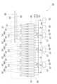
도 1은 본 발명의 실시예에 따른 원자층 증착 장치의 구성을 보여주는 도면이다.FIG. 1 is a drawing showing the configuration of an atomic layer deposition device according to an embodiment of the present invention.
도 1을 참조하면, 본 발명의 실시예에 따른 원자층 증착 장치(1)는, 원자층이 증착되는 기판(220)(도 2 참조)이 소스가스, 반응가스 및 퍼지가스가 공급되는 가스 공급 어셈블리(100)이 배치되는 챔버 영역(190)에서 일 방향(제1 방향) 또는 상기 제1 방향과 반대되는 타 방향(제2 방향)으로 이동되며, 상기 원자층의 증착이 이루어지는 공간분할 방식의 원자층 증착 장치이다. 기판(220)은 예시적으로 반도체 기판 또는 유리 기판일 수 있으며, 기판(220)의 일면에 상기 원자층이 증착될 수 있다. 한편, 기판(220)의 양면에 상기 원자층이 증착되는 구성 또한 본 발명의 실시예에 포함될 수 있다.Referring to FIG. 1, an atomic layer deposition apparatus (1) according to an embodiment of the present invention is a space-division type atomic layer deposition apparatus in which a substrate (220) on which an atomic layer is deposited (see FIG. 2) is moved in one direction (first direction) or in another direction (second direction) opposite to the first direction in a chamber region (190) in which a gas supply assembly (100) is arranged to which a source gas, a reaction gas, and a purge gas are supplied, and the deposition of the atomic layer is performed. The substrate (220) may be, for example, a semiconductor substrate or a glass substrate, and the atomic layer may be deposited on one surface of the substrate (220). Meanwhile, a configuration in which the atomic layer is deposited on both surfaces of the substrate (220) may also be included in an embodiment of the present invention.
본 발명의 실시예에 의하면, 기판(220)의 인입 위치에 따라, 상기 소스 가스 및 상기 퍼지 가스의 공급이 제어됨으로써, 상기 소스가스의 의도하지 않은 확산에 따른 원자층의 증착 품질 저하를 억제할 수 있다. 또한 다양한 종류의 소스 가스를 제공함으로써, IGZO(Indium Gallium Zinc Oxide)와 같은 다성분계 원자층 증착이 수행가능한 원자층 증착 장치가 제공될 수 있다.According to an embodiment of the present invention, the supply of the source gas and the purge gas is controlled according to the inlet position of the substrate (220), thereby suppressing the deterioration of the deposition quality of the atomic layer due to unintended diffusion of the source gas. In addition, by providing various types of source gases, an atomic layer deposition apparatus capable of performing multi-component atomic layer deposition such as IGZO (Indium Gallium Zinc Oxide) can be provided.
한편, 본 발명의 실시예에 따른 원자층 증착 장치(1)는 챔버 영역(190)에 불활성 기체가 채워진 상압 상태(Atmosphere Pressure)에서 구동될 수 있다. 다만, 원자층 증착 장치(1)의 챔버 영역(190)의 동작 압력이 상압 압력인 구성은 예시적인 구성일 뿐, 챔버 영역(190)이 진공 상태 또는 저압 상태인 구성 또한 본 발명의 사상에 포함될 수 있다.Meanwhile, the atomic layer deposition device (1) according to the embodiment of the present invention can be operated in an atmospheric pressure state in which the chamber region (190) is filled with an inert gas. However, the configuration in which the operating pressure of the chamber region (190) of the atomic layer deposition device (1) is atmospheric pressure is only an exemplary configuration, and a configuration in which the chamber region (190) is in a vacuum state or a low pressure state may also be included in the spirit of the present invention.
이하에서는 본 발명의 실시예에 따른 원자층 증착 장치(1)의 구성을 보다 상세하게 설명한다.Below, the configuration of an atomic layer deposition device (1) according to an embodiment of the present invention is described in more detail.
본 발명의 실시예에 따른 원자층 증착 장치(1)는, 소스가스, 반응 가스 및 퍼지 가스를 공급하는 가스 공급 어셈블리(100)와, 가스 공급 어셈블리(100)의 하측에 배치되며 선형으로 이동되며 상측에 기판(220)이 안착되는 기판 이송 모듈(200)을 포함한다.An atomic layer deposition apparatus (1) according to an embodiment of the present invention includes a gas supply assembly (100) that supplies a source gas, a reaction gas, and a purge gas, and a substrate transfer module (200) that is arranged on the lower side of the gas supply assembly (100), moves linearly, and has a substrate (220) placed on the upper side.
보다 상세히, 가스 공급 어셈블리(100)는,상기 퍼지가스가 유동되는 퍼지가스 공급라인(181)과 연결되는 퍼지가스 공급 모듈(111, 112, 130A ~ 130F)과, 상기 반응가스가 유동되는 반응가스 공급 라인(182)과 연결되는 반응가스 공급 모듈(121, 122, 123, 124)과, 퍼지가스 공급 라인(181)과 소스가스가 유동되는 소스가스 공급 라인(183, 184, 185) 중 어느 하나와 선택적으로 연통되는 소스가스 공급 모듈(141, 142, 143)과, 퍼지가스 공급모듈(111, 112, 130A ~ 130 F), 반응가스 공급모듈(121, 122, 123, 124) 및 소스가스 공급모듈(141, 142, 143) 사이에 각각 배치되며 음압을 제공하는 펌핑 모듈들(150)과, 상기 소스가스 공급 모듈이 상기 퍼지가스 공급라인과 상기 소스가스 공급라인(183, 184, 185) 중 어느 하나와 접속되도록 하고 다른 하나와 차단되도록 하는 밸브모듈(171, 172, 173, 174, 175, 176)과, 밸브모듈을 제어하기 위한 밸브모듈 제어부(미도시)를 포함한다. 또한, 본 발명의 실시예에 따른 원자층 증착장치는, 퍼지가스 공급라인(181)과 연결되어 상기 퍼지가스를 공급하는 퍼지가스 저장소(161), 반응가스 공급라인(182)과 연결되어 상기 반응가스를 공급하는 반응가스 저장소(162)를 포함한다. 펌핑 모듈(150)들은 음압을 제공하는 펌핑 장치(미도시)와 연결되며, 각 모듈 들에서 공급되는 상기 반응가스, 상기 소스가스 및 상기 퍼지가스이 챔버 영역(190)의 외부로 배출되도록 한다.In more detail, the gas supply assembly (100) comprises a purge gas supply module (111, 112, 130A to 130F) connected to a purge gas supply line (181) through which the purge gas flows, a reaction gas supply module (121, 122, 123, 124) connected to a reaction gas supply line (182) through which the reaction gas flows, a source gas supply module (141, 142, 143) selectively connected to one of the purge gas supply line (181) and the source gas supply line (183, 184, 185) through which the source gas flows, and a purge gas supply module (111, 112, 130A to 130 F), a reaction gas supply module (121, 122, 123, 124) and a source gas supply module (141, 142, 143) and provide negative pressure, respectively, a valve module (171, 172, 173, 174, 175, 176) that allows the source gas supply module to be connected to one of the purge gas supply line and the source gas supply line (183, 184, 185) and blocked from the other, and a valve module control unit (not shown) for controlling the valve module. In addition, the atomic layer deposition apparatus according to an embodiment of the present invention includes a purge gas storage unit (161) that is connected to the purge gas supply line (181) and supplies the purge gas, and a reaction gas storage unit (162) that is connected to the reaction gas supply line (182) and supplies the reaction gas. The pumping modules (150) are connected to a pumping device (not shown) that provides negative pressure, and the reaction gas, source gas, and purge gas supplied from each module are discharged to the outside of the chamber area (190).
또한, 원자층 증착장치는, 소스가스 공급라인(183, 184, 185)와 연결되어 상기 소스가스를 공급하는 소스가스 저장소(163, 164, 165)를 포함한다. 이때, 상기 소스가스들은, 서로 다른 종류의 소스가스 일 수 있으며, 예시적으로 제1 소스가스는 인듐을 포함하고, 제2 소스가스는 갈륨을 포함하고, 제3 소스가스는 아연을 포함할 수 있다. 그리고, 제1 소스가스 저장소(163)에는 상기 제1 소스가스가 저장되며, 제2 소스가스 저장소(164)에는 상기 제2 소스가스가 저장되고, 제3 소스가스 저장소(165)에는 상기 제3 소스가스가 저장된다.In addition, the atomic layer deposition apparatus includes a source gas reservoir (163, 164, 165) that is connected to a source gas supply line (183, 184, 185) and supplies the source gas. At this time, the source gases may be different types of source gases, and for example, the first source gas may include indium, the second source gas may include gallium, and the third source gas may include zinc. In addition, the first source gas is stored in the first source gas reservoir (163), the second source gas is stored in the second source gas reservoir (164), and the third source gas is stored in the third source gas reservoir (165).
한편, 본 발명의 실시예에 따른 밸브모듈(171, 172, 173, 174, 175, 176)은, 기판(220)의 위치에 따라, (1) 기판(220)이 소스가스 공급모듈(141, 142, 143) 측에 배치되는 경우에는 소스가스 공급모듈(141, 142, 143)과 소스가스 공급라인(183, 184, 185)을 접속시켜 상기 소스가스가 공급되도록 한다. 또한, 밸브모듈(171, 172, 173, 174, 175, 176)은 (2) 기판(220)이 소스가스 공급모듈(141, 142, 143) 측에 배치되지 않는 경우 소스가스 공급모듈(141, 142, 143)과 퍼지가스 공급라인(181)을 접속시켜 상기 퍼지가스가 공급되도록 한다. 이때, 상기 밸브모듈 제어부는, 상기 기판 이송 모듈(200)의 상기 제1 방향에 대한 위치, 기판 이송 모듈(200)에 기판(220)이 배치된 위치 및 기판 이송 모듈(200)의 이송 속도 중 적어도 하나에 기초하여 밸브모듈(171, 172, 173, 174, 175, 176)의 동작을 제어한다.Meanwhile, the valve module (171, 172, 173, 174, 175, 176) according to the embodiment of the present invention, depending on the location of the substrate (220), (1) when the substrate (220) is placed on the side of the source gas supply module (141, 142, 143), connects the source gas supply module (141, 142, 143) and the source gas supply line (183, 184, 185) so that the source gas is supplied. In addition, the valve module (171, 172, 173, 174, 175, 176) (2) connects the source gas supply module (141, 142, 143) and the purge gas supply line (181) to supply the purge gas when the substrate (220) is not arranged on the side of the source gas supply module (141, 142, 143). At this time, the valve module control unit controls the operation of the valve module (171, 172, 173, 174, 175, 176) based on at least one of the position of the substrate transport module (200) with respect to the first direction, the position at which the substrate (220) is arranged on the substrate transport module (200), and the transport speed of the substrate transport module (200).
밸브모듈(171, 172, 173, 174, 175, 176)은, 일측은 소스가스 공급라인(183, 184, 185)과 연결되며 타측은 퍼지가스 공급라인(181)과 연통되는 바이패스 라인(171A)과, 바이패스 라인(171A) 상에 배치되는 제1 밸브 유닛(171B)와, 소스가스 공급라인(183, 184, 185) 상에 배치되는 제2 밸브 유닛(174, 175, 176)를 포함한다. 제2 밸브 유닛(174, 175, 176)은, 소스가스 공급라인(183, 183, 184)과 상기 바이패스 라인(171A)이 연결된 지점과 소스가스 저장소(163, 164, 165) 사이에 배치된다.The valve modules (171, 172, 173, 174, 175, 176) include a bypass line (171A) which is connected to the source gas supply line (183, 184, 185) on one side and communicates with the purge gas supply line (181) on the other side, a first valve unit (171B) arranged on the bypass line (171A), and a second valve unit (174, 175, 176) arranged on the source gas supply line (183, 184, 185). The second valve unit (174, 175, 176) is arranged between a point where the source gas supply line (183, 183, 184) and the bypass line (171A) are connected and a source gas storage (163, 164, 165).
즉, 기판(220)의 위치에 따라 제1 소스가스 공급모듈(141)에서 상기 소스가스가 공급되도록 하는 경우, 제1 밸브 모듈(171, 174)의 제1 밸브 유닛(171B)은 바이패스 라인(171A)을 차단하고, 제2 밸브유닛(174)는 소스가스 공급라인(183)을 개방하여, 상기 소스가스가 제1 소스가스 공급모듈(141)에서 공급되도록 한다. 반대로, 제1 소스가스 공급모듈(141)에서 상기 퍼지가스가 공급되도록 하는 경우, 제1 밸브 모듈(171, 174)의 제1 밸브 유닛(171B)은 바이패스 라인(171A)을 개방하고, 제2 밸브유닛(174)는 소스가스 공급라인(183)을 차단하여, 상기 퍼지가스가 제1 소스가스 공급모듈(141)에서 공급되도록 한다.That is, when the source gas is supplied from the first source gas supply module (141) depending on the position of the substrate (220), the first valve unit (171B) of the first valve module (171, 174) blocks the bypass line (171A) and the second valve unit (174) opens the source gas supply line (183) so that the source gas is supplied from the first source gas supply module (141). Conversely, when the purge gas is supplied from the first source gas supply module (141), the first valve unit (171B) of the first valve module (171, 174) opens the bypass line (171A) and the second valve unit (174) blocks the source gas supply line (183) so that the purge gas is supplied from the first source gas supply module (141).
본 발명의 실시예에 따른 원자층 증착 장치(1)는, 기판(220)이 위치되지 않은 경우, 상기 소스가스가 공급되지 않고 예시적으로 질소, 아르곤 등과 같은 불활성 기체인 상기 퍼지가스가 공급되도록 함으로써, 의도하지 않은 상기 소스가스의 확산을 방지하여 고품질의 원자층을 증착할 수 있다. 또한 상기 소스가스의 사용량을 절약할 수 있는 장점이 있다.The atomic layer deposition device (1) according to an embodiment of the present invention prevents unintended diffusion of the source gas by supplying the purge gas, which is an inert gas such as nitrogen or argon, instead of the source gas when the substrate (220) is not positioned, thereby depositing a high-quality atomic layer. In addition, there is an advantage in that the amount of the source gas used can be saved.
한편, 퍼지가스 공급모듈(111, 112, 130A ~ 130 F)은, 기판(220)의 이송 방향인 제1 방향을 기준으로 가스공급 어셈블리(100)의 일측 및 타측에 각각 배치되는 제1 사이드 퍼지가스 공급모듈(111) 및 제2 사이드 퍼지가스 공급모듈(112)과, 반응가스 공급모듈(121, 122, 123, 124)과 소스가스 공급모듈(141, 142, 143) 사이에 배치되는 메인 퍼지가스 공급모듈(130A ~ 130F)들을 포함한다.Meanwhile, the purge gas supply modules (111, 112, 130A to 130 F) include a first side purge gas supply module (111) and a second side purge gas supply module (112) which are respectively arranged on one side and the other side of the gas supply assembly (100) with respect to the first direction, which is the transfer direction of the substrate (220), and main purge gas supply modules (130A to 130F) which are arranged between the reaction gas supply modules (121, 122, 123, 124) and the source gas supply modules (141, 142, 143).
메인 퍼지가스 공급모듈(130A ~ 130F)은, 퍼지가스 공급라인(181)과 각각 연결되는 제1 메인 퍼지가스 공급유닛(131)과 제2 메인 퍼지가스 공급유닛(132)을 포함한다. 제1 메인 퍼지가스 공급유닛(131)과 제2 메인 퍼지가스 공급유닛(132)은 상기 제1 방향을 기준으로 상호 이격되며, 제1 메인 퍼지가스 공급유닛(131)과 제2 메인 퍼지가스 공급유닛(132) 사이에는 펌핑 모듈(150)이 배치된다. 본 실시예에서 메인 퍼지가스 공급모듈(130A ~ 130F)은 한 쌍의 메인 퍼지가스 공급유닛(131, 132)을 포함하여, 반응가스 증착영역과 소스가스 증착영역 간의 차폐가 보다 효율적이고 원활하게 수행되도록 할 수 있다.The main purge gas supply modules (130A to 130F) include a first main purge gas supply unit (131) and a second main purge gas supply unit (132), which are each connected to a purge gas supply line (181). The first main purge gas supply unit (131) and the second main purge gas supply unit (132) are spaced apart from each other with respect to the first direction, and a pumping module (150) is arranged between the first main purge gas supply unit (131) and the second main purge gas supply unit (132). In the present embodiment, the main purge gas supply modules (130A to 130F) include a pair of main purge gas supply units (131, 132), so that shielding between a reaction gas deposition region and a source gas deposition region can be performed more efficiently and smoothly.
사이드 퍼지 모듈(111, 112)은, 상기 퍼지가스의 배출을 통하여, 가스공급 어셈블리(100)의 하측에 형성되는 증착 공간이 나머지 챔버 영역과 구분되도록 한다.The side purge module (111, 112) separates the deposition space formed at the lower side of the gas supply assembly (100) from the remaining chamber area by discharging the purge gas.
상기 퍼지가스가 배출되는 사이드 퍼지가스 공급유닛을 포함한다. 사이드 퍼지 모듈(111, 112)의 상기 사이드 퍼지가스 공급유닛은 하나로 마련될 수 있으며, 사이드 퍼지 모듈(111, 112)의 전방 및 후방에는 각각 펌핑 모듈(150)이 배치된다.It includes a side purge gas supply unit from which the above purge gas is discharged. The side purge gas supply unit of the side purge module (111, 112) can be provided as one, and a pumping module (150) is arranged at the front and rear of each of the side purge modules (111, 112).
한편, 사이드 퍼지가스 공급모듈(111, 112)에서 공급되는 상기 퍼지가스의 제1 공급압력은, 메인 퍼지가스 공급모듈(130A ~ 130F)에서 공급되는 상기 퍼지가스의 제2 공급압력과 다르게 형성될 수 있다. 예시적으로 상기 증착 공간에 대한 입구 영역 및 출구 영역에 상기 퍼지 가스를 공급하는 사이드 퍼지가스 공급모듈(111, 112)의 상기 제1 공급 압력보다, 상기 소스가스 및 상기 반응가스 간의 확산 차단을 목적으로 하는 메인 퍼지가스 공급모듈(130A ~ 130F)의 상기 제2 공급 압력이 더 작게 형성될 수 있다. 상압 조건에서 원자층 증착 장치의 원자층 증착이 수행되는 경우, 사이드 퍼지가스 공급모듈(111, 112)의 공급압력이 더 크게 마련되어, 상기 증착 공간과 외부의 유동을 차단한다.Meanwhile, the first supply pressure of the purge gas supplied from the side purge gas supply modules (111, 112) may be formed differently from the second supply pressure of the purge gas supplied from the main purge gas supply modules (130A to 130F). For example, the second supply pressure of the main purge gas supply modules (130A to 130F) for the purpose of blocking diffusion between the source gas and the reaction gas may be formed smaller than the first supply pressure of the side purge gas supply modules (111, 112) that supply the purge gas to the inlet area and the outlet area of the deposition space. When the atomic layer deposition of the atomic layer deposition apparatus is performed under atmospheric pressure conditions, the supply pressure of the side purge gas supply modules (111, 112) is provided to be greater to block flow between the deposition space and the outside.
그리고, 상기 제2 공급압력은 상기 기판의 움직임과 무관하게 일정하며, 상기 제1 공급압력은 기판(230)의 위치에 따라 가변된다. 보다 상세히, 기판(230)이 상기 증착 공간으로 진입하는 경우, 사이드 퍼지 모듈(111, 112)의 상기 제1 공급압력은, 기판(230)이 상기 증착 공간으로 완전하게 진입된 경우 또는 상기 증착 공간에서 완전하게 이탈된 경우, 사이드 퍼지 모듈(111, 112)의 상기 제1 공급압력보다 크게 형성되어, 상기 증착 공간과 상기 챔버 영역과 보다 원활하게 구획될 수 있도록 한다.And, the second supply pressure is constant regardless of the movement of the substrate, and the first supply pressure varies depending on the position of the substrate (230). More specifically, when the substrate (230) enters the deposition space, the first supply pressure of the side purge module (111, 112) is formed to be greater than the first supply pressure of the side purge module (111, 112) when the substrate (230) has completely entered the deposition space or completely exited the deposition space, so that the deposition space and the chamber area can be more smoothly partitioned.
한편, 소스가스 공급모듈(141, 142, 143)과 반응가스 공급모듈(121, 122, 123, 124)은 복수개로 마련되며, 상호 교번하여 배치된다. 예시적으로 반응가스 공급모듈(121, 122, 123, 124)은 제1 반응가스 공급모듈(121), 제2 반응가스 공급모듈(122), 제3 반응가스 공급모듈(123) 및 제4 반응가스 공급모듈(124)을 포함하며, 반응 가스는 예시적으로 산소일 수 있으며, 제1 반응가스 공급모듈(121), 제2 반응가스 공급모듈(122), 제3 반응가스 공급모듈(123) 및 제4 반응가스 공급모듈(124)에서 배출되는 상기 반응가스는 동일하다. 그리고, 소스가스 공급모듈(141, 142, 143)은 상기 제1 소스가스를 배출하는 제1 소스가스 공급모듈(141), 상기 제2 소스가스를 배출하는 제2 소스가스 공급모듈(142) 및 상기 제3 소스가스를 배출하는 제3 소스가스 공급모듈(143)을 포함한다.Meanwhile, a plurality of source gas supply modules (141, 142, 143) and reaction gas supply modules (121, 122, 123, 124) are provided and arranged alternately. For example, the reaction gas supply modules (121, 122, 123, 124) include a first reaction gas supply module (121), a second reaction gas supply module (122), a third reaction gas supply module (123), and a fourth reaction gas supply module (124). The reaction gas may be oxygen, for example, and the reaction gases discharged from the first reaction gas supply module (121), the second reaction gas supply module (122), the third reaction gas supply module (123), and the fourth reaction gas supply module (124) are the same. And, the source gas supply module (141, 142, 143) includes a first source gas supply module (141) that discharges the first source gas, a second source gas supply module (142) that discharges the second source gas, and a third source gas supply module (143) that discharges the third source gas.
이때, 가스공급 어셈블리(1)의 일측에 인접한 제1 반응가스 공급모듈(121)은, 제1 사이드 퍼지가스 공급모듈(111)과 인접한 제1 메인 퍼지가스 공급모듈(130A)과 제1 사이드 퍼지가스 공급모듈(111) 사이에 배치된다. 그리고, 가스공급 어셈블리(1)의 타측에 인접한 제2 반응가스 공급모듈(122)은, 제2 사이드 퍼지가스 공급모듈(112)과 인접한 제6 메인 퍼지가스 공급모듈(130F)과 제2 사이드 퍼지가스 공급모듈(112) 사이에 배치된다.At this time, the first reaction gas supply module (121) adjacent to one side of the gas supply assembly (1) is arranged between the first main purge gas supply module (130A) adjacent to the first side purge gas supply module (111) and the first side purge gas supply module (111). In addition, the second reaction gas supply module (122) adjacent to the other side of the gas supply assembly (1) is arranged between the sixth main purge gas supply module (130F) adjacent to the second side purge gas supply module (112) and the second side purge gas supply module (112).
이때 기판 이송 모듈(200)은, 기판 이송 모듈 몸체(210)에 기판(220)이 안착된 상태에서 상기 제1 방향 및 상기 제1 방향과 반대 방향은 제2 방향 중 어느 하나의 방향을 따라 선택적으로 이동될 수 있다.At this time, the substrate transfer module (200) can be selectively moved along one of the first direction and the second direction opposite to the first direction while the substrate (220) is secured to the substrate transfer module body (210).
본 실시예에 따른 원자층 증착장치에서 기판(220)은 상기 제1 방향 및 상기 제2 방향 중 어느 하나의 방향으로 이동하며 기판(220)의 상면에 원자층이 증착된다. 이때, 기판(220)이 상기 제1 방향으로 이동되며 원자층 증착 공정이 수행된 다음, 완전하게 상기 증착 공간에서 이탈된 상태에서, 다시 상기 제2 방향으로 이동되며 원자층 증착 공정이 수행될 수 있다. 본 실시예에서는 가스공급 어셈블리(1)의 일측 및 타측에 반응 가스 공급모듈(121, 124)이 배치됨으로써, 이러한 왕복 운동시 소스가스와 반응가스의 반응이 원활하게 이루어지도록 함으로써, 원자층 증착 효율을 증대시킬 수 있다.In the atomic layer deposition apparatus according to the present embodiment, the substrate (220) moves in one of the first direction and the second direction, and an atomic layer is deposited on the upper surface of the substrate (220). At this time, the substrate (220) is moved in the first direction, the atomic layer deposition process is performed, and then, when completely removed from the deposition space, it is moved in the second direction again, and the atomic layer deposition process can be performed. In the present embodiment, since the reaction gas supply modules (121, 124) are arranged on one side and the other side of the gas supply assembly (1), the reaction gas and the source gas can smoothly react during this reciprocating movement, thereby increasing the atomic layer deposition efficiency.
소스가스 공급모듈(141, 142, 143) 중 어느 하나의 제1 소스가스 공급모듈(141)과 다른 하나인 제2 소스가스 공급모듈(142) 사이에는, 펌핑모듈(150), 메인퍼지가스 공급모듈(130B, 130A) 및 반응가스 공급모듈(122)이 배치된다.Between one of the first source gas supply modules (141, 142, 143) and the other second source gas supply module (142), a pumping module (150), a main purge gas supply module (130B, 130A), and a reaction gas supply module (122) are arranged.
이때, 펌핑모듈(150), 메인퍼지가스 공급모듈(130B, 130A) 및 반응가스 공급모듈(122)은 '펌핑 모듈(150) - 제2 메인 퍼지가스 공급모듈(130B) - 펌핑 모듈(150) - 제2 반응가스 공급모듈(122) - 펌핑 모듈(150) - 제3 메인 퍼지가스 공급모듈(130C) - 펌핑 모듈(150)' 순으로 배치된다.At this time, the pumping module (150), the main purge gas supply module (130B, 130A), and the reaction gas supply module (122) are arranged in the order of 'pumping module (150) - second main purge gas supply module (130B) - pumping module (150) - second reaction gas supply module (122) - pumping module (150) - third main purge gas supply module (130C) - pumping module (150)'.
이때, 상기 소스 가스는, 제1 소스가스(예시적으로 인듐을 포함한 소스 가스)와 상기 제1 소스가스와 다른 물질인 제2 소스가스(예시적으로 갈륨을 포함한 소스 가스)를 포함한다. 제1 소스가스 공급모듈(141)은, 상기 제1 소스가스를 공급하기 위한 제1 소스가스 공급라인(183)과 선택적으로 접속되며. 제2 소스가스 공급모듈(142)은, 상기 제2 소스가스를 공급하기 위한 제2 소스가스 공급라인(184)과 선택적으로 접속된다. 이때, 제1 반응가스 공급모듈(121)은, 제1 사이드 퍼지가스 공급모듈(111)과 제1 메인 퍼지가스 공급모듈(130A) 사이에 배치되며, 제1 메인 퍼지가스 공급모듈(130A)은 제1 반응가스 공급모듈(121)과 제1 소스가스 공급모듈(141) 사이에 배치된다.At this time, the source gas includes a first source gas (for example, a source gas including indium) and a second source gas (for example, a source gas including gallium) that is a different material from the first source gas. The first source gas supply module (141) is selectively connected to a first source gas supply line (183) for supplying the first source gas. The second source gas supply module (142) is selectively connected to a second source gas supply line (184) for supplying the second source gas. At this time, the first reaction gas supply module (121) is arranged between the first side purge gas supply module (111) and the first main purge gas supply module (130A), and the first main purge gas supply module (130A) is arranged between the first reaction gas supply module (121) and the first source gas supply module (141).
한편, 제2 소스가스 공급모듈(142)과 제3 소스가스 공급모듈(143) 사이에 배치 구성은, 제2 소스가스 공급모듈(142)과 제3 소스가스 공급모듈(143) 사이의 배치 구성과 실질적으로 동일하므로, 이에 대한 상세한 설명은 생략한다.Meanwhile, the arrangement configuration between the second source gas supply module (142) and the third source gas supply module (143) is substantially the same as the arrangement configuration between the second source gas supply module (142) and the third source gas supply module (143), so a detailed description thereof is omitted.
그리고, 상기 제1 방향을 기준으로 어느 하나의 소스가스 공급모듈(141, 142,143), 예시적으로 제1 소스가스 공급모듈(141)의 전방에 배치되는 어느 하나의 퍼지가스 공급모듈(130A~130F), 예시적으로 제1 메인 퍼지가스 공급모듈(130A),과 제1 소스가스 공급모듈(141)의 후방에 배치되는 다른 하나의 퍼지가스 공급모듈(130A~130F) 사이에는, 예시적으로 제2 퍼지가스 공급모듈(130B), 소스가스 증착공간(311, 312, 313), 예시적으로 제1 소스가스 증착공간(311)이 형성된다.And, between one of the source gas supply modules (141, 142, 143), for example, one of the purge gas supply modules (130A to 130F) positioned in front of the first source gas supply module (141), for example, the first main purge gas supply module (130A), and another purge gas supply module (130A to 130F) positioned in the rear of the first source gas supply module (141), a second purge gas supply module (130B), a source gas deposition space (311, 312, 313), for example, a first source gas deposition space (311) are formed.
기판(220)의 일측이 제1 소스가스 증착공간(311)에 진입하면, 제1 밸브모듈(171, 174)은 제1 소스가스 증착공간(311)에 대응되는 제1 소스가스 공급모듈(141)이 상기 소스가스를 공급하도록 제어된다. 그리고, 기판(220)의 타측이 제1 소스가스 증착공간(311)에서 이탈되면, 밸브모듈(171, 174)은 제1 소스가스 증착공간(311)에 대응되는 제1 소스가스 공급모듈(141)이 상기 퍼지가스를 공급하도록 제어된다.When one side of the substrate (220) enters the first source gas deposition space (311), the first valve module (171, 174) is controlled so that the first source gas supply module (141) corresponding to the first source gas deposition space (311) supplies the source gas. Then, when the other side of the substrate (220) is separated from the first source gas deposition space (311), the valve module (171, 174) is controlled so that the first source gas supply module (141) corresponding to the first source gas deposition space (311) supplies the purge gas.
이때, 소스가스 증착공간(311, 312, 313)은 제1 소스가스 증착공간(311), 제2소스가스 증착공간(312) 및 제3 소스가스 증착공간(313)을 포함하고, 복수의 상기 소스가스 증착 공간(311, 312, 313)은 상기 제1 방향을 따라 상호 이격되도록 배치된다.At this time, the source gas deposition space (311, 312, 313) includes a first source gas deposition space (311), a second source gas deposition space (312), and a third source gas deposition space (313), and the plurality of source gas deposition spaces (311, 312, 313) are arranged to be spaced apart from each other along the first direction.
반응가스 공급모듈(121, 122, 123, 124)과, 반응가스 공급모듈(121, 122, 123, 124)에 인접한 소스가스 공급모듈(141, 142, 143) 사이에는 상기 퍼지가스가 기판에 공급되는 퍼지공간(321, 322, 323, 324, 325, 326)이 형성되며, 퍼지공간(321, 322, 323, 324, 325, 326)은 소스가스 증착공간(311, 312, 313)보다 상기 제1 방향을 기준으로 더 크게 형성될 수 있다.A purge space (321, 322, 323, 324, 325, 326) in which the purge gas is supplied to the substrate is formed between the reaction gas supply module (121, 122, 123, 124) and the source gas supply module (141, 142, 143) adjacent to the reaction gas supply module (121, 122, 123, 124), and the purge space (321, 322, 323, 324, 325, 326) may be formed larger than the source gas deposition space (311, 312, 313) with respect to the first direction.
소스가스 증착공간(311, 312, 313)보다 퍼지공간(321, 322, 323, 324, 325, 326)의 크기가 더 크게 형성됨으로써, 상기 증착 공간 내에서 상기 소스가스가 다른 가스가 유동되는 인접 영역으로 유입되는 것을 효율적으로 억제할 수 있다.By forming the purge space (321, 322, 323, 324, 325, 326) larger in size than the source gas deposition space (311, 312, 313), the source gas can be effectively suppressed from flowing into an adjacent area where another gas flows within the deposition space.
이때, 퍼지가스 공급모듈(130A~130F)의 헤드부의 상기 제1 방향에 대한 폭은 소스가스 증착모듈(141, 142, 143)의 헤드부의 상기 제1 방향에 대한 폭보다 크게 형성된다.At this time, the width of the head portion of the purge gas supply module (130A to 130F) in the first direction is formed to be larger than the width of the head portion of the source gas deposition module (141, 142, 143) in the first direction.
한편, 소스가스 공급모듈(141, 142, 143)과 다르게, 반응가스 공급모듈(121, 122, 123, 124) 및 퍼지가스 공급모듈(111, 112, 130A ~130F)은, 기판(220)의 위치와 무관하게 각각 상기 반응가스 및 상기 퍼지가스를 연속적으로 공급한다.Meanwhile, unlike the source gas supply modules (141, 142, 143), the reaction gas supply modules (121, 122, 123, 124) and the purge gas supply modules (111, 112, 130A to 130F) continuously supply the reaction gas and the purge gas, respectively, regardless of the position of the substrate (220).
이하에서는 본 발명의 실시예에 따른 원자층 증착장치를 이용한 원자층 증착방법을 상세하게 설명한다.Below, an atomic layer deposition method using an atomic layer deposition apparatus according to an embodiment of the present invention is described in detail.
도 2 내지 도 7은 도 1의 원자층 증착 장치에 의하여 기판에 원자층이 증착되는 과정을 보여주는 도면이다.Figures 2 to 7 are drawings showing the process of depositing an atomic layer on a substrate by the atomic layer deposition device of Figure 1.
먼저 도 2를 참조하면, 기판(220)이 상기 증착공간의 외부에 존재하는 경우, 반응가스 공급모듈(121, 122, 123, 124)에서는 상기 반응가스가 공급되며, 퍼지가스 공급모듈(111, 112, 130A ~130F) 및 소스가스 증착모듈(141, 142, 143)에서는 상기 퍼지가스가 공급된다. 펌핑 모듈(150)에서는 연속적으로 음압이 제공되어 가스들을 상기 증착공간의 외부로 배출시킨다.First, referring to FIG. 2, when the substrate (220) exists outside the deposition space, the reaction gas is supplied from the reaction gas supply module (121, 122, 123, 124), and the purge gas is supplied from the purge gas supply module (111, 112, 130A to 130F) and the source gas deposition module (141, 142, 143). The pumping module (150) continuously provides negative pressure to discharge the gases to the outside of the deposition space.
그 다음, 도 3을 참조하면, 기판(220)이 상기 제1 방향으로 이동하여 상기 증착공간에 진입하였으나, 기판(220)의 일측이 제1 퍼지공간(321)에 위치되며 제1 소스가스 증착공간(311)에 진입하기 전인 경우, 반응가스 공급모듈(121, 122, 123, 124)에서는 상기 반응가스가 공급되며, 퍼지가스 공급모듈(111, 112, 130A ~130F) 및 소스가스 증착모듈(141, 142, 143)에서는 상기 퍼지가스의 공급이 유지된다.Next, referring to FIG. 3, when the substrate (220) moves in the first direction and enters the deposition space, but one side of the substrate (220) is positioned in the first purge space (321) and before entering the first source gas deposition space (311), the reaction gas is supplied from the reaction gas supply modules (121, 122, 123, 124), and the supply of the purge gas is maintained from the purge gas supply modules (111, 112, 130A to 130F) and the source gas deposition modules (141, 142, 143).
그 다음, 도 4를 참조하면, 상기 제1 방향으로 이동하여, 기판(220)의 일측이 제1 소스가스 증착공간(311)에 진입하면 제1 소스가스 증착모듈(141)에서는 상기 퍼지가스의 공급이 차단되며 상기 제1 소스가스의 공급이 개시된다. 이때, 반응가스 공급모듈(121, 122, 123, 124)에서는 상기 반응가스가 공급되며, 퍼지가스 공급모듈(111, 112, 130A ~130F)과 나머지 소스가스 증착모듈(142, 143)에서는 상기 퍼지가스가 공급된다.Next, referring to FIG. 4, when moving in the first direction, when one side of the substrate (220) enters the first source gas deposition space (311), the supply of the purge gas is cut off in the first source gas deposition module (141) and the supply of the first source gas is started. At this time, the reaction gas is supplied in the reaction gas supply modules (121, 122, 123, 124), and the purge gas is supplied in the purge gas supply modules (111, 112, 130A to 130F) and the remaining source gas deposition modules (142, 143).
그 다음, 도 5를 참조하면, 기판(220)의 상기 일측이 제2 소스가스 증착공간(312)에 진입하면, 제2 소스가스 증착모듈(142)에서는 상기 퍼지가스의 공급이 차단되며 상기 제2 소스가스의 공급이 개시된다. 이때, 기판(220)의 일측에는 제1 소스가스 증착공간(311)과 반응가스 증착공간을 통과하면서 증착된 상기 제1 소스가스와 상기 반응가스가 상호 반응하여 형성된 제1 반응층이 형성될 수 있다.Next, referring to FIG. 5, when one side of the substrate (220) enters the second source gas deposition space (312), the supply of the purge gas is cut off in the second source gas deposition module (142) and the supply of the second source gas is started. At this time, a first reaction layer formed by the reaction gas and the first source gas deposited while passing through the first source gas deposition space (311) and the reaction gas deposition space reacting with each other can be formed on one side of the substrate (220).
이때, 기판(220)의 타측은 여전히 제1 소스가스 증착공간(311)에 진입하지 못한 상태이며, 제1 소스가스 증착모듈(141)에서는 상기 제1 소스가스의 공급이 유지된다. 기판(220)의 타측이 제1 소스가스 증착공간(311)에서 상기 제1 방향 측으로 이탈되기 전까지, 제1 소스가스 증착모듈(141)의 상기 제1 소스가스 공급이 연속적으로 수행된다.At this time, the other side of the substrate (220) has not yet entered the first source gas deposition space (311), and the first source gas is maintained for supply in the first source gas deposition module (141). Until the other side of the substrate (220) is removed from the first source gas deposition space (311) toward the first direction, the first source gas supply of the first source gas deposition module (141) is continuously performed.
그리고, 반응가스 공급모듈(121, 122, 123, 124)에서는 상기 반응가스가 공급되며, 퍼지가스 공급모듈(111, 112, 130A ~130F)과 제3 소스가스 증착모듈(142, 143)에서는 상기 퍼지가스가 상기 증착공간으로 공급된다.And, the reaction gas is supplied from the reaction gas supply modules (121, 122, 123, 124), and the purge gas is supplied to the deposition space from the purge gas supply modules (111, 112, 130A to 130F) and the third source gas deposition module (142, 143).
그 다음, 도 6을 참조하면, 기판(220)의 상기 일측은 제3 소스가스 증착공간(313)에 진입하였으며, 기판(220)의 상기 타측은 제1 소스가스 증착공간(311)에서 완전하게 이탈된다.Next, referring to FIG. 6, one side of the substrate (220) enters the third source gas deposition space (313), and the other side of the substrate (220) is completely separated from the first source gas deposition space (311).
이때, 기판(220)의 상기 일측이 제3 소스가스 증착공간(313)에 진입하면, 제3 소스가스 증착모듈(143)에서는 상기 퍼지가스의 공급이 차단되며 상기 제3 소스가스의 공급이 개시된다.At this time, when the above-mentioned one side of the substrate (220) enters the third source gas deposition space (313), the supply of the purge gas is cut off in the third source gas deposition module (143) and the supply of the third source gas is started.
그리고, 기판(220)의 상기 타측이 제1 소스가스 증착공간(311)에서 상기 제1 방향으로 이탈되면, 제1 소스가스 증착모듈(141)에서는 상기 제1 소스가스의 공급이 차단되며 상기 퍼지가스의 공급이 개시된다.And, when the other side of the substrate (220) is separated from the first source gas deposition space (311) in the first direction, the supply of the first source gas is cut off in the first source gas deposition module (141) and the supply of the purge gas is started.
이때, 여전히 제2 소스가스 증착모듈(312)은, 상기 증착공간의 제2 소스가스 증착공간(312)으로 상기 제2 소스가스를 공급한다.At this time, the second source gas deposition module (312) still supplies the second source gas to the second source gas deposition space (312) of the deposition space.
그리고, 반응가스 공급모듈(121, 122, 123, 124)에서는 상기 반응가스가 공급되며, 퍼지가스 공급모듈(111, 112, 130A ~130F)에서는 상기 퍼지가스가 공급된다.And, the reaction gas is supplied from the reaction gas supply modules (121, 122, 123, 124), and the purge gas is supplied from the purge gas supply modules (111, 112, 130A to 130F).
그 다음, 도 7을 참조하면, 본 실시예에 따른 원자층 증착장치는, 복수 개의 기판(220)이 가스 공급 모듈(100)의 하측에 형성되는 상기 증착 공간에 위치되는 경우, 기판(220)들이 위치되는 소스가스 증착공간(311, 312, 313)의 소스가스 공급모듈(141, 142, 143)이 상기 소스가스를 소스가스 증착공간(311, 312, 313)에 공급하도록 하고, 기판(220)들이 위치되지 않는 소스가스 증착공간(311, 312, 313)의 상기 소스가스 공급모듈(141, 142, 143)이 상기 퍼지가스를 소스가스 증착공간(311, 312, 313)에 공급하도록 한다.Next, referring to FIG. 7, in the atomic layer deposition apparatus according to the present embodiment, when a plurality of substrates (220) are positioned in the deposition space formed on the lower side of the gas supply module (100), the source gas supply modules (141, 142, 143) of the source gas deposition spaces (311, 312, 313) where the substrates (220) are positioned supply the source gas to the source gas deposition spaces (311, 312, 313), and the source gas supply modules (141, 142, 143) of the source gas deposition spaces (311, 312, 313) where the substrates (220) are not positioned supply the purge gas to the source gas deposition spaces (311, 312, 313).
즉, 기판(120)이 위치된 소스가스 공급모듈(141, 142, 143)에서는 상기 소스가스가 공급되며, 기판(120)이 위치되지 않은 소스가스 공급모듈(141, 142, 143)에서는 상기 퍼지가스가 공급된다.That is, the source gas is supplied to the source gas supply module (141, 142, 143) where the substrate (120) is positioned, and the purge gas is supplied to the source gas supply module (141, 142, 143) where the substrate (120) is not positioned.
단부위치
(전방측(일측))1st board
Short position
(Forward (one side))
단부위치
(후방측(타측))1st board
Short position
(rear side (other side))
(예) 인듐First source gas (S1 )
(Example) Indium
(예) 갈륨Second source gas (S2 )
(eg) gallium
(예) 아연Third source gas (S3 )
(Example) Zinc
(예) 산소Reaction gas (S1 )
(Example) Oxygen
표 1에서는 원자층 증착 장치의 제어 테이블이 도시된다.Table 1 shows the control table of the atomic layer deposition device.
표 1에 도시된 바와 같이, 본 발명의 실시예에 따른 원자층 증착 장치의 상기 밸브 제어부는, 기판(220)의 일측 및 타측 단부 위치에 대한 데이터 테이블에 기초하여, 밸브모듈(171, 172, 173, 174, 175, 176)을 제어한다.As shown in Table 1, the valve control unit of the atomic layer deposition apparatus according to the embodiment of the present invention controls the valve modules (171, 172, 173, 174, 175, 176) based on a data table for positions of one side and the other side of the substrate (220).
제안되는 실시예에 의하면, 공간분할 방식의 원자층 증착장치에서 기판(220)이 위치되지 않는 소스가스 공급모듈(141, 142, 143)에서는 상기 퍼지가스가 공급되며 기판(220)이 위치되는 소스가스 공급모듈(141, 142, 143)에서만 상기 소스가스가 공급됨으로써, 상기 증착 공간의 다른 영역으로 상기 소스가스가 누설되는 것을 억제할 수 있다.According to the proposed embodiment, in an atomic layer deposition device of a space-division type, the purge gas is supplied to a source gas supply module (141, 142, 143) where the substrate (220) is not positioned, and the source gas is supplied only to a source gas supply module (141, 142, 143) where the substrate (220) is positioned, thereby suppressing the source gas from leaking into other areas of the deposition space.
또한, 서로 다른 물질을 포함하는 소스가스들이 기판(220)의 1회 이동에 공급됨으로써, 다성분계 원자층을 형성할 수 있는 장점이 있다.In addition, there is an advantage in that a multi-component atomic layer can be formed by supplying source gases containing different substances in one movement of the substrate (220).
도 8은 본 발명의 다른 실시예에 따른 원자층 증착 장치를 보여주는 도면이다.FIG. 8 is a drawing showing an atomic layer deposition apparatus according to another embodiment of the present invention.
본 실시예는 밸브모듈의 구성에 있어서 차이가 있을 뿐, 다른 구성에 있어서는 도 1 내지 도 7에서 도시된 원자층 장착 장치 및 이를 이용한 원자층 증착 방법의 구성과 실질적으로 동일하므로, 이하에서는 본 실시예의 특징적인 부분을 중심으로 설명한다.This embodiment differs only in the configuration of the valve module, but in other configurations, it is substantially the same as the configuration of the atomic layer mounting device and the atomic layer deposition method using the same illustrated in FIGS. 1 to 7. Therefore, the following description focuses on the characteristic parts of this embodiment.
도 8을 참조하면, 제1 소스가스 공급라인(183), 제2 소스가스 공급라인(184) 및 제3 소스가스 공급라인(185)는 각각 퍼지가스 공급라인(181)은 상호 연결되며, 복수의 밸브모듈(177, 178, 179)은 소스가스 공급라인(183, 184, 185)과 상기 퍼지가스 공급라인(181)이 연결된 지점에 각각 설치된다.Referring to FIG. 8, the first source gas supply line (183), the second source gas supply line (184), and the third source gas supply line (185) are each interconnected with the purge gas supply line (181), and a plurality of valve modules (177, 178, 179) are each installed at the point where the source gas supply lines (183, 184, 185) and the purge gas supply line (181) are connected.
복수의 밸브모듈(177, 178, 179)들은 선택적으로 어느 하나의 가스만이 상기 소스가스 공급모듈(183, 184, 185) 측으로 공급되도록 한다. 예시적으로, 밸브모듈(177, 178, 178)은 유로전환밸브일 수 있다.A plurality of valve modules (177, 178, 179) selectively allow only one gas to be supplied to the source gas supply module (183, 184, 185). For example, the valve modules (177, 178, 178) may be flow switching valves.
본 실시예에 의하면, 밸브모듈의 구성이 단순해지는 장점이 있다.According to this embodiment, there is an advantage in that the configuration of the valve module is simplified.
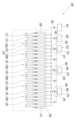
도 9는 본 발명의 또 다른 실시예에 따른 원자층 증착 장치를 보여주는 도면이다.FIG. 9 is a drawing showing an atomic layer deposition apparatus according to another embodiment of the present invention.
본 실시예는 소스가스 공급모듈의 구성에 있어서 차이가 있을 뿐, 다른 구성에 있어서는 도 1 내지 도 7에서 도시된 원자층 장착 장치 및 이를 이용한 원자층 증착 방법의 구성과 실질적으로 동일하므로, 이하에서는 본 실시예의 특징적인 부분을 중심으로 설명한다.This embodiment differs only in the configuration of the source gas supply module, but is substantially the same as the configuration of the atomic layer mounting device and the atomic layer deposition method using the same illustrated in FIGS. 1 to 7 in other configurations. Therefore, the following description will focus on the characteristic parts of this embodiment.
도 9를 참조하면, 제1 소스가스 공급모듈(141)은, 상기 제1 소스가스를 공급하기 위한 제1 서브 제1 소스가스 공급모듈(141A)과 제2 서브 제1 소스가스 공급모듈(141B)을 포함한다.Referring to FIG. 9, the first source gas supply module (141) includes a first sub-first source gas supply module (141A) and a second sub-first source gas supply module (141B) for supplying the first source gas.
이때, 제1 서브 제1 소스가스 공급모듈(141A)과 제2 서브 제1 소스가스 공급모듈(141B)은 상기 제1 방향으로 상호 이격되며, 제1 서브 제1 소스가스 공급모듈(141A)과 상기 제2 서브 제1 소스가스 공급모듈(141B) 사이에는, 펌핑모듈(150), 메인퍼지가스 공급모듈(130B, 130C) 및 반응가스 공급모듈(122)이 배치되며, '펌핑 모듈(150) - 제2 메인 퍼지가스 공급모듈(130B) - 펌핑 모듈(150) - 제2 반응가스 공급모듈(122) - 펌핑 모듈(150) - 제3 메인 퍼지가스 공급모듈(130C) - 펌핑 모듈(150)' 순으로 배치된다.At this time, the first sub-first source gas supply module (141A) and the second sub-first source gas supply module (141B) are spaced apart from each other in the first direction, and a pumping module (150), a main purge gas supply module (130B, 130C), and a reaction gas supply module (122) are arranged between the first sub-first source gas supply module (141A) and the second sub-first source gas supply module (141B), and are arranged in the order of 'pumping module (150) - second main purge gas supply module (130B) - pumping module (150) - second reaction gas supply module (122) - pumping module (150) - third main purge gas supply module (130C) - pumping module (150).'
본 실시예에 예시적으로 기판(220)이 상기 제1 방향으로 이동되며 증착되는 1 사이클 동안, 상기 제1 소스가스는 2회 증착되며, 상기 제2 소스가스 및 상기 제3 소스가스는 1회 증착된다. 즉, 다른 종류의 상기 소스가스들 간의 증착 횟수를 다르게 설정함으로써, 원하는 물성의 원자층을 형성할 수 있는 장점이 있다.In this embodiment, for example, during one cycle in which the substrate (220) is moved in the first direction and deposited, the first source gas is deposited twice, and the second source gas and the third source gas are deposited once. That is, by setting the deposition counts of different types of the source gases differently, there is an advantage in that an atomic layer having desired properties can be formed.
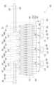
도 10은 본 발명의 또 다른 실시예에 따른 원자층 증착 장치를 보여주는 도면이다.FIG. 10 is a drawing showing an atomic layer deposition apparatus according to another embodiment of the present invention.
본 실시예는 플라즈마 발진부의 구성에 있어서 차이가 있을 뿐, 다른 구성에 있어서는 도 1 내지 도 7에서 도시된 원자층 장착 장치 및 이를 이용한 원자층 증착 방법의 구성과 실질적으로 동일하므로, 이하에서는 본 실시예의 특징적인 부분을 중심으로 설명한다.This embodiment differs only in the configuration of the plasma oscillation unit, but is substantially the same as the configuration of the atomic layer mounting device and the atomic layer deposition method using the same illustrated in FIGS. 1 to 7 in other configurations. Therefore, the following description will focus on the characteristic parts of this embodiment.
도 10을 참조하면, 본 발명의 실시예에 따른 원자층 증착 장치는 상기 반응가스를 이온화시키기 위한 플라즈마 발진부(300)를 더 포함한다.Referring to FIG. 10, the atomic layer deposition apparatus according to an embodiment of the present invention further includes a plasma oscillation unit (300) for ionizing the reaction gas.
플라즈마 발진부(300)는, 반응가스 공급라인(182)과 연결되어, 반응가스 저장소(162)로부터 공급되는 상기 반응가스를 이온화시켜, 상기 소스가스와 상기 반응가스의 반응이 보다 활발하게 이루어지도록 할 수 있다.The plasma generator (300) is connected to a reaction gas supply line (182) and ionizes the reaction gas supplied from the reaction gas storage (162), thereby allowing the reaction between the source gas and the reaction gas to occur more actively.
한편, 플라즈마 발진부(300)는 펄스 형태의 전압을 제공할 수 있으며, 반응가스 공급라인(182) 중 분기점과 반응가스 저장소(162) 사이에 연결될 수 있다.Meanwhile, the plasma generator (300) can provide a pulse-shaped voltage and can be connected between a branch point of the reaction gas supply line (182) and the reaction gas storage (162).
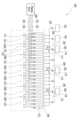
도 11은 본 발명의 또 다른 실시예에 따른 원자층 증착 장치를 보여주는 도면이다.FIG. 11 is a drawing showing an atomic layer deposition apparatus according to another embodiment of the present invention.
본 실시예는 플라즈마 발진부의 구성에 있어서 차이가 있을 뿐, 다른 구성에 있어서는 도 10에서 도시된 원자층 장착 장치 및 이를 이용한 원자층 증착 방법의 구성과 실질적으로 동일하므로, 이하에서는 본 실시예의 특징적인 부분을 중심으로 설명한다.This embodiment differs only in the configuration of the plasma oscillation unit, but is substantially the same as the configuration of the atomic layer mounting device and the atomic layer deposition method using the same illustrated in Fig. 10 in other configurations. Therefore, the following description focuses on the characteristic parts of this embodiment.
도 11을 참조하면, 플라즈마 발진부(300)는 반응가스 공급모듈(121, 122, 123, 124)에 연결되어, 반응가스 공급모듈(121, 122, 123, 124)에서 유동되는 상기 반응 가스를 이온화시킬 수 있다. 즉, 기판(220)의 상면 측으로 상기 반응가스를 공급하는 반응가스 공급모듈(121, 122, 123, 124)과 직접 연결되어 상기 펄스 형태의 전압을 제공함으로써, 상기 반응가스의 이온화 효율을 향상시킬 수 있다.Referring to FIG. 11, the plasma oscillation unit (300) is connected to the reaction gas supply module (121, 122, 123, 124) and can ionize the reaction gas flowing in the reaction gas supply module (121, 122, 123, 124). That is, by directly connecting to the reaction gas supply module (121, 122, 123, 124) that supplies the reaction gas to the upper surface of the substrate (220) and providing the pulse-shaped voltage, the ionization efficiency of the reaction gas can be improved.
Claims (18)
Translated fromKorean소스가스, 반응 가스 및 퍼지 가스를 공급하는 가스 공급 어셈블리; 및
상기 가스 공급 어셈블리의 하측에 배치되며 선형으로 이동되며 상측에 기판이 안착되는 기판 이송 모듈;을 포함하고,
상기 퍼지가스가 유동되는 퍼지가스 공급라인과 연결되는 퍼지가스 공급 모듈과, 상기 반응가스가 유동되는 반응가스 공급 라인과 연결되는 반응가스 공급 모듈과, 상기 퍼지가스 공급 라인과, 상기 소스가스가 유동되는 소스가스 공급 라인 중 어느 하나와 선택적으로 연통되는 소스가스 공급 모듈과, 상기 퍼지가스 공급모듈, 상기 반응가스 공급모듈 및 상기 소스가스 공급모듈 사이에 각각 배치되며 음압을 제공하는 펌핑 모듈과, 상기 소스가스 공급 모듈이 상기 퍼지가스 공급라인과 상기 소스가스 공급라인 중 어느 하나와 접속되도록 하고 다른 하나와 차단되도록 하는 밸브모듈을 포함하고,
상기 밸브모듈은, (1) 상기 기판이 상기 소스가스 공급모듈 측에 배치되는 경우에는 상기 소스가스 공급모듈과 상기 소스가스 공급라인을 접속시키며, (2) 상기 기판이 상기 소스가스 공급모듈 측에 배치되지 않는 경우 상기 소스가스 공급모듈과 상기 퍼지가스 공급라인을 접속시키고,
상기 퍼지가스 공급모듈은,
상기 기판의 이송 방향인 제1 방향을 기준으로 상기 가스공급 어셈블리의 일측에 배치되고 상기 가스 공급 모듈의 하측에 형성되는 증착 공간에 대한 입구 영역에 상기 퍼지 가스를 공급하여 상기 증착 공간과 외부의 유동을 차단하는 제1 사이드 퍼지가스 공급모듈과, 상기 가스공급 어셈블리의 타측에 배치되고 상기 증착 공간에 대한 출구 영역에 상기 퍼지 가스를 공급하여 상기 증착 공간과 외부의 유동을 차단하는 제2 사이드 퍼지가스 공급모듈과, 상기 반응가스 공급모듈과 상기 소스가스 공급모듈 사이에 배치되어 상기 소스가스 및 상기 반응가스 간의 확산을 차단하는 메인 퍼지가스 공급모듈을 포함하고,
상기 제1 사이드 퍼지가스 공급모듈 및 상기 제2 사이드 퍼지가스 공급모듈 각각은 상기 퍼지가스가 배출되는 사이드 퍼지가스 공급유닛을 포함하고,
상기 메인 퍼지가스 공급모듈은, 상기 퍼지가스 공급라인과 각각 연결되는 메인 퍼지가스 공급유닛을 포함하며,
상기 사이드 퍼지가스 공급유닛에서 공급되는 상기 퍼지가스의 제1 공급압력은, 상기 메인 퍼지가스 공급유닛에서 공급되는 상기 퍼지가스의 제2 공급압력과 크게 형성되어 상기 증착 공간과 외부의 유동을 차단하는 것을 특징으로 하는 원자층 증착 장치.
In an atomic layer deposition device,
A gas supply assembly for supplying source gas, reaction gas and purge gas; and
A substrate transfer module is disposed on the lower side of the gas supply assembly and moves linearly, and a substrate is placed on the upper side;
It comprises a purge gas supply module connected to a purge gas supply line through which the purge gas flows, a reaction gas supply module connected to a reaction gas supply line through which the reaction gas flows, a source gas supply module selectively connected to either the purge gas supply line or the source gas supply line through which the source gas flows, a pumping module respectively disposed between the purge gas supply module, the reaction gas supply module, and the source gas supply module and providing negative pressure, and a valve module that allows the source gas supply module to be connected to either one of the purge gas supply line and the source gas supply line and to be blocked from the other.
The above valve module, (1) when the substrate is placed on the source gas supply module side, connects the source gas supply module and the source gas supply line, and (2) when the substrate is not placed on the source gas supply module side, connects the source gas supply module and the purge gas supply line.
The above purge gas supply module,
A first side purge gas supply module is disposed on one side of the gas supply assembly based on the first direction, which is the transfer direction of the substrate, and supplies the purge gas to an inlet area for a deposition space formed on the lower side of the gas supply module to block flow between the deposition space and the outside, a second side purge gas supply module is disposed on the other side of the gas supply assembly and supplies the purge gas to an outlet area for the deposition space to block flow between the deposition space and the outside, and a main purge gas supply module is disposed between the reaction gas supply module and the source gas supply module to block diffusion between the source gas and the reaction gas.
Each of the first side purge gas supply module and the second side purge gas supply module includes a side purge gas supply unit from which the purge gas is discharged,
The above main purge gas supply module includes a main purge gas supply unit each connected to the purge gas supply line,
An atomic layer deposition device characterized in that the first supply pressure of the purge gas supplied from the side purge gas supply unit is formed to be significantly greater than the second supply pressure of the purge gas supplied from the main purge gas supply unit, thereby blocking flow between the deposition space and the outside.
상기 소스가스 공급모듈과 상기 반응가스 공급모듈은 복수개로 마련되며, 상호 교번하여 배치되는 것을 특징으로 하는 원자층 증착 장치.
In the first paragraph,
An atomic layer deposition device characterized in that the source gas supply module and the reaction gas supply module are provided in multiple numbers and arranged alternately.
상기 메인 퍼지가스 공급모듈은, 상기 퍼지가스 공급라인과 각각 연결되는 제1 메인 퍼지가스 공급유닛과 제2 메인 퍼지가스 공급유닛을 포함하고,
상기 제1 메인 퍼지가스 공급유닛과 상기 제2 메인 퍼지가스 공급유닛은 상기 제1 방향을 기준으로 상호 이격되며, 상기 제1 메인 퍼지가스 공급유닛과 상기 제2 메인 퍼지가스 공급유닛 사이에는 상기 펌핑 모듈이 배치되는 것을 특징으로 하는 원자층 증착 장치.
In the first paragraph,
The above main purge gas supply module includes a first main purge gas supply unit and a second main purge gas supply unit, each connected to the purge gas supply line.
An atomic layer deposition apparatus, characterized in that the first main purge gas supply unit and the second main purge gas supply unit are spaced apart from each other with respect to the first direction, and the pumping module is arranged between the first main purge gas supply unit and the second main purge gas supply unit.
상기 제2 공급압력은 상기 기판의 움직임과 무관하게 일정하며, 상기 제1 공급압력은 상기 기판의 위치에 따라 가변되는 것을 특징으로 하는 원자층 증착 장치.
In the third paragraph,
An atomic layer deposition apparatus, characterized in that the second supply pressure is constant regardless of the movement of the substrate, and the first supply pressure varies depending on the position of the substrate.
어느 하나의 상기 반응가스 공급모듈은, 복수의 상기 메인 퍼지가스 공급모듈들 중 상기 제1 사이드 퍼지가스 공급모듈과 인접한 상기 메인 퍼지가스 공급모듈과 상기 제1 사이드 퍼지가스 공급모듈 사이에 배치되며,
다른 하나의 상기 반응가스 공급모듈은, 복수의 상기 메인 퍼지가스 공급모듈들 중 상기 제2 사이드 퍼지가스 공급모듈과 인접한 상기 메인 퍼지가스 공급모듈과 상기 제2 사이드 퍼지가스 공급모듈 사이에 배치되며,
상기 기판 이송 모듈은, 상기 제1 방향 및 상기 제1 방향과 반대 방향은 제2 방향 중 어느 하나의 방향을 따라 선택적으로 이동되는 것을 특징으로 하는 원자층 증착 장치.
In the second paragraph,
Any one of the above reaction gas supply modules is arranged between the main purge gas supply module and the first side purge gas supply module, which is adjacent to the first side purge gas supply module among the plurality of above main purge gas supply modules.
Another of the above reaction gas supply modules is arranged between the main purge gas supply module and the second side purge gas supply module, which is adjacent to the second side purge gas supply module among the plurality of above main purge gas supply modules.
An atomic layer deposition device, wherein the substrate transfer module is selectively moved along one of the first direction and the second direction opposite to the first direction.
상기 소스가스 공급모듈 중 어느 하나의 제1 소스가스 공급모듈과 다른 하나인 제2 소스가스 공급모듈 사이에는,
상기 펌핑모듈, 상기 메인퍼지가스 공급모듈 및 상기 반응가스 공급모듈이 배치되며, '펌핑 모듈 - 메인 퍼지가스 공급모듈 - 펌핑 모듈 - 반응가스 공급모듈 -펌핑 모듈 - 메인 퍼지가스 공급모듈 - 펌핑 모듈' 순으로 배치되는 것을 특징으로 하는 원자층 증착장치.
In the second paragraph,
Between one of the first source gas supply modules and the other of the second source gas supply modules among the above source gas supply modules,
An atomic layer deposition apparatus characterized in that the pumping module, the main purge gas supply module, and the reaction gas supply module are arranged in the order of 'pumping module - main purge gas supply module - pumping module - reaction gas supply module - pumping module - main purge gas supply module - pumping module'.
상기 소스 가스는, 제1 소스가스와 상기 제1 소스가스와 다른 물질인 제2 소스가스를 포함하고,
상기 제1 소스가스 공급모듈은, 상기 제1 소스가스를 공급하기 위한 제1 소스가스 공급라인과 선택적으로 접속되며,
상기 제2 소스가스 공급모듈은, 상기 제2 소스가스를 공급하기 위한 제2 소스가스 공급라인과 선택적으로 접속되는 것을 특징으로 하는 원자층 증착 장치.
In Article 6,
The above source gas comprises a first source gas and a second source gas which is a different substance from the first source gas,
The above first source gas supply module is optionally connected to a first source gas supply line for supplying the first source gas,
An atomic layer deposition device, characterized in that the second source gas supply module is selectively connected to a second source gas supply line for supplying the second source gas.
상기 제1 소스가스 공급모듈은, 상기 제1 소스가스를 공급하기 위한 제1 서브 제1 소스가스 공급모듈과 제2 서브 제1 소스가스 공급모듈을 포함하고,
상기 제1 서브 제1 소스가스 공급모듈과 상기 제2 서브 제1 소스가스 공급모듈은 상기 제1 방향으로 상호 이격되며,
상기 제1 서브 제1 소스가스 공급모듈과 상기 제2 서브 제1 소스가스 공급모듈 사이에는, 상기 펌핑모듈, 상기 메인퍼지가스 공급모듈 및 상기 반응가스 공급모듈이 배치되며, '펌핑 모듈 - 메인 퍼지가스 공급모듈 - 펌핑 모듈 - 반응가스 공급모듈 -펌핑 모듈 - 메인 퍼지가스 공급모듈 - 펌핑 모듈' 순으로 배치되는 것을 특징으로 하는 원자층 증착 장치.
In Article 7,
The first source gas supply module includes a first sub-first source gas supply module and a second sub-first source gas supply module for supplying the first source gas,
The first sub-first source gas supply module and the second sub-first source gas supply module are spaced apart from each other in the first direction,
An atomic layer deposition apparatus characterized in that the pumping module, the main purge gas supply module, and the reaction gas supply module are arranged between the first sub-first source gas supply module and the second sub-first source gas supply module, and are arranged in the order of 'pumping module - main purge gas supply module - pumping module - reaction gas supply module - pumping module - main purge gas supply module - pumping module'.
복수의 상기 반응가스 공급모듈들에 공급되는 상기 반응 가스는 동일하며,
복수의 상기 퍼지가스 공급모듈들에 공급되는 상기 퍼지 가스는 동일한 것을 특징으로 하는 원자층 증착 장치.
In Article 7,
The reaction gas supplied to the plurality of reaction gas supply modules is the same,
An atomic layer deposition device, characterized in that the purge gas supplied to the plurality of purge gas supply modules is the same.
상기 제1 방향을 기준으로 어느 하나의 상기 소스가스 공급모듈의 전방에 배치되는 어느 하나의 상기 퍼지가스 공급모듈과 상기 소스가스 공급모듈의 후방에 배치되는 다른 하나의 상기 퍼지가스 공급모듈 사이에는, 소스가스 증착공간이 형성되며,
상기 기판의 일측이 상기 소스가스 증착공간에 진입하면, 상기 밸브모듈은 상기 소스가스 증착공간에 대응되는 상기 소스가스 공급모듈이 상기 소스가스를 공급하도록 제어되며,
상기 기판의 타측이 상기 소스가스 증착공간에서 이탈되면, 상기 밸브모듈은 상기 소스가스 증착공간에 대응되는 상기 소스가스 공급모듈이 상기 퍼지가스를 공급하도록 제어되는 것을 특징으로 하는 원자층 증착 장치.
In the first paragraph,
Between one of the purge gas supply modules positioned in front of one of the source gas supply modules with respect to the first direction and another of the purge gas supply modules positioned in the rear of the source gas supply module, a source gas deposition space is formed.
When one side of the substrate enters the source gas deposition space, the valve module is controlled so that the source gas supply module corresponding to the source gas deposition space supplies the source gas.
An atomic layer deposition device, characterized in that when the other side of the substrate is separated from the source gas deposition space, the valve module is controlled so that the source gas supply module corresponding to the source gas deposition space supplies the purge gas.
상기 밸브모듈을 제어하기 위한 밸브모듈 제어부를 더 포함하고,
상기 밸브모듈 제어부는, 상기 기판 이송 모듈의 상기 제1 방향에 대한 위치, 상기 기판 이송 모듈에 상기 기판이 배치된 위치 및 상기 기판 이송 모듈의 이송 속도 중 적어도 하나에 기초하여 상기 밸브모듈의 동작을 제어하는 것을 특징으로 하는 원자층 증착 장치.
In Article 10,
Further comprising a valve module control unit for controlling the above valve module,
An atomic layer deposition apparatus, characterized in that the valve module control unit controls the operation of the valve module based on at least one of the position of the substrate transport module in the first direction, the position at which the substrate is placed in the substrate transport module, and the transport speed of the substrate transport module.
상기 소스가스 증착공간은 복수개로 형성되며, 복수의 상기 소스가스 증착 공간은 상기 제1 방향을 따라 상호 이격되도록 배치되고,
복수 개의 상기 기판이 상기 가스 공급 모듈의 하측에 형성되는 증착 공간에 위치되는 경우, 상기 기판들이 위치되는 상기 소스가스 증착공간의 상기 소스가스 공급모듈은 상기 소스가스를 상기 소스가스 증착공간에 공급하고, 상기 기판들이 위치되지 않는 상기 소스가스 증착공간의 상기 소스가스 공급모듈은 상기 퍼지가스를 상기 소스가스 증착공간에 공급하는 것을 특징으로 하는 원자층 증착장치.
In Article 11,
The above source gas deposition spaces are formed in multiple numbers, and the multiple source gas deposition spaces are arranged to be spaced apart from each other along the first direction.
An atomic layer deposition apparatus, characterized in that when a plurality of the substrates are positioned in a deposition space formed on the lower side of the gas supply module, the source gas supply module of the source gas deposition space where the substrates are positioned supplies the source gas to the source gas deposition space, and the source gas supply module of the source gas deposition space where the substrates are not positioned supplies the purge gas to the source gas deposition space.
상기 반응가스 공급모듈 및 상기 퍼지가스 공급모듈은, 상기 기판의 위치와 무관하게 각각 상기 반응가스 및 상기 퍼지가스를 연속적으로 공급하는 것을 특징으로 하는 원자층 증착장치.
In Article 12,
An atomic layer deposition apparatus, characterized in that the reaction gas supply module and the purge gas supply module continuously supply the reaction gas and the purge gas, respectively, regardless of the position of the substrate.
상기 반응가스 공급모듈 및 상기 반응가스 공급모듈에 인접한 상기 소스가스 공급모듈 사이에는 상기 퍼지가스가 기판에 공급되는 퍼지공간이 형성되며, 상기 퍼지공간은 상기 소스가스 증착공간보다 상기 제1 방향을 기준으로 더 크게 형성되는 것을 특징으로 하는 원자층 증착 장치.
In Article 10,
An atomic layer deposition apparatus characterized in that a purge space is formed between the reaction gas supply module and the source gas supply module adjacent to the reaction gas supply module, in which the purge gas is supplied to the substrate, and the purge space is formed larger than the source gas deposition space with respect to the first direction.
상기 밸브모듈은,
일측은 상기 소스가스 공급라인과 연결되며 타측은 상기 퍼지가스 공급라인과 연결되는 바이패스 라인과, 상기 바이패스 라인 상에 배치되는 제1 밸브 유닛과, 상기 소스가스 공급라인 상에 배치되는 제2 밸브 유닛을 포함하고,
상기 제2 밸브 유닛은, 상기 소스가스 공급라인과 상기 바이패스 라인이 연결된 지점 사이과 상기 소스가스가 저장된 소스가스 저장소 사이에 배치되는 것을 특징으로 하는 원자층 증착 장치.
In the first paragraph,
The above valve module,
It comprises a bypass line, one side of which is connected to the source gas supply line and the other side of which is connected to the purge gas supply line, a first valve unit arranged on the bypass line, and a second valve unit arranged on the source gas supply line.
An atomic layer deposition apparatus, characterized in that the second valve unit is disposed between a point where the source gas supply line and the bypass line are connected and a source gas storage where the source gas is stored.
상기 소스가스 공급라인과 상기 퍼지가스 공급라인은 상호 연결되며,
상기 밸브모듈은 상기 소스가스 공급라인과 상기 퍼지가스 공급라인이 연결된 지점에 설치되며, 선택적으로 어느 하나의 가스만이 상기 소스가스 공급모듈 측으로 공급되도록 하는 것을 특징으로 하는 원자층 증착 장치.
In the first paragraph,
The above source gas supply line and the above purge gas supply line are interconnected,
An atomic layer deposition device characterized in that the valve module is installed at a point where the source gas supply line and the purge gas supply line are connected, and selectively allows only one gas to be supplied to the source gas supply module.
상기 반응가스를 이온화시키기 위한 플라즈마 발진부;를 더 포함하고,
상기 플라즈마 발진부는, (1) 상기 반응가스 공급라인 및 (2) 상기 반응가스 공급모듈 중 어느 하나에 연결되는 것을 특징으로 하는 원자층 증착 장치.
In the first paragraph,
Further comprising a plasma generating unit for ionizing the above reaction gas;
An atomic layer deposition device, characterized in that the plasma generating unit is connected to one of (1) the reaction gas supply line and (2) the reaction gas supply module.
An atomic layer deposition method using an atomic layer deposition device according to claim 1.
Priority Applications (3)
| Application Number | Priority Date | Filing Date | Title |
|---|---|---|---|
| KR1020210190716AKR102761054B1 (en) | 2021-12-29 | 2021-12-29 | Atmoic layer depositing apparatus and atmoic layer depositing method using the same |
| PCT/KR2022/010333WO2023128097A1 (en) | 2021-12-29 | 2022-07-15 | Atomic layer deposition apparatus and atomic layer deposition method using same |
| US18/755,892US20240352581A1 (en) | 2021-12-29 | 2024-06-27 | Atomic layer depositing apparatus and atomic layer depositing method using the same |
Applications Claiming Priority (1)
| Application Number | Priority Date | Filing Date | Title |
|---|---|---|---|
| KR1020210190716AKR102761054B1 (en) | 2021-12-29 | 2021-12-29 | Atmoic layer depositing apparatus and atmoic layer depositing method using the same |
Publications (2)
| Publication Number | Publication Date |
|---|---|
| KR20230100987A KR20230100987A (en) | 2023-07-06 |
| KR102761054B1true KR102761054B1 (en) | 2025-02-04 |
Family
ID=86999523
Family Applications (1)
| Application Number | Title | Priority Date | Filing Date |
|---|---|---|---|
| KR1020210190716AActiveKR102761054B1 (en) | 2021-12-29 | 2021-12-29 | Atmoic layer depositing apparatus and atmoic layer depositing method using the same |
Country Status (3)
| Country | Link |
|---|---|
| US (1) | US20240352581A1 (en) |
| KR (1) | KR102761054B1 (en) |
| WO (1) | WO2023128097A1 (en) |
Citations (2)
| Publication number | Priority date | Publication date | Assignee | Title |
|---|---|---|---|---|
| US20050221004A1 (en)* | 2004-01-20 | 2005-10-06 | Kilpela Olli V | Vapor reactant source system with choked-flow elements |
| JP2010157736A (en)* | 2008-12-29 | 2010-07-15 | Kc Tech Co Ltd | Atomic layer deposition apparatus |
Family Cites Families (4)
| Publication number | Priority date | Publication date | Assignee | Title |
|---|---|---|---|---|
| US20130143415A1 (en)* | 2011-12-01 | 2013-06-06 | Applied Materials, Inc. | Multi-Component Film Deposition |
| KR101828478B1 (en)* | 2016-06-24 | 2018-02-12 | 주식회사 넥서스비 | Deposition Apparatus for organic-inorganic thin layer and Deposition Method using the same |
| KR101972389B1 (en) | 2017-04-14 | 2019-04-25 | 주식회사 넥서스비 | Gas supply module for atomic layer deposition |
| KR102717050B1 (en)* | 2019-12-19 | 2024-10-14 | 주식회사 원익아이피에스 | Gas feeding apparatus, substrate processing apparatus and substrate processing system having the same |
- 2021
- 2021-12-29KRKR1020210190716Apatent/KR102761054B1/enactiveActive
- 2022
- 2022-07-15WOPCT/KR2022/010333patent/WO2023128097A1/ennot_activeCeased
- 2024
- 2024-06-27USUS18/755,892patent/US20240352581A1/enactivePending
Patent Citations (2)
| Publication number | Priority date | Publication date | Assignee | Title |
|---|---|---|---|---|
| US20050221004A1 (en)* | 2004-01-20 | 2005-10-06 | Kilpela Olli V | Vapor reactant source system with choked-flow elements |
| JP2010157736A (en)* | 2008-12-29 | 2010-07-15 | Kc Tech Co Ltd | Atomic layer deposition apparatus |
Also Published As
| Publication number | Publication date |
|---|---|
| KR20230100987A (en) | 2023-07-06 |
| WO2023128097A1 (en) | 2023-07-06 |
| US20240352581A1 (en) | 2024-10-24 |
Similar Documents
| Publication | Publication Date | Title |
|---|---|---|
| EP3157071B1 (en) | Apparatus and method for printing multilayer organic thin films from vapor phase in an ultra-pure gas ambient | |
| US11746408B2 (en) | Modular confined organic print head and system | |
| CN101578391B (en) | Deposition system and method | |
| US11830731B2 (en) | Semiconductor deposition reactor manifolds | |
| US20110268870A1 (en) | Film forming apparatus and film forming method | |
| KR102784801B1 (en) | Showerhead device for semiconductor processing system | |
| EP1932937A1 (en) | Film forming apparatus, film forming system, film forming method, and method for manufacturing electronic device or organic electroluminescence element | |
| TW201239133A (en) | Apparatus and process for atomic layer deposition | |
| KR20100055358A (en) | Vacuum processing system | |
| TWI475129B (en) | Method and system for thin film deposition | |
| CN104141117A (en) | Atomic layer deposition apparatus and atomic layer deposition method | |
| KR102761054B1 (en) | Atmoic layer depositing apparatus and atmoic layer depositing method using the same | |
| KR20200112698A (en) | Reactor manifolds | |
| CN104871293B (en) | Film deposition apparatus and membrane deposition method | |
| KR102840388B1 (en) | Atomic layer depositing apparatus | |
| CN111696892A (en) | Apparatus and method for processing substrate | |
| KR102568084B1 (en) | Apparatus and method for treating substrate | |
| KR100569604B1 (en) | Cluster tool system using twin process chamber and thin film deposition method | |
| KR20220114461A (en) | Roll-to-roll atomic layer depositing apparatus | |
| KR101173085B1 (en) | Thin layer deposition apparatus | |
| KR100521997B1 (en) | System for making thin film | |
| US20220364237A1 (en) | Roll-to-roll atomic layer deposition apparatus | |
| KR102556024B1 (en) | Substrate holder and deposition apparatus comprising the same | |
| KR20230021484A (en) | Deposition apparatus and cleaning method for deposition apparatus | |
| KR100739443B1 (en) | Thin film deposition system |
Legal Events
| Date | Code | Title | Description |
|---|---|---|---|
| PA0109 | Patent application | Patent event code:PA01091R01D Comment text:Patent Application Patent event date:20211229 | |
| PA0201 | Request for examination | ||
| PG1501 | Laying open of application | ||
| E902 | Notification of reason for refusal | ||
| PE0902 | Notice of grounds for rejection | Comment text:Notification of reason for refusal Patent event date:20240208 Patent event code:PE09021S01D | |
| E701 | Decision to grant or registration of patent right | ||
| PE0701 | Decision of registration | Patent event code:PE07011S01D Comment text:Decision to Grant Registration Patent event date:20241226 | |
| GRNT | Written decision to grant | ||
| PR0701 | Registration of establishment | Comment text:Registration of Establishment Patent event date:20250123 Patent event code:PR07011E01D | |
| PR1002 | Payment of registration fee | Payment date:20250124 End annual number:3 Start annual number:1 | |
| PG1601 | Publication of registration |