KR102758349B1 - Electrode body of electrode assembly, and electrode assembly for electrical stimulation, and method for manufacturing electrode assembly - Google Patents
Electrode body of electrode assembly, and electrode assembly for electrical stimulation, and method for manufacturing electrode assemblyDownload PDFInfo
- Publication number
- KR102758349B1 KR102758349B1KR1020207030554AKR20207030554AKR102758349B1KR 102758349 B1KR102758349 B1KR 102758349B1KR 1020207030554 AKR1020207030554 AKR 1020207030554AKR 20207030554 AKR20207030554 AKR 20207030554AKR 102758349 B1KR102758349 B1KR 102758349B1
- Authority
- KR
- South Korea
- Prior art keywords
- electrode
- electrode body
- electrode assembly
- carrier material
- delete delete
- Prior art date
- Legal status (The legal status is an assumption and is not a legal conclusion. Google has not performed a legal analysis and makes no representation as to the accuracy of the status listed.)
- Active
Links
Images


Classifications
- A—HUMAN NECESSITIES
- A61—MEDICAL OR VETERINARY SCIENCE; HYGIENE
- A61N—ELECTROTHERAPY; MAGNETOTHERAPY; RADIATION THERAPY; ULTRASOUND THERAPY
- A61N1/00—Electrotherapy; Circuits therefor
- A61N1/18—Applying electric currents by contact electrodes
- A61N1/32—Applying electric currents by contact electrodes alternating or intermittent currents
- A61N1/36—Applying electric currents by contact electrodes alternating or intermittent currents for stimulation
- A61N1/36014—External stimulators, e.g. with patch electrodes
- A61N1/36025—External stimulators, e.g. with patch electrodes for treating a mental or cerebral condition
- A—HUMAN NECESSITIES
- A61—MEDICAL OR VETERINARY SCIENCE; HYGIENE
- A61N—ELECTROTHERAPY; MAGNETOTHERAPY; RADIATION THERAPY; ULTRASOUND THERAPY
- A61N1/00—Electrotherapy; Circuits therefor
- A61N1/02—Details
- A61N1/04—Electrodes
- A61N1/05—Electrodes for implantation or insertion into the body, e.g. heart electrode
- A61N1/0502—Skin piercing electrodes
- A—HUMAN NECESSITIES
- A61—MEDICAL OR VETERINARY SCIENCE; HYGIENE
- A61N—ELECTROTHERAPY; MAGNETOTHERAPY; RADIATION THERAPY; ULTRASOUND THERAPY
- A61N1/00—Electrotherapy; Circuits therefor
- A61N1/02—Details
- A61N1/04—Electrodes
- A61N1/05—Electrodes for implantation or insertion into the body, e.g. heart electrode
- A61N1/0526—Head electrodes
- A61N1/0529—Electrodes for brain stimulation
- A61N1/0539—Anchoring of brain electrode systems, e.g. within burr hole
- A—HUMAN NECESSITIES
- A61—MEDICAL OR VETERINARY SCIENCE; HYGIENE
- A61N—ELECTROTHERAPY; MAGNETOTHERAPY; RADIATION THERAPY; ULTRASOUND THERAPY
- A61N1/00—Electrotherapy; Circuits therefor
- A61N1/18—Applying electric currents by contact electrodes
- A61N1/20—Applying electric currents by contact electrodes continuous direct currents
- A—HUMAN NECESSITIES
- A61—MEDICAL OR VETERINARY SCIENCE; HYGIENE
- A61N—ELECTROTHERAPY; MAGNETOTHERAPY; RADIATION THERAPY; ULTRASOUND THERAPY
- A61N1/00—Electrotherapy; Circuits therefor
- A61N1/18—Applying electric currents by contact electrodes
- A61N1/32—Applying electric currents by contact electrodes alternating or intermittent currents
- A61N1/36—Applying electric currents by contact electrodes alternating or intermittent currents for stimulation
- A61N1/3605—Implantable neurostimulators for stimulating central or peripheral nerve system
- H—ELECTRICITY
- H01—ELECTRIC ELEMENTS
- H01B—CABLES; CONDUCTORS; INSULATORS; SELECTION OF MATERIALS FOR THEIR CONDUCTIVE, INSULATING OR DIELECTRIC PROPERTIES
- H01B5/00—Non-insulated conductors or conductive bodies characterised by their form
- H01B5/14—Non-insulated conductors or conductive bodies characterised by their form comprising conductive layers or films on insulating-supports
Landscapes
- Health & Medical Sciences (AREA)
- Life Sciences & Earth Sciences (AREA)
- Radiology & Medical Imaging (AREA)
- Veterinary Medicine (AREA)
- Engineering & Computer Science (AREA)
- Biomedical Technology (AREA)
- Nuclear Medicine, Radiotherapy & Molecular Imaging (AREA)
- Public Health (AREA)
- Animal Behavior & Ethology (AREA)
- General Health & Medical Sciences (AREA)
- Neurology (AREA)
- Neurosurgery (AREA)
- Psychology (AREA)
- Heart & Thoracic Surgery (AREA)
- Cardiology (AREA)
- Child & Adolescent Psychology (AREA)
- Developmental Disabilities (AREA)
- Hospice & Palliative Care (AREA)
- Psychiatry (AREA)
- Social Psychology (AREA)
- Biophysics (AREA)
- Electrotherapy Devices (AREA)
Abstract
Translated fromKoreanDescription
Translated fromKorean본 발명은 생물(living being)의 조직(tissue)의 전기 자극을 위한, 특히 신경 자극을 위한 전극 어셈블리의 전극 몸체에 관한 것이다. 또한, 본 발명은 생물의 조직의 전기 자극을 위한, 특히 신경 자극을 위한 전극 어셈블리에 관한 것이다. 또한, 본 발명은 생물의 조직의 전기 자극을 위한 전극 어셈블리를 제조하기 위한 방법에 관한 것이다.The present invention relates to an electrode body of an electrode assembly for electrical stimulation of tissue of a living being, particularly for nerve stimulation. The present invention also relates to an electrode assembly for electrical stimulation of tissue of a living being, particularly for nerve stimulation. The present invention also relates to a method for manufacturing an electrode assembly for electrical stimulation of tissue of a living being.
상기 유형의 전극 몸체들 및 전극 어셈블리들은 생물의 조직의 전기 자극을 위해 상기 조직의 부위 내에 전계(electric field)를 생성하며, 전극들은 에너지원을 통해 전력을 공급받는다. 전극과 전극 몸체라는 용어들은 실질적으로 서로 동일시되며, 전극 몸체라는 용어는 하기에서 특히 전극 어셈블리의 상기 전극들의 구성 및 구조를 기술하기 위해 사용된다.The above types of electrode bodies and electrode assemblies generate an electric field within a portion of a tissue for electrical stimulation of the tissue of a living organism, and the electrodes are supplied with power through an energy source. The terms electrode and electrode body are substantially synonymous with each other, and the term electrode body is used hereinafter particularly to describe the configuration and structure of the electrodes of the electrode assembly.
EP 2 709 716 A1호는 머리 내에 또는 상에 이식을 위한 장치를 개시하고 있으며, 상기 장치는 복수의 전극이 그 내에 배치되어 있는 하우징을 포함하고, 전극들은 머리의 정해진 부분 내에 전계를 생성한다. 이 경우, 장치는 W-LAN을 통해 데이터를 수신하고 송신하도록 구성된다.
WO 2005/002665 A2호는 2개의 전극 열(electrode row)을 포함하여 사람에 이식을 위한 전극 시스템을 개시하고 있으며, 하나의 전극 열에는 복수의 전극들이 일직선상에 서로 나란히 배치된다. 전극 열들은 상이한 전압들에 의해 제어될 수 있고, 전계가 생성된다.WO 2005/002665 A2 discloses an electrode system for implantation in a human, comprising two electrode rows, one of which comprises a plurality of electrodes arranged in a straight line, one next to the other. The electrode rows can be controlled by different voltages, and an electric field is generated.
EP 2 038 004 B1호는 복수의 디스크 전극을 포함하여 두개골 바깥쪽에서 머리 상에 이식을 위한 전극 시스템을 개시하고 있으며, 디스크 전극들은 행렬로 배치된다. 이 경우, 선택된 디스크 전극들은, 각각의 적용에 따라서, 디스크 전극들의 위치를 변경할 필요 없이, 의도되는 전계를 생성하기 위해, 전환 서브 시스템을 통해 제어될 수 있다.
본 발명의 과제는, 종래 기술을 기반으로, 전극 어셈블리의 개선된 전극 몸체 및 개선된 전극 어셈블리를 제공하는 것에 있다. 또한, 본 발명의 과제는, 전극 어셈블리의 제조를 위한 개선된 방법을 제공하는 것에 있다.The object of the present invention is to provide an improved electrode body and an improved electrode assembly based on the prior art. In addition, the object of the present invention is to provide an improved method for manufacturing the electrode assembly.
상기 과제는 청구항 제1항의 특징들을 갖는 전극 몸체를 통해 해결된다. 바람직한 실시형태들은 종속 청구항들에 기술되어 있다.The above task is solved by means of an electrode body having the features of
그에 따라, 생물의 조직의 전기 자극을 위한, 특히 신경 자극을 위한 전극 어셈블리의 전극 몸체가 제공된다. 이런 경우, 전극 몸체는, 생물의 두개골과 두피 사이의 한 지점 상에 배치되도록 구성된다. 전극 몸체는, 교류 전류 펄스 및/또는 직류 전류 펄스를 통한 조직의 전기 자극을 생성하기 위해, 생물의 조직과 접촉되도록 구성되는 자극 표면(stimulation surface)을 포함한다. 상기 전류 펄스는, 결합(combination)되거나 중첩되는 교류 및 직류 전류 펄스들을 포함하며, 예컨대 양의 방향 및 음의 방향으로 동일한 순간적인 또는 적분 전류 흐름을 보유하는 비대칭 펄스들 역시도 포함한다.Accordingly, an electrode body of an electrode assembly for electrical stimulation of a tissue of a living organism, in particular for nerve stimulation, is provided. In this case, the electrode body is configured to be placed on a point between the skull and the scalp of the living organism. The electrode body comprises a stimulation surface, which is configured to come into contact with the tissue of the living organism, for generating electrical stimulation of the tissue by means of alternating current pulses and/or direct current pulses. The current pulses include alternating and direct current pulses which are combined or superimposed, and also include asymmetric pulses which have the same instantaneous or integral current flow in the positive and negative directions, for example.
본원의 전극 몸체는 최소한 50㎟의 단위 면적을 갖는 자극 표면을 포함할 수 있다. 전극 어셈블리의 전극 몸체에 의해 생성되는 전계는 생물의 두개골에 의해 약화된다. 전기 화학 공정들을 통해 자극 표면을 손상시키지 않으면서, 전극 몸체의 최소한 50㎟ 크기의 자극 표면을 통해 충분히 강력한 전계가 생성됨으로써, 두개골을 통한 상기 약화는 보다 더 충분하게 보상될 수 있다. 또한, 긴 펄스 기간을 갖는 전기 펄스들이 사용될 때, 최소한 50㎟ 크기의 자극 표면이 바람직한 것으로서 증명되는데, 그 이유는 전류 세기가 일정한 경우 상기 자극 표면이 자극 표면 상에서 보다 더 낮은 전류 밀도를 달성하고 그에 따라 비가역적인 전기 화학 공정들은 감소되기 때문이다. 그 외에도, 잠재적으로 자극받을 수 있는 뇌 표면은 증가된다. 또한, 비교적 큰 자극 표면은 신호 대 잡음비에 유리하게 작용한다.The electrode body of the present invention can include a stimulation surface having a unit area of at least 50㎟. The electric field generated by the electrode body of the electrode assembly is attenuated by the skull of the living organism. By generating a sufficiently strong electric field through the stimulation surface of at least 50㎟ of the electrode body without damaging the stimulation surface through electrochemical processes, the attenuation through the skull can be more sufficiently compensated. In addition, when electric pulses having a long pulse duration are used, a stimulation surface of at least 50㎟ proves to be preferable, since when the current intensity is constant, the stimulation surface achieves a lower current density on the stimulation surface, and thus irreversible electrochemical processes are reduced. In addition, the brain surface that can be potentially stimulated is increased. In addition, a relatively large stimulation surface acts advantageously on the signal-to-noise ratio.
그 대안으로, 또는 그에 추가로, 본원의 전극 몸체는 최소한 20㎟의 단위 면적을 갖는 자극 표면과, 그에 추가로 유효 자극 표면을 확대하는 표면 처리부(surface treatment)를 포함할 수 있다. 예컨대 상기 표면 처리부의 경우, 상대적으로 더 거칠거나 돌기들이 있는 표면, 또는 프랙텔 표면(fractal surface)이 제조될 수 있음으로써, 표면 확대가 달성되고 전극 몸체와 조직 간의 전이 임피던스는 감소되며, 그럼으로써 신호 대 잡음비는 개선되게 된다.Alternatively, or additionally, the electrode body of the present invention may include a stimulation surface having a unit area of at least 20㎟, and a surface treatment that further enlarges the effective stimulation surface. For example, in the case of the surface treatment, a relatively rougher or more protrusive surface, or a fractal surface, may be manufactured, whereby surface enlargement is achieved and the transfer impedance between the electrode body and the tissue is reduced, thereby improving the signal-to-noise ratio.
그 대안으로, 또는 그에 추가로, 본원의 전극 몸체는 생물의 조직 상에 전극 몸체를 고정하기 위한 고정 구조부(fixing structure)를 포함할 수 있다.Alternatively, or additionally, the electrode body of the present invention may include a fixing structure for fixing the electrode body on the tissue of a living organism.
그 대안으로, 또는 그에 추가로, 본원의 전극 몸체는 도체 단자(conductor terminal)를 포함할 수 있으며, 이 도체 단자를 통해서는, 본원의 전극 몸체가, 납땜, 접촉 결합, 용접 또는 기타 결합 기술을 통해, 전기 장치나 다른 전극 몸체와 본원의 전극 몸체의 전기 연결을 위한 전기 도체(electrical conductor)와 연결될 수 있다.Alternatively, or additionally, the electrode body of the present invention may include a conductor terminal, through which the electrode body of the present invention may be connected to an electrical conductor for electrically connecting the electrode body of the present invention to an electrical device or another electrode body, through soldering, contact bonding, welding or other bonding techniques.
그 대안으로, 또는 그에 추가로, 본원의 전극 몸체는, 자극 표면을 제외하고, 전기 절연성 캐리어 재료에 의해 완전하게 에워싸일 수 있다. 이는, 특히 전극 어셈블리의 위쪽에 배치되는 구조부 내에서 전극 몸체의 간단한 배치 및 고정을 가능하게 한다. 또한, 전기 절연성 캐리어 재료를 통해 누설 및 단락 전류들의 발생은 방지되거나 또는 적어도 감소된다. 이런 경우, 전극 몸체는 복수의 전기 절연성 캐리어 재료에 의해서도 에워싸일 수 있다. 예컨대 전극 몸체 상에 폴리이미드 기판이 적층될 수 있고, 이 폴리이미드 기판은 추가로 실리콘 내에 매립된다.Alternatively or additionally, the electrode body of the invention can be completely surrounded by an electrically insulating carrier material, with the exception of the stimulation surface. This enables simple placement and fixation of the electrode body, in particular within a structural section arranged above the electrode assembly. Furthermore, the occurrence of leakage and short-circuit currents is prevented or at least reduced by the electrically insulating carrier material. In this case, the electrode body can also be surrounded by a plurality of electrically insulating carrier materials. For example, a polyimide substrate can be laminated onto the electrode body, which polyimide substrate is additionally embedded in silicone.
그 대안으로, 또는 그에 추가로, 본원의 전극 몸체는 주연(circumference)에 걸쳐 분포 배치되어 캐리어 재료 내에서 전극 몸체를 고정하기 위한 리세스부들(recess)을 포함할 수 있다. 상기 유형의 리세스부들에는, 개선된 형상 결합식 연결부가 달성될 수 있음으로써, 전극 몸체가 보다 더 충분하게 캐리어 재료 내에 고정되어 유지될 수 있다는 장점이 있다. 제조 동안, 예컨대 실리콘처럼 처음에는 액상인 캐리어 재료가 전극 몸체의 리세스부들 내에 도달하며, 캐리어 재료의 경화 후에 전극 몸체는 캐리어 재료와 견고하게 연결된다. 리세스부들은 예컨대 전극 몸체의 체결 개구부(fastening opening) 둘레에, 그리고/또는 전극 테두리부를 따라서 환형으로 배치될 수 있다.Alternatively or additionally, the electrode body of the present invention may comprise recesses distributed over the circumference for securing the electrode body within the carrier material. Recesses of this type have the advantage that an improved form-fitting connection can be achieved, whereby the electrode body can be more sufficiently secured and held within the carrier material. During production, an initially liquid carrier material, such as silicone, reaches the recesses of the electrode body, and after hardening of the carrier material, the electrode body is firmly connected to the carrier material. The recesses can for example be arranged annularly around a fastening opening of the electrode body and/or along the electrode rim.
매우 유리한 구현예에서, 캐리어 재료는, 전극 몸체의 노출된 접촉 측에서 적어도 부분적으로 외주를 따라 연장되는 제1 실링 립(sealing lip)을 포함한다. 외주를 따라 연장되는 실링 립에는, 전극 몸체가 주변과 이식된 지점에서의 의도되지 않는 상호 작용으로부터 보호되고, 외주를 따라 연장되는 실링 립은 전극 몸체 또는 이 전극 몸체를 수용하는 전극 어셈블리의 변형 시에도 온전하게 유지되는 절연을 제공한다는 장점이 있다. 이렇게, 종래 기술로부터 공지된 전극 몸체들 및 전극 어셈블리들과 달리, 내구성은 개선될 수 있으며, 그리고 전극과 두개골 사이에 위치하는 전해질 또는 조직을 통한 단락들은 방지될 수 있거나 또는 적어도 분명하게 감소될 수 있다. 또한, 신호 대 잡음비도 개선된다. 이 경우, 외주를 따라 연장되는 제1 실링 립은 캐리어 재료로 일체형으로 성형될 수 있는 점도 생각해볼 수 있다.In a particularly advantageous embodiment, the carrier material comprises a first sealing lip which extends at least partially along the outer circumference on the exposed contact side of the electrode body. The sealing lip which extends along the outer circumference has the advantage that the electrode body is protected from unintended interaction with the surroundings at the implanted point, and that the sealing lip which extends along the outer circumference provides insulation which remains intact even in the event of deformation of the electrode body or of the electrode assembly which accommodates the electrode body. In this way, in contrast to electrode bodies and electrode assemblies known from the prior art, the durability can be improved, and short circuits through the electrolyte or tissue located between the electrode and the skull can be prevented or at least significantly reduced. In addition, the signal-to-noise ratio is also improved. In this case, it is also conceivable that the first sealing lip which extends along the outer circumference can be formed integrally from the carrier material.
바람직하게는, 적어도 부분적으로 외주를 따라 연장되는 제1 실링 립은 0.05㎜ 내지 1㎜, 특히 0.1㎜ 내지 0.3㎜만큼 전극 몸체보다 더 돌출된다.Preferably, the first sealing lip, which extends at least partially along the outer circumference, protrudes further than the electrode body by 0.05 mm to 1 mm, in particular by 0.1 mm to 0.3 mm.
확인된 점에 따르면, 상기 치수들은 전극 몸체 및 이 전극 몸체를 수용하는 전극 어셈블리의 가요성을 보장하고 이와 동시에 외부 영향들로부터 전극 몸체의 효율적인 절연을 제공한다. 이 경우, 실링 립은 각자의 공간 방향에서 전극 몸체보다 더 돌출될 수 있다. 예컨대 실링 립은 자극 표면의 법선 방향으로, 그리고/또는 자극 표면에 대해 구심(centripetal)으로 전극 몸체보다 더 돌출될 수 있다.According to the findings, the above dimensions ensure flexibility of the electrode body and of the electrode assembly accommodating the electrode body, while at the same time providing efficient insulation of the electrode body from external influences. In this case, the sealing lip can protrude further than the electrode body in its respective spatial direction. For example, the sealing lip can protrude further than the electrode body in the direction normal to the stimulation surface and/or centripetally with respect to the stimulation surface.
바람직한 실시형태에 따라서, 본원의 전극 몸체는 원형으로, 타원형으로, 환형으로, 또는 콩 모양으로 형성된다. 상기 형태에 의해, 생물의 조직 상에서 전극 몸체의 우수한 안착이 달성된다.According to a preferred embodiment, the electrode body of the present invention is formed in a circular, oval, annular, or bean shape. By the above shape, excellent fixation of the electrode body on the tissue of a living organism is achieved.
유리하게는, 본원의 전극 몸체의 도체 단자는 접선 도체 단자(tangential conductor terminal)로서 형성된다. 이 경우, 접선 도체 단자는 전극 몸체의 접촉점과 중심점 사이의 연결선에 대해 직교하여 연장된다. 도체 단자를 매개로 전극 몸체에 연결될 수 있는 도체는 접선처럼 전극 몸체에 접촉한다. 이는, 예컨대 인장력을 통한 경우처럼 전기 도체의 기계적 하중 재하 시에 연결 위치가 하중 완화됨으로써 연결 위치의 손상 확률 및 그에 따른 전극의 고장은 감소되게 된다는 장점이 있다. 이 경우, 전기 도체는 예컨대 전극 몸체 상에 용접되거나 납땜될 수 있다.Advantageously, the conductor terminal of the electrode body of the present invention is formed as a tangential conductor terminal. In this case, the tangential conductor terminal extends orthogonally to the connection line between the contact point and the center point of the electrode body. A conductor which can be connected to the electrode body via the conductor terminal contacts the electrode body as a tangential line. This has the advantage that, when a mechanical load is applied to the electric conductor, for example through tensile force, the connection location is relieved of the load, and thus the probability of damage to the connection location and thus failure of the electrode is reduced. In this case, the electric conductor can be welded or soldered onto the electrode body, for example.
그러나 본원의 전극 몸체의 도체 단자가 직각 도체 단자(rectangular conductor terminal)로서 형성되는 점 역시도 생각해볼 수 있다. 직각 도체 단자는, 접속 영역에서 도체와 윤곽선(contour line) 또는 주연선(circumferential line) 사이에 직각이 형성되는 정도로, 접속 영역에서 전극 몸체의 윤곽선 또는 주연선과 수직으로 교차하는 도체 단자를 의미한다. 접선 도체 단자에 비해, 직각 도체 단자는 전극 몸체의 접촉점과 중심점 사이의 연결선에 대해 직교하여 연장되는 것 대신 그에 대해 평행하게 연장된다. 이런 도체 단자 형태는 예컨대 폴리이미드 기판들에서 바람직하다.However, it is also conceivable that the conductor terminal of the electrode body of the present invention is formed as a rectangular conductor terminal. A rectangular conductor terminal means a conductor terminal which intersects perpendicularly with a contour line or circumferential line of the electrode body in the connection area to the extent that a right angle is formed between the conductor and the contour line or circumferential line in the connection area. Compared to a tangential conductor terminal, a rectangular conductor terminal extends parallel to a connecting line between a contact point and a center point of the electrode body instead of extending orthogonally thereto. This conductor terminal form is preferred, for example, in polyimide substrates.
바람직한 실시형태에서, 도체 단자에는, 전기 장치 또는 다른 전극 몸체와 본원의 전극 몸체의 전기 연결을 위한 전기 도체가 연결된다.In a preferred embodiment, the conductor terminal is connected to an electrical conductor for electrically connecting the electrode body of the present invention to an electrical device or another electrode body.
바람직하게는, 전기 도체는 곡류(meander) 형태로 연장된다. 곡류 형태의 배치는, 특히 전기 도체의 접속 영역에서, 예컨대 전극 몸체를 수용하는 전극 어셈블리를 굽히고 당기는 것을 통해 발생할 수 있는, 전기 도체의 하중 재하를 감소시킨다. 만곡된 경로 상에 도체의 배치를 통해, 하중 완화는 계속하여 개선된다. 바람직한 방식으로, 만곡된 경로는 일차 전극의 둘레에서 360°시스템에서 출발하여 40° 내지 100°의 각도 범위에 걸쳐서 연장된다.Preferably, the electrical conductor extends in the form of a meander. The meander arrangement reduces the load loading of the electrical conductor, which can occur, for example, by bending and pulling of the electrode assembly receiving the electrode body, in particular in the connection area of the electrical conductor. By arranging the conductor on a meander, the load relief is further improved. Preferably, the meandering path extends over an angular range of 40° to 100° starting from a 360° system around the primary electrode.
유리한 실시형태에 따라서, 본원의 전극 몸체와 전기 도체의 연결 위치는 밀봉되며, 특히 에폭시 수지로 밀봉된다. 이는, 민감한 연결 위치가 예컨대 부식을 통해 전극의 고장을 야기할 수도 있는, 예컨대 액체와 같은 외부 영향들로부터 보호된다는 장점이 있다.According to an advantageous embodiment, the connection location of the electrode body and the electrical conductor of the invention is sealed, in particular sealed with an epoxy resin. This has the advantage that the sensitive connection location is protected from external influences, such as liquids, which may lead to a failure of the electrode, for example through corrosion.
바람직한 실시형태에서, 전기 도체는, 이온 함유 용액 내에서 전극 몸체의 재료와 함께 전기 화학적 국소 원소(electrochemical local element)를 형성하지 않는 재료 또는 재료 조성물로 구성된다. 상기 재료 선택을 통해, 전극 또는 전기 도체의 손상을 야기하는 부식 과정들의 확률은 감소된다.In a preferred embodiment, the electrical conductor is comprised of a material or composition of materials which does not form electrochemical local elements with the material of the electrode body in the ion-containing solution. Through the selection of said materials, the probability of corrosion processes causing damage to the electrode or electrical conductor is reduced.
바람직한 방식으로, 본원의 전극 몸체, 또는 적어도 자극 표면은, 내재하는 방식으로, 또는 예컨대 이리듐 산화물 또는 그래핀을 이용한 특별한 코팅을 통해 높은 전하 주입 용량을 보유하는, 예컨대 백금-이리듐과 같은 생체에 적합한 불활성 소재로 완전하게, 또는 부분적으로 구성된다.Preferably, the electrode body of the invention, or at least the stimulation surface, is comprised completely or partially of a biocompatible inert material, such as platinum-iridium, which possesses a high charge injection capacity, either inherently or through a special coating, for example using iridium oxide or graphene.
바람직하게는, 본원의 전극 몸체의 고정 구조부는 전극 몸체에 대해 기계적 체결 요소(mechanical fastening element)를 절연하도록 구성되는 절연재 슬리브(insulating material sleeve)를 포함한다. 그에 따라, 절연재 슬리브는, 전극 몸체에서부터 체결 요소 쪽으로 의도되지 않는 전류가 생성되지 않는 정도로, 예컨대 나사와 같은 기계적 체결 요소의 전기 절연을 달성한다.Preferably, the fixing structure of the electrode body of the present invention comprises an insulating material sleeve configured to insulate a mechanical fastening element from the electrode body. Accordingly, the insulating material sleeve achieves electrical insulation of the mechanical fastening element, such as a screw, to such an extent that no unintended current is generated from the electrode body toward the fastening element.
본원의 전극 몸체의 고정 구조부는, 생물의 조직과 전극 몸체를 연결하기 위해, 전극 몸체의 주연 또는 일측 단부 상에 고정 수단들을 포함할 수 있거나, 또는 전극 몸체 옆에서, 또는 그에 인접하여 캐리어 재료 내에 매립되는 고정 수단들을 포함할 수 있다.The fixing structure of the electrode body of the present invention may include fixing means on the main body or one end of the electrode body, or may include fixing means embedded in a carrier material next to or adjacent to the electrode body, for connecting the electrode body with a tissue of a living organism.
유리한 실시형태에서, 고정 구조부는 본원의 전극 몸체 내에 하나 이상의 체결 개구부를 포함하며, 전극 몸체는 상기 체결 개구부를 통과하여 기계적 체결 요소, 예컨대 나사, 못, 클램프, 실 또는 유사한 기계적 체결 요소에 의해 생물의 조직 상에 체결될 수 있다. 또한, 특히 바람직하게는, 전술한 절연재 슬리브는 체결 개구부 내에 배치된다. 그런 다음, 예컨대 나사와 같은 기계적 체결 요소가 체결 개구부를 통과하여, 특히 바람직하게는 체결 개구부 내에 배치된 절연재 슬리브를 통과하여 안내되어 골상(bone structure) 상에 고정됨으로써, 전극 몸체는 체결 개구부를 통해 예컨대 생물의 골상 상에 체결될 수 있다. 그러나 전극 몸체의 체결을 위해 수술용 실들(surgical thread)과 같은 다른 체결 수단들 역시도 생각해볼 수 있다. 이런 경우에, 체결 개구부, 바람직하게는 체결 개구부 내에 배치된 절연재 슬리브는, 대안의 체결 수단의 체결이 가능하도록 형성된다. 예컨대, 수술용 실의 경우에, 절연재 슬리브는 2개 이상의 개구부를 포함한다.In an advantageous embodiment, the fixing structure comprises at least one fastening opening in the electrode body of the invention, through which the electrode body can be fastened to the tissue of a living organism by means of a mechanical fastening element, such as a screw, a nail, a clamp, a thread or a similar mechanical fastening element. Furthermore, particularly preferably, the aforementioned insulating sleeve is arranged in the fastening opening. Then, a mechanical fastening element, such as a screw, is guided through the fastening opening, particularly preferably through the insulating sleeve arranged in the fastening opening, and is fixed to the bone structure, so that the electrode body can be fastened to the bone structure of a living organism, for example, through the fastening opening. However, other fastening means, such as surgical threads, are also conceivable for fastening the electrode body. In this case, the fastening opening, preferably the insulating sleeve arranged in the fastening opening, is formed such that fastening of an alternative fastening means is possible. For example, in the case of a surgical thread, the insulating sleeve comprises two or more openings.
바람직한 실시형태에 따라서, 절연재 슬리브는, 적어도 부분적으로 외주를 따라 연장되는 제2 실링 립을 포함한다. 이는, 전극 몸체가, 전극 몸체 또는 이 전극 몸체를 수용하는 전극 어셈블리와 절연재 슬리브 사이의 틈들을 통해 전극 몸체에 도달할 수 있는 액체에 대해 보호된다는 장점이 있다. 이 경우, 절연재 슬리브, 또는 외주를 따라 연장되는 제2 실링 립은 캐리어 재료로 일체형으로 성형될 수 있는 점을 생각해볼 수 있다.According to a preferred embodiment, the insulating sleeve comprises a second sealing lip extending at least partially along the outer circumference. This has the advantage that the electrode body is protected against liquids which may reach the electrode body through gaps between the electrode body or an electrode assembly accommodating the electrode body and the insulating sleeve. In this case, it is conceivable that the insulating sleeve or the second sealing lip extending along the outer circumference can be formed integrally from the carrier material.
바람직하게는, 절연재 슬리브는 적어도 부분적으로 폴리에테르에테르케톤(PEEK)으로 구성된다. 폴리에테르에테르케톤은 내고온성의 열가소성 플라스틱이며, 이런 플라스틱은 의료 공학에서도 적용된다. 폴리에테르에테르케톤에는, 그 자체가 생체에 적합할 뿐만 아니라, X선에도 투과성이라는 장점이 있다. 그 외에도, 재료는 낮은 마찰 계수를 가지며, 그런 까닭에 나사와 같은 체결 수단에서부터 절연재 슬리브 상으로, 그리고 그에 따라 전극 몸체 상으로 낮은 힘 전달만이 수행될 수 있고 그에 따라 예컨대 변형과 같은 손상으로부터 상기 전극 몸체를 보호하게 된다. 또한, 폴리에테르에테르케톤은 전기 절연 방식으로 작용하며, 그런 까닭에 전극 몸체와 기계적 체결 수단 사이에서 의도되지 않는 전류는 흐를 수 없게 된다.Preferably, the insulating sleeve consists at least partially of polyetheretherketone (PEEK). Polyetheretherketone is a high-temperature-resistant thermoplastic, which also finds application in medical engineering. Polyetheretherketone has the advantage that it is not only biocompatible in itself, but is also transparent to X-rays. In addition, the material has a low coefficient of friction, which is why only low forces can be transmitted from the fastening means, such as a screw, onto the insulating sleeve and thus onto the electrode body, thereby protecting the electrode body from damage, such as deformation. Furthermore, polyetheretherketone acts as an electrical insulator, which is why no unintended current can flow between the electrode body and the mechanical fastening means.
본 발명의 바람직한 구현예에 따라서, 본원의 전극 몸체는 사전 성형된 오목한 자극 표면을 포함한다. 상기 자극 표면은 생물의 대부분의 두개골 부분의 외부 형태에 매칭될 수 있다. 그에 따라, 본원의 전극 몸체는 골상의 곡률에 보다 더 적합하게 매칭된다.According to a preferred embodiment of the present invention, the electrode body of the present invention comprises a pre-shaped concave stimulation surface. The stimulation surface can be matched to the external shape of most parts of the skull of a living organism. Accordingly, the electrode body of the present invention is more suitable for matching the curvature of the bone.
그 대안으로, 본원의 전극 몸체는 사전 성형되어 하나 이상의 절개부(incision) 및/또는 절결부(cutout)를 구비한 평면 자극 표면을 포함할 수 있으며, 상기 절개부 및/또는 절결부를 통해서는 생물의 두개골의 외부 윤곽에 대한 전극 몸체의 유연한 매칭성이 개선된다.Alternatively, the electrode body of the present invention may be pre-formed to include a planar stimulation surface having one or more incisions and/or cutouts, wherein the incisions and/or cutouts improve the flexible conformability of the electrode body to the external contours of the skull of the organism.
유리하게는, 본원의 전극 몸체는, 추가로, 생물의 생체 전기 신호들을 검출하기에 적합하다. 예컨대 본원의 전극 몸체에 의해, 뇌전도(EEG) 또는 심전도(ECG) 또는 근전도(EMG)가 기록될 수 있다. 이를 위해, 아날로그 및 디지털 컨버터(ADC)를 포함한 증폭기뿐만 아니라 경우에 따라 아날로그 또는 디지털 신호 필터가 전극 몸체와 연결될 수 있거나 그 내에 통합될 수 있으며, 상기 증폭기 및 신호 필터는 생물의 생체 전기 신호들의 검출 직후에 진단 목적을 위해, 또는 자극의 제어를 위해 이용될 수 있다. 이런 목적을 위해, 그 외에도, 평가 및 제어 유닛이 전극 몸체와 연결될 수 있거나, 또는 전극 몸체에 연결될 수 있는 에너지원 내에 통합될 수 있다.Advantageously, the electrode body of the present invention is furthermore suitable for detecting bioelectrical signals of a living organism. For example, an electroencephalogram (EEG) or an electrocardiogram (ECG) or an electromyogram (EMG) can be recorded by means of the electrode body of the present invention. For this purpose, an amplifier including an analog to digital converter (ADC) as well as, if desired, an analog or digital signal filter can be connected to the electrode body or integrated therein, wherein the amplifier and the signal filter can be used for diagnostic purposes or for controlling stimulation immediately after detection of the bioelectrical signals of the living organism. For this purpose, an evaluation and control unit can furthermore be connected to the electrode body or integrated into an energy source which can be connected to the electrode body.
바람직한 실시형태에서, 본원의 전극 몸체는 최대한 7.1㎠의 단위 면적, 특히 최대한 4.6㎠의 단위 면적을 보유한다. 비교적 소형으로 구성되는 상기 전극 몸체는, 조직 손상의 위험이 감소되는 정도로, 생물의 조직 내에서 우수한 통합 및 시술 감소를 가능하게 한다.In a preferred embodiment, the electrode body of the present invention has a unit area of at most 7.1㎠, particularly at most 4.6㎠. The electrode body, which is configured to be relatively small, enables excellent integration into the tissue of a living organism and reduction in the procedure to such an extent that the risk of tissue damage is reduced.
바람직한 실시형태에 따라서, 본원의 전극 몸체는 최대한 2㎜의 두께, 특히 최대한 1㎜의 두께를 보유한다. 이런 방식으로, 하나 또는 복수의 전극 몸체에 의해 형성되는 어셈블리는 마찬가지로 예컨대 3㎜ 미만, 2㎜ 미만, 또는 1㎜ 미만의 얇은 두께를 보유할 수 있다. 이런 방식으로, 이식된 전극 어셈블리는 생물의 두피 아래에서 거의 돌출되지 않는다. 이는, 미용상의 장점이 있으며, 주변 사람들은 이식된 전극 어셈블리를 인지할 수 없다. 또한, 외부 영향들을 통한 손상의 확률은 감소되는데, 그 이유는 상기 유형의 손상에 대한 잠재적인 면적이 축소되기 때문이다. 또한, 생물을 위한 착용감도 상대적으로 더 얇은 두께를 통해 개선된다.According to a preferred embodiment, the electrode body of the present invention has a thickness of at most 2 mm, in particular at most 1 mm. In this way, the assembly formed by one or more electrode bodies can likewise have a thin thickness of, for example, less than 3 mm, less than 2 mm or less than 1 mm. In this way, the implanted electrode assembly hardly protrudes under the scalp of the living organism. This has a cosmetic advantage, since the surrounding people cannot perceive the implanted electrode assembly. In addition, the probability of damage through external influences is reduced, since the potential area for said type of damage is reduced. In addition, the wearing comfort for the living organism is improved through the relatively thinner thickness.
또한, 본원의 과제는 청구항 제20항의 특징들을 갖는 전극 어셈블리를 통해 해결된다. 바람직한 실시형태들은 종속 청구항들에 기술되어 있다.Furthermore, the subject matter of the present invention is solved by an electrode assembly having the features of
그에 따라, 하나 이상의 일차 전극 및 하나 이상의 이차 전극을 포함하여 생물의 조직의 전기 자극을 위한 전극 어셈블리, 특히 신경 자극을 위한 전극 어셈블리가 제공된다. 이런 경우, 하나의, 복수의 또는 모든 일차 전극은 각각 하나의 전극 몸체를 통해 형성되고, 그리고/또는 하나의, 복수의 또는 모든 이차 전극은 각각 하나의 전극 몸체를 통해 형성된다.Accordingly, an electrode assembly for electrical stimulation of a tissue of a living organism, in particular an electrode assembly for nerve stimulation, is provided, comprising one or more primary electrodes and one or more secondary electrodes. In this case, one, a plurality or all of the primary electrodes are each formed by one electrode body, and/or one, a plurality or all of the secondary electrodes are each formed by one electrode body.
하나 이상의 일차 전극 및 하나 이상의 이차 전극은 각각 전기 도체들에 의해 하나의 접속 요소(connection element)와 연결되며, 접속 요소는 다른 전극 또는 에너지원에 접속되도록 구성된다. 그 대안으로, 또는 그에 추가로, 일차 전극 및 이차 전극은 하나의 공통 캐리어 재료 상에 배치된다.One or more primary electrodes and one or more secondary electrodes are each connected to a connection element by electrical conductors, the connection element being configured to be connected to another electrode or an energy source. Alternatively, or additionally, the primary electrodes and the secondary electrodes are arranged on a common carrier material.
본원의 전극 어셈블리의 전극들은 하나의 접속 요소와 연결되며, 접속 요소는, 전극들에 전류를 공급하기 위해, 에너지원에, 그리고/또는 전기 신호원에 연결될 수 있다. 전기 신호원은 전기 자극 신호들을 송신하도록 구성될 수 있다. 이 경우, 전극들은 캐리어 재료 내에 매립될 수 있다. 이 경우, 접속 요소는 플러그인 커넥터를 포함할 수 있거나, 또는 플러그인 커넥터로서 형성될 수 있다. 그러나 접속 요소가 전극 어셈블리와 에너지원 내지 전기 신호원 사이의 전이부를 나타내는 폴리에테르에테르케톤 어댑터로서 형성되는 점도 생각해볼 수 있다. 이 경우, 에너지원 및/또는 신호원은 생물의 신체 내에서 전극 어셈블리와 다른 위치에 이식될 수 있으며, 에너지원은 전기 도체에 의해 접속 요소와 연결되고, 상기 전기 도체는 접속 요소와 용접되거나 납땜될 수 있다.The electrodes of the electrode assembly of the present invention are connected to a connecting element, which can be connected to an energy source and/or an electrical signal source for supplying current to the electrodes. The electrical signal source can be configured to transmit electrical stimulation signals. In this case, the electrodes can be embedded in a carrier material. In this case, the connecting element can comprise a plug-in connector or can be formed as a plug-in connector. However, it is also conceivable that the connecting element is formed as a polyetheretherketone adapter representing a transition between the electrode assembly and the energy source or the electrical signal source. In this case, the energy source and/or the signal source can be implanted at a different location in the body of the living organism than the electrode assembly, and the energy source is connected to the connecting element by an electrical conductor, which electrical conductor can be welded or soldered to the connecting element.
또한, 본원의 과제는 청구항 제21항의 특징들을 갖는 전극 어셈블리를 통해서도 해결된다. 바람직한 실시형태들은 종속 청구항들에 기술되어 있다.Furthermore, the subject matter of the present invention is also solved by an electrode assembly having the features of
그에 따라, 생물의 조직의 전기 자극을 위한, 특히 신경 자극을 위한 전극 어셈블리가 제공되며, 전극 어셈블리는 생물의 두개골과 두피 사이의 한 지점 상에 배치되도록 구성된다. 전극 어셈블리는 하나 이상의 일차 전극과 하나 이상의 이차 전극을 포함한다. 그 외에도, 전극 어셈블리는, 교류 전류 펄스 및/또는 직류 전류 펄스를 통한 조직의 전기 자극을 생성하기 위해, 생물의 조직과 접촉되도록 구성되는 자극 표면을 포함한다. 상기 전류 펄스는, 결합되거나 중첩되는 교류 및 직류 전류 펄스들을 포함하며, 예컨대 양의 방향 및 음의 방향으로 동일한 순간적인 또는 적분 전류 흐름을 보유하는 비대칭 펄스들 역시도 포함한다.Accordingly, an electrode assembly for electrical stimulation of tissue of a living organism, in particular for nerve stimulation, is provided, the electrode assembly being configured to be placed on a point between the skull and the scalp of the living organism. The electrode assembly comprises at least one primary electrode and at least one secondary electrode. In addition, the electrode assembly comprises a stimulation surface configured to be in contact with the tissue of the living organism, for generating electrical stimulation of the tissue by means of alternating current pulses and/or direct current pulses. The current pulses include combined or superimposed alternating current and direct current pulses, and also include asymmetric pulses having the same instantaneous or integral current flow in the positive and negative directions, for example.
본 발명에 따른 전극 어셈블리는, 생물의 두피와 두개골 사이에 이식되도록 구성될 수 있다. 바로 약제를 이용한 치료가 효과가 없는 간질 환자를 위한 신경 자극의 분야에서, 종래에는, 각각의 환자를 완화시키기 위해, 보통 두개 내 전극 시스템(intracranial electrode system)의 이식을 통한 최대 침습적 방법(maximally invasive method)이 이용되었다. 본 발명에 따른 전극 어셈블리는, 정해진 대뇌 영역들의 필요한 자극을 달성하기 위해, 생물의 두개골 상에 이식될 수 있으며, 이는 환자에게서 분명히 보다 적은 침습적 시술(invasive procedure)을 나타내고 그에 따라 상기 환자에게 상대적으로 더 적은 부담을 의미한다.The electrode assembly according to the present invention can be configured to be implanted between the scalp and the skull of a living organism. In the field of neurostimulation for epileptic patients for whom drug treatment is ineffective, conventionally, maximally invasive methods via implantation of intracranial electrode systems have been used to alleviate the individual patient. The electrode assembly according to the present invention can be implanted on the skull of a living organism to achieve the required stimulation of defined cerebral regions, which obviously represents a less invasive procedure for the patient and therefore means a relatively less burden on the patient.
본원의 전극 어셈블리는, 최소한 50㎟의 단위 면적을 갖는 일차 전극들의 자극 표면의 전체 크기 및/또는 모든 이차 전극의 자극 표면의 전체 크기를 보유할 수 있다. 전극 어셈블리에 의해 생성되는 전계는 생물의 두개골에 의해 약화된다. 전기 화학 공정들을 통해 자극 표면을 손상시키지 않으면서, 전극 어셈블리의 최소한 50㎟ 크기의 자극 표면을 통해 충분히 강력한 전계가 생성됨으로써, 두개골을 통한 상기 약화는 보다 더 충분하게 보상될 수 있다. 또한, 긴 펄스 기간을 갖는 전기 펄스들이 사용될 때, 최소한 50㎟ 크기의 자극 표면이 바람직한 것으로서 증명되는데, 그 이유는 전류 세기가 일정한 경우 상기 자극 표면이 자극 표면 상에서 보다 더 낮은 전류 밀도를 달성하고 그에 따라 마찬가지로 비가역적인 전기 화학 공정들은 감소되기 때문이다. 그 외에도, 잠재적으로 자극받을 수 있는 뇌 표면은 증가된다. 또한, 비교적 큰 자극 표면은 신호 대 잡음비에 유리하게 작용한다. 이 경우, 전극 표면은, 사람에게 전극 어셈블리를 여전히 이식할 수 있도록 하기 위해, 상부 방향으로 전극 어셈블리의 전체 크기를 통해 한정된다.The electrode assembly of the present invention can have the entire size of the stimulation surfaces of the primary electrodes and/or the entire size of the stimulation surfaces of all secondary electrodes having a unit area of at least 50㎟. The electric field generated by the electrode assembly is attenuated by the skull of the living organism. The attenuation by the skull can be more sufficiently compensated by generating a sufficiently strong electric field through the stimulation surface of the electrode assembly of at least 50㎟ without damaging the stimulation surface through electrochemical processes. Furthermore, when electric pulses having long pulse durations are used, a stimulation surface of at least 50㎟ proves to be preferable, since the stimulation surface achieves a lower current density on the stimulation surface when the current intensity is constant, and thus irreversible electrochemical processes are likewise reduced. In addition, the brain surface that can potentially be stimulated is increased. Furthermore, a relatively large stimulation surface acts advantageously for the signal-to-noise ratio. In this case, the electrode surface is limited by the entire size of the electrode assembly in the upper direction, so that the electrode assembly can still be implanted in a human.
그 대안으로, 또는 그에 추가로, 본원의 전극 어셈블리는 최소한 20㎟의 단위 면적을 갖는 일차 전극들의 자극 표면의 전체 크기 및/또는 모든 이차 전극의 자극 표면의 전체 크기를 보유할 수 있고 그에 추가로 유효 자극 표면을 확대하는 표면 처리부를 포함할 수 있다. 예컨대 상기 표면 처리부의 경우, 상대적으로 더 거칠거나 돌기들이 있는 표면, 또는 프랙텔 표면이 제조될 수 있음으로써, 표면 확대가 달성되고 전극 몸체와 조직 간의 전이 임피던스는 감소되며, 그럼으로써 신호 대 잡음비가 개선되게 된다.Alternatively, or in addition, the electrode assembly of the present invention can have an overall stimulation surface area of the primary electrodes and/or an overall stimulation surface area of all secondary electrodes having a unit area of at least 20㎟, and can further include a surface treatment that enlarges the effective stimulation surface area. For example, in the case of the surface treatment, a relatively rougher or more protrusive surface, or a fractal surface, can be manufactured, whereby the surface enlargement is achieved and the transfer impedance between the electrode body and the tissue is reduced, thereby improving the signal-to-noise ratio.
그 대안으로, 또는 그에 추가로, 본원의 전극 어셈블리는 생물의 조직 상에 전극 어셈블리를 고정하기 위한 고정 구조부를 포함할 수 있다.Alternatively, or additionally, the electrode assembly of the present invention may include a fixing structure for fixing the electrode assembly on the tissue of a living organism.
그 대안으로, 또는 그에 추가로, 본원의 전극 어셈블리는, 일차 및 이차 전극들의 자극 표면들을 제외하고, 전기 절연성 캐리어 재료에 의해 완전하게 에워싸인다. 이는, 생물의 조직 상에 전극 어셈블리의 간단한 배치 및 고정을 가능하게 한다. 또한, 전기 절연성 캐리어 재료를 통해 전극들 상에서 누설 및 단락 전류들의 발생은 방지되거나 또는 적어도 감소된다. 이런 경우, 전극 어셈블리는 복수의 전기 절연성 캐리어 재료에 의해서도 에워싸일 수 있다. 예컨대 일차 전극들 및/또는 이차 전극들 상에 폴리이미드 기판이 적층될 수 있고, 이 폴리이미드 기판은 추가로 실리콘 내에 매립될 수 있다.Alternatively or additionally, the electrode assembly of the present invention is completely surrounded by an electrically insulating carrier material, except for the stimulating surfaces of the primary and secondary electrodes. This allows simple placement and fixation of the electrode assembly on the tissue of a living organism. Furthermore, the occurrence of leakage and short-circuit currents on the electrodes is prevented or at least reduced by the electrically insulating carrier material. In this case, the electrode assembly can also be surrounded by a plurality of electrically insulating carrier materials. For example, a polyimide substrate can be laminated on the primary electrodes and/or the secondary electrodes, and this polyimide substrate can be additionally embedded in silicon.
본원의 전극 어셈블리의 바람직한 구현예에서, 캐리어 재료 상에 보강 요소(reinforcing element), 특히 보강 메쉬(reinforcing mesh)가 배치된다. 상기 유형의 보강 요소를 통해, 전극 어셈블리의 내인열성이 증가될 수 있다. 이는, 전극 어셈블리의 기하학적 정밀도, 다시 말하면 일차 전극과 이차 전극들 상호 간의 상대적인 위치, 및 그에 따른 필요한 전계가 보장될 수 있다는 장점이 있다. 바람직한 방식으로, 보강 요소는 예컨대 자체의 스트랜드들(strand)이 일차 전극과 이차 전극들 사이에서 연장되는 것인, 수술용 메쉬(surgical mesh)와 같은 보강 메쉬이다. 이 경우, 전극 어셈블리의 특정한 부분들은 보강 요소를 포함하지 않을 수 있다. 이렇게, 예컨대 전극 어셈블리의 접촉 섹션의 가요성을 감소시키지 않기 위해, 상기 접촉 섹션 상에는 상기 유형의 보강 요소가 배치되지 않는 점을 생각해볼 수 있다.In a preferred embodiment of the electrode assembly of the invention, a reinforcing element, in particular a reinforcing mesh, is arranged on the carrier material. By means of said type of reinforcing element, the tear resistance of the electrode assembly can be increased. This has the advantage that the geometrical precision of the electrode assembly, i.e. the relative position of the primary and secondary electrodes to each other and therefore the required electric field, can be ensured. Preferably, the reinforcing element is a reinforcing mesh, such as a surgical mesh, the strands of which extend between the primary and secondary electrodes. In this case, certain parts of the electrode assembly can be free of reinforcing elements. In this way, it is conceivable that no reinforcing element of said type is arranged on the contact section of the electrode assembly, for example, so as not to reduce the flexibility of said contact section.
본원의 전극 어셈블리의 바람직한 실시형태에 따라서, 하나 이상의 전기 도체는 적어도 부분적으로 캐리어 재료에 의해 에워싸인다. 이는, 전기 도체가 캐리어 재료 상에서 자신의 위치에서 파지된다는 장점이 있다. 이는 전기 도체의 의도되지 않는 변위를 방지한다. 또한, 전기 도체는 외부 영향들에 대해 절연되며, 그런 까닭에 상기 전기 도체는 예컨대 액체로부터 차폐되고 그에 따라 의도되지 않는 반응은 방지된다.According to a preferred embodiment of the electrode assembly of the invention, at least one electrical conductor is at least partially surrounded by a carrier material. This has the advantage that the electrical conductor is held in its position on the carrier material. This prevents unintended displacement of the electrical conductor. Furthermore, the electrical conductor is insulated against external influences, whereby the electrical conductor is shielded, for example, from liquids and thus unintended reactions are prevented.
유리하게는, 본원의 전극 어셈블리의 두께는 4㎜ 미만이며, 특히 2㎜ 미만이다. 이런 방식으로, 이식된 전극 어셈블리는 생물의 두피 아래에서 거의 돌출되지 않는다. 이는, 미용상의 장점이 있으며, 주변 사람들은 이식된 전극 어셈블리를 인지할 수 없다. 또한, 외부 영향들을 통한 손상의 확률은 감소되는데, 그 이유는 상기 유형의 손상에 대한 잠재적인 면적이 축소되기 때문이다. 또한, 생물을 위한 착용감도 상대적으로 더 얇은 두께를 통해 개선된다.Advantageously, the thickness of the electrode assembly of the present invention is less than 4 mm, and in particular less than 2 mm. In this way, the implanted electrode assembly hardly protrudes under the scalp of the living organism. This has a cosmetic advantage, and the surrounding people cannot recognize the implanted electrode assembly. In addition, the probability of damage through external influences is reduced, because the potential area for said type of damage is reduced. In addition, the wearing comfort for the living organism is also improved through the relatively thinner thickness.
바람직한 실시형태에 따라서, 본원의 전극 어셈블리는 하나 이상의 일차 전극과 2개 이상의 이차 전극을 포함한다. 매우 바람직하게는, 본원의 전극 어셈블리는 4개 이상의 이차 전극을 포함한다. 보다 더 많은 개수의 전극은 전계 구성의 보다 더 정확한 제어를 허용하며, 이는 예컨대 조직의 전도성의 불균질성으로 인해, 또는 조직 영역에 대한 전계의 상대적으로 더 정확한 집속을 위해 바람직할 수 있다. 또한, 복수의 채널들 사이에서 전극이 복수인 경우 하나의 신호 리드(signal lead)가 선택될 수 있고, 이는 정보 내용을 증가시킨다. 바람직하게는, 본원의 전극 어셈블리는 3개와 8개 사이의 이차 전극을 포함하며, 특히 정확하게는 4개의 이차 전극을 포함한다.According to a preferred embodiment, the electrode assembly of the present invention comprises at least one primary electrode and at least two secondary electrodes. Very preferably, the electrode assembly of the present invention comprises at least four secondary electrodes. A greater number of electrodes allows for a more precise control of the field configuration, which may be desirable, for example, due to inhomogeneities in the conductivity of the tissue or for a relatively more precise focusing of the field on a tissue area. Furthermore, when there are multiple electrodes between the multiple channels, one signal lead can be selected, which increases the information content. Preferably, the electrode assembly of the present invention comprises between three and eight secondary electrodes, in particular precisely four secondary electrodes.
바람직하게는, 이차 전극들의 전기 도체들 중 적어도 하나는 곡류 형태로 일차 전극 둘레에 배치되며, 전기 도체의 곡류 형태의 배치는 일차 전극 둘레의 만곡된 경로를 따라서 진행된다. 곡류 형태의 배치는, 예컨대 전극 어셈블리를 굽히고 당기는 것을 통해 발생할 수 있는, 전기 도체들, 특히 이들 전기 도체의 접속 영역들의 기계적 하중 재하를 감소시킨다. 만곡된 경로 상에서의 배치를 통해, 하중 완화는 계속하여 개선된다. 바람직한 방식으로, 만곡된 경로는 일차 전극의 둘레에서 360°시스템에서 출발하여 40° 내지 100°의 각도 범위에 걸쳐서 연장된다.Preferably, at least one of the electrical conductors of the secondary electrodes is arranged around the primary electrode in a meandering shape, the meandering arrangement of the electrical conductors running along a curved path around the primary electrode. The meandering arrangement reduces the mechanical loading of the electrical conductors, in particular the connection areas of these electrical conductors, which can occur, for example, by bending and pulling of the electrode assembly. Through the arrangement along the curved path, the load relief is continuously improved. Preferably, the curved path starts from a 360° system around the primary electrode and extends over an angular range of 40° to 100°.
원칙상, 본원의 전극 어셈블리의 캐리어 재료는 체결 구조부들을 포함할 수 있으며, 이들 체결 구조부에 의해 전극 어셈블리는 생물의 골상 상에 체결될 수 있다. 체결 구조부들은 예컨대 나사 구멍들로서, 또는 솔기 연결부(seam connection)의 형성을 위한 아일릿들(eyelet)로서 형성될 수 있다.In principle, the carrier material of the electrode assembly of the present invention can include fastening structures, by means of which the electrode assembly can be fastened to a bone structure of a living organism. The fastening structures can be formed, for example, as screw holes or as eyelets for forming a seam connection.
그 대안으로, 또는 그와 조합되어, 일차 전극, 및/또는 이차 전극들 중 적어도 하나는 각각 하나 이상의 체결 개구부를 포함하며, 절연재 슬리브는 체결 개구부들 중 각각 하나 내에 배치된다. 그런 다음, 예컨대 나사들과 같은 체결 수단들이, 체결 개구부들 내에 배치된 절연재 슬리브들을 통해 안내되어 조직 구조(tissue structure) 상에 고정됨으로써, 전극 어셈블리는 체결 개구부를 통해 생물의 조직 구조 상에 체결될 수 있다. 그러나 전극들의 체결을 위해 수술용 실들과 같은 다른 체결 수단들 역시도 생각해볼 수 있다. 이런 경우에, 절연재 슬리브는, 대안의 체결 수단의 체결, 수술용 실의 경우에는 예컨대 절연재 슬리브 내 2개 이상의 개구부들을 통한 체결이 가능하도록 형성된다. 일차 전극 및/또는 이차 전극들을 매개로 한 고정을 통해, 그와 동시에, 의도되는 지점에서 전극 어셈블리의 이식 시간에 걸쳐서도 의도되는 전계가 생성될 수 있도록, 나머지 전극들은 의도되는 위치에서 파지될 수 있고 두개골에 대한 개선된 접촉이 달성될 수 있다. 상기 유형의 체결은 그 외에도 전극과 두개골 간의 의도되지 않는 조직 내성장(tissue ingrowth)을 감소시킨다. 또한, 절연재 슬리브는, 일차 전극 및/또는 이차 전극들에서부터 체결 수단 쪽으로 의도되지 않는 전류가 생성되지 않도록, 체결 수단의 전기 절연을 달성한다.Alternatively, or in combination therewith, at least one of the primary electrode and/or the secondary electrodes each comprises one or more fastening openings, and an insulating sleeve is arranged in one of the fastening openings. Fastening means, such as screws, are then guided through the insulating sleeves arranged in the fastening openings and fixed onto the tissue structure, so that the electrode assembly can be fastened onto the tissue structure of the organism via the fastening openings. However, other fastening means, such as surgical threads, are also conceivable for fastening the electrodes. In this case, the insulating sleeve is formed such that fastening of alternative fastening means, in the case of surgical threads, for example via two or more openings in the insulating sleeve, is possible. By means of the fastening via the primary electrode and/or the secondary electrodes, the remaining electrodes can be held at the intended location, so that the intended field can be generated even during the implantation time of the electrode assembly at the intended location, and an improved contact to the skull can be achieved. This type of fastening further reduces unintended tissue ingrowth between the electrode and the skull. In addition, the insulating sleeve achieves electrical insulation of the fastening means such that no unintended current is generated from the primary and/or secondary electrodes toward the fastening means.
절연재 슬리브는 적어도 부분적으로 폴리에테르에테르케톤(PEEK)으로 구성될 수 있다. 폴리에테르에테르케톤은 내고온성의 열가소성 플라스틱이며, 이런 플라스틱은 의료 공학에서도 적용된다. 폴리에테르에테르케톤에는, 그 자체가 생체에 적합할 뿐만 아니라, X선에도 투과성이라는 장점이 있다. 그 외에도, 재료는 낮은 마찰 계수를 가지며, 그런 까닭에 나사에서부터 절연재 슬리브 상으로, 그리고 그에 따라 각각의 전극 상으로 낮은 힘 전달만이 수행될 수 있고 그에 따라 예컨대 변형과 같은 손상으로부터 상기 전극을 보호한다. 또한, 폴리에테르에테르케톤은 전기 절연 방식으로 작용하며, 그런 까닭에 전극들과 나사 사이에서 의도되지 않는 전류는 흐를 수 없게 된다.The insulating sleeve can at least partially consist of polyetheretherketone (PEEK). Polyetheretherketone is a high-temperature-resistant thermoplastic, which also finds application in medical engineering. Polyetheretherketone has the advantage that it is not only biocompatible in itself, but is also transparent to X-rays. In addition, the material has a low coefficient of friction, which is why only low forces can be transmitted from the screw onto the insulating sleeve and thus onto the individual electrodes, thereby protecting the electrodes against damage, such as deformation. Furthermore, polyetheretherketone acts as an electrical insulator, which is why no unintended current can flow between the electrodes and the screw.
본원의 전극 어셈블리의 절연재 슬리브는, 적어도 부분적으로 외주를 따라 연장되는 제2 실링 립을 포함할 수 있다. 이는, 전극들이 전극 어셈블리와 절연재 슬리브 사이의 틈들을 통해 전극들에 도달할 수 있는 액체들에 대해 보호된다는 장점이 있다. 이 경우, 절연재 슬리브 또는 외주를 따라 연장되는 제2 실링 립은 캐리어 재료로 일체형으로 성형될 수 있는 점을 생각해볼 수 있다.The insulating sleeve of the electrode assembly of the present invention may include a second sealing lip extending at least partially along the outer periphery. This has the advantage that the electrodes are protected against liquids that may reach the electrodes through gaps between the electrode assembly and the insulating sleeve. In this case, it is conceivable that the insulating sleeve or the second sealing lip extending along the outer periphery may be integrally molded from a carrier material.
그 대안으로, 또는 그와 조합되어, 일차 전극, 및/또는 이차 전극들 중 적어도 하나는, 주연에 걸쳐 분포 배치되어 캐리어 재료 내 고정을 위한 리세스부들을 포함한다. 상기 유형의 리세스부들에는, 개선된 형상 결합식 연결이 달성될 수 있음으로써, 일차 전극과 이차 전극들이 캐리어 재료 내에 보다 더 충분하게 고정되어 유지될 수 있다는 장점이 있다. 제조 동안, 예컨대 실리콘처럼 맨 먼저 액상인 캐리어 재료가 일차 전극 및 이차 전극들의 리세스부들 내에 도달하며, 캐리어 재료의 경화 후에 일차 전극과 이차 전극들은 캐리어 재료와 단단하게 결합된다. 리세스부들은 예컨대 일차 전극, 및/또는 이차 전극들 중 적어도 하나의 이차 전극의 체결 개구부 둘레에, 그리고/또는 일차 전극, 및/또는 이차 전극들 중 적어도 하나의 이차 전극의 전극 테두리부를 따라서 환형으로 배치될 수 있다.Alternatively, or in combination therewith, at least one of the primary electrode and/or the secondary electrodes comprises recesses distributed over the main body for fixing in the carrier material. Recesses of this type have the advantage that an improved form-fitting connection can be achieved, whereby the primary electrode and the secondary electrodes can be more sufficiently fixed and held in the carrier material. During production, a liquid carrier material, for example silicone, first reaches the recesses of the primary electrode and the secondary electrodes, and after hardening of the carrier material, the primary electrode and the secondary electrodes are firmly connected to the carrier material. The recesses can for example be arranged annularly around the fastening opening of at least one of the primary electrode and/or the secondary electrode, and/or along the electrode perimeter of at least one of the primary electrode and/or the secondary electrode.
그 대안으로, 또는 그와 조합되어, 일차 전극과, 그리고/또는 이차 전극들 중 적어도 하나와 전기 도체의 연결 위치는 접선 도체 단자이다. 이 경우, 접선 도체 단자는 각각의 전극의 접촉점과 중심점 사이의 연결선에 대해 직교하여 연장된다. 도체는 접선처럼 전극에 접촉한다. 이는, 예컨대 인장력을 통한 경우처럼 전기 도체의 하중 재하 시에 연결 위치가 하중 완화됨으로써 연결 위치의 손상 및 그에 따른 각각의 전극의 고장의 확률이 감소되게 된다는 장점이 있다. 이 경우, 전기 도체는 예컨대 전극 상에 용접되거나 납땜될 수 있다.Alternatively, or in combination therewith, the connection location of the primary electrode and/or at least one of the secondary electrodes and the electrical conductor is a tangential conductor terminal. In this case, the tangential conductor terminal extends orthogonally to the connection line between the contact point and the center point of the respective electrode. The conductor contacts the electrode as a tangential line. This has the advantage that, when the electrical conductor is loaded, for example by tensile force, the connection location is relieved of the load, thereby reducing the probability of damage to the connection location and thus failure of the respective electrode. In this case, the electrical conductor can be welded or soldered onto the electrode, for example.
그러나 일차 전극과, 그리고/또는 이차 전극들 중 적어도 하나와 전기 도체의 연결 위치가 직각 도체 단자로서 형성되는 점 역시도 생각해볼 수 있다. 직각 도체 단자는, 접속 영역에서 도체와 윤곽선 또는 주연선 사이에 직각이 형성되는 정도로, 접속 영역에서 전극의 윤곽선 또는 주연선과 수직으로 교차하는 도체 단자를 의미한다. 접선 도체 단자에 비해, 직각 도체 단자는 전극의 접촉점과 중심점 사이의 연결선에 대해 직교하여 연장되는 것 대신 그에 대해 평행하게 연장된다. 이런 도체 단자 형태는 예컨대 폴리이미드 기판들에서 바람직하다.However, it is also conceivable that the connection location of the primary electrode and/or at least one of the secondary electrodes and the electrical conductor is formed as a right-angled conductor terminal. A right-angled conductor terminal means a conductor terminal which intersects perpendicularly with the contour or main line of the electrode in the connection area to such an extent that a right angle is formed between the conductor and the contour or main line in the connection area. In contrast to a tangential conductor terminal, a right-angled conductor terminal extends parallel to the connection line between the contact point and the center point of the electrode instead of orthogonally thereto. This form of conductor terminal is preferred, for example, in polyimide substrates.
유리한 실시형태에서, 본원의 전극 어셈블리는 접촉 섹션을 포함하며, 접속 요소는 접촉 섹션 상에 배치되고, 접촉 섹션은 전극 어셈블리로부터 측면으로 돌출된다. 돌출된 접촉 섹션을 통해, 접속 요소는, 의도되지 않는 상호 작용들이 방지되는 정도로, 일차 전극 및 이차 전극의 영역에서부터 기계적으로 절연될 수 있다.In an advantageous embodiment, the electrode assembly of the present invention comprises a contact section, the connecting element being arranged on the contact section, the contact section protruding laterally from the electrode assembly. By means of the protruding contact section, the connecting element can be mechanically insulated from the region of the primary electrode and the secondary electrode to such an extent that unintended interactions are prevented.
또한, 바람직하게는, 접촉 섹션은 폭보다 더 큰 길이를 보유한다. 길이는 접촉 섹션의 돌출 방향으로의 치수이며, 폭은 접촉 섹션의 돌출 방향에 대해 횡방향으로의 치수이다. 긴 길이의 구성을 통해, 접촉 섹션에 작용하는 힘들은 제거될 수 있으며, 그런 까닭에 상기 힘들은 전극들의 영역에 도달할 수 없고 그곳에서 손상을 야기할 수 없게 된다.Furthermore, preferably, the contact section has a length greater than its width. The length is a dimension in the protruding direction of the contact section, and the width is a dimension transverse to the protruding direction of the contact section. By means of the long-length configuration, the forces acting on the contact section can be eliminated, so that they cannot reach the area of the electrodes and cause damage there.
그 밖에도 바람직하게는, 접촉 섹션 상에는 나사 체결을 위한 체결 요소들이 배치된다. 체결 요소들은 예컨대 장공들(long hole)로서 형성될 수 있으며, 접촉 섹션은 나사들 또는 기타 체결 수단들에 의해 생물 상에 체결될 수 있다. 이런 방식으로, 생물 상에서 접촉 섹션의 확실한 체결이 수행될 수 있으며, 기계적 힘들은 두개골을 경유하여 제거될 수 있다. 체결 요소들은, 육가 베어링(sexivalent bearing)을 형성하는 방식으로 배치될 수 있으며, 회전 및 병진 자유도는 제한된다.In addition, preferably, fastening elements for screw fastening are arranged on the contact section. The fastening elements can be formed, for example, as long holes, and the contact section can be fastened to the living body by means of screws or other fastening means. In this way, a reliable fastening of the contact section to the living body can be carried out, and mechanical forces can be eliminated via the skull. The fastening elements can be arranged in such a way that they form a sexivalent bearing, the rotational and translational degrees of freedom being limited.
유리한 실시형태에 따라서, 이차 전극들의 전체 면적은 일차 전극의 면적보다 더 크다. 이런 실시형태는, 생물의 조직 표면에 걸친 우수한 전류 분포 및 조직 손상의 위험 감소를 가능하게 한다. 또한, 바람직하게는, 일차 전극 및/또는 이차 전극들은 각각 50㎟ 내지 71㎟의 면적, 특히 20㎟ 내지 46㎟의 면적을 보유한다. 이런 전극 면적들에 의해, 조직 손상의 위험이 감소되면서 매우 우수한 전류 분포가 달성된다.According to an advantageous embodiment, the total area of the secondary electrodes is larger than the area of the primary electrode. This embodiment allows for an excellent current distribution over the tissue surface of the organism and a reduced risk of tissue damage. Furthermore, it is preferred that the primary electrode and/or the secondary electrodes each have an area of between 50 mm2 and 71 mm2, in particular between 20 mm2 and 46 mm2. By means of these electrode areas, a very good current distribution is achieved while reducing the risk of tissue damage.
그 대안으로, 이차 전극들의 전체 면적은 바람직한 구성에서 일차 전극의 면적보다 더 작을 수도 있다. 이런 구성은, 전극들의 부식으로 인한 손상을 야기하지 않으면서, 캐소드 자극 대신 애노드 자극과 같은 반전된 자극 전류 방향을 허용한다. 이로써 상이한 적응증들 및 증상들이 치료될 수 있다.Alternatively, the total area of the secondary electrodes may be smaller than that of the primary electrode in a preferred configuration. This configuration allows for a reversed stimulation current direction, such as an anodal stimulation instead of a cathodic stimulation, without causing damage due to corrosion of the electrodes. This allows for different indications and symptoms to be treated.
바람직하게는, 이차 전극들은 일차 전극 둘레의 하나 이상의 원형 경로 상에 배치된다. 또 다른 바람직한 구현예에서, 본원의 전극 어셈블리의 이차 전극들은 일차 전극 둘레의 하나 이상의 원형 경로 상에 등거리로 배치될 수 있다. 또한, 유리하게는, 이차 전극들은 일차 전극 둘레의 동심 원형 경로 상에 분포된다. 일차 전극 둘레에서 이런 이차 전극들의 분포는 예컨대 두개관(skull cap)과 같은 차폐를 통과하는 전계의 생성을 추가로 촉진한다.Preferably, the secondary electrodes are arranged on one or more circular paths around the primary electrode. In another preferred embodiment, the secondary electrodes of the electrode assembly of the present invention can be arranged equidistantly on one or more circular paths around the primary electrode. Furthermore, advantageously, the secondary electrodes are distributed on concentric circular paths around the primary electrode. Such distribution of the secondary electrodes around the primary electrode additionally facilitates the generation of an electric field that passes through a shield, such as a skull cap, for example.
유리한 실시형태에 따라서, 이차 전극들 중 적어도 하나의 이차 전극의 중심점은 일차 전극의 중심점까지 5㎜ 내지 55㎜의 이격 간격으로, 특히 10㎜ 내지 50㎜의 이격 간격으로 이격되어 배치된다. 또한, 바람직하게는, 이차 전극들 중 적어도 하나의 이차 전극의 테두리부는 일차 전극의 테두리부까지 1㎜ 내지 8㎜의 이격 간격으로, 특히 2㎜ 내지 6㎜의 이격 간격으로 이격되어 배치된다. 확인된 점에 따르면, 일차 전극까지 이차 전극들의 작은 이격 간격들은 전계의 최적의 집속을 가능하게 하며, 일차 전극까지 이차 전극들의 충분한 이격 간격을 통해 누설 전류 및 단락 전류의 확률은 감소되거나 상기 전류가 방지되며, 그리고 머리 내로 전계의 침투 깊이는 증가될 수 있다. 그에 따라, 이런 이격 간격들은 집속과 누설 내지 단락 전류의 서로 반대되는 요건들 간의 최적화된 중도를 형성한다. 전극들의 상대적으로 더 큰 이격 간격은 신호를 보다 더 높이기는 하지만, 그러나 국소 초점(focality)은 보다 더 낮춘다.According to an advantageous embodiment, the center point of at least one of the secondary electrodes is arranged at a distance of 5 mm to 55 mm, in particular at a distance of 10 mm to 50 mm, from the center point of the primary electrode. Furthermore, it is preferred that the edge of at least one of the secondary electrodes is arranged at a distance of 1 mm to 8 mm, in particular at a distance of 2 mm to 6 mm, from the edge of the primary electrode. It has been found that small spacings of the secondary electrodes to the primary electrode enable optimal focusing of the electric field, and that by means of a sufficient spacing of the secondary electrodes to the primary electrode the probability of leakage currents and short-circuit currents is reduced or prevented, and the penetration depth of the electric field into the head can be increased. Accordingly, such spacings form an optimized intermediate between the mutually opposing requirements of focusing and leakage or short-circuit currents. A relatively larger spacing between the electrodes results in a higher signal, but lower focality.
바람직한 방식으로, 캐리어 재료는 하나 이상의 공동부를 포함하며, 공동부는 각각 인접한 이차 전극들 사이에 배치된다. 또한, 캐리어 재료가 일부 섹션에 테이퍼부(taper), 다시 말해 감소하거나 상대적으로 더 얇은 재료 두께를 보유하는 점 역시도 생각해볼 수 있다. 이런 방식으로, 본원의 전극 어셈블리는 유연하게 형성될 수 있다. 공동부 또는 테이퍼부는 특히 이차 전극들 상에서 가요성을 증가시키며, 바람직한 방식으로 각각 2개의 인접한 이차 전극 사이에 공동부 또는 테이퍼부가 배치된다. 이렇게, 증가된 가요성을 통해, 전극 어셈블리가 각자의 위치에서 두개관에 충분하게 접촉함으로써, 생물의 두개관의 불규칙한 표면에 따라 조치를 취할 수 있다.Preferably, the carrier material comprises one or more cavities, which cavities are arranged between adjacent secondary electrodes, respectively. It is also conceivable that the carrier material has a tapering, i.e. a decreasing or relatively thinner material thickness, in some sections. In this way, the electrode assembly of the invention can be formed flexibly. The cavities or tapering increases the flexibility, in particular, on the secondary electrodes, and preferably, the cavities or tapering are arranged between two adjacent secondary electrodes, respectively. In this way, through the increased flexibility, the electrode assembly can sufficiently contact the skull at its respective location, thereby taking action in accordance with the irregular surface of the skull of a living organism.
본원의 제안에 따라, 캐리어 재료는, 일차 전극의 노출된 접촉 측에, 그리고/또는 이차 전극들 중 적어도 하나 상에 적어도 부분적으로 외주를 따라 연장되는 제1 실링 립을 포함한다. 외주를 따라 연장되는 실링 립에는, 전극들이 주변과 이식된 지점에서의 의도되지 않는 상호 작용들로부터 보호되고, 외주를 따라 연장되는 실링 립은 전극 어셈블리의 변형 시에도 온전하게 유지되는 절연을 제공한다는 장점이 있다. 이렇게, 종래 기술로부터 공지된 전극 어셈블리들과 달리, 내구성은 개선될 수 있으며, 그리고 전극과 두개골 사이에 위치하는 전해질 또는 조직을 통한 단락들은 방지될 수 있거나 또는 적어도 분명하게 감소될 수 있다. 또한, 신호 대 잡음비도 개선된다. 이 경우, 외주를 따라 연장되는 제1 실링 립은 캐리어 재료로 일체형으로 성형될 수 있는 점도 생각해볼 수 있다.According to the present invention, the carrier material comprises a first sealing lip extending at least partially along the outer circumference on the exposed contact side of the primary electrode and/or on at least one of the secondary electrodes. The sealing lip extending along the outer circumference has the advantage that the electrodes are protected from unintended interactions at the implanted point with the surroundings, and that the sealing lip extending along the outer circumference provides insulation that remains intact even in the event of deformation of the electrode assembly. In this way, in contrast to electrode assemblies known from the prior art, the durability can be improved, and short circuits through the electrolyte or tissue located between the electrode and the skull can be prevented or at least significantly reduced. In addition, the signal-to-noise ratio is also improved. In this case, it is also conceivable that the first sealing lip extending along the outer circumference can be formed integrally from the carrier material.
바람직한 실시형태에 따라서, 적어도 부분적으로 외주를 따라 연장되는 제1 실링 립은, 0.05㎜ 내지 1㎜, 특히 0.1㎜ 내지 0.3㎜만큼, 적어도 부분적으로 하나의, 복수의 또는 모든 일차 전극보다 더 돌출되고, 그리고/또는 적어도 부분적으로 하나의, 복수의 또는 모든 이차 전극보다 더 돌출된다. 확인된 점에 따르면, 상기 치수들은 전극 어셈블리의 가요성을 보장하고 그와 동시에 외부 영향들로부터 전극들의 효율적인 절연을 제공한다. 이 경우, 실링 립은 각자의 공간 방향에서 각각의 전극의 전극 몸체보다 더 돌출될 수 있다. 예컨대 실링 립은 자극 표면의 법선 방향으로, 그리고/또는 자극 표면에 대해 구심으로 전극 몸체보다 더 돌출될 수 있다.According to a preferred embodiment, the first sealing lip, which extends at least partially along the outer circumference, protrudes at least partially further than one, a plurality or all of the primary electrodes by 0.05 mm to 1 mm, in particular by 0.1 mm to 0.3 mm, and/or at least partially further than one, a plurality or all of the secondary electrodes. According to the ascertained point, said dimensions ensure the flexibility of the electrode assembly and at the same time provide efficient insulation of the electrodes from external influences. In this case, the sealing lip can protrude further than the electrode body of the respective electrode in the respective spatial direction. For example, the sealing lip can protrude further than the electrode body normal to the stimulation surface and/or centrically with respect to the stimulation surface.
본 출원에서 기술되는, 예컨대 캐리어 재료 또는 실링 립들을 통한 모든 절연은 전극들의 개선된 신호 품질에도 기여하며, 그럼으로써 신호 대 잡음비는 개선되게 된다.Any insulation described in the present application, for example via carrier material or sealing lips, also contributes to improved signal quality of the electrodes, thereby improving the signal-to-noise ratio.
일차 전극, 및/또는 이차 전극들 중 적어도 하나와 전기 도체의 연결 위치는 밀봉될 수 있으며, 특히 에폭시 수지 또는 다른 실링 수단으로 밀봉될 수 있다. 이는, 민감한 연결 위치가, 예컨대 부식을 통해 각각의 전극의 고장을 야기할 수도 있는, 예컨대 액체와 같은 외부 영향들로부터 보호된다는 장점이 있다.The connection location of the electrical conductor with at least one of the primary electrode and/or the secondary electrodes can be sealed, in particular with an epoxy resin or other sealing means. This has the advantage that the sensitive connection location is protected from external influences, such as liquids, which could lead to a failure of the respective electrode, for example through corrosion.
바람직한 방식으로, 전기 도체는, 전극 재료와 전기 접촉하는 점에 한해 수성 전해질 용액 내에서 전기 화학적 국소 원소를 형성하지 않는 재료로 제조된다. 상기 재료 선택을 통해, 전극들 또는 전기 도체의 손상을 야기하는 부식 과정의 확률은 감소된다.Preferably, the electrical conductor is manufactured from a material which does not form electrochemical local elements in the aqueous electrolyte solution only at the point of electrical contact with the electrode material. By selecting said material, the probability of corrosion processes causing damage to the electrodes or the electrical conductor is reduced.
또한, 본원의 과제는, 청구항 제38항의 특징들을 갖는 방법을 통해 해결된다. 바람직한 실시형태들은 종속 청구항들에 기술되어 있다.Furthermore, the subject matter of the present invention is solved by a method having the features of claim 38. Preferred embodiments are described in the dependent claims.
그에 따라, 생물의 조직의 전기 자극을 위한 전극 어셈블리의 제조를 위한 방법, 특히 전술한 특징들에 따른 전극 어셈블리의 제조를 위한 방법이 제공된다.Accordingly, a method for manufacturing an electrode assembly for electrical stimulation of a biological tissue is provided, in particular a method for manufacturing an electrode assembly according to the above-mentioned features.
방법 단계 a)에서, 예컨대 레이저 절단 또는 천공 공정을 통해, 적합한 두께를 갖는 전극 재료의 포일에서 전극 몸체들이 제조된다. 방법 단계 b)에서, 경우에 따라, 전극 표면의 적어도 일부분 상에 표면 코팅층이 적층되고, 그리고/또는 표면의 구조화가 제공된다. 방법 단계 c)에서, 각자의 전극 몸체 상에 전기 도체가 부착되거나, 또는 전기 도체가 전극들과 함께 일체형으로 제조된다. 방법 단계 d)에서, 경우에 따라 에폭시 수지 또는 다른 전기 절연체가 연결 위치 상에 도포된다. 방법 단계 e)에서, 전극 어셈블리의 형태는 캐리어 재료로 제조된다. 방법 단계 f)에서, 전극 몸체, 그리고 경우에 따른 전기 도체 및 경우에 따른 보강 요소가 매립된다. 방법 단계 g)에서, 전기 도체는 전극 어셈블리의 접촉 섹션에 연결된다.In method step a), electrode bodies are produced from a foil of an electrode material having a suitable thickness, for example by means of a laser cutting or perforation process. In method step b), a surface coating layer is applied, if desired, on at least part of the electrode surface, and/or a structuring of the surface is provided. In method step c), an electrical conductor is attached to the respective electrode body, or an electrical conductor is produced integrally with the electrodes. In method step d), an epoxy resin or another electrical insulator is applied, if desired, on the connection points. In method step e), a shape of an electrode assembly is produced from a carrier material. In method step f), the electrode body, and if desired an electrical conductor and if desired a reinforcing element are embedded. In method step g), the electrical conductor is connected to the contact section of the electrode assembly.
또한, 본원의 과제는, 청구항 제39항의 특징들을 갖는 방법을 통해 해결된다. 바람직한 실시형태들은 종속 청구항들에 기술되어 있다.Furthermore, the subject matter of the present invention is solved by a method having the features of claim 39. Preferred embodiments are described in the dependent claims.
그에 따라, 생물의 조직의 전기 자극을 위한 전극 어셈블리의 제조를 위한 방법, 특히 전술한 특징들에 따른 전극 어셈블리의 제조를 위한 방법이 제공된다.Accordingly, a method for manufacturing an electrode assembly for electrical stimulation of a biological tissue is provided, in particular a method for manufacturing an electrode assembly according to the above-mentioned features.
방법 단계 a)에서 캐리어 재료가 공급된다. 방법 단계 b)에서, 하나 또는 복수의 전극 몸체가 기상 증착 공정을 통해, 그리고/또는 갈바닉 증착을 통해 캐리어 재료 상에 제조된다. 방법 단계 c)에서, 경우에 따라 전극 표면의 적어도 일부분 상에 표면 코팅층이 적층되고, 그리고/또는 표면의 구조화가 제공된다. 방법 단계 d)에서, 경우에 따라 캐리어 재료는 추가 절연성 캐리어 재료 내에 매립된다.In method step a), a carrier material is supplied. In method step b), one or more electrode bodies are produced on the carrier material by means of a vapor deposition process and/or by means of galvanic deposition. In method step c), a surface coating layer is optionally applied on at least a part of the electrode surface, and/or a structuring of the surface is provided. In method step d), the carrier material is optionally embedded in an additional insulating carrier material.
본원의 방법의 바람직한 실시형태에서, 전기 장치 또는 다른 전극 몸체와 본원의 전극 몸체의 전기 연결을 위한 하나 이상의 전기 도체는 기상 증착 공정을 통해, 그리고/또는 갈바닉 증착을 통해 제조되어 본원의 전극 몸체에 연결된다.In a preferred embodiment of the method of the present invention, one or more electrical conductors for electrical connection of the electrode body of the present invention with an electrical device or another electrode body are manufactured through a vapor deposition process and/or through galvanic deposition and connected to the electrode body of the present invention.
본 발명은 하기에서 예시로서 첨부한 도면들에 의해 보다 더 상세하게 설명된다.The present invention is explained in more detail below by way of examples in the attached drawings.
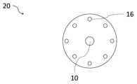
도 1은 전극 몸체를 도시한 개략적 구성도이다.
도 2는 연결된 전기 도체 및 절연재 슬리브를 포함한 전극 몸체를 도시한 개략도이다.
도 3은 캐리어 재료를 포함한 도 2에서의 전극 몸체를 도시한 개략도이다.
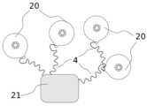
도 4는 전기 도체를 매개로 에너지원에 연결되어 있는 복수의 전극 몸체를 도시한 개략도이다.
도 5는 캐리어 재료 내에 매립된 전극 몸체를 개략적으로 도시한 측면도이다.
도 6은 전극 어셈블리를 개략적으로 도시한 상면도이다.
도 7은 캐리어 재료 내에 매립된 전극들을 포함한 전극 어셈블리를 개략적으로 도시한 측면도이다.
도 8은 전극 어셈블리의 제조를 위한 방법을 나타낸 개략도이다.
도 9는 전극 어셈블리의 제조를 위한 추가 방법을 나타낸 개략도이다.Figure 1 is a schematic diagram illustrating an electrode body.
Figure 2 is a schematic diagram illustrating an electrode body including connected electrical conductors and an insulating sleeve.
Figure 3 is a schematic diagram illustrating the electrode body in Figure 2 including a carrier material.
Figure 4 is a schematic diagram illustrating a plurality of electrode bodies connected to an energy source via an electrical conductor.
Figure 5 is a side view schematically illustrating an electrode body embedded in a carrier material.
Figure 6 is a top view schematically illustrating the electrode assembly.
FIG. 7 is a side view schematically illustrating an electrode assembly including electrodes embedded within a carrier material.
Figure 8 is a schematic diagram showing a method for manufacturing an electrode assembly.
Figure 9 is a schematic diagram illustrating an additional method for manufacturing an electrode assembly.
도 1에는, 전극 몸체(20)의 개략적 구성이 도시되어 있다. 이 경우, 도시된 전극 몸체(20)는 원형 전극으로서 형성된다. 그러나 다른 전극 형태들도 생각해볼 수 있다. 분명하게는, 전극 몸체(20)는 생물 상에서의 체결을 위한 체결 개구부(10)를 포함한다. 또한, 분명하게는, 전극 몸체(20)는 자신의 주연에 걸쳐 분포 배치되는 리세스부들(16)을 포함한다. 리세스부들(16)을 통해, 예컨대 도 3에 도시된 캐리어 재료(6) 내에서 전극 몸체(20)의 개선된 고정이 달성된다. 전극 몸체(20)를 수용하는, 예컨대 도 6에 도시된 전극 어셈블리(1)의 제조 동안, 캐리어 재료(6)는 맨 먼저 액상 상태이며, 캐리어 재료(6)는 리세스들(16) 내에 분포되고 그에 따라 전극 몸체(20)는 캐리어 재료(6)의 경화 후에 고정되어 유지될 수 있다.In Fig. 1, a schematic configuration of an electrode body (20) is illustrated. In this case, the illustrated electrode body (20) is formed as a cylindrical electrode. However, other electrode shapes are also conceivable. Obviously, the electrode body (20) comprises a fastening opening (10) for fastening in a biological phase. Furthermore, obviously, the electrode body (20) comprises recessed portions (16) which are distributed over its circumference. Via the recessed portions (16), an improved fixation of the electrode body (20) is achieved, for example, in the carrier material (6) illustrated in Fig. 3. During the production of an electrode assembly (1) containing the electrode body (20), for example as illustrated in Fig. 6, the carrier material (6) is first of all in a liquid state, the carrier material (6) is distributed in the recesses (16) so that the electrode body (20) can be fixed and held after hardening of the carrier material (6).
도 2에는, 연결된 전기 도체(4)를 포함하여 마찬가지로 원형 전극으로서 형성된 전극 몸체(20)가 개략적으로 도시되어 있다. 전기 도체(4)의 접속을 위해, 전극 몸체(20)에는, 예컨대 전극 몸체(20)의 유효 자극 표면을 감소시키지 않기 위해, 원형 전극의 원형 표면에서부터 돌출되는 돌출부로서 형성될 수 있는 도체 단자(7)가 제공된다. 도체 단자(7)는 본 실시예에서 접선 도체 단자(7)로서 형성되며, 그럼으로써 연결된 전기 도체(4)는 접선처럼 전극 몸체(20)에 접촉하게 된다. 이로써, 접속 위치는 인장력이 발생할 때 하중 완화되고 그에 따라 결과적으로 전극의 고장을 야기하는 도체 단자(7)의 손상은 방지된다. 전기 도체(4)는 전극 몸체(20)의 도체 단자(7) 상에 납땜되거나 용접될 수 있으며, 바람직하게는 연결 위치는 외부 영향들에 대해 예컨대 에폭시 수지로 밀봉된다. 여기서는, 전기 도체(4)가 곡류 형태로 연장되는 점이 확인된다. 이는, 특히 도체 단자(7) 상의 전기 도체의 접속 영역에서, 예컨대 전극 몸체를 수용하는 전극 어셈블리(1)를 굽히고 당기는 것을 통해 발생할 수 있는 전기 도체(4)의 하중 재하를 감소시킨다.In Fig. 2, an electrode body (20) is schematically illustrated, which is likewise formed as a circular electrode, including a connected electrical conductor (4). For the connection of the electrical conductor (4), the electrode body (20) is provided with a conductor terminal (7), which can be formed as a projection protruding from the circular surface of the circular electrode, for example, so as not to reduce the effective stimulating surface of the electrode body (20). The conductor terminal (7) is formed in this embodiment as a tangential conductor terminal (7), whereby the connected electrical conductor (4) comes into contact with the electrode body (20) in a tangential manner. As a result, the connection point is relieved of the load when tensile forces occur, and damage to the conductor terminal (7), which would consequently lead to a failure of the electrode, is prevented. The electrical conductor (4) can be soldered or welded onto the conductor terminal (7) of the electrode body (20), preferably the connection point is sealed against external influences, for example with an epoxy resin. Here, it is noted that the electrical conductor (4) extends in a meandering manner. This reduces the load loading of the electrical conductor (4), which may occur, for example, through bending and pulling of the electrode assembly (1) housing the electrode body, particularly in the connection area of the electrical conductor on the conductor terminal (7).
또한, 여기서는, 전극 몸체(20)가 체결 개구부(10)를 포함하고, 이 체결 개구부 내에는 절연재 슬리브(11)가 삽입되는 점도 확인된다. 그렇게 하여, 전극 몸체(20)는 체결 요소, 예컨대 나사를 매개로 절연재 슬리브(11)를 통과하여 생물의 두개골 상에 체결될 수 있다. 이 경우, 절연재 슬리브(11)는, 너무 큰 토크가 전극 몸체(20)로 전달되고 그에 따라 전극 몸체를 손상시키는 점을 방지한다. 또한, 전극 몸체(20)와 체결 요소 간의 의도되지 않는 전류 흐름도 방지된다. 이 경우, 절연재 슬리브(11)는 예컨대 폴리에테르에테르케톤으로 구성될 수 있다. 체결 개구부(10)를 매개로 하는 전극 몸체(20)의 체결을 통해, 목표 부분에서 의도되는 전계를 생성할 수 있는 전극 몸체(20)의 정확한 위치가 보장될 수 있다.In addition, it is confirmed here that the electrode body (20) includes a fastening opening (10), into which an insulating sleeve (11) is inserted. In this way, the electrode body (20) can be fastened to the skull of a living organism by passing through the insulating sleeve (11) via a fastening element, for example a screw. In this case, the insulating sleeve (11) prevents an excessively large torque from being transmitted to the electrode body (20) and thus damaging the electrode body. In addition, an unintended current flow between the electrode body (20) and the fastening element is also prevented. In this case, the insulating sleeve (11) can be composed of, for example, polyetheretherketone. Through the fastening of the electrode body (20) via the fastening opening (10), an exact position of the electrode body (20) capable of generating an intended electric field in the target area can be ensured.
도 3에는, 도 2에서의 전극 몸체(20)가 도시되어 있다. 본 도면에서는, 전극 몸체(20)가 빗금으로 표시된 캐리어 재료(6) 내에 매립되어 있는 점이 확인된다. 캐리어 재료(6)는 전기 절연성이며, 그리고 자극 표면을 제외하고 전극 몸체(20)를 완전하게 에워싼다. 이 경우, 캐리어 재료(6)는 예컨대 실리콘으로 구성될 수 있다. 그러나 적용에 따른 특성들(생체 적합성, 가요성, 전기 절연성 등)을 충족하는 다른 재료들 역시도 생각해볼 수 있다. 캐리어 재료(6)는 특히 전극 어셈블리(1)의 위쪽에 배치되는 구조부 내에서 전극 몸체(20)의 간단한 배치 및 고정을 가능하게 한다. 또한, 전기 절연성 캐리어 재료(6)를 통해 누설 및 단락 전류들의 발생은 방지되거나 또는 적어도 감소된다.In Fig. 3, the electrode body (20) from Fig. 2 is illustrated. In this drawing, it can be seen that the electrode body (20) is embedded in a carrier material (6) indicated by hatching. The carrier material (6) is electrically insulating and completely surrounds the electrode body (20) except for the stimulation surface. In this case, the carrier material (6) can consist of, for example, silicone. However, other materials that meet the properties required for the application (biocompatibility, flexibility, electrical insulation, etc.) are also conceivable. The carrier material (6) enables a simple arrangement and fixation of the electrode body (20) in particular within the structural section arranged above the electrode assembly (1). Furthermore, the occurrence of leakage and short-circuit currents is prevented or at least reduced by the electrically insulating carrier material (6).
또한, 전극 몸체(20)는 리세스들(16)을 포함한다. 제조 공정에서 맨 먼저 액상인 캐리어 재료(6)는 리세스들(16) 내로 파고들고 그에 따라 경화 후에 캐리어 재료(6) 내에서 전극 몸체(20)의 고정을 보조한다.Additionally, the electrode body (20) includes recesses (16). In the manufacturing process, the liquid carrier material (6) first penetrates into the recesses (16) and, after hardening, assists in fixing the electrode body (20) within the carrier material (6).
도 4에는, 전기 도체(4)를 매개로 에너지원(21)과 연결되어 있는 복수의, 요컨대 총 4개의 전극 몸체(20)가 개략적으로 도시되어 있다. 에너지원(21)은, 전극 몸체에 전류를 공급하고 이로써 전극 몸체의 작동을 가능하게 하기 위해, 공급원으로서 형성될 수 있다. 그 대안으로, 또는 그에 추가로, 에너지원(21)은, 목표한 바대로 전극들에서 전기 자극 신호들을 생성하기 위해, 신호원으로서 형성될 수 있다.In Fig. 4, a plurality of electrode bodies (20), in short, a total of four, are schematically illustrated, which are connected to an energy source (21) via an electrical conductor (4). The energy source (21) may be formed as a supply source in order to supply current to the electrode bodies and thereby enable operation of the electrode bodies. Alternatively, or additionally, the energy source (21) may be formed as a signal source in order to generate electrical stimulation signals at the electrodes as desired.
여기서는, 전극 몸체(20)가 에너지원(21)과 직접적으로 연결되지 않아도 되는 점이 확인된다. 동일하게, 일측 전극 몸체(20)가 추가 전극 몸체(20)와 연결되고, 이 추가 전극 몸체는 다시금 에너지원(21)에 연결되어 있는 배치 역시도 생각해볼 수 있다. 이를 위해, 각각의 전기 도체(4)는 하나의 전극 몸체(20)와 에너지원(21) 사이에서, 또는 2개의 전극 몸체들(20) 사이에서 연장된다. 또한, 추가 전극 몸체(20)를 매개로 에너지원(21)과 전극 몸체(20)의 간접적인 연결을 통해, 상대적으로 더 긴 전기 도체들(4)을 앞에 둘 필요 없이, 또는 상기 전기 도체들을 연장하고 그렇게 하여 상대적으로 더 높은 하중 위험에 노출시키지 않고, 추가로 에너지원(21)으로부터 이격된 조직 부분에 도달될 수 있다. 또한, 자명한 사실로서, 복수 개, 다시 말해 2개 이상의 전극 몸체(20) 역시도 하나의 추가 전극 몸체(20)와 연결될 수 있다. 전기 도체들(4)의 연결을 위해 제공되는 도체 단자(7) 상에는 복수의 도체들(4)이 예컨대 서로 나란히 납땜될 수 있다. 원칙상, 물론 마찬가지로, 공간상 이격된 전극 몸체(20)를 위해 상대적으로 더 긴 하나의 도체(4)를 이용하고 공간상 상대적으로 더 가까운 추가 전극 몸체(20)를 분기로서 전기적으로 결합하는 점 역시도 생각해볼 수 있다.Here, it can be seen that the electrode body (20) does not have to be directly connected to the energy source (21). Likewise, an arrangement is also conceivable in which one electrode body (20) is connected to an additional electrode body (20), which is in turn connected to the energy source (21). For this purpose, each electric conductor (4) extends between one electrode body (20) and the energy source (21), or between two electrode bodies (20). Furthermore, through the indirect connection of the energy source (21) and the electrode body (20) via the additional electrode body (20), it is possible to reach tissue parts that are further away from the energy source (21) without having to place relatively longer electric conductors (4) in front, or without extending said electric conductors and thereby exposing them to a relatively higher load risk. Furthermore, it goes without saying that a plurality of, that is to say two or more, electrode bodies (20) can also be connected to one additional electrode body (20). A plurality of conductors (4) can, for example, be soldered side by side to the conductor terminals (7) provided for the connection of the electrical conductors (4). In principle, it is also conceivable to use a relatively longer conductor (4) for the spatially spaced electrode bodies (20) and to electrically connect the spatially relatively closer additional electrode bodies (20) as branches.
도 5에는, 캐리어 재료(6) 내에 매립된 전극 몸체(20)가 측면도로 도시되어 있다. 여기서는, 전극 몸체(20)가 관통 체결 개구부(10)를 포함하고, 체결 개구부(10) 내에는 절연재 슬리브(11)가 배치되며, 전극 몸체(20)는 미도시한 체결 요소에 의해 절연재 슬리브(11)를 통해 생물의 골상 또는 기타 조직 구조 상에 체결될 수 있는 점이 확인된다. 분명하게는, 캐리어 재료(6)는 전극 몸체(20)의 접촉 측(15)에 외주를 따라 연장되는 제1 실링 립(14)을 포함한다. 이 경우, 외주를 따라 연장되는 실링 립(14)은 캐리어 재료(6)의 동일한 재료로 일체형으로 형성될 수 있다. 이런 방식으로, 전극 몸체(20)는, 비평면성에도 불구하고, 전극 몸체(20) 상에 변형이 발생하지 않으면서, 이식될 지점 상에 체결될 수 있다. 이 경우, 외주를 따라 연장되는 실링 립(14)이 전극 몸체(20)보다 부분적으로 더 돌출됨으로써 캐리어 재료(6) 내에 전극 몸체(20)의 개선된 고정이 가능해지게 하는 점도 생각해볼 수 있다. 또한, 전극 몸체(20)가 접촉 측(15)에서 노출되고 다른 측에서는 캐리어 재료(6)에 의해 절연 방식으로 덮여 있는 점도 확인할 수 있다. 그에 따라, 전극 몸체(20)는 캐리어 재료(6) 내에 매립된다. 이는, 바깥쪽을 향해 전극 몸체(20)의 효율적인 절연을 가능하게 하고 이와 동시에 접촉 측(15)으로 향하는 신체 부분에서 의도되는 전계의 생성을 보장한다. 또한, 절연재 슬리브(11)가, 외주를 따라 연장되어 상기 효과를 추가로 촉진하는 미도시된 제2 실링 립을 포함하는 점 역시도 생각해볼 수 있다.In Fig. 5, an electrode body (20) embedded in a carrier material (6) is illustrated in a side view. Here, it can be seen that the electrode body (20) includes a through-fastening opening (10), an insulating sleeve (11) is arranged within the fastening opening (10), and that the electrode body (20) can be fastened to a bone or other tissue structure of a living organism via the insulating sleeve (11) by means of a fastening element not shown. Specifically, the carrier material (6) includes a first sealing lip (14) extending along the outer periphery on the contact side (15) of the electrode body (20). In this case, the sealing lip (14) extending along the outer periphery can be formed integrally from the same material of the carrier material (6). In this way, the electrode body (20) can be fastened to the implantation site without causing deformation on the electrode body (20), despite its non-planarity. In this case, it is conceivable that the sealing lip (14) extending along the outer circumference partially protrudes further than the electrode body (20), thereby enabling an improved fixation of the electrode body (20) within the carrier material (6). It is also conceivable that the electrode body (20) is exposed on the contact side (15) and is insulatively covered on the other side by the carrier material (6). Accordingly, the electrode body (20) is embedded within the carrier material (6). This enables an efficient insulation of the electrode body (20) towards the outside and at the same time ensures the generation of the intended electric field in the body part directed towards the contact side (15). It is also conceivable that the insulating sleeve (11) comprises a not-shown second sealing lip extending along the outer circumference, which further promotes the above-described effect.
도 6에는, 전극 어셈블리(1)가 개략적인 상면도로 도시되어 있다. 명료화를 위해, 전극 어셈블리(1)는 부분적으로 임의로 절단되어 있으며, 전극 어셈블리(1)의 상이한 층들이 확인된다. 전극 어셈블리(1)는 일차 전극(2)을 포함하며, 일차 전극(2)은 4개의 이차 전극(3)에 의해 에워싸인다. 이 경우, 이차 전극들(3)은 일차 전극(2) 둘레의 하나의 공통 원형 경로 상에 배치된다. 이 경우, 일차 전극(2)과 이차 전극들(3)은 각각 하나의 전기 도체(4)를 매개로 접속 요소(5)와 연결되며, 접속 요소(5)는 에너지원(21)에 접속하도록 구성된다. 일차 및 이차 전극들(2, 3)은 바람직한 방식으로 전술한 전극 몸체(20)의 추가 특징들을 포함할 수 있다.In Fig. 6, an electrode assembly (1) is shown in a schematic top view. For clarity, the electrode assembly (1) is partially arbitrarily cut away, so that the different layers of the electrode assembly (1) are visible. The electrode assembly (1) comprises a primary electrode (2), which is surrounded by four secondary electrodes (3). In this case, the secondary electrodes (3) are arranged on one common circular path around the primary electrode (2). In this case, the primary electrode (2) and the secondary electrodes (3) are each connected via one electrical conductor (4) to a connecting element (5), which is configured to be connected to an energy source (21). The primary and secondary electrodes (2, 3) can preferably comprise further features of the electrode body (20) described above.
분명하게는, 컴포넌트들[일차 전극(2), 이차 전극들(3), 전기 도체들(4) 및 접속 요소(5)]은 하나의 캐리어 재료(6) 상에 배치된다. 이 경우, 캐리어 재료(6)는 예컨대 실리콘으로 구성될 수 있다. 그러나 적용에 따른 특성들(생체 적합성, 가요성, 전기 절연성 등)을 충족하는 다른 재료들 역시도 생각해볼 수 있다. 분명하게는, 일차 전극(2) 및 이차 전극들(3), 그리고 전기 도체들(4)은 캐리어 재료(6) 내에 매립된다. 또한, 분명하게는, 접속 요소(5)로부터 보다 더 멀리 이격된 후방 이차 전극들(3)의 전기 도체들(4)은 일차 전극(1) 둘레에 곡류 형태로 배치되고, 곡류 형태의 배치는 일차 전극(2) 둘레의 만곡된 경로 상에서 진행된다. 이런 방식으로, 전기 도체들(4)에 작용하는 하중 재하 및 그에 따른 이차 전극들(3)의 고장 확률 역시도 감소될 수 있다. 전기 도체들(4)은 연결 위치를 매개로 이차 전극들(3)과 연결되며, 연결 위치는 접선 도체 단자(7)이다. 이 경우, 전기 도체(4)는 이차 전극(3) 상에 납땜되거나 용접될 수 있으며, 바람직하게는 연결 위치는 외부 영향들에 대해 예컨대 에폭시 수지로 밀봉된다.It is apparent that the components (primary electrode (2), secondary electrodes (3), electrical conductors (4) and connection element (5)) are arranged on a carrier material (6). In this case, the carrier material (6) can consist of, for example, silicone. However, other materials are also conceivable which meet the properties required for the application (biocompatibility, flexibility, electrical insulation, etc.). It is apparent that the primary electrode (2) and the secondary electrodes (3) as well as the electrical conductors (4) are embedded in the carrier material (6). It is also apparent that the electrical conductors (4) of the rear secondary electrodes (3), which are spaced further away from the connection element (5), are arranged in a meandering shape around the primary electrode (1), the meandering arrangement running along a curved path around the primary electrode (2). In this way, the load acting on the electrical conductors (4) and thus also the probability of failure of the secondary electrodes (3) can be reduced. The electric conductors (4) are connected to the secondary electrodes (3) via a connection location, the connection location being a tangential conductor terminal (7). In this case, the electric conductors (4) can be soldered or welded onto the secondary electrode (3), and preferably, the connection location is sealed against external influences, for example, with an epoxy resin.
전극 어셈블리(1) 상에는 수술용 메쉬의 형태인 보강 요소(8)가 배치되며, 보강 요소(8)는 캐리어 재료의 외부 층들 사이에 삽입된다. 이 경우, 보강 요소(8)는 내인열성의 개선을 위해 일차 전극(2)과 이차 전극들(3) 사이에 배치된다.A reinforcing element (8) in the form of a surgical mesh is placed on the electrode assembly (1), and the reinforcing element (8) is inserted between the outer layers of the carrier material. In this case, the reinforcing element (8) is placed between the primary electrode (2) and the secondary electrodes (3) to improve the heat resistance.
여기서는, 접속 요소(5)가 접촉 섹션(9) 상에 배치되고, 접촉 섹션(9)은 전극 어셈블리(1)로부터 측면으로 돌출되고 폭(B)보다 더 큰 길이(L)를 보유하는 점을 확인할 수 있다. 접촉 섹션(9)의 길이가 긴 구성에는, 접속 요소(5)가 일차 전극(2) 및 이차 전극들(3)로부터 분리되고, 접촉 섹션(9)에 작용하는 힘들은, 이들 힘이 전극 어셈블리(1)로 전혀 전달되지 않거나 약하게 전달되는 정도로, 접촉 섹션(9)의 길이(L)를 통해 보상된다는 장점이 있다. 접촉 섹션(9)의 가요성을 보장하기 위해, 바람직하게는, 보강 요소(8)는 접촉 섹션(9) 상에 배치되지 않고 오직 접촉 섹션(9)을 향하는 전이 영역까지만 연장될 수 있거나, 또는 뒤틀림 방지부(kink protection)와 유사하게 점진적으로 작아지면서 접촉 섹션(9) 안쪽으로 연장될 수 있다.Here, it can be seen that the connecting element (5) is arranged on the contact section (9), and that the contact section (9) protrudes laterally from the electrode assembly (1) and has a length (L) that is greater than the width (B). The long configuration of the contact section (9) has the advantage that the connecting element (5) is separated from the primary electrode (2) and the secondary electrodes (3), and that the forces acting on the contact section (9) are compensated by the length (L) of the contact section (9) to such an extent that these forces are not transmitted at all or are only weakly transmitted to the electrode assembly (1). In order to ensure the flexibility of the contact section (9), the reinforcing element (8) can preferably not be arranged on the contact section (9) but can extend only as far as the transition region towards the contact section (9), or can extend gradually smaller into the contact section (9) similar to a kink protection.
전극 어셈블리(1)는, 예컨대 생물의 두피와 두개골 사이에 이식되도록 구성된다. 이 경우, 일차 전극(2)과 이차 전극들(3)은 체결 개구부들(10)을 포함하며, 각각 하나의 체결 개구부(10) 내에는 하나의 절연재 슬리브(11)가 삽입된다. 그런 다음, 전극 어셈블리(1)는 예컨대 나사들과 같은 체결 요소들을 매개로 절연재 슬리브(11)를 통과하여 생물의 두개골 상에 체결될 수 있다. 이 경우, 절연재 슬리브(11)는, 너무 큰 토크가 일차 전극(2) 또는 이차 전극(3)으로 전달되고 그에 따라 이들 전극을 손상시키는 점을 방지한다. 또한, 전극들[일차 전극(2) 및 이차 전극들(3)]과 체결 요소 간의 의도되지 않는 전류 흐름도 방지된다. 이 경우, 절연재 슬리브(11)는 예컨대 폴리에테르에테르케톤으로 구성될 수 있다. 각각의 전극들[일차 전극(2) 및 이차 전극들(3)] 상에서 체결 개구부들(10)을 매개로 하는 전극 어셈블리(1)의 체결을 통해, 목표 부분에서 의도되는 전계를 생성할 수 있는 전극들의 정확한 위치가 보장될 수 있다. 또한, 여기서는, 접촉 섹션(9) 상에, 생물 상에 나사 체결을 위한 2개의 체결 요소(12)가 배치되는 점도 확인할 수 있다. 접촉 섹션(9)은 체결 요소들(12)을 통해 생물의 두개골 상에 체결될 수 있다.The electrode assembly (1) is configured to be implanted, for example, between the scalp and the skull of a living organism. In this case, the primary electrode (2) and the secondary electrodes (3) have fastening openings (10), into each of which an insulating sleeve (11) is inserted. The electrode assembly (1) can then be fastened to the skull of the living organism by means of fastening elements, for example screws, through the insulating sleeve (11). In this case, the insulating sleeve (11) prevents excessively high torques from being transmitted to the primary electrode (2) or the secondary electrode (3) and thus damaging these electrodes. In addition, unintended current flow between the electrodes (primary electrode (2) and the secondary electrodes (3)) and the fastening elements is also prevented. In this case, the insulating sleeve (11) can be composed of, for example, polyetheretherketone. By fastening the electrode assembly (1) via the fastening openings (10) on the respective electrodes (primary electrode (2) and secondary electrodes (3)), the exact positioning of the electrodes capable of generating the intended electric field at the target area can be ensured. In addition, it can be confirmed here that two fastening elements (12) for screw fastening to the living organism are arranged on the contact section (9). The contact section (9) can be fastened to the skull of the living organism via the fastening elements (12).
분명하게는, 전극 어셈블리(1)는 각각 이차 전극들(3) 사이에 공동부(13)를 포함한다. 공동부들(13)은 특히 이차 전극들(3)의 영역에서 전극 어셈블리(1)의 가요성을 증가시킨다. 생물의 뼈는 일반적으로 평면으로 형성되어 있지 않지만, 전극들[일차 전극(2) 및 이차 전극들(3)]은 정확하게 뼈 상에 포지셔닝되어야 하기 때문에, 바람직하게는, 전극들(2, 3)이 그에 상응하게 뼈에 가깝게 체결될 수 있고 전극 어셈블리(1)는 뼈 형상에 적합하게 매칭될 수 있도록 하기 위해, 전극 어셈블리(1)의 가요성은 그에 상응하게 높다.Specifically, the electrode assembly (1) comprises a cavity (13) between the secondary electrodes (3). The cavity (13) increases the flexibility of the electrode assembly (1) particularly in the region of the secondary electrodes (3). Since the bones of a living organism are generally not formed flat, but the electrodes (primary electrode (2) and secondary electrodes (3)) have to be positioned precisely on the bone, the flexibility of the electrode assembly (1) is preferably correspondingly high so that the electrodes (2, 3) can be fastened correspondingly close to the bone and the electrode assembly (1) can be suitably matched to the bone shape.
도 7에는, 캐리어 재료(6) 내 일차 전극(2) 및 이차 전극(3)이 개략적으로 측면도로 도시되어 있다. 여기서는, 일차 전극(2)과 이차 전극(3)이 각각 하나의 관통 체결 개구부(10)를 포함하고, 체결 개구부(10) 내에는 하나의 절연재 슬리브(11)가 배치되며, 전극 어셈블리(1)는 체결 요소들에 의해 절연재 슬리브(11)를 통해 생물의 골상 또는 조직 구조 상에 체결될 수 있는 점이 확인된다.In Fig. 7, a primary electrode (2) and a secondary electrode (3) within a carrier material (6) are schematically illustrated in a side view. Here, it is confirmed that the primary electrode (2) and the secondary electrode (3) each include one through-fastening opening (10), and an insulating sleeve (11) is arranged within the fastening opening (10), and that the electrode assembly (1) can be fastened to a bone or tissue structure of a living organism via the insulating sleeve (11) by means of fastening elements.
분명하게는, 캐리어 재료(6)는, 이차 전극들(3)의 노출된 접촉 측(15)에 외주를 따라 연장되는 제1 실링 립(14)을 포함한다. 이 경우, 외주를 따라 연장되는 실링 립(14)은 캐리어 재료(6)의 동일한 재료로 일체형으로 형성될 수 있다. 이런 방식으로, 전극 어셈블리(1)는, 비평면성에도 불구하고, 이차 전극들(3) 상에 변형이 발생하지 않으면서, 이식될 지점 상에 체결될 수 있다. 이 경우, 외주를 따라 연장되는 실링 립(14)이 이차 전극(3)보다 부분적으로 더 돌출됨으로써 캐리어 재료(6) 내에 이차 전극(3)의 개선된 고정이 가능해지게 하는 점도 생각해볼 수 있다. 또한, 이차 전극들(3)이 접촉 측(15)에서 노출되고 다른 측에서는 캐리어 재료(6)에 의해 절연 방식으로 덮여 있는 점도 확인할 수 있다. 그에 따라, 이차 전극들(3)은 캐리어 재료(6) 내에 매립된다. 이는, 바깥쪽을 향해 이차 전극들(3)의 효율적인 절연을 가능하게 하고 이와 동시에 접촉 측(15)으로 향하는 신체 부분에서 의도되는 전계의 생성을 보장한다. 또한, 절연재 슬리브(11)가, 외주를 따라 연장되어 상기 효과를 추가로 촉진하는 제2 실링 립(17)을 포함하는 점 역시도 생각해볼 수 있다. 바람직하게는, 전극 어셈블리(1)의 모든 전극들은 상기 구성들을 포함한다.Specifically, the carrier material (6) comprises a first sealing lip (14) extending along the outer circumference on the exposed contact side (15) of the secondary electrodes (3). In this case, the sealing lip (14) extending along the outer circumference can be formed integrally from the same material of the carrier material (6). In this way, the electrode assembly (1) can be fastened onto the implanted point without causing deformation on the secondary electrodes (3), despite the non-planarity. In this case, it is also conceivable that the sealing lip (14) extending along the outer circumference partially protrudes further than the secondary electrode (3), thereby enabling an improved fixation of the secondary electrode (3) within the carrier material (6). It can also be seen that the secondary electrodes (3) are exposed on the contact side (15) and are insulatively covered on the other side by the carrier material (6). Accordingly, the secondary electrodes (3) are embedded within the carrier material (6). This enables efficient insulation of the secondary electrodes (3) towards the outside and at the same time ensures the generation of the intended electric field at the body part towards the contact side (15). It is also conceivable that the insulating sleeve (11) comprises a second sealing lip (17) extending along the outer periphery, which further promotes the effect. Preferably, all electrodes of the electrode assembly (1) comprise said configurations.
도 8에는, 생물의 조직의 전기 자극을 위한 전극 어셈블리의 제조를 위한 방법, 특히 전술한 특징들에 따른 전극 어셈블리(1)의 제조를 위한 방법이 개략적으로 도시되어 있다.FIG. 8 schematically illustrates a method for manufacturing an electrode assembly for electrical stimulation of a biological tissue, and in particular a method for manufacturing an electrode assembly (1) according to the above-described features.
방법 단계 a)에서, 예컨대 천공 공정을 통해, 또는 예컨대 레이저를 이용한 절단 공정을 통해 적합한 두께를 갖는 전극 재료의 포일에서 전극 몸체들(20)이 제조된다. 선택적인 방법 단계 b)에서, 전극 표면의 적어도 일부분 상에 표면 코팅층이 적층되고, 그리고/또는 표면의 구조화가 제공된다. 방법 단계 c)에서, 각자의 전극 몸체(20) 상에 전기 도체(4)가 부착된다. 선택적인 방법 단계 d)에서, 에폭시 수지 또는 다른 전기 절연체가 연결 위치 상에 도포된다. 방법 단계 e)에서, 전극 어셈블리(1)의 형태는 캐리어 재료(6)로 주조된다. 방법 단계 f)에서, 전극 몸체(20), 그리고 선택적으로 전기 도체(40) 및 선택적으로 보강 요소(8)가 매립된다. 방법 단계 g)에서, 전기 도체(4)는 전극 어셈블리(1)의 접촉 섹션(9)에 연결된다.In method step a), electrode bodies (20) are produced from a foil of electrode material having a suitable thickness, for example by means of a perforation process or by means of a cutting process using a laser. In optional method step b), a surface coating layer is applied onto at least part of the electrode surface and/or a structuring of the surface is provided. In method step c), an electrical conductor (4) is attached to the respective electrode body (20). In optional method step d), an epoxy resin or another electrical insulator is applied onto the connection points. In method step e), the shape of the electrode assembly (1) is cast from a carrier material (6). In method step f), the electrode body (20), and optionally an electrical conductor (40) and optionally a reinforcing element (8) are embedded. In method step g), the electrical conductor (4) is connected to the contact section (9) of the electrode assembly (1).
도 9에는, 생물의 조직의 전기 자극을 위한 전극 어셈블리(1)의 제조를 위한 추가 방법, 특히 전술한 특징들에 따른 전극 어셈블리(1)의 제조를 위한 추가 방법이 개략적으로 도시되어 있다. 방법 단계 a)에서, 캐리어 재료(6)가 공급된다. 방법 단계 b)에서, 하나 또는 복수의 전극 몸체(20)가 기상 증착 공정을 통해, 그리고/또는 갈바닉 증착을 통해 캐리어 재료(6) 상에 제조된다. 선택적인 방법 단계 c)에서, 전극 표면의 적어도 일부분 상에 표면 코팅층이 적층되고, 그리고/또는 표면의 구조화가 제공된다. 선택적인 방법 단계 d)에서, 캐리어 재료(6)는 추가 절연성 캐리어 재료 내에 매립된다.In Fig. 9, a further method for producing an electrode assembly (1) for electrical stimulation of a biological tissue is schematically illustrated, in particular a further method for producing an electrode assembly (1) according to the aforementioned features. In method step a), a carrier material (6) is supplied. In method step b), one or more electrode bodies (20) are produced on the carrier material (6) by means of a vapor deposition process and/or by means of galvanic deposition. In optional method step c), a surface coating layer is applied on at least a part of the electrode surface and/or a structuring of the surface is provided. In optional method step d), the carrier material (6) is embedded in a further insulating carrier material.
도면들은 가능한 실시예로서 해석된다. 그 밖에도, 본 발명에 따른 교시의 다른 형태들도 생각해볼 수 있다. 또한, 실시예의 구성들은 서로 불가분하게 결합되어 있지 않으며, 그런 까닭에 예컨대 본 발명의 실시예는 실시예의 특별히 기술되는 구성들에 종속되지 않는다. 이렇게, 예컨대 일차 전극(2), 이차 전극들(3), 공동부들(13) 및/또는 리세스들(16)과 같은 개별 요소들의 예컨대 개수 또는 지지의 가변성을 언제나 생각해볼 수 있다.The drawings are to be interpreted as possible embodiments. In addition, other forms of teaching according to the invention are conceivable. Furthermore, the components of the embodiments are not inseparably connected to one another, so that for example an embodiment of the invention is not dependent on the specifically described components of the embodiments. In this way, it is always conceivable to vary the number or the support of individual elements, such as for example the primary electrode (2), the secondary electrodes (3), the cavities (13) and/or the recesses (16).
Claims (40)
Translated fromKorean전극 몸체(20)는 생물의 두개골과 두피 사이의 한 지점상에 배치되도록 구성되고, 전극 몸체(20)는 교류 전류 펄스 또는 직류 전류 펄스를 통한 조직의 전기 자극을 생성하기 위해 생물의 조직과 접촉되도록 구성되는 자극 표면을 포함하고, 전극 몸체(20)는 주연에 걸쳐 분포 배치되어 캐리어 재료(6) 내에서 전극 몸체(20)를 고정하기 위한 리세스부(16)들을 포함하고,
전극 몸체(20)는 생물의 조직상에 전극 몸체(20)를 고정하기 위한 고정 구조부를 포함하고, 고정 구조부는 전극 몸체(20)에 대해 기계적 체결 요소를 절연하도록 구성되는 절연재 슬리브(11)를 포함하는 것을 특징으로 하는, 전극 어셈블리의 전극 몸체(20).In the electrode body (20) of the electrode assembly for electrical stimulation of a biological tissue or for nerve stimulation,
The electrode body (20) is configured to be placed on a point between the skull and scalp of a living organism, the electrode body (20) includes a stimulation surface configured to be in contact with the tissue of the living organism to generate an electrical stimulation of the tissue through an alternating current pulse or a direct current pulse, and the electrode body (20) includes recessed portions (16) distributed over the main body to fix the electrode body (20) within the carrier material (6).
An electrode body (20) of an electrode assembly, characterized in that the electrode body (20) includes a fixing structure for fixing the electrode body (20) to a tissue of a living organism, and the fixing structure includes an insulating sleeve (11) configured to insulate a mechanical fastening element with respect to the electrode body (20).
하나의, 복수의 또는 모든 일차 전극(2)은 각각 전극 몸체(20)를 통해 형성되고, 그리고/또는 하나의, 복수의 또는 모든 이차 전극(3)은 각각 전극 몸체(20)를 통해 형성되고, 일차 전극(2) 및 이차 전극(3)은 공통 캐리어 재료(6)상에 배치되고, 캐리어 재료(6)는 전극 몸체(20)의 노출된 접촉 측(15)에서 적어도 부분적으로 외주를 따라 연장되는 제1 실링 립(14)을 포함하고, 적어도 부분적으로 외주를 따라 연장되는 제1 실링 립(14)은 0.05㎜ 내지 1㎜ 또는 0.1㎜ 내지 0.3㎜만큼 적어도 부분적으로 하나의, 복수의 또는 모든 일차 전극(2)보다 더 돌출되고, 그리고/또는 적어도 부분적으로 하나의, 복수의 또는 모든 이차 전극(3)보다 더 돌출되고, 전극 몸체(20)는 생물의 조직상에 전극 몸체(20)를 고정하기 위한 고정 구조부를 포함하고, 고정 구조부는 전극 몸체(20)에 대해 기계적 체결 요소를 절연하도록 구성되는 절연재 슬리브(11)를 포함하는 것을 특징으로 하는, 전극 어셈블리(1).In an electrode assembly (1) for electrical stimulation of a biological tissue or an electrode assembly (1) for nerve stimulation, comprising at least one primary electrode (2) and at least one secondary electrode (3),
One, a plurality or all primary electrodes (2) are each formed through an electrode body (20), and/or one, a plurality or all secondary electrodes (3) are each formed through an electrode body (20), the primary electrode (2) and the secondary electrodes (3) are arranged on a common carrier material (6), the carrier material (6) comprises a first sealing lip (14) extending at least partly along the outer periphery on the exposed contact side (15) of the electrode body (20), the first sealing lip (14) extending at least partly along the outer periphery protrudes at least partly further than one, a plurality or all primary electrodes (2) by 0.05 mm to 1 mm or 0.1 mm to 0.3 mm, and/or at least partly further than one, a plurality or all secondary electrodes (3), the electrode body (20) comprises a fixing structure for fixing the electrode body (20) on a tissue of a living organism, the fixing structure mechanically engaging the electrode body (20). An electrode assembly (1), characterized by including an insulating sleeve (11) configured to insulate a fastening element.
a) 두께를 갖는 전극 재료의 포일에서 레이저 절단 공정을 통해 전극 몸체(20)들을 제조하는 단계;
b) 전극 표면의 적어도 일부분상에 표면 코팅층을 적층하고, 그리고/또는 표면의 구조화를 제공하는 단계;
c) 캐리어 재료(6) 내에 전극 몸체(20)를 고정하기 위해 주연에 걸쳐 분포 배치되는 전극 몸체(20)의 리세스부들을 제조하는 단계;
d) 각각의 전극 몸체(20)상에 전기 도체(4)를 부착하거나 제조하는 단계;
e) 연결 위치상에 에폭시 수지를 도포하는 단계;
f) 캐리어 재료(6)로부터 전극 어셈블리(1)의 형태를 주조하는 단계;
g) 전극 몸체(20), 전기 도체(4) 및 보강 요소(8)를 매립하는 단계; 및
h) 전극 어셈블리(1)의 접촉 섹션(9)에 전기 도체(4)를 연결하는 단계
를 특징으로 하고,
전극 몸체(20)는 생물의 조직상에 전극 몸체(20)를 고정하기 위한 고정 구조부를 포함하고, 고정 구조부는 전극 몸체(20)에 대해 기계적 체결 요소를 절연하도록 구성되는 절연재 슬리브(11)를 포함하는 것을 특징으로 하는, 전극 어셈블리 제조 방법.In an electrode assembly (1) for electrical stimulation of a living organism's tissue or a method for manufacturing an electrode assembly (1) according to claim 9 or claim 10,
a) A step of manufacturing electrode bodies (20) through a laser cutting process from a foil of electrode material having a thickness;
b) a step of depositing a surface coating layer on at least a portion of the electrode surface and/or providing structuring of the surface;
c) a step of manufacturing recessed portions of the electrode body (20) distributed across the main body to secure the electrode body (20) within the carrier material (6);
d) a step of attaching or manufacturing an electric conductor (4) on each electrode body (20);
e) a step of applying epoxy resin on the connection location;
f) a step of casting the shape of the electrode assembly (1) from a carrier material (6);
g) a step of embedding the electrode body (20), the electric conductor (4) and the reinforcing element (8); and
h) Step of connecting the electrical conductor (4) to the contact section (9) of the electrode assembly (1).
Featuring,
A method for manufacturing an electrode assembly, characterized in that the electrode body (20) includes a fixing structure for fixing the electrode body (20) to a biological tissue, and the fixing structure includes an insulating sleeve (11) configured to insulate a mechanical fastening element with respect to the electrode body (20).
a) 캐리어 재료(6)를 공급하는 단계;
b) 캐리어 재료(6)상에 기상 증착 공정 및/또는 갈바닉 증착을 통해 하나 또는 복수의 전극 몸체(20)를 제조하는 단계;
c) 전극 표면의 적어도 일부분상에 표면 코팅층을 적층하고, 그리고/또는 표면의 구조화를 제공하는 단계; 및
d) 추가 절연성 캐리어 재료 내에 캐리어 재료(6)를 매립하는 단계
를 특징으로 하고,
전극 몸체(20)는 생물의 조직상에 전극 몸체(20)를 고정하기 위한 고정 구조부를 포함하고, 고정 구조부는 전극 몸체(20)에 대해 기계적 체결 요소를 절연하도록 구성되는 절연재 슬리브(11)를 포함하는 것을 특징으로 하는, 전극 어셈블리 제조 방법.In an electrode assembly (1) for electrical stimulation of a living organism's tissue or a method for manufacturing an electrode assembly (1) according to claim 9 or claim 10,
a) Step of supplying carrier material (6);
b) a step of manufacturing one or more electrode bodies (20) through a vapor deposition process and/or galvanic deposition on a carrier material (6);
c) depositing a surface coating layer on at least a portion of the electrode surface and/or providing structuring of the surface; and
d) Step of embedding carrier material (6) within additional insulating carrier material
Featuring,
A method for manufacturing an electrode assembly, characterized in that the electrode body (20) includes a fixing structure for fixing the electrode body (20) to a biological tissue, and the fixing structure includes an insulating sleeve (11) configured to insulate a mechanical fastening element with respect to the electrode body (20).
Applications Claiming Priority (3)
| Application Number | Priority Date | Filing Date | Title |
|---|---|---|---|
| DE102018110239.9 | 2018-04-27 | ||
| DE102018110239.9ADE102018110239A1 (en) | 2018-04-27 | 2018-04-27 | Electrode pad for electrical stimulation |
| PCT/EP2019/059278WO2019206664A1 (en) | 2018-04-27 | 2019-04-11 | Electrode body of an electrode assembly and electrode assembly for electrical stimulation, and method for producing an electrode assembly |
Publications (2)
| Publication Number | Publication Date |
|---|---|
| KR20210005017A KR20210005017A (en) | 2021-01-13 |
| KR102758349B1true KR102758349B1 (en) | 2025-01-23 |
Family
ID=66240094
Family Applications (1)
| Application Number | Title | Priority Date | Filing Date |
|---|---|---|---|
| KR1020207030554AActiveKR102758349B1 (en) | 2018-04-27 | 2019-04-11 | Electrode body of electrode assembly, and electrode assembly for electrical stimulation, and method for manufacturing electrode assembly |
Country Status (11)
| Country | Link |
|---|---|
| US (2) | US11752330B2 (en) |
| EP (2) | EP3784327B8 (en) |
| JP (1) | JP7293336B2 (en) |
| KR (1) | KR102758349B1 (en) |
| CN (1) | CN112004573B (en) |
| AU (1) | AU2019259754B2 (en) |
| DE (1) | DE102018110239A1 (en) |
| ES (1) | ES2981055T3 (en) |
| PL (1) | PL3784327T3 (en) |
| PT (1) | PT3784327T (en) |
| WO (1) | WO2019206664A1 (en) |
Families Citing this family (7)
| Publication number | Priority date | Publication date | Assignee | Title |
|---|---|---|---|---|
| US20230256250A1 (en) | 2020-07-13 | 2023-08-17 | EPIC Neuro, Inc. | Brain stimulation using subcranial electrode and subcutaneous electrode |
| DE102020212509A1 (en)* | 2020-10-02 | 2022-04-07 | Fraunhofer-Gesellschaft zur Förderung der angewandten Forschung eingetragener Verein | Active implantable medical device and method for its manufacture |
| CN112716507A (en)* | 2021-01-18 | 2021-04-30 | 中国人民解放军西部战区总医院 | Anti-drop stimulator for repeated electrical stimulation |
| CN113041492A (en)* | 2021-03-15 | 2021-06-29 | 博睿康科技(常州)股份有限公司 | Electrode contact piece for balancing charge and manufacturing method |
| CN113101517B (en)* | 2021-04-15 | 2022-02-01 | 中国医学科学院北京协和医院 | Implantable electrode device and preparation method thereof |
| CN114225215B (en)* | 2021-12-31 | 2023-05-05 | 湖南安泰康成生物科技有限公司 | Electrode system |
| DE102022208671A1 (en) | 2022-08-22 | 2024-02-22 | Robert Bosch Gesellschaft mit beschränkter Haftung | Electrical connector and its use |
Citations (3)
| Publication number | Priority date | Publication date | Assignee | Title |
|---|---|---|---|---|
| JP2007521076A (en)* | 2003-06-26 | 2007-08-02 | ノーススター ニューロサイエンス インコーポレイテッド | Apparatus and system for applying electrical stimulation to a patient |
| US20090292336A1 (en) | 2008-05-22 | 2009-11-26 | Toshikazu Nishida | Neural interface systems and methods |
| US20110137381A1 (en)* | 2006-07-05 | 2011-06-09 | Harry Lee | Treatment of neurological disorders via electrical stimulation, and methods related thereto |
Family Cites Families (34)
| Publication number | Priority date | Publication date | Assignee | Title |
|---|---|---|---|---|
| US4883457A (en)* | 1983-08-18 | 1989-11-28 | Drug Delivery Systems Inc. | Disposable and/or replenishable transdermal drug applicators and methods of manufacturing same |
| US5450845A (en)* | 1993-01-11 | 1995-09-19 | Axelgaard; Jens | Medical electrode system |
| US7047084B2 (en)* | 2002-11-20 | 2006-05-16 | Advanced Neuromodulation Systems, Inc. | Apparatus for directionally stimulating nerve tissue |
| US7477941B2 (en)* | 2003-06-30 | 2009-01-13 | Johnson & Johnson Consumer Companies, Inc. | Methods of exfoliating the skin with electricity |
| US20070088419A1 (en)* | 2005-10-13 | 2007-04-19 | Fiorina Mark A | Conductive pad assembly for electrical therapy device |
| US7949401B2 (en)* | 2006-04-11 | 2011-05-24 | Advanced Neuromodulation Systems, Inc. | Electromagnetic signal delivery for tissue affected by neuronal dysfunction, degradation, damage, and/or necrosis, and associated systems and methods |
| US8175718B2 (en)* | 2006-12-19 | 2012-05-08 | Ethicon, Inc. | Electrode patch and method for neurostimulation |
| US20080255582A1 (en)* | 2007-04-11 | 2008-10-16 | Harris John F | Methods and Template Assembly for Implanting an Electrode Array in a Patient |
| US9248274B2 (en)* | 2007-10-10 | 2016-02-02 | Sorin Crm Sas | Neurostimulator and method for regulating same |
| US8498720B2 (en)* | 2008-02-29 | 2013-07-30 | Neuronexus Technologies, Inc. | Implantable electrode and method of making the same |
| US10751537B2 (en)* | 2009-10-20 | 2020-08-25 | Nyxoah SA | Arced implant unit for modulation of nerves |
| CH702371A1 (en)* | 2009-12-11 | 2011-06-15 | Carag Ag | Anchoring device for line in a cranial borehole. |
| US8560040B2 (en)* | 2010-01-04 | 2013-10-15 | Koninklijke Philips N.V. | Shielded biomedical electrode patch |
| FR2959420B1 (en)* | 2010-04-30 | 2012-08-03 | Univ Paris Curie | THREE-DIMENSIONAL GEOMETRY IMPLANT FOR THE ELECTRICAL STIMULATION OF A NERVOUS STRUCTURE |
| CA2981035C (en) | 2010-07-27 | 2021-01-05 | Neomed, Inc. | Fluid containment and dispensing system |
| CA2815193C (en)* | 2010-10-19 | 2019-02-12 | Research Foundation Of The City University Of New York | Electrode assembly |
| US10617361B2 (en)* | 2010-11-09 | 2020-04-14 | Osaka University | Casing of implantable device and implantable device, method for manufacturing casing of implantable device, and method for supporting treatment using implantable device |
| WO2012158834A1 (en) | 2011-05-16 | 2012-11-22 | Second Sight Medical Products, Inc. | Cortical interface with an electrode array divided into separate fingers and/or with a wireless transceiver |
| GB2500635A (en)* | 2012-03-27 | 2013-10-02 | Louise Mohn | Moulded stimulation pad |
| WO2013152316A1 (en)* | 2012-04-05 | 2013-10-10 | The Regents Of The University Of California | Subcutaneous electrodes for cranial nerve stimulation |
| US9724512B2 (en) | 2012-09-28 | 2017-08-08 | Valencia Technologies Corporation | Implantable electroacupuncture system and method for treating parkinson's disease and essential tremor through application of stimului at or near an acupoint on the chorea line |
| FR3020955B1 (en)* | 2014-05-19 | 2016-06-24 | Commissariat Energie Atomique | ELECTRICAL CONNECTOR, IN PARTICULAR FOR A CUTANE DEVICE. |
| DE102014108315A1 (en)* | 2014-06-12 | 2015-12-17 | Dirk Fritzsche | Treatment device and treatment method for the face |
| US9925376B2 (en)* | 2014-08-27 | 2018-03-27 | Aleva Neurotherapeutics | Treatment of autoimmune diseases with deep brain stimulation |
| US10639472B2 (en)* | 2014-11-19 | 2020-05-05 | Chambre De Commerce Et D'industrie De Region Paris Ile De France (Esiee Paris) | Process for manufacturing an implant for focal electrical stimulation of a nervous structure |
| EP3231363B1 (en)* | 2014-12-08 | 2021-01-06 | Prokidai Co., Ltd. | Bioelectrode |
| DE102015113420A1 (en)* | 2015-08-14 | 2017-02-16 | BULP UG (haftungsbeschränkt) | Arrangement and garment for electrical stimulation of muscles and nerves in body areas |
| JP2019506953A (en)* | 2016-02-22 | 2019-03-14 | ザ チャールズ スターク ドレイパー ラボラトリー インク | Method of manufacturing an implantable neural electrode interface platform |
| US11395917B2 (en)* | 2016-07-15 | 2022-07-26 | Precisis Gmbh | Neurostimulation using AC and/or DC stimulation pulses |
| PL3528888T3 (en) | 2016-10-19 | 2021-04-19 | Precisis Ag | Devices for the electrical stimulation of brain tissue via electrodes within cranial bone |
| WO2018089975A1 (en)* | 2016-11-14 | 2018-05-17 | Verily Life Sciences Llc | Implantable electrodes comprising mechanically anchored biocompatible hydrogels |
| JP7144425B2 (en)* | 2017-01-25 | 2022-09-29 | イーピーアイ-マインダー・ピーティーワイ・リミテッド | Electrode device for monitoring and/or stimulating activity in a subject |
| KR20180107750A (en)* | 2017-03-22 | 2018-10-02 | 주식회사 뉴딘스퀘어 | Wearable cervical transdermal pulsed electrical stimulation devices and control method of the same |
| CN106963358A (en)* | 2017-04-14 | 2017-07-21 | 上海交通大学 | An Implantable Nerve Electrode Based on Carbon Nanotube Wires |
- 2018
- 2018-04-27DEDE102018110239.9Apatent/DE102018110239A1/ennot_activeCeased
- 2019
- 2019-04-11KRKR1020207030554Apatent/KR102758349B1/enactiveActive
- 2019-04-11USUS17/050,668patent/US11752330B2/enactiveActive
- 2019-04-11CNCN201980027508.1Apatent/CN112004573B/enactiveActive
- 2019-04-11PTPT197186331Tpatent/PT3784327T/enunknown
- 2019-04-11AUAU2019259754Apatent/AU2019259754B2/enactiveActive
- 2019-04-11EPEP19718633.1Apatent/EP3784327B8/enactiveActive
- 2019-04-11ESES19718633Tpatent/ES2981055T3/enactiveActive
- 2019-04-11PLPL19718633.1Tpatent/PL3784327T3/enunknown
- 2019-04-11EPEP24165502.6Apatent/EP4364791B1/enactiveActive
- 2019-04-11WOPCT/EP2019/059278patent/WO2019206664A1/ennot_activeCeased
- 2019-04-11JPJP2021508063Apatent/JP7293336B2/enactiveActive
- 2023
- 2023-07-31USUS18/362,465patent/US20240017059A1/enactivePending
Patent Citations (3)
| Publication number | Priority date | Publication date | Assignee | Title |
|---|---|---|---|---|
| JP2007521076A (en)* | 2003-06-26 | 2007-08-02 | ノーススター ニューロサイエンス インコーポレイテッド | Apparatus and system for applying electrical stimulation to a patient |
| US20110137381A1 (en)* | 2006-07-05 | 2011-06-09 | Harry Lee | Treatment of neurological disorders via electrical stimulation, and methods related thereto |
| US20090292336A1 (en) | 2008-05-22 | 2009-11-26 | Toshikazu Nishida | Neural interface systems and methods |
Also Published As
| Publication number | Publication date |
|---|---|
| EP3784327B1 (en) | 2024-03-27 |
| JP2021522038A (en) | 2021-08-30 |
| CN112004573A (en) | 2020-11-27 |
| AU2019259754B2 (en) | 2024-07-04 |
| PT3784327T (en) | 2024-06-24 |
| US20240017059A1 (en) | 2024-01-18 |
| EP3784327A1 (en) | 2021-03-03 |
| KR20210005017A (en) | 2021-01-13 |
| PL3784327T3 (en) | 2024-08-05 |
| ES2981055T3 (en) | 2024-10-07 |
| AU2019259754A1 (en) | 2020-11-19 |
| BR112020021435A2 (en) | 2021-01-19 |
| US11752330B2 (en) | 2023-09-12 |
| EP3784327B8 (en) | 2024-05-01 |
| WO2019206664A1 (en) | 2019-10-31 |
| US20210236807A1 (en) | 2021-08-05 |
| EP4364791C0 (en) | 2025-03-26 |
| EP4364791A3 (en) | 2024-08-07 |
| EP4364791B1 (en) | 2025-03-26 |
| CN112004573B (en) | 2025-02-11 |
| WO2019206664A8 (en) | 2020-11-19 |
| JP7293336B2 (en) | 2023-06-19 |
| DE102018110239A1 (en) | 2019-10-31 |
| EP4364791A2 (en) | 2024-05-08 |
Similar Documents
| Publication | Publication Date | Title |
|---|---|---|
| KR102758349B1 (en) | Electrode body of electrode assembly, and electrode assembly for electrical stimulation, and method for manufacturing electrode assembly | |
| US7421297B2 (en) | Monopolar stimulation assembly including at least one remote electrode | |
| US7974707B2 (en) | Electrode assembly with fibers for a medical device | |
| US9155486B2 (en) | Intracranial sensing and monitoring device with macro and micro electrodes | |
| RU2658452C2 (en) | Biomedical electrode pad | |
| US8068892B2 (en) | Methods and systems for using intracranial electrodes | |
| ES2781450T3 (en) | Electrode and electrode pad for electrical stimulation of brain tissue or other tissue of a patient | |
| CN215653437U (en) | Electrode structure, cochlear implant electrode, and cochlear implant device | |
| BR112020021435B1 (en) | ELECTRODE BODY OF AN ELECTRODE ARRAY AND ELECTRODE ARRAY FOR ELECTRICAL STIMULATION AS WELL AS PROCESS FOR PRODUCING AN ELECTRODE ARRAY | |
| US9415204B2 (en) | Focal tissue stimulator | |
| US9656053B2 (en) | Medical lead system with router | |
| RU2346710C1 (en) | Electrode assembly | |
| Han et al. | Microelectrode technologies for deep brain stimulation | |
| CN115607830A (en) | Electrode structure, cochlear implant electrode, and cochlear implant device | |
| US8929993B2 (en) | Electrode arrangements for suborbital foramen medical lead |
Legal Events
| Date | Code | Title | Description |
|---|---|---|---|
| PA0105 | International application | Patent event date:20201023 Patent event code:PA01051R01D Comment text:International Patent Application | |
| PG1501 | Laying open of application | ||
| A201 | Request for examination | ||
| PA0201 | Request for examination | Patent event code:PA02012R01D Patent event date:20220316 Comment text:Request for Examination of Application | |
| E902 | Notification of reason for refusal | ||
| PE0902 | Notice of grounds for rejection | Comment text:Notification of reason for refusal Patent event date:20240326 Patent event code:PE09021S01D | |
| E701 | Decision to grant or registration of patent right | ||
| PE0701 | Decision of registration | Patent event code:PE07011S01D Comment text:Decision to Grant Registration Patent event date:20241128 | |
| PG1601 | Publication of registration |