KR102757139B1 - Electronic device and method for synchronizing based on display driving signal - Google Patents
Electronic device and method for synchronizing based on display driving signalDownload PDFInfo
- Publication number
- KR102757139B1 KR102757139B1KR1020200070370AKR20200070370AKR102757139B1KR 102757139 B1KR102757139 B1KR 102757139B1KR 1020200070370 AKR1020200070370 AKR 1020200070370AKR 20200070370 AKR20200070370 AKR 20200070370AKR 102757139 B1KR102757139 B1KR 102757139B1
- Authority
- KR
- South Korea
- Prior art keywords
- synchronization signal
- display
- electronic device
- pen
- signal
- Prior art date
- Legal status (The legal status is an assumption and is not a legal conclusion. Google has not performed a legal analysis and makes no representation as to the accuracy of the status listed.)
- Active
Links
Images


Classifications
- G—PHYSICS
- G06—COMPUTING OR CALCULATING; COUNTING
- G06F—ELECTRIC DIGITAL DATA PROCESSING
- G06F3/00—Input arrangements for transferring data to be processed into a form capable of being handled by the computer; Output arrangements for transferring data from processing unit to output unit, e.g. interface arrangements
- G06F3/01—Input arrangements or combined input and output arrangements for interaction between user and computer
- G06F3/03—Arrangements for converting the position or the displacement of a member into a coded form
- G06F3/041—Digitisers, e.g. for touch screens or touch pads, characterised by the transducing means
- G06F3/0416—Control or interface arrangements specially adapted for digitisers
- G06F3/0418—Control or interface arrangements specially adapted for digitisers for error correction or compensation, e.g. based on parallax, calibration or alignment
- G06F3/04184—Synchronisation with the driving of the display or the backlighting unit to avoid interferences generated internally
- G—PHYSICS
- G06—COMPUTING OR CALCULATING; COUNTING
- G06F—ELECTRIC DIGITAL DATA PROCESSING
- G06F1/00—Details not covered by groups G06F3/00 - G06F13/00 and G06F21/00
- G06F1/16—Constructional details or arrangements
- G06F1/1613—Constructional details or arrangements for portable computers
- G06F1/1626—Constructional details or arrangements for portable computers with a single-body enclosure integrating a flat display, e.g. Personal Digital Assistants [PDAs]
- G—PHYSICS
- G06—COMPUTING OR CALCULATING; COUNTING
- G06F—ELECTRIC DIGITAL DATA PROCESSING
- G06F1/00—Details not covered by groups G06F3/00 - G06F13/00 and G06F21/00
- G06F1/16—Constructional details or arrangements
- G06F1/1613—Constructional details or arrangements for portable computers
- G06F1/1633—Constructional details or arrangements of portable computers not specific to the type of enclosures covered by groups G06F1/1615 - G06F1/1626
- G06F1/1637—Details related to the display arrangement, including those related to the mounting of the display in the housing
- G06F1/1643—Details related to the display arrangement, including those related to the mounting of the display in the housing the display being associated to a digitizer, e.g. laptops that can be used as penpads
- G—PHYSICS
- G06—COMPUTING OR CALCULATING; COUNTING
- G06F—ELECTRIC DIGITAL DATA PROCESSING
- G06F1/00—Details not covered by groups G06F3/00 - G06F13/00 and G06F21/00
- G06F1/16—Constructional details or arrangements
- G06F1/1613—Constructional details or arrangements for portable computers
- G06F1/1633—Constructional details or arrangements of portable computers not specific to the type of enclosures covered by groups G06F1/1615 - G06F1/1626
- G06F1/1684—Constructional details or arrangements related to integrated I/O peripherals not covered by groups G06F1/1635 - G06F1/1675
- G06F1/1698—Constructional details or arrangements related to integrated I/O peripherals not covered by groups G06F1/1635 - G06F1/1675 the I/O peripheral being a sending/receiving arrangement to establish a cordless communication link, e.g. radio or infrared link, integrated cellular phone
- G—PHYSICS
- G06—COMPUTING OR CALCULATING; COUNTING
- G06F—ELECTRIC DIGITAL DATA PROCESSING
- G06F1/00—Details not covered by groups G06F3/00 - G06F13/00 and G06F21/00
- G06F1/26—Power supply means, e.g. regulation thereof
- G06F1/266—Arrangements to supply power to external peripherals either directly from the computer or under computer control, e.g. supply of power through the communication port, computer controlled power-strips
- G—PHYSICS
- G06—COMPUTING OR CALCULATING; COUNTING
- G06F—ELECTRIC DIGITAL DATA PROCESSING
- G06F3/00—Input arrangements for transferring data to be processed into a form capable of being handled by the computer; Output arrangements for transferring data from processing unit to output unit, e.g. interface arrangements
- G06F3/01—Input arrangements or combined input and output arrangements for interaction between user and computer
- G06F3/03—Arrangements for converting the position or the displacement of a member into a coded form
- G06F3/033—Pointing devices displaced or positioned by the user, e.g. mice, trackballs, pens or joysticks; Accessories therefor
- G06F3/0354—Pointing devices displaced or positioned by the user, e.g. mice, trackballs, pens or joysticks; Accessories therefor with detection of 2D relative movements between the device, or an operating part thereof, and a plane or surface, e.g. 2D mice, trackballs, pens or pucks
- G06F3/03545—Pens or stylus
- G—PHYSICS
- G06—COMPUTING OR CALCULATING; COUNTING
- G06F—ELECTRIC DIGITAL DATA PROCESSING
- G06F3/00—Input arrangements for transferring data to be processed into a form capable of being handled by the computer; Output arrangements for transferring data from processing unit to output unit, e.g. interface arrangements
- G06F3/01—Input arrangements or combined input and output arrangements for interaction between user and computer
- G06F3/03—Arrangements for converting the position or the displacement of a member into a coded form
- G06F3/033—Pointing devices displaced or positioned by the user, e.g. mice, trackballs, pens or joysticks; Accessories therefor
- G06F3/038—Control and interface arrangements therefor, e.g. drivers or device-embedded control circuitry
- G06F3/0383—Signal control means within the pointing device
- G—PHYSICS
- G06—COMPUTING OR CALCULATING; COUNTING
- G06F—ELECTRIC DIGITAL DATA PROCESSING
- G06F3/00—Input arrangements for transferring data to be processed into a form capable of being handled by the computer; Output arrangements for transferring data from processing unit to output unit, e.g. interface arrangements
- G06F3/01—Input arrangements or combined input and output arrangements for interaction between user and computer
- G06F3/03—Arrangements for converting the position or the displacement of a member into a coded form
- G06F3/041—Digitisers, e.g. for touch screens or touch pads, characterised by the transducing means
- G06F3/0416—Control or interface arrangements specially adapted for digitisers
- G06F3/04162—Control or interface arrangements specially adapted for digitisers for exchanging data with external devices, e.g. smart pens, via the digitiser sensing hardware
- G—PHYSICS
- G06—COMPUTING OR CALCULATING; COUNTING
- G06F—ELECTRIC DIGITAL DATA PROCESSING
- G06F3/00—Input arrangements for transferring data to be processed into a form capable of being handled by the computer; Output arrangements for transferring data from processing unit to output unit, e.g. interface arrangements
- G06F3/01—Input arrangements or combined input and output arrangements for interaction between user and computer
- G06F3/03—Arrangements for converting the position or the displacement of a member into a coded form
- G06F3/041—Digitisers, e.g. for touch screens or touch pads, characterised by the transducing means
- G06F3/0416—Control or interface arrangements specially adapted for digitisers
- G06F3/04166—Details of scanning methods, e.g. sampling time, grouping of sub areas or time sharing with display driving
- G—PHYSICS
- G06—COMPUTING OR CALCULATING; COUNTING
- G06F—ELECTRIC DIGITAL DATA PROCESSING
- G06F3/00—Input arrangements for transferring data to be processed into a form capable of being handled by the computer; Output arrangements for transferring data from processing unit to output unit, e.g. interface arrangements
- G06F3/01—Input arrangements or combined input and output arrangements for interaction between user and computer
- G06F3/03—Arrangements for converting the position or the displacement of a member into a coded form
- G06F3/041—Digitisers, e.g. for touch screens or touch pads, characterised by the transducing means
- G06F3/044—Digitisers, e.g. for touch screens or touch pads, characterised by the transducing means by capacitive means
- G06F3/0441—Digitisers, e.g. for touch screens or touch pads, characterised by the transducing means by capacitive means using active external devices, e.g. active pens, for receiving changes in electrical potential transmitted by the digitiser, e.g. tablet driving signals
- G—PHYSICS
- G06—COMPUTING OR CALCULATING; COUNTING
- G06F—ELECTRIC DIGITAL DATA PROCESSING
- G06F3/00—Input arrangements for transferring data to be processed into a form capable of being handled by the computer; Output arrangements for transferring data from processing unit to output unit, e.g. interface arrangements
- G06F3/01—Input arrangements or combined input and output arrangements for interaction between user and computer
- G06F3/03—Arrangements for converting the position or the displacement of a member into a coded form
- G06F3/041—Digitisers, e.g. for touch screens or touch pads, characterised by the transducing means
- G06F3/044—Digitisers, e.g. for touch screens or touch pads, characterised by the transducing means by capacitive means
- G06F3/0442—Digitisers, e.g. for touch screens or touch pads, characterised by the transducing means by capacitive means using active external devices, e.g. active pens, for transmitting changes in electrical potential to be received by the digitiser
- G—PHYSICS
- G06—COMPUTING OR CALCULATING; COUNTING
- G06F—ELECTRIC DIGITAL DATA PROCESSING
- G06F3/00—Input arrangements for transferring data to be processed into a form capable of being handled by the computer; Output arrangements for transferring data from processing unit to output unit, e.g. interface arrangements
- G06F3/01—Input arrangements or combined input and output arrangements for interaction between user and computer
- G06F3/03—Arrangements for converting the position or the displacement of a member into a coded form
- G06F3/041—Digitisers, e.g. for touch screens or touch pads, characterised by the transducing means
- G06F3/046—Digitisers, e.g. for touch screens or touch pads, characterised by the transducing means by electromagnetic means
- G—PHYSICS
- G09—EDUCATION; CRYPTOGRAPHY; DISPLAY; ADVERTISING; SEALS
- G09G—ARRANGEMENTS OR CIRCUITS FOR CONTROL OF INDICATING DEVICES USING STATIC MEANS TO PRESENT VARIABLE INFORMATION
- G09G3/00—Control arrangements or circuits, of interest only in connection with visual indicators other than cathode-ray tubes
- G09G3/20—Control arrangements or circuits, of interest only in connection with visual indicators other than cathode-ray tubes for presentation of an assembly of a number of characters, e.g. a page, by composing the assembly by combination of individual elements arranged in a matrix no fixed position being assigned to or needed to be assigned to the individual characters or partial characters
- G09G3/2092—Details of a display terminals using a flat panel, the details relating to the control arrangement of the display terminal and to the interfaces thereto
- G—PHYSICS
- G09—EDUCATION; CRYPTOGRAPHY; DISPLAY; ADVERTISING; SEALS
- G09G—ARRANGEMENTS OR CIRCUITS FOR CONTROL OF INDICATING DEVICES USING STATIC MEANS TO PRESENT VARIABLE INFORMATION
- G09G5/00—Control arrangements or circuits for visual indicators common to cathode-ray tube indicators and other visual indicators
- G09G5/12—Synchronisation between the display unit and other units, e.g. other display units, video-disc players
- G—PHYSICS
- G06—COMPUTING OR CALCULATING; COUNTING
- G06F—ELECTRIC DIGITAL DATA PROCESSING
- G06F2200/00—Indexing scheme relating to G06F1/04 - G06F1/32
- G06F2200/16—Indexing scheme relating to G06F1/16 - G06F1/18
- G06F2200/163—Indexing scheme relating to constructional details of the computer
- G06F2200/1632—Pen holder integrated in the computer
- G—PHYSICS
- G06—COMPUTING OR CALCULATING; COUNTING
- G06F—ELECTRIC DIGITAL DATA PROCESSING
- G06F2203/00—Indexing scheme relating to G06F3/00 - G06F3/048
- G06F2203/041—Indexing scheme relating to G06F3/041 - G06F3/045
- G06F2203/04106—Multi-sensing digitiser, i.e. digitiser using at least two different sensing technologies simultaneously or alternatively, e.g. for detecting pen and finger, for saving power or for improving position detection
- G—PHYSICS
- G09—EDUCATION; CRYPTOGRAPHY; DISPLAY; ADVERTISING; SEALS
- G09G—ARRANGEMENTS OR CIRCUITS FOR CONTROL OF INDICATING DEVICES USING STATIC MEANS TO PRESENT VARIABLE INFORMATION
- G09G2354/00—Aspects of interface with display user
- G—PHYSICS
- G09—EDUCATION; CRYPTOGRAPHY; DISPLAY; ADVERTISING; SEALS
- G09G—ARRANGEMENTS OR CIRCUITS FOR CONTROL OF INDICATING DEVICES USING STATIC MEANS TO PRESENT VARIABLE INFORMATION
- G09G2370/00—Aspects of data communication
- G09G2370/04—Exchange of auxiliary data, i.e. other than image data, between monitor and graphics controller
Landscapes
- Engineering & Computer Science (AREA)
- Theoretical Computer Science (AREA)
- General Engineering & Computer Science (AREA)
- Physics & Mathematics (AREA)
- General Physics & Mathematics (AREA)
- Human Computer Interaction (AREA)
- Computer Hardware Design (AREA)
- Multimedia (AREA)
- Electromagnetism (AREA)
- User Interface Of Digital Computer (AREA)
Abstract
Translated fromKoreanDescription
Translated fromKorean다양한 실시예들은 전자 장치 및 전자 장치에서 디스플레이 구동 신호 기반의 동기화 방법에 관한 것이다.Various embodiments relate to electronic devices and display drive signal-based synchronization methods in electronic devices.
전자 장치는 다양한 정보 표시가 가능하도록 하는 표시 장치를 포함할 수 있다. 표시 장치는 액정 표시 장치(liquid crystal display, LCD), 유기 발광 표시 장치(organic light emitting diode display, OLED display) 또는 전기 영동 표시 장치(electrophoretic display)의 디스플레이를 포함할 수 있다.The electronic device may include a display device that enables the display of various information. The display device may include a display of a liquid crystal display (LCD), an organic light emitting diode display (OLED display), or an electrophoretic display.
표시 장치는 전기장 생성 전극과 전기 광학 활성층(electro-optical active layer)을 포함할 수 있다. 액정 표시 장치는 전기 광학 활성층으로 액정층을 포함하고, 유기 발광 표시 장치는 전기 광학 활성층으로 유기 발광층을 포함하고, 전기 영동 표시 장치는 전하를 띤 입자를 포함할 수 있다. 전기장 생성 전극은 박막 트랜지스터 등의 스위칭 소자에 연결되어 데이터 신호를 인가받을 수 있고, 전기 광학 활성층은 이러한 데이터 신호를 광학 신호로 변환함으로써 영상을 표시할 수 있다.The display device may include an electric field generating electrode and an electro-optical active layer. A liquid crystal display device may include a liquid crystal layer as an electro-optical active layer, an organic light-emitting display device may include an organic light-emitting layer as an electro-optical active layer, and an electrophoretic display device may include charged particles. The electric field generating electrode may be connected to a switching element such as a thin film transistor to receive a data signal, and the electro-optical active layer may convert the data signal into an optical signal to display an image.
표시 장치는 영상을 표시하는 기능 이외에 사용자와의 상호 작용이 가능한 입력 기능(예를 들면, 터치 또는 펜 감지 기능)을 포함할 수 있다. 터치 또는 펜 감지 기능은 사용자가 화면 위에 손가락이나 터치 펜(touch pen) 등을 접촉하여 문자를 쓰거나 그림을 그리는 경우 표시 장치가 화면에 가한 압력, 전하, 빛 등의 변화를 감지함으로써 물체가 화면에 접촉하였는지 여부 및 그 접촉 위치 등의 접촉 정보를 알아내는 것이다. 전자 장치는 접촉 정보에 기반하여 입력 신호를 획득할 수 있고, 입력 신호에 기반하여 표시 장치에 표시될 출력 신호(예: 영상 신호)를 제공할 수 있다. 터치 또는 펜 감지 기능은 적어도 하나의 센서를 통해 구현될 수 있다. 적어도 하나의 센서는 저항막 방식(resistive type), 정전 용량 방식(capacitive type), 전자기 유도형(electro-magnetic type, EM), 광 감지 방식(optical type) 등 다양한 방식에 따라 분류될 수 있다. 적어도 하나의 센서는 펜 센서 및 터치(또는 터치 스크린) 센서를 포함할 수 있다.In addition to the function of displaying an image, the display device may include an input function (e.g., a touch or pen detection function) that enables interaction with the user. The touch or pen detection function detects changes in pressure, charge, light, etc. applied to the screen by the user when the user touches the screen with a finger or a touch pen to write letters or draw pictures, thereby determining contact information such as whether an object has touched the screen and the location of the contact. The electronic device may obtain an input signal based on the contact information, and may provide an output signal (e.g., a video signal) to be displayed on the display device based on the input signal. The touch or pen detection function may be implemented through at least one sensor. The at least one sensor may be classified according to various methods such as a resistive type, a capacitive type, an electromagnetic induction (EM) type, and an optical type. The at least one sensor may include a pen sensor and a touch (or touch screen) sensor.
전자 장치에서 표시 장치가 영상을 표시하면서도 사용자에 의한 입력을 수신할 수 있도록 디스플레이, 터치 센서, 펜 센서, 또는/및 프로세서의 동기화가 필요할 수 있다.An electronic device may require synchronization of a display, a touch sensor, a pen sensor, or/and a processor so that the display device can display an image while also receiving input from a user.
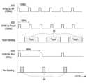
터치 센싱을 위한 터치 센서와 펜 센싱을 위한 펜 센서가 동시에 구동되는 경우, 각각의 센싱 간에 서로 간섭이 발생할 수 있다. 따라서 전자 장치는 터치 센싱 구간과 펜 센싱 구간이 서로 독립되도록(오버랩 되지 않도록) 하여 터치 센싱과 펜 센싱 사이의 간섭이 일어나지 않도록 할 필요성이 있다.When a touch sensor for touch sensing and a pen sensor for pen sensing are driven simultaneously, interference may occur between the respective sensing. Therefore, the electronic device needs to ensure that the touch sensing section and the pen sensing section are independent of each other (not overlapping) so that interference between the touch sensing and pen sensing does not occur.
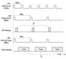
최근에는 디스플레이 구동 신호가 특정 주파수가 아닌 고속 모드와 같이 높은 주파수(예: 120Hz) 또는 다른 주파수의 이용이 요구되는 경우가 있고, 이러한 경우 디스플레이 구동 신호에 의한 터치 센싱 구간과 펜 센싱 구간이 서로 독립되지 못하는 경우(오버랩 되는 경우)가 발생하여 서로 간섭이 발생할 수 있다.Recently, there are cases where display driving signals require the use of high frequencies (e.g., 120 Hz) or other frequencies, such as high-speed modes rather than specific frequencies, and in such cases, the touch sensing section and pen sensing section by the display driving signal may not be independent of each other (overlap), and thus interference may occur.
따라서 디스플레이 구동 신호의 주파수에 관계없이 디스플레이 구동 신호에 의한 터치 센싱 구간과 펜 센싱 구간이 서로 독립되도록 하여 터치 센싱과 펜 센싱 간의 간섭을 최소화하여 입력 오류를 줄이는 것이 필요할 수 있다.Therefore, it may be necessary to minimize interference between touch sensing and pen sensing by making the touch sensing section and pen sensing section by the display driving signal independent of each other regardless of the frequency of the display driving signal, thereby reducing input errors.
다양한 실시예에 따르면 디스플레이와 터치 센싱 및 펜 센싱이 동기화되면서도 터치 센싱 기간과 펜 센싱 기간이 오버랩되지 않아 터치 센싱과 펜 센싱 간의 간섭이 일어나지 않도록 하는 전자 장치 및 전자 장치에서 디스플레이 구동 신호 기반의 동기화 방법을 제공할 수 있다.According to various embodiments, an electronic device and a synchronization method based on a display driving signal in an electronic device can be provided in which a display and touch sensing and pen sensing are synchronized while a touch sensing period and a pen sensing period do not overlap so that interference between touch sensing and pen sensing does not occur.
다양한 실시예에 따르면 고속 모드와 같이 디스플레이 구동 신호의 주파수가 높은 경우에도 디스플레이 구동 신호에 의한 터치 센싱 구간과 펜 센싱 구간이 서로 독립되도록 할 수 있는 전자 장치 및 전자 장치에서 디스플레이 구동 신호 기반의 동기화 방법을 제공할 수 있다.According to various embodiments, an electronic device and a synchronization method based on a display driving signal can be provided in the electronic device, which can make a touch sensing section and a pen sensing section by a display driving signal independent of each other even when the frequency of the display driving signal is high, such as in a high-speed mode.
다양한 실시예에 따르면 디스플레이 구동 신호의 주파수가 변경된 경우에도 변경된 디스플레이 구동 신호 주파수에 맞추어 터치 센싱 구동 신호 주파수와 펜 센싱 구동 신호 주파수도 서로 독립되도록 변경될 수 있는 전자 장치 및 전자 장치에서 디스플레이 구동 신호 기반의 동기화 방법을 제공할 수 있다.According to various embodiments, an electronic device and a synchronization method based on a display driving signal can be provided in which a touch sensing driving signal frequency and a pen sensing driving signal frequency can be independently changed to match the changed display driving signal frequency even when the frequency of the display driving signal is changed.
다양한 실시예에 따르면, 전자 장치는 디스플레이, 제1 센서 회로, 제2 센서 회로, 및 상기 디스플레이, 상기 제1 센서 회로, 및 상기 제2 센서 회로와 전기적으로 연결된 프로세서를 포함하고, 상기 디스플레이는, 상기 디스플레이의 디스플레이 구동 신호 변경에 기반하여 상기 프로세서에 상기 변경된 디스플레이 구동 신호에 대응된 제1 동기 신호를 제공하고, 및 상기 제1 동기 신호의 제공에 기반하여, 상기 제1 센서 회로 및 상기 제2 센서 회로 중 적어도 하나에 상기 제1 동기 신호와 다른 제2 동기 신호가 제공될 수 있다.According to various embodiments, an electronic device includes a display, a first sensor circuit, a second sensor circuit, and a processor electrically connected to the display, the first sensor circuit, and the second sensor circuit, wherein the display provides a first synchronization signal corresponding to a changed display driving signal of the display to the processor based on a change in a display driving signal of the display, and based on the provision of the first synchronization signal, a second synchronization signal different from the first synchronization signal can be provided to at least one of the first sensor circuit and the second sensor circuit.
다양한 실시예에 따르면, 전자 장치는 디스플레이 구동 IC를 포함하는 디스플레이, 터치 센서 IC를 포함하는 연성 인쇄 회로 기판, 및 상기 연성 인쇄 회로 기판과 연결되며 펜 센서 및 어플리케이션 프로세서를 포함하는 인쇄 회로 기판을 포함하고, 상기 디스플레이 구동 IC는 상기 디스플레이 구동 IC의 디스플레이 구동 신호 변경에 기반하여 상기 어플리케이션 프로세서에 상기 변경된 디스플레이 구동 신호에 대응된 제1 동기 신호를 제공하고, 상기 디스플레이 구동 신호에 대응된 상기 제1 동기 신호의 제공에 기반하여 상기 터치 센서 IC 및 상기 펜 센서 IC 중 적어도 하나에 상기 제1 동기 신호와 다른 제2 동기 신호가 제공될 수 있다.According to various embodiments, an electronic device includes a display including a display driving IC, a flexible printed circuit board including a touch sensor IC, and a printed circuit board connected to the flexible printed circuit board and including a pen sensor and an application processor, wherein the display driving IC provides a first synchronization signal corresponding to the changed display driving signal to the application processor based on a change in a display driving signal of the display driving IC, and a second synchronization signal different from the first synchronization signal can be provided to at least one of the touch sensor IC and the pen sensor IC based on the provision of the first synchronization signal corresponding to the display driving signal.
다양한 실시예에 따르면, 디스플레이 기반 동기화 신호 제공 방법은, 상기 전자 장치의 디스플레이가 디스플레이 구동 신호 변경에 기반하여 상기 전자 장치의 프로세서에 상기 변경된 디스플레이 구동 신호에 대응된 제1 동기 신호를 제공하는 동작, 및 상기 디스플레이의 상기 제1 동기 신호의 제공에 기반하여, 상기 전자 장치의 제1 센서 회로 및 상기 전자 장치의 제2 센서 회로 중 적어도 하나가 상기 제1 동기 신호와 다른 제2 동기 신호를 제공받는 동작을 포함할 수 있다.According to various embodiments, a method for providing a display-based synchronization signal may include an operation in which a display of the electronic device provides a first synchronization signal corresponding to a changed display driving signal to a processor of the electronic device based on a change in a display driving signal, and an operation in which, based on the provision of the first synchronization signal by the display, at least one of a first sensor circuit of the electronic device and a second sensor circuit of the electronic device receives a second synchronization signal different from the first synchronization signal.
다양한 실시예에 따르면 전자 장치에서 디스플레이와 터치 센싱 및 펜 센싱이 동기화되면서도 터치 센싱 기간과 펜 센싱 기간이 오버랩되지 않아 터치 센싱과 펜 센싱 간의 간섭이 일어나지 않도록 할 수 있다.According to various embodiments, a display and touch sensing and pen sensing in an electronic device can be synchronized while the touch sensing period and the pen sensing period do not overlap, thereby preventing interference between the touch sensing and pen sensing.
다양한 실시예에 따르면 전자 장치에서 고속 모드와 같이 디스플레이 구동 신호의 주파수가 높은 경우에도 디스플레이 구동 신호에 의한 터치 센싱 구간과 펜 센싱 구간이 서로 독립되도록 할 수 있다According to various embodiments, even when the frequency of the display driving signal is high, such as in a high-speed mode, in an electronic device, the touch sensing section and the pen sensing section by the display driving signal can be made independent of each other.
다양한 실시예에 따르면 전자 장치에서 디스플레이 구동 신호의 주파수가 변경된 경우에도 변경된 디스플레이 구동 신호 주파수에 맞추어 터치 센싱 구동 신호 주파수와 펜 센싱 구동 신호 주파수도 서로 독립되도록 변경하여 터치 센싱 과 펜 센싱 간의 간섭이 일어나지 않도록 할 수 있다.According to various embodiments, even when the frequency of a display driving signal in an electronic device is changed, the frequency of a touch sensing driving signal and the frequency of a pen sensing driving signal can be changed independently to match the changed frequency of the display driving signal, thereby preventing interference between touch sensing and pen sensing.
본 개시에서 얻을 수 있는 효과는 이상에서 언급한 효과들로 제한되지 않으며, 언급하지 않은 또 다른 효과들은 아래의 기재로부터 본 개시가 속하는 기술 분야에서 통상의 지식을 가진 자에게 명확하게 이해될 수 있을 것이다.The effects obtainable from the present disclosure are not limited to the effects mentioned above, and other effects not mentioned will be clearly understood by a person skilled in the art to which the present disclosure belongs from the description below.
도 1은 일 실시예에 따른 네트워크 환경 내의 전자 장치의 블럭도이다.
도 2는 다양한 실시예들에 따른 표시 장치의 블록도이다.
도 3a는 일 실시예에 따른 펜 입력 장치를 포함하는 전자 장치의 사시도이다.
도 3b는 일 실시예에 따른 전자 장치 및 펜 입력 장치 간의 관계를 설명하기 위한 도면이다.
도 4는 일 실시예에 따른 전자 장치의 디스플레이 구동 회로, 터치 센서 회로, 펜 센서 회로, 및 프로세서를 나타낸 도면이다.
도 5는 일 실시예에 따른 전자 장치에서 디스플레이 구동 회로, 터치 센서 회로, 및 펜 센서 회로 간의 신호 처리의 일 예를 나타낸 도면이다.
도 6는 일 실시예에 따른 전자 장치에서 디스플레이 구동 회로, 터치 센서 회로, 및 펜 센서 회로 간의 동기화 신호의 일 예를 나타낸 도면이다.
도 7은 일 실시예에 따른 전자 장치에서 디스플레이 구동 회로, 터치 센서 회로, 및 펜 센서 회로 간의 신호 처리의 다른 예를 나타낸 도면이다.
도 8은 일 실시예에 따른 전자 장치에서 디스플레이 구동 회로, 터치 센서 회로, 및 펜 센서 회로 간의 동기화 신호의 다른 예를 나타낸 도면이다.
도 9는 일 실시예에 따른 전자 장치에서 디스플레이 구동 회로, 터치 센서 회로, 및 펜 센서 회로 간의 신호 처리의 또 다른 예를 나타낸 도면이다.
도 10은 일 실시예에 따른 전자 장치에서 디스플레이 구동 회로, 터치 센서 회로, 및 펜 센서 회로 간의 동기화 신호의 또 다른 예를 나타낸 도면이다.
도 11은 일 실시예에 따른 디스플레이 구동 신호에 기반한 프로세서의 동작을 나타낸 도면이다.
도 12는 일 실시예에 따른 전자 장치의 디스플레이 구동 회로, 터치 센서 회로, 펜 센서 회로, 및 프로세서의 동작의 일 예를 나타낸 흐름도이다.
도 13은 일 실시예에 따른 전자 장치의 디스플레이 구동 회로, 터치 센서 회로, 펜 센서 회로, 및 프로세서의 동작의 다른 일예를 나타낸 흐름도이다.
도 14는 일 실시예에 따른 전자 장치의 디스플레이 구동 회로, 터치 센서 회로, 펜 센서 회로, 및 프로세서의 동작의 또 다른 일예를 나타낸 흐름도이다.
도면의 설명과 관련하여, 동일 또는 유사한 구성 요소에 대해서는 동일 또는 유사한 참조 부호가 사용될 수 있다.FIG. 1 is a block diagram of an electronic device within a network environment according to one embodiment.
FIG. 2 is a block diagram of a display device according to various embodiments.
FIG. 3A is a perspective view of an electronic device including a pen input device according to one embodiment.
FIG. 3b is a diagram illustrating a relationship between an electronic device and a pen input device according to one embodiment.
FIG. 4 is a diagram illustrating a display driving circuit, a touch sensor circuit, a pen sensor circuit, and a processor of an electronic device according to one embodiment.
FIG. 5 is a diagram illustrating an example of signal processing between a display driving circuit, a touch sensor circuit, and a pen sensor circuit in an electronic device according to one embodiment.
FIG. 6 is a diagram illustrating an example of a synchronization signal between a display driving circuit, a touch sensor circuit, and a pen sensor circuit in an electronic device according to one embodiment.
FIG. 7 is a diagram illustrating another example of signal processing between a display driving circuit, a touch sensor circuit, and a pen sensor circuit in an electronic device according to one embodiment.
FIG. 8 is a diagram illustrating another example of a synchronization signal between a display driving circuit, a touch sensor circuit, and a pen sensor circuit in an electronic device according to one embodiment.
FIG. 9 is a diagram illustrating another example of signal processing between a display driving circuit, a touch sensor circuit, and a pen sensor circuit in an electronic device according to one embodiment.
FIG. 10 is a diagram illustrating another example of a synchronization signal between a display driving circuit, a touch sensor circuit, and a pen sensor circuit in an electronic device according to one embodiment.
FIG. 11 is a diagram illustrating the operation of a processor based on a display driving signal according to one embodiment.
FIG. 12 is a flowchart illustrating an example of the operation of a display driving circuit, a touch sensor circuit, a pen sensor circuit, and a processor of an electronic device according to one embodiment.
FIG. 13 is a flowchart illustrating another example of the operation of a display driving circuit, a touch sensor circuit, a pen sensor circuit, and a processor of an electronic device according to one embodiment.
FIG. 14 is a flowchart illustrating another example of the operation of a display driving circuit, a touch sensor circuit, a pen sensor circuit, and a processor of an electronic device according to one embodiment.
In connection with the description of the drawings, the same or similar reference numerals may be used for identical or similar components.
본 문서에서 사용된 용어들은 단지 특정한 실시예를 설명하기 위해 사용된 것으로, 다른 실시예의 범위를 한정하려는 의도가 아닐 수 있다. 단수의 표현은 문맥상 명백하게 다르게 뜻하지 않는 한, 복수의 표현을 포함할 수 있다. 기술적이거나 과학적인 용어를 포함해서 여기서 사용되는 모든 용어들은 본 발명의 기술 분야에서 통상의 지식을 가진 자에 의해 일반적으로 이해되는 것과 동일한 의미를 가질 수 있다. 일반적으로 사용되는 사전에 정의된 용어들은 관련 기술의 문맥상 가지는 의미와 동일 또는 유사한 의미를 가지는 것으로 해석될 수 있으며, 본 문서에서 명백하게 정의되지 않는 한, 이상적이거나 과도하게 형식적인 의미로 해석되지 않는다. 경우에 따라서, 본 문서에서 정의된 용어일지라도 본 발명의 실시예들을 배제하도록 해석될 수 없다.The terms used in this document are only used to describe specific embodiments and may not be intended to limit the scope of other embodiments. The singular expression may include the plural expression unless the context clearly indicates otherwise. All terms used herein, including technical or scientific terms, may have the same meaning as commonly understood by a person having ordinary skill in the art of the present invention. Terms defined in commonly used dictionaries may be interpreted as having the same or similar meaning in the context of the related art, and shall not be interpreted in an ideal or excessively formal meaning unless explicitly defined in this document. In some cases, even if a term is defined in this document, it cannot be interpreted to exclude embodiments of the present invention.
도 1은, 다양한 실시예들에 따른, 네트워크 환경(100) 내의 전자 장치(101)의 블록도이다. 도 1을 참조하면, 네트워크 환경(100)에서 전자 장치(101)는 제 1 네트워크(198)(예: 근거리 무선 통신 네트워크)를 통하여 전자 장치(102)와 통신하거나, 또는 제 2 네트워크(199)(예: 원거리 무선 통신 네트워크)를 통하여 전자 장치(104) 또는 서버(108)와 통신할 수 있다. 일실시예에 따르면, 전자 장치(101)는 서버(108)를 통하여 전자 장치(104)와 통신할 수 있다. 일실시예에 따르면, 전자 장치(101)는 프로세서(120), 메모리(130), 입력 모듈(150), 음향 출력 모듈(155), 디스플레이 모듈(160), 오디오 모듈(170), 센서 모듈(176), 인터페이스(177), 연결 단자(178), 햅틱 모듈(179), 카메라 모듈(180), 전력 관리 모듈(188), 배터리(189), 통신 모듈(190), 가입자 식별 모듈(196), 또는 안테나 모듈(197)을 포함할 수 있다. 어떤 실시예에서는, 전자 장치(101)에는, 이 구성요소들 중 적어도 하나(예: 연결 단자(178))가 생략되거나, 하나 이상의 다른 구성요소가 추가될 수 있다. 어떤 실시예에서는, 이 구성요소들 중 일부들(예: 센서 모듈(176), 카메라 모듈(180), 또는 안테나 모듈(197))은 하나의 구성요소(예: 디스플레이 모듈(160))로 통합될 수 있다.FIG. 1 is a block diagram of an electronic device (101) in a network environment (100) according to various embodiments. Referring to FIG. 1, in the network environment (100), the electronic device (101) may communicate with the electronic device (102) via a first network (198) (e.g., a short-range wireless communication network), or may communicate with the electronic device (104) or a server (108) via a second network (199) (e.g., a long-range wireless communication network). According to one embodiment, the electronic device (101) may communicate with the electronic device (104) via the server (108). According to one embodiment, the electronic device (101) may include a processor (120), a memory (130), an input module (150), an audio output module (155), a display module (160), an audio module (170), a sensor module (176), an interface (177), a connection terminal (178), a haptic module (179), a camera module (180), a power management module (188), a battery (189), a communication module (190), a subscriber identification module (196), or an antenna module (197). In some embodiments, the electronic device (101) may omit at least one of these components (e.g., the connection terminal (178)), or may have one or more other components added. In some embodiments, some of these components (e.g., the sensor module (176), the camera module (180), or the antenna module (197)) may be integrated into one component (e.g., the display module (160)).
프로세서(120)는, 예를 들면, 소프트웨어(예: 프로그램(140))를 실행하여 프로세서(120)에 연결된 전자 장치(101)의 적어도 하나의 다른 구성요소(예: 하드웨어 또는 소프트웨어 구성요소)를 제어할 수 있고, 다양한 데이터 처리 또는 연산을 수행할 수 있다. 일실시예에 따르면, 데이터 처리 또는 연산의 적어도 일부로서, 프로세서(120)는 다른 구성요소(예: 센서 모듈(176) 또는 통신 모듈(190))로부터 수신된 명령 또는 데이터를 휘발성 메모리(132)에 저장하고, 휘발성 메모리(132)에 저장된 명령 또는 데이터를 처리하고, 결과 데이터를 비휘발성 메모리(134)에 저장할 수 있다. 일실시예에 따르면, 프로세서(120)는 메인 프로세서(121)(예: 중앙 처리 장치 또는 어플리케이션 프로세서) 또는 이와는 독립적으로 또는 함께 운영 가능한 보조 프로세서(123)(예: 그래픽 처리 장치, 신경망 처리 장치(NPU: neural processing unit), 이미지 시그널 프로세서, 센서 허브 프로세서, 또는 커뮤니케이션 프로세서)를 포함할 수 있다. 예를 들어, 전자 장치(101)가 메인 프로세서(121) 및 보조 프로세서(123)를 포함하는 경우, 보조 프로세서(123)는 메인 프로세서(121)보다 저전력을 사용하거나, 지정된 기능에 특화되도록 설정될 수 있다. 보조 프로세서(123)는 메인 프로세서(121)와 별개로, 또는 그 일부로서 구현될 수 있다.The processor (120) may control at least one other component (e.g., a hardware or software component) of an electronic device (101) connected to the processor (120) by executing, for example, software (e.g., a program (140)), and may perform various data processing or calculations. According to one embodiment, as at least a part of the data processing or calculations, the processor (120) may store a command or data received from another component (e.g., a sensor module (176) or a communication module (190)) in a volatile memory (132), process the command or data stored in the volatile memory (132), and store result data in a nonvolatile memory (134). According to one embodiment, the processor (120) may include a main processor (121) (e.g., a central processing unit or an application processor) or an auxiliary processor (123) (e.g., a graphics processing unit, a neural processing unit (NPU), an image signal processor, a sensor hub processor, or a communication processor) that can operate independently or together with the main processor (121). For example, when the electronic device (101) includes a main processor (121) and an auxiliary processor (123), the auxiliary processor (123) may be configured to use less power than the main processor (121) or to be specialized for a given function. The auxiliary processor (123) may be implemented separately from the main processor (121) or as a part thereof.
보조 프로세서(123)는, 예를 들면, 메인 프로세서(121)가 인액티브(예: 슬립) 상태에 있는 동안 메인 프로세서(121)를 대신하여, 또는 메인 프로세서(121)가 액티브(예: 어플리케이션 실행) 상태에 있는 동안 메인 프로세서(121)와 함께, 전자 장치(101)의 구성요소들 중 적어도 하나의 구성요소(예: 디스플레이 모듈(160), 센서 모듈(176), 또는 통신 모듈(190))와 관련된 기능 또는 상태들의 적어도 일부를 제어할 수 있다. 일실시예에 따르면, 보조 프로세서(123)(예: 이미지 시그널 프로세서 또는 커뮤니케이션 프로세서)는 기능적으로 관련 있는 다른 구성요소(예: 카메라 모듈(180) 또는 통신 모듈(190))의 일부로서 구현될 수 있다. 일실시예에 따르면, 보조 프로세서(123)(예: 신경망 처리 장치)는 인공지능 모델의 처리에 특화된 하드웨어 구조를 포함할 수 있다. 인공지능 모델은 기계 학습을 통해 생성될 수 있다. 이러한 학습은, 예를 들어, 인공지능이 수행되는 전자 장치(101) 자체에서 수행될 수 있고, 별도의 서버(예: 서버(108))를 통해 수행될 수도 있다. 학습 알고리즘은, 예를 들어, 지도형 학습(supervised learning), 비지도형 학습(unsupervised learning), 준지도형 학습(semi-supervised learning) 또는 강화 학습(reinforcement learning)을 포함할 수 있으나, 전술한 예에 한정되지 않는다. 인공지능 모델은, 복수의 인공 신경망 레이어들을 포함할 수 있다. 인공 신경망은 심층 신경망(DNN: deep neural network), CNN(convolutional neural network), RNN(recurrent neural network), RBM(restricted boltzmann machine), DBN(deep belief network), BRDNN(bidirectional recurrent deep neural network), 심층 Q-네트워크(deep Q-networks) 또는 상기 중 둘 이상의 조합 중 하나일 수 있으나, 전술한 예에 한정되지 않는다. 인공지능 모델은 하드웨어 구조 이외에, 추가적으로 또는 대체적으로, 소프트웨어 구조를 포함할 수 있다.The auxiliary processor (123) may control at least a portion of functions or states associated with at least one of the components of the electronic device (101) (e.g., the display module (160), the sensor module (176), or the communication module (190)), for example, while the main processor (121) is in an inactive (e.g., sleep) state, or together with the main processor (121) while the main processor (121) is in an active (e.g., application execution) state. In one embodiment, the auxiliary processor (123) (e.g., an image signal processor or a communication processor) may be implemented as a part of another functionally related component (e.g., a camera module (180) or a communication module (190)). In one embodiment, the auxiliary processor (123) (e.g., a neural network processing device) may include a hardware structure specialized for processing artificial intelligence models. The artificial intelligence models may be generated through machine learning. Such learning may be performed, for example, in the electronic device (101) on which artificial intelligence is performed, or may be performed through a separate server (e.g., server (108)). The learning algorithm may include, for example, supervised learning, unsupervised learning, semi-supervised learning, or reinforcement learning, but is not limited to the examples described above. The artificial intelligence model may include a plurality of artificial neural network layers. The artificial neural network may be one of a deep neural network (DNN), a convolutional neural network (CNN), a recurrent neural network (RNN), a restricted Boltzmann machine (RBM), a deep belief network (DBN), a bidirectional recurrent deep neural network (BRDNN), deep Q-networks, or a combination of two or more of the above, but is not limited to the examples described above. In addition to the hardware structure, the artificial intelligence model may additionally or alternatively include a software structure.
메모리(130)는, 전자 장치(101)의 적어도 하나의 구성요소(예: 프로세서(120) 또는 센서 모듈(176))에 의해 사용되는 다양한 데이터를 저장할 수 있다. 데이터는, 예를 들어, 소프트웨어(예: 프로그램(140)) 및, 이와 관련된 명령에 대한 입력 데이터 또는 출력 데이터를 포함할 수 있다. 메모리(130)는, 휘발성 메모리(132) 또는 비휘발성 메모리(134)를 포함할 수 있다.The memory (130) can store various data used by at least one component (e.g., processor (120) or sensor module (176)) of the electronic device (101). The data can include, for example, software (e.g., program (140)) and input data or output data for commands related thereto. The memory (130) can include volatile memory (132) or nonvolatile memory (134).
프로그램(140)은 메모리(130)에 소프트웨어로서 저장될 수 있으며, 예를 들면, 운영 체제(142), 미들 웨어(144) 또는 어플리케이션(146)을 포함할 수 있다.The program (140) may be stored as software in memory (130) and may include, for example, an operating system (142), middleware (144), or an application (146).
입력 모듈(150)은, 전자 장치(101)의 구성요소(예: 프로세서(120))에 사용될 명령 또는 데이터를 전자 장치(101)의 외부(예: 사용자)로부터 수신할 수 있다. 입력 모듈(150)은, 예를 들면, 마이크, 마우스, 키보드, 키(예: 버튼), 또는 디지털 펜(예: 스타일러스 펜)을 포함할 수 있다.The input module (150) can receive commands or data to be used in a component of the electronic device (101) (e.g., a processor (120)) from an external source (e.g., a user) of the electronic device (101). The input module (150) can include, for example, a microphone, a mouse, a keyboard, a key (e.g., a button), or a digital pen (e.g., a stylus pen).
음향 출력 모듈(155)은 음향 신호를 전자 장치(101)의 외부로 출력할 수 있다. 음향 출력 모듈(155)은, 예를 들면, 스피커 또는 리시버를 포함할 수 있다. 스피커는 멀티미디어 재생 또는 녹음 재생과 같이 일반적인 용도로 사용될 수 있다. 리시버는 착신 전화를 수신하기 위해 사용될 수 있다. 일실시예에 따르면, 리시버는 스피커와 별개로, 또는 그 일부로서 구현될 수 있다.The audio output module (155) can output an audio signal to the outside of the electronic device (101). The audio output module (155) can include, for example, a speaker or a receiver. The speaker can be used for general purposes such as multimedia playback or recording playback. The receiver can be used to receive an incoming call. According to one embodiment, the receiver can be implemented separately from the speaker or as a part thereof.
디스플레이 모듈(160)은 전자 장치(101)의 외부(예: 사용자)로 정보를 시각적으로 제공할 수 있다. 디스플레이 모듈(160)은, 예를 들면, 디스플레이, 홀로그램 장치, 또는 프로젝터 및 해당 장치를 제어하기 위한 제어 회로를 포함할 수 있다. 일실시예에 따르면, 디스플레이 모듈(160)은 터치를 감지하도록 설정된 터치 센서, 또는 상기 터치에 의해 발생되는 힘의 세기를 측정하도록 설정된 압력 센서를 포함할 수 있다.The display module (160) can visually provide information to an external party (e.g., a user) of the electronic device (101). The display module (160) can include, for example, a display, a holographic device, or a projector and a control circuit for controlling the device. According to one embodiment, the display module (160) can include a touch sensor configured to detect a touch, or a pressure sensor configured to measure the intensity of a force generated by the touch.
오디오 모듈(170)은 소리를 전기 신호로 변환시키거나, 반대로 전기 신호를 소리로 변환시킬 수 있다. 일실시예에 따르면, 오디오 모듈(170)은, 입력 모듈(150)을 통해 소리를 획득하거나, 음향 출력 모듈(155), 또는 전자 장치(101)와 직접 또는 무선으로 연결된 외부 전자 장치(예: 전자 장치(102))(예: 스피커 또는 헤드폰)를 통해 소리를 출력할 수 있다.The audio module (170) can convert sound into an electrical signal, or vice versa, convert an electrical signal into sound. According to one embodiment, the audio module (170) can obtain sound through an input module (150), or output sound through an audio output module (155), or an external electronic device (e.g., an electronic device (102)) (e.g., a speaker or a headphone) directly or wirelessly connected to the electronic device (101).
센서 모듈(176)은 전자 장치(101)의 작동 상태(예: 전력 또는 온도), 또는 외부의 환경 상태(예: 사용자 상태)를 감지하고, 감지된 상태에 대응하는 전기 신호 또는 데이터 값을 생성할 수 있다. 일실시예에 따르면, 센서 모듈(176)은, 예를 들면, 제스처 센서, 자이로 센서, 기압 센서, 마그네틱 센서, 가속도 센서, 그립 센서, 근접 센서, 컬러 센서, IR(infrared) 센서, 생체 센서, 온도 센서, 습도 센서, 또는 조도 센서를 포함할 수 있다.The sensor module (176) can detect an operating state (e.g., power or temperature) of the electronic device (101) or an external environmental state (e.g., user state) and generate an electric signal or data value corresponding to the detected state. According to one embodiment, the sensor module (176) can include, for example, a gesture sensor, a gyro sensor, a barometric pressure sensor, a magnetic sensor, an acceleration sensor, a grip sensor, a proximity sensor, a color sensor, an IR (infrared) sensor, a biometric sensor, a temperature sensor, a humidity sensor, or an illuminance sensor.
인터페이스(177)는 전자 장치(101)가 외부 전자 장치(예: 전자 장치(102))와 직접 또는 무선으로 연결되기 위해 사용될 수 있는 하나 이상의 지정된 프로토콜들을 지원할 수 있다. 일실시예에 따르면, 인터페이스(177)는, 예를 들면, HDMI(high definition multimedia interface), USB(universal serial bus) 인터페이스, SD카드 인터페이스, 또는 오디오 인터페이스를 포함할 수 있다.The interface (177) may support one or more designated protocols that may be used to directly or wirelessly connect the electronic device (101) with an external electronic device (e.g., the electronic device (102)). In one embodiment, the interface (177) may include, for example, a high definition multimedia interface (HDMI), a universal serial bus (USB) interface, an SD card interface, or an audio interface.
연결 단자(178)는, 그를 통해서 전자 장치(101)가 외부 전자 장치(예: 전자 장치(102))와 물리적으로 연결될 수 있는 커넥터를 포함할 수 있다. 일실시예에 따르면, 연결 단자(178)는, 예를 들면, HDMI 커넥터, USB 커넥터, SD 카드 커넥터, 또는 오디오 커넥터(예: 헤드폰 커넥터)를 포함할 수 있다.The connection terminal (178) may include a connector through which the electronic device (101) may be physically connected to an external electronic device (e.g., the electronic device (102)). According to one embodiment, the connection terminal (178) may include, for example, an HDMI connector, a USB connector, an SD card connector, or an audio connector (e.g., a headphone connector).
햅틱 모듈(179)은 전기적 신호를 사용자가 촉각 또는 운동 감각을 통해서 인지할 수 있는 기계적인 자극(예: 진동 또는 움직임) 또는 전기적인 자극으로 변환할 수 있다. 일실시예에 따르면, 햅틱 모듈(179)은, 예를 들면, 모터, 압전 소자, 또는 전기 자극 장치를 포함할 수 있다.The haptic module (179) can convert an electrical signal into a mechanical stimulus (e.g., vibration or movement) or an electrical stimulus that a user can perceive through a tactile or kinesthetic sense. According to one embodiment, the haptic module (179) can include, for example, a motor, a piezoelectric element, or an electrical stimulation device.
카메라 모듈(180)은 정지 영상 및 동영상을 촬영할 수 있다. 일실시예에 따르면, 카메라 모듈(180)은 하나 이상의 렌즈들, 이미지 센서들, 이미지 시그널 프로세서들, 또는 플래시들을 포함할 수 있다.The camera module (180) can capture still images and moving images. According to one embodiment, the camera module (180) can include one or more lenses, image sensors, image signal processors, or flashes.
전력 관리 모듈(188)은 전자 장치(101)에 공급되는 전력을 관리할 수 있다. 일실시예에 따르면, 전력 관리 모듈(188)은, 예를 들면, PMIC(power management integrated circuit)의 적어도 일부로서 구현될 수 있다.The power management module (188) can manage power supplied to the electronic device (101). According to one embodiment, the power management module (188) can be implemented as, for example, at least a part of a power management integrated circuit (PMIC).
배터리(189)는 전자 장치(101)의 적어도 하나의 구성요소에 전력을 공급할 수 있다. 일실시예에 따르면, 배터리(189)는, 예를 들면, 재충전 불가능한 1차 전지, 재충전 가능한 2차 전지 또는 연료 전지를 포함할 수 있다.The battery (189) can power at least one component of the electronic device (101). In one embodiment, the battery (189) can include, for example, a non-rechargeable primary battery, a rechargeable secondary battery, or a fuel cell.
통신 모듈(190)은 전자 장치(101)와 외부 전자 장치(예: 전자 장치(102), 전자 장치(104), 또는 서버(108)) 간의 직접(예: 유선) 통신 채널 또는 무선 통신 채널의 수립, 및 수립된 통신 채널을 통한 통신 수행을 지원할 수 있다. 통신 모듈(190)은 프로세서(120)(예: 어플리케이션 프로세서)와 독립적으로 운영되고, 직접(예: 유선) 통신 또는 무선 통신을 지원하는 하나 이상의 커뮤니케이션 프로세서를 포함할 수 있다. 일실시예에 따르면, 통신 모듈(190)은 무선 통신 모듈(192)(예: 셀룰러 통신 모듈, 근거리 무선 통신 모듈, 또는 GNSS(global navigation satellite system) 통신 모듈) 또는 유선 통신 모듈(194)(예: LAN(local area network) 통신 모듈, 또는 전력선 통신 모듈)을 포함할 수 있다. 이들 통신 모듈 중 해당하는 통신 모듈은 제 1 네트워크(198)(예: 블루투스, WiFi(wireless fidelity) direct 또는 IrDA(infrared data association)와 같은 근거리 통신 네트워크) 또는 제 2 네트워크(199)(예: 레거시 셀룰러 네트워크, 5G 네트워크, 차세대 통신 네트워크, 인터넷, 또는 컴퓨터 네트워크(예: LAN 또는 WAN)와 같은 원거리 통신 네트워크)를 통하여 외부의 전자 장치(104)와 통신할 수 있다. 이런 여러 종류의 통신 모듈들은 하나의 구성요소(예: 단일 칩)로 통합되거나, 또는 서로 별도의 복수의 구성요소들(예: 복수 칩들)로 구현될 수 있다. 무선 통신 모듈(192)은 가입자 식별 모듈(196)에 저장된 가입자 정보(예: 국제 모바일 가입자 식별자(IMSI))를 이용하여 제 1 네트워크(198) 또는 제 2 네트워크(199)와 같은 통신 네트워크 내에서 전자 장치(101)를 확인 또는 인증할 수 있다.The communication module (190) may support establishment of a direct (e.g., wired) communication channel or a wireless communication channel between the electronic device (101) and an external electronic device (e.g., the electronic device (102), the electronic device (104), or the server (108)), and performance of communication through the established communication channel. The communication module (190) may operate independently from the processor (120) (e.g., the application processor) and may include one or more communication processors that support direct (e.g., wired) communication or wireless communication. According to one embodiment, the communication module (190) may include a wireless communication module (192) (e.g., a cellular communication module, a short-range wireless communication module, or a GNSS (global navigation satellite system) communication module) or a wired communication module (194) (e.g., a local area network (LAN) communication module or a power line communication module). Among these communication modules, a corresponding communication module may communicate with an external electronic device (104) via a first network (198) (e.g., a short-range communication network such as Bluetooth, wireless fidelity (WiFi) direct, or infrared data association (IrDA)) or a second network (199) (e.g., a long-range communication network such as a legacy cellular network, a 5G network, a next-generation communication network, the Internet, or a computer network (e.g., a LAN or WAN)). These various types of communication modules may be integrated into a single component (e.g., a single chip) or implemented as multiple separate components (e.g., multiple chips). The wireless communication module (192) may use subscriber information (e.g., an international mobile subscriber identity (IMSI)) stored in the subscriber identification module (196) to identify or authenticate the electronic device (101) within a communication network such as the first network (198) or the second network (199).
무선 통신 모듈(192)은 4G 네트워크 이후의 5G 네트워크 및 차세대 통신 기술, 예를 들어, NR 접속 기술(new radio access technology)을 지원할 수 있다. NR 접속 기술은 고용량 데이터의 고속 전송(eMBB(enhanced mobile broadband)), 단말 전력 최소화와 다수 단말의 접속(mMTC(massive machine type communications)), 또는 고신뢰도와 저지연(URLLC(ultra-reliable and low-latency communications))을 지원할 수 있다. 무선 통신 모듈(192)은, 예를 들어, 높은 데이터 전송률 달성을 위해, 고주파 대역(예: mmWave 대역)을 지원할 수 있다. 무선 통신 모듈(192)은 고주파 대역에서의 성능 확보를 위한 다양한 기술들, 예를 들어, 빔포밍(beamforming), 거대 배열 다중 입출력(massive MIMO(multiple-input and multiple-output)), 전차원 다중입출력(FD-MIMO: full dimensional MIMO), 어레이 안테나(array antenna), 아날로그 빔형성(analog beam-forming), 또는 대규모 안테나(large scale antenna)와 같은 기술들을 지원할 수 있다. 무선 통신 모듈(192)은 전자 장치(101), 외부 전자 장치(예: 전자 장치(104)) 또는 네트워크 시스템(예: 제 2 네트워크(199))에 규정되는 다양한 요구사항을 지원할 수 있다. 일실시예에 따르면, 무선 통신 모듈(192)은 1eMBB 실현을 위한 Peak data rate(예: 20Gbps 이상), mMTC 실현을 위한 손실 Coverage(예: 164dB 이하), 또는 URLLC 실현을 위한 U-plane latency(예: 다운링크(DL) 및 업링크(UL) 각각 0.5ms 이하, 또는 라운드 트립 1ms 이하)를 지원할 수 있다.The wireless communication module (192) can support a 5G network and next-generation communication technology after a 4G network, for example, NR access technology (new radio access technology). The NR access technology can support high-speed transmission of high-capacity data (eMBB (enhanced mobile broadband)), terminal power minimization and connection of multiple terminals (mMTC (massive machine type communications)), or high reliability and low latency (URLLC (ultra-reliable and low-latency communications)). The wireless communication module (192) can support, for example, a high-frequency band (e.g., mmWave band) to achieve a high data transmission rate. The wireless communication module (192) may support various technologies for securing performance in a high-frequency band, such as beamforming, massive multiple-input and multiple-output (MIMO), full dimensional MIMO (FD-MIMO), array antenna, analog beam-forming, or large scale antenna. The wireless communication module (192) may support various requirements specified in an electronic device (101), an external electronic device (e.g., an electronic device (104)), or a network system (e.g., a second network (199)). According to one embodiment, the wireless communication module (192) can support a peak data rate (e.g., 20 Gbps or more) for realizing 1eMBB, a loss coverage (e.g., 164 dB or less) for realizing mMTC, or a U-plane latency (e.g., 0.5 ms or less for downlink (DL) and uplink (UL) each, or 1 ms or less for round trip) for realizing URLLC.
안테나 모듈(197)은 신호 또는 전력을 외부(예: 외부의 전자 장치)로 송신하거나 외부로부터 수신할 수 있다. 일실시예에 따르면, 안테나 모듈(197)은 서브스트레이트(예: PCB) 위에 형성된 도전체 또는 도전성 패턴으로 이루어진 방사체를 포함하는 안테나를 포함할 수 있다. 일실시예에 따르면, 안테나 모듈(197)은 복수의 안테나들(예: 어레이 안테나)을 포함할 수 있다. 이런 경우, 제 1 네트워크(198) 또는 제 2 네트워크(199)와 같은 통신 네트워크에서 사용되는 통신 방식에 적합한 적어도 하나의 안테나가, 예를 들면, 통신 모듈(190)에 의하여 상기 복수의 안테나들로부터 선택될 수 있다. 신호 또는 전력은 상기 선택된 적어도 하나의 안테나를 통하여 통신 모듈(190)과 외부의 전자 장치 간에 송신되거나 수신될 수 있다. 어떤 실시예에 따르면, 방사체 이외에 다른 부품(예: RFIC(radio frequency integrated circuit))이 추가로 안테나 모듈(197)의 일부로 형성될 수 있다.The antenna module (197) can transmit or receive signals or power to or from the outside (e.g., an external electronic device). According to one embodiment, the antenna module (197) can include an antenna including a radiator formed of a conductor or a conductive pattern formed on a substrate (e.g., a PCB). According to one embodiment, the antenna module (197) can include a plurality of antennas (e.g., an array antenna). In this case, at least one antenna suitable for a communication method used in a communication network, such as the first network (198) or the second network (199), can be selected from the plurality of antennas by, for example, the communication module (190). A signal or power can be transmitted or received between the communication module (190) and the external electronic device through the selected at least one antenna. According to some embodiments, in addition to the radiator, another component (e.g., a radio frequency integrated circuit (RFIC)) can be additionally formed as a part of the antenna module (197).
다양한 실시예에 따르면, 안테나 모듈(197)은 mmWave 안테나 모듈을 형성할 수 있다. 일실시예에 따르면, mmWave 안테나 모듈은 인쇄 회로 기판, 상기 인쇄 회로 기판의 제 1 면(예: 아래 면)에 또는 그에 인접하여 배치되고 지정된 고주파 대역(예: mmWave 대역)을 지원할 수 있는 RFIC, 및 상기 인쇄 회로 기판의 제 2 면(예: 윗 면 또는 측 면)에 또는 그에 인접하여 배치되고 상기 지정된 고주파 대역의 신호를 송신 또는 수신할 수 있는 복수의 안테나들(예: 어레이 안테나)을 포함할 수 있다.According to various embodiments, the antenna module (197) may form a mmWave antenna module. According to one embodiment, the mmWave antenna module may include a printed circuit board, an RFIC positioned on or adjacent a first side (e.g., a bottom side) of the printed circuit board and capable of supporting a designated high-frequency band (e.g., a mmWave band), and a plurality of antennas (e.g., an array antenna) positioned on or adjacent a second side (e.g., a top side or a side) of the printed circuit board and capable of transmitting or receiving signals in the designated high-frequency band.
상기 구성요소들 중 적어도 일부는 주변 기기들간 통신 방식(예: 버스, GPIO(general purpose input and output), SPI(serial peripheral interface), 또는 MIPI(mobile industry processor interface))을 통해 서로 연결되고 신호(예: 명령 또는 데이터)를 상호간에 교환할 수 있다.At least some of the above components may be interconnected and exchange signals (e.g., commands or data) with each other via a communication method between peripheral devices (e.g., a bus, a general purpose input and output (GPIO), a serial peripheral interface (SPI), or a mobile industry processor interface (MIPI)).
일실시예에 따르면, 명령 또는 데이터는 제 2 네트워크(199)에 연결된 서버(108)를 통해서 전자 장치(101)와 외부의 전자 장치(104)간에 송신 또는 수신될 수 있다. 외부의 전자 장치(102, 또는 104) 각각은 전자 장치(101)와 동일한 또는 다른 종류의 장치일 수 있다. 일실시예에 따르면, 전자 장치(101)에서 실행되는 동작들의 전부 또는 일부는 외부의 전자 장치들(102, 104, 또는 108) 중 하나 이상의 외부의 전자 장치들에서 실행될 수 있다. 예를 들면, 전자 장치(101)가 어떤 기능이나 서비스를 자동으로, 또는 사용자 또는 다른 장치로부터의 요청에 반응하여 수행해야 할 경우에, 전자 장치(101)는 기능 또는 서비스를 자체적으로 실행시키는 대신에 또는 추가적으로, 하나 이상의 외부의 전자 장치들에게 그 기능 또는 그 서비스의 적어도 일부를 수행하라고 요청할 수 있다. 상기 요청을 수신한 하나 이상의 외부의 전자 장치들은 요청된 기능 또는 서비스의 적어도 일부, 또는 상기 요청과 관련된 추가 기능 또는 서비스를 실행하고, 그 실행의 결과를 전자 장치(101)로 전달할 수 있다. 전자 장치(101)는 상기 결과를, 그대로 또는 추가적으로 처리하여, 상기 요청에 대한 응답의 적어도 일부로서 제공할 수 있다. 이를 위하여, 예를 들면, 클라우드 컴퓨팅, 분산 컴퓨팅, 모바일 에지 컴퓨팅(MEC: mobile edge computing), 또는 클라이언트-서버 컴퓨팅 기술이 이용될 수 있다. 전자 장치(101)는, 예를 들어, 분산 컴퓨팅 또는 모바일 에지 컴퓨팅을 이용하여 초저지연 서비스를 제공할 수 있다. 다른 실시예에 있어서, 외부의 전자 장치(104)는 IoT(internet of things) 기기를 포함할 수 있다. 서버(108)는 기계 학습 및/또는 신경망을 이용한 지능형 서버일 수 있다. 일실시예에 따르면, 외부의 전자 장치(104) 또는 서버(108)는 제 2 네트워크(199) 내에 포함될 수 있다. 전자 장치(101)는 5G 통신 기술 및 IoT 관련 기술을 기반으로 지능형 서비스(예: 스마트 홈, 스마트 시티, 스마트 카, 또는 헬스 케어)에 적용될 수 있다.In one embodiment, commands or data may be transmitted or received between the electronic device (101) and an external electronic device (104) via a server (108) connected to a second network (199). Each of the external electronic devices (102, or 104) may be the same or a different type of device as the electronic device (101). In one embodiment, all or part of the operations executed in the electronic device (101) may be executed in one or more of the external electronic devices (102, 104, or 108). For example, when the electronic device (101) is to perform a certain function or service automatically or in response to a request from a user or another device, the electronic device (101) may, instead of executing the function or service itself or in addition, request one or more external electronic devices to perform at least a part of the function or service. One or more external electronic devices that have received the request may execute at least a part of the requested function or service, or an additional function or service related to the request, and transmit the result of the execution to the electronic device (101). The electronic device (101) may process the result as it is or additionally and provide it as at least a part of a response to the request. For this purpose, for example, cloud computing, distributed computing, mobile edge computing (MEC), or client-server computing technology may be used. The electronic device (101) may provide an ultra-low latency service by using, for example, distributed computing or mobile edge computing. In another embodiment, the external electronic device (104) may include an IoT (Internet of Things) device. The server (108) may be an intelligent server using machine learning and/or a neural network. According to one embodiment, the external electronic device (104) or the server (108) may be included in the second network (199). The electronic device (101) can be applied to intelligent services (e.g., smart home, smart city, smart car, or healthcare) based on 5G communication technology and IoT-related technology.
도 2는 다양한 실시예들에 따른, 표시 장치(160)의 블록도(200)이다.FIG. 2 is a block diagram (200) of a display device (160) according to various embodiments.
도 2를 참조하면, 표시 장치(160)는 디스플레이(210), 및 이를 제어하기 위한 디스플레이 드라이버 IC(DDI, display driver integrated circuit)(또는 디스플레이 구동 회로)(230)를 포함할 수 있다. DDI(230)는 인터페이스 모듈(231), 메모리(233)(예: 버퍼 메모리), 이미지 처리 모듈(235), 또는 맵핑 모듈(237)을 포함할 수 있다. DDI(230)은, 예를 들면, 영상 데이터, 또는 상기 영상 데이터를 제어하기 위한 명령에 대응하는 영상 제어 신호를 포함하는 영상 정보를 인터페이스 모듈(231)을 통해 전자 장치(예: 도 1의 전자 장치(101))의 다른 구성요소로부터 수신할 수 있다. 예를 들면, 일 실시예에 따르면, 영상 정보는 프로세서(120)(예: 메인 프로세서(121)(예: 어플리케이션 프로세서) 또는 메인 프로세서(121)의 기능과 독립적으로 운영되는 보조 프로세서(123)(예: 그래픽 처리 장치)로부터 수신될 수 있다. DDI(230)는 터치 회로(250) 또는 센서 모듈(176) 등과 상기 인터페이스 모듈(231)을 통하여 커뮤니케이션할 수 있다. 또한, DDI(230)는 상기 수신된 영상 정보 중 적어도 일부를 메모리(233)에, 예를 들면, 프레임 단위로 저장할 수 있다. 일 실시예에 따르면, 메모리(233)는, 레지스터(register)(미도시)를 포함할 수 있고, 상기 레지스터는 전자 장치(101)의 기능 수행을 위한 설정 값이 저장될 수 있다. 이미지 처리 모듈(235)은, 예를 들면, 상기 영상 데이터의 적어도 일부를 상기 영상 데이터의 특성 또는 디스플레이(210)의 특성에 적어도 기반하여 전처리 또는 후처리(예: 해상도, 밝기, 또는 크기 조정)를 수행할 수 있다. 맵핑 모듈(237)은 이미지 처리 모듈(235)를 통해 전처리 또는 후처리된 상기 영상 데이터에 대응하는 전압 값 또는 전류 값을 생성할 수 있다. 일 실시예에 따르면, 전압 값 또는 전류 값의 생성은 예를 들면, 디스플레이(210)의 픽셀들의 속성(예: 픽셀들의 배열(RGB stripe 또는 PenTile 구조), 또는 서브 픽셀들 각각의 크기)에 적어도 일부 기반하여 수행될 수 있다. 디스플레이(210)의 적어도 일부 픽셀들은, 예를 들면, 상기 전압 값 또는 전류 값에 적어도 일부 기반하여 구동됨으로써 상기 영상 데이터에 대응하는 시각적 정보(예: 텍스트, 이미지, 또는 아이콘)가 디스플레이(210)를 통해 표시될 수 있다.Referring to FIG. 2, the display device (160) may include a display (210) and a display driver integrated circuit (DDI) (or display driving circuit) (230) for controlling the display (210). The DDI (230) may include an interface module (231), a memory (233) (e.g., a buffer memory), an image processing module (235), or a mapping module (237). The DDI (230) may receive, for example, image information including image data or an image control signal corresponding to a command for controlling the image data, from another component of an electronic device (e.g., the electronic device (101) of FIG. 1) through the interface module (231). For example, according to one embodiment, image information may be received from a processor (120) (e.g., a main processor (121) (e.g., an application processor) or an auxiliary processor (123) (e.g., a graphic processing unit) that operates independently of the function of the main processor (121). The DDI (230) may communicate with a touch circuit (250) or a sensor module (176) through the interface module (231). In addition, the DDI (230) may store at least some of the received image information in the memory (233), for example, on a frame basis. According to one embodiment, the memory (233) may include a register (not shown), and the register may store setting values for performing functions of the electronic device (101). The image processing module (235) may, for example, perform preprocessing or postprocessing (e.g., resolution, brightness, or size adjustment) on at least some of the image data based on at least a characteristic of the image data or a characteristic of the display (210). The mapping module (237) can generate a voltage value or a current value corresponding to the image data pre-processed or post-processed through the image processing module (235). According to one embodiment, the generation of the voltage value or the current value can be performed based at least in part on, for example, properties of pixels of the display (210) (e.g., an arrangement of pixels (RGB stripe or PenTile structure), or a size of each sub-pixel). At least some pixels of the display (210) can be driven based at least in part on, for example, the voltage value or the current value, so that visual information (e.g., text, an image, or an icon) corresponding to the image data can be displayed through the display (210).
일 실시예에 따르면, 표시 장치(160)는 터치 회로(250)를 더 포함할 수 있다. 터치 회로(250)는 터치 센서(251) 및 이를 제어하기 위한 터치 센서 IC(253)를 포함할 수 있다. 터치 센서 IC(또는 터치 센서 회로)(253)는, 예를 들면, 디스플레이(210)의 특정 위치에 대한 터치 입력 또는 호버링 입력을 감지하기 위해 터치 센서(251)를 제어할 수 있다. 예를 들면, 터치 센서 IC(253)는 디스플레이(210)의 특정 위치에 대한 신호(예: 전압, 광량, 저항, 또는 전하량)의 변화를 측정함으로써 터치 입력 또는 호버링 입력을 감지할 수 있다. 터치 센서 IC(253)는 감지된 터치 입력 또는 호버링 입력에 관한 정보(예: 위치, 면적, 압력, 또는 시간)를 프로세서(120) 에 제공할 수 있다. 일 실시예에 따르면, 터치 회로(250)의 적어도 일부(예: 터치 센서 IC(253))는 디스플레이 드라이버 IC(230), 또는 디스플레이(210)의 일부로, 또는 표시 장치(160)의 외부에 배치된 다른 구성요소(예: 보조 프로세서(123))의 일부로 포함될 수 있다.According to one embodiment, the display device (160) may further include a touch circuit (250). The touch circuit (250) may include a touch sensor (251) and a touch sensor IC (253) for controlling the same. The touch sensor IC (or touch sensor circuit) (253) may control the touch sensor (251) to detect, for example, a touch input or a hovering input for a specific location of the display (210). For example, the touch sensor IC (253) may detect the touch input or the hovering input by measuring a change in a signal (e.g., voltage, light amount, resistance, or charge amount) for a specific location of the display (210). The touch sensor IC (253) may provide information (e.g., location, area, pressure, or time) about the detected touch input or hovering input to the processor (120). In one embodiment, at least a portion of the touch circuit (250) (e.g., the touch sensor IC (253)) may be included as part of the display driver IC (230), or as part of the display (210), or as part of another component (e.g., the auxiliary processor (123)) disposed external to the display device (160).
일 실시예에 따르면, 표시 장치(160)는 센서 모듈(176)의 적어도 하나의 센서(예: 지문 센서, 홍채 센서, 압력 센서 또는 조도 센서), 또는 이에 대한 제어 회로를 더 포함할 수 있다. 이 경우, 상기 적어도 하나의 센서 또는 이에 대한 제어 회로는 표시 장치(160)의 일부(예: 디스플레이(210) 또는 DDI(230)) 또는 터치 회로(250)의 일부에 임베디드될 수 있다. 예를 들면, 표시 장치(160)에 임베디드된 센서 모듈(176)이 생체 센서(예: 지문 센서)를 포함할 경우, 상기 생체 센서는 디스플레이(210)의 일부 영역을 통해 터치 입력과 연관된 생체 정보(예: 지문 이미지)를 획득할 수 있다. 다른 예를 들면, 표시 장치(160)에 임베디드된 센서 모듈(176)이 압력 센서를 포함할 경우, 상기 압력 센서는 디스플레이(210)의 일부 또는 전체 영역을 통해 터치 입력과 연관된 압력 정보를 획득할 수 있다. 일 실시예에 따르면, 터치 센서(251) 또는 센서 모듈(176)은 디스플레이(210)의 픽셀 레이어의 픽셀들 사이에, 또는 상기 픽셀 레이어의 위에 또는 아래에 배치될 수 있다. 일 실시예에 따르면 센서 모듈(176)은 펜 센서(예: 펜 센서 회로, 펜 센서 IC, 또는 디지타이저 컨트롤러)를 더 포함할 수 있다.According to one embodiment, the display device (160) may further include at least one sensor (e.g., a fingerprint sensor, an iris sensor, a pressure sensor, or an illuminance sensor) of the sensor module (176), or a control circuit therefor. In this case, the at least one sensor or the control circuit therefor may be embedded in a part of the display device (160) (e.g., the display (210) or the DDI (230)) or a part of the touch circuit (250). For example, if the sensor module (176) embedded in the display device (160) includes a biometric sensor (e.g., a fingerprint sensor), the biometric sensor may obtain biometric information (e.g., a fingerprint image) associated with a touch input through a part of the display (210). As another example, if the sensor module (176) embedded in the display device (160) includes a pressure sensor, the pressure sensor may obtain pressure information associated with a touch input through a part or the entire part of the display (210). According to one embodiment, the touch sensor (251) or sensor module (176) may be positioned between pixels of a pixel layer of the display (210), or above or below the pixel layer. According to one embodiment, the sensor module (176) may further include a pen sensor (e.g., a pen sensor circuit, a pen sensor IC, or a digitizer controller).
도 3a는 일 실시예에 따른 펜 입력 장치를 포함하는 전자 장치의 사시도이다.FIG. 3A is a perspective view of an electronic device including a pen input device according to one embodiment.
도 3a를 참조하면, 일 실시예에에 따른 전자 장치(301)(예: 도 1의 전자 장치(101))는, 펜 입력 장치(30)(예: 도 1의 입력 장치(150))가 삽입될 수 있는 구조를 포함할 수 있다. 본 문서의 다양한 실시예들에 따른 전자 장치(301)는 하우징(310)을 포함하며, 상기 하우징의 일 부분, 예를 들면, 측면(310C)의 일 부분에는 홀(311)을 포함할 수 있다. 일 실시예에 따른 전자 장치(301)는, 상기 홀(311)과 연결된 수납 공간(312)을 포함할 수 있으며, 상기 펜 입력 장치(30)는 수납 공간(312) 내에 삽입될 수 있다. 도시된 실시예에 따르면, 펜 입력 장치(30)는, 펜 입력 장치(30)를 전자 장치(301)의 수납 공간(312)으로부터 꺼내기 용이하도록, 일 단부에, 눌림 가능한 버튼(301a)을 포함할 수 있다. 상기 버튼(301a)이 눌리면, 버튼(301a)과 연계 구성된 반발 메커니즘(예를 들어, 적어도 하나의 스프링)들이 작동하여, 수납 공간(312)으로부터 펜 입력 장치(30)가 이탈될 수 있다.Referring to FIG. 3a, an electronic device (301) according to an embodiment (e.g., the electronic device (101) of FIG. 1) may include a structure into which a pen input device (30) (e.g., the input device (150) of FIG. 1) may be inserted. The electronic device (301) according to various embodiments of the present document may include a housing (310), and a portion of the housing, for example, a portion of a side surface (310C), may include a hole (311). The electronic device (301) according to an embodiment may include a storage space (312) connected to the hole (311), and the pen input device (30) may be inserted into the storage space (312). According to the illustrated embodiment, the pen input device (30) may include a pressable button (301a) at one end to facilitate taking the pen input device (30) out of the storage space (312) of the electronic device (301). When the above button (301a) is pressed, the repulsive mechanisms (e.g., at least one spring) connected to the button (301a) are activated, so that the pen input device (30) can be detached from the storage space (312).
도 3b는 일 실시예에 따른 전자 장치 및 펜 입력 장치 간의 관계를 설명하기 위한 도면이다.FIG. 3b is a diagram illustrating a relationship between an electronic device and a pen input device according to one embodiment.
일 실시예에 따르면, 전자 장치(301)의 하우징(310)은 적어도 하나의 홀(또는 개구부)(예: 도 3a의 홀(311))를 포함할 수 있으며, 홀(311)(예: pocket)와 연결된 내부 공간에는 펜 입력 장치(30)가 삽입될 수 있다. 전자 장치(301)는, 예를 들면, 프로세서(processor, 320)(예: 도 1의 프로세서(120)), 디지타이저 컨트롤러(digitizer controller, 329), 검출 코일(detecting coil, 316), 안테나(antenna, 397) 및 마스터 블루투스 컨트롤러(master bluetooth controller, 393)를 포함할 수 있다.According to one embodiment, the housing (310) of the electronic device (301) may include at least one hole (or opening) (e.g., the hole (311) of FIG. 3A), and a pen input device (30) may be inserted into an internal space connected to the hole (311) (e.g., a pocket). The electronic device (301) may include, for example, a processor (processor 320) (e.g., the processor (120) of FIG. 1), a digitizer controller (digitizer controller 329), a detecting coil (316), an antenna (antenna 397), and a master Bluetooth controller (master Bluetooth controller 393).
펜 입력 장치(30)는, 예를 들면, 펜 팁(31), 코일(33)(예: EMR(electro-magnetic resonance) coil) 및 회로기판(35)을 포함할 수 있다. 일 실시예에 따르면, 펜 입력 장치(30)는 EMR 방식, AES(active electrostatic) 방식, 또는 ECR(electrically coupled resonance) 방식 중 적어도 하나를 이용할 수 있다.The pen input device (30) may include, for example, a pen tip (31), a coil (33) (e.g., an electro-magnetic resonance (EMR) coil), and a circuit board (35). According to one embodiment, the pen input device (30) may use at least one of an EMR method, an active electrostatic (AES) method, or an electrically coupled resonance (ECR) method.
표시 장치(360)(예: 도 1 의 표시 장치(160))는, 예를 들면, 윈도우(362), 디스플레이(364) 및 디지타이저(digitizer)(366)(예: 전자기 유도 패널)을 포함할 수 있다. 일 실시 예에 따르면, 표시 장치(360)는 전자 장치(301)에 포함되어 하우징(310) 중 적어도 일부를 통해 외부로 노출될 수 있다. 또 다른 실시 예에 따르면, 표시 장치(360)는 전자 장치(301)와 별도로 구비된 독립적인 장치일 수 있다. 일 실시예에 따르면, 표시 장치(360)는, 디스플레이 구동 회로(예: 도 4의 디스플레이 구동 회로(419))를 포함할 수 있고, 디스플레이 구동 회로(419)는 DDI 패키지일 수 있다. 예를 들면, DDI 패키지는 DDI(또는 DDI 칩), 타이밍컨트롤러(T-CON, timing controller), 그래픽 RAM(random access memory)(GRAM, graphic random access memory), 또는 전력 구동부(power generating circuits)를 포함할 수 있다. 타이밍컨트롤러는 프로세서(320)로부터 입력된 데이터 신호를 DDI에서 필요로 하는 신호로 변환시킬 수 있다. 타이밍컨트롤러는 입력 데이터 정보를 DDI의 게이트 드라이버(gate driver) 및 소스 드라이버(source driver)에 알맞은 신호로 조정하는 역할을 할 수 있다. 그래픽 RAM은 DDI로 입력할 데이터를 일시적으로 저장하는 메모리 역할을 할 수 있다. 그래픽 RAM은 입력된 신호를 저장하고 다시 DDI로 내보낼 수 있고, 이 때 타이밍컨트롤러와 상호 작용하여 신호를 처리할 수 있다. 전력 구동부는 플렉서블 디스플레이(130)를 구동하기 위한 전압을 생성하여 DDI의 게이트 드라이버 및 소스 드라이버에 필요한 전압을 공급할 수 있다.The display device (360) (e.g., the display device (160) of FIG. 1) may include, for example, a window (362), a display (364), and a digitizer (366) (e.g., an electromagnetic induction panel). According to one embodiment, the display device (360) may be included in the electronic device (301) and may be exposed to the outside through at least a portion of the housing (310). According to another embodiment, the display device (360) may be an independent device provided separately from the electronic device (301). According to one embodiment, the display device (360) may include a display driving circuit (e.g., the display driving circuit (419) of FIG. 4), and the display driving circuit (419) may be a DDI package. For example, the DDI package may include a DDI (or DDI chip), a timing controller (T-CON, timing controller), a graphic random access memory (GRAM, graphic random access memory), or power generating circuits. The timing controller may convert a data signal input from the processor (320) into a signal required by the DDI. The timing controller may adjust the input data information into signals suitable for the gate driver and the source driver of the DDI. The graphic RAM may serve as a memory that temporarily stores data to be input to the DDI. The graphic RAM may store the input signal and output it back to the DDI, and at this time, may interact with the timing controller to process the signal. The power generating circuit may generate a voltage for driving the flexible display (130) and supply the voltage required for the gate driver and the source driver of the DDI.
다양한 실시예에 따르면, 프로세서(320) 및/또는 디스플레이 구동 회로(419)는 다양한 인터페이스를 제어할 수 있다. 예를 들면, 인터페이스는 MIPI(mobile industry processor interface), MDDI(mobile display digital interface), SPI(serial peripheral interface), I2C(inter-integrated circuit), 또는 CDP(compact display port)를 포함할 수 있다.According to various embodiments, the processor (320) and/or the display driver circuit (419) may control various interfaces. For example, the interfaces may include a mobile industry processor interface (MIPI), a mobile display digital interface (MDDI), a serial peripheral interface (SPI), an inter-integrated circuit (I2C), or a compact display port (CDP).
다양한 실시예에 따르면, 프로세서(320)는 전자 장치(301)에 포함된 구성요소들을 제어하거나 구성요소들의 상태를 모니터링 할 수 있다. 예를 들어, 프로세서(320)는 디지타이저 컨트롤러(329)를 통해 디지타이저(366)를 제어하거나 디지타이저(366)로부터 수신되는 신호를 획득할 수 있다. 또한, 프로세서(320)는 검출 코일(316)을 이용하여, 외부 전자 장치(예: 펜 입력 장치(30))로 전기적 또는 자기적 신호(예: 전자기장 신호(EM(electromagnetic) field, 300))를 송신하거나 외부 전자 장치(예: 펜 입력 장치(30))로부터 전기적 또는 자기적 신호를 수신할 수 있다. 프로세서(320)는 디지타이저(366) 또는 검출 코일(316)을 통해 펜 입력 장치(30)로부터 수신되는 신호에 기초하여, 펜 입력 장치(30)의 위치 정보 또는 상태 정보를 판단할 수 있다. 일 실시예에 따르면, 검출 코일(316)은 펜 입력 장치(30)가 삽입될 수 있도록 구비된 전자 장치(301)의 내부 공간 중 적어도 일부에 하나 이상 배치될 수 있다.According to various embodiments, the processor (320) may control components included in the electronic device (301) or monitor the status of the components. For example, the processor (320) may control the digitizer (366) through the digitizer controller (329) or obtain a signal received from the digitizer (366). In addition, the processor (320) may transmit an electric or magnetic signal (e.g., an electromagnetic field (EM) signal, 300)) to an external electronic device (e.g., a pen input device (30)) or receive an electric or magnetic signal from the external electronic device (e.g., a pen input device (30)) using the detection coil (316). The processor (320) may determine position information or status information of the pen input device (30) based on a signal received from the pen input device (30) through the digitizer (366) or the detection coil (316). According to one embodiment, one or more detection coils (316) may be placed in at least a portion of an internal space of an electronic device (301) into which a pen input device (30) may be inserted.
다양한 실시예에 따르면, 프로세서(320)는 검출 코일(316) 및 코일(33) 간에 주고 받은 데이터를 이용하여 펜 입력 장치(30)가 전자 장치(301)에 구비된 내부 공간에 삽입되었는지 여부를 판단하거나, 펜 입력 장치(30)에 구비된 배터리(미도시)의 상태를 확인한 후 배터리가 충전될 수 있도록 적어도 하나의 구성 요소를 제어할 수 있다. 예컨대, 프로세서(320)는 전자 장치(301)의 검출 코일(316)과 펜 입력 장치(30)의 코일(33) 간에 송수신되는 데이터에 기초하여 펜 입력 장치(30)의 위치를 판단할 수 있으며, 판단된 펜 입력 장치(30)의 위치가 충전 가능한 범위 이내라고 판단되는 경우 검출 코일(316)을 통해 펜 입력 장치(30)로 전력 신호(예: 전자기장 신호(300))를 전달할 수 있다.According to various embodiments, the processor (320) may determine whether the pen input device (30) is inserted into an internal space equipped in the electronic device (301) by using data transmitted and received between the detection coil (316) and the coil (33), or may control at least one component so that the battery (not shown) may be charged after checking the status of a battery (not shown) equipped in the pen input device (30). For example, the processor (320) may determine the position of the pen input device (30) based on data transmitted and received between the detection coil (316) of the electronic device (301) and the coil (33) of the pen input device (30), and when it is determined that the determined position of the pen input device (30) is within a chargeable range, the processor may transmit a power signal (e.g., an electromagnetic field signal (300)) to the pen input device (30) through the detection coil (316).
다양한 실시예에 따르면, 프로세서(320)는 전자 장치(301)의 전반적인 동작을 제어하고, 클록(CLK, clock)에 따라 디스플레이 데이터(예: 디스플레이를 통해 표시되는 데이터)를 갖는 데이터 패킷들의 입출력을 제어할 수 있다. 여기서 데이터 패킷은, 디스플레이 데이터, 수평 동기 신호(Hsync, horizontal synchronization), 수직 동기 신호(Vsync, vertical synchronization) 및/또는 데이터 활성화 신호(DE, data enable)를 포함할 수 있다. 일 실시예에 따르면, 디스플레이 구동 회로(419)는 인터페이스를 통하여 프로세서(320)로부터 데이터 패킷들을 입력 받을 수 있고, 수평 동기 신호, 수직 동기 신호, 데이터 활성화 신호, 디스플레이 데이터 및/또는 클록을 출력할 수 있다.According to various embodiments, the processor (320) may control the overall operation of the electronic device (301) and control input/output of data packets having display data (e.g., data displayed through a display) according to a clock (CLK). Here, the data packets may include display data, a horizontal synchronization signal (Hsync, horizontal synchronization), a vertical synchronization signal (Vsync, vertical synchronization), and/or a data enable signal (DE, data enable). According to one embodiment, the display driving circuit (419) may receive data packets from the processor (320) through an interface, and output a horizontal synchronization signal, a vertical synchronization signal, a data enable signal, display data, and/or a clock.
다양한 실시예에 따르면, 표시 장치(360)는 디지타이저(366)를 포함하지 않는 터치 스크린 패널(touch screen panel)로 대체될 수 있다. 이 경우, 프로세서(320)는 터치 스크린 패널에 포함된 센서를 이용하여 펜 입력 장치(30)의 위치 및 입력을 식별할 수 있다. 다양한 실시예에 따르면, 펜 입력 장치(30)의 구현 방식에 따라 디지타이저(366)는 생략될 수 있다. 예를 들어, 펜 입력 장치(30)가, 펜 입력 장치(30)에 포함된 배터리의 전력을 이용하여 신호를 발생시키는 실시예에서는, 디지타이저(366)가 생략될 수 있다.According to various embodiments, the display device (360) may be replaced with a touch screen panel that does not include a digitizer (366). In this case, the processor (320) may identify the position and input of the pen input device (30) by using a sensor included in the touch screen panel. According to various embodiments, the digitizer (366) may be omitted depending on the implementation method of the pen input device (30). For example, in an embodiment in which the pen input device (30) generates a signal by using power from a battery included in the pen input device (30), the digitizer (366) may be omitted.
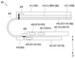
도 4는 일 실시예에 따른 전자 장치의 디스플레이 구동 회로, 터치 센서 회로, 펜 센서 회로, 및 프로세서를 나타낸 도면이다.FIG. 4 is a diagram illustrating a display driving circuit, a touch sensor circuit, a pen sensor circuit, and a processor of an electronic device according to one embodiment.
도 4를 참조하면, 전자 장치(401)(예: 도 1의 전자 장치(101), 또는 도 3a 및 도 3b의 전자 장치(301))는 터치스크린 패널(TSP, touch screen panel)(411), 디스플레이 패널(413)(display panel), 전자기 유도 패널(415), 기판 층(417), 디스플레이 구동 회로(DDI)(419), 제1 회로 기판(또는 연성 인쇄 회로 기판(예: M-FPCB: module flexible printed circuit board))(421), 터치 센서 회로(또는 터치 센서 IC)(423), 커넥터(425), 제2 회로 기판(또는 인쇄 기판 회로)(427)(예: PCB(printed circuit board), FPCB(flexible PCB) 또는 RFPCB(rigid-flexible PCB)), 펜 센서 회로(또는 펜 센서 IC)(429)(예: 도 3의 디지타이저 컨트롤러(329)), 프로세서(431)를 포함할 수 있다. 예를 들면, 제2 회로 기판(427)은 메인 보드이고, 제1 회로 기판(421)은 커넥터(425) 또는 다른 연결 수단을 이용하여 제2 회로 기판(427)에 연결된 서브 기판일 수 있다.Referring to FIG. 4, an electronic device (401) (e.g., the electronic device (101) of FIG. 1, or the electronic device (301) of FIGS. 3A and 3B) may include a touch screen panel (TSP) (411), a display panel (413), an electromagnetic induction panel (415), a substrate layer (417), a display driver circuit (DDI) (419), a first circuit board (or a flexible printed circuit board (e.g., a module flexible printed circuit board (M-FPCB)) (421), a touch sensor circuit (or a touch sensor IC) (423), a connector (425), a second circuit board (or a printed circuit circuit) (427) (e.g., a printed circuit board (PCB), a flexible PCB (FPCB), or a rigid-flexible PCB (RFPCB)), a pen sensor circuit (or a pen sensor IC) (429) (e.g., a digitizer controller (329) of FIG. 3), and a processor (431). For example, the second circuit board (427) may be a main board, and the first circuit board (421) may be a sub-board connected to the second circuit board (427) using a connector (425) or other connecting means.
일 실시예에 따른 TSP(411)는 적어도 하나의 전극(476)이 배치될 수 있으며, 전극들 사이를 형성하는 스위치(미도시)가 적어도 하나의 전극(476), 기판층(417)과 연결될 수 있다. 전극(476)은 연결 라인(미도시)에 의하여 연결될 수 있으며, DDI(419)에 의해 스위치가 온 상태로 제어되면 전극들이 서로 연결될 수 있다. 전극들은 터치 위치 또는 압력을 확인하기 위한 캐패시턴스 값들을 가질 수 있다. 일 실시예에 따르면, TSP(411)는 ITO(indium tin oxide)와 같은 다양한 도전성 물질을 기초로 하는 투명한 전도성 층(또는, 필름)을 포함할 수 있고, 투명한 전도성 층을 이용하여 전극들의 역할을 수행할 수 있다.According to one embodiment, a TSP (411) may have at least one electrode (476) arranged, and a switch (not shown) formed between the electrodes may be connected to at least one electrode (476) and the substrate layer (417). The electrodes (476) may be connected by a connection line (not shown), and when the switch is controlled to an on state by the DDI (419), the electrodes may be connected to each other. The electrodes may have capacitance values for identifying a touch position or pressure. According to one embodiment, the TSP (411) may include a transparent conductive layer (or film) based on various conductive materials such as ITO (indium tin oxide), and may perform the role of electrodes by using the transparent conductive layer.
일 실시예에 따르면 적어도 하나의 전극(476)은 기판층(417)과 연결될 수 있고, FPCB(478)를 통해 터치 센서 회로(423)와 연결될 수 있으며, 터치 센서 회로(423)에 의해 제어될 수 있다.According to one embodiment, at least one electrode (476) can be connected to the substrate layer (417), connected to the touch sensor circuit (423) via the FPCB (478), and controlled by the touch sensor circuit (423).
일 실시예에 따르면 터치 센서 회로(423)는 FPCB(478)와 제1 회로 기판(예: M-FPCB)(421)를 통해 DDI(419)와 전기적으로 연결될 수 있으며, DDI(419)로부터 동기 신호(예: 제1 동기 신호 또는 제2 동기 신호)를 수신할 수 있다.According to one embodiment, the touch sensor circuit (423) may be electrically connected to the DDI (419) through the FPCB (478) and the first circuit board (e.g., M-FPCB) (421), and may receive a synchronization signal (e.g., a first synchronization signal or a second synchronization signal) from the DDI (419).
일 실시예에 따른 디스플레이 패널(413)은 복수의 픽셀들을 포함할 수 있다. 복수의 픽셀들 각각은 적색 서브 픽셀, 녹색 서브 픽셀 및 청색 서브 픽셀을 포함할 수 있다. 또는 복수의 픽셀들 각각은 적색 서브 픽셀, 녹색 서브 픽셀, 또는 청색 서브 픽셀, 및 녹색 서브 픽셀을 포함할 수 있다. 또는 복수의 픽셀들 각각은 적색 서브 픽셀, 녹색 서브 픽셀, 청색 서브 픽셀, 및 백색 서브 픽셀을 포함할 수 있다. 일 실시예에 따른 디스플레이 패널(413)은 디스플레이 기판 층, 박막 트랜지스터(TFT: thin film transistors) 어레이, 유기 발광(organic light emitting) 층 및 박막 봉지(TFE: thin film encapsulation) 층을 포함할 수 있다. 디스플레이 기판 층은, 디스플레이 패널의 베이스를 이루는 베이스 층일 수 있다. 디스플레이 기판 층은, 유연성을 가지는 폴리머 소재로 형성될 수 있으나 이에 제한되지 않는다. 일 실시예에 따르면, 디스플레이 패널(413)은 OLED(organic light emitting diodes)를 포함하는, UB(unbreakable) type OLED 디스플레이(예: curved display)를 포함할 수 있다. 일 실시예에 따르면, 전자 장치(401)는, TSP(411)가 디스플레이 패널(413)의 적어도 일부로 형성되는 표시 장치(예: 도 3의 표시 장치(360))를 포함할 수 있다. 예를 들면, 표시 장치(360)는, OCTA(on cell touch AMOLED(active matrix organic light-emitting diode)) 방식의 디스플레이를 포함할 수 있다. 또한, 표시 장치(360)는, 이에 한정하지 않으며, 다양한 방식(예: add-on type, in-cell type)으로 형성될 수 있다.The display panel (413) according to one embodiment may include a plurality of pixels. Each of the plurality of pixels may include a red sub-pixel, a green sub-pixel, and a blue sub-pixel. Alternatively, each of the plurality of pixels may include a red sub-pixel, a green sub-pixel, a blue sub-pixel, and a green sub-pixel. Alternatively, each of the plurality of pixels may include a red sub-pixel, a green sub-pixel, a blue sub-pixel, and a white sub-pixel. The display panel (413) according to one embodiment may include a display substrate layer, a thin film transistor (TFT) array, an organic light emitting layer, and a thin film encapsulation (TFE) layer. The display substrate layer may be a base layer forming a base of the display panel. The display substrate layer may be formed of a flexible polymer material, but is not limited thereto. According to one embodiment, the display panel (413) may include an unbreakable (UB) type OLED display (e.g., a curved display) including organic light emitting diodes (OLEDs). According to one embodiment, the electronic device (401) may include a display device (e.g., the display device (360) of FIG. 3) in which the TSP (411) is formed as at least a portion of the display panel (413). For example, the display device (360) may include an OCTA (on cell touch AMOLED (active matrix organic light-emitting diode)) type display. In addition, the display device (360) is not limited thereto and may be formed in various ways (e.g., add-on type, in-cell type).
일 실시예에 따른 전자기 유도 패널(415)은 펜 입력 장치(예: 도 3a 내지 3b의 펜 입력 장치(30))의 위치를 확인하기 위한 신호(예: 전자기장)를 출력할 수 있다.An electromagnetic induction panel (415) according to one embodiment can output a signal (e.g., an electromagnetic field) to identify the position of a pen input device (e.g., the pen input device (30) of FIGS. 3A to 3B).
일 실시예에 따른 기판 층(417)은 디스플레이 패널(413)의 -z 방향(예: 하측 방향)에 배치될 수 있다. 기판 층(417)은 디스플레이 패널(413)에 전력 및/또는 신호를 공급하기 위한 배선을 포함할 수 있다. 다양한 실시 예에 따르면 기판 층(417)은 구부러질 수 있는 소재로 구성되어 디스플레이 패널(413)의 일단에서 제1 회로 기판(예: M-FPCB)(421)까지 연장될 수 있다. 일 실시예에 따른 기판 층(417)은 유연성 있는 소재로 형성될 수 있으며, 기판 층(417)은 적어도 하나 이상의 폴리머층을 포함할 수 있다.A substrate layer (417) according to one embodiment may be disposed in the -z direction (e.g., downward direction) of the display panel (413). The substrate layer (417) may include wiring for supplying power and/or signals to the display panel (413). According to various embodiments, the substrate layer (417) may be formed of a bendable material and may extend from one end of the display panel (413) to the first circuit board (e.g., M-FPCB) (421). The substrate layer (417) according to one embodiment may be formed of a flexible material, and the substrate layer (417) may include at least one polymer layer.
일 실시예에 따른 DDI(419)는 기판 층(417)의 일부 영역에 배치될 수 있다. DDI(419)는 기판 층(417)을 통해 디스플레이 패널(413)의 픽셀들을 제어할 수 있다. 일 실시예에 따른 DDI(419)는 디스플레이 구동 신호를 출력할 수 있다.A DDI (419) according to one embodiment may be placed in a portion of a substrate layer (417). The DDI (419) may control pixels of the display panel (413) through the substrate layer (417). The DDI (419) according to one embodiment may output a display driving signal.
일 실시예에 따른 DDI(419)는 복수의 구동 주파수들(예: 1Hz, 10Hz, 24Hz, 30Hz, 60Hz, 96Hz, 120Hz, 또는 240Hz를 포함하는 구동 주파수들)을 지원할 수 있으며, 복수의 구동 주파수들 중 동작 모드(예: 표시 모드)에 따라 선택된 구동 주파수의 디스플레이 구동 신호를 출력할 수 있다.A DDI (419) according to one embodiment can support a plurality of driving frequencies (e.g., driving frequencies including 1 Hz, 10 Hz, 24 Hz, 30 Hz, 60 Hz, 96 Hz, 120 Hz, or 240 Hz) and can output a display driving signal of a driving frequency selected from among the plurality of driving frequencies according to an operation mode (e.g., a display mode).
일 실시예에 따른 DDI(419)는 프로세서(431)와의 연동을 통해 화면 표시 중 구동 주파수를 동적으로 변경할 수 있고, 시작 구동 주파수에서 목표 구동 주파수로 변경하는 시간의 적어도 일부 구간에서 적어도 하나의 중간 구동 주파수(또는 bridge frequency)로 화면 표시를 수행할 수 있다. 예를 들어, DDI(419)는 화면 표시 중 구동 주파수를 60Hz에서 120Hz로 변경하여 출력할 수 있고, 구동 주파수를 60Hz에서 120Hz로 변경하는 동안 96Hz의 구동 주파수를 출력할 수도 있다.According to one embodiment, the DDI (419) can dynamically change the driving frequency during screen display through interworking with the processor (431), and can perform screen display with at least one intermediate driving frequency (or bridge frequency) during at least a portion of the time period for changing from the start driving frequency to the target driving frequency. For example, the DDI (419) can output the driving frequency by changing it from 60 Hz to 120 Hz during screen display, and can also output the driving frequency of 96 Hz while changing the driving frequency from 60 Hz to 120 Hz.
일 실시예에 따른 DDI(419)는 서로 다른 표시 모드에 기반하여 서로 다른 주파수의 디스플레이 구동 신호를 출력할 수 있다. 일 실시예에 따른 DDI(419)는 제1 모드에서 제1 주파수의 디스플레이 구동 신호 출력 중 제2 모드로의 표시 모드 변경에 기반하여 제2 주파수(예: 제1 주파수와 다른 주파수)의 디스플레이 구동 신호를 출력할 수 있다. 일 실시예에 따르면 디스플레이 구동 신호의 주파수가 변경되는 경우 변경된 디스플레이 구동 신호 주파수에 맞추어 터치 센싱 구동 신호 주파수와 펜 센싱 구동 신호 주파수도 서로 독립되도록 변경되어야 하는데 디스플레이 구동 신호가 터치 센서, 펜 센서, 프로세서로 동시에 제공되는 경우 터치 센싱 구동 신호와 펜 센싱 구동 신호의 변경이 어려울 수 있다.According to one embodiment, the DDI (419) can output display driving signals of different frequencies based on different display modes. According to one embodiment, the DDI (419) can output a display driving signal of a second frequency (e.g., a frequency different from the first frequency) based on a change in the display mode from the output of the display driving signal of the first frequency in the first mode to the second mode. According to one embodiment, when the frequency of the display driving signal is changed, the touch sensing driving signal frequency and the pen sensing driving signal frequency should also be changed independently of each other according to the changed display driving signal frequency. However, when the display driving signal is provided to the touch sensor, the pen sensor, and the processor at the same time, it may be difficult to change the touch sensing driving signal and the pen sensing driving signal.
일 실시예에 따른 DDI(419)는 제2 모드(예: 고속 모드)이거나, 제1 모드(예: 저속 모드)에서 제2 모드로의 변경에 기반하여 프로세서(431)에 제2 모드에 대응된 또는 제2 모드에 대응하도록 변경된 제1 동기화 신호를 제공하고 터치 센서 회로(423) 또는/및 펜 센서 회로(429)에 제1 동기화 신호와 다른 제2 동기화 신호를 제공할 수 있다. 일 실시예에 따르면 제1 구동 신호와 제2 구동 신호는 신호 속성이 다를 수 있다. 예를 들면, 신호 속성은 주파수(frequency), 위상(phase), 또는 펄스 폭(pulse width) 중 적어도 하나를 포함할 수 있다.According to one embodiment, the DDI (419) may provide a first synchronization signal corresponding to the second mode or changed to correspond to the second mode to the processor (431) based on a change from the first mode (e.g., the low-speed mode) to the second mode (e.g., the high-speed mode) and may provide a second synchronization signal different from the first synchronization signal to the touch sensor circuit (423) or/and the pen sensor circuit (429). According to one embodiment, the first drive signal and the second drive signal may have different signal properties. For example, the signal property may include at least one of a frequency, a phase, or a pulse width.
예를 들면, 제2 모드에 대응된 제1 동기화 신호의 주파수는 DDI(419)에서 지원하는 주파수 대역의 중간 주파수일 수 있다.For example, the frequency of the first synchronization signal corresponding to the second mode may be the middle frequency of the frequency band supported by the DDI (419).
예를 들면, 제1 동기화 신호의 주파수는 제1 주파수이고, 제2 동기화 신호의 주파수는 제2 주파수이고, 제2 주파수는 제1 주파수보다 낮은 주파수(Hz)일 수 있다. 예를 들면, 제 1주파수는 제 2주파수의 정수배가 될 수 있다. 예를 들면, 제1 주파수는 120Hz이고, 제2 주파수는 60Hz일 수 있다.For example, the frequency of the first synchronization signal may be a first frequency, the frequency of the second synchronization signal may be a second frequency, and the second frequency may be a frequency (Hz) lower than the first frequency. For example, the first frequency may be an integer multiple of the second frequency. For example, the first frequency may be 120 Hz and the second frequency may be 60 Hz.
예를 들면, DDI(419)는 고속 모드이거나, 저속 모드에서 고속 모드로의 변경에 기반하여 프로세서(431)에 고속 모드에 대응된 또는 변경된 제1 동기화 신호(예: 120Hz 신호)를 제공하고 터치 센서 회로(423)에 제1 동기화 신호(예: 120Hz 신호)와 다른 제2 동기화 신호(예: 60Hz 신호)를 제공할 수 있다. 터치 센서 회로(423)는 제2 동기화 신호(예: 60Hz 신호)를 기반으로 동작하면서 제2 동기화 신호를, 펜 센서 회로(429)로 펜 센서 구동 신호로써 제공할 수 있다.For example, the DDI (419) may provide a first synchronization signal (e.g., a 120 Hz signal) corresponding to or changed in the high-speed mode to the processor (431) based on a change from a low-speed mode to a high-speed mode, and may provide a second synchronization signal (e.g., a 60 Hz signal) different from the first synchronization signal (e.g., a 120 Hz signal) to the touch sensor circuit (423). The touch sensor circuit (423) may operate based on the second synchronization signal (e.g., a 60 Hz signal) and provide the second synchronization signal as a pen sensor driving signal to the pen sensor circuit (429).
다른 예를 들면, DDI(419)는 고속 모드이거나, 저속 모드에서 고속 모드로의 변경에 기반하여 프로세서(431)에 고속 모드에 대응된 또는 변경된 제1 동기화 신호(예: 제1 주파수 신호)를 제공하고 펜 센서 회로(429)에 제1 동기화 신호와 다른 동기화 신호(예: 제2 주파수 신호)를 제공할 수 있다. 펜 센서 회로(429)는 제2 동기화 신호에 기반하여 터치 센서(423)로 터치 센서 구동 신호를 제공할 수 있다. 예를 들면, 제2 주파수는 제1 주파수보다 낮은 주파수(Hz)일 수 있다. 예를 들면, 제 1주파수는 제 2주파수의 정수배가 될 수 있다. 예를 들면, 제1 주파수는 120Hz이고, 제2 주파수는 60Hz일 수 있다.As another example, the DDI (419) may provide a first synchronization signal (e.g., a first frequency signal) corresponding to or changed in the high-speed mode to the processor (431) based on a change from a low-speed mode to a high-speed mode, and may provide a synchronization signal (e.g., a second frequency signal) different from the first synchronization signal to the pen sensor circuit (429). The pen sensor circuit (429) may provide a touch sensor drive signal to the touch sensor (423) based on the second synchronization signal. For example, the second frequency may be a lower frequency (Hz) than the first frequency. For example, the first frequency may be an integer multiple of the second frequency. For example, the first frequency may be 120 Hz and the second frequency may be 60 Hz.
또 다른 예를 들면, DDI(419)는 고속 모드이거나, 저속 모드(예: 일반 표시 모드 또는 AOD(always on display)에서 고속 모드로 변경에 기반하여 프로세서(431)에 고속 모드에 대응된 또는 변경된 제1 동기화 신호(예: 제1 주파수 신호)를 제공하고, 터치 센서 회로(423) 및 펜 센서 회로(429)에 제1 동기화 신호와 다른 제2 동기화 신호(예: 제2 주파수 신호)를 제공할 수 있다. 예를 들면, 제2 주파수는 제1 주파수보다 낮은 주파수(Hz)일 수 있다. 예를 들면, 제 1주파수는 제 2주파수의 정수배가 될 수 있다. 예를 들면, 제1 주파수는 120Hz이고, 제2 주파수는 60Hz일 수 있다.As another example, the DDI (419) may provide a first synchronization signal (e.g., a first frequency signal) corresponding to or changed in the high-speed mode to the processor (431) based on a change from a high-speed mode or a low-speed mode (e.g., a normal display mode or an always on display (AOD) mode) to the high-speed mode, and may provide a second synchronization signal (e.g., a second frequency signal) different from the first synchronization signal to the touch sensor circuit (423) and the pen sensor circuit (429). For example, the second frequency may be a lower frequency (Hz) than the first frequency. For example, the first frequency may be an integer multiple of the second frequency. For example, the first frequency may be 120 Hz and the second frequency may be 60 Hz.
일 실시예에 따른 제1 회로 기판(예: M-FPCB)(421)은 기판 층(417)의 일부 영역과 전기적으로 연결될 수 있다. 예를 들어, 제1 회로 기판(421)은 기판 층(417)에 형성된 도전 패턴(또는 배선)과 전기적으로 연결될 수 있다. 예를 들면, 제1 회로 기판(421)은 M-FPCB(module-flexible printed circuit board)일 수 있다. 일 실시예에 따른 제1 회로 기판(421)은 커넥터(425)를 통해 제2 회로 기판(427)과 연결될 수 있다.A first circuit board (e.g., M-FPCB) (421) according to one embodiment may be electrically connected to a portion of a substrate layer (417). For example, the first circuit board (421) may be electrically connected to a conductive pattern (or wiring) formed on the substrate layer (417). For example, the first circuit board (421) may be a module-flexible printed circuit board (M-FPCB). The first circuit board (421) according to one embodiment may be connected to a second circuit board (427) through a connector (425).
일 실시예에 따른 터치 센서 회로(423)는 제1 회로 기판(421)의 적어도 일부에 배치될 수 있으며 DDI(419)로부터의 디스플레이 구동 신호 기반의 제1 동기화 신호 또는 제1 동기화 신호와 다른 제2 동기화 신호에 기반하여 제1 기간동안 터치 센싱 동작을 수행할 수 있다. 일 실시예에 따르면 터치 센서 회로(423)는 DDI(419)로부터의 디스플레이 구동 신호 기반의 제1 동기화 신호에 기반하여 펜 센서 회로(429)로 제1 동기화 신호 또는 제1 동기화 신호와 다른 제2 동기화 신호를 펜 센서 구동 신호로서 제공할 수 있다.A touch sensor circuit (423) according to one embodiment may be disposed on at least a portion of a first circuit board (421) and may perform a touch sensing operation for a first period of time based on a first synchronization signal based on a display driving signal from a DDI (419) or a second synchronization signal different from the first synchronization signal. According to one embodiment, the touch sensor circuit (423) may provide a first synchronization signal or a second synchronization signal different from the first synchronization signal as a pen sensor driving signal to a pen sensor circuit (429) based on the first synchronization signal based on the display driving signal from the DDI (419).
일 실시예에 따른 펜 센서 회로(429)는 제2 회로 기판(427)의 적어도 일부에 배치될 수 있으며, 디스플레이 구동 신호에 기반한 제1 동기화 신호 또는 제1 동기화 신호와 다른 제2 동기화 신호에 기반하여 제2 기간 동안 펜 센싱 동작을 수행할 수 있다. 일 실시예에 따르면 펜 센서 회로(429)는 DDI(419)로부터의 디스플레이 구동 신호에 기반한 제1 동기화 신호에 기반하여 터치 센서 회로(423)로 제1 동기화 신호 또는 제1 동기화 신호와 다른 제2 동기화 신호를 터치 센서 구동 신호로서 제공할 수 있다. 일 실시예에 따르면 제1 구동 신호와 제2 구동 신호는 신호 속성이 다를 수 있다. 예를 들면, 신호 속성은 주파수(frequency), 위상(phase), 또는 펄스 폭(pulse width) 중 적어도 하나를 포함할 수 있다.A pen sensor circuit (429) according to one embodiment may be disposed on at least a portion of a second circuit board (427) and may perform a pen sensing operation for a second period based on a first synchronization signal based on a display driving signal or a second synchronization signal different from the first synchronization signal. According to one embodiment, the pen sensor circuit (429) may provide a first synchronization signal or a second synchronization signal different from the first synchronization signal as a touch sensor driving signal to the touch sensor circuit (423) based on the first synchronization signal based on the display driving signal from the DDI (419). According to one embodiment, the first driving signal and the second driving signal may have different signal properties. For example, the signal property may include at least one of a frequency, a phase, or a pulse width.
일 실시예(미도시)에 따르면, 펜 센서 회로(429)의 배치 위치는 도시된 예에 한정하기 않으며, 다양하게 배치될 수 있다. 예를 들면, 펜 센서 회로(429)는, 제1 회로 기판(421)의 적어도 일부, 또는 DDI(419)가 배치된 영역에 인접한 영역에 배치될 수 있다.According to one embodiment (not shown), the arrangement location of the pen sensor circuit (429) is not limited to the illustrated example and may be arranged in various ways. For example, the pen sensor circuit (429) may be arranged in at least a portion of the first circuit board (421), or in an area adjacent to an area where the DDI (419) is arranged.
일 실시예에 따른 프로세서(431)는 제2 회로 기판(427)의 적어도 일부에 배치될 수 있으며 DDI(419), 터치 센서 회로(423), 및/또는 펜 센서 회로(429)와 전기적으로 연결될 수 있다. 일 실시예에 따르면 프로세서(431)는 DDI(419)로부터의 디스플레이 구동 신호에 기반하여 디스플레이를 제어하거나, 터치 센서 회로(423) 및/또는 펜 센서 회로(429)에 의한 터치 센싱 및/또는 펜 센싱 결과에 따른 입력을 확인할 수 있다. 예를 들면, 프로세서(431)는 AP(application processor)일 수 있다.A processor (431) according to one embodiment may be disposed on at least a portion of a second circuit board (427) and may be electrically connected to a DDI (419), a touch sensor circuit (423), and/or a pen sensor circuit (429). According to one embodiment, the processor (431) may control a display based on a display driving signal from the DDI (419), or may identify an input according to a result of touch sensing and/or pen sensing by the touch sensor circuit (423) and/or the pen sensor circuit (429). For example, the processor (431) may be an AP (application processor).
도 5는 일 실시예에 따른 전자 장치에서 디스플레이 구동 회로, 터치 센서 회로, 및 펜 센서 회로 간의 신호 처리의 일 예를 나타낸 도면이다. 예를 들면, 디스플레이 구동 회로가 프로세서와 터치 센서 회로에 디스플레이 구동 신호 기반의 동기화 신호를 제공하고 터치 센서 회로가 펜 센서 회로에 동기화 신호를 제공하는 경우를 나타낸 도면이다.FIG. 5 is a diagram illustrating an example of signal processing between a display driver circuit, a touch sensor circuit, and a pen sensor circuit in an electronic device according to one embodiment. For example, the diagram illustrates a case where the display driver circuit provides a synchronization signal based on a display driver signal to a processor and a touch sensor circuit, and the touch sensor circuit provides a synchronization signal to the pen sensor circuit.
도 5를 참조하면, 전자 장치(501)(예: 도 1의 전자 장치(101), 도 3의 전자 장치(301), 또는 도 4의 전자 장치(401))는 디스플레이 구동 회로(DDI, display driver integrated circuit)(519)를 포함하는 디스플레이 모듈(520), 터치 센서 회로(터치 센서 IC)(523)가 배치된 제1 회로 기판(또는 연성 인쇄 회로 기판)(예: M-FPCB)(521), 커넥터(525)를 통해 제1 회로 기판(521)과 전기적으로 연결되며 펜 센서 회로(펜 센서 IC)(529), 프로세서(AP)(531)가 배치된 제2 회로 기판(또는 인쇄 회로 기판)(예: PCB)(527)을 포함할 수 있다.Referring to FIG. 5, an electronic device (501) (e.g., the electronic device (101) of FIG. 1, the electronic device (301) of FIG. 3, or the electronic device (401) of FIG. 4) may include a display module (520) including a display driver integrated circuit (DDI) (519), a first circuit board (or flexible printed circuit board) (e.g., M-FPCB) (521) on which a touch sensor circuit (touch sensor IC) (523) is disposed, and a second circuit board (or printed circuit board) (e.g., PCB) (527) electrically connected to the first circuit board (521) via a connector (525) and on which a pen sensor circuit (pen sensor IC) (529) and a processor (AP) (531) are disposed.
일 실시예에 따른 디스플레이 구동 회로(519)는 제1 디스플레이 구동 신호 기반의 제1 동기화 신호를 터치 센싱을 위한 동기화 신호(SYNC for touch)로서 터치 센서 회로(523)에 제공할 수 있고, 제1 동기화 신호를 프로세서와의 동기화 신호(SYNC for AP)로서 프로세서(531)에 제공할 수 있다. 예를 들면, 제1 디스플레이 구동 신호와 제1 동기화 신호는 같거나 다를 수 있다.A display driving circuit (519) according to one embodiment may provide a first synchronization signal based on a first display driving signal to a touch sensor circuit (523) as a synchronization signal for touch sensing (SYNC for touch), and may provide the first synchronization signal to a processor (531) as a synchronization signal with a processor (SYNC for AP). For example, the first display driving signal and the first synchronization signal may be the same or different.
일 실시예에 따른 터치 센서 회로(523)는 제1 동기화 신호에 기반하여 터치 센싱 동작을 수행하고, 펜 센서 회로(529)에 제1 동기화 신호와 다른 주파수의 제2 동기화 신호(예: 펜 센싱을 위한 동기화 신호(SYNC for pen))를 펜 센서 회로(529)에 제공할 수 있다. 일 실시예에 따르면 제1 구동 신호와 제2 구동 신호는 신호 속성이 다를 수 있다. 예를 들면, 신호 속성은 주파수(frequency), 위상(phase), 또는 펄스 폭(pulse width) 중 적어도 하나를 포함할 수 있다. 예를 들면, 제1 동기화 신호와 제2 동기화 신호는, 터치 센싱 동작과 펜 센싱 동작이 오버랩되지 않도록 하는 신호들일 수 있다. 프로세서(531)는 제1 동기화 신호에 기반하여 프로세싱 동작을 수행할 수 있다. 펜 센서 회로(529)는 제1 동기화 신호와 다른, 제2 동기화 신호 즉, 펜 센싱을 위한 동기화 신호(SYNC for pen)를 이용하여 펜 센싱 동작을 수행할 수 있다.The touch sensor circuit (523) according to one embodiment may perform a touch sensing operation based on a first synchronization signal, and provide a second synchronization signal (e.g., a synchronization signal for pen sensing (SYNC for pen)) having a different frequency from the first synchronization signal to the pen sensor circuit (529). According to one embodiment, the first driving signal and the second driving signal may have different signal properties. For example, the signal properties may include at least one of a frequency, a phase, or a pulse width. For example, the first synchronization signal and the second synchronization signal may be signals that prevent the touch sensing operation and the pen sensing operation from overlapping. The processor (531) may perform a processing operation based on the first synchronization signal. The pen sensor circuit (529) may perform the pen sensing operation using the second synchronization signal, which is different from the first synchronization signal, that is, the synchronization signal for pen sensing (SYNC for pen).
도 6은 일 실시예에 따른 전자 장치에서 디스플레이 구동 회로, 터치 센서 회로, 및 펜 센서 회로 간의 동기화 신호의 일 예를 나타낸 도면이다. 예를 들면, 디스플레이 구동 회로가 프로세서와 터치 센서 회로에 디스플레이 구동 신호 기반의 동기화 신호를 제공하고 터치 센서 회로가 펜 센서 회로에 동기화 신호를 제공하는 경우 각 동기화 신호들을 설명하기 위한 도면이다.FIG. 6 is a diagram illustrating an example of synchronization signals between a display driving circuit, a touch sensor circuit, and a pen sensor circuit in an electronic device according to one embodiment. For example, this diagram is for explaining each synchronization signal when the display driving circuit provides a synchronization signal based on a display driving signal to a processor and a touch sensor circuit, and the touch sensor circuit provides a synchronization signal to the pen sensor circuit.
도 6을 참조하면, 디스플레이 구동 회로(519)에 의해 제1 디스플레이 구동 신호 기반의 제1 동기화 신호(예: 120Hz 신호)(620)가 터치 센싱을 위한 동기화 신호(SYNC for touch)(620)로서 터치 센서 회로(523)에 제공됨과 동시에 또는 순차적으로, 프로세싱을 위한 동기화 신호(SYNC for AP)(610)로서 프로세서(531)에 제공되고, 터치 센서 회로(523)에 의해 제1 동기화 신호와 다른 제2 동기화 신호(630)(예: 60Hz 신호)가, 펜 센싱을 위한 동기화 신호(SYNC for pen)로서 펜 센서 회로(529)에 제공될 수 있다. 일 실시예에 따르면 제1 구동 신호와 제2 구동 신호는 신호 속성들(예: 주파수(frequency), 위상(phase), 또는 펄스 폭(pulse width)) 중 주파수가 다른 경우일 수 있다.Referring to FIG. 6, a first synchronization signal (e.g., a 120 Hz signal) (620) based on a first display driving signal may be provided to a touch sensor circuit (523) as a synchronization signal (SYNC for touch) (620) for touch sensing by a display driving circuit (519) and, simultaneously or sequentially, provided to a processor (531) as a synchronization signal (SYNC for AP) (610) for processing, and a second synchronization signal (630) (e.g., a 60 Hz signal) different from the first synchronization signal may be provided to a pen sensor circuit (529) as a synchronization signal (SYNC for pen) for pen sensing by the touch sensor circuit (523). According to one embodiment, the first driving signal and the second driving signal may have different frequencies among signal properties (e.g., frequency, phase, or pulse width).
예를 들면, 터치 센서 회로(523)는 제1 동기화 신호(터치 센싱을 위한 동기화 신호(SYNC for touch)(620)) 수신에 기반하여 자체적으로 또는 프로세서(531)의 요청에 기반하여 터치 센싱 주파수를 변경할 수 있고, 변경된 터치 센싱 주파수에 따라 터치 센싱과 펜 센싱 간의 간섭이 발생하지 않도록 펜 센서 회로(529)에 전달하기 위한 제2 동기화 신호(예: 펜 센싱을 위한 동기화 신호(SYNC for pen)(630))를 생성할 수 있다.For example, the touch sensor circuit (523) can change the touch sensing frequency on its own or based on a request from the processor (531) based on reception of a first synchronization signal (a synchronization signal for touch sensing (SYNC for touch) (620)), and generate a second synchronization signal (e.g., a synchronization signal for pen sensing (SYNC for pen) (630)) to be transmitted to the pen sensor circuit (529) so that interference between touch sensing and pen sensing does not occur according to the changed touch sensing frequency.
예를 들면, 디스플레이 구동 회로(519)에 의해 제1 디스플레이 구동 신호 기반의 120hz의 제1 동기화 신호가 터치 센싱을 위한 동기화 신호(SYNC for touch)(620)로서 터치 센서 회로(523)에 제공됨과 동시에 또는 순차적으로, 프로세싱을 위한 동기화 신호(SYNC for AP)(610)로서 프로세서(531)에 제공되고, 터치 센서 회로(523)에 의해 제1 동기화 신호와 다른 60hz의 제2 동기화 신호가, 펜 센싱을 위한 동기화 신호(SYNC for pen)로서 펜 센서 회로(529)에 제공되는 경우, 터치 센싱 구간(62)와 펜 센싱 구간(64)의 오버랩이 방지되어 터치 센싱과 펜 센싱 간의 간섭이 발생되지 않을 수 있다.For example, when a first synchronization signal of 120 Hz based on a first display driving signal is provided to a touch sensor circuit (523) as a synchronization signal (SYNC for touch) (620) for touch sensing by a display driving circuit (519) and is simultaneously or sequentially provided to a processor (531) as a synchronization signal (SYNC for AP) (610) for processing, and a second synchronization signal of 60 Hz, different from the first synchronization signal, is provided to a pen sensor circuit (529) as a synchronization signal (SYNC for pen) for pen sensing by the touch sensor circuit (523), the overlap of the touch sensing section (62) and the pen sensing section (64) is prevented, so that interference between the touch sensing and the pen sensing may not occur.
도 7은 일 실시예에 따른 전자 장치에서 디스플레이 구동 회로, 터치 센서 회로, 및 펜 센서 회로 간의 신호 처리의 다른 예를 나타낸 도면이다. 예를 들면, 디스플레이 구동 회로가 프로세서에 디스플레이 구동 신호 기반의 동기화 신호를 제공하고, 터치 센서 회로 및 펜 센서 회로에 각각 터치 센싱을 위한 동기화 신호 및 펜 센싱을 위한 동기화 신호를 제공하는 경우를 나타낸 도면이다.FIG. 7 is a diagram showing another example of signal processing between a display driver circuit, a touch sensor circuit, and a pen sensor circuit in an electronic device according to one embodiment. For example, the diagram shows a case where the display driver circuit provides a synchronization signal based on a display driver signal to the processor, and provides a synchronization signal for touch sensing and a synchronization signal for pen sensing to the touch sensor circuit and the pen sensor circuit, respectively.
도 7을 참조하면, 전자 장치(701)(예: 도 1의 전자 장치(101), 도 3의 전자 장치(301), 또는 도 4의 전자 장치(401))는 디스플레이 구동 회로(DDI: display driver integrated circuit)(719)를 포함하는 디스플레이 모듈(720), 터치 센서 회로(또는 터치 센서 IC)(723)가 배치된 제1 회로 기판(또는 연성 회로 기판)(예: M-FPCB)(721), 커넥터(725)를 통해 제1 회로 기판(721)과 연결되며 펜 센서 회로(또는 펜 센서 IC)(729), 프로세서(AP)(731)가 배치된 제2 회로 기판(또는 인쇄 회로 기판)(예: PCB)(727)를 포함할 수 있다.Referring to FIG. 7, an electronic device (701) (e.g., the electronic device (101) of FIG. 1, the electronic device (301) of FIG. 3, or the electronic device (401) of FIG. 4) may include a display module (720) including a display driver integrated circuit (DDI) (719), a first circuit board (or flexible circuit board) (e.g., M-FPCB) (721) on which a touch sensor circuit (or touch sensor IC) (723) is disposed, and a second circuit board (or printed circuit board) (e.g., PCB) (727) connected to the first circuit board (721) via a connector (725) and on which a pen sensor circuit (or pen sensor IC) (729) and a processor (AP) (731) are disposed.
일 실시예에 따른 디스플레이 구동 회로(719)는 제1 디스플레이 구동 신호에 기반하여 디스플레이 동작을 수행할 수 있다. 디스플레이 구동 회로(719)는 제1 디스플레이 구동 신호 기반의 제1 동기화 신호를 프로세싱을 위한 동기화 신호(SYNC for AP)로서 프로세서(731)에 제공할 수 있다. 예를 들면, 제1 디스플레이 신호와 제1 동기화 신호는 같거나 다를 수 있다. 디스플레이 구동 회로(719)는 제1 디스플레이 구동 신호에 기반하여 제1 동기화 신호의 신호 속성과 다른 신호 속성의 제2 동기화 신호를 터치 센싱을 위한 동기화 신호(SYNC for touch)로서 터치 센서 회로(723)에 제공할 수 있다. 디스플레이 구동 회로(719)는 제1 디스플레이 구동 신호에 기반한 제1 동기화 신호와 다른 제2 동기화 신호를 펜 센싱을 위한 동기화 신호(SYNC for pen)로서 펜 센서 회로(729)에 제공할 수 있다. 예를 들면, 제1 동기화 신호의 신호 속성은 제2 동기화 신호의 신호 속성과 다를 수 있다. 예를 들면, 신호 속성은 주파수(frequency), 위상(phase), 또는 펄스 폭(pulse width) 중 적어도 하나를 포함할 수 있다.A display driving circuit (719) according to one embodiment can perform a display operation based on a first display driving signal. The display driving circuit (719) can provide a first synchronization signal based on the first display driving signal to the processor (731) as a synchronization signal (SYNC for AP) for processing. For example, the first display signal and the first synchronization signal may be the same or different. The display driving circuit (719) can provide a second synchronization signal having different signal properties from the signal properties of the first synchronization signal based on the first display driving signal as a synchronization signal (SYNC for touch) for touch sensing to the touch sensor circuit (723). The display driving circuit (719) can provide a second synchronization signal different from the first synchronization signal based on the first display driving signal as a synchronization signal (SYNC for pen) for pen sensing to the pen sensor circuit (729). For example, the signal properties of the first synchronization signal may be different from the signal properties of the second synchronization signal. For example, the signal properties may include at least one of frequency, phase, or pulse width.
일 실시예에 따른 디스플레이 구동 회로(719)는 이전 디스플레이 구동 신호로부터 제1 디스플레이 구동 신호로의 변경에 기반하여 제1 동기화 신호 또는/및 제2 동기화 신호를 변경하여 터치 센서 회로(723)에 제공되는 터치 센싱을 위한 동기화 신호(SYNC for touch)와 펜 센서 회로(729)에 제공되는 펜 센싱을 위한 동기화 신호(SYNC for pen)가 변경되도록 할 수 있다.A display driving circuit (719) according to one embodiment can change a first synchronization signal and/or a second synchronization signal based on a change from a previous display driving signal to a first display driving signal, thereby changing a synchronization signal (SYNC for touch) for touch sensing provided to a touch sensor circuit (723) and a synchronization signal (SYNC for pen) for pen sensing provided to a pen sensor circuit (729).
일 실시예에 따르면 디스플레이 구동 회로(719)는 디스플레이 구동 주파수 변경에 따라 출력 포트(sync output port) 내부의 레지스터 값을 변경 설정하고, 상기 변경 설정된 레지스터 값에 기반하여 터치 센서 회로(723)와 펜 센서 회로(729)에 제공할 제2 동기화 신호를 생성할 수 있다.According to one embodiment, the display driving circuit (719) can change and set a register value inside an output port (sync output port) according to a change in the display driving frequency, and generate a second synchronization signal to be provided to the touch sensor circuit (723) and the pen sensor circuit (729) based on the changed register value.
일 실시예에 따르면, 디스플레이 구동 회로(719)는 서로 다른 속성의 복수의 동기화 신호들을 생성할 수 있으며, 터치 센싱 또는 펜 센싱 상황에 따라 복수의 동기화 신호들 중 터치 센서 회로(723)와 펜 센서 회로(729) 사이에 간섭이 발생되지 않는 적어도 하나의 동기화 신호(예: 제1 동기화 신호 또는/및 제2 동기화 신호)를 선택하여 터치 센서 회로(723) 또는/및 펜 센서 회로(729)에 제공할 수도 있다. 일 실시예에 따른 프로세서(731)는 제1 디스플레이 구동 신호에 기반한 제1 동기화 신호에 기반하여 디스플레이 모듈(720)과 연관된 제어 동작을 수행할 수 있다. 일 실실시예에 따른 터치 센서 회로(723)는 터치 센싱을 위한 동기화 신호(SYNC for touch)에 기반하여 터치 센싱 동작을 수행할 수 있고, 펜 센서 회로(729)는 펜 센싱을 위한 동기화 신호(SYNC for pen)에 기반하여 펜 센싱 동작을 수행할 수 있다. 두 동기화 신호는 터치 센싱 동작과 펜 센싱 동작이 오버랩되지 않도록 하는 신호일 수 있다.According to one embodiment, the display driving circuit (719) can generate a plurality of synchronization signals having different properties, and may select at least one synchronization signal (e.g., a first synchronization signal and/or a second synchronization signal) among the plurality of synchronization signals that does not cause interference between the touch sensor circuit (723) and the pen sensor circuit (729) depending on a touch sensing or pen sensing situation, and provide the synchronization signal to the touch sensor circuit (723) or/and the pen sensor circuit (729). The processor (731) according to one embodiment can perform a control operation associated with the display module (720) based on the first synchronization signal based on the first display driving signal. The touch sensor circuit (723) according to one embodiment can perform a touch sensing operation based on a synchronization signal for touch sensing (SYNC for touch), and the pen sensor circuit (729) can perform a pen sensing operation based on a synchronization signal for pen sensing (SYNC for pen). The two synchronization signals may be signals that prevent touch sensing operations and pen sensing operations from overlapping.
도 8은 일 실시예에 따른 전자 장치에서 디스플레이 구동 회로, 터치 센서 회로, 및 펜 센서 회로 간의 동기화 신호의 다른 예를 나타낸 도면이다. 예를 들면, 디스플레이 구동 회로가 프로세서에 디스플레이 구동 신호 기반의 동기화 신호를 제공하고 터치 센서 회로 및 펜 센서 회로에 각각 터치 센싱을 위한 동기화 신호 및 펜 센싱을 위한 동기화 신호를 제공하는 경우 각 동기화 신호들을 설명하기 위한 도면이다.FIG. 8 is a diagram showing another example of a synchronization signal between a display driving circuit, a touch sensor circuit, and a pen sensor circuit in an electronic device according to one embodiment. For example, this diagram is for explaining each synchronization signal when the display driving circuit provides a synchronization signal based on a display driving signal to the processor and provides a synchronization signal for touch sensing and a synchronization signal for pen sensing to the touch sensor circuit and the pen sensor circuit, respectively.
도 8을 참조하면, 디스플레이 구동 회로(719)에 의해 제1 디스플레이 구동 신호 기반의 제1 동기화 신호(예: 120Hz 신호)가 프로세싱을 위한 동기화 신호(SYNC for AP)(810)로서 프로세서(731)에 제공되고, 제1 동기화 신호와 다른 제2 동기화 신호(예: 60Hz 신호)가 각각 터치 센싱을 위한 동기화 신호(SYNC for touch)(820) 및 펜 센싱을 위한 동기화 신호(SYNC for pen)(830)로서 각각 터치 센서 회로(723) 및 펜 센서 회로(729)에 제공되는 경우, 터치 센싱 구간(72)와 펜 센싱 구간(74)의 오버랩이 방지되어 터치 센싱과 펜 센싱 간의 간섭이 발생되지 않을 수 있다.Referring to FIG. 8, when a first synchronization signal (e.g., a 120 Hz signal) based on a first display driving signal is provided to a processor (731) as a synchronization signal (SYNC for AP) (810) for processing by a display driving circuit (719), and a second synchronization signal (e.g., a 60 Hz signal) different from the first synchronization signal is provided to a touch sensor circuit (723) and a pen sensor circuit (729) as a synchronization signal (SYNC for touch) (820) for touch sensing and a synchronization signal (SYNC for pen) (830) for pen sensing, respectively, an overlap between a touch sensing section (72) and a pen sensing section (74) is prevented, so that interference between touch sensing and pen sensing may not occur.
도 9는 일 실시예에 따른 전자 장치에서 디스플레이 구동 회로, 터치 센서 회로, 및 펜 센서 회로 간의 신호 처리의 또 다른 예를 나타낸 도면이다. 예를 들면, 디스플레이 구동 회로가 프로세서와 펜 센서 회로에 디스플레이 구동 신호에 기반한 동기화 신호를 제공하고 펜 센서 회로가 터치 센서 회로에 동기화 신호를 제공하는 경우를 나타낸 도면이다.FIG. 9 is a diagram illustrating another example of signal processing between a display driver circuit, a touch sensor circuit, and a pen sensor circuit in an electronic device according to one embodiment. For example, the diagram illustrates a case where the display driver circuit provides a synchronization signal based on a display driver signal to the processor and the pen sensor circuit, and the pen sensor circuit provides a synchronization signal to the touch sensor circuit.
도 9를 참조하면, 전자 장치(901)(예: 도 1의 전자 장치(101), 도 3의 전자 장치(301), 또는 도 4의 전자 장치(401))는 디스플레이 구동 회로(DDI: display driver integrated circuit)(919)를 포함하는 디스플레이 모듈(920), 터치 센서 회로(터치 센서 IC)(923)가 배치된 제1 회로 기판(또는 연성 인쇄 회로 기판)(예: M-FPCB)(921), 커넥터(925)를 통해 제1 회로 기판(921)과 전기적으로 연결되며 펜 센서 회로(펜 센서 IC)(929), 프로세서(AP)(931)가 배치된 제2 회로 기판(또는 인쇄 회로 기판)(927)을 포함할 수 있다.Referring to FIG. 9, an electronic device (901) (e.g., the electronic device (101) of FIG. 1, the electronic device (301) of FIG. 3, or the electronic device (401) of FIG. 4) may include a display module (920) including a display driver integrated circuit (DDI) (919), a first circuit board (or flexible printed circuit board) (e.g., M-FPCB) (921) on which a touch sensor circuit (touch sensor IC) (923) is disposed, a second circuit board (or printed circuit board) (927) electrically connected to the first circuit board (921) via a connector (925) and on which a pen sensor circuit (pen sensor IC) (929) and a processor (AP) (931) are disposed.
일 실시예에 따른 디스플레이 구동 회로(919)는 제1 디스플레이 구동 신호 기반의 제1 동기화 신호를 프로세싱을 위한 동기화 신호(SYNC for AP)로서 프로세서(931)에 제공함과 동시에, 또는 순차적으로 상기 제1 동기화 신호를 펜 센싱을 위한 동기화 신호(SYNC for pen)로서 펜 센서 회로(923)에 제공할 수 있다.A display driving circuit (919) according to one embodiment may provide a first synchronization signal based on a first display driving signal to a processor (931) as a synchronization signal for processing (SYNC for AP), or may sequentially provide the first synchronization signal to a pen sensor circuit (923) as a synchronization signal for pen sensing (SYNC for pen).
일 실시예에 따른 프로세서(931)는 제1 디스플레이 구동 신호에 기반하여 프로세싱 동작을 수행할 수 있다.A processor (931) according to one embodiment can perform a processing operation based on a first display driving signal.
일 실시예에 따른 펜 센서 회로(929)는 제1 동기화 신호에 기반하여 펜 센싱 동작을 수행하고, 터치 센서 회로(923)에 제1 동기화 신호와 다른 제2 동기화 신호를 터치 센싱을 위한 동기화 신호(SYNC for touch)로서 터치 센서 회로(923)에 제공할 수 있다.A pen sensor circuit (929) according to one embodiment may perform a pen sensing operation based on a first synchronization signal, and provide a second synchronization signal different from the first synchronization signal to the touch sensor circuit (923) as a synchronization signal for touch sensing (SYNC for touch).
예를 들면, 제1 동기화 신호의 신호 속성은 제2 동기화 신호의 신호 속성과 다를 수 있다. 예를 들면, 신호 속성은 주파수(frequency), 위상(phase), 또는 펄스 폭(pulse width) 중 적어도 하나를 포함할 수 있다.For example, a signal property of the first synchronization signal may be different from a signal property of the second synchronization signal. For example, the signal property may include at least one of frequency, phase, or pulse width.
예를 들면, 제1 동기화 신호와 제2 동기화 신호는 터치 센싱 동작과 펜 센싱 동작이 오버랩되지 않도록 하는 신호들일 수 있다.For example, the first synchronization signal and the second synchronization signal may be signals that prevent the touch sensing operation and the pen sensing operation from overlapping.
예를 들면, 펜 센서 회로(929)는 자체적으로 또는 프로세서(931)의 요청에 기반하여 펜 센싱 주파수를 변경할 수 있고, 변경된 펜 센싱 주파수에 따라 터치 센싱과 펜 센싱 간의 간섭이 발생하지 않도록 터치 센서 회로(923)에 전달하기 위한 제2 동기화 신호(예: 터치 센싱을 위한 동기화 신호(SYNC for pen))를 생성할 수 있다.For example, the pen sensor circuit (929) can change the pen sensing frequency by itself or based on a request from the processor (931), and generate a second synchronization signal (e.g., a synchronization signal for touch sensing (SYNC for pen)) to be transmitted to the touch sensor circuit (923) so that interference between touch sensing and pen sensing does not occur according to the changed pen sensing frequency.
일 실시예에 따르면, 펜 센서 회로(929)와 터치 센서 회로(923)가 하나의 모듈 또는 동일한 기판(예: 인쇄 기판 회로(927), 또는 연성 인쇄 회로 기판(921))에 배치되는 경우, 터치 센서 회로(923)는 펜 센서 회로(929)로부터 전송되는 제2 동기화 신호(예: 터치 센싱을 위한 동기화 신호(SYNC for touch))를 효과적으로 획득할 수 있다.According to one embodiment, when the pen sensor circuit (929) and the touch sensor circuit (923) are arranged in one module or the same substrate (e.g., a printed circuit board circuit (927) or a flexible printed circuit board (921)), the touch sensor circuit (923) can effectively obtain a second synchronization signal (e.g., a synchronization signal for touch sensing (SYNC for touch)) transmitted from the pen sensor circuit (929).
도 10은 일 실시예에 따른 전자 장치에서 디스플레이 구동 회로, 터치 센서 회로, 및 펜 센서 회로 간의 동기화 신호의 또 다른 예를 나타낸 도면이다. 예를 들면, 디스플레이 구동 회로가 프로세서와 펜 센서 회로에 디스플레이 구동 신호 기반의 제1 동기화 신호를 제공하고 펜 센서 회로가 터치 센서 회로에 제2 동기화 신호를 제공하는 경우 각 동기화 신호들을 설명하기 위한 도면이다.FIG. 10 is a diagram illustrating another example of synchronization signals between a display driver circuit, a touch sensor circuit, and a pen sensor circuit in an electronic device according to one embodiment. For example, this diagram is for explaining each synchronization signal when the display driver circuit provides a first synchronization signal based on a display driver signal to the processor and the pen sensor circuit, and the pen sensor circuit provides a second synchronization signal to the touch sensor circuit.
도 10을 참조하면, 디스플레이 구동 회로(919)에 의해 제1 디스플레이 구동 신호(120Hz 신호)가 프로세싱을 위한 동기화 신호(SYNC for AP)(1010)로서 프로세서(1031)에 제공됨과 동시에, 또는 순차적으로 펜 센싱을 위한 동기화 신호(SYNC for pen)(1030)로서 펜 센서 회로(929)에 제공되고, 펜 센서 회로(929)에 의해 제1 디스플레이 구동 신호와 다른 신호(60Hz 신호) 예컨대, 터치 센싱을 위한 동기화 신호(SYNC for touch)(1020)가 터치 센서 회로(923)에 제공되는 경우, 터치 센싱 구간(1002)과 펜 센싱 구간(1004)의 오버랩이 방지되어 터치 센싱과 펜 센싱 간의 간섭이 발생되지 않을 수 있다.Referring to FIG. 10, when a first display driving signal (120 Hz signal) is provided to a processor (1031) as a synchronization signal (SYNC for AP) (1010) for processing by a display driving circuit (919) and simultaneously or sequentially provided to a pen sensor circuit (929) as a synchronization signal (SYNC for pen) (1030) for pen sensing, and a signal (60 Hz signal) different from the first display driving signal, for example, a synchronization signal (SYNC for touch) (1020) for touch sensing is provided to a touch sensor circuit (923) by the pen sensor circuit (929), overlap between a touch sensing section (1002) and a pen sensing section (1004) is prevented, so that interference between touch sensing and pen sensing may not occur.
도 11은 일 실시예에 따른 디스플레이 구동 신호에 기반한 프로세서의 동작을 나타낸 도면이다.FIG. 11 is a diagram illustrating the operation of a processor based on a display driving signal according to one embodiment.
도 11을 참조하면, 일 실시예에 따른 전자 장치(예: 도 1의 전자 장치(101), 도 3의 전자 장치(301), 도 4의 전자 장치(401), 도 5의 전자 장치(501), 도 7의 전자 장치(701), 또는 도 9의 전자 장치(901))의 프로세서(예: 도 1의 프로세서(120), 도 4의 프로세서(431), 도 5의 프로세서(531), 도 7의 프로세서(731), 도 9의 프로세서(931))는 1101 내지 1103 동작 중 적어도 하나의 동작을 수행할 수 있다.Referring to FIG. 11, a processor (e.g., a processor (120) of FIG. 1, a processor (431) of FIG. 4, a processor (531) of FIG. 5, a processor (731) of FIG. 7, a processor (931) of FIG. 9) of an electronic device (e.g., an electronic device (101) of FIG. 1, an electronic device (301) of FIG. 3, an electronic device (401) of FIG. 4, an electronic device (501) of FIG. 5, an electronic device (701) of FIG. 7, or an electronic device (901) of FIG. 9) according to one embodiment of the present invention may perform at least one of
1101 동작에서, 프로세서(120)는 디스플레이 구동 회로에 의한 디스플레이 구동 신호가 제1 디스플레이 구동 신호로 변경된 것을 확인할 수 있다. 예를 들면, 디스플레이 구동 회로(919)는 저속 표시 모드에서 고속 표시 모드로 변경됨에 따라 디스플레이 구동 신호를 제1 디스플레이 구동 신호로 변경할 수 있고, 디스플레이 구동 신호 변경에 따라 변경된 제1 디스플레이 구동 신호를 프로세싱을 위한 동기화 신호(sync for AP)로서 프로세서(120)에 제공할 수 있다.In
1102 동작에서, 프로세서(120)는 디스플레이 구동 신호 변경에 기반하여 터치 센싱을 위한 동기화 신호 또는/및 펜 센싱을 위한 동기화 신호 변경을 확인할 수 있다.In
1103 동작에서, 프로세서(120)는 변경된 터치 센싱을 위한 동기화 신호 또는/및 펜 센싱을 위한 동기화 신호에 기반하여 터치 센싱 처리 및 펜 센싱 처리를 수행할 수 있다.In
다양한 실시예에 따른 전자 장치(예: 도 1의 전자 장치(101), 도 3의 전자 장치(301), 도 4의 전자 장치(401), 도 5의 전자 장치(501), 도 7의 전자 장치(701), 또는 도 9의 전자 장치(901))에서 디스플레이 기반 동기화 신호 제공 방법은, 상기 전자 장치의 디스플레이(예: 도 1 및 도 2의 표시 장치(160), 도 5의 디스플레이(520), 도 7의 디스플레이(720), 또는 도 9의 디스플레이(920))가 디스플레이 구동 신호 변경에 기반하여 상기 전자 장치의 프로세서(예: 도 1의 프로세서(120), 도 4의 프로세서(431), 도 5의 프로세서(531), 도 7의 프로세서(731), 도 9의 프로세서(931))에 상기 변경된 디스플레이 구동 신호에 대응된 제1 동기 신호를 제공하는 동작, 및 상기 디스플레이의 상기 제1 동기 신호의 제공에 기반하여, 상기 전자 장치의 제1 센서 회로(예: 도 2의 터치 센서 IC(253), 도 4의 터치 센서 회로(423), 도 5의 터치 센서 회로(523), 도 7의 터치 센서 회로(723), 도 9의 터치 센서 회로(923)) 및 상기 전자 장치의 제2 센서 회로(예: 도 4의 펜 센서 회로(429), 도 5의 펜 센서 회로(529), 도 7의 펜 센서 회로(729), 도 9의 펜 센서 회로(929))중 적어도 하나가 상기 제1 동기 신호와 다른 제2 동기 신호를 제공받는 동작을 포함할 수 있다.A method for providing a display-based synchronization signal in an electronic device (e.g., an electronic device (101) of FIG. 1, an electronic device (301) of FIG. 3, an electronic device (401) of FIG. 4, an electronic device (501) of FIG. 5, an electronic device (701) of FIG. 7, or an electronic device (901) of FIG. 9) according to various embodiments comprises: an operation in which a display of the electronic device (e.g., a display device (160) of FIGS. 1 and 2, a display (520) of FIG. 5, a display (720) of FIG. 7, or a display (920) of FIG. 9) provides a first synchronization signal corresponding to the changed display driving signal to a processor of the electronic device (e.g., a processor (120) of FIG. 1, a processor (431) of FIG. 4, a processor (531) of FIG. 5, a processor (731) of FIG. 7, a processor (931) of FIG. 9) based on a change in a display driving signal; and, based on the provision of the first synchronization signal by the display, a first sensor of the electronic device At least one of the circuit (e.g., the touch sensor IC (253) of FIG. 2, the touch sensor circuit (423) of FIG. 4, the touch sensor circuit (523) of FIG. 5, the touch sensor circuit (723) of FIG. 7, the touch sensor circuit (923) of FIG. 9) and the second sensor circuit (e.g., the pen sensor circuit (429) of FIG. 4, the pen sensor circuit (529) of FIG. 5, the pen sensor circuit (729) of FIG. 7, the pen sensor circuit (929) of FIG. 9) of the electronic device may include an operation of receiving a second synchronization signal different from the first synchronization signal.
도 12는 일 실시예에 따른 전자 장치의 디스플레이 구동 회로, 터치 센서 회로, 펜 센서 회로, 및 프로세서의 동작의 일 예를 나타낸 흐름도이다.FIG. 12 is a flowchart illustrating an example of the operation of a display driving circuit, a touch sensor circuit, a pen sensor circuit, and a processor of an electronic device according to one embodiment.
도 12를 참조하면, 1210 동작에서, 일 실시예에 따른 디스플레이 구동 회로(1219)(예: 도 2의 디스플레이 드라이버 IC(230), 도 4의 DDI(430), 도 5의 디스플레이 구동 회로(519), 도 7의 디스플레이 구동 회로(719), 도 9의 디스플레이 구동 회로(919))는 제1 디스플레이 구동 신호 기반의 제1 동기화 신호를, 터치 센싱을 위한 동기화 신호(SYNC for touch)로서 터치 센서 회로(1223)(예: 도 2의 터치 센서 IC(253), 도 4의 터치 센서 회로(423), 도 5의 터치 센서 회로(523), 도 7의 터치 센서 회로(723), 도 9의 터치 센서 회로(923))에 제공할 수 있다.Referring to FIG. 12, in
1220 동작에서, 디스플레이 구동 회로(1219)는 제1 동기화 신호를 터치 센싱을 위한 동기화 신호(SYNC for touch)로서 터치 센서 회로(1223)에 제공함과 동시에 또는 순차적으로 제1 동기화 신호를 프로세서와의 동기화 신호(SYNC for AP)로써 프로세서(1231)(예: 도 1의 프로세서(120), 도 4의 프로세서(431), 도 5의 프로세서(531), 도 7의 프로세서(731), 도 9의 프로세서(931))에 제공할 수 있다. 예를 들면, 제1 디스플레이 구동 신호와 제1 동기화 신호는 같거나 다를 수 있다.In
1230 동작에서, 터치 센서 회로(1223)는 제1 동기화 신호에 기반하여 터치 센싱 동작을 수행하고, 펜 센서 회로(1229)(예: 도 4의 펜 센서 회로(429), 도 5의 펜 센서 회로(529), 도 7의 펜 센서 회로(729), 도 9의 펜 센서 회로(929))에 제1 동기화 신호와 다른 속성의 제2 동기화 신호(예: 펜 센싱을 위한 동기화 신호(SYNC for pen))를 제공할 수 있다. 일 실시예에 따르면 제1 구동 신호와 제2 구동 신호는 신호 속성이 다를 수 있다. 예를 들면, 신호 속성은 주파수(frequency), 위상(phase), 또는 펄스 폭(pulse width) 중 적어도 하나를 포함할 수 있다. 예를 들면, 제1 동기화 신호와 제2 동기화 신호는, 터치 센싱 동작과 펜 센싱 동작이 오버랩되지 않도록 하는 신호들일 수 있다. 프로세서(1231)는 제1 동기화 신호에 기반하여 프로세싱 동작을 수행할 수 있다. 펜 센서 회로(1229)는 제1 동기화 신호와 다른, 제2 동기화 신호 즉, 펜 센싱을 위한 동기화 신호(SYNC for pen)를 이용하여 펜 센싱 동작을 수행할 수 있다.In
도 13은 일 실시예에 따른 전자 장치의 디스플레이 구동 회로, 터치 센서 회로, 펜 센서 회로, 및 프로세서의 동작의 다른 일예를 나타낸 흐름도이다.FIG. 13 is a flowchart illustrating another example of the operation of a display driving circuit, a touch sensor circuit, a pen sensor circuit, and a processor of an electronic device according to one embodiment.
도 13을 참조하면, 1310 동작에서, 일 실시예에 따른 디스플레이 구동 회로(1219)는 제1 디스플레이 구동 신호 기반의 제1 동기화 신호를 프로세싱을 위한 동기화 신호(SYNC for AP)로서 프로세서(1231)에 제공할 수 있다. 예를 들면, 제1 디스플레이 신호와 제1 동기화 신호는 같거나 다를 수 있다.Referring to FIG. 13, in
1320 동작에서, 일 실시예에 따른 디스플레이 구동 회로(1219)는 제1 디스플레이 구동 신호에 기반하여 제1 동기화 신호의 신호 속성과 다른 신호 속성의 제2 동기화 신호를 터치 센싱을 위한 동기화 신호(SYNC for touch)로서 터치 센서 회로(1223)에 제공할 수 있다.In
1330 동작에서, 일 실시예에 따른 디스플레이 구동 회로(1219)는 제1 디스플레이 구동 신호에 기반한 제1 동기화 신호와 다른 제2 동기화 신호를 펜 센싱을 위한 동기화 신호(SYNC for pen)로서 펜 센서 회로(1229)에 제공할 수 있다. 예를 들면, 제1 동기화 신호의 신호 속성은 제2 동기화 신호의 신호 속성과 다를 수 있다. 예를 들면, 신호 속성은 주파수(frequency), 위상(phase), 또는 펄스 폭(pulse width) 중 적어도 하나를 포함할 수 있다. 일 실시예에 따르면 제2 동기화 신호는 동시에 또는 순차적으로 터치 센서 회로(1223) 및 펜 센서 회로(1229)에 제공될 수 있다. 일 실시예에 따르면 제1 구동 신호와 제2 구동 신호는 신호 속성이 다를 수 있다. 예를 들면, 신호 속성은 주파수(frequency), 위상(phase), 또는 펄스 폭(pulse width) 중 적어도 하나를 포함할 수 있다. 예를 들면, 제1 동기화 신호와 제2 동기화 신호는, 터치 센싱 동작과 펜 센싱 동작이 오버랩되지 않도록 하는 신호들일 수 있다. 프로세서(1231)는 제1 동기화 신호에 기반하여 프로세싱 동작을 수행할 수 있다. 터치 센싱 회로(1223)와 펜 센서 회로(1229)와 는 제1 동기화 신호와 다른, 제2 동기화를 이용하여 펜 센싱 동작을 수행할 수 있다.In
도 14는 일 실시예에 따른 전자 장치의 디스플레이 구동 회로, 터치 센서 회로, 펜 센서 회로, 및 프로세서의 동작의 또 다른 일예를 나타낸 흐름도이다.FIG. 14 is a flowchart illustrating another example of the operation of a display driving circuit, a touch sensor circuit, a pen sensor circuit, and a processor of an electronic device according to one embodiment.
도 14를 참조하면, 1410 동작에서, 일 실시예에 따른 디스플레이 구동 회로(1219)는 제1 디스플레이 구동 신호 기반의 제1 동기화 신호를, 펜 센싱을 위한 동기화 신호(SYNC for pen)로서 펜 센서 회로(1229)에 제공할 수 있다.Referring to FIG. 14, in
1420 동작에서, 디스플레이 구동 회로(1219)는 제1 동기화 신호를 펜 센싱을 위한 동기화 신호(SYNC for pen)로서 펜 센서 회로(1229)에 제공함과 동시에 또는 순차적으로 제1 동기화 신호를 프로세서와의 동기화 신호(SYNC for AP)로서 프로세서(1231)에 제공할 수 있다. 예를 들면, 제1 디스플레이 구동 신호와 제1 동기화 신호는 같거나 다를 수 있다.In
1430 동작에서, 펜 센서 회로(1229)는 제1 동기화 신호에 기반하여 펜 센싱 동작을 수행하고, 터치 센서 회로(1223)에 제1 동기화 신호와 다른 주파수의 제2 동기화 신호(예: 터치 센싱을 위한 동기화 신호(SYNC for touch)를 제공할 수 있다. 일 실시예에 따르면 제1 구동 신호와 제2 구동 신호는 신호 속성이 다를 수 있다. 예를 들면, 신호 속성은 주파수(frequency), 위상(phase), 또는 펄스 폭(pulse width) 중 적어도 하나를 포함할 수 있다. 예를 들면, 제1 동기화 신호와 제2 동기화 신호는, 터치 센싱 동작과 펜 센싱 동작이 오버랩되지 않도록 하는 신호들일 수 있다. 프로세서(1231)는 제1 동기화 신호에 기반하여 프로세싱 동작을 수행할 수 있다. 터치 센서 회로(1223)는 제1 동기화 신호와 다른, 제2 동기화 신호 즉, 터치 센싱을 위한 동기화 신호(SYNC for touch)를 이용하여 터치 센싱 동작을 수행할 수 있다.In
본 문서에 개시된 다양한 실시예에 따른 전자 장치는 다양한 형태의 장치가 될 수 있다. 전자 장치는, 예를 들면, 휴대용 통신 장치(예: 스마트폰), 컴퓨터 장치, 휴대용 멀티미디어 장치, 휴대용 의료 기기, 카메라, 웨어러블 장치, 또는 가전 장치를 포함할 수 있다. 본 문서의 실시예에 따른 전자 장치는 전술한 기기들에 한정되지 않는다.The electronic devices according to various embodiments disclosed in this document may be devices of various forms. The electronic devices may include, for example, portable communication devices (e.g., smartphones), computer devices, portable multimedia devices, portable medical devices, cameras, wearable devices, or home appliance devices. The electronic devices according to embodiments of this document are not limited to the above-described devices.
본 문서의 다양한 실시예 및 이에 사용된 용어들은 본 문서에 기재된 기술적 특징들을 특정한 실시예들로 한정하려는 것이 아니며, 해당 실시예의 다양한 변경, 균등물, 또는 대체물을 포함하는 것으로 이해되어야 한다. 도면의 설명과 관련하여, 유사한 또는 관련된 구성요소에 대해서는 유사한 참조 부호가 사용될 수 있다. 아이템에 대응하는 명사의 단수 형은 관련된 문맥상 명백하게 다르게 지시하지 않는 한, 상기 아이템 한 개 또는 복수 개를 포함할 수 있다. 본 문서에서, "A 또는 B", "A 및 B 중 적어도 하나","A 또는 B 중 적어도 하나,""A, B 또는 C," "A, B 및 C 중 적어도 하나,"및 "A, B, 또는 C 중 적어도 하나"와 같은 문구들 각각은 그 문구들 중 해당하는 문구에 함께 나열된 항목들 중 어느 하나, 또는 그들의 모든 가능한 조합을 포함할 수 있다. "제 1", "제 2", 또는 "첫째" 또는 "둘째"와 같은 용어들은 단순히 해당 구성요소를 다른 해당 구성요소와 구분하기 위해 사용될 수 있으며, 해당 구성요소들을 다른 측면(예: 중요성 또는 순서)에서 한정하지 않는다. 어떤(예: 제 1) 구성요소가 다른(예: 제 2) 구성요소에, "기능적으로" 또는 "통신적으로"라는 용어와 함께 또는 이런 용어 없이, "커플드" 또는 "커넥티드"라고 언급된 경우, 그것은 상기 어떤 구성요소가 상기 다른 구성요소에 직접적으로(예: 유선으로), 무선으로, 또는 제 3 구성요소를 통하여 연결될 수 있다는 것을 의미한다.The various embodiments of this document and the terminology used herein are not intended to limit the technical features described in this document to specific embodiments, but should be understood to encompass various modifications, equivalents, or substitutes of the embodiments. In connection with the description of the drawings, similar reference numerals may be used for similar or related components. The singular form of a noun corresponding to an item may include one or more of the items, unless the context clearly dictates otherwise. In this document, each of the phrases "A or B," "at least one of A and B," "at least one of A or B," "A, B, or C," "at least one of A, B, and C," and "at least one of A, B, or C" can include any one of the items listed together in the corresponding phrase, or all possible combinations thereof. Terms such as "first," "second," or "first" or "second" may be used merely to distinguish the corresponding component from other corresponding components, and do not limit the corresponding components in any other respect (e.g., importance or order). When a component (e.g., a first component) is referred to as being “coupled” or “connected” to another component (e.g., a second component), with or without the terms “functionally” or “communicatively,” it means that the component can be connected to the other component directly (e.g., wired), wirelessly, or through a third component.
본 문서에서 사용된 용어 "모듈"은 하드웨어, 소프트웨어 또는 펌웨어로 구현된 유닛을 포함할 수 있으며, 예를 들면, 로직, 논리 블록, 부품, 또는 회로 등의 용어와 상호 호환적으로 사용될 수 있다. 모듈은, 일체로 구성된 부품 또는 하나 또는 그 이상의 기능을 수행하는, 상기 부품의 최소 단위 또는 그 일부가 될 수 있다. 예를 들면, 일 실시예에 따르면, 모듈은 ASIC(application-specific integrated circuit)의 형태로 구현될 수 있다.The term "module" as used in this document may include a unit implemented in hardware, software or firmware, and may be used interchangeably with terms such as logic, logic block, component, or circuit. A module may be an integrally configured component or a minimum unit of the component that performs one or more functions, or a portion thereof. For example, according to one embodiment, a module may be implemented in the form of an application-specific integrated circuit (ASIC).
본 문서의 다양한 실시예는 기기(machine)(예: 전자 장치(101))에 의해 읽을 수 있는 저장 매체(storage medium)(예: 내장 메모리(136) 또는 외장 메모리(138))에 저장된 하나 이상의 명령어들을 포함하는 소프트웨어(예: 프로그램(140))로서 구현될 수 있다. 예를 들면, 기기(예: 전자 장치(101))의 프로세서(예: 프로세서(120))는, 저장 매체로부터 저장된 하나 이상의 명령어들 중 적어도 하나의 명령을 호출하고, 그것을 실행할 수 있다. 이것은 기기가 상기 호출된 적어도 하나의 명령어에 따라 적어도 하나의 기능을 수행하도록 운영되는 것을 가능하게 한다. 상기 하나 이상의 명령어들은 컴파일러에 의해 생성된 코드 또는 인터프리터에 의해 실행될 수 있는 코드를 포함할 수 있다. 기기로 읽을 수 있는 저장매체 는, 비일시적(non-transitory) 저장매체의 형태로 제공될 수 있다. 여기서, ‘비일시적’은 저장매체가 실재(tangible)하는 장치이고, 신호(signal)(예: 전자기파)를 포함하지 않는다는 것을 의미할 뿐이며, 이 용어는 데이터가 저장매체에 반영구적으로 저장되는 경우와 임시적으로 저장되는 경우를 구분하지 않는다.Various embodiments of the present document may be implemented as software (e.g., a program (140)) including one or more instructions stored in a storage medium (e.g., an internal memory (136) or an external memory (138)) readable by a machine (e.g., an electronic device (101)). For example, a processor (e.g., a processor (120)) of the machine (e.g., an electronic device (101)) may call at least one instruction among the one or more instructions stored from the storage medium and execute it. This enables the machine to operate to perform at least one function according to the at least one called instruction. The one or more instructions may include code generated by a compiler or code executable by an interpreter. The machine-readable storage medium may be provided in the form of a non-transitory storage medium. Here, ‘non-transitory’ simply means that the storage medium is a tangible device and does not contain signals (e.g. electromagnetic waves), and the term does not distinguish between cases where data is stored semi-permanently or temporarily on the storage medium.
일 실시예에 따르면, 본 문서에 개시된 다양한 실시예에 따른 방법은 컴퓨터 프로그램 제품(computer program product)에 포함되어 제공될 수 있다. 컴퓨터 프로그램 제품은 상품으로서 판매자 및 구매자 간에 거래될 수 있다. 컴퓨터 프로그램 제품은 기기로 읽을 수 있는 저장 매체(예: compact disc read only memory (CD-ROM))의 형태로 배포되거나, 또는 어플리케이션 스토어(예: 플레이 스토어TM)를 통해 또는 두 개의 사용자 장치들(예: 스마트폰들) 간에 직접, 온라인으로 배포(예: 다운로드 또는 업로드)될 수 있다. 온라인 배포의 경우에, 컴퓨터 프로그램 제품의 적어도 일부는 제조사의 서버, 어플리케이션 스토어의 서버, 또는 중계 서버의 메모리와 같은 기기로 읽을 수 있는 저장 매체에 적어도 일시 저장되거나, 임시적으로 생성될 수 있다.According to one embodiment, the method according to various embodiments disclosed in the present document may be provided as included in a computer program product. The computer program product may be traded between a seller and a buyer as a commodity. The computer program product may be distributed in the form of a machine-readable storage medium (e.g., a compact disc read only memory (CD-ROM)), or may be distributed online (e.g., downloaded or uploaded) via an application store (e.g., Play StoreTM ) or directly between two user devices (e.g., smartphones). In the case of online distribution, at least a part of the computer program product may be at least temporarily stored or temporarily generated in a machine-readable storage medium, such as a memory of a manufacturer's server, a server of an application store, or an intermediary server.
다양한 실시예에 따르면, 상기 기술한 구성요소들의 각각의 구성요소(예: 모듈 또는 프로그램)는 단수 또는 복수의 개체를 포함할 수 있다. 다양한 실시예에 따르면, 전술한 해당 구성요소들 중 하나 이상의 구성요소들 또는 동작들이 생략되거나, 또는 하나 이상의 다른 구성요소들 또는 동작들이 추가될 수 있다. 대체적으로 또는 추가적으로, 복수의 구성요소들(예: 모듈 또는 프로그램)은 하나의 구성요소로 통합될 수 있다. 이런 경우, 통합된 구성요소는 상기 복수의 구성요소들 각각의 구성요소의 하나 이상의 기능들을 상기 통합 이전에 상기 복수의 구성요소들 중 해당 구성요소에 의해 수행되는 것과 동일 또는 유사하게 수행할 수 있다. 다양한 실시예에 따르면, 모듈, 프로그램 또는 다른 구성요소에 의해 수행되는 동작들은 순차적으로, 병렬적으로, 반복적으로, 또는 휴리스틱하게 실행되거나, 상기 동작들 중 하나 이상이 다른 순서로 실행되거나, 생략되거나, 또는 하나 이상의 다른 동작들이 추가될 수 있다.According to various embodiments, each component (e.g., a module or a program) of the above-described components may include a single or multiple entities. According to various embodiments, one or more of the components or operations of the above-described components may be omitted, or one or more other components or operations may be added. Alternatively or additionally, a plurality of components (e.g., a module or a program) may be integrated into a single component. In such a case, the integrated component may perform one or more functions of each of the components of the plurality of components identically or similarly to those performed by the corresponding component of the plurality of components prior to the integration. According to various embodiments, the operations performed by the module, program or other component may be executed sequentially, in parallel, repeatedly, or heuristically, or one or more of the operations may be executed in a different order, omitted, or one or more other operations may be added.
다양한 실시예에 따르면, 명령들을 저장하고 있는 저장 매체에 있어서, 상기 명령들은 적어도 하나의 프로세서에 의하여 실행될 때에 상기 적어도 하나의 프로세서로 하여금 적어도 하나의 동작을 수행하도록 설정된 것으로서, 상기 적어도 하나의 동작은, 디스플레이 구동 회로에 의한 디스플레이 구동 신호가 제1 디스플레이 구동 신호로 변경된 것을 확인하는 동작, 상기 디스플레이 구동 신호 변경에 기반하여 터치 센싱을 위한 동기화 신호 또는/및 펜 센싱을 위한 동기화 신호 변경을 확인하는 동작, 및 상기 변경된 터치 센싱을 위한 동기화 신호 또는/및 펜 센싱을 위한 동기화 신호에 기반하여 터치 센싱 처리 및 펜 센싱 처리를 수행하는 동작을 포함할 수 있다.According to various embodiments, a storage medium storing commands may include: the commands being configured to cause the at least one processor to perform at least one operation when executed by the at least one processor; the at least one operation may include: an operation of confirming that a display driving signal by a display driving circuit has been changed to a first display driving signal; an operation of confirming a change in a synchronization signal for touch sensing and/or a synchronization signal for pen sensing based on the change in the display driving signal; and an operation of performing touch sensing processing and pen sensing processing based on the changed synchronization signal for touch sensing and/or synchronization signal for pen sensing.
그리고 본 명세서와 도면에 발명된 본 발명의 실시예들은 본 발명의 실시예에 따른 기술 내용을 쉽게 설명하고 본 발명의 실시예의 이해를 돕기 위해 특정 예를 제시한 것일 뿐이며, 본 발명의 실시예의 범위를 한정하고자 하는 것은 아니다. 따라서 본 발명의 다양한 실시예의 범위는 여기에 발명된 실시예들 이외에도 본 발명의 다양한 실시예의 기술적 사상을 바탕으로 도출되는 모든 변경 또는 변형된 형태가 본 발명의 다양한 실시예의 범위에 포함되는 것으로 해석되어야 한다.And the embodiments of the present invention disclosed in this specification and drawings are merely specific examples presented to easily explain the technical contents according to the embodiments of the present invention and to help understand the embodiments of the present invention, and are not intended to limit the scope of the embodiments of the present invention. Therefore, the scope of the various embodiments of the present invention should be interpreted as including all changes or modified forms derived based on the technical ideas of the various embodiments of the present invention in addition to the embodiments disclosed herein.
Claims (20)
Translated fromKorean디스플레이;
제1 센서 회로;
제2 센서 회로;
상기 디스플레이, 상기 제1 센서 회로, 및 상기 제2 센서 회로와 전기적으로 연결된 프로세서; 및
디스플레이 구동 회로를 포함하고,
상기 디스플레이 구동 회로는,
상기 디스플레이의 디스플레이 구동 신호를 출력하고,
디스플레이 모드의 변경에 따른 상기 디스플레이의 상기 디스플레이 구동 신호의 변경에 기반하여 상기 프로세서에 변경된 디스플레이 구동 신호에 대응된 제1 동기 신호를 제공하고, 상기 제1 센서 회로 및 상기 제2 센서 회로에 상기 제1 동기 신호와 다른 제2 동기 신호를 제공하도록 설정된 전자 장치.
In electronic devices,
display;
First sensor circuit;
Second sensor circuit;
a processor electrically connected to the display, the first sensor circuit, and the second sensor circuit; and
Contains a display driving circuit,
The above display driving circuit,
Outputs a display driving signal of the above display,
An electronic device configured to provide a first synchronization signal corresponding to the changed display driving signal to the processor based on a change in the display driving signal of the display according to a change in the display mode, and to provide a second synchronization signal different from the first synchronization signal to the first sensor circuit and the second sensor circuit.
상기 제1 센서 회로는 터치 센서 IC를 포함하고,
상기 제2 센서 회로는 펜 센서 IC를 포함하는 전자 장치.
In the first paragraph,
The above first sensor circuit includes a touch sensor IC,
The second sensor circuit is an electronic device including a pen sensor IC.
상기 프로세서는 상기 제1 동기 신호에 기반하여 프로세싱을 수행하고,
상기 터치 센서 IC는 상기 제2 동기 신호에 기반하여 터치 센싱 동작을 수행하고,
상기 펜 센서 IC는 상기 제2 동기 신호에 기반하여 펜 센싱 동작을 수행하는 전자 장치.
In the second paragraph,
The above processor performs processing based on the first synchronization signal,
The above touch sensor IC performs a touch sensing operation based on the second synchronization signal,
The above pen sensor IC is an electronic device that performs a pen sensing operation based on the second synchronization signal.
상기 제1 동기 신호와 상기 제2 동기 신호는 상기 터치 센서 IC의 터치 센싱 동작 구간의 상기 터치 센싱 동작과 상기 펜 센서 IC의 펜 센싱 동작 구간의 상기 펜 센싱 동작이 오버랩되지 않도록 하는 신호들인 전자 장치.
In paragraph 4,
An electronic device in which the first synchronization signal and the second synchronization signal are signals that prevent the touch sensing operation of the touch sensing operation section of the touch sensor IC and the pen sensing operation of the pen sensing operation section of the pen sensor IC from overlapping.
상기 제2 동기 신호는 상기 터치 센서 IC의 상기 터치 센싱 동작 구간의 상기 터치 센싱 동작과 상기 펜 센서 IC의 상기 펜 센싱 동작 구간의 상기 펜 센싱 동작이 오버랩되지 않도록 복수의 동기 신호들 중 선택된 신호인 전자 장치.
In paragraph 5,
An electronic device in which the second synchronization signal is a signal selected from among a plurality of synchronization signals so that the touch sensing operation of the touch sensing operation section of the touch sensor IC and the pen sensing operation of the pen sensing operation section of the pen sensor IC do not overlap.
상기 제1 동기 신호는 제1 주파수의 동기 신호이고, 상기 제2 동기 신호는 제2 주파수의 동기 신호인 전자 장치.
In the first paragraph,
An electronic device wherein the first synchronization signal is a synchronization signal of a first frequency, and the second synchronization signal is a synchronization signal of a second frequency.
상기 제1 주파수는 120Hz를 포함하고, 상기 제2 주파수는 60Hz를 포함하는 전자 장치.
In Article 12,
An electronic device wherein the first frequency comprises 120 Hz and the second frequency comprises 60 Hz.
상기 전자 장치는,
제1 회로 기판; 및
제2 회로 기판을 더 포함하고,
상기 디스플레이는 디스플레이 구동 IC에 대응하는 상기 디스플레이 구동 회로를 포함하고,
상기 제1 회로 기판은 터치 센서 IC에 대응하는 상기 제1 센서 회로를 포함하고,
상기 제2 회로 기판은 상기 제1 회로 기판과 연결되며 펜 센서 IC에 대응하는 상기 제2 센서 회로 및 어플리케이션 프로세서에 대응하는 상기 프로세서를 포함하는 전자 장치.
In the first paragraph,
The above electronic device,
first circuit board; and
Further comprising a second circuit board,
The above display includes the display driving circuit corresponding to the display driving IC,
The above first circuit board includes the first sensor circuit corresponding to the touch sensor IC,
An electronic device wherein the second circuit board is connected to the first circuit board and includes the second sensor circuit corresponding to the pen sensor IC and the processor corresponding to the application processor.
디스플레이 구동 회로를 통해 상기 전자 장치의 디스플레이의 디스플레이 구동 신호를 출력하는 동작;
상기 전자 장치의 디스플레이 모드의 변경에 따른 상기 디스플레이의 상기 디스플레이 구동 신호의 변경에 기반하여 상기 디스플레이 구동회로를 통해 상기 전자 장치의 프로세서에 변경된 디스플레이 구동 신호에 대응된 제1 동기 신호를 제공하는 동작; 및
상기 디스플레이 구동회로를 통해 상기 전자 장치의 터치 센서 IC 및 상기 전자 장치의 펜 센서 IC에 각각 상기 제1 동기 신호와 다른 제2 동기 신호를 제공하는 동작을 포함하는 방법.A method for providing a display-based synchronization signal in an electronic device,
An operation of outputting a display driving signal of the display of the electronic device through a display driving circuit;
An operation of providing a first synchronization signal corresponding to the changed display driving signal to a processor of the electronic device through the display driving circuit based on a change in the display driving signal of the display according to a change in the display mode of the electronic device; and
A method including an operation of providing a second synchronization signal, which is different from the first synchronization signal, to the touch sensor IC of the electronic device and the pen sensor IC of the electronic device, respectively, through the display driving circuit.
Priority Applications (5)
| Application Number | Priority Date | Filing Date | Title |
|---|---|---|---|
| KR1020200070370AKR102757139B1 (en) | 2020-06-10 | 2020-06-10 | Electronic device and method for synchronizing based on display driving signal |
| EP21822359.2AEP4152129A4 (en) | 2020-06-10 | 2021-05-26 | ELECTRONIC DEVICE AND SYNCHRONIZATION METHOD BASED ON A DISPLAY CONTROL SIGNAL IN AN ELECTRONIC DEVICE |
| PCT/KR2021/006553WO2021251655A1 (en) | 2020-06-10 | 2021-05-26 | Electronic device and synchronization method based on display driving signal in electronic device |
| CN202180041858.0ACN115943356A (en) | 2020-06-10 | 2021-05-26 | Electronic device and synchronization method based on display driving signal in electronic device |
| US18/079,421US20230114167A1 (en) | 2020-06-10 | 2022-12-12 | Electronic device and synchronization method based on display driving signal in electronic device |
Applications Claiming Priority (1)
| Application Number | Priority Date | Filing Date | Title |
|---|---|---|---|
| KR1020200070370AKR102757139B1 (en) | 2020-06-10 | 2020-06-10 | Electronic device and method for synchronizing based on display driving signal |
Publications (2)
| Publication Number | Publication Date |
|---|---|
| KR20210153392A KR20210153392A (en) | 2021-12-17 |
| KR102757139B1true KR102757139B1 (en) | 2025-01-21 |
Family
ID=78846306
Family Applications (1)
| Application Number | Title | Priority Date | Filing Date |
|---|---|---|---|
| KR1020200070370AActiveKR102757139B1 (en) | 2020-06-10 | 2020-06-10 | Electronic device and method for synchronizing based on display driving signal |
Country Status (5)
| Country | Link |
|---|---|
| US (1) | US20230114167A1 (en) |
| EP (1) | EP4152129A4 (en) |
| KR (1) | KR102757139B1 (en) |
| CN (1) | CN115943356A (en) |
| WO (1) | WO2021251655A1 (en) |
Families Citing this family (1)
| Publication number | Priority date | Publication date | Assignee | Title |
|---|---|---|---|---|
| KR20250022941A (en) | 2023-08-08 | 2025-02-18 | 삼성디스플레이 주식회사 | Electonic device |
Citations (1)
| Publication number | Priority date | Publication date | Assignee | Title |
|---|---|---|---|---|
| US20140347320A1 (en) | 2012-07-19 | 2014-11-27 | Cypress Semiconductor Corporation | Interface and synchronization method between touch controller and display driver for operation with touch integrated displays |
Family Cites Families (9)
| Publication number | Priority date | Publication date | Assignee | Title |
|---|---|---|---|---|
| KR20100048236A (en)* | 2008-10-30 | 2010-05-11 | 삼성전자주식회사 | Touch controller increasing sensitivity, display driving circuit and display device having the same |
| JP6240530B2 (en)* | 2014-02-21 | 2017-11-29 | 株式会社ワコム | Signal processing circuit, signal processing method, position detection device, and electronic apparatus |
| US9880649B2 (en)* | 2014-09-29 | 2018-01-30 | Apple Inc. | Touch, pen and force sensor operation with variable refresh displays |
| KR102279817B1 (en)* | 2014-10-23 | 2021-07-21 | 엘지디스플레이 주식회사 | Input System and Method for Detecting Touch Using the Same |
| KR102299421B1 (en)* | 2015-01-30 | 2021-09-08 | 엘지디스플레이 주식회사 | Touch panel display device, Active stylus pen and controlling method thereof |
| KR102592118B1 (en)* | 2016-07-27 | 2023-10-20 | 삼성전자주식회사 | Electronic device having input sensing panels and methof for operating thereof |
| US10353493B2 (en)* | 2016-09-30 | 2019-07-16 | Microsoft Technology Licensing, Llc | Apparatus and method of pen detection at a digitizer |
| KR20180132496A (en)* | 2017-06-02 | 2018-12-12 | 삼성전자주식회사 | Operating method of optical fingerprint sensor and operating method of electronic device and display device including thereof |
| KR102485360B1 (en)* | 2017-12-20 | 2023-01-06 | 삼성전자주식회사 | Electronic device and method for controlling touch sensor controller |
- 2020
- 2020-06-10KRKR1020200070370Apatent/KR102757139B1/enactiveActive
- 2021
- 2021-05-26CNCN202180041858.0Apatent/CN115943356A/enactivePending
- 2021-05-26WOPCT/KR2021/006553patent/WO2021251655A1/ennot_activeCeased
- 2021-05-26EPEP21822359.2Apatent/EP4152129A4/enactivePending
- 2022
- 2022-12-12USUS18/079,421patent/US20230114167A1/ennot_activeAbandoned
Patent Citations (1)
| Publication number | Priority date | Publication date | Assignee | Title |
|---|---|---|---|---|
| US20140347320A1 (en) | 2012-07-19 | 2014-11-27 | Cypress Semiconductor Corporation | Interface and synchronization method between touch controller and display driver for operation with touch integrated displays |
Also Published As
| Publication number | Publication date |
|---|---|
| CN115943356A (en) | 2023-04-07 |
| EP4152129A1 (en) | 2023-03-22 |
| US20230114167A1 (en) | 2023-04-13 |
| WO2021251655A1 (en) | 2021-12-16 |
| KR20210153392A (en) | 2021-12-17 |
| EP4152129A4 (en) | 2023-11-01 |
Similar Documents
| Publication | Publication Date | Title |
|---|---|---|
| US11442587B2 (en) | Electronic device comprising touch layer having opening | |
| US10916200B2 (en) | Display device including scan driver for driving display panel in which empty area enclosed by display area is formed | |
| US20220189408A1 (en) | Electronic device and method for controlling refresh rate of display | |
| US10748491B2 (en) | Electronic device including inactive area | |
| KR102657681B1 (en) | Electronic device and method for quickly updating a partial area of the screen | |
| KR102769009B1 (en) | Electronic device and method for controlling touch function | |
| KR20200065324A (en) | Electronic device for preventing display burn-in | |
| KR102578096B1 (en) | Electronic device for improving visual recognition of partial area of display | |
| KR20220164431A (en) | Electronic device including a touchscreen and method of operating the same | |
| US20220293025A1 (en) | Electronic device and method of operating the same | |
| KR102865729B1 (en) | Electronic device and method for predicting residual image of display and compensating for residual image of the display | |
| US20230114167A1 (en) | Electronic device and synchronization method based on display driving signal in electronic device | |
| KR102725786B1 (en) | Electronic device including display and operation method thereof | |
| KR20230026236A (en) | Electronic device and method for synchronizing timing processing commands controlling display panel | |
| KR20220170610A (en) | Electronic device for controlling different display areas based on different emission signals and method thereof | |
| KR20220101445A (en) | Electronic device and method for controlling display operation in electronic device | |
| KR20220073943A (en) | Control method of an electronic device using stylus and electronic device receiving input from stylus using the same method | |
| KR102842255B1 (en) | Electronic device, method, and computer readable storage medium for reducing afterimage in display area | |
| US12284794B2 (en) | Electronic device including thermal diffusion member | |
| KR20220127024A (en) | Electronic device and method of operating the same | |
| KR20240087476A (en) | Electronic device and method for recognizing accessory using the same | |
| KR20240071254A (en) | Display, and electronic device including the same | |
| KR20240019660A (en) | Display having edge bending structure and electronic device including thereof | |
| KR20250083972A (en) | Electronic device and method for providing different refresh rates on different areas of display panel | |
| KR20240112160A (en) | Electronic device controlling pulse signal from processor to display |
Legal Events
| Date | Code | Title | Description |
|---|---|---|---|
| PA0109 | Patent application | Patent event code:PA01091R01D Comment text:Patent Application Patent event date:20200610 | |
| PG1501 | Laying open of application | ||
| A201 | Request for examination | ||
| PA0201 | Request for examination | Patent event code:PA02012R01D Patent event date:20230413 Comment text:Request for Examination of Application Patent event code:PA02011R01I Patent event date:20200610 Comment text:Patent Application | |
| E902 | Notification of reason for refusal | ||
| PE0902 | Notice of grounds for rejection | Comment text:Notification of reason for refusal Patent event date:20240528 Patent event code:PE09021S01D | |
| E701 | Decision to grant or registration of patent right | ||
| PE0701 | Decision of registration | Patent event code:PE07011S01D Comment text:Decision to Grant Registration Patent event date:20241105 | |
| GRNT | Written decision to grant | ||
| PR0701 | Registration of establishment | Comment text:Registration of Establishment Patent event date:20250115 Patent event code:PR07011E01D | |
| PR1002 | Payment of registration fee | Payment date:20250116 End annual number:3 Start annual number:1 | |
| PG1601 | Publication of registration |