KR102756765B1 - Electronic device including acoustic dimple - Google Patents
Electronic device including acoustic dimpleDownload PDFInfo
- Publication number
- KR102756765B1 KR102756765B1KR1020200089896AKR20200089896AKR102756765B1KR 102756765 B1KR102756765 B1KR 102756765B1KR 1020200089896 AKR1020200089896 AKR 1020200089896AKR 20200089896 AKR20200089896 AKR 20200089896AKR 102756765 B1KR102756765 B1KR 102756765B1
- Authority
- KR
- South Korea
- Prior art keywords
- case
- electronic device
- microphone
- circuit board
- sound
- Prior art date
- Legal status (The legal status is an assumption and is not a legal conclusion. Google has not performed a legal analysis and makes no representation as to the accuracy of the status listed.)
- Active
Links
Images


Classifications
- G—PHYSICS
- G06—COMPUTING OR CALCULATING; COUNTING
- G06F—ELECTRIC DIGITAL DATA PROCESSING
- G06F1/00—Details not covered by groups G06F3/00 - G06F13/00 and G06F21/00
- G06F1/16—Constructional details or arrangements
- G06F1/1613—Constructional details or arrangements for portable computers
- G06F1/163—Wearable computers, e.g. on a belt
- G—PHYSICS
- G06—COMPUTING OR CALCULATING; COUNTING
- G06F—ELECTRIC DIGITAL DATA PROCESSING
- G06F1/00—Details not covered by groups G06F3/00 - G06F13/00 and G06F21/00
- G06F1/16—Constructional details or arrangements
- G06F1/1613—Constructional details or arrangements for portable computers
- G06F1/1628—Enclosures for carrying portable computers with peripheral devices, e.g. cases for a laptop and a printer
- G—PHYSICS
- G06—COMPUTING OR CALCULATING; COUNTING
- G06F—ELECTRIC DIGITAL DATA PROCESSING
- G06F1/00—Details not covered by groups G06F3/00 - G06F13/00 and G06F21/00
- G06F1/16—Constructional details or arrangements
- G06F1/1613—Constructional details or arrangements for portable computers
- G06F1/1633—Constructional details or arrangements of portable computers not specific to the type of enclosures covered by groups G06F1/1615 - G06F1/1626
- G06F1/1684—Constructional details or arrangements related to integrated I/O peripherals not covered by groups G06F1/1635 - G06F1/1675
- G06F1/1688—Constructional details or arrangements related to integrated I/O peripherals not covered by groups G06F1/1635 - G06F1/1675 the I/O peripheral being integrated loudspeakers
- G—PHYSICS
- G06—COMPUTING OR CALCULATING; COUNTING
- G06F—ELECTRIC DIGITAL DATA PROCESSING
- G06F1/00—Details not covered by groups G06F3/00 - G06F13/00 and G06F21/00
- G06F1/16—Constructional details or arrangements
- G06F1/1613—Constructional details or arrangements for portable computers
- G06F1/1633—Constructional details or arrangements of portable computers not specific to the type of enclosures covered by groups G06F1/1615 - G06F1/1626
- G06F1/1684—Constructional details or arrangements related to integrated I/O peripherals not covered by groups G06F1/1635 - G06F1/1675
- G06F1/1698—Constructional details or arrangements related to integrated I/O peripherals not covered by groups G06F1/1635 - G06F1/1675 the I/O peripheral being a sending/receiving arrangement to establish a cordless communication link, e.g. radio or infrared link, integrated cellular phone
- H—ELECTRICITY
- H04—ELECTRIC COMMUNICATION TECHNIQUE
- H04R—LOUDSPEAKERS, MICROPHONES, GRAMOPHONE PICK-UPS OR LIKE ACOUSTIC ELECTROMECHANICAL TRANSDUCERS; DEAF-AID SETS; PUBLIC ADDRESS SYSTEMS
- H04R1/00—Details of transducers, loudspeakers or microphones
- H04R1/08—Mouthpieces; Microphones; Attachments therefor
- H04R1/083—Special constructions of mouthpieces
- H—ELECTRICITY
- H04—ELECTRIC COMMUNICATION TECHNIQUE
- H04R—LOUDSPEAKERS, MICROPHONES, GRAMOPHONE PICK-UPS OR LIKE ACOUSTIC ELECTROMECHANICAL TRANSDUCERS; DEAF-AID SETS; PUBLIC ADDRESS SYSTEMS
- H04R1/00—Details of transducers, loudspeakers or microphones
- H04R1/10—Earpieces; Attachments therefor ; Earphones; Monophonic headphones
- H04R1/1016—Earpieces of the intra-aural type
- H—ELECTRICITY
- H04—ELECTRIC COMMUNICATION TECHNIQUE
- H04R—LOUDSPEAKERS, MICROPHONES, GRAMOPHONE PICK-UPS OR LIKE ACOUSTIC ELECTROMECHANICAL TRANSDUCERS; DEAF-AID SETS; PUBLIC ADDRESS SYSTEMS
- H04R1/00—Details of transducers, loudspeakers or microphones
- H04R1/10—Earpieces; Attachments therefor ; Earphones; Monophonic headphones
- H04R1/1058—Manufacture or assembly
- H04R1/1075—Mountings of transducers in earphones or headphones
- H—ELECTRICITY
- H04—ELECTRIC COMMUNICATION TECHNIQUE
- H04R—LOUDSPEAKERS, MICROPHONES, GRAMOPHONE PICK-UPS OR LIKE ACOUSTIC ELECTROMECHANICAL TRANSDUCERS; DEAF-AID SETS; PUBLIC ADDRESS SYSTEMS
- H04R1/00—Details of transducers, loudspeakers or microphones
- H04R1/10—Earpieces; Attachments therefor ; Earphones; Monophonic headphones
- H04R1/1083—Reduction of ambient noise
- H—ELECTRICITY
- H04—ELECTRIC COMMUNICATION TECHNIQUE
- H04R—LOUDSPEAKERS, MICROPHONES, GRAMOPHONE PICK-UPS OR LIKE ACOUSTIC ELECTROMECHANICAL TRANSDUCERS; DEAF-AID SETS; PUBLIC ADDRESS SYSTEMS
- H04R1/00—Details of transducers, loudspeakers or microphones
- H04R1/20—Arrangements for obtaining desired frequency or directional characteristics
- H04R1/22—Arrangements for obtaining desired frequency or directional characteristics for obtaining desired frequency characteristic only
- H04R1/28—Transducer mountings or enclosures modified by provision of mechanical or acoustic impedances, e.g. resonator, damping means
- H—ELECTRICITY
- H04—ELECTRIC COMMUNICATION TECHNIQUE
- H04R—LOUDSPEAKERS, MICROPHONES, GRAMOPHONE PICK-UPS OR LIKE ACOUSTIC ELECTROMECHANICAL TRANSDUCERS; DEAF-AID SETS; PUBLIC ADDRESS SYSTEMS
- H04R1/00—Details of transducers, loudspeakers or microphones
- H04R1/20—Arrangements for obtaining desired frequency or directional characteristics
- H04R1/32—Arrangements for obtaining desired frequency or directional characteristics for obtaining desired directional characteristic only
- H04R1/40—Arrangements for obtaining desired frequency or directional characteristics for obtaining desired directional characteristic only by combining a number of identical transducers
- H04R1/406—Arrangements for obtaining desired frequency or directional characteristics for obtaining desired directional characteristic only by combining a number of identical transducers microphones
- H—ELECTRICITY
- H04—ELECTRIC COMMUNICATION TECHNIQUE
- H04R—LOUDSPEAKERS, MICROPHONES, GRAMOPHONE PICK-UPS OR LIKE ACOUSTIC ELECTROMECHANICAL TRANSDUCERS; DEAF-AID SETS; PUBLIC ADDRESS SYSTEMS
- H04R2201/00—Details of transducers, loudspeakers or microphones covered by H04R1/00 but not provided for in any of its subgroups
- H04R2201/10—Details of earpieces, attachments therefor, earphones or monophonic headphones covered by H04R1/10 but not provided for in any of its subgroups
- H04R2201/107—Monophonic and stereophonic headphones with microphone for two-way hands free communication
- H—ELECTRICITY
- H04—ELECTRIC COMMUNICATION TECHNIQUE
- H04R—LOUDSPEAKERS, MICROPHONES, GRAMOPHONE PICK-UPS OR LIKE ACOUSTIC ELECTROMECHANICAL TRANSDUCERS; DEAF-AID SETS; PUBLIC ADDRESS SYSTEMS
- H04R2460/00—Details of hearing devices, i.e. of ear- or headphones covered by H04R1/10 or H04R5/033 but not provided for in any of their subgroups, or of hearing aids covered by H04R25/00 but not provided for in any of its subgroups
- H04R2460/01—Hearing devices using active noise cancellation
- H—ELECTRICITY
- H04—ELECTRIC COMMUNICATION TECHNIQUE
- H04R—LOUDSPEAKERS, MICROPHONES, GRAMOPHONE PICK-UPS OR LIKE ACOUSTIC ELECTROMECHANICAL TRANSDUCERS; DEAF-AID SETS; PUBLIC ADDRESS SYSTEMS
- H04R2460/00—Details of hearing devices, i.e. of ear- or headphones covered by H04R1/10 or H04R5/033 but not provided for in any of their subgroups, or of hearing aids covered by H04R25/00 but not provided for in any of its subgroups
- H04R2460/11—Aspects relating to vents, e.g. shape, orientation, acoustic properties in ear tips of hearing devices to prevent occlusion
- H—ELECTRICITY
- H04—ELECTRIC COMMUNICATION TECHNIQUE
- H04R—LOUDSPEAKERS, MICROPHONES, GRAMOPHONE PICK-UPS OR LIKE ACOUSTIC ELECTROMECHANICAL TRANSDUCERS; DEAF-AID SETS; PUBLIC ADDRESS SYSTEMS
- H04R2499/00—Aspects covered by H04R or H04S not otherwise provided for in their subgroups
- H04R2499/10—General applications
- H04R2499/11—Transducers incorporated or for use in hand-held devices, e.g. mobile phones, PDA's, camera's
- H—ELECTRICITY
- H04—ELECTRIC COMMUNICATION TECHNIQUE
- H04R—LOUDSPEAKERS, MICROPHONES, GRAMOPHONE PICK-UPS OR LIKE ACOUSTIC ELECTROMECHANICAL TRANSDUCERS; DEAF-AID SETS; PUBLIC ADDRESS SYSTEMS
- H04R3/00—Circuits for transducers, loudspeakers or microphones
- H04R3/005—Circuits for transducers, loudspeakers or microphones for combining the signals of two or more microphones
Landscapes
- Engineering & Computer Science (AREA)
- Computer Hardware Design (AREA)
- Theoretical Computer Science (AREA)
- Physics & Mathematics (AREA)
- General Engineering & Computer Science (AREA)
- General Physics & Mathematics (AREA)
- Human Computer Interaction (AREA)
- Acoustics & Sound (AREA)
- Signal Processing (AREA)
- Health & Medical Sciences (AREA)
- Otolaryngology (AREA)
- Manufacturing & Machinery (AREA)
- Telephone Set Structure (AREA)
- Telephone Function (AREA)
Abstract
Translated fromKoreanDescription
Translated fromKorean본 문서에 개시된 다양한 실시예는 신체에 착용 가능한 전자 장치에 관한 것으로서, 예를 들면, 음향 홈을 포함하는 전자 장치에 관한 것이다.Various embodiments disclosed in this document relate to wearable electronic devices, for example, electronic devices including acoustic recesses.
전자, 정보, 및 통신 기술이 발달하면서, 하나의 전자 장치에 다양한 기능이 통합되고 있다. 예를 들어, 전자 장치(예: 스마트 폰)는 통신 기능과 아울러, 음향 재생 기기, 촬상 기기, 또는 전자 수첩과 같은 기능을 포함하고 있으며, 어플리케이션의 추가 설치를 통해 더욱 다양한 기능이 스마트 폰에서 구현될 수 있다. 전자 장치는 탑재된 어플리케이션이나 저장된 기능의 실행뿐만 아니라, 유선 또는 무선 방식으로 서버 또는 다른 전자 장치에 접속하여 다양한 정보들을 실시간으로 제공받을 수 있다.As electronic, information, and communication technologies develop, various functions are being integrated into a single electronic device. For example, an electronic device (e.g., a smart phone) includes functions such as a sound reproduction device, a photographing device, or an electronic notebook in addition to a communication function, and more diverse functions can be implemented in the smart phone through additional installation of applications. In addition to executing installed applications or stored functions, an electronic device can receive various information in real time by connecting to a server or other electronic devices in a wired or wireless manner.
전자 장치의 사용이 일상화되면서, 전자 장치의 휴대성과 사용성에 대한 사용자의 요구가 증가할 수 있다. 이러한 사용자 요구에 따라, 손목 시계나 안경과 유사하게, 신체에 착용한 상태로 휴대와 사용이 가능한 전자 장치(이하, '웨어러블(wearable) 전자 장치')가 상용화되기에 이르렀다. 손목 시계형 또는 안경형 전자 장치 이전에, 이어폰 또는 핸즈 프리 세트와 같은 음향 기능을 제공하는 전자 장치는, 스마트 폰과 같은 다른 전자 장치를 더욱 편리하게 사용할 수 있는 환경을 제공해 왔다. 블루투스와 같은 근거리 무선 통신이 보편화되면서, 이어폰이나 핸즈 프리 셋트와 같은 전자 장치는 사용자의 신체(예: 귀)에 착용된 상태에서 다른 전자 장치와 무선 통신을 통해 음향 신호를 송/수신할 수 있다.As the use of electronic devices becomes more common, users' demands for portability and usability of electronic devices may increase. In response to such user demands, electronic devices that can be carried and used while worn on the body, similar to wristwatches or glasses (hereinafter, "wearable electronic devices") have become commercialized. Prior to wristwatch-type or glasses-type electronic devices, electronic devices that provide audio functions, such as earphones or hands-free sets, have provided an environment in which other electronic devices, such as smartphones, can be used more conveniently. As short-range wireless communications such as Bluetooth become more widespread, electronic devices such as earphones or hands-free sets can transmit/receive audio signals through wireless communication with other electronic devices while worn on the user's body (e.g., ears).
사용자의 귀에 착용하는 전자 장치는 착용 부재나 마이크부를 포함할 수 있다. 착용 부재(예: 프레임 또는 후크)는 귀둘레를 감싸도록 구성되어 전자 장치가 사용자의 귀에서 이탈하는 것을 방지할 수 있으며, 마이크부는 사용자의 입(mouth) 가까이에서 음향을 수신할 수 있는 환경을 제공할 수 있다. 최근에는 별도의 착용 부재나 마이크부 없이, 전자 장치가 이도(auditory canal) 상에 위치되면서 이주(tragus), 대이주(antitragus) 및/또는 대이륜(antihelix)에 지지된 상태로 귀에 착용할 수 있는 전자 장치(예: 이어폰 또는 핸즈 프리 세트)의 사용이 보편화되고 있다.An electronic device worn on a user's ear may include a wearing member or a microphone unit. The wearing member (e.g., a frame or a hook) may be configured to wrap around an ear to prevent the electronic device from being removed from the user's ear, and the microphone unit may provide an environment in which sound can be received near the user's mouth. Recently, electronic devices (e.g., earphones or hands-free sets) that can be worn on the ear without a separate wearing member or microphone unit and are supported by the tragus, antitragus, and/or antihelix while being positioned on the auditory canal have become more common.
본 문서에 개시된 다양한 실시예는, 실질적으로 사용자의 귀에 둘러싸인 공간을 이용하여 착용 가능하면서, 복수의 마이크를 이용하여 음향을 수신할 수 있는 전자 장치를 제공할 수 있다.Various embodiments disclosed in this document can provide an electronic device that can receive sound using multiple microphones while being wearable using a space substantially surrounding a user's ears.
본 문서에 개시된 다양한 실시예는, 복수의 마이크를 이용하여 수신된 음향에 기반하여, 수신된 음향의 품질 또는 출력 음향의 품질을 향상시킬 수 있는 전자 장치를 제공할 수 있다.Various embodiments disclosed in this document can provide an electronic device capable of improving the quality of received sound or the quality of output sound based on sound received using multiple microphones.
본 문서에 개시된 다양한 실시예에 따르면, 전자 장치는, 상기 전자 장치가 신체에 착용된 상태에서 적어도 부분적으로 사용자 신체에 접촉하도록 배치되는 제1 케이스, 상기 제1 케이스와 마주보게 결합하고, 상기 전자 장치가 신체에 착용된 상태에서 외측면의 적어도 일부분(이하, '노출 영역')이 외부에 노출되도록 구성된 제2 케이스, 상기 노출 영역에서 상기 제2 케이스를 관통하게 형성된 제1 음향 홀, 상기 제1 음향 홀과는 다른 위치에서 상기 제2 케이스를 관통하게 형성된 제2 음향 홀, 및 상기 제2 케이스의 외측면에서 함몰 형성되며, 상기 제2 음향 홀로부터 연장된 음향 홈(acoustic dimple)을 포함할 수 있다.According to various embodiments disclosed in the present document, an electronic device may include a first case arranged to at least partially contact a user's body while the electronic device is worn on the body, a second case coupled to face the first case and configured such that at least a portion of an outer surface (hereinafter, 'exposure area') of the electronic device is exposed to the outside while the electronic device is worn on the body, a first acoustic hole formed to penetrate the second case in the exposure area, a second acoustic hole formed to penetrate the second case at a different location from the first acoustic hole, and an acoustic dimple formed to be recessed in the outer surface of the second case and extending from the second acoustic hole.
본 문서에 개시된 다양한 실시예에 따르면, 전자 장치는, 상기 전자 장치가 신체에 착용된 상태에서 적어도 부분적으로 사용자 신체에 접촉하도록 배치되는 제1 케이스, 상기 제1 케이스와 마주보게 결합하고, 상기 전자 장치가 신체에 착용된 상태에서 외측면의 적어도 일부분이 외부에 노출되도록 구성된 제2 케이스, 상기 노출 영역에서 상기 제2 케이스를 관통하게 형성된 제1 음향 홀, 상기 제2 케이스의 내측에서 상기 제1 음향 홀에 상응하게 배치된 제1 마이크, 상기 제1 음향 홀과는 다른 위치에서 상기 제2 케이스를 관통하게 형성된 제2 음향 홀, 상기 제2 케이스의 내측에서 상기 제2 음향 홀에 상응하게 배치된 제2 마이크, 상기 제2 케이스의 외측면에서 함몰 형성되며, 상기 제2 음향 홀로부터 연장되어 적어도 부분적으로 상기 노출 영역에 위치된 음향 홈, 및 프로세서를 포함하고, 상기 프로세서는, 상기 제1 마이크 또는 상기 제2 마이크 중 적어도 하나를 이용하여 음향을 수신하도록 설정될 수 있다.According to various embodiments disclosed in the present document, an electronic device includes a first case arranged to at least partially contact a user's body while the electronic device is worn on the body, a second case coupled to face the first case and configured such that at least a portion of an outer surface of the second case is exposed to the outside while the electronic device is worn on the body, a first acoustic hole formed to penetrate the second case in the exposed area, a first microphone arranged corresponding to the first acoustic hole on the inner side of the second case, a second acoustic hole formed to penetrate the second case at a different position from the first acoustic hole, a second microphone arranged corresponding to the second acoustic hole on the inner side of the second case, an acoustic groove formed recessed in the outer side of the second case, extending from the second acoustic hole and at least partially positioned in the exposed area, and a processor, wherein the processor may be configured to receive sound using at least one of the first microphone or the second microphone.
본 문서에 개시된 다양한 실시예에 따른 전자 장치는, 실질적으로 사용자의 귀에 둘러싸인 공간에 착용되면서, 복수의 경로 및/또는 복수의 마이크를 통해 음향을 수신할 수 있다. 예컨대, 복수의 경로 및/또는 복수의 마이크를 통해 수신된 음향에 기반하여, 전자 장치는 음향 빔포밍(beamforming), 액티브 노이즈 캔슬링(active noise canceling; ANC), 에코 캔슬링(echo canceling; EC), 노이즈 억제(noise suppression; NS) 및/또는 피드포워드(feedforward; FF)를 수행하여 사용자 음성과 같은 획득된 음향의 품질을 향상시킬 수 있다. 어떤 실시예에서, 음향을 출력할 때, 전자 장치가 ANC 기능 및/도는 NS 기능을 수행함으로써 출력 음향의 품질을 향상시킬 수 있다.The electronic device according to various embodiments disclosed in this document may be worn in a space substantially surrounding a user's ears, and may receive sound through multiple paths and/or multiple microphones. For example, based on the sound received through the multiple paths and/or multiple microphones, the electronic device may perform sound beamforming, active noise canceling (ANC), echo canceling (EC), noise suppression (NS), and/or feedforward (FF) to improve the quality of acquired sound, such as a user's voice. In some embodiments, when outputting sound, the electronic device may perform an ANC function and/or an NS function to improve the quality of the output sound.
도 1은 다양한 실시예에 따른, 네트워크 환경 내의 전자 장치를 나타내는 블럭도이다.
도 2는 본 문서에 개시된 다양한 실시예에 따른 전자 장치를 나타내는 사시도이다.
도 3은 본 문서에 개시된 다양한 실시예에 따른 전자 장치를 다른 방향에서 바라본 모습을 나타내는 사시도이다.
도 4a는 본 문서에 개시된 다양한 실시예에 따른 전자 장치의 제2 케이스를 나타내는 평면도이다.
도 4b는 도 4a의 라인 A-A'을 따라 본 문서에 개시된 다양한 실시예에 따른 전자 장치의 제2 케이스를 절개하여 나타내는 단면도이다.
도 5는 본 문서에 개시된 다양한 실시예에 따른 전자 장치가 사용자 신체에 착용된 모습을 나타내는 도면이다.
도 6은 본 문서에 개시된 다양한 실시예에 따른 전자 장치를 나타내는 분리 사시도이다.
도 7은 본 문서에 개시된 다양한 실시예에 따른 전자 장치에서, 제2 케이스가 제거된 모습을 나타내는 사시도이다.
도 8은 본 문서에 개시된 다양한 실시예에 따른 전자 장치의 제1 회로 기판을 나타내는 사시도이다.
도 9는 본 문서에 개시된 다양한 실시예에 따른 전자 장치의 브라켓이 배치되는 구조를 나타내는 분리 사시도이다.
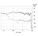
도 10은 본 문서에 개시된 다양한 실시예에 따른 전자 장치의 음압 레벨을 측정하여 나타내는 그래프이다.FIG. 1 is a block diagram illustrating an electronic device within a network environment according to various embodiments.
FIG. 2 is a perspective view illustrating an electronic device according to various embodiments disclosed in this document.
FIG. 3 is a perspective view showing an electronic device according to various embodiments disclosed in this document when viewed from another direction.
FIG. 4A is a plan view illustrating a second case of an electronic device according to various embodiments disclosed in this document.
FIG. 4b is a cross-sectional view illustrating a second case of an electronic device according to various embodiments disclosed in the present document, taken along line A-A' of FIG. 4a.
FIG. 5 is a drawing showing an electronic device according to various embodiments disclosed in this document worn on a user's body.
FIG. 6 is an exploded perspective view illustrating an electronic device according to various embodiments disclosed in this document.
FIG. 7 is a perspective view showing an electronic device according to various embodiments disclosed in this document with the second case removed.
FIG. 8 is a perspective view showing a first circuit board of an electronic device according to various embodiments disclosed in this document.
FIG. 9 is an exploded perspective view showing a structure in which a bracket of an electronic device according to various embodiments disclosed in this document is arranged.
FIG. 10 is a graph showing the measured sound pressure level of an electronic device according to various embodiments disclosed in this document.
도 1은, 다양한 실시예들에 따른, 네트워크 환경(100) 내의 전자 장치(101)의 블록도이다. 도 1을 참조하면, 네트워크 환경(100)에서 전자 장치(101)는 제1 네트워크(198)(예: 근거리 무선 통신 네트워크)를 통하여 전자 장치(102)와 통신하거나, 또는 제2 네트워크(199)(예: 원거리 무선 통신 네트워크)를 통하여 전자 장치(104) 또는 서버(108)와 통신할 수 있다. 일실시예에 따르면, 전자 장치(101)는 서버(108)를 통하여 전자 장치(104)와 통신할 수 있다. 일실시예에 따르면, 전자 장치(101)는 프로세서(120), 메모리(130), 입력 모듈(150), 음향 출력 모듈(155), 디스플레이 모듈(160), 오디오 모듈(170), 센서 모듈(176), 인터페이스(177), 연결 단자(178), 햅틱 모듈(179), 카메라 모듈(180), 전력 관리 모듈(188), 배터리(189), 통신 모듈(190), 가입자 식별 모듈(196), 또는 안테나 모듈(197)을 포함할 수 있다. 어떤 실시예에서는, 전자 장치(101)에는, 이 구성요소들 중 적어도 하나(예: 연결 단자(178))가 생략되거나, 하나 이상의 다른 구성 요소가 추가될 수 있다. 어떤 실시예에서는, 이 구성요소들 중 일부들(예: 센서 모듈(176), 카메라 모듈(180), 또는 안테나 모듈(197))은 하나의 구성요소(예: 디스플레이 모듈(160))로 통합될 수 있다.FIG. 1 is a block diagram of an electronic device (101) in a network environment (100) according to various embodiments. Referring to FIG. 1, in the network environment (100), the electronic device (101) may communicate with the electronic device (102) through a first network (198) (e.g., a short-range wireless communication network), or may communicate with the electronic device (104) or a server (108) through a second network (199) (e.g., a long-range wireless communication network). According to one embodiment, the electronic device (101) may communicate with the electronic device (104) through the server (108). According to one embodiment, the electronic device (101) may include a processor (120), a memory (130), an input module (150), an audio output module (155), a display module (160), an audio module (170), a sensor module (176), an interface (177), a connection terminal (178), a haptic module (179), a camera module (180), a power management module (188), a battery (189), a communication module (190), a subscriber identification module (196), or an antenna module (197). In some embodiments, the electronic device (101) may omit at least one of these components (e.g., the connection terminal (178)), or may include one or more other components. In some embodiments, some of these components (e.g., the sensor module (176), the camera module (180), or the antenna module (197)) may be integrated into one component (e.g., the display module (160)).
프로세서(120)는, 예를 들면, 소프트웨어(예: 프로그램(140))를 실행하여 프로세서(120)에 연결된 전자 장치(101)의 적어도 하나의 다른 구성요소(예: 하드웨어 또는 소프트웨어 구성요소)를 제어할 수 있고, 다양한 데이터 처리 또는 연산을 수행할 수 있다. 일실시예에 따르면, 데이터 처리 또는 연산의 적어도 일부로서, 프로세서(120)는 다른 구성요소(예: 센서 모듈(176) 또는 통신 모듈(190))로부터 수신된 명령 또는 데이터를 휘발성 메모리(132)에 저장하고, 휘발성 메모리(132)에 저장된 명령 또는 데이터를 처리하고, 결과 데이터를 비휘발성 메모리(134)에 저장할 수 있다. 일실시예에 따르면, 프로세서(120)는 메인 프로세서(121)(예: 중앙 처리 장치 또는 어플리케이션 프로세서), 또는 이와는 독립적으로 또는 함께 운영 가능한 보조 프로세서(123)(예: 그래픽 처리 장치, 신경망 처리 장치(NPU; neural processing unit), 이미지 시그널 프로세서, 센서 허브 프로세서, 또는 커뮤니케이션 프로세서)를 포함할 수 있다. 예를 들어, 전자 장치(101)가 메인 프로세서(121) 및 보조 프로세서(123)를 포함하는 경우, 보조 프로세서(123)는 메인 프로세서(121)보다 저전력을 사용하거나, 지정된 기능에 특화되도록 설정될 수 있다. 보조 프로세서(123)는 메인 프로세서(121)와 별개로, 또는 그 일부로서 구현될 수 있다.The processor (120) may control at least one other component (e.g., a hardware or software component) of an electronic device (101) connected to the processor (120) by executing, for example, software (e.g., a program (140)), and may perform various data processing or calculations. According to one embodiment, as at least a part of the data processing or calculations, the processor (120) may store a command or data received from another component (e.g., a sensor module (176) or a communication module (190)) in a volatile memory (132), process the command or data stored in the volatile memory (132), and store result data in a nonvolatile memory (134). According to one embodiment, the processor (120) may include a main processor (121) (e.g., a central processing unit or an application processor), or an auxiliary processor (123) (e.g., a graphics processing unit, a neural processing unit (NPU), an image signal processor, a sensor hub processor, or a communication processor) that can operate independently or together with the main processor (121). For example, when the electronic device (101) includes a main processor (121) and an auxiliary processor (123), the auxiliary processor (123) may be configured to use less power than the main processor (121) or to be specialized for a given function. The auxiliary processor (123) may be implemented separately from the main processor (121) or as a part thereof.
보조 프로세서(123)는, 예를 들면, 메인 프로세서(121)가 인액티브(예: 슬립) 상태에 있는 동안 메인 프로세서(121)를 대신하여, 또는 메인 프로세서(121)가 액티브(예: 어플리케이션 실행) 상태에 있는 동안 메인 프로세서(121)와 함께, 전자 장치(101)의 구성요소들 중 적어도 하나의 구성요소(예: 디스플레이 모듈(160), 센서 모듈(176), 또는 통신 모듈(190))와 관련된 기능 또는 상태들의 적어도 일부를 제어할 수 있다. 일실시예에 따르면, 보조 프로세서(123)(예: 이미지 시그널 프로세서 또는 커뮤니케이션 프로세서)는 기능적으로 관련 있는 다른 구성 요소(예: 카메라 모듈(180) 또는 통신 모듈(190))의 일부로서 구현될 수 있다. 일실시예에 따르면, 보조 프로세서(123)(예: 신경망 처리 장치)는 인공지능 모델의 처리에 특화된 하드웨어 구조를 포함할 수 있다. 인공지능 모델은 기계 학습을 통해 생성될 수 있다. 이러한 학습은, 예를 들어, 인공지능이 수행되는 전자 장치(101) 자체에서 수행될 수 있고, 별도의 서버(예: 서버(108))를 통해 수행될 수도 있다. 학습 알고리즘은, 예를 들어, 지도형 학습(supervised learning), 비지도형 학습(unsupervised learning), 준지도형 학습(semi-supervised learning) 또는 강화 학습(reinforcement learning)을 포함할 수 있으나, 전술한 예에 한정되지 않는다. 인공지능 모델은, 복수의 인공 신경망 레이어들을 포함할 수 있다. 인공 신경망은 심층 신경망(DNN: deep neural network), CNN(convolutional neural network), RNN(recurrent neural network), RBM(restricted boltzmann machine), DBN(deep belief network), BRDNN(bidirectional recurrent deep neural network), 심층 Q-네트워크(deep Q-networks) 또는 상기 중 둘 이상의 조합 중 하나일 수 있으나, 전술한 예에 한정되지 않는다. 인공지능 모델은 하드웨어 구조 이외에, 추가적으로 또는 대체적으로, 소프트웨어 구조를 포함할 수 있다.The auxiliary processor (123) may control at least a portion of functions or states associated with at least one of the components of the electronic device (101) (e.g., the display module (160), the sensor module (176), or the communication module (190)), for example, on behalf of the main processor (121) while the main processor (121) is in an inactive (e.g., sleep) state, or together with the main processor (121) while the main processor (121) is in an active (e.g., application execution) state. In one embodiment, the auxiliary processor (123) (e.g., an image signal processor or a communication processor) may be implemented as a part of another functionally related component (e.g., a camera module (180) or a communication module (190)). In one embodiment, the auxiliary processor (123) (e.g., a neural network processing unit) may include a hardware structure specialized for processing artificial intelligence models. The artificial intelligence models may be generated through machine learning. Such learning may be performed, for example, in the electronic device (101) on which artificial intelligence is performed, or may be performed through a separate server (e.g., server (108)). The learning algorithm may include, for example, supervised learning, unsupervised learning, semi-supervised learning, or reinforcement learning, but is not limited to the examples described above. The artificial intelligence model may include a plurality of artificial neural network layers. The artificial neural network may be one of a deep neural network (DNN), a convolutional neural network (CNN), a recurrent neural network (RNN), a restricted Boltzmann machine (RBM), a deep belief network (DBN), a bidirectional recurrent deep neural network (BRDNN), deep Q-networks, or a combination of two or more of the above, but is not limited to the examples described above. In addition to the hardware structure, the artificial intelligence model may additionally or alternatively include a software structure.
메모리(130)는, 전자 장치(101)의 적어도 하나의 구성요소(예: 프로세서(120) 또는 센서 모듈(176))에 의해 사용되는 다양한 데이터를 저장할 수 있다. 데이터는, 예를 들어, 소프트웨어(예: 프로그램(140)) 및, 이와 관련된 명령에 대한 입력 데이터 또는 출력 데이터를 포함할 수 있다. 메모리(130)는, 휘발성 메모리(132) 또는 비휘발성 메모리(134)를 포함할 수 있다.The memory (130) can store various data used by at least one component (e.g., processor (120) or sensor module (176)) of the electronic device (101). The data can include, for example, software (e.g., program (140)) and input data or output data for commands related thereto. The memory (130) can include volatile memory (132) or nonvolatile memory (134).
프로그램(140)은 메모리(130)에 소프트웨어로서 저장될 수 있으며, 예를 들면, 운영 체제(142), 미들 웨어(144) 또는 어플리케이션(146)을 포함할 수 있다.The program (140) may be stored as software in the memory (130) and may include, for example, an operating system (142), middleware (144), or an application (146).
입력 모듈(150)은, 전자 장치(101)의 구성요소(예: 프로세서(120))에 사용될 명령 또는 데이터를 전자 장치(101)의 외부(예: 사용자)로부터 수신할 수 있다. 입력 모듈(150)은, 예를 들면, 마이크, 마우스, 키보드, 키(예: 버튼) 또는 디지털 펜(예:스타일러스 펜)을 포함할 수 있다.The input module (150) can receive commands or data to be used for components of the electronic device (101) (e.g., processor (120)) from an external source (e.g., a user) of the electronic device (101). The input module (150) can include, for example, a microphone, a mouse, a keyboard, a key (e.g., a button), or a digital pen (e.g., a stylus pen).
음향 출력 모듈(155)은 음향 신호를 전자 장치(101)의 외부로 출력할 수 있다. 음향 출력 모듈(155)은, 예를 들면, 스피커 또는 리시버를 포함할 수 있다. 스피커는 멀티미디어 재생 또는 녹음 재생과 같이 일반적인 용도로 사용될 수 있다. 리시버는 착신 전화를 수신하기 위해 사용될 수 있다. 일실시예에 따르면, 리시버는 스피커와 별개로, 또는 그 일부로서 구현될 수 있다.The audio output module (155) can output an audio signal to the outside of the electronic device (101). The audio output module (155) can include, for example, a speaker or a receiver. The speaker can be used for general purposes such as multimedia playback or recording playback. The receiver can be used to receive an incoming call. According to one embodiment, the receiver can be implemented separately from the speaker or as a part thereof.
디스플레이 모듈(160)은 전자 장치(101)의 외부(예: 사용자)로 정보를 시각적으로 제공할 수 있다. 디스플레이 모듈(160)은, 예를 들면, 디스플레이, 홀로그램 장치, 또는 프로젝터 및 해당 장치를 제어하기 위한 제어 회로를 포함할 수 있다. 일실시예에 따르면, 디스플레이 모듈(160)은 터치를 감지하도록 설정된 터치 센서, 또는 상기 터치에 의해 발생되는 힘의 세기를 측정하도록 설정된 압력 센서를 포함할 수 있다.The display module (160) can visually provide information to an external party (e.g., a user) of the electronic device (101). The display module (160) can include, for example, a display, a holographic device, or a projector and a control circuit for controlling the device. According to one embodiment, the display module (160) can include a touch sensor configured to detect a touch, or a pressure sensor configured to measure the intensity of a force generated by the touch.
오디오 모듈(170)은 소리를 전기 신호로 변환시키거나, 반대로 전기 신호를 소리로 변환시킬 수 있다. 일실시예에 따르면, 오디오 모듈(170)은, 입력 모듈(150)을 통해 소리를 획득하거나, 음향 출력 모듈(155), 또는 전자 장치(101)와 직접 또는 무선으로 연결된 외부의 전자 장치(예: 전자 장치(102))(예: 스피커 또는 헤드폰))를 통해 소리를 출력할 수 있다.The audio module (170) can convert sound into an electrical signal, or vice versa, convert an electrical signal into sound. According to one embodiment, the audio module (170) can obtain sound through an input module (150), or output sound through an audio output module (155), or an external electronic device (e.g., an electronic device (102)) (e.g., a speaker or headphone) directly or wirelessly connected to the electronic device (101).
센서 모듈(176)은 전자 장치(101)의 작동 상태(예: 전력 또는 온도), 또는 외부의 환경 상태(예: 사용자 상태)를 감지하고, 감지된 상태에 대응하는 전기 신호 또는 데이터 값을 생성할 수 있다. 일실시예에 따르면, 센서 모듈(176)은, 예를 들면, 제스처 센서, 자이로 센서, 기압 센서, 마그네틱 센서, 가속도 센서, 그립 센서, 근접 센서, 컬러 센서, IR(infrared) 센서, 생체 센서, 온도 센서, 습도 센서, 또는 조도 센서를 포함할 수 있다.The sensor module (176) can detect an operating state (e.g., power or temperature) of the electronic device (101) or an external environmental state (e.g., user state) and generate an electric signal or data value corresponding to the detected state. According to one embodiment, the sensor module (176) can include, for example, a gesture sensor, a gyro sensor, a barometric pressure sensor, a magnetic sensor, an acceleration sensor, a grip sensor, a proximity sensor, a color sensor, an IR (infrared) sensor, a biometric sensor, a temperature sensor, a humidity sensor, or an illuminance sensor.
인터페이스(177)는 전자 장치(101)가 외부의 전자 장치(예: 전자 장치(102))와 직접 또는 무선으로 연결되기 위해 사용될 수 있는 하나 이상의 지정된 프로토콜들을 지원할 수 있다. 일실시예에 따르면, 인터페이스(177)는, 예를 들면, HDMI(high definition multimedia interface), USB(universal serial bus) 인터페이스, SD카드 인터페이스, 또는 오디오 인터페이스를 포함할 수 있다.The interface (177) may support one or more designated protocols that may be used to directly or wirelessly connect the electronic device (101) to an external electronic device (e.g., the electronic device (102)). In one embodiment, the interface (177) may include, for example, a high definition multimedia interface (HDMI), a universal serial bus (USB) interface, an SD card interface, or an audio interface.
연결 단자(178)는, 그를 통해서 전자 장치(101)가 외부의 전자 장치(예: 전자 장치(102))와 물리적으로 연결될 수 있는 커넥터를 포함할 수 있다. 일실시예에 따르면, 연결 단자(178)는, 예를 들면, HDMI 커넥터, USB 커넥터, SD 카드 커넥터, 또는 오디오 커넥터(예: 헤드폰 커넥터)를 포함할 수 있다.The connection terminal (178) may include a connector through which the electronic device (101) may be physically connected to an external electronic device (e.g., the electronic device (102)). According to one embodiment, the connection terminal (178) may include, for example, an HDMI connector, a USB connector, an SD card connector, or an audio connector (e.g., a headphone connector).
햅틱 모듈(179)은 전기적 신호를 사용자가 촉각 또는 운동 감각을 통해서 인지할 수 있는 기계적인 자극(예: 진동 또는 움직임) 또는 전기적인 자극으로 변환할 수 있다. 일실시예에 따르면, 햅틱 모듈(179)은, 예를 들면, 모터, 압전 소자, 또는 전기 자극 장치를 포함할 수 있다.The haptic module (179) can convert an electrical signal into a mechanical stimulus (e.g., vibration or movement) or an electrical stimulus that a user can perceive through a tactile or kinesthetic sense. According to one embodiment, the haptic module (179) can include, for example, a motor, a piezoelectric element, or an electrical stimulation device.
카메라 모듈(180)은 정지 영상 및 동영상을 촬영할 수 있다. 일실시예에 따르면, 카메라 모듈(180)은 하나 이상의 렌즈들, 이미지 센서들, 이미지 시그널 프로세서들, 또는 플래시들을 포함할 수 있다.The camera module (180) can capture still images and moving images. According to one embodiment, the camera module (180) can include one or more lenses, image sensors, image signal processors, or flashes.
전력 관리 모듈(188)은 전자 장치(101)에 공급되는 전력을 관리할 수 있다. 일실시예에 따르면, 전력 관리 모듈(188)은, 예를 들면, PMIC(power management integrated circuit)의 적어도 일부로서 구현될 수 있다.The power management module (188) can manage power supplied to the electronic device (101). According to one embodiment, the power management module (188) can be implemented as, for example, at least a part of a power management integrated circuit (PMIC).
배터리(189)는 전자 장치(101)의 적어도 하나의 구성 요소에 전력을 공급할 수 있다. 일실시예에 따르면, 배터리(189)는, 예를 들면, 재충전 불가능한 1차 전지, 재충전 가능한 2차 전지 또는 연료 전지를 포함할 수 있다.A battery (189) may power at least one component of the electronic device (101). In one embodiment, the battery (189) may include, for example, a non-rechargeable primary battery, a rechargeable secondary battery, or a fuel cell.
통신 모듈(190)은 전자 장치(101)와 외부의 전자 장치(예: 전자 장치(102), 전자 장치(104), 또는 서버(108))간의 직접(예: 유선) 통신 채널 또는 무선 통신 채널의 수립, 및 수립된 통신 채널을 통한 통신 수행을 지원할 수 있다. 통신 모듈(190)은 프로세서(120)(예: 어플리케이션 프로세서)와 독립적으로 운영되고, 직접(예: 유선) 통신 또는 무선 통신을 지원하는 하나 이상의 커뮤니케이션 프로세서를 포함할 수 있다. 일실시예에 따르면, 통신 모듈(190)은 무선 통신 모듈(192)(예: 셀룰러 통신 모듈, 근거리 무선 통신 모듈, 또는 GNSS(global navigation satellite system) 통신 모듈) 또는 유선 통신 모듈(194)(예: LAN(local area network) 통신 모듈, 또는 전력선 통신 모듈)을 포함할 수 있다. 이들 통신 모듈 중 해당하는 통신 모듈은 제1 네트워크(198)(예: 블루투스, WiFi(wireless fidelity) direct 또는 IrDA(infrared data association)와 같은 근거리 통신 네트워크) 또는 제2 네트워크(199)(예: 레거시 셀룰러 네트워크, 5G 네트워크, 차세대 통신 네트워크, 인터넷, 또는 컴퓨터 네트워크(예: LAN 또는 WAN)와 같은 원거리 통신 네트워크)를 통하여 외부의 전자 장치와 통신할 수 있다. 이런 여러 종류의 통신 모듈들은 하나의 구성 요소(예: 단일 칩)으로 통합되거나, 또는 서로 별도의 복수의 구성 요소들(예: 복수 칩들)로 구현될 수 있다. 무선 통신 모듈(192)은 가입자 식별 모듈(196)에 저장된 가입자 정보(예: 국제 모바일 가입자 식별자(IMSI))를 이용하여 제1 네트워크(198) 또는 제2 네트워크(199)와 같은 통신 네트워크 내에서 전자 장치(101)를 확인 또는 인증할 수 있다.The communication module (190) may support establishment of a direct (e.g., wired) communication channel or a wireless communication channel between the electronic device (101) and an external electronic device (e.g., the electronic device (102), the electronic device (104), or the server (108)), and performance of communication through the established communication channel. The communication module (190) may operate independently from the processor (120) (e.g., the application processor) and may include one or more communication processors that support direct (e.g., wired) communication or wireless communication. According to one embodiment, the communication module (190) may include a wireless communication module (192) (e.g., a cellular communication module, a short-range wireless communication module, or a GNSS (global navigation satellite system) communication module) or a wired communication module (194) (e.g., a local area network (LAN) communication module, or a power line communication module). Among these communication modules, a corresponding communication module can communicate with an external electronic device via a first network (198) (e.g., a short-range communication network such as Bluetooth, wireless fidelity (WiFi) direct, or infrared data association (IrDA)) or a second network (199) (e.g., a long-range communication network such as a legacy cellular network, a 5G network, a next-generation communication network, the Internet, or a computer network (e.g., a LAN or WAN)). These various types of communication modules can be integrated into a single component (e.g., a single chip) or implemented as multiple separate components (e.g., multiple chips). The wireless communication module (192) can identify or authenticate the electronic device (101) within a communication network such as the first network (198) or the second network (199) by using subscriber information (e.g., international mobile subscriber identity (IMSI)) stored in the subscriber identification module (196).
무선 통신 모듈(192)은 4G 네트워크 이후의 5G 네트워크 및 차세대 통신 기술, 예를 들어, NR 접속 기술(new radio access technology)을 지원할 수 있다. NR 접속 기술은 고용량 데이터의 고속 전송(eMBB(enhanced mobile broadband)), 단말 전력 최소화와 다수 단말의 접속(mMTC(massive machine type communications)), 또는 고신뢰도와 저지연(URLLC(ultra-reliable and low-latency communications))을 지원할 수 있다. 무선 통신 모듈(192)은, 예를 들어, 높은 데이터 전송률 달성을 위해, 고주파 대역(예: mmWave 대역)을 지원할 수 있다. 무선 통신 모듈(192)은 고주파 대역에서의 성능 확보를 위한 다양한 기술들, 예를 들어, 빔포밍(beamforming), 거대 배열 다중 입출력(massive MIMO(multiple-input and multiple-output)), 전차원 다중입출력(FD-MIMO: full dimensional MIMO), 어레이 안테나(array antenna), 아날로그 빔형성(analog beam-forming), 또는 대규모 안테나(large scale antenna)와 같은 기술들을 지원할 수 있다. 무선 통신 모듈(192)은 전자 장치(101), 외부의 전자 장치(예: 전자 장치(104)) 또는 네트워크 시스템(예: 제2 네트워크(199))에 규정되는 다양한 요구사항을 지원할 수 있다. 일실시예에 따르면, 무선 통신 모듈(192)은 eMBB 실현을 위한 Peak data rate(예: 20Gbps 이상), mMTC 실현을 위한 손실 Coverage(예: 164dB 이하), 또는 URLLC 실현을 위한 U-plane latency(예: 다운링크(DL) 및 업링크(UL) 각각 0.5ms 이하, 또는 라운드 트립 1ms 이하)를 지원할 수 있다.The wireless communication module (192) can support a 5G network and next-generation communication technology after a 4G network, for example, NR access technology (new radio access technology). The NR access technology can support high-speed transmission of high-capacity data (eMBB (enhanced mobile broadband)), terminal power minimization and connection of multiple terminals (mMTC (massive machine type communications)), or high reliability and low latency (URLLC (ultra-reliable and low-latency communications)). The wireless communication module (192) can support, for example, a high-frequency band (e.g., mmWave band) to achieve a high data transmission rate. The wireless communication module (192) may support various technologies for securing performance in a high-frequency band, such as beamforming, massive multiple-input and multiple-output (MIMO), full dimensional MIMO (FD-MIMO), array antenna, analog beam-forming, or large scale antenna. The wireless communication module (192) may support various requirements specified in the electronic device (101), an external electronic device (e.g., the electronic device (104)), or a network system (e.g., the second network (199)). According to one embodiment, the wireless communication module (192) can support a peak data rate (e.g., 20 Gbps or more) for eMBB realization, a loss coverage (e.g., 164 dB or less) for mMTC realization, or a U-plane latency (e.g., 0.5 ms or less for downlink (DL) and uplink (UL) each, or 1 ms or less for round trip) for URLLC realization.
안테나 모듈(197)은 신호 또는 전력을 외부(예: 외부의 전자 장치)로 송신하거나 외부로부터 수신할 수 있다. 일실시예에 따르면, 안테나 모듈은 서브스트레이트(예: PCB) 위에 형성된 도전체 또는 도전성 패턴으로 이루어진 방사체를 포함하는 안테나를 포함할 수 있다. 일실시예에 따르면, 안테나 모듈(197)은 복수의 안테나들(예: 어레이 안테나)을 포함할 수 있다. 이런 경우, 제1 네트워크(198) 또는 제2 네트워크(199)와 같은 통신 네트워크에서 사용되는 통신 방식에 적합한 적어도 하나의 안테나가, 예를 들면, 통신 모듈(190)에 의하여 상기 복수의 안테나들로부터 선택될 수 있다. 신호 또는 전력은 상기 선택된 적어도 하나의 안테나를 통하여 통신 모듈(190)과 외부의 전자 장치 간에 송신되거나 수신될 수 있다. 어떤 실시예에 따르면, 방사체 이외에 다른 부품(예: RFIC(radio frequency integrated circuit))이 추가로 안테나 모듈(197)의 일부로 형성될 수 있다.The antenna module (197) can transmit or receive signals or power to or from the outside (e.g., an external electronic device). According to one embodiment, the antenna module can include an antenna including a radiator formed of a conductor or a conductive pattern formed on a substrate (e.g., a PCB). According to one embodiment, the antenna module (197) can include a plurality of antennas (e.g., an array antenna). In this case, at least one antenna suitable for a communication method used in a communication network, such as the first network (198) or the second network (199), can be selected from the plurality of antennas by, for example, the communication module (190). A signal or power can be transmitted or received between the communication module (190) and the external electronic device through the at least one selected antenna. According to some embodiments, in addition to the radiator, another component (e.g., a radio frequency integrated circuit (RFIC)) can be additionally formed as a part of the antenna module (197).
다양한 실시예에 따르면, 안테나 모듈(197)은 mmWave 안테나 모듈을 형성할 수 있다. 일실시예에 따르면, mmWave 안테나 모듈은 인쇄 회로 기판, 상기 인쇄 회로 기판의 제1 면(예: 아래 면)에 또는 그에 인접하여 배치되고 지정된 고주파 대역(예: mmWave 대역)을 지원할 수 있는 RFIC, 및 상기 인쇄 회로 기판의 제2 면(예: 윗 면 또는 측 면)에 또는 그에 인접하여 배치되고 상기 지정된 고주파 대역의 신호를 송신 또는 수신할 수 있는 복수의 안테나들(예: 어레이 안테나)을 포함할 수 있다.According to various embodiments, the antenna module (197) may form a mmWave antenna module. According to one embodiment, the mmWave antenna module may include a printed circuit board, an RFIC positioned on or adjacent a first side (e.g., a bottom side) of the printed circuit board and capable of supporting a designated high-frequency band (e.g., a mmWave band), and a plurality of antennas (e.g., an array antenna) positioned on or adjacent a second side (e.g., a top side or a side) of the printed circuit board and capable of transmitting or receiving signals in the designated high-frequency band.
상기 구성요소들 중 적어도 일부는 주변 기기들간 통신 방식(예: 버스, GPIO(general purpose input and output), SPI(serial peripheral interface), 또는 MIPI(mobile industry processor interface))를 통해 서로 연결되고 신호(예: 명령 또는 데이터)를 상호간에 교환할 수 있다.At least some of the above components may be connected to each other and exchange signals (e.g., commands or data) with each other via a communication method between peripheral devices (e.g., a bus, a general purpose input and output (GPIO), a serial peripheral interface (SPI), or a mobile industry processor interface (MIPI)).
일실시예에 따르면, 명령 또는 데이터는 제2 네트워크(199)에 연결된 서버(108)를 통해서 전자 장치(101)와 외부의 전자 장치(104)간에 송신 또는 수신될 수 있다. 외부의 전자 장치(102 또는 104) 각각은 전자 장치(101)와 동일한 또는 다른 종류의 장치일 수 있다. 일실시예에 따르면, 전자 장치(101)에서 실행되는 동작들의 전부 또는 일부는 외부의 전자 장치들(102, 104 또는 108) 중 하나 이상의 외부 장치들에서 실행될 수 있다. 예를 들면, 전자 장치(101)가 어떤 기능이나 서비스를 자동으로, 또는 사용자 또는 다른 장치로부터의 요청에 반응하여 수행해야 할 경우에, 전자 장치(101)는 기능 또는 서비스를 자체적으로 실행시키는 대신에 또는 추가적으로, 하나 이상의 외부의 전자 장치들에게 그 기능 또는 그 서비스의 적어도 일부를 수행하라고 요청할 수 있다. 상기 요청을 수신한 하나 이상의 외부의 전자 장치들은 요청된 기능 또는 서비스의 적어도 일부, 또는 상기 요청과 관련된 추가 기능 또는 서비스를 실행하고, 그 실행의 결과를 전자 장치(101)로 전달할 수 있다. 전자 장치(101)는 상기 결과를, 그대로 또는 추가적으로 처리하여, 상기 요청에 대한 응답의 적어도 일부로서 제공할 수 있다. 이를 위하여, 예를 들면, 클라우드 컴퓨팅, 분산 컴퓨팅, 모바일 에지 컴퓨팅(MEC; mobile edge computing) 또는 클라이언트-서버 컴퓨팅 기술이 이용될 수 있다. 전자 장치(101)는, 예를 들어, 분산 컴퓨팅 또는 모바일 에지 컴퓨팅을 이용하여 초저지연 서비스를 제공할 수 있다. 다른 실시예에 있어서, 외부의 전자 장치(104)는 IoT(internet of things) 기기를 포함할 수 있다. 서버(108)는 기계 학습 및/또는 신경망을 이용한 지능형 서버일 수 있다. 일실시예에 따르면, 외부의 전자 장치(104) 또는 서버(108)는 제2 네트워크(199) 내에 포함될 수 있다. 전자 장치(101)는 5G 통신 기술 및 IoT 관련 기술을 기반으로 지능형 서비스(예: 스마트 홈, 스마트 시티, 스마트 카, 또는 헬스 케어)에 적용될 수 있다.According to one embodiment, a command or data may be transmitted or received between the electronic device (101) and an external electronic device (104) via a server (108) connected to a second network (199). Each of the external electronic devices (102 or 104) may be the same or a different type of device as the electronic device (101). According to one embodiment, all or part of the operations executed in the electronic device (101) may be executed in one or more of the external electronic devices (102, 104 or 108). For example, when the electronic device (101) is to perform a certain function or service automatically or in response to a request from a user or another device, the electronic device (101) may, instead of executing the function or service itself or in addition, request one or more external electronic devices to perform at least a part of the function or service. One or more external electronic devices that have received the request may execute at least a part of the requested function or service, or an additional function or service related to the request, and transmit the result of the execution to the electronic device (101). The electronic device (101) may process the result as is or additionally and provide it as at least a part of a response to the request. For this purpose, for example, cloud computing, distributed computing, mobile edge computing (MEC), or client-server computing technology may be used. The electronic device (101) may provide an ultra-low latency service by using, for example, distributed computing or mobile edge computing. In another embodiment, the external electronic device (104) may include an IoT (Internet of Things) device. The server (108) may be an intelligent server using machine learning and/or a neural network. According to one embodiment, the external electronic device (104) or the server (108) may be included in the second network (199). The electronic device (101) can be applied to intelligent services (e.g., smart home, smart city, smart car, or healthcare) based on 5G communication technology and IoT-related technology.
본 문서에 개시된 다양한 실시예들에 따른 전자 장치는 다양한 형태의 장치가 될 수 있다. 전자 장치는, 예를 들면, 휴대용 통신 장치(예: 스마트폰), 컴퓨터 장치, 휴대용 멀티미디어 장치, 휴대용 의료 기기, 카메라, 웨어러블 장치, 또는 가전 장치를 포함할 수 있다. 본 문서의 실시예에 따른 전자 장치는 전술한 기기들에 한정되지 않는다.The electronic devices according to various embodiments disclosed in this document may be devices of various forms. The electronic devices may include, for example, portable communication devices (e.g., smartphones), computer devices, portable multimedia devices, portable medical devices, cameras, wearable devices, or home appliance devices. The electronic devices according to embodiments of this document are not limited to the above-described devices.
본 문서의 다양한 실시예들 및 이에 사용된 용어들은 본 문서에 기재된 기술적 특징들을 특정한 실시예들로 한정하려는 것이 아니며, 해당 실시예의 다양한 변경, 균등물, 또는 대체물을 포함하는 것으로 이해되어야 한다. 도면의 설명과 관련하여, 유사한 또는 관련된 구성요소에 대해서는 유사한 참조 부호가 사용될 수 있다. 아이템에 대응하는 명사의 단수 형은 관련된 문맥상 명백하게 다르게 지시하지 않는 한, 상기 아이템 한 개 또는 복수 개를 포함할 수 있다. 본 문서에서, "A 또는 B", "A 및 B 중 적어도 하나",“A 또는 B 중 적어도 하나”, "A, B 또는 C", "A, B 및 C 중 적어도 하나”, 및 “A, B, 또는 C 중 적어도 하나"와 같은 문구들 각각은 그 문구들 중 해당하는 문구에 함께 나열된 항목들 중 어느 하나, 또는 그들의 모든 가능한 조합을 포함할 수 있다. "제1", "제2", 또는 "첫째" 또는 "둘째"와 같은 용어들은 단순히 해당 구성요소를 다른 해당 구성요소와 구분하기 위해 사용될 수 있으며, 해당 구성요소들을 다른 측면(예: 중요성 또는 순서)에서 한정하지 않는다. 어떤(예: 제1) 구성요소가 다른(예: 제2) 구성요소에, “기능적으로” 또는 “통신적으로”라는 용어와 함께 또는 이런 용어없이, “커플드” 또는 “커넥티드”라고 언급된 경우, 그것은 상기 어떤 구성요소가 상기 다른 구성요소에 직접적으로(예: 유선으로), 무선으로, 또는 제3 구성요소를 통하여 연결될 수 있다는 것을 의미한다.It should be understood that the various embodiments of this document and the terminology used herein are not intended to limit the technical features described in this document to specific embodiments, but rather to encompass various modifications, equivalents, or substitutes of the embodiments. In connection with the description of the drawings, similar reference numerals may be used for similar or related components. The singular form of a noun corresponding to an item may include one or more of the items, unless the context clearly dictates otherwise. In this document, each of the phrases "A or B", "at least one of A and B", "at least one of A or B", "A, B, or C", "at least one of A, B, and C", and "at least one of A, B, or C" can include any one of the items listed together in the corresponding phrase, or all possible combinations thereof. Terms such as "first", "second", or "first" or "second" may be used merely to distinguish one component from another, and do not limit the components in any other respect (e.g., importance or order). When a component (e.g., a first component) is referred to as "coupled" or "connected" to another (e.g., a second component), with or without the terms "functionally" or "communicatively," it means that the component can be connected to the other component directly (e.g., wired), wirelessly, or through a third component.
본 문서의 다양한 실시예들에서 사용된 용어 "모듈"은 하드웨어, 소프트웨어 또는 펌웨어로 구현된 유닛을 포함할 수 있으며, 예를 들면, 로직, 논리 블록, 부품, 또는 회로 등의 용어와 상호 호환적으로 사용될 수 있다. 모듈은, 일체로 구성된 부품 또는 하나 또는 그 이상의 기능을 수행하는, 상기 부품의 최소 단위 또는 그 일부가 될 수 있다. 예를 들면, 일실시예에 따르면, 모듈은 ASIC(application-specific integrated circuit)의 형태로 구현될 수 있다.The term "module" used in various embodiments of this document may include a unit implemented in hardware, software or firmware, and may be used interchangeably with terms such as logic, logic block, component, or circuit. A module may be an integrally configured component or a minimum unit of the component or a part thereof that performs one or more functions. For example, according to one embodiment, a module may be implemented in the form of an application-specific integrated circuit (ASIC).
본 문서의 다양한 실시예들은 기기(machine)(예: 전자 장치(101)) 의해 읽을 수 있는 저장 매체(storage medium)(예: 내장 메모리(136) 또는 외장 메모리(138))에 저장된 하나 이상의 명령어들을 포함하는 소프트웨어(예: 프로그램(140))로서 구현될 수 있다. 예를 들면, 기기(예: 전자 장치(101))의 프로세서(예: 프로세서(120))는, 저장 매체로부터 저장된 하나 이상의 명령어들 중 적어도 하나의 명령을 호출하고, 그것을 실행할 수 있다. 이것은 기기가 상기 호출된 적어도 하나의 명령어에 따라 적어도 하나의 기능을 수행하도록 운영되는 것을 가능하게 한다. 상기 하나 이상의 명령어들은 컴파일러에 의해 생성된 코드 또는 인터프리터에 의해 실행될 수 있는 코드를 포함할 수 있다. 기기로 읽을 수 있는 저장매체는, 비일시적(non-transitory) 저장매체의 형태로 제공될 수 있다. 여기서, ‘비일시적’은 저장매체가 실재(tangible)하는 장치이고, 신호(signal)(예: 전자기파)를 포함하지 않는다는 것을 의미할 뿐이며, 이 용어는 데이터가 저장매체에 반영구적으로 저장되는 경우와 임시적으로 저장되는 경우를 구분하지 않는다.Various embodiments of the present document may be implemented as software (e.g., a program (140)) including one or more instructions stored in a storage medium (e.g., an internal memory (136) or an external memory (138)) readable by a machine (e.g., an electronic device (101)). For example, a processor (e.g., a processor (120)) of the machine (e.g., an electronic device (101)) may call at least one instruction among the one or more instructions stored from the storage medium and execute it. This enables the machine to operate to perform at least one function according to the at least one called instruction. The one or more instructions may include code generated by a compiler or code executable by an interpreter. The machine-readable storage medium may be provided in the form of a non-transitory storage medium. Here, ‘non-transitory’ simply means that the storage medium is a tangible device and does not contain signals (e.g. electromagnetic waves), and the term does not distinguish between cases where data is stored semi-permanently or temporarily on the storage medium.
일실시예에 따르면, 본 문서에 개시된 다양한 실시예들에 따른 방법은 컴퓨터 프로그램 제품(computer program product)에 포함되어 제공될 수 있다. 컴퓨터 프로그램 제품은 상품으로서 판매자 및 구매자 간에 거래될 수 있다. 컴퓨터 프로그램 제품은 기기로 읽을 수 있는 저장 매체(예: compact disc read only memory (CD-ROM))의 형태로 배포되거나, 또는 어플리케이션 스토어(예: 플레이 스토어TM)를 통해 또는 두개의 사용자 장치들(예: 스마트폰들) 간에 직접, 온라인으로 배포(예: 다운로드 또는 업로드)될 수 있다. 온라인 배포의 경우에, 컴퓨터 프로그램 제품의 적어도 일부는 제조사의 서버, 어플리케이션 스토어의 서버, 또는 중계 서버의 메모리와 같은 기기로 읽을 수 있는 저장 매체에 적어도 일시 저장되거나, 임시적으로 생성될 수 있다.According to one embodiment, the method according to various embodiments disclosed in the present document may be provided as included in a computer program product. The computer program product may be traded between a seller and a buyer as a commodity. The computer program product may be distributed in the form of a machine-readable storage medium (e.g., a compact disc read only memory (CD-ROM)), or may be distributed online (e.g., downloaded or uploaded) via an application store (e.g., Play StoreTM ) or directly between two user devices (e.g., smartphones). In the case of online distribution, at least a part of the computer program product may be at least temporarily stored or temporarily generated in a machine-readable storage medium, such as a memory of a manufacturer's server, a server of an application store, or an intermediary server.
다양한 실시예들에 따르면, 상기 기술한 구성요소들의 각각의 구성요소(예: 모듈 또는 프로그램)는 단수 또는 복수의 개체를 포함할 수 있으며, 복수의 개체 중 일부는 다른 구성요소에 분리 배치될 수 있다. 다양한 실시예들에 따르면, 전술한 해당 구성요소들 중 하나 이상의 구성요소들 또는 동작들이 생략되거나, 또는 하나 이상의 다른 구성요소들 또는 동작들이 추가될 수 있다. 대체적으로 또는 추가적으로, 복수의 구성요소들(예: 모듈 또는 프로그램)은 하나의 구성요소로 통합될 수 있다. 이런 경우, 통합된 구성요소는 상기 복수의 구성요소들 각각의 구성요소의 하나 이상의 기능들을 상기 통합 이전에 상기 복수의 구성요소들 중 해당 구성요소에 의해 수행되는 것과 동일 또는 유사하게 수행할 수 있다. 다양한 실시예들에 따르면, 모듈, 프로그램 또는 다른 구성요소에 의해 수행되는 동작들은 순차적으로, 병렬적으로, 반복적으로, 또는 휴리스틱하게 실행되거나, 상기 동작들 중 하나 이상이 다른 순서로 실행되거나, 생략되거나, 또는 하나 이상의 다른 동작들이 추가될 수 있다.According to various embodiments, each component (e.g., a module or a program) of the above-described components may include a single or multiple entities, and some of the multiple entities may be separated and placed in other components. According to various embodiments, one or more of the components or operations of the above-described components may be omitted, or one or more other components or operations may be added. Alternatively or additionally, the multiple components (e.g., a module or a program) may be integrated into one component. In such a case, the integrated component may perform one or more functions of each of the multiple components identically or similarly to those performed by the corresponding component of the multiple components before the integration. According to various embodiments, the operations performed by the module, program, or other component may be executed sequentially, in parallel, repeatedly, or heuristically, or one or more of the operations may be executed in a different order, omitted, or one or more other operations may be added.
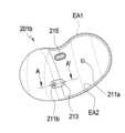
도 2는 본 문서에 개시된 다양한 실시예에 따른 전자 장치(200)(예: 도 1의 전자 장치(101, 102, 104))를 나타내는 사시도이다. 도 3은 본 문서에 개시된 다양한 실시예에 따른 전자 장치(200)를 다른 방향에서 바라본 모습을 나타내는 사시도이다.FIG. 2 is a perspective view showing an electronic device (200) (e.g., electronic device (101, 102, 104) of FIG. 1) according to various embodiments disclosed in this document. FIG. 3 is a perspective view showing an electronic device (200) according to various embodiments disclosed in this document when viewed from another direction.
도 2와 도 3을 참조하면, 전자 장치(200)는 하우징(201)과, 하우징(201)의 내부 공간에 수용된 각종 구조물 및/또는 전기 부품(도 6 참조)을 포함할 수 있다. 하우징(201)은, 예를 들면, 제1 케이스(201a)와 제2 케이스(201b)를 포함하며, 제1 케이스(201a)와 제2 케이스(201b)를 마주보게 결합함으로써 각종 구조물 및/또는 전기 부품을 수용하는 공간을 형성할 수 있다. 한 실시예에서, 제1 케이스(201a) 및/또는 제2 케이스(201b)는 세라믹, 폴리머, 금속 또는 상기 물질들 중 적어도 둘의 조합에 의해 형성될 수 있으며, 외부 표면 또는 내부 표면에 형성된 적어도 하나의 코팅 레이어들을 포함할 수 있다. 전자 장치(200)가 사용자 신체에 착용된 상태로 사용되므로, 전자 장치(200)의 무게나 착용감을 고려하여 제1 케이스(201a) 및/또는 제2 케이스(201b)의 재질은 적절하게 선택 또는 조합될 수 있다.Referring to FIGS. 2 and 3, the electronic device (200) may include a housing (201) and various structures and/or electrical components (see FIG. 6) accommodated in the internal space of the housing (201). The housing (201) may include, for example, a first case (201a) and a second case (201b), and may form a space for accommodating various structures and/or electrical components by facing and combining the first case (201a) and the second case (201b). In one embodiment, the first case (201a) and/or the second case (201b) may be formed by a combination of at least two of the above materials, such as ceramic, polymer, metal, or the like, and may include at least one coating layer formed on an external surface or an internal surface. Since the electronic device (200) is used while being worn on the user's body, the materials of the first case (201a) and/or the second case (201b) may be appropriately selected or combined in consideration of the weight or wearing comfort of the electronic device (200).
다양한 실시예에 따르면, 전자 장치(200)는 복수의 음향 홀(acoustic hole)(211a, 211b, 211c), 음향 홈(acoustic dimple)(213) 및/또는 복수의 전극들(electrode)(241a)을 포함할 수 있다. 한 실시예에서, 전자 장치(200)가 사용자의 신체에 착용된 상태에서, 제1 케이스(201a)는 실질적으로 사용자 신체를 향하게 배치되어 외측면(CS)이 사용자의 신체와 접촉할 수 있으며, 제2 케이스(201b)는 외부 공간을 향할 수 있다. 한 실시예에서, 사용자의 신체(예: 도 5의 귀(E)) 형상이나 전자 장치(200)를 착용한 상태에 따라, 제2 케이스(201b)의 외측면(ES) 중 일부는 외부 공간으로 노출되고 다른 일부는 사용자의 신체에 의해 은폐될 수 있다. 어떤 실시예에서 제2 케이스(201b)의 외측면(ES) 중 사용자의 신체에 의해 은폐된 부분은 사용자의 신체와 접촉할 수 있다.According to various embodiments, the electronic device (200) may include a plurality of acoustic holes (211a, 211b, 211c), an acoustic dimple (213), and/or a plurality of electrodes (241a). In one embodiment, when the electronic device (200) is worn on a user's body, the first case (201a) may be substantially positioned toward the user's body so that an outer surface (CS) may be in contact with the user's body, and the second case (201b) may be positioned toward the external space. In one embodiment, depending on the shape of the user's body (e.g., the ear (E) of FIG. 5) or the state in which the electronic device (200) is worn, a part of the outer surface (ES) of the second case (201b) may be exposed to the external space and another part may be concealed by the user's body. In some embodiments, a portion of the outer surface (ES) of the second case (201b) that is concealed by the user's body may come into contact with the user's body.
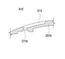
다양한 실시예에 따르면, 복수의 음향 홀(211a, 211b, 211c)들 중 제1 음향 홀(211a)과 제2 음향 홀(211b)은 서로 다른 위치에서 제2 케이스(201b)를 관통하게 형성될 수 있다. 예컨대, 전자 장치(200)는 서로 다른 적어도 두 개의 경로(예: 도 6의 제1 마이크(231a) 내지 제3 마이크(231c))를 통해 외부의 음향(예: 사용자의 음성이나 주변 환경의 음향)을 수신할 수 있다. 한 실시예에서, 음향 홈(213)은, 제2 케이스(201b)의 외측면(ES)에서 함몰 형성될 수 있다. 음향 홈(213)은 제2 음향 홀(211b)의 외경보다 넓은 외경을 갖는 리세스(recess) 구조를 포함할 수 있으며, 제2 음향 홀(211b)이 형성된 위치로부터 일 방향으로 연장된 형상을 가질 수 있다. 예컨대, 음향 홈(213)은 원형의 제2 음향 홀(211b)을 포함하는 모서리가 둥근 직사각형 형상을 가질 수 있다. 다양한 실시예에 따르면, 제2 음향 홀(211b) 및 음향 홈(213)의 형상은 다양하게 구현될 수 있음을 당업자라면 용이하게 이해할 수 있을 것이다. 예를 들어, 제2 음향 홀(211b)이 타원형으로 형성되고, 음향 홈(213)은 제2 음향 홀(211b)을 포함하는 긴 타원형의 형상을 가질 수 있다. 또는, 음향 홈(213)은 노출 영역(EA1, EA2)에 가까울수록 좁아지는 형상을 가질 수도 있다.According to various embodiments, among the plurality of acoustic holes (211a, 211b, 211c), the first acoustic hole (211a) and the second acoustic hole (211b) may be formed to penetrate the second case (201b) at different locations. For example, the electronic device (200) may receive external sound (e.g., a user's voice or sound of the surrounding environment) through at least two different paths (e.g., the first microphone (231a) to the third microphone (231c) of FIG. 6). In one embodiment, the acoustic groove (213) may be formed by being recessed in the outer surface (ES) of the second case (201b). The acoustic groove (213) may include a recessed structure having an outer diameter wider than the outer diameter of the second acoustic hole (211b) and may have a shape extending in one direction from a location where the second acoustic hole (211b) is formed. For example, the acoustic groove (213) may have a rectangular shape with rounded corners including a circular second acoustic hole (211b). According to various embodiments, it will be readily understood by those skilled in the art that the shapes of the second acoustic hole (211b) and the acoustic groove (213) may be implemented in various ways. For example, the second acoustic hole (211b) may be formed in an oval shape, and the acoustic groove (213) may have an elongated oval shape including the second acoustic hole (211b). Alternatively, the acoustic groove (213) may have a shape that becomes narrower as it approaches the exposed areas (EA1, EA2).
다양한 실시예에 따르면, 제2 음향 홀(211b)은 음향 홈(213)으로부터 제2 케이스(201b)의 내측으로 연장될 수 있다. 예컨대, 제2 음향 홀(211b)은 음향 홈(213)과 함께 외부의 소리가 제2 마이크(예: 도 6의 제2 마이크(231b))로 수신되도록 하는 소리의 경로를 형성할 수 있다. 복수의 음향 홀(211a, 211b, 211c)들 중 제3 음향 홀(211c)은 제1 케이스(201a)를 관통하게 형성되며, 하우징(201)에 내장된 스피커 유닛(예: 도 6의 스피커 유닛(253))에서 출력된 음향이 제3 음향 홀(211c)을 통해 외부로 방사될 수 있다. 어떤 실시예에서, 제3 음향 홀(211c)은 스피커 유닛(253)에서 출력된 음향을 방사하면서, 제3 마이크(예: 도 6의 제3 마이크(231c)), 예를 들면, 인-이어 마이크(in-ear microphone)로 외부의 소리가 수신되도록 하는 소리의 경로를 형성할 수 있다. 어떤 실시예에서, 전자 장치(200)는 제1 음향 홀(211a), 제2 음향 홀(211b) 및/또는 제3 음향 홀(211c)을 통해 각각 수신된 음향에 기반하여 음향 신호를 처리할 수 있다. 본 문서에 개시된 다양한 실시예에서, "전자 장치(200)가 음향 신호를 처리한다"함은, 음향 빔포밍, ANC, EC, NS 및/또는 FF 중 적어도 하나를 수행하기 위한 음향 신호 처리를 포함하는 의미로 해석될 수 있다.According to various embodiments, the second acoustic hole (211b) may extend from the acoustic groove (213) to the inside of the second case (201b). For example, the second acoustic hole (211b) may form a sound path together with the acoustic groove (213) to allow an external sound to be received by a second microphone (e.g., the second microphone (231b) of FIG. 6). Among the plurality of acoustic holes (211a, 211b, 211c), the third acoustic hole (211c) is formed to penetrate the first case (201a), and sound output from a speaker unit built into the housing (201) (e.g., the speaker unit (253) of FIG. 6) may be radiated to the outside through the third acoustic hole (211c). In some embodiments, the third sound hole (211c) may form a sound path that allows an external sound to be received by a third microphone (e.g., the third microphone (231c) of FIG. 6), for example, an in-ear microphone, while radiating sound output from the speaker unit (253). In some embodiments, the electronic device (200) may process an acoustic signal based on the sound received through each of the first sound hole (211a), the second sound hole (211b), and/or the third sound hole (211c). In various embodiments disclosed in this document, “the electronic device (200) processes an acoustic signal” may be interpreted to mean acoustic signal processing for performing at least one of acoustic beamforming, ANC, EC, NS, and/or FF.
다양한 실시예에 따르면, 전자 장치(200)는 제3 음향 홀(211c)과는 다른 위치에서 제1 케이스(201a)를 관통하게 형성된 더미 홀(211d)을 더 포함할 수 있다. 어떤 실시예에서, 더미 홀(211d)은 제3 마이크(231c)로 소리가 수신되록 하는 경로로서 활용될 수 있다. 다른 실시예에서, 사용자가 전자 장치(200)를 착용한 상태에서, 더미 홀(211d)은 벤트 홀(215)와 함께, 이도 내부의 압력을 외부 환경의 압력에 상응하게 조절하는 제2의 벤트 홀로서 기능할 수 있다. 다른 실시예에서, 후술할 센서(예: 도 6의 근접 센서(243a))가 더미 홀(211d)에 상응하게 배치될 수 있다. 예컨대, 실제 제작된 제품에서, 더미 홀(211d)은 소리의 경로, 기체의 통로 또는 빛의 통로와 같은 기능을 제공할 수 있다.According to various embodiments, the electronic device (200) may further include a dummy hole (211d) formed to penetrate the first case (201a) at a different location from the third sound hole (211c). In some embodiments, the dummy hole (211d) may be utilized as a path for receiving sound by the third microphone (231c). In other embodiments, when a user wears the electronic device (200), the dummy hole (211d) may function as a second vent hole for adjusting the pressure inside the ear canal to correspond to the pressure of the external environment, together with the vent hole (215). In other embodiments, a sensor to be described later (e.g., the proximity sensor (243a) of FIG. 6) may be arranged corresponding to the dummy hole (211d). For example, in an actually manufactured product, the dummy hole (211d) may provide a function such as a sound path, a gas path, or a light path.
다양한 실시예에 따르면, 복수의 전극들(241a)은 예를 들면, 충전 전력을 제공받기 위한 전극들로서, 제1 케이스(201a)의 외측면으로 노출될 수 있다. 제1 케이스(201a)의 외측면(CS)은 실질적으로 사용자의 신체에 접촉되도록 구성되므로, 전자 장치(200)가 사용자 신체에 착용된 상태에서 복수의 전극들(241a)은 시각적으로 은폐될 수 있다. 어떤 실시예에서, 전자 장치(200)는 유도 방식 또는 공진 방식으로 충전 전력을 제공받을 수 있다. 예를 들어, 전자 장치(200)는 제1 케이스(201a)의 외측면으로 노출된 복수의 전극(241a)을 포함하지 않더라도, 무선으로 충전 전력을 제공받을 수 있다. 다양한 실시예에 따르면, 복수의 전극들(241a) 각각의 형태 및 소재 중 적어도 하나는 다를 수 있음을 당업자면 용이하게 이해할 수 있을 것이다.According to various embodiments, the plurality of electrodes (241a) may be exposed to the outer surface of the first case (201a), for example, as electrodes for receiving charging power. Since the outer surface (CS) of the first case (201a) is configured to substantially contact the user's body, the plurality of electrodes (241a) may be visually concealed when the electronic device (200) is worn on the user's body. In some embodiments, the electronic device (200) may receive charging power in an inductive manner or a resonant manner. For example, the electronic device (200) may receive charging power wirelessly even if it does not include the plurality of electrodes (241a) exposed to the outer surface of the first case (201a). According to various embodiments, those skilled in the art will readily understand that at least one of the shape and material of each of the plurality of electrodes (241a) may be different.
다양한 실시예에 따르면, 전자 장치(200)는, 광학 윈도우(optical window)(219) 및/또는 벤트 홀(vent hole)(215)을 더 포함할 수 있다. 광학 윈도우(219)는 예를 들면, 제1 케이스(201a)의 외측면으로 노출될 수 있으며, 전자 장치(200)는 광학 윈도우(219)에 상응하게 배치된 센서(예: 도 6의 근접 센서(243a))를 포함함으로써, 전자 장치(200)가 사용자의 신체에 착용되었는지의 여부를 감지할 수 있다. 벤트 홀(215)은 제2 케이스(201b)를 관통하게 형성될 수 있으며, 사용자가 전자 장치(200)를 착용한 상태에서, 외부 공간으로 노출될 수 있다. 한 실시예에서, 하우징(201) 내부의 전기 부품들이 열을 발생시킬 때, 벤트 홀(215)은 하우징(201) 내부의 열을 외부로 유도 또는 방출할 수 있다. 다른 실시예에서, 하우징(201)에 스피커 유닛(예: 도 6의 스피커 유닛(253))이 내장된 경우, 벤트 홀(215)은 스피커 유닛(예: 진동판)이 안정적으로 작동할 수 있는 환경을 제공할 수 있다. 또 다른 실시예에서, 전자 장치(200)는 벤트 홀(215) 상에 배치된 스크린 부재(예: 도 3의 스크린 부재(263))를 포함함으로써, 벤트 홀(215)을 통해 열이나 기체가 유통하는 것을 허용하면서 외부의 이물질, 예를 들면, 먼지가 하우징(201)의 내부로 유입되는 것을 차단할 수 있다.According to various embodiments, the electronic device (200) may further include an optical window (219) and/or a vent hole (215). The optical window (219) may be exposed, for example, to an outer surface of the first case (201a), and the electronic device (200) may include a sensor (e.g., a proximity sensor (243a) of FIG. 6) disposed corresponding to the optical window (219) to detect whether the electronic device (200) is worn on a user's body. The vent hole (215) may be formed to penetrate the second case (201b) and may be exposed to an external space when the user wears the electronic device (200). In one embodiment, when electrical components inside the housing (201) generate heat, the vent hole (215) may induce or release the heat inside the housing (201) to the outside. In another embodiment, when a speaker unit (e.g., speaker unit (253) of FIG. 6) is built into the housing (201), the vent hole (215) can provide an environment in which the speaker unit (e.g., diaphragm) can operate stably. In another embodiment, the electronic device (200) can include a screen member (e.g., screen member (263) of FIG. 3) disposed on the vent hole (215), thereby allowing heat or gas to circulate through the vent hole (215) while blocking external foreign substances, such as dust, from entering the interior of the housing (201).
도 4a는 본 문서에 개시된 다양한 실시예에 따른 전자 장치(200)(예: 도 1의 전자 장치(101, 102, 104))의 제2 케이스(201b)를 나타내는 평면도이다. 도 4b는 도 4a의 라인 A-A'을 따라 본 문서에 개시된 다양한 실시예에 따른 전자 장치(200)의 제2 케이스(201b)를 절개하여 나타내는 단면도이다. 도 5는 본 문서에 개시된 다양한 실시예에 따른 전자 장치(200)가 사용자 신체에 착용된 모습을 나타내는 도면이다.FIG. 4A is a plan view showing a second case (201b) of an electronic device (200) (e.g., the electronic device (101, 102, 104) of FIG. 1) according to various embodiments disclosed in the present document. FIG. 4B is a cross-sectional view showing the second case (201b) of the electronic device (200) according to various embodiments disclosed in the present document taken along line A-A' of FIG. 4A. FIG. 5 is a drawing showing an electronic device (200) according to various embodiments disclosed in the present document being worn on a user's body.
도 4a 내지 도 5를 참조하면, 사용자가 전자 장치(200)를 착용한 상태에서, 제2 케이스(201b)의 외측면(예: 도 2의 외측면(ES)) 중 일부분, 예를 들어, 노출 영역(EA1, EA2)이 외부 환경으로 노출될 수 있다. 노출 영역(EA1, EA2)은 사용자 신체(예: 귀)의 형상이나 전자 장치(200)를 착용한 상태에 따라 다를 수 있다. 마이크들(예: 도 8의 제1 마이크(231a)와 제2 마이크(231b)) 사이의 간격 또는 음향 홀들(예: 제1 음향 홀(211a)과 제2 음향 홀(211b)) 사이의 간격이 클수록 음향 빔포밍이나 ANC와 같은 기능을 구현하기 용이할 수 있다. 이주, 대이주 및/또는 대이륜과 같은 신체 구조에 의해 형성된 공간에 착용 또는 지지될 정도로 소형화된 전자 장치에서, 마이크들 사이의 간격 또는 음향 홀들 사이의 간격을 충분히 확보하기 어려울 수 있다. 예컨대, 복수의 음향 홀(예: 제1 음향 홀과 제2 음향 홀)들 사이에 충분한 간격(예: 대략 12mm 이상)을 확보했다면, 전자 장치(200)가 사용자 신체에 착용된 상태에서, 복수의 음향 홀 중 하나(예: 제2 음향 홀)는 사용자의 신체(예: 이주)에 의해 가려질 수 있다.Referring to FIGS. 4A to 5, when a user wears the electronic device (200), a portion of the outer surface (e.g., the outer surface ES of FIG. 2) of the second case (201b), for example, the exposure areas EA1 and EA2, may be exposed to the external environment. The exposure areas EA1 and EA2 may vary depending on the shape of the user's body (e.g., the ear) or the state in which the electronic device (200) is worn. The larger the gap between microphones (e.g., the
다양한 실시예에 따르면, 도 4a에 도시된 바와 같이, 사용자 신체의 형상이나 착용 상태에 의해 제1 노출 영역(EA1)이 정의된 때, 제1 음향 홀(211a)은 제1 노출 영역(EA1)에 위치하고, 제2 음향 홀(211b)은 부분적으로 사용자의 신체에 의해 가려질 수 있다. 사용자 신체의 형상이나 착용 상태에 의해 제1 노출 영역(EA1)보다 작은 제2 노출 영역(EA2)이 정의된 때, 제1 음향 홀(211a)은 제2 노출 영역(EA2)에 위치하고, 제2 음향 홀(211b)의 적어도 일부는 실질적으로 사용자의 신체에 의해 가려질 수 있다. 예컨대, 사용자 신체의 형상이나 착용 상태에 따라 제2 음향 홀(211b)을 통해 수신되는 음향 또는 음압이 달라질 수 있다. 본 문서에 개시된 다양한 실시예에 따르면, 음향 홈(213)은 제2 음향 홀(211b)로부터 연장되면서 적어도 부분적으로 노출 영역(EA1, EA2)에 위치될 수 있다. 예컨대, 제2 음향 홀(211b)이 부분적으로 또는 실질적으로 사용자 신체에 의해 가려진 상태라 하더라도, 전자 장치(200)는 음향 홈(213)을 경유하여 제2 음향 홀(211b)로 입력되는 음향을 수신 또는 획득할 수 있다. 도 10을 통해 살펴보겠지만, 일 실시예에 따라, 착용 상태에서 제2 음향 홀(211b)이 사용자 신체에 가려지는 구조에서, 전자 장치(200)가 획득하는 음압 레벨은, 음향 홈(213)을 형성함으로써 지정된 주파수 대역에서 대략 40 dB 정도 개선될 수 있다.According to various embodiments, when the first exposure area (EA1) is defined by the shape of the user's body or the wearing state as illustrated in FIG. 4a, the first acoustic hole (211a) may be positioned in the first exposure area (EA1), and the second acoustic hole (211b) may be partially covered by the user's body. When the second exposure area (EA2) smaller than the first exposure area (EA1) is defined by the shape of the user's body or the wearing state, the first acoustic hole (211a) may be positioned in the second exposure area (EA2), and at least a portion of the second acoustic hole (211b) may be substantially covered by the user's body. For example, the sound or sound pressure received through the second acoustic hole (211b) may vary depending on the shape of the user's body or the wearing state. According to various embodiments disclosed in the present document, the acoustic groove (213) may be extended from the second acoustic hole (211b) and at least partially located in the exposure areas (EA1, EA2). For example, even if the second acoustic hole (211b) is partially or substantially covered by the user's body, the electronic device (200) can receive or acquire sound input to the second acoustic hole (211b) via the acoustic groove (213). As will be described with reference to FIG. 10, according to one embodiment, in a structure in which the second acoustic hole (211b) is covered by the user's body in a worn state, the sound pressure level acquired by the electronic device (200) can be improved by approximately 40 dB in a designated frequency band by forming the acoustic groove (213).
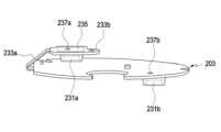
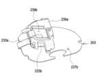
도 6은 본 문서에 개시된 다양한 실시예에 따른 전자 장치(200)(예: 도 1 또는 도 2의 전자 장치(101, 102, 104, 200))를 나타내는 분리 사시도이다. 도 7은 본 문서에 개시된 다양한 실시예에 따른 전자 장치(200)에서, 제2 케이스(예: 도 4a의 제2 케이스(201b))가 제거된 모습을 나타내는 사시도이다.FIG. 6 is an exploded perspective view showing an electronic device (200) (e.g., the electronic device (101, 102, 104, 200) of FIG. 1 or FIG. 2) according to various embodiments disclosed in the present document. FIG. 7 is a perspective view showing an electronic device (200) according to various embodiments disclosed in the present document with a second case (e.g., the second case (201b) of FIG. 4a) removed.
도 6과 도 7을 참조하면, 전자 장치(200)는, 하우징(201), 지지 구조(202), 제1 회로 기판(203), 제2 회로 기판(204), 배터리(251), 스피커 유닛(253) 및/또는 안테나 부재(255)를 포함할 수 있다. 전자 장치(200)는 제1 회로 기판(203) 및/또는 제2 회로 기판(204)에 배치된 복수의 마이크(231a, 231b, 231c; 제1 마이크(213a)는 도 8 참조))를 포함함으로써, 외부의 음향, 예를 들면, 사용자 음성이나 주변 환경의 음향을 수신 또는 획득할 수 있다. 한 실시예에서, 하우징(201)은 사용자의 신체에 접촉하도록 구성된 제1 케이스(201a)와, 제1 케이스(201a)에 마주보게 결합하는 제2 케이스(201b)를 포함할 수 있다. 전자 장치(200)가 사용자의 신체에 착용된 상태에서, 제1 케이스(201)는 실질적으로 사용자의 신체에 접촉하고, 제2 케이스(201b)는 적어도 부분적으로 외부에 노출될 수 있다.Referring to FIGS. 6 and 7, the electronic device (200) may include a housing (201), a support structure (202), a first circuit board (203), a second circuit board (204), a battery (251), a speaker unit (253), and/or an antenna member (255). The electronic device (200) may include a plurality of microphones (231a, 231b, 231c; the first microphone (213a) is shown in FIG. 8)) disposed on the first circuit board (203) and/or the second circuit board (204), thereby receiving or obtaining external sounds, for example, a user's voice or sounds of the surrounding environment. In one embodiment, the housing (201) may include a first case (201a) configured to come into contact with a user's body, and a second case (201b) coupled to face the first case (201a). When the electronic device (200) is worn on the user's body, the first case (201) may substantially contact the user's body, and the second case (201b) may be at least partially exposed to the outside.
다양한 실시예에 따르면, 지지 구조(202)는, 서로 마주보게 결합하는 제1 지지 부재(202a)와 제2 지지 부재(202b)를 포함할 수 있다. 제1 지지 부재(202a) 및/또는 제2 지지 부재(202b)는 폴리머 또는 금속 재질 중 적어도 하나의 재질로 제작될 수 있으며, 하우징(201)의 내부로 수용되어 전자 장치(200)의 강성을 향상시킬 수 있다. 어떤 실시예에서, 지지 구조(202)는 하우징(201)의 내부 공간을 복수로 분할할 수 있다. 예를 들어, 제1 회로 기판(203)과 제2 회로 기판(204)은 지지 구조(202)에 의해 일정 정도의 간격을 두고 하우징(201)의 내부에 배치될 수 있다. 어떤 실시예에서, 배터리(251) 및/또는 스피커 유닛(253)은 실질적으로 지지 구조(202)에 감싸진 상태로 하우징(202)의 내부에 배치될 수 있다. 배터리(251) 및/또는 스피커 유닛(253)이 배치된 공간은 지지 구조(202)에 의해 제1 회로 기판(203) 및/또는 제2 회로 기판(204)이 배치된 공간과 구분될 수 있다.According to various embodiments, the support structure (202) may include a first support member (202a) and a second support member (202b) that are coupled to face each other. The first support member (202a) and/or the second support member (202b) may be made of at least one of a polymer or a metal material and may be accommodated inside the housing (201) to improve the rigidity of the electronic device (200). In some embodiments, the support structure (202) may divide the internal space of the housing (201) into a plurality of parts. For example, the first circuit board (203) and the second circuit board (204) may be arranged inside the housing (201) with a predetermined amount of space therebetween by the support structure (202). In some embodiments, the battery (251) and/or the speaker unit (253) may be arranged inside the housing (202) substantially wrapped around the support structure (202). The space where the battery (251) and/or the speaker unit (253) is placed can be separated from the space where the first circuit board (203) and/or the second circuit board (204) is placed by the support structure (202).
다양한 실시예에 따르면, 제1 회로 기판(203)은, 실질적으로 전자 장치(200)의 주 회로 기판으로서, 도 1을 참조하여 설명된 구성요소들의 적어도 일부가 집적회로 칩 형태로 제1 회로 기판(203)에 배치될 수 있다. 제1 회로 기판(203)은 제2 케이스(201b)의 내측면과 마주보게 배치될 수 있다. 예를 들어, 제1 회로 기판(203)은 제2 케이스(201b)와 제2 지지 부재(202b) 사이에 배치될 수 있다. 제1 회로 기판(203)에는 복수(예: 한 쌍)의 마이크(231a, 231b))가 배치될 수 있으며, 이에 관한 실시예는 도 8과 도 9를 참조하여 좀더 상세하게 살펴보게 될 것이다. 제2 회로 기판(204)은 가요성 인쇄회로 기판을 포함할 수 있으며, 실질적으로 제1 케이스(201a)의 내측면과 마주보게 배치되고, 지지 구조(202)를 우회하여 제1 회로 기판(203)과 전기적으로 연결될 수 있다.According to various embodiments, the first circuit board (203) is substantially a main circuit board of the electronic device (200), and at least some of the components described with reference to FIG. 1 may be arranged on the first circuit board (203) in the form of integrated circuit chips. The first circuit board (203) may be arranged to face the inner side of the second case (201b). For example, the first circuit board (203) may be arranged between the second case (201b) and the second support member (202b). A plurality of microphones (231a, 231b) (e.g., a pair) may be arranged on the first circuit board (203), and embodiments thereof will be described in more detail with reference to FIGS. 8 and 9. The second circuit board (204) may include a flexible printed circuit board and may be positioned substantially facing the inner side of the first case (201a) and electrically connected to the first circuit board (203) by bypassing the support structure (202).
다양한 실시예에 따르면, 도 2의 복수의 전극들(241a)은 실질적으로 제2 회로 기판(204)에 배치되며, 제1 케이스(201a)에 형성된 전극 홀들(217)을 통해 외부로 노출될 수 있다. 한 실시예에서, 전자 장치(200)는 밀봉 부재, 예를 들면, 실리콘(silicone)이나 고무(rubber)와 같은 탄성체 재질로 형성된 오-링(O-ring)들(241b)을 포함할 수 있다. 오-링들(241b)은 전극들(241a)의 둘레를 감싸게 결합하며, 실질적으로 전극 홀들(217)의 내벽과 전극들(241a) 사이의 간격을 밀봉할 수 있다. 어떤 실시예에서, 복수의 마이크 중 하나(예: 제3 마이크(231c))가 제2 회로 기판(204)에 배치되어 제3 음향 홀(211c) 또는 더미 홀(211d) 중 어느 하나에 대응하게 배치될 수 있다. 예컨대, 제3 마이크(231c)는 제1 케이스(201a)에 형성된 제3 음향 홀(211c) 또는 더미 홀(211d) 중 어느 하나를 통해 입력되는 음향을 수신 또는 획득할 수 있다. 다른 실시예에서, 전자 장치(200)는 제2 회로 기판(204)에 배치된 센서, 예를 들면, 근접 센서(243a)를 더 포함할 수 있다. 근접 센서(243a)는 접착 부재(243b)에 의해 제1 케이스(201a)에 장착될 수 있으며, 제1 케이스(201a)에 형성된 광학 윈도우(219)에 상응하게 배치될 수 있다. 예를 들어, 근접 센서(243a)는 광학 윈도우(219)를 통해 전자 장치(200)에 외부 물체(예: 사용자 신체)에 접근하는지 여부 또는 지정된 시간 이상 접촉한 상태를 유지하는지 여부를 감지할 수 있다. 광학 윈도우(243c)는 가시광 또는 적외선을 적어도 일부 투과하는 글래스 부재를 포함할 수 있다. 근접 센서(243a)를 통해 감지된 정보에 따라, 전자 장치(200), 예를 들어, 도 1의 프로세서(120)는 사용자 신체에 착용되었는지의 여부를 판단할 수 있다.According to various embodiments, the plurality of electrodes (241a) of FIG. 2 may be substantially disposed on the second circuit board (204) and exposed to the outside through electrode holes (217) formed in the first case (201a). In one embodiment, the electronic device (200) may include O-rings (241b) formed of a sealing member, for example, an elastic material such as silicone or rubber. The O-rings (241b) may be coupled to surround the periphery of the electrodes (241a) and substantially seal the gap between the inner wall of the electrode holes (217) and the electrodes (241a). In some embodiments, one of the plurality of microphones (e.g., the third microphone (231c)) may be disposed on the second circuit board (204) and may be disposed to correspond to either the third sound hole (211c) or the dummy hole (211d). For example, the third microphone (231c) may receive or acquire sound input through either the third sound hole (211c) or the dummy hole (211d) formed in the first case (201a). In another embodiment, the electronic device (200) may further include a sensor, for example, a proximity sensor (243a), disposed on the second circuit board (204). The proximity sensor (243a) may be mounted on the first case (201a) by an adhesive member (243b) and may be disposed corresponding to an optical window (219) formed in the first case (201a). For example, the proximity sensor (243a) may detect whether an external object (for example, a user's body) approaches the electronic device (200) through the optical window (219) or whether the object remains in contact for a specified period of time or longer. The optical window (243c) may include a glass member that transmits at least some visible light or infrared light. Based on information detected through the proximity sensor (243a), the electronic device (200), for example, the processor (120) of FIG. 1, can determine whether it is worn on the user's body.
다양한 실시예에 따르면, 배터리(251)는 지지 구조(202), 예를 들면, 제1 지지 부재(202a)와 제2 지지 부재(202b) 사이에 장착 또는 고정될 수 있다. 배터리(251)는 전자 장치(200)의 적어도 하나의 구성요소에 전력을 공급하기 위한 장치로서, 예를 들면, 재충전 불가능한 1차 전지, 재충전 가능한 2차 전지 또는 연료 전지를 포함할 수 있다. 배터리(251)는 전자 장치(200)의 내부에 일체로 배치될 수 있고, 사용자가 교체할 수 있도록 배치될 수 있다. 어떤 실시예에서, 배터리(251)는 전극들(241a)을 통해 제공되는 전력에 의해 충전될 수 있다. 한 실시예에서, 스피커 유닛(253)은 배터리(251)의 일측에 배치될 수 있다. 예를 들어, 스피커 유닛(253)은 제1 지지 부재(202a)와 제2 지지 부재(202b) 사이에 장착 또는 고정되어 배터리(251)와 나란하게 배치될 수 있다. 한 실시예에 따르면, 스피커 유닛(253)이 출력하는 음향은 제1 케이스(201a)에 형성된 제3 음향 홀(예: 도 2의 제3 음향 홀(211c))을 통해 하우징(201) 또는 전자 장치(200)의 외부로 방사될 수 있다. 어떤 실시예에서, 제3 음향 홀(211c)은 제1 음향 홀(211a) 및/또는 제2 음향 홀(211b)보다 클 수 있다. 전자 장치(200)는 제3 음향 홀(211c) 상에 배치되는 다른 스크린 부재(261)를 더 포함함으로써, 스피커 유닛(253)이 출력한 음향을 외부로 방사하면서 외부에서 하우징(201)의 내부로 이물질(예: 먼지)이 유입되는 것을 차단할 수 있다.According to various embodiments, the battery (251) may be mounted or fixed between the support structure (202), for example, the first support member (202a) and the second support member (202b). The battery (251) is a device for supplying power to at least one component of the electronic device (200), and may include, for example, a non-rechargeable primary battery, a rechargeable secondary battery, or a fuel cell. The battery (251) may be integrally disposed within the electronic device (200) and may be disposed so as to be replaceable by a user. In some embodiments, the battery (251) may be charged by power provided through the electrodes (241a). In one embodiment, the speaker unit (253) may be disposed on one side of the battery (251). For example, the speaker unit (253) may be mounted or fixed between the first support member (202a) and the second support member (202b) and may be arranged parallel to the battery (251). According to one embodiment, sound output by the speaker unit (253) may be radiated to the outside of the housing (201) or the electronic device (200) through a third sound hole (e.g., the third sound hole (211c) of FIG. 2) formed in the first case (201a). In some embodiments, the third sound hole (211c) may be larger than the first sound hole (211a) and/or the second sound hole (211b). The electronic device (200) may further include another screen member (261) arranged on the third sound hole (211c), thereby blocking foreign substances (e.g., dust) from entering the inside of the housing (201) from the outside while radiating sound output by the speaker unit (253) to the outside.
어떤 실시예에서, 전자 장치(200)는 제1 케이스(201a)의 내측면에 배치된 자성체(249)를 더 포함할 수 있다. 사용자는 전자 장치(200)를 전용 케이스(미도시)에 수용하여 휴대 또는 보관할 수 있다. 전용 케이스에 장착된 상태에서, 전자 장치(200)는 전용 케이스를 통해 충전 전력을 공급받을 수 있다. 전자 장치(200)가 전용 케이스에 수용된 상태에서, 자성체(249)와 전용 케이스 사이에서 자기력(예: 인력)이 발생되어 전자 장치(200)를 전용 케이스에 고정할 수 있다. 예컨대, 전자 장치(200)가 전용 케이스에 장착된 상태에서, 지정된 크기 범위의 외력이 작용하더라도 전자 장치(200)는 전용 케이스에 안정적으로 고정될 수 있다.In some embodiments, the electronic device (200) may further include a magnetic body (249) disposed on the inner surface of the first case (201a). The user may carry or store the electronic device (200) by accommodating it in a dedicated case (not shown). While mounted in the dedicated case, the electronic device (200) may receive charging power through the dedicated case. While the electronic device (200) is accommodated in the dedicated case, a magnetic force (e.g., attractive force) may be generated between the magnetic body (249) and the dedicated case to fix the electronic device (200) to the dedicated case. For example, while the electronic device (200) is mounted in the dedicated case, even if an external force within a specified size range is applied, the electronic device (200) may be stably fixed to the dedicated case.
다양한 실시예에 따르면, 안테나 부재(255)(예: 도 1의 안테나 모듈(197))는 제2 케이스(201b)의 내측면에 배치될 수 있으며, 예를 들면, 도 1의 프로세서(102) 또는 통신 모듈(190)과 전기적으로 연결될 수 있다. 예를 들어, 프로세서(120) 또는 통신 모듈(190)은 안테나 부재(255)를 이용하여 무선 통신(예: 블루투스 통신)을 수행할 수 있다. 한 실시예에서, 사용자가 전자 장치(200)와 근거리 통신(예: 블루투스)으로 연결된 외부의 전자 장치(예: 도 1의 전자 장치(102, 104)), 예를 들면, 스마트 폰이 음악을 재생할 때, 전자 장치(200)가 재생되는 음악의 데이터(예: 사운드 패킷)를 수신하여 스피커 유닛(253)을 통해 음향으로 출력할 수 있다.According to various embodiments, the antenna member (255) (e.g., the antenna module (197) of FIG. 1) may be disposed on the inner surface of the second case (201b) and may be electrically connected to, for example, the processor (102) or the communication module (190) of FIG. 1. For example, the processor (120) or the communication module (190) may perform wireless communication (e.g., Bluetooth communication) using the antenna member (255). In one embodiment, when a user's external electronic device (e.g., the electronic device (102, 104) of FIG. 1) connected to the electronic device (200) via short-range communication (e.g., Bluetooth), for example, a smart phone, plays music, the electronic device (200) may receive data of the music being played (e.g., sound packets) and output it as sound through the speaker unit (253).
다양한 실시예에 따르면, 복수의 마이크 중 적어도 2개의 마이크(예: 도 8의 제1 마이크(231a)와 제2 마이크(231b))가 제1 회로 기판(203) 상에 제공될 수 있다. 제1 회로 기판(203)과 제1 마이크(231a) 및/또는 제2 마이크(231b)의 배치 구조에 관한 실시예는 도 8과 도 9를 더 참조하여 살펴보기로 한다.According to various embodiments, at least two microphones (e.g., the first microphone (231a) and the second microphone (231b) of FIG. 8) among the plurality of microphones may be provided on the first circuit board (203). An embodiment regarding the arrangement structure of the first circuit board (203) and the first microphone (231a) and/or the second microphone (231b) will be further examined with reference to FIGS. 8 and 9.
도 8은 본 문서에 개시된 다양한 실시예에 따른 전자 장치(예: 도 2 또는 도 6의 전자 장치(200))의 제1 회로 기판(203)을 나타내는 사시도이다. 도 9는 본 문서에 개시된 다양한 실시예에 따른 전자 장치(200)의 브라켓(239a)이 배치되는 구조를 나타내는 분리 사시도이다.FIG. 8 is a perspective view showing a first circuit board (203) of an electronic device (e.g., the electronic device (200) of FIG. 2 or FIG. 6) according to various embodiments disclosed in the present document. FIG. 9 is an exploded perspective view showing a structure in which a bracket (239a) of an electronic device (200) according to various embodiments disclosed in the present document is arranged.
도 6 및 도 7과 함께, 도 8과 도 9를 더 참조하면, 전자 장치(200)는 제1 회로 기판(203)으로부터 연장된 가요성 인쇄회로 기판(233a), 제1 회로 기판(203)에 마주보게 장착되는 브라켓(239a)을 더 포함할 수 있다. 복수의 마이크 중 제1 마이크(231a)는 가요성 인쇄회로 기판(233a) 상에 장착되어 제1 회로 기판(203)에 전기적으로 연결될 수 있으며, 복수의 마이크 중 제2 마이크(231b)는 제1 회로 기판(203)에 장착될 수 있다. 실시예에 따라, 가요성 인쇄회로 기판(233a)은 제1 마이크(231a)로부터 연장되어 제1 회로 기판(203)에 전기적으로 접속하는 것으로 해석될 수 있다. 예컨대, 가요성 인쇄회로 기판(233a)은 제1 마이크(231a)를 제1 회로 기판(203)에 전기적으로 연결할 수 있다. 어떤 실시예에서, 전자 장치(200)는 가요성 인쇄회로 기판(233a)의 단부에 제공되는 더미 기판(233b)을 더 포함할 수 있으며, 제1 마이크(231a)는 더미 기판(233b)에 장착될 수 있다.With further reference to FIGS. 8 and 9, along with FIGS. 6 and 7, the electronic device (200) may further include a flexible printed circuit board (233a) extending from a first circuit board (203), and a bracket (239a) mounted facing the first circuit board (203). A first microphone (231a) of the plurality of microphones may be mounted on the flexible printed circuit board (233a) and electrically connected to the first circuit board (203), and a second microphone (231b) of the plurality of microphones may be mounted on the first circuit board (203). According to an embodiment, the flexible printed circuit board (233a) may be interpreted as extending from the first microphone (231a) and electrically connected to the first circuit board (203). For example, the flexible printed circuit board (233a) can electrically connect the first microphone (231a) to the first circuit board (203). In some embodiments, the electronic device (200) can further include a dummy board (233b) provided at an end of the flexible printed circuit board (233a), and the first microphone (231a) can be mounted on the dummy board (233b).
다양한 실시예에 따르면, 제1 마이크(231a)는 제2 케이스(201b)에 형성된 제1 음향 홀(211a)에 상응하게 배치되고, 제2 마이크(211b)는 제2 케이스(201b)에 형성된 제2 음향 홀(211b)에 상응하게 배치될 수 있다. 예를 들어, 제1 마이크(231a)는 제1 음향 홀(211a)을 통해 입력되는 음향을 수신 또는 획득하고, 제2 마이크(231b)는 제2 음향 홀(211b)을 통해 입력되는 음향을 수신 또는 획득할 수 있다. 한 실시예에서, 제2 마이크(231b)를 통해 수신 또는 획득되는 음향은 적어도 부분적으로 음향 홈(예: 도 3 내지 도 4b의 음향 홈(213))을 경유할 수 있다.According to various embodiments, the first microphone (231a) may be arranged corresponding to the first acoustic hole (211a) formed in the second case (201b), and the second microphone (211b) may be arranged corresponding to the second acoustic hole (211b) formed in the second case (201b). For example, the first microphone (231a) may receive or acquire sound input through the first acoustic hole (211a), and the second microphone (231b) may receive or acquire sound input through the second acoustic hole (211b). In one embodiment, the sound received or acquired through the second microphone (231b) may at least partially pass through the acoustic groove (e.g., the acoustic groove (213) of FIGS. 3 to 4B).
다양한 실시예에 따르면, 제1 회로 기판(203)은 제2 케이스(201b)의 내측면과 마주보게 배치되며, 제1 마이크(231a)는 제1 회로 기판(203)과 제2 케이스(201b)의 내측면 사이에 배치될 수 있다. 제2 마이크(231b)는, 제1 회로 기판(203)에 장착되면서 제1 회로 기판(203)을 사이에 두고 제2 케이스(201b)의 내측면과 마주보게 배치될 수 있다. 예컨대, 제2 마이크(231b)와 제2 케이스(201b)의 내측면 사이에는 적어도 부분적으로 제1 회로 기판(203)이 배치될 수 있다. 한 실시예에서, 제1 회로 기판(203)을 기준으로 볼 때, 제1 마이크(231a)와 제2 마이크(231b)는 서로 다른 높이에 배치될 수 있다. 어떤 실시예에서, 제2 케이스(201b)의 내측면 또는 외측면은 곡면 형태를 가지며, 제1 회로 기판(203)에 대하여 제1 음향 홀(211a)과 제2 음향 홀(211b)은 서로 다른 높이에 형성될 수 있다. 한 실시예에 따르면, 제2 케이스(201b)가 곡면 형태를 가진 구조에서, 제1 마이크(231a)는 제1 음향 홀(211a)에 인접하게 배치되고, 제2 마이크(231b)는 제2 음향 홀(211b)과 인접하게 배치될 수 있다.According to various embodiments, the first circuit board (203) may be arranged to face the inner surface of the second case (201b), and the first microphone (231a) may be arranged between the first circuit board (203) and the inner surface of the second case (201b). The second microphone (231b) may be arranged to face the inner surface of the second case (201b) while being mounted on the first circuit board (203) with the first circuit board (203) interposed therebetween. For example, the first circuit board (203) may be arranged at least partially between the second microphone (231b) and the inner surface of the second case (201b). In one embodiment, the first microphone (231a) and the second microphone (231b) may be arranged at different heights with respect to the first circuit board (203). In some embodiments, the inner or outer surface of the second case (201b) has a curved shape, and the first sound hole (211a) and the second sound hole (211b) may be formed at different heights with respect to the first circuit board (203). According to one embodiment, in a structure in which the second case (201b) has a curved shape, the first microphone (231a) may be arranged adjacent to the first sound hole (211a), and the second microphone (231b) may be arranged adjacent to the second sound hole (211b).
다양한 실시예에 따르면, 전자 장치(200)는 제1 회로 기판(203) 및/또는 더미 기판(233b)을 관통하게 형성된 더미 홀(237a, 237b)들을 더 포함할 수 있다. 더미 홀들 중 제1 더미 홀(237a)은 제1 음향 홀(211a)로부터 더미 기판(233b)을 관통하여 제1 마이크(231a)에 이르는 음향 입력 경로를 제공할 수 있으며, 더미 홀들 중 제2 더미 홀(237b)은 제2 음향 홀(211b)로부터 제1 회로 기판(203)을 관통하여 제2 마이크(231b)에 이르는 음향 입력 경로를 제공할 수 있다. 도시되지는 않지만, 더미 기판(233b)과 제2 케이스(201b)의 내측면 사이 및/또는 제1 회로 기판(203)과 제2 케이스(201b)의 내측면 사이에는 밀봉 부재들이 배치될 수 있다. 밀봉 부재들 중 하나는 제1 음향 홀(211a)과 제1 더미 홀(237a)이 형성된 위치에서 더미 기판(233b)과 제2 케이스(201b)의 내측면 사이에 밀봉 구조를 형성할 수 있으며, 밀봉 부재들 중 다른 하나는 제2 음향 홀(211b)과 제2 더미 홀(237b)이 형성된 위치에서 제1 회로 기판(203)과 제2 케이스(201b)의 내측면 사이에 밀봉 구조를 형성할 수 있다.According to various embodiments, the electronic device (200) may further include dummy holes (237a, 237b) formed to penetrate the first circuit board (203) and/or the dummy board (233b). Among the dummy holes, the first dummy hole (237a) may provide an acoustic input path from the first acoustic hole (211a) to the first microphone (231a) through the dummy board (233b), and the second dummy hole (237b) among the dummy holes may provide an acoustic input path from the second acoustic hole (211b) to the first circuit board (203) through the first microphone (231b). Although not illustrated, sealing members may be arranged between the dummy board (233b) and the inner surface of the second case (201b) and/or between the first circuit board (203) and the inner surface of the second case (201b). One of the sealing members can form a sealing structure between the dummy substrate (233b) and the inner surface of the second case (201b) at a position where the first acoustic hole (211a) and the first dummy hole (237a) are formed, and the other of the sealing members can form a sealing structure between the first circuit substrate (203) and the inner surface of the second case (201b) at a position where the second acoustic hole (211b) and the second dummy hole (237b) are formed.
다양한 실시예에 따르면, 전자 장치(200)는 더미 기판(233b)에 제공된 터치 센서(235)를 더 포함할 수 있다. 터치 센서(235)는 가요성 인쇄회로 기판(233a)을 통해 제1 회로 기판(203)과 전기적으로 연결될 수 있으며, 제2 케이스(201b)의 내측면과 마주보게 배치될 수 있다. 한 실시예에 따르면, 사용자의 신체(예: 손가락)가 제2 케이스(201b)의 외측면에 접근 또는 접촉함을 감지하여, 또는 제2 케이스(201b)의 외측면으로부터 지정된 거리 이내에서 지정된 동작이 이루어지는 것을 감지하여 터치 센서(235)가 입력 신호를 발생시킬 수 있다. 다른 실시예에서, 사용자가 제2 케이스(201b)의 외측면에 미끄럼 접촉하거나 사용자 신체가 지정된 거리 이내에서 위치된 상태로 지정된 시간 이상 유지될 때, 터치 센서(235)가 이를 감지하여 입력 신호를 발생시킬 수 있다.According to various embodiments, the electronic device (200) may further include a touch sensor (235) provided on the dummy substrate (233b). The touch sensor (235) may be electrically connected to the first circuit board (203) through a flexible printed circuit board (233a) and may be arranged to face the inner surface of the second case (201b). According to one embodiment, the touch sensor (235) may generate an input signal by detecting that a user's body (e.g., a finger) approaches or comes into contact with an outer surface of the second case (201b), or that a specified operation is performed within a specified distance from the outer surface of the second case (201b). In another embodiment, when the user makes a sliding contact with the outer surface of the second case (201b) or when the user's body is positioned within a specified distance and maintained for a specified period of time or longer, the touch sensor (235) may detect this and generate an input signal.
다양한 실시예에 따르면, 브라켓(239a)은 제2 케이스(201b)의 내측면과 제1 회로 기판(203) 사이에 배치되며, 실질적으로 제1 회로 기판(203)의 어느 한 면에 장착될 수 있다. 참조번호를 부여하지는 않았지만, 브라켓(239a)은 복수의 후크들을 포함할 수 있으며, 후크들이 제1 회로 기판(203)의 가장자리에 결속되어 브라켓(239a)을 제1 회로 기판(203)에 고정할 수 있다. 어떤 실시예에서는, 제2 지지 부재(202b)에는 도시되지 않은 결속 돌기가 제공될 수 있다. 결속 돌기는 제1 회로 기판(203)을 관통하여 또는 제1 회로 기판(203)을 우회하여 브라켓(239a)과 결속될 수 있다. 이와 같이, 브라켓(239a)을 제1 회로 기판(203) 상에 장착하거나 고정하는 구조에 관해서는 제1 회로 기판(203)의 형상이나, 전기 부품들(예: 제1 마이크(231a) 및/또는 제2 마이크(231b))의 배치에 따라 적절하게 선택 또는 조합될 수 있다.According to various embodiments, the bracket (239a) is disposed between the inner surface of the second case (201b) and the first circuit board (203), and can be substantially mounted on either surface of the first circuit board (203). Although not given a reference number, the bracket (239a) may include a plurality of hooks, and the hooks may be fastened to an edge of the first circuit board (203) to secure the bracket (239a) to the first circuit board (203). In some embodiments, the second support member (202b) may be provided with a fastening protrusion, not shown. The fastening protrusion may be fastened to the bracket (239a) by penetrating the first circuit board (203) or bypassing the first circuit board (203). In this way, the structure for mounting or fixing the bracket (239a) on the first circuit board (203) may be appropriately selected or combined depending on the shape of the first circuit board (203) or the arrangement of electrical components (e.g., the first microphone (231a) and/or the second microphone (231b)).
다양한 실시예에 따르면, 제1 마이크(231a), 예를 들어, 더미 기판(233b)이 브라켓(239a)에 장착되어 제2 케이스(201b)의 내측면과 마주보게 배치될 수 있다. 한 실시예에서, 제1 마이크(231a)는 실질적으로 더미 기판(233b)을 사이에 두고 제2 케이스(201b)의 내측면에 마주보게 배치되며, 더미 기판(233b)의 어느 한 면에 돌출된 상태로 배치될 수 있다. 제1 마이크(233b)가 더미 기판(233b)으로부터 돌출된 구조에서 브라켓(239a)은 수용 홀(239b)을 포함함으로써, 제1 마이크(231a)의 적어도 일부분을 수용할 수 있다. 예를 들어, 제1 회로 기판(203) 상에서 제1 마이크(231a)의 적어도 일부가 브라켓(239a)과 실질적으로 동일한 높이에 배치될 수 있다.According to various embodiments, the first microphone (231a), for example, the dummy substrate (233b), may be mounted on the bracket (239a) and arranged to face the inner surface of the second case (201b). In one embodiment, the first microphone (231a) may be arranged to face the inner surface of the second case (201b) with the dummy substrate (233b) interposed therebetween, and may be arranged to protrude from one surface of the dummy substrate (233b). In a structure in which the first microphone (233b) protrudes from the dummy substrate (233b), the bracket (239a) may include an accommodation hole (239b) to accommodate at least a portion of the first microphone (231a). For example, at least a portion of the first microphone (231a) may be arranged at substantially the same height as the bracket (239a) on the first circuit substrate (203).
다양한 실시예에 따르면, 제1 회로 기판(203) 상에서, 제1 마이크(231a)와 제2 마이크(231b)가 서로 다른 높이에 배치됨으로써, 제1 마이크(231a)와 제2 마이크(231b) 사이의 간격이 더 확보될 수 있다. 예를 들어, 제1 회로 기판(203)에 평행한 방향에서 측정되는 간격이 동일하다고 할 때, 제1 마이크(231a)와 제2 마이크(231b)가 서로 다른 높이에 배치됨으로써, 또는 제1 마이크(231a)와 제2 마이크(231b)가 배치된 높이 차이가 클수록, 제1 마이크(231a)와 제2 마이크(231b) 사이의 간격이 커질 수 있다. 예컨대, 본 문서에 개시된 다양한 실시예에 따른 전자 장치(200)는, 사용자의 신체(예: 귀) 구조에 의해 둘러싸인 공간에 수용 또는 착용되면서도, 복수의 마이크(예: 제1 마이크(231a)와 제2 마이크(231b)) 사이에 충분한 간격을 확보할 수 있다. 복수의 마이크 사이에 충분한 간격을 확보할 때, 음향 빔포밍, ANC, EC, NS 및/또는 FF와 같은 음향 신호 처리가 더 효과적으로 구현될 수 있음을 앞서 언급한 바 있다.According to various embodiments, the first microphone (231a) and the second microphone (231b) may be arranged at different heights on the first circuit board (203), so that the gap between the first microphone (231a) and the second microphone (231b) may be further secured. For example, when the gaps measured in a direction parallel to the first circuit board (203) are the same, the gap between the first microphone (231a) and the second microphone (231b) may be increased as the gap between the first microphone (231a) and the second microphone (231b) is arranged at different heights, or as the difference in heights between the first microphone (231a) and the second microphone (231b) is greater. For example, the electronic device (200) according to various embodiments disclosed in this document can be accommodated or worn in a space surrounded by the structure of a user's body (e.g., an ear), while securing a sufficient space between a plurality of microphones (e.g., a first microphone (231a) and a second microphone (231b)). As mentioned above, when securing a sufficient space between a plurality of microphones, acoustic signal processing such as acoustic beamforming, ANC, EC, NS, and/or FF can be implemented more effectively.
다양한 실시예에 따르면, 복수의 마이크(예: 제1 마이크(231a)와 제2 마이크(231b))를 통해 음향을 수신 또는 획득함으로써, 전자 장치(200)가 획득하는 또는 사용자에게 제공되는 음향의 품질이 향상될 수 있다. 예를 들어, 동일한 음향이 수신되더라도, 서로 다른 두 마이크(예: 제1 마이크(231a)와 제2 마이크(231b))에서 획득된 음질은 서로 다를 수 있으며, 프로세서 또는 입력 모듈(예: 도 1의 프로세서(120) 또는 입력 모듈(150))은 제1 마이크(231a)와 제2 마이크(231b)를 통해 수신 또는 획득된 음향을 비교 또는 가공할 수 있다. 이러한 음향의 비교 또는 가공을 통해 전자 장치(200)를 통해 획득된 또는 사용자에게 제공되는 음향의 품질이 향상될 수 있다. 한 실시예에서, 음성 통화 모드라면, 전자 장치(200)는 주변 환경에서 발생된 소음을 억제 또는 상쇄하는 음향을 발생시키면서 사용자 음성을 획득할 수 있다. 다른 실시예에 따르면, 음악이나 동영상 재생과 같은 멀티미디어 모드에서, 예를 들어, 음향을 출력할 때, 전자 장치(200)는 외부의 전자 장치(예: 도 1의 전자 장치(102, 104))로부터 제공되는 음향을 재생하되, 주변 환경에서 발생되는 음향을 상쇄하는 음향을 출력하면서, 외부의 전자 장치에서 제공된 음향을 사용자에게 제공할 수 있다.According to various embodiments, by receiving or acquiring sound through a plurality of microphones (e.g., the first microphone (231a) and the second microphone (231b)), the quality of sound acquired by the electronic device (200) or provided to the user may be improved. For example, even if the same sound is received, the sound quality acquired from two different microphones (e.g., the first microphone (231a) and the second microphone (231b)) may be different, and a processor or an input module (e.g., the processor (120) or the input module (150) of FIG. 1) may compare or process the sounds received or acquired through the first microphone (231a) and the second microphone (231b). The quality of sound acquired through the electronic device (200) or provided to the user may be improved through such comparison or processing of sounds. In one embodiment, in a voice call mode, the electronic device (200) may acquire the user's voice while generating a sound that suppresses or offsets noise generated in the surrounding environment. According to another embodiment, in a multimedia mode such as music or video playback, for example, when outputting sound, the electronic device (200) may reproduce sound provided from an external electronic device (e.g., electronic device (102, 104) of FIG. 1), while outputting sound that cancels out sound generated in the surrounding environment, and provide the sound provided by the external electronic device to the user.
다양한 실시예에 따르면, 도 4a와 도 4b를 통해 살펴본 바와 같이, 전자 장치(200)가 사용자 신체에 착용된 상태에서, 복수의 음향 홀 중 하나(예: 제2 음향 홀(211b))는 사용자의 신체에 의해 적어도 부분적으로 가려질 수 있다. 예컨대, 전자 장치(200)가 사용자 신체에 착용된 상태에서, 복수의 마이크 중 하나(예: 제2 마이크(231b))가 음향을 적절히 수신 또는 획득하기 어려울 수 있다. 본 문서에 개시된 다양한 실시예에 따른 전자 장치(200)는 음향 홈(213)을 포함함으로써, 제2 음향 홀(231b)이 사용자의 신체에 가려지더라도 사용자 음성이나 주변 환경의 음향이 음향 홈(213)을 경유하여 제2 음향 홀(211b)로 입력될 수 있다. 일 실시예에 따라, 제2 음향 홀(211b)이 사용자의 신체에 가려진 상태에서, 제2 마이크(231b)를 통해 수신되는 음향의 음압 레벨(sound pressure level)을 측정한 결과에 관해 도 10을 참조하여 살펴보기로 한다.According to various embodiments, as examined through FIGS. 4A and 4B, when the electronic device (200) is worn on a user's body, one of the plurality of acoustic holes (e.g., the second acoustic hole (211b)) may be at least partially covered by the user's body. For example, when the electronic device (200) is worn on a user's body, it may be difficult for one of the plurality of microphones (e.g., the second microphone (231b)) to properly receive or acquire sound. The electronic device (200) according to various embodiments disclosed in the present document includes an acoustic groove (213), so that even if the second acoustic hole (231b) is covered by the user's body, the user's voice or sounds of the surrounding environment can be input into the second acoustic hole (211b) via the acoustic groove (213). According to one embodiment, the result of measuring the sound pressure level of sound received through the second microphone (231b) while the second sound hole (211b) is covered by the user's body will be examined with reference to FIG. 10.
도 10은 본 문서에 개시된 다양한 실시예에 따른 전자 장치(예: 도 2 또는 도 6의 전자 장치(200))의 음압 레벨을 측정하여 나타내는 그래프이다.FIG. 10 is a graph showing the measured sound pressure level of an electronic device (e.g., the electronic device (200) of FIG. 2 or FIG. 6) according to various embodiments disclosed in this document.
도 10에서, 'P'로 지시된 그래프는 비교예에 따른 음향 홈(예: 도 3 내지 도 4b의 음향 홈(213))이 없는 구조의 전자 장치에서 제2 음향 홀에 대응하는 마이크를 통해 획득된 음압 레벨을 나타내고, 'I'로 지시된 그래프는 본 문서에 개시된 다양한 실시예에 따른 전자 장치(200)에서 제2 마이크(231b)를 통해 획득된 음압 레벨을 나타내고 있다. 예컨대, 음압 레벨에 관해 'I'로 지시된 그래프는 도 3 내지 도 4b의 음향 홈(213)을 포함하는 전자 장치(200)에서 제2 마이크(231b)를 통해 획득된 음압 레벨을 나타내고 있다. 도 10을 통해 나타난 바와 같이, 음향 홈이 없는 구조에서 사용자 신체에 의해 제2 음향 홀(예: 도 3 내지 도 4b의 제2 음향 홀(211b))이 가려지면, 제2 마이크(231b)를 통해 획득되는 음압 레벨은 대략 -80 ~ -95 dB 정도에 불과한 것을 알 수 있다. 음향 홈(213)이 형성된 구조에서는, 사용자 신체에 의해 제2 음향 홀(211b)이 가려지더라도, 제2 마이크(231b)를 통해 획득되는 음압 레벨은 대략 -40 ~ -55 dB 정도로 개선됨을 알 수 있다. 예컨대, 음향 홀(213)이 형성된 구조에서는 제2 음향 홀(211b)이 사용자 신체에 의해 가려지더라도 외부의 음향(예: 사용자 음성 또는 주변 환경에서 발생된 음향)이 음향 홈(213)을 경유하여 제2 마이크(231b)에 도달할 수 있음을 충분히 예상할 수 있다. 이로써, 본 문서에 개시된 다양한 실시예에 따른 전자 장치(200)는, 소형화되어 사용자 신체에 착용하기 용이하면서도 복수의 마이크(예: 제1 마이크(231a)와 제2 마이크(231b))를 통해 충분한 음향을 획득할 수 있다. 예컨대, 본 문서에 개시된 다양한 실시예에 따른 전자 장치(200)는, 음향 빔포밍, ANC, EC, NS 및/또는 FF와 같은 음향 신호 처리를 효과적으로 구현하여, 향상된 품질의 음향을 사용자에게 제공하거나 획득된 음향의 품질을 향상시킬 수 있다.In FIG. 10, the graph indicated by 'P' represents a sound pressure level obtained through a microphone corresponding to a second acoustic hole in an electronic device having a structure without an acoustic groove (e.g., an acoustic groove (213) of FIGS. 3 to 4b) according to a comparative example, and the graph indicated by 'I' represents a sound pressure level obtained through a second microphone (231b) in an electronic device (200) according to various embodiments disclosed in the present document. For example, the graph indicated by 'I' with respect to a sound pressure level represents a sound pressure level obtained through a second microphone (231b) in an electronic device (200) including an acoustic groove (213) of FIGS. 3 to 4b. As shown in FIG. 10, when the second acoustic hole (e.g., the second acoustic hole (211b) of FIGS. 3 to 4b) is covered by the user's body in a structure without an acoustic groove, it can be seen that the sound pressure level obtained through the second microphone (231b) is only about -80 to -95 dB. In a structure in which an acoustic groove (213) is formed, even if the second acoustic hole (211b) is covered by the user's body, it can be seen that the sound pressure level obtained through the second microphone (231b) is improved to about -40 to -55 dB. For example, in a structure in which an acoustic hole (213) is formed, it can be sufficiently expected that external sound (e.g., the user's voice or sound generated in the surrounding environment) can reach the second microphone (231b) via the acoustic groove (213) even if the second acoustic hole (211b) is covered by the user's body. Accordingly, the electronic device (200) according to various embodiments disclosed in this document can obtain sufficient sound through a plurality of microphones (e.g., a first microphone (231a) and a second microphone (231b)) while being miniaturized and easy to wear on a user's body. For example, the electronic device (200) according to various embodiments disclosed in this document can effectively implement sound signal processing such as sound beamforming, ANC, EC, NS, and/or FF, thereby providing a user with improved quality sound or improving the quality of the obtained sound.
상술한 바와 같이, 본 문서에 개시된 다양한 실시예에 따르면, 전자 장치As described above, according to various embodiments disclosed in this document, the electronic device
(예: 도 1, 도 2 또는 도 6의 전자 장치(101, 102, 104, 200))는, 상기 전자 장치가 신체에 착용된 상태에서 적어도 부분적으로 사용자 신체에 접촉하도록 배치되는 제1 케이스(예: 도 2 또는 도 6의 제1 케이스(201a)), 상기 제1 케이스와 마주보게 결합하고, 상기 전자 장치가 신체에 착용된 상태에서 외측면의 적어도 일부분(이하, '노출 영역')(예: 도 4a의 'EA1' 또는 'EA2'로 지시된 영역)이 외부에 노출되도록 구성된 제2 케이스(예: 도 3, 도 4a, 도 4b 또는 도 6의 제2 케이스(201b)), 상기 노출 영역에서 상기 제2 케이스를 관통하게 형성된 제1 음향 홀(예: 도 3 또는 도 4a의 제1 음향 홀(211a)), 상기 제1 음향 홀과는 다른 위치에서 상기 제2 케이스를 관통하게 형성된 제2 음향 홀(예: 도 3 내지 도 4b의 제2 음향 홀(211b)), 및 상기 제2 케이스의 외측면에서 함몰 형성되며, 상기 제2 음향 홀로부터 연장된 음향 홈(acoustic dimple)(예: 도 3 내지 도 4b의 음향 홈(213))을 포함할 수 있다.(For example, an electronic device (101, 102, 104, 200) of FIG. 1, FIG. 2 or FIG. 6) comprises: a first case (for example, a first case (201a) of FIG. 2 or FIG. 6) arranged to at least partially contact a user's body while the electronic device is worn on the body; a second case (for example, a second case (201b) of FIG. 3, FIG. 4a, FIG. 4b or FIG. 6) coupled to face the first case and configured such that at least a portion of an outer surface (hereinafter, 'exposed area') (for example, an area designated as 'EA1' or 'EA2' of FIG. 4a) is exposed to the outside while the electronic device is worn on the body; a first sound hole (for example, a first sound hole (211a) of FIG. 3 or FIG. 4a) formed to penetrate the second case in the exposed area; a second sound hole (for example, a first sound hole (211a) of FIG. 3 or FIG. 4a) formed to penetrate the second case at a different location from the first sound hole; The second acoustic hole (211b) of 4b) and an acoustic dimple formed recessed in the outer surface of the second case and extending from the second acoustic hole (e.g., an acoustic dimple (213) of FIGS. 3 to 4b) may be included.
다양한 실시예에 따르면, 상기 음향 홈은 적어도 부분적으로 상기 노출 영역에 위치될 수 있다.According to various embodiments, the acoustic groove may be located at least partially in the exposed area.
다양한 실시예에 따르면, 상기와 같은 전자 장치는, 상기 제2 케이스의 내측에서 상기 제1 음향 홀에 상응하게 배치된 제1 마이크(예: 도 8의 제1 마이크(231a)), 및 상기 제2 케이스의 내측에서 상기 제2 음향 홀에 상응하게 배치된 제2 마이크(예: 도 6 또는 도 8의 제2 마이크(231b))를 더 포함할 수 있다.According to various embodiments, the electronic device as described above may further include a first microphone (e.g., the first microphone (231a) of FIG. 8) arranged corresponding to the first sound hole on the inside of the second case, and a second microphone (e.g., the second microphone (231b) of FIG. 6 or FIG. 8) arranged corresponding to the second sound hole on the inside of the second case.
다양한 실시예에 따르면, 상기 제2 마이크는 상기 음향 홈을 경유하는 음향의 적어도 일부를 수신하도록 설정될 수 있다.According to various embodiments, the second microphone may be configured to receive at least a portion of sound passing through the acoustic groove.
다양한 실시예에 따르면, 상기와 같은 전자 장치는 상기 제2 케이스의 내측면과 마주보게 배치된 회로 기판(예: 도 6 또는 도 8의 제1 회로 기판(203))을 더 포함하고, 상기 제1 마이크는 상기 제2 케이스의 내측면과 상기 회로 기판 사이에 배치되고, 상기 제2 마이크는 상기 회로 기판을 사이에 두고 상기 제2 케이스의 내측면과 마주보게 배치될 수 있다.According to various embodiments, the electronic device as described above may further include a circuit board (e.g., the first circuit board (203) of FIG. 6 or FIG. 8) disposed to face the inner side of the second case, the first microphone may be disposed between the inner side of the second case and the circuit board, and the second microphone may be disposed to face the inner side of the second case with the circuit board interposed therebetween.
다양한 실시예에 따르면, 상기와 같은 전자 장치는 상기 회로 기판을 관통하게 형성된 더미 홀(예: 도 8의 제2 더미 홀(237b))을 더 포함하고, 상기 더미 홀은 상기 제2 음향 홀과 상기 제2 마이크 사이에 위치될 수 있다.According to various embodiments, the electronic device as described above further includes a dummy hole formed to penetrate the circuit board (e.g., the second dummy hole (237b) of FIG. 8), and the dummy hole may be positioned between the second acoustic hole and the second microphone.
다양한 실시예에 따르면, 상기와 같은 전자 장치는, 상기 제2 케이스의 내측면과 마주보게 배치된 회로 기판, 및 상기 제2 케이스의 내측면과 상기 회로 기판 사이에 배치된 브라켓(예: 도 9의 브라켓(239a))을 더 포함하고, 상기 제1 마이크는 상기 브라켓에 장착되고, 상기 제2 마이크는 상기 회로 기판에 장착되어 상기 회로 기판을 사이에 두고 상기 제2 케이스의 내측면과 마주보게 배치될 수 있다.According to various embodiments, the electronic device as described above further includes a circuit board arranged to face the inner surface of the second case, and a bracket (e.g., bracket (239a) of FIG. 9) arranged between the inner surface of the second case and the circuit board, wherein the first microphone is mounted on the bracket, and the second microphone is mounted on the circuit board and arranged to face the inner surface of the second case with the circuit board interposed therebetween.
다양한 실시예에 따르면, 상기와 같은 전자 장치는 상기 제1 마이크로부터 연장된 가요성 인쇄회로 기판(예: 도 8 또는 도 9의 가요성 인쇄회로 기판(233a))을 더 포함하고, 상기 가요성 인쇄회로 기판이 상기 회로 기판에 전기적으로 접속될 수 있다.According to various embodiments, the electronic device as described above further includes a flexible printed circuit board (e.g., the flexible printed circuit board (233a) of FIG. 8 or FIG. 9) extending from the first microphone, and the flexible printed circuit board can be electrically connected to the circuit board.
다양한 실시예에 따르면, 상기와 같은 전자 장치는, 상기 제1 마이크 상에 제공되며 상기 제2 케이스의 내측면에 마주보게 배치되는 터치 센서(예: 도 7 또는 도 8의 터치 센서(235))를 더 포함할 수 있다.According to various embodiments, the electronic device as described above may further include a touch sensor (e.g., a touch sensor (235) of FIG. 7 or FIG. 8) provided on the first microphone and positioned facing the inner surface of the second case.
다양한 실시예에 따르면, 상기와 같은 전자 장치는, 상기 제1 케이스를 관통하게 형성된 제3 음향 홀(예: 도 2의 제3 음향 홀(211c), 및 상기 제1 케이스의 내부로 배치되어 상기 제3 음향 홀을 통해 음향을 출력하도록 구성된 스피커 유닛(예: 도 6 또는 도 7의 스피커 유닛(235))을 더 포함할 수 있다.According to various embodiments, the electronic device as described above may further include a third sound hole formed to penetrate the first case (e.g., the third sound hole (211c) of FIG. 2), and a speaker unit arranged inside the first case and configured to output sound through the third sound hole (e.g., the speaker unit (235) of FIG. 6 or 7).
다양한 실시예에 따르면, 상기와 같은 전자 장치는, 상기 제1 케이스에 장착되어 상기 제3 음향 홀 상에 배치된 스크린 부재(예: 도 6의 스크린 부재(261))를 더 포함할 수 있다.According to various embodiments, the electronic device as described above may further include a screen member (e.g., screen member (261) of FIG. 6) mounted on the first case and positioned on the third sound hole.
다양한 실시예에 따르면, 상기와 같은 전자 장치는, 상기 제2 케이스의 내측면에 장착된 안테나 부재(예: 도 6 또는 도 7의 안테나 부재(255))를 더 포함할 수 있다.According to various embodiments, the electronic device as described above may further include an antenna member (e.g., antenna member (255) of FIG. 6 or FIG. 7) mounted on an inner surface of the second case.
본 문서에 개시된 다양한 실시예에 따르면, 전자 장치는, 상기 전자 장치가 신체에 착용된 상태에서 적어도 부분적으로 사용자 신체에 접촉하도록 배치되는 제1 케이스, 상기 제1 케이스와 마주보게 결합하고, 상기 전자 장치가 신체에 착용된 상태에서 외측면의 적어도 일부분(이하, '노출 영역')이 외부에 노출되도록 구성된 제2 케이스, 상기 노출 영역에서 상기 제2 케이스를 관통하게 형성된 제1 음향 홀, 상기 제2 케이스의 내측에서 상기 제1 음향 홀에 상응하게 배치된 제1 마이크, 상기 제1 음향 홀과는 다른 위치에서 상기 제2 케이스를 관통하게 형성된 제2 음향 홀, 상기 제2 케이스의 내측에서 상기 제2 음향 홀에 상응하게 배치된 제2 마이크, 상기 제2 케이스의 외측면에서 함몰 형성되며, 상기 제2 음향 홀로부터 연장되어 적어도 부분적으로 상기 노출 영역에 위치된 음향 홈, 및 프로세서(예: 도 1의 프로세서(120))를 포함하고, 상기 프로세서는, 상기 제1 마이크 또는 상기 제2 마이크 중 적어도 하나를 이용하여 음향을 수신하도록 설정될 수 있다.According to various embodiments disclosed in the present document, an electronic device includes a first case arranged to at least partially contact a user's body while the electronic device is worn on the body, a second case coupled to face the first case and configured such that at least a portion of an outer surface (hereinafter, referred to as an 'exposure area') of the electronic device is exposed to the outside while the electronic device is worn on the body, a first acoustic hole formed to penetrate the second case in the exposure area, a first microphone arranged in correspondence with the first acoustic hole on the inner side of the second case, a second acoustic hole formed to penetrate the second case at a different position from the first acoustic hole, a second microphone arranged in correspondence with the second acoustic hole on the inner side of the second case, an acoustic groove formed to be recessed in the outer surface of the second case, extending from the second acoustic hole and at least partially positioned in the exposure area, and a processor (e.g., the processor (120) of FIG. 1 ), wherein the processor may be configured to receive sound using at least one of the first microphone or the second microphone.
다양한 실시예에 따르면, 상기 제2 마이크는 상기 음향 홈을 경유하는 음향의 적어도 일부를 수신하도록 설정될 수 있다.According to various embodiments, the second microphone may be configured to receive at least a portion of sound passing through the acoustic groove.
다양한 실시예에 따르면, 상기와 같은 전자 장치는, 상기 제2 케이스의 내측면과 마주보게 배치된 회로 기판, 및 상기 제2 케이스의 내측면과 상기 회로 기판 사이에 배치된 브라켓을 더 포함하고, 상기 제1 마이크는 상기 브라켓에 장착되고, 상기 제2 마이크는 상기 회로 기판에 장착되어 상기 회로 기판을 사이에 두고 상기 제2 케이스의 내측면과 마주보게 배치될 수 있다.According to various embodiments, the electronic device as described above further includes a circuit board arranged to face the inner side of the second case, and a bracket arranged between the inner side of the second case and the circuit board, wherein the first microphone is mounted on the bracket, and the second microphone is mounted on the circuit board and arranged to face the inner side of the second case with the circuit board therebetween.
다양한 실시예에 따르면, 상기와 같은 전자 장치는, 통신 모듈, 및 상기 제2 케이스의 내측면에 장착된 안테나 부재를 더 포함하고, 상기 프로세서 또는 상기 통신 모듈은 상기 안테나 부재를 이용하여 무선 통신을 수행하도록 설정될 수 있다.According to various embodiments, the electronic device as described above further includes a communication module and an antenna member mounted on an inner surface of the second case, and the processor or the communication module may be configured to perform wireless communication using the antenna member.
다양한 실시예에 따르면, 상기와 같은 전자 장치는, 상기 제1 케이스를 관통하게 형성된 제3 음향 홀, 및 상기 제1 케이스의 내부로 배치되어 상기 제3 음향 홀을 통해 음향을 출력하도록 구성된 스피커 유닛을 더 포함할 수 있다.According to various embodiments, the electronic device as described above may further include a third sound hole formed to penetrate the first case, and a speaker unit arranged inside the first case and configured to output sound through the third sound hole.
다양한 실시예에 따르면, 상기와 같은 전자 장치는, 상기 제1 케이스에 장착되어 상기 제3 음향 홀 상에 배치된 스크린 부재를 더 포함할 수 있다.According to various embodiments, the electronic device as described above may further include a screen member mounted on the first case and positioned on the third sound hole.
다양한 실시예에 따르면, 상기와 같은 전자 장치는, 상기 제1 케이스를 관통하게 형성된 더미 홀(예: 도 2 또는 도 6의 더미 홀(211d)), 및 상기 제1 케이스의 내부로 배치되어 상기 더미 홀을 통해 음향을 수신하도록 설정된 제3 마이크(예: 도 6의 제3 마이크(231c))를 더 포함할 수 있다.According to various embodiments, the electronic device as described above may further include a dummy hole formed to penetrate the first case (e.g., a dummy hole (211d) of FIG. 2 or FIG. 6), and a third microphone (e.g., a third microphone (231c) of FIG. 6) arranged inside the first case and configured to receive sound through the dummy hole.
다양한 실시예에 따르면, 상기와 같은 전자 장치는, 상기 제1 케이스의 내측면에 장착된 자성체(예: 도 6의 자성체(249))를 더 포함할 수 있다.According to various embodiments, the electronic device as described above may further include a magnetic body (e.g., magnetic body (249) of FIG. 6) mounted on the inner surface of the first case.
이상, 본 문서의 상세한 설명에서는 구체적인 실시 예에 관해서 설명하였으나, 본 발명의 범위에서 벗어나지 않는 한도 내에서 여러 가지 변형이 가능함은 당해 분야에서 통상의 지식을 가진 자에게 있어서 자명하다 할 것이다.Although the detailed description of this document has described specific embodiments, it will be apparent to those skilled in the art that various modifications may be made without departing from the scope of the present invention.
101, 102, 104, 200: 전자 장치
201: 하우징 201a: 제1 케이스
201b: 제2 케이스 202: 지지 구조
211a: 제1 음향 홀 211b: 제2 음향 홀
211c: 제3 음향 홀 213: 음향 홈
EA1, EA2: 노출 영역 239a: 브라켓
251: 배터리 253: 스피커 유닛101, 102, 104, 200: Electronic devices
201:
201b: Case 2 202: Support Structure
211a: First
211c: Third Sound Hall 213: Sound Home
EA1, EA2:
251: Battery 253: Speaker Unit
Claims (20)
Translated fromKorean상기 전자 장치가 신체에 착용된 상태에서 적어도 부분적으로 사용자 신체에 접촉하도록 배치되는 제1 케이스;
상기 제1 케이스와 마주보게 결합하고, 상기 전자 장치가 신체에 착용된 상태에서 외측면의 적어도 일부분(이하, '노출 영역')이 외부에 노출되도록 구성된 제2 케이스;
상기 노출 영역에서 상기 제2 케이스를 관통하게 형성된 제1 음향 홀;
상기 제1 음향 홀과는 다른 위치에서 상기 제2 케이스를 관통하게 형성된 제2 음향 홀; 및
상기 제2 케이스의 외측면에서 함몰 형성되며, 상기 제2 음향 홀로부터 연장된 음향 홈(acoustic dimple)을 포함하는 전자 장치.
In wearable electronic devices,
A first case arranged so as to at least partially contact a user's body while the electronic device is worn on the body;
A second case coupled to face the first case and configured such that at least a portion of an outer surface (hereinafter, “exposure area”) of the electronic device is exposed to the outside when the electronic device is worn on the body;
A first acoustic hole formed to penetrate the second case in the above exposure area;
A second sound hole formed to penetrate the second case at a different location from the first sound hole; and
An electronic device comprising an acoustic dimple formed in an outer surface of the second case and extending from the second acoustic hole.
In the first aspect, the electronic device wherein the acoustic groove is at least partially located in the exposed area.
상기 제2 케이스의 내측에서 상기 제1 음향 홀에 상응하게 배치된 제1 마이크; 및
상기 제2 케이스의 내측에서 상기 제2 음향 홀에 상응하게 배치된 제2 마이크를 더 포함하는 전자 장치.
In the first paragraph,
A first microphone positioned corresponding to the first sound hole on the inside of the second case; and
An electronic device further comprising a second microphone positioned corresponding to the second sound hole on the inner side of the second case.
In the third aspect, the electronic device wherein the second microphone is set to receive at least a portion of sound passing through the acoustic groove.
상기 제2 케이스의 내측면과 마주보게 배치된 회로 기판을 더 포함하고,
상기 제1 마이크는 상기 제2 케이스의 내측면과 상기 회로 기판 사이에 배치되고, 상기 제2 마이크는 상기 회로 기판을 사이에 두고 상기 제2 케이스의 내측면과 마주보게 배치된 전자 장치.
In the third paragraph,
Further comprising a circuit board positioned facing the inner side of the second case,
An electronic device in which the first microphone is positioned between the inner surface of the second case and the circuit board, and the second microphone is positioned facing the inner surface of the second case with the circuit board interposed therebetween.
상기 회로 기판을 관통하게 형성된 더미 홀을 더 포함하고,
상기 더미 홀은 상기 제2 음향 홀과 상기 제2 마이크 사이에 위치된 전자 장치.
In clause 5,
Further comprising a dummy hole formed to penetrate the circuit board,
The above dummy hole is an electronic device located between the second sound hole and the second microphone.
상기 제2 케이스의 내측면과 마주보게 배치된 회로 기판; 및
상기 제2 케이스의 내측면과 상기 회로 기판 사이에 배치된 브라켓을 더 포함하고,
상기 제1 마이크는 상기 브라켓에 장착되고, 상기 제2 마이크는 상기 회로 기판에 장착되어 상기 회로 기판을 사이에 두고 상기 제2 케이스의 내측면과 마주보게 배치된 전자 장치.
In the third paragraph,
A circuit board positioned facing the inner side of the second case; and
Further comprising a bracket arranged between the inner side of the second case and the circuit board,
An electronic device in which the first microphone is mounted on the bracket and the second microphone is mounted on the circuit board and positioned so as to face the inner side of the second case with the circuit board interposed therebetween.
상기 제1 마이크로부터 연장된 가요성 인쇄회로 기판을 더 포함하고,
상기 가요성 인쇄회로 기판이 상기 회로 기판에 전기적으로 접속되는 전자 장치.
In Article 7,
Further comprising a flexible printed circuit board extending from the first microphone,
An electronic device in which the above flexible printed circuit board is electrically connected to the above circuit board.
상기 제1 마이크 상에 제공되며, 상기 제2 케이스의 내측면에 마주보게 배치되는 터치 센서를 더 포함하는 전자 장치.
In the third paragraph,
An electronic device further comprising a touch sensor provided on the first microphone and arranged facing the inner surface of the second case.
상기 제1 케이스를 관통하게 형성된 제3 음향 홀; 및
상기 제1 케이스의 내부로 배치되어 상기 제3 음향 홀을 통해 음향을 출력하도록 구성된 스피커 유닛을 더 포함하는 전자 장치.
In the first paragraph,
A third sound hole formed to penetrate the first case; and
An electronic device further comprising a speaker unit arranged inside the first case and configured to output sound through the third sound hole.
상기 제1 케이스에 장착되어 상기 제3 음향 홀 상에 배치된 스크린 부재를 더 포함하는 전자 장치.
In Article 10,
An electronic device further comprising a screen member mounted on the first case and positioned on the third sound hole.
상기 제2 케이스의 내측면에 장착된 안테나 부재를 더 포함하는 전자 장치.
In the first paragraph,
An electronic device further comprising an antenna member mounted on an inner surface of the second case.
상기 전자 장치가 신체에 착용된 상태에서 적어도 부분적으로 사용자 신체에 접촉하도록 배치되는 제1 케이스;
상기 제1 케이스와 마주보게 결합하고, 상기 전자 장치가 신체에 착용된 상태에서 외측면의 적어도 일부분(이하, '노출 영역')이 외부에 노출되도록 구성된 제2 케이스;
상기 노출 영역에서 상기 제2 케이스를 관통하게 형성된 제1 음향 홀;
상기 제2 케이스의 내측에서 상기 제1 음향 홀에 상응하게 배치된 제1 마이크;
상기 제1 음향 홀과는 다른 위치에서 상기 제2 케이스를 관통하게 형성된 제2 음향 홀;
상기 제2 케이스의 내측에서 상기 제2 음향 홀에 상응하게 배치된 제2 마이크;
상기 제2 케이스의 외측면에서 함몰 형성되며, 상기 제2 음향 홀로부터 연장되어 적어도 부분적으로 상기 노출 영역에 위치된 음향 홈; 및
프로세서를 포함하고,
상기 프로세서는, 상기 제1 마이크 또는 상기 제2 마이크 중 적어도 하나를 이용하여 음향을 수신하도록 설정된 전자 장치.
In wearable electronic devices,
A first case arranged so as to at least partially contact a user's body while the electronic device is worn on the body;
A second case coupled to face the first case and configured such that at least a portion of an outer surface (hereinafter, “exposure area”) of the electronic device is exposed to the outside when the electronic device is worn on the body;
A first acoustic hole formed to penetrate the second case in the above exposure area;
A first microphone positioned corresponding to the first sound hole on the inside of the second case;
A second sound hole formed to penetrate the second case at a different location from the first sound hole;
A second microphone positioned corresponding to the second sound hole on the inside of the second case;
An acoustic groove formed recessed in the outer surface of the second case, extending from the second acoustic hole and at least partially positioned in the exposed area; and
Contains a processor,
An electronic device wherein the processor is configured to receive sound using at least one of the first microphone or the second microphone.
In the 13th paragraph, the electronic device wherein the second microphone is set to receive at least a portion of sound passing through the acoustic groove.
상기 제2 케이스의 내측면과 마주보게 배치된 회로 기판; 및
상기 제2 케이스의 내측면과 상기 회로 기판 사이에 배치된 브라켓을 더 포함하고,
상기 제1 마이크는 상기 브라켓에 장착되고, 상기 제2 마이크는 상기 회로 기판에 장착되어 상기 회로 기판을 사이에 두고 상기 제2 케이스의 내측면과 마주보게 배치된 전자 장치.
In Article 13,
A circuit board positioned facing the inner side of the second case; and
Further comprising a bracket arranged between the inner side of the second case and the circuit board,
An electronic device in which the first microphone is mounted on the bracket and the second microphone is mounted on the circuit board and positioned so as to face the inner side of the second case with the circuit board interposed therebetween.
통신 모듈; 및
상기 제2 케이스의 내측면에 장착된 안테나 부재를 더 포함하고,
상기 프로세서 또는 상기 통신 모듈은 상기 안테나 부재를 이용하여 무선 통신을 수행하도록 설정된 전자 장치.
In Article 13,
Communication module; and
Further comprising an antenna member mounted on the inner surface of the second case,
An electronic device wherein the processor or the communication module is configured to perform wireless communication using the antenna element.
상기 제1 케이스를 관통하게 형성된 제3 음향 홀; 및
상기 제1 케이스의 내부로 배치되어 상기 제3 음향 홀을 통해 음향을 출력하도록 구성된 스피커 유닛을 더 포함하는 전자 장치.
In Article 13,
A third sound hole formed to penetrate the first case; and
An electronic device further comprising a speaker unit arranged inside the first case and configured to output sound through the third sound hole.
상기 제1 케이스에 장착되어 상기 제3 음향 홀 상에 배치된 스크린 부재를 더 포함하는 전자 장치.
In Article 17,
An electronic device further comprising a screen member mounted on the first case and positioned on the third sound hole.
상기 제1 케이스를 관통하게 형성된 더미 홀; 및
상기 제1 케이스의 내부로 배치되어 상기 더미 홀을 통해 음향을 수신하도록 설정된 제3 마이크를 더 포함하는 전자 장치.
In Article 17,
A dummy hole formed to penetrate the first case; and
An electronic device further comprising a third microphone arranged inside the first case and configured to receive sound through the dummy hole.
상기 제1 케이스의 내측면에 장착된 자성체를 더 포함하는 전자 장치.In Article 13,
An electronic device further comprising a magnetic body mounted on the inner surface of the first case.
Priority Applications (4)
| Application Number | Priority Date | Filing Date | Title |
|---|---|---|---|
| KR1020200089896AKR102756765B1 (en) | 2020-07-20 | 2020-07-20 | Electronic device including acoustic dimple |
| PCT/KR2021/002821WO2022019430A1 (en) | 2020-07-20 | 2021-03-08 | Electronic device comprising acoustic dimple |
| EP21845648.1AEP4141612B1 (en) | 2020-07-20 | 2021-03-08 | Electronic device comprising acoustic dimple |
| US18/075,747US12302052B2 (en) | 2020-07-20 | 2022-12-06 | Electronic device comprising acoustic dimple |
Applications Claiming Priority (1)
| Application Number | Priority Date | Filing Date | Title |
|---|---|---|---|
| KR1020200089896AKR102756765B1 (en) | 2020-07-20 | 2020-07-20 | Electronic device including acoustic dimple |
Publications (2)
| Publication Number | Publication Date |
|---|---|
| KR20220011019A KR20220011019A (en) | 2022-01-27 |
| KR102756765B1true KR102756765B1 (en) | 2025-01-20 |
Family
ID=79729206
Family Applications (1)
| Application Number | Title | Priority Date | Filing Date |
|---|---|---|---|
| KR1020200089896AActiveKR102756765B1 (en) | 2020-07-20 | 2020-07-20 | Electronic device including acoustic dimple |
Country Status (4)
| Country | Link |
|---|---|
| US (1) | US12302052B2 (en) |
| EP (1) | EP4141612B1 (en) |
| KR (1) | KR102756765B1 (en) |
| WO (1) | WO2022019430A1 (en) |
Families Citing this family (3)
| Publication number | Priority date | Publication date | Assignee | Title |
|---|---|---|---|---|
| WO2024043646A1 (en)* | 2022-08-22 | 2024-02-29 | 삼성전자 주식회사 | Wearable electronic device comprising microphone module |
| US12394427B2 (en)* | 2022-09-22 | 2025-08-19 | Creative Technology Ltd | Method for selective noise suppression in audio playback |
| CN118923128A (en)* | 2022-12-01 | 2024-11-08 | 深圳市韶音科技有限公司 | Shell assembly and electronic equipment |
Citations (3)
| Publication number | Priority date | Publication date | Assignee | Title |
|---|---|---|---|---|
| US20160050474A1 (en) | 2014-08-12 | 2016-02-18 | Google Technology Holdings LLC | Circuit Assembly for Compact Acoustic Device |
| US20170094392A1 (en) | 2015-09-30 | 2017-03-30 | Apple Inc. | Earbud case with charging system |
| US20170195791A1 (en) | 2015-12-30 | 2017-07-06 | Gn Resound A/S | Head-wearable hearing device |
Family Cites Families (13)
| Publication number | Priority date | Publication date | Assignee | Title |
|---|---|---|---|---|
| US8411880B2 (en)* | 2008-01-29 | 2013-04-02 | Qualcomm Incorporated | Sound quality by intelligently selecting between signals from a plurality of microphones |
| KR200468763Y1 (en)* | 2012-02-07 | 2013-09-02 | 성국신 | Earphone with control pad for audio device |
| US10117012B2 (en)* | 2015-09-28 | 2018-10-30 | Apple Inc. | Wireless ear buds with proximity sensors |
| KR102451114B1 (en) | 2016-04-29 | 2022-10-05 | 삼성전자주식회사 | Wearable acoustic device with microphone |
| SE542475C2 (en) | 2017-01-03 | 2020-05-19 | Earin Ab | A storage and charging capsule for wireless earbuds |
| KR102059001B1 (en) | 2018-10-15 | 2019-12-24 | 엘지전자 주식회사 | Portable sound equipment |
| KR102571141B1 (en)* | 2018-12-07 | 2023-08-25 | 삼성전자주식회사 | Electronic device including speaker and microphone |
| CN110049398A (en) | 2019-05-23 | 2019-07-23 | 深圳市迈斯高科技有限公司 | A kind of Novel earphone structure and assemble method |
| US10827249B1 (en)* | 2019-06-27 | 2020-11-03 | Amazon Technologies, Inc. | Wireless earbud |
| JP2021034775A (en) | 2019-08-19 | 2021-03-01 | オンキヨーホームエンターテイメント株式会社 | earphone |
| KR102688841B1 (en) | 2020-02-10 | 2024-07-29 | 삼성전자 주식회사 | Ear wearable device |
| EP4140150A1 (en)* | 2020-04-22 | 2023-03-01 | Harman International Industries, Incorporated | Micro-electro-mechanical systems (mems) microphone assembly |
| US11689841B2 (en)* | 2021-09-29 | 2023-06-27 | Microsoft Technology Licensing, Llc | Earbud orientation-based beamforming |
- 2020
- 2020-07-20KRKR1020200089896Apatent/KR102756765B1/enactiveActive
- 2021
- 2021-03-08EPEP21845648.1Apatent/EP4141612B1/enactiveActive
- 2021-03-08WOPCT/KR2021/002821patent/WO2022019430A1/ennot_activeCeased
- 2022
- 2022-12-06USUS18/075,747patent/US12302052B2/enactiveActive
Patent Citations (3)
| Publication number | Priority date | Publication date | Assignee | Title |
|---|---|---|---|---|
| US20160050474A1 (en) | 2014-08-12 | 2016-02-18 | Google Technology Holdings LLC | Circuit Assembly for Compact Acoustic Device |
| US20170094392A1 (en) | 2015-09-30 | 2017-03-30 | Apple Inc. | Earbud case with charging system |
| US20170195791A1 (en) | 2015-12-30 | 2017-07-06 | Gn Resound A/S | Head-wearable hearing device |
Also Published As
| Publication number | Publication date |
|---|---|
| EP4141612B1 (en) | 2025-10-08 |
| EP4141612A1 (en) | 2023-03-01 |
| US12302052B2 (en) | 2025-05-13 |
| EP4141612A4 (en) | 2023-10-18 |
| US20230095154A1 (en) | 2023-03-30 |
| KR20220011019A (en) | 2022-01-27 |
| WO2022019430A1 (en) | 2022-01-27 |
Similar Documents
| Publication | Publication Date | Title |
|---|---|---|
| KR102745879B1 (en) | An electronic device including a sound port | |
| US12302052B2 (en) | Electronic device comprising acoustic dimple | |
| KR20220069367A (en) | Electronic device including speaker unit | |
| CN116710872A (en) | Loudspeaker module structure and electronic device including same | |
| US20230217152A1 (en) | Wearable device | |
| US20230171535A1 (en) | Electronic device including speaker | |
| KR102696907B1 (en) | Audio output apparatus obtaining biometric data and a method thereof | |
| KR20220159776A (en) | Mic structure and electronic device including the same | |
| US20230353925A1 (en) | Audio device with connection terminal and sensor | |
| US20230232141A1 (en) | Electronic device including speaker | |
| US12028590B2 (en) | Electronic device including camera module | |
| EP4270144A1 (en) | Electronic device comprising microphone module | |
| KR20230103814A (en) | Wearable device | |
| KR20220131764A (en) | Electronic device including a slit-shaped microphone hole | |
| EP4345573B1 (en) | Electronic device including speaker | |
| US12375845B2 (en) | Audio output device including extended resonance space and electronic device including the same | |
| US20240155274A1 (en) | Electronic device including insulating structure for speaker | |
| KR20220079220A (en) | Electronic device including camera module | |
| KR20250009321A (en) | Wearable electronic device comprising microphone module | |
| KR20250094488A (en) | Cover and electronic device with cover | |
| KR20250086446A (en) | Speaker and electronic device including the same | |
| KR20230072358A (en) | Electronic device comprising speaker | |
| KR20250057432A (en) | Electronic device including speaker unit | |
| KR20240022942A (en) | Electronic device including speaker | |
| KR20250015571A (en) | Electronic device including sensor assembly |
Legal Events
| Date | Code | Title | Description |
|---|---|---|---|
| PA0109 | Patent application | Patent event code:PA01091R01D Comment text:Patent Application Patent event date:20200720 | |
| PG1501 | Laying open of application | ||
| A201 | Request for examination | ||
| PA0201 | Request for examination | Patent event code:PA02012R01D Patent event date:20230704 Comment text:Request for Examination of Application Patent event code:PA02011R01I Patent event date:20200720 Comment text:Patent Application | |
| E701 | Decision to grant or registration of patent right | ||
| PE0701 | Decision of registration | Patent event code:PE07011S01D Comment text:Decision to Grant Registration Patent event date:20241113 | |
| GRNT | Written decision to grant | ||
| PR0701 | Registration of establishment | Comment text:Registration of Establishment Patent event date:20250114 Patent event code:PR07011E01D | |
| PR1002 | Payment of registration fee | Payment date:20250115 End annual number:3 Start annual number:1 | |
| PG1601 | Publication of registration |