KR102755741B1 - Cooling plate and plasma processing chamber including the same - Google Patents
Cooling plate and plasma processing chamber including the sameDownload PDFInfo
- Publication number
- KR102755741B1 KR102755741B1KR1020220159517AKR20220159517AKR102755741B1KR 102755741 B1KR102755741 B1KR 102755741B1KR 1020220159517 AKR1020220159517 AKR 1020220159517AKR 20220159517 AKR20220159517 AKR 20220159517AKR 102755741 B1KR102755741 B1KR 102755741B1
- Authority
- KR
- South Korea
- Prior art keywords
- window
- cooling plate
- gas
- ramp
- inlet
- Prior art date
- Legal status (The legal status is an assumption and is not a legal conclusion. Google has not performed a legal analysis and makes no representation as to the accuracy of the status listed.)
- Active
Links
- 238000001816coolingMethods0.000titleclaimsabstractdescription107
- 238000007789sealingMethods0.000claimsabstractdescription8
- 238000000034methodMethods0.000claimsdescription32
- 230000008569processEffects0.000claimsdescription31
- 239000000758substrateSubstances0.000claimsdescription29
- 230000000694effectsEffects0.000claimsdescription15
- 238000009832plasma treatmentMethods0.000claimsdescription15
- 239000007789gasSubstances0.000description120
- 238000005530etchingMethods0.000description9
- 238000004519manufacturing processMethods0.000description7
- 239000004065semiconductorSubstances0.000description6
- 238000009826distributionMethods0.000description5
- 238000010438heat treatmentMethods0.000description5
- 230000005540biological transmissionEffects0.000description4
- 238000000151depositionMethods0.000description4
- 230000008021depositionEffects0.000description4
- 239000000919ceramicSubstances0.000description3
- 238000007599dischargingMethods0.000description3
- 229910052782aluminiumInorganic materials0.000description2
- XAGFODPZIPBFFR-UHFFFAOYSA-NaluminiumChemical compound[Al]XAGFODPZIPBFFR-UHFFFAOYSA-N0.000description2
- PNEYBMLMFCGWSK-UHFFFAOYSA-Naluminium oxideInorganic materials[O-2].[O-2].[O-2].[Al+3].[Al+3]PNEYBMLMFCGWSK-UHFFFAOYSA-N0.000description2
- 239000006227byproductSubstances0.000description2
- 239000012530fluidSubstances0.000description2
- 239000010410layerSubstances0.000description2
- 239000000463materialSubstances0.000description2
- 238000004088simulationMethods0.000description2
- 239000007787solidSubstances0.000description2
- 230000032258transportEffects0.000description2
- IJGRMHOSHXDMSA-UHFFFAOYSA-NAtomic nitrogenChemical compoundN#NIJGRMHOSHXDMSA-UHFFFAOYSA-N0.000description1
- YCKRFDGAMUMZLT-UHFFFAOYSA-NFluorine atomChemical compound[F]YCKRFDGAMUMZLT-UHFFFAOYSA-N0.000description1
- 238000004140cleaningMethods0.000description1
- 239000012459cleaning agentSubstances0.000description1
- 239000011248coating agentSubstances0.000description1
- 238000000576coating methodMethods0.000description1
- 239000002826coolantSubstances0.000description1
- 229910052593corundumInorganic materials0.000description1
- 238000010586diagramMethods0.000description1
- 229910001873dinitrogenInorganic materials0.000description1
- 238000001312dry etchingMethods0.000description1
- 238000010891electric arcMethods0.000description1
- 230000005684electric fieldEffects0.000description1
- 238000005516engineering processMethods0.000description1
- 230000005284excitationEffects0.000description1
- 229910052731fluorineInorganic materials0.000description1
- 239000011737fluorineSubstances0.000description1
- 239000012535impuritySubstances0.000description1
- 238000009616inductively coupled plasmaMethods0.000description1
- 239000011810insulating materialSubstances0.000description1
- 238000010849ion bombardmentMethods0.000description1
- 238000005468ion implantationMethods0.000description1
- 230000007246mechanismEffects0.000description1
- 229910052751metalInorganic materials0.000description1
- 239000002184metalSubstances0.000description1
- 238000012986modificationMethods0.000description1
- 230000004048modificationEffects0.000description1
- 239000002245particleSubstances0.000description1
- 230000000149penetrating effectEffects0.000description1
- 229920001296polysiloxanePolymers0.000description1
- 239000011241protective layerSubstances0.000description1
- 239000010453quartzSubstances0.000description1
- 239000003507refrigerantSubstances0.000description1
- 230000008054signal transmissionEffects0.000description1
- VYPSYNLAJGMNEJ-UHFFFAOYSA-Nsilicon dioxideInorganic materialsO=[Si]=OVYPSYNLAJGMNEJ-UHFFFAOYSA-N0.000description1
- 239000002210silicon-based materialSubstances0.000description1
- 239000000126substanceSubstances0.000description1
- 229910001845yogo sapphireInorganic materials0.000description1
Images


Classifications
- H—ELECTRICITY
- H01—ELECTRIC ELEMENTS
- H01L—SEMICONDUCTOR DEVICES NOT COVERED BY CLASS H10
- H01L21/00—Processes or apparatus adapted for the manufacture or treatment of semiconductor or solid state devices or of parts thereof
- H01L21/67—Apparatus specially adapted for handling semiconductor or electric solid state devices during manufacture or treatment thereof; Apparatus specially adapted for handling wafers during manufacture or treatment of semiconductor or electric solid state devices or components ; Apparatus not specifically provided for elsewhere
- H01L21/67005—Apparatus not specifically provided for elsewhere
- H01L21/67011—Apparatus for manufacture or treatment
- H01L21/67098—Apparatus for thermal treatment
- H01L21/67109—Apparatus for thermal treatment mainly by convection
- F—MECHANICAL ENGINEERING; LIGHTING; HEATING; WEAPONS; BLASTING
- F28—HEAT EXCHANGE IN GENERAL
- F28F—DETAILS OF HEAT-EXCHANGE AND HEAT-TRANSFER APPARATUS, OF GENERAL APPLICATION
- F28F3/00—Plate-like or laminated elements; Assemblies of plate-like or laminated elements
- F28F3/12—Elements constructed in the shape of a hollow panel, e.g. with channels
- H—ELECTRICITY
- H01—ELECTRIC ELEMENTS
- H01J—ELECTRIC DISCHARGE TUBES OR DISCHARGE LAMPS
- H01J37/00—Discharge tubes with provision for introducing objects or material to be exposed to the discharge, e.g. for the purpose of examination or processing thereof
- H01J37/32—Gas-filled discharge tubes
- H01J37/32009—Arrangements for generation of plasma specially adapted for examination or treatment of objects, e.g. plasma sources
- H01J37/32082—Radio frequency generated discharge
- H01J37/32091—Radio frequency generated discharge the radio frequency energy being capacitively coupled to the plasma
- H—ELECTRICITY
- H01—ELECTRIC ELEMENTS
- H01J—ELECTRIC DISCHARGE TUBES OR DISCHARGE LAMPS
- H01J37/00—Discharge tubes with provision for introducing objects or material to be exposed to the discharge, e.g. for the purpose of examination or processing thereof
- H01J37/32—Gas-filled discharge tubes
- H01J37/32009—Arrangements for generation of plasma specially adapted for examination or treatment of objects, e.g. plasma sources
- H01J37/32082—Radio frequency generated discharge
- H01J37/321—Radio frequency generated discharge the radio frequency energy being inductively coupled to the plasma
- H01J37/3211—Antennas, e.g. particular shapes of coils
- H—ELECTRICITY
- H01—ELECTRIC ELEMENTS
- H01J—ELECTRIC DISCHARGE TUBES OR DISCHARGE LAMPS
- H01J37/00—Discharge tubes with provision for introducing objects or material to be exposed to the discharge, e.g. for the purpose of examination or processing thereof
- H01J37/32—Gas-filled discharge tubes
- H01J37/32009—Arrangements for generation of plasma specially adapted for examination or treatment of objects, e.g. plasma sources
- H01J37/32082—Radio frequency generated discharge
- H01J37/321—Radio frequency generated discharge the radio frequency energy being inductively coupled to the plasma
- H01J37/32119—Windows
- H—ELECTRICITY
- H01—ELECTRIC ELEMENTS
- H01J—ELECTRIC DISCHARGE TUBES OR DISCHARGE LAMPS
- H01J37/00—Discharge tubes with provision for introducing objects or material to be exposed to the discharge, e.g. for the purpose of examination or processing thereof
- H01J37/32—Gas-filled discharge tubes
- H01J37/32431—Constructional details of the reactor
- H01J37/3244—Gas supply means
- H01J37/32449—Gas control, e.g. control of the gas flow
- H—ELECTRICITY
- H01—ELECTRIC ELEMENTS
- H01J—ELECTRIC DISCHARGE TUBES OR DISCHARGE LAMPS
- H01J37/00—Discharge tubes with provision for introducing objects or material to be exposed to the discharge, e.g. for the purpose of examination or processing thereof
- H01J37/32—Gas-filled discharge tubes
- H01J37/32431—Constructional details of the reactor
- H01J37/32458—Vessel
- H01J37/32513—Sealing means, e.g. sealing between different parts of the vessel
- H—ELECTRICITY
- H01—ELECTRIC ELEMENTS
- H01J—ELECTRIC DISCHARGE TUBES OR DISCHARGE LAMPS
- H01J37/00—Discharge tubes with provision for introducing objects or material to be exposed to the discharge, e.g. for the purpose of examination or processing thereof
- H01J37/32—Gas-filled discharge tubes
- H01J37/32431—Constructional details of the reactor
- H01J37/32458—Vessel
- H01J37/32522—Temperature
- H—ELECTRICITY
- H01—ELECTRIC ELEMENTS
- H01L—SEMICONDUCTOR DEVICES NOT COVERED BY CLASS H10
- H01L21/00—Processes or apparatus adapted for the manufacture or treatment of semiconductor or solid state devices or of parts thereof
- H01L21/67—Apparatus specially adapted for handling semiconductor or electric solid state devices during manufacture or treatment thereof; Apparatus specially adapted for handling wafers during manufacture or treatment of semiconductor or electric solid state devices or components ; Apparatus not specifically provided for elsewhere
- H01L21/67005—Apparatus not specifically provided for elsewhere
- H01L21/67011—Apparatus for manufacture or treatment
- H01L21/67017—Apparatus for fluid treatment
- H01L21/67063—Apparatus for fluid treatment for etching
- H01L21/67069—Apparatus for fluid treatment for etching for drying etching
- H—ELECTRICITY
- H01—ELECTRIC ELEMENTS
- H01J—ELECTRIC DISCHARGE TUBES OR DISCHARGE LAMPS
- H01J2237/00—Discharge tubes exposing object to beam, e.g. for analysis treatment, etching, imaging
- H01J2237/002—Cooling arrangements
- H—ELECTRICITY
- H01—ELECTRIC ELEMENTS
- H01J—ELECTRIC DISCHARGE TUBES OR DISCHARGE LAMPS
- H01J2237/00—Discharge tubes exposing object to beam, e.g. for analysis treatment, etching, imaging
- H01J2237/20—Positioning, supporting, modifying or maintaining the physical state of objects being observed or treated
- H01J2237/2001—Maintaining constant desired temperature
- H—ELECTRICITY
- H01—ELECTRIC ELEMENTS
- H01J—ELECTRIC DISCHARGE TUBES OR DISCHARGE LAMPS
- H01J2237/00—Discharge tubes exposing object to beam, e.g. for analysis treatment, etching, imaging
- H01J2237/32—Processing objects by plasma generation
- H01J2237/33—Processing objects by plasma generation characterised by the type of processing
- H01J2237/334—Etching
Landscapes
- Engineering & Computer Science (AREA)
- Physics & Mathematics (AREA)
- Plasma & Fusion (AREA)
- Chemical & Material Sciences (AREA)
- Analytical Chemistry (AREA)
- General Physics & Mathematics (AREA)
- Condensed Matter Physics & Semiconductors (AREA)
- Manufacturing & Machinery (AREA)
- Computer Hardware Design (AREA)
- Microelectronics & Electronic Packaging (AREA)
- Power Engineering (AREA)
- Thermal Sciences (AREA)
- Mechanical Engineering (AREA)
- General Engineering & Computer Science (AREA)
- Drying Of Semiconductors (AREA)
Abstract
Translated fromKoreanDescription
Translated fromKorean본 발명은 상부에서 플라즈마 처리 공간을 밀폐하는 윈도우를 냉각시키기 위한 냉각 플레이트 및 이를 포함하는 플라즈마 처리 챔버에 관한 것이다.The present invention relates to a cooling plate for cooling a window sealing a plasma treatment space from above and a plasma treatment chamber including the same.
반도체 제조 공정은 기판(예: 웨이퍼) 상에 반도체 소자를 제조하기 위한 공정으로서, 예를 들어 노광, 증착, 식각, 이온 주입, 세정 등을 포함한다. 각각의 제조 공정을 수행하기 위하여, 반도체 제조 공장의 클린룸 내에 각 공정을 수행하는 반도체 제조 설비들이 구비되며, 반도체 제조 설비에 투입된 기판에 대한 공정 처리가 수행된다.The semiconductor manufacturing process is a process for manufacturing semiconductor devices on a substrate (e.g., a wafer), and includes, for example, exposure, deposition, etching, ion implantation, and cleaning. In order to perform each manufacturing process, semiconductor manufacturing facilities that perform each process are installed in a clean room of a semiconductor manufacturing plant, and process processing is performed on substrates introduced into the semiconductor manufacturing facilities.
반도체 제조 과정에 있어서 플라즈마를 이용한 공정, 예를 들어 식각, 증착 등이 널리 사용되고 있다. 플라즈마 처리 공정은 플라즈마 처리 공간에서 기판이 하부에 안착되고, 플라즈마 처리를 위한 가스의 공급과 함께 상부에 위치한 안테나에 의해 전압이 인가됨으로써 수행된다. 플라즈마 처리 공간을 밀폐시키되 안테나에 의해 전압이 인가되기 위한 윈도우가 상부에 설치된다. 다만, 안테나로 인가되는 전력에 의해 윈도우의 온도가 일정 수준 이상 상승하는 경우 플라즈마 분포 및 기판에 영향을 줄 수 있기 때문에 윈도우를 일정 온도로 유지하기 위한 장치가 필요하다.In the semiconductor manufacturing process, processes using plasma, such as etching and deposition, are widely used. The plasma treatment process is performed by placing the substrate at the bottom in the plasma treatment space, supplying gas for plasma treatment, and applying voltage by an antenna located at the top. The plasma treatment space is sealed, and a window to which voltage is applied by the antenna is installed at the top. However, since the temperature of the window rises above a certain level due to the power applied to the antenna, it may affect the plasma distribution and the substrate, so a device for maintaining the window at a certain temperature is required.
종래기술의 경우, 윈도우의 전체 영역을 덮는 플레이트에 공기를 주입하여 윈도우를 냉각시키는 방법이 사용되었으나, 플레이트로 인해 전자기파 신호 전달에 왜곡이 발생하여 에너지 전달 효율이 저하되는 것과 같이 한계가 존재하였다.In the case of conventional technology, a method was used to cool a window by injecting air into a plate covering the entire area of the window, but there were limitations such as distortion of electromagnetic wave signal transmission due to the plate, which reduced energy transmission efficiency.
본 발명은 윈도우를 덮는 영역을 축소하면서 윈도우의 전체 영역으로 공기가 유동하도록 하는 냉각 플레이트 및 이를 포함하는 플라즈마 처리 챔버를 제공하고자 한다.The present invention seeks to provide a cooling plate that allows air to flow over the entire area of a window while reducing the area covering the window, and a plasma processing chamber including the same.
본 발명에 따른 상부에서 플라즈마 처리 공간을 밀폐하는 윈도우를 냉각시키기 위한 냉각 플레이트는, 상기 윈도우의 중심 일부 영역을 덮는 원판 형태로 제공되는 바디; 상기 바디에 기체가 유입되는 유입구; 및 상기 바디에서 상기 기체가 상기 윈도우로 토출되는 배출구를 포함한다. 상기 유입구와 배출구 사이에는 상기 기체가 유동하는 유로 및 상기 유로에서 상기 윈도우를 향하여 경사로가 형성된다.A cooling plate for cooling a window sealing a plasma treatment space from above according to the present invention comprises a body provided in the shape of a disk covering a central portion of the window; an inlet for introducing gas into the body; and an outlet for discharging the gas from the body to the window. Between the inlet and the outlet, a path through which the gas flows and a slope from the path toward the window are formed.
본 발명에 따르면, 상기 기체가 상기 경사로를 따라 유동하면서 코안다 효과에 의해 상기 윈도우의 상부면으로 유도되도록 상기 경사로가 형성된다.According to the present invention, the ramp is formed so that the gas flows along the ramp and is guided to the upper surface of the window by the Coanda effect.
본 발명에 따르면, 상기 경사로에 의해 상기 윈도우와 상기 바디 사이에서 상기 기체가 유동하는 단면적이 좁아지도록 형성된다.According to the present invention, the cross-sectional area through which the gas flows between the window and the body is formed to be narrow by the ramp.
본 발명에 따르면, 상기 경사로는 상기 윈도우를 향하여 돌출된 곡선 형태로 제공된다.According to the present invention, the ramp is provided in a curved shape protruding toward the window.
본 발명에 따르면, 상기 유입구는 상기 바디의 상부면에 위치한다.According to the present invention, the inlet is located on the upper surface of the body.
본 발명에 따르면, 상기 배출구는 상기 바디의 외측에 위치한다.According to the present invention, the discharge port is located on the outside of the body.
본 발명에 따르면, 상기 배출구는 상기 바디의 외측에 형성된 지지부 사이의 공간에 의해 복수개 형성된다.According to the present invention, the discharge port is formed in plurality by a space between support members formed on the outside of the body.
본 발명에 따른 상부에서 플라즈마 처리 공간을 밀폐하는 윈도우를 냉각시키기 위한 냉각 플레이트는, 상기 윈도우의 가장자리 일부를 덮는 링 형태로 제공되는 바디; 상기 바디에 기체가 유입되는 유입구; 및 상기 바디에서 상기 기체가 상기 윈도우로 토출되는 배출구를 포함한다. 상기 유입구와 배출구 사이에는 상기 기체가 유동하는 유로 및 상기 유로에서 상기 윈도우를 향하여 경사로가 형성된다.A cooling plate for cooling a window sealing a plasma treatment space from above according to the present invention comprises a body provided in a ring shape covering a part of an edge of the window; an inlet for introducing gas into the body; and an outlet for discharging the gas from the body to the window. Between the inlet and the outlet, a path through which the gas flows and a slope from the path toward the window are formed.
본 발명에 따른 플라즈마 처리 챔버는, 상부가 개구되며 플라즈마 처리 공간을 형성하는 하우징; 상기 하우징의 개방된 상부를 덮도록 설치되는 상부 모듈; 상기 하우징의 내부에 설치되며, 기판을 지지하는 지지 유닛; 및 상기 하우징의 내부에 설치되며, 상기 기판을 처리하기 위한 공정 가스를 상기 하우징의 내부에 제공하는 샤워 헤드 유닛을 포함한다. 상기 상부 모듈은, 상부에서 상기 플라즈마 처리 공간을 밀폐하는 윈도우; 상기 윈도우를 냉각 플레이트를 냉각시키는 냉각 플레이트; 및 상기 냉각 플레이트의 상부에 위치하여 상기 플라즈마 처리 공간에 플라즈마를 형성하는 안테나 부재를 포함한다. 상기 냉각 플레이트는, 상기 윈도우의 중심 일부 영역을 덮는 원판 형태로 제공되는 내측 바디; 및 상기 윈도우의 가장자리 일부를 덮는 링 형태로 제공되는 외측 바디; 상기 내측 바디 및 외측 바디에 기체가 유입되는 유입구; 및 상기 내측 바디 및 외측 바디에서 상기 기체가 상기 윈도우로 토출되는 배출구를 포함한다. 상기 유입구와 배출구 사이에는 상기 기체가 유동하는 유로 및 상기 유로에서 상기 윈도우를 향하여 경사로가 형성된다.The plasma processing chamber according to the present invention comprises: a housing having an open upper portion and forming a plasma processing space; an upper module installed to cover the open upper portion of the housing; a support unit installed inside the housing and supporting a substrate; and a shower head unit installed inside the housing and providing a process gas for processing the substrate to the inside of the housing. The upper module comprises: a window sealing the plasma processing space at the upper portion; a cooling plate cooling the window; and an antenna member positioned above the cooling plate to form plasma in the plasma processing space. The cooling plate comprises: an inner body provided in a circular shape covering a central portion of the window; and an outer body provided in a ring shape covering a portion of an edge of the window; an inlet for introducing gas into the inner body and the outer body; and an outlet for discharging the gas from the inner body and the outer body to the window. A path through which the gas flows and a slope from the path toward the window are formed between the inlet and the outlet.
본 발명에 따르면, 윈도우의 일부 영역을 덮는 바디에서 유입구와 배출구 사이에 경사로를 형성하여 코안다 효과(Coanda effect)에 의해 기체가 윈도우의 표면에서 유동하도록 함으로써, 윈도우를 덮는 영역을 축소하면서 윈도우의 전체 영역으로 공기가 유동하도록 할 수 있다.According to the present invention, by forming a ramp between an inlet and an outlet in a body covering a portion of a window to allow gas to flow on the surface of the window by the Coanda effect, the area covering the window can be reduced while allowing air to flow over the entire area of the window.
도 1은 본 발명에 따른 플라즈마 처리 챔버의 개략적이 구조를 도시한다.
도 2는 본 발명에 따른 냉각 플레이트의 외관을 도시한다.
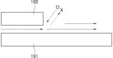
도 3은 코안다 효과(Coanda effect)를 설명하기 위한 도면이다.
도 4 및 도 5는 본 발명에 따른 내측 냉각 플레이트의 외관을 도시한다.
도 6은 본 발명에 따른 내측 냉각 플레이트의 단면을 도시한다.
도 7은 본 발명에 따른 내측 냉각 플레이트의 후면을 도시한다.
도 8 및 도 9는 본 발명에 따른 외측 냉각 플레이트의 외관을 도시한다.
도 10는 본 발명에 따른 외측 냉각 플레이트의 단면을 도시한다.
도 11은 본 발명에 따른 외측 냉각 플레이트의 후면을 도시한다.
도 12는 본 발명에 따른 냉각 플레이트에서 기체의 유동량에 대한 시뮬레이션 결과를 도시한다.Figure 1 schematically illustrates the structure of a plasma processing chamber according to the present invention.
Figure 2 illustrates the appearance of a cooling plate according to the present invention.
Figure 3 is a diagram explaining the Coanda effect.
Figures 4 and 5 illustrate the appearance of an inner cooling plate according to the present invention.
Figure 6 illustrates a cross-section of an inner cooling plate according to the present invention.
Figure 7 illustrates the rear surface of the inner cooling plate according to the present invention.
Figures 8 and 9 illustrate the appearance of an outer cooling plate according to the present invention.
Figure 10 illustrates a cross-section of an outer cooling plate according to the present invention.
Figure 11 illustrates the rear surface of the outer cooling plate according to the present invention.
Figure 12 shows the simulation results for the flow amount of gas in the cooling plate according to the present invention.
이하, 첨부한 도면을 참고로 하여 본 발명의 실시예들에 대하여 본 발명이 속하는 기술 분야에서 통상의 지식을 가진 자가 용이하게 실시할 수 있도록 상세히 설명한다. 본 발명은 여러 가지 상이한 형태로 구현될 수 있으며 여기에서 설명하는 실시예들에 한정되지 않는다.Hereinafter, embodiments of the present invention will be described in detail with reference to the attached drawings so that those skilled in the art can easily implement the present invention. The present invention may be implemented in various different forms and is not limited to the embodiments described herein.
본 발명을 명확하게 설명하기 위해서 설명과 관계없는 부분은 생략하였으며, 명세서 전체를 통하여 동일 또는 유사한 구성요소에 대해서는 동일한 참조 부호를 붙이도록 한다.In order to clearly explain the present invention, parts irrelevant to the description are omitted, and the same reference numerals are used for identical or similar components throughout the specification.
또한, 여러 실시예들에 있어서, 동일한 구성을 가지는 구성요소에 대해서는 동일한 부호를 사용하여 대표적인 실시예에서만 설명하고, 그 외의 다른 실시예에서는 대표적인 실시예와 다른 구성에 대해서만 설명하기로 한다.In addition, in various embodiments, components having the same configuration are described only in representative embodiments using the same reference numerals, and in other embodiments, only configurations different from the representative embodiments are described.
명세서 전체에서, 어떤 부분이 다른 부분과 "연결(또는 결합)"되어 있다고 할 때, 이는 "직접적으로 연결(또는 결합)"되어 있는 경우뿐만 아니라, 다른 부재를 사이에 두고 "간접적으로 연결(또는 결합)"된 것도 포함한다. 또한, 어떤 부분이 어떤 구성요소를 "포함"한다고 할 때, 이는 특별히 반대되는 기재가 없는 한 다른 구성요소를 제외하는 것이 아니라 다른 구성요소를 더 포함할 수 있는 것을 의미한다.Throughout the specification, when a part is said to be "connected (or coupled)" to another part, this includes not only the case where it is "directly connected (or coupled)" but also the case where it is "indirectly connected (or coupled)" with another member therebetween. Also, when a part is said to "include" a certain component, this does not mean that it excludes other components, but rather that it can include other components, unless otherwise specifically stated.
다르게 정의되지 않는 한, 기술적이거나 과학적인 용어를 포함해서 여기서 사용되는 모든 용어들은 본 발명이 속하는 기술 분야에서 통상의 지식을 가진 자에 의해 일반적으로 이해되는 것과 동일한 의미를 가지고 있다. 일반적으로 사용되는 사전에 정의되어 있는 것과 같은 용어들은 관련 기술의 문맥 상 가지는 의미와 일치하는 의미를 가지는 것으로 해석되어야 하며, 본 출원에서 명백하게 정의하지 않는 한, 이상적이거나 과도하게 형식적인 의미로 해석되지 않는다.Unless otherwise defined, all terms used herein, including technical or scientific terms, have the same meaning as commonly understood by one of ordinary skill in the art to which this invention belongs. Terms defined in commonly used dictionaries, such as those defined in common dictionaries, should be interpreted as having a meaning consistent with the meaning they have in the context of the relevant art, and will not be interpreted in an idealized or overly formal sense unless expressly defined in this application.
도 1은 본 발명에 따른 플라즈마 처리 챔버(100)의 개략적이 구조를 도시한다. 도 1을 참조하면, 플라즈마 처리 챔버(100)는 하우징(housing; 110), 기판 지지 유닛(120), 플라즈마 생성 유닛(130), 샤워 헤드 유닛(shower head unit; 140), 제1 가스 공급 유닛(150), 제2 가스 공급 유닛(160), 월 라이너(wall liner; 170), 배플 유닛(baffle unit; 180) 및 상부 모듈(190)을 포함하여 구성될 수 있다.FIG. 1 schematically illustrates a structure of a plasma processing chamber (100) according to the present invention. Referring to FIG. 1, the plasma processing chamber (100) may be configured to include a housing (110), a substrate support unit (120), a plasma generation unit (130), a shower head unit (140), a first gas supply unit (150), a second gas supply unit (160), a wall liner (170), a baffle unit (180), and an upper module (190).
플라즈마 처리 챔버(100)는 진공 환경에서 식각 공정(예를 들어, 건식 식각 공정(dry etching process))을 이용하여 기판(W)(예를 들어, 웨이퍼(wafer))을 처리한다. 플라즈마 처리 챔버(100)는 예를 들어, 플라즈마 공정(plasma process)을 이용하여 기판(W)을 처리할 수 있다.The plasma processing chamber (100) processes a substrate (W) (e.g., a wafer) using an etching process (e.g., a dry etching process) in a vacuum environment. The plasma processing chamber (100) can process the substrate (W) using, for example, a plasma process.
하우징(110)은 플라즈마 공정이 수행되는 플라즈마 처리 공간을 제공하는 것이다. 이러한 하우징(110)은 그 하부에 배기 홀(111)을 구비할 수 있다.The housing (110) provides a plasma treatment space where a plasma process is performed. The housing (110) may have an exhaust hole (111) at its lower portion.
배기 홀(111)은 펌프(112)가 장착된 배기 라인(113)과 연결될 수 있다. 이러한 배기 홀(111)은 배기 라인(113)을 통해 플라즈마 공정 과정에서 발생된 반응 부산물과 하우징(110)의 내부에 잔여하는 가스를 하우징(110)의 외부로 배출할 수 있다. 이 경우, 하우징(110)의 내부 공간(플라즈마 처리 공간)은 소정의 압력으로 감압될 수 있다.The exhaust hole (111) may be connected to an exhaust line (113) equipped with a pump (112). The exhaust hole (111) may discharge reaction byproducts generated during the plasma process and gases remaining inside the housing (110) to the outside of the housing (110) through the exhaust line (113). In this case, the internal space (plasma treatment space) of the housing (110) may be depressurized to a predetermined pressure.
하우징(110)은 그 측벽에 개구부(114)가 형성될 수 있다. 개구부(114)는 하우징(110)의 내부로 기판(W)이 출입하는 통로로서 기능할 수 있다. 이러한 개구부(114)는 도어 어셈블리(115)에 의해 개폐되도록 구성될 수 있다.The housing (110) may have an opening (114) formed in its side wall. The opening (114) may function as a passage through which a substrate (W) enters and exits the interior of the housing (110). This opening (114) may be configured to be opened and closed by a door assembly (115).
도어 어셈블리(115)는 외측 도어(115a) 및 도어 구동기(115b)를 포함하여 구성될 수 있다. 외측 도어(115a)는 하우징(110)의 외벽에 제공되는 것이다. 이러한 외측 도어(115a)는 도어 구동기(115b)를 통해 상하 방향(Z 방향)으로 이동될 수 있다. 도어 구동기(115b)는 모터, 유압 실린더, 공압 실린더 등을 이용하여 작동할 수 있다.The door assembly (115) may be configured to include an outer door (115a) and a door driver (115b). The outer door (115a) is provided on the outer wall of the housing (110). The outer door (115a) may be moved in the up-and-down direction (Z direction) by the door driver (115b). The door driver (115b) may be operated by using a motor, a hydraulic cylinder, a pneumatic cylinder, or the like.
기판 지지 유닛(120)은 하우징(110)의 내부 하측 영역에 설치되는 것이다. 이러한 기판 지지 유닛(120)은 정전기력을 이용하여 기판(W)을 지지할 수 있다. 그러나 본 실시예가 이에 한정되는 것은 아니다. 기판 지지 유닛(120)은 기계적 클램핑(mechanical clamping), 진공(vacuum) 등과 같은 다양한 방식으로 기판(W)을 지지하는 것도 가능하다.The substrate support unit (120) is installed in the inner lower region of the housing (110). The substrate support unit (120) can support the substrate (W) using electrostatic force. However, the present embodiment is not limited thereto. The substrate support unit (120) can also support the substrate (W) in various ways, such as mechanical clamping, vacuum, etc.
기판 지지 유닛(120)은 정전기력을 이용하여 기판(W)을 지지하는 경우, 척 바디(chuck body; 121)와 정전 척(electrostatic chuck; 122)를 포함할 수 있다.The substrate support unit (120) may include a chuck body (121) and an electrostatic chuck (122) when supporting the substrate (W) using electrostatic force.
척 바디(121)는 정전 척(122)을 하부에서 지지한다. 척 바디(121)는 예를 들어, 알루미늄 성분을 소재로 하여 제작되어 알루미늄 베이스 플레이트(Al base plate)로 제공될 수 있다.The chuck body (121) supports the electrostatic chuck (122) from below. The chuck body (121) may be manufactured using, for example, an aluminum component and provided as an aluminum base plate (Al base plate).
정전 척(122)은 정전기력을 이용하여 그 상부에 안착되는 기판(W)을 지지하는 것이다. 이러한 정전 척(122)은 세라믹 성분을 소재로 하여 제작되어 세라믹 플레이트(ceramic plate) 또는 세라믹 퍽(ceramic puck)으로 제공될 수 있으며, 척 바디(121) 상에 고정되도록 척 바디(121)와 결합될 수 있다.The electrostatic chuck (122) uses electrostatic force to support a substrate (W) mounted on its upper portion. The electrostatic chuck (122) is manufactured using a ceramic component and may be provided as a ceramic plate or a ceramic puck, and may be combined with the chuck body (121) so as to be fixed on the chuck body (121).
척 바디(121)와 그 위에 형성되는 정전 척(122) 사이에는 접합층(bonding layer)이 형성될 수 있으며, 접합층을 보호하기 위해 그 외곽에는 보호층이 설치될 수 있다.A bonding layer may be formed between the chuck body (121) and the electrostatic chuck (122) formed thereon, and a protective layer may be installed on the periphery to protect the bonding layer.
정전 척(122)은 구동 부재(미도시)를 이용하여 하우징(110)의 내부에서 상하 방향(Z 방향)으로 이동 가능하게 설치될 수도 있다. 정전 척(122)은 이와 같이 상하 방향으로 이동 가능하게 형성되는 경우, 기판(W)을 보다 균일한 플라즈마 분포를 나타내는 영역에 위치시키는 것이 가능해질 수 있다. 정전 척(122)의 내부에는 하부 전극(127)이 구비되어 플라즈마 처리 챔버(100)의 처리 공간에 플라즈마를 형성할 수 있다.The electrostatic chuck (122) may be installed so as to be able to move up and down (Z direction) inside the housing (110) using a driving member (not shown). When the electrostatic chuck (122) is formed so as to be able to move up and down in this way, it may be possible to position the substrate (W) in an area showing a more uniform plasma distribution. A lower electrode (127) is provided inside the electrostatic chuck (122) so as to form plasma in the processing space of the plasma processing chamber (100).
링 어셈블리(123)는 정전 척(122)의 테두리를 감싸도록 제공되는 것이다. 이러한 링 어셈블리(123)는 링 형상으로 제공되어, 기판(W)의 테두리 영역을 지지하도록 구성될 수 있다. 링 어셈블리(123)는 포커스 링(focus ring; 123a) 및 절연 링(123b)을 포함하여 구성될 수 있다.The ring assembly (123) is provided to surround the edge of the electrostatic chuck (122). This ring assembly (123) is provided in a ring shape and can be configured to support the edge area of the substrate (W). The ring assembly (123) can be configured to include a focus ring (123a) and an insulating ring (123b).
포커스 링(123a)은 절연 링(123b)의 내측에 형성되며, 정전 척(122)을 감싸도록 제공된다. 이러한 포커스 링(123a)은 실리콘 재질로 제공될 수 있으며, 플라즈마를 기판(W)으로 집중시킬 수 있다.A focus ring (123a) is formed on the inner side of an insulating ring (123b) and is provided to surround an electrostatic chuck (122). This focus ring (123a) may be provided with a silicon material and can focus plasma onto a substrate (W).
절연 링(123b)은 포커스 링(123a)의 외측에 형성되며, 포커스 링(123a)을 감싸도록 제공된다. 이러한 절연 링(123b)은 쿼츠(quartz) 재질로 제공될 수 있다.An insulating ring (123b) is formed on the outside of the focus ring (123a) and is provided to surround the focus ring (123a). This insulating ring (123b) may be provided from a quartz material.
한편, 링 어셈블리(123)는 포커스 링(123a)의 테두리에 밀착 형성되는 에지 링(edge ring)(미도시)을 더 포함할 수 있다. 에지 링은 플라즈마에 의해 정전 척(122)의 측면이 손상되는 것을 방지하기 위해 형성될 수 있다.Meanwhile, the ring assembly (123) may further include an edge ring (not shown) that is formed in close contact with the edge of the focus ring (123a). The edge ring may be formed to prevent the side of the electrostatic chuck (122) from being damaged by plasma.
제1 가스 공급 유닛(150)은 링 어셈블리(123)의 상부나 정전 척(122)의 테두리 부분에 잔류하는 이물질을 제거하기 위해 제1 가스를 공급하는 것이다. 이러한 제1 가스 공급 유닛(150)은 제1 가스 공급원(151) 및 제1 가스 공급 라인(152)을 포함하여 구성될 수 있다.The first gas supply unit (150) supplies the first gas to remove foreign substances remaining in the upper portion of the ring assembly (123) or the edge portion of the electrostatic chuck (122). The first gas supply unit (150) may be configured to include a first gas supply source (151) and a first gas supply line (152).
제1 가스 공급원(151)은 제1 가스로 질소 가스(N2 gas)를 공급할 수 있다. 그러나 본 실시예가 이에 한정되는 것은 아니다. 제1 가스 공급원(151)은 다른 가스나 세정제 등을 공급하는 것도 가능하다.The first gas supply source (151) can supply nitrogen gas (N2 gas) as the first gas. However, the present embodiment is not limited thereto. The first gas supply source (151) can also supply other gases or cleaning agents.
제1 가스 공급 라인(152)은 정전 척(122)과 링 어셈블리(123) 사이에 제공되는 것이다. 제1 가스 공급 라인(152)은 예를 들어, 정전 척(122)과 포커스 링(123a) 사이로 연결되도록 형성될 수 있다.A first gas supply line (152) is provided between the electrostatic chuck (122) and the ring assembly (123). The first gas supply line (152) may be formed to be connected between, for example, the electrostatic chuck (122) and the focus ring (123a).
한편, 제1 가스 공급 라인(152)은 포커스 링(123a)의 내부에 제공되어, 정전 척(122)과 포커스 링(123a) 사이로 연결되도록 절곡되도록 형성되는 것도 가능하다.Meanwhile, the first gas supply line (152) may be provided inside the focus ring (123a) and may be formed to be bent so as to be connected between the electrostatic chuck (122) and the focus ring (123a).
가열 부재(124) 및 냉각 부재(125)는 하우징(110)의 내부에서 식각 공정이 진행되고 있을 때에 기판(W)이 공정 온도를 유지할 수 있도록 제공되는 것이다. 가열 부재(124)는 이를 위해 열선으로 제공될 수 있으며, 냉각 부재(125)는 이를 위해 냉매가 흐르는 냉각 라인으로 제공될 수 있다.The heating member (124) and the cooling member (125) are provided so that the substrate (W) can maintain the process temperature when the etching process is in progress inside the housing (110). The heating member (124) may be provided as a heating wire for this purpose, and the cooling member (125) may be provided as a cooling line through which a coolant flows for this purpose.
가열 부재(124) 및 냉각 부재(125)는 기판(W)이 공정 온도를 유지할 수 있도록 하기 위해 정전 척(122)의 내부에 설치될 수 있다. 일례로, 가열 부재(124)는 정전 척(122)의 내부에 설치될 수 있으며, 냉각 부재(125)는 척 바디(121)의 내부에 설치될 수 있다.A heating member (124) and a cooling member (125) may be installed inside the electrostatic chuck (122) to allow the substrate (W) to maintain the process temperature. For example, the heating member (124) may be installed inside the electrostatic chuck (122), and the cooling member (125) may be installed inside the chuck body (121).
한편, 냉각 부재(125)는 냉각 장치(chiller; 126)를 이용하여 냉매를 공급받을 수 있다. 냉각 장치(126)는 하우징(110)의 외부에 설치될 수 있다.Meanwhile, the cooling member (125) can be supplied with refrigerant using a chiller (126). The cooling device (126) can be installed on the outside of the housing (110).
플라즈마 생성 유닛(130)은 방전 공간에 잔류하는 가스로부터 플라즈마를 발생시키는 것이다. 여기서, 방전 공간은 하우징(110)의 내부 공간 중에서 정전 척(122)의 상부에 위치하는 공간을 의미한다.The plasma generation unit (130) generates plasma from gas remaining in the discharge space. Here, the discharge space refers to a space located above the electrostatic chuck (122) among the internal spaces of the housing (110).
플라즈마 생성 유닛(130)은 유도 결합형 플라즈마(ICP; Inductively Coupled Plasma) 소스를 이용하여 하우징(110) 내부의 방전 공간에 플라즈마를 발생시킬 수 있다. 이 경우, 플라즈마 생성 유닛(130)은 상부 모듈(190)에 설치되는 안테나(antenna; 193)와 정전 척(122)의 하부 전극(127)을 사용하여 플라즈마를 형성하기 위한 전압을 인가할 수 있다.The plasma generation unit (130) can generate plasma in a discharge space inside the housing (110) using an inductively coupled plasma (ICP) source. In this case, the plasma generation unit (130) can apply voltage to form plasma using an antenna (antenna; 193) installed in the upper module (190) and a lower electrode (127) of an electrostatic chuck (122).
그러나 본 실시예가 이에 한정되는 것은 아니다. 플라즈마 생성 유닛(130)은 용량 결합형 플라즈마(CCP; Capacitively Coupled Plasma) 소스를 이용하여 하우징(110) 내부의 방전 공간에 플라즈마를 발생시키는 것도 가능하다.However, the present embodiment is not limited thereto. The plasma generation unit (130) can also generate plasma in the discharge space inside the housing (110) using a capacitively coupled plasma (CCP) source.
플라즈마 생성 유닛(130)은 상부 전원(131) 및 하부 전원(133)을 포함하여 구성될 수 있다.The plasma generation unit (130) may be configured to include an upper power source (131) and a lower power source (133).
상부 전원(131)은 상부 전극, 즉 안테나(193)에 전력을 인가하는 것이다. 이러한 상부 전원(131)은 플라즈마의 특성을 제어하도록 제공될 수 있다. 상부 전원(131)은 예를 들어, 이온 충격 에너지(ion bombardment energy)를 조절하도록 제공될 수 있다.The upper power source (131) supplies power to the upper electrode, i.e., the antenna (193). The upper power source (131) may be provided to control the characteristics of the plasma. The upper power source (131) may be provided to control, for example, ion bombardment energy.
상부 전원(131)은 도 1에 단일 개 도시되어 있지만, 본 실시예에서 복수 개 구비되는 것도 가능하다. 상부 전원(131)이 복수 개 구비되는 경우, 플라즈마 처리 챔버(100)는 복수 개의 상부 전원과 전기적으로 연결되는 제1 매칭 네트워크(미도시)를 더 포함할 수 있다.The upper power supply (131) is illustrated as a single unit in FIG. 1, but may be provided in multiple units in this embodiment. When multiple upper power supplies (131) are provided, the plasma processing chamber (100) may further include a first matching network (not illustrated) electrically connected to the multiple upper power supplies.
제1 매칭 네트워크는 각각의 상부 전원으로부터 입력되는 상이한 크기의 주파수 전력들을 매칭하여 안테나(193)에 인가할 수 있다.The first matching network can match different magnitudes of frequency power input from each upper power source and apply them to the antenna (193).
한편, 상부 전원(131)과 안테나(193)를 연결하는 제1 전송 선로(132) 상에는 임피던스 정합을 목적으로 제1 임피던스 정합 회로(미도시)가 마련될 수 있다.Meanwhile, a first impedance matching circuit (not shown) may be provided on the first transmission line (132) connecting the upper power supply (131) and the antenna (193) for the purpose of impedance matching.
제1 임피던스 정합 회로는 무손실 수동 회로로 작용하여 상부 전원(131)으로부터 안테나(193)로 전기 에너지가 효과적으로(즉, 최대로) 전달되도록 할 수 있다.The first impedance matching circuit can act as a lossless passive circuit to effectively (i.e., maximally) transfer electrical energy from the upper power source (131) to the antenna (193).
하부 전원(133)은 하부 전극, 즉 정전 척(122)에 전력을 인가하는 것이다. 이러한 하부 전원(133)은 플라즈마를 발생시키는 플라즈마 소스 역할을 하거나, 상부 전원(131)과 더불어 플라즈마의 특성을 제어하는 역할을 할 수 있다.The lower power source (133) supplies power to the lower electrode, i.e., the electrostatic chuck (122). The lower power source (133) may serve as a plasma source that generates plasma, or may serve to control the characteristics of plasma together with the upper power source (131).
하부 전원(133)은 도 1에 단일 개 도시되어 있지만, 상부 전원(131)과 마찬가지로 본 실시예에서 복수 개 구비되는 것도 가능하다. 하부 전원(133)이 복수 개 구비되는 경우, 복수 개의 하부 전원과 전기적으로 연결되는 제2 매칭 네트워크(미도시)를 더 포함할 수 있다.The lower power supply (133) is illustrated as a single unit in Fig. 1, but, like the upper power supply (131), it is also possible to have multiple units in this embodiment. When multiple lower power supplies (133) are provided, a second matching network (not illustrated) electrically connected to the multiple lower power supplies may be further included.
제2 매칭 네트워크는 각각의 하부 전원으로부터 입력되는 상이한 크기의 주파수 전력들을 매칭하여 정전 척(122)에 인가할 수 있다.The second matching network can match different magnitudes of frequency power input from each sub-power source and apply them to the electrostatic chuck (122).
한편, 하부 전원(133)과 정전 척(122)을 연결하는 제2 전송 선로(134) 상에는 임피던스 정합을 목적으로 제2 임피던스 정합 회로(미도시)가 마련될 수 있다.Meanwhile, a second impedance matching circuit (not shown) may be provided on the second transmission line (134) connecting the lower power supply (133) and the electrostatic chuck (122) for the purpose of impedance matching.
제2 임피던스 정합 회로는 제1 임피던스 정합 회로와 마찬가지로 무손실 수동 회로로 작용하여 하부 전원(133)으로부터 정전 척(122)으로 전기 에너지가 효과적으로(즉, 최대로) 전달되도록 할 수 있다.The second impedance matching circuit, like the first impedance matching circuit, can act as a lossless passive circuit to effectively (i.e., maximally) transfer electrical energy from the lower power source (133) to the electrostatic chuck (122).
샤워 헤드 유닛(140)은 정전 척(122)과 하우징(110)의 내부에서 상하로 대향되도록 설치될 수 있다. 이러한 샤워 헤드 유닛(140)은 하우징(110)의 내부로 가스를 분사하기 위해 복수 개의 가스 분사 홀(gas feeding hole; 141)을 구비할 수 있으며, 정전 척(122)보다 더 큰 직경을 가지도록 제공될 수 있다.The shower head unit (140) may be installed so as to face the electrostatic chuck (122) and the housing (110) in an up-and-down manner. The shower head unit (140) may be provided with a plurality of gas feeding holes (141) to inject gas into the interior of the housing (110), and may be provided to have a larger diameter than the electrostatic chuck (122).
한편, 샤워 헤드 유닛(140)은 실리콘 성분을 소재로 하여 제작될 수 있으며, 금속 성분을 소재로 하여 제작되는 것도 가능하다.Meanwhile, the shower head unit (140) can be manufactured using a silicone component, and can also be manufactured using a metal component.
제2 가스 공급 유닛(160)은 샤워 헤드 유닛(140)을 통해 하우징(110)의 내부로 공정 가스(제2 가스)를 공급하는 것이다. 이러한 제2 가스 공급 유닛(160)은 제2 가스 공급원(161) 및 제2 가스 공급 라인(162)을 포함할 수 있다.The second gas supply unit (160) supplies process gas (second gas) into the interior of the housing (110) through the shower head unit (140). The second gas supply unit (160) may include a second gas supply source (161) and a second gas supply line (162).
제2 가스 공급원(161)은 기판(W)을 처리하는 데에 이용되는 에칭 가스(etching gas)를 공정 가스로 공급하는 것이다. 이러한 제2 가스 공급원(161)은 에칭 가스로 불소(fluorine) 성분을 포함하는 가스(예를 들어, SF6, CF4 등의 가스)를 공급할 수 있다.The second gas supply source (161) supplies an etching gas used to process the substrate (W) as a process gas. The second gas supply source (161) can supply a gas containing a fluorine component (e.g., a gas such as SF6 or CF4) as the etching gas.
제2 가스 공급원(161)은 단일 개 구비되어 에칭 가스를 샤워 헤드 유닛(140)으로 공급할 수 있다. 그러나 본 실시예가 이에 한정되는 것은 아니다. 제2 가스 공급원(161)은 복수 개 구비되어 공정 가스를 샤워 헤드 유닛(140)으로 공급하는 것도 가능하다.The second gas supply source (161) may be provided in a single unit to supply the etching gas to the shower head unit (140). However, the present embodiment is not limited thereto. The second gas supply source (161) may also be provided in multiple units to supply the process gas to the shower head unit (140).
제2 가스 공급 라인(162)은 제2 가스 공급원(161)과 샤워 헤드 유닛(140)을 연결하는 것이다. 제2 가스 공급 라인(162)은 제2 가스 공급원(161)을 통해 공급되는 공정 가스를 샤워 헤드 유닛(140)으로 이송하여, 에칭 가스가 하우징(110)의 내부로 유입될 수 있도록 한다.The second gas supply line (162) connects the second gas supply source (161) and the shower head unit (140). The second gas supply line (162) transports the process gas supplied through the second gas supply source (161) to the shower head unit (140), thereby allowing the etching gas to flow into the interior of the housing (110).
한편, 샤워 헤드 유닛(140)이 센터 영역(center zone), 미들 영역(middle zone), 에지 영역(edge zone) 등으로 분할되는 경우, 제2 가스 공급 유닛(160)은 샤워 헤드 유닛(140)의 각 영역으로 공정 가스를 공급하기 위해 가스 분배기(미도시)와 가스 분배 라인(미도시)을 더 포함할 수 있다.Meanwhile, when the shower head unit (140) is divided into a center zone, a middle zone, an edge zone, etc., the second gas supply unit (160) may further include a gas distributor (not shown) and a gas distribution line (not shown) to supply process gas to each zone of the shower head unit (140).
가스 분배기는 제2 가스 공급원(161)으로부터 공급되는 공정 가스를 샤워 헤드 유닛(140)의 각 영역으로 분배하는 것이다. 이러한 가스 분배기는 제2 가스 공급 라인(162)을 통해 제2 가스 공급원(161)과 연결될 수 있다.The gas distributor distributes process gas supplied from the second gas supply source (161) to each area of the shower head unit (140). This gas distributor can be connected to the second gas supply source (161) through the second gas supply line (162).
가스 분배 라인은 가스 분배기와 샤워 헤드 유닛(140)의 각 영역을 연결하는 것이다. 가스 분배 라인은 이를 통해 가스 분배기에 의해 분배된 공정 가스를 샤워 헤드 유닛(140)의 각 영역으로 이송할 수 있다.The gas distribution line connects each area of the gas distributor and the shower head unit (140). The gas distribution line can thereby transport the process gas distributed by the gas distributor to each area of the shower head unit (140).
한편, 제2 가스 공급 유닛(160)은 증착 가스(deposition gas)를 공급하는 제3 가스 공급원(미도시)을 더 포함하는 것도 가능하다.Meanwhile, the second gas supply unit (160) may further include a third gas supply source (not shown) that supplies deposition gas.
제3 가스 공급원은 기판(W) 패턴의 측면을 보호하여 이방성 에칭이 가능해지도록 샤워 헤드 유닛(140)으로 공급하는 것이다. 이러한 제2 가스 공급원은 C4F8, C2F4 등의 가스를 증착 가스로 공급할 수 있다.The third gas supply source is supplied to the shower head unit (140) to protect the side of the substrate (W) pattern to enable anisotropic etching. This second gas supply source can supply gases such as C4F8 and C2F4 as deposition gases.
월 라이너 유닛(170)은 공정 가스가 여기되는 과정에서 발생되는 아크 방전, 기판 처리 공정 중에 발생되는 불순물 등으로부터 하우징(110)의 내측면을 보호하기 위한 것이다. 이러한 월 라이너 유닛(170)은 하우징(110)의 내부에 상부와 하부가 각각 개방된 원통 형상으로 제공될 수 있다.The wall liner unit (170) is intended to protect the inner surface of the housing (110) from arc discharge generated during the process of excitation of process gas, impurities generated during the substrate processing process, etc. This wall liner unit (170) may be provided in a cylindrical shape with the upper and lower portions each open inside the housing (110).
월 라이너 유닛(170)은 하우징(110)의 내측벽에 인접하도록 제공될 수 있다. 이러한 월 라이너 유닛(170)은 그 상부에 지지 링(171)을 구비할 수 있다. 지지 링(171)은 월 라이너 유닛(170)의 상부에서 외측 방향(즉, 제1 방향(10))으로 돌출 형성되며, 하우징(110)의 상단에 놓여 월 라이너 유닛(170)을 지지할 수 있다.The wall liner unit (170) may be provided adjacent to the inner wall of the housing (110). The wall liner unit (170) may have a support ring (171) on its upper portion. The support ring (171) is formed to protrude outwardly (i.e., in the first direction (10)) from the upper portion of the wall liner unit (170) and may be placed on the upper end of the housing (110) to support the wall liner unit (170).
배플 유닛(180)은 플라즈마의 공정 부산물, 미반응 가스 등을 배기하는 역할을 한다. 이러한 배플 유닛(180)은 하우징(110)의 내측벽과 정전 척(122) 사이에 설치될 수 있다. 배플 유닛(180)은 환형의 링 형상으로 제공될 수 있으며, 상하 방향(즉, 제3 방향([0083] 30))으로 관통되는 복수 개의 관통 홀을 구비할 수 있다. 배플 유닛(180)은 관통 홀의 개수 및 형상에 따라 공정 가스의 흐름을 제어할 수 있다.The baffle unit (180) serves to exhaust process byproducts of the plasma, unreacted gases, etc. The baffle unit (180) may be installed between the inner wall of the housing (110) and the electrostatic chuck (122). The baffle unit (180) may be provided in an annular ring shape and may have a plurality of through holes penetrating in the up-down direction (i.e., the third direction ([0083] 30)). The baffle unit (180) may control the flow of the process gas depending on the number and shape of the through holes.
상부 모듈(190)은 하우징(110)의 개방된 상부를 덮도록 설치되는 것이다. 이러한 상부 모듈(190)은 윈도우(191), 냉각 플레이트(192), 및 안테나(193)를 포함할 수 있다.The upper module (190) is installed to cover the open upper portion of the housing (110). The upper module (190) may include a window (191), a cooling plate (192), and an antenna (193).
윈도우(191)는 하우징(110)의 내부 공간을 밀폐시키기 위해 하우징(110)의 상부를 덮도록 형성되는 것이다. 이러한 윈도우(191)는 판(예를 들어, 원판) 형상으로 제공될 수 있으며, 절연 물질(예를 들어, 알루미나(Al2O3))을 소재로 하여 형성될 수 있다.The window (191) is formed to cover the upper part of the housing (110) in order to seal the internal space of the housing (110). This window (191) may be provided in a plate (e.g., a circular plate) shape and may be formed using an insulating material (e.g., alumina (Al2O3)) as a material.
윈도우(191)는 유전체 창(dielectric window)을 포함하여 형성될 수 있다 윈도우(191)는 제2 가스 공급 라인(162)이 삽입되기 위한 통공이 형성될 수 있으며, 하우징(110)의 내부에서 플라즈마 공정이 수행될 때 파티클(particle)의 발생을 억제하기 위해 그 표면에 코팅막이 형성될 수 있다. 냉각 플레이트(192)는 윈도우(191)로 공기를 유동시켜 윈도우(191)를 냉각시킨다. 냉각 플레이트(192)의 세부 구조는 도 2 내지 도 10을 참고하여 상세히 설명하도록 한다.The window (191) may be formed to include a dielectric window. The window (191) may have a through hole formed therein for inserting a second gas supply line (162), and a coating film may be formed on its surface to suppress the generation of particles when a plasma process is performed inside the housing (110). The cooling plate (192) cools the window (191) by allowing air to flow to the window (191). The detailed structure of the cooling plate (192) will be described in detail with reference to FIGS. 2 to 10.
안테나(193)는 윈도우(191) 및 냉각 플레이트(192)의 상부에 설치된다. 안테나(193)는 하부가 개방된 원통 형상으로 형성될 수 있으며, 하우징(110)과 대응되는 직경을 가지도록 제공될 수 있다. 안테나(193)는 윈도우(191)에 탈착 가능하도록 제공될 수 있다.The antenna (193) is installed on the upper part of the window (191) and the cooling plate (192). The antenna (193) may be formed in a cylindrical shape with an open bottom and may be provided to have a diameter corresponding to the housing (110). The antenna (193) may be provided to be detachably attached to the window (191).
안테나(193)는 상부 전극으로 기능하는 것으로서, 폐루프를 형성하도록 제공되는 코일이 장착된 것이다. 이러한 안테나(193)는 상부 전원(131)으로부터 공급되는 전력을 기초로 하우징(110)의 내부에 자기장 및 전기장을 생성하여, 샤워 헤드 유닛(140)을 통해 하우징(110)의 내부로 유입된 가스를 플라즈마로 여기시키는 기능을 한다.The antenna (193) functions as an upper electrode and is equipped with a coil provided to form a closed loop. This antenna (193) generates a magnetic field and an electric field inside the housing (110) based on power supplied from the upper power source (131), thereby exciting gas introduced into the inside of the housing (110) through the shower head unit (140) into plasma.
안테나(193)는 평판 스파이럴(planar spiral) 형태의 코일을 장착할 수 있다. 그러나 본 실시예가 이에 한정되는 것은 아니다. 코일의 구조나 크기 등은 당해 기술 분야에서 통상의 지식을 가진 자에 의해 다양하게 변경될 수 있다.The antenna (193) may be equipped with a coil in the form of a planar spiral. However, the present embodiment is not limited thereto. The structure and size of the coil may be variously changed by a person having ordinary knowledge in the relevant technical field.
이하, 본 발명에 따른 냉각 플레이트(192)에 대해 설명한다. 냉각 플레이트(192)는 윈도우(191)의 온도 유지를 위하여 윈도우(191)로 공기가 흐르도록 한다. 본 발명은 윈도우를 덮는 영역을 축소하면서 윈도우(191)의 전체 영역으로 공기가 유동하도록 하는 냉각 플레이트(192)를 제공한다. 본 발명에 따른 냉각 플레이트(192)는 내측 냉각 플레이트(210)와 외측 냉각 플레이트(220)를 포함할 수 있다.Hereinafter, a cooling plate (192) according to the present invention will be described. The cooling plate (192) allows air to flow to the window (191) in order to maintain the temperature of the window (191). The present invention provides a cooling plate (192) that allows air to flow to the entire area of the window (191) while reducing the area covering the window. The cooling plate (192) according to the present invention may include an inner cooling plate (210) and an outer cooling plate (220).
도 2를 참고하면, 내측 냉각 플레이트(210)는 윈도우(191) 중심 영역 일부를 덮도록 구성되고, 외측 냉각 플레이트(220)는 윈도우(191)의 가장자리 영역 일부를 덮도록 구성된다. 내측 냉각 플레이트(210)와 외측 냉각 플레이트(220) 사이에는 빈 공간이 존재하므로 안테나(193)로부터의 전자기 신호가 플라즈마 처리 공간으로 원활히 전달될 수 있다. 외측 냉각 플레이트(220)와 내측 냉각 플레이트(210)는 냉각 플레이트로 통칭될 수 있다. 냉각 플레이트(192)는 외측 냉각 플레이트(220) 만으로 구성될 수도 있고, 내측 냉각 플레이트(210) 만으로 구성될 수도 있고, 외측 냉각 플레이트(220)와 내측 냉각 플레이트(210)를 모두 포함하도록 구성될 수도 있다.Referring to FIG. 2, the inner cooling plate (210) is configured to cover a part of the central area of the window (191), and the outer cooling plate (220) is configured to cover a part of the edge area of the window (191). Since there is an empty space between the inner cooling plate (210) and the outer cooling plate (220), an electromagnetic signal from the antenna (193) can be smoothly transmitted to the plasma processing space. The outer cooling plate (220) and the inner cooling plate (210) may be collectively referred to as cooling plates. The cooling plate (192) may be configured only with the outer cooling plate (220), may be configured only with the inner cooling plate (210), or may be configured to include both the outer cooling plate (220) and the inner cooling plate (210).
본 발명에 따르면, 윈도우(191)의 전체가 덮이지 않고 일부 영역이 덮이기 때문에 전자기파 신호의 전달 및 냉각 효율이 증대될 수 있다. 다만 윈도우(191)의 전 영역으로 기체가 균일하게 유동할 수 있도록 코안다 효과(Coanda effect)에 의해 기체가 윈도우(191)의 표면으로 유동하도록 냉각 플레이트(192)가 형성될 수 있다. 코안다 효과는 벽면 주변을 흐르는 유체에서 나타나는 현상으로서, 고체면 위를 흐르는 유체가 고체면 위를 따라 계속 흐르고자 하는 성질을 의미한다. 도 3을 참고하면, 윈도우(191)와 냉각 플레이트(192) 사이에서 유동하는 기체는 지속적으로 윈도우(191)의 표면 주변에서 흐르는 성질을 갖기 때문에 윈도우(191)의 일부 영역만 덮도록 냉각 플레이트(192)가 형성된 경우에도 기체가 윈도우(191)의 표면을 따라 흐를 수 있다. 이하, 코안다 효과가 적용된 내측 냉각 플레이트(210) 및 외측 냉각 플레이트(220)의 구조에 대해 설명한다.According to the present invention, since the entire window (191) is not covered but only a portion thereof is covered, the transmission and cooling efficiency of electromagnetic wave signals can be increased. However, the cooling plate (192) can be formed so that the gas can flow uniformly over the entire area of the window (191) by the Coanda effect so that the gas can flow to the surface of the window (191). The Coanda effect is a phenomenon that occurs in a fluid flowing around a wall surface, and refers to a property of a fluid flowing over a solid surface to continue to flow along the solid surface. Referring to FIG. 3, since the gas flowing between the window (191) and the cooling plate (192) has a property of continuously flowing around the surface of the window (191), even when the cooling plate (192) is formed so as to cover only a portion of the window (191), the gas can flow along the surface of the window (191). Hereinafter, the structures of the inner cooling plate (210) and the outer cooling plate (220) to which the Coanda effect is applied will be described.
내측 냉각 플레이트(210)는, 윈도우(191)의 중심 일부 영역을 덮는 원판 형태로 제공되는 바디(212)(내측 바디)와, 바디(212)에 기체가 유입되는 유입구(214)와, 바디(212)에서 기체가 윈도우(191)로 토출되는 배출구(216)를 포함한다. 유입구(214)와 배출구(216) 사이에는 기체가 유동하는 유로(210A) 및 유로(210A)에서 윈도우(191)를 향하여 경사로(210B)가 형성될 수 있다.The inner cooling plate (210) includes a body (212) (inner body) provided in a disc shape covering a central portion of a window (191), an inlet (214) through which gas flows into the body (212), and an outlet (216) through which gas flows from the body (212) to the window (191). Between the inlet (214) and the outlet (216), a path (210A) through which gas flows and a slope (210B) from the path (210A) toward the window (191) can be formed.
도 4는 내측 냉각 플레이트(210)의 외관을 도시하며, 도 5는 내측 냉각 플레이트(210)의 내부 구조를 설명하기 위한 도면이다. 도 6은 도 5에서 내측 냉각 플레이트(210)의 단면 부분(A1)을 확대한 도면이다. 도 7은 내측 냉각 플레이트(210)의 후면을 도시한다.Fig. 4 illustrates the external appearance of the inner cooling plate (210), and Fig. 5 is a drawing for explaining the internal structure of the inner cooling plate (210). Fig. 6 is an enlarged drawing of a cross-sectional portion (A1) of the inner cooling plate (210) in Fig. 5. Fig. 7 illustrates the rear surface of the inner cooling plate (210).
도 4 및 도 5를 참고하면, 내측 냉각 플레이트(210)의 바디(212)는 중심부가 개방된 원판 형상으로 제공된다. 내측 냉각 플레이트(210)의 유입구(214)는 바디(212)의 상부면에 위치한다. 도 4 및 도 7에 도시된 것과 같이 유입구(214)는 바디(212)에서 돌출된 돌출부(215)에 형성될 수 있다. 유입구(214)로 기체를 공급하는 기체 공급관(미도시)이 장착될 수 있다. 내측 냉각 플레이트(210)의 배출구(216)는 바디(212)의 외측에 위치한다. 배출구(216)는 바디(212)와 윈도우(191) 사이의 공간에 의해 형성되며 배출구(216)를 통해 기체가 배출될 수 있다. 내측 냉각 플레이트(210)의 배출구(216)는 바디(212)의 외측에 형성된 지지부(218) 사이의 공간에 의해 복수개 형성될 수 있다.Referring to FIGS. 4 and 5, the body (212) of the inner cooling plate (210) is provided in a circular shape with an open center. The inlet (214) of the inner cooling plate (210) is located on the upper surface of the body (212). As shown in FIGS. 4 and 7, the inlet (214) may be formed in a protrusion (215) protruding from the body (212). A gas supply pipe (not shown) for supplying gas to the inlet (214) may be mounted. The outlet (216) of the inner cooling plate (210) is located on the outside of the body (212). The outlet (216) is formed by a space between the body (212) and the window (191), and gas may be discharged through the outlet (216). The discharge ports (216) of the inner cooling plate (210) can be formed in multiple numbers by the space between the support members (218) formed on the outer side of the body (212).
유입구(214)와 배출구(216)는 서로 연결되어 기체가 유동하도록 구성된다. 도 6에 도시된 것과 같이 유입구(214)와 배출구(216) 사이에는 기체가 유동하는 유로(210A) 및 유로(210A)에서 윈도우(191)를 향하여 경사로(210B)가 형성될 수 있다. 유로(210A)는 일정한 형태로 구성되어 기체가 일정하게 유동할 수 있으며, 기체는 유로(210A)에서 경사로(210B)를 따라 유동한 후 배출구(216)를 통해 배출된다. 기체는 경사로(210B)를 따라 유동하면서 코안다 효과에 의해 윈도우(191)의 상부면으로 유도되도록 경사로(210B)가 형성된다. 경사로(210B)에 의해 윈도우(191)와 바디(212) 사이에서 기체가 유동하는 단면적이 좁아지도록 형성된다. 경사로(210B)는 윈도우(191)를 향하여 돌출된 곡선 형태로 제공될 수 있다. 즉, 유입구(214)를 통해 유입된 기체는 유로(210A)를 따라 일정하게 유동하되 경사로(210B)를 따라 윈도우(191)의 표면측으로 유도된 후 최종적으로 배출구(216)를 통해 배출된다. 배출구(216)를 통해 배출된 기체는 코안다 효과에 의해 윈도우(191)의 상부 표면을 따라 흐르게 된다. 그리하여 윈도우(191)의 전체가 덮이지 않은 경우에도 기체가 윈도우(191)의 전 영역으로 균일하게 유동하여 냉각할 수 있다. 이와 유사한 메커니즘이 외측 냉각 플레이트(220)에도 적용될 수 있다.The inlet (214) and the outlet (216) are connected to each other so that the gas flows. As illustrated in FIG. 6, a path (210A) through which the gas flows and a ramp (210B) from the path (210A) toward the window (191) may be formed between the inlet (214) and the outlet (216). The path (210A) is configured in a certain shape so that the gas can flow at a certain rate, and the gas flows from the path (210A) along the ramp (210B) and is then discharged through the outlet (216). The ramp (210B) is formed so that the gas is guided to the upper surface of the window (191) by the Coanda effect while flowing along the ramp (210B). The ramp (210B) is formed so that the cross-sectional area through which the gas flows between the window (191) and the body (212) is narrowed. The ramp (210B) may be provided in a curved shape protruding toward the window (191). That is, the gas introduced through the inlet (214) flows steadily along the flow path (210A), but is guided toward the surface side of the window (191) along the ramp (210B) and is finally discharged through the outlet (216). The gas discharged through the outlet (216) flows along the upper surface of the window (191) due to the Coanda effect. Thus, even if the entire window (191) is not covered, the gas can flow uniformly to the entire area of the window (191) to cool it. A similar mechanism can also be applied to the outer cooling plate (220).
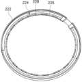
외측 냉각 플레이트(220)는, 윈도우(191)의 가장자리 일부 영역을 덮는 링 형태로 제공되는 바디(222)(외측 바디)와, 바디(222)에 기체가 유입되는 유입구(224)와, 바디(222)에서 기체가 윈도우(191)로 토출되는 배출구(226)를 포함한다. 유입구(224)와 배출구(226) 사이에는 기체가 유동하는 유로(220A) 및 유로(210A)에서 윈도우(191)를 향하여 경사로(220B)가 형성될 수 있다.The outer cooling plate (220) includes a body (222) (outer body) provided in a ring shape that covers a portion of an edge area of a window (191), an inlet (224) through which gas flows into the body (222), and an outlet (226) through which gas is discharged from the body (222) to the window (191). Between the inlet (224) and the outlet (226), a path (220A) through which gas flows and a slope (220B) from the path (210A) toward the window (191) can be formed.
도 8은 외측 냉각 플레이트(220)의 외관을 도시하며, 도 9는 외측 냉각 플레이트(220)의 내부 구조를 설명하기 위한 도면이다. 도 10은 도 9에서 외측 냉각 플레이트(220)의 단면 부분(A2)을 확대한 도면이다. 도 11은 외측 냉각 플레이트(220)의 후면을 도시한다.Fig. 8 illustrates the appearance of the outer cooling plate (220), and Fig. 9 is a drawing for explaining the internal structure of the outer cooling plate (220). Fig. 10 is an enlarged drawing of a cross-sectional portion (A2) of the outer cooling plate (220) in Fig. 9. Fig. 11 illustrates the rear surface of the outer cooling plate (220).
도 8 및 도 9, 도 11을 참고하면, 외측 냉각 플레이트(220)의 바디(222)는 윈도우(191)의 가장자리에 대응하는 링 형상으로 제공된다. 외측 냉각 플레이트(220)의 유입구(224)는 바디(222)의 상부면의 중심에 위치한다. 유입구(224)로 기체를 공급하는 기체 공급관(미도시)이 장착될 수 있다. 외측 냉각 플레이트(220)의 배출구(226)는 바디(222)의 내측에 위치한다. 배출구(226)는 바디(222)와 윈도우(191) 사이의 공간에 의해 형성되며 배출구(226)를 통해 기체가 배출될 수 있다. 외측 냉각 플레이트(220)의 배출구(226)는 바디(222)의 내측에 형성된 지지부(228) 사이의 공간에 의해 복수개 형성될 수 있다.Referring to FIGS. 8 and 9 and 11, the body (222) of the outer cooling plate (220) is provided in a ring shape corresponding to the edge of the window (191). The inlet (224) of the outer cooling plate (220) is located at the center of the upper surface of the body (222). A gas supply pipe (not shown) for supplying gas to the inlet (224) may be mounted. The outlet (226) of the outer cooling plate (220) is located on the inner side of the body (222). The outlet (226) is formed by the space between the body (222) and the window (191), and gas can be discharged through the outlet (226). The outlet (226) of the outer cooling plate (220) may be formed in multiple numbers by the space between the support members (228) formed on the inner side of the body (222).
유입구(224)와 배출구(226)는 서로 연결되어 기체가 유동하도록 구성된다. 도 10에 도시된 것과 같이 유입구(224)와 배출구(226) 사이에는 기체가 유동하는 유로(220A) 및 유로(220A)에서 윈도우(191)를 향하여 경사로(220B)가 형성될 수 있다. 유로(220A)는 일정한 형태로 구성되어 기체가 일정하게 유동할 수 있으며, 기체는 유로(220A)에서 경사로(220B)를 따라 유동한 후 배출구(226)를 통해 배출된다. 기체는 경사로(220B)를 따라 유동하면서 코안다 효과에 의해 윈도우(191)의 상부면으로 유도되도록 경사로(220B)가 형성된다. 경사로(220B)에 의해 윈도우(191)와 바디(222) 사이에서 기체가 유동하는 단면적이 좁아지도록 형성된다. 경사로(220B)는 윈도우(191)를 향하여 돌출된 곡선 형태로 제공될 수 있다. 즉, 유입구(224)를 통해 유입된 기체는 유로(220A)를 따라 일정하게 유동하되 경사로(220B)를 따라 윈도우(191)의 표면측으로 유도된 후 최종적으로 배출구(226)를 통해 배출된다. 배출구(226)를 통해 배출된 기체는 코안다 효과에 의해 윈도우(191)의 상부 표면을 따라 흐르게 된다. 그리하여 윈도우(191)의 전체가 덮이지 않은 경우에도 기체가 윈도우(191)의 전 영역으로 균일하게 유동하여 냉각할 수 있다.The inlet (224) and the outlet (226) are connected to each other and configured to allow gas to flow. As illustrated in FIG. 10, a path (220A) through which gas flows and a ramp (220B) from the path (220A) toward the window (191) may be formed between the inlet (224) and the outlet (226). The path (220A) is configured in a certain shape so that gas can flow at a certain rate, and the gas flows from the path (220A) along the ramp (220B) and is then discharged through the outlet (226). The ramp (220B) is formed so that the gas is guided to the upper surface of the window (191) by the Coanda effect while flowing along the ramp (220B). The ramp (220B) is formed so that the cross-sectional area through which gas flows between the window (191) and the body (222) is narrowed. The ramp (220B) may be provided in a curved shape protruding toward the window (191). That is, the gas introduced through the inlet (224) flows steadily along the flow path (220A), but is guided toward the surface side of the window (191) along the ramp (220B) and is finally discharged through the outlet (226). The gas discharged through the outlet (226) flows along the upper surface of the window (191) due to the Coanda effect. Thus, even if the entire window (191) is not covered, the gas can flow uniformly over the entire area of the window (191) to cool it.
도 12는 본 발명에 따른 냉각 플레이트(192)에서 기체의 유동량에 대한 시뮬레이션 결과를 도시한다. 도 10은 내측 냉각 플레이트(210)에서 공기의 유동에 대한 실험 결과를 나타내나, 유사한 결과가 외측 냉각 플레이트(220)에도 도출될 수 있음은 자명하다. 도 12에 도시된 것과 같이, 냉각 플레이트(192)의 유로(210A)에서 경사로(210B)를 따라 유동하면서 배출구(216)를 통해 배출된 기체는 코안다 효과에 듸해 윈도우(191)의 표면을 따라 유동함이 확인되었다. 이와 같이, 윈도우(191)의 일부 영역을 덮는 형태로 구성되는 냉각 플레이트(192)를 구성하되 내부에 코안다 효과를 발생시키는 경사로(210B)를 구성함으로써 전자기파의 손실 또는 왜곡을 저감하면서 윈도우(191)의 균일한 냉각 성능이 달성될 수 있다.Fig. 12 shows the simulation results for the amount of gas flowing in the cooling plate (192) according to the present invention. Fig. 10 shows the experimental results for the flow of air in the inner cooling plate (210), but it is obvious that similar results can be derived from the outer cooling plate (220). As shown in Fig. 12, it was confirmed that the gas discharged through the discharge port (216) while flowing along the ramp (210B) in the flow path (210A) of the cooling plate (192) flows along the surface of the window (191) due to the Coanda effect. In this way, by configuring the cooling plate (192) to cover a portion of the window (191) while configuring the ramp (210B) that generates the Coanda effect inside, the loss or distortion of electromagnetic waves can be reduced while achieving uniform cooling performance of the window (191).
본 실시예 및 본 명세서에 첨부된 도면은 본 발명에 포함되는 기술적 사상의 일부를 명확하게 나타내고 있는 것에 불과하며, 본 발명의 명세서 및 도면에 포함된 기술적 사상의 범위 내에서 당업자가 용이하게 유추할 수 있는 변형예와 구체적인 실시예는 모두 본 발명의 권리범위에 포함되는 것이 자명하다고 할 것이다.The present examples and the drawings attached to the present specification are merely intended to clearly illustrate a portion of the technical ideas included in the present invention, and it will be obvious that all modifications and specific embodiments that can be easily inferred by a person skilled in the art within the scope of the technical ideas included in the specification and drawings of the present invention are included in the scope of the rights of the present invention.
따라서, 본 발명의 사상은 설명된 실시예에 국한되어 정해져서는 아니 되며, 후술하는 특허청구범위뿐 아니라 이 특허청구범위와 균등하거나 등가적 변형이 있는 모든 것들은 본 발명 사상의 범주에 속한다고 할 것이다.Therefore, the idea of the present invention should not be limited to the described embodiments, and all things that are equivalent or equivalent to the claims described below as well as the claims are included in the scope of the idea of the present invention.
100: 플라즈마 처리 챔버
110: 하우징
120: 기판 지지 유닛
140: 샤워 헤드 유닛
190: 상부 모듈
191: 윈도우
192: 냉각 플레이트
193: 안테나
212, 222: 바디
214, 224: 유입구
216, 226: 배출구100: Plasma treatment chamber
110: Housing
120: Substrate support unit
140: Shower Head Unit
190: Upper module
191: Windows
192: Cooling plate
193: Antenna
212, 222: Body
214, 224: Inlet
216, 226: exhaust port
Claims (20)
Translated fromKorean상기 윈도우의 중심 일부 영역을 덮는 원판 형태로 제공되는 바디;
상기 바디에 기체가 유입되는 유입구; 및
상기 바디에서 상기 기체가 상기 윈도우로 토출되는 배출구를 포함하고,
상기 유입구와 배출구 사이에는 상기 기체가 유동하는 유로 및 상기 유로에서 상기 윈도우를 향하여 경사로가 형성되는 냉각 플레이트.
In a cooling plate for cooling a window sealing a plasma treatment space at the top,
A body provided in the form of a disc covering a central portion of the above window;
an inlet for gas to flow into the above body; and
In the above body, the gas comprises an outlet through which the gas is discharged to the window,
A cooling plate formed between the inlet and outlet in which the gas flows and a slope is formed from the gas flow toward the window.
상기 기체가 상기 경사로를 따라 유동하면서 코안다 효과에 의해 상기 윈도우의 상부면으로 유도되도록 상기 경사로가 형성되는 냉각 플레이트.
In the first paragraph,
A cooling plate in which the ramp is formed so that the gas flows along the ramp and is guided to the upper surface of the window by the Coanda effect.
상기 경사로에 의해 상기 윈도우와 상기 바디 사이에서 상기 기체가 유동하는 단면적이 좁아지도록 형성되는 냉각 플레이트.
In the first paragraph,
A cooling plate formed so that the cross-sectional area through which the gas flows between the window and the body is narrowed by the ramp.
상기 경사로는 상기 윈도우를 향하여 돌출된 곡선 형태로 제공되는 냉각 플레이트.
In the first paragraph,
The above ramp is a cooling plate provided in a curved shape protruding toward the above window.
상기 유입구는 상기 바디의 상부면에 위치하는 냉각 플레이트.
In the first paragraph,
The above inlet is a cooling plate located on the upper surface of the body.
상기 배출구는 상기 바디의 외측에 위치하는 냉각 플레이트.
In the first paragraph,
The above exhaust port is a cooling plate located on the outside of the body.
상기 배출구는 상기 바디의 외측에 형성된 지지부 사이의 공간에 의해 복수개 형성되는 냉각 플레이트.
In Article 6,
The above exhaust port is a cooling plate formed in multiple numbers by the space between the support members formed on the outside of the body.
상기 윈도우의 가장자리 일부를 덮는 링 형태로 제공되는 바디;
상기 바디에 기체가 유입되는 유입구; 및
상기 바디에서 상기 기체가 상기 윈도우로 토출되는 배출구를 포함하고,
상기 유입구와 배출구 사이에는 상기 기체가 유동하는 유로 및 상기 유로에서 상기 윈도우를 향하여 경사로가 형성되는 냉각 플레이트.
In a cooling plate for cooling a window sealing a plasma treatment space at the top,
A body provided in the form of a ring covering part of the edge of the above window;
an inlet for gas to flow into the above body; and
In the above body, the gas comprises an outlet through which the gas is discharged to the window,
A cooling plate formed between the inlet and outlet in which the gas flows and a slope is formed from the gas flow toward the window.
상기 기체가 상기 경사로를 따라 유동하면서 코안다 효과에 의해 상기 윈도우의 상부면으로 유도되도록 상기 경사로가 형성되는 냉각 플레이트.
In Article 8,
A cooling plate in which the ramp is formed so that the gas flows along the ramp and is guided to the upper surface of the window by the Coanda effect.
상기 경사로에 의해 상기 윈도우와 상기 바디 사이에서 상기 기체가 유동하는 단면적이 좁아지도록 형성되는 냉각 플레이트.
In Article 8,
A cooling plate formed so that the cross-sectional area through which the gas flows between the window and the body is narrowed by the ramp.
상기 경사로는 상기 윈도우를 향하여 돌출된 곡선 형태로 제공되는 냉각 플레이트.
In Article 8,
The above ramp is a cooling plate provided in a curved shape protruding toward the above window.
상기 유입구는 상기 바디의 상부면에 위치하는 냉각 플레이트.
In Article 8,
The above inlet is a cooling plate located on the upper surface of the body.
상기 배출구는 상기 바디의 내측에 위치하는 냉각 플레이트.
In Article 8,
The above exhaust port is a cooling plate located on the inside of the body.
상기 배출구는 상기 바디의 내측에 형성된 지지부 사이의 공간에 의해 복수개 형성되는 냉각 플레이트.
In Article 13,
The above exhaust port is a cooling plate formed in multiple numbers by the space between the support members formed on the inside of the body.
상부가 개구되며 플라즈마 처리 공간을 형성하는 하우징;
상기 하우징의 개방된 상부를 덮도록 설치되는 상부 모듈;
상기 하우징의 내부에 설치되며, 기판을 지지하는 지지 유닛; 및
상기 하우징의 내부에 설치되며, 상기 기판을 처리하기 위한 공정 가스를 상기 하우징의 내부에 제공하는 샤워 헤드 유닛을 포함하며,
상기 상부 모듈은,
상부에서 상기 플라즈마 처리 공간을 밀폐하는 윈도우;
상기 윈도우를 냉각시키는 냉각 플레이트; 및
상기 냉각 플레이트의 상부에 위치하여 상기 플라즈마 처리 공간에 플라즈마를 형성하는 안테나 부재를 포함하고,
상기 냉각 플레이트는,
상기 윈도우의 중심 일부 영역을 덮는 원판 형태로 제공되는 내측 바디;
및 상기 윈도우의 가장자리 일부를 덮는 링 형태로 제공되는 외측 바디;
상기 내측 바디 및 외측 바디에 기체가 유입되는 유입구; 및
상기 내측 바디 및 외측 바디에서 상기 기체가 상기 윈도우로 토출되는 배출구를 포함하고,
상기 유입구와 배출구 사이에는 상기 기체가 유동하는 유로 및 상기 유로에서 상기 윈도우를 향하여 경사로가 형성되는 플라즈마 처리 챔버.
In the plasma processing chamber,
A housing having an open top and forming a plasma treatment space;
An upper module installed to cover the open upper portion of the housing;
A support unit installed inside the housing and supporting the substrate; and
A shower head unit is installed inside the housing and provides a process gas for processing the substrate to the inside of the housing.
The above upper module,
A window sealing the plasma treatment space at the top;
a cooling plate for cooling the above window; and
It comprises an antenna member positioned on the upper part of the cooling plate and forming plasma in the plasma processing space,
The above cooling plate,
An inner body provided in the form of a disk covering a central portion of the above window;
and an outer body provided in the form of a ring covering a portion of the edge of the window;
An inlet for introducing gas into the inner and outer bodies; and
Including an outlet through which the gas is discharged to the window in the inner body and the outer body,
A plasma processing chamber having a path through which the gas flows and a slope formed from the path toward the window between the inlet and the outlet.
상기 기체가 상기 경사로를 따라 유동하면서 코안다 효과에 의해 상기 윈도우의 상부면으로 유도되도록 상기 경사로가 형성되는 플라즈마 처리 챔버.
In Article 15,
A plasma processing chamber in which the ramp is formed so that the gas flows along the ramp and is guided to the upper surface of the window by the Coanda effect.
상기 냉각 플레이트는 상기 경사로에 의해 상기 윈도우와 상기 바디 사이에서 상기 기체가 유동하는 단면적이 좁아지도록 형성되는 플라즈마 처리 챔버.
In Article 15,
A plasma processing chamber in which the cooling plate is formed so that the cross-sectional area through which the gas flows between the window and the body is narrowed by the ramp.
상기 경사로는 상기 윈도우를 향하여 돌출된 곡선 형태로 제공되는 플라즈마 처리 챔버.
In Article 15,
The above ramp is a plasma processing chamber provided in a curved shape protruding toward the above window.
상기 내측 바디의 상기 유입구는 상기 내측 바디의 상부면에 위치하고,
상기 내측 바디의 상기 배출구는 상기 내측 바디의 외측에 형성된 지지부 사이의 공간에 의해 복수개 형성되는 플라즈마 처리 챔버.
In Article 15,
The inlet of the inner body is located on the upper surface of the inner body,
A plasma processing chamber in which the discharge ports of the inner body are formed in plurality by spaces between support members formed on the outer side of the inner body.
상기 외측 바디의 상기 유입구는 상기 외측 바디의 상부면에 위치하고,
상기 외측 바디의 상기 배출구는 상기 외측 바디의 내측에 형성된 지지부 사이의 공간에 의해 복수개 형성되는 플라즈마 처리 챔버.
In Article 15,
The inlet of the outer body is located on the upper surface of the outer body,
A plasma processing chamber in which the outlets of the outer body are formed in plurality by spaces between the support members formed on the inner side of the outer body.
Priority Applications (5)
| Application Number | Priority Date | Filing Date | Title |
|---|---|---|---|
| KR1020220159517AKR102755741B1 (en) | 2022-11-24 | 2022-11-24 | Cooling plate and plasma processing chamber including the same |
| CN202310047383.7ACN118073163A (en) | 2022-11-24 | 2023-01-31 | Cooling plate and plasma processing chamber including the same |
| JP2023014288AJP2024076315A (en) | 2022-11-24 | 2023-02-01 | Cooling plate and plasma processing chamber including same |
| US18/372,954US20240177975A1 (en) | 2022-11-24 | 2023-09-26 | Cooling plate and plasma processing chamber including the same |
| KR1020250004353AKR20250016356A (en) | 2022-11-24 | 2025-01-10 | Cooling plate and plasma processing chamber including the same |
Applications Claiming Priority (1)
| Application Number | Priority Date | Filing Date | Title |
|---|---|---|---|
| KR1020220159517AKR102755741B1 (en) | 2022-11-24 | 2022-11-24 | Cooling plate and plasma processing chamber including the same |
Related Child Applications (1)
| Application Number | Title | Priority Date | Filing Date |
|---|---|---|---|
| KR1020250004353ADivisionKR20250016356A (en) | 2022-11-24 | 2025-01-10 | Cooling plate and plasma processing chamber including the same |
Publications (2)
| Publication Number | Publication Date |
|---|---|
| KR20240077235A KR20240077235A (en) | 2024-05-31 |
| KR102755741B1true KR102755741B1 (en) | 2025-01-21 |
Family
ID=91108064
Family Applications (2)
| Application Number | Title | Priority Date | Filing Date |
|---|---|---|---|
| KR1020220159517AActiveKR102755741B1 (en) | 2022-11-24 | 2022-11-24 | Cooling plate and plasma processing chamber including the same |
| KR1020250004353APendingKR20250016356A (en) | 2022-11-24 | 2025-01-10 | Cooling plate and plasma processing chamber including the same |
Family Applications After (1)
| Application Number | Title | Priority Date | Filing Date |
|---|---|---|---|
| KR1020250004353APendingKR20250016356A (en) | 2022-11-24 | 2025-01-10 | Cooling plate and plasma processing chamber including the same |
Country Status (4)
| Country | Link |
|---|---|
| US (1) | US20240177975A1 (en) |
| JP (1) | JP2024076315A (en) |
| KR (2) | KR102755741B1 (en) |
| CN (1) | CN118073163A (en) |
Families Citing this family (1)
| Publication number | Priority date | Publication date | Assignee | Title |
|---|---|---|---|---|
| WO2023021372A1 (en)* | 2021-08-16 | 2023-02-23 | AddOn Optics Ltd. | Apparatus and methods for applying vacuum-plasma treatment |
Family Cites Families (10)
| Publication number | Priority date | Publication date | Assignee | Title |
|---|---|---|---|---|
| JPH10167470A (en)* | 1996-12-02 | 1998-06-23 | Kiyoyuki Horii | Non-contact holding method and its device |
| KR20000001050U (en)* | 1998-06-19 | 2000-01-15 | 김영환 | Baffle to prevent quartz window deposition |
| KR100600583B1 (en)* | 2004-11-04 | 2006-07-18 | 삼성전자주식회사 | Process Chamber for Semiconductor Manufacturing |
| JP4616748B2 (en) | 2005-10-11 | 2011-01-19 | 株式会社新川 | Die pickup device |
| JP5444218B2 (en) | 2008-07-04 | 2014-03-19 | 東京エレクトロン株式会社 | Plasma processing apparatus and temperature adjustment mechanism of dielectric window |
| US9978565B2 (en)* | 2011-10-07 | 2018-05-22 | Lam Research Corporation | Systems for cooling RF heated chamber components |
| KR101271291B1 (en) | 2012-08-31 | 2013-06-04 | 세메스 주식회사 | Die ejecting device |
| US8970114B2 (en) | 2013-02-01 | 2015-03-03 | Lam Research Corporation | Temperature controlled window of a plasma processing chamber component |
| TWI623960B (en) | 2013-03-27 | 2018-05-11 | 蘭姆研究公司 | Semiconductor manufacturing apparatus and method for processing the same |
| KR102262034B1 (en) | 2019-10-02 | 2021-06-07 | 세메스 주식회사 | System for treating substrate |
- 2022
- 2022-11-24KRKR1020220159517Apatent/KR102755741B1/enactiveActive
- 2023
- 2023-01-31CNCN202310047383.7Apatent/CN118073163A/enactivePending
- 2023-02-01JPJP2023014288Apatent/JP2024076315A/enactivePending
- 2023-09-26USUS18/372,954patent/US20240177975A1/enactivePending
- 2025
- 2025-01-10KRKR1020250004353Apatent/KR20250016356A/enactivePending
Also Published As
| Publication number | Publication date |
|---|---|
| JP2024076315A (en) | 2024-06-05 |
| KR20240077235A (en) | 2024-05-31 |
| US20240177975A1 (en) | 2024-05-30 |
| CN118073163A (en) | 2024-05-24 |
| KR20250016356A (en) | 2025-02-03 |
Similar Documents
| Publication | Publication Date | Title |
|---|---|---|
| KR102380271B1 (en) | Substrate processing apparatus and substrate processing method | |
| US20040129218A1 (en) | Exhaust ring mechanism and plasma processing apparatus using the same | |
| JP7320874B2 (en) | SUBSTRATE PROCESSING APPARATUS AND SUBSTRATE PROCESSING METHOD | |
| KR100842452B1 (en) | Plasma processing apparatus and electrode assembly for the plasma processing apparatus | |
| KR102277809B1 (en) | Unit for supporting substrate and system for treating substrate with the unit | |
| US20190214235A1 (en) | Plasma processing apparatus | |
| KR20250016356A (en) | Cooling plate and plasma processing chamber including the same | |
| KR102344265B1 (en) | Component for protecting bonding layer and system for treating substrate with the component | |
| KR102297382B1 (en) | System and method for treating substrate | |
| CN112117177B (en) | Engineering gas supply device and substrate processing system equipped with the same | |
| KR20220044705A (en) | Shower head unit and system for treating substrate with the shower head unit | |
| KR102730643B1 (en) | Process gas supplying unit and substrate treating apparatus including the same | |
| KR102553385B1 (en) | Apparatus for treating substrate | |
| KR102262034B1 (en) | System for treating substrate | |
| KR20230032622A (en) | Apparatus for treating substrate and method for aligning dielectric plate using the same | |
| KR20230094104A (en) | Substrate support unit of plasma processing chamber | |
| KR102753526B1 (en) | An apparatus for treating substrate | |
| KR102200709B1 (en) | Wall liner unit and system for treating substrate with the wall liner unit | |
| KR20240114600A (en) | substrate processing apparatus | |
| KR20230142237A (en) | Substrate supporting unit and substrate processing apparatus | |
| JP4436098B2 (en) | Semiconductor manufacturing equipment | |
| KR20230063980A (en) | Electrostatic chuck and manufacturing method of electrostatic chuck | |
| KR100723377B1 (en) | Upper electrode assembly and plasma processing apparatus using the same | |
| KR20240003114A (en) | Window module and substrate treating apparatus including the same | |
| KR20250091540A (en) | Showerhead unit and substrate treating apparatus including the same |
Legal Events
| Date | Code | Title | Description |
|---|---|---|---|
| PA0109 | Patent application | Patent event code:PA01091R01D Comment text:Patent Application Patent event date:20221124 | |
| PA0201 | Request for examination | ||
| PG1501 | Laying open of application | ||
| E902 | Notification of reason for refusal | ||
| PE0902 | Notice of grounds for rejection | Comment text:Notification of reason for refusal Patent event date:20240821 Patent event code:PE09021S01D | |
| E701 | Decision to grant or registration of patent right | ||
| PE0701 | Decision of registration | Patent event code:PE07011S01D Comment text:Decision to Grant Registration Patent event date:20241024 | |
| GRNT | Written decision to grant | ||
| PR0701 | Registration of establishment | Comment text:Registration of Establishment Patent event date:20250113 Patent event code:PR07011E01D | |
| PR1002 | Payment of registration fee | Payment date:20250113 End annual number:3 Start annual number:1 | |
| PG1601 | Publication of registration |