KR102752371B1 - Humidifier - Google Patents
HumidifierDownload PDFInfo
- Publication number
- KR102752371B1 KR102752371B1KR1020190003413AKR20190003413AKR102752371B1KR 102752371 B1KR102752371 B1KR 102752371B1KR 1020190003413 AKR1020190003413 AKR 1020190003413AKR 20190003413 AKR20190003413 AKR 20190003413AKR 102752371 B1KR102752371 B1KR 102752371B1
- Authority
- KR
- South Korea
- Prior art keywords
- water
- humidifying
- humidifier
- water supply
- frame
- Prior art date
- Legal status (The legal status is an assumption and is not a legal conclusion. Google has not performed a legal analysis and makes no representation as to the accuracy of the status listed.)
- Active
Links
- XLYOFNOQVPJJNP-UHFFFAOYSA-NwaterSubstancesOXLYOFNOQVPJJNP-UHFFFAOYSA-N0.000claimsabstractdescription209
- 239000008400supply waterSubstances0.000claimsabstractdescription11
- 238000007664blowingMethods0.000claimsabstractdescription6
- 238000001514detection methodMethods0.000claimsdescription27
- 238000007789sealingMethods0.000claimsdescription16
- 238000005192partitionMethods0.000claimsdescription7
- 230000005540biological transmissionEffects0.000claimsdescription6
- 238000004887air purificationMethods0.000description14
- 238000010586diagramMethods0.000description6
- 238000009434installationMethods0.000description4
- 230000008016vaporizationEffects0.000description4
- 241000894006BacteriaSpecies0.000description3
- 238000010438heat treatmentMethods0.000description3
- 239000007921spraySubstances0.000description3
- 230000014509gene expressionEffects0.000description2
- 238000000034methodMethods0.000description2
- 238000009423ventilationMethods0.000description2
- 230000004308accommodationEffects0.000description1
- 238000004140cleaningMethods0.000description1
- 230000003749cleanlinessEffects0.000description1
- 238000011109contaminationMethods0.000description1
- 230000000694effectsEffects0.000description1
- 230000005484gravityEffects0.000description1
- 238000003780insertionMethods0.000description1
- 230000037431insertionEffects0.000description1
- 238000012986modificationMethods0.000description1
- 230000004048modificationEffects0.000description1
- 239000002245particleSubstances0.000description1
Images


Classifications
- F—MECHANICAL ENGINEERING; LIGHTING; HEATING; WEAPONS; BLASTING
- F24—HEATING; RANGES; VENTILATING
- F24F—AIR-CONDITIONING; AIR-HUMIDIFICATION; VENTILATION; USE OF AIR CURRENTS FOR SCREENING
- F24F6/00—Air-humidification, e.g. cooling by humidification
- F24F6/02—Air-humidification, e.g. cooling by humidification by evaporation of water in the air
- F24F6/06—Air-humidification, e.g. cooling by humidification by evaporation of water in the air using moving unheated wet elements
- F—MECHANICAL ENGINEERING; LIGHTING; HEATING; WEAPONS; BLASTING
- F16—ENGINEERING ELEMENTS AND UNITS; GENERAL MEASURES FOR PRODUCING AND MAINTAINING EFFECTIVE FUNCTIONING OF MACHINES OR INSTALLATIONS; THERMAL INSULATION IN GENERAL
- F16K—VALVES; TAPS; COCKS; ACTUATING-FLOATS; DEVICES FOR VENTING OR AERATING
- F16K15/00—Check valves
- F16K15/18—Check valves with actuating mechanism; Combined check valves and actuated valves
- F16K15/182—Check valves with actuating mechanism; Combined check valves and actuated valves with actuating mechanism
- F—MECHANICAL ENGINEERING; LIGHTING; HEATING; WEAPONS; BLASTING
- F24—HEATING; RANGES; VENTILATING
- F24F—AIR-CONDITIONING; AIR-HUMIDIFICATION; VENTILATION; USE OF AIR CURRENTS FOR SCREENING
- F24F11/00—Control or safety arrangements
- F24F11/0008—Control or safety arrangements for air-humidification
- F—MECHANICAL ENGINEERING; LIGHTING; HEATING; WEAPONS; BLASTING
- F24—HEATING; RANGES; VENTILATING
- F24F—AIR-CONDITIONING; AIR-HUMIDIFICATION; VENTILATION; USE OF AIR CURRENTS FOR SCREENING
- F24F13/00—Details common to, or for air-conditioning, air-humidification, ventilation or use of air currents for screening
- F24F13/28—Arrangement or mounting of filters
- F—MECHANICAL ENGINEERING; LIGHTING; HEATING; WEAPONS; BLASTING
- F24—HEATING; RANGES; VENTILATING
- F24F—AIR-CONDITIONING; AIR-HUMIDIFICATION; VENTILATION; USE OF AIR CURRENTS FOR SCREENING
- F24F6/00—Air-humidification, e.g. cooling by humidification
- F24F2006/008—Air-humidifier with water reservoir
- F—MECHANICAL ENGINEERING; LIGHTING; HEATING; WEAPONS; BLASTING
- F24—HEATING; RANGES; VENTILATING
- F24F—AIR-CONDITIONING; AIR-HUMIDIFICATION; VENTILATION; USE OF AIR CURRENTS FOR SCREENING
- F24F6/00—Air-humidification, e.g. cooling by humidification
- F24F6/02—Air-humidification, e.g. cooling by humidification by evaporation of water in the air
- F24F6/06—Air-humidification, e.g. cooling by humidification by evaporation of water in the air using moving unheated wet elements
- F24F2006/065—Air-humidification, e.g. cooling by humidification by evaporation of water in the air using moving unheated wet elements using slowly rotating discs for evaporation
- F—MECHANICAL ENGINEERING; LIGHTING; HEATING; WEAPONS; BLASTING
- F24—HEATING; RANGES; VENTILATING
- F24F—AIR-CONDITIONING; AIR-HUMIDIFICATION; VENTILATION; USE OF AIR CURRENTS FOR SCREENING
- F24F2203/00—Devices or apparatus used for air treatment
- F24F2203/10—Rotary wheel
- F24F2203/1024—Rotary wheel combined with a humidifier
- F—MECHANICAL ENGINEERING; LIGHTING; HEATING; WEAPONS; BLASTING
- F24—HEATING; RANGES; VENTILATING
- F24F—AIR-CONDITIONING; AIR-HUMIDIFICATION; VENTILATION; USE OF AIR CURRENTS FOR SCREENING
- F24F2203/00—Devices or apparatus used for air treatment
- F24F2203/10—Rotary wheel
- F24F2203/1048—Geometric details
Landscapes
- Engineering & Computer Science (AREA)
- General Engineering & Computer Science (AREA)
- Mechanical Engineering (AREA)
- Chemical & Material Sciences (AREA)
- Combustion & Propulsion (AREA)
- Air Humidification (AREA)
Abstract
Translated fromKoreanDescription
Translated fromKorean본 발명은 공기 중의 습도를 높이기 위한 가습기에 관한 것으로서, 보다 상세하게는 가습필터를 통해 물을 기화시켜 가습을 수행하는 자연식(송풍식) 가습기에 관한 것이다.The present invention relates to a humidifier for increasing humidity in the air, and more specifically, to a natural (ventilation type) humidifier that performs humidification by vaporizing water through a humidifying filter.
일반적으로, 실내의 습도를 높이기 위해 인공적으로 습기를 생성 분무하는 가습기는 습기의 생성 방법에 따라 수조에 저장된 물을 소정 온도로 가열시킴으로써 발생되는 수증기를 실내로 자연 분무시키는 방식인 가열식 가습기와, 수조에 저장된 물을 초음파 진동시켜 미세화된 물 입자를 실내로 분무시키는 방식인 초음파식 가습기와, 가열식 가습방식과 초음파식 가습방식이 동시에 구비된 복합식 가습기로 나뉜다.In general, humidifiers that artificially generate and spray moisture to increase indoor humidity are divided into heating humidifiers that naturally spray the generated water vapor into the room by heating the water stored in the tank to a certain temperature, ultrasonic humidifiers that spray fine water particles into the room by vibrating the water stored in the tank ultrasonically, and combined humidifiers that are equipped with both heating and ultrasonic humidification methods.
최근에는, 수조에 가습필터를 침지시킨 후 가습필터 상부측으로 이동한 물을 송풍에 의하여 기화시키거나, 다수의 디스크의 일부분을 수조에 침지시킨 상태에서 회전시킴으로써 디스크 표면에 부착된 물을 송풍에 의하여 기화시키는 등의 방식을 사용하는 자연식(송풍식) 가습기도 사용되고 있다.Recently, natural (ventilation) humidifiers have been used, which use methods such as immersing a humidifying filter in a water tank and vaporizing the water that has moved to the upper part of the humidifying filter by blowing air, or rotating a portion of a plurality of disks while immersing them in a water tank and vaporizing the water attached to the surface of the disks by blowing air.
일반적으로, 자연식 가습기 경우, 송풍팬이 외부 공기를 흡인함으로써, 송풍팬에 의해 흡인된 공기가 가습필터를 통과하면서 무화(霧化)된다. 무화된 공기는 가습기 토출구를 통해 외부로 토출되어, 건조한 실내를 가습한다.In general, in the case of a natural humidifier, the blower fan draws in outside air, and the air drawn in by the blower fan is atomized as it passes through the humidifying filter. The atomized air is discharged outside through the humidifier outlet, humidifying the dry indoor space.
이러한 자연식 가습기는 물통에서 공급된 물을 수용하는 수조를 사용하며, 수조에 수용된 물에 가습필터를 침지시키게 된다.These natural humidifiers use a tank that holds water supplied from a water tank, and a humidifying filter is immersed in the water contained in the tank.
그러나, 가습기에서 수조를 사용하는 경우, 수조의 청소를 하지 않는 경우 곰팡이나 스케일, 물때가 발생하거나 세균이 증식하여 건강에 해롭다는 문제점이 있다. 또한, 수조에 장시간 수용되어 있던 물을 비우거나 수조의 청소를 자주 해야 하는 사용상의 불편함이 있다.However, when using a water tank in a humidifier, if the water tank is not cleaned, mold, scale, and water stains may occur, or bacteria may multiply, which is harmful to health. In addition, there is the inconvenience of having to empty the water that has been stored in the water tank for a long time or frequently clean the water tank.
더욱이, 종래의 자연식 가습기는 가습필터를 수조에 침지시키므로 가습필터가 항상 젖은 상태로 유지되어 가습필터 자체의 오염이나 세균, 곰팡이 증식이 발생하는 문제점이 있다.
[선행기술문헌]
일본 공개특허공보 특개2012-225579호(2012.11.15.)Moreover, since conventional natural humidifiers immerse the humidifying filter in a water tank, there is a problem that the humidifying filter is always kept wet, which can cause contamination of the humidifying filter itself or growth of bacteria and mold.
[Prior art literature]
Japanese Patent Publication No. 2012-225579 (November 15, 2012)
본 발명은 상기와 같은 종래 기술의 문제점 중 적어도 일부를 해결하고자 안출된 것으로, 가습필터를 수조에 침지시키지 않도고 가습이 가능한 가습기를 제공하는 것을 목적으로 한다.The present invention has been made to solve at least some of the problems of the prior art as described above, and aims to provide a humidifier capable of humidifying without immersing a humidifying filter in a water tank.
또한, 본 발명은 일 측면으로서 수조를 구비할 필요가 없는 가습기를 제공하는 것을 목적으로 한다.In addition, the present invention aims to provide a humidifier that does not need to have a water tank as one aspect.
상기와 같은 목적을 달성하기 위한 일 측면으로서, 본 발명은, 흡입구와 토출구가 형성된 하우징; 물을 수용하는 물통; 상기 물통에 수용된 물을 공급받아 가습을 수행하는 가습필터와, 상기 가습필터를 수용하는 프레임을 구비하는 회전가습부재; 상기 회전가습부재를 회전 구동시키는 회전구동부; 상기 물통에 설치되며, 상기 물통에 수용된 물을 상기 회전가습부재에 공급하기 위해 상기 회전가습부재의 회전에 따라 개폐되도록 구성되는 물공급부재; 및 상기 흡입구로부터 유입된 공기가 상기 회전가습부재를 거쳐 상기 토출구로 유동하도록 송풍력을 제공하는 송풍부;를 포함하는 가습기를 제공한다.In one aspect to achieve the above object, the present invention provides a humidifier including: a housing having an intake port and an exhaust port; a water tank for receiving water; a humidifying filter for receiving water contained in the water tank and performing humidification, and a frame for receiving the humidifying filter; a rotary driving unit for rotating the rotary humidifying unit; a water supply unit installed in the water tank and configured to open and close according to the rotation of the rotary humidifying unit so as to supply water contained in the water tank to the rotary humidifying unit; and a blower unit for providing a blowing force so that air drawn in from the intake port flows through the rotary humidifying unit to the exhaust port.
상기 프레임은 상기 가습필터에 물을 공급하기 위하여 외주면 일부분에 원주방향을 따라 형성된 입수용 개구를 구비할 수 있다.The above frame may have a water intake opening formed along a circumferential direction on a portion of the outer surface to supply water to the humidifying filter.
또한, 상기 프레임은 상기 입수용 개구에 물이 공급되도록 상기 회전가습부재의 회전에 따라 상기 물공급부재를 작동시키는 돌출구조의 가압부를 구비할 수 있다.In addition, the frame may be provided with a pressurizing portion having a protruding structure that operates the water supply member according to the rotation of the rotary humidifying member so that water is supplied to the water intake opening.
그리고, 상기 가압부는 상기 프레임의 회전방향을 기준으로 할 때 상기 입수용 개구의 선단 측에 구비될 수 있다.And, the pressurizing portion may be provided at the front end side of the intake opening based on the rotational direction of the frame.
또한, 상기 물공급부재는 상기 가압부와의 물리적 접촉에 의해 개방되는 기계식 밸브 구조를 가질 수 있다. 이때, 상기 물공급부재는, 상기 물통에 결합되며 토출구가 형성된 캡부재와, 상기 토출구를 밀폐하거나 개방하는 밀폐부와, 상기 밀폐부를 상하방향으로 승강시키는 로드부와, 상기 로드부를 탄성지지하는 탄성부를 구비하며, 상기 로드부는 상기 가압부와 접촉하는 경우 상기 밀폐부와 함께 상승하여 상기 밀폐부가 상기 토출구를 개방하도록 할 수 있다.In addition, the water supply member may have a mechanical valve structure that opens by physical contact with the pressurized portion. At this time, the water supply member includes a cap member that is coupled to the water tank and has a discharge port formed therein, a sealing portion that seals or opens the discharge port, a load portion that raises and lowers the sealing portion, and an elastic portion that elastically supports the load portion. When the load portion comes into contact with the pressurized portion, the sealing portion may rise together with the discharge port so that the discharge port can be opened.
그리고, 상기 물공급부재는 상기 로드부와 연결되어 상기 토출구에서 토출되는 물을 수용하는 물수용부를 구비하며, 상기 토출구에서 토출된 물은 상기 물수용부에 수용된 후 상기 물수용부에 형성된 물공급개구를 통해 배출될 수 있다. 이때, 상기 물공급개구의 면적은 상기 토출구의 면적보다 작게 형성될 수 있다.And, the water supply member is connected to the load portion and has a water receiving portion that receives water discharged from the discharge port, and the water discharged from the discharge port can be received in the water receiving portion and then discharged through a water supply opening formed in the water receiving portion. At this time, the area of the water supply opening can be formed smaller than the area of the discharge port.
또한, 본 발명의 일 측면에 의한 가습기는, 상기 회전가습부재에 구비된 감지용 부재를 감지하는 감지센서; 및 상기 감지센서의 감지신호에 의해 상기 회전가습부재의 회전위치를 검출하고 상기 회전구동부의 구동을 제어하는 제어부;를 추가로 포함하며, 상기 제어부는 상기 가압부가 상기 물공급부재를 가압하지 않는 위치에서 상기 회전가습부재가 정지하도록 상기 회전구동부의 구동을 제어할 수 있다.In addition, a humidifier according to one aspect of the present invention further includes a detection sensor that detects a detection member provided in the rotating humidifying member; and a control unit that detects a rotational position of the rotating humidifying member by a detection signal of the detection sensor and controls the driving of the rotating driving unit; wherein the control unit can control the driving of the rotating driving unit so that the rotating humidifying member stops at a position where the pressurizing unit does not pressurize the water supply member.
그리고, 상기 프레임은 내주면에 상기 가습필터에서 흘러내리는 물을 수용하는 물수용공간을 구비할 수 있다. 이때, 상기 프레임의 내주면은 상기 가습필터의 외주면과 이격되도록 구성되며, 상기 물수용공간은 상기 프레임의 내주면과 상기 가습필터의 외주면 사이에 형성된 공간으로 이루어질 수 있다.And, the frame may have a water receiving space on the inner surface to receive water flowing from the humidifying filter. At this time, the inner surface of the frame is configured to be spaced apart from the outer surface of the humidifying filter, and the water receiving space may be formed as a space formed between the inner surface of the frame and the outer surface of the humidifying filter.
또한, 상기 물수용공간은 격벽부에 의해 복수의 공간으로 분할될 수 있다. 이때, 상기 격벽부는 상기 가습필터의 외주면과 접촉하여 상기 가습필터의 외주면을 지지할 수 있다.In addition, the water receiving space may be divided into a plurality of spaces by a partition wall. At this time, the partition wall may be in contact with the outer surface of the humidifying filter to support the outer surface of the humidifying filter.
그리고, 상기 프레임은 외주면 둘레에 상기 프레임의 회전을 위해 상기 회전구동부로부터 회전력을 전달받는 기어형상의 회전력 전달부를 구비할 수 있다.In addition, the frame may be provided with a gear-shaped rotational power transmission unit that receives rotational power from the rotational driving unit for rotation of the frame around the outer periphery.
한편, 상기 물공급부재는 전자신호에 의해 개폐되는 전자식 밸브 구조를 가질 수 있다.Meanwhile, the water supply member may have an electronic valve structure that is opened and closed by an electronic signal.
또한, 본 발명의 일 측면에 의한 가습기는, 상기 회전가습부재에 구비된 감지용 부재를 감지하는 감지센서; 및 상기 감지센서의 감지신호에 의해 상기 회전가습부재의 회전위치를 검출하고 전자식 밸브 구조를 갖는 상기 물공급부재의 개폐를 제어하는 제어부;를 추가로 포함하며, 상기 제어부는 상기 회전가습부재가 회전하여 상기 입수용 개구가 상기 물공급부재의 하부에 위치하는 경우에 상기 물공급부재를 개방할 수 있다.In addition, a humidifier according to one aspect of the present invention further includes a detection sensor that detects a detection member provided in the rotating humidifying member; and a control unit that detects a rotational position of the rotating humidifying member by a detection signal of the detection sensor and controls opening and closing of the water supply member having an electronic valve structure; wherein the control unit can open the water supply member when the rotating humidifying member rotates and the water intake opening is located at the bottom of the water supply member.
그리고, 본 발명의 일 측면에 의한 가습기는, 상기 흡입구로부터 유입된 공기를 정화하는 공기정화필터;를 추가로 포함할 수 있다.In addition, the humidifier according to one aspect of the present invention may additionally include an air purification filter that purifies air drawn in from the intake port.
이러한 구성을 갖는 본 발명의 일 실시예에 의하면, 가습필터가 수조에 침지되지 않으므로 가습필터의 위생성을 향상시킬 수 있다.According to one embodiment of the present invention having such a configuration, the hygiene of the humidifying filter can be improved because the humidifying filter is not immersed in the water tank.
그리고, 본 발명의 일 실시예에 의하면, 수조를 필요로 하지 않으므로 수조에 물때, 스케일, 곰팡이, 세균이 발생하거나 증식하지 않으며, 이에 따라 위생성, 청결성이 향상될 수 있다.And, according to one embodiment of the present invention, since a water tank is not required, water stains, scale, mold, or bacteria do not occur or grow in the water tank, and thus hygiene and cleanliness can be improved.
또한, 본 발명의 일 실시예에 의하면, 수조를 구비하지 않으므로 수조를 청소하거나 비우는 번거로운 작업이 필요하지 않으며, 이에 따라 사용 편의성이 증진된다는 효과를 얻을 수 있다.In addition, according to one embodiment of the present invention, since a water tank is not provided, the cumbersome task of cleaning or emptying the water tank is not required, and thus, the convenience of use is enhanced.
그리고, 본 발명의 일 실시예에 의하면, 수조를 구비하지 않으므로, 가습기의 원가절감을 달성할 수 있고, 구조의 단순화로 제품 크기나 디자인 측면에서 유리하다는 효과를 얻을 수 있다.In addition, according to one embodiment of the present invention, since a water tank is not provided, a cost reduction of the humidifier can be achieved, and an advantageous effect in terms of product size or design can be obtained due to simplification of the structure.
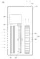
도 1은 본 발명의 일 실시예에 의한 가습기의 측방향 개략도.
도 2는 본 발명의 일 실시예에 의한 가습기의 후측 방향 개략도.
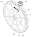
도 3은 본 발명의 일 실시예에 의한 회전가습부재와 물공급부재의 후측 방향 사시도.
도 4는 도 3에 도시된 회전가습부재의 분해사시도.
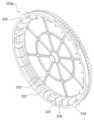
도 5는 도 4에 도시된 회전가습부재의 프레임 몸체를 전방에서 바라본 사시도.
도 6은 도 3에 도시된 회전가습부재의 단면도.
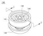
도 7은 도 3에 도시된 물공급부재의 사시도.
도 8은 도 7에 도시된 물공급부재의 단면도.
도 9는 도 7에 도시된 물공급부재의 분해 사시도.
도 10은 도 7에 도시된 물공급부재의 하측 방향 분해 사시도.
도 11은 본 발명의 다른 실시예에 의한 가습기의 후측 방향 개략도.Figure 1 is a lateral schematic diagram of a humidifier according to one embodiment of the present invention.
Figure 2 is a rearward schematic diagram of a humidifier according to one embodiment of the present invention.
Figure 3 is a rear perspective view of a rotating humidifying member and a water supply member according to one embodiment of the present invention.
Figure 4 is an exploded perspective view of the rotary humidifying member illustrated in Figure 3.
Figure 5 is a perspective view of the frame body of the rotating humidifying member illustrated in Figure 4 as viewed from the front.
Figure 6 is a cross-sectional view of the rotating humidifying member illustrated in Figure 3.
Figure 7 is a perspective view of the water supply member shown in Figure 3.
Fig. 8 is a cross-sectional view of the water supply member shown in Fig. 7.
Figure 9 is an exploded perspective view of the water supply member shown in Figure 7.
Figure 10 is a lower exploded perspective view of the water supply member illustrated in Figure 7.
Figure 11 is a rearward schematic diagram of a humidifier according to another embodiment of the present invention.
이하, 첨부된 도면을 참조하여 본 발명의 바람직한 실시 형태들을 설명한다. 그러나, 본 발명의 실시형태는 여러 가지 다른 형태로 변형될 수 있으며, 본 발명의 범위가 이하 설명하는 실시 형태로 한정되는 것은 아니다. 또한, 본 발명의 실시형태는 당해 기술분야에서 평균적인 지식을 가진 자에게 본 발명을 더욱 완전하게 설명하기 위해서 제공되는 것이다. 도면에서 요소들의 형상 및 크기 등은 보다 명확한 설명을 위해 과장될 수 있다.Hereinafter, preferred embodiments of the present invention will be described with reference to the attached drawings. However, the embodiments of the present invention may be modified in various other forms, and the scope of the present invention is not limited to the embodiments described below. In addition, the embodiments of the present invention are provided to more completely explain the present invention to those with average knowledge in the relevant technical field. The shapes and sizes of elements in the drawings may be exaggerated for a clearer explanation.
또한, 본 명세서에서 단수의 표현은 문맥상 명백하게 다르게 뜻하지 않는 한, 복수의 표현을 포함하며, 명세서 전체에 걸쳐 동일 참조 부호는 동일 구성 요소 또는 대응하는 구성요소를 지칭하는 것으로 한다.Additionally, in this specification, singular expressions include plural expressions unless the context clearly indicates otherwise, and the same reference signs throughout the specification are intended to refer to the same component or corresponding components.
이하, 본 발명의 실시예들에 대하여 도면을 참조하여 설명한다.Hereinafter, embodiments of the present invention will be described with reference to the drawings.
도 1은 본 발명의 일 실시예에 의한 가습기의 측방향 개략도이고, 도 2는 후측 방향 개략도이고, 도 3은 본 발명의 일 실시예에 의한 회전가습부재와 물공급부재의 후측 방향 사시도이고, 도 4는 도 3에 도시된 회전가습부재의 분해사시도이고, 도 5는 도 4에 도시된 회전가습부재의 프레임 몸체를 전방에서 바라본 사시도이며, 도 6은 도 3에 도시된 회전가습부재의 단면도이다. 또한, 도 7은 도 3에 도시된 물공급부재의 사시도이고, 도 8 내지 10은 각각 도 7에 도시된 물공급부재의 단면도, 분해 사시도, 하측 방향 분해 사시도이며, 도 11은 본 발명의 다른 실시예에 의한 가습기의 후측 방향 개략도이다.FIG. 1 is a lateral schematic diagram of a humidifier according to an embodiment of the present invention, FIG. 2 is a rearward schematic diagram, FIG. 3 is a rearward perspective view of a rotating humidifying member and a water supply member according to an embodiment of the present invention, FIG. 4 is an exploded perspective view of the rotating humidifying member illustrated in FIG. 3, FIG. 5 is a front perspective view of the frame body of the rotating humidifying member illustrated in FIG. 4, and FIG. 6 is a cross-sectional view of the rotating humidifying member illustrated in FIG. 3. In addition, FIG. 7 is a perspective view of the water supply member illustrated in FIG. 3, and FIGS. 8 to 10 are a cross-sectional view, an exploded perspective view, and a lower-side exploded perspective view, respectively, of the water supply member illustrated in FIG. 7, and FIG. 11 is a rearward schematic diagram of a humidifier according to another embodiment of the present invention.
도 1 내지 도 10에 도시된 바와 같이, 본 발명의 일 측면에 의한 가습기(100)는 제품의 외관을 형성하는 하우징(110), 물을 수용하는 물통(130), 가습을 수행하는 회전가습부재(200), 상기 회전가습부재(200)를 회전 구동시키는 회전구동부(150), 회전가습부재(200)에 물을 공급하도록 개폐되는 물공급부재(140) 및 공기의 유동을 형성하는 송풍부(160)를 포함하여 구성되며, 감지센서(170), 제어부(C), 공기정화필터(120)를 추가로 포함할 수 있다.As illustrated in FIGS. 1 to 10, a humidifier (100) according to one aspect of the present invention comprises a housing (110) forming the exterior of the product, a water tank (130) containing water, a rotary humidifying member (200) performing humidification, a rotary driving member (150) that rotates and drives the rotary humidifying member (200), a water supply member (140) that opens and closes to supply water to the rotary humidifying member (200), and a blower member (160) that forms the flow of air, and may additionally include a detection sensor (170), a control unit (C), and an air purification filter (120).
먼저, 하우징(110)은 본 발명의 일 실시예에 따른 가습기(100)의 외관을 구성하며, 외부 공기가 하우징(110)의 내부로 흡입되는 흡입구(111)와, 하우징(110) 내부의 공기가 외부로 토출되는 토출구(112)를 구비할 수 있다. 도 1에 도시된 바와 같이, 흡입구(111)가 하우징(110)의 전면에 설치되고, 토출구(112)가 하우징(110)의 상면에 설치될 수 있으나, 흡입구(111)와 토출구(112)의 설치 위치 및 개수는 다양한 변경이 가능하다. 예를 들어, 상기 흡입구(111)는 여러방향의 공기를 흡입할 수 있도록 하우징(110)의 전후좌우 면 중 적어도 일부에 설치될 수 있으며, 토출구(112)도 다수개 설치될 수 있다.First, the housing (110) constitutes the exterior of the humidifier (100) according to one embodiment of the present invention, and may be provided with an intake port (111) through which outside air is sucked into the interior of the housing (110), and an outlet port (112) through which air inside the housing (110) is discharged to the exterior. As illustrated in FIG. 1, the intake port (111) may be installed on the front of the housing (110), and the outlet port (112) may be installed on the upper surface of the housing (110), but the installation positions and numbers of the intake ports (111) and the outlet ports (112) may be variously changed. For example, the intake ports (111) may be installed on at least a portion of the front, rear, left, and right sides of the housing (110) so as to suck in air from various directions, and a plurality of outlet ports (112) may also be installed.
또한, 공기정화필터(120)는 하우징(110) 내부에 구비되어 흡입구(111)에서 유입되는 공기를 여과(정화)하도록 구성될 수 있다.Additionally, an air purification filter (120) may be provided inside the housing (110) and configured to filter (purify) air flowing in from the intake port (111).
상기 공기정화필터(120)는 흡입구(111)에서 유입된 공기가 공기정화필터(120)에서 여과된 후 송풍부(160)에 유입되도록 송풍부(160)의 전면에 설치될 수 있으나, 그 설치 위치는 제한되지 않는다.The above air purification filter (120) may be installed in front of the blower (160) so that air drawn in from the intake port (111) is filtered by the air purification filter (120) and then drawn into the blower (160), but the installation location is not limited.
예를 들어, 공기정화필터(120)는 흡입구(111) 후단의 공기유로에 배치될 수 있다. 이러한 공기정화필터(120)는 공기유로의 형상 및 단면적에 대응하는 사각형태로 구성될 수 있으며, 이를 통해, 하우징(110)의 흡입구(111)를 통해 유입된 공기는 전량 공기정화필터(120)를 통과할 수 있다. 다만, 공기정화필터(120)의 형상은 이에 한정되는 것은 아니며 공지된 다양한 형태의 필터가 사용될 수 있다. 예를 들어, 상기 공기정화필터(120)는 원형이나 각형 단면을 갖고 내부에 공간이 형성된 입체형 필터로 이루어질 수 있다.For example, the air purification filter (120) may be placed in the air path at the rear end of the intake port (111). This air purification filter (120) may be configured in a square shape corresponding to the shape and cross-sectional area of the air path, and through this, air drawn in through the intake port (111) of the housing (110) may pass through the air purification filter (120) in its entirety. However, the shape of the air purification filter (120) is not limited thereto, and various known filters may be used. For example, the air purification filter (120) may be configured as a three-dimensional filter having a circular or square cross-section and a space formed inside.
또한, 이러한 공기정화필터(120)는 다양한 형태와 기능을 갖는 필터 중에서 선택될 수 있으며, 필터의 종류와 개수, 형태 등은 도 1에 도시된 예로 한정되지 않고 다양한 변경이 가능하다.In addition, these air purification filters (120) can be selected from filters having various shapes and functions, and the type, number, shape, etc. of the filters are not limited to the example shown in FIG. 1 and can be changed in various ways.
그리고, 물통(130)은 회전가습부재(200)에 물을 공급하기 위하여 내부에 물을 수용한다. 이러한 물통(130)은 물통(130) 내부에 물을 용이하게 채울 수 있도록 가습기(100)에서 분리되는 구조를 가질 수 있으나, 이에 한정되는 것은 아니다. 물통(130)은 종래의 가습기에서 다양한 구조와 형태로 널리 공지되어 있으므로 상세한 설명은 생략하기로 한다.And, the water tank (130) accommodates water inside to supply water to the rotating humidifying member (200). This water tank (130) may have a structure that is separated from the humidifier (100) so that water can be easily filled inside the water tank (130), but is not limited thereto. Since the water tank (130) is widely known in various structures and shapes in conventional humidifiers, a detailed description thereof will be omitted.
다음으로, 본 발명의 일 실시예에 의한 회전가습부재(200)에 대해 설명한다.Next, a rotary humidifying member (200) according to one embodiment of the present invention will be described.
회전가습부재(200)는 물통(130)에 수용된 물을 공급받아 가습을 수행하는 가습필터(210)와, 상기 가습필터(210)를 수용하는 프레임(220)을 구비한다.The rotary humidifying member (200) is equipped with a humidifying filter (210) that receives water contained in a water tank (130) and performs humidification, and a frame (220) that accommodates the humidifying filter (210).
가습필터(210)는 내부에 흡수되거나 표면을 흐르는 물을 기화시켜 가습을 수행하게 된다. 가습필터(210)는 회전하는 구조를 가지므로 디스크 형상을 가질 수 있으나, 이에 한정되는 것은 아니다.The humidifying filter (210) performs humidification by vaporizing water absorbed inside or flowing on the surface. The humidifying filter (210) has a rotating structure, so it may have a disk shape, but is not limited thereto.
도 2 내지 도 6을 참조하면, 프레임(220)은 가습필터(210)의 전면, 후면 및 외주면을 감싸는 구조를 가진다. 이를 위해, 프레임(220)은 프레임 몸체(220a) 및 이에 결합되는 프레임 커버(220b)를 구비할 수 있다.Referring to FIGS. 2 to 6, the frame (220) has a structure that surrounds the front, rear, and outer surface of the humidifying filter (210). To this end, the frame (220) may have a frame body (220a) and a frame cover (220b) coupled thereto.
또한, 상기 프레임(220)의 전면과 후면은 가습필터(210)가 공기와 접촉하도록 격자구조의 격자부(225)를 구비할 수 있다.Additionally, the front and rear surfaces of the frame (220) may be provided with a grid portion (225) having a grid structure so that the humidifying filter (210) can come into contact with the air.
그리고, 상기 프레임(220)은, 물통(130)에서 제공된 물을 가습필터(210)에 공급하기 위하여 외주면 일부분에 원주방향을 따라 형성된 입수용 개구(222)를 구비할 수 있다. 따라서 물통(130)에서 공급된 물은 입수용 개구(222)로 유입되어 가습필터(210)에 제공될 수 있다.In addition, the frame (220) may be provided with a water intake opening (222) formed along a circumferential direction on a portion of the outer surface to supply water supplied from the water tank (130) to the humidifying filter (210). Accordingly, water supplied from the water tank (130) may flow into the water intake opening (222) and be supplied to the humidifying filter (210).
또한, 상기 프레임(220)은 물통(130)으로부터 입수용 개구(222)에 물이 공급되도록 프레임(220)의 회전에 따라 물통(130)에 연결된 물공급부재(140)를 작동시키는 돌출구조의 가압부(223)를 구비할 수 있다. 도 3을 참조하면 가압부(223)는 프레임(220)의 회전방향(화살표)을 기준으로 할 때 입수용 개구(222)의 선단 측에 구비될 수 있다. 따라서, 가압부(223)가 물공급부재(140)와 접촉하여 물공급부재(140)를 먼저 작동시킨 후, 프레임(220)의 회전에 따라 물공급부재(140)의 하단에 위치하는 입수용 개구(222)에 물이 공급될 수 있다.In addition, the frame (220) may be provided with a pressurizing member (223) having a protruding structure that operates the water supply member (140) connected to the water tank (130) according to the rotation of the frame (220) so that water is supplied from the water tank (130) to the water intake opening (222). Referring to FIG. 3, the pressurizing member (223) may be provided at the front end of the water intake opening (222) based on the rotational direction (arrow) of the frame (220). Accordingly, the pressurizing member (223) comes into contact with the water supply member (140) to first operate the water supply member (140), and then water may be supplied to the water intake opening (222) located at the bottom of the water supply member (140) according to the rotation of the frame (220).
그리고, 가습필터(210)의 효율적인 사용을 위해, 가압부(223) 및 입수용 개구(222)는 가습필터(210)의 여러 곳에 물의 공급될 수 있도록 일정한 간격으로 복수개 구비될 수 있다. 예를 들어, 도 2 내지 도 5에 도시된 바와 같이, 가압부(223) 및 입수용 개구(222)가 90도 간격으로 총 4개가 설치될 수 있으나, 그 개수 및 설치 간격은 이에 한정되는 것은 아니며 하나의 가압부(223) 및 입수용 개구(222)가 설치되는 것도 가능하다. 또한, 입수용 개구(222)의 길이는 후술하는 가압부(223)와 1회 접촉에 의해 물공급부재(140)에서 물이 공급되는 지속시간과 프레임(220)의 회전속도를 고려하여 결정될 수 있다.And, for efficient use of the humidifying filter (210), the pressurizing portion (223) and the water intake opening (222) may be provided in multiple numbers at regular intervals so that water can be supplied to multiple locations of the humidifying filter (210). For example, as shown in FIGS. 2 to 5, a total of four pressurizing portions (223) and water intake openings (222) may be installed at 90-degree intervals, but the number and the installation interval are not limited thereto, and it is also possible to install one pressurizing portion (223) and one water intake opening (222). In addition, the length of the water intake opening (222) may be determined in consideration of the duration for which water is supplied from the water supply member (140) by one contact with the pressurizing portion (223) described below and the rotation speed of the frame (220).
그리고, 프레임(220)의 내주면에는 가습필터(210)에서 흘러내리는 물을 수용하는 물수용공간(226)을 구비할 수 있다. 이러한 물수용공간(226)은 프레임(220)의 내주면과 가습필터(210)의 외주면 사이에 형성된 공간으로 이루어질 수 있다. 즉, 도 6에 도시된 바와 같이, 가습필터(210)가 프레임(220)에 장착되는 경우, 프레임(220)의 내주면은 가습필터(210)의 외주면과 이격되도록 구성되며, 프레임(220)의 내주면과 가습필터(210)의 외주면 사이에 물수용공간(226)이 형성될 수 있다.And, the inner surface of the frame (220) may be provided with a water receiving space (226) for receiving water flowing down from the humidifying filter (210). This water receiving space (226) may be formed as a space formed between the inner surface of the frame (220) and the outer surface of the humidifying filter (210). That is, as shown in FIG. 6, when the humidifying filter (210) is mounted on the frame (220), the inner surface of the frame (220) is configured to be spaced apart from the outer surface of the humidifying filter (210), and the water receiving space (226) may be formed between the inner surface of the frame (220) and the outer surface of the humidifying filter (210).
그리고, 상기 물수용공간(226)은 격벽부(227)에 의해 복수의 공간으로 분할될 수 있다. 이러한 격벽부(227)는 가습필터(210)의 외주면과 접촉하여 상기 가습필터(210)의 외주면을 지지하는 역할과, 물수용공간(226)에 수용된 물이 가습필터(210)로 재공급되도록 하는 역할을 수행한다. 즉, 가습필터(210)에서 기화되지 않고 중력 방향을 따라 흘러 내리는 물은 가습필터(210)의 회전과정에서 하측에 위치하는 물수용공간(226)에 수용되며, 가습필터(210)의 회전에 따라 물수용공간(226)이 상측으로 이동하면 물수용공간(226)에 수용된 물이 격벽부(227)를 타고 흘러 내려 가습필터(210)로 다시 공급될 수 있다.And, the water receiving space (226) can be divided into a plurality of spaces by the partition wall portion (227). The partition wall portion (227) supports the outer surface of the humidifying filter (210) by coming into contact with the outer surface of the humidifying filter (210) and allows the water received in the water receiving space (226) to be resupplied to the humidifying filter (210). That is, water that is not vaporized in the humidifying filter (210) but flows down along the direction of gravity is received in the water receiving space (226) located at the bottom during the rotation of the humidifying filter (210), and when the water receiving space (226) moves upward according to the rotation of the humidifying filter (210), the water received in the water receiving space (226) can flow down along the partition wall portion (227) and be resupplied to the humidifying filter (210).
이러한 물수용공간(226)과 격벽부(227)의 구성을 통하여 가습필터(210)에서 완전히 흡수되거나 기화되지 않고 흘러내리는 물을 수용하기 위한 수조나 별도의 구조물이 필요하지 않게 된다. 다만, 회전가습부재(200)에서 낙하한 물로 인한 감전이나 화재 등 안전사고 예방을 위하여 회전가습부재(200)의 하부에 낙하한 물이 전장부품 측으로 흘러 들어가는 방지하는 구성(예를 들어, 물받이)을 배제하는 것은 아니다.Through the configuration of the water receiving space (226) and the partition wall (227), a tank or separate structure is not required to receive water that flows down without being completely absorbed or vaporized in the humidifying filter (210). However, in order to prevent safety accidents such as electric shock or fire caused by water falling from the rotating humidifying member (200), a configuration (e.g., a water catcher) that prevents water that falls on the lower part of the rotating humidifying member (200) from flowing toward the electrical components is not excluded.
또한, 상기 프레임(220)은 회전축 부재(221, 221a)에 의해 회전 가능하게 지지되며, 회전구동부(150)로부터 동력을 전달받아 회전하게 된다. 이를 위해 상기 프레임(220)은 외주면 둘레에 회전력을 전달받는 회전력 전달부(224)를 구비할 수 있으며, 이러한 회전력 전달부(224)는 기어형상을 가질 수 있다.In addition, the frame (220) is rotatably supported by a rotational shaft member (221, 221a) and rotates by receiving power from a rotational driving unit (150). To this end, the frame (220) may be provided with a rotational power transmission unit (224) that receives rotational power around its outer circumference, and this rotational power transmission unit (224) may have a gear shape.
즉, 도 2에 도시된 바와 같이, 회전구동부(150)는 모터(151)의 회전에 따라 회전하는 구동기어(152)를 구비하며, 프레임(220)에 형성된 회전력 전달부(피동기어)(224)는 회전구동부(150)의 구동기어(152)와 맞물려 회전하게 된다.That is, as shown in FIG. 2, the rotary drive unit (150) has a drive gear (152) that rotates according to the rotation of the motor (151), and the rotary power transmission unit (driven gear) (224) formed on the frame (220) rotates by meshing with the drive gear (152) of the rotary drive unit (150).
그리고, 물공급부재(140)는 물통(130)에 수용된 물을 회전가습부재(200)의 입수용 개구(222)에 공급하기 위해 작동하도록 구성된다. 구체적으로, 상기 물공급부재(140)는 물통(130)에 수용된 물을 회전가습부재(200)에 공급하기 위해 회전가습부재(200)의 회전에 따라 개폐되도록 구성된다.And, the water supply member (140) is configured to operate to supply water contained in the water tank (130) to the water intake opening (222) of the rotary humidifying member (200). Specifically, the water supply member (140) is configured to open and close according to the rotation of the rotary humidifying member (200) to supply water contained in the water tank (130) to the rotary humidifying member (200).
이러한 물공급부재(140)는 회전가습부재(200)의 회전에 따라 프레임(220)의 가압부(223)와 물리적으로 접촉하여 개방되는 기계식 밸브 구조를 가질 수 있다.This water supply member (140) may have a mechanical valve structure that opens by physically contacting the pressurizing portion (223) of the frame (220) according to the rotation of the rotary humidifying member (200).
도 7 내지 도 10을 참조하면, 기계식 밸브 구조의 상기 물공급부재(140)는 물통(130)에 결합되며 토출구(141a)가 형성된 캡부재(141)와, 상기 토출구(141a)를 밀폐하거나 개방하는 밀폐부(144)와, 상기 밀폐부(144)를 상하방향으로 승강시키는 로드부(142)와, 상기 로드부(142)를 탄성지지하는 탄성부(145)를 구비할 수 있다. 이때, 로드부(142)는 밀폐부(144)와 일체로 이동하도록 밀폐부(144)의 끼움홀(144a)에 결합되는 함몰부(142a)와, 밀페부(144)의 이탈을 방지하는 이탈부지부(142b)를 구비할 수 있다.Referring to FIGS. 7 to 10, the water supply member (140) of the mechanical valve structure may be provided with a cap member (141) coupled to a water tank (130) and having a discharge port (141a) formed therein, a sealing member (144) that seals or opens the discharge port (141a), a load member (142) that raises and lowers the sealing member (144) in the vertical direction, and an elastic member (145) that elastically supports the load member (142). At this time, the load member (142) may be provided with a recessed member (142a) coupled to an insertion hole (144a) of the sealing member (144) so as to move integrally with the sealing member (144), and a detachment member (142b) that prevents detachment of the sealing member (144).
따라서, 로드부(142)는 가압부(223)와 접촉하는 경우 탄성부(145)의 탄성력을 극복하고 밀폐부(144)와 함께 상승하게 되며, 이에 따라 밀폐부(144)가 캡부재(141)에 형성된 토출구(141a)를 개방하게 된다.Accordingly, when the load portion (142) comes into contact with the pressurizing portion (223), it overcomes the elastic force of the elastic portion (145) and rises together with the sealing portion (144), and accordingly, the sealing portion (144) opens the discharge port (141a) formed in the cap member (141).
또한, 도 8에 도시된 바와 같이, 로드부(142)가 가압부(223)와 접촉하지 않는 경우 탄성부(145)의 탄성력에 의해 로드부(142)는 하측으로 이동한 상태를 유지하고 이에 따라 밀폐부(144)가 캡부재(141)에 형성된 토출구(141a)를 폐쇄하게 된다.In addition, as illustrated in FIG. 8, when the load portion (142) does not come into contact with the pressurizing portion (223), the load portion (142) is maintained in a downwardly moved state by the elastic force of the elastic portion (145), and accordingly, the sealing portion (144) closes the discharge port (141a) formed in the cap member (141).
한편, 물공급부재(140)는 로드부(142)와 연결되도록 구성되며 토출구(141a)에서 토출되는 물을 수용하는 물수용부(143)를 구비할 수 있다. 이러한 물수용부(143)는 다량의 물을 수용하기 위하여 움푹 패인 내부 공간을 갖는 형상을 가질 수 있다. 이와 같이, 물수용부(143)를 구비함으로써 캡부재(141)의 토출구(141a)에서 토출된 물은 프레임(220)의 입수용 개구(222)를 통해 가습필터(210)에 바로 공급되지 않으며, 물수용부(143)에 수용된 후 물수용부(143)에 형성된 물공급개구(143a)를 통해 입수용 개구(222) 측으로 배출될 수 있다.Meanwhile, the water supply member (140) is configured to be connected to the load member (142) and may be provided with a water receiving member (143) that receives water discharged from the discharge port (141a). This water receiving member (143) may have a shape having a sunken internal space to receive a large amount of water. In this way, by providing the water receiving member (143), water discharged from the discharge port (141a) of the cap member (141) is not directly supplied to the humidifying filter (210) through the water intake opening (222) of the frame (220), but is received in the water receiving member (143) and then discharged toward the water intake opening (222) through the water supply opening (143a) formed in the water receiving member (143).
따라서, 캡부재(141)의 토출구(141a)에서 토출된 다량의 물은 물수용부(143)에 먼저 수용된 후 물공급개구(143a)를 통해 천천히 배출될 수 있게 된다.Accordingly, a large amount of water discharged from the discharge port (141a) of the cap member (141) can be first received in the water receiving portion (143) and then slowly discharged through the water supply opening (143a).
즉, 가압부(223)의 개방에 따라 캡부재(141)의 토출구(141a)에서 토출된 다량의 물이 가습필터(210)의 일부분에 집중적으로 공급되는 경우에 비해, 물수용부(143)를 구비하는 경우에는 소량의 물을 가습필터(210)의 넓은 면적에 공급하므로 가습필터(210)에 흡수되거나 기화되지 않고 가습필터(210)의 하부로 물이 낙하하는 현상을 최소화할 수 있게 된다.That is, compared to the case where a large amount of water discharged from the discharge port (141a) of the cap member (141) is concentratedly supplied to a part of the humidifying filter (210) due to the opening of the pressurizing portion (223), in the case where the water receiving portion (143) is provided, a small amount of water is supplied to a large area of the humidifying filter (210), so the phenomenon of water falling to the bottom of the humidifying filter (210) without being absorbed or vaporized by the humidifying filter (210) can be minimized.
한편, 토출구(141a)에서 물수용부(143)에 공급된 물이 물수용부(143)에서 천천히 배출될 수 있도록 하기 위하여 도 10에 도시된 바와 같이 물공급개구(141a)의 면적은 토출구(143a)의 면적보다 작게 형성될 수 있다.Meanwhile, in order to allow water supplied to the water receiving portion (143) from the discharge port (141a) to be slowly discharged from the water receiving portion (143), the area of the water supply opening (141a) may be formed smaller than the area of the discharge port (143a), as shown in FIG. 10.
그리고, 송풍부(160)는 흡입구(111)로부터 유입된 공기가 회전가습부재(200)를 거쳐 토출구(112)로 유동하도록 송풍력을 제공한다. 흡입구(111)와 토출구(112) 사이에는 송풍부(160)의 구동에 의해 공기가 유동하는 공기 유동경로가 형성되며, 이러한 공기 유동경로는 흡입구(111)와 토출구(112)의 위치, 송풍부(160)의 흡입/토출 위치 및 방향에 따라 다양한 변경이 가능하다.In addition, the blower (160) provides blowing power so that air drawn in from the suction port (111) flows through the rotary humidifying member (200) to the discharge port (112). An air flow path is formed between the suction port (111) and the discharge port (112) through which air flows by the operation of the blower (160), and this air flow path can be changed in various ways depending on the positions of the suction port (111) and the discharge port (112) and the suction/discharge position and direction of the blower (160).
또한, 송풍부(160)는 공기를 유동시키는 송풍팬(161)과, 상기 송풍팬(161)을 구동시키는 팬모터(162)을 구비한다. 도 1에 도시된 바와 같이, 상기 송풍팬(161)은 공기 유동경로를 기준으로 하여 공기정화필터(120)의 후방에 배치되고 일측에서 흡입되는 구조를 가질 수 있으나, 그 설치 위치 및 흡입 구조는 도 1의 도시에 한정되지 않고 다양한 변경이 가능하다. 예를 들어, 상기 송풍팬(161)은 양흡입 구조를 가질 수도 있다.In addition, the blower (160) is equipped with a blower fan (161) that flows air, and a fan motor (162) that drives the blower fan (161). As illustrated in FIG. 1, the blower fan (161) may be arranged at the rear of the air purification filter (120) based on the air flow path and may have a structure in which suction is performed from one side, but the installation position and suction structure are not limited to those illustrated in FIG. 1 and may be variously changed. For example, the blower fan (161) may have a double suction structure.
한편, 본 발명의 일 실시예에 의한 가습기(100)는, 상기 회전가습부재(200)에 구비된 감지용 부재(도 2의 228)를 감지하기 위한 감지센서(도 2의 170)를 추가로 포함할 수 있다.Meanwhile, a humidifier (100) according to one embodiment of the present invention may additionally include a detection sensor (170 in FIG. 2) for detecting a detection member (228 in FIG. 2) provided in the rotating humidifying member (200).
일 예로서, 상기 감지용 부재(228)는 마그넷을 포함하여 구성되고, 상기 감지센서(170)는 자력을 감지하는 홀 센서로 구성될 수 있으나, 이에 한정되는 것은 아니다.As an example, the detection member (228) may be configured to include a magnet, and the detection sensor (170) may be configured as a Hall sensor that detects magnetic force, but is not limited thereto.
또한, 본 발명의 일 실시예에 의한 가습기(100)는, 상기 감지센서(170)의 감지신호에 의해 상기 회전가습부재(200)의 회전위치를 검출하고 회전구동부(150)의 구동을 제어하는 제어부(C)를 추가로 포함할 수 있다.In addition, the humidifier (100) according to one embodiment of the present invention may additionally include a control unit (C) that detects the rotational position of the rotary humidifying member (200) by the detection signal of the detection sensor (170) and controls the operation of the rotary driving unit (150).
즉, 가압부(223)가 물공급부재(140)를 가압한 상태에서 회전가습부재(200)의 회전이 정지되면 가압된 물공급부재(140)로부터 물이 계속 누출될 수 있다. 이러한 문제점을 해결하기 위하여 상기 제어부(C)는 감지센서(170)를 통해 회전가습부재(200)가 현재 어느 위치에 있는지 확인하고, 가압부(223)가 물공급부재(140)를 가압하지 않은 위치에서 회전가습부재(200)가 정지하도록 회전구동부(150)의 구동을 제어할 수 있다.That is, if the rotation of the rotary humidifying member (200) stops while the pressurizing member (223) is pressurizing the water supply member (140), water may continue to leak from the pressurized water supply member (140). To solve this problem, the control unit (C) can check the current position of the rotary humidifying member (200) through the detection sensor (170) and control the operation of the rotary driving unit (150) so that the rotary humidifying member (200) stops at a position where the pressurizing member (223) is not pressurizing the water supply member (140).
다음으로, 도 11을 참조하여 본 발명의 다른 실시예에 의한 가습기(100)에 대해 설명한다.Next, a humidifier (100) according to another embodiment of the present invention will be described with reference to FIG. 11.
도 11에 도시된 가습기(100)는 도 1 내지 도 10을 참조하여 설명한 가습기(100)와 마찬가지로, 제품의 외관을 형성하는 하우징(110), 물을 수용하는 물통(130), 가습을 수행하는 회전가습부재(200), 상기 회전가습부재(200)를 회전 구동시키는 회전구동부(150), 회전가습부재(200)에 물을 공급하도록 개폐되는 물공급부재(140) 및 공기의 유동을 형성하는 송풍부(160)를 포함하여 구성되며, 감지센서(170), 제어부(C), 공기정화필터(120)를 추가로 포함할 수 있다.The humidifier (100) illustrated in FIG. 11 is configured to include a housing (110) forming the exterior of the product, a water tank (130) containing water, a rotary humidifying member (200) performing humidification, a rotary driving member (150) that rotates and drives the rotary humidifying member (200), a water supply member (140) that opens and closes to supply water to the rotary humidifying member (200), and a blower member (160) that forms the flow of air, similar to the humidifier (100) described with reference to FIGS. 1 to 10, and may additionally include a detection sensor (170), a control member (C), and an air purification filter (120).
도 11에 도시된 가습기(100)는 물공급부재(140)의 구성을 제외한 나머지 구성은 도 1 내지 도 10을 참조하여 설명한 가습기(100)와 동일하므로, 나머지 구성에 대한 상세한 설명은 전술한 내용을 갈음하고 물공급부재(140)에 대해서만 설명하기로 한다.The humidifier (100) illustrated in Fig. 11 is identical to the humidifier (100) described with reference to Figs. 1 to 10 in terms of the remaining configuration except for the configuration of the water supply member (140), so the detailed description of the remaining configuration will be omitted and only the water supply member (140) will be described.
도 11에 도시된 가습기(100)의 경우, 물공급부재(140)는 회전가습부재(200)의 회전에 따라 전자신호에 의해 개폐되는 전자식 밸브 구조를 가질 수 있다.In the case of the humidifier (100) illustrated in Fig. 11, the water supply member (140) may have an electronic valve structure that is opened and closed by an electronic signal according to the rotation of the rotary humidifying member (200).
즉, 상기 물공급부재(140)는 물통(130)에 설치된 배터리, 건전지 등의 전원공급부(B)로부터 전원을 공급받아 작동하는 구조를 가질 수 있다. 또한, 상기 물공급부재(140)는 제어부(C)로부터 무선 또는 유선의 신호를 받아 작동할 수 있다.That is, the water supply member (140) may have a structure that operates by receiving power from a power supply unit (B) such as a battery or dry cell installed in the water tank (130). In addition, the water supply member (140) may operate by receiving a wireless or wired signal from a control unit (C).
이때, 제어부(C)는 회전가습부재(200)가 회전하여 입수용 개구(222)가 상기 물공급부재(140)의 하부에 위치하는 경우에 물공급부재(140)를 개방할 수 있다.At this time, the control unit (C) can open the water supply unit (140) when the rotating humidifying unit (200) rotates and the water intake opening (222) is located at the bottom of the water supply unit (140).
이상에서 본 발명의 실시예에 대하여 상세하게 설명하였지만 본 발명의 권리범위는 이에 한정되는 것은 아니고, 청구범위에 기재된 본 발명의 기술적 사상을 벗어나지 않는 범위 내에서 다양한 수정 및 변형이 가능하다는 것은 당 기술분야의 통상의 지식을 가진 자에게는 자명할 것이다.Although the embodiments of the present invention have been described in detail above, the scope of the present invention is not limited thereto, and it will be apparent to those skilled in the art that various modifications and variations are possible within a scope that does not depart from the technical spirit of the present invention described in the claims.
100... 가습기110... 하우징
111... 흡입구112... 토출구
120... 공기정화필터130... 물통
140... 물공급부재141... 캡부재
141a... 토출구142... 로드부
142a... 함몰부143... 물수용부
143a... 물공급개구 144... 밀봉부
144a... 끼움홀145... 탄성부재
150... 회전구동부151... 모터
152... 구동기어160... 송풍부
161... 송풍팬162... 팬모터
170... 감지센서200... 회전가습부재
210... 가습필터220... 프레임
220a... 프레임 몸체220b... 프레임 커버
221, 221a... 회전축 부재222... 입수용 개구
223... 가압부224... 회전력 전달부(피동기어)
225... 격자부226... 수용공간
227... 격벽부228... 감지용 부재
B... 전원공급부C... 제어부100...
111...
120...
140...
141a...
142a... sink 143... water receiving area
143a...
144a...
150... Rotating
152...
161...
170...
210...
220a...
221, 221a... Rotating
223...
225...
227...
B... Power supply C... Control unit
Claims (17)
Translated fromKorean물을 수용하는 물통;
상기 물통에 수용된 물을 공급받아 가습을 수행하는 가습필터와, 상기 가습필터를 수용하는 프레임을 구비하는 회전가습부재;
상기 회전가습부재를 회전 구동시키는 회전구동부;
상기 물통에 설치되며, 상기 물통에 수용된 물을 상기 회전가습부재에 공급하기 위해 상기 회전가습부재의 회전에 따라 개폐되도록 구성되는 물공급부재; 및
상기 흡입구로부터 유입된 공기가 상기 회전가습부재를 거쳐 상기 토출구로 유동하도록 송풍력을 제공하는 송풍부;
를 포함하고,
상기 프레임은 상기 가습필터에 물을 공급하기 위하여 외주면 일부분에 원주방향을 따라 형성된 입수용 개구를 구비하고,
상기 프레임은 상기 입수용 개구에 물이 공급되도록 상기 회전가습부재의 회전에 따라 상기 물공급부재를 작동시키는 돌출구조의 가압부를 구비하고,
상기 물공급부재는 상기 가압부와의 물리적 접촉에 의해 개방되는 기계식 밸브 구조를 가지고,
상기 물공급부재는, 상기 물통에 결합되며 토출구가 형성된 캡부재와, 상기 토출구를 밀폐하거나 개방하는 밀폐부와, 상기 밀폐부를 상하방향으로 승강시키는 로드부와, 상기 로드부를 탄성지지하는 탄성부를 구비하며,
상기 로드부는 상기 가압부와 접촉하는 경우 상기 밀폐부와 함께 상승하여 상기 밀폐부가 상기 토출구를 개방하도록 하고,
상기 물공급부재는 상기 로드부와 연결되어 상기 토출구에서 토출되는 물을 수용하는 물수용부를 구비하며,
상기 토출구에서 토출된 물은 상기 물수용부에 수용된 후 상기 물수용부에 형성된 물공급개구를 통해 배출되며,
상기 물공급개구의 면적은 상기 토출구의 면적보다 작게 형성되는 가습기.A housing having an inlet and an outlet formed therein;
A water container that holds water;
A rotating humidifying member having a humidifying filter that receives water contained in the water tank and performs humidification, and a frame that accommodates the humidifying filter;
A rotary driving unit that rotates the above rotary humidifying member;
A water supply member installed in the water tank and configured to open and close according to the rotation of the rotating humidifying member to supply water contained in the water tank to the rotating humidifying member; and
A blower unit that provides blowing force so that air drawn in from the above suction port flows through the above rotary humidifying member to the above discharge port;
Including,
The above frame has a water intake opening formed along the circumference of a portion of the outer surface to supply water to the humidifying filter,
The above frame has a pressurizing portion having a protruding structure that operates the water supply member according to the rotation of the rotating humidifying member so that water is supplied to the water intake opening.
The above water supply member has a mechanical valve structure that opens by physical contact with the pressurized portion,
The above water supply member comprises a cap member that is connected to the water tank and has a discharge port formed therein, a sealing member that seals or opens the discharge port, a load member that raises or lowers the sealing member, and an elastic member that elastically supports the load member.
The above load portion rises together with the sealing portion when in contact with the pressurized portion, thereby causing the sealing portion to open the discharge port,
The above water supply member is connected to the load section and has a water receiving section that receives water discharged from the discharge port.
The water discharged from the above discharge port is received in the water receiving portion and then discharged through the water supply opening formed in the water receiving portion.
A humidifier in which the area of the water supply opening is formed smaller than the area of the discharge port.
상기 가압부는 상기 프레임의 회전방향을 기준으로 할 때 상기 입수용 개구의 선단 측에 구비되는 가습기.In the first paragraph,
A humidifier in which the pressurizing portion is provided at the front end of the water intake opening based on the rotational direction of the frame.
상기 회전가습부재에 구비된 감지용 부재를 감지하는 감지센서; 및
상기 감지센서의 감지신호에 의해 상기 회전가습부재의 회전위치를 검출하고 상기 회전구동부의 구동을 제어하는 제어부;
를 추가로 포함하며,
상기 제어부는 상기 가압부가 상기 물공급부재를 가압하지 않는 위치에서 상기 회전가습부재가 정지하도록 상기 회전구동부의 구동을 제어하는 가습기.In the first paragraph,
A detection sensor that detects a detection member provided in the above rotary humidifying member; and
A control unit that detects the rotational position of the rotary humidifying member by the detection signal of the above detection sensor and controls the operation of the rotary driving unit;
In addition, it includes:
A humidifier in which the above control unit controls the operation of the rotary driving unit so that the rotary humidifying unit stops at a position where the pressurizing unit does not pressurize the water supply unit.
싱기 프레임은 내주면에 상기 가습필터에서 흘러내리는 물을 수용하는 물수용공간을 구비하는 가습기.In any one of paragraphs 1, 4 and 9,
A humidifier having a water-receiving space on its inner surface that receives water flowing down from the humidifying filter.
상기 물수용공간은 상기 프레임의 내주면과 상기 가습필터의 외주면 사이에 형성된 공간으로 이루어지는 가습기.In the 10th paragraph, the inner surface of the frame is configured to be spaced apart from the outer surface of the humidifying filter,
A humidifier in which the above water-receiving space is formed between the inner surface of the frame and the outer surface of the humidifying filter.
상기 물수용공간은 격벽부에 의해 복수의 공간으로 분할되는 가습기.In Article 11,
A humidifier in which the above water storage space is divided into multiple spaces by partition walls.
상기 격벽부는 상기 가습필터의 외주면과 접촉하여 상기 가습필터의 외주면을 지지하는 가습기.In Article 12,
A humidifier in which the above-mentioned bulkhead is in contact with the outer surface of the humidifying filter and supports the outer surface of the humidifying filter.
상기 프레임은 외주면 둘레에 상기 프레임의 회전을 위해 상기 회전구동부로부터 회전력을 전달받는 기어형상의 회전력 전달부를 구비하는 가습기.In any one of paragraphs 1, 4 and 9,
A humidifier in which the above frame has a gear-shaped rotational power transmission unit that receives rotational power from the rotational driving unit for rotation of the above frame around the outer periphery.
상기 물공급부재는 전자신호에 의해 개폐되는 전자식 밸브 구조를 갖는 가습기.In any one of paragraphs 1, 4 and 9,
The above water supply member is a humidifier having an electronic valve structure that is opened and closed by an electronic signal.
상기 회전가습부재에 구비된 감지용 부재를 감지하는 감지센서; 및
상기 감지센서의 감지신호에 의해 상기 회전가습부재의 회전위치를 검출하고 전자식 밸브 구조를 갖는 상기 물공급부재의 개폐를 제어하는 제어부;
를 추가로 포함하며,
상기 제어부는 상기 회전가습부재가 회전하여 상기 입수용 개구가 상기 물공급부재의 하부에 위치하는 경우에 상기 물공급부재를 개방하는 가습기.In Article 15,
A detection sensor that detects a detection member provided in the above rotary humidifying member; and
A control unit that detects the rotational position of the rotary humidifying member by the detection signal of the detection sensor and controls the opening and closing of the water supply member having an electronic valve structure;
In addition, it includes:
The above control unit is a humidifier that opens the water supply member when the rotating humidifying member rotates and the water intake opening is located at the bottom of the water supply member.
상기 흡입구로부터 유입된 공기를 정화하는 공기정화필터;
를 추가로 포함하는 가습기.In any one of paragraphs 1, 4 and 9,
An air purifying filter that purifies air drawn in from the above intake port;
A humidifier additionally including:
Priority Applications (1)
| Application Number | Priority Date | Filing Date | Title |
|---|---|---|---|
| KR1020190003413AKR102752371B1 (en) | 2019-01-10 | 2019-01-10 | Humidifier |
Applications Claiming Priority (1)
| Application Number | Priority Date | Filing Date | Title |
|---|---|---|---|
| KR1020190003413AKR102752371B1 (en) | 2019-01-10 | 2019-01-10 | Humidifier |
Publications (2)
| Publication Number | Publication Date |
|---|---|
| KR20200086972A KR20200086972A (en) | 2020-07-20 |
| KR102752371B1true KR102752371B1 (en) | 2025-01-10 |
Family
ID=71831921
Family Applications (1)
| Application Number | Title | Priority Date | Filing Date |
|---|---|---|---|
| KR1020190003413AActiveKR102752371B1 (en) | 2019-01-10 | 2019-01-10 | Humidifier |
Country Status (1)
| Country | Link |
|---|---|
| KR (1) | KR102752371B1 (en) |
Families Citing this family (5)
| Publication number | Priority date | Publication date | Assignee | Title |
|---|---|---|---|---|
| WO2023281921A1 (en)* | 2021-07-06 | 2023-01-12 | パナソニックIpマネジメント株式会社 | Humidification device |
| JP7685691B2 (en)* | 2021-07-30 | 2025-05-30 | パナソニックIpマネジメント株式会社 | humidifier |
| JP2023008363A (en)* | 2021-07-06 | 2023-01-19 | パナソニックIpマネジメント株式会社 | humidifier |
| JP7671940B2 (en)* | 2021-07-06 | 2025-05-07 | パナソニックIpマネジメント株式会社 | Humidification device |
| CN115004987B (en)* | 2021-12-21 | 2023-10-03 | 江苏安全技术职业学院 | Electromechanical integrated fan for greenhouse humidification |
Citations (4)
| Publication number | Priority date | Publication date | Assignee | Title |
|---|---|---|---|---|
| JP2012037144A (en)* | 2010-08-06 | 2012-02-23 | Fujitsu General Ltd | Humidification unit, and humidification device mounting the same |
| JP2012112613A (en)* | 2010-11-26 | 2012-06-14 | Panasonic Corp | Air cleaner with humidifying function |
| CN202382349U (en)* | 2011-12-21 | 2012-08-15 | 莱克电气股份有限公司 | Air purifier with novel humidification structure |
| JP2012225579A (en)* | 2011-04-20 | 2012-11-15 | Panasonic Corp | Humidification apparatus |
- 2019
- 2019-01-10KRKR1020190003413Apatent/KR102752371B1/enactiveActive
Patent Citations (4)
| Publication number | Priority date | Publication date | Assignee | Title |
|---|---|---|---|---|
| JP2012037144A (en)* | 2010-08-06 | 2012-02-23 | Fujitsu General Ltd | Humidification unit, and humidification device mounting the same |
| JP2012112613A (en)* | 2010-11-26 | 2012-06-14 | Panasonic Corp | Air cleaner with humidifying function |
| JP2012225579A (en)* | 2011-04-20 | 2012-11-15 | Panasonic Corp | Humidification apparatus |
| CN202382349U (en)* | 2011-12-21 | 2012-08-15 | 莱克电气股份有限公司 | Air purifier with novel humidification structure |
Also Published As
| Publication number | Publication date |
|---|---|
| KR20200086972A (en) | 2020-07-20 |
Similar Documents
| Publication | Publication Date | Title |
|---|---|---|
| KR102752371B1 (en) | Humidifier | |
| KR101551328B1 (en) | Water type air cleaner | |
| KR101599634B1 (en) | The air cleaner of pottery type to equip a humidifing function | |
| CN113272592B (en) | humidifier | |
| KR102457136B1 (en) | apparatus for both humidification and air cleaning | |
| CN104603547B (en) | Humidification device | |
| KR101321602B1 (en) | Wet Typer of Apparatus for Filtering with Function of Cleaning, Air Freshener,Sterilization and Humidification | |
| KR102834803B1 (en) | Humidifying Member And Humidifier Having The Same | |
| JP2014066478A (en) | Humidifier | |
| KR20120101788A (en) | Humidification apparatus | |
| KR20220008462A (en) | Air cleaning device | |
| KR101307843B1 (en) | Humidifying air cleaner | |
| KR20210051764A (en) | Smart ventilation system | |
| JP5690997B2 (en) | Humidified air purifier | |
| WO2014162799A1 (en) | Humidification device | |
| KR20120033591A (en) | Humidification apparatus having the rotating humidification filter | |
| KR20230071219A (en) | Air purifier using suction and spray of water | |
| JP2014066477A (en) | Humidifier | |
| JP2023058883A (en) | humidifier | |
| KR20210065526A (en) | Humidifier | |
| KR20210065528A (en) | Humidifying Structure of Centrifugal Water-spray type And Humidifier Having The Same | |
| JP6277293B2 (en) | Humidifier | |
| JP6081639B2 (en) | Humidifier | |
| KR100640770B1 (en) | Magnetic Driven Wet Air Purifier | |
| CN215260465U (en) | Water tank assembly and air treatment device and air conditioner with same |
Legal Events
| Date | Code | Title | Description |
|---|---|---|---|
| PA0109 | Patent application | Patent event code:PA01091R01D Comment text:Patent Application Patent event date:20190110 | |
| PG1501 | Laying open of application | ||
| E902 | Notification of reason for refusal | ||
| PE0902 | Notice of grounds for rejection | Comment text:Notification of reason for refusal Patent event date:20240219 Patent event code:PE09021S01D | |
| E701 | Decision to grant or registration of patent right | ||
| PE0701 | Decision of registration | Patent event code:PE07011S01D Comment text:Decision to Grant Registration Patent event date:20241008 | |
| GRNT | Written decision to grant | ||
| PR0701 | Registration of establishment | Comment text:Registration of Establishment Patent event date:20250106 Patent event code:PR07011E01D | |
| PR1002 | Payment of registration fee | Payment date:20250107 End annual number:3 Start annual number:1 | |
| PG1601 | Publication of registration |