KR102750135B1 - Reservoir assembly and apparatus for infusing medical liquid including the same - Google Patents
Reservoir assembly and apparatus for infusing medical liquid including the sameDownload PDFInfo
- Publication number
- KR102750135B1 KR102750135B1KR1020220021545AKR20220021545AKR102750135B1KR 102750135 B1KR102750135 B1KR 102750135B1KR 1020220021545 AKR1020220021545 AKR 1020220021545AKR 20220021545 AKR20220021545 AKR 20220021545AKR 102750135 B1KR102750135 B1KR 102750135B1
- Authority
- KR
- South Korea
- Prior art keywords
- reservoir
- cap member
- drug
- reservoir assembly
- assembly
- Prior art date
- Legal status (The legal status is an assumption and is not a legal conclusion. Google has not performed a legal analysis and makes no representation as to the accuracy of the status listed.)
- Active
Links
Images


Classifications
- A—HUMAN NECESSITIES
- A61—MEDICAL OR VETERINARY SCIENCE; HYGIENE
- A61M—DEVICES FOR INTRODUCING MEDIA INTO, OR ONTO, THE BODY; DEVICES FOR TRANSDUCING BODY MEDIA OR FOR TAKING MEDIA FROM THE BODY; DEVICES FOR PRODUCING OR ENDING SLEEP OR STUPOR
- A61M5/00—Devices for bringing media into the body in a subcutaneous, intra-vascular or intramuscular way; Accessories therefor, e.g. filling or cleaning devices, arm-rests
- A61M5/14—Infusion devices, e.g. infusing by gravity; Blood infusion; Accessories therefor
- A61M5/168—Means for controlling media flow to the body or for metering media to the body, e.g. drip meters, counters ; Monitoring media flow to the body
- A61M5/16831—Monitoring, detecting, signalling or eliminating infusion flow anomalies
- A—HUMAN NECESSITIES
- A61—MEDICAL OR VETERINARY SCIENCE; HYGIENE
- A61M—DEVICES FOR INTRODUCING MEDIA INTO, OR ONTO, THE BODY; DEVICES FOR TRANSDUCING BODY MEDIA OR FOR TAKING MEDIA FROM THE BODY; DEVICES FOR PRODUCING OR ENDING SLEEP OR STUPOR
- A61M5/00—Devices for bringing media into the body in a subcutaneous, intra-vascular or intramuscular way; Accessories therefor, e.g. filling or cleaning devices, arm-rests
- A61M5/14—Infusion devices, e.g. infusing by gravity; Blood infusion; Accessories therefor
- A61M5/142—Pressure infusion, e.g. using pumps
- A61M5/14244—Pressure infusion, e.g. using pumps adapted to be carried by the patient, e.g. portable on the body
- A61M5/14248—Pressure infusion, e.g. using pumps adapted to be carried by the patient, e.g. portable on the body of the skin patch type
- A—HUMAN NECESSITIES
- A61—MEDICAL OR VETERINARY SCIENCE; HYGIENE
- A61M—DEVICES FOR INTRODUCING MEDIA INTO, OR ONTO, THE BODY; DEVICES FOR TRANSDUCING BODY MEDIA OR FOR TAKING MEDIA FROM THE BODY; DEVICES FOR PRODUCING OR ENDING SLEEP OR STUPOR
- A61M5/00—Devices for bringing media into the body in a subcutaneous, intra-vascular or intramuscular way; Accessories therefor, e.g. filling or cleaning devices, arm-rests
- A61M5/14—Infusion devices, e.g. infusing by gravity; Blood infusion; Accessories therefor
- A61M5/142—Pressure infusion, e.g. using pumps
- A61M5/145—Pressure infusion, e.g. using pumps using pressurised reservoirs, e.g. pressurised by means of pistons
- A61M5/1452—Pressure infusion, e.g. using pumps using pressurised reservoirs, e.g. pressurised by means of pistons pressurised by means of pistons
- A—HUMAN NECESSITIES
- A61—MEDICAL OR VETERINARY SCIENCE; HYGIENE
- A61M—DEVICES FOR INTRODUCING MEDIA INTO, OR ONTO, THE BODY; DEVICES FOR TRANSDUCING BODY MEDIA OR FOR TAKING MEDIA FROM THE BODY; DEVICES FOR PRODUCING OR ENDING SLEEP OR STUPOR
- A61M5/00—Devices for bringing media into the body in a subcutaneous, intra-vascular or intramuscular way; Accessories therefor, e.g. filling or cleaning devices, arm-rests
- A61M5/14—Infusion devices, e.g. infusing by gravity; Blood infusion; Accessories therefor
- A61M2005/1401—Functional features
- A61M2005/1402—Priming
- A—HUMAN NECESSITIES
- A61—MEDICAL OR VETERINARY SCIENCE; HYGIENE
- A61M—DEVICES FOR INTRODUCING MEDIA INTO, OR ONTO, THE BODY; DEVICES FOR TRANSDUCING BODY MEDIA OR FOR TAKING MEDIA FROM THE BODY; DEVICES FOR PRODUCING OR ENDING SLEEP OR STUPOR
- A61M5/00—Devices for bringing media into the body in a subcutaneous, intra-vascular or intramuscular way; Accessories therefor, e.g. filling or cleaning devices, arm-rests
- A61M5/14—Infusion devices, e.g. infusing by gravity; Blood infusion; Accessories therefor
- A61M5/142—Pressure infusion, e.g. using pumps
- A61M2005/14208—Pressure infusion, e.g. using pumps with a programmable infusion control system, characterised by the infusion program
- A—HUMAN NECESSITIES
- A61—MEDICAL OR VETERINARY SCIENCE; HYGIENE
- A61M—DEVICES FOR INTRODUCING MEDIA INTO, OR ONTO, THE BODY; DEVICES FOR TRANSDUCING BODY MEDIA OR FOR TAKING MEDIA FROM THE BODY; DEVICES FOR PRODUCING OR ENDING SLEEP OR STUPOR
- A61M5/00—Devices for bringing media into the body in a subcutaneous, intra-vascular or intramuscular way; Accessories therefor, e.g. filling or cleaning devices, arm-rests
- A61M5/14—Infusion devices, e.g. infusing by gravity; Blood infusion; Accessories therefor
- A61M5/168—Means for controlling media flow to the body or for metering media to the body, e.g. drip meters, counters ; Monitoring media flow to the body
- A61M5/16831—Monitoring, detecting, signalling or eliminating infusion flow anomalies
- A61M2005/16863—Occlusion detection
- A—HUMAN NECESSITIES
- A61—MEDICAL OR VETERINARY SCIENCE; HYGIENE
- A61M—DEVICES FOR INTRODUCING MEDIA INTO, OR ONTO, THE BODY; DEVICES FOR TRANSDUCING BODY MEDIA OR FOR TAKING MEDIA FROM THE BODY; DEVICES FOR PRODUCING OR ENDING SLEEP OR STUPOR
- A61M2205/00—General characteristics of the apparatus
- A61M2205/02—General characteristics of the apparatus characterised by a particular materials
- A61M2205/0227—Materials having sensing or indicating function, e.g. indicating a pressure increase
- A—HUMAN NECESSITIES
- A61—MEDICAL OR VETERINARY SCIENCE; HYGIENE
- A61M—DEVICES FOR INTRODUCING MEDIA INTO, OR ONTO, THE BODY; DEVICES FOR TRANSDUCING BODY MEDIA OR FOR TAKING MEDIA FROM THE BODY; DEVICES FOR PRODUCING OR ENDING SLEEP OR STUPOR
- A61M2205/00—General characteristics of the apparatus
- A61M2205/02—General characteristics of the apparatus characterised by a particular materials
- A61M2205/0233—Conductive materials, e.g. antistatic coatings for spark prevention
- A—HUMAN NECESSITIES
- A61—MEDICAL OR VETERINARY SCIENCE; HYGIENE
- A61M—DEVICES FOR INTRODUCING MEDIA INTO, OR ONTO, THE BODY; DEVICES FOR TRANSDUCING BODY MEDIA OR FOR TAKING MEDIA FROM THE BODY; DEVICES FOR PRODUCING OR ENDING SLEEP OR STUPOR
- A61M2205/00—General characteristics of the apparatus
- A61M2205/18—General characteristics of the apparatus with alarm
- A—HUMAN NECESSITIES
- A61—MEDICAL OR VETERINARY SCIENCE; HYGIENE
- A61M—DEVICES FOR INTRODUCING MEDIA INTO, OR ONTO, THE BODY; DEVICES FOR TRANSDUCING BODY MEDIA OR FOR TAKING MEDIA FROM THE BODY; DEVICES FOR PRODUCING OR ENDING SLEEP OR STUPOR
- A61M2205/00—General characteristics of the apparatus
- A61M2205/33—Controlling, regulating or measuring
- A61M2205/3331—Pressure; Flow
Landscapes
- Health & Medical Sciences (AREA)
- Heart & Thoracic Surgery (AREA)
- Vascular Medicine (AREA)
- Engineering & Computer Science (AREA)
- Anesthesiology (AREA)
- Biomedical Technology (AREA)
- Hematology (AREA)
- Life Sciences & Earth Sciences (AREA)
- Animal Behavior & Ethology (AREA)
- General Health & Medical Sciences (AREA)
- Public Health (AREA)
- Veterinary Medicine (AREA)
- Dermatology (AREA)
- Infusion, Injection, And Reservoir Apparatuses (AREA)
Abstract
Translated fromKoreanDescription
Translated fromKorean본 발명은 레저버 어셈블리와 이를 포함하는 약액 주입 장치에 관한 것이다.The present invention relates to a reservoir assembly and a liquid injection device including the same.
일반적으로 약액 주입 장치는 환자에게 인슐린과 같은 약액을 주입하기 위해 사용된다. 약액 주입 장치는 의사나 간호사와 같은 전문 의료진에 의해 사용되기도 하지만, 대부분의 경우 환자 자신 또는 보호자와 같은 일반인에 의해 사용되고 있다.Typically, a drug infusion device is used to inject a drug solution, such as insulin, into a patient. Drug infusion devices are sometimes used by medical professionals, such as doctors or nurses, but in most cases, they are used by laypeople, such as the patient or their guardian.
이에, 일정한 기간 동안 환자의 신체에 부착하여 간편하게 사용할 수 있는 패치 형태의 양액 주입 장치가 개발되고 있으며, 이러한 약액 주입 장치는 환자의 복부 또는 허리 등과 같은 환자의 신체 일부에 일정한 기간 동안 패치 형태로 부착한 상태로 사용될 수 있다.Accordingly, a patch-type nutrient injection device that can be conveniently used by attaching it to the patient's body for a certain period of time is being developed, and this nutrient injection device can be used by attaching it in the form of a patch to a part of the patient's body, such as the patient's abdomen or waist, for a certain period of time.
약액 주입 장치가 환자의 신체에 부착되고, 약액 주입 장치에 마련된 니들과 캐뉼러가 환자의 신체 내부로 삽입되면, 약액 주입 장치 내부에 저장된 약액이 니들과 캐뉼러를 통하여 환자의 신체 내부로 주입될 수 있다.When a drug injection device is attached to a patient's body and a needle and cannula provided in the drug injection device are inserted into the patient's body, the drug stored inside the drug injection device can be injected into the patient's body through the needle and cannula.
그런데, 약액 주입 장치를 사용하는 중에 환자의 신체 내의 이물질에 의하여, 니들이나 캐뉼러 등이 막힘으로써, 약액 주입 장치 내부에서 약액의 유동이 원활하게 형성되지 않을 수 있다. 이 경우, 환자에게 약액이 전혀 공급되지 않거나 약액이 부족하게 공급될 수 있지만, 환자나 보호자는 약액이 원활하게 공급되는지 여부를 제대로 인지 못하는 문제가 발생할 수 있다.However, when using a drug infusion device, the needle or cannula may be blocked by foreign substances in the patient's body, preventing the drug from flowing smoothly inside the drug infusion device. In this case, the drug may not be supplied to the patient at all or may be supplied insufficiently, but the patient or guardian may not be able to properly recognize whether the drug is being supplied smoothly.
주입되는 약액에 의한 효과를 증대시키기 위하여, 약액이 환자에게 원활하게 주입되고 있는지 확인할 수 있는 방안이 요구되며, 다양한 방법으로 정량의 약액을 지속적으로 주입하기 위한 연구가 지속적으로 진행되고 있다.In order to increase the effectiveness of the injected drug, a method to ensure that the drug is being injected smoothly into the patient is required, and research is continuously being conducted to continuously inject a fixed amount of drug using various methods.
본 발명은 안전하게 구동되며, 정확하게 약물을 전달할 수 있는 레저버 어셈블리와 이를 포함하는 약액 주입 장치를 제공한다.The present invention provides a reservoir assembly capable of safely operating and accurately delivering a drug, and a drug injection device including the reservoir assembly.
상술한 기술적 과제를 달성하기 위한 수단으로서, 본 발명의 일 실시예에 따른 레저버 어셈블리는, 내부공간을 제공하고, 전방에서 상기 내부공간을 외부와 연통하게 하는 유입구, 배출구 및 감지구가 형성되는 레저버, 상기 내부공간에 삽입되어 전후방으로 이동하며 저장공간을 형성하는 플런저, 및 상기 감지구에 결합되어 상기 저장공간에 형성되는 기설정된 압력을 감지하는 센싱 유닛을 포함할 수 있다.As a means for achieving the above-described technical task, a reservoir assembly according to one embodiment of the present invention may include a reservoir that provides an internal space and has an inlet, an outlet, and a detection port formed in the front to communicate the internal space with the outside, a plunger that is inserted into the internal space and moves forward and backward to form a storage space, and a sensing unit that is coupled to the detection port and detects a preset pressure formed in the storage space.
일 실시예에서, 상기 센싱 유닛은, 상기 감지구에 삽입되는 캡 부재, 및 상기 캡 부재와 이격 배치되되, 상기 캡 부재의 이동에 의해 상기 캡 부재와 접촉하여 전기적 신호를 생성하는 감지 부재를 포함할 수 있다.In one embodiment, the sensing unit may include a cap member inserted into the sensing portion, and a sensing member spaced apart from the cap member, which contacts the cap member by movement of the cap member and generates an electrical signal.
일 실시예에서, 상기 센싱 유닛은 상기 캡 부재를 상기 감지구 측으로 가력하는 가력 부재를 더 포함할 수 있다.In one embodiment, the sensing unit may further include a urging member for urging the cap member toward the detection portion.
일 실시예에서, 상기 캡 부재는 상기 감지구에 삽입되는 패킹부 및 상기 감지 부재와 접촉하는 접촉부를 가지고, 상기 접촉부는 전도성 러버로 형성될 수 있다.In one embodiment, the cap member has a packing portion inserted into the sensing member and a contact portion that comes into contact with the sensing member, and the contact portion can be formed of a conductive rubber.
그리고, 본 발명의 일 실시예에 따른 약액 주입 장치는, 약액이 저장되는 레저버 어셈블리, 상기 레저버 어셈블리에서 이동한 상기 약액을 배출하는 니들 어셈블리, 및 상기 레저버 어셈블리와 연결되며, 구동 시에 상기 레저버에서 상기 니들 어셈블리로 상기 약액을 이동시키는 구동력을 생성하는 구동 유닛을 포함하고, 상기 레저버 어셈블리는, 내부공간을 제공하고, 전방에서 상기 내부공간을 외부와 연통하게 하는 유입구, 배출구 및 감지구가 형성되는 레저버, 상기 내부공간에 삽입되어 전후방으로 이동하며 저장공간을 형성하는 플런저, 및 상기 감지구에 결합되어 상기 저장공간에 형성되는 기설정된 압력을 감지하는 센싱 유닛을 포함할 수 있다.And, a drug injection device according to one embodiment of the present invention includes a reservoir assembly in which a drug is stored, a needle assembly for discharging the drug moved from the reservoir assembly, and a driving unit connected to the reservoir assembly and generating a driving force for moving the drug from the reservoir to the needle assembly when driven, wherein the reservoir assembly may include a reservoir providing an internal space, and having an inlet, an outlet, and a detection port formed therein to communicate the internal space with the outside at the front, a plunger inserted into the internal space and moving forward and backward to form a storage space, and a sensing unit coupled to the detection port for detecting a preset pressure formed in the storage space.
전술한 것 외의 다른 측면, 특징, 이점이 이하의 도면, 특허청구범위 및 발명의 상세한 설명으로부터 명확해질 것이다.Other aspects, features and advantages other than those described above will become apparent from the following drawings, claims and detailed description of the invention.
본 발명의 일 실시예에 따른 약액 주입 장치에 의하면, 사용자에게 안전하게 약액을 주입할 수 있다. 약액 주입 장치에 의하여 약액이 주입되는 동안, 정량의 약액이 제대로 주입되는 것을 확인할 수 있다.According to an embodiment of the present invention, a drug injection device can safely inject a drug into a user. While the drug is injected by the drug injection device, it can be confirmed that a proper amount of the drug is injected.
물론 이러한 효과에 의해 본 발명의 범위가 한정되는 것은 아니다.Of course, the scope of the present invention is not limited by these effects.
도 1은 본 발명의 일 실시예에 따른 약액 주입 시스템을 도시하는 블록도이다.
도 2는 본 발명의 일 실시예에 따른 약액 주입 장치를 도시하는 사시도이다.
도 3은 도 2의 약액 주입 장치의 분해 사시도이다.
도 4는 도 2의 레저버 어셈블리를 도시하는 도면이다.
도 5는 도 4의 레저버 어셈블리의 센싱 유닛을 도시한 도면이다.
도 6은 레저버 어셈블리에 약액이 저장되기 전의 상태를 도시한 도면이다.
도 7은 레저버 어셈블리에 약액이 저장되고 클러치 유닛이 활성화된 상태를 도시한 도면이다.
도 8는 도 5의 센싱 유닛이 작동하기 전의 상태를 도시한 도면이다.
도 9은 도 5의 센싱 유닛이 작동한 상태를 도시한 도면이다.FIG. 1 is a block diagram illustrating a drug injection system according to one embodiment of the present invention.
FIG. 2 is a perspective view illustrating a drug injection device according to one embodiment of the present invention.
Figure 3 is an exploded perspective view of the liquid injection device of Figure 2.
Figure 4 is a drawing illustrating the reservoir assembly of Figure 2.
FIG. 5 is a drawing illustrating a sensing unit of the reservoir assembly of FIG. 4.
Figure 6 is a drawing showing the state before the liquid is stored in the reservoir assembly.
Figure 7 is a drawing showing a state in which liquid is stored in the reservoir assembly and the clutch unit is activated.
Figure 8 is a drawing showing a state before the sensing unit of Figure 5 operates.
Figure 9 is a drawing showing the state in which the sensing unit of Figure 5 is operating.
본 발명은 다양한 변환을 가할 수 있고 여러 가지 실시예를 가질 수 있는 바, 특정 실시예들을 도면에 예시하고 상세한 설명에 상세하게 설명하고자 한다. 본 발명의 효과 및 특징, 그리고 그것들을 달성하는 방법은 도면과 함께 상세하게 후술되어 있는 실시예들을 참조하면 명확해질 것이다. 그러나 본 발명은 이하에서 개시되는 실시예들에 한정되는 것이 아니라 다양한 형태로 구현될 수 있다.The present invention can be modified in various ways and has various embodiments, and specific embodiments are illustrated in the drawings and described in detail in the detailed description. The effects and features of the present invention and the methods for achieving them will become clear with reference to the embodiments described in detail below together with the drawings. However, the present invention is not limited to the embodiments disclosed below, and can be implemented in various forms.
이하, 첨부된 도면을 참조하여 본 발명의 실시예들을 상세히 설명하기로 하며, 도면을 참조하여 설명할 때 동일하거나 대응하는 구성 요소는 동일한 도면부호를 부여하고 이에 대한 중복되는 설명은 생략하기로 한다.Hereinafter, embodiments of the present invention will be described in detail with reference to the attached drawings. When describing with reference to the drawings, identical or corresponding components are given the same drawing reference numerals and redundant descriptions thereof are omitted.
이하의 실시예에서, 단수의 표현은 문맥상 명백하게 다르게 뜻하지 않는 한, 복수의 표현을 포함한다.In the examples below, singular expressions include plural expressions unless the context clearly indicates otherwise.
이하의 실시예에서, 포함하다 또는 가지다 등의 용어는 명세서 상에 기재된 특징, 또는 구성요소가 존재함을 의미하는 것이고, 하나 이상의 다른 특징들 또는 구성요소가 부가될 가능성을 미리 배제하는 것은 아니다.In the examples below, terms such as “include” or “have” mean that a feature or component described in the specification is present, and do not exclude in advance the possibility that one or more other features or components may be added.
어떤 실시예가 달리 구현 가능한 경우에 특정한 공정 순서는 설명되는 순서와 다르게 수행될 수도 있다. 예를 들어, 연속하여 설명되는 두 공정이 실질적으로 동시에 수행될 수도 있고, 설명되는 순서와 반대의 순서로 진행될 수 있다.In some embodiments, where the implementation is otherwise feasible, a particular process sequence may be performed in a different order than the one described. For example, two processes described in succession may be performed substantially simultaneously, or in a reverse order from the one described.
도면에서는 설명의 편의를 위하여 구성 요소들이 그 크기가 과장 또는 축소될 수 있다. 예컨대, 도면에서 나타난 각 구성의 크기 및 두께는 설명의 편의를 위해 임의로 나타내었으므로, 이하의 실시예는 반드시 도시된 바에 한정되지 않는다.In the drawings, the sizes of components may be exaggerated or reduced for convenience of explanation. For example, the sizes and thicknesses of each component shown in the drawings are arbitrarily shown for convenience of explanation, and therefore the following embodiments are not necessarily limited to what is shown.
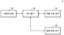
도 1은 본 발명의 일 실시예에 따른 약액 주입 시스템(1)을 도시하는 블록도이다.FIG. 1 is a block diagram illustrating a drug injection system (1) according to one embodiment of the present invention.
도 1을 참조하면, 약액 주입 시스템(1)은 약액 주입 장치(10), 사용자 단말(20), 컨트롤러(30) 및 생체 정보 센서(40)를 구비할 수 있다. 약액 주입 시스템(1)은 사용자 단말(20)을 이용하여 사용자가 시스템을 구동 및 제어할 수 있으며, 생체 정보 센서(40)에서 모니터링되는 혈당 정보를 기초로, 약액 주입 장치(10)에서 약액을 주기적으로 주입할 수 있다.Referring to Fig. 1, the drug injection system (1) may be equipped with a drug injection device (10), a user terminal (20), a controller (30), and a bio-information sensor (40). The drug injection system (1) may enable a user to drive and control the system using the user terminal (20), and may periodically inject a drug from the drug injection device (10) based on blood sugar information monitored by the bio-information sensor (40).
약액 주입 장치(10)는 생체 정보 센서(40)에서 센싱된 데이터를 기초로, 사용자에게 주입되어야 하는 약물 예컨대, 인슐린, 글루카곤, 마취제, 진통제, 도파민, 성장 호르몬, 금연 보조제 등의 약물을 주입하는 기능을 수행하기도 한다.The drug injection device (10) also performs the function of injecting drugs to be injected into the user, such as insulin, glucagon, anesthetics, painkillers, dopamine, growth hormones, smoking cessation aids, etc., based on data sensed by the biometric information sensor (40).
또한, 약액 주입 장치(10)는 장치의 잔여 배터리 용량 정보, 장치의 부팅 성공 여부, 주입 성공 여부 등을 포함하는 장치 상태 메시지를 컨트롤러(30)에 전달할 수 있다. 컨트롤러로 전달된 메시지들은 컨트롤러(30)를 거쳐 사용자 단말(20)로 전달될 수 있다. 또는 컨트롤러(30)는 수신된 메시지들을 가공한 개량 데이터를 사용자 단말(20)로 전달할 수 있다.In addition, the drug injection device (10) can transmit device status messages including information on the remaining battery capacity of the device, whether the device is booted successfully, whether the injection is successful, etc. to the controller (30). The messages transmitted to the controller can be transmitted to the user terminal (20) via the controller (30). Alternatively, the controller (30) can transmit improved data processed from the received messages to the user terminal (20).
일 실시예로, 약액 주입 장치(10)는 생체 정보 센서(40)와 별도로 구비되며, 사용자에 이격되어 설치될 수 있다. 다른 실시예로, 약액 주입 장치(10)와 생체 정보 센서(40)는 하나의 디바이스에 구비될 수 있다.In one embodiment, the drug injection device (10) may be provided separately from the biometric information sensor (40) and installed away from the user. In another embodiment, the drug injection device (10) and the biometric information sensor (40) may be provided in one device.
일 실시예로, 약액 주입 장치(10)는 사용자의 몸에 장착될 수 있다. 또한 다른 실시예로 약액 주입 장치(10)는 동물에도 장착되어 약액을 주입할 수 있다.In one embodiment, the drug injection device (10) can be mounted on the user's body. In another embodiment, the drug injection device (10) can also be mounted on an animal to inject the drug.
사용자 단말(20)은 약액 주입 시스템(1)을 구동 및 제어하기 위해 사용자로부터 입력 신호를 전달 받을 수 있다. 사용자 단말(20)은 컨트롤러(30)를 구동시키는 신호를 생성하여, 컨트롤러(30)를 제어하여 약액 주입 장치(10)를 구동시킬 수 있다. 또한, 사용자 단말(20)은 생체 정보 센서(40)로부터 측정된 생체 정보를 표시할 수 있으며, 약액 주입 장치(10)의 상태 정보를 표시할 수 있다.The user terminal (20) can receive an input signal from a user to drive and control the drug injection system (1). The user terminal (20) can generate a signal to drive the controller (30) and control the controller (30) to drive the drug injection device (10). In addition, the user terminal (20) can display biometric information measured from the biometric information sensor (40) and display status information of the drug injection device (10).
사용자 단말(20)은 유무선 통신 환경에서 이용할 수 있는 통신 단말을 의미한다. 예를 들어, 사용자 단말(20)은 스마트폰, 태블릿 PC, PC, 스마트 TV, 휴대폰, PDA(personal digital assistant), 랩톱, 미디어 플레이어, 마이크로 서버, GPS(global positioning system) 장치, 전자책 단말기, 디지털방송용 단말기, 네비게이션, 키오스크, MP3 플레이어, 디지털 카메라, 가전기기, 카메라가 탑재된 디바이스 및 기타 모바일 또는 비모바일 컴퓨팅 장치일 수 있다. 또한, 사용자 단말(2)은 통신 기능 및 데이터 프로세싱 기능을 구비한 시계, 안경, 헤어 밴드 및 반지 등의 웨어러블 디바이스일 수 있다. 그러나, 상술한 바와 같이 인터넷 통신이 가능한 애플리케이션을 탑재한 단말은 제한 없이 차용될 수 있다.The user terminal (20) refers to a communication terminal that can be used in a wired or wireless communication environment. For example, the user terminal (20) may be a smart phone, a tablet PC, a PC, a smart TV, a mobile phone, a PDA (personal digital assistant), a laptop, a media player, a micro server, a GPS (global positioning system) device, an e-book terminal, a digital broadcasting terminal, a navigation device, a kiosk, an MP3 player, a digital camera, a home appliance, a device equipped with a camera, and other mobile or non-mobile computing devices. In addition, the user terminal (2) may be a wearable device such as a watch, glasses, a hair band, and a ring equipped with a communication function and a data processing function. However, as described above, a terminal equipped with an application capable of Internet communication may be borrowed without limitation.
사용자 단말(20)은 미리 등록된 컨트롤러(30)와 1대1로 연결될 수 있다. 사용자 단말(20)은 외부의 장치로부터의 컨트롤러(30)가 구동 및 제어되는 것을 막기 위해서, 컨트롤러(30)와 암호화되어 연결될 수 있다.The user terminal (20) can be connected one-to-one with a pre-registered controller (30). The user terminal (20) can be connected to the controller (30) in an encrypted manner to prevent the controller (30) from being driven and controlled by an external device.
일 실시예로, 사용자 단말(20)과 컨트롤러(30)는 각각 분리되어 별도의 장치로 구비될 수 있다. 예컨대, 컨트롤러(30)는 약액 주입 장치(10)가 장착된 사용자에게 구비되고, 사용자 단말(20)은 사용자 또는 제3 자에게 구비될 수 있다. 보호자에 의해서 사용자 단말(20)이 구동되어, 약액 주입 시스템(1)의 안전성을 높일 수 있다.In one embodiment, the user terminal (20) and the controller (30) may be provided as separate devices, respectively. For example, the controller (30) may be provided to a user equipped with a drug injection device (10), and the user terminal (20) may be provided to the user or a third party. The user terminal (20) may be driven by a guardian, thereby increasing the safety of the drug injection system (1).
다른 실시예로, 사용자 단말(20)과 컨트롤러(30)는 하나의 디바이스로 구비될 수 있다. 사용자 단말(20)과 하나로 구비된 컨트롤러(30)가 약액 주입 장치(10)와 통신하여, 약물의 주입을 제어할 수 있다.In another embodiment, the user terminal (20) and the controller (30) may be provided as a single device. The user terminal (20) and the controller (30) provided as a single device may communicate with the drug injection device (10) to control the injection of the drug.
컨트롤러(30)는 약액 주입 장치(10)와 데이터를 송수신하는 기능을 수행하며, 약액 주입 장치(10)로 인슐린 등의 약물의 주입과 관련된 제어 신호를 전송하고, 생체 정보 센서(40)로부터 혈당 등의 생체값의 측정과 관련된 제어 신호를 수신 받을 수 있다.The controller (30) performs a function of transmitting and receiving data with the drug injection device (10), and can transmit a control signal related to the injection of a drug such as insulin to the drug injection device (10), and receive a control signal related to the measurement of a biological value such as blood sugar from a biological information sensor (40).
컨트롤러(30)는 일 예로 약액 주입 장치(10)로 사용자의 현 상태를 측정하라는 지시 요청을 전송하고, 지시 요청의 응답으로 약액 주입 장치(10)로부터 측정 데이터를 수신 받을 수 있다.The controller (30) can, for example, transmit a command request to measure the user's current condition to the liquid injection device (10) and receive measurement data from the liquid injection device (10) in response to the command request.
생체 정보 센서(40)는 목적에 따라 사용자의 혈당값, 혈압, 심박수 등의 생체값을 측정하는 기능을 수행할 수 있다. 생체 정보 센서(40)에서 측정된 데이터는 컨트롤러(30)에 전달될 수 있으며, 측정된 데이터를 기초로 약물이 주기 및/또는 주입량이 설정될 수 있다. 생체 정보 센서(40)에서 측정된 데어터는 사용자 단말(20)로 전달되어 표시될 수 있다.The biometric sensor (40) can perform a function of measuring the user's biometric values such as blood sugar level, blood pressure, and heart rate depending on the purpose. Data measured by the biometric sensor (40) can be transmitted to the controller (30), and the drug cycle and/or injection amount can be set based on the measured data. Data measured by the biometric sensor (40) can be transmitted to the user terminal (20) and displayed.
일 예로, 생체 정보 센서(40)는 사용자의 혈당량을 측정하는 센서일 수 있다. 연속 혈당 측정(CGM: Continuous Glucose Monitoring) 센서일 수 있다. 연속 혈당 측정 센서는 사용자에 부착되어 연속적으로 혈당량을 모니터링 할 수 있다.For example, the biometric information sensor (40) may be a sensor that measures the user's blood sugar level. It may be a continuous glucose monitoring (CGM) sensor. The continuous glucose monitoring sensor may be attached to the user and continuously monitor the blood sugar level.
사용자 단말(20), 컨트롤러(30) 및 약액 주입 장치(10)는 네트워크를 이용하여 통신을 수행할 수 있다. 예를 들어, 네트워크는 근거리 통신망(Local Area Network; LAN), 광역 통신망(Wide Area Network; WAN), 부가가치 통신망(Value Added Network; VAN), 이동 통신망(mobile radio communication network), 위성 통신망 및 이들의 상호 조합을 포함하며, 각 네트워크 구성 주체가 서로 원활하게 통신을 할 수 있도록 하는 포괄적인 의미의 데이터 통신망이며, 유선 인터넷, 무선 인터넷 및 모바일 무선 통신망을 포함할 수 있다. 또한, 무선 통신은 예를 들어, 무선 랜(Wi-Fi), 블루투스, 블루투스 저 에너지(Bluetooth low energy), 지그비, WFD(Wi-Fi Direct), UWB(ultra wideband), 적외선 통신(IrDA, infrared Data Association), NFC(Near Field Communication), 5G 등이 있을 수 있으나, 이에 한정되는 것은 아니다.The user terminal (20), the controller (30), and the drug injection device (10) may perform communication using a network. For example, the network includes a local area network (LAN), a wide area network (WAN), a value added network (VAN), a mobile radio communication network, a satellite communication network, and a combination thereof, and is a comprehensive data communication network that allows each network component to communicate smoothly with each other, and may include wired Internet, wireless Internet, and a mobile radio communication network. In addition, the wireless communication may include, but is not limited to, wireless LAN (Wi-Fi), Bluetooth, Bluetooth low energy, Zigbee, WFD (Wi-Fi Direct), UWB (ultra wideband), infrared communication (IrDA, infrared Data Association), NFC (Near Field Communication), 5G, etc.
도 2는 본 발명의 일 실시예에 따른 약액 주입 장치(10)를 도시하는 사시도이고, 도 3은 도 2의 약액 주입 장치(10)의 분해 사시도이다.FIG. 2 is a perspective view illustrating a drug injection device (10) according to one embodiment of the present invention, and FIG. 3 is an exploded perspective view of the drug injection device (10) of FIG. 2.
도 2 및 도 3을 참조하면, 약액 주입 장치(10)는 약액 주입 대상인 사용자에 부착된 상태에서, 내부에 저장된 약액을 사용자에게 설정된 정량으로 주입할 수 있다.Referring to FIGS. 2 and 3, the drug injection device (10) can inject the drug stored inside to the user in a set amount while attached to the user who is the target of the drug injection.
약액 주입 장치(10)는 주입되는 약액의 종류에 따라 다양한 용도로 사용될 수 있다. 예컨대, 약액은 당뇨병 환자를 위한 인슐린 계열 약액을 포함할 수 있고, 기타 췌장을 위한 약액, 심장용 약액 기타 다양한 종류의 약액을 포함할 수 있다.The drug injection device (10) can be used for various purposes depending on the type of drug to be injected. For example, the drug may include an insulin-based drug for diabetic patients, other drugs for the pancreas, drugs for the heart, and other various types of drugs.
약액 주입 장치(10)의 일 실시예는 외측을 커버하는 하우징(11), 사용자의 피부에 인접하게 위치하는 부착부(12)를 구비할 수 있다. 약액 주입 장치(10)는 하우징(11)과 부착부(12) 사이의 공간에 배치되는 복수개의 부품을 포함한다. 부착부(12)와 사용자의 피부 사이에는 별도의 접합수단이 더 개재될 수 있으며, 접합수단에 의해 약액 주입 장치(10)는 피부에 고정될 수 있다.One embodiment of the drug injection device (10) may include a housing (11) covering the outside and an attachment portion (12) positioned adjacent to the user's skin. The drug injection device (10) includes a plurality of parts arranged in a space between the housing (11) and the attachment portion (12). A separate bonding means may be further interposed between the attachment portion (12) and the user's skin, and the drug injection device (10) may be fixed to the skin by the bonding means.
약액 주입 장치(10)는 니들 어셈블리(100), 레저버 어셈블리(200), 구동 모듈(300), 배터리(350), 구동 유닛(400), 트리거 부재(500), 니들 커버 조립체(600), 알람 유닛(700)을 포함할 수 있다.The drug injection device (10) may include a needle assembly (100), a reservoir assembly (200), a driving module (300), a battery (350), a driving unit (400), a trigger member (500), a needle cover assembly (600), and an alarm unit (700).
약액 주입 장치(10)는 베이스 바디 중에서 적어도 하나 이상의 바디가 내부 부품을 지지하는 틀을 형성할 수 있다. 베이스 바디는 배치에 따라 제1 바디(13), 제2 바디(14) 및 제3 바디(15)를 가질 수 있다.The liquid injection device (10) may have at least one body among the base bodies form a frame that supports internal components. The base body may have a first body (13), a second body (14), and a third body (15) depending on the arrangement.
제1 바디(13)는 하우징(11)의 아래에 배치되며, 각 개구 또는 홈에 니들 어셈블리(100), 레저버 어셈블리(200), 구동 모듈(300), 배터리(350) 등이 지지될 수 있다. 제2 바디(14)는 제1 바디(13)의 아래에 배치되며, 부착부(12)와 연결될 수 있다. 제2 바디(14)는 약액 주입 장치(10)의 하부를 커버할 수 있다. 제3 바디(15)는 제1 바디(13)의 상측에 배치되어, 각 개구 또는 홈에 레저버 어셈블리(200), 구동 모듈(300), 배터리(350), 구동 유닛(400) 등을 지지될 수 있다. 도면에서는 제1 바디(13), 제2 바디(14) 및 제3 바디(15)를 도시하나, 이에 한정되지 않으며 일체로 구비되거나 복수 개로 구비될 수 있다.The first body (13) is arranged below the housing (11), and a needle assembly (100), a reservoir assembly (200), a driving module (300), a battery (350), etc. can be supported in each opening or groove. The second body (14) is arranged below the first body (13) and can be connected to the attachment part (12). The second body (14) can cover the lower part of the liquid injection device (10). The third body (15) is arranged above the first body (13), and a reservoir assembly (200), a driving module (300), a battery (350), a driving unit (400), etc. can be supported in each opening or groove. The drawing illustrates the first body (13), the second body (14), and the third body (15), but they are not limited thereto, and they may be provided integrally or in multiple pieces.
약액 주입 장치(10)의 내부에는 제어 유닛(미도시)이 배치될 수 있다. 제2 바디(14)의 아래에는 회로 기판인 제어 유닛이 배치되며, 약액 주입 장치(10)의 전체적인 구동을 제어할 수 있다. 제어 유닛은 구동 모듈(300), 알람 유닛(700) 및 복수 개의 센서(미도시)와 전기적으로 접촉하여, 이들의 동작을 제어할 수 있다.A control unit (not shown) may be placed inside the drug injection device (10). A control unit, which is a circuit board, is placed under the second body (14) and can control the overall operation of the drug injection device (10). The control unit electrically contacts a driving module (300), an alarm unit (700), and a plurality of sensors (not shown) and can control their operations.
사용자가 니들 어셈블리(100)를 회전시키면, 약액 주입 장치(10)는 캐뉼러를 사용자에게 삽입하고, 약액 주입을 개시하도록 클러치 유닛을 활성화시킬 수 있다.When the user rotates the needle assembly (100), the drug injection device (10) can activate the clutch unit to insert the cannula into the user and initiate drug injection.
니들 어셈블리(100)는 레저버 어셈블리(200)와 유체적으로 연결될 수 있다. 클러치 유닛이 활성화되면, 구동 모듈에서 발생하는 구동력이 레저버 어셈블리(200)로 전달되면서, 레저버 어셈블리(200)에 저장된 약액을 니들과 캐뉼러를 통하여 사용자에게 주입할 수 있다.The needle assembly (100) can be fluidly connected to the reservoir assembly (200). When the clutch unit is activated, the driving force generated from the driving module is transmitted to the reservoir assembly (200), and the drug stored in the reservoir assembly (200) can be injected to the user through the needle and cannula.
구동 모듈(300)은 전기에 의해 구동력을 생성하는 모든 종류의 장치가 사용될 수 있다. 예를 들면, 기계 변위형 마이크로펌프와 전자기운동형 마이크로펌프 등의 모든 종류의 펌프가 사용될 수 있다. 기계변위형 마이크로펌프는 유체의 흐름을 유도하기 위해 압력차를 일으키도록 기어나 다이어그램과 같은 고체 혹은 유체의 운동을 이용하는 펌프로서, 다이어프람 변위 펌프(Diaphragm displacement pump), 유체 변위 펌프(Fluid displacement pump), 회전 펌프(Rotary pump) 등이 있다. 전자기운동형 마이크로펌프는 전기적 또는 자기적 형태의 에너지를 바로 유체의 이동에 이용하는 펌프로서, 전기유체역학 펌프(Electro hydrodynamic pump, EHD), 전기삼투식 펌프(Electro osmotic pump), 자기유체역학 펌프(Magneto hydrodynamic pump), 전기습식 펌프(Electro wetting pump)등이 있다.The drive module (300) may use any kind of device that generates driving force by electricity. For example, any kind of pump such as a mechanical displacement type micropump and an electromagnetic motion type micropump may be used. A mechanical displacement type micropump is a pump that uses the movement of a solid or fluid such as a gear or diagram to generate a pressure difference to induce the flow of a fluid, and includes a diaphragm displacement pump, a fluid displacement pump, a rotary pump, etc. An electromagnetic motion type micropump is a pump that uses electric or magnetic energy directly to move a fluid, and includes an electrohydrodynamic pump (EHD), an electroosmotic pump, a magnetohydrodynamic pump, an electrowetting pump, etc.
배터리(350)는 약액 주입 장치(10)에 전기를 공급하여, 각 부품을 활성화 할 수 있다. 도면에서는 한 쌍의 배터리(350)를 도시하나, 이에 한정되지 않으며, 약액 주입 장치(10)의 용량, 사용범위, 사용 시간 등에 따라 다양하게 설정될 수 있다. 배터리(350)는 구동 모듈(300)에 인접하게 배치되며, 구동 모듈(300)로 전기를 공급할 수 있다. 또한, 배터리(350)는 상기 제어 모듈과 연결되며, 센서 유닛에서 측정된 전기적 신호를 기초로 구동 유닛(400)의 회전수 또는 회전 속도, 레저버 어셈블리(200)에 저장된 약액량, 사용자에게 주입된 약액량 등에 대한 데이터를 측정할 수 있다.The battery (350) supplies electricity to the drug injection device (10) to activate each component. The drawing illustrates a pair of batteries (350), but is not limited thereto, and may be set in various ways depending on the capacity, usage range, usage time, etc. of the drug injection device (10). The battery (350) is arranged adjacent to the driving module (300) and can supply electricity to the driving module (300). In addition, the battery (350) is connected to the control module, and can measure data on the rotational speed or rotational number of the driving unit (400), the amount of drug stored in the reservoir assembly (200), the amount of drug injected to the user, etc. based on the electrical signal measured by the sensor unit.
구동 유닛(400)은 구동 모듈(300)과 레저버 어셈블리(200)의 사이에 배치되어, 구동 모듈(300)에서 생성된 구동력이 레저버 어셈블리(200)로 전달되도록, 구동 모듈(300)과 레저버 어셈블리(200)를 구동적으로 연결할 수 있다. 이때, 구동 유닛(400)의 연결은 구동 유닛(400)에 마련된 클러치 유닛의 활성화 시에 이루어질 수 있다.The driving unit (400) is arranged between the driving module (300) and the reservoir assembly (200), and can drivably connect the driving module (300) and the reservoir assembly (200) so that the driving force generated in the driving module (300) is transmitted to the reservoir assembly (200). At this time, the connection of the driving unit (400) can be made when the clutch unit provided in the driving unit (400) is activated.
트리거 부재(500)는, 니들 어셈블리(100)가 회전하여 캐뉼러가 사용자에 삽입된 후, 약액 주입 장치(10)의 약액이 주입되는 기계적인 신호를 생성할 수 있다. 일 실시예로, 트리거 부재(500)는 제3 바디(15)의 일측에 회동 가능하게 배치되고, 니들 어셈블리(100)의 노브(미도시)가 트리거 부재(500)를 가력하여 트리거 부재(500)의 회전이 개시될 수 있다. 트리거 부재(500)가 회전하면서, 클러치 유닛의 커플러를 가력하여, 클러치 유닛이 활성화될 수 있다.The trigger member (500) can generate a mechanical signal for injecting the drug from the drug injection device (10) after the needle assembly (100) rotates and the cannula is inserted into the user. In one embodiment, the trigger member (500) is rotatably arranged on one side of the third body (15), and the rotation of the trigger member (500) can be initiated by a knob (not shown) of the needle assembly (100) applying force to the trigger member (500). As the trigger member (500) rotates, the coupler of the clutch unit is applied, so that the clutch unit can be activated.
니들 커버 조립체(600)는 니들 어셈블리(100)의 아래에 장착될 수 있다. 니들 커버 조립체(600)는 약액을 주입하기 전에 레저버 어셈블리(200)에 저장된 에어를 프라이밍(Priming) 할 수 있다. 약액 주입기(NI)를 통해서, 약액이 레저버(210)에 될때, 레저버(210)에 잔류된 기체(공기)를 외부로 배출할 수 있다.The needle cover assembly (600) can be mounted below the needle assembly (100). The needle cover assembly (600) can prime the air stored in the reservoir assembly (200) before injecting the drug. When the drug is injected into the reservoir (210) through the drug injector (NI), the gas (air) remaining in the reservoir (210) can be discharged to the outside.
니들 커버 조립체(600)는 제1 커버(610), 제2 커버(620), 필터 부재(630) 및 접착층(640)을 가질 수 있다.The needle cover assembly (600) may have a first cover (610), a second cover (620), a filter member (630), and an adhesive layer (640).
제1 커버(610)는 약액 주입 장치(10)의 하부에 배치될 수 있다. 제1 커버(610)의 개구에는 제2 커버(620)가 삽입되어 조립될 수 있다.The first cover (610) can be placed at the bottom of the liquid injection device (10). The second cover (620) can be inserted and assembled into the opening of the first cover (610).
제2 커버(620)는 제1 커버(610)에 조립되며, 중앙에 니들 및/또는 캐뉼러(C)가 정렬될 수 있다. 제2 커버(620)는 중앙에 높이방향으로 관통되며, 약액(D)이 저장되는 저장 공간을 가질 수 있다.The second cover (620) is assembled to the first cover (610), and a needle and/or cannula (C) can be aligned in the center. The second cover (620) can have a storage space that penetrates in the height direction in the center and stores the drug solution (D).
제1 커버(610)는 제2 커버(620)보다 강성이 더 크다. 제1 커버(610)는 외부에 노출되는 부분으로, 강성이 다소 큰 물질로 형성된다. 제2 커버(620)는 제1 커버(610)에 조립되고, 제3 바디(15)의 개구에 삽입되기 위해서 제1 커버(610)보다 강성이 작은 물질로 형성된다.The first cover (610) has greater rigidity than the second cover (620). The first cover (610) is a portion exposed to the outside and is formed of a material with somewhat greater rigidity. The second cover (620) is assembled to the first cover (610) and is formed of a material with less rigidity than the first cover (610) in order to be inserted into the opening of the third body (15).
제2 커버(620)의 중앙에는 제3 바디(15)에 삽입되는 돌출부(621)를 구비할 수 있다. 또한, 제2 커버(620)는 고정 돌기를 구비하고, 고정 돌기가 제1 커버(610)에 삽입되어, 제1 커버(610)와 제2 커버(620)가 조립될 수 있다.The center of the second cover (620) may be provided with a protrusion (621) that is inserted into the third body (15). In addition, the second cover (620) may be provided with a fixing protrusion, and the fixing protrusion may be inserted into the first cover (610), so that the first cover (610) and the second cover (620) may be assembled.
제2 커버(620)의 돌출부(621)는 제3 바디(15)의 하단의 개구에 삽입된다. 상기 개구의 직경보다 돌출부(621)의 직경이 약간 크게 설정된다. 제2 커버(620)는 소정의 탄성을 가지므로, 돌출부(621)가 상기 개구에 삽입되어 고정될 수 있다.The protrusion (621) of the second cover (620) is inserted into the opening at the bottom of the third body (15). The diameter of the protrusion (621) is set slightly larger than the diameter of the opening. Since the second cover (620) has a predetermined elasticity, the protrusion (621) can be inserted into and fixed in the opening.
제2 커버(620)는 내경을 가지어, 상부에 니들과 캐뉼러가 정렬될 수 있다. 제2 커버(620)의 내경는 제2 커버(620)의 저장 공간을 형성하며, 약액이 저장 또는 기체가 이동 및 배출될 수 있다.The second cover (620) has an inner diameter, so that a needle and a cannula can be aligned at the top. The inner diameter of the second cover (620) forms a storage space of the second cover (620), where a liquid can be stored or a gas can be moved and discharged.
필터 부재는 제2 커버(620)에 장착된다. 필터 부재는 제2 커버(620)의 저장공간의 아래에 배치되며, 공기 등의 기체는 필터 부재를 통과하나, 약액과 같은 액체는 필터 부재를 통과하지 않는다. 그리하여, 니들에서 배출된 공기는 필터 부재를 통과하여 외부로 배출되나, 니들에서 배출된 약액은 제2 커버(620)와 필터 부재로 정의되는 저장 공간에 저장될 수 있다.The filter member is mounted on the second cover (620). The filter member is placed below the storage space of the second cover (620), and gases such as air pass through the filter member, but liquids such as a chemical liquid do not pass through the filter member. Thus, air discharged from the needle passes through the filter member and is discharged to the outside, but the chemical liquid discharged from the needle can be stored in the storage space defined by the second cover (620) and the filter member.
필터 부재는 저장 공간에 저장되는 약액의 양에 따라 형상이 변화할 수 있다. 예컨대, 저장 공간에 약액이 채워지면, 필터 부재가 아래 방향으로 팽창하여, 사용자가 니들 커버 조립체(600)에 약액이 유입된 것을 인지할 수 있다.The filter member may change shape depending on the amount of the drug stored in the storage space. For example, when the storage space is filled with the drug, the filter member may expand downward, allowing the user to recognize that the drug has entered the needle cover assembly (600).
접착층은 니들 커버 조립체(600)의 일면에 배치되며, 부착부(12)에 니들 커버 조립체(600)를 부착시킬 수 있다.The adhesive layer is placed on one side of the needle cover assembly (600) and can attach the needle cover assembly (600) to the attachment portion (12).
알람 유닛(700)은 약액 주입 장치(10)의 내부 또는 외부에 배치되며, 약액 주입 장치(10)의 정상작동이나 오작동을 사용자에게 알릴 수 있다.The alarm unit (700) is placed inside or outside the drug injection device (10) and can notify the user of normal operation or malfunction of the drug injection device (10).
일 예로, 알람 유닛(700)은 하우징(11)의 아래에 배치되며, 회로 기판에 연결된다. 알람 유닛(700)은 경고음을 생성하거나, 빛을 생성하여, 외부 사용자에게 알람을 전달할 수 있다.For example, an alarm unit (700) is placed underneath the housing (11) and connected to the circuit board. The alarm unit (700) can generate a warning sound or generate light to convey an alarm to an external user.
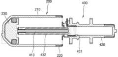
도 4는 도 2의 레저버 어셈블리(200)를 도시하는 도면이고, 도 5은 도 4의 레저버 어셈블리(200)의 센싱 유닛(260)을 도시한 도면이다.FIG. 4 is a drawing illustrating the reservoir assembly (200) of FIG. 2, and FIG. 5 is a drawing illustrating the sensing unit (260) of the reservoir assembly (200) of FIG. 4.
도 4 및 도 5를 참조하면, 레저버 어셈블리(200)는 레저버(210), 캡 커버(220), 플런저(230), 실링링(240), 센싱 유닛(260)을 구비할 수 있다.Referring to FIGS. 4 and 5, the reservoir assembly (200) may include a reservoir (210), a cap cover (220), a plunger (230), a sealing ring (240), and a sensing unit (260).
레저버(210)는 레저버 어셈블리(200)의 외관을 형성하고, 내부에 플런저(230)가 수용될 수 있는 내부공간을 제공할 수 있다.The reservoir (210) forms the exterior of the reservoir assembly (200) and can provide an internal space in which a plunger (230) can be accommodated.
일 실시예로, 레저버(210)는 전후 방향으로 연장된 실린더 형태로 형성될 수 있다. 레저버(210)의 후방에는 캡 커버(220)가 장착되어 레저버(210)와 캡 커버(220)에 의해 외부와 구분되는 내부공간이 규정될 수 있고, 캡 커버(220)에 배치된 개구(미도시)를 통해서 커넥터 부재(233) 및 로드 부재와 결합된 연결 부재(432)가 이동할 수 있다.In one embodiment, the reservoir (210) may be formed in a cylinder shape extending in the front-back direction. A cap cover (220) may be mounted on the rear of the reservoir (210) so that an internal space separated from the outside by the reservoir (210) and the cap cover (220) may be defined, and a connecting member (432) coupled with a connector member (233) and a load member may move through an opening (not shown) arranged in the cap cover (220).
플런저(230)는 내부공간에 수용되어 전후방향으로 이동할 수 있다. 일 실시예로, 플런저(230)는 내부공간으로 유입되는 약액에 의하여 전방에서 후방으로 이동할 수 있다. 그리고, 구동 모듈에서 생성되는 구동력에 의하여 후방에서 전방으로 이동할 수 있다. 플런저(230)의 전진에 따라, 레저버(210)에 저장된 약액은 니들 어셈블리로 배출될 수 있다.The plunger (230) is accommodated in the internal space and can move forward and backward. In one embodiment, the plunger (230) can move from front to back by the liquid flowing into the internal space. And, it can move from back to front by the driving force generated from the driving module. As the plunger (230) moves forward, the liquid stored in the reservoir (210) can be discharged to the needle assembly.
레저버(210)와 플런저(230)에 의해 내부공간의 일부는 약액이 저장되는 저장공간으로 규정될 수 있다. 내부공간에서 이동하는 플런저(230)에 의하여 저장공간의 체적은 변할 수 있다. 예를 들어, 플런저(230)가 내부공간의 최전방에 배치되어 플러저의 엔드단(231)과 경사면(232)이 레저버(210)와 밀착되는 경우 내부공간에서 저장공간은 형성되지 않을 수 있다. 그리고, 약액이 레저버(210)로 유입되면서 저장공간이 형성되며, 저장공간의 체적은 레저버(210)로 유입되는 약액에 의하여 증가할 수 있다. 그리고, 저장된 약액이 레저버(210)에서 배출되면서 저장공간의 체적은 감소할 수 있다.A part of the internal space may be defined as a storage space where the liquid is stored by the reservoir (210) and the plunger (230). The volume of the storage space may change by the plunger (230) moving in the internal space. For example, if the plunger (230) is positioned at the frontmost part of the internal space so that the end (231) and the inclined surface (232) of the plunger are in close contact with the reservoir (210), the storage space may not be formed in the internal space. Then, the storage space is formed as the liquid flows into the reservoir (210), and the volume of the storage space may increase due to the liquid flowing into the reservoir (210). Then, the volume of the storage space may decrease as the stored liquid is discharged from the reservoir (210).
플런저(230)는 전후방으로 연장되는 커넥터 부재(233)와 결합될 수 있다. 커넥터 부재(233)는 플런저(230)에 설치되어, 플런저(230)의 이동에 따라 함께 이동하며, 저장된 약액의 양을 센싱할 수 있다.The plunger (230) can be combined with a connector member (233) that extends forward and backward. The connector member (233) is installed on the plunger (230), moves together with the movement of the plunger (230), and can sense the amount of the stored liquid.
플런저(230)는 레저버(210)의 내측벽과 접촉하는 부분에 실링링(240)이 구비되어, 플런저(230)의 이동시에 플런저(230)와 레저버(210)의 내측벽 사이를 통하여 약액이 누설되는 것을 방지할 수 있다.The plunger (230) is provided with a sealing ring (240) at a portion that comes into contact with the inner wall of the reservoir (210), thereby preventing the liquid from leaking between the plunger (230) and the inner wall of the reservoir (210) when the plunger (230) moves.
레저버(210)의 전방에는 내부공간을 외부와 연통하게 하는 복수의 개구가 형성될 수 있다. 복수의 개구는 유입구(210I), 배출구(210E) 및 감지구(210S)일 수 있다. 일 실시예로, 유입구(210I), 배출구(210E) 및 감지구(210S)는 레저버(210)의 전방을 각각 관통하는 개구로 형성될 수 있다. 다른 실시예로, 유입구(210I), 배출구(210E) 및 감지구(210S)는 레저버(210)의 전방 내측면에 홈으로 형성된 유로(211)를 통하여 레저버(210)의 내부와 연통할 수 있다.A plurality of openings may be formed at the front of the reservoir (210) to communicate the internal space with the outside. The plurality of openings may be an inlet (210I), an outlet (210E), and a detection port (210S). In one embodiment, the inlet (210I), the outlet (210E), and the detection port (210S) may be formed as openings that penetrate the front of the reservoir (210), respectively. In another embodiment, the inlet (210I), the outlet (210E), and the detection port (210S) may communicate with the inside of the reservoir (210) through a channel (211) formed as a groove on the front inner surface of the reservoir (210).
유입구(210I)는 외부의 약액이 레저버(210)의 내부공간으로 유입되는 유로를 제공할 수 있다. 유입구(210I)에는 제1 패킹 부재(251)가 배치되어, 유입구(210I)를 패킹하고, 유입구(210I)를 통하여 약액이 누설되는 것을 방지할 수 있다. 제1 패킹 부재(251)는 약액의 누설을 방지하되, 주입용 니들(미도시)을 제1 패킹 부재(251)에 침습한 상태에서 약액을 주입할 수 있다.The inlet (210I) can provide a path for external liquid medicine to flow into the internal space of the reservoir (210). A first packing member (251) is arranged in the inlet (210I) to pack the inlet (210I) and prevent the liquid medicine from leaking through the inlet (210I). The first packing member (251) prevents the liquid medicine from leaking, but can inject the liquid medicine while the injection needle (not shown) is penetrated into the first packing member (251).
제1 패킹 부재(251)는 재밀폐성을 가질 수 있다. 예를 들어, 레저버(210)에 약액을 충전하기 위하여 주입용 니들이 제1 패킹 부재(251)를 침습한 후 제거되는 경우라도, 제1 패킹 부재(251)는 주입용 니들이 침습한 부분을 통해 약액이 누설되는 것을 방지할 수 있다. 제1 패킹 부재(251)는, 예를 들어, 폴리프로필렌, 열가소성 탄성 중합체, 식물성 오일 등을 포함하는 소재로 형성될 수 있다. 주입용 니들에 의해 주입되는 약액은 플런저(230)를 후방으로 밀며 레저버(210)의 내부공간으로 유입되면서 저장공간을 형성할 수 있다.The first packing member (251) may have a re-sealing property. For example, even if the injection needle penetrates the first packing member (251) and is then removed to fill the reservoir (210) with a drug, the first packing member (251) may prevent the drug from leaking through the portion penetrated by the injection needle. The first packing member (251) may be formed of a material including, for example, polypropylene, a thermoplastic elastomer, vegetable oil, or the like. The drug injected by the injection needle may form a storage space by pushing the plunger (230) backward and flowing into the internal space of the reservoir (210).
배출구(210E)에는 도관(N)이 연결되고, 레저버(210)는 도관(N)을 통하여 니들 어셈블리와 연결될 수 있다. 배출구(210E)와 도관(N) 사이에는 제2 패킹 부재(252)가 마련되어, 배출구(210E)와 도관 사이에서 약액이 누설되는 것을 방지할 수 있다. 레저버(210)에 저장된 약액은 배출구(210E)와 도관을 통하여 니들 어셈블리로 유동할 수 있다.A conduit (N) is connected to the discharge port (210E), and the reservoir (210) can be connected to the needle assembly through the conduit (N). A second packing member (252) is provided between the discharge port (210E) and the conduit (N), thereby preventing leakage of the chemical between the discharge port (210E) and the conduit. The chemical stored in the reservoir (210) can flow to the needle assembly through the discharge port (210E) and the conduit.
감지구(210S)에는 캡 부재(261)가 마련되어, 감지구(210S)를 통하여 레저버(210)에 저장된 약액이 누설되는 것을 방지할 수 있다.A cap member (261) is provided in the detection device (210S), so as to prevent leakage of the drug solution stored in the reservoir (210) through the detection device (210S).
도 5을 참조하면, 센싱 유닛(260)은 캡 부재(261), 감지 부재(262) 및 가력 부재(263)를 포함할 수 있다.Referring to FIG. 5, the sensing unit (260) may include a cap member (261), a detection member (262), and a force member (263).
캡 부재(261)는 감지구(210S)에 삽입 고정된 상태로 감지구(210S)를 통하여 저장공간에 저장된 약액이 누설되는 것을 방지할 수 있다. 캡 부재(261)는 감지구(210S)에 삽입 고정되되, 소정의 힘에 의해 이동할 수 있다.The cap member (261) can prevent the liquid stored in the storage space from leaking through the detection member (210S) while being inserted and fixed into the detection member (210S). The cap member (261) can be inserted and fixed into the detection member (210S), but can be moved by a predetermined force.
일 실시예로, 캡 부재(261)의 외측면과 감지구(210S)의 내측면 사이에서 작용하는 마찰력에 의해 캡 부재(261)가 감지구(210S)에 삽입 고정될 수 있다. 이때, 캡 부재(261)의 외측면은 감지구(210S)의 내측면과 대응되는 형태로 마련되고, 캡 부재(261)는 감지구(210S)에 삽입되어 마찰력을 발생시키기에 용이한 탄성 물질로 이루어질 수 있다.In one embodiment, the cap member (261) may be inserted and fixed into the detection member (210S) by a frictional force acting between the outer surface of the cap member (261) and the inner surface of the detection member (210S). At this time, the outer surface of the cap member (261) is provided in a shape corresponding to the inner surface of the detection member (210S), and the cap member (261) may be made of an elastic material that is easy to insert into the detection member (210S) and generate a frictional force.
캡 부재(261)는 일측에 감지구(210S)에 삽입되는 패킹부(261a)가 형성되고, 타측에 감지 부재(262)와 접촉하는 접촉부(261b)가 형성될 수 있다. 패킹부(261a)와 접촉부(261b)는 한 번에 일체로 제조될 수 있다. 또는, 패킹부(261a)와 접촉부(261b)는 각각 제조된 후 일체로 조립될 수 있다.The cap member (261) may have a packing part (261a) formed on one side to be inserted into the detection port (210S), and a contact part (261b) formed on the other side to be in contact with the detection member (262). The packing part (261a) and the contact part (261b) may be manufactured as one piece at a time. Alternatively, the packing part (261a) and the contact part (261b) may be manufactured separately and then assembled as one piece.
패킹부(261a)는 감지구(210S)의 내측면과 대응되는 형태로 마련되어, 감지구(210S)에 삽입된 상태로, 패킹부(261a)의 외측면과 감지구(210S)의 내측면 사이에 마찰력이 형성될 수 있다. 패킹부(261a)가 감지구(210S)에 삽입 고정된 상태에서, 저장공간을 향하는 패킹부(261a)의 일측이 저장공간에 저장된 약액과 접촉할 수 있으므로, 패킹부(261a)의 적어도 일부는 약액과 반응하지 않고 탄성을 갖는 물질, 예를 들어 생체 적합성 고무 또는 실리콘으로 이루어질 수 있다.The packing part (261a) is provided in a shape corresponding to the inner surface of the detection part (210S), so that when inserted into the detection part (210S), frictional force can be formed between the outer surface of the packing part (261a) and the inner surface of the detection part (210S). When the packing part (261a) is inserted and fixed into the detection part (210S), one side of the packing part (261a) facing the storage space can come into contact with the drug stored in the storage space, so at least a part of the packing part (261a) can be made of a material that does not react with the drug and has elasticity, for example, biocompatible rubber or silicone.
접촉부(261b)는 감지 부재(262)와 접촉하는 부분으로, 접촉부(261b)와 감지 부재(262)가 접촉하면 소정의 신호를 생성할 수 있다. 일 실시예로, 접촉부(261b)와 감지 부재(262)가 접촉하여 전기적 신호가 생성될 수 있다. 이때, 접촉부(261b)의 적어도 일부는 전기 전도성이 높은 물질로 이루어질 수 있다. 예를 들어, 접촉부(261b)는 전도성 금속이거나, 실리콘이나 고무에 은이나 니켈 등의 전도성 금속 파우더를 넣어서 압출하는 방식으로 제조되는 전도성 실리콘 또는 전도성 러버일 수 있다.The contact portion (261b) is a portion that comes into contact with the sensing member (262), and when the contact portion (261b) and the sensing member (262) come into contact, a predetermined signal can be generated. In one embodiment, an electrical signal can be generated when the contact portion (261b) and the sensing member (262) come into contact. At this time, at least a portion of the contact portion (261b) can be made of a material having high electrical conductivity. For example, the contact portion (261b) can be a conductive metal, or a conductive silicone or conductive rubber manufactured by extruding a conductive metal powder such as silver or nickel into silicone or rubber.
감지 부재(262)는 캡 부재(261)와 이격되되, 캡 부재(261)가 이동하면 캡 부재(261)와 접촉하도록 배치될 수 있다. 일 실시예로, 감지 부재(262)는 회로 기판으로 마련되어, 감지 부재(262)와 캡 부재(261)가 접촉하여 전기적 신호를 생성할 수 있다.The sensing member (262) may be positioned so as to be spaced apart from the cap member (261), but to come into contact with the cap member (261) when the cap member (261) moves. In one embodiment, the sensing member (262) may be provided as a circuit board, so that the sensing member (262) and the cap member (261) may come into contact to generate an electrical signal.
감지 부재(262)와 캡 부재(261)의 접촉부(261b) 사이의 이격 거리는 패킹부(261a)가 감지구(210S)에 삽입되는 깊이보다 작게 형성될 수 있다. 캡 부재(261)에 작용하는 소정의 힘에 의하여 캡 부재(261)의 접촉부(261b)가 감지 부재(262)와 접촉할 때까지 캡 부재(261)가 이동하더라도, 캡 부재(261)의 패킹부(261a)가 감지구(210S)에서 이탈되지 않고, 감지구(210S)를 통하여 약액이 누설되는 것을 방지할 수 있다.The distance between the contact portion (261b) of the detection member (262) and the cap member (261) can be formed smaller than the depth at which the packing portion (261a) is inserted into the detection port (210S). Even if the cap member (261) moves until the contact portion (261b) of the cap member (261) comes into contact with the detection member (262) by a predetermined force applied to the cap member (261), the packing portion (261a) of the cap member (261) does not come off from the detection port (210S), and leakage of the liquid through the detection port (210S) can be prevented.
가력 부재(263)는 캡 부재(261)를 감지구(210S) 측으로 가력할 수 있다. 가력 부재(263)는, 캡 부재(261)가 감지 부재(262) 측으로 이동하는 방향에 대하여 반대 방향으로, 캡 부재(261)에 힘을 가할 수 있다. 가력 부재(263)는 일 방향으로 힘을 가할 수 있는 것으로서, 예를 들어 판형 스프링 또는 코일 스프링으로 제공될 수 있다.The force member (263) can apply force to the cap member (261) toward the detection member (210S). The force member (263) can apply force to the cap member (261) in a direction opposite to the direction in which the cap member (261) moves toward the detection member (262). The force member (263) can apply force in one direction and can be provided as, for example, a plate spring or a coil spring.
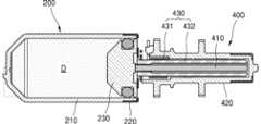
도 6은 레저버 어셈블리(200)에 약액이 저장되기 전의 상태를 도시한 도면이고, 도 7은 레저버 어셈블리(200)에 약액(D)이 저장되고 클러치 유닛(430)이 활성화된 상태를 도시한 도면다.FIG. 6 is a drawing showing a state before the liquid is stored in the reservoir assembly (200), and FIG. 7 is a drawing showing a state in which the liquid (D) is stored in the reservoir assembly (200) and the clutch unit (430) is activated.
도 6 및 도 7을 참조하여, 레저버 어셈블리(200)에 약액(D)이 저장되고, 레저버 어셈블리(200)에 저장된 약액(D)이 배출되는 매커니즘을 설명하면 다음과 같다.Referring to FIGS. 6 and 7, the mechanism by which the drug (D) is stored in the reservoir assembly (200) and the drug (D) stored in the reservoir assembly (200) is discharged is described as follows.
도 6에 도시된 바와 같이, 레저버 어셈블리(200)에 약액이 주입되기 전에는 레저버(210)의 내부공간 전방에 플런저(230)가 배치될 수 있다. 플런저(230)의 후단에 결합된 로드 부재(410)는 연결 부재(432)와 함께 캡 커버(220)에 형성된 개구를 통해 후방으로 연장될 수 있다.As illustrated in FIG. 6, before the liquid is injected into the reservoir assembly (200), a plunger (230) may be placed in the front of the internal space of the reservoir (210). A load member (410) coupled to the rear end of the plunger (230) may extend rearwardly through an opening formed in the cap cover (220) together with a connecting member (432).
로드 부재(410)와 연결 부재(432)는 서로에 대하여 상대적으로 이동 가능하도록 결합될 수 있다. 일 실시예로, 로드 부재(410)와 연결 부재(432)는, 로드 부재(410)의 외주면에 형성된 나사산과 연결 부재(432)의 내주면에 형성된 나사산에 의해 나사 결합을 이룰 수 있다. 로드 부재(410)와 연결 부재(432)는 동시에 이동가능하되, 연결 부재(432)의 회전에 의하여 로드 부재(410)는 연결 부재(432)에 대하여 상대적으로 직선 이동할 수 있다.The load member (410) and the connecting member (432) may be coupled to be relatively movable with respect to each other. In one embodiment, the load member (410) and the connecting member (432) may be screw-coupled by screw threads formed on the outer surface of the load member (410) and screw threads formed on the inner surface of the connecting member (432). The load member (410) and the connecting member (432) may be simultaneously movable, but the load member (410) may be relatively linearly moved with respect to the connecting member (432) by rotation of the connecting member (432).
클러치 유닛(430)의 비활성화 상태에서는, 커플러(431)가 연결 부재(432)를 그립하지 않으므로, 구동 휠(420)은 연결 부재(432)와 결합되지 않고, 연결 부재(432)는 구동 휠(420)의 동작과 무관하게 이동할 수 있다. 이때, 연결 부재(432)와 나사 결합을 이룬 로드 부재(410)는 연결 부재(432)와 함께 이동할 수 있다.In the deactivated state of the clutch unit (430), since the coupler (431) does not grip the connecting member (432), the driving wheel (420) is not coupled with the connecting member (432), and the connecting member (432) can move regardless of the operation of the driving wheel (420). At this time, the load member (410) that forms a screw connection with the connecting member (432) can move together with the connecting member (432).
약액은 별도로 제공되는 약액 주입기에 의해 레저버(210)의 전방에 형성된 유입구(210I)를 통해 레저버(210)로 유입될 수 있다. 이때, 약액은 레저버(210)와 플런저(230) 사이로 유입되며, 플런저(230)를 후방으로 밀어내며 저장공간을 형성하고, 저장공간의 체적을 점차 증가시키며 플런저(230)를 후방으로 이동시킬 수 있다. 플런저(230)에 연결된 로드 부재(410)와 연결 부재(432)는 플런저(230)의 이동과 함께 후방으로 이동할 수 있다.The drug can be introduced into the reservoir (210) through an inlet (210I) formed in the front of the reservoir (210) by a separately provided drug injector. At this time, the drug can be introduced between the reservoir (210) and the plunger (230), push the plunger (230) backward to form a storage space, and gradually increase the volume of the storage space and move the plunger (230) backward. The load member (410) and the connecting member (432) connected to the plunger (230) can be moved backward along with the movement of the plunger (230).
도 7에 도시된 바와 같이, 레저버(210)에 약액(D)의 주입이 완료되면, 레저버(210)의 내부공간 후방에 플런저(230)가 배치될 수 있다.As shown in Fig. 7, when the injection of the drug solution (D) into the reservoir (210) is completed, a plunger (230) can be placed at the rear of the internal space of the reservoir (210).
클러치 유닛(430)은 커플러(431)와 연결 부재(432)를 포함하고, 구동 휠(420)과 로드 부재(410) 사이에 배치되어 이들의 구동적 연결을 가능하게 한다. 일 실시예로, 클러치 유닛(430)의 비활성화 시, 커플러(431)는 연결 부재(432)의 외측에 위치한 상태에서 연결 부재(432)와 소정의 간격으로 이격될 수 있다. 클러치 유닛(430)이 활성화 되면 커플러(431)가 연결 부재(432)의 외측을 가력할 수 있는데, 이때 연결 부재(432)는 구동 휠(420)과 구동적으로 연결되어 구동 휠(420)의 회전과 아울러 회전할 수 있다. 그리고, 연결 부재(432)의 회전에 의하여, 연결 부재(432)와 나사 결합된 로드 부재(410)가 전방으로 이동할 수 있다.The clutch unit (430) includes a coupler (431) and a connecting member (432), and is arranged between the driving wheel (420) and the load member (410) to enable drivable connection thereof. In one embodiment, when the clutch unit (430) is deactivated, the coupler (431) may be spaced apart from the connecting member (432) by a predetermined distance while being located on the outside of the connecting member (432). When the clutch unit (430) is activated, the coupler (431) may apply force to the outside of the connecting member (432), and at this time, the connecting member (432) may be drivably connected to the driving wheel (420) and may rotate along with the rotation of the driving wheel (420). In addition, by the rotation of the connecting member (432), the load member (410) that is screw-connected to the connecting member (432) may move forward.
로드 부재(410)가 전방으로 이동하게 되면, 플런저(230)가 로드 부재(410)와 함께 전방으로 이동하며 저장공간에 저장된 약액(D)을 니들 어셈블리로 배출할 수 있다.When the load member (410) moves forward, the plunger (230) moves forward together with the load member (410) and discharges the liquid (D) stored in the storage space into the needle assembly.
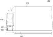
도 8는 도 5의 센싱 유닛(260)이 작동하기 전의 상태를 도시한 도면이고, 도 9은 도 5의 센싱 유닛(260)이 작동한 상태를 도시한 도면이다.FIG. 8 is a drawing showing a state before the sensing unit (260) of FIG. 5 operates, and FIG. 9 is a drawing showing a state after the sensing unit (260) of FIG. 5 operates.
약액이 저장된 약액 주입 장치가 사용자에 부착되면, 구동 모듈에서 발생하는 구동력에 의해 구동 휠(420)이 회전하고, 구동 휠(420)과 구동적으로 연결된 연결 부재(432)가 회전하며, 로드 부재(410)와 플런저(230)는 전방으로 이동할 수 있다. 레저버(210)에 형성된 개구 중에서 배출구를 제외한 나머지 개구는 패킹된 상태로, 플런저(230)가 전방으로 이동함에 따라 레저버(210)의 저장공간에 저장된 약액은 배출구를 통하여 니들 어셈블리로 이동할 수 있다.When a drug injection device storing a drug is attached to a user, the driving wheel (420) rotates by the driving force generated from the driving module, the connecting member (432) drivably connected to the driving wheel (420) rotates, and the load member (410) and the plunger (230) can move forward. Among the openings formed in the reservoir (210), except for the discharge port, the remaining openings are packed, and as the plunger (230) moves forward, the drug stored in the storage space of the reservoir (210) can move to the needle assembly through the discharge port.
도 8를 참조하면, 저장된 약액이 배출구를 통하여 저장공간에서 배출되는 동안 감지구(210S)는 센싱 유닛(260)의 캡 부재(261)에 의해 패킹될 수 있다.Referring to FIG. 8, while the stored medicine is discharged from the storage space through the discharge port, the detection port (210S) can be packed by the cap member (261) of the sensing unit (260).
캡 부재(261)가 감지구(210S)에 삽입된 상태로, 캡 부재(261)와 감지구(210S) 사이에 형성되는 마찰력에 의해 캡 부재(261)는 감지구(210S)에 고정될 수 있다.With the cap member (261) inserted into the detection port (210S), the cap member (261) can be fixed to the detection port (210S) by the frictional force formed between the cap member (261) and the detection port (210S).
그리고, 가력 부재(263)는, 캡 부재(261)가 감지구(210S)에 삽입 고정된 상태에서 이동하지 않도록, 캡 부재(261)의 일측과 접촉하여 캡 부재(261)를 일방으로 가력할 수 있다.In addition, the force member (263) can apply force to the cap member (261) in one direction by contacting one side of the cap member (261) so that the cap member (261) does not move while being inserted and fixed in the detection device (210S).
감지 부재(262)는 캡 부재(261)의 이동에 의해 신호를 생성할 수 있다. 일 실시예로, 감지 부재(262)는 캡 부재(261)와 이격 배치되어, 캡 부재(261)의 변위에 따른 전기적 신호를 생성할 수 있다. 예를 들어, 감지 부재(262)는 캡 부재(261)와 접촉 혹은, 감지 부재(262)와 캡 부재(261) 사이의 정전 용량 변화에 따른 전기적 신호를 생성할 수 있다.The sensing member (262) can generate a signal by the movement of the cap member (261). In one embodiment, the sensing member (262) is spaced apart from the cap member (261) and can generate an electrical signal according to the displacement of the cap member (261). For example, the sensing member (262) can generate an electrical signal according to the contact with the cap member (261) or the change in electrostatic capacitance between the sensing member (262) and the cap member (261).
저장된 약액이 레저버(210)의 저장공간에서 정상적으로 배출되는 경우, 캡 부재(261)는 감지구(210S)에 삽입 고정된 상태로, 캡 부재(261)와 이격된 상태를 유지할 수 있다.When the stored liquid is normally discharged from the storage space of the reservoir (210), the cap member (261) can be maintained in a state of being inserted and fixed in the detection port (210S) and separated from the cap member (261).
장치가 작동하여 약액이 주입되는 중에, 사용자 내부의 이물질에 의하여 니들 어셈블리의 니들이 막힐 수 있다. 이때, 플런저는 구동 모듈에서 생성되는 구동력에 의하여 전방으로 계속 이동하므로, 플런저의 이동에 의해 저장공간의 압력이 점차 증가할 수 있다.While the device is operating and the liquid is being injected, the needle of the needle assembly may be blocked by foreign substances inside the user. At this time, since the plunger continues to move forward by the driving force generated from the driving module, the pressure in the storage space may gradually increase due to the movement of the plunger.
도 9을 참조하면, 저장공간에 형성되는 압력이 점차 증가하다가 기설정된 값에 이르면, 캡 부재(261)는 저장공간에 형성되는 압력에 의하여 이동할 수 있다.Referring to FIG. 9, when the pressure formed in the storage space gradually increases and reaches a preset value, the cap member (261) can move due to the pressure formed in the storage space.
저장공간에 형성되는 압력에 의하여, 캡 부재(261)가 감지구(210S)에서 밀려나면서 전기적 신호를 생성할 수 있다. 일 실시예로, 캡 부재(261)가 감지 부재(262)가 접촉하면서, 전기적 신호가 발생할 수 있다.An electrical signal may be generated when the cap member (261) is pushed out of the detection member (210S) by the pressure formed in the storage space. In one embodiment, an electrical signal may be generated when the cap member (261) comes into contact with the detection member (262).
약액 주입 장치는 해당 신호에 따라 제어될 수 있다. 일 실시예로, 감지 부재(262)와 캡 부재(261)의 접촉 신호가 발생하면, 구동 모듈의 작동을 정지시켜 플런저의 전진을 중단시킬 수 있다. 그리고, 알람 유닛을 작동 시켜, 시각이나 청각 또는 촉각을 통하여 오작동을 사용자에게 알릴 수 있다. 예를 들어, 경고음이나 빛 또는 진동을 발생시킬 수 있다.The drug injection device can be controlled according to the signal. In one embodiment, when a contact signal between the detection member (262) and the cap member (261) occurs, the operation of the driving module can be stopped to stop the forward movement of the plunger. Then, the alarm unit can be operated to notify the user of the malfunction through visual, auditory or tactile means. For example, a warning sound, light or vibration can be generated.
캡 부재(261)가 감지구(210S)에 삽입된 깊이는, 캡 부재(261)가 이동한 거리보다 크게 형성될 수 있다. 저장공간에 형성되는 압력에 의하여 캡 부재(261)가 감지 부재(262)와 접촉할 때까지 밀려나더라도, 캡 부재(261)의 일부는 여전히 감지구(210S)에 삽입되어 감지구(210S)를 통하여 약액이 누설되는 것을 방지할 수 있다.The depth at which the cap member (261) is inserted into the detection port (210S) may be formed to be greater than the distance that the cap member (261) moves. Even if the cap member (261) is pushed out until it comes into contact with the detection member (262) due to the pressure formed in the storage space, a part of the cap member (261) may still be inserted into the detection port (210S), thereby preventing the liquid from leaking through the detection port (210S).
캡 부재(261)와 감지구(210S) 사이에 형성되는 마찰력, 가력 부재(263)가 캡 부재(261)에 가하는 힘, 캡 부재(261)가 감지구(210S)에 삽입된 깊이를 고려하여, 저장공간에 형성되는 압력의 기설정된 값을 결정할 수 있다.Considering the frictional force formed between the cap member (261) and the detection member (210S), the force applied by the applying member (263) to the cap member (261), and the depth at which the cap member (261) is inserted into the detection member (210S), a preset value of the pressure formed in the storage space can be determined.
이와 같이 본 발명은 도면에 도시된 일 실시예를 참고로 하여 설명하였으나 이는 예시적인 것에 불과하며 당해 분야에서 통상의 지식을 가진 자라면 이로부터 다양한 변형 및 실시예의 변형이 가능하다는 점을 이해할 것이다. 따라서, 본 발명의 진정한 기술적 보호 범위는 첨부된 특허청구범위의 기술적 사상에 의하여 정해져야 할 것이다.Although the present invention has been described with reference to one embodiment shown in the drawings, this is merely exemplary, and those skilled in the art will understand that various modifications and variations of embodiments are possible from this. Accordingly, the true technical protection scope of the present invention should be determined by the technical idea of the appended patent claims.
1: 약액 주입 시스템
10: 약액 주입 장치
100: 니들 어셈블리
200: 레저버 어셈블리
300: 구동 모듈
400: 구동 유닛
500: 트리거 부재
600: 니들 커버 조립체
700: 알람 유닛1: Liquid injection system
10: Liquid injection device
100: Needle Assembly
200: Reservoir Assembly
300: Drive module
400: Drive Unit
500: Trigger absent
600: Needle Cover Assembly
700: Alarm Unit
Claims (5)
Translated fromKorean상기 내부공간에 삽입되어 전후방으로 이동하며 저장공간을 형성하는 플런저; 및
상기 감지구에 결합되어 상기 저장공간에 형성되는 기설정된 압력을 감지하는 센싱 유닛;을 포함하고,
상기 센싱 유닛은,
상기 감지구에 삽입되는 캡 부재; 및
상기 캡 부재와 이격 배치되되, 상기 캡 부재의 이동에 의해 상기 캡 부재와 접촉하여 전기적 신호를 생성하는 감지 부재;를 포함하는,
레저버 어셈블리.A reservoir providing an internal space and having an inlet, an outlet, and a detector formed in the front to connect the internal space with the outside;
A plunger inserted into the internal space and moving forward and backward to form a storage space; and
A sensing unit coupled to the above detection device and detecting a preset pressure formed in the storage space;
The above sensing unit,
A cap member inserted into the above detection device; and
A sensing member disposed apart from the cap member and configured to generate an electrical signal by contacting the cap member by movement of the cap member;
Reservoir assembly.
상기 센싱 유닛은 상기 캡 부재를 상기 감지구 측으로 가력하는 가력 부재;를 더 포함하는,
레저버 어셈블리.In the first paragraph,
The sensing unit further includes a force member that forces the cap member toward the detection portion;
Reservoir assembly.
상기 캡 부재는 상기 감지구에 삽입되는 패킹부 및 상기 감지 부재와 접촉하는 접촉부를 가지고,
상기 접촉부는 전도성 러버로 형성되는,
레저버 어셈블리.In the first paragraph,
The above cap member has a packing portion inserted into the above detection hole and a contact portion that comes into contact with the above detection member,
The above contact portion is formed of conductive rubber,
Reservoir assembly.
상기 레저버 어셈블리에서 이동한 상기 약액을 배출하는 니들 어셈블리; 및
상기 레저버 어셈블리와 연결되며, 구동 시에 상기 레저버에서 상기 니들 어셈블리로 상기 약액을 이동시키는 구동력을 생성하는 구동 유닛;을 포함하고,
상기 레저버 어셈블리는,
내부공간을 제공하고, 전방에서 상기 내부공간을 외부와 연통하게 하는 유입구, 배출구 및 감지구가 형성되는 레저버;
상기 내부공간에 삽입되어 전후방으로 이동하며 저장공간을 형성하는 플런저; 및
상기 감지구에 결합되어 상기 저장공간에 형성되는 기설정된 압력을 감지하는 센싱 유닛;을 포함하고,
상기 센싱 유닛은,
상기 감지구에 삽입되는 캡 부재; 및
상기 캡 부재와 이격 배치되되, 상기 캡 부재의 이동에 의해 상기 캡 부재와 접촉하여 전기적 신호를 생성하는 감지 부재;를 포함하는,
약액 주입 장치.A reservoir assembly in which the drug solution is stored;
A needle assembly for discharging the liquid moved from the reservoir assembly; and
A driving unit connected to the reservoir assembly and generating a driving force to move the liquid from the reservoir to the needle assembly when driven;
The above reservoir assembly,
A reservoir providing an internal space and having an inlet, an outlet, and a detector formed in the front to connect the internal space with the outside;
A plunger inserted into the internal space and moving forward and backward to form a storage space; and
A sensing unit coupled to the above detection device and detecting a preset pressure formed in the storage space;
The above sensing unit,
A cap member inserted into the above detection device; and
A sensing member disposed apart from the cap member and configured to generate an electrical signal by contacting the cap member by movement of the cap member;
Liquid injection device.
Priority Applications (1)
| Application Number | Priority Date | Filing Date | Title |
|---|---|---|---|
| PCT/KR2022/019889WO2023132493A1 (en) | 2022-01-04 | 2022-12-08 | Reservoir assembly and liquid medicine injection device comprising same |
Applications Claiming Priority (2)
| Application Number | Priority Date | Filing Date | Title |
|---|---|---|---|
| KR1020220001047 | 2022-01-04 | ||
| KR20220001047 | 2022-01-04 |
Publications (2)
| Publication Number | Publication Date |
|---|---|
| KR20230105614A KR20230105614A (en) | 2023-07-11 |
| KR102750135B1true KR102750135B1 (en) | 2025-01-09 |
Family
ID=87159486
Family Applications (1)
| Application Number | Title | Priority Date | Filing Date |
|---|---|---|---|
| KR1020220021545AActiveKR102750135B1 (en) | 2022-01-04 | 2022-02-18 | Reservoir assembly and apparatus for infusing medical liquid including the same |
Country Status (1)
| Country | Link |
|---|---|
| KR (1) | KR102750135B1 (en) |
Family Cites Families (5)
| Publication number | Priority date | Publication date | Assignee | Title |
|---|---|---|---|---|
| KR101445363B1 (en)* | 2012-08-13 | 2014-09-26 | (주)바이오메디텍 | Pressure adjust type drug injection device |
| KR102073742B1 (en)* | 2013-03-29 | 2020-03-17 | 삼성전자주식회사 | Drug delivery device and operating method thereof |
| KR101833899B1 (en)* | 2016-02-18 | 2018-03-05 | (주)선메딕스 | Blood access apparatus with pressor sensor and drug filter |
| KR102038671B1 (en)* | 2017-06-26 | 2019-10-30 | 주식회사 지티지웰니스 | Air jet handpiece with pressure display |
| KR102351142B1 (en)* | 2019-10-04 | 2022-01-14 | 이오플로우 주식회사 | Apparatus for Infusing medical liquid |
- 2022
- 2022-02-18KRKR1020220021545Apatent/KR102750135B1/enactiveActive
Also Published As
| Publication number | Publication date |
|---|---|
| KR20230105614A (en) | 2023-07-11 |
Similar Documents
| Publication | Publication Date | Title |
|---|---|---|
| KR102648584B1 (en) | Apparatus for Infusing medical liquid | |
| KR20220150269A (en) | Needle assembly and drug injection device comprising the same | |
| KR20230117554A (en) | Apparatus for Infusing medical liquid | |
| KR102750135B1 (en) | Reservoir assembly and apparatus for infusing medical liquid including the same | |
| KR102783976B1 (en) | Apparatus for infusing medical liquid | |
| KR20240127100A (en) | Drug injection device | |
| US20250090745A1 (en) | Drug solution injection device | |
| KR102662719B1 (en) | Reservoir assembly and apparatus for infusing medical liquid comprising the same | |
| KR102564963B1 (en) | Apparatus for Infusing medical liquid | |
| KR102515617B1 (en) | Apparatus for Infusing medical liquid | |
| KR102515615B1 (en) | Apparatus for Infusing medical liquid | |
| KR20240162885A (en) | Apparatus for Infusing medical liquid | |
| KR102697668B1 (en) | Needle assembly and drug injection device comprising the same | |
| US20240299647A1 (en) | Reservoir assembly and drug solution injection device comprising same | |
| KR102791438B1 (en) | Apparatus for Infusing medical liquid | |
| KR102795646B1 (en) | Apparatus for Infusing medical liquid | |
| KR102548189B1 (en) | Apparatus for Infusing medical liquid | |
| KR102515616B1 (en) | Apparatus for Infusing medical liquid | |
| KR102669673B1 (en) | Reservoir assembly and apparatus for infusing medical liquid comprising the same | |
| WO2023132493A1 (en) | Reservoir assembly and liquid medicine injection device comprising same | |
| KR20240058506A (en) | Apparatus for infusing medical liquid | |
| KR20240097296A (en) | Apparatus for infusing medical liquid | |
| KR20230064864A (en) | Apparatus for infusing medical liquid |
Legal Events
| Date | Code | Title | Description |
|---|---|---|---|
| PA0109 | Patent application | St.27 status event code:A-0-1-A10-A12-nap-PA0109 | |
| PA0201 | Request for examination | St.27 status event code:A-1-2-D10-D11-exm-PA0201 | |
| R18-X000 | Changes to party contact information recorded | St.27 status event code:A-3-3-R10-R18-oth-X000 | |
| P11-X000 | Amendment of application requested | St.27 status event code:A-2-2-P10-P11-nap-X000 | |
| P13-X000 | Application amended | St.27 status event code:A-2-2-P10-P13-nap-X000 | |
| R15-X000 | Change to inventor requested | St.27 status event code:A-3-3-R10-R15-oth-X000 | |
| R16-X000 | Change to inventor recorded | St.27 status event code:A-3-3-R10-R16-oth-X000 | |
| PG1501 | Laying open of application | St.27 status event code:A-1-1-Q10-Q12-nap-PG1501 | |
| E902 | Notification of reason for refusal | ||
| PE0902 | Notice of grounds for rejection | St.27 status event code:A-1-2-D10-D21-exm-PE0902 | |
| E13-X000 | Pre-grant limitation requested | St.27 status event code:A-2-3-E10-E13-lim-X000 | |
| P11-X000 | Amendment of application requested | St.27 status event code:A-2-2-P10-P11-nap-X000 | |
| P13-X000 | Application amended | St.27 status event code:A-2-2-P10-P13-nap-X000 | |
| E701 | Decision to grant or registration of patent right | ||
| PE0701 | Decision of registration | St.27 status event code:A-1-2-D10-D22-exm-PE0701 | |
| PR0701 | Registration of establishment | St.27 status event code:A-2-4-F10-F11-exm-PR0701 | |
| PR1002 | Payment of registration fee | St.27 status event code:A-2-2-U10-U11-oth-PR1002 | |
| PG1601 | Publication of registration | St.27 status event code:A-4-4-Q10-Q13-nap-PG1601 | |
| R18-X000 | Changes to party contact information recorded | St.27 status event code:A-5-5-R10-R18-oth-X000 | |
| R18-X000 | Changes to party contact information recorded | St.27 status event code:A-5-5-R10-R18-oth-X000 | |
| P22-X000 | Classification modified | St.27 status event code:A-4-4-P10-P22-nap-X000 |