KR102750053B1 - Electronic device incuding glass plate - Google Patents
Electronic device incuding glass plateDownload PDFInfo
- Publication number
- KR102750053B1 KR102750053B1KR1020190088704AKR20190088704AKR102750053B1KR 102750053 B1KR102750053 B1KR 102750053B1KR 1020190088704 AKR1020190088704 AKR 1020190088704AKR 20190088704 AKR20190088704 AKR 20190088704AKR 102750053 B1KR102750053 B1KR 102750053B1
- Authority
- KR
- South Korea
- Prior art keywords
- light
- glass plate
- electronic device
- pattern
- region
- Prior art date
- Legal status (The legal status is an assumption and is not a legal conclusion. Google has not performed a legal analysis and makes no representation as to the accuracy of the status listed.)
- Active
Links
Images


Classifications
- G—PHYSICS
- G02—OPTICS
- G02B—OPTICAL ELEMENTS, SYSTEMS OR APPARATUS
- G02B6/00—Light guides; Structural details of arrangements comprising light guides and other optical elements, e.g. couplings
- G02B6/0001—Light guides; Structural details of arrangements comprising light guides and other optical elements, e.g. couplings specially adapted for lighting devices or systems
- G02B6/0011—Light guides; Structural details of arrangements comprising light guides and other optical elements, e.g. couplings specially adapted for lighting devices or systems the light guides being planar or of plate-like form
- G02B6/0033—Means for improving the coupling-out of light from the light guide
- G02B6/0058—Means for improving the coupling-out of light from the light guide varying in density, size, shape or depth along the light guide
- G02B6/006—Means for improving the coupling-out of light from the light guide varying in density, size, shape or depth along the light guide to produce indicia, symbols, texts or the like
- G—PHYSICS
- G06—COMPUTING OR CALCULATING; COUNTING
- G06F—ELECTRIC DIGITAL DATA PROCESSING
- G06F1/00—Details not covered by groups G06F3/00 - G06F13/00 and G06F21/00
- G06F1/16—Constructional details or arrangements
- G06F1/1613—Constructional details or arrangements for portable computers
- G06F1/1628—Enclosures for carrying portable computers with peripheral devices, e.g. cases for a laptop and a printer
- G—PHYSICS
- G02—OPTICS
- G02B—OPTICAL ELEMENTS, SYSTEMS OR APPARATUS
- G02B6/00—Light guides; Structural details of arrangements comprising light guides and other optical elements, e.g. couplings
- G02B6/0001—Light guides; Structural details of arrangements comprising light guides and other optical elements, e.g. couplings specially adapted for lighting devices or systems
- G02B6/0011—Light guides; Structural details of arrangements comprising light guides and other optical elements, e.g. couplings specially adapted for lighting devices or systems the light guides being planar or of plate-like form
- G02B6/0033—Means for improving the coupling-out of light from the light guide
- G02B6/0035—Means for improving the coupling-out of light from the light guide provided on the surface of the light guide or in the bulk of it
- G02B6/004—Scattering dots or dot-like elements, e.g. microbeads, scattering particles, nanoparticles
- G02B6/0043—Scattering dots or dot-like elements, e.g. microbeads, scattering particles, nanoparticles provided on the surface of the light guide
- G—PHYSICS
- G02—OPTICS
- G02B—OPTICAL ELEMENTS, SYSTEMS OR APPARATUS
- G02B6/00—Light guides; Structural details of arrangements comprising light guides and other optical elements, e.g. couplings
- G02B6/0001—Light guides; Structural details of arrangements comprising light guides and other optical elements, e.g. couplings specially adapted for lighting devices or systems
- G02B6/0011—Light guides; Structural details of arrangements comprising light guides and other optical elements, e.g. couplings specially adapted for lighting devices or systems the light guides being planar or of plate-like form
- G02B6/0081—Mechanical or electrical aspects of the light guide and light source in the lighting device peculiar to the adaptation to planar light guides, e.g. concerning packaging
- G02B6/0086—Positioning aspects
- G02B6/0088—Positioning aspects of the light guide or other optical sheets in the package
- G—PHYSICS
- G06—COMPUTING OR CALCULATING; COUNTING
- G06F—ELECTRIC DIGITAL DATA PROCESSING
- G06F1/00—Details not covered by groups G06F3/00 - G06F13/00 and G06F21/00
- G06F1/16—Constructional details or arrangements
- G—PHYSICS
- G06—COMPUTING OR CALCULATING; COUNTING
- G06F—ELECTRIC DIGITAL DATA PROCESSING
- G06F1/00—Details not covered by groups G06F3/00 - G06F13/00 and G06F21/00
- G06F1/16—Constructional details or arrangements
- G06F1/1613—Constructional details or arrangements for portable computers
- G06F1/1633—Constructional details or arrangements of portable computers not specific to the type of enclosures covered by groups G06F1/1615 - G06F1/1626
- G06F1/1656—Details related to functional adaptations of the enclosure, e.g. to provide protection against EMI, shock, water, or to host detachable peripherals like a mouse or removable expansions units like PCMCIA cards, or to provide access to internal components for maintenance or to removable storage supports like CDs or DVDs, or to mechanically mount accessories
- F—MECHANICAL ENGINEERING; LIGHTING; HEATING; WEAPONS; BLASTING
- F21—LIGHTING
- F21Y—INDEXING SCHEME ASSOCIATED WITH SUBCLASSES F21K, F21L, F21S and F21V, RELATING TO THE FORM OR THE KIND OF THE LIGHT SOURCES OR OF THE COLOUR OF THE LIGHT EMITTED
- F21Y2115/00—Light-generating elements of semiconductor light sources
- F21Y2115/10—Light-emitting diodes [LED]
- G—PHYSICS
- G06—COMPUTING OR CALCULATING; COUNTING
- G06F—ELECTRIC DIGITAL DATA PROCESSING
- G06F2200/00—Indexing scheme relating to G06F1/04 - G06F1/32
- G06F2200/16—Indexing scheme relating to G06F1/16 - G06F1/18
- G06F2200/163—Indexing scheme relating to constructional details of the computer
- G06F2200/1635—Stackable modules
Landscapes
- Engineering & Computer Science (AREA)
- Physics & Mathematics (AREA)
- General Physics & Mathematics (AREA)
- Theoretical Computer Science (AREA)
- Computer Hardware Design (AREA)
- General Engineering & Computer Science (AREA)
- Human Computer Interaction (AREA)
- Optics & Photonics (AREA)
- Telephone Set Structure (AREA)
- Devices For Indicating Variable Information By Combining Individual Elements (AREA)
Abstract
Translated fromKoreanDescription
Translated fromKorean본 개시의 다양한 실시예들은 지정된 패턴이 형성된 글래스 플레이트 및 이를 포함하는 전자 장치에 관한 것이다.Various embodiments of the present disclosure relate to a glass plate having a designated pattern formed thereon and an electronic device including the same.
정보통신 기술과 반도체 기술 등의 눈부신 발전에 힘입어 각종 전자 장치들의 보급과 이용이 급속도로 증가하고 있다. 특히 최근의 전자 장치들은 휴대하고 다니며 통신할 수 있도록 개발되고 있다.Thanks to the remarkable development of information and communication technology and semiconductor technology, the distribution and use of various electronic devices are rapidly increasing. In particular, recent electronic devices are being developed to be portable and communicate.
전자 장치라 함은, 가전제품으로부터, 전자 수첩, 휴대용 멀티미디어 재생기, 이동통신 단말기, 태블릿 PC, 영상/음향 장치, 데스크톱/랩톱 컴퓨터, 차량용 내비게이션 등, 탑재된 프로그램에 따라 특정 기능을 수행하는 장치를 의미할 수 있다. 예를 들면, 이러한 전자 장치들은 저장된 정보를 음향이나 영상으로 출력할 수 있다. 전자 장치의 집적도가 높아지고, 초고속, 대용량 무선통신이 보편화되면서, 최근에는, 이동통신 단말기와 같은 하나의 전자 장치에 다양한 기능이 탑재될 수 있다. 예를 들면, 통신 기능뿐만 아니라, 게임과 같은 엔터테인먼트 기능, 음악/동영상 재생과 같은 멀티미디어 기능, 모바일 뱅킹 등을 위한 통신 및 보안 기능, 일정 관리나 전자 지갑 등의 기능이 하나의 전자 장치에 집약되고 있는 것이다. 이러한 전자 장치는 사용자가 편리하게 휴대할 수 있도록 소형화되고 있다.An electronic device may refer to a device that performs a specific function according to the program installed on it, such as home appliances, electronic notebooks, portable multimedia players, mobile communication terminals, tablet PCs, audio/video devices, desktop/laptop computers, and car navigation systems. For example, these electronic devices can output stored information as audio or video. As the integration of electronic devices increases and ultra-high-speed, large-capacity wireless communications become widespread, various functions can be installed on a single electronic device, such as a mobile communication terminal, in recent years. For example, in addition to communication functions, entertainment functions such as games, multimedia functions such as music/video playback, communication and security functions for mobile banking, and functions such as schedule management and electronic wallets are being integrated into a single electronic device. These electronic devices are being miniaturized so that users can conveniently carry them.
이러한 다양화에 따라 전자 장치를 커버하는 하우징 및/또는 디스플레이 장치도 다양한 모양 및 기능을 갖추도록 변화하고 있다. 예를 들어, 디스플레이 장치의 디스플레이 패널을 커버하기 위한 전면 커버 또는 전자 장치 후면을 커버하는 후면 커버는, 다양한 색상 및 이미지를 제공하도록 구현하여, 사용자에게 미려감을 제공할 수 있다.In accordance with this diversification, the housing and/or display device covering the electronic device is also changing to have various shapes and functions. For example, the front cover for covering the display panel of the display device or the back cover for covering the back of the electronic device can be implemented to provide various colors and images, thereby providing a sense of beauty to the user.
일반적으로, 전자 장치의 전면 및/또는 후면을 커버하는 플레이트는, 글래스에 패턴 및/또는 색상이 구현된 필름을 합지하여 제조할 수 있다. 상기 제조 방식은 패턴이 외부에 노출되는 방식이 이미 정해져 있어 시인성이 떨어질 수 있다. 또한, 상기 제조 방식은 하나의 색상만을 나타낼 수 있지 때문에 사용자가 플레이트를 보고 느끼는 색상의 심도가 부족할 수 있다.In general, plates covering the front and/or back of electronic devices can be manufactured by laminating films with patterns and/or colors on glass. The above manufacturing method may have poor visibility because the method of exposing the pattern to the outside is already determined. In addition, since the above manufacturing method can only display one color, the depth of color that a user feels when looking at the plate may be insufficient.
본 개시의 다양한 실시예에 따르면, 전자 장치의 전면 및/또는 후면을 커버하는 플레이트가, 색상의 변화가 가능한 구조를 구현하여 신비한 느낌과 깊은 색재현성을 제공할 수 있다.According to various embodiments of the present disclosure, a plate covering the front and/or back of an electronic device can implement a structure capable of changing color to provide a mysterious feeling and deep color reproducibility.
본 개시의 다양한 실시예에 따르면, 전자 장치의 전면 및/또는 후면을 커버하는 플레이트에서, 글래스 자체적으로 패턴을 구현하여 다양한 디자인 효과와 미려감을 제공할 수 있다.According to various embodiments of the present disclosure, in a plate covering the front and/or back of an electronic device, a pattern can be implemented on the glass itself to provide various design effects and aesthetics.
본 개시의 다양한 실시예에 따른 전자 장치는, 제 1 영역 및 상기 제 1 영역으로부터 연장되어 굴곡면을 형성하는 제 2 영역을 포함하는 글래스 플레이트(glass plate)로서, 상기 제 1 영역의 적어도 일부에 적어도 하나의 지정된 제 1 패턴이 형성된 글래스 플레이트, 상기 글래스 플레이트의 상기 제 2 영역에 인접 배치되고, 상기 제 2 영역으로부터 상기 제 1 영역을 따라 광을 제공하는 광원부, 상기 글래스 플레이트와 적층 배치되고, 상기 글래스 플레이트를 향하도록 지정된 제 2 패턴들이 배열된 몰딩 패턴층, 및 상기 몰딩 패턴층과 적층 배치되고, 상기 광원부로부터 제공된 광이 상기 몰딩 패턴층 내부를 따라 이동하도록 광의 경로를 가이드하는 지지 필름층을 포함할 수 있다.An electronic device according to various embodiments of the present disclosure may include a glass plate including a first region and a second region extending from the first region to form a curved surface, wherein at least one designated first pattern is formed on at least a portion of the first region, a light source unit disposed adjacent to the second region of the glass plate and providing light along the first region from the second region, a molding pattern layer laminated with the glass plate and having designated second patterns arranged to face the glass plate, and a support film layer laminated with the molding pattern layer and guiding a path of light provided from the light source unit so that the light travels along the inside of the molding pattern layer.
본 개시의 다양한 실시예에 따른 전자 장치는, 하우징, 상기 하우징 내에 배치된 인쇄 회로 기판, 상기 하우징과 결합되고, 일부 영역에 적어도 하나의 지정된 제 1 패턴이 형성된 글래스 플레이트, 상기 인쇄 회로 기판과 전기적으로 연결되고, 상기 글래스 플레이트를 향해 광을 제공하는 광원부, 및 상기 글래스 플레이트와 적층 배치된 인쇄 필름층을 포함할 수 있다. 상기 인쇄 필름층은, 상기 글래스 플레이트를 향하도록 지정된 제 2 패턴들이 배열된 몰딩 패턴층, 및 상기 몰딩 패턴층과 적층 배치되고, 상기 광원부로부터 제공된 광이 상기 몰딩 패턴층 내부를 따라 이동하도록 광의 경로를 가이드하는 지지 필름층을 포함할 수 있다.An electronic device according to various embodiments of the present disclosure may include a housing, a printed circuit board disposed within the housing, a glass plate coupled to the housing and having at least one designated first pattern formed in a portion of a region thereof, a light source portion electrically connected to the printed circuit board and providing light toward the glass plate, and a printed film layer laminated with the glass plate. The printed film layer may include a molding pattern layer having designated second patterns arranged to face the glass plate, and a support film layer laminated with the molding pattern layer and guiding a path of light provided from the light source portion so that it travels along the interior of the molding pattern layer.
본 개시의 다양한 실시예에 따른 전자 장치는, 제 1 영역 및 상기 제 1 영역으로부터 연장되어 굴곡면을 형성하는 제 2 영역을 포함하는 글래스 플레이트(glass plate)로서, 상기 제 1 영역의 적어도 일부에 적어도 하나의 지정된 제 1 패턴이 형성된 글래스 플레이트, 상기 글래스 플레이트의 상기 제 2 영역에 인접 배치되고, 상기 제 2 영역으로부터 상기 제 1 영역을 따라 광을 제공하는 광원부, 상기 글래스 플레이트와 적층 배치되고, 상기 글래스 플레이트를 향하도록 지정된 제 2 패턴들이 배열된 몰딩 패턴층, 및 상기 몰딩 패턴층과 적층 배치되고, 상기 광원부로부터 제공된 광이 이동하는 경로를 제공하는 지지 필름층을 포함할 수 있다.An electronic device according to various embodiments of the present disclosure may include a glass plate including a first region and a second region extending from the first region to form a curved surface, wherein at least one designated first pattern is formed on at least a portion of the first region, a light source unit disposed adjacent to the second region of the glass plate and providing light along the first region from the second region, a molding pattern layer laminated with the glass plate and having designated second patterns arranged to face the glass plate, and a support film layer laminated with the molding pattern layer and providing a path along which light provided from the light source unit travels.
본 개시의 다양한 실시예에 따른 전자 장치는, 전면 및/또는 후면을 커버하는 플레이트에 사용자가 원하는 색상을 선택적으로 구현하도록 구성하여 신비한 느낌과 깊은 색재현성을 제공할 수 있다.Electronic devices according to various embodiments of the present disclosure can provide a mysterious feeling and deep color reproducibility by configuring a plate covering the front and/or the back to selectively implement a color desired by a user.
본 개시의 다양한 실시예에 따른 전자 장치는, 전면 및/또는 후면을 커버하는 플레이트에서, 글래스 내에 자체적으로 패턴을 구현하여 다양한 디자인 효과와 미려감을 제공할 수 있다.Electronic devices according to various embodiments of the present disclosure can provide various design effects and aesthetics by implementing patterns within glass on a plate covering the front and/or back.
본 개시의 다양한 실시예에 따른 전자 장치는, 전면 및/또는 후면을 커버하는 플레이트가 서로 적층 배치된 서로 다른 패턴을 형성하여, 사용자가 원하는 패턴을 선택적으로 강조할 수 있어, 이전 제품에 비하여 디자인 개선 및 차별화된 제품을 구현할 수 있다.Electronic devices according to various embodiments of the present disclosure can form different patterns in which plates covering the front and/or the back are laminated with each other, so that a user can selectively emphasize a desired pattern, thereby implementing a product with improved design and differentiation compared to previous products.
도 1은, 다양한 실시예들에 따르면, 네트워크 환경 내의 전자 장치의 블럭도이다.
도 2는 본 개시의 다양한 실시예에 따른, 전자 장치의 전면 사시도이다.
도 3은 본 개시의 다양한 실시예에 따른, 전자 장치의 후면 사시도이다.
도 4는 본 개시의 다양한 실시예에 따른, 전자 장치의 분해 사시도이다.
도 5는 본 개시의 다양한 실시예에 따른, 전자 장치의 후면 플레이트의 적층 구조 및 광원부에서 제공된 광의 경로를 제공한 단면도이다.
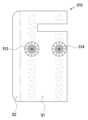
도 6은 본 개시의 다양한 실시예에 따른, 후면 플레이트 상에 배치된 복수 개의 광원들의 배열을 나타낸 정면도이다.
도 7은 본 개시의 다양한 실시예에 따른, 후면 플레이트를 구성하는 제 1 인쇄 필름층의 일부 영역의 패턴 구조를 확대한 확대도이다.
도 8은 본 개시의 다른 실시예에 따른, 전자 장치의 후면 플레이트의 적층 구조 및 광원부에서 제공된 광의 경로를 제공한 단면도이다.
도 9는 본 개시의 또 다른 실시예에 따른, 전자 장치의 후면 플레이트의 적층 구조 및 광원부에서 제공된 광의 경로를 제공한 단면도이다.
도 10은 본 개시의 다양한 실시예에 따른 글래스 플레이트의 적어도 일부 영역에 형성된 패턴을 나타낸 도면이다.
도 11은 본 개시의 다른 실시예에 따른, 전자 장치의 후면 플레이트의 적층 구조 및 광원부에서 제공된 광의 경로를 제공한 단면도이다.
도 12는 본 개시의 다른 실시예에 따른 글래스 플레이트의 적어도 일부 영역에 형성된 패턴을 나타낸 도면이다.
도 13은 본 개시의 다양한 실시예에 따른, 전자 장치의 후면 플레이트의 적층 구조 및 광원부에서 제공된 광의 경로를 제공한 단면도이다.FIG. 1 is a block diagram of an electronic device within a network environment, according to various embodiments.
FIG. 2 is a front perspective view of an electronic device according to various embodiments of the present disclosure.
FIG. 3 is a rear perspective view of an electronic device according to various embodiments of the present disclosure.
FIG. 4 is an exploded perspective view of an electronic device according to various embodiments of the present disclosure.
FIG. 5 is a cross-sectional view providing a laminated structure of a rear plate of an electronic device and a path of light provided from a light source unit according to various embodiments of the present disclosure.
FIG. 6 is a front view illustrating an arrangement of a plurality of light sources arranged on a rear plate according to various embodiments of the present disclosure.
FIG. 7 is an enlarged view of a pattern structure of a portion of a first printed film layer constituting a rear plate according to various embodiments of the present disclosure.
FIG. 8 is a cross-sectional view providing a laminated structure of a rear plate of an electronic device and a path of light provided from a light source unit according to another embodiment of the present disclosure.
FIG. 9 is a cross-sectional view providing a laminated structure of a rear plate of an electronic device and a path of light provided from a light source unit according to another embodiment of the present disclosure.
FIG. 10 is a drawing showing a pattern formed on at least a portion of a glass plate according to various embodiments of the present disclosure.
FIG. 11 is a cross-sectional view providing a laminated structure of a rear plate of an electronic device and a path of light provided from a light source unit according to another embodiment of the present disclosure.
FIG. 12 is a drawing showing a pattern formed on at least a portion of a glass plate according to another embodiment of the present disclosure.
FIG. 13 is a cross-sectional view providing a laminated structure of a rear plate of an electronic device and a path of light provided from a light source unit according to various embodiments of the present disclosure.
도 1의 다양한 실시예들에 따르면, 네트워크 환경(100) 내의 전자 장치(101)의 블럭도이다.According to various embodiments of FIG. 1, this is a block diagram of an electronic device (101) within a network environment (100).
도 1을 참조하면, 네트워크 환경(100)에서 전자 장치(101)는 제 1 네트워크(198)(예: 근거리 무선 통신 네트워크)를 통하여 전자 장치(102)와 통신하거나, 또는 제 2 네트워크(199)(예: 원거리 무선 통신 네트워크)를 통하여 전자 장치(104) 또는 서버(108)와 통신할 수 있다. 일실시예에 따르면, 전자 장치(101)는 서버(108)를 통하여 전자 장치(104)와 통신할 수 있다. 일실시예에 따르면, 전자 장치(101)는 프로세서(120), 메모리(130), 입력 장치(150), 음향 출력 장치(155), 표시 장치(160), 오디오 모듈(170), 센서 모듈(176), 인터페이스(177), 햅틱 모듈(179), 카메라 모듈(180), 전력 관리 모듈(188), 배터리(189), 통신 모듈(190), 가입자 식별 모듈(196), 또는 안테나 모듈(197)을 포함할 수 있다. 어떤 실시예에서는, 전자 장치(101)에는, 이 구성요소들 중 적어도 하나(예: 표시 장치(160) 또는 카메라 모듈(180))가 생략되거나, 하나 이상의 다른 구성 요소가 추가될 수 있다. 어떤 실시예에서는, 이 구성요소들 중 일부들은 하나의 통합된 회로로 구현될 수 있다. 예를 들면, 센서 모듈(176)(예: 지문 센서, 홍채 센서, 또는 조도 센서)은 표시 장치(160)(예: 디스플레이)에 임베디드된 채 구현될 수 있다.Referring to FIG. 1, in a network environment (100), an electronic device (101) may communicate with an electronic device (102) through a first network (198) (e.g., a short-range wireless communication network), or may communicate with an electronic device (104) or a server (108) through a second network (199) (e.g., a long-range wireless communication network). According to one embodiment, the electronic device (101) may communicate with the electronic device (104) through the server (108). According to one embodiment, the electronic device (101) may include a processor (120), a memory (130), an input device (150), an audio output device (155), a display device (160), an audio module (170), a sensor module (176), an interface (177), a haptic module (179), a camera module (180), a power management module (188), a battery (189), a communication module (190), a subscriber identification module (196), or an antenna module (197). In some embodiments, the electronic device (101) may omit at least one of these components (e.g., the display device (160) or the camera module (180)), or may include one or more other components. In some embodiments, some of these components may be implemented as a single integrated circuit. For example, a sensor module (176) (e.g., a fingerprint sensor, an iris sensor, or a light sensor) may be implemented embedded in a display device (160) (e.g., a display).
프로세서(120)는, 예를 들면, 소프트웨어(예: 프로그램(140))를 실행하여 프로세서(120)에 연결된 전자 장치(101)의 적어도 하나의 다른 구성요소(예: 하드웨어 또는 소프트웨어 구성요소)을 제어할 수 있고, 다양한 데이터 처리 또는 연산을 수행할 수 있다. 일실시예에 따르면, 데이터 처리 또는 연산의 적어도 일부로서, 프로세서(120)는 다른 구성요소(예: 센서 모듈(176) 또는 통신 모듈(190))로부터 수신된 명령 또는 데이터를 휘발성 메모리(132)에 로드하고, 휘발성 메모리(132)에 저장된 명령 또는 데이터를 처리하고, 결과 데이터를 비휘발성 메모리(134)에 저장할 수 있다. 일실시예에 따르면, 프로세서(120)는 메인 프로세서(121)(예: 중앙 처리 장치 또는 어플리케이션 프로세서), 및 이와는 독립적으로 또는 함께 운영 가능한 보조 프로세서(123)(예: 그래픽 처리 장치, 이미지 시그널 프로세서, 센서 허브 프로세서, 또는 커뮤니케이션 프로세서)를 포함할 수 있다. 추가적으로 또는 대체적으로, 보조 프로세서(123)은 메인 프로세서(121)보다 저전력을 사용하거나, 또는 지정된 기능에 특화되도록 설정될 수 있다. 보조 프로세서(123)는 메인 프로세서(121)와 별개로, 또는 그 일부로서 구현될 수 있다.The processor (120) may control at least one other component (e.g., a hardware or software component) of the electronic device (101) connected to the processor (120) by executing, for example, software (e.g., a program (140)), and may perform various data processing or calculations. According to one embodiment, as at least a part of the data processing or calculations, the processor (120) may load a command or data received from another component (e.g., a sensor module (176) or a communication module (190)) into the volatile memory (132), process the command or data stored in the volatile memory (132), and store the resulting data in the nonvolatile memory (134). According to one embodiment, the processor (120) may include a main processor (121) (e.g., a central processing unit or an application processor), and a secondary processor (123) (e.g., a graphic processing unit, an image signal processor, a sensor hub processor, or a communication processor) that may operate independently or together therewith. Additionally or alternatively, the auxiliary processor (123) may be configured to use less power than the main processor (121), or to be specialized for a given function. The auxiliary processor (123) may be implemented separately from the main processor (121), or as a part thereof.
보조 프로세서(123)는, 예를 들면, 메인 프로세서(121)가 인액티브(예: 슬립) 상태에 있는 동안 메인 프로세서(121)를 대신하여, 또는 메인 프로세서(121)가 액티브(예: 어플리케이션 실행) 상태에 있는 동안 메인 프로세서(121)와 함께, 전자 장치(101)의 구성요소들 중 적어도 하나의 구성요소(예: 표시 장치(160), 센서 모듈(176), 또는 통신 모듈(190))와 관련된 기능 또는 상태들의 적어도 일부를 제어할 수 있다. 일실시예에 따르면, 보조 프로세서(123)(예: 이미지 시그널 프로세서 또는 커뮤니케이션 프로세서)는 기능적으로 관련 있는 다른 구성 요소(예: 카메라 모듈(180) 또는 통신 모듈(190))의 일부로서 구현될 수 있다.The auxiliary processor (123) may control at least a portion of functions or states associated with at least one of the components of the electronic device (101) (e.g., the display device (160), the sensor module (176), or the communication module (190)), for example, on behalf of the main processor (121) while the main processor (121) is in an inactive (e.g., sleep) state, or together with the main processor (121) while the main processor (121) is in an active (e.g., application execution) state. In one embodiment, the auxiliary processor (123) (e.g., an image signal processor or a communication processor) may be implemented as a part of another functionally related component (e.g., a camera module (180) or a communication module (190)).
메모리(130)는, 전자 장치(101)의 적어도 하나의 구성요소(예: 프로세서(120) 또는 센서 모듈(176))에 의해 사용되는 다양한 데이터를 저장할 수 있다. 데이터는, 예를 들어, 소프트웨어(예: 프로그램(140)) 및, 이와 관련된 명령에 대한 입력 데이터 또는 출력 데이터를 포함할 수 있다. 메모리(130)는, 휘발성 메모리(132) 또는 비휘발성 메모리(134)를 포함할 수 있다.The memory (130) can store various data used by at least one component (e.g., processor (120) or sensor module (176)) of the electronic device (101). The data can include, for example, software (e.g., program (140)) and input data or output data for commands related thereto. The memory (130) can include volatile memory (132) or nonvolatile memory (134).
프로그램(140)은 메모리(130)에 소프트웨어로서 저장될 수 있으며, 예를 들면, 운영 체제(142), 미들 웨어(144) 또는 어플리케이션(146)을 포함할 수 있다.The program (140) may be stored as software in memory (130) and may include, for example, an operating system (142), middleware (144), or an application (146).
입력 장치(150)는, 전자 장치(101)의 구성요소(예: 프로세서(120))에 사용될 명령 또는 데이터를 전자 장치(101)의 외부(예: 사용자)로부터 수신할 수 있다. 입력 장치(150)은, 예를 들면, 마이크, 마우스, 키보드 또는 디지털 펜(예: 스타일러스 펜)을 포함할 수 있다.The input device (150) can receive commands or data to be used in a component of the electronic device (101) (e.g., a processor (120)) from an external source (e.g., a user) of the electronic device (101). The input device (150) can include, for example, a microphone, a mouse, a keyboard, or a digital pen (e.g., a stylus pen).
음향 출력 장치(155)는 음향 신호를 전자 장치(101)의 외부로 출력할 수 있다. 음향 출력 장치(155)는, 예를 들면, 스피커 또는 리시버를 포함할 수 있다. 스피커는 멀티미디어 재생 또는 녹음 재생과 같이 일반적인 용도로 사용될 수 있고, 리시버는 착신 전화를 수신하기 위해 사용될 수 있다. 일실시예에 따르면, 리시버는 스피커와 별개로, 또는 그 일부로서 구현될 수 있다.The audio output device (155) can output an audio signal to the outside of the electronic device (101). The audio output device (155) can include, for example, a speaker or a receiver. The speaker can be used for general purposes such as multimedia playback or recording playback, and the receiver can be used to receive an incoming call. According to one embodiment, the receiver can be implemented separately from the speaker or as a part thereof.
표시 장치(160)는 전자 장치(101)의 외부(예: 사용자)로 정보를 시각적으로 제공할 수 있다. 표시 장치(160)은, 예를 들면, 디스플레이, 홀로그램 장치, 또는 프로젝터 및 해당 장치를 제어하기 위한 제어 회로를 포함할 수 있다. 일실시예에 따르면, 표시 장치(160)는 터치를 감지하도록 설정된 터치 회로(touch circuitry), 또는 상기 터치에 의해 발생되는 힘의 세기를 측정하도록 설정된 센서 회로(예: 압력 센서)를 포함할 수 있다.The display device (160) can visually provide information to an external party (e.g., a user) of the electronic device (101). The display device (160) can include, for example, a display, a holographic device, or a projector and a control circuit for controlling the device. According to one embodiment, the display device (160) can include touch circuitry configured to detect a touch, or a sensor circuitry configured to measure a strength of a force generated by the touch (e.g., a pressure sensor).
오디오 모듈(170)은 소리를 전기 신호로 변환시키거나, 반대로 전기 신호를 소리로 변환시킬 수 있다. 일실시예에 따르면, 오디오 모듈(170)은, 입력 장치(150)를 통해 소리를 획득하거나, 음향 출력 장치(155), 또는 전자 장치(101)와 직접 또는 무선으로 연결된 외부 전자 장치(예: 전자 장치(102)) (예: 스피커 또는 헤드폰))를 통해 소리를 출력할 수 있다.The audio module (170) can convert sound into an electrical signal, or vice versa, convert an electrical signal into sound. According to one embodiment, the audio module (170) can obtain sound through an input device (150), or output sound through an audio output device (155), or an external electronic device (e.g., an electronic device (102)) (e.g., a speaker or a headphone) directly or wirelessly connected to the electronic device (101).
센서 모듈(176)은 전자 장치(101)의 작동 상태(예: 전력 또는 온도), 또는 외부의 환경 상태(예: 사용자 상태)를 감지하고, 감지된 상태에 대응하는 전기 신호 또는 데이터 값을 생성할 수 있다. 일실시예에 따르면, 센서 모듈(176)은, 예를 들면, 제스처 센서, 자이로 센서, 기압 센서, 마그네틱 센서, 가속도 센서, 그립 센서, 근접 센서, 컬러 센서, IR(infrared) 센서, 생체 센서, 온도 센서, 습도 센서, 또는 조도 센서를 포함할 수 있다.The sensor module (176) can detect an operating state (e.g., power or temperature) of the electronic device (101) or an external environmental state (e.g., user state) and generate an electric signal or data value corresponding to the detected state. According to one embodiment, the sensor module (176) can include, for example, a gesture sensor, a gyro sensor, a barometric pressure sensor, a magnetic sensor, an acceleration sensor, a grip sensor, a proximity sensor, a color sensor, an IR (infrared) sensor, a biometric sensor, a temperature sensor, a humidity sensor, or an illuminance sensor.
인터페이스(177)는 전자 장치(101)이 외부 전자 장치(예: 전자 장치(102))와 직접 또는 무선으로 연결되기 위해 사용될 수 있는 하나 이상의 지정된 프로토콜들을 지원할 수 있다. 일실시예에 따르면, 인터페이스(177)는, 예를 들면, HDMI(high definition multimedia interface), USB(universal serial bus) 인터페이스, SD카드 인터페이스, 또는 오디오 인터페이스를 포함할 수 있다.The interface (177) may support one or more designated protocols that may be used to directly or wirelessly connect the electronic device (101) to an external electronic device (e.g., the electronic device (102)). In one embodiment, the interface (177) may include, for example, a high definition multimedia interface (HDMI), a universal serial bus (USB) interface, an SD card interface, or an audio interface.
연결 단자(178)는, 그를 통해서 전자 장치(101)가 외부 전자 장치(예: 전자 장치(102))와 물리적으로 연결될 수 있는 커넥터를 포함할 수 있다. 일실시예에 따르면, 연결 단자(178)은, 예를 들면, HDMI 커넥터, USB 커넥터, SD 카드 커넥터, 또는 오디오 커넥터(예: 헤드폰 커넥터)를 포함할 수 있다.The connection terminal (178) may include a connector through which the electronic device (101) may be physically connected to an external electronic device (e.g., the electronic device (102)). According to one embodiment, the connection terminal (178) may include, for example, an HDMI connector, a USB connector, an SD card connector, or an audio connector (e.g., a headphone connector).
햅틱 모듈(179)은 전기적 신호를 사용자가 촉각 또는 운동 감각을 통해서 인지할 수 있는 기계적인 자극(예: 진동 또는 움직임) 또는 전기적인 자극으로 변환할 수 있다. 일실시예에 따르면, 햅틱 모듈(179)은, 예를 들면, 모터, 압전 소자, 또는 전기 자극 장치를 포함할 수 있다.The haptic module (179) can convert an electrical signal into a mechanical stimulus (e.g., vibration or movement) or an electrical stimulus that a user can perceive through a tactile or kinesthetic sense. According to one embodiment, the haptic module (179) can include, for example, a motor, a piezoelectric element, or an electrical stimulation device.
카메라 모듈(180)은 정지 영상 및 동영상을 촬영할 수 있다. 일실시예에 따르면, 카메라 모듈(180)은 하나 이상의 렌즈들, 이미지 센서들, 이미지 시그널 프로세서들, 또는 플래시들을 포함할 수 있다.The camera module (180) can capture still images and moving images. According to one embodiment, the camera module (180) can include one or more lenses, image sensors, image signal processors, or flashes.
전력 관리 모듈(188)은 전자 장치(101)에 공급되는 전력을 관리할 수 있다. 일실시예에 따르면, 전력 관리 모듈(388)은, 예를 들면, PMIC(power management integrated circuit)의 적어도 일부로서 구현될 수 있다.The power management module (188) can manage power supplied to the electronic device (101). According to one embodiment, the power management module (388) can be implemented as, for example, at least a part of a power management integrated circuit (PMIC).
배터리(189)는 전자 장치(101)의 적어도 하나의 구성 요소에 전력을 공급할 수 있다. 일실시예에 따르면, 배터리(189)는, 예를 들면, 재충전 불가능한 1차 전지, 재충전 가능한 2차 전지 또는 연료 전지를 포함할 수 있다.A battery (189) may power at least one component of the electronic device (101). In one embodiment, the battery (189) may include, for example, a non-rechargeable primary battery, a rechargeable secondary battery, or a fuel cell.
통신 모듈(190)은 전자 장치(101)와 외부 전자 장치(예: 전자 장치(102), 전자 장치(104), 또는 서버(108))간의 직접(예: 유선) 통신 채널 또는 무선 통신 채널의 수립, 및 수립된 통신 채널을 통한 통신 수행을 지원할 수 있다. 통신 모듈(190)은 프로세서(120)(예: 어플리케이션 프로세서)와 독립적으로 운영되고, 직접(예: 유선) 통신 또는 무선 통신을 지원하는 하나 이상의 커뮤니케이션 프로세서를 포함할 수 있다. 일실시예에 따르면, 통신 모듈(190)은 무선 통신 모듈(192)(예: 셀룰러 통신 모듈, 근거리 무선 통신 모듈, 또는 GNSS(global navigation satellite system) 통신 모듈) 또는 유선 통신 모듈(194)(예: LAN(local area network) 통신 모듈, 또는 전력선 통신 모듈)을 포함할 수 있다. 이들 통신 모듈 중 해당하는 통신 모듈은 제 1 네트워크(198)(예: 블루투스, WiFi direct 또는 IrDA(infrared data association) 같은 근거리 통신 네트워크) 또는 제 2 네트워크(199)(예: 셀룰러 네트워크, 인터넷, 또는 컴퓨터 네트워크(예: LAN 또는 WAN)와 같은 원거리 통신 네트워크)를 통하여 외부 전자 장치와 통신할 수 있다. 이런 여러 종류의 통신 모듈들은 하나의 구성 요소(예: 단일 칩)으로 통합되거나, 또는 서로 별도의 복수의 구성 요소들(예: 복수 칩들)로 구현될 수 있다. 무선 통신 모듈(192)은 가입자 식별 모듈(196)에 저장된 가입자 정보(예: 국제 모바일 가입자 식별자(IMSI))를 이용하여 제 1 네트워크(198) 또는 제 2 네트워크(199)와 같은 통신 네트워크 내에서 전자 장치(101)를 확인 및 인증할 수 있다.The communication module (190) may support establishment of a direct (e.g., wired) communication channel or a wireless communication channel between the electronic device (101) and an external electronic device (e.g., the electronic device (102), the electronic device (104), or the server (108)), and performance of communication through the established communication channel. The communication module (190) may operate independently from the processor (120) (e.g., the application processor) and may include one or more communication processors that support direct (e.g., wired) communication or wireless communication. According to one embodiment, the communication module (190) may include a wireless communication module (192) (e.g., a cellular communication module, a short-range wireless communication module, or a GNSS (global navigation satellite system) communication module) or a wired communication module (194) (e.g., a local area network (LAN) communication module, or a power line communication module). A corresponding communication module among these communication modules can communicate with an external electronic device via a first network (198) (e.g., a short-range communication network such as Bluetooth, WiFi direct, or infrared data association (IrDA)) or a second network (199) (e.g., a long-range communication network such as a cellular network, the Internet, or a computer network (e.g., a LAN or WAN)). These various types of communication modules can be integrated into a single component (e.g., a single chip) or implemented as multiple separate components (e.g., multiple chips). The wireless communication module (192) can identify and authenticate the electronic device (101) within a communication network such as the first network (198) or the second network (199) by using subscriber information (e.g., an international mobile subscriber identity (IMSI)) stored in the subscriber identification module (196).
안테나 모듈(197)은 신호 또는 전력을 외부(예: 외부 전자 장치)로 송신하거나 외부로부터 수신할 수 있다. 일실시예에 따르면, 안테나 모듈은 서브스트레이트(예: PCB) 위에 형성된 도전체 또는 도전성 패턴으로 이루어진 방사체를 포함하는 하나의 안테나를 포함할 수 있다. 일실시예에 따르면, 안테나 모듈(197)은 복수의 안테나들을 포함할 수 있다. 이런 경우, 제 1 네트워크(198) 또는 제 2 네트워크(199)와 같은 통신 네트워크에서 사용되는 통신 방식에 적합한 적어도 하나의 안테나가, 예를 들면, 통신 모듈(190)에 의하여 상기 복수의 안테나들로부터 선택될 수 있다. 신호 또는 전력은 상기 선택된 적어도 하나의 안테나를 통하여 통신 모듈(190)과 외부 전자 장치 간에 송신되거나 수신될 수 있다. 어떤 실시예에 따르면, 방사체 이외에 다른 부품(예: RFIC)이 추가로 안테나 모듈(197)의 일부로 형성될 수 있다.The antenna module (197) can transmit or receive signals or power to or from an external device (e.g., an external electronic device). According to one embodiment, the antenna module can include one antenna including a radiator formed of a conductor or a conductive pattern formed on a substrate (e.g., a PCB). According to one embodiment, the antenna module (197) can include a plurality of antennas. In this case, at least one antenna suitable for a communication method used in a communication network, such as the first network (198) or the second network (199), can be selected from the plurality of antennas by, for example, the communication module (190). A signal or power can be transmitted or received between the communication module (190) and the external electronic device through the selected at least one antenna. According to some embodiments, in addition to the radiator, another component (e.g., an RFIC) can be additionally formed as a part of the antenna module (197).
상기 구성요소들 중 적어도 일부는 주변 기기들간 통신 방식(예: 버스, GPIO(general purpose input and output), SPI(serial peripheral interface), 또는 MIPI(mobile industry processor interface))를 통해 서로 연결되고 신호(예: 명령 또는 데이터)를 상호간에 교환할 수 있다.At least some of the above components may be connected to each other and exchange signals (e.g., commands or data) with each other via a communication method between peripheral devices (e.g., a bus, a general purpose input and output (GPIO), a serial peripheral interface (SPI), or a mobile industry processor interface (MIPI)).
일실시예에 따르면, 명령 또는 데이터는 제 2 네트워크(199)에 연결된 서버(108)를 통해서 전자 장치(101)와 외부의 전자 장치(104)간에 송신 또는 수신될 수 있다. 전자 장치(102, 104) 각각은 전자 장치(101)와 동일한 또는 다른 종류의 장치일 수 있다. 일실시예에 따르면, 전자 장치(101)에서 실행되는 동작들의 전부 또는 일부는 외부 전자 장치들(102, 104, or 108) 중 하나 이상의 외부 장치들에서 실행될 수 있다. 예를 들면, 전자 장치(101)가 어떤 기능이나 서비스를 자동으로, 또는 사용자 또는 다른 장치로부터의 요청에 반응하여 수행해야 할 경우에, 전자 장치(101)는 기능 또는 서비스를 자체적으로 실행시키는 대신에 또는 추가적으로, 하나 이상의 외부 전자 장치들에게 그 기능 또는 그 서비스의 적어도 일부를 수행하라고 요청할 수 있다. 상기 요청을 수신한 하나 이상의 외부 전자 장치들은 요청된 기능 또는 서비스의 적어도 일부, 또는 상기 요청과 관련된 추가 기능 또는 서비스를 실행하고, 그 실행의 결과를 전자 장치(101)로 전달할 수 있다. 전자 장치(101)는 상기 결과를, 그대로 또는 추가적으로 처리하여, 상기 요청에 대한 응답의 적어도 일부로서 제공할 수 있다. 이를 위하여, 예를 들면, 클라우드 컴퓨팅, 분산 컴퓨팅, 또는 클라이언트-서버 컴퓨팅 기술이 이용될 수 있다.In one embodiment, a command or data may be transmitted or received between the electronic device (101) and an external electronic device (104) via a server (108) connected to a second network (199). Each of the electronic devices (102, 104) may be the same or a different type of device as the electronic device (101). In one embodiment, all or part of the operations executed in the electronic device (101) may be executed in one or more of the external electronic devices (102, 104, or 108). For example, when the electronic device (101) is to perform a certain function or service automatically or in response to a request from a user or another device, the electronic device (101) may, instead of executing the function or service itself or in addition, request one or more external electronic devices to perform at least a part of the function or service. One or more external electronic devices that have received the request may execute at least a part of the requested function or service, or an additional function or service related to the request, and transmit the result of the execution to the electronic device (101). The electronic device (101) may process the result as is or additionally and provide it as at least a part of a response to the request. For this purpose, for example, cloud computing, distributed computing, or client-server computing technology may be used.
본 문서에 개시된 다양한 실시예들에 따른 전자 장치는 다양한 형태의 장치가 될 수 있다. 전자 장치는, 예를 들면, 휴대용 통신 장치 (예: 스마트폰), 컴퓨터 장치, 휴대용 멀티미디어 장치, 휴대용 의료 기기, 카메라, 웨어러블 장치, 또는 가전 장치를 포함할 수 있다. 본 문서의 실시예에 따른 전자 장치는 전술한 기기들에 한정되지 않는다.Electronic devices according to various embodiments disclosed in this document may be devices of various forms. The electronic devices may include, for example, portable communication devices (e.g., smartphones), computer devices, portable multimedia devices, portable medical devices, cameras, wearable devices, or home appliance devices. Electronic devices according to embodiments of this document are not limited to the above-described devices.
본 문서의 다양한 실시예들 및 이에 사용된 용어들은 본 문서에 기재된 기술적 특징들을 특정한 실시예들로 한정하려는 것이 아니며, 해당 실시예의 다양한 변경, 균등물, 또는 대체물을 포함하는 것으로 이해되어야 한다. 도면의 설명과 관련하여, 유사한 또는 관련된 구성요소에 대해서는 유사한 참조 부호가 사용될 수 있다. 아이템에 대응하는 명사의 단수 형은 관련된 문맥상 명백하게 다르게 지시하지 않는 한, 상기 아이템 한 개 또는 복수 개를 포함할 수 있다. 본 문서에서, "A 또는 B", "A 및 B 중 적어도 하나", "A 또는 B 중 적어도 하나,""A, B 또는 C," "A, B 및 C 중 적어도 하나,"및 "A, B, 또는 C 중 적어도 하나"와 같은 문구들 각각은 그 문구들 중 해당하는 문구에 함께 나열된 항목들 중 어느 하나, 또는 그들의 모든 가능한 조합을 포함할 수 있다. "제 1", "제 2", 또는 "첫째" 또는 "둘째"와 같은 용어들은 단순히 해당 구성요소를 다른 해당 구성요소와 구분하기 위해 사용될 수 있으며, 해당 구성요소들을 다른 측면(예: 중요성 또는 순서)에서 한정하지 않는다. 어떤(예: 제 1) 구성요소가 다른(예: 제 2) 구성요소에, "기능적으로" 또는 "통신적으로"라는 용어와 함께 또는 이런 용어 없이, "커플드" 또는 "커넥티드"라고 언급된 경우, 그것은 상기 어떤 구성요소가 상기 다른 구성요소에 직접적으로(예: 유선으로), 무선으로, 또는 제 3 구성요소를 통하여 연결될 수 있다는 것을 의미한다.The various embodiments of this document and the terminology used herein are not intended to limit the technical features described in this document to specific embodiments, but should be understood to encompass various modifications, equivalents, or substitutes of the embodiments. In connection with the description of the drawings, similar reference numerals may be used for similar or related components. The singular form of a noun corresponding to an item may include one or more of the items, unless the context clearly indicates otherwise. In this document, each of the phrases "A or B," "at least one of A and B," "at least one of A or B," "A, B, or C," "at least one of A, B, and C," and "at least one of A, B, or C" can include any one of the items listed together in the corresponding phrase, or all possible combinations thereof. Terms such as "first," "second," or "first" or "second" may be used merely to distinguish the corresponding component from other corresponding components, and do not limit the corresponding components in any other respect (e.g., importance or order). When a component (e.g., a first component) is referred to as being “coupled” or “connected” to another component (e.g., a second component), with or without the terms “functionally” or “communicatively,” it means that the component can be connected to the other component directly (e.g., wired), wirelessly, or through a third component.
본 문서에서 사용된 용어 "모듈"은 하드웨어, 소프트웨어 또는 펌웨어로 구현된 유닛을 포함할 수 있으며, 예를 들면, 로직, 논리 블록, 부품, 또는 회로 같은 용어와 상호 호환적으로 사용될 수 있다. 모듈은, 일체로 구성된 부품 또는 하나 또는 그 이상의 기능을 수행하는, 상기 부품의 최소 단위 또는 그 일부가 될 수 있다. 예를 들면, 일실시예에 따르면, 모듈은 ASIC(application-specific integrated circuit)의 형태로 구현될 수 있다.The term "module" as used in this document may include a unit implemented in hardware, software or firmware, and may be used interchangeably with terms such as logic, logic block, component, or circuit. A module may be an integrally configured component or a minimum unit of the component or a portion thereof that performs one or more functions. For example, according to one embodiment, a module may be implemented in the form of an application-specific integrated circuit (ASIC).
본 문서의 다양한 실시예들은 기기(machine)(예: 전자 장치(101)) 의해 읽을 수 있는 저장 매체(storage medium)(예: 내장 메모리(136) 또는 외장 메모리(138))에 저장된 하나 이상의 명령어들을 포함하는 소프트웨어(예: 프로그램(140))로서 구현될 수 있다. 예를 들면, 기기(예: 전자 장치(101))의 프로세서(예: 프로세서(120))는, 저장 매체로부터 저장된 하나 이상의 명령어들 중 적어도 하나의 명령을 호출하고, 그것을 실행할 수 있다. 이것은 기기가 상기 호출된 적어도 하나의 명령어에 따라 적어도 하나의 기능을 수행하도록 운영되는 것을 가능하게 한다. 상기 하나 이상의 명령어들은 컴파일러에 의해 생성된 코드 또는 인터프리터에 의해 실행될 수 있는 코드를 포함할 수 있다. 기기로 읽을 수 있는 저장매체 는, 비일시적(non-transitory) 저장매체의 형태로 제공될 수 있다. 여기서, '비일시적'은 저장매체가 실재(tangible)하는 장치이고, 신호(signal)(예: 전자기파)를 포함하지 않는다는 것을 의미할 뿐이며, 이 용어는 데이터가 저장매체에 반영구적으로 저장되는 경우와 임시적으로 저장되는 경우를 구분하지 않는다.Various embodiments of the present document may be implemented as software (e.g., a program (140)) including one or more instructions stored in a storage medium (e.g., an internal memory (136) or an external memory (138)) readable by a machine (e.g., an electronic device (101)). For example, a processor (e.g., a processor (120)) of the machine (e.g., the electronic device (101)) may call at least one instruction among the one or more instructions stored from the storage medium and execute it. This enables the machine to operate to perform at least one function according to the called at least one instruction. The one or more instructions may include code generated by a compiler or code executable by an interpreter. The machine-readable storage medium may be provided in the form of a non-transitory storage medium. Here, 'non-transitory' simply means that the storage medium is a tangible device and does not contain signals (e.g. electromagnetic waves), and the term does not distinguish between cases where data is stored semi-permanently or temporarily on the storage medium.
일실시예에 따르면, 본 문서에 개시된 다양한 실시예들에 따른 방법은 컴퓨터 프로그램 제품(computer program product)에 포함되어 제공될 수 있다. 컴퓨터 프로그램 제품은 상품으로서 판매자 및 구매자 간에 거래될 수 있다. 컴퓨터 프로그램 제품은 기기로 읽을 수 있는 저장 매체(예: compact disc read only memory (CD-ROM))의 형태로 배포되거나, 또는 어플리케이션 스토어(예: 플레이 스토어TM)를 통해 또는 두개의 사용자 장치들(예: 스마트폰들) 간에 직접, 온라인으로 배포(예: 다운로드 또는 업로드)될 수 있다. 온라인 배포의 경우에, 컴퓨터 프로그램 제품의 적어도 일부는 제조사의 서버, 어플리케이션 스토어의 서버, 또는 중계 서버의 메모리와 같은 기기로 읽을 수 있는 저장 매체에 적어도 일시 저장되거나, 임시적으로 생성될 수 있다.According to one embodiment, the method according to various embodiments disclosed in the present document may be provided as included in a computer program product. The computer program product may be traded between a seller and a buyer as a commodity. The computer program product may be distributed in the form of a machine-readable storage medium (e.g., a compact disc read only memory (CD-ROM)), or may be distributed online (e.g., downloaded or uploaded) via an application store (e.g., Play StoreTM ) or directly between two user devices (e.g., smartphones). In the case of online distribution, at least a part of the computer program product may be at least temporarily stored or temporarily generated in a machine-readable storage medium, such as a memory of a manufacturer's server, a server of an application store, or an intermediary server.
다양한 실시예들에 따르면, 상기 기술한 구성요소들의 각각의 구성요소(예: 모듈 또는 프로그램)는 단수 또는 복수의 개체를 포함할 수 있다. 다양한 실시예들에 따르면, 전술한 해당 구성요소들 중 하나 이상의 구성요소들 또는 동작들이 생략되거나, 또는 하나 이상의 다른 구성요소들 또는 동작들이 추가될 수 있다. 대체적으로 또는 추가적으로, 복수의 구성요소들(예: 모듈 또는 프로그램)은 하나의 구성요소로 통합될 수 있다. 이런 경우, 통합된 구성요소는 상기 복수의 구성요소들 각각의 구성요소의 하나 이상의 기능들을 상기 통합 이전에 상기 복수의 구성요소들 중 해당 구성요소에 의해 수행되는 것과 동일 또는 유사하게 수행할 수 있다. 다양한 실시예들에 따르면, 모듈, 프로그램 또는 다른 구성요소에 의해 수행되는 동작들은 순차적으로, 병렬적으로, 반복적으로, 또는 휴리스틱하게 실행되거나, 상기 동작들 중 하나 이상이 다른 순서로 실행되거나, 생략되거나, 또는 하나 이상의 다른 동작들이 추가될 수 있다.According to various embodiments, each component (e.g., a module or a program) of the above-described components may include a single or multiple entities. According to various embodiments, one or more of the components or operations of the above-described components may be omitted, or one or more other components or operations may be added. Alternatively or additionally, a plurality of components (e.g., a module or a program) may be integrated into a single component. In such a case, the integrated component may perform one or more functions of each of the components of the plurality of components identically or similarly to those performed by the corresponding component of the plurality of components prior to the integration. According to various embodiments, the operations performed by the module, program or other component may be executed sequentially, in parallel, repeatedly, or heuristically, or one or more of the operations may be executed in a different order, omitted, or one or more other operations may be added.
도 2는 본 개시의 다양한 실시예에 따른, 전자 장치(101)의 전면 사시도이다. 도 3은 본 개시의 다양한 실시예에 따른, 전자 장치(101)의 후면 사시도이다.FIG. 2 is a front perspective view of an electronic device (101) according to various embodiments of the present disclosure. FIG. 3 is a rear perspective view of an electronic device (101) according to various embodiments of the present disclosure.
도 2 및 3을 참조하면, 일 실시예에 따른 전자 장치(101)는, 제 1 면(또는 전면)(310A), 제 2 면(또는 후면)(310B), 및 제 1 면(310A) 및 제 2 면(310B) 사이의 공간을 둘러싸는 측면(310C)을 포함하는 하우징(310)을 포함할 수 있다. 다른 실시예(미도시)에서는, 하우징은, 도 2의 제 1 면(310A), 제 2 면(310B) 및 측면(310C)들 중 일부를 형성하는 구조를 지칭할 수도 있다. 일 실시예에 따르면, 제 1 면(310A)은 적어도 일부분이 실질적으로 투명한 전면 플레이트(302)(예: 글라스 플레이트, 또는 폴리머 플레이트)에 의하여 형성될 수 있다. 제 2 면(310B)은 실질적으로 불투명한 후면 플레이트(311)에 의하여 형성될 수 있다. 상기 후면 플레이트(311)는, 예를 들어, 코팅 또는 착색된 유리, 세라믹, 폴리머, 금속(예: 알루미늄, 스테인레스 스틸(STS), 또는 마그네슘), 또는 상기 물질들 중 적어도 둘의 조합에 의하여 형성될 수 있다. 상기 측면(310C)은, 전면 플레이트(302) 및 후면 플레이트(311)와 결합하며, 금속 및/또는 폴리머를 포함하는 측면 베젤 구조 (또는 "측면 부재")(318)에 의하여 형성될 수 있다. 어떤 실시예에서는, 후면 플레이트(311) 및 측면 베젤 구조(318)는 일체로 형성되고 동일한 물질(예: 알루미늄과 같은 금속 물질)을 포함할 수 있다.Referring to FIGS. 2 and 3, an electronic device (101) according to one embodiment may include a housing (310) including a first side (or front side) (310A), a second side (or back side) (310B), and a side surface (310C) surrounding a space between the first side (310A) and the second side (310B). In another embodiment (not shown), the housing may refer to a structure forming a portion of the first side (310A), the second side (310B), and the side surface (310C) of FIG. 2. According to one embodiment, the first side (310A) may be formed by a front plate (302) (e.g., a glass plate or a polymer plate) that is at least partially transparent. The second side (310B) may be formed by a substantially opaque back plate (311). The back plate (311) may be formed of, for example, a coated or colored glass, ceramic, polymer, metal (e.g., aluminum, stainless steel (STS), or magnesium), or a combination of at least two of the above materials. The side (310C) may be formed by a side bezel structure (or “side member”) (318) that is coupled with the front plate (302) and the back plate (311) and comprises a metal and/or polymer. In some embodiments, the back plate (311) and the side bezel structure (318) may be formed integrally and comprise the same material (e.g., a metal material such as aluminum).
도시된 실시예에서는, 상기 전면 플레이트(302)는, 상기 제 1 면(310A)으로부터 상기 후면 플레이트(311) 쪽으로 휘어져 심리스하게(seamless) 연장된 2개의 제 1 영역(310D)들을, 상기 전면 플레이트(302)의 긴 엣지(long edge) 양단에 포함할 수 있다. 도시된 실시예(도 3 참조)에서, 상기 후면 플레이트(311)는, 상기 제 2 면(310B)으로부터 상기 전면 플레이트(302) 쪽으로 휘어져 심리스하게 연장된 2개의 제 2 영역(310E)들을 긴 엣지 양단에 포함할 수 있다. 어떤 실시예에서는, 상기 전면 플레이트(302)(또는 상기 후면 플레이트(311))가 상기 제 1 영역(310D)들(또는 상기 제 2 영역(310E)들) 중 하나 만을 포함할 수 있다. 다른 실시예에서는, 상기 제 1 영역(310D)들 또는 제 2 영역(310E)들 중 일부가 포함되지 않을 수 있다. 상기 실시예들에서, 상기 전자 장치(101)의 측면에서 볼 때, 측면 베젤 구조(318)는, 상기와 같은 제 1 영역(310D)들 또는 제 2 영역(310E)들이 포함되지 않는 측면 쪽에서는 제 1 두께(또는 폭)을 가지고, 상기 제 1 영역(310D)들 또는 제 2 영역(310E)들을 포함한 측면 쪽에서는 상기 제 1 두께보다 얇은 제 2 두께를 가질 수 있다.In the illustrated embodiment, the front plate (302) may include two first regions (310D) extending seamlessly from the first surface (310A) toward the rear plate (311), at both ends of a long edge of the front plate (302). In the illustrated embodiment (see FIG. 3), the rear plate (311) may include two second regions (310E) extending seamlessly from the second surface (310B) toward the front plate (302), at both ends of a long edge. In some embodiments, the front plate (302) (or the rear plate (311)) may include only one of the first regions (310D) (or the second regions (310E)). In other embodiments, some of the first regions (310D) or the second regions (310E) may not be included. In the embodiments, when viewed from the side of the electronic device (101), the side bezel structure (318) may have a first thickness (or width) on the side that does not include the first regions (310D) or the second regions (310E), and may have a second thickness that is thinner than the first thickness on the side that includes the first regions (310D) or the second regions (310E).
일 실시예에 따르면, 전자 장치(101)는, 디스플레이(301), 오디오 모듈(303, 307, 314), 센서 모듈(304, 316, 319), 카메라 모듈(305, 312, 313), 키 입력 장치(317), 발광 소자(306), 및 커넥터 홀(308, 309) 중 적어도 하나 이상을 포함할 수 있다. 어떤 실시예에서는, 전자 장치(101)는, 구성요소들 중 적어도 하나(예: 키 입력 장치(317), 또는 발광 소자(306))를 생략하거나 다른 구성요소를 추가적으로 포함할 수 있다.According to one embodiment, the electronic device (101) may include at least one of a display (301), an audio module (303, 307, 314), a sensor module (304, 316, 319), a camera module (305, 312, 313), a key input device (317), a light emitting element (306), and a connector hole (308, 309). In some embodiments, the electronic device (101) may omit at least one of the components (e.g., the key input device (317) or the light emitting element (306)) or may additionally include other components.
일 실시예에 따르면, 디스플레이(301)는, 예를 들어, 전면 플레이트(302)의 상당 부분을 통하여 시각적으로 노출될 수 있다. 어떤 실시예에서는, 상기 제 1 면(310A), 및 상기 측면(310C)의 제 1 영역(310D)들을 형성하는 전면 플레이트(302)를 통하여 상기 디스플레이(301)의 적어도 일부가 노출될 수 있다. 어떤 실시예에서는, 디스플레이(301)의 모서리를 상기 전면 플레이트(302)의 인접한 외곽 형상과 대체로 동일하게 형성할 수 있다. 다른 실시예(미도시)에서는, 디스플레이(301)가 노출되는 면적을 확장하기 위하여, 디스플레이(301)의 외곽과 전면 플레이트(302)의 외곽간의 간격이 대체로 동일하게 형성될 수 있다.In one embodiment, the display (301) may be visually exposed through, for example, a significant portion of the front plate (302). In some embodiments, at least a portion of the display (301) may be exposed through the front plate (302) forming the first surface (310A) and the first regions (310D) of the side surfaces (310C). In some embodiments, the edges of the display (301) may be formed to be substantially the same as the adjacent outer shape of the front plate (302). In other embodiments (not shown), the gap between the outer edge of the display (301) and the outer edge of the front plate (302) may be formed to be substantially the same in order to expand the area over which the display (301) is exposed.
다른 실시예(미도시)에서는, 디스플레이(301)의 화면 표시 영역의 일부에 리세스 또는 개구부(opening)을 형성하고, 상기 리세스 또는 상기 개구부(opening)와 정렬되는 오디오 모듈(314), 센서 모듈(304), 카메라 모듈(305), 및 발광 소자(306) 중 적어도 하나 이상을 포함할 수 있다. 다른 실시예(미도시)에서는, 디스플레이(301)의 화면 표시 영역의 배면에, 오디오 모듈(314), 센서 모듈(304), 카메라 모듈(305), 지문 센서(316), 및 발광 소자(306) 중 적어도 하나 이상을 포함할 수 있다. 다른 실시예(미도시)에서는, 디스플레이(301)는, 터치 감지 회로, 터치의 세기(압력)를 측정할 수 있는 압력 센서, 및/또는 자기장 방식의 스타일러스 펜을 검출하는 디지타이저와 결합되거나 인접하여 배치될 수 있다. 어떤 실시예에서는, 상기 센서 모듈(304, 519)의 적어도 일부, 및/또는 키 입력 장치(317)의 적어도 일부가, 상기 제 1 영역(310D)들, 및/또는 상기 제 2 영역(310E)들에 배치될 수 있다.In another embodiment (not shown), a recess or opening may be formed in a part of a screen display area of the display (301), and at least one of an audio module (314), a sensor module (304), a camera module (305), and a light-emitting element (306) may be included that is aligned with the recess or opening. In another embodiment (not shown), at least one of an audio module (314), a sensor module (304), a camera module (305), a fingerprint sensor (316), and a light-emitting element (306) may be included on a back surface of the screen display area of the display (301). In another embodiment (not shown), the display (301) may be coupled with or disposed adjacent to a touch detection circuit, a pressure sensor capable of measuring the intensity (pressure) of a touch, and/or a digitizer that detects a magnetic field-type stylus pen. In some embodiments, at least a portion of the sensor modules (304, 519), and/or at least a portion of the key input device (317), may be positioned in the first areas (310D), and/or the second areas (310E).
일 실시예에 따르면, 오디오 모듈(303, 307, 314)은, 예를 들어, 마이크 홀(303) 및 스피커 홀(307, 314)을 포함할 수 있다. 마이크 홀(303)은 외부의 소리를 획득하기 위한 마이크가 내부에 배치될 수 있고, 어떤 실시예에서는 소리의 방향을 감지할 수 있도록 복수개의 마이크가 배치될 수 있다. 스피커 홀(307, 314)은, 외부 스피커 홀(307) 및 통화용 리시버 홀(314)을 포함할 수 있다. 어떤 실시예에서는 스피커 홀(307, 314)과 마이크 홀(303)이 하나의 홀로 구현 되거나, 스피커 홀(307, 314) 없이 스피커가 포함될 수 있다(예: 피에조 스피커). 상기 오디오 모듈(303, 307, 314)은 상기 구조에 한정된 것은 아니며, 전자 장치(101)의 구조에 따라 일부 오디오 모듈만 장착되거나 새로운 오디오 모듈이 부가되는 등 다양하게 설계 변경할 수 있다.According to one embodiment, the audio module (303, 307, 314) may include, for example, a microphone hole (303) and a speaker hole (307, 314). The microphone hole (303) may have a microphone disposed inside for acquiring external sound, and in some embodiments, multiple microphones may be disposed to detect the direction of the sound. The speaker hole (307, 314) may include an external speaker hole (307) and a receiver hole (314) for calls. In some embodiments, the speaker hole (307, 314) and the microphone hole (303) may be implemented as a single hole, or a speaker may be included without the speaker hole (307, 314) (e.g., a piezo speaker). The above audio modules (303, 307, 314) are not limited to the above structure, and may be designed in various ways, such as by mounting only some audio modules or adding new audio modules, depending on the structure of the electronic device (101).
일 실시예에 따르면, 센서 모듈(304, 316, 319)은, 예를 들어, 전자 장치(101)의 내부의 작동 상태, 또는 외부의 환경 상태에 대응하는 전기 신호 또는 데이터 값을 생성할 수 있다. 센서 모듈(304, 316, 319)은, 예를 들어, 하우징(310)의 제 1 면(310A)에 배치된 제 1 센서 모듈(304)(예: 근접 센서) 및/또는 제 2 센서 모듈(미도시)(예: 지문 센서), 및/또는 상기 하우징(310)의 제 2 면(310B)에 배치된 제 3 센서 모듈(319)(예: HRM 센서) 및/또는 제 4 센서 모듈(316) (예: 지문 센서)을 포함할 수 있다. 상기 지문 센서는 하우징(310)의 제 1면(310A)(예: 디스플레이(301)뿐만 아니라 제 2면(310B)에 배치될 수 있다. 전자 장치(101)는, 도시되지 않은 센서 모듈, 예를 들어, 제스처 센서, 자이로 센서, 기압 센서, 마그네틱 센서, 가속도 센서, 그립 센서, 컬러 센서, IR(infrared) 센서, 생체 센서, 온도 센서, 습도 센서, 또는 조도 센서(304) 중 적어도 하나를 더 포함할 수 있다. 상기 센서 모듈(304, 316, 319)은 상기 구조에 한정된 것은 아니며, 전자 장치(101)의 구조에 따라 일부 센서 모듈만 장착되거나 새로운 센서 모듈이 부가되는 등 다양하게 설계 변경할 수 있다.According to one embodiment, the sensor modules (304, 316, 319) may generate electrical signals or data values corresponding to, for example, an internal operating state of the electronic device (101) or an external environmental state. The sensor modules (304, 316, 319) may include, for example, a first sensor module (304) (e.g., a proximity sensor) and/or a second sensor module (not shown) (e.g., a fingerprint sensor) disposed on a first surface (310A) of the housing (310), and/or a third sensor module (319) (e.g., an HRM sensor) and/or a fourth sensor module (316) (e.g., a fingerprint sensor) disposed on a second surface (310B) of the housing (310). The fingerprint sensor may be disposed on the first surface (310A) of the housing (310) (e.g., not only the display (301) but also the second surface (310B). The electronic device (101) may further include at least one of a sensor module not shown, for example, a gesture sensor, a gyro sensor, a pressure sensor, a magnetic sensor, an acceleration sensor, a grip sensor, a color sensor, an infrared sensor, a biometric sensor, a temperature sensor, a humidity sensor, or an illuminance sensor (304). The sensor modules (304, 316, 319) are not limited to the above structure, and may be designed in various ways, such as by mounting only some sensor modules or adding new sensor modules, depending on the structure of the electronic device (101).
일 실시예에 따르면, 카메라 모듈(305, 312, 313)은, 예를 들어, 전자 장치(101)의 제 1 면(310A)에 배치된 제 1 카메라 장치(305), 및 제 2 면(310B)에 배치된 제 2 카메라 장치(312), 및/또는 플래시(313)를 포함할 수 있다. 상기 카메라 모듈(305, 312)은, 하나 또는 복수의 렌즈들, 이미지 센서, 및/또는 이미지 시그널 프로세서를 포함할 수 있다. 플래시(313)는, 예를 들어, 발광 다이오드 또는 제논 램프(xenon lamp)를 포함할 수 있다. 어떤 실시예에서는, 2개 이상의 렌즈들 (적외선 카메라, 광각 및 망원 렌즈) 및 이미지 센서들이 전자 장치(101)의 한 면에 배치될 수 있다. 상기 카메라 모듈(305, 312, 313)은 상기 구조에 한정된 것은 아니며, 전자 장치(101)의 구조에 따라 일부 카메라 모듈만 장착되거나 새로운 카메라 모듈이 부가되는 등 다양하게 설계 변경할 수 있다.In one embodiment, the camera module (305, 312, 313) may include, for example, a first camera device (305) disposed on a first side (310A) of the electronic device (101), a second camera device (312) disposed on a second side (310B), and/or a flash (313). The camera module (305, 312) may include one or more lenses, an image sensor, and/or an image signal processor. The flash (313) may include, for example, a light emitting diode or a xenon lamp. In some embodiments, two or more lenses (infrared camera, wide-angle and telephoto lenses) and image sensors may be disposed on one side of the electronic device (101). The above camera modules (305, 312, 313) are not limited to the above structure, and may be designed in various ways, such as by mounting only some camera modules or adding new camera modules, depending on the structure of the electronic device (101).
일 실시예에 따르면, 키 입력 장치(317)는, 예를 들어, 하우징(310)의 측면(310C)에 배치될 수 있다. 다른 실시예에서는, 전자 장치(101)는 상기 언급된 키 입력 장치(317) 중 일부 또는 전부를 포함하지 않을 수 있고 포함되지 않은 키 입력 장치(317)는 디스플레이(301) 상에 소프트 키 등 다른 형태로 구현될 수 있다. 어떤 실시예에서, 키 입력 장치는 하우징(310)의 제 2면(310B)에 배치된 센서 모듈(316)을 포함할 수 있다.In one embodiment, the key input device (317) may be disposed, for example, on a side surface (310C) of the housing (310). In another embodiment, the electronic device (101) may not include some or all of the above-mentioned key input devices (317), and the key input devices (317) that are not included may be implemented in other forms, such as soft keys, on the display (301). In some embodiments, the key input device may include a sensor module (316) disposed on a second surface (310B) of the housing (310).
일 실시예에 따르면, 발광 소자(306)는, 예를 들어, 하우징(310)의 제 1 면(310A)에 배치될 수 있다. 발광 소자(306)는, 예를 들어, 전자 장치(101)의 상태 정보를 광 형태로 제공할 수 있다. 다른 실시예에서는, 발광 소자(306)는, 예를 들어, 카메라 모듈(305)의 동작과 연동되는 광원을 제공할 수 있다. 발광 소자(306)는, 예를 들어, LED, IR LED 및 제논 램프를 포함할 수 있다.In one embodiment, the light emitting element (306) may be disposed, for example, on the first surface (310A) of the housing (310). The light emitting element (306) may provide, for example, status information of the electronic device (101) in the form of light. In another embodiment, the light emitting element (306) may provide a light source that is linked to the operation of, for example, the camera module (305). The light emitting element (306) may include, for example, an LED, an IR LED, and a xenon lamp.
일 실시예에 따르면, 커넥터 홀(308, 309)은, 예를 들어, 외부 전자 장치와 전력 및/또는 데이터를 송수신하기 위한 커넥터(예를 들어, USB 커넥터)를 수용할 수 있는 제 1 커넥터 홀(308), 및/또는 외부 전자 장치와 오디오 신호를 송수신하기 위한 커넥터를 수용할 수 있는 제 2 커넥터 홀(예를 들어, 이어폰 잭)(309)을 포함할 수 있다. 상기 커넥터 홀(308, 309)은 상기 구조에 한정된 것은 아니며, 전자 장치(101)의 구조에 따라 일부 커넥터 홀만 장착되거나 새로운 커넥터 홀이 부가되는 등 다양하게 설계 변경할 수 있다.According to one embodiment, the connector holes (308, 309) may include, for example, a first connector hole (308) that can accommodate a connector (e.g., a USB connector) for transmitting and receiving power and/or data with an external electronic device, and/or a second connector hole (e.g., an earphone jack) (309) that can accommodate a connector for transmitting and receiving audio signals with an external electronic device. The connector holes (308, 309) are not limited to the above structure, and may be designed in various ways, such as by mounting only some of the connector holes or adding new connector holes, depending on the structure of the electronic device (101).
도 4는 본 개시의 다양한 실시예에 따른, 전자 장치(101)의 분해 사시도이다.FIG. 4 is an exploded perspective view of an electronic device (101) according to various embodiments of the present disclosure.
도 4를 참조하면, 다양한 실시예에 따른 전자 장치(101)(예: 도 1 내지 도 3의 전자 장치(101))는, 측면 베젤 구조(331), 제 1 지지부재(332)(예: 브라켓), 전면 플레이트(320), 디스플레이(330), 인쇄 회로 기판(340), 배터리(350), 제 2 지지부재(360)(예: 리어 케이스), 안테나(370), 및 후면 플레이트(380)를 포함할 수 있다. 어떤 실시예에서는, 전자 장치(101)는, 구성요소들 중 적어도 하나(예: 제 1 지지부재(332), 또는 제 2 지지부재(360))를 생략하거나 다른 구성요소를 추가적으로 포함할 수 있다. 전자 장치(101)의 구성요소들 중 적어도 하나는, 도 2, 또는 도 3의 전자 장치(101)의 구성요소들 중 적어도 하나와 동일, 또는 유사할 수 있으며, 중복되는 설명은 이하 생략한다.Referring to FIG. 4, an electronic device (101) according to various embodiments (e.g., the electronic device (101) of FIGS. 1 to 3) may include a side bezel structure (331), a first support member (332) (e.g., a bracket), a front plate (320), a display (330), a printed circuit board (340), a battery (350), a second support member (360) (e.g., a rear case), an antenna (370), and a rear plate (380). In some embodiments, the electronic device (101) may omit at least one of the components (e.g., the first support member (332) or the second support member (360)) or may additionally include other components. At least one of the components of the electronic device (101) may be identical to or similar to at least one of the components of the electronic device (101) of FIG. 2 or FIG. 3, and any redundant description will be omitted below.
다양한 실시예에 따르면, 제 1 지지부재(332)는, 전자 장치(101) 내부에 배치되어 측면 베젤 구조(331)와 연결될 수 있거나, 측면 베젤 구조(331)와 일체로 형성될 수 있다. 제 1 지지부재(332)는, 예를 들어, 금속 재질 및/또는 비금속 (예: 폴리머) 재질로 형성될 수 있다. 제 1 지지부재(332)는, 일면에 디스플레이(330)가 결합되고 타면에 인쇄 회로 기판(340)이 결합될 수 있다. 인쇄 회로 기판(340)에는, 프로세서, 메모리, 및/또는 인터페이스가 장착될 수 있다. 프로세서는, 예를 들어, 중앙처리장치, 어플리케이션 프로세서, 그래픽 처리 장치, 이미지 시그널 프로세서, 센서 허브 프로세서, 또는 커뮤니케이션 프로세서 중 하나 또는 그 이상을 포함할 수 있다.According to various embodiments, the first support member (332) may be disposed inside the electronic device (101) and connected to the side bezel structure (331), or may be formed integrally with the side bezel structure (331). The first support member (332) may be formed of, for example, a metal material and/or a non-metallic (e.g., polymer) material. The first support member (332) may have a display (330) coupled to one surface and a printed circuit board (340) coupled to the other surface. The printed circuit board (340) may be equipped with a processor, a memory, and/or an interface. The processor may include, for example, one or more of a central processing unit, an application processor, a graphic processing unit, an image signal processor, a sensor hub processor, or a communication processor.
다양한 실시예에 따르면, 메모리는, 예를 들어, 휘발성 메모리 또는 비휘발성 메모리를 포함할 수 있다.According to various embodiments, the memory may include, for example, volatile memory or non-volatile memory.
다양한 실시예에 따르면, 인터페이스는, 예를 들어, HDMI(high definition multimedia interface), USB(universal serial bus) 인터페이스, SD카드 인터페이스, 및/또는 오디오 인터페이스를 포함할 수 있다. 인터페이스는, 예를 들어, 전자 장치(101)를 외부 전자 장치와 전기적 또는 물리적으로 연결시킬 수 있으며, USB 커넥터, SD 카드/MMC 커넥터, 또는 오디오 커넥터를 포함할 수 있다.According to various embodiments, the interface may include, for example, a high definition multimedia interface (HDMI), a universal serial bus (USB) interface, an SD card interface, and/or an audio interface. The interface may electrically or physically connect the electronic device (101) to an external electronic device and may include, for example, a USB connector, an SD card/MMC connector, or an audio connector.
다양한 실시예에 따르면, 배터리(350)는 전자 장치(101)의 적어도 하나의 구성 요소에 전력을 공급하기 위한 장치로서, 예를 들면, 재충전 불가능한 1차 전지, 또는 재충전 가능한 2차 전지, 또는 연료 전지를 포함할 수 있다. 배터리(350)의 적어도 일부는, 예를 들어, 인쇄 회로 기판(340)과 실질적으로 동일 평면 상에 배치될 수 있다. 배터리(350)는 전자 장치(101) 내부에 일체로 배치될 수 있고, 전자 장치(101)와 탈부착 가능하게 배치될 수도 있다.According to various embodiments, the battery (350) is a device for supplying power to at least one component of the electronic device (101), and may include, for example, a non-rechargeable primary battery, a rechargeable secondary battery, or a fuel cell. At least a portion of the battery (350) may be disposed substantially on the same plane as, for example, the printed circuit board (340). The battery (350) may be disposed integrally within the electronic device (101), or may be disposed detachably from the electronic device (101).
다양한 실시예에 따르면, 안테나(370)는, 후면 플레이트(380)와 배터리(350) 사이에 배치될 수 있다. 안테나(370)는, 예를 들어, NFC(near field communication) 안테나, 무선 충전 안테나, 및/또는 MST(magnetic secure transmission) 안테나를 포함할 수 있다. 안테나(370)는, 예를 들어, 외부 장치와 근거리 통신을 하거나, 충전에 필요한 전력을 무선으로 송수신 할 수 있다. 다른 실시예에서는, 측면 베젤 구조(331) 및/또는 상기 제 1 지지부재(332)의 일부 또는 그 조합에 의하여 안테나 구조가 형성될 수 있다.According to various embodiments, the antenna (370) may be positioned between the back plate (380) and the battery (350). The antenna (370) may include, for example, a near field communication (NFC) antenna, a wireless charging antenna, and/or a magnetic secure transmission (MST) antenna. The antenna (370) may, for example, perform short-range communication with an external device or wirelessly transmit and receive power required for charging. In other embodiments, the antenna structure may be formed by a portion or a combination of the side bezel structure (331) and/or the first support member (332).
도 5는 본 개시의 다양한 실시예에 따른, 전자 장치의 후면 플레이트의 적층 구조 및 광원부에서 제공된 광의 경로를 제공한 단면도이다.FIG. 5 is a cross-sectional view providing a laminated structure of a rear plate of an electronic device and a path of light provided from a light source unit according to various embodiments of the present disclosure.
도 6은 본 개시의 다양한 실시예에 따른, 후면 플레이트 상에 배치된 복수 개의 광원들의 배열을 나타낸 정면도이다.FIG. 6 is a front view illustrating an arrangement of a plurality of light sources arranged on a rear plate according to various embodiments of the present disclosure.
도 7은 본 개시의 다양한 실시예에 따른, 후면 플레이트를 구성하는 제 1 인쇄 필름층의 일부 영역의 패턴 구조를 확대한 확대도이다.FIG. 7 is an enlarged view of a pattern structure of a portion of a first printed film layer constituting a rear plate according to various embodiments of the present disclosure.
다양한 실시예에 따르면, 전자 장치(예: 도 1 내지 4의 전자 장치(101))는 하우징(310), 디스플레이(330), 인쇄 회로 기판(340), 글래스 플레이트(510), 인쇄 필름층(600), 및 광원부(540)를 포함할 수 있다. 일 실시예에 따르면, 도 5의 상기 하우징(310), 디스플레이(330), 및 인쇄 회로 기판(340)의 구성은, 도 4의 제 1 지지부재(332), 디스플레이(330), 및 인쇄 회로 기판(340)의 구성과 일부 또는 전부가 동일할 수 있다.According to various embodiments, an electronic device (e.g., an electronic device (101) of FIGS. 1 to 4) may include a housing (310), a display (330), a printed circuit board (340), a glass plate (510), a printed film layer (600), and a light source unit (540). According to one embodiment, the configuration of the housing (310), the display (330), and the printed circuit board (340) of FIG. 5 may be partially or entirely identical to the configuration of the first support member (332), the display (330), and the printed circuit board (340) of FIG. 4.
도 5에서, 'Z'는 상기 전자 장치(101)의 두께 방향을 의미할 수 있다. 또한, 본 발명의 일 실시예에서, '+Z'는 전자 장치 내부의 전면 플레이트(320)가 향하는 전면 방향을 의미하고, '-Z'는 전자 장치의 후면 플레이트(380)가 향하는 후면 방향을 의미할 수 있다.In FIG. 5, 'Z' may mean the thickness direction of the electronic device (101). In addition, in one embodiment of the present invention, '+Z' may mean the front direction toward which the front plate (320) inside the electronic device faces, and '-Z' may mean the rear direction toward which the rear plate (380) of the electronic device faces.
다양한 실시예에 따르면, 상기 전면 플레이트(320)의 일면을 향하도록 디스플레이(330)가 배치될 수 있다. 상기 디스플레이(330)는 전자 장치 내측 방향으로, 복수 개의 레이어들(331-335)이 적층 배치될 수 있다. 예를 들어, 상기 전면 글래스 플레이트(511)의 일면을 기준으로, 유브이층(331), 디스플레이 패널(332), 차광층(333), 지지층(334) 및 금속층(335)의 순서로 적층 배치될 수 있다. 다만, 이에 한정된 적층 순서 이외에, 완충, 차폐, 및/또는 방열에 따라 효율적인 적층 순서로 설계 변경할 수 있다.According to various embodiments, a display (330) may be arranged to face one side of the front plate (320). The display (330) may have a plurality of layers (331-335) laminated and arranged in a direction inward of the electronic device. For example, based on one side of the front glass plate (511), a UV layer (331), a display panel (332), a light-shielding layer (333), a support layer (334), and a metal layer (335) may be laminated and arranged in that order. However, in addition to the laminated order limited thereto, the design may be changed to an efficient laminated order depending on buffering, shielding, and/or heat dissipation.
일 실시예에 따르면, 상기 디스플레이(330)의 유브이층(331)은 제 1 방향(+Z)을 향하는 제 1 글래스 플레이트(511)(예: 전면 글래스 플레이트)의 일면에 접착 배치될 수 있으며, 상기 제 1 글래스 플레이트(511)의 제 2 영역(S2)와 대면할 수 있도록 곡면 형상으로 제조될 수 있다. 일 실시예에 따르면, 차광층(333)은 디스플레이 패널(332) 후면을 차폐하는 층으로 제공될 수 있으며, 예를 들어, 쿠션 부재, 엠보 부재 또는 구리 시트(CU sheet)일 수 있으며, 흑색의 칼라를 포함할 수 있다. 또 다른 예로, 상기 지지층(334)은 디스플레이(330)를 지지하고, 상기 금속층(335)은 기판에서 발생하는 열을 차단하거나, 디스플레이 패널(332)로 전달되지 않도록 차단하는 방열 기능을 제공할 수 있다. 예를 들어, 상기 금속층(335)은 그라파이트(graphite) 소재를 포함할 수 있다.According to one embodiment, the UV layer (331) of the display (330) may be adhered and arranged on one surface of the first glass plate (511) (e.g., the front glass plate) facing the first direction (+Z), and may be manufactured in a curved shape so as to face the second region (S2) of the first glass plate (511). According to one embodiment, the light-shielding layer (333) may be provided as a layer that shields the rear surface of the display panel (332), and may be, for example, a cushion member, an embossed member, or a copper sheet (CU sheet), and may include a black color. As another example, the support layer (334) may support the display (330), and the metal layer (335) may provide a heat dissipation function that blocks heat generated from the substrate or prevents it from being transferred to the display panel (332). For example, the metal layer (335) may include a graphite material.
다양한 실시예에 따르면, 상기 전자 장치(101)의 글래스 플레이트(510)는 전자 장치(101)의 전면 및 측면의 적어도 일부를 커버하는 제 1 글래스 플레이트(511) 및 전자 장치(101)의 후면 및 측면의 적어도 일부를 커버하는 제 2 글래스 플레이트(512)를 포함할 수 있다. 상기 글래스 플레이트(510)는 적어도 일부분이 투명한 글래스 재질로 이루어질 수 있다. 상기 글래스 플레이트(510)는 적어도 일부분이 곡면(예: 2.5D, 또는 3D)을 포함할 수 있다. 예를 들어, 상기 글래스 플레이트(510)는 편평한 제 1 영역(S1)(예: 평면부) 및 상기 제 1 영역(S1)으로부터 연장된 곡면을 형성하는 제 2 영역(S2)(예: 곡면부)을 포함할 수 있다. 상기 제 1 영역(S1)은 글래스 플레이트(510)의 중심 영역일 수 있으며, 상기 제 2 영역(S2)은 글래스 플레이트(510)의 단부 영역의 일부일 수 있다. 상기 제 2 영역(S2)은 전면 방향(+Z)으로 심리스하게 휘어진 곡면 구조로, 상기 글래스 플레이트(510)의 길이 방향의 엣지(long edge) 영역에 배치될 수 있다.According to various embodiments, the glass plate (510) of the electronic device (101) may include a first glass plate (511) covering at least a portion of the front and side surfaces of the electronic device (101) and a second glass plate (512) covering at least a portion of the back and side surfaces of the electronic device (101). At least a portion of the glass plate (510) may be made of a transparent glass material. At least a portion of the glass plate (510) may include a curved surface (e.g., 2.5D or 3D). For example, the glass plate (510) may include a flat first region (S1) (e.g., a flat portion) and a second region (S2) (e.g., a curved portion) forming a curved surface extending from the first region (S1). The first region (S1) may be a central region of the glass plate (510), and the second region (S2) may be a part of an end region of the glass plate (510). The second region (S2) may be a curved structure that is seamlessly curved in the front direction (+Z) and may be arranged in an edge region in the length direction of the glass plate (510).
일 실시예에 따른, 도 6을 참조하면, 제 2 글래스 플레이트(512)의 상기 제 2 영역(S2)은 상기 제 1 영역(S1)을 중심으로 제 2 글래스 플레이트(512)의 가장자리 영역에 형성될 수 있다. 예를 들어, 상기 제 2 영역(S2)은 제 2-1 영역(S2a) 및 제 2-2 영역(S2b)을 포함하며, 상기 제 2-1 영역(S2a) 및 제 2-2 영역(S2b)은 상기 글래스 플레이트(510)의 길이 방향(X)을 따라 위치한 양 단부에 형성되고, 폭 방향(Y)을 따라 위치한 양 단부에는 형성되지 않을 수 있다.According to one embodiment, referring to FIG. 6, the second region (S2) of the second glass plate (512) may be formed in an edge region of the second glass plate (512) centered on the first region (S1). For example, the second region (S2) includes a 2-1 region (S2a) and a 2-2 region (S2b), and the 2-1 region (S2a) and the 2-2 region (S2b) may be formed at both ends located along the longitudinal direction (X) of the glass plate (510), and may not be formed at both ends located along the width direction (Y).
다양한 실시예에 따르면, 상기 광원부(540)는 상기 글래스 플레이트(510)의 상기 제 2 영역(S2)에 인접 배치되고, 상기 광원부(540)로부터 발산된 광은 상기 제 2 영역(S2) 및 상기 제 1 영역(S1)에 광을 제공할 수 있다. 예를 들어, 상기 발산된 광은, 상기 제 2 영역(S2)으로부터 상기 제 1 영역(S1)를 따라 광을 제공할 수 있다.According to various embodiments, the light source unit (540) is disposed adjacent to the second region (S2) of the glass plate (510), and light emitted from the light source unit (540) can provide light to the second region (S2) and the first region (S1). For example, the emitted light can provide light from the second region (S2) along the first region (S1).
일 실시예에 따르면, 상기 광원부(540)는 적어도 일부가 상기 전자 장치(101)의 측면을 형성하는 상기 하우징(310) 내에 배치될 수 있다. 예를 들어, 상기 전자 장치(101) 또는 글래스 플레이트(510)의 상부에서 바라볼 때, 상기 광원부(540)는 상기 전자 장치(101) 또는 글래스 플레이트(510)의 길이 방향의 엣지(long edge) 영역에 배치될 수 있다.According to one embodiment, the light source unit (540) may be disposed within the housing (310) at least part of which forms a side surface of the electronic device (101). For example, when viewed from above the electronic device (101) or the glass plate (510), the light source unit (540) may be disposed in a long edge region of the electronic device (101) or the glass plate (510).
일 실시예에 따르면, 상기 광원부(540)는 마이크로 엘이디(micro LED)를 사용할 수 있다. 예를 들어, 상기 마이크로 엘이디(micro LED)는 LED 칩 자체를 화소로 사용하고, OLED, LCD 대비 전력 효율성이 뛰어나 배터리 소모를 줄일 수 있다. 상기 마이크로 엘이디는 각각의 LED가 적색(R), 녹색(G), 청색(B)을 표현할 수 있으므로, 일반적인 LED 보다 유연하고 초소형화(100㎛이하)가 가능하다. 상기 초소형화된 광원부(540)는 전자 장치(101)의 측면 영역의 하우징(310) 내에 실장됨에 따라, 실장 공간의 추가 확보 없이 제조 설계가 가능하다.According to one embodiment, the light source unit (540) may use a micro LED. For example, the micro LED uses the LED chip itself as a pixel and has excellent power efficiency compared to OLED and LCD, thereby reducing battery consumption. Since each LED of the micro LED can express red (R), green (G), and blue (B), it is more flexible than a general LED and can be miniaturized (100 μm or less). Since the miniaturized light source unit (540) is mounted in the housing (310) of the side area of the electronic device (101), the manufacturing design is possible without securing additional mounting space.
일 실시예에 따르면, 상기 광원부(540)는 광이 발산될 필요가 없는 영역에 차폐부재(545)를 배치하여, 발산된 광이 지정된 방향으로만 경로를 형성하도록 할 수 있다. 예를 들어, 상기 광원부(540)의 제 1 방향(+Z)을 향하는 일면에 차폐부재(545)를 배치하여, 상기 제 1 글래스 플레이트(511)의 가장자리 영역에서 발생할 수 있는 빛샘 현상을 방지할 수 있다. 또한, 상기 광원부(540)에서 발산된 광은 상기 제 2 글래스 플레이트(512)를 향해서만 이동하도록 할 수 있다.According to one embodiment, the light source unit (540) can be configured to place a shielding member (545) in an area where light does not need to be emitted, so that the emitted light forms a path only in a designated direction. For example, by placing a shielding member (545) on one side of the light source unit (540) facing the first direction (+Z), a light leakage phenomenon that may occur in an edge area of the first glass plate (511) can be prevented. In addition, the light emitted from the light source unit (540) can be configured to travel only toward the second glass plate (512).
일 실시예에 따르면, 상기 광원부(540)는 상기 하우징(310)의 측면 가장자리를 따라 복수 개로 배열될 수 있다. 다시 도 6을 참고하면, 상기 광원부(540)는 복수 개의 마이크로 엘이디들이 상기 제 2 글래스 플레이트(512)의 제 2-1 영역(S2a)을 따라 배치된 제 1 광원부(541), 및 복수 개의 마이크로 엘이디들이 상기 제 2 글래스 플레이트(512)의 제 2-2 영역(S2b)을 따라 배치된 제 2 광원부(542)를 포함할 수 있다. 예를 들어, 상기 제 1 광원부(541)의 복수 개의 마이크로 엘이디들은 상기 글래스 플레이트(510)의 길이 방향의 엣지(long edge) 영역에 배열될 수 있으며, 상기 제 1 광원부(541)에서 제공된 광은 인쇄 필름층(600) 내측의 곡면부(P2)에서 평면부(P1)로 이동하며, 상기 제 2 글래스 플레이트(512)로 광을 방출할 수 있다. 또 다른 예로, 상기 제 2 광원부(542)의 복수 개의 마이크로 엘이디들은 상기 제 1 광원부(541)가 배치된 반대 방향으로, 상기 제 2 글래스 플레이트(512)의 길이 방향의 엣지(long edge) 영역에 배열될 수 있다. 상기 제 2 광원부(542)에서 제공된 광은 인쇄 필름층(600) 내측의 곡면부(P2)에서 평면부(P1)로 이동하며, 상기 제 2 글래스 플레이트(512)로 광을 방출할 수 있다. 상기 광원부(540)는 상기 제 2 글래스 플레이트(512)로 사용자가 원하는 다양한 색상을 선택적으로 제공할 수 있어, 후면 플레이트(380)에 입체적이고 역동적인 미려감을 제공할 수 있다.According to one embodiment, the light source unit (540) may be arranged in multiples along the side edge of the housing (310). Referring again to FIG. 6, the light source unit (540) may include a first light source unit (541) in which a plurality of micro LEDs are arranged along the 2-1 region (S2a) of the second glass plate (512), and a second light source unit (542) in which a plurality of micro LEDs are arranged along the 2-2 region (S2b) of the second glass plate (512). For example, the plurality of micro LEDs of the first light source unit (541) may be arranged in a long edge region of the glass plate (510) in the longitudinal direction, and the light provided from the first light source unit (541) may move from the curved portion (P2) inside the printed film layer (600) to the flat portion (P1) and emit light toward the second glass plate (512). As another example, the plurality of micro LEDs of the second light source unit (542) may be arranged in a long edge region of the second glass plate (512) in the opposite direction to where the first light source unit (541) is arranged. The light provided from the second light source unit (542) may move from the curved portion (P2) inside the printed film layer (600) to the flat portion (P1) and emit light toward the second glass plate (512). The above light source unit (540) can selectively provide various colors desired by the user to the second glass plate (512), thereby providing a three-dimensional and dynamic beauty to the rear plate (380).
일 실시예에 따르면, 상기 광원부(540)는 인쇄 회로 기판(340)과 전기적으로 연결될 수 있다. 예를 들어, 상기 광원부(540)의 복수 개의 마이크로 엘이디들과 전기적으로 연결된 전력 통합 라인이 상기 인쇄 회로 기판(340)에 전기적으로 연결되거나, 상기 광원부(540)의 복수 개의 마이크로 엘이디들이 개별적으로 상기 인쇄 회로 기판(340)에 각각 전기적으로 연결될 수 있다.According to one embodiment, the light source unit (540) may be electrically connected to the printed circuit board (340). For example, a power integration line electrically connected to a plurality of micro LEDs of the light source unit (540) may be electrically connected to the printed circuit board (340), or a plurality of micro LEDs of the light source unit (540) may be individually electrically connected to the printed circuit board (340).
본 개시에 따르면, 상기 광원부(540)가 상기 제 2 글래스 플레이트(512)로 향하도록 광을 제공하는 구조만을 설명하였지만, 이에 한정된 것은 아니며, 제 1 글래스 플레이트(511)를 향해 광을 제공하여, 상기 전자 장치(101)의 베젤 영역에 다양한 색상을 제공하는 광을 통해 미려감을 나타낼 수 있다.According to the present disclosure, only the structure in which the light source unit (540) provides light toward the second glass plate (512) has been described, but is not limited thereto, and light may be provided toward the first glass plate (511) to provide a sense of beauty through light of various colors to the bezel area of the electronic device (101).
다양한 실시예에 따르면, 상기 글래스 플레이트(510)의 일면에는 인쇄 필름층(600)이 배치될 수 있다. 예를 들어, 상기 인쇄 필름층(600)은 상기 글래스 플레이트(510)의 제 1 영역(S1) 및 제 2 영역(S2)과 대응되는 형상으로 마련되고, 상기 글래스 플레이트(510)의 제 1 방향(+Z)을 향하는 일면에 적층 배치될 수 있다. 예를 들어, 상기 인쇄 필름층(600)은 상기 제 1 영역(S1)과 대응하는 평면부(P1)와, 상기 평면부(P1)로부터 연장되고 곡면을 형성하여, 상기 제 2 영역(S2)과 대응하는 곡면부(P2)를 포함할 수 있다.According to various embodiments, a printed film layer (600) may be arranged on one surface of the glass plate (510). For example, the printed film layer (600) may be provided in a shape corresponding to the first region (S1) and the second region (S2) of the glass plate (510), and may be laminated and arranged on one surface of the glass plate (510) facing the first direction (+Z). For example, the printed film layer (600) may include a flat portion (P1) corresponding to the first region (S1), and a curved portion (P2) extending from the flat portion (P1) to form a curved surface and corresponding to the second region (S2).
다양한 실시예에 따르면, 상기 인쇄 필름층(600)은 멀티층(multi layer)으로 구현될 수 있다. 예를 들어, 상기 인쇄 필름층(600)은 몰딩 패턴층(610) 및 지지 필름층(620)을 포함할 수 있다.According to various embodiments, the printed film layer (600) may be implemented as a multi-layer. For example, the printed film layer (600) may include a molding pattern layer (610) and a support film layer (620).
일 실시예에 따르면, 상기 몰딩 패턴층(610)(molding pattern layer)은 몰딩 패턴 구조(611) 및 도광층(612)을 포함할 수 있다. 상기 몰딩 패턴층(610)의 몰딩 패턴 구조(611)는, 상기 제 2 글래스 플레이트(512)와 적층 배치되고, 상기 제 2 글래스 플레이트(512)를 향하도록(예: 제 2 방향(-Z)을 향하도록) 지정된 제 2 패턴(611a)들이 배열된 구조일 수 있다.According to one embodiment, the molding pattern layer (610) may include a molding pattern structure (611) and a light-guiding layer (612). The molding pattern structure (611) of the molding pattern layer (610) may be a structure in which second patterns (611a) are arranged to be laminated with the second glass plate (512) and directed toward the second glass plate (512) (e.g., directed toward the second direction (-Z)).
일 실시예에 따르면, 상기 몰딩 패턴 구조(611)의 제 2 패턴(611a)들은 복수 개가 지정된 간격으로 배열된 형태일 수 있으며, 상기 광원부(540)로부터 제공된 광을 글래스 플레이트(510)에 전달하여 컬러감 및 패턴감을 제공할 수 있다. 상기 제 2 패턴(611a)들의 배열 및 형상은 도 7a, 7b, 7c 및 7d에 나타난 것과 같이, 다양한 형상으로 마련될 수 있다. 예를 들어, 상기 제 2 패턴(611a)들은 상기 제 2 방향(-Z)을 향해 돌출 형성된 피라미드 구조, 삼각 구조, 도트 구조 등의 다양한 몰딩 패턴이 형성되고, 상기 형성된 제 2 패턴(611a)들이 규칙적으로 배열될 수 있다. 상기 지정된 제 2 패턴(611a)들의 배열은, 상기 도광층(612)을 따라 전반사 되는 광을 제 2 글래스 플레이트(512)의 전 영역으로 균일하게 전달하거나, 제 2 글래스 플레이트(512)의 일 영역에 국부적으로 전달하여 컬러감 및 패턴감을 제공할 수 있다.According to one embodiment, the second patterns (611a) of the molding pattern structure (611) may be arranged in a plurality of pieces at a specified interval, and may transmit light provided from the light source unit (540) to the glass plate (510) to provide a sense of color and pattern. The arrangement and shape of the second patterns (611a) may be provided in various shapes, as shown in FIGS. 7a, 7b, 7c, and 7d. For example, the second patterns (611a) may be formed in various molding patterns such as a pyramid structure, a triangle structure, a dot structure, etc. that are protruded toward the second direction (-Z), and the formed second patterns (611a) may be regularly arranged. The arrangement of the above-mentioned second patterns (611a) can uniformly transmit light totally reflected along the light guide layer (612) to the entire area of the second glass plate (512) or locally transmit light to a certain area of the second glass plate (512) to provide a sense of color and pattern.
일 실시예에 따르면, 상기 몰딩 패턴층(610)의 도광층(612)은 상기 광원부(540)로부터 발산된 광의 이동하는 경로를 제공할 수 있다. 상기 도광층(612)은 적어도 일부가 상기 제 2 패턴(611a)들의 배열을 커버하도록 상기 제 2 패턴(611a)들의 사이 또는 일면과 접촉하도록 배치될 수 있다. 상기 도광층(612)은 상기 광원부(540)가 배치된 곡면부(P2)로부터 연장되어 평면부(P1)까지 배치되고, 상기 광원부(540)에서 발산된 광은 상기 곡면부(P2)를 통과하여 상기 평면부(P1)까지 전반사 진행하거나, 광의 경로 상에 배치된 상기 제 2 패턴(611a)들의 일부와 난반사되어 제 2 글래스 플레이트(512)로 향할 수 있다.According to one embodiment, the light guide layer (612) of the molding pattern layer (610) can provide a path for light emitted from the light source portion (540) to travel. The light guide layer (612) can be arranged to contact between or on one surface of the second patterns (611a) so as to cover at least a portion of the arrangement of the second patterns (611a). The light guide layer (612) extends from the curved portion (P2) where the light source portion (540) is arranged to the flat portion (P1), and the light emitted from the light source portion (540) can pass through the curved portion (P2) and be totally reflected to the flat portion (P1), or can be diffusely reflected by some of the second patterns (611a) arranged on the path of the light and then directed to the second glass plate (512).
일 실시예에 따르면, 상기 인쇄 필름층(600)의 지지 필름층(620)은 PET 필름(polyethylene terephthalate film) 층으로서, 상기 몰딩 패턴층(610)과 적층 배치되고, 상기 광원부(540)로부터 발산된 광이 상기 몰딩 패턴층(610) 내부를 따라 이동하도록 경로를 가이드할 수 있다. 예를 들어, 상기 지지 필름층(620)은 상기 몰딩 패턴층(610)의 도광층(612)과 서로 다른 굴절율을 가지는 재료로 마련되어, 상기 광원부(540)에서 제공된 광이 도광층(612)과의 경계에서 전반사가 일어나, 상기 도광층(612) 내에서 이동 경로를 형성하도록 가이드할 수 있다.According to one embodiment, the support film layer (620) of the print film layer (600) is a PET film (polyethylene terephthalate film) layer, is laminated with the molding pattern layer (610), and can guide a path so that light emitted from the light source unit (540) moves along the inside of the molding pattern layer (610). For example, the support film layer (620) is formed of a material having a different refractive index from the light guide layer (612) of the molding pattern layer (610), so that light provided from the light source unit (540) can be guided to form a movement path within the light guide layer (612) by total reflection at the boundary with the light guide layer (612).
도 8은 본 개시의 다른 실시예에 따른, 전자 장치의 후면 플레이트의 적층 구조 및 광원부에서 제공된 광의 경로를 제공한 단면도이다.FIG. 8 is a cross-sectional view providing a laminated structure of a rear plate of an electronic device and a path of light provided from a light source unit according to another embodiment of the present disclosure.
다양한 실시예에 따르면, 전자 장치(예: 도 1 내지 4의 전자 장치(101))는 하우징(310), 디스플레이(330), 인쇄 회로 기판(340), 글래스 플레이트(510), 인쇄 필름층(600), 및 광원부(540)를 포함할 수 있다. 일 실시예에 따르면, 도 8의 상기 하우징(310), 디스플레이(330), 인쇄 회로 기판(340), 글래스 플레이트(510), 인쇄 필름층(600), 및 광원부(540)의 구성은, 도 5 내지 도 7의 하우징(310), 디스플레이(330), 인쇄 회로 기판(340), 글래스 플레이트(510), 인쇄 필름층(600), 및 광원부(540)의 구성과 일부 또는 전부가 동일할 수 있다.According to various embodiments, an electronic device (e.g., an electronic device (101) of FIGS. 1 to 4) may include a housing (310), a display (330), a printed circuit board (340), a glass plate (510), a printed film layer (600), and a light source unit (540). According to one embodiment, the configuration of the housing (310), the display (330), the printed circuit board (340), the glass plate (510), the printed film layer (600), and the light source unit (540) of FIG. 8 may be partially or entirely identical to the configuration of the housing (310), the display (330), the printed circuit board (340), the glass plate (510), the printed film layer (600), and the light source unit (540) of FIGS. 5 to 7.
도 8에서, 'Z'는 상기 전자 장치(101)의 두께 방향을 의미할 수 있다. 또한, 본 발명의 일 실시예에서, '+Z'는 전자 장치 내부의 전면 플레이트(320)가 향하는 전면 방향을 의미하고, '-Z'는 전자 장치의 후면 플레이트(380)가 향하는 후면 방향을 의미할 수 있다.In FIG. 8, 'Z' may mean the thickness direction of the electronic device (101). In addition, in one embodiment of the present invention, '+Z' may mean the front direction toward which the front plate (320) inside the electronic device faces, and '-Z' may mean the rear direction toward which the rear plate (380) of the electronic device faces.
이하, 도 5와 차이 있는 광의 전달 경로를 중심으로 설명한다.Below, the light transmission path that is different from that in Fig. 5 is explained.
다양한 실시예에 따르면, 상기 제 2 글래스 플레이트(512)의 일면에는 인쇄 필름층(600)이 배치될 수 있다. 예를 들어, 상기 인쇄 필름층(600)은 멀티층(multi layer)으로 구현될 수 있다. 상기 인쇄 필름층(600)은 상기 글래스 플레이트(510)의 일면에 적층 배치되고, 몰딩 패턴 구조를 포함하는 몰딩 패턴층(610)을 포함할 수 있다. 상기 인쇄 필름층(600)은 상기 몰딩 패턴층(610)의 일면에 적층 배치되고, PET 재질을 포함하는 지지 필름층(620)을 포함할 수 있다.According to various embodiments, a printed film layer (600) may be disposed on one surface of the second glass plate (512). For example, the printed film layer (600) may be implemented as a multi-layer. The printed film layer (600) may be laminated and disposed on one surface of the glass plate (510) and may include a molding pattern layer (610) including a molding pattern structure. The printed film layer (600) may be laminated and disposed on one surface of the molding pattern layer (610) and may include a support film layer (620) including a PET material.
다양한 실시예에 따르면, 상기 지지 필름층(620)은 광의 경로를 형성하는 광도파 기능을 제공할 수 있다. 상기 지지 필름층(620)은 상기 제 2 글래스 플레이트(512)의 제 1 영역(S1)과 대응하는 평면부(P1)와, 상기 평면부(P1)로부터 연장되고 곡면을 형성하여, 상기 제 2 글래스 플레이트(512)의 제 2 영역(S2)과 대응하는 곡면부(P2)를 포함할 수 있다.According to various embodiments, the support film layer (620) may provide a light-guiding function that forms a light path. The support film layer (620) may include a flat portion (P1) corresponding to the first region (S1) of the second glass plate (512), and a curved portion (P2) extending from the flat portion (P1) and forming a curved surface, thereby corresponding to the second region (S2) of the second glass plate (512).
일 실시예에 따르면, 상기 지지 필름층(620)은 상기 광원부(540)로부터 발산된 광이 상기 제 1 영역(S1) 및 상기 제 2 영역(S2)의 내측을 통과하는 경로를 형성할 수 있다. 예를 들어, 상기 광원부(540)에서 발산된 광은 상기 곡면부(P2)를 통과하여 상기 평면부(P1)까지 전반사 진행하거나, 광의 경로 상에 배치된 상기 제 2 패턴(611a)들의 일부와 난반사되어 제 2 글래스 플레이트(512)로 향할 수 있다. 상기 지지 필름층(620)이 광의 경로를 형성하는 광도파 기능을 제공하는 경우, 상기 몰딩 패턴층(610)은 광의 경로를 형성하지 않을 수 있다.According to one embodiment, the support film layer (620) may form a path through which light emitted from the light source unit (540) passes through the inner sides of the first region (S1) and the second region (S2). For example, the light emitted from the light source unit (540) may pass through the curved portion (P2) and be totally reflected to the flat portion (P1), or may be diffusely reflected by some of the second patterns (611a) arranged on the path of light and may then head toward the second glass plate (512). When the support film layer (620) provides a light guide function that forms a path of light, the molding pattern layer (610) may not form a path of light.
본 개시의 전자 장치는, 상기 지지 필름층(620)을 따라 전반사 되는 광을 제 2 글래스 플레이트(512)의 전 영역으로 균일하게 전달하거나, 제 2 글래스 플레이트(512)의 일 영역에 국부적으로 전달하여 컬러감 및 패턴감을 제공할 수 있다.The electronic device of the present disclosure can uniformly transmit light totally reflected along the support film layer (620) to the entire area of the second glass plate (512) or locally transmit it to a certain area of the second glass plate (512) to provide a sense of color and pattern.
도 9는 본 개시의 다른 실시예에 따른, 전자 장치의 후면 플레이트의 적층 구조 및 광원부에서 제공된 광의 경로를 제공한 단면도이다.FIG. 9 is a cross-sectional view providing a laminated structure of a rear plate of an electronic device and a path of light provided from a light source unit according to another embodiment of the present disclosure.
다양한 실시예에 따르면, 전자 장치(예: 도 1 내지 4의 전자 장치(101))는 하우징(310), 디스플레이(330), 인쇄 회로 기판(340), 글래스 플레이트(510), 인쇄 필름층(600), 및 광원부(540)를 포함할 수 있다. 일 실시예에 따르면, 도 9의 상기 하우징(310), 글래스 플레이트(510), 디스플레이(330), 인쇄 회로 기판(340), 및 인쇄 필름층(600)의 일부 구성은, 도 5 내지 도 7의 상기 하우징(310), 글래스 플레이트(510), 디스플레이(330), 인쇄 회로 기판(340), 및 인쇄 필름층(600)의 구성과 일부가 동일할 수 있다.According to various embodiments, an electronic device (e.g., an electronic device (101) of FIGS. 1 to 4) may include a housing (310), a display (330), a printed circuit board (340), a glass plate (510), a printed film layer (600), and a light source unit (540). According to one embodiment, some configurations of the housing (310), the glass plate (510), the display (330), the printed circuit board (340), and the printed film layer (600) of FIG. 9 may be partially identical to some configurations of the housing (310), the glass plate (510), the display (330), the printed circuit board (340), and the printed film layer (600) of FIGS. 5 to 7.
도 9에서, 'Z'는 상기 전자 장치(101)의 두께 방향을 의미할 수 있다. 또한, 본 발명의 일 실시예에서, '+Z'는 전자 장치 내부의 전면 플레이트(320)가 향하는 전면 방향을 의미하고, '-Z'는 전자 장치의 후면 플레이트(380)가 향하는 후면 방향을 의미할 수 있다.In FIG. 9, 'Z' may mean the thickness direction of the electronic device (101). In addition, in one embodiment of the present invention, '+Z' may mean the front direction toward which the front plate (320) inside the electronic device faces, and '-Z' may mean the rear direction toward which the rear plate (380) of the electronic device faces.
이하, 도 5와 차이 있는 광원부(540)의 배치 및 인쇄 필름층(600)의 구성을 중심으로 설명한다.Below, the arrangement of the light source unit (540) and the configuration of the printed film layer (600) that are different from those in Fig. 5 will be described.
다양한 실시예에 따르면, 상기 광원부(540)는 상기 글래스 플레이트(510)의 곡면부를 포함하는 제 2 영역(S2)에 인접 배치되고, 상기 제 2 영역(S2)으로부터 상기 제 1 영역(S1)을 향해 광을 제공할 수 있다. 예를 들어, 상기 전자 장치(101)의 외면은 전체적으로 상기 제 1 글래스 플레이트(511) 및 제 2 글래스 플레이트(512)에 의해 커버되고, 상기 제 1 글래스 플레이트(511) 및 제 2 글래스 플레이트(512)에 의해 형성된 내부 공간에 상기 하우징(310)이 위치할 수 있다. 상기 하우징(310)은 내부에 인쇄 회로 기판(340) 및 각종 전자 부품들이 실장되며, 상기 광원부(540)는 상기 하우징(310)의 길이 방향의 엣지(long edge) 영역에 배치될 수 있다. 도 9의 광원부(540)는 도 5의 광원부(540)와 비교하여, 전자 장치 내측으로 실장되어, 중심에 더 가까운 위치에 배치된 구조일 수 있다.According to various embodiments, the light source unit (540) may be disposed adjacent to the second region (S2) including the curved portion of the glass plate (510) and may provide light from the second region (S2) toward the first region (S1). For example, the outer surface of the electronic device (101) may be entirely covered by the first glass plate (511) and the second glass plate (512), and the housing (310) may be positioned in the internal space formed by the first glass plate (511) and the second glass plate (512). The housing (310) may have a printed circuit board (340) and various electronic components mounted therein, and the light source unit (540) may be disposed in a long edge region of the housing (310). The light source unit (540) of Fig. 9 may be structured to be mounted inside the electronic device and positioned closer to the center, compared to the light source unit (540) of Fig. 5.
일 실시예에 따르면, 상기 광원부(540)는 마이크로 엘이디(micro LED)를 사용할 수 있다. 상기 광원부(540)는 광이 발산될 필요가 없는 영역에 차폐부재(545)를 배치하여, 발산된 광이 지정된 방향으로만 경로를 형성하도록 할 수 있다. 예를 들어, 상기 광원부(540)의 제 1 방향(+Z)을 향하는 일면에 차폐부재(545)를 배치하여, 상기 제 1 글래스 플레이트(511)의 가장자리 영역에서 발생할 수 있는 빛샘 현상을 방지할 수 있다. 또한, 상기 광원부(540)에서 발산된 광은 상기 제 2 글래스 플레이트(512)를 향해서만 이동하도록 할 수 있다.According to one embodiment, the light source unit (540) may use a micro LED. The light source unit (540) may place a shielding member (545) in an area where light does not need to be emitted, so that the emitted light forms a path only in a designated direction. For example, by placing a shielding member (545) on one surface of the light source unit (540) facing the first direction (+Z), a light leakage phenomenon that may occur in the edge area of the first glass plate (511) may be prevented. In addition, the light emitted from the light source unit (540) may be allowed to travel only toward the second glass plate (512).
일 실시예에 따르면, 상기 광원부(540)에서 발산된 광이 상기 몰딩 패턴층(610)에 효율적으로 전달되기 위하여, 상기 광원부(540) 또는 상기 몰딩 패턴층(610)은 적어도 일부 영역이 경사지도록 형성될 수 있다. 예를 들어, 상기 광원부(540)의 광이 발산되는 영역은, 상기 몰딩 패턴층(610)의 단부를 향하도록 지정된 경사를 가지도록 배치될 수 있다. 이로 인해, 상기 광원부(540)에서 발산된 광이 상기 몰딩 패턴층(610) 내로 진입하는 이격 거리를 최소화할 수 있다.According to one embodiment, in order for the light emitted from the light source unit (540) to be efficiently transmitted to the molding pattern layer (610), the light source unit (540) or the molding pattern layer (610) may be formed such that at least a portion of the area is inclined. For example, the area where the light of the light source unit (540) is emitted may be arranged to have a designated incline toward an end of the molding pattern layer (610). As a result, the distance at which the light emitted from the light source unit (540) enters the molding pattern layer (610) can be minimized.
또 다른 예로, 상기 몰딩 패턴층(610)의 단부 영역은 상기 전자 장치(101) 내측을 향하도록 지정된 기울기를 가진 경사면(610a)을 형성할 수 있다. 상기 경사면(610a)은 상기 광원부(540)에서 발산된 광이 몰딩 패턴층(610)에 도달하는 경로의 길이를 줄일 수 있으며, 도달하는 면이 확장되어 상기 경사면(610a)을 벗어나는 광의 손실을 최소화할 수 있다.As another example, the end region of the molding pattern layer (610) may form an inclined surface (610a) having a designated inclination toward the inside of the electronic device (101). The inclined surface (610a) may reduce the length of the path through which light emitted from the light source unit (540) reaches the molding pattern layer (610), and the reaching surface may be expanded to minimize the loss of light that escapes the inclined surface (610a).
도 10은 본 개시의 다양한 실시예에 따른 글래스 플레이트의 적어도 일부 영역에 형성된 패턴을 나타낸 도면이다. 도 11은 본 개시의 다양한 실시예에 따른, 전자 장치의 후면 플레이트의 적층 구조 및 광원부에서 제공된 광의 경로를 제공한 단면도이다.FIG. 10 is a diagram showing a pattern formed on at least a portion of a glass plate according to various embodiments of the present disclosure. FIG. 11 is a cross-sectional view providing a laminated structure of a rear plate of an electronic device and a path of light provided from a light source unit according to various embodiments of the present disclosure.
다양한 실시예에 따르면, 전자 장치(예: 도 1 내지 4의 전자 장치(101))는 하우징(310), 디스플레이(330), 인쇄 회로 기판(340), 글래스 플레이트(510), 인쇄 필름층(600), 및 광원부(540)를 포함할 수 있다. 일 실시예에 따르면, 도 10 및 도 11의 상기 하우징(310), 디스플레이(330), 인쇄 회로 기판(340), 글래스 플레이트(510), 인쇄 필름층(600), 및 광원부(540)의 구성은, 도 5 내지 도 7의 하우징(310), 디스플레이(330), 인쇄 회로 기판(340), 글래스 플레이트(510), 인쇄 필름층(600), 및 광원부(540)의 구성과 일부 또는 전부가 동일할 수 있다.According to various embodiments, an electronic device (e.g., an electronic device (101) of FIGS. 1 to 4) may include a housing (310), a display (330), a printed circuit board (340), a glass plate (510), a printed film layer (600), and a light source unit (540). According to one embodiment, the configuration of the housing (310), the display (330), the printed circuit board (340), the glass plate (510), the printed film layer (600), and the light source unit (540) of FIGS. 10 and 11 may be partially or entirely identical to the configuration of the housing (310), the display (330), the printed circuit board (340), the glass plate (510), the printed film layer (600), and the light source unit (540) of FIGS. 5 to 7.
도 11에서, 'Z'는 상기 전자 장치(101)의 두께 방향을 의미할 수 있다. 또한, 본 발명의 일 실시예에서, '+Z'는 전자 장치 내부의 전면 플레이트(예: 도 5의 전면 플레이트(320))가 향하는 전면 방향을 의미하고, '-Z'는 전자 장치의 후면 플레이트(예: 도 5의 후면 플레이트(380))가 향하는 후면 방향을 의미할 수 있다.In FIG. 11, 'Z' may mean a thickness direction of the electronic device (101). In addition, in one embodiment of the present invention, '+Z' may mean a front direction toward which a front plate (e.g., a front plate (320) of FIG. 5) inside the electronic device faces, and '-Z' may mean a rear direction toward which a rear plate (e.g., a rear plate (380) of FIG. 5) of the electronic device faces.
이하, 도 5와 차이 있는, 글래스 플레이트(510)의 구체적인 구성 및 광의 전달 경로를 중심으로 설명한다.Below, the specific configuration of the glass plate (510) and the light transmission path, which are different from those in Fig. 5, will be described.
다양한 실시예에 따르면, 상기 글래스 플레이트(510)는 편평한 제 1 영역(S1) 및 상기 제 1 영역(S1)로부터 연장된 곡면을 형성하는 제 2 영역(S2)을 포함할 수 있다. 상기 제 1 영역(S1)은 글래스 플레이트(510)의 중심 영역일 수 있으며, 상기 제 2 영역(S2)은 글래스 플레이트(510)의 단부 영역의 일부일 수 있다. 상기 제 2 영역(S2)은 전면 방향(+Z)으로 심리스하게 휘어진 곡면 구조로, 상기 글래스 플레이트(510)의 길이 방향의 엣지(long edge) 영역에 배치될 수 있다.According to various embodiments, the glass plate (510) may include a flat first region (S1) and a second region (S2) forming a curved surface extending from the first region (S1). The first region (S1) may be a central region of the glass plate (510), and the second region (S2) may be a part of an end region of the glass plate (510). The second region (S2) may have a curved structure that is seamlessly curved in the front direction (+Z) and may be arranged on a long edge region of the glass plate (510).
다양한 실시예에 따르면, 상기 글래스 플레이트(510)의 제 1 영역(S1)에는 지정된 제 1 패턴(513, 514)이 형성될 수 있다. 상기 지정된 제 1 패턴(513,514)은 마이크로 블라스트팅(micro blasting)에 의한 공법에 의해 구현될 수 있다. 예를 들어, 다양한 이미지 또는 글자 패턴이 형성된 패턴 마스크(예: 메탈 마스크(metal mask))를 이용하여, 상기 글래스 플레이트(510)에 다양한 이미지 또는 글자 패턴을 직접 식각할 수 있다. 상기 다양한 이미지와 글자 패턴은 2D, 3D 이미지로 상기 마이크로 블라스팅을 통해, 작업자가 원하는 디자인 이미지를 글래스 플레이트(510)에 적어도 일부 영역에 구현할 수 있다.According to various embodiments, a designated first pattern (513, 514) may be formed in a first region (S1) of the glass plate (510). The designated first pattern (513, 514) may be implemented by a method using micro blasting. For example, various images or letter patterns may be directly etched into the glass plate (510) using a pattern mask (e.g., a metal mask) on which various images or letter patterns are formed. The various images and letter patterns may be implemented as 2D and 3D images through the micro blasting, and a worker may implement a desired design image on at least a portion of the glass plate (510).
일 실시예에 따르면, 상기 제 1 패턴(513,514)은 복수 개가 지정된 간격으로 배열된 형태일 수 있으며, 상기 글래스 플레이트(510)의 일 영역에만 국부적으로 나타날 수 있다. 이에 따라, 마이크로 엘이디로 구성된 광원부(540)로부터 제공된 광을 상기 글래스 플레이트(510)의 상기 제 1 패턴(513,514)에 전달하여 컬러감 및 패턴감을 제공할 수 있다.According to one embodiment, the first pattern (513, 514) may be arranged in a plurality of pieces at a specified interval and may appear locally only in one area of the glass plate (510). Accordingly, light provided from a light source unit (540) composed of micro LEDs may be transmitted to the first pattern (513, 514) of the glass plate (510) to provide a sense of color and pattern.
다양한 실시예에 따르면, 상기 글래스 플레이트(510)에 형성된 제 1 패턴(513,514)의 위치와 상기 몰딩 패턴층(610)에 형성된 제 2 패턴(611a)의 위치는 서로 대면하도록 배치될 수 있다. 예를 들어, 상기 글래스 플레이트(510)에는 서로 이격 배치된 제 1-1 패턴(513)과 1-2 패턴(514)이 형성될 수 있다. 상기 몰딩 패턴층(610)은 상기 제 1-1 패턴(513)의 적어도 일부가 대면하도록 형성된 제 2-1 패턴(611b), 및 상기 제 1-2 패턴(514)의 적어도 일부가 대면하도록 형성된 제 2-2 패턴(611c)을 포함할 수 있다. 상기 광원부(540)에서 발산된 광은, 상기 몰딩 패턴층(610)의 도광층(612)을 지나가면서, 상기 제 2-1 패턴(611b) 및 제 2-2 패턴(611c)이 위치한 부분에서 광량이 증가된 상태로, 난반사되어 상기 글래스 플레이트(510)로 제공될 수 있다. 상기 광이, 상기 제 2-1 패턴(611b) 및 제 2-2 패턴(611c)과 대응된 위치에 있는 상기 제 1-1 패턴(513)과 제 1-2 패턴(514)으로 제공되면, 상기 제 1-1 패턴(513)과 제 1-2 패턴(514)이 위치한 부분은 광의 집중화로 인하여 주변과 대비하여 차별화되고 다이내믹한 발광 효과를 제공할 수 있다. 또한, 상기 도광층(612)을 지나가는 광은 상기 제 1-1 패턴(513)과 제 1-2 패턴(514)으로 집중되어, 불필요 영역에서 발생되는 광 손실을 줄이고, 패턴감에 따른 미려감을 개선할 수 있다.According to various embodiments, the positions of the first patterns (513, 514) formed on the glass plate (510) and the positions of the second patterns (611a) formed on the molding pattern layer (610) may be arranged to face each other. For example, the glass plate (510) may have the 1-1 pattern (513) and the 1-2 pattern (514) formed spaced apart from each other. The molding pattern layer (610) may include the 2-1 pattern (611b) formed to face at least a portion of the 1-1 pattern (513), and the 2-2 pattern (611c) formed to face at least a portion of the 1-2 pattern (514). The light emitted from the light source unit (540) may be provided to the glass plate (510) by being diffusely reflected with an increased amount of light in the portions where the 2-1 pattern (611b) and the 2-2 pattern (611c) are located while passing through the light guide layer (612) of the molding pattern layer (610). When the light is provided to the 1-1 pattern (513) and the 1-2 pattern (514) at positions corresponding to the 2-1 pattern (611b) and the 2-2 pattern (611c), the portions where the 1-1 pattern (513) and the 1-2 pattern (514) are located may provide a differentiated and dynamic light-emitting effect compared to the surroundings due to the concentration of light. In addition, light passing through the light guide layer (612) is concentrated on the 1-1 pattern (513) and the 1-2 pattern (514), thereby reducing light loss occurring in unnecessary areas and improving the aesthetics according to the pattern.
도 12는 본 개시의 다른 실시예에 따른 글래스 플레이트의 적어도 일부 영역에 형성된 패턴을 나타낸 도면이다. 도 13은 본 개시의 다양한 실시예에 따른, 전자 장치의 후면 플레이트의 적층 구조 및 광원부에서 제공된 광의 경로를 제공한 단면도이다.FIG. 12 is a drawing showing a pattern formed on at least a portion of a glass plate according to another embodiment of the present disclosure. FIG. 13 is a cross-sectional view providing a laminated structure of a rear plate of an electronic device and a path of light provided from a light source according to various embodiments of the present disclosure.
다양한 실시예에 따르면, 전자 장치(예: 도 1 내지 4의 전자 장치(101))는 하우징(310), 디스플레이(330), 인쇄 회로 기판(340), 글래스 플레이트(510), 인쇄 필름층(600), 및 광원부(540)를 포함할 수 있다. 일 실시예에 따르면, 도 12 및 도 13의 상기 하우징(310), 디스플레이(330), 인쇄 회로 기판(340), 글래스 플레이트(510), 인쇄 필름층(600), 및 광원부(540)의 구성은, 도 5 내지 도 7의 하우징(310), 디스플레이(330), 인쇄 회로 기판(340), 글래스 플레이트(510), 인쇄 필름층(600), 및 광원부(540)의 구성과 일부 또는 전부가 동일할 수 있다.According to various embodiments, an electronic device (e.g., an electronic device (101) of FIGS. 1 to 4) may include a housing (310), a display (330), a printed circuit board (340), a glass plate (510), a printed film layer (600), and a light source unit (540). According to one embodiment, the configuration of the housing (310), the display (330), the printed circuit board (340), the glass plate (510), the printed film layer (600), and the light source unit (540) of FIGS. 12 and 13 may be partially or entirely identical to the configuration of the housing (310), the display (330), the printed circuit board (340), the glass plate (510), the printed film layer (600), and the light source unit (540) of FIGS. 5 to 7.
도 12에서, 'Z'는 상기 전자 장치(101)의 두께 방향을 의미할 수 있다. 또한, 본 발명의 일 실시예에서, '+Z'는 전자 장치 내부의 전면 플레이트(예: 도 5의 전면 플레이트(320))가 향하는 전면 방향을 의미하고, '-Z'는 전자 장치의 후면 플레이트(예: 도 5의 후면 플레이트(380))가 향하는 후면 방향을 의미할 수 있다.In FIG. 12, 'Z' may mean a thickness direction of the electronic device (101). In addition, in one embodiment of the present invention, '+Z' may mean a front direction toward which a front plate (e.g., a front plate (320) of FIG. 5) inside the electronic device faces, and '-Z' may mean a rear direction toward which a rear plate (e.g., a rear plate (380) of FIG. 5) of the electronic device faces.
이하, 도 5와 차이 있는, 글래스 플레이트(510)의 구체적인 구성 및 광의 전달 경로를 중심으로 설명한다.Below, the specific configuration of the glass plate (510) and the light transmission path, which are different from those in Fig. 5, will be described.
다양한 실시예에 따르면, 글래스 플레이트(510)는 편평한 제 1 영역(S1) 및 상기 제 1 영역(S1)로부터 연장된 곡면을 형성하는 제 2 영역(S2)을 포함할 수 있다. 상기 제 1 영역(S1)은 글래스 플레이트(510)의 중심 영역일 수 있으며, 상기 제 2 영역(S2)은 글래스 플레이트(510)의 단부 영역의 일부일 수 있다. 상기 제 2 영역(S2)은 전면 방향(+Z)으로 심리스하게 휘어진 곡면 구조로, 상기 글래스 플레이트(510)의 길이 방향의 엣지(long edge) 영역에 배치될 수 있다.According to various embodiments, the glass plate (510) may include a flat first region (S1) and a second region (S2) forming a curved surface extending from the first region (S1). The first region (S1) may be a central region of the glass plate (510), and the second region (S2) may be a part of an end region of the glass plate (510). The second region (S2) may be a curved structure that is seamlessly curved in the front direction (+Z) and may be arranged on a long edge region of the glass plate (510).
다양한 실시예에 따르면, 상기 글래스 플레이트(510)의 제 1 영역(S1)에는 지정된 제 1 패턴(513,514)이 형성될 수 있다. 상기 지정된 제 1 패턴(513,514)은 마이크로 블라스트팅(micro blasting)에 의한 공법에 의해 구현될 수 있다. 예를 들어, 다양한 이미지 또는 글자 패턴이 형성된 패턴 마스크(예: 메탈 마스크(metal mask))를 이용하여, 상기 글래스 플레이트(510)에 상기 다양한 이미지 또는 글자 패턴을 직접 식각할 수 있다. 상기 다양한 이미지와 글자 패턴은 2D, 3D 이미지로 상기 마이크로 블라스팅을 통해, 작업자가 원하는 디자인 이미지를 글래스 플레이트(510)에 적어도 일부 영역에 구현할 수 있다.According to various embodiments, a designated first pattern (513, 514) may be formed in a first region (S1) of the glass plate (510). The designated first pattern (513, 514) may be implemented by a method using micro blasting. For example, by using a pattern mask (e.g., a metal mask) on which various images or letter patterns are formed, the various images or letter patterns may be directly etched into the glass plate (510). The various images and letter patterns may be implemented as 2D and 3D images through the micro blasting, and a worker may implement a desired design image on at least a portion of the glass plate (510).
다양한 실시예에 따르면, 인쇄 필름층(600)은 제 1 인쇄 필름층(601) 및 상기 제 1 인쇄 필름층(601)과 동일한 구조로 형성되고, 상기 제 1 인쇄 필름층(601)에 적층 배치된 제 2 인쇄 필름층(602)을 포함할 수 있다.According to various embodiments, the print film layer (600) may include a first print film layer (601) and a second print film layer (602) formed with the same structure as the first print film layer (601) and laminated on the first print film layer (601).
일 실시예에 따르면, 상기 제 1 인쇄 필름층(601)은 제 1 몰딩 패턴층(610) 및 제 1 지지 필름층(620)을 포함하며, 상기 제 1 몰딩 패턴층(610)은 상기 글래스 플레이트(510)와 적층 배치되고, 상기 글래스 플레이트(510)를 향하도록(예: 제 2 방향(-Z)을 향하도록) 지정된 제 2 패턴(613)이 배열된 구조일 수 있다. 상기 제 1 몰딩 패턴층(610)은 제 1 광의 경로(L1)를 형성하는 제 1 도광층(614)을 포함할 수 있다. 상기 제 2 인쇄 필름층(602)은 상기 제 2 몰딩 패턴층(630) 및 제 2 지지 필름층(640)을 포함하며, 상기 제 2 몰딩 패턴층(630)은 상기 제 1 지지 필름층(620)과 적층 배치되고, 상기 글래스 플레이트(510)를 향하도록(예: 제 2 방향(-Z)을 향하도록) 지정된 제 3 패턴(633)이 배열된 구조일 수 있다. 상기 제 2 몰딩 패턴층(630)은 제 2 광의 경로(L2)를 형성하는 제 2 도광층(634)을 포함할 수 있다.According to one embodiment, the first printed film layer (601) includes a first molding pattern layer (610) and a first support film layer (620). The first molding pattern layer (610) may be laminated with the glass plate (510) and may have a structure in which a second pattern (613) is arranged so as to face the glass plate (510) (e.g., so as to face the second direction (-Z)). The first molding pattern layer (610) may include a first light guide layer (614) that forms a first light path (L1). The second printing film layer (602) includes the second molding pattern layer (630) and the second support film layer (640). The second molding pattern layer (630) may be laminated with the first support film layer (620) and may have a structure in which a third pattern (633) is arranged so as to face the glass plate (510) (e.g., so as to face the second direction (-Z)). The second molding pattern layer (630) may include a second light guide layer (634) that forms a second light path (L2).
다양한 실시예에 따르면, 상기 제 1 몰딩 패턴층(610)의 상기 제 2 패턴(613)은 상기 글래스 플레이트(510)에 형성된 제 1-1 패턴(513)과 대응되는 위치에 배치되고, 상기 제 2 몰딩 패턴층(630)의 상기 제 3 패턴(633)은 상기 글래스 플레이트(510)에 형성된 제 1-2 패턴(514)과 대응되는 위치에 배치될 수 있다.According to various embodiments, the second pattern (613) of the first molding pattern layer (610) may be arranged at a position corresponding to the 1-1 pattern (513) formed on the glass plate (510), and the third pattern (633) of the second molding pattern layer (630) may be arranged at a position corresponding to the 1-2 pattern (514) formed on the glass plate (510).
다양한 실시예에 따르면, 상기 광원부(540)는 상기 하우징(310)의 측면 가장자리에 배치되고, 상기 제 1 몰딩 패턴층(610)을 향하도록 배치된 제 1 광원부(541) 및 상기 제 2 몰딩 패턴층(630)을 향하도록 배치된 제 2 광원부(542)를 포함할 수 있다. 상기 제 1 광원부(541) 및 제 2 광원부(542)는 전자 장치(101) 또는 하우징(310)의 길이 방향을 따라 각각 복수 개로 배열될 수 있으며, 서로 다른 광의 경로를 제공할 수 있다. 상기 제 1 광원부(541) 및 제 2 광원부(542)는 마이크로 엘이디(micro LED)를 사용할 수 있으며, 구체적인 배열 구성은 도 6의 광원부(540)의 구성을 준용할 수 있다.According to various embodiments, the light source unit (540) may include a first light source unit (541) arranged at a side edge of the housing (310) and arranged to face the first molding pattern layer (610) and a second light source unit (542) arranged to face the second molding pattern layer (630). The first light source unit (541) and the second light source unit (542) may be arranged in multiple numbers along the longitudinal direction of the electronic device (101) or the housing (310) and may provide different light paths. The first light source unit (541) and the second light source unit (542) may use micro LEDs, and the specific arrangement configuration may apply the configuration of the light source unit (540) of FIG. 6.
다양한 실시예에 따르면, 상기 제 1 광원부(541)에서 발산된 광은, 상기 제 1 몰딩 패턴층(610)에 형성된 제 1 도광층(614)을 지나가는 제 1 광의 경로(L1)를 형성할 수 있다. 예를 들어, 상기 제 1 광의 경로(L1)를 따라 이동하는 광은, 상기 제 2 패턴(613)에서 광량이 증가된 상태로, 난반사되어 상기 글래스 플레이트(510)로 제공될 수 있다. 상기 광이, 상기 2 패턴(613)과 대면하는 위치에 형성된 상기 글래스 플레이트(510)의 제 1-1 패턴(513)으로 제공되면, 상기 제 1-1 패턴(513)이 위치한 부분은 광의 집중화로 인하여 주변과 대비하여 차별화되고 다이내믹한 발광 효과를 제공할 수 있다.According to various embodiments, the light emitted from the first light source unit (541) may form a first light path (L1) passing through the first light guide layer (614) formed on the first molding pattern layer (610). For example, the light traveling along the first light path (L1) may be diffusely reflected with an increased amount of light at the second pattern (613) and provided to the glass plate (510). When the light is provided to the 1-1 pattern (513) of the glass plate (510) formed at a position facing the 2 pattern (613), the portion where the 1-1 pattern (513) is located may provide a differentiated and dynamic light-emitting effect compared to the surroundings due to the concentration of light.
다양한 실시예에 따르면, 상기 제 2 광원부(542)에서 발산된 광은, 상기 제 2 몰딩 패턴층(630)에 형성된 제 2 도광층(634)을 지나가는 제 2 광의 경로(L2)를 형성할 수 있다. 예를 들어, 상기 제 2 광의 경로(L2)를 따라 이동하는 광은, 상기 제 3 패턴(633)에서 광량이 증가된 상태로, 난반사되어 상기 글래스 플레이트(510)로 제공될 수 있다. 상기 광이, 상기 3 패턴(633)과 대면하는 위치에 형성된 상기 글래스 플레이트(510)의 제 1-2 패턴(514)으로 제공되면, 상기 제 1-2 패턴(514)이 위치한 부분은 광의 집중화로 인하여 주변과 대비하여 차별화되고 다이내믹한 발광 효과를 제공할 수 있다.According to various embodiments, the light emitted from the second light source unit (542) may form a second light path (L2) passing through the second light guide layer (634) formed on the second molding pattern layer (630). For example, the light traveling along the second light path (L2) may be diffusely reflected with an increased amount of light at the third pattern (633) and provided to the glass plate (510). When the light is provided to the 1-2 pattern (514) of the glass plate (510) formed at a position facing the 3 pattern (633), the portion where the 1-2 pattern (514) is located may provide a differentiated and dynamic light-emitting effect compared to the surroundings due to the concentration of light.
본 개시에 따른 후면 플레이트의 구조는, 글래스 플레이트(510)에 형성된 각각의 제 1 패턴(예: 제 1-1 패턴(513) 및 제 1-2 패턴(514))마다 서로 다른 광 경로를 통한 광을 전달할 수 있다. 이에 따라, 각각의 제 1 패턴에 대한 패턴감을 서로 다르게 유지하고, 서로 다른 색상을 제공하여 다양한 미려감을 제공할 수 있다.The structure of the rear plate according to the present disclosure can transmit light through different light paths for each first pattern (e.g., the 1-1 pattern (513) and the 1-2 pattern (514)) formed on the glass plate (510). Accordingly, the pattern sense for each first pattern can be maintained differently, and different colors can be provided to provide various aesthetics.
본 개시의 다양한 실시예에 따른 전자 장치(예: 도 1 내지 도 4의 전자 장치(101))는, 제 1 영역(예: 도 5의 S1) 및 상기 제 1 영역으로부터 연장되어 굴곡면을 형성하는 제 2 영역(예: 도 5의 S2)을 포함하는 글래스 플레이트(glass plate)(예: 도 5의 510)로서, 상기 제 1 영역의 적어도 일부에 적어도 하나의 지정된 제 1 패턴(예: 도 10의 513,514)이 형성된 글래스 플레이트, 상기 글래스 플레이트의 상기 제 2 영역에 인접 배치되고, 상기 제 2 영역으로부터 상기 제 1 영역을 따라 광을 제공하는 광원부(예: 도 5의 540), 상기 글래스 플레이트와 적층 배치되고, 상기 글래스 플레이트를 향하도록 지정된 제 2 패턴(예: 도 5의 611a)들이 배열된 몰딩 패턴층(예: 도 5의 610), 및 상기 몰딩 패턴층과 적층 배치되고, 상기 광원부로부터 제공된 광이 상기 몰딩 패턴층 내부를 따라 이동하도록 광의 경로를 가이드하는 지지 필름층(예: 도 5의 620)을 포함할 수 있다.An electronic device according to various embodiments of the present disclosure (e.g., the electronic device (101) of FIGS. 1 to 4) comprises a glass plate (e.g., 510 of FIG. 5) including a first region (e.g., S1 of FIG. 5) and a second region (e.g., S2 of FIG. 5) extending from the first region to form a curved surface, wherein at least one designated first pattern (e.g., 513, 514 of FIG. 10) is formed on at least a portion of the first region, a light source unit (e.g., 540 of FIG. 5) disposed adjacent to the second region of the glass plate and providing light along the first region from the second region, a molding pattern layer (e.g., 610 of FIG. 5) arranged in a laminated manner with the glass plate and having designated second patterns (e.g., 611a of FIG. 5) arranged to face the glass plate, and a molding pattern layer (e.g., 610 of FIG. 5) arranged in a laminated manner with the molding pattern layer and extending from the light source unit. It may include a support film layer (e.g., 620 in FIG. 5) that guides the path of light so that the provided light travels along the inside of the molding pattern layer.
다양한 실시예에 따르면, 상기 몰딩 패턴층은, 상기 제 1 영역과 대응되는 평면부(예: 도 5의 P1), 및 상기 평면부로부터 연장되고, 굴곡면을 형성하는 굴곡부(예: 도 5의 P2)를 포함하고, 상기 평면부에 형성된 상기 지정된 제 2 패턴들은, 상기 글래스 플레이트의 상기 지정된 제 1 패턴 및 주변 영역으로 광산란을 유도할 수 있다.According to various embodiments, the molding pattern layer includes a planar portion (e.g., P1 of FIG. 5) corresponding to the first region, and a curved portion (e.g., P2 of FIG. 5) extending from the planar portion and forming a curved surface, and the designated second patterns formed on the planar portion can induce light scattering toward the designated first pattern and the surrounding region of the glass plate.
다양한 실시예에 따르면, 상기 몰딩 패턴층은, 상기 지정된 제 2 패턴들이 지정된 간격으로 배열된 몰딩 패턴 구조(예: 도 5의 611), 및 상기 지정된 제 2 패턴들의 사이 및 일면과 접촉 배치되고, 상기 광의 경로를 제공하는 도광층(예: 도 5의 612)을 포함할 수 있다.According to various embodiments, the molding pattern layer may include a molding pattern structure (e.g., 611 of FIG. 5) in which the designated second patterns are arranged at designated intervals, and a light guide layer (e.g., 612 of FIG. 5) arranged between and in contact with one surface of the designated second patterns and providing a path for light.
다양한 실시예에 따르면, 상기 글래스 플레이트와 인접 배치된 하우징(예: 도 5의 310)을 더 포함하고, 상기 광원부는 상기 하우징의 측면 가장자리를 따라 복수 개로 배열된 광원들을 포함할 수 있다.According to various embodiments, the glass plate may further include a housing (e.g., 310 of FIG. 5) disposed adjacent to the glass plate, and the light source unit may include a plurality of light sources arranged along a side edge of the housing.
다양한 실시예에 따르면, 상기 제 2 영역(예: 도 6의 S2)은 제 2-1 영역(예: 도 6의 S2a) 및 제 2-2 영역(예: 도 6의 S2b)을 포함하며, 상기 제 2-1 영역 및 상기 제 2-2 영역은 상기 글래스 플레이트의 폭 방향을 따라 위치한 양 단부에 형성되고, 상기 광원부는, 복수 개의 마이크로 엘이디들이 상기 제 2-1 영역을 따라 배열된 제 1 광원부(예: 도 6의 541), 및 복수 개의 마이크로 엘이디들이 상기 제 2-2 영역을 따라 배열된 제 2 광원부(예: 도 6의 542)를 포함할 수 있다.According to various embodiments, the second region (e.g., S2 of FIG. 6) includes a 2-1 region (e.g., S2a of FIG. 6) and a 2-2 region (e.g., S2b of FIG. 6), and the 2-1 region and the 2-2 region are formed at opposite ends located along the width direction of the glass plate, and the light source unit may include a first light source unit (e.g., 541 of FIG. 6) in which a plurality of micro LEDs are arranged along the 2-1 region, and a second light source unit (e.g., 542 of FIG. 6) in which a plurality of micro LEDs are arranged along the 2-2 region.
다양한 실시예에 따르면, 상기 지정된 제 2 패턴들 각각은, 상기 글래스 플레이트를 향해 돌출 형성된 피라미드 구조, 삼각 구조 또는 도트 구조 중 적어도 하나를 포함할 수 있다.According to various embodiments, each of the above-mentioned second patterns may include at least one of a pyramid structure, a triangular structure, or a dot structure that is formed to protrude toward the glass plate.
다양한 실시예에 따르면, 상기 글래스 플레이트의 상기 적어도 하나의 지정된 제 1 패턴은 마이크로 블라스트팅(micro blasting)에 의해 형성된 구조를 포함할 수 있다.According to various embodiments, the at least one designated first pattern of the glass plate may include a structure formed by micro blasting.
다양한 실시예에 따르면, 상기 광원부로부터 발산된 광은 상기 몰딩 패턴층에 제공된 도광층을 따라 광의 경로를 형성하고, 일부 광이 상기 지정된 제 2 패턴에 의해 집중된 후, 상기 글래스 플레이트의 상기 적어도 하나의 지정된 제 1 패턴을 향해 난반사될 수 있다.According to various embodiments, light emitted from the light source unit may form a light path along a light guide layer provided on the molding pattern layer, and some of the light may be focused by the designated second pattern and then reflected toward the at least one designated first pattern of the glass plate.
다양한 실시예에 따르면, 상기 광원부는 복수 개의 마이크로 엘이디들 및 차폐부재(예: 도 5의 545)를 포함하고, 상기 복수 개의 마이크로 엘이디들 각각은 상기 하우징 측면 내측으로 실장되어, 상기 몰딩 패턴층을 향하도록 배치될 수 있다. 상기 차폐부재는 상기 복수 개의 마이크로 엘이디들 각각의 일면에 배치되어, 상기 몰딩 패턴층의 반대 방향으로 향하는 광을 차폐할 수 있다.According to various embodiments, the light source unit includes a plurality of micro LEDs and a shielding member (e.g., 545 in FIG. 5), and each of the plurality of micro LEDs may be mounted on the inner side of the housing and arranged to face the molding pattern layer. The shielding member may be arranged on one surface of each of the plurality of micro LEDs to shield light directed in an opposite direction to the molding pattern layer.
다양한 실시예에 따르면, 상기 글래스 플레이트와 인접 배치된 하우징을 더 포함하고, 상기 하우징은 상기 적어도 일부가 상기 전자 장치의 외측면을 형성하도록 외부로 노출될 수 있다.According to various embodiments, the device further comprises a housing disposed adjacent to the glass plate, at least a portion of which may be exposed externally to form an outer surface of the electronic device.
다양한 실시예에 따르면, 상기 글래스 플레이트와 인접 배치된 하우징을 더 포함하고, 상기 글래스 플레이트는 상기 전자 장치의 외측면을 형성하고, 상기 하우징은 상기 글래스 플레이트가 형성하는 내부 공간에 배치될 수 있다.According to various embodiments, the electronic device may further include a housing disposed adjacent to the glass plate, wherein the glass plate forms an outer surface of the electronic device, and the housing may be disposed in an inner space formed by the glass plate.
다양한 실시예에 따르면, 상기 몰딩 패턴층의 단부는 상기 광원부에서 발산된 광을 유도하기 위한 지정된 기울기가 형성된 경사면(예: 도 8의 610a)을 포함할 수 있다.According to various embodiments, the end portion of the molding pattern layer may include an inclined surface (e.g., 610a of FIG. 8) having a designated slope formed to guide light emitted from the light source portion.
다양한 실시예에 따르면, 상기 글래스 플레이트의 상기 지정된 제 1 패턴은, 서로 이격 배치된 제 1-1 패턴(예: 도 11의 513)과 1-2 패턴(예: 도 11의 514)을 포함하고, 상기 몰딩 패턴층의 상기 지정된 제 2 패턴들은, 상기 제 1-1 패턴과 대응되도록 위치한 제 2-1 패턴(예: 도 11의 611b, 도 13의 613), 및 상기 제 1-2 패턴과 대응되도록 위치한 제 2-2 패턴(예: 도 11의 611c, 도 13의 633)을 포함할 수 있다.According to various embodiments, the designated first pattern of the glass plate may include a 1-1 pattern (e.g., 513 of FIG. 11) and a 1-2 pattern (e.g., 514 of FIG. 11) that are spaced apart from each other, and the designated second patterns of the molding pattern layer may include a 2-1 pattern (e.g., 611b of FIG. 11, 613 of FIG. 13) positioned to correspond to the 1-1 pattern, and a 2-2 pattern (e.g., 611c of FIG. 11, 633 of FIG. 13) positioned to correspond to the 1-2 pattern.
다양한 실시예에 따르면, 상기 광원부에서 발산된 광은, 상기 제 2-1 패턴이 위치한 부분에서 광량이 증가된 상태로 난반사되어 상기 제 1-1 패턴으로 집중된 후, 상기 글래스 플레이트 외부로 방출되는 제 1 광 경로 및, 상기 제 2-2 패턴이 위치한 부분에서 광량이 증가된 상태로, 난반사되어 상기 제 1-2 패턴으로 집중된 후, 상기 글래스 플레이트 외부로 방출되는 제 2 광 경로를 형성할 수 있다.According to various embodiments, light emitted from the light source unit may form a first light path in which light is diffusely reflected with an increased amount of light at a portion where the 2-1 pattern is located, focused on the 1-1 pattern, and then emitted outside the glass plate, and a second light path in which light is diffusely reflected with an increased amount of light at a portion where the 2-2 pattern is located, focused on the 1-2 pattern, and then emitted outside the glass plate.
다양한 실시예에 따르면, 상기 몰딩 패턴층은 상기 글래스 플레이트 일면에 배치된 제 1 몰딩 패턴층(예: 도 13의 610)과 상기 제 1 몰딩 패턴층과 적층 배치된 제 2 몰딩 패턴층(예: 도 13의 630)을 포함할 수 있다. 상기 지정된 제 2 패턴은, 상기 제 1-1 패턴과 대응된 위치하고, 상기 제 1 몰딩 패턴층 내에 형성된 상기 제 2-1 패턴(예: 도 13의 613), 및 상기 제 1-2 패턴과 대응된 위치하고, 상기 제 2 몰딩 패턴층 내에 형성된 상기 제 2-2 패턴(예: 도 13의 633)을 포함할 수 있다.According to various embodiments, the molding pattern layer may include a first molding pattern layer (e.g., 610 of FIG. 13) disposed on one surface of the glass plate, and a second molding pattern layer (e.g., 630 of FIG. 13) laminated with the first molding pattern layer. The designated second pattern may include a 2-1 pattern (e.g., 613 of FIG. 13) formed in the first molding pattern layer at a position corresponding to the 1-1 pattern, and a 2-2 pattern (e.g., 633 of FIG. 13) formed in the second molding pattern layer at a position corresponding to the 1-2 pattern.
다양한 실시예에 따르면, 상기 광원부는, 상기 제 1 몰딩 패턴층을 향해 배치되어, 제 1 광의 경로를 형성하기 위한 제 1 광원부(예: 도 13의 541), 및 상기 제 1 광원부와 나란하게 배치되고, 상기 제 2 몰딩 패턴층을 향해 배치되어, 제 2 광의 경로를 형성하는 제 2 광원부(예: 도 13의 542)를 포함할 수 있다.According to various embodiments, the light source unit may include a first light source unit (e.g., 541 of FIG. 13) arranged toward the first molding pattern layer to form a first light path, and a second light source unit (e.g., 542 of FIG. 13) arranged parallel to the first light source unit and arranged toward the second molding pattern layer to form a second light path.
본 개시의 다양한 실시예에 따른 전자 장치(예: 도 1 내지 도 4의 전자 장치(101))는, 하우징(예: 도 5의 310), 상기 하우징 내에 배치된 인쇄 회로 기판(예: 도 5의 340), 상기 하우징과 결합되고, 일부 영역에 적어도 하나의 지정된 제 1 패턴(예: 도 10의 513,514)이 형성된 글래스 플레이트(예: 도 5의 510), 상기 인쇄 회로 기판과 전기적으로 연결되고, 상기 글래스 플레이트를 향해 광을 제공하는 광원부(예: 도 5의 540), 상기 글래스 플레이트와 적층 배치된 인쇄 필름층(예: 도 5의 600)을 포함할 수 있다. 상기 인쇄 필름층은, 상기 글래스 플레이트를 향하도록 지정된 제 2 패턴(예: 도 5의 611a)들이 배열된 몰딩 패턴층(예: 도 5의 610), 및 상기 몰딩 패턴층과 적층 배치되고, 상기 광원부로부터 제공된 광이 상기 몰딩 패턴층 내부를 따라 이동하도록 광의 경로를 가이드하는 지지 필름층(예: 도 5의 620)을 포함할 수 있다.An electronic device according to various embodiments of the present disclosure (e.g., an electronic device (101) of FIGS. 1 to 4) may include a housing (e.g., 310 of FIG. 5), a printed circuit board (e.g., 340 of FIG. 5) disposed within the housing, a glass plate (e.g., 510 of FIG. 5) coupled to the housing and having at least one designated first pattern (e.g., 513, 514 of FIG. 10) formed in a portion of the housing, a light source unit (e.g., 540 of FIG. 5) electrically connected to the printed circuit board and providing light toward the glass plate, and a printed film layer (e.g., 600 of FIG. 5) laminated with the glass plate. The above-mentioned printed film layer may include a molding pattern layer (e.g., 610 of FIG. 5) in which second patterns (e.g., 611a of FIG. 5) designated to face the glass plate are arranged, and a support film layer (e.g., 620 of FIG. 5) laminated with the molding pattern layer and guiding the path of light provided from the light source so that it moves along the inside of the molding pattern layer.
다양한 실시예에 따르면, 상기 광원부는 상기 하우징의 측면 가장자리를 따라 복수 개로 배열된 광원들을 포함할 수 있다.According to various embodiments, the light source unit may include a plurality of light sources arranged along a side edge of the housing.
다양한 실시예에 따르면, 상기 몰딩 패턴층은, 상기 지정된 제 2 패턴들이 지정된 간격으로 배열된 몰딩 패턴 구조, 및 상기 지정된 제 2 패턴들의 사이 및 일면과 접촉 배치되고, 상기 광의 경로를 제공하는 도광층을 포함할 수 있다.According to various embodiments, the molding pattern layer may include a molding pattern structure in which the designated second patterns are arranged at designated intervals, and a light guide layer arranged between and in contact with one surface of the designated second patterns and providing a path for the light.
본 개시의 다양한 실시예에 따른 전자 장치(예: 도 1 내지 도 4의 전자 장치(101))는 제 1 영역(예: 도 8의 S1) 및 상기 제 1 영역으로부터 연장되어 굴곡면을 형성하는 제 2 영역(예: 도 8의 S2)을 포함하는 글래스 플레이트(glass plate)(예: 도 8의 510)로서, 상기 제 1 영역의 적어도 일부에 적어도 하나의 지정된 제 1 패턴(예: 도 10의 513,514)이 형성된 글래스 플레이트, 상기 글래스 플레이트의 상기 제 2 영역에 인접 배치되고, 상기 제 2 영역으로부터 상기 제 1 영역을 따라 광을 제공하는 광원부(예: 도 8의 540), 상기 글래스 플레이트와 적층 배치되고, 상기 글래스 플레이트를 향하도록 지정된 제 2 패턴(예: 도 8의 611a)들이 배열된 몰딩 패턴층(예: 도 8의 610), 및 상기 몰딩 패턴층과 적층 배치되고, 상기 광원부로부터 제공된 광이 이동하는 경로를 제공하는 지지 필름층(예: 도 8의620)을 포함할 수 있다.An electronic device according to various embodiments of the present disclosure (e.g., the electronic device (101) of FIGS. 1 to 4) comprises a glass plate (e.g., 510 of FIG. 8) including a first region (e.g., S1 of FIG. 8) and a second region (e.g., S2 of FIG. 8) extending from the first region to form a curved surface, wherein at least one designated first pattern (e.g., 513, 514 of FIG. 10) is formed on at least a portion of the first region, a light source unit (e.g., 540 of FIG. 8) disposed adjacent to the second region of the glass plate and providing light along the first region from the second region, a molding pattern layer (e.g., 610 of FIG. 8) arranged in a laminated manner with the glass plate and having designated second patterns (e.g., 611a of FIG. 8) facing the glass plate, and a molding pattern layer (e.g., 610 of FIG. 8) arranged in a laminated manner with the molding pattern layer and providing light from the light source unit. It may include a supporting film layer (e.g., 620 of FIG. 8) that provides a path for light to travel.
이상에서 설명한 본 개시의 다양한 실시예의 글래스 플레이트를 포함하는 전자 장치는 전술한 실시 예 및 도면에 의해 한정되는 것은 아니고, 본 개시의 기술적 범위 내에서 여러 가지 치환, 변형 및 변경이 가능함은 본 발명이 속하는 기술분야에서 통상의 지식을 가진 자에게 있어 명백할 것이다.The electronic device including the glass plate of the various embodiments of the present disclosure described above is not limited to the above-described embodiments and drawings, and it will be apparent to a person skilled in the art to which the present disclosure pertains that various substitutions, modifications, and changes are possible within the technical scope of the present disclosure.
전자 장치: 101
하우징: 310
인쇄 회로 기판: 340
디스플레이: 330
글래스 플레이트: 510
광원부: 540
인쇄 필름층: 600
몰딩 패턴층: 610
지지 필름층: 620
몰딩 패턴 구조: 611
도광층: 612Electronic devices: 101
Housing: 310
Printed Circuit Board: 340
Display: 330
Glass plate: 510
Light source: 540
Print film layer: 600
Molding pattern layer: 610
Supporting film layer: 620
Molding Pattern Structure: 611
Light source layer: 612
Claims (20)
Translated fromKorean제 1 영역 및 상기 제 1 영역으로부터 연장되어 굴곡면을 형성하는 제 2 영역을 포함하는 글래스 플레이트(glass plate)로서, 상기 제 1 영역의 적어도 일부에 적어도 하나의 지정된 제 1 패턴이 형성된 글래스 플레이트;
상기 글래스 플레이트의 상기 제 2 영역에 인접 배치되고, 상기 제 2 영역으로부터 상기 제 1 영역을 따라 광을 제공하는 광원부;
상기 글래스 플레이트와 적층 배치되고, 상기 글래스 플레이트를 향하도록 지정된 제 2 패턴들이 배열된 몰딩 패턴층; 및
상기 몰딩 패턴층과 적층 배치되고, 상기 광원부로부터 제공된 광이 상기 몰딩 패턴층 내부를 따라 이동하도록 광의 경로를 가이드하는 지지 필름층을 포함하는 전자 장치.
In electronic devices,
A glass plate comprising a first region and a second region extending from the first region to form a curved surface, wherein at least one designated first pattern is formed on at least a portion of the first region;
A light source unit disposed adjacent to the second region of the glass plate and providing light from the second region along the first region;
A molding pattern layer laminated with the glass plate and having second patterns arranged so as to face the glass plate; and
An electronic device comprising a support film layer laminated with the molding pattern layer and guiding the path of light so that light provided from the light source moves along the inside of the molding pattern layer.
상기 몰딩 패턴층은, 상기 제 1 영역과 대응되는 평면부, 및 상기 평면부로부터 연장되고, 굴곡면을 형성하는 굴곡부를 포함하고,
상기 평면부에 형성된 상기 지정된 제 2 패턴들은, 상기 글래스 플레이트의 상기 지정된 제 1 패턴 및 주변 영역으로 광산란을 유도하는 전자 장치.
In paragraph 1,
The above molding pattern layer includes a flat portion corresponding to the first region, and a curved portion extending from the flat portion and forming a curved surface,
An electronic device in which the designated second patterns formed on the above-described flat portion induce light scattering toward the designated first pattern of the glass plate and the surrounding area.
상기 몰딩 패턴층은,
상기 지정된 제 2 패턴들이 지정된 간격으로 배열된 몰딩 패턴 구조; 및
상기 지정된 제 2 패턴들의 사이 및 일면과 접촉 배치되고, 상기 광의 경로를 제공하는 도광층을 포함하는 전자 장치.
In paragraph 1,
The above molding pattern layer is,
A molding pattern structure in which the above-mentioned second patterns are arranged at a specified interval; and
An electronic device comprising a light-guiding layer arranged between and in contact with one surface of the second patterns and providing a path for light.
상기 글래스 플레이트와 인접 배치된 하우징을 더 포함하고,
상기 광원부는 상기 하우징의 측면 가장자리를 따라 복수 개로 배열된 광원들을 포함하는 전자 장치.
In paragraph 1,
Further comprising a housing disposed adjacent to the glass plate,
An electronic device wherein the light source unit includes a plurality of light sources arranged along the side edge of the housing.
상기 광원부는 복수 개의 마이크로 엘이디들 및 차폐부재를 포함하고,
상기 복수 개의 마이크로 엘이디들 각각은 상기 하우징 측면 내측으로 실장되어, 상기 몰딩 패턴층을 향하도록 배치되고,
상기 차폐부재는 상기 복수 개의 마이크로 엘이디들 각각의 일면에 배치되어, 상기 몰딩 패턴층의 반대 방향으로 향하는 광을 차폐하는 전자 장치.
In paragraph 4,
The above light source unit includes a plurality of micro LEDs and a shielding member,
Each of the plurality of micro LEDs is mounted on the inner side of the housing and arranged to face the molding pattern layer,
An electronic device in which the above shielding member is arranged on one side of each of the plurality of micro LEDs to shield light directed in the opposite direction of the molding pattern layer.
상기 글래스 플레이트와 인접 배치된 하우징을 더 포함하고,
상기 하우징은 상기 적어도 일부가 상기 전자 장치의 외측면을 형성하도록 외부로 노출된 전자 장치.
In the second paragraph,
Further comprising a housing disposed adjacent to the glass plate,
An electronic device wherein the housing is exposed externally so as to form at least a portion of an outer surface of the electronic device.
상기 글래스 플레이트와 인접 배치된 하우징을 더 포함하고,
상기 글래스 플레이트는 상기 전자 장치의 외측면을 형성하고, 상기 하우징은 상기 글래스 플레이트가 형성하는 내부 공간에 배치되고,
상기 몰딩 패턴층의 단부는 상기 광원부에서 발산된 광을 유도하기 위한 지정된 기울기가 형성된 경사면을 포함하는 전자 장치.
In paragraph 1,
Further comprising a housing disposed adjacent to the glass plate,
The glass plate forms an outer surface of the electronic device, and the housing is arranged in the inner space formed by the glass plate.
An electronic device in which the end of the molding pattern layer includes an inclined surface having a designated slope for inducing light emitted from the light source unit.
상기 글래스 플레이트의 상기 지정된 제 1 패턴은, 서로 이격 배치된 제 1-1 패턴과 제 1-2 패턴을 포함하고,
상기 몰딩 패턴층의 상기 지정된 제 2 패턴들은, 상기 제 1-1 패턴과 대응되도록 위치한 제 2-1 패턴, 및 상기 제 1-2 패턴과 대응되도록 위치한 제 2-2 패턴을 포함하고,
상기 광원부에서 발산된 광은,
상기 제 2-1 패턴이 위치한 부분에서 광량이 증가된 상태로 난반사되어 상기 제 1-1 패턴으로 집중된 후, 상기 글래스 플레이트 외부로 방출되는 제 1 광 경로, 및 상기 제 2-2 패턴이 위치한 부분에서 상기 광량이 증가된 상태로, 난반사되어 상기 제 1-2 패턴으로 집중된 후, 상기 글래스 플레이트 외부로 방출되는 제 2 광 경로를 형성하는 전자 장치.
In paragraph 1,
The above-mentioned first pattern of the above-mentioned glass plate includes a 1-1 pattern and a 1-2 pattern which are spaced apart from each other,
The above designated second patterns of the above molding pattern layer include a 2-1 pattern positioned to correspond to the 1-1 pattern, and a 2-2 pattern positioned to correspond to the 1-2 pattern,
The light emitted from the above light source is
An electronic device that forms a first optical path in which light is diffusely reflected with an increased amount of light at a portion where the 2-1 pattern is located, focused on the 1-1 pattern, and then emitted outside the glass plate, and a second optical path in which light is diffusely reflected with an increased amount of light at a portion where the 2-2 pattern is located, focused on the 1-2 pattern, and then emitted outside the glass plate.
상기 몰딩 패턴층은 상기 글래스 플레이트 일면에 배치된 제 1 몰딩 패턴층과 상기 제 1 몰딩 패턴층과 적층 배치된 제 2 몰딩 패턴층을 포함하고,
상기 지정된 제 2 패턴은, 상기 제 1-1 패턴과 대응되도록 위치하고, 상기 제 2 몰딩 패턴층 내에 형성된 상기 제 2-1 패턴, 및 상기 제 1-2 패턴과 대응되도록 위치하고, 상기 제 2 몰딩 패턴층 내에 형성된 상기 제 2-2 패턴을 포함하는 전자 장치.
In Article 13,
The above molding pattern layer includes a first molding pattern layer arranged on one side of the glass plate and a second molding pattern layer laminated with the first molding pattern layer,
An electronic device including the above-mentioned second pattern, the 2-1 pattern formed within the second molding pattern layer and positioned to correspond to the 1-1 pattern, and the 2-2 pattern formed within the second molding pattern layer and positioned to correspond to the 1-2 pattern.
상기 광원부는,
상기 제 1 몰딩 패턴층을 향해 배치되어, 제 1 광의 경로를 형성하기 위한 제 1 광원부; 및
상기 제 1 광원부와 나란하게 배치되고, 상기 제 2 몰딩 패턴층을 향해 배치되어, 제 2 광의 경로를 형성하는 제 2 광원부를 포함하는 전자 장치.
In Article 15,
The above light source part,
A first light source unit arranged toward the first molding pattern layer to form a first light path; and
An electronic device including a second light source unit arranged parallel to the first light source unit and facing the second molding pattern layer to form a second light path.
Priority Applications (3)
| Application Number | Priority Date | Filing Date | Title |
|---|---|---|---|
| KR1020190088704AKR102750053B1 (en) | 2019-07-23 | 2019-07-23 | Electronic device incuding glass plate |
| PCT/KR2020/008758WO2021015445A1 (en) | 2019-07-23 | 2020-07-03 | Electronic device comprising glass plate |
| US17/517,784US11662514B2 (en) | 2019-07-23 | 2021-11-03 | Electronic device with glass plate |
Applications Claiming Priority (1)
| Application Number | Priority Date | Filing Date | Title |
|---|---|---|---|
| KR1020190088704AKR102750053B1 (en) | 2019-07-23 | 2019-07-23 | Electronic device incuding glass plate |
Publications (2)
| Publication Number | Publication Date |
|---|---|
| KR20210011600A KR20210011600A (en) | 2021-02-02 |
| KR102750053B1true KR102750053B1 (en) | 2025-01-07 |
Family
ID=74193982
Family Applications (1)
| Application Number | Title | Priority Date | Filing Date |
|---|---|---|---|
| KR1020190088704AActiveKR102750053B1 (en) | 2019-07-23 | 2019-07-23 | Electronic device incuding glass plate |
Country Status (3)
| Country | Link |
|---|---|
| US (1) | US11662514B2 (en) |
| KR (1) | KR102750053B1 (en) |
| WO (1) | WO2021015445A1 (en) |
Families Citing this family (1)
| Publication number | Priority date | Publication date | Assignee | Title |
|---|---|---|---|---|
| KR102426365B1 (en)* | 2017-08-21 | 2022-07-29 | 삼성전자 주식회사 | Electronic device comprising antenna |
Family Cites Families (13)
| Publication number | Priority date | Publication date | Assignee | Title |
|---|---|---|---|---|
| JP2008030148A (en) | 2006-07-28 | 2008-02-14 | Hamamatsu Kagaku Gijutsu Kenkyu Shinkokai | Microblasting method and device |
| WO2008035736A1 (en)* | 2006-09-22 | 2008-03-27 | Nissha Printing Co., Ltd. | Housing case, method for manufacturing the housing case and glass insert forming die used in the method |
| KR101405497B1 (en) | 2008-10-22 | 2014-06-27 | 삼성전자주식회사 | Visual design display device |
| KR101591331B1 (en) | 2009-08-10 | 2016-02-03 | 엘지전자 주식회사 | Mobile terminal and operation control method thereof |
| US8638549B2 (en)* | 2010-08-24 | 2014-01-28 | Apple Inc. | Electronic device display module |
| KR20130037001A (en)* | 2011-10-05 | 2013-04-15 | 삼성전자주식회사 | User terminal and touch panel thereof |
| KR101930492B1 (en) | 2012-01-10 | 2018-12-17 | 엘지전자 주식회사 | Mobile terminal |
| KR101970526B1 (en) | 2012-04-26 | 2019-04-19 | 엘지전자 주식회사 | Mobile terminal |
| US8933433B2 (en) | 2012-07-30 | 2015-01-13 | LuxVue Technology Corporation | Method and structure for receiving a micro device |
| CN107004130B (en)* | 2015-06-18 | 2020-08-28 | 深圳市汇顶科技股份有限公司 | Optical sensor module under screen for sensing fingerprint on screen |
| KR102523907B1 (en) | 2015-07-06 | 2023-04-21 | 삼성전자주식회사 | Electronic Device Involving Glass Cover |
| KR102516344B1 (en)* | 2016-06-21 | 2023-04-03 | 삼성전자주식회사 | Cover window and electronic device including the same |
| KR102643660B1 (en) | 2017-02-14 | 2024-03-06 | 삼성전자주식회사 | electronic device including biometric sensor |
- 2019
- 2019-07-23KRKR1020190088704Apatent/KR102750053B1/enactiveActive
- 2020
- 2020-07-03WOPCT/KR2020/008758patent/WO2021015445A1/ennot_activeCeased
- 2021
- 2021-11-03USUS17/517,784patent/US11662514B2/enactiveActive
Also Published As
| Publication number | Publication date |
|---|---|
| US20220057563A1 (en) | 2022-02-24 |
| WO2021015445A1 (en) | 2021-01-28 |
| US11662514B2 (en) | 2023-05-30 |
| KR20210011600A (en) | 2021-02-02 |
Similar Documents
| Publication | Publication Date | Title |
|---|---|---|
| KR102651418B1 (en) | Electronic device including a shielding sheet and a heat radiation member | |
| KR102659482B1 (en) | Electronic device including interposer | |
| KR102494515B1 (en) | Electronic device incuding glass plate | |
| KR102763576B1 (en) | Electronic device incluidng optical sensor module | |
| US11331878B2 (en) | Decoration film and electronic device including the same | |
| KR102722363B1 (en) | Component stack mounting structure and electronic device with the same | |
| KR102613670B1 (en) | An electronic device including an expanded flexible print circuit board antenna module | |
| KR102600941B1 (en) | Electronic device including display | |
| KR102720651B1 (en) | Plate including micro pattern and electronic device including thereof | |
| KR20240122692A (en) | Electronic device including acoustic waveguide | |
| KR20200095738A (en) | Housing and electronic device including the same | |
| US12204379B2 (en) | Electronic device including printing film | |
| KR102555577B1 (en) | Electronic module including camera module | |
| KR20210133563A (en) | Electronic device incuding radiation sheet | |
| KR102750053B1 (en) | Electronic device incuding glass plate | |
| KR20230054015A (en) | Sound assembly and electronic device including the microphone assembly | |
| KR102763209B1 (en) | Electronic device incuding glass plate | |
| KR102850000B1 (en) | Mobile device, cover plate for the mobile device, and method of manufacturing the cover plate for the mobile device | |
| KR20230000306A (en) | Back surface plate and electronic device including the same | |
| KR102792124B1 (en) | Electronic device including back surface plate and manufacturing method of back surface plate | |
| KR20230174112A (en) | Housing and electronic device comprising housing | |
| KR20230153889A (en) | Electronic device including cover glass | |
| KR20240081249A (en) | Camera module and electronic device, including the same | |
| KR20220074701A (en) | Electronic device including display | |
| KR20240037794A (en) | Electronic device comprising fixing member |
Legal Events
| Date | Code | Title | Description |
|---|---|---|---|
| PA0109 | Patent application | Patent event code:PA01091R01D Comment text:Patent Application Patent event date:20190723 | |
| PG1501 | Laying open of application | ||
| A201 | Request for examination | ||
| PA0201 | Request for examination | Patent event code:PA02012R01D Patent event date:20220718 Comment text:Request for Examination of Application Patent event code:PA02011R01I Patent event date:20190723 Comment text:Patent Application | |
| E902 | Notification of reason for refusal | ||
| PE0902 | Notice of grounds for rejection | Comment text:Notification of reason for refusal Patent event date:20240403 Patent event code:PE09021S01D | |
| E701 | Decision to grant or registration of patent right | ||
| PE0701 | Decision of registration | Patent event code:PE07011S01D Comment text:Decision to Grant Registration Patent event date:20241122 | |
| GRNT | Written decision to grant | ||
| PR0701 | Registration of establishment | Comment text:Registration of Establishment Patent event date:20241230 Patent event code:PR07011E01D | |
| PR1002 | Payment of registration fee | Payment date:20241231 End annual number:3 Start annual number:1 | |
| PG1601 | Publication of registration |