KR102747671B1 - Display device and method of driving the same - Google Patents
Display device and method of driving the sameDownload PDFInfo
- Publication number
- KR102747671B1 KR102747671B1KR1020200150882AKR20200150882AKR102747671B1KR 102747671 B1KR102747671 B1KR 102747671B1KR 1020200150882 AKR1020200150882 AKR 1020200150882AKR 20200150882 AKR20200150882 AKR 20200150882AKR 102747671 B1KR102747671 B1KR 102747671B1
- Authority
- KR
- South Korea
- Prior art keywords
- light
- data
- element group
- display device
- temperature
- Prior art date
- Legal status (The legal status is an assumption and is not a legal conclusion. Google has not performed a legal analysis and makes no representation as to the accuracy of the status listed.)
- Active
Links
Images


Classifications
- G—PHYSICS
- G09—EDUCATION; CRYPTOGRAPHY; DISPLAY; ADVERTISING; SEALS
- G09G—ARRANGEMENTS OR CIRCUITS FOR CONTROL OF INDICATING DEVICES USING STATIC MEANS TO PRESENT VARIABLE INFORMATION
- G09G3/00—Control arrangements or circuits, of interest only in connection with visual indicators other than cathode-ray tubes
- G09G3/20—Control arrangements or circuits, of interest only in connection with visual indicators other than cathode-ray tubes for presentation of an assembly of a number of characters, e.g. a page, by composing the assembly by combination of individual elements arranged in a matrix no fixed position being assigned to or needed to be assigned to the individual characters or partial characters
- G09G3/22—Control arrangements or circuits, of interest only in connection with visual indicators other than cathode-ray tubes for presentation of an assembly of a number of characters, e.g. a page, by composing the assembly by combination of individual elements arranged in a matrix no fixed position being assigned to or needed to be assigned to the individual characters or partial characters using controlled light sources
- G09G3/30—Control arrangements or circuits, of interest only in connection with visual indicators other than cathode-ray tubes for presentation of an assembly of a number of characters, e.g. a page, by composing the assembly by combination of individual elements arranged in a matrix no fixed position being assigned to or needed to be assigned to the individual characters or partial characters using controlled light sources using electroluminescent panels
- G09G3/32—Control arrangements or circuits, of interest only in connection with visual indicators other than cathode-ray tubes for presentation of an assembly of a number of characters, e.g. a page, by composing the assembly by combination of individual elements arranged in a matrix no fixed position being assigned to or needed to be assigned to the individual characters or partial characters using controlled light sources using electroluminescent panels semiconductive, e.g. using light-emitting diodes [LED]
- G09G3/3208—Control arrangements or circuits, of interest only in connection with visual indicators other than cathode-ray tubes for presentation of an assembly of a number of characters, e.g. a page, by composing the assembly by combination of individual elements arranged in a matrix no fixed position being assigned to or needed to be assigned to the individual characters or partial characters using controlled light sources using electroluminescent panels semiconductive, e.g. using light-emitting diodes [LED] organic, e.g. using organic light-emitting diodes [OLED]
- G09G3/3225—Control arrangements or circuits, of interest only in connection with visual indicators other than cathode-ray tubes for presentation of an assembly of a number of characters, e.g. a page, by composing the assembly by combination of individual elements arranged in a matrix no fixed position being assigned to or needed to be assigned to the individual characters or partial characters using controlled light sources using electroluminescent panels semiconductive, e.g. using light-emitting diodes [LED] organic, e.g. using organic light-emitting diodes [OLED] using an active matrix
- G09G3/3233—Control arrangements or circuits, of interest only in connection with visual indicators other than cathode-ray tubes for presentation of an assembly of a number of characters, e.g. a page, by composing the assembly by combination of individual elements arranged in a matrix no fixed position being assigned to or needed to be assigned to the individual characters or partial characters using controlled light sources using electroluminescent panels semiconductive, e.g. using light-emitting diodes [LED] organic, e.g. using organic light-emitting diodes [OLED] using an active matrix with pixel circuitry controlling the current through the light-emitting element
- G—PHYSICS
- G09—EDUCATION; CRYPTOGRAPHY; DISPLAY; ADVERTISING; SEALS
- G09G—ARRANGEMENTS OR CIRCUITS FOR CONTROL OF INDICATING DEVICES USING STATIC MEANS TO PRESENT VARIABLE INFORMATION
- G09G3/00—Control arrangements or circuits, of interest only in connection with visual indicators other than cathode-ray tubes
- G09G3/20—Control arrangements or circuits, of interest only in connection with visual indicators other than cathode-ray tubes for presentation of an assembly of a number of characters, e.g. a page, by composing the assembly by combination of individual elements arranged in a matrix no fixed position being assigned to or needed to be assigned to the individual characters or partial characters
- G09G3/22—Control arrangements or circuits, of interest only in connection with visual indicators other than cathode-ray tubes for presentation of an assembly of a number of characters, e.g. a page, by composing the assembly by combination of individual elements arranged in a matrix no fixed position being assigned to or needed to be assigned to the individual characters or partial characters using controlled light sources
- G09G3/30—Control arrangements or circuits, of interest only in connection with visual indicators other than cathode-ray tubes for presentation of an assembly of a number of characters, e.g. a page, by composing the assembly by combination of individual elements arranged in a matrix no fixed position being assigned to or needed to be assigned to the individual characters or partial characters using controlled light sources using electroluminescent panels
- G09G3/32—Control arrangements or circuits, of interest only in connection with visual indicators other than cathode-ray tubes for presentation of an assembly of a number of characters, e.g. a page, by composing the assembly by combination of individual elements arranged in a matrix no fixed position being assigned to or needed to be assigned to the individual characters or partial characters using controlled light sources using electroluminescent panels semiconductive, e.g. using light-emitting diodes [LED]
- G09G3/3208—Control arrangements or circuits, of interest only in connection with visual indicators other than cathode-ray tubes for presentation of an assembly of a number of characters, e.g. a page, by composing the assembly by combination of individual elements arranged in a matrix no fixed position being assigned to or needed to be assigned to the individual characters or partial characters using controlled light sources using electroluminescent panels semiconductive, e.g. using light-emitting diodes [LED] organic, e.g. using organic light-emitting diodes [OLED]
- G—PHYSICS
- G09—EDUCATION; CRYPTOGRAPHY; DISPLAY; ADVERTISING; SEALS
- G09G—ARRANGEMENTS OR CIRCUITS FOR CONTROL OF INDICATING DEVICES USING STATIC MEANS TO PRESENT VARIABLE INFORMATION
- G09G5/00—Control arrangements or circuits for visual indicators common to cathode-ray tube indicators and other visual indicators
- G09G5/10—Intensity circuits
- H—ELECTRICITY
- H01—ELECTRIC ELEMENTS
- H01L—SEMICONDUCTOR DEVICES NOT COVERED BY CLASS H10
- H01L25/00—Assemblies consisting of a plurality of semiconductor or other solid state devices
- H01L25/03—Assemblies consisting of a plurality of semiconductor or other solid state devices all the devices being of a type provided for in a single subclass of subclasses H10B, H10D, H10F, H10H, H10K or H10N, e.g. assemblies of rectifier diodes
- H01L25/04—Assemblies consisting of a plurality of semiconductor or other solid state devices all the devices being of a type provided for in a single subclass of subclasses H10B, H10D, H10F, H10H, H10K or H10N, e.g. assemblies of rectifier diodes the devices not having separate containers
- H01L25/075—Assemblies consisting of a plurality of semiconductor or other solid state devices all the devices being of a type provided for in a single subclass of subclasses H10B, H10D, H10F, H10H, H10K or H10N, e.g. assemblies of rectifier diodes the devices not having separate containers the devices being of a type provided for in group H10H20/00
- H01L25/0753—Assemblies consisting of a plurality of semiconductor or other solid state devices all the devices being of a type provided for in a single subclass of subclasses H10B, H10D, H10F, H10H, H10K or H10N, e.g. assemblies of rectifier diodes the devices not having separate containers the devices being of a type provided for in group H10H20/00 the devices being arranged next to each other
- H01L33/20—
- H—ELECTRICITY
- H10—SEMICONDUCTOR DEVICES; ELECTRIC SOLID-STATE DEVICES NOT OTHERWISE PROVIDED FOR
- H10H—INORGANIC LIGHT-EMITTING SEMICONDUCTOR DEVICES HAVING POTENTIAL BARRIERS
- H10H20/00—Individual inorganic light-emitting semiconductor devices having potential barriers, e.g. light-emitting diodes [LED]
- H10H20/80—Constructional details
- H10H20/81—Bodies
- H10H20/819—Bodies characterised by their shape, e.g. curved or truncated substrates
- G—PHYSICS
- G09—EDUCATION; CRYPTOGRAPHY; DISPLAY; ADVERTISING; SEALS
- G09G—ARRANGEMENTS OR CIRCUITS FOR CONTROL OF INDICATING DEVICES USING STATIC MEANS TO PRESENT VARIABLE INFORMATION
- G09G2300/00—Aspects of the constitution of display devices
- G09G2300/08—Active matrix structure, i.e. with use of active elements, inclusive of non-linear two terminal elements, in the pixels together with light emitting or modulating elements
- G09G2300/0804—Sub-multiplexed active matrix panel, i.e. wherein one active driving circuit is used at pixel level for multiple image producing elements
- G—PHYSICS
- G09—EDUCATION; CRYPTOGRAPHY; DISPLAY; ADVERTISING; SEALS
- G09G—ARRANGEMENTS OR CIRCUITS FOR CONTROL OF INDICATING DEVICES USING STATIC MEANS TO PRESENT VARIABLE INFORMATION
- G09G2320/00—Control of display operating conditions
- G09G2320/02—Improving the quality of display appearance
- G09G2320/0233—Improving the luminance or brightness uniformity across the screen
- G—PHYSICS
- G09—EDUCATION; CRYPTOGRAPHY; DISPLAY; ADVERTISING; SEALS
- G09G—ARRANGEMENTS OR CIRCUITS FOR CONTROL OF INDICATING DEVICES USING STATIC MEANS TO PRESENT VARIABLE INFORMATION
- G09G2320/00—Control of display operating conditions
- G09G2320/02—Improving the quality of display appearance
- G09G2320/029—Improving the quality of display appearance by monitoring one or more pixels in the display panel, e.g. by monitoring a fixed reference pixel
- G—PHYSICS
- G09—EDUCATION; CRYPTOGRAPHY; DISPLAY; ADVERTISING; SEALS
- G09G—ARRANGEMENTS OR CIRCUITS FOR CONTROL OF INDICATING DEVICES USING STATIC MEANS TO PRESENT VARIABLE INFORMATION
- G09G2320/00—Control of display operating conditions
- G09G2320/04—Maintaining the quality of display appearance
- G09G2320/041—Temperature compensation
- G—PHYSICS
- G09—EDUCATION; CRYPTOGRAPHY; DISPLAY; ADVERTISING; SEALS
- G09G—ARRANGEMENTS OR CIRCUITS FOR CONTROL OF INDICATING DEVICES USING STATIC MEANS TO PRESENT VARIABLE INFORMATION
- G09G2330/00—Aspects of power supply; Aspects of display protection and defect management
- G—PHYSICS
- G09—EDUCATION; CRYPTOGRAPHY; DISPLAY; ADVERTISING; SEALS
- G09G—ARRANGEMENTS OR CIRCUITS FOR CONTROL OF INDICATING DEVICES USING STATIC MEANS TO PRESENT VARIABLE INFORMATION
- G09G2330/00—Aspects of power supply; Aspects of display protection and defect management
- G09G2330/02—Details of power systems and of start or stop of display operation
- G09G2330/021—Power management, e.g. power saving
- G—PHYSICS
- G09—EDUCATION; CRYPTOGRAPHY; DISPLAY; ADVERTISING; SEALS
- G09G—ARRANGEMENTS OR CIRCUITS FOR CONTROL OF INDICATING DEVICES USING STATIC MEANS TO PRESENT VARIABLE INFORMATION
- G09G2330/00—Aspects of power supply; Aspects of display protection and defect management
- G09G2330/02—Details of power systems and of start or stop of display operation
- G09G2330/025—Reduction of instantaneous peaks of current
- G—PHYSICS
- G09—EDUCATION; CRYPTOGRAPHY; DISPLAY; ADVERTISING; SEALS
- G09G—ARRANGEMENTS OR CIRCUITS FOR CONTROL OF INDICATING DEVICES USING STATIC MEANS TO PRESENT VARIABLE INFORMATION
- G09G2360/00—Aspects of the architecture of display systems
- G09G2360/14—Detecting light within display terminals, e.g. using a single or a plurality of photosensors
- G09G2360/145—Detecting light within display terminals, e.g. using a single or a plurality of photosensors the light originating from the display screen
Landscapes
- Engineering & Computer Science (AREA)
- Physics & Mathematics (AREA)
- Computer Hardware Design (AREA)
- General Physics & Mathematics (AREA)
- Theoretical Computer Science (AREA)
- Power Engineering (AREA)
- Microelectronics & Electronic Packaging (AREA)
- Condensed Matter Physics & Semiconductors (AREA)
- Control Of Indicators Other Than Cathode Ray Tubes (AREA)
- Control Of El Displays (AREA)
- Electroluminescent Light Sources (AREA)
Abstract
Translated fromKoreanDescription
Translated fromKorean본 발명은 표시 장치 및 이의 구동 방법에 관한 것이다.The present invention relates to a display device and a method for driving the same.
최근 정보 디스플레이에 관한 관심이 고조됨에 따라, 표시 장치에 대한 연구 개발이 지속적으로 이루어지고 있다.As interest in information displays has increased recently, research and development on display devices are continuously being conducted.
본 발명은 전체적으로 광효율이 증가하는 표시 장치 및 이의 구동 방법을 제공하는 것을 목적으로 한다.The present invention aims to provide a display device having an overall increased luminous efficiency and a method for driving the same.
본 발명의 일 실시예에 따른 표시 장치는 발광 소자들로 구성된 적어도 하나의 소자 그룹을 포함하는 발광 유닛들; 상기 소자 그룹들의 온도 데이터가 저장된 제1 저장부; 및 상기 온도 데이터 중 평균 온도보다 높은 온도 데이터를 가진 제1 소자 그룹을 추출하고, 추출된 상기 제1 소자 그룹을 기초로 영상 데이터를 보상하여 보상 데이터를 생성하는 보상부를 포함한다.A display device according to one embodiment of the present invention comprises: light-emitting units including at least one element group composed of light-emitting elements; a first storage unit storing temperature data of the element groups; and a compensation unit extracting a first element group having temperature data higher than an average temperature from among the temperature data, and compensating image data based on the extracted first element group to generate compensation data.
상기 보상부는 미리 결정된 전류보다 작은 전류가 상기 발광 유닛들에 인가되도록, 상기 영상 데이터를 보상하여 상기 보상 데이터를 생성할 수 있다.The above compensation unit can generate the compensation data by compensating the image data so that a current smaller than a predetermined current is applied to the light-emitting units.
상기 미리 결정된 전류는 상기 제1 소자 그룹에 인가되는 최초 전류일 수 있다.The above predetermined current may be an initial current applied to the first group of elements.
상기 평균 온도는 상기 소자 그룹들의 온도 데이터의 평균값일 수 있다.The above average temperature may be an average value of temperature data of the above groups of elements.
상기 보상부는 상기 온도 데이터 중 상기 평균 온도를 가진 제2 소자 그룹을 추출할 수 있다.The above compensation unit can extract a second element group having the average temperature among the temperature data.
상기 제1 소자 그룹에 포함된 발광 소자들의 개수는 상기 제2 소자 그룹에 포함된 발광 소자들의 개수보다 적을 수 있다.The number of light-emitting elements included in the first element group may be less than the number of light-emitting elements included in the second element group.
상기 제1 소자 그룹 및 상기 제2 소자 그룹에는 동일한 크기의 전류가 인가될 수 있다.A current of the same size can be applied to the first element group and the second element group.
상기 저장부는 상기 소자 그룹들의 휘도 데이터를 더 저장하고, 상기 보상부는 상기 제2 소자 그룹의 휘도 데이터를 기초로 상기 영상 데이터를 보상하여 상기 보상 데이터를 생성할 수 있다.The above storage unit can further store luminance data of the above element groups, and the compensation unit can generate the compensation data by compensating the image data based on the luminance data of the second element group.
상기 보상 데이터에 따라 상기 제2 소자 그룹의 전류 밀도의 최대값은 상기 제2 소자 그룹의 최대 광효율에 대응하는 전류 밀도의 30% 이하에 해당할 수 있다.According to the above compensation data, the maximum value of the current density of the second element group may correspond to 30% or less of the current density corresponding to the maximum luminous efficiency of the second element group.
상기 소자 그룹들의 온도 데이터는 외부의 촬상 소자로부터 제공될 수 있다.Temperature data of the above groups of elements can be provided from an external imaging element.
상기 발광 소자들은 기둥 형상의 발광 소자들일 수 있다.The above light-emitting elements may be pillar-shaped light-emitting elements.
일 실시예에 따른 표시부를 포함하며, 상기 표시부는 발광 소자들로 구성된 적어도 하나의 소자 그룹을 포함하는 발광 유닛을 구비하는 표시 장치의 구동 방법에 있어서, 상기 소자 그룹들의 온도 데이터를 수신하는 단계; 상기 온도 데이터 중 평균 온도보다 높은 온도 데이터를 가진 제1 소자 그룹을 추출하는 단계; 및 추출된 상기 제1 소자 그룹을 기초로 영상 데이터를 보상하여 보상 데이터를 생성하는 단계를 포함한다.A method for driving a display device, comprising: a display section according to one embodiment; wherein the display section comprises a light-emitting unit including at least one element group composed of light-emitting elements, the method comprising: receiving temperature data of the element groups; extracting a first element group having temperature data higher than an average temperature among the temperature data; and generating compensation data by compensating image data based on the extracted first element group.
상기 보상 데이터는 상기 제1 소자 그룹에 인가되는 최초 전류보다 작은 전류가 상기 발광 유닛에 인가되도록 생성될 수 있다.The above compensation data can be generated so that a current smaller than the initial current applied to the first element group is applied to the light emitting unit.
상기 보상 데이터를 상기 표시부에 인가하는 단계를 더 포함할 수 있다.The step of applying the above compensation data to the display unit may be further included.
상기 소자 그룹들의 온도 데이터는 외부의 촬상 소자로부터 제공될 수 있다.Temperature data of the above groups of elements can be provided from an external imaging element.
일 실시예에 따른 표시부를 포함하며, 상기 표시부는 발광 소자들로 구성된 적어도 하나의 소자 그룹을 포함하는 표시 장치의 구동 방법에 있어서, 상기 소자 그룹들의 온도 데이터 및 휘도 데이터를 수신하는 단계; 상기 온도 데이터 중 평균 온도를 가진 제2 소자 그룹을 추출하는 단계; 및 추출된 상기 제2 소자 그룹을 기초로 영상 데이터를 보상하여 보상 데이터를 생성하는 단계를 포함한다.A method for driving a display device, comprising: a display unit according to one embodiment; wherein the display unit includes at least one element group composed of light-emitting elements, the method comprising: receiving temperature data and brightness data of the element groups; extracting a second element group having an average temperature from the temperature data; and generating compensation data by compensating image data based on the extracted second element group.
상기 보상 데이터는 추출된 상기 제2 소자 그룹의 휘도 데이터를 기초로 상기 영상 데이터를 보상하여 생성될 수 있다.The above compensation data can be generated by compensating the image data based on the luminance data of the extracted second element group.
상기 보상 데이터를 상기 표시부에 인가하는 단계를 더 포함할 수 있다.The step of applying the above compensation data to the display unit may be further included.
상기 보상 데이터에 따라 상기 제2 소자 그룹의 전류 밀도의 최대값은 상기 제2 소자 그룹의 최대 광효율에 대응하는 전류 밀도의 30% 이하에 해당할 수 있다.According to the above compensation data, the maximum value of the current density of the second element group may correspond to 30% or less of the current density corresponding to the maximum luminous efficiency of the second element group.
일 실시예에 따르면, 소자 그룹의 온도(또는, 소자 그룹에 포함되는 발광 소자의 개수)에 대응하여, 발광 유닛들에 인가되는 전류를 최초 인가되는 전류보다 작은 값을 가진 전류로 제어함으로써, 광효율을 향상시킬 수 있다.According to one embodiment, the luminous efficiency can be improved by controlling the current applied to the light-emitting units to a current having a smaller value than the initially applied current in response to the temperature of the element group (or the number of light-emitting elements included in the element group).
또한, 광효율 향상에 따라, 휘도 특성을 향상시킬 수 있으므로, 표시 장치에서 소비되는 전력을 감소시킬 수 있고, 발광 소자의 수명을 증가시킬 수 있다.In addition, since luminance characteristics can be improved by improving luminous efficiency, power consumption in the display device can be reduced and the lifespan of the light-emitting element can be increased.
일 실시예에 따른 효과는 이상에서 예시된 내용에 의해 제한되지 않으며, 더욱 다양한 효과들이 본 명세서 내에 포함되어 있다.The effects according to one embodiment are not limited to those exemplified above, and more diverse effects are included in this specification.
도 1은 일 실시예에 따른 표시 장치를 나타내는 블록도이다.
도 2 및 도 3은 도 1의 표시 장치에 포함되는 화소의 일 예들을 나타낸 회로도이다.
도 4는 일 실시예에 따른 소자 그룹들의 구성을 일부 도시한 회로도이다.
도 5는 일 실시예에 따른 표시 장치의 온도 데이터를 획득하는 방법을 설명하기 위한 개념도이다.
도 6은 일 실시예에 따른 표시 장치의 전류 밀도에 따른 광효율을 설명하기 위한 그래프이다.
도 7은 일 실시예에 따른 표시 장치의 구동 방법을 나타낸 순서도이다.
도 8은 일 실시예에 따른 표시 장치의 구동 방법을 나타낸 순서도이다.
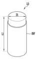
도 9는 일 실시예에 따른 표시 장치에 포함되는 발광 소자의 일 예를 나타낸 사시도이다.
도 10은 도 9의 단면도이다.FIG. 1 is a block diagram illustrating a display device according to one embodiment.
FIGS. 2 and 3 are circuit diagrams showing examples of pixels included in the display device of FIG. 1.
FIG. 4 is a circuit diagram partially illustrating the configuration of groups of elements according to one embodiment.
FIG. 5 is a conceptual diagram illustrating a method for obtaining temperature data of a display device according to one embodiment.
Figure 6 is a graph for explaining luminous efficiency according to current density of a display device according to one embodiment.
Figure 7 is a flowchart illustrating a method of driving a display device according to one embodiment.
Figure 8 is a flowchart illustrating a method of driving a display device according to one embodiment.
FIG. 9 is a perspective view showing an example of a light-emitting element included in a display device according to one embodiment.
Fig. 10 is a cross-sectional view of Fig. 9.
본 발명은 다양한 변경을 가할 수 있고 여러 가지 형태를 가질 수 있는 바, 특정 실시예들을 도면에 예시하고 본문에 상세하게 설명하고자 한다. 그러나, 이는 본 발명을 특정한 개시 형태에 대해 한정하려는 것이 아니며, 본 발명의 사상 및 기술 범위에 포함되는 모든 변경, 균등물 내지 대체물을 포함하는 것으로 이해되어야 한다.The present invention can be modified in various ways and can take various forms, and specific embodiments are illustrated in the drawings and described in detail in the text. However, this is not intended to limit the present invention to specific disclosed forms, but should be understood to include all modifications, equivalents, or substitutes included in the spirit and technical scope of the present invention.
제1, 제2 등의 용어는 다양한 구성요소들을 설명하는데 사용될 수 있지만, 상기 구성요소들은 상기 용어들에 의해 한정되어서는 안 된다. 상기 용어들은 하나의 구성요소를 다른 구성요소로부터 구별하는 목적으로만 사용된다. 예를 들어, 본 발명의 권리 범위를 벗어나지 않으면서 제1 구성요소는 제2 구성요소로 명명될 수 있고, 유사하게 제2 구성요소도 제1 구성요소로 명명될 수 있다. 단수의 표현은 문맥상 명백하게 다르게 뜻하지 않는 한, 복수의 표현을 포함한다.The terms first, second, etc. may be used to describe various components, but the components should not be limited by the terms. The terms are only used to distinguish one component from another. For example, without departing from the scope of the present invention, the first component may be referred to as the second component, and similarly, the second component may also be referred to as the first component. The singular expression includes the plural expression unless the context clearly indicates otherwise.
본 출원에서, "포함하다" 또는 "가지다" 등의 용어는 명세서 상에 기재된 특징, 숫자, 단계, 동작, 구성요소, 부품 또는 이들을 조합한 것이 존재함을 지정하려는 것이지, 하나 또는 그 이상의 다른 특징들이나 숫자, 단계, 동작, 구성요소, 부분품 또는 이들을 조합한 것들의 존재 또는 부가 가능성을 미리 배제하지 않는 것으로 이해되어야 한다.In this application, it should be understood that terms such as “include” or “have” are intended to specify the presence of a feature, number, step, operation, component, part or combination thereof described in the specification, but do not exclude in advance the possibility of the presence or addition of one or more other features, numbers, steps, operations, components, parts or combinations thereof.
본 출원에서, "어떤 구성요소(일 예로 '제1 구성요소')가 다른 구성요소(일 예로 '제2 구성요소')에 "(기능적으로 또는 통신적으로) 연결되어 ((operatively or communicatively) coupled with/to)" 있다거나, "접속되어 (connected to)" 있다고 언급된 때에는, 상기 어떤 구성요소가 상기 다른 구성요소에 직접적으로 연결되거나, 다른 구성요소(일 예로 '제3 구성요소')를 통하여 연결될 수 있다고 이해되어야 할 것이다. 반면에, 어떤 구성요소(일 예로 '제1 구성요소')가 다른 구성요소 (일 예로 '제2 구성요소')에 "직접 연결되어" 있다거나 "직접 접속되어" 있다고 언급된 때에는, 상기 어떤 구성요소와 상기 다른 구성요소 사이에 다른 구성요소(일 예로 '제3 구성요소')가 존재하지 않는 것으로 이해될 수 있다.In this application, when it is stated that "a component (e.g., a 'first component') is "(operatively or communicatively) coupled with/to" or "connected to" another component (e.g., a 'second component'), it should be understood that the component can be directly connected to the other component, or can be connected via another component (e.g., a 'third component'). On the other hand, when it is stated that a component (e.g., a 'first component') is "directly connected" or "directly connected" to another component (e.g., a 'second component'), it can be understood that no other component (e.g., a 'third component') exists between the component and the other component.
이하, 본 발명의 실시예들과 관련된 도면들을 참고하여, 본 발명의 실시예에 따른 표시 장치에 대해 설명하도록 한다. 아래의 설명에서, 단수의 표현은 문맥상 명백하게 단수만을 포함하지 않는 한, 복수의 표현도 포함한다.Hereinafter, a display device according to an embodiment of the present invention will be described with reference to drawings related to embodiments of the present invention. In the description below, singular expressions also include plural expressions unless the context clearly includes only the singular.
도 1은 일 실시예에 따른 표시 장치를 나타내는 블록도이다.FIG. 1 is a block diagram illustrating a display device according to one embodiment.
도 1을 참조하면, 일 실시예에 따른 표시 장치는 표시부(100), 주사 구동부(200), 데이터 구동부(300), 타이밍 제어부(400), 저장부(500), 및 보상부(600)를 포함할 수 있다.Referring to FIG. 1, a display device according to one embodiment may include a display unit (100), a scan driver unit (200), a data driver unit (300), a timing control unit (400), a storage unit (500), and a compensation unit (600).
표시 장치는 평면 표시 장치, 플렉서블(flexible) 표시 장치, 커브드(curved) 표시 장치, 폴더블(foldable) 표시 장치, 벤더블(bendable) 표시 장치, 스트레쳐블(stretchable) 표시 장치일 수 있다. 또한, 표시 장치는 투명 표시 장치, 헤드 마운트(head-mounted) 표시 장치, 웨어러블(wearable) 표시 장치 등에 적용될 수 있다. 또한, 표시 장치는 스마트폰, 태블릿, 스마트 패드, TV, 모니터 등의 다양한 전자 기기에 적용될 수 있다.The display device may be a flat display device, a flexible display device, a curved display device, a foldable display device, a bendable display device, or a stretchable display device. In addition, the display device may be applied to a transparent display device, a head-mounted display device, a wearable display device, etc. In addition, the display device may be applied to various electronic devices such as a smartphone, a tablet, a smart pad, a TV, and a monitor.
표시 장치는 복수의 자발광 소자들을 포함하는 자발광 표시 장치로 구현될 수 있다. 예를 들어, 표시 장치는 유기 발광 소자들을 포함하는 유기 발광 표시 장치, 무기 발광 소자들을 포함하는 표시 장치, 또는 무기 물질 및 유기 물질이 복합적으로 구성된 발광 소자들을 포함하는 표시 장치일 수 있다. 다만, 이는 예시적인 것으로서, 표시 장치는 액정 표시 장치, 플라즈마 표시 장치, 퀀텀닷 표시 장치 등으로 구현될 수도 있다.The display device may be implemented as a self-luminous display device including a plurality of self-luminous elements. For example, the display device may be an organic light-emitting display device including organic light-emitting elements, a display device including inorganic light-emitting elements, or a display device including light-emitting elements composed of a composite of inorganic and organic materials. However, this is merely exemplary, and the display device may also be implemented as a liquid crystal display device, a plasma display device, a quantum dot display device, etc.
표시부(100)는 데이터선(DL), 제1 주사선(SL), 제2 주사선(SSL), 및 센싱선(RL)에 접속되는 화소(PX)를 포함한다. 표시부(100)는 복수의 데이터선(DL), 복수의 제1 주사선(SL), 복수의 제2 주사선(SSL), 및 복수의 센싱선(RL)에 각각 접속되는 복수의 화소(PX)를 포함할 수 있다.The display unit (100) includes pixels (PX) connected to data lines (DL), first scan lines (SL), second scan lines (SSL), and sensing lines (RL). The display unit (100) may include a plurality of pixels (PX) connected to a plurality of data lines (DL), a plurality of first scan lines (SL), a plurality of second scan lines (SSL), and a plurality of sensing lines (RL), respectively.
화소(PX)는 외부로부터 제1 구동 전압(VDD), 제2 구동 전압(VSS), 및 초기화 전압을 공급받을 수 있다. 화소(PX)의 구체적인 구성은 이하 도 2에서 살펴본다.The pixel (PX) can receive a first driving voltage (VDD), a second driving voltage (VSS), and an initialization voltage from the outside. The specific configuration of the pixel (PX) is examined in Fig. 2 below.
한편, 도 1에서는 제1 주사선(SL) 및 제2 주사선(SSL)이 화소(PX)에 접속되는 것으로 도시되었으나, 본 발명은 이에 한정되는 것이 아니다. 실시예에 따라, 화소(PX)의 회로 구조에 대응하여 표시부(100)에는 하나 이상의 발광 제어선 등이 추가로 형성될 수 있다.Meanwhile, in Fig. 1, the first scanning line (SL) and the second scanning line (SSL) are illustrated as being connected to the pixel (PX), but the present invention is not limited thereto. According to an embodiment, one or more light-emitting control lines, etc. may be additionally formed in the display unit (100) corresponding to the circuit structure of the pixel (PX).
주사 구동부(200)는 타이밍 제어부(400)로부터 주사 제어 신호(SCS)를 수신한다. 주사 구동부(200)는 주사 제어 신호(SCS)에 응답하여 제1 주사선(SL)들로 각각 제1 주사 신호를 공급하고, 제2 주사선(SSL)들로 각각 제2 주사 신호를 공급할 수 있다.The injection driver (200) receives a injection control signal (SCS) from the timing controller (400). In response to the injection control signal (SCS), the injection driver (200) can supply a first injection signal to each of the first scan lines (SLs) and a second injection signal to each of the second scan lines (SSLs).
주사 구동부(200)는 제1 주사선(SL)들로 제1 주사 신호를 순차적으로 공급할 수 있다. 예를 들면, 제1 주사 신호는 화소(PX)에 포함된 트랜지스터가 턴-온될 수 있도록 게이트-온 전압으로 설정될 수 있다. 또한, 제1 주사 신호는 화소(PX)에 데이터 신호를 인가하는데 이용될 수 있다.The injection driver (200) can sequentially supply a first scan signal to the first scan lines (SL). For example, the first scan signal can be set to a gate-on voltage so that a transistor included in a pixel (PX) can be turned on. In addition, the first scan signal can be used to apply a data signal to the pixel (PX).
또한, 주사 구동부(200)는 제2 주사선(SSL)들로 제2 주사 신호를 공급할 수 있다. 예를 들면, 제2 주사 신호는 화소(PX)에 포함된 트랜지스터가 턴-온될 수 있도록 게이트-온 전압으로 설정될 수 있다. 제2 주사 신호는 화소(PX)에 흐르는 구동 전류를 센싱(또는, 추출)하거나 화소(PX)에 초기화 전압을 인가하는데 이용될 수 있다.Additionally, the scan driver (200) can supply a second scan signal to the second scan lines (SSL). For example, the second scan signal can be set to a gate-on voltage so that a transistor included in the pixel (PX) can be turned on. The second scan signal can be used to sense (or extract) a driving current flowing in the pixel (PX) or to apply an initialization voltage to the pixel (PX).
한편, 도 1에는 하나의 주사 구동부(200)가 제1 주사 신호와 제2 주사 신호를 모두 출력하는 것으로 도시되었으나, 이에 한정되는 것은 아니다. 실시예에 따라, 주사 구동부(200)는 제1 주사 신호를 표시부(100)에 공급하는 제1 주사 구동부 및 제2 주사 신호를 표시부(100)에 공급하는 제2 주사 구동부를 포함할 수 있다. 즉, 제1 주사 구동부 및 제2 주사 구동부는 별개의 구성으로 구현될 수 있다.Meanwhile, although FIG. 1 illustrates that one scan driver (200) outputs both the first scan signal and the second scan signal, it is not limited thereto. According to an embodiment, the scan driver (200) may include a first scan driver that supplies the first scan signal to the display unit (100) and a second scan driver that supplies the second scan signal to the display unit (100). That is, the first scan driver and the second scan driver may be implemented as separate configurations.
데이터 구동부(300)는 타이밍 제어부(400)로부터 데이터 제어 신호(DCS)를 수신한다. 또한, 데이터 구동부(300)는 보상부(600)로부터 보상 데이터(DATA2)를 수신한다. 데이더 구동부(300)는 데이터 제어 신호(DCS) 및 보상 데이터(DATA2)에 응답하여 데이터 신호(또는, 데이터 전압)들을 생성하고, 생성된 데이터 신호들을 데이터선(DL)들에 각각 공급할 수 있다. 즉, 데이터 구동부(300)는 한 프레임 기간 중 화소(PX)들 각각의 표시 기간 중에 데이터 신호(또는, 데이터 전압)를 표시부(100)에 공급할 수 있다.The data driving unit (300) receives a data control signal (DCS) from the timing control unit (400). In addition, the data driving unit (300) receives compensation data (DATA2) from the compensation unit (600). The data driving unit (300) can generate data signals (or data voltages) in response to the data control signal (DCS) and the compensation data (DATA2), and supply the generated data signals to the data lines (DL), respectively. That is, the data driving unit (300) can supply data signals (or data voltages) to the display unit (100) during the display period of each of the pixels (PX) during one frame period.
일 실시예에서, 데이터 구동부(300)는 감마 전압들을 이용하여 보상 데이터(DATA2)에 포함된 데이터값(또는, 계조값)에 대응하는 데이터 신호(또는, 데이터 전압)를 생성할 수 있다. 여기서, 감마 전압들은 데이터 구동부(300)에서 생성되거나 별도의 감마 전압 생성 회로(예를 들면, 감마 집적 회로)로부터 제공될 수 있다. 예를 들면, 데이터 구동부(300)는 데이터값에 기초하여 감마 전압들 중 하나를 선택하여 데이터 신호로 출력할 수 있다.In one embodiment, the data driving unit (300) can generate a data signal (or data voltage) corresponding to a data value (or grayscale value) included in compensation data (DATA2) using gamma voltages. Here, the gamma voltages can be generated by the data driving unit (300) or provided from a separate gamma voltage generating circuit (e.g., a gamma integrated circuit). For example, the data driving unit (300) can select one of the gamma voltages based on the data value and output it as a data signal.
데이터 구동부(300)는 표시 기간 중에 초기화 전원을 센싱선(RL)들로 공급할 수 있다. 또한, 데이터 구동부(300)는 센싱 모드(또는, 센싱 기간)에서 센싱선(RL)들에 초기화 전압을 인가한 후, 센싱선(RL)들을 통해 각 화소(PX)의 발광 특성을 센싱할 수도 있다.The data driving unit (300) can supply initialization power to the sensing lines (RL) during the display period. In addition, the data driving unit (300) can sense the light emission characteristics of each pixel (PX) through the sensing lines (RL) after applying the initialization voltage to the sensing lines (RL) in the sensing mode (or sensing period).
일 실시예에서, 센싱선(RL)들은 데이터 구동부(300)에 연결되는 것으로 도시되었으나, 실시예에 따라 별도의 센싱부가 구비되어, 데이터 구동부(300)와 센싱부는 별개의 구성으로 구현될 수 있다.In one embodiment, the sensing lines (RL) are shown as being connected to the data driving unit (300), but depending on the embodiment, a separate sensing unit may be provided, and the data driving unit (300) and the sensing unit may be implemented as separate configurations.
화소(PX)의 발광 특성은 화소(PX) 내 적어도 하나의 트랜지스터(예를 들어, 구동 트랜지스터)의 문턱 전압, 이동도, 및 발광 소자의 특성 정보(예를 들어, 전류-전압 특성)를 포함할 수 있다.The light-emitting characteristics of a pixel (PX) may include threshold voltage, mobility, and characteristic information of a light-emitting element (e.g., current-voltage characteristics) of at least one transistor (e.g., a driving transistor) within the pixel (PX).
타이밍 제어부(400)는 외부의 그래픽 기기와 같은 화상 소스로부터 제어 신호(CTL) 및 영상 신호(RGB)를 수신할 수 있다. 타이밍 제어부(400)는 외부로부터 공급되는 제어 신호(CTL)에 대응하여 데이터 제어 신호(DCS) 및 주사 제어 신호(SCS)를 생성할 수 있다. 타이밍 제어부(400)에서 생성된 데이터 제어 신호(DCS)는 데이터 구동부(300)로 공급되고, 주사 제어 신호(SCS)는 주사 구동부(200)로 공급될 수 있다.The timing control unit (400) can receive a control signal (CTL) and an image signal (RGB) from an image source such as an external graphic device. The timing control unit (400) can generate a data control signal (DCS) and a scan control signal (SCS) in response to the control signal (CTL) supplied from the outside. The data control signal (DCS) generated by the timing control unit (400) can be supplied to the data driving unit (300), and the scan control signal (SCS) can be supplied to the scan driving unit (200).
또한, 타이밍 제어부(400)는 외부로부터 공급된 영상 신호(RGB)가 재정렬된 영상 데이터(DATA1)를 보상부(600)에 공급할 수 있다.Additionally, the timing control unit (400) can supply image data (DATA1) in which image signals (RGB) supplied from the outside are rearranged to the compensation unit (600).
저장부(500)는 외부의 촬상 소자에서 촬상된 표시부(100)의 온도 데이터를 저장할 수 있다. 여기서, 표시부(100)의 온도 데이터가 저장되는 부분은 제1 저장부라 할 수 있다. 표시부(100)에 구비된 각 화소(PX)는 복수의 발광 소자(LD, 도 2 및 도 3 참조)를 포함하는 적어도 하나의 소자 그룹(SET, 도 2 및 도 3 참조)을 포함할 수 있다. 촬상 소자는 표시부(100)의 표시 영역을 촬상하여, 발광 소자(LD)의 발광에 따라, 소자 그룹(SET)(또는, 화소(PX))들의 온도 데이터를 생성할 수 있다. 온도 데이터는 표시부(100)에 포함되는 소정의 영역으로 구분된 복수의 화소(PX)들을 포함하는 영역들의 온도 데이터일 수 있고, 한 화소(PX)에 포함되는 소정의 소자 그룹(SET)들의 온도 데이터일 수 있다.The storage unit (500) can store temperature data of the display unit (100) captured by an external imaging element. Here, the part where the temperature data of the display unit (100) is stored can be referred to as the first storage unit. Each pixel (PX) provided in the display unit (100) can include at least one element group (SET, see FIGS. 2 and 3) including a plurality of light-emitting elements (LD, see FIGS. 2 and 3). The imaging element can capture a display area of the display unit (100) and generate temperature data of the element groups (SET) (or pixels (PX)) according to the light emission of the light-emitting elements (LD). The temperature data can be temperature data of areas including a plurality of pixels (PX) divided into predetermined areas included in the display unit (100), and can be temperature data of predetermined element groups (SET) included in one pixel (PX).
일 실시예에 따른 표시 장치는 온도 데이터를 추출하여, 표시 장치의 광효율을 제어할 수 있고, 광효율에 의해 소비 전력은 가변될 수 있다. 광효율은 표시 장치에서 소비되는 전력 대비 빛의 밝기가 어느정도 인지 알려주는 물리적인 양이다. 예를 들면, 광효율이 낮을수록 소비 전력보다 빛의 밝기가 어두울 수 있고, 광효율이 높을수록 소비 전력보다 빛의 밝기가 밝을 수 있다.A display device according to one embodiment can extract temperature data to control the luminous efficiency of the display device, and power consumption can be varied by the luminous efficiency. Luminous efficiency is a physical quantity that indicates how much brightness of light is compared to the power consumed by the display device. For example, the lower the luminous efficiency, the darker the light brightness can be compared to the power consumption, and the higher the luminous efficiency, the brighter the light brightness can be compared to the power consumption.
일 실시예에서는 평균보다 온도가 높은 소자 그룹(SET)을 추출하고, 광효율이 최적화되도록 표시부(100)에 인가되는 전류를 최초 인가되는 전류보다 작은 값을 가진 전류로 제어함으로써, 광효율을 향상시킬 수 있다. 이에 따라, 표시 장치의 휘도 특성이 향상될 수 있고, 표시 장치에서 소비되는 전력은 감소될 수 있다.In one embodiment, by extracting a group of elements (SET) having a higher temperature than the average and controlling the current applied to the display unit (100) to a current having a smaller value than the initially applied current so that the luminous efficiency is optimized, the luminous efficiency can be improved. Accordingly, the luminance characteristics of the display device can be improved, and the power consumed by the display device can be reduced.
또한, 일 실시예에서 온도 데이터에 의해 소자 그룹(SET)들에 포함되는 발광 소자(LD)들의 개수의 많고 적음을 유추할 수 있다. 각각의 소자 그룹(SET)들에는 동일한 구동 전류가 인가될 수 있다. 그러나, 소자 그룹(SET)들에 포함되는 발광 소자(LD)들의 개수 차이에 의해, 하나의 발광 소자(LD)에 인가되는 전류는 상이할 수 있다. 예를 들면, 제1 소자 그룹이 제2 소자 그룹보다 적은 개수의 발광 소자(LD)들을 포함한다면, 제1 소자 그룹의 온도가 제2 소자 그룹의 온도보다 높을 수 있다. 이는, 각각의 소자 그룹(SET)에는 동일한 구동 전류가 인가되므로, 발광 소자(LD)의 개수가 감소할수록, 하나의 발광 소자(LD)에 인가되는 전류(또는, 전류 스트레스)가 증가하기 때문이다. 이에 따라, 큰 온도 데이터를 갖는 소자 그룹(SET)은 작은 온도 데이터를 갖는 소자 그룹(SET)보다 적은 개수의 발광 소자(LD)들을 포함한다고 파악할 수 있다. 예를 들면, 온도가 높은 소자 그룹(SET)들은 온도가 낮은 소자 그룹(SET)들에 비해 적은 발광 소자(LD)들을 포함할 수 있다. 또한, 적은 개수의 발광 소자(LD)들을 포함한 소자 그룹(SET)들은 다른 소자 그룹(SET)보다 광효율이 낮을 수 있다.In addition, in one embodiment, the number of light-emitting elements (LD) included in the element groups (SET) can be inferred from the temperature data. The same driving current can be applied to each of the element groups (SET). However, the current applied to one light-emitting element (LD) can be different due to the difference in the number of light-emitting elements (LD) included in the element groups (SET). For example, if the first element group includes a smaller number of light-emitting elements (LD) than the second element group, the temperature of the first element group can be higher than the temperature of the second element group. This is because the same driving current is applied to each of the element groups (SET), and therefore, as the number of light-emitting elements (LD) decreases, the current (or current stress) applied to one light-emitting element (LD) increases. Accordingly, it can be determined that an element group (SET) having large temperature data includes a smaller number of light-emitting elements (LD) than an element group (SET) having small temperature data. For example, high temperature element groups (SETs) may include fewer light emitting elements (LDs) than low temperature element groups (SETs). Additionally, element groups (SETs) including a smaller number of light emitting elements (LDs) may have lower luminous efficiency than other element groups (SETs).
저장부(500)는 소자 그룹(SET)(또는, 화소(PX))들의 휘도 데이터를 저장하는 제2 저장부를 더 포함할 수 있다. 제2 저장부는 소자 그룹(SET)들의 휘도 데이터를 보상부(600)에 제공할 수 있다. 예를 들면, 제2 저장부에 저장되는 휘도 데이터는 0 내지 255 계조 중 적어도 하나의 계조에 대응하는 값일 수 있다. 또한, 휘도 데이터는 표시부(100)에 인가되는 전류에 대응하는 값일 수 있다. 이러한 휘도 데이터는 제품 출하 전, 제조 공정에서 저장부(500)의 룩 업 테이블(LUT)에 미리 저장된 값일 수 있다.The storage unit (500) may further include a second storage unit that stores luminance data of element groups (SET) (or pixels (PX)). The second storage unit may provide luminance data of element groups (SET) to the compensation unit (600). For example, the luminance data stored in the second storage unit may be a value corresponding to at least one gradation from 0 to 255. In addition, the luminance data may be a value corresponding to a current applied to the display unit (100). Such luminance data may be a value that is stored in advance in a look-up table (LUT) of the storage unit (500) during a manufacturing process before product shipment.
보상부(600)는 소자 그룹(SET)들의 온도 데이터 및 소자 그룹(SET)들의 휘도 데이터를 기초로, 영상 데이터(DATA1)를 보상하여 보상 데이터(DATA2)를 생성할 수 있다.The compensation unit (600) can generate compensation data (DATA2) by compensating image data (DATA1) based on temperature data of element groups (SET) and brightness data of element groups (SET).
저장부(500)는 EPROM(Erasable Programmable Read-Only Memory), EEPROM(Electrically Erasable Programmable ReadOnly Memory), 플래시 메모리(Flash Memory), PRAM(Phase Change Random Access Memory), RRAM(Resistance Random Access Memory), NFGM(Nano Floating Gate Memory), PoRAM(Polymer Random Access Memory), MRAM(Magnetic Random Access Memory), FRAM(Ferroelectric Random Access Memory) 등과 같은 비휘발성 메모리 장치로 구현될 수 있다.The storage unit (500) may be implemented as a nonvolatile memory device such as an EPROM (Erasable Programmable Read-Only Memory), an EEPROM (Electrically Erasable Programmable ReadOnly Memory), a flash memory, a PRAM (Phase Change Random Access Memory), a RRAM (Resistance Random Access Memory), a NFGM (Nano Floating Gate Memory), a PoRAM (Polymer Random Access Memory), a MRAM (Magnetic Random Access Memory), a FRAM (Ferroelectric Random Access Memory), etc.
보상부(600)는 저장부(500)(또는, 제1 저장부)에서 제공된 표시부(100)의 소자 그룹(SET)들의 온도 데이터에 기초하여, 영상 데이터(DATA1)를 보상하여 보상 데이터(DATA2)로 생성할 수 있다.The compensation unit (600) can compensate for the image data (DATA1) and generate compensation data (DATA2) based on the temperature data of the element groups (SET) of the display unit (100) provided from the storage unit (500) (or the first storage unit).
구체적으로, 보상부(600)는 저장부(500)에서 제공된 소자 그룹(SET)들의 온도 데이터 중 평균 온도보다 높은 온도 데이터를 가진 소자 그룹(SET)을 추출하고, 추출된 소자 그룹(SET)을 기초로 영상 데이터(DATA1)를 보상할 수 있다. 예를 들면, 보상부(600)는 메모리에 저장된 룩 업 테이블(LUT)을 참고하여, 영상 데이터(DATA1)를 보상할 수 있다. 룩 업 테이블(LUT)에는 추출된 소자 그룹(SET)에 대응되도록 계조 데이터, 표시부(100)에 인가되는 영상 데이터(DATA1)의 데이터 전압 범위, 감마 테이블 등이 저장될 수 있다.Specifically, the compensation unit (600) can extract a group of elements (SET) having temperature data higher than an average temperature among the temperature data of the groups of elements (SET) provided from the storage unit (500), and compensate for the image data (DATA1) based on the extracted group of elements (SET). For example, the compensation unit (600) can compensate for the image data (DATA1) by referring to a lookup table (LUT) stored in the memory. The lookup table (LUT) can store grayscale data, a data voltage range of the image data (DATA1) applied to the display unit (100), a gamma table, etc. corresponding to the extracted group of elements (SET).
이 때, 보상부(600)는 평균 온도보다 높은 온도 데이터를 가진 소자 그룹(SET)의 전류 밀도를 기준으로 표시부(100)에 인가되는 전류를 감소시킬 수 있다. 즉, 보상부(600)는 평균 온도보다 높은 온도 데이터를 가진 소자 그룹(SET)의 전류 밀도를 낮추기 위해, 미리 결정된 전류보다 작은 전류가 표시부(100)(또는, 화소(PX)들, 발광 유닛(EMU)들, 소자 그룹(SET)들)에 인가되도록, 영상 데이터(DATA1)를 보상할 수 있다. 구체적으로, 표시부(100)의 적어도 하나의 소자 그룹(SET)을 포함하는 발광 유닛(EMU)들에는 각각의 발광 유닛(EMU)에 소정의 전류 밀도가 유지될 수 있도록, 동일한 크기의 전류가 인가될 수 있다. 이에 따라, 표시 장치는 표시부(100)의 소자 그룹(SET)들의 전류 밀도를 광효율이 최적화되도록 제어할 수 있으므로, 전체적으로 광효율을 향상시킬 수 있다. 광효율 향상에 따라, 표시 장치의 소비 전력은 감소할 수 있다.At this time, the compensation unit (600) can reduce the current applied to the display unit (100) based on the current density of the element group (SET) having temperature data higher than the average temperature. That is, the compensation unit (600) can compensate the image data (DATA1) so that a current smaller than a predetermined current is applied to the display unit (100) (or, pixels (PX), light-emitting units (EMUs), element groups (SETs)) in order to reduce the current density of the element group (SET) having temperature data higher than the average temperature. Specifically, the same size of current can be applied to the light-emitting units (EMUs) including at least one element group (SET) of the display unit (100) so that a predetermined current density can be maintained for each light-emitting unit (EMU). Accordingly, the display device can control the current density of the element groups (SETs) of the display unit (100) so that the light efficiency is optimized, and thus the overall light efficiency can be improved. As the light efficiency is improved, the power consumption of the display device can be reduced.
또한, 보상부(600)는 저장부(500)로부터 소자 그룹(SET)들의 온도 데이터 및 휘도 데이터를 제공받고, 평균 온도를 가진 소자 그룹(SET)의 휘도 데이터를 기초로, 영상 데이터(DATA1)를 보상하여 보상 데이터(DATA2)를 생성할 수 있다.In addition, the compensation unit (600) can receive temperature data and brightness data of element groups (SETs) from the storage unit (500), and generate compensation data (DATA2) by compensating image data (DATA1) based on the brightness data of the element group (SET) having the average temperature.
구체적으로, 보상부(600)는 평균 온도를 가진 소자 그룹(SET)의 휘도 데이터를 반영하여 표시부(100)가 최대 휘도를 갖도록, 영상 데이터(DATA1)를 보상할 수 있다. 이 때, 표시부(100)의 휘도가 증가할수록, 표시 장치의 광효율이 저하될 수 있으므로, 보상부(600)는 소자 그룹(SET)(또는, 발광 유닛(EMU))에 인가되는 전류가 광효율을 크게 감소시키지 않는 범위에 해당하도록, 영상 데이터(DATA1)를 보상하여 보상 데이터(DATA2)를 생성할 수 있다. 예를 들면, 보상부(600)는 평균 온도를 가진 소자 그룹(SET)의 전류 밀도의 최대값이 해당 소자 그룹(SET)의 최대 광효율에 대응하는 전류 밀도의 30% 이하에 해당하도록 보상 데이터(DATA2)를 생성할 수 있다. 광효율 최적화를 위한 전류 밀도의 최대값을 파악하는 방법은 이하 도 6에서 상세히 살펴본다.Specifically, the compensation unit (600) can compensate the image data (DATA1) so that the display unit (100) has the maximum brightness by reflecting the brightness data of the element group (SET) having the average temperature. At this time, as the brightness of the display unit (100) increases, the light efficiency of the display device may decrease, so the compensation unit (600) can generate compensation data (DATA2) by compensating the image data (DATA1) so that the current applied to the element group (SET) (or, the light emitting unit (EMU)) falls within a range that does not significantly reduce the light efficiency. For example, the compensation unit (600) can generate compensation data (DATA2) so that the maximum value of the current density of the element group (SET) having the average temperature falls below 30% of the current density corresponding to the maximum light efficiency of the corresponding element group (SET). A method of determining the maximum value of the current density for optimizing the light efficiency will be described in detail with reference to FIG. 6 below.
한편, 도 1에서 주사 구동부(200), 데이터 구동부(300), 타이밍 제어부(400), 및 보상부(600)는 상호 독립적으로 구성된 것으로 도시되어 있으나, 이는 예시적인 것으로, 이에 한정되는 것은 아니다. 예를 들어, 주사 구동부(200), 데이터 구동부(300), 타이밍 제어부(400), 및 보상부(600) 중 적어도 하나는 표시부(100)에 구비되거나, 집적 회로로 구현되고 연성 회로 기판에 실장되어 표시부(100)에 연결될 수 있다. 예를 들어, 주사 구동부(200)는 표시부(100)에 구비될 수 있다. 또한, 주사 구동부(200), 데이터 구동부(300), 타이밍 제어부(400), 및 보상부(600) 중 적어도 2개는 하나의 집적 회로로 구현될 수 있다. 예를 들어, 데이터 구동부(300) 및 보상부(600)는 하나의 집적 회로로 구현될 수 있다.Meanwhile, in FIG. 1, the scan driver (200), the data driver (300), the timing control unit (400), and the compensation unit (600) are illustrated as being configured independently of each other, but this is exemplary and is not limited thereto. For example, at least one of the scan driver (200), the data driver (300), the timing control unit (400), and the compensation unit (600) may be provided in the display unit (100), or may be implemented as an integrated circuit and mounted on a flexible circuit board to be connected to the display unit (100). For example, the scan driver (200) may be provided in the display unit (100). In addition, at least two of the scan driver (200), the data driver (300), the timing control unit (400), and the compensation unit (600) may be implemented as one integrated circuit. For example, the data driver (300) and the compensation unit (600) may be implemented as one integrated circuit.
이하에서는 도 2 내지 도 4를 참조하여, 일 실시예에 따른 표시 장치의 화소를 살펴본다.Hereinafter, pixels of a display device according to one embodiment will be examined with reference to FIGS. 2 to 4.
도 2 및 도 3은 도 1의 표시 장치에 포함되는 화소의 일 예들을 나타낸 회로도이고, 도 4는 일 실시예에 따른 소자 그룹들의 구성을 일부 도시한 회로도이다.FIGS. 2 and 3 are circuit diagrams showing examples of pixels included in the display device of FIG. 1, and FIG. 4 is a circuit diagram partially showing the configuration of element groups according to one embodiment.
먼저, 도 2 및 도 3을 참조하면, 화소(PX)는 제1 트랜지스터(T1), 제2 트랜지스터(T2), 제3 트랜지스터(T3), 스토리지 커패시터(Cst), 및 발광 유닛(EMU)을 포함할 수 있다.First, referring to FIGS. 2 and 3, a pixel (PX) may include a first transistor (T1), a second transistor (T2), a third transistor (T3), a storage capacitor (Cst), and an emission unit (EMU).
제1 트랜지스터(T1)(또는, 구동 트랜지스터)의 제1 전극은 제1 전원선(PL1)에 접속되고, 제2 전극은 발광 유닛(EMU)의 제1 전극(EL1)(또는, 제2 노드(N2))에 접속될 수 있다. 제1 트랜지스터(T1)의 게이트 전극은 제1 노드(N1)에 접속될 수 있다. 일 실시예에서, 제1 전극은 드레인 전극일 수 있고, 제2 전극은 소스 전극일 수 있다. 제1 트랜지스터(T1)는 제1 노드(N1)의 전압에 대응하여, 발광 유닛(EMU)으로 흐르는 구동 전류(Id)의 전류량을 제어할 수 있다.A first electrode of a first transistor (T1) (or a driving transistor) may be connected to a first power line (PL1), and a second electrode may be connected to a first electrode (EL1) (or a second node (N2)) of a light emitting unit (EMU). A gate electrode of the first transistor (T1) may be connected to the first node (N1). In one embodiment, the first electrode may be a drain electrode, and the second electrode may be a source electrode. The first transistor (T1) may control an amount of a driving current (Id) flowing to the light emitting unit (EMU) in response to a voltage of the first node (N1).
제2 트랜지스터(T2)(또는, 스위칭 트랜지스터)의 제1 전극은 데이터선(DL)에 접속되고, 제2 전극은 제1 노드(N1)(또는, 제1 트랜지스터(T1)의 게이트 전극)에 접속될 수 있다. 제2 트랜지스터(T2)의 게이트 전극은 제1 주사선(SL)에 접속될 수 있다. 제2 트랜지스터(T2)는 제1 주사선(SL)으로 제1 주사 신호(SC)(예를 들면, 하이 레벨 전압)가 공급될 때 턴-온되어, 데이터선(DL)으로부터 데이터 전압(DATA)을 제1 노드(N1)로 전달할 수 있다.A first electrode of a second transistor (T2) (or a switching transistor) may be connected to a data line (DL), and a second electrode may be connected to a first node (N1) (or a gate electrode of the first transistor (T1)). A gate electrode of the second transistor (T2) may be connected to a first scan line (SL). The second transistor (T2) may be turned on when a first scan signal (SC) (e.g., a high level voltage) is supplied to the first scan line (SL), and may transmit a data voltage (DATA) from the data line (DL) to the first node (N1).
제3 트랜지스터(T3)의 제1 전극은 센싱선(RL)에 접속되고, 제2 전극은 제2 노드(N2)(또는, 제1 트랜지스터(T1)의 제2 전극)에 접속될 수 있다. 제3 트랜지스터(T3)의 게이트 전극은 제2 주사선(SSL)에 접속될 수 있다. 제3 트랜지스터(T3)는 소정의 센싱 기간 동안 제2 주사선(SSL)으로 제2 주사 신호(SS)(예를 들면, 하이 레벨 전압)가 공급될 때 턴-온되어, 센싱선(RL)과 제2 노드(N2)를 전기적으로 접속시킬 수 있다.A first electrode of a third transistor (T3) may be connected to a sensing line (RL), and a second electrode may be connected to a second node (N2) (or, a second electrode of the first transistor (T1)). A gate electrode of the third transistor (T3) may be connected to a second scan line (SSL). The third transistor (T3) may be turned on when a second scan signal (SS) (e.g., a high level voltage) is supplied to the second scan line (SSL) for a predetermined sensing period, thereby electrically connecting the sensing line (RL) and the second node (N2).
스토리지 커패시터(Cst)는 제1 노드(N1)와 제2 노드(N2) 사이에 접속된다. 이러한 스토리지 커패시터(Cst)는 한 프레임 동안 제1 노드(N1)로 공급되는 데이터 신호에 대응하는 데이터 전압(DATA)을 충전할 수 있다. 이에 따라, 스토리지 커패시터(Cst)는 제1 노드(N1)와 제2 노드(N2) 사이의 전압 차에 대응하는 전압을 저장할 수 있다. 일 예로, 스토리지 커패시터(Cst)는 제1 트랜지스터(T1)의 게이트 전극으로 공급되는 데이터 전압(DATA)과 제1 트랜지스터(T1)의 제2 전극으로 공급되는 초기화 전압(Vint)의 차에 대응하는 전압을 저장할 수 있다.A storage capacitor (Cst) is connected between a first node (N1) and a second node (N2). The storage capacitor (Cst) can charge a data voltage (DATA) corresponding to a data signal supplied to the first node (N1) for one frame. Accordingly, the storage capacitor (Cst) can store a voltage corresponding to a voltage difference between the first node (N1) and the second node (N2). For example, the storage capacitor (Cst) can store a voltage corresponding to a difference between a data voltage (DATA) supplied to a gate electrode of the first transistor (T1) and an initialization voltage (Vint) supplied to a second electrode of the first transistor (T1).
발광 유닛(EMU)은 제1 구동 전압(VDD)이 인가되는 제1 전원선(PL1)과 제2 구동 전압(VSS)이 인가되는 제2 전원선(PL2) 사이에 직렬 및/또는 병렬로 연결된 복수의 발광 소자(LD)들을 포함할 수 있다. 일 예로, 도 2를 참조한 발광 유닛(EMU)은 직렬로 연결된 복수의 발광 소자(LD)들을 포함할 수 있고, 도 3을 참조한 발광 유닛(EMU)은 직렬 및 병렬로 연결된 복수의 발광 소자(LD)들을 포함할 수 있다. 병렬 연결된 복수의 발광 소자(LD)들 중 서로 동일한 방향으로 연결된 각각의 발광 소자(LD)는 유효 광원을 구성할 수 있다. 또한, 서로 동일한 방향으로 병렬 연결된 발광 소자(LD)들은 소자 그룹(SET)을 구성할 수 있다.The light emitting unit (EMU) may include a plurality of light emitting elements (LDs) connected in series and/or in parallel between a first power line (PL1) to which a first driving voltage (VDD) is applied and a second power line (PL2) to which a second driving voltage (VSS) is applied. For example, the light emitting unit (EMU) referring to FIG. 2 may include a plurality of light emitting elements (LDs) connected in series, and the light emitting unit (EMU) referring to FIG. 3 may include a plurality of light emitting elements (LDs) connected in series and in parallel. Among the plurality of light emitting elements (LDs) connected in parallel, each light emitting element (LD) connected in the same direction may constitute an effective light source. In addition, the light emitting elements (LDs) connected in parallel in the same direction may constitute an element group (SET).
발광 유닛(EMU)은 제2 노드(N2)에 연결된 제1 전극(EL1)과 제2 전원선(PL2)에 연결된 제2 전극(EL2) 사이에 직렬 및/또는 병렬 연결되는 복수의 발광 소자(LD)를 포함할 수 있다. 여기서, 제1 전극(EL1)은 애노드(anode)일 수 있고, 제2 전극(EL2)은 캐소드(cathode)일 수 있다.The light emitting unit (EMU) may include a plurality of light emitting elements (LDs) connected in series and/or in parallel between a first electrode (EL1) connected to a second node (N2) and a second electrode (EL2) connected to a second power line (PL2). Here, the first electrode (EL1) may be an anode, and the second electrode (EL2) may be a cathode.
또한, 도 3을 참조하면, 제3 전극(EL3)은 캐소드일 수 있고, 제4 전극(EL4)은 애노드일 수 있다.Also, referring to FIG. 3, the third electrode (EL3) may be a cathode, and the fourth electrode (EL4) may be an anode.
일 실시예에서, 발광 유닛(EMU)은 제2 노드(N2)와 제2 전원선(PL2) 사이에 연결된 제1 서브 소자 그룹(SET1-1) 및 제2 서브 소자 그룹(SET1-2)을 포함할 수 있다. 제1 서브 소자 그룹(SET1-1)은 제1 전극(EL1)과 제3 전극(EL3) 사이에 서로 동일한 방향으로 연결된 적어도 하나의 발광 소자(LD1)를 포함할 수 있다. 제2 서브 소자 그룹(SET1-2)은 제4 전극(EL4)과 제2 전극(EL2) 사이에 서로 동일한 방향으로 연결된 적어도 하나의 발광 소자(LD2)를 포함할 수 있다. 또한, 제1 서브 소자 그룹(SET1-1)은 제1 전극(EL1) 제3 전극(EL3) 사이에 반대 방향으로 연결된 역방향 발광 소자(LDr)를 더 포함할 수 있고, 제2 서브 소자 그룹(SET1-2)은 제4 전극(EL4)과 제2 전극(EL2) 사이에 반대 방향으로 연결된 역방향 발광 소자(LDr)를 더 포함할 수 있다.In one embodiment, the light emitting unit (EMU) may include a first sub-element group (SET1-1) and a second sub-element group (SET1-2) connected between the second node (N2) and the second power line (PL2). The first sub-element group (SET1-1) may include at least one light emitting element (LD1) connected in the same direction between the first electrode (EL1) and the third electrode (EL3). The second sub-element group (SET1-2) may include at least one light emitting element (LD2) connected in the same direction between the fourth electrode (EL4) and the second electrode (EL2). In addition, the first sub-element group (SET1-1) may further include a reverse light emitting element (LDr) connected in the opposite direction between the first electrode (EL1) and the third electrode (EL3), and the second sub-element group (SET1-2) may further include a reverse light emitting element (LDr) connected in the opposite direction between the fourth electrode (EL4) and the second electrode (EL2).
제1 서브 소자 그룹(SET1-1)의 제1 서브 중간 전극(CTE-1)과 제2 서브 소자 그룹(SET1-2)의 제2 서브 중간 전극(CTE-2)은 일체로 제공되어 서로 연결될 수 있다. 제1 서브 중간 전극(CTE-1)과 제2 서브 중간 전극(CTE-2)은 연속하는 제1 서브 소자 그룹(SET1-1)과 제2 서브 소자 그룹(SET1-2)을 전기적으로 연결하는 중간 전극(CTE)을 구성할 수 있다. 제1 서브 중간 전극(CTE-1)과 제2 서브 중간 전극(CTE-2)이 일체로 제공되는 경우, 제1 서브 중간 전극(CTE-1)과 제2 서브 중간 전극(CTE-2)은 중간 전극(CTE)의 서로 다른 일 영역일 수 있다.The first sub-intermediate electrode (CTE-1) of the first sub-element group (SET1-1) and the second sub-intermediate electrode (CTE-2) of the second sub-element group (SET1-2) may be provided integrally and connected to each other. The first sub-intermediate electrode (CTE-1) and the second sub-intermediate electrode (CTE-2) may form an intermediate electrode (CTE) electrically connecting the continuous first sub-element group (SET1-1) and the second sub-element group (SET1-2). When the first sub-intermediate electrode (CTE-1) and the second sub-intermediate electrode (CTE-2) are provided integrally, the first sub-intermediate electrode (CTE-1) and the second sub-intermediate electrode (CTE-2) may be different regions of the intermediate electrode (CTE).
발광 유닛(EMU)은 제1 트랜지스터(T1)로부터 공급되는 구동 전류(Id)에 대응하여 소정 휘도의 빛을 생성할 수 있다. 예를 들면, 한 프레임 기간 동안, 제1 트랜지스터(T1)는 해당 프레임 데이터(예를 들면, 보상 데이터(DATA2, 도 1 참조))의 계조값에 대응하는 구동 전류(Id)를 발광 유닛(EMU)으로 공급할 수 있다. 발광 유닛(EMU)으로 공급되는 구동 전류(Id)는 발광 소자(LD)(또는, 소자 그룹(SET))들에 나뉘어 흐를 수 있다. 이에 따라, 각각의 발광 소자(LD)가 흐르는 전류에 상응하는 휘도로 발광하면서, 발광 유닛(EMU)(또는, 소자 그룹(SET))은 구동 전류(Id)에 대응하는 휘도의 광을 방출할 수 있다.The light emitting unit (EMU) can generate light of a predetermined brightness in response to the driving current (Id) supplied from the first transistor (T1). For example, during one frame period, the first transistor (T1) can supply the driving current (Id) corresponding to the grayscale value of the corresponding frame data (e.g., the compensation data (DATA2, see FIG. 1)) to the light emitting unit (EMU). The driving current (Id) supplied to the light emitting unit (EMU) can be divided and flowed to the light emitting elements (LD) (or the element group (SET)). Accordingly, while each light emitting element (LD) emits light with a brightness corresponding to the flowing current, the light emitting unit (EMU) (or the element group (SET)) can emit light with a brightness corresponding to the driving current (Id).
한편, 본 발명에서 화소(PX)의 회로 구조는 도 2와 도 3에 의하여 한정되지는 않는다. 일 예로, 발광 소자(LD)는 제1 전원선(PL1)과 제1 트랜지스터(T1)의 제1 전극 사이에 위치될 수도 있다.Meanwhile, the circuit structure of the pixel (PX) in the present invention is not limited to FIGS. 2 and 3. For example, the light emitting element (LD) may be positioned between the first power line (PL1) and the first electrode of the first transistor (T1).
또한, 도 2와 도 3에서는 트랜지스터를 NMOS로 도시하였지만, 본 발명은 이에 한정되지 않는다. 일 예로, 제1 내지 제3 트랜지스터(T1, T2, T3) 중 적어도 하나는 PMOS로 구현될 수 있다.In addition, although the transistors are illustrated as NMOS in FIGS. 2 and 3, the present invention is not limited thereto. For example, at least one of the first to third transistors (T1, T2, T3) may be implemented as PMOS.
도 4를 참조하면, 상이한 개수의 발광 소자(LD)를 포함하는 소자 그룹들이 도시되어 있다. 여기서, 제1 소자 그룹(SET1)과 제2 소자 그룹(SET2)은 각각 별개의 화소(PX)에 포함될 수 있다.Referring to FIG. 4, groups of elements including different numbers of light-emitting elements (LD) are illustrated. Here, the first element group (SET1) and the second element group (SET2) may each be included in a separate pixel (PX).
(a)와 (b)의 상단에 도시된, 제1 소자 그룹(SET1)과 제2 소자 그룹(SET2)은 각각 직렬 및 병렬로 연결된 복수의 발광 소자(LD)를 포함하고 있다.The first element group (SET1) and the second element group (SET2), shown at the top of (a) and (b), each include a plurality of light-emitting elements (LD) connected in series and parallel, respectively.
복수의 무기 발광 소자를 포함하는 표시 장치에서는, 애노드와 캐소드가 배치된 영역(예를 들면, 발광 영역) 사이에 복수의 발광 소자(LD)를 제공할 수 있다. 예를 들면, 발광 소자(LD)는 소정의 용액 내에 분산된 형태로 준비되어, 잉크젯 방식 등을 이용해 애노드 및 캐소드 상에 공급될 수 있다. 그러나, 잉크젯 프린팅 장치에서 노즐의 막힘 등의 문제로 잉크가 제대로 분사되지 않을 경우, 발광 영역에는 발광 소자(LD)가 원하는 개수, 위치로 제대로 제공될 수 없다. 이에 따라, 발광 영역에 발광 소자(LD)가 평균보다 적은 개수로 분포되는 경우, 광효율 저하 등의 문제점이 발생할 수 있다.In a display device including a plurality of inorganic light-emitting elements, a plurality of light-emitting elements (LD) can be provided between an area (e.g., a light-emitting area) where an anode and a cathode are arranged. For example, the light-emitting elements (LD) can be prepared in a form dispersed in a predetermined solution and supplied onto the anode and the cathode using an inkjet method or the like. However, if ink is not properly sprayed due to a problem such as clogging of a nozzle in an inkjet printing device, the light-emitting elements (LD) cannot be properly provided in the light-emitting area in a desired number and position. Accordingly, if the light-emitting elements (LD) are distributed in a less than average number in the light-emitting area, problems such as a decrease in luminous efficiency may occur.
일 예로, 제2 소자 그룹(SET2)에는 복수의 발광 소자(LD)가 제대로 증착되어 있다. 반면, 제1 소자 그룹(SET1)에는 발광 소자(LD)가 일부 영역(예를 들면, 점선으로 도시된 사각형)에서 제대로 증착되어 있지 않다.For example, in the second element group (SET2), a plurality of light-emitting elements (LDs) are properly deposited. On the other hand, in the first element group (SET1), the light-emitting elements (LDs) are not properly deposited in some areas (e.g., squares indicated by dotted lines).
이 때, 제1 소자 그룹(SET1) 및 제2 소자 그룹(SET2)의 발광 소자(LD)들은 제1 트랜지스터(T1)로부터 공급되는 구동 전류(Id)에 의하여 소정 휘도의 빛을 생성할 수 있다. 그리고, 제1 소자 그룹(SET1) 및 제2 소자 그룹(SET2)으로 공급되는 구동 전류(Id)는 발광 소자(LD)들에 나뉘어 흐를 수 있다. 이에 따라, 제1 소자 그룹(SET1) 및 제2 소자 그룹(SET2)의 발광 소자(LD)가 구동 전류(Id)에 상응하는 휘도로 발광하면서, 제1 소자 그룹(SET1) 및 제2 소자 그룹(SET2)은 구동 전류(Id)에 대응하는 휘도의 광을 방출할 수 있다.At this time, the light-emitting elements (LD) of the first element group (SET1) and the second element group (SET2) can generate light of a predetermined brightness by the driving current (Id) supplied from the first transistor (T1). In addition, the driving current (Id) supplied to the first element group (SET1) and the second element group (SET2) can be divided and flowed to the light-emitting elements (LD). Accordingly, while the light-emitting elements (LD) of the first element group (SET1) and the second element group (SET2) emit light with a brightness corresponding to the driving current (Id), the first element group (SET1) and the second element group (SET2) can emit light with a brightness corresponding to the driving current (Id).
그러나, 제1 소자 그룹(SET1) 및 제2 소자 그룹(SET2)에 포함되는 발광 소자(LD)들의 개수 차이에 의해, 하나의 발광 소자(LD)에 인가되는 전류는 증가할 수 있고, 적은 개수의 발광 소자(LD)를 포함하는 제1 소자 그룹(SET1)은 온도가 높아질 수 있다. 이는, 제1 소자 그룹(SET1) 및 제2 소자 그룹(SET2)에는 동일한 구동 전류(Id)가 인가되나, 발광 소자(LD)의 개수가 감소할수록, 하나의 발광 소자(LD)에 인가되는 전류(또는, 전류 스트레스)가 증가하기 때문이다.However, due to the difference in the number of light-emitting elements (LD) included in the first element group (SET1) and the second element group (SET2), the current applied to one light-emitting element (LD) may increase, and the temperature of the first element group (SET1) including a smaller number of light-emitting elements (LD) may increase. This is because the same driving current (Id) is applied to the first element group (SET1) and the second element group (SET2), but as the number of light-emitting elements (LD) decreases, the current (or current stress) applied to one light-emitting element (LD) increases.
일 실시예에서는, 소자 그룹(SET)의 온도(또는, 소자 그룹(SET)에 포함되는 발광 소자(LD)의 개수)에 대응하여, 소자 그룹(SET)(또는, 발광 유닛(EMU))에 인가되는 전류를 제어함으로써, 소자 그룹(SET)(또는, 발광 유닛(EMU))의 광효율을 향상시킬 수 있다. 즉, 표시 장치의 광효율을 최적화 할 수 있다.In one embodiment, by controlling the current applied to the element group (SET) (or the light-emitting unit (EMU)) in response to the temperature of the element group (SET) (or the number of light-emitting elements (LD) included in the element group (SET)), the luminous efficiency of the element group (SET) (or the light-emitting unit (EMU)) can be improved. That is, the luminous efficiency of the display device can be optimized.
예를 들면, 제1 소자 그룹(SET1)에 포함된 발광 소자(LD)들의 개수가 제2 소자 그룹(SET2)에 포함된 발광 소자(LD)들의 개수보다 적은 경우, 제1 소자 그룹(SET1)은 제2 소자 그룹(SET2)보다 높은 온도를 가질 수 있고, 제1 소자 그룹(SET1)에 의해 표시부(100)의 광효율은 전체적으로 저하될 수 있다.이 때, 표시부(100)의 광효율을 전체적으로 향상시키기 위하여, 제1 소자 그룹(SET1)의 전류 밀도가 감소하도록, 표시 장치는 소자 그룹(SET)(또는, 발광 유닛(EMU))에 미리 결정된 전류보다 작은 전류가 인가되도록, 보상 데이터를 인가할 수 있다. 여기서, 미리 결정된 전류의 값은 제1 소자 그룹(SET1)에 최초로 인가되는 전류값일 수 있다. 즉,일 실시예에 따른 표시 장치는 평균 온도보다 높은 온도 데이터를 가진 소자 그룹(SET)의 전류 밀도를 기준으로 표시부(100)에 인가되는 전류 밀도가 전체적으로 감소하도록 영상 데이터(DATA1)를 보상할 수 있다. 이에 따라, 표시 장치는 소자 그룹(SET)들의 전류 밀도를 제어함으로써, 전체적으로 광효율을 향상시킬 수 있다. 또한, 광효율이 향상됨에 따라, 표시 장치의 소비 전력은 감소할 수 있고, 발광 소자(LD)의 수명은 증가할 수 있다.For example, if the number of light-emitting elements (LD) included in the first element group (SET1) is less than the number of light-emitting elements (LD) included in the second element group (SET2), the first element group (SET1) may have a higher temperature than the second element group (SET2), and the overall light efficiency of the display unit (100) may be reduced by the first element group (SET1).At this time, in order to improve the overall luminous efficiency of the display unit (100), the display device may apply compensation data such that a current smaller than a predetermined current is applied to the element group (SET) (or, the light emitting unit (EMU)) so that the current density of the first element group (SET1) is reduced. Here, the value of the predetermined current may be a current value initially applied to the first element group (SET1). That is, the display device according to one embodiment may compensate the image data (DATA1) so that the current density applied to the display unit (100) is reduced overall based on the current density of the element group (SET) having temperature data higher than the average temperature. Accordingly, the display device may improve the overall luminous efficiency by controlling the current density of the element groups (SET). In addition, as the luminous efficiency is improved, the power consumption of the display device may be reduced, and the lifespan of the light emitting elements (LD) may be increased.
또한, 일 실시예에 따른 표시 장치는 발광 소자(LD)가 제대로 증착되지 않은 소자 그룹(SET)을 포함하는 화소(PX)에 관한 데이터를 저장할 수 있다. 표시 장치는 이러한 데이터를 사용하여, 발광 소자(LD)가 제대로 증착되지 않은 불량 화소(PX)를 중점적으로 열화 정도를 센싱할 수 있다. 이에 따라, 표시 장치는 표시부(100)의 화소(PX)를 전체적으로 센싱하는 것보다 센싱 시간을 감소시킬 수 있다.In addition, the display device according to one embodiment can store data regarding pixels (PX) including a group of elements (SET) in which light-emitting elements (LD) are not properly deposited. Using this data, the display device can sense the degree of deterioration of defective pixels (PX) in which light-emitting elements (LD) are not properly deposited. Accordingly, the display device can reduce the sensing time compared to sensing all of the pixels (PX) of the display unit (100).
이하에서는, 도 5 및 도 6을 참조하여 표시부의 온도와 광효율에 대하여 살펴본다.Below, the temperature and luminous efficiency of the display unit will be examined with reference to FIGS. 5 and 6.
도 5는 일 실시예에 따른 표시 장치의 온도 데이터를 획득하는 방법을 설명하기 위한 개념도이고, 도 6은 일 실시예에 따른 표시 장치의 전류 밀도에 따른 광효율을 설명하기 위한 그래프이다.FIG. 5 is a conceptual diagram for explaining a method for obtaining temperature data of a display device according to one embodiment, and FIG. 6 is a graph for explaining luminous efficiency according to current density of a display device according to one embodiment.
도 5를 참조하면, 저장부(500)는 외부의 촬상 소자(50)에 의해 촬상된 온도 데이터를 수신할 수 있다. 촬상 소자(50)는 표시부(100)의 전면의 전체 영역을 촬상할 수 있도록 소정의 각도로 위치할 수 있다.Referring to FIG. 5, the storage unit (500) can receive temperature data captured by an external imaging element (50). The imaging element (50) can be positioned at a predetermined angle so as to capture the entire area in front of the display unit (100).
촬상 소자(50)는 열 화상 카메라, CCD(Charge-Coupled Device) 카메라 등으로 구현될 수 있다. 촬상 소자(50)는 각 카메라의 수광 소자를 자체적으로 포함할 수 있다. 또한, 촬상 소자(50)는 자체적으로 수광 소자를 포함하지 않되, 외부 수광 소자와 연결되어, 외부 수광 소자가 촬상한 온도 데이터를 수신하도록 구성될 수도 있다.The imaging element (50) may be implemented as a thermal imaging camera, a CCD (Charge-Coupled Device) camera, etc. The imaging element (50) may include a light-receiving element of each camera. In addition, the imaging element (50) may not include a light-receiving element by itself, but may be configured to be connected to an external light-receiving element and receive temperature data captured by the external light-receiving element.
표시부(100)에 구비된 각 화소(PX)는 복수의 발광 소자(LD, 도 2 및 도 3 참조)를 포함하는 적어도 하나의 소자 그룹(SET, 도 2 및 도 3 참조)을 포함할 수 있다. 촬상 소자(50)는 표시부(100)의 표시 영역을 촬상하여, 발광 소자(LD)의 발광에 따라, 소자 그룹(SET)들의 온도 데이터를 생성할 수 있다.Each pixel (PX) provided in the display unit (100) may include at least one element group (SET, see FIGS. 2 and 3) including a plurality of light-emitting elements (LD, see FIGS. 2 and 3). The imaging element (50) may capture an image of the display area of the display unit (100) and generate temperature data of the element groups (SET) according to the light emission of the light-emitting elements (LD).
온도 데이터는 표시부(100)의 표시 영역 중 복수의 화소(PX)를 포함하는 일부 영역의 온도 데이터를 포함할 수 있고, 각 화소(PX)에 포함되는 소정의 소자 그룹(SET)들의 온도 데이터를 포함할 수 있다.The temperature data may include temperature data of a portion of a display area of the display unit (100) that includes a plurality of pixels (PX), and may include temperature data of a predetermined group of elements (SET) included in each pixel (PX).
일 실시예에서, 촬상 소자(50)가 획득한 온도 데이터의 온도가 평균 온도보다 높게 나타나는 경우, 해당 온도 데이터를 가진 지점은 제1 소자 그룹(SET1, 도 4 참조)으로 유추될 수 있다. 또한, 촬상 소자(50)가 획득한 온도 데이터의 온도가 평균 온도에 해당하는 경우, 해당 온도 데이터를 가진 지점은 제2 소자 그룹(SET2, 도 4 참조)으로 유추될 수 있다. 여기서, 평균 온도는 소자 그룹(SET)들의 온도 데이터의 평균값일 수 있다.In one embodiment, if the temperature of the temperature data acquired by the imaging element (50) is higher than the average temperature, the point having the corresponding temperature data can be inferred to be a first element group (SET1, see FIG. 4). In addition, if the temperature of the temperature data acquired by the imaging element (50) corresponds to the average temperature, the point having the corresponding temperature data can be inferred to be a second element group (SET2, see FIG. 4). Here, the average temperature may be an average value of the temperature data of the element groups (SETs).
일 실시예에 따른 표시 장치에서는 온도 데이터에 의해 표시 장치의 광효율을 확인할 수 있다. 예를 들면, 온도가 높은 소자 그룹(SET)들은 온도가 낮은 소자 그룹(SET)들에 비해 광효율이 낮을 수 있다.In a display device according to one embodiment, the luminous efficiency of the display device can be determined by temperature data. For example, element groups (SETs) having a high temperature may have lower luminous efficiency than element groups (SETs) having a low temperature.
도 6을 참조하면, A로 도시된 점선(LD less)은 하나의 소자 그룹(SET)에 포함되는 발광 소자(LD)들의 개수가 평균보다 적은 경우를 도시한 것이고, B로 도시된 점선(LD Avg)은 하나의 소자 그룹(SET)에 포함되는 발광 소자(LD)들의 개수가 평균인 경우를 도시한 것이고, C로 도시된 실선(LD more)은 발광 소자(LD)들의 개수가 평균보다 많은 경우를 도시한 것이다.Referring to FIG. 6, the dotted line (LD less) shown as A illustrates a case where the number of light-emitting elements (LD) included in one element group (SET) is less than the average, the dotted line (LD Avg) shown as B illustrates a case where the number of light-emitting elements (LD) included in one element group (SET) is the average, and the solid line (LD more) shown as C illustrates a case where the number of light-emitting elements (LD) is more than the average.
B로 도시된 점선(LD Avg)과 C로 도시된 실선(LD more)을 살펴보면, 일정 범위보다 전류 밀도가 증가하면, 광효율이 점차 낮아짐을 알 수 있다. 그러나, 최대 광효율과 비교할 때, 크게 감소되지 않을 수 있다. 예를 들면, B로 도시된 점선(LD Avg)과 C로 도시된 실선(LD more)은 전류 밀도가 약 40A/m2 이상이고 약 80A/m2일 때, 광효율이 6.5 cd/A 내지 약 6cd/A 범위에서 감소됨을 알 수 있다.Looking at the dotted line (LD Avg) shown as B and the solid line (LD more) shown as C, it can be seen that the luminous efficiency gradually decreases when the current density increases beyond a certain range. However, compared to the maximum luminous efficiency, it may not decrease significantly. For example, the dotted line (LD Avg) shown as B and the solid line (LD more) shown as C show that the luminous efficiency decreases in the range of 6.5 cd/A to about 6 cd/A when the current density is about 40 A/m2 or higher and about 80 A/m2 .
반면, A로 도시된 점선(LD less)을 살펴보면, 일정 범위보다 전류 밀도가 증가하면, 광효율이 급격하게 저하됨을 알 수 있다. 예를 들면, A로 도시된 점선(LD less)은 전류 밀도가 약 40A/m2 이상이고 약 80A/m2일 때, 광효율이 6.5 cd/A에서 약 5cd/A 정도로 급격하게 감소됨을 알 수 있다.On the other hand, if we look at the dotted line (LD less) indicated by A, we can see that the luminous efficiency decreases rapidly when the current density increases beyond a certain range. For example, the dotted line (LD less) indicated by A shows that when the current density is about 40 A/m2 or higher and about 80 A/m2 , the luminous efficiency decreases rapidly from 6.5 cd/A to about 5 cd/A.
이와 같이, 하나의 소자 그룹(SET)에 포함되는 발광 소자(LD)들의 개수가 평균보다 적은 경우, 표시 장치의 광효율은 급격하게 감소할 수 있다. 또한, 일정 영역에서 표시 장치의 광효율이 감소함에 따라, 전체적으로 표시 장치의 휘도 불균일이 발생할 수 있다.In this way, when the number of light-emitting elements (LDs) included in one element group (SET) is less than the average, the luminous efficiency of the display device may decrease rapidly. In addition, as the luminous efficiency of the display device decreases in a certain area, luminance unevenness of the display device may occur overall.
그러나, 일 실시예에서는 소자 그룹(SET)이 포함하는 발광 소자(LD)의 개수가 상이하더라도, 표시부(100, 도 1 참조)가 최적의 광효율을 가질 수 있도록, 소자 그룹(SET)(또는, 발광 유닛(EMU), 표시부(100))에 인가되는 전류를 최초 인가되는 전류보다 작은 전류로 제어함으로써, 표시부(100)의 광효율을 향상시킬 수 있다.However, in one embodiment, even if the number of light-emitting elements (LD) included in the element group (SET) is different, the light efficiency of the display unit (100, see FIG. 1) can be improved by controlling the current applied to the element group (SET) (or, light-emitting unit (EMU), display unit (100)) to a current smaller than the initially applied current so that the display unit (100) can have optimal light efficiency.
또한, 일 실시예에 따른 표시 장치에서는 최적의 광효율을 유지하도록 표시부(100)의 휘도를 제어할 수 있다. 예를 들면, B로 도시된 점선(LD Avg)의 평균 온도를 가진 소자 그룹(SET)의 휘도 데이터를 기초로, 표시부(100, 도 1 참조)의 휘도를 제어할 수 있다. 즉, 표시 장치는 평균 온도를 가진 소자 그룹(SET)의 휘도 데이터를 반영하여, 표시부(100)가 최대 휘도를 가지도록, 표시부(100)의 휘도를 제어할 수 있다. 이 때, 표시부(100)의 휘도가 증가할수록 표시 장치의 광효율이 저하될 수 있으므로, 표시 장치는 광효율이 크게 저하되지 않는 범위가 되도록, 소자 그룹(SET)에 인가되는 전류를 제어할 수 있다.In addition, in the display device according to one embodiment, the luminance of the display unit (100) can be controlled to maintain the optimal luminance efficiency. For example, the luminance of the display unit (100, see FIG. 1) can be controlled based on the luminance data of the element group (SET) having the average temperature of the dotted line (LD Avg) indicated by B. That is, the display device can control the luminance of the display unit (100) so that the display unit (100) has the maximum luminance by reflecting the luminance data of the element group (SET) having the average temperature. At this time, since the luminance of the display unit (100) may decrease as the luminance increases, the display device can control the current applied to the element group (SET) so that the luminance efficiency is not significantly decreased.
구체적으로, 다시 도 4를 함께 참조하면, B로 도시된 점선(LD Avg)은 발광 소자(LD)들이 정상적으로 증착된 제2 소자 그룹(SET2)에 대한 전류 밀도에 따른 광효율 그래프이다. 제2 소자 그룹(SET2)은 20 A/m2 내지 약 50 A/m2의 전류 밀도 범위에서, 최대 광효율을 가질 수 있다. 이 때, 표시부(100)의 휘도를 증가시킬수록, 즉, 제2 소자 그룹(SET2)의 전류 밀도가 일정범위 이상 증가할수록, 표시 장치의 광효율이 감소할 수 있다.일 실시예에서는, 표시 장치의 광효율이 저하되는 것을 방지하기 위하여, 제2 소자 그룹(SET2)의 전류 밀도가 약 20 A/m2 내지 약 50 A/m2에 해당하도록, 표시부(100)에 인가되는 보상 데이터(DATA2, 도 1 참조)를 제어할 수 있다. 즉, 제2 소자 그룹(SET2)의 전류 밀도의 최대값이 제2 소자 그룹(SET2)의 최대 광효율에 대응하는 전류 밀도의 30% 이하에 해당하도록 보상 데이터(DATA2)를 제어할 수 있다. 여기서, 전류 밀도의 범위 및 최대값의 범위는 예시적인 것으로, 각 소자 그룹의 전류 밀도의 범위 및 최대값의 범위는 실시예에 따라 다양하게 변경될 수 있다.Specifically, referring again to FIG. 4, the dotted line (LD Avg) illustrated as B is a graph of luminous efficiency according to current density for the second element group (SET2) in which light-emitting elements (LDs) are normally deposited. The second element group (SET2) can have maximum luminous efficiency in a current density range of 20 A/m2 to about 50 A/m2 . At this time, as the luminance of the display unit (100) increases, that is, as the current density of the second element group (SET2) increases beyond a certain range, the luminous efficiency of the display device can decrease. In one embodiment, in order to prevent the luminous efficiency of the display device from decreasing, compensation data (DATA2, see FIG. 1) applied to the display unit (100) can be controlled so that the current density of the second element group (SET2) corresponds to about 20 A/m2 to about 50 A/m2 . That is, the compensation data (DATA2) can be controlled so that the maximum value of the current density of the second element group (SET2) corresponds to 30% or less of the current density corresponding to the maximum light efficiency of the second element group (SET2). Here, the range of the current density and the range of the maximum value are exemplary, and the range of the current density and the range of the maximum value of each element group may be variously changed according to the embodiment.
이와 같이, 일 실시예에 따른 표시 장치는 소자 그룹(SET)들의 최대 휘도를 유지하면서, 광효율이 저하되지 않는 범위에 대응하도록 보상 데이터(DATA2)를 생성할 수 있다.In this way, the display device according to one embodiment can generate compensation data (DATA2) to correspond to a range in which light efficiency is not reduced while maintaining the maximum brightness of the element groups (SET).
이하에서는 도 7 및 도 8을 참조하여, 일 실시예에 따른 표시 장치의 구동 방법을 살펴본다.Hereinafter, a method of driving a display device according to one embodiment will be described with reference to FIGS. 7 and 8.
도 7은 일 실시예에 따른 표시 장치의 구동 방법이고, 도 8은 일 실시예에 따른 표시 장치의 구동 방법이다. 도 7 및 도 8은 도 1 내지 도 6을 참조하여 설명하며, 이하 도 1 내지 도 6을 참조한 도면 부호를 사용한다.FIG. 7 is a driving method of a display device according to one embodiment, and FIG. 8 is a driving method of a display device according to one embodiment. FIGS. 7 and 8 are described with reference to FIGS. 1 to 6, and hereinafter, reference numerals referring to FIGS. 1 to 6 are used.
먼저, 도 7을 참조하면, 일 실시예에 따른 표시 장치는 표시부(100)의 온도 데이터를 수신할 수 있다. 여기서, 표시부(100)는 발광 소자(LD)들로 구성된 적어도 하나의 소자 그룹(SET)을 포함할 수 있으며, 표시부(100)의 온도 데이터는 소자 그룹(SET)들의 온도 데이터일 수 있다. 온도 데이터는 외부의 촬상 소자(50)로부터 제공되는 것으로, 저장부(500)(또는, 제1 저장부)에 저장된 값일 수 있다.First, referring to FIG. 7, a display device according to one embodiment can receive temperature data of a display unit (100). Here, the display unit (100) can include at least one element group (SET) composed of light-emitting elements (LD), and the temperature data of the display unit (100) can be temperature data of the element groups (SET). The temperature data is provided from an external imaging element (50) and can be a value stored in a storage unit (500) (or, a first storage unit).
보상부(600)는 저장부(500)로부터 소자 그룹(SET)들의 온도 데이터를 수신(S110)하여, 온도 데이터 중 평균 온도보다 높은 온도 데이터를 가진 제1 소자 그룹(SET1)을 추출(S120)할 수 있다.The compensation unit (600) can receive temperature data of element groups (SETs) from the storage unit (500) (S110) and extract (S120) the first element group (SET1) having temperature data higher than the average temperature among the temperature data.
이후, 보상부(600)는 추출된 제1 소자 그룹(SET1)을 기초로 영상 데이터(DATA1)를 보상하여 보상 데이터(DATA2)를 생성(S130)할 수 있다. 생성된 보상 데이터(DATA2)는 데이터 구동부(300)에 의해 표시부(100)에 인가(S140)될 수 있다. 이 때, 보상 데이터(DATA2)는 제1 소자 그룹(SET1)에 인가되는 최초 전류보다 작은 전류에 대응하는 값일 수 있다.Thereafter, the compensation unit (600) can generate compensation data (DATA2) by compensating the image data (DATA1) based on the extracted first element group (SET1) (S130). The generated compensation data (DATA2) can be applied (S140) to the display unit (100) by the data driving unit (300). At this time, the compensation data (DATA2) can be a value corresponding to a current smaller than the initial current applied to the first element group (SET1).
이에 따라, 표시 장치는 표시부(100)의 소자 그룹(SET)들의 전류 밀도를 광효율이 최적화되도록 제어할 수 있고, 전체적으로 광효율을 향상시킬 수 있다.Accordingly, the display device can control the current density of the element groups (SETs) of the display portion (100) to optimize the light efficiency, and improve the overall light efficiency.
도 8을 참조하면,일 실시예에 따른 표시 장치는 표시부(100)의 온도 데이터 및 휘도 데이터를 수신할 수 있다. 휘도 데이터는 표시부(100)의 소자 그룹(SET)들의 휘도 값일 수 있고, 저장부(500)(또는, 제2 저장부)에 미리 저장된 값일 수 있다. 온도 데이터는 외부의 촬상 소자(50)로부터 제공되는 것으로, 저장부(500)(또는, 제1 저장부)에 저장된 값일 수 있다.Referring to Figure 8,A display device according to one embodiment can receive temperature data and brightness data of a display unit (100). The brightness data can be brightness values of element groups (SETs) of the display unit (100) and can be values previously stored in a storage unit (500) (or a second storage unit). The temperature data is provided from an external imaging element (50) and can be values stored in a storage unit (500) (or a first storage unit).
보상부(600)는 저장부(500)로부터 소자 그룹(SET)들의 온도 데이터를 수신(S210)하여, 평균 온도의 제2 소자 그룹(SET2)을 추출(S220)할 수 있다.The compensation unit (600) can receive temperature data of element groups (SETs) from the storage unit (500) (S210) and extract a second element group (SET2) with an average temperature (S220).
이후, 보상부(600)는 추출된 제2 소자 그룹(SET2)을 기초로 영상 데이터(DATA1)를 보상하여 보상 데이터(DATA2)를 생성(S230)할 수 있다. 생성된 보상 데이터(DATA2)는 데이터 구동부(300)에 의해 표시부(100)에 인가(S240)될 수 있다. 이 때, 보상 데이터(DATA2)는 제2 소자 그룹(SET2)의 휘도 데이터를 기초로 보상된 값일 수 있다. 예를 들면, 보상 데이터(DATA2)는 표시부(100)에 최대 휘도가 구현될 수 있는 값일 수 있다.Thereafter, the compensation unit (600) can generate compensation data (DATA2) by compensating the image data (DATA1) based on the extracted second element group (SET2) (S230). The generated compensation data (DATA2) can be applied to the display unit (100) by the data driving unit (300) (S240). At this time, the compensation data (DATA2) can be a value compensated based on the brightness data of the second element group (SET2). For example, the compensation data (DATA2) can be a value at which the maximum brightness can be implemented in the display unit (100).
이 때, 표시 장치의 휘도가 증가함에 따라, 표시 장치의 광효율이 저하될 수 있으므로, 일 실시예에 따른 표시 장치는 광효율이 저하되지 않는 범위에 대응하도록 보상 데이터(DATA2)를 생성할 수 있다. 예를 들면, 보상부(600)는 제2 소자 그룹(SET2)의 전류 밀도의 최대값이 제2 소자 그룹(SET2)의 최대 광효율에 대응하는 전류 밀도의 30% 이하에 해당하도록, 보상 데이터(DATA2)를 생성할 수 있다.At this time, since the luminance of the display device increases, the light efficiency of the display device may decrease, and therefore, the display device according to one embodiment may generate compensation data (DATA2) to correspond to a range in which the light efficiency does not decrease. For example, the compensation unit (600) may generate compensation data (DATA2) such that the maximum value of the current density of the second element group (SET2) corresponds to 30% or less of the current density corresponding to the maximum light efficiency of the second element group (SET2).
이에 따라, 일 실시예에 따른 표시 장치는 광효율이 향상될 수 있는 범위에 대응하도록 표시 장치의 휘도를 제어할 수 있다.Accordingly, the display device according to one embodiment can control the brightness of the display device to correspond to a range in which the light efficiency can be improved.
이하에서는 도 9 및 도 10을 참조하여, 일 실시예에 따른 표시 장치가 포함하는 발광 소자에 관하여 살펴본다.Hereinafter, with reference to FIGS. 9 and 10, a light-emitting element included in a display device according to one embodiment will be described.
도 9는 일 실시예에 따른 표시 장치에 포함되는 발광 소자의 일 예를 나타낸 사시도이고, 도 10은 도 9의 단면도이다.FIG. 9 is a perspective view showing an example of a light-emitting element included in a display device according to one embodiment, and FIG. 10 is a cross-sectional view of FIG. 9.
도 9 및 도 10에서는 기둥 형상의 발광 소자를 도시하였으나, 본 발명에 의한 발광 소자의 종류 및/또는 형상은 이에 한정되지 않는다.Although a pillar-shaped light-emitting element is illustrated in FIGS. 9 and 10, the type and/or shape of the light-emitting element according to the present invention is not limited thereto.
도 9 및 도 10을 참조하면, 일 실시예에 따른 발광 소자(LD)는 제1 반도체층(11), 제2 반도체층(13), 및 제1 반도체층(11)과 제2 반도체층(13) 사이에 위치하는 활성층(12)을 포함한다. 일 예로, 발광 소자(LD)는 길이(L1) 방향을 따라 제1 반도체층(11), 활성층(12) 및 제2 반도체층(13)이 순차적으로 적층된 적층체로 구성될 수 있다.Referring to FIGS. 9 and 10, a light-emitting element (LD) according to one embodiment includes a first semiconductor layer (11), a second semiconductor layer (13), and an active layer (12) positioned between the first semiconductor layer (11) and the second semiconductor layer (13). For example, the light-emitting element (LD) may be configured as a laminate in which the first semiconductor layer (11), the active layer (12), and the second semiconductor layer (13) are sequentially laminated along a length (L1) direction.
실시예에 따라, 발광 소자(LD)는 일 방향을 따라 연장된 막대 형상, 즉, 원 기둥 형상으로 제공될 수 있다. 발광 소자(LD)의 연장 방향을 길이(L1) 방향이라고 하면, 발광 소자(LD)는 길이(L1) 방향을 따라 일측 단부와 타측 단부를 가질 수 있다.According to an embodiment, the light emitting element (LD) may be provided in a rod shape extending in one direction, i.e., in a cylindrical shape. When the direction of extension of the light emitting element (LD) is referred to as the length (L1) direction, the light emitting element (LD) may have one end and the other end along the length (L1) direction.
실시예에 따라, 발광 소자(LD)의 일측 단부에는 제1 반도체층(11) 및 제2 반도체층(13) 중 하나가 배치되고, 발광 소자(LD)의 타측 단부에는 제1 반도체층(11) 및 제2 반도체층(13) 중 나머지 하나가 배치될 수 있다.According to an embodiment, one of the first semiconductor layer (11) and the second semiconductor layer (13) may be disposed on one end of the light-emitting element (LD), and the other of the first semiconductor layer (11) and the second semiconductor layer (13) may be disposed on the other end of the light-emitting element (LD).
실시예에 따라, 발광 소자(LD)는 막대 형상으로 제조된 막대형 발광 다이오드일 수 있다. 본 명세서에서, "막대형"이라 함은 원 기둥 또는 다각 기둥 등과 같이 길이(L1) 방향으로 긴(즉, 종횡비(aspect ratio)가 1보다 큰) 로드 형상(rod-like shape), 또는 바 형상(bar-like shape)을 포괄하며, 그 단면의 형상이 특별히 한정되지는 않는다. 예를 들어, 발광 소자(LD)의 길이(L1)는 그 직경(D1)(또는, 횡단면의 폭)보다 클 수 있다.According to an embodiment, the light emitting element (LD) may be a rod-shaped light emitting diode manufactured in a rod shape. In the present specification, the term "rod-shaped" includes a rod-like shape or a bar-like shape that is long in the length (L1) direction (i.e., an aspect ratio greater than 1), such as a cylindrical column or a polygonal column, and the shape of its cross-section is not particularly limited. For example, the length (L1) of the light emitting element (LD) may be greater than its diameter (D1) (or, width of the cross-section).
실시예에 따라, 발광 소자(LD)는 나노 스케일 내지 마이크로 스케일 정도로 작은 크기를 가질 수 있다. 발광 소자(LD)는 각각 나노 스케일 내지 마이크로 스케일 범위의 직경(D1) 및/또는 길이(L1)를 가질 수 있다. 일례로, 발광 소자(LD)의 길이(L1)는 약 100 nm 내지 10㎛ 일 수 있고, 발광 소자(LD)의 직경(D1)은 약 2㎛ 내지 6㎛ 일 수 있으며, 발광 소자(LD)의 종횡비는 약 1.2 내지 약 100 사이의 범위일 수 있다. 다만, 본 발명에서 발광 소자(LD)의 크기가 이에 한정되지는 않는다. 예를 들어, 발광 소자(LD)를 이용한 발광 장치를 광원으로 이용하는 각종 장치, 일 예로 표시 장치 등의 설계 조건에 따라 발광 소자(LD)의 크기는 다양하게 변경될 수 있다.According to an embodiment, the light emitting element (LD) may have a size as small as a nano-scale or micro-scale. The light emitting element (LD) may have a diameter (D1) and/or a length (L1) in a nano-scale or micro-scale range, respectively. For example, the length (L1) of the light emitting element (LD) may be about 100 nm to 10 μm, the diameter (D1) of the light emitting element (LD) may be about 2 μm to 6 μm, and the aspect ratio of the light emitting element (LD) may be in a range of about 1.2 to about 100. However, the size of the light emitting element (LD) in the present invention is not limited thereto. For example, the size of the light emitting element (LD) may be variously changed depending on design conditions of various devices that use a light emitting device using the light emitting element (LD) as a light source, such as a display device.
제1 반도체층(11)은 적어도 하나의 n형 반도체층을 포함할 수 있다. 예를 들어, 제1 반도체층(11)은 InAlGaN, GaN, AlGaN, InGaN, AlN, InN 중 어느 하나의 반도체 재료를 포함하며, Si, Ge, Sn 등과 같은 제1 도전형 도펀트가 도핑된 n형 반도체층을 포함할 수 있다. 다만, 제1 반도체층(11)을 구성하는 물질이 이에 한정되는 것은 아니며, 이 외에도 다양한 물질로 제1 반도체층(11)을 구성할 수 있다.The first semiconductor layer (11) may include at least one n-type semiconductor layer. For example, the first semiconductor layer (11) may include a semiconductor material of any one of InAlGaN, GaN, AlGaN, InGaN, AlN, and InN, and may include an n-type semiconductor layer doped with a first conductive dopant such as Si, Ge, or Sn. However, the material constituting the first semiconductor layer (11) is not limited thereto, and the first semiconductor layer (11) may be composed of various materials in addition to this.
활성층(12)은 제1 반도체층(11) 상에 배치되며, 단일 또는 다중 양자 우물 구조로 형성될 수 있다. 일 실시예에서, 활성층(12)의 상부 및/또는 하부에는 도전성 도펀트가 도핑된 클래드층(미도시)이 형성될 수도 있다. 일 예로, 클래드층은 AlGaN층 또는 InAlGaN층으로 형성될 수 있다. 실시예에 따라, AlGaN, InAlGaN 등의 물질이 활성층(12)을 형성하는 데에 이용될 수 있으며, 이 외에도 다양한 물질이 활성층(12)을 구성할 수 있다.The active layer (12) is arranged on the first semiconductor layer (11) and may be formed as a single or multiple quantum well structure. In one embodiment, a clad layer (not shown) doped with a conductive dopant may be formed on the upper and/or lower portion of the active layer (12). For example, the clad layer may be formed as an AlGaN layer or an InAlGaN layer. Depending on the embodiment, materials such as AlGaN and InAlGaN may be used to form the active layer (12), and in addition, various materials may form the active layer (12).
발광 소자(LD)의 양단에 문턱 전압 이상의 전압을 인가하게 되면, 활성층(12)에서 전자-정공 쌍이 결합하면서 발광 소자(LD)가 발광하게 된다. 이러한 원리를 이용하여 발광 소자(LD)의 발광을 제어함으로써, 발광 소자(LD)를 표시 장치의 화소를 비롯한 다양한 발광 장치의 광원으로 이용할 수 있다.When a voltage higher than the threshold voltage is applied to both ends of the light emitting element (LD), electron-hole pairs combine in the active layer (12) and the light emitting element (LD) emits light. By controlling the light emission of the light emitting element (LD) using this principle, the light emitting element (LD) can be used as a light source for various light emitting devices including pixels of a display device.
제2 반도체층(13)은 활성층(12) 상에 배치되며, 제1 반도체층(11)과 상이한 타입의 반도체층을 포함할 수 있다. 일 예로, 제2 반도체층(13)은 적어도 하나의 p형 반도체층을 포함할 수 있다. 예를 들어, 제2 반도체층(13)은 InAlGaN, GaN, AlGaN, InGaN, AlN, InN 중 적어도 하나의 반도체 재료를 포함하며, Mg, Zn, Ca, Sr, Ba 등과 같은 제2 도전형 도펀트가 도핑된 p형 반도체층을 포함할 수 있다. 다만, 제2 반도체층(13)을 구성하는 물질이 이에 한정되는 것은 아니며, 이 외에도 다양한 물질이 제2 반도체층(13)을 구성할 수 있다.The second semiconductor layer (13) is arranged on the active layer (12) and may include a semiconductor layer of a different type from the first semiconductor layer (11). For example, the second semiconductor layer (13) may include at least one p-type semiconductor layer. For example, the second semiconductor layer (13) may include at least one semiconductor material among InAlGaN, GaN, AlGaN, InGaN, AlN, and InN, and may include a p-type semiconductor layer doped with a second conductive dopant such as Mg, Zn, Ca, Sr, or Ba. However, the material constituting the second semiconductor layer (13) is not limited thereto, and various other materials may constituting the second semiconductor layer (13).
상술한 실시예에서는, 제1 반도체층(11)과 제2 반도체층(13)이 각각 하나의 층으로 구성된 것으로 설명하고 있으나, 본 발명이 이에 한정되는 것은 아니다. 일 실시예에 있어서, 활성층(12)의 물질에 따라 제1 반도체층(11)과 제2 반도체층(13) 각각은 적어도 하나 이상의 층들, 일 예로 클래드층 및/또는 TSBR(Tensile Strain Barrier Reducing) 층을 더 포함할 수도 있다. TSBR 층은 격자 구조가 다른 반도체층들 사이에 배치되어 격자 상수(lattice constant) 차이를 줄이기 위한 완충 역할을 하는 스트레인(strain) 완화층일 수 있다. TSBR 층은 p-GaInP, p-AlInP, p-AlGaInP 등과 같은 p형 반도체층으로 구성될 수 있으나, 본 발명이 이에 한정되는 것은 아니다. 또한, 실시예에 따라, 발광 소자(LD)는 표면에 제공된 절연막(INF)을 더 포함할 수 있다. 절연막(INF)은 활성층(12)의 외주면을 둘러싸도록 발광 소자(LD)의 표면에 형성될 수 있으며, 이외에도 제1 반도체층(11) 및 제2 반도체층(13)의 일 영역을 더 둘러쌀 수 있다. 다만, 절연막(INF)은 서로 다른 극성을 가지는 발광 소자(LD)의 양 단부를 노출할 수 있다. 예를 들어, 절연막(INF)은 길이(L1) 방향에서 발광 소자(LD)의 양단에 위치한 제1 반도체층(11) 및 제2 반도체층(13) 각각의 일단, 일 예로 원기둥의 두 밑면(발광 소자(LD)의 상부면 및 하부면)을 커버하지 않고 노출할 수 있다.In the above-described embodiment, the first semiconductor layer (11) and the second semiconductor layer (13) are described as each consisting of one layer, but the present invention is not limited thereto. In one embodiment, depending on the material of the active layer (12), each of the first semiconductor layer (11) and the second semiconductor layer (13) may further include at least one or more layers, for example, a clad layer and/or a TSBR (Tensile Strain Barrier Reducing) layer. The TSBR layer may be a strain relaxation layer that is arranged between semiconductor layers having different lattice structures and acts as a buffer to reduce the difference in lattice constants. The TSBR layer may be composed of a p-type semiconductor layer, such as p-GaInP, p-AlInP, p-AlGaInP, or the like, but the present invention is not limited thereto. In addition, according to an embodiment, the light-emitting element (LD) may further include an insulating film (INF) provided on a surface. The insulating film (INF) may be formed on the surface of the light-emitting element (LD) to surround the outer surface of the active layer (12), and may further surround a region of the first semiconductor layer (11) and the second semiconductor layer (13). However, the insulating film (INF) may expose both ends of the light-emitting element (LD) having different polarities. For example, the insulating film (INF) may expose one end of each of the first semiconductor layer (11) and the second semiconductor layer (13) located at both ends of the light-emitting element (LD) in the length (L1) direction, for example, two bottom surfaces of a cylinder (upper and lower surfaces of the light-emitting element (LD)) without covering them.
일 실시예에서, 발광 소자(LD)는 제1 반도체층(11), 활성층(12), 제2 반도체층(13), 및 절연막(INF) 외에도 추가적인 구성 요소를 더 포함할 수 있다. 예를 들면, 발광 소자(LD)는 제1 반도체층(11), 활성층(12), 및 제2 반도체층(13)의 일단 측에 배치된 하나 이상의 형광체층, 활성층, 반도체층 및/또는 전극을 추가적으로 포함할 수 있다.In one embodiment, the light emitting element (LD) may further include additional components in addition to the first semiconductor layer (11), the active layer (12), the second semiconductor layer (13), and the insulating film (INF). For example, the light emitting element (LD) may additionally include one or more phosphor layers, active layers, semiconductor layers, and/or electrodes disposed on one end side of the first semiconductor layer (11), the active layer (12), and the second semiconductor layer (13).
발광 소자(LD)의 일단 측면에 배치되는 전극(14)은 오믹(Ohmic) 컨택 전극 또는 쇼트키(Schottky) 컨택 전극일 수 있으나, 이에 한정되지는 않는다. 또한, 전극(14)은 금속 또는 금속 산화물을 포함할 수 있으며, 일 예로, Cr, Ti, Al, Au, Ni, ITO, IZO, ITZO 및 이들의 산화물 또는 합금 등을 단독 또는 혼합하여 사용할 수 있다. 또한, 실시예에 따라, 전극(14)은 실질적으로 투명 또는 반투명할 수 있다. 이에 따라, 발광 소자(LD)에서 생성되는 빛이 전극(14)을 투과하여 발광 소자(LD)의 외부로 방출될 수 있다.The electrode (14) arranged on one side of the light emitting element (LD) may be an Ohmic contact electrode or a Schottky contact electrode, but is not limited thereto. In addition, the electrode (14) may include a metal or a metal oxide, and for example, Cr, Ti, Al, Au, Ni, ITO, IZO, ITZO, and oxides or alloys thereof may be used alone or in combination. In addition, according to an embodiment, the electrode (14) may be substantially transparent or translucent. Accordingly, light generated from the light emitting element (LD) may transmit through the electrode (14) and be emitted to the outside of the light emitting element (LD).
실시예에 따라, 절연막(INF)은 전극(14)의 외주면을 적어도 부분적으로 감싸거나, 또는 감싸지 않을 수 있다. 즉, 절연막(INF)은 전극(14)의 표면에 선택적으로 형성될 수 있다. 또한, 절연막(INF)은 서로 다른 극성을 가지는 발광 소자(LD)의 양단을 노출하도록 형성되며, 일 예로 전극(14)의 적어도 일 영역을 노출할 수 있다. 실시예에 따라, 발광 소자(LD)의 단부에는 절연막(INF)이 제공되지 않을 수도 있다.According to an embodiment, the insulating film (INF) may at least partially surround an outer surface of the electrode (14), or may not surround it. That is, the insulating film (INF) may be selectively formed on the surface of the electrode (14). In addition, the insulating film (INF) is formed so as to expose both ends of the light-emitting element (LD) having different polarities, and may expose, for example, at least one area of the electrode (14). According to an embodiment, the insulating film (INF) may not be provided on the end of the light-emitting element (LD).
발광 소자(LD)의 표면, 특히 활성층(12)의 표면에 절연막(INF)이 제공되면, 활성층(12)이 도시되지 않은 적어도 하나의 전극(일 예로, 발광 소자(LD)의 양단에 연결되는 컨택 전극들 중 적어도 하나의 컨택 전극) 등과 단락되는 것을 방지할 수 있다. 이에 따라, 발광 소자(LD)의 전기적 안정성을 확보할 수 있다.When an insulating film (INF) is provided on the surface of the light-emitting element (LD), particularly on the surface of the active layer (12), the active layer (12) can be prevented from being short-circuited with at least one electrode (for example, at least one contact electrode among the contact electrodes connected to both ends of the light-emitting element (LD)) that is not shown. Accordingly, the electrical stability of the light-emitting element (LD) can be secured.
또한, 발광 소자(LD)의 표면에 절연막(INF)을 형성함에 의해 발광 소자(LD)의 표면 결함을 최소화하여 수명 및 효율을 향상시킬 수 있다. 또한, 각각의 발광 소자(LD)에 절연막(INF)이 형성되면, 다수의 발광 소자(LD)들이 서로 밀접하여 배치되어 있는 경우에도 발광 소자(LD)들의 사이에서 원치 않는 단락이 발생하는 것을 방지할 수 있다.In addition, by forming an insulating film (INF) on the surface of the light emitting element (LD), surface defects of the light emitting element (LD) can be minimized, thereby improving the lifespan and efficiency. In addition, when an insulating film (INF) is formed on each light emitting element (LD), even when a plurality of light emitting elements (LD) are arranged closely together, unwanted short circuits can be prevented from occurring between the light emitting elements (LD).
또한, 본 발명의 일 실시예에서, 발광 소자(LD)는 표면 처리 과정을 거쳐 제조될 수 있다. 예를 들어, 다수의 발광 소자(LD)들을 유동성의 용액(또는, 용매)에 혼합하여 각각의 발광 영역(일 예로, 각 화소의 발광 영역)에 공급할 때, 발광 소자(LD)들이 용액 내에 불균일하게 응집하지 않고 균일하게 분산될 수 있도록 각각의 발광 소자(LD)를 표면 처리할 수 있다.In addition, in one embodiment of the present invention, the light emitting elements (LD) can be manufactured through a surface treatment process. For example, when a plurality of light emitting elements (LD) are mixed in a fluid solution (or solvent) and supplied to each light emitting area (for example, the light emitting area of each pixel), each light emitting element (LD) can be surface treated so that the light emitting elements (LD) can be uniformly dispersed without being unevenly aggregated in the solution.
발광 소자(LD)는 표시 장치를 비롯하여 광원을 필요로 하는 다양한 종류의 장치에서 이용될 수 있다. 예를 들어, 표시 장치의 각 화소 영역에 적어도 하나의 발광 소자(LD), 일 예로 각각 나노 스케일 내지 마이크로 스케일의 크기를 가진 복수의 발광 소자(LD)들을 배치하고, 발광 소자(LD)들을 이용하여 각 화소의 광원(또는, 광원 유닛)을 구성할 수 있다. 다만, 본 발명에서 발광 소자(LD)의 적용 분야가 표시 장치에 한정되지는 않는다. 예를 들어, 발광 소자(LD)는 조명 장치 등과 같이 광원을 필요로 하는 다른 종류의 장치에도 이용될 수 있다.Light-emitting elements (LDs) can be used in various types of devices that require a light source, including display devices. For example, at least one light-emitting element (LD), for example, a plurality of light-emitting elements (LDs) each having a size of nano-scale or micro-scale, can be arranged in each pixel area of the display device, and a light source (or light source unit) of each pixel can be configured using the light-emitting elements (LDs). However, the application field of the light-emitting elements (LDs) in the present invention is not limited to display devices. For example, the light-emitting elements (LDs) can also be used in other types of devices that require a light source, such as lighting devices.
이상에서는 본 발명의 바람직한 실시예를 참조하여 설명하였지만, 해당 기술 분야의 숙련된 당업자 또는 해당 기술 분야에 통상의 지식을 갖는 자라면, 후술될 특허청구범위에 기재된 본 발명의 사상 및 기술 영역으로부터 벗어나지 않는 범위 내에서 본 발명을 다양하게 수정 및 변경시킬 수 있음을 이해할 수 있을 것이다.Although the present invention has been described above with reference to preferred embodiments thereof, it will be understood by those skilled in the art or having ordinary knowledge in the art that various modifications and changes may be made to the present invention without departing from the spirit and technical scope of the present invention as set forth in the claims below.
따라서, 본 발명의 기술적 범위는 명세서의 상세한 설명에 기재된 내용으로 한정되는 것이 아니라 특허청구범위에 의해 정해져야만 할 것이다.Therefore, the technical scope of the present invention should not be limited to the contents described in the detailed description of the specification, but should be defined by the scope of the patent claims.
100: 표시부200: 주사 구동부
300: 데이터 구동부400: 타이밍 제어부
500: 저장부600: 보상부
50: 촬상 소자
DL: 데이터선SL: 제1 주사선
SSL: 제2 주사선RL: 센싱선
LD: 발광 소자EMU: 발광 유닛
SET: 소자 그룹100: Display part 200: Injection driver part
300: Data drive unit 400: Timing control unit
500: Storage 600: Compensation
50: Image sensor
DL: Data line SL: First scan line
SSL: Second Scan Line RL: Sensing Line
LD: Light Emitting Diode EMU: Light Emitting Unit
SET: Element Group
Claims (19)
Translated fromKorean상기 소자 그룹들의 온도 데이터가 저장된 제1 저장부; 및
상기 온도 데이터 중 평균 온도보다 높은 온도 데이터를 가진 제1 소자 그룹을 추출하고, 추출된 상기 제1 소자 그룹을 기초로 영상 데이터를 보상하여 보상 데이터를 생성하는 보상부를 포함하고,
상기 발광 영역에 유효 광원을 구성하는 발광 소자의 부재로 인해 상기 제1 소자 그룹의 발광 소자들의 개수가 다른 소자 그룹보다 적은 경우, 상기 제1 소자 그룹은 상기 평균 온도보다 높은 온도를 가지고,
상기 보상부는 상기 제1 소자 그룹의 전류 밀도를 기초로 상기 소자 그룹들의 전류 밀도를 감소시켜 광효율이 향상되도록 상기 영상 데이터를 보상하여 상기 보상 데이터를 생성하는 표시 장치.Light-emitting units arranged in a light-emitting area and including groups of elements composed of light-emitting elements;
A first storage unit in which temperature data of the above groups of elements are stored; and
A compensation unit is included which extracts a first element group having temperature data higher than the average temperature among the above temperature data, and generates compensation data by compensating image data based on the extracted first element group.
When the number of light-emitting elements of the first element group is less than that of the other element groups due to the absence of light-emitting elements constituting an effective light source in the light-emitting area, the first element group has a temperature higher than the average temperature,
A display device in which the compensation unit compensates for the image data to generate the compensation data by reducing the current density of the element groups based on the current density of the first element group so as to improve the light efficiency.
상기 보상부는 상기 전류 밀도에 따라 미리 결정된 전류보다 작은 전류가 상기 발광 유닛들에 인가되도록, 상기 영상 데이터를 보상하여 상기 보상 데이터를 생성하는 표시 장치.In the first paragraph,
A display device in which the compensation unit generates the compensation data by compensating the image data so that a current smaller than a predetermined current according to the current density is applied to the light-emitting units.
상기 미리 결정된 전류는 상기 제1 소자 그룹에 인가되는 최초 전류인 표시 장치.In the second paragraph,
A display device wherein the above predetermined current is the initial current applied to the first group of elements.
상기 평균 온도는 상기 소자 그룹들의 온도 데이터의 평균값인 표시 장치.In the first paragraph,
The above average temperature is a display device that is an average value of temperature data of the above groups of elements.
상기 보상부는 상기 온도 데이터 중 상기 평균 온도를 가진 제2 소자 그룹을 추출하는 표시 장치.In paragraph 4,
The above compensation unit is a display device that extracts a second element group having the average temperature among the temperature data.
상기 제1 소자 그룹에 포함된 발광 소자들의 개수는 상기 제2 소자 그룹에 포함된 발광 소자들의 개수보다 적은 표시 장치.In paragraph 5,
A display device wherein the number of light-emitting elements included in the first element group is less than the number of light-emitting elements included in the second element group.
상기 제1 소자 그룹 및 상기 제2 소자 그룹에는 동일한 크기의 전류가 인가되는 표시 장치.In Article 6,
A display device in which currents of the same size are applied to the first element group and the second element group.
상기 저장부는 상기 소자 그룹들의 휘도 데이터를 더 저장하고,
상기 보상부는 상기 제2 소자 그룹의 휘도 데이터를 기초로 상기 영상 데이터를 보상하여 상기 보상 데이터를 생성하는 표시 장치.In paragraph 5,
The above storage unit further stores the luminance data of the above groups of elements,
A display device in which the compensation unit generates the compensation data by compensating the image data based on the luminance data of the second element group.
상기 보상 데이터에 따라 상기 제2 소자 그룹의 전류 밀도의 최대값은 상기 제2 소자 그룹의 최대 광효율에 대응하는 전류 밀도의 30% 이하에 해당하는 표시 장치.In Article 8,
A display device in which the maximum value of the current density of the second element group according to the above compensation data is 30% or less of the current density corresponding to the maximum luminous efficiency of the second element group.
상기 소자 그룹들의 온도 데이터는 외부의 촬상 소자로부터 제공되는 표시 장치.In the first paragraph,
A display device in which the temperature data of the above groups of elements is provided from an external imaging element.
상기 발광 소자들은 기둥 형상의 발광 소자들인 표시 장치.In the first paragraph,
A display device in which the above light-emitting elements are pillar-shaped light-emitting elements.
상기 소자 그룹들의 온도 데이터를 수신하는 단계;
상기 온도 데이터 중 평균 온도보다 높은 온도 데이터를 가진 제1 소자 그룹을 추출하는 단계; 및
추출된 상기 제1 소자 그룹을 기초로 영상 데이터를 보상하여 보상 데이터를 생성하는 단계를 포함하고,
상기 발광 영역에 유효 광원을 구성하는 발광 소자의 부재로 인해 상기 제1 소자 그룹의 발광 소자들의 개수가 다른 소자 그룹보다 적은 경우, 상기 제1 소자 그룹은 상기 평균 온도보다 높은 온도를 가지고,
상기 보상 데이터를 생성하는 단계는 상기 제1 소자 그룹의 전류 밀도를 기초로 상기 소자 그룹들의 전류 밀도를 감소시켜 상기 표시부의 광효율이 향상되도록 상기 영상 데이터를 보상하는 표시 장치의 구동 방법.A method for driving a display device comprising a display section, wherein the display section is arranged in a light-emitting area and has a light-emitting unit including element groups composed of light-emitting elements,
A step of receiving temperature data of the above groups of elements;
A step of extracting a first group of elements having temperature data higher than the average temperature among the above temperature data; and
Comprising a step of generating compensation data by compensating image data based on the extracted first element group,
When the number of light-emitting elements of the first element group is less than that of the other element groups due to the absence of light-emitting elements constituting an effective light source in the light-emitting area, the first element group has a temperature higher than the average temperature,
A method for driving a display device, wherein the step of generating the compensation data compensates for the image data by reducing the current density of the element groups based on the current density of the first element group so as to improve the light efficiency of the display unit.
상기 보상 데이터는 상기 제1 소자 그룹에 인가되는 최초 전류보다 작은 전류가 상기 발광 유닛에 인가되도록 생성되는 표시 장치의 구동 방법.In Article 12,
A method of driving a display device in which the above compensation data is generated so that a current smaller than the initial current applied to the first element group is applied to the light-emitting unit.
상기 보상 데이터를 상기 표시부에 인가하는 단계를 더 포함하는 표시 장치의 구동 방법.In Article 13,
A method for driving a display device further comprising the step of applying the above compensation data to the display unit.
상기 소자 그룹들의 온도 데이터는 외부의 촬상 소자로부터 제공되는 표시 장치의 구동 방법.In Article 14,
A method of driving a display device in which temperature data of the above groups of elements is provided from an external imaging element.
상기 소자 그룹들의 온도 데이터 및 휘도 데이터를 수신하는 단계;
상기 온도 데이터 중 평균 온도를 가진 제2 소자 그룹을 추출하는 단계; 및
추출된 상기 제2 소자 그룹을 기초로 영상 데이터를 보상하여 보상 데이터를 생성하는 단계를 포함하고,
제1 소자 그룹은 상기 온도 데이터 중 상기 평균 온도보다 높은 온도 데이터를 가지며,
상기 발광 영역에 유효 광원을 구성하는 발광 소자의 부재로 인해 상기 제1 소자 그룹의 발광 소자들의 개수가 다른 소자 그룹보다 적은 경우, 상기 제1 소자 그룹은 상기 평균 온도보다 높은 온도를 가지고,
상기 보상 데이터를 생성하는 단계는 상기 제2 소자 그룹의 전류 밀도를 기초로 상기 소자 그룹들의 전류 밀도를 감소시켜 상기 표시부의 광효율이 향상되도록 상기 영상 데이터를 보상하는 표시 장치의 구동 방법.A method for driving a display device, comprising: a display portion; the display portion being arranged in a light-emitting area; and a group of elements comprising light-emitting elements;
A step of receiving temperature data and brightness data of the above groups of elements;
A step of extracting a second element group having an average temperature among the above temperature data; and
Comprising a step of generating compensation data by compensating image data based on the extracted second element group,
The first group of elements has temperature data higher than the average temperature among the temperature data,
When the number of light-emitting elements of the first element group is less than that of the other element groups due to the absence of light-emitting elements constituting an effective light source in the light-emitting area, the first element group has a temperature higher than the average temperature,
A method for driving a display device, wherein the step of generating the compensation data compensates for the image data by reducing the current density of the element groups based on the current density of the second element group so as to improve the light efficiency of the display unit.
상기 보상 데이터는 추출된 상기 제2 소자 그룹의 휘도 데이터를 기초로 상기 영상 데이터를 보상하여 생성되는 표시 장치의 구동 방법.In Article 16,
A method for driving a display device in which the compensation data is generated by compensating the image data based on the extracted luminance data of the second element group.
상기 보상 데이터를 상기 표시부에 인가하는 단계를 더 포함하는 표시 장치의 구동 방법.In Article 17,
A method for driving a display device further comprising the step of applying the above compensation data to the display unit.
상기 보상 데이터에 따라 상기 제2 소자 그룹의 전류 밀도의 최대값은 상기 제2 소자 그룹의 최대 광효율에 대응하는 전류 밀도의 30% 이하에 해당하는 표시 장치의 구동 방법.In Article 18,
A driving method of a display device, wherein the maximum value of the current density of the second element group according to the above compensation data is 30% or less of the current density corresponding to the maximum luminous efficiency of the second element group.
Priority Applications (3)
| Application Number | Priority Date | Filing Date | Title |
|---|---|---|---|
| KR1020200150882AKR102747671B1 (en) | 2020-11-12 | 2020-11-12 | Display device and method of driving the same |
| US17/406,596US11948496B2 (en) | 2020-11-12 | 2021-08-19 | Display device and method of driving the same |
| CN202111237275.3ACN114495788A (en) | 2020-11-12 | 2021-10-21 | Display device and method of driving the same |
Applications Claiming Priority (1)
| Application Number | Priority Date | Filing Date | Title |
|---|---|---|---|
| KR1020200150882AKR102747671B1 (en) | 2020-11-12 | 2020-11-12 | Display device and method of driving the same |
Publications (2)
| Publication Number | Publication Date |
|---|---|
| KR20220065125A KR20220065125A (en) | 2022-05-20 |
| KR102747671B1true KR102747671B1 (en) | 2025-01-02 |
Family
ID=81453543
Family Applications (1)
| Application Number | Title | Priority Date | Filing Date |
|---|---|---|---|
| KR1020200150882AActiveKR102747671B1 (en) | 2020-11-12 | 2020-11-12 | Display device and method of driving the same |
Country Status (3)
| Country | Link |
|---|---|
| US (1) | US11948496B2 (en) |
| KR (1) | KR102747671B1 (en) |
| CN (1) | CN114495788A (en) |
Families Citing this family (2)
| Publication number | Priority date | Publication date | Assignee | Title |
|---|---|---|---|---|
| KR20240057534A (en)* | 2022-10-24 | 2024-05-03 | 삼성디스플레이 주식회사 | Display device, electronic device, and method for compensating image data of display device |
| KR20240118466A (en)* | 2023-01-27 | 2024-08-05 | 엘지디스플레이 주식회사 | Optical compensating system and method |
Citations (4)
| Publication number | Priority date | Publication date | Assignee | Title |
|---|---|---|---|---|
| US20060152454A1 (en)* | 2005-01-12 | 2006-07-13 | Eastman Kodak Company | Temperature measurement using an OLED device |
| US20120299801A1 (en)* | 2011-05-23 | 2012-11-29 | Panasonic Corporation | Light source device and image display apparatus |
| US20130320870A1 (en) | 2012-05-31 | 2013-12-05 | Toshiba Lighting & Technology Corporation | Light-emitting module and luminaire |
| US20180175104A1 (en)* | 2016-12-19 | 2018-06-21 | Samsung Display Co., Ltd. | Light emitting device and manufacturing method of the light emitting device |
Family Cites Families (28)
| Publication number | Priority date | Publication date | Assignee | Title |
|---|---|---|---|---|
| TWI223569B (en)* | 2002-03-20 | 2004-11-01 | Sanyo Electric Co | Method for reducing light quantity of organic EL panel and organic EL panel |
| US7375723B2 (en)* | 2003-06-10 | 2008-05-20 | Samsung Electronics Co., Ltd. | Display device and method of compensating primary image data to increase a response speed of the display |
| GB2441354B (en)* | 2006-08-31 | 2009-07-29 | Cambridge Display Tech Ltd | Display drive systems |
| JP2008292865A (en)* | 2007-05-25 | 2008-12-04 | Sony Corp | Cathode potential control device, self-luminous display device, electronic equipment, and cathode potential control method |
| JP2009025735A (en)* | 2007-07-23 | 2009-02-05 | Hitachi Displays Ltd | Image display device |
| US7800315B2 (en)* | 2007-09-21 | 2010-09-21 | Exclara, Inc. | System and method for regulation of solid state lighting |
| US20100214271A1 (en)* | 2009-02-25 | 2010-08-26 | Seiko Epson Corporation | Liquid crystal device, temperature detection method, and electronic apparatus |
| US10163401B2 (en)* | 2010-02-04 | 2018-12-25 | Ignis Innovation Inc. | System and methods for extracting correlation curves for an organic light emitting device |
| JP5608394B2 (en)* | 2010-03-09 | 2014-10-15 | 株式会社ジャパンディスプレイ | Liquid crystal display |
| US8835903B2 (en)* | 2010-07-29 | 2014-09-16 | National Tsing Hua University | Light-emitting diode display and method of producing the same |
| EP2657991A4 (en)* | 2010-12-24 | 2016-03-23 | Mitsubishi Chem Corp | LED LIGHT GENERATING DEVICE, TERMINAL NUMBER CONVERTER, AND LIGHTING DEVICE |
| EP2575411B1 (en)* | 2011-09-27 | 2018-07-25 | Infineon Technologies AG | LED driver with compensation of thermally induced colour drift |
| WO2013157262A1 (en)* | 2012-04-20 | 2013-10-24 | パナソニック株式会社 | Method for manufacturing light emitting panel, aging device, and display device provided with light emitting panel |
| KR101442680B1 (en)* | 2012-10-15 | 2014-09-19 | 엘지디스플레이 주식회사 | Apparatus and method for driving of organic light emitting display device |
| US10811576B2 (en)* | 2013-03-15 | 2020-10-20 | Quarkstar Llc | Color tuning of light-emitting devices |
| JP6108228B2 (en)* | 2013-08-01 | 2017-04-05 | 株式会社デンソー | Head-up display device |
| JP6308777B2 (en)* | 2013-12-25 | 2018-04-11 | Eizo株式会社 | Life prediction method, life prediction program, and life prediction device |
| KR102485574B1 (en)* | 2015-07-29 | 2023-01-09 | 삼성디스플레이 주식회사 | Display device and method of driving a display device |
| US10504456B2 (en)* | 2015-07-30 | 2019-12-10 | Sony Corporation | Display control apparatus and display control method |
| US10115332B2 (en)* | 2016-05-25 | 2018-10-30 | Chihao Xu | Active matrix organic light-emitting diode display device and method for driving the same |
| US10446116B2 (en)* | 2016-09-23 | 2019-10-15 | Apple Inc. | Temperature sensor on display active area |
| KR102455323B1 (en)* | 2017-11-27 | 2022-10-18 | 삼성디스플레이 주식회사 | Display device and operation method of the same |
| FR3076171B1 (en)* | 2017-12-22 | 2021-10-29 | Valeo Vision | CALIBRATION OF A LIGHT MODULE WITH ELECTROLUMINESCENT ELEMENTS |
| KR102575551B1 (en)* | 2018-04-12 | 2023-09-08 | 삼성디스플레이 주식회사 | Display device |
| KR102502205B1 (en)* | 2018-04-27 | 2023-02-22 | 삼성디스플레이 주식회사 | Degratation compensator, display device having the same, and method for compensaing image data of the display device |
| CN118565622A (en)* | 2018-08-03 | 2024-08-30 | 奇跃公司 | Characterization and calibration of LED thermal characteristics of an optical display |
| US10817082B1 (en)* | 2019-08-02 | 2020-10-27 | Dell Products L.P. | Information handling system flexible display smart stylus |
| KR20230013729A (en)* | 2021-07-19 | 2023-01-27 | 삼성디스플레이 주식회사 | Display device and method of driving the same |
- 2020
- 2020-11-12KRKR1020200150882Apatent/KR102747671B1/enactiveActive
- 2021
- 2021-08-19USUS17/406,596patent/US11948496B2/enactiveActive
- 2021-10-21CNCN202111237275.3Apatent/CN114495788A/enactivePending
Patent Citations (4)
| Publication number | Priority date | Publication date | Assignee | Title |
|---|---|---|---|---|
| US20060152454A1 (en)* | 2005-01-12 | 2006-07-13 | Eastman Kodak Company | Temperature measurement using an OLED device |
| US20120299801A1 (en)* | 2011-05-23 | 2012-11-29 | Panasonic Corporation | Light source device and image display apparatus |
| US20130320870A1 (en) | 2012-05-31 | 2013-12-05 | Toshiba Lighting & Technology Corporation | Light-emitting module and luminaire |
| US20180175104A1 (en)* | 2016-12-19 | 2018-06-21 | Samsung Display Co., Ltd. | Light emitting device and manufacturing method of the light emitting device |
Also Published As
| Publication number | Publication date |
|---|---|
| US11948496B2 (en) | 2024-04-02 |
| KR20220065125A (en) | 2022-05-20 |
| US20220148492A1 (en) | 2022-05-12 |
| CN114495788A (en) | 2022-05-13 |
Similar Documents
| Publication | Publication Date | Title |
|---|---|---|
| US11776973B2 (en) | Method of manufacturing display device | |
| KR102861708B1 (en) | Organic light emitting diode display device | |
| US11488520B2 (en) | Pixel, display device having same and driving method thereof | |
| CN103871362B (en) | organic light emitting display | |
| KR100611660B1 (en) | Organic electroluminescent device and operation method | |
| JP6405599B2 (en) | Display device and driving method thereof | |
| KR102747671B1 (en) | Display device and method of driving the same | |
| KR102781312B1 (en) | Display device | |
| KR102765748B1 (en) | Display device | |
| US11929013B2 (en) | Display device and method of driving the same | |
| US11996042B2 (en) | Method of compensating brightness of display and display | |
| KR102864791B1 (en) | Display device and driving method of thereof | |
| KR102747412B1 (en) | Display device and mehtod for driving the same | |
| KR102817844B1 (en) | Display device and method of driving the same | |
| CN114333688B (en) | Electroluminescent display panel with pixel driving circuit | |
| CN113539183B (en) | Display device | |
| KR102820509B1 (en) | Pixel and display device having the same | |
| US20230006116A1 (en) | Display device | |
| KR20230155635A (en) | Display device | |
| KR20240062156A (en) | Pixel and display device including the same | |
| KR102022991B1 (en) | Organic light-emitting diode display device |
Legal Events
| Date | Code | Title | Description |
|---|---|---|---|
| PA0109 | Patent application | Patent event code:PA01091R01D Comment text:Patent Application Patent event date:20201112 | |
| PG1501 | Laying open of application | ||
| PE0902 | Notice of grounds for rejection | Comment text:Notification of reason for refusal Patent event date:20240628 Patent event code:PE09021S01D | |
| E701 | Decision to grant or registration of patent right | ||
| PE0701 | Decision of registration | Patent event code:PE07011S01D Comment text:Decision to Grant Registration Patent event date:20240930 | |
| GRNT | Written decision to grant | ||
| PR0701 | Registration of establishment | Comment text:Registration of Establishment Patent event date:20241223 Patent event code:PR07011E01D | |
| PR1002 | Payment of registration fee | Payment date:20241224 End annual number:3 Start annual number:1 | |
| PG1601 | Publication of registration |