KR102747614B1 - Display device and adjusting method of gradation value - Google Patents
Display device and adjusting method of gradation valueDownload PDFInfo
- Publication number
- KR102747614B1 KR102747614B1KR1020200064118AKR20200064118AKR102747614B1KR 102747614 B1KR102747614 B1KR 102747614B1KR 1020200064118 AKR1020200064118 AKR 1020200064118AKR 20200064118 AKR20200064118 AKR 20200064118AKR 102747614 B1KR102747614 B1KR 102747614B1
- Authority
- KR
- South Korea
- Prior art keywords
- display
- area
- luminance
- value
- mentioned
- Prior art date
- Legal status (The legal status is an assumption and is not a legal conclusion. Google has not performed a legal analysis and makes no representation as to the accuracy of the status listed.)
- Active
Links
- 238000000034methodMethods0.000titleclaimsdescription21
- 238000012937correctionMethods0.000claimsabstractdescription35
- 238000001514detection methodMethods0.000claimsabstractdescription28
- 238000002834transmittanceMethods0.000claimsdescription11
- 230000007423decreaseEffects0.000claimsdescription10
- 230000003287optical effectEffects0.000claimsdescription6
- 229920006395saturated elastomerPolymers0.000claimsdescription3
- 230000002093peripheral effectEffects0.000description13
- 239000011521glassSubstances0.000description3
- 239000000853adhesiveSubstances0.000description2
- 230000001070adhesive effectEffects0.000description2
- 238000010586diagramMethods0.000description2
- 239000004973liquid crystal related substanceSubstances0.000description2
- 238000005259measurementMethods0.000description2
- 238000012986modificationMethods0.000description2
- 230000004048modificationEffects0.000description2
- 239000004033plasticSubstances0.000description2
- 239000002985plastic filmSubstances0.000description2
- 229920006255plastic filmPolymers0.000description2
- 230000005540biological transmissionEffects0.000description1
- 239000011810insulating materialSubstances0.000description1
- 239000010410layerSubstances0.000description1
- 239000000463materialSubstances0.000description1
- 239000011159matrix materialSubstances0.000description1
- 239000002184metalSubstances0.000description1
- 238000012545processingMethods0.000description1
- 239000002356single layerSubstances0.000description1
- 239000000758substrateSubstances0.000description1
Images


Classifications
- G—PHYSICS
- G09—EDUCATION; CRYPTOGRAPHY; DISPLAY; ADVERTISING; SEALS
- G09G—ARRANGEMENTS OR CIRCUITS FOR CONTROL OF INDICATING DEVICES USING STATIC MEANS TO PRESENT VARIABLE INFORMATION
- G09G3/00—Control arrangements or circuits, of interest only in connection with visual indicators other than cathode-ray tubes
- G09G3/20—Control arrangements or circuits, of interest only in connection with visual indicators other than cathode-ray tubes for presentation of an assembly of a number of characters, e.g. a page, by composing the assembly by combination of individual elements arranged in a matrix no fixed position being assigned to or needed to be assigned to the individual characters or partial characters
- G09G3/34—Control arrangements or circuits, of interest only in connection with visual indicators other than cathode-ray tubes for presentation of an assembly of a number of characters, e.g. a page, by composing the assembly by combination of individual elements arranged in a matrix no fixed position being assigned to or needed to be assigned to the individual characters or partial characters by control of light from an independent source
- G09G3/36—Control arrangements or circuits, of interest only in connection with visual indicators other than cathode-ray tubes for presentation of an assembly of a number of characters, e.g. a page, by composing the assembly by combination of individual elements arranged in a matrix no fixed position being assigned to or needed to be assigned to the individual characters or partial characters by control of light from an independent source using liquid crystals
- G—PHYSICS
- G09—EDUCATION; CRYPTOGRAPHY; DISPLAY; ADVERTISING; SEALS
- G09G—ARRANGEMENTS OR CIRCUITS FOR CONTROL OF INDICATING DEVICES USING STATIC MEANS TO PRESENT VARIABLE INFORMATION
- G09G3/00—Control arrangements or circuits, of interest only in connection with visual indicators other than cathode-ray tubes
- G09G3/20—Control arrangements or circuits, of interest only in connection with visual indicators other than cathode-ray tubes for presentation of an assembly of a number of characters, e.g. a page, by composing the assembly by combination of individual elements arranged in a matrix no fixed position being assigned to or needed to be assigned to the individual characters or partial characters
- G09G3/22—Control arrangements or circuits, of interest only in connection with visual indicators other than cathode-ray tubes for presentation of an assembly of a number of characters, e.g. a page, by composing the assembly by combination of individual elements arranged in a matrix no fixed position being assigned to or needed to be assigned to the individual characters or partial characters using controlled light sources
- G09G3/30—Control arrangements or circuits, of interest only in connection with visual indicators other than cathode-ray tubes for presentation of an assembly of a number of characters, e.g. a page, by composing the assembly by combination of individual elements arranged in a matrix no fixed position being assigned to or needed to be assigned to the individual characters or partial characters using controlled light sources using electroluminescent panels
- G09G3/32—Control arrangements or circuits, of interest only in connection with visual indicators other than cathode-ray tubes for presentation of an assembly of a number of characters, e.g. a page, by composing the assembly by combination of individual elements arranged in a matrix no fixed position being assigned to or needed to be assigned to the individual characters or partial characters using controlled light sources using electroluminescent panels semiconductive, e.g. using light-emitting diodes [LED]
- G09G3/3208—Control arrangements or circuits, of interest only in connection with visual indicators other than cathode-ray tubes for presentation of an assembly of a number of characters, e.g. a page, by composing the assembly by combination of individual elements arranged in a matrix no fixed position being assigned to or needed to be assigned to the individual characters or partial characters using controlled light sources using electroluminescent panels semiconductive, e.g. using light-emitting diodes [LED] organic, e.g. using organic light-emitting diodes [OLED]
- G—PHYSICS
- G09—EDUCATION; CRYPTOGRAPHY; DISPLAY; ADVERTISING; SEALS
- G09G—ARRANGEMENTS OR CIRCUITS FOR CONTROL OF INDICATING DEVICES USING STATIC MEANS TO PRESENT VARIABLE INFORMATION
- G09G2300/00—Aspects of the constitution of display devices
- G09G2300/04—Structural and physical details of display devices
- G09G2300/0439—Pixel structures
- G09G2300/0452—Details of colour pixel setup, e.g. pixel composed of a red, a blue and two green components
- G—PHYSICS
- G09—EDUCATION; CRYPTOGRAPHY; DISPLAY; ADVERTISING; SEALS
- G09G—ARRANGEMENTS OR CIRCUITS FOR CONTROL OF INDICATING DEVICES USING STATIC MEANS TO PRESENT VARIABLE INFORMATION
- G09G2320/00—Control of display operating conditions
- G09G2320/02—Improving the quality of display appearance
- G09G2320/0233—Improving the luminance or brightness uniformity across the screen
- G—PHYSICS
- G09—EDUCATION; CRYPTOGRAPHY; DISPLAY; ADVERTISING; SEALS
- G09G—ARRANGEMENTS OR CIRCUITS FOR CONTROL OF INDICATING DEVICES USING STATIC MEANS TO PRESENT VARIABLE INFORMATION
- G09G2320/00—Control of display operating conditions
- G09G2320/02—Improving the quality of display appearance
- G09G2320/0271—Adjustment of the gradation levels within the range of the gradation scale, e.g. by redistribution or clipping
- G—PHYSICS
- G09—EDUCATION; CRYPTOGRAPHY; DISPLAY; ADVERTISING; SEALS
- G09G—ARRANGEMENTS OR CIRCUITS FOR CONTROL OF INDICATING DEVICES USING STATIC MEANS TO PRESENT VARIABLE INFORMATION
- G09G2320/00—Control of display operating conditions
- G09G2320/06—Adjustment of display parameters
- G09G2320/0626—Adjustment of display parameters for control of overall brightness
- G—PHYSICS
- G09—EDUCATION; CRYPTOGRAPHY; DISPLAY; ADVERTISING; SEALS
- G09G—ARRANGEMENTS OR CIRCUITS FOR CONTROL OF INDICATING DEVICES USING STATIC MEANS TO PRESENT VARIABLE INFORMATION
- G09G2320/00—Control of display operating conditions
- G09G2320/06—Adjustment of display parameters
- G09G2320/0666—Adjustment of display parameters for control of colour parameters, e.g. colour temperature
- G—PHYSICS
- G09—EDUCATION; CRYPTOGRAPHY; DISPLAY; ADVERTISING; SEALS
- G09G—ARRANGEMENTS OR CIRCUITS FOR CONTROL OF INDICATING DEVICES USING STATIC MEANS TO PRESENT VARIABLE INFORMATION
- G09G2320/00—Control of display operating conditions
- G09G2320/06—Adjustment of display parameters
- G09G2320/0686—Adjustment of display parameters with two or more screen areas displaying information with different brightness or colours
- G—PHYSICS
- G09—EDUCATION; CRYPTOGRAPHY; DISPLAY; ADVERTISING; SEALS
- G09G—ARRANGEMENTS OR CIRCUITS FOR CONTROL OF INDICATING DEVICES USING STATIC MEANS TO PRESENT VARIABLE INFORMATION
- G09G2340/00—Aspects of display data processing
- G09G2340/04—Changes in size, position or resolution of an image
- G09G2340/0407—Resolution change, inclusive of the use of different resolutions for different screen areas
Landscapes
- Engineering & Computer Science (AREA)
- Physics & Mathematics (AREA)
- Computer Hardware Design (AREA)
- General Physics & Mathematics (AREA)
- Theoretical Computer Science (AREA)
- Chemical & Material Sciences (AREA)
- Crystallography & Structural Chemistry (AREA)
- Control Of Indicators Other Than Cathode Ray Tubes (AREA)
- Devices For Indicating Variable Information By Combining Individual Elements (AREA)
Abstract
Translated fromKoreanDescription
Translated fromKorean본 발명은 표시장치 및 계조값 조정방법 관한 것으로, 좀 더 상세하게는 영역에 따른 휘도의 차이를 감소시킬 수 있는 계조값 조정방법 및 신뢰성이 향상된 표시장치에 관한 것이다.The present invention relates to a display device and a method for adjusting grayscale values, and more specifically, to a method for adjusting grayscale values capable of reducing differences in brightness according to areas and a display device with improved reliability.
텔레비전, 휴대폰, 내비게이션, 컴퓨터 모니터와 같은 표시장치는 영상을 제공하는 표시패널을 구비한다. 상기 표시장치는 상기 표시패널의 종류에 따라 분류된다. 상기 표시패널은 플라즈마 표시패널, 액정 표시패널, 유기발광 표시패널 등이 있다.Display devices such as televisions, mobile phones, navigation devices, and computer monitors have display panels that provide images. The display devices are classified according to the type of the display panel. The display panels include plasma display panels, liquid crystal display panels, and organic light-emitting display panels.
상기 표시패널들 중 어느 하나를 구비한 상기 표시장치는 전자 부품의 배치에 따라, 일정 영역에 배치된 화소의 수가 주변 영역에 배치된 화소의 수와 달라질 수 있다.The display device having any one of the above display panels may have a number of pixels arranged in a certain area that may be different from the number of pixels arranged in a surrounding area depending on the arrangement of electronic components.
상기 표시장치는 사용자의 시인성을 향상시키기 위해 일정 영역에 배치된 화소의 휘도를 감소 또는 증가시킬 수 있다.The above display device can reduce or increase the brightness of pixels arranged in a certain area to improve user visibility.
본 발명은 신뢰성이 향상된 표시장치를 제공하는 것을 목적으로 한다.The present invention aims to provide a display device with improved reliability.
본 발명은 영역에 따른 휘도 차이를 감소시킬 수 있는 계조값 조정방법을 제공하는 것을 목적으로 한다.The purpose of the present invention is to provide a method for adjusting grayscale values capable of reducing luminance differences according to areas.
본 발명의 일 실시예에 따른 표시장치는 입력된 이미지의 위치값을 측정하고, 위치값에 따라 영역범위를 판단하여 영역값을 출력하는 영역 감지부; 상기 이미지의 휘도를 제1 휘도로 정의할 때, 상기 영역값에 따라 상기 제1 휘도에 대응하는 제1 계조값을 출력하는 계조값 감지부; 상기 제1 계조값에 대응하는 보정 계조값을 출력하는 제어부; 및 상기 이미지를 표시하거나, 또는 상기 보정 계조값에 대응하는 보정 휘도를 가지는 보정된 이미지를 표시하는 표시부; 를 포함하고, 상기 영역범위는 제1 표시영역 또는 제2 표시영역이고, 상기 입력된 이미지의 상기 영역범위가 상기 제1 표시영역인 경우, 상기 제1 휘도는 제1 표시휘도이고, 상기 입력된 이미지의 상기 영역범위가 상기 제2 표시영역인 경우, 상기 제1 휘도는 제2 표시휘도이고, 상기 제1 표시휘도는 상기 제2 표시휘도보다 작다.According to one embodiment of the present invention, a display device includes: an area detection unit which measures a position value of an input image, determines an area range according to the position value, and outputs the area value; a gradation value detection unit which, when defining the luminance of the image as a first luminance, outputs a first gradation value corresponding to the first luminance according to the area value; a control unit which outputs a correction gradation value corresponding to the first gradation value; and a display unit which displays the image or a correction image having a correction luminance corresponding to the correction gradation value; wherein the area range is a first display area or a second display area, and when the area range of the input image is the first display area, the first luminance is the first display luminance, and when the area range of the input image is the second display area, the first luminance is the second display luminance, and the first display luminance is lower than the second display luminance.
일 실시예에서, 상기 제1 표시영역의 단위 면적당 배치된 화소의 개수는 상기 제2 표시영역의 단위 면적당 배치된 화소의 개수보다 많을 수 있다.In one embodiment, the number of pixels arranged per unit area of the first display area may be greater than the number of pixels arranged per unit area of the second display area.
일 실시예에서, 상기 제1 표시영역은 상기 제2 표시영역을 둘러쌀 수 있다.In one embodiment, the first display area can surround the second display area.
일 실시예에서, 상기 입력된 이미지의 상기 영역범위가 상기 제1 표시영역인 경우, 상기 계조값 감지부는 상기 제1 계조값을 출력하지 않고, 상기 제어부는 상기 보정 계조값을 출력하지 않으며, 상기 표시부는 상기 이미지의 휘도를 표시할 수 있다.In one embodiment, when the area range of the input image is the first display area, the tone value detection unit does not output the first tone value, the control unit does not output the correction tone value, and the display unit can display the brightness of the image.
일 실시예에서, 상기 보정 휘도 및 상기 제2 표시휘도는 서로 상이할 수 있다.In one embodiment, the corrected luminance and the second display luminance may be different from each other.
일 실시예에서, 상기 보정 휘도는 상기 제2 표시휘도보다 작을 수 있다.In one embodiment, the corrected luminance may be less than the second display luminance.
일 실시예에서, 상기 보정 휘도는 상기 제1 표시휘도와 실질적으로 동일할 수 있다.In one embodiment, the corrected luminance can be substantially equal to the first display luminance.
일 실시예에서, 상기 표시장치와 사용자 사이의 거리를 인지하는 근접 센서를 더 포함할 수 있다.In one embodiment, the display device may further include a proximity sensor for detecting the distance between the display device and the user.
일 실시예에서, 상기 인지된 거리가 작아질수록 상기 보정 휘도는 감소할 수 있다.In one embodiment, the corrected luminance may decrease as the perceived distance decreases.
일 실시예에서, 상기 근접 센서는 광학 센서 또는 열감지 센서를 포함할 수 있다.In one embodiment, the proximity sensor may include an optical sensor or a thermal sensor.
일 실시예에서, 상기 제1 표시영역의 광 투과율은 상기 제2 표시영역의 광 투과율보다 낮을 수 있다.In one embodiment, the light transmittance of the first display area may be lower than the light transmittance of the second display area.
일 실시예에서, 상기 제2 표시영역 아래에 배치된 카메라 모듈을 더 포함할 수 있다.In one embodiment, the device may further include a camera module positioned below the second display area.
본 발명의 일 실시예에 따른 계조값 조정 방법은 입력된 이미지의 위치값을 측정하고, 위치값에 따라 영역범위를 판단하여 영역값을 출력하는 단계; 상기 이미지의 휘도를 제1 휘도로 정의할 때, 상기 영역값에 따라 상기 제1 휘도에 대응하는 제1 계조값을 출력하는 단계; 상기 제1 계조값에 대응하는 보정 계조값을 출력하는 단계; 및 상기 이미지를 표시하거나, 또는 상기 보정 계조값에 대응하는 보정 휘도를 가지는 보정된 이미지를 표시하는 표시단계; 를 포함하고, 상기 영역범위는 제1 표시영역 또는 제2 표시영역이고, 상기 입력된 이미지의 상기 영역범위가 상기 제1 표시영역인 경우, 상기 제1 휘도는 제1 표시휘도이고, 상기 입력된 이미지의 상기 영역범위가 상기 제2 표시영역인 경우, 상기 제1 휘도는 제2 표시휘도이고, 상기 제1 표시휘도는 상기 제2 표시휘도보다 작다.A method for adjusting a tone value according to one embodiment of the present invention comprises: a step of measuring a position value of an input image, determining an area range according to the position value, and outputting the area value; a step of outputting a first tone value corresponding to the first brightness according to the area value when defining the brightness of the image as a first brightness; a step of outputting a correction tone value corresponding to the first tone value; and a display step of displaying the image or a corrected image having a correction brightness corresponding to the correction tone value; wherein the area range is a first display area or a second display area, and when the area range of the input image is the first display area, the first brightness is the first display brightness, and when the area range of the input image is the second display area, the first brightness is the second display brightness, and the first display brightness is lower than the second display brightness.
일 실시예에서, 상기 입력된 이미지의 상기 영역범위가 상기 제1 표시영역인 경우, 상기 표시단계에서는 상기 입력된 이미지가 표시될 수 있다.In one embodiment, when the area range of the input image is the first display area, the input image can be displayed in the display step.
일 실시예에서, 상기 보정 휘도 및 상기 제2 표시휘도는 서로 상이할 수 있다.In one embodiment, the corrected luminance and the second display luminance may be different from each other.
일 실시예에서, 상기 보정 휘도는 상기 제2 표시휘도보다 작을 수 있다.In one embodiment, the corrected luminance may be less than the second display luminance.
일 실시예에서, 상기 보정 휘도는 상기 제1 표시휘도와 실질적으로 동일할 수 있다.In one embodiment, the corrected luminance can be substantially equal to the first display luminance.
일 실시예에서, 근접 센서를 이용하여 상기 이미지와 사용자 사이의 거리를 인지하는 단계를 더 포함할 수 있다.In one embodiment, the method may further include a step of recognizing a distance between the image and the user using a proximity sensor.
일 실시예에서, 상기 인지된 거리가 작아질수록 상기 보정 휘도는 감소할 수 있다.In one embodiment, the corrected luminance may decrease as the perceived distance decreases.
일 실시예에서, 상기 근접 센서는 광학 센서 또는 열감지 센서를 포함할 수 있다.In one embodiment, the proximity sensor may include an optical sensor or a thermal sensor.
본 발명의 표시장치는 신뢰성이 향상된 표시장치를 제공할 수 있다.The display device of the present invention can provide a display device with improved reliability.
본 발명의 계조값 조정방법은 신뢰성이 향상된 표시장치를 제공할 수 있다.The method for adjusting the tone value of the present invention can provide a display device with improved reliability.
도 1a는 본 발명의 일 실시예에 따른 표시장치의 결합 사시도이다.
도 1b는 본 발명의 일 실시예에 따른 표시장치의 분해 사시도이다.
도 2a는 본 발명의 일 실시예에 따른 표시패널의 평면도이다.
도 2b는 본 발명의 일 실시예에 따른 제1 표시영역의 일부를 확대하여 도시한 평면도이다.
도 2c는 본 발명의 일 실시예에 따른 제2 표시영역의 일부를 확대하여 도시한 평면도이다.
도 3은 본 발명의 일 실시예에 따른 표시장치의 블럭도이다.
도 4는 본 발명의 일 실시예에 따른 표시장치의 계조값 조정 방법의 순서도이다.
도 5는 본 발명의 일 실시예에 따른 표시장치의 휘도 제어 방법을 설명하기 위한 플로우차트를 도시한 것이다.
도 6은 본 발명의 일 실시예에 따른 표시장치의 영역별 계조에 따른 휘도 그래프를 도시한 것이다.
도 7은 본 발명의 일 실시예에 따른 제2 화소의 근접거리에 따른 휘도 그래프를 도시한 것이다.FIG. 1a is a perspective view of a combined display device according to one embodiment of the present invention.
FIG. 1b is an exploded perspective view of a display device according to one embodiment of the present invention.
FIG. 2a is a plan view of a display panel according to one embodiment of the present invention.
FIG. 2b is a plan view illustrating an enlarged portion of a first display area according to one embodiment of the present invention.
FIG. 2c is a plan view illustrating an enlarged portion of a second display area according to one embodiment of the present invention.
Figure 3 is a block diagram of a display device according to one embodiment of the present invention.
FIG. 4 is a flowchart of a method for adjusting the grayscale value of a display device according to one embodiment of the present invention.
FIG. 5 is a flowchart illustrating a method for controlling brightness of a display device according to one embodiment of the present invention.
FIG. 6 illustrates a luminance graph according to grayscale by area of a display device according to one embodiment of the present invention.
FIG. 7 illustrates a luminance graph according to the proximity distance of a second pixel according to one embodiment of the present invention.
본 발명은 다양한 변경을 가할 수 있고 여러 가지 형태를 가질 수 있는 바, 특정 실시예들을 도면에 예시하고 본문에 상세하게 설명하고자 한다. 그러나, 이는 본 발명을 특정한 개시 형태에 대해 한정하려는 것이 아니며, 본 발명의 사상 및 기술 범위에 포함되는 모든 변경, 균등물 내지 대체물을 포함하는 것으로 이해되어야 한다.The present invention can be modified in various ways and can take various forms, and specific embodiments are illustrated in the drawings and described in detail in the text. However, this is not intended to limit the present invention to specific disclosed forms, but should be understood to include all modifications, equivalents, or substitutes included in the spirit and technical scope of the present invention.
본 명세서에서, 어떤 구성요소(또는 영역, 층, 부분 등)가 다른 구성요소 "상에 있다", "연결된다", 또는 "결합된다"고 언급되는 경우에 그것은 다른 구성요소 상에 직접 배치/연결/결합될 수 있거나 또는 그들 사이에 제3의 구성요소가 배치될 수도 있다는 것을 의미한다.In this specification, when a component (or region, layer, portion, etc.) is referred to as being "on," "connected to," or "coupled to" another component, it means that it can be directly disposed/connected/coupled to the other component, or that a third component may be disposed between them.
동일한 도면부호는 동일한 구성요소를 지칭한다. 또한, 도면들에 있어서, 구성요소들의 두께, 비율, 및 치수는 기술적 내용의 효과적인 설명을 위해 과장된 것이다.Identical drawing symbols refer to identical components. Also, in the drawings, the thicknesses, proportions, and dimensions of components are exaggerated for the purpose of effectively explaining the technical contents.
"및/또는"은 연관된 구성들이 정의할 수 있는 하나 이상의 조합을 모두 포함한다.“And/or” includes any combination of one or more of the associated constructs that can be defined.
제1, 제2 등의 용어는 다양한 구성요소들을 설명하는데 사용될 수 있지만, 상기 구성요소들은 다른 구성요소로부터 구별하는 목적으로만 사용된다. 예를 들어, 본 발명의 권리 범위를 벗어나지 않으면서 제1 구성요소는 제2 구성요소로 명명될 수 있고, 유사하게 제2 구성요소도 제1 구성요소로 명명될 수 있다. 단수의 표현은 문맥상 명백하게 다르게 뜻하지 않는 한, 복수의 표현을 포함한다.The terms first, second, etc. may be used to describe various components, but are only used to distinguish them from other components. For example, without departing from the scope of the present invention, the first component may be referred to as the second component, and similarly, the second component may also be referred to as the first component. The singular expression includes the plural expression unless the context clearly indicates otherwise.
또한, "아래에", "하측에", "위에", "상측에" 등의 용어는 도면에 도시된 구성들의 연관관계를 설명하기 위해 사용된다. 상기 용어들은 상대적인 개념으로, 도면에 표시된 방향을 기준으로 설명된다.Additionally, terms such as "below," "lower," "above," and "upper," are used to describe the relationships between components depicted in the drawings. These terms are relative concepts and are described based on the directions depicted in the drawings.
다르게 정의되지 않는 한, 본 명세서에서 사용된 모든 용어 (기술 용어 및 과학 용어 포함)는 본 발명이 속하는 기술 분야의 당업자에 의해 일반적으로 이해되는 것과 동일한 의미를 갖는다. 또한, 일반적으로 사용되는 사전에서 정의된 용어와 같은 용어는 관련 기술의 맥락에서 의미와 일치하는 의미를 갖는 것으로 해석되어야 하고, 이상적인 또는 지나치게 형식적인 의미로 해석되지 않는 한, 명시적으로 여기에서 정의될 수 있다.Unless otherwise defined, all terms (including technical and scientific terms) used herein have the same meaning as commonly understood by one of ordinary skill in the art to which this invention belongs. In addition, terms that are defined in commonly used dictionaries, such as terms, should be interpreted as having a meaning consistent with the meaning in the context of the relevant art, and may be explicitly defined herein, unless interpreted in an idealized or overly formal meaning.
본 출원에서, "포함하다" 또는 "가지다" 등의 용어는 명세서 상에 기재된 특징, 숫자, 단계, 동작, 구성요소, 부품 또는 이들을 조합한 것이 존재함을 지정하려는 것이지, 하나 또는 그 이상의 다른 특징들이나 숫자, 단계, 동작, 구성요소, 부분품 또는 이들을 조합한 것들의 존재 또는 부가 가능성을 미리 배제하지 않는 것으로 이해되어야 한다.In this application, it should be understood that terms such as “include” or “have” are intended to specify the presence of a feature, number, step, operation, component, part or combination thereof described in the specification, but do not exclude in advance the possibility of the presence or addition of one or more other features, numbers, steps, operations, components, parts or combinations thereof.
이하, 본 발명에 따른 표시장치에 대하여 첨부한 도면을 참조하여 상세히 설명한다.Hereinafter, a display device according to the present invention will be described in detail with reference to the attached drawings.
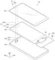
도 1a는 본 발명의 일 실시예에 따른 표시장치(DD)의 결합 사시도이다. 도 1b는 본 발명의 일 실시예에 따른 표시장치(DD)의 분해 사시도이다. 도 2a는 본 발명의 일 실시예에 따른 표시패널(210)의 평면도이다. 도 2b는 본 발명의 일 실시예에 따른 제1 표시영역의 일부를 확대하여 도시한 평면도이다. 도 2c는 본 발명의 일 실시예에 따른 제2 표시영역의 일부를 확대하여 도시한 평면도이다.FIG. 1A is a perspective view of a display device (DD) according to an embodiment of the present invention. FIG. 1B is an exploded perspective view of a display device (DD) according to an embodiment of the present invention. FIG. 2A is a plan view of a display panel (210) according to an embodiment of the present invention. FIG. 2B is a plan view illustrating a portion of a first display area according to an embodiment of the present invention in an enlarged manner. FIG. 2C is a plan view illustrating a portion of a second display area according to an embodiment of the present invention in an enlarged manner.
도 1a 및 도 1b를 참조하면, 표시장치(DD)는 전기적 신호에 따라 활성화되는 장치일 수 있다. 표시장치(DD)는 다양한 실시예들을 포함할 수 있다. 예를 들어, 표시장치(DD)는 태블릿, 노트북, 컴퓨터, 또는 텔레비전 등을 포함할 수 있다. 본 실시예에서, 표시장치(DD)는 스마트 폰으로 예시적으로 도시되었다.Referring to FIGS. 1A and 1B, the display device (DD) may be a device activated according to an electrical signal. The display device (DD) may include various embodiments. For example, the display device (DD) may include a tablet, a laptop, a computer, or a television. In the present embodiment, the display device (DD) is exemplarily illustrated as a smart phone.
표시장치(DD)는 제1 방향(DR1) 및 제2 방향(DR2) 각각에 평행한 표시면(FS)에 제3 방향(DR3)을 향해 영상(IM)을 표시할 수 있다. 영상(IM)이 표시되는 표시면(FS)은 표시장치(DD)의 전면(front surface)과 대응될 수 있으며, 윈도우(100)의 전면(FS)과 대응될 수 있다. 이하, 표시장치(DD)의 표시면, 전면, 및 윈도우(100)의 전면은 동일한 참조부호(FS)를 사용하기로 한다. 영상(IM)은 동적인 영상은 물론 정지 영상을 포함할 수 있다. 도 1a에서 영상(IM)의 일 예로 시계창 및 애플리케이션 아이콘들이 도시되었다.The display device (DD) can display an image (IM) toward a third direction (DR3) on a display surface (FS) parallel to each of the first direction (DR1) and the second direction (DR2). The display surface (FS) on which the image (IM) is displayed can correspond to the front surface of the display device (DD) and can correspond to the front surface (FS) of the window (100). Hereinafter, the display surface, the front surface, and the front surface of the display device (DD) and the front surface of the window (100) will use the same reference symbol (FS). The image (IM) can include a still image as well as a moving image. In Fig. 1a, a clock window and application icons are illustrated as examples of the image (IM).
본 실시예에서는 영상(IM)이 표시되는 방향을 기준으로 각 부재들의 전면(또는 상면)과 배면(또는 하면)이 정의된다. 전면과 배면은 제3 방향(DR3)에서 서로 대향(opposing)되고, 전면과 배면 각각의 법선 방향은 제3 방향(DR3)과 평행할 수 있다. 한편, 제1 내지 제3 방향들(DR1, DR2, DR3)이 지시하는 방향은 상대적인 개념으로서 다른 방향으로 변환될 수 있다.In this embodiment, the front (or upper surface) and the back (or lower surface) of each member are defined based on the direction in which the image (IM) is displayed. The front and the back are opposed to each other in the third direction (DR3), and the normal direction of each of the front and the back can be parallel to the third direction (DR3). Meanwhile, the directions indicated by the first to third directions (DR1, DR2, DR3) are relative concepts and can be converted into other directions.
표시장치(DD)는 윈도우(100), 표시 모듈(200), 구동 회로부(300), 하우징(400), 및 전자모듈들(500)을 포함할 수 있다. 본 실시예에서, 윈도우(100)와 하우징(400)은 결합되어 표시장치(DD)의 외관을 구성할 수 있다.The display device (DD) may include a window (100), a display module (200), a driving circuit (300), a housing (400), and electronic modules (500). In the present embodiment, the window (100) and the housing (400) may be combined to form the appearance of the display device (DD).
윈도우(100)는 광학적으로 투명한 절연 물질을 포함할 수 있다. 예를 들어, 윈도우(100)는 유리 또는 플라스틱을 포함할 수 있다. 윈도우(100)는 다층구조 또는 단층구조를 가질 수 있다. 예를 들어, 윈도우(100)는 접착제로 결합된 복수 개의 플라스틱 필름을 포함하거나, 접착제로 결합된 유리 기판과 플라스틱 필름을 포함할 수 있다.The window (100) may include an optically transparent insulating material. For example, the window (100) may include glass or plastic. The window (100) may have a multilayer structure or a single layer structure. For example, the window (100) may include a plurality of plastic films bonded with an adhesive, or may include a glass substrate and a plastic film bonded with an adhesive.
평면 상에서 윈도우(100)는 투과 영역(TA) 및 베젤 영역(BZA)으로 구분될 수 있다. 본 명세서 내에서 "평면 상에서"의 의미는 제3 방향(DR3)에서 바라보는 경우를 의미할 수 있다. 또한, "두께 방향"은 제3 방향(DR3)을 의미할 수 있다.On a plane, the window (100) can be divided into a transmission area (TA) and a bezel area (BZA). In this specification, the meaning of "on a plane" can mean a case of viewing from a third direction (DR3). In addition, "thickness direction" can mean the third direction (DR3).
투과 영역(TA)은 광학적으로 투명한 영역일 수 있다. 베젤 영역(BZA)은 투과 영역(TA)에 비해 상대적으로 광 투과율이 낮은 영역일 수 있다. 베젤 영역(BZA)은 투과 영역(TA)의 형상을 정의할 수 있다. 베젤 영역(BZA)은 투과 영역(TA)에 인접하며, 투과 영역(TA)을 에워쌀 수 있다.The transmissive area (TA) may be an optically transparent area. The bezel area (BZA) may be an area having relatively low light transmittance compared to the transmissive area (TA). The bezel area (BZA) may define a shape of the transmissive area (TA). The bezel area (BZA) may be adjacent to the transmissive area (TA) and may surround the transmissive area (TA).
베젤 영역(BZA)은 소정의 컬러를 가질 수 있다. 베젤 영역(BZA)은 표시 모듈(200)의 주변 영역(NAA)을 커버하여 주변 영역(NAA)이 외부에서 시인되는 것을 차단할 수 있다. 한편, 이는 예시적으로 도시된 것이고, 본 발명의 일 실시예에 따른 윈도우(100)에 있어서, 베젤 영역(BZA)은 생략될 수도 있다.The bezel area (BZA) may have a predetermined color. The bezel area (BZA) may cover the peripheral area (NAA) of the display module (200) to block the peripheral area (NAA) from being viewed from the outside. Meanwhile, this is illustrated as an example, and in the window (100) according to one embodiment of the present invention, the bezel area (BZA) may be omitted.
표시 모듈(200)은 윈도우(100) 아래에 배치될 수 있다. 본 명세서에서 "아래"는 표시 모듈(200)이 영상을 제공하는 방향의 반대 방향을 의미할 수 있다. 표시 모듈(200)은 영상(IM)을 표시하고 사용자의 입력(TC)을 감지할 수 있다. 표시 모듈(200)은 액티브 영역(AA) 및 주변 영역(NAA)을 포함하는 전면(IS)을 포함한다. 액티브 영역(AA)은 전기적 신호에 따라 활성화되는 영역일 수 있다.The display module (200) may be placed below the window (100). In this specification, “below” may mean the opposite direction to the direction in which the display module (200) provides an image. The display module (200) may display an image (IM) and detect a user’s input (TC). The display module (200) includes a front surface (IS) including an active area (AA) and a peripheral area (NAA). The active area (AA) may be an area that is activated according to an electrical signal.
본 실시예에서, 액티브 영역(AA)은 영상(IM)이 표시되는 영역이며, 동시에 사용자의 입력(TC)이 감지되는 영역일 수 있다. 투과 영역(TA)은 적어도 액티브 영역(AA)과 중첩한다. 예를 들어, 투과 영역(TA)은 액티브 영역(AA)의 전면 또는 적어도 일부와 중첩한다. 이에 따라, 사용자는 투과 영역(TA)을 통해 영상(IM)을 시인하거나, 사용자의 입력(TC)을 제공할 수 있다.In the present embodiment, the active area (AA) is an area where an image (IM) is displayed, and may also be an area where a user's input (TC) is detected. The transparent area (TA) overlaps at least the active area (AA). For example, the transparent area (TA) overlaps the entire surface or at least a portion of the active area (AA). Accordingly, the user can view the image (IM) or provide a user's input (TC) through the transparent area (TA).
주변 영역(NAA)은 베젤 영역(BZA)에 의해 커버되는 영역일 수 있다. 주변 영역(NAA)은 액티브 영역(AA)에 인접한다. 주변 영역(NAA)은 액티브 영역(AA)을 에워쌀 수 있다. 주변 영역(NAA)에는 액티브 영역(AA)을 구동하기 위한 구동 회로나 구동 배선 등이 배치될 수 있다.The peripheral area (NAA) may be an area covered by the bezel area (BZA). The peripheral area (NAA) is adjacent to the active area (AA). The peripheral area (NAA) may surround the active area (AA). A driving circuit or driving wiring for driving the active area (AA) may be arranged in the peripheral area (NAA).
본 실시예에서, 표시 모듈(200)은 액티브 영역(AA) 및 주변 영역(NAA)이 윈도우(100)를 향하는 평탄한 상태로 조립된다. 다만 이는 예시적으로 도시한 것이고, 주변 영역(NAA)의 일부는 휘어질 수 있다. 이때, 주변 영역(NAA) 중 일부는 표시장치(DD)의 배면을 향하게 되어, 표시장치(DD) 전면에서의 베젤 영역(BZA)의 면적이 감소될 수 있다. 또는, 표시 모듈(200)은 액티브 영역(AA)의 일부도 휘어진 상태로 조립될 수도 있다. 또는, 본 발명의 일 실시예에 따른 표시 모듈(200)에 있어서 주변 영역(NAA)은 생략될 수도 있다.In the present embodiment, the display module (200) is assembled in a flat state with the active area (AA) and the peripheral area (NAA) facing the window (100). However, this is merely an example, and a portion of the peripheral area (NAA) may be curved. In this case, a portion of the peripheral area (NAA) may face the back surface of the display device (DD), so that the area of the bezel area (BZA) on the front surface of the display device (DD) may be reduced. Alternatively, the display module (200) may be assembled in a state in which a portion of the active area (AA) is also curved. Alternatively, the peripheral area (NAA) may be omitted in the display module (200) according to one embodiment of the present invention.
표시 모듈(200)의 액티브 영역(AA)은 복수의 표시영역을 포함할 수 있다. 복수의 표시영역은 서로 다른 광투과율을 가질 수 있다. 본 발명의 일 예로, 표시 모듈(200)의 액티브 영역(AA)은 제1 표시영역(DA1) 및 제2 표시영역(DA2)을 포함한다. 제2 표시영역(DA2)은 제1 표시영역(DA1)보다 높은 광 투과율을 가질 수 있다.The active area (AA) of the display module (200) may include a plurality of display areas. The plurality of display areas may have different light transmittances. As an example of the present invention, the active area (AA) of the display module (200) includes a first display area (DA1) and a second display area (DA2). The second display area (DA2) may have higher light transmittance than the first display area (DA1).
구동 회로부(300)는 표시 모듈(200)과 전기적으로 연결될 수 있다. 구동 회로부(300)는 메인 회로 기판(MB) 및 연성 필름(CF)을 포함할 수 있다.The driving circuit unit (300) may be electrically connected to the display module (200). The driving circuit unit (300) may include a main circuit board (MB) and a flexible film (CF).
연성 필름(CF)은 표시 모듈(200)과 전기적으로 연결된다. 연성 필름(CF)은 주변 영역(NAA)에 배치된 표시 모듈(200)의 패드들(PD)에 접속될 수 있다. 연성 필름(CF)은 표시 모듈(200)을 구동하기 위한 전기적 신호를 표시 모듈(200)에 제공한다. 전기적 신호는 연성 필름(CF)에서 생성되거나 메인 회로 기판(MB)에서 생성된 것일 수 있다. 메인 회로 기판(MB)은 표시 모듈(200)을 구동하기 위한 각종 구동 회로나 전원 공급을 위한 커넥터 등을 포함할 수 있다.The flexible film (CF) is electrically connected to the display module (200). The flexible film (CF) can be connected to pads (PD) of the display module (200) arranged in the peripheral area (NAA). The flexible film (CF) provides an electrical signal for driving the display module (200) to the display module (200). The electrical signal may be generated from the flexible film (CF) or from the main circuit board (MB). The main circuit board (MB) may include various driving circuits for driving the display module (200) or connectors for power supply.
전자모듈들(500)은 제1 전자모듈(501) 및 제2 전자모듈(502)을 포함할 수 있다. 평면 상에서, 제1 및 제2 전자모듈들(501, 502)은 제2 표시영역(DA2)과 중첩할 수 있다. 제1 및 제2 전자모듈들(501, 502)은 표시 모듈(200) 아래에 배치될 수 있다. 제1 및 제2 전자모듈들(501, 502)은 제2 표시영역(DA2)을 통해 전달되는 외부 입력을 수신하거나, 제2 표시영역(DA2)을 통해 신호를 출력할 수 있다. 즉, 제2 표시영역(DA2)은 제1 표시영역(DA1)보다 광 투과율이 높기 때문에, 전자모듈들(500)이 제2 표시영역(DA2)을 통해 신호를 용이하게 전달 및/또는 수신할 수 있다.The electronic modules (500) may include a first electronic module (501) and a second electronic module (502). On a plane, the first and second electronic modules (501, 502) may overlap the second display area (DA2). The first and second electronic modules (501, 502) may be arranged under the display module (200). The first and second electronic modules (501, 502) may receive an external input transmitted through the second display area (DA2) or output a signal through the second display area (DA2). That is, since the second display area (DA2) has a higher light transmittance than the first display area (DA1), the electronic modules (500) may easily transmit and/or receive a signal through the second display area (DA2).
제1 및 제2 전자모듈들(501, 502) 각각은 음향출력 모듈(AOM), 발광 모듈(LM), 수광 모듈(LRM), 카메라 모듈(CMM) 중 적어도 어느 하나를 포함할 수 있다. 예를 들어, 제1 전자모듈(501)은 사용자와 표시장치(DD) 사이의 거리를 인지하는 근접센서를 포함할 수 있다. 예를 들어, 제1 전자모듈(501)은 광학 센서, 또는 열감지 센서일 수 있다. 제1 전자모듈(501)은 제2 표시영역(DA2)을 통해 수신되는 외부 피사체를 감지하거나, 열 등을 감지할 수 있다. 예를 들어, 제2 전자모듈(502)은 카메라 모듈(CMM)일 수 있다. 제2 전자모듈(502)은 제2 표시영역(DA2)을 통해 외부의 영상을 촬영할 수 있다.Each of the first and second electronic modules (501, 502) may include at least one of an audio output module (AOM), a light emitting module (LM), a light receiving module (LRM), and a camera module (CMM). For example, the first electronic module (501) may include a proximity sensor that recognizes the distance between a user and the display device (DD). For example, the first electronic module (501) may be an optical sensor or a heat detection sensor. The first electronic module (501) may detect an external subject received through the second display area (DA2), or may detect heat, etc. For example, the second electronic module (502) may be a camera module (CMM). The second electronic module (502) may capture an external image through the second display area (DA2).
하우징(400)은 윈도우(100)와 결합된다. 하우징(400)은 윈도우(100)와 결합되어 내부 공간을 제공한다. 표시 모듈(200) 및 전자모듈들(500)은 내부 공간에 수용될 수 있다.The housing (400) is coupled with the window (100). The housing (400) is coupled with the window (100) to provide an internal space. The display module (200) and electronic modules (500) can be accommodated in the internal space.
하우징(400)은 상대적으로 높은 강성을 가진 물질을 포함할 수 있다. 예를 들어, 하우징(400)은 유리, 플라스틱, 또는 금속을 포함하거나, 이들의 조합으로 구성된 복수 개의 프레임 및/또는 플레이트를 포함할 수 있다. 하우징(400)은 내부 공간에 수용된 표시장치(DD)의 구성들을 외부 충격으로부터 안정적으로 보호할 수 있다.The housing (400) may include a material having relatively high rigidity. For example, the housing (400) may include a plurality of frames and/or plates made of glass, plastic, or metal, or a combination thereof. The housing (400) may stably protect the components of the display device (DD) accommodated in the internal space from external impact.
도 1b 및 도 2a를 참조하면, 표시패널(210)에 제1 표시영역(DA1) 및 제2 표시영역(DA2)이 정의될 수 있다. 제1 표시영역(DA1) 및 제2 표시영역(DA2)은 표시 모듈(200, 도 1b 참조)의 액티브 영역(AA)에 대응할 수 있다.Referring to FIG. 1b and FIG. 2a, a first display area (DA1) and a second display area (DA2) may be defined on a display panel (210). The first display area (DA1) and the second display area (DA2) may correspond to an active area (AA) of a display module (200, see FIG. 1b).
제2 표시영역(DA2) 아래에는 전자모듈들(500, 도 1b 참조)이 배치될 수 있다. 제2 표시영역(DA2)의 광 투과율은 제1 표시영역(DA1)의 광 투과율보다 높을 수 있다. 따라서, 제2 표시영역(DA2)을 통해 신호가 용이하게 전자모듈들(500)로 전달 및/또는 수신될 수 있다. 광 투과율을 높이기 위해서, 제2 표시영역(DA2)의 일부 구성이 생략될 수 있다. 예를 들어, 제2 표시영역(DA2)에 배치된 화소들 중 일부가 제거될 수 있다.Electronic modules (500, see FIG. 1B) may be arranged under the second display area (DA2). The light transmittance of the second display area (DA2) may be higher than the light transmittance of the first display area (DA1). Therefore, signals may be easily transmitted to and/or received by the electronic modules (500) through the second display area (DA2). In order to increase the light transmittance, some components of the second display area (DA2) may be omitted. For example, some of the pixels arranged in the second display area (DA2) may be removed.
제1 표시영역(DA1)과 제2 표시영역(DA2)은 서로 인접할 수 있다. 제2 표시영역(DA2)이 사각 형상을 가질 수 있고, 제2 표시영역(DA2)을 정의하는 적어도 하나의 변이 제1 표시영역(DA1)과 인접할 수 있다. 예를 들어, 제1 표시영역(DA1)은 제2 표시영역(DA2)을 둘러싸는 것일 수 있다. 도 2a에서는 일 예로 제2 표시영역(DA2)의 3개의 변이 제1 표시영역(DA1)과 인접하고, 나머지 하나의 변이 주변 영역(NAA)에 인접하는 것을 도시하였으나, 본 발명은 이에 한정되지 않는다. 또한, 본 발명의 일 예로, 평면 상에서 보았을 때, 제2 표시영역(DA2)은 표시패널(210)의 상부에 정의될 수 있다.The first display area (DA1) and the second display area (DA2) may be adjacent to each other. The second display area (DA2) may have a rectangular shape, and at least one side defining the second display area (DA2) may be adjacent to the first display area (DA1). For example, the first display area (DA1) may surround the second display area (DA2). In FIG. 2A, as an example, three sides of the second display area (DA2) are adjacent to the first display area (DA1), and the remaining side is adjacent to the peripheral area (NAA), but the present invention is not limited thereto. In addition, as an example of the present invention, when viewed in a plan view, the second display area (DA2) may be defined on an upper portion of the display panel (210).
도 2a 및 도 2b를 참조하면, 제1 표시영역(DA1)에는 복수 개의 제1 화소들(PX1)이 배치될 수 있다. 제1 화소들(PX1)은 제1 방향(DR1) 및 제2 방향(DR2)으로 서로 이격되어 배치될 수 있다.Referring to FIGS. 2A and 2B, a plurality of first pixels (PX1) may be arranged in the first display area (DA1). The first pixels (PX1) may be arranged spaced apart from each other in the first direction (DR1) and the second direction (DR2).
제1 화소들(PX1)은 복수 개의 레드 화소들(PX_R1), 복수 개의 그린 화소들(PX_G1, PX_G2), 및 복수 개의 블루 화소들(PX_B1)들을 포함할 수 있다. 제1 화소들(PX1)은 복수 개의 제1 화소 그룹들(PG1)로 그룹핑될 수 있다. 예를 들어, 제1 화소 그룹(PG1)은 하나의 제1 레드 화소(PX_R1), 두 개의 제1 그린 화소(PX_G1, PX_G2), 및 하나의 제1 블루 화소(PX_B1)들을 포함할 수 있다. 제1 화소 그룹(PG1)의 제1 화소들(PX1) 각각은 발광 영역(EA) 및 비발광 영역(NEA)을 포함할 수 있다. 본 발명의 일 예로, 발광 영역(EA)은 사각 형상을 가질 수 있으나, 이에 한정되는 것은 아니다. 발광 영역(EA)에는 발광 소자가 배치되고, 비발광 영역(NEA)에는 발광 소자를 구동하기 위한 트랜지스터들이 배치될 수 있다.The first pixels (PX1) may include a plurality of red pixels (PX_R1), a plurality of green pixels (PX_G1, PX_G2), and a plurality of blue pixels (PX_B1). The first pixels (PX1) may be grouped into a plurality of first pixel groups (PG1). For example, the first pixel group (PG1) may include one first red pixel (PX_R1), two first green pixels (PX_G1, PX_G2), and one first blue pixel (PX_B1). Each of the first pixels (PX1) of the first pixel group (PG1) may include an emission area (EA) and a non-emission area (NEA). As an example of the present invention, the emission area (EA) may have a rectangular shape, but is not limited thereto. A emission element may be arranged in the emission area (EA), and transistors for driving the emission element may be arranged in the non-emission area (NEA).
제1 표시영역(DA1)의 제1 영역(A1)에는 복수 개의 제1 화소 그룹들(PG1)이 배치될 수 있다. 제1 영역(A1)은 단위 면적을 의미할 수 있다. 예를 들어, 제1 영역(A1)의 넓이는 1 inch X 1 inch일 수 있다.A plurality of first pixel groups (PG1) may be arranged in the first area (A1) of the first display area (DA1). The first area (A1) may mean a unit area. For example, the area of the first area (A1) may be 1
제1 영역(A1) 내에서, 제1 화소 그룹들(PG1)은 매트릭스 형상으로 배치될 수 있다. 예를 들어, 복수 개의 제1 화소 그룹들(PG1)은 제1 방향(DR1) 및 제2 방향(DR2)으로 서로 이격되어 배치될 수 있다.Within the first region (A1), the first pixel groups (PG1) may be arranged in a matrix shape. For example, a plurality of the first pixel groups (PG1) may be arranged spaced apart from each other in the first direction (DR1) and the second direction (DR2).
제1 영역(A1)에 18개의 제1 화소 그룹들(PG1)이 배치되는 것으로 도시하였으나, 이는 설명의 편의를 위한 예시적인 도시일 뿐, 이에 한정되는 것은 아니다. 제1 영역(A1)에 배치되는 제1 화소 그룹들(PG1)의 개수는 더 많을 수 있다.Although it is illustrated that 18 first pixel groups (PG1) are arranged in the first area (A1), this is only an exemplary illustration for convenience of explanation and is not limited thereto. The number of first pixel groups (PG1) arranged in the first area (A1) may be greater.
도 2a 및 도 2c를 참조하면, 제2 표시영역(DA2)의 제2 영역(A2)에는 복수 개의 제2 화소들(PX2)이 배치될 수 있다. 제2 영역(A2)은 복수 개의 제2 화소들(PX2)이 각각 배치되는 화소 영역들(PXA) 및 복수 개의 개구 영역들(OA1)을 포함할 수 있다. 개구 영역들(OA1)에는 실질적으로 화소들이 배치되지 않을 수 있다. 즉, 개구 영역들(OA1)은 제2 화소들(PX2) 중 일부 구성(예를 들어, 발광 소자)이 제거된 영역일 수 있다. 따라서, 단위 면적에서 제1 표시영역(DA1)의 해상도는 제2 표시영역(DA2)의 해상도보다 높을 수 있다.Referring to FIGS. 2A and 2C, a plurality of second pixels (PX2) may be arranged in a second area (A2) of a second display area (DA2). The second area (A2) may include pixel areas (PXA) in which a plurality of second pixels (PX2) are respectively arranged, and a plurality of aperture areas (OA1). In the aperture areas (OA1), pixels may not be substantially arranged. That is, the aperture areas (OA1) may be areas in which some components (e.g., light-emitting elements) of the second pixels (PX2) are removed. Therefore, the resolution of the first display area (DA1) in a unit area may be higher than the resolution of the second display area (DA2).
제2 화소들(PX2)은 제1 화소들(PX1)과 구조를 가질 수 있다. 제2 화소들(PX2)은 복수 개의 제2 화소 그룹들(PG2)로 그룹핑될 수 있다. 예를 들어, 제2 화소 그룹(PG2)은 하나의 제2 레드 화소(PX_R2), 두 개의 제2 그린 화소(PX_G3, PX_G4), 및 하나의 제2 블루 화소(PX_B2)들을 포함할 수 있다. 각 화소 영역들(PXA)은 발광 영역(EA) 및 비발광 영역(NEA)을 포함할 수 있다. 본 발명의 일 예로, 발광 영역(EA)은 사각 형상을 가질 수 있으나, 이에 한정되는 것은 아니다. 발광 영역(EA)에는 발광 소자가 배치되고, 비발광 영역(NEA)에는 발광 소자를 구동하기 위한 트랜지스터들이 배치될 수 있다.The second pixels (PX2) may have a structure similar to that of the first pixels (PX1). The second pixels (PX2) may be grouped into a plurality of second pixel groups (PG2). For example, the second pixel group (PG2) may include one second red pixel (PX_R2), two second green pixels (PX_G3, PX_G4), and one second blue pixel (PX_B2). Each pixel area (PXA) may include an emission area (EA) and a non-emission area (NEA). As an example of the present invention, the emission area (EA) may have a square shape, but is not limited thereto. A emission element may be arranged in the emission area (EA), and transistors for driving the emission element may be arranged in the non-emission area (NEA).
제2 영역(A2)은 제1 영역(A1)과 마찬가지로 단위 면적으로 정의될 수 있다. 즉, 제2 영역(A2)과 제1 영역(A1)은 서로 같은 면적을 가질 수 있다.The second area (A2) can be defined as a unit area, similar to the first area (A1). That is, the second area (A2) and the first area (A1) can have the same area.
제2 영역(A2)에는 4개의 제2 화소 그룹들(PG2)이 배치될 수 있다. 제2 영역(A2)에서 제2 화소 그룹들(PG2)이 배치되는 화소 영역들(PXA) 이외의 부분들은 개구 영역(OA1)으로 정의될 수 있다. 개구 영역(OA1)은 외부로부터 제공되는 광을 투과하는 광 경로일 수 있다. 이에 따라, 제2 표시영역(DA2)에 배치되는 센서들은 개구 영역(OA1)을 통해 투과되는 광을 인식하여 사용자의 입력 정보를 감지할 수 있다.In the second area (A2), four second pixel groups (PG2) may be arranged. Parts of the second area (A2) other than the pixel areas (PXA) in which the second pixel groups (PG2) are arranged may be defined as an aperture area (OA1). The aperture area (OA1) may be a light path that transmits light provided from the outside. Accordingly, sensors arranged in the second display area (DA2) may recognize light transmitted through the aperture area (OA1) to detect user input information.
제2 영역(A2)에서 화소 영역들(PXA)의 전체 면적은 개구 영역들(OA1)의 전체 면적보다 작을 수 있다.In the second area (A2), the total area of the pixel areas (PXA) may be smaller than the total area of the aperture areas (OA1).
한편, 동일한 면적 내에서 제2 화소들(PX2)의 개수가 제1 화소들(PX1)의 개수보다 작을 경우, 제1 표시영역(DA1) 및 제2 표시영역(DA2) 사이에 휘도 차이가 발생할 수 있다. 제1 표시영역(DA1) 및 제2 표시영역(DA2) 사이에 휘도 차이가 발생하는 것을 방지하기 위해, 제2 표시영역(DA2)의 휘도가 조절될 수 있다. 구체적으로, 사용자와 표시장치의 거리를 고려하여, 제2 표시영역(DA2)의 휘도가 제1 표시영역(DA1)의 휘도와 동일하도록 조절될 수 있다. 이하, 제2 표시영역(DA2)의 휘도 조절 방법에 대해 설명한다.Meanwhile, when the number of second pixels (PX2) within the same area is smaller than the number of first pixels (PX1), a difference in brightness may occur between the first display area (DA1) and the second display area (DA2). In order to prevent a difference in brightness from occurring between the first display area (DA1) and the second display area (DA2), the brightness of the second display area (DA2) may be adjusted. Specifically, considering the distance between the user and the display device, the brightness of the second display area (DA2) may be adjusted to be the same as the brightness of the first display area (DA1). Hereinafter, a method for adjusting the brightness of the second display area (DA2) will be described.
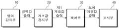
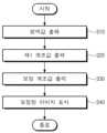
도 3은 본 발명의 일 실시예에 따른 표시장치(DD)의 블럭도이다. 도 4는 본 발명의 일 실시예에 따른 표시장치(DD)의 계조값 조정 방법의 순서도이다. 도 5는 본 발명의 일 실시예에 따른 표시장치(DD)의 휘도 제어 방법을 설명하기 위한 플로우차트를 도시한 것이다. 도 6은 본 발명의 일 실시예에 따른 표시장치(DD)의 영역별 계조에 따른 휘도 그래프를 도시한 것이다.FIG. 3 is a block diagram of a display device (DD) according to an embodiment of the present invention. FIG. 4 is a flowchart of a method for adjusting a grayscale value of a display device (DD) according to an embodiment of the present invention. FIG. 5 is a flowchart illustrating a method for controlling brightness of a display device (DD) according to an embodiment of the present invention. FIG. 6 is a graph illustrating brightness according to grayscale by area of a display device (DD) according to an embodiment of the present invention.
일 실시예의 표시장치(DD)는 영역 감지부(10), 계조값 감지부(20), 제어부(30), 및 표시부(40)를 포함할 수 있다.A display device (DD) of one embodiment may include an area detection unit (10), a grayscale value detection unit (20), a control unit (30), and a display unit (40).
영역 감지부(10)에 이미지가 입력되면, 영역값 출력 단계(S10)가 진행된다. 영역값 출력 단계(S10)는 이미지의 위치값 출력 단계(S11) 및 영역 범위 판단 단계(S12)로 구분될 수 있다.When an image is input to the area detection unit (10), an area value output step (S10) is performed. The area value output step (S10) can be divided into an image position value output step (S11) and an area range determination step (S12).
이미지의 위치값 출력 단계(S11)는 입력된 이미지에 배치된 화소의 위치를 이용하여, 이미지의 위치를 데이터값으로 출력하는 단계일 수 있다. 입력된 이미지에 배치된 화소는 제1 화소(PX1, 도 2a 참조) 또는 제2 화소(PX2, 도 2a 참조)일 수 있다. 이미지의 위치값은 제1 화소(PX1) 또는 제2 화소(PX2)에 대한 데이터 값일 수 있다.The image position value output step (S11) may be a step of outputting the image position as a data value by using the positions of pixels arranged in the input image. The pixels arranged in the input image may be a first pixel (PX1, see FIG. 2a) or a second pixel (PX2, see FIG. 2a). The image position value may be a data value for the first pixel (PX1) or the second pixel (PX2).
영역 범위 판단 단계(S12)는 이미지의 위치값에 따라 이미지가 속하는 영역을 판단하여 영역값을 출력하는 단계일 수 있다. 이미지에 배치된 화소가 제1 화소(PX1)일 경우, 제1 표시영역(DA1)의 영역값이 출력되고, 이미지에 배치된 화소가 제2 화소(PX2)일 경우, 제2 표시영역(DA2)의 영역값이 출력될 수 있다.The area range determination step (S12) may be a step of determining the area to which the image belongs based on the position value of the image and outputting the area value. If the pixel placed in the image is the first pixel (PX1), the area value of the first display area (DA1) may be output, and if the pixel placed in the image is the second pixel (PX2), the area value of the second display area (DA2) may be output.
영역값은 영역 감지부(10)에서 계조값 감지부(20)로 진행할지 여부를 판단하는 기준 인자(factor)가 된다. 예를 들어, 영역이 제1 표시영역(DA1)로 판단될 경우 플로우차트는 영역 감지부(10)에서 계조값 감지부(20)로 진행되지 않고, 종료될 수 있다. 영역이 제2 표시영역(DA2)으로 판단될 경우, 영역 감지부(10)는 계조값 감지부(20)로 영역값을 전송할 수 있다.The area value becomes a criterion factor for determining whether to proceed from the area detection unit (10) to the tone value detection unit (20). For example, if the area is determined to be the first display area (DA1), the flow chart may end without proceeding from the area detection unit (10) to the tone value detection unit (20). If the area is determined to be the second display area (DA2), the area detection unit (10) may transmit the area value to the tone value detection unit (20).
한편, 입력된 이미지는 휘도값을 가질 수 있다. 이미지의 휘도값은 제1 휘도로 정의한다. 구체적으로, 제1 화소(PX1)가 생성한 이미지가 입력될 경우, 제1 휘도는 제1 표시휘도이고, 제2 화소(PX2)가 생성한 이미지가 입력될 경우, 제1 휘도는 제2 표시휘도이다.Meanwhile, the input image may have a luminance value. The luminance value of the image is defined as the first luminance. Specifically, when an image generated by the first pixel (PX1) is input, the first luminance is the first display luminance, and when an image generated by the second pixel (PX2) is input, the first luminance is the second display luminance.
계조값 감지부(20)에 영역값이 수신되면, 제1 계조값 출력 단계(S20)가 진행된다. 제1 계조값 출력 단계(S20)는 제1 휘도에 대응하는 제1 계조값을 출력하는 단계이다. 계조값 감지부(20)가 작동되기 위해서는 제2 표시영역(DA2)에 대한 영역값이 수신된 경우이므로, 제1 휘도는 제2 표시휘도일 수 있다.When the area value is received by the tone value detection unit (20), the first tone value output step (S20) is performed. The first tone value output step (S20) is a step of outputting the first tone value corresponding to the first brightness. Since the tone value detection unit (20) operates when the area value for the second display area (DA2) is received, the first brightness may be the second display brightness.
제2 표시휘도에 대응하는 제1 계조값을 출력하는 과정을 설명하기 위하여, 도 6을 함께 참조한다.To explain the process of outputting the first tone value corresponding to the second display brightness, refer to Fig. 6.
도 6은 제1 표시영역(DA1)의 계조-휘도 그래프인 그래프 1 및 제2 표시영역(DA2)의 계조-휘도 그래프인 그래프 2를 도시한 것이다. 즉, 제1 표시영역(DA1)의 계조값 및 휘도값은 그래프 1에 적용될 수 있고, 제2 표시영역(DA2)의 계조값 및 화소값은 그래프 2에 적용될 수 있다. 그래프 1 및 그래프 2는 휘도계 및 조도계를 이용하여 일 실시예의 표시장치마다 데이터를 측정하여 얻을 수 있다.FIG. 6 illustrates
일 예로 측정된 제2 표시휘도가 L2일 때, 제2 표시영역(DA2)에 해당하는 그래프 2에서 제2 표시휘도에 대응하는 제1 계조값을 찾을 수 있다. 그래프 2의 A점은 계조값이 G1, 휘도값이 L2이므로 제2 표시휘도가 L2인 경우, 이에 대응하는 제1 계조값은 G1임을 산출할 수 있다.For example, when the measured second display luminance is L2, the first grayscale value corresponding to the second display luminance can be found in Graph 2 corresponding to the second display area (DA2). Since point A of Graph 2 has a grayscale value of G1 and a luminance value of L2, it can be calculated that when the second display luminance is L2, the first grayscale value corresponding to it is G1.
다시 도 5를 참조하면, 계조값 감지부(20)는 제1 계조값으로 G1을 출력하여 제어부(30)에 전송할수 있다.Referring again to FIG. 5, the tone value detection unit (20) can output G1 as the first tone value and transmit it to the control unit (30).
제어부(30)는 본 발명의 일 실시예에 따른 표시장치의 전반적인 동작을 제어한다. 예를 들어 음성 통화, 데이터 통신, 화상 통화 등을 위한 관련된 제어 및 처리를 수행한다. 또한, 제어부(30)는 통상적인 기능 이외에 표시부(40)의 동작을 제어할 수도 있다. 즉, 제어부(30)는 계조값 감지부(20)가 출력한 제1 계조값에 상응하여 표시부(40)에 표시되는 이미지의 휘도를 조절할 수 있다.The control unit (30) controls the overall operation of the display device according to one embodiment of the present invention. For example, it performs related control and processing for voice calls, data communications, video calls, etc. In addition, the control unit (30) can control the operation of the display unit (40) in addition to the normal functions. That is, the control unit (30) can adjust the brightness of the image displayed on the display unit (40) corresponding to the first grayscale value output by the grayscale value detection unit (20).
제어부(30)에 제1 계조값이 수신되면, 보정 계조값 출력 단계(S30)가 진행된다. 보정 계조값 출력 단계(S30)는 입력된 이미지가 속하는 제2 표시영역(DA2)이 제1 표시영역(DA1)과 동일한 휘도값을 갖기 위한 보정 계조값을 출력하는 단계이다.When the first tone value is received in the control unit (30), a correction tone value output step (S30) is performed. The correction tone value output step (S30) is a step of outputting a correction tone value so that the second display area (DA2) to which the input image belongs has the same brightness value as the first display area (DA1).
입력된 이미지는 보정 계조값으로 보정됨에 따라, 보정 휘도를 가질 수 있다. 보정 휘도는 제1 표시휘도와 실질적으로 동일한 것일 수 있다. 제2 표시영역(DA2)에 속하는 이미지가 보정 휘도를 가짐에 따라, 제1 표시영역(DA1) 및 제2 표시영역(DA2) 사이의 휘도 차이가 감소될 수 있다.The input image may have a compensation luminance as it is compensated with the compensation gradation value. The compensation luminance may be substantially the same as the first display luminance. As the image belonging to the second display area (DA2) has the compensation luminance, the luminance difference between the first display area (DA1) and the second display area (DA2) may be reduced.
본 명세서에서, '실질적으로 동일' 등의 용어는 측정된 수치 범위에 대하여 일반적으로 발생할 수 있는 측정 상의 오차 등을 포함하여 동일하다는 의미로 이해되어야 한다. 따라서, 보정 휘도와 제1 표시휘도가 실질적으로 동일하다는 것은 측정 상의 오차를 포함하여 보정 휘도 값과 제1 표시휘도의 값이 동일하다는 것으로 이해되어야 한다.In this specification, the terms "substantially the same" and the like should be understood to mean the same, including measurement errors that may generally occur for the measured numerical range. Accordingly, it should be understood that the corrected luminance and the first display luminance are substantially the same, including measurement errors, meaning that the corrected luminance value and the value of the first display luminance are the same.
제어부(30)는 보정 휘도를 찾기 위해, 그래프 2의 A점과 동일한 계조값인 G1을 가지는 그래프 1의 B점을 참조할 수 있다. B점은 계조값이 G1일 때, 휘도가 L1이다. 즉, 제1 표시영역(DA1)은 계조값이 G1일 때 제1 표시휘도가 L1이다. 따라서, 입력된 이미지는 제2 표시휘도인 L2에서 제1 표시휘도인 L1으로 보정되는 것이 바람직하며, 보정 휘도는 L1일 수 있다.The control unit (30) can refer to point B of
제어부(30)는 보정 휘도인 L1에 대응하는 보정 계조값을 찾기 위해, 그래프 2의 C점은 참조할 수 있다. C점은 계조값이 G2이고 휘도가 L1인 점이다. 따라서, 보정 휘도 L1에 대응하는 보정 계조값은 G2이다.The control unit (30) can refer to point C of graph 2 to find a compensation tone value corresponding to the compensation luminance L1. Point C is a point where the tone value is G2 and the luminance is L1. Therefore, the compensation tone value corresponding to the compensation luminance L1 is G2.
제어부(30)는 보정 계조값인 G2를 출력하여, 표시부(40)에 전송할 수 있다.The control unit (30) can output the compensation grayscale value G2 and transmit it to the display unit (40).
표시부(40)는 영상을 표시할 수 있는 표시패널의 일부일 수 있다. 표시패널은 특별히 한정되는 것은 아니며, 예를 들어, 유기발광표시패널(organic light emitting display panel), 액정표시패널(liquid crystal display panel), 플라즈마 표시장치(plasma display panel), 전기영동 표시패널(electrophoretic display panel), 및 일렉트로웨팅 표시패널(electrowetting display panel)등이 적용될 수 있다.The display unit (40) may be a part of a display panel capable of displaying an image. The display panel is not particularly limited, and for example, an organic light emitting display panel, a liquid crystal display panel, a plasma display panel, an electrophoretic display panel, and an electrowetting display panel may be applied.
표시부(40)가 보정 계조값을 수신하면, 보정된 이미지 출력 단계(S40)가 진행된다. 보정된 이미지는 보정 계조값 및 보정 휘도를 갖는 이미지일 수 있다.When the display unit (40) receives the correction tone value, a corrected image output step (S40) is performed. The corrected image may be an image having a correction tone value and a correction brightness.
입력된 이미지는, 영역 감지부(10), 계조값 감지부(20), 제어부(30), 및 표시부(40)를 통해서 보정된 이미지로 보정될 수 있다.The input image can be corrected into a corrected image through the area detection unit (10), the grayscale value detection unit (20), the control unit (30), and the display unit (40).
입력된 이미지는 제1 계조값 및 제2 표시휘도를 가지는 것에서, 보정 계조값 및 보정 휘도를 가지는 보정된 이미지로 보정된다.The input image is corrected from having a first tone value and a second display luminance to a corrected image having a corrected tone value and a corrected luminance.
보정 휘도는 제2 표시휘도와 상이한 값을 가질 수 있다. 예를 들어, 입력된 이미지가 제2 표시휘도인 L2에서 보정 휘도인 L1으로 보정되듯이, 보정 휘도는 제2 표시휘도보다 작을 수 있다.The correction luminance may have a different value from the second display luminance. For example, the correction luminance may be less than the second display luminance, as the input image is corrected from the second display luminance L2 to the correction luminance L1.
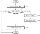
또한, 본 발명의 일 실시예에 따른 표시장치는 사용자의 근접거리를 인지하는 근접 센서를 더 포함할 수 있다. 예를 들어, 제1 전자모듈(501, 도 1b 참조)은 근접 센서일 수 있다. 근접 센서는 광학 센서 또는 열감지 센서를 포함할 수 있다.In addition, the display device according to one embodiment of the present invention may further include a proximity sensor for recognizing a proximity distance of a user. For example, the first electronic module (501, see FIG. 1B) may be a proximity sensor. The proximity sensor may include an optical sensor or a thermal sensor.
제1 전자모듈(501, 도 1b 참조)은 사용자의 근접거리를 인지할 수 있다. 제어부(30)는 상기 근접거리를 고려하여 보정 계조값을 결정할 수 있다.The first electronic module (501, see FIG. 1b) can recognize the proximity of the user. The control unit (30) can determine a compensation grayscale value by considering the proximity.
도 7은 본 발명의 일 실시예에 따른 제2 화소(PX2)의 근접거리에 따른 휘도 그래프를 도시한 것이다. 제2 표시영역(DA2)의 휘도는 제2 표시휘도로 정의하였으므로, 도 7의 그래프는 근접거리에 따른 제2 표시휘도일 수 있다.Fig. 7 illustrates a graph of luminance according to the proximity distance of a second pixel (PX2) according to one embodiment of the present invention. Since the luminance of the second display area (DA2) is defined as the second display luminance, the graph of Fig. 7 may be the second display luminance according to the proximity distance.
도 7을 참조하면, 제1 전자모듈(501, 도 1b 참조)에서 인지한 근접거리에 따라 제2 표시휘도가 조절될 수 있다.Referring to FIG. 7, the second display brightness can be adjusted according to the proximity distance recognized by the first electronic module (501, refer to FIG. 1b).
일 실시예의 표시장치(DD)에서 단위 면적당 제2 화소들(PX2)의 개수가 단위 면적당 제1 화소들(PX1)의 개수보다 작을 수 있다. 표시장치(DD)는 제1 표시영역(DA1) 및 제2 표시영역(DA2) 각각의 영역별 휘도가 동일하도록, 제2 화소(PX2)의 휘도를 감소시키거나 증가시킬 수 있다.In one embodiment of the display device (DD), the number of second pixels (PX2) per unit area may be smaller than the number of first pixels (PX1) per unit area. The display device (DD) may reduce or increase the brightness of the second pixel (PX2) so that the brightness of each area of the first display area (DA1) and the second display area (DA2) is the same.
예를 들어, 제2 화소(PX2)의 단위 면적당 개수는 제1 화소(PX1)의 단위 면적당 개수보다 작기 때문에 제2 화소(PX2) 각각의 휘도는 제1 화소(PX1) 각각의 휘도에 비해 크게 조절될 수 있다.For example, since the number per unit area of the second pixel (PX2) is smaller than the number per unit area of the first pixel (PX1), the brightness of each of the second pixels (PX2) can be adjusted to be greater than the brightness of each of the first pixels (PX1).
다만, 사용자와의 거리가 멀어질 경우, 예를 들어 근접거리가 30cm 이상일 경우에 사용자는 제1 표시영역(DA1) 및 제2 표시영역(DA2) 사이의 휘도 차이를 인지하기 어려울 수 있다. 따라서, 각각의 제2 화소(PX2)가 시인되는 휘도는 증가하다가 포화될 수 있다.However, when the distance from the user increases, for example, when the proximity is 30 cm or more, the user may have difficulty perceiving the difference in brightness between the first display area (DA1) and the second display area (DA2). Accordingly, the brightness recognized by each second pixel (PX2) may increase and then become saturated.
반대로 사용자와 표시장치 사이의 거리가 가까워질 경우, 예를 들어 근접거리가 30cm 이하일 경우에 제1 화소(PX1) 각각의 휘도 및 제2 화소(PX2) 각각의 휘도의 차이는 사용자에 쉽게 인지될 수 있다. 제1 화소(PX1) 및 제2 화소(PX2)의 휘도 차이를 줄이기 위해서, 근접거리가 30cm 이하일 경우의 제2 화소(PX2)의 보정 휘도는 근접거리가 30cm인 경우의 제2 화소(PX2)의 휘도보다 작아질 수 있다. 즉, 근접거리가 30cm 이하로 가까워질수록 제2 화소(PX2)의 휘도는 감소할 수 있다. 이에 따라, 제2 화소(PX2)가 배치된 제2 표시영역(DA2)의 상기 보정 휘도도 감소할 수 있다.Conversely, when the distance between the user and the display device becomes closer, for example, when the proximity distance is 30 cm or less, the difference between the luminance of each first pixel (PX1) and the luminance of each second pixel (PX2) can be easily recognized by the user. In order to reduce the luminance difference between the first pixel (PX1) and the second pixel (PX2), the corrected luminance of the second pixel (PX2) when the proximity distance is 30 cm or less can be made smaller than the luminance of the second pixel (PX2) when the proximity distance is 30 cm or less. That is, the luminance of the second pixel (PX2) can decrease as the proximity distance becomes 30 cm or less. Accordingly, the corrected luminance of the second display area (DA2) where the second pixel (PX2) is arranged can also decrease.
제1 전자모듈(501, 도 1b 참조)이 근접 센서일 경우, 제어부(30)는 근접거리를 고려한 보정 휘도를 산출하여 보정 계조값을 출력할 수 있다. 표시부(40)는 보정 계조값을 수신하여 근접거리를 고려한 보정 이미지를 표시할 수 있다.When the first electronic module (501, see FIG. 1b) is a proximity sensor, the control unit (30) can calculate a correction brightness considering the proximity distance and output a correction grayscale value. The display unit (40) can receive the correction grayscale value and display a correction image considering the proximity distance.
제1 전자모듈(501)에서 인지된 거리가 짧은 경우, 사용자는 화면을 볼 때 제2 표시영역(DA2)의 휘도를 제1 표시영역(DA1)의 휘도에 비해 상대적으로 밝게 인식할 수 있다. 이 때, 본 발명에 따른 영역 감지부(10), 계조값 감지부(20), 제어부(30), 및 표시부(40)는 거리에 맞게 제2 표시영역(DA2)의 휘도를 서서히 감소시킬 수 있다.When the distance recognized by the first electronic module (501) is short, the user may perceive the brightness of the second display area (DA2) as relatively brighter than the brightness of the first display area (DA1) when looking at the screen. At this time, the area detection unit (10), the grayscale value detection unit (20), the control unit (30), and the display unit (40) according to the present invention may gradually reduce the brightness of the second display area (DA2) according to the distance.
따라서, 본 발명에 따른 표시장치는 사용자와의 거리에 따라, 제2 표시영역(DA2)의 휘도를 다양하게 제어함으로써 제1 표시영역(DA1) 및 제2 표시영역(DA2) 사이의 휘도 차이를 감소시킬 수 있다. 이를 통해, 일 실시예에 따른 표시장치는 사용자의 거리에 관계없이 영역별로 일정한 휘도를 가지는 표시장치를 제공할 수 있다.Accordingly, the display device according to the present invention can reduce the difference in brightness between the first display area (DA1) and the second display area (DA2) by controlling the brightness of the second display area (DA2) in various ways depending on the distance from the user. Through this, the display device according to one embodiment can provide a display device having a constant brightness for each area regardless of the distance from the user.
이상에서는 본 발명의 바람직한 실시예를 참조하여 설명하였지만, 해당 기술 분야의 숙련된 당업자 또는 해당 기술 분야에 통상의 지식을 갖는 자라면, 후술될 청구범위에 기재된 본 발명의 사상 및 기술 영역으로부터 벗어나지 않는 범위 내에서 본 발명을 다양하게 수정 및 변경시킬 수 있음을 이해할 수 있을 것이다.Although the present invention has been described above with reference to preferred embodiments thereof, it will be understood by those skilled in the art or having ordinary knowledge in the art that various modifications and changes may be made to the present invention without departing from the spirit and technical scope of the present invention as set forth in the claims below.
따라서, 본 발명의 기술적 범위는 명세서의 상세한 설명에 기재된 내용으로 한정되는 것이 아니라 청구범위에 의해 정하여져야만 할 것이다.Therefore, the technical scope of the present invention should not be limited to the contents described in the detailed description of the specification, but should be defined by the claims.
10: 조도 감지부20: 계조값 감지부
30: 제어부40: 표시부
S10: 영역값 출력 단계S20: 제1 계조값 출력 단계
S30: 보정 계조값 출력 단계S40: 보정 이미지 표시 단계10: Illuminance detection unit 20: Gradation value detection unit
30: Control section 40: Display section
S10: Area value output step S20: First tone value output step
S30: Correction tone value output stage S40: Correction image display stage
Claims (20)
Translated fromKorean상기 이미지의 휘도를 제1 휘도로 정의할 때, 상기 영역값에 따라 상기 제1 휘도에 대응하는 제1 계조값을 출력하는 계조값 감지부;
표시장치와 사용자 사이의 거리를 인지하는 근접 센서;
상기 제1 계조값에 대응하는 보정 계조값을 출력하는 제어부; 및
상기 이미지를 표시하거나, 또는 상기 보정 계조값에 대응하는 보정 휘도를 가지는 보정된 이미지를 표시하는 표시부; 를 포함하고,
상기 영역범위는 제1 표시영역 또는 제2 표시영역이고,
상기 입력된 이미지의 상기 영역범위가 상기 제1 표시영역인 경우, 상기 제1 휘도는 제1 표시휘도이고,
상기 입력된 이미지의 상기 영역범위가 상기 제2 표시영역인 경우, 상기 제1 휘도는 제2 표시휘도이고,
상기 제1 표시휘도는 상기 제2 표시휘도보다 작고,
상기 보정 휘도는 상기 근접 센서에 의해 인지된 거리에 따라 결정되는 표시장치.An area detection unit that measures the position value of an input image, determines the area range based on the position value, and outputs the area value;
When defining the brightness of the above image as the first brightness, a grayscale value detection unit that outputs a first grayscale value corresponding to the first brightness according to the area value;
Proximity sensor that detects the distance between the display device and the user;
A control unit that outputs a correction tone value corresponding to the first tone value; and
A display unit for displaying the image or displaying a corrected image having a corrected luminance corresponding to the corrected grayscale value;
The above area range is the first display area or the second display area,
If the above-mentioned area range of the above-mentioned input image is the first display area, the first luminance is the first display luminance,
If the above-mentioned area range of the input image is the second display area, the first brightness is the second display brightness,
The above first display brightness is smaller than the above second display brightness,
A display device in which the above-mentioned compensation brightness is determined according to the distance recognized by the above-mentioned proximity sensor.
상기 제1 표시영역의 단위 면적당 배치된 화소의 개수는 상기 제2 표시영역의 단위 면적당 배치된 화소의 개수보다 많은 표시장치.In the first paragraph,
A display device in which the number of pixels arranged per unit area of the first display area is greater than the number of pixels arranged per unit area of the second display area.
상기 제1 표시영역은 상기 제2 표시영역을 둘러싸는 표시장치.In the first paragraph,
A display device in which the first display area surrounds the second display area.
상기 입력된 이미지의 상기 영역범위가 상기 제1 표시영역인 경우,
상기 계조값 감지부는 상기 제1 계조값을 출력하지 않고, 상기 제어부는 상기 보정 계조값을 출력하지 않으며, 상기 표시부는 상기 이미지의 휘도를 표시하는 표시장치.In the first paragraph,
If the above-mentioned area range of the input image is the above-mentioned first display area,
A display device in which the tone value detection unit does not output the first tone value, the control unit does not output the correction tone value, and the display unit displays the brightness of the image.
상기 보정 휘도 및 상기 제2 표시휘도는 서로 상이한 표시장치.In the first paragraph,
The above-mentioned corrected luminance and the above-mentioned second display luminance are different display devices.
상기 보정 휘도는 상기 제2 표시휘도보다 작은 표시장치.In the first paragraph,
A display device wherein the above-mentioned corrected luminance is smaller than the above-mentioned second display luminance.
상기 보정 휘도는 상기 제1 표시휘도와 실질적으로 동일한 표시장치.In the first paragraph,
A display device wherein the above-mentioned corrected luminance is substantially the same as the above-mentioned first display luminance.
상기 인지된 거리가 커질수록 상기 보정 휘도는 증가하다가 포화되는 표시장치.In the first paragraph,
A display device in which the corrected luminance increases and then becomes saturated as the perceived distance increases.
상기 인지된 거리가 작아질수록 상기 보정 휘도는 감소하는 표시장치.In the first paragraph,
A display device in which the correction brightness decreases as the perceived distance decreases.
상기 근접 센서는 광학 센서 또는 열감지 센서를 포함하는 표시장치.In the first paragraph,
The above proximity sensor is a display device including an optical sensor or a thermal sensor.
상기 제1 표시영역의 광 투과율은 상기 제2 표시영역의 광 투과율보다 낮은 표시장치.In the first paragraph,
A display device in which the light transmittance of the first display area is lower than the light transmittance of the second display area.
상기 제2 표시영역 아래에 배치된 카메라 모듈을 더 포함하는 표시장치.In the first paragraph,
A display device further comprising a camera module positioned below the second display area.
상기 이미지의 휘도를 제1 휘도로 정의할 때, 상기 영역값에 따라 상기 제1 휘도에 대응하는 제1 계조값을 출력하는 단계;
근접 센서를 이용하여 상기 이미지와 사용자 사이의 거리를 인지하는 단계;
상기 제1 계조값에 대응하는 보정 계조값을 출력하는 단계; 및
상기 이미지를 표시하거나, 또는 상기 보정 계조값에 대응하는 보정 휘도를 가지는 보정된 이미지를 표시하는 표시단계; 를 포함하고,
상기 영역범위는 제1 표시영역 또는 제2 표시영역이고,
상기 입력된 이미지의 상기 영역범위가 상기 제1 표시영역인 경우, 상기 제1 휘도는 제1 표시휘도이고,
상기 입력된 이미지의 상기 영역범위가 상기 제2 표시영역인 경우, 상기 제1 휘도는 제2 표시휘도이고,
상기 제1 표시휘도는 상기 제2 표시휘도보다 작고,
상기 보정 휘도는 상기 근접 센서에 의해 인지된 거리에 따라 결정되는 계조값 조정 방법.A step of measuring the position value of an input image, determining the area range based on the position value, and outputting the area value;
When defining the luminance of the above image as the first luminance, a step of outputting a first tone value corresponding to the first luminance according to the area value;
A step of recognizing the distance between the image and the user using a proximity sensor;
A step of outputting a correction tone value corresponding to the first tone value; and
A display step for displaying the image or displaying a corrected image having a corrected luminance corresponding to the corrected grayscale value;
The above area range is the first display area or the second display area,
If the above-mentioned area range of the above-mentioned input image is the first display area, the first luminance is the first display luminance,
If the above-mentioned area range of the input image is the second display area, the first brightness is the second display brightness,
The above first display brightness is smaller than the above second display brightness,
The above correction brightness is a method for adjusting the grayscale value determined according to the distance recognized by the proximity sensor.
상기 입력된 이미지의 상기 영역범위가 상기 제1 표시영역인 경우,
상기 표시단계에서는 상기 입력된 이미지가 표시되는 계조값 조정 방법.In Article 13,
If the above-mentioned area range of the input image is the above-mentioned first display area,
In the above display step, a method for adjusting the gradation value by which the input image is displayed.
상기 보정 휘도 및 상기 제2 표시휘도는 서로 상이한 계조값 조정 방법.In Article 13,
The above correction luminance and the second display luminance are different tone value adjustment methods.
상기 보정 휘도는 상기 제2 표시휘도보다 작은 계조값 조정 방법.In Article 13,
A method for adjusting the tone value in which the above-mentioned compensation luminance is smaller than the above-mentioned second display luminance.
상기 보정 휘도는 상기 제1 표시휘도와 실질적으로 동일한 계조값 조정 방법.In Article 13,
A method for adjusting the tone value in which the above-mentioned corrected luminance is substantially the same as the above-mentioned first display luminance.
상기 인지된 거리가 커질수록 상기 보정 휘도는 증가하다가 포화되는 계조값 조정 방법.In Article 13,
A method of adjusting the tone value in which the correction luminance increases and then becomes saturated as the perceived distance increases.
상기 인지된 거리가 작아질수록 상기 보정 휘도는 감소하는 계조값 조정 방법.In Article 13,
A method for adjusting the tone value in which the correction luminance decreases as the perceived distance decreases.
상기 근접 센서는 광학 센서 또는 열감지 센서를 포함하는 계조값 조정 방법.In Article 13,
A method for adjusting grayscale values, wherein the proximity sensor includes an optical sensor or a thermal sensor.
Priority Applications (4)
| Application Number | Priority Date | Filing Date | Title |
|---|---|---|---|
| KR1020200064118AKR102747614B1 (en) | 2020-05-28 | 2020-05-28 | Display device and adjusting method of gradation value |
| US17/213,435US11527187B2 (en) | 2020-05-28 | 2021-03-26 | Display device and method for adjusting gradation value |
| CN202110571711.4ACN113744678A (en) | 2020-05-28 | 2021-05-25 | Display device |
| US18/079,800US11935451B2 (en) | 2020-05-28 | 2022-12-12 | Display device and method for adjusting gradation value |
Applications Claiming Priority (1)
| Application Number | Priority Date | Filing Date | Title |
|---|---|---|---|
| KR1020200064118AKR102747614B1 (en) | 2020-05-28 | 2020-05-28 | Display device and adjusting method of gradation value |
Publications (2)
| Publication Number | Publication Date |
|---|---|
| KR20210148468A KR20210148468A (en) | 2021-12-08 |
| KR102747614B1true KR102747614B1 (en) | 2025-01-02 |
Family
ID=78705331
Family Applications (1)
| Application Number | Title | Priority Date | Filing Date |
|---|---|---|---|
| KR1020200064118AActiveKR102747614B1 (en) | 2020-05-28 | 2020-05-28 | Display device and adjusting method of gradation value |
Country Status (3)
| Country | Link |
|---|---|
| US (2) | US11527187B2 (en) |
| KR (1) | KR102747614B1 (en) |
| CN (1) | CN113744678A (en) |
Families Citing this family (1)
| Publication number | Priority date | Publication date | Assignee | Title |
|---|---|---|---|---|
| WO2025198195A1 (en)* | 2024-03-18 | 2025-09-25 | 주식회사 엘엑스세미콘 | Data compensation circuit and display device comprising same |
Citations (1)
| Publication number | Priority date | Publication date | Assignee | Title |
|---|---|---|---|---|
| US20200135147A1 (en)* | 2019-09-11 | 2020-04-30 | Wuhan Tianma Micro-Electronics Co., Ltd. | Driving method and driving device of display panel, and display device |
Family Cites Families (19)
| Publication number | Priority date | Publication date | Assignee | Title |
|---|---|---|---|---|
| JP5023756B2 (en)* | 2006-04-27 | 2012-09-12 | ソニー株式会社 | Display image quality control device by region, self-luminous display device, and computer program |
| KR101501949B1 (en) | 2008-04-04 | 2015-03-11 | 엘지전자 주식회사 | A mobile terminal and a control method capable of controlling operation using a proximity sensor |
| US8339429B2 (en)* | 2008-07-24 | 2012-12-25 | International Business Machines Corporation | Display monitor electric power consumption optimization |
| CN101814272B (en)* | 2009-02-20 | 2011-12-07 | 纬创资通股份有限公司 | Display device and brightness adjusting method thereof |
| US8698859B2 (en)* | 2010-10-19 | 2014-04-15 | Blackberry Limited | Display screen having regions of differing pixel density |
| GB2525388B (en)* | 2014-04-17 | 2021-01-13 | Advanced Risc Mach Ltd | Method of and apparatus for processing data for a display |
| KR102418360B1 (en)* | 2015-11-12 | 2022-07-08 | 삼성전자주식회사 | A method for executing a function of an electronic device using a bio-signal and the electronic device therefor |
| KR102702307B1 (en)* | 2016-08-03 | 2024-09-04 | 삼성전자주식회사 | Display apparatus and control method of Electronic apparatus |
| US9704216B1 (en)* | 2016-08-04 | 2017-07-11 | Le Technology | Dynamic size adjustment of rendered information on a display screen |
| KR102530765B1 (en)* | 2016-09-09 | 2023-05-11 | 삼성디스플레이주식회사 | Display device, driving device, and method for driving the display device |
| KR20180050473A (en) | 2016-11-04 | 2018-05-15 | 삼성디스플레이 주식회사 | Display device |
| CN106910487B (en)* | 2017-04-11 | 2019-02-26 | 武汉华星光电技术有限公司 | A kind of driving method and driving device of display |
| CN107945766A (en)* | 2017-11-03 | 2018-04-20 | 苏州佳世达电通有限公司 | Display device |
| CN109872670B (en) | 2017-12-05 | 2021-11-05 | 京东方科技集团股份有限公司 | Display screen, display device, display circuit and brightness compensation method thereof |
| CN108810201B (en)* | 2018-06-04 | 2020-07-17 | Oppo广东移动通信有限公司 | Electronic device and method for taking photo by using same |
| KR102651651B1 (en)* | 2018-11-09 | 2024-03-28 | 엘지디스플레이 주식회사 | Display Device and Driving Method Thereof |
| KR102832798B1 (en) | 2019-06-17 | 2025-07-11 | 삼성디스플레이 주식회사 | Display device |
| KR20210128554A (en) | 2020-04-16 | 2021-10-27 | 삼성디스플레이 주식회사 | Display panel and display device |
| KR102783330B1 (en)* | 2020-04-29 | 2025-03-20 | 삼성디스플레이 주식회사 | Display apparatus and method of compensating gamma value of the same |
- 2020
- 2020-05-28KRKR1020200064118Apatent/KR102747614B1/enactiveActive
- 2021
- 2021-03-26USUS17/213,435patent/US11527187B2/enactiveActive
- 2021-05-25CNCN202110571711.4Apatent/CN113744678A/enactivePending
- 2022
- 2022-12-12USUS18/079,800patent/US11935451B2/enactiveActive
Patent Citations (1)
| Publication number | Priority date | Publication date | Assignee | Title |
|---|---|---|---|---|
| US20200135147A1 (en)* | 2019-09-11 | 2020-04-30 | Wuhan Tianma Micro-Electronics Co., Ltd. | Driving method and driving device of display panel, and display device |
Also Published As
| Publication number | Publication date |
|---|---|
| US20230114324A1 (en) | 2023-04-13 |
| CN113744678A (en) | 2021-12-03 |
| US20210375175A1 (en) | 2021-12-02 |
| US11527187B2 (en) | 2022-12-13 |
| US11935451B2 (en) | 2024-03-19 |
| KR20210148468A (en) | 2021-12-08 |
Similar Documents
| Publication | Publication Date | Title |
|---|---|---|
| US10804346B2 (en) | Display panel, display device and driving method for display device | |
| US10444555B2 (en) | Display screen, electronic device, and light intensity detection method | |
| EP2437250B1 (en) | Display device and method of driving display device | |
| KR101007426B1 (en) | Electro-optical device, electronic device, external light detection device and method | |
| CN101488301B (en) | Display device and the brightness adjusting method of display device | |
| US7924273B2 (en) | Display apparatus with optical input function | |
| US20140293188A1 (en) | Displays with Local Dimming Elements | |
| US9349329B2 (en) | Displays with light leakage reduction structures | |
| US20080094348A1 (en) | Liquid crystal display device with light sensor on light guide plate thereof | |
| US20110134150A1 (en) | Display device and method of driving display device | |
| KR101918950B1 (en) | Touch-type liqiud crystal display device | |
| JP6000865B2 (en) | Active matrix substrate, inspection method, and electrical apparatus | |
| US20230061540A1 (en) | Display apparatus, photoelectric conversion apparatus, electric equipment, illumination apparatus, moving body, and wearable device | |
| JP2007065004A (en) | Illuminance detecting method, luminance control method, electro-optical device, and electronic equipment | |
| KR20160056386A (en) | Display apparatus | |
| US11804187B2 (en) | Displays with reduced color non-uniformity | |
| KR102747614B1 (en) | Display device and adjusting method of gradation value | |
| CN105334659A (en) | Liquid crystal display module and electronic equipment | |
| TW200827788A (en) | Polarizing plate, liquid crystal device, and electronic apparatus | |
| JP2006133555A (en) | Electro-optical device and electronic apparatus | |
| US8770788B2 (en) | Backlight unit, display device, and electronic device | |
| US10712595B2 (en) | Full screen module and smartphone | |
| KR20150030080A (en) | Backlight unit and liquid crystal display including the same | |
| JP2009224993A (en) | Differential interface device, display control device, and display | |
| JP2008281732A (en) | Electro-optical device and electronic apparatus |
Legal Events
| Date | Code | Title | Description |
|---|---|---|---|
| PA0109 | Patent application | Patent event code:PA01091R01D Comment text:Patent Application Patent event date:20200528 | |
| PG1501 | Laying open of application | ||
| E902 | Notification of reason for refusal | ||
| PE0902 | Notice of grounds for rejection | Comment text:Notification of reason for refusal Patent event date:20240618 Patent event code:PE09021S01D | |
| E701 | Decision to grant or registration of patent right | ||
| PE0701 | Decision of registration | Patent event code:PE07011S01D Comment text:Decision to Grant Registration Patent event date:20241010 | |
| GRNT | Written decision to grant | ||
| PR0701 | Registration of establishment | Comment text:Registration of Establishment Patent event date:20241223 Patent event code:PR07011E01D | |
| PR1002 | Payment of registration fee | Payment date:20241224 End annual number:3 Start annual number:1 | |
| PG1601 | Publication of registration |