KR102747261B1 - Transcatheter artificial leaflet for valvular regurgitation - Google Patents
Transcatheter artificial leaflet for valvular regurgitationDownload PDFInfo
- Publication number
- KR102747261B1 KR102747261B1KR1020217004421AKR20217004421AKR102747261B1KR 102747261 B1KR102747261 B1KR 102747261B1KR 1020217004421 AKR1020217004421 AKR 1020217004421AKR 20217004421 AKR20217004421 AKR 20217004421AKR 102747261 B1KR102747261 B1KR 102747261B1
- Authority
- KR
- South Korea
- Prior art keywords
- blocking device
- proximal
- tubular member
- loop
- distal
- Prior art date
- Legal status (The legal status is an assumption and is not a legal conclusion. Google has not performed a legal analysis and makes no representation as to the accuracy of the status listed.)
- Active
Links
- 206010067171RegurgitationDiseases0.000titledescription11
- 230000000903blocking effectEffects0.000claimsabstractdescription128
- 210000001765aortic valveAnatomy0.000claimsdescription36
- 210000004379membraneAnatomy0.000claimsdescription27
- 239000012528membraneSubstances0.000claimsdescription27
- 210000003709heart valveAnatomy0.000claimsdescription17
- 210000000591tricuspid valveAnatomy0.000claimsdescription10
- 210000004204blood vesselAnatomy0.000claimsdescription8
- 230000004888barrier functionEffects0.000claimsdescription4
- 210000003516pericardiumAnatomy0.000claimsdescription2
- 238000000034methodMethods0.000abstractdescription20
- 239000008280bloodSubstances0.000description27
- 210000004369bloodAnatomy0.000description27
- 210000005240left ventricleAnatomy0.000description24
- 201000002064aortic valve insufficiencyDiseases0.000description14
- 206010002915Aortic valve incompetenceDiseases0.000description12
- 210000000709aortaAnatomy0.000description9
- 210000004115mitral valveAnatomy0.000description7
- 206010010356Congenital anomalyDiseases0.000description6
- 206010027727Mitral valve incompetenceDiseases0.000description5
- 201000001943Tricuspid Valve InsufficiencyDiseases0.000description5
- 206010044640Tricuspid valve incompetenceDiseases0.000description5
- 230000006870functionEffects0.000description5
- 210000001105femoral arteryAnatomy0.000description4
- 201000010298pulmonary valve insufficiencyDiseases0.000description4
- 230000005540biological transmissionEffects0.000description3
- 230000017531blood circulationEffects0.000description3
- HLXZNVUGXRDIFK-UHFFFAOYSA-Nnickel titaniumChemical compound[Ti].[Ti].[Ti].[Ti].[Ti].[Ti].[Ti].[Ti].[Ti].[Ti].[Ti].[Ni].[Ni].[Ni].[Ni].[Ni].[Ni].[Ni].[Ni].[Ni].[Ni].[Ni].[Ni].[Ni].[Ni]HLXZNVUGXRDIFK-UHFFFAOYSA-N0.000description3
- 229910001000nickel titaniumInorganic materials0.000description3
- 210000003102pulmonary valveAnatomy0.000description3
- 238000001356surgical procedureMethods0.000description3
- 238000013459approachMethods0.000description2
- 210000001367arteryAnatomy0.000description2
- 239000004020conductorSubstances0.000description2
- 230000000694effectsEffects0.000description2
- 210000004013groinAnatomy0.000description2
- 230000036541healthEffects0.000description2
- 238000003384imaging methodMethods0.000description2
- 230000006698inductionEffects0.000description2
- 238000012966insertion methodMethods0.000description2
- 230000000149penetrating effectEffects0.000description2
- 210000005241right ventricleAnatomy0.000description2
- 229910000684Cobalt-chromeInorganic materials0.000description1
- 229920004934Dacron®Polymers0.000description1
- 208000031481Pathologic ConstrictionDiseases0.000description1
- WAIPAZQMEIHHTJ-UHFFFAOYSA-N[Cr].[Co]Chemical compound[Cr].[Co]WAIPAZQMEIHHTJ-UHFFFAOYSA-N0.000description1
- 230000002159abnormal effectEffects0.000description1
- 230000006978adaptationEffects0.000description1
- 230000001174ascending effectEffects0.000description1
- 210000004763bicuspidAnatomy0.000description1
- 239000000560biocompatible materialSubstances0.000description1
- 230000000747cardiac effectEffects0.000description1
- 239000010952cobalt-chromeSubstances0.000description1
- 230000007423decreaseEffects0.000description1
- 230000003247decreasing effectEffects0.000description1
- 238000002716delivery methodMethods0.000description1
- 230000004217heart functionEffects0.000description1
- 238000002513implantationMethods0.000description1
- 210000005246left atriumAnatomy0.000description1
- 239000000463materialSubstances0.000description1
- 238000012986modificationMethods0.000description1
- 230000004048modificationEffects0.000description1
- 230000007170pathologyEffects0.000description1
- 239000005020polyethylene terephthalateSubstances0.000description1
- 229920001343polytetrafluoroethylenePolymers0.000description1
- 239000004810polytetrafluoroethyleneSubstances0.000description1
- 238000007634remodelingMethods0.000description1
- 210000005245right atriumAnatomy0.000description1
- 229910001285shape-memory alloyInorganic materials0.000description1
- 239000010935stainless steelSubstances0.000description1
- 229910001220stainless steelInorganic materials0.000description1
- 230000036262stenosisEffects0.000description1
- 208000037804stenosisDiseases0.000description1
- 238000002560therapeutic procedureMethods0.000description1
- 238000002054transplantationMethods0.000description1
Images


Classifications
- A—HUMAN NECESSITIES
- A61—MEDICAL OR VETERINARY SCIENCE; HYGIENE
- A61F—FILTERS IMPLANTABLE INTO BLOOD VESSELS; PROSTHESES; DEVICES PROVIDING PATENCY TO, OR PREVENTING COLLAPSING OF, TUBULAR STRUCTURES OF THE BODY, e.g. STENTS; ORTHOPAEDIC, NURSING OR CONTRACEPTIVE DEVICES; FOMENTATION; TREATMENT OR PROTECTION OF EYES OR EARS; BANDAGES, DRESSINGS OR ABSORBENT PADS; FIRST-AID KITS
- A61F2/00—Filters implantable into blood vessels; Prostheses, i.e. artificial substitutes or replacements for parts of the body; Appliances for connecting them with the body; Devices providing patency to, or preventing collapsing of, tubular structures of the body, e.g. stents
- A61F2/02—Prostheses implantable into the body
- A61F2/24—Heart valves ; Vascular valves, e.g. venous valves; Heart implants, e.g. passive devices for improving the function of the native valve or the heart muscle; Transmyocardial revascularisation [TMR] devices; Valves implantable in the body
- A61F2/2442—Annuloplasty rings or inserts for correcting the valve shape; Implants for improving the function of a native heart valve
- A61F2/246—Devices for obstructing a leak through a native valve in a closed condition
- A—HUMAN NECESSITIES
- A61—MEDICAL OR VETERINARY SCIENCE; HYGIENE
- A61F—FILTERS IMPLANTABLE INTO BLOOD VESSELS; PROSTHESES; DEVICES PROVIDING PATENCY TO, OR PREVENTING COLLAPSING OF, TUBULAR STRUCTURES OF THE BODY, e.g. STENTS; ORTHOPAEDIC, NURSING OR CONTRACEPTIVE DEVICES; FOMENTATION; TREATMENT OR PROTECTION OF EYES OR EARS; BANDAGES, DRESSINGS OR ABSORBENT PADS; FIRST-AID KITS
- A61F2/00—Filters implantable into blood vessels; Prostheses, i.e. artificial substitutes or replacements for parts of the body; Appliances for connecting them with the body; Devices providing patency to, or preventing collapsing of, tubular structures of the body, e.g. stents
- A61F2/02—Prostheses implantable into the body
- A61F2/24—Heart valves ; Vascular valves, e.g. venous valves; Heart implants, e.g. passive devices for improving the function of the native valve or the heart muscle; Transmyocardial revascularisation [TMR] devices; Valves implantable in the body
- A61F2/2442—Annuloplasty rings or inserts for correcting the valve shape; Implants for improving the function of a native heart valve
- A61F2/2463—Implants forming part of the valve leaflets
- A—HUMAN NECESSITIES
- A61—MEDICAL OR VETERINARY SCIENCE; HYGIENE
- A61F—FILTERS IMPLANTABLE INTO BLOOD VESSELS; PROSTHESES; DEVICES PROVIDING PATENCY TO, OR PREVENTING COLLAPSING OF, TUBULAR STRUCTURES OF THE BODY, e.g. STENTS; ORTHOPAEDIC, NURSING OR CONTRACEPTIVE DEVICES; FOMENTATION; TREATMENT OR PROTECTION OF EYES OR EARS; BANDAGES, DRESSINGS OR ABSORBENT PADS; FIRST-AID KITS
- A61F2/00—Filters implantable into blood vessels; Prostheses, i.e. artificial substitutes or replacements for parts of the body; Appliances for connecting them with the body; Devices providing patency to, or preventing collapsing of, tubular structures of the body, e.g. stents
- A61F2/02—Prostheses implantable into the body
- A61F2/24—Heart valves ; Vascular valves, e.g. venous valves; Heart implants, e.g. passive devices for improving the function of the native valve or the heart muscle; Transmyocardial revascularisation [TMR] devices; Valves implantable in the body
- A61F2/2442—Annuloplasty rings or inserts for correcting the valve shape; Implants for improving the function of a native heart valve
- A61F2/2466—Delivery devices therefor
- A—HUMAN NECESSITIES
- A61—MEDICAL OR VETERINARY SCIENCE; HYGIENE
- A61F—FILTERS IMPLANTABLE INTO BLOOD VESSELS; PROSTHESES; DEVICES PROVIDING PATENCY TO, OR PREVENTING COLLAPSING OF, TUBULAR STRUCTURES OF THE BODY, e.g. STENTS; ORTHOPAEDIC, NURSING OR CONTRACEPTIVE DEVICES; FOMENTATION; TREATMENT OR PROTECTION OF EYES OR EARS; BANDAGES, DRESSINGS OR ABSORBENT PADS; FIRST-AID KITS
- A61F2/00—Filters implantable into blood vessels; Prostheses, i.e. artificial substitutes or replacements for parts of the body; Appliances for connecting them with the body; Devices providing patency to, or preventing collapsing of, tubular structures of the body, e.g. stents
- A61F2/02—Prostheses implantable into the body
- A61F2/24—Heart valves ; Vascular valves, e.g. venous valves; Heart implants, e.g. passive devices for improving the function of the native valve or the heart muscle; Transmyocardial revascularisation [TMR] devices; Valves implantable in the body
- A61F2/2478—Passive devices for improving the function of the heart muscle, i.e. devices for reshaping the external surface of the heart, e.g. bags, strips or bands
- A61F2/2481—Devices outside the heart wall, e.g. bags, strips or bands
- A—HUMAN NECESSITIES
- A61—MEDICAL OR VETERINARY SCIENCE; HYGIENE
- A61F—FILTERS IMPLANTABLE INTO BLOOD VESSELS; PROSTHESES; DEVICES PROVIDING PATENCY TO, OR PREVENTING COLLAPSING OF, TUBULAR STRUCTURES OF THE BODY, e.g. STENTS; ORTHOPAEDIC, NURSING OR CONTRACEPTIVE DEVICES; FOMENTATION; TREATMENT OR PROTECTION OF EYES OR EARS; BANDAGES, DRESSINGS OR ABSORBENT PADS; FIRST-AID KITS
- A61F2220/00—Fixations or connections for prostheses classified in groups A61F2/00 - A61F2/26 or A61F2/82 or A61F9/00 or A61F11/00 or subgroups thereof
- A61F2220/0008—Fixation appliances for connecting prostheses to the body
- A61F2220/0016—Fixation appliances for connecting prostheses to the body with sharp anchoring protrusions, e.g. barbs, pins, spikes
- A—HUMAN NECESSITIES
- A61—MEDICAL OR VETERINARY SCIENCE; HYGIENE
- A61F—FILTERS IMPLANTABLE INTO BLOOD VESSELS; PROSTHESES; DEVICES PROVIDING PATENCY TO, OR PREVENTING COLLAPSING OF, TUBULAR STRUCTURES OF THE BODY, e.g. STENTS; ORTHOPAEDIC, NURSING OR CONTRACEPTIVE DEVICES; FOMENTATION; TREATMENT OR PROTECTION OF EYES OR EARS; BANDAGES, DRESSINGS OR ABSORBENT PADS; FIRST-AID KITS
- A61F2220/00—Fixations or connections for prostheses classified in groups A61F2/00 - A61F2/26 or A61F2/82 or A61F9/00 or A61F11/00 or subgroups thereof
- A61F2220/0025—Connections or couplings between prosthetic parts, e.g. between modular parts; Connecting elements
- A61F2220/0075—Connections or couplings between prosthetic parts, e.g. between modular parts; Connecting elements sutured, ligatured or stitched, retained or tied with a rope, string, thread, wire or cable
- A—HUMAN NECESSITIES
- A61—MEDICAL OR VETERINARY SCIENCE; HYGIENE
- A61F—FILTERS IMPLANTABLE INTO BLOOD VESSELS; PROSTHESES; DEVICES PROVIDING PATENCY TO, OR PREVENTING COLLAPSING OF, TUBULAR STRUCTURES OF THE BODY, e.g. STENTS; ORTHOPAEDIC, NURSING OR CONTRACEPTIVE DEVICES; FOMENTATION; TREATMENT OR PROTECTION OF EYES OR EARS; BANDAGES, DRESSINGS OR ABSORBENT PADS; FIRST-AID KITS
- A61F2230/00—Geometry of prostheses classified in groups A61F2/00 - A61F2/26 or A61F2/82 or A61F9/00 or A61F11/00 or subgroups thereof
- A61F2230/0063—Three-dimensional shapes
- A61F2230/0067—Three-dimensional shapes conical
Landscapes
- Health & Medical Sciences (AREA)
- Cardiology (AREA)
- Oral & Maxillofacial Surgery (AREA)
- Transplantation (AREA)
- Engineering & Computer Science (AREA)
- Biomedical Technology (AREA)
- Heart & Thoracic Surgery (AREA)
- Vascular Medicine (AREA)
- Life Sciences & Earth Sciences (AREA)
- Animal Behavior & Ethology (AREA)
- General Health & Medical Sciences (AREA)
- Public Health (AREA)
- Veterinary Medicine (AREA)
- Prostheses (AREA)
- Surgical Instruments (AREA)
Abstract
Translated fromKoreanDescription
Translated fromKorean본 발명은 의료 장치의 분야에 관한 것이다. 보다 구체적으로, 본 발명은 판막 폐쇄 부전의 카테터 경유 치료(trans-catheter treatment)를 위한 인공 첨판(artificial cusp)에 관한 것이다.The present invention relates to the field of medical devices. More specifically, the present invention relates to an artificial cusp for trans-catheter treatment of valvular regurgitation.
판막 폐쇄 부전은 판막이 폐쇄 상태에 있을 때 판막 누출의 결과이다. 4 가지 판막 폐쇄 부전은 대동맥판 역류(AR), 승모판 역류(MR), 삼첨판 역류(TR), 및 폐동맥 역류(PR)이다. 증상을 유발하거나 또는 심각한 심장 재형성을 유발하는 상태에 있을 때, 이러한 병리에 대한 주된 치료는, 개방 심장 수술을 통한 판막 교체 또는 경우에 따라 카테터 기반 요법이다. 그러나, 이러한 치료는 특정 조건 하에서 MR 전용으로만, 그리고 TR로 제한된다.Valvular regurgitation is the result of valve leakage when the valve is in a closed state. The four types of valvular regurgitation are aortic regurgitation (AR), mitral regurgitation (MR), tricuspid regurgitation (TR), and pulmonary regurgitation (PR). When symptomatic or in a state of severe cardiac remodeling, the main treatment for this pathology is valve replacement through open heart surgery or, in some cases, catheter-based therapy. However, this treatment is limited to MR only and TR only under certain conditions.
예를 들어, 대동맥 판막은 좌심실과 대동맥 사이에 있다. 각 심장 박동(심장 수축기) 중에 좌심실이 수축하면, 좌심실의 압력이 상승한다. 좌심실의 압력이 대동맥의 압력보다 높아지면, 대동맥 판막이 개방되고, 혈액이 좌심실에서 대동맥으로 빠져 나갈 수 있다. 좌심실은 실제로 대동맥 판막을 구성하는 3 개의 유연한 컵 모양의 소엽을 통해 혈액을 밀어낸다. 좌심실이 이완될 때(심실 수축기가 종료될 때), 좌심실의 압력이 급격히 떨어지고, 대동맥 압력은 대동맥 판막이 폐쇄되도록 압박한다. 대동맥 판막은 폐쇄되고, 혈액이 좌심실로 다시 흐르는 것을 방지한다.For example, the aortic valve is located between the left ventricle and the aorta. During each heartbeat (systole), when the left ventricle contracts, the pressure in the left ventricle increases. When the pressure in the left ventricle becomes greater than the pressure in the aorta, the aortic valve opens, allowing blood to flow from the left ventricle into the aorta. The left ventricle actually pushes blood through three flexible, cup-shaped leaflets that make up the aortic valve. When the left ventricle relaxes (ends systole), the pressure in the left ventricle drops sharply, and the aortic pressure forces the aortic valve to close. The aortic valve closes, preventing blood from flowing back into the left ventricle.
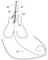
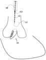
그러나, AR의 경우, 대동맥 판막이 폐쇄 상태에 있을 때 판막 누출이 발생한다. 소엽은 폐쇄 상태에서 대동맥 판막에서 부분적으로 폐쇄되고, 대동맥 판막의 일부를 개방된 상태(역류 오리피스)로 남겨, 혈액의 일부가 좌심실로 다시 흐르게 한다. 이로 인해 심장은 더 열심히 일해야 하고, 이는 환자의 건강을 악화시킨다. 도 1a는 대동맥 판막이 완전히 폐쇄된 건강한 정상 심장의 예를 보여준다. 도 1b는 비정상 대동맥 판막이 완전히 폐쇄되지 않아 혈액이 좌심실로 뒤로 누출되는 AR의 예를 보여준다.However, in AR, valve leakage occurs when the aortic valve is in a closed state. The leaflets are partially closed in the closed state, leaving part of the aortic valve open (regurgitant orifice), allowing some blood to flow back into the left ventricle. This causes the heart to work harder, which worsens the patient's health. Figure 1a shows an example of a healthy normal heart with a completely closed aortic valve. Figure 1b shows an example of AR where the abnormal aortic valve is not completely closed, allowing blood to leak backward into the left ventricle.
MR, TR 및 PR의 경우에는 각각, 준용하여, 승모판(이첨막), 삼첨판 및 폐동맥 판막에 유사한 누출이 발생한다.In the case of MR, TR and PR, similar leakage occurs in the mitral (bicuspid), tricuspid and pulmonary valves, respectively.
US 2015/0230919 A1은 승모판 또는 삼첨판의 소엽 연장을 위한 방법을 설명하고 있다. 장치가 소엽 주위에 이식되어, 이를 연장시키고 잠재적으로 부정확한 갭을 폐쇄한다.US 2015/0230919 A1 describes a method for lengthening the leaflets of the mitral or tricuspid valve. The device is implanted around the leaflets, lengthening them and closing potentially incorrect gaps.
그러나, 종래 기술의 접근법은 매우 침습적이고 위험한 수술일 수 있다. 이식에 기초한 종래 기술의 접근법에서 심장은 이식 위치에 비-내성일 수 있다. 또한, 갭의 개선된 효율적인 폐쇄가 여전히 필요하다.However, conventional approaches can be very invasive and risky surgeries. In conventional approaches based on transplantation, the heart may be non-resistant to the transplant site. In addition, improved efficient closure of the gap is still needed.
따라서, 본 발명의 목적은 AR, MR, TR 및 PR의 경우 혈액 누출을 방지하는 방법 및 수단을 제공하는 것이다.Accordingly, it is an object of the present invention to provide methods and means for preventing blood leakage in cases of AR, MR, TR and PR.
본 발명의 또 다른 목적은 전술한 혈액 누출을 방지하는 장치를 제공하는 것이다.Another object of the present invention is to provide a device for preventing blood leakage as described above.
본 발명의 또 다른 목적은 그 전달 방법을 제공하는 것이다.Another object of the present invention is to provide a method of transmission thereof.
본 발명의 다른 목적 및 이점은 설명이 진행됨에 따라 명백해질 것이다.Other objects and advantages of the present invention will become apparent as the description progresses.
본 발명은 판막 폐쇄 부전을 완화하기 위한 장치에 관한 것이다. 본 발명은 인공 판막 첨판을 선천적 또는 인공 첨판 또는 소엽에 부착함에 의한 판막 폐쇄 부전의 치료에 관한 것이다. 이를 통해, 판막 누출을 방지하거나 또는 감소시킴으로써 심장 기능을 향상시킨다. 인공 첨판은 판막이 개방 상태에 있을 때 판막 협착을 방지하기 위해 접힐 수 있다.The present invention relates to a device for alleviating valvular regurgitation. The present invention relates to the treatment of valvular regurgitation by attaching artificial valve leaflets to a congenital or artificial leaflet or leaflet, thereby improving heart function by preventing or reducing valve leakage. The artificial leaflets are foldable to prevent valvular stenosis when the valve is in the open state.
본 발명은 개구를 갖는 중공 관형 부재 및 파지 아암과 중공 관형 부재 사이에 작은 갭이 형성되도록 개구로부터 연장되는 파지 세장형 아암을 포함하는 차단 장치에 관한 것이다. 차단 장치는 심장 판막 첨판/소엽의 (역류 오리피스가 있는) 판막 폐쇄 부전으로 고통받는 심장 판막에 장착된다. 차단 장치는 첨판/소엽의 측면/벽이 작은 갭 내에 위치되도록 하는 방식으로 장착된다. 이는 갭이 실질적으로 증가하도록 파지 아암을 각지게 이동시키고, 각각의 첨판/소엽 측면/벽 위에 갭을 배치하고 그리고 갭이 다시 감소하도록 파지 아암을 각지게 복귀시켜, 첨판/소엽 측면/벽에 장치를 효과적으로 장착함으로써 수행된다. 차단 장치의 비교적 넓은 개구는 심장 판막이 폐쇄 상태에 있을 때 역류 오리피스를 실질적으로 폐쇄하여, 이 경우 혈액 누출을 방지한다.The present invention relates to a blocking device comprising a hollow tubular member having an opening and elongated phage arms extending from the opening such that a small gap is formed between the hollow tubular member and the phage arms. The blocking device is mounted on a heart valve suffering from valvular regurgitation (having a regurgitant orifice) of a heart valve leaflet/leaflet. The blocking device is mounted in such a way that a lateral/wall of the leaflet/leaflet is positioned within the small gap. This is accomplished by effectively mounting the device on the lateral/wall of the leaflet/leaflet by angularly moving the phage arms so that the gap substantially increases, positioning the gap over each leaflet/leaflet lateral/wall, and then angularly returning the phage arms so that the gap decreases again. The relatively wide opening of the blocking device substantially occludes the regurgitant orifice when the heart valve is in the closed state, thereby preventing blood leakage in this case.
본 발명은 차단 장치로서:The present invention is a blocking device:
a. 근위 단부의 근위 개구;a. Proximal opening of the proximal end;
b. 상기 근위 개구로부터 원위로 연장되는 실질적인 관형 표면;b. a substantially tubular surface extending distally from said proximal opening;
c. 원위 단부;c. distal end;
를 포함하는 중공 관형 부재; 및a hollow tubular member comprising; and
근위 단부에서 상기 개구로부터 원위로 연장되는 파지 아암A phage arm extending distally from the above opening at the proximal end
을 포함하고,Including,
원위 단부는 폐쇄되거나 또는 작은 오리피스를 포함하는, 차단 장치에 관한 것이다.The distal end relates to a blocking device, which is closed or includes a small orifice.
바람직하게는, 중공 관형 부재는 멤브레인(membrane)을 포함한다.Preferably, the hollow tubular member comprises a membrane.
바람직하게는, 멤브레인은 자가 확장 가능하다.Preferably, the membrane is self-expandable.
바람직하게는, 차단 장치는 하나 이상의 와이어를 포함하는 프레임을 더 포함하고;Preferably, the blocking device further comprises a frame comprising one or more wires;
멤브레인은 상기 프레임에 장착된다.The membrane is mounted on the above frame.
바람직하게는, 중공 관형 부재는 원위로 테이퍼진다.Preferably, the hollow tubular member is tapered distally.
바람직하게는, 파지 아암과 실질적인 관형 표면 사이에 얇은 갭이 형성된다.Preferably, a thin gap is formed between the phage arm and the actual tubular surface.
바람직하게는, 파지 아암은 제 1 그룹의 연결 요소를 포함한다.Preferably, the phage arm comprises a connecting element of the first group.
바람직하게는, 제 1 그룹의 연결 요소는 생체 적합성 바늘, 생체 적합성 핀 및 생체 적합성 스파이크로 구성된 그룹으로부터 선택된다.Preferably, the connecting elements of the first group are selected from the group consisting of biocompatible needles, biocompatible pins and biocompatible spikes.
바람직하게는, 제 1 그룹의 연결 요소는 파지 아암으로부터 근위로 연장되고 경사지는 생체 적합성 바늘이다.Preferably, the connecting element of the first group is a biocompatible needle extending proximally from the phage arm and being inclined.
바람직하게는, 실질적인 관형 표면은 제 2 그룹의 연결 요소를 포함한다.Preferably, the substantially tubular surface comprises connecting elements of the second group.
바람직하게는, 제 2 그룹의 연결 요소는 생체 적합성 바늘, 생체 적합성 핀 및 생체 적합성 스파이크로 구성된 그룹으로부터 선택된다.Preferably, the connecting elements of the second group are selected from the group consisting of biocompatible needles, biocompatible pins and biocompatible spikes.
바람직하게는, 제 2 그룹의 연결 요소는 실질적인 관형 표면으로부터 근위로 연장되고 경사지는 생체 적합성 바늘이다.Preferably, the connecting element of the second group is a biocompatible needle extending proximally and beveled from the substantially tubular surface.
바람직하게는, 차단 장치는 근위 개구에 부착된 근위 루프를 더 포함한다.Preferably, the blocking device further comprises a proximal loop attached to the proximal opening.
바람직하게는, 차단 장치는 중공 관형 부재의 원위 부분에 부착된 원위 루프를 더 포함한다.Preferably, the blocking device further comprises a distal loop attached to a distal portion of the hollow tubular member.
바람직하게는, 근위 루프 및 원위 루프는 서로 대면하고 정렬된다.Preferably, the proximal loop and the distal loop are facing and aligned with each other.
바람직하게는, 파지 아암은 원위 단부에 루프를 포함한다.Preferably, the phage arm comprises a loop at its distal end.
본 발명은 여기에 설명된 차단 장치를 심장 판막 첨판 또는 소엽에 이식하는 방법에 관한 것으로서, 상기 차단 장치는 근위 개구에 부착된 근위 루프를 포함하고;The present invention relates to a method of implanting a blocking device as described herein into a heart valve leaflet or cusp, said blocking device comprising a proximal loop attached to a proximal opening;
상기 방법은:The above method:
혈관에 개구를 생성하는 단계;A step of creating an opening in a blood vessel;
유도관을 삽입하는 단계;Step of inserting the guide tube;
유도관을 통해 가이드 와이어를 삽입하고, 이를 혈관을 통해 심장 판막까지 그리고 이를 통해 각각의 심실로 통과시키는 단계;The step of inserting a guide wire through the introducer sheath and passing it through the blood vessels to the heart valves and through them into each ventricle;
차단 장치 근위 루프를 통과하는 내부 시스를 제공하는 단계, 및A step of providing an internal sheath passing through the proximal loop of the blocking device, and
상기 내부 시스가 상기 근위 루프에 인접하게 배치된 두꺼운 부분을 포함하는 경우,If the inner sieve comprises a thick portion positioned adjacent to the proximal loop,
상기 장치가 각각의 심장 판막 앞에 배치될 때까지 상기 가이드 와이어 위로 내부 시스를 통과시키는 단계;A step of passing the inner sheath over the guide wire until the device is positioned in front of each heart valve;
유도관을 통해 삽입되고 내부 시스의 개구를 통과하고, 파지 아암 루프를 통과하고 내부 시스의 상기 개구를 통해 유도관으로 다시 통과하는 스트링을 제공하여, 상기 스트링의 양쪽 단부가 유도관으로부터 연장되는 단계;Providing a string which is inserted through the guide tube, passes through the opening of the inner sheath, passes through the phage arm loop and passes back into the guide tube through said opening of the inner sheath, such that both ends of the string extend from the guide tube;
상기 스트링의 2 개의 단부를 근위로 당겨 파지 아암을 개방하는 단계;A step of opening the phage arm by pulling the two ends of the above string proximally;
차단 장치를 올바른 의도된 위치에 위치 결정하는 단계;Step of positioning the blocking device in the correct intended location;
차단 장치를 원위로 밀어내는 단계;Step of pushing the blocking device distally;
상기 스트링의 상기 2 개의 단부를 원위로 해제시켜 파지 아암을 폐쇄하는 단계;A step of closing the phage arm by distally releasing the two ends of the string;
내부 시스를 근위로 회수하는 단계;Step of recovering the inner systole proximally;
상기 스트링이 파지 아암 루프를 빠져 나갈 때까지 상기 스트링의 한쪽 단부를 근위로 회수하고, 상기 스트링이 완전히 회수될 때까지 상기 스트링을 계속해서 근위로 회수하는 단계;A step of proximally withdrawing one end of the string until the string exits the phage arm loop, and continuing to proximally withdraw the string until the string is completely withdrawn;
상기 가이드 와이어를 근위로 회수하는 단계; 및A step of retrieving the guide wire proximally; and
상기 유도관을 제거하는 단계Step for removing the above induction tube
를 포함한다.Includes.
본 발명은 또한 차단 장치에 관한 것으로서, 상기 차단 장치는:The present invention also relates to a blocking device, said blocking device comprising:
a. 원위 단부의 원위 개구;a. Distal opening of the distal end;
b. 상기 원위 개구로부터 근위로 연장되는 실질적인 관형 표면;b. a substantially tubular surface extending proximally from said distal opening;
c. 근위 단부c. Proximal end
를 포함하는 중공 관형 부재를 포함하고,A hollow tubular member comprising:
상기 차단 장치는 원위 단부에서 상기 개구로부터 근위로 연장되는 파지 아암을 더 포함하고;The blocking device further comprises a phage arm extending proximally from the opening at the distal end;
근위 단부는 폐쇄되거나 또는 작은 오리피스를 포함한다.The proximal end is closed or contains a small orifice.
바람직하게는, 파지 아암은 근위 단부에 루프를 포함한다.Preferably, the phage arm comprises a loop at its proximal end.
바람직하게는, 차단 장치는 중공 관형 부재의 근위 부분에 부착된 근위 루프를 포함한다.Preferably, the blocking device comprises a proximal loop attached to the proximal portion of the hollow tubular member.
본 발명은 심장 판막 첨판 또는 소엽에 차단 장치를 이식하는 방법에 관한 것으로서,The present invention relates to a method for implanting a blocking device into a heart valve leaflet or leaflet,
상기 차단 장치는:The above blocking device:
a. 원위 단부의 원위 개구;a. Distal opening of the distal end;
b. 상기 원위 개구로부터 근위로 연장되는 실질적인 관형 표면;b. a substantially tubular surface extending proximally from said distal opening;
c. 근위 단부c. Proximal end
를 포함하는 중공 관형 부재를 포함하고,A hollow tubular member comprising:
상기 차단 장치는 원위 단부에서 상기 개구로부터 근위로 연장되는 파지 아암을 더 포함하고;The blocking device further comprises a phage arm extending proximally from the opening at the distal end;
근위 단부는 폐쇄되거나 또는 작은 오리피스를 포함하고;The proximal end is closed or contains a small orifice;
파지 아암은 근위 단부에 루프를 포함하고;The phage arm comprises a loop at its proximal end;
상기 차단 장치는 중공 관형 부재의 근위 부분에 부착된 근위 루프를 포함하고;The above blocking device comprises a proximal loop attached to a proximal portion of the hollow tubular member;
상기 방법은:The above method:
혈관에 개구를 생성하는 단계;A step of creating an opening in a blood vessel;
유도관을 삽입하는 단계;Step of inserting the guide tube;
유도관을 통해 가이드 와이어를 삽입하고, 이를 혈관을 통해 심장 판막까지 그리고 이를 통해 각각의 심실로 통과시키는 단계;The step of inserting a guide wire through the introducer sheath and passing it through the blood vessels to the heart valves and through them into each ventricle;
차단 장치 근위 루프를 통과하는 내부 시스를 제공하는 단계, 및A step of providing an internal sheath passing through the proximal loop of the blocking device, and
상기 내부 시스가 상기 근위 루프에 인접하게 배치된 두꺼운 부분을 포함하는 경우,If the inner sieve comprises a thick portion positioned adjacent to the proximal loop,
상기 장치가 상기 각각의 심실에 배치될 때까지 상기 가이드 와이어 위로 내부 시스를 통과시키는 단계;A step of passing the inner sheath over the guide wire until the device is positioned in each of the ventricles;
유도관을 통해 삽입되고 상기 원위 루프의 원위에 있는 내부 시스의 개구를 통과하고, 파지 아암 루프를 통과하고 내부 시스의 상기 개구를 통해 유도관으로 다시 통과하는 스트링을 제공하여, 상기 스트링의 양쪽 단부가 유도관으로부터 연장되는 단계;Providing a string which is inserted through the guide tube and passes through an opening in the inner sheath distal to said distal loop, passes through the phage arm loop and passes back into the guide tube through said opening in the inner sheath, such that both ends of the string extend from the guide tube;
상기 스트링의 2 개의 단부를 근위로 당겨 파지 아암을 개방하는 단계;A step of opening the phage arm by pulling the two ends of the above string proximally;
차단 장치를 올바른 의도된 위치에 위치 결정하는 단계;Step of positioning the blocking device in the correct intended location;
차단 장치를 근위로 당기는 단계;Step of pulling the blocking device towards the proximal;
상기 스트링의 상기 2 개의 단부를 원위로 해제시켜 파지 아암을 폐쇄하는 단계;A step of closing the phage arm by distally releasing the two ends of the string;
상기 스트링이 파지 아암 루프를 빠져 나갈 때까지 상기 스트링의 한쪽 단부를 근위로 회수하고, 상기 스트링이 완전히 회수될 때까지 상기 스트링을 계속해서 근위로 회수하는 단계;A step of proximally withdrawing one end of the string until the string exits the phage arm loop, and continuing to proximally withdraw the string until the string is completely withdrawn;
내부 시스를 근위로 회수하는 단계;Step of recovering the inner systole proximally;
상기 가이드 와이어를 근위로 회수하는 단계; 및A step of retrieving the guide wire proximally; and
상기 유도관을 제거하는 단계Step for removing the above induction tube
를 포함한다.Includes.
본 발명은 유사한 참조 부호가 유사한 요소를 일관되게 나타내는 첨부된 도면에서 예로서 예시된다.
도 1a 및 도 1b는 각각 정상 기능하는 심장 대동맥 판막 및 대동맥판 역류 기능 심장 대동맥 판막을 도시한다.
도 2a 및 도 2b는 본 발명의 실시예를 도시한다.
도 2c는 본 발명의 일 실시예에 따른 중공 관형 부재를 도시한다.
도 3a 내지 도 3b는 각각 개방 상태 및 폐쇄 상태에서 대동맥판 역류를 갖는 대동맥 판막의 개방 및 폐쇄를 도시한다.
도 3c 내지 도 3d는 도 3a 내지 도 3b에서와 같이 각각 개방 상태 및 폐쇄 상태에서 대동맥판 역류를 갖는 대동맥 판막의 개방 및 폐쇄를 도시하지만, 그러나 본 발명의 일 실시예에 따른 장치와 함께 기능한다.
도 4a 내지 도 4c는 각각 역류만을, 혈액 누출을, 그리고 본 발명을 갖는 대동맥 판막의 도면을 보여준다.
도 5는 단일 첨판에 부착된 본 발명의 도면을 보여준다.
도 6a 및 도 6b는 본 발명의 실시예를 도시한다.
도 7은 승모판 및 삼첨판에 대한 본 발명의 실시예의 예를 도시한다.
도 8a 내지 도 8n은 본 발명의 방법의 전달 방법 단계의 일 실시예를 도시한다.
도 9는 본 발명의 일 실시예에 따른 전달 방법의 한 단계를 도시한다.The present invention is illustrated by way of example in the accompanying drawings in which like reference numerals consistently represent similar elements.
Figures 1a and 1b illustrate a normally functioning aortic valve and a functioning aortic valve with aortic regurgitation, respectively.
Figures 2a and 2b illustrate embodiments of the present invention.
FIG. 2c illustrates a hollow tubular member according to one embodiment of the present invention.
Figures 3a and 3b illustrate the opening and closure of an aortic valve with aortic regurgitation in the open and closed states, respectively.
FIGS. 3c to 3d illustrate the opening and closing of an aortic valve with aortic regurgitation in the open and closed states, respectively, as in FIGS. 3a to 3b, but functioning in conjunction with a device according to an embodiment of the present invention.
Figures 4a to 4c show drawings of an aortic valve with only regurgitation, only blood leakage, and the present invention, respectively.
Figure 5 shows a drawing of the present invention attached to a single blade.
Figures 6a and 6b illustrate embodiments of the present invention.
FIG. 7 illustrates an example of an embodiment of the present invention for a mitral valve and a tricuspid valve.
FIGS. 8A to 8N illustrate one embodiment of a transmission method step of the method of the present invention.
Figure 9 illustrates one step of a transmission method according to one embodiment of the present invention.
본 발명은 인공 첨판에 관한 것이다. 보다 구체적으로, 본 발명은 심장 선천적 판막(대동맥 판막, 승모판, 폐동맥 판막, 삼첨판) 첨판/소엽 중 하나에 부착 가능한 중공 관형 부재를 포함하는 혈액 누출 차단 장치에 관한 것이다. 차단 장치는 폐쇄 상태에 있을 때 심장 선천적 판막이 효과적으로 완전히 폐쇄되게 한다. 중공 관형 부재는 판막을 개방 및 폐쇄할 때 첨판/소엽과 함께 이동하는 추가 부분인, 첨판/소엽에 대한 스캐폴드(scaffold)로 간주될 수 있다. 본 발명의 장치는 본 명세서에서 "커스퍼 장치(cusper device)"라고도 지칭된다.The present invention relates to artificial leaflets. More particularly, the present invention relates to a blood leak blocking device comprising a hollow tubular member attachable to one of the leaflets/leaflets of a congenital heart valve (aortic valve, mitral valve, pulmonary valve, tricuspid valve). The blocking device effectively causes the congenital heart valve to close completely when in a closed state. The hollow tubular member may be considered a scaffold for the leaflet/leaflet, being an additional portion that moves with the leaflet/leaflet as the valve opens and closes. The device of the present invention is also referred to herein as a "cusper device."
본 발명의 장치는 대동맥 판막과 관련하여 설명될 것이지만, 준용하여, 유사하게 다른 심장 선천적 판막 또는 인공 판막의 첨판 또는 소엽에도 부착될 수 있다.The device of the present invention will be described with respect to an aortic valve, but may similarly be attached to the leaflets or cusps of other congenital or prosthetic heart valves.
본 명세서에서, "근위 원위"는 장치를 전달하는 의료 인력에게 가장 가까운 단부를 지칭한다. "원위 단부"는 의료 인력으로부터 가장 멀고 장치 전달 중에 환자의 신체의 목표 위치에 가장 가까운 단부를 지칭한다. 본 발명의 장치를 대동맥을 통해 (좌심실을 향해) 삽입하는 실시예와 관련하여, "원위 방향"은 좌심실을 향한 방향을 나타내고, "근위 방향"은 반대 방향, 즉 좌심실로부터 멀리 대동맥을 향한 방향을 나타낸다. 따라서, 대동맥 판막을 통한 혈액은 원위로부터 근위 방향으로 흐른다.As used herein, "proximal distal" refers to the end closest to the medical personnel delivering the device. The "distal end" refers to the end furthest from the medical personnel and closest to the target location in the patient's body during device delivery. In the context of an embodiment where the device of the present invention is inserted through the aorta (toward the left ventricle), "distal" refers to the direction toward the left ventricle, and "proximal" refers to the opposite direction, i.e., away from the left ventricle and toward the aorta. Thus, blood through the aortic valve flows from distal to proximal.
심장에 대동맥 판막 폐쇄 부전이 있는 경우, 대동맥 판막이 폐쇄 상태에 있을 때 판막 누출이 발생한다. 소엽/첨판은 대동맥 판막에서 폐쇄 상태에서 부분적으로 폐쇄되고, 대동맥 판막의 일부가 개방된 상태로 남겨져, 혈액의 일부가 좌심실로 다시 흐르게 한다. 본 발명은 첨판 중 하나에 부착된 차단 장치가 대동맥 판막이 폐쇄 상태에 있을 때 대동맥 판막의 역류 오리피스에 위치되고 대동맥 판막의 역류 오리피스에서 판막 폐쇄 부전 "개방"을 효과적으로 차단하도록 구성된다. 따라서, 대동맥으로부터의 혈액은 좌심실로 다시 누출되지 않는다(혈액의 일부는 차단 장치의 중공 관형 부재의 내부로만 들어간다).When the heart has aortic valve regurgitation, valvular leakage occurs when the aortic valve is in the closed state. The leaflets/cusps partially close in the closed state in the aortic valve, leaving a portion of the aortic valve open, allowing some blood to flow back into the left ventricle. The present invention provides a blocking device attached to one of the leaflets, positioned at the regurgitant orifice of the aortic valve when the aortic valve is in the closed state, and configured to effectively block the regurgitant "opening" at the regurgitant orifice of the aortic valve. Thus, blood from the aorta does not leak back into the left ventricle (some blood only enters the interior of the hollow tubular member of the blocking device).
본 발명의 차단 장치는 판막 첨판에 부착 가능한 중공 관형 부재를 포함한다. 차단 장치의 중공 관형 부재는 근위 개방 단부, 측면 (사이드) 관형 표면 및 폐쇄 (밀봉된) 원위 단부 또는 (장치의 전달과 관련하여 이후에 설명되는 바와 같이 와이어가 통과하도록) 작은 구멍/오리피스가 제공된 단부를 포함한다. 보다 구체적으로, 차단 장치 중공 관형 부재는 근위 단부에 근위 개구, 근위 개구로부터 원위로 연장되는 실질적인 관형 표면 및 폐쇄된 원위 단부(또는 작은 오리피스가 제공된 단부)를 포함한다.The blocking device of the present invention comprises a hollow tubular member attachable to a valve leaflet. The hollow tubular member of the blocking device comprises a proximal open end, a lateral (side) tubular surface and a closed (sealed) distal end or end provided with a small hole/orifice (for passage of a wire as described hereinafter in connection with delivery of the device). More specifically, the blocking device hollow tubular member comprises a proximal opening at the proximal end, a substantially tubular surface extending distally from the proximal opening, and a closed distal end (or end provided with a small orifice).
장치는, 첨판에 부착될 때, 둘 중 어느 하나로 이루어진다:The device, when attached to the tip, consists of either:
1. 원위 단부가 완전히 폐쇄되는 경우, 혈액이 들어가고, 그 후 근위 개구로부터만 중공 관형 부재의 내부를 빠져 나갈 수 있다(즉, 원위 측면과 함께 측면 (사이드) 관형 표면이 모두 폐쇄/밀봉됨).1. When the distal end is completely occluded, blood can enter and then exit the interior of the hollow tubular member only from the proximal opening (i.e., both the lateral (side) tubular surfaces together with the distal side are occluded/sealed).
2. 원위 단부가 작은 오리피스를 포함하는 경우, 혈액이 들어가고, 그 후 주로 근위 개구로부터 중공 관형 부재의 내부를 빠져 나갈 수 있지만, 매우 적은 부분은 원위 작은 오리피스를 빠져 나갈 수 있다. 그러나, 이것은 심장의 기능에 최소한의 영향을 미치며, 잠재적인 누출 혈액의 대부분은 차단 장치에 의해 차단된다.2. If the distal end contains a small orifice, blood may enter and then escape through the interior of the hollow tubular member, primarily from the proximal opening, but a very small portion may escape through the distal small orifice. However, this has minimal effect on the function of the heart, and most of the potential leaking blood is blocked by the blocking device.
근위 개구는 그 내측면에 인접하여, 첨판의 (에지에서) 근위 단부 근처에 배치되어, 대동맥 판막이 폐쇄 상태에 있을 때, 차단 장치는 대동맥 판막의 역류 오리피스에서 판막 폐쇄 부전 "개방"을 차단한다.The proximal orifice is located near the proximal end (at the edge) of the leaflet, adjacent to its medial aspect, so that when the aortic valve is in the closed state, the blocking device blocks the valve regurgitation "opening" at the regurgitant orifice of the aortic valve.
차단 장치 중공 관형 부재는 압축 가능하며, 내부의 부피가 변할 수 있도록 확장될 수 있다. 수축기 동안, 대동맥 판막이 개방 상태에 있을 때, 상당한 흐름으로 좌심실을 빠져 나가는 혈액으로 인해 차단 장치가 부분적으로 압축되어 그 내부 부피가 감소한다. 심이완기 동안, 대동맥 판막이 폐쇄 상태에 있을 때, 대동맥으로부터의 혈액이 차단 장치 내부로 들어갈 수 있다(차단 장치 내부 부피의 확장 및 증가에 추가될 수 있음). 어느 경우든, 심이완기 동안, 혈액은 다른 첨판 내측면과 결합하는 차단 장치에 의해 차단되므로 좌심실로 다시 흐르지 않고, 차단 장치와 첨판 내측면(판막의 중앙을 향하는 측면) 사이의 결합 위치를 통해 혈액이 통과하지 못하도록 효과적으로 시일을 형성한다. 차단 장치는, 건강한 심장의 기능에서와 같이, 폐쇄 상태에 있을 때 심장 선천적 판막이 효과적으로 완전히 폐쇄되게 한다. 일부 실시예에서, 본 발명의 차단 장치는 (역류 오리피스에서) 완전한 시일을 형성하지 않고, 혈액 누출을 감소시켜, 환자의 건강을 향상시킨다.The hollow tubular member of the blocking device is compressible and expandable so that its internal volume can be changed. During systole, when the aortic valve is in the open state, the blocking device is partially compressed due to the blood leaving the left ventricle with a significant flow, thereby decreasing its internal volume. During diastole, when the aortic valve is in the closed state, blood from the aorta can enter the blocking device (which may add to the expansion and increase in the internal volume of the blocking device). In either case, during diastole, the blood is blocked by the blocking device engaging the other leaflet's inner surface, so that it does not flow back into the left ventricle, but effectively forms a seal between the blocking device and the leaflet's inner surface (the side facing the center of the valve) to prevent blood from passing through the engagement site. The blocking device effectively closes the congenital heart valve completely when in the closed state, as would occur in a healthy heart. In some embodiments, the blocking device of the present invention does not form a complete seal (at the regurgitant orifice), thereby reducing blood leakage, thereby improving patient health.
(근위 측에서) 차단 장치의 중공 관형 부재의 개구는 첨판 근위 단부 내측면 근처에 부착된다. 차단 장치는 차단 장치가 부착되는 첨판에 인접하게 이를 따라 원위로 연장된다. 바람직하게는, 차단 장치는 원위로 테이퍼진다. 이러한 방식으로, 차단 장치 중공 관형 부재의 넓은 근위 단부는 대동맥 판막의 첨판의 근위 단부(차단 장치가 부착되는 첨판 및 이들의 단부가 서로 결합하도록 폐쇄하는 경향이 있는 다른 첨판)와 결합하여 효과적인 밀봉을 유발한다. 첨판에 부착된 차단 장치 중공 관형 부재의 원위 부분은, 첨판의 원위 부분에 부착되어야 하지만 차단하기 위해 넓을 필요는 없기 때문에, 넓은 근위 개구보다 좁을 수 있다. 이러한 구성은 가장 효과적인 기능을 위해 차단 장치가 최소 질량을 가질 수 있게 한다. 근위 개구는 차단할 수 있을 만큼 충분히 넓게 구성된다.(On the proximal side) The opening of the hollow tubular member of the blocking device is attached near the inner surface of the proximal end of the leaflet. The blocking device extends distally along and adjacent the leaflet to which the blocking device is attached. Preferably, the blocking device tapers distally. In this manner, the widened proximal end of the hollow tubular member of the blocking device engages with the proximal ends of the leaflets of the aortic valve (the leaflet to which the blocking device is attached and the other leaflets whose ends tend to occlude each other so as to engage each other) to effect an effective seal. The distal portion of the hollow tubular member of the blocking device attached to the leaflet may be narrower than the wide proximal opening, since it must be attached to the distal portion of the leaflet but does not need to be wide enough to block. This configuration allows the blocking device to have a minimum mass for most effective function. The proximal opening is configured to be wide enough to block.
본 발명의 일 실시예에 따르면, 차단 장치 중공 관형 부재는 변형 가능한 멤브레인의 형태이다. (중공 관형 부재의 형태의) 멤브레인은 근위 개구, 측면 관형 표면 및 다음 중 어느 하나를 포함한다:According to one embodiment of the present invention, the blocking device hollow tubular member is in the form of a deformable membrane. The membrane (in the form of a hollow tubular member) comprises a proximal opening, a lateral tubular surface and one of the following:
1. 폐쇄된 원위 단부(바람직하게는 개구로부터 측면 관형 표면을 따라 원위 단부까지 원위로 테이퍼짐). 멤브레인의 내부는 (근위 개구를 제외하고) 완전히 폐쇄/밀봉된다.1. Closed distal end (preferably tapering distally from the opening along the lateral tubular surface to the distal end). The interior of the membrane is completely closed/sealed (except for the proximal opening).
2. 작은 오리피스를 포함하는 원위 단부(바람직하게는 개구로부터 측면 관형 표면을 따라 원위 단부까지 원위로 테이퍼짐). 멤브레인의 내부는 (근위 개구 및 원위 단부 오리피스를 제외하고) 폐쇄된다.2. A distal end including a small orifice (preferably tapering distally from the opening along the lateral tubular surface to the distal end). The interior of the membrane is closed (except for the proximal opening and the distal end orifice).
수축기 동안 멤브레인은 (수축기 혈류에 의해) 부분적으로 압축될 수 있으며, 이완기 동안 멤브레인은 "누출" 혈액이 중공 관형 부재의 내부로 들어가서 그 부피를 확대하므로 확장될 수 있다.During systole, the membrane may be partially compressed (due to systolic blood flow), and during diastole, the membrane may be distended as "leaking" blood enters the interior of the hollow tubular member, expanding its volume.
일 실시예에 따르면, 멤브레인은 자가 확장 가능하다(예를 들어 탄성적임). 수축기 동안 멤브레인은 (수축기 혈류에 의해) 부분적으로 압축되고, 이완기 동안 멤브레인은 확장된다. 멤브레인은 인공 소스, 생체 적합성 재료(예를 들어, Dacron, PTFE 등) 또는 생물학적 소스(예를 들어, 동물 판막 첨판, 동물 심막 등)를 포함할 수 있다.In one embodiment, the membrane is self-expanding (e.g., elastic). During systole, the membrane is partially compressed (due to systolic blood flow), and during diastole, the membrane is expanded. The membrane can comprise an artificial source, a biocompatible material (e.g., Dacron, PTFE, etc.), or a biological source (e.g., animal valve leaflets, animal pericardium, etc.).
본 발명의 다른 실시예에 따르면, 차단 장치는 일반적인 형상을 정의하는 하나 이상의 와이어를 포함하는 프레임을 포함한다. 와이어는 폐쇄된 원위 단부를 갖는 일반적인 중공 관형 형상을 형성하도록 구성된다. 프레임 와이어는 멤브레인이 그에 부착되어 근위 개방 단부, 근위 개방 단부로부터 원위로 연장되는 측면 관형 표면 및 (선택적으로 작은 오리피스를 갖는) 폐쇄된 원위 단부를 갖는 강화된 중공 관형 부재를 형성하도록 구성된다. 멤브레인은 실제로 프레임에 장착된다. 바람직하게는, 프레임 형상은 원위로 테이퍼진다.In another embodiment of the present invention, the barrier device comprises a frame comprising one or more wires defining a general shape. The wires are configured to form a generally hollow tubular shape having a closed distal end. The frame wires are configured to have a membrane attached thereto to form a reinforced hollow tubular member having a proximal open end, a lateral tubular surface extending distally from the proximal open end, and a closed distal end (optionally having a small orifice). The membrane is actually mounted to the frame. Preferably, the frame shape tapers distally.
본 발명의 차단 장치는 파지 아암과 측면 관형 표면의 외측면 사이에 얇은 갭을 갖는 중공 관형 부재의 측면 관형 표면의 외측면을 따라 근위 개구로부터 원위로 연장되는 파지 아암을 포함한다. 차단 장치가 삽입되면, 차단 장치는 차단 장치가 부착되는 첨판에 장착되어, 첨판이 얇은 갭 내에 위치된다. 측면 관형 표면의 외측면은 첨판의 내측면과 결합되고, 파지 아암은 첨판의 외측면과 결합된다. 파지 아암은 첨판에 연결될 수 있는 연결 요소를 포함한다.The blocking device of the present invention comprises a grip arm extending distally from a proximal opening along an outer surface of a lateral tubular surface of a hollow tubular member having a thin gap between the grip arm and the outer surface of the lateral tubular surface. When the blocking device is inserted, the blocking device is mounted on a cusp to which the blocking device is attached, such that the cusp is positioned within the thin gap. The outer surface of the lateral tubular surface is engaged with an inner surface of the cusp, and the grip arm is engaged with the outer surface of the cusp. The grip arm comprises a connecting element connectable to the cusp.
도 2a는 본 발명 차단 장치(10)의 일 실시예를 도시한다. 차단 장치(10)는 근위 개구(12)를 갖는 중공 테이퍼링 관형 부재(5)를 형성하는 멤브레인을 포함한다. 테이퍼링 관형 부재(5)의 내부는 (근위 개구(12)를 제외하고) 멤브레인에 의해 완전히 폐쇄/밀봉된다. 측면 관형 표면(6)은 근위 개구(12)로부터 원위로 연장되고, 원위로 테이퍼지고, 폐쇄된 원위 단부(7)에서 종결된다(다른 실시예에서(도시되지 않음) 원위 단부는 매우 작은 오리피스/구멍을 포함할 수 있다).FIG. 2a illustrates one embodiment of a blocking device (10) of the present invention. The blocking device (10) comprises a membrane forming a hollow tapered tubular member (5) having a proximal opening (12). The interior of the tapered tubular member (5) is completely closed/sealed by the membrane (except for the proximal opening (12)). A lateral tubular surface (6) extends distally from the proximal opening (12), tapers distally, and terminates in a closed distal end (7) (in other embodiments (not shown) the distal end may comprise a very small orifice/hole).
도 2b는 일반적인 형상을 정의하는 하나 이상의 와이어를 포함하는 프레임을 포함하는 본 발명의 차단 장치(10)의 실시예를 도시한다. 차단 장치(10)(도시되지 않음)의 멤브레인은 프레임에 부착되어, 프레임 및 이에 부착된 멤브레인이 함께 근위 개구(12)를 갖는 중공 테이퍼링 관형 부재(5)를 형성한다(테이퍼링 관형 부재(5)의 내부는 근위 개구(12)를 제외하고 멤브레인에 의해 완전히 폐쇄/밀봉된다). 일 실시예에서 프레임은 멤브레인 층의 외부에 있다. 다른 실시예에서, 프레임의 와이어는 멤브레인의 층 내에 포함될 수 있다.FIG. 2b illustrates an embodiment of a barrier device (10) of the present invention comprising a frame comprising one or more wires defining a general shape. A membrane of the barrier device (10) (not shown) is attached to the frame such that the frame and the membrane attached thereto together form a hollow tapered tubular member (5) having a proximal opening (12) (the interior of the tapered tubular member (5) being completely closed/sealed by the membrane except for the proximal opening (12). In one embodiment, the frame is external to the membrane layer. In another embodiment, the wires of the frame may be contained within the membrane layer.
테이퍼링 관형 부재(5)는 근위 개구(12)를 형성하는 근위 측 상에 둥근(바람직하게는 원형의) 와이어 부분을 포함한다. 테이퍼링 관형 부재(5)는 그 길이를 따라 하나 이상의 종 방향 와이어 요소(13)를 포함한다. 테이퍼링 관형 부재(5)는 그 길이를 따라 배치된 테이퍼링 관형 부재(5)의 하나 이상의 각각의 횡 방향 부분을 둘러싸는 하나 이상의 횡 방향 와이어 요소를 포함한다. 도 2b의 실시예는 각각 사인파 형태인 3 개의 횡 방향 둘러싸는 와이어 부분(14, 15, 16)을 도시한다. 테이퍼링 관형 부재(5)가 원위로 테이퍼지기 때문에, 각각의 2 개의 인접한 횡 방향 둘러싸는 와이어 부분의 경우, 2 개 중 더 근위의 것이 2 개 중 더 원위의 것보다 더 크다(즉, 더 긴 폭 부분을 둘러싼다). 이 경우, 와이어 부분(14)은 와이어 부분(16)보다 큰 와이어 부분(15)보다 크다.The tapering tubular member (5) comprises a round (preferably circular) wire portion on its proximal side forming a proximal opening (12). The tapering tubular member (5) comprises one or more longitudinal wire elements (13) along its length. The tapering tubular member (5) comprises one or more transverse wire elements that surround one or more respective transverse portions of the tapering tubular member (5) arranged along its length. The embodiment of FIG. 2b illustrates three transversely wrapping wire portions (14, 15, 16) each having a sinusoidal shape. Since the tapering tubular member (5) tapers distally, for each of two adjacent transversely wrapping wire portions, the more proximal of the two is larger (i.e., surrounds a longer width portion) than the more distal of the two. In this case, the wire portion (14) is larger than the wire portion (15), which is larger than the wire portion (16).
본 발명의 차단 장치(10)는 장치(10)를 첨판에 고정시키는 파지 아암(20)(도 2a 및 도 2b에 도시됨)을 포함한다. 도 2c는 파지 아암(20)이 없는 테이퍼링 중공 관형 부재(5)만을 도시한다는 점에 유의해야 한다. 파지 아암(20)은 근위 개구(12)에 고정되고, 그 사이에 얇은 갭(22)을 두고 (측면 관형 표면(6)을 따라) 중공 테이퍼링 관형 부재(5)의 외부 측면을 따라, 이로부터 원위로 연장된다. 차단 장치(10)가 환자의 신체에 삽입될 때, 첨판에 장착되어, 첨판이 얇은 갭(22) 내에(측면 관형 표면(6)과 파지 아암(20)의 내측면 사이 내에) 위치된다. 테이퍼링 관형 부재(5)의 측면 관형 표면(6)의 외부 표면은 첨판의 내측면(판막의 중심을 향하는 측면)과 맞물리고, 파지 아암(20)은 첨판의 외측면(혈관 벽을 향하는 측면, 즉 상승 대동맥 측벽)과 맞물린다.The blocking device (10) of the present invention includes a gripping arm (20) (as shown in FIGS. 2a and 2b) that secures the device (10) to a cusp. It should be noted that FIG. 2c shows only the tapered hollow tubular member (5) without the gripping arm (20). The gripping arm (20) is secured to the proximal opening (12) and extends distally along and along the outer side of the hollow tapered tubular member (5) (along the lateral tubular surface (6)) with a thin gap (22) therebetween. When the blocking device (10) is inserted into a patient's body, it is seated on the cusp, such that the cusp is positioned within the thin gap (22) (between the lateral tubular surface (6) and the inner side of the gripping arm (20)). The outer surface of the lateral tubular surface (6) of the tapering tubular member (5) engages with the inner surface of the leaflet (the side facing the center of the valve), and the phage arm (20) engages with the outer surface of the leaflet (the side facing the blood vessel wall, i.e., the ascending aortic side wall).
파지 아암(20)은 첨판에 연결 가능한 연결 요소(25)를 포함한다. 바람직하게는, 연결 요소는 파지 아암(20)의 원위 부분에 위치된다. 도 2a 내지 도 2b의 연결 요소(25)는 파지 아암(20)의 내측면으로부터 (파지 아암(20)으로부터 경사져) 근위로 실질적으로 연장되는 생체 적합성 바늘이다. 이러한 방식으로, 첨판이 갭(22)을 통과할 때, 차단 장치(10)는 생체 적합성 바늘(25)이 첨판을 손상시키지 않고 삽입될 수 있다. 차단 장치(10)가 완전히 삽입되면, 생체 적합성 바늘(25)이 첨판 외측면을 관통하여, 첨판에 차단 장치(10)를 영구적으로 고정시킨다.The phage arm (20) includes a connecting element (25) connectable to the phage plate. Preferably, the connecting element is located at a distal portion of the phage arm (20). The connecting element (25) of FIGS. 2A-2B is a biocompatible needle extending substantially proximally (at an angle from the phage arm (20)) from an inner surface of the phage arm (20). In this manner, when the phage plate passes through the gap (22), the blocking device (10) can be inserted without damaging the phage plate with the biocompatible needle (25). When the blocking device (10) is fully inserted, the biocompatible needle (25) penetrates the outer surface of the phage plate, thereby permanently securing the blocking device (10) to the phage plate.
바람직하게는, 테이퍼링 관형 부재(5)의 측면 관형 표면(6)의 외부 표면 부분(전형적으로 파지 아암(20)을 향하는 부분)은 첨판에 연결 가능한 연결 요소(26)를 포함한다. 바람직하게는, 연결 요소는 파지 아암(20)을 향하는 측면 관형 표면(6)의 외부 표면 부분의 원위 부분에 위치된다. 도 2a 내지 도 2b의 연결 요소(26)는 파지 아암(20)을 향하는 측면 관형 표면(6)의 외부 표면 부분으로부터 (측면 관형 표면(6)으로부터 경사져) 실질적으로 근위로 연장되는 생체 적합성 바늘이다. 이러한 방식으로, 차단 장치(10)는 첨판이 갭(22)을 통과할 때 생체 적합성 바늘(26)이 첨판을 손상시키지 않고 삽입될 수 있다. 차단 장치(10)가 완전히 삽입되면, 생체 적합성 바늘(26)은 첨판 내측면을 관통하여, 첨판에 차단 장치(10)를 고정하는 것을 돕는다. 생체 적합성 핀, 생체 적합성 스파이크 등과 같은 다른 유형의 연결 요소를 사용할 수 있다.Preferably, an outer surface portion (typically the portion facing the phage arm (20)) of the lateral tubular surface (6) of the tapering tubular member (5) comprises a connecting element (26) connectable to a cusp. Preferably, the connecting element is located at a distal portion of the outer surface portion of the lateral tubular surface (6) facing the phage arm (20). The connecting element (26) of FIGS. 2A-2B is a biocompatible needle extending substantially proximally from the outer surface portion of the lateral tubular surface (6) facing the phage arm (20) (at an angle from the lateral tubular surface (6)). In this manner, the blocking device (10) can be inserted without damaging the cusp when the biocompatible needle (26) passes through the gap (22). When the blocking device (10) is fully inserted, the biocompatible needle (26) penetrates the inner surface of the cusp, thereby helping to secure the blocking device (10) to the cusp. Other types of connecting elements can be used, such as biocompatible pins, biocompatible spikes, etc.
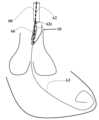
도 3a는 개방 상태에서 대동맥판 역류가 있는 대동맥 판막을 보여준다. 도 3b는 폐쇄 상태에서 대동맥판 역류가 있는 대동맥 판막을 보여주며, 여기서 누출 개구를 볼 수 있다. 도 3c는 차단 장치(10)가 판막 첨판에 부착된 상태에서 개방 상태에서 대동맥판 역류가 있는 대동맥 판막을 보여준다. 이 도면에서, 차단 장치(10)는 혈액이 좌심실로부터 흘러나올 때 첨판에 인접해 있다. 도 3d는 폐쇄 상태에서 대동맥판 역류가 있는 대동맥 판막을 보여주며, 여기서 누출 개구는 차단 장치(10)에 의해 차단된다.Figure 3a shows an aortic valve with aortic regurgitation in the open state. Figure 3b shows an aortic valve with aortic regurgitation in the closed state, where the leak opening is visible. Figure 3c shows an aortic valve with aortic regurgitation in the open state with a blocking device (10) attached to the valve leaflet. In this drawing, the blocking device (10) is adjacent the leaflet as blood flows out of the left ventricle. Figure 3d shows an aortic valve with aortic regurgitation in the closed state, where the leak opening is blocked by the blocking device (10).
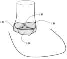
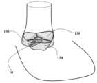
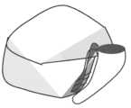
도 4a는 역류가 있는 대동맥 판막의 3D 예시를 보여준다. 3 개의 첨판(130) 및 역류 오리피스(140)가 도시되어 있다. 도 4b는 혈액 누출(150)이 있는 도 4a를 도시한다. 도 4c는 혈액 누출을 차단하도록 구성된 대동맥 판막 역류 오리피스(140) 내에 제 위치에 삽입된 차단 장치(10)의 3D 예시를 보여준다.Figure 4a shows a 3D example of an aortic valve with regurgitation. Three leaflets (130) and a regurgitation orifice (140) are shown. Figure 4b shows Figure 4a with blood leakage (150). Figure 4c shows a 3D example of a blocking device (10) inserted in place within an aortic valve regurgitation orifice (140) configured to block blood leakage.
도 5는 단일 선천적 또는 인공 판막에 부착된 차단 장치(10)를 보여준다.Figure 5 shows a blocking device (10) attached to a single congenital or artificial valve.
프레임 와이어, 파지 아암(20), 연결 요소(25, 26)는 형상 기억 합금, 스테인리스 강, 코발트 크롬 및 니티놀로 구성된 그룹으로부터 선택된 재료로 제조될 수 있다. 프레임은 피로를 견디고, 접을 수 있고 그리고/또는 자가 확장되도록 설계된다.The frame wire, the phage arms (20) and the connecting elements (25, 26) can be manufactured from a material selected from the group consisting of shape memory alloys, stainless steel, cobalt chromium and nitinol. The frame is designed to be fatigue-resistant, collapsible and/or self-expanding.
테이퍼링 관형 부재(5) 및 파지 아암(20)의 일반적인 길이는 일반적으로 4 내지 8 mm(예를 들어, 도 6a에 도시된 7 mm)이다.The typical length of the tapering tubular member (5) and the phage arm (20) is typically 4 to 8 mm (e.g., 7 mm as shown in FIG. 6a).
근위 개구(12)의 직경은 일반적으로 6 내지 8 mm(도 6a에 도시됨)이다.The diameter of the proximal opening (12) is typically 6 to 8 mm (as shown in Fig. 6a).
파지 아암(20)의 폭은 일반적으로 1 내지 4 mm이다. 파지 아암(20)의 두께는 일반적으로 0.1 내지 2 mm이다.The width of the phage arm (20) is generally 1 to 4 mm. The thickness of the phage arm (20) is generally 0.1 to 2 mm.
프레임 와이어의 직경은 일반적으로 0.1 내지 1 mm이다.The diameter of the frame wire is typically 0.1 to 1 mm.
연결 요소 생체 적합성 바늘(25, 26)의 직경은 일반적으로 0.1 내지 0.4 mm이다. 연결 요소 생체 적합성 바늘(25, 26)의 길이는 일반적으로 4 내지 10 mm이다.The diameter of the connecting element biocompatible needle (25, 26) is typically 0.1 to 0.4 mm. The length of the connecting element biocompatible needle (25, 26) is typically 4 to 10 mm.
멤브레인의 두께는 일반적으로 0.1 내지 1 mm이다.The membrane thickness is typically 0.1 to 1 mm.
도 7은 승모판 소엽에 부착된 차단 장치(210) 및 삼첨판 소엽에 부착된 다른 차단 장치(310)의 예를 도시한다.Figure 7 illustrates an example of a blocking device (210) attached to a mitral valve leaflet and another blocking device (310) attached to a tricuspid valve leaflet.
본 발명은 혈액으로 채워졌을 때 갭에 스스로 맞춰지는 인공 첨판으로 이것을 채움으로써 부정확한 갭을 폐쇄하는 장치를 제공한다. 본 발명의 잠재적인 이점은 종래 기술의 소엽 연장 방법(US 2015/0230919에서)보다 이식 위치에 대해 더 나은 공차를 제공하고, 갭의 더 효율적인 폐쇄를 제공한다는 것이다. 또한, 필요한 경우 제 2 장치가 제 1 장치 옆에 쉽게 이식될 수 있다.The present invention provides a device for closing an incorrect gap by filling it with an artificial leaflet that adapts itself to the gap when filled with blood. Potential advantages of the present invention include better tolerance for the implantation location and more efficient closure of the gap than prior art leaflet extension methods (see US 2015/0230919). In addition, a second device can be easily implanted next to the first device if desired.
본 발명은 전달 시스템을 통해 차단 장치(예를 들어, 본 명세서에 정의된 차단 장치)를 의도된 심장 판막 위치로 전달하고, 심장 판막의 기능을 개선함으로써 기능을 시작하도록 심장 판막 의도된 위치 내에 차단 장치를 전개하고 올바르게 위치 결정하는 방법에 관한 것이다. 도 8a 내지 도 8n은 본 발명의 차단 장치(10)를 심장 판막 첨판/소엽에 장착된 의도된 위치로 전달하는 방법을 도시한다.The present invention relates to a method for delivering a blocking device (e.g., a blocking device as defined herein) to an intended heart valve location via a delivery system and deploying and properly positioning the blocking device within an intended heart valve location to initiate function by improving the function of the heart valve. FIGS. 8A-8N illustrate a method for delivering a blocking device (10) of the present invention to an intended location mounted on a heart valve leaflet/cusp.
본 발명의 전달 방법은 대동맥 판막과 관련하여 설명될 것이지만, 유사하게 폐동맥 판막(그리고 승모판 및 삼첨판에 대한 많은 양태와 함께) 첨판/소엽에, 준용하여, 전달될 수 있다.The delivery method of the present invention will be described with respect to the aortic valve, but may similarly be applied to the pulmonary valve (and many aspects thereof, including the mitral and tricuspid valves) leaflets/valves.
본 발명의 일 실시예에 따르면, 전달 시스템은 외부 시스(60) 및 외부 시스를 통과하는 내부 시스(62)를 포함한다. 전달 시스템은 내부 시스(62)를 활주 가능하게 통과하는 가이드 와이어(63)를 포함한다. 선택적으로 가이드 와이어는 매우 강성 가이드 와이어이다. 선택적으로 가이드 와이어(63)는 035 유형이다. 내부 시스(62)는 가이드 와이어(63)가 이를 통해 통과할 수 있도록 구성된다.According to one embodiment of the present invention, the delivery system comprises an outer sheath (60) and an inner sheath (62) passing through the outer sheath. The delivery system comprises a guide wire (63) slidably passing through the inner sheath (62). Optionally, the guide wire is a very rigid guide wire. Optionally, the guide wire (63) is a 035 type. The inner sheath (62) is configured such that the guide wire (63) can pass through it.
도 6b는 근위 개구(12)에 부착된 근위 루프(71) 및 (전형적으로 테이퍼링 관형 부재(5)의 원위 단부에서) 테이퍼링 관형 부재(5)의 원위 부분에 부착된 원위 루프(72)를 갖는 차단 장치(10)의 일 실시예를 도시한다. 일부 실시예는 원위 루프(72) 없이 근위 루프(71)만을 포함할 수 있다.FIG. 6b illustrates one embodiment of a blocking device (10) having a proximal loop (71) attached to a proximal opening (12) and a distal loop (72) attached to a distal portion of the tapering tubular member (5) (typically at the distal end of the tapering tubular member (5)). Some embodiments may include only the proximal loop (71) without the distal loop (72).
바람직하게는, 루프(71 및 72)는 서로 대면하고 정렬되며, 테이퍼링 관형 부재(5) 표면에 대해(측면 관형 표면(6)에 대해) 수직으로 연장된다. 내부 시스(62)는 루프(71, 72)를 통과한다. 내부 시스는 근위 루프(71)에 인접하여 근위에 배치되도록 두꺼운 부분(62t)을 포함한다. 이러한 방식으로 시스(62)가 원위로 이동될 때 두꺼운 부분(62t)은 근위 루프(71)를 원위로 밀어내고, 따라서 전체 장치(10)를 원위로 밀어낸다. 전형적으로, 두꺼운 부분(62t)은 테이퍼링 관형 부재(5)의 길이보다 더 큰 원위 단부로부터의 거리에서 내부 시스(62)의 원위 부분에 있다. 전달 중 차단 장치(10)는 외부 시스(60) 내부에 있으며, 크림핑된, 압축된 또는 접힌 상태에 있다(예를 들어, 7 mm 미만의 작은 직경으로 크림핑됨). 장치는 전달 시스템에서 수동 또는 압축 상태(예를 들어, 사전 로딩 상태)로 접혀 있다.Preferably, the loops (71 and 72) face each other and are aligned and extend perpendicularly to the surface of the tapering tubular member (5) (relative to the lateral tubular surface (6)). The inner sheath (62) passes through the loops (71, 72). The inner sheath includes a thickened portion (62t) so as to be positioned proximally adjacent the proximal loop (71). In this way, when the sheath (62) is moved distally, the thickened portion (62t) pushes the proximal loop (71) distally, and thus the entire device (10) distally. Typically, the thickened portion (62t) is in the distal portion of the inner sheath (62) at a distance from the distal end that is greater than the length of the tapering tubular member (5). During delivery, the blocking device (10) is within the outer sheath (60) and is in a crimped, compressed or folded state (e.g., crimped to a small diameter of less than 7 mm). The device is folded manually or in a compressed state (e.g., pre-loaded state) in the delivery system.
파지 아암(20)은 그 원위 단부에 루프(75)를 포함한다. 도 6b는 파지 아암(20) 세장형 부분의 원위 단부에 부착된 루프(75)를 도시한다. 스트링(66)은 (의료 인력이 시스템을 작동하는 가장 근위 위치에서) 유도관을 통해, 루프(75)를 통해 그리고 유도관으로 다시 연장되어, (스트링(66)의 양쪽 단부가 유도관으로부터 연장되도록) 시스템을 작동하는 의료 인력이 스트링(66)의 양쪽 단부에 접근할 수 있다. 파지 아암(20)은 항상 폐쇄되는 경향이 있다(즉, 테이퍼링 관형 부재(5) 외부 표면에 인접하는 경향이 있어, 단지 작은 갭(22)만이 남겨짐). 스트링(66)의 양쪽 단부가 근위로 당겨질 때, 파지 아암(20)은 테이퍼링 관형 부재(5) 외부 표면으로부터 멀리(측면 관형 표면(6)으로부터 멀리) 이동된다. 스트링(66)의 양쪽 단부가 해제되면, 파지 아암(20)이 테이퍼링된 관형 부재(5) 외부 표면을 향해(측면 관형 표면(6)을 향해) 복귀된다. 파지 아암(20)은, 파지 아암(20)의 근위 단부가 항상 근위 개구(12)에 부착되기 때문에, 관형 부재(5) 외부 표면(측면 관형 표면(6))으로부터 그리고 이를 향해 각진 방식으로 이동한다. 스트링(66)은 가이드 와이어에 평행하게 또는 별도의 전용 루멘에서 내부 시스를 통과할 수 있고, 이를 당겨 개방하기 위해(갭(22) 확대하기 위해) 파지 아암(20) 위치 근처의 적절한 개구에서 내부 시스(62)를 빠져 나간다.The phage arm (20) includes a loop (75) at its distal end. FIG. 6b illustrates the loop (75) attached to the distal end of the elongated portion of the phage arm (20). The string (66) extends through the guide tube (at the most proximal location from which a medical personnel would operate the system), through the loop (75), and back into the guide tube so that both ends of the string (66) are accessible to the medical personnel operating the system (such that both ends of the string (66) extend from the guide tube). The phage arm (20) tends to always be closed (i.e., tends to abut the outer surface of the tapered tubular member (5), leaving only a small gap (22)). As both ends of the string (66) are pulled proximally, the phage arm (20) is moved away from the outer surface of the tapered tubular member (5) (away from the lateral tubular surface (6)). When both ends of the string (66) are released, the phage arm (20) is returned toward the outer surface of the tapered tubular member (5) (toward the lateral tubular surface (6)). The phage arm (20) moves in an angled manner from and toward the outer surface of the tubular member (5) (the lateral tubular surface (6)) since the proximal end of the phage arm (20) is always attached to the proximal opening (12). The string (66) can pass through the inner sheath parallel to the guide wire or in a separate dedicated lumen and exit the inner sheath (62) at an appropriate opening near the position of the phage arm (20) to pull it open (to widen the gap (22)).
루프(71 및 72)의 직경은 일반적으로 0.035" 내지 0.039" 이다.The diameter of the loops (71 and 72) is typically 0.035" to 0.039".
루프(75)의 직경은 일반적으로 0.5 내지 2 mm이다.The diameter of the loop (75) is typically 0.5 to 2 mm.
전달 시스템은 내부 시스(62)가 전달 튜브(64) 내에 배치되고 이로부터 원위로 연장되도록 이루어지며, 이들은 원위로 함께 그리고 근위로 함께 이동하도록 연결된다. 전달 시스템에서, 외부 시스(60)(초기 스테이지에서 내부 시스(62)는 외부 시스(64) 내에 있음)는 전달 튜브(64)의 원위 단부에 부착되고, 외부 시스(60)가 동축 방식으로 전달 튜브(64)의 원위 단부를 지나도록 근위로 당겨질 수 있다. 어느 경우든, 외부 시스(60) 및 전달 튜브(64)는 원위로 함께 그리고 근위로 함께 이동하도록 연결된다(특히 아래에서 설명되는 바와 같이 외부 시스를 단독으로 이동시키는 경우를 제외함). 전달 시스템은 전달 시스템을 제어하기 위한 근위 핸들(65)을 포함한다. 핸들(65)은 이에 따라 전달 튜브(64)를 근위로 또는 원위로(및 이에 따라 내부 시스(62) 및 외부 시스(60)) 제어하고 이동시키도록 구성된다. 핸들(65)의 또 다른 특징은 (장치(10)의 언시딩(unsheathing)을 위해) 동축 방식으로 전달 튜브(64)의 원위 단부를 지나도록 외부 시스(60)를 근위로 제어하고 후퇴하도록 구성된다는 것이다. 외부 시스(60)는 또한 원위로 이동될 수 있다.The delivery system is configured such that the inner sheath (62) is positioned within the delivery tube (64) and extends distally therefrom, and they are connected to move together distally and proximally. In the delivery system, the outer sheath (60) (in the initial stage the inner sheath (62) is within the outer sheath (64)) is attached to the distal end of the delivery tube (64), and the outer sheath (60) can be pulled proximally past the distal end of the delivery tube (64) in a coaxial manner. In either case, the outer sheath (60) and the delivery tube (64) are connected to move together distally and proximally (except in particular when the outer sheath is moved alone as described below). The delivery system includes a proximal handle (65) for controlling the delivery system. The handle (65) is configured to control and move the delivery tube (64) proximally or distally (and thus the inner sheath (62) and the outer sheath (60)). Another feature of the handle (65) is that it is configured to control the outer sheath (60) proximally and retractably past the distal end of the delivery tube (64) in a coaxial manner (for unsheathing of the device (10)). The outer sheath (60) may also be moved distally.
가이드 와이어(63)는 중공 관형 부재(5)의 원위 단부의 오리피스를 통과할 수 있으며, 이는 수술의 안정성에 기여할 수 있다는 점에 주목해야 한다.It should be noted that the guide wire (63) can pass through the orifice at the distal end of the hollow tubular member (5), which can contribute to the stability of the surgery.
차단 장치를 전달하는 방법은 다음 단계들을 포함한다.The method of delivering a blocking device comprises the following steps:
· (예를 들어, 사타구니에서) 피부 절개를 수행하는 단계.· A step to make a skin incision (e.g., in the groin).
· 혈관(예를 들어, 대퇴 동맥)에 개구를 생성하고 유도관(예를 들어, 6Fr 유도관)을 삽입하는 단계.· The step of creating an opening in a blood vessel (e.g., femoral artery) and inserting a introducer sheath (e.g., 6Fr introducer sheath).
· 선택적으로 폐쇄 장치를 삽입하는 단계.· Optional step of inserting a closure device.
· 강성 가이드 와이어(63)를 유도관을 통해 삽입하고 대퇴 동맥을 통해 통과시키는 단계.· A step of inserting a rigid guide wire (63) through the guide tube and passing it through the femoral artery.
· 선택적으로 6Fr 유도관을 큰 11 내지 16Fr 유도관으로 교체하는 단계.· Optionally replace the 6Fr introducer sheath with a larger 11 to 16Fr introducer sheath.
· 선택적으로 강성 가이드 와이어를 일반 가이드 와이어로 교체하고, 이를 대동맥까지 그리고 대동맥 판막의 개구를 통해 그리고 좌심실 내로 전진시키는 단계. 바람직하게는, 가이드 와이어는 바람직하게는 피그 테일 카테터를 사용하여 끝까지 좌심실의 내부 공동으로 윤곽을 이루도록 배치된다. 일부 실시예에서, 제 1 가이드 와이어는 전체 전달 절차를 위해 삽입된 유일한 가이드 와이어이다.· Optionally replacing the rigid guide wire with a conventional guide wire and advancing it up to the aorta and through the opening of the aortic valve and into the left ventricle. Preferably, the guide wire is positioned so as to contour the internal cavity of the left ventricle all the way through, preferably using a pigtail catheter. In some embodiments, the first guide wire is the only guide wire inserted for the entire delivery procedure.
· 바람직하게는, 일반 (부드러운) 가이드 와이어를 강성 가이드 와이어(63)로 교체하는 단계.· Preferably, a step of replacing a normal (soft) guide wire with a rigid guide wire (63).
· 전달 카테터 시스템을 원위로 통과시키는 단계(바람직하게는 이 시스템은 전달 튜브(64), 외부 시스(60), 외부 시스(60)를 통과하는 내부 시스(62), (근위 측에 배치된 근위 개구(12) 및 원위 측에 배치된 원위 단부(7)를 갖는) 본 발명의 차단 장치(10)를 포함하고, 여기서 내부 시스(62)는 루프(71, 72)를 통과하고, 두꺼운 부분(62t)이 장치(10)의 근위 루프(71)에 인접하고 근위에 배치됨). 내부 시스(62)는 (와이어(63)가 내부 시스(62)를 통과하는 동안) 와이어(63)를 통해 "오버 더 와이어 전달(over the wire delivery)" 방식으로 통과한다.· A step of distally passing a delivery catheter system (preferably the system comprises a delivery tube (64), an outer sheath (60), an inner sheath (62) passing through the outer sheath (60), a blocking device (10) of the present invention (having a proximal opening (12) disposed on a proximal side and a distal end (7) disposed on a distal side), wherein the inner sheath (62) passes through loops (71, 72) and a thickened portion (62t) is disposed proximally and adjacent to the proximal loop (71) of the device (10). The inner sheath (62) is passed through the wire (63) in an "over the wire delivery" manner (while the wire (63) passes through the inner sheath (62).
· 내부 시스의 원위 부분이 상행 대동맥에 도달하면(도 8a에서와 같이), 외부 시스(60)를 근위로 회수하여(차단 장치(10)를 언시딩하여) 차단 장치(10)를 해제하기 시작하는 단계(도 8b). 이 단계 동안, 본 발명의 근위 루프(71)가 두꺼운 부분(62t)에 인접한 상태로, 내부 시스(62)는 고정되어 있는 반면 외부 시스(60)는 근위로 이동한다. 외부 시스(60)가 근위로 후방으로 회수되면, 본 발명의 차단 장치(10)는 외부 시스(60)로부터 완전히 해제된다(도 8c). 도 8a는 핸들(65), 전달 튜브(64) 및 외부 튜브(60)를 도시하고 있다는 점에 유의해야 한다. 외부 튜브(60) 및 그 내용물은 확대되고 더욱 확대된 것으로 도시되어 있다.· When the distal portion of the inner sheath reaches the ascending aorta (as in FIG. 8a), the outer sheath (60) is withdrawn proximally (unsheathing the blocking device (10)) to begin releasing the blocking device (10) (FIG. 8b). During this step, the inner sheath (62) remains fixed while the outer sheath (60) moves proximally, with the proximal loop (71) of the present invention adjacent the thickened portion (62t). As the outer sheath (60) is withdrawn proximally and posteriorly, the blocking device (10) of the present invention is completely released from the outer sheath (60) (FIG. 8c). It should be noted that FIG. 8a illustrates the handle (65), the delivery tube (64), and the outer tube (60). The outer tube (60) and its contents are illustrated enlarged and further enlarged.
· 그 다음 스트링(66)의 2 개의 단부를 근위로 당겨서, 파지 아암(20)을 개방하는 단계(도 8d).· Next, the step of pulling the two ends of the string (66) proximally to open the phage arm (20) (Fig. 8d).
· 다음 단계는 본 발명의 차단 장치(10)를 첨판에 부착하기 전에 올바른 의도된 위치에 위치 결정하는 단계를 포함한다(도 8e 내지 도 8f). 이러한 위치 결정하는 단계는 시계 방향 또는 반 시계 방향 회전과 같이 전달 시스템을 조작함으로써 이미징 양식에 기초하여, 예를 들어 첨판에 부착되도록 차단 장치(10)를 회전시키는 단계를 포함한다. 이는 (핸들(65)에 의해) 전달 튜브(64)를 회전시킴으로써 수행되며, 이는 차례로 내부 시스(62), 외부 시스(60) 및 장치(10)를 회전시킨다.· The next step involves positioning the blocking device (10) of the present invention in the correct intended location prior to attaching it to the cusp (FIGS. 8E-8F). This positioning step involves rotating the blocking device (10) based on the imaging modality, for example, by manipulating the delivery system, such as clockwise or counterclockwise rotation. This is accomplished by rotating the delivery tube (64) (by means of the handle (65)), which in turn rotates the inner sheath (62), the outer sheath (60) and the device (10).
· (예를 들어, 미리 결정된 대동맥 첨판을 결합하기 위해) 필요한 위치에 위치되면, 차단 장치(10)는 이에 인접하는 선천적 대동맥 첨판에 대해 (내부 시스(62) 두꺼운 부분(62t)이 근위 루프(71)를 원위로 밀어냄으로써) 전방으로 나아간다(도 8g).· Once positioned in the desired position (e.g., to engage a predetermined aortic leaflet), the blocking device (10) is advanced forward (by the thickened portion (62t) of the inner sheath (62) pushing the proximal loop (71) distally) relative to the adjacent native aortic leaflet (Fig. 8g).
· 그 후, 파지 아암(20)은 항상 폐쇄되는 경향이 있기 때문에, 스트링(66)의 2 개의 단부가 원위로 해제되어 파지 아암(20)이 폐쇄된다(도 8h). 연결 요소(25)는 예를 들어 첨판에 연결되는데, 예를 들어 첨판 외측면을 관통한다. 따라서, 차단 장치(10)는 완전히 전개된다. 선택적으로, 측면 관형 표면(6) 상의 연결 요소(26)는 또한 연결을 강화하는 첨판 내측면을 관통한다. 선택적으로, 최종 위치 결정이 확인되면, 투열 요법 장치가 스트링(66)을 통해 적용되어 장치를 첨판에 추가로 고정한다. 스트링(66)은 니티놀을 포함할 수 있고 그리고/또는 다른 전도성 재료를 포함할 수 있다.· Afterwards, since the phage arm (20) always tends to close, the two ends of the string (66) are released distally so that the phage arm (20) is closed (Fig. 8h). The connecting element (25) is connected to the cusp, for example by penetrating the outer surface of the cusp. Thus, the blocking device (10) is fully deployed. Optionally, the connecting element (26) on the lateral tubular surface (6) also penetrates the inner surface of the cusp, which reinforces the connection. Optionally, once the final positioning is confirmed, a diathermy device is applied through the string (66) to further secure the device to the cusp. The string (66) may comprise nitinol and/or may comprise other conductive materials.
· 그 내부에 내부 시스(62) 및 그 위에 외부 시스(60)를 포함하는 전달 튜브(64)는 "오버 더 와이어" 방식으로 근위로 회수된다(도 8i).· A delivery tube (64) including an inner sieve (62) therein and an outer sieve (60) thereon is withdrawn proximally in an “over the wire” manner (Fig. 8i).
· 그 다음, 스트링(66)의 한쪽 단부는 근위로 당겨지고, 다른 쪽 단부는 루프(75)를 빠져 나갈 때까지 원위로 이동하고, 그 다음 완전히 회수될 때까지 근위로 복귀된다(도 8j).· Next, one end of the string (66) is pulled proximally, and the other end is moved distally until it exits the loop (75), and then returned proximally until it is completely recovered (Fig. 8j).
· 그 다음, 가이드 와이어(63)는 근위로 회수된다(도 8k 내지 도 8l에 도시된 바와 같이).· Next, the guide wire (63) is withdrawn proximally (as shown in FIGS. 8k to 8l).
· 그 다음, 유도관은 제거되고, 동맥은 폐쇄된다.· The catheter is then removed and the artery is occluded.
도 8m은 판막 개방 상태에서 작동하는 장치를 도시하고, 도 8n은 좌심실로의 혈액 누출을 방지하는 판막 폐쇄 상태에서 작동하는 장치를 도시한다.Figure 8m illustrates the device operating in the open valve state, and Figure 8n illustrates the device operating in the closed valve state preventing blood leakage into the left ventricle.
본 방법의 일부 실시예는, 준용하여, 외부 시스 없이 수행될 수 있다는 점에 유의해야 한다.It should be noted that some embodiments of the present method may, by way of application, be performed without an external system.
본 발명의 또 다른 양태에 따르면, 승모판 및 삼첨판으로의 전달을 위해, 차단 장치(10)는 전달 시스템 내에서 반대 방향으로, 즉 개방 부분이 원위로 그리고 폐쇄 부분이 근위로 장착된다. 본 발명의 이러한 양태에 따르면, 차단 장치(10)의 요소를 정의하는 "원위" 및 "근위"라는 용어가 전환되는데, 예를 들어 개구(12)는 원위 개구로 지칭될 것이며, 파지 아암(20)은 근위로 연장되고, 준용하여, 근위 루프(71)는 원위 루프로 지칭될 것이고 원위 루프(72)는 근위 루프 등으로 지칭될 것이다. 차단 장치는 110으로 참조된다.According to another aspect of the present invention, for delivery to the mitral and tricuspid valves, the blocking device (10) is mounted in the delivery system in opposite directions, i.e. with the open portion distally and the closed portion proximally. According to this aspect of the present invention, the terms "distal" and "proximal" defining elements of the blocking device (10) are switched, e.g. the opening (12) will be referred to as the distal opening, the gripping arm (20) will extend proximally, and, correspondingly, the proximal loop (71) will be referred to as the distal loop, the distal loop (72) will be referred to as the proximal loop, etc. The blocking device is referenced as 110.
본 발명의 이러한 양태에 따르면, 전달 시스템 및 삽입 방법은 거의 동일하며, 다음 부분은 주로 차이점을 강조할 것이다.According to this aspect of the present invention, the delivery system and the insertion method are almost the same, and the following part will mainly highlight the differences.
(삼첨판으로의 전달을 위한) 삽입 방법의 한 단계를 보여주는 도 9를 참조하도록 한다. 내부 시스는 근위 및 원위 루프를 통과한다. 내부 시스는 근위 루프(도시되지 않음)에 인접하고 근위에 배치되도록 두꺼운 부분(162t)을 포함한다. 이러한 방식으로, 내부 시스(162)가 원위로 이동될 때, 두꺼운 부분(162t)은 근위 루프를 원위로 밀고, 따라서 전체 장치(110)를 원위로 밀어 낸다.Refer to FIG. 9 which illustrates one step of the insertion method (for delivery to the tricuspid valve). The inner sheath passes through the proximal and distal loops. The inner sheath includes a thickened portion (162t) so as to be positioned proximally and adjacent to the proximal loop (not shown). In this manner, when the inner sheath (162) is moved distally, the thickened portion (162t) pushes the proximal loop distally, and thus pushes the entire device (110) distally.
파지 아암(120)은 그 근위 단부에 연결된 루프를 포함한다. 스트링(166)은 (의료 인력이 시스템을 작동하는 가장 근위 위치에서) 유도관으로부터, 파지 아암 루프를 통해 그리고 유도관으로 다시 연장되어, (스트링(166)의 양쪽 단부가 유도관으로부터 연장되도록) 시스템을 작동하는 의료 인력이 스트링(166)의 양쪽 단부에 접근할 수 있다. 파지 아암은 항상 폐쇄되는 경향이 있다. 스트링(166)의 양쪽 단부가 근위로 당겨질 때, 파지 아암은 테이퍼링 관형 부재 외부 표면으로부터 멀리(측면 관형 표면으로부터 멀리) 이동된다. 스트링(166)의 양쪽 단부가 해제될 때, 파지 아암은 테이퍼링 관형 부재 외부 표면을 향해(측면 관형 표면을 향해) 복귀한다. 파지 아암의 원위 단부가 항상 차단 장치(110)의 원위 개구에 부착되기 때문에 파지 아암은 관형 부재 외부 표면으로부터 그리고 관형 부재 외부 표면을 향해 각진 방식으로 이동한다. 이러한 기능을 위해, 스트링(166)은 차단 장치(110) 원위 루프에 가깝게 원위에 있는 위치에서, 예를 들어 도 9에 도시된 바와 같이 내부 시스(162)의 원위 단부에서 개구를 통해 내부 시스(162)를 빠져 나간다. 스트링(66)은 가이드 와이어에 평행하게 또는 별도의 전용 루멘에서 내부 시스(162)를 통과할 수 있다.The phage arm (120) includes a loop connected to its proximal end. The string (166) extends from the guide tube (at the most proximal location from which a medical personnel would operate the system), through the phage arm loop, and back into the guide tube, such that both ends of the string (166) are accessible to the medical personnel operating the system (such that both ends of the string (166) extend from the guide tube). The phage arm tends to always be closed. When both ends of the string (166) are pulled proximally, the phage arm moves away from the tapering tubular member outer surface (away from the lateral tubular surface). When both ends of the string (166) are released, the phage arm returns toward the tapering tubular member outer surface (toward the lateral tubular surface). Since the distal end of the phage arm is always attached to the distal opening of the blocking device (110), the phage arm moves in an angular manner away from and toward the tubular member outer surface. To achieve this function, the string (166) exits the inner sheath (162) through an opening at the distal end of the inner sheath (162) at a location distal to the distal loop of the blocking device (110), for example as shown in FIG. 9. The string (66) may pass through the inner sheath (162) parallel to the guide wire or in a separate dedicated lumen.
차단 장치를 전달하는 방법은 다음 단계들을 포함한다.The method of delivering a blocking device comprises the following steps:
· (예를 들어, 사타구니에서) 피부 절개를 수행하는 단계.· A step to make a skin incision (e.g., in the groin).
· 혈관(예를 들어, 대퇴 동맥)에 개구를 생성하고, 유도관(예를 들어, 6Fr 유도관)을 삽입하는 단계.· The step of creating an opening in a blood vessel (e.g., femoral artery) and inserting a introducer sheath (e.g., 6Fr introducer sheath).
· 선택적으로 폐쇄 장치를 삽입하는 단계.· Optional step of inserting a closure device.
· 강성 가이드 와이어(163)를 유도관을 통해 삽입하고, 이를 대퇴 동맥을 통해 통과시키는 단계.· A step of inserting a rigid guide wire (163) through the guide tube and passing it through the femoral artery.
· 선택적으로, 6Fr 유도관을 큰 11 내지 16Fr 유도관으로 교체하는 단계.· Optionally, a step of replacing the 6Fr introducer sheath with a larger 11 to 16Fr introducer sheath.
· 선택적으로 강성 가이드 와이어를 일반 가이드 와이어로 교체하고, 이를 삼첨판을 통해 우심방으로 그리고 우심실(또는, 준용하여, 좌심방, 승모판, 좌심실)로 전진시키는 단계. 바람직하게는, 가이드 와이어는 바람직하게는 피그 테일 카테터를 사용하여 끝까지 각 심실의 내부 공동으로 윤곽을 이루도록 배치된다. 일부 실시예에서, 제 1 가이드 와이어는 전체 전달 절차를 위해 삽입된 유일한 가이드 와이어이다.· Optionally, replacing the rigid guide wire with a conventional guide wire and advancing it through the tricuspid valve into the right atrium and into the right ventricle (or, where applicable, the left atrium, mitral valve, or left ventricle). Preferably, the guide wire is positioned so as to contour the internal cavity of each ventricle all the way through, preferably using a pigtail catheter. In some embodiments, the first guide wire is the only guide wire inserted for the entire delivery procedure.
· 바람직하게는, 일반 (부드러운) 가이드 와이어를 강성 가이드 와이어(163)로 교체하는 단계.· Preferably, a step of replacing a normal (soft) guide wire with a rigid guide wire (163).
· 전달 카테터 시스템을 원위로 통과시키는 단계(이 시스템은 바람직하게는 전달 튜브(164), 외부 시스(160), 외부 시스(160)를 통과하는 내부 시스(162), (원위 측에 배치된 원위 개구 및 근위 측에 배치된 근위 단부를 갖는) 본 발명의 차단 장치(110)를 포함하고, 여기서 내부 시스(162)는 차단 장치(110) 루프를 통과하고, 두꺼운 부분(162t)이 차단 장치(110) 근위 루프에 인접하고 근위에 배치됨). 내부 시스(162)는 (와이어(163)가 내부 시스(162)를 통과하는 동안) 와이어(163)를 통해 "오버 더 와이어 전달" 방식으로 통과한다.· A step of distally passing a delivery catheter system (preferably comprising a delivery tube (164), an outer sheath (160), an inner sheath (162) passing through the outer sheath (160), a blocking device (110) of the present invention (having a distal opening disposed on a distal side and a proximal end disposed on a proximal side), wherein the inner sheath (162) passes through a loop of the blocking device (110) and a thickened portion (162t) is disposed proximally and adjacent to the proximal loop of the blocking device (110). The inner sheath (162) is passed through the wire (163) in an "over-the-wire delivery" manner (while the wire (163) passes through the inner sheath (162).
· 내부 시스(162)의 원위 부분이 삼첨판(또는 승모판)을 통과하여 우심실(또는 좌심실)로 들어갈 때, 외부 시스(160)를 근위로 회수하여(차단 장치(110)를 언시딩하여) 차단 장치(10)를 해제하기 시작하는 단계. 이 단계 동안, 본 발명의 근위 루프가 두꺼운 부분(162t)에 인접한 상태로, 내부 시스(162)는 고정되어 있는 반면 외부 시스(160)는 근위로 이동한다. 외부 시스(160)가 근위로 후방으로 회수되면, 본 발명의 차단 장치(110)는 외부 시스(160)로부터 완전히 해제된다(도 8c).· A step of starting to release the blocking device (10) by proximally withdrawing the outer sheath (160) (unseating the blocking device (110)) when the distal portion of the inner sheath (162) passes through the tricuspid (or mitral) valve and enters the right ventricle (or left ventricle). During this step, the inner sheath (162) remains fixed while the outer sheath (160) moves proximally, with the proximal loop of the present invention adjacent the thickened portion (162t). When the outer sheath (160) is withdrawn proximally and posteriorly, the blocking device (110) of the present invention is completely released from the outer sheath (160) (FIG. 8c).
· 그 다음, 스트링(166)의 2 개의 단부를 근위로 당겨서, 파지 아암(120)을 개방하는 단계(도 9에 도시됨).· Next, the step of opening the phage arm (120) by pulling the two ends of the string (166) proximally (as shown in FIG. 9).
· 다음 단계는 본 발명의 차단 장치(110)를 첨판에 부착하기 전에 올바른 의도된 위치에 위치 결정하는 단계를 포함한다. 이러한 위치 결정하는 단계는 시계 방향 또는 반 시계 방향 회전과 같이 전달 시스템을 조작함으로써 이미징 양식에 기초하여, 예를 들어 첨판에 부착되도록 차단 장치(110)를 회전시키는 단계를 포함한다. 이것은 (전달 시스템 핸들에 의해) 전달 튜브(164)를 회전시킴으로써 수행되며, 이는 차례로 내부 시스(162), 외부 시스(160) 및 장치(110)를 회전시킨다.· The next step involves positioning the blocking device (110) of the present invention in the correct intended location prior to attaching it to the cusp. This positioning step involves rotating the blocking device (110) based on the imaging modality, for example, by manipulating the delivery system, such as clockwise or counterclockwise rotation. This is accomplished by rotating the delivery tube (164) (via the delivery system handle), which in turn rotates the inner sheath (162), the outer sheath (160), and the device (110).
· (예를 들어, 미리 결정된 첨판/소엽을 결합하기 위해) 필요한 위치에 위치되면, 첨판/소엽이 파지 아암(120)과 중공 테이퍼링 관형 부재 사이의 갭 내에 있을 때까지, 차단 장치(110)는 근위로 당겨진다(원위 루프에 대해 원위에 있는 내부 시스(162)의 개구로부터 나와 원위 루프를 효과적으로 후크하는 스트링(166)은 원위 루프를 근위로 밀고, 따라서 전체 장치(110)를 근위로 밀어냄).· Once positioned as desired (e.g., to engage a predetermined leaflet/seal), the blocking device (110) is pulled proximally (the string (166) that emerges from the opening in the inner sheath (162) distal to the distal loop and effectively hooks the distal loop) until the leaflet/seal is within the gap between the phage arm (120) and the hollow tapering tubular member, thereby pushing the distal loop proximally and thus the entire device (110) proximally.
· 그 후, 파지 아암(120)은 항상 폐쇄되는 경향이 있기 때문에, 스트링(166)의 2 개의 단부가 원위로 해제되어 파지 아암(120)이 폐쇄된다. 연결 요소(25)는 첨판에 연결되는데, 예를 들어 첨판 외측면을 관통한다. 따라서, 차단 장치(110)는 완전히 전개된다. 선택적으로, 측면 관형 표면의 연결 요소는 연결을 강화하는 첨판 내측면을 관통한다. 선택적으로 최종 위치 결정이 확인되면, 투열 요법 장치가 스트링(166)을 통해 적용되어 장치를 첨판에 추가로 고정한다. 스트링(166)은 니티놀을 포함할 수 있고 그리고/또는 다른 전도성 재료를 포함할 수 있다.· Thereafter, since the phage arm (120) always tends to close, the two ends of the string (166) are released distally to close the phage arm (120). The connecting element (25) is connected to the cusp, for example penetrating the outer surface of the cusp. Thus, the blocking device (110) is fully deployed. Optionally, the connecting element of the lateral tubular surface penetrates the inner surface of the cusp, which reinforces the connection. Optionally, once the final positioning is confirmed, a diathermy device is applied through the string (166) to further secure the device to the cusp. The string (166) may comprise nitinol and/or may comprise other conductive materials.
· 그 다음, 스트링(166)의 한쪽 단부는 근위로 당겨지고, 다른 쪽 단부는 파지 아암 루프를 빠져 나갈 때까지 원위로 이동하고, 그 다음 완전히 회수될 때까지 근위로 복귀된다. 본 발명의 이러한 양태에 따르면, 스트링(166)은 내부 시스(162) 이전에 회수되어, 내부 시스(162)가 원위 루프를 빠져 나갈 수 있다.· Next, one end of the string (166) is pulled proximally, and the other end is moved distally until it exits the phage arm loop, and then is returned proximally until it is completely withdrawn. According to this aspect of the present invention, the string (166) is withdrawn before the inner sheath (162), allowing the inner sheath (162) to exit the distal loop.
· 그 내부에 내부 시스(162) 및 그 위에 외부 시스(160)를 포함하는 전달 튜브(164)는 "오버 더 와이어" 방식으로 근위로 회수된다.· A delivery tube (164) including an inner sieve (162) therein and an outer sieve (160) thereon is withdrawn proximally in an “over the wire” manner.
· 가이드 와이어(163)는 그 후 근위로 회수된다.· The guide wire (163) is then withdrawn proximally.
· 그 다음, 유도관은 제거되고, 동맥은 폐쇄된다.· The catheter is then removed and the artery is occluded.
본 발명의 이러한 양태에 따르면, 본 방법의 일부 실시예는, 준용되어, 외부 시스 없이 수행될 수 있다는 점에 유의해야 한다.According to this aspect of the present invention, it should be noted that some embodiments of the present method can be applied and performed without an external system.
본 발명의 실시예 중 일부는 예시로서 설명되었지만, 본 발명은, 본 발명의 사상 또는 본 청구항들의 범위를 벗어나지 않으면서, 당업자의 범위 내에 있는 많은 수정, 변경 및 적응 및 수많은 등가물 또는 대안적인 해결 방안을 사용하여 실시될 수 있다는 것은 명백할 것이다.While some of the embodiments of the present invention have been described by way of example, it will be apparent that the present invention can be practiced using many modifications, changes, and adaptations and numerous equivalents or alternative solutions, which come within the scope of those skilled in the art, without departing from the spirit of the invention or the scope of the claims.
Claims (20)
Translated fromKoreana. 근위 단부의 근위 개구;
b. 상기 근위 개구로부터 원위로 연장되는 관형 표면; 및
c. 원위 단부;
를 포함하는 압축 가능한 중공 관형 부재; 및
상기 근위 단부에서 상기 개구로부터 원위로 연장되는 파지 아암;
을 포함하고,
상기 중공 관형 부재는 수축기 동안 부분적으로 압축되고 이완기 동안 자가 확장하도록 구성되고,
상기 파지 아암은 단일 소엽에 부착되도록 구성되고,
상기 원위 단부는 폐쇄되거나 또는 작은 오리피스를 포함하고,
상기 차단 장치는 상기 소엽에 인접하게 상기 소엽을 따라 원위로 연장되고,
상기 차단 장치는 판막이 개방되거나 폐쇄될 때 상기 소엽과 함께 이동하고,
상기 차단 장치는 대동맥 판막 또는 삼첨판에서 배치되도록 구성되는 것인, 차단 장치.As a blocking device configured to be deployed in a heart valve:
a. Proximal opening of the proximal end;
b. a tubular surface extending distally from the proximal opening; and
c. distal end;
A compressible hollow tubular member comprising:
A phage arm extending distally from the opening at the proximal end;
Including,
The above hollow tubular member is configured to be partially compressed during systole and self-expanded during diastole,
The above phage arm is configured to be attached to a single leaflet,
The distal end is closed or comprises a small orifice,
The blocking device extends distally along the leaflet adjacent to the leaflet,
The above blocking device moves with the leaflets when the valve opens or closes,
A blocking device, wherein the blocking device is configured to be placed in the aortic valve or the tricuspid valve.
상기 중공 관형 부재는 구부러진(curved) 것인, 차단 장치.In paragraph 1,
A blocking device wherein the hollow tubular member is curved.
상기 중공 관형 부재는 비대칭인 것인, 차단 장치.In the second paragraph,
A blocking device wherein the hollow tubular member is asymmetrical.
상기 중공 관형 부재는 멤브레인(membrane)을 포함하는 것인, 차단 장치.In the third paragraph,
A blocking device, wherein the hollow tubular member comprises a membrane.
상기 멤브레인은 자가 확장 가능한 것인, 차단 장치.In paragraph 4,
A barrier device wherein the above membrane is self-expanding.
상기 멤브레인은 심막을 포함하는 것인, 차단 장치.In paragraph 4,
A blocking device, wherein the above membrane comprises a pericardium.
하나 이상의 와이어를 포함하는 프레임을 더 포함하고;
상기 멤브레인은 상기 프레임에 장착되는 것인, 차단 장치.In paragraph 4,
Further comprising a frame comprising one or more wires;
A blocking device, wherein the above membrane is mounted on the above frame.
상기 중공 관형 부재는 와이어 프레임워크를 갖지 않는 것인, 차단 장치.In paragraph 4,
A blocking device wherein the hollow tubular member does not have a wire framework.
상기 중공 관형 부재는 원위로 테이퍼지는 것인, 차단 장치.In any one of claims 1 to 8,
A blocking device wherein the hollow tubular member is tapered distally.
상기 파지 아암과 상기 관형 표면 사이에 얇은 갭이 형성되는 것인, 차단 장치.In any one of claims 1 to 8,
A blocking device wherein a thin gap is formed between the above-mentioned phage arm and the above-mentioned tubular surface.
상기 파지 아암은 제 1 그룹의 연결 요소를 포함하는 것인, 차단 장치.In paragraph 1,
A blocking device, wherein the above-mentioned phage arm comprises a connecting element of the first group.
상기 제 1 그룹의 연결 요소는 생체 적합성 바늘, 생체 적합성 핀 및 생체 적합성 스파이크로 구성된 그룹으로부터 선택되는 것인, 차단 장치.In Article 11,
A blocking device, wherein the connecting elements of the first group are selected from the group consisting of biocompatible needles, biocompatible pins and biocompatible spikes.
상기 제 1 그룹의 연결 요소는 상기 파지 아암으로부터 근위로 연장되고 경사지는 생체 적합성 바늘인 것인, 차단 장치.In Article 12,
A blocking device, wherein the connecting element of the first group is a biocompatible needle extending proximally from the phage arm and being inclined.
상기 관형 표면은 제 2 그룹의 연결 요소를 포함하는 것인, 차단 장치.In any one of claims 1 to 8 and 11 to 13,
A blocking device, wherein the tubular surface comprises a connecting element of the second group.
상기 제 2 그룹의 연결 요소는 생체 적합성 바늘, 생체 적합성 핀 및 생체 적합성 스파이크로 구성된 그룹으로부터 선택되는 것인, 차단 장치.In Article 14,
A blocking device, wherein the connecting elements of the second group are selected from the group consisting of biocompatible needles, biocompatible pins and biocompatible spikes.
상기 제 2 그룹의 연결 요소는 상기 관형 표면으로부터 근위로 연장되고 경사지는 생체 적합성 바늘인 것인, 차단 장치.In Article 15,
A blocking device, wherein the connecting element of the second group is a biocompatible needle extending proximally from the tubular surface and being inclined.
혈관 내(transvascular) 배치를 위해 구성된, 상기 근위 개구에 부착된 근위 루프를 더 포함하는 것인, 차단 장치.In paragraph 1,
A blocking device further comprising a proximal loop attached to said proximal opening, said proximal loop configured for transvascular placement.
혈관 내 배치를 위해 구성된, 상기 중공 관형 부재의 원위 부분에 부착된 원위 루프를 더 포함하는 것인, 차단 장치.In Article 17,
A blocking device further comprising a distal loop attached to a distal portion of said hollow tubular member, said distal loop being configured for placement within a blood vessel.
상기 근위 루프 및 상기 원위 루프는 서로 대면하고 정렬되는 것인, 차단 장치.In Article 18,
A blocking device wherein the proximal loop and the distal loop are aligned and face each other.
상기 파지 아암은 그 원위 단부에 혈관 내 배치를 위해 구성된 루프를 포함하는 것인, 차단 장치.In any one of claims 1 to 8 and 17 to 19,
A blocking device, wherein the above-mentioned phage arm comprises a loop at its distal end configured for intravascular placement.
Applications Claiming Priority (3)
| Application Number | Priority Date | Filing Date | Title |
|---|---|---|---|
| US201862711532P | 2018-07-29 | 2018-07-29 | |
| US62/711,532 | 2018-07-29 | ||
| PCT/IL2019/050853WO2020026234A1 (en) | 2018-07-29 | 2019-07-28 | Transcatheter artificial cusp for valve insufficiency |
Publications (2)
| Publication Number | Publication Date |
|---|---|
| KR20210041570A KR20210041570A (en) | 2021-04-15 |
| KR102747261B1true KR102747261B1 (en) | 2024-12-26 |
Family
ID=69231499
Family Applications (1)
| Application Number | Title | Priority Date | Filing Date |
|---|---|---|---|
| KR1020217004421AActiveKR102747261B1 (en) | 2018-07-29 | 2019-07-28 | Transcatheter artificial leaflet for valvular regurgitation |
Country Status (8)
| Country | Link |
|---|---|
| US (2) | US11903832B2 (en) |
| EP (1) | EP3829487A4 (en) |
| JP (1) | JP7488810B2 (en) |
| KR (1) | KR102747261B1 (en) |
| CN (1) | CN112654332B (en) |
| CA (1) | CA3105319A1 (en) |
| IL (1) | IL279835B2 (en) |
| WO (1) | WO2020026234A1 (en) |
Families Citing this family (36)
| Publication number | Priority date | Publication date | Assignee | Title |
|---|---|---|---|---|
| US10517719B2 (en) | 2008-12-22 | 2019-12-31 | Valtech Cardio, Ltd. | Implantation of repair devices in the heart |
| US8449599B2 (en) | 2009-12-04 | 2013-05-28 | Edwards Lifesciences Corporation | Prosthetic valve for replacing mitral valve |
| EP3345573B1 (en) | 2011-06-23 | 2020-01-29 | Valtech Cardio, Ltd. | Closure element for use with annuloplasty structure |
| US9439763B2 (en) | 2013-02-04 | 2016-09-13 | Edwards Lifesciences Corporation | Prosthetic valve for replacing mitral valve |
| US9622863B2 (en) | 2013-11-22 | 2017-04-18 | Edwards Lifesciences Corporation | Aortic insufficiency repair device and method |
| WO2016090308A1 (en) | 2014-12-04 | 2016-06-09 | Edwards Lifesciences Corporation | Percutaneous clip for repairing a heart valve |
| EP3294219B1 (en) | 2015-05-14 | 2020-05-13 | Edwards Lifesciences Corporation | Heart valve sealing devices and delivery devices therefor |
| US10799675B2 (en) | 2016-03-21 | 2020-10-13 | Edwards Lifesciences Corporation | Cam controlled multi-direction steerable handles |
| US11219746B2 (en) | 2016-03-21 | 2022-01-11 | Edwards Lifesciences Corporation | Multi-direction steerable handles for steering catheters |
| US10973638B2 (en) | 2016-07-07 | 2021-04-13 | Edwards Lifesciences Corporation | Device and method for treating vascular insufficiency |
| US10653862B2 (en) | 2016-11-07 | 2020-05-19 | Edwards Lifesciences Corporation | Apparatus for the introduction and manipulation of multiple telescoping catheters |
| US10905554B2 (en) | 2017-01-05 | 2021-02-02 | Edwards Lifesciences Corporation | Heart valve coaptation device |
| US10675017B2 (en) | 2017-02-07 | 2020-06-09 | Edwards Lifesciences Corporation | Transcatheter heart valve leaflet plication |
| EP4613214A2 (en) | 2017-04-18 | 2025-09-10 | Edwards Lifesciences Corporation | Heart valve sealing devices and delivery devices therefor |
| US11224511B2 (en) | 2017-04-18 | 2022-01-18 | Edwards Lifesciences Corporation | Heart valve sealing devices and delivery devices therefor |
| US10799312B2 (en) | 2017-04-28 | 2020-10-13 | Edwards Lifesciences Corporation | Medical device stabilizing apparatus and method of use |
| US10959846B2 (en) | 2017-05-10 | 2021-03-30 | Edwards Lifesciences Corporation | Mitral valve spacer device |
| US11571305B2 (en) | 2017-07-24 | 2023-02-07 | Emory University | Cardiac valve leaflet enhancer devices and systems |
| US11051940B2 (en) | 2017-09-07 | 2021-07-06 | Edwards Lifesciences Corporation | Prosthetic spacer device for heart valve |
| US11065117B2 (en) | 2017-09-08 | 2021-07-20 | Edwards Lifesciences Corporation | Axisymmetric adjustable device for treating mitral regurgitation |
| US11040174B2 (en) | 2017-09-19 | 2021-06-22 | Edwards Lifesciences Corporation | Multi-direction steerable handles for steering catheters |
| US10111751B1 (en) | 2018-01-09 | 2018-10-30 | Edwards Lifesciences Corporation | Native valve repair devices and procedures |
| US10231837B1 (en) | 2018-01-09 | 2019-03-19 | Edwards Lifesciences Corporation | Native valve repair devices and procedures |
| FI3964175T3 (en) | 2018-01-09 | 2024-12-03 | Edwards Lifesciences Corp | Native valve repair devices |
| US10123873B1 (en) | 2018-01-09 | 2018-11-13 | Edwards Lifesciences Corporation | Native valve repair devices and procedures |
| US11389297B2 (en) | 2018-04-12 | 2022-07-19 | Edwards Lifesciences Corporation | Mitral valve spacer device |
| FR3085835B1 (en)* | 2018-09-13 | 2020-08-28 | Univ Compiegne Tech | HEART VALVE IMPLANT |
| US10945844B2 (en) | 2018-10-10 | 2021-03-16 | Edwards Lifesciences Corporation | Heart valve sealing devices and delivery devices therefor |
| CN113226223A (en) | 2018-11-20 | 2021-08-06 | 爱德华兹生命科学公司 | Deployment tools and methods for delivering devices to native heart valves |
| CA3118988A1 (en) | 2018-11-21 | 2020-05-28 | Edwards Lifesciences Corporation | Heart valve sealing devices, delivery devices therefor, and retrieval devices |
| CR20210312A (en) | 2018-11-29 | 2021-09-14 | Edwards Lifesciences Corp | Catheterization method and apparatus |
| ES2969252T3 (en) | 2019-02-14 | 2024-05-17 | Edwards Lifesciences Corp | Heart valve sealing devices and delivery devices therefor |
| CN116710029A (en)* | 2020-11-20 | 2023-09-05 | 半月医疗有限公司 | Tricuspid valve repair device and related systems and methods |
| USD1071198S1 (en) | 2023-06-28 | 2025-04-15 | Edwards Lifesciences Corporation | Cradle |
| US12433749B2 (en) | 2023-08-25 | 2025-10-07 | Emory University | Systems, devices, and methods for reducing heart valve regurgitation |
| US12396855B1 (en) | 2024-07-25 | 2025-08-26 | Nyra Medical, Inc. | Systems, devices, and methods for reducing heart valve regurgitation |
Citations (7)
| Publication number | Priority date | Publication date | Assignee | Title |
|---|---|---|---|---|
| US20140067048A1 (en)* | 2012-09-06 | 2014-03-06 | Edwards Lifesciences Corporation | Heart Valve Sealing Devices |
| US20140179993A1 (en) | 1999-08-09 | 2014-06-26 | Miles D. Alexander | Systems and methods for improving cardiac function |
| US20170143481A1 (en) | 2011-06-21 | 2017-05-25 | Twelve, Inc. | Prosthetic heart valve devices and associated systems and methods |
| US20170172741A1 (en) | 2008-04-16 | 2017-06-22 | Heart Repair Technologies, Inc. | Transvalvular intraannular band for valve repair |
| US20170189174A1 (en) | 2014-03-31 | 2017-07-06 | St. Jude Medical, Cardiology Division, Inc. | Paravalvular sealing via extended cuff mechanisms |
| WO2017217932A1 (en) | 2016-06-13 | 2017-12-21 | Singapore Health Services Pte. Ltd. | Device for cardiac valve repair and method of implanting the same |
| US20180185154A1 (en)* | 2017-01-05 | 2018-07-05 | Edwards Lifesciences Corporation | Heart valve coaptation device |
Family Cites Families (5)
| Publication number | Priority date | Publication date | Assignee | Title |
|---|---|---|---|---|
| US6797002B2 (en)* | 2000-02-02 | 2004-09-28 | Paul A. Spence | Heart valve repair apparatus and methods |
| EP2477555B1 (en) | 2009-09-15 | 2013-12-25 | Evalve, Inc. | Device for cardiac valve repair |
| CN108836414B (en) | 2014-02-14 | 2021-06-29 | 爱德华兹生命科学公司 | Percutaneous leaflet augmentation |
| US10441416B2 (en) | 2015-04-21 | 2019-10-15 | Edwards Lifesciences Corporation | Percutaneous mitral valve replacement device |
| DE102016111103A1 (en)* | 2016-06-17 | 2017-12-21 | Biotronik Ag | Heart valve prosthesis with outer apron |
- 2019
- 2019-07-28KRKR1020217004421Apatent/KR102747261B1/enactiveActive
- 2019-07-28WOPCT/IL2019/050853patent/WO2020026234A1/ennot_activeCeased
- 2019-07-28CACA3105319Apatent/CA3105319A1/enactivePending
- 2019-07-28USUS17/259,704patent/US11903832B2/enactiveActive
- 2019-07-28ILIL279835Apatent/IL279835B2/enunknown
- 2019-07-28CNCN201980051100.8Apatent/CN112654332B/enactiveActive
- 2019-07-28EPEP19844580.1Apatent/EP3829487A4/enactivePending
- 2019-07-28JPJP2021502591Apatent/JP7488810B2/enactiveActive
- 2024
- 2024-02-15USUS18/442,160patent/US20240180703A1/enactivePending
Patent Citations (7)
| Publication number | Priority date | Publication date | Assignee | Title |
|---|---|---|---|---|
| US20140179993A1 (en) | 1999-08-09 | 2014-06-26 | Miles D. Alexander | Systems and methods for improving cardiac function |
| US20170172741A1 (en) | 2008-04-16 | 2017-06-22 | Heart Repair Technologies, Inc. | Transvalvular intraannular band for valve repair |
| US20170143481A1 (en) | 2011-06-21 | 2017-05-25 | Twelve, Inc. | Prosthetic heart valve devices and associated systems and methods |
| US20140067048A1 (en)* | 2012-09-06 | 2014-03-06 | Edwards Lifesciences Corporation | Heart Valve Sealing Devices |
| US20170189174A1 (en) | 2014-03-31 | 2017-07-06 | St. Jude Medical, Cardiology Division, Inc. | Paravalvular sealing via extended cuff mechanisms |
| WO2017217932A1 (en) | 2016-06-13 | 2017-12-21 | Singapore Health Services Pte. Ltd. | Device for cardiac valve repair and method of implanting the same |
| US20180185154A1 (en)* | 2017-01-05 | 2018-07-05 | Edwards Lifesciences Corporation | Heart valve coaptation device |
Also Published As
| Publication number | Publication date |
|---|---|
| IL279835B2 (en) | 2025-02-01 |
| IL279835B1 (en) | 2024-10-01 |
| EP3829487A1 (en) | 2021-06-09 |
| US20210338418A1 (en) | 2021-11-04 |
| CN112654332B (en) | 2025-01-14 |
| CN112654332A (en) | 2021-04-13 |
| US20240180703A1 (en) | 2024-06-06 |
| CA3105319A1 (en) | 2020-02-06 |
| WO2020026234A1 (en) | 2020-02-06 |
| US11903832B2 (en) | 2024-02-20 |
| KR20210041570A (en) | 2021-04-15 |
| IL279835A (en) | 2021-03-01 |
| JP2021531861A (en) | 2021-11-25 |
| JP7488810B2 (en) | 2024-05-22 |
| EP3829487A4 (en) | 2022-04-20 |
Similar Documents
| Publication | Publication Date | Title |
|---|---|---|
| KR102747261B1 (en) | Transcatheter artificial leaflet for valvular regurgitation | |
| CN111200995B (en) | Prosthetic spacer device for heart valves | |
| US11938028B2 (en) | Method for implanting a prosthetic heart valve | |
| AU2022231785B2 (en) | Heart valve prosthesis | |
| KR102826146B1 (en) | Heart valve sealing devices and delivery devices therefor | |
| JP6727218B2 (en) | System and method for heart valve therapy | |
| CN117959037A (en) | Delivery systems and methods for reshaping a heart valve annulus, including the use of magnetic tools | |
| HK40042111A (en) | Transcatheter artificial cusp for valve insufficiency |
Legal Events
| Date | Code | Title | Description |
|---|---|---|---|
| PA0105 | International application | Patent event date:20210215 Patent event code:PA01051R01D Comment text:International Patent Application | |
| PG1501 | Laying open of application | ||
| A201 | Request for examination | ||
| PA0201 | Request for examination | Patent event code:PA02012R01D Patent event date:20220613 Comment text:Request for Examination of Application | |
| E902 | Notification of reason for refusal | ||
| PE0902 | Notice of grounds for rejection | Comment text:Notification of reason for refusal Patent event date:20240112 Patent event code:PE09021S01D | |
| PE0701 | Decision of registration | Patent event code:PE07011S01D Comment text:Decision to Grant Registration Patent event date:20240924 | |
| GRNT | Written decision to grant | ||
| PR0701 | Registration of establishment | Comment text:Registration of Establishment Patent event date:20241223 Patent event code:PR07011E01D | |
| PR1002 | Payment of registration fee | Payment date:20241223 End annual number:3 Start annual number:1 | |
| PG1601 | Publication of registration |