KR102745317B1 - The Method And System Of 2-Axis Automatic Loading And Unloading Using AMR, Including Transfer Robot And Control Server - Google Patents
The Method And System Of 2-Axis Automatic Loading And Unloading Using AMR, Including Transfer Robot And Control ServerDownload PDFInfo
- Publication number
- KR102745317B1 KR102745317B1KR1020240117815AKR20240117815AKR102745317B1KR 102745317 B1KR102745317 B1KR 102745317B1KR 1020240117815 AKR1020240117815 AKR 1020240117815AKR 20240117815 AKR20240117815 AKR 20240117815AKR 102745317 B1KR102745317 B1KR 102745317B1
- Authority
- KR
- South Korea
- Prior art keywords
- transport robot
- target object
- information
- fork
- pcb
- Prior art date
- Legal status (The legal status is an assumption and is not a legal conclusion. Google has not performed a legal analysis and makes no representation as to the accuracy of the status listed.)
- Active
Links
Images


Classifications
- B—PERFORMING OPERATIONS; TRANSPORTING
- B25—HAND TOOLS; PORTABLE POWER-DRIVEN TOOLS; MANIPULATORS
- B25J—MANIPULATORS; CHAMBERS PROVIDED WITH MANIPULATION DEVICES
- B25J9/00—Programme-controlled manipulators
- B25J9/16—Programme controls
- B25J9/1679—Programme controls characterised by the tasks executed
- B—PERFORMING OPERATIONS; TRANSPORTING
- B25—HAND TOOLS; PORTABLE POWER-DRIVEN TOOLS; MANIPULATORS
- B25J—MANIPULATORS; CHAMBERS PROVIDED WITH MANIPULATION DEVICES
- B25J13/00—Controls for manipulators
- B25J13/006—Controls for manipulators by means of a wireless system for controlling one or several manipulators
- B—PERFORMING OPERATIONS; TRANSPORTING
- B25—HAND TOOLS; PORTABLE POWER-DRIVEN TOOLS; MANIPULATORS
- B25J—MANIPULATORS; CHAMBERS PROVIDED WITH MANIPULATION DEVICES
- B25J13/00—Controls for manipulators
- B25J13/08—Controls for manipulators by means of sensing devices, e.g. viewing or touching devices
- B—PERFORMING OPERATIONS; TRANSPORTING
- B25—HAND TOOLS; PORTABLE POWER-DRIVEN TOOLS; MANIPULATORS
- B25J—MANIPULATORS; CHAMBERS PROVIDED WITH MANIPULATION DEVICES
- B25J15/00—Gripping heads and other end effectors
- B25J15/0014—Gripping heads and other end effectors having fork, comb or plate shaped means for engaging the lower surface on a object to be transported
- B—PERFORMING OPERATIONS; TRANSPORTING
- B25—HAND TOOLS; PORTABLE POWER-DRIVEN TOOLS; MANIPULATORS
- B25J—MANIPULATORS; CHAMBERS PROVIDED WITH MANIPULATION DEVICES
- B25J5/00—Manipulators mounted on wheels or on carriages
- B—PERFORMING OPERATIONS; TRANSPORTING
- B25—HAND TOOLS; PORTABLE POWER-DRIVEN TOOLS; MANIPULATORS
- B25J—MANIPULATORS; CHAMBERS PROVIDED WITH MANIPULATION DEVICES
- B25J9/00—Programme-controlled manipulators
- B25J9/16—Programme controls
- B25J9/1656—Programme controls characterised by programming, planning systems for manipulators
- B25J9/1661—Programme controls characterised by programming, planning systems for manipulators characterised by task planning, object-oriented languages
- B—PERFORMING OPERATIONS; TRANSPORTING
- B25—HAND TOOLS; PORTABLE POWER-DRIVEN TOOLS; MANIPULATORS
- B25J—MANIPULATORS; CHAMBERS PROVIDED WITH MANIPULATION DEVICES
- B25J9/00—Programme-controlled manipulators
- B25J9/16—Programme controls
- B25J9/1694—Programme controls characterised by use of sensors other than normal servo-feedback from position, speed or acceleration sensors, perception control, multi-sensor controlled systems, sensor fusion
- B25J9/1697—Vision controlled systems
- G—PHYSICS
- G05—CONTROLLING; REGULATING
- G05D—SYSTEMS FOR CONTROLLING OR REGULATING NON-ELECTRIC VARIABLES
- G05D1/00—Control of position, course, altitude or attitude of land, water, air or space vehicles, e.g. using automatic pilots
- G05D1/40—Control within particular dimensions
- G05D1/43—Control of position or course in two dimensions
- G—PHYSICS
- G06—COMPUTING OR CALCULATING; COUNTING
- G06T—IMAGE DATA PROCESSING OR GENERATION, IN GENERAL
- G06T7/00—Image analysis
- G06T7/70—Determining position or orientation of objects or cameras
Landscapes
- Engineering & Computer Science (AREA)
- Mechanical Engineering (AREA)
- Robotics (AREA)
- General Physics & Mathematics (AREA)
- Physics & Mathematics (AREA)
- Theoretical Computer Science (AREA)
- Aviation & Aerospace Engineering (AREA)
- Radar, Positioning & Navigation (AREA)
- Remote Sensing (AREA)
- Automation & Control Theory (AREA)
- Computer Vision & Pattern Recognition (AREA)
- Human Computer Interaction (AREA)
- Computer Networks & Wireless Communication (AREA)
- Manipulator (AREA)
Abstract
Translated fromKoreanDescription
Translated fromKorean본 발명은 이송로봇 및 관제서버를 포함하고 AMR을 이용한 2축 자동로딩 및 언로딩 방법 및 시스템에 관한 것으로서, 더 구체적으로는, 이송로봇 및 관제서버를 통해 이송로봇 및 대상객체에 대한 절대 좌표에서의 위치정보 및 자세정보를 도출하여 이송로봇의 이동경로를 도출함으로써 이송로봇이 대상객체를 자동적으로 로딩 및 언로딩할 수 있는, 이송로봇 및 관제서버를 포함하고 AMR을 이용한 2축 자동로딩 및 언로딩 방법 및 시스템에 관한 것이다.The present invention relates to a two-axis automatic loading and unloading method and system using an AMR, including a transport robot and a control server, and more specifically, to a two-axis automatic loading and unloading method and system using an AMR, including a transport robot and a control server, which derives position information and attitude information in absolute coordinates for a transport robot and a target object through the transport robot and the control server, thereby deriving a movement path of the transport robot, thereby enabling the transport robot to automatically load and unload a target object.
다양한 분야의 물류업체 또는 제조업체에서는 인력을 투입하여 자재 이동을 수행하고 있다. 만약, 내부 물류 자동화가 이루어져 자재 이동과 같은 단순한 작업은 로봇 등의 기계를 통해 자동화된다면 직원들은 이보다 더 가치 있는 활동에 집중할 수 있을 것이다. 자재의 운송을 자동화하는 것과 같이 대상객체를 자동적으로 인식하고 대상객체에 대한 로딩 및 언로딩 업무를 자동적으로 수행하는 로봇을 이용한다면 물류업체 또는 제조업체에서 직원의 업무 효율성을 높이고 생산성을 최적화할 수 있다.Logistics companies or manufacturers in various fields are using human resources to move materials. If internal logistics automation is achieved and simple tasks such as moving materials are automated by machines such as robots, employees will be able to focus on more valuable activities. If robots that automatically recognize target objects and automatically perform loading and unloading tasks for target objects are used, such as automating the transportation of materials, logistics companies or manufacturers can increase the work efficiency of employees and optimize productivity.
특히, 기존의 PCB 제조 공정에서는 완성된 PCB 또는 복수의 PCB를 보관하는 PCB매거진에 대하여, 직원이 직접 PCB매거진을 컨베이어에 올린 후 컨베이어를 통해 이동시킨 뒤 다시 직원이 직접 PCB매거진을 내리는 방식으로 PCB매거진을 이송하기 때문에 PCB매거진에 대한 로딩 및 언로딩 업무는 대부분 직원이 직접 수행하고 있다. 이러한 상황에서 인력의 개입을 줄이거나 제외하고 로봇을 통해 PCB매거진 등의 대상객체를 자동적으로 로딩하고 자율적인 경로를 통해 이동하며 다시 대상객체를 자동적으로 언로딩함으로써 대상객체의 이송을 완전히 자동화할 수 있는 기술이 요구되고 있다.In particular, in the existing PCB manufacturing process, since the PCB magazine storing the completed PCB or multiple PCBs is transported by having the employee directly load the PCB magazine onto the conveyor, move it via the conveyor, and then directly unload the PCB magazine again, most of the loading and unloading work for the PCB magazine is performed directly by the employee. In this situation, a technology is required that can completely automate the transport of the target object, such as the PCB magazine, by reducing or excluding the intervention of manpower, automatically loading the target object, such as the PCB magazine, moving it via an autonomous path, and automatically unloading the target object again.
해당 분야의 종래기술로는 대한민국 등록특허 제10-2362256호와 같이, AI기반의 자율주행이 가능한 모듈화된 로봇 플랫폼을 사용한 스마트 물류 시스템이 있다. 그러나, 상기 종래기술의 경우, 자율 이동 로봇을 통해 목표물의 재고 현황을 파악하고 창고에서 목표물을 피킹함으로써 물품을 효과적으로 피킹하고 재고를 관리할 수 있는 시스템에 대해 시사하고 있으나, 전술한 바와 같이, 깊이감지카메라를 통해 대상객체를 인식하여 이송로봇의 이동경로를 도출하고 이송로봇의 포크를 제1축 및 제2축으로 이동시켜 대상객체를 자동적으로 로딩 및 언로딩하는 방안에 대해서는 전혀 개시하고 있지 않아, 이를 해결할 수 있는 기술이 요구되는 실정이다.As a prior art in this field, there is a smart logistics system using a modularized robot platform capable of AI-based autonomous driving, such as Korean Patent No. 10-2362256. However, in the case of the above-mentioned prior art, although it suggests a system that can effectively pick goods and manage inventory by grasping the inventory status of a target object through an autonomous mobile robot and picking the target object from a warehouse, as described above, it does not disclose at all a method of recognizing a target object through a depth-sensing camera, deriving a movement path of a transport robot, and automatically loading and unloading the target object by moving the fork of the transport robot along the first and second axes. Therefore, a technology that can solve this problem is in demand.
본 발명은 이송로봇 및 관제서버를 포함하고 AMR을 이용한 2축 자동로딩 및 언로딩 방법 및 시스템에 관한 것으로서, 더 구체적으로는, 이송로봇 및 관제서버를 통해 이송로봇 및 대상객체에 대한 절대 좌표에서의 위치정보 및 자세정보를 도출하여 이송로봇의 이동경로를 도출함으로써 이송로봇이 대상객체를 자동적으로 로딩 및 언로딩할 수 있는, 이송로봇 및 관제서버를 포함하고 AMR을 이용한 2축 자동로딩 및 언로딩 방법 및 시스템을 제공하는 것을 목적으로 한다.The present invention relates to a two-axis automatic loading and unloading method and system using an AMR, including a transport robot and a control server. More specifically, the present invention provides a two-axis automatic loading and unloading method and system using an AMR, including a transport robot and a control server, which derives position information and attitude information in absolute coordinates for a transport robot and a target object through the transport robot and the control server, thereby deriving a movement path of the transport robot, thereby enabling the transport robot to automatically load and unload a target object.
상기와 같은 과제를 해결하기 위하여, 본 발명의 일 실시예에서는, 이송로봇 및 관제서버를 포함하고 AMR을 이용한 2축 자동로딩 및 언로딩 방법으로써, 이송로봇에 의하여, 상기 이송로봇이 관제서버로부터 기설정된 가상경로의 제1지점에 대한 정보를 수신하고, 이송로봇에 기저장된 상기 가상경로에 대한 정보에 기초하여 상기 제1지점으로 이동하는 제1이동단계; 이송로봇에 의하여, 상기 제1지점에서 상기 이송로봇에 탑재된 깊이감지카메라를 통해 대상객체를 포함하는 RGB 이미지를 촬영하는 대상이미지촬영단계; 이송로봇 또는 관제서버에 의하여, 상기 RGB 이미지에서 대상객체를 포함하는 영역에 대한 대상영역을 검출하고, 검출된 대상영역의 픽셀 별 색상정보 및 깊이정보에 기초하여 대상객체에 대한 절대 좌표에서의 위치정보 및 자세정보를 도출하는 대상영역검출단계; 이송로봇 또는 관제서버에 의하여, 상기 이송로봇의 슬램모듈에서 도출되는 절대 좌표에서의 이송로봇의 위치정보와 자세정보, 및 대상객체의 위치정보와 자세정보에 기초하여 이송로봇의 로딩경로정보를 생성하는 로딩경로정보생성단계; 이송로봇에 의하여, 상기 이송로봇이 상기 로딩경로정보를 따라 상기 대상객체 앞으로 이동하는 제2이동단계; 및 이송로봇에 의하여, 상기 이송로봇에 포함되는 포크를 제1축 및 제2축으로 이동시켜 상기 대상객체를 이송로봇에 포함되는 픽업케이스 내부에 삽입하는 로딩단계;를 포함하는, 자동로딩 및 언로딩 방법을 제공한다.In order to solve the above-mentioned problem, in one embodiment of the present invention, a two-axis automatic loading and unloading method using an AMR, including a transport robot and a control server, comprises: a first movement step in which the transport robot receives information about a first point of a virtual path preset from the control server and moves to the first point based on the information about the virtual path pre-stored in the transport robot; a target image capturing step in which the transport robot captures an RGB image including a target object at the first point using a depth-sensing camera mounted on the transport robot; a target area detection step in which the transport robot or the control server detects a target area including the target object in the RGB image and derives position information and attitude information in absolute coordinates for the target object based on color information and depth information per pixel of the detected target area; The present invention provides an automatic loading and unloading method, comprising: a loading path information generation step in which loading path information of a transport robot is generated based on position information and posture information of the transport robot in absolute coordinates derived from a slam module of the transport robot and position information and posture information of a target object by a transport robot or a control server; a second movement step in which the transport robot moves toward the target object along the loading path information by the transport robot; and a loading step in which the transport robot moves a fork included in the transport robot along the first axis and the second axis to insert the target object into a pickup case included in the transport robot.
본 발명의 일 실시예에서는, 상기 로딩단계는, 대상객체 및 대상객체에 포크가 삽입될 수 있는 부분을 인식하는 대상객체인식단계; 상기 포크가 삽입될 수 있는 부분의 높이에 상응하도록 포크의 높이를 조절하는 포크높이조절단계; 포크의 위치를 조절하여 대상객체에 포크를 삽입하는 포크삽입단계; 포크의 높이를 조절하여 대상객체를 들어올리는 대상객체픽업단계; 포크의 위치를 조절하여 대상객체를 이송로봇의 픽업케이스 내부에 삽입하는 대상객체삽입단계; 및 포크의 높이를 조절하여 대상객체를 픽업케이스의 바닥에 안착시키되, 이송로봇에 포함되는 바닥센서를 통해 대상객체가 상기 픽업케이스의 바닥에 정확하게 안착되었는지 확인하는 대상객체안착단계;를 포함할 수 있다.In one embodiment of the present invention, the loading step may include a target object recognition step of recognizing a target object and a portion of the target object into which a fork can be inserted; a fork height adjustment step of adjusting the height of the fork to correspond to the height of the portion into which the fork can be inserted; a fork insertion step of inserting the fork into the target object by adjusting the position of the fork; a target object pickup step of lifting the target object by adjusting the height of the fork; a target object insertion step of inserting the target object into a pickup case of a transport robot by adjusting the position of the fork; and a target object placement step of adjusting the height of the fork to place the target object on the floor of the pickup case, and confirming through a floor sensor included in the transport robot whether the target object is accurately placed on the floor of the pickup case.
본 발명의 일 실시예에서는, 상기 대상객체는 PCB기판을 보관할 수 있는 PCB매거진을 포함하고, 상기 PCB매거진은 1 이상의 PCB기판이 삽입되는 랙, 및 상부 커버를 포함하고, 상기 로딩단계에서 이송로봇에 포함되는 포크를 상기 상부 커버 하측면에 삽입하고 상기 포크를 제1축 및 제2축으로 이동시켜 상기 PCB매거진을 자동적으로 로딩 및 언로딩할 수 있다.In one embodiment of the present invention, the target object includes a PCB magazine capable of storing a PCB substrate, the PCB magazine includes a rack into which one or more PCB substrates are inserted, and an upper cover, and in the loading step, a fork included in a transport robot is inserted into a lower side of the upper cover and the fork is moved along a first axis and a second axis to automatically load and unload the PCB magazine.
본 발명의 일 실시예에서는, 상기 자동로딩 및 언로딩 방법은, 이송로봇에 의하여, 상기 이송로봇이 상기 관제서버로부터 기설정된 가상경로의 제2지점에 대한 정보를 수신하고, 이송로봇에 기저장된 상기 가상경로에 대한 정보에 기초하여 상기 제2지점으로 이동하는 제3이동단계; 및 이송로봇에 의하여, 이송로봇에 포함되는 포크를 제1축 및 제2축으로 이동시켜 상기 대상객체를 상기 제2지점으로 언로딩하는 언로딩단계;를 더 포함할 수 있다.In one embodiment of the present invention, the automatic loading and unloading method may further include a third moving step in which the transport robot receives information about a second point of a virtual path preset from the control server and moves to the second point based on the information about the virtual path pre-stored in the transport robot; and an unloading step in which the transport robot moves a fork included in the transport robot along the first axis and the second axis to unload the target object to the second point.
본 발명의 일 실시예에서는, 상기 이송로봇은, PCB매거진을 픽업하는 픽업모듈; 및 상기 픽업모듈을 이동시키는 AMR모듈;을 포함하고, 상기 픽업모듈은, 후면부가 개방된 상자 형태의 픽업케이스; 상기 픽업케이스의 우측면부 및 좌측면부를 따라 지면에서 수직방향으로 위치하는 봉 형태의 복수의 수직가이드; 상기 수직가이드를 따라 지면과 수직방향으로 이동하고, 중앙에 상기 수직가이드가 관통되는 관통홀이 형성된 복수의 수직이동체; 상기 픽업케이스의 상측면 일측에 배치되고 상기 수직이동체를 구동하는 제1구동모터; 상기 복수의 수직이동체에 지면과 수평방향으로 부착되는 판 형태의 플레이트; 상기 플레이트의 상측면에 상기 플레이트의 길이방향과 수평으로 위치하는 봉 형태의 수평가이드; 상기 수평가이드를 따라 지면과 수평방향으로 이동하고, 중앙에 상기 수평가이드가 관통되는 관통홀이 형성된 수평이동체; 상기 플레이트의 하측면 일측에 배치되고 상기 수평이동체를 구동하는 제2구동모터; 및 상기 플레이트의 하측면에 지면과 수평방향으로 위치하는 U자 형태의 포크;를 포함할 수 있다.In one embodiment of the present invention, the transport robot includes a pickup module for picking up a PCB magazine; and an AMR module for moving the pickup module; wherein the pickup module comprises: a box-shaped pickup case having an open rear end; a plurality of rod-shaped vertical guides positioned vertically from the ground along the right side and the left side of the pickup case; a plurality of vertical moving bodies that move vertically from the ground along the vertical guides and have a through hole formed in the center through which the vertical guides pass; a first drive motor disposed on one side of an upper surface of the pickup case and driving the vertical moving bodies; a plate in the shape of a plate attached horizontally from the ground to the plurality of vertical moving bodies; a rod-shaped horizontal guide positioned horizontally from the longitudinal direction of the plate on the upper surface of the plate; a horizontal moving body that moves horizontally from the ground along the horizontal guides and has a through hole formed in the center through which the horizontal guides pass; a second drive motor disposed on one side of a lower surface of the plate and driving the horizontal moving bodies; and may include a U-shaped fork positioned horizontally with respect to the ground on the lower surface of the plate.
상기와 같은 과제를 해결하기위하여, 본 발명의 일 실시예에서는, 이송로봇 및 관제서버를 포함하고 AMR을 이용한 2축 자동로딩 및 언로딩 시스템으로써, 상기 이송로봇은, 상기 이송로봇이 관제서버로부터 기설정된 가상경로의 제1지점에 대한 정보를 수신하고, 이송로봇에 기저장된 상기 가상경로에 대한 정보에 기초하여 상기 제1지점으로 이동하는 제1이동단계;를 수행하고, 상기 이송로봇은, 상기 제1지점에서 상기 이송로봇에 탑재된 깊이감지카메라를 통해 대상객체를 포함하는 RGB 이미지를 촬영하는 대상이미지촬영단계;를 수행하고, 상기 이송로봇 또는 상기 관제서버는, 상기 RGB 이미지에서 대상객체를 포함하는 영역에 대한 대상영역을 검출하고, 검출된 대상영역의 픽셀 별 색상정보 및 깊이정보에 기초하여 대상영역에 대한 절대 좌표에서의 위치정보 및 자세정보를 도출하는 대상영역검출단계;를 수행하고,상기 이송로봇 또는 상기 관제서버는, 상기 이송로봇의 슬램모듈에서 도출되는 절대 좌표에서의 이송로봇의 위치정보와 자세정보, 및 대상객체의 위치정보와 자세정보에 기초하여 이송로봇의 로딩경로정보를 생성하는 로딩경로정보생성단계;를 수행하고, 상기 이송로봇은, 상기 이송로봇이 상기 로딩경로정보를 따라 상기 대상객체 앞으로 이동하는 제2이동단계;를 수행하고, 상기 이송로봇은, 상기 이송로봇에 포함되는 포크를 제1축 및 제2축으로 이동시켜 상기 대상객체를 이송로봇에 포함되는 픽업케이스 내부에 삽입하는 로딩단계;를 수행하는, 자동로딩 및 언로딩 시스템을 제공한다.In order to solve the above-described problem, in one embodiment of the present invention, a two-axis automatic loading and unloading system using an AMR is provided, which includes a transport robot and a control server, wherein the transport robot performs a first movement step in which the transport robot receives information about a first point of a virtual path preset from the control server and moves to the first point based on information about the virtual path pre-stored in the transport robot; the transport robot performs a target image capturing step in which an RGB image including a target object is captured by a depth-sensing camera mounted on the transport robot at the first point; the transport robot or the control server detects a target area for an area including the target object in the RGB image, and derives position information and posture information in absolute coordinates for the target area based on color information and depth information for each pixel of the detected target area; the transport robot or the control server performs a target area detection step in which the transport robot detects a position in absolute coordinates derived from a slam module of the transport robot. The present invention provides an automatic loading and unloading system, which performs a loading path information generation step of generating loading path information of a transport robot based on position information and detail information, and position information and detail information of a target object; wherein the transport robot performs a second movement step of moving toward the target object along the loading path information; and wherein the transport robot performs a loading step of moving a fork included in the transport robot along a first axis and a second axis to insert the target object into a pickup case included in the transport robot.
본 발명의 일 실시예에 따르면, AMR을 이용한 이송로봇을 통해 다양한 크기의 대상객체를 자동적으로 로딩 및 언로딩할 수 있는 효과를 발휘할 수 있다.According to one embodiment of the present invention, it is possible to achieve the effect of automatically loading and unloading target objects of various sizes using a transport robot using AMR.
본 발명의 일 실시예에 따르면, 이송로봇의 슬램모듈을 통해 이송로봇에 대한 절대 좌표에서의 위치정보 및 자세정보를 도출하고, 이송로봇에 탑재된 깊이감지카메라를 통해 대상객체에 대한 절대 좌표에서의 위치정보 및 자세정보를 도출하여 이송로봇의 로딩경로정보를 생성할 수 있는 효과를 발휘할 수 있다.According to one embodiment of the present invention, the method can be effective in generating loading path information of the transport robot by deriving position information and attitude information in absolute coordinates for the transport robot through the slam module of the transport robot and deriving position information and attitude information in absolute coordinates for the target object through the depth sensing camera mounted on the transport robot.
본 발명의 일 실시예에 따르면, 이송로봇이 자동적으로 대상객체를 인식하여 대상객체에 포크를 삽입함으로써 대상객체를 상기 이송로봇의 픽업케이스 내부에 삽입할 수 있는 효과를 발휘할 수 있다.According to one embodiment of the present invention, a transport robot can automatically recognize a target object and insert a fork into the target object, thereby having the effect of inserting the target object into a pickup case of the transport robot.
본 발명의 일 실시예에 따르면, 이송로봇에 포함되는 포크를 제1축 및 제2축으로 이동시켜 대상객체를 자동적으로 로딩 및 언로딩할 수 있는 효과를 발휘할 수 있다.According to one embodiment of the present invention, the effect of automatically loading and unloading a target object can be achieved by moving a fork included in a transport robot along the first and second axes.
본 발명의 일 실시예에 따르면, 픽업케이스를 통해 대상객체 이송 시 파손 위험이 줄어들 수 있는 효과를 발휘할 수 있다.According to one embodiment of the present invention, the risk of damage to a target object can be reduced when transporting the target object through a pickup case.
본 발명의 일 실시예에 따르면, 바닥에 놓인 대상객체를 들거나 대상객체를 2단으로 적재할 수 있는 효과를 발휘할 수 있다.According to one embodiment of the present invention, it is possible to achieve the effect of lifting a target object placed on the floor or loading a target object in two stages.
본 발명의 일 실시예에 따르면, 픽업케이스의 바닥센서를 통해 픽업케이스에 삽입된 대상객체를 인식할 수 있는 효과를 발휘할 수 있다.According to one embodiment of the present invention, it is possible to achieve the effect of recognizing a target object inserted into a pickup case through a bottom sensor of the pickup case.
본 발명의 일 실시예에 따르면, 픽업모듈에 부착된 포크를 통해 대상객체를 안정적으로 들어올리거나 내려놓을 수 있는 효과를 발휘할 수 있다.According to one embodiment of the present invention, the effect of stably lifting or lowering a target object can be achieved through a fork attached to a pickup module.
본 발명의 일 실시예에 따르면, 제1구동모터를 통해 대상객체를 지면에서 수직방향으로 이동시킬 수 있고, 제2구동모터를 통해 대상객체를 지면에서 수평방향으로 이동시킬 수 있는 효과를 발휘할 수 있다.According to one embodiment of the present invention, the target object can be moved vertically on the ground through the first driving motor, and the target object can be moved horizontally on the ground through the second driving motor.
본 발명의 일 실시예에 따르면, 제1모터풀리 및 수직가이드풀리를 통해 수직이동체를 구동하여 플레이트를 이동시킴으로써 대상객체를 지면에서 수직방향으로 이동시킬 수 있는 효과를 발휘할 수 있다.According to one embodiment of the present invention, by driving a vertical moving body through a first motor pulley and a vertical guide pulley to move a plate, an effect of moving a target object vertically on the ground can be achieved.
본 발명의 일 실시예에 따르면, 제2모터풀리 및 수평가이드풀리를 통해 수평이동체를 구동하여 포크를 이동시킴으로써 대상객체를 지면에서 수평방향으로 이동시킬 수 있는 효과를 발휘할 수 있다.According to one embodiment of the present invention, by driving a horizontal moving body through a second motor pulley and a horizontal guide pulley to move a fork, an effect of moving a target object horizontally on the ground can be exhibited.
본 발명의 일 실시예에 따르면, AMR모듈을 통해 이송로봇이 고정된 경로가 아닌 자율적인 경로로 이동할 수 있는 효과를 발휘할 수 있다.According to one embodiment of the present invention, the AMR module can be used to enable a transport robot to move along an autonomous path rather than a fixed path.
본 발명의 일 실시예에 따르면, 픽업모듈을 통해 대상객체를 들어올리고 AMR모듈을 통해 상기 픽업모듈을 자동적으로 이동시킬 수 있는 효과를 발휘할 수 있다.According to one embodiment of the present invention, it is possible to achieve the effect of lifting a target object through a pickup module and automatically moving the pickup module through an AMR module.
도 1은 본 발명의 일 실시예에 따른 이송로봇 및 관제서버의 연결구성을 개략적으로 도시한다.
도 2는 본 발명의 일 실시예에 따른 자동로딩 및 언로딩 방법 및 시스템의 수행과정을 개략적으로 도시한다.
도 3은 본 발명의 일 실시예에 따른 제2이동단계의 수행과정을 개략적으로 도시한다.
도 4는 본 발명의 일 실시예에 따른 이송로봇의 사시도를 개략적으로 도시한다.
도 5는 본 발명의 일 실시예에 따른 이송로봇의 분해사시도를 개략적으로 도시한다.
도 6은 본 발명의 일 실시예에 따른 이송로봇의 정면도 및 배면도를 개략적으로 도시한다.
도 7은 본 발명의 일 실시예에 따른 이송로봇의 우측면도 및 좌측면도를 개략적으로 도시한다.
도 8은 본 발명의 일 실시예에 따른 이송로봇의 평면도 및 저면도를 개략적으로 도시한다.
도 9는 본 발명의 일 실시예에 따른 이송로봇 및 PCB매거진의사시도를 개략적으로 도시한다.
도 10은 본 발명의 일 실시예에 따른 이송로봇 및 PCB매거진의우측면도를 개략적으로 도시한다.
도 11은 본 발명의 일 실시예에 따른 PCB매거진이 삽입된 이송로봇의 사시도를개략적으로 도시한다.
도 12는 본 발명의 일 실시예에 따른 PCB매거진이 삽입된 픽업모듈을 개략적으로 도시한다.
도 13은 본 발명의 일 실시예에 따른 PCB매거진을 개략적으로 도시한다.
도 14는 본 발명의 일 실시예에 따른 픽업모듈의 내부구성을 개략적으로 도시한다.
도 15는 본 발명의 일 실시예에 따른 픽업모듈의 내부구성을 개략적으로 도시한다.
Figure 1 schematically illustrates the connection configuration of a transport robot and a control server according to one embodiment of the present invention.
FIG. 2 schematically illustrates the execution process of an automatic loading and unloading method and system according to one embodiment of the present invention.
Figure 3 schematically illustrates the execution process of the second moving step according to one embodiment of the present invention.
FIG. 4 schematically illustrates a perspective view of a transport robot according to one embodiment of the present invention.
Figure 5 schematically illustrates an exploded perspective view of a transport robot according to one embodiment of the present invention.
FIG. 6 schematically illustrates a front view and a back view of a transport robot according to one embodiment of the present invention.
FIG. 7 schematically illustrates a right side view and a left side view of a transport robot according to one embodiment of the present invention.
FIG. 8 schematically illustrates a plan view and a bottom view of a transport robot according to one embodiment of the present invention.
FIG. 9 is a schematic diagram illustrating a transport robot and a PCB magazine according to one embodiment of the present invention.
FIG. 10 schematically illustrates a right side view of a transport robot and a PCB magazine according to one embodiment of the present invention.
FIG. 11 schematically illustrates a perspective view of a transport robot having a PCB magazine inserted therein according to one embodiment of the present invention.
FIG. 12 schematically illustrates a pickup module having a PCB magazine inserted therein according to one embodiment of the present invention.
FIG. 13 schematically illustrates a PCB magazine according to one embodiment of the present invention.
Figure 14 schematically illustrates the internal configuration of a pickup module according to one embodiment of the present invention.
Figure 15 schematically illustrates the internal configuration of a pickup module according to one embodiment of the present invention.
이하에서는, 다양한 실시예들 및/또는 양상들이 이제 도면들을 참조하여 개시된다. 하기 설명에서는 설명을 목적으로, 하나 이상의 양상들의 전반적 이해를 돕기 위해 다수의 구체적인 세부사항들이 개시된다. 그러나, 이러한 양상(들)은 이러한 구체적인 세부사항들 없이도 실행될 수 있다는 점 또한 본 발명의 기술 분야에서 통상의 지식을 가진 자에게 인식될 수 있을 것이다. 이후의 기재 및 첨부된 도면들은 하나 이상의 양상들의 특정한 예시적인 양상들을 상세하게 기술한다. 하지만, 이러한 양상들은 예시적인 것이고 다양한 양상들의 원리들에서의 다양한 방법들 중 일부가 이용될 수 있으며, 기술되는 설명들은 그러한 양상들 및 그들의 균등물들을 모두 포함하고자 하는 의도이다.Hereinafter, various embodiments and/or aspects are now disclosed with reference to the drawings. In the following description, for purposes of explanation, numerous specific details are set forth in order to provide a general understanding of one or more aspects. It will be recognized, however, by one skilled in the art that such aspect(s) may be practiced without these specific details. The following description and the annexed drawings set forth specific exemplary aspects of one or more aspects in detail. It should be understood, however, that these aspects are exemplary and that any of the various methods of the principles of the various aspects may be utilized, and the description is intended to encompass all such aspects and their equivalents.
또한, 다양한 양상들 및 특징들이 다수의 디바이스들, 컴포넌트들 및/또는 모듈들 등을 포함할 수 있는 시스템에 의하여 제시될 것이다. 다양한 시스템들이, 추가적인 장치들, 컴포넌트들 및/또는 모듈들 등을 포함할 수 있다는 점 그리고/또는 도면들과 관련하여 논의된 장치들, 컴포넌트들, 모듈들 등 전부를 포함하지 않을 수도 있다는 점 또한 이해되고 인식되어야 한다.Additionally, various aspects and features will be presented by means of systems that may include a number of devices, components, and/or modules, etc. It is also to be understood and appreciated that various systems may include additional devices, components, and/or modules, etc., and/or may not include all of the devices, components, modules, etc. discussed in connection with the drawings.
본 명세서에서 사용되는 "실시예", "예", "양상", "예시" 등은 기술되는 임의의 양상 또는 설계가 다른 양상 또는 설계들보다 양호하다거나, 이점이 있는 것으로 해석되지 않을 수도 있다. 아래에서 사용되는 용어들 '~부', '컴포넌트', '모듈', '시스템', '인터페이스' 등은 일반적으로 컴퓨터 관련 엔티티(computer-related entity)를 의미하며, 예를 들어, 하드웨어, 하드웨어와 소프트웨어의 조합, 소프트웨어를 의미할 수 있다.The terms "embodiment," "example," "aspect," and "example" as used herein are not to be construed as implying that any aspect or design described is better or advantageous over other aspects or designs. The terms "part," "component," "module," "system," and "interface," as used below, generally refer to computer-related entities, and can refer to, for example, hardware, a combination of hardware and software, or software.
또한, "포함한다" 및/또는 "포함하는"이라는 용어는, 해당 특징 및/또는 구성요소가 존재함을 의미하지만, 하나 이상의 다른 특징, 구성요소 및/또는 이들의 그룹의 존재 또는 추가를 배제하지 않는 것으로 이해되어야 한다.Additionally, it should be understood that the terms "comprises" and/or "comprising" imply the presence of the features and/or components, but do not preclude the presence or addition of one or more other features, components and/or groups thereof.
또한, 제1, 제2 등과 같이 서수를 포함하는 용어는 다양한 구성요소들을 설명하는데 사용될 수 있지만, 상기 구성요소들은 상기 용어들에 의해 한정되지는 않는다. 상기 용어들은 하나의 구성요소를 다른 구성요소로부터 구별하는 목적으로만 사용된다. 예를 들어, 본 발명의 권리 범위를 벗어나지 않으면서 제1 구성요소는 제2 구성요소로 명명될 수 있고, 유사하게 제2 구성요소도 제1 구성요소로 명명될 수 있다. 및/또는 이라는 용어는 복수의 관련된 기재된 항목들의 조합 또는 복수의 관련된 기재된 항목들 중의 어느 항목을 포함한다.Also, terms including ordinal numbers such as first, second, etc. may be used to describe various components, but the components are not limited by the terms. The terms are only used to distinguish one component from another. For example, without departing from the scope of the present invention, the first component may be referred to as the second component, and similarly, the second component may also be referred to as the first component. The term and/or includes a combination of a plurality of related described items or any item among a plurality of related described items.
또한, 본 발명의 실시예들에서, 별도로 다르게 정의되지 않는 한, 기술적이거나 과학적인 용어를 포함해서 여기서 사용되는 모든 용어들은 본 발명이 속하는 기술 분야에서 통상의 지식을 가진 자에 의해 일반적으로 이해되는 것과 동일한 의미를 가지고 있다. 일반적으로 사용되는 사전에 정의되어 있는 것과 같은 용어들은 관련 기술의 문맥 상 가지는 의미와 일치하는 의미를 가지는 것으로 해석되어야 하며, 본 발명의 실시예에서 명백하게 정의하지 않는 한, 이상적이거나 과도하게 형식적인 의미로 해석되지 않는다.In addition, in the embodiments of the present invention, unless otherwise defined, all terms used herein, including technical or scientific terms, have the same meaning as commonly understood by a person of ordinary skill in the art to which the present invention belongs. Terms defined in commonly used dictionaries should be interpreted as having a meaning consistent with the meaning they have in the context of the relevant technology, and shall not be interpreted in an ideal or overly formal meaning unless explicitly defined in the embodiments of the present invention.
1. 이송로봇 및 관제서버를 포함하고 AMR을 이용한 2축 자동로딩 및 언로딩 방법 및 시스템1. A two-axis automatic loading and unloading method and system using AMR, including a transport robot and a control server
이하에서는 이송로봇(10) 및 관제서버(100)를 포함하고 AMR을 이용한 2축 자동로딩 및 언로딩 방법 및 시스템의 구성과 각각의 구성에 의하여 수행되는 수행단계들에 대해 설명하도록 한다.Below, the configuration of a two-axis automatic loading and unloading method and system using AMR, including a transport robot (10) and a control server (100), and the execution steps performed by each configuration will be described.
도 1은 본 발명의 일 실시예에 따른 이송로봇(10) 및 관제서버(100)의 연결구성을 개략적으로 도시한다.Figure 1 schematically illustrates the connection configuration of a transport robot (10) and a control server (100) according to one embodiment of the present invention.
개략적으로, 도 1은 상기 AMR을 이용한 2축 자동로딩 및 언로딩 방법 및 시스템을 수행하는 이송로봇(10) 및 관제서버(100)의 연결구성을 도시한다.Schematically, Fig. 1 illustrates the connection configuration of a transport robot (10) and a control server (100) that perform a two-axis automatic loading and unloading method and system using the above AMR.
구체적으로, 상기 AMR을 이용한 2축 자동로딩 및 언로딩 방법 및 시스템은, 이송로봇(10) 및 관제서버(100)를 포함하고, 도 1에 도시된 바와 같이, 이송로봇(10) 및 관제서버(100)가 서로 통신하며 상기 AMR을 이용한 2축 자동로딩 및 언로딩 방법 및 시스템을 수행할 수 있다.Specifically, the two-axis automatic loading and unloading method and system using the AMR includes a transport robot (10) and a control server (100), and as shown in FIG. 1, the transport robot (10) and the control server (100) communicate with each other and can perform the two-axis automatic loading and unloading method and system using the AMR.
상기 이송로봇(10)은 픽업모듈(1000), AMR모듈(2000), 및 슬램모듈(3000)을 포함하고, 상기 관제서버(100)로부터 기설정된 가상경로의 제1지점에 대한 정보, 대상객체에 대한 절대 좌표에서의 위치정보 및 자세정보, 로딩경로정보, 및 기설정된 가상경로의 제2지점에 대한 정보를 수신하거나 관제서버(100)로 RGB 이미지, 대상객체에 대한 절대 좌표에서의 위치정보 및 자세정보, 및 로딩경로정보를 송신할 수 있다.The above transport robot (10) includes a pickup module (1000), an AMR module (2000), and a slam module (3000), and can receive information about a first point of a preset virtual path, position information and detail information in absolute coordinates for a target object, loading path information, and information about a second point of the preset virtual path from the control server (100), or transmit an RGB image, position information and detail information in absolute coordinates for a target object, and loading path information to the control server (100).
본 발명의 일 실시예에서는, 상기 이송로봇(10)은 대상객체를 픽업하는 픽업모듈(1000); 및 상기 픽업모듈(1000)을 이동시키는 AMR모듈(2000);을 포함하고 상기 관제서버(100)의 명령에 따라 대상객체를 자동적으로 로딩 및 언로딩할 수 있는 이송로봇(10)에 해당할 수 있다. 상기 관제서버(100)는 상기 AMR을 이용한 2축 자동로딩 및 언로딩 방법 및 시스템을 통해 이송로봇(10) 및 대상객체를 관리하거나 이송로봇(10)으로 명령을 송신하는 서버를 포함할 수 있다.In one embodiment of the present invention, the transport robot (10) may include a pickup module (1000) that picks up a target object; and an AMR module (2000) that moves the pickup module (1000); and may correspond to a transport robot (10) that can automatically load and unload a target object according to a command from the control server (100). The control server (100) may include a server that manages the transport robot (10) and the target object or transmits a command to the transport robot (10) through a two-axis automatic loading and unloading method and system using the AMR.
예를 들어, 특정 물류센터에서 상기 AMR을 이용한 2축 자동로딩 및 언로딩 방법 및 시스템을 사용하는 경우, 해당 물류센터의 관리자는 상기 이송로봇(10) 및 상기 관제서버(100)를 관리할 수 있고, 해당 물류센터의 하나의 관제서버(100)를 통해 복수의 이송로봇(10) 및 복수의 대상객체를 관리할 수 있다.For example, when a two-axis automatic loading and unloading method and system using the AMR is used in a specific logistics center, the manager of the logistics center can manage the transfer robot (10) and the control server (100), and manage multiple transfer robots (10) and multiple target objects through one control server (100) of the logistics center.
또한, 도 1에 도시된 바와 같이, 상기 이송로봇(10)은, PCB매거진을 픽업하는 픽업모듈(1000); 상기 픽업모듈(1000)을 이동시키는 AMR모듈(2000); 및 절대 좌표에서의 이송로봇(10)의 위치정보와 자세정보를 도출하는 슬램모듈(3000);을 포함한다.In addition, as shown in FIG. 1, the transport robot (10) includes a pickup module (1000) that picks up a PCB magazine; an AMR module (2000) that moves the pickup module (1000); and a slam module (3000) that derives position information and posture information of the transport robot (10) in absolute coordinates.
구체적으로, 도 1에 도시된 이송로봇(10)에 포함되는 각각의 구성은, 본 발명의 AMR을 이용한 2축 자동로딩 및 언로딩 방법 및 시스템을 수행하는 상기 이송로봇(10)의 동작을 제어하는 역할을 수행한다.Specifically, each component included in the transport robot (10) illustrated in FIG. 1 serves to control the operation of the transport robot (10) that performs the two-axis automatic loading and unloading method and system using the AMR of the present invention.
상기 이송로봇(10)의 픽업모듈(1000)은, 후면부가 개방된 상자 형태의 픽업케이스(1100); 상기 픽업케이스(1100)의 우측면부 및 좌측면부를 따라 지면에서 수직방향으로 위치하는 봉 형태의 복수의 수직가이드(1200); 상기 수직가이드(1200)를 따라 지면과 수직방향으로 이동하고, 중앙에 상기 수직가이드(1200)가 관통되는 관통홀이 형성된 복수의 수직이동체(1300); 상기 픽업케이스(1100)의 상측면 일측에 배치되고 상기 수직이동체(1300)를 구동하는 제1구동모터(1400); 상기 복수의 수직이동체(1300)에 지면과 수평방향으로 부착되는 판 형태의 플레이트(1500); 상기 플레이트(1500)의 상측면에 상기 플레이트(1500)의 길이방향과 수평으로 위치하는 봉 형태의 수평가이드(1600); 상기 수평가이드(1600)를 따라 지면과 수평방향으로 이동하고, 중앙에 상기 수평가이드(1600)가 관통되는 관통홀이 형성된 수평이동체(1700); 상기 플레이트(1500)의 하측면 일측에 배치되고 상기 수평이동체(1700)를 구동하는 제2구동모터(1800); 상기 플레이트(1500)의 하측면에 지면과 수평방향으로 위치하는 U자 형태의 포크(1900); 상기 제1구동모터(1400)의 회전축에 연결된 제1모터풀리(1420); 상기 복수의 수직가이드(1200)의 중심축에 연결된 수직가이드풀리; 상기 제2구동모터(1800)의 회전축에 연결된 제2모터풀리(1820); 및 상기 수평가이드(1600)의 중심축에 연결된 수평가이드풀리(1821);를 포함한다.The pickup module (1000) of the transport robot (10) comprises: a box-shaped pickup case (1100) with an open rear end; a plurality of rod-shaped vertical guides (1200) positioned vertically from the ground along the right and left sides of the pickup case (1100); a plurality of vertical moving bodies (1300) that move vertically from the ground along the vertical guides (1200) and have a through hole formed in the center through which the vertical guides (1200) pass; a first drive motor (1400) positioned on one side of the upper side of the pickup case (1100) and driving the vertical moving bodies (1300); a plate (1500) in the shape of a plate attached horizontally from the ground to the plurality of vertical moving bodies (1300); a rod-shaped horizontal guide (1600) positioned horizontally to the longitudinal direction of the plate (1500) on the upper side of the plate (1500); It includes: a horizontal moving body (1700) that moves horizontally with the ground along the horizontal guide (1600) and has a through hole formed in the center through which the horizontal guide (1600) penetrates; a second driving motor (1800) that is arranged on one side of the lower surface of the plate (1500) and drives the horizontal moving body (1700); a U-shaped fork (1900) that is positioned horizontally with the ground on the lower surface of the plate (1500); a first motor pulley (1420) connected to the rotational axis of the first driving motor (1400); a vertical guide pulley connected to the central axes of the plurality of vertical guides (1200); a second motor pulley (1820) connected to the rotational axis of the second driving motor (1800); and a horizontal guide pulley (1821) connected to the central axis of the horizontal guide (1600).
상기 이송로봇(10)의 AMR모듈(2000)은, 상기 이송로봇(10)을 이동시키는 복수의 바퀴(2110)를 포함하는 AMR이동부(2100); 상기 AMR이동부(2100)를 구동하는 AMR구동부(2200); 상기 AMR구동부(2200)의 동작을 제어하는 AMR제어부(2300); 및 상기 AMR구동부(2200)로 전력을 공급하는 AMR배터리(2400);를 포함하고, 상기 AMR이동부(2100)가 구동함에 따라 상기 픽업모듈(1000)이 이동하여 상기 픽업케이스(1100)에 삽입된 PCB매거진을 자동적으로 이송할 수 있다.The AMR module (2000) of the above transport robot (10) includes an AMR moving unit (2100) including a plurality of wheels (2110) for moving the transport robot (10); an AMR driving unit (2200) for driving the AMR moving unit (2100); an AMR control unit (2300) for controlling the operation of the AMR driving unit (2200); and an AMR battery (2400) for supplying power to the AMR driving unit (2200). As the AMR moving unit (2100) is driven, the pickup module (1000) moves and can automatically transport the PCB magazine inserted into the pickup case (1100).
본 발명의 일 실시예에서는, 상기 AMR모듈(2000)은 독립적으로 환경을 이해하고자율적으로 이동할 수 있는 자율 모바일 로봇을 포함할 수 있고, 자율적으로 작동하며 고정된 경로가 없이도 통제되지 않은 환경에서 탐색할 수 있는 로봇에 해당할 수 있다. 본 발명의 AMR을 이용한 2축 자동로딩 및 언로딩 방법 및 시스템에서 상기 AMR모듈(2000)은 사전에 정의된 경로에 따라 이동할 수 있고, 사전에 정의되지 않은 자율적인 경로에 따라 이동할 수 있다.In one embodiment of the present invention, the AMR module (2000) may include an autonomous mobile robot that can independently understand an environment and move autonomously, and may correspond to a robot that can operate autonomously and explore an uncontrolled environment without a fixed path. In the two-axis automatic loading and unloading method and system using the AMR of the present invention, the AMR module (2000) may move along a predefined path and may move along an autonomous path that is not predefined.
상기 이송로봇(10)의 슬램모듈(3000)은, 절대 좌표에서의 상기 이송로봇(10)의 위치정보 및 자세정보를 도출할 수 있다. 본 발명의 일 실시예에서는, 이송로봇(10)에 탑재된 카메라, 영상센서, 또는 레이저센서를 통해 해당 이송로봇(10)의 위치정보 및 자세정보를 도출할 수 있다. 이송로봇(10)에 탑재된 카메라 또는 영상센서를 통해 획득한 영상에 기초하여 위치추정 및 지도작성을 수행할 수 있는 슬램 알고리즘을 이용하여 이송로봇(10)의 위치, 속도, 및 방향 등을 파악할 수 있고, 상기 이송로봇(10)의 위치정보및 자세정보를 도출할 수 있다.The slam module (3000) of the above transport robot (10) can derive position information and attitude information of the transport robot (10) in absolute coordinates. In one embodiment of the present invention, the position information and attitude information of the transport robot (10) can be derived through a camera, an image sensor, or a laser sensor mounted on the transport robot (10). The position, speed, and direction of the transport robot (10) can be identified by using a slam algorithm capable of performing position estimation and map creation based on an image acquired through a camera or image sensor mounted on the transport robot (10), and the position information and attitude information of the transport robot (10) can be derived.
또는, 이송로봇(10)에 탑재된 레이저센서에서 도출할 수 있는 2차원 또는 3차원포인트 클라우드 데이터를 통해상기 이송로봇(10)이 이동하는 기설정된공간 내에서 고정밀 거리 측정이 가능할 수 있고 슬램 알고리즘을 적용한 지도 생성을 수행할 수 있다. 상기 포인트 클라우드를 순차적으로 정합하면서 상기 이송로봇(10)의 움직임을 추정함으로써 이송로봇(10)의 위치정보및 자세정보를 도출할 수 있다.Alternatively, high-precision distance measurement can be performed within a preset space in which the transport robot (10) moves using 2D or 3D point cloud data that can be derived from a laser sensor mounted on the transport robot (10), and map generation using a SLAM algorithm can be performed. By sequentially aligning the point clouds and estimating the movement of the transport robot (10), position information and posture information of the transport robot (10) can be derived.
이 때, 상기 위치정보는 이송로봇(10)이 이동하는 상기 기설정된 공간 내에서 해당 이송로봇(10)이 어디에 위치하는지 파악할 수 있는 정보를 포함하고, 상기 자세정보는 상기 기설정된 공간 내에서 해당 이송로봇(10)이 어느 방향을 향해 위치하는지 파악할 수 있는 정보를 포함할 수 있다. 따라서, 이송로봇(10)의 상기 위치정보 및 상기 자세정보를 통해 상기 기설정된 공간 내에서 해당 이송로봇(10)이 어디에 위치하고 어느 방향을 향해 어떤 자세로 위치하고있는지 파악할 수 있다.At this time, the position information includes information that can determine where the transport robot (10) is located within the preset space in which the transport robot (10) moves, and the posture information can include information that can determine which direction the transport robot (10) is facing within the preset space. Therefore, through the position information and the posture information of the transport robot (10), it is possible to determine where the transport robot (10) is located, which direction it is facing, and in what posture it is located within the preset space.
또한, 상기 자동로딩 및 언로딩 시스템을 통해, 상기 이송로봇(10)은, 상기 이송로봇(10)이 관제서버(100)로부터 기설정된 가상경로의 제1지점에 대한 정보를 수신하고, 이송로봇(10)에 기저장된 상기 가상경로에 대한 정보에 기초하여 상기 제1지점으로 이동하는 제1이동단계;를 수행하고, 상기 이송로봇(10)은, 상기 제1지점에서 상기 이송로봇(10)에 탑재된 깊이감지카메라를 통해 대상객체를 포함하는 RGB 이미지를 촬영하는 대상이미지촬영단계;를 수행하고, 상기 이송로봇(10) 또는 상기 관제서버(100)는, 상기 RGB 이미지에서 대상객체를 포함하는 영역에 대한 대상영역을 검출하고, 검출된 대상영역의 픽셀 별 색상정보 및 깊이정보에 기초하여 대상영역에 대한 절대 좌표에서의 위치정보 및 자세정보를 도출하는 대상영역검출단계;를 수행하고, 상기 이송로봇(10) 또는 상기 관제서버(100)는, 상기 이송로봇(10)의 슬램모듈(3000)에서 도출되는 절대 좌표에서의 이송로봇(10)의 위치정보와 자세정보, 및 대상객체의 위치정보와 자세정보에 기초하여 이송로봇(10)의 로딩경로정보를 생성하는 로딩경로정보생성단계;를 수행하고,상기 이송로봇(10)은, 상기 이송로봇(10)이 상기 로딩경로정보를 따라 상기 대상객체 앞으로 이동하는 제2이동단계;를 수행하고, 상기 이송로봇(10)은, 상기 이송로봇(10)에 포함되는 포크(1900)를 제1축 및 제2축으로 이동시켜 상기 대상객체를 이송로봇(10)에 포함되는 픽업케이스(1100) 내부에 삽입하는 로딩단계;를 수행할 수 있다.In addition, through the automatic loading and unloading system, the transport robot (10) performs a first movement step in which the transport robot (10) receives information about a first point of a virtual path preset from the control server (100) and moves to the first point based on the information about the virtual path pre-stored in the transport robot (10); the transport robot (10) performs a target image capturing step in which an RGB image including a target object is captured by a depth-sensing camera mounted on the transport robot (10) at the first point; the transport robot (10) or the control server (100) performs a target area detection step in which the transport robot (10) detects a target area including a target object in the RGB image and derives position information and posture information in absolute coordinates for the target area based on color information and depth information for each pixel of the detected target area; the transport robot (10) or the control server (100) performs the A loading path information generation step of generating loading path information of a transport robot (10) based on position information and posture information of the transport robot (10) in absolute coordinates derived from a slam module (3000) of the transport robot (10) and position information and posture information of a target object is performed; and the transport robot (10) performs a second movement step of moving toward the target object along the loading path information; and the transport robot (10) can perform a loading step of moving a fork (1900) included in the transport robot (10) along the first axis and the second axis to insert the target object into a pickup case (1100) included in the transport robot (10).
도 2는 본 발명의 일 실시예에 따른 자동로딩 및 언로딩 방법 및 시스템의 수행과정을 개략적으로 도시한다.FIG. 2 schematically illustrates the execution process of an automatic loading and unloading method and system according to one embodiment of the present invention.
구체적으로, 상기 자동로딩 및 언로딩 방법은, 이송로봇(10)에 의하여, 상기 이송로봇(10)이 관제서버(100)로부터 기설정된 가상경로의 제1지점에 대한 정보를 수신하고, 이송로봇(10)에 기저장된 상기 가상경로에 대한 정보에 기초하여 상기 제1지점으로 이동하는 제1이동단계; 이송로봇(10)에 의하여, 상기 제1지점에서 상기 이송로봇(10)에 탑재된 깊이감지카메라를 통해 대상객체를 포함하는 RGB 이미지를 촬영하는 대상이미지촬영단계; 이송로봇(10) 또는 관제서버(100)에 의하여, 상기 RGB 이미지에서 대상객체를 포함하는 영역에 대한 대상영역을 검출하고, 검출된 대상영역의 픽셀 별 색상정보 및 깊이정보에 기초하여 대상객체에 대한 절대 좌표에서의 위치정보 및 자세정보를 도출하는 대상영역검출단계; 이송로봇(10) 또는 관제서버(100)에 의하여, 상기 이송로봇(10)의 슬램모듈(3000)에서 도출되는 절대 좌표에서의 이송로봇(10)의 위치정보와 자세정보, 및 대상객체의 위치정보와 자세정보에 기초하여 이송로봇(10)의 로딩경로정보를 생성하는 로딩경로정보생성단계; 이송로봇(10)에 의하여, 상기 이송로봇(10)이 상기 로딩경로정보를 따라 상기 대상객체 앞으로 이동하는 제2이동단계; 이송로봇(10)에 의하여, 상기 이송로봇(10)에 포함되는 포크(1900)를 제1축 및 제2축으로 이동시켜 상기 대상객체를 이송로봇(10)에 포함되는 픽업케이스(1100) 내부에 삽입하는 로딩단계; 이송로봇(10)에 의하여, 상기 이송로봇(10)이 상기 관제서버(100)로부터 기설정된 가상경로의 제2지점에 대한 정보를 수신하고, 이송로봇(10)에 기저장된 상기 가상경로에 대한 정보에 기초하여 상기 제2지점으로 이동하는 제3이동단계; 및 이송로봇(10)에 의하여, 이송로봇(10)에 포함되는 포크(1900)를 제1축 및 제2축으로 이동시켜 상기 대상객체를 상기 제2지점으로 언로딩하는 언로딩단계;를 포함한다.Specifically, the automatic loading and unloading method comprises: a first movement step in which the transport robot (10) receives information about a first point of a virtual path preset from a control server (100), and moves to the first point based on the information about the virtual path pre-stored in the transport robot (10); a target image capturing step in which the transport robot (10) captures an RGB image including a target object at the first point using a depth-sensing camera mounted on the transport robot (10); a target area detection step in which the transport robot (10) or the control server (100) detects a target area including the target object in the RGB image, and derives position information and attitude information in absolute coordinates for the target object based on color information and depth information for each pixel of the detected target area; A loading path information generation step in which loading path information of the transfer robot (10) is generated based on the position information and posture information of the transfer robot (10) in absolute coordinates derived from the slam module (3000) of the transfer robot (10) and the position information and posture information of the target object by the transfer robot (10) or the control server (100); a second movement step in which the transfer robot (10) moves toward the target object along the loading path information by the transfer robot (10); a loading step in which the fork (1900) included in the transfer robot (10) is moved along the first axis and the second axis by the transfer robot (10) to insert the target object into the pickup case (1100) included in the transfer robot (10); The method comprises: a third movement step in which the transport robot (10) receives information about a second point of a virtual path preset from the control server (100) and moves to the second point based on the information about the virtual path pre-stored in the transport robot (10); and an unloading step in which the transport robot (10) moves a fork (1900) included in the transport robot (10) along the first and second axes to unload the target object to the second point.
또한, 상기 로딩단계는, 대상객체 및 대상객체에 포크(1900)가 삽입될 수 있는 부분을 인식하는 대상객체인식단계; 상기 포크(1900)가 삽입될 수 있는 부분의 높이에 상응하도록 포크(1900)의 높이를 조절하는 포크(1900)높이조절단계; 포크(1900)의 위치를 조절하여 대상객체에 포크(1900)를 삽입하는 포크(1900)삽입단계; 포크(1900)의 높이를 조절하여 대상객체를 들어올리는 대상객체픽업단계; 포크(1900)의 위치를 조절하여 대상객체를 이송로봇(10)의 픽업케이스(1100) 내부에 삽입하는 대상객체삽입단계; 및 포크(1900)의 높이를 조절하여 대상객체를 픽업케이스(1100)의 바닥에 안착시키되, 이송로봇(10)에 포함되는 바닥센서(1110)를 통해 대상객체가 상기 픽업케이스(1100)의 바닥에 정확하게 안착되었는지 확인하는 대상객체안착단계;를 포함할 수 있다.In addition, the loading step includes: a target object recognition step for recognizing a target object and a portion of the target object into which a fork (1900) can be inserted; a fork (1900) height adjustment step for adjusting the height of the fork (1900) to correspond to the height of the portion into which the fork (1900) can be inserted; a fork (1900) insertion step for inserting the fork (1900) into the target object by adjusting the position of the fork (1900); a target object pickup step for lifting the target object by adjusting the height of the fork (1900); a target object insertion step for inserting the target object into the pickup case (1100) of the transport robot (10) by adjusting the position of the fork (1900). and a target object placement step of adjusting the height of the fork (1900) to place the target object on the bottom of the pickup case (1100), and confirming whether the target object is accurately placed on the bottom of the pickup case (1100) through a floor sensor (1110) included in the transfer robot (10).
이 때, 상기 대상객체는 PCB기판을 보관할 수 있는 PCB매거진을 포함하고, 상기 PCB매거진은 1 이상의 PCB기판이 삽입되는 랙, 및 상부 커버를 포함하고, 상기 로딩단계에서 이송로봇(10)에 포함되는 포크(1900)를 상기 상부 커버 하측면에 삽입하고 상기 포크(1900)를 제1축 및 제2축으로 이동시켜 상기 PCB매거진을 자동적으로 로딩 및 언로딩할 수 있다. 본 발명의 일 실시예에서는, 상기 PCB매거진은 상기 랙에 1 이상의 PCB기판이 삽입된 상태로 상기 이송로봇(10)을 통해 이송될 수 있다.At this time, the target object includes a PCB magazine capable of storing a PCB substrate, and the PCB magazine includes a rack into which one or more PCB substrates are inserted, and an upper cover, and in the loading step, a fork (1900) included in a transport robot (10) is inserted into the lower side of the upper cover, and the fork (1900) is moved along the first axis and the second axis to automatically load and unload the PCB magazine. In one embodiment of the present invention, the PCB magazine can be transported through the transport robot (10) in a state where one or more PCB substrates are inserted into the rack.
또한, 상기 대상객체는 상기 PCB매거진 뿐만 아니라 이송로봇(10)에 포함되는 포크(1900)를 통해 바닥 면을 들어올릴 수 있는 박스 형태의 물체를 포함할 수 있고, 상기 포크(1900)가 삽입될 수 있는 손잡이 또는 로프 등을 포함하는 물체 또한 포함할 수 있다. 상기 이송로봇(10)은 다양한 물체를 픽업 및 이송할 수 있기 때문에 다양한 분야의 제조 공정 또는 물류센터에서 활용할 수 있다.In addition, the target object may include not only the PCB magazine but also a box-shaped object that can be lifted from the floor by a fork (1900) included in the transport robot (10), and may also include an object including a handle or rope into which the fork (1900) can be inserted. Since the transport robot (10) can pick up and transport various objects, it can be utilized in manufacturing processes or logistics centers in various fields.
도 2에 도시된 바와 같이, 이송로봇(10)이 이동하는 기설정된공간 내에는 기설정된 가상경로가 존재할 수 있고, 상기 이송로봇(10)에는 상기 가상경로에 대한 정보가 기저장되어 있어 상기 이송로봇(10)은 상기 가상경로를 따라 이동할 수 있다. 만약, 이송로봇(10)을 사용하여현재 제1지점에 위치하는 대상객체를 제2지점으로 옮기고자 할 때, 관제서버(100)가 이송로봇(10)으로 제1지점에 대한 정보를 송신하면이송로봇(10)은 상기 제1지점에 대한 정보를 수신하고 이송로봇(10)에 기저장된 상기 가상경로에 대한 정보에 기초하여 자동적으로 상기 제1지점으로 이동할 수 있다.As illustrated in FIG. 2, a preset virtual path may exist within a preset space in which a transport robot (10) moves, and information about the virtual path is pre-stored in the transport robot (10), so that the transport robot (10) can move along the virtual path. If a target object currently located at a first point is to be moved to a second point using the transport robot (10), when the control server (100) transmits information about the first point to the transport robot (10), the transport robot (10) can receive the information about the first point and automatically move to the first point based on the information about the virtual path pre-stored in the transport robot (10).
이송로봇(10)이 제1지점에 도착하면 상기 이송로봇(10)에 탑재된 깊이감지카메라를 통해 대상객체를 포함하는 RGB 이미지를 촬영하거나 RGB 영상을 촬영한 뒤 RGB 이미지를 추출할 수 있고, 상기 제1지점에는 해당 대상객체가 존재하기 때문에 제1지점에 대한 RGB 이미지를 촬영하였을 때 해당 RGB 이미지에 해당 대상객체가 포함될 수 있다. 이 때, 상기 이송로봇(10)은 상기 관제서버(100)로부터 해당 대상객체에 대한 정보를 미리 수신하여 상기 RGB 이미지에서 해당 대상객체를 포함하는 대상영역을 검출할 수 있거나, 이송로봇(10)에서 획득한 상기 RGB 이미지를 이송로봇(10)이 관제서버(100)로 송신하면 관제서버(100)는 이를 수신하여 해당 RGB 이미지에서 상기 대상객체를 포함하는 대상영역을 검출할 수 있다.When the transport robot (10) arrives at the first point, an RGB image including the target object can be captured or an RGB image can be captured and then an RGB image can be extracted through a depth-sensing camera mounted on the transport robot (10). Since the target object exists at the first point, when an RGB image for the first point is captured, the target object can be included in the RGB image. At this time, the transport robot (10) can receive information about the target object in advance from the control server (100) and detect a target area including the target object in the RGB image. Alternatively, when the transport robot (10) transmits the RGB image acquired from the transport robot (10) to the control server (100), the control server (100) can receive it and detect a target area including the target object in the RGB image.
본 발명의 일 실시예에서는, 상기 깊이감지카메라는, AMR 또는 자율주행차량에 사용되어 주변 환경을 원활하게 탐색할 수 있게 하는 카메라를 포함할 수 있고, 깊이감지카메라는 해당 카메라에 포착된 물체를 자동으로 감지하고 이동 중에 해당 물체까지의 거리를 측정할 수 있는 카메라에 해당할 수 있다. 깊이감지는 해당 카메라 또는 해당 장치에서 특정 물체까지의 거리 또는 어떤 두 물체 사이의 거리를 측정하는 기술을 의미할 수 있고, 깊이감지는 두 개의 2D 센서 스테레오 이미지의 차이를 비교하는 방식, 3D 표면에 의한 조명 패턴의 왜곡을 감지하는 방식, 및 대상물체에서 반사된 빛이 통과하는시간을 측정하는 방식 등을 포함할 수 있다. 상기 깊이감지카메라는 3D깊이감지카메라, RGBD카메라, 및 뎁스카메라를 포함할 수 있다.In one embodiment of the present invention, the depth-sensing camera may include a camera that is used in an AMR or an autonomous vehicle to smoothly explore the surrounding environment, and the depth-sensing camera may correspond to a camera that can automatically detect an object captured by the camera and measure the distance to the object while moving. Depth sensing may refer to a technology for measuring a distance to a specific object or a distance between two objects by the camera or the device, and depth sensing may include a method for comparing the difference between two 2D sensor stereo images, a method for detecting distortion of a lighting pattern due to a 3D surface, and a method for measuring the time it takes for light reflected from a target object to pass, etc. The depth-sensing camera may include a 3D depth-sensing camera, an RGBD camera, and a depth camera.
또한, 상기 이송로봇(10) 또는 상기 관제서버(100)에서 상기 대상영역의 픽셀 별 색상정보 및 깊이정보에 기초하여 대상객체에 대한 절대 좌표에서의 위치정보 및 자세정보를 도출할 수 있다. 상기 이송로봇(10)의 슬램모듈(3000)에서 도출되는 절대 좌표에서의 이송로봇(10)의 위치정보와 자세정보, 및 대상객체의 상기 위치정보와 상기 자세정보에 기초하여 상기 이송로봇(10) 또는 상기 관제서버(100)에서 해당 이송로봇(10)의 로딩경로정보를 생성할 수 있다.In addition, the transfer robot (10) or the control server (100) can derive position information and posture information in absolute coordinates for the target object based on the color information and depth information for each pixel of the target area. Based on the position information and posture information of the transfer robot (10) in absolute coordinates derived from the slam module (3000) of the transfer robot (10) and the position information and posture information of the target object, the transfer robot (10) or the control server (100) can generate loading path information of the corresponding transfer robot (10).
본 발명의 일 실시예에서는, 상기 로딩경로정보는 상기 기설정된 가상경로에 따라 생성될 수 있고, 상기 가상경로와 상관없이 이송로봇(10)이 이동하는 상기 기설정된 공간 내에서 자율적인 경로로 생성될 수 있기 때문에, 상기 로딩경로정보에 기초하여 이송로봇(10)이 이동할 때는 상기 가상경로에 따라 이동할 수 있고, 또는 상기 가상경로와 상관없이 자율적인 경로로 이동할 수 있다.In one embodiment of the present invention, the loading path information can be generated according to the preset virtual path, and can be generated as an autonomous path within the preset space in which the transport robot (10) moves regardless of the virtual path, so when the transport robot (10) moves based on the loading path information, it can move according to the virtual path, or move in an autonomous path regardless of the virtual path.
상기 위치정보는 상기 가상경로 위에 해당 대상객체가 어디에 위치하고 있는지 파악할 수 있는 정보이고, 상기 자세정보는 상기 가상경로 위에 해당 대상객체가 어느 방향을 향해 위치하고 있는지 파악할 수 있는 정보를 포함한다. 상기 로딩경로정보는 이송로봇(10)이 관제서버(100)의 명령에 따라 특정 대상객체를 제1지점에서 제2지점으로 이송하고자 할 때 이송로봇(10)이 제1지점으로 이동하여 제1지점에서 해당 대상객체를 이송로봇(10)에 로딩한 뒤 제2지점으로 이동하여 제2지점에 해당 대상객체를 언로딩하기 위한 이송로봇(10)의 경로에 대한 정보를 포함할 수 있다.The above location information is information that can determine where the corresponding target object is located on the above virtual path, and the above detailed information includes information that can determine which direction the corresponding target object is facing on the above virtual path. The above loading path information may include information on a path of the transport robot (10) for moving to the first point, loading the corresponding target object onto the transport robot (10) at the first point, and then moving to the second point and unloading the corresponding target object at the second point when the transport robot (10) wants to transport a specific target object from a first point to a second point according to a command from the control server (100).
상기 로딩경로정보는 해당 이송로봇(10)이 대상객체를 로딩하기 위해서는 어떤 경로로 이동해야 하고 어떤 방향으로 대상객체 앞에 멈춰야 하는지 파악할 수 있는 정보를 포함하고, 상기 로딩경로정보에는 이송로봇(10)이 대상객체 근처로 이동할 수 있는 경로, 및 이송로봇(10)이 대상객체를 로딩하기 위해 멈춰야 하는 방향이 포함될 수 있다. 따라서, 상기 로딩경로정보에 따라 이송로봇(10)은 관제서버(100)의 명령에 상응하게 대상객체를 이송할 수 있다.The above loading path information includes information that can determine which path the transport robot (10) should move along and in which direction it should stop in front of the target object in order to load the target object, and the loading path information may include a path along which the transport robot (10) can move near the target object and a direction in which the transport robot (10) should stop in order to load the target object. Accordingly, the transport robot (10) can transport the target object in accordance with the command of the control server (100) according to the loading path information.
이 때, 이송로봇(10)을 통해 특정 대상객체를 이송하고자 할 때 관제서버(100)의 명령에 따라 이송로봇(10)은 제1지점으로 이동하여 대상객체가 포함되는 RGB 이미지를촬영하고 그 자리에서 상기 대상객체에 대한 절대 좌표에서의 위치정보및 자세정보를 도출하고 해당 이송로봇(10)의 로딩경로정보를 생성하여 해당 대상객체를 즉시 이송할 수도 있고, 특정 대상객체에 대한 이송 명령을 수신하기전 미리 이송로봇(10)이 상기 가상경로 위에 존재하는 모든 지점을 이동하면서 RGB 이미지를 촬영하여 모든 대상객체에 대한 절대 좌표에서의 위치정보및 자세정보를 이송로봇(10) 및 관제서버(100)에 저장한 뒤, 이후에 관제서버(100)로부터 특정 대상객체에 대한 이송 명령을 수신하면 그 때 이송로봇(10) 또는 관제서버(100)에서 이송로봇(10)의 로딩경로정보를 생성하여 해당 대상객체를 이송할 수 있다.At this time, when a specific target object is to be transported via the transport robot (10), the transport robot (10) moves to the first point and takes an RGB image containing the target object according to the command of the control server (100), derives position information and posture information in absolute coordinates for the target object at that point, and generates loading path information of the transport robot (10) to transport the target object immediately. Or, before receiving a transport command for a specific target object, the transport robot (10) takes RGB images while moving to all points existing on the virtual path, and stores position information and posture information in absolute coordinates for all target objects in the transport robot (10) and the control server (100). Then, when a transport command for a specific target object is received from the control server (100), the transport robot (10) or the control server (100) generates loading path information of the transport robot (10) to transport the target object.
이후, 상기 이송로봇(10)은 상기 로딩경로정보를 따라 상기 대상객체 앞으로 이동할 수 있고 상기 이송로봇(10)에 포함되는 포크(1900)를 제1축 및 제2축으로 이동시켜 상기 대상객체를 이송로봇(10)에 포함되는 픽업케이스(1100) 내부에 삽입할 수 있다. 이송로봇(10)이 관제서버(100)로부터 기설정된 가상경로의 제2지점에 대한 정보를 수신하면, 이송로봇(10)에 기저장된 상기 가상경로에 대한 정보에 기초하여 이송로봇(10)은 상기 제2지점으로 이동한 뒤, 이송로봇(10)에 포함되는 포크(1900)를 제1축 및 제2축으로 이동시켜 상기 대상객체를 상기 제2지점으로 언로딩할 수 있다.Thereafter, the transport robot (10) can move in front of the target object along the loading path information and move the fork (1900) included in the transport robot (10) along the first and second axes to insert the target object into the pickup case (1100) included in the transport robot (10). When the transport robot (10) receives information about the second point of the preset virtual path from the control server (100), the transport robot (10) can move to the second point based on the information about the virtual path pre-stored in the transport robot (10), and then move the fork (1900) included in the transport robot (10) along the first and second axes to unload the target object to the second point.
이 때, 관제서버(100)가 이송로봇(10)으로 상기 제1지점에 대한 정보를 송신할 때 상기 제2지점에 대한 정보를 함께 송신할 수 있고, 관제서버(100)가 이송로봇(10)으로 상기 제1지점에 대한 정보를 송신한 이후 상기 제2지점에 대한 정보를 송신할 수 있다. 이송로봇(10)은 이송로봇(10)에 기저장된 상기 가상경로에 대한 정보에 기초하여 가상경로를 따라 상기 제1지점에서 상기 제2지점으로 자동적으로 이동할 수 있다.At this time, when the control server (100) transmits information about the first point to the transport robot (10), information about the second point can be transmitted together, and after the control server (100) transmits information about the first point to the transport robot (10), information about the second point can be transmitted. The transport robot (10) can automatically move from the first point to the second point along the virtual path based on information about the virtual path pre-stored in the transport robot (10).
본 발명의 일 실시예에서는, 이송로봇(10)이 상기 대상객체를 로딩한 후 상기 제2지점으로 이동하여 제2지점에 해당 대상객체를 정확하게 언로딩하기 위하여 이송로봇(10) 또는 관제서버(100)에서는 언로딩경로정보를 생성할 수 있다. 상기 언로딩경로정보는 해당 이송로봇(10)이 대상객체를 언로딩하기 위해서는 어떤 경로로 이동해야 하고 어떤 방향으로 언로딩하고자 하는 지점에 멈춰야 하는지 파악할 수 있는 정보를 포함하고, 상기 언로딩경로정보에는 이송로봇(10)이 상기 언로딩하고자 하는 지점으로 이동할 수 있는 경로, 및 이송로봇(10)이 대상객체를 언로딩하기 위해 멈춰야 하는 방향이 포함될 수 있다. 따라서, 상기 언로딩경로정보에 따라 이송로봇(10)은 관제서버(100)의 명령에 상응하게 대상객체를 상기 제2지점에 언로딩할 수 있다.In one embodiment of the present invention, after the transport robot (10) loads the target object, the transport robot (10) or the control server (100) may generate unloading path information in order to move to the second point and accurately unload the target object at the second point. The unloading path information includes information that can determine which path the transport robot (10) should move to unload the target object and in which direction it should stop at the point where it wants to unload, and the unloading path information may include a path along which the transport robot (10) can move to the point where it wants to unload, and a direction in which the transport robot (10) should stop to unload the target object. Accordingly, the transport robot (10) can unload the target object to the second point in accordance with the command of the control server (100) according to the unloading path information.
바람직하게는, 상기 언로딩단계 이후 이송로봇(10)은 언로딩 된 해당 대상객체에 대한 위치정보를 관제서버(100)로 송신할 수 있고, 관제서버(100)에는 모든 대상객체에 대한 위치정보가 저장되어 있을 수 있다. 본 발명의 이송로봇(10)은 대상객체를 언로딩할 때 대상객체를 적재할 공간 또는 위치를 스스로 파악하고 적재할 수 있으며, 이송로봇(10)에 의해 자동적으로 언로딩된 대상객체에 대한 위치정보를 관제서버(100)로 송신함으로써 상기 관제서버(100)는 모든 대상객체에 대한 위치정보를 파악하고 관리할 수 있다.Preferably, after the unloading step, the transport robot (10) can transmit location information on the unloaded target object to the control server (100), and the control server (100) can store location information on all target objects. The transport robot (10) of the present invention can automatically identify and load a space or location for loading the target object when unloading the target object, and by automatically transmitting location information on the target object unloaded by the transport robot (10) to the control server (100), the control server (100) can identify and manage location information on all target objects.
만약, 상기 대상객체가 PCB매거진에 해당하는 경우, 이송로봇(10)은 관제서버(100)의 명령에 따라 이동한 뒤 이송로봇(10)의 포크(1900)를 제1축 및 제2축으로 이동시켜 상기 PCB매거진을 제1지점에서 제2지점으로 이송할 수 있다. 이 때, 상기 제1축은 지면에서 수직방향에 해당할 수 있고, 상기 제2축은 지면에서 수평방향에 해당할 수 있다.If the target object corresponds to a PCB magazine, the transport robot (10) can move according to the command of the control server (100) and then move the fork (1900) of the transport robot (10) along the first and second axes to transport the PCB magazine from the first point to the second point. At this time, the first axis may correspond to a vertical direction on the ground, and the second axis may correspond to a horizontal direction on the ground.
관제서버(100)로부터 상기 제1지점에 대한 정보를 수신하면 이송로봇(10)은 이송로봇(10)의 현재 위치에서 상기 제1지점으로 이동할 수 있다. 제1지점에 위치한 이송로봇(10)은 해당 PCB매거진에서 이송로봇(10)의 포크(1900)가 삽입될 수 있는 PCB매거진의 상부 커버 하측면을 인식하고 상기 PCB매거진의 상부 커버 하측면의 높이에 상응하도록 포크(1900)의 높이를 조절한 뒤 포크(1900)의 위치를 조절하여 PCB매거진에 포크(1900)를 삽입하고 포크(1900)의 높이를 조절하여 PCB매거진을 들어올릴 수 있다.When information about the first point is received from the control server (100), the transport robot (10) can move from the current location of the transport robot (10) to the first point. The transport robot (10) located at the first point recognizes the lower side of the upper cover of the PCB magazine into which the fork (1900) of the transport robot (10) can be inserted in the corresponding PCB magazine, adjusts the height of the fork (1900) to correspond to the height of the lower side of the upper cover of the PCB magazine, and then adjusts the position of the fork (1900) to insert the fork (1900) into the PCB magazine and adjusts the height of the fork (1900) to lift the PCB magazine.
또한, 포크(1900)의 위치를 조절하여 PCB매거진을 이송로봇(10)의 픽업케이스(1100) 내부에 삽입한 뒤 다시 포크(1900)의 높이를 조절하여 PCB매거진을 픽업케이스(1100)의 바닥에 안착시키되, 이송로봇(10)에 포함되는 바닥센서(1110)를 통해 PCB매거진이 상기 픽업케이스(1100)의 바닥에 정확하게 안착되었는지 확인할 수 있다.In addition, by adjusting the position of the fork (1900), the PCB magazine is inserted into the pickup case (1100) of the transport robot (10), and then the height of the fork (1900) is adjusted again to place the PCB magazine on the bottom of the pickup case (1100). However, it is possible to check whether the PCB magazine is accurately placed on the bottom of the pickup case (1100) through the floor sensor (1110) included in the transport robot (10).
이 때, 로딩은 이송로봇(10)이 대상객체를 이송하기 위하여 해당 대상객체를 기존의 위치에서 들어올려 해당 이송로봇(10)에 해당 대상객체를 삽입하는 과정, 및 대상객체를 이송로봇(10)에 적재하는 과정을 포함할 수 있고, 언로딩은 이송로봇(10)이 대상객체를 이송하기 위하여 해당 이송로봇(10)에 삽입되거나 적재된 해당 대상객체를 들어올려 지정된 장소에 해당 대상객체를 내려놓는 과정을 포함할 수 있다.At this time, loading may include a process in which the transport robot (10) lifts the target object from its existing location and inserts the target object into the transport robot (10) in order to transport the target object, and a process in which the target object is loaded onto the transport robot (10), and unloading may include a process in which the transport robot (10) lifts the target object inserted or loaded into the transport robot (10) in order to transport the target object and puts the target object down at a designated location.
도 3은 본 발명의 일 실시예에 따른 제2이동단계의 수행과정을 개략적으로 도시한다.Figure 3 schematically illustrates the execution process of the second moving step according to one embodiment of the present invention.
개략적으로, 상기 제2이동단계를 통해 상기 이송로봇(10)은 상기 로딩경로정보를 따라 상기 대상객체 앞으로 이동할 수 있다. 이 때, 상기 로딩경로정보는 해당 이송로봇(10)이 대상객체를 로딩하기 위해서는 어떤 경로로 이동해야 하고 어떤 방향으로 대상객체 앞에 멈춰야 하는지 파악할 수 있는 정보를 포함하고, 상기 로딩경로정보에는 이송로봇(10)이 대상객체 근처로 이동할 수 있는 경로, 및 이송로봇(10)이 대상객체를 로딩하기 위해 멈춰야 하는 방향이 포함될 수 있다.In general, through the second movement step, the transport robot (10) can move toward the target object along the loading path information. At this time, the loading path information includes information that can determine which path the transport robot (10) should move along and in which direction it should stop in front of the target object in order to load the target object, and the loading path information may include a path along which the transport robot (10) can move toward the target object and a direction in which the transport robot (10) should stop in order to load the target object.
본 발명의 일 실시예에서는, 이송로봇(10)은 상기 로딩경로정보에 기초하여 대상객체 근처로 이동할 수 있고, 이 때, 대상객체 근처는 대상객체에 대한 기설정된 반경 내를 의미할 수 있고, 상기 로딩경로정보에 기초하여 이동한 이송로봇(10)은 대상객체의 상기 기설정된 반경 내에 위치할 수 있다.In one embodiment of the present invention, the transport robot (10) can move near the target object based on the loading path information, and at this time, near the target object can mean within a preset radius of the target object, and the transport robot (10) that moves based on the loading path information can be located within the preset radius of the target object.
도 3에 도시된 바와 같이, 도 3에서 (A)는 대상객체 근처로 이동하기 전의 이송로봇(10)의 현재 위치에 해당하고, (B)는 이송로봇(10)이 대상객체의 기설정된 반경 내로 이동한 후의 이송로봇(10)의 위치에 해당하고, (C)는 이송로봇(10)이 대상객체를 대상객체에 로딩하기 위하여 자세를 바꾼 후의 이송로봇(10)의 위치 및 자세에 해당하고, (D)는 이송로봇(10)이 로딩 및 언로딩하고자 하는 대상객체에 해당할 수 있다.As illustrated in FIG. 3, (A) in FIG. 3 corresponds to the current position of the transport robot (10) before moving near the target object, (B) corresponds to the position of the transport robot (10) after the transport robot (10) moves within a preset radius of the target object, (C) corresponds to the position and posture of the transport robot (10) after the transport robot (10) changes its posture to load the target object onto the target object, and (D) may correspond to the target object that the transport robot (10) intends to load and unload.
또한, 도 3에서 (10)은 (D)에 대한 기설정된 반경에 해당하고, (2)는 기존에 (A)에 위치한 이송로봇(10)이 (D)의 기설정된 반경 내에 위치하기 위하여 이동할 수 있는 이동경로에 해당할 수 있으며, 이 때 (2)에 해당하는 이동경로는 (A)에 위치한 이송로봇(10)의 로딩경로정보에 포함될 수 있다.In addition, in Fig. 3, (10) corresponds to a preset radius for (D), and (2) may correspond to a movement path along which a transfer robot (10) located at (A) may move to be located within the preset radius of (D). In this case, the movement path corresponding to (2) may be included in the loading path information of the transfer robot (10) located at (A).
만약, 이송로봇(10)이 대상객체를 로딩하기 위하여 이송로봇(10)의 현재 위치 (A)에서 대상객체 근처로 이동한다면 이송로봇(10)은 해당 대상객체에 대하여 기설정된 반경 내에 위치하도록 이동할 수 있다. 예를 들어, 이송로봇(10)의 위치정보, 및 대상객체의 위치정보에 기초하여 이송로봇(10)의 로딩경로정보를 생성하고, 상기 로딩경로정보에 포함되는 이송로봇(10)의 이동경로에 따라 이송로봇(10)이 대상객체의 기설정된 반경 내에 위치하기 위한 이동을 수행할 수 있다.If the transport robot (10) moves from its current position (A) to near the target object in order to load the target object, the transport robot (10) can move to be located within a preset radius with respect to the target object. For example, based on the position information of the transport robot (10) and the position information of the target object, loading path information of the transport robot (10) can be generated, and the transport robot (10) can move to be located within a preset radius of the target object according to the movement path of the transport robot (10) included in the loading path information.
바람직하게는, (A)에 위치한 이송로봇(10)이 (2)의 경로를 따라 (D)의 기설정된 반경 내에 위치하기 위한 이동을 수행할 수 있고, (2)의 경로를 따라 이동한 이송로봇(10)은 (B)에 위치할 수 있다. 대상객체의 반경 내에 위치한 이송로봇(10)은 대상객체를 로딩하기 위한 방향으로 회전 또는 이동할 수 있다. 예를 들어, 이송로봇(10)의 자세정보, 및 대상객체의 자세정보에 기초하여 생성된 이송로봇(10)의 상기 로딩경로정보에 대하여, 상기 로딩경로정보에 포함되는 이송로봇(10)의 자세 또는 방향에 따라 이송로봇(10)이 대상객체를 이송로봇(10)에 로딩할 수 있는 방향으로 회전 또는 이동을 수행할 수 있다.Preferably, the transport robot (10) located at (A) can perform a movement to be located within a preset radius of (D) along the path of (2), and the transport robot (10) that has moved along the path of (2) can be located at (B). The transport robot (10) located within the radius of the target object can rotate or move in a direction for loading the target object. For example, with respect to the loading path information of the transport robot (10) generated based on the posture information of the transport robot (10) and the posture information of the target object, the transport robot (10) can rotate or move in a direction in which the target object can be loaded onto the transport robot (10) according to the posture or direction of the transport robot (10) included in the loading path information.
본 발명의 일 실시예에서는, 이송로봇(10)이 (C)와 같이 대상객체 앞에 위치하는 경우 이송로봇(10)에 탑재된 카메라를 통해 대상객체 및 대상객체에 포크(1900)가 삽입될 수 있는 부분을 인식할 수 있다. 이 때, 상기 대상객체가 PCB매거진에 해당하는 경우에는 이송로봇(10)의 포크(1900)는 PCB매거진의 상부 커버 하측면에 삽입될 수 있고, 상기 이송로봇(10)은 이송로봇(10)에 탑재된 카메라를 통해 PCB매거진의 상부 커버를 인식할 수 있다.In one embodiment of the present invention, when the transport robot (10) is positioned in front of a target object as in (C), the target object and the part of the target object into which the fork (1900) can be inserted can be recognized through the camera mounted on the transport robot (10). At this time, when the target object corresponds to a PCB magazine, the fork (1900) of the transport robot (10) can be inserted into the lower side of the upper cover of the PCB magazine, and the transport robot (10) can recognize the upper cover of the PCB magazine through the camera mounted on the transport robot (10).
이후, 상기 포크(1900)가 삽입될 수 있는 부분의 높이에 상응하도록 포크(1900)의 높이를 조절하고, 포크(1900)의 위치를 조절하여 대상객체에 포크(1900)를 삽입한 뒤, 포크(1900)의 높이를 조절하여 대상객체를 들어올릴 수 있다. 대상객체를 들어올린 뒤 다시 포크(1900)의 위치를 조절하여 대상객체를 이송로봇(10)의 픽업케이스(1100) 내부에 삽입하고, 포크(1900)의 높이를 조절하여 대상객체를 픽업케이스(1100)의 바닥에 안착시키되, 이송로봇(10)에 포함되는 바닥센서(1110)를 통해 대상객체가 상기 픽업케이스(1100)의 바닥에 정확하게 안착되었는지 확인할 수 있다.Thereafter, the height of the fork (1900) is adjusted to correspond to the height of the portion into which the fork (1900) can be inserted, the position of the fork (1900) is adjusted to insert the fork (1900) into the target object, and the height of the fork (1900) is adjusted to lift the target object. After lifting the target object, the position of the fork (1900) is adjusted again to insert the target object into the pickup case (1100) of the transport robot (10), and the height of the fork (1900) is adjusted to place the target object on the floor of the pickup case (1100). However, it is possible to check whether the target object is accurately placed on the floor of the pickup case (1100) through the floor sensor (1110) included in the transport robot (10).
바람직하게는, 상기 이송로봇(10)은 상기 관제서버(100)로부터 기설정된 가상경로의 제2지점에 대한 정보를 수신하면, 상기 대상객체가 상기 이송로봇(10)의 픽업케이스(1100)에 삽입된 이후, 이송로봇(10)에 기저장된 상기 가상경로에 대한 정보에 기초하여 상기 제2지점으로 이동할 수 있고, 이송로봇(10)에 포함되는 포크(1900)를 제1축 및 제2축으로 이동시켜 상기 대상객체를 상기 제2지점으로 언로딩할 수 있다. 이 때, 상기 대상객체를 언로딩하기 위한 공간 또는 위치 등을 상기 이송로봇(10)이 자동적으로 파악하여 해당 대상객체를 언로딩할 수 있고, 대상객체를 바닥에 언로딩하거나 다른 대상객체 위에 언로딩하여 대상객체를 2단으로 적재할 수도 있다.Preferably, when the transport robot (10) receives information about the second point of the preset virtual path from the control server (100), after the target object is inserted into the pickup case (1100) of the transport robot (10), the transport robot (10) can move to the second point based on the information about the virtual path pre-stored in the transport robot (10), and can unload the target object to the second point by moving the fork (1900) included in the transport robot (10) along the first and second axes. At this time, the transport robot (10) can automatically identify a space or position for unloading the target object and unload the corresponding target object, and can also unload the target object on the floor or on top of another target object to load the target object in two stages.
본 발명의 일 실시예에서는, 상기 이송로봇(10)이 대상객체를 들어올리는 방식은 포크를 통해 화물을 들어올리거나 운반할 수 있는 지게차와 유사한 방식으로 수행될 수 있지만, 지게차와는 다르게 상기 이송로봇(10)은 들어올린 대상객체를 해당 이송로봇(10)의 픽업케이스(1100)에 삽입한 뒤 이동하기 때문에 해당 대상객체의 파손에 대한 위험을 줄일 수 있다.In one embodiment of the present invention, the method in which the transport robot (10) lifts the target object can be performed in a manner similar to a forklift that can lift or transport cargo using a fork, but unlike a forklift, the transport robot (10) inserts the lifted target object into a pickup case (1100) of the transport robot (10) and then moves it, thereby reducing the risk of damage to the target object.
2. PCB매거진 이송로봇2. PCB magazine transport robot
전술한 도 1 내지 도 3에 대한 설명에서는 이송로봇(10) 및 관제서버(100)를 포함하고 AMR을 이용한 2축 자동로딩 및 언로딩 방법 및 시스템의 구성과 각각의 구성에 의하여 수행되는 수행단계들에 대해 서술하였다. 바람직하게는, 전술한 자동로딩 및 언로딩 방법 및 시스템의 구성은 후술하는 PCB매거진 이송로봇(1)을 포함하는 구성에 해당하며, 이하에서는 PCB매거진 이송로봇(1)의 구성과 각각의 구성에 의하여 수행되는 수행단계들에 대해 상세히 설명하도록 한다. 도 1 내지 도 3에서 전술한 이송로봇(10)은 도 4 내지 도 15에서 후술하는 PCB매거진 이송로봇(1)을 포함할 수 있다.In the description of the above-described FIGS. 1 to 3, the configuration of the two-axis automatic loading and unloading method and system using AMR, including the transport robot (10) and the control server (100), and the execution steps performed by each configuration have been described. Preferably, the configuration of the above-described automatic loading and unloading method and system corresponds to the configuration including the PCB magazine transport robot (1) described below, and the configuration of the PCB magazine transport robot (1) and the execution steps performed by each configuration will be described in detail below. The transport robot (10) described above in FIGS. 1 to 3 may include the PCB magazine transport robot (1) described below in FIGS. 4 to 15.
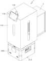
도 4는 본 발명의 일 실시예에 따른 PCB매거진 이송로봇(1)의 사시도를 개략적으로 도시한다.Figure 4 schematically illustrates a perspective view of a PCB magazine transport robot (1) according to one embodiment of the present invention.
도 4에 도시된 바와 같이, 본 발명의 PCB매거진 이송로봇(1)은, PCB매거진을 픽업하는 픽업모듈(1000); 및 상기 픽업모듈(1000)을 이동시키는 AMR모듈(2000);을 포함하고, 상기 픽업모듈(1000)은, 후면부가 개방된 상자 형태의 픽업케이스(1100); 상기 픽업케이스(1100)의 우측면부 및 좌측면부를 따라 지면에서 수직방향으로 위치하는 봉 형태의 복수의 수직가이드(1200); 상기 수직가이드를 따라 지면과 수직방향으로 이동하고, 중앙에 상기 수직가이드가 관통되는 관통홀이 형성된 복수의 수직이동체(1300); 상기 픽업케이스(1100)의 상측면 일측에 배치되고 상기 수직이동체를 구동하는 제1구동모터(1400); 상기 복수의 수직이동체(1300)에 지면과 수평방향으로 부착되는 판 형태의 플레이트(1500); 상기 플레이트(1500)의 상측면에 상기 플레이트(1500)의 길이방향과 수평으로 위치하는 봉 형태의 수평가이드(1600); 상기 수평가이드(1600)를 따라 지면과 수평방향으로 이동하고, 중앙에 상기 수평가이드(1600)가 관통되는 관통홀이 형성된 수평이동체(1700); 상기 플레이트(1500)의 하측면 일측에 배치되고 상기 수평이동체(1700)를 구동하는 제2구동모터(1800); 상기 플레이트(1500)의 하측면에 지면과 수평방향으로 위치하는 U자 형태의 포크(1900); 상기 제1구동모터(1400)의 회전축에 연결된 제1모터풀리(1420); 상기 복수의 수직가이드(1200)의 중심축에 연결된 수직가이드풀리; 상기 제2구동모터(1800)의 회전축에 연결된 제2모터풀리(1820); 및 상기 수평가이드(1600)의 중심축에 연결된 수평가이드풀리(1821);를 포함한다.As illustrated in FIG. 4, the PCB magazine transport robot (1) of the present invention comprises a pickup module (1000) for picking up a PCB magazine; and an AMR module (2000) for moving the pickup module (1000); wherein the pickup module (1000) comprises: a box-shaped pickup case (1100) having an open rear end; a plurality of rod-shaped vertical guides (1200) positioned vertically from the ground along the right and left sides of the pickup case (1100); a plurality of vertical moving bodies (1300) that move vertically from the ground along the vertical guides and have a through-hole formed in the center through which the vertical guides pass; a first drive motor (1400) disposed on one side of the upper side of the pickup case (1100) for driving the vertical moving bodies; a plate (1500) in the form of a plate attached horizontally from the ground to the plurality of vertical moving bodies (1300); A horizontal guide (1600) in the shape of a rod positioned horizontally in the longitudinal direction of the plate (1500) on the upper side of the plate (1500); A horizontal moving body (1700) that moves horizontally with the ground along the horizontal guide (1600) and has a through hole formed in the center through which the horizontal guide (1600) passes; A second driving motor (1800) that is positioned on one side of the lower side of the plate (1500) and drives the horizontal moving body (1700); A U-shaped fork (1900) positioned horizontally with the ground on the lower side of the plate (1500); A first motor pulley (1420) connected to the rotational axis of the first driving motor (1400); A vertical guide pulley connected to the central axes of the plurality of vertical guides (1200); A second motor pulley (1820) connected to the rotational axis of the second driving motor (1800); and a horizontal guide pulley (1821) connected to the central axis of the horizontal guide (1600).
이 때, 상기 수직가이드는 제1수직가이드(1210) 및 제2수직가이드(1220)를 포함할 수 있고, 상기 수직이동체는 제1수직이동체(1310) 및 제2수직이동체(1320)를 포함할 수 있고, 상기 수직가이드풀리는 제1수직가이드풀리(1421) 및 제2수직가이드풀리(1422)를 포함할 수 있다.At this time, the vertical guide may include a first vertical guide (1210) and a second vertical guide (1220), the vertical moving body may include a first vertical moving body (1310) and a second vertical moving body (1320), and the vertical guide pulley may include a first vertical guide pulley (1421) and a second vertical guide pulley (1422).
본 발명의 일 실시예에서는, 상기 픽업모듈(1000)은, PCB매거진 이송로봇(1) 또는 PCB매거진에 대한 정보를 표시하는모니터(1130); PCB매거진 이송로봇(1)에 대한 상황을 나타내는 표시등 및 경고음을 내장한 타워램프(1140); 및 비상 시에 즉시 전원을 차단하거나 공급할 수 있는 비상전원(1150);을 더 포함할 수 있다.In one embodiment of the present invention, the pickup module (1000) may further include a monitor (1130) that displays information about the PCB magazine transport robot (1) or the PCB magazine; a tower lamp (1140) that has built-in indicator lights and warning sounds that indicate the status of the PCB magazine transport robot (1); and an emergency power source (1150) that can immediately cut off or supply power in an emergency.
또한, 상기 수직가이드의 외주면의 일부에는 나사산이 형성되어 있고 상기 수직이동체의 상기 수직가이드가 관통되는 관통홀의 내주면에는 나사산이 형성되어 있고, 상기 수평가이드(1600)의 외주면의 일부에는 나사산이 형성되어 있고 상기 수평이동체(1700)의 상기 수평가이드(1600)가 관통되는 관통홀의 내주면에는 나사산이 형성되어 있고, 상기 제1구동모터(1400)의 회전에 의하여, 제1모터풀리(1420)가 회전하고 상기 제1모터풀리(1420)의 동력이 제1컨베이어벨트(1410)에 의하여 복수의 수직가이드풀리를 회전시켜 상기 복수의 수직가이드를 회전시킴에 따라 상기 복수의 수직이동체(1300)가 상하방향으로 이동하고 상기 수직이동체의 이동에 따라 상기 플레이트(1500)가 지면에서 수직방향으로 이동하고, 상기 제2구동모터(1800)의 회전에 의하여, 제2모터풀리(1820)가 회전하고, 상기 제2모터풀리(1820)의 동력이 제2컨베이어벨트(1810)에 의하여 수평가이드풀리(1821)를 회전시켜 상기 수평가이드(1600)를 회전시킴에 따라 상기 수평이동체(1700)가 수평방향으로 앞뒤로 이동하고 상기 수평이동체(1700)의 이동에 따라 상기 포크(1900)가 지면에서 수평방향으로 이동할 수 있다.In addition, a screw thread is formed on a part of the outer surface of the vertical guide, and a screw thread is formed on an inner surface of a through hole through which the vertical guide of the vertical moving body penetrates, a screw thread is formed on a part of the outer surface of the horizontal guide (1600), and a screw thread is formed on an inner surface of a through hole through which the horizontal guide (1600) of the horizontal moving body (1700) penetrates, and by the rotation of the first driving motor (1400), the first motor pulley (1420) rotates, and the power of the first motor pulley (1420) rotates the plurality of vertical guide pulleys by the first conveyor belt (1410), thereby rotating the plurality of vertical guides, so that the plurality of vertical moving bodies (1300) move up and down, and by the movement of the vertical moving bodies, the plate (1500) moves vertically on the ground, and by the rotation of the second driving motor (1800), As the second motor pulley (1820) rotates, the power of the second motor pulley (1820) rotates the horizontal guide pulley (1821) via the second conveyor belt (1810), thereby rotating the horizontal guide (1600), so that the horizontal moving body (1700) moves back and forth in the horizontal direction, and as the horizontal moving body (1700) moves, the fork (1900) can move horizontally on the ground.
상기 AMR모듈(2000)은, 상기 PCB매거진 이송로봇(1)을 이동시키는 복수의 바퀴(2110)를 포함하는 AMR이동부(2100); 상기 AMR이동부(2100)를 구동하는 AMR구동부(2200); 상기 AMR구동부(2200)의 동작을 제어하는 AMR제어부(2300); 및 상기 AMR구동부(2200)로 전력을 공급하는 AMR배터리(2400);를 포함하고, 상기 AMR이동부(2100)가 구동함에 따라 상기 픽업모듈(1000)이 이동할 수 있다. 또한, 상기 AMR구동부(2200), 상기 AMR제어부(2300), 및 상기 AMR배터리(2400)는 AMR모듈(2000)의 내부에 위치할 수 있다.The above AMR module (2000) includes an AMR moving unit (2100) including a plurality of wheels (2110) for moving the PCB magazine transport robot (1); an AMR driving unit (2200) for driving the AMR moving unit (2100); an AMR control unit (2300) for controlling the operation of the AMR driving unit (2200); and an AMR battery (2400) for supplying power to the AMR driving unit (2200). As the AMR moving unit (2100) is driven, the pickup module (1000) can move. In addition, the AMR driving unit (2200), the AMR control unit (2300), and the AMR battery (2400) can be located inside the AMR module (2000).
본 발명의 일 실시예에서는, 상기 PCB매거진 이송로봇(1)은, 상기 AMR모듈(2000)을 통해 이송할 대상PCB매거진 앞으로 이동하는 이동단계; 상기 제1구동모터(1400)를 통해 상기 대상PCB매거진의 상부 커버의 하측면에 상기 포크(1900)가 위치하도록 포크(1900)의 높이를 조절하는 포크높이조절단계; 상기 제2구동모터(1800)를 통해 포크(1900)의 위치를 조절하여 상기 대상PCB매거진의 상부 커버의 하측면에 포크(1900)를 삽입하는 포크삽입단계; 상기 제1구동모터(1400)를 통해 포크(1900)의 높이를 조절하여 상기 대상PCB매거진을 들어올리는 대상픽업단계; 상기 제2구동모터(1800)를 통해 포크(1900)의 위치를 조절하여 상기 대상PCB매거진을 픽업케이스(1100) 내부에 삽입하는 대상삽입단계; 상기 제1구동모터(1400)를 통해 포크(1900)의 높이를 조절하여 상기 대상PCB매거진의 하측면을 상기 픽업케이스(1100)의 바닥에 안착시키는 대상안착단계; 및 상기 AMR모듈(2000)을 통해 상기 대상PCB매거진을 이송하는 대상이송단계;를 수행할 수 있다.In one embodiment of the present invention, the PCB magazine transport robot (1) comprises: a moving step of moving toward a target PCB magazine to be transported via the AMR module (2000); a fork height adjustment step of adjusting the height of the fork (1900) via the first drive motor (1400) so that the fork (1900) is positioned on the lower side of the upper cover of the target PCB magazine; a fork insertion step of adjusting the position of the fork (1900) via the second drive motor (1800) to insert the fork (1900) into the lower side of the upper cover of the target PCB magazine; a target pickup step of lifting the target PCB magazine by adjusting the height of the fork (1900) via the first drive motor (1400); The following steps can be performed: a target insertion step for inserting the target PCB magazine into the pickup case (1100) by adjusting the position of the fork (1900) through the second driving motor (1800); a target mounting step for mounting the lower side of the target PCB magazine on the bottom of the pickup case (1100) by adjusting the height of the fork (1900) through the first driving motor (1400); and a target transfer step for transporting the target PCB magazine through the AMR module (2000).
또한, 상기 포크(1900)는, 이송할 대상PCB매거진의 상부 커버의 아래 면을 따라 삽입되고, 상기 제1구동모터(1400)를 통해 상기 대상PCB매거진을 지면에서 수직방향으로 이동시켜 들어올리고, 상기 제2구동모터(1800)를 통해 상기 대상PCB매거진을 지면에서 수평방향으로 이동시켜 상기 픽업케이스(1100) 내부에 삽입시키고, 상기 제1구동모터(1400)를 통해 상기 대상PCB매거진을 지면에서 수직방향으로 이동시켜 상기 픽업케이스(1100)의 바닥에 안착시킬 수 있다. 이 때, 상기 픽업케이스(1100)는, 픽업케이스(1100)의 바닥 면 일측에 배치되고 픽업케이스(1100)의 내부 물체를 인식하는 바닥센서(1110)를 포함하고, 상기 바닥센서(1110)는, PCB매거진이 상기 픽업케이스(1100) 내부에 삽입되면 상기 PCB매거진이 픽업케이스(1100) 내부에 안착되었는지 인식할 수 있다.In addition, the fork (1900) is inserted along the lower surface of the upper cover of the target PCB magazine to be transported, and lifts the target PCB magazine by moving it vertically from the ground through the first driving motor (1400), moves the target PCB magazine horizontally from the ground through the second driving motor (1800) and inserts it into the pickup case (1100), and moves the target PCB magazine vertically from the ground through the first driving motor (1400) and settles it on the bottom of the pickup case (1100). At this time, the pickup case (1100) includes a bottom sensor (1110) that is arranged on one side of the bottom surface of the pickup case (1100) and recognizes an object inside the pickup case (1100), and the bottom sensor (1110) can recognize whether the PCB magazine is seated inside the pickup case (1100) when the PCB magazine is inserted inside the pickup case (1100).
종래의 PCB 제조 공정에서는 직원이 PCB매거진을 직접 들고 이동시켜야 했다. 반면에, 본 발명의 PCB매거진 이송로봇(1)은 PCB매거진을 자동적으로 픽업하고 이송할 수 있기 때문에 PCB 제조 공정에서 인력을 최소화하여 효율적으로 PCB매거진을 이송할 수 있고, 다양한 높이, 크기, 형태, 및 무게의 PCB매거진을 픽업 및 이송할 수 있다. 정해진 경로에 따라 이송만 자동으로 수행할 수 있는 컨베이어 방식의 기술과는 달리 본 발명의 PCB매거진 이송로봇(1)은 PCB매거진을픽업하고 이동한 후 적재하는 단계까지 모두 자동적으로 수행될 수 있기 때문에 보다 효율적이고 빠른 운송을 수행할 수 있다.In the conventional PCB manufacturing process, employees had to personally carry and move the PCB magazine. On the other hand, the PCB magazine transport robot (1) of the present invention can automatically pick up and transport the PCB magazine, so that the PCB magazine can be transported efficiently by minimizing manpower in the PCB manufacturing process, and PCB magazines of various heights, sizes, shapes, and weights can be picked up and transported. Unlike the conveyor-type technology that can only automatically transport along a set path, the PCB magazine transport robot (1) of the present invention can automatically perform the steps from picking up the PCB magazine, moving it, to loading it, so that more efficient and faster transport can be performed.
이 때, 픽업이란, 지면 또는 다른 물체 위에 놓여 있는 PCB매거진을 들어올리는 과정, 및 들어올린 PCB매거진을 상기 픽업케이스(1100)에 삽입하는 과정을 포함할 수 있다.At this time, the pickup may include a process of lifting a PCB magazine placed on the ground or another object, and a process of inserting the lifted PCB magazine into the pickup case (1100).
도 5는 본 발명의 일 실시예에 따른 PCB매거진 이송로봇(1)의 분해사시도를 개략적으로 도시한다.Figure 5 schematically illustrates an exploded perspective view of a PCB magazine transport robot (1) according to one embodiment of the present invention.
개략적으로, 본 발명의 PCB매거진 이송로봇(1)은 PCB매거진을 픽업하는 픽업모듈(1000), 및 상기 픽업모듈(1000)을 이동시키는 AMR모듈(2000)을 포함한다.In outline, the PCB magazine transport robot (1) of the present invention includes a pickup module (1000) that picks up a PCB magazine, and an AMR module (2000) that moves the pickup module (1000).
도 5에 도시된 바와 같이, 픽업모듈(1000)은 PCB매거진 이송로봇(1)의 상단부에 위치하며 PCB매거진을 픽업할 수 있는 모듈을 포함할 수 있고, AMR모듈(2000)은 PCB매거진 이송로봇(1)의 하단부에 위치하며 상기 픽업모듈(1000)을 이동시킬 수 있는 모듈을 포함할 수 있다.As illustrated in FIG. 5, the pickup module (1000) is located at the upper end of the PCB magazine transport robot (1) and may include a module capable of picking up a PCB magazine, and the AMR module (2000) is located at the lower end of the PCB magazine transport robot (1) and may include a module capable of moving the pickup module (1000).
본 발명의 일 실시예에서는, 상기 PCB매거진 이송로봇(1)의 상단부는상기 픽업모듈(1000)에 해당하고, 상기 PCB매거진 이송로봇(1)의 하단부는상기 AMR모듈(2000)에 해당할 수 있다. 도 5와 같이 상기 픽업모듈(1000)과 상기 AMR모듈(2000)은 지면에서 수직방향으로 긴 형태의 4개의 원통형 수직 부재로 연결될 수 있고, 상기 AMR모듈(2000)의 이동에 따라 상기 픽업모듈(1000)이 함께 이동할 수 있다.In one embodiment of the present invention, the upper part of the PCB magazine transport robot (1) may correspond to the pickup module (1000), and the lower part of the PCB magazine transport robot (1) may correspond to the AMR module (2000). As shown in FIG. 5, the pickup module (1000) and the AMR module (2000) may be connected by four cylindrical vertical members having a long shape in a vertical direction from the ground, and the pickup module (1000) may move together as the AMR module (2000) moves.
따라서, 본 발명의 PCB매거진 이송로봇(1)에서 PCB매거진에 대한 픽업은 상기 픽업모듈(1000)에 의해 수행될 수 있고, PCB매거진에 대한 이동은 상기 AMR모듈(2000)에 의해 수행될 수 있다.Therefore, in the PCB magazine transport robot (1) of the present invention, pickup of the PCB magazine can be performed by the pickup module (1000), and movement of the PCB magazine can be performed by the AMR module (2000).
바람직하게는, 도 4를 참고하여, 상기 PCB매거진 이송로봇(1)의 픽업케이스(1100)는 4개의 면이 개방된 형태가 아닌 도 5와 같이 픽업케이스(1100)에는 커버(1120)가 존재하며 픽업케이스(1100)의 후면부만 커버(1120)가 없이 개방된 형태에 해당할 수 있다. 이 때, 픽업케이스(1100)의 전면부는 상기 모니터(1130)가 탑재된 면에 해당할 수 있고, 상기 픽업케이스(1100)의 후면부를 통해 PCB매거진이 상기 픽업케이스(1100) 내부로 삽입될 수 있다.Preferably, referring to Fig. 4, the pickup case (1100) of the PCB magazine transport robot (1) may be in a form in which, instead of having four open sides, the pickup case (1100) has a cover (1120) as shown in Fig. 5, and only the rear side of the pickup case (1100) is open without the cover (1120). In this case, the front side of the pickup case (1100) may correspond to the side on which the monitor (1130) is mounted, and the PCB magazine may be inserted into the pickup case (1100) through the rear side of the pickup case (1100).
또한, 도 4를 참고하여, 상기 PCB매거진 이송로봇(1)의 상측면부가 개방된 형태가 아닌 도 5와 같이 픽업모듈(1000)의 상측면부에도 커버(1120)가 존재할 수 있다. 상기 픽업케이스(1100) 및 상기 픽업모듈(1000)의 상측면부 각각에 커버(1120)가 존재하기 때문에 PCB매거진 이송로봇(1) 및 PCB매거진이 외부의 손상으로부터 보호될 수 있어 보다 안전하게 이동할 수 있다.In addition, referring to Fig. 4, instead of the upper side of the PCB magazine transport robot (1) being open, a cover (1120) may be present on the upper side of the pickup module (1000) as in Fig. 5. Since a cover (1120) is present on each of the upper side of the pickup case (1100) and the pickup module (1000), the PCB magazine transport robot (1) and the PCB magazine can be protected from external damage, and thus can be moved more safely.
본 발명의 일 실시예에서는, 상기 AMR모듈(2000)은 독립적으로 환경을 이해하고자율적으로 이동할 수 있는 자율 모바일 로봇을 포함할 수 있고, 자율적으로 작동하며 고정된 경로가 없이도 통제되지 않은 환경에서 탐색할 수 있는 로봇에 해당할 수 있다. 본 발명의 PCB매거진 이송로봇(1)에 포함되는 AMR모듈(2000)은 사전에 정의된 경로에 따라 이동할 수 있고, 사전에 정의되지 않은 자율적인 경로에 따라 이동할 수 있다. 따라서, 상기 AMR모듈(2000)을 통해 PCB매거진 이송로봇(1)이 고정된 경로가 아닌 자율적인 경로로 이동할 수 있는 효과를 발휘할 수 있다.In one embodiment of the present invention, the AMR module (2000) may include an autonomous mobile robot that can independently understand the environment and move autonomously, and may correspond to a robot that can operate autonomously and explore in an uncontrolled environment without a fixed path. The AMR module (2000) included in the PCB magazine transport robot (1) of the present invention may move along a predefined path, and may move along an autonomous path that is not predefined. Therefore, the PCB magazine transport robot (1) may have the effect of moving along an autonomous path rather than a fixed path through the AMR module (2000).
도 6은 본 발명의 일 실시예에 따른 PCB매거진 이송로봇(1)의 정면도 및 배면도를 개략적으로 도시한다.Figure 6 schematically illustrates a front view and a back view of a PCB magazine transport robot (1) according to one embodiment of the present invention.
개략적으로, 도 6의 (a)는 PCB매거진 이송로봇(1)의 정면도를 도시하고, 도 6의 (b)는 PCB매거진 이송로봇(1)의 배면도를 도시한다.Schematically, Fig. 6 (a) illustrates a front view of the PCB magazine transport robot (1), and Fig. 6 (b) illustrates a back view of the PCB magazine transport robot (1).
본 발명의 일 실시예에서는, 도 6의 (a)와 같이 모니터(1130)가 탑재된 부분이 PCB매거진 이송로봇(1)의 전면부에 해당하고, 도 6의 (b)와 같이 픽업케이스(1100)가 개방되어 PCB매거진이삽입되는 부분이 PCB매거진 이송로봇(1)의 후면부에 해당할 수 있다.In one embodiment of the present invention, as shown in (a) of FIG. 6, the part where the monitor (1130) is mounted may correspond to the front of the PCB magazine transport robot (1), and as shown in (b) of FIG. 6, the part where the pickup case (1100) is opened and the PCB magazine is inserted may correspond to the rear of the PCB magazine transport robot (1).
도 6의 (a)에 도시된 바와 같이, 상기 픽업케이스(1100)의 커버(1120)를 제외하였을 때, 상기 PCB매거진 이송로봇(1)의 전면부에서는 상기 픽업케이스(1100)의 내부에 위치하는 제2구동모터(1800), 제2모터풀리(1820), 수평가이드풀리(1821), 및 제2컨베이어벨트(1810)를 확인할 수 있다. 또한, 제1수직가이드(1210), 제2수직가이드(1220), 상기 제1수직가이드(1210)가 관통되는 제1수직이동체(1310), 상기 제2수직가이드(1220)가 관통되는 제2수직이동체(1320), 상기 제1수직이동체(1310) 및 상기 제2수직이동체(1320)에 부착되는 플레이트(1500), 상기 플레이트(1500)에 부착되는 제1수평부재(1611), 및 상기 플레이트(1500)에 부착되는 제2수평부재(1612)를 확인할 수 있다.As shown in (a) of Fig. 6, when the cover (1120) of the pickup case (1100) is removed, the second drive motor (1800), the second motor pulley (1820), the horizontal guide pulley (1821), and the second conveyor belt (1810) located inside the pickup case (1100) can be confirmed on the front side of the PCB magazine transport robot (1). In addition, a first vertical guide (1210), a second vertical guide (1220), a first vertical moving body (1310) through which the first vertical guide (1210) passes, a second vertical moving body (1320) through which the second vertical guide (1220) passes, a plate (1500) attached to the first vertical moving body (1310) and the second vertical moving body (1320), a first horizontal member (1611) attached to the plate (1500), and a second horizontal member (1612) attached to the plate (1500) can be confirmed.
본 발명의 일 실시예에서는, 상기 PCB매거진 이송로봇(1)의 전면부에서 상기 모니터(1130)를 조작하거나 상기 모니터(1130)를 통해 표시되는 화면을 확인할 수 있고, 상기 비상전원(1150)을 조작할 수 있고, 상기 타워램프(1140)를 통해 PCB매거진 이송로봇(1)의 전면부, 후면부, 우측면부, 또는 좌측면부 어디에서나 표시등 또는 경고음을통해 PCB매거진 이송로봇(1)에 대한 상황을 확인할 수 있다. 예를 들어, 상기 PCB매거진 이송로봇(1)은 자동적으로 PCB매거진을 픽업하고 자율적으로 이동하여PCB매거진을 이송할 수 있지만, 사람이 모니터(1130)를 통해 직접 상기 픽업모듈(1000)의 동작을 제어하여 PCB매거진을 픽업하도록 할 수 있고 상기 AMR모듈(2000)의 동작을 제어하여 PCB매거진을 이송하도록 조작할 수 있다.In one embodiment of the present invention, the monitor (1130) can be operated from the front of the PCB magazine transport robot (1) or the screen displayed through the monitor (1130) can be checked, the emergency power (1150) can be operated, and the status of the PCB magazine transport robot (1) can be checked through an indicator light or warning sound from anywhere on the front, rear, right side, or left side of the PCB magazine transport robot (1) through the tower lamp (1140). For example, the PCB magazine transport robot (1) can automatically pick up a PCB magazine and move autonomously to transport the PCB magazine, but a person can directly control the operation of the pickup module (1000) through the monitor (1130) to pick up the PCB magazine and control the operation of the AMR module (2000) to transport the PCB magazine.
도 6의 (b)에 도시된 바와 같이, 상기 픽업케이스(1100)의 커버(1120)를 제외하였을 때, 상기 PCB매거진 이송로봇(1)의 후면부에서는 상기 픽업케이스(1100)의 내부에 위치하는 제2구동모터(1800) 및 포크(1900)를 확인할 수 있고, 상기 제2구동모터(1800)의 작동에 따라 지면에서 수평방향 또는 상기 픽업케이스(1100)의 앞뒤방향으로 포크(1900)가 이동하는 것을 확인할 수 있다. 또한, 제1수직가이드(1210), 제2수직가이드(1220), 상기 제1수직가이드(1210)가 관통되는 제1수직이동체(1310), 상기 제2수직가이드(1220)가 관통되는 제2수직이동체(1320), 상기 제1수직이동체(1310) 및 상기 제2수직이동체(1320)에 부착되는 플레이트(1500), 상기 플레이트(1500)에 부착되는 제1수평부재(1611), 및 상기 플레이트(1500)에 부착되는 제2수평부재(1612)를 확인할 수 있다.As shown in (b) of FIG. 6, when the cover (1120) of the pickup case (1100) is removed, the second drive motor (1800) and the fork (1900) located inside the pickup case (1100) can be confirmed at the rear of the PCB magazine transport robot (1), and it can be confirmed that the fork (1900) moves horizontally on the ground or in the front-back direction of the pickup case (1100) depending on the operation of the second drive motor (1800). In addition, a first vertical guide (1210), a second vertical guide (1220), a first vertical moving body (1310) through which the first vertical guide (1210) passes, a second vertical moving body (1320) through which the second vertical guide (1220) passes, a plate (1500) attached to the first vertical moving body (1310) and the second vertical moving body (1320), a first horizontal member (1611) attached to the plate (1500), and a second horizontal member (1612) attached to the plate (1500) can be confirmed.
본 발명의 일 실시예에서는, 상기 포크(1900)가 상기 전면부에서 상기 후면부 방향으로 이동하면서 픽업케이스(1100) 외부로 포크(1900)가 돌출될 수 있고, 돌출된 포크(1900)는 픽업케이스(1100) 외부에 위치하는 대상PCB매거진에 삽입될 수 있으며, 상기 포크(1900)가 픽업케이스(1100) 내부 또는 외부에서 지면에서 수직방향으로 이동함으로써 상기 대상PCB매거진을 들어올리거나 내려놓을 수 있다. 이 때, 상기 대상PCB매거진은 1 이상의 PCB매거진 중 PCB매거진 이송로봇(1)이 이송하고자 하는 대상으로 결정된 PCB매거진에 해당할 수 있다.In one embodiment of the present invention, the fork (1900) may protrude outside the pickup case (1100) while moving from the front side toward the rear side, and the protruding fork (1900) may be inserted into a target PCB magazine located outside the pickup case (1100), and the fork (1900) may lift or put down the target PCB magazine by moving vertically on the ground inside or outside the pickup case (1100). At this time, the target PCB magazine may correspond to a PCB magazine determined as a target to be transported by the PCB magazine transport robot (1) among one or more PCB magazines.
바람직하게는, 상기 포크(1900)를 통해 들어올린 PCB매거진은 후면부가 개방된 상기 픽업케이스(1100)에 삽입될 수 있고, PCB매거진 이송로봇(1)이 다양한 크기의 PCB매거진을 이송할 수 있도록 상기 픽업케이스(1100)는 PCB매거진보다 큰 크기에 해당할 수 있다.Preferably, the PCB magazine lifted through the fork (1900) can be inserted into the pickup case (1100) with an open rear end, and the pickup case (1100) can be larger in size than the PCB magazine so that the PCB magazine transport robot (1) can transport PCB magazines of various sizes.
또한, 상기 전면부 및 상기 후면부에서는 상기 AMR모듈(2000)에 포함되는 복수의 바퀴(2110)를 확인할 수 있고, 상기 복수의 바퀴(2110)를 통해 상기 AMR모듈(2000)이 이동함에 따라 상기 픽업모듈(1000) 및 픽업케이스(1100)에 삽입된 PCB매거진이 이동할 수 있다.In addition, a plurality of wheels (2110) included in the AMR module (2000) can be confirmed in the front and rear parts, and as the AMR module (2000) moves through the plurality of wheels (2110), the PCB magazine inserted in the pickup module (1000) and the pickup case (1100) can move.
도 7은 본 발명의 일 실시예에 따른 PCB매거진 이송로봇(1)의 우측면도 및 좌측면도를 개략적으로 도시한다.Figure 7 schematically illustrates a right side view and a left side view of a PCB magazine transport robot (1) according to one embodiment of the present invention.
개략적으로, 도 7의 (a)는 PCB매거진 이송로봇(1)의 우측면도를 도시하고, 도 7의 (b)는 PCB매거진 이송로봇(1)의 좌측면도를 도시한다.Schematically, Fig. 7 (a) illustrates a right-side view of the PCB magazine transport robot (1), and Fig. 7 (b) illustrates a left-side view of the PCB magazine transport robot (1).
본 발명의 일 실시예에서는, 도 7의 (a)와 같이 상기 전면부의 오른쪽 면이 PCB매거진 이송로봇(1)의 우측면부에 해당하고, 도 7의 (b)와 같이 상기 전면부의 왼쪽 면이 PCB매거진 이송로봇(1)의 좌측면부에 해당할 수 있다.In one embodiment of the present invention, as shown in (a) of Fig. 7, the right side of the front part may correspond to the right side of the PCB magazine transport robot (1), and as shown in (b) of Fig. 7, the left side of the front part may correspond to the left side of the PCB magazine transport robot (1).
구체적으로, 상기 픽업모듈(1000)은 상기 픽업케이스(1100)의 우측면부 및 좌측면부를 따라 지면에서 수직방향으로 위치하는 복수의 수직부재(1230), 및 상기 플레이트(1500)의 상측면에 상기 플레이트(1500)의 길이방향과 수평으로 위치하는 복수의 수평부재(1610)를 더 포함하고, 상기 수직부재는 제1수직부재(1231), 제2수직부재(1232), 제3수직부재(1233), 및 제4수직부재(1234)를 포함할 수 있고, 상기 수평부재는 제1수평부재(1611) 및 제2수평부재(1612)를 포함할 수 있다.Specifically, the pickup module (1000) further includes a plurality of vertical members (1230) positioned vertically from the ground along the right side and left side of the pickup case (1100), and a plurality of horizontal members (1610) positioned horizontally with the length direction of the plate (1500) on the upper side of the plate (1500). The vertical members may include a first vertical member (1231), a second vertical member (1232), a third vertical member (1233), and a fourth vertical member (1234), and the horizontal members may include a first horizontal member (1611) and a second horizontal member (1612).
도 7의 (a)에 도시된 바와 같이, 상기 픽업케이스(1100)의 커버(1120)를 제외하였을 때, 상기 PCB매거진 이송로봇(1)의 우측면부에서는 상기 픽업케이스(1100)의 내부에 위치하는 제1수직가이드(1210), 제1수직부재(1231), 제2수직부재(1232), 상기 제1수직가이드(1210)가 관통되는 제1수직이동체(1310), 상기 제1수직이동체(1310)에 부착되는 플레이트(1500), 상기 플레이트(1500) 상측면에 위치하는 수평가이드(1600), 제1수평부재(1611), 상기 플레이트(1500) 하측면에 위치하는 제2구동모터(1800), 및 상기 플레이트(1500) 하측면에 위치하는 포크(1900)를 확인할 수 있고, 상기 제2구동모터(1800)의 작동에 따라 지면에서 수평방향 또는 상기 픽업케이스(1100)의 앞뒤방향으로 포크(1900)가 이동하는 것을 확인할 수 있다.As shown in (a) of Fig. 7, when the cover (1120) of the pickup case (1100) is excluded, on the right side of the PCB magazine transport robot (1), a first vertical guide (1210), a first vertical member (1231), a second vertical member (1232) located inside the pickup case (1100), a first vertical moving body (1310) through which the first vertical guide (1210) passes, a plate (1500) attached to the first vertical moving body (1310), a horizontal guide (1600) located on the upper side of the plate (1500), a first horizontal member (1611), a second driving motor (1800) located on the lower side of the plate (1500), and a fork (1900) located on the lower side of the plate (1500) can be confirmed. It can be confirmed that the fork (1900) moves horizontally on the ground or in the front-back direction of the pickup case (1100) according to the operation of the second driving motor (1800).
도 7의 (b)에 도시된 바와 같이, 상기 픽업케이스(1100)의 커버(1120)를 제외하였을 때, 상기 PCB매거진 이송로봇(1)의 좌측면부에서는 상기 픽업케이스(1100)의 내부에 위치하는 제2수직가이드(1220), 제3수직부재(1233), 제4수직부재(1234), 상기 제2수직가이드(1220)가 관통되는 제2수직이동체(1320), 상기 제2수직이동체(1320)에 부착되는 플레이트(1500), 상기 플레이트(1500) 상측면에 위치하는 수평가이드(1600), 제2수평부재(1612), 상기 플레이트(1500) 하측면에 위치하는 제2구동모터(1800), 및 상기 플레이트(1500) 하측면에 위치하는 포크(1900)를 확인할 수 있고, 상기 제2구동모터(1800)의 작동에 따라 지면에서 수평방향 또는 상기 픽업케이스(1100)의 앞뒤방향으로 포크(1900)가 이동하는것을 확인할 수 있다.As shown in (b) of Fig. 7, when the cover (1120) of the pickup case (1100) is excluded, on the left side of the PCB magazine transport robot (1), a second vertical guide (1220), a third vertical member (1233), a fourth vertical member (1234) located inside the pickup case (1100), a second vertical moving body (1320) through which the second vertical guide (1220) passes, a plate (1500) attached to the second vertical moving body (1320), a horizontal guide (1600) located on the upper side of the plate (1500), a second horizontal member (1612), a second driving motor (1800) located on the lower side of the plate (1500), and a fork (1900) located on the lower side of the plate (1500) can be confirmed. It can be confirmed that the fork (1900) moves horizontally on the ground or in the front-back direction of the pickup case (1100) depending on the operation of the second driving motor (1800).
또한, 상기 우측면부 및 상기 좌측면부에서는 상기 AMR모듈(2000)에 포함되는 복수의 바퀴(2110)를 확인할 수 있고, 상기 복수의 바퀴(2110)를 통해 상기 AMR모듈(2000)이 이동함에 따라 상기 픽업모듈(1000) 및 픽업케이스(1100)에 삽입된 PCB매거진이 이동할 수 있다. 본 발명의 일 실시예에서는, AMR모듈(2000)의 우측면부에는 AMR모듈(2000)의 전원 또는 AMR모듈(2000)의 조작과 관련된 버튼이 포함될 수 있다. 예를 들어, 상기 AMR모듈(2000)은 자율적으로 이동하여 PCB매거진을 이송할 수 있지만, 사람이 직접 상기 AMR모듈(2000)의 우측면부의 AMR모듈(2000)의 전원 또는 조작과 관련된 버튼을 제어함으로써 직접 AMR모듈(2000)의 동작을 제어할 수 있다.In addition, on the right side and the left side, a plurality of wheels (2110) included in the AMR module (2000) can be confirmed, and as the AMR module (2000) moves through the plurality of wheels (2110), the PCB magazine inserted in the pickup module (1000) and the pickup case (1100) can move. In one embodiment of the present invention, the right side of the AMR module (2000) may include a button related to the power of the AMR module (2000) or the operation of the AMR module (2000). For example, the AMR module (2000) can move autonomously to transport the PCB magazine, but a person can directly control the operation of the AMR module (2000) by directly controlling the button related to the power or operation of the AMR module (2000) on the right side of the AMR module (2000).
도 8은 본 발명의 일 실시예에 따른 PCB매거진 이송로봇(1)의 평면도 및 저면도를 개략적으로 도시한다.Figure 8 schematically illustrates a plan view and a bottom view of a PCB magazine transport robot (1) according to one embodiment of the present invention.
개략적으로, 도 8의 (a)는 PCB매거진 이송로봇(1)의 평면도를 도시하고, 도 8의 (b)는 PCB매거진 이송로봇(1)의 저면도를 도시한다.Schematically, Fig. 8 (a) illustrates a plan view of a PCB magazine transport robot (1), and Fig. 8 (b) illustrates a bottom view of the PCB magazine transport robot (1).
본 발명의 일 실시예에서는, 도 8의 (a)와 같이 제1모터풀리(1420)가 위치하는 부분이 PCB매거진 이송로봇(1)의 상측면부에 해당하고, 도 8의 (b)와 같이 복수의 바퀴(2110)가 위치하는 부분이 PCB매거진 이송로봇(1)의 하측면부에 해당할 수 있다.In one embodiment of the present invention, as shown in (a) of FIG. 8, the part where the first motor pulley (1420) is positioned may correspond to the upper side of the PCB magazine transport robot (1), and as shown in (b) of FIG. 8, the part where the plurality of wheels (2110) are positioned may correspond to the lower side of the PCB magazine transport robot (1).
도 8의 (a)에 도시된 바와 같이, 상기 픽업모듈(1000)의 상측면 커버(1120)를 제외하였을 때, 상기 PCB매거진 이송로봇(1)의 상측면부에서는 상기 픽업케이스(1100)의 내부에 위치하는 제1구동모터(1400), 제1컨베이어벨트(1410), 제1모터풀리(1420), 제1수직가이드풀리(1421), 및 제2수직가이드풀리(1422)를 확인할 수 있고, 상기 제2구동모터(1800)의 작동에 따라 지면에서 수평방향 또는 상기 픽업케이스(1100)의 앞뒤방향으로 포크(1900)가 이동하는것을 확인할 수 있다.As shown in (a) of FIG. 8, when the upper side cover (1120) of the pickup module (1000) is removed, the first drive motor (1400), the first conveyor belt (1410), the first motor pulley (1420), the first vertical guide pulley (1421), and the second vertical guide pulley (1422) located inside the pickup case (1100) can be confirmed on the upper side of the PCB magazine transport robot (1), and it can be confirmed that the fork (1900) moves horizontally on the ground or in the front-back direction of the pickup case (1100) according to the operation of the second drive motor (1800).
도 8의 (b)에 도시된 바와 같이, 상기 PCB매거진 이송로봇(1)의 하측면부에서는 상기 AMR모듈(2000)에 포함되는 복수의 바퀴(2110)를 확인할 수 있고, 상기 제2구동모터(1800)의 작동에 따라 지면에서 수평방향 또는 상기 픽업케이스(1100)의 앞뒤방향으로 포크(1900)가 이동하는것을 확인할 수 있다.As shown in (b) of Fig. 8, a plurality of wheels (2110) included in the AMR module (2000) can be confirmed on the lower side of the PCB magazine transport robot (1), and it can be confirmed that the fork (1900) moves horizontally on the ground or in the front and rear direction of the pickup case (1100) according to the operation of the second drive motor (1800).
본 발명의 일 실시예에서는, 상기 복수의 바퀴(2110)는 6개에 해당할 수 있고, 상기 6개의 바퀴는 보다 큰 크기의 2개의 바퀴와 보다 작은 크기의 4개의 바퀴를 포함할 수 있다. 이 때, 상기 2개의 바퀴는 앞뒤방향으로의 이동을 제어하며 AMR모듈(2000)의 중간 부분에 위치할 수 있고, 상기 4개의 바퀴는 회전 또는 방향을 제어하며 AMR모듈(2000)의 앞과 뒤 부분에 위치할 수 있다.In one embodiment of the present invention, the plurality of wheels (2110) may correspond to six, and the six wheels may include two wheels of a larger size and four wheels of a smaller size. At this time, the two wheels control movement in the forward and backward direction and may be located in the middle of the AMR module (2000), and the four wheels control rotation or direction and may be located in the front and rear of the AMR module (2000).
바람직하게는, 픽업모듈(1000)의 상측면에는 커버(1120)가 존재하기 때문에 도 8의 (a)에 도시된 제1구동모터(1400), 제1컨베이어벨트(1410), 제1모터풀리(1420), 제1수직가이드풀리(1421), 및 제2수직가이드풀리(1422)의 위쪽으로 커버(1120)가 위치할 수 있고, 따라서, 상기 제1구동모터(1400), 상기 제1컨베이어벨트(1410), 상기 제1모터풀리(1420), 상기 제1수직가이드풀리(1421), 및 상기 제2수직가이드풀리(1422)는 외부에서 보이거나 외부에서 조작될 수 없도록 보호될 수 있다.Preferably, since a cover (1120) exists on the upper side of the pickup module (1000), the cover (1120) can be positioned above the first driving motor (1400), the first conveyor belt (1410), the first motor pulley (1420), the first vertical guide pulley (1421), and the second vertical guide pulley (1422) as shown in (a) of FIG. 8, and thus, the first driving motor (1400), the first conveyor belt (1410), the first motor pulley (1420), the first vertical guide pulley (1421), and the second vertical guide pulley (1422) can be protected so as not to be visible from the outside or manipulated from the outside.
도 9는 본 발명의 일 실시예에 따른 PCB매거진 이송로봇(1) 및 PCB매거진(2)의 사시도를 개략적으로 도시한다.FIG. 9 schematically illustrates a perspective view of a PCB magazine transport robot (1) and a PCB magazine (2) according to one embodiment of the present invention.
도 9에 도시된 바와 같이, 상기 PCB매거진 이송로봇(1)의 전면부, 우측면부, 좌측면부, 및 상측면부에는 커버(1120)가 존재할 수 있다. 따라서, PCB매거진 이송로봇(1)에 포함되는 장치 또는 부재들의 임의 조작 및 손상을 방지할 수 있고, 동시에 픽업케이스(1100)에 삽입된 물체를 파손으로부터 보호할 수 있다. 이 때, PCB매거진 이송로봇(1) 외부의 커버(1120)로 인해 상기 픽업케이스(1100) 내부의 물체를 인식하기 어려울 수 있지만, 본 발명의 일 실시예에서는, 상기 PCB매거진 이송로봇(1) 전면부, 우측면부, 및 좌측면부 커버(1120) 각각에는 픽업케이스(1100) 내부를 확인할 수 있도록 일부가 뚫리거나 내부가 보일 수 있는 투명한 재질로 마감된 창이 존재할 수 있고, 상기 창을 통해 픽업케이스(1100) 내부에 PCB매거진(2)이 들어있는지 멀리서도 한 눈에 파악할 수 있다.As shown in Fig. 9, a cover (1120) may be present on the front, right side, left side, and upper side of the PCB magazine transport robot (1). Accordingly, arbitrary manipulation and damage to devices or parts included in the PCB magazine transport robot (1) can be prevented, and at the same time, an object inserted into the pickup case (1100) can be protected from damage. At this time, it may be difficult to recognize an object inside the pickup case (1100) due to the cover (1120) outside the PCB magazine transport robot (1), but in one embodiment of the present invention, the front, right side, and left side covers (1120) of the PCB magazine transport robot (1) may each have a window that is partially open or finished with a transparent material through which the inside can be seen so that the inside of the pickup case (1100) can be checked, and through the window, it is possible to check at a glance from a distance whether a PCB magazine (2) is inside the pickup case (1100).
본 발명의 일 실시예에서는, 상기 PCB매거진(2)을 이송하기 위하여 픽업할 때, 도 9과 같이 PCB매거진(2)에 포크(1900)가 삽입된 채로 PCB매거진(2)을 지면에서 들어올릴 수 있다. PCB매거진(2)을 들어올린 뒤 포크(1900)를 픽업케이스(1100) 내부 방향으로 이동시키면 현재 픽업케이스(1100) 외부에 위치한 PCB매거진(2)이 픽업케이스(1100) 내부로 삽입될 수 있다.In one embodiment of the present invention, when picking up the PCB magazine (2) for transport, the PCB magazine (2) can be lifted from the ground with the fork (1900) inserted into the PCB magazine (2) as shown in Fig. 9. After lifting the PCB magazine (2), if the fork (1900) is moved toward the inside of the pickup case (1100), the PCB magazine (2) currently located outside the pickup case (1100) can be inserted into the inside of the pickup case (1100).
도 10은 본 발명의 일 실시예에 따른 PCB매거진 이송로봇(1) 및 PCB매거진(2)의 우측면도를 개략적으로 도시한다.Figure 10 schematically illustrates a right side view of a PCB magazine transport robot (1) and a PCB magazine (2) according to one embodiment of the present invention.
도 10에 도시된 바와 같이, PCB매거진 이송로봇(1)이 PCB매거진(2)을 들어올렸을 때의 모습을 보면 PCB매거진(2)에 상기 포크(1900)가 삽입된 형태에 해당할 수 있고, 이 때 포크(1900)가 지면에서 수직방향으로 이동함에 따라 PCB매거진(2) 역시 함께 지면에서 수직방향으로 이동할 수 있다.As shown in Fig. 10, when the PCB magazine transport robot (1) lifts the PCB magazine (2), it can correspond to a form in which the fork (1900) is inserted into the PCB magazine (2), and at this time, as the fork (1900) moves vertically on the ground, the PCB magazine (2) can also move vertically on the ground.
만약, 도 10에 도시된 모습에서 포크(1900)를 아래쪽으로 내리는 경우에는도 10의 PCB매거진(2)은 지면에 안착될 수 있고, 포크(1900)를 위쪽으로 올리는 경우에는 픽업케이스(1100)의 상측면 쪽으로 PCB매거진(2)의 상부 커버가 더 올라갈 수 있다. 바람직하게는, 픽업케이스(1100) 내부의 부재들의 위치 및 동작에 따라 PCB매거진(2)이 올라가거나 내려갈 수 있는 높이는 제한이 있을 수 있고, 상기 PCB매거진 이송로봇(1) 및 상기 포크(1900)의 동작에 따라 PCB매거진(2)을 지면이 아닌 다른 물체 위에 내려놓을 수 있으며 지면에 내려놓지 않고 다른 PCB매거진 위에 적재할 수 있다.Even if the fork (1900) is lowered as shown in Fig. 10, the PCB magazine (2) of Fig. 10 can be settled on the ground, and if the fork (1900) is raised upward, the upper cover of the PCB magazine (2) can be raised further toward the upper side of the pickup case (1100). Preferably, the height at which the PCB magazine (2) can be raised or lowered may be limited depending on the position and operation of the components inside the pickup case (1100), and the PCB magazine (2) can be placed on an object other than the ground depending on the operation of the PCB magazine transport robot (1) and the fork (1900), and can be loaded on top of another PCB magazine without being placed on the ground.
이 때, 포크(1900)는 지면에서 수직방향, 및 지면에서 수평방향으로 이동할 수 있고, 도 10과 같이, PCB매거진(2)을 들어올리고 포크(1900)를 상기 픽업케이스(1100) 내부 방향으로 이동시켜 해당 PCB매거진(2)을 픽업케이스(1100) 내부에 삽입할 수 있다.At this time, the fork (1900) can move vertically on the ground and horizontally on the ground, and as shown in FIG. 10, the PCB magazine (2) can be lifted and the fork (1900) can be moved toward the inside of the pickup case (1100) to insert the PCB magazine (2) into the inside of the pickup case (1100).
본 발명의 일 실시예에서는, 만약 픽업케이스(1100)보다 크기가 커서 픽업케이스(1100)에 삽입할 수 없는 물체를 이송하고자 하는 경우에는, 해당 물체를 픽업케이스(1100)에 삽입하지 않고도 포크(1900)를 통해 해당 물체를 들어올린 채로 이동할 수 있다.In one embodiment of the present invention, if an object that is larger than the pickup case (1100) and cannot be inserted into the pickup case (1100) is to be transported, the object can be lifted and moved using the fork (1900) without inserting the object into the pickup case (1100).
도 11은 본 발명의 일 실시예에 따른 PCB매거진(2)이 삽입된 PCB매거진 이송로봇(1)의 사시도를개략적으로 도시한다.FIG. 11 schematically illustrates a perspective view of a PCB magazine transport robot (1) having a PCB magazine (2) inserted therein according to one embodiment of the present invention.
개략적으로, 도 11은 PCB매거진 이송로봇(1)의 우측면부 및 후면부에 해당할 수 있고, PCB매거진 이송로봇(1)의 픽업케이스(1100)에는 PCB매거진(2)이 삽입된 형태에 해당할 수 있다.In outline, Fig. 11 may correspond to the right side and rear side of the PCB magazine transport robot (1), and may correspond to a form in which a PCB magazine (2) is inserted into the pickup case (1100) of the PCB magazine transport robot (1).
본 발명의 일 실시예에서는, PCB매거진 이송로봇(1)의 전면부, 우측면부, 좌측면부, 및 상측면부에는 모두 커버(1120)가 존재할 수 있고, 도 11은 모든 커버(1120)를 제외한 형태에 해당할 수 있다.In one embodiment of the present invention, covers (1120) may be present on the front, right side, left side, and upper side of the PCB magazine transport robot (1), and Fig. 11 may correspond to a form excluding all covers (1120).
구체적으로, 상기 PCB매거진 이송로봇(1)은 상기 AMR모듈(2000)을 통해 이송할 대상PCB매거진(2) 앞으로 이동하는 이동단계; 상기 제1구동모터(1400)를 통해 상기 대상PCB매거진(2)의 상부 커버의 하측면에 상기 포크(1900)가 위치하도록 포크(1900)의 높이를 조절하는 포크높이조절단계; 상기 제2구동모터(1800)를 통해 포크(1900)의 위치를 조절하여 상기 대상PCB매거진(2)의 상부 커버의 하측면에 포크(1900)를 삽입하는 포크삽입단계; 상기 제1구동모터(1400)를 통해 포크(1900)의 높이를 조절하여 상기 대상PCB매거진(2)을 들어올리는 대상픽업단계; 상기 제2구동모터(1800)를 통해 포크(1900)의 위치를 조절하여 상기 대상PCB매거진(2)을 픽업케이스(1100) 내부에 삽입하는 대상삽입단계; 상기 제1구동모터(1400)를 통해 포크(1900)의 높이를 조절하여 상기 대상PCB매거진(2)의 하측면을 상기 픽업케이스(1100)의 바닥에 안착시키는 대상안착단계; 및 상기 AMR모듈(2000)을 통해 상기 대상PCB매거진(2)을 이송하는 대상이송단계;를 수행할 수 있다.Specifically, the PCB magazine transport robot (1) comprises: a moving step in which the PCB magazine transport robot (1) moves forward of the target PCB magazine (2) to be transported via the AMR module (2000); a fork height adjustment step in which the height of the fork (1900) is adjusted via the first drive motor (1400) so that the fork (1900) is positioned on the lower side of the upper cover of the target PCB magazine (2); a fork insertion step in which the position of the fork (1900) is adjusted via the second drive motor (1800) to insert the fork (1900) into the lower side of the upper cover of the target PCB magazine (2); a target pickup step in which the height of the fork (1900) is adjusted via the first drive motor (1400) to lift the target PCB magazine (2); The following steps can be performed: a target insertion step in which the position of the fork (1900) is adjusted through the second driving motor (1800) to insert the target PCB magazine (2) into the pickup case (1100); a target mounting step in which the height of the fork (1900) is adjusted through the first driving motor (1400) to mount the lower side of the target PCB magazine (2) on the bottom of the pickup case (1100); and a target transfer step in which the target PCB magazine (2) is transferred through the AMR module (2000).
본 발명의 일 실시예에서는, 상기 PCB매거진 이송로봇(1)이 PCB매거진(2)을 들어올리는 방식은 포크를 통해 화물을 들어올리거나 운반할 수 있는 지게차와 유사한 방식으로 수행될 수 있지만, 지게차와는 다르게 상기 PCB매거진 이송로봇(1)은 들어올린 PCB매거진(2)을 해당 PCB매거진 이송로봇(1)의 픽업케이스(1100)에 삽입한 뒤 이동하기 때문에 PCB매거진(2)의 파손에 대한 위험을 줄일 수 있다.In one embodiment of the present invention, the method in which the PCB magazine transport robot (1) lifts the PCB magazine (2) can be performed in a manner similar to a forklift that can lift or transport cargo using a fork, but unlike a forklift, the PCB magazine transport robot (1) inserts the lifted PCB magazine (2) into a pickup case (1100) of the PCB magazine transport robot (1) and then moves it, thereby reducing the risk of damage to the PCB magazine (2).
도 11에 도시된 바와 같이, PCB매거진(2)은 픽업케이스(1100) 후면부를 통해 픽업케이스(1100)로 삽입될 수 있고 픽업케이스(1100) 바닥 면의 바닥센서(1110)를 통해 PCB매거진(2)을 픽업케이스(1100)의 바닥에 안착시킬 수 있다. PCB매거진(2)을 픽업한 PCB매거진 이송로봇(1)은 도 11과 같은 모습으로 이동하며 PCB매거진(2)을 특정 장소로 이송할 수 있다.As shown in Fig. 11, the PCB magazine (2) can be inserted into the pickup case (1100) through the rear side of the pickup case (1100), and the PCB magazine (2) can be placed on the bottom of the pickup case (1100) through the bottom sensor (1110) on the bottom surface of the pickup case (1100). The PCB magazine transport robot (1) that picks up the PCB magazine (2) moves as shown in Fig. 11 and can transport the PCB magazine (2) to a specific location.
바람직하게는, 상기 픽업케이스(1100)의 내부에 PCB매거진(2)을 삽입하기 위하여 픽업케이스(1100) 내부는 PCB매거진(2)의 크기보다 큰 크기에 해당할 수 있고, PCB매거진(2)은 상기 픽업케이스(1100)의 후면부를 통해서만 픽업케이스(1100) 내부로 들어가거나 픽업케이스(1100) 외부로 나올 수 있다.Preferably, in order to insert the PCB magazine (2) into the interior of the pickup case (1100), the interior of the pickup case (1100) may be larger than the size of the PCB magazine (2), and the PCB magazine (2) may enter or exit the pickup case (1100) only through the rear of the pickup case (1100).
만약, 상기 PCB매거진 이송로봇(1)이 이동하는 기설정된 공간 내에 가상경로가 설정되어있다면 상기 AMR모듈(2000)은 상기 가상경로를 따라 이동할 수 있고, 또는 상기 가상경로와 상관없이 자율적인 경로로 이동할 수 있다.If a virtual path is set within the preset space in which the PCB magazine transport robot (1) moves, the AMR module (2000) can move along the virtual path, or can move along an autonomous path regardless of the virtual path.
도 12는 본 발명의 일 실시예에 따른 PCB매거진(2)이 삽입된 픽업모듈(1000)을 개략적으로 도시한다.FIG. 12 schematically illustrates a pickup module (1000) into which a PCB magazine (2) is inserted according to one embodiment of the present invention.
개략적으로, 도 12는 PCB매거진(2)이 삽입된 픽업모듈(1000)의 후면부에 해당하고, 픽업모듈(1000)의 개방된 후면부를 통해 PCB매거진(2)이 픽업케이스(1100)에 삽입된 모습에 해당할 수 있다.In outline, Fig. 12 corresponds to the rear side of the pickup module (1000) into which the PCB magazine (2) is inserted, and may correspond to the appearance in which the PCB magazine (2) is inserted into the pickup case (1100) through the open rear side of the pickup module (1000).
도 12에 도시된 바와 같이, 상기 플레이트(1500) 하측면에 위치하는 상기 포크(1900)는 픽업케이스(1100) 내부에서 외부 방향으로 이동하거나, 픽업케이스(1100) 외부에서 내부 방향으로 이동할 수 있고, 상기 포크(1900)의 이동을 통해 포크(1900)가 삽입된 PCB매거진(2)을 픽업케이스(1100) 내부에서 외부 방향으로 이동시키거나, 픽업케이스(1100) 외부에서 내부 방향으로 이동시킬 수 있다. 도 12와 같이, PCB매거진(2) 상부 커버의 아래 면을 따라 PCB매거진 이송로봇(1)의 포크(1900)가 삽입될 수 있고, PCB매거진(2)에 삽입된 포크(1900)를 통해 상기 PCB매거진(2)은 지면에서 들어올려지거나 지면으로 안착될 수 있고 픽업케이스(1100)로 삽입될 수 있다.As illustrated in FIG. 12, the fork (1900) positioned on the lower side of the plate (1500) can move outward from the inside of the pickup case (1100), or can move inward from the outside of the pickup case (1100), and through the movement of the fork (1900), the PCB magazine (2) into which the fork (1900) is inserted can be moved outward from the inside of the pickup case (1100), or can be moved inward from the outside of the pickup case (1100). As illustrated in FIG. 12, the fork (1900) of the PCB magazine transport robot (1) can be inserted along the lower surface of the upper cover of the PCB magazine (2), and the PCB magazine (2) can be lifted from the ground or settled on the ground through the fork (1900) inserted into the PCB magazine (2) and inserted into the pickup case (1100).
도 12에서는 PCB매거진(2)에 PCB기판이 삽입되어 있지 않지만 바람직하게는, 상기 PCB매거진(2)에는 1 이상의 PCB기판이 삽입되어 있을 수 있고, 상기 포크(1900)는 1 이상의 PCB기판이 삽입된 PCB매거진(2)을 픽업할 수 있다.In Fig. 12, no PCB substrate is inserted into the PCB magazine (2), but preferably, one or more PCB substrates may be inserted into the PCB magazine (2), and the fork (1900) may pick up the PCB magazine (2) with one or more PCB substrates inserted.
도 13은 본 발명의 일 실시예에 따른 PCB매거진(2)을 개략적으로 도시한다.Figure 13 schematically illustrates a PCB magazine (2) according to one embodiment of the present invention.
구체적으로, 상기 PCB매거진(2)은 1 이상의 PCB기판이 삽입되는 랙, 및 상부 커버를 포함하고, 상기 PCB매거진 이송로봇(1)에 포함되는 포크(1900)를 상기 상부 커버 하측면에 삽입하고 상기 포크(1900)를 지면에서 수직방향 및 지면에서 수평방향으로 이동시켜 상기 PCB매거진(2)을 자동적으로 픽업할 수 있다. 본 발명의 일 실시예에서는, 상기 PCB매거진(2)은 상기 랙에 1 이상의 PCB기판이 삽입된 상태로 상기 PCB매거진 이송로봇(1)을 통해 이송될 수 있다.Specifically, the PCB magazine (2) includes a rack into which one or more PCB substrates are inserted, and an upper cover, and a fork (1900) included in the PCB magazine transport robot (1) is inserted into the lower side of the upper cover, and the fork (1900) is moved vertically from the ground and horizontally from the ground to automatically pick up the PCB magazine (2). In one embodiment of the present invention, the PCB magazine (2) can be transported through the PCB magazine transport robot (1) with one or more PCB substrates inserted in the rack.
이 때, 상기 PCB기판은 저항기, 콘덴서, 및 집적 회로 등 전자 부품을 인쇄 배선판의 표면에 고정하고 부품 사이 구리 배선으로 연결해 전자 회로를 구성한 인쇄회로기판을 포함할 수 있다.At this time, the PCB board may include a printed circuit board that forms an electronic circuit by fixing electronic components such as resistors, capacitors, and integrated circuits to the surface of the printed wiring board and connecting the components with copper wiring.
본 발명의 일 실시예에서는, 상기 랙은 다양한 크기와 형태의 PCB기판을 수납할 수 있도록 조정 가능한 모듈형 랙, 복수의 PCB기판을 쌓아서 보관할 수 있는 스태킹 랙, 및 PCB기판에 쉽게 접근할 수 있도록 슬라이딩 메커니즘이 포함된 슬라이딩 랙을 포함할 수 있다.In one embodiment of the present invention, the rack may include a modular rack that is adjustable to accommodate PCB boards of various sizes and shapes, a stacking rack that can store a plurality of PCB boards by stacking them, and a sliding rack that includes a sliding mechanism to allow easy access to the PCB boards.
도 13에 도시된 바와 같이, 기존의 PCB매거진(2)은 랙 및 상부 커버를 포함하고 상기 랙과 상기 상부 커버 사이에는 상기 PCB매거진 이송로봇(1)의 포크(1900)가 삽입될 수 있는 부분이 존재한다. 도 13에서 (1)은 랙과 상부 커버 사이의 틈을 표시하고 해당 틈으로 상기 포크(1900)가 삽입됨으로써 상기 PCB매거진 이송로봇(1)이 PCB매거진(2)을 픽업할 수 있다. 상기 상부 커버는 PCB매거진(2) 상측면 부분의 부재 또는 PCB매거진(2) 상측면에 위치하는 커버를 포함할 수 있고, 도 13의 (3)에 해당할 수 있다. 또한, 상기 PCB매거진(2)은 도 13의 (2)와 같이 1 이상의 PCB기판을 삽입할 수 있는 랙을 포함하고, 상기 랙에는 1 이상의 PCB기판이 삽입된 채로 상기 PCB매거진 이송로봇(1)에 의해 이송될 수 있다.As illustrated in Fig. 13, the conventional PCB magazine (2) includes a rack and an upper cover, and a part into which a fork (1900) of the PCB magazine transport robot (1) can be inserted exists between the rack and the upper cover. In Fig. 13, (1) indicates a gap between the rack and the upper cover, and by inserting the fork (1900) into the gap, the PCB magazine transport robot (1) can pick up the PCB magazine (2). The upper cover may include a member of the upper side portion of the PCB magazine (2) or a cover positioned on the upper side of the PCB magazine (2), and may correspond to (3) of Fig. 13. In addition, the PCB magazine (2) includes a rack into which one or more PCB substrates can be inserted, as illustrated in (2) of Fig. 13, and one or more PCB substrates can be transported by the PCB magazine transport robot (1) while being inserted into the rack.
이 때, 본 발명의 PCB매거진 이송로봇(1)이 이송하는 PCB매거진(2)은 시중에 판매되거나 종래의 PCB 제조 공정에서 사용되고 있는 PCB매거진(2)에 해당할 수 있다. 바람직하게는, 상기 PCB매거진(2)은 랙에 삽입된 PCB기판이 파손되지 않도록 보호하는 안전케이스 및 충격흡수패드, 혹은 PCB기판이 랙에서 떨어지지 않도록 고정하는 부품 또는 장치를 더 포함할 수 있다. 따라서, 상기 PCB매거진 이송로봇(1)이 PCB매거진(2)을 들어올리더라도 PCB매거진(2)의 랙에 삽입된 1 이상의 PCB기판은 파손되거나 떨어지지 않고 안전하게 이송될 수 있다.At this time, the PCB magazine (2) transported by the PCB magazine transport robot (1) of the present invention may correspond to a PCB magazine (2) sold commercially or used in a conventional PCB manufacturing process. Preferably, the PCB magazine (2) may further include a safety case and a shock absorbing pad for protecting the PCB board inserted into the rack from being damaged, or a part or device for fixing the PCB board so that it does not fall off the rack. Accordingly, even if the PCB magazine transport robot (1) lifts the PCB magazine (2), one or more PCB boards inserted into the rack of the PCB magazine (2) can be safely transported without being damaged or falling off.
본 발명의 일 실시예에서는, 상기 PCB매거진 이송로봇(1)은 상기 PCB매거진(2) 뿐만 아니라 이송로봇에 포함되는 포크(1900)를 통해 바닥 면을 들어올릴 수 있는 박스 형태의 물체를 픽업 및 이송할 수 있고, 상기 포크(1900)가 삽입될 수 있는 손잡이 또는 로프 등을 포함하는 물체 또한 픽업 및 이송할 수 있다. 상기 PCB매거진 이송로봇(1)은 다양한 물체를 픽업 및 이송할 수 있기 때문에 다양한 분야의 제조 공정 또는 물류센터에서 활용할 수 있다.In one embodiment of the present invention, the PCB magazine transport robot (1) can pick up and transport not only the PCB magazine (2), but also a box-shaped object that can be lifted from the floor by means of a fork (1900) included in the transport robot, and can also pick up and transport an object that includes a handle or rope into which the fork (1900) can be inserted. Since the PCB magazine transport robot (1) can pick up and transport various objects, it can be utilized in manufacturing processes or logistics centers in various fields.
도 14는 본 발명의 일 실시예에 따른 픽업모듈(1000)의 내부구성을 개략적으로 도시한다.Figure 14 schematically illustrates the internal configuration of a pickup module (1000) according to one embodiment of the present invention.
개략적으로, 도 14는 상기 픽업모듈(1000)에서 픽업케이스(1100) 내부에서 구동되는 부분을 도시하고, 픽업케이스(1100)를 제거하고 위에서 바라본 모습에 해당한다.Schematically, Fig. 14 illustrates a part driven inside a pickup case (1100) of the pickup module (1000), and corresponds to a view viewed from above with the pickup case (1100) removed.
도 14에 도시된 바와 같이, 본 발명의 PCB매거진 이송로봇(1)은 상기 픽업모듈(1000) 및 상기 AMR모듈(2000)을 포함할 수 있고, 상기 픽업모듈(1000)의 내부에는 제1수직가이드(1210), 제2수직가이드(1220), 제1수직부재(1231), 제2수직부재(1232), 제3수직부재(1233), 제4수직부재(1234), 제1수직이동체(1310), 제2수직이동체(1320), 제1구동모터(1400), 제1컨베이어벨트(1410), 제1모터풀리(1420), 제1수직가이드풀리(1421), 제2수직가이드풀리(1422), 플레이트(1500), 수평가이드(1600), 제1수평부재(1611), 제2수평부재(1612), 수평이동체(1700), 제2구동모터(1800), 제2컨베이어벨트(1810), 제2모터풀리(1820), 수평가이드풀리(1821), 및 포크(1900)가 포함될 수 있다.As shown in FIG. 14, the PCB magazine transport robot (1) of the present invention may include the pickup module (1000) and the AMR module (2000), and inside the pickup module (1000), there may be provided a first vertical guide (1210), a second vertical guide (1220), a first vertical member (1231), a second vertical member (1232), a third vertical member (1233), a fourth vertical member (1234), a first vertical moving body (1310), a second vertical moving body (1320), a first drive motor (1400), a first conveyor belt (1410), a first motor pulley (1420), a first vertical guide pulley (1421), a second vertical guide pulley (1422), a plate (1500), a horizontal guide (1600), It may include a first horizontal member (1611), a second horizontal member (1612), a horizontal moving body (1700), a second driving motor (1800), a second conveyor belt (1810), a second motor pulley (1820), a horizontal guide pulley (1821), and a fork (1900).
이 때, 상기 플레이트(1500)의 상측면에는 제1구동모터(1400), 제1모터풀리(1420), 제1수직가이드풀리(1421), 및 제2수직가이드풀리(1422)가 위치할 수 있고, 상기 제1구동모터(1400)의 동력은 상기 제1구동모터(1400)의 회전축에 연결된 제1모터풀리(1420)로 전달되고, 상기 제1모터풀리(1420)의 동력은 제1모터풀리(1420)와 복수의 수직가이드풀리에 연결된 제1컨베이어벨트(1410)에 의하여 상기 복수의 수직가이드풀리로 전달될 수 있다. 도 14와 같이, 상기 복수의 수직가이드풀리는 상기 제1수직가이드(1210)에 연결된 제1수직가이드풀리(1421) 및 상기 제2수직가이드(1220)에 연결된 제2수직가이드풀리(1422)를 포함하여 5개의 수직가이드풀리를 포함할 수 있다. 상기 복수의 수직가이드풀리의 회전에 따라 상기 플레이트(1500) 하측면에 위치하는 복수의 수직이동체(1300)를 관통하는 복수의 수직가이드(1200)가 회전할 수 있고, 상기 복수의 수직가이드(1200)의 회전에 따라 상기 복수의 수직이동체(1300)가 지면에서 수직방향으로 이동할 수 있다.At this time, a first driving motor (1400), a first motor pulley (1420), a first vertical guide pulley (1421), and a second vertical guide pulley (1422) may be positioned on the upper surface of the plate (1500), and the power of the first driving motor (1400) may be transmitted to the first motor pulley (1420) connected to the rotational axis of the first driving motor (1400), and the power of the first motor pulley (1420) may be transmitted to the plurality of vertical guide pulleys by the first conveyor belt (1410) connected to the first motor pulley (1420) and the plurality of vertical guide pulleys. As shown in FIG. 14, the plurality of vertical guide pulleys may include five vertical guide pulleys, including a first vertical guide pulley (1421) connected to the first vertical guide (1210) and a second vertical guide pulley (1422) connected to the second vertical guide (1220). As the plurality of vertical guide pulleys rotate, the plurality of vertical guides (1200) penetrating the plurality of vertical moving bodies (1300) located on the lower side of the plate (1500) may rotate, and as the plurality of vertical guides (1200) rotate, the plurality of vertical moving bodies (1300) may move vertically on the ground.
본 발명의 일 실시예에서는, 상기 복수의 수직이동체(1300)의 이동에 따라 플레이트(1500)가 지면에서 수직방향으로 함께 이동하고, 이 때 플레이트(1500)가 지면에서 수직방향으로 이동함에 따라 플레이트(1500) 상측면에 부착된 수평가이드풀리(1821), 수평가이드(1600), 수평이동체(1700), 제1수평부재(1611), 및 제2수평부재(1612) 또는 플레이트(1500) 하측면에 부착된 제2구동모터(1800), 제2모터풀리(1820), 및 포크(1900)가 함께 지면에서 수직방향으로 이동할 수 있다.In one embodiment of the present invention, as the plurality of vertical moving bodies (1300) move, the plate (1500) moves together in a vertical direction on the ground, and at this time, as the plate (1500) moves vertically on the ground, the horizontal guide pulley (1821), the horizontal guide (1600), the horizontal moving body (1700), the first horizontal member (1611), and the second horizontal member (1612) attached to the upper surface of the plate (1500) or the second driving motor (1800), the second motor pulley (1820), and the fork (1900) attached to the lower surface of the plate (1500) can move together in a vertical direction on the ground.
또한, 상기 제1수직가이드(1210) 및 상기 제2수직가이드(1220)의 외주면의 일부에는 나사산이 형성되어 있고 상기 제1수직이동체(1310) 및 상기 제2수직이동체(1320) 각각에서 상기 제1수직가이드(1210) 또는 상기 제2수직가이드(1220)가 관통되는 관통홀의 내주면에는 나사산이 형성되어 있고, 상기 수평가이드(1600)의 외주면의 일부에는 나사산이 형성되어 있고 상기 수평이동체(1700)의 상기 수평가이드(1600)가 관통되는 관통홀의 내주면에는 나사산이 형성되어 있어, 상기 수직가이드 및 상기 수평가이드(1600)의 동작은 스크류 방식으로 작동할 수 있다.In addition, screw threads are formed on a portion of the outer surface of the first vertical guide (1210) and the second vertical guide (1220), and screw threads are formed on the inner surface of the through-hole through which the first vertical guide (1210) or the second vertical guide (1220) passes in each of the first vertical moving body (1310) and the second vertical moving body (1320), and screw threads are formed on a portion of the outer surface of the horizontal guide (1600), and screw threads are formed on the inner surface of the through-hole through which the horizontal guide (1600) of the horizontal moving body (1700) passes, so that the operation of the vertical guide and the horizontal guide (1600) can be operated in a screw manner.
또한, 상기 제1구동모터(1400)의 회전에 의하여, 상기 제1모터풀리(1420)가 회전하고 상기 제1모터풀리(1420)의 동력이 제1컨베이어벨트(1410)에 의하여 복수의 수직가이드풀리를 회전시켜 상기 복수의 수직가이드(1200)를 회전시킴에 따라 상기 복수의 수직이동체(1300)가 상하방향으로 이동하고 상기 수직이동체의 이동에 따라 상기 플레이트(1500)가 지면에서 수직방향으로 이동할 수 있고, 상기 제2구동모터(1800)의 회전에 의하여, 제2모터풀리(1820)가 회전하고, 상기 제2모터풀리(1820)의 동력이 제2컨베이어벨트(1810)에 의하여 수평가이드풀리(1821)를 회전시켜 상기 수평가이드(1600)를 회전시킴에 따라 상기 수평이동체(1700)가 수평방향으로 앞뒤로 이동하고 상기 수평이동체(1700)의 이동에 따라 상기 포크(1900)가 지면에서 수평방향으로 이동할 수 있다.In addition, by the rotation of the first driving motor (1400), the first motor pulley (1420) rotates, and the power of the first motor pulley (1420) rotates the plurality of vertical guide pulleys by the first conveyor belt (1410) to rotate the plurality of vertical guides (1200), thereby causing the plurality of vertical moving bodies (1300) to move up and down, and the plate (1500) can move vertically on the ground according to the movement of the vertical moving bodies, and by the rotation of the second driving motor (1800), the second motor pulley (1820) rotates, and the power of the second motor pulley (1820) rotates the horizontal guide pulley (1821) by the second conveyor belt (1810) to rotate the horizontal guide (1600), thereby causing the horizontal moving body (1700) to move horizontally. The fork (1900) can move horizontally on the ground by moving back and forth and according to the movement of the horizontal moving body (1700).
이 때, 상기 포크(1900)는 이송할 대상PCB매거진의 상부 커버의 아래 면을 따라 삽입되고, 상기 제1구동모터(1400)를 통해 상기 대상PCB매거진을 지면에서 수직방향으로 이동시켜 들어올리고, 상기 제2구동모터(1800)를 통해 상기 대상PCB매거진을 지면에서 수평방향으로 이동시켜 상기 픽업케이스(1100) 내부에 삽입시키고, 상기 제1구동모터(1400)를 통해 상기 대상PCB매거진을 지면에서 수직방향으로 이동시켜 상기 픽업케이스(1100)의 바닥에 안착시킬 수 있다.At this time, the fork (1900) is inserted along the lower surface of the upper cover of the target PCB magazine to be transported, and the target PCB magazine is lifted by moving it vertically from the ground through the first driving motor (1400), and the target PCB magazine is inserted into the pickup case (1100) by moving it horizontally from the ground through the second driving motor (1800), and the target PCB magazine is settled on the bottom of the pickup case (1100) by moving it vertically from the ground through the first driving motor (1400).
바람직하게는, 상기 제1구동모터(1400)가 회전함에 따라 제1수직이동체(1310), 제2수직이동체(1320), 플레이트(1500), 수평가이드(1600), 수평이동체(1700), 제1수평부재(1611), 제2수평부재(1612), 및 포크(1900)는 모두 함께 지면에서 수직방향으로 이동할 수 있고, 상기 제2구동모터(1800)가 회전함에 따라 수평이동체(1700) 및 포크(1900)는 모두 함께 지면에서 수평방향으로 이동할 수 있다.Preferably, as the first driving motor (1400) rotates, the first vertical moving body (1310), the second vertical moving body (1320), the plate (1500), the horizontal guide (1600), the horizontal moving body (1700), the first horizontal member (1611), the second horizontal member (1612), and the fork (1900) can all move vertically together on the ground, and as the second driving motor (1800) rotates, the horizontal moving body (1700) and the fork (1900) can all move horizontally together on the ground.
도 15는 본 발명의 일 실시예에 따른 픽업모듈(1000)의 내부구성을 개략적으로 도시한다.Figure 15 schematically illustrates the internal configuration of a pickup module (1000) according to one embodiment of the present invention.
개략적으로, 도 15는 상기 픽업모듈(1000)에서 픽업케이스(1100) 내부에서 구동되는 부분을 도시하고, 픽업케이스(1100)를 제거하고 아래에서 바라본 모습에 해당한다.Schematically, Fig. 15 illustrates a part driven inside a pickup case (1100) of the pickup module (1000), and corresponds to a view viewed from below with the pickup case (1100) removed.
도 15에 도시된 바와 같이, 상기 픽업모듈(1000)의 내부에는 제1수직가이드(1210), 제2수직가이드(1220), 제1수직부재(1231), 제2수직부재(1232), 제3수직부재(1233), 제4수직부재(1234), 제1수직이동체(1310), 제2수직이동체(1320), 제1구동모터(1400), 제1컨베이어벨트(1410), 제1모터풀리(1420), 제1수직가이드풀리(1421), 제2수직가이드풀리(1422), 플레이트(1500), 수평가이드(1600), 제1수평부재(1611), 제2수평부재(1612), 수평이동체(1700), 제2구동모터(1800), 제2컨베이어벨트(1810), 제2모터풀리(1820), 수평가이드풀리(1821), 및 포크(1900)가 포함될 수 있다.As shown in FIG. 15, inside the pickup module (1000), there are a first vertical guide (1210), a second vertical guide (1220), a first vertical member (1231), a second vertical member (1232), a third vertical member (1233), a fourth vertical member (1234), a first vertical moving body (1310), a second vertical moving body (1320), a first driving motor (1400), a first conveyor belt (1410), a first motor pulley (1420), a first vertical guide pulley (1421), a second vertical guide pulley (1422), a plate (1500), a horizontal guide (1600), a first horizontal member (1611), a second horizontal member (1612), a horizontal moving body (1700), a second driving motor (1800), A second conveyor belt (1810), a second motor pulley (1820), a horizontal guide pulley (1821), and a fork (1900) may be included.
이 때, 상기 플레이트(1500)의 상측면에는 수평가이드(1600), 수평가이드풀리(1821), 및 수평이동체(1700)가 위치할 수 있고, 상기 플레이트(1500)의 하측면에 위치하는 제2구동모터(1800)의 동력은 상기 제2구동모터(1800)의 회전축에 연결된 제2모터풀리(1820)로 전달되고, 상기 제2모터풀리(1820)의 동력은 제2모터풀리(1820)와 수평가이드풀리(1821)에 연결된 제2컨베이어벨트(1810)에 의하여 수평가이드풀리(1821)로 전달될 수 있다. 상기 수평가이드풀리(1821)의 회전에 따라 상기 플레이트(1500) 상측면에 위치하는 수평가이드(1600)가 회전할 수 있고, 상기 수평가이드(1600)의 회전에 따라 상기 수평이동체(1700)가 앞뒤방향으로 이동할 수 있다.At this time, a horizontal guide (1600), a horizontal guide pulley (1821), and a horizontal moving body (1700) can be positioned on the upper surface of the plate (1500), and the power of the second driving motor (1800) positioned on the lower surface of the plate (1500) is transmitted to the second motor pulley (1820) connected to the rotational axis of the second driving motor (1800), and the power of the second motor pulley (1820) can be transmitted to the horizontal guide pulley (1821) by the second conveyor belt (1810) connected to the second motor pulley (1820) and the horizontal guide pulley (1821). As the horizontal guide pulley (1821) above rotates, the horizontal guide (1600) located on the upper side of the plate (1500) can rotate, and as the horizontal guide (1600) rotates, the horizontal moving body (1700) can move forward and backward.
본 발명의 일 실시예에서는, 상기 수평이동체(1700)의 이동에 따라 포크(1900)가 지면에서 수평방향으로 함께 이동하고, 이 때 포크(1900)가 특정 물체에 삽입되어 있거나, 포크(1900)가 특정 물체를 받치고 있거나, 포크(1900)가 특정 물체에 걸려 있는 경우에는 포크(1900)가 지면에서 수평방향으로 이동함에 따라 상기 특정 물체가 함께 지면에서 수평방향으로 이동할 수 있으므로 상기 특정 물체를 지면에서 들어올리거나 다시 지면으로 내려놓을 수 있다.In one embodiment of the present invention, as the horizontal moving body (1700) moves, the fork (1900) moves horizontally on the ground, and when the fork (1900) is inserted into a specific object, or the fork (1900) supports a specific object, or the fork (1900) is caught on a specific object, as the fork (1900) moves horizontally on the ground, the specific object can move horizontally on the ground together, so that the specific object can be lifted from the ground or placed back down on the ground.
예를 들어, 상기 복수의 수직부재(1230)는 상기 플레이트(1500) 하측면에 부착된 ‘ㄱ’자 형태의 부재에 부착되어 상기 픽업케이스(1100) 우측면부 및 좌측면부를 따라 지면에서 수직방향으로 위치할 수 있다. 상기 포크(1900)는 상기 플레이트(1500)를 관통하는 ‘ㄱ’자 형태의 부재와 연결되어 상기 플레이트(1500) 하측면에 위치할 수 있고, 이 경우에는 상기 포크(1900)와 연결된 ‘ㄱ’자 형태의 부재는 상기 수평이동체(1700)와 연결되어, 상기 수평이동체(1700)가 이동함에 따라 상기 포크(1900)가 함께 이동할 수 있다. 따라서, 상기 플레이트(1500)는 상기 포크(1900)와 연결된 ‘ㄱ’자 형태의 부재가 관통될 수 있도록 플레이트(1500) 일측이 뚫린 판 형태에 해당할 수 있다.For example, the plurality of vertical members (1230) may be attached to a ‘L’ shaped member attached to the lower surface of the plate (1500) and positioned vertically from the ground along the right side and the left side of the pickup case (1100). The fork (1900) may be connected to a ‘L’ shaped member penetrating the plate (1500) and positioned on the lower surface of the plate (1500). In this case, the ‘L’ shaped member connected to the fork (1900) may be connected to the horizontal moving body (1700), so that the fork (1900) may move together as the horizontal moving body (1700) moves. Accordingly, the plate (1500) may correspond to a plate shape in which one side of the plate (1500) is open so that the ‘L’ shaped member connected to the fork (1900) may penetrate therethrough.
본 발명의 일 실시예에 따르면, AMR을 이용한 이송로봇을 통해 다양한 크기의 대상객체를 자동적으로 로딩 및 언로딩할 수 있는 효과를 발휘할 수 있다.According to one embodiment of the present invention, it is possible to achieve the effect of automatically loading and unloading target objects of various sizes using a transport robot using AMR.
본 발명의 일 실시예에 따르면, 이송로봇의 슬램모듈을 통해 이송로봇에 대한 절대 좌표에서의 위치정보 및 자세정보를 도출하고, 이송로봇에 탑재된 깊이감지카메라를 통해 대상객체에 대한 절대 좌표에서의 위치정보 및 자세정보를 도출하여 이송로봇의 로딩경로정보를 생성할 수 있는 효과를 발휘할 수 있다.According to one embodiment of the present invention, the method can be effective in generating loading path information of the transport robot by deriving position information and attitude information in absolute coordinates for the transport robot through the slam module of the transport robot and deriving position information and attitude information in absolute coordinates for the target object through the depth sensing camera mounted on the transport robot.
본 발명의 일 실시예에 따르면, 이송로봇이 자동적으로 대상객체를 인식하여 대상객체에 포크를 삽입함으로써 대상객체를 상기 이송로봇의 픽업케이스 내부에 삽입할 수 있는 효과를 발휘할 수 있다.According to one embodiment of the present invention, a transport robot can automatically recognize a target object and insert a fork into the target object, thereby having the effect of inserting the target object into a pickup case of the transport robot.
본 발명의 일 실시예에 따르면, 이송로봇에 포함되는 포크를 제1축 및 제2축으로 이동시켜 대상객체를 자동적으로 로딩 및 언로딩할 수 있는 효과를 발휘할 수 있다.According to one embodiment of the present invention, the effect of automatically loading and unloading a target object can be achieved by moving a fork included in a transport robot along the first and second axes.
본 발명의 일 실시예에 따르면, 픽업케이스를 통해 대상객체 이송 시 파손 위험이 줄어들 수 있는 효과를 발휘할 수 있다.According to one embodiment of the present invention, the risk of damage to a target object can be reduced when transporting the target object through a pickup case.
본 발명의 일 실시예에 따르면, 바닥에 놓인 대상객체를 들거나 대상객체를 2단으로 적재할 수 있는 효과를 발휘할 수 있다.According to one embodiment of the present invention, it is possible to achieve the effect of lifting a target object placed on the floor or loading a target object in two stages.
본 발명의 일 실시예에 따르면, 픽업케이스의 바닥센서를 통해 픽업케이스에 삽입된 대상객체를 인식할 수 있는 효과를 발휘할 수 있다.According to one embodiment of the present invention, it is possible to achieve the effect of recognizing a target object inserted into a pickup case through a bottom sensor of the pickup case.
본 발명의 일 실시예에 따르면, 픽업모듈에 부착된 포크를 통해 대상객체를 안정적으로 들어올리거나 내려놓을 수 있는 효과를 발휘할 수 있다.According to one embodiment of the present invention, the effect of stably lifting or lowering a target object can be achieved through a fork attached to a pickup module.
본 발명의 일 실시예에 따르면, 제1구동모터를 통해 대상객체를 지면에서 수직방향으로 이동시킬 수 있고, 제2구동모터를 통해 대상객체를 지면에서 수평방향으로 이동시킬 수 있는 효과를 발휘할 수 있다.According to one embodiment of the present invention, the target object can be moved vertically on the ground through the first driving motor, and the target object can be moved horizontally on the ground through the second driving motor.
본 발명의 일 실시예에 따르면, 제1모터풀리 및 수직가이드풀리를 통해 수직이동체를 구동하여 플레이트를 이동시킴으로써 대상객체를 지면에서 수직방향으로 이동시킬 수 있는 효과를 발휘할 수 있다.According to one embodiment of the present invention, by driving a vertical moving body through a first motor pulley and a vertical guide pulley to move a plate, an effect of moving a target object vertically on the ground can be achieved.
본 발명의 일 실시예에 따르면, 제2모터풀리 및 수평가이드풀리를 통해 수평이동체를 구동하여 포크를 이동시킴으로써 대상객체를 지면에서 수평방향으로 이동시킬 수 있는 효과를 발휘할 수 있다.According to one embodiment of the present invention, by driving a horizontal moving body through a second motor pulley and a horizontal guide pulley to move a fork, an effect of moving a target object horizontally on the ground can be exhibited.
본 발명의 일 실시예에 따르면, AMR모듈을 통해 이송로봇이 고정된 경로가 아닌 자율적인 경로로 이동할 수 있는 효과를 발휘할 수 있다.According to one embodiment of the present invention, the AMR module can be used to enable a transport robot to move along an autonomous path rather than a fixed path.
본 발명의 일 실시예에 따르면, 픽업모듈을 통해 대상객체를 들어올리고 AMR모듈을 통해 상기 픽업모듈을 자동적으로 이동시킬 수 있는 효과를 발휘할 수 있다.According to one embodiment of the present invention, it is possible to achieve the effect of lifting a target object through a pickup module and automatically moving the pickup module through an AMR module.
이상과 같이 실시예들이 비록 한정된 실시예와 도면에 의해 설명되었으나, 해당 기술분야에서 통상의 지식을 가진 자라면 상기의 기재로부터 다양한 수정 및 변형이 가능하다. 예를 들어, 설명된 기술들이 설명된 방법과 다른 순서로 수행되거나, 및/또는 설명된 시스템, 구조, 장치, 회로 등의 구성요소들이 설명된 방법과 다른 형태로 결합 또는 조합되거나, 다른 구성요소 또는 균등물에 의하여 대치되거나 치환되더라도 적절한 결과가 달성될 수 있다. 그러므로, 다른 구현들, 다른 실시예들 및 특허청구범위와 균등한 것들도 후술하는 특허청구범위의 범위에 속한다.Although the embodiments have been described above by way of limited examples and drawings, those skilled in the art can make various modifications and variations from the above description. For example, appropriate results can be achieved even if the described techniques are performed in a different order from the described method, and/or components of the described system, structure, device, circuit, etc. are combined or combined in a different form from the described method, or are replaced or substituted by other components or equivalents. Therefore, other implementations, other embodiments, and equivalents of the claims also fall within the scope of the claims described below.
10: 이송로봇 1320: 제2수직이동체
1; PCB매거진 이송로봇 1400: 제1구동모터
2: PCB매거진 1410: 제1컨베이어벨트
1000: 픽업모듈 1420: 제1모터풀리
2000: AMR모듈 1421: 제1수직가이드풀리
3000: 슬램모듈 1422: 제2수직가이드풀리
1100: 픽업케이스 1500: 플레이트
1110: 바닥센서 1600: 수평가이드
1120: 커버 1610: 수평부재
1130: 모니터 1611: 제1수평부재
1140: 타워램프 1612: 제2수평부재
1150: 비상전원 1700: 수평이동체
1200: 수직가이드 1800: 제2구동모터
1210: 제1수직가이드 1810: 제2컨베이어벨트
1220: 제2수직가이드 1820: 제2모터풀리
1230: 수직부재 1821: 수평가이드풀리
1231: 제1수직부재 1900: 포크
1232: 제2수직부재 2100: AMR이동부
1233: 제3수직부재 2110: 바퀴
1234: 제4수직부재 2200: AMR구동부
1300: 수직이동체 2300: AMR제어부
1310: 제1수직이동체 2400: AMR배터리10: Transfer robot 1320: Second vertical moving body
1; PCB magazine transfer robot 1400: 1st drive motor
2: PCB Magazine 1410: 1st Conveyor Belt
1000: Pickup module 1420: 1st motor pulley
2000: AMR module 1421: 1st vertical guide pulley
3000: Slam module 1422: 2nd vertical guide pulley
1100: Pickup Case 1500: Plate
1110: Floor sensor 1600: Horizontal guide
1120: Cover 1610: Horizontal member
1130: Monitor 1611: First horizontal member
1140: Tower lamp 1612: Second horizontal member
1150: Emergency power 1700: Horizontal moving body
1200: Vertical guide 1800: Second drive motor
1210: 1st vertical guide 1810: 2nd conveyor belt
1220: 2nd vertical guide 1820: 2nd motor pulley
1230: Vertical member 1821: Horizontal guide pulley
1231: 1st vertical member 1900: Fork
1232: 2nd vertical member 2100: AMR moving part
1233: 3rd vertical member 2110: Wheel
1234: 4th vertical member 2200: AMR drive unit
1300: Vertical moving body 2300: AMR control unit
1310: 1st vertical moving body 2400: AMR battery
Claims (6)
Translated fromKorean이송로봇에 의하여, 상기 이송로봇이 관제서버로부터 기설정된 가상경로의 제1지점에 대한 정보를 수신하고, 이송로봇에 기저장된 상기 가상경로에 대한 정보에 기초하여 상기 제1지점으로 이동하는 제1이동단계;
이송로봇에 의하여, 상기 제1지점에서 상기 이송로봇에 탑재된 깊이감지카메라를 통해 대상객체를 포함하는 RGB 이미지를 촬영하는 대상이미지촬영단계;
이송로봇 또는 관제서버에 의하여, 상기 RGB 이미지에서 대상객체를 포함하는 영역에 대한 대상영역을 검출하고, 검출된 대상영역의 픽셀 별 색상정보 및 깊이정보에 기초하여 대상객체에 대한 절대 좌표에서의 위치정보 및 자세정보를 도출하는 대상영역검출단계;
이송로봇 또는 관제서버에 의하여, 상기 이송로봇의 슬램모듈에서 도출되는 절대 좌표에서의 이송로봇의 위치정보와 자세정보, 및 대상객체의 위치정보와 자세정보에 기초하여 이송로봇의 로딩경로정보를 생성하는 로딩경로정보생성단계;
이송로봇에 의하여, 상기 이송로봇이 상기 로딩경로정보를 따라 상기 대상객체 앞으로 이동하는 제2이동단계; 및
이송로봇에 의하여, 상기 이송로봇에 포함되는 포크를 제1축 및 제2축으로 이동시켜 상기 대상객체를 이송로봇에 포함되는 픽업케이스 내부에 삽입하는 로딩단계;를 포함하고,
상기 대상객체는 PCB기판을 보관할 수 있는 PCB매거진을 포함하고,
상기 PCB매거진은 1 이상의 PCB기판이 삽입되는 랙, 및 상부 커버를 포함하고,
상기 로딩단계에서 이송로봇에 포함되는 포크를 상기 상부 커버 하측면에 삽입하고 상기 포크를 제1축 및 제2축으로 이동시켜 상기 PCB매거진을 자동적으로 로딩 및 언로딩하는, 자동로딩 및 언로딩 방법.A two-axis automatic loading and unloading method using AMR, including a transport robot and a control server.
A first movement step in which the transport robot receives information about a first point of a virtual path preset from a control server and moves to the first point based on information about the virtual path pre-stored in the transport robot;
A target image capturing step of capturing an RGB image including a target object at the first point using a depth sensing camera mounted on the transport robot by the transport robot;
A target area detection step of detecting a target area including a target object in the RGB image by a transport robot or a control server, and deriving position information and detailed information in absolute coordinates for the target object based on color information and depth information for each pixel of the detected target area;
A loading path information generation step for generating loading path information of a transport robot based on the position information and attitude information of the transport robot in absolute coordinates derived from the slam module of the transport robot and the position information and attitude information of the target object by the transport robot or the control server;
A second movement step in which the transport robot moves toward the target object along the loading path information by the transport robot; and
A loading step of inserting the target object into a pickup case included in the transport robot by moving the fork included in the transport robot along the first and second axes by the transport robot;
The above target object includes a PCB magazine capable of storing a PCB board,
The above PCB magazine includes a rack into which one or more PCB substrates are inserted, and an upper cover,
An automatic loading and unloading method in which a fork included in a transfer robot is inserted into the lower side of the upper cover in the above loading step and the fork is moved along the first and second axes to automatically load and unload the PCB magazine.
이송로봇에 의하여, 상기 이송로봇이 관제서버로부터 기설정된 가상경로의 제1지점에 대한 정보를 수신하고, 이송로봇에 기저장된 상기 가상경로에 대한 정보에 기초하여 상기 제1지점으로 이동하는 제1이동단계;
이송로봇에 의하여, 상기 제1지점에서 상기 이송로봇에 탑재된 깊이감지카메라를 통해 대상객체를 포함하는 RGB 이미지를 촬영하는 대상이미지촬영단계;
이송로봇 또는 관제서버에 의하여, 상기 RGB 이미지에서 대상객체를 포함하는 영역에 대한 대상영역을 검출하고, 검출된 대상영역의 픽셀 별 색상정보 및 깊이정보에 기초하여 대상객체에 대한 절대 좌표에서의 위치정보 및 자세정보를 도출하는 대상영역검출단계;
이송로봇 또는 관제서버에 의하여, 상기 이송로봇의 슬램모듈에서 도출되는 절대 좌표에서의 이송로봇의 위치정보와 자세정보, 및 대상객체의 위치정보와 자세정보에 기초하여 이송로봇의 로딩경로정보를 생성하는 로딩경로정보생성단계;
이송로봇에 의하여, 상기 이송로봇이 상기 로딩경로정보를 따라 상기 대상객체 앞으로 이동하는 제2이동단계; 및
이송로봇에 의하여, 상기 이송로봇에 포함되는 포크를 제1축 및 제2축으로 이동시켜 상기 대상객체를 이송로봇에 포함되는 픽업케이스 내부에 삽입하는 로딩단계;를 포함하고,
상기 로딩단계는,
대상객체 및 대상객체에 포크가 삽입될 수 있는 부분을 인식하는 대상객체인식단계;
상기 포크가 삽입될 수 있는 부분의 높이에 상응하도록 포크의 높이를 조절하는 포크높이조절단계;
포크의 위치를 조절하여 대상객체에 포크를 삽입하는 포크삽입단계;
포크의 높이를 조절하여 대상객체를 들어올리는 대상객체픽업단계;
포크의 위치를 조절하여 대상객체를 이송로봇의 픽업케이스 내부에 삽입하는 대상객체삽입단계; 및
포크의 높이를 조절하여 대상객체를 픽업케이스의 바닥에 안착시키되, 이송로봇에 포함되는 바닥센서를 통해 대상객체가 상기 픽업케이스의 바닥에 정확하게 안착되었는지 확인하는 대상객체안착단계;를 포함하는, 자동로딩 및 언로딩 방법.A two-axis automatic loading and unloading method using AMR, including a transport robot and a control server.
A first movement step in which the transport robot receives information about a first point of a virtual path preset from a control server and moves to the first point based on information about the virtual path pre-stored in the transport robot;
A target image capturing step of capturing an RGB image including a target object at the first point using a depth sensing camera mounted on the transport robot by the transport robot;
A target area detection step of detecting a target area including a target object in the RGB image by a transport robot or a control server, and deriving position information and detailed information in absolute coordinates for the target object based on color information and depth information for each pixel of the detected target area;
A loading path information generation step for generating loading path information of a transport robot based on the position information and attitude information of the transport robot in absolute coordinates derived from the slam module of the transport robot and the position information and attitude information of the target object by the transport robot or the control server;
A second movement step in which the transport robot moves toward the target object along the loading path information by the transport robot; and
A loading step of inserting the target object into a pickup case included in the transport robot by moving the fork included in the transport robot along the first and second axes by the transport robot;
The above loading step is,
A target object recognition step that recognizes the target object and the part of the target object into which a fork can be inserted;
A fork height adjustment step for adjusting the height of the fork to correspond to the height of the part into which the fork can be inserted;
A fork insertion step that inserts a fork into a target object by adjusting the position of the fork;
A target object pickup step that lifts the target object by adjusting the height of the fork;
A target object insertion step for inserting a target object into the pickup case of a transport robot by adjusting the position of the fork; and
An automatic loading and unloading method, comprising: a target object placement step of adjusting the height of a fork to place a target object on the bottom of a pickup case, and confirming through a floor sensor included in a transport robot whether the target object is accurately placed on the bottom of the pickup case.
이송로봇에 의하여, 상기 이송로봇이 관제서버로부터 기설정된 가상경로의 제1지점에 대한 정보를 수신하고, 이송로봇에 기저장된 상기 가상경로에 대한 정보에 기초하여 상기 제1지점으로 이동하는 제1이동단계;
이송로봇에 의하여, 상기 제1지점에서 상기 이송로봇에 탑재된 깊이감지카메라를 통해 대상객체를 포함하는 RGB 이미지를 촬영하는 대상이미지촬영단계;
이송로봇 또는 관제서버에 의하여, 상기 RGB 이미지에서 대상객체를 포함하는 영역에 대한 대상영역을 검출하고, 검출된 대상영역의 픽셀 별 색상정보 및 깊이정보에 기초하여 대상객체에 대한 절대 좌표에서의 위치정보 및 자세정보를 도출하는 대상영역검출단계;
이송로봇 또는 관제서버에 의하여, 상기 이송로봇의 슬램모듈에서 도출되는 절대 좌표에서의 이송로봇의 위치정보와 자세정보, 및 대상객체의 위치정보와 자세정보에 기초하여 이송로봇의 로딩경로정보를 생성하는 로딩경로정보생성단계;
이송로봇에 의하여, 상기 이송로봇이 상기 로딩경로정보를 따라 상기 대상객체 앞으로 이동하는 제2이동단계;
이송로봇에 의하여, 상기 이송로봇에 포함되는 포크를 제1축 및 제2축으로 이동시켜 상기 대상객체를 이송로봇에 포함되는 픽업케이스 내부에 삽입하는 로딩단계;
이송로봇에 의하여, 상기 이송로봇이 상기 관제서버로부터 기설정된 가상경로의 제2지점에 대한 정보를 수신하고, 이송로봇에 기저장된 상기 가상경로에 대한 정보에 기초하여 상기 제2지점으로 이동하는 제3이동단계; 및
이송로봇에 의하여, 이송로봇에 포함되는 포크를 제1축 및 제2축으로 이동시켜 상기 대상객체를 상기 제2지점으로 언로딩하는 언로딩단계;를 포함하는, 자동로딩 및 언로딩 방법.A two-axis automatic loading and unloading method using AMR, including a transport robot and a control server.
A first movement step in which the transport robot receives information about a first point of a virtual path preset from a control server and moves to the first point based on information about the virtual path pre-stored in the transport robot;
A target image capturing step of capturing an RGB image including a target object at the first point using a depth sensing camera mounted on the transport robot by the transport robot;
A target area detection step of detecting a target area including a target object in the RGB image by a transport robot or a control server, and deriving position information and detailed information in absolute coordinates for the target object based on color information and depth information for each pixel of the detected target area;
A loading path information generation step for generating loading path information of a transport robot based on the position information and attitude information of the transport robot in absolute coordinates derived from the slam module of the transport robot and the position information and attitude information of the target object by the transport robot or the control server;
A second movement step in which the transport robot moves toward the target object along the loading path information by the transport robot;
A loading step of inserting the target object into a pickup case included in the transport robot by moving the fork included in the transport robot along the first and second axes by the transport robot;
A third movement step in which the transport robot receives information about a second point of a virtual path preset from the control server and moves to the second point based on information about the virtual path pre-stored in the transport robot; and
An automatic loading and unloading method, comprising: an unloading step of unloading the target object to the second point by moving the fork included in the transport robot along the first and second axes by the transport robot.
이송로봇에 의하여, 상기 이송로봇이 관제서버로부터 기설정된 가상경로의 제1지점에 대한 정보를 수신하고, 이송로봇에 기저장된 상기 가상경로에 대한 정보에 기초하여 상기 제1지점으로 이동하는 제1이동단계;
이송로봇에 의하여, 상기 제1지점에서 상기 이송로봇에 탑재된 깊이감지카메라를 통해 대상객체를 포함하는 RGB 이미지를 촬영하는 대상이미지촬영단계;
이송로봇 또는 관제서버에 의하여, 상기 RGB 이미지에서 대상객체를 포함하는 영역에 대한 대상영역을 검출하고, 검출된 대상영역의 픽셀 별 색상정보 및 깊이정보에 기초하여 대상객체에 대한 절대 좌표에서의 위치정보 및 자세정보를 도출하는 대상영역검출단계;
이송로봇 또는 관제서버에 의하여, 상기 이송로봇의 슬램모듈에서 도출되는 절대 좌표에서의 이송로봇의 위치정보와 자세정보, 및 대상객체의 위치정보와 자세정보에 기초하여 이송로봇의 로딩경로정보를 생성하는 로딩경로정보생성단계;
이송로봇에 의하여, 상기 이송로봇이 상기 로딩경로정보를 따라 상기 대상객체 앞으로 이동하는 제2이동단계; 및
이송로봇에 의하여, 상기 이송로봇에 포함되는 포크를 제1축 및 제2축으로 이동시켜 상기 대상객체를 이송로봇에 포함되는 픽업케이스 내부에 삽입하는 로딩단계;를 포함하고,
상기 이송로봇은,
PCB매거진을 픽업하는 픽업모듈; 및 상기 픽업모듈을 이동시키는 AMR모듈;을 포함하고,
상기 픽업모듈은,
후면부가 개방된 상자 형태의 픽업케이스;
상기 픽업케이스의 우측면부 및 좌측면부를 따라 지면에서 수직방향으로 위치하는 봉 형태의 복수의 수직가이드;
상기 수직가이드를 따라 지면과 수직방향으로 이동하고, 중앙에 상기 수직가이드가 관통되는 관통홀이 형성된 복수의 수직이동체;
상기 픽업케이스의 상측면 일측에 배치되고 상기 수직이동체를 구동하는 제1구동모터;
상기 복수의 수직이동체에 지면과 수평방향으로 부착되는 판 형태의 플레이트;
상기 플레이트의 상측면에 상기 플레이트의 길이방향과 수평으로 위치하는 봉 형태의 수평가이드;
상기 수평가이드를 따라 지면과 수평방향으로 이동하고, 중앙에 상기 수평가이드가 관통되는 관통홀이 형성된 수평이동체;
상기 플레이트의 하측면 일측에 배치되고 상기 수평이동체를 구동하는 제2구동모터; 및
상기 플레이트의 하측면에 지면과 수평방향으로 위치하는 U자 형태의 포크;를 포함하는, 자동로딩 및 언로딩 방법.A two-axis automatic loading and unloading method using AMR, including a transport robot and a control server.
A first movement step in which the transport robot receives information about a first point of a virtual path preset from a control server and moves to the first point based on information about the virtual path pre-stored in the transport robot;
A target image capturing step of capturing an RGB image including a target object at the first point using a depth sensing camera mounted on the transport robot by the transport robot;
A target area detection step of detecting a target area including a target object in the RGB image by a transport robot or a control server, and deriving position information and detailed information in absolute coordinates for the target object based on color information and depth information for each pixel of the detected target area;
A loading path information generation step for generating loading path information of a transport robot based on the position information and attitude information of the transport robot in absolute coordinates derived from the slam module of the transport robot and the position information and attitude information of the target object by the transport robot or the control server;
A second movement step in which the transport robot moves toward the target object along the loading path information by the transport robot; and
A loading step of inserting the target object into a pickup case included in the transport robot by moving the fork included in the transport robot along the first and second axes by the transport robot;
The above transport robot is,
A pickup module for picking up a PCB magazine; and an AMR module for moving the pickup module;
The above pickup module,
A box-shaped pickup case with an open back;
A plurality of vertical guides in the shape of rods positioned vertically from the ground along the right and left sides of the above pickup case;
A plurality of vertical moving bodies that move vertically with the ground along the vertical guide and have a through hole formed in the center through which the vertical guide penetrates;
A first driving motor arranged on one side of the upper side of the pickup case and driving the vertical moving body;
A plate in the shape of a plate attached horizontally to the ground to the plurality of vertical moving bodies;
A horizontal guide in the shape of a rod positioned horizontally in the longitudinal direction of the plate on the upper side of the plate;
A horizontal moving body that moves horizontally with the ground along the horizontal guide and has a through hole formed in the center through which the horizontal guide passes;
A second driving motor arranged on one side of the lower surface of the above plate and driving the horizontal moving body; and
An automatic loading and unloading method, comprising a U-shaped fork positioned horizontally with respect to the ground on the lower surface of the plate.
상기 이송로봇은, 상기 이송로봇이 관제서버로부터 기설정된 가상경로의 제1지점에 대한 정보를 수신하고, 이송로봇에 기저장된 상기 가상경로에 대한 정보에 기초하여 상기 제1지점으로 이동하는 제1이동단계;를 수행하고,
상기 이송로봇은, 상기 제1지점에서 상기 이송로봇에 탑재된 깊이감지카메라를 통해 대상객체를 포함하는 RGB 이미지를 촬영하는 대상이미지촬영단계;를 수행하고,
상기 이송로봇 또는 상기 관제서버는, 상기 RGB 이미지에서 대상객체를 포함하는 영역에 대한 대상영역을 검출하고, 검출된 대상영역의 픽셀 별 색상정보 및 깊이정보에 기초하여 대상영역에 대한 절대 좌표에서의 위치정보 및 자세정보를 도출하는 대상영역검출단계;를 수행하고,
상기 이송로봇 또는 상기 관제서버는, 상기 이송로봇의 슬램모듈에서 도출되는 절대 좌표에서의 이송로봇의 위치정보와 자세정보, 및 대상객체의 위치정보와 자세정보에 기초하여 이송로봇의 로딩경로정보를 생성하는 로딩경로정보생성단계;를 수행하고,
상기 이송로봇은, 상기 이송로봇이 상기 로딩경로정보를 따라 상기 대상객체 앞으로 이동하는 제2이동단계;를 수행하고,
상기 이송로봇은, 상기 이송로봇에 포함되는 포크를 제1축 및 제2축으로 이동시켜 상기 대상객체를 이송로봇에 포함되는 픽업케이스 내부에 삽입하는 로딩단계;를 수행하고,
상기 대상객체는 PCB기판을 보관할 수 있는 PCB매거진을 포함하고,
상기 PCB매거진은 1 이상의 PCB기판이 삽입되는 랙, 및 상부 커버를 포함하고,
상기 로딩단계에서 이송로봇에 포함되는 포크를 상기 상부 커버 하측면에 삽입하고 상기 포크를 제1축 및 제2축으로 이동시켜 상기 PCB매거진을 자동적으로 로딩 및 언로딩하는, 자동로딩 및 언로딩 시스템.As a two-axis automatic loading and unloading system using AMR, including a transport robot and a control server,
The above transport robot performs a first movement step in which the transport robot receives information about the first point of a virtual path preset from a control server and moves to the first point based on information about the virtual path pre-stored in the transport robot;
The above transport robot performs a target image capturing step of capturing an RGB image including a target object through a depth sensing camera mounted on the transport robot at the first point;
The above transport robot or the control server performs a target area detection step of detecting a target area for an area including a target object in the RGB image, and deriving position information and detailed information in absolute coordinates for the target area based on color information and depth information for each pixel of the detected target area;
The above transport robot or the control server performs a loading path information generation step of generating loading path information of the transport robot based on the position information and posture information of the transport robot in absolute coordinates derived from the slam module of the transport robot and the position information and posture information of the target object;
The above transport robot performs a second movement step in which the transport robot moves toward the target object along the loading path information;
The above transport robot performs a loading step of moving the fork included in the transport robot along the first and second axes to insert the target object into the pickup case included in the transport robot;
The above target object includes a PCB magazine capable of storing a PCB board,
The above PCB magazine includes a rack into which one or more PCB substrates are inserted, and an upper cover,
An automatic loading and unloading system that automatically loads and unloads the PCB magazine by inserting a fork included in a transfer robot into the lower side of the upper cover in the above loading step and moving the fork along the first and second axes.
Priority Applications (1)
| Application Number | Priority Date | Filing Date | Title |
|---|---|---|---|
| KR1020240117815AKR102745317B1 (en) | 2024-08-30 | 2024-08-30 | The Method And System Of 2-Axis Automatic Loading And Unloading Using AMR, Including Transfer Robot And Control Server |
Applications Claiming Priority (1)
| Application Number | Priority Date | Filing Date | Title |
|---|---|---|---|
| KR1020240117815AKR102745317B1 (en) | 2024-08-30 | 2024-08-30 | The Method And System Of 2-Axis Automatic Loading And Unloading Using AMR, Including Transfer Robot And Control Server |
Publications (1)
| Publication Number | Publication Date |
|---|---|
| KR102745317B1true KR102745317B1 (en) | 2024-12-23 |
Family
ID=94078568
Family Applications (1)
| Application Number | Title | Priority Date | Filing Date |
|---|---|---|---|
| KR1020240117815AActiveKR102745317B1 (en) | 2024-08-30 | 2024-08-30 | The Method And System Of 2-Axis Automatic Loading And Unloading Using AMR, Including Transfer Robot And Control Server |
Country Status (1)
| Country | Link |
|---|---|
| KR (1) | KR102745317B1 (en) |
Citations (3)
| Publication number | Priority date | Publication date | Assignee | Title |
|---|---|---|---|---|
| KR102267514B1 (en)* | 2019-07-29 | 2021-06-21 | 한국기계연구원 | Method for picking and place object |
| KR102362256B1 (en) | 2021-07-28 | 2022-02-15 | 주식회사 코봇 | Smart order fulfillment system using AI based autonomous modularized robot platform |
| KR102363467B1 (en)* | 2018-04-26 | 2022-02-16 | 베이징 긱플러스 테크놀러지 씨오. 엘티디 | Robots, transport systems and methods |
- 2024
- 2024-08-30KRKR1020240117815Apatent/KR102745317B1/enactiveActive
Patent Citations (3)
| Publication number | Priority date | Publication date | Assignee | Title |
|---|---|---|---|---|
| KR102363467B1 (en)* | 2018-04-26 | 2022-02-16 | 베이징 긱플러스 테크놀러지 씨오. 엘티디 | Robots, transport systems and methods |
| KR102267514B1 (en)* | 2019-07-29 | 2021-06-21 | 한국기계연구원 | Method for picking and place object |
| KR102362256B1 (en) | 2021-07-28 | 2022-02-15 | 주식회사 코봇 | Smart order fulfillment system using AI based autonomous modularized robot platform |
Similar Documents
| Publication | Publication Date | Title |
|---|---|---|
| CN108910375B (en) | Goods picking method and device | |
| CN103043359B (en) | Robot system, robot, and sorted article manufacturing method | |
| CN112407726B (en) | Goods storage method and device, robot, warehousing system and storage medium | |
| CN109969781B (en) | Take-out device, transfer device, take-out method, and control device | |
| US11267138B2 (en) | Package identification code, sheet or sticker sheet displaying same, and robot hand used for same | |
| JP2022525441A (en) | Smart forklift and container position misalignment detection method | |
| EP4046943A1 (en) | Transport system, transport method, and non-transitory storage medium | |
| WO2021098789A1 (en) | Goods information checking method and system thereof, robot, and processing terminal | |
| KR20240016418A (en) | Container loading and unloading devices, storage systems and container retrieval and drop methods | |
| CN116648414A (en) | Picking system and method | |
| CN112573059B (en) | Replenishment or return method, handling robot, processing terminal and intelligent storage system | |
| KR20240089485A (en) | Order processing systems and methods | |
| JP7143145B2 (en) | Automated warehouse system | |
| KR102745317B1 (en) | The Method And System Of 2-Axis Automatic Loading And Unloading Using AMR, Including Transfer Robot And Control Server | |
| KR20070085517A (en) | Automatic warehouse | |
| KR102866025B1 (en) | Handler and automation system comprising the same | |
| KR20230081607A (en) | Automated warehouse system and automated warehouse control method | |
| KR20210056702A (en) | Multi-unloading manipulator for cargo | |
| US20250136374A1 (en) | Transport vehicle and transport system including the same | |
| CN114763212A (en) | Mobile robot | |
| JP5208873B2 (en) | Pallet drawer offset teaching method and electronic component mounting apparatus for component supply device | |
| KR102738317B1 (en) | Handler | |
| KR102815778B1 (en) | PCB Magazine Transfer Robot | |
| KR20210064570A (en) | Control method of multi-unloading manipulator for cargo | |
| CN216996057U (en) | An omnidirectional mobile lift-type handling robot |
Legal Events
| Date | Code | Title | Description |
|---|---|---|---|
| PA0109 | Patent application | Patent event code:PA01091R01D Comment text:Patent Application Patent event date:20240830 | |
| PA0201 | Request for examination | Patent event code:PA02011R01I Patent event date:20240830 Comment text:Patent Application | |
| PA0302 | Request for accelerated examination | Patent event date:20240903 Patent event code:PA03022R01D Comment text:Request for Accelerated Examination | |
| E902 | Notification of reason for refusal | ||
| PE0902 | Notice of grounds for rejection | Comment text:Notification of reason for refusal Patent event date:20241105 Patent event code:PE09021S01D | |
| E701 | Decision to grant or registration of patent right | ||
| PE0701 | Decision of registration | Patent event code:PE07011S01D Comment text:Decision to Grant Registration Patent event date:20241119 | |
| GRNT | Written decision to grant | ||
| PR0701 | Registration of establishment | Comment text:Registration of Establishment Patent event date:20241217 Patent event code:PR07011E01D | |
| PR1002 | Payment of registration fee | Payment date:20241217 End annual number:3 Start annual number:1 | |
| PG1601 | Publication of registration |