KR102742175B1 - laparoscopic surgical device with intuitive operation - Google Patents
laparoscopic surgical device with intuitive operationDownload PDFInfo
- Publication number
- KR102742175B1 KR102742175B1KR1020220140593AKR20220140593AKR102742175B1KR 102742175 B1KR102742175 B1KR 102742175B1KR 1020220140593 AKR1020220140593 AKR 1020220140593AKR 20220140593 AKR20220140593 AKR 20220140593AKR 102742175 B1KR102742175 B1KR 102742175B1
- Authority
- KR
- South Korea
- Prior art keywords
- support member
- extending
- surgical device
- laparoscopic surgical
- handle
- Prior art date
- Legal status (The legal status is an assumption and is not a legal conclusion. Google has not performed a legal analysis and makes no representation as to the accuracy of the status listed.)
- Active
Links
- 239000012636effectorSubstances0.000claimsdescription20
- 210000001015abdomenAnatomy0.000description8
- 238000010586diagramMethods0.000description7
- 238000002357laparoscopic surgeryMethods0.000description7
- 238000001356surgical procedureMethods0.000description4
- 239000012530fluidSubstances0.000description3
- 238000000034methodMethods0.000description3
- 230000006870functionEffects0.000description2
- 230000000149penetrating effectEffects0.000description2
- 208000032544CicatrixDiseases0.000description1
- 230000003187abdominal effectEffects0.000description1
- 238000005452bendingMethods0.000description1
- 230000015572biosynthetic processEffects0.000description1
- 230000001934delayEffects0.000description1
- 201000010099diseaseDiseases0.000description1
- 208000037265diseases, disorders, signs and symptomsDiseases0.000description1
- 238000012830laparoscopic surgical procedureMethods0.000description1
- 238000002350laparotomyMethods0.000description1
- 238000012986modificationMethods0.000description1
- 230000004048modificationEffects0.000description1
- 238000011084recoveryMethods0.000description1
- 231100000241scarToxicity0.000description1
- 230000037390scarringEffects0.000description1
- 230000037387scarsEffects0.000description1
- 238000004904shorteningMethods0.000description1
Images


Classifications
- A—HUMAN NECESSITIES
- A61—MEDICAL OR VETERINARY SCIENCE; HYGIENE
- A61B—DIAGNOSIS; SURGERY; IDENTIFICATION
- A61B17/00—Surgical instruments, devices or methods
- A61B17/28—Surgical forceps
- A61B17/29—Forceps for use in minimally invasive surgery
- A—HUMAN NECESSITIES
- A61—MEDICAL OR VETERINARY SCIENCE; HYGIENE
- A61B—DIAGNOSIS; SURGERY; IDENTIFICATION
- A61B17/00—Surgical instruments, devices or methods
- A61B17/28—Surgical forceps
- A61B17/29—Forceps for use in minimally invasive surgery
- A61B17/2909—Handles
- A—HUMAN NECESSITIES
- A61—MEDICAL OR VETERINARY SCIENCE; HYGIENE
- A61B—DIAGNOSIS; SURGERY; IDENTIFICATION
- A61B17/00—Surgical instruments, devices or methods
- A61B17/28—Surgical forceps
- A61B17/29—Forceps for use in minimally invasive surgery
- A61B2017/2901—Details of shaft
- A61B2017/2905—Details of shaft flexible
- A—HUMAN NECESSITIES
- A61—MEDICAL OR VETERINARY SCIENCE; HYGIENE
- A61B—DIAGNOSIS; SURGERY; IDENTIFICATION
- A61B17/00—Surgical instruments, devices or methods
- A61B17/28—Surgical forceps
- A61B17/29—Forceps for use in minimally invasive surgery
- A61B17/2909—Handles
- A61B2017/291—Handles the position of the handle being adjustable with respect to the shaft
- A—HUMAN NECESSITIES
- A61—MEDICAL OR VETERINARY SCIENCE; HYGIENE
- A61B—DIAGNOSIS; SURGERY; IDENTIFICATION
- A61B17/00—Surgical instruments, devices or methods
- A61B17/28—Surgical forceps
- A61B17/29—Forceps for use in minimally invasive surgery
- A61B2017/2926—Details of heads or jaws
- A61B2017/2932—Transmission of forces to jaw members
Landscapes
- Health & Medical Sciences (AREA)
- Surgery (AREA)
- Life Sciences & Earth Sciences (AREA)
- Biomedical Technology (AREA)
- Nuclear Medicine, Radiotherapy & Molecular Imaging (AREA)
- Engineering & Computer Science (AREA)
- Ophthalmology & Optometry (AREA)
- Heart & Thoracic Surgery (AREA)
- Medical Informatics (AREA)
- Molecular Biology (AREA)
- Animal Behavior & Ethology (AREA)
- General Health & Medical Sciences (AREA)
- Public Health (AREA)
- Veterinary Medicine (AREA)
- Surgical Instruments (AREA)
Abstract
Translated fromKoreanDescription
Translated fromKorean본 발명은 복강경 수술장치에 관한 것으로, 더욱 상세하게는 사용자 손 움직임에 의해 이동하는 몸체의 손잡이 이동 방향과 몸체로부터 이어지는 연장봉 선단의 유동부재 유동 방향이 동일하고, 상하좌우로의 움직임이 매끄럽게 이어짐으로써 직관적 조작이 가능함에 따라 사용이 용이하게 이루어질 수 있도록 하는 직관적 조작이 가능한 복강경 수술장치에 관한 것이다.The present invention relates to a laparoscopic surgical device, and more specifically, to a laparoscopic surgical device capable of intuitive operation, in which the direction of movement of a handle of a body moved by the movement of a user's hand and the direction of movement of a movable member of a tip of an extension rod extending from the body are the same, and the up, down, left, and right movements are smoothly connected, thereby enabling intuitive operation and thus facilitating use.
질환 치료의 일 방법으로 수술이 실시되고 있다.Surgery is performed as one method of treating the disease.
이때, 환자 복부를 갈라서 열고 실시하는 개복 수술의 경우 절개 부위가 상당하므로 수술 이후 절개 부위 회복에 상당한 시간이 소요될 수밖에 없어 정상적인 생활로의 복귀가 지연될 뿐만 아니라 수술 이후 적지 않은 흉터가 남게 되는 문제가 있었다.At this time, in the case of laparotomy, which is performed by splitting open the patient's abdomen, the incision area is significant, so it takes a considerable amount of time for the incision area to recover after the surgery, which not only delays the return to normal life, but also leaves a considerable amount of scarring after the surgery.
이러한 이유로 최근 복강경 수술의 실시가 늘고 있다.For this reason, the number of laparoscopic surgeries performed has been increasing recently.
복강경 수술은, 환자 복부를 최소로 절개한 후 절개 부위를 통해 카메라 및 대한민국 공개특허특공보 제10-2008-0021598호 등에 개시된 바와 같은 '복강경 수술장치'를 투입하여 카메라 영상을 통해 복부 내부를 관찰하며 복강경 수술장치로써 환부를 수술하는바, 복부 절개가 최소로 이루어짐에 따라 회복이 빠르게 이루어질 수 있어 수술 이후 정상적인 생활로의 복귀 시간이 단축될 수 있을 뿐만 아니라 흉터 발생이 최소화될 수 있다.Laparoscopic surgery involves making a minimal incision in the patient's abdomen, inserting a camera and a 'laparoscopic surgical device', such as that disclosed in Korean Patent Publication No. 10-2008-0021598, through the incision site, and observing the inside of the abdomen through the camera image while operating on the affected area using the laparoscopic surgical device. Since the abdominal incision is minimal, recovery can be accomplished quickly, shortening the time it takes to return to normal life after surgery and minimizing the formation of scars.
다만, 기존의 굴곡 가능한 복강경 수술장치는 사용자 손 움직임에 의해 이동하는 몸체의 손잡이 이동 방향과 몸체로부터 이어지는 연장봉 선단의 유동부재 유동 방향이 반대이거나, 유동부재 유동과 조작부와의 연계가 매끄럽지 않아 수술 과정에서 조작이 쉽지 않은 문제가 있었다.However, existing flexible laparoscopic surgical devices have a problem in that the direction of movement of the handle of the body that moves by the movement of the user's hand and the direction of movement of the movable member of the tip of the extension rod extending from the body are opposite, or the connection between the movement of the movable member and the operating part is not smooth, making it difficult to operate during the surgical process.
즉, 기존의 굴곡 가능한 복강경 수술장치는 몸체의 손잡이가 하부로 이동할 때 몸체로부터 이어지는 연장봉 선단의 유동부재가 상부로 유동하고, 몸체의 손잡이가 우측으로 이동할 때 몸체로부터 이어지는 연장봉 선단의 유동부재가 좌측으로 유동하므로 수술 과정에서 조작이 쉽지 않은 문제가 있었고, 일부의 장치는 상하로의 조작과 좌우로의 조작이 따로 분리된 듯 이루어져 있어 조작이 직관적으로 이루어질 수 없는 문제가 있었다.That is, in the case of existing flexible laparoscopic surgical devices, when the handle of the body moves downward, the movable member of the tip of the extension rod extending from the body moves upward, and when the handle of the body moves to the right, the movable member of the tip of the extension rod extending from the body moves to the left, so there was a problem that it was not easy to operate during the surgical process, and in some devices, the up-down operation and the left-right operation were configured as if they were separate, so there was a problem that the operation was not intuitive.
이러한 이유로 복강경 수술장치 사용자들은 평소 복강경 수술장치 사용법을 학습하고 있으나, 복강경 수술장치를 능숙하게 사용하기까지에는 상당한 학습 시간이 요구되는 문제가 있었다.For this reason, users of laparoscopic surgical devices are learning how to use laparoscopic surgical devices on a regular basis, but there is a problem that a considerable amount of learning time is required to use the laparoscopic surgical device skillfully.
상기의 이유로 해당 분야에서는 사용자 손 움직임에 의해 이동하는 몸체의 손잡이 이동 방향과 몸체로부터 이어지는 연장봉 선단의 유동부재 유동 방향이 동일함으로써 직관적 조작이 가능함에 따라 사용이 용이하게 이루어질 수 있도록 하는 복강경 수술장치의 개발을 시도하고 있으나, 현재까지는 만족할 만한 결과를 얻지 못하고 있는 실정이다.For the above reasons, the field has attempted to develop a laparoscopic surgical device that is easy to use by enabling intuitive operation by having the handle movement direction of the body moved by the user's hand movement and the flow direction of the moving member of the tip of the extension rod extending from the body be the same, but has not yet achieved satisfactory results.
본 발명은, 상기와 같은 종래 기술의 문제점을 해소하기 위하여 제안된 것으로, 사용자 손 움직임에 의해 이동하는 몸체의 손잡이 이동 방향과 몸체로부터 이어지는 연장봉 선단의 유동부재 유동 방향이 동일하고, 상하좌우로의 움직임이 매끄럽게 이어짐으로써 직관적 조작이 가능함에 따라 사용이 용이하게 이루어질 수 있도록 하는 복강경 수술장치를 제공하는데 그 목적이 있다.The present invention has been proposed to solve the problems of the prior art as described above, and the purpose of the present invention is to provide a laparoscopic surgical device in which the direction of movement of the handle of the body moved by the movement of the user's hand and the direction of movement of the moving member of the tip of the extension rod extending from the body are the same, and the up, down, left, and right movements are smoothly connected, thereby enabling intuitive operation and thus making it easy to use.
상기의 목적을 달성하기 위하여 본 발명은,
길이 방향 일단에 하부로 이어지는 손잡이가 마련된 몸체; 상기 몸체 길이 방향 다른 일단에 힌지 결합되어 폭방향으로 이어지는 제1힌지축을 중심으로 회전하되, 상단에 폭방향으로 이어지는 제2힌지축을 중심으로 회전하는 연장편이 마련된 제1지지부재; 상기 몸체 길이 방향 일단과 다른 일단 사이에 힌지 결합되어 폭방향으로 이어지는 제3힌지축을 중심으로 회전하되, 상단에 부분 절개된 원판부재가 마련된 제2지지부재; 상기 제2지지부재의 상기 원판부재에 회전 가능하게 결합되어 일 방향으로 이어지는 연장봉; 상기 연장봉 선단에 결합되되, 주름관으로 이루어지는 유동부재; 및 상기 유동부재 선단의 복수 개 지점으로부터 상기 제1지지부재의 상기 연장편 복수 개 지점으로 각각 이어지는 복수 개 와이어;를 포함하고, 상기 주름관으로 이루어지는 상기 유동부재는 상기 손잡이의 일 방향 이동에 의해 상기 복수 개 와이어 중 어느 하나의 당겨짐에 따라 그 선단이 구부러지며 상기 손잡이 이동방향과 동일한 방향으로 유동하는 것을 특징으로 하는 직관적 조작이 가능한 복강경 수술장치를 제안한다.In order to achieve the above purpose, the present invention,
A body having a handle extending downwardly at one end in the longitudinal direction; a first support member that is hingedly connected to the other end of the body in the longitudinal direction and rotates around a first hinge axis extending in the width direction, and has an extension member provided at the upper end that rotates around a second hinge axis extending in the width direction; a second support member that is hingedly connected between one end and the other end of the body in the longitudinal direction and rotates around a third hinge axis extending in the width direction, and has a partially cut disc member provided at the upper end; an extension rod that is rotatably connected to the disc member of the second support member and extends in one direction; a movable member that is connected to a tip end of the extension rod and is formed of a corrugated pipe; And a plurality of wires extending from a plurality of points of the front end of the above-mentioned movable member to a plurality of points of the above-mentioned extension piece of the above-mentioned first support member, respectively; The present invention proposes an intuitively operable laparoscopic surgical device, characterized in that the front end of the above-mentioned movable member formed of the above-mentioned corrugated pipe bends when any one of the above-mentioned plurality of wires is pulled by a one-way movement of the above-mentioned handle, and flows in the same direction as the direction of movement of the handle.
삭제delete
상기 연장편은 상면 및 하면으로 이어지는 상기 와이어와 접촉하는 원형 지지부를 포함한다.The above extension piece includes a circular support portion that contacts the wire extending to the upper and lower surfaces.
상기 원판부재는 상기 연장편 일 측면 및 다른 일 측면으로 이어지는 상기 와이어가 관통하는 홀을 포함한다.The above-mentioned disc member includes a hole through which the wire extending from one side of the extension piece to the other side passes.
삭제delete
상기 복수 개 와이어는, 상기 유동부재 선단의 상면으로부터 상기 제1지지부재의 상기 연장편 상면으로 이어지는 제1와이어; 상기 유동부재 선단의 하면으로부터 상기 제1지지부재의 상기 연장편 하면으로 이어지는 제2와이어; 상기 유동부재 선단의 일 측면으로부터 상기 제1지지부재의 상기 연장편 일 측면으로 이어지는 제3와이어; 및 상기 유동부재 선단의 다른 일 측면으로부터 상기 제1지지부재의 상기 연장편 다른 일 측면으로 이어지는 제4와이어;를 포함한다.The plurality of wires include a first wire extending from an upper surface of the front end of the movable member to an upper surface of the extension piece of the first support member; a second wire extending from a lower surface of the front end of the movable member to a lower surface of the extension piece of the first support member; a third wire extending from one side of the front end of the movable member to one side of the extension piece of the first support member; and a fourth wire extending from the other side of the front end of the movable member to the other side of the extension piece of the first support member.
본 발명은, 상기 유동부재 선단에 배치되되, 상기 몸체의 상기 손잡이에 마련되는 트리거 조작에 의해 작동하는 엔드이펙터를 더 포함할 수 있다.The present invention may further include an end effector disposed at the tip of the above-described moving member and operated by a trigger operation provided on the handle of the above-described body.
상기 엔드이펙터는 상기 트리거로부터 상기 유동부재를 거쳐 이어지는 별도 와이어가 상기 트리거 조작에 의해 당겨짐에 따라 작동할 수 있다.The above end effector can be operated by a separate wire extending from the trigger through the moving member being pulled by the operation of the trigger.
상기 엔드이펙터는 집게 또는 커터일 수 있다.The above end effector may be a gripper or a cutter.
본 발명에 의한 직관적 조작이 가능한 복강경 수술장치는, 유동부재 선단의 복수 개 지점으로부터 제1지지부재의 연장편 복수 개 지점으로 각각 이어지는 복수 개 와이어를 포함하는바, 복강경 수술 과정에서 연장봉이 환자 복부의 절개부를 관통한 상태로 고정된 상태에서 손잡이가 일 방향으로 이동하여 복수 개 와이어 중의 어느 하나가 당겨짐에 따라 유동부재 선단이 손잡이 이동방향과 동일한 방향으로 유동하게 되므로 직관적 조작이 이루어질 수 있을 뿐만 아니라 구조의 특성상 유동부재 선단이 의도치 않은 방향으로 구부러지는 현상이 방지됨에 따라 기존에 비해 사용이 용이할 수 있다.The intuitively operable laparoscopic surgical device according to the present invention includes a plurality of wires extending from a plurality of points of a front end of a movable member to a plurality of points of an extension piece of a first support member, such that during a laparoscopic surgical procedure, the extension rod is fixed in a state of penetrating an incision in a patient's abdomen, and when one of the plurality of wires is pulled, the front end of the movable member moves in the same direction as the direction in which the handle moves, thereby enabling intuitive operation. In addition, due to the structural characteristics, the front end of the movable member is prevented from bending in an unintended direction, so that the device can be used more easily than before.
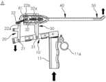
도 1은 본 발명에 의한 직관적 조작이 가능한 복강경 수술장치의 외형을 보인 사시도이다.
도 2는 본 발명에 의한 직관적 조작이 가능한 복강경 수술장치의 내부 구조를 보인 일 방향 단면도이다.
도 3은 본 발명에 의한 직관적 조작이 가능한 복강경 수술장치에서 손잡이의 하부 방향 이동에 의한 유동부재의 상부 방향 유동을 보인 예시도이다.
도 4는 본 발명에 의한 직관적 조작이 가능한 복강경 수술장치에서 손잡이의 상부 방향 이동에 의한 유동부재의 하부 방향 유동을 보인 예시도이다.
도 5는 본 발명에 의한 직관적 조작이 가능한 복강경 수술장치에서 손잡이의 일 측 방향 이동에 의한 유동부재의 일 측 방향 유동을 보인 예시도이다.
도 6은 본 발명에 의한 직관적 조작이 가능한 복강경 수술장치에서 손잡이의 다른 일 측 방향 이동에 의한 유동부재의 다른 일 측 방향 유동을 보인 예시도이다.
도 7은 본 발명에 의한 직관적 조작이 가능한 복강경 수술장치에 엔드이펙터가 적용된 형태를 보인 예시도이다.
도 8은 본 발명에 의한 직관적 조작이 가능한 복강경 수술장치에서 엔드이펙터 작동을 보인 예시도이다.
도 9는 본 발명에 의한 직관적 조작이 가능한 복강경 수술장치에서 와이어 연결 형태를 보인 예시도이다.Figure 1 is a perspective view showing the external appearance of a laparoscopic surgical device capable of intuitive operation according to the present invention.
Figure 2 is a one-way cross-sectional view showing the internal structure of a laparoscopic surgical device capable of intuitive operation according to the present invention.
FIG. 3 is an exemplary diagram showing the upward flow of a moving member due to downward movement of a handle in a laparoscopic surgical device capable of intuitive operation according to the present invention.
FIG. 4 is an exemplary diagram showing the downward flow of a moving member due to the upward movement of a handle in a laparoscopic surgical device capable of intuitive operation according to the present invention.
FIG. 5 is an exemplary diagram showing one-way flow of a moving member due to one-way movement of a handle in a laparoscopic surgical device capable of intuitive operation according to the present invention.
FIG. 6 is an exemplary diagram showing the other side flow of the moving member due to the other side movement of the handle in the intuitively operable laparoscopic surgical device according to the present invention.
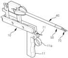
Figure 7 is an exemplary diagram showing a form in which an end effector is applied to a laparoscopic surgical device capable of intuitive operation according to the present invention.
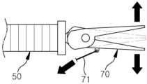
Figure 8 is an exemplary diagram showing the operation of an end effector in a laparoscopic surgical device capable of intuitive operation according to the present invention.
Figure 9 is an exemplary diagram showing the wire connection form in a laparoscopic surgical device capable of intuitive operation according to the present invention.
이하, 첨부 도면에 의거 본 발명에 대하여 상세히 설명하면 다음과 같다.Hereinafter, the present invention will be described in detail based on the attached drawings.
도 1 및 도 2에 도시된 바와 같이 본 발명에 의한 직관적 조작이 가능한 복강경 수술장치(A)는, 몸체(10); 제1지지부재(20); 제2지지부재(30); 연장봉(40); 유동부재(50); 및 와이어(60);를 포함한다.As shown in FIGS. 1 and 2, the intuitively operable laparoscopic surgical device (A) according to the present invention includes a body (10); a first support member (20); a second support member (30); an extension rod (40); a moving member (50); and a wire (60).
본 발명의 몸체(10)는 길이 방향 일단, 더욱 구체적으로 복강경 수술시 환자 복부에 인접하는 선단에 하부로 이어지는 손잡이(11)가 마련된다.The body (10) of the present invention is provided with a handle (11) extending downward at one end in the longitudinal direction, more specifically, at the end adjacent to the patient's abdomen during laparoscopic surgery.
이와 같은 몸체(10)는 제1지지부재(20) 및 제2지지부재(30)를 지지하는 것일 뿐 특별한 기능을 갖는 것은 아닌바, 몸체(10)에 관한 상세한 설명은 생략한다.This body (10) only supports the first support member (20) and the second support member (30) and does not have any special function, so a detailed description of the body (10) is omitted.
본 발명의 제1지지부재(20)는, 몸체(10) 길이 방향 다른 일단, 더욱 구체적으로 복강경 수술시 환자 복부로부터 더 멀리 위치하는 말단에 힌지 결합되어 폭방향으로 이어지는 제1힌지축(21)을 중심으로 회전하되, 상단에 폭방향으로 이어지는 제2힌지축(22a)을 중심으로 회전하는 연장편(22)이 마련된다.The first support member (20) of the present invention is hinged at one end of the body (10) in the longitudinal direction, more specifically, at an end located further from the patient's abdomen during laparoscopic surgery, and is provided with an extension piece (22) that rotates around a first hinge axis (21) extending in the width direction, while rotating around a second hinge axis (22a) extending in the width direction at the upper end.
이때, 연장편(22)은 원형 지지부(22b)를 포함함으로써 유동부재(50) 선단으로부터 연장편(22) 상면 및 하면으로 이어지는 와이어(60)가 원형 지지부(22b)에 의해 지지된다.At this time, the extension piece (22) includes a circular support member (22b), so that the wire (60) extending from the tip of the moving member (50) to the upper and lower surfaces of the extension piece (22) is supported by the circular support member (22b).
한편, 제1지지부재(20)에서 연장편(22) 외측은 커버(도면부호 미표시)로 감싸짐으로써 커버에 의해 연장편(22)의 보호가 이루어질 수 있다.Meanwhile, the outer side of the extension piece (22) of the first support member (20) is wrapped with a cover (drawing symbol not shown), so that the extension piece (22) can be protected by the cover.
본 발명의 제2지지부재(30)는, 몸체(10) 길이 방향 일단과 다른 일단 사이에 힌지 결합되어 폭방향으로 이어지는 제3힌지축(31)을 중심으로 회전하되, 상단에 부분 절개된 원판부재(32)가 마련된다.The second support member (30) of the present invention rotates around a third hinge axis (31) that is hinged between one end in the longitudinal direction of the body (10) and the other end in the width direction, and is provided with a partially cut disc member (32) at the top.
이때, 원판부재(32)는 일측과 다른 일측을 각각 관통하는 홀(32a)을 포함함으로써 유동부재(50) 선단으로부터 연장편(22) 일 측면 및 다른 일 측면으로 이어지는 와이어(60), 더욱 구체적으로 아래에서 설명하는 제3와이어(63) 및 제4와이어(64)가 홀(32a) 각각에 삽입됨에 따라 제3와이어(63) 및 제4와이어(64)가 원판부재(32)에 의해 지지된다.At this time, the disc member (32) includes a hole (32a) penetrating one side and the other side, respectively, so that the wire (60) extending from the tip of the movable member (50) to one side and the other side of the extension piece (22), more specifically, the third wire (63) and the fourth wire (64) described below, are inserted into each of the holes (32a), and thus the third wire (63) and the fourth wire (64) are supported by the disc member (32).
본 발명의 연장봉(40)은 제2지지부재(30)의 원판부재(32)에 회전 가능하게 결합되어 일 방향으로 이어진다.The extension rod (40) of the present invention is rotatably connected to the disc member (32) of the second support member (30) and extends in one direction.
이와 같은 연장봉(40)은 유동부재(50)를 지지하는 것일 뿐 특별한 기능을 갖는 것은 아닌바, 연장봉(40)에 관한 상세한 설명은 생략한다.Such an extension rod (40) only supports the moving member (50) and does not have any special function, so a detailed description of the extension rod (40) is omitted.
한편, 연장봉(40)과 유동부재(50)의 결합 부위는 커버(도면부호 미표시)로 감싸짐으로써 커버에 의해 연장봉(40)과 유동부재(50) 결합 부위의 보호가 이루어질 수 있다.Meanwhile, the joint portion of the extension rod (40) and the moving member (50) is covered with a cover (drawing symbol not shown), so that the joint portion of the extension rod (40) and the moving member (50) can be protected by the cover.
본 발명의 유동부재(50)는 연장봉(40) 선단에 결합된다.The fluid member (50) of the present invention is connected to the tip of an extension rod (40).
이때, 유동부재(50)는 주름관으로 이루어짐으로써 아래에서 설명하는 와이어(60) 어느 하나가 당겨짐에 따라 그 선단이 구부러지며 일 방향으로 유동할 수 있을 뿐만 아니라 와이어(60) 어느 하나의 당겨짐이 해제될 때 주름관 자체가 갖는 탄성력이 작용함에 따라 유동 이전 상태로 자동 복귀가 이루어질 수 있다.At this time, the fluid member (50) is formed of a corrugated pipe, so that when one of the wires (60) described below is pulled, its tip can bend and flow in one direction, and when the pulling of one of the wires (60) is released, the elastic force of the corrugated pipe itself can be applied, so that automatic return to the state before the flow can occur.
본 발명의 와이어(60)는 복수 개로 마련되어, 유동부재(50) 선단의 복수 개 지점으로부터 제1지지부재(20)의 연장편(22) 복수 개 지점으로 각각 이어진다.The wire (60) of the present invention is provided in multiple pieces and is connected from multiple points at the tip of the moving member (50) to multiple points on the extension piece (22) of the first support member (20).
이때, 복수 개 와이어(60)는, 도 9에 도시된 바와 같이 유동부재(50) 선단의 상면으로부터 제1지지부재(20)의 연장편(22) 상면으로 이어지는 제1와이어(61); 유동부재(50) 선단의 하면으로부터 제1지지부재(20)의 연장편(22) 하면으로 이어지는 제2와이어(62); 유동부재(50) 선단의 일 측면으로부터 제1지지부재(20)의 연장편(22) 일 측면으로 이어지는 제3와이어(63); 및 유동부재(50) 선단의 다른 일 측면으로부터 제1지지부재(20)의 연장편(22) 다른 일 측면으로 이어지는 제4와이어(64);를 포함함으로써 손잡이(11)의 상부 방향 이동에 의해 제1와이어(61)가 당겨짐에 따라 유동부재(50)가 상부 방향으로 유동하게 되고, 손잡이(11)의 하부 방향 이동에 의해 제2와이어(62)가 당겨짐에 따라 유동부재(50)가 하부 방향으로 유동하게 되며, 손잡이(11)의 일 측 방향 이동에 의해 제3와이어(63)가 당겨짐에 따라 유동부재(50)가 일 측 방향으로 유동하게 되고, 손잡이(11)의 다른 일 측 방향 이동에 의해 제4와이어(64)가 당겨짐에 따라 유동부재(50)가 다른 일 측 방향으로 유동하게 된다.At this time, the plurality of wires (60) include, as shown in FIG. 9, a first wire (61) extending from the upper surface of the tip of the movable member (50) to the upper surface of the extension piece (22) of the first support member (20); a second wire (62) extending from the lower surface of the tip of the movable member (50) to the lower surface of the extension piece (22) of the first support member (20); a third wire (63) extending from one side of the tip of the movable member (50) to one side of the extension piece (22) of the first support member (20); And the fourth wire (64) extending from the other side of the tip of the movable member (50) to the other side of the extension piece (22) of the first support member (20), by including the first wire (61) being pulled by the upward movement of the handle (11), the movable member (50) flows upwardly, the second wire (62) being pulled by the downward movement of the handle (11), the movable member (50) flows downwardly, the third wire (63) being pulled by the one-sided movement of the handle (11) causes the movable member (50) to flow in one direction, and the fourth wire (64) being pulled by the other-sided movement of the handle (11) causes the movable member (50) to flow in the other-sided direction.
또한, 추가적으로 본 발명에 의한 직관적 조작이 가능한 복강경 수술장치(A)는, 유동부재(50) 선단에 배치되는 엔드이펙터(70)를 더 포함할 수 있다.In addition, the laparoscopic surgical device (A) capable of intuitive operation according to the present invention may further include an end effector (70) arranged at the tip of the moving member (50).
이때, 엔드이펙터(70)는 몸체(10)의 손잡이(11)에 마련되는 트리거(11a) 조작에 의해 작동할 수 있다.At this time, the end effector (70) can be operated by operating the trigger (11a) provided on the handle (11) of the body (10).
여기서, 트리거(11a)와 엔드이펙터(70) 사이에는 유동부재(50)를 거쳐 이어지는 별도 와이어(71)가 연결됨으로써 트리거(11a) 조작에 의해 별도 와이어(71)가 당겨짐에 따라 엔드이펙터(70)의 작동이 이루어질 수 있다.Here, a separate wire (71) is connected between the trigger (11a) and the end effector (70) via a moving member (50), so that the end effector (70) can be operated by pulling the separate wire (71) by manipulating the trigger (11a).
한편, 엔드이펙터(70)는 트리거(11a) 조작에 의해 작동이 이루어질 수 있는 것이라면 통상의 어떠한 종류의 것이어도 무방하며, 그 예로는 집게 또는 커터일 수 있다.Meanwhile, the end effector (70) may be any type of conventional device that can be operated by manipulating a trigger (11a), and examples thereof include forceps or a cutter.
본 발명에 의한 직관적 조작이 가능한 복강경 수술장치(A)의 작동에 관하여 상세히 설명하면 다음과 같다.The operation of the intuitively operable laparoscopic surgical device (A) according to the present invention is described in detail as follows.
본 발명에서 선단의 하부에 손잡이(11)가 마련된 몸체(10)는 환자 복부의 외측에 위치하게 되며, 연장봉(40)은 절개부를 통해 환자의 복부 내측으로 삽입된다.In the present invention, a body (10) having a handle (11) provided at the lower end of the tip is positioned on the outside of the patient's abdomen, and an extension rod (40) is inserted into the inside of the patient's abdomen through an incision.
이때, 몸체(10)에는 제2지지부재(30)가 배치되되, 제2지지부재(30)는 몸체(10)의 길이 방향 일단과 타단 사이에 힌지 결합되는바, 제2지지부재(30) 하단을 지지점으로 하여 몸체(10)의 시소 운동이 이루어질 수 있으므로 이에 의해 손잡이(11)의 상부 또는 하부 방향 이동이 이루어질 수 있다.At this time, a second support member (30) is arranged on the body (10), and the second support member (30) is hinge-connected between one end and the other end in the longitudinal direction of the body (10), so that a seesaw movement of the body (10) can be achieved using the lower end of the second support member (30) as a support point, thereby allowing the handle (11) to move upward or downward.
여기서, 몸체(10) 선단의 손잡이(11)가 상부로 이동하게 되면 몸체(10) 말단에 위치하는 제1지지부재(20)는 몸체(10)의 시소 운동에 의해 하부로 향하게 되는바, 도 3에 도시된 바와 같이 유동부재(50) 선단의 상면으로부터 제1지지부재(20)의 연장편(22) 상면으로 이어지는 제1와이어(61)가 당겨지게 되므로 이에 의해 제1와이어(61)가 연결된 유동부재(50) 선단이 상부 방향으로 유동하게 된다.Here, when the handle (11) at the tip of the body (10) moves upward, the first support member (20) located at the end of the body (10) is directed downward by the seesaw movement of the body (10), and as shown in FIG. 3, the first wire (61) extending from the upper surface of the tip of the movable member (50) to the upper surface of the extension (22) of the first support member (20) is pulled, so that the tip of the movable member (50) to which the first wire (61) is connected flows upward.
반대로, 몸체(10) 선단의 손잡이(11)가 하부로 이동하게 되면 몸체(10) 말단에 위치하는 제1지지부재(20)는 몸체(10)의 시소 운동에 의해 상부로 향하게 되는바, 도 4에 도시된 바와 같이 유동부재(50) 선단의 하면으로부터 제1지지부재(20)의 연장편(22) 하면으로 이어지는 제2와이어(62)가 당겨지게 되므로 이에 의해 유동부재(50) 선단이 하부 방향으로 유동하게 된다.Conversely, when the handle (11) at the tip of the body (10) moves downward, the first support member (20) located at the end of the body (10) is directed upward by the seesaw movement of the body (10), and as shown in FIG. 4, the second wire (62) extending from the lower surface of the tip of the movable member (50) to the lower surface of the extension (22) of the first support member (20) is pulled, thereby causing the tip of the movable member (50) to move downward.
따라서 사용자 손 움직임에 의해 상하 이동하는 몸체(10)의 손잡이(11) 이동 방향과 몸체(10)로부터 이어지는 연장봉(40) 선단의 유동부재(50) 유동 방향이 동일함에 따라 직관적 조작이 이루어질 수 있어 복강경 수술이 용이할 수 있다.Accordingly, intuitive operation can be achieved since the movement direction of the handle (11) of the body (10) that moves up and down by the user's hand movement and the movement direction of the moving member (50) of the tip of the extension rod (40) extending from the body (10) are the same, making laparoscopic surgery easy.
그리고 본 발명에서 연장봉(40)은, 제2지지부재(30)의 원판부재(32)에 회전 가능하게 결합되는바, 제2지지부재(30)를 축으로 삼아 몸체(10)의 회전(연장봉이 절개부에 고정됨에 따라 몸체가 회전하게 됨)이 가능하므로 이에 의해 손잡이(11)의 일측 또는 다른 일측 방향 이동이 이루어질 수 있다.And in the present invention, the extension bar (40) is rotatably connected to the disc member (32) of the second support member (30), so that the body (10) can rotate (the body rotates as the extension bar is fixed to the cut-out) around the second support member (30) as an axis, thereby allowing movement of the handle (11) in one or the other direction.
이때, 몸체(10) 선단의 손잡이(11)가 일 측, 예컨대 우측으로 이동하게 되면 제1지지부재(20)가 배치된 몸체(10)에 배치되는 제1지지부재(20)와 제2지지부재(30)는 좌측을 향하게 되는바, 도 5에 도시된 바와 같이 유동부재(50) 선단의 우측면으로부터 제1지지부재(20)의 연장편(22) 우측면으로 이어지는 제3와이어(63)가 당겨지게 되므로 이에 의해 유동부재(50) 선단이 우측 방향으로 유동하게 된다.At this time, when the handle (11) of the tip of the body (10) moves to one side, for example, to the right, the first support member (20) and the second support member (30) arranged on the body (10) where the first support member (20) is arranged face the left, and as shown in FIG. 5, the third wire (63) extending from the right side of the tip of the moving member (50) to the right side of the extension (22) of the first support member (20) is pulled, thereby causing the tip of the moving member (50) to move in the right direction.
반대로, 몸체(10) 선단의 손잡이(11)가 다른 일 측, 예컨대 좌측으로 이동하게 되면 제1지지부재(20)가 배치된 몸체(10)에 배치되는 제1지지부재(20)와 제2지지부재(30)는 우측을 향하게 되는바, 도 6에 도시된 바와 같이 유동부재(50) 선단의 좌측면으로부터 제1지지부재(20)의 연장편(22) 좌측면으로 이어지는 제4와이어(64)가 당겨지게 되므로 이에 의해 유동부재(50) 선단이 좌측 방향으로 유동하게 된다.Conversely, when the handle (11) of the tip of the body (10) moves to the other side, for example, to the left, the first support member (20) and the second support member (30) arranged on the body (10) where the first support member (20) is arranged face to the right, and as shown in FIG. 6, the fourth wire (64) extending from the left side of the tip of the movable member (50) to the left side of the extension (22) of the first support member (20) is pulled, thereby causing the tip of the movable member (50) to move in the left direction.
따라서 사용자 손 움직임에 의해 좌우 이동하는 몸체(10)의 손잡이(11) 이동 방향과 몸체(10)로부터 이어지는 연장봉(40) 선단의 유동부재(50) 유동 방향이 동일함에 따라 직관적 조작이 이루어질 수 있어 복강경 수술이 용이할 수 있다.Accordingly, intuitive operation can be achieved since the movement direction of the handle (11) of the body (10) that moves left and right by the user's hand movement and the movement direction of the moving member (50) of the tip of the extension rod (40) extending from the body (10) are the same, making laparoscopic surgery easy.
여기서, 유동부재(50)는 주름관으로 이루어지는바, 와이어(60) 어느 하나가 당겨짐에 따라 그 선단이 구부러지며 일 방향으로 유동할 수 있을 뿐만 아니라 와이어(60) 어느 하나의 당겨짐이 해제될 때 주름관 자체가 갖는 탄성력이 작용함에 따라 유동 이전 상태로 자동 복귀가 이루어질 수 있다.Here, the fluid member (50) is formed of a corrugated pipe, and when one of the wires (60) is pulled, its tip bends and can flow in one direction. In addition, when the pulling of one of the wires (60) is released, the elastic force of the corrugated pipe itself acts, so that automatic return to the state before the flow can occur.
한편, 본 발명에서 유동부재(50) 선단에는 도 7에 도시된 바와 같이 엔드이펙터(70)가 배치될 수 있다.Meanwhile, in the present invention, an end effector (70) may be placed at the tip of the moving member (50) as shown in FIG. 7.
이때, 엔드이펙터(70)는 몸체(10)의 손잡이(11)에 마련되는 트리거(11a) 조작에 의해 작동, 즉 트리거(11a)로부터 유동부재(50)를 거쳐 이어지는 별도 와이어(71)가 트리거(11a) 조작에 의해 당겨짐에 따라 작동하는바, 유동부재(50) 유동에 의해 엔드이펙터(70)가 특정 지점으로 이동한 상태에서 도 8에 도시된 바와 같이 트리거(11a) 조작에 의해 엔드이펙터(70) 작동이 이루어짐에 따라 복강경 수술이 더욱 원활히 이루어질 수 있다.At this time, the end effector (70) is operated by the manipulation of the trigger (11a) provided on the handle (11) of the body (10), that is, the separate wire (71) connected from the trigger (11a) through the movable member (50) is pulled by the manipulation of the trigger (11a), and as the end effector (70) is moved to a specific point by the movement of the movable member (50), the end effector (70) is operated by the manipulation of the trigger (11a), as shown in FIG. 8, so that the laparoscopic surgery can be performed more smoothly.
여기서, 엔드이펙터(70)는 집게 또는 커터일 수 있는바, 트리거(11a) 조작을 통해 엔드이펙터(70)를 벌리거나 오므림으로써 환부의 특정 부위를 물어 당기거나 절단할 수 있다.Here, the end effector (70) may be a pair of forceps or a cutter, and by manipulating the trigger (11a) to open or close the end effector (70), a specific part of the affected area can be bitten, pulled, or cut.
이상에서 설명한 바와 같은 본 발명은 상기한 실시예에 한정되지 아니하므로 청구범위에서 청구하는 본 발명의 요지를 벗어나지 않는 범위 내에서 변경 가능하며, 그와 같은 변경은 이하 청구범위 기재에 의하여 정의되는 본 발명의 보호범위 내에 있게 된다.The present invention as described above is not limited to the above-described embodiments, and therefore may be modified within a scope that does not depart from the gist of the present invention as claimed in the claims, and such modifications are within the protection scope of the present invention defined by the following claims.
10 : 몸체 11 : 손잡이
11a : 트리거 20 : 제1지지부재
21 : 연장편 21 : 제1힌지축
22 : 연장편 22a : 제2힌지축
22b : 원형 지지부 30 : 제2지지부재
31 : 제3힌지축 32 : 원판부재
32a : 홀 40 : 연장봉
50 : 유동부재 60 : 와이어
61 : 제1와이어 62 : 제2와이어
63 : 제3와이어 64 : 제4와이어
70 : 엔드이펙터 71 : 별도 와이어
A : 복강경 수술장치10 : Body 11 : Handle
11a: Trigger 20: First support member
21: Extension 21: First Hinge Axis
22 :
22b: Circular support member 30: Second support member
31: Third hinge axis 32: Disc member
32a : Hole 40 : Extension bar
50 : floating member 60 : wire
61: 1st wire 62: 2nd wire
63: 3rd wire 64: 4th wire
70: End effector 71: Separate wire
A: Laparoscopic surgical device
Claims (8)
Translated fromKorean상기 몸체 길이 방향 다른 일단에 힌지 결합되어 폭방향으로 이어지는 제1힌지축을 중심으로 회전하되, 상단에 폭방향으로 이어지는 제2힌지축을 중심으로 회전하는 연장편이 마련된 제1지지부재;
상기 몸체 길이 방향 일단과 다른 일단 사이에 힌지 결합되어 폭방향으로 이어지는 제3힌지축을 중심으로 회전하되, 상단에 부분 절개된 원판부재가 마련된 제2지지부재;
상기 제2지지부재의 상기 원판부재에 회전 가능하게 결합되어 일 방향으로 이어지는 연장봉;
상기 연장봉 선단에 결합되되, 주름관으로 이루어지는 유동부재; 및
상기 유동부재 선단의 복수 개 지점으로부터 상기 제1지지부재의 상기 연장편 복수 개 지점으로 각각 이어지는 복수 개 와이어;를 포함하고,
상기 주름관으로 이루어지는 상기 유동부재는 상기 손잡이의 일 방향 이동에 의해 상기 복수 개 와이어 중 어느 하나가 당겨짐에 따라 그 선단이 구부러지며 상기 손잡이 이동방향과 동일한 방향으로 유동하는 것을 특징으로 하는 직관적 조작이 가능한 복강경 수술장치.A body having a handle extending downward at one end in the longitudinal direction;
A first support member having a first hinge axis that is hinged to another end of the body length direction and rotates around the first hinge axis extending in the width direction, and an extension piece that rotates around the second hinge axis extending in the width direction at the top;
A second support member that is hinge-joined between one end of the body length direction and the other end and rotates around a third hinge axis extending in the width direction, and has a partially cut disc member provided at the top;
An extension rod rotatably connected to the disk member of the second support member and extending in one direction;
A moving member connected to the tip of the above extension rod and formed of a corrugated pipe; and
A plurality of wires each extending from a plurality of points of the above floating member to a plurality of points of the above extension piece of the first support member;
A laparoscopic surgical device with intuitive operability, characterized in that the fluidic member formed of the above-mentioned corrugated tube has its tip bent and flows in the same direction as the direction of movement of the handle when one of the plurality of wires is pulled by the unidirectional movement of the handle.
상기 연장편은 상면 및 하면으로 이어지는 상기 와이어와 접촉하는 원형 지지부를 포함하는 것을 특징으로 하는 직관적 조작이 가능한 복강경 수술장치.In the first paragraph,
An intuitively operable laparoscopic surgical device characterized in that the extension piece includes a circular support part that contacts the wire extending to the upper and lower surfaces.
상기 원판부재는 상기 연장편 일 측면 및 다른 일 측면으로 이어지는 상기 와이어가 관통하는 홀을 포함하는 것을 특징으로 하는 직관적 조작이 가능한 복강경 수술장치.In the first paragraph,
An intuitively operable laparoscopic surgical device, characterized in that the above-mentioned disc member includes a hole through which the wire extending to one side of the extension piece and the other side thereof passes.
상기 복수 개 와이어는, 상기 유동부재 선단의 상면으로부터 상기 제1지지부재의 상기 연장편 상면으로 이어지는 제1와이어; 상기 유동부재 선단의 하면으로부터 상기 제1지지부재의 상기 연장편 하면으로 이어지는 제2와이어; 상기 유동부재 선단의 일 측면으로부터 상기 제1지지부재의 상기 연장편 일 측면으로 이어지는 제3와이어; 및 상기 유동부재 선단의 다른 일 측면으로부터 상기 제1지지부재의 상기 연장편 다른 일 측면으로 이어지는 제4와이어;를 포함하는 것을 특징으로 하는 직관적 조작이 가능한 복강경 수술장치.In the first paragraph,
An intuitively operable laparoscopic surgical device characterized in that the plurality of wires include: a first wire extending from an upper surface of a front end of the movable member to an upper surface of the extension piece of the first support member; a second wire extending from a lower surface of the front end of the movable member to a lower surface of the extension piece of the first support member; a third wire extending from one side of the front end of the movable member to one side of the extension piece of the first support member; and a fourth wire extending from the other side of the front end of the movable member to the other side of the extension piece of the first support member.
상기 유동부재 선단에 배치되되, 상기 몸체의 상기 손잡이에 마련되는 트리거 조작에 의해 작동하는 엔드이펙터를 더 포함하는 것을 특징으로 하는 직관적 조작이 가능한 복강경 수술장치.In the first paragraph,
An intuitively operable laparoscopic surgical device characterized in that it further includes an end effector that is arranged on the tip of the above-mentioned movable member and is operated by a trigger operation provided on the handle of the above-mentioned body.
상기 엔드이펙터는 상기 트리거로부터 상기 유동부재를 거쳐 이어지는 별도 와이어가 상기 트리거 조작에 의해 당겨짐에 따라 작동하는 것을 특징으로 하는 직관적 조작이 가능한 복강경 수술장치.In Article 6,
An intuitively operable laparoscopic surgical device characterized in that the end effector is operated by a separate wire extending from the trigger through the moving member being pulled by the trigger operation.
상기 엔드이펙터는 집게 또는 커터인 것을 특징으로 하는 직관적 조작이 가능한 복강경 수술장치.In Article 6,
An intuitively operable laparoscopic surgical device characterized in that the end effector is a forceps or a cutter.
Priority Applications (1)
| Application Number | Priority Date | Filing Date | Title |
|---|---|---|---|
| KR1020220140593AKR102742175B1 (en) | 2022-10-27 | 2022-10-27 | laparoscopic surgical device with intuitive operation |
Applications Claiming Priority (1)
| Application Number | Priority Date | Filing Date | Title |
|---|---|---|---|
| KR1020220140593AKR102742175B1 (en) | 2022-10-27 | 2022-10-27 | laparoscopic surgical device with intuitive operation |
Publications (2)
| Publication Number | Publication Date |
|---|---|
| KR20240059391A KR20240059391A (en) | 2024-05-07 |
| KR102742175B1true KR102742175B1 (en) | 2024-12-16 |
Family
ID=91078245
Family Applications (1)
| Application Number | Title | Priority Date | Filing Date |
|---|---|---|---|
| KR1020220140593AActiveKR102742175B1 (en) | 2022-10-27 | 2022-10-27 | laparoscopic surgical device with intuitive operation |
Country Status (1)
| Country | Link |
|---|---|
| KR (1) | KR102742175B1 (en) |
Citations (3)
| Publication number | Priority date | Publication date | Assignee | Title |
|---|---|---|---|---|
| KR101447266B1 (en) | 2014-04-28 | 2014-10-10 | 정화경 | Appratus for laparoscpoic surgery |
| JP2014534080A (en) | 2011-07-27 | 2014-12-18 | エコール ポリテクニーク フェデラル デ ローザンヌ (イーピーエフエル) | Mechanical remote control device for remote control |
| US20220039817A1 (en) | 2018-12-31 | 2022-02-10 | Livsmed Inc. | Surgical instrument |
Family Cites Families (3)
| Publication number | Priority date | Publication date | Assignee | Title |
|---|---|---|---|---|
| US7338513B2 (en) | 2003-10-30 | 2008-03-04 | Cambridge Endoscopic Devices, Inc. | Surgical instrument |
| KR102153407B1 (en)* | 2015-02-17 | 2020-09-08 | 주식회사 리브스메드 | Surgical instrument |
| KR102097782B1 (en)* | 2018-02-09 | 2020-04-06 | 한국기계연구원 | Apparatus for laparoscpoic surgery |
- 2022
- 2022-10-27KRKR1020220140593Apatent/KR102742175B1/enactiveActive
Patent Citations (3)
| Publication number | Priority date | Publication date | Assignee | Title |
|---|---|---|---|---|
| JP2014534080A (en) | 2011-07-27 | 2014-12-18 | エコール ポリテクニーク フェデラル デ ローザンヌ (イーピーエフエル) | Mechanical remote control device for remote control |
| KR101447266B1 (en) | 2014-04-28 | 2014-10-10 | 정화경 | Appratus for laparoscpoic surgery |
| US20220039817A1 (en) | 2018-12-31 | 2022-02-10 | Livsmed Inc. | Surgical instrument |
Also Published As
| Publication number | Publication date |
|---|---|
| KR20240059391A (en) | 2024-05-07 |
Similar Documents
| Publication | Publication Date | Title |
|---|---|---|
| JP5090441B2 (en) | Surgical instruments | |
| US8409245B2 (en) | Surgical instrument | |
| CN106999001B (en) | Shaft and selectivity with alternative bending bend the operation tool of the shaft and the cable when shaft bending in tensioning | |
| EP2240095B1 (en) | Apparatus for articulating the wrist of a laparoscopic grasping instrument | |
| CN104470414B (en) | For the multi-cavity catheter formula retractor systems of minimally invasive gastrointestinal surgery treatment | |
| JP3390436B2 (en) | Surgical instrument | |
| JP4154660B2 (en) | Recovery device | |
| US6319262B1 (en) | Calculus removal | |
| JP4979697B2 (en) | Surgical excision device | |
| CN109938787A (en) | Multi-lumen catheter retractor system for minimally invasive surgical gastrointestinal treatment | |
| EP2032050A2 (en) | Surgical instrument | |
| KR102850884B1 (en) | Steerable arm for use in endoscopic surgical procedures | |
| EP2111806B1 (en) | Endoscope treatment instrument | |
| US20240081970A1 (en) | Inferior Vena Cava Filter Retrieval Device and Method of Retrieving Same | |
| JP5178369B2 (en) | Endoscopic treatment tool | |
| KR101468007B1 (en) | Instrument for Minimally Invasive Surgery That Can Selectively Cover Its End Effector | |
| JP6165083B2 (en) | Medical device cap | |
| KR102742175B1 (en) | laparoscopic surgical device with intuitive operation | |
| JP5101036B2 (en) | Jointed anastomosis ring supply device | |
| US20130066329A1 (en) | Medical Retrieval Devices | |
| KR102601930B1 (en) | surgical instrument | |
| JP2018064883A (en) | Switchable laparoscopic forceps |
Legal Events
| Date | Code | Title | Description |
|---|---|---|---|
| PA0109 | Patent application | Patent event code:PA01091R01D Comment text:Patent Application Patent event date:20221027 | |
| PA0201 | Request for examination | ||
| PG1501 | Laying open of application | ||
| E902 | Notification of reason for refusal | ||
| PE0902 | Notice of grounds for rejection | Comment text:Notification of reason for refusal Patent event date:20241103 Patent event code:PE09021S01D | |
| E701 | Decision to grant or registration of patent right | ||
| PE0701 | Decision of registration | Patent event code:PE07011S01D Comment text:Decision to Grant Registration Patent event date:20241206 | |
| GRNT | Written decision to grant | ||
| PR0701 | Registration of establishment | Comment text:Registration of Establishment Patent event date:20241209 Patent event code:PR07011E01D | |
| PR1002 | Payment of registration fee | Payment date:20241210 End annual number:3 Start annual number:1 | |
| PG1601 | Publication of registration |