KR102737426B1 - Apparatus and method for generating driver skilled driving model using error monitoring - Google Patents
Apparatus and method for generating driver skilled driving model using error monitoringDownload PDFInfo
- Publication number
- KR102737426B1 KR102737426B1KR1020190131118AKR20190131118AKR102737426B1KR 102737426 B1KR102737426 B1KR 102737426B1KR 1020190131118 AKR1020190131118 AKR 1020190131118AKR 20190131118 AKR20190131118 AKR 20190131118AKR 102737426 B1KR102737426 B1KR 102737426B1
- Authority
- KR
- South Korea
- Prior art keywords
- driver
- mobility
- driving
- event
- driving model
- Prior art date
- Legal status (The legal status is an assumption and is not a legal conclusion. Google has not performed a legal analysis and makes no representation as to the accuracy of the status listed.)
- Active
Links
Images


Classifications
- A—HUMAN NECESSITIES
- A61—MEDICAL OR VETERINARY SCIENCE; HYGIENE
- A61B—DIAGNOSIS; SURGERY; IDENTIFICATION
- A61B5/00—Measuring for diagnostic purposes; Identification of persons
- A61B5/16—Devices for psychotechnics; Testing reaction times ; Devices for evaluating the psychological state
- A61B5/18—Devices for psychotechnics; Testing reaction times ; Devices for evaluating the psychological state for vehicle drivers or machine operators
- G—PHYSICS
- G06—COMPUTING OR CALCULATING; COUNTING
- G06F—ELECTRIC DIGITAL DATA PROCESSING
- G06F30/00—Computer-aided design [CAD]
- G06F30/20—Design optimisation, verification or simulation
- A—HUMAN NECESSITIES
- A61—MEDICAL OR VETERINARY SCIENCE; HYGIENE
- A61B—DIAGNOSIS; SURGERY; IDENTIFICATION
- A61B5/00—Measuring for diagnostic purposes; Identification of persons
- A61B5/16—Devices for psychotechnics; Testing reaction times ; Devices for evaluating the psychological state
- A61B5/165—Evaluating the state of mind, e.g. depression, anxiety
- A—HUMAN NECESSITIES
- A61—MEDICAL OR VETERINARY SCIENCE; HYGIENE
- A61B—DIAGNOSIS; SURGERY; IDENTIFICATION
- A61B5/00—Measuring for diagnostic purposes; Identification of persons
- A61B5/24—Detecting, measuring or recording bioelectric or biomagnetic signals of the body or parts thereof
- A61B5/316—Modalities, i.e. specific diagnostic methods
- A61B5/369—Electroencephalography [EEG]
- A61B5/372—Analysis of electroencephalograms
- A61B5/374—Detecting the frequency distribution of signals, e.g. detecting delta, theta, alpha, beta or gamma waves
- A—HUMAN NECESSITIES
- A61—MEDICAL OR VETERINARY SCIENCE; HYGIENE
- A61B—DIAGNOSIS; SURGERY; IDENTIFICATION
- A61B5/00—Measuring for diagnostic purposes; Identification of persons
- A61B5/24—Detecting, measuring or recording bioelectric or biomagnetic signals of the body or parts thereof
- A61B5/316—Modalities, i.e. specific diagnostic methods
- A61B5/369—Electroencephalography [EEG]
- A61B5/377—Electroencephalography [EEG] using evoked responses
- A61B5/378—Visual stimuli
- A—HUMAN NECESSITIES
- A61—MEDICAL OR VETERINARY SCIENCE; HYGIENE
- A61B—DIAGNOSIS; SURGERY; IDENTIFICATION
- A61B5/00—Measuring for diagnostic purposes; Identification of persons
- A61B5/24—Detecting, measuring or recording bioelectric or biomagnetic signals of the body or parts thereof
- A61B5/316—Modalities, i.e. specific diagnostic methods
- A61B5/369—Electroencephalography [EEG]
- A61B5/377—Electroencephalography [EEG] using evoked responses
- A61B5/38—Acoustic or auditory stimuli
- A—HUMAN NECESSITIES
- A61—MEDICAL OR VETERINARY SCIENCE; HYGIENE
- A61B—DIAGNOSIS; SURGERY; IDENTIFICATION
- A61B5/00—Measuring for diagnostic purposes; Identification of persons
- A61B5/72—Signal processing specially adapted for physiological signals or for diagnostic purposes
- A61B5/7221—Determining signal validity, reliability or quality
- A—HUMAN NECESSITIES
- A61—MEDICAL OR VETERINARY SCIENCE; HYGIENE
- A61B—DIAGNOSIS; SURGERY; IDENTIFICATION
- A61B5/00—Measuring for diagnostic purposes; Identification of persons
- A61B5/72—Signal processing specially adapted for physiological signals or for diagnostic purposes
- A61B5/7235—Details of waveform analysis
- A61B5/7264—Classification of physiological signals or data, e.g. using neural networks, statistical classifiers, expert systems or fuzzy systems
- B—PERFORMING OPERATIONS; TRANSPORTING
- B60—VEHICLES IN GENERAL
- B60W—CONJOINT CONTROL OF VEHICLE SUB-UNITS OF DIFFERENT TYPE OR DIFFERENT FUNCTION; CONTROL SYSTEMS SPECIALLY ADAPTED FOR HYBRID VEHICLES; ROAD VEHICLE DRIVE CONTROL SYSTEMS FOR PURPOSES NOT RELATED TO THE CONTROL OF A PARTICULAR SUB-UNIT
- B60W30/00—Purposes of road vehicle drive control systems not related to the control of a particular sub-unit, e.g. of systems using conjoint control of vehicle sub-units
- B—PERFORMING OPERATIONS; TRANSPORTING
- B60—VEHICLES IN GENERAL
- B60W—CONJOINT CONTROL OF VEHICLE SUB-UNITS OF DIFFERENT TYPE OR DIFFERENT FUNCTION; CONTROL SYSTEMS SPECIALLY ADAPTED FOR HYBRID VEHICLES; ROAD VEHICLE DRIVE CONTROL SYSTEMS FOR PURPOSES NOT RELATED TO THE CONTROL OF A PARTICULAR SUB-UNIT
- B60W40/00—Estimation or calculation of non-directly measurable driving parameters for road vehicle drive control systems not related to the control of a particular sub unit, e.g. by using mathematical models
- B60W40/02—Estimation or calculation of non-directly measurable driving parameters for road vehicle drive control systems not related to the control of a particular sub unit, e.g. by using mathematical models related to ambient conditions
- B—PERFORMING OPERATIONS; TRANSPORTING
- B60—VEHICLES IN GENERAL
- B60W—CONJOINT CONTROL OF VEHICLE SUB-UNITS OF DIFFERENT TYPE OR DIFFERENT FUNCTION; CONTROL SYSTEMS SPECIALLY ADAPTED FOR HYBRID VEHICLES; ROAD VEHICLE DRIVE CONTROL SYSTEMS FOR PURPOSES NOT RELATED TO THE CONTROL OF A PARTICULAR SUB-UNIT
- B60W40/00—Estimation or calculation of non-directly measurable driving parameters for road vehicle drive control systems not related to the control of a particular sub unit, e.g. by using mathematical models
- B60W40/08—Estimation or calculation of non-directly measurable driving parameters for road vehicle drive control systems not related to the control of a particular sub unit, e.g. by using mathematical models related to drivers or passengers
- B—PERFORMING OPERATIONS; TRANSPORTING
- B60—VEHICLES IN GENERAL
- B60W—CONJOINT CONTROL OF VEHICLE SUB-UNITS OF DIFFERENT TYPE OR DIFFERENT FUNCTION; CONTROL SYSTEMS SPECIALLY ADAPTED FOR HYBRID VEHICLES; ROAD VEHICLE DRIVE CONTROL SYSTEMS FOR PURPOSES NOT RELATED TO THE CONTROL OF A PARTICULAR SUB-UNIT
- B60W40/00—Estimation or calculation of non-directly measurable driving parameters for road vehicle drive control systems not related to the control of a particular sub unit, e.g. by using mathematical models
- B60W40/10—Estimation or calculation of non-directly measurable driving parameters for road vehicle drive control systems not related to the control of a particular sub unit, e.g. by using mathematical models related to vehicle motion
- A—HUMAN NECESSITIES
- A61—MEDICAL OR VETERINARY SCIENCE; HYGIENE
- A61B—DIAGNOSIS; SURGERY; IDENTIFICATION
- A61B5/00—Measuring for diagnostic purposes; Identification of persons
- A61B5/72—Signal processing specially adapted for physiological signals or for diagnostic purposes
- A61B5/7203—Signal processing specially adapted for physiological signals or for diagnostic purposes for noise prevention, reduction or removal
- B—PERFORMING OPERATIONS; TRANSPORTING
- B60—VEHICLES IN GENERAL
- B60W—CONJOINT CONTROL OF VEHICLE SUB-UNITS OF DIFFERENT TYPE OR DIFFERENT FUNCTION; CONTROL SYSTEMS SPECIALLY ADAPTED FOR HYBRID VEHICLES; ROAD VEHICLE DRIVE CONTROL SYSTEMS FOR PURPOSES NOT RELATED TO THE CONTROL OF A PARTICULAR SUB-UNIT
- B60W40/00—Estimation or calculation of non-directly measurable driving parameters for road vehicle drive control systems not related to the control of a particular sub unit, e.g. by using mathematical models
- B60W40/08—Estimation or calculation of non-directly measurable driving parameters for road vehicle drive control systems not related to the control of a particular sub unit, e.g. by using mathematical models related to drivers or passengers
- B60W2040/0818—Inactivity or incapacity of driver
- B60W2040/0863—Inactivity or incapacity of driver due to erroneous selection or response of the driver
- B—PERFORMING OPERATIONS; TRANSPORTING
- B60—VEHICLES IN GENERAL
- B60W—CONJOINT CONTROL OF VEHICLE SUB-UNITS OF DIFFERENT TYPE OR DIFFERENT FUNCTION; CONTROL SYSTEMS SPECIALLY ADAPTED FOR HYBRID VEHICLES; ROAD VEHICLE DRIVE CONTROL SYSTEMS FOR PURPOSES NOT RELATED TO THE CONTROL OF A PARTICULAR SUB-UNIT
- B60W40/00—Estimation or calculation of non-directly measurable driving parameters for road vehicle drive control systems not related to the control of a particular sub unit, e.g. by using mathematical models
- B60W40/08—Estimation or calculation of non-directly measurable driving parameters for road vehicle drive control systems not related to the control of a particular sub unit, e.g. by using mathematical models related to drivers or passengers
- B60W2040/0872—Driver physiology
- B—PERFORMING OPERATIONS; TRANSPORTING
- B60—VEHICLES IN GENERAL
- B60W—CONJOINT CONTROL OF VEHICLE SUB-UNITS OF DIFFERENT TYPE OR DIFFERENT FUNCTION; CONTROL SYSTEMS SPECIALLY ADAPTED FOR HYBRID VEHICLES; ROAD VEHICLE DRIVE CONTROL SYSTEMS FOR PURPOSES NOT RELATED TO THE CONTROL OF A PARTICULAR SUB-UNIT
- B60W50/00—Details of control systems for road vehicle drive control not related to the control of a particular sub-unit, e.g. process diagnostic or vehicle driver interfaces
- B60W2050/0001—Details of the control system
- B60W2050/0019—Control system elements or transfer functions
- B60W2050/0028—Mathematical models, e.g. for simulation
- B—PERFORMING OPERATIONS; TRANSPORTING
- B60—VEHICLES IN GENERAL
- B60W—CONJOINT CONTROL OF VEHICLE SUB-UNITS OF DIFFERENT TYPE OR DIFFERENT FUNCTION; CONTROL SYSTEMS SPECIALLY ADAPTED FOR HYBRID VEHICLES; ROAD VEHICLE DRIVE CONTROL SYSTEMS FOR PURPOSES NOT RELATED TO THE CONTROL OF A PARTICULAR SUB-UNIT
- B60W2420/00—Indexing codes relating to the type of sensors based on the principle of their operation
- B60W2420/40—Photo, light or radio wave sensitive means, e.g. infrared sensors
- B60W2420/403—Image sensing, e.g. optical camera
- B—PERFORMING OPERATIONS; TRANSPORTING
- B60—VEHICLES IN GENERAL
- B60W—CONJOINT CONTROL OF VEHICLE SUB-UNITS OF DIFFERENT TYPE OR DIFFERENT FUNCTION; CONTROL SYSTEMS SPECIALLY ADAPTED FOR HYBRID VEHICLES; ROAD VEHICLE DRIVE CONTROL SYSTEMS FOR PURPOSES NOT RELATED TO THE CONTROL OF A PARTICULAR SUB-UNIT
- B60W2520/00—Input parameters relating to overall vehicle dynamics
- B60W2520/10—Longitudinal speed
- B—PERFORMING OPERATIONS; TRANSPORTING
- B60—VEHICLES IN GENERAL
- B60W—CONJOINT CONTROL OF VEHICLE SUB-UNITS OF DIFFERENT TYPE OR DIFFERENT FUNCTION; CONTROL SYSTEMS SPECIALLY ADAPTED FOR HYBRID VEHICLES; ROAD VEHICLE DRIVE CONTROL SYSTEMS FOR PURPOSES NOT RELATED TO THE CONTROL OF A PARTICULAR SUB-UNIT
- B60W2540/00—Input parameters relating to occupants
- B60W2540/22—Psychological state; Stress level or workload
- B—PERFORMING OPERATIONS; TRANSPORTING
- B60—VEHICLES IN GENERAL
- B60W—CONJOINT CONTROL OF VEHICLE SUB-UNITS OF DIFFERENT TYPE OR DIFFERENT FUNCTION; CONTROL SYSTEMS SPECIALLY ADAPTED FOR HYBRID VEHICLES; ROAD VEHICLE DRIVE CONTROL SYSTEMS FOR PURPOSES NOT RELATED TO THE CONTROL OF A PARTICULAR SUB-UNIT
- B60W2540/00—Input parameters relating to occupants
- B60W2540/221—Physiology, e.g. weight, heartbeat, health or special needs
- B—PERFORMING OPERATIONS; TRANSPORTING
- B60—VEHICLES IN GENERAL
- B60Y—INDEXING SCHEME RELATING TO ASPECTS CROSS-CUTTING VEHICLE TECHNOLOGY
- B60Y2400/00—Special features of vehicle units
- B60Y2400/30—Sensors
- G—PHYSICS
- G06—COMPUTING OR CALCULATING; COUNTING
- G06F—ELECTRIC DIGITAL DATA PROCESSING
- G06F18/00—Pattern recognition
- G06F18/20—Analysing
- G06F18/24—Classification techniques
- G06F18/241—Classification techniques relating to the classification model, e.g. parametric or non-parametric approaches
- G06F18/2411—Classification techniques relating to the classification model, e.g. parametric or non-parametric approaches based on the proximity to a decision surface, e.g. support vector machines
- G—PHYSICS
- G06—COMPUTING OR CALCULATING; COUNTING
- G06F—ELECTRIC DIGITAL DATA PROCESSING
- G06F2218/00—Aspects of pattern recognition specially adapted for signal processing
- G—PHYSICS
- G06—COMPUTING OR CALCULATING; COUNTING
- G06F—ELECTRIC DIGITAL DATA PROCESSING
- G06F2218/00—Aspects of pattern recognition specially adapted for signal processing
- G06F2218/12—Classification; Matching
- G06F2218/16—Classification; Matching by matching signal segments
- G—PHYSICS
- G06—COMPUTING OR CALCULATING; COUNTING
- G06V—IMAGE OR VIDEO RECOGNITION OR UNDERSTANDING
- G06V20/00—Scenes; Scene-specific elements
- G06V20/50—Context or environment of the image
- G06V20/59—Context or environment of the image inside of a vehicle, e.g. relating to seat occupancy, driver state or inner lighting conditions
- G06V20/597—Recognising the driver's state or behaviour, e.g. attention or drowsiness
Landscapes
- Health & Medical Sciences (AREA)
- Engineering & Computer Science (AREA)
- Life Sciences & Earth Sciences (AREA)
- Physics & Mathematics (AREA)
- Psychiatry (AREA)
- Surgery (AREA)
- Veterinary Medicine (AREA)
- Biophysics (AREA)
- Biomedical Technology (AREA)
- Heart & Thoracic Surgery (AREA)
- Medical Informatics (AREA)
- Molecular Biology (AREA)
- Pathology (AREA)
- Animal Behavior & Ethology (AREA)
- General Health & Medical Sciences (AREA)
- Public Health (AREA)
- Psychology (AREA)
- Transportation (AREA)
- Mechanical Engineering (AREA)
- Automation & Control Theory (AREA)
- Mathematical Physics (AREA)
- Child & Adolescent Psychology (AREA)
- Developmental Disabilities (AREA)
- Educational Technology (AREA)
- Hospice & Palliative Care (AREA)
- Social Psychology (AREA)
- Artificial Intelligence (AREA)
- Signal Processing (AREA)
- Physiology (AREA)
- Computer Vision & Pattern Recognition (AREA)
- Evolutionary Computation (AREA)
- Theoretical Computer Science (AREA)
- Fuzzy Systems (AREA)
- Acoustics & Sound (AREA)
- Computer Hardware Design (AREA)
- Geometry (AREA)
- General Engineering & Computer Science (AREA)
- General Physics & Mathematics (AREA)
- Measurement And Recording Of Electrical Phenomena And Electrical Characteristics Of The Living Body (AREA)
- Measurement Of The Respiration, Hearing Ability, Form, And Blood Characteristics Of Living Organisms (AREA)
Abstract
Translated fromKoreanDescription
Translated fromKorean본 발명은 운전자 숙련용 주행 모델 생성 방법 및 장치에 관한 것이다. 구체적으로, 운전자의 상태에 기초하여 모빌리티의 동작이나 주행 상황을 모델링하는 장치 및 방법에 관한 것이다.The present invention relates to a method and device for generating a driving model for driver skill. Specifically, it relates to a device and method for modeling the operation of mobility or driving situations based on the state of a driver.
차량은 운송수단의 하나로서 현대인이 삶을 영위하는데 있어 매우 중요한 수단이자 도구이다. 나아가 어떤 누구에게는 차량은 그 자체로서 어떤 의미가 부여될 수 있는 특별한 존재로 간주될 수도 있다.A vehicle is a means of transportation and is a very important tool and means for modern people to lead their lives. Furthermore, for some people, a vehicle can be considered a special entity that can be given meaning in and of itself.
기술이 발전함에 따라 차량이 제공할 수 있는 기능도 점차 진화하고 있다. 예를 들어, 최근의 차량은 단순히 탑승자를 목적지까지 이동시켜주는 것에 그치지 않고, 탑승자의 니즈를 고려하여 보다 더 편안하고 안전하고 빠르게 목적지까지 이동시켜줄 수 있도록 개발되고 있다. 또한, 탑승자의 심미감, 편안함 등을 충족시켜주기 위한 새로운 장치가 차량 시스템에 추가되고 있다. 또한, 핸들, 변속기, 가속/감속 장치등과 같은 기존의 장치들도 조작을 통해 더 많은 기능을 사용자에게 제공할 수 있도록 개발되고 있다. 이에 따라, 최근 탑승자의 의도나 심리상태를 이해하고 이를 반영하여 차량을 제어하는 연구가 시도되고 있다.As technology advances, the functions that vehicles can provide are also gradually evolving. For example, recent vehicles are not just limited to simply transporting passengers to their destinations, but are being developed to take into account the needs of passengers and transport them to their destinations more comfortably, safely, and quickly. In addition, new devices are being added to vehicle systems to satisfy the aesthetics and comfort of passengers. In addition, steering wheels, transmissions, and acceleration/deceleration devicesExisting devices such as the back are also being developed to provide more functions to users through manipulation. Accordingly, research is being conducted to understand the intentions or psychological state of passengers and control the vehicle by reflecting this.
한편, 뇌-컴퓨터 인터페이스 또는 뇌-기계 인터페이스는 뇌파 신호를 이용하여 사람의 의도에 따라 컴퓨터 또는 기계를 제어하는 분야로서, 주로 인지 기능과 밀접한 관련이 있는 사건유발전위(ERP, Event-Related Potential)가 상기 연구를 수행하는데 이용되고 있다.Meanwhile, brain-computer interface or brain-machine interface is a field that controls a computer or machine according to a person's intention using brainwave signals, and event-related potentials (ERPs), which are closely related to cognitive functions, are mainly used to conduct the above research.
본 발명은 운전자 숙련용 주행 모델 생성 장치 및 방법을 제공하는 것을 목적으로 한다.The purpose of the present invention is to provide a device and method for generating a driving model for driver skill.
또한, 본 발명은 운전자의 상태에 기초하여 모빌리티의 동작이나 주행 상황을 모델링하는 장치 및 방법을 제공하는 것을 목적으로 한다.In addition, the present invention aims to provide a device and method for modeling the operation or driving situation of mobility based on the driver's state.
또한, 본 발명은 오류 모니터링을 이용하여 운전자의 상태를 판단하는 장치 및 방법을 제공하는 것을 목적으로 한다.In addition, the present invention aims to provide a device and method for judging the driver's status using error monitoring.
또한, 본 발명은 운전자의 상태에 기초하여 모빌리티의 동작이나 주행 상황을 검출하는 장치 및 방법을 제공하는 것을 목적으로 한다.In addition, the present invention aims to provide a device and method for detecting the operation or driving situation of mobility based on the driver's condition.
본 개시에서 이루고자 하는 기술적 과제들은 이상에서 언급한 기술적 과제들로 제한되지 않으며, 언급하지 않은 또 다른 기술적 과제들은 아래의 기재로부터 본 개시가 속하는 기술분야에서 통상의 지식을 가진 자에게 명확하게 이해될 수 있을 것이다.The technical problems to be achieved in the present disclosure are not limited to the technical problems mentioned above, and other technical problems not mentioned will be clearly understood by a person having ordinary skill in the technical field to which the present disclosure belongs from the description below.
본 발명에 따르면, 모빌리티 내의 운전자에 대한 뇌파 신호를 소정의 시간 동안 수집하는 센싱부; 상기 소정의 시간 동안 수집된 뇌파 신호를 분석함으로써 상기 운전자의 상태를 판단하고, 상기 판단된 운전자의 상태에 기초하여 상기 모빌리티의 동작 정보 및 주행 정보 중 적어도 하나를 검출하는 분석부; 및 상기 검출된 정보를 저장하는 저장부를 포함하고, 상기 뇌파 신호는, 사건유발전위를 포함하고, 상기 분석부는, 상기 사건유발전위를 분석함으로써 상기 운전자가 불안정 상태인지 여부를 판단하는 주행 모델 생성 장치가 제공될 수 있다.According to the present invention, a driving model generation device may be provided, including a sensing unit that collects brain wave signals of a driver in mobility for a predetermined period of time; an analysis unit that determines a state of the driver by analyzing the brain wave signals collected for the predetermined period of time, and detects at least one of operation information and driving information of the mobility based on the determined state of the driver; and a storage unit that stores the detected information, wherein the brain wave signals include event-induced potentials, and the analysis unit determines whether the driver is in an unstable state by analyzing the event-induced potentials.
일 실시예에 따른 상기 사건유발전위는, 오류 관련 부적전위(ERN, Error-Related Negativity) 및 오류 관련 정적전위(Pe, Error Positivity) 중 적어도 하나를 포함할 수 있다.According to one embodiment, the event-triggered potential may include at least one of an error-related negativity (ERN) and an error-related positivity (Pe).
일 실시예에 따른 상기 사건유발전위는, 정반응 관련 부적전위(CRN, Correct-Related Negativity) 및 정반응 관련 정적전위(Pc, Correct Positivity) 중 적어도 하나를 더 포함할 수 있다.According to one embodiment, the event-induced potential may further include at least one of a Correct-Related Negativity (CRN) and a Correct Positivity (Pc).
일 실시예에 따른 상기 분석은, 상기 소정의 시간 동안 수집된 사건유발전위의 크기를 제1 임계값과 비교할 수 있다.The analysis according to one embodiment may compare the magnitude of the event-induced potential collected during the predetermined period of time with a first threshold value.
일 실시예에 따른 상기 제1 임계값은, 상기 사건유발전위의 종류 및 상기 사건유발전위가 획득되는 운전자 중 적어도 하나에 따라 다르게 결정될 수 있다.The first threshold value according to one embodiment may be determined differently depending on at least one of the type of the event-induced potential and the driver from whom the event-induced potential is acquired.
일 실시예에 따른 상기 분석부는, 상기 소정의 시간 동안 수집된 뇌파 신호를 주파수 대역별 뇌파 신호로 분류하고, 상기 분류된 주파수 대역별 뇌파 신호의 크기를 제2 임계값과 비교함으로써 상기 운전자의 상태가 불안정 상태인지 여부를 더 판단할 수 있다.According to one embodiment, the analysis unit may further determine whether the driver's condition is unstable by classifying brain wave signals collected during the predetermined period of time into brain wave signals by frequency band and comparing the magnitude of the classified brain wave signals by frequency band with a second threshold value.
일 실시예에 따른 상기 분류된 주파수 대역별 뇌파 신호는, 세타파, 알파파 및 베타파 중 적어도 하나를 포함할 수 있다.According to one embodiment, the classified frequency band-specific brainwave signals may include at least one of theta waves, alpha waves, and beta waves.
일 실시예에 따른 상기 제2 임계값은, 상기 주파수 대역별 뇌파 신호의 종류에 따라 다르게 결정될 수 있다.According to one embodiment, the second threshold value may be determined differently depending on the type of brain wave signal for each frequency band.
일 실시예에 따른 상기 분석부는, 상기 사건유발전위의 분석 결과 및 상기 주파수 대역별 뇌파 신호의 분석 결과가 상기 운전자의 상태가 불안정 상태인 경우, 최종적으로 상기 운전자의 상태가 불안정 상태인 것으로 판단할 수 있다.According to one embodiment, the analysis unit may determine that the driver's state is unstable when the analysis result of the event-induced potential and the analysis result of the brain wave signal by frequency band indicate that the driver's state is unstable.
일 실시예에 따른 상기 센싱부는, 상기 모빌리티에 포함된 속도 측정부, 영상 획득부, 음향 획득부, 휠 모니터링부 및 조작 장치부 중 적어도 하나를 더 포함할 수 있다.According to one embodiment, the sensing unit may further include at least one of a speed measuring unit, an image acquisition unit, an audio acquisition unit, a wheel monitoring unit, and an operating device unit included in the mobility.
일 실시예에 따른 상기 분석부는, 상기 운전자의 상태가 불안정 상태로 판단된 경우, 상기 모빌리티에 포함된 속도 측정부, 영상 획득부, 음향 획득부, 휠 모니터링부 및 조작 장치부 중 적어도 하나를 이용하여 상기 모빌리티의 동작 정보 및 주행 정보 중 적어도 하나를 검출할 수 있다.According to one embodiment, the analysis unit may detect at least one of the operation information and driving information of the mobility by using at least one of the speed measurement unit, the image acquisition unit, the sound acquisition unit, the wheel monitoring unit, and the operating device unit included in the mobility, when the driver's state is determined to be unstable.
일 실시예에 따른 상기 저장부는, 상기 검출된 상기 모빌리티의 동작 정보 및 주행 정보 중 적어도 하나를 저장하고, 상기 모빌리티의 동작 정보는, 상기 모빌리티의 동작과 상기 동작에 대응되는 장소, 날짜, 시간, 속력 및 영상 중 적어도 하나를 포함하고, 상기 모빌리티의 주행 정보는, 상기 모빌리티의 주행 경로 및 상기 모빌리티가 수행 중인 이벤트 중 적어도 하나를 포함할 수 있다.According to one embodiment, the storage unit stores at least one of operation information and driving information of the detected mobility, and the operation information of the mobility may include at least one of the operation of the mobility and a location, date, time, speed, and image corresponding to the operation, and the driving information of the mobility may include at least one of the driving route of the mobility and an event being performed by the mobility.
일 실시예에 따른 주행 경로를 모델링하는 시뮬레이션부를 더 포함하고, 상기 시뮬레이션부는, 상기 운전자의 상태가 불안정 상태로 판단되었던 모빌리티의 동작 및 주행 상황 중 적어도 하나를 모델링할 수 있다.The present invention further includes a simulation unit for modeling a driving path according to one embodiment, wherein the simulation unit can model at least one of the operation and driving situations of the mobility in which the driver's state was determined to be unstable.
일 실시예에 따른 상기 시뮬레이션부는, 상기 운전자의 상태가 불안정 상태로 판단되었던 모빌리티의 소정의 동작에 대해, 상기 소정의 동작과 관련된 가상의 주행 상황을 모델링할 수 있다.The simulation unit according to one embodiment can model a virtual driving situation related to a predetermined operation of mobility in which the driver's state has been determined to be unstable.
또한, 본 발명에 따르면, 모빌리티 내의 운전자에 대한 뇌파 신호를 소정의 시간 동안 수집하는 센싱 단계; 상기 소정의 시간 동안 수집된 뇌파 신호를 분석함으로써 상기 운전자의 상태를 판단하는 판단 단계; 상기 판단된 운전자의 상태에 기초하여 상기 모빌리티의 동작 정보 및 주행 정보 중 적어도 하나를 검출하는 검출 단계; 및 상기 검출된 정보를 저장하는 저장 단계를 포함하고, 상기 뇌파 신호는, 사건유발전위를 포함하고, 상기 판단 단계는, 상기 사건유발전위를 분석함으로써 상기 운전자가 불안정 상태인지 여부를 판단하는 단계를 포함하는 주행 모델 생성 방법이 제공될 수 있다.In addition, according to the present invention, a driving model generation method can be provided, including a sensing step of collecting brainwave signals for a driver in mobility for a predetermined period of time; a judgment step of judging a state of the driver by analyzing the brainwave signals collected for the predetermined period of time; a detection step of detecting at least one of operation information and driving information of the mobility based on the judged state of the driver; and a storage step of storing the detected information, wherein the brainwave signals include event-induced potentials, and the judgment step includes a step of judging whether the driver is in an unstable state by analyzing the event-induced potential.
일 실시예에 따른 상기 사건유발전위는, 오류 관련 부적전위(ERN, Error-Related Negativity) 및 오류 관련 정적전위(Pe, Error Positivity) 중 적어도 하나를 포함할 수 있다.According to one embodiment, the event-triggered potential may include at least one of an error-related negativity (ERN) and an error-related positivity (Pe).
일 실시예에 따른 상기 사건유발전위는, 정반응 관련 부적전위(CRN, Correct-Related Negativity) 및 정반응 관련 정적전위(Pc, Correct Positivity) 중 적어도 하나를 더 포함할 수 있다.According to one embodiment, the event-induced potential may further include at least one of a Correct-Related Negativity (CRN) and a Correct Positivity (Pc).
일 실시예에 따른 상기 분석은, 상기 소정의 시간 동안 수집된 사건유발전위의 크기를 제1 임계값과 비교할 수 있다.The analysis according to one embodiment may compare the magnitude of the event-induced potential collected during the predetermined period of time with a first threshold value.
일 실시예에 따른 상기 제1 임계값은, 상기 사건유발전위의 종류 및 상기 사건유발전위가 획득되는 운전자 중 적어도 하나에 따라 다르게 결정될 수 있다.The first threshold value according to one embodiment may be determined differently depending on at least one of the type of the event-induced potential and the driver from whom the event-induced potential is acquired.
일 실시예에 따른 상기 판단 단계는, 상기 소정의 시간 동안 수집된 뇌파 신호를 주파수 대역별 뇌파 신호로 분류하는 단계; 및 상기 분류된 주파수 대역별 뇌파 신호의 크기를 제2 임계값과 비교함으로써 상기 운전자의 상태가 불안정 상태인지 여부를 판단하는 단계를 더 포함할 수 있다.The judgment step according to one embodiment may further include a step of classifying brain wave signals collected during the predetermined period of time into brain wave signals by frequency band; and a step of determining whether the driver's condition is unstable by comparing the magnitude of the classified brain wave signals by frequency band with a second threshold value.
일 실시예에 따른 상기 분류된 주파수 대역별 뇌파 신호는, 세타파, 알파파 및 베타파 중 적어도 하나를 포함할 수 있다.According to one embodiment, the classified frequency band-specific brainwave signals may include at least one of theta waves, alpha waves, and beta waves.
일 실시예에 따른 상기 제2 임계값은, 상기 주파수 대역별 뇌파 신호의 종류에 따라 다르게 결정될 수 있다.According to one embodiment, the second threshold value may be determined differently depending on the type of brain wave signal for each frequency band.
일 실시예에 따른 상기 판단 단계는, 상기 사건유발전위의 분석 결과 및 상기 주파수 대역별 뇌파 신호의 분석 결과가 상기 운전자의 상태가 불안정 상태인 경우, 최종적으로 상기 운전자의 상태가 불안정 상태인 것으로 판단하는 단계를 더 포함할 수 있다.The judgment step according to one embodiment may further include a step of finally determining that the driver's state is unstable when the analysis result of the event-induced potential and the analysis result of the brain wave signal by frequency band indicate that the driver's state is unstable.
일 실시예에 따른 상기 센싱 단계는, 상기 모빌리티에 포함된 속도 측정부, 영상 획득부, 음향 획득부, 휠 모니터링부 및 조작 장치부 중 적어도 하나를 더 포함할 수 있다.The sensing step according to one embodiment may further include at least one of a speed measuring unit, an image acquisition unit, an audio acquisition unit, a wheel monitoring unit, and an operating device unit included in the mobility.
일 실시예에 따른 상기 검출 단계는, 상기 운전자의 상태가 불안정 상태로 판단된 경우, 상기 모빌리티에 포함된 속도 측정부, 영상 획득부, 음향 획득부, 휠 모니터링부 및 조작 장치부 중 적어도 하나를 이용하여 상기 모빌리티의 동작 정보 및 주행 정보 중 적어도 하나를 검출하는 단계를 포함할 수 있다.The detection step according to one embodiment may include a step of detecting at least one of operation information and driving information of the mobility using at least one of a speed measurement unit, an image acquisition unit, an audio acquisition unit, a wheel monitoring unit, and an operating device unit included in the mobility, if the driver's state is determined to be unstable.
일 실시예에 따른 상기 저장 단계는, 상기 검출된 상기 모빌리티의 동작 정보 및 주행 정보 중 적어도 하나를 저장하는 단계를 포함하고, 상기 모빌리티의 동작 정보는, 상기 모빌리티의 동작과 상기 동작에 대응되는 장소, 날짜, 시간, 속력 및 영상 중 적어도 하나를 포함하고, 상기 모빌리티의 주행 정보는, 상기 모빌리티의 주행 경로 및 상기 모빌리티가 수행 중인 이벤트 중 적어도 하나를 포함할 수 있다.The storing step according to one embodiment includes a step of storing at least one of operation information and driving information of the detected mobility, wherein the operation information of the mobility includes at least one of operation of the mobility and a place, date, time, speed, and image corresponding to the operation, and the driving information of the mobility may include at least one of a driving route of the mobility and an event being performed by the mobility.
일 실시예에 따른 주행 경로를 모델링하는 시뮬레이션 단계를 더 포함하고, 상기 시뮬레이션 단계는, 상기 운전자의 상태가 불안정 상태로 판단되었던 모빌리티의 동작 및 주행 상황 중 적어도 하나를 모델링하는 단계를 포함할 수 있다.The method may further include a simulation step of modeling a driving path according to one embodiment, wherein the simulation step may include a step of modeling at least one of the operation and driving situations of the mobility in which the driver's state was determined to be unstable.
일 실시예에 따른 상기 시뮬레이션 단계는, 상기 운전자의 상태가 불안정 상태로 판단되었던 모빌리티의 소정의 동작에 대해, 상기 소정의 동작과 관련된 가상의 주행 상황을 모델링하는 단계를 포함할 수 있다.The simulation step according to one embodiment may include a step of modeling a virtual driving situation related to a predetermined operation of mobility in which the driver's state has been determined to be unstable.
본 개시에 대하여 위에서 간략하게 요약된 특징들은 후술하는 본 개시의 상세한 설명의 예시적인 양상일 뿐이며, 본 개시의 범위를 제한하는 것은 아니다.The features briefly summarized above regarding the present disclosure are merely exemplary aspects of the detailed description of the present disclosure that follows and do not limit the scope of the present disclosure.
본 발명에 따르면, 운전자 숙련용 주행 모델 생성 장치 및 방법이 제공될 수 있다.According to the present invention, a device and method for generating a driving model for driver skill can be provided.
또한, 본 발명에 따르면, 운전자의 상태에 기초하여 모빌리티의 동작이나 주행 상황을 모델링하는 장치 및 방법이 제공될 수 있다.In addition, according to the present invention, a device and method for modeling the operation or driving situation of mobility based on the driver's state can be provided.
또한, 본 발명에 따르면, 오류 모니터링을 이용하여 운전자의 상태를 판단하는 장치 및 방법이 제공될 수 있다.In addition, according to the present invention, a device and method for determining a driver's status using error monitoring can be provided.
또한, 본 발명에 따르면, 운전자의 상태에 기초하여 모빌리티의 동작이나 주행 상황을 검출하는 장치 및 방법이 제공될 수 있다.In addition, according to the present invention, a device and method for detecting the operation or driving situation of mobility based on the driver's condition can be provided.
본 개시에서 얻을 수 있는 효과는 이상에서 언급한 효과들로 제한되지 않으며, 언급하지 않은 또 다른 효과들은 아래의 기재로부터 본 개시가 속하는 기술분야에서 통상의 지식을 가진 자에게 명확하게 이해될 수 있을 것이다.The effects obtainable from the present disclosure are not limited to the effects mentioned above, and other effects not mentioned will be clearly understood by a person skilled in the art to which the present disclosure belongs from the description below.
도 1은 본 발명의 일 실시예에 따른 ERN의 일반적인 파형을 나타내는 도면이다.
도 2는 본 발명의 일 실시예에 따른 ERN 및 Pe의 일반적인 파형을 나타내는 도면이다.
도 3은 본 발명의 일 실시예에 따른 Pe의 편향 특성을 나타내는 도면이다.
도 4는 본 발명의 일 실시예에 따른 ERP 및 Pe의 측정 영역을 나타내는 도면이다.
도 5은 본 발명의 일 실시예에 따른 ERN 및 CRN의 일반적인 파형을 나타내는 도면이다.
도 6은 본 발명의 일 실시예에 따른 대뇌피질 영역에 대응되는 뇌파측정 채널을 나타내는 도면이다.
도 7은 본 발명의 일 실시예에 따른 오류 모니터링을 이용한 주행 모델 생성 장치의 구성을 나타내는 블록도이다.
도 8은 본 발명의 일 실시예에 따른 대상 사건유발전위가 ERN 및 Pe일 때의 측정 시간 범위를 나타내는 도면이다.
도 9는 본 발명의 일 실시예에 따른 대상 사건유발전위가 ERN 및 Pe일 때 소정의 임계값과 비교하는 과정을 나타내는 도면이다.
도 10은 본 발명의 일 실시예에 따른 주파수별 뇌파 신호와 소정의 임계값을 비교하는 과정을 나타내는 도면이다.
도 11은 본 발명의 다른 실시예에 따른 오류 모니터링을 이용한 주행 모델 생성 장치의 구성을 나타내는 블록도이다.
도 12는 본 발명의 일 실시예에 따른 오류 모니터링을 이용한 주행 모델 생성 방법을 나타내는 흐름도이다.FIG. 1 is a diagram showing a typical waveform of an ERN according to one embodiment of the present invention.
FIG. 2 is a diagram showing typical waveforms of ERN and Pe according to one embodiment of the present invention.
FIG. 3 is a diagram showing the deflection characteristics of Pe according to one embodiment of the present invention.
FIG. 4 is a diagram showing a measurement area of ERP and Pe according to one embodiment of the present invention.
FIG. 5 is a diagram showing typical waveforms of ERN and CRN according to one embodiment of the present invention.
FIG. 6 is a diagram showing an EEG measurement channel corresponding to a cerebral cortex area according to one embodiment of the present invention.
FIG. 7 is a block diagram showing the configuration of a driving model generation device using error monitoring according to one embodiment of the present invention.
FIG. 8 is a diagram showing a measurement time range when the target event-induced potentials are ERN and Pe according to one embodiment of the present invention.
FIG. 9 is a diagram showing a process of comparing a target event-induced potential with a predetermined threshold value when it is ERN and Pe according to one embodiment of the present invention.
FIG. 10 is a diagram showing a process of comparing a frequency-specific brainwave signal with a predetermined threshold value according to one embodiment of the present invention.
FIG. 11 is a block diagram showing the configuration of a driving model generation device using error monitoring according to another embodiment of the present invention.
FIG. 12 is a flowchart illustrating a method for generating a driving model using error monitoring according to one embodiment of the present invention.
이하에서는 첨부한 도면을 참고로 하여 본 개시의 실시예에 대하여 본 개시가 속하는 기술 분야에서 통상의 지식을 가진 자가 용이하게 실시할 수 있도록 상세히 설명한다. 그러나, 본 개시는 여러 가지 상이한 형태로 구현될 수 있으며 여기에서 설명하는 실시예에 한정되지 않는다.Hereinafter, embodiments of the present disclosure will be described in detail with reference to the attached drawings so that those skilled in the art can easily implement the present disclosure. However, the present disclosure may be implemented in various different forms and is not limited to the embodiments described herein.
본 개시의 실시예를 설명함에 있어서 공지 구성 또는 기능에 대한 구체적인 설명이 본 개시의 요지를 흐릴 수 있다고 판단되는 경우에는 그에 대한 상세한 설명은 생략한다. 그리고, 도면에서 본 개시에 대한 설명과 관계없는 부분은 생략하였으며, 유사한 부분에 대해서는 유사한 도면 부호를 붙였다.In describing embodiments of the present disclosure, if it is determined that a detailed description of a known configuration or function may obscure the gist of the present disclosure, a detailed description thereof will be omitted. In addition, parts in the drawings that are not related to the description of the present disclosure have been omitted, and similar parts have been given similar drawing reference numerals.
본 개시에 있어서, 어떤 구성요소가 다른 구성요소와 "연결", "결합" 또는 "접속"되어 있다고 할 때, 이는 직접적인 연결관계뿐만 아니라, 그 중간에 또 다른 구성요소가 존재하는 간접적인 연결관계도 포함할 수 있다. 또한 어떤 구성요소가 다른 구성요소를 "포함한다" 또는 "가진다"고 할 때, 이는 특별히 반대되는 기재가 없는 한 다른 구성요소를 배제하는 것이 아니라 또 다른 구성요소를 더 포함할 수 있는 것을 의미한다.In the present disclosure, when a component is said to be "connected," "coupled," or "connected" to another component, this may include not only a direct connection relationship, but also an indirect connection relationship in which another component exists in between. In addition, when a component is said to "include" or "have" another component, this does not exclude the other component unless specifically stated otherwise, but means that the other component may be included.
본 개시에 있어서, 제1, 제2 등의 용어는 하나의 구성요소를 다른 구성요소로부터 구별하는 목적으로만 사용되며, 특별히 언급되지 않는 한 구성요소들간의 순서 또는 중요도 등을 한정하지 않는다. 따라서, 본 개시의 범위 내에서 일 실시예에서의 제1 구성요소는 다른 실시예에서 제2 구성요소라고 칭할 수도 있고, 마찬가지로 일 실시예에서의 제2 구성요소를 다른 실시예에서 제1 구성요소라고 칭할 수도 있다.In this disclosure, the terms first, second, etc. are used only for the purpose of distinguishing one component from another component, and do not limit the order or importance between the components unless specifically stated otherwise. Accordingly, within the scope of this disclosure, a first component in one embodiment may be referred to as a second component in another embodiment, and similarly, a second component in one embodiment may be referred to as a first component in another embodiment.
본 개시에 있어서, 서로 구별되는 구성요소들은 각각의 특징을 명확하게 설명하기 위함이며, 구성요소들이 반드시 분리되는 것을 의미하지는 않는다. 즉, 복수의 구성요소가 통합되어 하나의 하드웨어 또는 소프트웨어 단위로 이루어질 수도 있고, 하나의 구성요소가 분산되어 복수의 하드웨어 또는 소프트웨어 단위로 이루어질 수도 있다. 따라서, 별도로 언급하지 않더라도 이와 같이 통합된 또는 분산된 실시예도 본 개시의 범위에 포함된다.In the present disclosure, the components that are distinguished from each other are intended to clearly explain the characteristics of each, and do not necessarily mean that the components are separated. That is, a plurality of components may be integrated to form a single hardware or software unit, or a single component may be distributed to form a plurality of hardware or software units. Accordingly, even if not mentioned separately, such integrated or distributed embodiments are also included in the scope of the present disclosure.
본 개시에 있어서, 다양한 실시예에서 설명하는 구성요소들이 반드시 필수적인 구성요소들은 의미하는 것은 아니며, 일부는 선택적인 구성요소일 수 있다. 따라서, 일 실시예에서 설명하는 구성요소들의 부분집합으로 구성되는 실시예도 본 개시의 범위에 포함된다. 또한, 다양한 실시예에서 설명하는 구성요소들에 추가적으로 다른 구성요소를 포함하는 실시예도 본 개시의 범위에 포함된다.In the present disclosure, the components described in various embodiments do not necessarily mean essential components, and some may be optional components. Accordingly, an embodiment that consists of a subset of the components described in one embodiment is also included in the scope of the present disclosure. In addition, an embodiment that includes other components in addition to the components described in various embodiments is also included in the scope of the present disclosure.
이하, 첨부한 도면을 참조하여 본 개시의 실시예들에 대해서 설명한다.Hereinafter, embodiments of the present disclosure will be described with reference to the attached drawings.
뇌파 신호(또는 뇌 신호, brain wave)는 두뇌를 구성하는 신경세포들의 전기적 활동으로서, 인간의 의식 또는 무의식의 상태를 직간접으로 반영하는 생체 신호를 의미한다. 인간의 두피 모든 영역에서 측정될 수 있으며, 주로 30Hz 이하의 주파수로 수십 마이크로 볼트의 전위차를 가진 파장으로서, 뇌 활동 상태에 따라 다양한 파형이 나타날 수 있다. 뇌파 신호를 이용하여 사람의 의도에 따른 인터페이스 제어에 관한 연구가 시도되고 있다. 뇌파 신호는 뇌의 활동에 의한 전기적 신호를 이용하는 뇌전도(EEG, Electro Encephalo Graphy), 전기적 신호와 함께 유발되는 자기적 신호를 이용하는 뇌자도(MEG, Magneto encephalo graphy), 혈중 산소포화도의 변화를 이용하는 기능적 자기공명영상(fMRI, functional Magnetic Resonance Imaging) 또는 기능적 근적외선 분광법(fNIRS, Near-Infrared Spectroscopy) 등의 방식을 이용하여 획득될 수 있다. fMRI 또는 fNIRS는 뇌의 활동을 측정하는데 유용한 기술이나, 일반적으로, fMRI는 시간 해상도(time-resolution)가 떨어지며, fNIRS는 공간 해상도(spatial-resolution)가 떨어지는 한계가 있으며, 휴대성이나 시간 분해 능력이 뛰어난 EEG 신호가 많이 이용되고 있다.EEG signals (or brain signals, brain waves) are electrical activities of the nerve cells that make up the brain, and are biosignals that directly or indirectly reflect the state of human consciousness or unconsciousness. They can be measured in all areas of the human scalp, and are waves with a potential difference of several tens of microvolts at a frequency of 30 Hz or less, and various waveforms can appear depending on the state of brain activity. Research is being attempted on interface control according to human intention using EEG signals. EEG signals can be obtained using methods such as electroencephalography (EEG), which uses electrical signals caused by brain activity, magneto encephalography (MEG), which uses magnetic signals induced with electrical signals, functional magnetic resonance imaging (fMRI), or functional near-infrared spectroscopy (fNIRS), which uses changes in blood oxygen saturation. fMRI or fNIRS are useful technologies for measuring brain activity, but in general, fMRI has limitations in terms of low time resolution and fNIRS has limitations in terms of low spatial resolution, and EEG signals, which have excellent portability and time-resolution capabilities, are widely used.
뇌파 신호는 뇌의 활동에 따라 시공간적으로 변화하게 되며, 일반적으로 뇌파 신호를 해석하기가 어렵고 그 파형을 시각적으로 분석하기가 용이하지 않기 때문에 이를 처리하기 위한 다양한 방법들이 제시되고 있다.Brain wave signals change spatiotemporally and temporally according to brain activity. Since it is generally difficult to interpret brain wave signals and difficult to visually analyze their waveforms, various methods have been proposed to process them.
일 예로, 뇌파 신호의 진동수(주파수)에 따라 주파수 대역별로 뇌파 신호를 분류할 수 있다(파워 스펙트럼 분류). 상기 분류는 측정되는 뇌파 신호를 특정한 주파수별 단순 신호들의 선형적 합으로 간주하여, 각각의 주파수 성분별로 분해하고 그 크기를 표시한 것이다. 주파수별 뇌파 신호는 일반적으로 잡음을 제거하기 위한 전처리(pre-processing), 주파수 영역으로의 변환을 위한 푸리에 변환 및 대역필터(BPF) 등을 이용하여 획득할 수 있다.For example, brainwave signals can be classified by frequency band according to the frequency of the brainwave signal (power spectrum classification). The classification is to consider the measured brainwave signal as a linear sum of simple signals of specific frequencies, decompose each frequency component, and display its size. Frequency-specific brainwave signals can generally be obtained by using preprocessing to remove noise, Fourier transform for conversion to the frequency domain, and bandpass filtering (BPF).
구체적으로, 주파수 대역에 따라 델타(delta)파, 세타(theta)파, 알파(alpha)파, 베타(beta)파, 감마(gamma)파로 분류될 수 있다. 델타파는 일반적으로 3.5Hz 이하의 주파수를 가진 뇌파로서, 20~200μV의 진폭을 보이며 정상인의 깊은 수면 상태나 신생아들에게서 주로 나타난다. 또한, 각성이 떨어질수록 증가할 수 있다. 세타파는 일반적으로 3.5 ~ 7Hz의 주파수를 가진 뇌파로서, 정서적으로 안정된 상태나 수면 상태에서 주로 나타난다. 또한, 주로 두정엽과 후두엽에서 주로 발생되며, 기억을 회상하거나 명상 등의 조용한 집중 상태에서 나타날 수 있다. 또한, 세타파는 스트레스가 발생하는 동안 그 크기가 증가할 수 있다. 알파파는 일반적으로 7 ~ 12Hz의 주파수를 가진 뇌파로서, 긴장이 이완된 편안한 상태에서 주로 나타난다. 또한, 휴식 상태의 후두엽에서 주로 발생되며 수면 상태에서는 약해질 수 있다. 베타파는 일반적으로 12 ~ 30Hz의 주파수를 가진 뇌파로서, 약간의 긴장상태나 일정 이상의 주의를 기울일 때 주로 나타난다. 또한, 주로 전두엽에서 발생되고, 각성 상태나 집중적 뇌 활동과 연관되며, 병리적 현상 및 약물 효과와 관련이 있으며, 뇌 전체에서 광범위하게 나타날 수 있다. 또한, 보다 세분하여, 상기 베타파는 12 ~ 15Hz의 주파수를 가진 SMR파, 15 ~ 18Hz의 주파수를 가진 중간 베타파, 20Hz 이상의 고 베타파로 구분될 수 있으며, 베타파는 불안, 긴장 등의 스트레스를 받을 때 더욱 강하게 나타나기 때문에 스트레스파라고 지칭된다. 감마파는 일반적으로 30 ~ 50Hz의 주파수를 가진 뇌파로서, 강한 흥분 상태 또는 고도의 인지 정보 처리 과정에서 주로 나타난다. 또한, 의식적 각성 상태와 REM 수면시 나타날 수 있으며, 베타파와 중복되어 나타날 수 있다.Specifically, they can be classified into delta waves, theta waves, alpha waves, beta waves, and gamma waves depending on the frequency band. Delta waves are brain waves with a frequency of generally 3.5 Hz or less, have an amplitude of 20–200 μV, and are mainly found in deep sleep states of normal people and newborns. In addition, they can increase as arousal decreases. Theta waves are brain waves with a frequency of generally 3.5–7 Hz, and are mainly found in emotionally stable states or sleep states. In addition, they are mainly generated in the parietal and occipital lobes, and can appear in quiet, focused states such as recalling memories or meditation. In addition, theta waves can increase in size during stress. Alpha waves are brain waves with a frequency of generally 7–12 Hz, and are mainly found in relaxed, comfortable states. In addition, they are mainly generated in the occipital lobes in resting states, and can be weakened in sleep states. Beta waves are brain waves with a frequency of 12 to 30 Hz, which mainly appear when you are slightly tense or paying a certain amount of attention. In addition, they are mainly generated in the frontal lobe, are associated with a state of arousal or concentrated brain activity, are related to pathological phenomena and drug effects, and can appear widely throughout the brain. In addition, more specifically, the beta waves can be divided into SMR waves with a frequency of 12 to 15 Hz, intermediate beta waves with a frequency of 15 to 18 Hz, and high beta waves with a frequency of 20 Hz or higher. Beta waves are called stress waves because they appear more strongly when you are stressed, such as anxious or tense. Gamma waves are brain waves with a frequency of 30 to 50 Hz, which mainly appear when you are in a state of strong excitement or when you are processing highly cognitive information. In addition, they can appear in a state of conscious arousal and REM sleep, and can appear overlapping with beta waves.
상기 주파수 대역별 뇌파 신호 각각은 특정 인지 기능(cognitive function)과 관련이 있으며, 예를 들어, 델타파는 수면 기능과 관련이 있고, 세타파는 작업 기억(working memory)과 관련이 있고, 알파파는 주의 집중(attention)이나 억제(inhibition) 기능과 관련이 있는 등 뇌파 신호의 주파수 대역별 속성은 특정 인지 기능을 선택적으로 나타낸다고 볼 수 있다. 또한, 상기 주파수 대역별 뇌파 신호는 머리 표면의 각 측정 부위마다 조금씩 다른 양상을 나타낼 수 있다. 대뇌피질은 전두엽(Frontal Lobe), 두정엽(Parietal Lobe), 측두엽(Temporal Lobe), 후두엽(Occipital Lobe) 등으로 구분할 수 있으며, 담당 역할이 조금씩 다를 수 있다. 예를 들어, 뒤통수에 해당하는 후두엽에는 일차 시각피질이 있기 때문에 일차적인 시각 정보 처리를 담당하며, 정수리 근처에 해당하는 두정엽에는 체성감각 피질이 있기 때문에 운동/감각관련 정보 처리를 담당할 수 있다. 또한, 전두엽은 기억력과 사고력에 관한 정보 처리를 담당할 수 있으며, 측두엽은 청각과 후각에 관한 정보 처리를 담당할 수 있다.Each of the above frequency band-specific brainwave signals is related to a specific cognitive function. For example, delta waves are related to sleep functions, theta waves are related to working memory, and alpha waves are related to attention or inhibition functions. Thus, the frequency band-specific properties of the brainwave signals can be viewed as selectively indicating specific cognitive functions. In addition, the above frequency band-specific brainwave signals can exhibit slightly different aspects for each measured area on the surface of the head. The cerebral cortex can be divided into the frontal lobe, parietal lobe, temporal lobe, and occipital lobe, and their respective roles can be slightly different. For example, the occipital lobe, which corresponds to the back of the head, has a primary visual cortex, which is responsible for primary visual information processing, and the parietal lobe, which corresponds to the crown of the head, has a somatosensory cortex, which can be responsible for motor/sensory information processing. Additionally, the frontal lobe may be responsible for processing information related to memory and reasoning, while the temporal lobe may be responsible for processing information related to hearing and smell.
한편, 다른 예로, 사건유발전위(ERP, Event-Related Potential)를 이용하여 뇌파 신호를 분석할 수 있다. ERP는 외부의 자극이나 내부의 심리적 과정과 관련하여 뇌에서 발생하는 전기적인 변화로서, 특정한 정보(예를 들어, 영상, 음성, 소리, 수행명령 등)를 내포하고 있는 자극을 제시한 다음 일정 시간 후에 상기 자극이 유발한 뇌의 전기적 활성도가 포함된 신호를 의미한다.Meanwhile, as another example, EEG signals can be analyzed using event-related potentials (ERPs). ERPs are electrical changes that occur in the brain in relation to external stimuli or internal psychological processes. They refer to signals that contain the electrical activity of the brain induced by a stimulus containing specific information (e.g., images, voices, sounds, instructions, etc.) after a certain period of time.
ERP를 분석하기 위해 잡음(noise)으로부터 신호(signal)를 분리하는 과정이 필요하며, 주로 평균화(averaging) 하는 방법을 이용할 수 있다. 구체적으로, 자극이 제시된 시간을 기준으로 측정된 뇌파들을 평균함으로써, 자극과 무관한 뇌파 신호는 제거되고 자극 처리에 공통으로 관여한 뇌 활동인 유발전위만을 추려낼 수 있다.In order to analyze ERP, a process of separating the signal from the noise is required, and the averaging method can be used primarily. Specifically, by averaging the brain waves measured based on the time when the stimulus was presented, brain wave signals unrelated to the stimulus are removed, and only the evoked potentials, which are brain activities commonly involved in stimulus processing, can be extracted.
ERP는 높은 시간해상도를 가지고 있기 때문에 인지 기능 연구와 밀접한 관련이 있는 것으로서, 외부의 자극에 의해 유발되거나(evoked) 내부의 상태와 관련이 있는(related) 전기적인 현상이다. ERP는 자극의 종류에 따라 청각, 시각, 체감, 후각 관련 전위로 구분할 수 있으며, 자극의 성질에 따라 외인성(exogenous) ERP와 내인성(endogenous) ERP로 구분할 수 있다. 외인성 ERP는 외부의 자극에 의하여 파(wave)의 모양이 결정되는 것으로서, 자동과정(automatic processing)과 관련이 있으며 주로 자극을 준 초기에 나타난다. 예를 들어, 외인성 ERP에는 뇌간전위(brainstem potentials) 등이 있다. 반면, 내인성 ERP는 자극과 관계없이 내부의 인지 과정에 의하여 심리적 과정이나 상태에 따라 결정되는 것으로서, 통제 과정(controlled processing)과 관련이 있다. 예를 들어, 내인성 ERP에는 P300, N400, P600, CNV(Contingent Negative Variation) 등이 있다.ERP is closely related to the study of cognitive function because it has high temporal resolution, and is an electrical phenomenon that is evoked by external stimuli or related to internal states. ERP can be classified into auditory, visual, sensory, and olfactory potentials depending on the type of stimulus, and can be classified into exogenous ERP and endogenous ERP depending on the nature of the stimulus. Exogenous ERP is a wave shape determined by external stimuli, is related to automatic processing, and mainly appears at the initial stage of stimulation. For example, exogenous ERP includes brainstem potentials. On the other hand, endogenous ERP is determined by psychological processes or states through internal cognitive processes regardless of stimuli, and is related to controlled processing. For example, endogenous ERPs include P300, N400, P600, and Contingent Negative Variation (CNV).
ERP 피크(peak)에 주어진 명칭은 보통 극성과 잠복기를 포함하며, 각 신호의 피크마다 개별적인 정의와 의미를 가진다. 예를 들어, 양 전위는 P, 음 전위는 N이라 하고, P300은 자극의 제시 후 300ms 전후 시점에서 측정되는 양(positive)의 피크를 의미한다. 또한, 나타나는 순서에 따라 1, 2, 3 또는 a, b, c 등을 붙이기도 하는, 예를 들어, P3는 자극 후 파형에서 세 번째 나타나는 양 전위를 의미한다.The names given to ERP peaks usually include polarity and latency, and each peak of the signal has its own definition and meaning. For example, a positive potential is P, a negative potential is N, and P300 means a positive peak measured around 300ms after the presentation of a stimulus. In addition, they are sometimes numbered 1, 2, 3, or a, b, c, depending on the order of appearance. For example, P3 means the third positive potential to appear in the waveform after the stimulus.
이하에서는, 다양한 ERP에 대하여 후술한다.Below, various ERPs are described.
일 예로, N100은 예측할 수 없는 자극에 대한 반응과 관련이 있다.For example, the N100 is associated with responses to unpredictable stimuli.
MMN(Mismatch Negativity)은 주의집중이 된 자극뿐만 아니라 주의집중이 안된 자극에도 발생될 수 있으며, 초기 주의집중 전 감각기억(잔향기억(echoic memory))의 작동여부에 대한 지표로 이용될 수 있다. 후술할 P300이 주의를 집중하고 판단하는 과정에서 나타나는 것에 비하여 MMN은 주의력을 집중하기 전 뇌에서 일어나는 과정의 일종으로 해석된다.MMN (Mismatch Negativity) can occur not only to stimuli that are focused on but also to stimuli that are not focused on, and can be used as an indicator of the operation of sensory memory (echoic memory) before initial attention. Compared to the P300, which will be described later, which appears during the process of focusing attention and making judgments, MMN is interpreted as a type of process that occurs in the brain before focusing attention.
다른 예로, N200(또는 N2)은 주로 시각자극과 청각자극에 따라 발생하며, 후술하는 P300과 함께 주의집중 후 기억의 형태인 단기기억(short-term memory) 또는 장기기억(long-term memory)과 관련이 있다.As another example, N200 (or N2) occurs mainly in response to visual and auditory stimuli, and is related to short-term memory or long-term memory, which are forms of memory after attention, along with P300, which will be described later.
또 다른 예로, P300(또는 P3)은 주로 자극에 대한 주의력, 자극 인지, 기억 탐색, 불확실감의 해소 등을 반영한 것으로서 외부에서 들어오는 자극을 구별하는 지각적 결정(perceptual decision)과 관련이 있다. P300의 발생은 인지 기능과 관련이 있기 때문에 제시되는 자극의 종류에 관계없이 발생한다. 예를 들어, 청각자극, 시각자극, 체성자극 등에서 모두 P300이 발생할 수 있다. P300는 뇌-컴퓨터 인터페이스 연구에 널리 응용되고 있다.Another example is P300 (or P3), which mainly reflects attention to stimuli, stimulus recognition, memory search, and resolution of uncertainty, and is related to perceptual decisions that distinguish externally coming stimuli. Since the occurrence of P300 is related to cognitive functions, it occurs regardless of the type of stimulus presented. For example, P300 can occur in auditory stimuli, visual stimuli, and somatic stimuli. P300 is widely applied in brain-computer interface research.
또 다른 예로, N400은 언어처리와 관련된 것으로서, 의미론적인 오류가 있는 문장, 의미론적인 오류가 있는 청각자극 등이 제공될 때 유발된다. 또한, N400은 기억과정과 관련이 있으며, 장기 기억으로부터 정보를 인출하거나 탐색하는 과정을 반영할 수 있다.As another example, N400 is related to language processing and is induced when a sentence with semantic errors or an auditory stimulus with semantic errors is presented. Also, N400 is related to memory processes and may reflect the process of retrieving or searching information from long-term memory.
또 다른 예로, P600은 재구성(reconstruction) 또는 회상 과정(recollective process)을 나타내는 지표로서, 장기 기억에 저장되어 있는 정보를 근거로 하여 자극을 더욱 정교하게 처리하는 과정과 관련이 있다.As another example, the P600 is an indicator of reconstruction or recollective processes, which are related to the process of further elaborating stimuli based on information stored in long-term memory.
또 다른 예로, CNV는 200 ~ 300ms부터 몇 초까지 나타나는 후반부의 전위로서 slow potentials(SPs)이라 하며, 기대(expectancy), 준비(preparation), 정신점화(mental priming), 연합과정, 주의집중, 운동기능(motor activity)과 관련이 있다.Another example is CNV, which is a late potential that appears from 200 to 300 ms to several seconds, called slow potentials (SPs), and is related to expectancy, preparation, mental priming, associative processes, attention, and motor activity.
또 다른 예로, 오류 관련 부적전위(ERN, Error-Related Negativity 또는 Ne, error negativity)는 실수나 오류에 의해 발생되는 사건유발전위로서, 피험자가 감각운동과제나 또는 그와 유사한 과제에서 실수를 한 경우 유발될 수 있다. 구체적으로, ERN은 피험자가 실수나 오류를 인지했을 때 약 50 ~ 150ms동안 음(negative)의 피크가 주로 전두, 중앙(frontal, central) 영역에서 발생되며, 특히 동작 반응(motor response)과 관련된 실수가 발생될 수 있는 상황에서 나타날 수 있으며, 부정적인 자가 판단을 가리키는데 이용될 수 있다.Another example, the Error-Related Negativity (ERN, or Ne, error negativity) is an event-evoked potential that is triggered by mistakes or errors, and can be induced when a subject makes a mistake in a sensorimotor task or a similar task. Specifically, the ERN produces a negative peak for about 50 to 150 ms, mainly in the frontal and central regions, when the subject recognizes a mistake or error, and can appear especially in situations where mistakes related to motor responses may occur, and can be used to indicate negative self-judgments.
이하에서는, ERN의 주요 특징에 대해서 보다 상세하게 후술한다.Below, the main features of ERN are described in more detail.
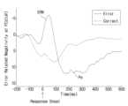
도 1은 본 발명의 일 실시예에 따른 ERN의 일반적인 파형을 나타내는 도면이다.FIG. 1 is a diagram showing a typical waveform of an ERN according to one embodiment of the present invention.
도 1을 참조하면, 가로축을 기준으로 상단에 음전위 값이 표시되어 있으며, 가로축을 기준으로 하단에 양전위 값이 표시되어 있다. 또한, 임의의 동작에 대한 반응의 발생(response onset) 이후 소정의 시간 범위 내에서 음의 피크값을 가지는 사건유발전위가 발생됨을 확인할 수 있다. 여기서, 상기 반응은 실수나 오류가 발생된 경우(Error Response)를 의미할 수 있다. 또한, 상기 소정의 시간 범위는 약 50 ~ 150ms를 의미할 수 있다. 또는, 상기 소정의 시간 범위는 약 0 ~ 100ms를 의미할 수 있다. 한편, 올바른 응답을 한 경우(Correct Response)에도, ERN보다는 상대적으로 작은 음의 피크를 가지는 사건유발전위가 발생됨을 알 수 있다.Referring to Fig. 1, a negative potential value is indicated at the top based on the horizontal axis, and a positive potential value is indicated at the bottom based on the horizontal axis. In addition, it can be confirmed that an event-evoked potential having a negative peak value is generated within a predetermined time range after the occurrence of a response to an arbitrary action (response onset). Here, the response may mean a case where a mistake or error occurs (Error Response). In addition, the predetermined time range may mean about 50 to 150 ms. Alternatively, the predetermined time range may mean about 0 to 100 ms. Meanwhile, it can be seen that even in the case of a correct response (Correct Response), an event-evoked potential having a relatively smaller negative peak than ERN is generated.
ERN은 초기 부적전위의 ERP로서, 응답 오류가 발생할 때까지 잠겨있다(time-locked). 또한, ERN은 행동 모니터링과 관련된 도파민성 시스템의 강화 활동을 반영하는 것으로 알려져 있으며, 앞쪽 대상(rostral cingulate) 영역을 포함한 전두-줄무늬체 회로(fronto-striatal loop)를 포함하고 있다. 한편, 도파민은 일반적으로 특정한 행동을 형성하여 사람으로 하여금 동기를 유발함으로써 즐거움과 재강화의 기분을 제공하는 뇌의 보상 시스템과 관련되어 있으며, 적절한 보상을 얻는 행동이 반복되면 습관으로서 학습이 된다. 또한, 감정 학습을 통해 더 많은 도파민의 분비가 일어나게 되고 상기 도파민 분비에 따라 새로운 행동을 시도하게 된다. 이와 같이, 보상에 의해 유도된 학습을 강화 학습이라 한다.The ERN is an ERP of the early negative potential, and is time-locked until a response error occurs. In addition, the ERN is known to reflect the reinforcing activity of the dopaminergic system related to action monitoring, and includes the fronto-striatal loop including the rostral cingulate region. Meanwhile, dopamine is generally related to the brain's reward system, which provides a feeling of pleasure and reinforcement by forming specific behaviors and motivating people, and when a behavior that obtains an appropriate reward is repeated, it becomes a habit. In addition, more dopamine is secreted through emotional learning, and new behaviors are attempted according to the dopamine secretion. In this way, learning induced by rewards is called reinforcement learning.
또한, ERN은 전두엽 리드를 통해 간섭 태스크(예를 들어, Go-noG0, Stroop, Flanker, Simon 태스크 등)를 수행하는 동안 야기된 잘못된 응답의 발생 후 0 ~ 100ms 사이에 발현될 수 있다.Additionally, the ERN can be expressed between 0 and 100 ms after the occurrence of an incorrect response induced during performance of interference tasks (e.g., Go-noG0, Stroop, Flanker, Simon tasks, etc.) via prefrontal leads.
또한, ERN은 후술할 CRN과 함께 올바른 행동과 잘못된 행동을 구별할 수 있는 일반적인 행동 모니터링 시스템의 활동을 반영한다고 알려져 있다.Additionally, ERN is known to reflect the activity of a general behavior monitoring system that can distinguish between correct and incorrect actions, together with CRN, which will be described later.
또한, ERN이 전두엽 전극에서 최대 진폭에 도달하는 사실은 대뇌 내 생성기가 앞쪽 대상 영역 또는 등쪽 전방 대상 피질(dorsal anterior cingulate cortex, dACC)에 위치하는 것을 반영하는 것으로 알려져 있다.Additionally, the fact that the ERN reaches its maximum amplitude at prefrontal electrodes is known to reflect that its intracerebral generator is located in the anterior cingulate area or dorsal anterior cingulate cortex (dACC).
또한, ERN은 부정적인 정서 상태에 따라 진폭의 변화를 보일 수 있다.Additionally, the ERN can show changes in amplitude depending on negative emotional states.
또한, ERN은 내부 동작 표현과 다르게 외부 평가 피드백 처리를 기반으로 동작 모니터링을 수행하는 상황에서도 보고될 수 있으며, 후술할 FRN으로 분류될 수 있다.Additionally, ERN can be reported in situations where motion monitoring is performed based on external evaluation feedback processing, unlike internal motion representation, and can be classified as FRN, which will be described later.
또한, ERN은 실수나 오류를 인지한 경우뿐만 아니라 상기 실수나 오류를 인지하기 전에도 발생될 수 있다.Additionally, ERN can occur not only when a mistake or error is recognized, but also before such a mistake or error is recognized.
또한, ERN은 자신의 실수나 오류에 대한 반응으로 발생될 뿐만 아니라 타인의 실수나 오류에 대해서도 그에 대한 반응으로 발생될 수 있다.Additionally, ERN can occur not only as a reaction to one's own mistakes or errors, but also as a reaction to the mistakes or errors of others.
또한, ERN은 실수나 오류에 대한 반응으로 발생될 뿐만 아니라 소정의 수행 과제 또는 대상에 대한 불안감, 스트레스에 대한 반응으로서 발생될 수 있다.Additionally, ERN can occur not only in response to mistakes or errors, but also in response to anxiety or stress about a given performance task or object.
또한, 획득되는 ERN의 피크 값이 클수록, 보다 중대한 실수나 오류에 대한 반응을 의미하는 것으로 판단될 수 있다.Additionally, a larger peak value of the acquired ERN may be judged to indicate a response to a more serious mistake or error.
한편, 또 다른 예로, 오류 정적전위(Pe, Error Positivity)는 ERN에 이어 발생되는 사건유발전위로서, 실수나 오류 후 약 150 ~ 300ms 사이에 주로 전두엽 전극 부위에서 발생되는 양의 값을 갖는 사건유발전위이다. Pe는 실수나 오류를 자각하고 주위를 더 기울이는 반응으로 알려져 있으며, 즉 오류 탐지 이후의 의식적인 오류 정보 처리 과정의 지표와 관련이 있다. ERN과 Pe는 오류 모니터링과 관련되는 사건유발전위로 알려져 있다.Meanwhile, as another example, the error positivity (Pe) is an event-evoked potential that occurs following the ERN, and is an event-evoked potential with a positive value that occurs mainly in the prefrontal electrode region about 150 to 300 ms after a mistake or error. Pe is known as a reaction to become aware of a mistake or error and to pay more attention, that is, it is related to the index of the conscious error information processing process after error detection. ERN and Pe are known as event-evoked potentials related to error monitoring.
이하에서는, Pe의 주요 특징에 대해서 보다 상세하게 후술한다.Below, the main features of Pe are described in more detail.
도 2는 본 발명의 일 실시예에 따른 ERN 및 Pe의 일반적인 파형을 나타내는 도면이다.FIG. 2 is a diagram showing typical waveforms of ERN and Pe according to one embodiment of the present invention.
도 2를 참조하면, 상단에 음전위 값이 표시되어 있으며, 하단에 양전위 값이 표시되어 있다. 또한, 임의의 동작에 대한 반응의 발생(response onset) 이후 제1 소정의 시간 범위 내에서 음의 피크값을 가지는 사건유발전위, 즉 ERN가 발생됨을 확인할 수 있다. 여기서, 상기 반응은 실수나 오류가 발생된 경우(Error Response)를 의미할 수 있다. 또한, 상기 제1 소정의 시간 범위는 약 50 ~ 150ms를 의미할 수 있다. 또는, 상기 제1 소정의 시간 범위는 약 0 ~ 200ms를 의미할 수 있다.Referring to FIG. 2, a negative potential value is indicated at the top, and a positive potential value is indicated at the bottom. In addition, it can be confirmed that an event-evoked potential, i.e., an ERN having a negative peak value is generated within a first predetermined time range after the occurrence of a response to an arbitrary action (response onset). Here, the response may mean a case where a mistake or error occurs (Error Response). In addition, the first predetermined time range may mean about 50 to 150 ms. Alternatively, the first predetermined time range may mean about 0 to 200 ms.
또한, 상기 ERN의 발생 이후 제2 소정의 시간 범위 내에서 양의 피크값을 가지는 사건유발전위, 즉 Pe가 발생됨을 확인할 수 있다. 여기서, 상기 제2 소정의 시간 범위는 오류 발생 이후 약 150 ~ 300ms를 의미할 수 있다. 또는, 상기 제2 소정의 시간 범위는 약 200 ~ 400ms를 의미할 수 있다.In addition, it can be confirmed that an event-induced potential, i.e., Pe, having a positive peak value occurs within a second predetermined time range after the occurrence of the ERN. Here, the second predetermined time range may mean about 150 to 300 ms after the occurrence of the error. Alternatively, the second predetermined time range may mean about 200 to 400 ms.
도 3은 본 발명의 일 실시예에 따른 Pe의 편향 특성을 나타내는 도면이다.FIG. 3 is a diagram showing the deflection characteristics of Pe according to one embodiment of the present invention.
도 3을 참조하면, Pe는 P3와 유사하게 넓은 편향 특성을 가지며, 신경총 생성기가 후대상피질 및 뇌섬엽피질 영역뿐 아니라 더 많은 앞쪽 전방 대상 피질을 포함한다.Referring to Figure 3, Pe has a broad bias characteristic similar to P3, with the plexus generators involving more of the anterior cingulate cortex as well as the posterior cingulate and insular cortex regions.
또한, Pe는 오류의 정서적 평가, P300과 같은 자극에 대한 집중 등을 반영할 수 있다. 또한, ERN은 맞는 반응과 틀린 반응 사이의 갈등을 나타내며, Pe는 실수를 자각하고 주의를 더 기울이는 반응이라고 알려져 있다. 즉, ERN은 자극을 탐지하는 과정에서 발생하고, Pe는 자극의 처리 과정에서 주의 여부에 따라 발생할 수 있다. ERN 및/또는 Pe의 값이 각각 상대적으로 큰 값을 갖는 경우, 이는 실수 후 더 천천히 더 정확한 반응을 하려는 적응적인 행동과 관련이 있는 것으로 알려져 있다.In addition, Pe can reflect the emotional evaluation of errors, attention to stimuli such as P300, etc. In addition, ERN indicates conflict between correct and incorrect responses, and Pe is known to be a response that recognizes mistakes and pays more attention. In other words, ERN occurs in the process of detecting stimuli, and Pe can occur depending on whether attention is paid during the process of processing stimuli. When the values of ERN and/or Pe are relatively large, it is known to be related to adaptive behavior of trying to respond more slowly and more accurately after a mistake.
도 4는 본 발명의 일 실시예에 따른 ERP 및 Pe의 측정 영역을 나타내는 도면이다.FIG. 4 is a diagram showing a measurement area of ERP and Pe according to one embodiment of the present invention.
ERN 및 Pe는 오류 모니터링과 관련되는 사건유발전위로 알려져 있으며, ERN 및 Pe의 측정 영역은 일반적으로 central 영역에서 각각 가장 큰 음의 값 및 양의 값이 측정될 수 있으나, 측정 조건에 따라 다소간의 차이가 있을 수 있다. 일 예로, 도 4의 (a)는 ERN이 측정되는 주요 영역으로서, ERN은 일반적으로 midline frontal 또는 central 영역(즉, FCZ)에서 가장 큰 음의 값이 측정될 수 있다. 또한, 도 4의 (b)는 Pe가 측정되는 주요 영역으로서, Pe는 일반적으로 ERN보다는 좀더 후방의(posterior) midline 영역에서 큰 양의 값이 측정될 수 있다.ERN and Pe are known as event-evoked potentials related to error monitoring, and the measurement areas of ERN and Pe can generally measure the largest negative and positive values in the central area, respectively, but there may be some differences depending on the measurement conditions. For example, Fig. 4 (a) shows the main area where ERN is measured, and ERN can generally measure the largest negative value in the midline frontal or central area (i.e., FCZ). In addition, Fig. 4 (b) shows the main area where Pe is measured, and Pe can generally measure a large positive value in the midline area, which is more posterior than ERN.
한편, 또 다른 예로, 피드백관련 부적전위(FRN, Feedback-Related Negativity)는 외부 평가 피드백에 기초하여 오류 검출이 획득되는 것과 관련된 사건유발전위이다. ERN 및/또는 Pe는 내부 모니터링 프로세스에 기초하여 오류 검출을 하지만, FRN의 경우 외부 평가 피드백에 기초하여 획득될 때 ERN의 프로세스와 유사하게 동작할 수 있다.Meanwhile, as another example, Feedback-Related Negativity (FRN) is an event-evoked potential related to error detection being obtained based on external evaluation feedback. ERN and/or Pe perform error detection based on internal monitoring processes, but FRN can operate similarly to the process of ERN when it is obtained based on external evaluation feedback.
또한, FRN은 ERN과 많은 전기 생리학적 성질을 공유할 수 있다. 예를 들어, FRN은 부정적인 피드백 발생 후 약 250 ~ 300ms 사이에 전두엽 전극에서 음의 값의 피크를 가지며, ERN과 동일한 등쪽 전방 대상 피질 영역에서 생성될 수 있다.In addition, the FRN may share many electrophysiological properties with the ERN. For example, the FRN has a negative peak at prefrontal electrodes approximately 250–300 ms after the onset of negative feedback, and may be generated in the same dorsal anterior cingulate cortex area as the ERN.
또한, FRN은 ERN과 유사하게 도파민성 시스템에 의한 강화 학습의 활동을 반영할 수 있다. 또한, FRN은 보통 양의 피드백에 비해 음의 값이 더 크며, 예측 가능한 결과에 비해 예측하지 못한 경우에 그 값이 더 클 수 있다.In addition, FRN can reflect the activity of reinforcement learning by the dopaminergic system, similar to ERN. In addition, FRN usually has a larger negative value than positive feedback, and its value can be larger in case of unexpected results than in case of predicted results.
또 다른 예로, 정반응 관련 부적전위(CRN, Correct-Related Negativity)는 올바른 응답(correct trial)을 한 경우 생성되는 ERP로서, ERN보다는 상대적으로 작은 크기를 갖은 음수이며 ERN과 동일한 초기 잠복기(예를 들어, 0 ~ 100ms) 사이에 생성될 수 있다. 도 5은 본 발명의 일 실시예에 따른 ERN 및 CRN의 일반적인 파형을 나타내는 도면이다.As another example, Correct-Related Negativity (CRN) is an ERP generated when a correct response (correct trial) is made, is a negative number with a relatively smaller size than the ERN, and can be generated within the same initial latency period as the ERN (e.g., 0 to 100 ms). FIG. 5 is a diagram showing typical waveforms of ERN and CRN according to one embodiment of the present invention.
또 다른 예로, 정반응 정적전위(Pc, Correct Positivity)는 CRN에 이어 발생되는 사건유발전위로서, 올바른 응답 이후 약 150 ~ 300ms 사이에 발생되는 사건유발전위이다. CRN과 Pc의 관계는 전술한 ERN과 Pe의 관계와 유사할 수 있다.As another example, the correct response potential (Pc) is an event-evoked potential that occurs following the CRN, and is an event-evoked potential that occurs approximately 150 to 300 ms after a correct response. The relationship between the CRN and Pc can be similar to the relationship between the ERN and Pe described above.
한편, ERP는 자극 잠금(stimulus-locked) ERP와 반응 잠금(response-locked) ERP로 구분할 수 있다. 상기 자극 잠금 ERP와 반응 잠금 ERP는 사건유발전위의 유발 원인, 반응 시점 등의 기준에 따라 구분될 수 있다. 예를 들어, 외부에서 사용자에게 글이나 그림을 제시했을 때로부터 유발되는 ERP를 자극 잠금 ERP라 할 수 있다. 또한, 예를 들어, 사용자가 말을 했을 때 또는 버튼을 눌렀을 때로부터 유발되는 ERP를 반응 잠금 ERP라 할 수 있다. 따라서, 상술한 기준에 따를 때, 일반적으로 자극 잠금 ERP에는 N100, N200, P2, P3 등이 있고, 반응 잠금 ERP는 ERN, Pe, CRN, Pc, FRN 등이 있다.Meanwhile, ERP can be divided into stimulus-locked ERP and response-locked ERP. The stimulus-locked ERP and response-locked ERP can be divided according to criteria such as the cause of the event-evoked potential and the timing of the response. For example, an ERP induced when a text or picture is presented to the user from the outside can be called a stimulus-locked ERP. In addition, an ERP induced when the user speaks or presses a button can be called a response-locked ERP. Accordingly, according to the criteria described above, stimulus-locked ERP generally includes N100, N200, P2, P3, etc., and response-locked ERP generally includes ERN, Pe, CRN, Pc, FRN, etc.
한편, 뇌파는 발현 동기에 따라 구분할 수 있는데, 사용자의 의지에 의해 발현되는 자발적 뇌파(자발전위)와 사용자의 의지에 관계없이 외부 자극에 따라 자연스럽게 발현되는 유발적 뇌파(유발전위)로 구분할 수 있다. 자발적 뇌파는 사용자 스스로 움직이거나 어떤 동작을 상상했을 때 발현될 수 있으며, 유발적 뇌파는, 예를 들어 시각, 청각, 후각, 촉각 등의 자극에 의해 발현될 수 있다.Meanwhile, brain waves can be classified by their occurrence motives, and can be classified into spontaneous brain waves (spontaneous potentials) that are generated by the user's will and evoked brain waves (evoked potentials) that are naturally generated by external stimuli regardless of the user's will. Spontaneous brain waves can be generated when the user moves or imagines a certain action, and evoked brain waves can be generated by stimuli such as sight, hearing, smell, and touch.
한편, 뇌파 신호는 10-20 국제시스템(International 10-20 system)에 의거하여 측정될 수 있다. 10-20 국제시스템은 뇌파 신호 측정점을 전극의 위치와 대뇌피질 영역의 관계에 기초하여 결정하고 있다.Meanwhile, brainwave signals can be measured according to the International 10-20 system. The International 10-20 system determines brainwave signal measurement points based on the relationship between the electrode locations and the cerebral cortex areas.
도 6은 본 발명의 일 실시예에 따른 대뇌피질 영역에 대응되는 뇌파측정 채널을 나타내는 도면이다.FIG. 6 is a diagram showing an EEG measurement channel corresponding to a cerebral cortex area according to one embodiment of the present invention.
도 6을 참조하면, 뇌 영역별(전전두엽 FP1, FP2; 전두엽 F3, F4, F7, F8, FZ, FC3, FC4, FT7, FT8, FCZ; 두정엽 C3, C4, CZ, CP3, CP4, CPZ, P3, P4, PZ; 측두엽 T7, T8, TP7, TP8, P7, P8; 후두엽 O1, O2, OZ)로 32개의 뇌파측정 채널에 대응되어 있다. 상기 각각의 채널에 대해 데이터를 획득하고 이를 이용하여 각 대뇌피질 영역에 대한 분석을 수행할 수 있다.Referring to Fig. 6, 32 EEG measurement channels are corresponding to each brain region (prefrontal cortex FP1, FP2; frontal cortex F3, F4, F7, F8, FZ, FC3, FC4, FT7, FT8, FCZ; parietal cortex C3, C4, CZ, CP3, CP4, CPZ, P3, P4, PZ; temporal cortex T7, T8, TP7, TP8, P7, P8; occipital cortex O1, O2, OZ). Data can be acquired for each channel and used to perform analysis on each cerebral cortex region.
도 7은 본 발명의 일 실시예에 따른 오류 모니터링을 이용한 주행 모델 생성 장치의 구성을 나타내는 블록도이다.FIG. 7 is a block diagram showing the configuration of a driving model generation device using error monitoring according to one embodiment of the present invention.
교통사고는 일반적으로 인적요인, 차량요인, 도로환경요인 등에 의해 발생될 수 있는데, 대부분의 경우 인적요인에 의해서 발생된다. 구체적으로, 인적요인으로는 운전자의 과실, 부주의, 운전미숙, 졸음, 음주, 법규 위반 등이 있으며, 차량요인으로는 기능 결함, 유지관리 소홀 등이 있다. 또한, 도로환경요인으로는 도로설계, 유지관리 소홀, 공사, 날씨, 시계(視界), 조명 등이 있다.Traffic accidents can generally be caused by human factors, vehicle factors, and road environment factors, but in most cases, they are caused by human factors. Specifically, human factors include driver negligence, carelessness, inexperienced driving, drowsiness, drinking, and violation of laws, and vehicle factors include functional defects and maintenance negligence. In addition, road environment factors include road design, maintenance negligence, construction, weather, visibility, and lighting.
한편, 운전자의 과실, 부주의, 운전미숙과 같은 인적요인의 경우에는, 일 예로, 운전자가 운전면허를 취득한지 얼마 되지 않아서 충분한 주행 연습이 되지 않았기 때문에 유발될 수 있다.On the other hand, in the case of human factors such as driver negligence, carelessness, and inexperience in driving, it can be caused by the driver not having sufficient driving practice because he or she has recently obtained a driver's license.
다른 예로, 초행길을 접하는 경우 운전미숙과 같은 인적요인이 발생될 수 있다.As another example, human factors such as inexperienced driving can occur when encountering a new road.
또 다른 예로, 좌회전, 차선 변경과 같은 특정 동작을 하는 경우에도 운전미숙과 같은 인적요인이 발생될 수 있다.As another example, human factors such as poor driving skills can occur even when performing certain actions such as turning left or changing lanes.
또 다른 예로, 운전자에게 익숙한 주행로인 경우, 예를 들어, 집 앞 길의 경우 운전자의 부주의가 유발될 수 있다.Another example is when a road is familiar to the driver, for example, the road in front of his house, this can lead to driver inattention.
따라서, 운전자가 자신이 없거나 불안해 하는 동작이나 주행 상황에 대해 미리 연습할 수 있다면, 그럼으로써 운전자의 운전미숙, 과실, 부주의 등의 요인들을 해소할 수 있다면, 향후 일어날 수도 있는 교통사고의 발생 가능성을 줄이는데 도움이 될 것이다.Therefore, if drivers can practice in advance the movements or driving situations that they are unsure of or anxious about, and thereby eliminate factors such as the driver's lack of driving skills, negligence, and carelessness, it will help reduce the possibility of traffic accidents that may occur in the future.
반응 잠금 사건유발전위는 실수나 오류를 인지한 경우에 발생된다. 또한, 반응 잠금 사건유발전위는 자신의 실수나 오류에 대한 반응으로 발생될 뿐만 아니라 타인의 실수나 오류에 대해서도 그에 대한 반응으로 발생될 수 있다. 또한, 소정의 수행 과제 또는 대상에 대한 불안감, 스트레스에 대한 반응으로서 발생될 수 있다. 여기서, 반응 잠금 사건유발전위는 ERN, Pe, CRN, Pc, FRN 등을 포함할 수 있다.Reaction-locked event-evoked potentials occur when a mistake or error is recognized. In addition, reaction-locked event-evoked potentials can occur not only as a response to one's own mistake or error, but also as a response to the mistakes or errors of others. In addition, they can occur as a response to anxiety or stress about a given task or object. Here, reaction-locked event-evoked potentials can include ERN, Pe, CRN, Pc, FRN, etc.
한편, 모빌리티의 주행 중에 소정의 시간 범위 내에서 운전자의 뇌파 신호에는 급격한 변화가 관측될 수 있다. 즉, 뇌파 신호는 인간의 의식 또는 무의식의 상태를 직간접으로 반영하는 생체 신호이기 때문에, 모빌리티의 주행 중에 운전자가 느끼는 불안감, 스트레스, 운전상 실수나 오류에 대한 감정 등은 운전자의 뇌파 신호에 급격한 변화를 유발시킬 수 있다. 다양한 원인이 있을 수 있겠지만, 주로 모빌리티를 주행하면서 운전자가 불편하거나 어렵다고 느끼는 동작, 조작, 주행 환경, 주행로 등을 접하는 경우, 상기 불안감, 스트레스, 운전상 실수나 오류에 대한 감정이 유발될 수 있을 것이다. 이때, 상기 동작, 조작, 주행 환경, 주행로 등은 운전자마다 각각 상이할 수 있다.Meanwhile, rapid changes in the driver's brainwave signals may be observed within a certain time range while driving a mobility vehicle. That is, since brainwave signals are biosignals that directly or indirectly reflect the state of human consciousness or unconsciousness, feelings of anxiety, stress, driving mistakes or errors felt by the driver while driving a mobility vehicle may induce rapid changes in the driver's brainwave signals. There may be various causes, but mainly, when the driver encounters movements, operations, driving environments, or driving routes that the driver finds uncomfortable or difficult while driving a mobility vehicle, the feelings of anxiety, stress, driving mistakes or errors may be induced. At this time, the movements, operations, driving environments, and driving routes may differ for each driver.
일 예로, 차선 변경을 하는 경우 어떤 운전자는 불안감 등을 느낄 수 있다.For example, some drivers may feel anxious or uneasy when changing lanes.
다른 예로, 비보호 좌회전을 하는 경우 어떤 운전자는 해당 조작이 어렵다고 느낄 수 있다.As another example, some drivers may find it difficult to make an unprotected left turn.
또 다른 예로, 고가도로를 주행하는 경우 어떤 운전자는 스트레스를 받을 수 있다.As another example, driving on an elevated highway can be stressful for some drivers.
또 다른 예로, 급커브 구간에서 어떤 운전자는 해당 조작이 불편하다고 느낄 수 있다.As another example, some drivers may find this maneuver uncomfortable on sharp curves.
또 다른 예로, 전면 주차를 하는 경우 어떤 운전자는 해당 조작이 어렵다고 느낄 수 있다.As another example, when parking in front of a vehicle, some drivers may find the maneuver difficult.
또한, 주파수 대역별로 분류된 뇌파 신호는 운전자가 느끼는 편안함, 불안감, 스트레스 등의 감정들을 반영할 수 있다.Additionally, brainwave signals classified by frequency band can reflect emotions felt by drivers, such as comfort, anxiety, and stress.
일 예로, 알파파는 일반적으로 8 ~ 12Hz의 주파수를 가진 뇌파로서, 긴장이 이완된 편안한 상태에서 주로 나타난다. 또한, 전두엽 또는 후두엽에서 주로 발생되며, 스트레스가 발생하면 감소하는 경향이 있다.For example, alpha waves are brain waves that generally have a frequency of 8 to 12 Hz and mainly appear in a relaxed and comfortable state. Also, they are mainly generated in the frontal or occipital lobe and tend to decrease when stress occurs.
다른 예로, 베타파는 일반적으로 13 ~ 30Hz의 주파수를 가진 뇌파로서, 약간의 긴장상태나 일정 이상의 주의를 기울일 때 주로 나타난다. 또한, 주로 전두엽에서 발생되고, 불안, 긴장 등의 스트레스를 받을 때 더욱 강하게 나타나기 때문에 스트레스파라고 지칭된다.As another example, beta waves are brain waves with a frequency of 13 to 30 Hz, and they mainly appear when you are slightly tense or paying a certain amount of attention. They are also called stress waves because they are mainly generated in the frontal lobe and appear more strongly when you are under stress such as anxiety or tension.
또 다른 예로, 세타파는 일반적으로 3.5 ~ 7Hz의 주파수를 가진 뇌파로서, 주로 두정엽과 후두엽에서 주로 발생된다. 또한, 스트레스가 발생하면 증가하는 경향이 있다.As another example, theta waves are brain waves that typically have a frequency of 3.5 to 7 Hz and are mainly generated in the parietal and occipital lobes. They also tend to increase when stress occurs.
전술한 바와 같이, 스트레스가 발생하지 않는 경우 알파파가 우세한(dominant) 신호로서 측정될 수 있으며, 스트레스가 발생하는 경우 알파파는 감소하고, 베타파 및/또는 세타파가 우세한 신호로서 측정될 수 있을 것이다.As mentioned above, when no stress occurs, alpha waves may be measured as the dominant signal, and when stress occurs, alpha waves may decrease and beta waves and/or theta waves may be measured as the dominant signals.
따라서, 소정의 시간 동안 수집된 운전자에 대한 뇌파 신호를 분석하면, 운전자의 심리 상태를 판단할 수 있을 것이다. 즉, 불안감, 스트레스, 실수나 오류에 대한 반응으로 발생되는 반응 잠금 사건유발전위를 획득하거나, 또는 알파파, 베타파, 세타파 등의 주파수별 뇌파 신호의 크기를 검출함으로써 운전자가 편안한 상태인지, 불안한 상태인지 여부 등을 판단할 수 있을 것이다.Therefore, by analyzing the brainwave signals collected for a certain period of time, it will be possible to determine the psychological state of the driver. That is, by obtaining response-locked event-evoked potentials that occur in response to anxiety, stress, mistakes, or errors, or by detecting the size of brainwave signals by frequency, such as alpha waves, beta waves, and theta waves, it will be possible to determine whether the driver is in a comfortable or anxious state.
한편, 상기 모빌리티는 차량, 이동/운송 장치 등의 의미를 포함할 수 있다.Meanwhile, the above mobility may include the meaning of vehicles, moving/transportation devices, etc.
또한, 상기 판단된 운전자의 상태에 기초하여 모빌리티의 동작 정보 및/또는 주행 정보를 검출할 수 있다. 이때, 해당 모빌리티에 포함된 다양한 센싱 장치를 이용함으로써 상기 모빌리티의 동작 정보 및/또는 주행 정보를 검출할 수 있을 것이다.In addition, based on the determined driver's status, the operation information and/or driving information of the mobility can be detected. At this time, the operation information and/or driving information of the mobility can be detected by using various sensing devices included in the mobility.
한편, 주파수별 뇌파 신호는 소정의 시간 동안 수집된 주파수 평면의 뇌파 신호의 파워를 추출하고, SVM(Support Vector Machine)과 같은 분류 모델을 이용하여 각 구간의 주파수별로 분류될 수 있다. 상기 분류 모델은 상술한 내용에 한정되지 않으며, 뇌파 신호를 분류할 수 있는 일반적인 방법들을 포함할 수 있다.Meanwhile, the frequency-specific brainwave signals can be classified by frequency of each section by extracting the power of the brainwave signals of the frequency plane collected for a given period of time and using a classification model such as SVM (Support Vector Machine). The classification model is not limited to the above-described content and may include general methods capable of classifying brainwave signals.
도 7을 참조하면, 주행 모델 생성 장치(700)는 센싱부(710), 분석부(720) 및/또는 저장부(730)를 포함할 수 있다. 다만, 이는 본 실시예를 설명하기 위해 필요한 일부 구성요소만을 도시한 것일 뿐, 주행 모델 생성 장치(700)에 포함된 구성요소가 전술한 예에 한정되는 것은 아니다. 예컨대, 둘 이상의 구성부가 하나의 구성부 내에서 구현될 수도 있고, 하나의 구성부에서 실행되는 동작이 분할되어 둘 이상의 구성부에서 실행되도록 구현될 수도 있다. 또한, 일부 구성부가 생략되거나 부가적인 구성부가 추가될 수도 있다.Referring to FIG. 7, the driving model generation device (700) may include a sensing unit (710), an analysis unit (720), and/or a storage unit (730). However, this only illustrates some of the components necessary for explaining the present embodiment, and the components included in the driving model generation device (700) are not limited to the above-described examples. For example, two or more components may be implemented in one component, or an operation executed in one component may be divided and implemented to be executed in two or more components. In addition, some components may be omitted or additional components may be added.
본 개시의 주행 모델 생성 방법 및/또는 장치는 소정의 시간 동안 수집된 모빌리티 내의 운전자에 대한 뇌파 신호를 분석함으로써 운전자의 상태를 판단할 수 있다. 또한, 주행 모델 생성 방법 및/또는 장치는 상기 판단된 운전자의 상태에 기초하여 모빌리티의 동작 정보 및/또는 주행 정보을 검출할 수 있다. 또한, 주행 모델 생성 방법 및/또는 장치는 상기 검출된 모빌리티의 동작 정보 및/또는 주행 정보 상황에 기초하여 운전자의 운전 특성이 반영된 주행 모델을 생성할 수 있다.The driving model generation method and/or device of the present disclosure can determine the driver's state by analyzing brain wave signals of the driver in the mobility collected for a predetermined period of time. In addition, the driving model generation method and/or device can detect the operation information and/or driving information of the mobility based on the determined driver's state. In addition, the driving model generation method and/or device can generate a driving model reflecting the driver's driving characteristics based on the detected operation information and/or driving information situation of the mobility.
구체적으로, 본 개시의 주행 모델 생성 장치(700)는 모빌리티 내의 운전자에 대한 뇌파 신호를 소정의 시간 동안 수집할 수 있다. 또한, 센싱부(710)는 상기 동작을 수행할 수 있다.Specifically, the driving model generation device (700) of the present disclosure can collect brain wave signals of a driver within a mobility for a predetermined period of time. In addition, the sensing unit (710) can perform the above operation.
여기서, 상기 뇌파 신호는 사건유발전위 및/또는 주파수별 뇌파 신호를 의미할 수 있다.Here, the brain wave signal may refer to an event-evoked potential and/or a frequency-specific brain wave signal.
여기서, 상기 사건유발전위는 반응 잠금 사건유발전위(response-locked ERP)를 의미할 수 있다. 또한, 상기 반응 잠금 사건유발전위는 ERN, Pe, CRN, Pc, FRN 등을 포함할 수 있다. 또한, 상기 ERN, Pe, CRN, Pc, FRN 이외에 소정의 응답이 발생(즉, response onset)한 이후 획득되는 기타 사건유발전위들도 포함될 수 있다. 또한, 상기 반응 잠금 사건유발전위는 복수의 사건유발전위들을 포함할 수 있다.Here, the event-evoked potential may mean a response-locked event-evoked potential (ERP). In addition, the response-locked event-evoked potential may include ERN, Pe, CRN, Pc, FRN, etc. In addition, other event-evoked potentials acquired after a predetermined response occurs (i.e., response onset) may also be included in addition to the ERN, Pe, CRN, Pc, and FRN. In addition, the response-locked event-evoked potential may include a plurality of event-evoked potentials.
또한, 여기서, 상기 뇌파 신호를 소정의 시간 동안 수집하는 것은 모빌리티 내의 운전자의 뇌파 신호를 측정하고, 상기 측정된 뇌파 신호에서 사건유발전위를 검출하는 과정을 포함할 수 있다.Additionally, collecting the brain wave signals here for a predetermined period of time may include a process of measuring brain wave signals of a driver within the mobility and detecting event-evoked potentials from the measured brain wave signals.
도 1 내지 도 6에서 상술한 바와 같이, ERN, Pe, CRN, Pc 및/또는 FRN은 오류나 실수 등의 잘못된 행동에 대한 반응 또는 올바른 행동에 대한 반응으로서 발생될 수 있다. 따라서, 상기 사건유발전위를 이용하면 모빌리티의 주행 중에 운전자가 느끼는 불안감, 스트레스, 운전상 실수나 오류에 대한 감정과 같은 운전자의 심리 상태를 판단할 수 있다. 또한, 상기 판단에 따라 운전자에게 적응적인 주행 모델을 생성할 수 있다.As described above in FIGS. 1 to 6, ERN, Pe, CRN, Pc and/or FRN may be generated as a response to an incorrect action such as an error or mistake, or as a response to a correct action. Therefore, by using the above event-induced potential, it is possible to determine the psychological state of the driver, such as anxiety, stress, and feelings about driving mistakes or errors felt by the driver while driving a mobility vehicle. In addition, an adaptive driving model can be generated for the driver based on the above determination.
일 예로, 어떤 운전자는 차선변경을 해야 하는 상황인 경우. ERN 및/또는 Pe가 발생될 수 있다.For example, if a driver is in a situation where he or she must change lanes, ERN and/or Pe may be generated.
다른 예로, 어떤 운전자는 고가도로를 주행해야 하는 상황인 경우, ERN 및/또는 Pe가 발생될 수 있다.As another example, a driver may encounter an ERN and/or Pe in a situation where they must drive on an elevated highway.
또 다른 예로, 어떤 운전자는 복잡하거나 초행길을 운전하는 등의 긴장되고 스트레스 받는 운전 상황인 경우, ERN 및/또는 Pe가 발생될 수 있다.As another example, some drivers may experience ERN and/or Pe in stressful driving situations, such as driving on complex or unfamiliar roads.
또 다른 예로, 어떤 운전자는 전면 주차를 해야 하는 상황인 경우, ERN 및/또는 Pe가 발생될 수 있다.As another example, a driver may encounter an ERN and/or Pe in a situation where they must park in front of the vehicle.
또한, 상기 소정의 시간은 특정 응답이 발생한 이후 약 0 ~ 400ms를 의미할 수 있다. 또한, 상기 소정의 시간은 전술한 반응 잠금 사건유발전위가 획득될 수 있는 시간 범위를 포함할 수 있다. 또한, 상기 소정의 시간은 반응 잠금 사건유발전위의 종류에 따라 달라질 수 있으며, 복수의 시간 범위를 가질 수 있다. 예컨대, 제1 사건유발전위를 획득하기 위해 제1 시간 범위가 주어지고 제2 사건유발전위를 획득하기 위해 제2 시간 범위가 주어질 수 있다.In addition, the predetermined time may mean about 0 to 400 ms after a specific response occurs. In addition, the predetermined time may include a time range in which the above-described response-locked event-evoked potential can be acquired. In addition, the predetermined time may vary depending on the type of the response-locked event-evoked potential and may have multiple time ranges. For example, a first time range may be given to acquire a first event-evoked potential, and a second time range may be given to acquire a second event-evoked potential.
일 예로, 제1 사건유발전위가 ERN이고, 제2 사건유발전위가 Pe인 경우, 제1 시간 범위는 ERN의 주요 측정 구간인 약 0 ~ 150ms이고, 제2 시간 범위는 Pe의 주요 측정 구간인 약 150 ~ 400ms일 수 있다. 도 8은 본 발명의 일 실시예에 따른 대상 사건유발전위가 ERN 및 Pe일 때의 측정 시간 범위를 나타내는 도면이다. 도 8을 참조하면, 제1 시간 범위(810)에서 ERN이 획득될 수 있고, 제2 시간 범위(820)에서 Pe가 획득될 수 있다.For example, when the first event-induced potential is ERN and the second event-induced potential is Pe, the first time range may be about 0 to 150 ms, which is a main measurement interval of ERN, and the second time range may be about 150 to 400 ms, which is a main measurement interval of Pe. FIG. 8 is a diagram showing a measurement time range when the target event-induced potentials are ERN and Pe according to one embodiment of the present invention. Referring to FIG. 8, ERN can be acquired in the first time range (810), and Pe can be acquired in the second time range (820).
다른 예로, 제1 사건유발전위가 ERN이고, 제2 사건유발전위가 CRN인 경우, 제1 시간 범위는 ERN의 주요 측정 구간인 약 0 ~ 200ms이고, 제2 시간 범위는 CRN의 주요 측정 구간인 약 0 ~ 200ms일 수 있다.As another example, if the first event-evoked potential is an ERN and the second event-evoked potential is a CRN, the first time range may be about 0 to 200 ms, which is a main measurement interval of the ERN, and the second time range may be about 0 to 200 ms, which is a main measurement interval of the CRN.
또한, 상기 운전자에 대한 뇌파 신호는 연속적으로, 예컨대 주기적으로 측정, 저장되고 있을 수 있다.Additionally, brain wave signals for the driver may be measured and stored continuously, for example periodically.
본 개시의 주행 모델 생성 장치(700)는 소정의 시간 동안 수집된 뇌파 신호를 분석함으로써 운전자의 상태를 판단할 수 있다. 또한, 분석부(720)는 상기 동작을 수행할 수 있다.The driving model generation device (700) of the present disclosure can determine the driver's condition by analyzing brain wave signals collected over a predetermined period of time. In addition, the analysis unit (720) can perform the above operation.
여기서, 상기 분석은 상기 소정의 시간 동안 수집된 사건유발전위의 크기와 소정의 임계값을 비교하는 과정을 포함할 수 있다.Here, the analysis may include a process of comparing the size of the event-induced potential collected over the predetermined period of time with a predetermined threshold value.
여기서, 상기 임계값은 기설정된 값이거나 사용자가 입력한 값일 수 있다. 또한, 상기 임계값은 사건유발전위가 수집되는 운전자마다 그 크기가 상이할 수 있다. 예컨대, 운전자별 뇌파 신호 특성이 반영된 값일 수 있다. 상기 뇌파 신호의 특성을 분석한 결과를 반영하기 위해 미리 운전자의 뇌파 신호에서 표출되는 반응 잠금 사건유발전위 특징들에 대해 소정의 학습 과정이 수행될 수 있다. 또한, 상기 임계값은 사건유발전위의 종류에 따라 달라질 수 있으며, 복수의 임계값을 가질 수 있다. 도 9는 본 발명의 일 실시예에 따른 대상 사건유발전위가 ERN 및 Pe일 때 소정의 임계값과 비교하는 과정을 나타내는 도면이다. 도 9를 참조하면, ERN의 경우 제1 임계값(910)과 그 크기를 비교하고, Pe의 경우 제2 임계값(920)과 그 크기를 비교할 수 있다. 여기서, 상기 크기는 절대값의 크기를 의미할 수 있다.Here, the threshold value may be a preset value or a value input by the user. In addition, the threshold value may have a different size for each driver for whom the event-evoked potential is collected. For example, it may be a value reflecting the characteristics of the brainwave signal for each driver. In order to reflect the result of analyzing the characteristics of the brainwave signal, a predetermined learning process may be performed on the response-locked event-evoked potential features expressed in the driver's brainwave signal in advance. In addition, the threshold value may vary depending on the type of the event-evoked potential and may have a plurality of threshold values. FIG. 9 is a diagram showing a process of comparing a target event-evoked potential with a predetermined threshold value when it is ERN and Pe according to one embodiment of the present invention. Referring to FIG. 9, in the case of ERN, the size may be compared with a first threshold value (910), and in the case of Pe, the size may be compared with a second threshold value (920). Here, the size may mean the size of the absolute value.
또한, 상기 분석은 사건유발전위의 크기가 소정의 시간 구간 동안 소정의 임계값보다 크거나 같은지(즉, 소정의 임계값 범위를 벗어나는지)를 판단하는 과정을 포함할 수 있다. 도 9를 참조하면, ERN의 경우 제3 시간 범위(912) 동안 ERN의 크기가 제1 임계값(910)보다 크거나 같은지를 비교하고, Pe의 경우 제4 시간 범위(922) 동안 Pe의 크기가 제2 임계값(920)보다 크거나 같은지를 비교할 수 있다.Additionally, the analysis may include a process of determining whether the magnitude of the event-induced potential is greater than or equal to a predetermined threshold value during a predetermined time interval (i.e., whether it falls outside a predetermined threshold range). Referring to FIG. 9, in the case of ERN, a comparison may be made as to whether the magnitude of ERN is greater than or equal to a first threshold value (910) during a third time interval (912), and in the case of Pe, a comparison may be made as to whether the magnitude of Pe is greater than or equal to a second threshold value (920) during a fourth time interval (922).
한편, 상기 분석에 앞서 뇌파 신호의 특징이 나타나는 시기 및/또는 뇌파 신호의 패턴을 이용하여 사건유발전위의 발생을 인지하는 과정이 선행될 수 있다. 또한, 상기 분석은 사건유발전위를 추출하는 과정을 포함할 수 있다.Meanwhile, prior to the above analysis, a process of recognizing the occurrence of an event-evoked potential by using the time at which the characteristics of the brain wave signal appear and/or the pattern of the brain wave signal may be performed. In addition, the above analysis may include a process of extracting the event-evoked potential.
또한, 한편 상기 분석에 이용되는 사건유발전위는 소정의 시간 동안 수집된 사건유발전위의 통계값일 수 있다. 예를 들어, 상기 통계값은 평균값, 가중평균값, 최대값, 최소값 등을 의미할 수 있다.In addition, the event-induced potential used in the above analysis may be a statistical value of the event-induced potential collected over a given period of time. For example, the statistical value may mean an average value, a weighted average value, a maximum value, a minimum value, etc.
또한, 상기 분석은 사건유발전위의 크기 또는 뇌파 신호의 크기가 소정의 임계값 보다 크거나 같은 지점에서부터 운전자의 상태를 판단할 수 있다.Additionally, the above analysis can determine the driver's condition from the point where the size of the event-induced potential or the size of the brain wave signal is greater than or equal to a predetermined threshold value.
여기서, 상기 운전자의 상태는 안정 상태, 불안정 상태 등을 포함할 수 있다.Here, the driver's state may include a stable state, an unstable state, etc.
반응 잠금 사건유발전위는 일반적으로 획득되는 사건유발전위의 피크 값의 크기(즉, 피크 값의 절대값)이 클수록, 보다 중대한 실수나 오류에 대한 반응을 의미하는 것으로 판단될 수 있다.The response-locked event-evoked potential can generally be judged to mean a response to a more serious mistake or error when the size of the peak value of the event-evoked potential obtained is larger (i.e., the absolute value of the peak value).
따라서, 도 9에서 상술한 바와 같이, 일 예로, ERN의 경우 제3 시간 범위(912) 동안 ERN의 크기가 제1 임계값(910)보다 크거나 같은지를 비교하여, ERN의 크기가 제1 임계값(910)보다 크거나 같은 경우, 운전자의 상태는 불안정 상태라고 판단될 수 있다.Accordingly, as described above in FIG. 9, for example, in the case of ERN, the size of ERN during the third time range (912) is compared to see if it is greater than or equal to the first threshold value (910), and if the size of ERN is greater than or equal to the first threshold value (910), the driver's condition can be determined to be unstable.
다른 예로, ERN의 크기가 제1 임계값(910)보다 작은 경우, 운전자의 상태는 안정 상태라고 판단될 수 있다.As another example, if the size of the ERN is less than the first threshold value (910), the driver's condition may be determined to be stable.
또 다른 예로, Pe의 경우 제4 시간 범위(922) 동안 Pe의 크기가 제2 임계값(920)보다 크거나 같은 경우, 운전자의 상태는 불안정 상태라고 판단될 수 있다.As another example, for Pe, if the size of Pe is greater than or equal to the second threshold value (920) during the fourth time range (922), the driver's condition may be determined to be unstable.
또 다른 예로, Pe의 크기가 제1 임계값(920)보다 작은 경우, 운전자의 상태는 안정 상태라고 판단될 수 있다.As another example, if the size of Pe is smaller than the first threshold value (920), the driver's state can be determined to be stable.
또 다른 예로, ERN 및/또는 Pe를 포함하는 사건유발전위의 피크 값의 크기가 제1 임계값(910) 및 제2 임계값(920) 중 적어도 하나보다 크거나 같은 경우, 운전자의 상태는 불안정 상태라고 판단될 수 있다.As another example, if the magnitude of the peak value of the event-evoked potential including ERN and/or Pe is greater than or equal to at least one of the first threshold value (910) and the second threshold value (920), the driver's condition may be determined to be unstable.
또한, 상기 분석은 운전자별 뇌파 신호 템플릿을 이용하여 수행할 수 있다. 여기서, 뇌파 신호 템플릿은 임의의 동작에 대한 반응의 발생(response onset) 이후 소정의 시간 범위 내에서 미리 획득된, 시간 평면에서의 뇌파 신호를 의미할 수 있다. 상기 반응은 오류나 실수, 올바른 응답 등을 포함할 수 있다. 상기 미리 만들어진 뇌파 신호 템플릿은 상기 분석 과정에서 스케일링 될 수 있다. 즉, 뇌파 신호 그래프의 크기가 소정의 비율만큼 크거나 작게 변경될 수 있다. 예컨대, 소정의 시간 동안 획득된 하나 및/또는 복수의 사건유발전위의 크기-시간 그래프 파형을 미리 결정된 상기 뇌파 신호 템플릿과 비교함으로써 상기 분석을 수행할 수 있다. 상기 뇌파 신호 템플릿은 가상 시뮬레이션 과정을 통해서 획득되거나 소정의 학습 과정을 통해 획득될 수 있다.In addition, the analysis can be performed using a driver-specific brainwave signal template. Here, the brainwave signal template can mean a brainwave signal in a time plane that is acquired in advance within a predetermined time range after the occurrence of a response to an arbitrary action (response onset). The response can include an error, a mistake, a correct response, etc. The pre-created brainwave signal template can be scaled during the analysis process. That is, the size of the brainwave signal graph can be changed to be larger or smaller by a predetermined ratio. For example, the analysis can be performed by comparing the magnitude-time graph waveform of one and/or a plurality of event-evoked potentials acquired during a predetermined time with the predetermined brainwave signal template. The brainwave signal template can be acquired through a virtual simulation process or acquired through a predetermined learning process.
또한, 상기 분석은 상기 소정의 시간 동안 수집된 주파수별 뇌파 신호의 크기와 소정의 임계값을 비교하는 과정을 포함할 수 있다.Additionally, the analysis may include a process of comparing the magnitude of the frequency-specific brainwave signals collected over the predetermined period of time with a predetermined threshold value.
여기서, 상기 임계값은 기설정된 값이거나 사용자가 입력한 값일 수 있다. 또한, 상기 임계값은 주파수별 뇌파 신호에 따라 크기가 상이할 수 있다. 또한, 상기 임계값은 주파수 도메인 또는 시간 도메인 상에서 나타낸 뇌파 신호에 대한 소정의 값일 수 있다.Here, the threshold value may be a preset value or a value input by the user. In addition, the threshold value may have different sizes depending on the EEG signal for each frequency. In addition, the threshold value may be a predetermined value for the EEG signal displayed in the frequency domain or the time domain.
도 10은 본 발명의 일 실시예에 따른 주파수별 뇌파 신호와 소정의 임계값을 비교하는 과정을 나타내는 도면이다.FIG. 10 is a diagram showing a process of comparing a frequency-specific brainwave signal with a predetermined threshold value according to one embodiment of the present invention.
일 예로, 세타파의 크기가 소정의 임계값보다 크거나 같은 경우, 운전자의 상태는 불안정 상태라고 판단될 수 있다.For example, if the size of theta waves is greater than or equal to a certain threshold value, the driver's condition may be judged to be unstable.
다른 예로, 알파파의 크기가 소정의 임계값보다 작은 경우, 운전자의 상태는 불안정 상태라고 판단될 수 있다.As another example, if the size of the alpha wave is smaller than a certain threshold, the driver's condition may be judged to be unstable.
또 다른 예로, 베타파의 크기가 소정의 임계값보다 크거나 같은 경우, 운전자의 상태는 불안정 상태라고 판단될 수 있다. 도 10의 (b)를 참조하면, 베타파의 크기가 소정의 임계값(1010)보다 크거나 같은 시간 구간에서 운전자의 상태는 불안정 상태라고 판단될 수 있다.As another example, if the size of the beta wave is greater than or equal to a predetermined threshold value, the driver's condition may be determined to be unstable. Referring to Fig. 10 (b), the driver's condition may be determined to be unstable in a time section in which the size of the beta wave is greater than or equal to a predetermined threshold value (1010).
한편, 각각의 주파수별 뇌파 신호를 조합함으로써 운전자의 상태를 판단할 수도 있다.Meanwhile, the driver's condition can also be determined by combining brain wave signals of each frequency.
일 예로, 알파파에 대한 베타파 크기의 비율값이 소정의 임계값보다 크거나 같은 경우, 운전자의 상태는 불안정 상태라고 판단될 수 있다.For example, if the ratio of the size of beta waves to alpha waves is greater than or equal to a predetermined threshold value, the driver's condition may be judged to be unstable.
다른 예로, 알파파에 대한 세타파 크기의 비율값이 소정의 임계값보다 크거나 같은 경우, 운전자의 상태는 불안정 상태라고 판단될 수 있다.As another example, if the ratio of theta wave size to alpha wave size is greater than or equal to a predetermined threshold value, the driver's condition may be judged to be unstable.
또 다른 예로, 알파파에 대한 세타파와 베타파의 선형 결합의 크기의 비율값이 소정의 임계값보다 크거나 같은 경우, 운전자의 상태는 불안정 상태라고 판단될 수 있다.As another example, if the ratio of the size of the linear combination of theta and beta waves to alpha waves is greater than or equal to a predetermined threshold value, the driver's condition may be judged to be unstable.
여기서, 상기 주파수별 뇌파 신호의 크기는 소정의 범위 내 주파수 대역의 파워를 의미할 수 있다. 즉, 상기 주파수별 뇌파 신호의 크기는 주파수 도메인 상에서, 예컨대, 측정된 신호들을 푸리에 변환을 이용하여 주파수 대역으로 변환한 파워를 의미할 수 있다.Here, the magnitude of the frequency-specific brainwave signal may mean the power of a frequency band within a predetermined range. That is, the magnitude of the frequency-specific brainwave signal may mean the power of measured signals converted into a frequency band using, for example, Fourier transform in the frequency domain.
한편, 소정의 시간 동안 수집된 사건유발전위를 분석함으로써 얻은 운전자가 불안정 상태인지 여부(이하 '제1 결과') 및/또는 소정의 시간 동안 수집된 주파수별 뇌파 신호를 분석함으로써 얻은 운전자가 불안정 상태인지 여부(이하 '제2 결과)를 이용하여 최종적으로 운전자가 안정 상태인지 또는 불안정 상태인지 여부가 판단될 수 있다.Meanwhile, whether the driver is in an unstable state can be ultimately determined by analyzing the event-induced potential collected over a given period of time (hereinafter referred to as the 'first result') and/or whether the driver is in an unstable state can be determined by analyzing the frequency-specific brain wave signals collected over a given period of time (hereinafter referred to as the 'second result').
일 예로, 제1 결과 및 제2 결과 모두 불안정 상태인 경우, 최종적으로 불안정 상태로 판단될 수 있다.For example, if both the first result and the second result are unstable, it can be ultimately judged as unstable.
다른 예로, 제1 결과 및 제2 결과 중 적어도 하나가 불안정 상태인 경우, 최종적으로 불안정 상태로 판단될 수 있다.As another example, if at least one of the first result and the second result is unstable, it can be ultimately determined to be unstable.
한편, 상기 제1 결과에서의 소정의 시간과 상기 제2 결과에서의 소정의 시간은 서로 다를 수 있다.Meanwhile, the predetermined time in the first result and the predetermined time in the second result may be different from each other.
본 개시의 주행 모델 생성 장치(700)는 운전자의 상태에 기초하여 모빌리티의 동작 및/또는 주행 정보를 검출할 수 있다. 또한, 분석부(720)는 상기 동작을 수행할 수 있다.The driving model generation device (700) of the present disclosure can detect the operation and/or driving information of mobility based on the driver's status. In addition, the analysis unit (720) can perform the above operation.
상기 검출은 사건유발전위의 크기 또는 뇌파 신호의 크기가 소정의 임계값 보다 크거나 같은 지점에서부터 수행될 수 있다.The above detection can be performed from a point where the size of the event-evoked potential or the size of the brain wave signal is greater than or equal to a predetermined threshold value.
예를 들어, 주행 모델 생성 장치(700)는 모빌리티를 구성하는 적어도 하나 이상의 센싱 장치를 이용함으로써 모빌리티의 동작 정보 및/또는 주행 정보를 검출할 수 있다. 한편, 센싱부(710)는 상기 센싱 장치를 포함할 수 있다.For example, the driving model generation device (700) can detect the operation information and/or driving information of the mobility by using at least one sensing device constituting the mobility. Meanwhile, the sensing unit (710) can include the sensing device.
구체적으로, 운전자의 상태가 불안정 상태로 판단되는 경우, 주행 모델 생성 장치(700)는 해당 모빌리티에 포함된 다양한 센싱 장치를 이용하여 상기 모빌리티의 동작 정보 및/또는 주행 정보를 검출할 수 있을 것이다.Specifically, when the driver's condition is determined to be unstable, the driving model generation device (700) may detect operation information and/or driving information of the mobility using various sensing devices included in the mobility.
여기서, 상기 센싱 장치는 속도 측정 장치, 영상 획득 장치, 음향 획득 장치, 휠 모니터링 장치, 조작 장치 등을 포함할 수 있다. 상기 조작 장치는 조향장치/엑셀 페달/브레이크 페달의 동작을 모니터링할 수 있다. 상기 영상 획득 장치는 블랙박스나 카메라 모듈을 포함할 수 있다.Here, the sensing device may include a speed measuring device, an image acquisition device, an audio acquisition device, a wheel monitoring device, an operating device, etc. The operating device may monitor the operation of the steering device/accelerator pedal/brake pedal. The image acquisition device may include a black box or a camera module.
여기서, 상기 모빌리티의 동작 정보는 좌회전, 우회전, 차선 변경, U턴, 가속, 감속 등의 모빌리티의 동작과 상기 각각의 동작이 발생된 시간, 위치 등을 포함할 수 있다.Here, the operation information of the mobility may include operations of the mobility such as left turn, right turn, lane change, U-turn, acceleration, and deceleration, as well as the time and location at which each of the operations occurred.
또한, 상기 모빌리티의 주행 정보는 커브길, 고가도로, 주차 상황 등 모빌리티가 주행 중인 경로나 모빌리티가 수행 중인 이벤트를 포함할 수 있다.In addition, the driving information of the above mobility may include the route on which the mobility is driving, such as a curved road, an overpass, or a parking situation, or an event being performed by the mobility.
일 예로, 운전자의 상태가 불안정 상태로 판단되는 경우, 주행 모델 생성 장치(700)는 조향장치의 움직임에 기초하여 모빌리티의 동작이 우회전 또는 좌회전 등과 같은 코너링 동작임을 검출할 수 있다.For example, when the driver's condition is determined to be unstable, the driving model generation device (700) can detect that the movement of the mobility is a cornering movement such as a right turn or a left turn based on the movement of the steering device.
다른 예로, 운전자의 상태가 불안정 상태로 판단되는 경우, 주행 모델 생성 장치(700)는 엑셀 페달 및/또는 브레이크 페달의 움직임에 기초하여 모빌리티의 동작이 가속 또는 감속 상태임을 검출할 수 있다.As another example, when the driver's condition is determined to be unstable, the driving model generation device (700) can detect that the operation of the mobility is in an acceleration or deceleration state based on the movement of the accelerator pedal and/or the brake pedal.
또 다른 예로, 운전자의 상태가 불안정 상태로 판단되는 경우, 주행 모델 생성 장치(700)는 조향장치의 움직임 또는 방향등에 기초하여 모빌리티가 차선 변경을 수행하고 있음을 검출할 수 있다.As another example, if the driver's condition is determined to be unstable, the driving model generation device (700) can detect that the mobility is performing a lane change based on the movement or direction of the steering device.
또 다른 예로, 운전자의 상태가 불안정 상태로 판단되는 경우, 주행 모델 생성 장치(700)는 영상 획득 장치로부터 획득한 영상에 기초하여 모빌리티가 전면 주차를 수행하고 있음을 검출할 수 있다.As another example, if the driver's condition is determined to be unstable, the driving model generation device (700) can detect that the mobility is performing front parking based on an image acquired from an image acquisition device.
본 개시의 주행 모델 생성 장치(700)는 상기 검출된 모빌리티의 동작 정보 및/또는 주행 정보를 저장할 수 있다. 또한, 저장부(730)는 상기 동작을 수행할 수 있다.The driving model generation device (700) of the present disclosure can store the operation information and/or driving information of the detected mobility. In addition, the storage unit (730) can perform the operation.
상기 저장은 사건유발전위의 크기 또는 뇌파 신호의 크기가 소정의 임계값 보다 크거나 같은 지점에서부터 수행될 수 있다.The above storage can be performed from a point where the size of the event-evoked potential or the size of the brain wave signal is greater than or equal to a predetermined threshold value.
일 예로, 상기 검출된 모빌리티의 동작 정보 및/또는 주행 정보는 표 1의 예와 같이 리스트의 형태로 저장될 수 있다.For example, the motion information and/or driving information of the detected mobility may be stored in the form of a list as in the example of Table 1.
표 1에서, 동작 항목은 상기 검출된 모빌리티의 동작을 의미할 수 있다. 주행 정보 항목은 상기 검출된 모빌리티의 주행 경로나 모빌리티가 수행 중인 이벤트를 의미할 수 있다. 장소, 날짜, 시간, 속력, 영상 항목은 각각 상기 검출된 모빌리티의 동작 및/또는 모빌리티가 수행 중인 이벤트가 발생한 장소, 날짜, 시간, 속력, 영상을 의미할 수 있다. 한편, 표 1에 기재된 각각의 항목은 일 실시예이며, 이에 한정되지 않으며, 모빌리티의 동작이나 모빌리티가 수행 중인 이벤트를 나타내는데 필요한 정보들은 상기 항목에 포함될 수 있다.In Table 1, the motion item may mean the motion of the detected mobility. The driving information item may mean the driving path of the detected mobility or the event being performed by the mobility. The location, date, time, speed, and video items may mean the location, date, time, speed, and video of the motion of the detected mobility and/or the event being performed by the mobility, respectively. Meanwhile, each item described in Table 1 is an example and is not limited thereto, and information necessary to indicate the motion of the mobility or the event being performed by the mobility may be included in the items.
다른 예로, 상기 검출된 모빌리티의 동작 정보 및/또는 주행 정보는 상기 동작 또는 주행 정보의 횟수에 따라 오름차순/내림차순으로 정렬되어 저장될 수 있다.As another example, the motion information and/or driving information of the detected mobility may be stored in ascending/descending order according to the number of times of the motion or driving information.
도 11은 본 발명의 다른 실시예에 따른 오류 모니터링을 이용한 주행 모델 생성 장치의 구성을 나타내는 블록도이다.FIG. 11 is a block diagram showing the configuration of a driving model generation device using error monitoring according to another embodiment of the present invention.
도 11을 참조하면, 주행 모델 생성 장치(1100)는 센싱부(1110), 분석부(1120), 저장부(1130) 및/또는 시뮬레이션부(1140)를 포함할 수 있다. 다만, 이는 본 실시예를 설명하기 위해 필요한 일부 구성요소만을 도시한 것일 뿐, 주행 모델 생성 장치(1100)에 포함된 구성요소가 전술한 예에 한정되는 것은 아니다. 예컨대, 둘 이상의 구성부가 하나의 구성부 내에서 구현될 수도 있고, 하나의 구성부에서 실행되는 동작이 분할되어 둘 이상의 구성부에서 실행되도록 구현될 수도 있다. 또한, 일부 구성부가 생략되거나 부가적인 구성부가 추가될 수도 있다.Referring to FIG. 11, the driving model generation device (1100) may include a sensing unit (1110), an analysis unit (1120), a storage unit (1130), and/or a simulation unit (1140). However, this only illustrates some of the components necessary for explaining the present embodiment, and the components included in the driving model generation device (1100) are not limited to the above-described examples. For example, two or more components may be implemented in one component, or an operation executed in one component may be divided and implemented to be executed in two or more components. In addition, some components may be omitted or additional components may be added.
도 11의 주행 모델 생성 장치(1100), 센싱부(1110), 분석부(1120) 및 저장부(1130)는 각각 도 7의 주행 모델 생성 장치(700), 센싱부(710), 분석부(720) 및 저장부(730)의 일 실시예일 수 있다.The driving model generation device (1100), sensing unit (1110), analysis unit (1120), and storage unit (1130) of FIG. 11 may each be an embodiment of the driving model generation device (700), sensing unit (710), analysis unit (720), and storage unit (730) of FIG. 7.
본 개시의 주행 모델 생성 장치(1100)는 도 7에서 상술하였던 모빌리티의 동작 정보 및/또는 주행 정보를 이용하여 주행 모델을 생성할 수 있다. 또한, 시뮬레이션부(1140)는 상기 동작을 수행할 수 있다.The driving model generation device (1100) of the present disclosure can generate a driving model using the operation information and/or driving information of the mobility described above in Fig. 7. In addition, the simulation unit (1140) can perform the above operation.
일 예로, 주행 모델 생성 장치(1100)는 운전자가 주행한 전체 경로를 모델링할 수 있다.For example, the driving model generation device (1100) can model the entire route driven by the driver.
다른 예로, 주행 모델 생성 장치(1100)는 운전자의 상태가 불안정 상태로 판단되었던 모빌리티의 동작 및/또는 주행 상황을 모델링할 수 있다.As another example, the driving model generation device (1100) can model the operation and/or driving situation of the mobility in which the driver's state was judged to be unstable.
또 다른 예로, 주행 모델 생성 장치(1100)는 운전자가 주행한 전체 경로를 모델링하고, 상기 모델링된 전체 경로 중 운전자의 상태가 불안정 상태로 판단되었던 모빌리티의 동작 및/또는 주행 상황을 사용자에게 제공할 수 있다. 예를 들어, 운전자의 상태가 불안정 상태로 판단되었던 좌회전, U턴, 차선변경, 전면주차, 고가도로 등의 키워드가 사용자에게 제공될 수 있다. 또는, 운전자의 상태로 불안정 상태로 판단되었던 지점이 상기 모델링된 전체 경로에서 표시될 수 있다.As another example, the driving model generation device (1100) can model the entire route driven by the driver and provide the user with the operation and/or driving situation of the mobility in which the driver's status was determined to be unstable among the entire modeled route. For example, keywords such as left turn, U-turn, lane change, front parking, overpass, etc. in which the driver's status was determined to be unstable can be provided to the user. Alternatively, the point in which the driver's status was determined to be unstable can be displayed in the entire modeled route.
또 다른 예로, 운전자의 상태가 불안정 상태로 판단되었던 모빌리티의 동작이 좌회전 상황이었다면, 주행 모델 생성 장치(1100)는 적어도 하나 이상의 가상 좌회전 상황을 모델링하여 사용자에게 제공할 수 있다. 상기 가상 좌회전 상황은 상기 검출된 정보를 이용하거나, 가상 시뮬레이션 과정 또는 소정의 학습 과정을 통해 획득될 수 있다.As another example, if the operation of the mobility in which the driver's state was judged to be unstable was a left turn situation, the driving model generation device (1100) can model at least one virtual left turn situation and provide it to the user. The virtual left turn situation can be obtained by using the detected information, through a virtual simulation process, or through a predetermined learning process.
또 다른 예로, 운전자의 상태가 불안정 상태로 판단되었던 모빌리티의 주행 상황이 전면 주차 상황이었다면, 주행 모델 생성 장치(1100)는 적어도 하나 이상의 가상 전면 주차 상황을 모델링하여 사용자에게 제공할 수 있다. 상기 가상 전면 주차 상황은 상기 검출된 정보를 이용하거나, 가상 시뮬레이션 과정 또는 소정의 학습 과정을 통해 획득될 수 있다.As another example, if the driving situation of the mobility in which the driver's state was judged to be unstable was a front parking situation, the driving model generation device (1100) can model at least one virtual front parking situation and provide it to the user. The virtual front parking situation can be obtained by using the detected information, through a virtual simulation process, or through a predetermined learning process.
따라서, 운전자의 상태가 불안정 상태로 판단되었던 모빌리티의 동작 및/또는 주행 상황이 모델링된 시뮬레이션 프로그램을 사용자에게 제공함으로써, 사용자는 반복적으로 상기 시뮬레이션 프로그램을 연습할 수 있고, 사용자는 운전 습관을 개선하고 나아가 교통 사고를 예방할 수 있을 것이다.Therefore, by providing a user with a simulation program that models the operation and/or driving situation of mobility in which the driver's state was judged to be unstable, the user can repeatedly practice the simulation program, and the user can improve driving habits and further prevent traffic accidents.
도 12는 본 발명의 일 실시예에 따른 오류 모니터링을 이용한 주행 모델 생성 방법을 나타내는 흐름도이다.FIG. 12 is a flowchart illustrating a method for generating a driving model using error monitoring according to one embodiment of the present invention.
단계 S1201에서, 모빌리티 내의 운전자에 대한 뇌파 신호를 소정의 시간 동안 수집할 수 있다.In step S1201, brain wave signals of a driver within a mobility can be collected for a predetermined period of time.
여기서, 상기 뇌파 신호는, 사건유발전위를 포함할 수 있다.Here, the brain wave signal may include an event-evoked potential.
한편, 상기 사건유발전위는, 오류 관련 부적전위(ERN, Error-Related Negativity) 및 오류 관련 정적전위(Pe, Error Positivity) 중 적어도 하나를 포함할 수 있다. 또한, 상기 사건유발전위는, 정반응 관련 부적전위(CRN, Correct-Related Negativity) 및 정반응 관련 정적전위(Pc, Correct Positivity) 중 적어도 하나를 더 포함할 수 있다.Meanwhile, the event-induced potential may include at least one of an error-related negativity (ERN) and an error-related positivity (Pe). In addition, the event-induced potential may further include at least one of a correct-related negativity (CRN) and a correct-related positivity (Pc).
단계 S1202에서, 소정의 시간 동안 수집된 뇌파 신호를 분석함으로써 운전자의 상태를 판단할 수 있다.In step S1202, the driver's condition can be determined by analyzing brain wave signals collected over a predetermined period of time.
여기서, 상기 분석은, 상기 소정의 시간 동안 수집된 사건유발전위의 크기를 제1 임계값과 비교하는 것을 포함할 수 있다.Here, the analysis may include comparing the magnitude of the event-evoked potential collected during the predetermined time period with a first threshold value.
여기서, 상기 제1 임계값은, 상기 사건유발전위의 종류 및 상기 사건유발전위가 획득되는 운전자 중 적어도 하나에 따라 다르게 결정될 수 있다.Here, the first threshold value may be determined differently depending on at least one of the type of the event-induced potential and the driver from whom the event-induced potential is acquired.
여기서, 상기 운전자의 상태를 판단하는 것은, 사건유발전위를 분석함으로써 상기 운전자가 안정 상태인지 또는 불안정 상태인지 여부를 판단하는 것을 포함할 수 있다.Here, determining the driver's condition may include determining whether the driver is in a stable or unstable state by analyzing the event-triggering potential.
또한, 상기 운전자의 상태를 판단하는 것은, 상기 소정의 시간 동안 수집된 뇌파 신호를 주파수 대역별 뇌파 신호로 분류하고, 상기 분류된 주파수 대역별 뇌파 신호의 크기를 제2 임계값과 비교함으로써 상기 운전자의 상태가 안정 상태인지 또는 불안정 상태인지 여부를 판단하는 것을 포함할 수 있다.In addition, determining the driver's condition may include classifying brain wave signals collected during the predetermined period of time into brain wave signals by frequency band, and comparing the magnitude of the classified brain wave signals by frequency band with a second threshold value to determine whether the driver's condition is stable or unstable.
한편, 상기 분류된 주파수 대역별 뇌파 신호는, 세타파, 알파파 및 베타파 중 적어도 하나를 포함할 수 있다.Meanwhile, the brainwave signals classified by frequency band may include at least one of theta waves, alpha waves, and beta waves.
한편, 상기 제2 임계값은, 상기 주파수 대역별 뇌파 신호의 종류에 따라 다르게 결정될 수 있다.Meanwhile, the second threshold value may be determined differently depending on the type of brain wave signal for each frequency band.
또한, 상기 운전자의 상태를 판단하는 것은, 상기 사건유발전위의 분석 결과 및 상기 주파수 대역별 뇌파 신호의 분석 결과가 상기 운전자의 상태가 불안정 상태인 경우, 최종적으로 상기 운전자의 상태가 불안정 상태인 것으로 판단하는 것을 포함할 수 있다.In addition, determining the driver's condition may include, if the analysis results of the event-induced potential and the analysis results of the brain wave signals by frequency band indicate that the driver's condition is unstable, ultimately determining that the driver's condition is unstable.
단계 S1203에서, 판단된 운전자의 상태에 기초하여 모빌리티의 동작 정보 및 주행 정보 중 적어도 하나를 검출할 수 있다.In step S1203, at least one of the operation information and driving information of the mobility can be detected based on the determined driver's status.
한편, 상기 검출은, 상기 운전자의 상태가 불안정 상태로 판단된 경우, 상기 모빌리티에 포함된 속도 측정부, 영상 획득부, 음향 획득부, 휠 모니터링부 및 조작 장치부 중 적어도 하나를 이용하여 상기 모빌리티의 동작 정보 및 주행 정보 중 적어도 하나를 검출하는 것을 포함할 수 있다.Meanwhile, the detection may include detecting at least one of the operation information and driving information of the mobility using at least one of the speed measurement unit, the image acquisition unit, the sound acquisition unit, the wheel monitoring unit, and the operating device unit included in the mobility, if the driver's state is determined to be unstable.
단계 S1204에서, 검출된 정보를 저장할 수 있다.In step S1204, the detected information can be stored.
한편, 상기 저장은, 상기 검출된 상기 모빌리티의 동작 정보 및 주행 정보 중 적어도 하나를 저장하는 것을 포함할 수 있다.Meanwhile, the storage may include storing at least one of the operation information and driving information of the detected mobility.
여기서, 상기 모빌리티의 동작 정보는, 상기 모빌리티의 동작과 상기 동작에 대응되는 장소, 날짜, 시간, 속력 및 영상 중 적어도 하나를 포함할 수 있다.Here, the motion information of the mobility may include at least one of the motion of the mobility and a location, date, time, speed, and image corresponding to the motion.
여기서, 상기 모빌리티의 주행 정보는, 상기 모빌리티의 주행 경로 및 상기 모빌리티가 수행 중인 이벤트 중 적어도 하나를 포함할 수 있다.Here, the driving information of the mobility may include at least one of the driving route of the mobility and the event being performed by the mobility.
한편, 상기 방법은, 주행 경로를 모델링하는 시뮬레이션할 수 있으며, 상기 시뮬레이션은 상기 운전자의 상태가 불안정 상태로 판단되었던 모빌리티의 동작 및 주행 상황 중 적어도 하나를 모델링하는 것을 포함할 수 있다.Meanwhile, the method may simulate modeling a driving path, and the simulation may include modeling at least one of the operation and driving situations of the mobility in which the driver's state was judged to be unstable.
한편, 상기 시뮬레이션은, 상기 운전자의 상태가 불안정 상태로 판단되었던 모빌리티의 소정의 동작에 대해, 상기 소정의 동작과 관련된 가상의 주행 상황을 모델링하는 것을 포함할 수 있다.Meanwhile, the simulation may include modeling a virtual driving situation related to a given operation of mobility in which the driver's state was judged to be unstable.
본 개시의 예시적인 방법들은 설명의 명확성을 위해서 동작의 시리즈로 표현되어 있지만, 이는 단계가 수행되는 순서를 제한하기 위한 것은 아니며, 필요한 경우에는 각각의 단계가 동시에 또는 상이한 순서로 수행될 수도 있다. 본 개시에 따른 방법을 구현하기 위해서, 예시하는 단계에 추가적으로 다른 단계를 포함하거나, 일부의 단계를 제외하고 나머지 단계를 포함하거나, 또는 일부의 단계를 제외하고 추가적인 다른 단계를 포함할 수도 있다.Although the exemplary methods of the present disclosure are presented as a series of operations for clarity of description, this is not intended to limit the order in which the steps are performed, and each step may be performed simultaneously or in a different order, if desired. In order to implement a method according to the present disclosure, additional steps may be included in addition to the steps illustrated, or some of the steps may be excluded and the remaining steps may be included, or some of the steps may be excluded and additional other steps may be included.
본 개시의 다양한 실시예는 모든 가능한 조합을 나열한 것이 아니고 본 개시의 대표적인 양상을 설명하기 위한 것이며, 다양한 실시예에서 설명하는 사항들은 독립적으로 적용되거나 또는 둘 이상의 조합으로 적용될 수도 있다.The various embodiments of the present disclosure are not intended to list all possible combinations but rather to illustrate representative aspects of the present disclosure, and the matters described in the various embodiments may be applied independently or in combinations of two or more.
또한, 본 개시의 다양한 실시예는 하드웨어, 펌웨어(firmware), 소프트웨어, 또는 그들의 결합 등에 의해 구현될 수 있다. 하드웨어에 의한 구현의 경우, 하나 또는 그 이상의 ASICs(Application Specific Integrated Circuits), DSPs(Digital Signal Processors), DSPDs(Digital Signal Processing Devices), PLDs(Programmable Logic Devices), FPGAs(Field Programmable Gate Arrays), 범용 프로세서(general processor), 컨트롤러, 마이크로 컨트롤러, 마이크로 프로세서 등에 의해 구현될 수 있다.Additionally, various embodiments of the present disclosure may be implemented by hardware, firmware, software, or a combination thereof. In the case of hardware implementation, the present disclosure may be implemented by one or more ASICs (Application Specific Integrated Circuits), DSPs (Digital Signal Processors), DSPDs (Digital Signal Processing Devices), PLDs (Programmable Logic Devices), FPGAs (Field Programmable Gate Arrays), general processors, controllers, microcontrollers, microprocessors, and the like.
본 개시의 범위는 다양한 실시예의 방법에 따른 동작이 장치 또는 컴퓨터 상에서 실행되도록 하는 소프트웨어 또는 머신-실행가능한 명령들(예를 들어, 운영체제, 애플리케이션, 펌웨어(firmware), 프로그램 등), 및 이러한 소프트웨어 또는 명령 등이 저장되어 장치 또는 컴퓨터 상에서 실행 가능한 비-일시적 컴퓨터-판독가능 매체(non-transitory computer-readable medium)를 포함한다.The scope of the present disclosure includes software or machine-executable instructions (e.g., an operating system, an application, firmware, a program, etc.) that cause operations according to various embodiments of the present disclosure to be executed on a device or a computer, and a non-transitory computer-readable medium having such software or instructions stored thereon and being executable on the device or the computer.
Claims (28)
Translated fromKorean상기 소정의 시간 동안 수집된 뇌파 신호를 분석함으로써 상기 운전자의 상태를 판단하고, 상기 판단된 운전자의 상태에 기초하여 상기 모빌리티의 동작 정보 및 주행 정보 중 적어도 하나를 검출하는 분석부; 및
상기 검출된 정보를 저장하는 저장부; 및
주행 경로를 모델링하는 시뮬레이션부를 포함하고,
상기 뇌파 신호는, 사건유발전위를 포함하고,
상기 분석부는, 상기 사건유발전위를 분석함으로써 상기 운전자가 불안정 상태인지 여부를 판단하되,
상기 시뮬레이션부는, 상기 운전자의 상태가 불안정 상태로 판단되었던 모빌리티의 동작 및 주행 상황 중 적어도 하나를 모델링하는, 주행 모델 생성 장치.A sensing unit that collects brain wave signals of a driver within a mobility device for a predetermined period of time;
An analysis unit that determines the driver's condition by analyzing brain wave signals collected during the above-determined period of time, and detects at least one of the operation information and driving information of the mobility based on the determined driver's condition; and
A storage unit for storing the above detected information; and
Includes a simulation section that models the driving path,
The above brain wave signal includes event-evoked potentials,
The above analysis unit determines whether the driver is in an unstable state by analyzing the event-induced potential.
The above simulation unit is a driving model generation device that models at least one of the operation and driving situations of the mobility in which the driver's state was judged to be unstable.
상기 사건유발전위는, 오류 관련 부적전위(ERN, Error-Related Negativity) 및 오류 관련 정적전위(Pe, Error Positivity) 중 적어도 하나를 포함하는 주행 모델 생성 장치.In the first paragraph,
A driving model generation device in which the above-mentioned event-induced potential includes at least one of an error-related negativity potential (ERN) and an error-related positivity potential (Pe).
상기 사건유발전위는, 정반응 관련 부적전위(CRN, Correct-Related Negativity) 및 정반응 관련 정적전위(Pc, Correct Positivity) 중 적어도 하나를 더 포함하는 주행 모델 생성 장치.In the second paragraph,
A driving model generating device in which the above event-induced potential further includes at least one of a correct-related negativity potential (CRN) and a correct-related positivity potential (Pc).
상기 분석은, 상기 소정의 시간 동안 수집된 사건유발전위의 크기를 제1 임계값과 비교하는 주행 모델 생성 장치.In the first paragraph,
The above analysis is a driving model generation device that compares the size of the event-induced potential collected during the above-mentioned predetermined time with a first threshold value.
상기 제1 임계값은, 상기 사건유발전위의 종류 및 상기 사건유발전위가 획득되는 운전자 중 적어도 하나에 따라 다르게 결정되는 주행 모델 생성 장치.In paragraph 4,
A driving model generation device in which the above first threshold value is determined differently depending on at least one of the type of the event-induced potential and the driver from whom the event-induced potential is obtained.
상기 분석부는, 상기 소정의 시간 동안 수집된 뇌파 신호를 주파수 대역별 뇌파 신호로 분류하고, 상기 분류된 주파수 대역별 뇌파 신호의 크기를 제2 임계값과 비교함으로써 상기 운전자의 상태가 불안정 상태인지 여부를 더 판단하는 주행 모델 생성 장치.In the first paragraph,
The above analysis unit is a driving model generation device that further determines whether the driver's condition is unstable by classifying the brain wave signals collected during the above specified period of time into brain wave signals by frequency band and comparing the magnitude of the classified brain wave signals by frequency band with a second threshold value.
상기 분류된 주파수 대역별 뇌파 신호는, 세타파, 알파파 및 베타파 중 적어도 하나를 포함하는 주행 모델 생성 장치.In Article 6,
A driving model generating device in which the brainwave signals classified by frequency band above include at least one of theta waves, alpha waves, and beta waves.
상기 제2 임계값은, 상기 주파수 대역별 뇌파 신호의 종류에 따라 다르게 결정되는 주행 모델 생성 장치.In Article 7,
A driving model generation device in which the second threshold value is determined differently depending on the type of brain wave signal for each frequency band.
상기 분석부는, 상기 사건유발전위의 분석 결과 및 상기 주파수 대역별 뇌파 신호의 분석 결과가 상기 운전자의 상태가 불안정 상태인 경우, 최종적으로 상기 운전자의 상태가 불안정 상태인 것으로 판단하는 주행 모델 생성 장치.In Article 6,
The above analysis unit is a driving model generation device that ultimately determines that the driver's state is unstable when the analysis results of the event-induced potential and the analysis results of the brain wave signals by frequency band indicate that the driver's state is unstable.
상기 센싱부는, 상기 모빌리티에 포함된 속도 측정부, 영상 획득부, 음향 획득부, 휠 모니터링부 및 조작 장치부 중 적어도 하나를 더 포함하는 주행 모델 생성 장치.In the first paragraph,
A driving model generation device wherein the sensing unit further includes at least one of a speed measuring unit, an image acquisition unit, an audio acquisition unit, a wheel monitoring unit, and an operating device unit included in the mobility.
상기 분석부는, 상기 운전자의 상태가 불안정 상태로 판단된 경우, 상기 모빌리티에 포함된 속도 측정부, 영상 획득부, 음향 획득부, 휠 모니터링부 및 조작 장치부 중 적어도 하나를 이용하여 상기 모빌리티의 동작 정보 및 주행 정보 중 적어도 하나를 검출하는 주행 모델 생성 장치.In Article 10,
The above analysis unit is a driving model generation device that detects at least one of the operation information and driving information of the mobility by using at least one of the speed measurement unit, the image acquisition unit, the sound acquisition unit, the wheel monitoring unit, and the operating device unit included in the mobility when the driver's state is determined to be unstable.
상기 저장부는, 상기 검출된 상기 모빌리티의 동작 정보 및 주행 정보 중 적어도 하나를 저장하고,
상기 모빌리티의 동작 정보는, 상기 모빌리티의 동작과 상기 동작에 대응되는 장소, 날짜, 시간, 속력 및 영상 중 적어도 하나를 포함하고,
상기 모빌리티의 주행 정보는, 상기 모빌리티의 주행 경로 및 상기 모빌리티가 수행 중인 이벤트 중 적어도 하나를 포함하는 주행 모델 생성 장치.In the first paragraph,
The above storage unit stores at least one of the operation information and driving information of the detected mobility,
The motion information of the above mobility includes at least one of the motion of the mobility and the location, date, time, speed, and image corresponding to the motion.
A driving model generation device, wherein the driving information of the above mobility includes at least one of the driving route of the above mobility and the event being performed by the above mobility.
상기 시뮬레이션부는, 상기 운전자의 상태가 불안정 상태로 판단되었던 모빌리티의 소정의 동작에 대해, 상기 소정의 동작과 관련된 가상의 주행 상황을 모델링하는 주행 모델 생성 장치.In the first paragraph,
The above simulation unit is a driving model generation device that models a virtual driving situation related to a predetermined operation of mobility in which the driver's state has been determined to be unstable.
상기 소정의 시간 동안 수집된 뇌파 신호를 분석함으로써 상기 운전자의 상태를 판단하는 판단 단계;
상기 판단된 운전자의 상태에 기초하여 상기 모빌리티의 동작 정보 및 주행 정보 중 적어도 하나를 검출하는 검출 단계; 및
상기 검출된 정보를 저장하는 저장 단계; 및
주행 경로를 모델링하는 시뮬레이션 단계를 더 포함하고,
상기 뇌파 신호는, 사건유발전위를 포함하고,
상기 판단 단계는, 상기 사건유발전위를 분석함으로써 상기 운전자가 불안정 상태인지 여부를 판단하되,
상기 시뮬레이션 단계는, 상기 운전자의 상태가 불안정 상태로 판단되었던 모빌리티의 동작 및 주행 상황 중 적어도 하나를 모델링하는 단계를 포함하는 주행 모델 생성 방법.A sensing step for collecting brainwave signals of a driver within a mobility vehicle for a predetermined period of time;
A judgment step of judging the driver's condition by analyzing brain wave signals collected during the above-mentioned predetermined period of time;
A detection step for detecting at least one of the operation information and driving information of the mobility based on the determined driver's status; and
A storage step for storing the above detected information; and
Further including a simulation step for modeling the driving path,
The above brain wave signal includes event-evoked potentials,
The above judgment step determines whether the driver is in an unstable state by analyzing the event-triggering potential.
A driving model creation method, wherein the simulation step includes a step of modeling at least one of the operation and driving situations of the mobility in which the driver's state was judged to be unstable.
상기 사건유발전위는, 오류 관련 부적전위(ERN, Error-Related Negativity) 및 오류 관련 정적전위(Pe, Error Positivity) 중 적어도 하나를 포함하는 주행 모델 생성 방법.In Article 15,
A driving model generation method wherein the above event-induced potential includes at least one of an error-related negativity potential (ERN) and an error-related positivity potential (Pe).
상기 사건유발전위는, 정반응 관련 부적전위(CRN, Correct-Related Negativity) 및 정반응 관련 정적전위(Pc, Correct Positivity) 중 적어도 하나를 더 포함하는 주행 모델 생성 방법.In Article 16,
A driving model generation method wherein the above event-induced potential further includes at least one of a correct-related negativity potential (CRN) and a correct-related positivity potential (Pc).
상기 분석은, 상기 소정의 시간 동안 수집된 사건유발전위의 크기를 제1 임계값과 비교하는 주행 모델 생성 방법.In Article 15,
The above analysis is a driving model generation method that compares the size of the event-induced potential collected during the above-mentioned predetermined time with a first threshold value.
상기 제1 임계값은, 상기 사건유발전위의 종류 및 상기 사건유발전위가 획득되는 운전자 중 적어도 하나에 따라 다르게 결정되는 주행 모델 생성 방법.In Article 18,
A driving model generation method, wherein the first threshold value is determined differently depending on at least one of the type of the event-induced potential and the driver from whom the event-induced potential is obtained.
상기 판단 단계는,
상기 소정의 시간 동안 수집된 뇌파 신호를 주파수 대역별 뇌파 신호로 분류하는 단계; 및
상기 분류된 주파수 대역별 뇌파 신호의 크기를 제2 임계값과 비교함으로써 상기 운전자의 상태가 불안정 상태인지 여부를 판단하는 단계를 더 포함하는 주행 모델 생성 방법.In Article 15,
The above judgment step is,
A step of classifying brain wave signals collected during the above-mentioned predetermined period of time into brain wave signals by frequency band; and
A driving model generation method further comprising a step of determining whether the driver's condition is unstable by comparing the magnitude of the brain wave signal classified by frequency band with a second threshold value.
상기 분류된 주파수 대역별 뇌파 신호는, 세타파, 알파파 및 베타파 중 적어도 하나를 포함하는 주행 모델 생성 방법.In Article 20,
A method for generating a driving model, wherein the brainwave signals classified by frequency band above include at least one of theta waves, alpha waves, and beta waves.
상기 제2 임계값은, 상기 주파수 대역별 뇌파 신호의 종류에 따라 다르게 결정되는 주행 모델 생성 방법.In Article 21,
A driving model generation method in which the second threshold value is determined differently depending on the type of brain wave signal for each frequency band.
상기 판단 단계는,
상기 사건유발전위의 분석 결과 및 상기 주파수 대역별 뇌파 신호의 분석 결과가 상기 운전자의 상태가 불안정 상태인 경우, 최종적으로 상기 운전자의 상태가 불안정 상태인 것으로 판단하는 단계를 더 포함하는 주행 모델 생성 방법.In Article 20,
The above judgment step is,
A driving model creation method further comprising a step of determining that the driver's state is unstable when the analysis results of the event-induced potential and the analysis results of the brain wave signals by frequency band indicate that the driver's state is unstable.
상기 센싱 단계는, 상기 모빌리티에 포함된 속도 측정부, 영상 획득부, 음향 획득부, 휠 모니터링부 및 조작 장치부 중 적어도 하나를 더 포함하는 주행 모델 생성 방법.In Article 15,
A driving model generation method wherein the sensing step further includes at least one of a speed measurement unit, an image acquisition unit, an audio acquisition unit, a wheel monitoring unit, and an operating device unit included in the mobility.
상기 검출 단계는, 상기 운전자의 상태가 불안정 상태로 판단된 경우, 상기 모빌리티에 포함된 속도 측정부, 영상 획득부, 음향 획득부, 휠 모니터링부 및 조작 장치부 중 적어도 하나를 이용하여 상기 모빌리티의 동작 정보 및 주행 정보 중 적어도 하나를 검출하는 단계를 포함하는 주행 모델 생성 방법.In Article 24,
The above detection step is a driving model generation method including a step of detecting at least one of the operation information and driving information of the mobility by using at least one of the speed measurement unit, the image acquisition unit, the sound acquisition unit, the wheel monitoring unit, and the operating device unit included in the mobility, if the driver's state is determined to be unstable.
상기 저장 단계는, 상기 검출된 상기 모빌리티의 동작 정보 및 주행 정보 중 적어도 하나를 저장하는 단계를 포함하고,
상기 모빌리티의 동작 정보는, 상기 모빌리티의 동작과 상기 동작에 대응되는 장소, 날짜, 시간, 속력 및 영상 중 적어도 하나를 포함하고,
상기 모빌리티의 주행 정보는, 상기 모빌리티의 주행 경로 및 상기 모빌리티가 수행 중인 이벤트 중 적어도 하나를 포함하는 주행 모델 생성 방법.In Article 15,
The above storage step includes a step of storing at least one of the operation information and driving information of the detected mobility,
The motion information of the above mobility includes at least one of the motion of the mobility and the location, date, time, speed, and image corresponding to the motion.
A driving model generation method wherein the driving information of the above mobility includes at least one of the driving route of the above mobility and the event being performed by the above mobility.
상기 시뮬레이션 단계는, 상기 운전자의 상태가 불안정 상태로 판단되었던 모빌리티의 소정의 동작에 대해, 상기 소정의 동작과 관련된 가상의 주행 상황을 모델링하는 단계를 포함하는 주행 모델 생성 방법.In Article 15,
A driving model creation method, wherein the above simulation step includes a step of modeling a virtual driving situation related to a predetermined operation of mobility in which the driver's state has been determined to be unstable.
Priority Applications (4)
| Application Number | Priority Date | Filing Date | Title |
|---|---|---|---|
| KR1020190131118AKR102737426B1 (en) | 2019-10-22 | 2019-10-22 | Apparatus and method for generating driver skilled driving model using error monitoring |
| US17/038,573US12059257B2 (en) | 2019-10-22 | 2020-09-30 | Apparatus and method for generating driver skilled driving model using error monitoring |
| DE102020127613.3ADE102020127613A1 (en) | 2019-10-22 | 2020-10-20 | Device and method for generating a driver experience driving model by means of error monitoring |
| CN202011138862.2ACN112784397B (en) | 2019-10-22 | 2020-10-22 | Device and method for generating a driving model for driver proficiency using error monitoring |
Applications Claiming Priority (1)
| Application Number | Priority Date | Filing Date | Title |
|---|---|---|---|
| KR1020190131118AKR102737426B1 (en) | 2019-10-22 | 2019-10-22 | Apparatus and method for generating driver skilled driving model using error monitoring |
Publications (2)
| Publication Number | Publication Date |
|---|---|
| KR20210047477A KR20210047477A (en) | 2021-04-30 |
| KR102737426B1true KR102737426B1 (en) | 2024-12-02 |
Family
ID=75268783
Family Applications (1)
| Application Number | Title | Priority Date | Filing Date |
|---|---|---|---|
| KR1020190131118AActiveKR102737426B1 (en) | 2019-10-22 | 2019-10-22 | Apparatus and method for generating driver skilled driving model using error monitoring |
Country Status (4)
| Country | Link |
|---|---|
| US (1) | US12059257B2 (en) |
| KR (1) | KR102737426B1 (en) |
| CN (1) | CN112784397B (en) |
| DE (1) | DE102020127613A1 (en) |
Families Citing this family (5)
| Publication number | Priority date | Publication date | Assignee | Title |
|---|---|---|---|---|
| KR102735979B1 (en)* | 2019-10-29 | 2024-11-28 | 현대자동차주식회사 | Apparatus and method for determining riding comfort of mobility user using brain wave |
| WO2023286313A1 (en)* | 2021-07-15 | 2023-01-19 | ソニーグループ株式会社 | Signal processing device and method |
| CN114312819B (en)* | 2022-03-09 | 2022-06-28 | 武汉理工大学 | Brain-inspired automatic driving assistance system and method based on capsule neural network |
| CN116098632B (en)* | 2022-08-30 | 2024-11-26 | 北京机械设备研究所 | A method and device for analyzing EEG characteristic information based on Big Five personality |
| CN118526041A (en)* | 2024-05-30 | 2024-08-23 | 奇瑞汽车股份有限公司 | Method and helmet for indicating driving intention |
Citations (5)
| Publication number | Priority date | Publication date | Assignee | Title |
|---|---|---|---|---|
| WO2010032491A1 (en)* | 2008-09-19 | 2010-03-25 | パナソニック株式会社 | Inattentiveness detecting device, inattentiveness detecting method, and computer program |
| WO2011045936A1 (en)* | 2009-10-15 | 2011-04-21 | パナソニック株式会社 | Driving attention amount determination device, method, and computer program |
| JP2011248535A (en)* | 2010-05-25 | 2011-12-08 | Toyota Motor Corp | Driver state determination device and driver support device |
| US20150310750A1 (en)* | 2012-12-03 | 2015-10-29 | Klaus Glaunsinger | Method for verifying the validity of reactions of a person |
| JP2017061192A (en)* | 2015-09-24 | 2017-03-30 | 日産自動車株式会社 | Support apparatus and support method |
Family Cites Families (28)
| Publication number | Priority date | Publication date | Assignee | Title |
|---|---|---|---|---|
| KR100696275B1 (en)* | 2001-08-24 | 2007-03-20 | 뉴로스카이 인코포레이션 | Wireless system for brain-machine interface operation and its control method |
| EP1997705B1 (en)* | 2005-12-28 | 2012-06-13 | National University Corporation Nagoya University | Drive behavior estimating device, drive supporting device, vehicle evaluating system, driver model making device, and drive behavior judging device |
| US8112139B2 (en)* | 2007-02-02 | 2012-02-07 | University of Pittsburgh—of the Commonwealth System of Higher Education | Skin screw electrode |
| JP4814816B2 (en)* | 2007-02-28 | 2011-11-16 | 株式会社豊田中央研究所 | Accident occurrence prediction simulation apparatus, method and program, safety system evaluation apparatus and accident alarm apparatus |
| CN101491443A (en)* | 2009-03-06 | 2009-07-29 | 北京理工大学 | Relational model of driver fatigue and vehicle riding trail |
| US8805489B1 (en)* | 2010-02-08 | 2014-08-12 | Einat OFEK | Personal meaning extraction |
| CN101872559A (en)* | 2010-06-08 | 2010-10-27 | 广东工业大学 | A virtual driving active safety early warning system and early warning method for automobile driving simulator |
| DE102010062350A1 (en)* | 2010-12-02 | 2012-06-06 | Robert Bosch Gmbh | Method for assisting a driver of a motor vehicle |
| CN104802737B (en)* | 2015-03-25 | 2017-05-10 | 清华大学 | A mobile phone-based vehicle abnormal driving behavior detection method |
| KR20170046340A (en)* | 2015-10-21 | 2017-05-02 | 현대자동차주식회사 | Advanced driver assist system and vehicle comprising the same, control method for the advanced driver assist system |
| JP2017146730A (en)* | 2016-02-16 | 2017-08-24 | トヨタ自動車株式会社 | Route determination device |
| WO2017177128A1 (en)* | 2016-04-08 | 2017-10-12 | The Trustees Of Columbia University In The City Of New York | Systems and methods for deep reinforcement learning using a brain-artificial intelligence interface |
| US10521677B2 (en)* | 2016-07-14 | 2019-12-31 | Ford Global Technologies, Llc | Virtual sensor-data-generation system and method supporting development of vision-based rain-detection algorithms |
| JP2018102617A (en)* | 2016-12-27 | 2018-07-05 | オムロン株式会社 | Emotion estimation apparatus, method, and program |
| US10564720B2 (en)* | 2016-12-31 | 2020-02-18 | Daqri, Llc | User input validation and verification for augmented and mixed reality experiences |
| CN107316436B (en)* | 2017-07-31 | 2021-06-18 | 努比亚技术有限公司 | Dangerous driving state processing method, electronic device and storage medium |
| CN107784709A (en)* | 2017-09-05 | 2018-03-09 | 百度在线网络技术(北京)有限公司 | The method and apparatus for handling automatic Pilot training data |
| US10816978B1 (en)* | 2018-02-22 | 2020-10-27 | Msc.Software Corporation | Automated vehicle artificial intelligence training based on simulations |
| WO2019191306A1 (en)* | 2018-03-27 | 2019-10-03 | Nvidia Corporation | Training, testing, and verifying autonomous machines using simulated environments |
| US12159470B2 (en)* | 2018-05-14 | 2024-12-03 | Neucogs Ltd. | Driver predictive mental response profile and application to automated vehicle brain interface control |
| US11279344B2 (en)* | 2018-11-30 | 2022-03-22 | International Business Machines Corporation | Preemptive mitigation of collision risk |
| US20200241525A1 (en)* | 2019-01-27 | 2020-07-30 | Human Autonomous Solutions LLC | Computer-based apparatus system for assessing, predicting, correcting, recovering, and reducing risk arising from an operator?s deficient situation awareness |
| CN109833049A (en)* | 2019-03-05 | 2019-06-04 | 浙江强脑科技有限公司 | Fatigue driving prevention method, device and readable storage medium storing program for executing |
| US10807527B1 (en)* | 2019-05-01 | 2020-10-20 | Smartdrive Systems, Inc. | Systems and methods for verifying whether vehicle operators are paying attention |
| CN110281938B (en)* | 2019-05-30 | 2020-10-20 | 南京航空航天大学 | A car-by-wire intelligent steering system integrating fatigue detection and its control method |
| US20210048815A1 (en)* | 2019-08-16 | 2021-02-18 | GM Global Technology Operations LLC | Method and apparatus for method for predicting automated driving system disengagement |
| US11237562B2 (en)* | 2019-09-19 | 2022-02-01 | Caterpillar Inc. | System and method for avoiding contact between autonomous and manned vehicles caused by loss of traction |
| US12051247B2 (en)* | 2019-09-27 | 2024-07-30 | Dish Network L.L.C. | Wireless vehicular systems and methods for detecting roadway conditions |
- 2019
- 2019-10-22KRKR1020190131118Apatent/KR102737426B1/enactiveActive
- 2020
- 2020-09-30USUS17/038,573patent/US12059257B2/enactiveActive
- 2020-10-20DEDE102020127613.3Apatent/DE102020127613A1/enactivePending
- 2020-10-22CNCN202011138862.2Apatent/CN112784397B/enactiveActive
Patent Citations (5)
| Publication number | Priority date | Publication date | Assignee | Title |
|---|---|---|---|---|
| WO2010032491A1 (en)* | 2008-09-19 | 2010-03-25 | パナソニック株式会社 | Inattentiveness detecting device, inattentiveness detecting method, and computer program |
| WO2011045936A1 (en)* | 2009-10-15 | 2011-04-21 | パナソニック株式会社 | Driving attention amount determination device, method, and computer program |
| JP2011248535A (en)* | 2010-05-25 | 2011-12-08 | Toyota Motor Corp | Driver state determination device and driver support device |
| US20150310750A1 (en)* | 2012-12-03 | 2015-10-29 | Klaus Glaunsinger | Method for verifying the validity of reactions of a person |
| JP2017061192A (en)* | 2015-09-24 | 2017-03-30 | 日産自動車株式会社 | Support apparatus and support method |
Also Published As
| Publication number | Publication date |
|---|---|
| CN112784397A (en) | 2021-05-11 |
| KR20210047477A (en) | 2021-04-30 |
| CN112784397B (en) | 2025-06-24 |
| DE102020127613A1 (en) | 2021-04-22 |
| US20210114599A1 (en) | 2021-04-22 |
| US12059257B2 (en) | 2024-08-13 |
Similar Documents
| Publication | Publication Date | Title |
|---|---|---|
| KR102737426B1 (en) | Apparatus and method for generating driver skilled driving model using error monitoring | |
| KR102774639B1 (en) | Apparatus and method for monitoring epilepsy driver using brain wave | |
| KR102685114B1 (en) | Vehicle controlling method and apparatus using error monitoring | |
| KR102833624B1 (en) | Mobility user authentication apparatus and method using brain wave | |
| KR102758528B1 (en) | Apparatus and method for generating image using brain wave | |
| KR102774638B1 (en) | Traffic surveillance system using error monitoring | |
| KR102735979B1 (en) | Apparatus and method for determining riding comfort of mobility user using brain wave | |
| CN113002556A (en) | Apparatus and method for providing customized driving path of moving body using brain wave signal | |
| KR102758526B1 (en) | Apparatus and method for selecting item using brain wave | |
| KR102758527B1 (en) | Apparatus and method for generating image using brain wave | |
| US20210181734A1 (en) | Apparatus and Method for Controlling Emergency Driving Situation Using Brain Wave | |
| KR102758525B1 (en) | Traffic accident analysis system using error monitoring | |
| van Gent et al. | Towards real-time, nonintrusive estimation of driver workload in a simulated environment |
Legal Events
| Date | Code | Title | Description |
|---|---|---|---|
| PA0109 | Patent application | Patent event code:PA01091R01D Comment text:Patent Application Patent event date:20191022 | |
| PG1501 | Laying open of application | ||
| PA0201 | Request for examination | Patent event code:PA02012R01D Patent event date:20221014 Comment text:Request for Examination of Application Patent event code:PA02011R01I Patent event date:20191022 Comment text:Patent Application | |
| E902 | Notification of reason for refusal | ||
| PE0902 | Notice of grounds for rejection | Comment text:Notification of reason for refusal Patent event date:20240328 Patent event code:PE09021S01D | |
| E701 | Decision to grant or registration of patent right | ||
| PE0701 | Decision of registration | Patent event code:PE07011S01D Comment text:Decision to Grant Registration Patent event date:20241127 | |
| GRNT | Written decision to grant | ||
| PR0701 | Registration of establishment | Comment text:Registration of Establishment Patent event date:20241128 Patent event code:PR07011E01D | |
| PR1002 | Payment of registration fee | Payment date:20241128 End annual number:3 Start annual number:1 | |
| PG1601 | Publication of registration |