KR102731628B1 - Method and system for compensating ettitude error of inertial navigation system - Google Patents
Method and system for compensating ettitude error of inertial navigation systemDownload PDFInfo
- Publication number
- KR102731628B1 KR102731628B1KR1020240030905AKR20240030905AKR102731628B1KR 102731628 B1KR102731628 B1KR 102731628B1KR 1020240030905 AKR1020240030905 AKR 1020240030905AKR 20240030905 AKR20240030905 AKR 20240030905AKR 102731628 B1KR102731628 B1KR 102731628B1
- Authority
- KR
- South Korea
- Prior art keywords
- error
- inertial navigation
- navigation device
- correction
- attitude
- Prior art date
- Legal status (The legal status is an assumption and is not a legal conclusion. Google has not performed a legal analysis and makes no representation as to the accuracy of the status listed.)
- Active
Links
- 238000000034methodMethods0.000titleclaimsabstractdescription66
- 238000012937correctionMethods0.000claimsabstractdescription213
- 239000011159matrix materialSubstances0.000claimsdescription54
- 230000009466transformationEffects0.000claimsdescription30
- 238000004364calculation methodMethods0.000claimsdescription9
- 238000004590computer programMethods0.000claimsdescription4
- 230000014509gene expressionEffects0.000description18
- 238000004891communicationMethods0.000description14
- 238000005259measurementMethods0.000description13
- 230000006870functionEffects0.000description10
- 230000001133accelerationEffects0.000description8
- 238000005516engineering processMethods0.000description6
- 230000008569processEffects0.000description6
- 230000007423decreaseEffects0.000description5
- 238000010586diagramMethods0.000description5
- 230000008859changeEffects0.000description4
- 230000005484gravityEffects0.000description4
- 230000000644propagated effectEffects0.000description4
- 239000012530fluidSubstances0.000description3
- 238000012545processingMethods0.000description3
- 206010034719Personality changeDiseases0.000description2
- 238000013459approachMethods0.000description2
- 238000004422calculation algorithmMethods0.000description2
- 238000011161developmentMethods0.000description2
- 230000000694effectsEffects0.000description2
- 238000012544monitoring processMethods0.000description2
- 230000006641stabilisationEffects0.000description2
- 238000011105stabilizationMethods0.000description2
- 238000007796conventional methodMethods0.000description1
- 230000003247decreasing effectEffects0.000description1
- 230000010354integrationEffects0.000description1
- 230000007246mechanismEffects0.000description1
- 238000012986modificationMethods0.000description1
- 230000004048modificationEffects0.000description1
- 230000003287optical effectEffects0.000description1
- 230000001151other effectEffects0.000description1
- 238000011160researchMethods0.000description1
- 230000004044responseEffects0.000description1
- 230000026676system processEffects0.000description1
Images


Classifications
- G—PHYSICS
- G01—MEASURING; TESTING
- G01C—MEASURING DISTANCES, LEVELS OR BEARINGS; SURVEYING; NAVIGATION; GYROSCOPIC INSTRUMENTS; PHOTOGRAMMETRY OR VIDEOGRAMMETRY
- G01C21/00—Navigation; Navigational instruments not provided for in groups G01C1/00 - G01C19/00
- G01C21/10—Navigation; Navigational instruments not provided for in groups G01C1/00 - G01C19/00 by using measurements of speed or acceleration
- G01C21/12—Navigation; Navigational instruments not provided for in groups G01C1/00 - G01C19/00 by using measurements of speed or acceleration executed aboard the object being navigated; Dead reckoning
- G01C21/16—Navigation; Navigational instruments not provided for in groups G01C1/00 - G01C19/00 by using measurements of speed or acceleration executed aboard the object being navigated; Dead reckoning by integrating acceleration or speed, i.e. inertial navigation
- G01C21/183—Compensation of inertial measurements, e.g. for temperature effects
- G—PHYSICS
- G01—MEASURING; TESTING
- G01C—MEASURING DISTANCES, LEVELS OR BEARINGS; SURVEYING; NAVIGATION; GYROSCOPIC INSTRUMENTS; PHOTOGRAMMETRY OR VIDEOGRAMMETRY
- G01C21/00—Navigation; Navigational instruments not provided for in groups G01C1/00 - G01C19/00
- G01C21/10—Navigation; Navigational instruments not provided for in groups G01C1/00 - G01C19/00 by using measurements of speed or acceleration
- G01C21/12—Navigation; Navigational instruments not provided for in groups G01C1/00 - G01C19/00 by using measurements of speed or acceleration executed aboard the object being navigated; Dead reckoning
- G01C21/16—Navigation; Navigational instruments not provided for in groups G01C1/00 - G01C19/00 by using measurements of speed or acceleration executed aboard the object being navigated; Dead reckoning by integrating acceleration or speed, i.e. inertial navigation
- G01C21/18—Stabilised platforms, e.g. by gyroscope
- G—PHYSICS
- G01—MEASURING; TESTING
- G01C—MEASURING DISTANCES, LEVELS OR BEARINGS; SURVEYING; NAVIGATION; GYROSCOPIC INSTRUMENTS; PHOTOGRAMMETRY OR VIDEOGRAMMETRY
- G01C25/00—Manufacturing, calibrating, cleaning, or repairing instruments or devices referred to in the other groups of this subclass
- G01C25/005—Manufacturing, calibrating, cleaning, or repairing instruments or devices referred to in the other groups of this subclass initial alignment, calibration or starting-up of inertial devices
Landscapes
- Engineering & Computer Science (AREA)
- Radar, Positioning & Navigation (AREA)
- Remote Sensing (AREA)
- Physics & Mathematics (AREA)
- General Physics & Mathematics (AREA)
- Automation & Control Theory (AREA)
- Manufacturing & Machinery (AREA)
- Navigation (AREA)
Abstract
Translated fromKoreanDescription
Translated fromKorean본 개시(disclosure)는 일반적으로 이동체에 탑재된 관성항법 장치의 자세 오차를 보정하는 방법 및 시스템에 관한 것으로, 보다 구체적으로 유동적인 회전 절차를 이용하여 관성항법 장치의 관성센서 오차를 보정하는 방법 및 시스템에 관한 것이다.The present disclosure generally relates to a method and system for compensating attitude error of an inertial navigation device mounted on a moving object, and more specifically, to a method and system for compensating inertial sensor error of an inertial navigation device using a fluid rotation procedure.
관성항법장치(Inertial Navigation System, INS)는 잠수함, 항공기와 같은 이동체에 장착되어 외부로부터의 유도 전자 필요 없이 관성센서와 같은 장치들로 구성되는 독자적인 항법 장치이다. 관성항법장치는 내장된 관성센서만을 이용하여 외부의 도움 없이 항체의 가속도 및 각속도를 이용하여 항법 정보를 계산할 수 있다. 관성항법장치는 속도 및 위치 데이터와 같은 항법 정보를 처리하여 이용함으로써 자동 조종 장치와 연동되어 이동체를 미리 설정된 항로로 자동으로 비행할 수 있게 함으로써, 비관성 센서와 통합되어 무기체계 등의 항법 장치로 널리 사용되고 있다.An inertial navigation system (INS) is an independent navigation device that is installed on a moving object such as a submarine or aircraft and consists of devices such as inertial sensors without the need for external guidance electronics. An inertial navigation system can calculate navigation information using the acceleration and angular velocity of the object without external assistance using only the built-in inertial sensors. An inertial navigation system processes and uses navigation information such as speed and position data, and by linking with an autopilot, it enables the object to automatically fly along a preset route. Therefore, it is widely used as a navigation device for weapon systems, etc., integrated with non-inertial sensors.
하지만, 관성항법장치는 시간이 지남에 따라 관성 센서 오차 및 초기 정렬 오차가 지구회전 각속도와 지구 중력의 상호 관계에 의해서 위치 오차가 누적되어 항법 성능이 저하될 수 있다. 관성항법장치의 항법 성능을 개선하는 방법으로 관성 센서 오차에 따른 관성항법장치의 누적 오차를 줄이기 위한 연구가 진행되고 있다. 관성항법장치는 관성 센서 조립체를 회전시켜 관성 센서 오차를 상쇄 시킬 수 있으며, 이를 회전형 관성항법장치(Rotational Inertial Navigation System, RINS)라고 한다. 관성 센서 오차는 관성항법장치의 자세 변화를 통해 항법 축에서 항법 오차로 전파되는데, 이 때 관성 센서 조립체를 일정하게 회전시켜 항법 좌표계에서의 관성 센서 오차의 총합이 0이 되게 할 수 있다. 이를 통해 관성 센서 오차는 항법 중 항법 축에서 전파되지 않게 되고, 관성항법장치의 위치 오차 성능을 향상 시킬 수 있다. 최근에는 관성항법장치의 초기 정렬 및 교정 과정을 통해 관성 센서 오차를 최소화하거나, 항법 중 발생하는 관성항법장치의 자세 변화를 이용해 오차의 변화량을 보상하는 방법들이 연구되고 있다.However, over time, the inertial navigation system may accumulate position errors due to the inertial sensor errors and initial alignment errors caused by the relationship between the Earth's rotation angular velocity and the Earth's gravity, which may deteriorate its navigation performance. Research is being conducted to reduce the accumulated errors of the inertial navigation system due to inertial sensor errors as a way to improve the navigation performance of the inertial navigation system. The inertial navigation system can offset the inertial sensor errors by rotating the inertial sensor assembly, and this is called a rotational inertial navigation system (RIS). The inertial sensor errors are propagated as navigation errors in the navigation axes through changes in the attitude of the inertial navigation system, and at this time, the sum of the inertial sensor errors in the navigation coordinate system can be made 0 by constantly rotating the inertial sensor assembly. This prevents the inertial sensor errors from being propagated in the navigation axes during navigation, and improves the position error performance of the inertial navigation system. Recently, methods are being studied to minimize inertial sensor errors through the initial alignment and calibration process of the inertial navigation system, or to compensate for the change in error by utilizing the attitude change of the inertial navigation system that occurs during navigation.
전술한 기술은 발명자가 본 발명의 도출을 위해 보유하고 있었거나, 본 발명의 도출 과정에서 습득한 기술 정보로서, 반드시 본 발명의 출원 전에 일반 공중에게 공개된 공지 기술을 지시하지 않는다.The above-mentioned technology is technical information that the inventor possessed for deriving the present invention or acquired in the process of deriving the present invention, and does not necessarily indicate publicly known technology disclosed to the general public prior to the application of the present invention.
상술한 바와 같은 논의를 바탕으로, 본 개시(disclosure)는 유동적인 회전 절차를 이용하여 이동체에 탑재된 관성항법 장치(INS: inertial navigation system)의 관성센서 오차를 보정하기 위한 방법 및 시스템을 제공한다.Based on the above discussion, the present disclosure provides a method and system for compensating inertial sensor errors of an inertial navigation system (INS) mounted on a moving object using a fluid rotation procedure.
또한, 본 개시는 관성항법장치에 고정된 회전 절차가 아닌 관성항법장치의 복수의 오차 요인에 의해서 발생하는 자세 오차를 산출하고, 추가 회전 조건 만족 여부를 판단하여 추가 보정 회전 절차를 적용함으로써 관성항법장치의 성능을 개선시키는 방법 및 시스템을 제공한다.In addition, the present disclosure provides a method and system for improving the performance of an inertial navigation device by calculating an attitude error caused by multiple error factors of the inertial navigation device rather than a fixed rotation procedure of the inertial navigation device, and applying an additional corrective rotation procedure by determining whether an additional rotation condition is satisfied.
본 개시의 다양한 실시 예들에 따르면, 이동체에 탑재된 관성항법 장치(INS: inertial navigation system)의 자세 오차를 보정하는 방법은 상기 관성항법 장치를 복수의 기본 회전을 포함하는 기본 회전 시퀀스에 따라 회전시키는 단계, 상기 관성항법 장치로부터 오차 값 및 오차 방향을 포함하는 자세 오차를 획득하는 단계, 상기 자세 오차를 기초로 미리 설정된 회전 조건을 만족하는지 판단하는 단계, 상기 회전 조건의 만족 여부를 기초로 상기 복수의 기본 회전에 따라 보정 회전축을 결정하고, 상기 오차 값을 기초로 보정 회전각을 결정하는 단계, 및 상기 관성항법 장치를 상기 보정 회전축을 기준으로 상기 보정 회전각만큼 회전하는 보정 회전에 따라 회전시켜 상기 자세 오차를 감소시키는 단계를 포함하고, 상기 보정 회전에 따라 상기 자세 오차를 감소시키는 단계는, 상기 복수의 기본 회전 각각의 방향의 반대 방향을 보정 방향으로 결정하는 단계, 및 상기 관성항법 장치를 상기 보정 회전축을 기준으로 상기 보정 방향에 따라 상기 보정 회전각만큼 회전시키는 단계를 포함하는 것을 특징으로 한다.According to various embodiments of the present disclosure, a method for correcting an attitude error of an inertial navigation system (INS) mounted on a mobile body includes the steps of: rotating the inertial navigation system according to a basic rotation sequence including a plurality of basic rotations, obtaining an attitude error including an error value and an error direction from the inertial navigation system, determining whether a preset rotation condition is satisfied based on the attitude error, determining a correction rotation axis according to the plurality of basic rotations based on whether the rotation condition is satisfied and determining a correction rotation angle based on the error value, and rotating the inertial navigation system according to a correction rotation that rotates around the correction rotation axis by the correction rotation angle to reduce the attitude error, wherein the step of reducing the attitude error according to the correction rotation includes the steps of: determining an opposite direction to each of the plurality of basic rotations as a correction direction, and rotating the inertial navigation system by the correction rotation angle according to the correction direction based on the correction rotation axis.
일 예에 따르면, 상기 보정 회전은 상기 회전 조건에 따라 수행되는 것으로, 상기 회전 조건은 상기 관성항법 장치의 자세에 따라 결정되는 상기 오차 방향 및 상기 오차 값이 미리 설정된 임계값을 초과하는지 여부를 기초로 설정되는 것을 특징으로 할 수 있다.According to one example, the correction rotation may be performed according to the rotation condition, and the rotation condition may be set based on whether the error direction determined according to the attitude of the inertial navigation device and whether the error value exceeds a preset threshold value.
다른 예에 따르면, 상기 자세 오차는 상기 관성항법 장치에 탑재된 관성센서의 오차이고, 각속도계 오차 및 가속도계 오차 중 적어도 하나인 것을 특징으로 할 수 있다.According to another example, the attitude error is an error of an inertial sensor mounted on the inertial navigation device, and may be characterized by at least one of an angular velocity error and an accelerometer error.
또 다른 예에 따르면, 상기 자세 오차를 획득하는 단계는 상기 관성항법 장치에 탑재된 엔코더(encoder) 및 관성센서를 이용하여 상기 관성항법 장치의 자세를 계산하는 단계, 상기 관성항법 장치의 자세에서 롤(roll) 축이 진북 방향을 기준으로 틀어진 각도를 기초로 상기 오차 방향을 계산하는 단계, 및 상기 자세 오차에 포함되는 복수의 오차 요인을 기초로 상기 오차 값을 산출하는 단계를 포함할 수 있다.According to another example, the step of obtaining the attitude error may include the step of calculating the attitude of the inertial navigation device using an encoder and an inertial sensor mounted on the inertial navigation device, the step of calculating the error direction based on an angle at which a roll axis in the attitude of the inertial navigation device is deviated from the true north direction, and the step of calculating the error value based on a plurality of error factors included in the attitude error.
또 다른 예에 따르면, 상기 오차 값은 상기 이동체의 동체 좌표계와 상기 관성항법 장치의 항법 좌표계 간 좌표 변환 행렬, 방향코사인행렬(Direction Cosine Matrix), 및 상기 복수의 오차 요인 각각의 자세 오차 벡터를 기초로 산출되는 것을 특징으로 할 수 있다.According to another example, the error value may be characterized in that it is calculated based on a coordinate transformation matrix between the body coordinate system of the moving object and the navigation coordinate system of the inertial navigation device, a direction cosine matrix, and an attitude error vector of each of the plurality of error factors.
또 다른 예에 따르면, 상기 복수의 오차 요인은 바이어스(bias) 오차, 척도계수(scale factor) 오차, 및 비정렬(misalignment) 오차를 포함하는 것을 특징으로 할 수 있다.According to another example, the plurality of error factors may be characterized as including bias error, scale factor error, and misalignment error.
또 다른 예에 따르면, 상기 회전 조건을 만족하는지 판단하는 단계는 상기 복수의 오차 요인 중 상기 척도계수 오차를 나타내는 복수의 제1 오차 요소 및 상기 복수의 제1 오차 요소 각각에 대해 설정된 복수의 제1 임계값을 기초로 상기 척도계수 오차를 판단하는 단계를 포함하고, 상기 척도계수 오차를 판단하는 단계는 상기 복수의 제1 오차 요소 중 제1 오차 요소가 상기 복수의 제1 임계값 중 상기 제1 오차 요소에 대해 설정된 제1 임계값을 초과하는지 판단하는 단계를 포함하는 것을 특징으로 할 수 있다.According to another example, the step of determining whether the rotation condition is satisfied may include a step of determining the scale factor error based on a plurality of first error elements representing the scale factor error among the plurality of error elements and a plurality of first threshold values set for each of the plurality of first error elements, and the step of determining the scale factor error may include a step of determining whether the first error element among the plurality of first error elements exceeds a first threshold value set for the first error element among the plurality of first threshold values.
또 다른 예에 따르면, 상기 척도계수 오차를 판단하는 단계에서 상기 오차 값이 상기 제1 오차 요소에 대응하는 값이고, 상기 오차 값이 상기 제1 오차 요소에 대해 설정된 상기 제1 임계값을 초과하는 경우, 상기 보정 회전각은 360도이고 상기 보정 회전축은 상기 제1 오차 요소를 기초로 결정되는 것을 특징으로 할 수 있다.According to another example, in the step of determining the scale coefficient error, if the error value is a value corresponding to the first error element and the error value exceeds the first threshold value set for the first error element, the correction rotation angle may be 360 degrees and the correction rotation axis may be determined based on the first error element.
또 다른 예에 따르면, 상기 복수의 제1 오차 요소는 롤축 오차 요소 및 요축 오차 요소를 포함하고, 상기 제1 오차 요소가 상기 롤축 오차 요소인 경우 상기 보정 회전축은 롤축이고, 상기 제1 오차 요소가 상기 요축 오차 요소인 경우 상기 보정 회전축은 요축인 것을 특징으로 할 수 있다.According to another example, the plurality of first error elements may include a roll axis error element and a yaw axis error element, and when the first error element is the roll axis error element, the correction rotation axis may be the roll axis, and when the first error element is the yaw axis error element, the correction rotation axis may be the yaw axis.
또 다른 예에 따르면, 상기 회전 조건을 만족하는지 판단하는 단계는 상기 복수의 오차 요인 중 상기 비정렬 오차를 나타내는 복수의 제2 오차 요소 및 상기 복수의 제2 오차 요소 각각에 대해 설정된 복수의 제2 임계값을 기초로 상기 비정렬 오차를 판단하는 단계를 포함하고, 상기 비정렬 오차를 판단하는 단계는 상기 복수의 제2 오차 요소 중 제2 오차 요소가 상기 복수의 제2 임계값 중 상기 제2 오차 요소에 대해 설정된 제2 임계값을 초과하는지 판단하는 단계를 포함하는 것을 특징으로 할 수 있다.According to another example, the step of determining whether the rotation condition is satisfied may include a step of determining the misalignment error based on a plurality of second error elements representing the misalignment error among the plurality of error elements and a plurality of second threshold values set for each of the plurality of second error elements, and the step of determining the misalignment error may include a step of determining whether the second error element among the plurality of second error elements exceeds the second threshold value set for the second error element among the plurality of second threshold values.
또 다른 예에 따르면, 상기 비정렬 오차를 판단하는 단계에서 상기 오차 값이 상기 제2 오차 요소에 대응하는 값이고 상기 오차 값이 상기 제2 오차 요소에 대해 설정된 상기 제2 임계값을 초과하는 경우, 상기 보정 방향은 상기 기본 회전 시퀀스에 포함된 상기 복수의 기본 회전들에 포함된 방향이고, 상기 보정 회전축은 상기 복수의 기본 회전 각각의 회전축이고, 상기 보정 회전각은 180도인 것을 특징으로 할 수 있다.According to another example, in the step of determining the misalignment error, if the error value is a value corresponding to the second error element and the error value exceeds the second threshold value set for the second error element, the correction direction may be a direction included in the plurality of basic rotations included in the basic rotation sequence, the correction rotation axis may be a rotation axis of each of the plurality of basic rotations, and the correction rotation angle may be 180 degrees.
상술한 기술적 과제들을 달성하기 위한 기술적 수단으로서, 본 발명의 일 측면에 따른 컴퓨터 프로그램은 컴퓨팅 장치를 이용하여 전술한 관성항법장치의 자세 오차 보정 방법을 실행시키기 위하여 매체에 저장된다.As a technical means for achieving the above-described technical tasks, a computer program according to one aspect of the present invention is stored in a medium to execute the attitude error compensation method of the above-described inertial navigation device using a computing device.
본 개시의 다양한 실시 예들에 따르면, 이동체에 탑재된 관성항법 장치(INS: inertial navigation system)의 자세 오차 보정 시스템은, 상기 관성항법 장치를 복수의 기본 회전을 포함하는 기본 회전 시퀀스에 따라 회전시키는 오차 생성부, 상기 관성항법 장치로부터 오차 값 및 오차 방향을 포함하는 자세 오차를 획득하는 오차 획득부, 상기 자세 오차를 기초로 미리 설정된 회전 조건을 만족하는지 판단하는 오차 판단부, 상기 회전 조건의 만족 여부를 기초로 상기 복수의 기본 회전에 따라 보정 회전축을 결정하고, 상기 오차 값을 기초로 보정 회전각을 결정하고, 상기 복수의 기본 회전 각각의 방향의 반대 방향을 보정 방향으로 결정하는 보정 결정부, 및 상기 관성항법 장치를 상기 보정 회전축을 기준으로 상기 보정 회전각만큼 회전하는 보정 회전에 따라 회전시켜 상기 자세 오차를 감소시키는 오차 보정부를 포함하고, 상기 오차 보정부는 상기 관성항법 장치를 상기 보정 회전축을 기준으로 상기 보정 방향에 따라 상기 보정 회전각만큼 회전시키는 것을 특징으로 한다.According to various embodiments of the present disclosure, a posture error correction system of an inertial navigation system (INS) mounted on a mobile device includes: an error generation unit that rotates the inertial navigation device according to a basic rotation sequence including a plurality of basic rotations, an error acquisition unit that acquires a posture error including an error value and an error direction from the inertial navigation device, an error determination unit that determines whether a preset rotation condition is satisfied based on the posture error, a correction determination unit that determines a correction rotation axis according to the plurality of basic rotations based on whether the rotation condition is satisfied, determines a correction rotation angle based on the error value, and determines a direction opposite to each direction of the plurality of basic rotations as a correction direction, and an error correction unit that rotates the inertial navigation device according to a correction rotation that rotates the inertial navigation device about the correction rotation axis by the correction rotation angle to reduce the posture error, wherein the error correction unit is characterized in that it rotates the inertial navigation device about the correction rotation axis by the correction rotation angle according to the correction direction.
일 예에 따르면, 상기 오차 획득부는 상기 관성항법 장치에 탑재된 엔코더(encoder) 및 관성 센서를 이용하여 상기 관성항법 장치의 자세를 계산하고, 상기 관성항법 장치의 자세에서 롤(roll) 축이 진북 방향을 기준으로 틀어진 각도를 기초로 상기 오차 방향을 계산하는 오차 방향 산출부, 및 상기 자세 오차에 포함되는 복수의 오차 요인을 기초로 상기 오차 값을 산출하는 오차 값 산출부를 포함할 수 있다.According to one example, the error acquisition unit may include an error direction calculation unit that calculates the attitude of the inertial navigation device using an encoder and an inertial sensor mounted on the inertial navigation device, and calculates the error direction based on an angle at which a roll axis is deviated from the true north direction in the attitude of the inertial navigation device, and an error value calculation unit that calculates the error value based on a plurality of error factors included in the attitude error.
다른 예에 따르면, 상기 복수의 오차 요인은 바이어스(bias) 오차, 척도계수(scale factor) 오차, 및 비정렬(misalignment) 오차를 포함하는 것을 특징으로 할 수 있다.In another example, the plurality of error sources may be characterized as including bias error, scale factor error, and misalignment error.
또 다른 예에 따르면, 상기 오차 판단부는 상기 복수의 오차 요인 중 상기 척도계수 오차를 나타내는 복수의 제1 오차 요소 및 상기 복수의 제1 오차 요소 각각에 대해 설정된 복수의 제1 임계값을 기초로 상기 척도계수 오차를 판단하는 것을 특징으로 할 수 있다.According to another example, the error judgment unit may be characterized by judging the scale factor error based on a plurality of first error elements representing the scale factor error among the plurality of error factors and a plurality of first threshold values set for each of the plurality of first error elements.
또 다른 예에 따르면, 상기 오차 값이 상기 제1 오차 요소에 대응하는 값이고, 상기 오차 값이 상기 제1 오차 요소에 대해 설정된 상기 제1 임계값을 초과하는 경우, 상기 보정 회전각은 360도이고 상기 보정 회전축은 상기 제1 오차 요소를 기초로 결정되는 것을 특징으로 할 수 있다.According to another example, when the error value is a value corresponding to the first error element and the error value exceeds the first threshold value set for the first error element, the correction rotation angle may be 360 degrees and the correction rotation axis may be determined based on the first error element.
또 다른 예에 따르면, 상기 복수의 제1 오차 요소는 롤축 오차 요소 및 요축 오차 요소를 포함하고, 상기 제1 오차 요소가 상기 롤축 오차 요소인 경우 상기 보정 회전축은 롤축이고, 상기 제1 오차 요소가 상기 요축 오차 요소인 경우 상기 보정 회전축은 요축인 것을 특징으로 할 수 있다.According to another example, the plurality of first error elements may include a roll axis error element and a yaw axis error element, and when the first error element is the roll axis error element, the correction rotation axis may be the roll axis, and when the first error element is the yaw axis error element, the correction rotation axis may be the yaw axis.
또 다른 예에 따르면, 상기 오차 판단부는 상기 복수의 오차 요인 중 상기 비정렬 오차를 나타내는 복수의 제2 오차 요소 및 상기 복수의 제2 오차 요소 각각에 대해 설정된 복수의 제2 임계값을 기초로 상기 비정렬 오차를 판단하는 것을 특징으로 할 수 있다.According to another example, the error judgment unit may be characterized by judging the misalignment error based on a plurality of second error elements representing the misalignment error among the plurality of error factors and a plurality of second threshold values set for each of the plurality of second error elements.
또 다른 예에 따르면, 상기 오차 값이 상기 제2 오차 요소에 대응하는 값이고 상기 오차 값이 상기 제2 오차 요소에 대해 설정된 상기 제2 임계값을 초과하는 경우, 상기 보정 방향은 상기 기본 회전 시퀀스에 포함된 상기 복수의 기본 회전들에 포함된 방향이고, 상기 보정 회전축은 상기 복수의 기본 회전 각각의 회전축이고, 상기 보정 회전각은 180도인 것을 특징으로 할 수 있다.According to another example, when the error value is a value corresponding to the second error element and the error value exceeds the second threshold value set for the second error element, the correction direction may be a direction included in the plurality of basic rotations included in the basic rotation sequence, the correction rotation axis may be a rotation axis of each of the plurality of basic rotations, and the correction rotation angle may be 180 degrees.
본 발명의 특정 실시 예들(certain embodiments)의 목적은 종래 기술과 관련된 문제점 및/또는 단점들 중 적어도 하나를, 적어도 부분적으로, 해결, 완화 또는 제거하는 것에 있다. 특정 실시 예들은 후술하는 장점들 중 적어도 하나를 제공하는 것을 목적으로 한다.It is an object of certain embodiments of the present invention to solve, alleviate or eliminate, at least in part, at least one of the problems and/or disadvantages associated with the prior art. Certain embodiments aim to provide at least one of the advantages described below.
본 개시의 다양한 실시 예들에 따른 방법 및 시스템은 관성항법장치의 관성센서 오차를 지속적으로 모니터링하여 각 오차에 의해서 발생하는 관성항법장치의 자세 오차를 구할 수 있다. 또한, 회전형 관성항법장치(Rotational Inertial Navigation System, RINS)의 고정된 회전 절차가 아닌 관성항법장치의 회전 중 자세 오차가 커지는 방향의 반대 방향으로 추가 회전을 주어 자세 오차가 발산하는 것을 방지함으로써, 기존의 고정된 회전 절차를 사용하는 관성항법장치보다 더 나은 항법 성능을 제공할 수 있다.The method and system according to various embodiments of the present disclosure can continuously monitor inertial sensor errors of an inertial navigation device and obtain attitude errors of the inertial navigation device caused by each error. In addition, by preventing attitude errors from diverging by giving an additional rotation in the opposite direction to the direction in which attitude errors increase during rotation of the inertial navigation device instead of the fixed rotation procedure of a rotational inertial navigation system (RINS), better navigation performance can be provided than an inertial navigation device using a conventional fixed rotation procedure.
본 개시에서 얻을 수 있는 효과는 이상에서 언급한 효과들로 제한되지 않으며, 언급하지 않은 또 다른 효과들은 아래의 기재로부터 본 개시가 속하는 기술 분야에서 통상의 지식을 가진 자에게 명확하게 이해될 수 있을 것이다.The effects obtainable from the present disclosure are not limited to the effects mentioned above, and other effects not mentioned will be clearly understood by a person skilled in the art to which the present disclosure belongs from the description below.
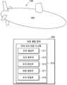
도 1은 본 발명의 일 실시예에 따른 관성항법장치의 자세 오차 보정 시스템을 개략적으로 도시한다.
도 2는 본 발명의 일 실시예에 따른 관성항법장치의 자세 오차 보정 방법을 실행하기 위한 컴퓨팅 장치의 개략적인 블록도이다.
도 3은 본 발명의 일 실시예에 따른 관성항법장치의 자세 오차 보정 방법을 설명하기 위한 순서도를 도시한다.
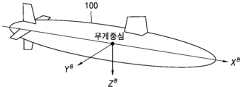
도 4는 본 발명의 일 실시예에 따른 관성항법장치의 구조를 개략적으로 도시한다.
도 5는 본 발명의 일 실시예에 따른 이동체의 동체 좌표계를 도시한다.
도 6은 본 발명의 일 실시예에 따른 관성항법장치의 자세 오차 보정 방법의 개념도를 개략적으로 도시한다.
도 7은 본 발명의 일 실시예에 따른 관성항법장치의 회전을 통한 자세 오차 보정 방법의 일 예를 도시한다.
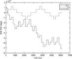
도 8a는 관성항법장치의 자세 오차를 보정하지 않은 결과의 일 예를 도시한다.
도 8b는 본 발명의 일 실시예에 따른 관성항법장치의 자세 오차 결과의 일 예를 도시한다.
도 9a는 본 발명의 일 실시예에 따른 관성항법장치의 척도계수 오차에 의한 자세 오차 결과의 일 예를 도시한다.
도 9b는 본 발명의 일 실시예에 따른 관성항법장치의 비정렬 오차에 의한 자세 오차 결과의 일 예를 도시한다.FIG. 1 schematically illustrates an attitude error compensation system of an inertial navigation device according to one embodiment of the present invention.
FIG. 2 is a schematic block diagram of a computing device for executing a method for correcting attitude errors of an inertial navigation device according to one embodiment of the present invention.
FIG. 3 illustrates a flowchart for explaining a method for correcting attitude errors of an inertial navigation device according to one embodiment of the present invention.
Figure 4 schematically illustrates the structure of an inertial navigation device according to one embodiment of the present invention.
FIG. 5 illustrates a body coordinate system of a mobile body according to one embodiment of the present invention.
FIG. 6 schematically illustrates a conceptual diagram of a method for correcting attitude errors of an inertial navigation device according to one embodiment of the present invention.
FIG. 7 illustrates an example of a method for correcting attitude error through rotation of an inertial navigation device according to one embodiment of the present invention.
Figure 8a shows an example of a result in which the attitude error of the inertial navigation device is not corrected.
FIG. 8b illustrates an example of attitude error results of an inertial navigation device according to one embodiment of the present invention.
FIG. 9a illustrates an example of a posture error result due to a scale factor error of an inertial navigation device according to one embodiment of the present invention.
FIG. 9b illustrates an example of a posture error result due to misalignment error of an inertial navigation device according to one embodiment of the present invention.
본 개시에서 사용되는 용어들은 단지 특정한 실시 예를 설명하기 위해 사용된 것으로, 다른 실시 예의 범위를 한정하려는 의도가 아닐 수 있다. 단수의 표현은 문맥상 명백하게 다르게 뜻하지 않는 한, 복수의 표현을 포함할 수 있다. 기술적이거나 과학적인 용어를 포함해서 여기서 사용되는 용어들은 본 개시에 기재된 기술 분야에서 통상의 지식을 가진 자에 의해 일반적으로 이해되는 것과 동일한 의미를 가질 수 있다. 본 개시에 사용된 용어들 중 일반적인 사전에 정의된 용어들은, 관련 기술의 문맥상 가지는 의미와 동일 또는 유사한 의미로 해석될 수 있으며, 본 개시에서 명백하게 정의되지 않는 한, 이상적이거나 과도하게 형식적인 의미로 해석되지 않는다. 경우에 따라서, 본 개시에서 정의된 용어일지라도 본 개시의 실시 예들을 배제하도록 해석될 수 없다.The terms used in this disclosure are only used to describe specific embodiments and may not be intended to limit the scope of other embodiments. The singular expression may include the plural expression unless the context clearly indicates otherwise. The terms used herein, including technical or scientific terms, may have the same meaning as commonly understood by a person having ordinary skill in the art described in this disclosure. Among the terms used in this disclosure, terms defined in general dictionaries may be interpreted as having the same or similar meaning as the meaning they have in the context of the related technology, and shall not be interpreted in an ideal or excessively formal meaning unless explicitly defined in this disclosure. In some cases, even if a term is defined in this disclosure, it cannot be interpreted to exclude embodiments of the present disclosure.
이하에서 설명되는 본 개시의 다양한 실시 예들에서는 하드웨어적인 접근 방법을 예시로서 설명한다. 하지만, 본 개시의 다양한 실시 예들에서는 하드웨어와 소프트웨어를 모두 사용하는 기술을 포함하고 있으므로, 본 개시의 다양한 실시 예들이 소프트웨어 기반의 접근 방법을 제외하는 것은 아니다.In the various embodiments of the present disclosure described below, a hardware-based approach is described as an example. However, since the various embodiments of the present disclosure include techniques using both hardware and software, the various embodiments of the present disclosure do not exclude a software-based approach.
이하 본 개시는 이동체에 탑재된 관성항법장치의 자세 오차를 보정하기 위한 방법 및 시스템에 관한 것이다. 본 개시는 관성항법장치의 복수의 오차 요인을 산출하고, 상기 복수의 오차 요인에 따라 추가 회전 절차를 통해 관성항법장치의 자세 오차를 보정할 수 있는 기술을 설명한다.The present disclosure relates to a method and system for correcting attitude errors of an inertial navigation device mounted on a mobile body. The present disclosure describes a technique for calculating a plurality of error factors of an inertial navigation device and correcting attitude errors of the inertial navigation device through an additional rotation procedure according to the plurality of error factors.
아래에서는 첨부한 도면을 참조하여 본 개시가 속하는 기술 분야에서 통상의 지식을 가진 자가 용이하게 실시할 수 있도록 다양한 실시예들을 상세히 설명한다. 그러나 본 개시의 기술적 사상은 다양한 형태로 변형되어 구현될 수 있으므로 본 명세서에서 설명하는 실시예들로 제한되지 않는다. 본 명세서에 개시된 실시예들을 설명함에 있어서 관련된 공지 기술을 구체적으로 설명하는 것이 본 개시의 기술적 사상의 요지를 흐릴 수 있다고 판단되는 경우 그 공지 기술에 대한 구체적인 설명을 생략한다. 동일하거나 유사한 구성요소는 동일한 참조 번호를 부여하고 이에 대한 중복되는 설명은 생략하기로 한다.Hereinafter, various embodiments will be described in detail with reference to the attached drawings so that those skilled in the art can easily implement the present disclosure. However, the technical idea of the present disclosure can be modified and implemented in various forms and is therefore not limited to the embodiments described in this specification. In describing the embodiments disclosed in this specification, if it is determined that a specific description of a related known technology may obscure the gist of the technical idea of the present disclosure, a specific description of the known technology will be omitted. Identical or similar components will be given the same reference numerals and redundant descriptions thereof will be omitted.
본 명세서에서 어떤 요소가 다른 요소와 "연결"되어 있다고 기술될 때, 이는 "직접적으로 연결"되어 있는 경우뿐 아니라 그 중간에 다른 요소를 사이에 두고 "간접적으로 연결"되어 있는 경우도 포함한다. 어떤 요소가 다른 요소를 "포함"한다고 할 때, 이는 특별히 반대되는 기재가 없는 한 다른 요소 외에 또 다른 요소를 배제하는 것이 아니라 또 다른 요소를 더 포함할 수 있는 것을 의미한다.When an element is described as being "connected" to another element in this specification, this includes not only the case where it is "directly connected" but also the case where it is "indirectly connected" with another element in between. When an element is described as "comprising" another element, this does not exclude other elements in addition to the other elements, unless specifically stated to the contrary, but rather means that it can include other elements.
일부 실시예들은 기능적인 블록 구성들 및 다양한 처리 단계들로 설명될 수 있다. 이러한 기능 블록들의 일부 또는 전부는 특정 기능을 실행하는 다양한 개수의 하드웨어 및/또는 소프트웨어 구성들로 구현될 수 있다. 예를 들어, 본 개시의 기능 블록들은 하나 이상의 마이크로프로세서들에 의해 구현되거나, 소정의 기능을 위한 회로 구성들에 의해 구현될 수 있다. 본 개시의 기능 블록들은 다양한 프로그래밍 또는 스크립팅 언어로 구현될 수 있다. 본 개시의 기능 블록들은 하나 이상의 프로세서들에서 실행되는 알고리듬으로 구현될 수 있다. 본 개시의 기능 블록이 수행하는 기능은 복수의 기능 블록에 의해 수행되거나, 본 개시에서 복수의 기능 블록이 수행하는 기능들은 하나의 기능 블록에 의해 수행될 수도 있다. 또한, 본 개시는 전자적인 환경 설정, 신호 처리, 및/또는 데이터 처리 등을 위하여 종래 기술을 채용할 수 있다.Some embodiments may be described in terms of functional block configurations and various processing steps. Some or all of these functional blocks may be implemented by various numbers of hardware and/or software configurations that perform specific functions. For example, the functional blocks of the present disclosure may be implemented by one or more microprocessors, or by circuit configurations for a given function. The functional blocks of the present disclosure may be implemented in various programming or scripting languages. The functional blocks of the present disclosure may be implemented by an algorithm that is executed on one or more processors. The functions performed by the functional blocks of the present disclosure may be performed by a plurality of functional blocks, or the functions performed by the plurality of functional blocks in the present disclosure may be performed by one functional block. In addition, the present disclosure may employ conventional techniques for electronic environment setting, signal processing, and/or data processing.
또한, 본 개시에서, 특정 조건의 만족(satisfied), 충족(fulfilled) 여부를 판단하기 위해, 초과 또는 미만의 표현이 사용되었으나, 이는 일 예를 표현하기 위한 기재일 뿐 이상 또는 이하의 기재를 배제하는 것이 아니다. '이상'으로 기재된 조건은 '초과', '이하'로 기재된 조건은 '미만', '이상 및 미만'으로 기재된 조건은 '초과 및 이하'로 대체될 수 있다.In addition, in the present disclosure, the expressions "more than" and "less than" are used to determine whether a specific condition is satisfied or fulfilled, but this is only a description for expressing an example and does not exclude descriptions of more than or less than. A condition described as "more than" may be replaced with "more than," a condition described as "less than" may be replaced with "less than," and a condition described as "more than and less than" may be replaced with "more than and less than."
도 1은 본 발명의 일 실시예에 따른 관성항법장치의 자세 오차 보정 시스템을 개략적으로 도시한다.FIG. 1 schematically illustrates an attitude error compensation system of an inertial navigation device according to one embodiment of the present invention.
도 1을 참조하면, 이동체(100)에 탑재된 관성항법장치(INS: inertial navigation system, 200)의 자세 오차 보정 시스템(210)은 오차 생성부(211), 오차 획득부(213), 오차 판단부(215), 보정 결정부(217) 및 오차 보정부(219)를 포함한다.Referring to FIG. 1, the attitude error correction system (210) of an inertial navigation system (INS: 200) mounted on a moving object (100) includes an error generation unit (211), an error acquisition unit (213), an error judgment unit (215), a correction decision unit (217), and an error correction unit (219).
관성항법장치(200)는 외부의 도움 없이 관성측정장치(Inertial measurement unit, IMU)를 이용하여 이동체(100)의 각속도 및 가속도를 측정함으로써 이동체(100)의 위치, 속도 및 자세를 계산하는 항법 장치이다. 관성항법장치(200)는 잠수함, 항공기, 선박, 및 미사일 등의 이동체(100)에 탑재될 수 있다. 관성항법장치(200)는 관성측정장치에 포함된 관성센서의 출력 값을 적분함으로써 이동체(100)의 위치, 속도, 및 자세와 같은 항법 정보를 산출하는 항법 알고리즘을 이용할 수 있고, 항법 정보를 기초로 항법을 수행할 수 있다. 예컨대, 관성항법장치(200)는 3개의 가속도계와 각속도계로 이루어진 관성측정장치를 Local-level frame(LLF)에 대해서 일정 자세를 유지하도록 하는 김블형 관성항법장치Gimbaled INS, GINS)일 수 있다. 관성항법장치(200)는 외부의 도움 없이 추측 항법(Dead reckoning navigation)이 가능하지만, 관성센서의 출력 값을 적분하는 과정에서 관성센서 오차가 누적되고, 관성센서 오차는 시간이 지남에 따라 관성항법장치(200)의 항법 성능을 저하시키는 주 요인으로 작용할 수 있다. 따라서, 관성항법장치(200)의 항법 성능을 향상시키기 위해서는 관성항법장치(200)의 자세 오차를 감소시키는 기술이 필요하다.An inertial navigation device (200) is a navigation device that calculates the position, speed, and attitude of a moving object (100) by measuring the angular velocity and acceleration of the moving object (100) using an inertial measurement unit (IMU) without external assistance. The inertial navigation device (200) can be mounted on a moving object (100) such as a submarine, an aircraft, a ship, and a missile. The inertial navigation device (200) can utilize a navigation algorithm that calculates navigation information such as the position, speed, and attitude of the moving object (100) by integrating the output values of the inertial sensors included in the inertial measurement device, and can perform navigation based on the navigation information. For example, the inertial navigation device (200) can be a gimbaled INS (GINS) that allows an inertial measurement device composed of three accelerometers and a gyrometer to maintain a constant attitude with respect to a local-level frame (LLF). The inertial navigation device (200) is capable of dead reckoning navigation without external assistance, but in the process of integrating the output values of the inertial sensors, inertial sensor errors accumulate, and the inertial sensor errors can act as a major factor in lowering the navigation performance of the inertial navigation device (200) over time. Therefore, in order to improve the navigation performance of the inertial navigation device (200), a technology for reducing the attitude error of the inertial navigation device (200) is required.
이하, 본 발명에 따른 관성항법장치(200)는 관성센서조립체를 일정한 절차로 회전시켜 관성센서 오차를 상쇄시킴로써 항법 성능을 개선시킬 수 있는 회전형 관성항법장치(Rotational Inertial Navigation System, RINS)인 것으로 가정하고 기술한다. 회전형 관성항법장치는 관성항법장치(200)의 축 별로 발생하는 관성센서 오차를 상쇄할 수 있는 회전 절차를 설계하여 운용될 수 있다. 예컨대, 회전형 관성항법장치에 포함된 축의 개수는 단일축, 2축, 및 3축 중 적어도 하나일 수 있다. 회전형 관성항법장치는 각 축 별 다양한 회전 순서를 이용하여 관성센서의 바이어스(bias) 오차, 척도계수(scale factor) 오차, 및 비정렬(misalignment) 오차를 상쇄시킬 수 있다. 본 발명의 자세 오차 보정 시스템(210)에서 관성항법장치(200)는 2축으로 구성되고, 2축은 롤(roll) 축 및 요(yaw) 축으로 구성되는 것으로 가정하고 기술한다.Hereinafter, the inertial navigation device (200) according to the present invention is described assuming that it is a rotational inertial navigation system (RINS) that can improve navigation performance by rotating an inertial sensor assembly in a certain procedure to offset inertial sensor errors. The rotational inertial navigation device can be operated by designing a rotation procedure that can offset inertial sensor errors occurring for each axis of the inertial navigation device (200). For example, the number of axes included in the rotational inertial navigation device can be at least one of a single axis, two axes, and three axes. The rotational inertial navigation device can offset bias errors, scale factor errors, and misalignment errors of the inertial sensors by using various rotation sequences for each axis. In the attitude error correction system (210) of the present invention, it is assumed and described that the inertial navigation device (200) is composed of two axes, and the two axes are composed of a roll axis and a yaw axis.
이하, 본 발명에 따른 유동적 회전 절차인 보정 회전이 필요한 환경에 대해 기술한다. 일 예에 따라, 관성항법장치(200)에 자세 안정화 시스템이 없는 경우, 이동체(100)가 계속 이동함에 따라 회전형 관성항법장치의 회전과 상관없는 오차가 계속 누적되므로 기존 고정된 회전 절차로 오차를 상쇄시킬 수 없다. 다른 예에 따라, 관성항법장치(200)의 외축이 롤(Roll) 축이고 내축이 요(Yaw) 축인 경우일 수 있다. 관성항법장치(200)의 외축이 롤 축인 경우, 안정화 시스템이 있더라도 구조적인 문제로 항체와 외축이 고정되어 있어 롤 축 기준으로 회전을 하기 위해서는 이동체(100)의 자세에 영향을 받게 된다. 따라서, 이동체(100)가 이동함에 따라 오차가 누적되고 상기 오차는 고정된 회전 절차로 상쇄될 수 없다. 상기 기술한 환경에서는 고정된 회전 절차인 기본 회전 시퀀스에 추가로 본 발명에 따른 보정 회전을 수행하여 관성항법장치(200)의 자세 오차를 보정하는 시스템이 필요할 수 있다.Hereinafter, an environment requiring a compensation rotation, which is a fluid rotation procedure according to the present invention, will be described. For example, if there is no attitude stabilization system in the inertial navigation device (200), errors unrelated to the rotation of the rotational inertial navigation device continue to accumulate as the mobile body (100) continues to move, and thus the errors cannot be offset by the existing fixed rotation procedure. For another example, the outer axis of the inertial navigation device (200) may be the roll axis and the inner axis may be the yaw axis. If the outer axis of the inertial navigation device (200) is the roll axis, even if there is a stabilization system, since the inner and outer axes are fixed due to structural problems, the attitude of the mobile body (100) is affected in order to rotate based on the roll axis. Therefore, errors accumulate as the mobile body (100) moves, and the errors cannot be offset by the fixed rotation procedure. In the environment described above, a system may be required to correct the attitude error of the inertial navigation device (200) by performing a correction rotation according to the present invention in addition to the basic rotation sequence, which is a fixed rotation procedure.
오차 생성부(211)는 이동체(100)에 탑재된 관성항법장치(200)를 복수의 기본 회전을 포함하는 기본 회전 시퀀스에 따라 회전시킬 수 있다. 본 발명에 따르면, 관성항법장치(200)의 자세 오차를 발생시키는 오차 요인 중 적어도 하나를 기초로, 관성항법장치(200)의 자세 오차를 발생시키는 기본 회전 시퀀스를 미리 설정할 수 있다. 본 발명은 상기 오차 요인 별로 오차 방향 및 오차 값을 획득하고, 오차 방향 및 오차 값에 따라 결정되는 보정 회전을 통해 관성항법장치(200)의 자세 오차를 감소시키는 것을 특징으로 한다. 따라서, 오차 생성부(211)는 특정 오차 요인에 따른 자세 오차를 발생시키는 기본 회전 시퀀스를 미리 설정하고, 상기 기본 회전 시퀀스에 따라 관성항법장치(200)를 회전시킬 수 있다. 기본 회전 시퀀스는 관성항법장치(200)의 위치를 원점으로 갖는 ENU 좌표계 상의 E축, N축, 및 U축 중 적어도 하나 이상을 기초로 결정되는 축을 기준으로 회전할 수 있다. 예컨대, ENU 좌표계 상의 E축은 관성항법장치(200)의 피치 축, N축은 관성항법장치(200)의 롤 축, U축은 관성항법장치(200)의 요 축에 대응될 수 있다. 다만 이는 예시적인 것이며, ENU 좌표계의 축과 대응하는 관성항법장치(200)의 축의 종류가 본 발명을 제한하지 않는다.The error generation unit (211) can rotate the inertial navigation device (200) mounted on the mobile body (100) according to a basic rotation sequence including a plurality of basic rotations. According to the present invention, the basic rotation sequence that generates the attitude error of the inertial navigation device (200) can be preset based on at least one of the error factors that generate the attitude error of the inertial navigation device (200). The present invention is characterized in that the error direction and error value are acquired for each of the error factors, and the attitude error of the inertial navigation device (200) is reduced through a correction rotation determined according to the error direction and error value. Therefore, the error generation unit (211) can preset a basic rotation sequence that generates an attitude error according to a specific error factor, and rotate the inertial navigation device (200) according to the basic rotation sequence. The basic rotation sequence may rotate based on an axis determined based on at least one of the E-axis, the N-axis, and the U-axis on the ENU coordinate system having the position of the inertial navigation device (200) as the origin. For example, the E-axis on the ENU coordinate system may correspond to the pitch axis of the inertial navigation device (200), the N-axis may correspond to the roll axis of the inertial navigation device (200), and the U-axis may correspond to the yaw axis of the inertial navigation device (200). However, this is exemplary, and the types of axes of the inertial navigation device (200) corresponding to the axes of the ENU coordinate system do not limit the present invention.
관성항법장치(200)가 회전함에 따라 척도계수 오차 및 비정렬 오차가 발생할 수 있다. 다만, 특정 회전 이후에는 척도계수 오차 및 비정렬 오차 중 하나의 오차만 발생시키고, 다른 하나의 오차는 회전에 의해 상쇄시킬 수 있다. 이하 특정 회전 수행 이후, 척도계수 오차 및 비정렬 오차 중 하나의 오차만을 발생시키는 기본 회전 시퀀스에 대해 기술한다. 일 예에 따르면, 기본 회전 시퀀스가 척도계수 오차에 의한 관성항법장치(200)의 자세 오차를 발생시키는 회전 시퀀스인 경우, 기본 회전 시퀀스에 포함된 복수의 기본 회전은 관성항법장치(200)를 한 방향으로 360도 회전시키는 것을 특징으로 할 수 있다. 관성항법장치(200)를 한 방향으로 360도 회전시키는 기본 회전 시퀀스에 따르면, 비정렬 오차는 회전 중 발생하였다가 360도 회전 후에는 오차 값이 0으로 수렴할 수 있다. 이 경우, 관성항법장치(200)의 자세 오차의 요인이 되는 오차는 척도계수 오차일 수 있다.As the inertial navigation device (200) rotates, a scale factor error and a misalignment error may occur. However, after a specific rotation, only one of the scale factor error and the misalignment error may occur, and the other error may be offset by the rotation. Hereinafter, a basic rotation sequence that generates only one of the scale factor error and the misalignment error after a specific rotation is performed will be described. According to an example, when the basic rotation sequence is a rotation sequence that generates a posture error of the inertial navigation device (200) due to the scale factor error, a plurality of basic rotations included in the basic rotation sequence may be characterized by rotating the inertial navigation device (200) 360 degrees in one direction. According to the basic rotation sequence that rotates the inertial navigation device (200) 360 degrees in one direction, a misalignment error may occur during the rotation, and the error value may converge to 0 after the 360-degree rotation. In this case, the error causing the attitude error of the inertial navigation device (200) may be a scale factor error.
다른 예에 따르면, 기본 회전 시퀀스가 비정렬 오차에 의한 관성항법장치(200)의 자세 오차를 발생시키는 회전 시퀀스인 경우, 기본 회전 시퀀스에 포함된 복수의 기본 회전 각각은 한 방향이 아닌 특정 방향으로 180도씩 회전하는 것을 특징으로 할 수 있다. 예컨대, 관성항법장치(200)를 특정 방향으로 180도씩 4회전시키는 기본 회전 시퀀스에 따르면, 척도계수 오차는 회전 중 발생하였다가 180도씩 4회전 후에는 오차 값이 0으로 수렴할 수 있다. 이 경우, 관성항법장치(200)의 자세 오차의 요인이 되는 오차는 비정렬 오차일 수 있다. 관성항법장치(200)의 자세 오차를 유발하는 기본 회전 시퀀스의 예시에 대해서는 도 6에서 더 자세히 기술한다.In another example, if the basic rotation sequence is a rotation sequence that causes an attitude error of the inertial navigation device (200) due to misalignment error, each of the plurality of basic rotations included in the basic rotation sequence may be characterized by rotating 180 degrees in a specific direction rather than in one direction. For example, according to the basic rotation sequence that rotates the inertial navigation device (200) 4 times by 180 degrees in a specific direction, the scale factor error may occur during the rotation and the error value may converge to 0 after 4 rotations by 180 degrees. In this case, the error that causes the attitude error of the inertial navigation device (200) may be a misalignment error. An example of a basic rotation sequence that causes an attitude error of the inertial navigation device (200) is described in more detail in FIG. 6.
오차 획득부(213)는 관성항법 장치로부터 오차 값 및 오차 방향을 포함하는 자세 오차를 획득할 수 있다. 자세 오차는 관성항법 장치에 탑재된 관성센서의 오차이고, 각속도계 오차 및 가속도계 오차 중 적어도 하나일 수 있다. 오차 획득부(213)는 오차 방향 산출부 및 오차 값 산출부를 포함할 수 있다.The error acquisition unit (213) can acquire attitude error including an error value and an error direction from an inertial navigation device. The attitude error is an error of an inertial sensor mounted on the inertial navigation device, and may be at least one of an angular velocity error and an accelerometer error. The error acquisition unit (213) may include an error direction calculation unit and an error value calculation unit.
오차 방향 산출부는 관성항법 장치에 탑재된 엔코더(encoder) 및 관성 센서를 이용하여 관성항법 장치의 자세를 계산하고, 관성항법 장치의 자세에서 롤(roll) 축이 진북 방향을 기준으로 틀어진 각도를 기초로 오차 방향을 계산할 수 있다. 엔코더는 회전 운동이나 직선운동을 하는 기계 장치의 위치와 속도의 정보를 전기적인 신호로 출력하는 센서로, 기계 장치의 위치, 각도, 속도 등을 측정하거나 모터의 회전속도, 회전량을 제어하기 위해 이용될 수 있다. 관성 센서는 이동관성을 측정할 수 있는 가속도계(accelerometer)와 회전관성을 측정할 수 있는 각속도계(gyroscope)를 포함할 수 있다. 오차 획득부(213)는 가속도계 및 각속도계를 이용하여 관성센서 측정치에 내재되어 있는 오차 데이터를 획득할 수 있다. 오차 획득부(213)는 항법 좌표계 상에서 관성항법장치(200)의 각속도계의 오차가 포함된 각속도 측정치를 제공하는 각속도계 및 항법 좌표계 상에서 관성항법장치(200)의 가속도계의 오차가 포함된 가속도 측정치를 제공하는 가속도계를 포함할 수 있다.The error direction calculation unit calculates the attitude of the inertial navigation device using an encoder and an inertial sensor mounted on the inertial navigation device, and can calculate the error direction based on the angle at which the roll axis is deviated from the true north direction in the attitude of the inertial navigation device. An encoder is a sensor that outputs information on the position and speed of a mechanical device that performs rotational or linear motion as an electrical signal, and can be used to measure the position, angle, speed, etc. of the mechanical device or to control the rotational speed and rotational amount of a motor. The inertial sensor may include an accelerometer that can measure movement inertia and a gyroscope that can measure rotational inertia. The error acquisition unit (213) can acquire error data inherent in the inertial sensor measurement value using the accelerometer and the gyroscope. The error acquisition unit (213) may include an angular velocity meter that provides an angular velocity measurement value that includes an error of the angular velocity meter of the inertial navigation device (200) on the navigation coordinate system and an accelerometer that provides an acceleration measurement value that includes an error of the accelerometer of the inertial navigation device (200) on the navigation coordinate system.
오차 값 산출부는 자세 오차에 포함되는 복수의 오차 요인을 기초로 오차 값을 산출할 수 있다. 복수의 오차 요인은 바이어스(bias) 오차, 척도계수(scale factor) 오차, 및 비정렬(misalignment) 오차를 포함할 수 있다. 오차 값은 이동체(100)의 동체 좌표계와 관성항법 장치의 항법 좌표계 간 좌표 변환 행렬, 방향코사인행렬(Direction Cosine Matrix), 및 복수의 오차 요인 각각의 자세 오차 벡터를 기초로 산출될 수 있다.The error value calculation unit can calculate the error value based on a plurality of error factors included in the attitude error. The plurality of error factors can include a bias error, a scale factor error, and a misalignment error. The error value can be calculated based on a coordinate transformation matrix between the body coordinate system of the moving body (100) and the navigation coordinate system of the inertial navigation device, a direction cosine matrix, and an attitude error vector of each of the plurality of error factors.
자세 오차는 관성항법 장치에 탑재된 관성센서의 오차이고, 각속도계 오차 및 가속도계 오차 중 적어도 하나일 수 있다. 일 예에 따라, 자세 오차가 각속도계 오차인 경우, 각속도계 오차 모델(δωbib)은 수학식 (1)와 같이 정의될 수 있다.The attitude error is an error of an inertial sensor mounted on an inertial navigation device, and may be at least one of an angular velocity error and an accelerometer error. For example, when the attitude error is an angular velocity error, the angular velocity error model (δωbib ) may be defined as in mathematical equation (1).
수학식 (1)Mathematical formula (1)
다른 예에 따라, 자세 오차가 가속도계 오차인 경우, 가속도계 오차 모델(δfb)은 수학식 (2)와 같이 정의될 수 있다.As another example, when the attitude error is an accelerometer error, the accelerometer error model (δfb ) can be defined as in mathematical expression (2).
수학식 (2)Mathematical formula (2)
여기서, Ba, Ka, Aa, ga는 각각 바이어스 오차, 척도계수 오차, 비정렬 오차, 백색 잡음을 나타낼 수 있다. 바이어스 오차(Ba), 척도계수 오차(Ka), 비정렬 오차(Aa)는 각각 아래 수학식(3) 내지 (5) 같은 행렬 모델로 표현할 수 있다.Here, Ba , Ka , Aa , and ga can represent bias error, scale factor error, misalignment error, and white noise, respectively. The bias error (Ba ), scale factor error (Ka ), and misalignment error (Aa ) can be expressed as matrix models such as the following mathematical equations (3) to (5), respectively.
수학식 (3)Mathematical formula (3)
수학식 (4)Mathematical formula (4)
수학식 (5)Mathematical formula (5)
아래에서는 자세 오차가 각속도계 오차인 경우로 기술한다. 회전형 관성항법장치의 자세 오차에 가장 큰 영향을 주는 요소는 척도계수 오차(Ka) 및 비정렬 오차(Aa)일 수 있다. 본 발명에서는 복수의 오차 요인 중 척도계수 오차(Ka) 및 비정렬 오차(Aa)을 고려하여 관성항법장치(200)의 자세 오차를 보정하는 시스템인 것으로 가정하고 기술한다.Below, the attitude error is described as a case where the attitude error is an angular velocity error. The factors that have the greatest influence on the attitude error of a rotary inertial navigation device may be the scale factor error (Ka ) and the misalignment error (Aa ). In the present invention, it is assumed and described that the system compensates for the attitude error of an inertial navigation device (200) by considering the scale factor error (Ka ) and the misalignment error (Aa ) among multiple error factors.
오차 값 산출부는 플랫폼 좌표계를 동체 좌표계로 변환하는 좌표 변환 행렬(Cbp), 동체 좌표계를 항법 좌표계로 변환하는 좌표 변환 행렬(Cnb), 및 자세 오차 벡터의 곱을 적분함으로써 복수의 오차 요인 별 자세 오차 값을 산출할 수 있다. 여기서 Cnb은 동체 좌표계(b-frame)와 항법 좌표계(n-frame) 사이의 좌표변환 행렬로 관성항법장치(200)의 자세 오차 보정 후 자세 오차가 없다고 가정하면 Cnb는 단위 행렬일 수 있다. 자세 오차 값이 미리 설정된 임계값을 초과하는 경우, 보정 회전을 통해 관성항법장치(200)의 자세 오차를 감소시키는 보정을 수행할 수 있다. 예컨대, 플랫폼 좌표계를 동체 좌표계로 변환하는 좌표 변환 행렬(Cbp)은 방향코사인행렬(Direct Cosine Matrix, DCM)로 나타낼 수 있다. 방향 코사인 행렬은 회전 행렬(Rotation matrix)이라고도 하며, 두 좌표계 간의 상대적인 회전을 기술하는 행렬이다. 예컨대, 방향 코사인 행렬의 각 요소들은 각도를 포함하는 삼각함수(예컨대, sin(.), cos(.) 등)로 표현될 수 있다.The error value calculation unit can calculate attitude error values for multiple error factors by integrating the product of a coordinate transformation matrix (Cbp ) that transforms the platform coordinate system into a body coordinate system, a coordinate transformation matrix (Cnb ) that transforms the body coordinate system into a navigation coordinate system, and an attitude error vector. Here, Cnb is a coordinate transformation matrix between the body coordinate system (b-frame) and the navigation coordinate system (n-frame), and assuming that there is no attitude error after the attitude error correction of the inertial navigation device (200), Cnb may be a unit matrix. When the attitude error value exceeds a preset threshold value, a correction may be performed to reduce the attitude error of the inertial navigation device (200) through a correction rotation. For example, the coordinate transformation matrix (Cbp ) that transforms the platform coordinate system into the body coordinate system may be expressed as a direct cosine matrix (DCM). The direction cosine matrix is also called a rotation matrix and is a matrix that describes the relative rotation between two coordinate systems. For example, each element of the direction cosine matrix can be expressed as a trigonometric function involving an angle (e.g., sin(.), cos(.), etc.).
복수의 오차 요인 각각의 자세 오차 벡터는 x축, y축, 및 z축으로 구성된 좌표계에서 관성항법장치(200)의 기준 자세 대비 현재 상대적인 자세의위치에 따른 각속도 벡터에 오차 요인 별 행렬을 더하거나 곱해줌으로써 산출될 수 있다. 복수의 오차 요인 중 바이어스 오차(Ba)만 존재하는 경우, 바이어스 오차(Ba)에 따른 자세 오차 벡터는 수학식 (3)에 따른 벡터에 관성항법장치(200)의 각속도 벡터를 더함으로써 산출될 수 있다. 예컨대, 각속도 벡터는 자이로 센서에서 출력되는 센서 출력 값일 수 있다. 각속도 벡터는 각 증분 값으로 관성항법장치가 일정 각속도로 회전하였을 때, 회전 후 위치에서 자이로 센서에 의해 측정되는 각속도를 나타낼 수 있다. 일 예에 따라, 복수의 오차 요인 중 척도계수 오차(Ka)만 존재하는 경우, 척도계수 오차(Ka)에 따른 자세 오차 벡터는 수학식 (4)에 따른 행렬에 관성항법장치(200)의 각속도 벡터를 곱함으로써 산출될 수 있다. 다른 예에 따라, 복수의 오차 요인 중 비정렬 오차(Aa)만 존재하는 경우, 비정렬 오차(Aa)에 따른 자세 오차 벡터는 수학식 (5)에 따른 행렬에 관성항법장치(200)의 각속도 벡터를 곱함으로써 산출될 수 있다. 이를 통해, 복수의 오차 요인 별 자세 오차로부터 오차 값을 산출함으로써, 항법 좌표계(n-frame) 상에서의 오차 값을 획득할 수 있다.The attitude error vector of each of the plurality of error factors can be calculated by adding or multiplying a matrix for each error factor to an angular velocity vector according to the current relative attitude position with respect to the reference attitude of the inertial navigation device (200) in a coordinate system composed of the x-axis, the y-axis, and the z-axis. When only the bias error (Ba ) exists among the plurality of error factors, the attitude error vector according to the bias error (Ba ) can be calculated by adding the angular velocity vector of the inertial navigation device (200) to the vector according to mathematical expression (3). For example, the angular velocity vector may be a sensor output value output from a gyro sensor. The angular velocity vector may represent the angular velocity measured by the gyro sensor at the position after the rotation when the inertial navigation device rotates at a constant angular velocity by each incremental value. For example, when only the scale coefficient error (Ka ) exists among the plurality of error factors, the attitude error vector due to the scale coefficient error (Ka ) can be calculated by multiplying the matrix according to mathematical expression (4) by the angular velocity vector of the inertial navigation device (200). For another example, when only the misalignment error (Aa ) exists among the plurality of error factors, the attitude error vector due to the misalignment error (Aa ) can be calculated by multiplying the matrix according to mathematical expression (5) by the angular velocity vector of the inertial navigation device (200). In this way, by calculating the error value from the attitude error for each of the plurality of error factors, the error value on the navigation coordinate system (n-frame) can be obtained.
일 예에 따르면, 오차 판단부(215)는 자세 오차를 기초로 미리 설정된 회전 조건을 만족하는지 판단할 수 있다. 회전 조건은 관성항법 장치의 자세에 따라 결정되는 오차 방향 및 오차 값이 미리 설정된 임계값을 초과하는지 여부를 기초로 미리 설정될 수 있다. 오차 판단부(215)는 복수의 오차 요인 중 척도계수 오차(Scale-factor) 및 비정렬(misalignment) 오차에 대응하는 오차 값이 미리 설정된 임계값을 초과하는지 판단할 수 있다.According to one example, the error determination unit (215) can determine whether a preset rotation condition is satisfied based on the attitude error. The rotation condition can be preset based on whether the error direction and error value determined according to the attitude of the inertial navigation device exceed a preset threshold value. The error determination unit (215) can determine whether an error value corresponding to a scale factor error and a misalignment error among a plurality of error factors exceeds a preset threshold value.
일 예에 따르면, 오차 판단부(215)는 복수의 오차 요인 중 척도계수 오차를 나타내는 복수의 제1 오차 요소 및 복수의 제1 오차 요소 각각에 대해 설정된 복수의 제1 임계값을 기초로 척도계수 오차를 판단할 수 있다. 복수의 제1 오차 요소는 롤축 오차 요소 및 요축 오차 요소를 포함할 수 있다. 예컨대, 제1 오차 요소가 롤축 오차 요소인 경우 보정 회전축은 롤축이고, 제1 오차 요소가 요축 오차 요소인 경우 보정 회전축은 요축일 수 있다.According to one example, the error determination unit (215) may determine the scale factor error based on a plurality of first error elements representing the scale factor error among a plurality of error factors and a plurality of first threshold values set for each of the plurality of first error elements. The plurality of first error elements may include a roll axis error element and a yaw axis error element. For example, when the first error element is a roll axis error element, the correction rotation axis may be the roll axis, and when the first error element is a yaw axis error element, the correction rotation axis may be the yaw axis.
일 예에 따라 오차 생성부(211)에서 척도계수 오차를 발생시키는 기본 회전 시퀀스에 따라 관성항법장치(200)를 회전시킨 경우, 오차 판단부(215)는 척도계수 오차를 판단할 수 있다. 예컨대, 관성항법장치(200)를 한 방향으로 360도 회전시킨 기본 회전 시퀀스에 따라, 수학식 (4)와 같이 대각 행렬에 대한 성분의 오차가 발생할 수 있다. 이 경우, 비정렬 오차는 기본 회전 시퀀스 수행 중 발생하였다가 0으로 수렴할 수 있다.For example, when the inertial navigation device (200) is rotated according to a basic rotation sequence that generates a scale factor error in the error generating unit (211), the error determining unit (215) can determine the scale factor error. For example, according to a basic rotation sequence that rotates the inertial navigation device (200) 360 degrees in one direction, an error in the component of the diagonal matrix may occur as in mathematical expression (4). In this case, the misalignment error may occur during the execution of the basic rotation sequence and then converge to 0.
척도계수 오차 모델을 나타내는 수학식 (4)를 참고하면, 복수의 제1 오차 요소는 K11, K22, 및 K33 일 수 있다. 예컨대, K11은 피치 축 오차 요소, K22는 롤 축 오차 요소, K33는 요 축 오차 요소를 나타낼 수 있다. 다만, 본 제안 발명에서는 롤 축 및 요 축으로 구성된 관성항법장치(200)인 것으로 가정하였으므로, 복수의 제1 오차 요소는 롤 축을 나타내는 K22와 요 축을 나타내는 K33 일 수 있다. 따라서, K22는 관성항법장치(200)의 롤 축이 발생시키는 척도계수 오차를 나타낼 수 있다. K33는 관성항법장치(200)의 요 축이 발생시키는 척도계수 오차를 나타낼 수 있다. 다만, 이는 예시적이며 수학식 (4)의 행렬 내 각각의 요소가 나타내는 축의 종류가 본 발명을 제한하지 않는다. 복수의 제1 오차 요소는 관성항법장치(200)의 관성센서를 통해 획득할 수 있다. 예컨대, 복수의 제1 오차 요소는 관성항법장치(200)의 관성센서 개발 시 교정 절차를 후 획득되는 관성센서의 규격 값일 수 있다.Referring to mathematical expression (4) representing a scale factor error model, the plurality of first error elements may be K11 , K22 , and K33 . For example, K11 may represent a pitch axis error element, K22 may represent a roll axis error element, and K33 may represent a yaw axis error element. However, since the present proposed invention assumes that the inertial navigation device (200) is composed of a roll axis and a yaw axis, the plurality of first error elements may be K22 representing the roll axis and K33 representing the yaw axis. Accordingly, K22 may represent a scale factor error generated by the roll axis of the inertial navigation device (200). K33 may represent a scale factor error generated by the yaw axis of the inertial navigation device (200). However, this is exemplary, and the type of axis represented by each element in the matrix of mathematical expression (4) does not limit the present invention. A plurality of first error elements can be acquired through the inertial sensor of the inertial navigation device (200). For example, the plurality of first error elements can be standard values of the inertial sensor acquired after a calibration procedure is performed during the development of the inertial sensor of the inertial navigation device (200).
오차 판단부(215)는 복수의 제1 오차 요소 중 제1 오차 요소가 복수의 제1 임계값 중 제1 오차 요소에 대해 설정된 제1 임계값을 초과하는지에 따라 척도계수 오차를 판단할 수 있다. 제1 임계값은 제1 오차 요소 각각에 대해 미리 설정된 값일 수 있다. 예컨대, 오차 판단부(215)는 척도계수 오차 판단시, 오차 값이 복수의 제1 오차 요소 중 롤 축을 나타내는 K22에 대응하는 값이고 오차 값이 K22에 대해 설정된 제1 임계값을 초과하는 것으로 판단할 수 있다. 이는, 관성항법장치(200)의 롤 축 오차에 의해 척도계수 오차가 발생하는 것을 나타낼 수 있다.The error determination unit (215) can determine the scale factor error based on whether the first error element among the plurality of first error elements exceeds the first threshold value set for the first error element among the plurality of first threshold values. The first threshold value may be a value set in advance for each of the first error elements. For example, when determining the scale factor error, the error determination unit (215) can determine that the error value is a value corresponding to K22 representing the roll axis among the plurality of first error elements and that the error value exceeds the first threshold value set for K22. This may indicate that the scale factor error occurs due to the roll axis error of the inertial navigation device (200).
보정 결정부(217)는 회전 조건의 만족 여부를 기초로 복수의 기본 회전에 따라 보정 회전축을 결정할 수 있다. 보정 결정부(217)는 회전 조건의 만족 여부에 따라 오차 값을 기초로 보정 회전각을 결정할 수 있다. 보정 결정부(217)는 복수의 기본 회전 각각의 방향의 반대 방향을 보정 방향으로 결정할 수 있다. 보정 방향은 기본 회전 시퀀스에 포함된 복수의 기본 회전 각각의 방향의 반대 방향들의 집합일 수 있다. 보정 회전축은 롤 축, 피치 축 및 요 축 중 적어도 하나의 축일 수 있다. 보정 회전각은 180도 및 360도 중 적어도 하나의 각도일 수 있다.The correction decision unit (217) can determine a correction rotation axis according to a plurality of basic rotations based on whether a rotation condition is satisfied. The correction decision unit (217) can determine a correction rotation angle based on an error value according to whether a rotation condition is satisfied. The correction decision unit (217) can determine a direction opposite to each of the directions of the plurality of basic rotations as a correction direction. The correction direction can be a set of directions opposite to each of the directions of the plurality of basic rotations included in the basic rotation sequence. The correction rotation axis can be at least one of the roll axis, the pitch axis, and the yaw axis. The correction rotation angle can be at least one of 180 degrees and 360 degrees.
오차 판단부(215)에서 척도계수 오차 판단시, 오차 값이 제1 오차 요소에 대응하는 값이고 오차 값이 제1 오차 요소에 대해 설정된 제1 임계값을 초과하는 것으로 판단한 경우, 보정 결정부(217)는 보정 회전각은 360도이고 보정 회전축은 제1 오차 요소를 기초로 결정할 수 있다. 오차 판단부(215)에서 예컨대, 오차 값이 복수의 제1 오차 요소 중 롤 축을 나타내는 K22에 대응하는 값이고 오차 값이 K22에 대해 설정된 제1 임계값을 초과하는 것으로 판단한 경우, 보정 결정부(217)는 보정 회전각은 360도이고 보정 회전축은 롤 축, 보정 방향은 기본 회전 시퀀스에 포함된 방향의 역방향으로 결정할 수 있다.When the error judgment unit (215) determines the scale coefficient error, if it is determined that the error value is a value corresponding to the first error element and the error value exceeds the first threshold value set for the first error element, the correction decision unit (217) can determine the correction rotation angle as 360 degrees and the correction rotation axis based on the first error element. If the error judgment unit (215) determines, for example, that the error value is a value corresponding to K22 representing the roll axis among the plurality of first error elements and the error value exceeds the first threshold value set for K22 , the correction decision unit (217) can determine the correction rotation angle as 360 degrees, the correction rotation axis as the roll axis, and the correction direction as the reverse direction of the direction included in the basic rotation sequence.
오차 보정부(219)는 보정 회전축을 기준으로 보정 회전각만큼 회전하는 보정 회전에 따라 관성항법 장치를 회전시켜 자세 오차를 감소시킬 수 있다. 보정 회전은 보정 회전축을 기준으로 복수의 기본 회전 각각의 방향인 보정 방향에 따라 보정 회전각만큼 회전시키는 것을 특징으로 할 수 있다.The error correction unit (219) can reduce attitude errors by rotating the inertial navigation device according to a correction rotation that rotates by a correction rotation angle based on a correction rotation axis. The correction rotation can be characterized by rotating by a correction rotation angle according to a correction direction, which is the direction of each of a plurality of basic rotations based on the correction rotation axis.
일 예에 따라, 척도계수 오차를 발생시키는 기본 회전 시퀀스에 따라 보정 결정부(217)에서 보정 방향, 보정 회전축, 및 보정 회전각을 결정한 경우, 오차 보정부(219)는 기본 회전 시퀀스에 포함된 360도 회전 방향의 반대 방향을 보정 방향으로 결정할 수 있다. 오차 값이 복수의 제1 오차 요소 중 롤 축을 나타내는 K22에 대응하는 값이고 오차 값이 K22에 대해 설정된 제1 임계값을 초과하는 것으로 판단된 경우, 오차 보정부(219)는 관성항법장치(200)를 롤 축을 기준으로 하여 보정 방향으로 360도 회전시킴으로써 척도계수 오차를 감소시킬 수 있다. 상기 기술한 예에서 오차 값이 복수의 제1 오차 요소 중 요 축을 나타내는 K33에 대응하는 값인 경우, 자세 오차 보정 시스템(210)은 관성항법장치(200)의 요 축 자세 오차를 감소시키기 위해 동작할 수 있다.For example, if the correction decision unit (217) determines the correction direction, the correction rotation axis, and the correction rotation angle according to the basic rotation sequence that generates the scale factor error, the error correction unit (219) can determine the opposite direction of the 360-degree rotation direction included in the basic rotation sequence as the correction direction. If it is determined that the error value is a value corresponding to K22 representing the roll axis among the plurality of first error elements and the error value exceeds the first threshold value set for K22 , the error correction unit (219) can reduce the scale factor error by rotating the inertial navigation device (200) 360 degrees in the correction direction based on the roll axis. In the example described above, if the error value is a value corresponding to K33 representing the yaw axis among the plurality of first error elements, the attitude error correction system (210) can operate to reduce the yaw axis attitude error of the inertial navigation device (200).
다른 예에 따르면, 오차 판단부(215)는 복수의 오차 요인 중 비정렬 오차를 나타내는 복수의 제2 오차 요소 및 복수의 제2 오차 요소 각각에 대해 설정된 복수의 제2 임계값을 기초로 비정렬 오차를 판단할 수 있다. 복수의 제2 오차 요소는 관성항법장치(200)의 관성센서를 통해 획득될 수 있다. 예컨대, 복수의 제2 오차 요소는 관성항법장치(200)의 관성센서 개발 시 교정 절차를 후 획득되는 관성센서의 규격 값일 수 있다.According to another example, the error determination unit (215) may determine the misalignment error based on a plurality of second error elements representing misalignment errors among a plurality of error factors and a plurality of second threshold values set for each of the plurality of second error elements. The plurality of second error elements may be acquired through the inertial sensor of the inertial navigation device (200). For example, the plurality of second error elements may be standard values of the inertial sensor acquired after a calibration procedure is performed during the development of the inertial sensor of the inertial navigation device (200).
일 예에 따라 오차 생성부(211)에서 비정렬 오차를 발생시키는 기본 회전 시퀀스에 따라 관성항법장치(200)를 회전시킨 경우, 오차 판단부(215)는 비정렬 오차를 판단할 수 있다. 예컨대, 관성항법장치(200)를 한 방향이 아닌 특정 방향으로 180도씩 회전시킨 기본 회전 시퀀스에 따라, 수학식 (5)와 같이 행렬의 대각 성분을 제외한 성분에 대한 오차가 발생할 수 있다. 이 경우, 척도계수 오차는 기본 회전 시퀀스 수행 중 발생하였다가 0으로 수렴할 수 있다.For example, if the inertial navigation device (200) is rotated according to a basic rotation sequence that generates a misalignment error in the error generating unit (211), the error determining unit (215) can determine the misalignment error. For example, according to a basic rotation sequence that rotates the inertial navigation device (200) 180 degrees in a specific direction rather than in one direction, an error for components other than the diagonal components of the matrix may occur as in mathematical expression (5). In this case, the scale coefficient error may occur during the execution of the basic rotation sequence and then converge to 0.
비정렬 오차 모델을 나타내는 수학식 (5)를 참고하면, 복수의 제2 오차 요소는 K12, K13, K21, K23, K31, K32 일 수 있다. 비정렬 오차를 나타내는 행렬(Aa)의 행 성분 및 열 성분은 순서대로 관성항법장치(200)의 피치 축, 롤 축, 및 요 축을 나타낼 수 있다. 복수의 제2 오차 요소 각각은 관성항법장치(200)의 롤 축, 피치 축, 및 요 축 간의 각도 차이를 나타낼 수 있다. 비정렬오차는 각 축 간에 틀어진 정도를 의미할 수 있다. . 다만, 본 제안 발명에서는 롤 축 및 요 축으로 구성된 관성항법장치(200)인 것으로 가정하였으므로, K23 및 K32 은 관성항법장치(200)의 롤 축 및 요 축 간의 각도 차이를 나타내는 제2 오차 요소일 수 있다. 예컨대, K23은 롤 축 기준으로 요 축이 틀어진 각도를 나타낼 수 있다. K32는 요 축 기준으로 롤 축이 틀어진 각도를 나타낼 수 있다. 따라서, K23 및 K32 은 관성항법장치(200)의 롤 축 및 요 축 간의 각도 차이의 오차에 따라 발생되는 비정렬 오차를 나타낼 수 있다. 다만, 이는 예시적이며 수학식 (5)의 행렬 내 각각의 요소가 나타내는 축의 종류가 본 발명을 제한하지 않는다.Referring to mathematical expression (5) representing a misalignment error model, a plurality of second error elements may be K12 , K13 , K21 , K23 , K31 , and K32 . The row and column elements of the matrix (Aa ) representing the misalignment error may represent the pitch axis, the roll axis, and the yaw axis of the inertial navigation device (200) in that order. Each of the plurality of second error elements may represent the angular difference between the roll axis, the pitch axis, and the yaw axis of the inertial navigation device (200). The misalignment error may mean the degree of misalignment between each axis. However, since the present proposed invention assumes that the inertial navigation device (200) is composed of a roll axis and a yaw axis, K23 and K32 may be second error elements representing the angular difference between the roll axis and the yaw axis of the inertial navigation device (200). For example, K23 may represent an angle at which the yaw axis is twisted relative to the roll axis. K32 may represent an angle at which the roll axis is twisted relative to the yaw axis. Accordingly, K23 and K32 may represent misalignment errors that occur due to errors in the angular difference between the roll axis and the yaw axis of the inertial navigation device (200). However, this is merely exemplary, and the type of axis represented by each element in the matrix of mathematical expression (5) does not limit the present invention.
오차 판단부(215)는 복수의 제2 오차 요소 중 제2 오차 요소가 복수의 제2 임계값 중 제2 오차 요소에 대해 설정된 제2 임계값을 초과하는지에 따라 비정렬 오차를 판단할 수 있다. 제2 임계값은 제2 오차 요소 각각에 대해 미리 설정된 값일 수 있다. 예컨대, 오차 판단부(215)는 비정렬 오차 판단시, 오차 값이 복수의 제2 오차 요소 중 롤 축 및 요 축과 같은 관성센서의 축 간 비정렬에 따른 오차를 나타내는 K23에 대응하는 값이고 오차 값이 K23에 대해 설정된 제2 임계값을 초과하는 것으로 판단할 수 있다. 이는, 관성항법장치(200)의 롤 축 및 요 축에 따른 오차에 의해 비정렬 오차가 발생하는 것을 나타낼 수 있다.The error determination unit (215) can determine a misalignment error based on whether a second error element among a plurality of second error elements exceeds a second threshold value set for the second error element among a plurality of second threshold values. The second threshold value may be a value set in advance for each of the second error elements. For example, when determining a misalignment error, the error determination unit (215) can determine that the error value is a value corresponding to K23 representing an error due to misalignment between axes of an inertial sensor, such as a roll axis and a yaw axis, among a plurality of second error elements, and that the error value exceeds the second threshold value set for K23. This may indicate that a misalignment error occurs due to an error according to the roll axis and the yaw axis of the inertial navigation device (200).
오차 판단부(215)에서 예컨대, 오차 값이 복수의 제2 오차 요소 중 롤 축 및 요 축과 같은 관성센서의 축 간 비정렬에 따른 오차를 나타내는 K23에 대응하는 값이고 오차 값이 K23에 대해 설정된 제2 임계값을 초과하는 것으로 판단한 경우, 보정 결정부(217)는 보정 회전각은 180도이고 보정 방향은 기본 회전 시퀀스에 포함된 회전 방향들의 역방향으로 결정할 수 있다. 이 경우, 보정 결정부(217)는 복수의 기본 회전 각각의 회전축을 기초로 롤 축 및 요 축 중 적어도 하나를 보정 회전축으로 결정할 수 있다.In the error judgment unit (215), for example, if it is determined that the error value is a value corresponding to K23 representing an error due to misalignment between axes of an inertial sensor such as the roll axis and the yaw axis among a plurality of second error elements and the error value exceeds a second threshold value set for K23 , the correction decision unit (217) may determine that the correction rotation angle is 180 degrees and the correction direction is the reverse direction of the rotation directions included in the basic rotation sequence. In this case, the correction decision unit (217) may determine at least one of the roll axis and the yaw axis as the correction rotation axis based on the rotation axis of each of the plurality of basic rotations.
오차 보정부(219)는 관성항법 장치를 보정 회전축을 기준으로 보정 회전각만큼 회전하는 보정 회전에 따라 회전시켜 자세 오차를 감소시킬 수 있다. 보정 회전은 보정 회전축을 기준으로 복수의 기본 회전 각각의 방향의 반대 방향인 보정 방향에 따라 보정 회전각만큼 회전시키는 것을 특징으로 할 수 있다. 일 예에 따라, 비정렬 오차를 발생시키는 기본 회전 시퀀스에 따라 보정 결정부(217)에서 보정 방향, 보정 회전축, 및 보정 회전각을 결정한 경우, 오차 보정부(219)는 상기 기본 회전 시퀀스에 포함된 180도 회전 각각의 반대 방향을 보정 방향으로 결정할 수 있다. 오차 값이 복수의 제2 오차 요소 중 롤 축 및 요 축과 같은 관성센서의 축 간 비정렬에 따른 오차를 나타내는 K23에 대응하는 값이고 오차 값이 K23에 대해 설정된 제2 임계값을 초과하는 것으로 판단된 경우, 오차 보정부(219)는 관성항법장치(200)를 보정 회전축을 기준으로 하여 보정 방향으로 180도씩 회전시킴으로써 비정렬 오차를 감소시킬 수 있다.The error correction unit (219) can reduce attitude error by rotating the inertial navigation device according to a correction rotation that rotates the device by a correction rotation angle based on the correction rotation axis. The correction rotation may be characterized by rotating the device by a correction rotation angle in a correction direction that is the opposite direction of each of a plurality of basic rotations based on the correction rotation axis. For example, when the correction determination unit (217) determines a correction direction, a correction rotation axis, and a correction rotation angle based on a basic rotation sequence that generates a misalignment error, the error correction unit (219) can determine the opposite direction of each of the 180-degree rotations included in the basic rotation sequence as the correction direction. If the error value is a value corresponding to K23 representing an error due to misalignment between axes of an inertial sensor, such as the roll axis and the yaw axis, among a plurality of second error elements, and it is determined that the error value exceeds a second threshold value set for K23 , the error correction unit (219) can reduce the misalignment error by rotating the inertial navigation device (200) by 180 degrees in the correction direction based on the correction rotation axis.
관성 센서 오차는 관성항법장치(200)의 자세 변화를 통해 항법 축에서 항법 오차로 전파될 수 있다. 본 발명은 관성항법장치(200)를 일정하게 회전시켜, 회전에 따라 항법 중 발생하는 관성 센서의 오차 전파를 상호 반대 방향으로 만드는 추가 회전을 통해 항법 좌표계에서의 관성 센서 오차를 서로 상쇄시킴으로써 감소시키는 회전형 관성항법장치에 관한 것이다. 이를 통해, 관성 센서 오차는 항법 중 항법 축에서 전파되지 않게 되고 관성항법장치(200)의 위치 오차 성능을 향상시킬 수 있다.Inertial sensor errors can be propagated as navigation errors in the navigation axis through attitude changes of the inertial navigation device (200). The present invention relates to a rotational inertial navigation device that rotates the inertial navigation device (200) at a constant rate, thereby reducing inertial sensor errors in the navigation coordinate system by making additional rotations that cause propagation of inertial sensor errors occurring during navigation in opposite directions according to the rotation, thereby canceling out each other. Through this, inertial sensor errors are prevented from being propagated in the navigation axis during navigation, and position error performance of the inertial navigation device (200) can be improved.
도 2는 본 발명의 일 실시예에 따른 관성항법장치의 자세 오차 보정 방법을 실행하기 위한 컴퓨팅 장치의 개략적인 블록도이다. 이하 사용되는 '...부', '...기' 등의 용어는 적어도 하나의 기능이나 동작을 처리하는 단위를 의미하며, 이는 하드웨어나 소프트웨어, 또는, 하드웨어 및 소프트웨어의 결합으로 구현될 수 있다. 컴퓨팅 장치(10)는 메모리(20), 프로세서(30), 통신부(40), 디스플레이부(50) 및 입출력 인터페이스(60)를 포함할 수 있다.FIG. 2 is a schematic block diagram of a computing device for executing a method for correcting attitude errors of an inertial navigation device according to one embodiment of the present invention. Terms such as '... unit', '... device', etc. used hereinafter mean a unit that processes at least one function or operation, which may be implemented by hardware or software, or a combination of hardware and software. The computing device (10) may include a memory (20), a processor (30), a communication unit (40), a display unit (50), and an input/output interface (60).
메모리(20)는 컴퓨팅 장치(10)의 동작을 위한 기본 프로그램, 응용 프로그램, 설정 정보 등의 데이터를 일시적 또는 영구적으로 저장한다. 메모리(20)는 RAM(random access memory), ROM(read only memory) 및 디스크 드라이브와 같은 비소멸성 대용량 기록장치(permanent mass storage device)를 포함할 수 있으나, 본 발명이 이에 한정되는 것은 아니다. 이러한 소프트웨어 구성요소들은 드라이브 메커니즘(drive mechanism)을 이용하여 메모리(20)와 별도의 컴퓨터에서 판독 가능한 기록 매체로부터 로딩될 수 있다. 이러한 별도의 컴퓨터에서 판독 가능한 기록 매체는 플로피 드라이브, 디스크, 테이프, DVD/CD-ROM 드라이브, 메모리 카드 등의 컴퓨터에서 판독 가능한 기록 매체를 포함할 수 있다. 일 실시예에 따라서, 소프트웨어 구성요소들은 컴퓨터에서 판독 가능한 기록 매체가 아닌 통신부(40)를 통해 메모리(20)에 로딩될 수도 있다. 또한, 메모리(20)는 프로세서(30)의 요청에 따라 저장된 데이터를 제공할 수 있다. 본 개시의 일 실시 예에 따르면, 메모리(20)는 복수의 기본 회전을 포함하는 기본 회전 시퀀스에 관한 데이터를 미리 저장할 수 있다. 메모리(20)는 관성항법장치의 보정 회전 수행 여부를 결정하는 회전 조건에 관한 데이터를 미리 저장할 수 있다. 메모리(20)는 관성센서로부터 획득한 관성항법장치의 자세 데이터 및 자세 오차 데이터를 저장할 수 있다.The memory (20) temporarily or permanently stores data such as basic programs, application programs, and setting information for the operation of the computing device (10). The memory (20) may include a non-perishable mass storage device such as a random access memory (RAM), a read only memory (ROM), and a disk drive, but the present invention is not limited thereto. These software components may be loaded from a computer-readable recording medium separate from the memory (20) using a drive mechanism. The separate computer-readable recording medium may include a computer-readable recording medium such as a floppy drive, a disk, a tape, a DVD/CD-ROM drive, a memory card, and the like. According to one embodiment, the software components may be loaded into the memory (20) through a communication unit (40) other than a computer-readable recording medium. In addition, the memory (20) may provide stored data upon a request of the processor (30). According to one embodiment of the present disclosure, the memory (20) may pre-store data regarding a basic rotation sequence including a plurality of basic rotations. The memory (20) can store data on rotation conditions that determine whether to perform a correction rotation of the inertial navigation device in advance. The memory (20) can store attitude data and attitude error data of the inertial navigation device obtained from an inertial sensor.
프로세서(30)는 컴퓨팅 장치(10)의 전반적인 동작들을 제어한다. 예를 들어, 프로세서(30)는 통신부(40)를 통해 신호가 송신 및 수신되도록 제어할 수 있다. 또한, 프로세서(30)는 기본적인 산술, 로직 및 입출력 연산을 수행함으로써, 컴퓨터 프로그램의 명령을 처리하도록 구성될 수 있다. 명령은 메모리(20) 또는 통신부(40)에 의해 프로세서(30)로 제공될 수 있다. 예를 들어 프로세서(30)는 메모리(20)와 같은 기록 장치에 저장된 프로그램 코드에 따라 수신되는 명령을 실행하도록 구성될 수 있다.The processor (30) controls the overall operations of the computing device (10). For example, the processor (30) can control signals to be transmitted and received through the communication unit (40). In addition, the processor (30) can be configured to process instructions of a computer program by performing basic arithmetic, logic, and input/output operations. Instructions can be provided to the processor (30) by the memory (20) or the communication unit (40). For example, the processor (30) can be configured to execute instructions received according to program code stored in a storage device such as the memory (20).
본 개시의 일 실시 예에 따르면, 프로세서(30)는 이동체에 탑재된 관성항법장치의 자세 오차 데이터를 기초로 미리 설정된 회전 조건을 만족하는지 판단할 수 있다. 프로세서(30)는 메모리(20)에 저장된 회전 조건의 만족 여부를 기초로 관성항법장치의 보정 방향 및 보정 회전축을 결정하고, 오차 값을 기초로 보정 회전각을 결정할 수 있다. 프로세서(30)는 보정 회전축, 보정 회전각 및 보정 방향을 기초로 관성항법장치의 자세 오차를 감소시킬 수 있다. 예를 들어, 프로세서(30)는 컴퓨팅 장치(10)가 후술하는 다양한 실시 예들에 따른 동작들을 수행하도록 제어할 수 있다.According to one embodiment of the present disclosure, the processor (30) can determine whether a preset rotation condition is satisfied based on attitude error data of an inertial navigation device mounted on a mobile body. The processor (30) can determine a correction direction and a correction rotation axis of the inertial navigation device based on whether the rotation condition stored in the memory (20) is satisfied, and can determine a correction rotation angle based on the error value. The processor (30) can reduce the attitude error of the inertial navigation device based on the correction rotation axis, the correction rotation angle, and the correction direction. For example, the processor (30) can control the computing device (10) to perform operations according to various embodiments described below.
통신부(40)는 무선 채널을 통해 신호를 송수신하기 위한 기능들을 수행한다. 통신부(40)의 전부 또는 일부는 송신부, 수신부, 송수신부로 지칭될 수 있다. 통신부(40)는 통신망을 통해 컴퓨팅 장치(10)와 적어도 하나의 다른 노드가 서로 통신하기 위한 기능을 제공할 수 있다. 본 개시의 일 실시 예에 따르면, 컴퓨팅 장치(10)의 프로세서(30)가 메모리(20)와 같은 기록 장치에 저장된 프로그램 코드에 따라 요청 신호를 생성한 경우, 요청 신호는 통신부(40)의 제어에 따라 통신망을 통해 적어도 하나의 다른 노드로 전달될 수 있다. 역으로, 적어도 하나의 다른 노드의 프로세서의 제어에 따라 제공되는 제어 신호나 명령, 콘텐츠, 파일 등이 통신부(40)를 통해 컴퓨팅 장치(10)로 수신될 수 있다.The communication unit (40) performs functions for transmitting and receiving signals via a wireless channel. All or part of the communication unit (40) may be referred to as a transmitter, a receiver, or a transceiver. The communication unit (40) may provide a function for the computing device (10) and at least one other node to communicate with each other via a communication network. According to one embodiment of the present disclosure, when the processor (30) of the computing device (10) generates a request signal according to a program code stored in a storage device such as a memory (20), the request signal may be transmitted to at least one other node via the communication network under the control of the communication unit (40). Conversely, a control signal or command, content, file, etc. provided under the control of the processor of at least one other node may be received by the computing device (10) via the communication unit (40).
디스플레이부(50)는 하나 이상의 디스플레이를 포함하는 디스플레이 모듈을 지시한다. 디스플레이부(50)에 포함된 하나 이상의 디스플레이 각각은 개별적으로 독립된 컨텐츠를 표시할 수 있고, 전술한 하나 이상의 디스플레이가 결합하여 단일 컨텐츠를 표시할 수도 있다. 본 개시의 일 실시 예에 따르면, 디스플레이부(50)에 포함된 하나 이상의 디스플레이는 물리적으로 분리된 다중 디스플레이를 포함할 수 있고, 물리적으로 결합된 다중 디스플레이일 수도 있으며, 하나의 화면을 분할하여 사용할 수 있는 디스플레이일 수도 있음에 유의한다.The display unit (50) indicates a display module including one or more displays. Each of the one or more displays included in the display unit (50) can individually display independent content, and the one or more displays described above can be combined to display a single content. It should be noted that, according to one embodiment of the present disclosure, the one or more displays included in the display unit (50) can include physically separated multiple displays, can be physically combined multiple displays, or can be displays that can be used by dividing a single screen.
입출력 인터페이스(60)는 입출력 장치와의 인터페이스를 위한 수단일 수 있다. 이때 입력 장치는 예를 들어 키보드 또는 마우스 등의 장치를, 그리고 출력 장치는 이미지를 표시하기 위한 디스플레이부 등과 같은 장치의 형태로 구비될 수 있다. 다른 예로 입출력 인터페이스(60)는 터치스크린과 같이 입력과 출력을 위한 기능이 하나로 통합된 장치와의 인터페이스를 위한 수단일 수도 있다. 구체적으로, 컴퓨팅 장치(10)의 프로세서(30)는 메모리(20)에 로딩된 컴퓨터 프로그램의 명령을 처리함에 있어서 서버가 제공하는 데이터를 이용하여 구성되는 서비스 화면이나 컨텐츠가 입출력 인터페이스(60)를 통해 디스플레이에 표시될 수 있다. 본 개시의 일 실시 예에 따르면, 입출력 인터페이스(60)는 디스플레이부(50)와의 인터페이스를 위한 수단을 포함할 수 있다. 입출력 인터페이스(60)는 디스플레이부(50)에 표시된 웹 브라우징 윈도우에 대한 사용자 입력을 수신할 수 있고, 전술한 사용자 입력에 응답하여 디스플레이부(50)를 통해 출력할 출력 데이터를 프로세서(30)로부터 전달받을 수 있다.The input/output interface (60) may be a means for interfacing with an input/output device. In this case, the input device may be provided in the form of a device such as a keyboard or a mouse, and the output device may be provided in the form of a device such as a display unit for displaying images. As another example, the input/output interface (60) may be a means for interfacing with a device that integrates functions for input and output, such as a touch screen. Specifically, the processor (30) of the computing device (10) may process a command of a computer program loaded into the memory (20), and a service screen or content configured using data provided by a server may be displayed on the display through the input/output interface (60). According to one embodiment of the present disclosure, the input/output interface (60) may include a means for interfacing with the display unit (50). The input/output interface (60) may receive a user input for a web browsing window displayed on the display unit (50), and may receive output data to be output through the display unit (50) in response to the aforementioned user input from the processor (30).
도 3은 본 발명의 일 실시예에 따른 관성항법장치의 자세 오차 보정 방법을 설명하기 위한 순서도를 도시한다.FIG. 3 illustrates a flowchart for explaining a method for correcting attitude errors of an inertial navigation device according to one embodiment of the present invention.
도 3은 본 개시의 다양한 실시 예들에 따른 이동체에 탑재된 관성항법장치(도 1의 200)의 자세 오차 보정 방법에 관한 순서도를 도시한다. 도 3은 도 2의 컴퓨팅 장치(도 2의 10)가 프로세서(도 2의 30)를 이용하여 동작하는 방법을 예시한다. 도 3에 도시된 자세 오차 보정 방법을 참조하면, 이동체에 탑재된 관성항법장치의 오차 요인 별 자세 오차 정보에 따라 보정 회전을 통해 관성항법장치의 자세 오차를 보정할 수 있다.FIG. 3 is a flowchart illustrating a method for correcting an attitude error of an inertial navigation device (200 of FIG. 1) mounted on a mobile body according to various embodiments of the present disclosure. FIG. 3 illustrates a method in which a computing device (10 of FIG. 2) of FIG. 2 operates using a processor (30 of FIG. 2). Referring to the attitude error correction method illustrated in FIG. 3, the attitude error of an inertial navigation device mounted on a mobile body can be corrected through a correction rotation according to attitude error information for each error factor of the inertial navigation device.
이동체에 탑재된 관성항법 장치(INS: inertial navigation system)를 복수의 기본 회전을 포함하는 기본 회전 시퀀스에 따라 회전시킬 수 있다(S10).An inertial navigation system (INS) mounted on a mobile device can be rotated according to a basic rotation sequence including multiple basic rotations (S10).
관성항법 장치로부터 오차 값 및 오차 방향을 포함하는 자세 오차를 획득할 수 있다(S20). 자세 오차는 관성항법 장치에 탑재된 관성센서의 오차일 수 있다. 예컨대, 자세 오차는 각속도계 오차 및 가속도계 오차 중 적어도 하나를 포함할 수 있다. 단계(S20)에서 관성항법 장치에 탑재된 엔코더(encoder) 및 관성센서를 이용하여 관성항법 장치의 자세를 계산할 수 있다. 단계(S20)에서 관성항법 장치의 자세에서 롤(roll) 축이 진북 방향을 기준으로 틀어진 각도를 기초로 오차 방향을 계산할 수 있다. 단계(S20)에서 자세 오차에 포함되는 복수의 오차 요인을 기초로 오차 값을 산출할 수 있다. 복수의 오차 요인은 바이어스(bias) 오차, 척도계수(scale factor) 오차, 및 비정렬(misalignment) 오차를 포함할 수 있다. 오차 값은 이동체의 동체 좌표계와 관성항법 장치의 항법 좌표계 간 좌표 변환 행렬, 방향코사인행렬(Direction Cosine Matrix), 및 복수의 오차 요인 각각의 자세 오차 벡터를 기초로 산출될 수 있다. 오차 값을 산출하는 내용은 도 1에 기술된 내용을 참조한다.An attitude error including an error value and an error direction can be obtained from an inertial navigation device (S20). The attitude error may be an error of an inertial sensor mounted on the inertial navigation device. For example, the attitude error may include at least one of an angular velocity error and an accelerometer error. In step (S20), the attitude of the inertial navigation device can be calculated using an encoder and an inertial sensor mounted on the inertial navigation device. In step (S20), the error direction can be calculated based on an angle at which the roll axis in the attitude of the inertial navigation device is deviated with respect to the true north direction. In step (S20), an error value can be calculated based on a plurality of error factors included in the attitude error. The plurality of error factors may include a bias error, a scale factor error, and a misalignment error. The error value can be calculated based on the coordinate transformation matrix between the body coordinate system of the moving object and the navigation coordinate system of the inertial navigation device, the direction cosine matrix, and the attitude error vector of each of the multiple error factors. For the content of calculating the error value, refer to the content described in Fig. 1.
자세 오차를 기초로 미리 설정된 회전 조건을 만족하는지 판단할 수 있다(S30). 회전 조건은 관성항법 장치의 자세에 따라 결정되는 오차 방향 및 오차 값이 미리 설정된 임계값을 초과하는지 여부를 기초로 설정될 수 있다. 일 예에 따르면, 단계(S30)에서 복수의 오차 요인 중 척도계수 오차를 나타내는 복수의 제1 오차 요소 및 복수의 제1 오차 요소 각각에 대해 설정된 복수의 제1 임계값을 기초로 척도계수 오차를 판단할 수 있다. 단계(S30)에서 복수의 제1 오차 요소 중 제1 오차 요소가 복수의 제1 임계값 중 제1 오차 요소에 대해 설정된 제1 임계값을 초과하는지에 따라 척도계수 오차를 판단할 수 있다.It can be determined whether a preset rotation condition is satisfied based on a posture error (S30). The rotation condition can be set based on whether an error direction and an error value determined according to a posture of an inertial navigation device exceed a preset threshold value. According to an example, in step (S30), the scale factor error can be determined based on a plurality of first error elements representing a scale factor error among a plurality of error factors and a plurality of first threshold values set for each of the plurality of first error elements. In step (S30), the scale factor error can be determined based on whether the first error element among the plurality of first error elements exceeds the first threshold value set for the first error element among the plurality of first threshold values.
회전 조건의 만족 여부를 기초로 복수의 기본 회전에 따라 보정 회전축을 결정하고, 오차 값을 기초로 보정 회전각을 결정할 수 있다(S40).A correction rotation axis can be determined based on multiple basic rotations based on whether the rotation condition is satisfied, and a correction rotation angle can be determined based on an error value (S40).
단계(S30)의 척도계수 오차를 판단하는 단계에서 오차 값이 제1 오차 요소에 대응하는 값이고 오차 값이 제1 오차 요소에 대해 설정된 제1 임계값을 초과하는 경우, 단계(S40)에서 보정 회전각은 360도이고 보정 회전축은 제1 오차 요소를 기초로 결정될 수 있다. 복수의 제1 오차 요소는 롤축 오차 요소 및 요축 오차 요소를 포함할 수 있다. 예컨대, 제1 오차 요소가 롤축 오차 요소인 경우 보정 회전축은 롤축이고, 제1 오차 요소가 요축 오차 요소인 경우 보정 회전축은 요축일 수 있다.In the step of determining the scale factor error of step (S30), if the error value is a value corresponding to the first error element and the error value exceeds the first threshold value set for the first error element, then in step (S40), the correction rotation angle is 360 degrees and the correction rotation axis can be determined based on the first error element. The plurality of first error elements can include a roll axis error element and a yaw axis error element. For example, if the first error element is a roll axis error element, the correction rotation axis can be the roll axis, and if the first error element is a yaw axis error element, the correction rotation axis can be the yaw axis.
다른 예에 따르면, 단계(S30)에서 복수의 오차 요인 중 비정렬 오차를 나타내는 복수의 제2 오차 요소 및 복수의 제2 오차 요소 각각에 대해 설정된 복수의 제2 임계값을 기초로 비정렬 오차를 판단할 수 있다. 예컨대, 복수의 제2 오차 요소 중 제2 오차 요소가 복수의 제2 임계값 중 제2 오차 요소에 대해 설정된 제2 임계값을 초과하는지 판단할 수 있다. 단계(S30)의 비정렬 오차를 판단하는 단계에서 오차 값이 제2 오차 요소에 대응하는 값이고 오차 값이 제2 오차 요소에 대해 설정된 제2 임계값을 초과하는 경우, 단계(S40)에서 보정 방향은 기본 회전 시퀀스에 포함된 복수의 기본 회전들에 포함된 방향의 반대 방향이고, 보정 회전축은 복수의 기본 회전 각각의 회전축이고, 보정 회전각은 180도로 결정될 수 있다.According to another example, in step (S30), the misalignment error may be determined based on a plurality of second error elements representing misalignment errors among the plurality of error factors and a plurality of second threshold values set for each of the plurality of second error elements. For example, it may be determined whether the second error element among the plurality of second error elements exceeds the second threshold value set for the second error element among the plurality of second threshold values. In the step of determining the misalignment error in step (S30), if the error value is a value corresponding to the second error element and the error value exceeds the second threshold value set for the second error element, in step (S40), the correction direction may be the opposite direction to the direction included in the plurality of basic rotations included in the basic rotation sequence, the correction rotation axis may be the rotation axis of each of the plurality of basic rotations, and the correction rotation angle may be determined as 180 degrees.
관성항법장치를 보정 회전축을 기준으로 보정 회전각만큼 회전하는 보정 회전에 따라 회전시켜 자세 오차를 감소시킬 수 있다(S50). 단계(S50)에서 보정 방향은 복수의 기본 회전 각각의 방향의 반대 방향으로 결정될 수 있다. 단계(S50)에서 관성항법 장치를 보정 회전축을 기준으로 보정 방향에 따라 보정 회전각만큼 회전시킴으로써 관성항법장치의 자세 오차를 보정할 수 있다.The attitude error can be reduced by rotating the inertial navigation device according to a correction rotation that rotates the inertial navigation device by a correction rotation angle based on the correction rotation axis (S50). In step (S50), the correction direction can be determined as the opposite direction of each of the plurality of basic rotations. In step (S50), the attitude error of the inertial navigation device can be corrected by rotating the inertial navigation device by the correction rotation angle based on the correction rotation axis in the correction direction.
도 4는 본 발명의 일 실시예에 따른 관성항법장치의 구조를 개략적으로 도시한다.Figure 4 schematically illustrates the structure of an inertial navigation device according to one embodiment of the present invention.
도 4를 참조하면, 관성항법장치(200)는 가속도계(201), 각속도계(203), 롤(roll) 축 모터(205), 피치(pitch) 축 모터(207), 및 요(yaw) 축 모터(209)를 포함할 수 있다. 도 4에 도시되어 있지는 않으나, 관성항법장치(200)는 도 1에 도시된 항공기와 같은 이동체(도 1의 100)에 탑재되어 이동체의 위치를 감지하고 목적지까지 유도하기 위한 장치일 수 있다. 관성항법장치(200)는 본 발명에 따른 자세 오차 보정 시스템(도 1의 210)을 포함할 수 있다. 도 4에 도시된 ENU 좌표계(동북상 좌표계)는 관성항법장치(200)를 회전시키는 기준이 되는 좌표계일 수 있다. ENU 좌표계에 대해서는 도 6에서 더 자세히 기술한다.Referring to FIG. 4, the inertial navigation device (200) may include an accelerometer (201), a gyrometer (203), a roll axis motor (205), a pitch axis motor (207), and a yaw axis motor (209). Although not illustrated in FIG. 4, the inertial navigation device (200) may be a device mounted on a moving body (100 of FIG. 1), such as an aircraft illustrated in FIG. 1, to detect the position of the moving body and guide it to a destination. The inertial navigation device (200) may include an attitude error compensation system (210 of FIG. 1) according to the present invention. The ENU coordinate system (Northeast coordinate system) illustrated in FIG. 4 may be a coordinate system that serves as a reference for rotating the inertial navigation device (200). The ENU coordinate system is described in more detail in FIG. 6.
롤 축 모터(205), 피치 축 모터(207), 및 요 축 모터(209)는 각각 롤 축, 피치 축, 및 요 축을 기준으로 관성항법장치(200)를 회전시킬 수 있다. 관성항법장치(200)가 탑재된 이동체가 롤 축을 향해서 이동을 하고 있는 경우, 종축은 롤 축, 횡축은 피치 축, 수직 축은 요 축으로 정의될 수 있다. 롤 축 모터(205), 피치 축 모터(207), 및 요 축 모터(209) 중 적어도 하나 이상의 모터는 관성항법장치(200)의 자세 오차 보정을 위해 작동되어 롤 축, 피치 축, 및 요 축 중 적어도 하나 이상의 축을 기준으로 관성항법장치(200)를 회전시킬 수 있다.The roll axis motor (205), the pitch axis motor (207), and the yaw axis motor (209) can rotate the inertial navigation device (200) about the roll axis, the pitch axis, and the yaw axis, respectively. When a moving body on which the inertial navigation device (200) is mounted moves toward the roll axis, the longitudinal axis can be defined as the roll axis, the lateral axis as the pitch axis, and the vertical axis as the yaw axis. At least one motor among the roll axis motor (205), the pitch axis motor (207), and the yaw axis motor (209) can be operated to correct attitude errors of the inertial navigation device (200) and rotate the inertial navigation device (200) about at least one axis among the roll axis, the pitch axis, and the yaw axis.
도 4에 도시되어 있지는 않으나, 관성항법장치(200)는 가속도계(201)(Accelerometer)와 각속도계(203)(Gyroscope)로 구성된 관성측정장치(Inertial Measurement Unit, IMU) 및 연산 장치(마이크로프로세서)로 구성될 수 있다. 관성측정장치(IMU)는 가속도계(201)를 이용하여 관성항법장치(200)로부터 선형 가속도를 감지 및 계산하고, 각속도계(203)를 이용하여 회전 속도를 감지 및 계산할 수 있다. 예컨대, 관성측정장치(IMU)는 3차원 공간 정보를 계산하기 위해 3개의 축(예컨대, x축, y축, 및 z축) 별로 가속도계(201) 및 각속도계(203)를 포함할 수 있다. 예컨대, 가속도계(201) 및 각속도계(203)는 각각 롤 축, 피치 축, 및 요 축 각 축 별로 복수의 가속도계(201) 및 각속도계(203)로 구성될 수 있다. 3축 가속도계(201)는 x축, y축, 및 z축 방향으로의 이동체의 가속도를 측정할 수 있고, 가속도의 단위는 [g]일 수 있다. 3축 각속도계(203)는 x축, y축, 및 z축 방향으로의 이동체의 각속도를 측정할 수 있고, 각속도의 단위는 [degree/sec]일 수 있다.Although not shown in FIG. 4, the inertial navigation device (200) may be composed of an inertial measurement unit (IMU) including an accelerometer (201) and a gyrometer (203) and a computing unit (microprocessor). The inertial measurement unit (IMU) may detect and calculate linear acceleration from the inertial navigation device (200) using the accelerometer (201) and may detect and calculate rotational speed using the gyrometer (203). For example, the inertial measurement unit (IMU) may include an accelerometer (201) and a gyrometer (203) for each of three axes (e.g., x-axis, y-axis, and z-axis) to calculate three-dimensional spatial information. For example, the accelerometer (201) and the angular velocity meter (203) may be configured with a plurality of accelerometers (201) and angular velocity meters (203) for each of the roll axis, the pitch axis, and the yaw axis, respectively. The three-axis accelerometer (201) can measure the acceleration of a moving body in the x-axis, the y-axis, and the z-axis directions, and the unit of the acceleration can be [g]. The three-axis angular velocity meter (203) can measure the angular velocity of a moving body in the x-axis, the y-axis, and the z-axis directions, and the unit of the angular velocity can be [degree/sec].
관성항법장치(200)는 내장된 관성측정장치(IMU)로부터 획득한 가속도 및 각속도를 각각 시간에 대해 적분하여 이동체의 속도를 계산하고, 이동체의 속도를 적분하여 이동거리를 계산할 수 있다. 관성항법장치(200)는 초기 위치에 이동거리를 더하여 현재 관성항법장치(200)의 위치를 계산할 수 있다. 관성항법장치(200)는 측정된 각속도를 시간에 대해 적분하여 각도를 획득할 수 있다. 다만, 각속도계(203)에서 측정되는 각속도는 노이즈 등에 의해 측정 값에 오차가 발생할 수 있고, 측정 값 적분 시 오차가 누적됨에 따라 각도가 변하게 될 수 있다.The inertial navigation device (200) can calculate the velocity of a moving object by integrating the acceleration and angular velocity acquired from the built-in inertial measurement unit (IMU) with respect to time, and can calculate the travel distance by integrating the velocity of the moving object. The inertial navigation device (200) can calculate the current position of the inertial navigation device (200) by adding the travel distance to the initial position. The inertial navigation device (200) can obtain an angle by integrating the measured angular velocity with respect to time. However, the angular velocity measured by the angular velocity meter (203) may have an error in the measurement value due to noise, etc., and the angle may change as the error accumulates during the integration of the measurement value.
도 5는 본 발명의 일 실시예에 따른 이동체의 동체 좌표계를 도시한다.Figure 5 illustrates a body coordinate system of a mobile body according to one embodiment of the present invention.
도 5를 참조하면, 관성항법장치가 탑재된 이동체(100)의 동체 좌표계(body frame)를 개략적으로 도시한다. 도 1 및 도 5를 참조하면, 이동체(100)는 자세 오차 보정 시스템을 포함할 수 있다. 동체 좌표계는 항공기, 선박과 같은 이동체(100)의 무게중심(CG: center of gravity)을 원점으로 가질 수 있다. 각속도 및 가속도 성분이 동체 좌표계 상에서 정의됨에 따라, 동체 좌표계는 관성센서 측정치 및 관성센서 오차를 기술하는데 이용될 수 있다.Referring to FIG. 5, a body frame of a mobile body (100) equipped with an inertial navigation device is schematically illustrated. Referring to FIGS. 1 and 5, the mobile body (100) may include an attitude error compensation system. The body frame may have a center of gravity (CG) of the mobile body (100), such as an aircraft or a ship, as its origin. Since angular velocity and acceleration components are defined on the body frame, the body frame may be used to describe inertial sensor measurements and inertial sensor errors.
도 5에 도시된 동체 좌표계는 XB 축, ZB 축, 및 YB 축으로 구성된 직교좌표계(orthogonal coordinate system)로 정의될 수 있다. 일 예에 따라, 동체 좌표계의 XB 축은 이동체(100)의 전면 방향 축, ZB 축은 이동체(100)의 하단 방향 축, YB 축은 오른손 법칙에 의해 결정되는 축일 수 있다. 예를 들어, 항공기의 경우 동체 좌표계에서 XB 축은 기준 기수 방향 축(roll 회전축), YB 축은 오른쪽 날개 방향 축(pitch 회전축), ZB 축은 배면 방향 축(yaw 회전축)으로 정의될 수 있다. 이동체(100)의 동체 좌표계는 관성항법장치의 오차 값 산출 시 이용되는 좌표 변환 행렬, 예컨대 방향 코사인 행렬(Direction Cosine Matrix)에 이용될 수 있다. 방향 코사인 행렬은 이동체(100)의 위치, 속도 및 자세 계산 시 이용될 수 있다. 방향 코사인 행렬은 회전 행렬(Rotation matrix)이라고도 하며, 두 좌표계 간의 상대적인 회전을 기술하는 행렬이다. 예컨대, 방향 코사인 행렬의 각 요소들은 각도를 포함하는 삼각함수(예컨대, sin(.), cos(.) 등)로 표현될 수 있다. 예컨대, 관성항법장치의 항법 좌표계(navigation frame)와 이동체(100)의 동체 좌표계 간 변환을 수행하는 좌표 변환 행렬(Cnb), 플랫폼 좌표계(platform frame)와 동체 좌표계 간 변환을 수행하는 좌표 변환 행렬(Cbp)을 이용하여 관성항법장치의 오차 값을 산출할 수 있다. 관성항법장치의 항법 좌표계와 이동체(100)의 동체 좌표계 간 변환하는 좌표 변환 행렬(Cnb)은 동체 좌표계와 항법 좌표계 사이의 상대적인 자세각(attitude angle)을 기초로 결정될 수 있다. 본 제안 발명에 따라 관성항법장치의 자세 오차를 보정한 경우, 관성항법장치의 항법 좌표계(navigation frame)와 이동체(100)의 동체 좌표계 간 변환을 수행하는 좌표 변환 행렬(Cnb)은 단위 행렬일 수 있다. 플랫폼 좌표계(platform frame)와 동체 좌표계 간 변환을 수행하는 좌표 변환 행렬(Cbp)의 예시는 아래 도 7에서 기술하는 자세 오차 보정 방법의 일 예를 참고한다.The fuselage coordinate system illustrated in FIG. 5 may be defined as an orthogonal coordinate system composed of an XB axis, a ZB axis, and a YB axis. According to an example, the XB axis of the fuselage coordinate system may be a front direction axis of the moving body (100), the ZB axis may be a bottom direction axis of the moving body (100), and the YB axis may be an axis determined by the right-hand rule. For example, in the case of an aircraft, the XB axis in the fuselage coordinate system may be defined as a reference nose direction axis (roll axis), the YB axis may be defined as a right wing direction axis (pitch axis), and the ZB axis may be defined as a back direction axis (yaw axis). The fuselage coordinate system of the moving body (100) may be used for a coordinate transformation matrix used when calculating an error value of an inertial navigation device, such as a direction cosine matrix. The direction cosine matrix may be used when calculating the position, velocity, and attitude of the moving body (100). The direction cosine matrix, also called a rotation matrix, is a matrix that describes the relative rotation between two coordinate systems. For example, each element of the direction cosine matrix can be expressed as a trigonometric function including an angle (e.g., sin(.), cos(.), etc.). For example, the error value of the inertial navigation system can be calculated using a coordinate transformation matrix (Cnb ) that performs transformation between the navigation frame of the inertial navigation system and the body coordinate system of the moving object (100), and a coordinate transformation matrix (Cbp ) that performs transformation between the platform frame and the body coordinate system. The coordinate transformation matrix (Cnb ) that transforms between the navigation frame of the inertial navigation system and the body coordinate system of the moving object (100) can be determined based on the relative attitude angle between the body coordinate system and the navigation coordinate system. When the attitude error of an inertial navigation device is corrected according to the present invention, the coordinate transformation matrix (Cnb ) that performs the transformation between the navigation frame of the inertial navigation device and the body coordinate system of the moving object (100) may be a unit matrix. For an example of the coordinate transformation matrix (Cbp ) that performs the transformation between the platform frame and the body coordinate system, refer to an example of the attitude error correction method described in Fig. 7 below.
도 6은 본 발명의 일 실시예에 따른 관성항법장치의 자세 오차 보정 방법의 개념도를 개략적으로 도시한다.FIG. 6 schematically illustrates a conceptual diagram of a method for correcting attitude errors of an inertial navigation device according to one embodiment of the present invention.
도 6을 참조하면, 정육면체(200)의 무게중심에 관성항법장치가 위치하고, 정육면체(200)의 내부에 관성항법장치의 위치를 원점으로 갖는 ENU 좌표계가 정의될 수 있고, 이하 이를 전제로 기술한다. 관성항법장치는 정육면체(200)의 무게중심에 고정되어 ENU 좌표계 상의 E축, N축, 및 U축 중 적어도 하나 이상을 기초로 결정되는 축을 기준으로 회전할 수 있다. ENU 좌표계 상의 E축은 관성항법장치의 피치 축, N축은 관성항법장치의 롤 축, U축은 관성항법장치의 요 축에 대응될 수 있다. 다만 이는 예시적인 것이며, ENU 좌표계의 축과 관성항법장치의 롤 축, 피치 축, 및 요 축 중 ENU 좌표계의 각축과 대응되는 축의 종류가 본 발명을 제한하지는 않는다.Referring to FIG. 6, an inertial navigation device is positioned at the center of gravity of a cube (200), and an ENU coordinate system having the location of the inertial navigation device inside the cube (200) as its origin can be defined, and the following description is based on this assumption. The inertial navigation device is fixed to the center of gravity of the cube (200) and can rotate around an axis determined based on at least one of the E-axis, the N-axis, and the U-axis on the ENU coordinate system. The E-axis on the ENU coordinate system can correspond to the pitch axis of the inertial navigation device, the N-axis can correspond to the roll axis of the inertial navigation device, and the U-axis can correspond to the yaw axis of the inertial navigation device. However, this is exemplary, and the types of axes corresponding to each axis of the ENU coordinate system among the axes of the ENU coordinate system and the roll axis, pitch axis, and yaw axis of the inertial navigation device do not limit the present invention.
도 6을 참조하면, 관성항법장치는 복수의 기본 회전을 포함한 기본 회전 시퀀스(220) 및 보정 회전(240)에 따라 회전할 수 있다. 도 6에 도시된 바와 같이 기본 회전 시퀀스는 복수 회 수행될 수 있으나, 이하 기본 회전 시퀀스(220)는 하나의 정육면체에서 수행되는 관성항법장치의 4회 기본 회전을 포함하는 것으로 가정하고 기술한다. 보정 회전(240)은 기본 회전 시퀀스(220) 수행 후 관성항법장치의 자세 오차가 미리 설정된 회전 조건을 만족하였는지 여부에 따라, 회전 조건을 만족한 경우 기본 회전 시퀀스(220) 다음 단계에 추가로 수행되는 회전일 수 있다.Referring to FIG. 6, the inertial navigation device can rotate according to a basic rotation sequence (220) including a plurality of basic rotations and a correction rotation (240). As illustrated in FIG. 6, the basic rotation sequence can be performed a plurality of times, but the following description assumes that the basic rotation sequence (220) includes four basic rotations of the inertial navigation device performed on one cube. The correction rotation (240) can be a rotation additionally performed in a step following the basic rotation sequence (220) if the rotation condition is satisfied, depending on whether the attitude error of the inertial navigation device satisfies a preset rotation condition after performing the basic rotation sequence (220).
일 예에 따라, 도 6에 도시된 A, B, C, 및 D는 한 회전이 끝난 후 관성항법장치의 정지 시간 동안 자세를 나타낼 수 있다. 예컨대, 관성항법장치의 자세는 롤 축 방향을 기준으로 정의될 수 있다. 예컨대, 관성항법장치의 A에서의 자세는 관성항법장치의 롤 축이 A 방향을 향하고 있을 때의 자세를 나타낼 수 있다. 다만, 이는 예시적이며 관성항법장치의 한 회전이 끝난 후 정지 시간 동안의 자세에 대한 축의 종류가 본 발명을 제한하지는 않는다. 관성항법장치의 복수의 기본 회전 각각은 도 6에 도시된 A, B, C, 및 D를 기초로 결정된 화살표 방향의 회전일 수 있다. 예컨대, 도 6에 도시된 바와 같이 복수의 기본 회전 각각은 ENU 좌표계를 기준으로 각 축에 대해 시계 방향 또는 반시계 방향으로의 180도 회전일 수 있다.For example, A, B, C, and D illustrated in FIG. 6 may represent attitudes during a stationary time of the inertial navigation device after one rotation is completed. For example, the attitude of the inertial navigation device may be defined with reference to the roll axis direction. For example, the attitude of the inertial navigation device at A may represent an attitude when the roll axis of the inertial navigation device is directed in the A direction. However, this is exemplary and the type of axes for the attitude during a stationary time after one rotation of the inertial navigation device is not limited to the present invention. Each of the plurality of basic rotations of the inertial navigation device may be a rotation in the direction of an arrow determined based on A, B, C, and D illustrated in FIG. 6. For example, each of the plurality of basic rotations as illustrated in FIG. 6 may be a 180 degree rotation clockwise or counterclockwise about each axis with respect to the ENU coordinate system.
보정 회전(240)은 관성항법장치의 자세 오차가 척도계수 오차에 의한 오차인지와 비정렬 오차에 의한 오차인지에 따라 보정 회전축, 보정 방향 및 보정 회전각이 결정될 수 있다. 일 예에 따라, 기본 회전 시퀀스(220)에 포함된 복수의 기본 회전에 따라 관성항법장치가 한 방향으로 360도 회전을 수행한 경우, 관성항법장치의 자세 오차는 척도계수 오차에 의해 발생한 오차일 수 있다. 보정 회전축은 롤 축 및 요 축 중 적어도 하나일 수 있고, 보정 회전각은 360도로 보정 방향은 관성항법장치가 360도 회전을 수행한 방향의 반대 방향일 수 있다. 다른 예에 따라, 기본 회전 시퀀스(220)에서 복수의 기본 회전에 따라 관성항법장치가 한 방향이 아닌 특정 방향으로 180도씩 회전을 수행한 경우, 관성항법장치의 자세 오차는 비정렬 오차에 의해 발생한 오차일 수 있다. 이 경우, 보정 회전축은 롤 축, 피치 축 및 요 축 중 적어도 하나 이상의 축을 기초로 결정되는 축일 수 있고, 보정 회전각은 180도일 수 있다. 보정 방향은 특정 방향을 갖는 복수의 기본 회전을 포함하는 기본 회전 시퀀스(220)에 따라 관성항법장치가 회전을 수행한 방향의 반대 방향일 수 있다. 도 6은 특정 4회전에 따라 비정렬 오차에 의한 관성항법장치의 자세 오차가 발생하고 이를 감소시키는 방법의 개념도를 개략적으로 도시하고, 이를 전제로 기술한다.The correction rotation (240) may determine the correction rotation axis, correction direction, and correction rotation angle depending on whether the attitude error of the inertial navigation device is an error due to a scale factor error or an error due to a misalignment error. For example, if the inertial navigation device performs a 360-degree rotation in one direction according to a plurality of basic rotations included in the basic rotation sequence (220), the attitude error of the inertial navigation device may be an error caused by a scale factor error. The correction rotation axis may be at least one of the roll axis and the yaw axis, and the correction rotation angle may be 360 degrees and the correction direction may be the opposite direction to the direction in which the inertial navigation device performed the 360-degree rotation. For another example, if the inertial navigation device performs a 180-degree rotation in a specific direction other than one direction according to a plurality of basic rotations in the basic rotation sequence (220), the attitude error of the inertial navigation device may be an error caused by a misalignment error. In this case, the correction rotation axis may be an axis determined based on at least one of the roll axis, the pitch axis, and the yaw axis, and the correction rotation angle may be 180 degrees. The correction direction may be the opposite direction to the direction in which the inertial navigation device performs the rotation according to the basic rotation sequence (220) including a plurality of basic rotations having a specific direction. FIG. 6 schematically illustrates a concept of a method for reducing an attitude error of an inertial navigation device caused by a misalignment error according to a specific four rotations, and describes it based on this premise.
도 6은 관성항법장치가 4회의 기본 회전을 포함하는 기본 회전 시퀀스(220)를 각각 4회 수행하고 보정 회전(240)을 수행한 예를 도시한다. 예컨대, 도 6에서 복수의 기본 회전 각각은 회전 1 내지 16으로 도시되어 있고, 회전 1 내지 16 각각에 표시된 화살표는 관성항법장치의 회전 방향을 나타낼 수 있다.FIG. 6 illustrates an example in which an inertial navigation device performs a basic rotation sequence (220) including four basic rotations four times each and performs a correction rotation (240). For example, in FIG. 6, each of the plurality of basic rotations is illustrated as
도 6에서 관성항법장치는 4번의 기본 회전을 포함하는 기본 회전 시퀀스(220)에 따라 회전을 수행한 후에 기본 회전 전 초기 자세로 되돌아올 수 있다. 예컨대, 관성항법장치는 4번의 기본 회전 시퀀스(220)에 따라 회전을 수행한 후, 마지막 기본 회전인 회전 16에서의 관성항법장치의 자세(A)는 회전 13 수행 전 관성항법장치의 초기 자세(A)와 동일할 수 있다. 다만, 기본 회전 시퀀스(220)를 수행하는 중에 척도계수 오차 및 비정렬 오차와 같은 자세 오차가 발생하여 기본 회전 시퀀스(220) 수행 후 실제 관성항법장치의 자세는 자세 오차를 포함할 수 있다. 기존 회전형 관성항법장치의 회전 절차는 기본 회전 시퀀스(220)만을 이용하지만, 본 제안 발명은 회전 조건 만족 여부에 따라 오차를 감소시켜주는 보정 회전(240)을 추가로 수행함으로써 관성항법장치의 자세 오차를 보정할 수 있다.In FIG. 6, the inertial navigation device can return to the initial attitude before the basic rotation after performing a rotation according to the basic rotation sequence (220) including four basic rotations. For example, after the inertial navigation device performs a rotation according to the four basic rotation sequences (220), the attitude (A) of the inertial navigation device in rotation 16, which is the last basic rotation, can be the same as the initial attitude (A) of the inertial navigation device before performing rotation 13. However, attitude errors such as scale factor error and misalignment error occur during the performance of the basic rotation sequence (220), so that the actual attitude of the inertial navigation device after performing the basic rotation sequence (220) can include the attitude error. The rotation procedure of the existing rotation-type inertial navigation device only uses the basic rotation sequence (220), but the proposed invention can compensate for the attitude error of the inertial navigation device by additionally performing a correction rotation (240) that reduces the error depending on whether the rotation condition is satisfied.
본 발명에 따르면, 기본 회전 시퀀스(220)를 1회 수행할 때 마다 미리 설정된 회전 조건을 만족하는지 여부를 판단할 수 있다. 도 6에서는 관성항법장치가 3번째 기본 회전 시퀀스(220)에 따라 회전하였을 때까지는 회전 조건을 만족하지 않았으나, 4번째 기본 회전 시퀀스(220)를 수행한 후에는 회전 조건을 만족하여 보정 회전(240)을 수행한 예를 도시한다. 회전 조건은 관성항법장치의 회전 후 오차 값이 특정 임계값을 초과하였는지 여부로 결정될 수 있다. 예컨대, 회전 조건은 관성항법 장치의 자세에 따라 결정되는 오차 방향 및 오차 값이 미리 설정된 임계값을 초과하는지 여부를 기초로 설정될 수 있고, 회전 조건에 대한 내용은 도 1에 기술된 내용을 참고한다. 도 6에는 하나의 기본 회전 시퀀스(220)에 4개의 기본 회전이 포함된 것으로 도시되어 있으나, 기본 회전 시퀀스(220)에 포함된 기본 회전의 개수가 본 발명을 제한하지는 않는다. 보정 회전(240)에서 보정 회전축은 롤 축, 피치 축, 및 요 축 중 적어도 하나일 수 있다. 다른 예에 따라, 보정 회전 축은 롤 축, 피치 축, 및 요 축 중 적어도 2 이상을 기초로 결정되는 축일 수 있다. 보정 회전각은 기본 회전의 회전각과 동일하게 180도일 수 있다. 도 6에 도시되어 있지는 않으나, 보정 회전각은 360도 일 수 있다. 보정 방향은 기본 회전 시퀀스(220)에 포함된 복수의 기본 회전(회전 1 내지 16) 각각의 방향의 반대 방향일 수 있다. 보정 방향은 한 방향으로의 360도 회전이 아닌 특정 방향일 수 있다. 도 6에 도시되어 있지는 않으나, 보정 방향은 한 방향일 수 있다. 관성항법장치는 보정 회전축을 기준으로 보정 방향에 따라 보정 회전 각만큼의 보정 회전(240)을 수행함으로써 자세 오차를 감소시킬 수 있다. 도 6에 도시된 관성항법장치의 자세 오차 보정 개념도에 따라 자세 오차를 보정하는 예시는 도 7에서 더 자세히 기술한다.According to the present invention, it is possible to determine whether a preset rotation condition is satisfied each time the basic rotation sequence (220) is performed. FIG. 6 illustrates an example in which the rotation condition is not satisfied until the inertial navigation device rotates according to the third basic rotation sequence (220), but the rotation condition is satisfied after the fourth basic rotation sequence (220) is performed, thereby performing a correction rotation (240). The rotation condition may be determined based on whether the error value after the rotation of the inertial navigation device exceeds a specific threshold value. For example, the rotation condition may be set based on whether the error direction determined according to the attitude of the inertial navigation device and whether the error value exceeds a preset threshold value, and for the rotation condition, refer to the contents described in FIG. 1. Although FIG. 6 illustrates that one basic rotation sequence (220) includes four basic rotations, the number of basic rotations included in the basic rotation sequence (220) does not limit the present invention. In the compensation rotation (240), the compensation rotation axis may be at least one of the roll axis, the pitch axis, and the yaw axis. According to another example, the compensation rotation axis may be an axis determined based on at least two of the roll axis, the pitch axis, and the yaw axis. The compensation rotation angle may be 180 degrees, which is the same as the rotation angle of the basic rotation. Although not shown in FIG. 6, the compensation rotation angle may be 360 degrees. The compensation direction may be the opposite direction of each of the plurality of basic rotations (
도 7은 본 발명의 일 실시예에 따른 관성항법장치의 회전을 통한 자세 오차 보정 방법의 일 예를 도시한다.FIG. 7 illustrates an example of a method for correcting attitude error through rotation of an inertial navigation device according to one embodiment of the present invention.
도 7은 관성항법장치의 자세 오차를 발생시키는 복수의 오차 요인 중 비정렬(misalignment) 오차를 감소시키는 방법의 일 예이다.Figure 7 is an example of a method for reducing misalignment error among multiple error factors that cause attitude errors in an inertial navigation device.
본 발명에 따른 회전형 관성항법장치의 자세 오차 보정 방법은 기본 회전 시퀀스 이후 추가로 보정 회전에 따라 관성항법장치를 회전시켜 센서 오차를 상쇄시킬 수 있다. 도 7에 도시된 관성항법장치의 기본 회전 방향은 관성항법장치의 항법 좌표계 및 ENU 좌표계에서 U축 및 N축 중 하나의 축에 표시된 화살표를 참고할 수 있다. 관성항법장치는 4회전 마다 회전 전 초기 자세로 돌아올 수 있다.The attitude error compensation method of a rotary inertial navigation device according to the present invention can offset a sensor error by additionally rotating the inertial navigation device according to a compensation rotation after the basic rotation sequence. The basic rotation direction of the inertial navigation device illustrated in Fig. 7 can refer to an arrow indicated on one of the U-axis and the N-axis in the navigation coordinate system and the ENU coordinate system of the inertial navigation device. The inertial navigation device can return to the initial attitude before the rotation every four rotations.
도 7에 도시된 ENU 좌표계에서 E축은 관성항법장치의 피치 축, N축은 관성항법장치의 롤 축, U축은 관성항법장치의 요 축을 나타낼 수 있다. 이에 대응하여 항법 좌표계에서 x축은 피치 축, y축은 롤 축, z축은 요 축을 나타낼 수 있다. 도 7에서 관성항법장치의 회전은 총 8회전(R1 내지 R8)으로 각 회전 이후 관성항법장치의 자세(221 내지 230)를 항법 좌표계의 3축을 통해 개략적으로 도시한다. 이 때 R1 내지 R4의 회전 각각은 기본 회전으로 이들의 집합은 기본 회전 시퀀스일 수 있다. 마찬가지로, R5 내지 R8의 회전 각각은 기본 회전으로 이들의 집합은 또 다른 기본 회전 시퀀스일 수 있다. 기본 회전 시 회전 축은 롤 축(예컨대, N축, y축) 및 요 축(예컨대, U축, z축) 중 적어도 하나이고, 회전 각도는 180도일 수 있다. 상기 기본 회전 시퀀스는 복수의 오차 요인 중 비정렬 오차를 발생시키기 위한 기본 회전들을 포함할 수 있다.In the ENU coordinate system illustrated in FIG. 7, the E-axis may represent the pitch axis of the inertial navigation device, the N-axis may represent the roll axis of the inertial navigation device, and the U-axis may represent the yaw axis of the inertial navigation device. Correspondingly, in the navigation coordinate system, the x-axis may represent the pitch axis, the y-axis may represent the roll axis, and the z-axis may represent the yaw axis. In FIG. 7, the rotation of the inertial navigation device is a total of 8 rotations (R1 to R8), and the attitude (221 to 230) of the inertial navigation device after each rotation is schematically illustrated through the three axes of the navigation coordinate system. At this time, each of the rotations of R1 to R4 may be a basic rotation, and a set of these may be a basic rotation sequence. Similarly, each of the rotations of R5 to R8 may be a basic rotation, and a set of these may be another basic rotation sequence. In the basic rotation, the rotation axis is at least one of the roll axis (e.g., N-axis, y-axis) and the yaw axis (e.g., U-axis, z-axis), and the rotation angle may be 180 degrees. The above basic rotation sequence may include basic rotations for generating misalignment errors among multiple error sources.
관성항법장치는 기본 회전 시퀀스에 따라 회전을 수행한 후, 회전 전 초기 자세로 되돌아올 수 있다. 도 7에 따르면, 관성항법장치는 4번의 기본 회전(R1 내지 R4) 후의 자세(225)는 초기 자세(221)와 동일할 수 있다. CR1(241) 및 CR2(242)는 기본 회전 시퀀스 이후 수행되는 보정 회전일 수 있다. 다른 예로, 보정 회전은 복수의 기본 회전 시퀀스 수행 중 추가적으로 수행될 수 있다. 보정 회전의 보정 방향, 보정 회전축 및 보정 회전각은 기본 회전 시퀀스에 따라 결정될 수 있다. 상기 예에 따르면, 척도계수에 의한 관성항법장치의 자세 오차는 R1 내지 R4 회전 중 발생하였다가 R4 회전 이후 0으로 수렴할 수 있다. R4 회전 이후에는 비정렬 오차에 의한 자세 오차만 발생할 수 있다.An inertial navigation device can return to an initial attitude before the rotation after performing a rotation according to a basic rotation sequence. According to FIG. 7, the attitude (225) of the inertial navigation device after four basic rotations (R1 to R4) may be the same as the initial attitude (221). CR1 (241) and CR2 (242) may be correction rotations performed after the basic rotation sequence. As another example, the correction rotation may be additionally performed during the performance of a plurality of basic rotation sequences. The correction direction, the correction rotation axis, and the correction rotation angle of the correction rotation may be determined according to the basic rotation sequence. According to the above example, the attitude error of the inertial navigation device due to the scale factor may occur during the R1 to R4 rotations and may converge to 0 after the R4 rotation. After the R4 rotation, only an attitude error due to a misalignment error may occur.
비정렬 오차를 나타내는 행렬(Aa)은 복수의 제2 오차 요소를 포함하여 도 1에서 정의한 수학식 (5)와 같이 정의될 수 있다.The matrix (Aa ) representing the misalignment error can be defined as mathematical expression (5) defined in Fig. 1, including multiple second error elements.
수학식(5)Mathematical formula (5)
수학식(5)를 참고하면, 복수의 제2 오차 요소는 K12, K13, K21, K23, K31, K32 일 수 있다. 비정렬 오차를 나타내는 행렬(Aa)의 행 성분 및 열 성분은 순서대로 관성항법장치의 피치 축, 롤 축, 및 요 축을 나타낼 수 있다. 복수의 제2 오차 요소 각각은 관성항법장치의 롤 축, 피치 축, 및 요 축 간의 각도 차이를 나타낼 수 있다. 예컨대, K23, K32 은 관성항법장치의 롤 축 및 요 축 간의 각도 차이를 나타내는 제2 오차 요소일 수 있다.Referring to mathematical expression (5), the plurality of second error elements may be K12 , K13 , K21 , K23 , K31 , and K32 . The row and column elements of the matrix (Aa ) representing the misalignment error may represent the pitch axis, the roll axis, and the yaw axis of the inertial navigation device, in that order. Each of the plurality of second error elements may represent the angular difference between the roll axis, the pitch axis, and the yaw axis of the inertial navigation device. For example, K23 , K32 may be second error elements representing the angular difference between the roll axis and the yaw axis of the inertial navigation device.
복수의 제2 오차 요소 중 K23, K32 의 경우, 도 7에 도시된 바와 같이 롤 축 및 요 축 기준으로 일정 방향의 회전(예컨대, 시계 방향 또는 반시계 방향)을 통해 비정렬 오차를 발생시킬 수 있다. 도 7을 참조하면, ENU 좌표계는 관성항법장치를 원점으로 갖고 E축, N축, 및 U축을 포함하는 3축으로 구성될 수 있다. ENU 좌표계에 대한 자세한 설명은 도 6을 참조한다. 항법 좌표계는 관성항법장치를 원점으로 갖고 x축, y축, 및 z축을 포함하는 3축으로 구성될 수 있다. 관성항법장치는 ENU 좌표계 및 항법 좌표계의 원점에 위치하여, 롤 축 및 요 축을 기준으로 회전할 수 있다. 도 7에 도시된 바와 같이 관성항법장치가 회전함에 따라 관성항법장치의 자세를 나타내는 항법 좌표계의 축 방향이 달라질 수 있다.In the case of K23 and K32 among the plurality of second error elements, a misalignment error may be generated through a rotation in a certain direction (e.g., clockwise or counterclockwise) with respect to the roll axis and the yaw axis, as illustrated in FIG. 7. Referring to FIG. 7, the ENU coordinate system may be configured with three axes including the E-axis, the N-axis, and the U-axis with the inertial navigation device as the origin. For a detailed description of the ENU coordinate system, refer to FIG. 6. The navigation coordinate system may be configured with three axes including the x-axis, the y-axis, and the z-axis with the inertial navigation device as the origin. The inertial navigation device is located at the origin of the ENU coordinate system and the navigation coordinate system, and may rotate with respect to the roll axis and the yaw axis. As illustrated in FIG. 7, as the inertial navigation device rotates, the axis direction of the navigation coordinate system indicating the attitude of the inertial navigation device may change.
도 7에서 R1 내지 R4 회전을 제1 기본 회전 시퀀스라고 가정하고, 제1 기본 회전 시퀀스에 따라 발생하는 관성항법장치의 자세 오차에 대해 기술한다. 관성항법장치의 자세 오차에 따른 오차 값은 플랫폼 좌표계를 동체 좌표계로 변환하는 좌표 변환 행렬(Cbp), 동체 좌표계를 항법 좌표계로 변환하는 좌표 변환 행렬(Cnb), 및 자세 오차 벡터의 곱을 적분함으로써 산출될 수 있다. 비정렬 오차의 경우, 자세 오차 벡터는 수학식(5)에 따른 비정렬 오차 모델에 관성항법장치의 각속도 벡터를 곱함으로써 산출될 수 있다. 각속도 벡터의 성분은 각각 피치 축, 롤 축, 및 요 축을 나타낼 수 있다. 예컨대, 도 7의 R1 회전에서 동체 좌표계를 항법 좌표계로 변환하는 좌표 변환 행렬(Cnb)은이고, 각속도 벡터는 [0 0 ω]T일 수 있다. 이는 R1 회전이 요 축을 기준으로 180도 회전임을 나타낼 수 있다. R2 회전에서 동체 좌표계를 항법 좌표계로 변환하는 좌표 변환 행렬(Cnb)은이고, 각속도 벡터는 [0 -ω 0]T일 수 있다. 이는 R2 회전이 롤 축을 기준으로 180도 회전임을 나타낼 수 있다. R3 회전에서 동체 좌표계를 항법 좌표계로 변환하는 좌표 변환 행렬(Cnb)은이고, 각속도 벡터는 [0 0 ω]T일 수 있다. 이는 R3 회전이 요 축을 기준으로 180도 회전임을 나타낼 수 있다. R4 회전에서 동체 좌표계를 항법 좌표계로 변환하는 좌표 변환 행렬(Cnb)은이고, 각속도 벡터는 [0 -ω 0]T일 수 있다. 이는 R4 회전이 롤 축을 기준으로 180도 회전임을 나타낼 수 있다. 제1 기본 회전 시퀀스에 따라 관성항법장치의 척도계수 오차는 R1 내지 R4 회전 중 발생하였다가 R4 회전 이후 0으로 수렴할 수 있다. 상기 예에서, 비정렬 오차는 R4 회전 이후 [-4k23-4k32 0 0]T일 수 있다. 여기서, k23, k32는 비정렬 오차 모델의 성분 중 K23, K32 각각에 대응되는 값일 수 있다. 이는 제1 기본 회전 시퀀스에 따라 관성항법장치에 비정렬 오차에 따른 자세 오차가 발생한 것을 나타낼 수 있다. 제1 기본 회전 시퀀스 수행 후 보정 회전(CR1)을 수행할 수 있다. 보정 회전(CR1)의 보정 방향은 R1 내지 R4 회전 각각의 반대 방향일 수 있다. 보정 회전(CR1)의 보정 회전 축은 R1 내지 R4 회전 각각의 회전 축에 따라 롤 축 및 요 축 중 적어도 하나일 수 있다. 보정 회전(CR1)의 보정 회전각은 R1 내지 R4 회전 각각의 회전 각도에 따라 180도 일 수 있다. 보정 회전(CR1)을 통해 제1 기본 회전 시퀀스에 따라 발생한 비정렬 오차를 감소시킬 수 있다.In Fig. 7, assuming that R1 to R4 rotations are the first basic rotation sequence, the attitude error of the inertial navigation system occurring according to the first basic rotation sequence is described. The error value according to the attitude error of the inertial navigation system can be calculated by integrating the product of the coordinate transformation matrix (Cbp ) that transforms the platform coordinate system into the body coordinate system, the coordinate transformation matrix (Cnb ) that transforms the body coordinate system into the navigation coordinate system, and the attitude error vector. In the case of misalignment error, the attitude error vector can be calculated by multiplying the misalignment error model according to mathematical expression (5) by the angular velocity vector of the inertial navigation system. The components of the angular velocity vector can represent the pitch axis, the roll axis, and the yaw axis, respectively. For example, the coordinate transformation matrix (Cnb ) that transforms the body coordinate system into the navigation coordinate system in the R1 rotation of Fig. 7 is , and the angular velocity vector can be [0 0 ω]T. This can indicate that the R1 rotation is a 180-degree rotation about the yaw axis. The coordinate transformation matrix (Cnb ) that transforms the body coordinate system to the navigation coordinate system in the R2 rotation is , and the angular velocity vector can be [0 -ω 0]T. This can indicate that the R2 rotation is a 180-degree rotation about the roll axis. The coordinate transformation matrix (Cnb ) that transforms the body coordinate system to the navigation coordinate system in the R3 rotation is , and the angular velocity vector can be [0 0 ω]T. This can indicate that the R3 rotation is a 180-degree rotation about the yaw axis. The coordinate transformation matrix (Cnb ) that transforms the body coordinate system to the navigation coordinate system in the R4 rotation is , and the angular velocity vector may be [0 -ω 0]T. This may indicate that the R4 rotation is a 180 degree rotation about the roll axis. According to the first basic rotation sequence, the scale factor error of the inertial navigation device may occur during the R1 to R4 rotations and converge to 0 after the R4 rotation. In the above example, the misalignment error may be [-4k23 -
도 7에서 R5 내지 R8 회전을 제2 기본 회전 시퀀스라고 가정하고, 제2 기본 회전 시퀀스에 따라 발생하는 관성항법장치의 자세 오차에 대해 기술한다. 마찬가지로, 관성항법장치의 자세 오차에 따른 오차 값은 플랫폼 좌표계를 동체 좌표계로 변환하는 좌표 변환 행렬(Cbp), 동체 좌표계를 항법 좌표계로 변환하는 좌표 변환 행렬(Cnb), 및 자세 오차 벡터의 곱을 적분함으로써 산출될 수 있다. 비정렬 오차의 경우, 자세 오차 벡터는 수학식(5)에 따른 비정렬 오차 모델에 관성항법장치의 각속도 벡터를 곱함으로써 산출될 수 있다. 도 7의 R5 회전에서 동체 좌표계를 항법 좌표계로 변환하는 좌표 변환 행렬(Cnb)은이고, 각속도 벡터는 [0 -ω 0]T일 수 있다. 이는 R5 회전이 요 축을 기준으로 180도 회전임을 나타낼 수 있다. R6 회전에서 동체 좌표계를 항법 좌표계로 변환하는 좌표 변환 행렬(Cnb)은이고, 각속도 벡터는 [0 0 ω]T일 수 있다. 이는 R6 회전이 롤 축을 기준으로 180도 회전임을 나타낼 수 있다. R7 회전에서 동체 좌표계를 항법 좌표계로 변환하는 좌표 변환 행렬(Cnb)은이고, 각속도 벡터는 [0 -ω 0]T일 수 있다. 이는 R7 회전이 요 축을 기준으로 180도 회전임을 나타낼 수 있다. R8 회전에서 동체 좌표계를 항법 좌표계로 변환하는 좌표 변환 행렬(Cnb)은고, 각속도 벡터는 [0 0 ω]T일 수 있다. 이는 R8 회전이 롤 축을 기준으로 180도 회전임을 나타낼 수 있다. 제2 기본 회전 시퀀스에 따라 관성항법장치의 척도계수 오차는 R5 내지 R8 회전 중 발생하였다가 R8 회전 이후 0으로 수렴할 수 있다. 상기 예에서, 비정렬 오차는 R8 회전 이후 [4k23+4k32 0 0]T일 수 있다. 여기서, k23, k32는 비정렬 오차 모델의 성분 중 K23, K32 각각에 대응되는 값일 수 있다. 이는 제2 기본 회전 시퀀스에 따라 관성항법장치에 비정렬 오차에 따른 자세 오차가 발생한 것을 나타낼 수 있다. 제2 기본 회전 시퀀스 수행 후 보정 회전(CR2)을 수행할 수 있다. 보정 회전(CR2)의 보정 방향은 R5 내지 R8 회전 각각의 반대 방향일 수 있다. 보정 회전(CR2)의 보정 회전 축은 R5 내지 R8 회전 각각의 회전 축에 따라 롤 축 및 요 축 중 적어도 하나일 수 있다. 보정 회전(CR2)의 보정 회전각은 R5 내지 R8 회전 각각의 회전 각도에 따라 180도 일 수 있다. 보정 회전(CR2)을 통해 제2 기본 회전 시퀀스에 따라 발생한 비정렬 오차를 감소시킬 수 있다.In Fig. 7, assuming that the R5 to R8 rotations are the second basic rotation sequence, the attitude error of the inertial navigation system occurring according to the second basic rotation sequence is described. Similarly, the error value according to the attitude error of the inertial navigation system can be calculated by integrating the product of the coordinate transformation matrix (Cbp ) that transforms the platform coordinate system into the body coordinate system, the coordinate transformation matrix (Cnb ) that transforms the body coordinate system into the navigation coordinate system, and the attitude error vector. In the case of misalignment error, the attitude error vector can be calculated by multiplying the misalignment error model according to mathematical expression (5) by the angular velocity vector of the inertial navigation system. The coordinate transformation matrix (Cnb ) that transforms the body coordinate system into the navigation coordinate system in the R5 rotation of Fig. 7 is , and the angular velocity vector can be [0 -ω 0]T. This can indicate that the R5 rotation is a 180-degree rotation about the yaw axis. The coordinate transformation matrix (Cnb ) that transforms the body coordinate system to the navigation coordinate system in the R6 rotation is , and the angular velocity vector can be [0 0 ω]T. This can indicate that the R6 rotation is a 180-degree rotation about the roll axis. The coordinate transformation matrix (Cnb ) that transforms the body coordinate system to the navigation coordinate system in the R7 rotation is , and the angular velocity vector can be [0 -ω 0]T. This can indicate that the R7 rotation is a 180-degree rotation about the yaw axis. The coordinate transformation matrix (Cnb ) that transforms the body coordinate system to the navigation coordinate system in the R8 rotation is And the angular velocity vector may be [0 0 ω]T. This may indicate that the R8 rotation is a 180 degree rotation about the roll axis. According to the second basic rotation sequence, the scale factor error of the inertial navigation device may occur during the R5 to R8 rotations and converge to 0 after the R8 rotation. In the above example, the misalignment error may be [4k23 +
도 8 및 도 9는 관성항법장치에서 이용되는 ENU 좌표계(동북상 좌표계) 상에서 각 축인 E(East)축, N(North)축, 및 U(Up)축 방향에 대한 관성항법장치의 자세 오차 결과를 도시한다. 도 8 및 도 9의 그래프에서 가로축은 시간(hour), 세로축은 자세 오차(degree)를 나타낸다. 예컨대, 자세 오차는 자세 오차가 발생하지 않은 관성항법장치의 이상적인 자세와 실제 관성항법장치의 자세 간 각도 차이일 수 있다. 도 8 및 도 9에 도시된 그래프는 관성항법장치의 회전에 의해 시간이 지남에 따라 관성항법장치의 자세 오차가 증가 또는 감소하며 변화하는 것을 도시한다. 도 8 및 도 9에서, 관성항법장치의 자세 오차 중 ENU 좌표계 상에서 E축의 자세 오차는 점선, N축의 자세 오차는 1점 쇄선, U축의 자세 오차는 실선으로 도시한다. 예컨대, 관성항법장치의 E축의 자세 오차는 피치 축의 자세 오차, N축의 자세 오차는 롤 축의 자세 오차, U축의 자세 오차는 요 축의 자세 오차일 수 있다. 다만 이는 예시적인 것이며, ENU 좌표계의 축과 관성항법장치의 롤 축, 피치 축, 및 요 축 중 ENU 좌표계의 각축과 대응되는 축의 종류가 본 발명을 제한하지는 않는다.FIGS. 8 and 9 illustrate attitude error results of an inertial navigation system for each axis, namely, the E (East) axis, the N (North) axis, and the U (Up) axis, in the ENU coordinate system (Northeast-North coordinate system) used in the inertial navigation system. In the graphs of FIGS. 8 and 9, the horizontal axis represents time (hour), and the vertical axis represents attitude error (degree). For example, the attitude error may be the angular difference between the ideal attitude of an inertial navigation system in which no attitude error occurs and the actual attitude of the inertial navigation system. The graphs illustrated in FIGS. 8 and 9 illustrate that the attitude error of the inertial navigation system changes over time by increasing or decreasing due to the rotation of the inertial navigation system. In FIGS. 8 and 9, among the attitude errors of the inertial navigation system, the attitude error of the E-axis in the ENU coordinate system is illustrated by a dotted line, the attitude error of the N-axis by a dashed line, and the attitude error of the U-axis by a solid line. For example, the attitude error of the E-axis of the inertial navigation device may be an attitude error of the pitch axis, the attitude error of the N-axis may be an attitude error of the roll axis, and the attitude error of the U-axis may be an attitude error of the yaw axis. However, this is merely exemplary, and the types of axes corresponding to each axis of the ENU coordinate system among the axes of the ENU coordinate system and the roll axis, pitch axis, and yaw axis of the inertial navigation device do not limit the present invention.
도 8a는 관성항법장치의 자세 오차를 보정하지 않은 결과의 일 예를 도시한다. 도 8a를 참조하면, 관성항법장치의 회전에 의해 시간이 경과할수록 N축 및 U축로 관성항법장치의 자세 오차가 증가 또는 감소할 수 있다. 도 8a에 따르면, N축 자세 오차 값은 0(deg)을 기준으로 크게 변화가 없는 반면, U축 자세 오차는 시간이 지남에 따라 자세 오차 값이 0(deg)으로부터 멀어지는 것을 확인할 수 있다. 이는 관성항법장치의 자세 오차를 유발하는 주된 요인은 U축 자세 오차이나, 관성항법장치의 자세 오차를 보정하지 않아 관성항법장치의 U축 자세 오차가 누적되어 발산하는 것을 확인할 수 있다. 관성항법장치의 U축 자세 오차는 복수의 오차 요인 중 척도계수 오차 및 비정렬 오차 중 적어도 하나의 오차에 의해 발생할 수 있다. 도 8a에 따르면, 시간이 지남에 따라 관성항법장치의 자세 오차가 누적되어 증가하게 되므로 관성항법장치의 항법 성능이 저하될 수 있다.Fig. 8a shows an example of a result of not compensating the attitude error of an inertial navigation device. Referring to Fig. 8a, the attitude error of the inertial navigation device may increase or decrease along the N-axis and U-axis as time passes due to the rotation of the inertial navigation device. According to Fig. 8a, the N-axis attitude error value does not change significantly with respect to 0(deg), whereas the U-axis attitude error value moves away from 0(deg) as time passes. This shows that the main factor causing the attitude error of the inertial navigation device is the U-axis attitude error, but since the attitude error of the inertial navigation device is not compensated, the U-axis attitude error of the inertial navigation device accumulates and diverges. The U-axis attitude error of the inertial navigation device may be caused by at least one of the scale factor error and the misalignment error among multiple error factors. According to Fig. 8a, since the attitude error of the inertial navigation device accumulates and increases as time passes, the navigation performance of the inertial navigation device may deteriorate.
도 8b는 본 발명의 일 실시예에 따른 관성항법장치의 자세 오차 결과의 일 예를 도시한다. 도 8b는 도 8a와 달리, 관성항법장치의 U축으로 자세 오차를 지속적으로 모니터링하여 자세 오차 값이 특정 오차 값 이상인 경우, 보정 회전을 통해 복수의 기본 회전 각각의 방향의 반대 방향인 보정 방향으로 관성항법장치를 회전시켜 자세 오차를 감소시킨 결과를 도시한다. 도 8b를 참조하면, 시간이 경과할수록 관성항법장치의 회전에 의해 N축 및 U축로 관성항법장치의 자세 오차가 증가 또는 감소하나, 도 8a와 달리 본 발명에 따라 U축 자세 오차를 보정함으로써 자세 오차 값이 특정 오차 값 이상으로 증가하지 않고 지속적으로 0(deg)인 구간으로 수렴하여 보정되는 것을 확인할 수 있다. 본 발명에 따르면, 관성항법장치의 자세 오차를 최소화함으로써 관성항법장치의 위치 오차 성능 및 항법 성능을 향상시킬 수 있다.FIG. 8B illustrates an example of a result of an attitude error of an inertial navigation device according to an embodiment of the present invention. Unlike FIG. 8A, FIG. 8B illustrates a result of continuously monitoring an attitude error along the U-axis of an inertial navigation device, and reducing the attitude error by rotating the inertial navigation device in a correction direction opposite to each direction of a plurality of basic rotations through a correction rotation when the attitude error value is greater than a specific error value. Referring to FIG. 8B, as time passes, the attitude error of the inertial navigation device increases or decreases along the N-axis and U-axis due to the rotation of the inertial navigation device, but unlike FIG. 8A, by correcting the U-axis attitude error according to the present invention, it can be confirmed that the attitude error value does not increase beyond a specific error value but continuously converges to a section that is 0(deg) and is corrected. According to the present invention, the position error performance and navigation performance of the inertial navigation device can be improved by minimizing the attitude error of the inertial navigation device.
도 9a는 본 발명의 일 실시예에 따른 관성항법장치의 척도계수 오차에 의한 자세 오차 결과의 일 예를 도시한다. 도 9a는 관성항법장치의 자세 오차를 유발하는 오차 요인 중 척도계수 오차에 의한 자세 오차 및 상기 자세 오차를 자세 오차 보정 방법에 따라 보정한 결과의 일 예를 도시한다. 도 9a를 참조하면, 관성항법장치의 척도계수 오차에 의한 관성항법장치의 자세 오차는 E축 자세 오차, N축 자세 오차, 및 U축 자세 오차 중 적어도 하나일 수 있다. 이에 따라, 시간이 경과할수록 관성항법장치의 회전에 의해 E축, N축 및 U축로 관성항법장치의 자세 오차 값이 증가 또는 감소할 수 있다. 척도계수 오차에 의한 오차 값을 산출하는 내용은 도 1에서 기술한 내용을 참고한다.FIG. 9A illustrates an example of a posture error result due to a scale factor error of an inertial navigation device according to an embodiment of the present invention. FIG. 9A illustrates an example of a posture error due to a scale factor error among error factors causing a posture error of an inertial navigation device and a result of correcting the posture error according to a posture error correction method. Referring to FIG. 9A, the posture error of the inertial navigation device due to the scale factor error of the inertial navigation device may be at least one of an E-axis posture error, an N-axis posture error, and a U-axis posture error. Accordingly, as time passes, the posture error value of the inertial navigation device may increase or decrease in the E-axis, N-axis, and U-axis directions due to the rotation of the inertial navigation device. For the content of calculating the error value due to the scale factor error, refer to the content described in FIG. 1.
도 9b는 본 발명의 일 실시예에 따른 관성항법장치의 비정렬 오차에 의한 자세 오차 결과의 일 예를 도시한다. 도 9b는 관성항법장치의 자세 오차를 유발하는 오차 요인 중 비정렬 오차에 의한 자세 오차 및 상기 자세 오차를 자세 오차 보정 방법에 따라 보정한 결과의 일 예를 도시한다. 도 9b를 참조하면, 관성항법장치의 비정렬 오차에 의한 관성항법장치의 자세 오차는 E축 자세 오차, N축 자세 오차, 및 U축 자세 오차 중 적어도 하나일 수 있다. 이에 따라, 시간이 경과할수록 관성항법장치의 회전에 의해 E축, N축 및 U축로 관성항법장치의 자세 오차 값이 증가 또는 감소할 수 있다. 비정렬 오차에 의한 오차 값을 산출하는 내용은 도 1에서 기술한 내용을 참고한다.FIG. 9b illustrates an example of a posture error result due to a misalignment error of an inertial navigation device according to an embodiment of the present invention. FIG. 9b illustrates an example of a posture error due to a misalignment error among error factors causing a posture error of an inertial navigation device and a result of correcting the posture error according to a posture error correction method. Referring to FIG. 9b, the posture error of the inertial navigation device due to the misalignment error of the inertial navigation device may be at least one of an E-axis posture error, an N-axis posture error, and a U-axis posture error. Accordingly, as time passes, the posture error value of the inertial navigation device may increase or decrease in the E-axis, N-axis, and U-axis directions due to the rotation of the inertial navigation device. For the content of calculating the error value due to the misalignment error, refer to the content described in FIG. 1.
도 9a 및 도 9b는 관성항법장치의 E축, N축 및 U축 각 축의 자세 오차를 지속적으로 모니터링하여 자세 오차 값이 특정 오차 값 이상인 경우, 보정 회전을 통해 보정 방향으로 관성항법장치를 회전시켜 자세 오차를 감소시킨 결과를 도시한다. 도 9a 및 도 9b를 참조하면, 시간이 경과할수록 관성항법장치의 회전에 의해 ENU 좌표계 상의 각 축 별 관성항법장치의 자세 오차가 증가 또는 감소하나, 본 발명에 따라 각 축 별 자세 오차를 보정함으로써 자세 오차 값이 특정 오차 값 이상으로 증가하지 않고 지속적으로 0(deg)인 구간으로 수렴하여 보정되는 것을 확인할 수 있다. 본 발명에 따르면, 주기적으로 관성항법장치의 자세 오차를 측정하여 자세 오차 값이 특정 오차 값을 초과하지 않도록 보정함으로써 관성항법장치의 위치 오차 성능 및 항법 성능을 향상시킬 수 있다.FIGS. 9A and 9B illustrate the results of continuously monitoring the attitude error of each axis of the E-axis, N-axis, and U-axis of the inertial navigation device, and reducing the attitude error by rotating the inertial navigation device in the correction direction through a compensation rotation when the attitude error value exceeds a specific error value. Referring to FIGS. 9A and 9B, as time passes, the attitude error of the inertial navigation device for each axis on the ENU coordinate system increases or decreases due to the rotation of the inertial navigation device, but it can be confirmed that by compensating the attitude error for each axis according to the present invention, the attitude error value does not increase beyond a specific error value and continuously converges to a section that is 0(deg) and is corrected. According to the present invention, the position error performance and navigation performance of the inertial navigation device can be improved by periodically measuring the attitude error of the inertial navigation device and compensating it so that the attitude error value does not exceed a specific error value.
본 개시의 청구항 또는 명세서에 기재된 실시 예들에 따른 방법들은 하드웨어, 소프트웨어, 또는 하드웨어와 소프트웨어의 조합의 형태로 구현될(implemented) 수 있다.The methods according to the embodiments described in the claims or specification of the present disclosure may be implemented in the form of hardware, software, or a combination of hardware and software.
소프트웨어로 구현하는 경우, 하나 이상의 프로그램(소프트웨어 모듈)을 저장하는 컴퓨터 판독 가능 저장 매체가 제공될 수 있다. 컴퓨터 판독 가능 저장 매체에 저장되는 하나 이상의 프로그램은, 전자 장치(device) 내의 하나 이상의 프로세서에 의해 실행 가능하도록 구성된다(configured for execution). 하나 이상의 프로그램은, 전자 장치로 하여금 본 개시의 청구항 또는 명세서에 기재된 실시 예들에 따른 방법들을 실행하게 하는 명령어(instructions)를 포함한다.In the case of software implementation, a computer-readable storage medium storing one or more programs (software modules) may be provided. The one or more programs stored in the computer-readable storage medium are configured for execution by one or more processors in an electronic device. The one or more programs include instructions that cause the electronic device to execute methods according to the embodiments described in the claims or specification of the present disclosure.
이러한 프로그램(소프트웨어 모듈, 소프트웨어)은 랜덤 액세스 메모리 (random access memory), 플래시(flash) 메모리를 포함하는 불휘발성(non-volatile) 메모리, 롬, 전기적 삭제가능 프로그램가능 롬(EEPROM: electrically erasable programmable read only memory), 자기 디스크 저장 장치(magnetic disc storage device), 컴팩트 디스크 롬(CD-ROM: compact disc-ROM), 디지털 다목적 디스크(DVDs: digital versatile discs) 또는 다른 형태의 광학 저장 장치, 마그네틱 카세트(magnetic cassette)에 저장될 수 있다. 또는, 이들의 일부 또는 전부의 조합으로 구성된 메모리에 저장될 수 있다. 또한, 각각의 구성 메모리는 다수 개 포함될 수도 있다.These programs (software modules, software) may be stored in a random access memory, a non-volatile memory including flash memory, a ROM, an electrically erasable programmable read only memory (EEPROM), a magnetic disc storage device, a compact disc-ROM (CD-ROM), digital versatile discs (DVDs) or other forms of optical storage devices, a magnetic cassette. Or, they may be stored in a memory formed by a combination of some or all of these. In addition, each configuration memory may be included in multiple numbers.
또한, 프로그램은 인터넷(Internet), 인트라넷(Intranet), LAN(local area network), WAN(wide area network), 또는 SAN(storage area network)과 같은 통신 네트워크, 또는 이들의 조합으로 구성된 통신 네트워크를 통하여 접근(access)할 수 있는 부착 가능한(attachable) 저장 장치(storage device)에 저장될 수 있다. 이러한 저장 장치는 외부 포트를 통하여 본 개시의 실시 예를 수행하는 장치에 접속할 수 있다. 또한, 통신 네트워크상의 별도의 저장장치가 본 개시의 실시 예를 수행하는 장치에 접속할 수도 있다.Additionally, the program may be stored in an attachable storage device that is accessible via a communications network, such as the Internet, an Intranet, a local area network (LAN), a wide area network (WAN), or a storage area network (SAN), or a combination thereof. The storage device may be connected to a device performing an embodiment of the present disclosure via an external port. Additionally, a separate storage device on the communications network may be connected to the device performing an embodiment of the present disclosure.
상술한 본 개시의 구체적인 실시 예들에서, 개시에 포함되는 구성 요소는 제시된 구체적인 실시 예에 따라 단수 또는 복수로 표현되었다. 그러나, 단수 또는 복수의 표현은 설명의 편의를 위해 제시한 상황에 적합하게 선택된 것으로서, 본 개시가 단수 또는 복수의 구성 요소에 제한되는 것은 아니며, 복수로 표현된 구성 요소라 하더라도 단수로 구성되거나, 단수로 표현된 구성 요소라 하더라도 복수로 구성될 수 있다.In the specific embodiments of the present disclosure described above, the components included in the disclosure are expressed in the singular or plural form depending on the specific embodiment presented. However, the singular or plural expressions are selected to suit the presented situation for the convenience of explanation, and the present disclosure is not limited to the singular or plural components, and even if a component is expressed in the plural form, it may be composed of the singular form, or even if a component is expressed in the singular form, it may be composed of the plural form.
한편 본 개시의 상세한 설명에서는 구체적인 실시 예에 관해 설명하였으나, 본 개시의 범위에서 벗어나지 않는 한도 내에서 여러 가지 변형이 가능함은 물론이다. 그러므로 본 개시의 범위는 설명된 실시 예에 국한되어 정해져서는 아니 되며 후술하는 특허청구의 범위뿐만 아니라 이 특허청구의 범위와 균등한 것들에 의해 정해져야 한다.Meanwhile, although the detailed description of the present disclosure has described specific embodiments, it is obvious that various modifications are possible without departing from the scope of the present disclosure. Therefore, the scope of the present disclosure should not be limited to the described embodiments, but should be determined not only by the scope of the claims described below, but also by equivalents of the scope of the claims.
10 : 컴퓨팅 장치
20 : 메모리
30 : 프로세서
40 : 통신부
50 : 디스플레이부
60 : 입출력 인터페이스
100 : 이동체
200 : 관성항법장치
201 : 가속도계
203 : 각속도계
205 : 롤 축 모터
207 : 피치 축 모터
209 : 요 축 모터
210 : 자세 오차 보정 시스템
211 : 오차 생성부
213 : 오차 획득부
215 : 오차 판단부
217 : 보정 결정부
219 : 오차 보정부
220 : 기본 회전 시퀀스
240 : 보정 회전10 : Computing Device
20 : Memory
30 : Processor
40: Communication Department
50 : Display section
60 : Input/output interface
100 : Mobile
200 : Inertial Navigation System
201 : Accelerometer
203 : Velocity Meter
205 : Roll axis motor
207 : Pitch axis motor
209 : This axis motor
210: Posture error correction system
211: Error generation section
213: Error acquisition section
215: Error judgment unit
217: Correction Decision Section
219: Error correction unit
220 : Basic Rotation Sequence
240 : Correction Rotation
Claims (20)
Translated fromKorean상기 관성항법 장치로부터 오차 값 및 오차 방향을 포함하는 자세 오차를 획득하는 단계;
상기 자세 오차를 기초로 미리 설정된 회전 조건을 만족하는지 판단하는 단계;
상기 회전 조건의 만족 여부를 기초로 상기 복수의 기본 회전에 따라 보정 회전축을 결정하고, 상기 오차 값을 기초로 보정 회전각을 결정하는 단계; 및
상기 관성항법 장치를 상기 보정 회전축을 기준으로 상기 보정 회전각만큼 회전하는 보정 회전에 따라 회전시켜 상기 자세 오차를 감소시키는 단계를 포함하고,
상기 보정 회전에 따라 상기 자세 오차를 감소시키는 단계는,
상기 복수의 기본 회전 각각의 방향의 반대 방향을 보정 방향으로 결정하는 단계; 및
상기 관성항법 장치를 상기 보정 회전축을 기준으로 상기 보정 방향에 따라 상기 보정 회전각만큼 회전시키는 단계를 포함하고,
상기 자세 오차를 획득하는 단계는,
상기 관성항법 장치에 탑재된 엔코더(encoder) 및 관성센서를 이용하여 상기 관성항법 장치의 자세를 계산하는 단계;
상기 관성항법 장치의 자세에서 롤(roll) 축이 진북 방향을 기준으로 틀어진 각도를 기초로 상기 오차 방향을 계산하는 단계; 및
상기 자세 오차에 포함되는 복수의 오차 요인을 기초로 상기 오차 값을 산출하는 단계를 포함하는 관성항법 장치의 자세 오차 보정 방법.
A step of rotating an inertial navigation system (INS) mounted on a moving body according to a basic rotation sequence including a plurality of basic rotations;
A step of obtaining attitude error including error value and error direction from the inertial navigation device;
A step of determining whether a preset rotation condition is satisfied based on the above-mentioned posture error;
A step of determining a correction rotation axis according to the plurality of basic rotations based on whether the above rotation condition is satisfied, and determining a correction rotation angle based on the error value; and
A step of reducing the attitude error by rotating the inertial navigation device according to a correction rotation that rotates the correction rotation angle based on the correction rotation axis,
The step of reducing the posture error according to the above correction rotation is:
A step of determining the opposite direction of each of the plurality of basic rotations as the correction direction; and
A step of rotating the inertial navigation device by the correction rotation angle along the correction direction based on the correction rotation axis,
The step of obtaining the above detailed error is:
A step of calculating the attitude of the inertial navigation device using an encoder and an inertial sensor mounted on the inertial navigation device;
A step for calculating the error direction based on the angle at which the roll axis is tilted relative to the true north direction in the attitude of the inertial navigation device; and
A method for correcting attitude errors of an inertial navigation device, comprising a step of calculating an error value based on a plurality of error factors included in the attitude error.
상기 보정 회전은 상기 회전 조건에 따라 수행되는 것으로,
상기 회전 조건은 상기 관성항법 장치의 자세에 따라 결정되는 상기 오차 방향 및 상기 오차 값이 미리 설정된 임계값을 초과하는지 여부를 기초로 설정되는 것을 특징으로 하는 관성항법 장치의 자세 오차 보정 방법.In claim 1,
The above correction rotation is performed according to the above rotation conditions.
A method for correcting attitude errors of an inertial navigation device, characterized in that the rotation condition is set based on whether the error direction and the error value determined according to the attitude of the inertial navigation device exceed a preset threshold value.
상기 자세 오차는 상기 관성항법 장치에 탑재된 관성센서의 오차이고, 각속도계 오차 및 가속도계 오차 중 적어도 하나인 것을 특징으로 하는 관성항법 장치의 자세 오차 보정 방법.In claim 1,
A method for correcting attitude errors of an inertial navigation device, characterized in that the attitude error is an error of an inertial sensor mounted on the inertial navigation device and is at least one of an angular velocity error and an accelerometer error.
상기 오차 값은 상기 이동체의 동체 좌표계와 상기 관성항법 장치의 항법 좌표계 간 좌표 변환 행렬, 방향코사인행렬(Direction Cosine Matrix), 및 상기 복수의 오차 요인 각각의 자세 오차 벡터를 기초로 산출되는 것을 특징으로 하는 관성항법 장치의 자세 오차 보정 방법.In claim 1,
A method for correcting attitude errors of an inertial navigation device, characterized in that the error value is calculated based on a coordinate transformation matrix between the body coordinate system of the moving object and the navigation coordinate system of the inertial navigation device, a direction cosine matrix, and an attitude error vector of each of the plurality of error factors.
상기 복수의 오차 요인은 바이어스(bias) 오차, 척도계수(scale factor) 오차, 및 비정렬(misalignment) 오차를 포함하는 것을 특징으로 하는 관성항법 장치의 자세 오차 보정 방법.In claim 5,
A method for correcting attitude errors of an inertial navigation device, characterized in that the above-mentioned multiple error factors include bias error, scale factor error, and misalignment error.
상기 회전 조건을 만족하는지 판단하는 단계는,
상기 복수의 오차 요인 중 상기 척도계수 오차를 나타내는 복수의 제1 오차 요소 및 상기 복수의 제1 오차 요소 각각에 대해 설정된 복수의 제1 임계값을 기초로 상기 척도계수 오차를 판단하는 단계를 포함하고,
상기 척도계수 오차를 판단하는 단계는,
상기 복수의 제1 오차 요소 중 제1 오차 요소가 상기 복수의 제1 임계값 중 상기 제1 오차 요소에 대해 설정된 제1 임계값을 초과하는지 판단하는 단계를 포함하는 것을 특징으로 하는 관성항법 장치의 자세 오차 보정 방법.In claim 6,
The step of determining whether the above rotation conditions are satisfied is:
A step of determining the scale factor error based on a plurality of first error factors representing the scale factor error among the plurality of error factors and a plurality of first threshold values set for each of the plurality of first error factors,
The steps for determining the above scale coefficient error are:
A method for correcting attitude errors in an inertial navigation device, characterized by including a step of determining whether a first error element among the plurality of first error elements exceeds a first threshold value set for the first error element among the plurality of first threshold values.
상기 척도계수 오차를 판단하는 단계에서,
상기 오차 값이 상기 제1 오차 요소에 대응하는 값이고, 상기 오차 값이 상기 제1 오차 요소에 대해 설정된 상기 제1 임계값을 초과하는 경우,
상기 보정 회전각은 360도이고 상기 보정 회전축은 상기 제1 오차 요소를 기초로 결정되는 것을 특징으로 하는 관성항법 장치의 자세 오차 보정 방법.In claim 7,
In the step of judging the above scale coefficient error,
If the above error value is a value corresponding to the first error element, and the error value exceeds the first threshold value set for the first error element,
A method for correcting attitude errors of an inertial navigation device, characterized in that the correction rotation angle is 360 degrees and the correction rotation axis is determined based on the first error element.
상기 복수의 제1 오차 요소는 롤축 오차 요소 및 요축 오차 요소를 포함하고,
상기 제1 오차 요소가 상기 롤축 오차 요소인 경우 상기 보정 회전축은 롤축이고,
상기 제1 오차 요소가 상기 요축 오차 요소인 경우 상기 보정 회전축은 요축인 것을 특징으로 하는 관성항법 장치의 자세 오차 보정 방법.In claim 8,
The above plurality of first error elements include a roll axis error element and a yaw axis error element,
If the above first error element is the roll axis error element, the correction rotation axis is the roll axis,
A method for correcting attitude errors of an inertial navigation device, characterized in that when the first error element is the yaw axis error element, the correction rotation axis is the yaw axis.
상기 회전 조건을 만족하는지 판단하는 단계는,
상기 복수의 오차 요인 중 상기 비정렬 오차를 나타내는 복수의 제2 오차 요소 및 상기 복수의 제2 오차 요소 각각에 대해 설정된 복수의 제2 임계값을 기초로 상기 비정렬 오차를 판단하는 단계를 포함하고,
상기 비정렬 오차를 판단하는 단계는,
상기 복수의 제2 오차 요소 중 제2 오차 요소가 상기 복수의 제2 임계값 중 상기 제2 오차 요소에 대해 설정된 제2 임계값을 초과하는지 판단하는 단계를 포함하는 것을 특징으로 하는 관성항법 장치의 자세 오차 보정 방법.In claim 9,
The step of determining whether the above rotation conditions are satisfied is:
A step of determining the misalignment error based on a plurality of second error factors representing the misalignment error among the plurality of error factors and a plurality of second threshold values set for each of the plurality of second error factors,
The steps for judging the above misalignment error are:
A method for correcting attitude errors of an inertial navigation device, characterized in that it comprises a step of determining whether a second error element among the plurality of second error elements exceeds a second threshold value set for the second error element among the plurality of second threshold values.
상기 비정렬 오차를 판단하는 단계에서,
상기 오차 값이 상기 제2 오차 요소에 대응하는 값이고 상기 오차 값이 상기 제2 오차 요소에 대해 설정된 상기 제2 임계값을 초과하는 경우,
상기 보정 방향은 상기 기본 회전 시퀀스에 포함된 상기 복수의 기본 회전들에 포함된 방향이고, 상기 보정 회전축은 상기 복수의 기본 회전 각각의 회전축이고, 상기 보정 회전각은 180도인 것을 특징으로 하는 관성항법 장치의 자세 오차 보정 방법.In claim 10,
In the step of judging the above misalignment error,
If the above error value is a value corresponding to the second error element and the error value exceeds the second threshold value set for the second error element,
A method for correcting an attitude error of an inertial navigation device, characterized in that the correction direction is a direction included in the plurality of basic rotations included in the basic rotation sequence, the correction rotation axis is a rotation axis of each of the plurality of basic rotations, and the correction rotation angle is 180 degrees.
상기 관성항법 장치로부터 오차 값 및 오차 방향을 포함하는 자세 오차를 획득하는 오차 획득부;
상기 자세 오차를 기초로 미리 설정된 회전 조건을 만족하는지 판단하는 오차 판단부;
상기 회전 조건의 만족 여부를 기초로 상기 복수의 기본 회전에 따라 보정 회전축을 결정하고, 상기 오차 값을 기초로 보정 회전각을 결정하고, 상기 복수의 기본 회전 각각의 방향의 반대 방향을 보정 방향으로 결정하는 보정 결정부; 및
상기 관성항법 장치를 상기 보정 회전축을 기준으로 상기 보정 회전각만큼 회전하는 보정 회전에 따라 회전시켜 상기 자세 오차를 감소시키는 오차 보정부를 포함하고,
상기 오차 보정부는,
상기 관성항법 장치를 상기 보정 회전축을 기준으로 상기 보정 방향에 따라 상기 보정 회전각만큼 회전시키는 것을 특징으로 하고,
상기 오차 획득부는,
상기 관성항법 장치에 탑재된 엔코더(encoder) 및 관성 센서를 이용하여 상기 관성항법 장치의 자세를 계산하고, 상기 관성항법 장치의 자세에서 롤(roll) 축이 진북 방향을 기준으로 틀어진 각도를 기초로 상기 오차 방향을 계산하는 오차 방향 산출부; 및
상기 자세 오차에 포함되는 복수의 오차 요인을 기초로 상기 오차 값을 산출하는 오차 값 산출부를 포함하는 관성항법 장치의 자세 오차 보정 시스템.An error generating unit that rotates an inertial navigation system (INS) mounted on a moving object according to a basic rotation sequence including multiple basic rotations;
An error acquisition unit for acquiring an attitude error including an error value and an error direction from the above inertial navigation device;
An error judgment unit that determines whether a preset rotation condition is satisfied based on the above-mentioned posture error;
A correction determining unit that determines a correction rotation axis according to the plurality of basic rotations based on whether the above rotation condition is satisfied, determines a correction rotation angle based on the error value, and determines a direction opposite to the direction of each of the plurality of basic rotations as a correction direction; and
It includes an error correction unit that reduces the attitude error by rotating the inertial navigation device according to a correction rotation that rotates the correction rotation angle based on the correction rotation axis.
The above error correction unit,
It is characterized in that the above inertial navigation device is rotated by the above correction rotation angle in the above correction direction based on the above correction rotation axis,
The above error acquisition unit is,
An error direction calculation unit that calculates the attitude of the inertial navigation device using an encoder and an inertial sensor mounted on the inertial navigation device, and calculates the error direction based on the angle at which the roll axis is tilted with respect to the true north direction in the attitude of the inertial navigation device; and
An attitude error correction system for an inertial navigation device, comprising an error value calculation unit that calculates the error value based on a plurality of error factors included in the above attitude error.
상기 복수의 오차 요인은 바이어스(bias) 오차, 척도계수(scale factor) 오차, 및 비정렬(misalignment) 오차를 포함하는 것을 특징으로 하는 관성항법 장치의 자세 오차 보정 시스템.In claim 13,
An attitude error compensation system for an inertial navigation device, characterized in that the above-mentioned multiple error factors include bias error, scale factor error, and misalignment error.
상기 오차 판단부는,
상기 복수의 오차 요인 중 상기 척도계수 오차를 나타내는 복수의 제1 오차 요소 및 상기 복수의 제1 오차 요소 각각에 대해 설정된 복수의 제1 임계값을 기초로 상기 척도계수 오차를 판단하는 것을 특징으로 하는 관성항법 장치의 자세 오차 보정 시스템.In claim 15,
The above error judgment unit is,
An attitude error correction system for an inertial navigation device, characterized in that the scale factor error is determined based on a plurality of first error factors representing the scale factor error among the plurality of error factors and a plurality of first threshold values set for each of the plurality of first error factors.
상기 오차 값이 상기 제1 오차 요소에 대응하는 값이고, 상기 오차 값이 상기 제1 오차 요소에 대해 설정된 상기 제1 임계값을 초과하는 경우,
상기 보정 회전각은 360도이고 상기 보정 회전축은 상기 제1 오차 요소를 기초로 결정되는 것을 특징으로 하는 관성항법 장치의 자세 오차 보정 시스템.In claim 16,
If the above error value is a value corresponding to the first error element, and the error value exceeds the first threshold value set for the first error element,
An attitude error compensation system for an inertial navigation device, characterized in that the above-mentioned correction rotation angle is 360 degrees and the above-mentioned correction rotation axis is determined based on the above-mentioned first error element.
상기 복수의 제1 오차 요소는 롤축 오차 요소 및 요축 오차 요소를 포함하고,
상기 제1 오차 요소가 상기 롤축 오차 요소인 경우 상기 보정 회전축은 롤축이고,
상기 제1 오차 요소가 상기 요축 오차 요소인 경우 상기 보정 회전축은 요축인 것을 특징으로 하는 관성항법 장치의 자세 오차 보정 시스템.In claim 17,
The above plurality of first error elements include a roll axis error element and a yaw axis error element,
If the above first error element is the roll axis error element, the correction rotation axis is the roll axis,
An attitude error correction system for an inertial navigation device, characterized in that when the first error element is the yaw axis error element, the correction rotation axis is the yaw axis.
상기 오차 판단부는,
상기 복수의 오차 요인 중 상기 비정렬 오차를 나타내는 복수의 제2 오차 요소 및 상기 복수의 제2 오차 요소 각각에 대해 설정된 복수의 제2 임계값을 기초로 상기 비정렬 오차를 판단하는 것을 특징으로 하는 관성항법 장치의 자세 오차 보정 시스템.In claim 15,
The above error judgment unit is,
An attitude error correction system for an inertial navigation device, characterized in that the misalignment error is determined based on a plurality of second error factors representing the misalignment error among the plurality of error factors and a plurality of second threshold values set for each of the plurality of second error factors.
상기 오차 값이 상기 제2 오차 요소에 대응하는 값이고 상기 오차 값이 상기 제2 오차 요소에 대해 설정된 상기 제2 임계값을 초과하는 경우,
상기 보정 방향은 상기 기본 회전 시퀀스에 포함된 상기 복수의 기본 회전들에 포함된 방향이고, 상기 보정 회전축은 상기 복수의 기본 회전 각각의 회전축이고, 상기 보정 회전각은 180도인 것을 특징으로 하는 관성항법 장치의 자세 오차 보정 시스템.In claim 19,
If the above error value is a value corresponding to the second error element and the error value exceeds the second threshold value set for the second error element,
An attitude error correction system for an inertial navigation device, characterized in that the correction direction is a direction included in the plurality of basic rotations included in the basic rotation sequence, the correction rotation axis is a rotation axis of each of the plurality of basic rotations, and the correction rotation angle is 180 degrees.
Priority Applications (1)
| Application Number | Priority Date | Filing Date | Title |
|---|---|---|---|
| KR1020240030905AKR102731628B1 (en) | 2024-03-04 | 2024-03-04 | Method and system for compensating ettitude error of inertial navigation system |
Applications Claiming Priority (1)
| Application Number | Priority Date | Filing Date | Title |
|---|---|---|---|
| KR1020240030905AKR102731628B1 (en) | 2024-03-04 | 2024-03-04 | Method and system for compensating ettitude error of inertial navigation system |
Publications (1)
| Publication Number | Publication Date |
|---|---|
| KR102731628B1true KR102731628B1 (en) | 2024-11-18 |
Family
ID=93702958
Family Applications (1)
| Application Number | Title | Priority Date | Filing Date |
|---|---|---|---|
| KR1020240030905AActiveKR102731628B1 (en) | 2024-03-04 | 2024-03-04 | Method and system for compensating ettitude error of inertial navigation system |
Country Status (1)
| Country | Link |
|---|---|
| KR (1) | KR102731628B1 (en) |
Cited By (2)
| Publication number | Priority date | Publication date | Assignee | Title |
|---|---|---|---|---|
| CN119642853A (en)* | 2024-11-25 | 2025-03-18 | 北京航天控制仪器研究所 | A method and system for evaluating dynamic attitude navigation error of a rotating inertial system |
| CN120403624A (en)* | 2025-07-02 | 2025-08-01 | 成都航维智芯科技有限公司 | Method for correcting yaw angle based on encoder and IMU |
Citations (4)
| Publication number | Priority date | Publication date | Assignee | Title |
|---|---|---|---|---|
| JP2010256284A (en)* | 2009-04-28 | 2010-11-11 | Yokohama Rubber Co Ltd:The | Vehicle evaluation method and vehicle evaluation device |
| WO2015177865A1 (en)* | 2014-05-20 | 2015-11-26 | 日産自動車株式会社 | Object detection device and object detection method |
| JP2017211549A (en)* | 2016-05-26 | 2017-11-30 | 日本電産サンキョー株式会社 | Imaging system with shake correction function |
| JP2020050272A (en)* | 2018-09-28 | 2020-04-02 | 三菱電機株式会社 | Gimbal profile generation device, gimbal profile generation program, and gimbal profile generation method |
- 2024
- 2024-03-04KRKR1020240030905Apatent/KR102731628B1/enactiveActive
Patent Citations (4)
| Publication number | Priority date | Publication date | Assignee | Title |
|---|---|---|---|---|
| JP2010256284A (en)* | 2009-04-28 | 2010-11-11 | Yokohama Rubber Co Ltd:The | Vehicle evaluation method and vehicle evaluation device |
| WO2015177865A1 (en)* | 2014-05-20 | 2015-11-26 | 日産自動車株式会社 | Object detection device and object detection method |
| JP2017211549A (en)* | 2016-05-26 | 2017-11-30 | 日本電産サンキョー株式会社 | Imaging system with shake correction function |
| JP2020050272A (en)* | 2018-09-28 | 2020-04-02 | 三菱電機株式会社 | Gimbal profile generation device, gimbal profile generation program, and gimbal profile generation method |
Cited By (2)
| Publication number | Priority date | Publication date | Assignee | Title |
|---|---|---|---|---|
| CN119642853A (en)* | 2024-11-25 | 2025-03-18 | 北京航天控制仪器研究所 | A method and system for evaluating dynamic attitude navigation error of a rotating inertial system |
| CN120403624A (en)* | 2025-07-02 | 2025-08-01 | 成都航维智芯科技有限公司 | Method for correcting yaw angle based on encoder and IMU |
Similar Documents
| Publication | Publication Date | Title |
|---|---|---|
| KR102731628B1 (en) | Method and system for compensating ettitude error of inertial navigation system | |
| JP6094026B2 (en) | Posture determination method, position calculation method, and posture determination apparatus | |
| US4583178A (en) | Strapped-down inertial system for a vehicle | |
| US7421343B2 (en) | Systems and methods for reducing vibration-induced errors in inertial sensors | |
| US10132634B2 (en) | Inertial navigation system and method | |
| JP4586172B2 (en) | Inertial navigation system | |
| US8930138B2 (en) | North finder | |
| EP1983304B1 (en) | Heading stabilization for aided inertial navigation systems | |
| EP3527948B1 (en) | Air data aided inertial measurement unit | |
| CN113566849B (en) | Method and device for calibrating installation angle of inertial measurement unit and computer equipment | |
| CN113566850B (en) | Method and device for calibrating installation angle of inertial measurement unit and computer equipment | |
| CN102257358A (en) | Method for determining orientation to true north using an inertial measurement unit | |
| EP2930467A1 (en) | A system and method for sensing the inclination of a moving platform with respect to gravity | |
| CN114111771B (en) | A dynamic attitude measurement method for a dual-axis stabilized platform | |
| CN110873563B (en) | Cloud deck attitude estimation method and device | |
| CN110940357B (en) | Inner rod arm calibration method for self-alignment of rotary inertial navigation single shaft | |
| JP2018052489A (en) | System and method for compensating for absence of sensor measurement in heading measuring system | |
| Wu et al. | The calibration for inner and outer lever-arm errors based on velocity differences of two RINSs | |
| US8566055B1 (en) | Gyro indexing compensation method and system | |
| CN108627152A (en) | A kind of air navigation aid of the miniature drone based on Fusion | |
| Fu et al. | Multiposition alignment for rotational INS based on real-time estimation of inner lever arms | |
| CN111141285B (en) | Aviation gravity measuring device | |
| JP2015004593A (en) | Navigation device | |
| RU2339002C1 (en) | Method of evaluation of navigation parameters of operated mobile objects and related device for implementation thereof | |
| CN114964214B (en) | Extended Kalman filtering attitude calculation method of attitude heading reference system |
Legal Events
| Date | Code | Title | Description |
|---|---|---|---|
| PA0109 | Patent application | Patent event code:PA01091R01D Comment text:Patent Application Patent event date:20240304 | |
| PA0201 | Request for examination | Patent event code:PA02011R01I Patent event date:20240304 Comment text:Patent Application | |
| PA0302 | Request for accelerated examination | Patent event date:20240305 Patent event code:PA03022R01D Comment text:Request for Accelerated Examination | |
| PE0902 | Notice of grounds for rejection | Comment text:Notification of reason for refusal Patent event date:20240530 Patent event code:PE09021S01D | |
| E701 | Decision to grant or registration of patent right | ||
| PE0701 | Decision of registration | Patent event code:PE07011S01D Comment text:Decision to Grant Registration Patent event date:20241112 | |
| GRNT | Written decision to grant | ||
| PR0701 | Registration of establishment | Comment text:Registration of Establishment Patent event date:20241113 Patent event code:PR07011E01D | |
| PR1002 | Payment of registration fee | Payment date:20241114 End annual number:3 Start annual number:1 | |
| PG1601 | Publication of registration |