KR102730862B1 - Apparatus for generating magnetic field with inclined type winding coil - Google Patents
Apparatus for generating magnetic field with inclined type winding coilDownload PDFInfo
- Publication number
- KR102730862B1 KR102730862B1KR1020210183381AKR20210183381AKR102730862B1KR 102730862 B1KR102730862 B1KR 102730862B1KR 1020210183381 AKR1020210183381 AKR 1020210183381AKR 20210183381 AKR20210183381 AKR 20210183381AKR 102730862 B1KR102730862 B1KR 102730862B1
- Authority
- KR
- South Korea
- Prior art keywords
- coil
- magnetic
- winding layer
- magnetic field
- coil winding
- Prior art date
- Legal status (The legal status is an assumption and is not a legal conclusion. Google has not performed a legal analysis and makes no representation as to the accuracy of the status listed.)
- Active
Links
Images


Classifications
- A—HUMAN NECESSITIES
- A61—MEDICAL OR VETERINARY SCIENCE; HYGIENE
- A61N—ELECTROTHERAPY; MAGNETOTHERAPY; RADIATION THERAPY; ULTRASOUND THERAPY
- A61N2/00—Magnetotherapy
- A61N2/02—Magnetotherapy using magnetic fields produced by coils, including single turn loops or electromagnets
- A—HUMAN NECESSITIES
- A61—MEDICAL OR VETERINARY SCIENCE; HYGIENE
- A61N—ELECTROTHERAPY; MAGNETOTHERAPY; RADIATION THERAPY; ULTRASOUND THERAPY
- A61N2/00—Magnetotherapy
- A61N2/004—Magnetotherapy specially adapted for a specific therapy
Landscapes
- Health & Medical Sciences (AREA)
- Engineering & Computer Science (AREA)
- Biomedical Technology (AREA)
- Nuclear Medicine, Radiotherapy & Molecular Imaging (AREA)
- Radiology & Medical Imaging (AREA)
- Life Sciences & Earth Sciences (AREA)
- Animal Behavior & Ethology (AREA)
- General Health & Medical Sciences (AREA)
- Public Health (AREA)
- Veterinary Medicine (AREA)
- Magnetic Resonance Imaging Apparatus (AREA)
- Magnetic Treatment Devices (AREA)
Abstract
Translated fromKoreanDescription
Translated fromKorean본 발명은 경사형 코일을 구비한 자기장 발생 장치에 관한 것으로서, 보다 구체적으로는 펄스 자기장을 발생시키는 코일과 냉각 수단을 구비한 자기장 발생 장치에 관한 것이다.The present invention relates to a magnetic field generating device having a tilted coil, and more specifically, to a magnetic field generating device having a coil for generating a pulsed magnetic field and a cooling means.
요실금은 갱년기의 호르몬의 변화로 인한 근육의 약화, 임신이나 출산 또는 수술로 인한 신경의 손상 등으로 인해 골반저근을 지배하는 근육이 고정되어 있지 못하고 밑으로 처지는 원인에 기인한다.Urinary incontinence is caused by the muscles that control the pelvic floor becoming unstable and sagging due to weakening of the muscles caused by hormonal changes during menopause, nerve damage caused by pregnancy, childbirth, or surgery, etc.
또한 전립선 비대는 비뇨기에 속하는 전립선이 차차 비대해지는 증상으로, 전립선 비대증이 심해지면 전립선이 요도를 압박하여 방광과 신장이 손상을 입어서 요독증과 같은 치명적인 합병증이 발생할 수 있는 질환이다.Also, benign prostatic hyperplasia is a condition in which the prostate gland, which belongs to the urinary system, gradually becomes enlarged. If benign prostatic hyperplasia becomes severe, the prostate gland may compress the urethra, damaging the bladder and kidneys, which can lead to fatal complications such as uremia.
이러한 요실금과 전립선 비대의 물리적인 치료 방법으로는 골반운동, 전자기 자극과 같은 비수술적 치료와 수술치료로 구분해볼 수 있다. 통상 비수술적 치료방법은 요실금 치료기의 형태에 따라 삽입형과 착좌형으로 구분된다.Physical treatment methods for incontinence and prostate enlargement can be divided into non-surgical treatments such as pelvic exercise and electromagnetic stimulation, and surgical treatments. Non-surgical treatment methods are usually divided into insertion and sitting types according to the type of incontinence treatment device.
일반적으로 착좌형의 치료장치는 코일에 펄스형 전류를 인가하여 자기장을 유도하고, 발생된 자기장에 의한 전류가 인체 조직 내에 유도되어 환부를 자극하는 방식으로 동작한다. 이러한 자기장 치료장치는 본체로부터 인가되는 전류에 의해 자기장을 발생시키는 코일을 구비하고, 코일에 수천 A정도의 전류를 짧은 시간(50~300μs)에 인가해 코일 주변에 원하는 강도의 자기장을 발생시킨다.In general, a seated treatment device operates by applying a pulsed current to a coil to induce a magnetic field, and the current generated by the magnetic field is induced in human tissue to stimulate the affected area. This magnetic field treatment device is equipped with a coil that generates a magnetic field by a current applied from the main body, and applies a current of several thousand A to the coil for a short time (50 to 300 μs) to generate a magnetic field of the desired strength around the coil.
하지만 종래기술의 착좌형 장치의 경우 사용자의 둔부의 넓은 영역에 자기장을 인가하는 형태로 작동하기 때문에 둔부 전반에 대한 자극을 수행하는 경우가 많고, 회음부 측에 자극의 강도가 약하여 그 효과가 미미한 단점이 있다.However, in the case of conventional seated devices, since they operate by applying a magnetic field to a wide area of the user's buttocks, they often stimulate the entire buttocks, and the intensity of the stimulation on the perineum is weak, so there is a disadvantage in that the effect is minimal.
비수술적 요실금 치료장치로서 이러한 종래기술의 문제점들은 아직까지 상존하고 있으며 이에 대한 대책이 요구되는 실정이다.As a non-surgical treatment device for urinary incontinence, these problems with conventional technology still exist, and countermeasures are required.
본 발명은 상기와 같은 종래의 문제점을 해소하기 위해 안출한 것으로서, 자기 발생 코일의 코일이 다단으로 권취되는 1개 이상의 코일 권취층이 경사지게 배치됨으로써, 코일의 자기 발생을 코일 권취층의 경사진 부위에 집중시켜 자기장의 발생성능을 향상시키는 동시에 코일의 배치 형태를 다양하게 구성하여 다양한 형태의 하우징의 밀착면에 적용할 수 있는 경사형 코일을 구비한 자기장 발생 장치를 제공하는 것을 그 목적으로 한다.The present invention has been made to solve the above-mentioned conventional problems, and the purpose of the present invention is to provide a magnetic field generating device having an inclined coil in which one or more coil winding layers, in which coils of a magnetic generating coil are wound in multiple stages, are arranged inclinedly so as to concentrate the magnetic generation of the coil on an inclined portion of the coil winding layer, thereby improving the generation performance of a magnetic field, and at the same time, the arrangement form of the coil is configured in various ways so that it can be applied to the contact surface of various types of housing.
또한, 본 발명은 자기 발생 코일의 코일이 다단으로 권취된 코일 권취층이 상방으로 경사지게 배치됨으로써, 밀착면의 전방에서 후방으로 경사부위를 따라 자기 발생 범위를 형성하여 코일의 자기 발생을 인체의 전방에서 후방으로 다양하게 변화시켜 자기장의 발생성능을 향상시킬 수 있는 경사형 코일을 구비한 자기장 발생 장치를 제공하는 것을 또 다른 목적으로 한다.In addition, the present invention provides a magnetic field generating device having an inclined coil in which the coil winding layers, in which the coils of the magnetic generating coil are wound in multiple stages and arranged to be inclined upward, thereby forming a magnetic generation range along an inclined portion from the front to the rear of a contact surface, thereby changing the magnetic generation of the coil in various ways from the front to the rear of the human body, thereby improving the generation performance of the magnetic field.
또한, 본 발명은 자기 발생 코일의 코일이 다단으로 권취된 제1 코일 권취층과 그 후방에 제2 코일 권취층을 상방으로 경사지게 배치함으로써, 밀착면의 전방에서 후방으로 코일의 자기 발생범위를 다양하게 집중시켜 자기장의 발생성능을 향상시킬 수 있는 경사형 코일을 구비한 자기장 발생 장치를 제공하는 것을 또 다른 목적으로 한다.In addition, the present invention has another object to provide a magnetic field generating device having an inclined coil, which can improve the generation performance of a magnetic field by arranging a first coil winding layer in which the coils of the magnetic generating coil are wound in multiple stages and a second coil winding layer at an angle upward at the rear thereof, thereby concentrating the magnetic generation range of the coil in various ways from the front to the rear of the contact surface.
상기와 같은 목적을 달성하기 위한 본 발명은, 신체의 일부가 밀착되는 밀착면의 하측에 배치되어 자기를 발생시키는 자기 발생 코일; 상기 자기 발생 코일을 냉각시키는 유체를 공급하는 송풍장치; 및 상기 자기 발생 코일와 상기 송풍장치의 사이에서 상기 유체를 가이드하는 덕트;를 포함하고, 상기 자기 발생 코일은, 코일이 다단으로 권취되는 1개 이상의 코일 권취층이 경사지게 배치되어 있는 것을 특징으로 한다.In order to achieve the above object, the present invention comprises: a magnetic generating coil which generates magnetism and is arranged on the lower side of a contact surface with which a part of the body is in contact; a blower which supplies a fluid which cools the magnetic generating coil; and a duct which guides the fluid between the magnetic generating coil and the blower; wherein the magnetic generating coil is characterized in that at least one coil winding layer in which the coil is wound in multiple stages is arranged obliquely.
본 발명의 상기 코일 권취층은, 상방으로 경사지게 배치되어 있는 것을 특징으로 한다.The coil winding layer of the present invention is characterized in that it is arranged so as to be inclined upward.
본 발명의 상기 자기 발생 코일은, 전방부위가 상방으로 경사지게 배치되어 있는 제1 코일 권취층; 및 상기 제1 코일 권취층을 후방에 설치되되 후방부위가 상방으로 경사지게 배치되어 있는 제2 코일 권취층;을 포함하는 것을 특징으로 한다.The magnetic generating coil of the present invention is characterized by including a first coil winding layer having a front portion inclined upward; and a second coil winding layer installed at the rear of the first coil winding layer and having a rear portion inclined upward.
본 발명의 상기 제1 코일 권취층과 상기 제2 코일 권취층은, 서로 대칭되도록 경사지게 배치되어 있는 것을 특징으로 한다.The first coil winding layer and the second coil winding layer of the present invention are characterized in that they are arranged at an angle so as to be symmetrical to each other.
이상에서 살펴본 바와 같이, 본 발명은 자기 발생 코일의 코일이 다단으로 권취되는 1개 이상의 코일 권취층이 경사지게 배치됨으로써, 코일의 자기 발생을 코일 권취층의 경사진 부위에 집중시켜 자기장의 발생성능을 향상시키는 동시에 코일의 배치 형태를 다양하게 구성하여 다양한 형태의 하우징의 밀착면에 적용할 수 있는 효과를 제공한다.As described above, the present invention provides an effect in which one or more coil winding layers, in which coils of a magnetic generating coil are wound in multiple stages, are arranged obliquely, thereby concentrating the magnetic generation of the coil on an inclined portion of the coil winding layer, thereby improving the generation performance of a magnetic field, and at the same time, by configuring the arrangement form of the coil in various ways, enabling application to the contact surface of various types of housing.
또한, 자기 발생 코일의 코일이 다단으로 권취된 코일 권취층이 상방으로 경사지게 배치됨으로써, 밀착면의 전방에서 후방으로 경사부위를 따라 자기 발생 범위를 형성하여 코일의 자기 발생을 인체의 전방에서 후방으로 다양하게 변화시켜 자기장의 발생성능을 향상시킬 수 있는 효과를 제공한다.In addition, since the coils of the magnetic generating coil are wound in multiple stages and arranged so as to be inclined upward, the magnetic generating range is formed along the inclined portion from the front to the rear of the contact surface, thereby providing the effect of improving the generation performance of the magnetic field by changing the magnetic generation of the coil in various ways from the front to the rear of the human body.
또한, 자기 발생 코일의 코일이 다단으로 권취된 제1 코일 권취층과 그 후방에 제2 코일 권취층을 상방으로 경사지게 배치함으로써, 밀착면의 전방에서 후방으로 코일의 자기 발생범위를 다양하게 집중시켜 자기장의 발생성능을 향상시킬 수 있는 효과를 제공한다.In addition, by arranging the first coil winding layer in which the coils of the magnetic generating coil are wound in multiple stages and the second coil winding layer behind it at an upward angle, the magnetic generating range of the coil is concentrated in various ways from the front to the rear of the contact surface, thereby providing an effect of improving the generation performance of the magnetic field.
도 1은 본 발명의 일 실시예에 따른 자기장 발생 장치를 도시한 전방 사시도.
도 2는 본 발명의 일 실시예에 따른 자기장 발생 장치를 도시한 저면도.
도 3은 본 발명의 일 실시예에 따른 자기장 발생 장치를 도시한 후방 사시도.
도 4는 본 발명의 일 실시예에 따른 자기장 발생 장치를 도시한 단면도.
도 5는 본 발명의 일 실시예에 따른 자기장 발생 장치의 유입측 송풍장치가 배치되는 위치를 개략적으로 도시한 개념도.
도 6은 본 발명의 일 실시예에 따른 자기장 발생 장치의 유출측 송풍장치가 배치되는 위치를 개략적으로 도시한 개념도.
도 7은 본 발명의 냉각 구조를 비교하여 설명하기 위해 도시한 단면도.
도 8은 도 4의 A영역을 확대하여 도시한 단면도.
도 9는 본 발명의 일 실시예에 따른 자기장 발생 장치의 자기 발생 코일을 도시한 평면도.
도 10은 본 발명의 일 실시예에 따른 자기장 발생 장치의 자기 발생 코일을 도시한 정면도.FIG. 1 is a front perspective view illustrating a magnetic field generating device according to one embodiment of the present invention.
FIG. 2 is a bottom view illustrating a magnetic field generating device according to one embodiment of the present invention.
FIG. 3 is a rear perspective view illustrating a magnetic field generating device according to one embodiment of the present invention.
FIG. 4 is a cross-sectional view illustrating a magnetic field generating device according to one embodiment of the present invention.
Figure 5 is a conceptual diagram schematically illustrating the position where an inlet-side blower of a magnetic field generating device according to one embodiment of the present invention is placed.
Figure 6 is a conceptual diagram schematically illustrating the location where the outlet side blower of the magnetic field generating device according to one embodiment of the present invention is arranged.
Fig. 7 is a cross-sectional view illustrating the cooling structure of the present invention for comparison.
Figure 8 is an enlarged cross-sectional view of area A of Figure 4.
FIG. 9 is a plan view illustrating a magnetic generating coil of a magnetic field generating device according to one embodiment of the present invention.
FIG. 10 is a front view illustrating a magnetic generating coil of a magnetic field generating device according to one embodiment of the present invention.
본 발명의 이점 및 특징, 그리고 그것들을 달성하는 방법은 첨부되는 도면과 함께 상세하게 후술되어 있는 실시예들을 참조하면 명확해질 것이다. 그러나 본 발명은 이하에서 개시되는 실시예들에 한정되는 것이 아니라 서로 다른 다양한 형태로 구현될 것이며, 단지 본 실시예들은 본 발명의 개시가 완전하도록 하며, 본 발명이 속하는 기술분야에서 통상의 지식을 가진 자에게 발명의 범주를 완전하게 알려주기 위해 제공되는 것이며, 본 발명은 청구항의 범주에 의해 정의될 뿐이다.The advantages and features of the present invention, and the method for achieving them, will become clear with reference to the embodiments described in detail below together with the accompanying drawings. However, the present invention is not limited to the embodiments disclosed below, but may be implemented in various different forms, and these embodiments are provided only to make the disclosure of the present invention complete and to fully inform a person having ordinary skill in the art to which the present invention belongs of the scope of the invention, and the present invention is defined only by the scope of the claims.
비록 제1, 제2 등이 다양한 구성요소들을 서술하기 위해서 사용되나, 이들 구성요소들은 이들 용어에 의해 제한되지 않음은 물론이다. 이들 용어들은 단지 하나의 구성요소를 다른 구성요소와 구별하기 위하여 사용하는 것이 다. 따라서, 이하에서 언급되는 제1 구성요소는 본 발명의 기술적 사상 내에서 제2 구성요소일 수도 있음은 물론이다.Although the terms first, second, etc. are used to describe various components, it is to be understood that these components are not limited by these terms. These terms are merely used to distinguish one component from another. Accordingly, it is to be understood that the first component referred to below may also be the second component within the technical concept of the present invention.
이하의 실시예에서, 포함하다 또는 가지다 등의 용어는 명세서상에 기재된 특징, 또는 구성요소가 존재함을 의미하는 것이고, 하나 이상의 다른 특징들 또는 구성요소가 부가될 가능성을 미리 배제하는 것은 아니다.In the examples below, terms such as “include” or “have” mean that a feature or component described in the specification is present, and do not exclude in advance the possibility that one or more other features or components may be added.
도면에서는 설명의 편의를 위하여 구성 요소들이 그 크기가 과장 또는 축소될 수 있다. 예컨대, 도면에서 나타난 각 구성의 크기 및 형태는 설명의 편의를 위해 임의로 나타내었으므로, 본 발명이 반드시 도시된 바에 한정되지 않는다.In the drawings, the sizes of components may be exaggerated or reduced for convenience of explanation. For example, the sizes and shapes of each component shown in the drawings are arbitrarily shown for convenience of explanation, and therefore the present invention is not necessarily limited to what is shown.
명세서 전체에 걸쳐 동일 참조 부호는 동일 구성 요소를 지칭한다.Throughout the specification, identical reference numerals refer to identical components.
어떤 구성 요소가 다른 구성 요소에 "연결되어" 있다거나 "접속되어" 있다고 언급된 때에는, 그 다른 구성 요소에 직접적으로 연결되어 있거나 또는 접속되어 있을 수도 있지만, 중간에 다른 구성 요소가 존재할 수도 있다고 이해되어야 할 것이다. 반면에, 어떤 구성 요소가 다른 구성 요소에 "직접 연결되어" 있다거나 "직접 접속되어"있다고 언급된 때에는, 중간에 다른 구성 요소가 존재하지 않는 것으로 이해되어야 할 것이다.When it is said that a component is "connected" or "connected" to another component, it should be understood that it may be directly connected or connected to that other component, but that there may be other components in between. On the other hand, when it is said that a component is "directly connected" or "directly connected" to another component, it should be understood that there are no other components in between.
구성 요소(elements) 또는 층이 다른 구성 요소 또는 층의 "위(on)" 또는 "상([on)"으로 지칭되는 것은 다른 구성 요소 또는 층의 바로 위뿐만 아니라 중간에 다른 층 또는 다른 구성 요소를 개재한 경우를 모두 포함한다. 반면, 구성 요소가 "직접 위(directly on)" 또는 "바로 위"로 지칭되는 것은 중간에 다른 구성 요소 또는 층을 개재하지 않은 것을 나타낸다.When elements or layers are referred to as being "on" or "[on]" another element or layer, this includes not only directly on the other element or layer, but also whether or not there are other elements or layers intervening. Conversely, when elements or layers are referred to as being "directly on" or "directly above" another element or layer, this includes whether or not there are other elements or layers intervening.
공간적으로 상대적인 용어인 "아래(below)", "아래(beneath)", "하부(lower)", "위(above)", "상부(upper)" 등은 도면에 도시되어 있는 바와 같이 하나의 구성 요소 또는 다른 구성 요소들과의 상관관계를 용이하게 기술하기 위해 사용될 수 있다. 공간적으로 상대적인 용어는 도면에 도시되어 있는 방향에 더하여 사용시 또는 동작시 소자의 서로 다른 방향을 포함하는 용어로 이해되어야 한다.The spatially relative terms "below," "beneath," "lower," "above," "upper," and the like may be used to easily describe a component's relationship to other components as depicted in the drawings. The spatially relative terms should be understood to include different orientations of the component during use or operation in addition to the orientations depicted in the drawings.
본 발명의 여러 실시예들의 각각 특징들이 부분적으로 또는 전체적으로 서로 결합 또는 조합 가능하며, 당업자가 충분히 이해할 수 있듯이 기술적으로 다양한 연동 및 구동이 가능하며, 각 실시예들이 서로에 대하여 독립적으로 실시 가능할 수도 있고 연관 관계로 함께 실시 가능할 수도 있다.The individual features of the various embodiments of the present invention may be partially or wholly combined or combined with each other, and as can be fully understood by those skilled in the art, various technical connections and operations are possible, and each embodiment may be implemented independently of each other or may be implemented together in a related relationship.
이하, 첨부도면을 참조하여 본 발명의 바람직한 일 실시예를 더욱 상세히 설명한다.Hereinafter, a preferred embodiment of the present invention will be described in more detail with reference to the attached drawings.
도 1은 본 발명의 일 실시예에 따른 자기장 발생 장치를 도시한 전방 사시도이고, 도 2는 본 발명의 일 실시예에 따른 자기장 발생 장치를 도시한 저면도이고, 도 3은 본 발명의 일 실시예에 따른 자기장 발생 장치를 도시한 후방 사시도이고, 도 4는 본 발명의 일 실시예에 따른 자기장 발생 장치를 도시한 단면도이고, 도 5는 본 발명의 일 실시예에 따른 자기장 발생 장치의 유입측 송풍장치가 배치되는 위치를 개략적으로 도시한 개념도이고, 도 6은 본 발명의 일 실시예에 따른 자기장 발생 장치의 유출측 송풍장치가 배치되는 위치를 개략적으로 도시한 개념도이고, 도 7은 본 발명의 냉각 구조를 비교하여 설명하기 위해 도시한 단면도이고, 도 8은 도 4의 A영역을 확대하여 도시한 단면도이고, 도 9는 본 발명의 일 실시예에 따른 자기장 발생 장치의 자기 발생 코일을 도시한 평면도이고, 도 10은 본 발명의 일 실시예에 따른 자기장 발생 장치의 자기 발생 코일을 도시한 정면도이다.FIG. 1 is a front perspective view illustrating a magnetic field generating device according to an embodiment of the present invention, FIG. 2 is a bottom view illustrating a magnetic field generating device according to an embodiment of the present invention, FIG. 3 is a rear perspective view illustrating a magnetic field generating device according to an embodiment of the present invention, FIG. 4 is a cross-sectional view illustrating a magnetic field generating device according to an embodiment of the present invention, FIG. 5 is a conceptual diagram schematically illustrating a position where an inlet-side blower of the magnetic field generating device according to an embodiment of the present invention is arranged, FIG. 6 is a conceptual diagram schematically illustrating a position where an outlet-side blower of the magnetic field generating device according to an embodiment of the present invention is arranged, FIG. 7 is a cross-sectional view illustrated to compare and explain the cooling structure of the present invention, FIG. 8 is an enlarged cross-sectional view illustrating area A of FIG. 4, FIG. 9 is a plan view illustrating a magnetic generating coil of the magnetic field generating device according to an embodiment of the present invention, and FIG. 10 is a front view illustrating a magnetic generating coil of the magnetic field generating device according to an embodiment of the present invention.
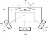
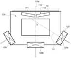
도 1 내지 도 4에 나타낸 바와 같이, 본 발명의 자기장 발생 장치(100)는 자기 발생 코일(110), 송풍장치(120), 유체를 가이드하는 덕트(130), 하우징(140) 및 내부 전자장치(150)를 포함한다.As shown in FIGS. 1 to 4, the magnetic field generating device (100) of the present invention includes a magnetic generating coil (110), a blower (120), a duct (130) for guiding a fluid, a housing (140), and internal electronic devices (150).
다만, 상술한 구성 요소들은 자기장 발생 장치(100)를 구현하는데 있어서 필수적인 것은 아니어서, 자기장 발생 장치(100)는 위에서 열거된 구성요소들 보다 많거나, 또는 적은 구성요소들을 가질 수 있다. 여기서, 각각의 구성 요소들은 별개의 칩이나 모듈이나 장치로 구성될 수 있고, 하나의 장치 내에 포함될 수도 있다.However, the above-described components are not essential for implementing the magnetic field generating device (100), and thus the magnetic field generating device (100) may have more or fewer components than the components listed above. Here, each component may be configured as a separate chip, module, or device, and may be included in one device.
자기 발생 코일(110)은 인가되는 전류를 통해 펄스 자기장을 생성한다. 자기 발생 코일(110)은 신체의 일부가 밀착되는 밀착면(141)의 하측에 배치된다. 이러한 자기 발생 코일(110)은, 코일이 다단으로 권취되는 1개 이상의 코일 권취층이 경사지게 배치되어 있는 것도 가능함은 물론이다.The magnetic generating coil (110) generates a pulse magnetic field through an applied current. The magnetic generating coil (110) is placed on the lower side of the contact surface (141) to which a part of the body is in contact. It is also possible for the magnetic generating coil (110) to have one or more coil winding layers in which the coils are wound in multiple stages and arranged obliquely.
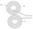
또한, 자기 발생 코일(110)은, 도 9 및 도 10에 나타낸 바와 같이 코일이 다단으로 권취된 제1 코일 권취층(111)과, 이 제1 코일 권취층(111)의 후방부위에 코일이 다단으로 권취된 제2 코일 권취층(112)으로 이루어져 있는 것이 가능함은 물론이다.In addition, it is possible that the self-generating coil (110) is composed of a first coil winding layer (111) in which coils are wound in multiple stages, as shown in FIGS. 9 and 10, and a second coil winding layer (112) in which coils are wound in multiple stages on the rear portion of the first coil winding layer (111).
특히, 이러한 제1 코일 권취층(111)과 제2 코일 권취층(112)은 개별적으로 통전 제어되거나 제1 코일 권취층(111)과 제2 코일 권취층(112)이 함께 통전 제어되는 것이 가능함은 물론이다.In particular, it is possible for the first coil winding layer (111) and the second coil winding layer (112) to be individually controlled for current conduction, or for the first coil winding layer (111) and the second coil winding layer (112) to be controlled for current conduction together.
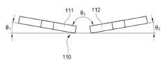
또한, 자기 발생 코일(110)은, 전방부위가 상방 제1 경사각(θ1)으로 경사지게 배치되어 있는 제1 코일 권취층(111)과, 이 제1 코일 권취층(111)의 후방에 설치되되 후방부위가 상방 제2 경사각(θ2)으로 경사지게 배치되어 있는 제2 코일 권취층(112)으로 이루어져 있는 것이 가능함은 물론이다.In addition, it is possible for the self-generating coil (110) to be composed of a first coil winding layer (111) in which the front portion is arranged to be inclined at a first upward inclination angle (θ1 ), and a second coil winding layer (112) installed at the rear of the first coil winding layer (111) and having the rear portion be inclined at a second upward inclination angle (θ2 ).
이러한 제1 경사각(θ1) 및 제2 경사각(θ2)으로는, 신체의 일부가 밀착되는 밀착면의 하측공간과 여기를 통과하는 유체의 통로공간을 제공하도록 밀착면의 평면을 기준해서 대략 5∼30°로 형성되어 있는 것이 바람직하다.It is preferable that the first inclination angle (θ1 ) and the second inclination angle (θ2 ) be formed at an angle of approximately 5 to 30° with respect to the plane of the contact surface to provide a space below the contact surface where a part of the body is in contact and a passage space for a fluid passing therethrough.
특히, 제1 코일 권취층(111)과 제2 코일 권취층(112)은, 서로 대칭되도록 경사지게 배치되어 제1 경사각(θ1) 및 제2 경사각(θ2)이 동일하게 형성되어 있거나, 서로 비대칭으로 경사지게 배치되어 제1 경사각(θ1) 및 제2 경사각(θ2)이 서로 다르게 형성되어 있는 것도 가능함은 물론이다.In particular, the first coil winding layer (111) and the second coil winding layer (112) may be arranged to be symmetrical to each other and inclined so that the first inclination angle (θ1 ) and the second inclination angle (θ2 ) are formed identically, or they may be arranged to be asymmetrical to each other and inclined so that the first inclination angle (θ1 ) and the second inclination angle (θ2 ) are formed differently.
특히, 이러한 제1 코일 권취층(111)과 제2 코일 권취층(112)은 개별적으로 통전 제어되거나 제1 코일 권취층(111)과 제2 코일 권취층(112)이 함께 통전 제어되는 것이 가능함은 물론이다.In particular, it is possible for the first coil winding layer (111) and the second coil winding layer (112) to be individually controlled for current conduction, or for the first coil winding layer (111) and the second coil winding layer (112) to be controlled for current conduction together.
또한, 자기 발생 코일(110)의 다른예는, 제1 코일 권취층(111)과 제2 코일 권취층(112) 사이의 상방 경사각이 제3 경사각(θ3)으로 서로 상방으로 경사지게 배치되어 있는 것이 가능함은 물론이다.In addition, it is of course possible for another example of the self-generating coil (110) to be arranged so that the upward inclination angle between the first coil winding layer (111) and the second coil winding layer (112) is inclined upwards at a third inclination angle (θ3 ).
이러한 제3 경사각(θ3)으로는, 신체의 일부가 밀착되는 밀착면의 하측공간과 여기를 통과하는 유체의 통로공간을 제공하도록 대략 150∼170°로 형성되어 있는 것이 바람직하다.It is preferable that this third inclination angle (θ3 ) be formed at approximately 150 to 170° to provide a space below the contact surface where a part of the body is in contact and a passage space for the fluid passing therethrough.
따라서, 자기 발생 코일(110)은, 제2 코일 권취층(112)이 제1 코일 권취층(111) 보다 높게 배치되거나 상방으로 경사지게 배치되어 신체의 일부가 밀착되는 밀착면의 하측에 배치되면, 사용자의 신체의 밀착면의 후방부위에 제2 코일 권취층(112)이 더 근접하게 되어 신체의 후방부위에, 예를 들면 신체의 꼬리뼈 부근에 자기 발생 효과가 더 크게 된다.Accordingly, when the magnetic generating coil (110) is positioned on the lower side of the contact surface with which a part of the body is in contact, such that the second coil winding layer (112) is positioned higher than the first coil winding layer (111) or is positioned at an upward angle, the second coil winding layer (112) comes closer to the rear part of the contact surface of the user's body, so that the magnetic generating effect is greater in the rear part of the body, for example, near the tailbone of the body.
또한, 자기 발생 코일(110)은, 측방부위가 상방 제1 경사각(θ1)으로 경사지게 배치되어 있는 제1 코일 권취층(111)과, 이 제1 코일 권취층(111)의 측방에 설치되되 측방부위가 상방 제2 경사각(θ2)으로 경사지게 배치되어 있는 제2 코일 권취층(112)으로 이루어져 있는 것이 가능함은 물론이다.In addition, it is possible for the self-generating coil (110) to be composed of a first coil winding layer (111) whose side portion is arranged to be inclined upward at a first inclination angle (θ1 ), and a second coil winding layer (112) installed on the side of the first coil winding layer (111) but whose side portion is arranged to be inclined upward at a second inclination angle (θ2 ).
따라서, 자기 발생 코일(110)은, 코일 권취층의 후반부위와 전반부위가 중앙부위 보다 높게 형성되어 신체의 일부가 밀착되는 밀착면의 하측에 배치되므로, 사용자의 신체의 밀착면의 전방부위와 후방부위가 더 근접하게 되어 신체의 전방부위와 후방부위에, 예를 들면 신체의 꼬리뼈 부근에 자기 발생 효과가 더 크게 된다.Accordingly, the magnetic generating coil (110) is formed so that the latter and former parts of the coil winding layer are higher than the central part and is placed on the lower side of the contact surface with which a part of the body is in contact, so that the front and rear parts of the contact surface of the user's body become closer, and the magnetic generating effect is greater in the front and rear parts of the body, for example, near the tailbone of the body.
송풍장치(120)는 자기 발생 코일(110)을 냉각시키는 유체를 공급한다.The blower (120) supplies fluid to cool the magnetic generating coil (110).
도 4를 참조하면, 송풍장치(120)는 자기 발생 코일(110) 측으로 유체를 공급하는 유입측 송풍장치(120a) 및 상기 자기 발생 코일(110)을 통과한 유체를 외부로 배기하는 유출측 송풍장치(120b)를 포함한다.Referring to FIG. 4, the blower (120) includes an inlet-side blower (120a) that supplies fluid toward the magnetic generating coil (110) and an outlet-side blower (120b) that exhausts fluid passing through the magnetic generating coil (110) to the outside.
유입측 송풍장치(120a)와 유출측 송풍장치(120b)는 자기 발생 코일(110)을 기준으로 서로 대칭되는 위치에 배치될 수 있다.The inlet-side blower (120a) and the outlet-side blower (120b) can be positioned symmetrically with respect to the magnetic generating coil (110).
유입측 송풍장치(120a)는 외부에서 본 발명의 자기장 발생 장치(100)의 내부로 유체를 공급한다. 이때 유입측 송풍장치(120a)는 팬(fan), 블로워(blower), 콤프레셔(compressor) 및 펌프(pump) 중 선택된 것일 수 있다.The inlet-side blower (120a) supplies fluid from the outside to the inside of the magnetic field generating device (100) of the present invention. At this time, the inlet-side blower (120a) may be selected from a fan, a blower, a compressor, and a pump.
도 5를 참조하면, 유입측 송풍장치(120a)는 자기 발생 코일(110)의 하측에 배치된다. 유입측 송풍장치(120a)는 유입측 송풍장치(120a)로부터의 유체의 공급 방향(121)과 자기 발생 코일(110)의 중심축(110a)이 이루는 각도(θ)가 수직 각도 이하가 되도록 배치된다.Referring to Fig. 5, the inlet-side blower (120a) is positioned below the magnetic generating coil (110). The inlet-side blower (120a) is positioned so that the angle (θ) formed by the supply direction (121) of the fluid from the inlet-side blower (120a) and the central axis (110a) of the magnetic generating coil (110) is less than the vertical angle.
유출측 송풍장치(120b)는 자기장 발생 장치(100)의 내부에 유동하는 유체를 외부로 배기한다. 이때 유입측 송풍장치(120a)는 팬, 블로워, 콤프레셔 및 펌프 중 선택된 것일 수 있다.The outlet-side blower (120b) exhausts the fluid flowing inside the magnetic field generating device (100) to the outside. At this time, the inlet-side blower (120a) may be selected from among a fan, a blower, a compressor, and a pump.
도 6을 참조하면, 유출측 송풍장치(120b)는 자기 발생 코일(110)의 하측에 배치된다. 유출측 송풍장치(120b)는 유출측 송풍장치(120b)로부터의 유체의 공급 방향(121)과 자기 발생 코일(110)의 중심축(110a)이 이루는 각도(θ)가 수직 각도 이하가 되도록 배치된다.Referring to Fig. 6, the outlet-side blower (120b) is positioned below the magnetic generating coil (110). The outlet-side blower (120b) is positioned so that the angle (θ) formed by the supply direction (121) of the fluid from the outlet-side blower (120b) and the central axis (110a) of the magnetic generating coil (110) is less than the vertical angle.
여기서, 유체의 공급 방향(121)과 자기 발생 코일(110)의 중심축(110a)이 이루는 각도(θ)는 0도 초과 90도 미만의 각도일 수 있고, 바람직하게는 10도 이상 60도 이하의 각도일 수 있다.Here, the angle (θ) formed by the fluid supply direction (121) and the central axis (110a) of the magnetic generating coil (110) may be an angle greater than 0 degrees and less than 90 degrees, and preferably an angle greater than or equal to 10 degrees and less than or equal to 60 degrees.
도 7의 (a) 및 (b)를 참조하여, 유입측 송풍장치(120a)로부터의 유체의 공급 방향(121)이 자기 발생 코일(110)의 중심축(110a)과 소정의 각도를 이루는 경우의 이점을 설명한다.Referring to (a) and (b) of FIG. 7, the advantage of a case where the supply direction (121) of the fluid from the inlet-side blower (120a) forms a predetermined angle with the central axis (110a) of the magnetic generating coil (110) is explained.
본 발명의 자기장 발생 장치(100)는 유입측 송풍장치(120a) 및 유출측 송풍장치(120b)로부터의 유체의 공급 방향(121)과 자기 발생 코일(110)의 중심축(110a)이 이루는 각도(θ)를 기설정된 각도로 설정함으로써, 송풍장치(120)를 자기 발생 코일(110)과 동일 평면상에 배치하지 않으면서도 자기 발생 코일(110)의 냉각 효율을 향상시킬 수 있도록 한다.The magnetic field generating device (100) of the present invention sets the angle (θ) formed by the supply direction (121) of the fluid from the inlet-side blower (120a) and the outlet-side blower (120b) and the central axis (110a) of the magnetic generating coil (110) to a preset angle, thereby improving the cooling efficiency of the magnetic generating coil (110) without having to place the blower (120) on the same plane as the magnetic generating coil (110).
도 7의 (a)는 유입측 송풍장치(120a)로부터의 유체의 공급 방향(121)이 자기 발생 코일(110)의 중심축(110a)과 90도 각도로 배치된 경우로, 이 경우 유입측 송풍장치(120a)로부터 공급된 유체가 자기 발생 코일(110) 측으로 향하지 못하고 덕트(130)의 내주면에 의해 유입측 송풍장치(120a)로 되돌아 나오는 경우가 발생하게 된다.Figure 7 (a) shows a case where the supply direction (121) of the fluid from the inlet-side blower (120a) is arranged at a 90-degree angle with the central axis (110a) of the magnetic generating coil (110). In this case, the fluid supplied from the inlet-side blower (120a) does not flow toward the magnetic generating coil (110) but instead returns to the inlet-side blower (120a) by the inner surface of the duct (130).
이러한 배치는 유입측 송풍장치(120a)로부터 공급된 유체가 자기 발생 코일(110) 측으로 효과적으로 이동하지 못하게 되어 본 발명의 자기장 발생 장치(100)의 냉각 효율이 저하된다.This arrangement prevents the fluid supplied from the inlet-side blower (120a) from effectively moving toward the magnetic field generating coil (110), thereby reducing the cooling efficiency of the magnetic field generating device (100) of the present invention.
반면, 도 7의 (b)는 유입측 송풍장치(120a)로부터의 유체의 공급 방향(121)이 자기 발생 코일(110)의 중심축(110a)과 소정의 각도를 갖도록 배치된 경우로, 이 경우 유입측 송풍장치(120a)로부터 공급된 유체가 자기 발생 코일(110) 측으로 지향하게 되므로 유입측 송풍장치(120a)로부터 공급된 유체가 자기 발생 코일(110) 측으로 효과적으로 이동할 수 있게 되는 이점이 있다.On the other hand, (b) of Fig. 7 is a case where the supply direction (121) of the fluid from the inlet-side blower (120a) is arranged to have a predetermined angle with the central axis (110a) of the magnetic generating coil (110). In this case, the fluid supplied from the inlet-side blower (120a) is directed toward the magnetic generating coil (110), so there is an advantage in that the fluid supplied from the inlet-side blower (120a) can effectively move toward the magnetic generating coil (110).
나아가, 유입측 송풍장치(120a) 및 유출측 송풍장치(120b)로부터의 유체의 공급 방향(121)과 자기 발생 코일(110)의 중심축(110a)이 이루는 각도(θ)를 기설정된 각도로 설정함으로써, 본 발명의 자기장 발생 장치(100)의 전체적인 부피를 줄일 수 있다.Furthermore, by setting the angle (θ) formed by the supply direction (121) of the fluid from the inlet-side blower (120a) and the outlet-side blower (120b) and the central axis (110a) of the magnetic generating coil (110) to a preset angle, the overall volume of the magnetic field generating device (100) of the present invention can be reduced.
도 4에 도시된 바와 같이 송풍장치(120)와 자기 발생 코일(110)의 사이 영역의 하우징(140)에 홈부를 마련하여 사용자가 손잡이로 사용할 수 있도록 함으로써 사용의 편의성을 향상시킬 수도 있다.As shown in Fig. 4, the convenience of use can be improved by providing a groove in the housing (140) between the blower (120) and the magnetic generating coil (110) so that the user can use it as a handle.
또한, 유입측 송풍장치(120a) 및 유출측 송풍장치(120b)로부터의 유체의 공급 방향(121)과 자기 발생 코일(110)의 중심축(110a)이 이루는 각도(θ)를 기설정된 각도로 설정함으로써, 유입측 송풍장치(120a)를 팬, 블로워, 콤프레셔 및 펌프 중 어느 하나로 채용하더라도 바닥부에 있는 먼지가 유입되는 문제를 예방할 수 있다.In addition, by setting the angle (θ) formed by the supply direction (121) of the fluid from the inlet-side blower (120a) and the outlet-side blower (120b) and the central axis (110a) of the magnetic generating coil (110) to a preset angle, the problem of dust from the bottom being drawn in can be prevented even when the inlet-side blower (120a) is employed as any one of a fan, a blower, a compressor, and a pump.
도 4를 참조하면, 덕트(130)는 송풍장치(120)와 자기 발생 코일(110)의 사이에서 유체를 가이드한다.Referring to FIG. 4, a duct (130) guides fluid between a blower (120) and a magnetic generating coil (110).
구체적으로, 덕트(130)는 일단(131a)이 유입측 송풍장치(120a)로 개방되고 타단(131b)이 유출측 송풍장치(120b)로 개방되도록 형성된다. 덕트(130)는 유입측 송풍장치(120a)에서 유입된 유체가 자기 발생 코일(110)을 거쳐 유출측 송풍장치(120b)에서 배기되도록 유체를 가이드한다.Specifically, the duct (130) is formed so that one end (131a) is opened to the inlet-side blower (120a) and the other end (131b) is opened to the outlet-side blower (120b). The duct (130) guides the fluid introduced from the inlet-side blower (120a) through the magnetic generating coil (110) and exhausted from the outlet-side blower (120b).
덕트(130)는 자기 발생 코일(110)이 배치되는 영역의 내부 단면적이 일단(131a) 및 타단(131b)의 단면적 보다 작게 형성된다. 다시 말해, 덕트(130)는 안착면(132)이 형성된 영역에서의 단면적이 일단(131a) 및 타단(131b)의 단면적 보다 작게 형성된다. 내부 단면적이 작아진 영역에서 유체의 유속이 빨라지므로, 덕트(130)는 자기 발생 코일(110)이 배치되는 영역에서 유체의 유속이 빨라지는 구조로 형성된다.The duct (130) is formed so that the internal cross-sectional area of the region where the magnetic generating coil (110) is placed is smaller than the cross-sectional areas of one end (131a) and the other end (131b). In other words, the duct (130) is formed so that the cross-sectional area of the region where the mounting surface (132) is formed is smaller than the cross-sectional areas of one end (131a) and the other end (131b). Since the flow rate of the fluid increases in the region where the internal cross-sectional area is smaller, the duct (130) is formed so that the flow rate of the fluid increases in the region where the magnetic generating coil (110) is placed.
덕트(130)는 밀착면(141)과 대응되는 위치에 자기 발생 코일(110)이 안착되는 안착면(132)을 구비한다.The duct (130) has a mounting surface (132) on which a magnetic generating coil (110) is mounted at a position corresponding to the contact surface (141).
자기 발생 코일(110)은 안착면(132) 상에 안착되고, 덕트(130)는 이 위치에 대응하여 자기 발생 코일(110)을 지지하는 지지부(133)를 포함한다. 지지부(133)는 자기 발생 코일(110)이 덕트(130)의 내주면으로부터 일정 간격 이격되어 위치될 수 있도록 한다. 지지부(133)에 의해 이격된 공간을 통하여 유입측 송풍장치(120a)로부터 공급된 유체가 유동한다.The magnetic generating coil (110) is mounted on a mounting surface (132), and the duct (130) includes a support member (133) that supports the magnetic generating coil (110) corresponding to this position. The support member (133) allows the magnetic generating coil (110) to be positioned at a predetermined distance from the inner surface of the duct (130). A fluid supplied from an inlet-side blower (120a) flows through the space separated by the support member (133).
지지부(133)는 러버(rubber)일 수 있다. 지지부(133)는 자기 발생 코일(110)이 작동되는 과정에서 발생되는 진동을 흡수하는 역할을 수행할 수 있다.The support member (133) may be rubber. The support member (133) may play a role in absorbing vibrations generated during the operation of the magnetic generating coil (110).
도 4를 참조하면, 덕트(130)는 안착면(132)에서 자기 발생 코일(110) 측으로 돌출된 돌출부(134)를 포함한다. 돌출부(134)는 유입측 송풍장치(120a)와 자기 발생 코일(110)의 사이에 형성된 안착면(132)의 적어도 일부 영역에 형성된다.Referring to FIG. 4, the duct (130) includes a protrusion (134) protruding from the mounting surface (132) toward the magnetic generating coil (110). The protrusion (134) is formed in at least a portion of the mounting surface (132) formed between the inlet-side blower (120a) and the magnetic generating coil (110).
돌출부(134)는 도 5에 도시된 바와 같이 유입측 송풍장치(120a)로부터 유입된 유체가 자기 발생 코일(110)의 상부로 향하도록 가이드한다. 다시 말해, 돌출부(134)는 유입측 송풍장치(120a)로부터 유입된 유체가 자기 발생 코일(110)과 밀착면(141)의 사이에 형성된 영역으로 향할 수 있도록 유체를 가이드한다.The protrusion (134) guides the fluid introduced from the inlet-side blower (120a) to the upper portion of the magnetic generating coil (110) as shown in Fig. 5. In other words, the protrusion (134) guides the fluid introduced from the inlet-side blower (120a) to the area formed between the magnetic generating coil (110) and the contact surface (141).
돌출부(134)는 자기 발생 코일(110)과 밀착면(141)의 사이 영역에 공급되는 유량과 유속을 향상시킴으로써 사용자의 신체 부위가 밀착되는 부분의 냉각 효율을 향상시킬 수 있다.The protrusion (134) can improve the cooling efficiency of the part of the user's body that is in contact with the surface by improving the flow rate and velocity supplied to the area between the magnetic generating coil (110) and the contact surface (141).
본 발명에서 돌출부(134)는 덕트(130)의 내주면의 일부가 굴곡된 것으로 예시하고 있지만 이에 한정되는 것은 아니고, 별도의 부재가 덕트(130)의 내주면의 일부에 부착되는 등의 다양한 방식으로 형성될 수 있음은 물론이다.In the present invention, the protrusion (134) is exemplified as a part of the inner surface of the duct (130) being bent, but is not limited thereto, and of course can be formed in various ways, such as a separate member being attached to a part of the inner surface of the duct (130).
도 4를 참조하면, 덕트(130)는 유입측 송풍장치(120a)와 자기 발생 코일(110)의 사이의 적어도 일부 영역에 홀(135)을 포함한다.Referring to FIG. 4, the duct (130) includes a hole (135) in at least a portion of the area between the inlet side blower (120a) and the magnetic generating coil (110).
홀(135)은 덕트(130)에 유입된 유체의 일부를 관통시킨다. 홀(135)을 통해 관통된 유체는 내부 전자장치(150)를 냉각시킬 수 있다. 덕트(130)가 홀(135)의 구성을 포함함으로써, 유입측 송풍장치(120a)로부터 유입된 유체의 일부는 자기 발생 코일(110)에서 발생된 열을 냉각시키고, 나머지 일부는 내부 전자장치(150)에서 발생된 열을 냉각시키는데 사용될 수 있다.The hole (135) allows a portion of the fluid introduced into the duct (130) to pass through it. The fluid introduced through the hole (135) can cool the internal electronic device (150). Since the duct (130) includes the configuration of the hole (135), a portion of the fluid introduced from the inlet-side blower (120a) can be used to cool the heat generated from the magnetic generating coil (110), and the remaining portion can be used to cool the heat generated from the internal electronic device (150).
이때, 홀(135)은 공급된 유체가 자기 발생 코일(110) 측으로 70%, 내부 전자장치(150) 측으로 30% 정도의 비율로 유동할 수 있도록 홀의 직경과 개수가 결정될 수 있다.At this time, the diameter and number of holes (135) can be determined so that the supplied fluid can flow at a ratio of about 70% toward the magnetic generating coil (110) and about 30% toward the internal electronic device (150).
덕트(130)는 홀(135)을 포함하여 자기 발생 코일(110)과 내부 전자장치(150)를 동시에 냉각시킬 수 있고, 이를 통해 본 발명의 자기장 발생 장치(100)는 내부 전자장치(150)를 위한 별도의 냉각 수단을 구비하지 않고 콤팩트한 구조로 냉각 효율을 높일 수 있다.The duct (130) can cool the magnetic generating coil (110) and the internal electronic device (150) simultaneously, including the hole (135), and through this, the magnetic field generating device (100) of the present invention can increase cooling efficiency with a compact structure without having a separate cooling means for the internal electronic device (150).
도 4를 참조하면, 덕트(130)는 유입측 송풍장치(120a)와 자기 발생 코일(110)의 사이의 적어도 일부 내주면이 굴곡진 굴곡부(136)를 포함할 수 있다.Referring to FIG. 4, the duct (130) may include a curved portion (136) having at least a portion of the inner circumference between the inlet-side blower (120a) and the magnetic generating coil (110).
본 발명에서 굴곡부(136)는 덕트(130)의 내주면의 일부가 굴곡된 것으로 예시하고 있지만 이에 한정되는 것은 아니고, 엠보싱 형상으로 형성될 수도 있고, 별도의 부재가 덕트(130)의 내주면의 일부에 부착되는 등의 다양한 방식으로 형성될 수 있음은 물론이다.In the present invention, the bent portion (136) is exemplified as a portion of the inner surface of the duct (130) being bent, but is not limited thereto, and may be formed in an embossed shape or may be formed in various ways, such as a separate member being attached to a portion of the inner surface of the duct (130).
덕트(130)가 굴곡부(136)의 구성을 포함함으로써, 팬이나 블로워 사용 시 발생하는 소음을 감소시킬 수 있다. 유입측 송풍장치(120a)로부터 유입된 유체가 덕트(130)가 굴곡부(136)에 닿는 경우 그렇지 않은 영역에 닿는 것 보다 소음이 저감될 수 있다.Since the duct (130) includes a configuration of a bent portion (136), noise generated when using a fan or blower can be reduced. When the fluid introduced from the inlet-side blower (120a) touches the bent portion (136) of the duct (130), noise can be reduced compared to when it touches an area that does not have such a configuration.
하우징(140)은 사용자의 신체를 지지하는 밀착면(141)을 포함한다. 밀착면(141)은 사용자가 착좌시 사용자의 신체의 일부 예컨대, 사용자의 둔부가 밀착되는 면이다. 밀착면(141)은 도시된 바와 같이 평평한 면으로 형성될 수도 있고, 소정의 굴곡을 가진 면으로 형성될 수도 있다.The housing (140) includes a contact surface (141) that supports the user's body. The contact surface (141) is a surface that a part of the user's body, such as the user's buttocks, contacts when the user sits. The contact surface (141) may be formed as a flat surface as illustrated, or may be formed as a surface having a predetermined curve.
한편, 도 8를 참조하면, 밀착면(141)은 하면에 자기 발생 코일(110) 측으로 돌출된 지지부(142)를 포함한다. 여기서 밀착면(141)은 하우징(140)의 일부일 수도 있고, 덕트(130)의 일부로 형성될 수도 있다.
지지부(142)는, 밀착면(141)의 하면에 자기 발생 코일(110) 측으로 돌출 형성된 지지부재로서, 자기 발생 코일(110)의 코일 권취층(111)의 상부를 밀착면(141)의 하면에서 소정거리 이격 상태로 지지하여 송풍장치(120)에 의한 유체의 유동공간을 형성하게 된다.
이러한 지지부(142)는, 밀착면(141)의 하부에서 권취형상이 상방으로 경사지게 배치된 코일 권취층(111)의 상부를 지지하도록 다양한 길이로 돌출되어 지지하는 것이 바람직하다.Meanwhile, referring to Fig. 8, the contact surface (141) includes a support portion (142) protruding toward the magnetic generating coil (110) on the lower surface. Here, the contact surface (141) may be a part of the housing (140) or may be formed as a part of the duct (130).
The support member (142) is a support member that is formed by protruding toward the magnetic generating coil (110) on the lower surface of the contact surface (141), and supports the upper portion of the coil winding layer (111) of the magnetic generating coil (110) at a predetermined distance from the lower surface of the contact surface (141) to form a fluid flow space by the blower (120).
It is preferable that these support members (142) protrude to various lengths to support the upper part of the coil winding layer (111) in which the winding shape is arranged to be inclined upward from the lower part of the contact surface (141).
지지부(142)는 자기 발생 코일(110)이 밀착면(141)으로부터 일정 간격 이격되어 위치될 수 있도록 한다. 지지부(142)에 의해 이격된 공간을 통하여 유입측 송풍장치(120a)로부터 공급된 유체가 유동한다. 지지부(142)는 안착면(132)에 형성된 지지부(133)와 같이, 러버(rubber)일 수 있다. 지지부(142)는 자기 발생 코일(110)이 작동되는 과정에서 발생되는 진동을 흡수하는 역할을 수행할 수 있다.The support member (142) allows the magnetic generating coil (110) to be positioned at a certain distance from the contact surface (141). The fluid supplied from the inlet-side blower (120a) flows through the space separated by the support member (142). The support member (142) may be rubber, like the support member (133) formed on the mounting surface (132). The support member (142) may play a role in absorbing vibrations generated during the operation of the magnetic generating coil (110).
또한, 하우징(140)은 냉각을 위해 전후면이나 좌우면이나 상하면에 다수의 측면 개방홀(143)과 후면 개방홀(144) 등과 같이 다양한 개방홀을 포함할 수 있고, 전면에 전원 및 동작을 제어하는 제어패널(145)을 포함할 수 있다. 이러한 측면 개방홀(143)과 후면 개방홀(144)은 송풍장치(120)가 배치된 위치에 대응되는 곳에 형성될 수 있다.In addition, the housing (140) may include various open holes such as a number of side open holes (143) and rear open holes (144) on the front and rear sides, left and right sides, and upper and lower sides for cooling, and may include a control panel (145) on the front for controlling power and operation. These side open holes (143) and rear open holes (144) may be formed at locations corresponding to locations where the blower (120) is placed.
내부 전자장치(150)는, 자기 발생 코일(110)에 전력을 공급하는 전원장치와 전원공급을 제어하는 제어보드와 송풍장치(120)를 제어하는 냉각제어기 등과 같이 다양한 전자설비 및 전기설비 등이 내장되어 있다.The internal electronic device (150) has various electronic and electrical devices built in, such as a power supply device that supplies power to the magnetic generating coil (110), a control board that controls the power supply, and a cooling controller that controls the blower device (120).
이상 설명한 바와 같이, 본 발명에 따르면 자기 발생 코일의 코일이 다단으로 권취되는 1개 이상의 코일 권취층이 경사지게 배치됨으로써, 코일의 자기 발생을 코일 권취층의 경사진 부위에 집중시켜 자기장의 발생성능을 향상시키는 동시에 코일의 배치 형태를 다양하게 구성하여 다양한 형태의 하우징의 밀착면에 적용할 수 있는 효과를 제공한다.As described above, according to the present invention, since one or more coil winding layers in which the coils of the magnetic generating coil are wound in multiple stages are arranged obliquely, the magnetic generation of the coil is concentrated on the oblique portion of the coil winding layer, thereby improving the generation performance of the magnetic field, and at the same time, by configuring the arrangement form of the coil in various ways, it provides the effect of being applicable to the contact surface of various types of housing.
또한, 자기 발생 코일의 코일이 다단으로 권취된 코일 권취층이 상방으로 경사지게 배치됨으로써, 밀착면의 전방에서 후방으로 경사부위를 따라 자기 발생 범위를 형성하여 코일의 자기 발생을 인체의 전방에서 후방으로 다양하게 변화시켜 자기장의 발생성능을 향상시킬 수 있는 효과를 제공한다.In addition, since the coils of the magnetic generating coil are wound in multiple stages and arranged so as to be inclined upward, the magnetic generating range is formed along the inclined portion from the front to the rear of the contact surface, thereby providing the effect of improving the generation performance of the magnetic field by changing the magnetic generation of the coil in various ways from the front to the rear of the human body.
또한, 자기 발생 코일의 코일이 다단으로 권취된 제1 코일 권취층과 그 후방에 제2 코일 권취층을 상방으로 경사지게 배치함으로써, 밀착면의 전방에서 후방으로 코일의 자기 발생범위를 다양하게 집중시켜 자기장의 발생성능을 향상시킬 수 있는 효과를 제공한다.In addition, by arranging the first coil winding layer in which the coils of the magnetic generating coil are wound in multiple stages and the second coil winding layer behind it at an upward angle, the magnetic generating range of the coil is concentrated in various ways from the front to the rear of the contact surface, thereby providing an effect of improving the generation performance of the magnetic field.
이상 설명한 본 발명은 그 기술적 사상 또는 주요한 특징으로부터 벗어남이 없이 다른 여러 가지 형태로 실시될 수 있다. 따라서 상기 실시예는 모든 점에서 단순한 예시에 지나지 않으며 한정적으로 해석되어서는 안 된다.The present invention described above can be implemented in various other forms without departing from the technical idea or main characteristics thereof. Therefore, the above embodiments are merely illustrative in all respects and should not be construed as limiting.
100 … 자기장 발생 장치
110 … 자기 발생 코일
111 … 제1 코일 권취층
112 … 제2 코일 권취층
120 … 송풍장치
120a … 유입측 송풍장치
120b … 유출측 송풍장치
121 … 유체 공급 방향
130 … 덕트
131a … 일단
131b … 타단
132 … 안착면
133 … 지지부
134 … 돌출부
135 … 홀
136 … 굴곡부
140 … 하우징
141 … 밀착면
142 … 지지부
143 … 측면 개방홀
144 … 후면 개방홀
145 … 제어패널
150 … 내부 전자장치100 … magnetic field generating device
110 … Self-generating coil
111 … 1st coil winding layer
112 … 2nd coil winding layer
120 … blower
120a … Inlet side blower
120b … Outlet side blower
121 … fluid supply direction
130 … duct
131a … first of all
131b … the other end
132 … Settlement area
133 … support
134 … protrusion
135 … hole
136 … bend
140 … Housing
141 … close contact surface
142 … support
143 … side opening hole
144 … Rear opening hole
145 … Control Panel
150 … internal electronics
Claims (4)
Translated fromKorean상기 자기 발생 코일을 냉각시키는 유체를 공급하는 송풍장치;
상기 자기 발생 코일와 상기 송풍장치의 사이에서 상기 유체를 가이드하는 덕트; 및
상기 밀착면의 하면에 상기 자기 발생 코일 측으로 돌출 형성된 지지부;를 포함하고,
상기 자기 발생 코일은, 코일이 다단으로 권취되는 1개 이상의 코일 권취층이 경사지게 배치되어 있고,
상기 코일 권취층은, 상방으로 경사지게 배치되어 있고,
상기 지지부는, 상기 코일 권취층을 상기 밀착면의 하면에서 소정거리 이격 상태로 지지하도록 설치되되 상기 코일 권취층을 상기 덕트의 안착면으로부터 소정거리 이격상태로 지지하도록 설치되어, 상기 밀착면의 하부에서 권취형상이 상방으로 경사지게 배치된 코일 권취층의 상부와 하부를 지지하도록 서로 다른 길이로 돌출되어 있는 것을 특징으로 하는 경사형 코일을 구비한 자기장 발생 장치.A magnetic generating coil that generates magnetism and is placed on the lower side of the contact surface with which a part of the body is in contact;
A blower for supplying fluid to cool the above-mentioned magnetic generating coil;
A duct guiding the fluid between the magnetic generating coil and the blower; and
Including a support portion formed protruding toward the magnetic generating coil on the lower surface of the above-mentioned contact surface;
The above magnetic generating coil has one or more coil winding layers in which the coils are wound in multiple stages and arranged obliquely,
The above coil winding layer is arranged so as to be inclined upward,
The above-mentioned support member is installed to support the coil winding layer at a predetermined distance from the lower surface of the contact surface, and is installed to support the coil winding layer at a predetermined distance from the mounting surface of the duct, and is characterized in that it protrudes with different lengths to support the upper and lower parts of the coil winding layer whose winding shape is arranged to be inclined upward from the lower surface of the contact surface.
상기 자기 발생 코일은,
전방부위가 상방으로 경사지게 배치되어 있는 제1 코일 권취층; 및
상기 제1 코일 권취층을 후방에 설치되되 후방부위가 상방으로 경사지게 배치되어 있는 제2 코일 권취층;을 포함하는 것을 특징으로 하는 경사형 코일을 구비한 자기장 발생 장치.In paragraph 1,
The above magnetic generating coil,
A first coil winding layer having a front portion inclined upward; and
A magnetic field generating device having an inclined coil, characterized by including a second coil winding layer installed at the rear of the first coil winding layer and having the rear portion inclined upward.
상기 제1 코일 권취층과 상기 제2 코일 권취층은, 서로 대칭되도록 경사지게 배치되어 있는 것을 특징으로 하는 경사형 코일을 구비한 자기장 발생 장치.In the third paragraph,
A magnetic field generating device having an inclined coil, characterized in that the first coil winding layer and the second coil winding layer are arranged at an angle symmetrically to each other.
Priority Applications (1)
| Application Number | Priority Date | Filing Date | Title |
|---|---|---|---|
| KR1020210183381AKR102730862B1 (en) | 2021-12-21 | 2021-12-21 | Apparatus for generating magnetic field with inclined type winding coil |
Applications Claiming Priority (1)
| Application Number | Priority Date | Filing Date | Title |
|---|---|---|---|
| KR1020210183381AKR102730862B1 (en) | 2021-12-21 | 2021-12-21 | Apparatus for generating magnetic field with inclined type winding coil |
Publications (2)
| Publication Number | Publication Date |
|---|---|
| KR20230094313A KR20230094313A (en) | 2023-06-28 |
| KR102730862B1true KR102730862B1 (en) | 2024-11-15 |
Family
ID=86994245
Family Applications (1)
| Application Number | Title | Priority Date | Filing Date |
|---|---|---|---|
| KR1020210183381AActiveKR102730862B1 (en) | 2021-12-21 | 2021-12-21 | Apparatus for generating magnetic field with inclined type winding coil |
Country Status (1)
| Country | Link |
|---|---|
| KR (1) | KR102730862B1 (en) |
Families Citing this family (9)
| Publication number | Priority date | Publication date | Assignee | Title |
|---|---|---|---|---|
| US20180001107A1 (en) | 2016-07-01 | 2018-01-04 | Btl Holdings Limited | Aesthetic method of biological structure treatment by magnetic field |
| US11534619B2 (en) | 2016-05-10 | 2022-12-27 | Btl Medical Solutions A.S. | Aesthetic method of biological structure treatment by magnetic field |
| US11141219B1 (en) | 2016-08-16 | 2021-10-12 | BTL Healthcare Technologies, a.s. | Self-operating belt |
| US12156689B2 (en) | 2019-04-11 | 2024-12-03 | Btl Medical Solutions A.S. | Methods and devices for aesthetic treatment of biological structures by radiofrequency and magnetic energy |
| ES2926904T3 (en) | 2019-04-11 | 2022-10-31 | Btl Medical Solutions A S | Device for the aesthetic treatment of biological structures using radiofrequency and magnetic energy |
| US11878167B2 (en) | 2020-05-04 | 2024-01-23 | Btl Healthcare Technologies A.S. | Device and method for unattended treatment of a patient |
| WO2021224678A1 (en) | 2020-05-04 | 2021-11-11 | Btl Medical Technologies S.R.O. | Device and method for unattended treatment of a patient |
| EP4415812A1 (en) | 2021-10-13 | 2024-08-21 | BTL Medical Solutions a.s. | Devices for aesthetic treatment of biological structures by radiofrequency and magnetic energy |
| US11896816B2 (en) | 2021-11-03 | 2024-02-13 | Btl Healthcare Technologies A.S. | Device and method for unattended treatment of a patient |
Citations (3)
| Publication number | Priority date | Publication date | Assignee | Title |
|---|---|---|---|---|
| KR101754395B1 (en)* | 2016-04-21 | 2017-07-19 | 주식회사 온누리헬스케어 | Apparatus for urinary incontinence treatment having stimulation coil |
| JP2021512690A (en) | 2018-02-05 | 2021-05-20 | ブレインズウェイ リミテッド | Electromagnetic coil assembly |
| JP2021078906A (en) | 2019-11-21 | 2021-05-27 | 株式会社デンケン | Magnetic stimulation device and magnetic stimulation device cooling method |
Family Cites Families (4)
| Publication number | Priority date | Publication date | Assignee | Title |
|---|---|---|---|---|
| KR100575541B1 (en)* | 2004-08-12 | 2006-05-03 | (주) 엠큐브테크놀로지 | Stimulation module with improved magnetic field formation efficiency and its stimulator |
| KR100841596B1 (en) | 2007-06-05 | 2008-06-26 | 한국전기연구원 | Cooling device of magnetic field therapy device |
| KR101061451B1 (en) | 2008-07-14 | 2011-09-01 | 김병수 | Incontinence Therapy Device Using Magnetic Field |
| KR102174725B1 (en) | 2018-10-15 | 2020-11-05 | 전주대학교 산학협력단 | Hybrid cold device and magnetic stimulator having the same |
- 2021
- 2021-12-21KRKR1020210183381Apatent/KR102730862B1/enactiveActive
Patent Citations (3)
| Publication number | Priority date | Publication date | Assignee | Title |
|---|---|---|---|---|
| KR101754395B1 (en)* | 2016-04-21 | 2017-07-19 | 주식회사 온누리헬스케어 | Apparatus for urinary incontinence treatment having stimulation coil |
| JP2021512690A (en) | 2018-02-05 | 2021-05-20 | ブレインズウェイ リミテッド | Electromagnetic coil assembly |
| JP2021078906A (en) | 2019-11-21 | 2021-05-27 | 株式会社デンケン | Magnetic stimulation device and magnetic stimulation device cooling method |
Also Published As
| Publication number | Publication date |
|---|---|
| KR20230094313A (en) | 2023-06-28 |
Similar Documents
| Publication | Publication Date | Title |
|---|---|---|
| KR102730862B1 (en) | Apparatus for generating magnetic field with inclined type winding coil | |
| KR102818343B1 (en) | Apparatus for generating magnetic field with winding coil | |
| KR102703564B1 (en) | Magnetic field application device | |
| KR102764235B1 (en) | Treatment device using magnetic field | |
| KR102699704B1 (en) | Apparatus for generating magnetic field with round type winding coil | |
| KR20220040784A (en) | Treatment device using magnetic field | |
| KR102624102B1 (en) | Magnetic stimulation device with air cooled | |
| CA2908587C (en) | Magnetic stimulation device | |
| EP0850665B1 (en) | Magnetic stimulus type urinary incontinence treatment coil apparatus | |
| EP2760542B1 (en) | Magnetic coil with two layers or comprising part of a spherical surface | |
| EP0960632A2 (en) | Urinary incontinence treatment instrument | |
| JP2021078906A (en) | Magnetic stimulation device and magnetic stimulation device cooling method | |
| KR102707928B1 (en) | Mgnetic field application device including a support for supporting the body | |
| KR20230045779A (en) | Treatment device using magnetic field | |
| KR102642773B1 (en) | Apparatus for generating magnetic field with core | |
| KR101754395B1 (en) | Apparatus for urinary incontinence treatment having stimulation coil | |
| US20240306342A1 (en) | Electromagnetic field output handle unit for electromagnetic therapy device using thermal management function | |
| JP4221688B2 (en) | Coil air cooling device for urinary incontinence treatment | |
| JP2011243469A (en) | Induction heating cooker | |
| KR100737750B1 (en) | Inductively Coupled Plasma Treatment Equipment | |
| CN107869762B (en) | Air conditioner indoor unit | |
| KR20230073903A (en) | Apparatus for generating ac magnetic field for thermotherapy | |
| CN112915388A (en) | High magnetic physiotherapy device and electromagnetic pulse treatment chair | |
| JP2007503967A (en) | Electromagnetic field configuration with reduced divergence |
Legal Events
| Date | Code | Title | Description |
|---|---|---|---|
| PA0109 | Patent application | St.27 status event code:A-0-1-A10-A12-nap-PA0109 | |
| PA0201 | Request for examination | St.27 status event code:A-1-2-D10-D11-exm-PA0201 | |
| R18-X000 | Changes to party contact information recorded | St.27 status event code:A-3-3-R10-R18-oth-X000 | |
| PG1501 | Laying open of application | St.27 status event code:A-1-1-Q10-Q12-nap-PG1501 | |
| D13-X000 | Search requested | St.27 status event code:A-1-2-D10-D13-srh-X000 | |
| D14-X000 | Search report completed | St.27 status event code:A-1-2-D10-D14-srh-X000 | |
| E902 | Notification of reason for refusal | ||
| PE0902 | Notice of grounds for rejection | St.27 status event code:A-1-2-D10-D21-exm-PE0902 | |
| E13-X000 | Pre-grant limitation requested | St.27 status event code:A-2-3-E10-E13-lim-X000 | |
| P11-X000 | Amendment of application requested | St.27 status event code:A-2-2-P10-P11-nap-X000 | |
| P13-X000 | Application amended | St.27 status event code:A-2-2-P10-P13-nap-X000 | |
| R18-X000 | Changes to party contact information recorded | St.27 status event code:A-3-3-R10-R18-oth-X000 | |
| E701 | Decision to grant or registration of patent right | ||
| PE0701 | Decision of registration | St.27 status event code:A-1-2-D10-D22-exm-PE0701 | |
| GRNT | Written decision to grant | ||
| PR0701 | Registration of establishment | St.27 status event code:A-2-4-F10-F11-exm-PR0701 | |
| PR1002 | Payment of registration fee | St.27 status event code:A-2-2-U10-U11-oth-PR1002 Fee payment year number:1 | |
| PG1601 | Publication of registration | St.27 status event code:A-4-4-Q10-Q13-nap-PG1601 | |
| R18-X000 | Changes to party contact information recorded | St.27 status event code:A-5-5-R10-R18-oth-X000 |