KR102729199B1 - Pulse generation system providing cardiac synchronized multi-pulsing and pulse generation mehtod thereof - Google Patents
Pulse generation system providing cardiac synchronized multi-pulsing and pulse generation mehtod thereofDownload PDFInfo
- Publication number
- KR102729199B1 KR102729199B1KR1020240009057AKR20240009057AKR102729199B1KR 102729199 B1KR102729199 B1KR 102729199B1KR 1020240009057 AKR1020240009057 AKR 1020240009057AKR 20240009057 AKR20240009057 AKR 20240009057AKR 102729199 B1KR102729199 B1KR 102729199B1
- Authority
- KR
- South Korea
- Prior art keywords
- pulse
- interval
- pulsing
- ecg
- voltage
- Prior art date
- Legal status (The legal status is an assumption and is not a legal conclusion. Google has not performed a legal analysis and makes no representation as to the accuracy of the status listed.)
- Active
Links
Images


Classifications
- A—HUMAN NECESSITIES
- A61—MEDICAL OR VETERINARY SCIENCE; HYGIENE
- A61B—DIAGNOSIS; SURGERY; IDENTIFICATION
- A61B18/00—Surgical instruments, devices or methods for transferring non-mechanical forms of energy to or from the body
- A61B18/04—Surgical instruments, devices or methods for transferring non-mechanical forms of energy to or from the body by heating
- A61B18/12—Surgical instruments, devices or methods for transferring non-mechanical forms of energy to or from the body by heating by passing a current through the tissue to be heated, e.g. high-frequency current
- A—HUMAN NECESSITIES
- A61—MEDICAL OR VETERINARY SCIENCE; HYGIENE
- A61B—DIAGNOSIS; SURGERY; IDENTIFICATION
- A61B18/00—Surgical instruments, devices or methods for transferring non-mechanical forms of energy to or from the body
- A61B2018/00571—Surgical instruments, devices or methods for transferring non-mechanical forms of energy to or from the body for achieving a particular surgical effect
- A61B2018/00613—Irreversible electroporation
- A—HUMAN NECESSITIES
- A61—MEDICAL OR VETERINARY SCIENCE; HYGIENE
- A61B—DIAGNOSIS; SURGERY; IDENTIFICATION
- A61B18/00—Surgical instruments, devices or methods for transferring non-mechanical forms of energy to or from the body
- A61B2018/00636—Sensing and controlling the application of energy
- A61B2018/00642—Sensing and controlling the application of energy with feedback, i.e. closed loop control
- A—HUMAN NECESSITIES
- A61—MEDICAL OR VETERINARY SCIENCE; HYGIENE
- A61B—DIAGNOSIS; SURGERY; IDENTIFICATION
- A61B18/00—Surgical instruments, devices or methods for transferring non-mechanical forms of energy to or from the body
- A61B2018/00636—Sensing and controlling the application of energy
- A61B2018/00696—Controlled or regulated parameters
- A61B2018/0072—Current
- A—HUMAN NECESSITIES
- A61—MEDICAL OR VETERINARY SCIENCE; HYGIENE
- A61B—DIAGNOSIS; SURGERY; IDENTIFICATION
- A61B18/00—Surgical instruments, devices or methods for transferring non-mechanical forms of energy to or from the body
- A61B2018/00636—Sensing and controlling the application of energy
- A61B2018/00696—Controlled or regulated parameters
- A61B2018/00767—Voltage
- A—HUMAN NECESSITIES
- A61—MEDICAL OR VETERINARY SCIENCE; HYGIENE
- A61B—DIAGNOSIS; SURGERY; IDENTIFICATION
- A61B18/00—Surgical instruments, devices or methods for transferring non-mechanical forms of energy to or from the body
- A61B2018/00636—Sensing and controlling the application of energy
- A61B2018/00773—Sensed parameters
- A61B2018/00839—Bioelectrical parameters, e.g. ECG, EEG
Landscapes
- Health & Medical Sciences (AREA)
- Surgery (AREA)
- Engineering & Computer Science (AREA)
- Life Sciences & Earth Sciences (AREA)
- Biomedical Technology (AREA)
- Otolaryngology (AREA)
- Nuclear Medicine, Radiotherapy & Molecular Imaging (AREA)
- Plasma & Fusion (AREA)
- Physics & Mathematics (AREA)
- Heart & Thoracic Surgery (AREA)
- Medical Informatics (AREA)
- Molecular Biology (AREA)
- Animal Behavior & Ethology (AREA)
- General Health & Medical Sciences (AREA)
- Public Health (AREA)
- Veterinary Medicine (AREA)
- Electrotherapy Devices (AREA)
Abstract
Translated fromKoreanDescription
Translated fromKorean본 발명은 펄스 생성 시스템에 관한 것으로, 더욱 상세하게는 심장 동기화 멀티-펄싱을 제공하는 펄스 생성 시스템 및 그것의 펄스 생성 방법에 관한 것이다.The present invention relates to a pulse generation system, and more particularly, to a pulse generation system providing cardiac synchronous multi-pulsing and a pulse generation method thereof.
비가역 전기천공법(Irreversible Electroporation: 이하, IRE)은 전극의 양 끝단에 고전압 또는 고전류를 흐르게 하여 전극 사이에 강한 전기장을 생성하여 고형암과 같은 악성 종양을 세포 단위로 소작하여 제거하는 방법이다. 이러한 방법은 주요 혈관 및 장기에 인접하여 수술적 치료가 불가능한 환자에게 새로운 국소 치료법으로 제한적인 범위에서 이용되고 있다.Irreversible Electroporation (IRE) is a method of removing malignant tumors such as solid tumors by cauterizing them at the cell level by applying high voltage or high current to both ends of the electrodes to create a strong electric field between the electrodes. This method is being used in a limited range as a new local treatment method for patients who are adjacent to major blood vessels and organs and cannot be treated surgically.
비가역 전기천공 시스템을 사용하여 환자에게 전기천공 시술을 수행하기 위해서는 심장 신호에 동기하여 펄스를 생성한다. 전기천공 시술에서는 고전압 펄스가 사용되기 때문에, 환자의 심장에 전기적 충격을 최소화해야 한다. 따라서, 심전도 신호의 안전 구간(Ts)에서 환자의 환부에 펄스가 인가되어야 환자의 심장에 미치는 영향을 최소화할 수 있기 때문이다.In order to perform electroporation on a patient using an irreversible electroporation system, pulses are generated in synchronization with the heart signal. Since high-voltage pulses are used in the electroporation procedure, the electrical shock to the patient's heart must be minimized. Therefore, the pulse must be applied to the patient's affected area within the safe zone (Ts) of the electrocardiogram signal to minimize the impact on the patient's heart.
하지만, 심장 신호에 동기하여 전기천공 시술을 시행할 때, 하나의 심전도 주기에 하나의 펄스를 할당하는 방식에서는 시술 시간이 길어진다. 또한, 하나의 펄스를 길게 인가할 때, 온도가 급격히 상승하여 과전류가 흐를 수 있다. 따라서, 비가역적 전기천공 시스템의 시술 시간을 줄일 수 있고, 과전류를 줄일 수 있는 펄싱 기술이 필요한 실정이다.However, when performing electroporation in synchronization with a heart signal, the procedure time becomes longer when one pulse is assigned to one electrocardiogram cycle. In addition, when one pulse is applied for a long time, the temperature may rise rapidly and an overcurrent may flow. Therefore, a pulsing technology that can reduce the procedure time of an irreversible electroporation system and reduce the overcurrent is needed.
본 발명의 목적은, 시술 시간을 단축시킬 수 있으면서도 과전류 위험도를 낮출 수 있는 펄서 생성 시스템 또는 비가역적 전기천공 시스템을 제공하는 데 있다.The purpose of the present invention is to provide a pulser generation system or an irreversible electroporation system capable of reducing the risk of overcurrent while shortening the treatment time.
본 발명의 일 실시 예에 따른 환자에게 인가되는 펄스를 생성하는 펄스 생성 시스템의 펄스 생성 방법은, 심전도 신호를 수신하는 단계, 상기 심전도 신호의 주기 또는 R-R 인터벌로부터 심장의 자극이 최소화되는 안전 구간을 검출하는 단계, 멀티-펄싱 전압을 구성하기 위한 펄스 수, 펄스 폭, 그리고 펄스 간격들 중 상수로 적용될 적어도 하나의 제 1 파라미터 값을 수신하는 단계, 상기 제 1 파라미터 값 조건에서 상기 펄스 수, 상기 펄스 폭, 그리고 상기 펄스 간격들 중에서 변수로 적용되는 제 2 파라미터 값을 최적화하는 단계, 그리고 상기 제 1 파라미터 값과 최적화된 상기 제 2 파라미터 값을 기초로 상기 안전 구간 내에서 적어도 2개의 펄스가 포함되는 멀티-펄싱 전압을 생성하는 단계를 포함한다.A pulse generation method of a pulse generation system for generating a pulse applied to a patient according to one embodiment of the present invention includes the steps of receiving an electrocardiogram signal, detecting a safe section in which stimulation of the heart is minimized from a period or an R-R interval of the electrocardiogram signal, receiving at least one first parameter value to be applied as a constant among a pulse number, a pulse width, and pulse intervals for configuring a multi-pulsing voltage, optimizing a second parameter value to be applied as a variable among the pulse number, the pulse width, and the pulse intervals under a condition of the first parameter value, and generating a multi-pulsing voltage including at least two pulses within the safe section based on the first parameter value and the optimized second parameter value.
이 실시 예에서, 상기 제 2 파라미터 값은 수학식 조건에 따라 최적화된다(여기서, 'W'는 상기 펄스 폭, 'N'은 상기 펄스 수, 'I'는 상기 펄스 간격, 그리고 'Ts'는 상기 안전 구간).In this embodiment, the second parameter value is expressed by the mathematical formula is optimized according to the conditions (where, 'W' is the pulse width, 'N' is the pulse number, 'I' is the pulse interval, and 'Ts' is the safe interval).
이 실시 예에서, 상기 제 1 파라미터 값으로 상기 펄스 폭과 상기 펄스 간격이 입력되는 경우, 최적화되는 상기 제 2 파라미터 값에 대응하는 상기 펄스 수는 상기 안전 구간 내에 수용되는 최대 펄스 수에 대응한다.In this embodiment, when the pulse width and the pulse interval are input as the first parameter values, the pulse number corresponding to the second parameter value to be optimized corresponds to the maximum pulse number accommodated within the safe interval.
이 실시 예에서, 상기 제 1 파라미터 값으로 상기 펄스 폭과 상기 펄스 수가 입력되는 경우, 최적화되는 상기 제 2 파라미터 값에 대응하는 상기 펄스 간격은 상기 수학식 조건을 만족하는 최대 펄스 폭 또는 최소 펄스 폭에 대응한다.In this embodiment, when the pulse width and the pulse number are input as the first parameter value, the pulse interval corresponding to the second parameter value to be optimized corresponds to the maximum pulse width or minimum pulse width that satisfies the mathematical expression condition.
상술한 본 발명의 실시 예에 따르면, 멀티 펄싱이 가능한 비가역적 전기천공 시스템을 제공할 수 있다. 따라서, 시술 시간을 단축시킬 수 있으면서도 과전류 위험도를 낮출 수 있는 펄스 생성 시스템 또는 비가역적 전기천공 시스템의 구현이 가능하다.According to the above-described embodiment of the present invention, an irreversible electroporation system capable of multi-pulsing can be provided. Accordingly, it is possible to implement a pulse generation system or an irreversible electroporation system capable of reducing the risk of overcurrent while shortening the treatment time.
도 1은 본 발명의 실시 예에 따른 멀티 펄싱을 수행하는 비가역적 전기천공 시스템을 개략적으로 보여주는 도면이다.
도 2는 본 발명의 실시 예에 따른 멀티-펄싱 전압(MP)을 예시적으로 보여주는 파형도이다.
도 3은 도 2의 심전도 신호(ECG)의 하나의 파형을 보여주는 그래프이다.
도 4는 본 발명의 실시 예에 비가역적 전기천공 시스템의 멀티-펄스 전압(MP)을 생성하는 방법을 보여주는 순서도이다.
도 5는 본 발명의 실시 예에 따른 비가역적 전기천공 시스템의 멀티-펄싱 방법을 보여주는 순서도이다.
도 6은 도 5의 실시 예에 따른 멀티-펄싱 방법에 따른 멀티-펄스 전압(MP)의 변화를 보여주는 파형도이다.
도 7은 본 발명의 다른 실시 예에 따른 비가역적 전기천공 시스템의 멀티-펄싱 방법을 보여주는 순서도이다.
도 8은 도 7의 실시 예에 따른 멀티-펄싱 방법에 따른 멀티-펄스 전압(MP)의 변화를 보여주는 파형도이다.
도 9는 본 발명의 또 다른 실시 예에 따른 비가역적 전기천공 시스템의 멀티-펄싱 방법을 보여주는 순서도이다.
도 10은 도 9의 실시 예에 따른 멀티-펄싱 방법에 따른 멀티-펄스 전압(MP)의 변화를 보여주는 파형도이다.
도 11은 도 1의 멀티-펄스 생성부의 다른 예를 보여주는 블록도이다.FIG. 1 is a schematic diagram showing an irreversible electroporation system performing multi-pulsing according to an embodiment of the present invention.
FIG. 2 is a waveform diagram exemplarily showing a multi-pulsing voltage (MP) according to an embodiment of the present invention.
Figure 3 is a graph showing one waveform of the electrocardiogram signal (ECG) of Figure 2.
FIG. 4 is a flowchart showing a method for generating a multi-pulse voltage (MP) of an irreversible electroporation system according to an embodiment of the present invention.
FIG. 5 is a flowchart showing a multi-pulsing method of an irreversible electroporation system according to an embodiment of the present invention.
FIG. 6 is a waveform diagram showing changes in multi-pulse voltage (MP) according to the multi-pulsing method according to the embodiment of FIG. 5.
FIG. 7 is a flowchart showing a multi-pulsing method of an irreversible electroporation system according to another embodiment of the present invention.
FIG. 8 is a waveform diagram showing changes in multi-pulse voltage (MP) according to the multi-pulsing method according to the embodiment of FIG. 7.
FIG. 9 is a flowchart showing a multi-pulsing method of an irreversible electroporation system according to another embodiment of the present invention.
FIG. 10 is a waveform diagram showing changes in multi-pulse voltage (MP) according to the multi-pulsing method according to the embodiment of FIG. 9.
Fig. 11 is a block diagram showing another example of the multi-pulse generator of Fig. 1.
이하, 본 발명의 일부 실시 예들을 예시적인 도면을 참조하여 상세하게 설명한다. 각 도면의 구성요소들에 참조 부호를 부가함에 있어서, 동일한 구성 요소들에 대해서는 비록 다른 도면상에 표시되더라도 가능한 한 동일한 부호를 가질 수 있다. 또한, 본 발명을 설명함에 있어, 관련된 공지 구성 또는 기능에 대한 구체적인 설명이 본 발명의 요지를 흐릴 수 있다고 판단되는 경우에는 그 상세한 설명은 생략할 수 있다.Hereinafter, some embodiments of the present invention will be described in detail with reference to exemplary drawings. When adding reference signs to components in each drawing, the same components may have the same signs as much as possible even if they are shown in different drawings. In addition, when describing the present invention, if it is determined that a specific description of a related known configuration or function may obscure the gist of the present invention, the detailed description may be omitted.
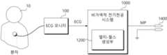
도 1은 본 발명의 실시 예에 따른 멀티 펄싱을 수행하는 비가역적 전기천공 시스템을 개략적으로 보여주는 도면이다. 비가역적 전기천공 시스템(1000)은 환자(10)의 심전도를 측정하는 ECG 모니터(100)로부터 심전도 신호(ECG)를 수신한다. 그리고 비가역적 전기천공 시스템(1000)은 심전도 신호(ECG)의 주기(또는, R-R 인터벌)에 따라 최적의 멀티-펄싱 전압(MP)을 생성할 수 있다.FIG. 1 is a schematic diagram of an irreversible electroporation system performing multi-pulsing according to an embodiment of the present invention. The irreversible electroporation system (1000) receives an electrocardiogram signal (ECG) from an ECG monitor (100) that measures an electrocardiogram of a patient (10). And the irreversible electroporation system (1000) can generate an optimal multi-pulsing voltage (MP) according to the cycle (or R-R interval) of the electrocardiogram signal (ECG).
ECG 모니터(100)는 환자의 심전도를 측정하여 심전도 신호(ECG)를 제공한다. 또는, ECG 모니터(100)는 환자의 심전도 그래프에서 심실이 극성화되는 R 피크들 간의 간격(이하, R-R 인터벌)을 제공할 수도 있다. ECG 모니터(100)는 심전도 신호(ECG)를 측정하기 위해 비가역적 전기천공 시스템(1000)과는 별도의 장비로서 제공될 수 있다. 하지만, 어떤 실시 예에서는 ECG 모니터(100)는 비가역적 전기천공 시스템(1000)의 일부로 구성될 수도 있을 것이다.The ECG monitor (100) measures the electrocardiogram of the patient and provides an electrocardiogram signal (ECG). Alternatively, the ECG monitor (100) may provide an interval between R peaks (hereinafter, R-R interval) in which the ventricles are polarized in the electrocardiogram of the patient. The ECG monitor (100) may be provided as a separate device from the irreversible electroporation system (1000) to measure the electrocardiogram signal (ECG). However, in some embodiments, the ECG monitor (100) may be configured as a part of the irreversible electroporation system (1000).
비가역적 전기천공 시스템(1000)은 심전도 신호(ECG) 또는 심전도 신호(ECG)의 R-R 인터벌을 기초로 환자(10)의 시술을 위한 멀티-펄싱 전압(MP)을 제공한다. 이를 위해 비가역적 전기천공 시스템(1000)은 멀티-펄스 생성부(1200)를 포함할 수 있다. 멀티-펄스 생성부(1200)는 심전도 신호(ECG)에 동기하여 멀티-펄싱 전압(MP)을 생성한다. 멀티-펄싱 전압(MP)은 하나의 심전도 신호(ECG) 주기에 동기하여 둘 이상의 펄스로 제공되는 고전압을 의미한다.The irreversible electroporation system (1000) provides a multi-pulsing voltage (MP) for the treatment of a patient (10) based on an electrocardiogram (ECG) signal or an R-R interval of the electrocardiogram (ECG) signal. To this end, the irreversible electroporation system (1000) may include a multi-pulse generation unit (1200). The multi-pulse generation unit (1200) generates a multi-pulsing voltage (MP) in synchronization with the electrocardiogram (ECG) signal. The multi-pulsing voltage (MP) means a high voltage provided as two or more pulses in synchronization with one electrocardiogram (ECG) signal cycle.
멀티-펄스 생성부(1200)는 심전도 신호(ECG)의 R-R 인터벌을 검출하고, R-R 인터벌의 크기에 따라 가변되는 멀티-펄싱 전압(MP)을 생성할 수 있다. 예를 들면, 멀티-펄스 생성부(1200)는 R-R 인터벌의 크기에 따라 펄스 수(N)를 최적 값으로 가변할 수 있다. 또는, 멀티-펄스 생성부(1200)는 R-R 인터벌의 크기에 따라 펄스들 간의 간격인 펄스 간격(I)을 최적 값으로 가변할 수 있다. 또는, 멀티-펄스 생성부(1200)는 R-R 인터벌의 크기에 따라 펄스 폭(W)을 최적 값으로 가변할 수 있다. 즉, 멀티-펄스 생성부(1200)는 심전도 신호(ECG)의 R-R 인터벌에 따라 멀티-펄싱 전압(MP)의 펄스 수(N), 펄스 간격(I), 그리고 펄스 폭(W) 중에서 적어도 하나를 최적 값으로 가변할 수 있다.The multi-pulse generation unit (1200) can detect an R-R interval of an electrocardiogram signal (ECG) and generate a multi-pulsing voltage (MP) that varies according to the size of the R-R interval. For example, the multi-pulse generation unit (1200) can vary the number of pulses (N) to an optimal value according to the size of the R-R interval. Alternatively, the multi-pulse generation unit (1200) can vary the pulse interval (I), which is an interval between pulses, to an optimal value according to the size of the R-R interval. Alternatively, the multi-pulse generation unit (1200) can vary the pulse width (W) to an optimal value according to the size of the R-R interval. That is, the multi-pulse generation unit (1200) can vary at least one of the number of pulses (N), the pulse interval (I), and the pulse width (W) of the multi-pulsing voltage (MP) to an optimal value according to the R-R interval of the electrocardiogram signal (ECG).
여기서, 멀티-펄싱 전압(MP)의 조정을 위한 소스로서 심전도 신호(ECG)의 R-R 인터벌이 설명되었으나 본 발명은 여기에 국한되지 않는다. 즉, 심전도 신호(ECG)의 R-R 인터벌 대신에 심전도 신호(ECG)의 주기를 대표할 수 있는 다양한 값들이 사용될 수 있을 것이다. 예를 들면, 심전도 신호(ECG)의 피크 포인트들 간의 간격인 P-P 인터벌, T-T 인터벌, S-T 인터벌 등이 멀티-펄싱 전압(MP)의 조정을 위한 소스로 사용될 수 있을 것이다.Here, the R-R interval of the electrocardiogram signal (ECG) is described as a source for adjusting the multi-pulsing voltage (MP), but the present invention is not limited thereto. That is, instead of the R-R interval of the electrocardiogram signal (ECG), various values that can represent the cycle of the electrocardiogram signal (ECG) may be used. For example, the P-P interval, the T-T interval, the S-T interval, etc., which are intervals between peak points of the electrocardiogram signal (ECG), may be used as a source for adjusting the multi-pulsing voltage (MP).
멀티-펄스 생성부(1200)는 마이콤(MICOM)이나 다양한 컨트롤 유닛들을 사용하여 구현될 수 있다. 멀티-펄스 생성부(1200)는 프로세서에 의해서 구동되는 알고리즘을 사용하여 구현될 수 있다. 또는, 멀티-펄스 생성부(1200)는 하나의 칩이나 모듈과 같은 하드웨어로 구현될 수도 있을 것이다.The multi-pulse generator (1200) may be implemented using a microcomputer (MICOM) or various control units. The multi-pulse generator (1200) may be implemented using an algorithm driven by a processor. Alternatively, the multi-pulse generator (1200) may be implemented as hardware such as a single chip or module.
프로브(1400)는 고전압의 멀티-펄싱 전압(MP)을 환부나 조직에 인가하기 위한 전극으로 제공될 수 있다. 프로브(1400)는, 예를 들면, 시술시에 내시경에 장착되어 비가역적 전기천공법에 따라 조직에 접근될 수 있다.The probe (1400) may be provided as an electrode for applying a high-voltage multi-pulsing voltage (MP) to a target or tissue. The probe (1400) may be mounted on an endoscope during a procedure and may be accessed to a tissue using irreversible electroporation, for example.
이상의 본 발명의 비가역적 전기천공 시스템(1000)은 심전도 신호(ECG)에 동기되어 멀티-펄싱 전압(MP)의 펄스 수(N), 펄스 간격(I), 그리고 펄스 폭(W) 중에서 적어도 하나를 최적 값으로 가변할 수 있다. 특히, 비가역적 전기천공 시스템(1000)은 하나의 심전도 신호(ECG) 주기 내에서 2개 이상의 펄스 수(N)가 할당되는 멀티-펄싱 전압(MP)을 제공할 수 있다. 따라서, 싱글-펄싱(Single-pulsing)을 적용할 때보다 비가역적 전기천공 시술의 시간을 줄일 수 있고, 그에 따라 발생하는 과전류를 줄일 수 있다. 도시되지는 않았지만, 비가역적 전기천공 시스템(1000)은 멀티-펄싱 생성부(1200)에서 제공되는 펄스 신호를 고전압으로 부스팅하기 위한 부스트 소자나 회로를 더 포함할 수 있음은 잘 이해될 것이다.The irreversible electroporation system (1000) of the present invention can vary at least one of the pulse number (N), pulse interval (I), and pulse width (W) of the multi-pulsing voltage (MP) to an optimal value in synchronization with an electrocardiogram (ECG) signal. In particular, the irreversible electroporation system (1000) can provide a multi-pulsing voltage (MP) to which two or more pulse numbers (N) are allocated within one electrocardiogram (ECG) signal cycle. Therefore, the time of the irreversible electroporation procedure can be reduced compared to when a single-pulsing is applied, and the resulting overcurrent can be reduced. Although not illustrated, it will be well understood that the irreversible electroporation system (1000) may further include a boost element or circuit for boosting a pulse signal provided from a multi-pulsing generation unit (1200) to a high voltage.
여기서, 환자에게 치료나 시술을 목적으로 인가되는 펄스를 생성하는 장치로비가역적 전기천공 시스템(1000)을 예시로 들었으나, 본 발명의 여기의 개시에 국한되지 않는다. 즉, 비가역적 전기천공 시스템(1000)이 전압이나 전류 펄스를 치료나 시술을 목적으로 생성하는 제세동기, 고주파 치료기와 같은 다양한 펄스 생성 시스템이나 장치에 확장 적용될 수 있음은 잘 이해될 것이다.Here, the irreversible electroporation system (1000) is exemplified as a device for generating pulses applied to a patient for the purpose of treatment or treatment, but is not limited to the disclosure herein of the present invention. That is, it will be well understood that the irreversible electroporation system (1000) can be widely applied to various pulse generating systems or devices, such as defibrillators and high-frequency treatment devices, that generate voltage or current pulses for the purpose of treatment or treatment.
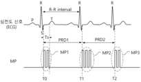
도 2는 본 발명의 실시 예에 따른 멀티-펄싱 전압(MP)을 예시적으로 보여주는 파형도이다. 도 2를 참조하면, 멀티-펄스 생성부(1200, 도 1 참조)는 심전도 신호(ECG)의 주기 또는, R-R 인터벌에 따라 최적의 멀티-펄싱 전압(MP)을 생성할 수 있다. 여기서, 최적이란 멀티-펄싱 전압(MP)의 펄스 수(N), 펄스 간격(I), 그리고 펄스 폭(W) 중에서 적어도 하나가 사용자가 선택한 조건에서 최적화될 수 있음을 의미한다.FIG. 2 is a waveform diagram exemplarily showing a multi-pulsing voltage (MP) according to an embodiment of the present invention. Referring to FIG. 2, a multi-pulse generation unit (1200, see FIG. 1) can generate an optimal multi-pulsing voltage (MP) according to a cycle of an electrocardiogram signal (ECG) or an R-R interval. Here, optimality means that at least one of the pulse number (N), pulse interval (I), and pulse width (W) of the multi-pulsing voltage (MP) can be optimized under conditions selected by a user.
T0 시점에서 멀티-펄스 생성부(1200)는 이전 주기에서 검출된 심전도 신호(ECG)의 R-R 인터벌(또는, 주기)에 따라 제 1 멀티-펄싱 전압(MP1)을 출력한다. 심전도 신호(ECG)의 R-R 인터벌의 크기에 따라 멀티-펄스 생성부(1200)는 하나의 펄스 주기(PRD1) 이내에서 2개 펄스(N=2)를 갖는 제 1 멀티-펄싱 전압(MP1)을 생성할 수 있다. 이때, 제 1 멀티-펄싱 전압(MP1)은 심전도 신호(ECG)의 안전 구간(Ts)에서 인가되어야 한다. 왜냐하면, 심전도 신호(ECG)의 S-피크와 T-피크 사이가 심장의 자극이 최소화되는 휴지기이기 때문이다.At time T0, the multi-pulse generator (1200) outputs a first multi-pulsing voltage (MP1) according to the R-R interval (or cycle) of the electrocardiogram signal (ECG) detected in the previous cycle. Depending on the size of the R-R interval of the electrocardiogram signal (ECG), the multi-pulse generator (1200) can generate the first multi-pulsing voltage (MP1) having two pulses (N=2) within one pulse cycle (PRD1). At this time, the first multi-pulsing voltage (MP1) must be applied in the safe section (Ts) of the electrocardiogram signal (ECG). This is because the period between the S-peak and the T-peak of the electrocardiogram signal (ECG) is a resting period in which stimulation of the heart is minimized.
T1 시점에서 멀티-펄스 생성부(1200)는 이전 주기에서 검출된 심전도 신호(ECG)의 R-R 인터벌(또는, 주기)에 따라 제 2 멀티-펄싱 전압(MP2)을 출력한다. 검출된 심전도 신호(ECG)의 R-R 인터벌의 크기에 따라 멀티-펄스 생성부(1200)는 펄스 주기(PRD2) 이내에서 3개 펄스(N=3)를 갖는 제 2 멀티-펄싱 전압(MP2)을 생성할 수 있다. 마찬가지로, 제 2 멀티-펄싱 전압(MP2)은 심전도 신호(ECG)의 안전 구간(Ts)에서 인가되어야 할 것이다.At time T1, the multi-pulse generator (1200) outputs a second multi-pulsing voltage (MP2) according to the R-R interval (or cycle) of the electrocardiogram signal (ECG) detected in the previous cycle. Depending on the size of the R-R interval of the detected electrocardiogram signal (ECG), the multi-pulse generator (1200) can generate the second multi-pulsing voltage (MP2) having three pulses (N=3) within the pulse cycle (PRD2). Similarly, the second multi-pulsing voltage (MP2) should be applied in the safe section (Ts) of the electrocardiogram signal (ECG).
T2 시점에서 멀티-펄스 생성부(1200)는 이전 주기에서 검출된 심전도 신호(ECG)의 R-R 인터벌(또는, 주기)에 따라 제 3 멀티-펄싱 전압(MP3)을 출력한다. 검출된 심전도 신호(ECG)의 R-R 인터벌의 크기에 따라 멀티-펄스 생성부(1200)는 펄스 주기 이내에서 2개 펄스(N=2)를 갖는 제 3 멀티-펄싱 전압(MP3)을 생성할 수 있다. 마찬가지로, 제 3 멀티-펄싱 전압(MP3)은 심전도 신호(ECG)의 안전 구간(Ts)에서 인가되어야 할 것이다.At time T2, the multi-pulse generator (1200) outputs a third multi-pulsing voltage (MP3) according to the R-R interval (or cycle) of the electrocardiogram signal (ECG) detected in the previous cycle. Depending on the size of the R-R interval of the detected electrocardiogram signal (ECG), the multi-pulse generator (1200) may generate the third multi-pulsing voltage (MP3) having two pulses (N=2) within the pulse cycle. Similarly, the third multi-pulsing voltage (MP3) should be applied in the safe section (Ts) of the electrocardiogram signal (ECG).
이상에서는 본 발명의 멀티-펄스 생성부(1200)에 의해서 수행되는 멀티-펄싱 전압(MP)의 특성이 간략히 설명되었다. 멀티-펄스 생성부(1200)는 심전도 신호(ECG)의 주기 또는 R-R 인터벌의 크기에 따라 가변되는 멀티-펄싱 전압(MP)을 생성할 수 있다. 도시된 예와 같이, 멀티-펄스 생성부(1200)는 R-R 인터벌의 크기에 따라 펄스 수(N)를 최적 값으로 가변할 수 있다. 다른 실시 예에서는, 멀티-펄스 생성부(1200)는 심전도 신호(ECG)의 R-R 인터벌에 따라 멀티-펄싱 전압(MP)의 펄스 간격(I)이나 펄스 폭(W)을 최적 값으로 설정할 수 있다.In the above, the characteristics of the multi-pulsing voltage (MP) performed by the multi-pulse generating unit (1200) of the present invention have been briefly described. The multi-pulse generating unit (1200) can generate a multi-pulsing voltage (MP) that varies according to the period of an electrocardiogram signal (ECG) or the size of an R-R interval. As in the illustrated example, the multi-pulse generating unit (1200) can vary the number of pulses (N) to an optimal value according to the size of the R-R interval. In another embodiment, the multi-pulse generating unit (1200) can set the pulse interval (I) or pulse width (W) of the multi-pulsing voltage (MP) to an optimal value according to the R-R interval of the electrocardiogram signal (ECG).
도 3은 도 2의 심전도 신호(ECG)의 하나의 파형을 보여주는 그래프이다. 도 3을 참조하면, 심전도 신호(ECG)는 ECG 모니터(100, 도 1 참조)와 같은 별도의 측정 장비를 통해 추출될 수 있지만, 본 발명은 여기에 국한되지 않는다. 심전도 신호(ECG)는 심장의 전기적 활동을 분석하여 파장 형태로 기록한 것을 말한다. 심장의 근육 세포들은 전류에 반응하여 수축/이완하며, 이러한 활동은 심장의 전도계에서 흘려보내는 전류에 의해 통제된다. 따라서, 심장의 전기적 활동을 분석하는 것으로 심장의 움직임이나 이상 여부를 알 수 있다.FIG. 3 is a graph showing one waveform of the electrocardiogram signal (ECG) of FIG. 2. Referring to FIG. 3, the electrocardiogram signal (ECG) can be extracted through a separate measuring device such as an ECG monitor (100, see FIG. 1), but the present invention is not limited thereto. The electrocardiogram signal (ECG) refers to the electrical activity of the heart analyzed and recorded in the form of waves. The muscle cells of the heart contract/relax in response to electric current, and this activity is controlled by the electric current flowing through the conduction system of the heart. Therefore, by analyzing the electrical activity of the heart, the movement or abnormality of the heart can be identified.
심전도 신호(ECG)는 복수의 파형들(P, Q, R, S, T)로 특징지을 수 있다. 먼저, P-파에서는 심장의 동방결절에서 전류 신호가 발생하고, 이것이 심방을 극성화 시키면서 판막의 심근이 수축하고, 심방이 비극성화되면서 판막의 심근은 다시 이완된다. 방실결절이 페이스 메이킹 중이라면 P-파의 파형이 뒤집힐 것이다. P-파의 폭은 심방의 전도 시간을 의미하며 정상 범위는 0.12초 이내이다. 이것이 비정상적으로 증가하면 좌심방의 확장을 시사한다.The electrocardiogram (ECG) signal can be characterized by multiple waveforms (P, Q, R, S, T). First, in the P wave, the current signal is generated in the sinoatrial node of the heart, and this polarizes the atrium, causing the myocardium of the valve to contract, and then the myocardium of the valve to relax again as the atrium becomes nonpolar. If the AV node is pacemaking, the waveform of the P wave will be inverted. The width of the P wave indicates the conduction time of the atrium, and the normal range is within 0.12 seconds. If this increases abnormally, it suggests enlargement of the left atrium.
P-Q 인터벌은 전류 신호가 심장을 자극하지 않는 휴지기라서 일직선으로 표시된다. 이때 P-파에 대한 반응으로 극성화되었던 심방이 수축한다. 또한, 심방이 수축할 때 심실이 반응하지 않도록 방실결절이 전류 신호를 묶어 놓는다.The P-Q interval is a resting period when the current signal does not stimulate the heart, so it is represented as a straight line. At this time, the atrium, which was polarized in response to the P wave, contracts. In addition, the AV node binds the current signal so that the ventricle does not respond when the atrium contracts.
QRS 피크들은 방실결절이 전류 신호를 놓아주면 Q-피크로 나타나고, 심실이 즉시 R-피크와 같이 극성화된다. 그리고 곧바로 심실은 S-피크로 비극성화된다. 이 과정에서 심실의 판막의 심근이 수축한다. Q-R-S 타이밍에서 아직 심실은 박동하지 않은 상태이다.The QRS peaks appear as Q-peaks when the AV node releases the current signal, and the ventricles immediately become polarized as R-peaks. Then, immediately after, the ventricles become depolarized as S-peaks. During this process, the myocardium of the ventricular valves contracts. At the Q-R-S timing, the ventricles have not yet started to beat.
S-파와 T-파 사이에서는 전류 신호가 심장을 자극하지 않는 휴지기라서 일직선으로 표시된다. 이때 QRS 피크들의 자극에 반응한 심실이 수축하고 심실에 있던 피가 폐와 신체 곳곳으로 출발한다. 만일 일직선이 아닌 경우에는 심내/외막의 허혈 손상을 의심할 수 있다. T-파에서는 심실이 다시 약하게 극성화되었다가 다시 비극성화되면서 심실과 심실 판막의 심근이 동시에 이완된다.Between the S-wave and the T-wave, the current signal is a resting period that does not stimulate the heart, so it is displayed as a straight line. At this time, the ventricle contracts in response to the stimulation of the QRS peaks, and the blood in the ventricle departs to the lungs and various parts of the body. If it is not a straight line, ischemic damage to the endocardium/epicardium can be suspected. In the T-wave, the ventricle is weakly polarized again and then depolarized again, and the myocardium of the ventricle and ventricular valve relaxes simultaneously.
본 발명의 멀티-펄스 전압(MP)은 전류 신호가 심장을 자극하지 않는 휴지기인 안전 구간(Ts)에서 환부에 인가된다. 안전 구간(Ts)은 S-파와 T-파 사이에서 설정될 수 있다.The multi-pulse voltage (MP) of the present invention is applied to the affected area during a safe period (Ts), which is a resting period in which the current signal does not stimulate the heart. The safe period (Ts) can be set between the S-wave and the T-wave.
도 4는 본 발명의 실시 예에 비가역적 전기천공 시스템의 멀티-펄스 전압(MP)을 생성하는 방법을 보여주는 순서도이다. 도 4를 참조하면, 비가역적 전기천공 시스템(1000, 도 1 참조)은 심전도 신호(ECG)에 동기하여 하나의 주기 동안 둘 이상의 펄스를 포함하는 제공되는 멀티-펄싱 전압(MP)을 생성할 수 있다.FIG. 4 is a flowchart showing a method for generating a multi-pulse voltage (MP) of an irreversible electroporation system according to an embodiment of the present invention. Referring to FIG. 4, the irreversible electroporation system (1000, see FIG. 1) can generate a provided multi-pulsing voltage (MP) comprising two or more pulses during one cycle in synchronization with an electrocardiogram signal (ECG).
S110 단계에서, 비가역적 전기천공 시스템(1000)은 심전도 신호(EC)를 수신한다. 심전도 신호(ECG)는 별도로 구비되어 환자의 심전도를 측정하기 위한 ECG 모니터(100)로부터 제공받을 수도 있다. 다른 실시 예에서, ECG 모니터(100)는 비가역적 전기천공 시스템(1000) 내부에 장착되는 방식으로 구성될 수도 있을 것이다. 다른 실시 예에서, 비가역적 전기천공 시스템(1000)은 심전도 신호(ECG)는 ECG 모니터(100)로부터 환자의 심전도 그래프에서 심실이 극성화되는 R-피크들 간의 간격인 R-R 인터벌의 크기를 수신할 수도 있다.At step S110, the irreversible electroporation system (1000) receives an electrocardiogram (ECG) signal. The ECG signal (ECG) may be provided separately from an ECG monitor (100) for measuring an electrocardiogram of a patient. In another embodiment, the ECG monitor (100) may be configured to be mounted inside the irreversible electroporation system (1000). In another embodiment, the irreversible electroporation system (1000) may receive the ECG signal (ECG) from the ECG monitor (100) as the size of an R-R interval, which is the interval between R-peaks in which the ventricles are polarized in the electrocardiogram of the patient.
S120 단계에서, 비가역적 전기천공 시스템(1000)은 심전도 신호(ECG) 또는 심전도 신호(ECG)의 R-R 인터벌을 기초로 심전도 신호(ECG)의 안전 구간(Refractory period: Ts)을 계산한다. 안전 구간(Ts)은 심전도 신호(ECG)의 S-피크와 T-피크 사이에 위치하며, 심장의 자극이 최소화되는 휴지기이다. 안전 구간(Ts)에서 본 발명의 멀티-펄싱 전압(MP1)이 환부에 인가되어야 한다.At step S120, the irreversible electroporation system (1000) calculates a refractory period (Ts) of the electrocardiogram signal (ECG) based on the electrocardiogram signal (ECG) or the R-R interval of the electrocardiogram signal (ECG). The refractory period (Ts) is located between the S-peak and the T-peak of the electrocardiogram signal (ECG) and is a resting period in which stimulation of the heart is minimized. The multi-pulsing voltage (MP1) of the present invention should be applied to the affected area in the refractory period (Ts).
S130 단계에서, 비가역적 전기천공 시스템(1000)은 멀티-펄싱을 위한 사용자가 선택한 고정 변수를 수신한다. 사용자 선택 고정 변수는 멀티-펄싱 최적화 연산에서 고정된 값으로 지정되는 파라미터를 의미한다. 예를 들면, 사용자가 멀티-펄싱 전압(MP)의 최적화 연산에서 고정된 값으로 설정하는 값을 의미한다. 예를 들면, 멀티-펄싱을 위한 파라미터로 멀티-펄싱 전압(MP)의 펄스 수(N), 펄스 간격(I), 그리고 펄스 폭(W)이 사용될 수 있을 것이다. 그러면, 이들 멀티-펄싱 파라미터들 중에서 사용자는 두 가지의 파라미터를 고정값으로 선택할 수 있다. 그러면, 최적화 연산에 의해서 나머지 하나의 멀티-펄싱 파라미터가 서치될 수 있다. 여기서, 본 발명의 실시 예에서 사용자 선택 고정 변수의 수는 다양하게 변경될 수 있다. 예를 들면, 사용자 선택 고정 변수는 한 가지로 선택될 수 있고, 나머지 두 가지의 파라미터들이 최적화 알고리즘에 의해서 서치될 수 있을 것이다. 또는, 사용자 선택 고정 변수가 선택되지 않고, 세 가지의 파라미터들이 최적화 알고리즘에 의해서 서치될 수 있을 것이다.In step S130, the irreversible electroporation system (1000) receives fixed variables selected by the user for multi-pulsing. The fixed variables selected by the user refer to parameters that are set as fixed values in the optimization operation of the multi-pulsing. For example, they refer to values that the user sets as fixed values in the optimization operation of the multi-pulsing voltage (MP). For example, the pulse number (N), pulse interval (I), and pulse width (W) of the multi-pulsing voltage (MP) may be used as parameters for multi-pulsing. Then, among these multi-pulsing parameters, the user may select two parameters as fixed values. Then, the remaining one multi-pulsing parameter may be searched by the optimization operation. Here, the number of fixed variables selected by the user may be changed in various ways in the embodiment of the present invention. For example, one fixed variable selected by the user may be selected, and the remaining two parameters may be searched by the optimization algorithm. Or, the fixed variables selected by the user may not be selected, and three parameters may be searched by the optimization algorithm.
S140 단계에서, S130 단계에서 선택된 사용자 선택 고정 변수를 기반으로 최적 멀티-펄싱 파라미터를 서치하기 위한 연산이 수행된다. 만일, 멀티-펄싱 전압(MP)의 펄스 간격(I)과 펄스 폭(W)이 사용자 선택 고정 변수에 대응하는 경우, 최적화 연산은 안전 구간(Ts) 내에 수용될 수 있는 최대 펄스 수(N)를 서치하게 될 것이다. 예를 들면, 사용자 선택 고정 변수 조건에서 안전 구간(Ts) 내에 들어갈 수 있는 최대 펄스 수(N)가 '3'인 경우, 멀티-펄스 생성부(1200)는 최적 펄스 수를 '3'으로 확정할 것이다. 만일, 사용자 선택 고정 변수가 펄스 수(N=3)와 펄스 폭(W=W1)인 경우, 멀티-펄스 생성부(1200)는 안전 구간(Ts) 내에 수용될 수 있는 최적의 펄스 간격(I)을 서치할 것이다.In step S140, an operation is performed to search for optimal multi-pulsing parameters based on the user-selected fixed variables selected in step S130. If the pulse interval (I) and pulse width (W) of the multi-pulsing voltage (MP) correspond to the user-selected fixed variables, the optimization operation will search for the maximum number of pulses (N) that can be accommodated within the safe section (Ts). For example, if the maximum number of pulses (N) that can be accommodated within the safe section (Ts) is '3' under the user-selected fixed variable conditions, the multi-pulse generation unit (1200) will determine the optimal number of pulses as '3'. If the user-selected fixed variables are the number of pulses (N=3) and the pulse width (W=W1), the multi-pulse generation unit (1200) will search for the optimal pulse interval (I) that can be accommodated within the safe section (Ts).
S150 단계에서, 비가역적 전기천공 시스템(1000)은 S140 단계에서 결정된 멀티-펄싱 파라미터들을 기반으로 고전압의 전기천공 전압을 생성한다. 즉, 비가역적 전기천공 시스템(1000)은 멀티-펄싱 최적화 연산을 통해서 결정된 펄스 수(N), 펄스 간격(I), 그리고 펄스 폭(W)을 기반으로 멀티-펄싱 전압(MP)을 생성할 것이다. 그리고 생성된 전압은 프로브(1400)를 통해서 환자(10, 도 1 참조)의 환부에 인가될 수 있다.In step S150, the irreversible electroporation system (1000) generates a high-voltage electroporation voltage based on the multi-pulsing parameters determined in step S140. That is, the irreversible electroporation system (1000) will generate a multi-pulsing voltage (MP) based on the pulse number (N), pulse interval (I), and pulse width (W) determined through the multi-pulsing optimization operation. Then, the generated voltage can be applied to the affected area of the patient (10, see FIG. 1) through the probe (1400).
이상에서 설명된 순서도에 따르면, 본 발명의 비가역적 전기천공 시스템(1000)은 심전도 신호(ECG)에 동기하여 최적의 펄스 파라미터를 갖는 멀티-펄스 전압(MP)을 생성할 수 있다. 따라서, 싱글-펄싱(Single-pulsing)을 적용할 때보다 비가역적 전기천공 시술의 시간을 줄일 수 있고, 그에 따라 발생하는 과전류 문제를 해결할 수 있다.According to the flow chart described above, the irreversible electroporation system (1000) of the present invention can generate a multi-pulse voltage (MP) having optimal pulse parameters in synchronization with an electrocardiogram signal (ECG). Therefore, the time for the irreversible electroporation procedure can be reduced compared to when applying single-pulsing, and the resulting overcurrent problem can be solved.
도 5는 본 발명의 실시 예에 따른 비가역적 전기천공 시스템의 멀티-펄싱 방법을 보여주는 순서도이다. 도 5를 참조하면, 비가역적 전기천공 시스템(1000, 도 1 참조)은 사용자로부터 펄스 폭(W)과 펄스 간격(I)의 크기를 수신한다. 그리고 비가역적 전기천공 시스템(1000)은 최적의 펄스 수(N)를 멀티-펄싱 최적화 연산을 통해서 결정할 수 있다.FIG. 5 is a flowchart showing a multi-pulsing method of an irreversible electroporation system according to an embodiment of the present invention. Referring to FIG. 5, the irreversible electroporation system (1000, see FIG. 1) receives the size of a pulse width (W) and a pulse interval (I) from a user. Then, the irreversible electroporation system (1000) can determine an optimal pulse number (N) through a multi-pulsing optimization operation.
S210 단계에서, 비가역적 전기천공 시스템(1000)은 심전도 신호(EC)를 수신한다. 심전도 신호(ECG)는 별도로 구비되어 환자의 심전도를 측정하기 위한 ECG 모니터(100)로부터 제공받을 수도 있다. 다른 실시 예에서, ECG 모니터(100)는 비가역적 전기천공 시스템(1000) 내부에 구비될 수도 있을 것이다.At step S210, the irreversible electroporation system (1000) receives an electrocardiogram (EC) signal. The electrocardiogram (ECG) signal may be provided from an ECG monitor (100) separately provided for measuring the electrocardiogram of the patient. In another embodiment, the ECG monitor (100) may be provided inside the irreversible electroporation system (1000).
S220 단계에서, 비가역적 전기천공 시스템(1000)은 해당 환자(10, 도 1 참조)의 심전도 신호의 주기 또는 특성 정보를 추출한다. 예를 들면, 비가역적 전기천공 시스템(1000)은 환자(10)의 심전도 신호(ECG)로부터 심실이 극성화되는 R-피크들 간의 간격인 R-R 인터벌을 검출할 수 있다.At step S220, the irreversible electroporation system (1000) extracts period or characteristic information of the electrocardiogram signal of the patient (10, see FIG. 1). For example, the irreversible electroporation system (1000) can detect an R-R interval, which is the interval between R-peaks at which the ventricles are polarized, from the electrocardiogram signal (ECG) of the patient (10).
S230 단계에서, 비가역적 전기천공 시스템(1000)은 심전도 신호(ECG) 또는 심전도 신호(ECG)의 R-R 인터벌을 기초로 심전도 신호(ECG)의 안전 구간(Refractory period: Ts)을 계산한다. 안전 구간(Ts)은 심전도 신호(ECG)의 S-피크와 T-피크 사이에 위치하며, 심장의 자극이 최소화되는 휴지기이다. 최종적으로 생성될 멀티-펄싱 전압(MP)은 이 안전 구간(Ts)에서 환자에게 인가되어야 한다. 따라서, 생성될 멀티-펄싱 전압(MP)의 펄스 수(N)는 안전 구간(Ts)을 충족하는 값으로 최적화될 것이다.At step S230, the irreversible electroporation system (1000) calculates a refractory period (Ts) of the electrocardiogram signal (ECG) based on the electrocardiogram signal (ECG) or the R-R interval of the electrocardiogram signal (ECG). The refractory period (Ts) is located between the S-peak and the T-peak of the electrocardiogram signal (ECG) and is a resting period in which stimulation of the heart is minimized. The multi-pulsing voltage (MP) to be finally generated should be applied to the patient in this refractory period (Ts). Therefore, the number of pulses (N) of the multi-pulsing voltage (MP) to be generated will be optimized to a value that satisfies the refractory period (Ts).
S240 단계에서, 비가역적 전기천공 시스템(1000)은 멀티-펄싱을 위한 사용자 선택 고정 변수를 수신한다. 사용자 선택 고정 변수는 멀티-펄싱 최적화 연산에서 고정된 값으로 지정되는 파라미터들을 의미한다. 이 실시 예에서, 멀티-펄싱 파라미터들 중에서 사용자 선택 고정 변수는 펄스 간격(I)과 펄스 폭(W)이다. 비가역적 전기천공 시스템(1000)은 사용자가 입력하는 펄스 간격(I)과 펄스 폭(W)의 값을 상수 값으로 저장한다.In step S240, the irreversible electroporation system (1000) receives user-selected fixed variables for multi-pulsing. The user-selected fixed variables refer to parameters that are designated as fixed values in a multi-pulsing optimization operation. In this embodiment, among the multi-pulsing parameters, the user-selected fixed variables are pulse interval (I) and pulse width (W). The irreversible electroporation system (1000) stores the values of the pulse interval (I) and pulse width (W) input by the user as constant values.
S250 단계에서, 비가역적 전기천공 시스템(1000)은 고정된 값의 펄스 간격(I)과 펄스 폭(W) 조건에서, 최적 멀티-펄싱 파라미터를 서치하기 위한 펄스 최적화 연산 또는 펄스 최적화 알고리즘이 실행된다. 멀티-펄싱 전압(MP)의 펄스 간격(I)과 펄스 폭(W)이 사용자 선택 고정 변수이기 때문에, 펄스 최적화 연산은 안전 구간(Ts) 내에 수용될 수 있는 최대 펄스 수(N)를 구하는 연산이 될 것이다. 펄스 최적화 연산은 S252 단계, S254 단계, 그리고 S256 단계의 동작 루프를 통해서 구현될 수 있다.In step S250, the irreversible electroporation system (1000) executes a pulse optimization operation or pulse optimization algorithm to search for optimal multi-pulsing parameters under conditions of fixed values of pulse interval (I) and pulse width (W). Since the pulse interval (I) and pulse width (W) of the multi-pulsing voltage (MP) are user-selected fixed variables, the pulse optimization operation will be an operation to obtain the maximum number of pulses (N) that can be accommodated within the safety interval (Ts). The pulse optimization operation can be implemented through the operation loops of steps S252, S254, and S256.
S252 단계에서, 멀티-펄스 생성부(1200, 도 1 참조)는 펄스 수(N)를 초기화한다. 예를 들면, 펄스 수(N)를 미리 설정된 최대값(Nmax)을 초기값으로 선택할 수 있다. 펄스 수(N)의 최대값(Nmax)은, 예를 들면, 안전 구간(Ts)을 펄스 폭(W)으로 나눈 값의 반올림한 정수값으로 선택될 수 있다.In step S252, the multi-pulse generator (1200, see FIG. 1) initializes the pulse number (N). For example, the pulse number (N) may be selected as a preset maximum value (Nmax) as the initial value. The maximum value (Nmax) of the pulse number (N) may be selected as, for example, a rounded integer value of the value obtained by dividing the safety interval (Ts) by the pulse width (W).
S254 단계에서, 멀티-펄스 생성부(1200)는 해당 루프에서의 펄스 수(N)에 대응하는 멀티-펄스 구간(MPD)이 안전 구간(Ts) 요건을 충족하는지 판단한다. 안전 구간(Ts) 요건은 아래 수학식 1로 표현될 수 있다.In step S254, the multi-pulse generator (1200) determines whether the multi-pulse section (MPD) corresponding to the number of pulses (N) in the corresponding loop satisfies the safety section (Ts) requirement. The safety section (Ts) requirement can be expressed by the following
수학식 1은 고정된 상수 값의 펄스 간격(I)과 펄스 폭(W) 조건에서 펄스 수(N)에 따른 멀티-펄스 구간(MPD)이 안전 구간(Ts) 이내에 위치할 수 있는지를 판단하는 기준을 의미한다. 만일, 멀티-펄스 구간(MPD)이 안전 구간(Ts)보다 큰 경우('No' 방향), 절차는 S256 단계로 이동한다. 반면, 멀티-펄스 구간(MPD)이 안전 구간(Ts)보다 작은 경우('No' 방향), 절차는 S260 단계로 이동할 것이다.
S256 단계에서, 멀티-펄스 생성부(1200)는 펄스 수(N)를 1만큼 감소시킨다. 예를 들면, S254 단계에서 적용된 펄스 수(N)에서 1을 감소시킨 값(N-1)으로 펄스 수(N)를 재설정할 수 있다. 이어서, 절차는 S254 단계로 복귀하여 수학식 1에 정의된 바와 같이 감소된 펄스 수(N-1)가 멀티-펄스 구간(MPD)이 안전 구간(Ts) 요건을 충족하는지 판단할 것이다. S254, S256 루프는 멀티-펄스 구간(MPD)이 안전 구간(Ts) 요건을 충족하는 최대 펄스 수가 검출될 때까지 반복될 것이다.At step S256, the multi-pulse generator (1200) decreases the pulse number (N) by 1. For example, the pulse number (N) may be reset to a value (N-1) obtained by decreasing 1 from the pulse number (N) applied at step S254. Then, the procedure returns to step S254 to determine whether the decreased pulse number (N-1) as defined in
S260 단계에서, 안전 구간(Ts) 요건을 충족하는 최대 펄스 수에 근거하여 멀티-펄싱 파라미터가 확정된다. 즉, 멀티-펄스 구간(MPD)이 안전 구간(Ts) 요건을 충족하는 최대 펄스 수를 최적 펄스 수(Nopt)로 확정된다. 더불어, 멀티-펄싱 전압(MP)의 펄스 수(N), 펄스 간격(I), 그리고 펄스 폭(W) 이외의 파라미터들도 확정될 수도 있을 것이다.In step S260, the multi-pulsing parameters are determined based on the maximum number of pulses that satisfy the safety interval (Ts) requirement. That is, the multi-pulsing interval (MPD) is determined as the maximum number of pulses that satisfy the safety interval (Ts) requirement as the optimal pulse number (Nopt). In addition, parameters other than the pulse number (N), pulse interval (I), and pulse width (W) of the multi-pulsing voltage (MP) may also be determined.
S270 단계에서, 멀티-펄스 생성부(1200)는 S220 단계에서의 검출된 R-R 인터벌의 후속되는 심전도 신호(ECG)에서도 여전히 S220 단계에서의 R-R 인터벌을 유지하는지 판단한다. 심전도 신호(ECG)의 특성은 급격하게 R-R 인터벌이 변화하지는 않는다. 따라서, S220 단계에서의 검출된 R-R 인터벌과 이후에 검출된 R-R 인터벌이 동일한지 판단하여, S220 단계에서의 검출된 R-R 인터벌을 기초로 생성된 최적 멀티-펄스 전압(MP)을 인가할지 판단할 수 있다. 만일, R-R 인터벌이 유지되지 않고 변경된 경우('No' 방향), 절차는 S220 단계로 복귀하여 새로운 R-R 인터벌에 기초하여 펄스 최적화 연산이 시작될 것이다. 반면, R-R 인터벌이 유지되고 있는 경우('Yes' 방향), 절차는 S280 단계로 이동한다.In step S270, the multi-pulse generation unit (1200) determines whether the R-R interval in step S220 is still maintained in the subsequent electrocardiogram signal (ECG) of the R-R interval detected in step S220. The characteristic of the electrocardiogram signal (ECG) is that the R-R interval does not change abruptly. Therefore, by determining whether the detected R-R interval in step S220 and the subsequently detected R-R interval are the same, it is possible to determine whether to apply the optimal multi-pulse voltage (MP) generated based on the detected R-R interval in step S220. If the R-R interval is not maintained but changed ('No' direction), the procedure returns to step S220 and the pulse optimization operation is started based on the new R-R interval. On the other hand, if the R-R interval is maintained ('Yes' direction), the procedure moves to step S280.
S280 단계에서, 비가역적 전기천공 시스템(1000)은 S260 단계에서 확정된 최적화된 멀티-펄싱 파라미터를 기초로 고전압의 멀티-펄싱 전압(MP)을 생성하고, 환부에 인가하는 전기천공 펄싱을 수행할 것이다.At step S280, the irreversible electroporation system (1000) will generate a high voltage multi-pulsing voltage (MP) based on the optimized multi-pulsing parameters determined at step S260 and perform electroporation pulsing applied to the affected area.
이상에서는, 본 발명의 일 실시 예에 따른 비가역적 전기천공 시스템의 멀티-펄싱 방법이 간략히 설명되었다. 비가역적 전기천공 시스템(1000)은 상수로 설정되는 펄스 폭(W)과 펄스 간격(I)을 기초로 안전 구간(Ts) 요건을 충족하는 최대 펄스 수(Nopt)를 멀티-펄싱 최적화 연산을 통해서 결정할 수 있다.In the above, a multi-pulsing method of an irreversible electroporation system according to an embodiment of the present invention has been briefly described. The irreversible electroporation system (1000) can determine the maximum number of pulses (Nopt) that satisfies the safety interval (Ts) requirement through a multi-pulsing optimization operation based on a pulse width (W) and a pulse interval (I) that are set as constants.
도 6은 도 5의 실시 예에 따른 멀티-펄싱 방법에 따른 멀티-펄스 전압(MP)의 변화를 보여주는 파형도이다. 도 6을 참조하면, 본 발명의 펄스 최적화 알고리즘에 따라 펄스 간격(I)과 펄스 폭(W)이 고정된 조건에서 안전 구간(Ts) 요건을 충족하는 최대 펄스 수가 최적 펄스 수(Nopt)로 설정될 수 있다.Fig. 6 is a waveform diagram showing a change in a multi-pulse voltage (MP) according to a multi-pulsing method according to the embodiment of Fig. 5. Referring to Fig. 6, according to the pulse optimization algorithm of the present invention, the maximum number of pulses satisfying the safety section (Ts) requirement under the condition that the pulse interval (I) and pulse width (W) are fixed can be set as the optimal pulse number (Nopt).
T0 시점에서 심전도 신호(ECG)의 펄스들이 입력된다. 멀티-펄스 생성부(1200)는 T0 시점 이전 주기에서 검출된 심전도 신호(ECG)의 R-R 인터벌(또는, 주기)에 따라 안전 구간(Ts0)을 검출할 수 있다. 그리고 안전 구간(Ts0) 요건을 충족하는 최대 펄스 수를 최적 펄스 수(Nopt=4)로 결정할 수 있다. 따라서, 멀티-펄스 전압(MP)은 4개의 펄스들이 안전 구간(Ts0) 내에서 제공될 수 있다.At time T0, pulses of an electrocardiogram signal (ECG) are input. The multi-pulse generator (1200) can detect a safe section (Ts0) according to an R-R interval (or cycle) of an electrocardiogram signal (ECG) detected in a cycle prior to time T0. Then, the maximum number of pulses satisfying the requirement of the safe section (Ts0) can be determined as an optimal pulse number (Nopt=4). Accordingly, the multi-pulse voltage (MP) can be provided with four pulses within the safe section (Ts0).
T1 시점에서, 멀티-펄스 생성부(1200)는 T0 시점에 검출된 파형과 T1 시점에서 검출된 파형을 이용하여 R-R 인터벌(ΔT1)을 검출한다. 멀티-펄스 생성부(1200)는 R-R 인터벌(ΔT1)에 따라 안전 구간(Ts1)을 계산할 수 있다. 그리고 안전 구간(Ts1) 요건을 충족하는 최대 펄스 수를 최적 펄스 수(Nopt=3)로 결정할 수 있다. 따라서, 멀티-펄스 생성부(1200)는 T1 시점에서부터 3개의 펄스들을 갖는 멀티-펄스 전압(MP)을 안전 구간(Ts1) 내에서 제공할 수 있다.At time T1, the multi-pulse generator (1200) detects the R-R interval (ΔT1) using the waveform detected at time T0 and the waveform detected at time T1. The multi-pulse generator (1200) can calculate the safety section (Ts1) according to the R-R interval (ΔT1). Then, the maximum number of pulses satisfying the safety section (Ts1) requirement can be determined as the optimal pulse number (Nopt=3). Therefore, the multi-pulse generator (1200) can provide a multi-pulse voltage (MP) having three pulses from time T1 within the safety section (Ts1).
T2 시점에서는 멀티-펄스 생성부(1200)는 T1 시점에 검출된 파형과 T2 시점에서 검출된 파형을 이용하여 R-R 인터벌(ΔT1)을 검출한다. 멀티-펄스 생성부(1200)는 R-R 인터벌(ΔT1)에 따라 안전 구간(Ts1)을 계산할 수 있다. 즉, 멀티-펄스 생성부(1200)는 T1 시점에서와 동일한 크기의 안전 구간(Ts1)으로 판단할 것이다. 이어서, 안전 구간(Ts1) 요건을 충족하는 최대 펄스 수를 최적 펄스 수(Nopt=3)로 결정할 수 있다. 따라서, 멀티-펄스 생성부(1200)는 T2 시점부터 3개의 펄스들을 갖는 멀티-펄스 전압(MP)을 안전 구간(Ts1) 내에서 제공할 수 있다.At time T2, the multi-pulse generator (1200) detects the R-R interval (ΔT1) using the waveform detected at time T1 and the waveform detected at time T2. The multi-pulse generator (1200) can calculate the safety section (Ts1) according to the R-R interval (ΔT1). That is, the multi-pulse generator (1200) will determine the safety section (Ts1) to be of the same size as that at time T1. Then, the maximum number of pulses satisfying the safety section (Ts1) requirement can be determined as the optimal pulse number (Nopt=3). Therefore, the multi-pulse generator (1200) can provide a multi-pulse voltage (MP) having three pulses from time T2 within the safety section (Ts1).
T3 시점에서, 멀티-펄스 생성부(1200)는 T2 시점에 검출된 파형과 T3 시점에서 검출된 파형을 이용하여 R-R 인터벌(ΔT2)을 검출한다. 멀티-펄스 생성부(1200)는 R-R 인터벌(ΔT2)에 따라 안전 구간(Ts2)을 계산할 수 있다. 그리고, 안전 구간(Ts2) 요건을 충족하는 최대 펄스 수를 최적 펄스 수(Nopt=5)로 결정할 수 있다. 따라서, 멀티-펄스 생성부(1200)는 T3 시점에서부터 5개의 펄스들을 갖는 멀티-펄스 전압(MP)을 안전 구간(Ts2) 내에서 제공할 수 있다.At time T3, the multi-pulse generator (1200) detects the R-R interval (ΔT2) using the waveform detected at time T2 and the waveform detected at time T3. The multi-pulse generator (1200) can calculate the safety section (Ts2) according to the R-R interval (ΔT2). Then, the maximum number of pulses satisfying the safety section (Ts2) requirement can be determined as the optimal pulse number (Nopt=5). Therefore, the multi-pulse generator (1200) can provide a multi-pulse voltage (MP) having five pulses from time T3 within the safety section (Ts2).
T4 시점에서는 멀티-펄스 생성부(1200)는 T3 시점에 검출된 파형과 T4 시점에서 검출된 파형을 이용하여 R-R 인터벌(ΔT2)을 검출한다. 멀티-펄스 생성부(1200)는 R-R 인터벌(ΔT2)에 따라 안전 구간(Ts2)을 계산할 수 있다. 즉, 멀티-펄스 생성부(1200)는 T3 시점에서와 동일한 크기의 안전 구간(Ts2)으로 판단할 것이다. 이어서, 안전 구간(Ts2) 요건을 충족하는 최대 펄스 수를 최적 펄스 수(Nopt=5)로 결정할 수 있다. 따라서, 멀티-펄스 생성부(1200)는 T4 시점에서부터 5개의 펄스들을 갖는 멀티-펄스 전압(MP)을 안전 구간(Ts2) 내에서 제공할 수 있다.At time T4, the multi-pulse generator (1200) detects the R-R interval (ΔT2) using the waveform detected at time T3 and the waveform detected at time T4. The multi-pulse generator (1200) can calculate the safety section (Ts2) according to the R-R interval (ΔT2). That is, the multi-pulse generator (1200) will determine the safety section (Ts2) to be of the same size as that at time T3. Then, the maximum number of pulses satisfying the safety section (Ts2) requirement can be determined as the optimal pulse number (Nopt=5). Therefore, the multi-pulse generator (1200) can provide a multi-pulse voltage (MP) having five pulses from time T4 within the safety section (Ts2).
T5 시점에서, 멀티-펄스 생성부(1200)는 T4 시점에 검출된 파형과 T5 시점에서 검출된 파형을 이용하여 R-R 인터벌(ΔT3)을 검출한다. 멀티-펄스 생성부(1200)는 R-R 인터벌(ΔT3)에 따라 안전 구간(Ts3)을 계산할 수 있다. 그리고, 안전 구간(Ts3) 요건을 충족하는 최대 펄스 수를 최적 펄스 수(Nopt=2)로 결정할 수 있다. 따라서, 멀티-펄스 생성부(1200)는 T5 시점에서부터 2개의 펄스들을 갖는 멀티-펄스 전압(MP)을 안전 구간(Ts3) 내에서 제공할 수 있다.At time T5, the multi-pulse generator (1200) detects the R-R interval (ΔT3) using the waveform detected at time T4 and the waveform detected at time T5. The multi-pulse generator (1200) can calculate the safety section (Ts3) according to the R-R interval (ΔT3). Then, the maximum number of pulses satisfying the safety section (Ts3) requirement can be determined as the optimal pulse number (Nopt=2). Therefore, the multi-pulse generator (1200) can provide a multi-pulse voltage (MP) having two pulses from time T5 within the safety section (Ts3).
T6 시점에서는 멀티-펄스 생성부(1200)는 T5 시점에 검출된 파형과 T6 시점에서 검출된 파형을 이용하여 R-R 인터벌(ΔT3)을 검출한다. 멀티-펄스 생성부(1200)는 R-R 인터벌(ΔT3)에 따라 안전 구간(Ts3)을 계산할 수 있다. 즉, 멀티-펄스 생성부(1200)는 T5 시점에서와 동일한 크기의 안전 구간(Ts3)으로 판단할 것이다. 이어서, 안전 구간(Ts3) 요건을 충족하는 최대 펄스 수를 최적 펄스 수(Nopt=2)로 결정할 수 있다. 따라서, 멀티-펄스 생성부(1200)는 T6 시점에서부터 2개의 펄스들을 갖는 멀티-펄스 전압(MP)을 안전 구간(Ts3) 내에서 제공할 수 있다.At time T6, the multi-pulse generator (1200) detects the R-R interval (ΔT3) using the waveform detected at time T5 and the waveform detected at time T6. The multi-pulse generator (1200) can calculate the safety section (Ts3) according to the R-R interval (ΔT3). That is, the multi-pulse generator (1200) will determine the safety section (Ts3) to be of the same size as that at time T5. Then, the maximum number of pulses satisfying the safety section (Ts3) requirement can be determined as the optimal pulse number (Nopt=2). Therefore, the multi-pulse generator (1200) can provide a multi-pulse voltage (MP) having two pulses from time T6 within the safety section (Ts3).
이상에서는, 본 발명의 멀티-펄스 생성부(1200)에 의해서 수행되는 고정된 펄스 간격(I)과 펄스 폭(W) 조건에서 최적 펄스 수(Nopt)를 검출하는 멀티-펄스 최적화 연산의 특징이 설명되었다. 도시된 바와 같이 멀티-펄스 생성부(1200)는 R-R 인터벌의 크기에 따라 멀티-펄스 전압(MP)의 펄스 수(N)를 최적값(Nopt)으로 조정할 수 있다.In the above, the characteristics of the multi-pulse optimization operation for detecting the optimal pulse number (Nopt) under the conditions of the fixed pulse interval (I) and pulse width (W) performed by the multi-pulse generator (1200) of the present invention have been described. As illustrated, the multi-pulse generator (1200) can adjust the pulse number (N) of the multi-pulse voltage (MP) to the optimal value (Nopt) according to the size of the R-R interval.
도 7은 본 발명의 다른 실시 예에 따른 비가역적 전기천공 시스템의 멀티-펄싱 방법을 보여주는 순서도이다. 도 7을 참조하면, 비가역적 전기천공 시스템(1000, 도 1 참조)은 사용자 선택 고정 변수로서 펄스 폭(W)과 펄스 수(N)의 값을 수신한다. 그리고 비가역적 전기천공 시스템(1000)은 최적의 펄스 간격(I)을 멀티-펄싱 최적화 연산을 통해서 결정할 수 있다.FIG. 7 is a flowchart showing a multi-pulsing method of an irreversible electroporation system according to another embodiment of the present invention. Referring to FIG. 7, the irreversible electroporation system (1000, see FIG. 1) receives values of pulse width (W) and pulse number (N) as user-selected fixed variables. Then, the irreversible electroporation system (1000) can determine an optimal pulse interval (I) through a multi-pulsing optimization operation.
S310 단계에서, 비가역적 전기천공 시스템(1000)은 심전도 신호(EC)를 수신한다. 심전도 신호(ECG)는 별도로 구비되어 환자의 심전도를 측정하기 위한 ECG 모니터(100)로부터 제공받을 수도 있다. 다른 실시 예에서, ECG 모니터(100)는 비가역적 전기천공 시스템(1000) 내부에 구비될 수도 있을 것이다.At step S310, the irreversible electroporation system (1000) receives an electrocardiogram (EC) signal. The electrocardiogram (ECG) signal may be provided from an ECG monitor (100) separately provided for measuring the electrocardiogram of the patient. In another embodiment, the ECG monitor (100) may be provided inside the irreversible electroporation system (1000).
S320 단계에서, 비가역적 전기천공 시스템(1000)은 환자(10, 도 1 참조)의 심전도 신호(ECG)의 주기 또는 특성 정보를 추출한다. 예를 들면, 비가역적 전기천공 시스템(1000)은 환자(10)의 심전도 신호(ECG)로부터 심실이 극성화되는 R-피크들 간의 간격인 R-R 인터벌을 검출할 수 있다.At step S320, the irreversible electroporation system (1000) extracts period or characteristic information of an electrocardiogram (ECG) signal of a patient (10, see FIG. 1). For example, the irreversible electroporation system (1000) can detect an R-R interval, which is the interval between R-peaks at which the ventricles are polarized, from the electrocardiogram (ECG) signal of the patient (10).
S330 단계에서, 비가역적 전기천공 시스템(1000)은 심전도 신호(ECG) 또는 심전도 신호(ECG)의 R-R 인터벌을 기초로 심전도 신호(ECG)의 안전 구간(Ts)을 계산한다. 안전 구간(Ts)은 심전도 신호(ECG)의 S-피크와 T-피크 사이에 위치하며, 심장의 자극이 최소화되는 휴지기이다. 최종적으로 생성될 멀티-펄싱 전압(MP)은 이 안전 구간(Ts)에서 환자(10)에게 인가되어야 한다. 따라서, 생성될 멀티-펄싱 전압(MP)의 펄스 간격(I)은 안전 구간(Ts)을 충족하는 값으로 최적화될 것이다.In step S330, the irreversible electroporation system (1000) calculates a safe interval (Ts) of the electrocardiogram signal (ECG) based on the electrocardiogram signal (ECG) or the R-R interval of the electrocardiogram signal (ECG). The safe interval (Ts) is located between the S-peak and the T-peak of the electrocardiogram signal (ECG) and is a resting period in which stimulation of the heart is minimized. The multi-pulsing voltage (MP) to be finally generated should be applied to the patient (10) in this safe interval (Ts). Therefore, the pulse interval (I) of the multi-pulsing voltage (MP) to be generated will be optimized to a value that satisfies the safe interval (Ts).
S340 단계에서, 비가역적 전기천공 시스템(1000)은 멀티-펄싱을 위한 사용자 선택 고정 변수를 수신한다. 사용자 선택 고정 변수는 멀티-펄싱 최적화 연산에서 고정된 값으로 지정되는 파라미터들을 의미한다. 이 실시 예에서, 멀티-펄싱 파라미터들 중에서 사용자 선택 고정 변수는 펄스 폭(W)과 펄스 수(N)이다. 비가역적 전기천공 시스템(1000)은 사용자가 입력하는 펄스 폭(W)과 펄스 수(N)의 값을 상수 값으로 저장한다.In step S340, the irreversible electroporation system (1000) receives user-selected fixed variables for multi-pulsing. The user-selected fixed variables refer to parameters that are designated as fixed values in a multi-pulsing optimization operation. In this embodiment, among the multi-pulsing parameters, the user-selected fixed variables are pulse width (W) and pulse number (N). The irreversible electroporation system (1000) stores the values of pulse width (W) and pulse number (N) input by the user as constant values.
S350 단계에서, 비가역적 전기천공 시스템(1000)은 고정된 값의 펄스 폭(W)과 펄스 수(N) 조건에서 최적 멀티-펄싱 파라미터를 서치하기 위한 펄스 최적화 연산 또는 펄스 최적화 알고리즘을 실행한다. 멀티-펄싱 전압(MP)의 펄스 폭(W)과 펄스 수(N)가 사용자 선택 고정 변수이기 때문에, 펄스 최적화 연산은 안전 구간(Ts) 내에 수용될 수 있는 최적의 펄스 구간(I)을 구하는 연산이 될 것이다. 펄스 최적화 연산은 S352 단계, S354 단계, 그리고 S356 단계의 동작 루프를 통해서 구현될 수 있다.In step S350, the irreversible electroporation system (1000) executes a pulse optimization operation or a pulse optimization algorithm to search for optimal multi-pulsing parameters under the conditions of fixed values of pulse width (W) and pulse number (N). Since the pulse width (W) and pulse number (N) of the multi-pulsing voltage (MP) are user-selected fixed variables, the pulse optimization operation will be an operation to obtain an optimal pulse section (I) that can be accommodated within the safety section (Ts). The pulse optimization operation can be implemented through the operation loops of steps S352, S354, and S356.
S352 단계에서, 멀티-펄스 생성부(1200, 도 1 참조)는 펄스 구간(I)을 초기화한다. 예를 들면, 미리 설정된 펄스 구간(I)의 최대값(Imax)을 초기값으로 사용할 수 있다. 펄스 구간(I)의 최대값(Imax)은, 예를 들면, 안전 구간(Ts)을 펄스 수(N)으로 나눈 값에 기반하여 결정될 수 있다.In step S352, the multi-pulse generator (1200, see FIG. 1) initializes the pulse interval (I). For example, the maximum value (Imax) of the preset pulse interval (I) can be used as the initial value. The maximum value (Imax) of the pulse interval (I) can be determined, for example, based on a value obtained by dividing the safety interval (Ts) by the number of pulses (N).
S354 단계에서, 멀티-펄스 생성부(1200)는 해당 루프에서의 펄스 구간(I)에 대응하는 멀티-펄스 구간(MPD)이 안전 구간(Ts) 요건을 충족하는지 판단한다. 안전 구간(Ts) 요건은 상술한 수학식 1에 근거하여 판단될 수 있다. 즉, 멀티-펄스 생성부(1200)는 수학식 1에 근거하여 고정된 상수 값의 펄스 수(N)와 펄스 폭(W) 조건에서 조정된 펄스 간격(I)에 따른 멀티-펄스 구간(MPD)이 안전 구간(Ts) 이내에 위치할 수 있는지를 판단할 수 있다. 만일, 멀티-펄스 구간(MPD)이 안전 구간(Ts)보다 큰 경우('No' 방향), 절차는 S356 단계로 이동한다. 반면, 멀티-펄스 구간(MPD)이 안전 구간(Ts)보다 작은 경우('No' 방향), 절차는 S360 단계로 이동할 것이다.In step S354, the multi-pulse generation unit (1200) determines whether the multi-pulse period (MPD) corresponding to the pulse period (I) in the corresponding loop satisfies the safety period (Ts) requirement. The safety period (Ts) requirement can be determined based on the
S356 단계에서, 멀티-펄스 생성부(1200)는 펄스 간격(I)을 'ΔI'만큼 감소시킨다. 예를 들면, S354 단계에서 적용된 펄스 간격(I)에서 'ΔI'를 차감한 값(I-ΔI)으로 펄스 간격(I)을 재설정할 수 있다. 이어서, 절차는 S354 단계로 복귀하여 수학식 1에 정의된 바와 같이 감소된 펄스 간격(I-ΔI)이 멀티-펄스 구간(MPD)이 안전 구간(Ts) 요건을 충족하는지 판단할 것이다. S354, S356 루프는 멀티-펄스 구간(MPD)이 안전 구간(Ts) 요건을 충족하는 최적 펄스 간격(Iopt)이 검출될 때까지 반복될 것이다.In step S356, the multi-pulse generator (1200) reduces the pulse interval (I) by 'ΔI'. For example, the pulse interval (I) may be reset to a value (I-ΔI) obtained by subtracting 'ΔI' from the pulse interval (I) applied in step S354. Then, the procedure returns to step S354 to determine whether the reduced pulse interval (I-ΔI) satisfies the requirement of the multi-pulse interval (MPD) for the safe interval (Ts) as defined in
S360 단계에서, 안전 구간(Ts) 요건을 충족하는 최대 펄스 수에 근거하여 멀티-펄싱 파라미터가 확정된다. 즉, 멀티-펄스 구간(MPD)이 안전 구간(Ts) 요건을 충족하는 최적 펄스 간격(Iopt)이 확정된다. 더불어, 멀티-펄싱 전압(MP)의 펄스 수(N), 펄스 간격(I), 그리고 펄스 폭(W) 이외의 파라미터들도 추가적으로 확정될 수도 있을 것이다.In step S360, the multi-pulsing parameters are determined based on the maximum number of pulses that satisfy the safety interval (Ts) requirement. That is, the optimal pulse interval (Iopt) that satisfies the safety interval (Ts) requirement of the multi-pulsing interval (MPD) is determined. In addition, parameters other than the number of pulses (N), pulse interval (I), and pulse width (W) of the multi-pulsing voltage (MP) may also be additionally determined.
S370 단계에서, 멀티-펄스 생성부(1200)는 S320 단계에서의 검출된 R-R 인터벌의 후속되는 심전도 신호(ECG)에서도 여전히 S320 단계에서의 R-R 인터벌을 유지하는지 판단한다. 심전도 신호(ECG)의 특성은 급격하게 R-R 인터벌이 변화하지는 않는다. 따라서, S320 단계에서의 검출된 R-R 인터벌과 이후에 검출된 R-R 인터벌이 동일한지 판단하여, S320 단계에서의 검출된 R-R 인터벌을 기초로 생성된 최적 멀티-펄스 전압(MP)을 인가할지 판단할 수 있다. 만일, R-R 인터벌이 유지되지 않고 변경된 경우('No' 방향), 절차는 S320 단계로 복귀하여 새로운 R-R 인터벌에 기초하여 펄스 최적화 연산이 시작될 것이다. 반면, R-R 인터벌이 유지되고 있는 경우('Yes' 방향), 절차는 S380 단계로 이동한다.In step S370, the multi-pulse generation unit (1200) determines whether the R-R interval in step S320 is still maintained in the subsequent electrocardiogram signal (ECG) of the R-R interval detected in step S320. The characteristic of the electrocardiogram signal (ECG) does not change the R-R interval abruptly. Therefore, by determining whether the detected R-R interval in step S320 and the subsequently detected R-R interval are the same, it is possible to determine whether to apply the optimal multi-pulse voltage (MP) generated based on the detected R-R interval in step S320. If the R-R interval is not maintained but changed ('No' direction), the procedure returns to step S320 and the pulse optimization operation is started based on the new R-R interval. On the other hand, if the R-R interval is maintained ('Yes' direction), the procedure moves to step S380.
S380 단계에서, 비가역적 전기천공 시스템(1000)은 S360 단계에서 확정된 최적화된 멀티-펄싱 파라미터를 기초로 고전압의 멀티-펄싱 전압(MP)을 생성하고, 환자에게 인가하는 전기천공 펄싱을 수행할 것이다.At step S380, the irreversible electroporation system (1000) will generate a high voltage multi-pulsing voltage (MP) based on the optimized multi-pulsing parameters determined at step S360 and perform electroporation pulsing applied to the patient.
이상에서는, 본 발명의 일 실시 예에 따른 비가역적 전기천공 시스템의 멀티-펄싱 방법이 간략히 설명되었다. 비가역적 전기천공 시스템(1000)은 상수로 설정되는 펄스 폭(W)과 펄스 수(N)를 기초로 안전 구간(Ts) 요건을 충족하는 최적 펄스 간격(Iopt)을 멀티-펄싱 최적화 연산을 통해서 결정할 수 있다.In the above, a multi-pulsing method of an irreversible electroporation system according to an embodiment of the present invention has been briefly described. The irreversible electroporation system (1000) can determine an optimal pulse interval (Iopt) that satisfies a safety interval (Ts) requirement through a multi-pulsing optimization operation based on a pulse width (W) and a pulse number (N) that are set as constants.
도 8은 도 7의 실시 예에 따른 멀티-펄싱 방법에 따른 멀티-펄스 전압(MP)의 변화를 보여주는 파형도이다. 도 8을 참조하면, 본 발명의 펄스 최적화 알고리즘에 따라 펄스 수(N=3)와 펄스 폭(W)이 고정된 조건에서 안전 구간(Ts) 요건을 충족하는 최적 펄스 간격(Iopt)이 서치될 수 있다.Fig. 8 is a waveform diagram showing a change in a multi-pulse voltage (MP) according to a multi-pulsing method according to the embodiment of Fig. 7. Referring to Fig. 8, an optimal pulse interval (Iopt) satisfying a safety section (Ts) requirement can be searched under the condition that the number of pulses (N=3) and the pulse width (W) are fixed according to the pulse optimization algorithm of the present invention.
T0 시점에서 심전도 신호(ECG)의 펄스들이 입력된다. 멀티-펄스 생성부(1200)는 T0 시점 이전 주기에서 검출된 심전도 신호(ECG)의 R-R 인터벌(또는, 주기)에 따라 안전 구간(Ts0)을 검출할 수 있다. 그리고, 안전 구간(Ts0) 요건을 충족하는 최적 펄스 간격(Iopt=I0)이 결정될 수 있다.At time T0, pulses of an electrocardiogram signal (ECG) are input. The multi-pulse generator (1200) can detect a safe section (Ts0) based on the R-R interval (or cycle) of the electrocardiogram signal (ECG) detected in a cycle prior to time T0. Then, an optimal pulse interval (Iopt=I0) that satisfies the requirement of the safe section (Ts0) can be determined.
T1 시점에서, 멀티-펄스 생성부(1200)는 T0 시점에 검출된 파형과 T1 시점에서 검출된 파형을 이용하여 R-R 인터벌(ΔT1)을 검출한다. 멀티-펄스 생성부(1200)는 R-R 인터벌(ΔT1)에 따라 안전 구간(Ts1)을 계산할 수 있다. 그리고 멀티-펄스 생성부(1200)는 안전 구간(Ts1) 요건을 충족하는 최적 펄스 간격(Iopt=I1)으로 결정할 수 있다. 따라서, 멀티-펄스 생성부(1200)는 T1 시점에서부터 펄스 폭(W)의 3개의 펄스들이 펄스 간격(I1)에 따라 생성되는 멀티-펄스 전압(MP)을 안전 구간(Ts1) 내에서 제공할 수 있다.At time T1, the multi-pulse generator (1200) detects the R-R interval (ΔT1) using the waveform detected at time T0 and the waveform detected at time T1. The multi-pulse generator (1200) can calculate the safety section (Ts1) according to the R-R interval (ΔT1). Then, the multi-pulse generator (1200) can determine the optimal pulse interval (Iopt=I1) that satisfies the safety section (Ts1) requirement. Therefore, the multi-pulse generator (1200) can provide the multi-pulse voltage (MP) in which three pulses of the pulse width (W) are generated according to the pulse interval (I1) from time T1 within the safety section (Ts1).
T2 시점에서는 멀티-펄스 생성부(1200)는 T1 시점에 검출된 파형과 T2 시점에서 검출된 파형을 이용하여 R-R 인터벌(ΔT1)을 검출한다. 멀티-펄스 생성부(1200)는 R-R 인터벌(ΔT1)에 따라 안전 구간(Ts1)을 계산할 수 있다. 즉, 멀티-펄스 생성부(1200)는 T1 시점에서와 동일한 크기의 안전 구간(Ts1)으로 판단할 것이다. 이어서, 멀티-펄스 생성부(1200)는 안전 구간(Ts1) 요건을 충족하는 최적 펄스 간격(Iopt=I1)으로 결정할 수 있다. 따라서, 멀티-펄스 생성부(1200)는 T2 시점에서부터 펄스 폭(W)의 3개의 펄스들이 펄스 간격(I1)에 따라 생성되는 멀티-펄스 전압(MP)을 안전 구간(Ts1) 동안 제공할 것이다.At time T2, the multi-pulse generator (1200) detects the R-R interval (ΔT1) using the waveform detected at time T1 and the waveform detected at time T2. The multi-pulse generator (1200) can calculate the safety section (Ts1) according to the R-R interval (ΔT1). That is, the multi-pulse generator (1200) will determine the safety section (Ts1) to be of the same size as that at time T1. Then, the multi-pulse generator (1200) can determine the optimal pulse interval (Iopt=I1) that satisfies the safety section (Ts1) requirement. Therefore, the multi-pulse generator (1200) will provide the multi-pulse voltage (MP) in which three pulses of the pulse width (W) are generated according to the pulse interval (I1) from time T2 during the safety section (Ts1).
T3 시점에서, 멀티-펄스 생성부(1200)는 T2 시점에 검출된 파형과 T3 시점에서 검출된 파형을 이용하여 R-R 인터벌(ΔT2)을 검출한다. 멀티-펄스 생성부(1200)는 R-R 인터벌(ΔT2)에 따라 안전 구간(Ts2)을 계산할 수 있다. 그리고 멀티-펄스 생성부(1200)는 안전 구간(Ts2) 요건을 충족하는 최적 펄스 간격(Iopt=I2)으로 결정할 수 있다. 따라서, 멀티-펄스 생성부(1200)는 T3 시점에서부터 펄스 폭(W)의 3개의 펄스들이 펄스 간격(I2)에 따라 생성되는 멀티-펄스 전압(MP)을 안전 구간(Ts2) 동안 제공할 것이다.At time T3, the multi-pulse generator (1200) detects the R-R interval (ΔT2) using the waveform detected at time T2 and the waveform detected at time T3. The multi-pulse generator (1200) can calculate the safety section (Ts2) according to the R-R interval (ΔT2). Then, the multi-pulse generator (1200) can determine the optimal pulse interval (Iopt=I2) that satisfies the safety section (Ts2) requirement. Accordingly, the multi-pulse generator (1200) will provide the multi-pulse voltage (MP) in which three pulses of the pulse width (W) are generated according to the pulse interval (I2) from time T3 during the safety section (Ts2).
T4 시점에서는 멀티-펄스 생성부(1200)는 T3 시점에 검출된 파형과 T4 시점에서 검출된 파형을 이용하여 R-R 인터벌(ΔT2)을 검출한다. 멀티-펄스 생성부(1200)는 R-R 인터벌(ΔT2)에 따라 안전 구간(Ts2)을 계산할 수 있다. 즉, 멀티-펄스 생성부(1200)는 T3 시점에서와 동일한 크기의 안전 구간(Ts2)으로 판단할 것이다. 이어서, 멀티-펄스 생성부(1200)는 안전 구간(Ts2) 요건을 충족하는 최적 펄스 간격(Iopt=I2)으로 결정할 수 있다. 따라서, 멀티-펄스 생성부(1200)는 T4 시점에서부터 펄스 폭(W)의 3개의 펄스들이 펄스 간격(I2)에 따라 생성되는 멀티-펄스 전압(MP)을 안전 구간(Ts2) 동안 제공할 것이다.At time T4, the multi-pulse generator (1200) detects the R-R interval (ΔT2) using the waveform detected at time T3 and the waveform detected at time T4. The multi-pulse generator (1200) can calculate the safety section (Ts2) according to the R-R interval (ΔT2). That is, the multi-pulse generator (1200) will determine the safety section (Ts2) to be of the same size as that at time T3. Then, the multi-pulse generator (1200) can determine the optimal pulse interval (Iopt=I2) that satisfies the safety section (Ts2) requirement. Therefore, the multi-pulse generator (1200) will provide the multi-pulse voltage (MP) in which three pulses of the pulse width (W) are generated according to the pulse interval (I2) from time T4 during the safety section (Ts2).
T5 시점에서, 멀티-펄스 생성부(1200)는 T4 시점에 검출된 파형과 T5 시점에서 검출된 파형을 이용하여 R-R 인터벌(ΔT3)을 검출한다. 멀티-펄스 생성부(1200)는 R-R 인터벌(ΔT3)에 따라 안전 구간(Ts3)을 계산할 수 있다. 그리고 멀티-펄스 생성부(1200)는 안전 구간(Ts3) 요건을 충족하는 최적 펄스 간격(Iopt=I3)으로 결정할 수 있다. 따라서, 멀티-펄스 생성부(1200)는 T4 시점에서부터 펄스 폭(W)의 3개의 펄스들이 펄스 간격(I3)에 따라 생성되는 멀티-펄스 전압(MP)을 안전 구간(Ts3) 동안 제공할 것이다.At time T5, the multi-pulse generator (1200) detects the R-R interval (ΔT3) using the waveform detected at time T4 and the waveform detected at time T5. The multi-pulse generator (1200) can calculate the safety section (Ts3) according to the R-R interval (ΔT3). Then, the multi-pulse generator (1200) can determine the optimal pulse interval (Iopt=I3) that satisfies the safety section (Ts3) requirement. Therefore, the multi-pulse generator (1200) will provide the multi-pulse voltage (MP) in which three pulses of the pulse width (W) are generated according to the pulse interval (I3) from time T4 during the safety section (Ts3).
T6 시점에서는 멀티-펄스 생성부(1200)는 T5 시점에 검출된 파형과 T6 시점에서 검출된 파형을 이용하여 R-R 인터벌(ΔT3)을 검출한다. 멀티-펄스 생성부(1200)는 R-R 인터벌(ΔT3)에 따라 안전 구간(Ts3)을 계산할 수 있다. 즉, 멀티-펄스 생성부(1200)는 T5 시점에서와 동일한 크기의 안전 구간(Ts3)으로 판단할 것이다. 이어서, 멀티-펄스 생성부(1200)는 안전 구간(Ts3) 요건을 충족하는 최적 펄스 간격(Iopt=I3)으로 결정할 수 있다. 따라서, 멀티-펄스 생성부(1200)는 T6 시점에서부터 펄스 폭(W)의 3개의 펄스들이 펄스 간격(I3)에 따라 생성되는 멀티-펄스 전압(MP)을 안전 구간(Ts3) 동안 제공할 것이다.At time T6, the multi-pulse generator (1200) detects the R-R interval (ΔT3) using the waveform detected at time T5 and the waveform detected at time T6. The multi-pulse generator (1200) can calculate the safety section (Ts3) according to the R-R interval (ΔT3). That is, the multi-pulse generator (1200) will determine the safety section (Ts3) to be of the same size as that at time T5. Then, the multi-pulse generator (1200) can determine the optimal pulse interval (Iopt=I3) that satisfies the safety section (Ts3) requirement. Therefore, the multi-pulse generator (1200) will provide the multi-pulse voltage (MP) in which three pulses of the pulse width (W) are generated according to the pulse interval (I3) from time T6 during the safety section (Ts3).
이상에서는, 본 발명의 멀티-펄스 생성부(1200)에 의해서 수행되는 고정된 펄스 수(N)와 펄스 폭(W) 조건에서 최적 펄스 간격(Iopt)을 검출하는 멀티-펄스 최적화 연산의 특징이 설명되었다. 도시된 바와 같이 멀티-펄스 생성부(1200)는 R-R 인터벌의 크기에 따라 멀티-펄스 전압(MP)의 펄스 간격(I)을 최적값(Iopt)으로 조정할 수 있다.In the above, the characteristics of the multi-pulse optimization operation for detecting the optimal pulse interval (Iopt) under the conditions of the fixed pulse number (N) and pulse width (W) performed by the multi-pulse generator (1200) of the present invention have been described. As illustrated, the multi-pulse generator (1200) can adjust the pulse interval (I) of the multi-pulse voltage (MP) to the optimal value (Iopt) according to the size of the R-R interval.
도 9는 본 발명의 또 다른 실시 예에 따른 비가역적 전기천공 시스템의 멀티-펄싱 방법을 보여주는 순서도이다. 도 9를 참조하면, 비가역적 전기천공 시스템(1000, 도 1 참조)은 사용자 선택 고정 변수로서 펄스 수(N)와 펄스 간격(I)을 수신할 수 있다. 그리고 비가역적 전기천공 시스템(1000)은 최적의 펄스 폭(W)을 멀티-펄싱 최적화 연산을 통해서 결정할 수 있다.FIG. 9 is a flowchart showing a multi-pulsing method of an irreversible electroporation system according to another embodiment of the present invention. Referring to FIG. 9, the irreversible electroporation system (1000, see FIG. 1) can receive a pulse number (N) and a pulse interval (I) as user-selected fixed variables. And the irreversible electroporation system (1000) can determine an optimal pulse width (W) through a multi-pulsing optimization operation.
S410 단계에서, 비가역적 전기천공 시스템(1000)은 심전도 신호(EC)를 수신한다. 심전도 신호(ECG)는 별도로 구비되어 환자의 심전도를 측정하기 위한 ECG 모니터(100)로부터 제공받을 수도 있다. 다른 실시 예에서, ECG 모니터(100)는 비가역적 전기천공 시스템(1000) 내부에 구비될 수도 있을 것이다.At step S410, the irreversible electroporation system (1000) receives an electrocardiogram (EC) signal. The electrocardiogram (ECG) signal may be provided from an ECG monitor (100) separately provided for measuring the electrocardiogram of the patient. In another embodiment, the ECG monitor (100) may be provided inside the irreversible electroporation system (1000).
S420 단계에서, 비가역적 전기천공 시스템(1000)은 환자(10, 도 1 참조)의 심전도 신호(ECG)의 주기 또는 특성 정보를 추출한다. 예를 들면, 비가역적 전기천공 시스템(1000)은 환자(10)의 심전도 신호(ECG)로부터 심실이 극성화되는 R-피크들 간의 간격인 R-R 인터벌을 검출할 수 있다.At step S420, the irreversible electroporation system (1000) extracts period or characteristic information of an electrocardiogram (ECG) signal of a patient (10, see FIG. 1). For example, the irreversible electroporation system (1000) can detect an R-R interval, which is the interval between R-peaks at which the ventricles are polarized, from the electrocardiogram (ECG) signal of the patient (10).
S430 단계에서, 비가역적 전기천공 시스템(1000)은 심전도 신호(ECG) 또는 심전도 신호(ECG)의 R-R 인터벌을 기초로 심전도 신호(ECG)의 안전 구간(Ts)을 계산한다. 안전 구간(Ts)은 심전도 신호(ECG)의 S-피크와 T-피크 사이에 위치하며, 심장의 자극이 최소화되는 휴지기이다. 최종적으로 생성될 멀티-펄싱 전압(MP)은 이 안전 구간(Ts)에서 환자(10)에게 인가되어야 한다. 따라서, 멀티-펄싱 전압(MP)의 펄스 폭(W)은 안전 구간(Ts)을 충족하는 값으로 최적화될 것이다.In step S430, the irreversible electroporation system (1000) calculates a safe interval (Ts) of the electrocardiogram signal (ECG) based on the electrocardiogram signal (ECG) or the R-R interval of the electrocardiogram signal (ECG). The safe interval (Ts) is located between the S-peak and the T-peak of the electrocardiogram signal (ECG) and is a resting period in which stimulation of the heart is minimized. The multi-pulsing voltage (MP) to be finally generated should be applied to the patient (10) in this safe interval (Ts). Therefore, the pulse width (W) of the multi-pulsing voltage (MP) will be optimized to a value that satisfies the safe interval (Ts).
S440 단계에서, 비가역적 전기천공 시스템(1000)은 멀티-펄싱을 위한 사용자 선택 고정 변수를 수신한다. 사용자 선택 고정 변수는 멀티-펄싱 최적화 연산에서 고정된 값으로 지정되는 파라미터들을 의미한다. 이 실시 예에서, 멀티-펄싱 파라미터들 중에서 사용자 선택 고정 변수는 펄스 수(N)와 펄스 간격(I)이다. 비가역적 전기천공 시스템(1000)은 사용자가 입력하는 펄스 수(N)와 펄스 간격(I)의 값을 상수 값으로 저장한다.In step S440, the irreversible electroporation system (1000) receives user-selected fixed variables for multi-pulsing. The user-selected fixed variables refer to parameters that are designated as fixed values in a multi-pulsing optimization operation. In this embodiment, among the multi-pulsing parameters, the user-selected fixed variables are the pulse number (N) and the pulse interval (I). The irreversible electroporation system (1000) stores the values of the pulse number (N) and the pulse interval (I) input by the user as constant values.
S450 단계에서, 비가역적 전기천공 시스템(1000)은 고정된 값의 펄스 수(N)와 펄스 간격(I) 조건에서 최적 멀티-펄싱 파라미터를 서치하기 위한 펄스 최적화 연산 또는 펄스 최적화 알고리즘을 실행한다. 멀티-펄싱 전압(MP)의 펄스 폭(W)과 펄스 수(N)가 사용자 선택 고정 변수이기 때문에, 펄스 최적화 연산은 안전 구간(Ts) 내에 수용될 수 있는 최적의 펄스 폭(Wopt)을 구하는 연산이 될 것이다. 펄스 최적화 연산은 S452 단계, S454 단계, 그리고 S456 단계의 동작 루프를 통해서 구현될 수 있다.In step S450, the irreversible electroporation system (1000) executes a pulse optimization operation or a pulse optimization algorithm to search for optimal multi-pulsing parameters under the conditions of fixed values of the number of pulses (N) and the pulse interval (I). Since the pulse width (W) and the number of pulses (N) of the multi-pulsing voltage (MP) are user-selected fixed variables, the pulse optimization operation will be an operation to obtain an optimal pulse width (Wopt) that can be accommodated within the safety interval (Ts). The pulse optimization operation can be implemented through the operation loops of steps S452, S454, and S456.
S452 단계에서, 멀티-펄스 생성부(1200, 도 1 참조)는 펄스 폭(W)을 초기화한다. 예를 들면, 미리 설정된 펄스 폭(W)의 최대값(Wmax)이 초기값으로 사용될 수 있다. 펄스 폭(W)의 최대값(Wmax)은, 예를 들면, 안전 구간(Ts)을 펄스 수(N)로 나눈 값에 기반하여 결정될 수 있다.In step S452, the multi-pulse generator (1200, see FIG. 1) initializes the pulse width (W). For example, the preset maximum value (Wmax) of the pulse width (W) may be used as the initial value. The maximum value (Wmax) of the pulse width (W) may be determined, for example, based on a value obtained by dividing the safety interval (Ts) by the number of pulses (N).
S454 단계에서, 멀티-펄스 생성부(1200)는 해당 루프에서의 펄스 폭(W)에 대응하는 멀티-펄스 구간(MPD)이 안전 구간(Ts) 요건을 충족하는지 판단한다. 안전 구간(Ts) 요건은 상술한 수학식 1에 근거하여 판단될 수 있다. 즉, 멀티-펄스 생성부(1200)는 수학식 1에 근거하여 고정된 상수 값의 펄스 수(N)와 펄스 간격(I) 조건에서 조정된 펄스 폭(W)에 따른 멀티-펄스 구간(MPD)이 안전 구간(Ts) 이내에 위치할 수 있는지를 판단할 수 있다. 만일, 멀티-펄스 구간(MPD)이 안전 구간(Ts)보다 큰 경우('No' 방향), 절차는 S456 단계로 이동한다. 반면, 멀티-펄스 구간(MPD)이 안전 구간(Ts)보다 작은 경우('No' 방향), 절차는 S460 단계로 이동할 것이다.In step S454, the multi-pulse generation unit (1200) determines whether the multi-pulse section (MPD) corresponding to the pulse width (W) in the corresponding loop satisfies the safety section (Ts) requirement. The safety section (Ts) requirement can be determined based on the
S456 단계에서, 멀티-펄스 생성부(1200)는 펄스 폭(W)을 'ΔW'만큼 감소시킨다. 예를 들면, S454 단계에서 적용된 펄스 폭(W)에서 'ΔW'를 차감한 값(W-ΔW)으로 펄스 폭(W)을 재설정할 수 있다. 이어서, 절차는 S454 단계로 복귀하여 수학식 1에 정의된 바와 같이 감소된 펄스 간격(W-ΔW)에 따른 멀티-펄스 구간(MPD)이 안전 구간(Ts) 요건을 충족하는지 판단할 것이다. S454, S456 루프는 멀티-펄스 구간(MPD)이 안전 구간(Ts) 요건을 충족하는 최적 펄스 폭(Wopt)이 검출될 때까지 반복될 것이다.At step S456, the multi-pulse generator (1200) reduces the pulse width (W) by 'ΔW'. For example, the pulse width (W) may be reset to a value (W-ΔW) obtained by subtracting 'ΔW' from the pulse width (W) applied at step S454. Then, the procedure returns to step S454 to determine whether the multi-pulse interval (MPD) according to the reduced pulse interval (W-ΔW) satisfies the safety interval (Ts) requirement as defined in
S460 단계에서, 안전 구간(Ts) 요건을 충족하는 최대 펄스 수에 근거하여 멀티-펄싱 파라미터가 확정된다. 즉, 멀티-펄스 구간(MPD)이 안전 구간(Ts) 요건을 충족하는 최적 펄스 폭(Wopt)이 확정된다. 더불어, 멀티-펄싱 전압(MP)의 펄스 수(N), 펄스 간격(I), 그리고 펄스 폭(W) 이외의 파라미터들도 추가적으로 확정될 수도 있을 것이다.In step S460, the multi-pulsing parameters are determined based on the maximum number of pulses that satisfy the safety interval (Ts) requirement. That is, the optimal pulse width (Wopt) that satisfies the safety interval (Ts) requirement of the multi-pulsing period (MPD) is determined. In addition, parameters other than the number of pulses (N), pulse interval (I), and pulse width (W) of the multi-pulsing voltage (MP) may also be additionally determined.
S470 단계에서, 멀티-펄스 생성부(1200)는 S420 단계에서의 검출된 R-R 인터벌의 후속되는 심전도 신호(ECG)에서도 여전히 S320 단계에서의 R-R 인터벌을 유지하는지 판단한다. 심전도 신호(ECG)의 특성은 급격하게 R-R 인터벌이 변화하지는 않는다. 따라서, S420 단계에서의 검출된 R-R 인터벌과 이후에 검출된 R-R 인터벌이 동일한지 판단하여, S420 단계에서의 검출된 R-R 인터벌을 기초로 생성된 최적 멀티-펄스 전압(MP)을 인가할지 판단할 수 있다. 만일, R-R 인터벌이 유지되지 않고 변경된 경우('No' 방향), 절차는 S420 단계로 복귀하여 새로운 R-R 인터벌에 기초하여 펄스 최적화 연산이 시작될 것이다. 반면, R-R 인터벌이 유지되고 있는 경우('Yes' 방향), 절차는 S480 단계로 이동한다.In step S470, the multi-pulse generation unit (1200) determines whether the R-R interval in step S320 is still maintained in the subsequent electrocardiogram signal (ECG) of the R-R interval detected in step S420. The characteristic of the electrocardiogram signal (ECG) is that the R-R interval does not change abruptly. Therefore, by determining whether the detected R-R interval in step S420 and the subsequently detected R-R interval are the same, it is possible to determine whether to apply the optimal multi-pulse voltage (MP) generated based on the detected R-R interval in step S420. If the R-R interval is not maintained but changed ('No' direction), the procedure returns to step S420 and the pulse optimization operation is started based on the new R-R interval. On the other hand, if the R-R interval is maintained ('Yes' direction), the procedure moves to step S480.
S480 단계에서, 비가역적 전기천공 시스템(1000)은 S460 단계에서 확정된 최적화된 멀티-펄싱 파라미터를 기초로 고전압의 멀티-펄싱 전압(MP)을 생성하고, 환자에게 인가하는 전기천공 펄싱을 수행할 것이다.At step S480, the irreversible electroporation system (1000) will generate a high voltage multi-pulsing voltage (MP) based on the optimized multi-pulsing parameters determined at step S460 and perform electroporation pulsing applied to the patient.
이상에서는, 본 발명의 일 실시 예에 따른 비가역적 전기천공 시스템의 멀티-펄싱 방법이 간략히 설명되었다. 비가역적 전기천공 시스템(1000)은 상수로 설정되는 펄스 간격(I)과 펄스 수(N)를 기초로 안전 구간(Ts) 요건을 충족하는 최적 펄스 폭(Wopt)을 멀티-펄싱 최적화 연산을 통해서 결정할 수 있다.In the above, a multi-pulsing method of an irreversible electroporation system according to an embodiment of the present invention has been briefly described. The irreversible electroporation system (1000) can determine an optimal pulse width (Wopt) that satisfies a safety interval (Ts) requirement through a multi-pulsing optimization operation based on a pulse interval (I) and a pulse number (N) set as constants.
도 10은 도 9의 실시 예에 따른 멀티-펄싱 방법에 따른 멀티-펄스 전압(MP)의 변화를 보여주는 파형도이다. 도 10을 참조하면, 본 발명의 펄스 최적화 알고리즘에 따라 펄스 수(N=3)와 펄스 간격(I)이 고정된 조건에서 안전 구간(Ts) 요건을 충족하는 최적 펄스 폭(Wopt)이 서치될 수 있다.Fig. 10 is a waveform diagram showing a change in a multi-pulse voltage (MP) according to a multi-pulsing method according to the embodiment of Fig. 9. Referring to Fig. 10, an optimal pulse width (Wopt) satisfying a safety section (Ts) requirement can be searched under the condition that the number of pulses (N=3) and the pulse interval (I) are fixed according to the pulse optimization algorithm of the present invention.
T0 시점에서 심전도 신호(ECG)의 펄스들이 입력된다. 멀티-펄스 생성부(1200)는 T0 시점 이전 주기에서 검출된 심전도 신호(ECG)의 R-R 인터벌(또는, 주기)에 따라 안전 구간(Ts0)을 검출할 수 있다. 그리고, 안전 구간(Ts0) 요건을 충족하는 최적 펄스 폭(Wopt=W0)이 결정될 수 있다.At time T0, pulses of an electrocardiogram signal (ECG) are input. The multi-pulse generator (1200) can detect a safe section (Ts0) based on the R-R interval (or cycle) of the electrocardiogram signal (ECG) detected in a cycle prior to time T0. Then, an optimal pulse width (Wopt=W0) that satisfies the requirement of the safe section (Ts0) can be determined.
T1 시점에서, 멀티-펄스 생성부(1200)는 T0 시점에 검출된 파형과 T1 시점에서 검출된 파형을 이용하여 R-R 인터벌(ΔT1)을 검출한다. 멀티-펄스 생성부(1200)는 R-R 인터벌(ΔT1)에 따라 안전 구간(Ts1)을 계산할 수 있다. 그리고 멀티-펄스 생성부(1200)는 안전 구간(Ts1) 요건을 충족하는 최적 펄스 폭(Wopt=W1)으로 결정할 수 있다. 따라서, 멀티-펄스 생성부(1200)는 T1 시점에서부터 펄스 간격(I)의 3개의 펄스들이 펄스 폭(W1)에 따라 생성되는 멀티-펄스 전압(MP)을 안전 구간(Ts1) 내에서 제공할 수 있다.At time T1, the multi-pulse generator (1200) detects the R-R interval (ΔT1) using the waveform detected at time T0 and the waveform detected at time T1. The multi-pulse generator (1200) can calculate the safety section (Ts1) according to the R-R interval (ΔT1). Then, the multi-pulse generator (1200) can determine the optimal pulse width (Wopt=W1) that satisfies the safety section (Ts1) requirement. Therefore, the multi-pulse generator (1200) can provide the multi-pulse voltage (MP) in which three pulses of the pulse interval (I) are generated according to the pulse width (W1) from time T1 within the safety section (Ts1).
T2 시점에서는 멀티-펄스 생성부(1200)는 T1 시점에 검출된 파형과 T2 시점에서 검출된 파형을 이용하여 R-R 인터벌(ΔT1)을 검출한다. 멀티-펄스 생성부(1200)는 R-R 인터벌(ΔT1)에 따라 안전 구간(Ts1)을 계산할 수 있다. 즉, 멀티-펄스 생성부(1200)는 T1 시점에서와 동일한 크기의 안전 구간(Ts1)으로 판단할 것이다. 이어서, 멀티-펄스 생성부(1200)는 안전 구간(Ts1) 요건을 충족하는 최적 펄스 폭(Wopt=W1)으로 결정할 수 있다. 따라서, 멀티-펄스 생성부(1200)는 T2 시점에서부터 펄스 간격(I)의 3개의 펄스들이 펄스 폭(W1)에 따라 생성되는 멀티-펄스 전압(MP)을 안전 구간(Ts1) 동안 제공할 것이다.At time T2, the multi-pulse generator (1200) detects the R-R interval (ΔT1) using the waveform detected at time T1 and the waveform detected at time T2. The multi-pulse generator (1200) can calculate the safety section (Ts1) according to the R-R interval (ΔT1). That is, the multi-pulse generator (1200) will determine the safety section (Ts1) to be of the same size as that at time T1. Then, the multi-pulse generator (1200) can determine the optimal pulse width (Wopt=W1) that satisfies the safety section (Ts1) requirement. Therefore, the multi-pulse generator (1200) will provide the multi-pulse voltage (MP) in which three pulses of the pulse interval (I) are generated according to the pulse width (W1) from time T2 during the safety section (Ts1).
T3 시점에서, 멀티-펄스 생성부(1200)는 T2 시점에 검출된 파형과 T3 시점에서 검출된 파형을 이용하여 R-R 인터벌(ΔT2)을 검출한다. 멀티-펄스 생성부(1200)는 R-R 인터벌(ΔT2)에 따라 안전 구간(Ts2)을 계산할 수 있다. 그리고 멀티-펄스 생성부(1200)는 안전 구간(Ts2) 요건을 충족하는 최적 펄스 폭(Wopt=W2)으로 결정할 수 있다. 따라서, 멀티-펄스 생성부(1200)는 T3 시점에서부터 펄스 간격(I)의 3개의 펄스들이 펄스 폭(W2)에 따라 생성되는 멀티-펄스 전압(MP)을 안전 구간(Ts2) 동안 제공할 것이다.At time T3, the multi-pulse generator (1200) detects the R-R interval (ΔT2) using the waveform detected at time T2 and the waveform detected at time T3. The multi-pulse generator (1200) can calculate the safety section (Ts2) according to the R-R interval (ΔT2). Then, the multi-pulse generator (1200) can determine the optimal pulse width (Wopt=W2) that satisfies the safety section (Ts2) requirement. Therefore, the multi-pulse generator (1200) will provide the multi-pulse voltage (MP) in which three pulses of the pulse interval (I) are generated according to the pulse width (W2) from time T3 during the safety section (Ts2).
T4 시점에서는 멀티-펄스 생성부(1200)는 T3 시점에 검출된 파형과 T4 시점에서 검출된 파형을 이용하여 R-R 인터벌(ΔT2)을 검출한다. 멀티-펄스 생성부(1200)는 R-R 인터벌(ΔT2)에 따라 안전 구간(Ts2)을 계산할 수 있다. 즉, 멀티-펄스 생성부(1200)는 T3 시점에서와 동일한 크기의 안전 구간(Ts2)으로 판단할 것이다. 이어서, 멀티-펄스 생성부(1200)는 안전 구간(Ts2) 요건을 충족하는 최적 펄스 폭(Wopt=W2)으로 결정할 수 있다. 따라서, 멀티-펄스 생성부(1200)는 T4 시점에서부터 펄스 간격(I)의 3개의 펄스들이 펄스 폭(W2)에 따라 생성되는 멀티-펄스 전압(MP)을 안전 구간(Ts2) 동안 제공할 것이다.At time T4, the multi-pulse generator (1200) detects the R-R interval (ΔT2) using the waveform detected at time T3 and the waveform detected at time T4. The multi-pulse generator (1200) can calculate the safety section (Ts2) according to the R-R interval (ΔT2). That is, the multi-pulse generator (1200) will determine the safety section (Ts2) to be of the same size as that at time T3. Then, the multi-pulse generator (1200) can determine the optimal pulse width (Wopt=W2) that satisfies the safety section (Ts2) requirement. Therefore, the multi-pulse generator (1200) will provide the multi-pulse voltage (MP) in which three pulses of the pulse interval (I) are generated according to the pulse width (W2) from time T4 during the safety section (Ts2).
T5 시점에서, 멀티-펄스 생성부(1200)는 T4 시점에 검출된 파형과 T5 시점에서 검출된 파형을 이용하여 R-R 인터벌(ΔT3)을 검출한다. 멀티-펄스 생성부(1200)는 R-R 인터벌(ΔT3)에 따라 안전 구간(Ts3)을 계산할 수 있다. 그리고 멀티-펄스 생성부(1200)는 안전 구간(Ts3) 요건을 충족하는 최적 펄스 폭(Wopt=W3)으로 결정할 수 있다. 따라서, 멀티-펄스 생성부(1200)는 T5 시점에서부터 펄스 간격(I)의 3개의 펄스들이 펄스 폭(W3)에 따라 생성되는 멀티-펄스 전압(MP)을 안전 구간(Ts3) 동안 제공할 것이다.At time T5, the multi-pulse generator (1200) detects the R-R interval (ΔT3) using the waveform detected at time T4 and the waveform detected at time T5. The multi-pulse generator (1200) can calculate the safety section (Ts3) according to the R-R interval (ΔT3). Then, the multi-pulse generator (1200) can determine the optimal pulse width (Wopt=W3) that satisfies the safety section (Ts3) requirement. Therefore, the multi-pulse generator (1200) will provide the multi-pulse voltage (MP) in which three pulses of the pulse interval (I) are generated according to the pulse width (W3) from time T5 during the safety section (Ts3).
T6 시점에서는 멀티-펄스 생성부(1200)는 T5 시점에 검출된 파형과 T6 시점에서 검출된 파형을 이용하여 R-R 인터벌(ΔT3)을 검출한다. 멀티-펄스 생성부(1200)는 R-R 인터벌(ΔT3)에 따라 안전 구간(Ts3)을 계산할 수 있다. 즉, 멀티-펄스 생성부(1200)는 T5 시점에서와 동일한 크기의 안전 구간(Ts3)으로 판단할 것이다. 이어서, 멀티-펄스 생성부(1200)는 안전 구간(Ts3) 요건을 충족하는 최적 펄스 폭(Wopt=W3)으로 결정할 수 있다. 따라서, 멀티-펄스 생성부(1200)는 T6 시점에서부터 펄스 간격(I)의 3개의 펄스들이 펄스 폭(W3)에 따라 생성되는 멀티-펄스 전압(MP)을 안전 구간(Ts3) 동안 제공할 것이다.At time T6, the multi-pulse generator (1200) detects the R-R interval (ΔT3) using the waveform detected at time T5 and the waveform detected at time T6. The multi-pulse generator (1200) can calculate the safety section (Ts3) according to the R-R interval (ΔT3). That is, the multi-pulse generator (1200) will determine the safety section (Ts3) to be of the same size as that at time T5. Then, the multi-pulse generator (1200) can determine the optimal pulse width (Wopt=W3) that satisfies the safety section (Ts3) requirement. Therefore, the multi-pulse generator (1200) will provide the multi-pulse voltage (MP) in which three pulses of the pulse interval (I) are generated according to the pulse width (W3) from time T6 during the safety section (Ts3).
이상에서는, 본 발명의 멀티-펄스 생성부(1200)에 의해서 수행되는 고정된 펄스 수(N)와 펄스 간격(I) 조건에서 최적 펄스 폭(Wopt)을 검출하는 멀티-펄스 최적화 연산의 특징이 설명되었다. 도시된 바와 같이 멀티-펄스 생성부(1200)는 R-R 인터벌의 크기에 따라 멀티-펄스 전압(MP)의 최적 펄스 폭(W)을 최적값(Wopt)으로 조정할 수 있다.In the above, the characteristics of the multi-pulse optimization operation for detecting the optimal pulse width (Wopt) under the conditions of the fixed pulse number (N) and pulse interval (I) performed by the multi-pulse generator (1200) of the present invention have been described. As illustrated, the multi-pulse generator (1200) can adjust the optimal pulse width (W) of the multi-pulse voltage (MP) to the optimal value (Wopt) according to the size of the R-R interval.
도 11은 도 1의 멀티-펄스 생성부의 다른 예를 보여주는 블록도이다. 도 11을 참조하면, 멀티-펄스 생성부(1200)는 실시간으로 입력되는 심전도 신호(ECG)를 수신하여 최적의 펄스 파라미터를 갖는 멀티-펄싱 전압(MP)을 생성할 수 있다. 이를 위해 멀티-펄스 생성부(1200)는 안전 구간 계산부(1210), 변수 입력부(1230), 펄스 최적화부(1250), 그리고 펄스 생성부(1270)를 포함할 수 있다.Fig. 11 is a block diagram showing another example of the multi-pulse generation unit of Fig. 1. Referring to Fig. 11, the multi-pulse generation unit (1200) can receive an electrocardiogram signal (ECG) input in real time and generate a multi-pulsing voltage (MP) having an optimal pulse parameter. To this end, the multi-pulse generation unit (1200) can include a safety interval calculation unit (1210), a variable input unit (1230), a pulse optimization unit (1250), and a pulse generation unit (1270).
안전 구간 계산부(1210)는 심전도 신호(ECG)를 수신하여 R-R 인터벌 또는 심전도 주기를 검출한다. 그리고 안전 구간 계산부(1210)는 R-R 인터벌을 기초로 심전도 신호(ECG)의 안전 구간(Refractory period: Ts)을 계산한다. 안전 구간(Ts)은 심전도 신호(ECG)의 S-피크와 T-피크 사이에 위치하며, 심장의 자극이 최소화되는 휴지기이다. 안전 구간(Ts)에서 본 발명의 멀티-펄싱 전압(MP)이 환부에 인가될 것이다. 심전도 신호(ECG)는 별도로 구비되어 환자의 심전도를 측정하기 위한 ECG 모니터(100, 도 1 참조)로부터 제공받을 수도 있다.The safe period calculation unit (1210) receives an electrocardiogram (ECG) signal and detects an R-R interval or an electrocardiogram cycle. Then, the safe period calculation unit (1210) calculates a safe period (Refractory period: Ts) of the electrocardiogram (ECG) signal based on the R-R interval. The safe period (Ts) is located between the S-peak and the T-peak of the electrocardiogram (ECG) signal and is a resting period in which stimulation of the heart is minimized. The multi-pulsing voltage (MP) of the present invention will be applied to the affected area in the safe period (Ts). The electrocardiogram (ECG) signal may be provided separately from an ECG monitor (100, see FIG. 1) for measuring an electrocardiogram of a patient.
변수 입력부(1230)는 멀티-펄싱을 위해 사용자로부터 고정 변수를 수신한다. 사용자 선택 고정 변수는 멀티-펄싱 최적화 연산에서 고정된 값으로 지정되는 파라미터를 의미한다. 예를 들면, 멀티-펄싱을 위한 파라미터로 멀티-펄싱 전압(MP)의 펄스 수(N), 펄스 간격(I), 그리고 펄스 폭(W)이 사용될 수 있을 것이다. 그러면, 이들 멀티-펄싱 파라미터들 중에서 사용자는 한 가지 또는 두 가지의 파라미터를 고정값으로 선택할 수 있다. 그러면, 최적화 연산에 의해서 나머지 하나 또는 둘의 멀티-펄싱 파라미터가 서치될 수 있다.The variable input unit (1230) receives fixed variables from the user for multi-pulsing. The user-selected fixed variables refer to parameters that are designated as fixed values in a multi-pulsing optimization operation. For example, the pulse number (N), pulse interval (I), and pulse width (W) of the multi-pulsing voltage (MP) may be used as parameters for multi-pulsing. Then, among these multi-pulsing parameters, the user may select one or two parameters as fixed values. Then, the remaining one or two multi-pulsing parameters may be searched by the optimization operation.
펄스 최적화부(1250)는 선택된 사용자 선택 고정 변수를 기반으로 최적 멀티-펄싱 파라미터를 서치하기 위한 연산을 수행한다. 만일, 멀티-펄싱 전압(MP)의 펄스 간격(I)과 펄스 폭(W)이 사용자 선택 고정 변수에 대응하는 경우, 펄스 최적화부(1250)는 안전 구간(Ts) 내에 수용될 수 있는 최대 펄스 수(N)를 서치하게 될 것이다. 예를 들면, 사용자 선택 고정 변수 조건에서 안전 구간(Ts) 내에 들어갈 수 있는 최대 펄스 수(N)가 '3'인 경우, 펄스 최적화부(1250)는 최적 펄스 수를 '3'으로 계산하게 될 것이다. 만일, 사용자 선택 고정 변수가 펄스 수(N=3)와 펄스 폭(W=W1)인 경우, 멀티-펄스 생성부(1200)는 안전 구간(Ts) 내에 수용될 수 있는 최적의 펄스 간격(I)을 계산할 것이다.The pulse optimization unit (1250) performs an operation to search for an optimal multi-pulsing parameter based on the selected user-selected fixed variables. If the pulse interval (I) and pulse width (W) of the multi-pulsing voltage (MP) correspond to the user-selected fixed variables, the pulse optimization unit (1250) will search for the maximum number of pulses (N) that can be accommodated within the safe section (Ts). For example, if the maximum number of pulses (N) that can be accommodated within the safe section (Ts) is '3' under the user-selected fixed variable conditions, the pulse optimization unit (1250) will calculate the optimal number of pulses as '3'. If the user-selected fixed variables are the number of pulses (N=3) and the pulse width (W=W1), the multi-pulse generation unit (1200) will calculate the optimal pulse interval (I) that can be accommodated within the safe section (Ts).
펄스 생성부(1270)는 펄스 최적화부(1250)에서 결정된 멀티-펄싱 파라미터들을 기반으로 고전압의 전기천공 전압을 생성한다. 즉, 펄스 생성부(1270)는 멀티-펄싱 최적화 연산을 통해서 결정된 펄스 수(N), 펄스 간격(I), 그리고 펄스 폭(W)을 기반으로 멀티-펄싱 전압(MP)을 생성할 것이다. 그리고 생성된 전압은 프로브(1400)를 통해서 환자(10, 도 1 참조)에게 인가될 것이다.The pulse generation unit (1270) generates a high-voltage electroporation voltage based on the multi-pulsing parameters determined by the pulse optimization unit (1250). That is, the pulse generation unit (1270) will generate a multi-pulsing voltage (MP) based on the pulse number (N), pulse interval (I), and pulse width (W) determined through the multi-pulsing optimization operation. Then, the generated voltage will be applied to the patient (10, see FIG. 1) through the probe (1400).
멀티-펄스 생성부(1200)는 상술한 구성을 갖는 컨트롤 유닛들로 구현될 수 있을 것이다. 또는, 멀티-펄스 생성부(1200)는 하나의 칩이나, 복수의 칩들로 구성되는 모듈, FPGA와 같은 하드웨어로 구현될 수도 있을 것이다.The multi-pulse generator (1200) may be implemented with control units having the configuration described above. Alternatively, the multi-pulse generator (1200) may be implemented with hardware such as a single chip, a module composed of multiple chips, or an FPGA.
상술된 내용은 본 발명을 실시하기 위한 구체적인 실시 예들이다. 본 발명은 상술된 실시 예들뿐만 아니라, 단순하게 설계 변경되거나 용이하게 변경할 수 있는 실시 예들 또한 포함할 것이다. 또한, 본 발명은 실시 예들을 이용하여 용이하게 변형하여 실시할 수 있는 기술들도 포함될 것이다. 따라서, 본 발명의 범위는 상술된 실시 예들에 국한되어 정해져서는 안되며 후술하는 특허청구범위뿐만 아니라 이 발명의 특허청구범위와 균등한 것들에 의해 정해져야 할 것이다.The above-described contents are specific embodiments for carrying out the present invention. The present invention will include not only the above-described embodiments, but also embodiments that can be simply designed or easily changed. In addition, the present invention will also include technologies that can be easily modified and implemented using the embodiments. Therefore, the scope of the present invention should not be limited to the above-described embodiments, but should be determined by the claims described below as well as the equivalents of the claims of this invention.
Claims (4)
Translated fromKorean심전도 신호를 수신하는 단계;
상기 심전도 신호의 주기 또는 R-R 인터벌로부터 심장의 자극이 최소화되는 안전 구간을 검출하는 단계;
멀티-펄싱 전압을 구성하기 위한 펄스 수, 펄스 폭, 그리고 펄스 간격들 중 상수로 적용될 적어도 하나의 제 1 파라미터 값을 수신하는 단계;
상기 제 1 파라미터 값 조건에서 상기 펄스 수, 상기 펄스 폭, 그리고 상기 펄스 간격들 중에서 변수로 적용되는 제 2 파라미터 값을 선택하는 단계; 그리고
상기 제 1 파라미터 값과 선택된 상기 제 2 파라미터 값을 기초로 상기 안전 구간 내에서 적어도 2개의 펄스가 포함되는 멀티-펄싱 전압을 생성하는 단계를 포함하되,
상기 제 2 파라미터 값은 수학식 조건에 따라 선택되는 펄스 생성 방법(여기서, 'W'는 상기 펄스 폭, 'N'은 상기 펄스 수, 'I'는 상기 펄스 간격, 그리고 'Ts'는 상기 안전 구간).A pulse generation method of a pulse generation system that generates a pulse applied to a patient:
Step of receiving an electrocardiogram signal;
A step of detecting a safe interval in which stimulation of the heart is minimized from the cycle or RR interval of the above electrocardiogram signal;
A step of receiving at least one first parameter value to be applied as a constant among the number of pulses, pulse width, and pulse intervals for configuring a multi-pulsing voltage;
A step of selecting a second parameter value applied as a variable among the pulse number, the pulse width, and the pulse intervals under the first parameter value condition; and
A step of generating a multi-pulsing voltage including at least two pulses within the safety range based on the first parameter value and the selected second parameter value,
The above second parameter value is a mathematical formula A pulse generation method selected according to conditions (wherein, 'W' represents the pulse width, 'N' represents the pulse number, 'I' represents the pulse interval, and 'Ts' represents the safe interval).
상기 제 1 파라미터 값으로 상기 펄스 폭과 상기 펄스 간격이 입력되는 경우, 선택되는 상기 제 2 파라미터 값에 대응하는 상기 펄스 수는 상기 안전 구간 내에 수용되는 최대 펄스 수에 대응하는 펄스 생성 방법.In paragraph 1,
A pulse generation method in which the pulse width and the pulse interval are input as the first parameter value, and the pulse number corresponding to the selected second parameter value corresponds to the maximum pulse number accommodated within the safe interval.
상기 제 1 파라미터 값으로 상기 펄스 폭과 상기 펄스 수가 입력되는 경우, 선택되는 상기 제 2 파라미터 값에 대응하는 상기 펄스 간격은 상기 수학식 조건을 만족하는 최대 펄스 폭 또는 최소 펄스 폭에 대응하는 펄스 생성 방법.
In paragraph 1,
A pulse generation method in which, when the pulse width and the pulse number are input as the first parameter value, the pulse interval corresponding to the selected second parameter value corresponds to the maximum pulse width or minimum pulse width that satisfies the mathematical expression condition.
Priority Applications (1)
| Application Number | Priority Date | Filing Date | Title |
|---|---|---|---|
| KR1020240153183AKR20250063768A (en) | 2023-11-01 | 2024-11-01 | Multi-pulse generation system for cardiac synchronized |
Applications Claiming Priority (2)
| Application Number | Priority Date | Filing Date | Title |
|---|---|---|---|
| KR1020230149505 | 2023-11-01 | ||
| KR20230149505 | 2023-11-01 |
Related Child Applications (1)
| Application Number | Title | Priority Date | Filing Date |
|---|---|---|---|
| KR1020240153183ADivisionKR20250063768A (en) | 2023-11-01 | 2024-11-01 | Multi-pulse generation system for cardiac synchronized |
Publications (1)
| Publication Number | Publication Date |
|---|---|
| KR102729199B1true KR102729199B1 (en) | 2024-11-13 |
Family
ID=93458655
Family Applications (2)
| Application Number | Title | Priority Date | Filing Date |
|---|---|---|---|
| KR1020240009057AActiveKR102729199B1 (en) | 2023-11-01 | 2024-01-19 | Pulse generation system providing cardiac synchronized multi-pulsing and pulse generation mehtod thereof |
| KR1020240153183APendingKR20250063768A (en) | 2023-11-01 | 2024-11-01 | Multi-pulse generation system for cardiac synchronized |
Family Applications After (1)
| Application Number | Title | Priority Date | Filing Date |
|---|---|---|---|
| KR1020240153183APendingKR20250063768A (en) | 2023-11-01 | 2024-11-01 | Multi-pulse generation system for cardiac synchronized |
Country Status (1)
| Country | Link |
|---|---|
| KR (2) | KR102729199B1 (en) |
Citations (8)
| Publication number | Priority date | Publication date | Assignee | Title |
|---|---|---|---|---|
| US20030204161A1 (en)* | 2002-04-25 | 2003-10-30 | Bozidar Ferek-Petric | Implantable electroporation therapy device and method for using same |
| US20070129761A1 (en)* | 2002-04-08 | 2007-06-07 | Ardian, Inc. | Methods for treating heart arrhythmia |
| US20190060632A1 (en)* | 2017-08-24 | 2019-02-28 | Cardiac Pacemakers, Inc. | Electroporation delivery systems and methods of using electroporation delivery systems |
| KR20200078522A (en)* | 2017-10-23 | 2020-07-01 | 메이오 파운데이션 포 메디칼 에쥬케이션 앤드 리써치 | System and method for electroporation |
| KR20210149591A (en) | 2020-06-01 | 2021-12-09 | 바이오센스 웹스터 (이스라엘) 리미티드 | Application of irreversible electroporation (ire) ablation using catheter with electrode array |
| KR102346167B1 (en) | 2021-06-29 | 2022-01-03 | (주)더스탠다드 | Pulse applying method of high-frequency irreversible electroporation system for inducing electrochemical reaction |
| KR20220014803A (en)* | 2020-07-28 | 2022-02-07 | 바이오센스 웹스터 (이스라엘) 리미티드 | Automatically performing irreversible electroporation ablation during heart refractory period |
| KR102588742B1 (en) | 2022-09-15 | 2023-10-13 | 신용준 | Cardiac arrest system |
- 2024
- 2024-01-19KRKR1020240009057Apatent/KR102729199B1/enactiveActive
- 2024-11-01KRKR1020240153183Apatent/KR20250063768A/enactivePending
Patent Citations (8)
| Publication number | Priority date | Publication date | Assignee | Title |
|---|---|---|---|---|
| US20070129761A1 (en)* | 2002-04-08 | 2007-06-07 | Ardian, Inc. | Methods for treating heart arrhythmia |
| US20030204161A1 (en)* | 2002-04-25 | 2003-10-30 | Bozidar Ferek-Petric | Implantable electroporation therapy device and method for using same |
| US20190060632A1 (en)* | 2017-08-24 | 2019-02-28 | Cardiac Pacemakers, Inc. | Electroporation delivery systems and methods of using electroporation delivery systems |
| KR20200078522A (en)* | 2017-10-23 | 2020-07-01 | 메이오 파운데이션 포 메디칼 에쥬케이션 앤드 리써치 | System and method for electroporation |
| KR20210149591A (en) | 2020-06-01 | 2021-12-09 | 바이오센스 웹스터 (이스라엘) 리미티드 | Application of irreversible electroporation (ire) ablation using catheter with electrode array |
| KR20220014803A (en)* | 2020-07-28 | 2022-02-07 | 바이오센스 웹스터 (이스라엘) 리미티드 | Automatically performing irreversible electroporation ablation during heart refractory period |
| KR102346167B1 (en) | 2021-06-29 | 2022-01-03 | (주)더스탠다드 | Pulse applying method of high-frequency irreversible electroporation system for inducing electrochemical reaction |
| KR102588742B1 (en) | 2022-09-15 | 2023-10-13 | 신용준 | Cardiac arrest system |
Also Published As
| Publication number | Publication date |
|---|---|
| KR20250063768A (en) | 2025-05-08 |
Similar Documents
| Publication | Publication Date | Title |
|---|---|---|
| CN110693605B (en) | High-voltage pulse system for cardiac ablation | |
| US11259869B2 (en) | Methods and apparatus for selective tissue ablation | |
| US6088614A (en) | Tissue characterization to identify an ablation site | |
| De Bakker et al. | Macroreentry in the infarcted human heart: the mechanism of ventricular tachycardias with a “focal” activation pattern | |
| US6346104B2 (en) | System for simultaneous unipolar multi-electrode ablation | |
| US7792563B2 (en) | Method and apparatus for the guided ablative therapy of fast ventricular arrhythmia | |
| EP4442217A1 (en) | Closed-loop control system for pulse ablation | |
| US12082877B2 (en) | Ablation catheter and operation method of same | |
| AU2019258653B2 (en) | Ablation focus evaluation method and system | |
| CN107921258A (en) | Melt cardiac pulses field | |
| CA2353901A1 (en) | Method and apparatus for guiding ablative therapy of abnormal biological electrical excitation | |
| EP3932349A1 (en) | Temperature control for ire | |
| JP6144361B2 (en) | Catheter system for estimating recovery curves for mapping anatomical structures | |
| EP3944829B1 (en) | Cautious irreversible-electroporation (ire) protocol for avoiding bubble generation | |
| KR102729199B1 (en) | Pulse generation system providing cardiac synchronized multi-pulsing and pulse generation mehtod thereof | |
| CZ33133U1 (en) | Electroporation generator for cardiac tissue ablation | |
| US20240016540A1 (en) | Timing of pulsed field ablation energy deliveries | |
| EP3342455B1 (en) | Apparatus for terminating or unpinning rotating electric activity in a cardiac tissue | |
| CZ33134U1 (en) | High voltage AC power supply for electroporation purposes | |
| CN113995498B (en) | A cautious irreversible electroporation (IRE) protocol to avoid air bubble generation | |
| Masnok et al. | Effects of Increased Catheter Contact Force on the Ablation Impedance in the Radiofrequency Catheter Ablation of Cardiac Arrhythmias | |
| WO2024013601A1 (en) | Timing of pulsed field ablation energy deliveries | |
| CN118319468A (en) | Catheter-mediated cardiovascular irreversible electroporation ablation system | |
| Siles et al. | Comparative Characterization of Electrical and Panoramic Optical Mapping in Langendorff-Perfused Rabbit Hearts: From Sinus Rhythm to Fibrillation | |
| Oral et al. | Is There a Role For Mapping of Dominant Frequency in Human Atrial Fibrillation? |
Legal Events
| Date | Code | Title | Description |
|---|---|---|---|
| PA0109 | Patent application | Patent event code:PA01091R01D Comment text:Patent Application Patent event date:20240119 | |
| PA0201 | Request for examination | Patent event code:PA02011R01I Patent event date:20240119 Comment text:Patent Application | |
| PA0302 | Request for accelerated examination | Patent event date:20240131 Patent event code:PA03022R01D Comment text:Request for Accelerated Examination | |
| PE0902 | Notice of grounds for rejection | Comment text:Notification of reason for refusal Patent event date:20240327 Patent event code:PE09021S01D | |
| E701 | Decision to grant or registration of patent right | ||
| PE0701 | Decision of registration | Patent event code:PE07011S01D Comment text:Decision to Grant Registration Patent event date:20241030 | |
| A107 | Divisional application of patent | ||
| PA0107 | Divisional application | Comment text:Divisional Application of Patent Patent event date:20241101 Patent event code:PA01071R01D | |
| GRNT | Written decision to grant | ||
| PR0701 | Registration of establishment | Comment text:Registration of Establishment Patent event date:20241107 Patent event code:PR07011E01D | |
| PR1002 | Payment of registration fee | Payment date:20241107 End annual number:6 Start annual number:1 | |
| PG1601 | Publication of registration |