KR102728460B1 - 3-dimensional scanning system and method for controlling thereof - Google Patents
3-dimensional scanning system and method for controlling thereofDownload PDFInfo
- Publication number
- KR102728460B1 KR102728460B1KR1020220031163AKR20220031163AKR102728460B1KR 102728460 B1KR102728460 B1KR 102728460B1KR 1020220031163 AKR1020220031163 AKR 1020220031163AKR 20220031163 AKR20220031163 AKR 20220031163AKR 102728460 B1KR102728460 B1KR 102728460B1
- Authority
- KR
- South Korea
- Prior art keywords
- scanner
- dimensional
- scan
- scan data
- feedback means
- Prior art date
- Legal status (The legal status is an assumption and is not a legal conclusion. Google has not performed a legal analysis and makes no representation as to the accuracy of the status listed.)
- Active
Links
- 238000000034methodMethods0.000titleclaimsabstractdescription92
- 230000004913activationEffects0.000claimsabstractdescription15
- 230000003287optical effectEffects0.000claimsdescription27
- 238000005259measurementMethods0.000claimsdescription25
- 238000001514detection methodMethods0.000claimsdescription23
- 238000006243chemical reactionMethods0.000claimsdescription5
- 230000003213activating effectEffects0.000claimsdescription2
- 230000008569processEffects0.000description25
- 210000000214mouthAnatomy0.000description24
- 230000008901benefitEffects0.000description9
- 238000004891communicationMethods0.000description9
- 230000009849deactivationEffects0.000description6
- 238000010586diagramMethods0.000description4
- 238000005516engineering processMethods0.000description4
- 230000000007visual effectEffects0.000description4
- 238000012937correctionMethods0.000description3
- 238000003384imaging methodMethods0.000description3
- 238000004088simulationMethods0.000description3
- 230000008859changeEffects0.000description2
- 238000003825pressingMethods0.000description2
- 230000007704transitionEffects0.000description2
- 238000013459approachMethods0.000description1
- 238000013473artificial intelligenceMethods0.000description1
- 230000000740bleeding effectEffects0.000description1
- 210000000988bone and boneAnatomy0.000description1
- 238000012217deletionMethods0.000description1
- 230000037430deletionEffects0.000description1
- 238000011161developmentMethods0.000description1
- 238000000605extractionMethods0.000description1
- 210000004195gingivaAnatomy0.000description1
- 230000006872improvementEffects0.000description1
- 238000007689inspectionMethods0.000description1
- 238000004519manufacturing processMethods0.000description1
- 239000007769metal materialSubstances0.000description1
- 238000012986modificationMethods0.000description1
- 230000004048modificationEffects0.000description1
- 239000011505plasterSubstances0.000description1
- 238000012545processingMethods0.000description1
- 230000035939shockEffects0.000description1
Images


Classifications
- A—HUMAN NECESSITIES
- A61—MEDICAL OR VETERINARY SCIENCE; HYGIENE
- A61C—DENTISTRY; APPARATUS OR METHODS FOR ORAL OR DENTAL HYGIENE
- A61C9/00—Impression cups, i.e. impression trays; Impression methods
- A61C9/004—Means or methods for taking digitized impressions
- A61C9/0046—Data acquisition means or methods
- A61C9/0053—Optical means or methods, e.g. scanning the teeth by a laser or light beam
- A—HUMAN NECESSITIES
- A61—MEDICAL OR VETERINARY SCIENCE; HYGIENE
- A61B—DIAGNOSIS; SURGERY; IDENTIFICATION
- A61B1/00—Instruments for performing medical examinations of the interior of cavities or tubes of the body by visual or photographical inspection, e.g. endoscopes; Illuminating arrangements therefor
- A61B1/24—Instruments for performing medical examinations of the interior of cavities or tubes of the body by visual or photographical inspection, e.g. endoscopes; Illuminating arrangements therefor for the mouth, i.e. stomatoscopes, e.g. with tongue depressors; Instruments for opening or keeping open the mouth
- A—HUMAN NECESSITIES
- A61—MEDICAL OR VETERINARY SCIENCE; HYGIENE
- A61B—DIAGNOSIS; SURGERY; IDENTIFICATION
- A61B5/00—Measuring for diagnostic purposes; Identification of persons
- A61B5/0059—Measuring for diagnostic purposes; Identification of persons using light, e.g. diagnosis by transillumination, diascopy, fluorescence
- A61B5/0062—Arrangements for scanning
- A—HUMAN NECESSITIES
- A61—MEDICAL OR VETERINARY SCIENCE; HYGIENE
- A61B—DIAGNOSIS; SURGERY; IDENTIFICATION
- A61B5/00—Measuring for diagnostic purposes; Identification of persons
- A61B5/0059—Measuring for diagnostic purposes; Identification of persons using light, e.g. diagnosis by transillumination, diascopy, fluorescence
- A61B5/0082—Measuring for diagnostic purposes; Identification of persons using light, e.g. diagnosis by transillumination, diascopy, fluorescence adapted for particular medical purposes
- A61B5/0088—Measuring for diagnostic purposes; Identification of persons using light, e.g. diagnosis by transillumination, diascopy, fluorescence adapted for particular medical purposes for oral or dental tissue
- A—HUMAN NECESSITIES
- A61—MEDICAL OR VETERINARY SCIENCE; HYGIENE
- A61C—DENTISTRY; APPARATUS OR METHODS FOR ORAL OR DENTAL HYGIENE
- A61C1/00—Dental machines for boring or cutting ; General features of dental machines or apparatus, e.g. hand-piece design
- A61C1/0007—Control devices or systems
- A—HUMAN NECESSITIES
- A61—MEDICAL OR VETERINARY SCIENCE; HYGIENE
- A61C—DENTISTRY; APPARATUS OR METHODS FOR ORAL OR DENTAL HYGIENE
- A61C19/00—Dental auxiliary appliances
- A61C19/04—Measuring instruments specially adapted for dentistry
- G—PHYSICS
- G01—MEASURING; TESTING
- G01B—MEASURING LENGTH, THICKNESS OR SIMILAR LINEAR DIMENSIONS; MEASURING ANGLES; MEASURING AREAS; MEASURING IRREGULARITIES OF SURFACES OR CONTOURS
- G01B11/00—Measuring arrangements characterised by the use of optical techniques
- G01B11/24—Measuring arrangements characterised by the use of optical techniques for measuring contours or curvatures
- G01B11/25—Measuring arrangements characterised by the use of optical techniques for measuring contours or curvatures by projecting a pattern, e.g. one or more lines, moiré fringes on the object
- H—ELECTRICITY
- H04—ELECTRIC COMMUNICATION TECHNIQUE
- H04R—LOUDSPEAKERS, MICROPHONES, GRAMOPHONE PICK-UPS OR LIKE ACOUSTIC ELECTROMECHANICAL TRANSDUCERS; DEAF-AID SETS; PUBLIC ADDRESS SYSTEMS
- H04R1/00—Details of transducers, loudspeakers or microphones
- H04R1/20—Arrangements for obtaining desired frequency or directional characteristics
- H04R1/32—Arrangements for obtaining desired frequency or directional characteristics for obtaining desired directional characteristic only
- H04R1/323—Arrangements for obtaining desired frequency or directional characteristics for obtaining desired directional characteristic only for loudspeakers
- A—HUMAN NECESSITIES
- A61—MEDICAL OR VETERINARY SCIENCE; HYGIENE
- A61B—DIAGNOSIS; SURGERY; IDENTIFICATION
- A61B18/00—Surgical instruments, devices or methods for transferring non-mechanical forms of energy to or from the body
- A61B18/18—Surgical instruments, devices or methods for transferring non-mechanical forms of energy to or from the body by applying electromagnetic radiation, e.g. microwaves
- A61B18/20—Surgical instruments, devices or methods for transferring non-mechanical forms of energy to or from the body by applying electromagnetic radiation, e.g. microwaves using laser
- A61B2018/2035—Beam shaping or redirecting; Optical components therefor
- A61B2018/20351—Scanning mechanisms
- A61B2018/20353—Scanning in three dimensions [3D]
Landscapes
- Health & Medical Sciences (AREA)
- Life Sciences & Earth Sciences (AREA)
- Engineering & Computer Science (AREA)
- General Health & Medical Sciences (AREA)
- Animal Behavior & Ethology (AREA)
- Veterinary Medicine (AREA)
- Physics & Mathematics (AREA)
- Public Health (AREA)
- Dentistry (AREA)
- Oral & Maxillofacial Surgery (AREA)
- Biophysics (AREA)
- Biomedical Technology (AREA)
- Surgery (AREA)
- Medical Informatics (AREA)
- Molecular Biology (AREA)
- Heart & Thoracic Surgery (AREA)
- Pathology (AREA)
- Epidemiology (AREA)
- Nuclear Medicine, Radiotherapy & Molecular Imaging (AREA)
- Radiology & Medical Imaging (AREA)
- Optics & Photonics (AREA)
- Audiology, Speech & Language Pathology (AREA)
- Water Supply & Treatment (AREA)
- Computer Vision & Pattern Recognition (AREA)
- General Physics & Mathematics (AREA)
- Otolaryngology (AREA)
- Acoustics & Sound (AREA)
- Signal Processing (AREA)
- Dental Tools And Instruments Or Auxiliary Dental Instruments (AREA)
- Length Measuring Devices By Optical Means (AREA)
Abstract
Translated fromKoreanDescription
Translated fromKorean본 발명은 3차원 스캐닝 시스템 및 3차원 스캐닝 시스템의 제어 방법에 관한 것이다.The present invention relates to a three-dimensional scanning system and a control method for a three-dimensional scanning system.
3차원 스캐닝 기술은 측정, 검사, 역설계, 컨텐츠 생성, 치과 치료용 CAD/CAM, 의료기기 등 다양한 산업 분야에서 사용되고 있으며 컴퓨팅 기술의 발전으로 인한 스캐닝 성능의 향상으로 인해 그 실용성이 더욱 확대되고 있다. 특히, 치과 치료 분야에서, 3차원 스캐닝 기술은 환자의 치료를 위하여 수행되므로, 3차원 스캐닝을 통해 획득되는 3차원 모델은 높은 정밀도를 가질 것이 요구된다.3D scanning technology is used in various industrial fields such as measurement, inspection, reverse engineering, content creation, CAD/CAM for dental treatment, and medical devices, and its practicality is further expanding due to the improvement of scanning performance caused by the development of computing technology. In particular, in the dental treatment field, 3D scanning technology is performed for patient treatment, so the 3D model obtained through 3D scanning is required to have high precision.
3차원 스캐너를 통해 3차원 모델을 생성하는 과정에서, 3차원 스캐너는 측정 대상체에 대한 촬영을 통해 획득한 이미지 데이터(2차원 또는 3차원)를 3차원 모델로 변환함으로써 전체 3차원 모델 데이터를 획득한다. 또한, 대상체를 면밀히 촬영할수록 3차원 스캐너가 획득하는 이미지는 증가하고, 그에 따라 실시간으로 변환된 3차원 모델에 대한 최종 데이터의 신뢰도는 향상된다.In the process of creating a 3D model using a 3D scanner, the 3D scanner acquires the entire 3D model data by converting the image data (2D or 3D) acquired by photographing the measurement target into a 3D model. In addition, the more closely the target is photographed, the more images the 3D scanner acquires, and accordingly, the reliability of the final data for the 3D model converted in real time is improved.
한편, 3차원 스캐너에 의해 획득되는 이미지 데이터들은 상호 얼라인될 수 있다. 이미지 데이터들 간의 얼라인 과정에 의해, 대상체를 정밀하게 표현하는 3차원 모델 데이터를 획득할 수 있다.Meanwhile, image data acquired by a 3D scanner can be mutually aligned. Through the alignment process between image data, 3D model data that precisely expresses the object can be acquired.
다만, 이미지 데이터들 간의 얼라인이 실패하는 경우, 얼라인 실패를 전후로 획득한 이미지 데이터들 간 데이터 공백이 발생할 수 있으며, 상기 데이터 공백은 정밀한 3차원 모델 데이터 획득을 저해한다. 3차원 스캐너는 얼라인 실패가 발생한 경우 사용자에게 상기 얼라인 실패를 알릴 수 있다.However, if alignment between image data fails, a data gap may occur between image data acquired before and after the alignment failure, and the data gap hinders acquisition of precise 3D model data. If alignment failure occurs, the 3D scanner can notify the user of the alignment failure.
3차원 스캐너가 사용자에게 얼라인 실패를 알리는 다양한 방식이 존재한다. 일반적으로, 사용자는 3차원 스캐너를 사용하여 대상체를 스캔하는 과정에서 대상체를 주시할 수 있다. 즉, 사용자는 스캔 과정 중에 3차원 스캐너에 의해 획득되는 이미지 데이터가 표시되는 디스플레이부의 사용자 인터페이스 화면을 계속적으로 확인하기 어렵다. 사용자가 사용자 인터페이스 화면을 계속 확인할 경우 사용자의 피로도는 빠르게 증가할 수 있고, 사용자가 대상체를 스캔하는 과정에서 집중력이 분산되는 바, 환자의 구강에 대한 3차원 모델을 획득함에 있어 데이터의 정확도가 감소할 우려가 있다.There are various ways in which a 3D scanner can notify a user of an alignment failure. Typically, a user can keep his/her eyes on an object while scanning the object using a 3D scanner. That is, it is difficult for the user to continuously check the user interface screen of the display unit on which image data acquired by the 3D scanner is displayed during the scanning process. If the user continuously checks the user interface screen, the user's fatigue may increase rapidly, and since the user's concentration may be distracted while scanning the object, there is a concern that the accuracy of data may decrease when acquiring a 3D model of the patient's oral cavity.
따라서, 3차원 스캐너가 사용자에게 얼라인 실패를 알리는 적합한 방식으로, 3차원 스캐너에 내장된 광 프로젝터를 이용하여 시각적으로 표현하는 방식, 3차원 스캐너에 내장되거나 별도로 구비된 사운드 출력 장치를 이용하여 청각적으로 표현하는 방식, 및 3차원 스캐너에 내장된 액추에이터를 이용하여 촉각적으로 표현하는 방식 중 적어도 하나가 사용될 수 있다. 이와 같은 방식을 사용하여 사용자에게 얼라인 실패를 알림으로써, 사용자의 주의가 분산되지 않고 사용자는 얼라인 실패 여부를 용이하게 인지할 수 있다.Therefore, as a suitable method for the 3D scanner to notify the user of the alignment failure, at least one of a visual method using a light projector built into the 3D scanner, an auditory method using a sound output device built into the 3D scanner or provided separately, and a tactile method using an actuator built into the 3D scanner may be used. By notifying the user of the alignment failure using such a method, the user's attention is not distracted, and the user can easily recognize whether the alignment failure has occurred.
전술한 바와 같이, 3차원 스캐너가 사용자에게 특정한 상태를 알리는 방식으로 사용자의 오감 중 일부(예를 들면, 광 프로젝터의 광 조사를 이용한 시각적 방식, 스피커의 소리 발생을 이용한 청각적 방식, 및 액추에이터의 진동을 이용한 촉각적 방식)가 사용될 수 있다. 다만, 광 조사를 이용한 시각적 방식을 사용할 경우, 광 프로젝터의 발광 순서(발광 시퀀스)는 대상체를 표현하는 3차원 데이터를 획득하기 위한 최적의 순서로 설정되어 있으므로, 사용자에게 3차원 스캐너의 상태를 알리기 위해 기설정된 발광 순서를 변경하는 것은 기술적으로 어려운 문제가 있다.As described above, some of the user's five senses (e.g., a visual method using light irradiation from a light projector, an auditory method using sound generation from a speaker, and a tactile method using vibration from an actuator) can be used to inform the user of a specific status of the 3D scanner. However, when a visual method using light irradiation is used, the light emission order (light emission sequence) of the light projector is set to an optimal order for obtaining 3D data representing the object, so it is technically difficult to change the preset light emission order to inform the user of the status of the 3D scanner.
또한, 스피커의 소리 발생을 이용한 청각적 방식을 사용할 경우, 사용자는 주변 환경에 따라 발생하는 소음에 의해 스피커의 소리를 인지하지 못할 수 있다. 또한, 환자가 스피커의 소리를 함께 듣게 되므로, 환자가 진료받는 과정에서 불편함이 발생할 수 있다.In addition, when using an auditory method that utilizes the sound generation of a speaker, the user may not be able to recognize the sound of the speaker due to noise generated by the surrounding environment. In addition, since the patient also hears the sound of the speaker, discomfort may occur during the treatment process.
따라서, 액추에이터의 진동을 이용한 촉각적 방식을 사용하여 사용자에게 3차원 스캐너의 상태를 알리는 것이 가장 정확하고 효과적일 수 있다. 그러나, 액추에이터의 진동을 통해 사용자에게 얼라인 실패를 촉각적으로 알리는 방식을 사용하는 경우, 3차원 스캐너가 대상체에 근접한 상태에서 얼라인 실패가 발생하였을 때, 액추에이터가 진동함으로써 상기 대상체와 충돌할 수 있다. 사용자가 환자의 실제 구강을 스캔하는 과정에서 얼라인 실패가 발생하는 경우, 3차원 스캐너에 내장된 액추에이터의 진동에 의해 3차원 스캐너와 환자의 구강(치아, 치은, 볼 내부 등)과의 충돌이 발생할 수 있다. 이 경우, 3차원 스캐너가 환자의 치아에 닿으면 환자에게 불쾌감을 줄 가능성이 있다. 특히, 3차원 스캐너가 닿는 환자의 치아가 치료가 필요한 치아인 경우, 환자의 통증을 유발할 수 있는 문제가 있다. 보다 상세하게는, 구강 내 어버트먼트 또는 스캔바디는 메탈 소재의 특성상 스캔이 어려운 부분인 관계로 전술한 상황들이 빈번하게 발생하게 되고, 특히 상기 장치(어버트먼트 또는 스캔바디를 지칭한디)가 설치된 부위는 픽스쳐가 치조골에 골유착 되어있지 않은 상태에서 충격에 매우 민감하므로, 환자의 불편함은 가중될 수 있다.Therefore, it may be most accurate and effective to inform the user of the status of the 3D scanner using a tactile method utilizing the vibration of the actuator. However, when using a method of tactilely informing the user of an alignment failure through the vibration of the actuator, if an alignment failure occurs while the 3D scanner is close to the object, the actuator may vibrate and collide with the object. If an alignment failure occurs while the user is scanning the actual oral cavity of the patient, a collision may occur between the 3D scanner and the patient's oral cavity (teeth, gingiva, inside of the cheek, etc.) due to the vibration of the actuator built into the 3D scanner. In this case, if the 3D scanner touches the patient's teeth, it may cause discomfort to the patient. In particular, if the patient's teeth that the 3D scanner touches are teeth that require treatment, there is a problem that it may cause pain to the patient. More specifically, since the abutment or scan body inside the oral cavity is difficult to scan due to the nature of the metal material, the aforementioned situations occur frequently, and in particular, the area where the device (referring to the abutment or scan body) is installed is very sensitive to shock in a state where the fixture is not osseointegrated with the alveolar bone, so the patient's discomfort may be aggravated.
본 발명은 3차원 스캐너와 대상체와의 간격을 획득하여, 상기 간격을 기초로 스캔 과정에서 환자의 불편을 초래할 수 있는 피드백 수단을 비활성화하는 3차원 스캐닝 시스템 및 3차원 스캐닝 시스템의 제어 방법을 제공한다.The present invention provides a three-dimensional scanning system and a control method of the three-dimensional scanning system which obtains a distance between a three-dimensional scanner and a target object and deactivates a feedback means that may cause discomfort to a patient during a scanning process based on the distance.
본 발명의 기술적 과제들은 이상에서 언급한 기술적 과제들로 제한되지 않으며, 언급되지 않은 또 다른 기술적 과제들은 아래의 기재들로부터 당업자에게 명확하게 이해될 수 있을 것이다.The technical problems of the present invention are not limited to the technical problems mentioned above, and other technical problems not mentioned will be clearly understood by those skilled in the art from the description below.
전술한 바와 같은 목적을 달성하기 위해서, 본 발명에 따른 3차원 스캐닝 시스템의 제어 방법은, 3차원 스캐너를 사용하여 대상체를 스캔하여 상기 3차원 스캐너와 상기 대상체 간의 간격을 획득하는 스캔 단계, 및 상기 간격에 기초하여 적어도 하나의 피드백 수단의 활성화 상태를 전환시키는 전환 단계를 포함한다.In order to achieve the above-described purpose, a control method of a three-dimensional scanning system according to the present invention includes a scanning step of scanning an object using a three-dimensional scanner to obtain a distance between the three-dimensional scanner and the object, and a switching step of switching an activation state of at least one feedback means based on the distance.
또한, 본 발명에 따른 3차원 스캐닝 시스템의 제어 방법은 전술한 단계들을 포함하여 다른 추가적인 단계들을 더 포함할 수 있으며, 이에 따라 사용자가 완성도 높은 3차원 모델을 획득하면서 환자의 불편을 최소화할 수 있도록 한다.In addition, the control method of the three-dimensional scanning system according to the present invention may further include other additional steps, including the steps described above, thereby enabling the user to obtain a three-dimensional model with high degree of completion while minimizing patient discomfort.
또한, 3차원 스캐닝 시스템의 제어 방법이 수행되는 3차원 스캐닝 시스템은, 대상체를 스캔하여 상기 대상체를 나타내는 스캔 데이터를 획득하는 3차원 스캐너, 상기 스캔 데이터의 상태에 따라 피드백을 발생시키는 적어도 하나의 피드백 수단, 및 상기 스캔 데이터에 기초하여 상기 피드백 수단의 활성화 상태를 전환하는 제어 유닛을 포함한다.In addition, a three-dimensional scanning system in which a control method of a three-dimensional scanning system is performed includes a three-dimensional scanner for scanning an object to obtain scan data representing the object, at least one feedback means for generating feedback according to a state of the scan data, and a control unit for switching an activation state of the feedback means based on the scan data.
또한, 본 발명에 다른 3차원 스캐닝 시스템은 전술한 구성들을 포함하여 다른 추가적인 구성들을 더 포함할 수 있으며, 이에 따라 사용자가 완성도 높은 3차원 모델을 획득하면서 환자의 불편을 최소화할 수 있도록 한다.In addition, the three-dimensional scanning system according to the present invention may further include other additional components including the aforementioned components, thereby enabling the user to obtain a high-quality three-dimensional model while minimizing patient discomfort.
본 발명에 따른 3차원 스캐너 시스템, 및 3차원 스캐너 시스템의 제어 방법을 사용함으로써, 사용자는 3차원 스캐너가 대상체로부터 근접하였을 때 3차원 스캐너가 진동함으로써 대상체에 의도치 않게 충돌하는 것을 방지하는 이점이 있다.By using the 3D scanner system according to the present invention and the control method of the 3D scanner system, the user has the advantage of preventing the 3D scanner from unintentionally colliding with the object by vibrating when the 3D scanner approaches the object.
또한, 완성도 높은 3차원 모델을 획득하기 위해 필요한, 3차원 스캔샷 간의 얼라인 과정이 실패한 경우에 액추에이터를 비활성화하므로, 대상체를 스캔하면서 발생하는 사용자 및 환자의 불편을 최소화하고, 결과적으로 사용자가 완성도 높은 3차원 모델을 획득할 수 있도록 하는 이점이 있다.In addition, since the actuator is deactivated when the alignment process between 3D scan shots, which is necessary to obtain a high-quality 3D model, fails, there is an advantage in minimizing user and patient discomfort that occurs while scanning an object, and consequently enabling the user to obtain a high-quality 3D model.
또한, 액추에이터에 의한 진동 피드백 외의 다른 피드백 수단을 통해 사용자에게 스캔 데이터의 상태를 피드백함으로써, 사용자는 환자의 불편이 최소화된 상태에서 디스플레이 유닛을 보지 않고 문제 상황을 신속하게 인지할 수 있는 이점이 있다.In addition, by feeding back the status of scan data to the user through a feedback means other than vibration feedback by the actuator, the user has the advantage of being able to quickly recognize a problem situation without looking at the display unit while minimizing patient discomfort.
또한, 3차원 스캐너와 대상체 간의 간격으로부터 부가적으로 획득한 측정값을 기초로 3차원 스캐너와 대상체의 근접 여부를 판단함으로써, 3차원 스캐너와 대상체의 근접 여부 판단의 정확성을 향상시킬 수 있고, 안정적으로 액추에이터에 의한 진동 피드백을 활성화/비활성화할 수 있는 이점이 있다.In addition, by determining whether the 3D scanner and the target are in proximity based on additionally acquired measurements from the distance between the 3D scanner and the target, the accuracy of determining whether the 3D scanner and the target are in proximity can be improved, and there is an advantage in that vibration feedback by the actuator can be stably activated/deactivated.
또한, 대상체가 환자의 실제 구강인 경우에 액추에이터를 비활성화하므로, 환자에게 불편을 초래할 우려가 없는 대상체를 스캔할 때는 액추에이터에 의한 진동 피드백이 작동되어 사용자가 신속하게 문제 상황을 인지할 수 있는 이점이 있다.In addition, since the actuator is deactivated when the target is the patient's actual oral cavity, there is an advantage in that when scanning a target that does not cause discomfort to the patient, vibration feedback by the actuator is activated, allowing the user to quickly recognize a problem situation.
도 1은 본 발명에 따른 3차원 스캐너 시스템의 제어 방법에서 사용되는 3차원 스캐너 시스템의 개략적인 구성을 나타낸 것이다.
도 2는 본 발명에 따른 3차원 스캐너 시스템의 일 구성인 3차원 스캐너의 개략적인 사시도이다.
도 3은 본 발명에 따른 3차원 스캐너 시스템의 일 구성인 3차원 스캐너의 개략적인 구성도이다.
도 4는 본 발명에 따른 3차원 스캐너 시스템의 일 구성인 제어 유닛의 개략적인 구성도이다.
도 5는 본 발명의 제1 실시예에 따른 3차원 스캐너 시스템의 제어 방법의 순서도이다.
도 6은 도 5의 전환 단계(S120)의 세부 순서도이다.
도 7 내지 도 10은 3차원 스캐너와 대상체 사이의 간격을 획득하는 다양한 실시예들을 설명하기 위한 것이다.
도 11은 본 발명의 제2 실시예에 따른 3차원 스캐닝 시스템의 제어 방법의 순서도이다.
도 12는 도 11의 스캔 데이터 판단 단계(S220)의 세부 순서도이다.
도 13은 본 발명의 제3 실시예에 따른 3차원 스캐닝 시스템의 제어 방법의 순서도이다.
도 14는 본 발명의 제4 실시예에 따른 3차원 스캐닝 시스템의 제어 방법의 순서도이다.Figure 1 illustrates a schematic configuration of a 3D scanner system used in a control method for a 3D scanner system according to the present invention.
FIG. 2 is a schematic perspective view of a 3D scanner, which is one component of a 3D scanner system according to the present invention.
FIG. 3 is a schematic diagram of a three-dimensional scanner, which is one component of a three-dimensional scanner system according to the present invention.
Figure 4 is a schematic configuration diagram of a control unit, which is one component of a three-dimensional scanner system according to the present invention.
FIG. 5 is a flowchart of a control method of a three-dimensional scanner system according to the first embodiment of the present invention.
Figure 6 is a detailed flowchart of the transition step (S120) of Figure 5.
Figures 7 to 10 are intended to explain various embodiments of obtaining the distance between a 3D scanner and a target object.
Figure 11 is a flowchart of a control method of a three-dimensional scanning system according to the second embodiment of the present invention.
Figure 12 is a detailed flowchart of the scan data judgment step (S220) of Figure 11.
Figure 13 is a flowchart of a control method of a three-dimensional scanning system according to a third embodiment of the present invention.
Figure 14 is a flowchart of a control method of a three-dimensional scanning system according to the fourth embodiment of the present invention.
이하, 본 발명의 일부 실시예들을 예시적인 도면을 통해 상세하게 설명한다. 각 도면의 구성요소들에 참조부호를 부가함에 있어서, 동일한 구성요소들에 대해서는 비록 다른 도면상에 표시되더라도 가능한 한 동일한 부호를 가지도록 하고 있음에 유의해야 한다. 또한, 본 발명의 실시예를 설명함에 있어, 관련된 공지 구성 또는 기능에 대한 구체적인 설명이 본 발명의 실시예에 대한 이해를 방해한다고 판단되는 경우에는 그 상세한 설명은 생략한다.Hereinafter, some embodiments of the present invention will be described in detail with reference to exemplary drawings. When adding reference numerals to components in each drawing, it should be noted that the same components are given the same numerals as much as possible even if they are shown in different drawings. In addition, when describing embodiments of the present invention, if it is determined that a specific description of a related known configuration or function hinders understanding of the embodiments of the present invention, the detailed description thereof will be omitted.
본 발명의 실시예의 구성 요소를 설명하는 데 있어서, 제 1, 제 2, A, B, (a), (b) 등의 용어를 사용할 수 있다. 이러한 용어는 그 구성 요소를 다른 구성 요소와 구별하기 위한 것일 뿐, 그 용어에 의해 해당 구성 요소의 본질이나 차례 또는 순서 등이 한정되지 않는다. 또한, 다르게 정의되지 않는 한, 기술적이거나 과학적인 용어를 포함해서 여기서 사용되는 모든 용어들은 본 발명이 속하는 기술 분야에서 통상의 지식을 가진 자에 의해 일반적으로 이해되는 것과 동일한 의미를 가진다. 일반적으로 사용되는 사전에 정의되어 있는 것과 같은 용어들은 관련 기술의 문맥상 가지는 의미와 일치하는 의미를 가진 것으로 해석되어야 하며, 본 출원에서 명백하게 정의하지 않는 한, 이상적이거나 과도하게 형식적인 의미로 해석되지 않는다.In describing components of embodiments of the present invention, terms such as first, second, A, B, (a), (b), etc. may be used. These terms are only intended to distinguish the components from other components, and the nature, order, or sequence of the components are not limited by these terms. In addition, unless otherwise defined, all terms used herein, including technical or scientific terms, have the same meaning as generally understood by a person having ordinary skill in the art to which the present invention belongs. Terms defined in commonly used dictionaries should be interpreted as having a meaning consistent with the meaning they have in the context of the relevant technology, and shall not be interpreted in an idealistic or overly formal sense, unless explicitly defined in this application.
도 1은 본 발명에 따른 3차원 스캐너 시스템의 제어 방법에서 사용되는 3차원 스캐너 시스템(1)의 개략적인 구성을 나타낸 것이다.Figure 1 shows a schematic configuration of a three-dimensional scanner system (1) used in a control method of a three-dimensional scanner system according to the present invention.
도 1을 참조하면, 본 발명에 따른 3차원 스캐너 시스템(1)은 3차원 스캐너(10)와 제어 유닛(20)을 포함할 수 있다. 3차원 스캐너(10)는 대상체를 스캔하여 대상체를 나타내는 스캔 데이터를 획득하기 위해 사용될 수 있다. 예시적으로, 3차원 스캐너(10)는 사용자가 파지하여 대상체를 자유로운 거리 및 각도로 스캔할 수 있는 핸드헬드 스캐너일 수 있다. 또한, 3차원 스캐너(10)는 트레이 상에 대상체를 거치시키고 상기 대상체를 회전 또는 틸팅시켜 스캔하는 테이블 스캐너일 수 있다. 다만, 본 발명의 목적상, 본 발명에 따른 3차원 스캐너 시스템(1)에 사용되는 3차원 스캐너(10)로 핸드헬드 형식의 스캐너가 사용되는 것이 바람직하다.Referring to FIG. 1, a three-dimensional scanner system (1) according to the present invention may include a three-dimensional scanner (10) and a control unit (20). The three-dimensional scanner (10) may be used to scan an object to obtain scan data representing the object. For example, the three-dimensional scanner (10) may be a handheld scanner that a user can hold to scan an object at a free distance and angle. In addition, the three-dimensional scanner (10) may be a table scanner that places an object on a tray and scans the object by rotating or tilting it. However, for the purpose of the present invention, it is preferable that a handheld type scanner is used as the three-dimensional scanner (10) used in the three-dimensional scanner system (1) according to the present invention.
한편, 대상체는 치과 치료를 위한 3차원 모델의 실물을 의미하며, 대상체는 환자의 실제 구강 내부일 수 있다. 즉, 사용자는 3차원 스캐너(10)로 환자의 실제 구강 내부를 스캔하여 환자의 실제 구강 내부를 표현하는 3차원 모델을 획득할 수 있다. 또한, 대상체는 환자의 실제 구강 내부에 대한 형상 정보를 표현하는 다른 물체일 수도 있다. 예시적으로, 대상체는 환자의 구강을 인상채득하여 획득한 주형인 임프레션 모형일 수 있고, 상기 임프레션 모형에 석고를 가하여 생성된 구강 모형일 수도 있다.Meanwhile, the object means an actual 3D model for dental treatment, and the object may be the actual inside of the patient's mouth. That is, the user may scan the actual inside of the patient's mouth with a 3D scanner (10) to obtain a 3D model expressing the actual inside of the patient's mouth. In addition, the object may be another object expressing shape information about the actual inside of the patient's mouth. For example, the object may be an impression model, which is a mold obtained by taking an impression of the patient's mouth, or an oral model created by applying plaster to the impression model.
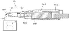
3차원 스캐너(10)는 사용자가 파지할 수 있는 케이스(100)를 포함할 수 있다. 케이스(100)는 3차원 스캐너(10)의 구성요소들을 내장하는 스캐너 본체(101)와, 상기 스캐너 본체(101)에 착탈 가능하도록 결합되는 스캐너 팁(104)을 포함한다.The 3D scanner (10) may include a case (100) that can be held by a user. The case (100) includes a scanner body (101) that houses components of the 3D scanner (10) and a scanner tip (104) that is detachably connected to the scanner body (101).
스캐너 본체(101)는 스캐너 본체(101)의 하측을 구성하는 로워 케이스(102)와, 스캐너 본체(101)의 상측을 구성하고 상기 로워 케이스(102)와 결합되는 어퍼 케이스(103)를 포함할 수 있다. 스캐너 본체(101)는 로워 케이스(102)와 어퍼 케이스(103)의 결합에 의해, 그 내부에 3차원 스캐너(10)의 구성요소들을 외부 환경(물리적 충격, 화학 반응 등)으로부터 안전하게 보호할 수 있다. 다만, 스캐너 본체(101)는 반드시 로워 케이스(102)와 어퍼 케이스(103)의 결합에 의해 구성되는 것으로 한정되지 않으며, 스캐너 본체(101)는 일체로서 형성될 수도 있고, 또는 3 이상의 부재의 결합에 의해 형성될 수도 있다.The scanner body (101) may include a lower case (102) forming the lower side of the scanner body (101) and an upper case (103) forming the upper side of the scanner body (101) and coupled with the lower case (102). The scanner body (101) can safely protect the components of the 3D scanner (10) inside it from the external environment (physical impact, chemical reaction, etc.) by combining the lower case (102) and the upper case (103). However, the scanner body (101) is not limited to being formed by combining the lower case (102) and the upper case (103), and the scanner body (101) may be formed as an integral part, or may be formed by combining three or more members.
스캐너 팁(104)은 3차원 스캐너(10)의 내부에서 발생하는 광이 외부로 조사되도록 가이딩할 수 있고, 외부로부터 인입되는 광을 3차원 스캐너(10)의 내부로 가이딩할 수 있다.The scanner tip (104) can guide light generated inside the 3D scanner (10) to be irradiated to the outside, and can guide light introduced from the outside to the inside of the 3D scanner (10).
스캐너 본체(101)의 일면에는 스캔 버튼(105)이 형성될 수 있다. 사용자는 스캐너 본체(101)를 파지하고 스캔 버튼(105)을 가압함으로써 스캔 데이터를 획득할 수 있다. 다만, 스캔 데이터를 획득하는 과정은, 스캔 버튼(105)을 가압하는 과정 이외에도 유저 인터페이스 화면에 표시되는 스캔 시작 아이콘(미도시)를 선택함으로써 수행될 수도 있다.A scan button (105) may be formed on one side of the scanner body (101). A user may obtain scan data by holding the scanner body (101) and pressing the scan button (105). However, the process of obtaining scan data may also be performed by selecting a scan start icon (not shown) displayed on a user interface screen in addition to the process of pressing the scan button (105).
제어 유닛(20)은 3차원 스캐너(10)가 획득한 스캔 데이터를 기초로 스캔 데이터의 상태를 알리는(피드백하는) 피드백 수단의 활성화 상태를 전환할 수 있다. 즉, 제어 유닛(20)은 특정 조건에 따라 피드백 수단을 활성화하거나 비활성화할 수 있다. 제어 유닛(20)은 데이터 연산 처리가 가능한 마이크로프로세서(microprocessor)를 포함하는 컴퓨팅 장치일 수 있다. 예시적으로, 제어 유닛(20)은 PC, 태블릿 장치, 서버(클라우드 서버를 포함한다) 중 적어도 하나일 수 있다.The control unit (20) can switch the activation status of a feedback means for notifying (feeding back) the status of scan data acquired by the 3D scanner (10). That is, the control unit (20) can activate or deactivate the feedback means according to specific conditions. The control unit (20) can be a computing device including a microprocessor capable of data operation processing. For example, the control unit (20) can be at least one of a PC, a tablet device, and a server (including a cloud server).
제어 유닛(20)와 3차원 스캐너(10)는 전기적으로 연결될 수 있다. 예시적으로, 3차원 스캐너(10)는 제어 유닛(20)과 유선 연결되어, 스캔 과정에서 획득한 스캔 데이터를 제어 유닛(20)에 전송할 수 있다. 다른 예시로, 3차원 스캐너(10)는 제어 유닛(20)과 무선 통신 연결되어, 스캔 과정에서 획득한 스캔 데이터를 제어 유닛(20)에 무선 전송할 수 있다. 제어 유닛(20)의 세부구성에 대해서는 후술하기로 한다.The control unit (20) and the 3D scanner (10) can be electrically connected. For example, the 3D scanner (10) can be wiredly connected to the control unit (20) and transmit scan data acquired during the scanning process to the control unit (20). As another example, the 3D scanner (10) can be wirelessly connected to the control unit (20) and transmit scan data acquired during the scanning process to the control unit (20) wirelessly. The detailed configuration of the control unit (20) will be described later.
디스플레이 유닛(30)은 3차원 스캐너(10)에 의해 획득되는 스캔 데이터의 적어도 일부를 표시할 수 있다. 디스플레이 유닛(30)은 사용자가 스캔 데이터가 획득되는 과정, 획득된 스캔 데이터의 상태, 스캔 데이터를 기초로 교정 계획이 적용된 교정 시뮬레이션 결과 등을 시각적으로 확인할 수 있도록 한다. 디스플레이 유닛(30)은 모니터, 태블릿 스크린, 터치 스크린 등 알려진 시각적 표시 장치 중 적어도 하나일 수 있다.The display unit (30) can display at least a portion of the scan data acquired by the 3D scanner (10). The display unit (30) allows a user to visually check the process of acquiring the scan data, the status of the acquired scan data, the results of a correction simulation to which a correction plan is applied based on the scan data, etc. The display unit (30) can be at least one of known visual display devices such as a monitor, a tablet screen, a touch screen, etc.
이하에서는, 스캔 데이터의 상태를 피드백하는 피드백 수단, 및 3차원 스캐너(10)의 세부 구성에 대해 보다 상세히 설명한다.Below, the feedback means for feeding back the status of scan data and the detailed configuration of the 3D scanner (10) are described in more detail.
도 2는 본 발명에 따른 3차원 스캐너 시스템(1)의 일 구성인 3차원 스캐너(10)의 개략적인 사시도이다.Figure 2 is a schematic perspective view of a 3D scanner (10), which is one component of a 3D scanner system (1) according to the present invention.
도 2를 참조하면, 일 예시로 핸드헬드 형태의 3차원 스캐너(10)가 도시된다. 3차원 스캐너(10)의 스캐너 본체(101)는 소정 수용공간을 형성하는 피드백 수단 수용부(106)를 더 포함할 수 있다. 예시적으로, 피드백 수단 수용부(106)는 스캐너 본체(101) 중 로워 케이스(102) 측에 형성될 수 있으나, 반드시 이에 한정되는 것은 아니다. 피드백 수단 수용부(106)에 의해 형성된 수용공간에, 사용자에게 스캔 데이터의 상태에 따라 피드백을 발생시키기 위한 피드백 수단이 배치될 수 있다. 보다 상세하게는, 피드백 수단 수용부(106)는 제어 신호에 따라 진동하는 액추에이터(130)를 수용하는 액추에이터 수용부일 수 있으며, 상기 액추에이터 수용부에 배치되는 피드백 수단은 3차원 스캐너(10)를 진동시키는 액추에이터(130)일 수 있다. 피드백 수단 수용부(106)는 사용자가 3차원 스캐너(10)를 사용할 때 파지하는 부분에 인접하도록 형성될 수 있다. 이에 따라, 액추에이터(130)는 사용자의 손에 가까이 배치되므로, 사용자는 스캔 데이터의 상태를 피드백하기 위한 액추에이터의 진동을 용이하게 감지할 수 있다.Referring to FIG. 2, a handheld type 3D scanner (10) is illustrated as an example. The scanner body (101) of the 3D scanner (10) may further include a feedback means receiving portion (106) forming a predetermined receiving space. For example, the feedback means receiving portion (106) may be formed on the lower case (102) side of the scanner body (101), but is not necessarily limited thereto. A feedback means for generating feedback to the user according to the state of scan data may be arranged in the receiving space formed by the feedback means receiving portion (106). More specifically, the feedback means receiving portion (106) may be an actuator receiving portion that receives an actuator (130) that vibrates according to a control signal, and the feedback means arranged in the actuator receiving portion may be an actuator (130) that vibrates the 3D scanner (10). The feedback means receiving portion (106) may be formed adjacent to a portion that a user holds when using a 3D scanner (10). Accordingly, since the actuator (130) is placed close to the user's hand, the user can easily detect the vibration of the actuator for feeding back the status of the scan data.
도 3은 본 발명에 따른 3차원 스캐너 시스템(1)의 일 구성인 3차원 스캐너(10)의 개략적인 구성도이다.Figure 3 is a schematic diagram of a three-dimensional scanner (10), which is one component of a three-dimensional scanner system (1) according to the present invention.
도 2 및 도 3을 참조하면, 3차원 스캐너(10)의 스캐너 본체(101) 내부에는 복수의 구성요소들이 내장 배치될 수 있다. 예시적으로, 3차원 스캐너(10)는 3차원 스캐너(10)의 내부에서 광을 생성하는 광 프로젝터(110)를 포함할 수 있다. 광 프로젝터(110)는 대상체의 스캔 데이터를 용이하게 획득하기 위해, 소정 광(내부광)을 생성하여 대상체를 조명할 수 있다. 예시적으로, 광 프로젝터(110)는 대상체를 표현하는 스캔 데이터의 색상을 용이하게 획득하기 위해, 가시광선 영역의 파장 범위를 가지는 광을 생성하여 대상체로 조사할 수 있다. 또한, 광 프로젝터(110)는 대상체를 표현하는 스캔 데이터의 3차원 형상(예를 들면, 3차원 모델 표면의 굴곡)을 용이하게 획득하기 위해, 기설정된 패턴을 가지는 구조광을 생성하여 대상체로 조사할 수 있다. 예시적으로, 스캔 데이터의 3차원 형상을 획득하기 위해 광 프로젝터(110)는 스트라이프 패턴의 구조광을 대상체에 조사할 수 있으나, 구조광은 반드시 전술한 스트라이프 패턴에 한정되지 않는다.Referring to FIGS. 2 and 3, a plurality of components may be built-in and arranged inside the scanner body (101) of the 3D scanner (10). For example, the 3D scanner (10) may include a light projector (110) that generates light inside the 3D scanner (10). The light projector (110) may generate predetermined light (internal light) to illuminate the object in order to easily obtain scan data of the object. For example, the light projector (110) may generate light having a wavelength range of the visible light region and irradiate the light onto the object in order to easily obtain a color of the scan data representing the object. In addition, the light projector (110) may generate structured light having a preset pattern and irradiate the light onto the object in order to easily obtain a 3D shape of the scan data representing the object (for example, a curvature of the surface of the 3D model). For example, to obtain a three-dimensional shape of scan data, the light projector (110) can irradiate structured light in a stripe pattern onto the target object, but the structured light is not necessarily limited to the above-described stripe pattern.
또한, 3차원 스캐너(10)는 대상체의 표면으로부터 반사된 광을 수용하는 적어도 하나의 카메라(120)를 포함한다. 카메라(120)는 3차원 스캐너(10)의 외부로부터 내부로 인입된 광을 기초로 2차원 이미지 또는 3차원 스캔샷을 생성할 수 있다. 예시적으로, 카메라(120)의 렌즈는 3차원 스캐너(10)에 인입된 광을 수용하고, 카메라(120)의 이미징 센서는 상기 카메라(120)의 렌즈에 수용된 광을 기초로 2차원 이미지 또는 3차원 스캔샷을 생성할 수 있다. CCD 센서, CMOS 센서, 컬러 이미징 센서 등 알려진 센서들 중 적어도 하나가 이미징 센서로 사용될 수 있다. 카메라(120)는 하나의 싱글 카메라일 수도 있으나 이에 한정되는 것은 아니며, 2 이상의 멀티 카메라일 수도 있다.In addition, the 3D scanner (10) includes at least one camera (120) that receives light reflected from the surface of the object. The camera (120) can generate a 2D image or a 3D scan shot based on light introduced from the outside to the inside of the 3D scanner (10). For example, the lens of the camera (120) receives light introduced into the 3D scanner (10), and the imaging sensor of the camera (120) can generate a 2D image or a 3D scan shot based on light received by the lens of the camera (120). At least one of known sensors such as a CCD sensor, a CMOS sensor, and a color imaging sensor can be used as the imaging sensor. The camera (120) may be, but is not limited to, a single camera, and may be two or more multi-cameras.
전술한 내용에서, 광 프로젝터(110)로부터 생성된 광 중 적어도 일부는 스캐너 팁(104)의 일측에 형성된 개구부를 통해 3차원 스캐너(10)의 외부로 조사될 수 있다. 이 때, 광 프로젝터(110)로부터 생성된 광은 스캐너 팁(104)의 내측에 배치된 광경로 변경부재(107)에 의해 굴절 및/또는 반사되어 개구부를 향하도록 가이딩될 수 있다. 또한, 대상체의 표면으로부터 반사된 광 중 적어도 일부는 스캐너 팁(104)의 일측에 형성된 개구부를 통해 3차원 스캐너(10)의 내부로 입사할 수 있다. 3차원 스캐너(10)의 내부로 입사한 광은 광경로 변경부재(107)에 의해 굴절 및/또는 반사되어 적어도 하나의 카메라(120)의 렌즈를 향하도록 가이딩될 수 있다.In the above, at least a portion of the light generated from the light projector (110) can be irradiated to the outside of the 3D scanner (10) through an opening formed on one side of the scanner tip (104). At this time, the light generated from the light projector (110) can be guided toward the opening by being refracted and/or reflected by an optical path changing member (107) arranged on the inside of the scanner tip (104). In addition, at least a portion of the light reflected from the surface of the object can be incident into the inside of the 3D scanner (10) through an opening formed on one side of the scanner tip (104). The light incident into the inside of the 3D scanner (10) can be refracted and/or reflected by the optical path changing member (107) and guided toward a lens of at least one camera (120).
또한, 3차원 스캐너(10)는 액추에이터(130)를 포함할 수 있다. 액추에이터(130)는 3차원 스캐너(10)의 작동 상태, 3차원 스캐너(10)의 스캔 과정으로부터 획득되는 스캔 데이터의 상태를 사용자에게 피드백하기 위해, 기설정된 진동을 발생시킬 수 있다. 예시적으로, 액추에이터(130)는 스캔 데이터의 얼라인 과정이 실패하면 진동할 수 있다.In addition, the 3D scanner (10) may include an actuator (130). The actuator (130) may generate preset vibrations to provide feedback to the user on the operating status of the 3D scanner (10) and the status of scan data acquired from the scanning process of the 3D scanner (10). For example, the actuator (130) may vibrate when the alignment process of the scan data fails.
또한, 3차원 스캐너(10)는 스캐너 본체(101) 내부에 통신 유닛(140)을 더 포함할 수 있다. 통신 유닛(140)은 제어 유닛(20)과 데이터 통신을 가능하게 하며, 3차원 스캐너(10)의 스캔 과정에서 획득한 스캔 데이터를 제어 유닛(20)으로 전송할 수 있다. 또한, 통신 유닛(140)은 제어 유닛(20)이 전송한 제어 신호를 수신하여, 제어 유닛(20)이 3차원 스캐너(10)의 작동을 제어할 수 있도록 한다. 통신 유닛(140)으로, 알려진 유선 통신 장치 및/또는 무선 통신 장치가 사용될 수 있다.In addition, the 3D scanner (10) may further include a communication unit (140) inside the scanner body (101). The communication unit (140) enables data communication with the control unit (20) and may transmit scan data acquired during the scanning process of the 3D scanner (10) to the control unit (20). In addition, the communication unit (140) receives a control signal transmitted by the control unit (20), thereby enabling the control unit (20) to control the operation of the 3D scanner (10). As the communication unit (140), a known wired communication device and/or a wireless communication device may be used.
3차원 스캐너(10)는 스캐너 본체(101) 내부에 전원 공급 유닛(150)을 더 포함할 수 있다. 전원 공급 유닛(150)은 광 프로젝터(110), 카메라(120), 액추에이터(130), 및 통신 유닛(140)의 작동에 필요한 전력을 공급하는 역할을 할 수 있다. 예시적으로, 전원 공급 유닛(150)은 외부 전원과 유선 연결되어 상기 외부 전원에 의해 전달받은 전력을 3차원 스캐너(10)의 구성요소들에 공급할 수 있다. 다른 예시로, 전원 공급 유닛(150)은 외부 전원의 연결 없이 직접 구성요소들에 전력을 공급할 수 있다. 이 때, 전원 공급 유닛(150)은 배터리일 수 있다. 전원 공급 유닛(150)의 전원 공급 방식에 따라, 3차원 스캐너(10)는 유선 스캐너일 수도 있고, 무선 스캐너일 수도 있다.The 3D scanner (10) may further include a power supply unit (150) inside the scanner body (101). The power supply unit (150) may serve to supply power required for the operation of the light projector (110), the camera (120), the actuator (130), and the communication unit (140). For example, the power supply unit (150) may be wiredly connected to an external power source and may supply power received from the external power source to components of the 3D scanner (10). As another example, the power supply unit (150) may directly supply power to components without connecting to an external power source. In this case, the power supply unit (150) may be a battery. Depending on the power supply method of the power supply unit (150), the 3D scanner (10) may be a wired scanner or a wireless scanner.
이하에서는, 피드백 수단에 대해 보다 상세히 설명한다.Below, the feedback means are described in more detail.
피드백 수단은 3차원 스캐너(10)의 상태, 및 3차원 스캐너(10)에 의해 획득되는 스캔 데이터의 상태 중 적어도 하나를 사용자에게 피드백할 수 있다. 보다 상세하게는, 피드백 수단은 3차원 스캐너(10)의 상태, 및 3차원 스캐너(10)에 의해 획득되는 스캔 데이터의 상태가 소정 판단 기준에 미달하는 경우 피드백 동작을 발생시킬 수 있다. 예시적으로, 피드백 수단은 3차원 스캐너(10)의 외부로 광을 조사하는 광 프로젝터(110)일 수 있다. 광 프로젝터(110)는 3차원 스캐너(10)의 상태 또는 스캔 데이터의 상태를 피드백하기 위한 특정한 색상의 광 또는 패턴광을 조사할 수 있다. 예시적으로, 광 프로젝터(110)는 대상체를 스캔할 때 청색광을 조사하다가, 스캔 데이터의 상태가 소정 판단 기준에 미달하는 경우 적색광을 조사할 수 있다. 다른 예시로, 광 프로젝터(110)는 대상체를 스캔할 때 스트라이프 형태의 구조광을 조사하다가, 스캔 데이터의 상태가 소정 판단 기준에 미달하는 경우 영문자 ‘X’ 패턴을 가지는 패턴광을 조사할 수 있다. 이에 따라, 사용자는 스캔 데이터의 상태를 시각적으로 인지할 수 있다.The feedback means can feed back at least one of the status of the 3D scanner (10) and the status of scan data acquired by the 3D scanner (10) to the user. More specifically, the feedback means can generate a feedback operation when the status of the 3D scanner (10) and the status of scan data acquired by the 3D scanner (10) fall below a predetermined judgment criterion. For example, the feedback means can be a light projector (110) that irradiates light to the outside of the 3D scanner (10). The light projector (110) can irradiate light of a specific color or pattern light to feed back the status of the 3D scanner (10) or the status of scan data. For example, the light projector (110) can irradiate blue light when scanning an object, and irradiate red light when the status of the scan data falls below a predetermined judgment criterion. As another example, the light projector (110) may irradiate structured light in the form of stripes when scanning an object, and if the state of the scan data falls below a predetermined judgment criterion, may irradiate patterned light having an English letter ‘X’ pattern. Accordingly, the user can visually recognize the state of the scan data.
또한, 피드백 수단은 전술한 액추에이터(130)일 수 있다. 예시적으로, 액추에이터(130)는 스캔 데이터의 상태가 소정 판단 기준에 미달하는 경우 진동할 수 있다. 이에 따라, 사용자는 스캔 데이터의 상태를 촉각적으로 인지할 수 있다.In addition, the feedback means may be the actuator (130) described above. For example, the actuator (130) may vibrate when the state of the scan data falls below a predetermined judgment criterion. Accordingly, the user may tactilely recognize the state of the scan data.
또한, 피드백 수단은 소리를 발생시키는 스피커(미도시)일 수 있다. 스피커는 제어 유닛(20)과 연결될 수 있다. 또는, 스피커는 3차원 스캐너(10)에 내장된 추가적인 구성요소일 수도 있다. 예시적으로, 스피커는 스캔 데이터의 상태가 소정 판단 기준에 미달하는 경우 소리(예를 들면, 비프음)을 발생시킬 수 있다. 이에 따라, 사용자는 스캔 데이터의 상태를 청각적으로 인지할 수 있다.Additionally, the feedback means may be a speaker (not shown) that generates sound. The speaker may be connected to the control unit (20). Alternatively, the speaker may be an additional component built into the 3D scanner (10). For example, the speaker may generate a sound (e.g., a beep) when the state of the scan data falls below a predetermined judgment criterion. Accordingly, the user may recognize the state of the scan data audibly.
또한, 피드백 수단은 디스플레이 유닛(30)일 수 있다. 디스플레이 유닛(30)은 스캔 데이터의 상태가 소정 판단 기준에 미달하는 경우, 스캔 데이터의 상태를 화면에 표시할 수 있다. 예시적으로, 디스플레이 유닛(30)은 스캔 데이터의 얼라인이 실패한 경우, 유저 인터페이서 화면 상에 형성되고 3차원 스캐너(10)에 의해 획득한 3차원 스캔샷이 입력되는 스캔 박스의 색상을 변경할 수 있다. 이에 따라, 사용자는 스캔 데이터의 상태를 시각적으로 인지할 수 있다.In addition, the feedback means may be a display unit (30). The display unit (30) may display the status of the scan data on the screen when the status of the scan data falls below a predetermined judgment criterion. For example, when the alignment of the scan data fails, the display unit (30) may change the color of a scan box formed on the user interface screen and into which a 3D scan shot acquired by the 3D scanner (10) is input. Accordingly, the user may visually recognize the status of the scan data.
사용자에게 스캔 데이터의 상태를 피드백하기 위해, 전술한 피드백 수단들 중 적어도 하나가 사용될 수 있으며, 복수의 피드백 수단들이 동시에 작동하여 사용자에게 스캔 데이터의 상태를 피드백할 수도 있다.To feed back the status of the scan data to the user, at least one of the aforementioned feedback means may be used, and a plurality of feedback means may operate simultaneously to feed back the status of the scan data to the user.
이하에서는, 제어 유닛(20)의 세부 구성에 대해 보다 상세히 설명한다.Below, the detailed configuration of the control unit (20) is described in more detail.
도 4는 본 발명에 따른 3차원 스캐너 시스템(1)의 일 구성인 제어 유닛(20)의 개략적인 구성도이다.Figure 4 is a schematic diagram of a control unit (20), which is one component of a three-dimensional scanner system (1) according to the present invention.
도 1, 도 3, 및 도 4를 참조하면, 제어 유닛(20)은 이미지 데이터 생성부(210)를 포함할 수 있다. 이미지 데이터 생성부(210)는 3차원 스캐너(10)의 카메라(120)에 수용된 광을 기초로 스캔 데이터를 생성할 수 있다. 이 때, 스캔 데이터는 2차원 이미지 데이터 및/또는 상기 2차원 이미지 데이터를 입체화한 3차원 스캔샷일 수 있다. 제어 유닛(20)은 이미지 데이터 생성부(210)에 의해 생성된 스캔 데이터를 디스플레이 유닛(30)을 통해 실시간으로 표시할 수 있다.Referring to FIGS. 1, 3, and 4, the control unit (20) may include an image data generating unit (210). The image data generating unit (210) may generate scan data based on light received by the camera (120) of the 3D scanner (10). At this time, the scan data may be 2D image data and/or a 3D scan shot that stereoscopically converts the 2D image data. The control unit (20) may display the scan data generated by the image data generating unit (210) in real time through the display unit (30).
제어 유닛(20)은 얼라인부(220)를 포함할 수 있다. 얼라인부(220)는 대상체를 스캔하여 획득하는 스캔 데이터 중 적어도 2개의 3차원 스캔샷을 얼라인할 수 있다. 이 때, 3차원 스캔샷들을 얼라인하는 것은, 각각의 3차원 스캔샷의 상호 중첩되는 부분을 연결하고 정렬하는 것을 의미할 수 있다. 얼라인부(220)는 알려진 얼라인 방식 중 적어도 하나를 사용하여 3차원 스캔샷들을 얼라인할 수 있다. 예시적으로, 얼라인부(220)는 ICP(iterative closest point) 방식을 사용하여 3차원 스캔샷들을 얼라인할 수 있다.The control unit (20) may include an aligning unit (220). The aligning unit (220) may align at least two 3D scan shots among scan data acquired by scanning the target object. At this time, aligning the 3D scan shots may mean connecting and aligning mutually overlapping portions of each 3D scan shot. The aligning unit (220) may align the 3D scan shots using at least one of the known alignment methods. For example, the aligning unit (220) may align the 3D scan shots using an ICP (iterative closest point) method.
또한, 제어 유닛(20)은 3차원 모델링부(230)를 포함할 수 있다. 3차원 모델링부(230)는 얼라인된 3차원 스캔샷들을 머징하여 3차원 모델을 생성할 수 있다. 사용자는 3차원 모델링부(230)에 의해 생성된 3차원 모델을 이용하여 교정 계획을 수립(치아 삭제, 발치 등)하거나, 교정 계획에 따른 교정 시뮬레이션을 수행하거나, 환자의 구강에 적용할 보철물 실물을 제작하기 이전의 가상의 보철물을 적용할 수 있다.In addition, the control unit (20) may include a three-dimensional modeling unit (230). The three-dimensional modeling unit (230) may merge aligned three-dimensional scan shots to create a three-dimensional model. Using the three-dimensional model created by the three-dimensional modeling unit (230), a user may establish an orthodontic plan (tooth deletion, tooth extraction, etc.), perform an orthodontic simulation according to the orthodontic plan, or apply a virtual prosthesis before creating an actual prosthesis to be applied to the patient's oral cavity.
또한, 제어 유닛(20)은 데이터베이스부(240)를 포함할 수 있다. 데이터베이스부(240)는 스캔 데이터, 2차원 이미지 데이터를 3차원 스캔샷으로 변환하는 로직, 얼라인부(220)가 3차원 스캔샷들을 얼라인하는 로직, 3차원 모델링부(230)에서 머징을 수행하는 로직, 스캔 데이터의 상태를 판단하기 위한 판단 기준, 3차원 스캐너(10)와 대상체 간의 간격을 측정하는 로직, 측정된 간격으로부터 부가적인 측정값을 연산하는 로직 등을 저장할 수 있다.In addition, the control unit (20) may include a database unit (240). The database unit (240) may store scan data, logic for converting two-dimensional image data into three-dimensional scan shots, logic for aligning three-dimensional scan shots by the alignment unit (220), logic for performing merging in the three-dimensional modeling unit (230), judgment criteria for judging the status of scan data, logic for measuring the distance between the three-dimensional scanner (10) and the target object, logic for calculating additional measurement values from the measured distance, etc.
또한, 제어 유닛(20)은 파라미터 측정부(250)를 포함할 수 있다. 파라미터 측정부(250)는 3차원 스캐너(10)와 대상체 간의 간격을 획득할 수 있다. 예시적으로, 3차원 스캐너(10)와 대상체 간의 간격은 스캔 데이터의 깊이값(예를 들면, z값)으로 획득될 수 있으며, 스캔 데이터의 깊이값은 카메라(120)의 일부 구성을 기준으로 대상체의 표면에 이르는 광경로의 길이일 수 있다. 또한, 파라미터 측정부(250)는 획득한 간격을 기초로 부가적인 측정값을 더 획득할 수 있다. 예시적으로, 부가적인 측정값은 최근접 지점을 포함하는 스캔 볼륨일 수 있다.In addition, the control unit (20) may include a parameter measuring unit (250). The parameter measuring unit (250) may obtain a distance between the 3D scanner (10) and the target object. For example, the distance between the 3D scanner (10) and the target object may be obtained as a depth value (e.g., a z value) of scan data, and the depth value of the scan data may be a length of an optical path reaching the surface of the target object based on some configuration of the camera (120). In addition, the parameter measuring unit (250) may further obtain an additional measurement value based on the obtained distance. For example, the additional measurement value may be a scan volume including a closest point.
또한, 제어 유닛(20)은 피드백 수단 조절부(260)를 포함할 수 있다. 피드백 수단 조절부(260)는 전술한 피드백 수단들 중 적어도 하나를 활성화하거나 비활성화할 수 있다. 한편, 피드백 수단을 활성화하거나 비활성화하는 기준은 파라미터 측정부(250)에서 획득한 간격 및/또는 측정값일 수 있다. 예시적으로, 피드백 수단 조절부(260)는 획득한 3차원 스캐너(10)와 대상체 사이의 간격이 기저장된 임계값 이하인 경우 특정 피드백 수단을 선택적으로 비활성화할 수 있다. 예시적으로, 상기 간격이 기저장된 임계값 이하인 경우, 피드백 수단 조절부(260)는 3차원 스캐너(10)에 제어 신호를 인가하여 액추에이터(130)를 비활성화할 수 있다. 이에 따라, 3차원 스캐너(10)와 대상체 사이의 간격이 작은 경우 3차원 스캐너(10)가 대상체에 인접한 것으로 판단될 수 있으며, 3차원 스캐너(10)가 대상체에 인접한 경우 액추에이터(130)에 의한 진동 피드백이 비활성화되도록 전환될 수 있다.In addition, the control unit (20) may include a feedback means control unit (260). The feedback means control unit (260) may activate or deactivate at least one of the aforementioned feedback means. Meanwhile, the criterion for activating or deactivating the feedback means may be an interval and/or a measurement value acquired by the parameter measuring unit (250). For example, the feedback means control unit (260) may selectively deactivate a specific feedback means when the acquired interval between the 3D scanner (10) and the target is less than or equal to a pre-stored threshold value. For example, when the interval is less than or equal to the pre-stored threshold value, the feedback means control unit (260) may apply a control signal to the 3D scanner (10) to deactivate the actuator (130). Accordingly, when the gap between the 3D scanner (10) and the target is small, the 3D scanner (10) can be determined to be adjacent to the target, and when the 3D scanner (10) is adjacent to the target, the vibration feedback by the actuator (130) can be switched to be deactivated.
또한, 제어 유닛(20)은 대상체 감지부(270)를 포함할 수 있다. 대상체 감지부(270)는 3차원 스캐너(10)의 스캔을 통해 획득하는 스캔 데이터가 표현하는 대상체의 종류를 감지할 수 있다. 예시적으로, 대상체 감지부(270)는 사용자가 3차원 스캐너(10)로 환자의 실제 구강 내부를 스캔하는 경우, 대상체는 환자의 실제 구강 내부인 것을 감지할 수 있다. 다른 예시로, 대상체 감지부(270)는 사용자가 3차원 스캐너(10)로 구강 모형을 스캔하는 경우, 대상체는 구강 모형인 것을 감지할 수 있다. 피드백 수단 조절부(260)는 대상체 감지부(270)의 대상체 감지 결과에 따라, 선택적으로 피드백 수단의 활성화 여부 또는 비활성화 여부를 결정할 수 있다. 예시적으로, 3차원 스캐너(10)와 대상체와의 간격이 기저장된 임계값 이하이더라도, 대상체 감지부(270)에 의해 감지된 대상체의 종류가 임프레션 모형 또는 구강 모형인 경우, 피드백 수단 조절부(260)는 피드백 수단 중 액추에이터(130)를 비활성화하지 않을 수 있다.In addition, the control unit (20) may include an object detection unit (270). The object detection unit (270) may detect the type of object represented by scan data acquired through a scan of the three-dimensional scanner (10). For example, the object detection unit (270) may detect that the object is the actual inside of the patient's oral cavity when a user scans the actual inside of the patient's oral cavity with the three-dimensional scanner (10). As another example, the object detection unit (270) may detect that the object is an oral cavity model when a user scans an oral cavity model with the three-dimensional scanner (10). The feedback means control unit (260) may selectively determine whether to activate or deactivate the feedback means according to the object detection result of the object detection unit (270). For example, even if the distance between the 3D scanner (10) and the target is less than or equal to a preset threshold value, if the type of target detected by the target detection unit (270) is an impression model or an oral model, the feedback means control unit (260) may not deactivate the actuator (130) among the feedback means.
또한, 제어 유닛(20)은 배터리 잔량 측정부(280)를 더 포함?A 수 있다. 배터리 잔량 측정부(280)는 3차원 스캐너(10)의 전원 공급 유닛(150)이 배터리인 경우, 배터리의 잔량을 획득할 수 있다. 이 때, 배터리의 잔량이 배터리 임계값 이하인 경우, 피드백 수단이 작동하여 사용자에게 피드백을 발생시킬 수 있다. 다만, 이러한 경우에도, 파라미터 측정부(250)에서 획득한 간격 및/또는 측정값이 기저장된 임계값 이하인 경우, 피드백 수단 조절부(260)는 액추에이터(130)를 비활성화할 수 있다.In addition, the control unit (20) may further include a battery remaining capacity measurement unit (280). The battery remaining capacity measurement unit (280) may obtain the remaining capacity of the battery when the power supply unit (150) of the 3D scanner (10) is a battery. At this time, when the remaining capacity of the battery is lower than or equal to a battery threshold value, the feedback means may operate to generate feedback to the user. However, even in this case, when the interval and/or measurement value obtained by the parameter measurement unit (250) is lower than or equal to a pre-stored threshold value, the feedback means control unit (260) may deactivate the actuator (130).
이하에서는, 본 발명의 다양한 실시예에 따른 3차원 스캐닝 시스템의 제어 방법에 대해 상세히 설명하기로 한다. 한편, 본 발명의 다양한 실시예에 따른 3차원 스캐닝 시스템의 제어 방법을 설명함에 있어, 전술한 3차원 스캐닝 시스템의 내용과 중복되는 내용은 간략히 언급하거나 설명을 생략할 수 있다.Hereinafter, a control method of a three-dimensional scanning system according to various embodiments of the present invention will be described in detail. Meanwhile, when describing a control method of a three-dimensional scanning system according to various embodiments of the present invention, any content that overlaps with the content of the three-dimensional scanning system described above may be briefly mentioned or may be omitted from the description.
도 5는 본 발명의 제1 실시예에 따른 3차원 스캐너 시스템의 제어 방법의 순서도이고, 도 6은 도 5의 전환 단계(S120)의 세부 순서도이다. 또한, 도 7 내지 도 10은 3차원 스캐너(10)와 대상체(O) 사이의 간격을 획득하는 다양한 실시예들을 설명하기 위한 것이다.FIG. 5 is a flowchart of a control method of a three-dimensional scanner system according to the first embodiment of the present invention, and FIG. 6 is a detailed flowchart of a switching step (S120) of FIG. 5. In addition, FIGS. 7 to 10 are intended to explain various embodiments of obtaining a distance between a three-dimensional scanner (10) and a target object (O).
도 5 내지 도 7을 참조하면, 본 발명의 제1 실시예에 따른 3차원 스캐너 시스템의 제어 방법은 스캔 단계(S110), 및 전환 단계(S120)를 포함할 수 있다.Referring to FIGS. 5 to 7, a control method of a three-dimensional scanner system according to the first embodiment of the present invention may include a scanning step (S110) and a switching step (S120).
먼저, 스캔 단계(S110)는 사용자가 3차원 스캐너(10)를 사용하여, 3차원 스캐너(10)가 대상체(O)를 스캔할 수 있다. 전술한 바와 같이, 대상체(O)는 환자의 실제 구강 내부, 임프레션 모형, 및 구강 모형 중 하나일 수 있다. 사용자는 3차원 스캐너(10)를 파지하고 대상체(O)를 표현하는 스캔 데이터를 정밀하게 획득하기 위해, 3차원 스캐너(10)를 대상체(O)에 대하여 다양한 스캔 거리와 다양한 스캔 각도를 가지도록 이동시킬 수 있다. 스캔 단계(S110)에서, 3차원 스캐너(10)는 대상체(O)를 표현하는 스캔 데이터를 획득할 수 있고, 상기 스캔 데이터는 2차원 이미지 데이터 및/또는 3차원 스캔샷일 수 있다.First, in the scan step (S110), a user can use a 3D scanner (10) to scan an object (O) using the 3D scanner (10). As described above, the object (O) can be one of an actual inside of a patient's mouth, an impression model, and an oral model. The user can move the 3D scanner (10) to have various scan distances and various scan angles with respect to the object (O) in order to grasp the 3D scanner (10) and precisely obtain scan data representing the object (O). In the scan step (S110), the 3D scanner (10) can obtain scan data representing the object (O), and the scan data can be 2D image data and/or 3D scan shots.
한편, 3차원 스캐너(10)가 대상체(O)와 근접하여 스캔하는 단계(S110)가 진행될 때, 3차원 스캐너(10)가 진동하게 되면 3차원 스캐너(10)와 대상체(O)가 충돌할 수 있다. 대상체(O)가 환자의 실제 구강 내부인 경우, 3차원 스캐너(10)의 진동에 의하여 치아, 치은, 또는 볼의 내벽에 3차원 스캐너(10)가 충돌할 수 있으므로, 환자는 스캔 과정에서 불편함을 느낄 수 있다. 특히, 3차원 스캐너(10)의 진동에 의하여 3차원 스캐너(10)가 환자의 치료 대상 치아에 충돌하는 경우, 환자는 통증 또는 출혈과 같은 불편을 겪을 수 있다. 따라서, 3차원 스캐너(100와 대상체(O) 사이의 간격이 작을 때, 3차원 스캐너(10)의 진동이 억제될 필요가 있다.Meanwhile, when the step (S110) of scanning the 3D scanner (10) by approaching the object (O) is performed, if the 3D scanner (10) vibrates, the 3D scanner (10) and the object (O) may collide. If the object (O) is the actual inside of the patient's oral cavity, the vibration of the 3D scanner (10) may cause the 3D scanner (10) to collide with the inner wall of the teeth, gums, or cheeks, and thus the patient may feel discomfort during the scanning process. In particular, if the vibration of the 3D scanner (10) causes the 3D scanner (10) to collide with the patient's teeth to be treated, the patient may experience discomfort such as pain or bleeding. Therefore, when the gap between the 3D scanner (100) and the object (O) is small, the vibration of the 3D scanner (10) needs to be suppressed.
따라서, 스캔 단계(S110)는 3차원 스캐너(10)와 대상체(O) 간의 이격 거리인 간격을 획득할 수 있다. 즉, 스캔 단계(S110)에서, 3차원 스캐너(10)는 대상체(O)를 스캔하여 3차원 데이터(예를 들면, 3차원 스캔샷)를 획득하고, 3차원 데이터를 획득하는 과정에서 3차원 스캐너(10)와 대상체(O)와의 간격이 자동적으로 측정 및 획득될 수 있다. 스캔 단계(S110)에서 간격을 획득하는 과정은 전술한 본 발명에 따른 3차원 스캐닝 시스템의 제어 유닛(20)의 일 구성인 파라미터 측정부(250)에 의해 수행될 수 있다.Accordingly, the scan step (S110) can obtain the gap, which is the distance between the 3D scanner (10) and the target object (O). That is, in the scan step (S110), the 3D scanner (10) scans the target object (O) to obtain 3D data (e.g., a 3D scan shot), and in the process of obtaining the 3D data, the gap between the 3D scanner (10) and the target object (O) can be automatically measured and obtained. The process of obtaining the gap in the scan step (S110) can be performed by the parameter measuring unit (250), which is a component of the control unit (20) of the 3D scanning system according to the present invention described above.
3차원 스캐너(10)와 대상체(O) 간의 간격은 스캔 데이터의 z축 방향 깊이값으로부터 획득될 수 있다. 예시적으로, 3차원 스캐너(10)가 대상체(O)를 스캔함으로써 스캔 데이터를 획득하면, 스캔 데이터 중 3차원 스캔샷은 3차원 공간 상에서 가로(x축 방향), 세로(y축 방향), 깊이(z축 방향)를 가질 수 있다. 이 때, 3차원 스캔샷의 깊이(예시적으로, z축 방향)를 기초로 3차원 스캐너(10)와 대상체(O) 사이의 간격을 획득할 수 있다.The distance between the 3D scanner (10) and the target object (O) can be obtained from the z-axis direction depth value of the scan data. For example, when the 3D scanner (10) obtains scan data by scanning the target object (O), the 3D scan shot among the scan data can have a horizontal (x-axis direction), a vertical (y-axis direction), and a depth (z-axis direction) in the 3D space. At this time, the distance between the 3D scanner (10) and the target object (O) can be obtained based on the depth (for example, z-axis direction) of the 3D scan shot.
보다 상세하게는, 3차원 스캔샷들은 복수의 지점들을 포함하고, 3차원 스캔샷이 얼라인됨으로써 얼라인된 3차원 스캔샷들 또한 복수의 지점들을 포함한다. 이 때, 스캔 데이터의 깊이값은 스캔 데이터(보다 상세하게는, 얼라인된 3차원 스캔샷들)의 지점들 중 일축에 대하여 최소 좌표값을 가지는 최근접 지점을 기초로 획득될 수 있다. 예시적으로, 스캔 데이터의 깊이값은 스캔 데이터에 포함된 지점들 중 z축 방향에 대하여 최소 좌표값을 가지는 최근접 지점의 깊이값(z값)으로 획득될 수 있다. 즉, 스캔 데이터 중 가장 높은 위치에 형성된 지점에 대하여 3차원 스캐너(10)와 대상체(O) 사이의 간격을 획득할 수 있다.More specifically, the 3D scan shots include a plurality of points, and when the 3D scan shots are aligned, the aligned 3D scan shots also include a plurality of points. At this time, the depth value of the scan data can be acquired based on the closest point having the minimum coordinate value with respect to one axis among the points of the scan data (more specifically, the aligned 3D scan shots). For example, the depth value of the scan data can be acquired as the depth value (z value) of the closest point having the minimum coordinate value with respect to the z-axis direction among the points included in the scan data. That is, the distance between the 3D scanner (10) and the target object (O) can be acquired with respect to the point formed at the highest position among the scan data.
한편, 3차원 스캐너(10)와 대상체(O) 사이의 간격은 3차원 스캐너(10)에 내장된 카메라(120)의 일부분과 대상체(O) 사이의 광경로 길이를 기초로 획득될 수 있다. 일 예시로, 도 8을 참조하면, 3차원 스캐너(10)와 대상체(O) 사이의 간격(z)은 카메라(120)의 렌즈 일면으로부터 광경로를 따라 대상체(O)와 만나는 대상체(O)의 최근접 지점(P) 사이의 거리일 수 있다. 다른 예시로, 3차원 스캐너(10)와 대상체(O) 사이의 간격(z)은 카메라(120)의 이미지 센서로부터 광경로를 따라 대상체(O)와 만나는 대상체(O)의 최근접 지점(P) 사이의 거리일 수 있다.Meanwhile, the distance between the 3D scanner (10) and the target (O) can be acquired based on the optical path length between a part of the camera (120) built into the 3D scanner (10) and the target (O). As an example, referring to FIG. 8, the distance (z) between the 3D scanner (10) and the target (O) can be the distance between the closest point (P) of the target (O) that meets the target (O) along the optical path from one surface of the lens of the camera (120). As another example, the distance (z) between the 3D scanner (10) and the target (O) can be the distance between the closest point (P) of the target (O) that meets the target (O) along the optical path from the image sensor of the camera (120).
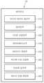
스캔 단계(S110)가 수행되면, 제어 유닛(20)의 피드백 수단 조절부(260)에 의해 피드백 수단의 활성화 상태를 전환시키는 전환 단계(S120)가 수행될 수 있다. 상기 전환 단계(S120)는 스캔 단계(S110)에서 획득한 간격에 기초하여, 적어도 하나의 피드백 수단의 활성화 상태를 전환시킬 수 있다. 예시적으로, 3차원 스캐너(10)와 대상체(O) 사이의 간격이 기저장된 임계값 이하인 경우 피드백 수단을 선택적으로 비활성화할 수 있다.When the scan step (S110) is performed, a switching step (S120) for switching the activation state of the feedback means may be performed by the feedback means control unit (260) of the control unit (20). The switching step (S120) may switch the activation state of at least one feedback means based on the interval obtained in the scan step (S110). For example, when the interval between the 3D scanner (10) and the target object (O) is less than or equal to a pre-stored threshold value, the feedback means may be selectively deactivated.
전환 단계(S120)에 대해 보다 상세히 설명한다. 도 6을 참조하면, 전환 단계(S120)는 간격 판단 단계(S121)를 포함할 수 있다. 간격 판단 단계(S121)는 스캔 단계(S110)에서 획득한 간격을 기저장된 임계값과 비교할 수 있다. 이 때, 기저장된 임계값은 3차원 스캐너(10)와 대상체(O) 사이의 권장되는 최소 간격일 수 있다. 간격 판단 단계(S121)에서, 획득한 간격이 기저장된 임계값 이하인 경우, 피드백 수단 중 액추에이터(130)의 진동에 의한 환자 불편이 초래될 수 있다. 따라서, 획득한 간격이 기저장된 임계값 이하인 경우, 액추에이터 비활성화 단계(S122)가 수행되어, 피드백 수단 조절부(260)는 3차원 스캐너(10)에 내장된 액추에이터(130)를 비활성화할 수 있다. 이 때, ‘비활성화’는 3차원 스캐너의 상태, 및 스캔 데이터의 상태(이하, 피드백 상황으로 지칭한다)를 피드백하기 위한 제어 신호를 대응되는 피드백 수단에 전송하지 않는 것을 의미할 수 있다. 다른 예시로, 액추에이터 비활성화 단계(S122)에서, 피드백 수단 조절부(260)는 3차원 스캐너(10)의 전원 공급 유닛(150)이 액추에이터(130)의 동작을 위한 전력을 액추에이터(130)에 공급하지 않도록 제어할 수 있다. 이에 따라, 액추에이터(130)는 3차원 스캐너(10)가 대상체(O)와 근접한 상태에서 비활성화되어, 스캔 과정에서 발생할 수 있는 환자의 불편함을 최소화할 수 있는 이점이 있다.The switching step (S120) will be described in more detail. Referring to FIG. 6, the switching step (S120) may include a gap determination step (S121). The gap determination step (S121) may compare the gap acquired in the scanning step (S110) with a pre-stored threshold value. At this time, the pre-stored threshold value may be a recommended minimum gap between the 3D scanner (10) and the object (O). In the gap determination step (S121), if the acquired gap is less than or equal to the pre-stored threshold value, patient discomfort may be caused by vibration of the actuator (130) among the feedback means. Therefore, if the acquired gap is less than or equal to the pre-stored threshold value, the actuator deactivation step (S122) may be performed, so that the feedback means control unit (260) may deactivate the actuator (130) built into the 3D scanner (10). At this time, ‘deactivation’ may mean not transmitting a control signal for feeding back the status of the 3D scanner and the status of scan data (hereinafter referred to as a feedback situation) to the corresponding feedback means. As another example, in the actuator deactivation step (S122), the feedback means control unit (260) may control the power supply unit (150) of the 3D scanner (10) not to supply power for the operation of the actuator (130) to the actuator (130). Accordingly, the actuator (130) is deactivated while the 3D scanner (10) is in proximity to the object (O), which has the advantage of minimizing discomfort to the patient that may occur during the scanning process.
이하에서는, 간격 판단 단계(S121)에서의 기저장된 임계값에 대해 상세히 설명한다.Below, the stored threshold values in the interval judgment step (S121) are described in detail.
도 8을 참조하면, 대상체(O)의 적어도 일부는 스캐너 팁(104)의 일측에 형성된 개구부(104a)를 통해 스캐너 팁(104)의 내부로 인입될 수 있다. 대상체(O)의 적어도 일부가 스캐너 팁(104)의 내부에 인입된 상태에서 3차원 스캐너(10)가 진동하는 경우, 환자는 3차원 스캐너(10)와 대상체(예를 들면, 치아)의 충돌에 의한 불편함을 느낄 수 있다. 따라서, 임계값은 카메라(120)와 3차원 스캐너(10)의 일단 내부에 배치된 광경로 변경부재(107) 사이의 광경로 길이(L1)일 수 있다. 도 8 중 A 부분의 확대도에서, 카메라(120)의 렌즈와 광경로 변경부재(107) 사이에 대상체(O)의 최근접 지점(P)이 배치될 수 있다. 이 때, 카메라(120)의 렌즈와 대상체(O)의 최근접 지점(P) 사이의 간격(z)은 카메라(120)의 렌즈와 광경로 변경부재(107) 사이의 광경로 길이(L1) 이하이므로, 액추에이터 비활성화 단계(S132)가 수행될 수 있다.Referring to FIG. 8, at least a part of the object (O) can be introduced into the scanner tip (104) through the opening (104a) formed on one side of the scanner tip (104). When the 3D scanner (10) vibrates while at least a part of the object (O) is introduced into the scanner tip (104), the patient may feel discomfort due to the collision between the 3D scanner (10) and the object (e.g., teeth). Therefore, the threshold value may be the optical path length (L1) between the camera (120) and the optical path changing member (107) arranged inside one end of the 3D scanner (10). In the enlarged view of part A of FIG. 8, the closest point (P) of the object (O) can be arranged between the lens of the camera (120) and the optical path changing member (107). At this time, the distance (z) between the lens of the camera (120) and the closest point (P) of the object (O) is less than or equal to the optical path length (L1) between the lens of the camera (120) and the optical path changing member (107), so the actuator deactivation step (S132) can be performed.
도 9를 참조하면, 대상체(O)의 적어도 일부는 개구부(104a)를 통해 스캐너 팁(104)의 내부로 인입될 수 있다. 이 때, 대상체(O)는 개구부(104a)를 통해 일부분만 인입될 수 있다. 이러한 경우 또한, 3차원 스캐너(10)의 진동에 의하여 3차원 스캐너(10)와 대상체(O)가 충돌할 가능성이 있다. 따라서, 임계값은 카메라(120)의 렌즈와 3차원 스캐너(10)의 일단에 형성된 개구부(104a) 사이의 광경로 길이(L1+L2)일 수 있다. 도 9 중 B 부분의 확대도에서, 광경로 변경부재(107)와 개구부(104a) 사이에 대상체(O)의 최근접 지점(P)이 배치될 수 있다. 카메라(120)의 렌즈와 대상체(O)의 최근접 지점(P) 사이의 간격(z)은 카메라(120)의 렌즈와 광경로 변경부재(107) 사이의 광경로 길이(L1)와, 광경로 변경부재(107)와 개구부(104a) 사이의 광경로 길이(L2)의 합(L1+L2) 이하이므로, 액추에이터 비활성화 단계(S132)가 수행될 수 있다.Referring to FIG. 9, at least a part of the object (O) can be introduced into the scanner tip (104) through the opening (104a). At this time, only a part of the object (O) can be introduced through the opening (104a). In this case, there is also a possibility that the 3D scanner (10) and the object (O) may collide due to vibration of the 3D scanner (10). Therefore, the threshold value may be the optical path length (L1+L2) between the lens of the camera (120) and the opening (104a) formed at one end of the 3D scanner (10). In the enlarged view of part B of FIG. 9, the closest point (P) of the object (O) can be placed between the optical path changing member (107) and the opening (104a). Since the distance (z) between the lens of the camera (120) and the closest point (P) of the object (O) is less than or equal to the sum (L1+L2) of the optical path length (L1) between the lens of the camera (120) and the optical path changing member (107) and the optical path length (L2) between the optical path changing member (107) and the opening (104a), the actuator deactivation step (S132) can be performed.
도 10을 참조하면, 대상체(O)는 3차원 스캐너(10)의 내부에 인입되지 않을 수 있다. 다만, 대상체(O)가 3차원 스캐너(10)의 내부에 직접 인입된 상태가 아니더라도, 3차원 스캐너(10)의 진동에 의해 3차원 스캐너(10)의 케이스(100) 외부와 대상체(O)가 충돌할 가능성이 존재한다. 따라서, 임계값은 카메라(120)의 렌즈와 개구부(104a)의 외부로 소정 오프셋 간격 이격되어 형성된 가상면 사이의 광경로 길이(L1+L2+δ)일 수 있다. 도 10 중 C 부분의 확대도에서, 3차원 스캐너(10)의 외부에 대상체(O)의 최근접 지점(P)이 배치될 수 있다. 카메라(120)의 렌즈와 대상체(O)의 최근접 지점(P) 사이의 간격(z)이 카메라(120)의 렌즈와 광경로 변경부재(107) 사이의 광경로 길이(L1)와, 광경로 변경부재(107)와 개구부(104a) 사이의 광경로 길이(L2), 그리고 개구부(104a)로부터 소정 길이 이격된 오프셋 간격(δ)의 합(L1+L2+δ) 이하인 경우, 액추에이터 비활성화 단계(S122)가 수행될 수 있다.Referring to FIG. 10, the object (O) may not be introduced into the interior of the 3D scanner (10). However, even if the object (O) is not directly introduced into the interior of the 3D scanner (10), there is a possibility that the object (O) may collide with the outside of the case (100) of the 3D scanner (10) due to the vibration of the 3D scanner (10). Therefore, the threshold value may be the optical path length (L1+L2+δ) between the lens of the camera (120) and the virtual plane formed by a predetermined offset distance outside the opening (104a). In the enlarged view of part C of FIG. 10, the closest point (P) of the object (O) may be placed outside the 3D scanner (10). When the distance (z) between the lens of the camera (120) and the closest point (P) of the object (O) is less than or equal to the sum (L1+L2+δ) of the optical path length (L1) between the lens of the camera (120) and the optical path changing member (107), the optical path length (L2) between the optical path changing member (107) and the opening (104a), and the offset distance (δ) spaced apart by a predetermined length from the opening (104a), the actuator deactivation step (S122) can be performed.
한편, 간격(z)이 기저장된 임계값을 벗어나는(초과하는) 경우에는 액추에이터 활성화 단계(S123)가 수행될 수 있다. 예시적으로, 액추에이터 활성화 단계(S123)는 제어 유닛(20) 중 피드백 수단 조절부(260)가 피드백 상황에서 사용자에게 피드백 상황을 알리기 위한 제어 신호를 액추에이터(130)에 전송하는 것을 의미할 수 있다. 다른 예시로, 액추에이터 활성화 단계(S123)에서 피드백 수단 조절부(260)는 3차원 스캐너(10)의 전원 공급 유닛(150)이 액추에이터(130)의 동작을 위한 전력을 액추에이터(130)에 공급하도록 제어할 수 있다.Meanwhile, when the interval (z) deviates from (exceeds) the stored threshold value, an actuator activation step (S123) may be performed. For example, the actuator activation step (S123) may mean that the feedback means control unit (260) of the control unit (20) transmits a control signal to the actuator (130) to notify the user of a feedback situation in a feedback situation. As another example, in the actuator activation step (S123), the feedback means control unit (260) may control the power supply unit (150) of the 3D scanner (10) to supply power for the operation of the actuator (130) to the actuator (130).
전술한 바와 같이, 스캔 단계(S110)에서 획득한 간격(z)와 기저장된 임계값을 비교하여 액추에이터(130)를 활성화 또는 비활성화 함으로써, 스캔 과정에서 발생할 수 있는 환자의 불편함을 최소화할 수 있다.As described above, by comparing the interval (z) obtained in the scan step (S110) with the stored threshold value to activate or deactivate the actuator (130), patient discomfort that may occur during the scan process can be minimized.
한편, 임계값은 3차원 스캐너(10)의 스캔 심도에 따라 상이하게 설정될 수 있다. 예시적으로, 3차원 스캐너(10)의 스캔 심도가 큰 경우, 임계값은 상대적으로 크게 설정될 수 있고, 3차원 스캐너(10)의 스캔 심도가 작은 경우, 임계값은 상대적으로 작게 설정될 수 있다. 특히, 3차원 스캐너(10)의 스캔 심도가 큰 경우, 3차원 스캐너(10)의 스캔 심도가 작을 때보다 오프셋 간격(δ)이 크게 설정될 수 있다. 이에 따라, 3차원 스캐너(10)의 스캔 심도가 큰 경우, 대상체(O)가 3차원 스캐너(10)로부터 더욱 원거리에 형성된 경우에도 액추에이터(130)를 비활성화할 수 있다.Meanwhile, the threshold value may be set differently depending on the scan depth of the 3D scanner (10). For example, when the scan depth of the 3D scanner (10) is large, the threshold value may be set relatively large, and when the scan depth of the 3D scanner (10) is small, the threshold value may be set relatively small. In particular, when the scan depth of the 3D scanner (10) is large, the offset interval (δ) may be set larger than when the scan depth of the 3D scanner (10) is small. Accordingly, when the scan depth of the 3D scanner (10) is large, the actuator (130) may be deactivated even when the target object (O) is formed at a further distance from the 3D scanner (10).
또한, 피드백 수단의 활성화 상태를 전환시키는 전환 단계(S120) 이전에, 피드백 수단은 2 이상이 작동할 수 있다. 예시적으로, 피드백 상황을 사용자에게 알리기 위해, 광 프로젝터(110)와 액추에이터(130)가 활성화될 수 있다. 이러한 경우, 전환 단계(S120)에서, 액추에이터(130)는 비활성화되고, 광 프로젝터(110)의 활성화된 상태를 유지한다.In addition, before the switching step (S120) of switching the activation state of the feedback means, two or more feedback means may be operated. For example, in order to inform the user of the feedback situation, the light projector (110) and the actuator (130) may be activated. In this case, in the switching step (S120), the actuator (130) is deactivated, and the activated state of the light projector (110) is maintained.
다른 예시로, 피드백 수단은 하나가 작동할 수 있다. 예를 들면, 피드백 상황을 사용자에게 알리기 위해, 액추에이터(130)가 활성화될 수 있다. 이러한 경우, 전환 단계(S120)에서, 피드백 수단 조절부(260)는 액추에이터(130)를 비활성화하고, 광 프로젝터(110)를 활성화하여 피드백 상황을 사용자가 시각적으로 인지할 수 있도록 할 수 있다. 다만, 전술한 내용은 예시적인 것이며, 광 프로젝터(110)가 아닌 다른 피드백 수단(예를 들면, 스캔 데이터의 상태를 나타내기 위해 소리를 발생시키는 스피커, 및 스캔 데이터의 상태를 화면에 표시하는 디스플레이 유닛 등)이 광 프로젝터(110)를 대체하여, 또는 광 프로젝터(110)와 함께 사용될 수도 있다.As another example, the feedback means may operate alone. For example, the actuator (130) may be activated to notify the user of the feedback situation. In this case, in the switching step (S120), the feedback means control unit (260) may deactivate the actuator (130) and activate the light projector (110) so that the user can visually recognize the feedback situation. However, the above description is exemplary, and other feedback means (e.g., a speaker that generates a sound to indicate the status of the scan data, a display unit that displays the status of the scan data on a screen, etc.) other than the light projector (110) may be used instead of the light projector (110) or together with the light projector (110).
이하에서는, 본 발명의 제2 실시예에 따른 3차원 스캐닝 시스템의 제어 방법에 대해 설명한다.Below, a control method of a three-dimensional scanning system according to a second embodiment of the present invention is described.
도 11은 본 발명의 제2 실시예에 따른 3차원 스캐닝 시스템의 제어 방법의 순서도이고, 도 12는 도 11의 스캔 데이터 판단 단계(S220)의 세부 순서도이다.FIG. 11 is a flowchart of a control method of a three-dimensional scanning system according to a second embodiment of the present invention, and FIG. 12 is a detailed flowchart of the scan data judgment step (S220) of FIG. 11.
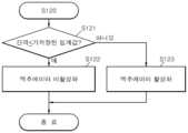
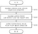
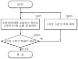
도 11을 참조하면, 본 발명의 제2 실시예에 따른 3차원 스캐닝 시스템의 제어 방법은 스캔 단계(S210), 스캔 데이터 판단 단계(S220), 및 전환 단계(S230)를 포함할 수 있다. 한편, 스캔 단계(S210)는 전술한 본 발명의 제1 실시예에 따른 3차원 스캐닝 시스템의 제어 방법 중 스캔 단계(S110)와 동일하고, 전환 단계(S230)는 전술한 본 발명의 제1 실시예에 따른 3차원 스캐닝 시스템의 제어 방법 중 전환 단계(S120)와 동일한 바, 상세한 설명은 생략하기로 한다.Referring to FIG. 11, a control method of a three-dimensional scanning system according to a second embodiment of the present invention may include a scan step (S210), a scan data determination step (S220), and a conversion step (S230). Meanwhile, the scan step (S210) is identical to the scan step (S110) of the control method of the three-dimensional scanning system according to the first embodiment of the present invention described above, and the conversion step (S230) is identical to the conversion step (S120) of the control method of the three-dimensional scanning system according to the first embodiment of the present invention described above, and thus a detailed description thereof will be omitted.
본 발명의 제2 실시예에 따른 3차원 스캐닝 시스템의 제어 방법에서, 전환 단계(S230)는 스캔 데이터 판단 단계(S220)에서 스캔 데이터의 상태가 소정 판단 기준에 미달하는 경우에만 수행될 수 있다. 즉, 전환 단계(S230)는 스캔 데이터의 상태가 양호한 경우에는 수행되지 않을 수 있다.In the control method of the three-dimensional scanning system according to the second embodiment of the present invention, the switching step (S230) may be performed only when the state of the scan data falls below a predetermined judgment criterion in the scan data judgment step (S220). That is, the switching step (S230) may not be performed when the state of the scan data is good.
스캔 데이터 판단 단계(S220)에 대해 보다 상세하게 설명한다. 도 11 및 도 12를 참조하면, 스캔 데이터를 판단하기 위한 소정 판단 기준은, 스캔 데이터에 포함되는 적어도 2개의 3차원 스캔샷의 얼라인 성공 여부를 포함할 수 있다. 전술한 바와 같이, 3차원 스캐너(10)를 사용하여 대상체(O)를 스캔하면, 복수의 3차원 스캔샷들이 획득될 수 있다. 상기 복수의 3차원 스캔샷들은 제어 유닛(20)에 의해 얼라인되고, 머징되어 3차원 모델로 생성될 수 있다. 다만, 사용자가 대상체(O)를 스캔하는 과정에서, 대상체(O)를 정밀하게 스캔하지 않은 경우 3차원 스캔샷 간의 중첩되는 부분이 부존재하여 3차원 스캔샷 간의 얼라인 실패가 발생할 수 있다. 3차원 스캔샷 간의 얼라인 실패가 발생하는 경우, 3차원 모델에 데이터 공백이 발생할 수 있고, 특히 치아를 표현하는 부분의 데이터 공백은 교정 시뮬레이션 오류, 부정확한 보철물 제작을 야기할 수 있다. 따라서, 스캔 데이터의 상태 중 얼라인 성공 여부는 완성도 높은 3차원 모델을 획득하기 위한 중요한 요소일 수 있다.The scan data judgment step (S220) will be described in more detail. Referring to FIGS. 11 and 12, a predetermined judgment criterion for judging the scan data may include whether the alignment of at least two 3D scan shots included in the scan data is successful. As described above, when the object (O) is scanned using the 3D scanner (10), a plurality of 3D scan shots may be acquired. The plurality of 3D scan shots may be aligned and merged by the control unit (20) to create a 3D model. However, when the user does not scan the object (O) precisely during the process of scanning the object (O), an overlapping portion between the 3D scan shots may not exist, resulting in an alignment failure between the 3D scan shots. When an alignment failure occurs between the 3D scan shots, a data gap may occur in the 3D model, and in particular, a data gap in a portion expressing a tooth may cause a correction simulation error and inaccurate production of a prosthesis. Therefore, the success or failure of alignment among the scan data statuses can be an important factor in obtaining a high-quality 3D model.
일반적으로 3차원 스캔샷들의 얼라인이 실패하면 피드백 수단을 통해 사용자에게 얼라인 실패를 피드백할 수 있다. 다만, 이러한 경우에도 액추에이터(130)에 의한 진동 피드백은 3차원 스캐너(10)와 대상체(O)가 근접하였을 때 비활성화되는 것이 바람직하다. 따라서, 스캔 데이터 판단 단계(S220)는 제어 유닛(20)의 얼라인부(220)가 스캔 데이터에 포함되는 적어도 2개의 3차원 스캔샷을 얼라인하는 얼라인 단계(S221)를 포함한다. 얼라인 단계(S221)는 제어 유닛(20)의 얼라인부(220)에서 전술한 바와 같이, 적어도 2개의 3차원 스캔샷의 중첩되는 부분을 정렬 및 연결하는 단계일 수 있다. 한편, 얼라인 단계(S221)는 3차원 스캔샷을 구성하는 복수의 지점들의 점단위 정렬을 통해 수행될 수도 있고, 3차원 스캔샷을 구성하는 영역의 영역단위 정렬을 통해 수행될 수도 있다.In general, when the alignment of 3D scan shots fails, the alignment failure can be fed back to the user through a feedback means. However, even in this case, it is preferable that the vibration feedback by the actuator (130) be deactivated when the 3D scanner (10) and the target (O) come into proximity. Therefore, the scan data determination step (S220) includes an alignment step (S221) in which the alignment unit (220) of the control unit (20) aligns at least two 3D scan shots included in the scan data. The alignment step (S221) may be a step of aligning and connecting overlapping portions of at least two 3D scan shots, as described above in the alignment unit (220) of the control unit (20). Meanwhile, the alignment step (S221) may be performed through point-by-point alignment of a plurality of points constituting the 3D scan shot, or may be performed through area-by-area alignment of an area constituting the 3D scan shot.
이후, 제어 유닛(20)의 얼라인부(220)는 스캔 데이터의 상태를 판단하기 위한 소정 판단 기준 중 얼라인 성공여부를 판단하는 얼라인 성공여부 판단 단계(S222)를 수행할 수 있다. 예시적으로, 3차원 스캔샷들 중 중첩되는 지점 및/또는 영역이 존재하지 않는 경우, 3차원 스캔샷 간의 얼라인은 실패한 것으로 판단될 수 있다. 이와 같이, 얼라인 성공여부 판단 단계(S222)에 의해 3차원 스캔샷 간의 얼라인이 실패한 것으로 판단된 경우, 전환 단계(S230)가 수행될 수 있다. 전환 단계(S230)는 스캔 데이터 판단 단계(S220)에서 판단된 얼라인 성공여부와, 스캔 단계(S110)에서 획득된 3차원 스캐너(10)와 대상체(O) 사이의 간격과 기거장된 임계값을 비교한 결과를 기초로 피드백 수단을 비활성화할 수 있다. 반면, 얼라인 성공여부 판단 단계(S222)에서 3차원 스캔샷 간의 얼라인이 성공한 것으로 판단된 경우, 3차원 스캐너(10)는 별도의 피드백 없이 계속하여 스캔 과정을 수행하는 3차원 스캔샷 획득을 재개하는 3차원 스캔샷 획득 재개 단계(S223)가 수행된다.Thereafter, the alignment unit (220) of the control unit (20) may perform an alignment success determination step (S222) for determining whether the alignment is successful among predetermined determination criteria for determining the status of the scan data. For example, if there is no overlapping point and/or area among the 3D scan shots, the alignment between the 3D scan shots may be determined to have failed. In this way, if the alignment between the 3D scan shots is determined to have failed by the alignment success determination step (S222), the switching step (S230) may be performed. The switching step (S230) may deactivate the feedback means based on the result of comparing the alignment success determined in the scan data determination step (S220) with the distance between the 3D scanner (10) and the target object (O) acquired in the scan step (S110) and the stored threshold value. On the other hand, if the alignment between the 3D scan shots is determined to be successful in the alignment success determination step (S222), the 3D scanner (10) performs a 3D scan shot acquisition resumption step (S223) to resume acquisition of the 3D scan shots, which continues to perform the scanning process without separate feedback.
이하에서는, 본 발명의 제3 실시예에 따른 3차원 스캐닝 시스템의 제어 방법에 대해 설명한다.Below, a control method of a three-dimensional scanning system according to a third embodiment of the present invention is described.
도 13은 본 발명의 제3 실시예에 따른 3차원 스캐닝 시스템의 제어 방법의 순서도이다.Figure 13 is a flowchart of a control method of a three-dimensional scanning system according to a third embodiment of the present invention.
도 13을 참조하면, 본 발명의 제3 실시예에 따른 3차원 스캐닝 시스템의 제어 방법은 스캔 단계(S310), 스캔 데이터 판단 단계(S320), 부가 측정값 획득 단계(S330), 및 피드백 수단의 활성화 상태를 전환시키는 전환 단계(S340)를 포함할 수 있다. 한편, 본 발명의 제3 실시예에 따른 3차원 스캐닝 시스템의 제어 방법에서, 스캔 단계(S310)는 본 발명의 제1 실시예에 따른 3차원 스캐닝 시스템의 제어 방법 중 스캔 단계(S110)와, 본 발명의 제2 실시예에 따른 3차원 스캐닝 시스템의 제어 방법 중 스캔 단계(S210)와 동일하다. 또한, 스캔 데이터 판단 단계(S320)는 본 발명의 제2 실시예에 따른 3차원 스캐닝 시스템의 제어 방법 중 스캔 데이터 판단 단계(S220)와 동일한 바, 상세한 설명은 생략한다.Referring to FIG. 13, a control method of a three-dimensional scanning system according to a third embodiment of the present invention may include a scan step (S310), a scan data determination step (S320), an additional measurement value acquisition step (S330), and a switching step (S340) for switching the activation state of a feedback means. Meanwhile, in the control method of a three-dimensional scanning system according to the third embodiment of the present invention, the scan step (S310) is identical to the scan step (S110) of the control method of a three-dimensional scanning system according to the first embodiment of the present invention and the scan step (S210) of the control method of a three-dimensional scanning system according to the second embodiment of the present invention. In addition, the scan data determination step (S320) is identical to the scan data determination step (S220) of the control method of a three-dimensional scanning system according to the second embodiment of the present invention, and thus a detailed description thereof will be omitted.
본 발명의 제3 실시예에 따른 3차원 스캐닝 시스템의 제어 방법의 부가 측정값 획득 단계(S330)에서, 파라미터 측정부(250)는 획득한 간격(z)을 기초로 부가적인 측정값을 획득할 수 있다. 예시적으로, 파라미터 측정부(250)는 간격(z)을 기초로 대상체(O)를 표현하는 스캔 데이터의 스캔 볼륨을 획득할 수 있다. 한편, 스캔 볼륨은 스캔 데이터의 지점들 중 일축에 대하여 최소 좌표값을 가지는 최근접 지점을 포함할 수 있다.In the additional measurement value acquisition step (S330) of the control method of the three-dimensional scanning system according to the third embodiment of the present invention, the parameter measurement unit (250) can acquire an additional measurement value based on the acquired interval (z). For example, the parameter measurement unit (250) can acquire a scan volume of scan data expressing the target object (O) based on the interval (z). Meanwhile, the scan volume can include the closest point having the minimum coordinate value with respect to one axis among the points of the scan data.
이후, 전환 단계(S340)에서 간격(z)과 연관되며, 부가 측정값 획득 단계(S330)에서 간격(z)을 기초로 부가적으로 획득되는 측정값을 기초로, 피드백 수단을 선택적으로 비활성화할 수 있다. 보다 상세하게는, 피드백 수단 조절부(260)는 간격(z)과 연관된 측정값인 상기 스캔 볼륨 내에, 대상체(O)가 3차원 스캐너(10)에 최근접하여 형성된 최근접 지점(P)이 3차원 스캐너(10)의 임계 스캔 볼륨 내에 포함되는지 판단할 수 있다. 만약 스캔 볼륨 내에 형성된 최근접 지점(P)이 임계 스캔 볼륨 내에 포함되는 경우, 3차원 스캐너(10)와 대상체(O)는 근접한 것으로 판단될 수 있다. 이에 따라, 제어 유닛(20)의 피드백 수단 조절부(260)는 3차원 스캐너(10)의 액추에이터(130)를 비활성화할 수 있다. 이와 같이, 3차원 스캐너(10)와 대상체(O) 사이의 간격(z) 이외의 다른 측정값을 사용하여 피드백 수단의 비활성화 여부를 판단함으로써, 3차원 스캐너(10)와 대상체(O)의 근접 여부를 잘못 판단하는 것을 방지하는 이점이 있다.Thereafter, in the switching step (S340), the feedback means can be selectively deactivated based on the measurement value additionally acquired based on the interval (z) in the additional measurement value acquisition step (S330), which is associated with the interval (z). More specifically, the feedback means control unit (260) can determine whether the closest point (P) formed by the object (O) being closest to the 3D scanner (10) within the scan volume, which is a measurement value associated with the interval (z), is included within the critical scan volume of the 3D scanner (10). If the closest point (P) formed within the scan volume is included within the critical scan volume, the 3D scanner (10) and the object (O) can be determined to be close. Accordingly, the feedback means control unit (260) of the control unit (20) can deactivate the actuator (130) of the 3D scanner (10). In this way, by determining whether the feedback means is deactivated using a measurement value other than the distance (z) between the 3D scanner (10) and the object (O), there is an advantage in preventing incorrect judgment of whether the 3D scanner (10) and the object (O) are in close proximity.
이하에서는, 본 발명의 제4 실시예에 따른 3차원 스캐닝 시스템의 제어 방법에 대해 설명한다.Below, a control method of a three-dimensional scanning system according to a fourth embodiment of the present invention is described.
도 14는 본 발명의 제4 실시예에 따른 3차원 스캐닝 시스템의 제어 방법의 순서도이다.Figure 14 is a flowchart of a control method of a three-dimensional scanning system according to the fourth embodiment of the present invention.
도 14를 참조하면, 본 발명의 제4 실시예에 따른 3차원 스캐닝 시스템의 제어 방법은 스캔 단계(S410), 스캔 데이터 판단 단계(S420), 대상체 감지 단계(S430), 및 피드백 수단의 활성화 상태를 전환시키는 전환 단계(S440)를 포함할 수 있다. 본 발명의 제4 실시예에 따른 3차원 스캐닝 시스템의 제어 방법에서, 스캔하는 단계(S410)는 본 발명의 제1 실시예 내지 제3 실시예에 따른 3차원 스캐닝 시스템의 제어 방법 중 스캔 단계(S110, S210, 및 S310)와 동일할 수 있다. 또한, 스캔 데이터 판단 단계(S420)는 본 발명의 제2 실시예 및 제3 실시예에 따른 3차원 스캐닝 시스템의 제어 방법 중 스캔 데이터 판단 단계(S220, 및 S320)와 동일한 바, 관련한 상세한 설명은 생략한다.Referring to FIG. 14, a control method of a three-dimensional scanning system according to a fourth embodiment of the present invention may include a scanning step (S410), a scan data determination step (S420), a target detection step (S430), and a switching step (S440) for switching an activation state of a feedback means. In the control method of a three-dimensional scanning system according to the fourth embodiment of the present invention, the scanning step (S410) may be identical to the scanning steps (S110, S210, and S310) of the control methods of the three-dimensional scanning system according to the first to third embodiments of the present invention. In addition, the scan data determination step (S420) is identical to the scan data determination steps (S220 and S320) of the control methods of the three-dimensional scanning system according to the second and third embodiments of the present invention, and thus, a detailed description thereof will be omitted.
한편, 본 발명의 제4 실시예에 따른 3차원 스캐닝 시스템의 제어 방법은, 대상체 감지 단계(S430)를 더 포함할 수 있다. 대상체 감지 단계(S430)에서, 대상체 감지부(270)는 3차원 스캐너(10)에 의해 스캔되는 대상체(O)의 종류를 감지할 수 있다. 예시적으로, 대상체 감지부(270)는 3차원 스캐너(10)에 의해 스캔되는 대상체(O)가 환자의 실제 구강 내부인지, 임프레션 모형인지, 아니면 구강 모형인지 감지할 수 있다. 대상체 감지 단계(S430)에서, 대상체 감지부(270)가 대상체(O)를 감지하기 위해, 기학습된 정보가 사용될 수 있다. 상기 기학습된 정보는, 제어 유닛(20)의 데이터베이스부(240)에 인공지능 학습되어 저장된 대상체 감지 로직일 수 있으며, 대상체 감지 로직은 환자의 실제 구강 내부, 임프레션, 모형, 및 구강 모형 각각의 특징에 대한 정보를 포함할 수 있다. 대상체 감지 단계(S430)에서, 감지된 대상체(O)의 종류가 임프레션 모형 또는 구강 모형인 경우, 피드백 수단 조절부(260)는 액추에이터(130)의 진동 피드백을 비활성화하지 않을 수 있다. 대상체(O)의 종류가 임프레션 모형 또는 구강 모형인 경우, 3차원 스캐너(10)가 진동하더라도 환자의 불편을 초래하는 문제가 발생하지 않으며, 액추에이터(130)의 진동 피드백은 사용자에게 스캔 데이터의 상태를 포함하는 피드백 상황을 용이하게 알릴 수 있는 수단이기 때문이다. 반면, 대상체 감지 단계(S430)에서, 대상체 감지부(270)가 상기 대상체(O)를 환자의 실제 구강 내부로 감지한 경우, 3차원 스캐너(10)와 대상체(O) 간의 간격을 획득하여, 이에 따른 적절한 제어(액추에이터를 비활성화하는 제어)를 수행할 수 있다. 즉, 대상체(O)의 종류가 환자의 실제 구강 내부로 감지된 경우, 전환 단계(S440)가 수행되어, 3차원 스캐너(10)와 환자의 구강 사이의 간격이 근접하였을 때 액추에이터(130)에 의한 진동 피드백이 발생하는 것을 방지할 수 있다. 대상체(O)의 종류에 따라 피드백 수단의 활성화 여부가 전환됨으로써, 환자에게 불편을 초래하지 않는 스캔 과정에서는 액추에이터(130)에 의한 진동 피드백이 작동하도록 하고, 환자에게 불편을 초래할 우려가 있는 스캔 과정에서는 액추에이터(130)에 의한 진동 피드백이 비활성화되도록 한다. 이에 따라, 3차원 스캐너(10)를 사용한 스캔 과정에서 발생할 수 있는 환자의 불편을 최소화할 수 있는 이점이 있다.Meanwhile, the control method of the three-dimensional scanning system according to the fourth embodiment of the present invention may further include an object detection step (S430). In the object detection step (S430), the object detection unit (270) may detect the type of the object (O) scanned by the three-dimensional scanner (10). For example, the object detection unit (270) may detect whether the object (O) scanned by the three-dimensional scanner (10) is the actual inside of the patient's oral cavity, an impression model, or an oral cavity model. In the object detection step (S430), pre-learned information may be used for the object detection unit (270) to detect the object (O). The pre-learned information may be an object detection logic that is learned by artificial intelligence and stored in the database unit (240) of the control unit (20), and the object detection logic may include information on the features of each of the patient's actual inside of the oral cavity, the impression, the model, and the oral cavity model. In the object detection step (S430), if the type of the detected object (O) is an impression model or an oral model, the feedback means control unit (260) may not deactivate the vibration feedback of the actuator (130). If the type of the object (O) is an impression model or an oral model, even if the 3D scanner (10) vibrates, there is no problem of causing discomfort to the patient, and the vibration feedback of the actuator (130) is a means of easily informing the user of a feedback situation including the status of the scan data. On the other hand, in the object detection step (S430), if the object detection unit (270) detects the object (O) as the actual inside of the patient's oral cavity, the distance between the 3D scanner (10) and the object (O) can be acquired, and appropriate control (control to deactivate the actuator) can be performed accordingly. That is, when the type of the object (O) is detected as inside the patient's actual oral cavity, the switching step (S440) is performed so that the vibration feedback by the actuator (130) can be prevented from occurring when the distance between the 3D scanner (10) and the patient's oral cavity becomes close. Since the activation of the feedback means is switched depending on the type of the object (O), the vibration feedback by the actuator (130) is activated in a scanning process that does not cause discomfort to the patient, and the vibration feedback by the actuator (130) is deactivated in a scanning process that may cause discomfort to the patient. Accordingly, there is an advantage in that the discomfort to the patient that may occur during the scanning process using the 3D scanner (10) can be minimized.
또한, 본 발명에 따른 3차원 스캐닝 시스템 및 이의 제어 방법을 사용하여 다양한 피드백 수단을 필요에 따라 활성화 또는 비활성화함으로써, 사용자는 디스플레이 유닛(30)을 주시하지 않고도 용이하게 스캔 과정을 수행할 수 있는 이점이 있다.In addition, by using the three-dimensional scanning system and its control method according to the present invention to activate or deactivate various feedback means as needed, there is an advantage in that the user can easily perform the scanning process without having to look at the display unit (30).
이상의 설명은 본 발명의 기술 사상을 예시적으로 설명한 것에 불과한 것으로서, 본 발명이 속하는 기술 분야에서 통상의 지식을 가진 자라면 본 발명의 본질적인 특성에서 벗어나지 않는 범위에서 다양한 수정 및 변형이 가능할 것이다.The above description is merely an example of the technical idea of the present invention, and those skilled in the art will appreciate that various modifications and variations may be made without departing from the essential characteristics of the present invention.
따라서, 본 발명에 개시된 실시예들은 본 발명의 기술 사상을 한정하기 위한 것이 아니라 설명하기 위한 것이고, 이러한 실시예에 의하여 본 발명의 기술 사상의 범위가 한정되는 것은 아니다. 본 발명의 보호 범위는 아래의 청구범위에 의하여 해석되어야 하며, 그와 동등한 범위 내에 있는 모든 기술 사상은 본 발명의 권리범위에 포함되는 것으로 해석되어야 할 것이다.Therefore, the embodiments disclosed in the present invention are not intended to limit the technical idea of the present invention but to explain it, and the scope of the technical idea of the present invention is not limited by these embodiments. The protection scope of the present invention should be interpreted by the following claims, and all technical ideas within the equivalent scope should be interpreted as being included in the scope of the rights of the present invention.
10: 3차원 스캐너20: 제어 유닛
30: 디스플레이 유닛
110: 광 프로젝터120: 카메라
130: 액추에이터140: 통신 유닛
150: 전원 공급 유닛
210: 이미지 데이터 생성부220: 얼라인부
230: 3차원 모델링부240: 데이터베이스부
250: 파라미터 측정부260: 피드백 수단 조절부
270: 대상체 감지부280: 배터리 잔량 측정부
S110: 스캔 단계S120: 전환 단계
S220: 스캔 데이터 판단 단계
S340: 부가 측정값 획득 단계
S430: 대상체 감지 단계10: 3D scanner 20: Control unit
30: Display unit
110: Light projector 120: Camera
130: Actuator 140: Communication unit
150: Power supply unit
210: Image data generation section 220: Alignment section
230: 3D Modeling Department 240: Database Department
250: Parameter measurement section 260: Feedback means control section
270: Object detection unit 280: Battery remaining capacity measurement unit
S110: Scanning phase S120: Transition phase
S220: Scan data judgment step
S340: Additional Measurement Value Acquisition Step
S430: Object Detection Step
Claims (19)
Translated fromKorean상기 간격에 기초하여 적어도 하나의 피드백 수단의 활성화 상태를 전환시키는 전환 단계;를 포함하고,
상기 전환 단계는 상기 3차원 스캐너로부터 획득한 스캔 데이터의 상태가 소정 판단 기준에 미달하는 경우 수행되며,
상기 간격이 기저장된 임계값 이하인 경우 상기 피드백 수단을 선택적으로 비활성화하여 상기 3차원 스캐너와 상기 대상체 간의 충돌을 방지하는 것을 특징으로 하는 3차원 스캐닝 시스템의 제어 방법.A scanning step of scanning an object using a 3D scanner to obtain a distance between the 3D scanner and the object; and
A switching step for switching the activation state of at least one feedback means based on the above interval;
The above conversion step is performed when the status of the scan data acquired from the 3D scanner falls below a predetermined judgment criterion.
A control method for a three-dimensional scanning system, characterized in that the feedback means is selectively deactivated when the gap is less than or equal to a preset threshold value, thereby preventing collision between the three-dimensional scanner and the target object.
상기 소정 판단 기준은, 상기 스캔 데이터에 포함되는 적어도 2개의 3차원 스캔샷의 얼라인 성공 여부를 포함하는 것을 특징으로 하는 3차원 스캐닝 시스템의 제어 방법.In claim 1,
A control method for a 3D scanning system, wherein the above-described predetermined judgment criterion includes whether at least two 3D scan shots included in the scan data are aligned successfully.
상기 스캔 데이터에 포함되는 적어도 2개의 3차원 스캔샷을 얼라인하는 얼라인 단계; 및
상기 스캔 데이터의 상태를 판단하기 위한 상기 소정 판단 기준 중 얼라인 성공여부를 판단하는 얼라인 성공여부 판단 단계;를 더 포함하고,
상기 전환 단계는 상기 얼라인 성공여부와, 상기 간격과 기저장된 임계값을 비교하여 상기 피드백 수단을 비활성화하는 것을 특징으로 하는 3차원 스캐닝 시스템의 제어 방법.In claim 1,
An alignment step of aligning at least two three-dimensional scan shots included in the above scan data; and
Further comprising an alignment success determination step for determining whether alignment is successful among the above predetermined determination criteria for determining the status of the above scan data;
A control method for a three-dimensional scanning system, characterized in that the switching step deactivates the feedback means by comparing the alignment success or failure with the interval and a stored threshold value.
상기 간격은,
상기 스캔 데이터의 깊이값을 포함하는 것을 특징으로 하는 3차원 스캐닝 시스템의 제어 방법.In claim 1,
The above interval is,
A control method for a three-dimensional scanning system, characterized in that it includes a depth value of the above scan data.
상기 깊이값은 상기 스캔 데이터의 지점들 중 일축에 대하여 최소 좌표값을 가지는 최근접 지점을 기초로 획득되는 것을 특징으로 하는 3차원 스캐닝 시스템의 제어 방법.In claim 6,
A control method for a three-dimensional scanning system, characterized in that the depth value is obtained based on the closest point having the minimum coordinate value with respect to one axis among the points of the scan data.
상기 간격은 상기 3차원 스캐너에 내장된 카메라와 상기 대상체 사이의 광경로 길이를 기초로 획득되고,
상기 임계값은,
상기 카메라의 렌즈와 상기 3차원 스캐너의 일단 내부에 배치된 광경로 변경부재 사이의 광경로 길이, 상기 카메라의 렌즈와 상기 3차원 스캐너의 일단에 형성된 개구부 사이의 광경로 길이, 및 상기 카메라의 렌즈와 상기 개구부의 외부로 소정 오프셋 간격 이격되어 형성된 가상면 사이의 광경로 길이 중 어느 하나를 기초로 획득되는 것을 특징으로 하는 3차원 스캐닝 시스템의 제어 방법.In claim 1,
The above interval is obtained based on the optical path length between the camera built into the 3D scanner and the target object,
The above threshold is,
A control method for a three-dimensional scanning system, characterized in that the control method is obtained based on any one of the following: an optical path length between a lens of the camera and an optical path changing member arranged inside one end of the three-dimensional scanner, an optical path length between the lens of the camera and an opening formed in one end of the three-dimensional scanner, and an optical path length between the lens of the camera and a virtual plane formed at a predetermined offset distance outside the opening.
상기 전환 단계는, 상기 간격과 연관되며, 상기 간격을 기초로 부가적으로 획득되는 측정값을 기초로 상기 피드백 수단을 선택적으로 비활성화하며,
상기 측정값은 상기 스캔 데이터의 지점들 중 일축에 대하여 최소 좌표값을 가지는 최근접 지점을 포함하는 스캔 볼륨을 포함하는 것을 특징으로 하는 3차원 스캐닝 시스템의 제어 방법.In claim 1,
The above switching step is associated with the interval and selectively deactivates the feedback means based on additionally acquired measurements based on the interval,
A control method for a three-dimensional scanning system, wherein the above measurement value includes a scan volume including a closest point having a minimum coordinate value with respect to one axis among points of the scan data.
상기 피드백 수단은, 상기 3차원 스캐너를 진동시키는 액추에이터를 포함하는 것을 특징으로 하는 3차원 스캐닝 시스템의 제어 방법.In claim 1
A control method for a three-dimensional scanning system, characterized in that the feedback means includes an actuator that vibrates the three-dimensional scanner.
상기 피드백 수단은, 상기 3차원 스캐너의 외부로 광을 조사하는 광 프로젝터, 상기 스캔 데이터의 상태를 나타내기 위해 소리를 발생시키는 스피커, 및 상기 스캔 데이터의 상태를 화면에 표시하는 디스플레이 유닛 중 적어도 하나를 더 포함하는 것을 특징으로 하는 3차원 스캐닝 시스템의 제어 방법.In claim 10,
A control method for a three-dimensional scanning system, characterized in that the feedback means further includes at least one of a light projector that irradiates light to the outside of the three-dimensional scanner, a speaker that generates sound to indicate the status of the scan data, and a display unit that displays the status of the scan data on a screen.
상기 임계값은 상기 3차원 스캐너의 스캔 심도에 따라 상이하게 설정되는 것을 특징으로 하는 3차원 스캐닝 시스템의 제어 방법.In claim 1,
A control method for a three-dimensional scanning system, characterized in that the threshold value is set differently depending on the scan depth of the three-dimensional scanner.
상기 대상체의 종류를 감지하는 대상체 감지 단계;를 더 포함하고,
상기 전환 단계는 감지된 상기 대상체의 종류에 기초하여 선택적으로 수행되는 것을 특징으로 하는 3차원 스캐닝 시스템의 제어 방법.In claim 1,
Further comprising an object detection step for detecting the type of the object;
A control method for a three-dimensional scanning system, characterized in that the above switching step is selectively performed based on the type of the detected target object.
상기 스캔 데이터의 상태에 따라 피드백을 발생시키는 적어도 하나의 피드백 수단; 및
상기 스캔 데이터에 기초하여 상기 피드백 수단의 활성화 상태를 전환하는 제어 유닛; 을 포함하고,
상기 제어 유닛은,
상기 대상체를 스캔하여 획득하는 적어도 2개의 3차원 스캔샷을 얼라인하는 얼라인부;
상기 3차원 스캐너와 상기 대상체 간의 간격을 획득하는 파라미터 측정부; 및
상기 파라미터 측정부가 획득한 상기 간격에 기초하여 상기 피드백 수단을 활성화하거나 비활성화하는 피드백 수단 조절부; 를 포함하며,
상기 피드백 수단 조절부는 상기 간격이 기저장된 임계값 이하인 경우 상기 피드백 수단을 선택적으로 비활성화하여 상기 3차원 스캐너와 상기 대상체 간의 충돌을 방지하는 것을 특징으로 하는 3차원 스캐닝 시스템.A 3D scanner that scans an object to obtain scan data representing the object;
At least one feedback means for generating feedback according to the status of said scan data; and
A control unit for switching the activation state of the feedback means based on the scan data;
The above control unit,
An alignment unit for aligning at least two three-dimensional scan shots obtained by scanning the above object;
A parameter measuring unit for obtaining the distance between the 3D scanner and the target object; and
A feedback means control unit for activating or deactivating the feedback means based on the interval obtained by the parameter measuring unit;
A three-dimensional scanning system, characterized in that the feedback means control unit selectively deactivates the feedback means when the gap is less than a preset threshold value, thereby preventing collision between the three-dimensional scanner and the target object.
상기 피드백 수단은, 상기 3차원 스캐너를 진동시키는 액추에이터를 포함하는 것을 특징으로 하는 3차원 스캐닝 시스템.In claim 14,
A three-dimensional scanning system, characterized in that the feedback means includes an actuator that vibrates the three-dimensional scanner.
상기 피드백 수단은, 상기 3차원 스캐너의 외부로 광을 조사하는 광 프로젝터, 상기 스캔 데이터의 상태를 나타내기 위해 소리를 발생시키는 스피커, 및 상기 스캔 데이터의 상태를 화면에 표시하는 디스플레이 유닛 중 적어도 하나를 더 포함하는 것을 특징으로 하는 3차원 스캐닝 시스템.In claim 17,
A three-dimensional scanning system, characterized in that the feedback means further includes at least one of a light projector that irradiates light to the outside of the three-dimensional scanner, a speaker that generates sound to indicate the status of the scan data, and a display unit that displays the status of the scan data on a screen.
상기 제어 유닛은,
상기 대상체의 종류를 감지하는 대상체 감지부;를 더 포함하며,
상기 피드백 수단 조절부는 감지된 상기 대상체의 종류에 기초하여 선택적으로 동작하는 것을 특징으로 하는 3차원 스캐닝 시스템.
In claim 14,
The above control unit,
It further includes an object detection unit that detects the type of the object;
A three-dimensional scanning system, characterized in that the feedback means control unit selectively operates based on the type of the detected target object.
Priority Applications (3)
| Application Number | Priority Date | Filing Date | Title |
|---|---|---|---|
| US17/719,373US12305975B2 (en) | 2021-04-14 | 2022-04-13 | Three-dimensional scanning system and method for controlling the same |
| EP22168079.6AEP4075095A1 (en) | 2021-04-14 | 2022-04-13 | Three-dimensional scanning system and method for controlling the same |
| CN202210392793.0ACN115192241B (en) | 2021-04-14 | 2022-04-14 | Three-dimensional scanning system and control method thereof |
Applications Claiming Priority (2)
| Application Number | Priority Date | Filing Date | Title |
|---|---|---|---|
| KR1020210048727 | 2021-04-14 | ||
| KR20210048727 | 2021-04-14 |
Publications (2)
| Publication Number | Publication Date |
|---|---|
| KR20220142339A KR20220142339A (en) | 2022-10-21 |
| KR102728460B1true KR102728460B1 (en) | 2024-11-11 |
Family
ID=83805157
Family Applications (1)
| Application Number | Title | Priority Date | Filing Date |
|---|---|---|---|
| KR1020220031163AActiveKR102728460B1 (en) | 2021-04-14 | 2022-03-14 | 3-dimensional scanning system and method for controlling thereof |
Country Status (1)
| Country | Link |
|---|---|
| KR (1) | KR102728460B1 (en) |
Citations (3)
| Publication number | Priority date | Publication date | Assignee | Title |
|---|---|---|---|---|
| US20090298017A1 (en)* | 2006-01-20 | 2009-12-03 | 3M Innivative Properties Company | Digital dentistry |
| JP2012529352A (en) | 2009-06-08 | 2012-11-22 | エムアールアイ・インターヴェンションズ,インコーポレイテッド | MRI guided intervention system capable of tracking flexible internal devices and generating dynamic visualization in near real time |
| US10019839B2 (en) | 2016-06-30 | 2018-07-10 | Microsoft Technology Licensing, Llc | Three-dimensional object scanning feedback |
Family Cites Families (2)
| Publication number | Priority date | Publication date | Assignee | Title |
|---|---|---|---|---|
| EP3427070A4 (en)* | 2016-03-11 | 2019-10-16 | Cyberoptics Corporation | CALIBRATION OF FIELD OF NON-CONTACT THREE-DIMENSIONAL SCAN SYSTEM |
| ES3007214T3 (en)* | 2019-02-15 | 2025-03-19 | Medit Corp | Method for replaying scanning process |
- 2022
- 2022-03-14KRKR1020220031163Apatent/KR102728460B1/enactiveActive
Patent Citations (3)
| Publication number | Priority date | Publication date | Assignee | Title |
|---|---|---|---|---|
| US20090298017A1 (en)* | 2006-01-20 | 2009-12-03 | 3M Innivative Properties Company | Digital dentistry |
| JP2012529352A (en) | 2009-06-08 | 2012-11-22 | エムアールアイ・インターヴェンションズ,インコーポレイテッド | MRI guided intervention system capable of tracking flexible internal devices and generating dynamic visualization in near real time |
| US10019839B2 (en) | 2016-06-30 | 2018-07-10 | Microsoft Technology Licensing, Llc | Three-dimensional object scanning feedback |
Also Published As
| Publication number | Publication date |
|---|---|
| KR20220142339A (en) | 2022-10-21 |
Similar Documents
| Publication | Publication Date | Title |
|---|---|---|
| KR101977181B1 (en) | Dental intraoral scanner system | |
| KR102370017B1 (en) | Investigating method for optical portion embedded in intraoral scanner and system using the same | |
| US20150097931A1 (en) | Calibration of 3d scanning device | |
| CN113397739A (en) | Intraoral scanner with touch sensitive input | |
| US12102465B2 (en) | Three-dimensional scanner and scanning method using same | |
| WO2014144434A1 (en) | System and method for imaging in laser dental treatment | |
| US10898306B2 (en) | Dental treatment system | |
| KR101832753B1 (en) | Apparatus for scanning for both model and oral cavity | |
| US10325365B2 (en) | Method for measuring a dental object | |
| KR102236360B1 (en) | Method for providing scan guide and image processing apparatus therefor | |
| US20230397804A1 (en) | Oral image processing device and oral image processing method | |
| US20230355360A1 (en) | System and method for providing dynamic feedback during scanning of a dental object | |
| EP4075095A1 (en) | Three-dimensional scanning system and method for controlling the same | |
| EP4191523A1 (en) | Data processing device, data processing method, and data processing program | |
| KR102728460B1 (en) | 3-dimensional scanning system and method for controlling thereof | |
| KR20110068954A (en) | Oral Scanner | |
| KR102632337B1 (en) | Align-state indicating apparatus and method thereof | |
| EP4191522A1 (en) | Data processing device, data processing method, and data processing program | |
| KR102575216B1 (en) | After-processing system and after-processing method of scanned data | |
| KR102613531B1 (en) | An intraoral image processing apparatus, an intraoral image processing method | |
| KR20230002038A (en) | Method for data compensation and apparatus for data compensation using thereof | |
| KR20230052246A (en) | Image processing apparatus and image processing method using thereof | |
| KR20220133073A (en) | A data processing apparatus, a data processing method | |
| KR20240040634A (en) | A scanner, a data processing apparatus, and a data processing method |
Legal Events
| Date | Code | Title | Description |
|---|---|---|---|
| PA0109 | Patent application | Patent event code:PA01091R01D Comment text:Patent Application Patent event date:20220314 | |
| PA0201 | Request for examination | ||
| PG1501 | Laying open of application | ||
| E902 | Notification of reason for refusal | ||
| PE0902 | Notice of grounds for rejection | Comment text:Notification of reason for refusal Patent event date:20231221 Patent event code:PE09021S01D | |
| E701 | Decision to grant or registration of patent right | ||
| PE0701 | Decision of registration | Patent event code:PE07011S01D Comment text:Decision to Grant Registration Patent event date:20240807 | |
| GRNT | Written decision to grant | ||
| PR0701 | Registration of establishment | Comment text:Registration of Establishment Patent event date:20241106 Patent event code:PR07011E01D | |
| PR1002 | Payment of registration fee | Payment date:20241106 End annual number:3 Start annual number:1 | |
| PG1601 | Publication of registration |