KR102728383B1 - Method and Apparatus for Measuring Displacement of Target Object using Artificial Intelligence Model Predicting Real Distance between Two Points - Google Patents
Method and Apparatus for Measuring Displacement of Target Object using Artificial Intelligence Model Predicting Real Distance between Two PointsDownload PDFInfo
- Publication number
- KR102728383B1 KR102728383B1KR1020240129533AKR20240129533AKR102728383B1KR 102728383 B1KR102728383 B1KR 102728383B1KR 1020240129533 AKR1020240129533 AKR 1020240129533AKR 20240129533 AKR20240129533 AKR 20240129533AKR 102728383 B1KR102728383 B1KR 102728383B1
- Authority
- KR
- South Korea
- Prior art keywords
- real
- image
- point
- laser beam
- distance
- Prior art date
- Legal status (The legal status is an assumption and is not a legal conclusion. Google has not performed a legal analysis and makes no representation as to the accuracy of the status listed.)
- Active
Links
Images


Classifications
- G—PHYSICS
- G01—MEASURING; TESTING
- G01B—MEASURING LENGTH, THICKNESS OR SIMILAR LINEAR DIMENSIONS; MEASURING ANGLES; MEASURING AREAS; MEASURING IRREGULARITIES OF SURFACES OR CONTOURS
- G01B11/00—Measuring arrangements characterised by the use of optical techniques
- G01B11/16—Measuring arrangements characterised by the use of optical techniques for measuring the deformation in a solid, e.g. optical strain gauge
- G01B11/165—Measuring arrangements characterised by the use of optical techniques for measuring the deformation in a solid, e.g. optical strain gauge by means of a grating deformed by the object
- G—PHYSICS
- G01—MEASURING; TESTING
- G01B—MEASURING LENGTH, THICKNESS OR SIMILAR LINEAR DIMENSIONS; MEASURING ANGLES; MEASURING AREAS; MEASURING IRREGULARITIES OF SURFACES OR CONTOURS
- G01B11/00—Measuring arrangements characterised by the use of optical techniques
- G01B11/02—Measuring arrangements characterised by the use of optical techniques for measuring length, width or thickness
- G01B11/026—Measuring arrangements characterised by the use of optical techniques for measuring length, width or thickness by measuring distance between sensor and object
- G—PHYSICS
- G01—MEASURING; TESTING
- G01B—MEASURING LENGTH, THICKNESS OR SIMILAR LINEAR DIMENSIONS; MEASURING ANGLES; MEASURING AREAS; MEASURING IRREGULARITIES OF SURFACES OR CONTOURS
- G01B11/00—Measuring arrangements characterised by the use of optical techniques
- G01B11/02—Measuring arrangements characterised by the use of optical techniques for measuring length, width or thickness
- G01B11/03—Measuring arrangements characterised by the use of optical techniques for measuring length, width or thickness by measuring coordinates of points
- G—PHYSICS
- G01—MEASURING; TESTING
- G01B—MEASURING LENGTH, THICKNESS OR SIMILAR LINEAR DIMENSIONS; MEASURING ANGLES; MEASURING AREAS; MEASURING IRREGULARITIES OF SURFACES OR CONTOURS
- G01B21/00—Measuring arrangements or details thereof, where the measuring technique is not covered by the other groups of this subclass, unspecified or not relevant
- G01B21/02—Measuring arrangements or details thereof, where the measuring technique is not covered by the other groups of this subclass, unspecified or not relevant for measuring length, width, or thickness
- G01B21/04—Measuring arrangements or details thereof, where the measuring technique is not covered by the other groups of this subclass, unspecified or not relevant for measuring length, width, or thickness by measuring coordinates of points
- G01B21/045—Correction of measurements
- G—PHYSICS
- G06—COMPUTING OR CALCULATING; COUNTING
- G06N—COMPUTING ARRANGEMENTS BASED ON SPECIFIC COMPUTATIONAL MODELS
- G06N20/00—Machine learning
- G—PHYSICS
- G01—MEASURING; TESTING
- G01B—MEASURING LENGTH, THICKNESS OR SIMILAR LINEAR DIMENSIONS; MEASURING ANGLES; MEASURING AREAS; MEASURING IRREGULARITIES OF SURFACES OR CONTOURS
- G01B2210/00—Aspects not specifically covered by any group under G01B, e.g. of wheel alignment, caliper-like sensors
- G01B2210/58—Wireless transmission of information between a sensor or probe and a control or evaluation unit
Landscapes
- General Physics & Mathematics (AREA)
- Physics & Mathematics (AREA)
- Engineering & Computer Science (AREA)
- Software Systems (AREA)
- Theoretical Computer Science (AREA)
- Data Mining & Analysis (AREA)
- Medical Informatics (AREA)
- Evolutionary Computation (AREA)
- Computing Systems (AREA)
- General Engineering & Computer Science (AREA)
- Computer Vision & Pattern Recognition (AREA)
- Mathematical Physics (AREA)
- Artificial Intelligence (AREA)
- Length Measuring Devices By Optical Means (AREA)
Abstract
Translated fromKoreanDescription
Translated fromKorean본 발명은 교량의 거더 등과 같은 대상물에 설치된 레이저 광원부로부터 조사된 레이저 빔의 도트(dot)가 맺힌 결상 플레이트를 카메라로 촬영한 영상을 이용하여 대상물의 변위를 계측하는 방법 및 이러한 방법이 적용된 장치에 관한 것으로서, 특별히 촬영영상에 왜곡이 발생하게 되는 카메라 렌즈의 고유한 특성을 미리 파악하여, 이러한 촬영영상의 왜곡을 보상할 수 있는 인공지능 모델을 미리 구축해두고, 결상 플레이트의 촬영영상에서 파악된 변위를 인공지능 모델을 이용하여 실제 발생된 변위로 환산하여 보정함으로써 고가의 렌즈가 아닌 저렴한 렌즈를 구비한 카메라를 사용하더라도 대상물의 변위를 높은 신뢰도로 계측할 수 있게 되어 대상물의 변위계측 비용을 절감할 수 있는 "인공지능 모델을 이용한 렌즈 왜곡 보정 변위계측방법" 및 이러한 변위계측방법에 의해 변위를 계측하는 "변위계측장치"에 관한 것이다.The present invention relates to a method for measuring displacement of an object using an image of an imaging plate on which dots of a laser beam irradiated from a laser light source installed on an object such as a bridge girder are formed, captured by a camera, and to a device to which this method is applied. In particular, the present invention relates to a "lens distortion correction displacement measurement method using an artificial intelligence model", which detects the unique characteristics of a camera lens that cause distortion in a captured image in advance, builds an artificial intelligence model capable of compensating for the distortion of such a captured image, converts the displacement detected in the captured image of the imaging plate into an actual displacement and corrects it using the artificial intelligence model, thereby enabling the displacement of an object to be measured with a high degree of reliability even when a camera equipped with an inexpensive lens instead of an expensive lens is used, thereby reducing the cost of measuring displacement of an object.
본 발명은 아래의 연구결과물에 해당한다.The present invention corresponds to the following research results.
[이 발명을 지원한 연구개발사업][Research and development projects supporting this invention]
[과제고유번호] D2403013[Project ID] D2403013
[부처명] 경기도[Buddha Name] Gyeonggi-do
[연구관리전문기관] (재)경기도경제과학진흥원[Research Management Specialist Agency] Gyeonggi Province Economic and Science Promotion Agency
[연구사업명] 기업주도(일반_첫걸음)[Research Project Name] Corporate-led (General_First Step)
[연구과제명] 딥러닝-레이저빔-비전 기반 교량 처짐 측정 시스템 개발[Research Project Name] Development of a Deep Learning-Laser Beam-Vision Based Bridge Deflection Measurement System
[기여율] 1/1[Contribution rate] 1/1
[주관연구기관] (주)카이센테크[Research Institution] Kaisentech Co., Ltd.
[연구기간] 2024-08-01 ~ 2026-07-31[Research Period] 2024-08-01 ~ 2026-07-31
대상물의 변위를 계측하고, 더 나아가 이를 지속적으로 모니터링해야 할 경우가 사회기반 시설에서는 빈번하게 발생한다. 예를 들어, 교량 등과 같은 건설구조물의 경우, 구조적인 건전성 등의 상태를 평가하기 위하여 외력에 의한 구조물의 변위를 계측하여 모니터링해야 하는 것이다. 이와 같이 대상물의 변위계측을 위한 종래 기술로는 LVDT, 와이어와 링게이지를 이용한 방법이나, 레이저 변위계와 망원렌즈를 이용한 방법 등이 제안되어 있다. 특히, "교량 처짐 계측 시스템"이라는 발명의 명칭을 가지는 대한민국 등록특허 제10-1917619호에는 교량에 레이저 광원부를 설치하고 이와 이격된 위치에 결상 플레이트를 설치한 상태에서, 레이저 광원부로부터 출사된 레이저 빔이 결상 플레이트에 도트(dot) 형태로 맺혀 있는 상태를 촬영하고, 촬영된 영상(촬영 이미지/촬영영상) 내에서 레이저 빔의 도트(dot)가 이동한 거리를 산출한 후 이를 이용하여 교량의 변위를 파악하는 매우 유용한 기술이 개시되어 있다.In social infrastructure, there are frequent cases where the displacement of an object must be measured and further continuously monitored. For example, in the case of a construction structure such as a bridge, the displacement of the structure due to an external force must be measured and monitored in order to evaluate the condition of the structural soundness, etc. As conventional techniques for measuring the displacement of an object, methods using LVDT, wires and ring gauges, methods using laser displacement meters and telephoto lenses, etc. have been proposed. In particular, Korean Patent No. 10-1917619 entitled “Bridge Deflection Measurement System” discloses a very useful technique of installing a laser light source on a bridge, installing a focusing plate at a location separate from it, photographing a state in which a laser beam emitted from the laser light source is focused on the focusing plate in the form of a dot, calculating the distance traveled by the dot of the laser beam in the photographed image (photographed image/photographed video), and then using this to determine the displacement of the bridge.
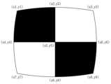
그런데 이미지를 촬영하는 카메라의 경우, 렌즈 특성에 따른 왜곡이 발생할 수 있다. 도 1의 (a), (b) 및 (c)의 각각에는 렌즈 특성에 따른 이미지의 왜곡 현상을 설명하기 위한 촬영영상의 예를 보여주는 개략도가 도시되어 있다. 도 1의 (a)에 도시된 정사각형 그리드(grind)의 정상적인 형태를 카메라로 촬영하였을 때, 카메라 렌즈로 인하여 촬영영상에서의 그리드가 도 1의 (b)에 도시된 것처럼 볼록형태로 왜곡(barrel distortion)되거나 또는 도 1의 (c)에 도시된 것처럼 오목형태로 왜곡(pincushion distortion)될 수 있다.However, in the case of a camera that captures an image, distortion may occur depending on the lens characteristics. Each of (a), (b), and (c) of Fig. 1 is a schematic diagram showing an example of a captured image to explain the phenomenon of image distortion depending on the lens characteristics. When the normal shape of the square grid (grind) shown in (a) of Fig. 1 is captured by a camera, the grid in the captured image may be distorted into a convex shape (barrel distortion) as shown in (b) of Fig. 1 or into a concave shape (pincushion distortion) as shown in (c) of Fig. 1 due to the camera lens.
따라서 상기한 대한민국 등록특허 제10-1917619호의 기술처럼 대상물에 설치된 레이저 광원부로부터 조사된 레이저 빔의 도트(dot)가 맺힌 결상 플레이트를 카메라로 촬영한 영상을 이용하여 대상물의 변위를 계측하는 기술에 있어서는 렌즈 특성에 따른 이미지 왜곡의 문제를 해결하는 것이 매우 중요하다. 고가의 정밀한 렌즈를 구비한 카메라는 이용한다면 위와 같은 이미지 왜곡의 문제를 다소 줄일 수 있겠지만, 이 경우 촬영영상을 이용한 변위 계측에 소요되는 비용이 크게 증가하게 되는 단점이 있으며, 아무리 고가의 정밀한 렌즈를 사용하더라도 이미지 왜곡의 문제가 완전히 해결되지 못한다는 한계가 여전히 존재한다.Therefore, in a technology for measuring the displacement of an object by using an image of a dot-forming plate formed by a laser beam irradiated from a laser light source installed on the object, such as the technology of the above-mentioned Republic of Korea Registration Patent No. 10-1917619, it is very important to solve the problem of image distortion due to lens characteristics. If a camera equipped with an expensive, precise lens is used, the problem of image distortion as described above can be reduced to some extent. However, in this case, there is a disadvantage in that the cost required for displacement measurement using the captured image significantly increases, and there still exists a limitation in that the problem of image distortion cannot be completely solved even if an expensive, precise lens is used.
본 발명은 위와 같은 종래 기술의 한계를 극복하기 위하여 개발된 것으로서, 교량의 거더 등과 같은 대상물에 설치된 레이저 광원부로부터 조사된 레이저 빔의 도트가 맺힌 결상 플레이트를 카메라로 촬영한 영상을 이용하여 대상물의 변위를 계측함에 있어서, 카메라 렌즈의 촬영영상 왜곡으로 인한 변위 계측의 부정확성 발생 문제를 해결하기 위하여 개발된 것이다.The present invention has been developed to overcome the limitations of the above-mentioned prior art, and to solve the problem of inaccuracy in displacement measurement due to distortion of the captured image by the camera lens when measuring the displacement of an object using an image of an imaging plate in which dots of a laser beam irradiated from a laser light source installed on an object such as a bridge girder are formed by a camera.
구체적으로 본 발명은 저가의 카메라 렌즈를 사용하더라도 촬영영상 왜곡으로 인하여 발생하는 상기한 문제를 해결할 수 있으며, 그에 따라 촬영영상을 이용하여 대상물의 변위를 계측할 때 소요되는 비용을 크게 절감할 수 있고, 변위계측의 신뢰도를 높일 수 있는 기술을 제공하는 것을 목적으로 한다.Specifically, the present invention aims to provide a technology that can solve the above-mentioned problem caused by distortion of a photographed image even when using a low-cost camera lens, thereby significantly reducing the cost required to measure the displacement of an object using a photographed image, and increasing the reliability of displacement measurement.
위와 같은 과제를 달성하기 위하여 본 발명에서는, 카메라를 포함하는 광원수신부를 변위 측정의 대상물에 설치된 레이저 광원부로부터 이격된 위치에 설치하고; 광원수신부에 복수개의 교차점을 가지도록 격자가 형성된 보정판을 설치하고 카메라로 촬영하여 보정영상을 취득한 후, 제어연산장치에 의하여 보정영상에서 2개의 보정영상 교차점을 추출하여, 보정영상 교차점의 픽셀좌표를 취득하고 보정영상 교차점 각각에 대응되는 보정판 교차점 간의 실거리를 파악하되, 상기 보정영상 교차점의 픽셀좌표 취득 작업 및 상기 보정판 교차점 간의 실거리 파악 작업을 보정영상의 모든 보정영상 교차점에 대해 수행하여, 모든 보정영상 교차점의 쌍에 대한 픽셀좌표 및 보정영상 교차점 쌍에 대응되는 보정판 교차점 쌍 사이의 실거리를 취득하고; 취득된 모든 보정영상 교차점의 쌍에 대한 픽셀좌표와, 보정영상 교차점 쌍에 대응되는 보정판 교차점 쌍 사이의 실거리를 입력 데이터로 이용하여, 인공지능 알고리즘으로 이루어진 인공지능 모델을 기계학습시켜서, 촬영영상 속 2개의 점에 대한 픽셀좌표를 입력하면, 촬영영상 속 2개 점에 대응되는 원판 상의 2개 점 사이의 실거리를 출력하도록 학습된 "인공지능 실거리 예측모델"을 구축하고; 광원수신부에 결상 플레이트를 설치하고 레이저 광원부로부터 조사된 레이저 빔이 도트(dot) 형태로 맺혀 있는 결상 플레이트를 카메라로 촬영하여 결상영상을 취득하고; 제어연산장치에 의하여 결상영상에서 레이저 빔의 도트가 이동하기 전의 위치에 해당하는 "레이저 빔 시작점"의 픽셀좌표와, 레이저 빔의 도트가 이동한 후의 위치에 해당하는 "레이저 빔 이동점"의 픽셀좌표를 파악하고; 제어연산장치에 의하여 레이저 빔 시작점과 레이저 빔 이동점의 픽셀좌표를 인공지능 실거리 예측모델에 입력하여 레이저 빔 시작점과 레이저 빔 이동점 사이의 결상 플레이트 상의 실거리를 산출함으로써 레이저 광원부가 설치된 대상물에 발생한 변위를 계측하는 것을 특징으로 하는 변위계측방법이 제공된다.In order to achieve the above-mentioned task, in the present invention, a light source receiving unit including a camera is installed at a position spaced apart from a laser light source unit installed in an object of displacement measurement; a correction plate having a grid formed to have a plurality of intersections is installed in the light source receiving unit, and a correction image is acquired by photographing with a camera, and then two correction image intersections are extracted from the correction image by a control operation unit, so as to acquire pixel coordinates of the correction image intersections, and the real distance between the correction plate intersections corresponding to each of the correction image intersections is determined, and the work of acquiring the pixel coordinates of the correction image intersections and the work of determining the real distance between the correction plate intersections are performed for all correction image intersections of the correction image, so as to acquire pixel coordinates for all pairs of correction image intersections and the real distance between the correction plate intersections corresponding to the pairs of correction image intersections; By using the pixel coordinates of all pairs of intersection points of acquired correction images and the real distances between the intersection points of correction plates corresponding to the intersection points of the correction images as input data, an "artificial intelligence real distance prediction model" is constructed by performing machine learning on an artificial intelligence model composed of an artificial intelligence algorithm so that, when the pixel coordinates of two points in a photographed image are input, an "artificial intelligence real distance prediction model" is learned to output the real distance between two points on a plate corresponding to the two points in the photographed image; an imaging plate is installed in a light source receiving unit, and a camera is used to capture an imaging image by photographing the imaging plate on which a laser beam irradiated from a laser light source unit is formed in the form of a dot; and the control operation unit determines the pixel coordinates of the "laser beam starting point" corresponding to the position before the dot of the laser beam moves in the imaging image, and the pixel coordinates of the "laser beam moving point" corresponding to the position after the dot of the laser beam moves; A displacement measurement method is provided, characterized in that the method inputs pixel coordinates of a laser beam starting point and a laser beam moving point into an artificial intelligence real-distance prediction model by a control operation unit, and calculates the real distance between the laser beam starting point and the laser beam moving point on an imaging plate, thereby measuring displacement occurring in an object in which a laser light source is installed.
특히, 본 발명에서는 상기한 변위계측방법에서 인공지능 실거리 예측모델을 이용한 보정작업을 더 수행한 방법이 제공되는데, 구체적으로는 상기한 본 발명에서 결상영상을 취득한 후, 결상영상에서 레이저 빔 시작점과 레이저 빔 이동점을 둘러싸도록 존재하는 점으로서 결상 플레이트 상에서의 실좌표를 알고 있는 점 중에서 복수개의 점을 가상(假想) 기준점으로 설정하여, 제어연산장치를 통해서 복수개의 가상 기준점 각각의 픽셀좌표를 파악하고; 제어연산장치를 통해서, 가상 기준점과 레이저 빔 시작점 각각의 픽셀좌표를 이미 학습되어 구축된 인공지능 실거리 예측모델에 입력하여 가상 기준점과 레이저 빔 시작점 사이의 결상 플레이트 상의 실거리를 산출하며, 가상 기준점과 레이저 빔 이동점 각각의 픽셀좌표를 상기 인공지능 실거리 예측모델에 입력하여 가상 기준점과 레이저 빔 이동점 사이의 결상 플레이트 상의 실거리를 산출하되, 상기 실거리 산출 작업을 복수개의 가상 기준점 각각에 대하여 수행하고; 각각의 가상 기준점에 대응되는 결상 플레이트 상의 점(실제 기준점)에 대한 실좌표에, 인공지능 실거리 예측모델에 의해 산출된 가상 기준점과 레이저 빔 시작점 사이의 결상 플레이트 상의 실거리를 적용하여 실제 시작점에 대한 추정 실좌표를 산출하고, 각각의 가상 기준점에 대응되는 결상 플레이트 상의 실제 기준점에 대한 실좌표에, 인공지능 실거리 예측모델에 의해 산출된 가상 기준점과 레이저 빔 이동점 사이의 실거리를 적용하여 실제 이동점에 대한 추정 실좌표를 산출하는 작업을 제어연산장치를 통해서 수행하고; 제어연산장치를 통해서, 복수개의 가상 기준점 각각에 대하여 산출한 실제 시작점의 복수개 추정 실좌표에 대한 산술평균을 수행하여 실제 시작점의 보정 실좌표를 산출하고, 복수개의 가상 기준점 각각에 대하여 산출한 실제 이동점의 복수개 추정 실좌표에 대한 산술평균을 수행하여 실제 이동점의 보정 실좌표를 산출한 후, 산출된 실제 시작점의 보정 실좌표와 실제 이동점의 보정 실좌표에 의해 실제 시작점과 실제 이동점 사이의 실거리를 산출하여, 산출된 실제 시작점과 실제 이동점 사이의 실거리를 결상 플레이트 상에서 레이저 빔의 도트가 실제로 이동한 거리로 간주함으로써 레이저 광원부가 설치된 대상물에 발생한 변위를 계측하는 것을 특징으로 하는 변위계측방법이 제공된다.In particular, the present invention provides a method for further performing a correction operation using an artificial intelligence real-time distance prediction model in the displacement measurement method described above. Specifically, after acquiring an imaging image in the present invention described above, among points existing to surround a laser beam starting point and a laser beam moving point in the imaging image and having known real coordinates on an imaging plate, a plurality of points are set as virtual reference points, and the pixel coordinates of each of the plurality of virtual reference points are identified through a control and computation device; and, through the control and computation device, the pixel coordinates of the virtual reference point and the laser beam starting point are input into an artificial intelligence real-time distance prediction model that has already been learned and constructed, so as to calculate the real distance on the imaging plate between the virtual reference point and the laser beam starting point, and the pixel coordinates of the virtual reference point and the laser beam moving point are input into the artificial intelligence real-time distance prediction model, so as to calculate the real distance on the imaging plate between the virtual reference point and the laser beam moving point, wherein the real distance calculation operation is performed for each of the plurality of virtual reference points; For each virtual reference point, the real coordinates for the points on the imaging plate (real reference points) corresponding to the virtual reference point are applied by the real distance on the imaging plate between the virtual reference point and the starting point of the laser beam, which is calculated by the artificial intelligence real distance prediction model, to calculate the estimated real coordinates for the real starting point, and for each virtual reference point, the real distance between the virtual reference point and the moving point of the laser beam, which is calculated by the artificial intelligence real distance prediction model, is calculated by the control operation unit to calculate the estimated real coordinates for the real moving point; A displacement measuring method is provided, characterized in that the method comprises: calculating a corrected real coordinate of the actual starting point by performing an arithmetic mean on a plurality of estimated real coordinates of the calculated actual starting point for each of a plurality of virtual reference points through a control operation unit; calculating a corrected real coordinate of the actual moving point by performing an arithmetic mean on a plurality of estimated real coordinates of the calculated actual moving point for each of a plurality of virtual reference points; and then calculating a real distance between the actual starting point and the actual moving point by the calculated corrected real coordinates of the actual starting point and the corrected real coordinates of the actual moving point, and considering the calculated real distance between the actual starting point and the actual moving point as a distance actually moved by a dot of a laser beam on an imaging plate, thereby measuring a displacement occurring in an object in which a laser light source is installed.
또한 본 발명에서는 변위 계측이 필요한 대상물에 설치되어 레이저 빔을 조사하는 레이저 광원부, 카메라를 포함하는 광원수신부, 및 상기 레이저 광원부와 상기 광원수신부의 작동 뿐을 제어하고 변위 산출 연산을 수행하는 제어연산장치를 포함하며; 상기한 본 발명의 변위계측방법에 의해, 레이저 광원부가 설치된 대상물에 발생한 변위를 계측하는 것을 특징으로 하는 변위계측장치가 제공된다.In addition, the present invention includes a laser light source unit installed on an object requiring displacement measurement and irradiating a laser beam, a light source receiver unit including a camera, and a control operation unit that controls only the operations of the laser light source unit and the light source receiver unit and performs displacement calculation operations; and a displacement measuring device characterized in that it measures displacement occurring in an object on which the laser light source unit is installed by the displacement measuring method of the present invention described above.
본 발명에서는 결상영상에서의 레이저 빔 시작점 및 레이저 빔 이동점에 대한 픽셀좌표를 입력하면 결상 플레이트 상에서의 실제 시작점과 실제 이동점 사이의 물리 거리를 출력데이터로 제공하는 인공지능 알고리즘 형태의 학습된 인공지능 실거리 예측모델을 구축하여 이용하게 되므로, 레이저 빔이 결상 플레이트에 맺히는 도트의 이동 거리를 매우 쉽게 파악할 수 있게 되고, 그에 따라 대상물의 변위 계측을 더욱 효율적이고 용이하게 수행할 수 있다.In the present invention, by inputting pixel coordinates for a laser beam starting point and a laser beam moving point in an imaging image, an artificial intelligence real-distance prediction model learned in the form of an artificial intelligence algorithm is constructed and utilized to provide the physical distance between the actual starting point and the actual moving point on the imaging plate as output data, so that the moving distance of a dot formed by a laser beam on the imaging plate can be determined very easily, and accordingly, displacement measurement of an object can be performed more efficiently and easily.
특히, 본 발명에서는 인공지능 실거리 예측모델을 이용한 보정작업을 더 시행할 수 있으며, 이를 통해서 결상 플레이트를 촬영한 결상영상에서 발생하는 영상왜곡 즉, 카메라에 구비된 렌즈의 고유한 특성으로 인하여 결상영상에 왜곡이 발생하고 이로 인하여 결상영상에서 도트가 이동한 거리가, 결상 플레이트에서 실제 도트가 이동한 거리와 상이하게 되는 문제점을 해소하게 되고, 그에 따라 레이저 빔이 결상 플레이트에 맺히는 도트의 이동 거리에 대한 계측 정확성을 더욱 높일 수 있게 되며 대상물의 변위 계측에 대한 신뢰도를 더욱 향상시키게 되는 효과가 발휘된다.In particular, in the present invention, a correction operation using an artificial intelligence real-time distance prediction model can be further performed, through which the image distortion occurring in the image formed by photographing the image forming plate, that is, the problem in which the image forming image is distorted due to the unique characteristics of the lens equipped in the camera, and thus the distance moved by the dot in the image forming image is different from the actual distance moved by the dot in the image forming plate, is resolved, and accordingly, the measurement accuracy of the distance moved by the dot formed by the laser beam on the image forming plate can be further improved, and the reliability of the displacement measurement of the target object is further improved.
도 1의 (a), (b) 및 (c)의 각각은 렌즈 특성에 따른 이미지의 왜곡 현상을 설명하기 위한 촬영영상의 예를 보여주는 개략도이다.
도 2는 본 발명에 따른 변위계측장치의 구성을 보여주는 개략도이다.
도 3은 본 발명의 변위계측장치에 구비된 제어연산장치의 상세 구성을 보여주는 개략적인 블록도이다.
도 4는 본 발명에 따른 변위계측방법에 대한 개략적인 흐름도이다.
도 5는 본 발명에 따른 <영상 보정을 위한 인공지능 실거리 예측모델 구축작업>에 대한 개략적인 흐름도이다.
도 6은 보정원판의 일예에 대한 개략적인 정면도이다.
도 7은 도 6에 예시된 보정원판에서 서로 직교하도록 교차하는 3개의 수평선과 3개의 수직선에 의해 9개의 교차점을 가지는 부분만을 발췌하여 보여주는 개략도이다.
도 8은 도 7에 도시된 보정원판의 부분을 촬영한 영상을 보여주는 개략도이다.
도 9는 본 발명에 따라 실거리 예측모델을 구축하기 위하여 수행되는 상세한 작업 단계에 대한 흐름도이다.
도 10은 본 발명에 따른 <인공지능 실거리 예측모델을 이용한 보정작업>의 상세 단계에 대한 개략적인 흐름도이다.
도 11은 결상영상에서 가상 기준점을 설정한 것을 보여주는 개략도이다.
도 12는 결상 플레이트 상에서 실제 기준점과 실제 시작점 사이의 실거리를 표시한 개략도이다.
도 13은 결상 플레이트 상에서 실제 기준점과 실제 이동점 사이의 실거리를 표시한 개략도이다.Each of (a), (b), and (c) of Figure 1 is a schematic diagram showing an example of a captured image to explain the phenomenon of image distortion according to lens characteristics.
Figure 2 is a schematic diagram showing the configuration of a displacement measuring device according to the present invention.
Figure 3 is a schematic block diagram showing the detailed configuration of a control operation device provided in the displacement measuring device of the present invention.
Figure 4 is a schematic flow chart of a displacement measurement method according to the present invention.
Figure 5 is a schematic flow chart for the <artificial intelligence real-distance prediction model construction work for image correction> according to the present invention.
Figure 6 is a schematic front view of an example of a compensation plate.
Figure 7 is a schematic diagram showing only a portion having nine intersection points by three horizontal lines and three vertical lines intersecting each other orthogonally in the correction plate illustrated in Figure 6.
Figure 8 is a schematic diagram showing an image taken of a portion of the correction plate illustrated in Figure 7.
Figure 9 is a flow chart of detailed work steps performed to build a real-time prediction model according to the present invention.
Figure 10 is a schematic flow chart of detailed steps of <correction work using an artificial intelligence real-time distance prediction model> according to the present invention.
Figure 11 is a schematic diagram showing the setting of a virtual reference point in a resolution image.
Figure 12 is a schematic diagram showing the actual distance between the actual reference point and the actual starting point on the determination plate.
Figure 13 is a schematic diagram showing the actual distance between the actual reference point and the actual moving point on the imaging plate.
아래에서는 첨부한 도면을 참조하여 본 발명을 설명하게 되는데, 이러한 설명은 본 발명의 바람직한 실시예를 예시한 것이며, 이것에 의해 본 발명의 기술적 사상과 그 핵심 구성 및 작용이 제한되는 것은 아니다. 특히, 본 발명을 설명함에 있어서, 후술하는 제어연산장치는 프로세서, 메모리, 사용자 입출력부 및 네트워크 입출력부를 포함하는 일종의 컴퓨터 장치로 형성될 수 있다. 컴퓨터 장치는 cpu를 통해 데이터를 처리하는 연산이 가능한 것일 수 있으며 cpu 상에 연산 프로그램을 로딩하여 연산하는 것일 수 있다. 연산이 이루어지는 cpu는 하나 또는 복수일 수도 있다. 하나의 cpu 상에 복수의 프로그램을 로딩하는 것도 가능하며 각각 다른 cpu를 가진 복수의 장치에서 서로 다른 프로그램을 로딩하는 구조도 가능하다. 첨부된 블록도의 각 블록과 흐름도의 각 단계의 조합들은 컴퓨터 프로그램 인스트럭션들(실행 엔진)에 의해 수행될 수도 있으며, 이들 컴퓨터 프로그램 인스트럭션들은 범용 컴퓨터, 특수용 컴퓨터 또는 기타 프로그램 가능한 데이터 프로세싱 장비의 프로세서에 탑재될 수 있으므로, 컴퓨터 또는 기타 프로그램 가능한 데이터 프로세싱 장비의 프로세서를 통해 수행되는 그 인스트럭션들이 블록도의 각 블록 또는 흐름도의 각 단계에서 설명된 기능들을 수행하는 수단을 생성하게 된다. 이들 컴퓨터 프로그램 인스트럭션들은 특정 방식으로 기능을 구현하기 위해 컴퓨터 또는 기타 프로그램 가능한 데이터 프로세싱 장비를 지향할 수 있는 컴퓨터 이용가능 또는 컴퓨터 판독 가능 메모리에 저장되는 것도 가능하므로, 그 컴퓨터 이용가능 또는 컴퓨터 판독 가능 메모리에 저장된 인스트럭션들은 블록도의 각 블록 또는 흐름도의 각 단계에서 설명된 기능을 수행하는 인스트럭션 수단을 내포하는 제조 품목을 생산하는 것도 가능하다. 그리고 컴퓨터 프로그램 인스트럭션들은 컴퓨터 또는 기타 프로그램 가능한 데이터 프로세싱 장비 상에 탑재되는 것도 가능하므로, 컴퓨터 또는 기타 프로그램 가능한 데이터 프로세싱 장비 상에서 일련의 동작 단계들이 수행되어 컴퓨터로 실행되는 프로세스를 생성해서 컴퓨터 또는 기타 프로그램 가능한 데이터 프로세싱 장비를 수행하는 인스트럭션들은 블록도의 각 블록 및 흐름도의 각 단계에서 설명되는 기능들을 실행하기 위한 단계들을 제공하는 것도 가능하다. 또한, 각 블록 또는 각 단계(작업/과정)는 특정된 논리적 기능들을 실행하기 위한 하나 이상의 실행 가능한 인스트럭션들을 포함하는 모듈, 세그먼트 또는 코드의 일부를 나타낼 수 있으며, 몇 가지 대체 실시예들에서는 블록들 또는 단계들에서 언급된 기능들이 순서를 벗어나서 발생하는 것도 가능하다. 예를 들면, 잇달아 도시되어 있는 두 개의 블록들 또는 단계들은 사실 실질적으로 동시에 수행되는 것도 가능하며, 또한 그 블록들 또는 단계들이 필요에 따라 해당하는 기능의 역순으로 수행되는 것도 가능하다. 제어연산장치에 구비되는 각종 "모듈"은 적어도 하나의 기능이나 동작을 처리하는 단위를 의미하며, 이는 하드웨어나 소프트웨어, 또는 하드웨어 및 소프트웨어의 결합으로 구현될 수 있다.Hereinafter, the present invention will be described with reference to the attached drawings. This description is an example of a preferred embodiment of the present invention, and the technical idea of the present invention and its core structure and operation are not limited thereby. In particular, in describing the present invention, the control operation device described below may be formed as a kind of computer device including a processor, a memory, a user input/output unit, and a network input/output unit. The computer device may be capable of processing data through a CPU, and may load an operation program onto the CPU and perform the operation. The CPU where the operation is performed may be one or more. It is also possible to load multiple programs onto one CPU, and a structure in which different programs are loaded on multiple devices each having a different CPU is also possible. The combination of each block of the attached block diagram and each step of the flowchart may be performed by computer program instructions (execution engine), and these computer program instructions may be installed in a processor of a general-purpose computer, a special-purpose computer, or other programmable data processing apparatus, so that the instructions, which are executed by the processor of the computer or other programmable data processing apparatus, create a means for performing the functions described in each block of the block diagram or each step of the flowchart. These computer program instructions may also be stored in a computer-available or computer-readable memory that can be directed to a computer or other programmable data processing apparatus to implement the function in a specific manner, so that the instructions stored in the computer-available or computer-readable memory can produce an article of manufacture including an instruction means for performing the functions described in each block of the block diagram or each step of the flowchart. And since the computer program instructions can also be installed on a computer or other programmable data processing equipment, a series of operation steps are performed on the computer or other programmable data processing equipment to create a computer-executable process, and the instructions that perform the computer or other programmable data processing equipment can also provide steps for performing the functions described in each block of the block diagram and each step of the flowchart. In addition, each block or each step (task/process) can represent a module, segment, or part of code that includes one or more executable instructions for performing specific logical functions, and in some alternative embodiments, the functions mentioned in the blocks or steps can occur out of order. For example, two blocks or steps shown in succession can actually be performed substantially simultaneously, and the blocks or steps can also be performed in the reverse order of the corresponding functions as needed. Various "modules" provided in the control processing device mean units that process at least one function or operation, and this can be implemented by hardware or software, or a combination of hardware and software.
도 2에는 본 발명에 따른 변위계측장치의 구성을 보여주는 개략도가 도시되어 있고, 도 3에는 본 발명의 변위계측장치에 구비된 제어연산장치의 상세 구성을 보여주는 개략적인 블록도가 도시되어 있다. 편의상 도 2에서 변위를 계측하기 위한 대상물은 도시를 생략하였다. 도 2에 도시된 것처럼 본 발명에 따른 변위계측장치는, 변위 계측이 필요한 대상물(예를 들면, 교량의 거더/ 도면에서는 도시를 생략함)에 설치되어 레이저 빔을 조사하는 레이저 광원부(1), 레이저 빔이 조사된 결상 플레이트(20)를 카메라(21)로 촬영하게 되는 광원수신부(2), 및 제어와 연산 작동을 수행하는 제어연산장치(3)를 포함하는 구성을 가진다.FIG. 2 is a schematic diagram showing the configuration of a displacement measuring device according to the present invention, and FIG. 3 is a schematic block diagram showing the detailed configuration of a control operation unit equipped in the displacement measuring device of the present invention. For convenience, an object for measuring displacement is not illustrated in FIG. 2. As illustrated in FIG. 2, the displacement measuring device according to the present invention has a configuration including a laser light source unit (1) installed on an object requiring displacement measurement (e.g., a bridge girder/not illustrated in the drawing) and irradiating a laser beam, a light source receiver unit (2) that photographs an imaging plate (20) irradiated with a laser beam using a camera (21), and a control operation unit (3) that performs control and operation operations.
레이저 광원부(1)는 변위 계측이 필요한 대상물(예를 들면, 교량의 거더)에 설치되어 레이저 빔을 조사한다. 광원수신부(2)는 레이저 광원부(1)로부터 이격된 위치에 설치되는 것으로서, 레이저 광원부(1)로부터의 레이저 빔이 광원수신부(2)를 향하여 조사된다. 광원수신부(2)는 상자 형태의 함체를 구비하고 있고, 함체 내에는 결상 플레이트(20)와 카메라(21)가 함체의 연장방향으로 이격되어 배치되어 있는 구성을 가진다. 따라서 광원수신부(2)가 레이저 광원부(1)로부터 이격된 위치에 설치된 상태에서 레이저 광원부(1)에서 함체를 향하여 레이저 빔이 출사되면, 레이저 빔은 함체의 입구를 통해서 결상 플레이트(20)의 정면에 조사되어 도트(dot) 형태로 맺히게 된다. 본 발명에서 결상 플레이트(20)는 레이저 빔이 조사되는 정면에 햇빛 차단 필름이 도포된 판재로 이루어질 수 있다. 이와 같이 결상 플레이트(20)가 판재의 정면에 햇빛 차단 필름이 도포되어 있는 구성을 가지는 경우, 레이저 빔이 조사되어 결상 플레이트(20)에 도트 형태로 맺힐 때, 햇빛 등과 같이 대상물의 변위 측정을 방해하거나 불필요한 빛이 결상 플레이트(20)에 조사되어 정확한 도트 이동거리 산출이 어려워지는 문제가 발생하는 것을 방지하거나 최소화시킬 수 있다.The laser light source unit (1) is installed on an object requiring displacement measurement (e.g., a girder of a bridge) and irradiates a laser beam. The light source receiver unit (2) is installed at a location spaced from the laser light source unit (1), and a laser beam from the laser light source unit (1) is irradiated toward the light source receiver unit (2). The light source receiver unit (2) has a box-shaped body, and has a configuration in which an imaging plate (20) and a camera (21) are arranged spaced apart from each other in the extension direction of the body. Therefore, when a laser beam is emitted from the laser light source unit (1) toward the body while the light source receiver unit (2) is installed at a location spaced from the laser light source unit (1), the laser beam is irradiated to the front of the imaging plate (20) through the entrance of the body and is formed in the form of a dot. In the present invention, the imaging plate (20) may be formed of a plate having a sunlight-blocking film applied to the front surface on which the laser beam is irradiated. In this way, when the imaging plate (20) has a configuration in which a sunlight blocking film is applied to the front surface of the plate, when a laser beam is irradiated and formed into a dot shape on the imaging plate (20), the problem of interference with the displacement measurement of the object, such as sunlight, or unnecessary light being irradiated on the imaging plate (20) and making it difficult to calculate the accurate dot movement distance can be prevented or minimized.
카메라(21)는 도트 형태로 레이저 빔이 맺혀 있는 결상 플레이트(20)를 촬영하여 디지털 이미지 형태로 이루어진 결상 플레이트의 촬영영상을 취득하는 것이다. 제어연산장치(3)는 레이저 광원부(1)와 상기 광원수신부(2)의 작동을 제어함과 동시에 대상물의 변위 산출에 필요한 연산을 수행하게 되는데, 구체적으로는 데이터베이스 모듈(31), 인공지능모델 구축 모듈(32), 이미지 프로세싱 모듈(33), 교차점 추출 모듈(34) 및 좌표거리산출 모듈(35)을 포함하는 구성을 가진다.The camera (21) photographs the imaging plate (20) on which laser beams are focused in the form of dots, thereby acquiring a photographed image of the imaging plate in the form of a digital image. The control operation unit (3) controls the operation of the laser light source unit (1) and the light source receiver unit (2), and at the same time performs operations necessary for calculating displacement of the target object. Specifically, the control operation unit has a configuration including a database module (31), an artificial intelligence model construction module (32), an image processing module (33), an intersection extraction module (34), and a coordinate distance calculation module (35).
데이터베이스 모듈(31)은 제어연산장치에서 사용되고 산출되는 각종 데이터를 저장하는 기능을 수행하는 것으로서, 특히 후술하는 것처럼 사전에 파악된 기지(旣知)의 정보가 데이터베이스 모듈(31)에 저장된다. 인공지능모델 구축 모듈(32)은 촬영영상 내 2개 점을 선정하여 해당 점의 픽셀좌표를 입력하면, 촬영영상의 대상이 된 원판에서 상기 2개의 점에 대응되는 점 사이의 실질적인 물리(物理) 거리를 산출하는 신경망을 이용한 인공지능 알고리즘 형태의 "인공지능 실(實)거리 예측모델"을 기계학습에 의해 구축하는 기능을 수행한다. 이미지 프로세싱 모듈(33)은 공지(公知)의 이미지 프로세싱 방법을 이용하여, 디지털 이미지 형태의 촬영영상 속의 점(point)에 대한 픽셀좌표(픽셀 X좌표와 픽셀 Y좌표)를 취득하는 기능을 수행한다. 교차점 추출 모듈(34)은 격자로 이루어진 판을 촬영한 촬영영상에서 수직선과 수평선이 교차하는 교차점을 추출하는 기능을 수행한다. 좌표거리산출 모듈(35)은 후술하는 것처럼 가상 기준점을 기준으로 하는 실제 시작점의 "추정 실좌표"를 산출하고, 산출된 추정 실좌표를 이용한 "보정 실좌표"를 산출하는 기능을 수행한다. 또한 좌표거리산출 모듈(35)은 후술하는 것처럼 교차점 간의 실거리를 산출하는 기능을 수행한다.The database module (31) performs the function of storing various data used and produced in the control operation unit, and in particular, as described below, previously known information is stored in the database module (31). The artificial intelligence model construction module (32) performs the function of constructing an "artificial intelligence real distance prediction model" in the form of an artificial intelligence algorithm using a neural network that calculates the actual physical distance between points corresponding to the two points on the original plate that is the target of the photographed image by selecting two points in the photographed image and inputting the pixel coordinates of the corresponding points through machine learning. The image processing module (33) performs the function of acquiring pixel coordinates (pixel X-coordinate and pixel Y-coordinate) for points in the photographed image in the form of a digital image by using a publicly known image processing method. The intersection extraction module (34) performs the function of extracting the intersection point where vertical and horizontal lines intersect in the photographed image that captures the plate made of a grid. The coordinate distance calculation module (35) performs the function of calculating the "estimated real coordinates" of the actual starting point based on the virtual reference point as described below, and calculating the "corrected real coordinates" using the calculated estimated real coordinates. In addition, the coordinate distance calculation module (35) performs the function of calculating the real distance between intersections as described below.
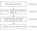
본 발명에 따른 변위계측방법에서는 상기한 구성을 가지는 본 발명의 변위계측장치를 이용하여 대상물의 변위를 계측하게 된다. 도 4에는 본 발명에 따른 변위계측방법에 대한 개략적인 흐름도가 도시되어 있다. 본 발명의 변위계측방법에서는 레이저 빔을 조사하는 레이저 광원부(1)를 변위 계측이 필요한 대상물(예를 들면, 교량의 거더)에 설치하고 레이저 광원부(1)로부터 이격된 위치에 광원수신부(2)를 설치한다(Step 1). 광원수신부(2)의 함체 내에서 결상 플레이트(20)를 설치할 위치에 보정원판을 설치하고 보정원판에 대한 촬영영상 즉, 보정영상을 취득하며, 취득된 보정영상을 이용하여 인공지능 실거리 예측모델 구축작업(Step 2)을 수행한다. 편의상 본 명세서의 설명 및 도면에서는 인공지능 실거리 예측모델 구축작업(Step 2)이 상기한 Step 1의 레이저 광원부(1)/광원수신부(2)의 설치 작업에 후속하여 진행하는 것처럼 서술하고 있지만, 상기한 Step 1과 Step 2는 어느 것을 먼저 수행하여도 무방하다.In the displacement measurement method according to the present invention, the displacement measurement device of the present invention having the above-described configuration is used to measure the displacement of an object. FIG. 4 is a schematic flowchart illustrating the displacement measurement method according to the present invention. In the displacement measurement method of the present invention, a laser light source unit (1) that irradiates a laser beam is installed on an object requiring displacement measurement (e.g., a girder of a bridge), and a light source receiver unit (2) is installed at a location spaced apart from the laser light source unit (1)(Step 1) . A correction plate is installed at a location where an imaging plate (20) is to be installed within the body of the light source receiver unit (2), and a photographed image of the correction plate, i.e., a correction image, is acquired, and an artificial intelligence real-distance prediction model construction task(Step 2) is performed using the acquired correction image. For convenience, the description and drawings of this specification describe the work of constructing an artificial intelligence real-time prediction model (Step 2) as being performed subsequent to the installation work of the laser light source unit (1)/light source receiver unit (2) of
보정원판이 제거되고 그 대신에 결상 플레이트(20)가 설치된 광원수신부(2)가 레이저 광원부(1)로부터 이격된 위치에 설치된 상태에서 레이저 광원부(1)에서 함체를 향하여 레이저 빔이 출사되면, 레이저 빔은 함체의 입구를 통해서 결상 플레이트(20)의 정면에 조사되어 도트(dot) 형태로 맺히게 되며 레이저 광원부(1)가 설치되어 있는 대상물에 변위가 발생하게 되면 결상 플레이트(20)에 맺혀 있는 레이저 빔의 도트가 이동하게 되는데(Step 3), 카메라(21)는 도트 형태로 레이저 빔이 맺혀 있는 결상 플레이트(20)를 촬영하여 디지털 이미지 형태로 이루어진 결상 플레이트의 촬영영상("결상영상")을 취득하게 된다(Step 4). 이 때 대상물의 변위로 인하여 레이저 빔의 도트가 이동하기 전, 후의 상태 각각에 대한 촬영영상을 취득하게 된다. 그리고 취득한 결상영상을 이용하여 실물의 결상 플레이트(20) 상에서 레이저 빔의 도트가 이동한 거리("도트의 실제 이동거리")를 산출한다(Step 6).When the compensation plate is removed and the light source receiver (2) with the imaging plate (20) installed instead is installed at a position spaced from the laser light source (1), and a laser beam is emitted from the laser light source (1) toward the body, the laser beam is irradiated to the front of the imaging plate (20) through the entrance of the body and is focused in the form of a dot, and when a displacement occurs in the object on which the laser light source (1) is installed, the dot of the laser beam focused on the imaging plate (20) moves(Step 3) . The camera (21) photographs the imaging plate (20) on which the laser beam is focused in the form of a dot, and acquires a photographed image (“image”) of the imaging plate in the form of a digital image(Step 4) . At this time, photographs are acquired for each state before and after the dot of the laser beam moves due to the displacement of the object. And, using the acquired imaging image, the distance traveled by the dot of the laser beam on the actual imaging plate (20) (“actual movement distance of the dot”) is calculated(Step 6) .
그런데 앞서 도 1을 참조하여 살펴본 것처럼, 카메라(21)에 구비된 렌즈의 고유한 특성으로 인하여 결상영상에는 왜곡이 존재하고, 이로 인하여 결상영상에서 직접 파악한 도트의 이동거리가 결상 플레이트 상에서의 도트의 실제 이동거리와 상이하다는 문제점이 발생할 수 있다. 본 발명에서는 이러한 문제점을 해결하기 위하여 즉, 결상영상을 이용하여 결상 플레이트 상에서의 도트의 실제 이동거리를 정확하게 파악할 수 있도록, 결상 플레이트 상에서의 도트의 실제 이동거리를 산출하는 Step 6을 수행하기에 앞서 아래에서 설명하는<인공지능 실거리 예측모델을 이용한 보정작업>(Step 5)을 수행하게 된다.However, as previously examined with reference to Fig. 1, due to the unique characteristics of the lens equipped in the camera (21), there may be distortion in the image formation, and as a result, a problem may arise that the movement distance of the dot directly detected in the image formation is different from the actual movement distance of the dot on the image formation plate. In order to solve this problem, that is, in order to accurately detect the actual movement distance of the dot on the image formation plate using the image formation image, the following is performed before performing Step 6 of calculating the actual movement distance of the dot on the image formation plate.<Correction work using artificial intelligence real-time prediction model>(Step 5) will be performed.
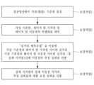
도 5에는 본 발명에 따른 <Step 2 : 영상 보정을 위한 인공지능 실거리 예측모델 구축작업>의 상세 단계를 보여주는 흐름도가 도시되어 있다. 본 발명에서 <영상 보정을 위한 인공지능 실거리 예측모델 구축작업>(Step 2)은 광원수신부(2)의 함체 내에서 결상 플레이트가 설치될 위치에 보정판을 설치하고 카메라(21)로 보정판을 촬영하여 보정판에 대한 촬영영상("보정영상")을 취득하게 되는 "ⓐ보정영상 취득단계"와, 학습된 인공지능 알고리즘 형태의 인공지능 실거리 예측모델을 구축하는 "ⓑ인공지능 실거리 예측모델 구축단계"를 포함한다.FIG. 5 is a flowchart showing detailed steps of <Step 2: Construction of an artificial intelligence real-time prediction model for image correction> according to the present invention. In the present invention, <Construction of an artificial intelligence real-time prediction model for image correction> (Step 2) includes a “a) correction image acquisition step” of installing a correction plate at a location where an imaging plate is to be installed within a body of a light source receiver (2) and photographing the correction plate with a camera (21) to acquire a photographed image (“correction image”) of the correction plate, and a “b) artificial intelligence real-time prediction model construction step” of constructing an artificial intelligence real-time prediction model in the form of a learned artificial intelligence algorithm.
ⓐ보정영상 취득단계 : 보정판의 준비 및 보정판의 촬영ⓐ Correction image acquisition stage: Preparation of correction plate and shooting of correction plate
보정판(補正板)(standard plate for calibration)은 서로 직교하는 복수개의 수평선과 복수개의 수직선에 의해 격자가 형성된 판으로서, 사용자는 미리 이러한 보정판을 준비한다. 도 6에는 보정판의 일예에 대한 개략적인 정면도가 도시되어 있다. 도 7에는 도 6에 예시된 보정판에서 서로 직교하도록 교차하는 3개의 수평선과 3개의 수직선에 의해 9개의 교차점을 가지는 부분만을 발췌한 개략도가 도시되어 있다. 이렇게 보정판에 존재하는 교차점은 "보정판 교차점"이라고 기재한다.A calibration plate (standard plate for calibration) is a plate in which a grid is formed by a plurality of mutually orthogonal horizontal lines and a plurality of vertical lines, and the user prepares such a calibration plate in advance. Fig. 6 is a schematic front view of an example of a calibration plate. Fig. 7 is a schematic diagram extracting only a portion having nine intersections by three mutually orthogonal horizontal lines and three vertical lines from the calibration plate illustrated in Fig. 6. Such intersections existing on the calibration plate are described as "calibration plate intersections."
보정판은 사용자가 준비하는 것이므로, 사용자는 보정판에 존재하는 보정판 교차점 중 하나를 특정하여 이를 "좌표계의 기준원점"으로 삼고, 보정판에 존재하는 모든 보정판 교차점에 대한 보정판 상의 좌표 즉, "보정판 교차점 실좌표(實座標)"를 파악하여 기지(旣知)의 정보로서 확보해둔다. 예를 들어, 복수개의 수평선과 복수개의 수직선에 의해 격자가 형성된 보정판의 정면에서 서로 직교하는 수평 X축과 수직 Y축으로 이루진 X-Y좌표계를 설정하되 좌측 최상단 모서리의 교차점(도 7에서 A1으로 표시된 교차점)을 X-Y좌표계의 좌표가 (0,0)인 "기준원점"으로 삼고, 보정판에 존재하는 나머지 모든 보정판 교차점 각각에 대해 X-Y좌표계에 따른 보정판 교차점 실좌표를 미리 파악하여 기지의 정보로서 확보해둘 수 있는 것이다. 물론 X-Y좌표계 이외에도 각도좌표계를 이용할 수도 있으며, 보정판의 정면에서 좌측 최상단 모서리의 교차점이 아닌 다른 교차점을 좌표계의 기준원점으로 삼을 수도 있다. 이렇게 사전에 파악하여 확보한 보정판 교차점 실좌표는 데이터베이스 모듈(31)에 저장된다.Since the correction plate is prepared by the user, the user specifies one of the correction plate intersections existing on the correction plate and sets it as the "reference origin of the coordinate system", and identifies the coordinates on the correction plate for all correction plate intersections existing on the correction plate, that is, the "correction plate intersection real coordinates" and secures them as known information. For example, an X-Y coordinate system consisting of a horizontal X-axis and a vertical Y-axis that are orthogonal to each other on the front of a correction plate formed by a grid of a plurality of horizontal lines and a plurality of vertical lines is set, and the intersection point at the upper left corner (the intersection point indicated as A1 in Fig. 7) is set as the "reference origin" whose coordinate is (0,0) in the X-Y coordinate system, and the real coordinates of the correction plate intersections according to the X-Y coordinate system for each of the remaining correction plate intersections existing on the correction plate can be identified in advance and secured as known information. Of course, in addition to the X-Y coordinate system, an angular coordinate system can be used, and a point other than the intersection of the upper left corners of the front of the correction plate can be used as the reference origin of the coordinate system. The actual coordinates of the correction plate intersections, which are obtained in advance in this way, are stored in the database module (31).
또한 사용자는 보정판에 존재하는 보정판 교차점의 전부에 대해서 수평선을 따라 서로 이웃하는 교차점 사이의 실제 물리적인 거리 및 수직선을 따라 이웃하는 교차점 사이의 실제 물리적인 거리를 사전에 파악하여 기지(旣知)의 정보로서 확보해둔다. 즉, 보정판에 존재하는 모든 보정판 교차점으로 만들 수 있는 <보정판 교차점의 쌍(雙)>에 대하여 해당 보정판 교차점 쌍을 이루는 두 개의 보정판 교차점 사이의 실제 물리적인 거리를 미리 산출하여 파악하는 것이다. 도 7에 기재된 d1x, d2x, d4x, d5x, d7x 및 d8x는 각각 격자를 이루는 수직선 사이의 수평간격을 의미하며 d1y, d2y, d4y, d5y, d7y 및 d8y는 각각 격자를 이루는 수평선 사이의 수직간격을 의미한다. 보정판 교차점은 수직선과 수평선에 의해 만들어지므로, <보정판 교차점의 쌍>을 이루는 두 개의 보정판 교차점 사이의 실제 물리적인 거리는 수직거리와 수평거리로 구분하여 파악할 수 있다. 이렇게 파악하여 확보한 두 개의 보정판 교차점 사이의 실제 물리적인 거리에 대한 정보는 데이터베이스 모듈(31)에 저장된다.In addition, the user obtains in advance the actual physical distances between neighboring intersections along the horizontal line and the actual physical distances between neighboring intersections along the vertical line for all of the correction plate intersections existing on the correction plate and secures them as known information. In other words, for each <pair of correction plate intersections> that can be created with all correction plate intersections existing on the correction plate, the actual physical distances between two correction plate intersections forming the corresponding correction plate intersection pair are calculated in advance and obtained. d1x, d2x, d4x, d5x, d7x, and d8x described in Fig. 7 represent horizontal intervals between vertical lines forming a grid, respectively, and d1y, d2y, d4y, d5y, d7y, and d8y represent vertical intervals between horizontal lines forming a grid, respectively. Since the correction plate intersection is created by vertical and horizontal lines, the actual physical distance between the two correction plate intersections forming a <pair of correction plate intersections> can be identified by dividing them into vertical distance and horizontal distance. Information on the actual physical distance between the two correction plate intersections thus identified is stored in the database module (31).
위와 같이 보정판이 준비되면, 광원수신부(2)의 함체 내에서 결상 플레이트가 설치될 위치에 보정판을 설치하고 보정판과 이격된 위치에서 함체 내에 설치된 카메라(21)로 보정판을 촬영하여 디지털 이미지로 이루어진 촬영영상을 취득한다. 도 8에는 도 7에 도시된 보정판의 부분을 촬영한 영상이 도시되어 있는데, 도 7에서 (x1, y1), (x2, y2) 등으로 기재되어 있는 것은 보정영상에서 교차점의 픽셀좌표를 의미한다. 보정판을 카메라로 촬영하여 디지털 이미지 형태로 획득한 영상은 본 명세서(청구범위 포함)에서 "보정영상"이라고 기재한다.When the correction plate is prepared as above, the correction plate is installed in the position where the imaging plate is to be installed within the body of the light source receiver (2), and the correction plate is photographed with a camera (21) installed within the body at a position spaced apart from the correction plate to acquire a photographed image composed of a digital image. FIG. 8 illustrates an image taken of a portion of the correction plate illustrated in FIG. 7, and in FIG. 7, (x1, y1), (x2, y2), etc., indicate pixel coordinates of intersection points in the correction image. An image acquired in the form of a digital image by photographing the correction plate with a camera is referred to as a “corrected image” in this specification (including the claims).
ⓑ인공지능 실거리 예측모델 구축단계 : 보정영상 속 2개 임의점(任意點)에 대한 실거리를 산출하도록 학습된 <인공지능 실거리 예측모델> 구축ⓑ Artificial intelligence real-time prediction model construction stage: Construction of an <artificial intelligence real-time prediction model> trained to calculate the real-time distance for two arbitrary points in the corrected image
보정판이 준비되고 이를 촬영하여 디지털 이미지 형태로 이루어진 보정영상을 취득한 후, 사용자가 보정영상 내의 이격된 2개 점을 임의로 특정하면 이에 대응되는 보정판 상의 2개 점 사이의 물리적 거리가 얼마인지를 산출하도록 학습된 인공지능 모델 형태의 <실(實)거리 예측모델>을 구축하는 작업을 인공지능모델 구축 모듈(32)을 통해서 수행하게 된다.After the correction plate is prepared and photographed to obtain a correction image in the form of a digital image, when a user arbitrarily specifies two points spaced apart in the correction image, a <real distance prediction model> in the form of an artificial intelligence model trained to calculate the physical distance between the two points on the corresponding correction plate is constructed through the artificial intelligence model construction module (32).
보정판에 존재하는 점(點)을 촬영하면 보정영상에도 점이 존재하게 되는데, 이렇게 보정판에 존재하는 점과 이를 촬영한 보정영상 속의 점은 서로 "대응"하는 관계에 있다. 따라서 본 명세서에서 "보정영상의 A점과 보정판의 B점이 대응한다"는 표현은 보정판에 존재하는 B점이 보정영상에서는 A점으로 존재한다는 의미가 되며, "보정영상의 A에 대응하는 보정판의 B점"이라는 표현 또는 "보정판의 B점에 대응하는 보정영상의 A점"이라는 표현은 보정판에 존재하는 B점을 촬영하면, 그 보정영상에서는 B점이 A점으로 존재한다는 의미인 것이다. 위에서 "실(實)거리"라는 용어를 사용하였는데, 보정판과 결상 플레이트와 같이 실제 물리적으로 존재하는 판(板)에서의 두 점 사이의 실제 물리(物理) 거리를 본 명세서 전체에서 "실(實)거리"라고 기재한다. 앞서 두 개의 보정판 교차점과 관련하여 설명하였듯이 판(板)에 존재하는 두 점 사이의 실제 물리적인 거리는 "수직거리(X축 거리)"와 "수평거리(Y축 거리)"로 표현할 수 있듯이 "실거리" 역시 X축 실거리와 Y축 실거리로 표현할 수 있다. 따라서 보정판의 P점과 Q점이 각각 보정영상의 R점과 S점에 대응될 때, "보정영상 속의 R점과 S점 사이의 실거리"라는 것은 "보정판의 P점과 Q점 사이의 실제 물리적인 거리"를 의미하는 것으로 이해되어야 한다. 즉, 디지털 이미지 형태의 촬영영상 속의 2개 점 사이의 실거리는 결국 촬영 대상이 되는 원판(原板) 상의 대응되는 2개 점 사이의 실제 물리적인 거리를 의미하는 것이다.When a point (點) existing on the correction plate is photographed, a point also exists on the correction image, and in this way, the point existing on the correction plate and the point in the correction image that photographed it have a "corresponding" relationship with each other. Therefore, the expression "point A on the correction image and point B on the correction plate correspond" in this specification means that point B on the correction plate exists as point A in the correction image, and the expression "point B on the correction plate corresponding to A in the correction image" or "point A on the correction image corresponding to point B on the correction plate" means that when point B on the correction plate is photographed, point B exists as point A in the correction image. The term "actual distance" was used above, and the actual physical distance between two points on a plate (板) that actually physically exists, such as a correction plate and an imaging plate, is referred to as the "actual distance" throughout this specification. As explained above in relation to the intersection of the two correction plates, just as the actual physical distance between two points on the plate can be expressed as the "vertical distance (X-axis distance)" and the "horizontal distance (Y-axis distance)", the "actual distance" can also be expressed as the X-axis actual distance and the Y-axis actual distance. Therefore, when points P and Q on the correction plate correspond to points R and S on the corrected image, respectively, "the actual distance between points R and S in the corrected image" should be understood to mean "the actual physical distance between points P and Q on the correction plate." In other words, the actual distance between two points in a photographed image in the form of a digital image ultimately means the actual physical distance between two corresponding points on the original plate that is the subject of the photograph.
아래에서는 인공지능모델 구축 모듈(32)을 통해서 수행되는 <ⓑ인공지능 실거리 예측모델 구축단계 : 보정영상 속 2개 임의점(任意點)에 대한 실거리를 산출하도록 학습된 "인공지능 실거리 예측모델" 구축> 작업에 대해 더욱 상세히 설명한다.Below, the work of <ⓑ Artificial Intelligence Real-Time Prediction Model Construction Step: Construction of an “Artificial Intelligence Real-Time Prediction Model” trained to calculate the real-time distance for two arbitrary points in a corrected image> performed through the artificial intelligence model construction module (32) is described in more detail.
본 발명에서 "인공지능 실거리 예측모델"은 ANN(Artificial Neural Network), CNNs(Convolutional Neural Networks), RNNs(Recurrent Neural Networks) 등과 같은 공지의 신경망을 이용한 기계학습 기반의 인공지능 알고리즘 형태의 것으로서, "인공지능 실거리 예측모델"은 디지털 이미지 형태의 촬영영상 속 "2개의 영상 특정점 각각에 대한 픽셀좌표"를 입력하게 되면, 2개의 영상 특정점에 각각 대응되는 원판 특정점 사이의 "실거리"가 얼마인지를 출력하게 되는 인공지능 모델이다. 즉, 본 발명의 "인공지능 실거리 예측모델"은, 사용자가 보정영상 속에서 2개의 점을 특정하여 그 픽셀좌표를 입력 데이터로 제공하게 되면, 상기 특정된 점에 대응하는 실제 보정판 상의 점 사이의 실거리를 산출하여 출력 데이터로 제시하게 되는 인공지능 모델인 것이다.In the present invention, the "artificial intelligence distance prediction model" is an artificial intelligence algorithm based on machine learning using known neural networks such as ANN (Artificial Neural Network), CNNs (Convolutional Neural Networks), RNNs (Recurrent Neural Networks), etc., and the "artificial intelligence distance prediction model" is an artificial intelligence model that, when "pixel coordinates of two image specific points" in a captured image in the form of a digital image are input, outputs the "real distance" between the original plate specific points corresponding to the two image specific points respectively. That is, the "artificial intelligence distance prediction model" of the present invention is an artificial intelligence model that, when a user specifies two points in a corrected image and provides the pixel coordinates thereof as input data, calculates the real distance between points on an actual corrected plate corresponding to the specified points and presents the result as output data.
기계학습 과정을 통해서 이러한 본 발명의 인공지능 실거리 예측모델을 구축함에 있어서는 구체적으로 아래에서 설명하는 <모델구축단계1>부터 <모델구축단계4>가 순차적으로 수행된다. 도 9에는 본 발명에 따라 상기한 <ⓑ인공지능 실거리 예측모델 구축단계 : 보정영상 속 2개 임의점에 대한 실거리를 산출하도록 학습된 "실거리 예측모델" 구축> 작업에서 수행되는 상세단계에 대한 흐름도가 도시되어 있다. 아래에서는 도 9을 참조하여 이에 대해 구체적으로 설명한다.In constructing the artificial intelligence real-time prediction model of the present invention through a machine learning process, the <
(모델구축단계1) : 2개의 보정영상 교차점 추출(Model building step 1): Extracting the intersection of two correction images
보정판에는 직교하는 수직선과 수평선에 의해 격자가 형성되어 있고, 그에 따라 보정판 교차점이 존재하므로, 카메라의 촬영에 의해 획득한 보정영상에도 보정판과 마찬가지로 격자가 형성되어 있으며 복수개의 교차점("보정영상 교차점")이 보정영상에 존재한다. 그러나 카메라 렌즈의 한계로 인하여 보정판과 완전히 동일하지 아니한 왜곡된 형태의 격자가 보정영상에 존재한다. 모델구축단계1에서는 이러한 왜곡된 형태의 격자가 존재하는 보정영상에서 서로 다른 위치에 존재하는 2개의 보정영상 교차점을 추출하는데, 편의상 이렇게 보정판 촬영영상에서 추출된 2개의 보정영상 교차점을 각각 "제1보정영상 교차점"과 "제2보정영상 교차점"이라고 명명하여, 이 두 개의 보정영상 교차점을 동시에 언급할 때는 "제1,2보정영상 교차점"이라고 기재한다. 이와 같이 2개의 보정영상 교차점을 추출하는 작업은 교차점 추출 모듈(34)에서 수행된다.Since the correction plate has a grid formed by orthogonal vertical and horizontal lines, and correction plate intersections exist accordingly, the correction image acquired by the camera shooting also has a grid formed just like the correction plate, and multiple intersections (“correction image intersections”) exist in the correction image. However, due to the limitations of the camera lens, a distorted grid that is not completely identical to the correction plate exists in the correction image. In the
(모델구축단계2) : 제1,2보정영상 교차점에 대한 보정영상에서의 픽셀좌표 취득(Model building stage 2): Obtaining pixel coordinates from the correction image for the intersection of the first and second correction images
보정영상은 디지털 이미지이므로, 모델구축단계1에서 추출한 제1,2보정영상 교차점 각각에 대해서는 픽셀(pixel)좌표를 취득할 수 있다. 모델구축단계2는 이미지 프로세싱 모듈(33)에 의해 수행되는데, 구체적으로 공지(公知)의 이미지 프로세싱 방법을 이용하여, 이러한 제1,2보정영상 교차점 각각에 대한 보정영상에서의 픽셀좌표를 취득하는 작업이 모델구축단계2에서 수행된다. 보정영상은 디지털 이미지이고, 디지털 이미지의 경우 픽셀의 집합에 의해 이미지가 형성되므로, 디지털 이미지 상의 2개 점 각각에 대해서는 픽셀 단위로 표현되는 좌표 즉, "픽셀좌표"가 존재한다. 모델구축단계2에서는 제1보정영상 교차점과 제2보정영상 교차점 각각에 대하여 이러한 픽셀좌표를 취득하는 것이다. 이 때, 보정영상을 정면에서 바라보았을 때 좌측 최상단에 위치하는 보정영상 교차점을 픽셀좌표의 원점(픽셀 X좌표와 픽셀 Y좌표가 각각 0(zero)인 점)으로 삼아서 공지(公知)의 다양한 이미지 프로세싱 방법을 이용하여 각 보정영상 교차점의 픽셀좌표를 파악할 수 있다. 위의 도 3 및 도 4에 예시된 보정판 및 보정영상의 경우, 도면에서 (x1, y1)으로 기재된 보정영상 교차점을 픽셀좌표의 원점으로 삼아서, 제1보정영상 교차점과 제2보정영상 교차점 각각에 대한 픽셀좌표를 취득할 수 있는 것이다.Since the correction image is a digital image, pixel coordinates can be acquired for each of the intersection points of the first and second correction images extracted in
(모델구축단계3) : 제1,2보정영상 교차점 각각에 대응되는 보정판 교차점 간의 실거리 산출(Model building stage 3): Calculating the actual distance between the correction plate intersection points corresponding to each of the first and second correction image intersection points
모델구축단계3에서는 보정판에 실제로 존재하는 보정판 교차점 중에서 제1보정영상 교차점에 대응되는 보정판 교차점("제1보정판 교차점")과, 제2보정영상 교차점에 대응되는 보정판 교차점("제2보정판 교차점") 간의 실거리(X축 실거리와 Y축 실거리)를 각각 파악한다. 이러한 모델구축단계3의 작업은 좌표거리산출 모듈(35)에서 수행된다.In the
앞서 <ⓐ보정영상 취득단계 : 보정판의 준비 및 보정판의 촬영> 작업에 대한 설명에서 알 수 있듯이, 보정판에 실제 존재하는 모든 보정판 교차점에 대한 보정판 상의 실제 좌표(보정판 교차점 실좌표), 그리고 이웃하는 보정판 교차점 사이의 실거리는 기지(旣知)의 정보의 정보로서 데이터베이스 모듈(31)에 저장되어 있다. 따라서 사용자는 보정판 교차점 중에서 제1보정영상 교차점 및 제2보정영상 교차점에 각각 대응되는 보정판 교차점이 어느 것인지 즉, 제1보정판 교차점과 제2보정판 교차점이 각각 어느 것인지를 파악하여 이를 좌표거리산출 모듈(35)에 입력하면, 좌표거리산출 모듈(35)에서는 기지의 정보(제1보정판 교차점의 실좌표와 제2보정판 교차점의 실좌표, 그리고 보정판 교차점 사이의 실거리)로부터 제1보정판 교차점과 제2보정판 교차점 사이의 실거리(X축 실거리와 Y축 실거리)를 각각 파악하여 산출하는 모델구축단계3의 작업을 수행하게 된다.As can be seen from the description of the work of <ⓐCorrection image acquisition stage: Preparation of correction plate and shooting of correction plate> above, the actual coordinates on the correction plate for all correction plate intersections that actually exist on the correction plate (correction plate intersection point actual coordinates) and the actual distances between neighboring correction plate intersections are stored in the database module (31) as known information. Accordingly, the user determines which of the correction plate intersections corresponds to the first correction image intersection and the second correction image intersection, i.e., which of the first correction plate intersection and the second correction plate intersection, and inputs these into the coordinate distance calculation module (35). Then, the coordinate distance calculation module (35) performs the task of
(모델구축단계4) : 기계학습에 의한 "인공지능 실거리 예측모델"의 구축(Model building stage 4): Building an “artificial intelligence real-time prediction model” using machine learning
보정영상 내에 존재하는 모든 보정영상 교차점을 이용하여 만들어 낼 수 있는 2개 보정영상 교차점으로 이루어진 <보정영상 교차점의 쌍(雙)>의 전부에 대하여, 상기한 모델구축단계1부터 모델구축단계3까지의 작업을 반복하여 수행하게 되는데, 이러한 반복수행의 결과물로서 보정영상 내에 존재하는 모든 보정영상 교차점의 쌍에 대한 픽셀좌표(픽셀 X좌표와 픽셀 Y좌표) 데이터, 그리고 상기 보정영상 교차점의 쌍 각각에 대응하는 보정판 교차점의 쌍에 대한 보정판 교차점 실거리(보정판 교차점 사이의 실거리)의 데이터가 취득된다. 이렇게 취득된 데이터를 입력데이터로 사용하여 인공지능 알고리즘으로 이루어진 인공지능 모델을 기계학습시킨다.For all <pairs of correction image intersections> consisting of two correction image intersections that can be created using all correction image intersections existing in the correction image, the work from the
이러한 기계학습의 결과로서, 보정영상에서 2개의 점을 특정하여 각각의 픽셀좌표를 입력하면 보정영상 속의 특정된 2개 점에 각각 대응되는 보정판 상의 2개 점 사이의 실거리를 출력하도록 학습된 "인공지능 실거리 예측모델"이 구축된다. 위에서 설명한 기계학습에 의한 인공지능 실거리 예측모델의 구축 작업은 인공지능모델 구축 모듈(32)에 의해 수행된다.As a result of this machine learning, an "artificial intelligence distance prediction model" is constructed that learns to output the actual distance between two points on the correction plate corresponding to the two specified points in the correction image by specifying two points in the correction image and inputting their respective pixel coordinates. The construction work of the artificial intelligence distance prediction model by machine learning described above is performed by the artificial intelligence model construction module (32).
본 발명에서는 위에서 설명한 내용에 따라 ⓐ보정영상 취득단계와 ⓑ인공지능 실거리 예측모델 구축단계를 포함하는 <Step 2 : 영상 보정을 위한 인공지능 실거리 모델 구축작업>을 수행한 후, 보정판이 제거되고 그 자리에 결상 플레이트(20)가 설치되어 있는 광원수신부(2)를 향하여 레이저 광원부(1)에서 레이저 빔을 조사하여(Step 3), 결상 플레이트(20)에 레이저 빔이 도트 형태로 맺히게 하면서 카메라(21)로 결상 플레이트(20)를 촬영한다(Step 4). 편의상 이렇게 결상 플레이트(20)를 촬영한 영상을 "결상영상"이라고 약칭한다. 이 때, 보정판과 결상 플레이트(20)를 구분하여 준비한 경우에는 광원수신부(2)에 설치되어 있던 보정판을 제거하고 보정판 대신에 결상 플레이트(20)를 설치하게 되지만, 보정판 자체를 결상 플레이트(20)로서 사용할 수도 있다. 또한 보정판을 제거하고 보정판 대신에 결상 플레이트(20)를 광원수신부(2)에 설치할 때 격자가 그려져 있는 판을 결상 플레이트(20)로 이용할 수도 있다.In the present invention, after <Step 2: Construction of an AI Real-Time Model for Image Correction> including ⓐ a correction image acquisition step and ⓑ an AI real-time prediction model construction step is performed according to the contents described above, a laser light source unit (1) irradiates a laser beam toward a light source and receiver unit (2) where a correction plate is removed and an imaging plate (20) is installed in its place (Step 3), and the imaging plate (20) is photographed with a camera (21) while the laser beam is focused in a dot shape on the imaging plate (20)(Step 4) . For convenience, the image of the imaging plate (20) photographed in this way is abbreviated as an "imaging image." At this time, if the correction plate and the imaging plate (20) are prepared separately, the correction plate installed in the light source and receiver unit (2) is removed and the imaging plate (20) is installed instead of the correction plate, but the correction plate itself can also be used as the imaging plate (20). In addition, when removing the correction plate and installing the imaging plate (20) instead of the correction plate in the light source receiver (2), a plate with a grid drawn on it can be used as the imaging plate (20).
레이저 광원부(1)가 설치되어 있는 대상물에 변위가 발생하여 결상 플레이트(20)에 맺힌 레이저 빔의 도트가 이동하게 되면, 결상영상에서도 레이저 빔의 도트가 이동하게 되는데, 결상영상에서 도트가 이동한 거리를 파악하여 이를 통해서 도트의 실제 이동거리를 산출하게 된다(Step 6).When displacement occurs in the target object on which the laser light source (1) is installed, and the dot of the laser beam formed on the imaging plate (20) moves, the dot of the laser beam also moves in the imaging image. The distance that the dot has moved in the imaging image is determined, and the actual moving distance of the dot is calculated through this(Step 6) .
상기 Step 6을 수행함에 있어서는 이미 구축해놓은 인공지능 실거리 예측모델을 이용한다. 앞서 설명한 것처럼 본 발명에서 이용하는 인공지능 실거리 예측모델은, 디지털 이미지로 이루어진 촬영영상에서 2개의 점을 특정하여 각각의 픽셀좌표를 입력하면 촬영영상 속의 특정된 2개 점에 각각 대응되는 원판 상의 2개 점 사이의 실거리를 출력하도록 학습된 것이다. 따라서 상기 Step 6에서 결상영상에서 레이저 빔의 도트가 이동하기 전의 위치 즉, "레이저 빔 시작점"을 찾아서 그 픽셀좌표를 추출하고, 레이저 빔의 도트가 이동한 후의 위치 즉, "레이저 빔 이동점"을 찾아서 그 픽셀좌표를 추출한 후, 이를 미리 구축해놓은 인공지능 실거리 예측모델에 입력하게 되면, 인공지능 실거리 예측모델에서는 결상영상에서의 레이저 빔 시작점과 레이저 빔 이동점 사이의 실거리를 산출하게 된다. 결상영상 속의 레이저 빔 시작점에 대응되는 결상 플레이트 상의 점을 "실제 시작점"이라고 기재하고, 결상영상 속의 레이저 빔 이동점에 대응되는 결상 플레이트 상의 점을 "실제 이동점"이라고 기재하면, 인공지능 실거리 예측모델은 결상 플레이트 상에서의 실제 시작점과 실제 이동점 사이의 물리 거리를 출력데이터로 제공하게 되는 것이다. 이와 같이 본 발명에서는 결상영상에서의 레이저 빔 시작점 및 레이저 빔 이동점에 대한 픽셀좌표를 추출하여 이를 인공지능 실거리 예측모델에 입력하게 되면, 결상 플레이트 상에서의 실제 시작점과 실제 이동점 사이의 물리 거리를 취득할 수 있게 되는 것이다. 즉, 본 발명에서는 인공지능 실거리 예측모델을 이용하는 바, 레이저 빔이 결상 플레이트에 맺히는 도트의 이동 거리를 매우 쉽게 파악할 수 있게 되고, 그에 따라 대상물의 변위 계측을 더욱 효율적이고 용이하게 수행할 수 있게 되는 장점이 발휘되는 것이다.In performing the above Step 6, the already constructed artificial intelligence distance prediction model is used. As explained above, the artificial intelligence distance prediction model used in the present invention is trained to output the real distance between two points on the original plate corresponding to the two specified points in the captured image by specifying two points in the captured image and inputting the respective pixel coordinates. Therefore, in Step 6, the position before the laser beam dot moves in the image, that is, the "laser beam starting point", is found, the pixel coordinates are extracted, and the position after the laser beam dot moves, that is, the "laser beam moving point", is found, the pixel coordinates are extracted, and then these are input into the previously constructed artificial intelligence distance prediction model, so that the artificial intelligence distance prediction model calculates the real distance between the laser beam starting point and the laser beam moving point in the image. If the point on the imaging plate corresponding to the starting point of the laser beam in the imaging image is described as the "actual starting point", and the point on the imaging plate corresponding to the moving point of the laser beam in the imaging image is described as the "actual moving point", the artificial intelligence real-distance prediction model will provide the physical distance between the actual starting point and the actual moving point on the imaging plate as output data. In this way, in the present invention, by extracting the pixel coordinates for the starting point of the laser beam and the moving point of the laser beam in the imaging image and inputting them into the artificial intelligence real-distance prediction model, the physical distance between the actual starting point and the actual moving point on the imaging plate can be acquired. That is, since the present invention uses the artificial intelligence real-distance prediction model, the moving distance of the dot where the laser beam is focused on the imaging plate can be very easily determined, and accordingly, the displacement measurement of the object can be performed more efficiently and easily, which is an advantage.
그런데 앞서 언급한 것처럼 카메라에 구비된 렌즈의 고유한 특성으로 인하여 결상영상에 왜곡이 발생하고 이로 인하여 결상영상에서 도트가 이동한 거리가, 결상 플레이트에서 실제 도트가 이동한 거리와 상이하게 되는 문제점이 생길 수 있다.However, as mentioned above, due to the unique characteristics of the lens equipped in the camera, distortion may occur in the image formation, which may cause a problem in that the distance the dot moves in the image formation may be different from the actual distance the dot moves on the image formation plate.
본 발명에서는 상기한 Step 6을 수행하기에 앞서 아래에서 설명하는 <인공지능 실거리 예측모델을 이용한 보정작업>(Step 5)을 시행함으로써, 이러한 문제점을 해결하여 레이저 빔이 결상 플레이트에 맺히는 도트의 이동 거리에 대한 계측 정확성을 더욱 높이게 되고, 대상물의 변위 계측에 대한 신뢰도를 더욱 향상시키게 된다.In the present invention, by performing <Correction work using an artificial intelligence distance prediction model>(Step 5) described below prior to performing Step 6 described above, this problem is solved, thereby further increasing the measurement accuracy of the movement distance of a dot formed by a laser beam on an imaging plate, and further improving the reliability of displacement measurement of an object.
도 10에는 본 발명에서 수행하는 <Step 5 : 인공지능 실거리 예측모델을 이용한 보정작업>의 상세 단계에 대한 개략적인 흐름도가 도시되어 있다.Figure 10 illustrates a schematic flow chart of the detailed steps of <Step 5: Correction work using an artificial intelligence real-time prediction model> performed in the present invention.
(보정작업1) : 결상영상에서 가상(假想) 기준점 설정(Correction task 1): Setting a virtual reference point in the image
우선 결상영상에서 레이저 빔의 도트가 이동하기 전의 위치 주변에 존재하는 복수개의 점을 선정하여 이를 "가상 기준점"으로 삼는다. 도 11에는 결상영상에서 가상 기준점을 설정한 것을 보여주는 개략도가 도시되어 있다. 도 11에서 L1은 레이저 빔 시작점을 나타내고, L2는 레이저 빔 이동점을 나타낸다. 그리고 도 11에서 a1, a2, a3, a4, a5 및 a6는 각각 결상영상 속의 가상 기준점을 나타낸다. 앞서 설명하였듯이 레이저 빔 시작점은 결상영상에서 레이저 빔의 도트가 이동하기 전의 위치에 존재하는 점을 의미하고, 레이저 빔 이동점은 결상영상에서 레이저 빔의 도트가 이동한 후의 위치에 있는 점을 의미한다.First, a plurality of points existing around the position before the laser beam dot moves in the image are selected and used as "virtual reference points". Fig. 11 is a schematic diagram showing the setting of virtual reference points in the image. In Fig. 11, L1 represents the laser beam starting point, and L2 represents the laser beam moving point. In addition, in Fig. 11, a1, a2, a3, a4, a5, and a6 represent virtual reference points in the image, respectively. As explained above, the laser beam starting point means a point existing at a position before the laser beam dot moves in the image, and the laser beam moving point means a point at a position after the laser beam dot moves in the image.
복수개의 가상 기준점 각각을 설정함에 있어서는, 도면에 예시된 것처럼 결상영상에서 레이저 빔 시작점 L1과 레이저 빔 이동점 L2를 둘러싸도록 존재하는 점으로서, 결상 플레이트 상에서의 실좌표를 알고 있는 점 중에서 사용자가 원하는 점을 가상 기준점으로 정하게 되는 것이다. 따라서 결상영상에서 가상 기준점을 선정하였을 때, 가상 기준점에 대응되는 결상 플레이트 상의 점에 대해서는 그 실좌표를 알고 있는 상태가 된다. 다시 말하면 결상 플레이트 상에서의 실좌표를 알고 있는 점(결상 플레이트 상의 점)에 대응되는 결상영상 속의 점을 가상 기준점으로 설정하는 것이다. 이 때, 결상 플레이트의 표면에 물리적인 선을 수직/수평하게 그어서 격자를 만들고 격자에 좌표계를 설정한 상태에서 해당 좌표계에서의 실좌표를 파악할 수 있는 교차점("결상 플레이트 교차점")들에 대응되는 결상영상 속의 점("결상영상 교차점")을 가상 기준점으로 설정할 수 있다. 이와 달리 물리적인 선을 결상 플레이트에 긋지 않은 상태에서 결상 플레이트에 가상 좌표계를 설정하고 이러한 결상 플레이트 상의 가상 좌표계에서의 실좌표를 알고 있는 특정점들을 결상 플레이트 상에 표시하여 그 표시된 점들에 대응되는 결상영상 속의 점을 가상 기준점으로 삼을 수도 있다.In setting each of the plurality of virtual reference points, as illustrated in the drawing, a point desired by the user among the points whose real coordinates on the imaging plate are known, which exist so as to surround the laser beam starting point L1 and the laser beam movement point L2 in the imaging image, is set as a virtual reference point. Therefore, when a virtual reference point is selected in the imaging image, the real coordinates are known for the point on the imaging plate corresponding to the virtual reference point. In other words, the point in the imaging image corresponding to the point whose real coordinates on the imaging plate are known (the point on the imaging plate) is set as a virtual reference point. At this time, a grid is created by drawing physical lines vertically/horizontally on the surface of the imaging plate, and a coordinate system is set on the grid, and the points in the imaging image corresponding to the intersections whose real coordinates in the corresponding coordinate system can be identified (“imaging plate intersection points”) can be set as virtual reference points. Alternatively, a virtual coordinate system can be set up on the imaging plate without drawing a physical line on the imaging plate, and specific points whose real coordinates in the virtual coordinate system on the imaging plate are known can be marked on the imaging plate, and points in the imaging image corresponding to the marked points can be used as virtual reference points.
(보정작업2) : 가상 기준점, 레이저 빔 시작점, 및 레이저 빔 이동점의 픽셀좌표 파악(Correction task 2): Identifying pixel coordinates of virtual reference point, laser beam starting point, and laser beam movement point
결상영상 내에서 복수개의 가장 기준점이 설정된 후에는, 각각의 가상 기준점, 레이저 빔 시작점 및 레이저 빔 이동점에 대한 픽셀좌표를 파악하게 된다. 이미지 프로세싱 모듈(33)에서 공지의 이미지 프로세싱 기법으로 결상영상을 영상처리함으로써 결상영상 내에서 가상 기준점 각각의 픽셀좌표, 결상영상 내에서 레이저 빔 시작점의 픽셀좌표, 및 결상영상 내에서 레이저 빔 이동점의 픽셀좌표를 파악하게 되는 것이다.After a plurality of reference points are set within the image, pixel coordinates for each virtual reference point, laser beam starting point, and laser beam moving point are identified. By processing the image using a known image processing technique in the image processing module (33), pixel coordinates of each virtual reference point within the image, pixel coordinates of the laser beam starting point within the image, and pixel coordinates of the laser beam moving point within the image are identified.
특히, 레이저 빔 시작점과 레이저 빔 이동점 각각의 픽셀좌표를 설정함에 있어서는, 결상영상의 배경을 단색(單色)으로 만들고 레이저 빔이 맺힌 도트 부분만이 명확하게 보이도록 결상영상에 대한 이미지 프로세싱을 진행함으로써 레이저 빔 시작점과 레이저 빔 이동점 각각을 더욱 선명한 상태로 그리고 한 점에 집중된 형태로 만든 후 각각의 픽셀좌표를 파악하는 것도 바람직하다.In particular, when setting the pixel coordinates of each of the laser beam starting point and the laser beam moving point, it is also desirable to perform image processing on the image so that the background of the image is made a single color and only the dot portion where the laser beam is focused is clearly visible, thereby making each of the laser beam starting point and the laser beam moving point clearer and focused on one point, and then identify the pixel coordinates of each.
(보정작업3) : "인공지능 실거리 예측모델"을 이용한 가상 기준점과 레이저 빔 시작점 사이의 실거리, 및 가상 기준점과 레이저 빔 이동점 사이의 실거리 산출, 그리고 이를 이용한 실제 시작점과 실제 이동점의 추정(推定) 실좌표 산출(Correction task 3): Calculating the actual distance between the virtual reference point and the laser beam starting point, and the actual distance between the virtual reference point and the laser beam moving point using the “AI distance prediction model,” and calculating the estimated real coordinates of the actual starting point and the actual moving point using this.
결상영상 속에서 가상 기준점, 레이저 빔 시작점, 및 레이저 빔 이동점의 각각에 대한 픽셀좌표가 파악된 후에는, 각각의 가상 기준점과 레이저 빔 시작점 사이의 실거리를 미리 구축해놓은 인공지능 실거리 예측모델을 이용하여 산출한다. 또한 각각의 가상 기준점과 레이저 빔 이동점 사이의 실거리 역시 인공지능 실거리 예측모델을 이용하여 산출한다.After the pixel coordinates for each of the virtual reference point, laser beam starting point, and laser beam moving point in the image are identified, the actual distance between each virtual reference point and the laser beam starting point is calculated using a pre-built artificial intelligence distance prediction model. In addition, the actual distance between each virtual reference point and the laser beam moving point is also calculated using the artificial intelligence distance prediction model.
앞서 살펴본 것처럼 보정판을 이용하여 해당 카메라에 대해 <영상 보정을 위한 인공지능 모델 구축작업>(Step 2)을 수행함으로써, 인공지능 알고리즘으로 이루어진 "인공지능 실거리 예측모델"이 구축된 상태이고, 상기 인공지능 실거리 예측모델은 디지털 이미지 형태의 영상에서 2개의 점(2개의 특정점)을 선정하여 각각의 픽셀좌표를 입력하면 2개의 특정점 사이의 실거리(영상 속의 2개의 특정점에 대응되는 촬영대상 원판 상의 2개 점 사이의 X축 실거리와 Y축 실거리)를 출력하도록 기계학습이 완료된 것이다.As examined above, by performing the <Work to build an artificial intelligence model for image correction> (Step 2) for the camera using the correction plate, an "artificial intelligence real-distance prediction model" made up of an artificial intelligence algorithm is built, and the artificial intelligence real-distance prediction model completes machine learning so that when two points (two specific points) are selected from an image in the form of a digital image and the pixel coordinates of each are input, the real distance between the two specific points is output (the X-axis real distance and the Y-axis real distance between the two points on the shooting target original corresponding to the two specific points in the image).
따라서 보정작업3에서 가상 기준점과 레이저 빔 시작점을 상기한 결상영상 내 2개의 특정점으로 삼아서 각각의 픽셀좌표를 인공지능 실거리 예측모델에 입력하게 되면, 인공지능 실거리 예측모델은 가상 기준점과 레이저 빔 시작점 사이의 실거리를 산출하여 출력 값으로서 제시하게 된다.Therefore, in
도 12에는 결상 플레이트 상에서 실제 기준점 AA1과 실제 시작점 LL1 사이의 실거리를 표시한 개략도가 도시되어 있다. 도 11에 표시된 가상 기준점 a1과 레이저 빔 시작점 L1을 결상영상 내의 2개 영상 특정점으로 삼아서 각각의 픽셀좌표를 인공지능 거리 예측모델에 입력하게 되면, 인공지능 실거리 예측모델은 도 12에 예시된 것처럼 가상 기준점 a1과 레이저 빔 시작점 L1 사이의 실거리(도 12에서 D1x와 D1y로 각각 표시된 X축 실거리와 Y축 실거리)를 출력하게 되는 것이다. 도 12에서 AA1은 가상 기준점 a1에 대응되는 결상 플레이트 상의 "실제 기준점"이고, LL1은 레이저 빔 시작점 L1에 대응되는 결상 플레이트 상의 "실제 시작점"이다.FIG. 12 is a schematic diagram showing the real distance between the real reference point AA1 and the real starting point LL1 on the imaging plate. When the virtual reference point a1 and the laser beam starting point L1 shown in FIG. 11 are considered as two image-specific points in the imaging image and their respective pixel coordinates are input into the artificial intelligence distance prediction model, the artificial intelligence real distance prediction model outputs the real distance (the X-axis real distance and the Y-axis real distance, respectively indicated as D1x and D1y in FIG. 12) between the virtual reference point a1 and the laser beam starting point L1 as illustrated in FIG. 12. In FIG. 12, AA1 is a "real reference point" on the imaging plate corresponding to the virtual reference point a1, and LL1 is a "real starting point" on the imaging plate corresponding to the laser beam starting point L1.
가상 기준점 a1과 레이저 빔 시작점 L1 사이의 실거리가 파악되면 이를 이용하여, 실제 시작점의 실좌표(도 12에서 LL1으로 표시된 점의 결상 플레이트 상에서의 좌표)를 파악하는 작업을 수행한다. 앞서 설명한 것처럼 결상영상 속의 가상 기준점은 "결상 플레이트 상에서의 실좌표를 알고 있는 점" 중에서 선정된 것이다. 따라서 위 도 11을 참조한 설명에서 결상영상 속의 가상 기준점 a1에 대응되는 결상 플레이트 상의 실제 기준점 AA1에 대해서는 결상 플레이트 상에서의 실좌표를 알고 있다. 앞서 설명하였듯이 인공지능 실거리 예측모델을 통해서 가상 기준점 a1과 레이저 빔 시작점 L1 사이의 X축 실거리와 Y축 실거리를 알게 되었으므로, 가상 기준점 a1에 대응되는 결상 플레이트 상의 실제 기준점 AA1에 대한 실좌표에서 상기한 X축 실거리와 Y축 실거리만큼 이격된 점을 찾으면, 그 점이 바로 결상영상 속의 레이저 빔 시작점 L1에 대응하는 결상 플레이트 속의 "실제 시작점 LL1"에 해당한다. 따라서 가상 기준점 a1에 대응되는 결상 플레이트 상의 실제 기준점 AA1에 대한 실좌표에 상기한 X축 실거리와 Y축 실거리를 적용하게 되면, 결상 플레이트 상의 실제 시작점 LL1에 대한 실좌표를 산출할 수 있게 된다. 이렇게 결상영상속의 1개의 가상 기준점과 레이저 빔 시작점을 이용하여 산출한 결상 플레이트 상의 실제 시작점에 대한 실좌표를 편의상 "실제 시작점의 추정(推定) 실좌표"라고 기재한다. 즉, 도면의 예시에서 실제 시작점 LL1에 대하여 산출한 실좌표는 "실제 시작점 LL1의 추정 실좌표"인 것이다.Once the real distance between the virtual reference point a1 and the laser beam starting point L1 is identified, the real coordinates of the real starting point (the coordinates of the point indicated as LL1 in FIG. 12 on the imaging plate) are identified using this. As explained above, the virtual reference point in the imaging image is selected from among the "points whose real coordinates on the imaging plate are known." Therefore, in the explanation referring to FIG. 11 above, the real coordinates on the imaging plate are known for the real reference point AA1 on the imaging plate corresponding to the virtual reference point a1 in the imaging image. As explained above, since the real X-axis distance and the real Y-axis distance between the virtual reference point a1 and the laser beam starting point L1 are known through the artificial intelligence real distance prediction model, if a point is found that is spaced apart by the above-mentioned real X-axis distance and real Y-axis distance from the real coordinates of the real reference point AA1 on the imaging plate corresponding to the virtual reference point a1, that point corresponds to the "real starting point LL1" on the imaging plate corresponding to the laser beam starting point L1 in the imaging image. Therefore, by applying the above-mentioned real distance along the X-axis and the real distance along the Y-axis to the real coordinates for the real reference point AA1 on the imaging plate corresponding to the virtual reference point a1, the real coordinates for the real starting point LL1 on the imaging plate can be calculated. The real coordinates for the real starting point on the imaging plate calculated using one virtual reference point in the imaging image and the starting point of the laser beam are conveniently described as "estimated real coordinates of the real starting point." That is, the real coordinates calculated for the real starting point LL1 in the example of the drawing are "estimated real coordinates of the real starting point LL1."
가상 기준점은 복수개로 선정하였으므로, 복수개의 가상 기준점에 대해 이와 동일한 방식으로 각 가상 기준점과 레이저 빔 시작점 사이의 실거리 산출, 및 결상 플레이트 상의 실제 시작점에 대한 실좌표 산출의 작업을 수행한다. 도면에 도시된 예시에서는 a1, a2, a3, a4, a5 및 a6의 여섯 개 가상 기준점이 설정되어 있으므로, 가상 기준점 a1을 기준으로 하는 실제 시작점의 추정 실좌표가 산출된 후에는, 가상 기준점 a2와 레이저 빔 시작점 L1 사이의 실거리를 산출하고, 산출된 실거리를 가상 기준점 a2에 대응되는 결상 플레이트 상의 점의 실좌표에 적용함으로써 가상 기준점 a2를 기준으로 하는 실제 시작점의 추정 실좌표를 산출한다. 그리고 가상 기준점 a3에 대해서도 이와 동일하게 가상 기준점 a3과 레이저 빔 시작점 L1 사이의 실거리를 산출하고, 산출된 실거리를 가상 기준점 a3에 대응되는 결상 플레이트 상의 점의 실좌표에 적용함으로써 가상 기준점 a3을 기준으로 하는 실제 시작점의 추정 실좌표를 산출하며, 가상 기준점 a4, a5, a6의 모두에 대해서도 상기한 작업을 동일하게 수행함으로써 각각의 가상 기준점을 기준으로 하는 실제 시작점의 추정 실좌표를 산출한다.Since a plurality of virtual reference points are selected, the calculation of the real distance between each virtual reference point and the starting point of the laser beam, and the calculation of the real coordinates for the real starting point on the imaging plate are performed in the same manner for the plurality of virtual reference points. In the example illustrated in the drawing, since six virtual reference points of a1, a2, a3, a4, a5, and a6 are set, after the estimated real coordinates of the real starting point based on the virtual reference point a1 are calculated, the real distance between the virtual reference point a2 and the starting point L1 of the laser beam is calculated, and the estimated real coordinates of the real starting point based on the virtual reference point a2 are calculated by applying the calculated real distance to the real coordinates of the point on the imaging plate corresponding to the virtual reference point a2. And for the virtual reference point a3, in the same way, the real distance between the virtual reference point a3 and the starting point L1 of the laser beam is calculated, and the calculated real distance is applied to the real coordinates of the point on the imaging plate corresponding to the virtual reference point a3, thereby calculating the estimated real coordinates of the real starting point based on the virtual reference point a3. In addition, by performing the above-mentioned work in the same way for all of the virtual reference points a4, a5, and a6, the estimated real coordinates of the real starting point based on each virtual reference point are calculated.
레이저 빔 이동점에 대해서도 위와 마찬가지로 "각각의 가상 기준점과 레이저 빔 이동점 사이의 실거리 도출" 작업 및 "각각의 가상 기준점을 기준으로 하는 실제 이동점의 추정 실좌표 산출" 작업을 수행한다. 도 13에는 결상 플레이트 상에서 실제 기준점 AA1과 실제 이동점 LL2 사이의 실거리를 표시한 개략도가 도시되어 있다. 본 명세서에 기재된 "실제 이동점"이라는 용어는, 결상영상 속의 레이저 빔 이동점 L2에 대응되는 결상 플레이트 상의 점을 지칭하는 것으로서, 도 13에서 LL2로 표시된 것이 결상 플레이트 상의 "실제 이동점"이다.For the laser beam movement point, the same operations as above are performed to "derive the actual distance between each virtual reference point and the laser beam movement point" and "calculate the estimated actual coordinates of the actual movement point based on each virtual reference point." Fig. 13 is a schematic diagram showing the actual distance between the actual reference point AA1 and the actual movement point LL2 on the imaging plate. The term "actual movement point" described in this specification refers to a point on the imaging plate corresponding to the laser beam movement point L2 in the imaging image, and the "actual movement point" indicated as LL2 in Fig. 13 is the "actual movement point" on the imaging plate.
앞서 결상영상 속의 레이저 빔 시작점 및 결상 플레이트 상의 실제 시작점에 대해 설명한 것과 마찬가지의 방식으로 가상 기준점 a1과 레이저 빔 이동점 L2를 결상영상 내의 2개 영상 특정점으로 삼아서 각각의 픽셀좌표를 "실거리 예측모델"에 입력하게 되면 인공지능 실거리 예측모델은 도 13에 예시된 것처럼 가상 기준점 a1과 레이저 빔 이동점 L2 사이의 실거리(도 13에서 S1x와 S1y로 각각 표시된 X축 실거리와 Y축 실거리)를 출력한다. 가상 기준점 a1에 대응되는 결상 플레이트 상의 실제 기준점 AA1에 대한 실좌표에서 상기한 X축 실거리와 Y축 실거리(도 12에서 S1x와 S1y로 각각 표시된 X축 실거리와 Y축 실거리)만큼 이격된 점(도 13에서 LL2로 표시된 점)을 "실제 이동점"으로 간주하게 되고, 가상 기준점 a1에 대응되는 결상 플레이트 상의 점에 대한 실좌표에 상기한 X축 실거리와 Y축 실거리(도 12에서 S1x와 S1y로 각각 표시된 X축 실거리와 Y축 실거리)를 적용하여 결상 플레이트 상의 실제 이동점(도 13에서 LL2로 표시된 점)에 대한 실좌표 즉, "실제 이동점의 추정(推定) 실좌표"를 산출한다. 이와 같은 "가상 기준점을 기준으로 하는 실제 이동점의 추정 실좌표" 산출 작업을 복수개 가상 기준점 각각에 대해 수행함으로써, 각각의 가상 기준점을 기준으로 하는 실제 이동점의 추정 실좌표를 산출한다.In the same manner as described above for the starting point of the laser beam in the image and the actual starting point on the image plate, when the virtual reference point a1 and the laser beam movement point L2 are set as two image-specific points in the image and the pixel coordinates of each are input into the "real-world distance prediction model," the artificial intelligence real-world distance prediction model outputs the real-world distance (the X-axis real-world distance and the Y-axis real-world distance, respectively indicated as S1x and S1y in FIG. 13) between the virtual reference point a1 and the laser beam movement point L2, as illustrated in FIG. 13. A point (a point indicated as LL2 in FIG. 13) spaced apart from the real coordinates of the actual reference point AA1 on the imaging plate corresponding to the virtual reference point a1 by the above-mentioned real distance on the X-axis and the real distance on the Y-axis (the real distance on the X-axis and the real distance on the Y-axis, respectively indicated as S1x and S1y in FIG. 12) is regarded as an "actual moving point", and by applying the above-mentioned real distance on the X-axis and the real distance on the Y-axis (the real distance on the X-axis and the real distance on the Y-axis, respectively indicated as S1x and S1y in FIG. 12) to the real coordinates of the point on the imaging plate corresponding to the virtual reference point a1, the real coordinates of the actual moving point on the imaging plate (the point indicated as LL2 in FIG. 13), i.e., the "estimated real coordinates of the actual moving point". By performing the task of calculating the "estimated real coordinates of the actual moving point based on the virtual reference point" in this way for each of a plurality of virtual reference points, the estimated real coordinates of the actual moving point based on each virtual reference point are calculated.
위에서 설명한 "실제 시작점의 추정 실좌표 산출" 작업 및 "실제 이동점의 추정 실좌표 산출" 작업은 좌표거리산출 모듈(35)에 의해 수행된다.The tasks of “calculating estimated real coordinates of the actual starting point” and “calculating estimated real coordinates of the actual moving point” described above are performed by the coordinate distance calculation module (35).
(보정작업4) : 실제 시작점과 실제 이동점 각각의 추정 실좌표에 대한 보정 실좌표 산출(Correction task 4): Calculating the corrected real coordinates for each estimated real coordinate of the actual starting point and actual moving point
인공지능 실거리 예측모델에서 출력하는 가상 기준점과 레이저 빔 시작점 사이의 실거리, 그리고 가상 기준점과 레이저 빔 이동점 사이의 실거리는 사실상 "추정(推定)" 값이다. 이러한 이유에서 위의 보정작업3을 설명할 때 인공지능 실거리 예측모델에서 출력된 실거리를 이용하여 산출된 결상 플레이트 상의 실제 시작점과 실제 이동점 좌표에 대해 "추정(推定)"이라는 표현을 사용하였다. 본 발명에서는 실제 시작점과 실제 이동점 각각의 추정 실좌표에 대하여 아래와 같은 평균을 이용한 보정작업을 수행함으로써 높은 정확도를 가지는 "보정 실좌표"를 산출하게 된다. 이러한 작업 역시 좌표거리산출 모듈(35)에 의해 수행된다.The real distance between the virtual reference point and the starting point of the laser beam output from the artificial intelligence distance prediction model, and the real distance between the virtual reference point and the moving point of the laser beam, are in fact "estimated" values. For this reason, when explaining the
앞서 설명한 보정작업3을 수행하게 되면, 각각의 가상 기준점을 기준으로 하는 실제 시작점의 추정 실좌표가 산출된다. 위에서 예시한 것처럼 a1, a2, a3, a4, a5 및 a6의 여섯 개 가상 기준점을 이용할 경우, 가상 기준점을 기준으로 하는 실제 시작점의 추정 실좌표 역시 6개가 산출되는 것이다. 본 발명의 보정작업에서는 이렇게 산출된 복수개의 <실제 시작점의 추정 실좌표>에 대한 평균을 산출하게 된다. X-Y좌표계를 이용한 경우, 실제 시작점의 추정 실좌표는 X축 좌표와 Y축 좌표로 표현될 수 있는데, 복수개의 가상 기준점을 기준으로 하여 산출된 복수개의 실제 시작점의 추정 실좌표들의 X축 좌표값들을 모두 합산한 후 가상 기준점의 개수로 나누어서 X축 좌표값의 산술평균을 구하고, Y축 좌표값들에 대해서도 이와 동일한 방식으로 연산작업을 수행하여 Y축 좌표값의 산술평균을 구한다. 이렇게 구해진 X축 좌표값의 산술평균과 Y축 좌표값의 산술평균을 <실제 시작점의 보정 실좌표>의 X축 좌표와 Y축 좌표로 삼게 된다.When the
앞서 도면에 예시된 내용을 기준으로 설명하면, 가상 기준점 a1을 기준으로 하여 산출된 X-Y좌표계에 따른 실제 시작점 LL1의 추정 실좌표 (xa1, ya1)이 보정작업 3에 의해 도출되고, 가상 기준점 a2를 기준으로 하여 산출된 X-Y좌표계에 따른 실제 시작점 LL1의 추정 실좌표 (xa2, ya2)가 보정작업3에 의해 도출된다. 그리고 가상 기준점 a3을 기준으로 하여 산출된 X-Y좌표계에 따른 실제 시작점 LL1의 추정 실좌표 (xa3, ya3)와, 가상 기준점 a4를 기준으로 하여 산출된 X-Y좌표계에 따른 실제 시작점 LL1의 추정 실좌표 (xa4, ya4), 및 가상 기준점 a5를 기준으로 하여 산출된 X-Y좌표계에 따른 실제 시작점 LL1의 추정 실좌표 (xa5, ya5)와, 가상 기준점 a6을 기준으로 하여 산출된 X-Y좌표계에 따른 실제 시작점 LL1의 추정 실좌표 (xa6, ya6)이 보정작업3에 의해 도출된다. 이렇게 추정 실좌표 (xa1, ya1), (xa2, ya2) (xa3, ya3), (xa4, ya4), (xa5, ya5) 및 (xa6, ya6)이 도출되면, xa1부터 xa6까지의 값을 합산한 후 가상 기준점의 개수인 6으로 나누어서 실제 시작점 LL1의 추정 실좌표 중 X축 실좌표의 평균값을 구하며, ya1부터 ya6까지의 값에 대해서도 동일한 연산을 수행하여 실제 시작점 LL1의 추정 실좌표 중 Y축 실좌표의 평균값을 구해서, 이렇게 구해진 X-Y좌표계 상의 좌표 (X축 실좌표의 평균값, Y축 실좌표의 평균값)를 X-Y좌표계에 따른 실제 시작점 LL1의 "보정 실좌표"로 간주하는 것이다.With reference to the content exemplified in the drawing above, the estimated real coordinates (xa1, ya1) of the actual starting point LL1 according to the X-Y coordinate system calculated based on the virtual reference point a1 are derived by
<실제 이동점의 보정 실좌표> 역시 위와 동일한 보정작업 즉, 복수개의 <실제 이동점의 추정 실좌표>에 대한 평균을 산출하는 작업을 수행함으로써 도출된다. X-Y좌표계를 적용하여, 복수개의 가상 기준점을 기준으로 하여 산출된 복수개의 실제 이동점의 추정 실좌표에서, X축 좌표값들을 모두 합산한 후 가상 기준점의 개수로 나누어서 X축 좌표값의 산술평균을 구하고 Y축 좌표값들에 대해서도 이와 동일한 방식으로 연산작업을 수행하여 Y축 좌표값의 산술평균을 구해서, 이들 값을 <실제 이동점의 보정 실좌표>의 X축 좌표와 Y축 좌표로 삼는 것이다.<Corrected real coordinates of the actual moving point> are also derived by performing the same correction work as above, that is, calculating the average for multiple <estimated real coordinates of the actual moving point>. By applying the X-Y coordinate system, in the estimated real coordinates of multiple actual moving points calculated based on multiple virtual reference points, all X-axis coordinate values are added up and divided by the number of virtual reference points to obtain the arithmetic mean of the X-axis coordinate values, and the same calculation work is performed for the Y-axis coordinate values to obtain the arithmetic mean of the Y-axis coordinate values, and these values are used as the X-axis coordinate and Y-axis coordinate of the <Corrected real coordinates of the actual moving point>.
위에서 살펴본 과정에 의해 실제 시작점과 실제 이동점 각각에 대해 높은 정확도를 가지는 "보정 실좌표"가 산출되면, 이를 이용하여 최종적으로 실제 시작점과 실제 이동점 사이의 실거리를 산출함으로써, 실물의 결상 플레이트(20) 상에서 레이저 빔의 도트가 이동한 거리를 파악하게 된다. 앞서 서술한 것처럼 "실제 시작점"은 대상물에 변위가 발생하기 전의 상태일 때 결상 플레이트 상에서 레이저 빔의 도트가 맺혀 있는 점을 의미하고 "실제 이동점"은 대상물이 변위된 후의 상태에서 결상 플레이트 상에서 레이저 빔의 도트가 맺혀 있는 점을 의미한다. 그리고 "보정 실좌표"는 결상 플레이트에 설정된 좌표계에서 최종적인 보정작업을 거쳐서 높은 정확도를 가지도록 산출된 점 즉, 도트의 좌표를 의미한다. 따라서 앞서 설명한 본 발명에 의해 위에서 살펴본 과정에 의해 실제 시작점과 실제 이동점 각각에 대해 높은 정확도를 가지는 "보정 실좌표"가 산출되면, 2개와 좌표를 이용하여 최종적으로 실제 시작점과 실제 이동점 사이의 실거리를 산출할 수 있고, 이렇게 산출된 실거리는 결상 플레이트 상에서 레이저 빔의 도트가 맺혀 있는 점이 대상물의 변위에 의해 이동한 거리가 되는 것이다. 본 발명에서는 이와 같은 레이저 빔의 도트가 실제로 이동한 거리를 지속적으로 산출함으로써 레이저 광원부가 설치되어 있는 대상물에 발생한 변위를 계측할 수 있게 된다. 위의 설명에서는 Step 5와 Step 6을 구분하는 형태로 서술하였지만, 렌즈 왜곡에 대한 보정을 적용할 경우에는 사실상 Step 5와 Step 6은 함께 결합되어 수행될 수 있다.When the "corrected real coordinates" having high accuracy are calculated for each of the actual starting point and the actual moving point through the process discussed above, these are used to finally calculate the actual distance between the actual starting point and the actual moving point, thereby identifying the distance moved by the dot of the laser beam on the actual imaging plate (20). As described above, the "actual starting point" refers to the point where the dot of the laser beam is formed on the imaging plate before displacement occurs in the object, and the "actual moving point" refers to the point where the dot of the laser beam is formed on the imaging plate after displacement of the object. In addition, the "corrected real coordinates" refer to the point that is calculated to have high accuracy through the final correction process in the coordinate system set on the imaging plate, i.e., the coordinates of the dot. Therefore, if the "corrected real coordinates" having high accuracy for each of the real starting point and the real moving point are calculated through the process examined above by the present invention described above, the real distance between the real starting point and the real moving point can be finally calculated using the two and the coordinates, and the real distance calculated in this way is the distance moved by the point where the dot of the laser beam is focused on the imaging plate due to the displacement of the object. In the present invention, by continuously calculating the distance actually moved by the dot of the laser beam, it is possible to measure the displacement that occurred in the object on which the laser light source is installed. In the above explanation, Steps 5 and 6 were described as being separated, but in fact, Steps 5 and 6 can be performed together in combination when applying correction for lens distortion.
위에서 살펴본 것처럼 본 발명에서는 기본적으로, 결상 플레이트와 카메라를 포함하는 구성을 가진 광원수신부를 레이저 광원부로부터 이격된 위치에 설치하고, 레이저 광원부로부터 레이저 빔이 결상 플레이트의 정면에 조사되어 도트(dot) 형태로 맺혀 있는 상태의 결상 플레이트를 카메라로 촬영하여 결상영상을 취득하며, 이러한 결상영상에서 레이저 빔의 도트가 이동한 위치 및 그 좌표를 파악하여 이에 근거하여 결상 플레이트 상에서 실제 레이저 빔의 도트가 이동한 위치 및 그 좌표를 파악함으로써, 결상 플레이트 상에서 실제 레이저 빔의 도트가 이동한 거리를 산출하고, 이를 통해서 레이저 광원부가 설치되어 있는 대상에 발생한 변위를 측정할 수 있게 된다.As described above, in the present invention, a light source receiving unit having a configuration including an imaging plate and a camera is installed at a position spaced apart from a laser light source unit, a laser beam from the laser light source unit is irradiated onto the front of the imaging plate and the imaging plate is captured by a camera in a state where the laser beam is formed in the form of a dot, thereby acquiring an imaging image, and the position and coordinates of the moved position of the dot of the laser beam are identified in this imaging image, and based on this, the position and coordinates of the actual moved position of the dot of the laser beam on the imaging plate are identified, thereby calculating the distance the actual moved dot of the laser beam on the imaging plate, and through this, it is possible to measure displacement that has occurred in an object on which the laser light source unit is installed.
이 때 본 발명에서는 광원수신부에 보정판을 설치하고, 보정판을 촬영하여 보정영상을 취득하고, 보정영상 속 2개 점에 대한 실제 보정판에서의 물리적 거리를 산출하도록 학습된 <인공지능 실거리 예측모델> 구축하면서 광원수신부에 구비된 카메라의 특성을 우선적으로 파악하며, 이러한 <인공지능 실거리 예측모델>을 이용하여 결상 플레이트 상에서 실제 레이저 빔의 도트가 이동한 거리를 매우 효율적으로 산출하게 된다.At this time, in the present invention, a correction plate is installed in the light source receiver, the correction plate is photographed to acquire a correction image, and an <artificial intelligence real-time distance prediction model> trained to calculate the physical distance on the actual correction plate for two points in the correction image is constructed, while first identifying the characteristics of the camera equipped in the light source receiver, and using this <artificial intelligence real-time distance prediction model>, the distance traveled by the actual laser beam dot on the imaging plate is very efficiently calculated.
본 발명에서는 특별히 카메라에 구비된 렌즈의 고유한 특성으로 인하여 결상 플레이트의 촬영영상에 왜곡이 발생하고 이로 인하여 결상영상에서 도트가 이동한 거리가, 결상 플레이트에서 실제 도트가 이동한 거리와 상이하게 되는 문제점을 해결하기 위하여 보정작업을 수행한다. 상기한 <인공지능 실거리 예측모델>이 구축된 상태에서, 광원수신부에 결상 플레이트를 설치하여 레이저 광원부로부터 레이저 빔이 결상 플레이트의 정면에 조사되어 도트(dot) 형태로 맺혀 있는 상태를 카메라로 촬영하여 결상영상을 취득하며, 이러한 결상영상에서 도트가 이동한 위치를 파악한다. 본 발명에서는 결상영상에서 파악된 도트의 위치를 그대로 이용하는 것이 아니라, 결상영상에서의 가상(假想) 기준점 설정 작업, 그리고 가상 기준점, 레이저 빔 시작점 및 레이저 빔 이동점의 픽셀좌표 파악 작업, 이에 후속하여 수행되는 <인공지능 실거리 예측모델>을 이용한 가상 기준점과 레이저 빔 시작점 사이의 실거리, 및 가상 기준점과 레이저 빔 이동점 사이의 실거리 추정 작업, 결상 플레이트 상의 실제 시작점과 실제 이동점의 추정 실좌표 산출 작업, 그리고 추정 실좌표에 대한 보정작업을 포함하는 <인공지능 실거리 예측모델을 이용한 보정작업>을 수행함으로써, 결상 플레이트 상의 실제 시작점과 실제 이동점 각각의 높은 정밀도와 정확도를 가지는 보정 실좌표를 취득하고, 이를 통해서 결상 플레이트 상에서 레이저 빔의 도트가 실제로 이동한 거리를 파악하게 된다.In the present invention, a correction operation is performed to solve the problem that distortion occurs in the captured image of the imaging plate due to the unique characteristics of the lens provided in the camera, and therefore the distance moved by the dot in the imaging image is different from the actual distance moved by the dot in the imaging plate. In a state where the above-mentioned <artificial intelligence real-distance prediction model> is established, an imaging plate is installed in a light source receiver, and a laser beam from a laser light source is irradiated to the front of the imaging plate and formed into a dot shape, and a camera is used to capture a imaging image, and the position where the dot has moved is identified in this imaging image. In the present invention, rather than directly using the positions of dots identified in an imaging image, a virtual reference point is set in the imaging image, and pixel coordinates of the virtual reference point, the laser beam starting point, and the laser beam moving point are identified, followed by an <artificial intelligence real distance prediction model>-based correction operation including estimating the real distance between the virtual reference point and the laser beam starting point, and the real distance between the virtual reference point and the laser beam moving point, calculating the estimated real coordinates of the real starting point and the real moving point on the imaging plate, and a correction operation for the estimated real coordinates. As a result, corrected real coordinates having high precision and accuracy are obtained for each of the real starting point and the real moving point on the imaging plate, and through this, the distance the dot of the laser beam has actually moved on the imaging plate is determined.
이와 같이 본 발명에서는, 촬영영상에 왜곡이 발생하게 되는 카메라 렌즈의 고유한 특성을 미리 파악하여, 이러한 촬영영상의 왜곡에 대한 적절한 보상을 할 수 있는 인공지능 알고리즘 형태의 인공지능 실거리 예측모델을 미리 구축해두고, 촬영영상에서 파악된 변위를 이러한 인공지능 실거리 예측모델을 이용하여 실제 발생된 변위로 환산하게 되는 것이다. 따라서 본 발명을 적용할 경우, 고가의 렌즈가 아닌 저렴한 렌즈를 구비한 카메라를 사용할 수 있으며, 그만큼 비용을 절감할 수 있고 경제적이고 효율적으로 대상물의 변위를 높은 신뢰도로 측정하고 모니터링할 수 있게 되는 유용한 장점이 발휘된다.In this way, in the present invention, by identifying in advance the unique characteristics of a camera lens that causes distortion in a captured image, an artificial intelligence real-time prediction model in the form of an artificial intelligence algorithm capable of appropriately compensating for the distortion of the captured image is established in advance, and the displacement identified in the captured image is converted into an actual displacement using the artificial intelligence real-time prediction model. Therefore, when the present invention is applied, a camera equipped with an inexpensive lens instead of an expensive lens can be used, which reduces costs and exhibits the useful advantage of being able to measure and monitor the displacement of an object with high reliability in an economical and efficient manner.
Claims (3)
Translated fromKorean광원수신부(2)에 복수개의 교차점을 가지도록 격자가 형성된 보정판을 설치하고 카메라로 촬영하여 보정영상을 취득한 후, 제어연산장치(3)에 의하여 보정영상에서 2개의 보정영상 교차점을 추출하여, 보정영상 교차점의 픽셀좌표를 취득하고 보정영상 교차점 각각에 대응되는 보정판 교차점 간의 실거리를 파악하되, 상기 보정영상 교차점의 픽셀좌표 취득 작업 및 상기 보정판 교차점 간의 실거리 파악 작업을 보정영상의 모든 보정영상 교차점에 대해 수행하여, 모든 보정영상 교차점의 쌍에 대한 픽셀좌표 및 보정영상 교차점 쌍에 대응되는 보정판 교차점 쌍 사이의 실거리를 취득하고;
취득된 모든 보정영상 교차점의 쌍에 대한 픽셀좌표와, 보정영상 교차점 쌍에 대응되는 보정판 교차점 쌍 사이의 실거리를 입력 데이터로 이용하여, 인공지능 알고리즘으로 이루어진 인공지능 모델을 기계학습시켜서, 촬영영상 속 2개의 점에 대한 픽셀좌표를 입력하면, 촬영영상 속 2개 점에 대응되는 원판 상의 2개 점 사이의 실거리를 출력하도록 학습된 "인공지능 실거리 예측모델"을 구축하고;
광원수신부(2)에서 보정판이 있던 위치에 결상 플레이트(20)를 설치하고 레이저 광원부(1)로부터 조사된 레이저 빔이 도트(dot) 형태로 맺혀 있는 결상 플레이트(20)를 카메라로 촬영하여 결상영상을 취득하고;
제어연산장치(3)에 의하여 결상영상에서 레이저 빔의 도트가 이동하기 전의 위치에 해당하는 "레이저 빔 시작점"의 픽셀좌표와, 레이저 빔의 도트가 이동한 후의 위치에 해당하는 "레이저 빔 이동점"의 픽셀좌표를 파악하고;
제어연산장치(3)에 의하여 레이저 빔 시작점과 레이저 빔 이동점의 픽셀좌표를 인공지능 실거리 예측모델에 입력하여 레이저 빔 시작점과 레이저 빔 이동점 사이의 결상 플레이트 상의 실거리를 산출함으로써 레이저 광원부가 설치된 대상물에 발생한 변위를 계측하는 것을 특징으로 하는 변위계측방법.A light source receiving unit (2) including a camera (21) is installed at a location away from a laser light source unit (1) installed on an object of displacement measurement;
A correction plate having a grid formed to have multiple intersections is installed in a light source receiving unit (2), and a correction image is acquired by photographing the correction plate with a camera, and two correction image intersections are extracted from the correction image by a control operation unit (3), pixel coordinates of the correction image intersections are acquired, and the real distance between the correction plate intersections corresponding to each correction image intersection is determined, and the work of acquiring the pixel coordinates of the correction image intersections and the work of determining the real distance between the correction plate intersections are performed for all correction image intersections of the correction image, so as to acquire pixel coordinates for all pairs of correction image intersections and the real distance between the correction plate intersections corresponding to the pairs of correction image intersections;
An "artificial intelligence distance prediction model" is constructed by machine learning an artificial intelligence model composed of an artificial intelligence algorithm using pixel coordinates for pairs of intersection points of all acquired correction images and the real distance between pairs of intersection points of correction plates corresponding to the intersection points of the correction images as input data, so that when pixel coordinates of two points in a photographed image are input, the model outputs the real distance between two points on the original plate corresponding to the two points in the photographed image;
A focusing plate (20) is installed in the position where the correction plate was in the light source receiving unit (2), and the focusing plate (20) on which the laser beam irradiated from the laser light source unit (1) is focused in the form of dots is photographed with a camera to obtain a focusing image;
By means of a control operation unit (3), the pixel coordinates of the “laser beam starting point” corresponding to the position before the laser beam dot moves in the image are identified, and the pixel coordinates of the “laser beam moving point” corresponding to the position after the laser beam dot moves are identified;
A displacement measurement method characterized in that the displacement occurring in an object in which a laser light source is installed is measured by inputting the pixel coordinates of the laser beam starting point and the laser beam moving point into an artificial intelligence real distance prediction model by a control operation unit (3) and calculating the real distance on the imaging plate between the laser beam starting point and the laser beam moving point.
결상영상을 취득한 후, 결상영상에서 레이저 빔 시작점과 레이저 빔 이동점을 둘러싸도록 존재하는 점으로서 결상 플레이트 상에서의 실좌표를 알고 있는 점 중에서 복수개의 점을 가상(假想) 기준점으로 설정하여, 제어연산장치(3)를 통해서 복수개의 가상 기준점 각각의 픽셀좌표를 파악하고;
제어연산장치(3)를 통해서, 가상 기준점과 레이저 빔 시작점 각각의 픽셀좌표를 인공지능 실거리 예측모델에 입력하여 가상 기준점과 레이저 빔 시작점 사이의 결상 플레이트 상의 실거리를 산출하며, 가상 기준점과 레이저 빔 이동점 각각의 픽셀좌표를 인공지능 실거리 예측모델에 입력하여 가상 기준점과 레이저 빔 이동점 사이의 결상 플레이트 상의 실거리를 산출하되, 상기 실거리 산출 작업을 복수개의 가상 기준점 각각에 대하여 수행하고;
각각의 가상 기준점에 대응되는 결상 플레이트 상의 점(실제 기준점)에 대한 실좌표에, 인공지능 실거리 예측모델에 의해 산출된 가상 기준점과 레이저 빔 시작점 사이의 결상 플레이트 상의 실거리를 적용하여 실제 시작점에 대한 추정 실좌표를 산출하고, 각각의 가상 기준점에 대응되는 결상 플레이트 상의 실제 기준점에 대한 실좌표에, 인공지능 실거리 예측모델에 의해 산출된 가상 기준점과 레이저 빔 이동점 사이의 실거리를 적용하여 실제 이동점에 대한 추정 실좌표를 산출하는 작업을 제어연산장치(3)를 통해서 수행하고;
제어연산장치(3)를 통해서, 복수개의 가상 기준점 각각에 대하여 산출한 실제 시작점의 복수개 추정 실좌표에 대한 산술평균을 수행하여 실제 시작점의 보정 실좌표를 산출하고, 복수개의 가상 기준점 각각에 대하여 산출한 실제 이동점의 복수개 추정 실좌표에 대한 산술평균을 수행하여 실제 이동점의 보정 실좌표를 산출한 후, 산출된 실제 시작점의 보정 실좌표와 실제 이동점의 보정 실좌표에 의해 실제 시작점과 실제 이동점 사이의 실거리를 산출하여, 산출된 실제 시작점과 실제 이동점 사이의 실거리를 결상 플레이트 상에서 레이저 빔의 도트가 실제로 이동한 거리로 간주함으로써 레이저 광원부가 설치된 대상물에 발생한 변위를 계측하는 것을 특징으로 하는 변위계측방법.In the first paragraph,
After acquiring the image, among the points that exist surrounding the laser beam starting point and the laser beam moving point in the image, and whose real coordinates on the image plate are known, a plurality of points are set as virtual reference points, and the pixel coordinates of each of the plurality of virtual reference points are identified through the control operation unit (3);
Through the control operation unit (3), the pixel coordinates of each of the virtual reference point and the laser beam starting point are input into the artificial intelligence real distance prediction model to calculate the real distance on the imaging plate between the virtual reference point and the laser beam starting point, and the pixel coordinates of each of the virtual reference point and the laser beam moving point are input into the artificial intelligence real distance prediction model to calculate the real distance on the imaging plate between the virtual reference point and the laser beam moving point, wherein the real distance calculation task is performed for each of a plurality of virtual reference points;
The work of calculating the estimated real coordinates for the real starting point by applying the real distance on the imaging plate between the virtual reference point calculated by the artificial intelligence real distance prediction model and the laser beam starting point to the real coordinates for the point (real reference point) on the imaging plate corresponding to each virtual reference point, and calculating the estimated real coordinates for the real moving point by applying the real distance between the virtual reference point calculated by the artificial intelligence real distance prediction model and the laser beam moving point to the real coordinates for the real reference point on the imaging plate corresponding to each virtual reference point is performed through the control operation unit (3);
A displacement measuring method characterized in that the method comprises: calculating a corrected real coordinate of an actual starting point by performing an arithmetic mean on a plurality of estimated real coordinates of an actual starting point calculated for each of a plurality of virtual reference points through a control operation unit (3); calculating a corrected real coordinate of an actual moving point by performing an arithmetic mean on a plurality of estimated real coordinates of an actual moving point calculated for each of a plurality of virtual reference points; calculating a corrected real coordinate of an actual moving point by performing an arithmetic mean on a plurality of estimated real coordinates of an actual moving point calculated for each of a plurality of virtual reference points; calculating a real distance between the actual starting point and the actual moving point by the calculated corrected real coordinates of the actual starting point and the corrected real coordinates of the actual moving point; and measuring a displacement occurring in an object on which a laser light source is installed by considering the calculated real distance between the actual starting point and the actual moving point as the distance actually moved by a dot of a laser beam on an imaging plate.
청구항 제1항 또는 제2항에 따른 변위계측방법에 의해, 레이저 광원부가 설치된 대상물에 발생한 변위를 계측하는 것을 특징으로 하는 변위계측장치.It includes a laser light source unit (1) installed on an object requiring displacement measurement and irradiating a laser beam, a light source receiving unit (2) including a camera (21), and a control operation unit (3) that controls only the operation of the laser light source unit (1) and the light source receiving unit (2) and performs displacement calculation operations;
A displacement measuring device characterized by measuring displacement occurring in an object in which a laser light source is installed by a displacement measuring method according to claim 1 or 2.
Priority Applications (1)
| Application Number | Priority Date | Filing Date | Title |
|---|---|---|---|
| KR1020240129533AKR102728383B1 (en) | 2024-09-25 | 2024-09-25 | Method and Apparatus for Measuring Displacement of Target Object using Artificial Intelligence Model Predicting Real Distance between Two Points |
Applications Claiming Priority (1)
| Application Number | Priority Date | Filing Date | Title |
|---|---|---|---|
| KR1020240129533AKR102728383B1 (en) | 2024-09-25 | 2024-09-25 | Method and Apparatus for Measuring Displacement of Target Object using Artificial Intelligence Model Predicting Real Distance between Two Points |
Publications (1)
| Publication Number | Publication Date |
|---|---|
| KR102728383B1true KR102728383B1 (en) | 2024-11-13 |
Family
ID=93458709
Family Applications (1)
| Application Number | Title | Priority Date | Filing Date |
|---|---|---|---|
| KR1020240129533AActiveKR102728383B1 (en) | 2024-09-25 | 2024-09-25 | Method and Apparatus for Measuring Displacement of Target Object using Artificial Intelligence Model Predicting Real Distance between Two Points |
Country Status (1)
| Country | Link |
|---|---|
| KR (1) | KR102728383B1 (en) |
Citations (5)
| Publication number | Priority date | Publication date | Assignee | Title |
|---|---|---|---|---|
| EP0442969A1 (en)* | 1988-11-14 | 1991-08-28 | I-Stat Corporation | Wholly microfabricated biosensors and process for the manufacture and use thereof |
| JPH10126676A (en)* | 1996-10-17 | 1998-05-15 | Tokimec Inc | Image stabilizing method and device therefor, and camera posture control method and device therefor |
| JP2006129473A (en)* | 2004-10-27 | 2006-05-18 | Quality Vision Internatl Inc | Method and apparatus for correction of nonlinear field of view distortion of digital imaging system |
| KR101917619B1 (en) | 2018-02-23 | 2018-11-13 | (주)카이센 | System for measuring bridge deflection |
| KR20190001966A (en)* | 2017-06-28 | 2019-01-08 | 한국철도기술연구원 | Apparatus and method for measuring long term displacement of structures |
- 2024
- 2024-09-25KRKR1020240129533Apatent/KR102728383B1/enactiveActive
Patent Citations (5)
| Publication number | Priority date | Publication date | Assignee | Title |
|---|---|---|---|---|
| EP0442969A1 (en)* | 1988-11-14 | 1991-08-28 | I-Stat Corporation | Wholly microfabricated biosensors and process for the manufacture and use thereof |
| JPH10126676A (en)* | 1996-10-17 | 1998-05-15 | Tokimec Inc | Image stabilizing method and device therefor, and camera posture control method and device therefor |
| JP2006129473A (en)* | 2004-10-27 | 2006-05-18 | Quality Vision Internatl Inc | Method and apparatus for correction of nonlinear field of view distortion of digital imaging system |
| KR20190001966A (en)* | 2017-06-28 | 2019-01-08 | 한국철도기술연구원 | Apparatus and method for measuring long term displacement of structures |
| KR101917619B1 (en) | 2018-02-23 | 2018-11-13 | (주)카이센 | System for measuring bridge deflection |
Similar Documents
| Publication | Publication Date | Title |
|---|---|---|
| CN107564069B (en) | Method and device for determining calibration parameters and computer readable storage medium | |
| CN101101509B (en) | Input and correction method for pointer input system | |
| JP2004340840A (en) | Distance measuring device, distance measuring method, and distance measuring program | |
| CN111161358A (en) | Camera calibration method and device for structured light depth measurement | |
| CN1595054A (en) | Compatible and accurate calibration method for double eye line structure photo-sensor and implementing apparatus | |
| US12094227B2 (en) | Object recognition device and object recognition method | |
| KR102023087B1 (en) | Method for camera calibration | |
| CN110705433A (en) | Bridge deformation monitoring method, device and equipment based on visual perception | |
| JP2010091426A (en) | Distance measuring device and program | |
| CN112292577B (en) | Three-dimensional measuring device and method | |
| US20250095206A1 (en) | Intelligent manufacturing industrial internet of things with front split service platform for calibrating binocular camera, control method and medium thereof | |
| KR102728383B1 (en) | Method and Apparatus for Measuring Displacement of Target Object using Artificial Intelligence Model Predicting Real Distance between Two Points | |
| CN112580578B (en) | Face ranging method and system for binocular living camera | |
| CN114295331A (en) | Multi-camera module optical axis testing method, device, equipment and medium | |
| CN111536895B (en) | Appearance recognition device, appearance recognition system, and appearance recognition method | |
| CN112669388A (en) | Calibration method and device for laser radar and camera device and readable storage medium | |
| CN112700500B (en) | Binocular camera calibration method and device and readable storage medium | |
| CN116524040A (en) | Evaluation method, device, equipment and medium of camera internal reference | |
| JP4468019B2 (en) | Image processing device | |
| CN110232715B (en) | Method, device and system for self calibration of multi-depth camera | |
| JP2961140B2 (en) | Image processing method | |
| JP4351090B2 (en) | Image processing apparatus and image processing method | |
| JPH11190611A (en) | Three-dimensional measuring method and three-dimensional measuring processor using this method | |
| KR20200074798A (en) | Method and apparatus for 3-dimensional scanning | |
| CN119850732B (en) | A method for target positioning on a plane based on monocular vision |
Legal Events
| Date | Code | Title | Description |
|---|---|---|---|
| A201 | Request for examination | ||
| A302 | Request for accelerated examination | ||
| PA0109 | Patent application | Patent event code:PA01091R01D Comment text:Patent Application Patent event date:20240925 | |
| PA0201 | Request for examination | Patent event code:PA02011R01I Patent event date:20240925 Comment text:Patent Application | |
| PA0302 | Request for accelerated examination | Patent event date:20240925 Patent event code:PA03022R01D Comment text:Request for Accelerated Examination Patent event date:20240925 Patent event code:PA03021R01I Comment text:Patent Application | |
| E701 | Decision to grant or registration of patent right | ||
| PE0701 | Decision of registration | Patent event code:PE07011S01D Comment text:Decision to Grant Registration Patent event date:20241029 | |
| GRNT | Written decision to grant | ||
| PR0701 | Registration of establishment | Comment text:Registration of Establishment Patent event date:20241106 Patent event code:PR07011E01D | |
| PR1002 | Payment of registration fee | Payment date:20241107 End annual number:3 Start annual number:1 | |
| PG1601 | Publication of registration |