KR102728304B1 - method for drying substrate, photoresist developing method and photolithography method using the same - Google Patents
method for drying substrate, photoresist developing method and photolithography method using the sameDownload PDFInfo
- Publication number
- KR102728304B1 KR102728304B1KR1020180139730AKR20180139730AKR102728304B1KR 102728304 B1KR102728304 B1KR 102728304B1KR 1020180139730 AKR1020180139730 AKR 1020180139730AKR 20180139730 AKR20180139730 AKR 20180139730AKR 102728304 B1KR102728304 B1KR 102728304B1
- Authority
- KR
- South Korea
- Prior art keywords
- substrate
- liquid
- chamber
- photoresist
- drying
- Prior art date
- Legal status (The legal status is an assumption and is not a legal conclusion. Google has not performed a legal analysis and makes no representation as to the accuracy of the status listed.)
- Active
Links
- 239000000758substrateSubstances0.000titleclaimsabstractdescription111
- 229920002120photoresistant polymerPolymers0.000titleclaimsabstractdescription98
- 238000001035dryingMethods0.000titleclaimsabstractdescription62
- 238000000034methodMethods0.000titleclaimsabstractdescription60
- 238000000206photolithographyMethods0.000titleclaimsabstractdescription18
- 239000007788liquidSubstances0.000claimsabstractdescription163
- 239000012530fluidSubstances0.000claimsabstractdescription49
- CURLTUGMZLYLDI-UHFFFAOYSA-NCarbon dioxideChemical compoundO=C=OCURLTUGMZLYLDI-UHFFFAOYSA-N0.000claimsdescription43
- 239000001569carbon dioxideSubstances0.000claimsdescription21
- 229910002092carbon dioxideInorganic materials0.000claimsdescription21
- 239000012487rinsing solutionSubstances0.000claimsdescription9
- 230000005484gravityEffects0.000claimsdescription8
- WGTYBPLFGIVFAS-UHFFFAOYSA-Mtetramethylammonium hydroxideChemical compound[OH-].C[N+](C)(C)CWGTYBPLFGIVFAS-UHFFFAOYSA-M0.000claimsdescription8
- XLYOFNOQVPJJNP-UHFFFAOYSA-NwaterChemical compoundOXLYOFNOQVPJJNP-UHFFFAOYSA-N0.000claimsdescription7
- 238000007599dischargingMethods0.000claimsdescription6
- 239000008367deionised waterSubstances0.000claimsdescription5
- 229910021641deionized waterInorganic materials0.000claimsdescription5
- DKPFZGUDAPQIHT-UHFFFAOYSA-Nbutyl acetateChemical compoundCCCCOC(C)=ODKPFZGUDAPQIHT-UHFFFAOYSA-N0.000claimsdescription3
- 239000012454non-polar solventSubstances0.000claimsdescription3
- 239000003960organic solventSubstances0.000description8
- 239000000243solutionSubstances0.000description8
- 238000011161developmentMethods0.000description6
- 230000007547defectEffects0.000description4
- 238000004519manufacturing processMethods0.000description2
- 239000000463materialSubstances0.000description2
- 239000004065semiconductorSubstances0.000description2
- 239000007864aqueous solutionSubstances0.000description1
- 230000015572biosynthetic processEffects0.000description1
- 235000011089carbon dioxideNutrition0.000description1
- 238000005530etchingMethods0.000description1
- 238000005468ion implantationMethods0.000description1
- 238000012827research and developmentMethods0.000description1
- 238000000527sonicationMethods0.000description1
- 238000004528spin coatingMethods0.000description1
- 238000003756stirringMethods0.000description1
Images


Classifications
- H—ELECTRICITY
- H01—ELECTRIC ELEMENTS
- H01L—SEMICONDUCTOR DEVICES NOT COVERED BY CLASS H10
- H01L21/00—Processes or apparatus adapted for the manufacture or treatment of semiconductor or solid state devices or of parts thereof
- H01L21/67—Apparatus specially adapted for handling semiconductor or electric solid state devices during manufacture or treatment thereof; Apparatus specially adapted for handling wafers during manufacture or treatment of semiconductor or electric solid state devices or components ; Apparatus not specifically provided for elsewhere
- H01L21/67005—Apparatus not specifically provided for elsewhere
- H01L21/67011—Apparatus for manufacture or treatment
- H01L21/67017—Apparatus for fluid treatment
- H01L21/67028—Apparatus for fluid treatment for cleaning followed by drying, rinsing, stripping, blasting or the like
- H01L21/67034—Apparatus for fluid treatment for cleaning followed by drying, rinsing, stripping, blasting or the like for drying
- H—ELECTRICITY
- H01—ELECTRIC ELEMENTS
- H01L—SEMICONDUCTOR DEVICES NOT COVERED BY CLASS H10
- H01L21/00—Processes or apparatus adapted for the manufacture or treatment of semiconductor or solid state devices or of parts thereof
- H01L21/02—Manufacture or treatment of semiconductor devices or of parts thereof
- H01L21/02041—Cleaning
- H01L21/02043—Cleaning before device manufacture, i.e. Begin-Of-Line process
- H01L21/02046—Dry cleaning only
- G—PHYSICS
- G03—PHOTOGRAPHY; CINEMATOGRAPHY; ANALOGOUS TECHNIQUES USING WAVES OTHER THAN OPTICAL WAVES; ELECTROGRAPHY; HOLOGRAPHY
- G03F—PHOTOMECHANICAL PRODUCTION OF TEXTURED OR PATTERNED SURFACES, e.g. FOR PRINTING, FOR PROCESSING OF SEMICONDUCTOR DEVICES; MATERIALS THEREFOR; ORIGINALS THEREFOR; APPARATUS SPECIALLY ADAPTED THEREFOR
- G03F7/00—Photomechanical, e.g. photolithographic, production of textured or patterned surfaces, e.g. printing surfaces; Materials therefor, e.g. comprising photoresists; Apparatus specially adapted therefor
- G03F7/16—Coating processes; Apparatus therefor
- G03F7/168—Finishing the coated layer, e.g. drying, baking, soaking
- G—PHYSICS
- G03—PHOTOGRAPHY; CINEMATOGRAPHY; ANALOGOUS TECHNIQUES USING WAVES OTHER THAN OPTICAL WAVES; ELECTROGRAPHY; HOLOGRAPHY
- G03F—PHOTOMECHANICAL PRODUCTION OF TEXTURED OR PATTERNED SURFACES, e.g. FOR PRINTING, FOR PROCESSING OF SEMICONDUCTOR DEVICES; MATERIALS THEREFOR; ORIGINALS THEREFOR; APPARATUS SPECIALLY ADAPTED THEREFOR
- G03F7/00—Photomechanical, e.g. photolithographic, production of textured or patterned surfaces, e.g. printing surfaces; Materials therefor, e.g. comprising photoresists; Apparatus specially adapted therefor
- G03F7/26—Processing photosensitive materials; Apparatus therefor
- G03F7/30—Imagewise removal using liquid means
- G03F7/32—Liquid compositions therefor, e.g. developers
- G03F7/322—Aqueous alkaline compositions
- G—PHYSICS
- G03—PHOTOGRAPHY; CINEMATOGRAPHY; ANALOGOUS TECHNIQUES USING WAVES OTHER THAN OPTICAL WAVES; ELECTROGRAPHY; HOLOGRAPHY
- G03F—PHOTOMECHANICAL PRODUCTION OF TEXTURED OR PATTERNED SURFACES, e.g. FOR PRINTING, FOR PROCESSING OF SEMICONDUCTOR DEVICES; MATERIALS THEREFOR; ORIGINALS THEREFOR; APPARATUS SPECIALLY ADAPTED THEREFOR
- G03F7/00—Photomechanical, e.g. photolithographic, production of textured or patterned surfaces, e.g. printing surfaces; Materials therefor, e.g. comprising photoresists; Apparatus specially adapted therefor
- G03F7/26—Processing photosensitive materials; Apparatus therefor
- G03F7/40—Treatment after imagewise removal, e.g. baking
- G—PHYSICS
- G03—PHOTOGRAPHY; CINEMATOGRAPHY; ANALOGOUS TECHNIQUES USING WAVES OTHER THAN OPTICAL WAVES; ELECTROGRAPHY; HOLOGRAPHY
- G03F—PHOTOMECHANICAL PRODUCTION OF TEXTURED OR PATTERNED SURFACES, e.g. FOR PRINTING, FOR PROCESSING OF SEMICONDUCTOR DEVICES; MATERIALS THEREFOR; ORIGINALS THEREFOR; APPARATUS SPECIALLY ADAPTED THEREFOR
- G03F7/00—Photomechanical, e.g. photolithographic, production of textured or patterned surfaces, e.g. printing surfaces; Materials therefor, e.g. comprising photoresists; Apparatus specially adapted therefor
- G03F7/70—Microphotolithographic exposure; Apparatus therefor
- G03F7/70008—Production of exposure light, i.e. light sources
- G03F7/70033—Production of exposure light, i.e. light sources by plasma extreme ultraviolet [EUV] sources
- G—PHYSICS
- G03—PHOTOGRAPHY; CINEMATOGRAPHY; ANALOGOUS TECHNIQUES USING WAVES OTHER THAN OPTICAL WAVES; ELECTROGRAPHY; HOLOGRAPHY
- G03F—PHOTOMECHANICAL PRODUCTION OF TEXTURED OR PATTERNED SURFACES, e.g. FOR PRINTING, FOR PROCESSING OF SEMICONDUCTOR DEVICES; MATERIALS THEREFOR; ORIGINALS THEREFOR; APPARATUS SPECIALLY ADAPTED THEREFOR
- G03F7/00—Photomechanical, e.g. photolithographic, production of textured or patterned surfaces, e.g. printing surfaces; Materials therefor, e.g. comprising photoresists; Apparatus specially adapted therefor
- G03F7/70—Microphotolithographic exposure; Apparatus therefor
- G03F7/708—Construction of apparatus, e.g. environment aspects, hygiene aspects or materials
- G03F7/70908—Hygiene, e.g. preventing apparatus pollution, mitigating effect of pollution or removing pollutants from apparatus
- G03F7/70925—Cleaning, i.e. actively freeing apparatus from pollutants, e.g. using plasma cleaning
- H—ELECTRICITY
- H01—ELECTRIC ELEMENTS
- H01L—SEMICONDUCTOR DEVICES NOT COVERED BY CLASS H10
- H01L21/00—Processes or apparatus adapted for the manufacture or treatment of semiconductor or solid state devices or of parts thereof
- H01L21/02—Manufacture or treatment of semiconductor devices or of parts thereof
- H01L21/02041—Cleaning
- H01L21/02043—Cleaning before device manufacture, i.e. Begin-Of-Line process
- H01L21/02052—Wet cleaning only
- H—ELECTRICITY
- H01—ELECTRIC ELEMENTS
- H01L—SEMICONDUCTOR DEVICES NOT COVERED BY CLASS H10
- H01L21/00—Processes or apparatus adapted for the manufacture or treatment of semiconductor or solid state devices or of parts thereof
- H01L21/02—Manufacture or treatment of semiconductor devices or of parts thereof
- H01L21/02041—Cleaning
- H01L21/02101—Cleaning only involving supercritical fluids
- H—ELECTRICITY
- H01—ELECTRIC ELEMENTS
- H01L—SEMICONDUCTOR DEVICES NOT COVERED BY CLASS H10
- H01L21/00—Processes or apparatus adapted for the manufacture or treatment of semiconductor or solid state devices or of parts thereof
- H01L21/02—Manufacture or treatment of semiconductor devices or of parts thereof
- H01L21/02104—Forming layers
- H01L21/02107—Forming insulating materials on a substrate
- H01L21/02109—Forming insulating materials on a substrate characterised by the type of layer, e.g. type of material, porous/non-porous, pre-cursors, mixtures or laminates
- H01L21/02112—Forming insulating materials on a substrate characterised by the type of layer, e.g. type of material, porous/non-porous, pre-cursors, mixtures or laminates characterised by the material of the layer
- H01L21/02118—Forming insulating materials on a substrate characterised by the type of layer, e.g. type of material, porous/non-porous, pre-cursors, mixtures or laminates characterised by the material of the layer carbon based polymeric organic or inorganic material, e.g. polyimides, poly cyclobutene or PVC
- H—ELECTRICITY
- H01—ELECTRIC ELEMENTS
- H01L—SEMICONDUCTOR DEVICES NOT COVERED BY CLASS H10
- H01L21/00—Processes or apparatus adapted for the manufacture or treatment of semiconductor or solid state devices or of parts thereof
- H01L21/02—Manufacture or treatment of semiconductor devices or of parts thereof
- H01L21/027—Making masks on semiconductor bodies for further photolithographic processing not provided for in group H01L21/18 or H01L21/34
- H01L21/0271—Making masks on semiconductor bodies for further photolithographic processing not provided for in group H01L21/18 or H01L21/34 comprising organic layers
- H01L21/0273—Making masks on semiconductor bodies for further photolithographic processing not provided for in group H01L21/18 or H01L21/34 comprising organic layers characterised by the treatment of photoresist layers
Landscapes
- Engineering & Computer Science (AREA)
- Physics & Mathematics (AREA)
- General Physics & Mathematics (AREA)
- Condensed Matter Physics & Semiconductors (AREA)
- Manufacturing & Machinery (AREA)
- Computer Hardware Design (AREA)
- Microelectronics & Electronic Packaging (AREA)
- Power Engineering (AREA)
- Plasma & Fusion (AREA)
- Health & Medical Sciences (AREA)
- Epidemiology (AREA)
- Public Health (AREA)
- Life Sciences & Earth Sciences (AREA)
- Atmospheric Sciences (AREA)
- Environmental & Geological Engineering (AREA)
- Exposure Of Semiconductors, Excluding Electron Or Ion Beam Exposure (AREA)
- Cleaning Or Drying Semiconductors (AREA)
Abstract
Translated fromKoreanDescription
Translated fromKorean본 발명은 반도체 소자의 제조 방법 및 그의 제조 장치에 관한 것으로, 보다 상세하게는 기판 건조 방법, 포토레지스트 현상 방법, 포토리소그래피 방법, 및 기판 건조 장치에 관한 것이다.The present invention relates to a method for manufacturing a semiconductor device and a manufacturing apparatus thereof, and more specifically, to a substrate drying method, a photoresist developing method, a photolithography method, and a substrate drying apparatus.
반도체 소자의 고집적화에 따라 포토 공정이라 일컬어지는 포토리소그래피 방법의 연구 개발에 집중되고 있다. 포토리소그래피 방법은 식각 공정 또는 이온주입 공정을 수행하기 전에 기판 또는 가공막 상에 포토레지스트 패턴을 형성하는 방법이다. 예를 들어, 포토리소그래피 방법은 포토레지스트의 형성 공정, 노광 공정, 및 현상 공정을 포함할 수 있다. 노광 공정은 포토 마스크를 통과하는 입사광으로 포토레지스트를 감광시키는 공정일 수 있다. 노광 공정은 상기 입사광의 파장에 따라 미세 패턴의 임계치수(CD)를 결정할 수 있다. 현상 공정은 상기 입사광에 감광된 포토레지스트를 제거하는 포지티브 톤 현상 공정과, 상기 상기 입사광에 감광되지 않은 포토레지스트를 제거하는 네거티브 톤 현상 공정을 포함할 수 있다.As semiconductor devices become more highly integrated, research and development of photolithography methods, also known as photo processes, are being focused on. The photolithography method is a method of forming a photoresist pattern on a substrate or a processing film before performing an etching process or an ion implantation process. For example, the photolithography method may include a photoresist formation process, an exposure process, and a development process. The exposure process may be a process of exposing the photoresist with incident light passing through a photomask. The exposure process may determine the critical dimension (CD) of the fine pattern according to the wavelength of the incident light. The development process may include a positive tone development process for removing the photoresist exposed to the incident light, and a negative tone development process for removing the photoresist not exposed to the incident light.
본 발명의 해결 과제는, 포토레지스트 패턴의 쓰러짐 불량(leaning defects)을 최소화하거나 방지할 수 있는 기판 건조 방법, 포토레지스트 현상 방법, 및 그들을 포함하는 포토리소그래피 방법을 제공하는 데 있다.The problem of the present invention is to provide a substrate drying method, a photoresist developing method, and a photolithography method including them, which can minimize or prevent leaning defects of a photoresist pattern.
본 발명은 기판 건조 방법을 개시한다. 그의 방법은, 기판 상에 건식 액체를 제공하는 단계; 상기 건조 액체의 압력을 증가시켜 초임계 유체를 생성하는 단계; 및 상기 초임계 유체를 제거하여 상기 기판을 건조하는 단계를 포함한다.The present invention discloses a method for drying a substrate. The method comprises the steps of: providing a drying liquid on a substrate; increasing a pressure of the drying liquid to produce a supercritical fluid; and removing the supercritical fluid to dry the substrate.
본 발명의 일 예에 따른 현상 방법은, 기판 상에 현상액을 제공하는 단계; 상기 기판 상에 린스 액을 제공하여 상기 현상액을 제거하는 단계; 및 상기 기판을 건조하여 상기 린스 액을 제거하는 단계를 포함한다. 여기서, 상기 기판을 건조하는 단계는: 상기 기판 상에 건식 액체를 제공하는 단계; 상기 건식 액체의 압력을 증가시켜 초임계 유체를 생성하는 단계; 및 상기 초임계 유체를 제거하여 상기 기판을 건조하는 단계를 포함할 수 있다.A developing method according to one embodiment of the present invention comprises: a step of providing a developing solution on a substrate; a step of providing a rinsing solution on the substrate to remove the developing solution; and a step of drying the substrate to remove the rinsing solution. Here, the step of drying the substrate may include: a step of providing a drying liquid on the substrate; a step of increasing a pressure of the drying liquid to generate a supercritical fluid; and a step of removing the supercritical fluid to dry the substrate.
본 발명의 일 예에 따른 포토리소그래피 방법은, 기판 상에 포토레지스트를 형성하는 단계; 상기 포토레지스트의 일부분을 광에 노출하는 단계; 및 상기 포토레지스트를 현상하여 상기 기판 상에 포토레지스트 패턴을 형성하는 단계를 포함한다. 여기서, 상기 포토레지스트를 현상하는 단계는: 상기 기판 상에 현상액을 제공하는 단계; 상기 기판 상에 린스 액을 제공하여 상기 현상액을 제거하는 단계; 및 상기 기판을 건조하여 상기 린스 액을 제거하는 단계를 포함할 수 있다. 상기 기판을 건조하는 단계는: 상기 기판 상에 건조 액체를 제공하는 단계; 상기 건조 액체의 압력을 증가시켜 초임계 유체를 생성하는 단계; 및 상기 초임계 유체를 제거하여 상기 기판을 건조하는 단계를 포함할 수 있다.A photolithography method according to one embodiment of the present invention includes: forming a photoresist on a substrate; exposing a portion of the photoresist to light; and developing the photoresist to form a photoresist pattern on the substrate. Here, the step of developing the photoresist may include: providing a developing solution on the substrate; providing a rinsing solution on the substrate to remove the developing solution; and drying the substrate to remove the rinsing solution. The step of drying the substrate may include: providing a drying solution on the substrate; increasing a pressure of the drying solution to generate a supercritical fluid; and removing the supercritical fluid to dry the substrate.
본 발명의 일 예에 따른 기판 건조 장치는, 챔버; 상기 챔버 내에 배치되고, 기판을 수납하는 카세트; 상기 기판 상에 습식 액체를 공급하는 제 1 액체 공급 부; 상기 습식 액체 상에 상기 습식 액체의 비중보다 낮은 비중의 상기 건식 액체를 공급하는 제 2 액체 공급 부; 및 상기 챔버의 하부에 연결되어 상기 습식 액체를 선택적으로 배출하는 배출 부를 포함한다.According to one embodiment of the present invention, a substrate drying device comprises: a chamber; a cassette disposed within the chamber and storing a substrate; a first liquid supply unit for supplying a wet liquid onto the substrate; a second liquid supply unit for supplying a dry liquid having a lower specific gravity than the specific gravity of the wet liquid onto the wet liquid; and a discharge unit connected to a lower portion of the chamber and selectively discharging the wet liquid.
본 발명의 일 예에 따른 기판 건조 장치는, 챔버; 상기 챔버 내에 배치되고, 기판을 수납하는 카세트; 및 상기 챔버에 연결되고, 상기 챔버 내에 건식 액체를 공급하는 제 1 액체 공급 부를 포함한다. 여기서, 상기 제 1 액체 공급 부는 상기 건식 액체의 압력을 증가시켜 상기 건식 액체를 초임계 유체로 변환시키는 펌프를 포함할 수 있다.According to one embodiment of the present invention, a substrate drying device comprises: a chamber; a cassette disposed within the chamber and storing a substrate; and a first liquid supply unit connected to the chamber and supplying a drying liquid within the chamber. Here, the first liquid supply unit may include a pump that increases the pressure of the drying liquid to convert the drying liquid into a supercritical fluid.
본 발명의 실시 예에 따른 기판 건조 방법은 기판 상의 린스 액을 건조 액체 초임계 유체로 치환하여 포토레지스트 패턴의 쓰러짐 불량을 최소화하거나 방지할 수 있다.A substrate drying method according to an embodiment of the present invention can minimize or prevent photoresist pattern collapse defects by replacing a rinse liquid on a substrate with a drying liquid supercritical fluid.
도 1은 본 발명의 개념에 따른 포토리소그래피 방법을 보여주는 플로우 챠트이다.
도 2 내지 도 6은 도 1의 포토리소그래피 방법을 보여주는 공정 단면도들이다.
도 7은 도 3의 포토레지스트를 현상하는 단계의 일 예를 보여주는 플로우 챠트이다.
도 8은 도 6의 기판을 건조하는 단계의 일 예를 보여주는 플로우 챠트이다.
도 9 내지 도 15는 도 6의 기판의 건조 장치의 일 예를 보여주는 도면들이다.
도 16은 도 12의 건식 액체 및 초임계 유체의 상 변화를 보여주는 그래프이다.
도 17은 도 3의 포토레지스트를 현상하는 단계의 일 예를 보여주는 플로우 챠트이다.
도 18 내지 도 20은 도 3 포토레지스트를 현상하는 단계를 보여주는 공정 단면도들이다.
도 21은 도 20의 기판을 건조하는 단계의 일 예를 보여주는 플로우 챠트이다.
도 22 내지 도 25는 도 20의 기판을 건조하는 단계를 보여주는 도면들이다.Figure 1 is a flow chart showing a photolithography method according to the concept of the present invention.
Figures 2 to 6 are process cross-sectional views showing the photolithography method of Figure 1.
Figure 7 is a flow chart showing an example of a step for developing the photoresist of Figure 3.
Figure 8 is a flow chart showing an example of a step for drying the substrate of Figure 6.
FIGS. 9 to 15 are drawings showing an example of a drying device for the substrate of FIG. 6.
Figure 16 is a graph showing the phase changes of the dry liquid and supercritical fluid of Figure 12.
Figure 17 is a flow chart showing an example of a step for developing the photoresist of Figure 3.
Figures 18 to 20 are process cross-sectional views showing the steps of developing the photoresist of Figure 3.
Figure 21 is a flow chart showing an example of a step for drying the substrate of Figure 20.
Figures 22 to 25 are drawings showing steps for drying the substrate of Figure 20.
도 1은 본 발명의 개념에 따른 포토리소그래피 방법을 보여준다.Figure 1 shows a photolithography method according to the concept of the present invention.
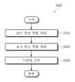
도 1을 참조하면, 본 발명의 포토리소그래피 방법은 포토레지스트 패턴을 형성하는 방법일 수 있다. 일 예에 따르면, 본 발명의 포토리소그래피 방법은 포토레지스트를 형성하는 단계(S100), 상기 포토레지스트의 일부를 광에 노출하는 단계(S200), 및 상기 포토레지스트를 현상하는 단계(S300)를 포함할 수 있다.Referring to FIG. 1, the photolithography method of the present invention may be a method of forming a photoresist pattern. According to one example, the photolithography method of the present invention may include a step of forming a photoresist (S100), a step of exposing a portion of the photoresist to light (S200), and a step of developing the photoresist (S300).
도 2 내지 도 6은 도 1의 포토리소그래피 방법을 보여주는 공정 단면도들이다.Figures 2 to 6 are process cross-sectional views showing the photolithography method of Figure 1.
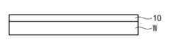
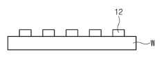
도 1 및 도 2를 참조하면, 기판(W) 상에 포토레지스트(10)를 형성한다(S100). 상기 포토레지스트(10)는 상기 기판(W)의 스핀 코팅 방법에 의해 형성될 수 있으나, 본 발명은 이에 한정되지 않을 수 있다. 일 예로, 상기 포토레지스트(10)는 감광성 물질(light-sensitive material)의 종류에 따라 포지티브 포토레지스트 및 네가티브 포토레지스트로 분류될 수 있다.Referring to FIGS. 1 and 2, a photoresist (10) is formed on a substrate (W) (S100). The photoresist (10) may be formed by a spin coating method on the substrate (W), but the present invention may not be limited thereto. For example, the photoresist (10) may be classified into a positive photoresist and a negative photoresist depending on the type of light-sensitive material.
도 1 및 도 3을 참조하면, 상기 포토레지스트(10)의 일부를 광(11)에 노출한다(S200). 예를 들어, 상기 광(11)은 EUV(Extreme Ultraviolet) 광을 포함할 수 있다. 이와 달리, 상기 광(11)은 ArF 또는 KrF 엑시머 레이저 광을 포함하며 본 발명은 이에 한정되지 않을 수 있다. 상기 포토레지스트(10)는 노광 영역(15)과 비 노광 영역(17)을 가질 수 있다. 상기 노광 영역(15)은 상기 광(11)에 노출된 영역이고, 상기 비 노광 영역(17)은 상기 광(11)에 노출되지 않은 영역일 수 있다. 상기 포토레지스트(10)은 그의 종류에 따라 현상 공정을 통해 상기 노광 영역(15) 및 상기 비 노광 영역(17) 중 어느 하나가 선택적으로 제거되어 포토레지스트 패턴으로 형성될 수 있다. 먼저, 상기 포토레지스트(10)가 상기 포지티브 포토레지스트일 경우, 상기 노광 영역(15)은 제거되고, 상기 비 노광 영역((17)은 포토레지스트 패턴(12)으로 형성될 수 있다. 반면, 상기 포토레지스트(10)가 상기 네거티브 포토레지스트일 경우, 상기 비 노광 영역(17)은 제거되고, 노광 영역(15)은 포토레지스트 패턴(12)으로 형성될 할 수 있다.Referring to FIGS. 1 and 3, a portion of the photoresist (10) is exposed to light (11) (S200). For example, the light (11) may include EUV (Extreme Ultraviolet) light. Alternatively, the light (11) may include ArF or KrF excimer laser light, and the present invention may not be limited thereto. The photoresist (10) may have an exposure area (15) and a non-exposure area (17). The exposure area (15) may be an area exposed to the light (11), and the non-exposure area (17) may be an area not exposed to the light (11). Depending on its type, the photoresist (10) may be formed into a photoresist pattern by selectively removing either the exposure area (15) or the non-exposure area (17) through a development process. First, if the photoresist (10) is the positive photoresist, the exposure area (15) can be removed, and the non-exposure area ((17)) can be formed as a photoresist pattern (12). On the other hand, if the photoresist (10) is the negative photoresist, the non-exposure area (17) can be removed, and the exposure area (15) can be formed as a photoresist pattern (12).
이하, 포지티브 포토레지스트의 포토레지스트(10)의 현상 방법에 대해 설명한다.Below, a method for developing a photoresist (10) of a positive photoresist is described.
도 1, 도 4 내지 도 6을 참조하면, 상기 포토레지스트(10)를 현상하여 포토레지스트 패턴(12)을 형성한다(S300).Referring to FIG. 1, FIG. 4 to FIG. 6, the photoresist (10) is developed to form a photoresist pattern (12) (S300).
도 7은 도 3의 포토레지스트(10)를 현상하는 단계(S300)의 일 예를 보여준다.Figure 7 shows an example of a step (S300) of developing the photoresist (10) of Figure 3.
도 4내지 도 7을 참조하면, 상기 포토레지스트(10)가 포지티브 포토레지스트일 경우, 상기 포토레지스트(10)를 현상하는 단계(S300)는 포지티브 톤 현상(Positive Tone Development: PTD) 공정을 포함할 수 있다. 일 예로, 상기 포토레지스트(10)를 현상하는 단계(S300)는 습식 현상액(14)을 제공하는 단계(S310), 습식 린스 액(16)을 제공하는 단계(S320), 기판(W)을 건조하는 단계(S330)를 포함할 수 있다.Referring to FIGS. 4 to 7, when the photoresist (10) is a positive photoresist, the step (S300) of developing the photoresist (10) may include a positive tone development (PTD) process. For example, the step (S300) of developing the photoresist (10) may include a step (S310) of providing a wet developer (14), a step (S320) of providing a wet rinse solution (16), and a step (S330) of drying the substrate (W).
도 4 및 도 7을 참조하면, 상기 포토레지스트(10) 상에 상기 습식 현상액(14)을 제공한다(S310). 상기 습식 현상액(14)은 상기 포토레지스트(10)의 상기 노광 영역(15)을 제거하여 상기 비 노광 영역(17)의 포토레지스트 패턴(12)을 형성시킬 수 있다. 상기 습식 현상액(14)은 수용액의 베이스 물질을 포함하며, 친수성을 가질 수 있다. 예를 들어, 상기 습식 현상액(14)은 TMAH(TetraMethyl-Ammonium-Hydroxide)를 포함하고, 본 발명은 이에 한정되지 않을 수 있다.Referring to FIG. 4 and FIG. 7, the wet developer (14) is provided on the photoresist (10) (S310). The wet developer (14) can remove the exposed area (15) of the photoresist (10) to form a photoresist pattern (12) of the non-exposed area (17). The wet developer (14) contains a base material of an aqueous solution and may have hydrophilicity. For example, the wet developer (14) contains TMAH (TetraMethyl-Ammonium-Hydroxide), but the present invention may not be limited thereto.
도 5 및 도 7을 참조하면, 상기 포토레지스트 패턴(12) 및 상기 기판(W) 상에 습식 린스 액(16)을 제공하여 상기 습식 현상액(14)을 제거한다(S320). 상기 습식 린스 액(16)은 탈이온수(DI water)를 포함할 수 있다.Referring to FIG. 5 and FIG. 7, a wet rinsing solution (16) is provided on the photoresist pattern (12) and the substrate (W) to remove the wet developer (14) (S320). The wet rinsing solution (16) may include deionized water (DI water).
도 6 및 도 7을 참조하면, 상기 기판(W)을 건조하여 상기 습식 린스 액(16)을 제거한다(S330). 상기 습식 린스 액(16)이 대기 중 건조될 경우, 상기 습식 린스 액(16)의 표면장력에 의해 상기 포토레지스트 패턴(12)의 쓰러짐 불량이 발생될 수 있다. 이에 본 발명은 습식 린스 액(16)을 표면 장력이 “0”인 초임계 유체로 치환(replace)하여 포토레지스트 패턴(12)의 쓰러짐 불량을 최소화하거나 방지할 수 있다.Referring to FIGS. 6 and 7, the substrate (W) is dried to remove the wet rinse liquid (16) (S330). If the wet rinse liquid (16) dries in the air, the photoresist pattern (12) may be collapsed due to the surface tension of the wet rinse liquid (16). Accordingly, the present invention can minimize or prevent the collapse of the photoresist pattern (12) by replacing the wet rinse liquid (16) with a supercritical fluid having a surface tension of “0”.
이하, 초임계 유체를 이용한 상기 기판(W)의 건조 방법에 대해 설명한다.Below, a method for drying the substrate (W) using a supercritical fluid is described.
도 8은 도 6의 기판(W)을 건조하는 단계(S330)의 일 예를 보여준다.Figure 8 shows an example of a step (S330) of drying the substrate (W) of Figure 6.
도 8을 참조하면, 상기 기판(W)을 건조하는 단계(S330)는 습식 액체를 제공하는 단계(S340), 상기 기판(W)을 반전하는 단계(S350), 건식 액체를 제공하는 단계(S360), 상기 습식 액체를 배출하는 단계(S370), 상기 건식 액체의 압력 또는 온도를 증가시키는 단계(S380), 초임계 유체를 제거하는 단계(S390), 및 상기 기판(W)을 재 반전(reinvert)하는 단계(S400)를 포함할 수 있다.Referring to FIG. 8, the step of drying the substrate (W) (S330) may include a step of providing a wet liquid (S340), a step of inverting the substrate (W) (S350), a step of providing a dry liquid (S360), a step of discharging the wet liquid (S370), a step of increasing the pressure or temperature of the dry liquid (S380), a step of removing a supercritical fluid (S390), and a step of reinverting the substrate (W) (S400).
도 9 내지 도 15는 도 6의 기판(W)의 건조 장치(100)의 일 예를 보여준다.Figures 9 to 15 show an example of a drying device (100) of the substrate (W) of Figure 6.
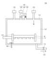
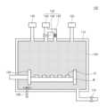
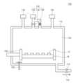
도 9 내지 도 15를 참조하면, 본 발명의 건조 장치(100)는 챔버(110), 카세트(120), 제 1 액체 공급 부(130), 제 2액체 공급 부(140), 가스 공급 부(150), 교반기(agitator, 160) 및 배출 부(170)를 포함할 수 있다. 상기 챔버(110)는 상기 기판(W)에 대해 외부로부터 밀폐된 공간을 제공할 수 있다. 상기 카세트(120)는 상기 챔버(110) 내에 배치되고, 상기 기판(W)을 수납할 수 있다. 상기 카세트(120)는 상기 기판(W)을 반전(invert and/or reverse)시킬 수 있다. 상기 제 1 액체 공급 부(130)는 상기 챔버(110) 내에 습식 액체(132)를 공급 할 수 있다. 상기 제 2 액체 공급 부(140)는 상기 챔버(110) 내에 건식 액체(142)를 공급할 수 있다. 일 에에 따르면, 상기 제 2 액체 공급 부(140)는 건식 액체 탱크(146), 밸브(148) 및 펌프(149)를 포함할 수 있다. 상기 건식 액체 탱크(146)는 상기 건식 액체(142)를 저장할 수 있다. 상기 밸브(148)와 상기 펌프(149)는 상기 건식 액체 탱크(146)와 상기 챔버(110) 사이에 병렬로 연결될 수 있다. 상기 밸브(148)는 상기 건식 액체(142)의 공급을 제어할 수 있다. 상기 펌프(149)는 상기 건식 액체(142)의 압력을 제어할 수 있다. 상기 가스 공급 부(150)는 상기 챔버(110) 내에 건조 가스(152)를 공급할 수 있다. 상기 교반기(160)는 상기 챔버(110)의 하부에 배치될 수 있다. 상기 교반기(160)는 상기 건식 액체(142)를 교반할 수 있다. 상기 배출 부(170)는 상기 챔버(110)의 하부에 연결될 수 있다. 상기 배출 부(170)는 직렬 연결되는 복수개의 밸브들을 포함하여 상기 챔버(110)의 압력을 버퍼링시킬 수 있다. 상기 배출 부(170)는 상기 챔버(110) 내의 상기 습식 액체(132), 상기 건식 액체(142), 초임계 유체(144), 및 건조 가스(152)를 배출하거나 배기할 수 있다.Referring to FIGS. 9 to 15, the drying device (100) of the present invention may include a chamber (110), a cassette (120), a first liquid supply unit (130), a second liquid supply unit (140), a gas supply unit (150), an agitator (160), and a discharge unit (170). The chamber (110) may provide a space sealed from the outside with respect to the substrate (W). The cassette (120) may be disposed within the chamber (110) and may store the substrate (W). The cassette (120) may invert and/or reverse the substrate (W). The first liquid supply unit (130) may supply a wet liquid (132) within the chamber (110). The second liquid supply unit (140) can supply dry liquid (142) into the chamber (110). According to one example, the second liquid supply unit (140) can include a dry liquid tank (146), a valve (148), and a pump (149). The dry liquid tank (146) can store the dry liquid (142). The valve (148) and the pump (149) can be connected in parallel between the dry liquid tank (146) and the chamber (110). The valve (148) can control the supply of the dry liquid (142). The pump (149) can control the pressure of the dry liquid (142). The gas supply unit (150) can supply a dry gas (152) into the chamber (110). The agitator (160) may be placed at the bottom of the chamber (110). The agitator (160) may agitate the dry liquid (142). The discharge unit (170) may be connected to the bottom of the chamber (110). The discharge unit (170) may include a plurality of valves connected in series to buffer the pressure of the chamber (110). The discharge unit (170) may discharge or exhaust the wet liquid (132), the dry liquid (142), the supercritical fluid (144), and the drying gas (152) within the chamber (110).
도 8 및 도 9를 참조하면, 제 1 액체 공급 부(130)는 기판(W) 상에 습식 액체(132)를 제공한다(S340). 상기 기판(W)은 상기 습식 액체(132) 내에 침지(dipped)될 수 있다. 일 에에 따르면, 상기 습식 액체(132)는 상기 습식 린스 액(16)과 동일할 수 있다. 예를 들어, 상기 습식 액체(132)는 탈이온수를 포함할 수 있다. 상기 습식 액체(132)는 상기 습식 린스 액(16)과 혼합될 수 있다.Referring to FIGS. 8 and 9, the first liquid supply unit (130) provides a wet liquid (132) onto a substrate (W) (S340). The substrate (W) may be dipped in the wet liquid (132). According to one example, the wet liquid (132) may be the same as the wet rinse liquid (16). For example, the wet liquid (132) may include deionized water. The wet liquid (132) may be mixed with the wet rinse liquid (16).
도 8 및 도 10을 참조하면, 상기 카세트(120)는 상기 기판(W)을 반전시킨다(S350). 상기 기판(W)은 상기 습식 액체(132) 내에서 반전될 수 있다.Referring to FIG. 8 and FIG. 10, the cassette (120) inverts the substrate (W) (S350). The substrate (W) can be inverted within the wet liquid (132).
도시되지 않았지만, 상기 기판(W)과 상기 포토레지스트 패턴(12) 상에 유기 용매(미도시)가 제공될 수 있다. 상기 기판(W)과 상기 포토레지스트 패턴(12) 상에 유기 용매가 제공될 경우, 상기 습식 액체(132)를 제공하는 단계(S340), 및 상기 기판(W)을 반전하는 단계(S350)는 생략될 수 있다.Although not shown, an organic solvent (not shown) may be provided on the substrate (W) and the photoresist pattern (12). When an organic solvent is provided on the substrate (W) and the photoresist pattern (12), the step of providing the wet liquid (132) (S340) and the step of inverting the substrate (W) (S350) may be omitted.
도 8 및 도 11을 참조하면, 제 2 액체 공급 부(140)는 기판(W) 상에 건식 액체(142)를 제공한다(S360). 상기 건식 액체(142)는 상기 밸브(148)를 통해 상기 챔버(110) 내에 제공될 수 있다. 상기 건식 액체(142)는 약 0℃ 내지 약 35℃의 온도를 가질 수 있다. 예를 들어, 상기 건식 액체(142)는 상온(ex, 20℃)을 가질 수 있다. 상기 습식 액체(132)는 상온에서 얼지 않을 수 있다. 일 예로, 상기 건식 액체(142)는 상기 습식 액체(132) 및 상기 습식 린스 액(16)의 비중보다 작은 비중을 가질 수 있다. 상기 습식 액체(132)와 상기 건식 액체(142)는 그들의 비중 차에 의해 상기 챔버(110)의 아래 위로 분리될 수 있다. 상기 습식 액체(132)는 상기 건식 액체(142) 아래에 존재(be)할 수 있다. 상기 건식 액체(142)는 물을 포함하지 않은 액체일 수 있다. 상기 건식 액체(142)는 액체 이산화탄소를 포함할 수 있다. 상기 건식 액체(142)는 상압보다 높은 압력을 가질 수 있다. 예를 들어, 상기 건식 액체(142)는 약 5bar 내지 약 74.8bar의 압력을 가질 수 있다.Referring to FIG. 8 and FIG. 11, the second liquid supply unit (140) provides a dry liquid (142) onto the substrate (W) (S360). The dry liquid (142) may be provided into the chamber (110) through the valve (148). The dry liquid (142) may have a temperature of about 0° C. to about 35° C. For example, the dry liquid (142) may have a room temperature (ex, 20° C.). The wet liquid (132) may not freeze at room temperature. For example, the dry liquid (142) may have a specific gravity lower than the specific gravity of the wet liquid (132) and the wet rinse liquid (16). The wet liquid (132) and the dry liquid (142) may be separated into the upper and lower portions of the chamber (110) by the difference in their specific gravity. The wet liquid (132) may be present below the dry liquid (142). The dry liquid (142) may be a liquid that does not contain water. The dry liquid (142) may contain liquid carbon dioxide. The dry liquid (142) may have a pressure higher than atmospheric pressure. For example, the dry liquid (142) may have a pressure of about 5 bar to about 74.8 bar.
도시되지는 않았지만, 상기 기판(W)과 상기 포토레지스트 패턴(12) 상에 유기 용매가 제공될 경우, 상기 건식 액체(142)는 상기 유기 용매와 쉽게 혼합될 수 있다. 상기 유기 용매는 포토레지스트 패턴들(12) 사이에서 제거될 수 있다.Although not shown, when an organic solvent is provided on the substrate (W) and the photoresist pattern (12), the dry liquid (142) can be easily mixed with the organic solvent. The organic solvent can be removed between the photoresist patterns (12).
도 8 및 도 12를 참조하면, 상기 배출 부(170)는 습식 액체(132)를 배출(drain)한다(S370). 상기 습식 액체(132)는 상기 건식 액체(142)에 대해 선택적으로 배출될 수 있다. 상기 배출 부(170)는 상기 습식 액체(132)뿐만 아니라 상기 습식 린스 액(16)을 배출할 수 있다. 상기 기판(W)이 상기 상기 습식 린스 액(16) 및 포토레지스트 패턴(12) 상에 위치(locate)하기 때문에 상기 습식 린스 액(16)은 상기 배출 부(170)를 통해 상기 기판(W)의 방해(interruption) 없이 손쉽게 배출될 수 있다. 상기 기판(W)은 상기 건식 액체(142) 내에 침지될 수 있다. 상기 교반기(160)는 상기 건식 액체(142)를 교반(stir)하여 상기 기판(W) 또는 상기 포토레지스트 패턴(12) 상의 상기 습식 액체(132) 또는 .습식 린스 액(16)을 제거시킬 수 있다. 이와 달리, 상기 교반기(160)는 상기 건식 액체(142)에 소닉을 가할 수 있다.Referring to FIG. 8 and FIG. 12, the discharge unit (170) drains the wet liquid (132) (S370). The wet liquid (132) can be selectively discharged with respect to the dry liquid (142). The discharge unit (170) can discharge not only the wet liquid (132) but also the wet rinse liquid (16). Since the substrate (W) is located on the wet rinse liquid (16) and the photoresist pattern (12), the wet rinse liquid (16) can be easily discharged through the discharge unit (170) without interruption of the substrate (W). The substrate (W) can be immersed in the dry liquid (142). The above stirrer (160) can stir the dry liquid (142) to remove the wet liquid (132) or wet rinse liquid (16) on the substrate (W) or the photoresist pattern (12). Alternatively, the stirrer (160) can apply sonication to the dry liquid (142).
도시되지 않았지만, 상기 기판(W)과 상기 포토레지스트 패턴(12) 상에 유기 용매가 제공될 경우, 상기 습식 액체(132)를 배출하는 단계(S370)는 생략될 수 있다.Although not shown, when an organic solvent is provided on the substrate (W) and the photoresist pattern (12), the step (S370) of discharging the wet liquid (132) may be omitted.
도 8 및 도 13을 참조하면, 상기 펌프(149)는 상기 건식 액체(142)의 압력을 증가시켜 초임계 유체(144)를 생성한다(S380). 예를 들어, 상기 펌프(149)는 상기 건식 액체(142)의 압력을 상기 초임계 유체(144)의 임계 점(critical point)이상으로 증가시킬 수 있다. 상기 건식 액체 탱크(146)와 상기 펌프(149)는 초임계 유체 공급 장치(Supercritical fluid supply)로 사용될 수 있다.Referring to FIG. 8 and FIG. 13, the pump (149) increases the pressure of the dry liquid (142) to generate a supercritical fluid (144) (S380). For example, the pump (149) can increase the pressure of the dry liquid (142) to a critical point or higher of the supercritical fluid (144). The dry liquid tank (146) and the pump (149) can be used as a supercritical fluid supply device.
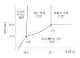
도 16은 도 12의 건식 액체(142) 및 초임계 유체(144)의 상 변화(phase change)를 보여주는 그래프이다.Figure 16 is a graph showing the phase change of the dry liquid (142) and supercritical fluid (144) of Figure 12.
도 16을 참조하면, 상기 건식 액체(142)가 액체 이산화탄소일 경우, 초임계 유체(144)는 약 74.8bar 의 압력과 약 31.1℃ 의 온도의 상기 임계점(141)을 가질 수 있다. 상기 건식 액체(142)는 상기 임계점(141) 이상의 압력과 온도에서 상기 초임계 유체(144)로 변화될 수 있다. 상기 초임계 유체(144)는 “0”의 표면 장력을 가질 수 있다. 상기 임계점(141) 이하의 압력 및 온도에서 상기 초임계 유체(144)는 상기 건식 액체(142), 또는 이산화탄소 가스(145)로 변화될 수 있다.Referring to FIG. 16, when the dry liquid (142) is liquid carbon dioxide, the supercritical fluid (144) may have the critical point (141) of a pressure of about 74.8 bar and a temperature of about 31.1° C. The dry liquid (142) may change into the supercritical fluid (144) at a pressure and temperature higher than the critical point (141). The supercritical fluid (144) may have a surface tension of “0.” At a pressure and temperature lower than the critical point (141), the supercritical fluid (144) may change into the dry liquid (142) or carbon dioxide gas (145).
상기 건식 액체(142)는 삼중점(143) 이상의 압력과 온도를 가질 수 있다. 예를 들어, 상기 삼중 점은 약 5.2bar의 기압과 -56.6℃의 온도일 수 있다. 삼중점 이하의 압력 및 온도에서 상기 건식 액체(142)는 이산화탄소 가스(145) 및 드라이 아이스(147)로 변환될 수 있다.The dry liquid (142) may have a pressure and temperature above the triple point (143). For example, the triple point may be a pressure of about 5.2 bar and a temperature of -56.6° C. At a pressure and temperature below the triple point, the dry liquid (142) may be converted into carbon dioxide gas (145) and dry ice (147).
도시되지는 않았지만, 본 발명의 건조 장치(100)는 제 2 액체 공급 부(140)와 독립적인 초임계 유체 공급 부(미도시)를 포함할 수 있다. 초임계 유체 공급 부는 초임계 유체(144)를 챔버(110) 내에 공급할 수 있다. 상기 초임계 유체(144)가 상기 챔버(110) 내에 공급되면, 상기 챔버(110) 내의 상기 건식 액체(142)는 그의 압력이 증가하여 초임계 유체(144)로 변환될 수 있다.Although not shown, the drying device (100) of the present invention may include a supercritical fluid supply unit (not shown) independent of the second liquid supply unit (140). The supercritical fluid supply unit may supply supercritical fluid (144) into the chamber (110). When the supercritical fluid (144) is supplied into the chamber (110), the drying liquid (142) in the chamber (110) may be converted into supercritical fluid (144) by increasing its pressure.
다시 도 8 및 도 14를 참조하면, 상기 배출 부(170)는 상기 초임계 유체(144)를 상기 챔버(110)의 외부로 배출한다(S390). 상기 배출되는 초임계 유체(144)는 “0”의 표면 장력 때문에 포토레지스트 패턴(12)의 쓰러짐 불량을 최소화하거나 방지할 수 있다. 상기 초임계 유체(144)는 상기 챔버 내의 잔존 가스(residual gas)로 변환될 수 있다. 상기 배출 부(170)는 상기 잔존 가스를 상기 챔버(110)의 외부로 배기할 수 있다. 그리고, 상기 가스 공급 부(150)는 상기 챔버(110) 내에 건조 가스(152)를 공급하여 상기 초임계 유체(144)를 배출하거나 상기 잔존 가스를 배기시킬 수 있다. 상기 건조 가스(152)는 이산화탄소(CO2) 가스를 포함할 수 있다.Referring again to FIG. 8 and FIG. 14, the discharge unit (170) discharges the supercritical fluid (144) to the outside of the chamber (110) (S390). The discharged supercritical fluid (144) can minimize or prevent the collapse defect of the photoresist pattern (12) due to the surface tension of “0”. The supercritical fluid (144) can be converted into residual gas within the chamber. The discharge unit (170) can exhaust the residual gas to the outside of the chamber (110). In addition, the gas supply unit (150) can supply a dry gas (152) within the chamber (110) to discharge the supercritical fluid (144) or exhaust the residual gas. The dry gas (152) can include carbon dioxide (CO2 ) gas.
도 8 및 도 도 15를 참조하면, 상기 카세트(120)는 상기 기판(W)을 재 반전시킨다(S400). 상기 포토레지스트 패턴(12)은 상기 기판(W) 상에 위치할 수 있다. 이후, 로봇 암(미도시)은 상기 기판(W)의 하부 면을 지지하여 상기 기판(W)을 상기 챔버(110)의 외부로 반출(unload)할 수 있다.Referring to FIG. 8 and FIG. 15, the cassette (120) re-inverts the substrate (W) (S400). The photoresist pattern (12) may be positioned on the substrate (W). Thereafter, a robot arm (not shown) may support the lower surface of the substrate (W) to unload the substrate (W) out of the chamber (110).
도시되지 않았지만, 상기 기판(W)과 상기 포토레지스트 패턴(12) 상에 유기 용매가 제공될 경우, 상기 기판(W)을 재 반전시키는 단계(S400)는 생략될 수 있다.Although not shown, when an organic solvent is provided on the substrate (W) and the photoresist pattern (12), the step (S400) of re-inverting the substrate (W) may be omitted.
이하, 네거티브 포토레지스트의 포토레지스트(10)의 현상 방법에 대해 설명한다.Below, a method for developing a photoresist (10) of a negative photoresist is described.
도 17은 도 3의 포토레지스트(10)를 현상하는 단계(S300)의 일 예를 보여준다.Fig. 17 shows an example of a step (S300) of developing the photoresist (10) of Fig. 3.
도 17을 참조하면, 상기 포토레지스트(10)가 네거티브 포토레지스트일 경우, 상기 포토레지스트(10)를 현상하는 단계(S300)는 네거티브 톤 현상 방법을 포함할 수 있다. 일 예로, 상기 포토레지스트(10)를 현상하는 단계(S300)는 건식 현상액을 제공하는 단계(S312), 건식 린스 액을 제공하는 단계(S322), 및 기판(W)을 건조하는 단계(S330)를 포함할 수 있다.Referring to FIG. 17, when the photoresist (10) is a negative photoresist, the step (S300) of developing the photoresist (10) may include a negative tone developing method. For example, the step (S300) of developing the photoresist (10) may include a step (S312) of providing a dry developing solution, a step (S322) of providing a dry rinsing solution, and a step (S330) of drying the substrate (W).
도 18 내지 도 20은 도 3의 포토레지스트(10)를 현상하는 단계(S300)를 보여주는 공정 단면도들이다.Figures 18 to 20 are process cross-sectional views showing the step (S300) of developing the photoresist (10) of Figure 3.
도 17 및 도 18을 참조하면, 상기 기판(W) 상에 건식 현상액(18)을 제공한다(S312). 상기 건식 현상액(18)은 상기 포토레지스트(10)의 상기 비 노광 영역(17)을 제거하여 상기 노광 영역(15)을 포토레지스트 패턴(12)으로 형성시킬 수 있다. 상기 건식 현상액(18)은 무극성 용매(ex, 유기 용매(organic solvent)를 포함하고, 본 발명은 이에 한정되지 않을 수 있다.Referring to FIGS. 17 and 18, a dry developer (18) is provided on the substrate (W) (S312). The dry developer (18) can remove the non-exposed area (17) of the photoresist (10) to form the exposed area (15) as a photoresist pattern (12). The dry developer (18) includes a non-polar solvent (e.g., an organic solvent), and the present invention may not be limited thereto.
도 17 및 도 19를 참조하면, 상기 기판(W) 상에 건식 린스 액(20)을 제공하여 상기 건식 현상액(18)을 제거한다(S322). 상기 건식 린스 액(20)은 엔-부틸 아세테이트(normal-Butyl Acetate)를 포함하고, 본 발명은 이에 한정되지 않을 수 있다.Referring to FIG. 17 and FIG. 19, a dry rinsing liquid (20) is provided on the substrate (W) to remove the dry developer (18) (S322). The dry rinsing liquid (20) contains normal-butyl acetate, but the present invention may not be limited thereto.
도 17 및 도 20을 참조하면, 상기 기판(W)을 건조한다(S330).Referring to FIG. 17 and FIG. 20, the substrate (W) is dried (S330).
도 21은 도 20의 기판(W)을 건조하는 단계(S330)의 일 예를 보여준다.Fig. 21 shows an example of a step (S330) of drying the substrate (W) of Fig. 20.
도 21을 참조하면, 상기 기판(W)을 건조하는 단계(S330)는 건조 가스(152)를 제공하는 단계(S342), 건식 액체(142)를 제공하는 단계(S360), 상기 건식 액체(142)의 압력을 증가시켜 초임계 유체(144)를 생성하는 단계(S380), 및 상기 초임계 유체(144)를 제거하는 단계(S390)를 포함할 수 있다.Referring to FIG. 21, the step (S330) of drying the substrate (W) may include a step (S342) of providing a drying gas (152), a step (S360) of providing a drying liquid (142), a step (S380) of increasing the pressure of the drying liquid (142) to generate a supercritical fluid (144), and a step (S390) of removing the supercritical fluid (144).
도 22 내지 도 25는 도 20의 기판(W)을 건조하는 단계(S330)를 보여주는 도면들이다.Figures 22 to 25 are drawings showing a step (S330) of drying the substrate (W) of Figure 20.
도 21 및 도 22를 참조하면, 가스 공급 부(150)는 챔버(110) 내에 건조 가스(152)를 공급한다(S342). 상기 건조 가스(152)는 이산화탄소(CO2) 가스를 포함할 수 있다. 상기 챔버(110) 내의 상기 건조 가스(152)는 상기 삼중점(143) 이상 및 상기 임계점(141) 이하의 압력을 가질 수 있다. 예를 들어, 상기 건조 가스(152)는 약 5.2bar이상의 압력을 가질 수 있다.Referring to FIGS. 21 and 22, the gas supply unit (150) supplies dry gas (152) into the chamber (110) (S342). The dry gas (152) may include carbon dioxide (CO2 ) gas. The dry gas (152) in the chamber (110) may have a pressure higher than the triple point (143) and lower than the critical point (141). For example, the dry gas (152) may have a pressure of about 5.2 bar or higher.
도 21 및 도 23을 참조하면, 제 2 액체 공급 부(140)는 기판(W) 상에 건식 액체(142)를 제공한다(S360). 상기 건식 액체(142)는 액체 이산화탄소를 포함할 수 있다. 상기 건식 액체(142)는 상기 건식 린스 액(20)과 혼합될 수 있다.Referring to FIG. 21 and FIG. 23, the second liquid supply unit (140) provides dry liquid (142) onto the substrate (W) (S360). The dry liquid (142) may include liquid carbon dioxide. The dry liquid (142) may be mixed with the dry rinse liquid (20).
도시되지 않았지만, 배출 부(170)는 상기 건식 액체(142) 및 상기 건식 린스 액(20)의 일부를 배출하고, 상기 제 2 액체 공급 부(140)는 상기 밸브(148)를 통해 상기 건식 액체(142)를 추가로 공급하여 상기 건식 액체(142) 내의 건식 린스 액(20)의 농도를 감소시킬 수 있다.Although not shown, the discharge portion (170) discharges a portion of the dry liquid (142) and the dry rinse liquid (20), and the second liquid supply portion (140) additionally supplies the dry liquid (142) through the valve (148) to reduce the concentration of the dry rinse liquid (20) in the dry liquid (142).
도 21 및 도 24를 참조하면, 상기 제 2 액체 공급 부(140)의 상기 펌프(149)는 건식 액체(142)의 압력를 증가시켜 초임계 유체(144)를 생성한다(S380). 상기 건식 액체(142)의 압력은 임계점(141) 이상으로 증가되고, 상기 건식 액체(142)는 상기 초임계 유체(144)로 변환될 수 있다. 상기 건식 린스 액(20)의 압력이 상기 임계점(141) 이상으로 증가되면, 상기 건식 린스 액(20)은 상기 초임계 유체(144)로 변환될 수 있다. 예를 들어, 상기 건식 린스 액(20)은 약 70bar 이하의 압력에서 상기 초임계 유체(144)로 변환될 수 있다.Referring to FIG. 21 and FIG. 24, the pump (149) of the second liquid supply unit (140) increases the pressure of the dry liquid (142) to generate a supercritical fluid (144) (S380). The pressure of the dry liquid (142) increases above the critical point (141), and the dry liquid (142) can be converted into the supercritical fluid (144). When the pressure of the dry rinse liquid (20) increases above the critical point (141), the dry rinse liquid (20) can be converted into the supercritical fluid (144). For example, the dry rinse liquid (20) can be converted into the supercritical fluid (144) at a pressure of about 70 bar or less.
도 21 및 도 25를 참조하면, 상기 배출 부(170)는 상기 초임계 유체(144)를 배출한다(S390). 상기 초임계 유체(144)의 표면 장력이 “0”이기 때문에 상기 포토레지스트 패턴(12)은 상기 표면 장력에 의한 쓰러짐 불량 없이 건조될 수 있다.Referring to FIG. 21 and FIG. 25, the discharge unit (170) discharges the supercritical fluid (144) (S390). Since the surface tension of the supercritical fluid (144) is “0”, the photoresist pattern (12) can be dried without collapse defects due to the surface tension.
이후, 상기 로봇 암은 상기 기판(W)의 하부 면을 지지하여 상기 기판(W)을 상기 챔버(110)의 외부로 반출할 수 있다.Thereafter, the robot arm can support the lower surface of the substrate (W) and transport the substrate (W) out of the chamber (110).
이상, 첨부된 도면을 참조하여 본 발명의 실시 예를 설명하였지만, 본 발명이 속하는 기술분야에서 통상의 지식을 가진 자는 본 발명이 그 기술적 사상이나 필수적인 특징을 변경하지 않고서 다른 구체적인 형태로 실시될 수 있다는 것을 이해할 수 있을 것이다. 그러므로 이상에서 기술한 실시 예에는 모든 면에서 예시적인 것이며 한정적이 아닌 것으로 이해해야만 한다.Above, while the embodiments of the present invention have been described with reference to the attached drawings, those skilled in the art to which the present invention pertains will understand that the present invention can be implemented in other specific forms without changing the technical idea or essential features thereof. Therefore, it should be understood that the embodiments described above are exemplary in all respects and not restrictive.
Claims (20)
Translated fromKorean상기 챔버 내에 습식 액체를 공급하여 상기 포토레지스트 패턴을 상기 습식 액체 내에 침지시키는 단계;
상기 포토레지스트 패턴들이 상기 챔버의 내면 바닥에 인접하도록 상기 습식 액체 내에서 상기 카세트를 회전시켜 상기 기판을 반전하는 단계;
상기 습식 액체의 비중보다 낮은 비중을 갖는 액체 이산화탄소를 상기 챔버 내에 공급하여 상기 습식 액체 상에 상기 액체 이산화탄소를 제공하는 단계;
상기 챔버의 상기 바닥 부분을 통하여 상기 습식 액체를 선택적으로 배출하여 상기 포토레지스트 패턴들 사이의 상기 습식 액체를 상기 액체 이산화탄소로 치환하는 단계;
상기 챔버 내의 상기 액체 이산화탄소의 압력을 증가시켜 초임계 유체를 생성하는 단계;
상기 챔버 내의 상기 초임계 유체를 제거하여 상기 기판을 건조하는 단계; 및
상기 포토레지스트 패턴들이 상기 챔버의 내면 상부에 인접하도록 상기 챔버 내에서 상기 카세트를 회전시켜 상기 기판을 재 반전하는 단계를 포함하는 기판 건조 방법.
A step of providing a substrate having an upper surface with photoresist patterns on a cassette within a chamber;
A step of supplying a wet liquid into the chamber and immersing the photoresist pattern into the wet liquid;
A step of inverting the substrate by rotating the cassette within the wet liquid so that the photoresist patterns are adjacent to the inner bottom of the chamber;
A step of supplying liquid carbon dioxide having a specific gravity lower than that of the wet liquid into the chamber to provide the liquid carbon dioxide on the wet liquid;
A step of selectively discharging the wet liquid through the bottom portion of the chamber to replace the wet liquid between the photoresist patterns with the liquid carbon dioxide;
A step of generating a supercritical fluid by increasing the pressure of the liquid carbon dioxide within the chamber;
A step of drying the substrate by removing the supercritical fluid within the chamber; and
A method for drying a substrate, comprising the step of rotating the cassette within the chamber so as to re-invert the substrate so that the photoresist patterns are adjacent to the upper inner surface of the chamber.
상기 습식 액체는 탈이온수를 포함하는 기판 건조 방법.
In paragraph 1,
A substrate drying method wherein the above wet liquid comprises deionized water.
상기 초임계 유체는 초임계 이산화탄소를 포함하는 기판 건조 방법.
In paragraph 1,
A method for drying a substrate, wherein the supercritical fluid comprises supercritical carbon dioxide.
상기 챔버 내의 상기 초임계 유체를 제거하여 상기 기판을 건조하는 단계는 상기 기판 상에 건조 가스를 제공하는 단계를 포함하는 기판 건조 방법.
In paragraph 1,
A method for drying a substrate, wherein the step of removing the supercritical fluid within the chamber and drying the substrate includes the step of providing a drying gas onto the substrate.
상기 건조 가스는 이산화탄소 가스를 포함하는 기판 건조 방법.
In Article 9,
A substrate drying method wherein the above drying gas includes carbon dioxide gas.
상기 기판 상에 린스 액을 제공하여 상기 현상액을 제거하는 단계; 및
상기 기판을 건조하여 상기 린스 액을 제거하는 단계를 포함하되,
상기 기판을 건조하는 단계는:
포토레지스트 패턴들을 구비한 상부면을 갖는 기판을 챔버 내의 카세트 상에 제공하는 단계;
상기 챔버 내에 습식 액체를 공급하여 상기 포토레지스트 패턴을 상기 습식 액체 내에 제공하는 단계;
상기 포토레지스트 패턴들이 상기 챔버의 내면 바닥에 인접하도록 상기 습식 액체 내에서 상기 카세트를 회전시켜 상기 기판을 반전하는 단계;
상기 습식 액체의 비중보다 낮은 비중을 갖는 액체 이산화탄소를 상기 챔버 내에 공급하여 상기 습식 액체 상에 상기 액체 이산화탄소를 제공하는 단계;
상기 챔버의 상기 바닥 부분을 통하여 상기 습식 액체를 선택적으로 배출하여 상기 포토레지스트 패턴들 사이의 상기 습식 액체를 상기 액체 이산화탄소로 치환하는 단계;
상기 챔버 내의 상기 액체 이산화탄소의 압력을 증가시켜 초임계 유체를 생성하는 단계;
상기 챔버 내의 상기 초임계 유체를 제거하여 상기 기판을 건조하는 단계; 및
상기 포토레지스트 패턴들이 상기 챔버의 내면 상부에 인접하도록 상기 챔버 내에서 상기 카세트를 회전시켜 상기 기판을 재 반전하는 단계를 포함하는 현상 방법.
A step of providing a developer on a substrate;
A step of providing a rinsing solution on the substrate to remove the developer; and
Including a step of drying the substrate to remove the rinse liquid,
The steps for drying the above substrate are:
A step of providing a substrate having an upper surface with photoresist patterns on a cassette within a chamber;
A step of supplying a wet liquid into the chamber to provide the photoresist pattern into the wet liquid;
A step of inverting the substrate by rotating the cassette within the wet liquid so that the photoresist patterns are adjacent to the inner bottom of the chamber;
A step of supplying liquid carbon dioxide having a specific gravity lower than that of the wet liquid into the chamber to provide the liquid carbon dioxide on the wet liquid;
A step of selectively discharging the wet liquid through the bottom portion of the chamber to replace the wet liquid between the photoresist patterns with the liquid carbon dioxide;
A step of generating a supercritical fluid by increasing the pressure of the liquid carbon dioxide within the chamber;
A step of drying the substrate by removing the supercritical fluid within the chamber; and
A developing method comprising the step of rotating the cassette within the chamber so as to re-invert the substrate so that the photoresist patterns are adjacent to the upper inner surface of the chamber.
상기 현상액은 TMAH를 포함하되,
상기 린스 액은 탈이온수를 포함하는 현상 방법.
In Article 11,
The above developer contains TMAH,
A developing method wherein the above rinse liquid contains deionized water.
상기 현상액은 무극성 용매를 포함하되,
상기 린스 액은 엔-부틸 아세테이트(normal-Butyl Acetate)를 포함하는 현상 방법.
In Article 11,
The above developer comprises a non-polar solvent,
A developing method wherein the above rinse liquid contains normal-butyl acetate.
상기 챔버 내의 상기 초임계 유체를 제거하여 상기 기판을 건조하는 단계는 상기 기판 상에 삼중점의 압력의 건조 가스를 제공하는 단계를 포함하는 현상 방법.
In Article 11,
A developing method, wherein the step of removing the supercritical fluid within the chamber and drying the substrate includes the step of providing a dry gas at a pressure of the triple point on the substrate.
상기 포토레지스트의 일부분을 광에 노출하는 단계; 및
상기 포토레지스트를 현상하여 상기 기판 상에 포토레지스트 패턴을 형성하는 단계를 포함하되,
상기 포토레지스트를 현상하는 단계는:
상기 기판 상에 현상액을 제공하는 단계;
상기 기판 상에 린스 액을 제공하여 상기 현상액을 제거하는 단계; 및
상기 기판을 건조하여 상기 린스 액을 제거하는 단계를 포함하되,
상기 기판을 건조하는 단계는:
상기 포토레지스트 패턴들을 구비한 상부면을 갖는 기판을 챔버 내의 카세트 상에 제공하는 단계;
상기 챔버 내에 습식 액체를 공급하여 상기 포토레지스트 패턴을 상기 습식 액체 내에 제공하는 단계;
상기 포토레지스트 패턴들이 상기 챔버의 내면 바닥에 인접하도록 상기 습식 액체 내에서 상기 카세트를 회전시켜 상기 기판을 반전하는 단계;
상기 습식 액체의 비중보다 낮은 비중을 갖는 액체 이산화탄소를 상기 챔버 내에 공급하여 상기 습식 액체 상에 상기 액체 이산화탄소를 제공하는 단계;
상기 챔버의 상기 바닥 부분을 통하여 상기 습식 액체를 선택적으로 배출하여 상기 포토레지스트 패턴들 사이의 상기 습식 액체를 상기 액체 이산화탄소로 치환하는 단계;
상기 챔버 내의 상기 액체 이산화탄소의 압력을 증가시켜 초임계 유체를 생성하는 단계;
상기 챔버 내의 상기 초임계 유체를 제거하여 상기 기판을 건조하는 단계; 및
상기 포토레지스트 패턴들이 상기 챔버의 내면 상부에 인접하도록 상기 챔버 내에서 상기 카세트를 회전시켜 상기 기판을 재 반전하는 단계를 포함하는 포토리소그래피 방법.
A step of forming a photoresist on a substrate;
a step of exposing a portion of the above photoresist to light; and
Comprising a step of developing the above photoresist to form a photoresist pattern on the substrate,
The steps for developing the above photoresist are:
A step of providing a developer on the substrate;
A step of providing a rinsing solution on the substrate to remove the developer; and
Including a step of drying the substrate to remove the rinse liquid,
The steps for drying the above substrate are:
A step of providing a substrate having an upper surface provided with the photoresist patterns onto a cassette within a chamber;
A step of supplying a wet liquid into the chamber to provide the photoresist pattern into the wet liquid;
A step of inverting the substrate by rotating the cassette within the wet liquid so that the photoresist patterns are adjacent to the inner bottom of the chamber;
A step of supplying liquid carbon dioxide having a specific gravity lower than that of the wet liquid into the chamber to provide the liquid carbon dioxide on the wet liquid;
A step of selectively discharging the wet liquid through the bottom portion of the chamber to replace the wet liquid between the photoresist patterns with the liquid carbon dioxide;
A step of generating a supercritical fluid by increasing the pressure of the liquid carbon dioxide within the chamber;
A step of drying the substrate by removing the supercritical fluid within the chamber; and
A photolithography method comprising the step of rotating the cassette within the chamber to re-invert the substrate so that the photoresist patterns are adjacent to the upper inner surface of the chamber.
상기 포토레지스트는 포지티브 포토레지스트를 포함하되,
상기 현상액은 TMAH를 포함하되,
상기 린스 액은 탈이온수를 포함하는 포토리소그래피 방법.
In Article 16,
The above photoresist includes a positive photoresist,
The above developer contains TMAH,
A photolithography method wherein the above rinse liquid contains deionized water.
상기 포토레지스트는 네거티브 포토레지스트를 포함하되,
상기 현상액은 무극성 용매를 포함하되,
상기 린스 액은 엔-부틸 아세테이트(normal-Butyl Acetate)를 포함하는 포토리소그래피 방법.
In Article 16,
The above photoresist includes a negative photoresist,
The above developer comprises a non-polar solvent,
A photolithography method wherein the above rinse liquid contains normal-butyl acetate.
상기 광은 EUV 빔을 포함하는 포토리소그래피 방법.
In Article 16,
The above light is a photolithography method including an EUV beam.
Priority Applications (3)
| Application Number | Priority Date | Filing Date | Title |
|---|---|---|---|
| KR1020180139730AKR102728304B1 (en) | 2018-11-14 | 2018-11-14 | method for drying substrate, photoresist developing method and photolithography method using the same |
| US16/420,776US11189503B2 (en) | 2018-11-14 | 2019-05-23 | Substrate drying method, photoresist developing method, photolithography method including the same, and substrate drying system |
| CN201910722297.5ACN111190331A (en) | 2018-11-14 | 2019-08-06 | Substrate drying method, developing method, photolithography method, and substrate drying system |
Applications Claiming Priority (1)
| Application Number | Priority Date | Filing Date | Title |
|---|---|---|---|
| KR1020180139730AKR102728304B1 (en) | 2018-11-14 | 2018-11-14 | method for drying substrate, photoresist developing method and photolithography method using the same |
Publications (2)
| Publication Number | Publication Date |
|---|---|
| KR20200056515A KR20200056515A (en) | 2020-05-25 |
| KR102728304B1true KR102728304B1 (en) | 2024-11-11 |
Family
ID=70549955
Family Applications (1)
| Application Number | Title | Priority Date | Filing Date |
|---|---|---|---|
| KR1020180139730AActiveKR102728304B1 (en) | 2018-11-14 | 2018-11-14 | method for drying substrate, photoresist developing method and photolithography method using the same |
Country Status (3)
| Country | Link |
|---|---|
| US (1) | US11189503B2 (en) |
| KR (1) | KR102728304B1 (en) |
| CN (1) | CN111190331A (en) |
Families Citing this family (3)
| Publication number | Priority date | Publication date | Assignee | Title |
|---|---|---|---|---|
| CN110943186B (en)* | 2019-11-28 | 2021-01-01 | 深圳市华星光电半导体显示技术有限公司 | Perovskite patterned film and its preparation method and display device |
| US11640115B2 (en) | 2020-09-04 | 2023-05-02 | Samsung Electronics Co., Ltd. | Substrate processing apparatus, semiconductor manufacturing equipment, and substrate processing method |
| KR102798786B1 (en) | 2020-12-29 | 2025-04-22 | 삼성전자주식회사 | Methods of processing substrate and forming micropatterns, and apparatus for processing substrate |
Family Cites Families (18)
| Publication number | Priority date | Publication date | Assignee | Title |
|---|---|---|---|---|
| ID28922A (en) | 1999-06-11 | 2001-07-12 | Raytheon Co | CLEANING DIOXIDE CARBON CLEANING MATERIALS USING NATURAL AND MODIFIED NATURAL SOLUTIONS |
| US6334266B1 (en)* | 1999-09-20 | 2002-01-01 | S.C. Fluids, Inc. | Supercritical fluid drying system and method of use |
| US6576066B1 (en)* | 1999-12-06 | 2003-06-10 | Nippon Telegraph And Telephone Corporation | Supercritical drying method and supercritical drying apparatus |
| TW538472B (en)* | 2001-04-27 | 2003-06-21 | Kobe Steel Ltd | Method and system for processing substrate |
| JP4042412B2 (en) | 2002-01-11 | 2008-02-06 | ソニー株式会社 | Cleaning and drying method |
| JP2003337406A (en) | 2002-05-22 | 2003-11-28 | Matsushita Electric Ind Co Ltd | Pattern formation method |
| JP3965693B2 (en)* | 2003-05-07 | 2007-08-29 | 株式会社日立ハイテクサイエンスシステムズ | Fine structure drying method and apparatus and high-pressure vessel thereof |
| DE102004029077B4 (en) | 2003-06-26 | 2010-07-22 | Samsung Electronics Co., Ltd., Suwon | Apparatus and method for removing a photoresist from a substrate |
| JP2005194613A (en)* | 2004-01-09 | 2005-07-21 | Ebara Corp | Method for treating substrate in wet process and treatment apparatus therefor |
| JP4999487B2 (en)* | 2007-02-15 | 2012-08-15 | 大日本スクリーン製造株式会社 | Substrate processing equipment |
| US8153533B2 (en)* | 2008-09-24 | 2012-04-10 | Lam Research | Methods and systems for preventing feature collapse during microelectronic topography fabrication |
| US8961701B2 (en)* | 2008-09-24 | 2015-02-24 | Lam Research Corporation | Method and system of drying a microelectronic topography |
| KR101163553B1 (en)* | 2010-01-07 | 2012-07-06 | 세메스 주식회사 | Method of processing a wafer, wafer transfer robot used for performing the same and apparatus for performing the same |
| KR101329317B1 (en) | 2011-12-07 | 2013-11-25 | 한국과학기술연구원 | Apparatus and method for drying substrate |
| US8898928B2 (en)* | 2012-10-11 | 2014-12-02 | Lam Research Corporation | Delamination drying apparatus and method |
| JP6240404B2 (en)* | 2013-05-09 | 2017-11-29 | アーゼッド・エレクトロニック・マテリアルズ(ルクセンブルグ)ソシエテ・ア・レスポンサビリテ・リミテ | Rinsing liquid for lithography and pattern forming method using the same |
| KR101941596B1 (en)* | 2014-06-16 | 2019-01-23 | 에이에스엠엘 네델란즈 비.브이. | Lithographic apparatus, method of transferring a substrate and device manufacturing method |
| KR102054605B1 (en)* | 2015-10-04 | 2019-12-10 | 어플라이드 머티어리얼스, 인코포레이티드 | Drying process for high aspect ratio features |
- 2018
- 2018-11-14KRKR1020180139730Apatent/KR102728304B1/enactiveActive
- 2019
- 2019-05-23USUS16/420,776patent/US11189503B2/enactiveActive
- 2019-08-06CNCN201910722297.5Apatent/CN111190331A/enactivePending
Also Published As
| Publication number | Publication date |
|---|---|
| CN111190331A (en) | 2020-05-22 |
| US11189503B2 (en) | 2021-11-30 |
| US20200152486A1 (en) | 2020-05-14 |
| KR20200056515A (en) | 2020-05-25 |
Similar Documents
| Publication | Publication Date | Title |
|---|---|---|
| KR100814040B1 (en) | Immersion lithography defect reduction | |
| JP4476979B2 (en) | Method for forming immersion lithography of semiconductor substrate and method for processing semiconductor wafer | |
| US8088565B2 (en) | Exposure system and pattern formation method | |
| KR102728304B1 (en) | method for drying substrate, photoresist developing method and photolithography method using the same | |
| US7367345B1 (en) | Apparatus and method for providing a confined liquid for immersion lithography | |
| JP6634429B2 (en) | Lithography equipment | |
| JP2007013161A (en) | Liquid immersion lithography executing method, liquid immersion lithography system and liquid immersion lithography executing apparatus | |
| US20160041471A1 (en) | Acidified conductive water for developer residue removal | |
| JP4571067B2 (en) | Immersion photolithography using megasonic ultrasonic rinse | |
| KR100897351B1 (en) | Substrate development method and apparatus | |
| US20240295810A1 (en) | Method and system for manufacturing a semiconductor device | |
| US20090166319A1 (en) | System and Method for Performing High Flow Rate Dispensation of a Chemical onto a Photolithographic Component | |
| US6692164B2 (en) | Apparatus for cleaning a substrate on which a resist pattern is formed | |
| JP2006119292A (en) | Resist pattern forming method | |
| US6513996B1 (en) | Integrated equipment to drain water-hexane developer for pattern collapse | |
| JP5012393B2 (en) | Coating, developing device, coating, developing method and storage medium | |
| JP4922358B2 (en) | Device manufacturing method | |
| KR100734672B1 (en) | Pattern formation method of immersion lithography | |
| TWI857131B (en) | A fluid handling system, method and lithographic apparatus | |
| KR100835415B1 (en) | Photoresist developer for semiconductor device manufacturing | |
| JP2011071170A (en) | Pattern formation method and pattern formation device | |
| US20030129544A1 (en) | Method for forming resist pattern | |
| JPH07106226A (en) | Resist developing method and apparatus | |
| KR100849721B1 (en) | How to remove haze of photo mask | |
| KR20040061442A (en) | Method and apparatus of removing edge bead for a substrate |
Legal Events
| Date | Code | Title | Description |
|---|---|---|---|
| PA0109 | Patent application | Patent event code:PA01091R01D Comment text:Patent Application Patent event date:20181114 | |
| PG1501 | Laying open of application | ||
| PA0201 | Request for examination | Patent event code:PA02012R01D Patent event date:20211112 Comment text:Request for Examination of Application Patent event code:PA02011R01I Patent event date:20181114 Comment text:Patent Application | |
| E902 | Notification of reason for refusal | ||
| PE0902 | Notice of grounds for rejection | Comment text:Notification of reason for refusal Patent event date:20230619 Patent event code:PE09021S01D | |
| E902 | Notification of reason for refusal | ||
| PE0902 | Notice of grounds for rejection | Comment text:Notification of reason for refusal Patent event date:20231221 Patent event code:PE09021S01D | |
| E701 | Decision to grant or registration of patent right | ||
| PE0701 | Decision of registration | Patent event code:PE07011S01D Comment text:Decision to Grant Registration Patent event date:20240809 | |
| GRNT | Written decision to grant | ||
| PR0701 | Registration of establishment | Comment text:Registration of Establishment Patent event date:20241105 Patent event code:PR07011E01D | |
| PR1002 | Payment of registration fee | Payment date:20241106 End annual number:3 Start annual number:1 | |
| PG1601 | Publication of registration |