KR102727805B1 - Video coding method and apparatus - Google Patents
Video coding method and apparatusDownload PDFInfo
- Publication number
- KR102727805B1 KR102727805B1KR1020237019216AKR20237019216AKR102727805B1KR 102727805 B1KR102727805 B1KR 102727805B1KR 1020237019216 AKR1020237019216 AKR 1020237019216AKR 20237019216 AKR20237019216 AKR 20237019216AKR 102727805 B1KR102727805 B1KR 102727805B1
- Authority
- KR
- South Korea
- Prior art keywords
- motion vector
- block
- prediction
- candidate
- reference block
- Prior art date
- Legal status (The legal status is an assumption and is not a legal conclusion. Google has not performed a legal analysis and makes no representation as to the accuracy of the status listed.)
- Active
Links
Images


Classifications
- H—ELECTRICITY
- H04—ELECTRIC COMMUNICATION TECHNIQUE
- H04N—PICTORIAL COMMUNICATION, e.g. TELEVISION
- H04N19/00—Methods or arrangements for coding, decoding, compressing or decompressing digital video signals
- H04N19/10—Methods or arrangements for coding, decoding, compressing or decompressing digital video signals using adaptive coding
- H04N19/102—Methods or arrangements for coding, decoding, compressing or decompressing digital video signals using adaptive coding characterised by the element, parameter or selection affected or controlled by the adaptive coding
- H04N19/103—Selection of coding mode or of prediction mode
- H04N19/105—Selection of the reference unit for prediction within a chosen coding or prediction mode, e.g. adaptive choice of position and number of pixels used for prediction
- H—ELECTRICITY
- H04—ELECTRIC COMMUNICATION TECHNIQUE
- H04N—PICTORIAL COMMUNICATION, e.g. TELEVISION
- H04N19/00—Methods or arrangements for coding, decoding, compressing or decompressing digital video signals
- H04N19/10—Methods or arrangements for coding, decoding, compressing or decompressing digital video signals using adaptive coding
- H04N19/169—Methods or arrangements for coding, decoding, compressing or decompressing digital video signals using adaptive coding characterised by the coding unit, i.e. the structural portion or semantic portion of the video signal being the object or the subject of the adaptive coding
- H04N19/17—Methods or arrangements for coding, decoding, compressing or decompressing digital video signals using adaptive coding characterised by the coding unit, i.e. the structural portion or semantic portion of the video signal being the object or the subject of the adaptive coding the unit being an image region, e.g. an object
- H04N19/176—Methods or arrangements for coding, decoding, compressing or decompressing digital video signals using adaptive coding characterised by the coding unit, i.e. the structural portion or semantic portion of the video signal being the object or the subject of the adaptive coding the unit being an image region, e.g. an object the region being a block, e.g. a macroblock
- H—ELECTRICITY
- H04—ELECTRIC COMMUNICATION TECHNIQUE
- H04N—PICTORIAL COMMUNICATION, e.g. TELEVISION
- H04N19/00—Methods or arrangements for coding, decoding, compressing or decompressing digital video signals
- H04N19/46—Embedding additional information in the video signal during the compression process
- H04N19/463—Embedding additional information in the video signal during the compression process by compressing encoding parameters before transmission
- H—ELECTRICITY
- H04—ELECTRIC COMMUNICATION TECHNIQUE
- H04N—PICTORIAL COMMUNICATION, e.g. TELEVISION
- H04N19/00—Methods or arrangements for coding, decoding, compressing or decompressing digital video signals
- H04N19/50—Methods or arrangements for coding, decoding, compressing or decompressing digital video signals using predictive coding
- H04N19/503—Methods or arrangements for coding, decoding, compressing or decompressing digital video signals using predictive coding involving temporal prediction
- H04N19/51—Motion estimation or motion compensation
- H04N19/513—Processing of motion vectors
- H04N19/517—Processing of motion vectors by encoding
- H04N19/52—Processing of motion vectors by encoding by predictive encoding
- H—ELECTRICITY
- H04—ELECTRIC COMMUNICATION TECHNIQUE
- H04N—PICTORIAL COMMUNICATION, e.g. TELEVISION
- H04N19/00—Methods or arrangements for coding, decoding, compressing or decompressing digital video signals
- H04N19/50—Methods or arrangements for coding, decoding, compressing or decompressing digital video signals using predictive coding
- H04N19/503—Methods or arrangements for coding, decoding, compressing or decompressing digital video signals using predictive coding involving temporal prediction
- H04N19/51—Motion estimation or motion compensation
- H04N19/53—Multi-resolution motion estimation; Hierarchical motion estimation
- H—ELECTRICITY
- H04—ELECTRIC COMMUNICATION TECHNIQUE
- H04N—PICTORIAL COMMUNICATION, e.g. TELEVISION
- H04N19/00—Methods or arrangements for coding, decoding, compressing or decompressing digital video signals
- H04N19/50—Methods or arrangements for coding, decoding, compressing or decompressing digital video signals using predictive coding
- H04N19/503—Methods or arrangements for coding, decoding, compressing or decompressing digital video signals using predictive coding involving temporal prediction
- H04N19/51—Motion estimation or motion compensation
- H04N19/56—Motion estimation with initialisation of the vector search, e.g. estimating a good candidate to initiate a search
- H—ELECTRICITY
- H04—ELECTRIC COMMUNICATION TECHNIQUE
- H04N—PICTORIAL COMMUNICATION, e.g. TELEVISION
- H04N19/00—Methods or arrangements for coding, decoding, compressing or decompressing digital video signals
- H04N19/50—Methods or arrangements for coding, decoding, compressing or decompressing digital video signals using predictive coding
- H04N19/503—Methods or arrangements for coding, decoding, compressing or decompressing digital video signals using predictive coding involving temporal prediction
- H04N19/51—Motion estimation or motion compensation
- H04N19/577—Motion compensation with bidirectional frame interpolation, i.e. using B-pictures
- H—ELECTRICITY
- H04—ELECTRIC COMMUNICATION TECHNIQUE
- H04N—PICTORIAL COMMUNICATION, e.g. TELEVISION
- H04N19/00—Methods or arrangements for coding, decoding, compressing or decompressing digital video signals
- H04N19/70—Methods or arrangements for coding, decoding, compressing or decompressing digital video signals characterised by syntax aspects related to video coding, e.g. related to compression standards
- H—ELECTRICITY
- H04—ELECTRIC COMMUNICATION TECHNIQUE
- H04N—PICTORIAL COMMUNICATION, e.g. TELEVISION
- H04N19/00—Methods or arrangements for coding, decoding, compressing or decompressing digital video signals
- H04N19/50—Methods or arrangements for coding, decoding, compressing or decompressing digital video signals using predictive coding
- H04N19/503—Methods or arrangements for coding, decoding, compressing or decompressing digital video signals using predictive coding involving temporal prediction
- H04N19/51—Motion estimation or motion compensation
- H04N19/523—Motion estimation or motion compensation with sub-pixel accuracy
- H—ELECTRICITY
- H04—ELECTRIC COMMUNICATION TECHNIQUE
- H04N—PICTORIAL COMMUNICATION, e.g. TELEVISION
- H04N19/00—Methods or arrangements for coding, decoding, compressing or decompressing digital video signals
- H04N19/50—Methods or arrangements for coding, decoding, compressing or decompressing digital video signals using predictive coding
- H04N19/503—Methods or arrangements for coding, decoding, compressing or decompressing digital video signals using predictive coding involving temporal prediction
- H04N19/51—Motion estimation or motion compensation
- H04N19/567—Motion estimation based on rate distortion criteria
Landscapes
- Engineering & Computer Science (AREA)
- Multimedia (AREA)
- Signal Processing (AREA)
- Compression Or Coding Systems Of Tv Signals (AREA)
Abstract
Translated fromKoreanDescription
Translated fromKorean본 출원은 비디오 코딩 기술의 분야, 특히, 비디오 코딩 방법 및 장치에 관한 것이다.The present application relates to the field of video coding technology, and more particularly, to a video coding method and device.
디지털 비디오 기술은 디지털 텔레비전, 디지털 생방송 시스템, 무선 방송 시스템, 개인용 디지털 보조기(PDA), 노트북 컴퓨터, 태블릿 컴퓨터, 전자책 단말기, 디지털 카메라, 디지털 기록 장치, 디지털 미디어 플레이어, 비디오 게임 장치, 비디오 게임 콘솔, 셀룰러 또는 위성 무선 전화, 화상 회의 장치, 비디오 스트리밍 송신 장치 등을 포함하는 다양한 장치에 널리 적용될 수 있다. 디지털 비디오 장치는 비디오 디코딩 기술, 예컨대, MPEG-2, MPEG-4, ITU-T H.263, ITU-T H.264/MPEG-4 Part 10 고급 비디오 디코딩(advanced video coding, AVC), ITU-T H.265(고효율 비디오 디코딩(HEVC)이라고도 지칭됨)와, 이들 표준의 확장 부분에 설명된 비디오 디코딩 기술을 구현한다. 디지털 비디오 장치는 이들 비디오 디코딩 기술을 구현함으로써 디지털 비디오 정보를 보다 효율적으로 송신, 수신, 인코딩, 디코딩, 및/또는 저장할 수 있다.Digital video technology can be widely applied to various devices including digital televisions, digital broadcasting systems, wireless broadcasting systems, personal digital assistants (PDAs), notebook computers, tablet computers, e-book readers, digital cameras, digital recording devices, digital media players, video game devices, video game consoles, cellular or satellite radio telephones, video conferencing devices, video streaming transmitters, etc. Digital video devices implement video decoding technologies, such as MPEG-2, MPEG-4, ITU-T H.263, ITU-T H.264/MPEG-4 Part 10 advanced video coding (AVC), ITU-T H.265 (also referred to as high efficiency video decoding (HEVC)), and the video decoding technologies described in the extensions to these standards. By implementing these video decoding technologies, digital video devices can transmit, receive, encode, decode, and/or store digital video information more efficiently.
비디오 압축 기술에서는, 공간적(인트라) 예측 및/또는 시간적(인터) 예측을 수행함으로써 비디오 시퀀스에서의 고유한 중복 정보가 감소되거나 제거될 수 있다. 블록 기반 비디오 디코딩을 위해, 동화상(video picture)은 비디오 블록으로 분할될 수 있다. 비디오 블록은 또한 트리 블록(tree block), 인코딩 유닛/디코딩 유닛(코딩 유닛, CU), 또는 인코딩 노드/디코딩 노드라고 지칭될 수 있다. 인트라 디코딩된(I) 픽처의 슬라이스(slice)에 있어서의 비디오 블록은 동일한 픽처의 인접 블록에 있는 참조 샘플에 대한 공간적 예측을 통해 인코딩된다. 인터 디코딩된(P 또는 B) 픽처의 슬라이스에 있어서의 비디오 블록은 동일한 픽처의 인접 블록에 있는 참조 샘플에 대한 공간적 예측 또는 다른 참조 픽처의 참조 샘플에 대한 시간적 예측을 통해 인코딩될 수 있다. 픽처는 프레임이라고 지칭될 수 있고, 참조 픽처는 참조 프레임이라고 지칭될 수 있다.In video compression technology, unique redundant information in a video sequence can be reduced or removed by performing spatial (intra) prediction and/or temporal (inter) prediction. For block-based video decoding, a video picture can be divided into video blocks. A video block may also be referred to as a tree block, an encoding unit/decoding unit (coding unit, CU), or an encoding node/decoding node. A video block in a slice of an intra-decoded (I) picture is encoded through spatial prediction with respect to reference samples in adjacent blocks of the same picture. A video block in a slice of an inter-decoded (P or B) picture may be encoded through spatial prediction with respect to reference samples in adjacent blocks of the same picture or temporal prediction with respect to reference samples in another reference picture. A picture may be referred to as a frame, and a reference picture may be referred to as a reference frame.
본 출원의 실시예는 비디오 코딩 방법 및 관련 디바이스를 제공하고, 주로 모션 벡터의 획득과 관련된다. 모션 추정과 관련된 종래의 인터 예측 기술 및 인트라 예측 기술에서, 모션 벡터는 핵심 구현 요소이고, 처리 대상 블록의 예측자(predictor)를 결정하여 처리 대상 블록을 재구성하기 위해 사용된다. 일반적으로, 모션 벡터는 예측 모션 벡터 및 모션 벡터 차이로 구성된다. 모션 벡터 차이는 모션 벡터와 예측 모션 벡터의 차이이다. 일부 기술에서는, 예컨대, 모션 벡터 병합 모드(Merge mode)에서 모션 벡터 차이가 사용되지 않고, 예측 모션 벡터가 직접 모션 벡터로 간주된다. 예측 모션 벡터는 일반적으로 처리 대상 블록과 시간적 또는 공간적 상관을 갖는 이전의 코딩 또는 디코딩 블록으로부터 획득되고, 처리 대상 블록의 모션 벡터는 일반적으로 후속 코딩 블록 또는 디코딩 블록의 예측 모션 벡터로서 사용된다.The embodiments of the present application provide a video coding method and a related device, and are mainly related to obtaining a motion vector. In conventional inter prediction techniques and intra prediction techniques related to motion estimation, a motion vector is a key implementation element, and is used to determine a predictor of a target block to be processed and to reconstruct the target block to be processed. In general, a motion vector is composed of a predicted motion vector and a motion vector difference. The motion vector difference is the difference between a motion vector and a predicted motion vector. In some techniques, for example, in a motion vector merge mode, the motion vector difference is not used, and the predicted motion vector is directly regarded as a motion vector. The predicted motion vector is generally obtained from a previous coding or decoding block having a temporal or spatial correlation with the target block to be processed, and the motion vector of the target block to be processed is generally used as a predicted motion vector of a subsequent coding block or decoding block.
그러나, 기술의 발달과 함께, 모션 벡터 업데이트와 관련된 기술이 등장하고 있다. 처리 대상 블록의 예측자를 결정하기 위한 모션 벡터는 더 이상 예측 모션 벡터 또는 예측 모션 벡터와 모션 벡터 차이의 합(여기서, 예측 모션 벡터 또는 예측 모션 벡터와 모션 벡터 차이의 합은 초기 모션 벡터라고 지칭된다)으로부터 직접 취하여지지 않고, 초기 모션 벡터의 업데이트된 값으로부터 취하여진다. 구체적으로, 처리 대상 블록의 초기 모션 벡터가 획득된 후, 먼저 실제 모션 벡터를 획득하기 위해 초기 모션 벡터가 업데이트되고, 그 다음, 실제 모션 벡터를 사용하여 처리 대상 블록의 예측 블록이 획득된다. 실제 모션 벡터는 후속 코딩 블록 또는 디코딩 블록의 예측 절차에 사용하기 위해 저장된다. 모션 벡터 업데이트 기술은 예측 정확도 및 인코딩 효율을 향상시킨다. 그러나, 후속 코딩 블록 또는 디코딩 블록에 대해, 하나 이상의 이전의 코딩 블록 또는 디코딩 블록에 대한 모션 벡터 업데이트가 완료된 후에만, 다시 말해서, 실제 모션 벡터가 결정된 후에만 예측 스텝이 수행될 수 있다. 이것은 모션 벡터 업데이트가 수행되지 않는 방법에 비해 상이한 블록의 병렬 처리 또는 파이프라인(pipe-line) 처리에 대한 지연을 초래한다.However, with the development of technology, a technology related to motion vector update has emerged. The motion vector for determining the predictor of the block to be processed is no longer taken directly from the predicted motion vector or the sum of the predicted motion vector and the motion vector difference (wherein the predicted motion vector or the sum of the predicted motion vector and the motion vector difference is referred to as the initial motion vector), but is taken from the updated value of the initial motion vector. Specifically, after the initial motion vector of the block to be processed is obtained, the initial motion vector is first updated to obtain the actual motion vector, and then the predicted block of the block to be processed is obtained using the actual motion vector. The actual motion vector is stored for use in the prediction procedure of the subsequent coding block or decoding block. The motion vector update technology improves the prediction accuracy and encoding efficiency. However, for the subsequent coding block or decoding block, the prediction step can be performed only after the motion vector update for one or more previous coding blocks or decoding blocks is completed, in other words, only after the actual motion vector is determined. This introduces a delay in parallel processing or pipeline processing of different blocks compared to methods where motion vector updates are not performed.
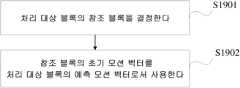
본 출원의 제 1 측면에 따르면, 모션 벡터를 획득하기 위한 방법이 제공되고, 처리 대상 블록의 참조 블록을 결정하는 것 - 참조 블록 및 처리 대상 블록은 미리 설정된 시간적 또는 공간적 상관을 갖고, 참조 블록은 초기 모션 벡터 및 하나 이상의 미리 설정된 모션 벡터 오프셋을 갖고, 참조 블록의 초기 모션 벡터는 참조 블록의 예측 모션 벡터에 근거하여 획득되고, 참조 블록의 예측 블록은 초기 모션 벡터 및 하나 이상의 미리 설정된 모션 벡터 오프셋에 근거하여 획득됨 - 과, 참조 블록의 초기 모션 벡터를 처리 대상 블록의 예측 모션 벡터로서 사용하는 것을 포함한다.According to a first aspect of the present application, a method for obtaining a motion vector is provided, comprising: determining a reference block of a block to be processed, wherein the reference block and the block to be processed have a preset temporal or spatial correlation, the reference block has an initial motion vector and one or more preset motion vector offsets, the initial motion vector of the reference block is obtained based on a predicted motion vector of the reference block, and the predicted block of the reference block is obtained based on the initial motion vector and the one or more preset motion vector offsets, and using the initial motion vector of the reference block as a predicted motion vector of the block to be processed.
상술한 방식에서, 업데이트 전의 초기 모션 벡터는 실제 모션 벡터를 대체하기 위해 사용되고 후속 코딩 블록 또는 디코딩 블록을 예측하기 위해 사용된다. 실제 모션 벡터의 업데이트가 완료되기 전에 후속 코딩 블록 또는 디코딩 블록에 대한 예측 스텝이 수행될 수 있다. 이것은 모션 벡터 업데이트로 인한 인코딩 효율 향상을 보장하고, 처리 지연을 제거한다.In the above-described method, the initial motion vector before the update is used to replace the actual motion vector and is used to predict the subsequent coding block or decoding block. The prediction step for the subsequent coding block or decoding block can be performed before the update of the actual motion vector is completed. This ensures improved encoding efficiency due to the motion vector update and eliminates processing delay.
제 1 측면의 제 1 실현 가능한 구현에서, 참조 블록의 초기 모션 벡터는 구체적으로 참조 블록의 예측 모션 벡터를 참조 블록의 초기 모션 벡터로서 사용하는 방식, 또는 참조 블록의 초기 모션 벡터를 획득하기 위해 참조 블록의 예측 모션 벡터와 참조 블록의 모션 벡터 차이를 더하는 방식으로 획득된다.In a first feasible implementation of the first aspect, the initial motion vector of the reference block is obtained in a manner that specifically uses a predicted motion vector of the reference block as the initial motion vector of the reference block, or in a manner that adds a difference between a predicted motion vector of the reference block and a motion vector of the reference block to obtain the initial motion vector of the reference block.
상이한 인터 예측 모드에서, 초기 모션 벡터는 예측 모션 벡터 또는 예측 모션 벡터와 모션 벡터 차이의 합으로부터 취하여질 수 있다. 이것은 인코딩 효율을 향상시킨다.In different inter prediction modes, the initial motion vector can be taken from the predicted motion vector or the sum of the predicted motion vector and the difference of the motion vector. This improves the encoding efficiency.
제 1 측면의 제 2 실현 가능한 구현에서, 참조 블록의 예측 블록은 구체적으로 참조 블록의 참조 프레임으로부터 참조 블록의 초기 모션 벡터에 의해 나타내어지는 픽처 블록을 획득하고, 획득된 픽처 블록을 참조 블록의 임시 예측 블록으로서 사용하는 방식과, 하나 이상의 실제 모션 벡터를 획득하기 위해 참조 블록의 초기 모션 벡터와 하나 이상의 미리 설정된 모션 벡터 오프셋을 더하는 방식 - 각각의 실제 모션 벡터는 검색 위치를 나타냄 - 과, 하나 이상의 실제 모션 벡터에 의해 나타내어지는 검색 위치에서 하나 이상의 후보 예측 블록을 획득하는 방식 - 각각의 검색 위치는 하나의 후보 예측 블록에 대응함 - 과, 하나 이상의 후보 예측 블록으로부터 임시 예측 블록과의 최소 화소 차이를 갖는 후보 예측 블록을 참조 블록의 예측 블록으로서 선택하는 방식으로 획득된다.In a second feasible implementation of the first aspect, the prediction block of the reference block is specifically obtained by: obtaining a picture block indicated by an initial motion vector of the reference block from a reference frame of the reference block, using the obtained picture block as a temporary prediction block of the reference block; adding the initial motion vector of the reference block and one or more preset motion vector offsets to obtain one or more actual motion vectors, each of the actual motion vectors indicating a search position; obtaining one or more candidate prediction blocks from search positions indicated by the one or more actual motion vectors, each of the search positions corresponding to one candidate prediction block; and selecting a candidate prediction block having a minimum pixel difference from the temporary prediction block from the one or more candidate prediction blocks as the prediction block of the reference block.
이 구현에서, 모션 벡터 업데이트 방식이 구체적으로 설명된다. 모션 벡터 업데이트에 근거하여, 예측이 더 정확하고, 인코딩 효율이 향상된다.In this implementation, a motion vector update method is specifically described. Based on the motion vector update, the prediction is more accurate and the encoding efficiency is improved.
제 1 측면의 제 3 실현 가능한 구현에서, 방법은 양방향 예측에 사용되고, 참조 프레임은 제 1 방향 참조 프레임 및 제 2 방향 참조 프레임을 포함하고, 초기 모션 벡터는 제 1 방향 초기 모션 벡터 및 제 2 방향 초기 모션 벡터를 포함하고, 참조 블록의 참조 프레임으로부터 참조 블록의 초기 모션 벡터에 의해 나타내어지는 픽처 블록을 획득하고, 획득된 픽처 블록을 참조 블록의 임시 예측 블록으로서 사용하는 것은 참조 블록의 제 1 방향 참조 프레임으로부터 참조 블록의 제 1 방향 초기 모션 벡터에 의해 나타내어지는 제 1 픽처 블록을 획득하는 것과, 참조 블록의 제 2 방향 참조 프레임으로부터 참조 블록의 제 2 방향 초기 모션 벡터에 의해 나타내어지는 제 2 픽처 블록을 획득하는 것과, 참조 블록의 임시 예측 블록을 획득하기 위해 제 1 픽처 블록 및 제 2 픽처 블록을 가중하는 것을 포함한다.In a third feasible implementation of the first aspect, the method is used for bidirectional prediction, the reference frame includes a first-direction reference frame and a second-direction reference frame, the initial motion vector includes the first-direction initial motion vector and the second-direction initial motion vector, obtaining a picture block represented by the initial motion vector of the reference block from the reference frame of the reference block, and using the obtained picture block as a temporary prediction block of the reference block includes obtaining a first picture block represented by the first-direction initial motion vector of the reference block from the first-direction reference frame of the reference block, obtaining a second picture block represented by the second-direction initial motion vector of the reference block from the second-direction reference frame of the reference block, and weighting the first picture block and the second picture block to obtain the temporary prediction block of the reference block.
이 구현에서, 양방향 예측 동안의 모션 벡터 업데이트 방식이 구체적으로 설명된다. 모션 벡터 업데이트에 근거하여, 예측이 더 정확하고, 인코딩 효율이 향상된다.In this implementation, a motion vector update method during bidirectional prediction is specifically described. Based on the motion vector update, the prediction is more accurate and the encoding efficiency is improved.
제 1 측면의 제 4 실현 가능한 구현에서, 방법은 실제 모션 벡터의 모션 벡터 분해(resolution)가 미리 설정된 화소 정밀도보다 높은 경우, 처리된 실제 모션 벡터의 모션 벡터 분해가 미리 설정된 화소 정밀도와 같도록, 실제 모션 벡터의 모션 벡터 분해를 라운딩(rounding)하는 것을 더 포함한다.In a fourth feasible implementation of the first aspect, the method further includes rounding a motion vector decomposition of the actual motion vector such that a motion vector decomposition of the processed actual motion vector becomes equal to the preset pixel precision, if the motion vector resolution of the actual motion vector is higher than the preset pixel precision.
이 구현은 실제 모션 벡터의 모션 벡터 분해가 미리 설정된 화소 정밀도와 같은 것을 보장하고, 상이한 모션 벡터 분해로 인한 계산의 복잡함을 감소시킨다. 업데이트 전의 초기 모션 벡터가 실제 모션 벡터를 대체하기 위해 사용되고 후속 코딩 블록 또는 디코딩 블록을 예측하기 위해 사용되는 방법이 사용되지 않는 경우, 모션 벡터 업데이트의 복잡함이 감소되기 때문에, 이 구현이 별도로 사용되면 이 구현은 또한 지연을 감소시킬 수 있음을 이해해야 한다.This implementation ensures that the motion vector decomposition of the actual motion vector is at the same pixel precision as the preset one, and reduces the computational complexity due to different motion vector decompositions. Since the complexity of the motion vector update is reduced when the initial motion vector before the update is used to replace the actual motion vector and no method is used to predict the subsequent coding block or decoding block, it should be understood that this implementation can also reduce the delay if used separately.
제 1 측면의 제 5 실현 가능한 구현에서, 하나 이상의 후보 예측 블록으로부터 임시 예측 블록과의 최소 화소 차이를 갖는 후보 예측 블록을 참조 블록의 예측 블록으로서 선택하는 것은 하나 이상의 후보 예측 블록으로부터 임시 예측 블록과의 최소 화소 차이를 갖는 후보 예측 블록에 대응하는 실제 모션 벡터를 선택하는 것과, 선택된 실제 모션 벡터의 모션 벡터 분해가 미리 설정된 화소 정밀도보다 높은 경우, 처리된 선택된 실제 모션 벡터의 모션 벡터 분해가 미리 설정된 화소 정밀도와 같도록, 선택된 실제 모션 벡터의 모션 벡터 분해를 라운딩하는 것과, 처리된 선택된 실제 모션 벡터에 의해 나타내어지는 위치에 대응하는 예측 블록이 참조 블록의 예측 블록이라고 결정하는 것을 포함한다.In a fifth feasible implementation of the first aspect, selecting a candidate prediction block having a minimum pixel difference from a temporary prediction block from one or more candidate prediction blocks as a prediction block of a reference block includes: selecting a real motion vector corresponding to the candidate prediction block having the minimum pixel difference from the temporary prediction block from the one or more candidate prediction blocks; and, if a motion vector decomposition of the selected real motion vector is higher than a preset pixel precision, rounding the motion vector decomposition of the selected real motion vector such that a motion vector decomposition of the processed selected real motion vector becomes equal to the preset pixel precision; and determining that a prediction block corresponding to a position indicated by the processed selected real motion vector is a prediction block of the reference block.
이 구현은 또한 실제 모션 벡터의 모션 벡터 분해가 미리 설정된 화소 정밀도와 같은 것을 보장하고, 상이한 모션 벡터 분해로 인한 계산의 복잡함을 감소시킨다. 업데이트 전의 초기 모션 벡터가 실제 모션 벡터를 대체하기 위해 사용되고 후속 코딩 블록 또는 디코딩 블록을 예측하기 위해 사용되는 방법이 사용되지 않는 경우, 모션 벡터 업데이트의 복잡함이 감소되기 때문에, 이 구현이 별도로 사용되면 이 구현은 또한 지연을 감소시킬 수 있음을 이해해야 한다.This implementation also ensures that the motion vector decomposition of the actual motion vector is at the same pixel precision as the preset, and reduces the computational complexity due to different motion vector decompositions. Since the complexity of the motion vector update is reduced when the initial motion vector before the update is used to replace the actual motion vector and no method is used to predict the subsequent coding block or decoding block, it should be understood that this implementation can also reduce the delay if used separately.
제 1 측면의 제 6 실현 가능한 구현에서, 미리 설정된 화소 정밀도는 정수 화소 정밀도, 1/2 화소 정밀도, 1/4 화소 정밀도, 또는 1/8 화소 정밀도이다.In a sixth feasible implementation of the first aspect, the preset pixel precision is integer pixel precision, half pixel precision, quarter pixel precision, or eighth pixel precision.
제 1 측면의 제 7 실현 가능한 구현에서, 방법은 처리 대상 블록의 예측 모션 벡터를 처리 대상 블록의 초기 모션 벡터로서 사용하는 것을 더 포함한다.In a seventh feasible implementation of the first aspect, the method further comprises using a predicted motion vector of the target block as an initial motion vector of the target block.
제 1 측면의 제 8 실현 가능한 구현에서, 방법은 처리 대상 블록의 초기 모션 벡터를 획득하기 위해 처리 대상 블록의 예측 모션 벡터와 처리 대상 블록의 모션 벡터 차이를 더하는 것을 더 포함한다.In an eighth feasible implementation of the first aspect, the method further comprises adding a difference between a predicted motion vector of the target block and a motion vector of the target block to obtain an initial motion vector of the target block.
제 1 측면의 제 9 실현 가능한 구현에서, 방법은 비디오 디코딩에 사용되고, 처리 대상 블록의 모션 벡터 차이는 비트스트림에서 제 1 식별 정보를 파싱(parsing)함으로써 획득된다.In a ninth feasible implementation of the first aspect, the method is used for video decoding, wherein a motion vector difference of a block to be processed is obtained by parsing first identification information from a bitstream.
상이한 인터 예측 모드에서, 초기 모션 벡터는 예측 모션 벡터 또는 예측 모션 벡터와 모션 벡터 차이의 합으로부터 취하여질 수 있다. 이것은 인코딩 효율을 향상시킨다.In different inter prediction modes, the initial motion vector can be taken from the predicted motion vector or the sum of the predicted motion vector and the difference of the motion vector. This improves the encoding efficiency.
제 1 측면의 제 10 실현 가능한 구현에서, 방법은 비디오 디코딩에 사용되고, 처리 대상 블록의 참조 블록을 결정하는 것은 제 2 식별 정보를 획득하기 위해 비트스트림을 파싱하는 것과, 제 2 식별 정보에 근거하여 처리 대상 블록의 참조 블록을 결정하는 것을 포함한다.In a tenth feasible implementation of the first aspect, the method is used for video decoding, wherein determining a reference block of a block to be processed comprises parsing a bitstream to obtain second identification information, and determining the reference block of the block to be processed based on the second identification information.
제 1 측면의 제 11 실현 가능한 구현에서, 방법은 비디오 인코딩에 사용되고, 처리 대상 블록의 참조 블록을 결정하는 것은 처리 대상 블록의 하나 이상의 후보 참조 블록으로부터 최소 레이트 왜곡 비용(minimum rate-distortion cost)을 갖는 후보 참조 블록을 처리 대상 블록의 참조 블록으로서 선택하는 것을 포함한다.In an eleventh feasible implementation of the first aspect, the method is used in video encoding, wherein determining a reference block of a block to be processed comprises selecting a candidate reference block having a minimum rate-distortion cost from one or more candidate reference blocks of the block to be processed as the reference block of the block to be processed.
참조 블록은 처리 대상 블록과의 공간적 또는 시간적 상관을 갖는 동화상 블록이고, 예컨대, 공간적으로 인접한 블록 또는 시간적으로 동일 배치(co-located) 블록일 수 있다. 참조 블록의 모션 벡터는 처리 대상 블록의 모션 벡터를 예측하기 위해 사용된다. 이것은 모션 벡터의 인코딩 효율을 향상시킨다.A reference block is a moving image block that has a spatial or temporal correlation with the target block, and may be, for example, a spatially adjacent block or a temporally co-located block. The motion vector of the reference block is used to predict the motion vector of the target block. This improves the encoding efficiency of the motion vector.
본 출원의 제 2 측면에 따르면, 모션 벡터를 획득하기 위한 장치가 제공되고, 처리 대상 블록의 참조 블록을 결정하도록 구성된 결정 모듈 - 참조 블록 및 처리 대상 블록은 미리 설정된 시간적 또는 공간적 상관을 갖고, 참조 블록은 초기 모션 벡터 및 하나 이상의 미리 설정된 모션 벡터 오프셋을 갖고, 참조 블록의 초기 모션 벡터는 참조 블록의 예측 모션 벡터에 근거하여 획득되고, 참조 블록의 예측 블록은 초기 모션 벡터 및 하나 이상의 미리 설정된 모션 벡터 오프셋에 근거하여 획득됨 - 과, 참조 블록의 초기 모션 벡터를 처리 대상 블록의 예측 모션 벡터로서 사용하도록 구성된 획득 모듈을 포함한다.According to a second aspect of the present application, a device for obtaining a motion vector is provided, comprising: a determining module configured to determine a reference block of a block to be processed, wherein the reference block and the block to be processed have a preset temporal or spatial correlation, the reference block has an initial motion vector and one or more preset motion vector offsets, the initial motion vector of the reference block is obtained based on a predicted motion vector of the reference block, and the predicted block of the reference block is obtained based on the initial motion vector and one or more preset motion vector offsets; and an obtaining module configured to use the initial motion vector of the reference block as a predicted motion vector of the block to be processed.
제 2 측면의 제 1 실현 가능한 구현에서, 획득 모듈은 참조 블록의 예측 모션 벡터를 참조 블록의 초기 모션 벡터로서 사용하도록, 또는 참조 블록의 초기 모션 벡터를 획득하기 위해 참조 블록의 예측 모션 벡터와 참조 블록의 모션 벡터 차이를 더하도록 더 구성된다.In a first feasible implementation of the second aspect, the acquisition module is further configured to use the predicted motion vector of the reference block as an initial motion vector of the reference block, or to add a difference between the predicted motion vector of the reference block and the motion vector of the reference block to obtain the initial motion vector of the reference block.
제 2 측면의 제 2 실현 가능한 구현에서, 획득 모듈은 참조 블록의 참조 프레임으로부터 참조 블록의 초기 모션 벡터에 의해 나타내어지는 픽처 블록을 획득하고, 획득된 픽처 블록을 참조 블록의 임시 예측 블록으로서 사용하도록, 또한 하나 이상의 실제 모션 벡터를 획득하기 위해 참조 블록의 초기 모션 벡터와 하나 이상의 미리 설정된 모션 벡터 오프셋을 더하도록 - 각각의 실제 모션 벡터는 검색 위치를 나타냄 - , 또한 하나 이상의 실제 모션 벡터에 의해 나타내어지는 검색 위치에서 하나 이상의 후보 예측 블록을 획득하도록 - 각각의 검색 위치는 하나의 후보 예측 블록에 대응함 - , 또한 하나 이상의 후보 예측 블록으로부터 임시 예측 블록과의 최소 화소 차이를 갖는 후보 예측 블록을 참조 블록의 예측 블록으로서 선택하도록 더 구성된다.In a second feasible implementation of the second aspect, the obtaining module is further configured to obtain a picture block indicated by an initial motion vector of the reference block from a reference frame of the reference block, to use the obtained picture block as a temporary prediction block of the reference block, and to add one or more preset motion vector offsets to the initial motion vector of the reference block to obtain one or more actual motion vectors, each of the actual motion vectors indicating a search position, and to obtain one or more candidate prediction blocks at search positions indicated by the one or more actual motion vectors, each of the search positions corresponding to one candidate prediction block, and to select a candidate prediction block having a minimum pixel difference from the temporary prediction block from the one or more candidate prediction blocks as a prediction block of the reference block.
제 2 측면의 제 3 실현 가능한 구현에서, 장치는 양방향 예측을 위해 구성되고, 참조 프레임은 제 1 방향 참조 프레임 및 제 2 방향 참조 프레임을 포함하고, 초기 모션 벡터는 제 1 방향 초기 모션 벡터 및 제 2 방향 초기 모션 벡터를 포함하고, 획득 모듈은 구체적으로 참조 블록의 제 1 방향 참조 프레임으로부터 참조 블록의 제 1 방향 초기 모션 벡터에 의해 나타내어지는 제 1 픽처 블록을 획득하도록, 또한 참조 블록의 제 2 방향 참조 프레임으로부터 참조 블록의 제 2 방향 초기 모션 벡터에 의해 나타내어지는 제 2 픽처 블록을 획득하도록, 또한 참조 블록의 임시 예측 블록을 획득하기 위해 제 1 픽처 블록 및 제 2 픽처 블록을 가중하도록 구성된다.In a third feasible implementation of the second aspect, the device is configured for bidirectional prediction, the reference frame includes a first-direction reference frame and a second-direction reference frame, the initial motion vector includes the first-direction initial motion vector and the second-direction initial motion vector, and the obtaining module is specifically configured to obtain a first picture block represented by the first-direction initial motion vector of the reference block from the first-direction reference frame of the reference block, further to obtain a second picture block represented by the second-direction initial motion vector of the reference block from the second-direction reference frame of the reference block, and further to weight the first picture block and the second picture block to obtain a temporary prediction block of the reference block.
제 2 측면의 제 4 실현 가능한 구현에서, 장치는 실제 모션 벡터의 모션 벡터 분해가 미리 설정된 화소 정밀도보다 높은 경우, 처리된 실제 모션 벡터의 모션 벡터 분해가 미리 설정된 화소 정밀도와 같도록, 실제 모션 벡터의 모션 벡터 분해를 라운딩하도록 구성된 라운딩 모듈을 더 포함한다.In a fourth feasible implementation of the second aspect, the device further includes a rounding module configured to round the motion vector decomposition of the actual motion vector so that the motion vector decomposition of the processed actual motion vector becomes equal to the preset pixel precision, if the motion vector decomposition of the actual motion vector is higher than the preset pixel precision.
제 2 측면의 제 5 실현 가능한 구현에서, 획득 모듈은 구체적으로 하나 이상의 후보 예측 블록으로부터, 임시 예측 블록과의 최소 화소 차이를 갖는 후보 예측 블록에 대응하는 실제 모션 벡터를 선택하도록, 또한 선택된 실제 모션 벡터의 모션 벡터 분해가 미리 설정된 화소 정밀도보다 높은 경우, 처리된 선택된 실제 모션 벡터의 모션 벡터 분해가 미리 설정된 화소 정밀도와 같도록, 선택된 실제 모션 벡터의 모션 벡터 분해를 라운딩하도록, 또한 처리된 선택된 실제 모션 벡터에 의해 나타내어지는 위치에 대응하는 예측 블록이 참조 블록의 예측 블록이라고 결정하도록 구성된다.In a fifth feasible implementation of the second aspect, the acquisition module is specifically configured to select, from one or more candidate prediction blocks, a real motion vector corresponding to a candidate prediction block having a minimum pixel difference from a temporary prediction block, and further configured to round the motion vector decomposition of the selected real motion vector such that the motion vector decomposition of the processed selected real motion vector becomes equal to the preset pixel precision if the motion vector decomposition of the selected real motion vector is higher than a preset pixel precision, and further configured to determine that a prediction block corresponding to a position indicated by the processed selected real motion vector is a prediction block of the reference block.
제 2 측면의 제 6 실현 가능한 구현에서, 미리 설정된 화소 정밀도는 정수 화소 정밀도, 1/2 화소 정밀도, 1/4 화소 정밀도, 또는 1/8 화소 정밀도이다.In a sixth feasible implementation of the second aspect, the preset pixel precision is integer pixel precision, half pixel precision, quarter pixel precision, or eighth pixel precision.
제 2 측면의 제 7 실현 가능한 구현에서, 획득 모듈은 구체적으로 처리 대상 블록의 예측 모션 벡터를 처리 대상 블록의 초기 모션 벡터로서 사용하도록 구성된다.In a seventh feasible implementation of the second aspect, the acquisition module is specifically configured to use a predicted motion vector of the target block as an initial motion vector of the target block.
제 2 측면의 제 8 실현 가능한 구현에서, 획득 모듈은 구체적으로 처리 대상 블록의 초기 모션 벡터를 획득하기 위해 처리 대상 블록의 예측 모션 벡터와 처리 대상 블록의 모션 벡터 차이를 더하도록 구성된다.In the eighth feasible implementation of the second aspect, the acquisition module is specifically configured to add the difference between the predicted motion vector of the target block and the motion vector of the target block to obtain an initial motion vector of the target block.
제 2 측면의 제 9 실현 가능한 구현에서, 장치는 비디오 디코딩에 사용되고, 처리 대상 블록의 모션 벡터 차이는 비트스트림에서 제 1 식별 정보를 파싱함으로써 획득된다.In a ninth feasible implementation of the second aspect, the device is used for video decoding, and a motion vector difference of a block to be processed is obtained by parsing first identification information from a bitstream.
제 2 측면의 제 10 실현 가능한 구현에서, 장치는 비디오 디코딩에 사용되고, 결정 모듈은 구체적으로 제 2 식별 정보를 획득하기 위해 비트스트림을 파싱하도록, 또한 제 2 식별 정보에 근거하여 처리 대상 블록의 참조 블록을 결정하도록 구성된다.In a tenth feasible implementation of the second aspect, the device is used for video decoding, and the decision module is specifically configured to parse the bitstream to obtain second identification information, and further determine a reference block of the target block of processing based on the second identification information.
제 2 측면의 제 11 실현 가능한 구현에서, 장치는 비디오 인코딩에 사용되고, 결정 모듈은 구체적으로 처리 대상 블록의 하나 이상의 후보 참조 블록으로부터 최소 레이트 왜곡 비용을 갖는 후보 참조 블록을 처리 대상 블록의 참조 블록으로서 선택하도록 구성된다.In an eleventh feasible implementation of the second aspect, the device is used for video encoding, and the decision module is specifically configured to select a candidate reference block having a minimum rate distortion cost from one or more candidate reference blocks of a target block to be processed as a reference block of the target block to be processed.
본 출원의 제 3 측면에 따르면, 모션 벡터를 획득하기 위한 방법이 제공되고, 처리 대상 블록의 참조 블록을 결정하는 것 - 참조 블록 및 처리 대상 블록은 미리 설정된 시간적 또는 공간적 상관을 가짐 - 과, 참조 블록에 근거하여 처리 대상 블록의 초기 모션 벡터를 획득하는 것과, 처리 대상 블록의 초기 모션 벡터 및 하나 이상의 미리 설정된 모션 벡터 오프셋에 근거하여 처리 대상 블록의 예측 블록을 획득하는 것과, 처리 대상 블록의 초기 모션 벡터를 처리 대상 블록 후에 처리되는 후속 처리 대상 블록의 예측 모션 벡터로서 사용하는 것을 포함한다.According to a third aspect of the present application, a method for obtaining a motion vector is provided, comprising: determining a reference block of a block to be processed, wherein the reference block and the block to be processed have a preset temporal or spatial correlation; obtaining an initial motion vector of the block to be processed based on the reference block; obtaining a prediction block of the block to be processed based on the initial motion vector of the block to be processed and at least one preset motion vector offset; and using the initial motion vector of the block to be processed as a prediction motion vector of a subsequent block to be processed after the block to be processed.
제 3 측면의 제 1 실현 가능한 구현에서, 참조 블록에 근거하여 처리 대상 블록의 초기 모션 벡터를 획득하는 것은 참조 블록의 초기 모션 벡터를 처리 대상 블록의 초기 모션 벡터로서 사용하는 것, 또는 처리 대상 블록의 초기 모션 벡터를 획득하기 위해 참조 블록의 초기 모션 벡터와 처리 대상 블록의 모션 벡터 차이를 더하는 것을 포함한다.In a first feasible implementation of the third aspect, obtaining the initial motion vector of the target block based on the reference block includes using the initial motion vector of the reference block as the initial motion vector of the target block, or adding a difference between the initial motion vector of the reference block and the motion vector of the target block to obtain the initial motion vector of the target block.
제 3 측면의 제 2 실현 가능한 구현에서, 처리 대상 블록의 초기 모션 벡터 및 하나 이상의 미리 설정된 모션 벡터 오프셋에 근거하여 처리 대상 블록의 예측 블록을 획득하는 것은 처리 대상 블록의 참조 프레임으로부터 처리 대상 블록의 초기 모션 벡터에 의해 나타내어지는 픽처 블록을 획득하고, 획득된 픽처 블록을 처리 대상 블록의 임시 예측 블록으로서 사용하는 것과, 하나 이상의 실제 모션 벡터를 획득하기 위해 처리 대상 블록의 초기 모션 벡터와 하나 이상의 미리 설정된 모션 벡터 오프셋을 더하는 것 - 각각의 실제 모션 벡터는 검색 위치를 나타냄 - 과, 하나 이상의 실제 모션 벡터에 의해 나타내어지는 검색 위치에서 하나 이상의 후보 예측 블록을 획득하는 것 - 각각의 검색 위치는 하나의 후보 예측 블록에 대응함 - 과, 하나 이상의 후보 예측 블록으로부터 임시 예측 블록과의 최소 화소 차이를 갖는 후보 예측 블록을 처리 대상 블록의 예측 블록으로서 선택하는 것을 포함한다.In a second feasible implementation of the third aspect, obtaining a prediction block of the target block based on an initial motion vector of the target block and one or more preset motion vector offsets includes: obtaining a picture block indicated by the initial motion vector of the target block from a reference frame of the target block, using the obtained picture block as a temporary prediction block of the target block, adding the initial motion vector of the target block and the one or more preset motion vector offsets to obtain one or more actual motion vectors, each actual motion vector indicating a search position; obtaining one or more candidate prediction blocks at search positions indicated by the one or more actual motion vectors, each search position corresponding to one candidate prediction block; and selecting a candidate prediction block having a minimum pixel difference from the temporary prediction block from the one or more candidate prediction blocks as the prediction block of the target block.
제 3 측면의 제 3 실현 가능한 구현에서, 방법은 양방향 예측에 사용되고, 참조 프레임은 제 1 방향 참조 프레임 및 제 2 방향 참조 프레임을 포함하고, 처리 대상 블록의 초기 모션 벡터는 제 1 방향 초기 모션 벡터 및 제 2 방향 초기 모션 벡터를 포함하고, 처리 대상 블록의 참조 프레임으로부터 처리 대상 블록의 초기 모션 벡터에 의해 나타내어지는 픽처 블록을 획득하고, 획득된 픽처 블록을 처리 대상 블록의 임시 예측 블록으로서 사용하는 것은 처리 대상 블록의 제 1 방향 참조 프레임으로부터 처리 대상 블록의 제 1 방향 초기 모션 벡터에 의해 나타내어지는 제 1 픽처 블록을 획득하는 것과, 처리 대상 블록의 제 2 방향 참조 프레임으로부터 처리 대상 블록의 제 2 방향 초기 모션 벡터에 의해 나타내어지는 제 2 픽처 블록을 획득하는 것과, 처리 대상 블록의 임시 예측 블록을 획득하기 위해 제 1 픽처 블록 및 제 2 픽처 블록을 가중하는 것을 포함한다.In a third feasible implementation of the third aspect, the method is used for bidirectional prediction, the reference frame includes a first-direction reference frame and a second-direction reference frame, the initial motion vector of the target block to be processed includes the first-direction initial motion vector and the second-direction initial motion vector, obtaining a picture block represented by the initial motion vector of the target block to be processed from the reference frame of the target block to be processed, and using the obtained picture block as a temporary prediction block of the target block to be processed includes: obtaining a first picture block represented by the first-direction initial motion vector of the target block to be processed from the first-direction reference frame of the target block to be processed, obtaining a second picture block represented by the second-direction initial motion vector of the target block to be processed from the second-direction reference frame of the target block, and weighting the first picture block and the second picture block to obtain the temporary prediction block of the target block to be processed.
제 3 측면의 제 4 실현 가능한 구현에서, 방법은 실제 모션 벡터의 모션 벡터 분해가 미리 설정된 화소 정밀도보다 높은 경우, 처리된 실제 모션 벡터의 모션 벡터 분해가 미리 설정된 화소 정밀도와 같도록, 실제 모션 벡터의 모션 벡터 분해를 라운딩하는 것을 더 포함한다.In a fourth feasible implementation of the third aspect, the method further includes rounding the motion vector decomposition of the actual motion vector, if the motion vector decomposition of the actual motion vector is higher than the preset pixel precision, so that the motion vector decomposition of the processed actual motion vector becomes equal to the preset pixel precision.
제 3 측면의 제 5 실현 가능한 구현에서, 하나 이상의 후보 예측 블록으로부터 임시 예측 블록과의 최소 화소 차이를 갖는 후보 예측 블록을 처리 대상 블록의 예측 블록으로서 선택하는 것은 하나 이상의 후보 예측 블록으로부터 임시 예측 블록과의 최소 화소 차이를 갖는 후보 예측 블록에 대응하는 실제 모션 벡터를 선택하는 것과, 선택된 실제 모션 벡터의 모션 벡터 분해가 미리 설정된 화소 정밀도보다 높은 경우, 처리된 선택된 실제 모션 벡터의 모션 벡터 분해가 미리 설정된 화소 정밀도와 같도록, 선택된 실제 모션 벡터의 모션 벡터 분해를 라운딩하는 것과, 처리된 선택된 실제 모션 벡터에 의해 나타내어지는 위치에 대응하는 예측 블록이 처리 대상 블록의 예측 블록이라고 결정하는 것을 포함한다.In a fifth feasible implementation of the third aspect, selecting a candidate prediction block having a minimum pixel difference from a temporary prediction block from one or more candidate prediction blocks as a prediction block of a target block to be processed includes: selecting a real motion vector corresponding to the candidate prediction block having the minimum pixel difference from the temporary prediction block from one or more candidate prediction blocks; and, if a motion vector decomposition of the selected real motion vector is higher than a preset pixel precision, rounding the motion vector decomposition of the selected real motion vector so that a motion vector decomposition of the processed selected real motion vector becomes equal to the preset pixel precision; and determining that a prediction block corresponding to a position indicated by the processed selected real motion vector is a prediction block of the target block to be processed.
제 3 측면의 제 6 실현 가능한 구현에서, 미리 설정된 화소 정밀도는 정수 화소 정밀도, 1/2 화소 정밀도, 1/4 화소 정밀도, 또는 1/8 화소 정밀도이다.In a sixth feasible implementation of the third aspect, the preset pixel precision is integer pixel precision, half pixel precision, quarter pixel precision, or eighth pixel precision.
제 3 측면의 제 7 실현 가능한 구현에서, 방법은 처리 대상 블록 후에 처리되는 후속 처리 대상 블록의 예측 모션 벡터를 처리 대상 블록 후에 처리되는 후속 처리 대상 블록의 초기 모션 벡터로서 사용하는 것을 더 포함한다.In a seventh feasible implementation of the third aspect, the method further includes using a predicted motion vector of a subsequent processing target block processed after the processing target block as an initial motion vector of the subsequent processing target block processed after the processing target block.
제 3 측면의 제 8 실현 가능한 구현에서, 방법은 처리 대상 블록 후에 처리되는 후속 처리 대상 블록의 초기 모션 벡터를 획득하기 위해 처리 대상 블록 후에 처리되는 후속 처리 대상 블록의 예측 모션 벡터와 모션 벡터를 더하는 것을 더 포함한다.In an eighth feasible implementation of the third aspect, the method further includes adding the motion vector and a predicted motion vector of a subsequent block to be processed after the subject block to obtain an initial motion vector of the subsequent block to be processed after the subject block.
제 3 측면의 제 9 실현 가능한 구현에서, 방법은 비디오 디코딩에 사용되고, 처리 대상 블록 후에 처리되는 후속 처리 대상 블록의 모션 벡터 차이는 비트스트림에서 제 1 식별 정보를 파싱함으로써 획득된다.In a ninth feasible implementation of the third aspect, the method is used for video decoding, wherein a motion vector difference of a subsequent processing target block to be processed after a processing target block is obtained by parsing first identification information from a bitstream.
제 3 측면의 제 10 실현 가능한 구현에서, 방법은 비디오 디코딩에 사용되고, 처리 대상 블록의 참조 블록을 결정하는 것은 제 2 식별 정보를 획득하기 위해 비트스트림을 파싱하는 것과, 제 2 식별 정보에 근거하여 처리 대상 블록의 참조 블록을 결정하는 것을 포함한다.In a tenth feasible implementation of the third aspect, the method is used for video decoding, wherein determining a reference block of a block to be processed includes parsing a bitstream to obtain second identification information, and determining the reference block of the block to be processed based on the second identification information.
제 3 측면의 제 11 실현 가능한 구현에서, 방법은 비디오 인코딩에 사용되고, 처리 대상 블록의 참조 블록을 결정하는 것은 처리 대상 블록의 하나 이상의 후보 참조 블록으로부터 최소 레이트 왜곡 비용을 갖는 후보 참조 블록을 처리 대상 블록의 참조 블록으로서 선택하는 것을 포함한다.In an eleventh feasible implementation of the third aspect, the method is used in video encoding, wherein determining a reference block of a block to be processed comprises selecting a candidate reference block having a minimum rate distortion cost from one or more candidate reference blocks of the block to be processed as a reference block of the block to be processed.
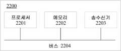
본 출원의 제 4 측면에 따르면, 모션 벡터를 획득하기 위한 디바이스가 제공된다. 디바이스는 인코더 측 또는 디코더 측에 적용될 수 있다. 디바이스는 프로세서 및 메모리를 포함한다. 프로세서 및 메모리는 서로 연결된다(예컨대, 버스를 통해 서로 연결된다). 가능한 구현에서, 디바이스는 송수신기를 더 포함할 수 있다. 송수신기는 프로세서 및 메모리에 연결되고, 데이터를 수신/송신하도록 구성된다. 메모리는 프로그램 코드 및 비디오 데이터를 저장하도록 구성된다. 프로세서는 제 1 측면 또는 제 3 측면에서 설명된 방법을 수행하기 위해 메모리에 저장된 프로그램 코드를 읽도록 구성된다.According to a fourth aspect of the present application, a device for obtaining a motion vector is provided. The device can be applied to an encoder side or a decoder side. The device includes a processor and a memory. The processor and the memory are connected to each other (e.g., connected to each other via a bus). In a possible implementation, the device may further include a transceiver. The transceiver is connected to the processor and the memory and is configured to receive/transmit data. The memory is configured to store program code and video data. The processor is configured to read the program code stored in the memory to perform the method described in the first aspect or the third aspect.
본 출원의 제 5 측면에 따르면, 비디오 코딩 시스템이 제공된다. 비디오 코딩 시스템은 소스 장치 및 목적지 장치를 포함한다. 소스 장치 및 목적지 장치는 통신적으로 연결될 수 있다. 소스 장치는 인코딩된 비디오 데이터를 생성한다. 따라서, 소스 장치는 비디오 인코딩 장치 또는 비디오 인코딩 디바이스라고 지칭될 수 있다. 목적지 장치는 소스 장치에 의해 생성된 인코딩된 비디오 데이터를 디코딩할 수 있다. 따라서, 목적지 장치는 비디오 디코딩 장치 또는 비디오 디코딩 디바이스라고 지칭될 수 있다. 소스 장치 및 목적지 장치는 비디오 코딩 장치 또는 비디오 코딩 디바이스의 예일 수 있다. 제 1 측면 또는 제 3 측면에서 설명된 방법은 비디오 코딩 장치 또는 비디오 코딩 디바이스에 적용된다.According to a fifth aspect of the present application, a video coding system is provided. The video coding system includes a source device and a destination device. The source device and the destination device may be communicatively connected. The source device generates encoded video data. Accordingly, the source device may be referred to as a video encoding device or a video encoding device. The destination device may decode the encoded video data generated by the source device. Accordingly, the destination device may be referred to as a video decoding device or a video decoding device. The source device and the destination device may be examples of a video coding device or a video coding device. The method described in the first aspect or the third aspect is applied to the video coding device or the video coding device.
본 출원의 제 6 측면에 따르면, 컴퓨터 판독 가능 저장 매체가 제공된다. 컴퓨터 판독 가능 저장 매체는 명령을 저장한다. 명령이 컴퓨터에서 실행되면, 컴퓨터는 제 1 측면 또는 제 3 측면에서 설명된 방법을 수행하는 것이 가능하게 된다.According to a sixth aspect of the present application, a computer-readable storage medium is provided. The computer-readable storage medium stores instructions. When the instructions are executed on a computer, the computer is enabled to perform the method described in the first aspect or the third aspect.
본 출원의 제 7 측면에 따르면, 명령을 포함하는 컴퓨터 프로그램 제품이 제공된다. 컴퓨터 프로그램 제품이 컴퓨터에서 실행되면, 컴퓨터는 제 1 측면 또는 제 3 측면에서 설명된 방법을 수행하는 것이 가능하게 된다.According to the seventh aspect of the present application, a computer program product comprising instructions is provided. When the computer program product is executed on a computer, the computer is enabled to perform the method described in the first aspect or the third aspect.
본 출원의 제 2 측면 내지 제 7 측면에 대응하는 실시예 및 본 출원의 제 1 측면에 대응하는 실시예는 동일한 발명 목적, 유사한 기술적 특징, 및 동일한 유익한 기술적 효과를 갖는다는 것을 이해해야 한다. 세부사항은 다시 설명되지 않는다.It should be understood that the embodiments corresponding to the second to seventh aspects of the present application and the embodiments corresponding to the first aspect of the present application have the same inventive purpose, similar technical features, and the same advantageous technical effects. The details are not described again.
도 1은 본 출원의 실시예에서 사용하도록 구성될 수 있는 비디오 코딩 시스템의 예의 블록도이다.
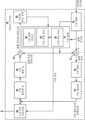
도 2는 본 출원의 실시예에서 사용하도록 구성될 수 있는 비디오 인코더의 예의 시스템 블록도이다.
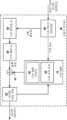
도 3은 본 출원의 실시예에서 사용하도록 구성될 수 있는 비디오 디코더의 예의 시스템 블록도이다.
도 4는 본 출원의 실시예에서 사용하도록 구성될 수 있는 인터 예측 모듈의 예의 블록도이다.
도 5는 병합 예측 모드의 예시적인 구현의 흐름도이다.
도 6은 진보된 모션 벡터 예측 모드의 예시적인 구현의 흐름도이다.
도 7은 본 출원의 실시예에서 사용하도록 구성될 수 있는 비디오 디코더에 의한 모션 보상의 예시적인 구현의 흐름도이다.
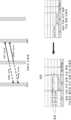
도 8은 코딩 유닛 및 코딩 유닛과 연관된 인접 위치 픽처 블록의 예의 개략도이다.
도 9는 후보 예측 모션 벡터 목록을 구성하는 예시적인 구현의 흐름도이다.
도 10은 결합된 후보 모션 벡터를 병합 모드 후보 예측 모션 벡터 목록에 추가하는 예시적인 구현의 개략도이다.
도 11은 스케일링된 후보 모션 벡터를 병합 모드 후보 예측 모션 벡터 목록에 추가하는 예시적인 구현의 개략도이다.
도 12는 제로 모션 벡터를 병합 모드 후보 예측 모션 벡터 목록에 추가하는 예시적인 구현의 개략도이다.
도 13은 본 출원의 실시예에 따른 비디오 인코딩에서 모션 벡터를 업데이트하기 위한 방법의 개략적인 흐름도이다.
도 14는 본 출원의 실시예에 따른 비디오 디코딩에서 모션 벡터를 업데이트하기 위한 방법의 개략적인 흐름도이다.
도 15는 본 출원의 실시예에 따라 모션 벡터를 업데이트하는 개략적인 흐름도이다.
도 16은 본 출원의 실시예에 따라 모션 벡터를 업데이트하는 개략적인 흐름도이다.
도 17은 본 출원의 실시예에 따라 모션 벡터를 업데이트하는 개략적인 흐름도이다.
도 18은 본 출원의 실시예에 따라 모션 벡터를 업데이트하는 개략적인 흐름도이다.
도 19는 본 출원의 실시예에 따른 비디오 인코딩에서 모션 벡터를 획득하기 위한 방법의 개략적인 흐름도이다.
도 20은 본 출원의 실시예에 따른 비디오 디코딩에서 모션 벡터를 획득하기 위한 방법의 개략적인 흐름도이다.
도 21은 본 출원의 실시예에 따른 비디오 디코딩에서 모션 벡터를 획득하기 위한 장치의 개략적인 블록도이다.
도 22는 본 출원의 실시예에 따른 비디오 코딩 장치의 개략적인 블록도이다.FIG. 1 is a block diagram of an example of a video coding system that may be configured for use in embodiments of the present application.
FIG. 2 is a system block diagram of an example of a video encoder that may be configured for use in embodiments of the present application.
FIG. 3 is a system block diagram of an example of a video decoder that may be configured for use in embodiments of the present application.
FIG. 4 is a block diagram of an example of an inter prediction module that may be configured for use in embodiments of the present application.
Figure 5 is a flowchart of an exemplary implementation of the merge prediction mode.
Figure 6 is a flowchart of an exemplary implementation of an advanced motion vector prediction mode.
FIG. 7 is a flowchart of an exemplary implementation of motion compensation by a video decoder that may be configured for use in embodiments of the present application.
Figure 8 is a schematic diagram of an example of a coding unit and an adjacent position picture block associated with the coding unit.
Figure 9 is a flowchart of an exemplary implementation of constructing a list of candidate predicted motion vectors.
Figure 10 is a schematic diagram of an exemplary implementation of adding a combined candidate motion vector to the list of merge mode candidate predicted motion vectors.
Figure 11 is a schematic diagram of an exemplary implementation of adding scaled candidate motion vectors to the list of merge mode candidate predicted motion vectors.
Figure 12 is a schematic diagram of an exemplary implementation of adding zero motion vectors to the list of merge mode candidate predicted motion vectors.
FIG. 13 is a schematic flowchart of a method for updating a motion vector in video encoding according to an embodiment of the present application.
FIG. 14 is a schematic flowchart of a method for updating a motion vector in video decoding according to an embodiment of the present application.
FIG. 15 is a schematic flowchart of updating a motion vector according to an embodiment of the present application.
FIG. 16 is a schematic flowchart of updating a motion vector according to an embodiment of the present application.
FIG. 17 is a schematic flowchart of updating a motion vector according to an embodiment of the present application.
FIG. 18 is a schematic flowchart of updating a motion vector according to an embodiment of the present application.
FIG. 19 is a schematic flowchart of a method for obtaining a motion vector in video encoding according to an embodiment of the present application.
FIG. 20 is a schematic flowchart of a method for obtaining a motion vector in video decoding according to an embodiment of the present application.
FIG. 21 is a schematic block diagram of a device for obtaining a motion vector in video decoding according to an embodiment of the present application.
FIG. 22 is a schematic block diagram of a video coding device according to an embodiment of the present application.
이하에서는 본 출원의 실시예의 첨부 도면을 참조하여 본 출원의 실시예의 기술적 해법을 명확하게 설명한다.Hereinafter, the technical solution of the embodiment of the present application is clearly explained with reference to the attached drawings of the embodiment of the present application.
도 1은 본 출원의 실시예에 따른 비디오 코딩 시스템(10)의 개략적인 블록도이다. 도 1에 나타낸 바와 같이, 시스템(10)은 소스 장치(12)를 포함한다. 소스 장치(12)는 목적지 장치(14)에 의해 이후에 디코딩될 인코딩된 비디오 데이터를 생성한다. 소스 장치(12) 및 목적지 장치(14)는 데스크톱 컴퓨터, 노트북 컴퓨터, 태블릿 컴퓨터, 셋톱 박스, "스마트" 폰과 같은 전화 핸드셋, "스마트" 터치패드, 텔레비전, 카메라, 디스플레이 장치, 디지털 미디어 플레이어, 비디오 게임 콘솔, 비디오 스트리밍 송신 장치 등을 포함하는 광범위한 장치 중 어느 하나를 포함할 수 있다. 몇몇 응용에서, 소스 장치(12) 및 목적지 장치(14)는 무선 통신을 위해 장착될 수 있다.FIG. 1 is a schematic block diagram of a video coding system (10) according to an embodiment of the present application. As shown in FIG. 1, the system (10) includes a source device (12). The source device (12) generates encoded video data that is subsequently decoded by a destination device (14). The source device (12) and the destination device (14) may include any of a wide variety of devices, including desktop computers, notebook computers, tablet computers, set-top boxes, telephone handsets such as "smart" phones, "smart" touchpads, televisions, cameras, display devices, digital media players, video game consoles, video streaming transmitters, and the like. In some applications, the source device (12) and the destination device (14) may be equipped for wireless communication.
목적지 장치(14)는 링크(16)를 통해 디코딩될 인코딩된 비디오 데이터를 수신할 수 있다. 링크(16)는 소스 장치(12)로부터 목적지 장치(14)에 인코딩된 비디오 데이터를 전송할 수 있는 임의의 유형의 매체 또는 장치를 포함할 수 있다. 실현 가능한 구현에서, 링크(16)는 소스 장치(12)가 인코딩된 비디오 데이터를 실시간으로 목적지 장치(14)에 직접 송신하는 것을 가능하게 하는 통신 매체를 포함할 수 있다. 인코딩된 비디오 데이터는 통신 표준(예컨대, 무선 통신 프로토콜)에 따라 변조된 후에 목적지 장치(14)에 송신될 수 있다. 통신 매체는 임의의 무선 또는 유선 통신 매체, 예컨대, 무선 주파수 스펙트럼 또는 하나 이상의 물리적 송신 회선을 포함할 수 있다. 통신 매체는 패킷 기반 네트워크(예컨대, 근거리 통신망, 광역 통신망, 또는 인터넷과 같은 글로벌 네트워크)의 일부를 구성할 수 있다. 통신 매체는 라우터, 스위치, 기지국, 또는 소스 장치(12)로부터 목적지 장치(14)로의 통신을 가능하게 하기 위해 사용될 수 있는 임의의 다른 디바이스를 포함할 수 있다.The destination device (14) can receive encoded video data to be decoded via the link (16). The link (16) can include any type of medium or device capable of transmitting encoded video data from the source device (12) to the destination device (14). In a feasible implementation, the link (16) can include a communication medium that enables the source device (12) to transmit encoded video data directly to the destination device (14) in real time. The encoded video data can be transmitted to the destination device (14) after being modulated according to a communication standard (e.g., a wireless communication protocol). The communication medium can include any wireless or wired communication medium, such as a radio frequency spectrum or one or more physical transmission lines. The communication medium can form part of a packet-based network (e.g., a local area network, a wide area network, or a global network such as the Internet). The communication medium can include a router, a switch, a base station, or any other device that can be used to enable communication from the source device (12) to the destination device (14).
대안적으로, 인코딩된 데이터는 출력 인터페이스(22)를 통해 저장 장치(24)에 출력될 수 있다. 유사하게, 인코딩된 데이터는 입력 인터페이스를 통해 저장 장치(24)로부터 액세스될 수 있다. 저장 장치(24)는 복수의 분산된 또는 로컬 데이터 저장 매체, 예컨대, 하드 디스크 드라이브, 블루레이 디스크, DVD, CD-ROM, 플래시 메모리, 휘발성 또는 비 휘발성 메모리, 또는 인코딩된 비디오 데이터를 저장하도록 구성된 임의의 다른 적절한 디지털 저장 매체 중 어느 하나를 포함할 수 있다. 다른 실현 가능한 구현에서, 저장 장치(24)는 소스 장치(12)에 의해 생성된 인코딩된 비디오를 유지할 수 있는 파일 서버 또는 다른 중간 저장 장치에 대응할 수 있다. 목적지 장치(14)는 스트리밍 송신 또는 다운로딩을 통해 저장 장치(24)로부터 저장된 비디오 데이터에 액세스할 수 있다. 파일 서버는 인코딩된 비디오 데이터를 저장하고 인코딩된 비디오 데이터를 목적지 장치(14)에 송신할 수 있는 임의의 유형의 서버일 수 있다. 실현 가능한 구현에서, 파일 서버는 웹사이트 서버, 파일 전송 프로토콜 서버, 네트워크 접속 저장 장치, 또는 로컬 디스크 드라이브를 포함한다. 목적지 장치(14)는 인터넷 연결을 포함하는 임의의 표준 데이터 연결을 통해 인코딩된 비디오 데이터에 액세스할 수 있다. 데이터 연결은 파일 서버에 저장된 인코딩된 비디오 데이터에 액세스하기에 적합한 무선 채널(예컨대, Wi-Fi 연결) 또는 유선 연결(예컨대, 케이블 모뎀), 또는 이들의 조합을 포함할 수 있다. 인코딩된 비디오 데이터는 스트리밍 방식, 다운로딩, 또는 이들의 조합을 통해 저장 장치(24)로부터 송신될 수 있다.Alternatively, the encoded data may be output to a storage device (24) via the output interface (22). Similarly, the encoded data may be accessed from the storage device (24) via the input interface. The storage device (24) may include any one of a plurality of distributed or local data storage media, such as a hard disk drive, a Blu-ray disc, a DVD, a CD-ROM, flash memory, volatile or non-volatile memory, or any other suitable digital storage media configured to store encoded video data. In another feasible implementation, the storage device (24) may correspond to a file server or other intermediate storage device capable of maintaining the encoded video generated by the source device (12). The destination device (14) may access the stored video data from the storage device (24) via streaming transmission or downloading. The file server may be any type of server capable of storing encoded video data and transmitting the encoded video data to the destination device (14). In a feasible implementation, the file server comprises a website server, a file transfer protocol server, a network-attached storage device, or a local disk drive. The destination device (14) can access the encoded video data via any standard data connection, including an Internet connection. The data connection can include a wireless channel (e.g., a Wi-Fi connection) or a wired connection (e.g., a cable modem), or a combination thereof, suitable for accessing encoded video data stored on a file server. The encoded video data can be transmitted from the storage device (24) via streaming, downloading, or a combination thereof.
본 출원의 기술은 반드시 무선 응용 또는 설정으로 제한되지는 않는다. 기술은 복수의 멀티미디어 응용, 예컨대, 무선 텔레비전 방송, 케이블 텔레비전 송신, 위성 텔레비전 송신, (예컨대, 인터넷을 통한) 비디오 스트리밍 송신, 데이터 저장 매체에 저장하기 위한 디지털 비디오의 인코딩, 데이터 저장 매체에 저장된 디지털 비디오의 디코딩, 또는 다른 응용 중 하나를 지원하기 위해 비디오 디코딩에 적용될 수 있다. 몇몇 실현 가능한 구현에서, 시스템(10)은 비디오 스트리밍 송신, 비디오 재생, 비디오 방송, 및/또는 비디오 전화와 같은 응용을 지원하기 위해 단방향 또는 양방향 비디오 송신을 지원하도록 구성될 수 있다.The technology of the present application is not necessarily limited to wireless applications or settings. The technology may be applied to video decoding to support any of a number of multimedia applications, such as wireless television broadcasting, cable television transmission, satellite television transmission, streaming video transmission (e.g., over the Internet), encoding digital video for storage on a data storage medium, decoding digital video stored on a data storage medium, or other applications. In some feasible implementations, the system (10) may be configured to support one-way or two-way video transmission to support applications such as video streaming transmission, video playback, video broadcasting, and/or video telephony.
도 1의 실현 가능한 구현에서, 소스 장치(12)는 비디오 소스(18), 비디오 인코더(20), 및 출력 인터페이스(22)를 포함한다. 몇몇 응용에서, 출력 인터페이스(22)는 변조기/복조기(모뎀) 및/또는 송신기를 포함할 수 있다. 소스 장치(12)에서, 비디오 소스(18)는, 예컨대, 비디오 캡처 장치(예컨대, 비디오 카메라), 이전에 캡처된 비디오를 포함하는 비디오 아카이브, 비디오 콘텐츠 제공자로부터 비디오를 수신하기 위한 비디오 피드인 인터페이스, 및/또는 컴퓨터 그래픽 데이터를 소스 비디오로서 생성하기 위한 컴퓨터 그래픽 시스템, 또는 이들의 조합과 같은 소스를 포함할 수 있다. 실현 가능한 구현에서, 비디오 소스(18)가 비디오 카메라인 경우, 소스 장치(12) 및 목적지 장치(14)가 카메라 폰 또는 비디오 폰을 구성할 수 있다. 예컨대, 본 출원에서 설명된 기술은 비디오 디코딩에 적용할 수 있고, 무선 및/또는 유선 응용에 적용할 수 있다.In a feasible implementation of FIG. 1, the source device (12) includes a video source (18), a video encoder (20), and an output interface (22). In some applications, the output interface (22) may include a modulator/demodulator (modem) and/or a transmitter. In the source device (12), the video source (18) may include a source such as, for example, a video capture device (e.g., a video camera), a video archive containing previously captured video, a video feed interface for receiving video from a video content provider, and/or a computer graphics system for generating computer graphics data as the source video, or a combination thereof. In a feasible implementation, when the video source (18) is a video camera, the source device (12) and the destination device (14) may comprise a camera phone or a video phone. For example, the techniques described herein may be applicable to video decoding and may be applicable to wireless and/or wired applications.
비디오 인코더(20)는 캡처된 또는 미리 캡처된 비디오 또는 컴퓨터에 의해 생성된 비디오를 인코딩할 수 있다. 인코딩된 비디오 데이터는 소스 장치(12)의 출력 인터페이스(22)를 통해 목적지 장치(14)에 직접 송신될 수 있다. 인코딩된 비디오 데이터는 또한(또는 대안적으로) 저장 장치(24)에 저장될 수 있고, 따라서 목적지 장치(14) 또는 다른 장치가 디코딩 및/또는 재생을 위해 인코딩된 비디오 데이터에 이후에 액세스한다.A video encoder (20) can encode captured or pre-captured video or computer-generated video. The encoded video data can be transmitted directly to a destination device (14) via an output interface (22) of the source device (12). The encoded video data can also (or alternatively) be stored in a storage device (24), so that the destination device (14) or another device can later access the encoded video data for decoding and/or playback.
목적지 장치(14)는 입력 인터페이스(28), 비디오 디코더(30), 및 디스플레이 장치(32)를 포함한다. 몇몇 응용에서, 입력 인터페이스(28)는 수신기 및/또는 모뎀을 포함할 수 있다. 목적지 장치(14)의 입력 인터페이스(28)는 링크(16)를 통해 인코딩된 비디오 데이터를 수신한다. 링크(16)를 통해 저장 장치(24)에 송신 또는 제공된 인코딩된 비디오 데이터는 비디오 인코더(20)에 의해 생성되고 비디오 데이터를 디코딩하기 위해 비디오 디코더(30)에 의해 사용되는 복수의 구문 요소를 포함할 수 있다. 이들 구문 요소는 통신 매체를 통해 송신되고 저장 매체에 저장되거나 파일 서버에 저장되는 인코딩된 비디오 데이터에 포함될 수 있다.The destination device (14) includes an input interface (28), a video decoder (30), and a display device (32). In some applications, the input interface (28) may include a receiver and/or a modem. The input interface (28) of the destination device (14) receives encoded video data via the link (16). The encoded video data transmitted or provided to the storage device (24) via the link (16) may include a plurality of syntax elements generated by the video encoder (20) and used by the video decoder (30) to decode the video data. These syntax elements may be included in the encoded video data transmitted via a communication medium and stored on the storage medium or stored on a file server.
디스플레이 장치(32)는 목적지 장치(14)와 통합되거나 목적지 장치(14)의 외부에 배치될 수 있다. 몇몇 실현 가능한 구현에서, 목적지 장치(14)는 통합 디스플레이 장치를 포함할 수 있고 또한 외부 디스플레이 장치의 인터페이스에 연결하도록 구성될 수 있다. 다른 실현 가능한 구현에서, 목적지 장치(14)는 디스플레이 장치일 수 있다. 일반적으로, 디스플레이 장치(32)는 디코딩된 비디오 데이터를 사용자에게 표시하고, 복수의 디스플레이 장치, 예컨대, 액정 디스플레이, 플라즈마 디스플레이, 유기 발광 다이오드 디스플레이, 또는 다른 유형의 디스플레이 장치 중 하나를 포함할 수 있다.The display device (32) may be integrated with the destination device (14) or may be external to the destination device (14). In some feasible implementations, the destination device (14) may include an integrated display device and may also be configured to connect to an interface of an external display device. In other feasible implementations, the destination device (14) may be a display device. Typically, the display device (32) displays decoded video data to a user and may include one of a plurality of display devices, such as a liquid crystal display, a plasma display, an organic light emitting diode display, or other types of display devices.
비디오 인코더(20) 및 비디오 디코더(30)는, 예컨대, 현재 개발되고 있는 차세대 비디오 코딩 압축 표준(H.266)에 따라 동작할 수 있고, H.266 테스트 모델(JEM)을 준수할 수 있다. 대안적으로, 비디오 인코더(20) 및 비디오 디코더(30)는, 예컨대, ITU-T H.265 표준 또는 ITU-T H.264 표준과 같은 다른 전용 또는 산업 표준, 또는 이들 표준의 확장에 따라 동작할 수 있다. ITU-T H.265 표준은 고효율 비디오 코딩 표준이라고도 지칭되고, ITU-T H.264 표준은 대안적으로 MPEG-4 Part 10, 또는 고급 비디오 코딩(advanced video coding, AVC)이라고 지칭된다. 그러나, 본 출원의 기술은 특정한 코딩 표준에 국한되지 않는다. 다른 실현 가능한 구현에서, 비디오 압축 표준은 MPEG-2 및 ITU-T H.263을 포함한다.The video encoder (20) and the video decoder (30) may operate, for example, according to the currently under-development next generation video coding compression standard (H.266) and may be compliant with the H.266 Test Model (JEM). Alternatively, the video encoder (20) and the video decoder (30) may operate according to other proprietary or industry standards, such as, for example, the ITU-T H.265 standard or the ITU-T H.264 standard, or extensions of these standards. The ITU-T H.265 standard is also referred to as the High Efficiency Video Coding standard, and the ITU-T H.264 standard is alternatively referred to as MPEG-4
도 1에 나타내지 않았지만, 몇몇 측면에서, 비디오 인코더(20) 및 비디오 디코더(30)는 각각 오디오 인코더 및 오디오 디코더와 통합될 수 있고, 동일한 데이터 스트림 또는 별도의 데이터 스트림에서의 오디오 및 비디오를 모두 인코딩하기 위한 적절한 멀티플렉서-디멀티플렉서(MUX-DEMUX) 유닛 또는 다른 하드웨어 및 소프트웨어를 포함할 수 있다. 적용 가능한 경우, 몇몇 실현 가능한 구현에서, MUX-DEMUX 유닛은 ITU H.223 멀티플렉서 프로토콜 또는 사용자 데이터그램 프로토콜(UDP)과 같은 다른 프로토콜을 준수할 수 있다.Although not shown in FIG. 1, in some aspects, the video encoder (20) and video decoder (30) may be integrated with an audio encoder and audio decoder, respectively, and may include a suitable multiplexer-demultiplexer (MUX-DEMUX) unit or other hardware and software for encoding both audio and video in the same data stream or separate data streams. Where applicable, in some feasible implementations, the MUX-DEMUX unit may comply with the ITU H.223 multiplexer protocol or another protocol, such as the User Datagram Protocol (UDP).
비디오 인코더(20) 및 비디오 디코더(30)는 각각 복수의 적절한 인코더 회로, 예컨대, 하나 이상의 마이크로프로세서, 디지털 신호 프로세서(DSP), 특정 용도용 집적 회로(ASIC), 필드 프로그래밍 가능 게이트 어레이(FPGA), 개별 로직, 소프트웨어, 하드웨어, 펌웨어, 또는 이들의 조합 중 하나로서 구현될 수 있다. 기술이 소프트웨어에서 부분적으로 구현되면, 장치는 소프트웨어에 대한 명령을 적절한 비 일시적 컴퓨터 판독 가능 매체에 저장할 수 있고, 본 출원의 기술을 실행하기 위해 하나 이상의 프로세서를 사용하여 하드웨어에서 명령을 실행할 수 있다. 비디오 인코더(20) 및 비디오 디코더(30)는 각각 하나 이상의 인코더 또는 디코더에 포함될 수 있다. 비디오 인코더(20) 및 비디오 디코더(30) 중 하나는 대응하는 장치에서 결합된 인코더/디코더(CODEC)의 일부로서 통합될 수 있다.The video encoder (20) and the video decoder (30) may each be implemented as one or more suitable encoder circuits, such as one or more microprocessors, digital signal processors (DSPs), application-specific integrated circuits (ASICs), field programmable gate arrays (FPGAs), discrete logic, software, hardware, firmware, or any combination thereof. When the techniques are implemented partially in software, a device may store instructions for the software in a suitable non-transitory computer-readable medium and execute the instructions in hardware using one or more processors to implement the techniques of the present application. The video encoder (20) and the video decoder (30) may each be included in one or more encoders or decoders. One of the video encoder (20) and the video decoder (30) may be integrated as part of a combined encoder/decoder (CODEC) in a corresponding device.
본 출원은, 예컨대, 비디오 인코더(20)가 특정한 정보를, 예컨대, 비디오 디코더(30)에 시그널링하는 다른 장치와 관련될 수 있다. 그러나, 비디오 인코더(20)는 정보를 시그널링하기 위해 특정한 구문 요소를 비디오 데이터의 인코딩된 부분과 연관시킬 수 있다는 것을 이해해야 한다. 즉, 비디오 인코더(20)는 데이터를 시그널링하기 위해 특정한 구문 요소를 비디오 데이터의 인코딩된 부분의 헤더 정보에 저장할 수 있다. 몇몇 응용에서, 이들 구문 요소는 비디오 디코더(30)에 의해 수신 및 디코딩되기 전에 인코딩 및 저장(예컨대, 저장 시스템(34) 또는 파일 서버(36)에 저장)될 수 있다. 따라서, "신호"라고 하는 용어는, 예컨대, 송신이 실시간으로 수행되는지, 거의 실시간으로 수행되는지, 또는 시간 범위 내에서 수행되는지에 상관없이, 구문의 송신 또는 압축된 비디오 데이터를 디코딩하기 위해 사용되는 다른 데이터의 송신을 의미할 수 있다. 예컨대, 인코딩 동안에 구문 요소가 매체에 저장될 때 송신이 수행될 수 있고, 그 후, 구문 요소는 매체에 저장된 후에 언제든지 디코딩 장치에 의해 조사될 수 있다.The present application may relate to, for example, a video encoder (20) that signals certain information to, for example, a video decoder (30). However, it should be understood that the video encoder (20) may associate certain syntax elements with encoded portions of video data to signal the information. That is, the video encoder (20) may store certain syntax elements in header information of the encoded portions of video data to signal the data. In some applications, these syntax elements may be encoded and stored (e.g., stored in a storage system (34) or a file server (36)) prior to being received and decoded by the video decoder (30). Accordingly, the term "signal" may mean, for example, the transmission of syntax or other data used to decode compressed video data, regardless of whether the transmission is performed in real time, near real time, or within a time window. For example, transmission may be performed when the syntax elements are stored on the medium during encoding, and the syntax elements may then be inspected by a decoding device at any time after they have been stored on the medium.
JCT-VC는 H.265(HEVC) 표준을 개발했다. HEVC 표준화는 비디오 디코딩 장치의 진화된 모델에 근거하고 있고, 모델은 HEVC 테스트 모델(HM)이라고 지칭된다. 최신 H.265 표준 문서가 http://www.itu.int/rec/T-REC-H.265에서 이용 가능하다. 표준 문서의 최신 버전은 H.265(12/16)이고, 표준 문서는 전체적으로 참조에 의해 여기에 포함된다. HM에서, 비디오 디코딩 장치는 기존의 ITU-T H.264/AVC의 알고리즘에 비해 몇 가지 추가 기능을 갖는다고 가정된다. 예컨대, H.264는 9개의 인트라 예측 코딩 모드를 제공하는 반면, HM은 최대 35개의 인트라 예측 코딩 모드를 제공할 수 있다.The JCT-VC has developed the H.265 (HEVC) standard. The HEVC standardization is based on an evolved model of a video decoder, referred to as the HEVC Test Model (HM). The latest H.265 standard is available at http://www.itu.int/rec/T-REC-H.265. The latest version of the standard is H.265(12/16), which is incorporated herein by reference in its entirety. In the HM, the video decoder is assumed to have several additional features compared to the existing ITU-T H.264/AVC algorithm. For example, while H.264 provides nine intra prediction coding modes, the HM can provide up to 35 intra prediction coding modes.
JVET는 H.266 표준을 개발하는 것에 전념하고 있다. H.266 표준화 프로세스는 비디오 디코딩 장치의 진화된 모델에 근거하고 있고, 모델은 H.266 테스트 모델이라고 지칭된다. H.266 알고리즘 설명은 http://phenix.int-evry.fr/jvet에서 이용 가능하고, 최신 알고리즘 설명은 JVET-G1001-v1에 포함된다. 알고리즘 설명 문서는 그 전체가 참조에 의해 여기에 포함된다. 또한, JEM 테스트 모델에 대한 참조 소프트웨어는 https://jvet.hhi.fraunhofer.de/svn/svn_HMJEMSoftware/에서 이용 가능하고, 그 전체가 또한 참조에 의해 여기에 포함된다.JVET is dedicated to developing the H.266 standard. The H.266 standardization process is based on an evolved model of a video decoder, referred to as the H.266 Test Model. The H.266 algorithm description is available at http://phenix.int-evry.fr/jvet and the latest algorithm description is included in JVET-G1001-v1. The algorithm description document is incorporated herein by reference in its entirety. In addition, the reference software for the JEM Test Model is available at https://jvet.hhi.fraunhofer.de/svn/svn_HMJEMSoftware/ and is also incorporated herein by reference in its entirety.
일반적으로, HM 작업 모델에서 설명된 바와 같이, 비디오 프레임 또는 픽처는 휘도 및 색차 샘플을 모두 포함하는 트리 블록 또는 최대 코딩 유닛(largest coding unit, LCU)의 시퀀스로 분할될 수 있다. LCU는 CTU라고도 지칭된다. 트리 블록은 H.264 표준의 매크로블록과 유사한 기능을 갖는다. 슬라이스는 디코딩 순서로 여러 개의 연속적인 트리 블록을 포함한다. 비디오 프레임 또는 픽처는 하나 이상의 슬라이스로 분할될 수 있다. 각각의 트리 블록은 쿼드트리에 근거하여 코딩 유닛으로 분할될 수 있다. 예컨대, 쿼드트리의 루트 노드의 역할을 하는 트리 블록은 4개의 자식 노드로 분할될 수 있고, 각각의 자식 노드는 또한 부모 노드의 역할을 할 수 있고 4개의 다른 자식 노드로 분할될 수 있다. 쿼드트리의 잎새 노드의 역할을 하는 분할 불가능한 최종 자식 노드는 디코딩 노드, 예컨대, 디코딩된 비디오 블록을 포함한다. 디코딩된 비트스트림과 연관된 구문 데이터에서, 트리 블록이 분할될 수 있는 최대 횟수 및 디코딩 노드의 최소 크기가 정의될 수 있다.In general, as described in the HM operation model, a video frame or picture can be partitioned into a sequence of tree blocks or largest coding units (LCUs) containing both luminance and chrominance samples. An LCU is also referred to as a CTU. A tree block has a similar function to a macroblock in the H.264 standard. A slice contains several consecutive tree blocks in decoding order. A video frame or picture can be partitioned into one or more slices. Each tree block can be partitioned into coding units based on a quadtree. For example, a tree block serving as a root node of a quadtree can be partitioned into four child nodes, and each child node can also serve as a parent node and be partitioned into four other child nodes. An indivisible final child node serving as a leaf node of the quadtree contains a decoding node, e.g., a decoded video block. In the syntax data associated with a decoded bitstream, a maximum number of times a tree block can be partitioned and a minimum size of a decoding node can be defined.
코딩 유닛은 디코딩 노드, 예측 유닛(prediction unit, PU), 및 디코딩 노드와 연관된 변환 유닛(transform unit, TU)을 포함한다. CU의 크기는 디코딩 노드의 크기에 대응하고, CU의 형상은 정사각형이어야 한다. CU의 크기는 8×8 화소로부터 최대 64×64 화소 또는 더 큰 트리 블록 크기까지 다양하다. 각각의 CU는 하나 이상의 PU 및 하나 이상의 TU를 포함할 수 있다. 예컨대, CU와 연관된 구문 데이터는 하나의 CU를 하나 이상의 PU로 분할하는 것을 설명할 수 있다. 분할 패턴은 CU가 스킵 또는 다이렉트 모드로 인코딩되거나, 인트라 예측 모드로 인코딩되거나, 인터 예측 모드로 인코딩될 때에 달라질 수 있다. 분할을 통해 획득된 PU는 정사각형이 아닌 형상일 수 있다. 예컨대, CU와 연관된 구문 데이터는 또한 쿼드트리에 근거하여 하나의 CU를 하나 이상의 TU로 분할하는 것을 설명할 수 있다. TU는 정사각형 또는 정사각형이 아닌 형상일 수 있다.A coding unit includes a decoding node, a prediction unit (PU), and a transform unit (TU) associated with the decoding node. The size of the CU corresponds to the size of the decoding node, and the shape of the CU must be square. The size of the CU varies from 8×8 pixels to a maximum of 64×64 pixels or a larger tree block size. Each CU may include one or more PUs and one or more TUs. For example, syntax data associated with a CU may describe splitting a CU into one or more PUs. The splitting pattern may vary when the CU is encoded in skip or direct mode, encoded in intra prediction mode, or encoded in inter prediction mode. The PU obtained through the splitting may have a non-square shape. For example, syntax data associated with a CU may also describe splitting a CU into one or more TUs based on a quadtree. The TU may have a square or non-square shape.
HEVC 표준은 TU 기반 변환을 허용하고, TU는 상이한 CU에 대해 상이할 수 있다. TU의 크기는 일반적으로 분할된 LCU에 대해 정의된 특정한 CU 내의 PU의 크기에 근거하여 설정된다. 그러나, 사례는 항상 이와 같지는 않을 수 있다. TU의 크기는 일반적으로 PU의 크기와 같거나 작다. 몇몇 실현 가능한 구현에서, CU에 대응하는 잔여 샘플을 더 작은 유닛으로 분할하기 위해 "잔여 쿼드트리"(residual quadtree, RQT)라고 지칭되는 쿼드트리 구조가 사용될 수 있다. RQT의 잎새 노드는 TU라고 지칭될 수 있다. TU와 연관된 화소 차이는 변환 계수를 생성하기 위해 변환될 수 있고, 변환 계수는 양자화될 수 있다.The HEVC standard allows TU-based transforms, where TUs can be different for different CUs. The size of a TU is typically set based on the size of a PU within a particular CU defined for the partitioned LCU. However, this may not always be the case. The size of a TU is typically equal to or smaller than the size of a PU. In some feasible implementations, a quadtree structure called a "residual quadtree" (RQT) may be used to partition the residual samples corresponding to a CU into smaller units. The leaf nodes of the RQT may be referred to as TUs. The pixel differences associated with a TU may be transformed to generate transform coefficients, which may be quantized.
일반적으로, PU는 예측 프로세스와 관련된 데이터를 포함한다. 예컨대, PU가 인트라 예측 모드로 인코딩되는 경우, PU는 PU의 인트라 예측 모드를 설명하는 데이터를 포함할 수 있다. 다른 실현 가능한 구현에서, PU가 인터 예측 모드로 인코딩되는 경우, PU는 PU에 대한 모션 벡터를 정의하는 데이터를 포함할 수 있다. 예컨대, PU에 대한 모션 벡터를 정의하는 데이터는 모션 벡터의 수평 성분, 모션 벡터의 수직 성분, 모션 벡터의 분해(예컨대, 1/4 화소 정밀도 또는 1/8 화소 정밀도), 모션 벡터가 가리키는 참조 픽처, 및/또는 모션 벡터의 참조 픽처 목록(예컨대, 목록 0, 목록 1, 또는 목록 C)을 설명할 수 있다.In general, a PU includes data related to a prediction process. For example, if the PU is encoded in an intra prediction mode, the PU may include data describing the intra prediction mode of the PU. In another feasible implementation, if the PU is encoded in an inter prediction mode, the PU may include data defining a motion vector for the PU. For example, the data defining a motion vector for the PU may describe a horizontal component of the motion vector, a vertical component of the motion vector, a decomposition of the motion vector (e.g., to 1/4 pixel precision or 1/8 pixel precision), a reference picture to which the motion vector points, and/or a list of reference pictures for the motion vector (e.g.,
일반적으로, TU에는 변환 및 양자화 프로세스가 사용된다. 하나 이상의 PU를 포함하는 특정한 CU는 또한 하나 이상의 TU를 포함할 수 있다. 예측 후, 비디오 인코더(20)는 PU에 대응하는 잔여 값을 계산할 수 있다. 잔여 값은 화소 차이를 포함한다. 화소 차이는 변환 계수로 변환될 수 있고, 변환 계수는 양자화되고 TU 스캐닝을 거쳐 엔트로피 디코딩을 위한 직렬화된 변환 계수를 생성한다. 본 출원에서, "비디오 블록"이라는 용어는 일반적으로 CU의 디코딩 노드를 나타내기 위해 사용된다. 몇몇 특정한 응용에서, 본 출원에서, "비디오 블록"이라는 용어는 디코딩 노드, PU, 및 TU를 포함하는 트리 블록을 나타내기 위해 사용될 수도 있고, 예컨대, 트리 블록은 LCU 또는 CU이다.In general, a transform and quantization process is used for a TU. A particular CU including one or more PUs may also include one or more TUs. After prediction, the video encoder (20) may compute a residual value corresponding to the PU. The residual value includes a pixel difference. The pixel difference may be converted into a transform coefficient, and the transform coefficient is quantized and goes through TU scanning to generate a serialized transform coefficient for entropy decoding. In this application, the term "video block" is generally used to indicate a decoding node of a CU. In some specific applications, the term "video block" may also be used in this application to indicate a tree block including a decoding node, a PU, and a TU, for example, the tree block is an LCU or a CU.
비디오 시퀀스는 일반적으로 일련의 비디오 프레임 또는 픽처를 포함한다. 예컨대, 픽처의 그룹(group of pictures, GOP)은 일련의 동화상, 또는 하나 이상의 동화상을 포함한다. GOP는 GOP의 헤더 정보, 하나 이상의 픽처의 헤더 정보, 또는 다른 곳에 구문 데이터를 포함할 수 있고, 구문 데이터는 GOP에 포함된 픽처의 양을 설명한다. 픽처의 각각의 슬라이스는 대응하는 픽처의 코딩 모드를 설명하는 슬라이스 구문 데이터를 포함할 수 있다. 비디오 인코더(20)는 일반적으로 비디오 데이터를 인코딩하기 위해 몇몇 비디오 슬라이스의 비디오 블록에 대한 동작을 수행한다. 비디오 블록은 CU의 디코딩 노드에 대응할 수 있다. 비디오 블록의 크기는 고정되거나 변경될 수 있고, 지정된 디코딩 표준에 따라 달라질 수 있다.A video sequence typically comprises a series of video frames or pictures. For example, a group of pictures (GOP) comprises a series of moving pictures, or one or more moving pictures. A GOP may include header information of the GOP, header information of one or more pictures, or elsewhere, syntax data, which describes the quantity of pictures included in the GOP. Each slice of a picture may include slice syntax data that describes the coding mode of the corresponding picture. A video encoder (20) typically performs operations on video blocks of several video slices to encode video data. A video block may correspond to a decoding node of a CU. The size of a video block may be fixed or variable, and may vary depending on a specified decoding standard.
실현 가능한 구현에서, HM은 다양한 PU 크기에 대한 예측을 지원한다. 특정한 CU의 크기가 2N×2N이라고 가정하면, HM은 2N×2N 또는 N×N의 PU 크기에 대한 인트라 예측과, 2N×2N, 2N×N, N×2N, 또는 N×N의 대칭 PU 크기에 대한 인터 예측을 지원한다. HM은 2N×nU, 2N×nD, nL×2N, 및 nR×2N의 PU 크기에 대한 인터 예측을 위한 비대칭 분할도 지원한다. 비대칭 분할에서, CU는 한 방향으로 분할되지 않고, 다른 방향으로 두 부분으로 분할되고, 한 부분은 CU의 25%를 차지하고 다른 부분은 CU의 75%를 차지한다. CU의 25%를 차지하는 부분은 그 뒤에 "U(Up)", "D(Down)", "L(Left)" 또는 "R(Right)"이 따르는 "n"을 포함하는 표시자에 의해 나타내어진다. 따라서, 예컨대, "2N×nU"는 맨 위에 2N×0.5N PU가 있고 맨 아래에 2N×1.5N PU가 있는 수평으로 분할된 2N×2N CU를 지칭한다.In a feasible implementation, the HM supports prediction for various PU sizes. Assuming that a particular CU is of size 2N×2N, the HM supports intra prediction for PU sizes of 2N×2N or N×N, and inter prediction for symmetric PU sizes of 2N×2N, 2N×N, N×2N, or N×N. The HM also supports asymmetric partitioning for inter prediction for PU sizes of 2N×nU, 2N×nD, nL×2N, and nR×2N. In an asymmetric partitioning, the CU is not partitioned in one direction, but rather is partitioned into two parts in the other direction, one part occupying 25% of the CU and the other part occupying 75% of the CU. The part occupying 25% of the CU is indicated by an indicator including an "n" followed by "U (Up)", "D (Down)", "L (Left)", or "R (Right)". So, for example, "2N×nU" refers to a horizontally partitioned 2N×2N CU with 2N×0.5N PUs on top and 2N×1.5N PUs on the bottom.
본 출원에서, "N×M" 및 "N 곱하기 M", 예컨대, 16×16 화소 또는 16 곱하기 16 화소는 비디오 블록의 화소 크기를 세로 치수 및 가로 치수로 나타내기 위해 서로 교환 가능하게 사용될 수 있다. 일반적으로, 16×16 블록은 세로 방향으로 16화소(y=16)를 갖고, 가로 방향으로 16화소(x=16)를 갖는다. 유사하게, N×N 블록은 세로 방향으로 N개의 화소를 갖고 가로 방향으로 N개의 화소를 갖고, N은 음이 아닌 정수이다. 블록의 화소는 행과 열로 배열될 수 있다. 또한, 블록에서, 가로 방향의 화소의 수와 세로 방향의 화소의 수가 반드시 같을 필요는 없다. 예컨대, 블록은 N×M 화소를 포함할 수 있고, M은 반드시 N과 같지는 않다.In the present application, "N×M" and "N times M", e.g., 16×16 pixels or 16×16 pixels, may be used interchangeably to represent the pixel dimensions of a video block in terms of its vertical and horizontal dimensions. Typically, a 16×16 block has 16 pixels in a vertical direction (y=16) and 16 pixels in a horizontal direction (x=16). Similarly, an N×N block has N pixels in a vertical direction and N pixels in a horizontal direction, where N is a non-negative integer. The pixels in a block may be arranged in rows and columns. Furthermore, in a block, the number of pixels in a horizontal direction and the number of pixels in a vertical direction need not necessarily be equal. For example, a block may include N×M pixels, where M is not necessarily equal to N.
CU의 PU에 대해 인트라 또는 인터 예측 디코딩을 수행한 후, 비디오 인코더(20)는 CU의 TU의 잔여 데이터를 계산할 수 있다. PU는 공간 영역(화소 영역이라고도 지칭된다)에 화소 데이터를 포함할 수 있다. TU는 변환(예컨대, 이산 코사인 변환(discrete cosine transform, DCT), 정수 변환, 웨이블릿 변환, 또는 개념적으로 유사한 변환)이 잔여 비디오 데이터에 대해 수행된 후에 변환 영역에 계수를 포함할 수 있다. 잔여 데이터는 인코딩되지 않은 픽처의 화소와 PU에 대응하는 예측자 사이의 화소 차이에 대응할 수 있다. 비디오 인코더(20)는 CU의 잔여 데이터를 포함하는 TU를 생성한 후, TU를 변환하여 CU의 변환 계수를 생성할 수 있다.After performing intra or inter prediction decoding on a PU of a CU, the video encoder (20) can compute residual data of a TU of the CU. The PU can include pixel data in the spatial domain (also referred to as pixel domain). The TU can include coefficients in the transform domain after a transform (e.g., a discrete cosine transform (DCT), an integer transform, a wavelet transform, or a conceptually similar transform) is performed on the residual video data. The residual data can correspond to the pixel difference between a pixel of an unencoded picture and a predictor corresponding to the PU. The video encoder (20) can generate a TU including the residual data of the CU, and then transform the TU to generate transform coefficients of the CU.
변환 계수를 생성하기 위해 임의의 변환을 수행한 후, 비디오 인코더(20)는 변환 계수를 양자화할 수 있다. 양자화는, 예컨대, 계수를 표현하기 위해 사용되는 데이터의 양을 줄이고 추가 압축을 구현하기 위해 계수를 양자화하는 프로세스를 지칭한다. 양자화 프로세스는 계수의 일부 또는 전부와 연관된 비트 심도를 줄일 수 있다. 예컨대, 양자화 동안, n비트 값은 라운딩을 통해 m비트 값으로 감소될 수 있고, n은 m보다 크다.After performing any transform to generate transform coefficients, the video encoder (20) may quantize the transform coefficients. Quantization refers to the process of quantizing the coefficients, for example, to reduce the amount of data used to represent the coefficients and to implement further compression. The quantization process may reduce the bit depth associated with some or all of the coefficients. For example, during quantization, an n-bit value may be reduced to an m-bit value through rounding, where n is greater than m.
JEM 모델은 동화상 코딩 구조를 더욱 향상시킨다. 특히, "쿼드트리 플러스 바이너리 트리(quadtree plus binary tree, QTBT)" 구조라고 지칭되는 블록 코딩 구조가 도입된다. HEVC에서 CU, PU, 및 TU와 같은 개념을 사용하지 않으면서, QTBT 구조는 더 유연한 분할된 CU 형상을 지원한다. 하나의 CU는 정사각형 또는 직사각형 형상일 수 있다. 쿼드트리 분할이 먼저 CTU에 대하여 수행되고, 바이너리 트리 분할이 쿼드트리의 잎새 노드에 대하여 추가로 수행된다. 또한, 바이너리 트리 분할에는 대칭 가로 분할 및 대칭 세로 분할의 두 가지 분할 패턴이 있다. 바이너리 트리의 잎새 노드는 CU라고 지칭된다. JEM 모델의 CU는 예측 및 변환 중에 더 분할될 수 없다. 다시 말해서, JEM 모델의 CU, PU, 및 TU는 동일한 블록 크기를 갖는다. 기존 JEM 모델에서, 최대 CTU 크기는 256×256 휘도 화소이다.The JEM model further improves the motion picture coding structure. In particular, a block coding structure called the "quadtree plus binary tree (QTBT)" structure is introduced. While not using the concepts of CU, PU, and TU in HEVC, the QTBT structure supports more flexible split CU shapes. A CU can be square or rectangular in shape. Quadtree splitting is first performed on the CTU, and binary tree splitting is further performed on the leaf nodes of the quadtree. In addition, there are two splitting patterns in the binary tree splitting: symmetric horizontal splitting and symmetric vertical splitting. The leaf nodes of the binary tree are referred to as CUs. The CUs of the JEM model cannot be split further during prediction and transformation. In other words, the CUs, PUs, and TUs of the JEM model have the same block size. In the existing JEM model, the maximum CTU size is 256 × 256 luminance pixels.
몇몇 실현 가능한 구현에서, 비디오 인코더(20)는 미리 정의된 스캐닝 순서로 양자화된 변환 계수를 스캔하여 엔트로피 코딩될 수 있는 직렬화된 벡터를 생성할 수 있다. 다른 실현 가능한 구현에서, 비디오 인코더(20)는 적응 스캐닝을 수행할 수 있다. 양자화된 변환 계수를 스캔하여 1차원 벡터를 형성한 후, 비디오 인코더(20)는 콘텍스트 기반 적응형 가변 길이 코딩(context-based adaptive variable length coding, CAVLC), 콘텍스트 기반 적응형 이진 산술 디코딩(context-based adaptive binary arithmetic decoding, CABAC), 구문 기반 콘텍스트 적응형 이진 산술 디코딩(syntax-based context-adaptive binary arithmetic decoding, SBAC), 확률 간격 분할 엔트로피(probability interval partitioning entropy, PIPE) 디코딩, 또는 다른 엔트로피 디코딩 방법을 사용하여 1차원 벡터에 대한 엔트로피 디코딩을 수행할 수 있다. 비디오 인코더(20)는, 비디오 디코더(30)가 비디오 데이터를 디코딩하도록, 인코딩된 비디오 데이터와 연관된 구문 요소에 대해 엔트로피 코딩을 더 수행할 수 있다.In some feasible implementations, the video encoder (20) may scan the quantized transform coefficients in a predefined scanning order to generate a serialized vector that can be entropy coded. In other feasible implementations, the video encoder (20) may perform adaptive scanning. After scanning the quantized transform coefficients to form a one-dimensional vector, the video encoder (20) may perform entropy decoding on the one-dimensional vector using context-based adaptive variable length coding (CAVLC), context-based adaptive binary arithmetic decoding (CABAC), syntax-based context-adaptive binary arithmetic decoding (SBAC), probability interval partitioning entropy (PIPE) decoding, or another entropy decoding method. The video encoder (20) may further perform entropy coding on syntax elements associated with the encoded video data so that the video decoder (30) can decode the video data.
CABAC를 수행하기 위해, 비디오 인코더(20)는 콘텍스트 모델에 있어서의 콘텍스트를 송신 대상 심볼에 할당할 수 있다. 콘텍스트는 심볼의 인접 값이 0이 아닌지 여부와 관련될 수 있다. CAVLC를 수행하기 위해, 비디오 인코더(20)는 송신 대상 심볼의 가변 길이 코드를 선택할 수 있다. 가변 길이 코딩(variable-length coding, VLC)의 코드워드는, 더 짧은 코드가 더 확률이 높은 심볼에 대응하고 더 긴 코드가 더 확률이 낮은 심볼에 대응하도록, 구성될 수 있다. 이러한 방식으로, 모든 송신 대상 심볼에 대해 동일한 길이의 코드워드를 사용하는 것에 비하여, VLC를 사용하는 것은 비트 레이트를 줄일 수 있다. CABAC의 확률은 심볼에 할당된 콘텍스트에 근거하여 결정될 수 있다.To perform CABAC, the video encoder (20) can assign a context in a context model to a symbol to be transmitted. The context can be related to whether an adjacent value of a symbol is not 0. To perform CAVLC, the video encoder (20) can select a variable-length code of a symbol to be transmitted. A codeword of variable-length coding (VLC) can be configured so that a shorter code corresponds to a symbol with a higher probability and a longer code corresponds to a symbol with a lower probability. In this way, using VLC can reduce a bit rate compared to using a codeword of the same length for all symbols to be transmitted. The probability of CABAC can be determined based on the context assigned to the symbol.
본 출원의 이 실시예에서, 비디오 인코더는 픽처 사이의 시간적 중복을 줄이기 위해 인터 예측을 수행할 수 있다. 상술한 바와 같이, CU는 상이한 비디오 압축 코딩 표준에 따라 하나 이상의 예측 유닛 PU를 가질 수 있다. 다시 말해서, 복수의 PU가 CU에 속할 수 있고, 또는 PU와 CU가 동일한 크기를 갖는다. 본 명세서에서, CU와 PU가 동일한 크기를 갖는 경우, CU의 분할 패턴은 분할이 아니거나, CU는 하나의 PU로 분할되고, PU는 설명을 위해 균일하게 사용된다. 비디오 인코더가 인터 예측을 수행하는 경우, 비디오 인코더는 PU에 대한 모션 정보를 비디오 디코더에 시그널링할 수 있다. 예컨대, PU에 대한 모션 정보는 참조 픽처 인덱스, 모션 벡터, 및 예측 방향 식별자를 포함할 수 있다. 모션 벡터는 PU의 픽처 블록(비디오 블록, 화소 블록, 화소 세트 등으로도 지칭된다)과 PU의 참조 블록 사이의 변위를 나타낼 수 있다. PU의 참조 블록은 PU의 픽처 블록과 유사한 참조 픽처의 일부일 수 있다. 참조 블록은 참조 픽처 인덱스 및 예측 방향 식별자에 의해 나타내어지는 참조 픽처에 위치할 수 있다.In this embodiment of the present application, the video encoder may perform inter prediction to reduce temporal overlap between pictures. As described above, a CU may have one or more prediction units PU according to different video compression coding standards. In other words, multiple PUs may belong to a CU, or the PU and the CU have the same size. In this specification, if the CU and the PU have the same size, the partitioning pattern of the CU is not partitioned, or the CU is partitioned into one PU, and the PU is uniformly used for description. When the video encoder performs inter prediction, the video encoder may signal motion information for the PU to the video decoder. For example, the motion information for the PU may include a reference picture index, a motion vector, and a prediction direction identifier. The motion vector may indicate a displacement between a picture block (also referred to as a video block, a pixel block, a pixel set, etc.) of the PU and a reference block of the PU. The reference block of the PU may be a part of a reference picture similar to the picture block of the PU. A reference block can be located in a reference picture indicated by a reference picture index and a prediction direction identifier.
PU에 대한 모션 정보를 표현하기 위해 필요한 코딩된 비트의 양을 줄이기 위해, 비디오 인코더는 병합 예측 모드 또는 진보된 모션 벡터 예측 모드에 따라 각각의 PU에 대한 후보 예측 모션 벡터(Motion Vector, MV) 목록을 생성할 수 있다. PU에 대한 후보 예측 모션 벡터 목록 내의 각각의 후보 예측 모션 벡터는 모션 정보를 나타낼 수 있다. 후보 예측 모션 벡터 목록 내의 일부 후보 예측 모션 벡터에 의해 나타내어지는 모션 정보는 다른 PU에 대한 모션 정보에 근거할 수 있다. 후보 예측 모션 벡터가 지정된 공간적 후보 예측 모션 벡터 위치 또는 지정된 시간적 후보 예측 모션 벡터 위치 중 하나의 모션 정보를 나타내는 경우, 후보 예측 모션 벡터는 본 출원에서 "원래의" 후보 예측 모션 벡터라고 지칭될 수 있다. 예컨대, 본 명세서에서 병합 예측 모드라고도 지칭되는 병합 모드에서, 5개의 원래의 공간적 후보 예측 모션 벡터 위치 및 1개의 원래의 시간적 후보 예측 모션 벡터 위치가 있을 수 있다. 몇몇 예에서, 비디오 인코더는 상이한 원래의 후보 예측 모션 벡터로부터 몇몇 모션 벡터를 결합하거나, 원래의 후보 예측 모션 벡터를 수정하거나, 후보 예측 모션 벡터로서 제로 모션 벡터만을 삽입함으로써 추가적인 후보 예측 모션 벡터를 생성할 수 있다. 추가적인 후보 예측 모션 벡터는 원래의 후보 예측 모션 벡터로 간주되지 않고 본 출원에서는 인위적으로 생성된 후보 예측 모션 벡터라고 지칭될 수 있다.To reduce the amount of coded bits required to represent motion information for a PU, a video encoder may generate a list of candidate prediction motion vectors (MVs) for each PU, depending on a merge prediction mode or an advanced motion vector prediction mode. Each candidate prediction motion vector in the list of candidate prediction motion vectors for the PU may represent motion information. The motion information represented by some of the candidate prediction motion vectors in the list of candidate prediction motion vectors may be based on motion information for other PUs. When a candidate prediction motion vector represents motion information for one of a designated spatial candidate prediction motion vector location or a designated temporal candidate prediction motion vector location, the candidate prediction motion vector may be referred to herein as an "original" candidate prediction motion vector. For example, in a merge mode, also referred to herein as a merge prediction mode, there may be five original spatial candidate prediction motion vector locations and one original temporal candidate prediction motion vector location. In some examples, the video encoder may generate additional candidate prediction motion vectors by combining several motion vectors from different original candidate prediction motion vectors, modifying the original candidate prediction motion vectors, or inserting only zero motion vectors as candidate prediction motion vectors. The additional candidate prediction motion vectors are not considered as original candidate prediction motion vectors and may be referred to in the present application as artificially generated candidate prediction motion vectors.
본 출원의 기술은 일반적으로 비디오 인코더에서 후보 예측 모션 벡터 목록을 생성하기 위한 기술 및 비디오 디코더에서 동일한 후보 예측 모션 벡터 목록을 생성하기 위한 기술을 포함한다. 비디오 인코더 및 비디오 디코더는 후보 예측 모션 벡터 목록을 구성하기 위한 동일한 기술을 구현함으로써 동일한 후보 예측 모션 벡터 목록을 생성할 수 있다. 예컨대, 비디오 인코더 및 비디오 디코더는 동일한 양의 후보 예측 모션 벡터(예컨대, 5개의 후보 예측 모션 벡터)로 목록을 구성할 수 있다. 비디오 인코더 및 비디오 디코더는 먼저 공간적 후보 예측 모션 벡터(예컨대, 동일한 픽처의 인접 블록)를 고려한 후에 시간적 후보 예측 모션 벡터(예컨대, 상이한 픽처의 후보 예측 모션 벡터)를 고려하고, 마지막으로, 필요한 양의 후보 예측 모션 벡터가 목록에 추가될 때까지, 인위적으로 생성된 후보 예측 모션 벡터를 고려할 수 있다. 본 출원의 기술에 따르면, 후보 예측 모션 벡터 목록을 구성하는 동안, 후보 예측 모션 벡터 목록으로부터 반복된 후보 예측 모션 벡터를 제거하기 위해 몇몇 유형의 후보 예측 모션 벡터에 대해 프루닝(pruning) 동작이 수행될 수 있고, 디코더의 복잡함을 줄이기 위해 다른 유형의 후보 예측 모션 벡터에 대해서는 수행되지 않을 수도 있다. 예컨대, 공간적 후보 예측 모션 벡터의 세트 및 시간적 후보 예측 모션 벡터에 대해, 후보 예측 모션 벡터 목록으로부터 반복된 모션 정보를 갖는 후보 예측 모션 벡터를 제거하기 위해 프루닝 동작이 수행될 수 있다. 그러나, 인위적으로 생성된 후보 예측 모션 벡터는 프 루닝되지 않고서 후보 예측 모션 벡터 목록에 추가될 수 있다.The technology of the present application generally includes a technology for generating a list of candidate prediction motion vectors in a video encoder and a technology for generating the same list of candidate prediction motion vectors in a video decoder. The video encoder and the video decoder may generate the same list of candidate prediction motion vectors by implementing the same technology for constructing the list of candidate prediction motion vectors. For example, the video encoder and the video decoder may construct the list with the same amount of candidate prediction motion vectors (e.g., five candidate prediction motion vectors). The video encoder and the video decoder may first consider spatial candidate prediction motion vectors (e.g., adjacent blocks of the same picture), then consider temporal candidate prediction motion vectors (e.g., candidate prediction motion vectors of different pictures), and finally consider artificially generated candidate prediction motion vectors until a required amount of candidate prediction motion vectors are added to the list. According to the technology of the present application, while constructing a list of candidate prediction motion vectors, a pruning operation may be performed on some types of candidate prediction motion vectors to remove repeated candidate prediction motion vectors from the list of candidate prediction motion vectors, and may not be performed on other types of candidate prediction motion vectors to reduce the complexity of the decoder. For example, for a set of spatial candidate prediction motion vectors and a set of temporal candidate prediction motion vectors, a pruning operation may be performed to remove candidate prediction motion vectors having repeated motion information from the list of candidate prediction motion vectors. However, artificially generated candidate prediction motion vectors may be added to the list of candidate prediction motion vectors without being pruned.
CU의 PU에 대한 후보 예측 모션 벡터 목록을 생성한 후, 비디오 인코더는 후보 예측 모션 벡터 목록으로부터 후보 예측 모션 벡터를 선택하고 후보 예측 모션 벡터 인덱스를 비트스트림에 출력할 수 있다. 선택된 후보 예측 모션 벡터는 디코딩되고 있는 타겟 PU의 예측자와 가장 근접하게 일치하는 모션 벡터를 생성하기 위한 후보 예측 모션 벡터일 수 있다. 후보 예측 모션 벡터 인덱스는 후보 예측 모션 벡터 목록 내의 선택된 후보 예측 모션 벡터의 위치를 나타낼 수 있다. 비디오 인코더는 PU에 대한 모션 정보에 의해 나타내어지는 참조 블록에 근거하여 PU에 대한 예측 픽처 블록을 더 생성할 수 있다. PU에 대한 모션 정보는 선택된 후보 예측 모션 벡터에 의해 나타내어지는 모션 정보에 근거하여 결정될 수 있다. 예컨대, 병합 모드에서, PU에 대한 모션 정보는 선택된 후보 예측 모션 벡터에 의해 나타내어지는 모션 정보와 동일할 수 있다. AMVP 모드에서, PU에 대한 모션 정보는 PU에 대한 모션 벡터 차이 및 선택된 후보 예측 모션 벡터에 의해 나타내어지는 모션 정보에 근거하여 결정될 수 있다. 비디오 인코더는 CU의 PU에 대한 예측 픽처 블록 및 CU에 대한 원래의 픽처 블록에 근거하여 CU에 대한 하나 이상의 잔여 픽처 블록을 생성할 수 있다. 그리고, 비디오 인코더는 하나 이상의 잔여 픽처 블록을 인코딩하고 하나 이상의 잔여 픽처 블록을 비트스트림에 출력할 수 있다.After generating a candidate prediction motion vector list for a PU of a CU, the video encoder can select a candidate prediction motion vector from the candidate prediction motion vector list and output a candidate prediction motion vector index to a bitstream. The selected candidate prediction motion vector may be a candidate prediction motion vector for generating a motion vector that most closely matches a predictor of a target PU being decoded. The candidate prediction motion vector index may indicate a position of the selected candidate prediction motion vector within the candidate prediction motion vector list. The video encoder can further generate a prediction picture block for the PU based on a reference block indicated by the motion information for the PU. The motion information for the PU can be determined based on the motion information indicated by the selected candidate prediction motion vector. For example, in the merge mode, the motion information for the PU can be identical to the motion information indicated by the selected candidate prediction motion vector. In the AMVP mode, the motion information for the PU can be determined based on a motion vector difference for the PU and the motion information indicated by the selected candidate prediction motion vector. A video encoder can generate one or more residual picture blocks for a CU based on a predicted picture block for a PU of the CU and an original picture block for the CU. Then, the video encoder can encode the one or more residual picture blocks and output the one or more residual picture blocks to a bitstream.
비트스트림은 PU에 대한 후보 예측 모션 벡터 목록 내의 선택된 후보 예측 모션 벡터를 식별하는 데이터를 포함할 수 있다. 비디오 디코더는 PU에 대한 후보 예측 모션 벡터 목록 내의 선택된 후보 예측 모션 벡터에 의해 나타내어지는 모션 정보에 근거하여 PU에 대한 모션 정보를 결정할 수 있다. 비디오 디코더는 PU에 대한 모션 정보에 근거하여 PU에 대한 하나 이상의 참조 블록을 식별할 수 있다. PU에 대한 하나 이상의 참조 블록을 식별한 후, 비디오 디코더는 PU에 대한 하나 이상의 참조 블록에 근거하여 PU에 대한 예측 픽처 블록을 생성할 수 있다. 비디오 디코더는 CU의 PU에 대한 예측 픽처 블록 및 CU에 대한 하나 이상의 잔여 픽처 블록에 근거하여 CU에 대한 픽처 블록을 재구성할 수 있다.The bitstream may include data identifying a selected candidate predictive motion vector in a list of candidate predictive motion vectors for the PU. The video decoder may determine motion information for the PU based on motion information represented by the selected candidate predictive motion vector in the list of candidate predictive motion vectors for the PU. The video decoder may identify one or more reference blocks for the PU based on the motion information for the PU. After identifying the one or more reference blocks for the PU, the video decoder may generate a predictive picture block for the PU based on the one or more reference blocks for the PU. The video decoder may reconstruct a picture block for the CU based on the predictive picture block for the PU of the CU and one or more residual picture blocks for the CU.
설명의 편의를 위해, 본 출원에서는, 위치 또는 픽처 블록이 CU 또는 PU와 다양한 공간적 관계를 갖는 것으로 설명될 수 있다. 설명은 다음과 같이 설명될 수 있다. 위치 또는 픽처 블록은 CU 또는 PU와 연관된 픽처 블록과 다양한 공간적 관계를 갖는다. 또한, 본 출원에서, 비디오 디코더에 의해 현재 디코딩되고 있는 PU는 현재의 PU라고 지칭될 수 있고, 현재의 처리 대상 픽처 블록이라고도 지칭될 수 있다. 본 출원에서, 비디오 디코더에 의해 현재 디코딩되고 있는 CU는 현재의 CU라고 지칭될 수 있다. 본 출원에서, 비디오 디코더에 의해 현재 디코딩되고 있는 픽처는 현재의 픽처라고 지칭될 수 있다. 본 출원은 PU와 CU가 동일한 크기를 갖거나, PU가 CU이고, PU가 설명을 위해 균일하게 사용되는 경우에도 적용할 수 있음을 이해해야 한다.For convenience of explanation, in the present application, a position or picture block may be described as having various spatial relationships with a CU or PU. The explanation may be described as follows. A position or picture block may have various spatial relationships with a picture block associated with a CU or PU. In addition, in the present application, a PU currently being decoded by a video decoder may be referred to as a current PU, and may also be referred to as a current processing target picture block. In the present application, a CU currently being decoded by a video decoder may be referred to as a current CU. In the present application, a picture currently being decoded by a video decoder may be referred to as a current picture. It should be understood that the present application can also be applied to a case where a PU and a CU have the same size, or a PU is a CU, and a PU is uniformly used for explanation.
간단히 상술한 바와 같이, 비디오 인코더(20)는 인터 예측을 통해 CU의 PU에 대한 예측 픽처 블록 및 모션 정보를 생성할 수 있다. 많은 예에서, 특정한 PU에 대한 모션 정보는 하나 이상의 인접한 PU(즉, 자신의 픽처 블록이 특정한 PU의 픽처 블록에 공간적으로 또는 시간적으로 인접한 PU)에 대한 모션 정보와 동일하거나 유사할 수 있다. 인접한 PU는 종종 유사한 모션 정보를 갖기 때문에, 비디오 인코더(20)는 인접한 PU에 대한 모션 정보에 근거하여 특정한 PU에 대한 모션 정보를 인코딩할 수 있다. 인접한 PU에 대한 모션 정보에 근거하여 특정한 PU에 대한 모션 정보를 인코딩하는 것은 특정한 PU에 대한 모션 정보를 나타내기 위해 비트스트림에서 필요한 코딩된 비트의 양을 줄일 수 있다.As briefly described above, the video encoder (20) can generate a predicted picture block and motion information for a PU of a CU through inter prediction. In many instances, the motion information for a particular PU may be the same as or similar to the motion information for one or more adjacent PUs (i.e., PUs whose picture blocks are spatially or temporally adjacent to the picture blocks of the particular PU). Since adjacent PUs often have similar motion information, the video encoder (20) can encode the motion information for a particular PU based on the motion information for the adjacent PUs. Encoding the motion information for a particular PU based on the motion information for the adjacent PUs can reduce the amount of coded bits needed in the bitstream to represent the motion information for the particular PU.
비디오 인코더(20)는 인접한 PU에 대한 모션 정보에 근거하여 특정한 PU에 대한 모션 정보를 다양한 방식으로 인코딩할 수 있다. 예컨대, 비디오 인코더(20)는 특정한 PU에 대한 모션 정보가 인접한 PU에 대한 모션 정보와 동일함을 나타낼 수 있다. 본 출원에서, 병합 모드는 특정한 PU에 대한 모션 정보가 인접한 PU에 대한 모션 정보와 동일하거나 그로부터 도출될 수 있음을 나타내기 위해 사용될 수 있다. 다른 실현 가능한 구현에서, 비디오 인코더(20)는 특정한 PU에 대한 모션 벡터 차이(Motion Vector Difference, MVD)를 계산할 수 있다. MVD는 특정한 PU에 대한 모션 벡터와 인접한 PU에 대한 모션 벡터의 차이를 나타낸다. 비디오 인코더(20)는 특정한 PU에 대한 모션 정보에 특정한 PU에 대한 모션 벡터 대신 MVD를 포함시킬 수 있다. 비트스트림에서, MVD를 표현하기 위해 필요한 코딩된 비트의 양은 특정한 PU에 대한 모션 벡터를 표현하기 위해 필요한 코딩된 비트의 양보다 적다. 본 출원에서, 진보된 모션 벡터 예측 모드는 특정한 PU에 대한 모션 정보가 MVD 및 후보 모션 벡터를 식별하기 위해 사용되는 인덱스 값을 사용하여 디코더에 시그널링됨을 나타내기 위해 사용될 수 있다.The video encoder (20) can encode the motion information for a particular PU in various ways based on the motion information for the adjacent PUs. For example, the video encoder (20) can indicate that the motion information for the particular PU is the same as the motion information for the adjacent PUs. In the present application, the merge mode can be used to indicate that the motion information for the particular PU is the same as or can be derived from the motion information for the adjacent PUs. In another feasible implementation, the video encoder (20) can compute a Motion Vector Difference (MVD) for the particular PU. The MVD represents the difference between the motion vector for the particular PU and the motion vector for the adjacent PU. The video encoder (20) can include the MVD in the motion information for the particular PU instead of the motion vector for the particular PU. In the bitstream, the amount of coded bits required to represent the MVD is less than the amount of coded bits required to represent the motion vector for the particular PU. In the present application, the advanced motion vector prediction mode can be used to indicate that motion information for a particular PU is signaled to the decoder using the MVD and an index value used to identify candidate motion vectors.
병합 모드 또는 AMVP 모드에서, 특정한 PU에 대한 모션 정보를 디코더에 시그널링하기 위해, 비디오 인코더(20)는 특정한 PU에 대한 후보 예측 모션 벡터 목록을 생성할 수 있다. 후보 예측 모션 벡터 목록은 하나 이상의 후보 예측 모션 벡터를 포함할 수 있다. 특정한 PU에 대한 후보 예측 모션 벡터 목록 내의 후보 예측 모션 벡터의 각각은 모션 정보를 명시할 수 있다. 각각의 후보 예측 모션 벡터에 의해 나타내어지는 모션 정보는 모션 벡터, 참조 픽처 인덱스, 및 예측 방향 식별자를 포함할 수 있다. 후보 예측 모션 벡터 목록 내의 후보 예측 모션 벡터는 "원래의" 후보 예측 모션 벡터를 포함할 수 있고, 각각의 "원래의" 후보 예측 모션 벡터는 특정한 PU와 상이한 PU 내의 명시된 후보 예측 모션 벡터 위치 중 하나의 모션 정보를 나타낸다.In merge mode or AMVP mode, to signal motion information for a particular PU to a decoder, the video encoder (20) may generate a list of candidate prediction motion vectors for the particular PU. The list of candidate prediction motion vectors may include one or more candidate prediction motion vectors. Each of the candidate prediction motion vectors in the list of candidate prediction motion vectors for the particular PU may specify motion information. The motion information represented by each candidate prediction motion vector may include a motion vector, a reference picture index, and a prediction direction identifier. The candidate prediction motion vectors in the list of candidate prediction motion vectors may include "original" candidate prediction motion vectors, and each "original" candidate prediction motion vector represents motion information for one of the specified candidate prediction motion vector locations in a PU different from the particular PU.
PU에 대한 후보 예측 모션 벡터 목록을 생성한 후, 비디오 인코더(20)는 PU에 대한 후보 예측 모션 벡터 목록으로부터 하나의 후보 예측 모션 벡터를 선택할 수 있다. 예컨대, 비디오 인코더는 각각의 후보 예측 모션 벡터를 디코딩되고 있는 PU와 비교할 수 있고 원하는 레이트 왜곡 비용을 갖는 후보 예측 모션 벡터를 선택할 수 있다. 비디오 인코더(20)는 PU에 대한 후보 예측 모션 벡터 인덱스를 출력할 수 있다. 후보 예측 모션 벡터 인덱스는 후보 예측 모션 벡터 목록에서의 선택된 후보 예측 모션 벡터의 위치를 식별할 수 있다.After generating the candidate prediction motion vector list for the PU, the video encoder (20) can select one candidate prediction motion vector from the candidate prediction motion vector list for the PU. For example, the video encoder can compare each candidate prediction motion vector with the PU being decoded and select the candidate prediction motion vector having a desired rate distortion cost. The video encoder (20) can output a candidate prediction motion vector index for the PU. The candidate prediction motion vector index can identify the position of the selected candidate prediction motion vector in the candidate prediction motion vector list.
또한, 비디오 인코더(20)는 PU에 대한 모션 정보에 의해 나타내어지는 참조 블록에 근거하여 PU에 대한 예측 픽처 블록을 생성할 수 있다. PU에 대한 모션 정보는 PU에 대한 후보 예측 모션 벡터 목록에서의 선택된 후보 예측 모션 벡터에 의해 나타내어지는 모션 정보에 근거하여 결정될 수 있다. 예컨대, 병합 모드에서, PU에 대한 모션 정보는 선택된 후보 예측 모션 벡터에 의해 나타내어지는 모션 정보와 동일할 수 있다. AMVP 모드에서, PU에 대한 모션 정보는 PU에 대한 모션 벡터 차이 및 선택된 후보 예측 모션 벡터에 의해 나타내어지는 모션 정보에 근거하여 결정될 수 있다. 상술한 바와 같이, 비디오 인코더(20)는 PU에 대한 예측 픽처 블록을 처리할 수 있다.Additionally, the video encoder (20) can generate a prediction picture block for the PU based on a reference block indicated by the motion information for the PU. The motion information for the PU can be determined based on the motion information indicated by the selected candidate prediction motion vector from the candidate prediction motion vector list for the PU. For example, in the merge mode, the motion information for the PU can be identical to the motion information indicated by the selected candidate prediction motion vector. In the AMVP mode, the motion information for the PU can be determined based on the motion vector difference for the PU and the motion information indicated by the selected candidate prediction motion vector. As described above, the video encoder (20) can process the prediction picture block for the PU.
비디오 디코더(30)가 비트스트림을 수신하면, 비디오 디코더(30)는 CU의 각각의 PU에 대한 후보 예측 모션 벡터 목록을 생성할 수 있다. PU에 대해 비디오 디코더(30)에 의해 생성된 후보 예측 모션 벡터 목록은 PU에 대해 비디오 인코더(20)에 의해 생성된 후보 예측 모션 벡터 목록과 동일할 수 있다. 비트스트림을 파싱함으로서 획득된 구문 요소는 PU에 대한 후보 예측 모션 벡터 목록에서의 선택된 후보 예측 모션 벡터의 위치를 나타낼 수 있다. PU에 대한 후보 예측 모션 벡터 목록을 생성한 후, 비디오 디코더(30)는 PU에 대한 모션 정보에 의해 나타내어지는 하나 이상의 참조 블록에 근거하여 PU에 대한 예측 픽처 블록을 생성할 수 있다. 비디오 디코더(30)는 PU에 대한 후보 예측 모션 벡터 목록에서의 선택된 후보 예측 모션 벡터에 의해 나타내어지는 모션 정보에 근거하여 PU에 대한 모션 정보를 결정할 수 있다. 비디오 디코더(30)는 PU에 대한 예측 픽처 블록 및 CU에 대한 잔여 픽처 블록에 근거하여 CU에 대한 픽처 블록을 재구성할 수 있다.When the video decoder (30) receives the bitstream, the video decoder (30) can generate a candidate prediction motion vector list for each PU of the CU. The candidate prediction motion vector list generated by the video decoder (30) for the PU may be identical to the candidate prediction motion vector list generated by the video encoder (20) for the PU. A syntax element obtained by parsing the bitstream may indicate a position of a selected candidate prediction motion vector in the candidate prediction motion vector list for the PU. After generating the candidate prediction motion vector list for the PU, the video decoder (30) can generate a prediction picture block for the PU based on one or more reference blocks indicated by the motion information for the PU. The video decoder (30) can determine motion information for the PU based on the motion information indicated by the selected candidate prediction motion vector in the candidate prediction motion vector list for the PU. A video decoder (30) can reconstruct a picture block for a CU based on a predicted picture block for the PU and a residual picture block for the CU.
실현 가능한 구현에서, 디코더에서, 후보 예측 모션 벡터 목록을 구성하는 것 및 후보 예측 모션 벡터 목록에서의 선택된 후보 예측 모션 벡터의 위치를 획득하기 위해 비트스트림을 파싱하는 것은 서로 독립적이고 임의의 순서로 또는 병렬로 수행될 수 있다는 것을 이해해야 한다.It should be understood that in a feasible implementation, in the decoder, constructing the list of candidate predicted motion vectors and parsing the bitstream to obtain the position of a selected candidate predicted motion vector in the list of candidate predicted motion vectors are independent of each other and can be performed in any order or in parallel.
다른 실현 가능한 구현에서, 디코더에서, 후보 예측 모션 벡터 목록에서의 선택된 후보 예측 모션 벡터의 위치는 먼저 비트스트림을 파싱함으로써 획득되고, 그 다음, 파싱을 통해 획득된 위치에 근거하여 후보 예측 모션 벡터 목록이 구성된다. 이 구현에서는, 모든 후보 예측 모션 벡터 목록을 구성할 필요는 없고, 구체적으로, 위치의 후보 예측 모션 벡터가 결정될 수 있는 것을 조건으로, 파싱을 통해 획득된 위치의 후보 예측 모션 벡터 목록만 구성되면 된다. 예컨대, 비트스트림을 파싱함으로써, 선택된 후보 예측 모션 벡터가 후보 예측 모션 벡터 목록에서 인덱스가 3인 후보 예측 모션 벡터인 경우, 인덱스 0으로부터 인덱스 3까지의 후보 예측 모션 벡터 목록만 구성되면 되고, 인덱스가 3인 후보 예측 모션 벡터가 결정될 수 있다. 이것은 복잡함을 줄이고 디코딩 효율을 향상시킬 수 있다.In another feasible implementation, in the decoder, the position of the selected candidate prediction motion vector in the candidate prediction motion vector list is first obtained by parsing the bitstream, and then the candidate prediction motion vector list is constructed based on the position obtained through the parsing. In this implementation, it is not necessary to construct all the candidate prediction motion vector lists, and specifically, only the candidate prediction motion vector list of the position obtained through the parsing is constructed, provided that the candidate prediction motion vector of the position can be determined. For example, if the candidate prediction motion vector selected by parsing the bitstream is a candidate prediction motion vector having an index of 3 in the candidate prediction motion vector list, only the candidate prediction motion vector list from
도 2는 본 출원의 실시예에 따른 비디오 인코더(20)의 개략적인 블록도이다. 비디오 인코더(20)는 비디오 슬라이스의 비디오 블록에 대해 인트라 인코딩 및 인터 인코딩을 수행할 수 있다. 인트라 인코딩은 특정한 비디오 프레임 또는 픽처에서 비디오의 공간적 중복을 줄이거나 제거하기 위해 공간적 예측에 의존한다. 인터 인코딩은 비디오 시퀀스의 인접한 프레임 또는 픽처에서 비디오의 시간적 중복을 줄이거나 제거하기 위해 시간적 예측에 의존한다. 인트라 모드(I 모드)는 여러 공간 기반 압축 모드 중 하나일 수 있다. 단방향 예측 모드(P 모드) 또는 양방향 예측 모드(B 모드)와 같은 인터 모드는 여러 시간 기반 압축 모드 중 하나일 수 있다.FIG. 2 is a schematic block diagram of a video encoder (20) according to an embodiment of the present application. The video encoder (20) can perform intra-encoding and inter-encoding on video blocks of a video slice. Intra-encoding relies on spatial prediction to reduce or remove spatial redundancy of video in a particular video frame or picture. Inter-encoding relies on temporal prediction to reduce or remove temporal redundancy of video in adjacent frames or pictures of a video sequence. The intra mode (I mode) can be one of several spatial-based compression modes. The inter mode, such as a unidirectional prediction mode (P mode) or a bidirectional prediction mode (B mode), can be one of several temporal-based compression modes.
도 2의 실현 가능한 구현에서, 비디오 인코더(20)는 분할 유닛(35), 예측 유닛(41), 참조 픽처 메모리(64), 합산기(50), 변환 처리 유닛(52), 양자화 유닛(54), 및 엔트로피 코딩 유닛(56)을 포함한다. 예측 유닛(41)은 모션 추정 유닛(42), 모션 보상 유닛(44), 및 인트라 예측 유닛(46)을 포함한다. 비디오 블록 재구성을 위해, 비디오 인코더(20)는 역 양자화 유닛(58), 역 변환 유닛(60), 및 합산기(62)를 더 포함한다. 비디오 인코더(20)는 재구성된 비디오로부터 블로킹 아티팩트를 제거하기 위해 블록 경계를 필터링하기 위한 디블로킹 필터(도 2에 나타내지 않음)를 더 포함할 수 있다. 필요한 경우, 디블로킹 필터는 일반적으로 합산기(62)의 출력을 필터링한다. 디블로킹 필터에 더하여, 추가적인 루프 필터(루프 내 또는 후)가 또한 사용될 수 있다.In a feasible implementation of FIG. 2, the video encoder (20) includes a segmentation unit (35), a prediction unit (41), a reference picture memory (64), a summer (50), a transform processing unit (52), a quantization unit (54), and an entropy coding unit (56). The prediction unit (41) includes a motion estimation unit (42), a motion compensation unit (44), and an intra prediction unit (46). For video block reconstruction, the video encoder (20) further includes an inverse quantization unit (58), an inverse transform unit (60), and a summer (62). The video encoder (20) may further include a deblocking filter (not shown in FIG. 2) for filtering block boundaries to remove blocking artifacts from the reconstructed video. If desired, the deblocking filter typically filters the output of the summer (62). In addition to the deblocking filter, an additional loop filter (in-loop or post-loop) may also be used.
도 2에 나타낸 바와 같이, 비디오 인코더(20)는 비디오 데이터를 수신하고, 분할 유닛(35)은 데이터를 비디오 블록으로 분할한다. 이러한 분할은 슬라이스, 픽처 블록, 또는 다른 더 큰 유닛으로의 분할, 및 (예컨대) LCU 및 CU의 쿼드트리 구조에 근거하는 비디오 블록 분할을 더 포함할 수 있다. 예컨대, 비디오 인코더(20)는 인코딩 대상 비디오 슬라이스에서 비디오 블록을 인코딩하기 위한 구성요소이다. 일반적으로, 하나의 슬라이스는 복수의 비디오 블록으로 분할될 수 있다(그리고 픽처 블록이라고 지칭되는 비디오 블록의 세트로 분할될 수 있다).As shown in FIG. 2, the video encoder (20) receives video data, and the partitioning unit (35) partitions the data into video blocks. The partitioning may further include partitioning into slices, picture blocks, or other larger units, and video block partitioning based on a quadtree structure of (for example) LCUs and CUs. For example, the video encoder (20) is a component for encoding a video block in a video slice to be encoded. In general, one slice may be partitioned into a plurality of video blocks (and may be partitioned into a set of video blocks, referred to as picture blocks).
예측 유닛(41)은 인코딩 품질 및 비용 계산 결과(예컨대, 레이트 왜곡 비용 RDcost, 또는 레이트 왜곡 비용이라고 지칭됨)에 근거하여 현재의 비디오 블록에 대하여 복수의 가능한 디코딩 모드 중 하나, 예컨대, 복수의 인트라 디코딩 모드 중 하나 또는 복수의 인터 디코딩 모드 중 하나를 선택할 수 있다. 예측 유닛(41)은 획득된 인트라 디코딩된 또는 인터 디코딩된 블록을 합산기(50)에 제공하여 잔여 블록 데이터를 생성하고, 획득된 인트라 디코딩된 또는 인터 디코딩된 블록을 합산기(62)에 제공하여 인코딩된 블록을 재구성하고 재구성된 인코딩된 블록을 참조 픽처로서 사용할 수 있다.The prediction unit (41) can select one of a plurality of possible decoding modes for the current video block, for example, one of a plurality of intra decoding modes or one of a plurality of inter decoding modes, based on the encoding quality and cost calculation result (e.g., referred to as rate distortion cost RDcost, or rate distortion cost). The prediction unit (41) can provide the obtained intra decoded or inter decoded block to a summer (50) to generate residual block data, and can provide the obtained intra decoded or inter decoded block to a summer (62) to reconstruct the encoded block and use the reconstructed encoded block as a reference picture.
예측 유닛(41)의 모션 추정 유닛(42) 및 모션 보상 유닛(44)은 시간 압축을 제공하기 위해 하나 이상의 참조 픽처의 하나 이상의 예측 블록에 관하여 현재의 비디오 블록에 대해 인터 예측 디코딩을 수행한다. 모션 추정 유닛(42)은 비디오 시퀀스의 미리 설정된 모드에 근거하여 비디오 슬라이스에 대한 인터 예측 모드를 결정하도록 구성될 수 있다. 미리 설정된 모드에서, 시퀀스의 비디오 슬라이스는 P 슬라이스, B 슬라이스, 또는 GPB 슬라이스으로서 명시될 수 있다. 모션 추정 유닛(42)과 모션 보상 유닛(44)은 고도로 집적될 수 있지만, 개념을 설명하기 위해 별도로 설명된다. 모션 추정 유닛(42)에 의해 수행되는 모션 추정은 비디오 블록을 추정하기 위한 모션 벡터를 생성하는 프로세스이다. 예컨대, 모션 벡터는 참조 픽처의 예측 블록에 관하여 현재의 비디오 프레임 또는 픽처에서의 비디오 블록의 PU의 변위를 나타낼 수 있다.The motion estimation unit (42) and the motion compensation unit (44) of the prediction unit (41) perform inter-prediction decoding for a current video block with respect to one or more prediction blocks of one or more reference pictures to provide temporal compression. The motion estimation unit (42) may be configured to determine an inter-prediction mode for a video slice based on a preset mode of a video sequence. In the preset mode, a video slice of the sequence may be specified as a P slice, a B slice, or a GPB slice. The motion estimation unit (42) and the motion compensation unit (44) may be highly integrated, but are described separately for the purpose of explaining the concept. The motion estimation performed by the motion estimation unit (42) is a process of generating a motion vector for estimating a video block. For example, the motion vector may represent a displacement of a PU of a video block in a current video frame or picture with respect to a prediction block of a reference picture.
예측 블록은 화소 차이에 근거하여 디코딩 대상 비디오 블록과 밀접하게 매칭되는 것으로 발견되는 PU 내의 블록이다. 화소 차이는 절대 차이의 합(SAD), 차이의 제곱의 합(SSD), 또는 다른 차이 측정기준에 근거하여 결정될 수 있다. 몇몇 실현 가능한 구현에서, 비디오 인코더(20)는 참조 픽처 메모리(64)에 저장된 참조 픽처의 정수 아래의(sub-integer) 화소 위치의 값을 계산할 수 있다. 예컨대, 비디오 인코더(20)는 참조 픽처의 1/4 화소 위치, 1/8 화소 위치, 또는 다른 분수의 화소 위치의 값을 보간할 수 있다. 따라서, 모션 추정 유닛(42)은 전체 화소 위치 및 분수의 화소 위치에 대하여 모션 검색을 수행하고, 분수의 화소 정밀도로 모션 벡터를 출력할 수 있다.A predicted block is a block within a PU that is found to closely match a target video block to be decoded based on pixel differences. The pixel differences may be determined based on the sum of absolute differences (SAD), the sum of squared differences (SSD), or other difference metrics. In some feasible implementations, the video encoder (20) may compute values of sub-integer pixel positions of reference pictures stored in the reference picture memory (64). For example, the video encoder (20) may interpolate values of quarter pixel positions, eighth pixel positions, or other fractional pixel positions of the reference picture. Accordingly, the motion estimation unit (42) may perform a motion search for full pixel positions and fractional pixel positions, and output a motion vector with fractional pixel precision.
모션 추정 유닛(42)은 참조 픽처에서 PU의 위치와 예측 블록의 위치를 비교함으로써 인터 디코딩된 슬라이스에서 비디오 블록의 PU에 대한 모션 벡터를 계산한다. 참조 픽처는 제 1 참조 픽처 목록(목록 0) 또는 제 2 참조 픽처 목록(목록 1)으로부터 선택될 수 있다. 목록의 각각의 항목은 참조 픽처 메모리(64)에 저장된 하나 이상의 참조 픽처를 식별하기 위해 사용된다. 모션 추정 유닛(42)은 계산된 모션 벡터를 엔트로피 코딩 유닛(56) 및 모션 보상 유닛(44)에 보낸다.The motion estimation unit (42) calculates a motion vector for a PU of a video block in an inter-decoded slice by comparing the location of the PU in the reference picture with the location of the prediction block. The reference picture can be selected from a first reference picture list (List 0) or a second reference picture list (List 1). Each entry in the list is used to identify one or more reference pictures stored in the reference picture memory (64). The motion estimation unit (42) sends the calculated motion vector to the entropy coding unit (56) and the motion compensation unit (44).
모션 보상 유닛(44)에 의해 수행되는 모션 보상은 모션 추정을 통해 결정된 모션 벡터에 근거하여 예측 블록을 추출하거나 생성하는 것을 포함할 수 있고, 서브 화소 레벨에서 보간이 수행될 수 있다. 현재의 비디오 블록의 PU의 모션 벡터를 수신한 후, 모션 보상 유닛(44)은 참조 픽처 목록 중 하나에서 모션 벡터가 가리키는 예측 블록을 찾을 수 있다. 비디오 인코더(20)는 디코딩되고 있는 현재의 비디오 블록의 화소 값으로부터 예측 블록의 화소 값을 감산하여, 잔여 비디오 블록을 획득하고, 화소 차이를 획득한다. 화소 차이는 블록의 잔여 데이터를 구성하고, 휘도 차이 성분 및 색차 차이 성분을 모두 포함할 수 있다. 합산기(50)는 감산 연산을 수행하는 하나 이상의 구성요소이다. 모션 보상 유닛(44)은, 비디오 디코더(30)가 비디오 슬라이스의 비디오 블록을 디코딩하도록, 비디오 블록 및 비디오 슬라이스과 연관된 구문 요소를 더 생성할 수 있다.The motion compensation performed by the motion compensation unit (44) may include extracting or generating a prediction block based on a motion vector determined through motion estimation, and interpolation may be performed at a sub-pixel level. After receiving the motion vector of the PU of the current video block, the motion compensation unit (44) may find a prediction block pointed to by the motion vector in one of the reference picture lists. The video encoder (20) subtracts a pixel value of the prediction block from a pixel value of the current video block being decoded to obtain a residual video block and obtain a pixel difference. The pixel difference constitutes residual data of the block and may include both a luminance difference component and a chrominance difference component. The summer (50) is one or more components that perform the subtraction operation. The motion compensation unit (44) may further generate syntax elements associated with the video block and the video slice so that the video decoder (30) decode the video block of the video slice.
PU가 B 슬라이스에 위치하는 경우, PU를 포함하는 픽처는 "목록 0" 및 "목록 1"이라고 지칭되는 2개의 참조 픽처 목록과 연관될 수 있다. 몇몇 실현 가능한 구현에서, B 슬라이스를 포함하는 픽처는 목록 0 및 목록 1의 목록 결합과 연관될 수 있다.When a PU is located in a B slice, the picture containing the PU may be associated with two reference picture lists, referred to as "
또한, PU가 B 슬라이스에 위치하는 경우, 모션 추정 유닛(42)은 PU에 대해 단방향 예측 또는 양방향 예측을 수행할 수 있다. 몇몇 실현 가능한 구현에서, 양방향 예측은 참조 픽처 목록 0의 픽처 및 참조 픽처 목록 1의 픽처에 근거하여 별도로 수행되는 예측이다. 몇몇 다른 실현 가능한 구현에서, 양방향 예측은 표시 순서로 현재의 프레임의 것인 재구성된 미래 프레임 및 재구성된 과거 프레임에 근거하여 별도로 수행되는 예측이다. 모션 추정 유닛(42)이 PU에 대한 단방향 예측을 수행하는 경우, 모션 추정 유닛(42)은 PU에 대한 참조 블록에 대해 목록 0 또는 목록 1에서 참조 픽처를 검색할 수 있다. 그러면, 모션 추정 유닛(42)은 목록 0 또는 목록 1에 참조 블록을 포함하는 참조 픽처를 나타내는 참조 인덱스와, PU와 참조 블록 사이의 공간적 변위를 나타내는 모션 벡터를 생성할 수 있다. 모션 추정 유닛(42)은 참조 인덱스, 예측 방향 식별자, 및 모션 벡터를 PU에 대한 모션 정보로서 출력할 수 있다. 예측 방향 식별자는 참조 인덱스가 목록 0 또는 목록 1에서 참조 픽처를 나타냄을 나타낼 수 있다. 모션 보상 유닛(44)은 PU에 대한 모션 정보에 의해 나타내어지는 참조 블록에 근거하여 PU에 대한 예측 픽처 블록을 생성할 수 있다.In addition, when the PU is located in a B slice, the motion estimation unit (42) may perform unidirectional prediction or bidirectional prediction for the PU. In some feasible implementations, bidirectional prediction is prediction that is performed separately based on pictures in
모션 추정 유닛(42)이 PU에 대해 양방향 예측을 수행하는 경우, 모션 추정 유닛(42)은 PU에 대한 참조 블록에 대해 목록 0에서 참조 픽처를 검색할 수 있고, PU에 대한 다른 참조 블록에 대해 목록 1에서 참조 픽처를 더 검색할 수 있다. 그리고, 모션 추정 유닛(42)은 목록 0 및 목록 1의 참조 블록을 포함하는 참조 픽처를 나타내는 참조 인덱스와, 참조 블록과 PU 사이의 공간적 변위를 나타내는 모션 벡터를 생성할 수 있다. 모션 추정 유닛(42)은 PU에 대한 참조 인덱스 및 모션 벡터를 PU에 대한 모션 정보로서 출력할 수 있다. 모션 보상 유닛(44)은 PU에 대한 모션 정보에 의해 나타내어지는 참조 블록에 근거하여 PU에 대한 예측 픽처 블록을 생성할 수 있다.When the motion estimation unit (42) performs bidirectional prediction for the PU, the motion estimation unit (42) can search for a reference picture in
몇몇 실현 가능한 구현에서, 모션 추정 유닛(42)은 PU에 대한 모션 정보의 완전한 세트를 엔트로피 코딩 유닛(56)에 출력하지 않는다. 대신, 모션 추정 유닛(42)은 다른 PU에 대한 모션 정보를 참조하여 PU에 대한 모션 정보를 시그널링할 수 있다. 예컨대, 모션 추정 유닛(42)은 PU에 대한 모션 정보가 인접한 PU에 대한 모션 정보와 유사하다고 결정할 수 있다. 이 구현에서, 모션 추정 유닛(42)은 PU와 연관된 구문 구조에서 표시자 값을 나타낼 수 있고, 표시자 값은 PU에 대한 모션 정보가 인접한 PU에 대한 모션 정보와 동일하거나 그로부터 도출될 수 있음을 비디오 디코더(30)에 나타낸다. 다른 구현에서, 모션 추정 유닛(42)은, PU와 연관된 구문 구조에서, 인접한 PU와 연관되는 후보 예측 모션 벡터 및 모션 벡터 차이(MVD)를 식별할 수 있다. MVD는 PU에 대한 모션 벡터와 인접한 PU와 연관된 나타내어진 후보 예측 모션 벡터의 차이를 나타낸다. 비디오 디코더(30)는 PU에 대한 모션 벡터를 결정하기 위해 나타내어진 후보 예측 모션 벡터 및 MVD를 사용할 수 있다.In some feasible implementations, the motion estimation unit (42) does not output a complete set of motion information for a PU to the entropy coding unit (56). Instead, the motion estimation unit (42) may signal motion information for a PU by referencing motion information for another PU. For example, the motion estimation unit (42) may determine that the motion information for the PU is similar to motion information for an adjacent PU. In such an implementation, the motion estimation unit (42) may indicate an indicator value in a syntax structure associated with the PU, the indicator value indicating to the video decoder (30) that the motion information for the PU is identical to or derived from the motion information for the adjacent PU. In another implementation, the motion estimation unit (42) may identify, in the syntax structure associated with the PU, a candidate predicted motion vector and a motion vector difference (MVD) associated with the adjacent PU. The MVD indicates the difference between a motion vector for the PU and an indicated candidate predicted motion vector associated with the adjacent PU. A video decoder (30) can use the candidate predicted motion vector and MVD shown to determine a motion vector for the PU.
상술한 바와 같이, 예측 유닛(41)은 CU의 각각의 PU에 대해 후보 예측 모션 벡터 목록을 생성할 수 있다. 후보 예측 모션 벡터 목록 중 하나 이상은 하나 이상의 원래의 후보 예측 모션 벡터 및 하나 이상의 원래의 후보 예측 모션 벡터로부터 도출된 하나 이상의 추가적인 후보 예측 모션 벡터를 포함할 수 있다.As described above, the prediction unit (41) can generate a list of candidate prediction motion vectors for each PU of the CU. One or more of the list of candidate prediction motion vectors can include one or more original candidate prediction motion vectors and one or more additional candidate prediction motion vectors derived from the one or more original candidate prediction motion vectors.
예측 유닛(41)의 인트라 예측 유닛(46)은 디코딩 대상 현재의 블록과 동일한 픽처 또는 슬라이스에 있는 하나 이상의 인접한 블록에 관하여 현재의 비디오 블록에 대해 인트라 예측 디코딩을 수행하여 공간적 압축을 제공할 수 있다. 따라서, 모션 추 정 유닛(42) 및 모션 보상 유닛(44)에 의해 수행되는 (상술한 바와 같은) 인터 예측의 대안으로서, 인트라 예측 유닛(46)은 현재의 블록에 대해 인트라 예측을 수행할 수 있다. 구체적으로, 인트라 예측 유닛(46)은 현재의 블록을 인코딩하기 위한 인트라 예측 모드를 결정할 수 있다. 몇몇 실현 가능한 구현에서, 인트라 예측 유닛(46)은 (예컨대) 다양한 인트라 예측 모드를 사용하여 별도의 인코딩 순회 동안 현재의 블록을 인코딩할 수 있고, 인트라 예측 유닛(46)(또는 몇몇 실현 가능한 구현에서는 모드 선택 유닛(40))은 테스트된 모드로부터 적절한 인트라 예측 모드를 선택할 수 있다.The intra prediction unit (46) of the prediction unit (41) can perform intra prediction decoding on the current video block with respect to one or more adjacent blocks in the same picture or slice as the current block to be decoded to provide spatial compression. Thus, as an alternative to the inter prediction (as described above) performed by the motion estimation unit (42) and the motion compensation unit (44), the intra prediction unit (46) can perform intra prediction on the current block. Specifically, the intra prediction unit (46) can determine an intra prediction mode for encoding the current block. In some feasible implementations, the intra prediction unit (46) can encode the current block during separate encoding passes using (e.g.) different intra prediction modes, and the intra prediction unit (46) (or the mode selection unit (40) in some feasible implementations) can select an appropriate intra prediction mode from the tested modes.
예측 유닛(41)이 인터 예측 또는 인트라 예측을 통해 현재의 비디오 블록의 예측 블록을 생성한 후, 비디오 인코더(20)는 현재의 비디오 블록으로부터 예측 블록을 감산하여, 잔여 비디오 블록을 획득한다. 잔여 블록의 잔여 비디오 데이터는 하나 이상의 TU에 포함되어, 변환 처리 유닛(52)에 적용될 수 있다. 변환 처리 유닛(52)은 변환, 예컨대, 이산 코사인 변환(DCT) 또는 개념적으로 유사한 변환(예컨대, 이산 사인 변환(DST))을 수행하여 잔여 비디오 데이터를 잔여 변환 계수로 변환한다. 변환 처리 유닛(52)은 잔여 비디오 데이터를 화소 영역 데이터로부터 변환 영역(예컨대, 주파수 영역) 데이터로 변환할 수 있다.After the prediction unit (41) generates a prediction block of a current video block through inter prediction or intra prediction, the video encoder (20) subtracts the prediction block from the current video block to obtain a residual video block. The residual video data of the residual block may be included in one or more TUs and applied to a transform processing unit (52). The transform processing unit (52) performs a transform, for example, a discrete cosine transform (DCT) or a conceptually similar transform (for example, a discrete sine transform (DST)), to transform the residual video data into residual transform coefficients. The transform processing unit (52) may transform the residual video data from pixel domain data into transform domain (for example, frequency domain) data.
변환 처리 유닛(52)은 획득된 변환 계수를 양자화 유닛(54)에 보낼 수 있다. 양자화 유닛(54)은 비트 레이트를 더 감소시키기 위해 변환 계수를 양자화한다. 양자화 프로세스는 계수의 일부 또는 전부와 연관된 비트 심도를 줄일 수 있다. 양자화 파라미터를 조정함으로써 양자화 정도가 수정될 수 있다. 그리고, 몇몇 실현 가능한 구현에서, 양자화 유닛(54)은 양자화된 변환 계수를 포함하는 행렬을 스캔할 수 있다. 대안적으로, 엔트로피 코딩 유닛(56)이 스캐닝을 수행할 수 있다.The transform processing unit (52) can send the obtained transform coefficients to the quantization unit (54). The quantization unit (54) quantizes the transform coefficients to further reduce the bit rate. The quantization process can reduce the bit depth associated with some or all of the coefficients. The degree of quantization can be modified by adjusting the quantization parameters. And, in some feasible implementations, the quantization unit (54) can scan the matrix containing the quantized transform coefficients. Alternatively, the entropy coding unit (56) can perform the scanning.
양자화 후에, 엔트로피 코딩 유닛(56)은 양자화된 변환 계수에 대해 엔트로피 코딩을 수행할 수 있다. 예컨대, 엔트로피 코딩 유닛(56)은 콘텍스트 적응형 가변 길이 디코딩(CAVLC), 콘텍스트 적응형 이진 산술 디코딩(CABAC), 구문 기반 콘텍스트 적응형 이진 산술 디코딩(SBAC), 확률 간격 분할 엔트로피(PIPE) 디코딩, 또는 다른 엔트로피 코딩 방법 또는 기술을 수행할 수 있다. 엔트로피 코딩 유닛(56)은 모션 벡터 및 디코딩되고 있는 현재의 비디오 슬라이스의 다른 구문 요소에 대해 엔트로피 코딩을 더 수행할 수 있다. 엔트로피 코딩 유닛(56)이 엔트로피 코딩을 수행한 후, 인코딩된 비트스트림이 비디오 디코더(30)에 송신되거나, 후속 송신을 위해 또는 비디오 디코더(30)에 의한 연구를 위해 보관될 수 있다.After quantization, the entropy coding unit (56) can perform entropy coding on the quantized transform coefficients. For example, the entropy coding unit (56) can perform context adaptive variable length decoding (CAVLC), context adaptive binary arithmetic decoding (CABAC), syntax-based context adaptive binary arithmetic decoding (SBAC), probability interval partitioned entropy (PIPE) decoding, or other entropy coding methods or techniques. The entropy coding unit (56) can further perform entropy coding on the motion vectors and other syntax elements of the current video slice being decoded. After the entropy coding unit (56) performs entropy coding, the encoded bitstream can be transmitted to the video decoder (30), or archived for subsequent transmission or for study by the video decoder (30).
엔트로피 코딩 유닛(56)은, 본 출원의 기술에 따라, 선택된 인트라 예측 모드를 나타내는 정보를 인코딩할 수 있다. 비디오 인코더(20)는, 복수의 인트라 예측 모드 인덱스 테이블 및 복수의 수정된 인트라 예측 모드 인덱스 테이블(코드워드 매핑 테이블이라고도 지칭된다)을 포함할 수 있는 송신된 비트스트림 구성 데이터에, 다양한 블록의 인코딩 콘텍스트의 정의와, 콘텍스트의 각각을 위해 사용되는 MPM, 인트라 예측 모드 인덱스 테이블, 및 수정된 인트라 예측 모드 인덱스 테이블의 표시를 포함시킬 수 있다.The entropy coding unit (56) may encode information indicating a selected intra prediction mode according to the technology of the present application. The video encoder (20) may include, in the transmitted bitstream configuration data, which may include a plurality of intra prediction mode index tables and a plurality of modified intra prediction mode index tables (also referred to as codeword mapping tables), a definition of encoding contexts of various blocks, and an indication of the MPM, the intra prediction mode index table, and the modified intra prediction mode index table used for each of the contexts.
역 양자화 유닛(58) 및 역 변환 유닛(60)은 각각 역 양자화 및 역 변환을 수행하여, 이후에 참조 픽처의 참조 블록으로서 사용될 화소 영역의 잔여 블록을 재구성한다. 모션 보상 유닛(44)은 참조 픽처 목록 중 하나의 참조 픽처에서 잔여 블록과 예측 블록을 더함으로써 참조 블록을 계산할 수 있다. 모션 보상 유닛(44)은 또한, 모션 추정을 위한 정수 아래의 화소 값을 계산하기 위해, 하나 이상의 보간 필터를 재구성된 잔여 블록에 적용할 수 있다. 합산기(62)는 재구성된 잔여 블록과 모션 보상 유닛(44)에 의해 생성된 모션 보상 예측 블록을 더하여 참조 블록을 생성하고, 참조 블록은 참조 픽처 메모리(64)에 저장된다. 참조 블록은 모션 추정 유닛(42) 및 모션 보상 유닛(44)에 의해 후속 비디오 프레임 또는 픽처의 블록에 대해 인터 예측을 수행하기 위한 참조 블록으로서 사용될 수 있다.The inverse quantization unit (58) and the inverse transformation unit (60) perform inverse quantization and inverse transformation, respectively, to reconstruct a residual block of a pixel area to be used as a reference block of a reference picture later. The motion compensation unit (44) can calculate a reference block by adding a residual block and a prediction block from one reference picture of a reference picture list. The motion compensation unit (44) can also apply one or more interpolation filters to the reconstructed residual block to calculate a pixel value below an integer for motion estimation. The summer (62) adds the reconstructed residual block and the motion compensation prediction block generated by the motion compensation unit (44) to generate a reference block, and the reference block is stored in the reference picture memory (64). The reference block can be used as a reference block for performing inter prediction on a block of a subsequent video frame or picture by the motion estimation unit (42) and the motion compensation unit (44).
도 3은 본 출원의 실시예에 따른 비디오 디코더(30)의 개략적인 블록도이다. 도 3의 실현 가능한 구현에서, 비디오 디코더(30)는 엔트로피 디코딩 유닛(80), 예측 유닛(81), 역 양자화 유닛(86), 역 변환 유닛(88), 합산기(90), 및 참조 픽처 메모리(92)를 포함한다. 예측 유닛(81)은 모션 보상 유닛(82) 및 인트라 예측 유닛(84)을 포함한다. 몇몇 실현 가능한 구현에서, 비디오 디코더(30)는 도 4의 비디오 인코더(20)에 대해 설명된 인코딩 프로세스와 반대인 예시적인 디코딩 프로세스를 수행할 수 있다.FIG. 3 is a schematic block diagram of a video decoder (30) according to an embodiment of the present application. In a feasible implementation of FIG. 3, the video decoder (30) includes an entropy decoding unit (80), a prediction unit (81), an inverse quantization unit (86), an inverse transform unit (88), a summer (90), and a reference picture memory (92). The prediction unit (81) includes a motion compensation unit (82) and an intra prediction unit (84). In some feasible implementations, the video decoder (30) may perform an exemplary decoding process that is the opposite of the encoding process described for the video encoder (20) of FIG. 4.
디코딩 동안, 비디오 디코더(30)는, 비디오 인코더(20)로부터, 인코딩된 비디오 슬라이스 및 연관된 구문 요소의 비디오 블록을 표현하는 인코딩된 비디오 비트스트림을 수신한다. 비디오 디코더(30)의 엔트로피 코딩 유닛(80)은 양자화된 계수, 모션 벡터, 및 다른 구문 요소를 생성하기 위해 비트스트림에 대해 엔트로피 디코딩을 수행한다. 엔트로피 코딩 유닛(80)은 모션 벡터 및 다른 구문 요소를 예측 유닛(81)에 전송한다. 비디오 디코더(30)는 비디오 슬라이스 레벨 및/또는 비디오 블록 레벨에서 구문 요소를 수신할 수 있다.During decoding, the video decoder (30) receives an encoded video bitstream representing video blocks of encoded video slices and associated syntax elements from the video encoder (20). An entropy coding unit (80) of the video decoder (30) performs entropy decoding on the bitstream to generate quantized coefficients, motion vectors, and other syntax elements. The entropy coding unit (80) transmits the motion vectors and other syntax elements to a prediction unit (81). The video decoder (30) can receive syntax elements at the video slice level and/or the video block level.
비디오 슬라이스가 인트라 디코딩된(I) 슬라이스로 디코딩되면, 예측 유닛(81)의 인트라 예측 유닛(84)은 시그널링된 인트라 예측 모드 및 현재의 프레임 또는 픽처의 이전에 디코딩된 블록의 데이터에 근거하여 현재의 비디오 슬라이스의 비디오 블록의 예측 데이터를 생성할 수 있다.When a video slice is decoded into an intra decoded (I) slice, the intra prediction unit (84) of the prediction unit (81) can generate prediction data of a video block of the current video slice based on a signaled intra prediction mode and data of a previously decoded block of the current frame or picture.
동화상이 인터 디코딩된 슬라이스(예컨대, B 슬라이스, P 슬라이스, 또는 GPB 슬라이스)으로 디코딩되면, 예측 유닛(81)의 모션 보상 유닛(82)은 모션 벡터 및 엔트로피 코딩 유닛(80)으로부터 수신되는 다른 구문 요소에 근거하여 현재의 동화상의 비디오 블록의 예측 블록을 생성한다. 예측 블록은 참조 픽처 목록 중 하나에서의 하나의 참조 픽처로부터 생성될 수 있다. 비디오 디코더(30)는 참조 픽처 메모리(92)에 저장된 참조 픽처에 근거하여 참조 픽처 목록(목록 0 및 목록 1)을 구성하기 위해 디폴트 구성 기술을 사용할 수 있다.When a video image is decoded into an inter-decoded slice (e.g., a B slice, a P slice, or a GPB slice), a motion compensation unit (82) of a prediction unit (81) generates a prediction block of a video block of the current video image based on the motion vector and other syntax elements received from the entropy coding unit (80). The prediction block can be generated from one of the reference pictures in one of the reference picture lists. The video decoder (30) can use a default construction technique to construct the reference picture lists (
모션 보상 유닛(82)은 모션 벡터 및 다른 구문 요소를 파싱함으로써 현재의 비디오 슬라이스의 비디오 블록의 예측 정보를 결정하고, 예측 정보를 사용하여 디코딩되고 있는 현재의 비디오 블록의 예측 블록을 생성한다. 예컨대, 모션 보상 유닛(82)은 비디오 슬라이스의 비디오 블록을 디코딩하기 위한 예측 모드(예컨대, 인트라 예측 또는 인터 예측), 인터 예측 슬라이스 유형(예컨대, B 슬라이스, P 슬라이스, 또는 GPB 슬라이스), 슬라이스의 참조 픽처 목록 중 하나 이상의 구성 정보, 슬라이스의 각각의 인터 인코딩된 비디오 블록의 모션 벡터, 슬라이스의 각각의 인터 디코딩된 비디오 블록의 인터 예측 상태, 및 현재의 비디오 슬라이스의 비디오 블록을 디코딩하기 위한 다른 정보를 결정하기 위해 수신된 구문 요소 중 일부를 사용한다.The motion compensation unit (82) determines prediction information of a video block of a current video slice by parsing the motion vector and other syntax elements, and generates a prediction block of the current video block being decoded using the prediction information. For example, the motion compensation unit (82) uses some of the received syntax elements to determine a prediction mode (e.g., intra prediction or inter prediction) for decoding a video block of the video slice, an inter prediction slice type (e.g., B slice, P slice, or GPB slice), configuration information of one or more of a list of reference pictures of the slice, a motion vector of each inter-encoded video block of the slice, an inter prediction state of each inter-decoded video block of the slice, and other information for decoding a video block of the current video slice.
모션 보상 유닛(82)은 보간 필터를 사용하여 보간을 더 수행할 수 있다. 모션 보상 유닛(82)은, 예컨대, 비디오 블록 인코딩 동안 비디오 인코더(20)에 의해 사용되는 보간 필터를 사용하여, 참조 블록의 정수 아래의 화소의 보간 값을 계산할 수 있다. 본 출원에서, 모션 보상 유닛(82)은, 수신된 구문 요소에 근거하여, 비디오 인코더(20)에 의해 사용되는 보간 필터를 결정하고, 보간 필터를 사용하여 예측 블록을 생성할 수 있다.The motion compensation unit (82) can further perform interpolation using an interpolation filter. The motion compensation unit (82) can, for example, calculate interpolation values of pixels below an integer of a reference block using an interpolation filter used by the video encoder (20) during video block encoding. In the present application, the motion compensation unit (82) can determine the interpolation filter used by the video encoder (20) based on the received syntax elements, and generate a prediction block using the interpolation filter.
인터 예측을 통해 PU가 인코딩되는 경우, 모션 보상 유닛(82)은 PU에 대한 후보 예측 모션 벡터 목록을 생성할 수 있다. 비트스트림은 PU에 대한 후보 예측 모션 벡터 목록에서의 선택된 후보 예측 모션 벡터의 위치를 식별하기 위한 데이터를 포함할 수 있다. PU에 대한 후보 예측 모션 벡터를 생성한 후, 모션 보상 유닛(82)은 PU에 대한 모션 정보에 의해 나타내어지는 하나 이상의 참조 블록에 근거하여 PU에 대한 예측 픽처 블록을 생성할 수 있다. PU에 대한 참조 블록은 PU의 시간 픽처와 상이한 시간 픽처에 위치할 수 있다. 모션 보상 유닛(82)은 PU에 대한 후보 예측 모션 벡터 목록에서의 선택된 모션 정보에 근거하여 PU에 대한 모션 정보를 결정할 수 있다.When a PU is encoded via inter prediction, the motion compensation unit (82) can generate a list of candidate prediction motion vectors for the PU. The bitstream can include data for identifying a position of a selected candidate prediction motion vector in the list of candidate prediction motion vectors for the PU. After generating the candidate prediction motion vectors for the PU, the motion compensation unit (82) can generate a prediction picture block for the PU based on one or more reference blocks indicated by the motion information for the PU. The reference blocks for the PU can be located in a temporal picture different from a temporal picture of the PU. The motion compensation unit (82) can determine motion information for the PU based on the selected motion information in the list of candidate prediction motion vectors for the PU.
역 양자화 유닛(86)은 비트스트림에서 제공되고 엔트로피 코딩 유닛(80)에 의해 디코딩되는 양자화된 변환 계수에 대해 역 양자화(예컨대, dequantization)를 수행한다. 역 양자화 프로세스는 비디오 슬라이스의 각각의 비디오 블록에 대해 비디오 인코더(20)에 의해 계산된 양자화 파라미터에 근거하여 양자화 정도를 결정하는 것과, 유사하게 적용될 역 양자화 정도를 결정하는 것을 포함할 수 있다. 역 변환 유닛(88)은 화소 영역 잔여 블록을 생성하기 위해 변환 계수에 대해 역 변환(예컨대, 역 DCT, 역 정수 변환, 또는 개념적으로 유사한 역 변환 프로세스)을 수행한다.The inverse quantization unit (86) performs inverse quantization (e.g., dequantization) on the quantized transform coefficients provided in the bitstream and decoded by the entropy coding unit (80). The inverse quantization process may include determining a degree of quantization based on a quantization parameter calculated by the video encoder (20) for each video block of the video slice, and similarly determining a degree of inverse quantization to be applied. The inverse transform unit (88) performs an inverse transform (e.g., an inverse DCT, an inverse integer transform, or a conceptually similar inverse transform process) on the transform coefficients to generate a pixel-domain residual block.
모션 보상 유닛(82)이 모션 벡터 및 다른 구문 요소에 근거하여 현재의 비디오 블록의 예측 블록을 생성한 후, 비디오 디코더(30)는 역 변환 유닛(88)으로부터의 잔여 블록과 모션 보상 유닛(82)에 의해 생성된 대응하는 예측 블록을 더하여, 디코딩된 비디오 블록을 구성한다. 합산기(90)는 합산 연산을 수행하는 하나 이상의 구성요소이다. 필요한 경우, 디코딩된 블록을 필터링하여 블로킹 아티팩트를 제거하기 위해 디블로킹 필터가 더 사용될 수 있다. 화소를 평활화하기 위해 다른 루프 필터(디코딩 루프 내 또는 후)가 더 사용될 수 있고, 또는 다른 방식으로 비디오 품질이 향상될 수 있다. 그리고, 특정한 프레임 또는 픽처의 디코딩된 비디오 블록이 참조 픽처 메모리(92)에 저장된다. 참조 픽처 메모리(92)는 후속 모션 보상을 위해 사용되는 참조 픽처를 저장한다. 참조 픽처 메모리(92)는 도 1의 디스플레이 장치(32)와 같은 디스플레이 장치에 이후에 표시될 디코딩된 비디오를 더 저장한다.After the motion compensation unit (82) generates a prediction block of the current video block based on the motion vector and other syntax elements, the video decoder (30) adds the residual block from the inverse transform unit (88) and the corresponding prediction block generated by the motion compensation unit (82) to form a decoded video block. The adder (90) is one or more components that perform the sum operation. If necessary, a deblocking filter may be further used to filter the decoded block to remove blocking artifacts. Another loop filter (in or after the decoding loop) may be further used to smooth the pixels, or the video quality may be improved in other ways. Then, the decoded video block of a particular frame or picture is stored in the reference picture memory (92). The reference picture memory (92) stores a reference picture used for subsequent motion compensation. The reference picture memory (92) further stores decoded video to be later displayed on a display device, such as the display device (32) of Fig. 1.
상술한 바와 같이, 본 출원의 기술은, 예컨대, 인터 디코딩과 관련된다. 본 출원의 기술은 본 출원에 설명된 임의의 비디오 코덱에 의해 수행될 수 있고, 비디오 디코더는 (예컨대) 도 1 내지 도 3에 도시되고 설명된 비디오 인코더(20) 및 비디오 디코더(30)를 포함한다는 것을 이해해야 한다. 구체적으로, 실현 가능한 구현에서, 도 2에 설명된 예측 유닛(41)은 비디오 데이터의 블록의 인코딩 동안 인터 예측이 수행되는 경우에 이하에서 설명되는 특정한 기술을 수행할 수 있다. 다른 실현 가능한 구현에서, 도 3에 설명된 예측 유닛(81)은 비디오 데이터의 블록의 디코딩 동안 인터 예측이 수행되는 경우에 이하에 설명된 특정한 기술을 수행할 수 있다. 따라서, 일반적인 "비디오 인코더" 또는 "비디오 디코더"에 대한 언급은 비디오 인코더(20), 비디오 디코더(30), 또는 다른 비디오 인코딩 유닛 또는 디코딩 유닛을 포함할 수 있다.As described above, the techniques of the present application relate to, for example, inter-decoding. It should be understood that the techniques of the present application may be performed by any video codec described in the present application, and that the video decoder includes (for example) the video encoder (20) and the video decoder (30) illustrated and described in FIGS. 1-3. Specifically, in a feasible implementation, the prediction unit (41) described in FIG. 2 may perform the specific techniques described below when inter-prediction is performed during encoding of a block of video data. In another feasible implementation, the prediction unit (81) described in FIG. 3 may perform the specific techniques described below when inter-prediction is performed during decoding of a block of video data. Accordingly, references to a general "video encoder" or "video decoder" may include the video encoder (20), the video decoder (30), or other video encoding or decoding units.
도 4는 본 출원의 실시예에 따른 인터 예측 모듈의 개략적인 블록도이다. 인터 예측 모듈(121)은, 예컨대, 모션 추정 유닛(42) 및 모션 보상 유닛(44)을 포함할 수 있다. PU와 CU의 관계는 비디오 압축 코딩 표준에 따라 다르다. 인터 예측 모듈(121)은 복수의 분할 패턴에 따라 현재의 CU를 PU로 분할할 수 있다. 예컨대, 인터 예측 모듈(121)은 2N×2N, 2N×N, N×2N, N×N 분할 패턴에 따라 현재의 CU를 PU로 분할할 수 있다. 다른 실시예에서, 현재의 CU는 현재의 PU이고, 이것은 제한되지 않는다.FIG. 4 is a schematic block diagram of an inter prediction module according to an embodiment of the present application. The inter prediction module (121) may include, for example, a motion estimation unit (42) and a motion compensation unit (44). The relationship between a PU and a CU varies depending on a video compression coding standard. The inter prediction module (121) may divide a current CU into PUs according to a plurality of partitioning patterns. For example, the inter prediction module (121) may divide a current CU into PUs according to a 2N×2N, 2N×N, N×2N, or N×N partitioning pattern. In another embodiment, the current CU is a current PU, and this is not limited.
인터 예측 모듈(121)은 각각의 PU에 대해 정수 모션 추정(Integer Motion Estimation, IME) 및 분수 모션 추정(Fraction Motion Estimation, FME)을 수행할 수 있다. 인터 예측 모듈(121)이 PU에 대해 IME를 수행하는 경우, 인터 예측 모듈(121)은 PU에 대한 참조 블록에 대한 하나 이상의 참조 픽처를 검색할 수 있다. PU에 대한 참조 블록을 찾은 후, 인터 예측 모듈(121)은 PU와 PU에 대한 참조 블록 사이의 공간적 변위를 정수 정밀도로 나타내는 모션 벡터를 생성할 수 있다. 인터 예측 모듈(121)이 PU에 대해 FME를 수행하는 경우, 인터 예측 모듈(121)은 PU에 대해 IME를 수행함으로써 생성된 모션 벡터를 개선할 수 있다. PU에 대해 FME를 수행함으로써 생성된 모션 벡터는 정수 아래의 정밀도(예컨대, 1/2 화소 정밀도 또는 1/4 화소 정밀도)를 가질 수 있다. PU에 대한 모션 벡터를 생성한 후, 인터 예측 모듈(121)은 PU에 대한 모션 벡터를 사용하여 PU에 대한 예측 픽처 블록을 생성할 수 있다.The inter prediction module (121) can perform Integer Motion Estimation (IME) and Fraction Motion Estimation (FME) for each PU. When the inter prediction module (121) performs IME for the PU, the inter prediction module (121) can search for one or more reference pictures for a reference block for the PU. After finding the reference block for the PU, the inter prediction module (121) can generate a motion vector representing a spatial displacement between the PU and the reference block for the PU with integer precision. When the inter prediction module (121) performs FME for the PU, the inter prediction module (121) can improve the motion vector generated by performing IME for the PU. The motion vector generated by performing FME for the PU can have a precision below the integer (e.g., 1/2 pixel precision or 1/4 pixel precision). After generating a motion vector for the PU, the inter prediction module (121) can generate a predicted picture block for the PU using the motion vector for the PU.
인터 예측 모듈(121)이 AMVP 모드에서 디코더에 PU에 대한 모션 정보를 시그널링하는 몇몇 실현 가능한 구현에서, 인터 예측 모듈(121)은 PU에 대한 후보 예측 모션 벡터 목록을 생성할 수 있다. 후보 예측 모션 벡터 목록은 하나 이상의 원래의 후보 예측 모션 벡터 및 하나 이상의 원래의 후보 예측 모션 벡터로부터 도출된 하나 이상의 추가적인 후보 예측 모션 벡터를 포함할 수 있다. PU에 대한 후보 예측 모션 벡터 목록을 생성한 후, 인터 예측 모듈(121)은 후보 예측 모션 벡터 목록으로부터 후보 예측 모션 벡터를 선택하고 PU에 대한 모션 벡터 차이(MVD)를 생성할 수 있다. PU에 대한 MVD는 선택된 후보 예측 모션 벡터에 의해 나타내어지는 모션 벡터와 IME 및 FME를 통해 PU에 대해 생성된 모션 벡터의 차이를 나타낼 수 있다. 이들 실현 가능한 구현에서, 인터 예측 모듈(121)은 후보 예측 모션 벡터 목록에서의 선택된 후보 예측 모션 벡터의 위치를 식별하는 후보 예측 모션 벡터 인덱스를 출력할 수 있다. 인터 예측 모듈(121)은 PU에 대한 MVD를 더 출력할 수 있다. 이하에서는 본 출원의 이 실시예에서의 도 6의 진보된 모션 벡터 예측(AMVP) 모드의 실현 가능한 구현을 상세히 설명한다.In some feasible implementations where the inter prediction module (121) signals motion information for the PU to the decoder in AMVP mode, the inter prediction module (121) may generate a list of candidate prediction motion vectors for the PU. The list of candidate prediction motion vectors may include one or more original candidate prediction motion vectors and one or more additional candidate prediction motion vectors derived from the one or more original candidate prediction motion vectors. After generating the list of candidate prediction motion vectors for the PU, the inter prediction module (121) may select a candidate prediction motion vector from the list of candidate prediction motion vectors and generate a motion vector difference (MVD) for the PU. The MVD for the PU may represent the difference between a motion vector represented by the selected candidate prediction motion vector and a motion vector generated for the PU via the IME and the FME. In these feasible implementations, the inter prediction module (121) may output a candidate prediction motion vector index that identifies the position of the selected candidate prediction motion vector in the list of candidate prediction motion vectors. The inter prediction module (121) may further output the MVD for the PU. Below, a feasible implementation of the advanced motion vector prediction (AMVP) mode of FIG. 6 in this embodiment of the present application is described in detail.
PU에 대한 모션 정보를 생성하기 위해 PU에 대해 IME 및 FME를 수행하는 것 외에도, 인터 예측 모듈(121)은 PU에 대해 병합(Merge) 동작을 더 수행할 수 있다. 인터 예측 모듈(121)이 PU에 대해 병합 동작을 수행하면, 인터 예측 모듈(121)은 PU에 대한 후보 예측 모션 벡터 목록을 생성할 수 있다. PU에 대한 후보 예측 모션 벡터 목록은 하나 이상의 원래의 후보 예측 모션 벡터 및 하나 이상의 원래의 후보 예측 모션 벡터로부터 도출된 하나 이상의 추가적인 후보 예측 모션 벡터를 포함할 수 있다. 후보 예측 모션 벡터 목록의 원래의 후보 예측 모션 벡터는 하나 이상의 공간적 후보 예측 모션 벡터 및 시간적 후보 예측 모션 벡터를 포함할 수 있다. 공간적 후보 예측 모션 벡터는 현재의 픽처에서의 다른 PU에 대한 모션 정보를 나타낼 수 있다. 시간적 후보 예측 모션 벡터는 현재의 픽처와 상이한 픽처에서의 대응하는 PU에 대한 모션 정보에 근거할 수 있다. 시간적 후보 예측 모션 벡터는 시간적 모션 벡터 예측(TMVP)이라고도 지칭될 수 있다.In addition to performing IME and FME on the PU to generate motion information for the PU, the inter prediction module (121) may further perform a Merge operation on the PU. When the inter prediction module (121) performs the Merge operation on the PU, the inter prediction module (121) may generate a list of candidate prediction motion vectors for the PU. The list of candidate prediction motion vectors for the PU may include one or more original candidate prediction motion vectors and one or more additional candidate prediction motion vectors derived from the one or more original candidate prediction motion vectors. The original candidate prediction motion vectors of the list of candidate prediction motion vectors may include one or more spatial candidate prediction motion vectors and temporal candidate prediction motion vectors. The spatial candidate prediction motion vectors may represent motion information for another PU in the current picture. The temporal candidate prediction motion vectors may be based on motion information for a corresponding PU in a different picture from the current picture. The temporal candidate prediction motion vectors may also be referred to as temporal motion vector prediction (TMVP).
후보 예측 모션 벡터 목록을 생성한 후, 인터 예측 모듈(121)은 후보 예측 모션 벡터 목록으로부터 하나의 후보 예측 모션 벡터를 선택할 수 있다. 그리고, 인터 예측 모듈(121)은 PU에 대한 모션 정보에 의해 나타내어지는 참조 블록에 근거하여 PU에 대한 예측 픽처 블록을 생성할 수 있다. 병합 모드에서, PU에 대한 모션 정보는 선택된 후보 예측 모션 벡터에 의해 나타내어지는 모션 정보와 동일할 수 있다. 이하에 설명된 도 5는 병합 모드의 예의 흐름도이다.After generating the candidate prediction motion vector list, the inter prediction module (121) can select one candidate prediction motion vector from the candidate prediction motion vector list. Then, the inter prediction module (121) can generate a prediction picture block for the PU based on a reference block indicated by the motion information for the PU. In the merge mode, the motion information for the PU can be the same as the motion information indicated by the selected candidate prediction motion vector. FIG. 5 described below is a flowchart of an example of the merge mode.
IME 및 FME를 통해 PU에 대한 예측 픽처 블록을 생성하고 병합 동작을 통해 PU에 대한 예측 픽처 블록을 생성한 후, 인터 예측 모듈(121)은 FME 동작을 수행함으로써 생성된 예측 픽처 블록 또는 병합 동작을 수행함으로써 생성된 예측 픽처 블록을 선택할 수 있다. 몇몇 실현 가능한 구현에서, 인터 예측 모듈(121)은 FME 동작을 수행함으로써 생성된 예측 픽처 블록 및 병합 동작을 수행함으로써 생성된 예측 픽처 블록의 레이트 왜곡 비용을 분석함으로써 PU에 대한 예측 픽처 블록을 선택할 수 있다.After generating a prediction picture block for a PU through IME and FME and generating a prediction picture block for the PU through a merge operation, the inter prediction module (121) can select a prediction picture block generated by performing the FME operation or a prediction picture block generated by performing the merge operation. In some feasible implementations, the inter prediction module (121) can select a prediction picture block for the PU by analyzing rate distortion costs of the prediction picture block generated by performing the FME operation and the prediction picture block generated by performing the merge operation.
인터 예측 모듈(121)이 각각의 분할 패턴에 따라 현재의 CU를 분할함으로써 생성된 PU의 예측 픽처 블록을 선택한 후(몇몇 구현에서, 코딩 트리 유닛(CTU)이 CU로 분할된 후, CU는 더 작은 PU로 더 분할되지 않고, 이 경우, PU는 CU와 동등하다), 인터 예측 모듈(121)은 현재의 CU에 대한 분할 패턴을 선택할 수 있다. 몇몇 구현에서, 인터 예측 모듈(121)은 각각의 분할 패턴에 따라 현재의 CU를 분할함으로써 생성된 PU의 선택된 예측 픽처 블록의 레이트 왜곡 비용을 분석함으로써 현재의 CU에 대한 분할 패턴을 선택할 수 있다. 인터 예측 모듈(121)은 선택된 분할 패턴에 속하는 PU와 연관된 예측 픽처 블록을 잔여 생성 모듈(102)에 출력할 수 있다. 인터 예측 모듈(121)은 선택된 분할 패턴에 속하는 PU에 대한 모션 정보의 구문 요소를 엔트로피 코딩 모듈(116)에 출력할 수 있다.After the inter prediction module (121) selects a prediction picture block of a PU generated by splitting the current CU according to each split pattern (in some implementations, after a coding tree unit (CTU) is split into a CU, the CU is not split into smaller PUs, in which case the PU is equivalent to the CU), the inter prediction module (121) may select a split pattern for the current CU. In some implementations, the inter prediction module (121) may select the split pattern for the current CU by analyzing a rate distortion cost of a selected prediction picture block of the PU generated by splitting the current CU according to each split pattern. The inter prediction module (121) may output a prediction picture block associated with a PU belonging to the selected split pattern to the residual generation module (102). The inter prediction module (121) may output a syntax element of motion information for a PU belonging to the selected split pattern to the entropy coding module (116).
도 4에 나타낸 개략도에서, 인터 예측 모듈(121)은 IME 모듈(180A~180N)(집합적으로 "IME 모듈(180)"이라고 지칭된다), FME 모듈(182A~182N)(집합적으로 "FME 모듈(182)"이라고 지칭된다), 병합 모듈(184A~184N)(집합적으로 "병합 모듈(184)"이라고 지칭된다), PU 패턴 결정 모듈(186A~186N)(집합적으로 "PU 패턴 결정 모듈(186)"이라고 지칭된다), 및 CU 패턴 결정 모듈(188)을 포함한다(그리고 CTU 대 CU 패턴 결정 프로세스를 더 수행할 수 있다).In the schematic diagram shown in FIG. 4, the inter prediction module (121) includes IME modules (180A-180N) (collectively referred to as the “IME module (180)”), FME modules (182A-182N) (collectively referred to as the “FME module (182)”), merge modules (184A-184N) (collectively referred to as the “merging module (184)”), PU pattern decision modules (186A-186N) (collectively referred to as the “PU pattern decision module (186)”), and a CU pattern decision module (188) (and may further perform a CTU to CU pattern decision process).
IME 모듈(180), FME 모듈(182), 및 병합 모듈(184)은 각각 현재의 CU의 PU에 대해 IME 동작, FME 동작, 및 병합 동작을 수행할 수 있다. 도 4에 나타낸 개략도에서, 인터 예측 모듈(121)은 CU에 대한 각각의 분할 패턴에서의 각각의 PU에 대한 개별 IME 모듈(180), 개별 FME 모듈(182), 및 개별 병합 모듈(184)을 포함하는 것으로 설명된다. 다른 실현 가능한 구현에서, 인터 예측 모듈(121)은 CU의 각각의 분할 패턴에서의 각각의 PU에 대한 개별 IME 모듈(180), 개별 FME 모듈(182), 또는 개별 병합 모듈(184)을 포함하지 않는다.The IME module (180), the FME module (182), and the merge module (184) can perform the IME operation, the FME operation, and the merge operation for the PUs of the current CU, respectively. In the schematic diagram illustrated in FIG. 4, the inter prediction module (121) is described as including an individual IME module (180), an individual FME module (182), and an individual merge module (184) for each PU in each partition pattern for the CU. In another feasible implementation, the inter prediction module (121) does not include an individual IME module (180), an individual FME module (182), or an individual merge module (184) for each PU in each partition pattern of the CU.
도 4에 나타낸 개략도에 도시된 바와 같이, IME 모듈(180A), FME 모듈(182A), 및 병합 모듈(184A)은 각각 2N×2N 분할 패턴에 따라 CU를 분할함으로써 생성된 PU에 대해 IME 동작, FME 동작, 및 병합 동작을 수행할 수 있다. PU 패턴 결정 모듈(186A)은 IME 모듈(180A), FME 모듈(182A), 및 병합 모듈(184A)에 의해 생성된 예측 픽처 블록 중 하나를 선택할 수 있다.As illustrated in the schematic diagram in Fig. 4, the IME module (180A), the FME module (182A), and the merge module (184A) can perform an IME operation, an FME operation, and a merge operation on a PU generated by dividing a CU according to a 2N×2N split pattern, respectively. The PU pattern determination module (186A) can select one of the predicted picture blocks generated by the IME module (180A), the FME module (182A), and the merge module (184A).
IME 모듈(180B), FME 모듈(182B), 및 병합 모듈(184B)은 각각 N×2N 분할 패턴에 따라 CU를 분할함으로써 생성된 좌측 PU에 대해 IME 동작, FME 동작, 및 병합 동작을 수행할 수 있다. PU 패턴 결정 모듈(186B)은 IME 모듈(180B), FME 모듈(182B), 및 병합 모듈(184B)에 의해 생성된 예측 픽처 블록 중 하나를 선택할 수 있다.The IME module (180B), the FME module (182B), and the merge module (184B) can perform the IME operation, the FME operation, and the merge operation on the left PU generated by splitting the CU according to the N×2N split pattern, respectively. The PU pattern determination module (186B) can select one of the predicted picture blocks generated by the IME module (180B), the FME module (182B), and the merge module (184B).
IME 모듈(180C), FME 모듈(182C), 및 병합 모듈(184C)은 각각 N×2N 분할 패턴에 따라 CU를 분할함으로써 생성된 우측 PU에 대해 IME 동작, FME 동작, 및 병합 동작을 수행할 수 있다. PU 패턴 결정 모듈(186C)은 IME 모듈(180C), FME 모듈(182C), 및 병합 모듈(184C)에 의해 생성된 예측 픽처 블록 중 하나를 선택할 수 있다.The IME module (180C), the FME module (182C), and the merge module (184C) can perform the IME operation, the FME operation, and the merge operation on the right PU generated by splitting the CU according to the N×2N split pattern, respectively. The PU pattern determination module (186C) can select one of the predicted picture blocks generated by the IME module (180C), the FME module (182C), and the merge module (184C).
IME 모듈(180N), FME 모듈(182N), 및 병합 모듈(184N)은 각각 N×N 분할 패턴에 따라 CU를 분할함으로써 생성된 우측 하단 PU에 대해 IME 동작, FME 동작, 및 병합 동작을 수행할 수 있다. PU 패턴 결정 모듈(186N)은 IME 모듈(180N), FME 모듈(182N), 및 병합 모듈(184N)에 의해 생성된 예측 픽처 블록 중 하나를 선택할 수 있다.The IME module (180N), the FME module (182N), and the merge module (184N) can perform the IME operation, the FME operation, and the merge operation on the right lower PU generated by splitting the CU according to an N×N split pattern, respectively. The PU pattern determination module (186N) can select one of the predicted picture blocks generated by the IME module (180N), the FME module (182N), and the merge module (184N).
PU 패턴 결정 모듈(186)은 복수의 가능한 예측 픽처 블록의 레이트 왜곡 비용을 분석함으로써 예측 픽처 블록을 선택하고, 특정한 디코딩 시나리오에서 최적의 레이트 왜곡 비용을 제공하는 예측 픽처 블록을 선택할 수 있다. 예컨대, 대역폭이 제한된 응용의 경우, PU 패턴 결정 모듈(186)은 압축률이 증가되는 예측 픽처 블록을 선호할 수 있고, 다른 응용의 경우, PU 패턴 결정 모듈(186)은 재구성된 비디오의 품질이 향상되는 예측 픽처 블록을 선호할 수 있다. PU 패턴 결정 모듈(186)이 현재의 CU의 PU에 대한 예측 픽처 블록을 선택한 후, CU 패턴 결정 모듈(188)은 현재의 CU에 대한 분할 패턴을 선택하고 예측 픽처 블록 및 선택된 분할 패턴에 속하는 PU에 대한 모션 정보를 출력한다.The PU pattern decision module (186) selects a prediction picture block by analyzing the rate distortion cost of a plurality of possible prediction picture blocks, and may select a prediction picture block that provides the optimal rate distortion cost in a specific decoding scenario. For example, for a bandwidth-constrained application, the PU pattern decision module (186) may prefer a prediction picture block that increases a compression ratio, and for other applications, the PU pattern decision module (186) may prefer a prediction picture block that improves the quality of the reconstructed video. After the PU pattern decision module (186) selects a prediction picture block for a PU of the current CU, the CU pattern decision module (188) selects a partition pattern for the current CU and outputs motion information for the prediction picture block and the PU belonging to the selected partition pattern.
도 5는 본 출원의 실시예에 따른 병합 모드의 예의 흐름도이다. 비디오 인코더(예컨대, 비디오 인코더(20))는 병합 동작(200)을 수행할 수 있다. 다른 실현 가능한 구현에서, 비디오 인코더는 병합 동작(200)과 상이한 병합 동작을 수행할 수 있다. 예컨대, 다른 실현 가능한 구현에서, 비디오 인코더는 병합 동작을 수행할 수 있고, 비디오 인코더는 병합 동작(200)의 스텝보다 많거나 적은 스텝 또는 병합 동작(200)의 스텝과 상이한 스텝을 수행한다. 다른 실현 가능한 구현에서, 비디오 인코더는 병합 동작(200)의 스텝을 상이한 순서로 또는 병렬로 수행할 수 있다. 인코더는 스킵(skip) 모드로 인코딩된 PU에 대해 병합 동작(200)을 더 수행할 수 있다.FIG. 5 is a flowchart of an example of a merge mode according to an embodiment of the present application. A video encoder (e.g., video encoder (20)) may perform a merge operation (200). In another feasible implementation, the video encoder may perform a different merge operation than the merge operation (200). For example, in another feasible implementation, the video encoder may perform the merge operation, and the video encoder may perform more or fewer steps than the steps of the merge operation (200) or different steps than the steps of the merge operation (200). In another feasible implementation, the video encoder may perform the steps of the merge operation (200) in a different order or in parallel. The encoder may further perform the merge operation (200) for PUs encoded in skip mode.
비디오 인코더가 병합 동작(200)을 시작한 후, 비디오 인코더는 현재의 PU에 대한 후보 예측 모션 벡터 목록을 생성할 수 있다(202). 비디오 인코더는 다양한 방식으로 현재의 PU에 대한 후보 예측 모션 벡터 목록을 생성할 수 있다. 예컨대, 비디오 인코더는, 도 8 내지 도 12와 관련하여 이하에서 설명되는 예시적인 기술 중 하나에 따라, 현재의 PU에 대한 후보 예측 모션 벡터 목록을 생성할 수 있다.After the video encoder starts the merging operation (200), the video encoder can generate a list of candidate predictive motion vectors for the current PU (202). The video encoder can generate the list of candidate predictive motion vectors for the current PU in various ways. For example, the video encoder can generate the list of candidate predictive motion vectors for the current PU according to one of the exemplary techniques described below with respect to FIGS. 8 through 12.
상술한 바와 같이, 현재의 PU에 대한 후보 예측 모션 벡터 목록은 시간적 후보 예측 모션 벡터를 포함할 수 있다. 시간적 후보 예측 모션 벡터는 대응하는 시간 영역 동일 배치(co-located) PU에 대한 모션 정보를 나타낼 수 있다. 동일 배치 PU는 현재의 픽처 대신 참조 픽처의 픽처 프레임에서 현재의 PU와 동일한 위치에 공간적으로 위치할 수 있다. 본 출원에서, 대응하는 시간 영역 PU를 포함하는 참조 픽처는 관련 참조 픽처라고 지칭될 수 있다. 본 출원에서, 관련 참조 픽처의 참조 픽처 인덱스는 관련 참조 픽처 인덱스라고 지칭될 수 있다. 상술한 바와 같이, 현재의 픽처는 하나 이상의 참조 픽처 목록(예컨대, 목록 0 및 목록 1)과 연관될 수 있다. 참조 픽처 인덱스는 참조 픽처 목록에서의 참조 픽처의 위치를 나타냄으로써 참조 픽처를 나타낼 수 있다. 몇몇 실현 가능한 구현에서, 현재의 픽처는 결합된 참조 픽처 목록과 연관될 수 있다.As described above, the candidate prediction motion vector list for the current PU may include a temporal candidate prediction motion vector. The temporal candidate prediction motion vector may indicate motion information for a corresponding temporal co-located PU. The co-located PU may be spatially located at the same location as the current PU in a picture frame of a reference picture instead of the current picture. In the present application, a reference picture including a corresponding temporal domain PU may be referred to as a related reference picture. In the present application, a reference picture index of the related reference picture may be referred to as a related reference picture index. As described above, the current picture may be associated with one or more reference picture lists (e.g.,
몇몇 비디오 인코더에서, 관련 참조 픽처 인덱스는 현재의 PU와 연관된 참조 인덱스 소스 위치를 커버하는 PU에 대한 참조 픽처 인덱스이다. 이들 비디오 인코더에서, 현재의 PU와 연관된 참조 인덱스 소스 위치는 현재의 PU의 좌측에 인접하거나 현재의 PU의 상단에 인접한다. 본 출원에서, PU와 연관된 픽처 블록이 특정한 위치를 포함하는 경우, PU는 특정한 위치를 "커버"할 수 있다. 이들 비디오 인코더에서, 비디오 인코더는 참조 인덱스 소스 위치를 이용할 수 없는 경우에 참조 픽처 인덱스 0을 사용할 수 있다.In some video encoders, the associated reference picture index is the reference picture index for a PU that covers the reference index source location associated with the current PU. In these video encoders, the reference index source location associated with the current PU is adjacent to the left of the current PU or adjacent to the top of the current PU. In the present application, a PU can "cover" a particular location if a picture block associated with the PU includes the particular location. In these video encoders, the video encoder can use
그러나, 예에서, 현재의 PU와 연관된 참조 인덱스 소스 위치는 현재의 CU 내에 있다. 이 예에서, 현재의 PU와 연관된 참조 인덱스 소스 위치를 커버하는 PU는 PU가 현재의 CU의 위 또는 좌측에 있는 경우에 이용 가능한 것으로 간주될 수 있다. 이 경우, 비디오 인코더는 동일 배치 PU를 포함하는 참조 픽처를 결정하기 위해 현재의 CU의 다른 PU에 대한 모션 정보에 액세스해야 할 수 있다. 따라서, 이들 비디오 인코더는 현재의 CU에 속하는 PU에 대한 모션 정보(예컨대, 참조 픽처 인덱스)를 사용하여 현재의 PU에 대한 시간적 후보 예측 모션 벡터를 생성할 수 있다. 다시 말해서, 이들 비디오 인코더는 현재의 CU에 속하는 PU에 대한 모션 정보를 사용하여 시간적 후보 예측 모션 벡터를 생성할 수 있다. 따라서, 비디오 인코더는 현재의 PU 및 현재의 PU와 연관된 참조 인덱스 소스 위치를 커버하는 PU에 대한 후보 예측 모션 벡터 목록을 병렬로 생성할 수 없을 수 있다.However, in the example, the reference index source location associated with the current PU is within the current CU. In this example, the PU covering the reference index source location associated with the current PU may be considered available if the PU is above or to the left of the current CU. In this case, the video encoder may need to access the motion information for other PUs of the current CU to determine the reference pictures containing the co-located PUs. Therefore, these video encoders may generate temporal candidate prediction motion vectors for the current PU using the motion information (e.g., reference picture index) for the PUs belonging to the current CU. In other words, these video encoders may generate temporal candidate prediction motion vectors using the motion information for the PUs belonging to the current CU. Therefore, the video encoder may not be able to generate candidate prediction motion vector lists for the current PU and the PUs covering the reference index source location associated with the current PU in parallel.
본 출원의 기술에 따르면, 비디오 인코더는 임의의 다른 PU에 대한 참조 픽처 인덱스를 참조하지 않고서 관련 참조 픽처 인덱스를 명시적으로 설정할 수 있다. 이러한 방식으로, 비디오 인코더는 현재의 PU 및 현재의 CU의 다른 PU에 대한 후보 예측 모션 벡터 목록을 병렬로 생성할 수 있다. 비디오 인코더가 관련 참조 픽처 인덱스를 명시적으로 설정하기 때문에, 관련 참조 픽처 인덱스는 현재의 CU의 임의의 다른 PU에 대한 모션 정보에 근거하지 않는다. 비디오 인코더가 관련 참조 픽처 인덱스를 명시적으로 설정하는 몇몇 실현 가능한 구현에서, 비디오 인코더는 항상 관련 참조 픽처 인덱스를 고정된 미리 설정된 참조 픽처 인덱스(예컨대, 0)로 설정할 수 있다. 이러한 방식으로, 비디오 인코더는 미리 설정된 참조 픽처 인덱스에 의해 나타내어지는 참조 프레임에서의 동일 배치 PU에 대한 모션 정보에 근거하여 시간적 후보 예측 모션 벡터를 생성할 수 있고, 시간적 후보 예측 모션 벡터는 현재의 CU에 대한 후보 예측 모션 벡터 목록에 포함될 수 있다.According to the technology of the present application, a video encoder can explicitly set a relevant reference picture index without referring to a reference picture index for any other PU. In this way, the video encoder can generate a list of candidate prediction motion vectors for a current PU and other PUs of the current CU in parallel. Since the video encoder explicitly sets the relevant reference picture index, the relevant reference picture index is not based on motion information for any other PU of the current CU. In some feasible implementations where the video encoder explicitly sets the relevant reference picture index, the video encoder can always set the relevant reference picture index to a fixed preset reference picture index (e.g., 0). In this way, the video encoder can generate a temporal candidate prediction motion vector based on the motion information for the co-located PU in the reference frame indicated by the preset reference picture index, and the temporal candidate prediction motion vector can be included in the list of candidate prediction motion vectors for the current CU.
비디오 인코더가 관련 참조 픽처 인덱스를 명시적으로 설정하는 실현 가능한 구현에서, 비디오 인코더는 관련 참조 픽처 인덱스를 구문 구조(예컨대, 픽처 헤더, 슬라이스 헤더, APS, 또는 다른 구문 구조)에서 명시적으로 시그널링할 수 있다. 이 실현 가능한 구현에서, 비디오 인코더는 각각의 LCU(즉, CTU), CU, PU, TU, 또는 다른 유형의 서브 블록에 대한 관련 참조 픽처 인덱스를 디코더에 시그널링할 수 있다. 예컨대, 비디오 인코더는 CU의 각각의 PU에 대한 관련 참조 픽처 인덱스가 "1"임을 시그널링할 수 있다.In a feasible implementation where the video encoder explicitly sets the relevant reference picture index, the video encoder can explicitly signal the relevant reference picture index in a syntax structure (e.g., a picture header, a slice header, an APS, or another syntax structure). In this feasible implementation, the video encoder can signal the relevant reference picture index for each LCU (i.e., CTU), CU, PU, TU, or other type of sub-block to the decoder. For example, the video encoder can signal that the relevant reference picture index for each PU of the CU is "1".
몇몇 실현 가능한 구현에서, 관련 참조 픽처 인덱스는 명시적이 아닌 암시적으로 설정될 수 있다. 이들 실현 가능한 구현에서, 비디오 인코더는 현재의 CU 밖의 위치가 현재의 PU에 엄밀하게 인접하지 않더라도 이들 위치를 커버하는 PU에 대한 참조 픽처 인덱스에 의해 나타내어지는 참조 픽처에서의 PU에 대한 모션 정보를 사용하여 현재의 CU의 PU에 대한 후보 예측 모션 벡터 목록에서의 각각의 시간적 후보 예측 모션 벡터를 생성할 수 있다.In some feasible implementations, the relevant reference picture indices may be set implicitly rather than explicitly. In these feasible implementations, the video encoder may generate each temporal candidate predictive motion vector in the candidate predictive motion vector list for the PU of the current CU using the motion information for the PU in the reference pictures indicated by the reference picture indices for the PUs covering these locations, even if those locations are not strictly adjacent to the current PU.
현재의 PU에 대한 후보 예측 모션 벡터 목록을 생성한 후, 비디오 인코더는 후보 예측 모션 벡터 목록에서의 후보 예측 모션 벡터와 연관된 예측 픽처 블록을 생성할 수 있다(204). 비디오 인코더는 나타내어진 후보 예측 모션 벡터의 모션 정보에 근거하여 현재의 PU에 대한 모션 정보를 결정한 후 현재의 PU에 대한 모션 정보에 의해 나타내어지는 하나 이상의 참조 블록에 근거하여 예측 픽처 블록을 생성하여, 후보 예측 모션 벡터와 연관된 예측 픽처 블록을 생성할 수 있다. 그리고, 비디오 인코더는 후보 예측 모션 벡터 목록으로부터 하나의 후보 예측 모션 벡터를 선택할 수 있다(206). 비디오 인코더는 다양한 방식으로 후보 예측 모션 벡터를 선택할 수 있다. 예컨대, 비디오 인코더는 후보 예측 모션 벡터와 연관된 각각의 예측 픽처 블록의 레이트 왜곡 비용을 분석함으로써 하나의 후보 예측 모션 벡터를 선택할 수 있다.After generating a list of candidate prediction motion vectors for a current PU, the video encoder can generate a prediction picture block associated with a candidate prediction motion vector in the list of candidate prediction motion vectors (204). The video encoder can determine motion information for the current PU based on the motion information of the indicated candidate prediction motion vector, and then generate a prediction picture block based on one or more reference blocks indicated by the motion information for the current PU, thereby generating a prediction picture block associated with the candidate prediction motion vector. Then, the video encoder can select one candidate prediction motion vector from the list of candidate prediction motion vectors (206). The video encoder can select the candidate prediction motion vector in various ways. For example, the video encoder can select one candidate prediction motion vector by analyzing a rate distortion cost of each prediction picture block associated with the candidate prediction motion vector.
후보 예측 모션 벡터를 선택한 후, 비디오 인코더는 후보 예측 모션 벡터 인덱스를 출력할 수 있다(208). 후보 예측 모션 벡터 인덱스는 후보 예측 모션 벡터 목록에서의 선택된 후보 예측 모션 벡터의 위치를 나타낼 수 있다. 몇몇 실현 가능한 구현에서, 후보 예측 모션 벡터 인덱스는 "merge_idx"로 표현될 수 있다.After selecting a candidate prediction motion vector, the video encoder can output a candidate prediction motion vector index (208). The candidate prediction motion vector index can indicate the position of the selected candidate prediction motion vector in the candidate prediction motion vector list. In some feasible implementations, the candidate prediction motion vector index can be expressed as "merge_idx".
도 6은 본 출원의 실시예에 따른 진보된 모션 벡터 예측(AMVP) 모드의 예의 흐름도이다. 비디오 인코더(예컨대, 비디오 인코더(20))는 AMVP 동작(210)을 수행할 수 있다.Figure 6 is a flow diagram of an example of an advanced motion vector prediction (AMVP) mode according to an embodiment of the present application. A video encoder (e.g., video encoder (20)) can perform an AMVP operation (210).
비디오 인코더가 AMVP 동작(210)을 시작한 후, 비디오 인코더는 현재의 PU에 대한 하나 이상의 모션 벡터를 생성할 수 있다(211). 비디오 인코더는 현재의 PU에 대한 모션 벡터를 생성하기 위해 정수 모션 추정 및 분수 모션 추정을 수행할 수 있다. 상술한 바와 같이, 현재의 픽처는 2개의 참조 픽처 목록(목록 0 및 목록 1)과 연관될 수 있다. 현재의 PU가 단방향으로 예측되는 경우, 비디오 인코더는 현재의 PU에 대해 목록-0 모션 벡터 또는 목록-1 모션 벡터를 생성할 수 있다. 목록-0 모션 벡터는 현재의 PU에 대응하는 픽처 블록과 목록 0에 있는 참조 픽처의 참조 블록 사이의 공간적 변위를 나타낼 수 있다. 목록-1 모션 벡터는 현재의 PU에 대응하는 픽처 블록과 목록 1에 있는 참조 픽처의 참조 블록 사이의 공간적 변위를 나타낼 수 있다. 현재의 PU가 양방향으로 예측되는 경우, 비디오 인코더는 현재의 PU에 대한 목록-0 모션 벡터 및 목록-1 모션 벡터를 생성할 수 있다.After the video encoder starts the AMVP operation (210), the video encoder may generate one or more motion vectors for the current PU (211). The video encoder may perform integer motion estimation and fractional motion estimation to generate the motion vector for the current PU. As described above, the current picture may be associated with two reference picture lists (
현재의 PU에 대한 하나 이상의 모션 벡터를 생성한 후, 비디오 인코더는 현재의 PU에 대한 예측 픽처 블록을 생성할 수 있다(212). 비디오 인코더는 현재의 PU에 대한 하나 이상의 모션 벡터에 의해 나타내어지는 하나 이상의 참조 블록에 근거하여 현재의 PU에 대한 예측 픽처 블록을 생성할 수 있다.After generating one or more motion vectors for the current PU, the video encoder can generate a predictive picture block for the current PU (212). The video encoder can generate the predictive picture block for the current PU based on one or more reference blocks represented by the one or more motion vectors for the current PU.
또한, 비디오 인코더는 현재의 PU에 대한 후보 예측 모션 벡터 목록을 생성할 수 있다(213). 비디오 인코더는 다양한 방식으로 현재의 PU에 대한 후보 예측 모션 벡터 목록을 생성할 수 있다. 예컨대, 비디오 인코더는 도 8 내지 도 12와 관련하여 이하에서 설명되는 실현 가능한 구현 중 하나 이상에 따라 현재의 PU에 대한 후보 예측 모션 벡터 목록을 생성할 수 있다. 몇몇 실현 가능한 구현에서, 비디오 인코더가 AMVP 동작(210)에서 후보 예측 모션 벡터 목록을 생성하는 경우, 후보 예측 모션 벡터 목록은 2개의 후보 예측 모션 벡터로 제한될 수 있다. 반면, 비디오 인코더가 병합 동작에서 후보 예측 모션 벡터 목록을 생성하는 경우, 후보 예측 모션 벡터 목록은 더 많은 후보 예측 모션 벡터(예컨대, 5개의 후보 예측 모션 벡터)를 포함할 수 있다.Additionally, the video encoder can generate a list of candidate predictive motion vectors for the current PU (213). The video encoder can generate the list of candidate predictive motion vectors for the current PU in various ways. For example, the video encoder can generate the list of candidate predictive motion vectors for the current PU according to one or more of the possible implementations described below with respect to FIGS. 8-12. In some possible implementations, when the video encoder generates the list of candidate predictive motion vectors in an AMVP operation (210), the list of candidate predictive motion vectors may be limited to two candidate predictive motion vectors. On the other hand, when the video encoder generates the list of candidate predictive motion vectors in a merge operation, the list of candidate predictive motion vectors may include more candidate predictive motion vectors, e.g., five candidate predictive motion vectors.
현재의 PU에 대한 후보 예측 모션 벡터 목록을 생성한 후, 비디오 인코더는 후보 예측 모션 벡터 목록에서의 각각의 후보 예측 모션 벡터에 대해 하나 이상의 모션 벡터 차이(MVD)를 생성할 수 있다(214). 비디오 인코더는 후보 예측 모션 벡터에 대한 모션 벡터 차이를 생성하기 위해 후보 예측 모션 벡터에 의해 나타내어지는 모션 벡터와 현재의 PU에 대한 대응하는 모션 벡터의 차이를 결정할 수 있다.After generating a list of candidate predicted motion vectors for the current PU, the video encoder can generate one or more motion vector differences (MVDs) for each candidate predicted motion vector in the list of candidate predicted motion vectors (214). The video encoder can determine a difference between a motion vector represented by a candidate predicted motion vector and a corresponding motion vector for the current PU to generate a motion vector difference for a candidate predicted motion vector.
현재의 PU가 단방향으로 예측되는 경우, 비디오 인코더는 각각의 후보 예측 모션 벡터에 대해 단일 MVD를 생성할 수 있다. 현재의 PU가 양방향으로 예측되는 경우, 비디오 인코더는 각각의 후보 예측 모션 벡터에 대해 2개의 MVD를 생성할 수 있다. 첫 번째 MVD는 후보 예측 모션 벡터에 의해 나타내어지는 모션 벡터와 현재의 PU에 대한 목록-0 모션 벡터의 차이를 나타낼 수 있다. 두 번째 MVD는 후보 예측 모션 벡터에 의해 나타내어지는 모션 벡터와 현재의 PU에 대한 목록-1 모션 벡터의 차이를 나타낼 수 있다.If the current PU is unidirectionally predicted, the video encoder may generate a single MVD for each candidate predicted motion vector. If the current PU is bidirectionally predicted, the video encoder may generate two MVDs for each candidate predicted motion vector. The first MVD may represent the difference between the motion vector represented by the candidate predicted motion vector and the list-0 motion vector for the current PU. The second MVD may represent the difference between the motion vector represented by the candidate predicted motion vector and the list-1 motion vector for the current PU.
비디오 인코더는 후보 예측 모션 벡터 목록으로부터 하나 이상의 후보 예측 모션 벡터를 선택할 수 있다(215). 비디오 인코더는 다양한 방식으로 하나 이상의 후보 예측 모션 벡터를 선택할 수 있다. 예컨대, 비디오 인코더는 인코딩 대상 모션 벡터의 연관된 모션 벡터와 최소 오차로 매칭되는 후보 예측 모션 벡터를 선택할 수 있다. 이것은 후보 예측 모션 벡터에 대한 모션 벡터 차이를 표현하기 위해 필요한 비트의 양을 줄일 수 있다.The video encoder can select one or more candidate predictive motion vectors from the list of candidate predictive motion vectors (215). The video encoder can select the one or more candidate predictive motion vectors in various ways. For example, the video encoder can select the candidate predictive motion vector that matches the associated motion vector of the target motion vector with the smallest error. This can reduce the amount of bits required to express the motion vector difference for the candidate predictive motion vector.
하나 이상의 후보 예측 모션 벡터를 선택한 후, 비디오 인코더는 현재의 PU에 대한 하나 이상의 참조 픽처 인덱스, 현재의 PU에 대한 하나 이상의 후보 예측 모션 벡터 인덱스, 및 하나 이상의 선택된 후보 예측 모션 벡터에 대한 하나 이상의 모션 벡터 차이를 출력할 수 있다(216).After selecting one or more candidate predicted motion vectors, the video encoder can output one or more reference picture indices for the current PU, one or more candidate predicted motion vector indices for the current PU, and one or more motion vector differences for the one or more selected candidate predicted motion vectors (216).
현재의 픽처가 2개의 참조 픽처 목록(목록 0 및 목록 1)과 연관되어 있고 현재의 PU가 단방향으로 예측되는 예에서, 비디오 인코더는 목록 0에 대한 참조 픽처 인덱스("ref_idx_10") 또는 목록 1에 대한 참조 픽처 인덱스("ref_idx_11")를 출력할 수 있다. 비디오 인코더는 후보 예측 모션 벡터 목록에서의 현재의 PU에 대한 목록-0 모션 벡터의 선택된 후보 예측 모션 벡터의 위치를 나타내는 후보 예측 모션 벡터 인덱스("mvp_10_flag")를 더 출력할 수 있다. 대안적으로, 비디오 인코더는 후보 예측 모션 벡터 목록에서의 현재의 PU에 대한 목록-1 모션 벡터의 선택된 후보 예측 모션 벡터의 위치를 나타내는 후보 예측 모션 벡터 인덱스("mvp_11_flag")를 출력할 수 있다. 비디오 인코더는 현재의 PU에 대한 목록-0 모션 벡터 또는 목록-1 모션 벡터에 대한 MVD를 더 출력할 수 있다.In an example where a current picture is associated with two reference picture lists (
현재의 픽처가 2개의 참조 픽처 목록(목록 0 및 목록 1)과 연관되어 있고 현재의 PU가 양방향으로 예측되는 예에서, 비디오 인코더는 목록 0에 대한 참조 픽처 인덱스("ref_idx_10") 및 목록 1에 대한 참조 픽처 인덱스("ref_idx_11")를 출력할 수 있다. 비디오 인코더는 후보 예측 모션 벡터 목록에서의 현재의 PU에 대한 목록-0 모션 벡터의 선택된 후보 예측 모션 벡터의 위치를 나타내는 후보 예측 모션 벡터 인덱스("mvp_10_flag")를 더 출력할 수 있다. 또한, 비디오 인코더는 후보 예측 모션 벡터 목록에서의 현재의 PU에 대한 목록-1 모션 벡터의 선택된 후보 예측 모션 벡터의 위치를 나타내는 후보 예측 모션 벡터 인덱스("mvp_11_flag")를 출력할 수 있다. 비디오 인코더는 현재의 PU에 대한 목록-0 모션 벡터에 대한 MVD 및 현재의 PU에 대한 목록-1 모션 벡터에 대한 MVD를 더 출력할 수 있다.In an example where a current picture is associated with two reference picture lists (
도 7은 본 출원의 실시예에 따른 비디오 디코더(예컨대, 비디오 디코더(30))에 의해 수행되는 모션 보상의 예의 흐름도이다.FIG. 7 is a flowchart of an example of motion compensation performed by a video decoder (e.g., video decoder (30)) according to an embodiment of the present application.
비디오 디코더가 모션 보상 동작(220)을 수행하면, 비디오 디코더는 현재의 PU에 대한 선택된 후보 예측 모션 벡터에 대한 표시를 수신할 수 있다(222). 예컨대, 비디오 디코더는 현재의 PU에 대한 후보 예측 모션 벡터 목록에서의 선택된 후보 예측 모션 벡터의 위치를 나타내는 후보 예측 모션 벡터 인덱스를 수신할 수 있다.When the video decoder performs a motion compensation operation (220), the video decoder may receive an indication of a selected candidate predictive motion vector for the current PU (222). For example, the video decoder may receive a candidate predictive motion vector index indicating a position of the selected candidate predictive motion vector in a list of candidate predictive motion vectors for the current PU.
현재의 PU에 대한 모션 정보가 AMVP 모드로 인코딩되고 현재의 PU가 양방향으로 예측되는 경우, 비디오 디코더는 제 1 후보 예측 모션 벡터 인덱스 및 제 2 후보 예측 모션 벡터 인덱스를 수신할 수 있다. 제 1 후보 예측 모션 벡터 인덱스는 후보 예측 모션 벡터 목록에서의 현재의 PU에 대한 목록-0 모션 벡터의 선택된 후보 예측 모션 벡터의 위치를 나타낸다. 제 2 후보 예측 모션 벡터 인덱스는 후보 예측 모션 벡터 목록에서의 현재의 PU에 대한 목록-1 모션 벡터의 선택된 후보 예측 모션 벡터의 위치를 나타낸다. 몇몇 실현 가능한 구현에서, 2개의 후보 예측 모션 벡터 인덱스를 식별하기 위해 단일 구문 요소가 사용될 수 있다.If the motion information for the current PU is encoded in AMVP mode and the current PU is bidirectionally predicted, the video decoder may receive a first candidate prediction motion vector index and a second candidate prediction motion vector index. The first candidate prediction motion vector index indicates the position of a selected candidate prediction motion vector of the list-0 motion vector for the current PU in the candidate prediction motion vector list. The second candidate prediction motion vector index indicates the position of a selected candidate prediction motion vector of the list-1 motion vector for the current PU in the candidate prediction motion vector list. In some feasible implementations, a single syntax element may be used to identify the two candidate prediction motion vector indices.
또한, 비디오 디코더는 현재의 PU에 대한 후보 예측 모션 벡터 목록을 생성할 수 있다(224). 비디오 디코더는 다양한 방식으로 현재의 PU에 대한 후보 예측 모션 벡터 목록을 생성할 수 있다. 예컨대, 비디오 디코더는 도 8 내지 도 12를 참조하여 이하에 설명되는 기술을 사용하여 현재의 PU에 대한 후보 예측 모션 벡터 목록을 생성할 수 있다. 비디오 디코더가 후보 예측 모션 벡터 목록에 대한 시간적 후보 예측 모션 벡터를 생성하는 경우, 도 5와 관련하여 상술한 바와 같이, 비디오 디코더는 동일 배치 PU를 포함하는 참조 픽처를 식별하는 참조 픽처 인덱스를 명시적으로 또는 암시적으로 설정할 수 있다.Additionally, the video decoder can generate a list of candidate predictive motion vectors for the current PU (224). The video decoder can generate the list of candidate predictive motion vectors for the current PU in various ways. For example, the video decoder can generate the list of candidate predictive motion vectors for the current PU using the techniques described below with reference to FIGS. 8 through 12. When the video decoder generates temporal candidate predictive motion vectors for the list of candidate predictive motion vectors, the video decoder can explicitly or implicitly set a reference picture index that identifies a reference picture containing the same-positioned PU, as described above with respect to FIG. 5.
현재의 PU에 대한 후보 예측 모션 벡터 목록을 생성한 후, 비디오 디코더는 현재의 PU에 대한 후보 예측 모션 벡터 목록에서의 하나 이상의 선택된 후보 예측 모션 벡터에 의해 나타내어지는 모션 정보에 근거하여 현재의 PU에 대한 모션 정보를 결정할 수 있다(225). 예컨대, 현재의 PU에 대한 모션 정보가 병합 모드로 인코딩되는 경우, 현재의 PU에 대한 모션 정보는 선택된 후보 예측 모션 벡터에 의해 나타내어지는 모션 정보와 동일할 수 있다. 현재의 PU에 대한 모션 정보가 AMVP 모드로 인코딩되는 경우, 비디오 디코더는 하나 이상의 선택된 후보 예측 모션 벡터 및 비트스트림에 나타내어지는 하나 이상의 MVD에 의해 나타내어지는 하나 이상의 모션 벡터를 사용하여 현재의 PU에 대한 하나 이상의 모션 벡터를 재구성할 수 있다. 현재의 PU의 참조 픽처 인덱스 및 예측 방향 식별자는 하나 이상의 선택된 후보 예측 모션 벡터의 참조 픽처 인덱스 및 예측 방향 식별자와 동일할 수 있다. 현재의 PU에 대한 모션 정보를 결정한 후, 비디오 디코더는 현재의 PU에 대한 모션 정보에 의해 나타내어지는 하나 이상의 참조 블록에 근거하여 현재의 PU에 대한 예측 픽처 블록을 생성할 수 있다(226).After generating a list of candidate prediction motion vectors for a current PU, the video decoder can determine motion information for the current PU based on motion information represented by one or more selected candidate prediction motion vectors in the list of candidate prediction motion vectors for the current PU (225). For example, if the motion information for the current PU is encoded in a merge mode, the motion information for the current PU may be identical to the motion information represented by the selected candidate prediction motion vector. If the motion information for the current PU is encoded in an AMVP mode, the video decoder can reconstruct one or more motion vectors for the current PU using the one or more selected candidate prediction motion vectors and the one or more motion vectors represented by the one or more MVDs indicated in the bitstream. The reference picture index and the prediction direction identifier of the current PU may be identical to the reference picture index and the prediction direction identifier of the one or more selected candidate prediction motion vectors. After determining the motion information for the current PU, the video decoder can generate a prediction picture block for the current PU based on one or more reference blocks represented by the motion information for the current PU (226).
도 8은 본 출원의 실시예에 따른 코딩 유닛(CU) 및 코딩 유닛과 연관된 인접 위치 픽처 블록의 예의 개략도이다. 도 8은 CU(250) 및 CU(250)와 연관된 개략적 인 후보 예측 모션 벡터 위치(252A~252E)를 예시하기 위한 개략도이다. 본 출원에서, 후보 예측 모션 벡터 위치(252A~252E)는 집합적으로 후보 예측 모션 벡터 위치(252)라고 지칭될 수 있다. 후보 예측 모션 벡터 위치(252)는 CU(250)와 동일한 픽처에 있는 공간적 후보 예측 모션 벡터를 표현한다. 후보 예측 모션 벡터 위치(252A)는 CU(250)의 좌측에 위치한다. 후보 예측 모션 벡터 위치(252B)는 CU(250)의 위에 위치한다. 후보 예측 모션 벡터 위치(252C)는 CU(250)의 우측 상단에 위치한다. 후보 예측 모션 벡터 위치(252D)는 CU(250)의 좌측 하단에 위치한다. 후보 예측 모션 벡터 위치(252E)는 CU(250)의 좌측 상단에 위치한다. 도 8은 인터 예측 모듈(121) 및 모션 보상 모듈(162)이 후보 예측 모션 벡터 목록을 생성할 수 있는 방식의 개략적 구현을 나타낸다. 이하에서, 구현은 인터 예측 모듈(121)을 참조하여 설명된다. 그러나, 모션 보상 모듈(162)은 동일한 기술을 구현할 수 있고, 따라서 동일한 후보 예측 모션 벡터 목록을 생성할 수 있음을 이해해야 한다. 본 출원의 이 실시예에서, 후보 예측 모션 벡터 위치가 위치하는 픽처 블록은 참조 블록이라고 지칭된다. 또한, 참조 블록은 공간적 참조 블록, 예컨대, 252A~252E가 위치하는 픽처 블록을 포함하고, 또한 시간적 참조 블록, 예컨대, 동일 배치 블록이 위치하는 픽처 블록, 또는 동일 배치 블록의 공간적으로 인접한 픽처 블록을 포함한다.FIG. 8 is a schematic diagram of an example of a coding unit (CU) and adjacent position picture blocks associated with the coding unit according to an embodiment of the present application. FIG. 8 is a schematic diagram illustrating a CU (250) and schematic candidate prediction motion vector locations (252A to 252E) associated with the CU (250). In the present application, the candidate prediction motion vector locations (252A to 252E) may be collectively referred to as candidate prediction motion vector locations (252). The candidate prediction motion vector locations (252) represent spatial candidate prediction motion vectors in the same picture as the CU (250). The candidate prediction motion vector location (252A) is located to the left of the CU (250). The candidate prediction motion vector location (252B) is located above the CU (250). The candidate prediction motion vector location (252C) is located at the upper right of the CU (250). The candidate prediction motion vector location (252D) is located at the lower left of the CU (250). The candidate prediction motion vector location (252E) is located at the upper left of the CU (250). FIG. 8 shows a schematic implementation of how the inter prediction module (121) and the motion compensation module (162) can generate a list of candidate prediction motion vectors. Hereinafter, the implementation is described with reference to the inter prediction module (121). However, it should be understood that the motion compensation module (162) can implement the same technique and thus generate the same list of candidate prediction motion vectors. In this embodiment of the present application, the picture block where the candidate prediction motion vector location is located is referred to as a reference block. In addition, the reference block includes a spatial reference block, for example, a picture block where 252A to 252E are located, and also includes a temporal reference block, for example, a picture block where a co-located block is located, or a spatially adjacent picture block of the co-located block.
도 9는 본 출원의 실시예에 따라 후보 예측 모션 벡터 목록을 구성하는 예의 흐름도이다. 도 9의 기술은 5개의 후보 예측 모션 벡터를 포함하는 목록에 근거하여 설명되지만, 본 명세서에서 설명되는 기술은 다른 크기의 목록과 함께 대안적으로 사용될 수 있다. 5개의 후보 예측 모션 벡터 각각은 인덱스(예컨대, 0~4)를 가질 수 있다. 도 9의 기술은 일반적인 비디오 디코더에 근거하여 설명된다. 일반적인 비디오 디코더는, 예컨대, 비디오 인코더(예컨대, 비디오 인코더(20)) 또는 비디오 디코더(예컨대, 비디오 디코더(30))일 수 있다.FIG. 9 is a flowchart of an example of constructing a candidate prediction motion vector list according to an embodiment of the present application. Although the technique of FIG. 9 is described based on a list including five candidate prediction motion vectors, the technique described herein may alternatively be used with lists of different sizes. Each of the five candidate prediction motion vectors may have an index (e.g., 0 to 4). The technique of FIG. 9 is described based on a typical video decoder. The typical video decoder may be, for example, a video encoder (e.g., video encoder (20)) or a video decoder (e.g., video decoder (30)).
도 9의 구현에 따라 후보 예측 모션 벡터 목록을 재구성하기 위해, 비디오 디코더는 먼저 4개의 공간적 후보 예측 모션 벡터를 고려한다(902). 4개의 공간적 후보 예측 모션 벡터는 후보 예측 모션 벡터 위치(252A, 252B, 252C, 252D)를 포함할 수 있다. 4개의 공간적 후보 예측 모션 벡터는 현재의 CU(예컨대, CU(250))와 동일한 픽처에 위치하는 4개의 PU에 대한 모션 정보에 대응할 수 있다. 비디오 디코더는 지정된 순서로 목록에서의 4개의 공간적 후보 예측 모션 벡터를 고려할 수 있다. 예컨대, 후보 예측 모션 벡터 위치(252A)가 먼저 고려될 수 있다. 후보 예측 모션 벡터 위치(252A)가 이용 가능한 경우, 후보 예측 모션 벡터 위치(252A)는 인덱스 0에 할당될 수 있다. 후보 예측 모션 벡터 위치(252A)가 이용 불가능한 경우, 비디오 디코더는 후보 예측 모션 벡터 목록에 후보 예측 모션 벡터 위치(252A)를 추가하지 않을 수 있다. 후보 예측 모션 벡터 위치는 다양한 이유로 이용 불가능할 수 있다. 예컨대, 후보 예측 모션 벡터 위치가 현재의 픽처 내에 위치하지 않는 경우, 후보 예측 모션 벡터 위치는 이용 불가능할 수 있다. 다른 실현 가능한 구현에서, 후보 예측 모션 벡터 위치에 인트라 예측이 행하여지는 경우, 후보 예측 모션 벡터 위치는 이용 불가능할 수 있다. 다른 실현 가능한 구현에서, 후보 예측 모션 벡터 위치가 현재의 CU와 상이한 슬라이스에 위치하는 경우, 후보 예측 모션 벡터 위치는 이용 불가능할 수 있다.To reconstruct the candidate prediction motion vector list according to the implementation of FIG. 9, the video decoder first considers four spatial candidate prediction motion vectors (902). The four spatial candidate prediction motion vectors may include candidate prediction motion vector positions (252A, 252B, 252C, 252D). The four spatial candidate prediction motion vectors may correspond to motion information for four PUs located in the same picture as the current CU (e.g., CU (250)). The video decoder may consider the four spatial candidate prediction motion vectors in the list in a specified order. For example, the candidate prediction motion vector position (252A) may be considered first. If the candidate prediction motion vector position (252A) is available, the candidate prediction motion vector position (252A) may be assigned to
후보 예측 모션 벡터 위치(252A)를 고려한 후, 비디오 디코더는 후보 예측 모션 벡터 위치(252B)를 고려할 수 있다. 후보 예측 모션 벡터 위치(252B)가 이용 가능하고 후보 예측 모션 벡터 위치(252A)와 상이한 경우, 비디오 디코더는 후보 예측 모션 벡터 목록에 후보 예측 모션 벡터 위치(252B)를 추가할 수 있다. 이 특정한 콘텍스트에서, "동일하다" 또는 "상이하다"라고 하는 용어는 후보 예측 모션 벡터 위치와 연관된 모션 정보가 동일하거나 상이하다는 것을 의미한다. 따라서, 2개의 후보 예측 모션 벡터 위치가 동일한 모션 정보를 갖는 경우, 2개의 후보 예측 모션 벡터 위치는 동일한 것으로 간주된다. 또는 2개의 후보 예측 모션 벡터 위치가 상이한 모션 정보를 갖는 경우, 2개의 후보 예측 모션 벡터 위치는 상이한 것으로 간주된다. 후보 예측 모션 벡터 위치(252A)가 이용 불가능한 경우, 비디오 디코더는 후보 예측 모션 벡터 위치(252B)를 인덱스 0에 할당할 수 있다. 후보 예측 모션 벡터 위치(252A)가 이용 가능한 경우, 비디오 디코더는 후보 예측 모션 벡터 위치(252)를 인덱스 1에 할당할 수 있다. 후보 예측 모션 벡터 위치(252B)가 이용 불가능하거나 후보 예측 모션 벡터 위치(252A)와 동일한 경우, 비디오 디코더는 후보 예측 모션 벡터 목록에 후보 예측 모션 벡터 위치(252B)를 추가하는 것을 생략한다.After considering the candidate predicted motion vector location (252A), the video decoder may consider the candidate predicted motion vector location (252B). If the candidate predicted motion vector location (252B) is available and is different from the candidate predicted motion vector location (252A), the video decoder may add the candidate predicted motion vector location (252B) to the list of candidate predicted motion vectors. In this particular context, the terms “same” or “different” mean that the motion information associated with the candidate predicted motion vector locations is the same or different. Thus, if two candidate predicted motion vector locations have the same motion information, the two candidate predicted motion vector locations are considered to be the same. Or, if two candidate predicted motion vector locations have different motion information, the two candidate predicted motion vector locations are considered to be different. If the candidate predicted motion vector location (252A) is not available, the video decoder may assign the candidate predicted motion vector location (252B) to
유사하게, 비디오 디코더는 후보 예측 모션 벡터 위치(252C)를 목록에 추가할지 여부를 결정하기 위해 후보 예측 모션 벡터 위치(252C)를 고려한다. 후보 예측 모션 벡터 위치(252C)가 이용 가능하고 후보 예측 모션 벡터 위치(252B, 252A)와 상이한 경우, 비디오 디코더는 후보 예측 모션 벡터 위치(252C)를 다음 이용 가능한 인덱스에 할당할 수 있다. 후보 예측 모션 벡터 위치(252C)가 이용 불가능하거나 후보 예측 모션 벡터 위치(252A, 252B) 중 적어도 하나와 동일한 경우, 비디오 디코더는 후보 예측 모션 벡터 위치(252C)를 후보 예측 모션 벡터 목록에 추가하지 않는다. 다음으로, 비디오 디코더는 후보 예측 모션 벡터 위치(252D)를 고려한다. 후보 예측 모션 벡터 위치(252D)가 이용 가능하고 후보 예측 모션 벡터 위치(252A, 252B, 252C)와 상이한 경우, 비디오 디코더는 후보 예측 모션 벡터 위치(252D)를 다음 이용 가능한 인덱스에 할당할 수 있다. 후보 예측 모션 벡터 위치(252D)가 이용 불가능하거나 후보 예측 모션 벡터 위치(252A, 252B, 252C) 중 적어도 하나와 동일한 경우, 비디오 디코더는 후보 예측 모션 벡터 위치(252D)를 후보 예측 모션 벡터 목록에 추가하지 않는다. 상술한 구현에서는, 후보 예측 모션 벡터 위치(252A~252D)를 고려하여 후보 예측 모션 벡터 목록에 포함될지 여부를 결정하는 예가 일반적으로 설명된다. 그러나, 몇몇 구현에서, 모든 후보 예측 모션 벡터 위치(252A~252D)가 먼저 후보 예측 모션 벡터 목록에 추가될 수 있고, 그 다음, 반복되는 후보 예측 모션 벡터 위치가 후보 예측 모션 벡터 목록으로부터 제거된다.Similarly, the video decoder considers the candidate predicted motion vector location (252C) to determine whether to add the candidate predicted motion vector location (252C) to the list. If the candidate predicted motion vector location (252C) is available and is different from the candidate predicted motion vector locations (252B, 252A), the video decoder can assign the candidate predicted motion vector location (252C) to the next available index. If the candidate predicted motion vector location (252C) is not available or is equal to at least one of the candidate predicted motion vector locations (252A, 252B), the video decoder does not add the candidate predicted motion vector location (252C) to the list of candidate predicted motion vectors. Next, the video decoder considers the candidate predicted motion vector location (252D). If a candidate predicted motion vector location (252D) is available and is different from the candidate predicted motion vector locations (252A, 252B, 252C), the video decoder can assign the candidate predicted motion vector location (252D) to the next available index. If the candidate predicted motion vector location (252D) is not available or is equal to at least one of the candidate predicted motion vector locations (252A, 252B, 252C), the video decoder does not add the candidate predicted motion vector location (252D) to the candidate predicted motion vector list. In the implementations described above, an example is generally described in which the candidate predicted motion vector locations (252A-252D) are considered to determine whether to be included in the candidate predicted motion vector list. However, in some implementations, all the candidate predicted motion vector locations (252A-252D) may be first added to the candidate predicted motion vector list, and then the repeated candidate predicted motion vector locations are removed from the candidate predicted motion vector list.
비디오 디코더가 처음 4개의 공간적 후보 예측 모션 벡터를 고려한 후, 후보 예측 모션 벡터 목록은 4개의 공간적 후보 예측 모션 벡터를 포함할 수 있거나, 목록이 4개 미만의 공간적 후보 예측 모션 벡터를 포함할 수 있다. 목록이 4개의 공간적 후보 예측 모션 벡터를 포함하는 경우(904, 예), 비디오 디코더는 시간적 후보 예측 모션 벡터를 고려한다(906). 시간적 후보 예측 모션 벡터는 현재의 픽처와 상이한 픽처의 동일 배치 PU에 대한 모션 정보에 대응할 수 있다. 시간적 후보 예측 모션 벡터가 이용 가능하고 처음 4개의 공간적 후보 예측 모션 벡터와 상이한 경우, 비디오 디코더는 시간적 후보 예측 모션 벡터를 인덱스 4에 할당한다. 시간적 후보 예측 모션 벡터가 이용 불가능하거나 처음 4개의 공간적 후보 예측 모션 벡터 중 하나와 동일한 경우, 비디오 디코더는 시간적 후보 예측 모션 벡터를 후보 예측 모션 벡터 목록에 추가하지 않는다. 따라서, 비디오 디코더가 시간적 후보 예측 모션 벡터를 고려한 후(906), 후보 예측 모션 벡터 목록은 5개의 후보 예측 모션 벡터(902에서 고려된 처음 4개의 공간적 후보 예측 모션 벡터 및 906에서 고려된 시간적 후보 예측 모션 벡터)를 포함할 수 있거나, 4개의 후보 예측 모션 벡터(902에서 고려된 처음 4개의 공간적 후보 예측 모션 벡터)를 포함할 수 있다. 후보 예측 모션 벡터 목록이 5개의 후보 예측 모션 벡터를 포함하는 경우(908, 예), 비디오 디코더는 목록을 구성하는 것을 완료한다.After the video decoder considers the first four spatial candidate prediction motion vectors, the candidate prediction motion vector list may include four spatial candidate prediction motion vectors, or the list may include less than four spatial candidate prediction motion vectors. If the list includes four spatial candidate prediction motion vectors (904, yes), the video decoder considers temporal candidate prediction motion vectors (906). The temporal candidate prediction motion vectors may correspond to motion information for co-located PUs of a different picture from the current picture. If the temporal candidate prediction motion vector is available and is different from the first four spatial candidate prediction motion vectors, the video decoder assigns the temporal candidate prediction motion vector to
후보 예측 모션 벡터 목록이 4개의 후보 예측 모션 벡터를 포함하는 경우(908, 아니오), 비디오 디코더는 제 5 공간적 후보 예측 모션 벡터를 고려할 수 있다(910). 제 5 공간적 후보 예측 모션 벡터는 (예컨대) 후보 예측 모션 벡터 위치(252E)에 대응할 수 있다. 위치(252E)의 후보 예측 모션 벡터가 이용 가능하고 위치(252A, 252B, 252C, 252D)의 후보 예측 모션 벡터와 상이한 경우, 비디오 디코더는 제 5 공간적 후보 예측 모션 벡터를 후보 예측 모션 벡터 목록에 추가하고, 제 5 공간적 후보 예측 모션 벡터를 인덱스 4에 할당할 수 있다. 위치(252E)의 후보 예측 모션 벡터가 이용 불가능하거나 후보 예측 모션 벡터 위치(252A, 252B, 252C, 252D)의 후보 예측 모션 벡터와 동일한 경우, 비디오 디코더는 위치(252E)의 후보 예측 모션 벡터를 후보 예측 모션 벡터 목록에 추가하지 않을 수 있다. 따라서, 제 5 공간적 후보 예측 모션 벡터가 고려된 후(910), 목록은 5개의 후보 예측 모션 벡터(902에서 고려된 처음 4개의 공간적 후보 예측 모션 벡터 및 910에서 고려된 제 5 공간적 후보 예측 모션 벡터)를 포함할 수 있거나, 4개의 후보 예측 모션 벡터(902에서 고려된 처음 4개의 공간적 후보 예측 모션 벡터)를 포함할 수 있다.If the candidate prediction motion vector list includes four candidate prediction motion vectors (908, No), the video decoder may consider a fifth spatial candidate prediction motion vector (910). The fifth spatial candidate prediction motion vector may correspond to (for example) candidate prediction motion vector location (252E). If the candidate prediction motion vector at location (252E) is available and is different from the candidate prediction motion vectors at locations (252A, 252B, 252C, 252D), the video decoder may add the fifth spatial candidate prediction motion vector to the candidate prediction motion vector list and assign the fifth spatial candidate prediction motion vector to
후보 예측 모션 벡터 목록이 5개의 후보 예측 모션 벡터를 포함하는 경우(912, 예), 비디오 디코더는 후보 예측 모션 벡터 목록을 생성하는 것을 완료한다. 후보 예측 모션 벡터 목록이 4개의 후보 예측 모션 벡터를 포함하는 경우(912, 아니오), 비디오 디코더는 목록이 5개의 후보 예측 모션 벡터를 포함할 때까지(916, 예) 인위적으로 생성된 후보 예측 모션 벡터를 추가한다(914).If the candidate prediction motion vector list contains five candidate prediction motion vectors (912, Yes), the video decoder completes generating the candidate prediction motion vector list. If the candidate prediction motion vector list contains four candidate prediction motion vectors (912, No), the video decoder adds artificially generated candidate prediction motion vectors (914) until the list contains five candidate prediction motion vectors (916, Yes).
비디오 디코더가 처음 4개의 공간적 후보 예측 모션 벡터를 고려한 후 목록이 4개 미만의 공간적 후보 예측 모션 벡터를 포함하는 경우(904, 아니오), 비디오 디코더는 제 5 공간적 후보 예측 모션 벡터를 고려할 수 있다(918). 제 5 공간적 후보 예측 모션 벡터는 (예컨대) 후보 예측 모션 벡터 위치(252E)에 대응할 수 있다. 위치(252E)의 후보 예측 모션 벡터가 이용 가능하고 후보 예측 모션 벡터 목록에서의 기존 후보 예측 모션 벡터와 상이한 경우, 비디오 디코더는 후보 예측 모션 벡터 목록에 제 5 공간적 후보 예측 모션 벡터를 추가하고, 제 5 공간적 후보 예측 모션 벡터를 다음 이용 가능한 인덱스에 할당할 수 있다. 위치(252E)의 후보 예측 모션 벡터가 이용 불가능하거나 후보 예측 모션 벡터 목록에서의 기존 후보 예측 모션 벡터 중 하나와 동일한 경우, 비디오 디코더는 위치(252E)의 후보 예측 모션 벡터를 후보 예측 모션 벡터 목록에 추가하지 않을 수 있다. 다음으로, 비디오 디코더는 시간적 후보 예측 모션 벡터를 고려할 수 있다(920). 시간적 후보 예측 모션 벡터가 이용 가능하고 후보 예측 모션 벡터 목록에서의 기존 후보 예측 모션 벡터와 상이한 경우, 비디오 디코더는 시간적 후보 예측 모션 벡터를 후보 예측 모션 벡터 목록에 추가하고, 시간적 후보 예측 모션 벡터를 다음 이용 가능한 인덱스에 할당할 수 있다. 시간적 후보 예측 모션 벡터가 이용 불가능하거나 후보 예측 모션 벡터 목록에서의 기존 후보 예측 모션 벡터 중 하나와 동일한 경우, 비디오 디코더는 시간적 후보 예측 모션 벡터를 후보 예측 모션 벡터 목록에 추가하지 않을 수 있다.If the video decoder considers the first four spatial candidate prediction motion vectors and the list contains fewer than four spatial candidate prediction motion vectors (904, No), the video decoder may consider a fifth spatial candidate prediction motion vector (918). The fifth spatial candidate prediction motion vector may correspond to (for example) candidate prediction motion vector location (252E). If the candidate prediction motion vector at location (252E) is available and is different from an existing candidate prediction motion vector in the candidate prediction motion vector list, the video decoder may add the fifth spatial candidate prediction motion vector to the candidate prediction motion vector list and assign the fifth spatial candidate prediction motion vector to the next available index. If the candidate prediction motion vector at location (252E) is unavailable or is identical to one of the existing candidate prediction motion vectors in the candidate prediction motion vector list, the video decoder may not add the candidate prediction motion vector at location (252E) to the candidate prediction motion vector list. Next, the video decoder can consider the temporal candidate prediction motion vector (920). If the temporal candidate prediction motion vector is available and is different from an existing candidate prediction motion vector in the candidate prediction motion vector list, the video decoder can add the temporal candidate prediction motion vector to the candidate prediction motion vector list and assign the temporal candidate prediction motion vector to the next available index. If the temporal candidate prediction motion vector is unavailable or is identical to one of the existing candidate prediction motion vectors in the candidate prediction motion vector list, the video decoder may not add the temporal candidate prediction motion vector to the candidate prediction motion vector list.
(918에서) 제 5 공간적 후보 예측 모션 벡터 및 (920에서) 시간적 후보 예측 모션 벡터가 고려된 후에 후보 예측 모션 벡터 목록이 5개의 후보 예측 모션 벡터를 포함하는 경우(922, 예), 비디오 디코더는 후보 예측 모션 벡터 목록을 생성하는 것을 완료한다. 후보 예측 모션 벡터 목록이 5개 미만의 후보 예측 모션 벡터를 포함하는 경우(922, 아니오), 비디오 디코더는 목록이 5개의 후보 예측 모션 벡터를 포함할 때까지(916, 예) 인위적으로 생성된 후보 예측 모션 벡터를 추가한다(914).(918) If the candidate prediction motion vector list contains five candidate prediction motion vectors after the fifth spatial candidate prediction motion vector and (920) temporal candidate prediction motion vector are considered, the video decoder completes generating the candidate prediction motion vector list (922, Yes). If the candidate prediction motion vector list contains less than five candidate prediction motion vectors (922, No), the video decoder adds artificially generated candidate prediction motion vectors (914) until the list contains five candidate prediction motion vectors (916, Yes).
본 출원의 기술에 따르면, 공간적 후보 예측 모션 벡터 및 시간적 후보 예측 모션 벡터 후에 추가적인 병합 후보 예측 모션 벡터가 인위적으로 생성될 수 있으므로, 병합 후보 예측 모션 벡터 목록의 크기가 고정되고 병합 후보 예측 모션 벡터의 지정된 양(예컨대, 위의 도 9의 실현 가능한 구현에서 5개)과 같다. 추가적인 병합 후보 예측 모션 벡터는 결합된 이중 예측 병합 후보 예측 모션 벡터(후보 예측 모션 벡터 1), 스케일링된 이중 예측 병합 후보 예측 모션 벡터(후보 예측 모션 벡터 2), 및 제로 벡터 병합/AMVP 후보 예측 모션 벡터(후보 예측 모션 벡터 3)의 예를 포함할 수 있다.According to the technology of the present application, additional merge candidate prediction motion vectors can be artificially generated after the spatial candidate prediction motion vectors and the temporal candidate prediction motion vectors, so that the size of the list of merge candidate prediction motion vectors is fixed and equal to a given amount of merge candidate prediction motion vectors (e.g., 5 in the feasible implementation of FIG. 9 above). The additional merge candidate prediction motion vectors can include examples of combined dual prediction merge candidate prediction motion vectors (candidate prediction motion vector 1), scaled dual prediction merge candidate prediction motion vectors (candidate prediction motion vector 2), and zero vector merge/AMVP candidate prediction motion vectors (candidate prediction motion vector 3).
도 10은 본 출원의 실시예에 따라 결합된 후보 모션 벡터를 병합 모드 후보 예측 모션 벡터 목록에 추가하는 예의 개략도이다. 결합된 이중 예측 병합 후보 예측 모션 벡터는 원래의 병합 후보 예측 모션 벡터를 결합함으로써 생성될 수 있다. 구체적으로, 2개의 원래의 후보 예측 모션 벡터(mvL0 및 refIdxL0 또는 mvL1 및 refIdxL1을 갖는다)를 사용하여 이중 예측 병합 후보 예측 모션 벡터를 생성할 수 있다. 도 10에서, 2개의 후보 예측 모션 벡터는 원래의 병합 후보 예측 모션 벡터 목록에 포함된다. 하나의 후보 예측 모션 벡터의 예측 유형은 목록 0을 사용하는 단방향 예측이고, 다른 후보 예측 모션 벡터의 예측 유형은 목록 1을 사용하는 단방향 예측이다. 이 실현 가능한 구현에서, mvL0_A 및 ref0은 목록 0으로부터 취하여지고, mvL1_B 및 ref0은 목록 1로부터 취하여진다. 그리고, 이중 예측 병합 후보 예측 모션 벡터(목록 0에서 mvL0_A 및 ref0, 목록 1에서 mvL1_B 및 ref0을 갖는다)가 생성될 수 있고, 이중 예측 병합 후보 예측 모션 벡터가 후보 예측 모션 벡터 목록에서의 기존 후보 예측 모션 벡터와 상이한지 여부가 확인된다. 이중 예측 병합 후보 예측 모션 벡터가 기존 후보 예측 모션 벡터와 상이한 경우, 비디오 디코더는 이중 예측 병합 후보 예측 모션 벡터를 후보 예측 모션 벡터 목록에 추가할 수 있다.FIG. 10 is a schematic diagram of an example of adding a combined candidate motion vector to a merge mode candidate prediction motion vector list according to an embodiment of the present application. The combined dual prediction merge candidate prediction motion vector can be generated by combining original merge candidate prediction motion vectors. Specifically, two original candidate prediction motion vectors (having mvL0 and refIdxL0 or mvL1 and refIdxL1) can be used to generate the dual prediction merge candidate prediction motion vector. In FIG. 10, two candidate prediction motion vectors are included in the original merge candidate prediction motion vector list. The prediction type of one candidate prediction motion vector is unidirectional
도 11은 본 출원의 실시예에 따라 스케일링된 후보 모션 벡터를 병합 모드 후보 예측 모션 벡터 목록에 추가하는 예의 개략도이다. 스케일링된 이중 예측 병합 후보 예측 모션 벡터는 원래의 병합 후보 예측 모션 벡터를 스케일링함으로써 생성될 수 있다. 구체적으로, 하나의 원래의 후보 예측 모션 벡터(mvLX 및 refIdxLX를 갖는다)는 이중 예측 병합 후보 예측 모션 벡터를 생성하기 위해 사용될 수 있다. 도 11의 실현 가능한 구현에서, 2개의 후보 예측 모션 벡터는 원래의 병합 후보 예측 모션 벡터 목록에 포함된다. 하나의 후보 예측 모션 벡터의 예측 유형은 목록 0을 사용하는 단방향 예측이고, 다른 후보 예측 모션 벡터의 예측 유형은 목록 1을 사용하는 단방향 예측이다. 이 실현 가능한 구현에서, mvL0_A 및 ref0은 목록 0으로부터 취하여질 수 있고, ref0은 목록 1에 복사될 수 있고 참조 인덱스 ref0'로서 나타내어진다. 다음으로, mvL0'_A는 mvL0_A를 ref0 및 ref0'로 스케일링함으로써 계산될 수 있다. 스케일링은 POC(Picture Order Count) 거리에 따라 달라질 수 있다. 다음으로, 이중 예측 병합 후보 예측 모션 벡터(목록 0에서 mvL0_A 및 ref0, 목록 1에서 mvL0'_A 및 ref0'를 갖는다)가 생성될 수 있고, 이중 예측 병합 후보 예측 모션 벡터가 반복되는지 여부가 확인된다. 이중 예측 병합 후보 예측 모션 벡터가 반복되지 않는 경우, 병합 후보 예측 모션 벡터 목록에 추가될 수 있다.FIG. 11 is a schematic diagram of an example of adding a scaled candidate motion vector to a merge mode candidate prediction motion vector list according to an embodiment of the present application. The scaled dual prediction merge candidate prediction motion vector can be generated by scaling an original merge candidate prediction motion vector. Specifically, one original candidate prediction motion vector (having mvLX and refIdxLX) can be used to generate the dual prediction merge candidate prediction motion vector. In a feasible implementation of FIG. 11, two candidate prediction motion vectors are included in the original merge candidate prediction motion vector list. The prediction type of one candidate prediction motion vector is unidirectional
도 12는 본 출원의 실시예에 따라 병합 모드 후보 예측 모션 벡터 목록에 제로 모션 벡터를 추가하는 예의 개략도이다. 제로 벡터와 참조될 수 있는 참조 인덱스를 결합함으로써 제로 벡터 병합 후보 예측 모션 벡터가 생성될 수 있다. 제로 벡터 병합 후보 예측 모션 벡터가 반복되지 않는 경우, 병합 후보 예측 모션 벡터 목록에 추가될 수 있다. 각각의 생성된 병합 후보 예측 모션 벡터의 모션 정보는 목록에서의 이전 후보 예측 모션 벡터의 모션 정보와 비교될 수 있다.FIG. 12 is a schematic diagram of an example of adding a zero motion vector to a merge mode candidate prediction motion vector list according to an embodiment of the present application. A zero vector merge candidate prediction motion vector can be generated by combining a zero vector and a reference index that can be referenced. If a zero vector merge candidate prediction motion vector is not repeated, it can be added to the merge candidate prediction motion vector list. The motion information of each generated merge candidate prediction motion vector can be compared with the motion information of a previous candidate prediction motion vector in the list.
실현 가능한 구현에서, 새로 생성된 후보 예측 모션 벡터가 후보 예측 모션 벡터 목록에서의 기존 후보 예측 모션 벡터와 상이한 경우, 생성된 후보 예측 모션 벡터는 병합 후보 예측 모션 벡터 목록에 추가된다. 후보 예측 모션 벡터가 후보 예측 모션 벡터 목록에서의 기존 후보 예측 모션 벡터와 상이한지 여부를 결정하는 프로세스는 때때로 프루닝(pruning)이라고 지칭된다. 프루닝을 통해, 각각의 새로 생성된 후보 예측 모션 벡터가 목록에서의 기존 후보 예측 모션 벡터와 비교될 수 있다. 몇몇 실현 가능한 구현에서, 프루닝 동작은 하나 이상의 새로운 후보 예측 모션 벡터를 후보 예측 모션 벡터 목록에서의 기존 후보 예측 모션 벡터와 비교하는 것과, 후보 예측 모션 벡터 목록에서의 기존 후보 예측 모션 벡터와 동일한 새로운 후보 예측 모션 벡터를 추가하는 것을 건너뛰는 것을 포함할 수 있다. 몇몇 다른 실현 가능한 구현에서, 프루닝 동작은 하나 이상의 새로운 후보 예측 모션 벡터를 후보 예측 모션 벡터 목록에 추가한 다음, 반복되는 후보 예측 모션 벡터를 목록으로부터 제거하는 것을 포함할 수 있다.In a feasible implementation, if a newly generated candidate prediction motion vector is different from an existing candidate prediction motion vector in the candidate prediction motion vector list, the generated candidate prediction motion vector is added to the merged candidate prediction motion vector list. The process of determining whether a candidate prediction motion vector is different from an existing candidate prediction motion vector in the candidate prediction motion vector list is sometimes referred to as pruning. Through pruning, each newly generated candidate prediction motion vector may be compared to an existing candidate prediction motion vector in the list. In some feasible implementations, the pruning operation may include comparing one or more new candidate prediction motion vectors to existing candidate prediction motion vectors in the candidate prediction motion vector list, and skipping adding new candidate prediction motion vectors that are identical to existing candidate prediction motion vectors in the candidate prediction motion vector list. In some other feasible implementations, the pruning operation may include adding one or more new candidate prediction motion vectors to the candidate prediction motion vector list, and then removing repeated candidate prediction motion vectors from the list.
본 출원의 실현 가능한 구현에서, 인터 예측 동안, 처리 대상 픽처 블록의 모션 정보를 예측하기 위한 방법은 모션 벡터가 처리 대상 픽처 블록이 위치하는 픽처에서 결정되는 적어도 하나의 픽처 블록의 모션 정보를 획득하는 것 - 모션 벡터가 결정되는 적어도 하나의 픽처 블록은 처리 대상 픽처 블록에 인접하지 않고 모션 벡터가 결정되는 픽처 블록을 포함함 - 과, 제 1 식별 정보를 획득하는 것 - 제 1 식별 정보는 모션 벡터가 결정되는 적어도 하나의 픽처 블록의 모션 정보에서 타겟 모션 정보를 결정하기 위해 사용됨 - 과, 타겟 모션 정보에 근거하여 처리 대상 픽처 블록의 모션 정보를 예측하는 것을 포함한다.In a feasible implementation of the present application, during inter prediction, a method for predicting motion information of a target picture block includes: obtaining motion information of at least one picture block whose motion vector is determined in a picture in which the target picture block is located, wherein the at least one picture block whose motion vector is determined is not adjacent to the target picture block and includes a picture block whose motion vector is determined; obtaining first identification information, wherein the first identification information is used to determine target motion information from the motion information of the at least one picture block whose motion vector is determined; and predicting the motion information of the target picture block based on the target motion information.
도 13은 본 출원의 실시예에 따른 비디오 인코딩에서 모션 벡터를 업데이트하는 예의 흐름도이다. 처리 대상 블록은 인코딩 대상 블록이다.Fig. 13 is a flowchart of an example of updating a motion vector in video encoding according to an embodiment of the present application. A processing target block is an encoding target block.
S1301 : 처리 대상 블록의 예측 모션 벡터에 근거하여 처리 대상 블록의 초기 모션 벡터를 획득한다.S1301: Obtain an initial motion vector of a block to be processed based on a predicted motion vector of the block to be processed.
실현 가능한 구현에서, 예컨대, 병합 모드에서, 처리 대상 블록의 예측 모션 벡터가 처리 대상 블록의 초기 모션 벡터로서 사용된다.In a feasible implementation, for example in merge mode, the predicted motion vector of the target block is used as the initial motion vector of the target block.
다른 실현 가능한 구현에서, 예컨대, AMVP 모드에서, 처리 대상 블록의 예측 모션 벡터와 처리 대상 블록의 모션 벡터 차이가 더해져 처리 대상 블록의 초기 모션 벡터를 획득한다.In another feasible implementation, for example, in AMVP mode, the difference between the predicted motion vector of the target block and the motion vector of the target block is added to obtain the initial motion vector of the target block.
처리 대상 블록의 예측 모션 벡터는 본 출원의 실시예의 도 9 내지 도 12에 나타낸 방법 또는 H.265 표준 또는 JEM 참조 모드에서 예측 모션 벡터를 획득하기 위한 기존 방법 중 하나에 따라 획득될 수 있다. 이것은 제한되지 않는다. 모션 벡터 차이는 처리 대상 블록을 참조로서 사용하고, 처리 대상 블록의 예측 모션 벡터에 근거하여 결정된 검색 범위 내에서 모션 추정을 수행하고, 처리 대상 블록의, 모션 추정 후 획득된 모션 벡터와 처리 대상 블록의 예측 모션 벡터의 차이를 계산함으로써 획득될 수 있다.The predicted motion vector of the processing target block can be obtained according to one of the methods shown in FIGS. 9 to 12 of the embodiment of the present application or the existing methods for obtaining the predicted motion vector in the H.265 standard or the JEM reference mode. This is not limited. The motion vector difference can be obtained by using the processing target block as a reference, performing motion estimation within a search range determined based on the predicted motion vector of the processing target block, and calculating the difference between the motion vector of the processing target block obtained after motion estimation and the predicted motion vector of the processing target block.
양방향 예측 동안, 이 스텝은 구체적으로 처리 대상 블록의 전방 예측 모션 벡터에 근거하여 처리 대상 블록의 전방 초기 모션 벡터를 획득하고, 처리 대상 블록의 후방 예측 모션 벡터에 근거하여 처리 대상 블록의 후방 초기 모션 벡터를 획득하는 것을 포함한다.During bidirectional prediction, this step specifically includes obtaining a forward initial motion vector of the target block based on a forward predicted motion vector of the target block, and obtaining a backward initial motion vector of the target block based on a backward predicted motion vector of the target block.
S1302 : 초기 모션 벡터 및 하나 이상의 미리 설정된 모션 벡터 오프셋에 근거하여 처리 대상 블록의 예측 블록을 획득한다. 구체적으로,S1302: Obtain a prediction block of a target block based on an initial motion vector and one or more preset motion vector offsets. Specifically,
S13021 : 처리 대상 블록의 것이고 처리 대상 블록의 참조 프레임 인덱스에 의해 나타내어지는 참조 프레임으로부터, 처리 대상 블록의 초기 모션 벡터에 의해 나타내어지는 픽처 블록을 획득하고, 획득된 픽처 블록을 처리 대상 블록의 임시 예측 블록으로서 사용한다.S13021: A picture block indicated by an initial motion vector of the processing target block is obtained from a reference frame indicated by a reference frame index of the processing target block and is of the processing target block, and the obtained picture block is used as a temporary prediction block of the processing target block.
S13022 : 처리 대상 블록의 초기 모션 벡터와 하나 이상의 미리 설정된 모션 벡터 오프셋을 더하여 하나 이상의 실제 모션 벡터를 획득한다. 각각의 실제 모션 벡터는 검색 위치를 나타낸다.S13022: Obtain one or more actual motion vectors by adding an initial motion vector of a block to be processed and one or more preset motion vector offsets. Each actual motion vector indicates a search position.
S13023 : 하나 이상의 실제 모션 벡터에 의해 나타내어지는 검색 위치에서 하나 이상의 후보 예측 블록을 획득한다. 각각의 검색 위치는 하나의 후보 예측 블록에 대응한다.S13023: Obtain one or more candidate prediction blocks at search locations represented by one or more actual motion vectors. Each search location corresponds to one candidate prediction block.
S13024 : 하나 이상의 후보 예측 블록으로부터, 임시 예측 블록과의 최소 화소 차이를 갖는 후보 예측 블록을 처리 대상 블록의 예측 블록으로서 선택한다.S13024: From one or more candidate prediction blocks, a candidate prediction block having a minimum pixel difference from a temporary prediction block is selected as a prediction block of a target block.
화소 차이는 복수의 방식으로 계산될 수 있음을 이해해야 한다. 예컨대, 후보 예측 블록 및 임시 예측 블록의 화소 행렬 사이의 절대 오차의 합이 계산될 수 있거나, 화소 행렬 사이의 평균 제곱 오차가 계산될 수 있거나, 화소 행렬 사이의 상관이 계산될 수 있다. 이것은 제한되지 않는다.It should be understood that the pixel difference can be computed in multiple ways. For example, the sum of the absolute errors between the pixel matrices of the candidate prediction block and the tentative prediction block can be computed, the mean square error between the pixel matrices can be computed, or the correlation between the pixel matrices can be computed. This is not limited.
양방향 예측 동안, 이 스텝은 구체적으로 처리 대상 블록의 것이고 처리 대상 블록의 전방 참조 프레임 인덱스에 의해 나타내어지는 전방 참조 프레임으로부터, 처리 대상 블록의 전방 초기 모션 벡터에 의해 나타내어지는 제 1 픽처 블록을 획득하고, 처리 대상 블록의 것이고 처리 대상 블록의 후방 참조 프레임 인덱스에 의해 나타내어지는 후방 참조 프레임으로부터, 처리 대상 블록의 후방 초기 모션 벡터에 의해 나타내어지는 제 2 픽처 블록을 획득하고, 처리 대상 블록의 임시 예측 블록을 획득하기 위해 제 1 픽처 블록 및 제 2 픽처 블록을 가중하는 것과, 하나 이상의 전방 실제 모션 벡터를 획득하기 위해 처리 대상 블록의 전방 초기 모션 벡터와 하나 이상의 미리 설정된 모션 벡터 오프셋을 더하고, 하나 이상의 후방 실제 모션 벡터를 획득하기 위해 처리 대상 블록의 후방 초기 모션 벡터와 하나 이상의 미리 설정된 모션 벡터 오프셋을 더하는 것과, 하나 이상의 전방 실제 모션 벡터에 의해 나타내어지는 검색 위치에서 하나 이상의 전방 후보 예측 블록을 획득하고, 하나 이상의 후방 실제 모션 벡터에 의해 나타내어지는 검색 위치에서 하나 이상의 후방 후보 예측 블록을 획득하는 것과, 하나 이상의 전방 후보 예측 블록으로부터, 임시 예측 블록과의 최소 화소 차이를 갖는 후보 예측 블록을 처리 대상 블록의 전방 예측 블록으로서 선택하고, 하나 이상의 후방 후보 예측 블록으로부터, 임시 예측 블록과의 최소 화소 차이를 갖는 후보 예측 블록을 처리 대상 블록의 후방 예측 블록으로서 선택하고, 처리 대상 블록의 예측 블록을 획득하기 위해 전방 예측 블록 및 후방 예측 블록을 가중하는 것을 포함한다.During bidirectional prediction, this step specifically comprises: obtaining a first picture block indicated by a forward initial motion vector of the processing target block from a forward reference frame that is of the processing target block and is indicated by a forward reference frame index of the processing target block; obtaining a second picture block indicated by a backward initial motion vector of the processing target block from a backward reference frame that is of the processing target block and is indicated by a backward reference frame index of the processing target block; weighting the first picture block and the second picture block to obtain a temporary prediction block of the processing target block; adding the forward initial motion vector of the processing target block and one or more preset motion vector offsets to obtain one or more forward real motion vectors; adding the backward initial motion vector of the processing target block and one or more preset motion vector offsets to obtain one or more backward real motion vectors; obtaining one or more forward candidate prediction blocks at search positions indicated by the one or more forward real motion vectors; obtaining one or more backward candidate prediction blocks at search positions indicated by the one or more backward real motion vectors; and weighting the first picture block and the second picture block to obtain a temporary prediction block of the processing target block. The method comprises: selecting, from a block, a candidate prediction block having a minimum pixel difference from a temporary prediction block as a forward prediction block of a target block; selecting, from one or more backward candidate prediction blocks, a candidate prediction block having a minimum pixel difference from a temporary prediction block as a backward prediction block of the target block; and weighting the forward prediction block and the backward prediction block to obtain a prediction block of the target block.
선택적으로, 실현 가능한 구현에서, 스텝 S13022 후에, 방법은 이하의 스텝을 더 포함한다.Optionally, in a feasible implementation, after step S13022, the method further comprises the following steps:
S13025 : 실제 모션 벡터의 모션 벡터 분해가 미리 설정된 화소 정밀도보다 높은 경우, 실제 모션 벡터의 모션 벡터 분해를 라운딩하여, 처리된 실제 모션 벡터의 모션 벡터 분해가 미리 설정된 화소 정밀도와 같아지도록 한다. 미리 설정된 화소 정밀도는 정수 화소 정밀도, 1/2 화소 정밀도, 1/4 화소 정밀도, 또는 1/8 화소 정밀도이고, 이것은 제한되지 않는다.S13025: If the motion vector decomposition of the actual motion vector is higher than the preset pixel precision, the motion vector decomposition of the actual motion vector is rounded so that the motion vector decomposition of the processed actual motion vector becomes equal to the preset pixel precision. The preset pixel precision is an integer pixel precision, a 1/2 pixel precision, a 1/4 pixel precision, or a 1/8 pixel precision, but is not limited thereto.
모션 벡터 분해는 모션 추정 또는 모션 보상 프로세스에서 모션 벡터에 의해 구별될 수 있는 화소 정밀도라는 것을 이해해야 한다. 라운딩은 화소 정밀도의 유형에 근거하여 반올림, 올림, 버림 등을 포함할 수 있다. 이것은 제한되지 않는다.Motion vector decomposition should be understood as a pixel precision that can be distinguished by motion vectors in the motion estimation or motion compensation process. Rounding may include rounding up, rounding down, rounding down, etc. based on the type of pixel precision. This is not limited.
예컨대, 라운딩은 이하의 연산을 포함할 수 있다.For example, rounding may involve the following operations:
처리 대상 모션 벡터의 수평 성분 또는 수직 성분은 정수부 a, 소수부 b, 부호 비트로 분해된다. 분명히, a는 음이 아닌 정수이고, b는 0보다 크고 1보다 작은 분수이고, 부호 비트는 양 또는 음이다.The horizontal or vertical component of the motion vector to be processed is decomposed into an integer part a, a fractional part b, and a sign bit. Obviously, a is a non-negative integer, b is a fraction greater than 0 and less than 1, and the sign bit is either positive or negative.
미리 설정된 화소 정밀도는 N 화소 정밀도이고, N은 0보다 크고 1보다 작거나 같고, c는 b를 N으로 나눈 것과 같다고 가정할 수 있다.The preset pixel precision is N pixel precision, where N is greater than 0 and less than or equal to 1, and c is equal to b divided by N.
반올림 규칙이 사용되는 경우, c의 소수부가 반올림되고, 올림 규칙이 사용되는 경우, c의 정수부가 1 증가되고 소수부는 버려지고, 버림 규칙이 사용되는 경우, c의 소수부가 버려진다. 처리 후에 획득된 c는 d라고 가정할 수 있다.When the rounding rule is used, the fractional part of c is rounded up; when the up rule is used, the integer part of c is increased by 1 and the fractional part is discarded; when the down rule is used, the fractional part of c is discarded. The c obtained after the processing can be assumed to be d.
처리된 모션 벡터 성분의 절댓값은 d에 N을 곱한 다음 a를 더함으로써 획득되고, 모션 벡터 성분의 양 또는 음의 부호는 변경되지 않고 그대로 유지된다.The absolute value of the processed motion vector component is obtained by multiplying d by N and then adding a, and the positive or negative sign of the motion vector component remains unchanged.
예컨대, 실제 모션 벡터 (1.25, 1)의 경우, 미리 설정된 화소 정밀도가 정수 화소 정밀도인 경우, 실제 모션 벡터는 (1, 1)을 획득하기 위해 라운딩된다. 실제 모션 벡터 (-1.7, -1)의 경우, 미리 설정된 화소 정밀도가 1/4 화소 정밀도인 경우, 실제 모션 벡터는 (-1.75, -1)을 획득하기 위해 라운딩된다.For example, for the actual motion vector (1.25, 1), if the preset pixel precision is integer pixel precision, the actual motion vector is rounded to obtain (1, 1). For the actual motion vector (-1.7, -1), if the preset pixel precision is 1/4 pixel precision, the actual motion vector is rounded to obtain (-1.75, -1).
선택적으로, 다른 실현 가능한 구현에서, 스텝 S13024는 하나 이상의 후보 예측 블록으로부터, 임시 예측 블록과의 최소 화소 차이를 갖는 후보 예측 블록에 대응하는 실제 모션 벡터를 선택하는 것과, 선택된 실제 모션 벡터의 모션 벡터 분해가 미리 설정된 화소 정밀도보다 높은 경우, 선택된 실제 모션 벡터의 모션 벡터 분해를 라운딩하여, 처리된 선택된 실제 모션 벡터의 모션 벡터 분해가 미리 설정된 화소 정밀도와 같도록 하는 것과, 처리된 선택된 실제 모션 벡터에 의해 나타내어지는 위치에 대응하는 예측 블록이 처리 대상 블록의 예측 블록이라고 결정하는 것을 포함한다.Optionally, in another feasible implementation, step S13024 includes selecting, from one or more candidate prediction blocks, a real motion vector corresponding to a candidate prediction block having a minimum pixel difference from a temporary prediction block, and, if a motion vector decomposition of the selected real motion vector is higher than a preset pixel precision, rounding the motion vector decomposition of the selected real motion vector so that the motion vector decomposition of the processed selected real motion vector becomes equal to the preset pixel precision, and determining that a prediction block corresponding to a position indicated by the processed selected real motion vector is a prediction block of the target block to be processed.
마찬가지로, 미리 설정된 화소 정밀도는 정수 화소 정밀도, 1/2 화소 정밀도, 1/4 화소 정밀도, 또는 1/8 화소 정밀도이다. 이것은 제한되지 않는다. 라운딩에 대해서는, 상술한 실현 가능한 구현의 예를 참조하라. 세부사항은 다시 설명되지 않는다.Similarly, the preset pixel precision is integer pixel precision, half pixel precision, quarter pixel precision, or eighth pixel precision. This is not limited. For rounding, see the example of a feasible implementation described above. Details are not described again.
더 높은 화소 정밀도는 일반적으로 모션 벡터 분해를 미리 설정된 화소 정밀도와 같게 만들기 위해 모션 추정 또는 모션 보상 프로세스에서 더 복잡한 화소 보간(보간)이 검색 영역에서 수행되어야 함을 의미한다는 것을 이해해야 한다. 이것은 복잡함을 줄일 수 있다.It should be understood that higher pixel precision generally means that more complex pixel interpolation (interpolation) must be performed in the search domain in the motion estimation or motion compensation process to make the motion vector decomposition equal to the preset pixel precision. This can reduce complexity.
도 14는 본 출원의 실시예에 따른 비디오 디코딩에서 모션 벡터를 업데이트하는 예의 흐름도이다. 처리 대상 블록은 디코딩 대상 블록이다.Fig. 14 is a flowchart of an example of updating a motion vector in video decoding according to an embodiment of the present application. A processing target block is a decoding target block.
S1401 : 처리 대상 블록의 예측 모션 벡터에 근거하여 처리 대상 블록의 초기 모션 벡터를 획득한다.S1401: Obtain an initial motion vector of a block to be processed based on a predicted motion vector of the block to be processed.
실현 가능한 구현에서, 예컨대, 병합 모드에서, 처리 대상 블록의 예측 모션 벡터는 처리 대상 블록의 초기 모션 벡터로서 사용된다.In a feasible implementation, for example in merge mode, the predicted motion vector of the target block is used as the initial motion vector of the target block.
다른 실현 가능한 구현에서, 예컨대, AMVP 모드에서, 처리 대상 블록의 예측 모션 벡터와 처리 대상 블록의 모션 벡터 차이는 처리 대상 블록의 초기 모션 벡터를 획득하기 위해 더해진다.In another feasible implementation, for example, in AMVP mode, the difference between the predicted motion vector of the to-be-processed block and the motion vector of the to-be-processed block is added to obtain the initial motion vector of the to-be-processed block.
처리 대상 블록의 예측 모션 벡터는 본 출원의 실시예의 도 9 내지 도 12에 나타낸 방법 또는 H.265 표준 또는 JEM 참조 모드에서 예측 모션 벡터를 획득하기 위한 기존 방법 중 하나에 따라 획득될 수 있다. 이것은 제한되지 않는다. 모션 벡터 차이는 비트스트림을 파싱함으로써 획득될 수 있다.The predicted motion vector of the target block can be obtained according to one of the methods shown in FIGS. 9 to 12 of the embodiment of the present application or the existing methods for obtaining the predicted motion vector in the H.265 standard or the JEM reference mode. This is not limited. The motion vector difference can be obtained by parsing the bitstream.
양방향 예측 동안, 이 스텝은 구체적으로 처리 대상 블록의 전방 예측 모션 벡터에 근거하여 처리 대상 블록의 전방 초기 모션 벡터를 획득하고, 처리 대상 블록의 후방 예측 모션 벡터에 근거하여 처리 대상 블록의 후방 초기 모션 벡터를 획득하는 것을 포함한다.During bidirectional prediction, this step specifically includes obtaining a forward initial motion vector of the target block based on a forward predicted motion vector of the target block, and obtaining a backward initial motion vector of the target block based on a backward predicted motion vector of the target block.
S1402 : 초기 모션 벡터 및 하나 이상의 미리 설정된 모션 벡터 오프셋에 근거하여 처리 대상 블록의 예측 블록을 획득한다. 구체적으로,S1402: Obtain a prediction block of a target block based on an initial motion vector and one or more preset motion vector offsets. Specifically,
S14021 : 처리 대상 블록의 것이고 처리 대상 블록의 참조 프레임 인덱스에 의해 나타내어지는 참조 프레임으로부터, 처리 대상 블록의 초기 모션 벡터에 의해 나타내어지는 픽처 블록을 획득하고, 획득된 픽처 블록을 처리 대상 블록의 임시 예측 블록으로서 사용한다.S14021: Obtain a picture block indicated by an initial motion vector of the processing target block from a reference frame indicated by a reference frame index of the processing target block and which is of the processing target block, and use the obtained picture block as a temporary prediction block of the processing target block.
S14022 : 처리 대상 블록의 초기 모션 벡터와 하나 이상의 미리 설정된 모션 벡터 오프셋을 더하여 하나 이상의 실제 모션 벡터를 획득한다. 각각의 실제 모션 벡터는 검색 위치를 나타낸다.S14022: Obtain one or more actual motion vectors by adding an initial motion vector of a block to be processed and one or more preset motion vector offsets. Each actual motion vector indicates a search position.
S14023 : 하나 이상의 실제 모션 벡터에 의해 나타내어지는 검색 위치에서 하나 이상의 후보 예측 블록을 획득한다. 각각의 검색 위치는 하나의 후보 예측 블록에 대응한다.S14023: Obtain one or more candidate prediction blocks at search locations represented by one or more actual motion vectors. Each search location corresponds to one candidate prediction block.
S14024 : 하나 이상의 후보 예측 블록으로부터, 임시 예측 블록과의 최소 화소 차이를 갖는 후보 예측 블록을 처리 대상 블록의 예측 블록으로서 선택한다.S14024: From one or more candidate prediction blocks, a candidate prediction block having a minimum pixel difference from a temporary prediction block is selected as a prediction block of a target block to be processed.
화소 차이는 복수의 방식으로 계산될 수 있음을 이해해야 한다. 예컨대, 후보 예측 블록 및 임시 예측 블록의 화소 행렬 사이의 절대 오차의 합이 계산될 수 있거나, 화소 행렬 사이의 평균 제곱 오차가 계산될 수 있거나, 화소 행렬 사이의 상관이 계산될 수 있다. 이것은 제한되지 않는다.It should be understood that the pixel difference can be computed in multiple ways. For example, the sum of the absolute errors between the pixel matrices of the candidate prediction block and the tentative prediction block can be computed, the mean square error between the pixel matrices can be computed, or the correlation between the pixel matrices can be computed. This is not limited.
양방향 예측 동안, 이 스텝은 구체적으로 처리 대상 블록의 것이고 처리 대상 블록의 전방 참조 프레임 인덱스에 의해 나타내어지는 전방 참조 프레임으로부터, 처리 대상 블록의 전방 초기 모션 벡터에 의해 나타내어지는 제 1 픽처 블록을 획득하고, 처리 대상 블록의 것이고 처리 대상 블록의 후방 참조 프레임 인덱스에 의해 나타내어지는 후방 참조 프레임으로부터, 처리 대상 블록의 후방 초기 모션 벡터에 의해 나타내어지는 제 2 픽처 블록을 획득하고, 처리 대상 블록의 임시 예측 블록을 획득하기 위해 제 1 픽처 블록 및 제 2 픽처 블록을 가중하는 것과, 하나 이상의 전방 실제 모션 벡터를 획득하기 위해 처리 대상 블록의 전방 초기 모션 벡터와 하나 이상의 미리 설정된 모션 벡터 오프셋을 더하고, 하나 이상의 후방 실제 모션 벡터를 획득하기 위해 처리 대상 블록의 후방 초기 모션 벡터와 하나 이상의 미리 설정된 모션 벡터 오프셋을 더하는 것과, 하나 이상의 전방 실제 모션 벡터에 의해 나타내어지는 검색 위치에서 하나 이상의 전방 후보 예측 블록을 획득하고, 하나 이상의 후방 실제 모션 벡터에 의해 나타내어지는 검색 위치에서 하나 이상의 후방 후보 예측 블록을 획득하는 것과, 하나 이상의 전방 후보 예측 블록으로부터, 임시 예측 블록과의 최소 화소 차이를 갖는 후보 예측 블록을 처리 대상 블록의 전방 예측 블록으로서 선택하고, 하나 이상의 후방 후보 예측 블록으로부터, 임시 예측 블록과의 최소 화소 차이를 갖는 후보 예측 블록을 처리 대상 블록의 후방 예측 블록으로서 선택하고, 처리 대상 블록의 예측 블록을 획득하기 위해 전방 예측 블록 및 후방 예측 블록을 가중하는 것을 포함한다.During bidirectional prediction, this step specifically comprises: obtaining a first picture block indicated by a forward initial motion vector of the processing target block from a forward reference frame that is of the processing target block and is indicated by a forward reference frame index of the processing target block; obtaining a second picture block indicated by a backward initial motion vector of the processing target block from a backward reference frame that is of the processing target block and is indicated by a backward reference frame index of the processing target block; weighting the first picture block and the second picture block to obtain a temporary prediction block of the processing target block; adding the forward initial motion vector of the processing target block and one or more preset motion vector offsets to obtain one or more forward real motion vectors; adding the backward initial motion vector of the processing target block and one or more preset motion vector offsets to obtain one or more backward real motion vectors; obtaining one or more forward candidate prediction blocks at search positions indicated by the one or more forward real motion vectors; obtaining one or more backward candidate prediction blocks at search positions indicated by the one or more backward real motion vectors; and weighting the first picture block and the second picture block to obtain a temporary prediction block of the processing target block. The method comprises: selecting, from a block, a candidate prediction block having a minimum pixel difference from a temporary prediction block as a forward prediction block of a target block; selecting, from one or more backward candidate prediction blocks, a candidate prediction block having a minimum pixel difference from a temporary prediction block as a backward prediction block of the target block; and weighting the forward prediction block and the backward prediction block to obtain a prediction block of the target block.
선택적으로, 실현 가능한 구현에서, 스텝 S14022 후에, 방법은 이하의 스텝을 더 포함한다.Optionally, in a feasible implementation, after step S14022, the method further comprises the following steps:
S14025 : 실제 모션 벡터의 모션 벡터 분해가 미리 설정된 화소 정밀도보다 높은 경우, 실제 모션 벡터의 모션 벡터 분해를 라운딩하여, 처리된 실제 모션 벡터의 모션 벡터 분해가 미리 설정된 화소 정밀도와 같도록 한다. 미리 설정된 화소 정밀도는 정수 화소 정밀도, 1/2 화소 정밀도, 1/4 화소 정밀도, 또는 1/8 화소 정밀도이고, 이것은 제한되지 않는다.S14025: If the motion vector decomposition of the actual motion vector is higher than the preset pixel precision, the motion vector decomposition of the actual motion vector is rounded so that the motion vector decomposition of the processed actual motion vector becomes equal to the preset pixel precision. The preset pixel precision is an integer pixel precision, a 1/2 pixel precision, a 1/4 pixel precision, or a 1/8 pixel precision, and is not limited thereto.
선택적으로, 다른 실현 가능한 구현에서, 스텝 S14024는 하나 이상의 후보 예측 블록으로부터, 임시 예측 블록과의 최소 화소 차이를 갖는 후보 예측 블록에 대응하는 실제 모션 벡터를 선택하는 것과, 선택된 실제 모션 벡터의 모션 벡터 분해가 미리 설정된 화소 정밀도보다 높은 경우, 선택된 실제 모션 벡터의 모션 벡터 분해를 라운딩하여, 처리된 선택된 실제 모션 벡터의 모션 벡터 분해가 미리 설정된 화소 정밀도와 같도록 하는 것과, 처리된 선택된 실제 모션 벡터에 의해 나타내어지는 위치에 대응하는 예측 블록이 처리 대상 블록의 예측 블록이라고 결정하는 것을 포함한다.Optionally, in another feasible implementation, step S14024 includes selecting, from one or more candidate prediction blocks, a real motion vector corresponding to a candidate prediction block having a minimum pixel difference from a temporary prediction block, and, if a motion vector decomposition of the selected real motion vector is higher than a preset pixel precision, rounding the motion vector decomposition of the selected real motion vector so that the motion vector decomposition of the processed selected real motion vector becomes equal to the preset pixel precision, and determining that a prediction block corresponding to a position indicated by the processed selected real motion vector is a prediction block of the target block to be processed.
마찬가지로, 미리 설정된 화소 정밀도는 정수 화소 정밀도, 1/2 화소 정밀도, 1/4 화소 정밀도, 또는 1/8 화소 정밀도이다. 이것은 제한되지 않는다. 라운딩에 대해서는, 상술한 실현 가능한 구현의 예를 참조하라. 세부사항은 다시 설명되지 않는다.Similarly, the preset pixel precision is integer pixel precision, half pixel precision, quarter pixel precision, or eighth pixel precision. This is not limited. For rounding, see the example of a feasible implementation described above. Details are not described again.
여러 특정한 실시예를 사용함으로써, 이하에서는 모션 벡터를 업데이트하는 구현을 상세히 설명한다. 도 13의 인코딩 방법 및 도 14의 디코딩 방법에서 설명된 바와 같이, 모션 벡터를 업데이트하는 것은 인코더 및 디코더에서 일관성이 있음을 이해해야 한다. 따라서, 이하의 실시예는 인코더 또는 디코더로부터만 설명된다. 인코더로부터 설명이 제공되는 경우, 디코더에서의 구현은 인코더에서의 구현과 일관성을 유지하고, 디코더로부터 설명이 제공되는 경우, 인코더에서의 구현은 디코더에서의 구현과 일관성을 유지한다는 것을 이해해야 한다.By using several specific embodiments, the implementation of updating a motion vector is described in detail below. It should be understood that updating a motion vector is consistent across the encoder and decoder, as described in the encoding method of FIG. 13 and the decoding method of FIG. 14. Therefore, the embodiments below are described only from the encoder or the decoder. It should be understood that when the description is provided from the encoder, the implementation in the decoder is consistent with the implementation in the encoder, and when the description is provided from the decoder, the implementation in the encoder is consistent with the implementation in the decoder.
실시예 1Example 1
도 15에 나타낸 바와 같이, 현재의 디코딩 블록은 제 1 디코딩 블록이고, 현재의 디코딩 블록의 예측 모션 정보가 획득된다. 현재의 디코딩 블록의 전방 및 후방 모션 벡터 예측자는 각각 (-10, 4) 및 (5, 6)이고, 현재의 디코딩 블록이 위치하는 픽처의 POC는 4이고, 참조 픽처의 것이고 참조 픽처의 인덱스 값에 의해 나타내어지는 POC는 각각 2 및 6이다. 따라서, 현재의 디코딩 블록에 대응하는 POC는 4이고, 전방 예측 참조 픽처 블록에 대응하는 POC는 2이고, 후방 예측 참조 픽처 블록에 대응하는 POC는 6이다.As shown in Fig. 15, the current decoding block is the first decoding block, and the prediction motion information of the current decoding block is obtained. The forward and backward motion vector predictors of the current decoding block are (-10, 4) and (5, 6), respectively, the POC of the picture where the current decoding block is located is 4, and the POCs of the reference picture and those indicated by the index values of the reference picture are 2 and 6, respectively. Therefore, the POC corresponding to the current decoding block is 4, the POC corresponding to the forward prediction reference picture block is 2, and the POC corresponding to the backward prediction reference picture block is 6.
현재의 디코딩 블록에 대해 전방 예측 및 후방 예측이 별도로 수행되어 현재의 디코딩 블록의 초기 전방 디코딩 예측 블록(Forward Prediction Block, FPB) 및 초기 후방 디코딩 예측 블록(Backward Prediction Block, BPB)을 획득하고, 초기 전방 디코딩 예측 블록 및 초기 후방 디코딩 예측 블록은 각각 FPB1 및 BPB1이라고 가정한다. 현재의 디코딩 블록의 제 1 디코딩 예측 블록(Decoding Prediction Block, DPB)은 FPB1 및 BPB1에 대해 가중 합산을 수행함으로써 획득되고, DPB1이라고 가정된다.For a current decoding block, forward prediction and backward prediction are performed separately to obtain an initial forward decoding prediction block (FPB) and an initial backward decoding prediction block (BPB) of the current decoding block, and it is assumed that the initial forward decoding prediction block and the initial backward decoding prediction block are FPB1 and BPB1, respectively. A first decoding prediction block (DPB) of the current decoding block is obtained by performing a weighted summation on FPB1 and BPB1, and it is assumed that the DPB1.
(-10, 4) 및 (5, 6)은 전방 및 후방 모션 벡터 예측자의 참조 입력으로서 사용되고, 전방 예측 참조 픽처 블록 및 후방 예측 참조 픽처 블록에 대해 제 1 정밀도의 모션 검색이 별도로 수행된다. 이 경우, 제 1 정밀도는 1 화소 범위에서 1/2 화소 정밀도이다. 제 1 디코딩 예측 블록(DPB1)이 참조로서 사용된다. 각각의 모션 검색에서 획득된 대응하는 새로운 전방 및 후방 디코딩 예측 블록이 제 1 디코딩 예측 블록(DPB1)과 비교되어, DPB1과의 최소 차이를 갖는 새로운 디코딩 예측 블록을 획득하고, 새로운 디코딩 예측 블록에 대응하는 전방 및 후방 모션 벡터 예측자가 타겟 모션 벡터 예측자로서 사용되고, 각각 (-11, 4) 및 (6, 6)으로 가정된다.(-10, 4) and (5, 6) are used as reference inputs of forward and backward motion vector predictors, and a first precision motion search is performed separately for the forward prediction reference picture block and the backward prediction reference picture block. In this case, the first precision is 1/2 pixel precision in 1 pixel range. The first decoded prediction block (DPB1) is used as a reference. The corresponding new forward and backward decoded prediction blocks obtained in each motion search are compared with the first decoded prediction block (DPB1) to obtain a new decoded prediction block having the minimum difference from DPB1, and the forward and backward motion vector predictors corresponding to the new decoded prediction blocks are used as target motion vector predictors, and are assumed to be (-11, 4) and (6, 6), respectively.
타겟 모션 벡터 예측자는 (-11, 4) 및 (6, 6)으로 업데이트되고, 타겟 모션 벡터 예측자에 근거하여 제 1 디코딩 블록에서 전방 예측 및 후방 예측이 수행되고, 획득된 새로운 전방 및 후방 디코딩 예측 블록에 대해 가중 합산을 수행함으로써 타겟 디코딩 예측 블록이 획득되어, DPB2로 가정되고, 현재의 디코딩 블록의 디코딩 예측 블록이 DPB2로 업데이트된다.The target motion vector predictor is updated to (-11, 4) and (6, 6), forward prediction and backward prediction are performed on the first decoding block based on the target motion vector predictor, and a target decoding prediction block is obtained by performing a weighted sum on the obtained new forward and backward decoding prediction blocks, which are assumed to be DPB2, and the decoding prediction block of the current decoding block is updated to DPB2.
전방 예측 참조 픽처 블록 및 후방 예측 참조 픽처 블록에 대해 제 1 정밀도의 모션 검색이 수행되는 경우, 제 1 정밀도는 임의의 지정된 정밀도일 수 있고, 예컨대, 정수 화소 정밀도, 1/2 화소 정밀도, 1/4 화소 정밀도, 또는 1/8 화소 정밀도일 수 있음에 유의해야 한다.When a first precision motion search is performed on a forward prediction reference picture block and a backward prediction reference picture block, it should be noted that the first precision can be any specified precision, for example, integer pixel precision, 1/2 pixel precision, 1/4 pixel precision, or 1/8 pixel precision.
실시예 2Example 2
도 16에 나타낸 바와 같이, 현재의 디코딩 블록은 제 1 디코딩 블록이고, 현재의 디코딩 블록의 예측 모션 정보가 획득된다. 현재의 디코딩 블록의 전방 모션 벡터 예측자는 (-21, 18)이고, 현재의 디코딩 블록이 위치하는 픽처의 POC는 4이고, 참조 픽처의 것이고 참조 픽처의 인덱스 값에 의해 나타내어지는 POC는 2라고 가정한다. 따라서, 현재의 디코딩 블록에 대응하는 POC는 4이고, 전방 예측 참조 픽처 블록에 대응하는 POC는 2이다.As shown in Fig. 16, the current decoding block is the first decoding block, and the prediction motion information of the current decoding block is obtained. The forward motion vector predictor of the current decoding block is (-21, 18), and the POC of the picture where the current decoding block is located is 4, and it is assumed that the POC of the reference picture and the POC indicated by the index value of the reference picture is 2. Therefore, the POC corresponding to the current decoding block is 4, and the POC corresponding to the forward prediction reference picture block is 2.
현재의 디코딩 블록에 대해 전방 예측이 수행되어 현재의 디코딩 블록의 초기 전방 디코딩 예측 블록을 획득하고, 초기 전방 디코딩 예측 블록은 FPB1이라고 가정한다. 이 경우, FPB1은 현재의 디코딩 블록의 제 1 디코딩 예측 블록으로서 사용되고, 제 1 디코딩 예측 블록은 DPB1로서 나타내어진다.Forward prediction is performed on the current decoding block to obtain an initial forward decoding prediction block of the current decoding block, and it is assumed that the initial forward decoding prediction block is FPB1. In this case, FPB1 is used as the first decoding prediction block of the current decoding block, and the first decoding prediction block is denoted as DPB1.
(-21, 18)은 전방 모션 벡터 예측자의 참조 입력으로서 사용되고, 전방 예측 참조 픽처 블록에 대해 제 1 정밀도의 모션 검색이 수행된다. 이 경우, 제 1 정밀도는 5 화소 범위에서 1 화소 정밀도이다. 제 1 디코딩 예측 블록(DPB1)이 참조로서 사용된다. 각각의 모션 검색에서 획득된 대응하는 새로운 전방 디코딩 예측 블록이 DPB1과의 최소 차이를 갖는 새로운 디코딩 예측 블록을 획득하기 위해 제 1 디코딩 예측 블록(DPB1)과 비교되고, 새로운 디코딩 예측 블록에 대응하는 전방 모션 벡터 예측자가 타겟 모션 벡터 예측자로서 사용되고, (-19, 19)로 가정된다.(-21, 18) is used as a reference input of a forward motion vector predictor, and a first precision motion search is performed on the forward prediction reference picture block. In this case, the first precision is 1 pixel precision in a 5 pixel range. The first decoded prediction block (DPB1) is used as a reference. A corresponding new forward decoded prediction block obtained in each motion search is compared with the first decoded prediction block (DPB1) to obtain a new decoded prediction block having a minimum difference from DPB1, and a forward motion vector predictor corresponding to the new decoded prediction block is used as a target motion vector predictor, and is assumed to be (-19, 19).
타겟 모션 벡터 예측자는 (-19, 19)로 업데이트되고, 타겟 모션 벡터 예측자에 근거하여 제 1 디코딩 블록에 대해 전방 예측이 수행되고, 획득된 새로운 전방 디코딩 예측 블록이 타겟 디코딩 예측 블록으로서 사용되어, DPB2라고 가정되고, 현재의 디코딩 블록의 디코딩 예측 블록이 DPB2로 업데이트된다.The target motion vector predictor is updated to (-19, 19), forward prediction is performed for the first decoding block based on the target motion vector predictor, and the obtained new forward decoding prediction block is used as the target decoding prediction block, which is assumed to be DPB2, and the decoding prediction block of the current decoding block is updated to DPB2.
전방 예측 참조 픽처 블록 및 후방 예측 참조 픽처 블록에 대해 제 1 정밀도의 모션 검색이 수행되는 경우, 제 1 정밀도는 임의의 지정된 정밀도일 수 있고, 예컨대, 정수 화소 정밀도, 1/2 화소 정밀도, 1/4 화소 정밀도, 또는 1/8 화소 정밀도일 수 있음에 유의해야 한다.When a first precision motion search is performed on a forward prediction reference picture block and a backward prediction reference picture block, it should be noted that the first precision can be any specified precision, for example, integer pixel precision, 1/2 pixel precision, 1/4 pixel precision, or 1/8 pixel precision.
실시예 3Example 3
도 17에 나타낸 바와 같이, 현재의 코딩 블록은 제 1 코딩 블록이고, 현재의 코딩 블록의 예측 모션 정보가 획득된다. 현재의 코딩 블록의 전방 및 후방 모션 벡터 예측자는 각각 (-6, 12) 및 (8, 4)이고, 현재의 인코딩 블록이 위치하는 픽처의 POC는 8이고, 참조 픽처의 것이고 참조 픽처의 인덱스 값에 의해 나타내어지는 POC는 각각 4 및 12라고 가정한다. 따라서, 현재의 코딩 블록에 대응하는 POC는 4이고, 전방 예측 참조 픽처 블록에 대응하는 POC는 4이고, 후방 예측 참조 픽처 블록에 대응하는 POC는 12이다.As shown in Fig. 17, the current coding block is the first coding block, and the prediction motion information of the current coding block is obtained. It is assumed that the forward and backward motion vector predictors of the current coding block are (-6, 12) and (8, 4), respectively, and the POC of the picture where the current encoding block is located is 8, and that of the reference picture and the POCs indicated by the index values of the reference picture are 4 and 12, respectively. Therefore, the POC corresponding to the current coding block is 4, the POC corresponding to the forward prediction reference picture block is 4, and the POC corresponding to the backward prediction reference picture block is 12.
현재의 코딩 블록에 대해 전방 예측 및 후방 예측이 별도로 수행되어 현재의 코딩 블록의 초기 전방 인코딩 예측 블록 및 초기 후방 인코딩 예측 블록을 획득하고, 초기 전방 인코딩 예측 블록 및 초기 후방 인코딩 예측 블록은 각각 FPB1 및 BPB1이라고 가정한다. 현재의 코딩 블록의 제 1 인코딩 예측 블록이 FPB1 및 BPB1에 대해 가중 합산을 수행함으로써 획득되고, DPB1이라고 가정된다.For a current coding block, forward prediction and backward prediction are performed separately to obtain an initial forward encoded prediction block and an initial backward encoded prediction block of the current coding block, and it is assumed that the initial forward encoded prediction block and the initial backward encoded prediction block are FPB1 and BPB1, respectively. A first encoded prediction block of the current coding block is obtained by performing a weighted summation on FPB1 and BPB1, and is assumed to be DPB1.
(-6, 12) 및 (8, 4)는 전방 및 후방 모션 벡터 예측자의 참조 입력으로서 사용되고, 전방 예측 참조 픽처 블록 및 후방 예측 참조 픽처 블록에 대해 제 1 정밀도의 모션 검색이 별도로 수행된다. 제 1 인코딩 예측 블록(DPB1)이 참조로서 사용된다. 각각의 모션 검색에서 획득된 대응하는 새로운 전방 및 후방 인코딩 예측 블록이 제 1 인코딩 예측 블록(DPB1)과 비교되어, DPB1과의 최소 차이를 갖는 새로운 인코딩 예측 블록을 획득하고, 새로운 인코딩 예측 블록에 대응하는 전방 및 후방 모션 벡터 예측자가 타겟 모션 벡터 예측자로서 사용되고, 각각 (-11, 4) 및 (6, 6)으로 가정된다.(-6, 12) and (8, 4) are used as reference inputs of forward and backward motion vector predictors, and first precision motion search is performed separately for the forward prediction reference picture block and the backward prediction reference picture block. The first encoded prediction block (DPB1) is used as a reference. The corresponding new forward and backward encoded prediction blocks obtained in each motion search are compared with the first encoded prediction block (DPB1) to obtain a new encoded prediction block having the minimum difference from DPB1, and the forward and backward motion vector predictors corresponding to the new encoded prediction blocks are used as target motion vector predictors, and are assumed to be (-11, 4) and (6, 6), respectively.
타겟 모션 벡터 예측자는 (-11, 4) 및 (6, 6)으로 업데이트되고, 타겟 모션 벡터 예측자에 근거하여 제 1 코딩 블록에 대해 전방 예측 및 후방 예측이 수행되고, 타겟 인코딩 예측 블록은 획득된 새로운 전방 및 후방 인코딩 예측 블록에 대해 가중 합산을 수행함으로써 획득되어, DPB2로 가정되고, 현재의 코딩 블록의 인코딩 예측 블록은 DPB2로 업데이트된다.The target motion vector predictor is updated to (-11, 4) and (6, 6), forward prediction and backward prediction are performed for the first coding block based on the target motion vector predictor, and the target encoded prediction block is obtained by performing a weighted summation on the obtained new forward and backward encoded prediction blocks, assumed as DPB2, and the encoded prediction block of the current coding block is updated to DPB2.
그리고, 전방 및 후방 모션 벡터 예측자의 참조 입력으로서 (-11, 4) 및 (6, 6)이 사용되고, 전방 예측 참조 픽처 블록 및 후방 예측 참조 픽처 블록에 대해 제 1 정밀도의 모션 검색이 별도로 수행된다. 현재의 코딩 블록의 인코딩 예측 블록(DPB2)이 참조로서 사용된다. 각각의 모션 검색에서 획득된 대응하는 새로운 전방 및 후방 인코딩 예측 블록은 DPB2와의 최소 차이를 갖는 새로운 인코딩 예측 블록을 획득하기 위해 제 1 인코딩 예측 블록(DPB2)과 비교되고, 새로운 인코딩 예측 블록에 대응하는 전방 및 후방 모션 벡터 예측자는 새로운 타겟 모션 벡터 예측자로서 사용되고, 각각 (-7, 11) 및 (6, 5)로 가정된다.And, (-11, 4) and (6, 6) are used as reference inputs of forward and backward motion vector predictors, and first precision motion search is performed separately for the forward prediction reference picture block and the backward prediction reference picture block. The encoding prediction block (DPB2) of the current coding block is used as a reference. The corresponding new forward and backward encoding prediction blocks obtained in each motion search are compared with the first encoding prediction block (DPB2) to obtain a new encoding prediction block having the minimum difference from DPB2, and the forward and backward motion vector predictors corresponding to the new encoding prediction blocks are used as new target motion vector predictors, and are assumed to be (-7, 11) and (6, 5), respectively.
그리고, 타겟 모션 벡터 예측자가 (-7, 11) 및 (6, 5)로 업데이트되고, 가장 최근의 타겟 모션 벡터 예측자에 근거하여 제 1 코딩 블록에 대해 전방 예측 및 후방 예측이 수행되고, 획득된 새로운 전방 및 후방 인코딩 예측 블록에 대해 가중 합산을 수행함으로써 타겟 인코딩 예측 블록이 획득되어, DPB3으로 가정되고, 현재의 코딩 블록의 인코딩 예측 블록이 DPB3으로 업데이트된다.Then, the target motion vector predictor is updated to (-7, 11) and (6, 5), forward prediction and backward prediction are performed for the first coding block based on the most recent target motion vector predictor, and a weighted sum is performed on the obtained new forward and backward encoding prediction blocks to obtain a target encoding prediction block, which is assumed to be DPB3, and the encoding prediction block of the current coding block is updated to DPB3.
또한, 타겟 모션 벡터 예측자는 상술한 방법에 따라 지속적으로 업데이트될 수 있고, 주기의 수는 제한되지 않는다.Additionally, the target motion vector predictor can be continuously updated according to the above-described method, and the number of cycles is not limited.
전방 예측 참조 픽처 블록 및 후방 예측 참조 픽처 블록에 대해 제 1 정밀도의 모션 검색이 수행되는 경우, 제 1 정밀도는 임의의 지정된 정밀도일 수 있고, 예컨대, 정수 화소 정밀도, 1/2 화소 정밀도, 1/4 화소 정밀도, 또는 1/8 화소 정밀도일 수 있음을 유의해야 한다.When a first precision motion search is performed on a forward prediction reference picture block and a backward prediction reference picture block, it should be noted that the first precision can be any specified precision, for example, integer pixel precision, 1/2 pixel precision, 1/4 pixel precision, or 1/8 pixel precision.
몇몇 실현 가능한 실시예에서, 조건이 만족될 때에 주기가 종료된다는 것을 이해해야 한다. 예컨대, DPBn과 DPBn-1의 차이가 임계치보다 작을 때에 주기가 종료되고, n은 2보다 큰 양의 정수이다.It should be understood that in some feasible embodiments, the cycle is terminated when a condition is satisfied. For example, the cycle is terminated when the difference between DPBn and DPBn-1 is less than a threshold, where n is a positive integer greater than 2.
실시예 4Example 4
도 18에 나타낸 바와 같이, 현재의 디코딩 블록은 제 1 디코딩 블록이고, 현재의 디코딩 블록의 예측 모션 정보가 획득된다. 현재의 디코딩 블록의 전방 및 후방 모션 벡터 예측 값은 각각 (-10, 4) 및 (5, 6)이고, 현재의 디코딩 블록의 전방 및 후방 모션 벡터 차이는 각각 (-2, 1) 및 (1, 1)이고, 현재의 디코딩 블록이 위치하는 픽처의 POC는 4이고, 참조 픽처의 것이고 참조 픽처의 인덱스 값에 의해 나타내어지는 POC는 각각 2 및 6이라고 가정한다. 따라서, 현재의 디코딩 블록에 대응하는 POC는 4이고, 전방 예측 참조 픽처 블록에 대응하는 POC는 2이고, 후방 예측 참조 픽처 블록에 대응하는 POC는 6이다.As shown in Fig. 18, the current decoding block is the first decoding block, and the prediction motion information of the current decoding block is obtained. The forward and backward motion vector prediction values of the current decoding block are (-10, 4) and (5, 6), respectively, and the forward and backward motion vector differences of the current decoding block are (-2, 1) and (1, 1), respectively, and it is assumed that the POC of the picture where the current decoding block is located is 4, and that of the reference picture and the POC indicated by the index value of the reference picture are 2 and 6, respectively. Therefore, the POC corresponding to the current decoding block is 4, the POC corresponding to the forward prediction reference picture block is 2, and the POC corresponding to the backward prediction reference picture block is 6.
현재의 디코딩 블록의 초기 전방 디코딩 예측 블록(FPB) 및 초기 후방 디코딩 예측 블록(BPB)을 획득하기 위해 현재의 디코딩 블록에 대해 전방 예측 및 후방 예측이 별도로 수행되고, 초기 전방 디코딩 예측 블록 및 초기 후방 디코딩 예측 블록은 각각 FPB1 및 BPB1이라고 가정한다. 현재의 디코딩 블록의 제 1 디코딩 예측 블록(DPB)은 FPB1 및 BPB1에 대해 가중 합산을 수행함으로써 획득되고, DPB1이라고 가정된다.Forward prediction and backward prediction are performed separately for the current decoding block to obtain an initial forward decoding prediction block (FPB) and an initial backward decoding prediction block (BPB) of the current decoding block, and the initial forward decoding prediction block and the initial backward decoding prediction block are assumed to be FPB1 and BPB1, respectively. A first decoding prediction block (DPB) of the current decoding block is obtained by performing a weighted summation on the FPB1 and BPB1, and is assumed to be DPB1.
전방 모션 벡터 예측자와 전방 모션 벡터 차이의 합 및 후방 모션 벡터 예측자와 후방 모션 벡터 차이의 합, 즉 (-10, 4)+(-2, 1)=(-12, 5) 및 (5, 6)+(1, 1)=(6, 7)은 각각 전방 모션 벡터 및 후방 모션 벡터로서 사용되고, 전방 예측 참조 픽처 블록 및 후방 예측 참조 픽처 블록에 대해 제 1 정밀도의 모션 검색이 별도로 수행된다. 이 경우, 제 1 정밀도는 1 화소 범위에서 1/4 화소 정밀도이다. 제 1 디코딩 예측 블록(DPB1)이 참조로서 사용된다. 각각의 모션 검색에서 획득된 대응하는 새로운 전방 및 후방 디코딩 예측 블록이 제 1 디코딩 예측 블록(DPB1)과 비교되어, DPB1과의 최소 차이를 갖는 새로운 디코딩 예측 블록을 획득하고, 새로운 디코딩 예측 블록에 대응하는 전방 및 후방 모션 벡터가 타겟 모션 벡터 예측자로서 사용되고, 각각 (-11, 4) 및 (6, 6)으로 가정된다.The sum of the forward motion vector predictor and the forward motion vector difference and the sum of the backward motion vector predictor and the backward motion vector difference, i.e., (-10, 4)+(-2, 1)=(-12, 5) and (5, 6)+(1, 1)=(6, 7), are used as the forward motion vector and the backward motion vector, respectively, and the first precision motion search is performed separately for the forward prediction reference picture block and the backward prediction reference picture block. In this case, the first precision is 1/4 pixel precision in 1 pixel range. The first decoded prediction block (DPB1) is used as a reference. The corresponding new forward and backward decoded prediction blocks obtained in each motion search are compared with the first decoded prediction block (DPB1) to obtain a new decoded prediction block having the minimum difference from DPB1, and the forward and backward motion vectors corresponding to the new decoded prediction block are used as the target motion vector predictor, and are assumed to be (-11, 4) and (6, 6), respectively.
타겟 모션 벡터는 (-11, 4) 및 (6, 6)으로 업데이트되고, 타겟 모션 벡터에 근거하여 제 1 디코딩 블록에 대해 전방 예측 및 후방 예측이 별도로 수행되고, 타겟 디코딩 예측 블록은 획득된 새로운 전방 및 후방 디코딩 예측 블록에 대해 가중 합산을 수행함으로써 획득되어, DPB2로 가정되고, 현재의 디코딩 블록의 디코딩 예측 블록은 DPB2로 업데이트된다.The target motion vector is updated to (-11, 4) and (6, 6), forward prediction and backward prediction are performed separately for the first decoding block based on the target motion vector, and the target decoding prediction block is obtained by performing a weighted summation on the obtained new forward and backward decoding prediction blocks, assumed as DPB2, and the decoding prediction block of the current decoding block is updated to DPB2.
도 19는 본 출원의 실시예에 따라 인코더에 의해 모션 벡터를 획득하기 위한 방법의 개략적인 흐름도이다. 방법은 이하의 스텝을 포함한다.Fig. 19 is a schematic flowchart of a method for obtaining a motion vector by an encoder according to an embodiment of the present application. The method includes the following steps.
S1901 : 처리 대상 블록의 참조 블록을 결정한다.S1901: Determine the reference block of the block to be processed.
참조 블록은 도 8을 참조하여 위에서 설명되었다. 참조 블록은 도 8에 나타낸 처리 대상 블록의 공간적으로 인접한 블록을 포함할 뿐만 아니라, 처리 대상 블록과의 미리 설정된 시간적 또는 공간적 상관을 갖는 다른 실제 또는 가상 픽처 블록도 포함한다는 것을 이해해야 한다.The reference block is described above with reference to Fig. 8. It should be understood that the reference block includes not only spatially adjacent blocks of the target block to be processed as shown in Fig. 8, but also other real or virtual picture blocks having a preset temporal or spatial correlation with the target block to be processed.
본 출원의 이 실시예의 유익한 효과는 처리 대상 블록의 참조 블록의 모션 벡터가 업데이트되는 시나리오에 반영된다는 것을 이해해야 한다. 구체적으로, 참조 블록은 초기 모션 벡터 및 하나 이상의 미리 설정된 모션 벡터 오프셋을 갖고, 참조 블록의 초기 모션 벡터는 참조 블록의 예측 모션 벡터에 근거하여 획득되고, 참조 블록의 예측 블록은 초기 모션 벡터 및 하나 이상의 미리 설정된 모션 벡터 오프셋에 근거하여 획득된다.It should be understood that the beneficial effects of this embodiment of the present application are reflected in a scenario in which a motion vector of a reference block of a processing target block is updated. Specifically, the reference block has an initial motion vector and one or more preset motion vector offsets, the initial motion vector of the reference block is obtained based on a predicted motion vector of the reference block, and the predicted block of the reference block is obtained based on the initial motion vector and one or more preset motion vector offsets.
구체적으로, 참조 블록의 모션 벡터를 업데이트하고 초기 모션 벡터를 획득하는 프로세스에 대해서는, 본 출원의 도 13과 관련된 실시예를 참조하라. 도 19와 관련된 실시예에서의 참조 블록은 도 13과 관련된 실시예에서의 처리 대상 블록이라는 것을 이해해야 한다.Specifically, for the process of updating the motion vector of the reference block and obtaining the initial motion vector, refer to the embodiment related to Fig. 13 of the present application. It should be understood that the reference block in the embodiment related to Fig. 19 is the target block to be processed in the embodiment related to Fig. 13.
몇몇 실현 가능한 구현에서, 처리 대상 블록의 참조 블록을 결정하는 것은 구체적으로 처리 대상 블록의 하나 이상의 후보 참조 블록으로부터, 최소 레이트 왜곡 비용을 갖는 후보 참조 블록을 처리 대상 블록의 참조 블록으로서 선택하는 것을 포함한다.In some feasible implementations, determining a reference block of a block to be processed specifically includes selecting, from one or more candidate reference blocks of the block to be processed, a candidate reference block with a minimum rate distortion cost as the reference block of the block to be processed.
몇몇 실현 가능한 구현에서, 처리 대상 블록의 하나 이상의 후보 참조 블록에서 처리 대상 블록의 참조 블록을 결정한 후, 방법은 하나 이상의 후보 참조 블록에서의 결정된 참조 블록의 식별 정보를 비트스트림으로 인코딩하는 것을 더 포함한다.In some feasible implementations, after determining a reference block of the target block from one or more candidate reference blocks of the target block, the method further includes encoding identification information of the determined reference block from the one or more candidate reference blocks into a bitstream.
S1902 : 참조 블록의 초기 모션 벡터를 처리 대상 블록의 예측 모션 벡터로서 사용한다.S1902: The initial motion vector of the reference block is used as the predicted motion vector of the target block.
몇몇 실현 가능한 구현에서, 예컨대, 병합 모드에서, 스텝 S1902 후에, 방법은 처리 대상 블록의 예측 모션 벡터를 처리 대상 블록의 초기 모션 벡터로서 사용하는 것을 더 포함한다. 대안적으로, 스텝 S1902에서, 참조 블록의 초기 모션 벡터는 처리 대상 블록의 초기 모션 벡터로서 사용된다.In some feasible implementations, for example, in the merge mode, after step S1902, the method further includes using the predicted motion vector of the target block as the initial motion vector of the target block. Alternatively, in step S1902, the initial motion vector of the reference block is used as the initial motion vector of the target block.
다른 실현 가능한 구현에서, 예컨대, AMVP 모드에서, 스텝 S1902 후에, 방법은 처리 대상 블록의 초기 모션 벡터를 획득하기 위해 처리 대상 블록의 예측 모션 벡터와 처리 대상 블록의 모션 벡터 차이를 더하는 것을 더 포함한다.In another feasible implementation, for example, in the AMVP mode, after step S1902, the method further includes adding a difference between a predicted motion vector of the target block and a motion vector of the target block to obtain an initial motion vector of the target block.
도 20은 본 출원의 실시예에 따라 디코더에 의해 모션 벡터를 획득하기 위한 방법의 개략적인 흐름도이다. 방법은 이하의 스텝을 포함한다.Fig. 20 is a schematic flowchart of a method for obtaining a motion vector by a decoder according to an embodiment of the present application. The method includes the following steps.
S2001 : 처리 대상 블록의 참조 블록을 결정한다.S2001: Determine the reference block of the block to be processed.
본 출원의 이 실시예의 유익한 효과는 처리 대상 블록의 참조 블록의 모션 벡터가 업데이트되는 시나리오에 반영된다는 것을 이해해야 한다. 구체적으로, 참조 블록은 초기 모션 벡터 및 하나 이상의 미리 설정된 모션 벡터 오프셋을 갖고, 참조 블록의 초기 모션 벡터는 참조 블록의 예측 모션 벡터에 근거하여 획득되고, 참조 블록의 예측 블록은 초기 모션 벡터 및 하나 이상의 미리 설정된 모션 벡터 오프셋에 근거하여 획득된다.It should be understood that the beneficial effects of this embodiment of the present application are reflected in a scenario in which a motion vector of a reference block of a processing target block is updated. Specifically, the reference block has an initial motion vector and one or more preset motion vector offsets, the initial motion vector of the reference block is obtained based on a predicted motion vector of the reference block, and the predicted block of the reference block is obtained based on the initial motion vector and one or more preset motion vector offsets.
구체적으로, 참조 블록의 모션 벡터를 업데이트하고 초기 모션 벡터를 획득하는 프로세스에 대해서는, 본 출원의 도 14와 관련된 실시예를 참조하라. 도 20과 관련된 실시예에서의 참조 블록은 도 14와 관련된 실시예에서의 처리 대상 블록이라는 것을 이해해야 한다.Specifically, for the process of updating the motion vector of the reference block and obtaining the initial motion vector, refer to the embodiment related to Fig. 14 of the present application. It should be understood that the reference block in the embodiment related to Fig. 20 is the target block to be processed in the embodiment related to Fig. 14.
몇몇 실현 가능한 구현에서, 처리 대상 블록의 참조 블록을 결정하는 것은 구체적으로 제 2 식별 정보를 획득하기 위해 비트스트림을 파싱하는 것과, 제 2 식별 정보에 근거하여 처리 대상 블록의 참조 블록을 결정하는 것을 포함한다.In some feasible implementations, determining a reference block of a block to be processed specifically includes parsing the bitstream to obtain second identifying information, and determining the reference block of the block to be processed based on the second identifying information.
S2002 : 참조 블록의 초기 모션 벡터를 처리 대상 블록의 예측 모션 벡터로서 사용한다.S2002: The initial motion vector of the reference block is used as the predicted motion vector of the target block.
실현 가능한 구현에서, 예컨대, 병합 모드에서, 스텝 S2002 후에, 방법은 처리 대상 블록의 예측 모션 벡터를 처리 대상 블록의 초기 모션 벡터로서 사용하는 것을 더 포함한다. 대안적으로, 스텝 S2002에서, 참조 블록의 초기 모션 벡터는 처리 대상 블록의 초기 모션 벡터로서 사용된다.In a feasible implementation, for example, in the merge mode, after step S2002, the method further includes using the predicted motion vector of the target block as an initial motion vector of the target block. Alternatively, in step S2002, the initial motion vector of the reference block is used as the initial motion vector of the target block.
다른 실현 가능한 구현에서, 예컨대, AMVP 모드에서, 스텝 S2002 후에, 방법은 처리 대상 블록의 초기 모션 벡터를 획득하기 위해 처리 대상 블록의 예측 모션 벡터와 처리 대상 블록의 모션 벡터 차이를 더하는 것을 더 포함하고, 처리 대상 블록의 모션 벡터 차이는 비트스트림에서 제 1 식별 정보를 파싱함으로써 획득된다.In another feasible implementation, for example, in the AMVP mode, after step S2002, the method further includes adding a difference between a predicted motion vector of the target block and a motion vector of the target block to obtain an initial motion vector of the target block, wherein the motion vector difference of the target block is obtained by parsing the first identification information from the bitstream.
상술한 구현에서, 업데이트 전의 초기 모션 벡터는 실제 모션 벡터를 대체하기 위해 사용되고, 후속 코딩 블록 또는 디코딩 블록을 예측하기 위해 사용된다. 실제 모션 벡터의 업데이트가 완료되기 전에 후속 코딩 블록 또는 디코딩 블록에 대한 예측 스텝이 수행될 수 있다. 이것은 모션 벡터 업데이트로 인한 인코딩 효율 향상을 보장하고, 처리 지연을 제거한다.In the above implementation, the initial motion vector before the update is used to replace the actual motion vector and is used to predict the subsequent coding block or decoding block. The prediction step for the subsequent coding block or decoding block can be performed before the update of the actual motion vector is completed. This ensures improved encoding efficiency due to the motion vector update and eliminates processing delay.
도 21은 본 출원의 실시예에 따라 모션 벡터를 획득하기 위한 장치(2100)의 개략적인 블록도이다. 장치(2100)는 처리 대상 블록의 참조 블록을 결정하도록 구성된 결정 모듈(2101) - 참조 블록 및 처리 대상 블록은 미리 설정된 시간적 또는 공간적 상관을 갖고, 참조 블록은 초기 모션 벡터 및 하나 이상의 미리 설정된 모션 벡터 오프셋을 갖고, 참조 블록의 초기 모션 벡터는 참조 블록의 예측 모션 벡터에 근거하여 획득되고, 참조 블록의 예측 블록은 초기 모션 벡터 및 하나 이상의 미리 설정된 모션 벡터 오프셋에 근거하여 획득됨 - 과, 참조 블록의 초기 모션 벡터를 처리 대상 블록의 예측 모션 벡터로서 사용하도록 구성된 획득 모듈(2102)을 포함한다.FIG. 21 is a schematic block diagram of a device (2100) for obtaining a motion vector according to an embodiment of the present application. The device (2100) includes a determining module (2101) configured to determine a reference block of a block to be processed, wherein the reference block and the block to be processed have a preset temporal or spatial correlation, the reference block has an initial motion vector and one or more preset motion vector offsets, the initial motion vector of the reference block is obtained based on a predicted motion vector of the reference block, and the predicted block of the reference block is obtained based on the initial motion vector and one or more preset motion vector offsets, and an obtaining module (2102) configured to use the initial motion vector of the reference block as a predicted motion vector of the block to be processed.
실현 가능한 구현에서, 획득 모듈(2102)은 참조 블록의 예측 모션 벡터를 참조 블록의 초기 모션 벡터로서 사용하도록, 또는 참조 블록의 초기 모션 벡터를 획득하기 위해 참조 블록의 예측 모션 벡터와 참조 블록의 모션 벡터 차이를 더하도록 더 구성된다.In a feasible implementation, the acquisition module (2102) is further configured to use the predicted motion vector of the reference block as an initial motion vector of the reference block, or to add the difference between the predicted motion vector of the reference block and the motion vector of the reference block to obtain the initial motion vector of the reference block.
실현 가능한 구현에서, 획득 모듈(2102)은 참조 블록의 참조 프레임으로부터, 참조 블록의 초기 모션 벡터에 의해 나타내어지는 픽처 블록을 획득하고, 획득된 픽처 블록을 참조 블록의 임시 예측 블록으로서 사용하도록, 하나 이상의 실제 모션 벡터를 획득하기 위해 참조 블록의 초기 모션 벡터와 하나 이상의 미리 설정된 모션 벡터 오프셋을 더하도록 - 각각의 실제 모션 벡터는 검색 위치를 나타냄 - , 하나 이상의 실제 모션 벡터에 의해 나타내어지는 검색 위치에서 하나 이상의 후보 예측 블록을 획득하도록 - 각각의 검색 위치는 하나의 후보 예측 블록에 대응함 - , 하나 이상의 후보 예측 블록으로부터, 임시 예측 블록과의 최소 화소 차이를 갖는 후보 예측 블록을 참조 블록의 예측 블록으로서 선택하도록 더 구성된다.In a feasible implementation, the acquisition module (2102) is further configured to acquire, from a reference frame of the reference block, a picture block indicated by an initial motion vector of the reference block, and to add one or more preset motion vector offsets to the initial motion vector of the reference block to obtain one or more actual motion vectors to use the acquired picture block as a temporary prediction block of the reference block, wherein each actual motion vector indicates a search position, acquire one or more candidate prediction blocks at search positions indicated by the one or more actual motion vectors, wherein each search position corresponds to one candidate prediction block, and select, from the one or more candidate prediction blocks, a candidate prediction block having a minimum pixel difference from the temporary prediction block as the prediction block of the reference block.
실현 가능한 구현에서, 장치(2100)는 양방향 예측을 위해 구성되고, 참조 프레임은 제 1 방향 참조 프레임 및 제 2 방향 참조 프레임을 포함하고, 초기 모션 벡터는 제 1 방향 초기 모션 벡터 및 제 2 방향 초기 모션 벡터를 포함하고, 획득 모듈(2102)은 구체적으로 참조 블록의 제 1 방향 참조 프레임으로부터, 참조 블록의 제 1 방향 초기 모션 벡터에 의해 나타내어지는 제 1 픽처 블록을 획득하도록, 참조 블록의 제 2 방향 참조 프레임으로부터, 참조 블록의 제 2 방향 초기 모션 벡터에 의해 나타내어지는 제 2 픽처 블록을 획득하도록, 참조 블록의 임시 예측 블록을 획득하기 위해 제 1 픽처 블록 및 제 2 픽처 블록을 가중하도록 구성된다.In a feasible implementation, the device (2100) is configured for bidirectional prediction, the reference frame includes a first-direction reference frame and a second-direction reference frame, the initial motion vector includes the first-direction initial motion vector and the second-direction initial motion vector, and the obtaining module (2102) is specifically configured to obtain, from the first-direction reference frame of the reference block, a first picture block represented by the first-direction initial motion vector of the reference block, the second picture block represented by the second-direction initial motion vector of the reference block, the second picture block being weighted to obtain a temporary prediction block of the reference block.
실현 가능한 구현에서, 장치(2100)는 실제 모션 벡터의 모션 벡터 분해가 미리 설정된 화소 정밀도보다 높은 경우, 실제 모션 벡터의 모션 벡터 분해를 라운딩하여, 처리된 실제 모션 벡터의 모션 벡터 분해가 미리 설정된 화소 정밀도와 같게 하도록 구성된 라운딩 모듈(2103)을 더 포함한다.In a feasible implementation, the device (2100) further includes a rounding module (2103) configured to round the motion vector decomposition of the actual motion vector when the motion vector decomposition of the actual motion vector is higher than the preset pixel precision, so that the motion vector decomposition of the processed actual motion vector becomes equal to the preset pixel precision.
실현 가능한 구현에서, 획득 모듈(2102)은 구체적으로 하나 이상의 후보 예측 블록으로부터, 임시 예측 블록과의 최소 화소 차이를 갖는 후보 예측 블록에 대응하는 실제 모션 벡터를 선택하도록, 선택된 실제 모션 벡터의 모션 벡터 분해가 미리 설정된 화소 정밀도보다 높은 경우, 선택된 실제 모션 벡터의 모션 벡터 분해를 라운딩하여, 처리된 선택된 실제 모션 벡터의 모션 벡터 분해가 미리 설정된 화소 정밀도와 같게 하도록, 처리된 선택된 실제 모션 벡터에 의해 나타내어지는 위치에 대응하는 예측 블록이 참조 블록의 예측 블록이라고 결정하도록 구성된다.In a feasible implementation, the acquisition module (2102) is specifically configured to select, from one or more candidate prediction blocks, a real motion vector corresponding to a candidate prediction block having a minimum pixel difference from a temporary prediction block, if a motion vector decomposition of the selected real motion vector is higher than a preset pixel precision, round the motion vector decomposition of the selected real motion vector so that the motion vector decomposition of the processed selected real motion vector becomes equal to the preset pixel precision, and determine that a prediction block corresponding to a position indicated by the processed selected real motion vector is a prediction block of the reference block.
실현 가능한 구현에서, 미리 설정된 화소 정밀도는 정수 화소 정밀도, 1/2 화소 정밀도, 1/4 화소 정밀도, 또는 1/8 화소 정밀도이다.In a feasible implementation, the preset pixel precision is integer pixel precision, half-pixel precision, quarter-pixel precision, or eighth-pixel precision.
실현 가능한 구현에서, 획득 모듈(2102)은 구체적으로 처리 대상 블록의 예측 모션 벡터를 처리 대상 블록의 초기 모션 벡터로서 사용하도록 구성된다.In a feasible implementation, the acquisition module (2102) is specifically configured to use the predicted motion vector of the block to be processed as the initial motion vector of the block to be processed.
실현 가능한 구현에서, 획득 모듈(2102)은 구체적으로 처리 대상 블록의 초기 모션 벡터를 획득하기 위해 처리 대상 블록의 예측 모션 벡터와 처리 대상 블록의 모션 벡터 차이를 더하도록 구성된다.In a feasible implementation, the acquisition module (2102) is specifically configured to add the difference between the predicted motion vector of the target block and the motion vector of the target block to obtain an initial motion vector of the target block.
실현 가능한 구현에서, 장치(2100)는 비디오 디코딩을 위해 구성되고, 처리 대상 블록의 모션 벡터 차이는 비트스트림에서 제 1 식별 정보를 파싱함으로써 획득된다.In a feasible implementation, the device (2100) is configured for video decoding, and the motion vector difference of the target block to be processed is obtained by parsing the first identification information from the bitstream.
실현 가능한 구현에서, 장치(2100)는 비디오 디코딩을 위해 구성되고, 결정 모듈(2101)은 구체적으로 제 2 식별 정보를 획득하기 위해 비트스트림을 파싱하도록, 제 2 식별 정보에 근거하여 처리 대상 블록의 참조 블록을 결정하도록 구성된다.In a feasible implementation, the device (2100) is configured for video decoding, and the decision module (2101) is specifically configured to parse the bitstream to obtain second identification information, and to determine a reference block of a block to be processed based on the second identification information.
실현 가능한 구현에서, 장치(2100)는 비디오 인코딩을 위해 구성되고, 결정 모듈(2101)은 구체적으로 처리 대상 블록의 하나 이상의 후보 참조 블록으로부터, 최소 레이트 왜곡 비용을 갖는 후보 참조 블록을 처리 대상 블록의 참조 블록으로서 선택하도록 구성된다.In a feasible implementation, the device (2100) is configured for video encoding, and the decision module (2101) is specifically configured to select, from one or more candidate reference blocks of a block to be processed, a candidate reference block having a minimum rate distortion cost as a reference block of the block to be processed.
도 22는 본 출원의 실시예에 따른 비디오 코딩 디바이스의 개략적인 블록도이다. 디바이스(2200)는 인코더에 적용될 수도 있고, 디코더에 적용될 수도 있다. 디바이스(2200)는 프로세서(2201) 및 메모리 (2202)를 포함한다. 프로세서(2201) 및 메모리(2202)는 서로 연결된다(예컨대, 버스(2204)를 통해 서로 연결된다). 가능한 구현에서, 디바이스(2200)는 송수신기(2203)를 더 포함할 수 있다. 송수신기(2203)는 프로세서(2201) 및 메모리(2202)에 연결되고, 데이터를 수신/송신하도록 구성된다.FIG. 22 is a schematic block diagram of a video coding device according to an embodiment of the present application. The device (2200) may be applied to an encoder or a decoder. The device (2200) includes a processor (2201) and a memory (2202). The processor (2201) and the memory (2202) are connected to each other (e.g., connected to each other via a bus (2204)). In a possible implementation, the device (2200) may further include a transceiver (2203). The transceiver (2203) is connected to the processor (2201) and the memory (2202) and is configured to receive/transmit data.
메모리(2202)는 랜덤 액세스 메모리(random access memory, RAM), 읽기 전용 메모리(read-only memory, ROM), 지울 수 있는 프로그래밍 가능한 읽기 전용 메모리(erasable programmable read only memory, EPROM), 또는 콤팩트 디스크 읽기 전용 메모리(compact disc read-only memory, CD-ROM)를 포함하지만 이들로 국한되지 않는다. 메모리(2202)는 관련 프로그램 코드 및 비디오 데이터를 저장하도록 구성된다.Memory (2202) includes, but is not limited to, random access memory (RAM), read-only memory (ROM), erasable programmable read only memory (EPROM), or compact disc read-only memory (CD-ROM). Memory (2202) is configured to store associated program code and video data.
프로세서(2201)는 하나 이상의 중앙 처리 장치(central processing unit, CPU)일 수 있다. 프로세서(2201)가 하나의 CPU인 경우, CPU는 싱글 코어 CPU 또는 멀티 코어 CPU일 수 있다.The processor (2201) may be one or more central processing units (CPUs). When the processor (2201) is one CPU, the CPU may be a single-core CPU or a multi-core CPU.
프로세서(2201)는 메모리(2202)에 저장된 프로그램 코드를 읽고, 도 13 내지 도 20에 대응하는 임의의 구현 해법에서의 동작 및 구현 해법의 다양한 실현 가능한 구현을 수행하도록 구성된다.The processor (2201) is configured to read program code stored in the memory (2202) and perform operations in any implementation solution corresponding to FIGS. 13 to 20 and various feasible implementations of the implementation solution.
예컨대, 본 출원의 실시예는 컴퓨터 판독 가능 저장 매체를 더 제공한다. 컴퓨터 판독 가능 저장 매체는 명령을 저장한다. 명령이 컴퓨터에서 실행되면, 컴퓨터는 도 13 내지 도 20에 대응하는 임의의 구현 해법에서의 동작 및 구현 해법의 다양한 실현 가능한 구현을 수행하는 것이 가능하게 된다.For example, an embodiment of the present application further provides a computer-readable storage medium. The computer-readable storage medium stores instructions. When the instructions are executed on a computer, the computer is enabled to perform operations in any of the implementation solutions corresponding to FIGS. 13 to 20 and various feasible implementations of the implementation solutions.
예컨대, 본 출원의 실시예는 명령을 포함하는 컴퓨터 프로그램 제품을 더 제공한다. 컴퓨터 프로그램 제품이 컴퓨터에서 실행되면, 컴퓨터는 도 13 내지 도 20에 대응하는 임의의 구현 해법에서의 동작 및 구현 해법의 다양한 실현 가능한 구현을 수행하는 것이 가능하게 된다.For example, embodiments of the present application further provide a computer program product including instructions. When the computer program product is executed on a computer, the computer is enabled to perform operations in any of the implementation solutions corresponding to FIGS. 13 to 20 and various feasible implementations of the implementation solutions.
당업자는 본 명세서에 개시된 실시예에서 설명된 예와 결합하여, 유닛 및 알고리즘 스텝이 전자 하드웨어 또는 컴퓨터 소프트웨어와 전자 하드웨어의 조합에 의해 구현될 수 있음을 알 수 있다. 기능이 하드웨어 또는 소프트웨어에 의해 수행되는지 여부는 기술적 해법의 특정한 응용 및 설계 제약에 따라 다르다. 당업자는 각각의 특정한 응용에 대한 설명된 기능을 구현하기 위해 상이한 방법을 사용할 수 있지만, 구현이 본 출원의 범위를 벗어나는 것으로 간주되어서는 안 된다.Those skilled in the art will recognize that the units and algorithm steps, in combination with the examples described in the embodiments disclosed herein, may be implemented by electronic hardware or a combination of computer software and electronic hardware. Whether the functions are performed by hardware or software depends on the specific application and design constraints of the technical solution. Those skilled in the art may use different methods to implement the described functions for each specific application, but the implementation should not be considered to be outside the scope of the present application.
편리하고 간단한 설명을 위해, 상술한 시스템, 장치, 및 유닛의 상세한 작업 프로세스에 대해서는, 상술한 방법 실시예에서의 대응하는 프로세스를 참조한다는 것을 당업자는 명확하게 이해할 수 있을 것이고, 세부사항은 여기서 다시 설명되지 않는다.For the sake of convenience and simple explanation, it will be clearly understood by those skilled in the art that for the detailed operation process of the above-described system, device, and unit, reference is made to the corresponding process in the above-described method embodiment, and the details are not described again herein.
상술한 실시예의 전부 또는 일부는 소프트웨어, 하드웨어, 펌웨어, 또는 이들의 임의의 조합을 사용하여 구현될 수 있다. 실시예를 구현하기 위해 소프트웨어가 사용되면, 실시예는 컴퓨터 프로그램 제품의 형태로 완전히 또는 부분적으로 구현될 수 있다. 컴퓨터 프로그램 제품은 하나 이상의 컴퓨터 명령을 포함하고, 컴퓨터 프로그램 명령이 컴퓨터에 로드되어 실행되면, 본 발명의 실시예에 따른 절차 또는 기능의 전부 또는 일부가 생성된다. 컴퓨터는 범용 컴퓨터, 특수 목적 컴퓨터, 컴퓨터 네트워크, 또는 다른 프로그래밍 가능한 장치일 수 있다. 컴퓨터 명령은 컴퓨터 판독 가능 저장 매체에 저장될 수 있거나 컴퓨터 판독 가능 저장 매체로부터 다른 컴퓨터 판독 가능 저장 매체에 송신될 수 있다. 예컨대, 컴퓨터 명령은 웹사이트, 컴퓨터, 서버, 또는 데이터 센터로부터 다른 웹사이트, 컴퓨터, 서버, 또는 데이터 센터에 유선(예컨대, 동축 케이블, 광섬유, 또는 디지털 가입자 회선) 또는 무선(예컨대, 적외선 또는 마이크로파) 방식으로 송신될 수 있다. 컴퓨터 판독 가능 저장 매체는 컴퓨터에 의해 액세스 가능한 임의의 사용 가능한 매체일 수 있거나, 하나 이상의 사용 가능한 매체를 통합하는 서버 또는 데이터 센터와 같은 데이터 저장 디바이스일 수 있다. 사용 가능한 매체는 자기 매체(예컨대, 플로피 디스크, 하드 디스크, 또는 자기 테이프), 광학 매체(예컨대, DVD), 반도체 매체(예컨대, 솔리드 스테이트 드라이브) 등일 수 있다.All or part of the embodiments described above may be implemented using software, hardware, firmware, or any combination thereof. When software is used to implement the embodiments, the embodiments may be implemented completely or partially in the form of a computer program product. The computer program product includes one or more computer instructions, and when the computer program instructions are loaded into a computer and executed, all or part of the procedures or functions according to the embodiments of the present invention are generated. The computer may be a general purpose computer, a special purpose computer, a computer network, or other programmable device. The computer instructions may be stored in a computer-readable storage medium or transmitted from the computer-readable storage medium to another computer-readable storage medium. For example, the computer instructions may be transmitted from a website, computer, server, or data center to another website, computer, server, or data center by wire (e.g., coaxial cable, fiber optics, or digital subscriber line) or wirelessly (e.g., infrared or microwave). The computer-readable storage medium may be any available medium that can be accessed by a computer, or may be a data storage device, such as a server or data center that incorporates one or more available media. The available media may be magnetic media (e.g., floppy disks, hard disks, or magnetic tape), optical media (e.g., DVDs), semiconductor media (e.g., solid state drives), etc.
상술한 실시예에서, 각각의 실시예의 설명은 각각의 초점을 갖는다. 실시예에서 상세하게 설명되지 않는 부분에 대해서는, 다른 실시예의 관련 설명을 참조하라.In the embodiments described above, the description of each embodiment has its own focus. For parts not described in detail in the embodiments, refer to the relevant descriptions of other embodiments.
상술한 설명은 단지 본 발명의 특정한 구현일 뿐이고, 본 발명의 보호 범위를 제한하려는 의도가 아니다. 본 발명에 개시된 기술적 범위 내에서 당업자에 의해 용이하게 파악되는 임의의 변형 또는 대체는 본 발명의 보호 범위 내에 속할 것이다. 따라서, 본 발명의 보호 범위는 청구범위의 보호 범위에 따른다.The above description is only a specific implementation of the present invention and is not intended to limit the protection scope of the present invention. Any modification or replacement easily figured out by a person skilled in the art within the technical scope disclosed in the present invention will fall within the protection scope of the present invention. Therefore, the protection scope of the present invention follows the protection scope of the claims.
Claims (24)
Translated fromKorean처리 대상 블록의 참조 블록을 결정하는 단계 - 상기 참조 블록 및 상기 처리 대상 블록은 미리 설정된 시간적 또는 공간적 상관을 갖고, 상기 참조 블록은 초기 모션 벡터 및 하나 이상의 미리 설정된 모션 벡터 오프셋을 갖고, 상기 참조 블록의 상기 초기 모션 벡터는 상기 참조 블록의 예측 모션 벡터에 근거하여 획득되고, 상기 참조 블록의 예측 블록은 상기 초기 모션 벡터 및 모션 벡터 오프셋에 근거하여 획득되고, 상기 모션 벡터 오프셋은 상기 초기 모션 벡터 및 상기 하나 이상의 미리 설정된 모션 벡터 오프셋에 근거하여 획득되며, 상기 참조 블록의 예측 모션 벡터는 상기 참조 블록과 시간적 또는 공간적 상관을 갖는 이전의 비디오 인코딩 또는 디코딩 블록으로부터 획득됨 - 와,
상기 참조 블록의 상기 초기 모션 벡터를 상기 처리 대상 블록의 후보 모션 벡터 목록에 추가하는 단계와,
상기 후보 모션 벡터 목록에 기초하여 상기 처리 대상 블록의 예측 모션 벡터를 획득하는 단계를 포함하는,
방법.As a method for obtaining a motion vector,
A step of determining a reference block of a block to be processed, wherein the reference block and the block to be processed have a preset temporal or spatial correlation, the reference block has an initial motion vector and one or more preset motion vector offsets, the initial motion vector of the reference block is obtained based on a predicted motion vector of the reference block, a predicted block of the reference block is obtained based on the initial motion vector and the motion vector offset, the motion vector offset is obtained based on the initial motion vector and the one or more preset motion vector offsets, and the predicted motion vector of the reference block is obtained from a previous video encoding or decoding block having a temporal or spatial correlation with the reference block.
A step of adding the initial motion vector of the above reference block to the list of candidate motion vectors of the above processing target block,
A step of obtaining a predicted motion vector of the target block for processing based on the list of candidate motion vectors,
method.
상기 참조 블록의 상기 초기 모션 벡터는 구체적으로,
상기 참조 블록의 상기 예측 모션 벡터를 상기 참조 블록의 상기 초기 모션 벡터로 사용하거나, 또는,
상기 참조 블록의 상기 초기 모션 벡터를 획득하기 위해 상기 참조 블록의 상기 예측 모션 벡터와 상기 참조 블록의 모션 벡터 차이를 더하는 것으로 획득되는
방법.In paragraph 1,
Specifically, the initial motion vector of the above reference block is
using the predicted motion vector of the reference block as the initial motion vector of the reference block, or,
The initial motion vector of the reference block is obtained by adding the difference between the predicted motion vector of the reference block and the motion vector of the reference block.
method.
상기 참조 블록의 상기 예측 블록은 구체적으로,
상기 참조 블록의 참조 프레임으로부터, 상기 참조 블록의 상기 초기 모션 벡터에 의해 나타내어지는 픽처 블록을 획득하고, 상기 획득된 픽처 블록을 상기 참조 블록의 임시 예측 블록으로서 사용하는 것과,
하나 이상의 실제 모션 벡터를 획득하기 위해 상기 참조 블록의 상기 초기 모션 벡터와 상기 하나 이상의 미리 설정된 모션 벡터 오프셋을 더하는 것 - 각각의 실제 모션 벡터는 검색 위치를 나타냄 - 과,
상기 하나 이상의 실제 모션 벡터에 의해 나타내어지는 검색 위치에서 하나 이상의 후보 예측 블록을 획득하는 것 - 각각의 검색 위치는 하나의 후보 예측 블록에 대응함 - 과,
상기 하나 이상의 후보 예측 블록으로부터, 상기 임시 예측 블록과의 최소 화소 차이를 갖는 후보 예측 블록을 상기 참조 블록의 상기 예측 블록으로서 선택하는 것으로 획득되는
방법.In paragraph 1,
Specifically, the prediction block of the above reference block is:
Obtaining a picture block represented by the initial motion vector of the reference block from the reference frame of the reference block, and using the obtained picture block as a temporary prediction block of the reference block;
adding said initial motion vector of said reference block and said one or more preset motion vector offsets to obtain one or more actual motion vectors, each of which represents a search position; and
Obtaining one or more candidate prediction blocks at search locations represented by the one or more actual motion vectors, each search location corresponding to one candidate prediction block; and
is obtained by selecting a candidate prediction block having a minimum pixel difference from the temporary prediction block from the one or more candidate prediction blocks as the prediction block of the reference block.
method.
상기 방법은 양방향 예측에 사용되고, 상기 참조 프레임은 제 1 방향 참조 프레임 및 제 2 방향 참조 프레임을 포함하고, 상기 초기 모션 벡터는 제 1 방향 초기 모션 벡터 및 제 2 방향 초기 모션 벡터를 포함하고, 상기 참조 블록의 참조 프레임으로부터, 상기 참조 블록의 상기 초기 모션 벡터에 의해 나타내어지는 픽처 블록을 획득하고, 상기 획득된 픽처 블록을 상기 참조 블록의 임시 예측 블록으로서 사용하는 것은,
상기 참조 블록의 상기 제 1 방향 참조 프레임으로부터, 상기 참조 블록의 상기 제 1 방향 초기 모션 벡터에 의해 나타내어지는 제 1 픽처 블록을 획득하는 것과,
상기 참조 블록의 상기 제 2 방향 참조 프레임으로부터, 상기 참조 블록의 상기 제 2 방향 초기 모션 벡터에 의해 나타내어지는 제 2 픽처 블록을 획득하는 것과,
상기 참조 블록의 상기 임시 예측 블록을 획득하기 위해 상기 제 1 픽처 블록 및 상기 제 2 픽처 블록을 가중하는 것을 포함하는
방법.In the third paragraph,
The method is used for bidirectional prediction, the reference frame includes a first-direction reference frame and a second-direction reference frame, the initial motion vector includes a first-direction initial motion vector and a second-direction initial motion vector, and obtaining a picture block represented by the initial motion vector of the reference block from the reference frame of the reference block, and using the obtained picture block as a temporary prediction block of the reference block.
Obtaining a first picture block represented by the first direction initial motion vector of the reference block from the first direction reference frame of the reference block,
Obtaining a second picture block represented by the second direction initial motion vector of the reference block from the second direction reference frame of the reference block,
weighting the first picture block and the second picture block to obtain the temporary prediction block of the reference block;
method.
상기 실제 모션 벡터의 모션 벡터 분해(resolution)가 미리 설정된 화소 정밀도보다 높은 경우, 상기 실제 모션 벡터의 상기 모션 벡터 분해를 라운딩(rounding)하여, 처리된 실제 모션 벡터의 모션 벡터 분해가 상기 미리 설정된 화소 정밀도와 같게 하는 단계를 더 포함하는
방법.In the third paragraph,
If the motion vector resolution of the actual motion vector is higher than the preset pixel precision, the method further includes a step of rounding the motion vector resolution of the actual motion vector so that the motion vector resolution of the processed actual motion vector becomes equal to the preset pixel precision.
method.
상기 하나 이상의 후보 예측 블록으로부터, 상기 임시 예측 블록과의 최소 화소 차이를 갖는 후보 예측 블록을 상기 참조 블록의 상기 예측 블록으로서 선택하는 것은,
상기 하나 이상의 후보 예측 블록으로부터, 상기 임시 예측 블록과의 상기 최소 화소 차이를 갖는 상기 후보 예측 블록에 대응하는 실제 모션 벡터를 선택하는 것과,
상기 선택된 실제 모션 벡터의 모션 벡터 분해가 미리 설정된 화소 정밀도보다 높은 경우, 상기 선택된 실제 모션 벡터의 상기 모션 벡터 분해를 라운딩하여, 처리된 선택된 실제 모션 벡터의 모션 벡터 분해가 상기 미리 설정된 화소 정밀도와 같게 하는 것과,
상기 처리된 선택된 실제 모션 벡터에 의해 나타내어지는 위치에 대응하는 예측 블록이 상기 참조 블록의 상기 예측 블록이라고 결정하는 것을 포함하는
방법.In the third paragraph,
From the one or more candidate prediction blocks, selecting a candidate prediction block having a minimum pixel difference from the temporary prediction block as the prediction block of the reference block,
selecting, from the one or more candidate prediction blocks, an actual motion vector corresponding to the candidate prediction block having the minimum pixel difference from the temporary prediction block;
If the motion vector decomposition of the above-mentioned selected real motion vector is higher than the preset pixel precision, the motion vector decomposition of the above-mentioned selected real motion vector is rounded so that the motion vector decomposition of the processed selected real motion vector becomes equal to the preset pixel precision,
Including determining that the prediction block corresponding to the position indicated by the selected actual motion vector processed above is the prediction block of the reference block.
method.
상기 미리 설정된 화소 정밀도는 정수 화소 정밀도, 1/2 화소 정밀도, 1/4 화소 정밀도, 또는 1/8 화소 정밀도인
방법.In paragraph 5,
The above preset pixel precision is integer pixel precision, 1/2 pixel precision, 1/4 pixel precision, or 1/8 pixel precision.
method.
상기 처리 대상 블록의 상기 예측 모션 벡터를 상기 처리 대상 블록의 초기 모션 벡터로서 사용하는 단계를 더 포함하는
방법.In paragraph 1,
A method further comprising the step of using the predicted motion vector of the above processing target block as an initial motion vector of the above processing target block.
method.
상기 처리 대상 블록의 초기 모션 벡터를 획득하기 위해 상기 처리 대상 블록의 상기 예측 모션 벡터와 상기 처리 대상 블록의 모션 벡터 차이를 더하는 단계를 더 포함하는
방법.In paragraph 1,
Further comprising a step of adding the difference between the predicted motion vector of the processing target block and the motion vector of the processing target block to obtain an initial motion vector of the processing target block.
method.
상기 방법은 비디오 디코딩에 사용되고, 상기 처리 대상 블록의 상기 모션 벡터 차이는 비트스트림에서 제 1 식별 정보를 파싱(parsing)함으로써 획득되는
방법.In Article 9,
The above method is used for video decoding, and the motion vector difference of the processing target block is obtained by parsing the first identification information in the bitstream.
method.
상기 방법은 비디오 디코딩에 사용되고, 상기 처리 대상 블록의 참조 블록을 결정하는 단계는,
제 2 식별 정보를 획득하기 위해 비트스트림을 파싱하는 단계와,
상기 제 2 식별 정보에 근거하여 상기 처리 대상 블록의 상기 참조 블록을 결정하는 단계를 포함하는
방법.In paragraph 1,
The above method is used for video decoding, and the step of determining a reference block of the block to be processed is,
A step of parsing the bitstream to obtain second identification information, and
A step of determining the reference block of the processing target block based on the second identification information.
method.
상기 방법은 비디오 인코딩에 사용되고, 상기 처리 대상 블록의 참조 블록을 결정하는 단계는,
상기 처리 대상 블록의 하나 이상의 후보 참조 블록으로부터, 최소 레이트 왜곡 비용(minimum rate-distortion cost)을 갖는 후보 참조 블록을 상기 처리 대상 블록의 상기 참조 블록으로서 선택하는 단계를 포함하는
방법.In paragraph 1,
The above method is used for video encoding, and the step of determining a reference block of the block to be processed comprises:
A step of selecting a candidate reference block having a minimum rate-distortion cost as the reference block of the processing target block from one or more candidate reference blocks of the processing target block.
method.
처리 대상 블록의 참조 블록을 결정하도록 구성된 결정 모듈 - 상기 참조 블록 및 상기 처리 대상 블록은 미리 설정된 시간적 또는 공간적 상관을 갖고, 상기 참조 블록은 초기 모션 벡터를 갖고, 상기 참조 블록의 상기 초기 모션 벡터는 상기 참조 블록의 예측 모션 벡터에 근거하여 획득되고, 상기 참조 블록의 예측 블록은 상기 초기 모션 벡터 및 모션 벡터 오프셋에 근거하여 획득되고, 상기 모션 벡터 오프셋은 상기 초기 모션 벡터 및 하나 이상의 미리 설정된 모션 벡터 오프셋에 근거하여 획득되며, 상기 참조 블록의 예측 모션 벡터는 상기 참조 블록과 시간적 또는 공간적 상관을 갖는 이전의 비디오 인코딩 또는 디코딩 블록으로부터 획득됨 - 과,
상기 참조 블록의 상기 초기 모션 벡터를 상기 처리 대상 블록의 후보 모션 벡터 목록에 추가하도록 구성된 추가 모듈과,
상기 후보 모션 벡터 목록에 기초하여 상기 처리 대상 블록의 예측 모션 벡터를 획득하도록 구성된 획득 모듈을 포함하는,
장치.As a device for obtaining a motion vector,
A determining module configured to determine a reference block of a processing target block, wherein the reference block and the processing target block have a preset temporal or spatial correlation, the reference block has an initial motion vector, the initial motion vector of the reference block is obtained based on a predicted motion vector of the reference block, a predicted block of the reference block is obtained based on the initial motion vector and a motion vector offset, the motion vector offset is obtained based on the initial motion vector and one or more preset motion vector offsets, and the predicted motion vector of the reference block is obtained from a previous video encoding or decoding block having a temporal or spatial correlation with the reference block.
An additional module configured to add the initial motion vector of the reference block to a list of candidate motion vectors of the block to be processed;
An acquisition module configured to acquire a predicted motion vector of the target block for processing based on the list of candidate motion vectors,
device.
상기 획득 모듈은,
상기 참조 블록의 상기 예측 모션 벡터를 상기 참조 블록의 상기 초기 모션 벡터로서 사용하거나, 또는,
상기 참조 블록의 상기 초기 모션 벡터를 획득하기 위해 상기 참조 블록의 상기 예측 모션 벡터와 상기 참조 블록의 모션 벡터 차이를 더하도록 더 구성되는
장치.In Article 13,
The above acquisition module,
using the predicted motion vector of the reference block as the initial motion vector of the reference block, or,
Further configured to add the difference between the predicted motion vector of the reference block and the motion vector of the reference block to obtain the initial motion vector of the reference block.
device.
상기 획득 모듈은,
상기 참조 블록의 참조 프레임으로부터, 상기 참조 블록의 상기 초기 모션 벡터에 의해 나타내어지는 픽처 블록을 획득하고, 상기 획득된 픽처 블록을 상기 참조 블록의 임시 예측 블록으로서 사용하고,
하나 이상의 실제 모션 벡터를 획득하기 위해 상기 참조 블록의 상기 초기 모션 벡터와 상기 하나 이상의 미리 설정된 모션 벡터 오프셋을 더하고 - 각각의 실제 모션 벡터는 검색 위치를 나타냄 - ,
상기 하나 이상의 실제 모션 벡터에 의해 나타내어지는 검색 위치에서 하나 이상의 후보 예측 블록을 획득하며 - 각각의 검색 위치는 하나의 후보 예측 블록에 대응함 -,
상기 하나 이상의 후보 예측 블록으로부터, 상기 임시 예측 블록과의 최소 화소 차이를 갖는 후보 예측 블록을 상기 참조 블록의 상기 예측 블록으로서 선택하도록 더 구성되는
장치.In Article 13,
The above acquisition module,
From the reference frame of the above reference block, a picture block represented by the initial motion vector of the above reference block is obtained, and the obtained picture block is used as a temporary prediction block of the above reference block.
adding said initial motion vector of said reference block and said one or more preset motion vector offsets to obtain one or more actual motion vectors, each of which represents a search position;
Obtaining one or more candidate prediction blocks at search locations represented by one or more of the above real motion vectors, each search location corresponding to one candidate prediction block;
Further configured to select, from the one or more candidate prediction blocks, a candidate prediction block having a minimum pixel difference from the temporary prediction block as the prediction block of the reference block.
device.
상기 장치는 양방향 예측을 위해 구성되고, 상기 참조 프레임은 제 1 방향 참조 프레임 및 제 2 방향 참조 프레임을 포함하고, 상기 초기 모션 벡터는 제 1 방향 초기 모션 벡터 및 제 2 방향 초기 모션 벡터를 포함하고, 상기 획득 모듈은 구체적으로,
상기 참조 블록의 상기 제 1 방향 참조 프레임으로부터, 상기 참조 블록의 상기 제 1 방향 초기 모션 벡터에 의해 나타내어지는 제 1 픽처 블록을 획득하고,
상기 참조 블록의 상기 제 2 방향 참조 프레임으로부터, 상기 참조 블록의 상기 제 2 방향 초기 모션 벡터에 의해 나타내어지는 제 2 픽처 블록을 획득하며,
상기 참조 블록의 상기 임시 예측 블록을 획득하기 위해 상기 제 1 픽처 블록 및 상기 제 2 픽처 블록을 가중하도록 구성되는
장치.In Article 15,
The device is configured for bidirectional prediction, the reference frame includes a first direction reference frame and a second direction reference frame, the initial motion vector includes a first direction initial motion vector and a second direction initial motion vector, and the acquisition module specifically,
From the first direction reference frame of the above reference block, a first picture block represented by the first direction initial motion vector of the above reference block is obtained,
From the second direction reference frame of the above reference block, a second picture block represented by the second direction initial motion vector of the above reference block is obtained,
configured to weight the first picture block and the second picture block to obtain the temporary prediction block of the reference block.
device.
상기 실제 모션 벡터의 모션 벡터 분해가 미리 설정된 화소 정밀도보다 높은 경우, 상기 실제 모션 벡터의 상기 모션 벡터 분해를 라운딩하여, 처리된 실제 모션 벡터의 모션 벡터 분해가 상기 미리 설정된 화소 정밀도와 같게 하도록 구성된 라운딩 모듈을 더 포함하는
장치.In Article 15,
Further comprising a rounding module configured to round the motion vector decomposition of the actual motion vector when the motion vector decomposition of the actual motion vector is higher than the preset pixel precision, so that the motion vector decomposition of the processed actual motion vector becomes equal to the preset pixel precision.
device.
상기 획득 모듈은 구체적으로,
상기 하나 이상의 후보 예측 블록으로부터, 상기 임시 예측 블록과의 상기 최소 화소 차이를 갖는 상기 후보 예측 블록에 대응하는 실제 모션 벡터를 선택하고,
상기 선택된 실제 모션 벡터의 모션 벡터 분해가 미리 설정된 화소 정밀도보다 높은 경우, 상기 선택된 실제 모션 벡터의 상기 모션 벡터 분해를 라운딩하여, 처리된 선택된 실제 모션 벡터의 모션 벡터 분해가 상기 미리 설정된 화소 정밀도와 같게 하며,
상기 처리된 선택된 실제 모션 벡터에 의해 나타내어지는 위치에 대응하는 예측 블록이 상기 참조 블록의 상기 예측 블록이라고 결정하도록 구성되는
장치.In Article 15,
The above acquisition module specifically,
From the one or more candidate prediction blocks, select an actual motion vector corresponding to the candidate prediction block having the minimum pixel difference with the temporary prediction block,
If the motion vector decomposition of the above-mentioned selected real motion vector is higher than the preset pixel precision, the motion vector decomposition of the above-mentioned selected real motion vector is rounded so that the motion vector decomposition of the processed selected real motion vector becomes equal to the preset pixel precision.
It is configured to determine that the prediction block corresponding to the position indicated by the selected actual motion vector processed above is the prediction block of the reference block.
device.
상기 미리 설정된 화소 정밀도는 정수 화소 정밀도, 1/2 화소 정밀도, 1/4 화소 정밀도, 또는 1/8 화소 정밀도인
장치.In Article 17,
The above preset pixel precision is integer pixel precision, 1/2 pixel precision, 1/4 pixel precision, or 1/8 pixel precision.
device.
상기 획득 모듈은 구체적으로,
상기 처리 대상 블록의 상기 예측 모션 벡터를 상기 처리 대상 블록의 초기 모션 벡터로서 사용하도록 구성되는
장치.In Article 13,
The above acquisition module specifically,
configured to use the predicted motion vector of the above processing target block as an initial motion vector of the above processing target block.
device.
상기 획득 모듈은 구체적으로,
상기 처리 대상 블록의 초기 모션 벡터를 획득하기 위해 상기 처리 대상 블록의 상기 예측 모션 벡터와 상기 처리 대상 블록의 모션 벡터 차이를 더하도록 구성되는
장치.In Article 13,
The above acquisition module specifically,
configured to add the difference between the predicted motion vector of the processing target block and the motion vector of the processing target block to obtain the initial motion vector of the processing target block.
device.
상기 장치는 비디오 디코딩에 사용되고, 상기 처리 대상 블록의 상기 모션 벡터 차이는 비트스트림에서 제 1 식별 정보를 파싱함으로써 획득되는
장치.In Article 21,
The above device is used for video decoding, and the motion vector difference of the processing target block is obtained by parsing the first identification information from the bitstream.
device.
상기 장치는 비디오 디코딩에 사용되고, 상기 결정 모듈은 구체적으로,
제 2 식별 정보를 획득하기 위해 비트스트림을 파싱하고,
상기 제 2 식별 정보에 근거하여 상기 처리 대상 블록의 상기 참조 블록을 결정하도록 구성되는
장치.In Article 13,
The above device is used for video decoding, and the decision module specifically,
Parse the bitstream to obtain secondary identification information,
It is configured to determine the reference block of the block to be processed based on the second identification information.
device.
상기 장치는 비디오 인코딩에 사용되고, 상기 결정 모듈은 구체적으로,
상기 처리 대상 블록의 하나 이상의 후보 참조 블록으로부터, 최소 레이트 왜곡 비용을 갖는 후보 참조 블록을 상기 처리 대상 블록의 상기 참조 블록으로서 선택하도록 구성되는
장치.In Article 13,
The above device is used for video encoding, and the decision module specifically,
It is configured to select, from one or more candidate reference blocks of the above processing target block, a candidate reference block having a minimum rate distortion cost as the reference block of the above processing target block.
device.
Applications Claiming Priority (2)
| Application Number | Priority Date | Filing Date | Title |
|---|---|---|---|
| PCT/CN2018/087180WO2019218286A1 (en) | 2018-05-16 | 2018-05-16 | Video encoding and decoding method and apparatus |
| KR1020207033200AKR102542196B1 (en) | 2018-05-16 | 2018-05-16 | Video coding method and apparatus |
Related Parent Applications (1)
| Application Number | Title | Priority Date | Filing Date |
|---|---|---|---|
| KR1020207033200ADivisionKR102542196B1 (en) | 2018-05-16 | 2018-05-16 | Video coding method and apparatus |
Publications (2)
| Publication Number | Publication Date |
|---|---|
| KR20230085231A KR20230085231A (en) | 2023-06-13 |
| KR102727805B1true KR102727805B1 (en) | 2024-11-07 |
Family
ID=68539347
Family Applications (2)
| Application Number | Title | Priority Date | Filing Date |
|---|---|---|---|
| KR1020207033200AActiveKR102542196B1 (en) | 2018-05-16 | 2018-05-16 | Video coding method and apparatus |
| KR1020237019216AActiveKR102727805B1 (en) | 2018-05-16 | 2018-05-16 | Video coding method and apparatus |
Family Applications Before (1)
| Application Number | Title | Priority Date | Filing Date |
|---|---|---|---|
| KR1020207033200AActiveKR102542196B1 (en) | 2018-05-16 | 2018-05-16 | Video coding method and apparatus |
Country Status (14)
| Country | Link |
|---|---|
| US (3) | US11765378B2 (en) |
| EP (1) | EP3783888B1 (en) |
| JP (3) | JP7407741B2 (en) |
| KR (2) | KR102542196B1 (en) |
| CN (6) | CN115361564B (en) |
| AU (1) | AU2018423422B2 (en) |
| BR (1) | BR112020022246A2 (en) |
| CA (1) | CA3098488C (en) |
| MX (1) | MX2020012244A (en) |
| MY (1) | MY206099A (en) |
| PH (1) | PH12020551803A1 (en) |
| RU (1) | RU2767993C1 (en) |
| SG (1) | SG11202010578WA (en) |
| WO (1) | WO2019218286A1 (en) |
Families Citing this family (8)
| Publication number | Priority date | Publication date | Assignee | Title |
|---|---|---|---|---|
| WO2019218286A1 (en) | 2018-05-16 | 2019-11-21 | 华为技术有限公司 | Video encoding and decoding method and apparatus |
| CN117615155A (en) | 2019-09-19 | 2024-02-27 | 北京字节跳动网络技术有限公司 | Derivation of reference sample position in video encoding and decoding |
| CN114503588B (en) | 2019-10-05 | 2024-10-08 | 北京字节跳动网络技术有限公司 | Signaling of level-based video codec tools |
| CN117499640A (en) | 2019-10-12 | 2024-02-02 | 北京字节跳动网络技术有限公司 | Prediction type signaling in video coding |
| WO2021073488A1 (en) | 2019-10-13 | 2021-04-22 | Beijing Bytedance Network Technology Co., Ltd. | Interplay between reference picture resampling and video coding tools |
| WO2021129866A1 (en) | 2019-12-27 | 2021-07-01 | Beijing Bytedance Network Technology Co., Ltd. | Signaling of slice types in video pictures headers |
| KR20230017238A (en)* | 2020-05-21 | 2023-02-03 | 엘지전자 주식회사 | Video encoding/decoding method and device for determining motion information based on inter-layer prediction, and method for transmitting bitstream |
| US12401818B2 (en)* | 2021-02-26 | 2025-08-26 | Qualcomm Incorporated | Efficient video encoder architecture |
Citations (2)
| Publication number | Priority date | Publication date | Assignee | Title |
|---|---|---|---|---|
| WO2014058796A1 (en)* | 2012-10-08 | 2014-04-17 | Google Inc | Method and apparatus for video coding using reference motion vectors |
| US20180084260A1 (en) | 2016-09-16 | 2018-03-22 | Qualcomm Incorporated | Offset vector identification of temporal motion vector predictor |
Family Cites Families (28)
| Publication number | Priority date | Publication date | Assignee | Title |
|---|---|---|---|---|
| US7817866B2 (en)* | 2006-01-12 | 2010-10-19 | Lg Electronics Inc. | Processing multiview video |
| KR101279573B1 (en)* | 2008-10-31 | 2013-06-27 | 에스케이텔레콤 주식회사 | Motion Vector Encoding/Decoding Method and Apparatus and Video Encoding/Decoding Method and Apparatus |
| CN101742278B (en)* | 2008-11-12 | 2012-11-07 | 富士通半导体股份有限公司 | Method and system for acquiring motion vector and edge intensity of image |
| US8559519B2 (en)* | 2010-01-08 | 2013-10-15 | Blackberry Limited | Method and device for video encoding using predicted residuals |
| US8855205B2 (en)* | 2010-05-26 | 2014-10-07 | Newratek Inc. | Method of predicting motion vectors in video codec in which multiple references are allowed, and motion vector encoding/decoding apparatus using the same |
| CN102340663B (en)* | 2010-07-22 | 2013-02-27 | 华为技术有限公司 | Image motion estimation method and device |
| CN102710934B (en)* | 2011-01-22 | 2015-05-06 | 华为技术有限公司 | Motion predicting or compensating method |
| WO2013059504A1 (en)* | 2011-10-21 | 2013-04-25 | Dolby Laboratories Licensing Corporation | Hierarchical motion estimation for video compression and motion analysis |
| JP5485969B2 (en)* | 2011-11-07 | 2014-05-07 | 株式会社Nttドコモ | Moving picture predictive coding apparatus, moving picture predictive coding method, moving picture predictive coding program, moving picture predictive decoding apparatus, moving picture predictive decoding method, and moving picture predictive decoding program |
| US20130114717A1 (en)* | 2011-11-07 | 2013-05-09 | Qualcomm Incorporated | Generating additional merge candidates |
| RU2579665C9 (en)* | 2011-12-28 | 2016-12-27 | ДжейВиСи КЕНВУД КОРПОРЕЙШН | Moving picture coding device, moving picture coding method, and moving picture coding program, and moving picture decoding device, moving picture decoding method, and moving picture decoding program |
| CN102883161B (en)* | 2012-09-19 | 2015-09-30 | 华为技术有限公司 | The processing method of Video coding and decoding and device |
| US9485515B2 (en)* | 2013-08-23 | 2016-11-01 | Google Inc. | Video coding using reference motion vectors |
| CN103024378B (en)* | 2012-12-06 | 2016-04-13 | 浙江大学 | Movable information deriving method and device in a kind of coding and decoding video |
| US10531116B2 (en) | 2014-01-09 | 2020-01-07 | Qualcomm Incorporated | Adaptive motion vector resolution signaling for video coding |
| US10123036B2 (en) | 2014-06-27 | 2018-11-06 | Microsoft Technology Licensing, Llc | Motion vector selection for video encoding |
| EP3203743A4 (en)* | 2014-10-31 | 2018-01-10 | Samsung Electronics Co., Ltd. | Method and device for encoding/decoding motion vector |
| US10602188B2 (en)* | 2015-06-10 | 2020-03-24 | Samsung Electronics Co., Ltd. | Method and apparatus for encoding or decoding image using syntax signaling for adaptive weight prediction |
| EP3264769A1 (en)* | 2016-06-30 | 2018-01-03 | Thomson Licensing | Method and apparatus for video coding with automatic motion information refinement |
| CN107623849B (en)* | 2016-07-13 | 2019-06-18 | 北京大学 | Video decoding method and apparatus |
| US11638027B2 (en)* | 2016-08-08 | 2023-04-25 | Hfi Innovation, Inc. | Pattern-based motion vector derivation for video coding |
| US10462462B2 (en)* | 2016-09-29 | 2019-10-29 | Qualcomm Incorporated | Motion vector difference coding technique for video coding |
| BR112019005678B1 (en) | 2016-09-30 | 2023-12-12 | Huawei Technologies Co., Ltd | METHOD AND APPARATUS FOR IMAGE CODING AND DECODING THROUGH INTERPREDICTION |
| CN106507106B (en)* | 2016-11-08 | 2018-03-06 | 中国科学技术大学 | Video Inter-frame Predictive Coding Method Based on Reference Slices |
| US10701366B2 (en)* | 2017-02-21 | 2020-06-30 | Qualcomm Incorporated | Deriving motion vector information at a video decoder |
| CN117425006A (en)* | 2017-03-22 | 2024-01-19 | 韩国电子通信研究院 | Prediction method and apparatus using reference block |
| CN107948654A (en)* | 2017-11-21 | 2018-04-20 | 广州市百果园信息技术有限公司 | Video sending, receiving method and device and terminal |
| WO2019218286A1 (en)* | 2018-05-16 | 2019-11-21 | 华为技术有限公司 | Video encoding and decoding method and apparatus |
- 2018
- 2018-05-16WOPCT/CN2018/087180patent/WO2019218286A1/ennot_activeCeased
- 2018-05-16CNCN202210767035.2Apatent/CN115361564B/enactiveActive
- 2018-05-16AUAU2018423422Apatent/AU2018423422B2/enactiveActive
- 2018-05-16MYMYPI2020005610Apatent/MY206099A/enunknown
- 2018-05-16EPEP18919173.7Apatent/EP3783888B1/enactiveActive
- 2018-05-16CNCN202410348806.3Apatent/CN118301331A/enactivePending
- 2018-05-16CACA3098488Apatent/CA3098488C/enactiveActive
- 2018-05-16KRKR1020207033200Apatent/KR102542196B1/enactiveActive
- 2018-05-16RURU2020141081Apatent/RU2767993C1/enactive
- 2018-05-16CNCN202211000223.9Apatent/CN115866272A/enactivePending
- 2018-05-16MXMX2020012244Apatent/MX2020012244A/enunknown
- 2018-05-16CNCN201880087003.XApatent/CN111684796B/enactiveActive
- 2018-05-16JPJP2020564260Apatent/JP7407741B2/enactiveActive
- 2018-05-16BRBR112020022246-1Apatent/BR112020022246A2/enunknown
- 2018-05-16SGSG11202010578WApatent/SG11202010578WA/enunknown
- 2018-05-16CNCN202010896083.2Apatent/CN112653895B/enactiveActive
- 2018-05-16CNCN202010897427.1Apatent/CN112399184B/enactiveActive
- 2018-05-16KRKR1020237019216Apatent/KR102727805B1/enactiveActive
- 2020
- 2020-10-28PHPH12020551803Apatent/PH12020551803A1/enunknown
- 2020-11-13USUS16/949,793patent/US11765378B2/enactiveActive
- 2023
- 2023-03-22JPJP2023045825Apatent/JP2023083293A/enactivePending
- 2023-07-25USUS18/358,700patent/US12278981B2/enactiveActive
- 2025
- 2025-03-20USUS19/085,508patent/US20250280142A1/enactivePending
- 2025-04-02JPJP2025061440Apatent/JP2025100574A/enactivePending
Patent Citations (2)
| Publication number | Priority date | Publication date | Assignee | Title |
|---|---|---|---|---|
| WO2014058796A1 (en)* | 2012-10-08 | 2014-04-17 | Google Inc | Method and apparatus for video coding using reference motion vectors |
| US20180084260A1 (en) | 2016-09-16 | 2018-03-22 | Qualcomm Incorporated | Offset vector identification of temporal motion vector predictor |
Also Published As
Similar Documents
| Publication | Publication Date | Title |
|---|---|---|
| KR102503943B1 (en) | Picture prediction method and device, and codec | |
| KR102616711B1 (en) | Inter prediction method and device | |
| KR102727805B1 (en) | Video coding method and apparatus | |
| US12225203B2 (en) | Motion vector obtaining method and apparatus, computer device, and storage medium | |
| US20210203944A1 (en) | Decoding method and decoding apparatus for predicting motion information | |
| US11394996B2 (en) | Video coding method and apparatus |
Legal Events
| Date | Code | Title | Description |
|---|---|---|---|
| A107 | Divisional application of patent | ||
| PA0104 | Divisional application for international application | Comment text:Divisional Application for International Patent Patent event code:PA01041R01D Patent event date:20230607 Application number text:1020207033200 Filing date:20201118 | |
| PA0201 | Request for examination | ||
| PG1501 | Laying open of application | ||
| E902 | Notification of reason for refusal | ||
| PE0902 | Notice of grounds for rejection | Comment text:Notification of reason for refusal Patent event date:20240126 Patent event code:PE09021S01D | |
| E701 | Decision to grant or registration of patent right | ||
| PE0701 | Decision of registration | Patent event code:PE07011S01D Comment text:Decision to Grant Registration Patent event date:20240905 | |
| GRNT | Written decision to grant | ||
| PR0701 | Registration of establishment | Comment text:Registration of Establishment Patent event date:20241105 Patent event code:PR07011E01D | |
| PR1002 | Payment of registration fee | Payment date:20241105 End annual number:3 Start annual number:1 | |
| PG1601 | Publication of registration |