KR102727389B1 - A surgical stapler - Google Patents
A surgical staplerDownload PDFInfo
- Publication number
- KR102727389B1 KR102727389B1KR1020240104222AKR20240104222AKR102727389B1KR 102727389 B1KR102727389 B1KR 102727389B1KR 1020240104222 AKR1020240104222 AKR 1020240104222AKR 20240104222 AKR20240104222 AKR 20240104222AKR 102727389 B1KR102727389 B1KR 102727389B1
- Authority
- KR
- South Korea
- Prior art keywords
- support member
- articulation link
- surgical stapler
- adjusting
- coupled
- Prior art date
- Legal status (The legal status is an assumption and is not a legal conclusion. Google has not performed a legal analysis and makes no representation as to the accuracy of the status listed.)
- Active
Links
Images


Classifications
- A—HUMAN NECESSITIES
- A61—MEDICAL OR VETERINARY SCIENCE; HYGIENE
- A61B—DIAGNOSIS; SURGERY; IDENTIFICATION
- A61B17/00—Surgical instruments, devices or methods
- A61B17/068—Surgical staplers, e.g. containing multiple staples or clamps
- A61B17/072—Surgical staplers, e.g. containing multiple staples or clamps for applying a row of staples in a single action, e.g. the staples being applied simultaneously
- A61B17/07207—Surgical staplers, e.g. containing multiple staples or clamps for applying a row of staples in a single action, e.g. the staples being applied simultaneously the staples being applied sequentially
- A—HUMAN NECESSITIES
- A61—MEDICAL OR VETERINARY SCIENCE; HYGIENE
- A61B—DIAGNOSIS; SURGERY; IDENTIFICATION
- A61B17/00—Surgical instruments, devices or methods
- A61B2017/0046—Surgical instruments, devices or methods with a releasable handle; with handle and operating part separable
- A61B2017/00473—Distal part, e.g. tip or head
- A—HUMAN NECESSITIES
- A61—MEDICAL OR VETERINARY SCIENCE; HYGIENE
- A61B—DIAGNOSIS; SURGERY; IDENTIFICATION
- A61B17/00—Surgical instruments, devices or methods
- A61B17/28—Surgical forceps
- A61B17/29—Forceps for use in minimally invasive surgery
- A61B2017/2901—Details of shaft
Landscapes
- Health & Medical Sciences (AREA)
- Life Sciences & Earth Sciences (AREA)
- Surgery (AREA)
- Heart & Thoracic Surgery (AREA)
- Engineering & Computer Science (AREA)
- Biomedical Technology (AREA)
- Nuclear Medicine, Radiotherapy & Molecular Imaging (AREA)
- Medical Informatics (AREA)
- Molecular Biology (AREA)
- Animal Behavior & Ethology (AREA)
- General Health & Medical Sciences (AREA)
- Public Health (AREA)
- Veterinary Medicine (AREA)
- Surgical Instruments (AREA)
Abstract
Translated fromKoreanDescription
Translated fromKorean본 발명은 외과용 스테이플러에 관한 것으로, 보다 상세하게는 제2 아티큘레이션링크의 초기 위치를 안정적으로 지지할 수 있는 외과용 스테이플러에 관한 것이다.The present invention relates to a surgical stapler, and more particularly, to a surgical stapler capable of stably supporting the initial position of a second articulation link.
일반적으로, 외과용 스테이플러는 복부 및 흉부 장기 수술에서 장기의 절단 및 문합에 많이 사용되는 의료용 기구이다. 이러한 외과용 스테이플러로는 개흉 또는 개복한 상태에서 사용되는 오픈(open)용 스테이플러와, 흉강경, 복강경에 사용되는 엔도(endo)용 스테이플러가 있다.In general, surgical staplers are medical instruments that are widely used for cutting and anastomosis of organs in abdominal and thoracic organ surgeries. These surgical staplers include open staplers used in thoracoscopic or laparotomic conditions, and endo staplers used in thoracoscopic and laparotomic procedures.
외과용 스테이플러는 수술부위의 절단과 동시에 장기의 문합을 수행할 수 있기 때문에 수술시간의 단축뿐 아니라, 수술부위의 정확한 스테이플링을 이 룰 수 있는 장점을 가진다. 뿐만 아니라, 외과용 스테이플러는 조직 절단 및 스테이플링을 위하여 외과용 스테이플링사를 사용할 때보다 회복이 빠르고 흉터가 적은장점으로 인해 현대 외과 수술에서 광범위하게 쓰이고 있다.Surgical staplers have the advantage of not only shortening the surgical time but also achieving precise stapling of the surgical site because they can perform cutting of the surgical site and anastomosis of the organ at the same time. In addition, surgical staplers are widely used in modern surgical operations because they have the advantage of faster recovery and less scarring than when using surgical stapling threads for tissue cutting and stapling.
특히, 외과용 스테이플러는 암 수술에 있어 암 조직을 절단하고, 절단 부위를 스테이플링하기 위해 널리 사용되고 있다.In particular, surgical staplers are widely used in cancer surgery to cut cancer tissue and staple the cut area.
여기서, 종래의 외과용 스테이플러는 노브유닛의 조작을 통해 툴어셈블리를 피벗 운동시킬 수 있다.Here, a conventional surgical stapler can pivotally move the tool assembly by operating the knob unit.
하지만, 종래의 외과용 스테이플러에서는 제1 아티큘레이션링크와 링크 결합되는 제2 아티큘레이션링크가 스테이플샤프트 내부에서 안정적으로 지지되지 못하는 문제점이 있었다.However, in conventional surgical staplers, there was a problem in that the second articulation link, which is linked to the first articulation link, was not stably supported inside the staple shaft.
(특허문헌 0001) 대한민국 등록특허공보 제10-1363298호(2014. 02. 28.)(Patent Document 0001) Republic of Korea Patent Publication No. 10-1363298 (February 28, 2014)
상기와 같은 문제를 해결하기 위한 본 발명의 목적은 제2 아티큘레이션링크에 형성되는 위치조절부가 하부 지지부재의 상부방향 또는 상부지지부재의 하부방향으로 돌출되는 위치조절벽과 선택적으로 결합됨으로써 제2 아티큘레이션링크의 초기 위치를 안정적으로 지지할 수 있는 외과용 스테이플러를 제공하는 것이다.The purpose of the present invention to solve the above problems is to provide a surgical stapler capable of stably supporting the initial position of the second articulation link by selectively combining a position-adjusting portion formed in the second articulation link with a position-adjusting wall protruding upwardly from the lower support member or downwardly from the upper support member.
본 발명이 이루고자 하는 기술적 과제는 이상에서 언급한 기술적 과제로 제한되지 않으며, 언급되지 않은 또 다른 기술적 과제들은 아래의 기재로부터 본 발명이 속하는 기술 분야에서 통상의 지식을 가진 자에게 명확하게 이해될 수 있을 것이다.The technical problems to be achieved by the present invention are not limited to the technical problems mentioned above, and other technical problems not mentioned can be clearly understood by a person having ordinary skill in the technical field to which the present invention belongs from the description below.
상기와 같은 목적을 달성하기 위한 본 발명은 노브부를 포함하는 핸들어셈블리; 상기 핸들어셈블리의 길이방향을 따라 배치되는 연결부와, 상기 연결부의 내부에 위치하여 상기 노브부에 결합되는 제1 아티큘레이션링크를 포함하는 연장샤프트; 및 상기 연장샤프트의 길이방향을 따라 배치되는 지지부재를 포함하는 스테이플샤프트와, 상기 스테이플샤프트와 결합되는 엔드이펙터와, 일단은 상기 제1 아티큘레이션링크와 결합되고 타단은 상기 엔드이펙터와 결합되는 제2 아티큘레이션링크를 포함하는 툴어셈블리;를 포함하는 외과용 스테이플러를 제공한다.In order to achieve the above-described purpose, the present invention provides a surgical stapler including a handle assembly including a knob portion; an extension shaft including a connection portion arranged along the longitudinal direction of the handle assembly, and a first articulation link positioned inside the connection portion and coupled to the knob portion; and a tool assembly including a staple shaft including a support member arranged along the longitudinal direction of the extension shaft, an end effector coupled to the staple shaft, and a second articulation link having one end coupled to the first articulation link and the other end coupled to the end effector.
상기 지지부재는 하부 지지부재 및 상기 하부 지지부재의 상부에 결합되는 상부 지지부재를 포함할 수 있다.The above support member may include a lower support member and an upper support member coupled to an upper portion of the lower support member.
상기 하부 지지부재와 상기 상부 지지부재 중 어느 하나에는 상기 제2 아티큘레이션링크와 선택적으로 결합되는 위치조절벽이 하부 지지부재의 상부방향 또는 상부 지지부재의 하부방향으로 돌출 형성될 수 있다.A position-adjusting wall, which is selectively coupled with the second articulation link, may be formed to protrude upwardly from either the lower support member or the upper support member.
상기 제2 아티큘레이션링크의 측면에는 상기 위치조절벽과 결합되어 상기 제2 아티큘레이션링크의 초기 위치를 설정하는 위치조절부가 형성될 수 있다.A position adjusting portion may be formed on a side of the second articulation link to be combined with the position adjusting wall and set the initial position of the second articulation link.
상기 위치조절벽에는 삽입부가 형성되고, 상기 위치조절부는 상기 삽입부에 삽입될 수 있다.An insertion portion is formed in the above position-adjusting wall, and the position-adjusting portion can be inserted into the insertion portion.
상기 삽입부는 상기 위치조절벽을 관통하는 홀의 형상을 가질 수 있다.The above insertion portion may have the shape of a hole penetrating the position-adjusting wall.
상기 삽입부는 상기 지지부재가 형성되는 길이방향을 따라 장홀 형상으로 형성될 수 있다.The above insertion portion can be formed in a long hole shape along the longitudinal direction in which the support member is formed.
상기 삽입부가 형성되는 내측면 중 일측면에는 상기 지지부재의 길이방향과 수직한 방향으로 위치조절돌기가 돌출 형성될 수 있다.On one of the inner surfaces where the above insertion portion is formed, a position-adjusting protrusion may be formed to protrude in a direction perpendicular to the longitudinal direction of the support member.
상기 위치조절부는 상기 제2 아티큘레이션링크의 측면으로부터 멀어질수록 폭이 좁아지는 돌기 형상을 가질 수 있다.The above position adjustment part may have a protrusion shape whose width becomes narrower as it gets farther away from the side of the second articulation link.
상기와 같은 구성에 따르는 본 발명은 제2 아티큘레이션링크에 형성되는 위치조절부가 하부 지지부재로부터 상부방향 또는 상부 지지부재로부터 하부방향으로 돌출되는 위치조절벽과 선택적으로 결합됨으로써 제2 아티큘레이션링크의 초기 위치를 안정적으로 지지할 수 있는 장점을 가진다. 이로 인하여, 제2 아티큘레이션링크의 오작동을 미연에 방지할 뿐만 아니라 동작의 정확성을 향상시킬 수 있다.The present invention according to the above configuration has an advantage in that the position-adjusting portion formed in the second articulation link can stably support the initial position of the second articulation link by selectively combining with a position-adjusting wall protruding upward from the lower support member or downward from the upper support member. Accordingly, not only can malfunction of the second articulation link be prevented in advance, but also the accuracy of operation can be improved.
본 발명의 효과는 상기한 효과로 한정되는 것은 아니며, 본 발명의 상세한 설명 또는 특허청구범위에 기재된 발명의 구성으로부터 추론 가능한 모든 효과를 포함하는 것으로 이해되어야 한다.The effects of the present invention are not limited to the effects described above, and should be understood to include all effects that can be inferred from the detailed description of the present invention or the composition of the invention described in the claims.
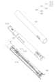
도 1은 본 발명의 제1 실시예에 따른 외과용 스테이플러를 나타낸 일 방향에서의 사시도이다.
도 2는 본 발명의 제1 실시예에 따른 외과용 스테이플러 및 이에 구비된 회전헤드부 및 노브부를 나타낸 부분 분해사시도이다.
도 3은 본 발명의 제1 실시예에 따른 외과용 스테이플러에 구비된 노브부를 나타낸 부분상세도이다.
도 4는 본 발명의 제1 실시예에 따른 외과용 스테이플러에 구비된 연장샤프트 및 엔트이펙터를 나타낸 부분상세도이다.
도 5는 본 발명의 제1 실시예에 따른 외과용 스테이플러에 구비된 툴어셈블리를 나타낸 일 방향에서의 사시도이다.
도 6은 본 발명의 제1 실시예에 따른 외과용 스테이플러에 구비된 툴어셈블리를 나타낸 일 방향에서의 분해사시도이다.
도 7의 (a)는 본 발명의 제1 실시예에 따른 외과용 스테이플러에 구비된 홀 형상의 삽입부를 나타낸 일 방향에서의 단면도이다.
도 7의 (b)는 본 발명의 제2 실시예에 따른 외과용 스테이플러에 구비된 장홀 형상의 삽입부를 나타낸 일 방향에서의 단면도이다.
도 8은 본 발명의 제1 실시예에 따른 외과용 스테이플러에 구비된 제2 아티큘레이션링크의 위치조절부가 홀 형상의 삽입부에 삽입된 것을 나타낸 일 방향에서의 측면도이다.
도 9는 본 발명의 제2 실시예에 따른 외과용 스테이플러에 구비된 제2 아티큘레이션링크의 위치조절부가 장홀 형상의 삽입부에 삽입된 것을 나타낸 일 방향에서의 측면도이다.
도 10의 (a)는 본 발명의 제1 실시예에 따른 외과용 스테이플러에 구비된 제2 아티큘레이션링크, 링크후크, 힌지부 및 위치조절부를 나타낸 정면도이다.
도 10의 (b)는 본 발명의 제1 실시예에 따른 외과용 스테이플러에 구비된 제2 아티큘레이션링크, 링크후크, 힌지부 및 위치조절부를 나타낸 측면도이다.FIG. 1 is a perspective view from one direction showing a surgical stapler according to a first embodiment of the present invention.
FIG. 2 is a partially exploded perspective view showing a surgical stapler and a rotating head and knob portion provided therein according to the first embodiment of the present invention.
FIG. 3 is a partial detailed view showing a knob portion provided in a surgical stapler according to the first embodiment of the present invention.
FIG. 4 is a partial detailed view showing an extension shaft and an end effector provided in a surgical stapler according to the first embodiment of the present invention.
FIG. 5 is a perspective view from one direction showing a tool assembly provided in a surgical stapler according to the first embodiment of the present invention.
FIG. 6 is an exploded perspective view in one direction showing a tool assembly provided in a surgical stapler according to the first embodiment of the present invention.
Fig. 7 (a) is a cross-sectional view in one direction showing a hole-shaped insertion part provided in a surgical stapler according to the first embodiment of the present invention.
Fig. 7 (b) is a cross-sectional view in one direction showing an insertion portion in the shape of a long hole provided in a surgical stapler according to the second embodiment of the present invention.
FIG. 8 is a side view in one direction showing that the position adjustment part of the second articulation link provided in the surgical stapler according to the first embodiment of the present invention is inserted into the hole-shaped insertion part.
FIG. 9 is a side view in one direction showing that the position adjustment part of the second articulation link equipped in the surgical stapler according to the second embodiment of the present invention is inserted into the insertion part having a long hole shape.
FIG. 10 (a) is a front view showing a second articulation link, a link hook, a hinge part, and a position adjustment part provided in a surgical stapler according to the first embodiment of the present invention.
FIG. 10 (b) is a side view showing a second articulation link, a link hook, a hinge part, and a position adjustment part provided in a surgical stapler according to the first embodiment of the present invention.
이하에서는 첨부한 도면을 참조하여 본 발명을 설명하기로 한다. 그러나 본 발명은 여러 가지 상이한 형태로 구현될 수 있으며, 따라서 여기에서 설명하는 실시예로 한정되는 것은 아니다. 그리고 도면에서 본 발명을 명확하게 설명하기 위해서 설명과 관계없는 부분은 생략하였으며, 명세서 전체를 통하여 유사한 부분에 대해서는 유사한 도면 부호를 붙였다.Hereinafter, the present invention will be described with reference to the attached drawings. However, the present invention can be implemented in various different forms, and therefore is not limited to the embodiments described herein. In addition, in order to clearly describe the present invention in the drawings, parts that are not related to the description are omitted, and similar parts are assigned similar drawing reference numerals throughout the specification.
명세서 전체에서, 어떤 부분이 다른 부분과 "연결(접속, 접촉, 결합)"되어 있다고 할 때, 이는 "직접적으로 연결"되어 있는 경우뿐 아니라, 그 중간에 다른 부재를 사이에 두고 "간접적으로 연결"되어 있는 경우도 포함한다. 또한 어떤 부분이 어떤 구성요소를 "포함"한다고 할 때, 이는 특별히 반대되는 기재가 없는 한 다른 구성요소를 제외하는 것이 아니라 다른 구성요소를 더 구비할 수 있다는 것을 의미한다.Throughout the specification, when a part is said to be "connected (connected, contacted, joined)" to another part, this includes not only the case where it is "directly connected" but also the case where it is "indirectly connected" with another member in between. Also, when a part is said to "include" a certain component, this does not mean that other components are excluded, unless otherwise specifically stated, but that other components can be included.
본 명세서에서 사용한 용어는 단지 특정한 실시예를 설명하기 위해 사용된 것으로, 본 발명을 한정하려는 의도가 아니다. 단수의 표현은 문맥상 명백하게 다르게 뜻하지 않는 한, 복수의 표현을 포함한다. 본 명세서에서, "포함하다" 또는 "가지다" 등의 용어는 명세서상에 기재된 특징, 숫자, 단계, 동작, 구성요소, 부품 또는 이들을 조합한 것이 존재함을 지정하려는 것이지, 하나 또는 그 이상의 다른 특징들이나 숫자, 단계, 동작, 구성요소, 부품 또는 이들을 조합한 것들의 존재 또는 부가 가능성을 미리 배제하지 않는 것으로 이해되어야 한다.The terminology used herein is for the purpose of describing particular embodiments only and is not intended to be limiting of the present invention. The singular expression includes the plural expression unless the context clearly indicates otherwise. As used herein, the terms "comprises" or "has" and the like are intended to specify the presence of a feature, number, step, operation, component, part or combination thereof described in the specification, but should be understood to not exclude in advance the possibility of the presence or addition of one or more other features, numbers, steps, operations, components, parts or combinations thereof.
이하 첨부된 도면을 참고하여 본 발명의 실시예를 상세히 설명하기로 한다.Hereinafter, an embodiment of the present invention will be described in detail with reference to the attached drawings.
이하, 도 1 내지 도 10을 참조하여 본 발명의 제1, 2 실시예에 따른 외과용 스테이플러를 설명하도록 한다.Hereinafter, a surgical stapler according to the first and second embodiments of the present invention will be described with reference to FIGS. 1 to 10.
도 1은 본 발명의 제1 실시예에 따른 외과용 스테이플러를 나타낸 일 방향에서의 사시도이다.FIG. 1 is a perspective view from one direction showing a surgical stapler according to a first embodiment of the present invention.
도 1을 참조하면, 본 발명의 제1 실시예에 따른 외과용 스테이플러는 핸들어셈블리(100), 연장샤프트(200) 및 툴어셈블리(300)를 포함한다.Referring to FIG. 1, a surgical stapler according to the first embodiment of the present invention includes a handle assembly (100), an extension shaft (200), and a tool assembly (300).
핸들어셈블리(100)는 수술부위의 절단과 문합을 위해 사용자가 조작한다.The handle assembly (100) is operated by the user for cutting and anastomosis of the surgical site.
핸들어셈블리(100)는 지지손잡이부(110), 조작손잡이부(120), 당김부(130), 회전헤드부(140), 노브부(150) 및 컨트롤 로드(160)를 포함한다.The handle assembly (100) includes a support handle portion (110), an operating handle portion (120), a pulling portion (130), a rotating head portion (140), a knob portion (150), and a control rod (160).
지지손잡이부(110)는 사용자에 의해 파지되는 부분으로서, 사용자의 그립감을 위해 인체공학적으로 형성될 수 있다.The support handle part (110) is a part that is held by the user and can be ergonomically formed to provide a comfortable grip for the user.
조작손잡이부(120)는 지지손잡이부(110)와 힌지 결합되고, 지지손잡이부(110)의 전방에 배치된다The operating handle part (120) is hinge-connected to the support handle part (110) and is positioned in front of the support handle part (110).
당김부(130)는 지지손잡이부(110)에 슬라이드 이동 가능하게 결합된다.The pulling part (130) is slidably connected to the support handle part (110).
구체적으로 당김부(130)는 지지손잡이부(110)의 상부 길이 방향을 따라 슬라이드 이동되도록 한다.Specifically, the pulling part (130) is configured to slide along the upper longitudinal direction of the support handle part (110).
이를 위한 당김부(130)는 지지손잡이부(110)의 상부에 배치된다.The pulling part (130) for this purpose is placed on the upper part of the support handle part (110).
도 2는 본 발명의 제1 실시예에 따른 외과용 스테이플러 및 이에 구비된 회전헤드부 및 노브부를 나타낸 부분 분해사시도이다. 도 3은 본 발명의 제1 실시예에 따른 외과용 스테이플러에 구비된 노브부를 나타낸 부분상세도이다.Fig. 2 is a partially exploded perspective view showing a surgical stapler according to a first embodiment of the present invention and a rotating head and a knob part provided therein. Fig. 3 is a partially detailed view showing a knob part provided in a surgical stapler according to the first embodiment of the present invention.
회전헤드부(140)는 지지손잡이부(110)에 결합된다.The rotating head part (140) is connected to the support handle part (110).
또한, 회전헤드부(140)는 지지손잡이부(110)에 회전 가능하게 결합된다.Additionally, the rotating head part (140) is rotatably connected to the support handle part (110).
또한, 회전헤드부(140)은 당김부(130)의 원위에 배치된다.Additionally, the rotating head part (140) is placed on the circumference of the pulling part (130).
도 1 내지 도 3을 참조하면, 회전헤드부(140)는 제1 회전헤드(141) 및 제2 회전헤드(142)를 포함한다.Referring to FIGS. 1 to 3, the rotary head portion (140) includes a first rotary head (141) and a second rotary head (142).
제1 회전헤드(141)는 연장샤프트(200)의 길이방향을 따라 연장된다.The first rotary head (141) extends along the length of the extension shaft (200).
또한, 제1 회전헤드(141)의 일측부는 지지손잡이부(110)의 타측 하부에 결합된다.Additionally, one side of the first rotary head (141) is connected to the lower part of the other side of the support handle (110).
제2 회전헤드(142)는 연장샤프트(200)의 길이방향을 따라 연장되고, 제1 회전헤드(141)와 상응하도록 형성된다.The second rotary head (142) extends along the longitudinal direction of the extension shaft (200) and is formed to correspond to the first rotary head (141).
또한, 제2 회전헤드(142)의 상부 중앙부에는 상하방향으로 관통하는 회전헤드홀(142a)이 형성되고, 이러한 회전헤드홀(142a)에는 후술되는 노브(151)의 하단부가 삽입된다.In addition, a rotation head hole (142a) penetrating in the upper central portion of the second rotation head (142) is formed, and the lower portion of a knob (151) described later is inserted into this rotation head hole (142a).
노브부(150)는 툴어셈블리(300)의 피벗 운동을 위해 사용자가 조작하는 부분이고, 노드부(150)의 하단부는 적어도 일부가 회전헤드부(140)의 상부에 위치하도록 회전헤드부(140)의 내부에 위치한다.The knob portion (150) is a portion that the user operates for pivot movement of the tool assembly (300), and the lower portion of the node portion (150) is located inside the rotary head portion (140) so that at least a portion thereof is located above the rotary head portion (140).
도 2및 도 3을 참조하면, 노브부(150)는 노브(151), 체결블럭(152), 이동부재(153), 회전부재(154), 핀부재(155), 탄성부재(156), 지지블럭(157) 및 가이드부재(158)를 포함한다.Referring to FIGS. 2 and 3, the knob portion (150) includes a knob (151), a fastening block (152), a moving member (153), a rotating member (154), a pin member (155), an elastic member (156), a support block (157), and a guide member (158).
노브(151)는 회전헤드부(140)의 상부에 위치하여 회전 가능하다.The knob (151) is located at the top of the rotary head (140) and can rotate.
노브(151)는 회전부재(154)와 결합됨에 따라 외력에 의하여 상기 노브(151)가 회전될 때 회전부재(154)를 회전시킨다.As the knob (151) is combined with the rotary member (154), when the knob (151) is rotated by an external force, the rotary member (154) is rotated.
체결블럭(152)은 회전헤드부(140)의 내부에 위치한다.The fastening block (152) is located inside the rotating head part (140).
구체적으로 체결블럭(152)은 이동부재(153)의 수평이동 여부와 회전부재(154)의 회전 여부를 결정한다. 체결블럭(152)은 회전헤드부(140)에 내장된 상태로 슬라이드 이동된다. 일예로, 체결블럭(152)은 툴어셈블리(300)의 결합 여부에 따라 슬라이드 이동될 수 있다.Specifically, the fastening block (152) determines whether the movable member (153) moves horizontally and whether the rotating member (154) rotates. The fastening block (152) slides while being built into the rotating head (140). For example, the fastening block (152) can slide depending on whether the tool assembly (300) is engaged.
도 2 및 도 3을 참조하면, 이동부재(153)는 상하방향으로 관통하는 관통홀이 형성되고 체결블럭(152)의 상부 및 측부에 밀착되어 제1 아티큘레이션링크(220)에 결합된다.Referring to FIGS. 2 and 3, the movable member (153) is formed with a through hole extending vertically and is attached to the upper and side of the fastening block (152) and coupled to the first articulation link (220).
이동부재(153)에는 핀부재(155)와 결합되는 결합부가 형성되어 있으며, 이동부재(153)는 핀부재(155)가 회전하는 동안 핀부재(155)의 회전방향을 따라 핀부재(155)와 함께 이동한다. 결합부는 핀부재(155)의 종횡비와 동일한 종횡비를 갖는 관통홀 또는 삽입홈의 형태를 가질 수 있다. 즉, 핀부재(155)의 단면형상과 결합부의 단면형상의 종횡비가 동일하다. 본 실시예에서 결합부는 관통홀의 형태를 가진다.A joint portion that is coupled with a pin member (155) is formed in the movable member (153), and the movable member (153) moves together with the pin member (155) along the rotational direction of the pin member (155) while the pin member (155) rotates. The joint portion may have a shape of a through hole or insertion groove having the same aspect ratio as that of the pin member (155). That is, the aspect ratio of the cross-sectional shape of the pin member (155) and the cross-sectional shape of the joint portion are the same. In the present embodiment, the joint portion has the shape of a through hole.
이동부재(153)가 회전부재(154)의 회전중심을 기준으로 핀부재(155)의 회전방향을 따라 이동되면, 이동부재(153)가 움직인 궤적은 연장샤프트(200)의 길이방향으로 이동한 수평거리와 연장샤프트의 길이방향에 수직한 방향으로 이동한 수직거리의 벡터합으로 나타나게 된다. 여기서, 이동부재(153)는 연장샤프트(200)의 길이방향으로 이동한 수평거리만큼 제1 아티큘레이션링크(220)를 수평이동 시키게 된다.When the movable member (153) moves along the rotational direction of the pin member (155) based on the rotational center of the rotary member (154), the trajectory along which the movable member (153) moves is expressed as the vector sum of the horizontal distance moved in the longitudinal direction of the extension shaft (200) and the vertical distance moved in the direction perpendicular to the longitudinal direction of the extension shaft. Here, the movable member (153) moves the first articulation link (220) horizontally by the horizontal distance moved in the longitudinal direction of the extension shaft (200).
이동부재(153)는 수평부재(도면번호 미부여), 수직부재(도면번호 미부여) 및 걸림부재(도면번호 미부여)를 포함한다.The movable member (153) includes a horizontal member (drawing number not assigned), a vertical member (drawing number not assigned), and a hanging member (drawing number not assigned).
수평부재는 체결블럭(152)의 상면에 밀착되어 슬라이딩 가능하다.The horizontal member is in close contact with the upper surface of the fastening block (152) and can slide.
구체적으로 수평부재는 소정의 두께를 가지는 평판 형상을 가질 수 있다.Specifically, the horizontal member may have a flat plate shape with a predetermined thickness.
또한, 수평부재의 일측부에는 한 쌍의 결합부재가 서로 이격되도록 형성되고, 한 쌍의 결합부재 사이에는 결합홈(미도시)이 형성된다.In addition, a pair of connecting members are formed spaced apart from each other on one side of the horizontal member, and a connecting groove (not shown) is formed between the pair of connecting members.
수직부재는 체결블럭(152)의 측부에 밀착되도록 수평부재의 타측부로부터 하부로 연장된다. 이에 따른 수직부재는 수평부재와 수직하게 된다.The vertical member extends downward from the other side of the horizontal member so as to be in close contact with the side of the fastening block (152). Accordingly, the vertical member becomes perpendicular to the horizontal member.
걸림부재는 수직부재의 타측부로부터 수평부재와 평행하도록 연장된다.The catch member extends from the other side of the vertical member parallel to the horizontal member.
특히, 도 3을 참조하면, 걸림부재는 제1 아티큘레이션링크(220)의 일측부에 관통 형성되는 연결홀(미도시)과 상응하도록 형성되어 연결홀에 삽입됨에 따라 걸림부재의 수평이동 시 제1 아티큘레이션링크(220)를 수평이동시킨다.In particular, referring to FIG. 3, the engaging member is formed to correspond to a connecting hole (not shown) formed penetrating one side of the first articulation link (220), and when inserted into the connecting hole, the first articulation link (220) moves horizontally when the engaging member moves horizontally.
결합홈은 수평부재의 일측부에 서로 이격되도록 형성되는 한 쌍의 결합부재 사이에 형성되고, 결합홈에는 체결블럭(152)의 일측 상부에 형성되는 스토퍼(미도시)가 삽입된다.A joining groove is formed between a pair of joining members that are formed to be spaced apart from each other on one side of a horizontal member, and a stopper (not shown) formed on the upper side of one side of a fastening block (152) is inserted into the joining groove.
관통홀(도면번호 미부여)은 핀부재(155)의 하측부와 상응하도록 수평부재에 형성된다.A through hole (drawing number not given) is formed in the horizontal member to correspond to the lower part of the pin member (155).
관통홀의 하부 내경은 관통홀의 상부 내경보다 크게 형성된다.The lower inner diameter of the through hole is formed larger than the upper inner diameter of the through hole.
이에 따른 관통홀은 관통홀의 상부와 관통홀의 하부로 이루어져 단차지도록 형성된다.The through hole according to this is formed in a stepped manner, consisting of an upper part of the through hole and a lower part of the through hole.
나아가, 본 발명에서는 핀부재(155)의 횡단면이 원형으로 설명되고 있으나, 이에 한정되는 것은 아니며, 예시적으로 핀부재(155)의 횡단면은 타원형이거나 다각형일 수 있고, 이에 따라 관통홀 역시 핀부재(155)와 상응하도록 형성될 수 있다.Furthermore, in the present invention, the cross-section of the pin member (155) is described as being circular, but is not limited thereto. For example, the cross-section of the pin member (155) may be elliptical or polygonal, and accordingly, the through hole may also be formed to correspond to the pin member (155).
도 3을 참조하면, 회전부재(154)는 가이드부재(158)의 내부에 위치하여 노브(151)와 결합된다. 즉, 가이드부재(154)는 회전부재(154)를 둘러싸도록 배치된다.Referring to FIG. 3, the rotary member (154) is positioned inside the guide member (158) and is coupled with the knob (151). That is, the guide member (154) is arranged to surround the rotary member (154).
회전부재(154)의 하면에는 제1 회전부재홈(154a)이 형성되고, 제1 회전부재홈(154a)에는 핀부재(155)가 삽입된다A first rotation member groove (154a) is formed on the lower surface of the rotation member (154), and a pin member (155) is inserted into the first rotation member groove (154a).
제1 회전부재홈(154a)은 회전부재(154)의 하부로부터 상방으로 함입되도록 형성될 수 있다.The first rotary member home (154a) can be formed to be inserted upward from the bottom of the rotary member (154).
회전부재(154)의 상면에는 한 쌍의 제2 회전부재홈(154b)이 형성되고, 한 상의 제2 회전부재홈(154b)에는 노브(151)의 하부로부터 하방으로 돌출되는 한 쌍의 회전걸림부재(미도시)가 삽입된다.A pair of second rotation member grooves (154b) are formed on the upper surface of the rotation member (154), and a pair of rotation engaging members (not shown) protruding downward from the lower portion of the knob (151) are inserted into one of the second rotation member grooves (154b).
핀부재(155)는 제1 회전부재홈(154a)과 관통홀에 삽입되어 노브(151)의 회전 시 이동부재(153)를 이동시킨다.The pin member (155) is inserted into the first rotating member groove (154a) and the through hole to move the moving member (153) when the knob (151) is rotated.
보다 상세하게, 핀부재(155)는 회전부재(154)의 회전중심에 대하여 편심된 위치에서 상기 회전부재(154)와 결합되어 상기 회전부재(154)의 회전중심을 기준으로 상기 회전부재(154)와 함께 회전한다.More specifically, the pin member (155) is coupled to the rotating member (154) at an eccentric position with respect to the center of rotation of the rotating member (154) and rotates together with the rotating member (154) with respect to the center of rotation of the rotating member (154).
또한, 도 2를 참조하면, 핀부재(155)는 회전체로 형성되고, 이러한 핀부재(155)의 하측 외주면에는 외측방향으로 돌출되는 단턱부재(미도시)가 형성된다.In addition, referring to FIG. 2, the pin member (155) is formed as a rotating body, and a step member (not shown) protruding outward is formed on the lower outer surface of the pin member (155).
도 2 및 도 3을 참조하면, 탄성부재(156)는 회전부재(154)의 내부공간 상에 배치된다.Referring to FIGS. 2 and 3, the elastic member (156) is placed on the internal space of the rotating member (154).
구체적으로 탄성부재(156)의 일단은 회전부재(154)의 내부 일측면에 밀착되고, 탄성부재(156)의 타단은 지지블럭(157)에 밀착된다.Specifically, one end of the elastic member (156) is in close contact with one side of the inner surface of the rotating member (154), and the other end of the elastic member (156) is in close contact with the support block (157).
상기한 탄성부재(156)는 회전부재(154)와 지지블럭(157)로 탄성력을 제공한다.The above-mentioned elastic member (156) provides elasticity to the rotating member (154) and the support block (157).
도 2 및 도 3을 참조하면, 지지블럭(157)은 회전부재(154)의 내부에 위치하여 탄성부재(156)의 타단을 지지한다. 즉, 지지블럭(157)은 탄성부재(156)의 일측을 지지하면서 상기 가이드부재(158)의 내주면과 선택적으로 결합된다.Referring to FIGS. 2 and 3, the support block (157) is positioned inside the rotating member (154) and supports the other end of the elastic member (156). That is, the support block (157) supports one side of the elastic member (156) and is selectively coupled with the inner surface of the guide member (158).
가이드부재(158)의 내주면 일부영역에는 다수의 치합부재(미도시)가 구비되고, 가이드부재(158)의 내주면과 대향되는 지지블럭(157)의 일측면에는 다수의 치형부재(미도시)가 구비되어 서로 치형결합 될 수 있다.A plurality of engagement members (not shown) are provided on a portion of the inner surface of the guide member (158), and a plurality of tooth members (not shown) are provided on one side of the support block (157) facing the inner surface of the guide member (158) so that they can be tooth-connected with each other.
결과적으로, 노브(151)의 회전 시 회전부재(154)가 회전함에 따라 지지블럭(157)도 회전부재(154)와 함께 회전하게 되는데, 지지블럭(157)은 회전부재(154)의 내부공간에서 탄성부재(156)에 의하여 탄성지지 됨으로써 지지블럭(157)의 치형부재와 가이드부재(158)의 치합부재의 결합여부에 따라 회전부재(154)와 가이드부재(158) 사이를 이동하게 된다.As a result, as the rotary member (154) rotates when the knob (151) rotates, the support block (157) also rotates together with the rotary member (154). Since the support block (157) is elastically supported by the elastic member (156) in the internal space of the rotary member (154), it moves between the rotary member (154) and the guide member (158) depending on whether the tooth member of the support block (157) and the engagement member of the guide member (158) are engaged.
즉, 지지블럭(157)의 치형부재는 회전부재(154)를 통과하여 가이드부재(158)의 내측면에 결합된다.That is, the tooth member of the support block (157) passes through the rotating member (154) and is joined to the inner surface of the guide member (158).
가이드부재(158)는 이동부재(153)의 상부에 위치하도록 회전헤드부(140)의 내부에 배치된다.The guide member (158) is placed inside the rotating head part (140) so as to be positioned above the moving member (153).
상기 가이드부재(158)는 노브(151)의 회전 시 회전부재(154)가 제자리에서 회전할 수 있도록 안내한다.The above guide member (158) guides the rotating member (154) to rotate in place when the knob (151) rotates.
컨트롤로드(160)는 지지손잡이부(110)에서 연장되고, 회전헤드부(140)를 관통한다.The control rod (160) extends from the support handle part (110) and passes through the rotating head part (140).
도 4는 본 발명의 제1 실시예에 따른 외과용 스테이플러에 구비된 연장샤프트 및 엔트이펙터를 나타낸 부분상세도이다.FIG. 4 is a partial detailed view showing an extension shaft and an end effector provided in a surgical stapler according to the first embodiment of the present invention.
도 1 및 도 4를 참조하면, 연장샤프트(200)는 연결부(210) 및 제1 아티큘레이션링크(220)를 포함한다.Referring to FIGS. 1 and 4, the extension shaft (200) includes a connecting portion (210) and a first articulation link (220).
연결부(210)는 핸들어셈블리(100)의 길이방향을 따라 배치된다.The connecting portion (210) is arranged along the longitudinal direction of the handle assembly (100).
상기한 연결부(210)는 베이스부재(211) 및 커버부재(212)를 포함한다.The above-mentioned connecting member (210) includes a base member (211) and a cover member (212).
또한, 베이스부재(211)는 핸들어셈블리(140)의 길이방향을 따라 배치되고, 커버부재(212)의 내부에 위치한다.Additionally, the base member (211) is arranged along the longitudinal direction of the handle assembly (140) and is located inside the cover member (212).
제1 아티큘레이션링크(220)의 일측부에 형성되는 연결홀에는 이동부재(153)의 걸림부재가 삽입된다.A catch member of a moving member (153) is inserted into a connecting hole formed on one side of the first articulation link (220).
또한, 베이스부재(211)의 일측에는 제1 아티큘레이션링크(220)가 구비된다.Additionally, a first articulation link (220) is provided on one side of the base member (211).
도 4를 참조하면, 베이스부재(211)에는 제1 아티큘레이션링크(220)가 베이스부재(211)로 삽입된다.Referring to FIG. 4, a first articulation link (220) is inserted into the base member (211).
도 4를 참조하면, 커버부재(212)는 베이스부재(211)를 둘러싸도록 형성되고, 이러한 커버부재(212)는 외부로부터 전달되는 충격으로부터 베이스부재(211)를 보호하는 역할을 한다.Referring to FIG. 4, the cover member (212) is formed to surround the base member (211), and this cover member (212) serves to protect the base member (211) from impact transmitted from the outside.
도 3 및 도 4를 참조하면, 제1 아티큘레이션링크(220)는 연결부(210)의 내부에 위치하여 노브부(150), 즉 이동부재(153)에 결합된다.Referring to FIGS. 3 and 4, the first articulation link (220) is located inside the connecting portion (210) and is coupled to the knob portion (150), i.e., the moving member (153).
구체적으로 도 4를 참조하면, 제1 아티큘레이션링크(220)는 연장샤프트(200)의 길이방향으로 길게 형성되고, 소정의 두께를 갖는다.Specifically, referring to FIG. 4, the first articulation link (220) is formed long in the longitudinal direction of the extension shaft (200) and has a predetermined thickness.
또한, 제1 아티큘레이션링크(220)의 일측부에는 도 3에 도시된 바와 같이 제1 아티큘레이션링크(220)를 수직하도록 관통하는 연결홀이 형성되고, 제1 아티큘레이션링크(220)의 타측부에는 도 4에 도시된 바와 같이 후술되는 링크후크(331)와 결합되는 후크 형상의 연결후크(222)가 형성된다.In addition, a connecting hole that penetrates the first articulation link (220) vertically is formed on one side of the first articulation link (220) as illustrated in FIG. 3, and a hook-shaped connecting hook (222) that is combined with a link hook (331) described later is formed on the other side of the first articulation link (220) as illustrated in FIG. 4.
도 4를 참조하면, 연결후크(222)는 제1 아티큘레이션링크(220)의 타측부에 후크 형상으로 형성되어 링크후크(331)에 결합된다.Referring to FIG. 4, a connecting hook (222) is formed in a hook shape on the other side of the first articulation link (220) and is connected to a link hook (331).
도 5는 본 발명의 제1 실시예에 따른 외과용 스테이플러에 구비된 툴어셈블리를 나타낸 일 방향에서의 사시도이다.FIG. 5 is a perspective view from one direction showing a tool assembly provided in a surgical stapler according to the first embodiment of the present invention.
도 5를 참조하면, 툴어셈블리(300)는 피벗축(301), 편심연결부재(302), 스테이플샤프트(310), 엔드이펙터(320) 및 제2 아티큘레이션링크(330)를 포함한다.Referring to FIG. 5, the tool assembly (300) includes a pivot shaft (301), an eccentric connecting member (302), a staple shaft (310), an end effector (320), and a second articulation link (330).
피벗축(301)은 스테이플샤프트(310)와 엔드이펙터(320) 사이에 위치하는 편심연결부재(302), 스테이플샤프트(310)의 타측부 및 엔드이펙터(320)의 일측부에 삽입되어 엔드이펙터(320)가 편심연결부재(302)를 기준으로 피벗운동할 수 있도록 지원한다.A pivot shaft (301) is inserted into an eccentric connecting member (302) located between a staple shaft (310) and an end effector (320), the other side of the staple shaft (310) and one side of the end effector (320), and supports the end effector (320) to pivot relative to the eccentric connecting member (302).
편심연결부재(302)는 스테이플샤프트(310)와 엔드이펙터(320) 사이에 위치한다.The eccentric connecting member (302) is located between the staple shaft (310) and the end effector (320).
도 6은 본 발명의 제1 실시예에 따른 외과용 스테이플러에 구비된 툴어셈블리를 나타낸 일 방향에서의 분해사시도이다.FIG. 6 is an exploded perspective view in one direction showing a tool assembly provided in a surgical stapler according to the first embodiment of the present invention.
도 6을 참조하면, 스테이플샤프트(310)는 연장샤프트(200)의 길이방향을 따라 배치된다.Referring to FIG. 6, the staple shaft (310) is arranged along the longitudinal direction of the extension shaft (200).
스테이플샤프트(310)는 지지부재(311) 및 외관부재(312)를 포함한다.The staple shaft (310) includes a support member (311) and an exterior member (312).
지지부재(311)는 연장샤프트(200)의 길이방향을 따라 배치된다.The support member (311) is arranged along the length of the extension shaft (200).
지지부재(311)는 하부 지지부재(311a) 및 상부 지지부재(311e)를 포함한다.The support member (311) includes a lower support member (311a) and an upper support member (311e).
도 7의 (a)는 본 발명의 제1 실시예에 따른 외과용 스테이플러에 구비된 홀 형상의 삽입부를 나타낸 일 방향에서의 단면도이다.Fig. 7 (a) is a cross-sectional view in one direction showing a hole-shaped insertion part provided in a surgical stapler according to the first embodiment of the present invention.
도 6 및 도7의 (a)를 참조하면, 하부 지지부재(311a)는 연장샤프트(200)의 길이방향을 따라 배치되고, 상부 지지부재(311e)의 하부에 위치한다.Referring to (a) of FIG. 6 and FIG. 7, the lower support member (311a) is arranged along the longitudinal direction of the extension shaft (200) and is located below the upper support member (311e).
또한, 하부 지지부재(311a)는 상부 지지부재(311e)와 결합된다.Additionally, the lower support member (311a) is connected to the upper support member (311e).
이러한 하부 지지부재(311a)에는 제2 아티큘레이션링크(330)와 수직한 위치조절벽(311b)이 형성된다.A second articulation link (330) and a vertical position adjustment wall (311b) are formed on the lower support member (311a).
위치조절벽(311b)은 하부 지지부재(311a)의 내부 하측면으로부터 상방으로 연장된다.The position adjustment wall (311b) extends upward from the inner lower surface of the lower support member (311a).
예시적으로 위치조절벽(311b)은 도 6 및 도 7의 (a)에 도시된 바와 같이 직육면체 형상을 가질 수 있으나, 이에 한정되는 것은 아니다.For example, the position adjustment wall (311b) may have a rectangular parallelepiped shape as shown in (a) of FIG. 6 and FIG. 7, but is not limited thereto.
또한, 위치조절벽(311b)은 하부 지지부재와 상부 지지부재 중 어느 하나에 형성되어 제2 아티큘레이션링크와 선택적으로 결합될 수 있다.Additionally, the position adjustment wall (311b) may be formed on either the lower support member or the upper support member and may be selectively combined with the second articulation link.
예를 들면, 위치조절벽(311b)은 상부 지지부재의 내측면으로부터 하부방향으로 연장될 수 있다.For example, the position adjustment wall (311b) may extend downward from the inner surface of the upper support member.
또한, 하부 지지부재로부터 위치조절벽이 돌출 형성되는 경우에는 상부 지지부재에 위치조절벽을 수용하는 상부 조절벽 수용공간이 형성될 수 있다. 마찬가지로, 상부 지지부재로부터 위치조절벽이 돌출 형성되는 경우에는 하부 지지부재에 위치조절벽을 수용하는 하부 조절별 수용공간이 형성될 수 있다.In addition, when the position-adjusting wall is formed by protruding from the lower support member, an upper adjustment wall receiving space for receiving the position-adjusting wall may be formed in the upper support member. Similarly, when the position-adjusting wall is formed by protruding from the upper support member, a lower adjustment-specific receiving space for receiving the position-adjusting wall may be formed in the lower support member.
특히, 도 7의 (a)를 참조하면, 위치조절벽(311b)에는 제2 아티큘레이션링크(330)의 적어도 일부분이 삽입되는 삽입부(311c)가 구비된다.In particular, referring to (a) of Fig. 7, the position adjustment wall (311b) is provided with an insertion portion (311c) into which at least a portion of the second articulation link (330) is inserted.
구체적으로 제1 실시예에 따르면, 삽입부(311c)는 도 7의 (a)에 도시된 바와 같이 위치조절벽(311b)을 관통하는 홀을 형상을 가질 수 있다.Specifically, according to the first embodiment, the insertion portion (311c) may have a shape of a hole penetrating the position-adjusting wall (311b) as shown in (a) of FIG. 7.
도 7의 (b)는 본 발명의 제2 실시예에 따른 외과용 스테이플러에 구비된 장홀 형상의 삽입부를 나타낸 일 방향에서의 단면도이다.Fig. 7 (b) is a cross-sectional view in one direction showing an insertion portion in the shape of a long hole provided in a surgical stapler according to the second embodiment of the present invention.
한편, 제2 실시예에 따르면, 삽입부(311c)는 도 7의 (b)에 도시된 바와 같이 지지부재(311a)가 형성되는 길이방향을 따라 장홀 형상으로 형성된다.Meanwhile, according to the second embodiment, the insertion portion (311c) is formed in a long hole shape along the longitudinal direction in which the support member (311a) is formed, as shown in (b) of FIG. 7.
추가적으로 도 7의 (b)를 참조하면, 삽입부(311c)가 형성되는 내측면 중 일측면에는 지지부재(311a)의 길이방향과 수직한 방향으로 위치조절돌기(311d)가 돌출 형성된다.Additionally, referring to (b) of Fig. 7, a position-adjusting protrusion (311d) is formed to protrude in a direction perpendicular to the longitudinal direction of the support member (311a) on one of the inner surfaces where the insertion portion (311c) is formed.
전술한 제1, 2 실시예에 따르면, 삽입부(311c)에는 제2 아티큘레이션링크(330)에 구비된 위치조절부(333)가 삽입된다.According to the first and second embodiments described above, a position adjustment part (333) provided in the second articulation link (330) is inserted into the insertion part (311c).
결과적으로, 위치조절부(333)는 초기에 삽입부(311c)에 삽입되어 안정적으로 위치를 유지하다가 일정 힘 이상의 외력에 의하여 제2 아티큘레이션링크(330)가 직선이동을 하게 되면 위치조절부(333)는 삽입부(311c)에서 벗어나게 된다.As a result, the position adjustment part (333) is initially inserted into the insertion part (311c) and stably maintains the position, but when the second articulation link (330) moves linearly due to an external force greater than a certain force, the position adjustment part (333) comes out of the insertion part (311c).
물론, 본 발명은 상술한 실시 예에 한정되지 않고, 위치조절벽에는 위치조절돌기가 돌출 형성되고, 위치조절부는 제2 아티큘레이션링크의 측면에 홈 형상으로 구비될 수도 있다.Of course, the present invention is not limited to the above-described embodiment, and a position-adjusting protrusion may be formed protrudingly on the position-adjusting wall, and the position-adjusting portion may be provided in a groove shape on the side of the second articulation link.
도 8은 본 발명의 제1 실시예에 따른 외과용 스테이플러에 구비된 제2 아티큘레이션링크의 위치조절부가 홀 형상의 삽입부에 삽입된 것을 나타낸 일 방향에서의 측면도이다.FIG. 8 is a side view in one direction showing that the position adjustment part of the second articulation link provided in the surgical stapler according to the first embodiment of the present invention is inserted into the hole-shaped insertion part.
제1 실시예에 따르면, 삽입부(311c)에는 도 8에 도시된 바와 같이 제2 아티큘레이션링크(330)에 구비된 위치조절부(333)가 삽입된다.According to the first embodiment, a position adjustment part (333) provided in the second articulation link (330) is inserted into the insertion part (311c) as shown in FIG. 8.
도 9는 본 발명의 제2 실시예에 따른 외과용 스테이플러에 구비된 제2 아티큘레이션링크의 위치조절부가 장홀 형상의 삽입부에 삽입된 것을 나타낸 일 방향에서의 측면도이다.FIG. 9 is a side view in one direction showing that the position adjustment part of the second articulation link equipped in the surgical stapler according to the second embodiment of the present invention is inserted into the insertion part having a long hole shape.
제2 실시예에 따르면, 삽입부(311c)에는 도 9에 도시된 바와 같이 제2 아티큘레이션링크(330)에 구비된 위치조절부(333)가 삽입된다.According to the second embodiment, a position adjustment part (333) provided in the second articulation link (330) is inserted into the insertion part (311c) as shown in FIG. 9.
도 6을 참조하면, 상부 지지부재(311e)는 하부 지지부재(311a)의 상부에 결합된다.Referring to Fig. 6, the upper support member (311e) is connected to the upper portion of the lower support member (311a).
도 6을 참조하면, 외관부재(312)는 지지부재(311)을 둘러싸는 관 형상을 가진다.Referring to FIG. 6, the exterior member (312) has a tubular shape surrounding the support member (311).
도 5를 참조하면, 엔드이펙터(320)는 연장샤프트(200)의 길이방향을 따라 배치되되, 상기 스테이플샤프트(310)와 결합된다.Referring to FIG. 5, the end effector (320) is arranged along the longitudinal direction of the extension shaft (200) and is coupled with the staple shaft (310).
도 5를 참조하면, 제2 아티큘레이션링크(330)는 스테이플샤프트(310)의 내부에 삽입되어 제1 아티큘레이션링크(220)와 결합되고 스테이플샤프트(310)와 엔드이펙터(320) 사이에 위치하는 편심연결부재(302)에 힌지 결합된다.Referring to FIG. 5, the second articulation link (330) is inserted into the interior of the staple shaft (310) and is coupled with the first articulation link (220) and hinge-coupled to an eccentric connecting member (302) located between the staple shaft (310) and the end effector (320).
구체적으로 제2아티큘레이션링크(330)는 제1아티큘레이션링크(220)와 피벗축(301)에서 이격된 편심연결부재(302)를 연결한다.Specifically, the second articulation link (330) connects the first articulation link (220) and an eccentric connecting member (302) spaced from the pivot axis (301).
도 10의 (a)는 본 발명의 제1 실시예에 따른 외과용 스테이플러에 구비된 제2 아티큘레이션링크, 링크후크, 힌지부 및 위치조절부를 나타낸 정면도이다. 도 10의 (b)는 본 발명의 제1 실시예에 따른 외과용 스테이플러에 구비된 제2 아티큘레이션링크, 링크후크, 힌지부 및 위치조절부를 나타낸 측면도이다.Fig. 10(a) is a front view showing a second articulation link, a link hook, a hinge part, and a position adjusting part provided in a surgical stapler according to the first embodiment of the present invention. Fig. 10(b) is a side view showing a second articulation link, a link hook, a hinge part, and a position adjusting part provided in a surgical stapler according to the first embodiment of the present invention.
또한, 도 4를 참조하면, 제2아티큘레이션링크(330)의 근위단부에는 연결후크(222)와 걸림 결합되는 링크후크(331)가 구비된다.In addition, referring to FIG. 4, the proximal end of the second articulation link (330) is provided with a link hook (331) that is hooked to a connecting hook (222).
또한, 도 10의 (a), (b)를 참조하면, 제2아티큘레이션링크(330)의 원위단부에는 엔드이펙터(320)의 근위단부와 힌지 결합되는 힌지부(332)가 구비되고, 힌지부(332)에는 힌지부(332)의 중심을 관통하는 힌지부홀(332a)이 형성된다.In addition, referring to (a) and (b) of FIG. 10, a hinge part (332) that is hinge-connected to a proximal end of an end effector (320) is provided at the distal end of the second articulation link (330), and a hinge part hole (332a) that penetrates the center of the hinge part (332) is formed in the hinge part (332).
또한, 도 10의 (a), (b)를 참조하면, 제2 아티큘레이션링크(330)의 측면에는 삽입부(311c)에 삽입되어 제2 아티큘레이션링크(330)의 초기 위치를 조절하는 위치조절부(330)가 형성된다.In addition, referring to (a) and (b) of FIG. 10, a position adjusting portion (330) is formed on the side of the second articulation link (330) to be inserted into the insertion portion (311c) and adjust the initial position of the second articulation link (330).
도 10의 (a), (b)를 참조하면, 위치조절부(333)는 제2 아티큘레이션링크의 측면으로부터 멀어질수록 폭이 좁아지는 돌기형상을 가질 수 있다.Referring to (a) and (b) of FIG. 10, the position adjustment part (333) may have a protrusion shape whose width becomes narrower as it gets farther from the side of the second articulation link.
전술한 본 발명의 설명은 예시를 위한 것이며, 본 발명이 속하는 기술분야의 통상의 지식을 가진 자는 본 발명의 기술적 사상이나 필수적인 특징을 변경하지 않고서 다른 구체적인 형태로 쉽게 변형이 가능하다는 것을 이해할 수 있을 것이다. 그러므로 이상에서 기술한 실시예들은 모든 면에서 예시적인 것이며 한정적이 아닌 것으로 이해해야만 한다. 예를 들어, 단일형으로 설명되어 있는 각 구성 요소는 분산되어 실시될 수도 있으며, 마찬가지로 분산된 것으로 설명되어 있는 구성 요소들도 결합된 형태로 실시될 수 있다.The above description of the present invention is for illustrative purposes, and those skilled in the art will understand that the present invention can be easily modified into other specific forms without changing the technical idea or essential features of the present invention. Therefore, it should be understood that the embodiments described above are exemplary in all respects and not restrictive. For example, each component described as a single component may be implemented in a distributed manner, and likewise, components described as distributed may be implemented in a combined manner.
본 발명의 범위는 후술하는 특허청구범위에 의하여 나타내어지며, 특허청구범위의 의미 및 범위 그리고 그 균등 개념으로부터 도출되는 모든 변경 또는 변형된 형태가 본 발명의 범위에 포함되는 것으로 해석되어야 한다.The scope of the present invention is indicated by the claims described below, and all changes or modifications derived from the meaning and scope of the claims and their equivalent concepts should be interpreted as being included in the scope of the present invention.
100: 핸들어셈블리
110: 지지손잡이부
120: 조작손잡이부
130: 당김부
140: 회전헤드부
141: 제1 회전헤드
142: 제2 회전헤드
150: 노브부
151: 노브
152: 체결블럭
153: 이동부재
154: 회전부재
154a: 제1 회전부재홈
154b: 제2 회전부재홈
155: 핀부재
156: 탄성부재
157: 지지블럭
158: 가이드부재
160: 컨트롤 로드
200: 연장샤프트
210: 연결부
211: 베이스부재
212: 커버부재
220: 제1 아티큘레이션링크
300: 툴어셈블리
301: 피벗축
302: 편심연결부재
310: 스테이플샤프트
311: 지지부재
311a: 하부 지지부재
311b: 위치조절벽
311c: 삽입부
311d: 위치조절돌기
311e: 상부 지지부재
312: 외관부재
320: 엔드이펙터
330: 제2 아티큘레이션링크
331: 링크후크
332: 힌지부
332a: 힌지부홀
333: 위치조절부100: Handle assembly
110: Support handle
120: Control handle part
130: Pull-up part
140: Rotating head part
141: 1st rotary head
142: 2nd rotary head
150: Knob
151: Knob
152: Conclusion block
153: Absence of movement
154: Rotating member
154a: 1st rotary member home
154b: Second rotary member home
155: Pin Absence
156: Elastic member
157: Support block
158: Absence of guide
160: Control Road
200: Extension shaft
210: Connection
211: Base Absence
212: Cover Absence
220: 1st Articulation Link
300: Tool Assembly
301: Pivot axis
302: Eccentric connecting member
310: Staple Shaft
311: Absence of support
311a: Lower support member
311b: Positioning Wall
311c: Insert
311d: Position adjustment protrusion
311e: Upper support member
312: Absence of external appearance
320: End effector
330: Second Articulation Link
331: Link Hook
332: Hinge
332a: Hinge hole
333: Position control unit
Claims (6)
Translated fromKorean상기 핸들어셈블리의 길이방향을 따라 배치되는 연결부와, 상기 연결부의 내부에 위치하여 상기 노브부에 결합되는 제1 아티큘레이션링크를 포함하는 연장샤프트; 및
상기 연장샤프트의 길이방향을 따라 배치되는 지지부재를 포함하는 스테이플샤프트와, 상기 스테이플샤프트와 결합되는 엔드이펙터와, 일단은 상기 제1 아티큘레이션링크와 결합되고 타단은 상기 엔드이펙터와 결합되는 제2 아티큘레이션링크를 포함하는 툴어셈블리;를 포함하고,
상기 지지부재는 하부 지지부재 및 상기 하부 지지부재의 상부에 결합되는 상부 지지부재를 포함하며,
상기 하부 지지부재와 상기 상부 지지부재 중 어느 하나에는 상기 제2 아티큘레이션링크와 선택적으로 결합되는 위치조절벽이 상기 하부 지지부재의 상부방향 또는 상기 상부지지부재의 하부방향으로 돌출 형성되고,
상기 제2 아티큘레이션링크의 측면에는 상기 위치조절벽과 결합되어 상기 제2 아티큘레이션링크의 초기 위치를 설정하는 위치조절부가 형성되는 것을 특징으로 하는 외과용 스테이플러.
Handle assembly including knob portion;
An extension shaft including a connecting portion arranged along the longitudinal direction of the handle assembly and a first articulation link positioned inside the connecting portion and coupled to the knob portion; and
A tool assembly comprising a staple shaft including a support member arranged along the longitudinal direction of the extension shaft, an end effector coupled with the staple shaft, and a second articulation link having one end coupled with the first articulation link and the other end coupled with the end effector;
The above support member includes a lower support member and an upper support member coupled to the upper portion of the lower support member,
A position-adjusting wall, which is selectively coupled with the second articulation link, is formed to protrude upwardly of the lower support member or downwardly of the upper support member, on either of the lower support member and the upper support member.
A surgical stapler, characterized in that a position-adjusting portion is formed on a side of the second articulation link to be combined with the position-adjusting wall and set the initial position of the second articulation link.
상기 위치조절벽에는 삽입부가 형성되고, 상기 위치조절부는 상기 삽입부에 삽입되는 것을 특징으로 하는 외과용 스테이플러.
In the first paragraph,
A surgical stapler, characterized in that an insertion portion is formed in the position-adjusting wall, and the position-adjusting portion is inserted into the insertion portion.
상기 삽입부는 상기 위치조절벽을 관통하는 홀의 형상을 가지는 것을 특징으로 하는 외과용 스테이플러.
In the second paragraph,
A surgical stapler, characterized in that the insertion portion has a shape of a hole penetrating the position-adjusting wall.
상기 삽입부는 상기 지지부재가 형성되는 길이방향을 따라 장홀 형상으로 형성되는 것을 특징으로 하는 외과용 스테이플러.
In the second paragraph,
A surgical stapler, characterized in that the insertion portion is formed in a long hole shape along the longitudinal direction in which the support member is formed.
상기 삽입부가 형성되는 내측면 중 일측면에는 상기 지지부재의 길이방향과 수직한 방향으로 위치조절돌기가 돌출 형성되는 것을 특징으로 하는 외과용 스테이플러.
In the fourth paragraph,
A surgical stapler characterized in that a position-adjusting protrusion is formed protruding in a direction perpendicular to the longitudinal direction of the support member on one of the inner surfaces where the insertion portion is formed.
상기 위치조절부는 상기 제2 아티큘레이션링크의 측면으로부터 멀어질수록 폭이 좁아지는 돌기 형상을 갖는 것을 특징으로 하는 외과용 스테이플러.In the first paragraph,
A surgical stapler characterized in that the position adjustment part has a protrusion shape whose width becomes narrower as it gets farther from the side of the second articulation link.
Priority Applications (1)
| Application Number | Priority Date | Filing Date | Title |
|---|---|---|---|
| KR1020240104222AKR102727389B1 (en) | 2024-08-05 | 2024-08-05 | A surgical stapler |
Applications Claiming Priority (1)
| Application Number | Priority Date | Filing Date | Title |
|---|---|---|---|
| KR1020240104222AKR102727389B1 (en) | 2024-08-05 | 2024-08-05 | A surgical stapler |
Publications (1)
| Publication Number | Publication Date |
|---|---|
| KR102727389B1true KR102727389B1 (en) | 2024-11-07 |
Family
ID=93462605
Family Applications (1)
| Application Number | Title | Priority Date | Filing Date |
|---|---|---|---|
| KR1020240104222AActiveKR102727389B1 (en) | 2024-08-05 | 2024-08-05 | A surgical stapler |
Country Status (1)
| Country | Link |
|---|---|
| KR (1) | KR102727389B1 (en) |
Citations (4)
| Publication number | Priority date | Publication date | Assignee | Title |
|---|---|---|---|---|
| JP2011240148A (en)* | 2001-10-05 | 2011-12-01 | Tyco Healthcare Group Lp | Surgical stapling device |
| JP2013009973A (en)* | 2006-10-06 | 2013-01-17 | Tyco Healthcare Group Lp | Surgical instrument with articulating tool assembly |
| JP2017500148A (en)* | 2013-12-23 | 2017-01-05 | エシコン・エンド−サージェリィ・エルエルシーEthicon Endo−Surgery, LLC | Surgical instrument having articulatable shaft arrangement |
| KR101760824B1 (en)* | 2016-08-12 | 2017-07-24 | 주식회사 메디튤립 | Knob unit for articulation of end-effector and surgical stapling device using the knob unit |
- 2024
- 2024-08-05KRKR1020240104222Apatent/KR102727389B1/enactiveActive
Patent Citations (4)
| Publication number | Priority date | Publication date | Assignee | Title |
|---|---|---|---|---|
| JP2011240148A (en)* | 2001-10-05 | 2011-12-01 | Tyco Healthcare Group Lp | Surgical stapling device |
| JP2013009973A (en)* | 2006-10-06 | 2013-01-17 | Tyco Healthcare Group Lp | Surgical instrument with articulating tool assembly |
| JP2017500148A (en)* | 2013-12-23 | 2017-01-05 | エシコン・エンド−サージェリィ・エルエルシーEthicon Endo−Surgery, LLC | Surgical instrument having articulatable shaft arrangement |
| KR101760824B1 (en)* | 2016-08-12 | 2017-07-24 | 주식회사 메디튤립 | Knob unit for articulation of end-effector and surgical stapling device using the knob unit |
Similar Documents
| Publication | Publication Date | Title |
|---|---|---|
| US20240268823A1 (en) | Surgical stapling end effector component with tip having varying bend angle | |
| CA2473506C (en) | Surgical stapling instrument incorporating an articulation joint for a firing bar track | |
| JP5143509B2 (en) | Surgical instrument with articulating tool assembly | |
| JP2022520031A (en) | Surgical stapler with distal tip to toggle | |
| KR101760824B1 (en) | Knob unit for articulation of end-effector and surgical stapling device using the knob unit | |
| AU2004203121A1 (en) | Surgical stapling instrument incorporating a tapered firing bar for increased flexibility around the articulation joint | |
| CN102835983B (en) | Linear staplers | |
| EP4464260A1 (en) | Surgical instrument | |
| JP5704926B2 (en) | Method and apparatus for swinging a list of laparoscopic grasping instruments | |
| CA2473612C (en) | Surgical stapling instrument having articulation joint support plates for supporting a firing bar | |
| US20140131421A1 (en) | Surgical Stapler Having an Articulation Mechanism | |
| AU2007219293A1 (en) | Surgical instrument including a locking assembly | |
| JP2022049677A (en) | Range of motion for surgical stapled devices | |
| KR102727389B1 (en) | A surgical stapler | |
| CN117100342A (en) | Surgical instrument | |
| CN208031241U (en) | A kind of resist-nailed seat and its surgical instruments | |
| KR102767432B1 (en) | A surgical stapler | |
| KR102768547B1 (en) | A surgical stapler | |
| KR101330256B1 (en) | Flexible surgical tool for laparoscopic operation | |
| CN217365963U (en) | Surgical instrument | |
| JP7659888B2 (en) | Switchable laparoscopic surgical forceps | |
| CN117442267A (en) | Suture device | |
| WO2021159446A1 (en) | Surgical stapling device | |
| JP7369296B2 (en) | Swing head mechanism and medical stapler | |
| CN112401955B (en) | Driving device for intracavity surgery stitching instrument and stitching instrument |
Legal Events
| Date | Code | Title | Description |
|---|---|---|---|
| PA0109 | Patent application | Patent event code:PA01091R01D Comment text:Patent Application Patent event date:20240805 | |
| PA0201 | Request for examination | Patent event code:PA02011R01I Patent event date:20240805 Comment text:Patent Application | |
| PA0302 | Request for accelerated examination | Patent event date:20240821 Patent event code:PA03022R01D Comment text:Request for Accelerated Examination | |
| E701 | Decision to grant or registration of patent right | ||
| PE0701 | Decision of registration | Patent event code:PE07011S01D Comment text:Decision to Grant Registration Patent event date:20241028 | |
| GRNT | Written decision to grant | ||
| PR0701 | Registration of establishment | Comment text:Registration of Establishment Patent event date:20241104 Patent event code:PR07011E01D | |
| PR1002 | Payment of registration fee | Payment date:20241104 End annual number:3 Start annual number:1 | |
| PG1601 | Publication of registration |