KR102725243B1 - Electronic device comprising image sensor and method of operation thereof - Google Patents
Electronic device comprising image sensor and method of operation thereofDownload PDFInfo
- Publication number
- KR102725243B1 KR102725243B1KR1020190172916AKR20190172916AKR102725243B1KR 102725243 B1KR102725243 B1KR 102725243B1KR 1020190172916 AKR1020190172916 AKR 1020190172916AKR 20190172916 AKR20190172916 AKR 20190172916AKR 102725243 B1KR102725243 B1KR 102725243B1
- Authority
- KR
- South Korea
- Prior art keywords
- photodiode
- signal
- pixel signal
- pixel
- image sensor
- Prior art date
- Legal status (The legal status is an assumption and is not a legal conclusion. Google has not performed a legal analysis and makes no representation as to the accuracy of the status listed.)
- Active
Links
- 238000000034methodMethods0.000titleclaimsdescription15
- 230000007613environmental effectEffects0.000claimsabstractdescription98
- 238000004422calculation algorithmMethods0.000claimsdescription13
- 238000011017operating methodMethods0.000claimsdescription10
- 238000004891communicationMethods0.000description38
- 239000002131composite materialSubstances0.000description16
- 238000012545processingMethods0.000description16
- 230000006870functionEffects0.000description11
- 238000010586diagramMethods0.000description8
- 230000002194synthesizing effectEffects0.000description8
- 230000008569processEffects0.000description7
- 239000003381stabilizerSubstances0.000description5
- 238000004590computer programMethods0.000description4
- 230000000712assemblyEffects0.000description3
- 238000000429assemblyMethods0.000description3
- 230000003287optical effectEffects0.000description3
- 230000004044responseEffects0.000description3
- 230000001133accelerationEffects0.000description2
- 230000015572biosynthetic processEffects0.000description2
- 238000004364calculation methodMethods0.000description2
- 230000000295complement effectEffects0.000description2
- 230000000694effectsEffects0.000description2
- 239000011159matrix materialSubstances0.000description2
- 238000012986modificationMethods0.000description2
- 230000004048modificationEffects0.000description2
- 230000002093peripheral effectEffects0.000description2
- 238000003786synthesis reactionMethods0.000description2
- 238000012935AveragingMethods0.000description1
- 230000010267cellular communicationEffects0.000description1
- 230000001413cellular effectEffects0.000description1
- 239000004020conductorSubstances0.000description1
- 230000003111delayed effectEffects0.000description1
- 238000001514detection methodMethods0.000description1
- 238000011161developmentMethods0.000description1
- 230000009977dual effectEffects0.000description1
- 238000005516engineering processMethods0.000description1
- 238000000605extractionMethods0.000description1
- 239000000446fuelSubstances0.000description1
- 230000010354integrationEffects0.000description1
- 230000003155kinesthetic effectEffects0.000description1
- 229910044991metal oxideInorganic materials0.000description1
- 150000004706metal oxidesChemical class0.000description1
- 230000008707rearrangementEffects0.000description1
- 230000009467reductionEffects0.000description1
- 239000004065semiconductorSubstances0.000description1
- 230000005236sound signalEffects0.000description1
- 230000000638stimulationEffects0.000description1
- 239000000758substrateSubstances0.000description1
- 239000013589supplementSubstances0.000description1
- 230000000007visual effectEffects0.000description1
- 229910052724xenonInorganic materials0.000description1
- FHNFHKCVQCLJFQ-UHFFFAOYSA-Nxenon atomChemical compound[Xe]FHNFHKCVQCLJFQ-UHFFFAOYSA-N0.000description1
Images


Classifications
- H—ELECTRICITY
- H10—SEMICONDUCTOR DEVICES; ELECTRIC SOLID-STATE DEVICES NOT OTHERWISE PROVIDED FOR
- H10F—INORGANIC SEMICONDUCTOR DEVICES SENSITIVE TO INFRARED RADIATION, LIGHT, ELECTROMAGNETIC RADIATION OF SHORTER WAVELENGTH OR CORPUSCULAR RADIATION
- H10F39/00—Integrated devices, or assemblies of multiple devices, comprising at least one element covered by group H10F30/00, e.g. radiation detectors comprising photodiode arrays
- H10F39/80—Constructional details of image sensors
- H10F39/803—Pixels having integrated switching, control, storage or amplification elements
- H—ELECTRICITY
- H10—SEMICONDUCTOR DEVICES; ELECTRIC SOLID-STATE DEVICES NOT OTHERWISE PROVIDED FOR
- H10F—INORGANIC SEMICONDUCTOR DEVICES SENSITIVE TO INFRARED RADIATION, LIGHT, ELECTROMAGNETIC RADIATION OF SHORTER WAVELENGTH OR CORPUSCULAR RADIATION
- H10F39/00—Integrated devices, or assemblies of multiple devices, comprising at least one element covered by group H10F30/00, e.g. radiation detectors comprising photodiode arrays
- H10F39/10—Integrated devices
- H10F39/12—Image sensors
- H10F39/18—Complementary metal-oxide-semiconductor [CMOS] image sensors; Photodiode array image sensors
- H10F39/182—Colour image sensors
- H01L27/14609—
- H01L27/14643—
- H—ELECTRICITY
- H04—ELECTRIC COMMUNICATION TECHNIQUE
- H04N—PICTORIAL COMMUNICATION, e.g. TELEVISION
- H04N23/00—Cameras or camera modules comprising electronic image sensors; Control thereof
- H04N23/60—Control of cameras or camera modules
- H04N23/63—Control of cameras or camera modules by using electronic viewfinders
- H04N23/631—Graphical user interfaces [GUI] specially adapted for controlling image capture or setting capture parameters
- H—ELECTRICITY
- H04—ELECTRIC COMMUNICATION TECHNIQUE
- H04N—PICTORIAL COMMUNICATION, e.g. TELEVISION
- H04N23/00—Cameras or camera modules comprising electronic image sensors; Control thereof
- H04N23/60—Control of cameras or camera modules
- H04N23/65—Control of camera operation in relation to power supply
- H—ELECTRICITY
- H04—ELECTRIC COMMUNICATION TECHNIQUE
- H04N—PICTORIAL COMMUNICATION, e.g. TELEVISION
- H04N23/00—Cameras or camera modules comprising electronic image sensors; Control thereof
- H04N23/60—Control of cameras or camera modules
- H04N23/667—Camera operation mode switching, e.g. between still and video, sport and normal or high- and low-resolution modes
- H—ELECTRICITY
- H04—ELECTRIC COMMUNICATION TECHNIQUE
- H04N—PICTORIAL COMMUNICATION, e.g. TELEVISION
- H04N23/00—Cameras or camera modules comprising electronic image sensors; Control thereof
- H04N23/60—Control of cameras or camera modules
- H04N23/67—Focus control based on electronic image sensor signals
- H—ELECTRICITY
- H04—ELECTRIC COMMUNICATION TECHNIQUE
- H04N—PICTORIAL COMMUNICATION, e.g. TELEVISION
- H04N23/00—Cameras or camera modules comprising electronic image sensors; Control thereof
- H04N23/60—Control of cameras or camera modules
- H04N23/68—Control of cameras or camera modules for stable pick-up of the scene, e.g. compensating for camera body vibrations
- H04N23/682—Vibration or motion blur correction
- H04N23/685—Vibration or motion blur correction performed by mechanical compensation
- H04N23/687—Vibration or motion blur correction performed by mechanical compensation by shifting the lens or sensor position
- H—ELECTRICITY
- H04—ELECTRIC COMMUNICATION TECHNIQUE
- H04N—PICTORIAL COMMUNICATION, e.g. TELEVISION
- H04N25/00—Circuitry of solid-state image sensors [SSIS]; Control thereof
- H—ELECTRICITY
- H04—ELECTRIC COMMUNICATION TECHNIQUE
- H04N—PICTORIAL COMMUNICATION, e.g. TELEVISION
- H04N25/00—Circuitry of solid-state image sensors [SSIS]; Control thereof
- H04N25/40—Extracting pixel data from image sensors by controlling scanning circuits, e.g. by modifying the number of pixels sampled or to be sampled
- H04N25/42—Extracting pixel data from image sensors by controlling scanning circuits, e.g. by modifying the number of pixels sampled or to be sampled by switching between different modes of operation using different resolutions or aspect ratios, e.g. switching between interlaced and non-interlaced mode
- H—ELECTRICITY
- H04—ELECTRIC COMMUNICATION TECHNIQUE
- H04N—PICTORIAL COMMUNICATION, e.g. TELEVISION
- H04N25/00—Circuitry of solid-state image sensors [SSIS]; Control thereof
- H04N25/70—SSIS architectures; Circuits associated therewith
- H04N25/703—SSIS architectures incorporating pixels for producing signals other than image signals
- H04N25/704—Pixels specially adapted for focusing, e.g. phase difference pixel sets
- H—ELECTRICITY
- H04—ELECTRIC COMMUNICATION TECHNIQUE
- H04N—PICTORIAL COMMUNICATION, e.g. TELEVISION
- H04N25/00—Circuitry of solid-state image sensors [SSIS]; Control thereof
- H04N25/70—SSIS architectures; Circuits associated therewith
- H04N25/76—Addressed sensors, e.g. MOS or CMOS sensors
- H04N25/77—Pixel circuitry, e.g. memories, A/D converters, pixel amplifiers, shared circuits or shared components
- H04N25/778—Pixel circuitry, e.g. memories, A/D converters, pixel amplifiers, shared circuits or shared components comprising amplifiers shared between a plurality of pixels, i.e. at least one part of the amplifier must be on the sensor array itself
- H—ELECTRICITY
- H10—SEMICONDUCTOR DEVICES; ELECTRIC SOLID-STATE DEVICES NOT OTHERWISE PROVIDED FOR
- H10F—INORGANIC SEMICONDUCTOR DEVICES SENSITIVE TO INFRARED RADIATION, LIGHT, ELECTROMAGNETIC RADIATION OF SHORTER WAVELENGTH OR CORPUSCULAR RADIATION
- H10F39/00—Integrated devices, or assemblies of multiple devices, comprising at least one element covered by group H10F30/00, e.g. radiation detectors comprising photodiode arrays
- H10F39/10—Integrated devices
- H10F39/12—Image sensors
- H10F39/18—Complementary metal-oxide-semiconductor [CMOS] image sensors; Photodiode array image sensors
- H—ELECTRICITY
- H10—SEMICONDUCTOR DEVICES; ELECTRIC SOLID-STATE DEVICES NOT OTHERWISE PROVIDED FOR
- H10F—INORGANIC SEMICONDUCTOR DEVICES SENSITIVE TO INFRARED RADIATION, LIGHT, ELECTROMAGNETIC RADIATION OF SHORTER WAVELENGTH OR CORPUSCULAR RADIATION
- H10F39/00—Integrated devices, or assemblies of multiple devices, comprising at least one element covered by group H10F30/00, e.g. radiation detectors comprising photodiode arrays
- H10F39/80—Constructional details of image sensors
- H10F39/805—Coatings
- H10F39/8053—Colour filters
- H—ELECTRICITY
- H10—SEMICONDUCTOR DEVICES; ELECTRIC SOLID-STATE DEVICES NOT OTHERWISE PROVIDED FOR
- H10F—INORGANIC SEMICONDUCTOR DEVICES SENSITIVE TO INFRARED RADIATION, LIGHT, ELECTROMAGNETIC RADIATION OF SHORTER WAVELENGTH OR CORPUSCULAR RADIATION
- H10F39/00—Integrated devices, or assemblies of multiple devices, comprising at least one element covered by group H10F30/00, e.g. radiation detectors comprising photodiode arrays
- H10F39/80—Constructional details of image sensors
- H10F39/806—Optical elements or arrangements associated with the image sensors
- H10F39/8063—Microlenses
- H—ELECTRICITY
- H10—SEMICONDUCTOR DEVICES; ELECTRIC SOLID-STATE DEVICES NOT OTHERWISE PROVIDED FOR
- H10F—INORGANIC SEMICONDUCTOR DEVICES SENSITIVE TO INFRARED RADIATION, LIGHT, ELECTROMAGNETIC RADIATION OF SHORTER WAVELENGTH OR CORPUSCULAR RADIATION
- H10F39/00—Integrated devices, or assemblies of multiple devices, comprising at least one element covered by group H10F30/00, e.g. radiation detectors comprising photodiode arrays
- H10F39/80—Constructional details of image sensors
- H10F39/811—Interconnections
- H—ELECTRICITY
- H04—ELECTRIC COMMUNICATION TECHNIQUE
- H04N—PICTORIAL COMMUNICATION, e.g. TELEVISION
- H04N23/00—Cameras or camera modules comprising electronic image sensors; Control thereof
- H04N23/60—Control of cameras or camera modules
- H04N23/68—Control of cameras or camera modules for stable pick-up of the scene, e.g. compensating for camera body vibrations
- H04N23/681—Motion detection
- H04N23/6812—Motion detection based on additional sensors, e.g. acceleration sensors
- H—ELECTRICITY
- H04—ELECTRIC COMMUNICATION TECHNIQUE
- H04N—PICTORIAL COMMUNICATION, e.g. TELEVISION
- H04N25/00—Circuitry of solid-state image sensors [SSIS]; Control thereof
- H04N25/10—Circuitry of solid-state image sensors [SSIS]; Control thereof for transforming different wavelengths into image signals
- H04N25/11—Arrangement of colour filter arrays [CFA]; Filter mosaics
- H04N25/13—Arrangement of colour filter arrays [CFA]; Filter mosaics characterised by the spectral characteristics of the filter elements
- H04N25/134—Arrangement of colour filter arrays [CFA]; Filter mosaics characterised by the spectral characteristics of the filter elements based on three different wavelength filter elements
- H—ELECTRICITY
- H04—ELECTRIC COMMUNICATION TECHNIQUE
- H04N—PICTORIAL COMMUNICATION, e.g. TELEVISION
- H04N25/00—Circuitry of solid-state image sensors [SSIS]; Control thereof
- H04N25/40—Extracting pixel data from image sensors by controlling scanning circuits, e.g. by modifying the number of pixels sampled or to be sampled
- H04N25/44—Extracting pixel data from image sensors by controlling scanning circuits, e.g. by modifying the number of pixels sampled or to be sampled by partially reading an SSIS array
- H04N25/445—Extracting pixel data from image sensors by controlling scanning circuits, e.g. by modifying the number of pixels sampled or to be sampled by partially reading an SSIS array by skipping some contiguous pixels within the read portion of the array
Landscapes
- Engineering & Computer Science (AREA)
- Multimedia (AREA)
- Signal Processing (AREA)
- Human Computer Interaction (AREA)
- Physics & Mathematics (AREA)
- Spectroscopy & Molecular Physics (AREA)
- Studio Devices (AREA)
Abstract
Translated fromKoreanDescription
Translated fromKorean본 문서에서 개시되는 실시 예들은, 이미지 센서를 포함하는 전자 장치 및 전자 장치의 동작 방법과 관련된다.Embodiments disclosed in this document relate to an electronic device including an image sensor and a method of operating the electronic device.
이미지 센서(image sensor)는 광학 영상을 전기 신호로 변환시키는 소자이다. 최근 들어, 컴퓨터 산업과 통신 산업의 발달에 따라 디지털 카메라, 캠코더, PCS(personal communication system), 게임 기기, 경비용 카메라, 의료용 마이크로 카메라, 로보트 등 다양한 분야에서 성능이 향상된 이미지 센서의 수요가 증대되고 있다.Image sensors are devices that convert optical images into electrical signals. Recently, with the development of the computer and communications industries, the demand for image sensors with improved performance has been increasing in various fields such as digital cameras, camcorders, PCS (personal communication systems), game devices, security cameras, medical micro cameras, and robots.
이미지 센서는 적어도 하나의 마이크로 렌즈를 포함할 수 있다. 마이크로 렌즈 아래에는 적어도 하나의 픽셀이 배치될 수 있다.The image sensor may include at least one microlens. At least one pixel may be arranged beneath the microlens.
하나의 마이크로 렌즈 아래에 복수개의 픽셀들이 배치되는 단위 픽셀을 포함하는 이미지 센서에서, 좌우 영상을 이용해 고해상도를 구현하는 것이 어려울 수 있다.In an image sensor that includes a unit pixel in which multiple pixels are arranged under a single micro lens, it can be difficult to implement high resolution using left and right images.
본 문서에 개시되는 실시 예에 따르면, 고해상도 이미지를 구현할 수 있는 이미지 센서를 제공하고자 한다.According to embodiments disclosed in this document, an image sensor capable of implementing high-resolution images is provided.
본 개시의 일실시예에 따른 전자 장치는, 제1 컬러 필터를 사이에 두고 서로 마주보는 제1 마이크로 렌즈와 복수의 포토 다이오드를 포함하는 제1 단위 픽셀, 및제2 컬러 필터를 사이에 두고 서로 마주보는 제2 마이크로 렌즈와 복수의 포토 다이오드를 포함하는 제2 단위 픽셀을 포함하는 이미지 센서, 상기 이미지 센서를 포함하는 카메라 모듈, 및 상기 이미지 센서와 작동적으로 연결되는 프로세서를 포함하고, 상기 제1 단위 픽셀은 가로 개수와 세로 개수가 같도록 정사각형 형태로 배치된 제1 포토 다이오드, 제2 포토 다이오드, 제3 포토 다이오드 및 제4 포토 다이오드를 포함하며, 상기 제2 단위 픽셀은 가로 개수와 세로 개수가 같도록 정사각형 형태로 배치된 제5 포토 다이오드, 제6 포토 다이오드, 제7 포토 다이오드 및 제8 포토 다이오드를 포함하고, 상기 이미지 센서는, 상기 카메라 모듈의 동작 설정 및 외부 환경 조건을 식별하고, 상기 동작 설정이 프리뷰 모드(preview mode)이고 상기 외부 환경 조건이 고조도 환경임을 식별함에 따라, 상기 제1 단위 픽셀 중 서로 연접하는 상기 제1 포토 다이오드 및 상기 제2 포토 다이오드의 신호에 해당하는 제1 영역 신호를 식별하고, 상기 제2 단위 픽셀 중 상기 제1 포토 다이오드의 위치에 대응되는 상기 제5 포토 다이오드 및 상기 제2 포토 다이오드의 위치에 대응되는 상기 제6 포토 다이오드의 신호에 해당하는 제2 영역 신호를 식별하며, 상기 제1 영역 신호 및 상기 제2 영역 신호를 기반으로 제1 AF(auto focus) 정보를 형성할 수 있다.An electronic device according to one embodiment of the present disclosure includes an image sensor including a first unit pixel including a first micro lens and a plurality of photodiodes that face each other with a first color filter therebetween, and a second unit pixel including a second micro lens and a plurality of photodiodes that face each other with a second color filter therebetween, a camera module including the image sensor, and a processor operatively connected to the image sensor, wherein the first unit pixel includes a first photodiode, a second photodiode, a third photodiode, and a fourth photodiode that are arranged in a square shape such that the horizontal and vertical numbers are the same, and the second unit pixel includes a fifth photodiode, a sixth photodiode, a seventh photodiode, and an eighth photodiode that are arranged in a square shape such that the horizontal and vertical numbers are the same, and wherein the image sensor identifies an operation setting and an external environmental condition of the camera module, and, when identifying that the operation setting is a preview mode and that the external environmental condition is a high-light environment, identifies a first region corresponding to signals of the first photodiode and the second photodiode that are connected to each other among the first unit pixels. A signal can be identified, a second region signal corresponding to a signal of the fifth photodiode corresponding to a position of the first photodiode among the second unit pixels and the sixth photodiode corresponding to a position of the second photodiode can be identified, and first AF (auto focus) information can be formed based on the first region signal and the second region signal.
본 개시의 일 실시예에 따른, 제1 마이크로 렌즈와 가로 개수와 세로 개수가 같도록 정사각형 형태로 배치된 복수의 포토 다이오드를 포함하는 제1 단위 픽셀, 그리고 서로 마주보는 제2 마이크로 렌즈와 가로 개수와 세로 개수가 같도록 정사각형 형태로 배치된 복수의 포토 다이오드를 포함하는 제2 단위 픽셀을 포함하는 이미지 센서, 상기 이미지 센서를 포함하는 카메라 모듈, 및 상기 이미지 센서와 작동적으로 연결되는 프로세서를 포함하는 전자 장치의 동작 방법에 있어서, 상기 이미지 센서에 의해, 상기 카메라 모듈의 동작 설정 및 외부 환경 조건을 식별하고, 상기 동작 설정이 프리뷰 모드(preview mode)이고 상기 외부 환경 조건이 고조도 환경임을 식별함에 따라, 또는 상기 동작 설정이 동영상 모드이고 상기 외부 환경 조건이 저조도 환경임을 식별함에 따라, 상기 이미지 센서에 의해, 상기 제1 단위 픽셀에 포함되는 서로 연접하는 제1 포토 다이오드 및 제2 포토 다이오드의 신호에 해당하는 제1 영역 신호를 식별하고, 상기 제2 단위 픽셀에 포함되는, 상기 제1 포토 다이오드의 위치에 대응되는 제5 포토 다이오드 및 상기 제2 포토 다이오드의 위치에 대응되는 제6 포토 다이오드의 신호에 해당하는 제2 영역 신호를 식별하며, 상기 제1 영역 신호 및 상기 제2 영역 신호를 기반으로 제1 AF(auto focus) 정보를 형성할 수 있다.According to one embodiment of the present disclosure, an operating method of an electronic device including an image sensor including a first unit pixel including a first micro lens and a plurality of photodiodes arranged in a square shape with the same horizontal and vertical numbers, and a second unit pixel including a second micro lens facing each other and a plurality of photodiodes arranged in a square shape with the same horizontal and vertical numbers, a camera module including the image sensor, and a processor operatively connected to the image sensor, wherein, by the image sensor, an operation setting and an external environmental condition of the camera module are identified, and when the operation setting is a preview mode and the external environmental condition is a high-illuminance environment, or when the operation setting is a video mode and the external environmental condition is a low-illuminance environment, a first area signal corresponding to signals of a first photodiode and a second photodiode included in the first unit pixel, which are connected to each other, are identified, and a fifth photodiode corresponding to a position of the first photodiode and a sixth photodiode corresponding to a position of the second photodiode included in the second unit pixel, are identified. A second area signal can be identified, and first AF (auto focus) information can be formed based on the first area signal and the second area signal.
본 문서에 개시되는 실시 예들에 따르면, 카메라 동작 설정 및 외부 환경 조건에 따라 AF(auto focus) 정보 및 이미지 센서의 출력을 상이하게 함으로써 고해상도 이미지를 구현할 수 있다 고해상도 이미지를 구현할 수 있다.According to embodiments disclosed in this document, a high-resolution image can be implemented by varying the AF (auto focus) information and the output of the image sensor according to camera operation settings and external environmental conditions. A high-resolution image can be implemented.
이 외에, 본 문서를 통해 직접적 또는 간접적으로 파악되는 다양한 효과들이 제공될 수 있다.In addition, various effects may be provided that are directly or indirectly identified through this document.
도 1은, 다양한 실시 예들에 따른, 네트워크 환경(100) 내의 전자 장치(101)의 블럭도이다.
도 2는, 다양한 실시 예들에 따른, 카메라 모듈(180)을 예시하는 블럭도(200)이다.
도 3은 본 문서에 개시되는 실시 예에 따른 이미지 센서(300)를 설명하기 위한 도면이다.
도 4는 본 문서에 개시되는 실시 예에 따른 단위 픽셀들을 설명하기 위한 도면(400)이다.
도 5는 도 4의 하나의 단위 픽셀을 z-z'선을 따라 자른 단면을 도시한 단면도(500)이다.
도 6은 본 문서에 개시되는 실시 예에 따른 이미지 센서의 동작을 설명하는 순서도(600)이다.
도 7은 본 문서에 개시되는 실시 예에 따른 이미지 센서에 포함되는 하드웨어들을 나타낸 블럭도(700)이다.
도 8은 본 문서에 개시되는 실시 예에 따른 이미지 센서에 포함되는 단위 픽셀들을 나타낸 도면(800)이다.
도 9는 본 문서에 개시되는 실시 예에 따른 이미지 센서의 신호들을 기반으로 배이어 패턴 이미지(Bayer-patterned image)를 형성하는 예시를 나타낸 도면(900)이다.
도 10은 본 문서에 개시되는 실시 예에 따른 이미지 센서의 출력 신호들을 두 가지의 경우(1010, 1020)로 나타낸 도면이다.
도 11은 본 문서에 개시되는 실시 예에 따른 이미지 센서의 차이 값 산출 방법을 나타낸 도면(1100)이다.
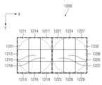
도 12는 일 실시예에 따른 이미지 센서의 픽셀 어레이에 포함되는 단위 픽셀들을 나타낸 도면(1200)이다.
도면의 설명과 관련하여, 동일 또는 유사한 구성요소에 대해서는 동일 또는 유사한 참조 부호가 사용될 수 있다.FIG. 1 is a block diagram of an electronic device (101) within a network environment (100) according to various embodiments.
FIG. 2 is a block diagram (200) illustrating a camera module (180) according to various embodiments.
FIG. 3 is a drawing for explaining an image sensor (300) according to an embodiment disclosed in this document.
FIG. 4 is a drawing (400) for explaining unit pixels according to an embodiment disclosed in this document.
FIG. 5 is a cross-sectional view (500) showing a cross-section of one unit pixel of FIG. 4 cut along the z-z' line.
FIG. 6 is a flowchart (600) explaining the operation of an image sensor according to an embodiment disclosed in this document.
FIG. 7 is a block diagram (700) showing hardware included in an image sensor according to an embodiment disclosed in this document.
FIG. 8 is a drawing (800) showing unit pixels included in an image sensor according to an embodiment disclosed in this document.
FIG. 9 is a drawing (900) showing an example of forming a Bayer-patterned image based on signals of an image sensor according to an embodiment disclosed in this document.
FIG. 10 is a diagram showing output signals of an image sensor according to an embodiment disclosed in this document in two cases (1010, 1020).
FIG. 11 is a drawing (1100) showing a method for calculating a difference value of an image sensor according to an embodiment disclosed in this document.
FIG. 12 is a drawing (1200) showing unit pixels included in a pixel array of an image sensor according to one embodiment.
In connection with the description of the drawings, the same or similar reference numerals may be used for identical or similar components.
이하, 본 발명의 다양한 실시 예가 첨부된 도면을 참조하여 기재된다. 그러나, 이는 본 발명을 특정한 실시 형태에 대해 한정하려는 것이 아니며, 본 발명의 실시 예의 다양한 변경(modification), 균등물(equivalent), 및/또는 대체물(alternative)을 포함하는 것으로 이해되어야 한다.Hereinafter, various embodiments of the present invention will be described with reference to the attached drawings. However, this is not intended to limit the present invention to specific embodiments, but should be understood to include various modifications, equivalents, and/or alternatives of the embodiments of the present invention.
도 1은, 다양한 실시 예들에 따른, 네트워크 환경(100) 내의 전자 장치(101)의 블럭도이다. 도 1을 참조하면, 네트워크 환경(100)에서 전자 장치(101)는 제 1 네트워크(198)(예: 근거리 무선 통신 네트워크)를 통하여 전자 장치(102)와 통신하거나, 또는 제 2 네트워크(199)(예: 원거리 무선 통신 네트워크)를 통하여 전자 장치(104) 또는 서버(108)와 통신할 수 있다. 일 실시 예에 따르면, 전자 장치(101)는 서버(108)를 통하여 전자 장치(104)와 통신할 수 있다. 일 실시 예에 따르면, 전자 장치(101)는 프로세서(120), 메모리(130), 입력 장치(150), 음향 출력 장치(155), 표시 장치(160), 오디오 모듈(170), 센서 모듈(176), 인터페이스(177), 햅틱 모듈(179), 카메라 모듈(180), 전력 관리 모듈(188), 배터리(189), 통신 모듈(190), 가입자 식별 모듈(196), 또는 안테나 모듈(197)을 포함할 수 있다. 어떤 실시 예에서는, 전자 장치(101)에는, 이 구성요소들 중 적어도 하나가 생략되거나, 하나 이상의 다른 구성요소가 추가될 수 있다. 어떤 실시 예에서는, 이 구성요소들 중 일부들은 하나의 통합된 회로로 구현될 수 있다. 예를 들면, 센서 모듈(176)(예: 지문 센서, 홍채 센서, 또는 조도 센서)은 표시 장치(160)(예: 디스플레이)에 임베디드된 채 구현될 수 있다FIG. 1 is a block diagram of an electronic device (101) in a network environment (100) according to various embodiments. Referring to FIG. 1, in the network environment (100), the electronic device (101) may communicate with the electronic device (102) through a first network (198) (e.g., a short-range wireless communication network), or may communicate with the electronic device (104) or a server (108) through a second network (199) (e.g., a long-range wireless communication network). According to one embodiment, the electronic device (101) may communicate with the electronic device (104) through the server (108). According to one embodiment, the electronic device (101) may include a processor (120), a memory (130), an input device (150), an audio output device (155), a display device (160), an audio module (170), a sensor module (176), an interface (177), a haptic module (179), a camera module (180), a power management module (188), a battery (189), a communication module (190), a subscriber identification module (196), or an antenna module (197). In some embodiments, the electronic device (101) may omit at least one of these components, or may have one or more other components added. In some embodiments, some of these components may be implemented as a single integrated circuit. For example, the sensor module (176) (e.g., a fingerprint sensor, an iris sensor, or an ambient light sensor) may be implemented embedded in the display device (160) (e.g., a display).
프로세서(120)는, 예를 들면, 소프트웨어(예: 프로그램(140))를 실행하여 프로세서(120)에 연결된 전자 장치(101)의 적어도 하나의 다른 구성요소(예: 하드웨어 또는 소프트웨어 구성요소)를 제어할 수 있고, 다양한 데이터 처리 또는 연산을 수행할 수 있다. 일 실시 예에 따르면, 데이터 처리 또는 연산의 적어도 일부로서, 프로세서(120)는 다른 구성요소(예: 센서 모듈(176) 또는 통신 모듈(190))로부터 수신된 명령 또는 데이터를 휘발성 메모리(132)에 로드하고, 휘발성 메모리(132)에 저장된 명령 또는 데이터를 처리하고, 결과 데이터를 비휘발성 메모리(134)에 저장할 수 있다. 일 실시 예에 따르면, 프로세서(120)는 메인 프로세서(121)(예: 중앙 처리 장치 또는 어플리케이션 프로세서), 및 이와는 독립적으로 또는 함께 운영 가능한 보조 프로세서(123)(예: 그래픽 처리 장치, 이미지 시그널 프로세서, 센서 허브 프로세서, 또는 커뮤니케이션 프로세서)를 포함할 수 있다. 추가적으로 또는 대체적으로, 보조 프로세서(123)는 메인 프로세서(121)보다 저전력을 사용하거나, 또는 지정된 기능에 특화되도록 설정될 수 있다. 보조 프로세서(123)는 메인 프로세서(121)와 별개로, 또는 그 일부로서 구현될 수 있다.The processor (120) may control at least one other component (e.g., a hardware or software component) of the electronic device (101) connected to the processor (120) by executing, for example, software (e.g., a program (140)), and may perform various data processing or calculations. According to one embodiment, as at least a part of the data processing or calculation, the processor (120) may load a command or data received from another component (e.g., a sensor module (176) or a communication module (190)) into a volatile memory (132), process the command or data stored in the volatile memory (132), and store result data in a non-volatile memory (134). According to one embodiment, the processor (120) may include a main processor (121) (e.g., a central processing unit or an application processor), and a secondary processor (123) (e.g., a graphic processing unit, an image signal processor, a sensor hub processor, or a communication processor) that may operate independently or together therewith. Additionally or alternatively, the auxiliary processor (123) may be configured to use less power than the main processor (121), or to be specialized for a given function. The auxiliary processor (123) may be implemented separately from the main processor (121), or as a part thereof.
보조 프로세서(123)는, 예를 들면, 메인 프로세서(121)가 인액티브(예: 슬립) 상태에 있는 동안 메인 프로세서(121)를 대신하여, 또는 메인 프로세서(121)가 액티브(예: 어플리케이션 실행) 상태에 있는 동안 메인 프로세서(121)와 함께, 전자 장치(101)의 구성요소들 중 적어도 하나의 구성요소(예: 표시 장치(160), 센서 모듈(176), 또는 통신 모듈(190))와 관련된 기능 또는 상태들의 적어도 일부를 제어할 수 있다. 일 실시 예에 따르면, 보조 프로세서(123)(예: 이미지 시그널 프로세서 또는 커뮤니케이션 프로세서)는 기능적으로 관련 있는 다른 구성 요소(예: 카메라 모듈(180) 또는 통신 모듈(190))의 일부로서 구현될 수 있다.The auxiliary processor (123) may control at least a portion of functions or states associated with at least one of the components of the electronic device (101) (e.g., the display device (160), the sensor module (176), or the communication module (190)), for example, on behalf of the main processor (121) while the main processor (121) is in an inactive (e.g., sleep) state, or together with the main processor (121) while the main processor (121) is in an active (e.g., application execution) state. According to one embodiment, the auxiliary processor (123) (e.g., an image signal processor or a communication processor) may be implemented as a part of another functionally related component (e.g., a camera module (180) or a communication module (190)).
메모리(130)는, 전자 장치(101)의 적어도 하나의 구성요소(예: 프로세서(120) 또는 센서모듈(176))에 의해 사용되는 다양한 데이터를 저장할 수 있다. 데이터는, 예를 들어, 소프트웨어(예: 프로그램(140)) 및, 이와 관련된 명령에 대한 입력 데이터 또는 출력 데이터를 포함할 수 있다. 메모리(130)는, 휘발성 메모리(132) 또는 비휘발성 메모리(134)를 포함할 수 있다.The memory (130) can store various data used by at least one component (e.g., processor (120) or sensor module (176)) of the electronic device (101). The data can include, for example, software (e.g., program (140)) and input data or output data for commands related thereto. The memory (130) can include volatile memory (132) or nonvolatile memory (134).
프로그램(140)은 메모리(130)에 소프트웨어로서 저장될 수 있으며, 예를 들면, 운영 체제(142), 미들 웨어(144) 또는 어플리케이션(146)을 포함할 수 있다.The program (140) may be stored as software in memory (130) and may include, for example, an operating system (142), middleware (144), or an application (146).
입력 장치(150)는, 전자 장치(101)의 구성요소(예: 프로세서(120))에 사용될 명령 또는 데이터를 전자 장치(101)의 외부(예: 사용자)로부터 수신할 수 있다. 입력 장치(150)는, 예를 들면, 마이크, 마우스, 키보드, 또는 디지털 펜(예: 스타일러스 펜)을 포함할 수 있다.The input device (150) can receive commands or data to be used in a component of the electronic device (101) (e.g., a processor (120)) from an external source (e.g., a user) of the electronic device (101). The input device (150) can include, for example, a microphone, a mouse, a keyboard, or a digital pen (e.g., a stylus pen).
음향 출력 장치(155)는 음향 신호를 전자 장치(101)의 외부로 출력할 수 있다. 음향 출력 장치(155)는, 예를 들면, 스피커 또는 리시버를 포함할 수 있다. 스피커는 멀티미디어 재생 또는 녹음 재생과 같이 일반적인 용도로 사용될 수 있고, 리시버는 착신 전화를 수신하기 위해 사용될 수 있다. 일 실시 예에 따르면, 리시버는 스피커와 별개로, 또는 그 일부로서 구현될 수 있다.The audio output device (155) can output an audio signal to the outside of the electronic device (101). The audio output device (155) can include, for example, a speaker or a receiver. The speaker can be used for general purposes such as multimedia playback or recording playback, and the receiver can be used to receive an incoming call. According to one embodiment, the receiver can be implemented separately from the speaker or as a part thereof.
표시 장치(160)는 전자 장치(101)의 외부(예: 사용자)로 정보를 시각적으로 제공할 수 있다. 표시 장치(160)는, 예를 들면, 디스플레이, 홀로그램 장치, 또는 프로젝터 및 해당 장치를 제어하기 위한 제어 회로를 포함할 수 있다. 일 실시 예에 따르면, 표시 장치(160)는 터치를 감지하도록 설정된 터치 회로(touch circuitry), 또는 상기 터치에 의해 발생되는 힘의 세기를 측정하도록 설정된 센서 회로(예: 압력 센서)를 포함할 수 있다.The display device (160) can visually provide information to an external party (e.g., a user) of the electronic device (101). The display device (160) can include, for example, a display, a holographic device, or a projector and a control circuit for controlling the device. According to one embodiment, the display device (160) can include touch circuitry configured to detect a touch, or a sensor circuitry configured to measure a strength of a force generated by the touch (e.g., a pressure sensor).
오디오 모듈(170)은 소리를 전기 신호로 변환시키거나, 반대로 전기 신호를 소리로 변환시킬 수 있다. 일 실시 예에 따르면, 오디오 모듈(170)은, 입력 장치(150)를 통해 소리를 획득하거나, 음향 출력 장치(155), 또는 전자 장치(101)와 직접 또는 무선으로 연결된 외부 전자 장치(예: 전자 장치(102))(예: 스피커 또는 헤드폰)를 통해 소리를 출력할 수 있다.The audio module (170) can convert sound into an electric signal, or vice versa, convert an electric signal into sound. According to one embodiment, the audio module (170) can obtain sound through an input device (150), or output sound through an audio output device (155), or an external electronic device (e.g., an electronic device (102)) (e.g., a speaker or a headphone) directly or wirelessly connected to the electronic device (101).
센서 모듈(176)은 전자 장치(101)의 작동 상태(예: 전력 또는 온도), 또는 외부의 환경 상태(예: 사용자 상태)를 감지하고, 감지된 상태에 대응하는 전기 신호 또는 데이터 값을 생성할 수 있다. 일 실시 예에 따르면, 센서 모듈(176)은, 예를 들면, 제스처 센서, 자이로 센서, 기압 센서, 마그네틱 센서, 가속도 센서, 그립 센서, 근접 센서, 컬러 센서, IR(infrared) 센서, 생체 센서, 온도 센서, 습도 센서, 또는 조도 센서를 포함할 수 있다.The sensor module (176) can detect an operating state (e.g., power or temperature) of the electronic device (101) or an external environmental state (e.g., user state) and generate an electric signal or data value corresponding to the detected state. According to one embodiment, the sensor module (176) can include, for example, a gesture sensor, a gyro sensor, a barometric pressure sensor, a magnetic sensor, an acceleration sensor, a grip sensor, a proximity sensor, a color sensor, an IR (infrared) sensor, a biometric sensor, a temperature sensor, a humidity sensor, or an illuminance sensor.
인터페이스(177)는 전자 장치(101)가 외부 전자 장치(예: 전자 장치(102))와 직접 또는 무선으로 연결되기 위해 사용될 수 있는 하나 이상의 지정된 프로토콜들을 지원할 수 있다. 일 실시 예에 따르면, 인터페이스(177)는, 예를 들면, HDMI(high definition multimedia interface), USB(universal serial bus) 인터페이스, SD카드 인터페이스, 또는 오디오 인터페이스를 포함할 수 있다.The interface (177) may support one or more designated protocols that may be used to directly or wirelessly connect the electronic device (101) with an external electronic device (e.g., the electronic device (102)). According to one embodiment, the interface (177) may include, for example, a high definition multimedia interface (HDMI), a universal serial bus (USB) interface, an SD card interface, or an audio interface.
연결 단자(178)는, 그를 통해서 전자 장치(101)가 외부 전자 장치(예: 전자 장치(102))와 물리적으로 연결될 수 있는 커넥터를 포함할 수 있다. 일 실시 예에 따르면, 연결 단자(178)는, 예를 들면, HDMI 커넥터, USB 커넥터, SD 카드 커넥터, 또는 오디오 커넥터(예: 헤드폰 커넥터)를 포함할 수 있다.The connection terminal (178) may include a connector through which the electronic device (101) may be physically connected to an external electronic device (e.g., the electronic device (102)). According to one embodiment, the connection terminal (178) may include, for example, an HDMI connector, a USB connector, an SD card connector, or an audio connector (e.g., a headphone connector).
햅틱 모듈(179)은 전기적 신호를 사용자가 촉각 또는 운동 감각을 통해서 인지할 수 있는 기계적인 자극(예: 진동 또는 움직임) 또는 전기적인 자극으로 변환할 수 있다. 일 실시 예에 따르면, 햅틱 모듈(179)은, 예를 들면, 모터, 압전 소자, 또는 전기 자극 장치를 포함할 수 있다.The haptic module (179) can convert an electrical signal into a mechanical stimulus (e.g., vibration or movement) or an electrical stimulus that a user can perceive through a tactile or kinesthetic sense. According to one embodiment, the haptic module (179) can include, for example, a motor, a piezoelectric element, or an electrical stimulation device.
카메라 모듈(180)은 정지 영상 및 동영상을 촬영할 수 있다. 일 실시 예에 따르면, 카메라 모듈(180)은 하나 이상의 렌즈들, 이미지 센서들, 이미지 시그널 프로세서들, 또는 플래시들을 포함할 수 있다.The camera module (180) can capture still images and moving images. According to one embodiment, the camera module (180) can include one or more lenses, image sensors, image signal processors, or flashes.
전력 관리 모듈(188)은 전자 장치(101)에 공급되는 전력을 관리할 수 있다. 일 실시 예에 따르면, 전력 관리 모듈(188)은, 예를 들면, PMIC(power management integrated circuit)의 적어도 일부로서 구현될 수 있다.The power management module (188) can manage power supplied to the electronic device (101). According to one embodiment, the power management module (188) can be implemented as, for example, at least a part of a power management integrated circuit (PMIC).
배터리(189)는 전자 장치(101)의 적어도 하나의 구성요소에 전력을 공급할 수 있다. 일 실시 예에 따르면, 배터리(189)는, 예를 들면, 재충전 불가능한 1차 전지, 재충전 가능한 2차 전지 또는 연료 전지를 포함할 수 있다.The battery (189) can power at least one component of the electronic device (101). In one embodiment, the battery (189) can include, for example, a non-rechargeable primary battery, a rechargeable secondary battery, or a fuel cell.
통신 모듈(190)은 전자 장치(101)와 외부 전자 장치(예: 전자 장치(102), 전자 장치(104), 또는 서버(108))간의 직접(예: 유선) 통신 채널 또는 무선 통신 채널의 수립, 및 수립된 통신 채널을 통한 통신 수행을 지원할 수 있다. 통신 모듈(190)은 프로세서(120)(예: 어플리케이션 프로세서)와 독립적으로 운영되고, 직접(예: 유선) 통신 또는 무선 통신을 지원하는 하나 이상의 커뮤니케이션 프로세서를 포함할 수 있다. 일 실시 예에 따르면, 통신 모듈(190)은 무선 통신 모듈(192)(예: 셀룰러 통신 모듈, 근거리 무선 통신 모듈, 또는 GNSS(global navigation satellite system) 통신 모듈) 또는 유선 통신 모듈(194)(예: LAN(local area network) 통신 모듈, 또는 전력선 통신 모듈)을 포함할 수 있다. 이들 통신 모듈 중 해당하는 통신 모듈은 제 1 네트워크(198)(예: 블루투스, WiFi direct 또는 IrDA(infrared data association)와 같은 근거리 통신 네트워크) 또는 제 2 네트워크(199)(예: 셀룰러 네트워크, 인터넷, 또는 컴퓨터 네트워크(예: LAN 또는 WAN)와 같은 원거리 통신 네트워크)를 통하여 외부 전자 장치(104)와 통신할 수 있다. 이런 여러 종류의 통신 모듈들은 하나의 구성요소(예: 단일 칩)로 통합되거나, 또는 서로 별도의 복수의 구성요소들(예: 복수 칩들)로 구현될 수 있다. 무선 통신 모듈(192)은 가입자 식별 모듈(196)에 저장된 가입자 정보(예: 국제 모바일 가입자 식별자(IMSI))를 이용하여 제 1 네트워크(198) 또는 제 2 네트워크(199)와 같은 통신 네트워크 내에서 전자 장치(101)를 확인 및 인증할 수 있다.The communication module (190) may support establishment of a direct (e.g., wired) communication channel or a wireless communication channel between the electronic device (101) and an external electronic device (e.g., the electronic device (102), the electronic device (104), or the server (108)), and performance of communication through the established communication channel. The communication module (190) may operate independently from the processor (120) (e.g., the application processor) and may include one or more communication processors that support direct (e.g., wired) communication or wireless communication. According to one embodiment, the communication module (190) may include a wireless communication module (192) (e.g., a cellular communication module, a short-range wireless communication module, or a GNSS (global navigation satellite system) communication module) or a wired communication module (194) (e.g., a local area network (LAN) communication module, or a power line communication module). A corresponding communication module among these communication modules can communicate with an external electronic device (104) via a first network (198) (e.g., a short-range communication network such as Bluetooth, WiFi direct, or IrDA (infrared data association)) or a second network (199) (e.g., a long-range communication network such as a cellular network, the Internet, or a computer network (e.g., a LAN or WAN)). These various types of communication modules can be integrated into a single component (e.g., a single chip) or implemented as multiple separate components (e.g., multiple chips). The wireless communication module (192) can identify and authenticate the electronic device (101) within a communication network such as the first network (198) or the second network (199) by using subscriber information (e.g., an international mobile subscriber identity (IMSI)) stored in the subscriber identification module (196).
안테나 모듈(197)은 신호 또는 전력을 외부(예: 외부 전자 장치)로 송신하거나 외부로부터 수신할 수 있다. 일 실시 예에 따르면, 안테나 모듈(197)은 서브스트레이트(예: PCB) 위에 형성된 도전체 또는 도전성 패턴으로 이루어진 방사체를 포함하는 하나의 안테나를 포함할 수 있다. 일 실시 예에 따르면, 안테나 모듈(197)은 복수의 안테나들을 포함할 수 있다. 이런 경우, 제 1 네트워크(198) 또는 제 2 네트워크(199)와 같은 통신 네트워크에서 사용되는 통신 방식에 적합한 적어도 하나의 안테나가, 예를 들면, 통신 모듈(190)에 의하여 상기 복수의 안테나들로부터 선택될 수 있다. 신호 또는 전력은 상기 선택된 적어도 하나의 안테나를 통하여 통신 모듈(190)과 외부 전자 장치 간에 송신되거나 수신될 수 있다. 어떤 실시 예에 따르면, 방사체 이외에 다른 부품(예: RFIC)이 추가로 안테나 모듈(197)의 일부로 형성될 수 있다.The antenna module (197) can transmit or receive signals or power to or from an external device (e.g., an external electronic device). According to one embodiment, the antenna module (197) can include one antenna including a radiator formed of a conductor or a conductive pattern formed on a substrate (e.g., a PCB). According to one embodiment, the antenna module (197) can include a plurality of antennas. In this case, at least one antenna suitable for a communication method used in a communication network, such as the first network (198) or the second network (199), can be selected from the plurality of antennas by, for example, the communication module (190). A signal or power can be transmitted or received between the communication module (190) and the external electronic device through the selected at least one antenna. According to some embodiments, in addition to the radiator, another component (e.g., an RFIC) can be additionally formed as a part of the antenna module (197).
상기 구성요소들 중 적어도 일부는 주변 기기들간 통신 방식(예: 버스, GPIO(general purpose input and output), SPI(serial peripheral interface), 또는 MIPI(mobile industry processor interface))을 통해 서로 연결되고 신호(예: 명령 또는 데이터)를 상호간에 교환할 수 있다.At least some of the above components may be interconnected and exchange signals (e.g., commands or data) with each other via a communication method between peripheral devices (e.g., a bus, a general purpose input and output (GPIO), a serial peripheral interface (SPI), or a mobile industry processor interface (MIPI)).
일 실시 예에 따르면, 명령 또는 데이터는 제 2 네트워크(199)에 연결된 서버(108)를 통해서 전자 장치(101)와 외부의 전자 장치(104)간에 송신 또는 수신될 수 있다. 외부 전자 장치(102, 104) 각각은 전자 장치(101)와 동일한 또는 다른 종류의 장치일 수 있다. 일 실시 예에 따르면, 전자 장치(101)에서 실행되는 동작들의 전부 또는 일부는 외부 전자 장치들(102, 104, 또는 108) 중 하나 이상의 외부 전자 장치들에서 실행될 수 있다. 예를 들면, 전자 장치(101)가 어떤 기능이나 서비스를 자동으로, 또는 사용자 또는 다른 장치로부터의 요청에 반응하여 수행해야 할 경우에, 전자 장치(101)는 기능 또는 서비스를 자체적으로 실행시키는 대신에 또는 추가적으로, 하나 이상의 외부 전자 장치들에게 그 기능 또는 그 서비스의 적어도 일부를 수행하라고 요청할 수 있다. 상기 요청을 수신한 하나 이상의 외부 전자 장치들은 요청된 기능 또는 서비스의 적어도 일부, 또는 상기 요청과 관련된 추가 기능 또는 서비스를 실행하고, 그 실행의 결과를 전자 장치(101)로 전달할 수 있다. 전자 장치(101)는 상기 결과를, 그대로 또는 추가적으로 처리하여, 상기 요청에 대한 응답의 적어도 일부로서 제공할 수 있다. 이를 위하여, 예를 들면, 클라우드 컴퓨팅, 분산 컴퓨팅, 또는 클라이언트-서버 컴퓨팅 기술이 이용될 수 있다.According to one embodiment, a command or data may be transmitted or received between the electronic device (101) and an external electronic device (104) via a server (108) connected to a second network (199). Each of the external electronic devices (102, 104) may be the same or a different type of device as the electronic device (101). According to one embodiment, all or part of the operations executed in the electronic device (101) may be executed in one or more of the external electronic devices (102, 104, or 108). For example, when the electronic device (101) is to perform a certain function or service automatically or in response to a request from a user or another device, the electronic device (101) may, instead of or in addition to executing the function or service by itself, request one or more external electronic devices to perform at least a part of the function or service. One or more external electronic devices that have received the request may execute at least a part of the requested function or service, or an additional function or service related to the request, and transmit the result of the execution to the electronic device (101). The electronic device (101) may process the result as is or additionally and provide it as at least a part of a response to the request. For this purpose, for example, cloud computing, distributed computing, or client-server computing technology may be used.
도 2는, 다양한 실시 예들에 따른, 카메라 모듈(180)을 예시하는 블럭도(200)이다. 도 2를 참조하면, 카메라 모듈(180)은 렌즈 어셈블리(210), 플래쉬(220), 이미지 센서(230), 이미지 스태빌라이저(240), 메모리(250)(예: 버퍼 메모리), 또는 이미지 시그널 프로세서(260)를 포함할 수 있다. 렌즈 어셈블리(210)는 이미지 촬영의 대상인 피사체로부터 방출되는 빛을 수집할 수 있다. 렌즈 어셈블리(210)는 하나 또는 그 이상의 렌즈들을 포함할 수 있다. 일 실시 예에 따르면, 카메라 모듈(180)은 복수의 렌즈 어셈블리(210)들을 포함할 수 있다. 이런 경우, 카메라 모듈(180)은, 예를 들면, 듀얼 카메라, 360도 카메라, 또는 구형 카메라(spherical camera)를 형성할 수 있다. 복수의 렌즈 어셈블리(210)들 중 일부는 동일한 렌즈 속성(예: 화각, 초점 거리, 자동 초점, f 넘버(f number), 또는 광학 줌)을 갖거나, 또는 적어도 하나의 렌즈 어셈블리는 다른 렌즈 어셈블리의 렌즈 속성들과 다른 하나 이상의 렌즈 속성들을 가질 수 있다. 렌즈 어셈블리(210)는, 예를 들면, 광각 렌즈 또는 망원 렌즈를 포함할 수 있다.FIG. 2 is a block diagram (200) illustrating a camera module (180) according to various embodiments. Referring to FIG. 2, the camera module (180) may include a lens assembly (210), a flash (220), an image sensor (230), an image stabilizer (240), a memory (250) (e.g., a buffer memory), or an image signal processor (260). The lens assembly (210) may collect light emitted from a subject that is a target of image capturing. The lens assembly (210) may include one or more lenses. According to one embodiment, the camera module (180) may include a plurality of lens assemblies (210). In this case, the camera module (180) may form, for example, a dual camera, a 360-degree camera, or a spherical camera. Some of the plurality of lens assemblies (210) may have the same lens properties (e.g., angle of view, focal length, autofocus, f number, or optical zoom), or at least one lens assembly may have one or more lens properties that are different from the lens properties of the other lens assemblies. The lens assembly (210) may include, for example, a wide-angle lens or a telephoto lens.
플래쉬(220)는 피사체로부터 방출 또는 반사되는 빛을 강화하기 위하여 사용되는 빛을 방출할 수 있다. 일 실시 예에 따르면, 플래쉬(220)는 하나 이상의 발광 다이오드들(예: RGB(red-green-blue) LED, white LED, infrared LED, 또는 ultraviolet LED), 또는 xenon lamp를 포함할 수 있다. 이미지 센서(230)는 피사체로부터 방출 또는 반사되어 렌즈 어셈블리(210) 를 통해 전달된 빛을 전기적인 신호로 변환함으로써, 상기 피사체에 대응하는 이미지를 획득할 수 있다. 일 실시 예에 따르면, 이미지 센서(230)는, 예를 들면, RGB 센서, BW(black and white) 센서, IR 센서, 또는 UV 센서와 같이 속성이 다른 이미지 센서들 중 선택된 하나의 이미지 센서, 동일한 속성을 갖는 복수의 이미지 센서들, 또는 다른 속성을 갖는 복수의 이미지 센서들을 포함할 수 있다. 이미지 센서(230)에 포함된 각각의 이미지 센서는, 예를 들면, CCD(charged coupled device) 센서 또는 CMOS(complementary metal oxide semiconductor) 센서를 이용하여 구현될 수 있다.The flash (220) can emit light used to enhance light emitted or reflected from a subject. According to one embodiment, the flash (220) can include one or more light-emitting diodes (e.g., red-green-blue (RGB) LEDs, white LEDs, infrared LEDs, or ultraviolet LEDs), or a xenon lamp. The image sensor (230) can convert light emitted or reflected from a subject and transmitted through the lens assembly (210) into an electrical signal, thereby obtaining an image corresponding to the subject. According to one embodiment, the image sensor (230) can include one image sensor selected from among image sensors having different properties, such as, for example, an RGB sensor, a black and white (BW) sensor, an IR sensor, or a UV sensor, a plurality of image sensors having the same property, or a plurality of image sensors having different properties. Each image sensor included in the image sensor (230) may be implemented using, for example, a CCD (charged coupled device) sensor or a CMOS (complementary metal oxide semiconductor) sensor.
이미지 스태빌라이저(240)는 카메라 모듈(180) 또는 이를 포함하는 전자 장치(101)의 움직임에 반응하여, 렌즈 어셈블리(210)에 포함된 적어도 하나의 렌즈 또는 이미지 센서(230)를 특정한 방향으로 움직이거나 이미지 센서(230)의 동작 특성을 제어(예: 리드 아웃(read-out) 타이밍을 조정 등)할 수 있다. 이는 촬영되는 이미지에 대한 상기 움직임에 의한 부정적인 영향의 적어도 일부를 보상하게 해 준다. 일 실시 예에 따르면, 이미지 스태빌라이저(240)는, 일 실시 예에 따르면, 이미지 스태빌라이저(240)은 카메라 모듈(180)의 내부 또는 외부에 배치된 자이로 센서(미도시) 또는 가속도 센서(미도시)를 이용하여 카메라 모듈(180) 또는 전자 장치(101)의 그런 움직임을 감지할 수 있다. 일 실시 예에 따르면, 이미지 스태빌라이저(240)는, 예를 들면, 광학식 이미지 스태빌라이저로 구현될 수 있다. 메모리(250)는 이미지 센서(230)을 통하여 획득된 이미지의 적어도 일부를 다음 이미지 처리 작업을 위하여 적어도 일시 저장할 수 있다. 예를 들어, 셔터에 따른 이미지 획득이 지연되거나, 또는 복수의 이미지들이 고속으로 획득되는 경우, 획득된 원본 이미지(예: Bayer-patterned 이미지 또는 높은 해상도의 이미지)는 메모리(250)에 저장이 되고, 그에 대응하는 사본 이미지(예: 낮은 해상도의 이미지)는 표시 장치(160)을 통하여 프리뷰될 수 있다. 이후, 지정된 조건이 만족되면(예: 사용자 입력 또는 시스템 명령) 메모리(250)에 저장되었던 원본 이미지의 적어도 일부가, 예를 들면, 이미지 시그널 프로세서(260)에 의해 획득되어 처리될 수 있다. 일 실시 예에 따르면, 메모리(250)는 메모리(130)의 적어도 일부로, 또는 이와는 독립적으로 운영되는 별도의 메모리로 구성될 수 있다.The image stabilizer (240) can move at least one lens or image sensor (230) included in the lens assembly (210) in a specific direction or control the operating characteristics of the image sensor (230) (e.g., adjusting read-out timing, etc.) in response to the movement of the camera module (180) or the electronic device (101) including the same. This allows compensating for at least some of the negative effects of the movement on the captured image. In one embodiment, the image stabilizer (240) can detect such movement of the camera module (180) or the electronic device (101) by using a gyro sensor (not shown) or an acceleration sensor (not shown) disposed inside or outside the camera module (180). In one embodiment, the image stabilizer (240) can be implemented as, for example, an optical image stabilizer. The memory (250) can temporarily store at least a portion of an image acquired through the image sensor (230) for the next image processing task. For example, when image acquisition is delayed due to a shutter, or when a plurality of images are acquired at high speed, the acquired original image (e.g., a Bayer-patterned image or a high-resolution image) is stored in the memory (250), and a corresponding copy image (e.g., a low-resolution image) can be previewed through the display device (160). Thereafter, when a specified condition is satisfied (e.g., a user input or a system command), at least a portion of the original image stored in the memory (250) can be acquired and processed by, for example, an image signal processor (260). According to one embodiment, the memory (250) can be configured as at least a portion of the memory (130), or as a separate memory that operates independently therefrom.
이미지 시그널 프로세서(260)는 이미지 센서(230)을 통하여 획득된 이미지 또는 메모리(250)에 저장된 이미지에 대하여 하나 이상의 이미지 처리들을 수행할 수 있다. 상기 하나 이상의 이미지 처리들은, 예를 들면, 깊이 지도(depth map) 생성, 3차원 모델링, 파노라마 생성, 특징점 추출, 이미지 합성, 또는 이미지 보상(예: 노이즈 감소, 해상도 조정, 밝기 조정, 블러링(blurring), 샤프닝(sharpening), 또는 소프트닝(softening)을 포함할 수 있다. 추가적으로 또는 대체적으로, 이미지 시그널 프로세서(260)는 카메라 모듈(180)에 포함된 구성 요소들 중 적어도 하나(예: 이미지 센서(230))에 대한 제어(예: 노출 시간 제어, 또는 리드 아웃 타이밍 제어 등)를 수행할 수 있다. 이미지 시그널 프로세서(260)에 의해 처리된 이미지는 추가 처리를 위하여 메모리(250)에 다시 저장 되거나 카메라 모듈(180)의 외부 구성 요소(예: 메모리(130), 표시 장치(160), 전자 장치(102), 전자 장치(104), 또는 서버(108))로 제공될 수 있다. 일 실시 예에 따르면, 이미지 시그널 프로세서(260)는 프로세서(120)의 적어도 일부로 구성되거나, 프로세서(120)와 독립적으로 운영되는 별도의 프로세서로 구성될 수 있다. 이미지 시그널 프로세서(260)이 프로세서(120)과 별도의 프로세서로 구성된 경우, 이미지 시그널 프로세서(260)에 의해 처리된 적어도 하나의 이미지는 프로세서(120)에 의하여 그대로 또는 추가의 이미지 처리를 거친 후 표시 장치(160)를 통해 표시될 수 있다.The image signal processor (260) can perform one or more image processing operations on an image acquired through an image sensor (230) or an image stored in a memory (250). The one or more image processing operations may include, for example, depth map generation, 3D modeling, panorama generation, feature point extraction, image synthesis, or image compensation (e.g., noise reduction, resolution adjustment, brightness adjustment, blurring, sharpening, or softening). Additionally or alternatively, the image signal processor (260) may perform control (e.g., exposure time control, or read-out timing control, etc.) for at least one of the components included in the camera module (180) (e.g., the image sensor (230)). The image processed by the image signal processor (260) may be stored back in the memory (250) for further processing or provided to an external component of the camera module (180) (e.g., the memory (130), the display device (160), the electronic device (102), the electronic device (104), or the server (108)). According to one embodiment, the image signal processor (260) may include at least one of the processors (120). It may be configured as a part of the image signal processor (260) or as a separate processor that operates independently of the processor (120). When the image signal processor (260) is configured as a separate processor from the processor (120), at least one image processed by the image signal processor (260) may be displayed through the display device (160) as is or after undergoing additional image processing by the processor (120).
일 실시 예에 따르면, 전자 장치(101)는 각각 다른 속성 또는 기능을 가진 복수의 카메라 모듈(180)들을 포함할 수 있다. 이런 경우, 예를 들면, 상기 복수의 카메라 모듈(180)들 중 적어도 하나는 광각 카메라이고, 적어도 다른 하나는 망원 카메라일 수 있다. 유사하게, 상기 복수의 카메라 모듈(180)들 중 적어도 하나는 전면 카메라이고, 적어도 다른 하나는 후면 카메라일 수 있다.According to one embodiment, the electronic device (101) may include a plurality of camera modules (180), each having different properties or functions. In this case, for example, at least one of the plurality of camera modules (180) may be a wide-angle camera, and at least another may be a telephoto camera. Similarly, at least one of the plurality of camera modules (180) may be a front camera, and at least another may be a rear camera.
이하에서, 도 3, 도 4 및 도 5를 참조하여 본 문서에 개시되는 실시 예에 따른 전자 장치에 대해 설명한다. 설명의 명확성을 위해 앞서 설명한 것과 중복되는 것은 간략히 하거나 생략될 수 있다.Hereinafter, an electronic device according to an embodiment disclosed in the present document will be described with reference to FIGS. 3, 4, and 5. For clarity of explanation, any part that overlaps with what has been described above may be simplified or omitted.
도 3은 본 문서에 개시되는 실시 예에 따른 이미지 센서(300)를 설명하기 위한 도면이다. 도 4는 본 문서에 개시되는 실시 예에 따른 단위 픽셀들을 설명하기 위한 도면(400)이다. 도 5는 도 4의 하나의 단위 픽셀을 z-z'선을 따라 자른 단면을 도시한 단면도(500)이다.FIG. 3 is a drawing for explaining an image sensor (300) according to an embodiment disclosed in this document. FIG. 4 is a drawing (400) for explaining unit pixels according to an embodiment disclosed in this document. FIG. 5 is a cross-sectional view (500) showing a cross-section of one unit pixel of FIG. 4 taken along the z-z' line.
도 3을 참조하면, 이미지 센서(300)는 픽셀 어레이(332), 제1 스캔 회로(331), 제2 스캔 회로(333) 및 판독 회로(335)를 포함할 수 있다.Referring to FIG. 3, the image sensor (300) may include a pixel array (332), a first scan circuit (331), a second scan circuit (333), and a readout circuit (335).
픽셀 어레이(332)는, 복수의 단위 픽셀들(310, 311, 312, …, 320, 321, 322, …)을 포함할 수 있다. 복수의 단위 픽셀들(310, 311, 312, …, 320, 321, 322, …)은 예를 들어, 제1 단위 픽셀(310) 및 제2 단위 픽셀(311)을 포함할 수 있다. 복수의 단위 픽셀들은, X 방향(예: 행 방향) 및 Y 방향(예: 열 방향)을 따라 배열될 수 있다.The pixel array (332) may include a plurality of unit pixels (310, 311, 312, ..., 320, 321, 322, ...). The plurality of unit pixels (310, 311, 312, ..., 320, 321, 322, ...) may include, for example, a first unit pixel (310) and a second unit pixel (311). The plurality of unit pixels may be arranged along the X direction (e.g., row direction) and the Y direction (e.g., column direction).
복수의 단위 픽셀들 각각은, 하나의 마이크로 렌즈를 포함할 수 있다. 예를 들어, 제1 단위 픽셀(310)은 제1 마이크로 렌즈(305)를 포함할 수 있다. 예를 들어, 제2 단위 픽셀(311)은 제2 마이크로 렌즈(306)를 포함할 수 있다.Each of the plurality of unit pixels may include one micro lens. For example, the first unit pixel (310) may include a first micro lens (305). For example, the second unit pixel (311) may include a second micro lens (306).
복수의 단위 픽셀들 각각(예: 제1 단위 픽셀(310))은, 적어도 하나의 포토 다이오드(예: 제1 포토 다이오드(301), 제2 포토 다이오드(302), 제3 포토 다이오드(303) 및 제4 포토 다이오드(304))를 포함할 수 있다. 복수의 단위 픽셀들 각각에 포함되는 포토 다이오드의 개수는, 복수의 단위 픽셀들 각각에 포함되는 픽셀의 개수에 기반할 수 있다.Each of the plurality of unit pixels (e.g., the first unit pixel (310)) may include at least one photodiode (e.g., the first photodiode (301), the second photodiode (302), the third photodiode (303), and the fourth photodiode (304)). The number of photodiodes included in each of the plurality of unit pixels may be based on the number of pixels included in each of the plurality of unit pixels.
제1 스캔 회로(331) 및 제2 스캔 회로(333)는, 프로세서(310)의 제어에 따라, 복수의 단위 픽셀들(310, 311, 312, …, 320, 321, 322, …) 각각에 대한 신호를 검출할 수 있다. 제1 스캔 회로(331)는, 복수의 단위 픽셀들(310, 311, 312, …, 320, 321, 322, …) 각각에 대해 Y 방향을 따라 신호를 검출할 수 있다. 제2 스캔 회로(333)는, 복수의 단위 픽셀들(310, 311, 312, …, 320, 321, 322, …) 각각에 대해 X 방향을 따라 신호를 검출할 수 있다. 판독 회로(335)는, 검출된 신호를 읽어 들일 수 있다.The first scan circuit (331) and the second scan circuit (333) can detect signals for each of the plurality of unit pixels (310, 311, 312, ..., 320, 321, 322, ...) under the control of the processor (310). The first scan circuit (331) can detect signals for each of the plurality of unit pixels (310, 311, 312, ..., 320, 321, 322, ...) along the Y direction. The second scan circuit (333) can detect signals for each of the plurality of unit pixels (310, 311, 312, ..., 320, 321, 322, ...) along the X direction. The read circuit (335) can read the detected signals.
복수의 단위 픽셀들(310, 311, 312, …, 320, 321, 322, …) 각각은, nXn개의 픽셀들(단, n은 1보다 큰 자연수)을 포함할 수 있다. 예를 들어, 제1 단위 픽셀(310)은, 제1 마이크로 렌즈(305)와 중첩되는 nXn개의 픽셀들을 포함할 수 있다. 예를 들어, 제2 단위 픽셀(311)은, 제2 마이크로 렌즈(306)와 중첩되는 nXn개의 픽셀들을 포함할 수 있다. nXn개의 픽셀들 각각은 하나의 포토 다이오드에 대응할 수 있다.Each of the plurality of unit pixels (310, 311, 312, …, 320, 321, 322, …) may include nXn pixels (where n is a natural number greater than 1). For example, the first unit pixel (310) may include nXn pixels overlapping the first micro lens (305). For example, the second unit pixel (311) may include nXn pixels overlapping the second micro lens (306). Each of the nXn pixels may correspond to one photodiode.
일 실시예 따라, 복수의 픽셀들(310, 311, 312, …, 320, 321, 322,…) 각각(예: 제1 단위 픽셀(310))은 하나의 마이크로 렌즈(예: 제1 마이크로 렌즈(305)), 복수의 포토 다이오드(예: 제1 포토 다이오드(301), 제2 포토 다이오드(302), 제3 포토 다이오드(303) 및 제4 포토 다이오드(304)) 및 한가지 색상의 컬러 필터(예: green)를 포함할 수 있다.According to one embodiment, each of the plurality of pixels (310, 311, 312, ..., 320, 321, 322, ...) (e.g., the first unit pixel (310)) may include one micro lens (e.g., the first micro lens (305)), a plurality of photo diodes (e.g., the first photo diode (301), the second photo diode (302), the third photo diode (303), and the fourth photo diode (304)) and a color filter of one color (e.g., green).
이하 도 4 및 도 5를 참조하여, 도 3의 이미지 센서(300)의 픽셀 어레이(332)에 포함되는 단위 픽셀들에 대하여 자세히 설명한다.Referring to FIGS. 4 and 5 below, the unit pixels included in the pixel array (332) of the image sensor (300) of FIG. 3 will be described in detail.
도 4를 참조하면, 일 실시 예에서 복수의 단위 픽셀들 각각은, 2X2개의 포토 다이오드들을 포함할 수 있다. 예를 들어, 제1 단위 픽셀(310)은, 제1 마이크로 렌즈(305)와 중첩되도록 배치되는, 제1 포토 다이오드(301), 제2 포토 다이오드(302), 제3 포토 다이오드(303) 및 제4 포토 다이오드(304)을 포함할 수 있다. 제1 포토 다이오드(301) 및 제3 포토 다이오드(303)은, 제1 행을 따라 배열될 수 있다. 제2 포토 다이오드(302) 및 제4 포토 다이오드(304)은, 제2 행을 따라 배열될 수 있다. 제1 포토 다이오드(301) 및 제2 포토 다이오드(302)은, 제1 열을 따라 배열될 수 있다. 제3 포토 다이오드(303) 및 제4 포토 다이오드(304)은, 제2 열을 따라 배열될 수 있다. 제1 포토 다이오드(301), 제2 포토 다이오드 (302), 제3 포토 다이오드 (303) 및 제4 포토 다이오드(304) 각각은 하나의 픽셀에 대응될 수 있다.Referring to FIG. 4, in one embodiment, each of the plurality of unit pixels may include 2X2 photodiodes. For example, the first unit pixel (310) may include a first photodiode (301), a second photodiode (302), a third photodiode (303), and a fourth photodiode (304) arranged to overlap the first micro lens (305). The first photodiode (301) and the third photodiode (303) may be arranged along a first row. The second photodiode (302) and the fourth photodiode (304) may be arranged along a second row. The first photodiode (301) and the second photodiode (302) may be arranged along a first column. The third photodiode (303) and the fourth photodiode (304) may be arranged along a second column. Each of the first photodiode (301), the second photodiode (302), the third photodiode (303), and the fourth photodiode (304) can correspond to one pixel.
일 실시예에 따라 제1 단위 픽셀(310)은 하나의 마이크로 렌즈(305), 4개의 포토 다이오드(301, 302, 303, 304) 및 녹색의 컬러 필터(G)를 포함할 수 있다. 제2 단위 픽셀(311)은 제1 단위 픽셀(310)과 구조가 동일할 수 있으므로 설명을 생략한다. 다만, 단위 픽셀들 각각이 포함하는 컬러 필터의 색상은 녹색(G)일 수 있을 뿐만 아니라 적색(R) 또는 청색(B) 등으로 상이할 수 있다.According to one embodiment, the first unit pixel (310) may include one micro lens (305), four photodiodes (301, 302, 303, 304), and a green color filter (G). The second unit pixel (311) may have the same structure as the first unit pixel (310), so its description is omitted. However, the color of the color filter included in each of the unit pixels may be different, such as not only green (G), but also red (R) or blue (B).
도 5를 참조하면, 제1 단위 픽셀(310)에서 제1 마이크로 렌즈(305)와 제1 포토 다이오드(301) 및 제2 포토 다이오드(302)는 컬러 필터(501)를 사이에 두고 서로 마주보도록 배치될 수 있다. 이미지 센서에 입사되는 빛은 제1 마이크로 렌즈(305)를 통하여 집광되어 각각 다른 포토다이오드(301 또는 302)에 입사될 수 있으며 각각의 포토다이오드에 입사되는 빛에 대한 신호를 제1 스캔 회로(예: 도 3의 제1 스캔 회로(331))또는 제2 스캔 회로(예: 도 3의 제2 스캔 회로(332))에서 검출할 수 있다.Referring to FIG. 5, in the first unit pixel (310), the first micro lens (305) and the first photo diode (301) and the second photo diode (302) may be arranged to face each other with the color filter (501) therebetween. Light incident on the image sensor may be collected through the first micro lens (305) and incident on each different photo diode (301 or 302), and a signal for the light incident on each photo diode may be detected by the first scan circuit (e.g., the first scan circuit (331) of FIG. 3) or the second scan circuit (e.g., the second scan circuit (332) of FIG. 3).
이하에서, 도 6, 도 7, 도 8, 및 도 9를 참조하여, 본 문서에 개시되는 실시 예에 따른 전자 장치의 동작에 대해 설명한다. 설명의 명확성을 위해 앞서 설명한 것과 중복되는 것은 간략히 하거나 생략될 수 있다.Hereinafter, with reference to FIGS. 6, 7, 8, and 9, the operation of an electronic device according to an embodiment disclosed in the present document will be described. For clarity of explanation, any part that overlaps with what has been described above may be simplified or omitted.
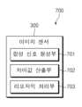
이하에서는 도 3의 이미지 센서(300)가 도 6의 프로세스를 수행하는 것을 가정한다. 이미지 센서(300)에 의해 수행되는 것으로 기술된 동작은 이미지 센서(300)에 포함된 합성 신호 형성부(701), 차이값 산출부(702) 및/또는 리모자익 처리부(703)에 의해 수행될 수 있다.In the following, it is assumed that the image sensor (300) of FIG. 3 performs the process of FIG. 6. The operation described as being performed by the image sensor (300) may be performed by the composite signal forming unit (701), the difference value calculating unit (702), and/or the remosaic processing unit (703) included in the image sensor (300).
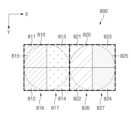
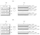
도 6은 본 문서에 개시되는 실시 예에 따른 이미지 센서(예: 도 3의 이미지 센서(300))의 동작을 설명하는 순서도(600)이다. 도 7은 본 문서에 개시되는 실시 예에 따른 이미지 센서(예: 도 3의 이미지 센서(300))에 포함되는 하드웨어들을 나타낸 블럭도(700)이다. 도 8 은 본 문서에 개시되는 실시 예에 따른 이미지 센서(예: 도 3의 이미지 센서(300))에 포함되는 단위 픽셀들을 나타낸 도면(800)이다. 도 9는 본 문서에 개시되는 실시 예에 따른 이미지 센서의 신호들을 기반으로 배이어 패턴 이미지(Bayer-patterned image)를 형성하는 예시를 나타낸 도면(900)이다.FIG. 6 is a flowchart (600) illustrating the operation of an image sensor (e.g., the image sensor (300) of FIG. 3) according to an embodiment disclosed in the present document. FIG. 7 is a block diagram (700) illustrating hardware included in an image sensor (e.g., the image sensor (300) of FIG. 3) according to an embodiment disclosed in the present document. FIG. 8 is a drawing (800) illustrating unit pixels included in an image sensor (e.g., the image sensor (300) of FIG. 3) according to an embodiment disclosed in the present document. FIG. 9 is a drawing (900) illustrating an example of forming a Bayer-patterned image based on signals of an image sensor according to an embodiment disclosed in the present document.
도 6을 참조하면, 동작 610에서, 이미지 센서는, 카메라 동작 설정 및/또는 외부 환경 조건을 식별할 수 있다.Referring to FIG. 6, at
카메라 동작 설정은 예를 들어, 전자 장치(예: 도 1의 전자 장치(101))에 포함된 카메라 모듈(예: 도 1의 카메라 모듈(180))이 프리뷰 모드, 사진 모드 및 동영상 모드 중 어느 모드에 해당되는지 나타낼 수 있다. 프리뷰 모드는 카메라 모듈이 사진 촬영이나 동영상 촬영을 수행하고 있지 않을 때 이미지 센서에 의해 포착되고 있는 화면을 사용자에게 미리보기(preview)로 제공하는 모드일 수 있다. 사진 모드는 카메라 모듈이 사진을 촬영하는 모드일 수 있다. 동영상 모드는 카메라 모뮬이 동영상을 촬영하는 모드일 수 있다.The camera operation setting may indicate, for example, which mode a camera module (e.g., the camera module (180) of FIG. 1) included in an electronic device (e.g., the electronic device (101) of FIG. 1) is in among a preview mode, a photo mode, and a video mode. The preview mode may be a mode in which the camera module provides a user with a preview of a screen captured by an image sensor when the camera module is not performing a photo shoot or a video shoot. The photo mode may be a mode in which the camera module takes a photo. The video mode may be a mode in which the camera module takes a video.
외부 환경 조건은 예를 들어, 전자 장치의 외부 환경이 고조도 및 저조도 중 어느 것에 해당되는지 나타낼 수 있다. 일 실시예에 따라 고조도는 lux에 상응하는 BV(brightness value) 값이 특정 임계 값 이상인 경우를 의미할 수 있다. 일 실시예에 따라 저조도는 BV 값이 특정 임계 값 미만 경우를 의미할 수 있다.The external environmental condition may indicate, for example, whether the external environment of the electronic device corresponds to high illuminance or low illuminance. In one embodiment, high illuminance may mean a case where a brightness value (BV) corresponding to lux is above a specific threshold value. In one embodiment, low illuminance may mean a case where a BV value is below a specific threshold value.
일 실시 예에따라, 이미지 센서는 카메라 동작 설정 및 외부 환경 조건을 직접 식별하지 않고, 전자 장치의 프로세서(예: 도 1의 프로세서(120))로부터 프로세서가 식별한 정보를 수신할 수도 있다.In one embodiment, the image sensor may receive information identified by the processor of the electronic device (e.g., processor (120) of FIG. 1) rather than directly identifying camera operation settings and external environmental conditions.
동작 620에서, 이미지 센서는, 동작 610에서 식별한 카메라 동작 설정 및/또는 외부 환경 조건 기반하여, 이미지 센서의 동작 및 출력할 신호를 결정 할 수 있다. 이하, [표 1]을 참조하여, 식별한 카메라 동작 설정 및/또는 외부 환경 조건에 따른 이미지 센서의 동작 및 출력 신호에 대하여 자세히 설명한다.In

[표 1]에서, 제1 카메라 동작 설정, 제2 카메라 동작 설정 및 제3 카메라 동작 설정 는 카메라 모듈(예: 도 1의 카메라 모듈(180))의 서로 다른 모드일 수 있다. 예를 들어, 제1 카메라 동작 설정 는 프리뷰 모드일 수 있고, 제2 카메라 동작 설정 는 동영상 모드일 수 있고, 제3 카메라 동작 설정 는 사진 모드일 수 있다.In [Table 1], the first camera operation setting, the second camera operation setting, and the third camera operation setting may be different modes of the camera module (e.g., the camera module (180) of FIG. 1). For example, the first camera operation setting may be a preview mode, the second camera operation setting may be a video mode, and the third camera operation setting may be a photo mode.
[표 1]에서, 제1 외부 환경 조건 및 제2 외부 환경 조건은 카메라 모듈(예: 도 1의 카메라 모듈(180))의 주변 환경에 관한 서로 다른 조건을 나타낼 수 있다. 예를 들어, 제1 외부 환경 조건은 고조도 조건일 수 있고, 제2 외부 환경 조건은 저조도 조건일 수 있다.[Table 1], the first external environmental condition and the second external environmental condition may represent different conditions regarding the surrounding environment of the camera module (e.g., the camera module (180) of FIG. 1). For example, the first external environmental condition may be a high-light condition, and the second external environmental condition may be a low-light condition.
[표 1]에서 이미지 센서의 동작은, 식별한 카메라 동작 설정 및/또는 외부 환경 조건에 따라, 이미지 센서가 이미지 센서의 어떤 신호를 읽어들이는(read out) 동작을 수행하는 지를 의미할 수 있다.In [Table 1], the operation of the image sensor may mean that the image sensor performs an operation of reading out a signal of the image sensor according to the identified camera operation settings and/or external environmental conditions.
[표 1]에서 AF 정보는 오토 포커스(auto focus)에 대한 정보로, 식별한 카메라 동작 설정 및/또는 외부 환경 조건에 따라, 이미지 센서가 어떤 AF 정보를 형성하여 프로세서(예: 도 1의 프로세서(120))로 출력하는지를 의미할 수 있다.In [Table 1], AF information is information about auto focus, and may mean what AF information the image sensor forms and outputs to a processor (e.g., processor (120) of FIG. 1) depending on the identified camera operation settings and/or external environmental conditions.
[표 1]에서 출력 신호는 전자 장치의 표시 장치(예: 도 1의 표시 자치(160))에서 출력될 신호로, 식별한 카메라 동작 설정 및/또는 외부 환경 조건에 따라, 이미지 센서가 어떤 출력 신호를 형성하여 프로세서(예: 도 1의 프로세서(120))로 출력하는지를 의미할 수 있다.In [Table 1], the output signal is a signal to be output from a display device of an electronic device (e.g., display device (160) of FIG. 1), and may mean what output signal the image sensor forms and outputs to a processor (e.g., processor (120) of FIG. 1) depending on the identified camera operation settings and/or external environmental conditions.
[표 1]을 참고하면, 이미지 센서는, 제1 카메라 동작 설정 및 제1 외부 환경 조건에 기반하여, 제1 수직 영역 신호, 제2 수직 영역 신호, 제3 수직 영역 신호 및 제4 수직 영역 신호를 검출하고, 제1 AF 정보, 제2 AF 정보 및 제1 출력 신호를 생성하여 출력할 수 있다. 이하, 도 7 및 도 8을 참고하여, 수직 영역 신호, AF 정보 및 출력 신호가 의미하는 바에 대하여 자세히 설명한다.Referring to [Table 1], the image sensor can detect a first vertical region signal, a second vertical region signal, a third vertical region signal, and a fourth vertical region signal based on the first camera operation setting and the first external environmental condition, and generate and output the first AF information, the second AF information, and the first output signal. Hereinafter, with reference to FIGS. 7 and 8, the meaning of the vertical region signal, the AF information, and the output signal will be described in detail.
도 7 및 도 8을 참조하면, 이미지 센서(300))는, 이미지 센서(300)는 합성 신호 형성부(701), 차이값 산출부(702), 리모자익 처리부(703)을 포함할 수 있다. 도 7의 합성 신호 형성부 (701), 차이값 산출부(702), 리모자익 처리부(703)는 이미지 센서(300)에 포함되는 하드웨어들을 블록도로 나타낸 것이나, 실시예에 따라 합성 신호 형성부 (701), 차이값 산출부(702), 리모자익 처리부(703)는 소프트 웨어로도 구현 가능할 수 있다.Referring to FIGS. 7 and 8, the image sensor (300) may include a composite signal forming unit (701), a difference value calculating unit (702), and a remosaic processing unit (703). The composite signal forming unit (701), the difference value calculating unit (702), and the remosaic processing unit (703) of FIG. 7 are block diagrams of hardware included in the image sensor (300), but according to an embodiment, the composite signal forming unit (701), the difference value calculating unit (702), and the remosaic processing unit (703) may also be implemented as software.
이미지 센서(300)는, 제1 카메라 동작 설정 및 제1 외부 환경 조건에 기반하여, 제1 수직 영역 신호, 제2 수직 영역 신호, 제3 수직 영역 신호 및 제4 수직 영역 신호를 검출할 수 있다.The image sensor (300) can detect a first vertical region signal, a second vertical region signal, a third vertical region signal, and a fourth vertical region signal based on the first camera operation setting and the first external environmental condition.
이미지 센서(300)는 제1 카메라 동작 설정 및 제1 외부 환경 조건에 기반하여, 제1 단위 픽셀(810)의 제1 마이크로 렌즈(815)를 통하여 제1 포토 다이오드(811) 및 제2 포토 다이오드(812)에 입사된 빛에 대한 신호인 제1 수직 영역 신호(816)를 스캔 회로(예: 도 3의 제1 스캔 회로(331) 및/또는 제2 스캔 회로(333))를 통하여 검출하여 이미지 센서(300)의 합성 신호 형성부(701)로 전송할 수 있다.The image sensor (300) can detect a first vertical area signal (816), which is a signal for light incident on the first photodiode (811) and the second photodiode (812) through the first micro lens (815) of the first unit pixel (810), based on the first camera operation setting and the first external environmental condition, through a scan circuit (e.g., the first scan circuit (331) and/or the second scan circuit (333) of FIG. 3), and transmit the signal to the composite signal forming unit (701) of the image sensor (300).
동일한 방법으로 이미지 센서(300)는 제1 카메라 동작 설정 모드 및 제1 외부 환경 조건에 기반하여, 제2 단위 픽셀(820)의 제2 마이크로 렌즈(825)를 통하여 제5 포토 다이오드(821) 및 제6 포토 다이오드(822)에 입사된 빛에 대한 신호인 제3 수직 영역 신호(826)를 합성 신호 형성부(701)로 전송할 수 있다.In the same manner, the image sensor (300) can transmit a third vertical area signal (826), which is a signal for light incident on the fifth photodiode (821) and the sixth photodiode (822) through the second micro lens (825) of the second unit pixel (820), to the composite signal forming unit (701) based on the first camera operation setting mode and the first external environmental condition.
동일한 방법으로 이미지 센서(300)는 제1 카메라 동작 설정 모드 및 제1 외부 환경 조건에 기반하여, 제3 포토 다이오드(813) 및 제4 포토 다이오드(814)에 입사된 빛에 대한 신호인 제2 수직 영역 신호(817)를 합성 신호 형성부(701)로 전송할 수 있다.In the same manner, the image sensor (300) can transmit a second vertical region signal (817), which is a signal for light incident on the third photodiode (813) and the fourth photodiode (814), to the composite signal forming unit (701) based on the first camera operation setting mode and the first external environmental condition.
동일한 방법으로 이미지 센서(300)는 제1 카메라 동작 설정 모드 및 제1 외부 환경 조건에 기반하여, 제7 포토 다이오드(823) 및 제8 포토 다이오드(824)에 입사된 빛에 대한 신호인 제4 수직 영역 신호(827)를 합성 신호 형성부(701)로 전송할 수 있다.In the same manner, the image sensor (300) can transmit a fourth vertical region signal (827), which is a signal for light incident on the seventh photodiode (823) and the eighth photodiode (824), to the composite signal forming unit (701) based on the first camera operation setting mode and the first external environmental condition.
이렇게 이미지 센서(300)가 포토 다이오드들(811, 812, 813, 814, 821, 822, 823, 824) 각각의 신호를 검출하지 않고 영역 별로 묶어서 신호를 검출하는 것은, 프리뷰 모드는 실시간으로 화면을 출력해야하므로 고조도 환경에서 고해상도로 실시간으로 화면을 출력하는 경우 전자 장치의 전력 소모가 과도할 수 있기 때문일 수 있다. 따라서 포토 다이오드들을 영역 별로 묶어 신호를 검출함으로써 이미지 센서가 검출해야할 신호를 1/2로 저감하여 소모 전력을 저감하기 위함일 수 있다.The reason why the image sensor (300) detects signals by grouping them by area instead of detecting the signals of each of the photodiodes (811, 812, 813, 814, 821, 822, 823, 824) may be that the preview mode must output the screen in real time, so if the screen is output in real time at a high resolution in a high-light environment, the power consumption of the electronic device may be excessive. Therefore, by grouping the photodiodes by area and detecting the signals, the signal that the image sensor must detect may be reduced by half, thereby reducing power consumption.
이미지 센서(300)는, 제1 카메라 동작 설정 및 제1 외부 환경 조건에 기반하여, 제1 AF 정보 및 제2 AF 정보를 형성하여 프로세서(예: 도 1의 프로세서(120))으로 출력할 수 있다.The image sensor (300) can form first AF information and second AF information based on the first camera operation settings and the first external environmental conditions and output them to a processor (e.g., the processor (120) of FIG. 1).
이미지 센서(300)의 합성 신호 형성부(701)는 수신한 제1 수직 영역 신호(816)와 제3 수직 영역 신호(826)를 합성하여 제1 AF 정보를 형성할 수 있다.The composite signal forming unit (701) of the image sensor (300) can form first AF information by synthesizing the received first vertical area signal (816) and third vertical area signal (826).
이미지 센서(300)의 합성 신호 형성부(701)는 수신한 제2 수직 영역 신호(817)와 제4 수직 영역 신호(827)를 합성하여 제2 AF 정보를 형성할 수 있다.The composite signal forming unit (701) of the image sensor (300) can form second AF information by synthesizing the received second vertical area signal (817) and fourth vertical area signal (827).
이미지 센서(300)는 형성한 제1 AF 정보 및 제2 AF 정보를 프로세서(예: 도 1의 프로세서(120))으로 출력할 수 있다.The image sensor (300) can output the formed first AF information and second AF information to a processor (e.g., processor (120) of FIG. 1).
이미지 센서(300)가 가로 방향의 포커스 정보인 제1 AF 정보 및 제2 AF 정보만 프로세서(예: 도 1의 프로세서(120))로 출력하는 것은, 고조도의 환경에서는 초점을 맞추기 용이하므로 세로 방향 포커스 정보 없이 가로 방향의 포커스 정보만으로도 초점을 맞추어 전자 장치의 전력 소모를 저감하기 위함일 수 있다. 본 실시예에서는 이미지 센서가 가로 방향 포커스 정보를 프로세서로 출력하는 것으로 기술하였으나, 세로 방향 포커스 정보만 프로세서로 출력할 수도 있으며, 세로 방향 포커스 정보는 이하 해당 부분에서 후술한다.The image sensor (300) outputs only the first AF information and the second AF information, which are horizontal focus information, to the processor (e.g., the processor (120) of FIG. 1). This may be to reduce power consumption of the electronic device by focusing only with the horizontal focus information without the vertical focus information, since it is easy to focus in a high-light environment. In this embodiment, the image sensor is described as outputting the horizontal focus information to the processor, but only the vertical focus information may be output to the processor, and the vertical focus information will be described later in the relevant section.
이미지 센서(300)는, 제1 카메라 동작 설정 및 제1 외부 환경 조건에 기반하여, 제1 출력 신호를 형성하여 프로세서(예: 도 1의 프로세서(120))으로 출력할 수 있다. 이미지 센서(300) 는, 제1 카메라 동작 설정 및 제1 외부 환경 조건에 기반하여, 제1 단위 픽셀(810)에 대해, 제1 수직 영역 신호(816) 및 제2 수직 영역 신호(817)의 합인 제1 출력 신호를 생성하여 프로세서로 출력할 수 있다. 이미지 센서(300)는, 제1 카메라 동작 설정 및 제1 외부 환경 조건에 기반하여,픽셀 어레이(예: 도 3의 픽셀 어레이(332))에 포함된 단위 픽셀들 각각에 대해 제1 출력 신호와 대응되는 출력 신호를 생성하여 프로세서로 출력할 수 있다.The image sensor (300) may form a first output signal based on the first camera operation setting and the first external environmental condition and output the first output signal to a processor (e.g., the processor (120) of FIG. 1). The image sensor (300) may generate a first output signal, which is a sum of a first vertical region signal (816) and a second vertical region signal (817), for the first unit pixel (810) based on the first camera operation setting and the first external environmental condition, and output the first output signal to the processor. The image sensor (300) may generate an output signal corresponding to the first output signal for each of the unit pixels included in a pixel array (e.g., the pixel array (332) of FIG. 3) based on the first camera operation setting and the first external environmental condition, and output the first output signal to the processor.
이미지 센서(300)가 단위 픽셀에 포함된 복수의 포토 다이오드들 각각의 신호를 프로세싱하지 않고 단위 픽셀에 포함된 복수의 포토 다이오들을 하나의 신호(제1 출력 신호)로 출력하는 것은, 프리뷰 모드에서는 해상도의 중요도가 낮으므로 해상도가 감소하더라도 전자 장치의 전력 소모를 저감하기 위함일 수 있다.The image sensor (300) outputs the multiple photo diodes included in the unit pixel as a single signal (first output signal) without processing the signals of each of the multiple photo diodes included in the unit pixel. This may be to reduce power consumption of the electronic device even if the resolution is reduced, since the importance of resolution is low in the preview mode.
다시 [표 1]을 참조하면, 이미지 센서(300)는, 제1 카메라 동작 설정 및 제2 외부 환경 조건에 기반하여, 제1 단위 픽셀(810) 당 제1 픽셀 신호, 제2 픽셀 신호, 제3 픽셀 신호, 제4 픽셀 신호를 검출하고, 제2 단위 픽셀(820) 당 제5 픽셀 신호, 제6 픽셀 신호, 제7 픽셀 신호, 제8 픽셀 신호를 검출하고, 제1 AF 정보, 제2 AF 정보, 제3 AF 정보, 제4 AF 정보 및 제2 출력 신호를 생성하여 출력할 수 있다. 이하, 도 7 및 도 9를 참고하여, 자세히 설명한다.Referring back to [Table 1], the image sensor (300) can detect a first pixel signal, a second pixel signal, a third pixel signal, and a fourth pixel signal per the first unit pixel (810), and can detect a fifth pixel signal, a sixth pixel signal, a seventh pixel signal, and an eighth pixel signal per the second unit pixel (820), based on the first camera operation settings and the second external environmental conditions, and can generate and output first AF information, second AF information, third AF information, fourth AF information, and a second output signal. This will be described in detail below with reference to FIGS. 7 and 9.
도 7 및 도 9를 참조하면, 이미지 센서(300)는, 제1 카메라 동작 설정 및 제2 외부 환경 조건에 기반하여, 제1 단위 픽셀(810) 당 제1 픽셀 신호, 제2 픽셀 신호, 제3 픽셀 신호, 제4 픽셀 신호를 검출할 수 있다. 제1 픽셀 신호는 제1 포토 다이오드(811)에 입사된 빛에 대한 신호에 대응될 수 있다. 제2 픽셀 신호는 제2 포토 다이오드(812)에 입사된 빛에 대한 신호에 대응될 수 있다. 제3 픽셀 신호는 제3 포토 다이오드(813)에 입사된 빛에 대한 신호에 대응될 수 있다. 제4 픽셀 신호는 제4 포토 다이오드(814)에 입사된 빛에 대한 신호에 대응될 수 있다.Referring to FIGS. 7 and 9, the image sensor (300) may detect a first pixel signal, a second pixel signal, a third pixel signal, and a fourth pixel signal per the first unit pixel (810) based on the first camera operation settings and the second external environmental conditions. The first pixel signal may correspond to a signal for light incident on the first photodiode (811). The second pixel signal may correspond to a signal for light incident on the second photodiode (812). The third pixel signal may correspond to a signal for light incident on the third photodiode (813). The fourth pixel signal may correspond to a signal for light incident on the fourth photodiode (814).
이미지 센서(300)는 검출한 제1 픽셀 신호, 제2 픽셀 신호, 제3 픽셀 신호, 제4 픽셀 신호를 스캔 회로(예: 도 3의 제1 스캔 회로(331) 및/또는 제2 스캔 회로(333))를 통하여 검출하여 이미지 센서(300)의 합성 신호 형성부(701)로 전송할 수 있다.The image sensor (300) can detect the first pixel signal, the second pixel signal, the third pixel signal, and the fourth pixel signal through a scan circuit (e.g., the first scan circuit (331) and/or the second scan circuit (333) of FIG. 3) and transmit them to the composite signal forming unit (701) of the image sensor (300).
이미지 센서(300)는, 제1 카메라 동작 설정 및 제2 외부 환경 조건에 기반하여, 제2 단위 픽셀(820) 당 제5 픽셀 신호, 제6 픽셀 신호, 제7 픽셀 신호, 제8 픽셀 신호를 검출할 수 있다. 제5 픽셀 신호는 제5 포토 다이오드(821)에 입사된 빛에 대한 신호에 대응될 수 있다. 제6 픽셀 신호는 제6 포토 다이오드(822)에 입사된 빛에 대한 신호에 대응될 수 있다. 제7 픽셀 신호는 제7 포토 다이오드(823)에 입사된 빛에 대한 신호에 대응될 수 있다. 제8 픽셀 신호는 제8 포토 다이오드(824)에 입사된 빛에 대한 신호에 대응될 수 있다.The image sensor (300) can detect a fifth pixel signal, a sixth pixel signal, a seventh pixel signal, and an eighth pixel signal per second unit pixel (820) based on the first camera operation setting and the second external environmental conditions. The fifth pixel signal can correspond to a signal for light incident on the fifth photodiode (821). The sixth pixel signal can correspond to a signal for light incident on the sixth photodiode (822). The seventh pixel signal can correspond to a signal for light incident on the seventh photodiode (823). The eighth pixel signal can correspond to a signal for light incident on the eighth photodiode (824).
이미지 센서(300)는 검출한 제5 픽셀 신호, 제6 픽셀 신호, 제3 픽셀 신호, 제8 픽셀 신호를 스캔 회로(예: 도 3의 제1 스캔 회로(331) 및/또는 제2 스캔 회로(333))를 통하여 검출하여 이미지 센서(300)의 합성 신호 형성부(701)로 전송할 수 있다.The image sensor (300) can detect the fifth pixel signal, the sixth pixel signal, the third pixel signal, and the eighth pixel signal through a scan circuit (e.g., the first scan circuit (331) and/or the second scan circuit (333) of FIG. 3) and transmit them to the composite signal forming unit (701) of the image sensor (300).
이미지 센서(300)는, 제1 카메라 동작 설정 및 제2 외부 환경 조건에 기반하여, 제1 AF 정보, 제2 AF 정보, 제3 AF 정보 및 제4 AF 정보를 형성하여 프로세서(예: 도 1의 프로세서(120))으로 출력할 수 있다.The image sensor (300) can form first AF information, second AF information, third AF information, and fourth AF information based on the first camera operation settings and the second external environmental conditions and output them to a processor (e.g., the processor (120) of FIG. 1).
이미지 센서(300)의 합성 신호 형성부(701)는 수신한 제1 픽셀 신호, 제2 픽셀 신호, 제5 픽셀 신호, 제6 픽셀 신호를 합성하여 제1 AF 정보를 형성할 수 있다.The composite signal forming unit (701) of the image sensor (300) can form first AF information by synthesizing the received first pixel signal, second pixel signal, fifth pixel signal, and sixth pixel signal.
이미지 센서(300)의 합성 신호 형성부(701)는 수신한 제3 픽셀 신호, 제4 픽셀 신호, 제7 픽셀 신호, 제8 픽셀 신호를 합성하여 제2 AF 정보를 형성할 수 있다.The composite signal forming unit (701) of the image sensor (300) can form second AF information by synthesizing the received third pixel signal, fourth pixel signal, seventh pixel signal, and eighth pixel signal.
이미지 센서(300)의 합성 신호 형성부(701)는 수신한 제1 픽셀 신호, 제3 픽셀 신호, 제5 픽셀 신호, 제7 픽셀 신호를 합성하여 제3 AF 정보를 형성할 수 있다.The composite signal forming unit (701) of the image sensor (300) can form third AF information by synthesizing the received first pixel signal, third pixel signal, fifth pixel signal, and seventh pixel signal.
이미지 센서(300)의 합성 신호 형성부(701)는 수신한 제2 픽셀 신호, 제4 픽셀 신호, 제6 픽셀 신호, 제8 픽셀 신호를 합성하여 제4 AF 정보를 형성할 수 있다.The composite signal forming unit (701) of the image sensor (300) can form fourth AF information by synthesizing the received second pixel signal, fourth pixel signal, sixth pixel signal, and eighth pixel signal.
이미지 센서(300)는 형성한 제1 AF 정보, 제2 AF 정보, 제3 AF 정보 및 제4 AF 정보를 프로세서(예: 도 1의 프로세서(120))으로 출력할 수 있다.The image sensor (300) can output the formed first AF information, second AF information, third AF information, and fourth AF information to a processor (e.g., processor (120) of FIG. 1).
이미지 센서(300)가 가로 방향의 포커스 정보인 제1 AF 정보 및 제2 AF 정보 및 세로 방향의 포커스 정보인 제3 AF 정보 및 제4 AF 정보를 모두 형성하여 프로세서(예: 도 1의 프로세서(120))로 출력하는 것은, 저조도의 환경에서는 초점을 맞추기 어려우므로 세로 방향 포커스 정보와 가로 방향의 포커스 정보를 모두 사용함으로써 정보를 서로 보완하여 초점을 맞기 위함일 수 있다.The image sensor (300) forms and outputs all of the first AF information and the second AF information, which are horizontal focus information, and the third AF information and the fourth AF information, which are vertical focus information, to a processor (e.g., the processor (120) of FIG. 1). This may be done to complement each other's information and focus by using both the vertical focus information and the horizontal focus information, since it is difficult to focus in a low-light environment.
이미지 센서(300)는, 제1 카메라 동작 설정 및 제2 외부 환경 조건에 기반하여, 제2 출력 신호를 형성하여 프로세서(예: 도 1의 프로세서(120))으로 출력할 수 있다. 이미지 센서(300)는, 제1 카메라 동작 설정 및 제2 외부 환경 조건에 기반하여, 제1 픽셀 신호, 제2 픽셀 신호, 세3 픽셀 신호 및 제4 픽셀 신호를 합산한 제2 출력 신호를 생성하여 프로세서로 출려할 수 있다. 이미지 센서(300)는, 제1 카메라 동작 설정 및 제2 외부 환경 조건에 기반하여, 픽셀 어레이(예: 도 3의 픽셀 어레이(332))에 포함된 단위 픽셀들 각각에 대해 제2 출력 신호와 대응되는 출력 신호를 생성할 수 있다.The image sensor (300) may form a second output signal based on the first camera operation setting and the second external environmental condition and output the second output signal to a processor (e.g., the processor (120) of FIG. 1). The image sensor (300) may generate a second output signal by summing the first pixel signal, the second pixel signal, the third pixel signal, and the fourth pixel signal based on the first camera operation setting and the second external environmental condition and output the second output signal to the processor. The image sensor (300) may generate an output signal corresponding to the second output signal for each of the unit pixels included in the pixel array (e.g., the pixel array (332) of FIG. 3) based on the first camera operation setting and the second external environmental condition.
이미지 센서(300)가 단위 픽셀에 포함된 복수의 포토 다이오들의 신호들을 합하여 하나의 신호(제2 출력 신호)로 출력하는 것은, 프리뷰 모드에서는 디스플레이되는 화면의 해상도는 중요도가 낮기 때문일 수 있다.The reason why the image sensor (300) combines signals from multiple photo diodes included in a unit pixel and outputs them as one signal (second output signal) may be because the resolution of the displayed screen is not important in preview mode.
다시 [표 1]을 참조하면, 이미지 센서(300)는, 제2 카메라 동작 설정 및 제1 외부 환경 조건에 기반하여, 제1 단위 픽셀(810) 당 제1 픽셀 신호, 제2 픽셀 신호, 제3 픽셀 신호, 제4 픽셀 신호를 검출하고, 제2 단위 픽셀(820) 당 제5 픽셀 신호, 제6 픽셀 신호, 제7 픽셀 신호, 제8 픽셀 신호를 검출하고, 제1 AF 정보, 제2 AF 정보, 제3 AF 정보, 제4 AF 정보 및 제3 출력 신호를 생성하여 출력할 수 있다. 제2 카메라 동작 설정 및 제1 외부 환경 조건에 기반한 이미지 센서(300)의 동작 및 AF 정보 출력에 대한 설명은 제1 카메라 동작 설정 및 제2 외부 환경 조건인 경우와 동일할 수 있으므로 설명을 생략한다. 일 실시예에 따라 제3 출력 신호는 배이어 패턴 이미지(Bayer-patterned image)에 해당할 수 있으며, 이하, 도 7 및 도 9를 참고하여, 제3 출력 신호에 대하여 자세히 설명한다.Referring back to [Table 1], the image sensor (300) may detect a first pixel signal, a second pixel signal, a third pixel signal, and a fourth pixel signal per the first unit pixel (810), and may detect a fifth pixel signal, a sixth pixel signal, a seventh pixel signal, and an eighth pixel signal per the second unit pixel (820), and may generate and output first AF information, second AF information, third AF information, fourth AF information, and a third output signal, based on the second camera operation setting and the first external environmental condition. Since a description of the operation of the image sensor (300) and the AF information output based on the second camera operation setting and the first external environmental condition may be the same as in the case of the first camera operation setting and the second external environmental condition, a description thereof will be omitted. According to one embodiment, the third output signal may correspond to a Bayer-patterned image, and the third output signal will be described in detail below with reference to FIGS. 7 and 9.
도 7 및 도 9를 참조하면, 이미지 센서(300)의 픽셀 어레이(910)는 복수의 포토 다이오드들(811, 812, 813, 814, 821, 822, 823, 824, …)을 포함할 수 있고, 이미지 센서(300)는 제2 카메라 동작 설정 및 제1 외부 환경 조건에 기반하여 복수의 포토 다이오드들(811, 812, 813, 814, 821, 822, 823, 824, …) 각각으로부터 제1 픽셀 신호, 제2 픽셀 신호, 제3 픽셀 신호, 제4 픽셀 신호, 제5 픽셀 신호, 제6 픽셀 신호, 제7 픽셀 신호, 제8 픽셀 신호,…를 검출할 수 있다.Referring to FIGS. 7 and 9, a pixel array (910) of an image sensor (300) may include a plurality of photodiodes (811, 812, 813, 814, 821, 822, 823, 824, ...), and the image sensor (300) may detect a first pixel signal, a second pixel signal, a third pixel signal, a fourth pixel signal, a fifth pixel signal, a sixth pixel signal, a seventh pixel signal, an eighth pixel signal, ... from each of the plurality of photodiodes (811, 812, 813, 814, 821, 822, 823, 824, ...) based on a second camera operation setting and a first external environmental condition.
이미지 센서(300)의 리모자익 처리부(703)은 검출한 제1 픽셀 신호, 제2 픽셀 신호, 제3 픽셀 신호, 제4 픽셀 신호, 제5 픽셀 신호, 제6 픽셀 신호, 제7 픽셀 신호, 제8 픽셀 신호,…을 변환하여 배이어 패턴 이미지(bayer-patterned image)(920)를 형성할 수 있다.The remosaic processing unit (703) of the image sensor (300) can convert the detected first pixel signal, second pixel signal, third pixel signal, fourth pixel signal, fifth pixel signal, sixth pixel signal, seventh pixel signal, eighth pixel signal, etc. to form a bayer-patterned image (920).
배이어 패턴 이미지는 인간의 시각 특성을 따라서 녹색(G)이 50%, 적색(R)과 청색(B)이 각각 25%가 되도록 교차 배치된 패턴을 의미할 수 있다. 일 실시예에 따라, 프로세서(예: 도 2의 이미지 시그널 프로세서(260))에서 영상 처리(image signal prcoessing, ISP)를 가능하게 하기 위하여 이미지 센서에서 검출한 신호들을 배이어 패턴 이미지로 변환하는 과정이 필요할 수 있다.A beam pattern image may refer to a pattern in which green (G) is 50%, red (R) and blue (B) are 25% each, in accordance with human visual characteristics. According to one embodiment, a process of converting signals detected by an image sensor into a beam pattern image may be required to enable image signal processing (ISP) in a processor (e.g., an image signal processor (260) of FIG. 2).
일 실시예에 따라 이미지 센서(300)에서 검출한 신호들(제1 픽셀 신호, 제2 픽셀 신호, 제3 픽셀 신호, 제4 픽셀 신호, 제5 픽셀 신호, 제6 픽셀 신호, 제7 픽셀 신호, 제8 픽셀 신호,…)을 배이어 패턴 이미지(920)로 변환하는 과정은, 이미지 센서(300)에서 검출한 신호들에 대한 재배치, 합성, 애버리지(average), 웨이트(weight), 엣지(dege) 부분의 콘트라스(contrast) 조정 등의 과정을 포함할 수 있으며, 배이어 패턴 이미지(920)를 형성하기 위해 이미지 센서(300)에서 검출한 신호들에 적용하는 알고리즘을 리모자익(remosaic) 알고리즘이라 할 수 있다. 리모자익 알고리즘은 이미지 센서의 제조사마다 내용이 상이할 수 있으며, 이미지를 형성하기 위해 이미지 센서에서 검출한 신호들에 적용하는 알고리즘을 통칭하여 리모자익 알고리즘이라 할 수 있다.According to one embodiment, the process of converting signals (a first pixel signal, a second pixel signal, a third pixel signal, a fourth pixel signal, a fifth pixel signal, a sixth pixel signal, a seventh pixel signal, an eighth pixel signal, ...) detected by the image sensor (300) into a carrier pattern image (920) may include processes such as rearrangement, synthesis, averaging, weight, and edge contrast adjustment for the signals detected by the image sensor (300), and an algorithm applied to the signals detected by the image sensor (300) to form the carrier pattern image (920) may be referred to as a remosaic algorithm. The remosaic algorithm may have different contents depending on the manufacturer of the image sensor, and an algorithm applied to the signals detected by the image sensor to form an image may be collectively referred to as a remosaic algorithm.
이미지 센서(300)는, 제2 카메라 동작 설정 및 제1 외부 환경 조건에 기반하여, 배이어 패터 이미지(920)인 제3 출력 신호를 형성하여 프로세서(예: 도 1의 프로세서(120))으로 출력할 수 있다.The image sensor (300) can form a third output signal, which is a bias pattern image (920), based on the second camera operation settings and the first external environmental conditions and output it to a processor (e.g., the processor (120) of FIG. 1).
이미지 센서(300)가 단위 픽셀에 포함된 복수의 포토 다이오들 각각의 신호를 검출하고 프로세싱을 거쳐 배이어 패턴 이미지를 형성하고 출력하는 것은, 동영상 모드에서는 전자 장치의 전력 소모 저감보다 해상도의 중요도가 높기 때문일 수 있다.다시 [표 1]을 참조하면, 이미지 센서(300)는, 제2 카메라 동작 설정 및 제2 외부 환경 조건에 기반하여, 제1 수직 영역 신호, 제2 수직 영역 신호, 제3 수직 영역 신호 및 제4 수직 영역 신호를 검출하고, 제1 AF 정보, 제2 AF 정보 및 제1 출력 신호를 생성하여 출력할 수 있다. 제2 카메라 동작 설정 및 제3 외부 환경 조건에 기반한 이미지 센서(300)의 동작, AF 정보, 및 출력 신호에 대한 설명은 제1 카메라 동작 설정 및 제1 외부 환경 조건인 경우와 동일할 수 있으므로 설명을 생략한다.The reason why the image sensor (300) detects and processes signals of each of the plurality of photo diodes included in a unit pixel to form and output a bias pattern image may be because, in the video mode, the importance of resolution is higher than that of reducing power consumption of the electronic device. Referring again to [Table 1], the image sensor (300) may detect a first vertical region signal, a second vertical region signal, a third vertical region signal, and a fourth vertical region signal based on the second camera operation setting and the second external environmental condition, and may generate and output first AF information, second AF information, and a first output signal. Since the description of the operation, AF information, and output signal of the image sensor (300) based on the second camera operation setting and the third external environmental condition may be the same as in the case of the first camera operation setting and the first external environmental condition, the description will be omitted.
이미지 센서(300)가 제2 카메라 동작 설정 및 제2 외부 환경 조건일 때, 단위 픽셀에 포함된 복수의 포토 다이오들 각각의 신호를 검출하지 않고 영역 별로 묶어서 신호를 검출하며, 가로 방향의 포커스 정보인 제1 AF 정보 및 제2 AF 정보만 프로세서로 출력하는 것은, 저조도일 때 충분한 노출 시간이 확보되지 않으므로 저조도 환경에서 동영상의 화질을 보완하기 위해 이미지 센서가 검출하는 신호를 감축하여 검출 노이즈(read out noise)를 줄이기 위함일 수 있다.When the image sensor (300) is in the second camera operation setting and the second external environmental condition, the signals of the plurality of photo diodes included in the unit pixel are not detected individually, but rather the signals are detected by grouping them by area, and only the first AF information and the second AF information, which are the horizontal focus information, are output to the processor. This may be to reduce the detection noise (read out noise) by reducing the signals detected by the image sensor in order to supplement the image quality of the video in a low-light environment, since sufficient exposure time is not secured in low-light.
다시 [표 1]을 참조하면, 이미지 센서(300)는, 제3 카메라 동작 설정 및 제1 외부 환경 조건에 기반하여, 제1 단위 픽셀(810) 당 제1 픽셀 신호, 제2 픽셀 신호, 제3 픽셀 신호, 제4 픽셀 신호를 검출하고, 제2 단위 픽셀(820) 당 제5 픽셀 신호, 제6 픽셀 신호, 제7 픽셀 신호, 제8 픽셀 신호를 검출하고, 제3 출력 신호를 생성하여 출력할 수 있다. 제3 카메라 동작 설정 및 제1 외부 환경 조건에 기반한 이미지 센서(300)의 동작 및 출력 신호에 대한 설명은 제2 카메라 동작 설정 및 제1 외부 환경 조건인 경우와 동일할 수 있으므로 설명을 생략한다.Referring again to [Table 1], the image sensor (300) can detect a first pixel signal, a second pixel signal, a third pixel signal, and a fourth pixel signal per the first unit pixel (810), and can detect a fifth pixel signal, a sixth pixel signal, a seventh pixel signal, and an eighth pixel signal per the second unit pixel (820), and generate and output a third output signal based on the third camera operation setting and the first external environmental condition. Since the description of the operation and output signal of the image sensor (300) based on the third camera operation setting and the first external environmental condition may be the same as in the case of the second camera operation setting and the first external environmental condition, the description is omitted.
이미지 센서(300)는, 제3 카메라 동작 설정 및 제1 외부 환경 조건인 경우, AF 정보를 생성하지 않을 수 있다. 이는 프리뷰 모드에서 형성된 AF 정보를 사용하면되므로 사진 모드에서는 별도로 AF 정보를 형성할 필요가 없기 때문일 수 있다. 또한, 이미지 센서(300)가 제3 카메라 동작 설정 및 제1 외부 환경 조건일 때, 제3 출려 신호(배이어 패턴 이미지)를 형성하는 것은 고조도의 환경에서 고해상도의 사진을 출력하기 위함일 수 있다.다시 [표 1]을 참조하면, 이미지 센서(300)는, 제3 카메라 동작 설정 및 제2 외부 환경 조건에 기반하여, 제1 단위 픽셀 신호, 제2 단위 픽셀 신호를 검출하고, 이를 출력할 수 있다.The image sensor (300) may not generate AF information in the case of the third camera operation setting and the first external environmental condition. This may be because there is no need to separately form AF information in the photo mode since the AF information formed in the preview mode can be used. In addition, the image sensor (300) may form the third output signal (bearer pattern image) in the case of the third camera operation setting and the first external environmental condition in order to output a high-resolution photo in a high-light environment. Referring again to [Table 1], the image sensor (300) may detect the first unit pixel signal and the second unit pixel signal based on the third camera operation setting and the second external environmental condition, and output them.
이미지 센서(300)는, 제3 카메라 동작 설정 및 제2 외부 환경 조건인 경우, 제1 단위 픽셀(810)에 대응하는 신호인 제1 단위 픽셀 신호를 검출할 수 있다. 또한, 이미지 센서(300)는 제2 단위 픽셀(820)에 대응하는 신호인 제2 단위 픽셀 신호를 검출할 수 있다. 이미지 센서(300)는 검출한 제2 단위 픽셀 신호 및 제2 단위 픽셀 신호를 프로세서로 출력할 수 있다. 이미지 센서(300)가 제3 카메라 동작 설정 및 제2 외부 환경 조건에서 단위 픽셀에 포함된 복수의 포토 다이오드들의 신호를 묶어서 검출하는 이유는 저조도의 환경에서 사진의 해상도가 무의미할 수 있으므로 전자 장치의 소모 전력을 감축하는데 중점을 둔 것일 수 있다.The image sensor (300) can detect a first unit pixel signal, which is a signal corresponding to the first unit pixel (810), in the case of the third camera operation setting and the second external environmental condition. In addition, the image sensor (300) can detect a second unit pixel signal, which is a signal corresponding to the second unit pixel (820). The image sensor (300) can output the detected second unit pixel signal and the second unit pixel signal to the processor. The reason why the image sensor (300) detects the signals of the plurality of photodiodes included in the unit pixel by bundling them in the third camera operation setting and the second external environmental condition may be that the resolution of the photo may be meaningless in a low-light environment, and thus the focus may be on reducing the power consumption of the electronic device.
이미지 센서(300)는, 제3 카메라 동작 설정 및 제2 외부 환경 조건인 경우, AF 정보를 생성하지 않을 수 있다. 이는 프리뷰 모드에서 형성된 AF 정보를 사용하면되므로 사진 모드에서는 별도로 AF 정보를 형성할 필요가 없기 때문일 수 있다.The image sensor (300) may not generate AF information in the case of the third camera operation setting and the second external environmental condition. This may be because there is no need to separately form AF information in the photo mode since the AF information formed in the preview mode can be used.
이하, 도 10 및 도 11을 참고하여, 일 실시예에 따른 이미지 센서의 출력 신호들에 대하여 설명한다. 앞서 설명한 실시예와 동일한 구성은 동일한 참조 번호로 참조될 수 있으며 이에 대한 설명은 생략한다.Hereinafter, output signals of an image sensor according to one embodiment will be described with reference to FIGS. 10 and 11. The same configuration as the previously described embodiment may be referenced by the same reference numerals, and a description thereof will be omitted.
도 10은 일 실시예에 따른 이미지 센서의 출력 신호들을 두 가지의 경우(1010, 1020)로 나타낸 도면이다. 도 11은 일 실시예에 따른 이미지 센서의 차이 값 산출 방법을 나타낸 도면(1100)이다.Fig. 10 is a drawing showing output signals of an image sensor according to one embodiment in two cases (1010, 1020). Fig. 11 is a drawing (1100) showing a method for calculating a difference value of an image sensor according to one embodiment.
도 10을 참고하면, 이미지 센서(300)은 프로세서(예: 도 1의 프로세서(120))으로 제1 출력 신호들(1011) 또는 제2 출력 신호들(1021)를 출력할 수 있다. 먼저,이미지 센서(300)가 제1 출력 신호들(1011)을 출력하는 경우를 설명한다. 제1 출력 신호들(1011)은 하나의 프레임을 출력하기 위한 신호들일 수 있다. 제1 출력 신호들(1011)은 제1 카메라 동작 설정 및 제2 외부 환경 조건인 경우 또는 제2 카메라 동작 설정 및 제1 외부 환경 조건인 경우에 이미지 센서(300)가 하나의 프레임을 출력하기 위한 신호들일 수 있다.Referring to FIG. 10, the image sensor (300) can output first output signals (1011) or second output signals (1021) to a processor (e.g., processor (120) of FIG. 1). First, a case where the image sensor (300) outputs first output signals (1011) will be described. The first output signals (1011) may be signals for outputting one frame. The first output signals (1011) may be signals for the image sensor (300) to output one frame in the case of the first camera operation setting and the second external environmental condition or in the case of the second camera operation setting and the first external environmental condition.
이미지 센서(300)는 하나의 프레임에 대한 이미지 신호들(1012, 1015, …, 1018)을 모두 전송한 뒤, 가로 방향의 포커스 정보(Horizantal Y)(1013, 1016, …, 1019)를 모두 전송하고, 세로 방향의 포커스 정보(Vertical Y)(1014, 1017, …, 1020)를 모두 전송하는 것이 아니라, 이미지 신호들의 일부 신호(1012), 가로 방향의 포커스 정보의 일부 신호(1013), 세로 방향의 포커스 정보의 일부 신호(1014), 이미지 신호들의 일부 신호(1015), 가로 방향의 포커스 정보의 일부 신호(1016), 세로 방향의 포커스 정보의 일부 신호(1017),…와 같이 번갈아가며 신호를 전송할 수 있다. 가로 방향의 포커스 정보는 상술한 바와 같이 제1 AF 정보 및 제2 AF 정보를 포함할 수 있으며, 세로 방향의 포커스 정보를는 상술한 바와 같이 제3 AF 정보 및 제4 AF 정보를 포함할 수The image sensor (300) does not transmit all image signals (1012, 1015, …, 1018) for one frame, then all horizontal focus information (Horizantal Y) (1013, 1016, …, 1019), and all vertical focus information (Vertical Y) (1014, 1017, …, 1020), but may alternately transmit signals such as part of the image signals (1012), part of the horizontal focus information (1013), part of the vertical focus information (1014), part of the image signals (1015), part of the horizontal focus information (1016), part of the vertical focus information (1017), …. The horizontal focus information may include the first AF information and the second AF information as described above, and the vertical focus information may include the third AF information and the fourth AF information as described above.
하나의 프레임에 대한 신호들(1012 내지 1020) 각각은 별도의 신호 규격(예: MIPI)의 버추어 채널(virtual channel. VC)와 데이터 타입(data type, DT)로 구분되로 프로세서로 전달될 수 있다. 각각의 신호별 버추어 채널 및 데이터 타입의 예시는 [표 2]와 같을 수 있다.Each of the signals (1012 to 1020) for one frame can be transmitted to the processor as a virtual channel (VC) and data type (DT) of a separate signal standard (e.g., MIPI). Examples of the virtual channel and data type for each signal can be as shown in [Table 2].

[표 2]에서 세로 방향의 차이 값 정보(Vertical disparity)에 대하여는 후술한다.The vertical disparity information in [Table 2] is described later.
이하 이미지 센서(300)가 제2 출력 신호들(1021)을 출력하는 경우를 설명한다. 제2 출력 신호들(1021)은 하나의 프레임을 출력하기 위한 신호들일 수 있다. 제2 출력 신호들(1021)은 제1 카메라 동작 설정 및 제2 외부 환경 조건인 경우 또는 제2 카메라 동작 설정 및 제1 외부 환경 조건인 경우에 이미지 센서(300)가 하나의 프레임을 출력하기 위한 신호들일 수 있다.Hereinafter, a case in which the image sensor (300) outputs second output signals (1021) will be described. The second output signals (1021) may be signals for outputting one frame. The second output signals (1021) may be signals for the image sensor (300) to output one frame in the case of the first camera operation setting and the second external environmental condition or in the case of the second camera operation setting and the first external environmental condition.
이미지 센서(300)는 이미지 신호들의 일부 신호(1022), 가로 방향의 포커스 정보의 일부 신호(1023), 세로 방향의 차이 값 정보(Vertical disparity)의 일부 신호(1024), 이미지 신호들의 일부 신호(1025), 가로 방향의 포커스 정보의 일부 신호(1026), 세로 방향의 차이 값 정보의 일부 신호(1027),…와 같이 번갈아가며 신호를 전송할 수 있다.The image sensor (300) can alternately transmit signals such as a part of the image signals (1022), a part of the horizontal focus information signal (1023), a part of the vertical disparity information signal (1024), a part of the image signals (1025), a part of the horizontal focus information signal (1026), a part of the vertical disparity information signal (1027), …
이하, 도 10 및 도 11을 참고하여, 차이 값 정보에 대하여 자세히 설명한다. 앞서 설명한 실시예와 동일한 구성은 동일한 참조 번호로 참조될 수 있으며 이에 대한 설명은 생략한다.Hereinafter, with reference to FIGS. 10 and 11, the difference value information will be described in detail. The same configuration as the previously described embodiment may be referenced with the same reference number, and the description thereof will be omitted.
일 실시예에 따라 이미지 센서(300)는 제1 수직 영역 신호(816), 및 제3 수직 영역 신호(826)을 합성하여 좌측 신호 이미지(1120)를 형성할 수 있다. 즉 이미지 센서(300)는 제1 AF 정보를 기반으로 좌측 신호 이미지(1120)를 형성할 수 있다.According to one embodiment, the image sensor (300) may form a left signal image (1120) by synthesizing the first vertical region signal (816) and the third vertical region signal (826). That is, the image sensor (300) may form the left signal image (1120) based on the first AF information.
또한, 이미지 센서(230)는 제2 수직 영역 신호(817) 및 제4 수직 영역 신호(827)을 합성하여 우측 신호 이미지(1121)를 형성할 수 있다. 즉 이미지 센서(300)는 제2 AF 정보를 기반으로 우측 신호 이미지(1121)를 형성할 수 있다.Additionally, the image sensor (230) can form a right signal image (1121) by synthesizing the second vertical region signal (817) and the fourth vertical region signal (827). That is, the image sensor (300) can form a right signal image (1121) based on the second AF information.
이미지 센서(230)의 차이 값 산출부(702)는 좌측 신호 이미지(1013,1016,1019)와 우측 신호 이미지(1013,1016,1019) 간의 차이 값(disparity)인 가로 방향의 차이값 정보(Horizontal disparity) 을 산출할 수 있다. 가로 방향 차이 값은 좌측 신호 이미지(1013,1016,1019)의 중앙선(c1)과 우측 신호 이미지(1013,1016,1019)의 중앙선(c2) 간의 거리일 수 있다. 가로 방향 차이 값이 클수록 이미지 센서(300)의 초점이 어긋난 정도가 큰 상태를 의미할 수 있으며, 좌측 신호 이미지(1013,1016,1019)의 중앙선(c1)과 우측 신호 이미지(1013,1016,1019)의 중앙선(c2)이 완전히 겹쳐져 가로 방향 차이 값(1130)이 0인 경우 이미지 센서(300)의 초점이 맞는 상태를 의미할 수 있다. 동일하게 이미지 센서(230)의 차이 값 산출부(702)는 상측 신호 이미지(1014,1017,1020)와 하측 신호 이미지(1014,1017,1020) 간의 차이 값(disparity)인 세로 방향의 차이값 정보(Vertical disparity) (1024, 1027, 1030)을 산출할 수 있다.The difference value calculating unit (702) of the image sensor (230) can calculate horizontal disparity information, which is a disparity value between the left signal image (1013, 1016, 1019) and the right signal image (1013, 1016, 1019). The horizontal disparity value can be the distance between the center line (c1) of the left signal image (1013, 1016, 1019) and the center line (c2) of the right signal image (1013, 1016, 1019). A larger horizontal difference value may indicate a greater degree of misfocus of the image sensor (300), and when the center line (c1) of the left signal image (1013, 1016, 1019) and the center line (c2) of the right signal image (1013, 1016, 1019) completely overlap and the horizontal difference value (1130) is 0, this may indicate a state in which the image sensor (300) is in focus. Similarly, the difference value calculating unit (702) of the image sensor (230) may calculate vertical difference value information (vertical disparity) (1024, 1027, 1030), which is a difference value (disparity) between the upper signal image (1014, 1017, 1020) and the lower signal image (1014, 1017, 1020).
다시 도 10을 참조하면, 이미지 센서(300)는 세로 방향의 포커스 정보(Vertical Y)(1014, 1017, …, 1020) 대신 세로 방향의 차이 값 정보(Vertical disparity)(1024, 1027, …, 1030)를 프로세서로 출력할 수 있다.Referring again to FIG. 10, the image sensor (300) can output vertical difference value information (Vertical disparity) (1024, 1027, …, 1030) to the processor instead of vertical focus information (Vertical Y) (1014, 1017, …, 1020).
이하 12를 참조하여, 이미지 센서의 픽셀 어레이에 포함되는 단위 픽셀이 3x3개의 포토 다이오드를 포함하는 실시예에 대하여 자세히 설명한다.Referring to 12 below, an embodiment in which a unit pixel included in a pixel array of an image sensor includes 3x3 photodiodes is described in detail.
도 12는 일 실시예에 따른 이미지 센서의 픽셀 어레이에 포함되는 단위 픽셀들을 나타낸 도면(1200)이다. 이미지 센서의 동작은 상술한 실시예와 동일하므로 단위 픽셀이 3x3개의 포토 다이오드를 포함하는 경우의 수직 영역 신호 및 AF 정보의 정의에 대하여만 설명한다.FIG. 12 is a drawing (1200) showing unit pixels included in a pixel array of an image sensor according to one embodiment. Since the operation of the image sensor is the same as in the above-described embodiment, only the definition of vertical area signals and AF information in the case where a unit pixel includes 3x3 photodiodes is described.
도 12를 참조하면, 일 실시 예에서 복수의 단위 픽셀들 각각은, 3X3개의 픽셀들을 포함할 수 있다. 예를 들어, 제1 단위 픽셀(1210)은, 제1 마이크로 렌즈(1231)와 중첩되도록 배치되는 제1 내지 제9 포토 다이오드(1211, 1212, 1213, 1214, 1215, 1216, 1217, 1218, 1219)를 포함할 수 있다. 제1 단위 픽셀(1210)에 대한 설명은, 제2 단위 픽셀(1220)에 대해서도 적용될 수 있다.Referring to FIG. 12, in one embodiment, each of the plurality of unit pixels may include 3X3 pixels. For example, the first unit pixel (1210) may include first to ninth photodiodes (1211, 1212, 1213, 1214, 1215, 1216, 1217, 1218, 1219) arranged to overlap the first micro lens (1231). The description of the first unit pixel (1210) may also be applied to the second unit pixel (1220).
제1 단위 픽셀(1210)의 제1 수직 영역 신호는, 제1 포토 다이오드(1211), 제2 포토 다이오드(1212), 제3 포토 다이오드(1213), 제4 포토 다이오드(1214), 제5 포토 다이오드(1215) 및 제6 포토 다이오드(1216)에서 검출되는 신호를 의미할 수 있다. 제1 단위 픽셀(1210)의 제2 수직 영역은, 제4 포토 다이오드(1214), 제5 포토 다이오드(1215), 제6 포토 다이오드 (1216), 제7 포토 다이오드(1217), 제8 포토 다이오드(1218) 및 제9 포토 다이오드(1219)을 포함할 수 있다.The first vertical region signal of the first unit pixel (1210) may refer to a signal detected by the first photodiode (1211), the second photodiode (1212), the third photodiode (1213), the fourth photodiode (1214), the fifth photodiode (1215), and the sixth photodiode (1216). The second vertical region of the first unit pixel (1210) may include the fourth photodiode (1214), the fifth photodiode (1215), the sixth photodiode (1216), the seventh photodiode (1217), the eighth photodiode (1218), and the ninth photodiode (1219).
제2 단위 픽셀(1220)의 제3 수직 영역은, 제10 포토 다이오드(1221), 제11 포토 다이오드(1222), 제12 포토 다이오드(1223), 제13 포토 다이오드 (1214), 제14 포토 다이오드(1215) 및 제15 포토 다이오드(1216)을 포함할 수 있다. 제2 단위 픽셀(1220)의 제4 수직 영역은, 제13 포토 다이오드 (1224), 제14 포토 다이오드(1215), 제15 포토 다이오드(1216), 제16 포토 다이오드(1217), 제17 포토 다이오드(1218) 및 제18 포토 다이오드 (1219)을 포함할 수 있다.The third vertical region of the second unit pixel (1220) may include a tenth photodiode (1221), an eleventh photodiode (1222), a twelfth photodiode (1223), a thirteenth photodiode (1214), a fourteenth photodiode (1215), and a fifteenth photodiode (1216). The fourth vertical region of the second unit pixel (1220) may include a thirteenth photodiode (1224), a fourteenth photodiode (1215), a fifteenth photodiode (1216), a sixteenth photodiode (1217), a seventeenth photodiode (1218), and an eighteenth photodiode (1219).
제1 AF 정보는 제1 단위 픽셀(1210)의 제1 수직 영역 신호와 제2 단위 픽셀(1220)의 제3 수직 영역 신호를 기반하여 형성될 수 있으며, 제2 AF 정보는 제1 단위 픽셀(1210)의 제2 수직 영역 신호와 제2 단위 픽셀(1220)의 제4 수직 영역 신호를 기반하여 형성될 수 있다.The first AF information may be formed based on the first vertical area signal of the first unit pixel (1210) and the third vertical area signal of the second unit pixel (1220), and the second AF information may be formed based on the second vertical area signal of the first unit pixel (1210) and the fourth vertical area signal of the second unit pixel (1220).
단위 픽셀이 2X2개의 포토 다이오드들 또는 3X3개의 포토 다이오드 들을 포함하는 것만을 예로 들어 설명하였으나, 이에 제한되는 것은 아니다. 예를 들어 이미지 센서가 단위 픽셀 당 nXn개의 포토 다이오드들을 포함할 수 있다.Although the example illustrates that a unit pixel includes 2X2 photodiodes or 3X3 photodiodes, the present invention is not limited thereto. For example, an image sensor may include nXn photodiodes per unit pixel.
본 개시의 일실시예에 따른 전자 장치는, 제1 컬러 필터를 사이에 두고 서로 마주보는 제1 마이크로 렌즈와 복수의 포토 다이오드를 포함하는 제1 단위 픽셀, 및제2 컬러 필터를 사이에 두고 서로 마주보는 제2 마이크로 렌즈와 복수의 포토 다이오드를 포함하는 제2 단위 픽셀을 포함하는 이미지 센서, 상기 이미지 센서를 포함하는 카메라 모듈, 및 상기 이미지 센서와 작동적으로 연결되는 프로세서를 포함하고, 상기 제1 단위 픽셀은 가로 개수와 세로 개수가 같도록 정사각형 형태로 배치된 제1 포토 다이오드, 제2 포토 다이오드, 제3 포토 다이오드 및 제4 포토 다이오드를 포함하며, 상기 제2 단위 픽셀은 가로 개수와 세로 개수가 같도록 정사각형 형태로 배치된 제5 포토 다이오드, 제6 포토 다이오드, 제7 포토 다이오드 및 제8 포토 다이오드를 포함하고, 상기 이미지 센서는, 상기 카메라 모듈의 동작 설정 및 외부 환경 조건을 식별하고, 상기 동작 설정이 프리뷰 모드(preview mode)이고 상기 외부 환경 조건이 고조도 환경임을 식별함에 따라, 상기 제1 단위 픽셀 중 서로 연접하는 상기 제1 포토 다이오드 및 상기 제2 포토 다이오드의 신호에 해당하는 제1 영역 신호를 식별하고, 상기 제2 단위 픽셀 중 상기 제1 포토 다이오드의 위치에 대응되는 상기 제5 포토 다이오드 및 상기 제2 포토 다이오드의 위치에 대응되는 상기 제6 포토 다이오드의 신호에 해당하는 제2 영역 신호를 식별하며, 상기 제1 영역 신호 및 상기 제2 영역 신호를 기반으로 제1 AF(auto focus) 정보를 형성할 수 있다.An electronic device according to one embodiment of the present disclosure includes an image sensor including a first unit pixel including a first micro lens and a plurality of photodiodes that face each other with a first color filter therebetween, and a second unit pixel including a second micro lens and a plurality of photodiodes that face each other with a second color filter therebetween, a camera module including the image sensor, and a processor operatively connected to the image sensor, wherein the first unit pixel includes a first photodiode, a second photodiode, a third photodiode, and a fourth photodiode that are arranged in a square shape such that the horizontal and vertical numbers are the same, and the second unit pixel includes a fifth photodiode, a sixth photodiode, a seventh photodiode, and an eighth photodiode that are arranged in a square shape such that the horizontal and vertical numbers are the same, and wherein the image sensor identifies an operation setting and an external environmental condition of the camera module, and, when identifying that the operation setting is a preview mode and that the external environmental condition is a high-light environment, identifies a first region corresponding to signals of the first photodiode and the second photodiode that are connected to each other among the first unit pixels. A signal can be identified, a second region signal corresponding to a signal of the fifth photodiode corresponding to a position of the first photodiode among the second unit pixels and the sixth photodiode corresponding to a position of the second photodiode can be identified, and first AF (auto focus) information can be formed based on the first region signal and the second region signal.
본 개시의 일실시예에 따르면, 상기 이미지 센서는, 상기 동작 설정이 프리뷰 모드(preview mode)이고 상기 외부 환경 조건이 고조도 환경임을 식별함에 따라, 상기 제1 단위 픽셀 중 서로 연접하는 상기 제3 포토 다이오드 및 상기 제4 포토 다이오드의 신호에 해당하는 제3 영역 신호를 식별하고, 상기 제2 단위 픽셀 중 상기 제7 포토 다이오드 및 상기 제8 포토 다이오드의 신호에 해당하는 제4 영역 신호를 식별하며, 상기 제3 영역 신호 및 상기 제4 영역 신호를 기반으로 제2 AF 정보를 형성하고, 상기 형성된 제1 AF 정보 및 상기 형성된 제2 AF 정보를 상기 프로세서로 출력할 수 있다.According to one embodiment of the present disclosure, when the image sensor determines that the operation setting is a preview mode and the external environmental condition is a high-light environment, the image sensor may identify a third region signal corresponding to signals of the third photodiode and the fourth photodiode which are connected to each other among the first unit pixels, identify a fourth region signal corresponding to signals of the seventh photodiode and the eighth photodiode among the second unit pixels, form second AF information based on the third region signal and the fourth region signal, and output the formed first AF information and the formed second AF information to the processor.
본 개시의 일 실시예에 따르면, 상기 이미지 센서는 프리뷰 이미지에 대한 이미지 신호를 상기 프로세서로 출력하며, 상기 이미지 신호는 상기 제1 영역 신호 및 상기 제2 영역 신호를 합성한 신호 및 상기 제3 영역 신호 및 상기 제4 영역 신호를 합성한 신호를 포함할 수 있다.According to one embodiment of the present disclosure, the image sensor outputs an image signal for a preview image to the processor, wherein the image signal may include a signal synthesized from the first region signal and the second region signal and a signal synthesized from the third region signal and the fourth region signal.
본 개시의 일 실시예에 따르면, 상기 동작 설정이 프리뷰 모드이고 상기 외부 환경 조건이 저조도 환경임을 식별함에 따라, 상기 제1 포토 다이오드의 제1 픽셀 신호, 상기 제2 포토 다이오드의 제2 픽셀 신호, 상기 제5 포토 다이오드의 제5 픽셀 신호 및 상기 제6 포토 다이오드의 제6 픽셀 신호를 기반으로 상기 제1 AF 정보를 형성하고, 상기 제3 포토 다이오드의 제3 픽셀 신호, 상기 제4 포토 다이오드의 제4 픽셀 신호, 상기 제7 포토 다이오드의 제7 픽셀 신호 및 상기 제8 포토 다이오드의 제8 픽셀 신호를 기반으로 제2 AF 정보를 형성하고, 상기 제1 포토 다이오드의 제1 픽셀 신호, 상기 제3 포토 다이오드의 제3 픽셀 신호, 상기 제5 포토 다이오드의 제5 픽셀 신호 및 상기 제7 포토 다이오드의 제7 픽셀 신호를 기반으로 제3 AF 정보를 형성하고, 상기 제2 포토 다이오드의 제2 픽셀 신호, 상기 제4 포토 다이오드의 제4 픽셀 신호, 상기 제6 포토 다이오드의 제6 픽셀 신호 및 상기 제8 포토 다이오드의 제8 픽셀 신호를 기반으로 제4 AF 정보를 형성하고, 상기 형성된 제1 AF 정보 및 상기 형성된 제2 AF 정보를 상기 프로세서로 출력하며, 상기 형성된 제3 AF 정보 및 상기 형성된 제4 AF 정보를 상기 프로세서로 출력할 수 있다.According to one embodiment of the present disclosure, when it is identified that the operation setting is a preview mode and the external environmental condition is a low-light environment, the first AF information is formed based on a first pixel signal of the first photodiode, a second pixel signal of the second photodiode, a fifth pixel signal of the fifth photodiode, and a sixth pixel signal of the sixth photodiode, and the second AF information is formed based on a third pixel signal of the third photodiode, a fourth pixel signal of the fourth photodiode, a seventh pixel signal of the seventh photodiode, and an eighth pixel signal of the eighth photodiode, and the third AF information is formed based on the first pixel signal of the first photodiode, the third pixel signal of the third photodiode, the fifth pixel signal of the fifth photodiode, and the seventh pixel signal of the seventh photodiode, and the fourth AF information is formed based on a second pixel signal of the second photodiode, a fourth pixel signal of the fourth photodiode, a sixth pixel signal of the sixth photodiode, and an eighth pixel signal of the eighth photodiode, and the formed first AF information and the formed second AF information are formed. The AF information can be output to the processor, and the formed third AF information and the formed fourth AF information can be output to the processor.
본 개시의 일 실시예에 따르면, 상기 이미지 센서는 프리뷰 이미지에 대한 이미지 신호를 상기 프로세서로 출력하며, 상기 이미지 신호는 상기 제1 픽셀 신호, 제2 픽셀 신호, 제3 픽셀 신호 및 제4 픽셀 신호를 합성한 신호 및 제5 픽셀 신호, 제6 픽셀 신호, 제7 픽셀 신호 및 제8 픽셀 신호를 합성한 신호를 포함할 수 있다.According to one embodiment of the present disclosure, the image sensor outputs an image signal for a preview image to the processor, wherein the image signal may include a signal synthesized from the first pixel signal, the second pixel signal, the third pixel signal, and the fourth pixel signal, and a signal synthesized from the fifth pixel signal, the sixth pixel signal, the seventh pixel signal, and the eighth pixel signal.
본 개시의 일 실시예에 따르면, 상기 이미지 센서는, 상기 동작 설정이 동영상 모드이고 상기 외부 환경 조건이 고조도 환경임을 식별함에 따라, 상기 제1 포토 다이오드의 제1 픽셀 신호, 상기 제2 포토 다이오드의 제2 픽셀 신호, 상기 제3 포토 다이오드의 제3 픽셀 신호, 상기 제4 포토 다이오드의 제4 픽셀 신호, 상기 제5 포토 다이오드의 제5 픽셀 신호, 상기 제6 포토 다이오드의 제6 픽셀 신호, 상기 제7 포토 다이오드의 제7 픽셀 신호 및 상기 제8 포토 다이오드의 제8 픽셀 신호를 식별하고, 상기 제1 픽셀 신호, 상기 제2 픽셀 신호, 상기 제3 픽셀 신호, 상기 제4 픽셀 신호, 상기 제5 픽셀 신호, 상기 제6 픽셀 신호, 상기 제7 픽셀 신호 및 상기 제8 픽셀 신호에 리모자익 알고리즘을 적용하여 배이어 패턴 이미지(Bayer-patterned image)를 형성하며, 상기 배이어 패턴 이미지를 이미지 신호로서 상기 프로세서로 출력할 수 있다.According to one embodiment of the present disclosure, when the image sensor identifies that the operation setting is a video mode and the external environmental condition is a high-light environment, the image sensor identifies a first pixel signal of the first photodiode, a second pixel signal of the second photodiode, a third pixel signal of the third photodiode, a fourth pixel signal of the fourth photodiode, a fifth pixel signal of the fifth photodiode, a sixth pixel signal of the sixth photodiode, a seventh pixel signal of the seventh photodiode, and an eighth pixel signal of the eighth photodiode, and applies a remosaic algorithm to the first pixel signal, the second pixel signal, the third pixel signal, the fourth pixel signal, the fifth pixel signal, the sixth pixel signal, the seventh pixel signal, and the eighth pixel signal to form a Bayer-patterned image, and outputs the Bayer-patterned image to the processor as an image signal.
본 개시의 일 실시예에 따르면, 상기 제1 픽셀 신호, 상기 제2 픽셀 신호, 상기 제5 픽셀 신호 및 상기 제6 픽셀 신호를 기반으로 상기 제1 AF 정보를 형성하고, 상기 제3 픽셀 신호, 상기 제4 픽셀 신호, 상기 제7 픽셀 신호 및 상기 제8 픽셀 신호를 기반으로 제2 AF 정보를 형성하며, 상기 제1 픽셀 신호, 상기 제3 픽셀 신호, 상기 제5 픽셀 신호 및 상기 제7 픽셀 신호를 기반으로 제3 AF 정보를 형성하고, 상기 제2 픽셀 신호, 상기 제4 픽셀 신호, 상기 제6 픽셀 신호 및 상기 제8 픽셀 신호를 기반으로 제4 AF 정보를 형성하며, 상기 형성된 제1 AF 정보 및 상기 형성된 제2 AF 정보를 상기 프로세서로 출력하며, 상기 형성된 제3 AF 정보 및 상기 형성된 제4 AF 정보를 상기 프로세서로 출력할 수 있다.According to one embodiment of the present disclosure, the first AF information is formed based on the first pixel signal, the second pixel signal, the fifth pixel signal, and the sixth pixel signal, the second AF information is formed based on the third pixel signal, the fourth pixel signal, the seventh pixel signal, and the eighth pixel signal, the third AF information is formed based on the first pixel signal, the third pixel signal, the fifth pixel signal, and the seventh pixel signal, the fourth AF information is formed based on the second pixel signal, the fourth pixel signal, the sixth pixel signal, and the eighth pixel signal, the formed first AF information and the formed second AF information can be output to the processor, and the formed third AF information and the formed fourth AF information can be output to the processor.
본 개시의 일 실시예에 따르면, 상기 이미지 센서는, 상기 동작 설정이 동영상 모드이고 상기 외부 환경 조건이 저조도 환경임을 식별함에 따라, 상기 제1 포토 다이오드 및 상기 제2 포토 다이오드의 신호에 해당하는 제1 영역 신호를 식별하고, 상기 제5 포토 다이오드 및 상기 제6 포토 다이오드의 신호에 해당하는 제2 영역 신호를 식별하며, 상기 제1 영역 신호 및 상기 제2 영역 신호를 기반으로 상기 제1 AF 정보를 형성하고, 상기 제3 포토 다이오드 및 상기 제4 포토 다이오드의 신호에 해당하는 제3 영역 신호를 식별하고, 상기 제7 포토 다이오드 및 상기 제8 포토 다이오드의 신호에 해당하는 제4 영역 신호를 식별하며, 상기 제3 영역 신호 및 상기 제4 영역 신호를 기반으로 제2 AF 정보를 형성하고, 상기 형성된 제1 AF 정보 및 상기 형성된 제2 AF 정보를 상기 프로세서로 출력할 수 있다.According to one embodiment of the present disclosure, when the operation setting is a video mode and the external environmental condition is a low-light environment, the image sensor may identify a first region signal corresponding to signals of the first photodiode and the second photodiode, identify a second region signal corresponding to signals of the fifth photodiode and the sixth photodiode, form the first AF information based on the first region signal and the second region signal, identify a third region signal corresponding to signals of the third photodiode and the fourth photodiode, identify a fourth region signal corresponding to signals of the seventh photodiode and the eighth photodiode, form second AF information based on the third region signal and the fourth region signal, and output the formed first AF information and the formed second AF information to the processor.
본 개시의 일 실시예에 따르면, 상기 이미지 센서는 상기 카메라 모듈로 촬영한 동영상에 대한 이미지 신호를 상기 프로세서로 출력하며, 상기 이미지 신호는 상기 제1 영역 신호 및 상기 제2 영역 신호를 합성한 신호 및 상기 제3 영역 신호 및 상기 제4 영역 신호를 합성한 신호를 포함할 수 있다.According to one embodiment of the present disclosure, the image sensor outputs an image signal for a video captured by the camera module to the processor, and the image signal may include a signal synthesized from the first region signal and the second region signal and a signal synthesized from the third region signal and the fourth region signal.
본 개시의 일 실시예에 따르면, 상기 이미지 센서는, 상기 동작 설정이 사진 모드이고 상기 외부 환경 조건이 고조도 환경임을 식별함에 따라, 상기 제1 포토 다이오드의 제1 픽셀 신호, 상기 제2 포토 다이오드의 제2 픽셀 신호, 상기 제3 포토 다이오드의 제3 픽셀 신호, 상기 제4 포토 다이오드의 제4 픽셀 신호, 상기 제5 포토 다이오드의 제5 픽셀 신호, 상기 제6 포토 다이오드의 제6 픽셀 신호, 상기 제7 포토 다이오드의 제7 픽셀 신호 및 상기 제8 포토 다이오드의 제8 픽셀 신호를 식별하고, 상기 제1 픽셀 신호, 제2 픽셀 신호, 제3 픽셀 신호, 제4 픽셀 신호, 제5 픽셀 신호, 제6 픽셀 신호, 제7 픽셀 신호 및 제8 픽셀 신호에 리모자익 알고리즘을 적용하여 배이어 패턴 이미지를 형성하며, 상기 배이어 패턴 이미지를 이미지 신호로서 상기 프로세서로 출력할 수 있다.According to one embodiment of the present disclosure, when the image sensor identifies that the operation setting is a photo mode and the external environmental condition is a high-light environment, the image sensor identifies a first pixel signal of the first photodiode, a second pixel signal of the second photodiode, a third pixel signal of the third photodiode, a fourth pixel signal of the fourth photodiode, a fifth pixel signal of the fifth photodiode, a sixth pixel signal of the sixth photodiode, a seventh pixel signal of the seventh photodiode, and an eighth pixel signal of the eighth photodiode, and applies a remosaic algorithm to the first pixel signal, the second pixel signal, the third pixel signal, the fourth pixel signal, the fifth pixel signal, the sixth pixel signal, the seventh pixel signal, and the eighth pixel signal to form a carrier pattern image, and outputs the carrier pattern image as an image signal to the processor.
본 개시의 일 실시예에 따르면, 상기 이미지 센서는, 상기 동작 설정이 사진 모드이고 상기 외부 환경 조건이 저조도 환경임을 식별함에 따라, 상기 제1 포토 다이오드, 상기 제2 포토 다이오드, 상기 제3 포토 다이오드 및 상기 제4 포토 다이오드의 신호인 제1 단위 픽셀 신호를 식별하고, 상기 제5 포토 다이오드, 상기 제6 포토 다이오드, 상기 제7 포토 다이오드 및 상기 제8 포토 다이오드의 신호인 제2 단위 픽셀 신호를 식별하며, 상기 제1 단위 픽셀 신호 및 상기 제2 단위 픽셀 신호를 포함하는 이미지 신호를 상기 프로세서로 출력할 수 있다.According to one embodiment of the present disclosure, the image sensor can identify a first unit pixel signal, which is a signal of the first photodiode, the second photodiode, the third photodiode, and the fourth photodiode, and a second unit pixel signal, which is a signal of the fifth photodiode, the sixth photodiode, the seventh photodiode, and the eighth photodiode, when the operation setting is a photo mode and the external environmental condition is a low-light environment, and output an image signal including the first unit pixel signal and the second unit pixel signal to the processor.
본 개시의 일 실시예에 따른, 제1 마이크로 렌즈와 가로 개수와 세로 개수가 같도록 정사각형 형태로 배치된 복수의 포토 다이오드를 포함하는 제1 단위 픽셀, 그리고 서로 마주보는 제2 마이크로 렌즈와 가로 개수와 세로 개수가 같도록 정사각형 형태로 배치된 복수의 포토 다이오드를 포함하는 제2 단위 픽셀을 포함하는 이미지 센서, 상기 이미지 센서를 포함하는 카메라 모듈, 및 상기 이미지 센서와 작동적으로 연결되는 프로세서를 포함하는 전자 장치의 동작 방법에 있어서, 상기 이미지 센서에 의해, 상기 카메라 모듈의 동작 설정 및 외부 환경 조건을 식별하고, 상기 동작 설정이 프리뷰 모드(preview mode)이고 상기 외부 환경 조건이 고조도 환경임을 식별함에 따라, 또는 상기 동작 설정이 동영상 모드이고 상기 외부 환경 조건이 저조도 환경임을 식별함에 따라, 상기 이미지 센서에 의해, 상기 제1 단위 픽셀에 포함되는 서로 연접하는 제1 포토 다이오드 및 제2 포토 다이오드의 신호에 해당하는 제1 영역 신호를 식별하고, 상기 제2 단위 픽셀에 포함되는, 상기 제1 포토 다이오드의 위치에 대응되는 제5 포토 다이오드 및 상기 제2 포토 다이오드의 위치에 대응되는 제6 포토 다이오드의 신호에 해당하는 제2 영역 신호를 식별하며, 상기 제1 영역 신호 및 상기 제2 영역 신호를 기반으로 제1 AF(auto focus) 정보를 형성할 수 있다.According to one embodiment of the present disclosure, an operating method of an electronic device including an image sensor including a first unit pixel including a first micro lens and a plurality of photodiodes arranged in a square shape with the same horizontal and vertical numbers, and a second unit pixel including a second micro lens facing each other and a plurality of photodiodes arranged in a square shape with the same horizontal and vertical numbers, a camera module including the image sensor, and a processor operatively connected to the image sensor, wherein, by the image sensor, an operation setting and an external environmental condition of the camera module are identified, and when the operation setting is a preview mode and the external environmental condition is a high-illuminance environment, or when the operation setting is a video mode and the external environmental condition is a low-illuminance environment, a first area signal corresponding to signals of a first photodiode and a second photodiode included in the first unit pixel, which are connected to each other, are identified, by the image sensor, and a signal corresponding to a signal of a fifth photodiode corresponding to a position of the first photodiode and a sixth photodiode corresponding to a position of the second photodiode included in the second unit pixel, A second area signal can be identified, and first AF (auto focus) information can be formed based on the first area signal and the second area signal.
본 개시의 일 실시예에 따르면, 상기 동작 설정이 프리뷰 모드이고 상기 외부 환경 조건이 고조도 환경임을 식별함에 따라, 또는 상기 동작 설정이 동영상 모드이고 상기 외부 환경 조건이 저조도 환경임을 식별함에 따라, 상기 이미지 센서에 의해, 상기 제1 단위 픽셀에 포함되는 서로 연접하는 제3 포토 다이오드 및 제4 포토 다이오드의 신호에 해당하는 제3 영역 신호를 식별하고, 상기 제2 단위 픽셀에 포함되는, 상기 제7 포토 다이오드 및 상기 제8 포토 다이오드의 신호에 해당하는 제4 영역 신호를 식별하며, 상기 제3 영역 신호 및 상기 제4 영역 신호를 기반으로 제2 AF 정보를 형성하고, 상기 형성된 제1 AF 정보 및 상기 형성된 제2 AF 정보를 상기 프로세서로 출력할 수 있다.According to one embodiment of the present disclosure, when the operation setting is a preview mode and the external environmental condition is a high-light environment, or when the operation setting is a video mode and the external environmental condition is a low-light environment, the image sensor may identify a third region signal corresponding to signals of a third photodiode and a fourth photodiode, which are connected to each other and included in the first unit pixel, and may identify a fourth region signal corresponding to signals of the seventh photodiode and the eighth photodiode, which are included in the second unit pixel, and may form second AF information based on the third region signal and the fourth region signal, and may output the formed first AF information and the formed second AF information to the processor.
본 개시의 일 실시예에 따르면, 상기 이미지 센서에 의해 프리뷰 이미지에 대한 이미지 신호를 상기 프로세서로 출력하며, 상기 이미지 신호는 상기 제1 영역 신호 및 상기 제2 영역 신호를 합성한 신호 및 상기 제3 영역 신호 및 상기 제4 영역 신호를 합성한 신호를 포함할 수 있다.According to one embodiment of the present disclosure, an image signal for a preview image is output to the processor by the image sensor, and the image signal may include a signal synthesized from the first region signal and the second region signal and a signal synthesized from the third region signal and the fourth region signal.
본 개시의 일 실시예에 따르면, 상기 이미지 센서에 의해 상기 동작 설정이 프리뷰 모드이고 상기 외부 환경 조건이 저조도 환경임을 식별함에 따라, 또는 상기 이미지 센서에 의해 상기 동작 설정이 동영상 모드이고 상기 외부 환경 조건이 고조도 환경임을 식별함에 따라, 상기 제1 포토 다이오드의 제1 픽셀 신호, 상기 제2 포토 다이오드의 제2 픽셀 신호, 상기 제5 포토 다이오드의 제5 픽셀 신호 및 상기 제6 포토 다이오드의 제6 픽셀 신호를 기반으로 상기 제1 AF 정보를 형성하고, 상기 제3 포토 다이오드의 제3 픽셀 신호, 상기 제4 포토 다이오드의 제4 픽셀 신호, 상기 제7 포토 다이오드의 제7 픽셀 신호 및 상기 제8 포토 다이오드의 제8 픽셀 신호를 기반으로 제2 AF 정보를 형성하고, 상기 제1 포토 다이오드의 제1 픽셀 신호, 상기 제3 포토 다이오드의 제3 픽셀 신호, 상기 제5 포토 다이오드의 제5 픽셀 신호 및 상기 제7 포토 다이오드의 제7 픽셀 신호를 기반으로 제3 AF 정보를 형성하고, 상기 제2 포토 다이오드의 제2 픽셀 신호, 상기 제4 포토 다이오드의 제4 픽셀 신호, 상기 제6 포토 다이오드의 제6 픽셀 신호 및 상기 제8 포토 다이오드의 제8 픽셀 신호를 기반으로 제4 AF 정보를 형성하고, 상기 형성된 제1 AF 정보 및 상기 형성된 제2 AF 정보를 상기 프로세서로 출력하며, 상기 형성된 제3 AF 정보 및 상기 형성된 제4 AF 정보를 상기 프로세서로 출력할 수 있다.According to one embodiment of the present disclosure, when the image sensor identifies that the operation setting is a preview mode and the external environmental condition is a low-light environment, or when the image sensor identifies that the operation setting is a video mode and the external environmental condition is a high-light environment, the first AF information is formed based on a first pixel signal of the first photodiode, a second pixel signal of the second photodiode, a fifth pixel signal of the fifth photodiode, and a sixth pixel signal of the sixth photodiode, and the second AF information is formed based on a third pixel signal of the third photodiode, a fourth pixel signal of the fourth photodiode, a seventh pixel signal of the seventh photodiode, and an eighth pixel signal of the eighth photodiode, and the third AF information is formed based on the first pixel signal of the first photodiode, the third pixel signal of the third photodiode, the fifth pixel signal of the fifth photodiode, and the seventh pixel signal of the seventh photodiode, and the second pixel signal of the second photodiode, the fourth pixel signal of the fourth photodiode, and the sixth pixel signal of the sixth photodiode. And based on the 8th pixel signal of the 8th photodiode, 4th AF information can be formed, and the formed 1st AF information and the formed 2nd AF information can be output to the processor, and the formed 3rd AF information and the formed 4th AF information can be output to the processor.
본 개시의 일 실시예에 따르면, 상기 이미지 센서에 의해 상기 동작 설정이 프리뷰 모드이고 상기 외부 환경 조건이 저조도 환경임을 식별함에 따라, 상기 이미지 센서는 프리뷰 이미지에 대한 이미지 신호를 상기 프로세서로 출력하며, 상기 이미지 신호는 상기 제1 픽셀 신호, 제2 픽셀 신호, 제3 픽셀 신호 및 제4 픽셀 신호를 합성한 신호 및 제5 픽셀 신호, 제6 픽셀 신호, 제7 픽셀 신호 및 제8 픽셀 신호를 합성한 신호를 포함할 수 있다.According to one embodiment of the present disclosure, when the image sensor identifies that the operation setting is a preview mode and the external environmental condition is a low-light environment, the image sensor outputs an image signal for a preview image to the processor, wherein the image signal may include a signal synthesized from the first pixel signal, the second pixel signal, the third pixel signal, and the fourth pixel signal, and a signal synthesized from the fifth pixel signal, the sixth pixel signal, the seventh pixel signal, and the eighth pixel signal.
본 개시의 일 실시예에 따르면, 상기 이미지 센서에 의해 상기 동작 설정이 동영상 모드이고 상기 외부 환경 조건이 고조도 환경임을 식별함에 따라, 상기 제1 픽셀 신호, 상기 제2 픽셀 신호, 상기 제3 픽셀 신호, 상기 제4 픽셀 신호, 상기 제5 픽셀 신호, 상기 제6 픽셀 신호, 상기 제7 픽셀 신호 및 상기 제8 픽셀 신호에 리모자익 알고리즘을 적용하여 배이어 패턴 이미지(Bayer-patterned image)를 형성하며, 상기 배이어 패턴 이미지를 이미지 신호로서 상기 프로세서로 출력할 수 있다.According to one embodiment of the present disclosure, when the image sensor identifies that the operation setting is a video mode and the external environmental condition is a high-light environment, a Bayer-patterned image may be formed by applying a remosaic algorithm to the first pixel signal, the second pixel signal, the third pixel signal, the fourth pixel signal, the fifth pixel signal, the sixth pixel signal, the seventh pixel signal, and the eighth pixel signal, and the Bayer-patterned image may be output to the processor as an image signal.
본 개시의 일 실시예에 따르면, 상기 이미지 센서에 의해, 상기 동작 설정이 사진 모드이고 상기 외부 환경 조건이 고조도 환경임을 식별함에 따라, 상기 제1 포토 다이오드의 제1 픽셀 신호, 상기 제2 포토 다이오드의 제2 픽셀 신호, 상기 제3 포토 다이오드의 제3 픽셀 신호, 상기 제4 포토 다이오드의 제4 픽셀 신호, 상기 제5 포토 다이오드의 제5 픽셀 신호, 상기 제6 포토 다이오드의 제6 픽셀 신호, 상기 제7 포토 다이오드의 제7 픽셀 신호 및 상기 제8 포토 다이오드의 제8 픽셀 신호를 식별하고, 상기 제1 픽셀 신호, 제2 픽셀 신호, 제3 픽셀 신호, 제4 픽셀 신호, 제5 픽셀 신호, 제6 픽셀 신호, 제7 픽셀 신호 및 제8 픽셀 신호에 리모자익 알고리즘을 적용하여 배이어 패턴 이미지를 형성하며, 상기 배이어 패턴 이미지를 이미지 신호로서 상기 프로세서로 출력할 수 있다.According to one embodiment of the present disclosure, when the operation setting is a photo mode and the external environmental condition is a high-light environment, the image sensor identifies a first pixel signal of the first photodiode, a second pixel signal of the second photodiode, a third pixel signal of the third photodiode, a fourth pixel signal of the fourth photodiode, a fifth pixel signal of the fifth photodiode, a sixth pixel signal of the sixth photodiode, a seventh pixel signal of the seventh photodiode, and an eighth pixel signal of the eighth photodiode, and applies a remosaic algorithm to the first pixel signal, the second pixel signal, the third pixel signal, the fourth pixel signal, the fifth pixel signal, the sixth pixel signal, the seventh pixel signal, and the eighth pixel signal to form a matrix pattern image, and outputs the matrix pattern image as an image signal to the processor.
본 개시의 일 실시예에 따르면, 상기 이미지 센서에 의해, 상기 동작 설정이 사진 모드이고 상기 외부 환경 조건이 저조도 환경임을 식별함에 따라, 상기 제1 포토 다이오드, 상기 제2 포토 다이오드, 상기 제3 포토 다이오드 및 상기 제4 포토 다이오드의 신호인 제1 단위 픽셀 신호를 식별하고, 상기 제5 포토 다이오드, 상기 제6 포토 다이오드, 상기 제7 포토 다이오드 및 상기 제8 포토 다이오드의 신호인 제2 단위 픽셀 신호를 식별하며, 상기 제1 단위 픽셀 신호 및 상기 제2 단위 픽셀 신호를 포함하는 이미지 신호를 상기 프로세서로 출력할 수 있다.According to one embodiment of the present disclosure, when the operation setting is identified by the image sensor as a photo mode and the external environmental condition is a low-light environment, a first unit pixel signal which is a signal of the first photodiode, the second photodiode, the third photodiode and the fourth photodiode can be identified, a second unit pixel signal which is a signal of the fifth photodiode, the sixth photodiode, the seventh photodiode and the eighth photodiode can be identified, and an image signal including the first unit pixel signal and the second unit pixel signal can be output to the processor.
본 문서의 다양한 실시 예들 및 이에 사용된 용어들은 본 문서에 기재된 기술적 특징들을 특정한 실시 예들로 한정하려는 것이 아니며, 해당 실시 예의 다양한 변경, 균등물, 또는 대체물을 포함하는 것으로 이해되어야 한다. 도면의 설명과 관련하여, 유사한 또는 관련된 구성요소에 대해서는 유사한 참조 부호가 사용될 수 있다. 아이템에 대응하는 명사의 단수 형은 관련된 문맥상 명백하게 다르게 지시하지 않는 한, 상기 아이템 한 개 또는 복수 개를 포함할 수 있다. 본 문서에서, "A 또는 B", "A 및 B 중 적어도 하나","A 또는 B 중 적어도 하나", "A, B 또는 C", "A, B 및 C 중 적어도 하나" 및 "A, B, 또는 C 중 적어도 하나"와 같은 문구들 각각은 그 문구들 중 해당하는 문구에 함께 나열된 항목들 중 어느 하나, 또는 그들의 모든 가능한 조합을 포함할 수 있다. "제 1", "제 2", 또는 "첫째" 또는 "둘째"와 같은 용어들은 단순히 해당 구성요소를 다른 해당 구성요소와 구분하기 위해 사용될 수 있으며, 해당 구성요소들을 다른 측면(예: 중요성 또는 순서)에서 한정하지 않는다. 어떤(예: 제 1) 구성요소가 다른(예: 제 2) 구성요소에, "기능적으로" 또는 "통신적으로"라는 용어와 함께 또는 이런 용어 없이, "커플드" 또는 "커넥티드"라고 언급된 경우, 그것은 상기 어떤 구성요소가 상기 다른 구성요소에 직접적으로(예: 유선으로), 무선으로, 또는 제 3 구성요소를 통하여 연결될 수 있다는 것을 의미한다.The various embodiments of this document and the terminology used herein are not intended to limit the technical features described in this document to specific embodiments, but should be understood to include various modifications, equivalents, or substitutes of the embodiments. In connection with the description of the drawings, similar reference numerals may be used for similar or related components. The singular form of a noun corresponding to an item may include one or more of the items, unless the context clearly indicates otherwise. In this document, each of the phrases "A or B", "at least one of A and B", "at least one of A or B", "A, B, or C", "at least one of A, B, and C" and "at least one of A, B, or C" can include any one of the items listed together in the corresponding phrase among the phrases, or all possible combinations thereof. Terms such as "first", "second", or "first" or "second" may be used merely to distinguish one component from another, and do not limit the components in any other respect (e.g., importance or order). When a component (e.g., a first) is referred to as "coupled" or "connected" to another (e.g., a second) component, with or without the terms "functionally" or "communicatively," it means that the component can be connected to the other component directly (e.g., wired), wirelessly, or through a third component.
본 문서에서 사용된 용어 "모듈"은 하드웨어, 소프트웨어 또는 펌웨어로 구현된 유닛을 포함할 수 있으며, 예를 들면, 로직, 논리 블록, 부품, 또는 회로와 같은 용어와 상호 호환적으로 사용될 수 있다. 모듈은, 일체로 구성된 부품 또는 하나 또는 그 이상의 기능을 수행하는, 상기 부품의 최소 단위 또는 그 일부가 될 수 있다. 예를 들면, 일 실시 예에 따르면, 모듈은 ASIC(application-specific integrated circuit)의 형태로 구현될 수 있다.The term "module" as used in this document may include a unit implemented in hardware, software or firmware, and may be used interchangeably with terms such as logic, logic block, component, or circuit, for example. A module may be an integrally configured component or a minimum unit of the component or a portion thereof that performs one or more functions. For example, according to one embodiment, a module may be implemented in the form of an application-specific integrated circuit (ASIC).
본 문서의 다양한 실시 예들은 기기(machine)(예: 전자 장치(101)) 의해 읽을 수 있는 저장 매체(storage medium)(예: 내장 메모리(136) 또는 외장 메모리(138))에 저장된 하나 이상의 명령어들을 포함하는 소프트웨어(예: 프로그램(140))로서 구현될 수 있다. 예를 들면, 기기(예: 전자 장치(101))의 프로세서(예: 프로세서(120))는, 저장 매체로부터 저장된 하나 이상의 명령어들 중 적어도 하나의 명령을 호출하고, 그것을 실행할 수 있다. 이것은 기기가 상기 호출된 적어도 하나의 명령어에 따라 적어도 하나의 기능을 수행하도록 운영되는 것을 가능하게 한다. 상기 하나 이상의 명령어들은 컴파일러에 의해 생성된 코드 또는 인터프리터에 의해 실행될 수 있는 코드를 포함할 수 있다. 기기로 읽을 수 있는 저장 매체는, 비일시적(non-transitory) 저장 매체의 형태로 제공될 수 있다. 여기서, '비일시적'은 저장 매체가 실재(tangible)하는 장치이고, 신호(signal)(예: 전자기파)를 포함하지 않는다는 것을 의미할 뿐이며, 이 용어는 데이터가 저장 매체에 반영구적으로 저장되는 경우와 임시적으로 저장되는 경우를 구분하지 않는다.Various embodiments of the present document may be implemented as software (e.g., a program (140)) including one or more instructions stored in a storage medium (e.g., an internal memory (136) or an external memory (138)) readable by a machine (e.g., an electronic device (101)). For example, a processor (e.g., a processor (120)) of the machine (e.g., an electronic device (101)) may call at least one instruction among the one or more instructions stored from the storage medium and execute it. This enables the machine to operate to perform at least one function according to the at least one called instruction. The one or more instructions may include code generated by a compiler or code executable by an interpreter. The machine-readable storage medium may be provided in the form of a non-transitory storage medium. Here, 'non-transitory' simply means that the storage medium is a tangible device and does not contain signals (e.g. electromagnetic waves), and the term does not distinguish between cases where data is stored semi-permanently or temporarily on the storage medium.
일 실시 예에 따르면, 본 문서에 개시된 다양한 실시 예들에 따른 방법은 컴퓨터 프로그램 제품(computer program product)에 포함되어 제공될 수 있다. 컴퓨터 프로그램 제품은 상품으로서 판매자 및 구매자 간에 거래될 수 있다. 컴퓨터 프로그램 제품은 기기로 읽을 수 있는 저장 매체(예: compact disc read only memory(CD-ROM))의 형태로 배포되거나, 또는 어플리케이션 스토어(예: 플레이 스토어™)를 통해 또는 두 개의 사용자 장치들(예: 스마트폰들) 간에 직접, 온라인으로 배포(예: 다운로드 또는 업로드)될 수 있다. 온라인 배포의 경우에, 컴퓨터 프로그램 제품의 적어도 일부는 제조사의 서버, 어플리케이션 스토어의 서버, 또는 중계 서버의 메모리와 같은 기기로 읽을 수 있는 저장 매체에 적어도 일시 저장되거나, 임시적으로 생성될 수 있다.According to one embodiment, the method according to the various embodiments disclosed in the present document may be provided as included in a computer program product. The computer program product may be traded between a seller and a buyer as a commodity. The computer program product may be distributed in the form of a machine-readable storage medium (e.g., a compact disc read only memory (CD-ROM)), or may be distributed online (e.g., downloaded or uploaded) via an application store (e.g., Play Store™ ) or directly between two user devices (e.g., smartphones). In the case of online distribution, at least a part of the computer program product may be at least temporarily stored or temporarily generated in a machine-readable storage medium, such as a memory of a manufacturer's server, a server of an application store, or an intermediary server.
다양한 실시 예들에 따르면, 상기 기술한 구성요소들의 각각의 구성요소(예: 모듈 또는 프로그램)는 단수 또는 복수의 개체를 포함할 수 있다. 다양한 실시 예들에 따르면, 전술한 해당 구성요소들 중 하나 이상의 구성요소들 또는 동작들이 생략되거나, 또는 하나 이상의 다른 구성요소들 또는 동작들이 추가될 수 있다. 대체적으로 또는 추가적으로, 복수의 구성요소들(예: 모듈 또는 프로그램)은 하나의 구성요소로 통합될 수 있다. 이런 경우, 통합된 구성요소는 상기 복수의 구성요소들 각각의 구성요소의 하나 이상의 기능들을 상기 통합 이전에 상기 복수의 구성요소들 중 해당 구성요소에 의해 수행되는 것과 동일 또는 유사하게 수행할 수 있다. 다양한 실시 예들에 따르면, 모듈, 프로그램 또는 다른 구성요소에 의해 수행되는 동작들은 순차적으로, 병렬적으로, 반복적으로, 또는 휴리스틱하게 실행되거나, 상기 동작들 중 하나 이상이 다른 순서로 실행되거나, 생략되거나, 또는 하나 이상의 다른 동작들이 추가될 수 있다.According to various embodiments, each of the components (e.g., modules or programs) described above may include a single or multiple entities. According to various embodiments, one or more of the components or operations of the aforementioned components may be omitted, or one or more other components or operations may be added. Alternatively or additionally, a plurality of components (e.g., modules or programs) may be integrated into a single component. In such a case, the integrated component may perform one or more functions of each of the components of the plurality of components identically or similarly to those performed by the corresponding component of the plurality of components prior to the integration. According to various embodiments, the operations performed by the modules, programs or other components may be executed sequentially, in parallel, repeatedly, or heuristically, or one or more of the operations may be executed in a different order, omitted, or one or more other operations may be added.
Claims (19)
Translated fromKorean제1 컬러 필터를 사이에 두고 서로 마주보는 제1 마이크로 렌즈와 복수의 포토 다이오드를 포함하는 제1 단위 픽셀, 및제2 컬러 필터를 사이에 두고 서로 마주보는 제2 마이크로 렌즈와 복수의 포토 다이오드를 포함하는 제2 단위 픽셀을 포함하는 이미지 센서;
상기 이미지 센서를 포함하는 카메라 모듈; 및
상기 이미지 센서와 작동적으로 연결되는 프로세서; 를 포함하고,
상기 제1 단위 픽셀은 가로 개수와 세로 개수가 같도록 정사각형 형태로 배치된 제1 포토 다이오드, 제2 포토 다이오드, 제3 포토 다이오드 및 제4 포토 다이오드를 포함하며,
상기 제2 단위 픽셀은 가로 개수와 세로 개수가 같도록 정사각형 형태로 배치된 제5 포토 다이오드, 제6 포토 다이오드, 제7 포토 다이오드 및 제8 포토 다이오드를 포함하고
상기 이미지 센서는,
상기 카메라 모듈의 동작 설정 및 외부 환경 조건을 식별하고,
상기 동작 설정이 프리뷰 모드(preview mode)이고 상기 외부 환경 조건이 고조도 환경임을 식별함에 따라, 상기 제1 단위 픽셀 중 서로 연접하는 상기 제1 포토 다이오드 및 상기 제2 포토 다이오드의 신호에 해당하는 제1 영역 신호를 식별하고, 상기 제2 단위 픽셀 중 상기 제1 포토 다이오드의 위치에 대응되는 상기 제5 포토 다이오드 및 상기 제2 포토 다이오드의 위치에 대응되는 상기 제6 포토 다이오드의 신호에 해당하는 제2 영역 신호를 식별하며, 상기 제1 영역 신호 및 상기 제2 영역 신호를 기반으로 제1 AF(auto focus) 정보를 형성하는, 전자 장치.In electronic devices,
An image sensor comprising a first unit pixel including a first micro lens and a plurality of photodiodes facing each other with a first color filter therebetween, and a second unit pixel including a second micro lens and a plurality of photodiodes facing each other with a second color filter therebetween;
A camera module including the image sensor; and
A processor operatively connected to the image sensor;
The above first unit pixel includes a first photodiode, a second photodiode, a third photodiode, and a fourth photodiode arranged in a square shape so that the horizontal and vertical numbers are equal,
The second unit pixel includes a fifth photodiode, a sixth photodiode, a seventh photodiode, and an eighth photodiode arranged in a square shape so that the horizontal and vertical numbers are equal.
The above image sensor,
Identify the operating settings and external environmental conditions of the above camera module,
An electronic device, wherein, when it is determined that the above operation setting is a preview mode and the external environmental condition is a high-light environment, a first area signal corresponding to signals of the first photodiode and the second photodiode which are connected to each other among the first unit pixels is identified, a second area signal corresponding to signals of the fifth photodiode corresponding to the position of the first photodiode and the sixth photodiode corresponding to the position of the second photodiode among the second unit pixels is identified, and first AF (auto focus) information is formed based on the first area signal and the second area signal.
상기 이미지 센서는,
상기 동작 설정이 프리뷰 모드(preview mode)이고 상기 외부 환경 조건이 고조도 환경임을 식별함에 따라, 상기 제1 단위 픽셀 중 서로 연접하는 상기 제3 포토 다이오드 및 상기 제4 포토 다이오드의 신호에 해당하는 제3 영역 신호를 식별하고, 상기 제2 단위 픽셀 중 상기 제7 포토 다이오드 및 상기 제8 포토 다이오드의 신호에 해당하는 제4 영역 신호를 식별하며, 상기 제3 영역 신호 및 상기 제4 영역 신호를 기반으로 제2 AF 정보를 형성하고,
상기 형성된 제1 AF 정보 및 상기 형성된 제2 AF 정보를 상기 프로세서로 출력하는, 전자 장치.In claim 1,
The above image sensor,
When the above operation setting is a preview mode and the external environmental condition is identified as a high-light environment, a third area signal corresponding to signals of the third photodiode and the fourth photodiode which are connected to each other among the first unit pixels is identified, a fourth area signal corresponding to signals of the seventh photodiode and the eighth photodiode among the second unit pixels is identified, and second AF information is formed based on the third area signal and the fourth area signal.
An electronic device that outputs the formed first AF information and the formed second AF information to the processor.
상기 이미지 센서는 프리뷰 이미지에 대한 이미지 신호를 상기 프로세서로 출력하며,
상기 이미지 신호는 상기 제1 영역 신호 및 상기 제2 영역 신호를 합성한 신호 및 상기 제3 영역 신호 및 상기 제4 영역 신호를 합성한 신호를 포함하는, 전자 장치.In claim 2,
The above image sensor outputs an image signal for a preview image to the above processor,
An electronic device, wherein the image signal includes a signal synthesized from the first region signal and the second region signal and a signal synthesized from the third region signal and the fourth region signal.
상기 동작 설정이 프리뷰 모드이고 상기 외부 환경 조건이 저조도 환경임을 식별함에 따라,
상기 제1 포토 다이오드의 제1 픽셀 신호, 상기 제2 포토 다이오드의 제2 픽셀 신호, 상기 제5 포토 다이오드의 제5 픽셀 신호 및 상기 제6 포토 다이오드의 제6 픽셀 신호를 기반으로 상기 제1 AF 정보를 형성하고,
상기 제3 포토 다이오드의 제3 픽셀 신호, 상기 제4 포토 다이오드의 제4 픽셀 신호, 상기 제7 포토 다이오드의 제7 픽셀 신호 및 상기 제8 포토 다이오드의 제8 픽셀 신호를 기반으로 제2 AF 정보를 형성하고,
상기 제1 포토 다이오드의 제1 픽셀 신호, 상기 제3 포토 다이오드의 제3 픽셀 신호, 상기 제5 포토 다이오드의 제5 픽셀 신호 및 상기 제7 포토 다이오드의 제7 픽셀 신호를 기반으로 제3 AF 정보를 형성하고,
상기 제2 포토 다이오드의 제2 픽셀 신호, 상기 제4 포토 다이오드의 제4 픽셀 신호, 상기 제6 포토 다이오드의 제6 픽셀 신호 및 상기 제8 포토 다이오드의 제8 픽셀 신호를 기반으로 제4 AF 정보를 형성하고,
상기 형성된 제1 AF 정보 및 상기 형성된 제2 AF 정보를 상기 프로세서로 출력하며,
상기 형성된 제3 AF 정보 및 상기 형성된 제4 AF 정보를 상기 프로세서로 출력하는, 전자 장치.In claim 1,
As the above operation setting is in preview mode and the external environmental condition is identified as a low-light environment,
Forming the first AF information based on the first pixel signal of the first photodiode, the second pixel signal of the second photodiode, the fifth pixel signal of the fifth photodiode, and the sixth pixel signal of the sixth photodiode,
Forming second AF information based on the third pixel signal of the third photodiode, the fourth pixel signal of the fourth photodiode, the seventh pixel signal of the seventh photodiode, and the eighth pixel signal of the eighth photodiode,
Forming third AF information based on the first pixel signal of the first photodiode, the third pixel signal of the third photodiode, the fifth pixel signal of the fifth photodiode, and the seventh pixel signal of the seventh photodiode,
Forming fourth AF information based on the second pixel signal of the second photodiode, the fourth pixel signal of the fourth photodiode, the sixth pixel signal of the sixth photodiode, and the eighth pixel signal of the eighth photodiode,
The first AF information formed above and the second AF information formed above are output to the processor,
An electronic device that outputs the formed third AF information and the formed fourth AF information to the processor.
상기 이미지 센서는 프리뷰 이미지에 대한 이미지 신호를 상기 프로세서로 출력하며,
상기 이미지 신호는 상기 제1 픽셀 신호, 제2 픽셀 신호, 제3 픽셀 신호 및 제4 픽셀 신호를 합성한 신호 및 제5 픽셀 신호, 제6 픽셀 신호, 제7 픽셀 신호 및 제8 픽셀 신호를 합성한 신호를 포함하는, 전자 장치.In claim 4,
The above image sensor outputs an image signal for a preview image to the above processor,
An electronic device, wherein the image signal includes a signal synthesized from the first pixel signal, the second pixel signal, the third pixel signal, and the fourth pixel signal, and a signal synthesized from the fifth pixel signal, the sixth pixel signal, the seventh pixel signal, and the eighth pixel signal.
상기 이미지 센서는,
상기 동작 설정이 동영상 모드이고 상기 외부 환경 조건이 고조도 환경임을 식별함에 따라,
상기 제1 포토 다이오드의 제1 픽셀 신호, 상기 제2 포토 다이오드의 제2 픽셀 신호, 상기 제3 포토 다이오드의 제3 픽셀 신호, 상기 제4 포토 다이오드의 제4 픽셀 신호, 상기 제5 포토 다이오드의 제5 픽셀 신호, 상기 제6 포토 다이오드의 제6 픽셀 신호, 상기 제7 포토 다이오드의 제7 픽셀 신호 및 상기 제8 포토 다이오드의 제8 픽셀 신호를 식별하고,
상기 제1 픽셀 신호, 상기 제2 픽셀 신호, 상기 제3 픽셀 신호, 상기 제4 픽셀 신호, 상기 제5 픽셀 신호, 상기 제6 픽셀 신호, 상기 제7 픽셀 신호 및 상기 제8 픽셀 신호에 리모자익 알고리즘을 적용하여 배이어 패턴 이미지(Bayer-patterned image)를 형성하며,
상기 배이어 패턴 이미지를 이미지 신호로서 상기 프로세서로 출력하는, 전자 장치.In claim 1,
The above image sensor,
As the above motion setting is video mode and the above external environmental condition is identified as a high-light environment,
Identifying a first pixel signal of the first photodiode, a second pixel signal of the second photodiode, a third pixel signal of the third photodiode, a fourth pixel signal of the fourth photodiode, a fifth pixel signal of the fifth photodiode, a sixth pixel signal of the sixth photodiode, a seventh pixel signal of the seventh photodiode, and an eighth pixel signal of the eighth photodiode,
A Bayer-patterned image is formed by applying a remosaic algorithm to the first pixel signal, the second pixel signal, the third pixel signal, the fourth pixel signal, the fifth pixel signal, the sixth pixel signal, the seventh pixel signal, and the eighth pixel signal.
An electronic device that outputs the above-mentioned pattern image as an image signal to the processor.
상기 제1 픽셀 신호, 상기 제2 픽셀 신호, 상기 제5 픽셀 신호 및 상기 제6 픽셀 신호를 기반으로 상기 제1 AF 정보를 형성하고,
상기 제3 픽셀 신호, 상기 제4 픽셀 신호, 상기 제7 픽셀 신호 및 상기 제8 픽셀 신호를 기반으로 제2 AF 정보를 형성하며,
상기 제1 픽셀 신호, 상기 제3 픽셀 신호, 상기 제5 픽셀 신호 및 상기 제7 픽셀 신호를 기반으로 제3 AF 정보를 형성하고,
상기 제2 픽셀 신호, 상기 제4 픽셀 신호, 상기 제6 픽셀 신호 및 상기 제8 픽셀 신호를 기반으로 제4 AF 정보를 형성하며,
상기 형성된 제1 AF 정보 및 상기 형성된 제2 AF 정보를 상기 프로세서로 출력하며,
상기 형성된 제3 AF 정보 및 상기 형성된 제4 AF 정보를 상기 프로세서로 출력하는, 전자 장치.In claim 6,
Forming the first AF information based on the first pixel signal, the second pixel signal, the fifth pixel signal, and the sixth pixel signal,
Forming second AF information based on the third pixel signal, the fourth pixel signal, the seventh pixel signal, and the eighth pixel signal,
Forming third AF information based on the first pixel signal, the third pixel signal, the fifth pixel signal, and the seventh pixel signal,
Forming fourth AF information based on the second pixel signal, the fourth pixel signal, the sixth pixel signal, and the eighth pixel signal,
The first AF information formed above and the second AF information formed above are output to the processor,
An electronic device that outputs the formed third AF information and the formed fourth AF information to the processor.
상기 이미지 센서는,
상기 동작 설정이 동영상 모드이고 상기 외부 환경 조건이 저조도 환경임을 식별함에 따라,
상기 제1 포토 다이오드 및 상기 제2 포토 다이오드의 신호에 해당하는 제1 영역 신호를 식별하고, 상기 제5 포토 다이오드 및 상기 제6 포토 다이오드의 신호에 해당하는 제2 영역 신호를 식별하며, 상기 제1 영역 신호 및 상기 제2 영역 신호를 기반으로 상기 제1 AF 정보를 형성하고,
상기 제3 포토 다이오드 및 상기 제4 포토 다이오드의 신호에 해당하는 제3 영역 신호를 식별하고, 상기 제7 포토 다이오드 및 상기 제8 포토 다이오드의 신호에 해당하는 제4 영역 신호를 식별하며, 상기 제3 영역 신호 및 상기 제4 영역 신호를 기반으로 제2 AF 정보를 형성하고,
상기 형성된 제1 AF 정보 및 상기 형성된 제2 AF 정보를 상기 프로세서로 출력하는, 전자 장치.In claim 1,
The above image sensor,
As the above motion setting is video mode and the external environmental condition is identified as a low-light environment,
Identifying a first region signal corresponding to the signals of the first photodiode and the second photodiode, identifying a second region signal corresponding to the signals of the fifth photodiode and the sixth photodiode, and forming the first AF information based on the first region signal and the second region signal,
Identifying a third region signal corresponding to the signals of the third photodiode and the fourth photodiode, identifying a fourth region signal corresponding to the signals of the seventh photodiode and the eighth photodiode, and forming second AF information based on the third region signal and the fourth region signal,
An electronic device that outputs the formed first AF information and the formed second AF information to the processor.
상기 이미지 센서는 상기 카메라 모듈로 촬영한 동영상에 대한 이미지 신호를 상기 프로세서로 출력하며,
상기 이미지 신호는 상기 제1 영역 신호 및 상기 제2 영역 신호를 합성한 신호 및 상기 제3 영역 신호 및 상기 제4 영역 신호를 합성한 신호를 포함하는, 전자 장치.In claim 8,
The above image sensor outputs an image signal for a video captured by the above camera module to the above processor,
An electronic device, wherein the image signal includes a signal synthesized from the first region signal and the second region signal and a signal synthesized from the third region signal and the fourth region signal.
상기 이미지 센서는,
상기 동작 설정이 사진 모드이고 상기 외부 환경 조건이 고조도 환경임을 식별함에 따라,
상기 제1 포토 다이오드의 제1 픽셀 신호, 상기 제2 포토 다이오드의 제2 픽셀 신호, 상기 제3 포토 다이오드의 제3 픽셀 신호, 상기 제4 포토 다이오드의 제4 픽셀 신호, 상기 제5 포토 다이오드의 제5 픽셀 신호, 상기 제6 포토 다이오드의 제6 픽셀 신호, 상기 제7 포토 다이오드의 제7 픽셀 신호 및 상기 제8 포토 다이오드의 제8 픽셀 신호를 식별하고,
상기 제1 픽셀 신호, 제2 픽셀 신호, 제3 픽셀 신호, 제4 픽셀 신호, 제5 픽셀 신호, 제6 픽셀 신호, 제7 픽셀 신호 및 제8 픽셀 신호에 리모자익 알고리즘을 적용하여 배이어 패턴 이미지를 형성하며,
상기 배이어 패턴 이미지를 이미지 신호로서 상기 프로세서로 출력하는, 전자 장치.In claim 1,
The above image sensor,
As the above operation setting is in photo mode and the above external environmental condition is identified as a high-light environment,
Identifying a first pixel signal of the first photodiode, a second pixel signal of the second photodiode, a third pixel signal of the third photodiode, a fourth pixel signal of the fourth photodiode, a fifth pixel signal of the fifth photodiode, a sixth pixel signal of the sixth photodiode, a seventh pixel signal of the seventh photodiode, and an eighth pixel signal of the eighth photodiode,
A remosaic algorithm is applied to the first pixel signal, the second pixel signal, the third pixel signal, the fourth pixel signal, the fifth pixel signal, the sixth pixel signal, the seventh pixel signal, and the eighth pixel signal to form a carrier pattern image.
An electronic device that outputs the above-mentioned pattern image as an image signal to the processor.
상기 이미지 센서는,
상기 동작 설정이 사진 모드이고 상기 외부 환경 조건이 저조도 환경임을 식별함에 따라,
상기 제1 포토 다이오드, 상기 제2 포토 다이오드, 상기 제3 포토 다이오드 및 상기 제4 포토 다이오드의 신호인 제1 단위 픽셀 신호를 식별하고,
상기 제5 포토 다이오드, 상기 제6 포토 다이오드, 상기 제7 포토 다이오드 및 상기 제8 포토 다이오드의 신호인 제2 단위 픽셀 신호를 식별하며,
상기 제1 단위 픽셀 신호 및 상기 제2 단위 픽셀 신호를 포함하는 이미지 신호를 상기 프로세서로 출력하는, 전자 장치.In claim 1,
The above image sensor,
As the above operation setting is in photo mode and the above external environmental condition is identified as a low-light environment,
Identifying a first unit pixel signal which is a signal of the first photodiode, the second photodiode, the third photodiode and the fourth photodiode,
Identifying the second unit pixel signal, which is a signal of the fifth photodiode, the sixth photodiode, the seventh photodiode and the eighth photodiode,
An electronic device that outputs an image signal including the first unit pixel signal and the second unit pixel signal to the processor.
상기 이미지 센서에 의해, 상기 카메라 모듈의 동작 설정 및 외부 환경 조건을 식별하고;
상기 동작 설정이 프리뷰 모드(preview mode)이고 상기 외부 환경 조건이 고조도 환경임을 식별함에 따라, 또는 상기 동작 설정이 동영상 모드이고 상기 외부 환경 조건이 저조도 환경임을 식별함에 따라, 상기 이미지 센서에 의해,
상기 제1 단위 픽셀에 포함되는 서로 연접하는 제1 포토 다이오드 및 제2 포토 다이오드의 신호에 해당하는 제1 영역 신호를 식별하고;
상기 제2 단위 픽셀에 포함되는, 상기 제1 포토 다이오드의 위치에 대응되는 제5 포토 다이오드 및 상기 제2 포토 다이오드의 위치에 대응되는 제6 포토 다이오드의 신호에 해당하는 제2 영역 신호를 식별하며;
상기 제1 영역 신호 및 상기 제2 영역 신호를 기반으로 제1 AF(auto focus) 정보를 형성하는, 전자 장치의 동작 방법.An operating method of an electronic device comprising: an image sensor including a first unit pixel including a first micro lens and a plurality of photodiodes arranged in a square shape with the same horizontal and vertical numbers, and a second unit pixel including a second micro lens facing each other and a plurality of photodiodes arranged in a square shape with the same horizontal and vertical numbers; a camera module including the image sensor; and a processor operatively connected to the image sensor;
By the image sensor, the operation settings and external environmental conditions of the camera module are identified;
When the above operation setting is a preview mode and the external environmental condition is identified as a high-light environment, or when the above operation setting is a video mode and the external environmental condition is identified as a low-light environment, by the image sensor,
Identifying a first region signal corresponding to signals of a first photodiode and a second photodiode that are connected to each other and included in the first unit pixel;
Identifying a second region signal corresponding to a signal of a fifth photodiode corresponding to the position of the first photodiode and a sixth photodiode corresponding to the position of the second photodiode included in the second unit pixel;
An operating method of an electronic device, which forms first AF (auto focus) information based on the first area signal and the second area signal.
상기 동작 설정이 프리뷰 모드이고 상기 외부 환경 조건이 고조도 환경임을 식별함에 따라, 또는 상기 동작 설정이 동영상 모드이고 상기 외부 환경 조건이 저조도 환경임을 식별함에 따라, 상기 이미지 센서에 의해,
상기 제1 단위 픽셀에 포함되는 서로 연접하는 제3 포토 다이오드 및 제4 포토 다이오드의 신호에 해당하는 제3 영역 신호를 식별하고;
상기 제2 단위 픽셀에 포함되는, 제7 포토 다이오드 및 제8 포토 다이오드의 신호에 해당하는 제4 영역 신호를 식별하며;
상기 제3 영역 신호 및 상기 제4 영역 신호를 기반으로 제2 AF 정보를 형성하고;
상기 형성된 제1 AF 정보 및 상기 형성된 제2 AF 정보를 상기 프로세서로 출력하는, 전자 장치의 동작 방법.In claim 12,
When the above operation setting is in preview mode and the external environmental condition is identified as a high-light environment, or when the above operation setting is in video mode and the external environmental condition is identified as a low-light environment, by the image sensor,
Identifying a third region signal corresponding to signals of a third photodiode and a fourth photodiode that are connected to each other and included in the first unit pixel;
Identifying a fourth region signal corresponding to the signals of the seventh photodiode and the eighth photodiode included in the second unit pixel;
Forming second AF information based on the third area signal and the fourth area signal;
An operating method of an electronic device, which outputs the formed first AF information and the formed second AF information to the processor.
상기 이미지 센서에 의해 프리뷰 이미지에 대한 이미지 신호를 상기 프로세서로 출력하며,
상기 이미지 신호는 상기 제1 영역 신호 및 상기 제2 영역 신호를 합성한 신호 및 상기 제3 영역 신호 및 상기 제4 영역 신호를 합성한 신호를 포함하는, 전자 장치의 동작 방법.In claim 13,
The image signal for the preview image is output to the processor by the image sensor,
An operating method of an electronic device, wherein the image signal includes a signal synthesized from the first region signal and the second region signal and a signal synthesized from the third region signal and the fourth region signal.
상기 이미지 센서에 의해 상기 동작 설정이 프리뷰 모드이고 상기 외부 환경 조건이 저조도 환경임을 식별함에 따라, 또는 상기 이미지 센서에 의해 상기 동작 설정이 동영상 모드이고 상기 외부 환경 조건이 고조도 환경임을 식별함에 따라,
상기 제1 포토 다이오드의 제1 픽셀 신호, 상기 제2 포토 다이오드의 제2 픽셀 신호, 상기 제5 포토 다이오드의 제5 픽셀 신호 및 상기 제6 포토 다이오드의 제6 픽셀 신호를 기반으로 상기 제1 AF 정보를 형성하고,
상기 제3 포토 다이오드의 제3 픽셀 신호, 상기 제4 포토 다이오드의 제4 픽셀 신호, 상기 제7 포토 다이오드의 제7 픽셀 신호 및 상기 제8 포토 다이오드의 제8 픽셀 신호를 기반으로 제2 AF 정보를 형성하고,
상기 제1 포토 다이오드의 제1 픽셀 신호, 상기 제3 포토 다이오드의 제3 픽셀 신호, 상기 제5 포토 다이오드의 제5 픽셀 신호 및 상기 제7 포토 다이오드의 제7 픽셀 신호를 기반으로 제3 AF 정보를 형성하고,
상기 제2 포토 다이오드의 제2 픽셀 신호, 상기 제4 포토 다이오드의 제4 픽셀 신호, 상기 제6 포토 다이오드의 제6 픽셀 신호 및 상기 제8 포토 다이오드의 제8 픽셀 신호를 기반으로 제4 AF 정보를 형성하고,
상기 형성된 제1 AF 정보 및 상기 형성된 제2 AF 정보를 상기 프로세서로 출력하며,
상기 형성된 제3 AF 정보 및 상기 형성된 제4 AF 정보를 상기 프로세서로 출력하는, 전자 장치의 동작 방법.In claim 13,
As the image sensor identifies that the operation setting is a preview mode and the external environmental condition is a low-light environment, or as the image sensor identifies that the operation setting is a video mode and the external environmental condition is a high-light environment,
Forming the first AF information based on the first pixel signal of the first photodiode, the second pixel signal of the second photodiode, the fifth pixel signal of the fifth photodiode, and the sixth pixel signal of the sixth photodiode,
Forming second AF information based on the third pixel signal of the third photodiode, the fourth pixel signal of the fourth photodiode, the seventh pixel signal of the seventh photodiode, and the eighth pixel signal of the eighth photodiode,
Forming third AF information based on the first pixel signal of the first photodiode, the third pixel signal of the third photodiode, the fifth pixel signal of the fifth photodiode, and the seventh pixel signal of the seventh photodiode,
Forming fourth AF information based on the second pixel signal of the second photodiode, the fourth pixel signal of the fourth photodiode, the sixth pixel signal of the sixth photodiode, and the eighth pixel signal of the eighth photodiode,
The first AF information formed above and the second AF information formed above are output to the processor,
An operating method of an electronic device, which outputs the formed third AF information and the formed fourth AF information to the processor.
상기 이미지 센서에 의해 상기 동작 설정이 프리뷰 모드이고 상기 외부 환경 조건이 저조도 환경임을 식별함에 따라, 상기 이미지 센서는 프리뷰 이미지에 대한 이미지 신호를 상기 프로세서로 출력하며,
상기 이미지 신호는 상기 제1 픽셀 신호, 제2 픽셀 신호, 제3 픽셀 신호 및 제4 픽셀 신호를 합성한 신호 및 제5 픽셀 신호, 제6 픽셀 신호, 제7 픽셀 신호 및 제8 픽셀 신호를 합성한 신호를 포함하는, 전자 장치의 동작 방법.In claim 15,
As the image sensor identifies that the operation setting is a preview mode and the external environmental condition is a low-light environment, the image sensor outputs an image signal for a preview image to the processor,
A method of operating an electronic device, wherein the image signal includes a signal synthesized from the first pixel signal, the second pixel signal, the third pixel signal, and the fourth pixel signal, and a signal synthesized from the fifth pixel signal, the sixth pixel signal, the seventh pixel signal, and the eighth pixel signal.
상기 이미지 센서에 의해 상기 동작 설정이 동영상 모드이고 상기 외부 환경 조건이 고조도 환경임을 식별함에 따라,
상기 제1 픽셀 신호, 상기 제2 픽셀 신호, 상기 제3 픽셀 신호, 상기 제4 픽셀 신호, 상기 제5 픽셀 신호, 상기 제6 픽셀 신호, 상기 제7 픽셀 신호 및 상기 제8 픽셀 신호에 리모자익 알고리즘을 적용하여 배이어 패턴 이미지(Bayer-patterned image)를 형성하며,
상기 배이어 패턴 이미지를 이미지 신호로서 상기 프로세서로 출력하는, 전자 장치의 동작 방법.In claim 15,
As the above image sensor identifies that the above operation setting is a video mode and the above external environmental condition is a high-light environment,
A Bayer-patterned image is formed by applying a remosaic algorithm to the first pixel signal, the second pixel signal, the third pixel signal, the fourth pixel signal, the fifth pixel signal, the sixth pixel signal, the seventh pixel signal, and the eighth pixel signal.
An operating method of an electronic device, which outputs the above-mentioned pattern image as an image signal to the processor.
상기 이미지 센서에 의해, 상기 동작 설정이 사진 모드이고 상기 외부 환경 조건이 고조도 환경임을 식별함에 따라,
상기 제1 포토 다이오드의 제1 픽셀 신호, 상기 제2 포토 다이오드의 제2 픽셀 신호, 상기 제3 포토 다이오드의 제3 픽셀 신호, 상기 제4 포토 다이오드의 제4 픽셀 신호, 상기 제5 포토 다이오드의 제5 픽셀 신호, 상기 제6 포토 다이오드의 제6 픽셀 신호, 상기 제7 포토 다이오드의 제7 픽셀 신호 및 상기 제8 포토 다이오드의 제8 픽셀 신호를 식별하고,
상기 제1 픽셀 신호, 제2 픽셀 신호, 제3 픽셀 신호, 제4 픽셀 신호, 제5 픽셀 신호, 제6 픽셀 신호, 제7 픽셀 신호 및 제8 픽셀 신호에 리모자익 알고리즘을 적용하여 배이어 패턴 이미지를 형성하며,
상기 배이어 패턴 이미지를 이미지 신호로서 상기 프로세서로 출력하는, 전자 장치의 동작 방법.In claim 13,
By the image sensor, it is identified that the operation setting is a photo mode and the external environmental condition is a high-light environment.
Identifying a first pixel signal of the first photodiode, a second pixel signal of the second photodiode, a third pixel signal of the third photodiode, a fourth pixel signal of the fourth photodiode, a fifth pixel signal of the fifth photodiode, a sixth pixel signal of the sixth photodiode, a seventh pixel signal of the seventh photodiode, and an eighth pixel signal of the eighth photodiode,
A remosaic algorithm is applied to the first pixel signal, the second pixel signal, the third pixel signal, the fourth pixel signal, the fifth pixel signal, the sixth pixel signal, the seventh pixel signal, and the eighth pixel signal to form a carrier pattern image.
An operating method of an electronic device, which outputs the above-mentioned pattern image as an image signal to the processor.
상기 이미지 센서에 의해, 상기 동작 설정이 사진 모드이고 상기 외부 환경 조건이 저조도 환경임을 식별함에 따라,
상기 제1 포토 다이오드, 상기 제2 포토 다이오드, 상기 제3 포토 다이오드 및 상기 제4 포토 다이오드의 신호인 제1 단위 픽셀 신호를 식별하고,
상기 제5 포토 다이오드, 상기 제6 포토 다이오드, 상기 제7 포토 다이오드 및 상기 제8 포토 다이오드의 신호인 제2 단위 픽셀 신호를 식별하며,
상기 제1 단위 픽셀 신호 및 상기 제2 단위 픽셀 신호를 포함하는 이미지 신호를 상기 프로세서로 출력하는, 전자 장치의 동작 방법.
In claim 13,
By the image sensor, it is identified that the operation setting is a photo mode and the external environmental condition is a low-light environment.
Identifying a first unit pixel signal which is a signal of the first photodiode, the second photodiode, the third photodiode and the fourth photodiode,
Identifying the second unit pixel signal, which is a signal of the fifth photodiode, the sixth photodiode, the seventh photodiode and the eighth photodiode,
An operating method of an electronic device, which outputs an image signal including the first unit pixel signal and the second unit pixel signal to the processor.
Priority Applications (7)
| Application Number | Priority Date | Filing Date | Title |
|---|---|---|---|
| KR1020190172916AKR102725243B1 (en) | 2019-12-23 | 2019-12-23 | Electronic device comprising image sensor and method of operation thereof |
| US17/130,778US11626447B2 (en) | 2019-12-23 | 2020-12-22 | Electronic device comprising image sensor for identifying an operation setting and an external environmental condition and method of operation thereof |
| EP20904591.3AEP4046199A4 (en) | 2019-12-23 | 2020-12-22 | ELECTRONIC DEVICE COMPRISING AN IMAGE SENSOR AND METHOD OF OPERATION |
| CN202080090049.4ACN114846608A (en) | 2019-12-23 | 2020-12-22 | Electronic device including image sensor and method of operating the same |
| PCT/KR2020/018873WO2021133025A1 (en) | 2019-12-23 | 2020-12-22 | Electronic device comprising image sensor and method of operation thereof |
| US18/132,625US12230663B2 (en) | 2019-12-23 | 2023-04-10 | Electronic device comprising image sensor for identifying an operation setting and an external environmental condition and method of operation thereof |
| KR1020240149860AKR20240160057A (en) | 2019-12-23 | 2024-10-29 | Electronic device comprising image sensor and method of operation thereof |
Applications Claiming Priority (1)
| Application Number | Priority Date | Filing Date | Title |
|---|---|---|---|
| KR1020190172916AKR102725243B1 (en) | 2019-12-23 | 2019-12-23 | Electronic device comprising image sensor and method of operation thereof |
Related Child Applications (1)
| Application Number | Title | Priority Date | Filing Date |
|---|---|---|---|
| KR1020240149860ADivisionKR20240160057A (en) | 2019-12-23 | 2024-10-29 | Electronic device comprising image sensor and method of operation thereof |
Publications (2)
| Publication Number | Publication Date |
|---|---|
| KR20210080875A KR20210080875A (en) | 2021-07-01 |
| KR102725243B1true KR102725243B1 (en) | 2024-11-01 |
Family
ID=76439260
Family Applications (2)
| Application Number | Title | Priority Date | Filing Date |
|---|---|---|---|
| KR1020190172916AActiveKR102725243B1 (en) | 2019-12-23 | 2019-12-23 | Electronic device comprising image sensor and method of operation thereof |
| KR1020240149860ACeasedKR20240160057A (en) | 2019-12-23 | 2024-10-29 | Electronic device comprising image sensor and method of operation thereof |
Family Applications After (1)
| Application Number | Title | Priority Date | Filing Date |
|---|---|---|---|
| KR1020240149860ACeasedKR20240160057A (en) | 2019-12-23 | 2024-10-29 | Electronic device comprising image sensor and method of operation thereof |
Country Status (5)
| Country | Link |
|---|---|
| US (2) | US11626447B2 (en) |
| EP (1) | EP4046199A4 (en) |
| KR (2) | KR102725243B1 (en) |
| CN (1) | CN114846608A (en) |
| WO (1) | WO2021133025A1 (en) |
Families Citing this family (5)
| Publication number | Priority date | Publication date | Assignee | Title |
|---|---|---|---|---|
| TWI888470B (en)* | 2020-02-03 | 2025-07-01 | 日商索尼半導體解決方案公司 | Electronic equipment |
| KR102778978B1 (en)* | 2020-11-18 | 2025-03-11 | 삼성전자주식회사 | A camera module and an electronic device including the camera module |
| KR20220156332A (en) | 2021-05-18 | 2022-11-25 | 삼성전자주식회사 | Image sensor including auto-focus pixel |
| KR20230014490A (en)* | 2021-07-21 | 2023-01-30 | 삼성전자주식회사 | Method for providing auto focus function and electronic device thereof |
| KR20230103437A (en)* | 2021-12-31 | 2023-07-07 | 에스케이하이닉스 주식회사 | Image sensor and image processing system including piexl array |
Citations (1)
| Publication number | Priority date | Publication date | Assignee | Title |
|---|---|---|---|---|
| US20190109994A1 (en) | 2017-10-11 | 2019-04-11 | Olympus Corporation | Focus detection device, focus detection method, and storage medium storing focus detection program |
Family Cites Families (24)
| Publication number | Priority date | Publication date | Assignee | Title |
|---|---|---|---|---|
| JPWO2012039180A1 (en)* | 2010-09-24 | 2014-02-03 | 富士フイルム株式会社 | Imaging device and imaging apparatus |
| US9829374B2 (en) | 2012-10-12 | 2017-11-28 | Advanced Systems & Technologies, Inc. | Method and system for conformal imaging vibrometry |
| US9274135B2 (en) | 2012-10-12 | 2016-03-01 | Advanced Systems & Technologies, Inc. | Method and system for conformal imaging vibrometry |
| JP6408372B2 (en) | 2014-03-31 | 2018-10-17 | ソニーセミコンダクタソリューションズ株式会社 | SOLID-STATE IMAGING DEVICE, ITS DRIVE CONTROL METHOD, AND ELECTRONIC DEVICE |
| US10070088B2 (en) | 2015-01-05 | 2018-09-04 | Canon Kabushiki Kaisha | Image sensor and image capturing apparatus for simultaneously performing focus detection and image generation |
| US9749556B2 (en) | 2015-03-24 | 2017-08-29 | Semiconductor Components Industries, Llc | Imaging systems having image sensor pixel arrays with phase detection capabilities |
| KR102374112B1 (en)* | 2015-07-15 | 2022-03-14 | 삼성전자주식회사 | An image sensor including an auto focusing pixel, and an image processing system including the same |
| KR102348760B1 (en) | 2015-07-24 | 2022-01-07 | 삼성전자주식회사 | Image sensor and signal processing method thereof |
| KR102390836B1 (en) | 2015-10-05 | 2022-04-26 | 삼성전자주식회사 | Electronic device and method for generating an image data |
| KR20170056909A (en)* | 2015-11-16 | 2017-05-24 | 삼성전자주식회사 | Image sensor and electronic device having the same |
| JP2017194558A (en)* | 2016-04-20 | 2017-10-26 | オリンパス株式会社 | Imaging apparatus and imaging method |
| CN107040724B (en) | 2017-04-28 | 2020-05-15 | Oppo广东移动通信有限公司 | Dual-core focusing image sensor, focusing control method thereof and imaging device |
| CN107105141B (en)* | 2017-04-28 | 2019-06-28 | Oppo广东移动通信有限公司 | Image sensor, image processing method, imaging device and mobile terminal |
| US10439720B2 (en) | 2017-05-19 | 2019-10-08 | Adolite Inc. | FPC-based optical interconnect module on glass interposer |
| KR102354991B1 (en)* | 2017-05-24 | 2022-01-24 | 삼성전자주식회사 | Pixel circuit and image sensor including thereof |
| US10187600B2 (en)* | 2017-06-15 | 2019-01-22 | SmartSens Technology (U.S.), Inc. | Four shared pixel with phase detection and full array readout modes |
| US10567636B2 (en)* | 2017-08-07 | 2020-02-18 | Qualcomm Incorporated | Resolution enhancement using sensor with plural photodiodes per microlens |
| US10440301B2 (en)* | 2017-09-08 | 2019-10-08 | Apple Inc. | Image capture device, pixel, and method providing improved phase detection auto-focus performance |
| JP6710670B2 (en) | 2017-10-30 | 2020-06-17 | ヤンマーパワーテクノロジー株式会社 | Control device for internal combustion engine |
| JP2019140528A (en)* | 2018-02-09 | 2019-08-22 | ソニーセミコンダクタソリューションズ株式会社 | Imaging apparatus and electronic apparatus |
| KR102531128B1 (en) | 2018-02-23 | 2023-05-10 | 삼성전자주식회사 | Electronic device for photographing image using camera according to a plurality of frame rate and method for operating thereof |
| JP2019175912A (en) | 2018-03-27 | 2019-10-10 | ソニーセミコンダクタソリューションズ株式会社 | Imaging apparatus and image processing system |
| US11405535B2 (en)* | 2019-02-28 | 2022-08-02 | Qualcomm Incorporated | Quad color filter array camera sensor configurations |
| US11367744B2 (en)* | 2019-12-05 | 2022-06-21 | Omnivision Technologies, Inc. | Image sensor with shared microlens and polarization pixel |
- 2019
- 2019-12-23KRKR1020190172916Apatent/KR102725243B1/enactiveActive
- 2020
- 2020-12-22CNCN202080090049.4Apatent/CN114846608A/enactivePending
- 2020-12-22EPEP20904591.3Apatent/EP4046199A4/enactivePending
- 2020-12-22USUS17/130,778patent/US11626447B2/enactiveActive
- 2020-12-22WOPCT/KR2020/018873patent/WO2021133025A1/ennot_activeCeased
- 2023
- 2023-04-10USUS18/132,625patent/US12230663B2/enactiveActive
- 2024
- 2024-10-29KRKR1020240149860Apatent/KR20240160057A/ennot_activeCeased
Patent Citations (1)
| Publication number | Priority date | Publication date | Assignee | Title |
|---|---|---|---|---|
| US20190109994A1 (en) | 2017-10-11 | 2019-04-11 | Olympus Corporation | Focus detection device, focus detection method, and storage medium storing focus detection program |
Also Published As
| Publication number | Publication date |
|---|---|
| US11626447B2 (en) | 2023-04-11 |
| KR20210080875A (en) | 2021-07-01 |
| KR20240160057A (en) | 2024-11-08 |
| CN114846608A (en) | 2022-08-02 |
| EP4046199A1 (en) | 2022-08-24 |
| US12230663B2 (en) | 2025-02-18 |
| WO2021133025A1 (en) | 2021-07-01 |
| US20230246057A1 (en) | 2023-08-03 |
| US20210193728A1 (en) | 2021-06-24 |
| EP4046199A4 (en) | 2022-12-21 |
Similar Documents
| Publication | Publication Date | Title |
|---|---|---|
| KR102739219B1 (en) | Electronic device comprising image sensor and method of operation thereof | |
| KR102385360B1 (en) | Electronic device performing image correction and operation method of thereof | |
| KR102525000B1 (en) | Electronic device for blurring an image obtained by combining a plurality of images based on depth information and method of driving the electronic device | |
| KR102725243B1 (en) | Electronic device comprising image sensor and method of operation thereof | |
| US11039056B2 (en) | Image sensor for generating depth data by a path difference of light generated through micro lens covering a plurality of sub-pixels and electronic device including the image sensor | |
| EP4629654A2 (en) | Electronic device for recording image as per multiple frame rates using camera and method for operating same | |
| KR102382871B1 (en) | Electronic Device for controlling lens focus and the controlling Method thereof | |
| EP3864835B1 (en) | Camera module having multi-cell structure and portable communication device including the same | |
| KR102318013B1 (en) | Electronic device composing a plurality of images and method | |
| KR102835449B1 (en) | Electronic device, method, and computer readable medium for providing bokeh effect in video | |
| EP3675477B1 (en) | Electronic device for providing function by using rgb image and ir image acquired through one image sensor | |
| KR102663537B1 (en) | electronic device and method of image processing | |
| KR102383134B1 (en) | Electronic device for processing image based on priority and method for operating thefeof | |
| KR20200067027A (en) | Electronic device for acquiring depth information using at least one of cameras or depth sensor | |
| KR102752429B1 (en) | Color filter array of an electronic deviceand the electronic | |
| KR102733063B1 (en) | Electronic device for generating composite image and method thereof | |
| US11238279B2 (en) | Method for generating plural information using camera to sense plural wave bandwidth and apparatus thereof | |
| KR20210158201A (en) | Electronic device including image sensor and control method thereof | |
| US11558587B2 (en) | Camera module comprising complementary color filter array and electronic device comprising same | |
| KR20200101803A (en) | Electronic device for generating depth map and method thereof | |
| KR102798007B1 (en) | Image Processing Device and Image Processing Method | |
| US11070751B2 (en) | Electronic device and image up-sampling method for electronic device | |
| KR20190065736A (en) | Electronic device and method for generating 3d image |
Legal Events
| Date | Code | Title | Description |
|---|---|---|---|
| PA0109 | Patent application | Patent event code:PA01091R01D Comment text:Patent Application Patent event date:20191223 | |
| PG1501 | Laying open of application | ||
| A201 | Request for examination | ||
| PA0201 | Request for examination | Patent event code:PA02012R01D Patent event date:20221201 Comment text:Request for Examination of Application Patent event code:PA02011R01I Patent event date:20191223 Comment text:Patent Application | |
| E902 | Notification of reason for refusal | ||
| PE0902 | Notice of grounds for rejection | Comment text:Notification of reason for refusal Patent event date:20231218 Patent event code:PE09021S01D | |
| E701 | Decision to grant or registration of patent right | ||
| PE0701 | Decision of registration | Patent event code:PE07011S01D Comment text:Decision to Grant Registration Patent event date:20240726 | |
| GRNT | Written decision to grant | ||
| PR0701 | Registration of establishment | Comment text:Registration of Establishment Patent event date:20241029 Patent event code:PR07011E01D | |
| PR1002 | Payment of registration fee | Payment date:20241030 End annual number:3 Start annual number:1 | |
| PG1601 | Publication of registration |