KR102723754B1 - Portable communication device including sealing member - Google Patents
Portable communication device including sealing memberDownload PDFInfo
- Publication number
- KR102723754B1 KR102723754B1KR1020200002991AKR20200002991AKR102723754B1KR 102723754 B1KR102723754 B1KR 102723754B1KR 1020200002991 AKR1020200002991 AKR 1020200002991AKR 20200002991 AKR20200002991 AKR 20200002991AKR 102723754 B1KR102723754 B1KR 102723754B1
- Authority
- KR
- South Korea
- Prior art keywords
- housing structure
- sealing member
- hinge cover
- housing
- hinge
- Prior art date
- Legal status (The legal status is an assumption and is not a legal conclusion. Google has not performed a legal analysis and makes no representation as to the accuracy of the status listed.)
- Active
Links
Images


Classifications
- H—ELECTRICITY
- H04—ELECTRIC COMMUNICATION TECHNIQUE
- H04M—TELEPHONIC COMMUNICATION
- H04M1/00—Substation equipment, e.g. for use by subscribers
- H04M1/02—Constructional features of telephone sets
- H04M1/18—Telephone sets specially adapted for use in ships, mines, or other places exposed to adverse environment
- G—PHYSICS
- G06—COMPUTING OR CALCULATING; COUNTING
- G06F—ELECTRIC DIGITAL DATA PROCESSING
- G06F1/00—Details not covered by groups G06F3/00 - G06F13/00 and G06F21/00
- G06F1/16—Constructional details or arrangements
- G06F1/1613—Constructional details or arrangements for portable computers
- G06F1/1615—Constructional details or arrangements for portable computers with several enclosures having relative motions, each enclosure supporting at least one I/O or computing function
- G06F1/1616—Constructional details or arrangements for portable computers with several enclosures having relative motions, each enclosure supporting at least one I/O or computing function with folding flat displays, e.g. laptop computers or notebooks having a clamshell configuration, with body parts pivoting to an open position around an axis parallel to the plane they define in closed position
- G—PHYSICS
- G06—COMPUTING OR CALCULATING; COUNTING
- G06F—ELECTRIC DIGITAL DATA PROCESSING
- G06F1/00—Details not covered by groups G06F3/00 - G06F13/00 and G06F21/00
- G06F1/16—Constructional details or arrangements
- G06F1/1613—Constructional details or arrangements for portable computers
- G06F1/1628—Enclosures for carrying portable computers with peripheral devices, e.g. cases for a laptop and a printer
- G—PHYSICS
- G06—COMPUTING OR CALCULATING; COUNTING
- G06F—ELECTRIC DIGITAL DATA PROCESSING
- G06F1/00—Details not covered by groups G06F3/00 - G06F13/00 and G06F21/00
- G06F1/16—Constructional details or arrangements
- G06F1/1613—Constructional details or arrangements for portable computers
- G06F1/1633—Constructional details or arrangements of portable computers not specific to the type of enclosures covered by groups G06F1/1615 - G06F1/1626
- G06F1/1637—Details related to the display arrangement, including those related to the mounting of the display in the housing
- G06F1/1652—Details related to the display arrangement, including those related to the mounting of the display in the housing the display being flexible, e.g. mimicking a sheet of paper, or rollable
- G—PHYSICS
- G06—COMPUTING OR CALCULATING; COUNTING
- G06F—ELECTRIC DIGITAL DATA PROCESSING
- G06F1/00—Details not covered by groups G06F3/00 - G06F13/00 and G06F21/00
- G06F1/16—Constructional details or arrangements
- G06F1/1613—Constructional details or arrangements for portable computers
- G06F1/1633—Constructional details or arrangements of portable computers not specific to the type of enclosures covered by groups G06F1/1615 - G06F1/1626
- G06F1/1656—Details related to functional adaptations of the enclosure, e.g. to provide protection against EMI, shock, water, or to host detachable peripherals like a mouse or removable expansions units like PCMCIA cards, or to provide access to internal components for maintenance or to removable storage supports like CDs or DVDs, or to mechanically mount accessories
- G—PHYSICS
- G06—COMPUTING OR CALCULATING; COUNTING
- G06F—ELECTRIC DIGITAL DATA PROCESSING
- G06F1/00—Details not covered by groups G06F3/00 - G06F13/00 and G06F21/00
- G06F1/16—Constructional details or arrangements
- G06F1/1613—Constructional details or arrangements for portable computers
- G06F1/1633—Constructional details or arrangements of portable computers not specific to the type of enclosures covered by groups G06F1/1615 - G06F1/1626
- G06F1/1675—Miscellaneous details related to the relative movement between the different enclosures or enclosure parts
- G06F1/1681—Details related solely to hinges
- G—PHYSICS
- G09—EDUCATION; CRYPTOGRAPHY; DISPLAY; ADVERTISING; SEALS
- G09F—DISPLAYING; ADVERTISING; SIGNS; LABELS OR NAME-PLATES; SEALS
- G09F9/00—Indicating arrangements for variable information in which the information is built-up on a support by selection or combination of individual elements
- G09F9/30—Indicating arrangements for variable information in which the information is built-up on a support by selection or combination of individual elements in which the desired character or characters are formed by combining individual elements
- G09F9/301—Indicating arrangements for variable information in which the information is built-up on a support by selection or combination of individual elements in which the desired character or characters are formed by combining individual elements flexible foldable or roll-able electronic displays, e.g. thin LCD, OLED
- H—ELECTRICITY
- H04—ELECTRIC COMMUNICATION TECHNIQUE
- H04M—TELEPHONIC COMMUNICATION
- H04M1/00—Substation equipment, e.g. for use by subscribers
- H04M1/02—Constructional features of telephone sets
- H04M1/0202—Portable telephone sets, e.g. cordless phones, mobile phones or bar type handsets
- H04M1/0206—Portable telephones comprising a plurality of mechanically joined movable body parts, e.g. hinged housings
- H04M1/0208—Portable telephones comprising a plurality of mechanically joined movable body parts, e.g. hinged housings characterized by the relative motions of the body parts
- H04M1/0214—Foldable telephones, i.e. with body parts pivoting to an open position around an axis parallel to the plane they define in closed position
- H04M1/0216—Foldable in one direction, i.e. using a one degree of freedom hinge
- H—ELECTRICITY
- H04—ELECTRIC COMMUNICATION TECHNIQUE
- H04M—TELEPHONIC COMMUNICATION
- H04M1/00—Substation equipment, e.g. for use by subscribers
- H04M1/02—Constructional features of telephone sets
- H04M1/0202—Portable telephone sets, e.g. cordless phones, mobile phones or bar type handsets
- H04M1/026—Details of the structure or mounting of specific components
- H04M1/0266—Details of the structure or mounting of specific components for a display module assembly
- H04M1/0268—Details of the structure or mounting of specific components for a display module assembly including a flexible display panel
- G—PHYSICS
- G06—COMPUTING OR CALCULATING; COUNTING
- G06F—ELECTRIC DIGITAL DATA PROCESSING
- G06F2200/00—Indexing scheme relating to G06F1/04 - G06F1/32
- G06F2200/16—Indexing scheme relating to G06F1/16 - G06F1/18
- G06F2200/163—Indexing scheme relating to constructional details of the computer
- G06F2200/1633—Protecting arrangement for the entire housing of the computer
- G—PHYSICS
- G06—COMPUTING OR CALCULATING; COUNTING
- G06F—ELECTRIC DIGITAL DATA PROCESSING
- G06F2203/00—Indexing scheme relating to G06F3/00 - G06F3/048
- G06F2203/041—Indexing scheme relating to G06F3/041 - G06F3/045
- G06F2203/04102—Flexible digitiser, i.e. constructional details for allowing the whole digitising part of a device to be flexed or rolled like a sheet of paper
- H—ELECTRICITY
- H04—ELECTRIC COMMUNICATION TECHNIQUE
- H04M—TELEPHONIC COMMUNICATION
- H04M1/00—Substation equipment, e.g. for use by subscribers
- H04M1/02—Constructional features of telephone sets
- H04M1/0202—Portable telephone sets, e.g. cordless phones, mobile phones or bar type handsets
- H04M1/0206—Portable telephones comprising a plurality of mechanically joined movable body parts, e.g. hinged housings
- H04M1/0208—Portable telephones comprising a plurality of mechanically joined movable body parts, e.g. hinged housings characterized by the relative motions of the body parts
- H04M1/0214—Foldable telephones, i.e. with body parts pivoting to an open position around an axis parallel to the plane they define in closed position
- H04M1/0216—Foldable in one direction, i.e. using a one degree of freedom hinge
- H04M1/0218—The hinge comprising input and/or output user interface means
- H—ELECTRICITY
- H04—ELECTRIC COMMUNICATION TECHNIQUE
- H04M—TELEPHONIC COMMUNICATION
- H04M1/00—Substation equipment, e.g. for use by subscribers
- H04M1/02—Constructional features of telephone sets
- H04M1/0202—Portable telephone sets, e.g. cordless phones, mobile phones or bar type handsets
- H04M1/026—Details of the structure or mounting of specific components
- H04M1/0266—Details of the structure or mounting of specific components for a display module assembly
- H04M1/0268—Details of the structure or mounting of specific components for a display module assembly including a flexible display panel
- H04M1/0269—Details of the structure or mounting of specific components for a display module assembly including a flexible display panel mounted in a fixed curved configuration, e.g. display curved around the edges of the telephone housing
Landscapes
- Engineering & Computer Science (AREA)
- Computer Hardware Design (AREA)
- Theoretical Computer Science (AREA)
- Physics & Mathematics (AREA)
- General Engineering & Computer Science (AREA)
- General Physics & Mathematics (AREA)
- Human Computer Interaction (AREA)
- Signal Processing (AREA)
- Mathematical Physics (AREA)
- Telephone Set Structure (AREA)
- Casings For Electric Apparatus (AREA)
Abstract
Translated fromKoreanDescription
Translated fromKorean본 문서에 개시된 다양한 실시예는 휴대용 통신 장치 또는 전자 장치에 관한 것으로서, 예를 들면, 밀봉 부재를 포함하는 휴대용 통신 장치 또는 전자 장치에 관한 것이다.Various embodiments disclosed in this document relate to portable communication devices or electronic devices, for example, to portable communication devices or electronic devices including a sealing member.
전자, 정보, 통신 기술이 발달하면서, 하나의 휴대용 통신 장치 또는 전자 장치에 다양한 기능이 통합되고 있다. 예를 들어, 스마트 폰은 통신 기능과 아울러, 음향 재생 기기, 촬상 기기 또는 전자 수첩의 기능을 포함하고 있으며, 어플리케이션의 추가 설치를 통해 더욱 다양한 기능이 스마트 폰에서 구현될 수 있다.As electronic, information, and communication technologies develop, various functions are being integrated into a single portable communication device or electronic device. For example, a smart phone includes functions as a sound player, a camera device, or an electronic notebook in addition to a communication function, and through the additional installation of applications, even more diverse functions can be implemented in the smart phone.
사용자는, 휴대용 통신 장치 또는 전자 장치 자체에 탑재된 기능(예: 어플리케이션)이나 정보에 한정되지 않고, 네트워크에 접속함으로써 더 많은 정보를 검색하고, 선별하여 획득할 수 있다. 네트워크에 접속함에 있어, 직접 접속 방식(예: 유선 통신)은 빠르고 안정된 통신 수립을 제공할 수 있지만, 활용 영역이 고정된 위치 또는 일정 정도의 공간으로 제한될 수 있다. 네트워크에 접속함에 있어, 무선 통신 방식은 위치나 공간의 제약이 적고, 전송 속도나 안정성은 점차 직접 접속 방식과 동등한 수준에 이르고 있다. 향후에는 직접 접속 방식보다 무선 통신 방식이 더 빠르고 안정된 통신 수립을 제공할 것으로 예상된다.Users can search, select, and obtain more information by accessing a network, rather than being limited to the functions (e.g., applications) or information installed in the portable communication device or the electronic device itself. When accessing a network, a direct access method (e.g., wired communication) can provide fast and stable communication establishment, but the area of use may be limited to a fixed location or a certain amount of space. When accessing a network, a wireless communication method has fewer location or space restrictions, and the transmission speed and stability are gradually reaching the same level as the direct access method. In the future, it is expected that a wireless communication method will provide faster and more stable communication establishment than a direct access method.
스마트 폰과 같은 개인용 또는 휴대용 통신 장치의 사용이 보편화되면서, 휴대성과 사용의 편의성에 대한 사용자 요구가 증가하고 있다. 예를 들어, 터치스크린 디스플레이는 화면, 예컨대, 시각적 정보를 출력하는 출력 장치이면서, 기계적인 입력 장치(예: 버튼식 입력 장치)를 대체하는 가상의 키패드를 제공할 수 있다. 이로써, 휴대용 통신 장치 또는 전자 장치는 소형화되면서도 동일한 또는 더욱 향상된 활용성(예: 더 큰 화면)을 제공할 수 있게 되었다. 향후에는 유연성을 가진(flexible), 예를 들어, 접혀질 수 있는(foldable) 또는 말아질 수 있는(rollable) 디스플레이가 상용화되면서, 전자 장치의 휴대성과 사용의 편의성은 더욱 향상될 것으로 예상된다.As the use of personal or portable communication devices such as smart phones becomes widespread, user demands for portability and ease of use are increasing. For example, a touchscreen display is an output device that outputs a screen, for example, visual information, and can provide a virtual keypad that replaces a mechanical input device (e.g., a button-type input device). As a result, portable communication devices or electronic devices can be made smaller while providing the same or improved usability (e.g., a larger screen). In the future, as flexible displays, for example, foldable or rollable displays, become commercialized, the portability and ease of use of electronic devices are expected to further improve.
디스플레이 또는 전자 장치가 접혀질 수 있게 또는 말을 수 있게 제작된다면, 휴대가 용이하면서, 펼친 상태로 사용함으로써 더 넓은 화면을 제공할 수 있다. 하지만 외부 충격으로부터 내부의 전자 부품이나 배터리를 보호하기 위해, 전자 장치의 외관 구조물(예: 하우징(housing)(들))은 강성(rigidity)을 가질 수 있다. 전자 장치가 접혀지거나 말아지거나 펼쳐지는 개폐 동작을 구현하기 위해, 복수의 외관 구조물이 서로에 대하여 이동 또는 회동 가능하게 결합될 수 있다.If a display or electronic device is manufactured to be foldable or rollable, it can be easily carried and provide a wider screen when used in an unfolded state. However, in order to protect internal electronic components or batteries from external impact, the outer structures (e.g., housing(s)) of the electronic device may have rigidity. In order to implement an opening/closing motion in which the electronic device is folded, rolled, or unfolded, a plurality of outer structures may be movably or rotatably coupled to each other.
서로에 대하여 이동 또는 회동하는 동작에서 강성을 가진 외관 구조물들이 서로 마찰(예: 미끄럼 접촉)할 경우, 소음이나 구조물의 손상을 유발할 수 있다. 한 실시예에서, 외관 구조물들을 결합함에 있어 서로 인접하는 두 부분(예: 이동 또는 회동 동작에서 마찰하는 부분) 사이에 일정 정도의 간격을 제공함으로써, 마찰에 의한 소음이나 구조물의 손상을 방지할 수 있다. 하지만, 마찰을 방지하기 위해 형성된 간격을 통해 두 구조물 사이 또는 두 구조물이 제공하는 내부 공간으로 이물질이 유입될 수 있다. 두 구조물 사이 또는 내부 공간으로 유입된 이물질은 내부의 전자 부품을 오염시킬 수 있다. 어떤 실시예에서, 내부 공간으로 유입된 이물질은 내부 공간에서 서로에 대하여 이동하는 기계적인 또는 전자적인 부품들에 간섭되어 부품들을 변형 또는 균열시키는 원인이 될 수 있다.When rigid outer structures rub against each other (e.g., sliding contact) during a movement or rotation with respect to each other, noise or damage to the structures may occur. In one embodiment, by providing a certain amount of gap between two adjacent parts (e.g., parts that rub against each other during the movement or rotation) when joining the outer structures, noise or damage to the structures due to friction can be prevented. However, foreign substances may be introduced between the two structures or into the internal space provided by the two structures through the gap formed to prevent friction. Foreign substances introduced between the two structures or into the internal space may contaminate electronic components inside. In some embodiments, foreign substances introduced into the internal space may interfere with mechanical or electronic components moving relative to each other in the internal space, causing the components to be deformed or cracked.
본 문서에 개시된 다양한 실시예는, 외관 구조물들 사이에 배치된 밀봉 부재를 포함하는 휴대용 통신 장치 또는 전자 장치를 제공할 수 있다.Various embodiments disclosed herein may provide a portable communication device or electronic device including a sealing member disposed between exterior structures.
본 문서에 개시된 다양한 실시예는, 밀봉 부재를 포함함으로써, 내부의 부품들이 변형 또는 균열을 방지할 수 있는 휴대용 통신 장치 또는 전자 장치를 제공할 수 있다.Various embodiments disclosed in this document can provide a portable communication device or electronic device capable of preventing internal components from being deformed or cracked by including a sealing member.
본 문서에 개시된 다양한 실시예에 따르면, 휴대용 통신 장치 또는 전자 장치는, 제1 하우징 구조, 제2 하우징 구조 및 상기 제1 하우징 구조의 적어도 일부와 상기 제2 하우징 구조의 적어도 일부 사이에 위치된 힌지 커버를 포함하는 하우징, 상기 하우징에 적어도 부분적으로 수용되고, 상기 제1 하우징 구조에 대응하는 제1 부분, 상기 제2 하우징 구조에 대응하는 제2 부분 및 상기 힌지 커버에 대응하는 제3 부분을 포함하는 플렉서블 디스플레이, 상기 플렉서블 디스플레이의 상기 제3 부분과 상기 힌지 커버 사이에 위치되고, 상기 제1 하우징 구조와 상기 제2 하우징 구조에 연결된 힌지 구조, 및 상기 플렉서블 디스플레이의 상기 제3 영역과 상기 힌지 커버 사이에 위치되고, 상기 힌지 커버에 접촉된 적어도 하나의 밀봉 부재를 포함할 수 있다.According to various embodiments disclosed in the present document, a portable communication device or an electronic device may include a housing including a first housing structure, a second housing structure, and a hinge cover positioned between at least a portion of the first housing structure and at least a portion of the second housing structure, a flexible display at least partially received in the housing and including a first portion corresponding to the first housing structure, a second portion corresponding to the second housing structure, and a third portion corresponding to the hinge cover, a hinge structure positioned between the third portion of the flexible display and the hinge cover and connected to the first housing structure and the second housing structure, and at least one sealing member positioned between the third region of the flexible display and the hinge cover and in contact with the hinge cover.
본 문서에 개시된 다양한 실시예에 따르면, 휴대용 통신 장치 또는 전자 장치는, 제1 하우징 구조, 상기 제1 하우징 구조와 마주보게 접혀진 제1 위치와, 상기 제1 하우징 구조의 일측에 나란하게 펼쳐진 제2 위치 사이에서 회동하는 제2 하우징 구조, 상기 제1 하우징 구조와 상기 제2 하우징 구조를 회동 가능하게 결합시키는 힌지 구조, 상기 제1 하우징 구조와 상기 제2 하우징 구조 사이에 배치되며, 상기 힌지 구조를 감싸는 힌지 커버, 상기 제1 하우징 구조에 배치된 제1 부분과, 상기 제2 하우징 구조에 배치된 제2 부분과, 상기 제1 부분과 상기 제2 부분 사이에 제공되어 상기 힌지 커버와 대응하게 배치된 폴딩 부분을 포함하는 디스플레이, 및 상기 힌지 커버에 장착되어 상기 힌지 커버와 상기 디스플레이 사이로 이물질이 유입되는 것을 차단하는 적어도 하나의 밀봉 부재를 포함하고, 상기 밀봉 부재는 상기 디스플레이의 가장자리에 밀착할 수 있다.According to various embodiments disclosed in the present document, a portable communication device or an electronic device includes a first housing structure, a second housing structure that rotates between a first position folded to face the first housing structure and a second position unfolded parallel to one side of the first housing structure, a hinge structure that rotatably connects the first housing structure and the second housing structure, a hinge cover that is disposed between the first housing structure and the second housing structure and surrounds the hinge structure, a display that includes a first portion disposed in the first housing structure, a second portion disposed in the second housing structure, and a folding portion that is provided between the first portion and the second portion and is disposed correspondingly to the hinge cover, and at least one sealing member that is mounted on the hinge cover and blocks foreign substances from entering between the hinge cover and the display, wherein the sealing member can come into close contact with an edge of the display.
본 문서에 개시된 다양한 실시예에 따르면, 제1 하우징 구조, 제2 하우징 구조, 힌지 구조와 같은 외관 구조물들 사이에 밀봉 부재가 배치되어 외부에서 전자 장치의 내부로 이물질이 유입되는 것을 방지할 수 있다. 예컨대, 유입된 이물질에 의해 내부의 기계적인 또는 전자적인 부품들이 손상되는 것을 방지할 수 있다. 한 실시예에서, 밀봉 부재가 배치된 만큼 외관 구조물들 사이에는 일정 정도의 간격이 확보될 수 있어, 개폐 동작에서 강성 구조물들이 직접 마찰하는 것을 방지할 수 있다. 다른 실시예에서, 휴대용 통신 장치 또는 전자 장치의 개폐 동작에 따라 디스플레이의 일부 영역이 평판 형태에서 곡면 형태로 (또는 곡면 형태에서 평판 형태로) 변형될 수 있으며, 디스플레이가 변형되는 영역에서 다른 밀봉 부재가 배치되어 이물질이 유입되는 경로를 밀봉할 수 있다. 또 다른 실시예에서, 디스플레이가 변형되는 영역에 대응하는 밀봉 부재는 스펀지와 같은 저밀도 탄성 부재로 제작되어 디스플레이에 가해지는 하중(load)을 최소화하면서, 이물질 유입 경로를 차단할 수 있다.According to various embodiments disclosed in the present document, a sealing member is arranged between exterior structures such as a first housing structure, a second housing structure, and a hinge structure to prevent foreign substances from entering the interior of an electronic device from the outside. For example, damage to internal mechanical or electronic components can be prevented by the introduced foreign substances. In one embodiment, a certain amount of gap can be secured between the exterior structures as much as the sealing member is arranged, so that direct friction between rigid structures can be prevented during an opening and closing operation. In another embodiment, a part of a display can be transformed from a flat shape to a curved shape (or from a curved shape to a flat shape) according to an opening and closing operation of a portable communication device or an electronic device, and another sealing member can be arranged in an area where the display is transformed to seal a path through which foreign substances enter. In yet another embodiment, a sealing member corresponding to an area where the display is transformed can be made of a low-density elastic member such as a sponge to minimize a load applied to the display while blocking a path through which foreign substances enter.
도 1은 본 문서에 개시된 다양한 실시예에 따른 휴대용 통신 장치 또는 전자 장치의 펼침 상태를 나타내는 도면이다.
도 2는 본 문서에 개시된 다양한 실시예에 따른 도 1의 전자 장치의 접힘 상태를 나타내는 도면이다.
도 3은 본 문서에 개시된 다양한 실시예에 따른 휴대용 통신 장치 또는 전자 장치의 분리 사시도이다.
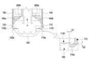
도 4 는 본 문서에 개시된 다양한 실시예에 따른 휴대용 통신 장치 또는 전자 장치에서, 제1 밀봉 부재 또는 제2 밀봉 부재가 장착되는 구성을 나타내는 분리 사시도이다.
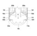
도 5는 본 문서에 개시된 다양한 실시예에 따른 휴대용 통신 장치 또는 전자 장치가 접혀진 모습을 나타내는 단면 구성도이다.
도 6은 본 문서에 개시된 다양한 실시예에 따른 휴대용 통신 장치 또는 전자 장치가 펼쳐진 모습을 나타내는 단면 구성도이다.
도 7과 도 8은 본 문서에 개시된 다양한 실시예에 따른 휴대용 통신 장치 또는 전자 장치에서 제1 밀봉 부재 또는 제2 밀봉 부재의 변형 예를 나타내는 단면 구성도이다.
도 9는 본 문서에 개시된 다양한 실시예에 따른 휴대용 통신 장치 또는 전자 장치에서, 제3 밀봉 부재가 장착되는 구성을 나타내는 분리 사시도이다.
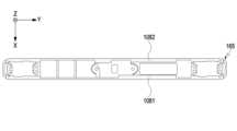
도 10은 본 문서에 개시된 다양한 실시예에 따른 휴대용 통신 장치 또는 전자 장치에서, 디스플레이 상에 형성되는 밀봉 구조를 설명하기 위한 도면이다.
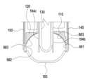
도 11은 본 문서에 개시된 다양한 실시예에 따른 휴대용 통신 장치 또는 전자 장치에서, 제3 밀봉 부재에 의해 형성된 밀봉 구조를 설명하기 위한 단면 구성도이다.
도 12는 본 문서에 개시된 다양한 실시예에 따른 휴대용 통신 장치 또는 전자 장치가 접혀진 상태에서, 제3 밀봉 부재에 의해 형성된 밀봉 구조를 설명하기 위한 단면 구성도이다.
도 13은 본 문서에 개시된 다양한 실시예에 따른 휴대용 통신 장치 또는 전자 장치의 힌지 커버를 나타내는 평면도이다.
도 14 내지 도 19는 본 문서에 개시된 다양한 실시예에 따른 휴대용 통신 장치 또는 전자 장치에서 제1 밀봉 부재 또는 제2 밀봉 부재의 다른 변형 예를 나타내는 단면 구성도이다.
도 20은 본 문서에 개시된 다양한 실시예에 따른 휴대용 통신 장치 또는 전자 장치에서, 제1 밀봉 부재 또는 제2 밀봉 부재가 장착되는 구조의 다른 예를 나타내는 분리 사시도이다.
도 21은 본 문서에 개시된 다양한 실시예에 따른 휴대용 통신 장치 또는 전자 장치에서, 제1 밀봉 부재 또는 제2 밀봉 부재가 장착된 구조의 다른 예를 나타내는 평면도이다.
도 22와 도 23은 본 문서에 개시된 다양한 실시예에 따른 휴대용 통신 장치 또는 전자 장치에서 제1 밀봉 부재 또는 제2 밀봉 부재의 또 다른 변형 예를 나타내는 단면 구성도이다.
도 24와 도 25는 본 문서에 개시된 다양한 실시예에 따른 휴대용 통신 장치 또는 전자 장치의 변형 예를 나타내는 단면 구성도이다.
도 26은 본 문서에 개시된 다양한 실시예에 따른 휴대용 통신 장치 또는 전자 장치의 또 다른 변형 예를 나타내는 단면 구성도이다.
도 27은 본 문서에 개시된 다양한 실시예에 따른 휴대용 통신 장치 또는 전자 장치에서, 밀봉 부재의 또 다른 변형 예를 나타내는 사시도이다.FIG. 1 is a drawing showing an unfolded state of a portable communication device or electronic device according to various embodiments disclosed in this document.
FIG. 2 is a drawing showing a folded state of the electronic device of FIG. 1 according to various embodiments disclosed in this document.
FIG. 3 is an exploded perspective view of a portable communication device or electronic device according to various embodiments disclosed herein.
FIG. 4 is an exploded perspective view showing a configuration in which a first sealing member or a second sealing member is mounted in a portable communication device or an electronic device according to various embodiments disclosed in the present document.
FIG. 5 is a cross-sectional diagram showing a folded state of a portable communication device or electronic device according to various embodiments disclosed in this document.
FIG. 6 is a cross-sectional diagram showing an unfolded state of a portable communication device or electronic device according to various embodiments disclosed in this document.
FIGS. 7 and 8 are cross-sectional diagrams showing modified examples of a first sealing member or a second sealing member in a portable communication device or an electronic device according to various embodiments disclosed in the present document.
FIG. 9 is an exploded perspective view showing a configuration in which a third sealing member is mounted in a portable communication device or electronic device according to various embodiments disclosed in this document.
FIG. 10 is a drawing for explaining a sealing structure formed on a display in a portable communication device or electronic device according to various embodiments disclosed in this document.
FIG. 11 is a cross-sectional configuration diagram for explaining a sealing structure formed by a third sealing member in a portable communication device or electronic device according to various embodiments disclosed in the present document.
FIG. 12 is a cross-sectional configuration diagram illustrating a sealing structure formed by a third sealing member in a folded state of a portable communication device or electronic device according to various embodiments disclosed in this document.
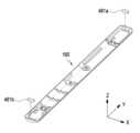
FIG. 13 is a plan view illustrating a hinge cover of a portable communication device or electronic device according to various embodiments disclosed in the present document.
FIGS. 14 to 19 are cross-sectional diagrams showing other modified examples of a first sealing member or a second sealing member in a portable communication device or an electronic device according to various embodiments disclosed in the present document.
FIG. 20 is an exploded perspective view showing another example of a structure in which a first sealing member or a second sealing member is mounted in a portable communication device or an electronic device according to various embodiments disclosed in the present document.
FIG. 21 is a plan view showing another example of a structure in which a first sealing member or a second sealing member is mounted in a portable communication device or an electronic device according to various embodiments disclosed in the present document.
FIGS. 22 and 23 are cross-sectional diagrams showing further variations of a first sealing member or a second sealing member in a portable communication device or an electronic device according to various embodiments disclosed in the present document.
FIGS. 24 and 25 are cross-sectional diagrams showing modified examples of portable communication devices or electronic devices according to various embodiments disclosed in this document.
FIG. 26 is a cross-sectional diagram illustrating another modified example of a portable communication device or electronic device according to various embodiments disclosed in this document.
FIG. 27 is a perspective view showing another modified example of a sealing member in a portable communication device or electronic device according to various embodiments disclosed in the present document.
본 문서의 다양한 실시예들 및 이에 사용된 용어들은 본 문서에 기재된 기술적 특징들을 특정한 실시예들로 한정하려는 것이 아니며, 해당 실시예의 다양한 변경, 균등물, 또는 대체물을 포함하는 것으로 이해되어야 한다. 도면의 설명과 관련하여, 유사한 또는 관련된 구성요소에 대해서는 유사한 참조 부호가 사용될 수 있다. 아이템에 대응하는 명사의 단수 형은 관련된 문맥상 명백하게 다르게 지시하지 않는 한, 상기 아이템 한 개 또는 복수 개를 포함할 수 있다. 본 문서에서, "A 또는 B", "A 및 B 중 적어도 하나",“A 또는 B 중 적어도 하나,”"A, B 또는 C", "A, B 및 C 중 적어도 하나”, 및 “A, B, 또는 C 중 적어도 하나"와 같은 문구들 각각은 그 문구들 중 해당하는 문구에 함께 나열된 항목들 중 어느 하나, 또는 그들의 모든 가능한 조합을 포함할 수 있다. "제1", "제2", 또는 "첫째" 또는 "둘째"와 같은 용어들은 단순히 해당 구성요소를 다른 해당 구성요소와 구분하기 위해 사용될 수 있으며, 해당 구성요소들을 다른 측면(예: 중요성 또는 순서)에서 한정하지 않는다. 어떤(예: 제1) 구성요소가 다른(예: 제2) 구성요소에, “기능적으로” 또는 “통신적으로”라는 용어와 함께 또는 이런 용어 없이, “커플드” 또는 “커넥티드”라고 언급된 경우, 그것은 상기 어떤 구성요소가 상기 다른 구성요소에 직접적으로(예: 유선으로), 무선으로, 또는 제3 구성요소를 통하여 연결될 수 있다는 것을 의미한다.The various embodiments of this document and the terminology used herein are not intended to limit the technical features described in this document to specific embodiments, but should be understood to encompass various modifications, equivalents, or alternatives of the embodiments. In connection with the description of the drawings, similar reference numerals may be used for similar or related components. The singular form of a noun corresponding to an item may include one or more of the items, unless the context clearly indicates otherwise. In this document, each of the phrases "A or B," "at least one of A and B," "at least one of A or B," "A, B, or C," "at least one of A, B, and C," and "at least one of A, B, or C" may include any one of the items listed together in the corresponding phrase, or all possible combinations thereof. Terms such as "first," "second," or "first" or "second" may be used merely to distinguish the corresponding component from other corresponding components, and do not limit the corresponding components in any other respect (e.g., importance or order). When a component (e.g., a first component) is referred to as being “coupled” or “connected” to another component (e.g., a second component), with or without the terms “functionally” or “communicatively,” it means that the component can be connected to the other component directly (e.g., wired), wirelessly, or through a third component.
본 문서에서 사용된 용어 "모듈"은 하드웨어, 소프트웨어 또는 펌웨어로 구현된 유닛을 포함할 수 있으며, 예를 들면, 로직, 논리 블록, 부품, 또는 회로 등의 용어와 상호 호환적으로 사용될 수 있다. 모듈은, 일체로 구성된 부품 또는 하나 또는 그 이상의 기능을 수행하는, 상기 부품의 최소 단위 또는 그 일부가 될 수 있다. 예를 들면, 일실시예에 따르면, 모듈은 ASIC(application-specific integrated circuit)의 형태로 구현될 수 있다.The term "module" as used in this document may include a unit implemented in hardware, software or firmware, and may be used interchangeably with terms such as logic, logic block, component, or circuit. A module may be an integrally configured component or a minimum unit of the component or a part thereof that performs one or more functions. For example, according to one embodiment, a module may be implemented in the form of an application-specific integrated circuit (ASIC).
본 문서의 다양한 실시예들은 기기(machine)(예: 전자 장치) 의해 읽을 수 있는 저장 매체(storage medium)(예: 내장 메모리 또는 외장 메모리)에 저장된 하나 이상의 명령어들을 포함하는 소프트웨어(예: 프로그램)로서 구현될 수 있다. 예를 들면, 기기(예: 전자 장치)의 프로세서(예: 프로세서)는, 저장 매체로부터 저장된 하나 이상의 명령어들 중 적어도 하나의 명령을 호출하고, 그것을 실행할 수 있다. 이것은 기기가 상기 호출된 적어도 하나의 명령어에 따라 적어도 하나의 기능을 수행하도록 운영되는 것을 가능하게 한다. 상기 하나 이상의 명령어들은 컴파일러에 의해 생성된 코드 또는 인터프리터에 의해 실행될 수 있는 코드를 포함할 수 있다. 기기로 읽을 수 있는 저장매체는, 비일시적(non-transitory) 저장매체의 형태로 제공될 수 있다. 여기서, ‘비일시적’은 저장매체가 실재(tangible)하는 장치이고, 신호(signal)(예: 전자기파)를 포함하지 않는다는 것을 의미할 뿐이며, 이 용어는 데이터가 저장매체에 반영구적으로 저장되는 경우와 임시적으로 저장되는 경우를 구분하지 않는다.Various embodiments of the present document may be implemented as software (e.g., a program) including one or more instructions stored in a storage medium (e.g., an internal memory or an external memory) that can be read by a machine (e.g., an electronic device). For example, a processor (e.g., a processor) of the machine (e.g., an electronic device) may call at least one instruction among the one or more instructions stored from the storage medium and execute it. This enables the machine to operate to perform at least one function according to the at least one instruction called. The one or more instructions may include code generated by a compiler or code that can be executed by an interpreter. The machine-readable storage medium may be provided in the form of a non-transitory storage medium. Here, ‘non-transitory’ only means that the storage medium is a tangible device and does not include a signal (e.g., an electromagnetic wave), and this term does not distinguish between cases where data is stored semi-permanently and cases where it is stored temporarily in the storage medium.
일실시예에 따르면, 본 문서에 개시된 다양한 실시예들에 따른 방법은 컴퓨터 프로그램 제품(computer program product)에 포함되어 제공될 수 있다. 컴퓨터 프로그램 제품은 상품으로서 판매자 및 구매자 간에 거래될 수 있다. 컴퓨터 프로그램 제품은 기기로 읽을 수 있는 저장 매체(예: compact disc read only memory (CD-ROM))의 형태로 배포되거나, 또는 어플리케이션 스토어(예: 플레이 스토어TM)를 통해 또는 두개의 사용자 장치들(예: 스마트폰들) 간에 직접, 온라인으로 배포(예: 다운로드 또는 업로드)될 수 있다. 온라인 배포의 경우에, 컴퓨터 프로그램 제품의 적어도 일부는 제조사의 서버, 어플리케이션 스토어의 서버, 또는 중계 서버의 메모리와 같은 기기로 읽을 수 있는 저장 매체에 적어도 일시 저장되거나, 임시적으로 생성될 수 있다.According to one embodiment, the method according to various embodiments disclosed in the present document may be provided as included in a computer program product. The computer program product may be traded between a seller and a buyer as a commodity. The computer program product may be distributed in the form of a machine-readable storage medium (e.g., compact disc read only memory (CD-ROM)), or may be distributed online (e.g., downloaded or uploaded) via an application store (e.g., Play StoreTM) or directly between two user devices (e.g., smartphones). In the case of online distribution, at least a part of the computer program product may be at least temporarily stored or temporarily generated in a machine-readable storage medium, such as a memory of a manufacturer's server, a server of an application store, or an intermediary server.
다양한 실시예들에 따르면, 상기 기술한 구성요소들의 각각의 구성요소(예: 모듈 또는 프로그램)는 단수 또는 복수의 개체를 포함할 수 있다. 다양한 실시예들에 따르면, 전술한 해당 구성요소들 중 하나 이상의 구성요소들 또는 동작들이 생략되거나, 또는 하나 이상의 다른 구성요소들 또는 동작들이 추가될 수 있다. 대체적으로 또는 추가적으로, 복수의 구성요소들(예: 모듈 또는 프로그램)은 하나의 구성요소로 통합될 수 있다. 이런 경우, 통합된 구성요소는 상기 복수의 구성요소들 각각의 구성요소의 하나 이상의 기능들을 상기 통합 이전에 상기 복수의 구성요소들 중 해당 구성요소에 의해 수행되는 것과 동일 또는 유사하게 수행할 수 있다. 다양한 실시예들에 따르면, 모듈, 프로그램 또는 다른 구성요소에 의해 수행되는 동작들은 순차적으로, 병렬적으로, 반복적으로, 또는 휴리스틱하게 실행되거나, 상기 동작들 중 하나 이상이 다른 순서로 실행되거나, 생략되거나, 또는 하나 이상의 다른 동작들이 추가될 수 있다.According to various embodiments, each component (e.g., a module or a program) of the above-described components may include a single or multiple entities. According to various embodiments, one or more of the components or operations of the above-described components may be omitted, or one or more other components or operations may be added. Alternatively or additionally, a plurality of components (e.g., a module or a program) may be integrated into a single component. In such a case, the integrated component may perform one or more functions of each of the components of the plurality of components identically or similarly to those performed by the corresponding component of the plurality of components prior to the integration. According to various embodiments, the operations performed by the module, program or other component may be executed sequentially, in parallel, repeatedly, or heuristically, or one or more of the operations may be executed in a different order, omitted, or one or more other operations may be added.
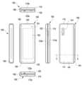
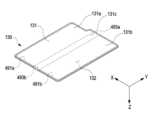
도 1은 본 문서에 개시된 다양한 실시예에 따른 휴대용 통신 장치 또는 전자 장치(100)의 펼침 상태를 나타내는 도면이다. 도 2는 본 문서에 개시된 다양한 실시예에 따른 도 1의 전자 장치(100)의 접힘 상태를 나타내는 도면이다.FIG. 1 is a drawing showing an unfolded state of a portable communication device or electronic device (100) according to various embodiments disclosed in this document. FIG. 2 is a drawing showing a folded state of the electronic device (100) of FIG. 1 according to various embodiments disclosed in this document.
이하의 상세한 설명에서, 한 쌍의 하우징 구조가 힌지 구조에 의해 회동 가능하게 결합된 구성에 관해 예시될 수 있다. 하지만 이러한 실시예가 본 문서에 개시된 다양한 실시예에 따른 휴대용 통신 장치 또는 전자 장치를 한정하지 않음에 유의한다. 예를 들어, 본 문서에 개시된 다양한 실시예에 따른 휴대용 통신 장치 또는 전자 장치는 세 개 이상의 하우징 구조를 포함할 수 있으며, 이하에서 개시하는 실시예의 "한 쌍의 하우징 구조"는 "세 개 이상의 하우징 구조 중 서로 회동 가능하게 결합된 두 개의 하우징 구조"를 의미할 수 있다.In the detailed description below, a configuration in which a pair of housing structures are rotatably coupled by a hinge structure may be exemplified. However, it should be noted that this embodiment does not limit the portable communication device or the electronic device according to various embodiments disclosed in the present document. For example, the portable communication device or the electronic device according to various embodiments disclosed in the present document may include three or more housing structures, and the "pair of housing structures" in the embodiments disclosed below may mean "two housing structures that are rotatably coupled to each other among the three or more housing structures."
도 1을 참조하면, 전자 장치(100)는, 서로에 대하여 접히도록 힌지 구조(예: 도 3의 힌지 구조(164a))를 통해 회동 가능하게 결합되는 한 쌍의 하우징 구조(110, 120), 한 쌍의 하우징 구조(110, 120)의 접힘 가능한 부분을 커버하는 힌지 커버(165), 및 한 쌍의 하우징 구조(110, 120)에 의해 형성된 공간에 배치 또는 수용되는 디스플레이(130)(예: 플렉서블(flexible) 디스플레이 또는 폴더블(foldable) 디스플레이)를 포함할 수 있다. 힌지 커버(165)는 제1 하우징 구조(110)의 적어도 일부와 제2 하우징 구조(120)의 적어도 일부 사이에 위치될 수 있다. 힌지 구조(164)는 디스플레이(130)과 힌지 커버(165) 사이에 배치되며, 제1 하우징 구조(110)와 제2 하우징 구조(120)에 연결될 수 있다. 한 실시예에서, 전자 장치(100)는 한 쌍의 하우징 구조(110, 120)가 서로 마주보게 접혀진 위치로부터 서로에 대하여 나란하게 펼쳐진 위치까지 회동 가능하게 결합된 폴더블 하우징을 포함할 수 있다. 본 문서에서, 한 쌍의 하우징 구조(110, 120)가 서로의 일측에 나란하게 펼쳐진 때, 디스플레이(130)가 배치된 면은 전자 장치(100)의 전면으로 정의될 수 있으며, 전면의 반대 면은 전자 장치(100)의 후면으로 정의될 수 있다. 또한 전면과 후면 사이의 공간을 둘러싸는 면은 전자 장치(100)의 측면으로 정의될 수 있다.Referring to FIG. 1, an electronic device (100) may include a pair of housing structures (110, 120) that are rotatably coupled to each other via a hinge structure (e.g., hinge structure (164a) of FIG. 3) to be folded with respect to each other, a hinge cover (165) that covers a foldable portion of the pair of housing structures (110, 120), and a display (130) (e.g., a flexible display or a foldable display) that is positioned or accommodated in a space formed by the pair of housing structures (110, 120). The hinge cover (165) may be positioned between at least a portion of a first housing structure (110) and at least a portion of a second housing structure (120). The hinge structure (164) is disposed between the display (130) and the hinge cover (165) and may be connected to the first housing structure (110) and the second housing structure (120). In one embodiment, the electronic device (100) may include a foldable housing in which a pair of housing structures (110, 120) are rotatably coupled from a position in which the pair of housing structures (110, 120) are folded to face each other to a position in which the pair of housing structures (110, 120) are unfolded parallel to each other. In this document, when the pair of housing structures (110, 120) are unfolded parallel to each other on one side, the side on which the display (130) is disposed may be defined as the front side of the electronic device (100), and the opposite side of the front side may be defined as the back side of the electronic device (100). In addition, a side surrounding the space between the front side and the back side may be defined as a side surface of the electronic device (100).
일 실시예에서, 한 쌍의 하우징 구조(110, 120)는 센서 영역(131d)을 포함하는 제1 하우징 구조(110), 제2 하우징 구조(120), 제1 후면 커버(140) 및 제2 후면 커버(150)를 포함할 수 있다. 전자 장치(100)의 한 쌍의 하우징 구조(110, 120)는 도 1 및 도 2에 도시된 형태 및 결합으로 제한되지 않으며, 다른 형상이나 부품의 조합 및/또는 결합에 의해 구현될 수 있다. 예를 들어, 다른 실시예에서는, 제1 하우징 구조(110)와 제1 후면 커버(140)가 일체로 형성될 수 있고, 제2 하우징 구조(120)와 제2 후면 커버(150)가 일체로 형성될 수 있다. 다른 실시예에서, 제1 하우징 구조(110)는 제1 후면 커버(140)를 포함하며, 제2 하우징 구조(120)는 제2 후면 커버(150)를 포함할 수 있다.In one embodiment, the pair of housing structures (110, 120) may include a first housing structure (110) including a sensor area (131d), a second housing structure (120), a first back cover (140), and a second back cover (150). The pair of housing structures (110, 120) of the electronic device (100) are not limited to the shapes and combinations illustrated in FIGS. 1 and 2, and may be implemented by other shapes or combinations and/or combinations of parts. For example, in another embodiment, the first housing structure (110) and the first back cover (140) may be formed integrally, and the second housing structure (120) and the second back cover (150) may be formed integrally. In another embodiment, the first housing structure (110) may include the first back cover (140), and the second housing structure (120) may include the second back cover (150).
일 실시예에 따르면, 제1 하우징 구조(110)와 제2 하우징 구조(120)는 제1 축, 예를 들면 폴딩 축(A)을 중심으로 양측에 배치되고, 폴딩 축(A)에 대하여 전체적으로 대칭인 형상을 가질 수 있다. 어떤 실시예에서, 제1 하우징 구조(110)와 제2 하우징 구조(120)는 서로 다른 폴딩 축을 중심으로 힌지 구조(164a) 또는 상기 힌지 커버(165)에 대하여 회동할 수 있다. 예컨대, 제1 하우징 구조(110)와 제2 하우징 구조(120)는 힌지 구조(164a) 또는 힌지 커버(165)에 각각 회동 가능하게 결합될 수 있다. 한 실시예에 따르면, 제1 하우징 구조(110)와 제2 하우징 구조(120)는 폴딩 축(A)에 대하여 또는 서로 다른 폴딩 축에 대하여 각각 회동함으로써, 전면의 서로 다른 두 영역이 마주보게 접혀진 위치로부터 서로에 대하여 경사진 위치 또는 서로에 대하여 나란하게 펼쳐진 위치 사이에서 회동할 수 있다.According to one embodiment, the first housing structure (110) and the second housing structure (120) may be arranged on both sides about a first axis, for example, a folding axis (A), and may have a shape that is overall symmetrical about the folding axis (A). In some embodiments, the first housing structure (110) and the second housing structure (120) may be rotatable about different folding axes about the hinge structure (164a) or the hinge cover (165). For example, the first housing structure (110) and the second housing structure (120) may be rotatably coupled to the hinge structure (164a) or the hinge cover (165), respectively. In one embodiment, the first housing structure (110) and the second housing structure (120) can be rotated about the folding axis (A) or about different folding axes, respectively, so that the two different areas of the front surface can be rotated between a position where they are folded facing each other, to a position where they are inclined relative to each other, or a position where they are unfolded parallel to each other.
본 문서에서, "서로 나란하게 위치된다" 또는 "서로 나란하게 연장된다"라 함은 두 구조물이 적어도 부분적으로 서로의 옆에 위치된 상태 또는 적어도 서로의 옆에 위치된 부분들이 평행하게 배치된 상태를 의미할 수 있다. 어떤 실시예에서, "서로 나란하게 배치된다"라 함은 두 구조물이 서로의 옆에 위치되면서 평행한 방향 또는 동일한 방향을 바라보게 배치된 것을 의미할 수 있다. 다른 실시예에서, “서로 나란하게 배치된다”라 함은 대략 160도 내지 180도 각도 범위에서 서로에 대하여 경사진 상태를 포함하는 의미로 해석될 수 있다. 이하의 상세한 설명에서 "나란하게", "평행하게" 등의 표현이 사용될 수 있지만, 이는 첨부된 도면 등을 참고하여 구조물의 형상이나 배치 관계에 따라 용이하게 이해할 수 있을 것이다.In this document, the phrases “positioned parallel to each other” or “extending parallel to each other” may mean a state in which two structures are positioned at least partially next to each other or a state in which at least portions positioned next to each other are arranged in parallel. In some embodiments, the phrase “positioned parallel to each other” may mean that two structures are positioned next to each other and are arranged to face a parallel direction or the same direction. In other embodiments, the phrase “positioned parallel to each other” may be interpreted to mean a state in which they are inclined with respect to each other within an angle range of approximately 160 degrees to 180 degrees. Although expressions such as “parallel” and “parallel” may be used in the detailed description below, this may be easily understood according to the shape or arrangement relationship of the structures by referring to the attached drawings, etc.
일 실시예에 따르면, 제1 하우징 구조(110) 및 제2 하우징 구조(120)는 전자 장치(100)의 상태가 펼침 상태(exteded state, flat state 또는 open state)인지, 접힘 상태(folding state)인지, 또는 중간 상태인지 여부에 따라 서로 이루는 각도나 거리가 달라질 수 있다. 일 실시예에 따르면, 제1 하우징 구조(110)는 제2 하우징 구조(120)와 달리 다양한 센서들이 배치되는 센서 영역(131d)을 추가로 포함하지만, 이외의 영역에서는 상호 대칭적인 형상을 가질 수 있다. 다른 실시예로, 센서 영역(131d)은 제2 하우징 구조(120)의 적어도 일부 영역에 추가로 배치되거나 대체될 수도 있다.According to one embodiment, the angle or distance between the first housing structure (110) and the second housing structure (120) may vary depending on whether the state of the electronic device (100) is an extended state (flat state or open state), a folded state, or an intermediate state. According to one embodiment, the first housing structure (110) additionally includes a sensor area (131d) in which various sensors are arranged, unlike the second housing structure (120), but may have a shape that is symmetrical in other areas. In another embodiment, the sensor area (131d) may be additionally arranged in or replaced with at least a portion of the second housing structure (120).
일 실시예에서, 제1 하우징 구조(110)는 전자 장치(100)의 펼침 상태에서, 힌지 구조(예: 도 3의 힌지 구조(164a))에 연결되며, 전자 장치(100)의 전면을 향하도록 배치된 제1 면(111), 제1 면(111)의 반대 방향을 향하는 제2 면(112), 및 제1 면(111)과 제2 면(112) 사이의 공간의 적어도 일부를 둘러싸는 제1 측면 부재(113)를 포함할 수 있다. 일 실시예에서, 제1 측면 부재(113)는 폴딩 축(A)과 평행하게 배치되는 제1 측면(113a), 제1 측면(113a)의 일단으로부터 폴딩 축(A)과 수직한 방향으로 연장되는 제2 측면(113b) 및 제1 측면(113a)의 타단으로부터 폴딩 축(A)과 수직한 방향으로 연장되는 제3 측면(113c)을 포함할수 있다. 본 발명의 다양한 실시예를 설명함에 있어, 상술한 측면들의 배치 관계에 관해 "평행하게" 또는 "수직하게" 등의 표현을 사용하고 있으나, 실시예에 따라 이는 "부분적으로 평행하게" 또는 "부분적으로 수직하게"라는 의미를 포함할 수 있다. 어떤 실시예에서, "평행하게" 또는 "수직하게" 등의 표현은 대략 10도 이내의 각도 범위에서 경사진 배치 관계를 포함하는 의미일 수 있다.In one embodiment, the first housing structure (110) may include a first side (111) that is connected to a hinge structure (e.g., hinge structure (164a) of FIG. 3) when the electronic device (100) is in an unfolded state and is arranged to face the front of the electronic device (100), a second side (112) that faces in an opposite direction to the first side (111), and a first side member (113) that surrounds at least a portion of a space between the first side (111) and the second side (112). In one embodiment, the first side member (113) may include a first side (113a) that is arranged parallel to a folding axis (A), a second side (113b) that extends from one end of the first side (113a) in a direction perpendicular to the folding axis (A), and a third side (113c) that extends from the other end of the first side (113a) in a direction perpendicular to the folding axis (A). In describing various embodiments of the present invention, expressions such as “parallel” or “vertical” are used with respect to the arrangement relationship of the above-described aspects, but depending on the embodiment, this may include the meaning of “partially parallel” or “partially perpendicular.” In some embodiments, expressions such as “parallel” or “vertical” may include an inclined arrangement relationship within an angular range of approximately 10 degrees.
일 실시예에서, 제2 하우징 구조(120)는 힌지 구조(예: 도 3의 힌지 구조(164a))와 연결되며, 전자 장치(100)의 펼침 상태에서 전자 장치(100)의 전면을 향하도록 배치된 제3 면(121), 제3 면(121)의 반대 방향을 향하는 제4 면(122), 및 제3 면(121) 및 제4 면(122) 사이의 공간의 적어도 일부를 둘러싸는 제2 측면 부재(123)를 포함할 수 있다. 일 실시예에서, 제2 측면 부재(123)는 폴딩 축(A)과 평행하게 배치되는 제4 측면(123a), 제4 측면(123a)의 일단으로부터 폴딩 축(A)과 수직한 방향으로 연장되는 제5 측면(123b) 및 제4 측면(123a)의 타단으로부터 폴딩 축(A)과 수직한 방향으로 연장되는 제6 측면(123c)을 포함할수 있다. 일 실시예에서, 제3 면(121)은 접힘 상태에서 제1 면(111)과 마주보도록 배치될 수 있다. 어떤 실시예에서, 구체적인 형상에서 일부 차이가 있기는 하나 상기 제2 측면 부재(123)는 상기 제1 측면 부재(113)와 실질적으로 동일한 형상 또는 재질로 제작될 수 있다.In one embodiment, the second housing structure (120) may include a third side (121) that is connected to a hinge structure (e.g., the hinge structure (164a) of FIG. 3) and is arranged to face the front of the electronic device (100) in an unfolded state of the electronic device (100), a fourth side (122) that faces in an opposite direction to the third side (121), and a second side member (123) that surrounds at least a portion of a space between the third side (121) and the fourth side (122). In one embodiment, the second side member (123) may include a fourth side (123a) that is arranged parallel to the folding axis (A), a fifth side (123b) that extends from one end of the fourth side (123a) in a direction perpendicular to the folding axis (A), and a sixth side (123c) that extends from the other end of the fourth side (123a) in a direction perpendicular to the folding axis (A). In one embodiment, the third side (121) may be positioned to face the first side (111) in a folded state. In some embodiments, the second side member (123) may be manufactured with substantially the same shape or material as the first side member (113), although there may be some differences in specific shapes.
일 실시예에서, 전자 장치(100)는 제1 하우징 구조(110)와, 제2 하우징 구조(120)의 구조적 형상 결합을 통하여 디스플레이(130)를 수용하도록 형성되는 리세스(101)를 포함할 수 있다. 리세스(101)는 디스플레이(130)와 실질적으로 동일한 크기를 가질 수 있다. 일 실시예에서, 센서 영역(131d)으로 인해, 리세스(101)는 폴딩 축(A)에 대해 수직한 방향으로 서로 다른 2개 이상의 폭(W1, W2)을 가질 수 있다. 예를 들어, 리세스(101)는 제2 하우징 구조(120) 중 폴딩 축(A)에 평행한 제1 부분(120a)과 제1 하우징 구조(110) 중 센서 영역(131d)의 가장자리에 형성되는 제1 부분(110a) 사이의 제1 폭(W1), 및 제2 하우징 구조(120)의 제2 부분(120b)과 제1 하우징 구조(110) 중 센서 영역(131d)에 해당하지 않으면서 폴딩 축(A)에 평행한 제2 부분(110b)에 의해 형성되는 제2 폭(W2)을 가질 수 있다. 이러한 경우, 제2 폭(W2)은 제1 폭(W1)보다 길게 형성될 수 있다. 예컨대, 리세스(101)는 상호 비대칭 형상을 갖는 제1 하우징 구조(110)의 제1 부분(110a)으로부터 제2 하우징 구조(120)의 제1 부분(120a)까지 형성되는 제1 폭(W1)과, 상호 대칭 형상을 갖는 제1 하우징 구조(110)의 제2 부분(110b)으로부터 제2 하우징 구조(120)의 제2 부분(120b)까지 형성되는 제2 폭(W2)을 갖도록 형성될 수 있다. 일 실시예에서, 제1 하우징 구조(110)의 제1 부분(110a) 및 제2 부분(110b)은 폴딩 축(A)으로부터 서로 다른 거리를 갖도록 형성될 수 있다. 리세스(101)의 폭은 도시된 예시로 한정되지 아니한다. 다양한 실시예에서, 센서 영역(131d)의 형태 또는 제1 하우징 구조(110) 및 제2 하우징 구조(120)의 비대칭 형상을 갖는 부분에 의해 리세스(101)는 2개 이상의 서로 다른 폭을 가질 수도 있다.In one embodiment, the electronic device (100) may include a recess (101) formed to accommodate a display (130) through a structural shape combination of a first housing structure (110) and a second housing structure (120). The recess (101) may have substantially the same size as the display (130). In one embodiment, due to the sensor area (131d), the recess (101) may have two or more different widths (W1, W2) in a direction perpendicular to the folding axis (A). For example, the recess (101) may have a first width (W1) between a first portion (120a) of the second housing structure (120) that is parallel to the folding axis (A) and a first portion (110a) formed at an edge of the sensor area (131d) of the first housing structure (110), and a second width (W2) formed by a second portion (120b) of the second housing structure (120) and a second portion (110b) that is parallel to the folding axis (A) and does not correspond to the sensor area (131d) of the first housing structure (110). In this case, the second width (W2) may be formed longer than the first width (W1). For example, the recess (101) may be formed to have a first width (W1) formed from a first portion (110a) of a first housing structure (110) having a mutually asymmetrical shape to a first portion (120a) of a second housing structure (120), and a second width (W2) formed from a second portion (110b) of the first housing structure (110) having a mutually symmetrical shape to a second portion (120b) of the second housing structure (120). In one embodiment, the first portion (110a) and the second portion (110b) of the first housing structure (110) may be formed to have different distances from the folding axis (A). The width of the recess (101) is not limited to the illustrated example. In various embodiments, the recess (101) may have two or more different widths due to the shape of the sensor area (131d) or the asymmetrical shape of the first housing structure (110) and the second housing structure (120).
일 실시예에서, 제1 하우징 구조(110) 및 제2 하우징 구조(120)의 적어도 일부는 디스플레이(130)를 지지하기 위해 선택된 크기의 강성을 갖는 금속 재질 또는 비금속 재질로 형성될 수 있다. 다른 실시예에서, 제1 하우징 구조(110) 및 제2 하우징 구조(120)의 적어도 일부는 도전성 재질(electrically conductive material)을 포함할 수 있다. 제1 하우징 구조(110) 및 제2 하우징 구조(120)가 도전성 재질을 포함하는 경우, 전자 장치(100)는 제1 하우징 구조(110) 및 제2 하우징 구조(120)의 도전성 재질로 이루어진 부분을 이용하여 무선 전파를 송수신할 수 있다. 예컨대, 전자 장치(100)의 프로세서 또는 통신 모듈은 제1 하우징 구조(110) 및 제2 하우징 구조(120)의 일부분을 이용하여 무선 통신을 수행할 수 있다.In one embodiment, at least a portion of the first housing structure (110) and the second housing structure (120) may be formed of a metallic or non-metallic material having a rigidity selected to support the display (130). In another embodiment, at least a portion of the first housing structure (110) and the second housing structure (120) may include an electrically conductive material. When the first housing structure (110) and the second housing structure (120) include a conductive material, the electronic device (100) may transmit and receive wireless radio waves using portions of the first housing structure (110) and the second housing structure (120) made of the conductive material. For example, a processor or a communication module of the electronic device (100) may perform wireless communication using portions of the first housing structure (110) and the second housing structure (120).
일 실시예에서, 센서 영역(131d)은 제1 하우징 구조(110)의 일측 코너에 인접하여 소정 영역을 가지도록 형성될 수 있다. 다만 센서 영역(131d)의 배치, 형상, 또는 크기는 도시된 예시에 한정되지 아니한다. 예를 들어, 다른 실시예에서 센서 영역(131d)은 제1 하우징 구조(110)의 다른 코너 혹은 상단 코너와 하단 코너 사이의 임의의 영역에 제공될 수 있다. 다른 실시예로, 센서 영역(131d)은 제2 하우징 구조(120)의 적어도 일부 영역에 배치될 수도 있다. 다른 실시예로, 센서 영역(131d)은 제1 하우징 구조(110) 및 제2 하우징 구조(120)에 연장되도록 배치될 수도 있다. 일 실시예에서, 전자 장치(100)는 센서 영역(131d)을 통하거나, 또는 센서 영역(131d)에 마련된 하나 이상의 개구(opening)를 통해 전자 장치(100)의 전면에 노출된 부품들(components)을 포함할 수 있으며, 이러한 부품들을 통해 다양한 기능을 수행할 수 있다. 센서 영역(131d)에 배치된 부품들은, 예를 들어, 전면 카메라 장치, 근접 센서, 조도 센서, 홍채 인식 센서, 초음파 센서 또는 인디케이터 중 적어도 하나를 포함할 수 있다.In one embodiment, the sensor region (131d) may be formed to have a predetermined region adjacent to one corner of the first housing structure (110). However, the arrangement, shape, or size of the sensor region (131d) is not limited to the illustrated example. For example, in another embodiment, the sensor region (131d) may be provided at another corner of the first housing structure (110) or any region between the upper corner and the lower corner. In another embodiment, the sensor region (131d) may be arranged at at least a portion of the second housing structure (120). In another embodiment, the sensor region (131d) may be arranged to extend to the first housing structure (110) and the second housing structure (120). In one embodiment, the electronic device (100) may include components exposed on the front side of the electronic device (100) through the sensor area (131d) or through one or more openings provided in the sensor area (131d), and may perform various functions through these components. The components disposed in the sensor area (131d) may include, for example, at least one of a front camera device, a proximity sensor, an illuminance sensor, an iris recognition sensor, an ultrasonic sensor, or an indicator.
일 실시예에서, 제1 후면 커버(140)는 제1 하우징 구조(110)의 제2 면(112)에 배치될 수 있고, 실질적으로 직사각형인 가장자리(periphery)를 가질 수 있다. 일 실시예에서, 제1 후면 커버(140)의 가장자리는 적어도 부분적으로 제1 하우징 구조(110)에 의해 감싸질 수 있다. 유사하게, 제2 후면 커버(150)는 제2 하우징 구조(120)의 제4 면(122)에 배치될 수 있고, 제2 하우징 구조(120)에 의해 그 가장자리의 적어도 일부가 감싸질 수 있다.In one embodiment, the first back cover (140) can be disposed on the second side (112) of the first housing structure (110) and can have a substantially rectangular periphery. In one embodiment, the periphery of the first back cover (140) can be at least partially wrapped by the first housing structure (110). Similarly, the second back cover (150) can be disposed on the fourth side (122) of the second housing structure (120) and can have at least a portion of its periphery wrapped by the second housing structure (120).
도시된 실시예에서, 제1 후면 커버(140) 및 제2 후면 커버(150)는 폴딩 축(A)을 기준으로 실질적으로 대칭적인 형상을 가질 수 있다. 다른 실시예로, 제1 후면 커버(140) 및 제2 후면 커버(150)는 서로 다른 다양한 형상을 포함할 수도 있다. 또 다른 실시예로, 제1 후면 커버(140)는 제1 하우징 구조(110)와 일체로 형성될 수 있고, 제2 후면 커버(150)는 제2 하우징 구조(120)와 일체로 형성될 수 있다.In the illustrated embodiment, the first rear cover (140) and the second rear cover (150) may have substantially symmetrical shapes with respect to the folding axis (A). In another embodiment, the first rear cover (140) and the second rear cover (150) may include various different shapes. In yet another embodiment, the first rear cover (140) may be formed integrally with the first housing structure (110), and the second rear cover (150) may be formed integrally with the second housing structure (120).
일 실시예에서, 제1 후면 커버(140), 제2 후면 커버(150), 제1 하우징 구조(110), 및 제2 하우징 구조(120)는 서로 결합된 구조를 통해 전자 장치(100)의 다양한 부품들(예: 인쇄회로 기판, 안테나 모듈, 센서 모듈 또는 배터리)이 배치될 수 있는 공간을 제공할 수 있다. 일 실시예에서, 전자 장치(100)의 후면에는 하나 이상의 부품(components)이 배치되거나 시각적으로 노출될 수 있다. 예를 들어, 제1 후면 커버(140)의 제1 후면 영역(141)을 통해 하나 이상의 부품 또는 센서가 시각적으로 노출될 수 있다. 다양한 실시예에서 상기 센서는 근접 센서, 후면 카메라 장치 및/또는 플래시를 포함할 수 있다. 다른 실시예에서, 제2 후면 커버(150)의 제2 후면 영역(151)을 통해 서브 디스플레이(152)의 적어도 일부가 시각적으로 노출될 수 있다.In one embodiment, the first rear cover (140), the second rear cover (150), the first housing structure (110), and the second housing structure (120) may be structured to be coupled to each other to provide a space in which various components of the electronic device (100) (e.g., a printed circuit board, an antenna module, a sensor module, or a battery) may be placed. In one embodiment, one or more components may be placed or visually exposed on the rear surface of the electronic device (100). For example, one or more components or sensors may be visually exposed through the first rear area (141) of the first rear cover (140). In various embodiments, the sensors may include a proximity sensor, a rear camera device, and/or a flash. In another embodiment, at least a portion of the sub-display (152) may be visually exposed through the second rear area (151) of the second rear cover (150).
디스플레이(130)는, 한 쌍의 하우징 구조(110, 120)에 의해 형성된 공간 상에 배치될 수 있다. 예를 들어, 디스플레이(130)는 한 쌍의 하우징 구조(110, 120)에 의해 형성되는 리세스(recess)(예: 도 1의 리세스(101))에 안착될 수 있으며, 전자 장치(100)의 전면의 실질적으로 대부분을 차지하도록 배치될 수 있다. 예를 들어, 전자 장치(100)의 전면은 디스플레이(130) 및 디스플레이(130)에 인접한 제1 하우징 구조(110)의 일부 영역(예: 가장자리 영역) 및 제2 하우징 구조(120)의 일부 영역(예: 가장자리 영역)을 포함할 수 있다. 일 실시예에서, 전자 장치(100)의 후면은 제1 후면 커버(140), 제1 후면 커버(140)에 인접한 제1 하우징 구조(110)의 일부 영역(예: 가장자리 영역), 제2 후면 커버(150) 및 제2 후면 커버(150)에 인접한 제2 하우징 구조(120)의 일부 영역(예: 가장자리 영역)을 포함할 수 있다.The display (130) may be placed on a space formed by a pair of housing structures (110, 120). For example, the display (130) may be mounted in a recess (e.g., recess (101) of FIG. 1) formed by a pair of housing structures (110, 120) and may be placed to occupy substantially most of the front surface of the electronic device (100). For example, the front surface of the electronic device (100) may include the display (130) and a portion (e.g., an edge portion) of the first housing structure (110) adjacent to the display (130) and a portion (e.g., an edge portion) of the second housing structure (120). In one embodiment, the back surface of the electronic device (100) may include a first back cover (140), a portion (e.g., an edge portion) of a first housing structure (110) adjacent the first back cover (140), a second back cover (150), and a portion (e.g., an edge portion) of a second housing structure (120) adjacent the second back cover (150).
일 실시예에서, 디스플레이(130)는, 적어도 일부 영역이 평면 또는 곡면으로 변형될 수 있는 디스플레이를 의미할 수 있다. 일 실시예에서, 디스플레이(130)는 폴딩 부분(131c), 폴딩 부분(131c)을 기준으로 일측(예: 폴딩 부분(131c)의 우측 영역)에 배치되는 제1 부분(131a) 및 타측(예: 폴딩 부분(131c)의 좌측 영역)에 배치되는 제2 부분(131b)을 포함할 수 있다. 예를 들면, 제1 부분(131a)은 제1 하우징 구조(110)의 제1 면(111)에 배치되고, 제2 부분(131b)은 제2 하우징 구조(120)의 제3 면(121)에 배치될 수 있다. 예컨대, 디스플레이(130)는 제1 면(111)으로부터 힌지 커버(165) 또는 도 3의 힌지 구조(164a)를 지나 상기 제3 면(121)으로 연장될 수 있으며, 적어도 힌지 커버(165) 또는 힌지 구조(164a)와 대응하는 부분(예: 폴딩 부분(131c))은 평판 형태에서 곡면 형태로 변형 가능한 플렉서블 부분(flexible portion)일 수 있다.In one embodiment, the display (130) may mean a display in which at least a portion of the display can be transformed into a flat or curved surface. In one embodiment, the display (130) may include a folding portion (131c), a first portion (131a) disposed on one side (e.g., a right side of the folding portion (131c)) with respect to the folding portion (131c), and a second portion (131b) disposed on the other side (e.g., a left side of the folding portion (131c)). For example, the first portion (131a) may be disposed on a first surface (111) of the first housing structure (110), and the second portion (131b) may be disposed on a third surface (121) of the second housing structure (120). For example, the display (130) may extend from the first surface (111) to the third surface (121) through the hinge cover (165) or the hinge structure (164a) of FIG. 3, and at least a portion corresponding to the hinge cover (165) or the hinge structure (164a) (e.g., the folding portion (131c)) may be a flexible portion that can be transformed from a flat shape to a curved shape.
일 실시예에서, 디스플레이(130)의 영역 구분은 예시적인 것이며, 디스플레이(130)는 구조 또는 기능에 따라 복수(예를 들어, 4개 이상 혹은 2개)의 영역으로 구분될 수도 있다. 일례로, 도 1에 도시된 실시예에서, 폴딩 부분(131c)은 폴딩 축(A)에 평행한 세로축(예: 도 3의 y축) 방향으로 연장되며, 폴딩 부분(131c) 또는 폴딩 축(A축)에 의해 디스플레이(130)의 영역이 구분될 수 있으나, 다른 실시예에서 디스플레이(130)는 다른 폴딩 부분(예: 가로축(예: 도 3의 x축)에 평행한 폴딩 부분) 또는 다른 폴딩 축(예: 도 3의 x축에 평행한 폴딩 축)을 기준으로 영역이 구분될 수도 있다. 전술한 디스플레이의 영역 구분은 한 쌍의 하우징 구조(110, 120) 및 힌지 구조(예: 힌지 커버(165) 또는 도 3의 힌지 구조(164a))에 의한 물리적 구분일 뿐, 실질적으로 하나의 디스플레이(130)가 한 쌍의 하우징 구조(110, 120) 및 힌지 구조(예: 힌지 커버(165) 또는 도 3의 힌지 구조(164a))가 제공하는 영역 또는 공간에 배치되어 하나의 전체 화면을 표시할 수 있다.In one embodiment, the division of regions of the display (130) is exemplary, and the display (130) may be divided into a plurality of regions (for example, four or more or two) depending on the structure or function. For example, in the embodiment illustrated in FIG. 1, the folding portion (131c) extends in the direction of the vertical axis (for example, the y-axis of FIG. 3) parallel to the folding axis (A), and the regions of the display (130) may be divided by the folding portion (131c) or the folding axis (A-axis), but in another embodiment, the display (130) may be divided into regions based on another folding portion (for example, a folding portion parallel to the horizontal axis (for example, the x-axis of FIG. 3)) or another folding axis (for example, a folding axis parallel to the x-axis of FIG. 3). The above-described display area division is merely a physical division by a pair of housing structures (110, 120) and a hinge structure (e.g., a hinge cover (165) or a hinge structure (164a) of FIG. 3), and in reality, one display (130) may be placed in an area or space provided by a pair of housing structures (110, 120) and a hinge structure (e.g., a hinge cover (165) or a hinge structure (164a) of FIG. 3) to display one entire screen.
한 실시예에 따르면, 제1 부분(131a)과 제2 부분(131b)은 폴딩 부분(131c)을 중심으로 전체적으로 대칭인 형상을 가질 수 있다. 다만, 제1 부분(131a)은, 제2 부분(131b)과 달리, 센서 영역(131d)을 제공하는 노치(notch) 영역(예: 도 3의 노치 영역(133))을 포함할 수 있으며, 이외의 영역에서는 제2 부분(131b)과 대칭적인 형상을 가질 수 있다. 예컨대, 제1 부분(131a)과 제2 부분(131b)은 서로 대칭적인 형상을 갖는 부분과, 서로 비대칭적인 형상을 갖는 부분을 포함할 수 있다.According to one embodiment, the first portion (131a) and the second portion (131b) may have an overall symmetrical shape centered on the folding portion (131c). However, unlike the second portion (131b), the first portion (131a) may include a notch region (e.g., the notch region (133) of FIG. 3) that provides a sensor region (131d), and may have a shape symmetrical with respect to the second portion (131b) in other regions. For example, the first portion (131a) and the second portion (131b) may include a portion having a symmetrical shape with respect to each other and a portion having an asymmetrical shape with respect to each other.
도 3을 더 참조하면, 힌지 커버(165)는, 제1 하우징 구조(110)와 제2 하우징 구조(120) 사이에 배치되어, 내부 부품(예: 도 3의 힌지 구조(164a))을 가릴 수 있도록 구성될 수 있다. 일 실시예에서, 힌지 커버(165)는, 전자 장치(100)의 작동 상태(펼침 상태(extended state) 또는 접힘 상태(folded state))에 따라, 제1 하우징 구조(110) 및 제2 하우징 구조(120)의 일부에 의해 가려지거나, 외부로 노출될 수 있다. 예를 들어, 힌지 커버(165)는 펼침 상태에서보다 접힘 상태에서 더 많이 외부로 노출될 수 있다.Referring further to FIG. 3, the hinge cover (165) may be configured to be disposed between the first housing structure (110) and the second housing structure (120) so as to cover an internal component (e.g., the hinge structure (164a) of FIG. 3). In one embodiment, the hinge cover (165) may be covered by a portion of the first housing structure (110) and the second housing structure (120) or exposed to the outside depending on the operating state (extended state or folded state) of the electronic device (100). For example, the hinge cover (165) may be exposed to the outside more in the folded state than in the extended state.
이하, 전자 장치(100)의 작동 상태(예: 펼침 상태(extended state) 및 접힘 상태(folded state))에 따른 제1 하우징 구조(110) 및 제2 하우징 구조(120)의 동작과 디스플레이(130)의 각 영역을 설명한다.Hereinafter, the operation of the first housing structure (110) and the second housing structure (120) and each area of the display (130) according to the operating state (e.g., extended state and folded state) of the electronic device (100) will be described.
일 실시예에서, 전자 장치(100)가 펼침 상태(extended state)(예: 도 1의 상태)인 경우, 제1 하우징 구조(110) 및 제2 하우징 구조(120)는 180도의 각도를 이루며, 디스플레이의 제1 부분(131a) 및 제2 부분(131b)은 동일 방향을 향하도록, 예를 들어, 서로 평행한 방향으로 화면을 표시하도록 배치될 수 있다. 또한, 폴딩 부분(131c)은 제1 부분(131a) 및 제2 부분(131b)과 동일 평면을 형성할 수 있다.In one embodiment, when the electronic device (100) is in an extended state (e.g., the state of FIG. 1), the first housing structure (110) and the second housing structure (120) form an angle of 180 degrees, and the first part (131a) and the second part (131b) of the display may be arranged to face the same direction, for example, to display the screen in a direction parallel to each other. In addition, the folding part (131c) may form the same plane as the first part (131a) and the second part (131b).
일 실시예에서, 전자 장치(100)가 접힘 상태(folded state)(예: 도 2의 상태)인 경우, 제1 하우징 구조(110) 및 제2 하우징 구조(120)는 서로 마주보게 배치될 수 있다. 예를 들어, 전자 장치(100)가 접힘 상태(folded state)(예: 도 2의 상태)인 경우, 디스플레이(130)의 제1 부분(131a)과 제2 부분(131b)은 서로 좁은 각도(예: 0도에서 10도 사이)를 형성하며, 서로 마주볼 수 있다. 전자 장치(100)가 접힘 상태(folded state)(예: 도 2의 상태)인 경우, 폴딩 부분(131c)은 적어도 일부가 소정의 곡률을 가지는 곡면을 이룰 수 있다.In one embodiment, when the electronic device (100) is in a folded state (e.g., the state of FIG. 2), the first housing structure (110) and the second housing structure (120) may be arranged to face each other. For example, when the electronic device (100) is in a folded state (e.g., the state of FIG. 2), the first part (131a) and the second part (131b) of the display (130) may form a narrow angle (e.g., between 0 and 10 degrees) with each other and face each other. When the electronic device (100) is in a folded state (e.g., the state of FIG. 2), the folding part (131c) may form a curved surface having at least a predetermined curvature.
일 실시예에서, 전자 장치(100)가 중간 상태(intermediate state)인 경우, 제1 하우징 구조(110) 및 제2 하우징 구조(120)는 서로 소정의 각도(a certain angle)를 이루게, 예를 들면, 90도 또는 120도 각도를 이루게 배치될 수 있다. 예컨대, 중간 상태에서, 디스플레이(130)의 제1 부분(131a)과 제2 부분(131b)은 접힘 상태보다 크고, 펼침 상태보다 작은 각도를 형성할 수 있다. 폴딩 부분(131c)은 적어도 일부가 소정의 곡률을 가지는 곡면으로 이루어질 수 있으며, 이 때의 곡률은 접힘 상태(folded state)인 경우보다 작을 수 있다.In one embodiment, when the electronic device (100) is in an intermediate state, the first housing structure (110) and the second housing structure (120) may be arranged to form a certain angle with respect to each other, for example, a 90 degree or 120 degree angle. For example, in the intermediate state, the first portion (131a) and the second portion (131b) of the display (130) may form an angle that is larger than the folded state and smaller than the unfolded state. The folding portion (131c) may be formed of a curved surface having at least a certain curvature, and the curvature at this time may be smaller than that in the folded state.
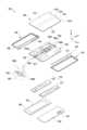
도 3은 본 문서에 개시된 다양한 실시예에 따른 휴대용 통신 장치 또는 전자 장치(100)의 분리 사시도이다.FIG. 3 is an exploded perspective view of a portable communication device or electronic device (100) according to various embodiments disclosed in this document.
도 3을 참조하면, 일 실시예에서, 전자 장치(100)는 디스플레이(130), 지지 부재 어셈블리(160), 적어도 하나의 인쇄회로 기판(170), 제1 하우징 구조(110), 제2 하우징 구조(120), 제1 후면 커버(140) 및 제2 후면 커버(150)를 포함할 수 있다. 본 문서에서, 디스플레이(display)(130)는 디스플레이 모듈(module) 또는 디스플레이 어셈블리(assembly)로 불릴 수 있다.Referring to FIG. 3, in one embodiment, the electronic device (100) may include a display (130), a support member assembly (160), at least one printed circuit board (170), a first housing structure (110), a second housing structure (120), a first back cover (140), and a second back cover (150). In this document, the display (130) may be referred to as a display module or a display assembly.
상기 디스플레이(130)는 디스플레이 패널(131)(예: 플렉서블 디스플레이 패널)과, 디스플레이 패널(131)이 안착되는 하나 이상의 플레이트(132) 또는 층을 포함할 수 있다. 일 실시예에서, 플레이트(132)는 디스플레이 패널(131)과 지지 부재 어셈블리(160) 사이에 배치될 수 있다. 플레이트(132)의 일면(예: 도 3의 Z 방향의 면)의 적어도 일부에는 디스플레이 패널(131)이 배치될 수 있다. 플레이트(132)는 디스플레이 패널(131)과 대응되는 형상으로 형성될 수 있다. 예를 들어, 플레이트(132)의 일부 영역은 디스플레이 패널(131)의 노치 영역(133)에 대응되는 형상으로 형성될 수 있다.The display (130) may include a display panel (131) (e.g., a flexible display panel) and one or more plates (132) or layers on which the display panel (131) is mounted. In one embodiment, the plate (132) may be disposed between the display panel (131) and the support member assembly (160). The display panel (131) may be disposed on at least a portion of one surface (e.g., a surface in the Z direction of FIG. 3) of the plate (132). The plate (132) may be formed in a shape corresponding to the display panel (131). For example, a portion of the plate (132) may be formed in a shape corresponding to a notch region (133) of the display panel (131).
지지 부재 어셈블리(160)는 제1 지지 부재(161), 제2 지지 부재(162), 제1 지지 부재(161)와 제2 지지 부재(162) 사이에 배치되는 힌지 구조(164a), 힌지 구조(164a)를 외부에서 볼 때, 이를 커버하는 힌지 커버(165), 및 제1 지지 부재(161)와 제2 지지 부재(162)를 가로지르는 배선 부재(예: 가요성 인쇄회로 기판(FPCB; flexible printed circuit board))를 포함할 수 있다. 한 실시예에서, 지지 부재 어셈블리(160)는 제1 지지 부재(161)에 장착된 제1 힌지 플레이트(164b)와 제2 지지 부재(162)에 장착된 제2 힌지 플레이트(164c)를 포함할 수 있다. 다른 실시예에서, 배선 부재는 제1 지지 부재(161)와 제2 지지 부재(162)를 가로지르는 방향(예: x축 방향)으로 배치될 수 있으며, 제1 힌지 플레이트(164b) 또는 제2 힌지 플레이트(164c)에 의해 가려져 도 3에서는 도시되지 않을 수 있다.The support member assembly (160) may include a first support member (161), a second support member (162), a hinge structure (164a) disposed between the first support member (161) and the second support member (162), a hinge cover (165) covering the hinge structure (164a) when viewed from the outside, and a wiring member (e.g., a flexible printed circuit board (FPCB)) crossing the first support member (161) and the second support member (162). In one embodiment, the support member assembly (160) may include a first hinge plate (164b) mounted on the first support member (161) and a second hinge plate (164c) mounted on the second support member (162). In another embodiment, the wiring member may be arranged in a direction (e.g., in the x-axis direction) transverse to the first support member (161) and the second support member (162), and may be covered by the first hinge plate (164b) or the second hinge plate (164c) and thus not shown in FIG. 3.
다양한 실시예에 따르면, 제1 힌지 플레이트(164b)는 제1 하우징 구조(110)의 내부에 장착되며, 제2 힌지 플레이트(164c)는 제2 하우징 구조(120)의 내부에 장착될 수 있다. 어떤 실시예에서, 제1 힌지 플레이트(164b)는 제1 지지 구조(161)에 직접 장착되고, 제2 힌지 플레이트(164c)는 제2 지지 구조(162)에 직접 장착될 수 있다. 다른 실시예에서, 제1 힌지 플레이트(164b)(또는 제2 힌지 플레이트(164c))는 제1 하우징 구조(110)(또는 제2 하우징 구조(120))의 내부에서 다른 구조물(예: 제1 회전 지지면(114) 또는 제2 회전 지지면(124))에 직접 장착될 수 있다. 예컨대, 제1 하우징 구조(110)(또는 제2 하우징 구조(120))의 내부에서 제1 힌지 플레이트(164b)(또는 제2 힌지 플레이트(164c))가 장착되는 구조물은 실시예에 따라 다양할 수 있다. 또 다른 실시예에서, 힌지 구조(164a)는 제1 힌지 플레이트(164b)와 제2 힌지 플레이트(164c)에 장착되어 제2 힌지 플레이트(164c)를 제1 힌지 플레이트(164b)에 회동 가능하게 연결할 수 있다. 예를 들어, 힌지 구조(164a)에 의해 폴딩 축(예: 도 1의 폴딩 축(A))이 형성되며, 제1 하우징 구조(110)와 제2 하우징 구조(120)(또는 제1 지지 구조(161)와 제2 지지 구조(162))는 실질적으로 폴딩 축(A)를 중심으로 서로에 대하여 회동할 수 있다.According to various embodiments, the first hinge plate (164b) may be mounted within the first housing structure (110), and the second hinge plate (164c) may be mounted within the second housing structure (120). In some embodiments, the first hinge plate (164b) may be directly mounted to the first support structure (161), and the second hinge plate (164c) may be directly mounted to the second support structure (162). In other embodiments, the first hinge plate (164b) (or the second hinge plate (164c)) may be directly mounted to another structure (e.g., the first rotational support surface (114) or the second rotational support surface (124)) within the first housing structure (110) (or the second housing structure (120)). For example, the structure in which the first hinge plate (164b) (or the second hinge plate (164c)) is mounted inside the first housing structure (110) (or the second housing structure (120)) may vary depending on the embodiment. In another embodiment, the hinge structure (164a) may be mounted on the first hinge plate (164b) and the second hinge plate (164c) so as to rotatably connect the second hinge plate (164c) to the first hinge plate (164b). For example, a folding axis (e.g., the folding axis (A) of FIG. 1) is formed by the hinge structure (164a), and the first housing structure (110) and the second housing structure (120) (or the first support structure (161) and the second support structure (162)) may substantially rotate relative to each other about the folding axis (A).
일 실시예에서, 지지 부재 어셈블리(160)는 플레이트(132)와 적어도 하나의 인쇄회로 기판(170) 사이에 배치될 수 있다. 일례로, 제1 지지 부재(161)는 디스플레이(130)의 제1 부분(131a)과 제1 인쇄회로 기판(171) 사이에 배치될 수 있다. 제2 지지 부재(162)는 디스플레이(130)의 제2 부분(131b)과 제2 인쇄회로 기판(172) 사이에 배치될 수 있다.In one embodiment, a support member assembly (160) can be positioned between the plate (132) and at least one printed circuit board (170). For example, a first support member (161) can be positioned between a first portion (131a) of the display (130) and a first printed circuit board (171). A second support member (162) can be positioned between a second portion (131b) of the display (130) and a second printed circuit board (172).
적어도 하나의 인쇄회로 기판(170)은 위에서 언급된 바와 같이, 제1 지지 부재(161) 측에 배치되는 제1 인쇄회로 기판(171)과 제2 지지 부재(162) 측에 배치되는 제2 인쇄회로 기판(172)을 포함할 수 있다. 상기 제1 인쇄회로 기판(171)과 제2 인쇄회로 기판(172)은 지지 부재 어셈블리(160), 제1 하우징 구조(110), 제2 하우징 구조(120), 제1 후면 커버(140) 및 제2 후면 커버(150)에 의해 형성되는 공간의 내부에 배치될 수 있다. 제1 인쇄회로 기판(171)과 제2 인쇄회로 기판(172)에는 전자 장치(100)의 다양한 기능을 구현하기 위한 부품들이 실장될 수 있다.At least one printed circuit board (170) may include a first printed circuit board (171) disposed on the first support member (161) side and a second printed circuit board (172) disposed on the second support member (162) side, as mentioned above. The first printed circuit board (171) and the second printed circuit board (172) may be disposed inside a space formed by the support member assembly (160), the first housing structure (110), the second housing structure (120), the first rear cover (140), and the second rear cover (150). Components for implementing various functions of the electronic device (100) may be mounted on the first printed circuit board (171) and the second printed circuit board (172).
일 실시예에서, 제1 하우징 구조(110) 및 제2 하우징 구조(120)는 지지 부재 어셈블리(160)에 디스플레이(130)가 결합된 상태에서, 지지 부재 어셈블리(160)의 양측으로 결합되도록 서로 조립될 수 있다. 제1 하우징 구조(110)와 제2 하우징 구조(120)는 지지 부재 어셈블리(160)의 양 측에, 예를 들어, 제1 지지 부재(161)와 제2 지지 부재(162)에 각각 슬라이드 이동 가능하게 결합될 수 있다. 제1 지지 부재(161)와 제2 지지 부재(162)는 실질적으로 제1 하우징 구조(110)와 제2 하우징 구조(120)에 수용되는 것으로서, 실시예에 따라 제1 하우징 구조(110)와 제2 하우징 구조(120)의 일부로 해석될 수 있다.In one embodiment, the first housing structure (110) and the second housing structure (120) may be assembled to each other so as to be coupled to both sides of the support member assembly (160) while the display (130) is coupled to the support member assembly (160). The first housing structure (110) and the second housing structure (120) may be slidably coupled to both sides of the support member assembly (160), for example, to the first support member (161) and the second support member (162), respectively. The first support member (161) and the second support member (162) are substantially accommodated in the first housing structure (110) and the second housing structure (120), and may be interpreted as a part of the first housing structure (110) and the second housing structure (120) according to an embodiment.
일 실시예에서, 제1 하우징 구조(110)는 제1 회전 지지면(114)을 포함할 수 있고, 제2 하우징 구조(120)는 제1 회전 지지면(114)에 대응되는 제2 회전 지지면(124)을 포함할 수 있다. 제1 회전 지지면(114)과 제2 회전 지지면(124)은 힌지 커버(165)에 포함된 곡면과 대응되는 곡면을 포함할 수 있다.In one embodiment, the first housing structure (110) may include a first rotational support surface (114), and the second housing structure (120) may include a second rotational support surface (124) corresponding to the first rotational support surface (114). The first rotational support surface (114) and the second rotational support surface (124) may include curved surfaces corresponding to curved surfaces included in the hinge cover (165).
일 실시예에서, 전자 장치(100)가 펼침 상태(예: 도 1의 상태)인 경우, 제1 회전 지지면(114)과 제2 회전 지지면(124)이 힌지 커버(165)를 덮어 힌지 커버(165)가 전자 장치(100)의 후면으로 노출되지 않거나 최소한으로 노출될 수 있다. 일 실시예에서, 전자 장치(100)가 접힘 상태(예: 도 2의 상태)인 경우, 제1 회전 지지면(114)과 제2 회전 지지면(124)이 힌지 커버(165)에 포함된 곡면을 따라 회전하여 힌지 커버(165)를 전자 장치(100)의 후면으로 최대한 노출시킬 수 있다.In one embodiment, when the electronic device (100) is in an unfolded state (e.g., the state of FIG. 1), the first rotational support surface (114) and the second rotational support surface (124) may cover the hinge cover (165) so that the hinge cover (165) is not exposed or is minimally exposed to the rear surface of the electronic device (100). In one embodiment, when the electronic device (100) is in a folded state (e.g., the state of FIG. 2), the first rotational support surface (114) and the second rotational support surface (124) may rotate along a curve included in the hinge cover (165) so that the hinge cover (165) is maximally exposed to the rear surface of the electronic device (100).
이상의 상세한 설명에서, 제1 하우징 구조(110), 제2 하우징 구조(120), 제1 측면 부재(113) 또는 제2 측면 부재(123) 등, 서수를 사용하여 구성요소들을 단순히 구분하기 위한 것으로서, 이러한 서수의 기재에 의해 본 발명이 한정되지 않음에 유의한다. 예를 들어, 센서 영역(131d)이 제1 하우징 구조(110)에 형성된 구성으로 예시하였지만, 센서 영역(131d)은 제2 하우징 구조(120)에 형성되거나 제1, 제2 하우징 구조(110, 120)에 모두 형성될 수 있다. 다른 실시예에서, 제1 후면 영역(141)이 제1 후면 커버(140)에, 서브 디스플레이(152)가 제2 후면 커버(150)에 각각 배치된 구성이 예시되고 있지만, 센서 등을 배치하기 위한 제1 후면 영역(141)과, 화면을 출력하기 위한 서브 디스플레이(152)가 모두 상기 제1 후면 커버(140)과 상기 제2 후면 커버(150) 중 어느 하나에 배치될 수 있다.In the detailed description above, the ordinal numbers, such as first housing structure (110), second housing structure (120), first side member (113), or second side member (123), are used to simply distinguish the components, and it should be noted that the present invention is not limited by the description of such ordinal numbers. For example, although the sensor region (131d) is exemplified as being formed in the first housing structure (110), the sensor region (131d) may be formed in the second housing structure (120) or may be formed in both the first and second housing structures (110, 120). In another embodiment, a configuration is exemplified in which the first rear area (141) is disposed on the first rear cover (140) and the sub-display (152) is disposed on the second rear cover (150), but the first rear area (141) for disposing sensors, etc., and the sub-display (152) for outputting a screen may both be disposed on either the first rear cover (140) or the second rear cover (150).
이하의 상세한 설명에서는, 필요에 따라 도 1 내지 도 3의 전자 장치(100)가 참조될 수 있다. 이하의 실시예를 살펴봄에 있어, 선행 실시예와 동일하거나 선행 실시예를 통해 용이하게 이해할 수 있는 구성에 대해서는 도면의 참조번호를 동일하게 부여하거나 생략하고, 그 상세한 설명 또한 생략하기로 한다. 아울러, 이하에서, "제1 하우징 구조(110)와 제2 하우징 구조(120)가 서로 마주보게 접혀진 상태(예: 도 2의 상태)"를 "제1 위치"라 칭할 수 있으며, "제1 하우징 구조(110)와 제2 하우징 구조(120)가 서로의 일측에 나란하게 펼쳐진 상태(예: 도 1의 상태)"를 "제2 위치"라 칭할 수 있다.In the detailed description below, reference may be made to the electronic device (100) of FIGS. 1 to 3 as needed. In examining the embodiments below, reference numerals in the drawings will be given to or omitted for components that are the same as or can be easily understood through the preceding embodiments, and detailed descriptions thereof will also be omitted. In addition, below, a "state in which the first housing structure (110) and the second housing structure (120) are folded to face each other (e.g., the state of FIG. 2)" may be referred to as a "first position", and a "state in which the first housing structure (110) and the second housing structure (120) are unfolded parallel to one side of each other (e.g., the state of FIG. 1)" may be referred to as a "second position".
다양한 실시예에 따르면, 전자 장치(100)는 힌지 커버(165)와 제1 하우징 구조(110) 또는 제2 하우징 구조(120) 사이에 제공되는 밀봉 부재들(181, 182)을 포함할 수 있다. 어떤 실시예에서, 전자 장치(100)는 힌지 커버(165)와 디스플레이(130) 사이에 제공되는 다른 밀봉 부재(183)들을 포함할 수 있다. 이하에서 도 4 내지 도 6을 참조하여 힌지 커버(165)와 제1 하우징 구조(110)(또는 제2 하우징 구조(120)) 사이에 형성되는 밀봉 구조에 관해 살펴보기로 한다. 본 문서에 개시된 다양한 실시예에 따르면, '밀봉 구조'라 함은, 먼지(dust)나 부스러기(chip)와 같은 고체 입자 형태 또는 액체 형태의 이물질이 유입되는 것을 차단하는 구조를 의미할 수 있다. '밀봉 구조'를 형성하는 부재(member) 또는 부품(component)(예: 후술할 도 4의 밀봉 부재들(181, 182, 183))은 탄성을 가진 물질로 제작되어 외력에 의해 압축되면서 탄성력을 축적할 수 있으며, 외력이 가해지지 않은 상태에서는 제작 초기의 형상으로 복원될 수 있다. 예컨대, 본 문서에 개시된 다양한 실시예에서, '밀봉 구조'를 형성하는 부재 또는 부품은 적어도 고체 입자 형태 또는 액체 형태의 이물질이 전자 장치(100)의 내부로 유입되는 것을 차단할 수 있다.According to various embodiments, the electronic device (100) may include sealing members (181, 182) provided between the hinge cover (165) and the first housing structure (110) or the second housing structure (120). In some embodiments, the electronic device (100) may include other sealing members (183) provided between the hinge cover (165) and the display (130). Hereinafter, a sealing structure formed between the hinge cover (165) and the first housing structure (110) (or the second housing structure (120)) will be described with reference to FIGS. 4 to 6. According to various embodiments disclosed in the present document, the 'sealing structure' may mean a structure that blocks foreign substances in the form of solid particles or liquids, such as dust or chips, from entering. A member or component forming a 'sealing structure' (e.g., sealing members (181, 182, 183) of FIG. 4 to be described later) is made of an elastic material and can accumulate elasticity when compressed by an external force, and can be restored to its initial shape when no external force is applied. For example, in various embodiments disclosed in this document, the member or component forming a 'sealing structure' can block foreign substances in the form of at least solid particles or liquids from entering the interior of the electronic device (100).
도 4 는 본 문서에 개시된 다양한 실시예에 따른 휴대용 통신 장치 또는 전자 장치(예: 도 1 내지 도 3의 전자 장치(100))에서, 제1 밀봉 부재 또는 제2 밀봉 부재(예: 도 3의 제1 밀봉 부재(181) 또는 제2 밀봉 부재(182))가 장착되는 구성을 나타내는 분리 사시도이다. 도 5는 본 문서에 개시된 다양한 실시예에 따른 휴대용 통신 장치 또는 전자 장치(예: 도 1 내지 도 3의 전자 장치(100))가 접혀진 모습을 나타내는 단면 구성도이다. 도 6은 본 문서에 개시된 다양한 실시예에 따른 휴대용 통신 장치 또는 전자 장치(예: 도 1 내지 도 3의 전자 장치(100))가 펼쳐진 모습을 나타내는 단면 구성도이다.FIG. 4 is an exploded perspective view showing a configuration in which a first sealing member or a second sealing member (e.g., a first sealing member (181) or a second sealing member (182) of FIG. 3) is mounted in a portable communication device or an electronic device (e.g., an electronic device (100) of FIGS. 1 to 3) according to various embodiments disclosed in the present document. FIG. 5 is a cross-sectional configuration diagram showing a folded state of a portable communication device or an electronic device (e.g., an electronic device (100) of FIGS. 1 to 3) according to various embodiments disclosed in the present document. FIG. 6 is a cross-sectional configuration diagram showing an unfolded state of a portable communication device or an electronic device (e.g., an electronic device (100) of FIGS. 1 to 3) according to various embodiments disclosed in the present document.
도 4 내지 도 6을 더 참조하면, 상기 제1 밀봉 부재(181)는 러버(rubber), 실리콘(silicone), 스펀지(sponge), 폴리카보네이트나 테프론과 같은 탄성 물질을 포함하는 것으로서, 상기 전자 장치(100)의 길이 방향(예: 도 3의 y 방향)으로 연장될 수 있다. 한 실시예에서, 상기 제1 밀봉 부재(181)는 제1 하우징 구조(예: 도 3의 제1 하우징 구조(110))와 힌지 커버(예: 도 3의 힌지 커버(165)) 사이에 제공되어 상기 제1 하우징 구조(110)와 상기 힌지 커버(165) 사이에 밀봉 구조를 형성할 수 있다.Referring further to FIGS. 4 to 6, the first sealing member (181) may include an elastic material such as rubber, silicone, sponge, polycarbonate, or Teflon, and may extend in the longitudinal direction of the electronic device (100) (e.g., the y direction of FIG. 3). In one embodiment, the first sealing member (181) may be provided between a first housing structure (e.g., the first housing structure (110) of FIG. 3) and a hinge cover (e.g., the hinge cover (165) of FIG. 3) to form a sealing structure between the first housing structure (110) and the hinge cover (165).
다양한 실시예에 따르면, 제1 회전 지지면(예: 도 3의 제1 회전 지지면(114)) 또는 제2 회전 지지면(예: 도 3의 제2 회전 지지면(124))은 상기 힌지 커버(165)의 외주면에 상응하는 곡면(curved surface)(265a, 265b)을 포함할 수 있다. 예컨대, 상기 제1 회전 지지면(114)이 상기 힌지 커버(165)의 외주면을 적어도 부분적으로 감싸게 배치될 수 있다. 제1 하우징 구조(110) 또는 제2 하우징 구조(120)가 제1 위치와 제2 위치 사이에서 회동할 때, 실질적으로 상기 제1 회전 지지면(114)이 상기 힌지 커버(165)의 외주면과 적어도 부분적으로 마주보는 상태로 이동하면서, 상기 힌지 커버(165)의 일부분을 은폐 또는 노출시킬 수 있다. 한 실시예에 따르면, 제2 위치에서보다 제1 위치에서 상기 힌지 커버(165)가 외부로 더 많이 노출될 수 있다. 이러한 상대적인 이동 동작에서, 강성(rigidity)을 가진 두 구조물(예: 상기 제1 하우징 구조(110)과 상기 힌지 커버(165))가 직접 마찰할 경우, 소음이나 마모의 원인이 될 수 있음을 앞서 언급한 바 있다. 본 문서에 개시된 다양한 실시예에 따르면, 상기 제1 회전 지지면(114)과 상기 힌지 커버(165)의 외주면 사이에는 일정 정도의 간격이 형성됨으로써, 강성 구조물들 사이의 마찰에 의한 소음이나 마모를 방지할 수 있다.According to various embodiments, the first rotational support surface (e.g., the first rotational support surface (114) of FIG. 3) or the second rotational support surface (e.g., the second rotational support surface (124) of FIG. 3) may include a curved surface (265a, 265b) corresponding to the outer circumference of the hinge cover (165). For example, the first rotational support surface (114) may be arranged to at least partially surround the outer circumference of the hinge cover (165). When the first housing structure (110) or the second housing structure (120) rotates between the first position and the second position, the first rotational support surface (114) may substantially move to at least partially face the outer circumference of the hinge cover (165), thereby concealing or exposing a portion of the hinge cover (165). According to one embodiment, the hinge cover (165) may be more exposed to the outside in the first position than in the second position. As mentioned above, in such a relative movement motion, if two structures having rigidity (e.g., the first housing structure (110) and the hinge cover (165)) directly rub against each other, this may cause noise or wear. According to various embodiments disclosed in this document, a certain amount of gap is formed between the first rotational support surface (114) and the outer surface of the hinge cover (165), thereby preventing noise or wear due to friction between the rigid structures.
다양한 실시예에 따르면, 상기 제1 밀봉 부재(181)는 상기 제1 하우징 구조(110)(예: 상기 제1 회전 지지면(114))와 상기 힌지 커버(165) 사이의 간격을 밀봉할 수 있다. 예컨대, 상기 제1 하우징 구조(110)와 상기 힌지 커버(165)의 조합에 의해 형성된 내측 공간은 상기 제1 하우징 구조(110)와 상기 힌지 커버(165) 사이의 간격을 통해 외측 공간에 연결될 수 있지만, 상기 제1 밀봉 부재(181)가 이러한 간격을 밀봉할 수 있다. 한 실시예에 따르면, 상기 제1 밀봉 부재(181)는 탄성 물질을 포함함으로써, 상기 제1 하우징 구조(110)와 상기 힌지 커버(165) 사이의 간격을 밀봉하면서, 상기 하우징 구조들(110, 120)의 회동 동작에서 발생하는 마찰력을 완화하고, 마찰에 따른 소음이나 마모를 억제할 수 있다.According to various embodiments, the first sealing member (181) can seal a gap between the first housing structure (110) (e.g., the first rotational support surface (114)) and the hinge cover (165). For example, an inner space formed by a combination of the first housing structure (110) and the hinge cover (165) can be connected to an outer space through a gap between the first housing structure (110) and the hinge cover (165), but the first sealing member (181) can seal this gap. According to one embodiment, the first sealing member (181) includes an elastic material, thereby sealing the gap between the first housing structure (110) and the hinge cover (165), while alleviating frictional force generated during the rotational motion of the housing structures (110, 120), and suppressing noise or wear due to friction.
다양한 실시예에 따르면, 상기 제1 밀봉 부재(181)는 상기 제1 회전 지지면(114)에 장착 또는 부착될 수 있다. 예를 들어, 상기 제1 밀봉 부재(181)는 상기 제1 하우징 구조(110)에 장착되면서 상기 힌지 커버(165)와 접촉하게 위치될 수 있다. 도 6을 참조하면, 상기 제1 밀봉 부재(181)는 고정부(fixing portion)(181a)와 밀봉부(sealing portion)(181b)를 포함할 수 있다. 상기 고정부(181a)는 상기 제1 하우징 구조(110)(또는 제2 하우징 구조(120))에 장착되며, 도 3의 x 방향에서 일정 정도의 폭을 가지면서, 도 3의 y 방향으로 연장될 수 있다. 한 실시예에 따르면, 상기 밀봉부(181b)는 상기 고정부(181a)로부터 연장되며 상기 힌지 커버(165)와 밀착할 수 있다. 본 실시예에서는 상기 제1 밀봉 부재(181)는 상기 제1 회전 지지면(114)에 장착 또는 부착된 구성이 예시되었으나, 본 발명이 이에 한정되지 않음에 유의한다. 예를 들어, 상기 제1 밀봉 부재(181)는 상기 제1 하우징 구조(110)에 의해 항상 은폐되는 위치 또는 영역에서 상기 힌지 커버(165)에 장착될 수 있다. 예컨대, 상기 제1 밀봉 부재(181)가 상기 힌지 커버(165)에 장착된다면, 상기 제1 밀봉 부재(181)는 상기 제1 하우징 구조(110)와 접촉하게 위치될 수 있다.According to various embodiments, the first sealing member (181) may be mounted or attached to the first rotational support surface (114). For example, the first sealing member (181) may be positioned to be in contact with the hinge cover (165) while being mounted on the first housing structure (110). Referring to FIG. 6, the first sealing member (181) may include a fixing portion (181a) and a sealing portion (181b). The fixing portion (181a) is mounted on the first housing structure (110) (or the second housing structure (120)) and may extend in the y direction of FIG. 3 while having a certain width in the x direction of FIG. 3. According to one embodiment, the sealing portion (181b) may extend from the fixing portion (181a) and come into close contact with the hinge cover (165). In this embodiment, the first sealing member (181) is configured to be mounted or attached to the first rotational support surface (114), but it should be noted that the present invention is not limited thereto. For example, the first sealing member (181) may be mounted to the hinge cover (165) at a position or area that is always concealed by the first housing structure (110). For example, if the first sealing member (181) is mounted to the hinge cover (165), the first sealing member (181) may be positioned to come into contact with the first housing structure (110).
다양한 실시예에 따르면, 상기 힌지 커버(165)와 밀착했을 때, 상기 밀봉부(181b)는 적어도 부분적으로 상기 고정부(181a)에 대하여 경사지게 또는 곡선 형태로 변형될 수 있다. 예를 들어, 상기 제1 밀봉 부재(181)는 상기 고정부(181a)와 상기 밀봉부(181b)에 의해 적어도 부분적으로 둘러싸인 홈부(recessed portion)(181c)를 포함할 수 있다. 다른 실시예에서, 상기 밀봉부(181b)는 상기 힌지 커버(165)와 밀착하기 전, 적어도 부분적으로 상기 고정부(181a)에 대하여 경사지게 또는 곡선 형태로 형성될 수 있다. 예컨대, 상기 제1 밀봉 부재(181)는 상기 홈부(181c)를 포함하는 형상으로 제작될 수 있다.According to various embodiments, when in close contact with the hinge cover (165), the sealing portion (181b) may be deformed to be at least partially inclined or curved with respect to the fixing portion (181a). For example, the first sealing member (181) may include a recessed portion (181c) that is at least partially surrounded by the fixing portion (181a) and the sealing portion (181b). In another embodiment, the sealing portion (181b) may be formed to be at least partially inclined or curved with respect to the fixing portion (181a) before being in close contact with the hinge cover (165). For example, the first sealing member (181) may be manufactured in a shape including the recessed portion (181c).
한 실시예에서, 상기 제2 밀봉 부재(182)는 제2 하우징 구조(120)(예: 도 3의 제2 하우징 구조(120))에 장착되며 그 형상이나 크기 등에 다소 차이가 있을 수 있지만, 실질적으로 상기 제1 밀봉 부재(181)의 구성을 통해 용이하게 이해할 수 있을 것이다. 따라서 상기 제2 밀봉 부재(182)의 구체적인 구성에 관한 상세한 설명은 생략하기로 한다.In one embodiment, the second sealing member (182) is mounted on the second housing structure (120) (e.g., the second housing structure (120) of FIG. 3) and may have some differences in shape or size, but can be easily understood through the configuration of the first sealing member (181). Therefore, a detailed description of the specific configuration of the second sealing member (182) will be omitted.
도 5는 제1 위치에서, 예를 들어, 상기 제1 하우징 구조(110)와 상기 제2 하우징 구조(120)가 서로 마주보게 접혀진 위치에서, 도 2의 라인 C-C를 따라 상기 전자 장치(100)를 절개한 단면 구성도를 도시하고 있다. 도 5를 참조하면, 제1 위치에서, 상기 제1 밀봉 부재(181)는 상기 힌지 커버(165)의 일측 가장자리에 인접하게 위치하고, 상기 제2 밀봉 부재(182)는 상기 힌지 커버(165)의 타측 가장자리에 인접하게 위치될 수 있다. 도 6은 제2 위치에서, 예를 들어, 상기 제1 하우징 구조(110)와 상기 제2 하우징 구조(120)가 서로의 일측에 나란하게 펼쳐진 위치에서, 도 1의 라인 B-B를 따라 상기 전자 장치(100)를 절개한 단면 구성도를 도시하고 있다. 도 6을 참조하면, 제2 위치에서, 상기 제1 밀봉 부재(181)와 상기 제2 밀봉 부재(182)가 서로 인접하게 위치될 수 있다.FIG. 5 is a cross-sectional view of the electronic device (100) taken along line C-C of FIG. 2 at a first position, for example, at a position where the first housing structure (110) and the second housing structure (120) are folded to face each other. Referring to FIG. 5, at the first position, the first sealing member (181) may be positioned adjacent to one edge of the hinge cover (165), and the second sealing member (182) may be positioned adjacent to the other edge of the hinge cover (165). FIG. 6 is a cross-sectional view of the electronic device (100) taken along line B-B of FIG. 1 at a second position, for example, at a position where the first housing structure (110) and the second housing structure (120) are unfolded parallel to one side of each other. Referring to FIG. 6, at the second position, the first sealing member (181) and the second sealing member (182) can be positioned adjacent to each other.
다양한 실시예에 따르면, 도 6에서, 상기 밀봉부(181b)가 상기 힌지 커버(165)와 중첩하는 형상으로 도시하고 있으나, 이는 상기 제1 밀봉 부재(181) 또는 상기 제2 밀봉 부재(182)의 형상을 좀더 명확하게 도시하기 위한 것임에 유의한다. 예컨대, 실제 전자 장치에서 상기 밀봉부(181b)는 상기 힌지 커버(165)와 밀착하면서 변형될 수 있다. 한 실시예에 따르면, 상기 밀봉부(181b)가 변형되면서 탄성력을 축적함으로써 상기 힌지 커버(165)와의 밀착 상태를 안정적으로 유지할 수 있다. 한 실시예에서, 상기 밀봉부(181b)에 과도한 탄성력이 축적된 경우, 기계적인 구조물(예: 상기 제1, 2 하우징 구조(110, 120) 또는 상기 힌지 커버(165))에 불필요한 하중이 가해질 수 있다. 어떤 실시예에서, 상기 홈부(181c)는 상기 밀봉부(181b)의 변형을 원활하게 함으로써 과도한 탄성력이 축적되는 것, 또는, 기계적인 구조물에 불필요한 하중이 가해지는 것을 완화 또는 방지할 수 있다.According to various embodiments, in FIG. 6, the sealing portion (181b) is illustrated as overlapping the hinge cover (165), but it should be noted that this is to more clearly illustrate the shape of the first sealing member (181) or the second sealing member (182). For example, in an actual electronic device, the sealing portion (181b) may be deformed while in close contact with the hinge cover (165). According to one embodiment, the sealing portion (181b) may stably maintain a close contact state with the hinge cover (165) by accumulating elastic force while being deformed. In one embodiment, when excessive elastic force is accumulated in the sealing portion (181b), an unnecessary load may be applied to a mechanical structure (e.g., the first and second housing structures (110, 120) or the hinge cover (165)). In some embodiments, the groove (181c) can alleviate or prevent excessive elastic force from accumulating or unnecessary load from being applied to the mechanical structure by facilitating deformation of the sealing portion (181b).
다양한 실시예에 따르면, 상기 전자 장치(100)가 펼쳐지거나 접혀지는 동작에서, 상기 제1 밀봉 부재(181) 또는 상기 제2 밀봉 부재(182)는 상기 힌지 커버(165)의 외주면과 미끄럼 접촉하면서, 상기 제1 밀봉 부재(181)와 상기 제2 밀봉 부재(182)는 안정된 밀봉 구조를 유지할 수 있다. 예컨대, 상기 제1 밀봉 부재(181) 또는 상기 제2 밀봉 부재(182)는, 상기 제1 하우징 구조(110)와 상기 힌지 구조(165) 사이의 간격 또는 상기 제2 하우징 구조(120)와 상기 힌지 구조(165) 사이의 간격을 밀봉할 수 있다. 이로써, 상기 제1 하우징 구조(110), 상기 제2 하우징 구조(120) 및 상기 힌지 커버(165)의 조합에 의해 형성된 내측 공간은 상기 제1 밀봉 부재(181) 또는 상기 제2 밀봉 부재(182)에 의해 외측 공간에 대하여 밀봉될 수 있다.According to various embodiments, when the electronic device (100) is unfolded or folded, the first sealing member (181) or the second sealing member (182) may be in sliding contact with the outer surface of the hinge cover (165), while the first sealing member (181) or the second sealing member (182) may maintain a stable sealing structure. For example, the first sealing member (181) or the second sealing member (182) may seal a gap between the first housing structure (110) and the hinge structure (165) or a gap between the second housing structure (120) and the hinge structure (165). Accordingly, the inner space formed by the combination of the first housing structure (110), the second housing structure (120), and the hinge cover (165) can be sealed against the outer space by the first sealing member (181) or the second sealing member (182).
다양한 실시예에 따르면, 접혀질 수 있는 또는 말아질 수 있는 전자 장치(예: 도 1 내지 도 3의 전자 장치(100))를 구성함에 있어, 강성을 가진 복수의 구조물들(예: 상기 제1 하우징 구조(110), 상기 제2 하우징 구조(120) 및/또는 상기 힌지 커버(165))이 조합되어 내부 공간을 적어도 부분적으로 정의할 수 있다. 강성을 가진 복수의 구조물들이 서로에 대하여 상대적으로 이동하거나 회동함으로써 상기 전자 장치(100)가 접혀진 형상(또는 말아진 형상)과 펼쳐진 형상으로 변형될 수 있다. 강성을 가진 복수의 구조물들이 결합되는 부위에서는 일정 정도의 간격을 확보함으로써, 상대적인 이동 또는 회동 동작에서의 마찰을 방지할 수 있다. 본 문서에 개시된 다양한 실시예는, 마찰 방지를 위해 형성된 간격(예: 강성을 가진 복수의 구조물들 사이의 간격)에 밀봉 부재(예: 상기 제1 밀봉 부재(181) 또는 상기 제2 밀봉 부재(182))를 배치함으로써, 외부의 이물질이 내부 공간으로 유입되는 것을 방지할 수 있다. 밀봉 부재는 탄성 물질을 포함함으로써, 마찰에 따른 소음이나 마모를 억제 또는 완화할 수 있다.According to various embodiments, in configuring a foldable or rollable electronic device (e.g., the electronic device (100) of FIGS. 1 to 3), a plurality of rigid structures (e.g., the first housing structure (110), the second housing structure (120), and/or the hinge cover (165)) may be combined to at least partially define an internal space. The electronic device (100) may be deformed into a folded shape (or a rolled shape) and an unfolded shape by relatively moving or rotating the plurality of rigid structures with respect to each other. By securing a certain amount of gap at a portion where the plurality of rigid structures are combined, friction during the relative movement or rotational motion may be prevented. Various embodiments disclosed in this document can prevent external foreign substances from entering the internal space by arranging a sealing member (e.g., the first sealing member (181) or the second sealing member (182)) in a gap formed to prevent friction (e.g., a gap between a plurality of rigid structures). The sealing member can suppress or alleviate noise or wear due to friction by including an elastic material.
도 7과 도 8은 본 문서에 개시된 다양한 실시예에 따른 휴대용 통신 장치 또는 전자 장치(예: 도 1의 전자 장치(100))에서 제1 밀봉 부재 또는 제2 밀봉 부재(예: 도 3 또는 도 5의 제1 밀봉 부재(181) 또는 제2 밀봉 부재(182))의 변형 예를 나타내는 단면 구성도이다.FIGS. 7 and 8 are cross-sectional views showing modified examples of a first sealing member or a second sealing member (e.g., a first sealing member (181) or a second sealing member (182) of FIG. 3 or FIG. 5) in a portable communication device or an electronic device (e.g., an electronic device (100) of FIG. 1) according to various embodiments disclosed in the present document.
도 7을 참조하면, 제1 밀봉 부재(281) 또는 제2 밀봉 부재(282)는 스펀지(sponge)로 제작된 몸체(281a, 282a)를 포함할 수 있다. 예컨대, 상기 몸체(281a, 282a)가 상기 제1 하우징 구조(110)(또는 상기 제2 하우징 구조(120))와 상기 힌지 커버(165) 사이에서 밀봉 구조를 형성할 수 있다. 스펀지는 저밀도 탄성체의 일종으로서, 상기 제1 하우징 구조(110)와 상기 힌지 커버(165) 사이에 밀봉 구조를 제공하면서도 상기 제1 하우징 구조(110) 또는 상기 힌지 커버(165)에 가해지는 하중 또는 전자 장치(200)의 개폐 동작에서의 마찰력을 줄일 수 있다. 한 실시예에서, 저밀도 탄성체인 상기 몸체(281a, 282a)가 외부 요인에 의해 손상되는 경우, 이물질을 발생시키는 원인이 될 수 있다. 한 실시예에서, 상기 제1 밀봉 부재(281) 또는 상기 제2 밀봉 부재(282)는 상기 몸체(281a, 282a)를 감싸는 피복층(sheath layer)(281b, 282b)을 포함할 수 있다. 상기 피복층(281b, 282b)은 직물 재질(fabric material)로 제작되어 상기 몸체(281a, 282a)의 손상을 방지할 수 있다. 다른 실시예에서, 상기 피복층(281b, 282b)의 원료에 따라 마찰계수를 다양하게 설정할 수 있다. 예를 들어, 상기 피복층(281b, 282b)은 상기 제1 밀봉 부재(281) 또는 상기 제2 밀봉 부재(282)와 상기 힌지 커버(165) 사이의 마찰력을 줄일 수 있다.Referring to FIG. 7, the first sealing member (281) or the second sealing member (282) may include a body (281a, 282a) made of a sponge. For example, the body (281a, 282a) may form a sealing structure between the first housing structure (110) (or the second housing structure (120)) and the hinge cover (165). The sponge is a type of low-density elastic body, and may provide a sealing structure between the first housing structure (110) and the hinge cover (165), while reducing a load applied to the first housing structure (110) or the hinge cover (165) or frictional force during the opening and closing operation of the electronic device (200). In one embodiment, if the body (281a, 282a), which is a low-density elastic body, is damaged by an external factor, it may cause foreign substances to be generated. In one embodiment, the first sealing member (281) or the second sealing member (282) may include a sheath layer (281b, 282b) that surrounds the body (281a, 282a). The sheath layer (281b, 282b) may be made of a fabric material to prevent damage to the body (281a, 282a). In another embodiment, the coefficient of friction may be set variously depending on the raw material of the sheath layer (281b, 282b). For example, the sheath layer (281b, 282b) may reduce the frictional force between the first sealing member (281) or the second sealing member (282) and the hinge cover (165).
도 8을 참조하면, 상기 힌지 커버는(165), 양측 가장자리에서, 외측면에 형성된 돌출부(들)(383)를 더 포함할 수 있다. 대체로, 제1 밀봉 부재(381)와 제2 밀봉 부재(382)는 그 폭(예: 도 3의 x 방향으로 측정되는 길이) 전체가 상기 힌지 커버(165)와 밀착함으로써 밀봉 구조를 형성할 수 있다. 한 실시예에 따르면, 제1 위치에서, 예를 들어, 전자 장치(300)(예: 도 1 내지 도 3의 전자 장치(100))가 접혀진 상태에서, 상기 제1 밀봉 부재(381) 또는 상기 제2 밀봉 부재(382)의 일부분이 상기 힌지 커버(165)와 접촉하지 않게 위치할 수 있다. 상기 돌출부(들)(383)는 제1 위치에서 상기 제1 밀봉 부재(381) 또는 상기 제2 밀봉 부재(382)와 간섭됨으로써, 상기 제1 밀봉 부재(381) 또는 상기 제2 밀봉 부재(382)를 압축시킬 수 있다. 예컨대, 제1 위치에서, 상기 제1 밀봉 부재(381) 또는 상기 제2 밀봉 부재(382)와 상기 힌지 커버(165)의 접촉 면적은 다소 감소하지만, 상기 돌출부(들)(383)와 더 밀착함으로써 안정된 밀봉 구조를 유지할 수 있다. 한 실시예에서, 상기 제1 밀봉 부재(381) 또는 상기 제2 밀봉 부재(382)는 윤활성을 가진 소재, 예를 들어, 아세탈 수지나 테플론 시트로 제작되어 상기 힌지 커버(165)와 마찰하면서도 상기 힌지 커버(165)의 마모나 소음의 발생을 억제할 수 있다.Referring to FIG. 8, the hinge cover (165) may further include protrusion(s) (383) formed on the outer surface at both edges. In general, the first sealing member (381) and the second sealing member (382) may form a sealing structure by being in close contact with the hinge cover (165) over their entire width (e.g., the length measured in the x direction of FIG. 3). According to one embodiment, in a first position, for example, when the electronic device (300) (e.g., the electronic device (100) of FIGS. 1 to 3) is folded, a portion of the first sealing member (381) or the second sealing member (382) may be positioned so as not to come into contact with the hinge cover (165). The above protrusion(s) (383) can compress the first sealing member (381) or the second sealing member (382) by interfering with the first sealing member (381) or the second sealing member (382) at the first position. For example, at the first position, the contact area between the first sealing member (381) or the second sealing member (382) and the hinge cover (165) is somewhat reduced, but a stable sealing structure can be maintained by making closer contact with the protrusion(s) (383). In one embodiment, the first sealing member (381) or the second sealing member (382) is made of a material having lubricity, for example, an acetal resin or a Teflon sheet, so as to suppress wear or noise of the hinge cover (165) while causing friction with the hinge cover (165).
다양한 실시예에 따르면, 상기 돌출부(383)는 상기 힌지 커버(165)가 연장된 또는 돌출된 일부분일 수 있다. 예컨대, 상기 돌출부(383)는 상기 힌지 커버(165)와 동일하게 강성 구조를 가질 수 있다. 다른 실시예에서, 상기 돌출부(383)는 상기 힌지 커버(165)의 강성 구조와는 다른 재질, 예를 들어, 탄성 물질로 제작될 수 있다. 상기 돌출부(383)가 탄성 물질로 제작되는 경우, 인서트 사출에 의해 상기 돌출부(383)가 성형됨과 동시에 상기 힌지 커버(165)에 결합될 수 있다.According to various embodiments, the protrusion (383) may be an extended or protruding portion of the hinge cover (165). For example, the protrusion (383) may have a rigid structure similar to that of the hinge cover (165). In another embodiment, the protrusion (383) may be made of a material different from the rigid structure of the hinge cover (165), for example, an elastic material. When the protrusion (383) is made of an elastic material, the protrusion (383) may be formed by insert injection and simultaneously coupled to the hinge cover (165).
다양한 실시예에 따르면, 디스플레이(예: 도 3의 디스플레이(130))가 강성 구조물들(예: 도 3의 제1 하우징 구조(110), 제2 하우징 구조(120) 및 힌지 커버(165))과 결합함으로써 전자 장치(예: 도 1 내지 도 3의 전자 장치(100))의 내부 공간이 정의될 수 있다(may be defined). 예컨대, 상기 전자 장치(100)의 내부 공간은 실질적으로, 상기 디스플레이(130)와 강성 구조물들에 의해 둘러싸인 공간을 의미할 수 있다.According to various embodiments, an internal space of an electronic device (e.g., the electronic device (100) of FIGS. 1 to 3) may be defined by combining a display (e.g., the display (130) of FIG. 3) with rigid structures (e.g., the first housing structure (110), the second housing structure (120) and the hinge cover (165) of FIG. 3). For example, the internal space of the electronic device (100) may substantially mean a space surrounded by the display (130) and the rigid structures.
상기 디스플레이(130)의 폴딩 부분(예: 도 3의 폴딩 부분(131c))은 상기 전자 장치(100)의 개폐 동작에 따라 곡면 형상으로 변형될 수 있으며, 외력이 가해질 경우 쉽게 손상될 수 있다. 예컨대, 상기 디스플레이(130)의 폴딩 부분(131c)을 강성 구조물(예: 상기 힌지 커버(165))에 결합 또는 부착하는 것이 제한될 수 있다. 한 실시예에서, 상기 디스플레이(130)의 가장자리에서, 상기 폴딩 부분(131c)과 그에 대응하는 강성 구조물 사이에 간격이 형성됨으로써, 상기 폴딩 부분(131c)이 곡면 형태로 변형될 수 있는 공간을 제공할 수 있다. 어떤 실시예에서, 상기 폴딩 부분(131c)과 그에 대응하는 강성 구조물 사이에 형성된 간격은 외부 이물질이 유입되는 경로가 될 수 있다. 다양한 실시예에 따르면, 상기 전자 장치(100)는 제3 밀봉 부재(예: 도 3의 밀봉 부재(183) 또는 후술할 도 9의 제3 밀봉 부재(481a, 481b))를 포함함으로써, 상기 폴딩 부분(131c)과 그에 대응하는 강성 구조물(예: 상기 힌지 커버(165)) 사이에서 밀봉 구조를 형성할 수 있다. 제3 밀봉 부재를 이용한 밀봉 구조에 관해서는 도 9 내지 도 12를 참조하여 살펴보기로 한다.The folding portion (e.g., the folding portion (131c) of FIG. 3) of the display (130) may be deformed into a curved shape according to the opening and closing operation of the electronic device (100), and may be easily damaged when an external force is applied. For example, the coupling or attachment of the folding portion (131c) of the display (130) to a rigid structure (e.g., the hinge cover (165)) may be restricted. In one embodiment, a space may be provided in which the folding portion (131c) may be deformed into a curved shape by forming a gap between the folding portion (131c) and the corresponding rigid structure at the edge of the display (130). In some embodiments, the gap formed between the folding portion (131c) and the corresponding rigid structure may become a path through which external foreign substances may be introduced. According to various embodiments, the electronic device (100) may include a third sealing member (e.g., the sealing member (183) of FIG. 3 or the third sealing member (481a, 481b) of FIG. 9, which will be described later), thereby forming a sealing structure between the folding portion (131c) and the corresponding rigid structure (e.g., the hinge cover (165)). A sealing structure using the third sealing member will be described with reference to FIGS. 9 to 12.
도 9는 본 문서에 개시된 다양한 실시예에 따른 휴대용 통신 장치 또는 전자 장치(예: 도 1 내지 도 3의 전자 장치(100))에서, 제3 밀봉 부재(481a, 481b)(예: 도 3의 밀봉 부재(183))가 장착되는 구성을 나타내는 분리 사시도이다.FIG. 9 is an exploded perspective view showing a configuration in which a third sealing member (481a, 481b) (e.g., sealing member (183) of FIG. 3) is mounted in a portable communication device or electronic device (e.g., electronic device (100) of FIGS. 1 to 3) according to various embodiments disclosed in this document.
도 9를 참조하면, 전자 장치(100)는 디스플레이(예: 도 3의 디스플레이(130))와 힌지 커버(예: 도 3의 힌지 커버(165)) 사이에 제공된 적어도 하나의 제3 밀봉 부재(481a, 481b)를 포함할 수 있다. 한 실시예에 따르면, 한 쌍의 상기 제3 밀봉 부재(481a, 481b)가 제공되어 상기 힌지 커버(165)의 상단과 하단에 각각 접촉 또는 부착될 수 있다. 한 실시예에서, 상기 제3 밀봉 부재(481a, 481b)는 하면 또는 측면이 상기 힌지 커버(165)에 접촉하게 배치될 수 있다. 어떤 실시예에서, 상기 제3 밀봉 부재(481a, 481b)는 실질적으로 하면 또는 측면이 상기 힌지 커버(165)에 부착될 수 있다. 상기 디스플레이(130)가 상기 힌지 커버(165) 상에 배치되면, 상기 제3 밀봉 부재(481a, 481b)가 상기 디스플레이(130)의 내측면(예: 도 2의 폴딩 영역(131c))에 접촉할 수 있다. 예를 들어, 상기 제3 밀봉 부재(481a, 481b)는 상기 디스플레이(130)의 가장자리에서, 폴딩 부분(131c)의 양단에 접촉하여 상기 폴딩 부분(131c)과 강성 구조물(예: 상기 힌지 커버(165)) 사이에 밀봉 구조를 형성할 수 있다. 다른 실시예에서, 상기 제3 밀봉 부재(481a, 481b)는 스펀지와 같은 저밀도 탄성체로 제작될 수 있다. 상기 제3 밀봉 부재(481a, 481b)가 저밀도 탄성체로 제작됨으로써 상기 전자 장치(100)의 개폐 동작에서, 상기 폴딩 부분(131c)에 밀착하면서도, 상기 제3 밀봉 부재(481a, 481b)에 축적된 탄성력에 의해 상기 디스플레이에 가해지는 하중이 작을 수 있다.Referring to FIG. 9, the electronic device (100) may include at least one third sealing member (481a, 481b) provided between a display (e.g., the display (130) of FIG. 3) and a hinge cover (e.g., the hinge cover (165) of FIG. 3). According to one embodiment, a pair of the third sealing members (481a, 481b) may be provided to contact or be attached to the upper and lower portions of the hinge cover (165), respectively. In one embodiment, the third sealing members (481a, 481b) may be arranged such that a lower surface or a side surface contacts the hinge cover (165). In some embodiments, the third sealing members (481a, 481b) may be substantially attached to the hinge cover (165) at a lower surface or a side surface. When the display (130) is placed on the hinge cover (165), the third sealing member (481a, 481b) may contact an inner surface of the display (130) (e.g., the folding area (131c) of FIG. 2). For example, the third sealing member (481a, 481b) may contact both ends of the folding portion (131c) at the edge of the display (130) to form a sealing structure between the folding portion (131c) and a rigid structure (e.g., the hinge cover (165)). In another embodiment, the third sealing member (481a, 481b) may be made of a low-density elastic body such as a sponge. Since the third sealing member (481a, 481b) is made of a low-density elastic body, during the opening and closing operation of the electronic device (100), the load applied to the display can be small due to the elastic force accumulated in the third sealing member (481a, 481b) while being in close contact with the folding portion (131c).
도 10은 본 문서에 개시된 다양한 실시예에 따른 휴대용 통신 장치 또는 전자 장치(예: 도 3의 전자 장치(100))에서, 디스플레이(130) 상에 형성되는 밀봉 구조를 설명하기 위한 도면이다.FIG. 10 is a drawing for explaining a sealing structure formed on a display (130) in a portable communication device or electronic device (e.g., the electronic device (100) of FIG. 3) according to various embodiments disclosed in this document.
도 10을 더 참조하면, 상기 디스플레이(130)의 제1 부분(131a)과 제2 부분(131b)은 상기 제1 하우징 구조(110)와 상기 제2 하우징 구조(120)에 장착되어 상기 전자 장치(100)의 개폐 동작에서도 평판 형상을 유지할 수 있다. 예컨대, 상기 제1 부분(131a)과 상기 제2 부분(131b)은 강성 구조물에 장착될 수 있다. 한 실시예에 따르면, 상기 디스플레이(130)는 상기 제1 부분(131a)의 가장자리를 따라 제공된 제1 부착 영역(491a), 상기 제2 영역(131b)의 가장자리를 따라 제공된 제2 부착 영역(491b)을 포함할 수 있다. 상기 제1 부착 영역(491a) 또는 상기 제2 부착 영역(491b)은 강성 구조물, 예를 들어, 상기 제1 하우징 구조(110)의 측면 부재(예: 도 1 또는 도 2의 제1 측면 부재(113))나 상기 제2 하우징 구조(120)의 측면 부재(예: 도 1 또는 도 2의 제2 측면 부재(123))에 장착될 수 있다. 예컨대, 상기 제1 부분(131a)과 강성 구조물(예: 도 1 내지 도 3의 제1 하우징 구조(110)) 사이에서는 상기 제1 부착 영역(491a)에 대응하게 밀봉 구조가 형성되며, 상기 제2 부분(131b)과 강성 구조물(예: 도 1 내지 도 3의 제2 하우징 구조(120)) 사이에서는 상기 제2 부착 영역(491b)에 대응하게 밀봉 구조가 형성될 수 있다.Referring further to FIG. 10, the first part (131a) and the second part (131b) of the display (130) are mounted on the first housing structure (110) and the second housing structure (120) so as to maintain a flat shape even during an opening and closing operation of the electronic device (100). For example, the first part (131a) and the second part (131b) may be mounted on a rigid structure. According to one embodiment, the display (130) may include a first attachment area (491a) provided along an edge of the first part (131a), and a second attachment area (491b) provided along an edge of the second area (131b). The first attachment area (491a) or the second attachment area (491b) may be mounted on a rigid structure, for example, a side member of the first housing structure (110) (e.g., the first side member (113) of FIG. 1 or 2) or a side member of the second housing structure (120) (e.g., the second side member (123) of FIG. 1 or 2). For example, a sealing structure may be formed between the first portion (131a) and the rigid structure (e.g., the first housing structure (110) of FIGS. 1 to 3) to correspond to the first attachment area (491a), and a sealing structure may be formed between the second portion (131b) and the rigid structure (e.g., the second housing structure (120) of FIGS. 1 to 3) to correspond to the second attachment area (491b).
다양한 실시예에 따르면, 상기 디스플레이(130)는 내측면에서, 상기 폴딩 부분(131c)의 양 단부에 제공된 접촉 영역(493a, 493b)들를 포함할 수 있다. 한 실시예에서, 상기 접촉 영역(493a, 493b)들은 상기 디스플레이(130)의 가장자리에 위치하며, 상기 제1 부착 영역(491a) 또는 상기 제2 부착 영역(491b)과 접할 수 있다. 예컨대, 상기 접촉 영역(493a, 493b)들 중 하나(예: 참조번호 '493a'로 지시된 접촉 영역)는 상기 제1 부착 영역(491a)의 한 단부와 상기 제2 부착 영역(491b)의 한 단부 사이의 영역을 의미할 수 있으며, 상기 접촉 영역(493a, 493b)들 중 다른 하나(예: 참조번호 '493b'로 지시된 접촉 영역)는 상기 제1 부착 영역(491a)의 다른 단부와 상기 제2 부착 영역(491b)의 다른 단부 사이의 영역을 의미할 수 있다. 어떤 실시예에서, 상기 제1 부착 영역(491a), 상기 제2 부착 영역(491b) 및 상기 접촉 영역(493a, 493b)들이 조합되어 폐곡선(closed loop or closed curve)를 형성할 수 있다.According to various embodiments, the display (130) may include contact areas (493a, 493b) provided at both ends of the folding portion (131c) on the inner side. In one embodiment, the contact areas (493a, 493b) are located at the edges of the display (130) and may come into contact with the first attachment area (491a) or the second attachment area (491b). For example, one of the contact areas (493a, 493b) (e.g., a contact area indicated by reference numeral '493a') may mean an area between one end of the first attachment area (491a) and one end of the second attachment area (491b), and the other of the contact areas (493a, 493b) (e.g., a contact area indicated by reference numeral '493b') may mean an area between the other end of the first attachment area (491a) and the other end of the second attachment area (491b). In some embodiments, the first attachment area (491a), the second attachment area (491b), and the contact areas (493a, 493b) may be combined to form a closed loop or closed curve.
다양한 실시예에 따르면, 상기 제1 부착 영역(491a)이 상기 제1 하우징 구조(110)에 부착되고, 상기 제2 부착 영역(491b)이 상기 제2 하우징 구조(120)에 부착되면, 상기 접촉 영역(493a, 493b)들은 상기 힌지 커버(165)의 양 단부에 대응하게 위치할 수 있다. 한 실시예에서, 상기 제3 밀봉 부재(481a, 481b)들은 상기 접촉 영역(493a, 493b)들 중 하나와 접촉함으로써, 상기 폴딩 부분(131c)의 단부와 상기 힌지 커버(165)의 단부 사이에 밀봉 구조를 형성할 수 있다.According to various embodiments, when the first attachment area (491a) is attached to the first housing structure (110) and the second attachment area (491b) is attached to the second housing structure (120), the contact areas (493a, 493b) may be positioned to correspond to both ends of the hinge cover (165). In one embodiment, the third sealing members (481a, 481b) may form a sealing structure between the end of the folding portion (131c) and the end of the hinge cover (165) by contacting one of the contact areas (493a, 493b).
도 11은 본 문서에 개시된 다양한 실시예에 따른 휴대용 통신 장치 또는 전자 장치(예: 도 1 내지 도 3의 전자 장치(100))에서, 제3 밀봉 부재(481a, 481b)에 의해 형성된 밀봉 구조를 설명하기 위한 단면 구성도이다. 도 12는 본 문서에 개시된 다양한 실시예에 따른 휴대용 통신 장치 또는 전자 장치(예: 도 1 내지 도 3의 전자 장치(100))가 접혀진 상태에서, 제3 밀봉 부재(481a)에 의해 형성된 밀봉 구조를 설명하기 위한 단면 구성도이다.FIG. 11 is a cross-sectional configuration diagram for explaining a sealing structure formed by a third sealing member (481a, 481b) in a portable communication device or electronic device (e.g., an electronic device (100) of FIGS. 1 to 3) according to various embodiments disclosed in the present document. FIG. 12 is a cross-sectional configuration diagram for explaining a sealing structure formed by a third sealing member (481a) in a folded state in a portable communication device or electronic device (e.g., an electronic device (100) of FIGS. 1 to 3) according to various embodiments disclosed in the present document.
도 11은, 예를 들면, 도 1의 폴딩 축(A)을 따라 전자 장치(100)를 절개한 단면 구성도로서, 도 11을 더 참조하면, 제2 위치에서 상기 제3 밀봉 부재(481a)는 실질적으로 다면체, 예컨대, 직육면체 형상을 유지하면서, 상기 디스플레이(130)(예: 상기 접촉 영역(493a, 493b)들 중 하나)와 밀착될 수 있다. 한 실시예에서, 힌지 커버(165)의 내부 공간에는 결속부(464d)(들)가 제공될 수 있다. 상기 결속부(464d)는 예를 들면, 힌지 플레이트(예: 도 3의 제1 힌지 플레이트(164b) 또는 제2 힌지 플레이트(164c))에 제공되며, 도 3의 힌지 구조(164a)가 상기 결속부(464d)를 통해 제1 힌지 플레이트(164b) 또는 제2 힌지 플레이트(164c)에 결합할 수 있다.FIG. 11 is a cross-sectional configuration diagram of the electronic device (100) cut along, for example, the folding axis (A) of FIG. 1. Referring further to FIG. 11, at the second position, the third sealing member (481a) may be brought into close contact with the display (130) (e.g., one of the contact areas (493a, 493b)) while substantially maintaining a polyhedral shape, for example, a rectangular parallelepiped shape. In one embodiment, a fastening portion (464d)(s) may be provided in the internal space of the hinge cover (165). The above-described fastening portion (464d) is provided, for example, on a hinge plate (e.g., the first hinge plate (164b) or the second hinge plate (164c) of FIG. 3), and the hinge structure (164a) of FIG. 3 can be coupled to the first hinge plate (164b) or the second hinge plate (164c) through the above-described fastening portion (464d).
도 12는 도 11의 라인 D-D를 따라 전자 장치(100)의 일부분을 절개한 단면 구성도로서, 제1 위치, 예컨대, 도 2에서와 같이, 제1 하우징 구조(110)와 제2 하우징 구조(120)이 접혀진 상태를 도시하고 있다. 도 12를 더 참조하면, 제1 위치에서, 상기 디스플레이(130), 예를 들어, 상기 폴딩 부분(131c)이 적어도 부분적으로 접히거나 곡면 형태로 변형되면서 상기 제3 밀봉 부재(481a)를 압축할 수 있다. 예컨대, 상기 디스플레이(130)가 평판 형상일 때 상기 제3 밀봉 부재(481a)는 상기 전자 장치(100) 내에서 최대로 확장된 상태이며, 상기 디스플레이(130)의 일부(예: 상기 폴딩 부분(131c) 또는 상기 접촉 영역(493a, 493b)들)가 곡면 형태로 변형될 때 상기 제3 밀봉 부재(481a)가 압축될 수 있다. 상기 제3 밀봉 부재(481a)는 스펀지와 같은 저밀도 탄성체로 제작되어 압축된 상태라 하더라도 상기 디스플레이(130)에 가해지는 하중은 미약할 수 있다.FIG. 12 is a cross-sectional configuration diagram of a portion of the electronic device (100) taken along the line D-D of FIG. 11, illustrating a state in which the first housing structure (110) and the second housing structure (120) are folded at a first position, for example, as in FIG. 2. Referring further to FIG. 12, at the first position, the display (130), for example, the folding portion (131c), may be at least partially folded or deformed into a curved shape to compress the third sealing member (481a). For example, when the display (130) has a flat shape, the third sealing member (481a) is in a maximally expanded state within the electronic device (100), and when a portion of the display (130) (for example, the folding portion (131c) or the contact areas (493a, 493b)) is deformed into a curved shape, the third sealing member (481a) may be compressed. The third sealing member (481a) is made of a low-density elastic material such as a sponge, so even when in a compressed state, the load applied to the display (130) may be slight.
상술한 바와 같이, 본 문서에 개시된 다양한 실시예에 따르면, 강성 구조물들(예: 도 1 내지 도 3의 제1 하우징 구조(110), 제2 하우징 구조(120) 및 힌지 커버(165))을 서로에 대하여 이동 또는 회동 가능하게 결합하면서, 제1 밀봉 부재 또는 제2 밀봉 부재(예: 도 3의 제1 밀봉 부재(181) 또는 제2 밀봉 부재(182))를 이용하여 강성 구조물들 사이에 안정된 밀봉 구조를 형성할 수 있다. 예컨대, 전자 장치(예: 도 1 내지 도 3의 전자 장치(100))는 접혀지거나 말아질 수 있는 구조를 가지면서, 강성 구조물들 사이의 간격을 통해 내부로 이물질이 유입되는 것을 방지할 수 있다.As described above, according to various embodiments disclosed in the present document, while rigid structures (e.g., the first housing structure (110), the second housing structure (120), and the hinge cover (165) of FIGS. 1 to 3) are movably or rotatably coupled with respect to each other, a first sealing member or a second sealing member (e.g., the first sealing member (181) or the second sealing member (182) of FIG. 3) can be used to form a stable sealing structure between the rigid structures. For example, an electronic device (e.g., the electronic device (100) of FIGS. 1 to 3) can have a structure that can be folded or rolled, and can prevent foreign substances from entering the interior through a gap between the rigid structures.
다양한 실시예에 따르면, 디스플레이(예: 도 3 또는 도 10의 디스플레이(130)를 장착함에 있어, 평판 형상을 유지하는 부분에서는 디스플레이의 가장자리(예: 도 10의 제1 부착 영역(491a)과 제2 부착 영역(491b))를 강성 구조물(예: 도 1 내지 도 3의 제1 하우징 구조(110)와 제2 하우징 구조(120))에 직접 부착할 수 있다. 한 실시예에서, 디스플레이 중에서 곡면 형태로 변형되는 부분(예: 도 10의 접촉 영역(493a, 493b)들)에서는 제3 밀봉 부재(예: 도 9 도는 도 11의 제3 밀봉 부재(481a, 481b))가 밀봉 구조를 형성할 수 있다. 예컨대, 대체로 상기 디스플레이(130)의 가장자리 전체가 강성 구조물에 직접 부착되어 밀봉 구조를 형성하되, 상기 디스플레이(130) 중에서 곡면 형태로 변형되는 부분에서는 상기 제3 밀봉 부재(481a, 481b)가 밀봉 구조를 형성할 수 있다. 한 실시예에 따르면, 상기 디스플레이(130)의 가장자리에서 강성 구조물에 부착되는 영역(예: 도 10의 제1 부착 영역(491a)과 제2 부착 영역(491b))과 상기 제3 밀봉 부재(481a, 481b)에 접촉하는 영역(예: 도 10의 접촉 영역(493a, 493b)들)이 조합되어 폐곡선을 형성할 수 있다. 예컨대, 상기 디스플레이(130)와 강성 구조물 사이에 이물질이 유입될 수 있는 경로가 차단될 수 있다.According to various embodiments, when mounting a display (e.g., a display (130) of FIG. 3 or FIG. 10), the edge of the display (e.g., the first attachment area (491a) and the second attachment area (491b) of FIG. 10) in a portion that maintains a flat shape may be directly attached to a rigid structure (e.g., the first housing structure (110) and the second housing structure (120) of FIGS. 1 to 3). In one embodiment, a third sealing member (e.g., the third sealing member (481a, 481b) of FIG. 9 or FIG. 11) may form a sealing structure in a portion of the display that is deformed into a curved shape (e.g., the contact areas (493a, 493b) of FIG. 10). For example, generally, the entire edge of the display (130) is directly attached to the rigid structure to form a sealing structure, but in a portion of the display (130) that is deformed into a curved shape, the third sealing member (481a, 481b) of FIG. 481b) can form a sealing structure. According to one embodiment, an area attached to a rigid structure at an edge of the display (130) (e.g., the first attachment area (491a) and the second attachment area (491b) of FIG. 10) and an area contacting the third sealing member (481a, 481b) (e.g., the contact areas (493a, 493b) of FIG. 10) can be combined to form a closed curve. For example, a path through which foreign substances may be introduced between the display (130) and the rigid structure can be blocked.
도 13은 본 문서에 개시된 다양한 실시예에 따른 휴대용 통신 장치 또는 전자 장치(예: 도 1 내지 도 3의 전자 장치(100))의 힌지 커버(예: 도 1 내지 도 3의 힌지 커버(165))를 나타내는 평면도이다.FIG. 13 is a plan view showing a hinge cover (e.g., hinge cover (165) of FIGS. 1 to 3) of a portable communication device or electronic device (e.g., electronic device (100) of FIGS. 1 to 3) according to various embodiments disclosed in the present document.
도 13을 참조하면, 상기 전자 장치(100)는 그 내부 공간에 제공된 제1 점착층(581)을 더 포함할 수 있다. 상기 제1 점착층(581)은 점착 물질(gluing agent)을 포함할 수 있으며, 상기 전자 장치(100)의 내부에서 그 주변에서 존재 또는 유동하는 이물질을 부착할 수 있다. 예컨대, 상기 제1 점착층(581)은 상기 전자 장치(100)의 내부에서 이물질이 자유롭게 이동하거나 내부 부품 등을 오염시키는 것을 방지할 수 있다. 한 실시예에서, 상기 제1 점착층(581)은 힌지 커버(예: 도 1 내지 도 3의 힌지 커버(165))의 내측면에 형성될 수 있다. 예를 들어, 상기 힌지 커버(165)의 내측면에 점착 물질을 직접 도포하거나, 점착 물질이 도포된 필름 형태의 기재(base material)를 적절한 위치에서 상기 전자 장치(100)의 내부에 부착하여 형성될 수 있다.Referring to FIG. 13, the electronic device (100) may further include a first adhesive layer (581) provided in its internal space. The first adhesive layer (581) may include a gluing agent and may attach a foreign substance existing or flowing around the inside of the electronic device (100). For example, the first adhesive layer (581) may prevent a foreign substance from freely moving inside the electronic device (100) or contaminating internal components, etc. In one embodiment, the first adhesive layer (581) may be formed on an inner surface of a hinge cover (e.g., the hinge cover (165) of FIGS. 1 to 3). For example, the adhesive agent may be directly applied to the inner surface of the hinge cover (165), or the adhesive agent may be applied to a film-shaped base material attached to the inside of the electronic device (100) at an appropriate location.
다양한 실시예에 따르면, 상기 힌지 커버(165)의 주위에서는 구조물들, 예를 들어, 도 3의 제1 하우징 구조(110), 제2 하우징 구조(120), 힌지 구조(165), 제1 힌지 플레이트(164b), 제2 힌지 플레이트(164c)가 서로에 대하여 이동하거나 회동하는 동작이 빈번할 수 있다. 대체로 상술한 제1 밀봉 부재(181), 제2 밀봉 부재(182) 또는 상기 제3 밀봉 부재(481a, 481b)를 배치함으로써 이물질이 유입되는 것을 차단할 수 있지만, 구조물들의 상대적인 이동으로 인하여 이물질이 유입될 수 있다. 한 실시예에서, 상기 제1 점착층(581)은 상기 힌지 커버(165)의 내측면에 제공될 수 있으며, 상기 힌지 커버(165)의 주위에서 유입되는 이물질이 있다면, 유입된 이물질은 상기 제1 점착층(581)에 부착될 수 있다. 예컨대, 상기 제1 점착층(581)이 제공되어 이물질의 유동을 방지함으로써, 상기 전자 장치(100)의 내부에서 기계적인 또는 전자적인 부품들의 오염이나 손상을 방지할 수 있다.According to various embodiments, around the hinge cover (165), structures, for example, the first housing structure (110), the second housing structure (120), the hinge structure (165), the first hinge plate (164b), and the second hinge plate (164c) of FIG. 3, may frequently move or rotate relative to each other. Generally, by arranging the first sealing member (181), the second sealing member (182) or the third sealing member (481a, 481b) described above, foreign substances may be prevented from being introduced, but foreign substances may be introduced due to the relative movement of the structures. In one embodiment, the first adhesive layer (581) may be provided on the inner surface of the hinge cover (165), and if foreign substances are introduced around the hinge cover (165), the introduced foreign substances may be attached to the first adhesive layer (581). For example, the first adhesive layer (581) is provided to prevent the flow of foreign substances, thereby preventing contamination or damage to mechanical or electronic components inside the electronic device (100).
도 14 내지 도 19는 본 문서에 개시된 다양한 실시예에 따른 휴대용 통신 장치 또는 전자 장치에서 제1 밀봉 부재 또는 제2 밀봉 부재의 다른 변형 예를 나타내는 단면 구성도이다.FIGS. 14 to 19 are cross-sectional diagrams showing other modified examples of a first sealing member or a second sealing member in a portable communication device or electronic device according to various embodiments disclosed in the present document.
도 14와 도 15를 참조하면, 제1 밀봉 부재(681)는 제1 하우징 구조(110)의 곡면(265a)에, 제2 밀봉 부재(682)는 제2 하우징 구조(120)의 곡면(265b)에 각각 배치될 수 있다. 한 실시예에서, 상기 제1 밀봉 부재(681)와 상기 제2 밀봉 부재(682)는 각각 일부분이 돌출된 형상으로서, 적어도 부분적으로 힌지 커버(165)의 외주면과 접촉할 수 있다. 한 실시예에 따르면, 상기 힌지 커버(165)의 외주면과 접촉한 상태에서, 상기 제1 밀봉 부재(681)와 상기 제2 밀봉 부재(682)는 압축된 상태로 탄성력을 축적할 수 있다. 예컨대, 상기 제1 밀봉 부재(681)와 상기 제2 밀봉 부재(682)는 상기 곡면들(265a, 265b)과 상기 힌지 커버(165)의 외주면 사이에 형성된 간격을 밀봉함으로써, 외부에서 이물질(예: 먼지나 부스러기와 같은 고체 입자)이 전자 장치(예: 도 1 내지 도 3의 전자 장치(100))의 내부로 유입되는 것을 차단할 수 있다. 상기 전자 장치(100)가 접혀지거나 펼쳐지는 동작에서 상기 제1 밀봉 부재(681)와 상기 제2 밀봉 부재(682)는 상기 힌지 커버(165)의 외주면과 미끄럼 접촉할 수 있으며, 마찰 계수가 낮은 소재, 예를 들면, 섬유 재질이나 윤활성을 가진 고분자 물질을 포함함으로써 소음이나 마모가 발생하는 것을 방지할 수 있다.Referring to FIGS. 14 and 15, the first sealing member (681) may be disposed on the curved surface (265a) of the first housing structure (110), and the second sealing member (682) may be disposed on the curved surface (265b) of the second housing structure (120), respectively. In one embodiment, the first sealing member (681) and the second sealing member (682) may each have a partially protruding shape and may at least partially contact the outer surface of the hinge cover (165). According to one embodiment, in a state of contacting the outer surface of the hinge cover (165), the first sealing member (681) and the second sealing member (682) may accumulate elastic force in a compressed state. For example, the first sealing member (681) and the second sealing member (682) can seal the gap formed between the curved surfaces (265a, 265b) and the outer surface of the hinge cover (165), thereby preventing foreign substances (e.g., solid particles such as dust or crumbs) from flowing into the interior of the electronic device (e.g., the electronic device (100) of FIGS. 1 to 3). When the electronic device (100) is folded or unfolded, the first sealing member (681) and the second sealing member (682) can come into sliding contact with the outer surface of the hinge cover (165), and can prevent noise or wear from occurring by including a material having a low coefficient of friction, for example, a fiber material or a polymer material having lubricity.
한 실시예에서, 힌지 구조(예: 도 3의 힌지 구조(164a))는 복수의 기어들이 조합된 구조일 수 있으며, 도 3의 제1 힌지 플레이트(164b)와 제2 힌지 플레이트(164c)를 서로에 대하여 회동 가능하게 연결할 수 있다. 어떤 실시예에서, 상기 힌지 구조(164a)는 도 11의 결속부(464d)를 통해 상기 제1 힌지 플레이트(164b) 또는 상기 제2 힌지 플레이트(164c)와 결합할 수 있다. 도 14의 단면도로 볼 때, 상기 힌지 구조(164a)가 짝수(even number)의 기어를 포함한다면, 상기 제1 하우징 구조(110)과 상기 제2 하우징 구조(120)는 서로에 대하여 역방향으로 회동할 수 있다. 예컨대, 도 14에서, 상기 제1 하우징 구조(110)이 상기 힌지 구조(164a)를 중심으로 시계 방향으로 회동하면, 상기 제2 하우징 구조(120)는 상기 힌지 구조(164a)를 중심으로 반시계 방향으로 회동할 수 있다.In one embodiment, the hinge structure (e.g., the hinge structure (164a) of FIG. 3) may be a structure in which a plurality of gears are combined, and the first hinge plate (164b) and the second hinge plate (164c) of FIG. 3 may be rotatably connected with respect to each other. In some embodiments, the hinge structure (164a) may be coupled with the first hinge plate (164b) or the second hinge plate (164c) through the fastening portion (464d) of FIG. 11. As seen from the cross-sectional view of FIG. 14, if the hinge structure (164a) includes an even number of gears, the first housing structure (110) and the second housing structure (120) may be rotatable with respect to each other in opposite directions. For example, in FIG. 14, when the first housing structure (110) rotates clockwise about the hinge structure (164a), the second housing structure (120) can rotate counterclockwise about the hinge structure (164a).
도 16과 도 17을 참조하면, 제1 밀봉 부재(781)와 제2 밀봉 부재(782)는 제2 하우징 구조(120)의 곡면(265b)에 각각 장착될 수 있다. 한 실시예에서, 전자 장치(예: 도 1 내지 도 3의 전자 장치(100))는 힌지 커버(165)의 양측 가장자리에 배치된 간섭 부재(783)들을 더 포함할 수 있다. 상기 간섭 부재(783)들은 길이 방향(예: 도 3의 y 방향)으로 연장된 형태로 상기 힌지 커버(165)에 장착 또는 부착될 수 있다. 예컨대, 상기 간섭 부재(783)들은 실질적으로 도 3의 y 방향으로 연장되어 상기 제1 밀봉 부재(781) 또는 상기 제2 밀봉 부재(782)와 평행한 상태로 상기 힌지 커버(165)에 배치되며, 도 16에 도시된 바와 같이 제1 위치에서는 상기 제1 밀봉 부재(781)와 제2 밀봉 부재(782)에 간섭될 수 있다.Referring to FIGS. 16 and 17, the first sealing member (781) and the second sealing member (782) may be mounted on the curved surface (265b) of the second housing structure (120), respectively. In one embodiment, the electronic device (e.g., the electronic device (100) of FIGS. 1 to 3) may further include interference members (783) arranged on both edges of the hinge cover (165). The interference members (783) may be mounted or attached to the hinge cover (165) in a form that extends in the longitudinal direction (e.g., the y direction of FIG. 3). For example, the interference members (783) are arranged on the hinge cover (165) so as to substantially extend in the y direction of FIG. 3 and are parallel to the first sealing member (781) or the second sealing member (782), and can interfere with the first sealing member (781) and the second sealing member (782) at the first position as shown in FIG. 16.
다양한 실시예에 따르면, 상기 간섭 부재(783)들은 탄성 물질을 포함함으로써, 상기 제1 밀봉 부재(781) 또는 상기 제2 밀봉 부재(782)와 간섭되었을 때 압축되면서 탄성력을 축적할 수 있다. 예컨대, 상기 간섭 부재(783)들은 적어도 제1 위치에서 상기 곡면들(265a, 265b)과 상기 힌지 커버(165)의 외주면 사이에 형성된 밀봉 구조를 안정적으로 유지할 수 있다. 상기 간섭 부재(783)와 간섭된 상태에서 상기 제1 밀봉 부재(781)와 상기 제2 밀봉 부재(782)도 압축되면서 탄성력을 축적할 수 있다.According to various embodiments, the interference members (783) may include an elastic material, and thus may be compressed and accumulate elastic force when interfered with the first sealing member (781) or the second sealing member (782). For example, the interference members (783) may stably maintain a sealing structure formed between the curved surfaces (265a, 265b) and the outer peripheral surface of the hinge cover (165) at least at the first position. In a state of interference with the interference member (783), the first sealing member (781) and the second sealing member (782) may also be compressed and accumulate elastic force.
다양한 실시예에 따르면, 제1 위치에서 상기 제1 밀봉 부재(781)와 상기 제2 밀봉 부재(782)는 상기 간섭 부재(783)와 제1 면적만큼 접촉 또는 간섭된 상태일 수 있다. 제1 하우징 구조 및/또는 제2 하우징 구조(예: 도 1 내지 도 3의 제1 하우징 구조(110) 및/또는 제2 하우징 구조(120))가 회동하여 펼쳐지면, 상기 제1 밀봉 부재(781)와 상기 제2 밀봉 부재(782)는 상기 힌지 커버(165)의 외주면과 제2 면적만큼 접촉 또는 밀착할 수 있다. 상기 힌지 커버(165)의 외주면과 접촉 또는 밀착한 상태에서, 상기 제1 밀봉 부재(781)와 상기 제2 밀봉 부재(782)는 상기 간섭 부재(783)에 간섭되었을 때보다 낮은 탄성력을 축적할 수 있다. 한 실시예에 따르면, 상기 제1 면적(예: 상기 간섭 부재(783)와 접촉 또는 간섭되는 면적)보다 상기 제2 면적(예: 상기 힌지 커버(165)의 외주면과 접촉 또는 밀착하는 면적)이 더 넓을 수 있다. 예컨대, 상기 간섭 부재(783)와 간섭되지 않은 상태라 하더라도, 상기 제1 밀봉 부재(781)와 상기 제2 밀봉 부재(782)는 상기 곡면들(265a, 265b)과 상기 힌지 커버(165)의 외주면 사이에서 안정된 밀봉 구조를 유지할 수 있다.According to various embodiments, at the first position, the first sealing member (781) and the second sealing member (782) may be in contact with or interfere with the interference member (783) by a first area. When the first housing structure and/or the second housing structure (e.g., the first housing structure (110) and/or the second housing structure (120) of FIGS. 1 to 3) rotates and unfolds, the first sealing member (781) and the second sealing member (782) may be in contact with or come into close contact with the outer surface of the hinge cover (165) by a second area. In a state of being in contact with or in close contact with the outer surface of the hinge cover (165), the first sealing member (781) and the second sealing member (782) may accumulate lower elastic force than when they interfere with the interference member (783). According to one embodiment, the second area (e.g., the area that comes into contact with or comes into close contact with the outer surface of the hinge cover (165)) may be wider than the first area (e.g., the area that comes into contact with or interferes with the interference member (783). For example, even when not interfering with the interference member (783), the first sealing member (781) and the second sealing member (782) may maintain a stable sealing structure between the curved surfaces (265a, 265b) and the outer surface of the hinge cover (165).
도 18을 참조하면, 전자 장치(예: 도 1 내지 도 3의 전자 장치(100))는 제1 하우징 구조(110) 또는 제2 하우징 구조(120)에 형성된 제2 점착층(883)을 포함할 수 있다. 상기 제2 점착층(883)은 상기 제1 하우징 구조(110) 또는 상기 제2 하우징 구조(120)의 곡면(예: 도 4의 곡면(265a, 265b))에 도포된 점착 물질을 포함할 수 있다. 한 실시예에서, 상기 제2 점착층(883)은 제1 점착층(예: 도 13의 제1 점착층(581))과 함께, 적어도 상기 힌지 커버(165)에 둘러싸인 공간에서 존재 또는 유동하는 이물질을 부착할 수 있다. 예컨대, 상기 제2 점착층(883)은 상기 전자 장치(100)의 내부에서 이물질이 자유롭게 이동하거나 내부 부품 등을 오염시키는 것을 방지할 수 있다. 한 실시예에서, 상기 제2 점착층(883)은 점착 물질을 상기 곡면(265a, 265b))에 직접 도포하거나, 점착 물질이 도포된 필름 형태의 기재를 부착하여 형성될 수 있다.Referring to FIG. 18, an electronic device (e.g., the electronic device (100) of FIGS. 1 to 3) may include a second adhesive layer (883) formed on a first housing structure (110) or a second housing structure (120). The second adhesive layer (883) may include an adhesive material applied to a curved surface (e.g., a curved surface (265a, 265b) of FIG. 4) of the first housing structure (110) or the second housing structure (120). In one embodiment, the second adhesive layer (883) may, together with the first adhesive layer (e.g., the first adhesive layer (581) of FIG. 13), attach a foreign substance existing or flowing in a space surrounded by at least the hinge cover (165). For example, the second adhesive layer (883) can prevent foreign substances from freely moving inside the electronic device (100) or contaminating internal components, etc. In one embodiment, the second adhesive layer (883) can be formed by directly applying an adhesive material to the curved surface (265a, 265b) or attaching a film-shaped substrate on which an adhesive material is applied.
도 19를 참조하면, 전자 장치(예: 도 1 내지 도 3의 전자 장치(100))는 제1 하우징 구조(110) 또는 제2 하우징 구조(120)에 형성된 제3 점착층(981)을 포함할 수 있다. 상기 제3 점착층(981)은 상기 제1 하우징 구조(110) 또는 상기 제2 하우징 구조(120)의 곡면(예: 도 4의 곡면(265a, 265b))에 도포된 점착 물질을 포함할 수 있다. 한 실시예에서, 상기 제3 점착층(981)은 실질적으로 상기 곡면(265a, 265b) 전체에 형성될 수 있다. 예컨대, 제1 밀봉 부재 또는 제2 밀봉 부재(예: 도 4의 제1 밀봉 부재(181) 또는 제2 밀봉 부재(182))가 생략되고, 상기 제3 점착층(981)의 일부가 상기 곡면(265a, 265b)에서 도 4의 제1 밀봉 부재(181) 또는 제2 밀봉 부재(182)가 부착되는 영역의 적어도 일부에 배치될 수 있다. 상기 제3 점착층(981)은 제1 점착층(예: 도 13의 제1 점착층(581))과 함께, 적어도 상기 힌지 커버(165)에 둘러싸인 공간에서 존재 또는 유동하는 이물질을 부착할 수 있다. 예컨대, 상기 제2 점착층(883)은 상기 전자 장치(100)의 내부에서 이물질이 자유롭게 이동하거나 내부 부품 등을 오염시키는 것을 방지할 수 있다. 한 실시예에서, 상기 제2 점착층(883)은 점착 물질을 상기 곡면(265a, 265b))에 직접 도포하거나, 점착 물질이 도포된 필름 형태의 기재를 부착하여 형성될 수 있다. 어떤 실시예에서, 상기 제3 점착층(981)과 상기 힌지 커버(165) 사이에는 대략 0.1mm 정도의 간격(G)이 형성될 수 있다. 예컨대, 상기 제3 점착층(981)은 상기 힌지 커버(165)의 외주면과 직접 접촉하지 않으면서, 내부 공간(예: 상기 힌지 커버(165)에 의해 적어도 부분적으로 둘러싸인 공간)으로 유입되는 이물질을 부착할 수 있다. 한 실시예에서, 상기 전자 장치(100)가 제1 위치와 제2 위치 사이에서 변형될 때, 상기 제3 점착층(981)은 상기 힌지 커버(165)의 외주면 일부와 마주보는 상태로 상기 힌지 커버(165)에 대하여 이동할 수 있다.Referring to FIG. 19, an electronic device (e.g., the electronic device (100) of FIGS. 1 to 3) may include a third adhesive layer (981) formed on a first housing structure (110) or a second housing structure (120). The third adhesive layer (981) may include an adhesive material applied to a curved surface (e.g., a curved surface (265a, 265b) of FIG. 4) of the first housing structure (110) or the second housing structure (120). In one embodiment, the third adhesive layer (981) may be formed substantially on the entire curved surface (265a, 265b). For example, the first sealing member or the second sealing member (e.g., the first sealing member (181) or the second sealing member (182) of FIG. 4) may be omitted, and a part of the third adhesive layer (981) may be disposed on at least a part of an area of the curved surface (265a, 265b) where the first sealing member (181) or the second sealing member (182) of FIG. 4 is attached. The third adhesive layer (981), together with the first adhesive layer (e.g., the first adhesive layer (581) of FIG. 13), may attach a foreign substance existing or flowing in at least a space surrounded by the hinge cover (165). For example, the second adhesive layer (883) may prevent the foreign substance from freely moving inside the electronic device (100) or from contaminating internal components, etc. In one embodiment, the second adhesive layer (883) may be formed by directly applying an adhesive material to the curved surface (265a, 265b) or by attaching a film-shaped substrate to which an adhesive material is applied. In some embodiments, a gap (G) of approximately 0.1 mm may be formed between the third adhesive layer (981) and the hinge cover (165). For example, the third adhesive layer (981) may attach a foreign substance that flows into an internal space (e.g., a space at least partially surrounded by the hinge cover (165)) without directly contacting the outer surface of the hinge cover (165). In one embodiment, when the electronic device (100) is deformed between the first position and the second position, the third adhesive layer (981) may move with respect to the hinge cover (165) in a state where it faces a portion of the outer surface of the hinge cover (165).
도 20은 본 문서에 개시된 다양한 실시예에 따른 휴대용 통신 장치 또는 전자 장치(예: 도 1 또는 도 2의 전자 장치(100))에서, 제1 밀봉 부재(1081) 또는 제2 밀봉 부재(1082)가 장착되는 구조의 다른 예를 나타내는 분리 사시도이다. 도 21은 본 문서에 개시된 다양한 실시예에 따른 휴대용 통신 장치 또는 전자 장치에서, 제1 밀봉 부재 또는 제2 밀봉 부재가 장착된 구조의 다른 예를 나타내는 평면도이다.FIG. 20 is an exploded perspective view showing another example of a structure in which a first sealing member (1081) or a second sealing member (1082) is mounted in a portable communication device or an electronic device (e.g., the electronic device (100) of FIG. 1 or FIG. 2) according to various embodiments disclosed in the present document. FIG. 21 is a plan view showing another example of a structure in which a first sealing member or a second sealing member is mounted in a portable communication device or an electronic device according to various embodiments disclosed in the present document.
도 20과 도 21을 참조하면, 상기 제1 밀봉 부재(1081) 또는 상기 제2 밀봉 부재(1082)는 힌지 커버(165)의 양측 가장자리에 각각 장착될 수 있다. 여기서, "힌지 커버(165)의 가장자리"라 함은, 도 1에서와 같이 하우징 구조(예: 도 1의 제1 하우징 구조(110)과 제2 하우징 구조(120))들이 펼쳐진 상태에서 전자 장치(예: 도 1의 전자 장치(100))의 정면을 향하는 힌지 커버(165)의 한 면 또는 영역의 가장자리를 포함하는 의미로 해석될 수 있다. 도 22 또는 도 23을 통해 살펴보겠지만, 상기 제1 밀봉 부재(1081)의 일부분 또는 상기 제2 밀봉 부재(1082)의 일부분은 상기 힌지 커버(165)의 외주면으로부터 돌출될 수 있다. 한 실시예에서, 상기 제1 밀봉 부재(1081) 또는 상기 제2 밀봉 부재(1082)는 실질적으로 상기 하우징 구조(110, 120)들(예: 도 4의 곡면(265a, 265b))과 상기 힌지 커버(165) 사이에 위치하지 않으면서, 상기 하우징 구조(110, 120)들과 상기 힌지 커버(165) 사이의 간격을 밀봉할 수 있다.Referring to FIGS. 20 and 21, the first sealing member (1081) or the second sealing member (1082) may be mounted on each of the two edges of the hinge cover (165). Here, the “edge of the hinge cover (165)” may be interpreted to mean an edge of one side or area of the hinge cover (165) facing the front of the electronic device (e.g., the electronic device (100) of FIG. 1) when the housing structures (e.g., the first housing structure (110) and the second housing structure (120) of FIG. 1) are unfolded, as in FIG. 1. As will be seen with reference to FIG. 22 or FIG. 23, a portion of the first sealing member (1081) or a portion of the second sealing member (1082) may protrude from the outer surface of the hinge cover (165). In one embodiment, the first sealing member (1081) or the second sealing member (1082) can seal a gap between the housing structures (110, 120) and the hinge cover (165) without being substantially positioned between the housing structures (110, 120) (e.g., the curved surfaces (265a, 265b) of FIG. 4) and the hinge cover (165).
다양한 실시예에 따르면, 상기 제1 밀봉 부재(1081) 또는 상기 제2 밀봉 부재(1082)는 접착, 융착 또는 용접에 의해 상기 힌지 커버(165)에 고정될 수 있다. 다른 실시예에서, 스냅 핏 구조 또는 스크루와 같은 체결 구조를 통해 상기 제1 밀봉 부재(1081) 또는 상기 제2 밀봉 부재(1082)는 상기 힌지 커버(165)에 고정될 수 있다. 또 다른 실시예에서, 상기 힌지 커버(165)에는 그 길이 방향을 따라 연장된 슬릿(slit)(들)이 형성될 수 있으며, 상기 제1 밀봉 부재(1081) 또는 상기 제2 밀봉 부재(1082)는 부분적으로 상기 힌지 커버(165)에 형성된 슬릿에 삽입된 상태로 고정될 수 있다.According to various embodiments, the first sealing member (1081) or the second sealing member (1082) may be fixed to the hinge cover (165) by bonding, fusing or welding. In another embodiment, the first sealing member (1081) or the second sealing member (1082) may be fixed to the hinge cover (165) by a fastening structure such as a snap fit structure or a screw. In yet another embodiment, the hinge cover (165) may be formed with slit(s) extending along its length, and the first sealing member (1081) or the second sealing member (1082) may be fixed in a state in which it is partially inserted into the slit(s) formed in the hinge cover (165).
다양한 실시예에 따르면, 상기 제1 밀봉 부재(1081) 또는 상기 제2 밀봉 부재(1082)는 강성 재질(rigid material)의 플레이트로서, 예를 들면, 서스(SUS)와 같은 금속 재질로 제작될 수 있다. 다른 실시예에서, 제1 하우징 구조(100) 또는 제2 하우징 구조(102)가 회동할 때, 상기 제1 밀봉 부재(1081) 또는 상기 제2 밀봉 부재(1082)는 상기 제1 하우징 구조(110) 또는 상기 제2 하우징 구조(102)의 내측면(예: 도 4의 곡면(265a, 265b))과 미끄럼 접촉할 수 있다. 상기 곡면(265a, 265b)과 미끄럼 접촉하는 구조에서, 상기 제1 밀봉 부재(1081) 또는 상기 제2 밀봉 부재(1082)는 합성수지 재질, 예를 들면, 기계적 강도가 우수하면서도 윤활성을 가지는 아세탈 수지로 제작될 수 있다. 또 다른 실시예에서, 상기 제1 밀봉 부재(1081) 또는 상기 제2 밀봉 부재(1082)는 실리콘, 스펀지 또는 스펀지를 감싸는 직물 재질을 포함할 수 있다.According to various embodiments, the first sealing member (1081) or the second sealing member (1082) may be made of a plate of a rigid material, for example, a metal material such as SUS. In another embodiment, when the first housing structure (100) or the second housing structure (102) rotates, the first sealing member (1081) or the second sealing member (1082) may be in sliding contact with an inner surface (e.g., a curved surface (265a, 265b) of FIG. 4) of the first housing structure (110) or the second housing structure (102). In a structure in sliding contact with the curved surface (265a, 265b), the first sealing member (1081) or the second sealing member (1082) may be made of a synthetic resin material, for example, an acetal resin having excellent mechanical strength and lubricity. In another embodiment, the first sealing member (1081) or the second sealing member (1082) may include silicone, sponge, or a fabric material wrapping the sponge.
도 22와 도 23은 본 문서에 개시된 다양한 실시예에 따른 휴대용 통신 장치 또는 전자 장치(예: 도 1 또는 도 2의 전자 장치(100))에서 제1 밀봉 부재(1081) 또는 제2 밀봉 부재(1082)의 또 다른 변형 예를 나타내는 단면 구성도이다.FIGS. 22 and 23 are cross-sectional views illustrating further variations of a first sealing member (1081) or a second sealing member (1082) in a portable communication device or electronic device (e.g., the electronic device (100) of FIG. 1 or FIG. 2) according to various embodiments disclosed in the present document.
도 22와 도 23을 더 참조하면, 상기 제1 하우징 구조(110) 또는 상기 제2 하우징 구조(120)는 가장자리 중 일부, 예를 들어, 상기 곡면(265a, 265b)의 가장자리에 형성된 절곡부(110e, 120e)들을 포함할 수 있다. 한 실시예에 따르면, 상기 절곡부(110e, 120e)들은 실질적으로 서로에 대하여 대칭을 이루게 배치될 수 있으며, 상기 곡면(265a, 265b)의 곡률 반경 방향 또는 상기 힌지 커버(165) 외주면의 곡률 반경 방향과 실질적으로 평행하게 정렬될 수 있다. 예컨대, 상기 곡면(265a, 265b) 또는 상기 힌지 커버(165)의 외주면은 폴딩 축(A)(예: 도 1의 폴딩 축(A))을 중심으로 원주 방향을 따라 연장된다면, 상기 절곡부(110e, 120e)들의 단부면(end face)은 상기 폴딩 축(A)을 향하게 배치될 수 있다.Referring further to FIGS. 22 and 23, the first housing structure (110) or the second housing structure (120) may include folded portions (110e, 120e) formed at some of the edges, for example, the edges of the curved surfaces (265a, 265b). According to one embodiment, the folded portions (110e, 120e) may be arranged substantially symmetrically with respect to one another, and may be aligned substantially parallel to the curvature radius direction of the curved surfaces (265a, 265b) or the curvature radius direction of the outer surface of the hinge cover (165). For example, if the outer surface of the curved surface (265a, 265b) or the hinge cover (165) extends in a circumferential direction centered on the folding axis (A) (e.g., the folding axis (A) of FIG. 1), the end faces of the folded portions (110e, 120e) can be arranged to face the folding axis (A).
다양한 실시예에 따르면, 도 22 또는 도 23의 단면도로 볼 때, 상기 제1 밀봉 부재(1081) 또는 상기 제2 밀봉 부재(1082)는 상기 힌지 커버(165)의 상단에서 양측 가장자리에 장착되며, 상기 제1 밀봉 부재(1081) 또는 상기 제2 밀봉 부재(1082)의 일부는 상기 힌지 커버(165)의 외주면으로부터 돌출될 수 있다. 한 실시예에서, 상기 제1 하우징 구조(110)와 상기 제2 하우징 구조(120)가 서로 마주보게 접철된 상태, 예를 들어, 도 2에 도시된 제1 위치에서, 상기 제1 밀봉 부재(1081)는 상기 절곡부(110e, 120e)들 중 제1 절곡부(110e)와 밀착하게 배치되고, 상기 제2 밀봉 부재(1082)는 상기 절곡부(110e, 120e)들 중 제2 절곡부(120e)와 밀착하게 배치될 수 있다. 다른 실시예에서, 상기 밀봉 부재(1081, 1082)들은 상기 힌지 커버(165)의 외주면과 상기 절곡부(110e, 120e)들 사이의 간격을 밀봉하게 배치될 수 있다. 예컨대, 상기 제1 위치에서, 상기 제1 밀봉 부재(1081)는 상기 제1 절곡부(110e)의 단부면과 상기 힌지 커버(165)의 외주면 사이의 간격을 밀봉하고, 상기 제2 밀봉 부재(1082)는 상기 제2 절곡부(120e)의 단부면과 상기 힌지 커버(165)의 외주면 사이의 간격을 밀봉할 수 있다. 어떤 실시예에서, 상기 제1 밀봉 부재(1081)의 한 면 중 일부는 상기 힌지 커버(165)에 밀착하고, 상기 제1 밀봉 부재(1081)의 한 면 중 다른 일부는 상기 제1 하우징 구조(110), 예를 들어, 상기 제1 절곡부(110e)와 밀착할 수 있다. 상기 제1 밀봉 부재(1081)와 유사하게, 상기 제2 밀봉 부재(1082)의 한 면 중 일부는 상기 힌지 커버(165)에 밀착하고, 상기 제2 밀봉 부재(1082)의 한 면 중 다른 일부는 상기 제2 하우징 구조(120), 예를 들어, 상기 제1 절곡부(120e)와 밀착할 수 있다. 또 다른 실시예에서, 상기 제1 하우징 구조(110)와 상기 제2 하우징 구조(120)가 서로의 일측에 나란하게 펼쳐진 상태, 예를 들어, 도 1에 도시된 제2 위치에서, 상기 제1 밀봉 부재(1081) 또는 상기 제2 밀봉 부재(1082)는 제1 힌지 플레이트(164b) 또는 제2 힌지 플레이트(164c)와 접촉할 수 있다. 예를 들어, 상기 제2 위치에서, 상기 제1 밀봉 부재(1081) 또는 상기 제2 밀봉 부재(1082)는 상기 힌지 플레이트(164b, 164c)들과 상기 힌지 커버(165) 사이의 간격을 밀봉할 수 있다.According to various embodiments, when viewed in the cross-sectional view of FIG. 22 or FIG. 23, the first sealing member (1081) or the second sealing member (1082) is mounted on both edges at the top of the hinge cover (165), and a portion of the first sealing member (1081) or the second sealing member (1082) may protrude from the outer peripheral surface of the hinge cover (165). In one embodiment, when the first housing structure (110) and the second housing structure (120) are folded so as to face each other, for example, in the first position illustrated in FIG. 2, the first sealing member (1081) may be positioned in close contact with the first bent portion (110e) among the bent portions (110e, 120e), and the second sealing member (1082) may be positioned in close contact with the second bent portion (120e) among the bent portions (110e, 120e). In another embodiment, the sealing members (1081, 1082) may be positioned to seal the gap between the outer surface of the hinge cover (165) and the bent portions (110e, 120e). For example, in the first position, the first sealing member (1081) can seal a gap between an end surface of the first folded portion (110e) and an outer surface of the hinge cover (165), and the second sealing member (1082) can seal a gap between an end surface of the second folded portion (120e) and an outer surface of the hinge cover (165). In some embodiments, a portion of one surface of the first sealing member (1081) can be in close contact with the hinge cover (165), and another portion of one surface of the first sealing member (1081) can be in close contact with the first housing structure (110), for example, the first folded portion (110e). Similar to the first sealing member (1081), a part of one side of the second sealing member (1082) may be in close contact with the hinge cover (165), and another part of one side of the second sealing member (1082) may be in close contact with the second housing structure (120), for example, the first bending portion (120e). In another embodiment, when the first housing structure (110) and the second housing structure (120) are spread out parallel to one side of each other, for example, in the second position illustrated in FIG. 1, the first sealing member (1081) or the second sealing member (1082) may be in contact with the first hinge plate (164b) or the second hinge plate (164c). For example, at the second position, the first sealing member (1081) or the second sealing member (1082) can seal the gap between the hinge plates (164b, 164c) and the hinge cover (165).
이와 같이, 상기 제1 밀봉 부재(1081) 또는 상기 제2 밀봉 부재(1082)는 적어도 상기 제1 위치 또는 상기 제2 위치에서 상기 힌지 커버(165)의 내부 공간(예: 상기 폴딩 축(A)이 위치하는 공간)을 다른 공간으로부터 밀봉할 수 있다. 어떤 실시예에서, 상기 제1 밀봉 부재(1081) 또는 상기 제2 밀봉 부재(1082)는 상기 제1 하우징 구조(110) 또는 상기 제2 하우징 구조(120)의 내측면(예: 상기 곡면(265a, 265b))과 미끄럼 접촉할 수 있다. 예를 들어, 상기 하우징 구조(110, 120)들이 서로에 대하여 회동할 때, 상기 제1 밀봉 부재(1081) 또는 상기 제2 밀봉 부재(1082)가 상기 곡면(265a, 265b)과 미끄럼 접촉하면서 상기 곡면(265a, 265b)과 상기 힌지 커버(165)의 외주면 사이의 간격을 밀봉할 수 있다.In this way, the first sealing member (1081) or the second sealing member (1082) can seal an inner space of the hinge cover (165) (e.g., a space where the folding axis (A) is positioned) from another space at least at the first position or the second position. In some embodiments, the first sealing member (1081) or the second sealing member (1082) can be in sliding contact with an inner surface (e.g., the curved surface (265a, 265b)) of the first housing structure (110) or the second housing structure (120). For example, when the housing structures (110, 120) rotate relative to each other, the first sealing member (1081) or the second sealing member (1082) may seal the gap between the curved surface (265a, 265b) and the outer surface of the hinge cover (165) while making sliding contact with the curved surface (265a, 265b).
도 24와 도 25는 본 문서에 개시된 다양한 실시예에 따른 휴대용 통신 장치 또는 전자 장치(예: 도 1 또는 도 2의 전자 장치(100))의 변형 예를 나타내는 단면 구성도이다.FIGS. 24 and 25 are cross-sectional diagrams showing modified examples of a portable communication device or electronic device (e.g., the electronic device (100) of FIG. 1 or FIG. 2) according to various embodiments disclosed in this document.
도 24와 도 25를 참조하면, 상기 전자 장치는 힌지 커버(165)에 제공된 더미 부재(1181, 1182)(예: 도 20 내지 도 23의 밀봉 부재들(1081, 1082))들을 포함할 수 있다. 실시예에 따라, 더미 부재(1181, 1182)는 힌지 커버(165)와 일체형으로 제작되거나 별도로 제작될 수 있으며, 힌지 커버(165)와 별도로 제작된 경우 힌지 커버(165)에 조립 또는 부착될 수 있다. 한 실시예에서, 상기 더미 부재(1181, 1182)들은 선행 실시예의 밀봉 부재(예; 도 23의 밀봉 부재(1081, 1082))들과 유사하지만, 제1 하우징 구조(110) 또는 제2 하우징 구조(120)와 접촉하지 않을 수 있다. 예를 들어, 제1 위치에서, 상기 더미 부재(1181, 1182)들은 상기 힌지 커버(165)와 하우징 구조(110, 120) 사이의 틈(gap)(예: 제1 간격(G1))을 일부 가리거나 일정 정도 간격(예: 제2 간격(G2))을 두고 상기 제1 하우징 구조(110) 또는 상기 제2 하우징 구조(120)와 마주보게 배치될 수 있다. 이와 같이, 적어도 제1 위치에서, 더미 부재(1181, 1182)의 일부분은 상기 힌지 커버(165)와 하우징 구조(110, 120) 사이의 틈(gap)을 가릴 수 있으며, 더미 부재(1181, 1182)의 다른 일부분은 하우징 구조(110, 120)의 내측면과 마주보게 배치될 수 있다.Referring to FIGS. 24 and 25, the electronic device may include dummy members (1181, 1182) provided on the hinge cover (165) (e.g., the sealing members (1081, 1082) of FIGS. 20 to 23). Depending on the embodiment, the dummy members (1181, 1182) may be manufactured integrally with the hinge cover (165) or manufactured separately, and when manufactured separately from the hinge cover (165), may be assembled to or attached to the hinge cover (165). In one embodiment, the dummy members (1181, 1182) are similar to the sealing members of the preceding embodiment (e.g., the sealing members (1081, 1082) of FIG. 23), but may not come into contact with the first housing structure (110) or the second housing structure (120). For example, at the first position, the dummy members (1181, 1182) may be arranged to partially cover a gap (e.g., a first gap G1) between the hinge cover (165) and the housing structure (110, 120) or to face the first housing structure (110) or the second housing structure (120) with a predetermined gap (e.g., a second gap G2). In this way, at least at the first position, a part of the dummy members (1181, 1182) may cover the gap between the hinge cover (165) and the housing structure (110, 120), and another part of the dummy members (1181, 1182) may be arranged to face an inner surface of the housing structure (110, 120).
상기 제1 간격(G1)은 외부에서 이물질이 유입되지 않을 정도로 작게 형성될 수 있다. 다만, 본 발명은 이러한 구체적인 실시예에 한정되지 않으며, 선행 실시예(들)를 통해 살펴본 바와 같이, 상기 더미 부재(1181, 1182)들은 상기 힌지 커버(165)와 하우징 구조(110, 120) 사이에 형성된 틈 또는 간격을 밀봉할 수 있다. 상기 제1 간격(G1)은, 도 24의 수평 방향에서 측정되는 상기 힌지 커버(165)와 상기 제1 하우징 구조(110)(또는 상기 제2 하우징 구조(120)) 사이의 거리로서, 대략 0.05mm일 수 있다. 본 실시예에서, 상기 힌지 커버(165)와 상기 하우징 구조(110, 120)들 사이의 상기 제1 간격(G1)에 관해 일부 수치를 예시하고 있지만, 본 발명이 이에 한정되지 않음에 유의한다. 예를 들어, 상기 제1 간격(G1)의 수치는 상기 하우징 구조(110, 120)들의 회동 동작이나, 이물질의 유입을 차단하는 것을 고려하여 다양하게 설계될 수 있다.The above first gap (G1) may be formed small enough to prevent foreign substances from entering from the outside. However, the present invention is not limited to this specific embodiment, and as examined through the preceding embodiment(s), the dummy members (1181, 1182) may seal the gap or space formed between the hinge cover (165) and the housing structure (110, 120). The first gap (G1) may be a distance measured in the horizontal direction of FIG. 24 between the hinge cover (165) and the first housing structure (110) (or the second housing structure (120)), and may be approximately 0.05 mm. In the present embodiment, some numerical values are exemplified for the first gap (G1) between the hinge cover (165) and the housing structures (110, 120), but it should be noted that the present invention is not limited thereto. For example, the numerical value of the first gap (G1) can be designed in various ways taking into account the rotational motion of the housing structures (110, 120) or blocking the inflow of foreign substances.
다양한 실시예에 따르면, 상기 더미 부재(1181, 1182)들은, 예를 들면, 금속 플레이트로서, 상기 힌지 커버(165)의 일측 가장자리에 장착된 제1 더미 부재(1181)와, 상기 힌지 커버(165)의 타측 가장자리에 장착된 제2 더미 부재(1182)를 포함할 수 있다. 한 실시예에서, 상기 제1 더미 부재(1181)와 상기 제2 더미 부재(1182)의 일부는 상기 힌지 커버(165)의 외측으로 더 돌출될 수 있다. 예를 들어, 상기 제1 하우징 구조(110)와 상기 제2 하우징 구조(120)가 서로 마주보게 접철된 제1 위치(예: 도 5에 도시된 상태)에서, 상기 힌지 커버(165)의 외부에서 본다면 상기 제1 더미 부재(1181)의 일부가 상기 힌지 커버(165)와 상기 제1 하우징 구조(110) 사이의 틈, 예컨대, 상기 제1 간격(G1)을 통해 외부로 보여질 수 있다. 다른 실시예에 따르면, 상기 제1 위치에서, 상기 힌지 커버(165)의 외부에서 본다면 상기 제2 더미 부재(1182)의 일부가 상기 힌지 커버(165)와 상기 제2 하우징 구조(120) 사이의 틈을 통해 외부로 보여질 수 있다. 예컨대, 상기 제1 더미 부재(1181)와 상기 제2 더미 부재(1182)는 상기 힌지 커버(165)와 상기 하우징 구조(110, 120)들 사이의 틈을 적어도 부분적으로 가릴 수 있다. 한 실시예에 따르면, 상기 제1 더미 부재(1181)와 상기 제2 더미 부재(1182)는 상기와 같은 틈(예: 상기 제1 간격(G1))을 통해 외부에서 유입되는 이물질을 적어도 부분적으로 차단할 수 있다. 본 실시예에서, 상기 제1 더미 부재(1181) 또는 상기 제2 더미 부재(1182)가 상기 제1 간격(G)을 가진 틈을 통해 외부로 보여지는 구성을 예시하고 있지만, 본 발명이 이에 한정되지 않음에 유의한다. 예를 들어, 제1 절곡부(110e)의 단부가 상기 힌지 커버(165)의 외주면에 상응하는 경사면 또는 곡면을 포함하는 형상일 때, 상기 힌지 커버(165)와 상기 하우징 구조(110, 120)들 사이의 틈이 존재할 수 있지만, 상기 제1 더미 부재(1181) 또는 상기 제2 더미 부재(1182)는 외부로 보여지지 않을 수 있다. 또 다른 실시예에서, 상기 제1 간격(G)은 육안(naked eye)으로 식별되지 않을 만큼 작아, 상기 힌지 커버(165)와 상기 하우징 구조(110, 120)들 사이의 틈이 존재하더라도 상기 제1 더미 부재(1181) 또는 상기 제2 더미 부재(1182)는 외부로 보여지지 않을 수 있다.According to various embodiments, the dummy members (1181, 1182) may include a first dummy member (1181) mounted on one edge of the hinge cover (165), for example, as a metal plate, and a second dummy member (1182) mounted on the other edge of the hinge cover (165). In one embodiment, portions of the first dummy member (1181) and the second dummy member (1182) may further protrude outwardly of the hinge cover (165). For example, in a first position (e.g., a state illustrated in FIG. 5) where the first housing structure (110) and the second housing structure (120) are folded to face each other, when viewed from the outside of the hinge cover (165), a part of the first dummy member (1181) may be viewed to the outside through a gap, e.g., the first gap (G1), between the hinge cover (165) and the first housing structure (110). According to another embodiment, in the first position, when viewed from the outside of the hinge cover (165), a part of the second dummy member (1182) may be viewed to the outside through a gap between the hinge cover (165) and the second housing structure (120). For example, the first dummy member (1181) and the second dummy member (1182) can at least partially cover the gap between the hinge cover (165) and the housing structures (110, 120). According to one embodiment, the first dummy member (1181) and the second dummy member (1182) can at least partially block foreign substances flowing in from the outside through the gap (e.g., the first gap (G1)). In the present embodiment, a configuration in which the first dummy member (1181) or the second dummy member (1182) is visible to the outside through a gap having the first gap (G) is exemplified, but it should be noted that the present invention is not limited thereto. For example, when the end of the first bend (110e) has a shape including an inclined surface or a curved surface corresponding to the outer surface of the hinge cover (165), a gap may exist between the hinge cover (165) and the housing structures (110, 120), but the first dummy member (1181) or the second dummy member (1182) may not be visible to the outside. In another embodiment, the first gap (G) is small enough not to be discernible to the naked eye, so that even if a gap exists between the hinge cover (165) and the housing structures (110, 120), the first dummy member (1181) or the second dummy member (1182) may not be visible to the outside.
다양한 실시예에 따르면, 상기 제1 위치에서, 상기 제1 더미 부재(1181)의 일부는 상기 제1 하우징 구조(110)의 내측면(예: 도 23의 제1 절곡부(110e))과 마주보게 배치될 수 있다. 예를 들어, 상기 제1 위치에서, 상기 제1 더미 부재(1181)의 일부와 상기 제1 하우징 구조(110)의 내측면은 제2 간격(G2)을 형성하면서 서로 마주보게 배치될 수 있다. 상기 제2 간격(G2)은, 도 24의 수직 방향에서 측정되는 상기 제1 더미 부재(1181)와 상기 제1 하우징 구조(110) 사이의 거리로서, 대략 0.13mm일 수 있다. 다른 실시예에서, 상기 제1 위치에서, 상기 제2 더미 부재(1182)는 상기 제2 간격(G2)을 두고 상기 제2 하우징 구조(120)의 내측면과 마주보게 배치될 수 있다. 본 실시예에서, 상기 제1 더미 부재(1181)와 상기 제1 하우징 구조(110) 사이 또는 상기 제2 더미 부재(1182)와 상기 제2 하우징 구조(120) 사이의 상기 제2 간격(G2)에 관해 일부 수치를 예시하고 있지만, 본 발명이 이에 한정되지 않음에 유의한다. 예를 들어, 상기 제2 간격(G2)의 수치는 상기 하우징 구조(110, 120)들의 회동 동작이나, 이물질의 유입을 차단하는 것을 고려하여 다양하게 설계될 수 있다. 또 다른 실시예에서는, 선행 실시예에서 살펴본 바와 같이, 상기 제1 더미 부재(1181) 또는 상기 제2 더미 부재(1182)는 상기 제1 하우징 구조(110) 또는 상기 제2 하우징 구조(120)의 내측면과 접촉하여 상기 힌지 커버(165)와 상기 하우징 구조(110, 120)들 사이의 틈을 밀봉할 수 있다.According to various embodiments, at the first position, a portion of the first dummy member (1181) may be disposed to face an inner surface of the first housing structure (110) (e.g., the first bend portion (110e) of FIG. 23). For example, at the first position, a portion of the first dummy member (1181) and the inner surface of the first housing structure (110) may be disposed to face each other while forming a second gap (G2). The second gap (G2) may be a distance between the first dummy member (1181) and the first housing structure (110) measured in the vertical direction of FIG. 24, and may be approximately 0.13 mm. In another embodiment, at the first position, the second dummy member (1182) may be disposed to face an inner surface of the second housing structure (120) with the second gap (G2) therebetween. In the present embodiment, some numerical values are exemplified for the second gap (G2) between the first dummy member (1181) and the first housing structure (110) or between the second dummy member (1182) and the second housing structure (120), but it should be noted that the present invention is not limited thereto. For example, the numerical value of the second gap (G2) may be designed in various ways in consideration of the rotational motion of the housing structures (110, 120) or blocking the inflow of foreign substances. In another embodiment, as described in the preceding embodiment, the first dummy member (1181) or the second dummy member (1182) may contact the inner surface of the first housing structure (110) or the second housing structure (120) to seal the gap between the hinge cover (165) and the housing structures (110, 120).
다양한 실시예에 따르면, 상기 더미 부재(1181, 1182)들을 포함하는 구조의 실시예는 도 9 내지 도 12의 밀봉 부재(예: 제3 밀봉 부재(481a, 481b))와 조합되어 전자 장치(예: 도 1 또는 도 2의 전자 장치(100))에 배치될 수 있다. 본 실시예에서 상기 더미 부재(1181, 1182)들이 금속 플레이트를 포함하는 구성이 예시되고 있지만, 본 발명이 이에 한정되지 않는다. 예를 들어, 상기 더미 부재(1181, 1182)들은 스펀지, 고무와 같은 탄성체 재질, 강성 재질이지만 얇은 두께로 제작되어 유연성을 가지는 합성수지 필름으로 제작될 수 있다. 어떤 실시예에서, 상기 더미 부재(1181, 1182)들은 금속 플레이트, 탄성체 재질, 합성수지 필름 중 적어도 둘을 조합한 복합 소재로 제작될 수 있다.According to various embodiments, an embodiment of a structure including the dummy members (1181, 1182) may be arranged in an electronic device (e.g., the electronic device (100) of FIG. 1 or 2) in combination with a sealing member (e.g., the third sealing member (481a, 481b)) of FIGS. 9 to 12. Although the dummy members (1181, 1182) include a metal plate as an example in the present embodiment, the present invention is not limited thereto. For example, the dummy members (1181, 1182) may be made of an elastic material such as sponge or rubber, or a synthetic resin film that is rigid but thin and flexible. In some embodiments, the dummy members (1181, 1182) may be made of a composite material that combines at least two of a metal plate, an elastic material, and a synthetic resin film.
도 26은 본 문서에 개시된 다양한 실시예에 따른 휴대용 통신 장치 또는 전자 장치(예: 도 1 또는 도 2의 전자 장치(100))의 또 다른 변형 예를 나타내는 단면 구성도이다.FIG. 26 is a cross-sectional diagram illustrating another modified example of a portable communication device or electronic device (e.g., the electronic device (100) of FIG. 1 or FIG. 2) according to various embodiments disclosed in this document.
도 26을 참조하면, 제1 위치에서 힌지 커버(165)와 하우징 구조(110, 120)들 사이에는 제3 간격(G3)이 형성될 수 있다. 상기 제3 간격(G3)은 도 24의 제1 간격(G1)보다 더 작은 크기, 예를 들어, 대략 0.03mm를 가질 수 있다. 한 실시예에 따르면, 상기 제3 간격(G3)을 상기 제1 간격(G1)보다 더 작게 형성하기 위해, 상기 하우징 구조(110, 120)들(예: 제1 하우징 구조(110))은 제1 돌출부(110f)를 포함할 수 있으며, 상기 힌지 커버(165)는 제2 돌출부(1281)를 포함할 수 있다. 상기 제1 위치에서 상기 제1 돌출부(110f)는 상기 제2 돌출부(1281)에 인접하게 위치할 수 있으며, 상기 제3 간격(G3)은 실질적으로 상기 제1 돌출부(110f)와 상기 제2 돌출부(1281) 사이의 거리를 의미할 수 있다.Referring to FIG. 26, a third gap (G3) may be formed between the hinge cover (165) and the housing structures (110, 120) at the first position. The third gap (G3) may have a smaller size than the first gap (G1) of FIG. 24, for example, approximately 0.03 mm. According to one embodiment, in order to form the third gap (G3) smaller than the first gap (G1), the housing structures (110, 120) (e.g., the first housing structure (110)) may include a first protrusion (110f), and the hinge cover (165) may include a second protrusion (1281). At the first position, the first protrusion (110f) may be positioned adjacent to the second protrusion (1281), and the third gap (G3) may substantially mean the distance between the first protrusion (110f) and the second protrusion (1281).
다양한 실시예에 따르면, 상기 제1 돌출부(110f) (또는 상기 제2 돌출부(1281))는 상기 제1 하우징 구조(110) (또는 상기 힌지 커버(165))를 이루는 금속 재질 자체의 형상일 수 있다. 다른 실시예에서, 상기 제1 돌출부(110f) (또는 상기 제2 돌출부(1281))는 도장층 또는 코팅층의 일부로서, 상기 제1 하우징 구조(110) (또는 상기 힌지 커버(165))를 이루는 금속 재질의 표면에 형성될 수 있다. 또 다른 실시예에서, 상기 제1 돌출부(110f) (또는 상기 제2 돌출부(1281))는 상기 제1 하우징 구조(110) (또는 상기 힌지 커버(165))를 이루는 금속 재질의 표면에서, 필요한 부분(예: 상기 힌지 커버(165) 외측면의 가장자리)에 추가의 도장 또는 코팅을 실시하여 형성될 수 있다. 어떤 실시예에서, 상기 제1 돌출부(110f)는 상기 제1 하우징 구조(110)에 다른 금속 부재를 접합(예: 용접)하거나, 인서트 사출을 통해 합성 수지 재질로 형성될 수 있다. 또 다른 실시예에서, 상기 제1 하우징 구조(110)가 합성 수지 재질로 제작될 때, 이중 사출을 통해 상기 제1 돌출부(110f)가 합성 수지 재질로 형성될 수 있다. 어떤 실시예에서, 상기 제1 돌출부(110f)는 테이프 또는 테이프에 의해 상기 제1 하우징 구조(110) 또는 상기 제2 하우징 구조(120)에 부착되는 부재(member)를 포함할 수 있다. 예를 들어, 테이프 및/또는 테이프에 의해 부착되는 부재의 두께만큼 상기 제1 하우징 구조(110)의 내측면에서 돌출될 수 있다. 한 실시예에서, 테이프에 의해 부착되는 부재는 사출물이나 금속 구조물을 포함할 수 있다.According to various embodiments, the first protrusion (110f) (or the second protrusion (1281)) may be in the shape of the metal material itself forming the first housing structure (110) (or the hinge cover (165)). In another embodiment, the first protrusion (110f) (or the second protrusion (1281)) may be formed on the surface of the metal material forming the first housing structure (110) (or the hinge cover (165)) as a part of a paint layer or a coating layer. In yet another embodiment, the first protrusion (110f) (or the second protrusion (1281)) may be formed by additionally applying paint or coating to a necessary portion (e.g., an edge of an outer surface of the hinge cover (165)) of the surface of the metal material forming the first housing structure (110) (or the hinge cover (165)). In some embodiments, the first protrusion (110f) may be formed of a synthetic resin material by joining (e.g., welding) another metal member to the first housing structure (110) or by insert injection. In another embodiment, when the first housing structure (110) is made of a synthetic resin material, the first protrusion (110f) may be formed of a synthetic resin material by double injection. In some embodiments, the first protrusion (110f) may include a tape or a member attached to the first housing structure (110) or the second housing structure (120) by the tape. For example, the first protrusion (110f) may protrude from the inner surface of the first housing structure (110) by a thickness of the tape and/or the member attached by the tape. In one embodiment, the member attached by the tape may include an injection-molded product or a metal structure.
도 27은 본 문서에 개시된 다양한 실시예에 따른 휴대용 통신 장치 또는 전자 장치에서, 밀봉 부재의 또 다른 변형 예를 나타내는 사시도이다.FIG. 27 is a perspective view showing another modified example of a sealing member in a portable communication device or electronic device according to various embodiments disclosed in the present document.
도 27을 참조하면, 제1 밀봉 부재(1381) 또는 제2 밀봉 부재(1382)는 길이 방향(Y)을 따라 연장 또는 배치되며, 힌지 커버(165)에 장착될 수 있다. 앞서 언급한 바와 같이, 실시예에 따라, 제1 밀봉 부재(1381) 또는 제2 밀봉 부재(1382)는 힌지 커버(165)에 일체형으로 형성될(integrally formed) 수 있다. 도 27에서 제1 밀봉 부재(1381)와 제2 밀봉 부재(1382)는 서로 대칭을 이루게 배치되는 별도의 구성요소로서 도시되고 있지만, 본 발명이 이에 한정되지 않음에 유의한다. 예를 들어, 제1 밀봉 부재(1381)와 제2 밀봉 부재(1382)는 일체형으로 형성될 수 있으며, 힌지 커버(165)의 가장자리를 따라 부착될 수 있다. 다른 실시예에서, 제1 밀봉 부재(1381)와 제2 밀봉 부재(1382)는 폐곡선을 이루는 형상일 수 있으며, 힌지 커버(165)의 가장자리를 따라 부착될 수 있다.Referring to FIG. 27, the first sealing member (1381) or the second sealing member (1382) may be extended or arranged along the longitudinal direction (Y) and mounted to the hinge cover (165). As mentioned above, depending on the embodiment, the first sealing member (1381) or the second sealing member (1382) may be integrally formed with the hinge cover (165). In FIG. 27, the first sealing member (1381) and the second sealing member (1382) are illustrated as separate components arranged symmetrically to each other, but it should be noted that the present invention is not limited thereto. For example, the first sealing member (1381) and the second sealing member (1382) may be integrally formed and attached along an edge of the hinge cover (165). In another embodiment, the first sealing member (1381) and the second sealing member (1382) may have a closed curve shape and may be attached along the edge of the hinge cover (165).
다양한 실시예에 따르면, 제3 밀봉 부재(1383a, 1383b)는 길이 방향(Y)의 양단에서, 힌지 커버(165)의 내측면에 부착될 수 있다. 어떤 실시예에서, 제3 밀봉 부재(1383a, 1383b)는 제1 밀봉 부재(1381) 및 제2 밀봉 부재(1382)와 폐곡선 궤적을 이루게 배치될 수 있다. 다른 실시예에서, 제1 밀봉 부재(1381)와 제2 밀봉 부재(1382)가 일체형으로 또는 폐곡선을 이루는 형상인 경우, 제3 밀봉 부재(1383a, 1383b)는 적어도 부분적으로 제1 밀봉 부재(1381)와 제2 밀봉 부재(1382)에 둘러싸인 영역 내에 배치될 수 있다.According to various embodiments, the third sealing member (1383a, 1383b) may be attached to the inner surface of the hinge cover (165) at both ends in the longitudinal direction (Y). In some embodiments, the third sealing member (1383a, 1383b) may be arranged to form a closed-loop trajectory with the first sealing member (1381) and the second sealing member (1382). In other embodiments, when the first sealing member (1381) and the second sealing member (1382) are integrally formed or have a closed-loop shape, the third sealing member (1383a, 1383b) may be arranged within an area at least partially surrounded by the first sealing member (1381) and the second sealing member (1382).
다양한 실시예에 따르면, 실제 제품을 구현함에 있어서, 상술한 다양한 실시예의 구성은 상호 조합되거나, 대체될 수 있다. 예를 들어, 도 4의 하우징 구조(110, 120)에 배치되는 밀봉 부재(181, 182)는 힌지 커버(165)에 배치되는 도 20의 밀봉 부재(1081, 1082) 또는 도 24의 더미 부재(1181, 1182)로 대체될 수 있다. 어떤 실시예에서, 전자 장치(예: 도 1 내지 도 3의 전자 장치(100))는 하우징 구조(110, 120)에 배치되는 밀봉 부재(181, 182)와, 힌지 커버(165)에 배치되는 밀봉 부재(1081, 1082) 또는 더미 부재(1181, 1182)를 포함할 수 있다. 이러한 밀봉 부재들(181, 182, 1081, 1082, 1181, 1182) 중 선택된 일부는 도 9 또는 도 27의 제3 밀봉 부재(481a, 481b, 1383a, 1383b) 중 선택된 일부와 조합되어 힌지 커버와 하우징 구조(110, 120) 사이 또는 힌지 커버와 디스플레이 사이에서 밀봉 구조를 형성할 수 있다.According to various embodiments, in implementing an actual product, the configurations of the various embodiments described above may be mutually combined or replaced. For example, the sealing member (181, 182) disposed in the housing structure (110, 120) of FIG. 4 may be replaced with the sealing member (1081, 1082) of FIG. 20 disposed in the hinge cover (165) or the dummy member (1181, 1182) of FIG. 24. In some embodiments, the electronic device (e.g., the electronic device (100) of FIGS. 1 to 3) may include the sealing member (181, 182) disposed in the housing structure (110, 120) and the sealing member (1081, 1082) or the dummy member (1181, 1182) disposed in the hinge cover (165). Selected some of these sealing members (181, 182, 1081, 1082, 1181, 1182) can be combined with selected some of the third sealing members (481a, 481b, 1383a, 1383b) of FIG. 9 or FIG. 27 to form a sealing structure between the hinge cover and the housing structure (110, 120) or between the hinge cover and the display.
상술한 바와 같이, 본 문서에 개시된 다양한 실시예에 따르면, 휴대용 통신 장치 또는 전자 장치(예: 도 1 내지 도 8의 전자 장치(100, 200, 300))는, 제1 하우징 구조(예: 도 1 내지 도 3의 제1 하우징 구조(110)), 제2 하우징 구조(예: 도 1 내지 도 3의 제2 하우징 구조(120)) 및 상기 제1 하우징 구조의 적어도 일부와 상기 제2 하우징 구조의 적어도 일부 사이에 위치된 힌지 커버(예: 도 1 내지 도 3의 힌지 커버(165))를 포함하는 하우징과, 상기 하우징에 적어도 부분적으로 수용되고, 상기 제1 하우징 구조에 대응하는 제1 부분(예: 도 2 또는 도 10의 제1 부분(131a)), 상기 제2 하우징 구조에 대응하는 제2 부분(예: 도 2 또는 도 10의 제2 부분(131b)) 및 상기 힌지 커버에 대응하는 제3 부분(예: 도 2 또는 도 10의 폴딩 부분(131c))을 포함하는 플렉서블 디스플레이(예: 도 2 또는 도 10의 디스플레이(130))와, 상기 플렉서블 디스플레이의 상기 제3 부분과 상기 힌지 커버 사이에 위치되고, 상기 제1 하우징 구조와 상기 제2 하우징 구조에 연결된 힌지 구조(예: 도 3의 힌지 구조(164)), 및 상기 플렉서블 디스플레이의 상기 제3 영역과 상기 힌지 커버 사이에 위치되고, 상기 힌지 커버에 접촉된 적어도 하나의 밀봉 부재(예: 도 9, 도 11 또는 도 12의 제3 밀봉 부재(481a, 481b))를 포함할 수 있다.As described above, according to various embodiments disclosed in the present document, a portable communication device or an electronic device (e.g., an electronic device (100, 200, 300) of FIGS. 1 to 8) comprises a housing including a first housing structure (e.g., a first housing structure (110) of FIGS. 1 to 3), a second housing structure (e.g., a second housing structure (120) of FIGS. 1 to 3), and a hinge cover (e.g., a hinge cover (165) of FIGS. 1 to 3) positioned between at least a portion of the first housing structure and at least a portion of the second housing structure, and a first portion (e.g., a first portion (131a) of FIG. 2 or FIG. 10) corresponding to the first housing structure, a second portion (e.g., a second portion (131b) of FIG. 2 or FIG. 10) corresponding to the second housing structure, and a third portion (e.g., a first portion (131a) of FIG. 2 or FIG. 10) corresponding to the hinge cover, which is at least partially accommodated in the housing. A flexible display (e.g., the display (130) of FIG. 2 or FIG. 10) including a folding portion (131c) of 10), a hinge structure (e.g., the hinge structure (164) of FIG. 3) positioned between the third portion of the flexible display and the hinge cover and connected to the first housing structure and the second housing structure, and at least one sealing member (e.g., the third sealing member (481a, 481b) of FIG. 9, FIG. 11 or FIG. 12) positioned between the third region of the flexible display and the hinge cover and in contact with the hinge cover.
다양한 실시예에 따르면, 상기와 같은 휴대용 통신 장치 또는 전자 장치는, 상기 제1 하우징 구조와 상기 힌지 커버 사이에 위치된 제1 밀봉 부재(예: 도 3 내지 도 8의 제1 밀봉 부재(181, 281, 381))를 더 포함할 수 있다.According to various embodiments, the portable communication device or electronic device as described above may further include a first sealing member (e.g., the first sealing member (181, 281, 381) of FIGS. 3 to 8) positioned between the first housing structure and the hinge cover.
다양한 실시예에 따르면, 상기 제1 밀봉 부재는 상기 제1 하우징 구조에 접촉하게 위치될 수 있다.According to various embodiments, the first sealing member can be positioned to contact the first housing structure.
다양한 실시예에 따르면, 상기 제1 밀봉 부재는 상기 힌지 커버에 접촉하게 위치될 수 있다.According to various embodiments, the first sealing member can be positioned to contact the hinge cover.
다양한 실시예에 따르면, 상기와 같은 휴대용 통신 장치 또는 전자 장치는 상기 제2 하우징 구조와 상기 힌지 커버 사이에 위치된 제2 밀봉 부재(예: 도 3 내지 도 8의 제2 밀봉 부재(182, 282, 382))를 더 포함할 수 있다.According to various embodiments, the portable communication device or electronic device as described above may further include a second sealing member (e.g., the second sealing member (182, 282, 382) of FIGS. 3 to 8) positioned between the second housing structure and the hinge cover.
다양한 실시예에 따르면, 상기 제2 밀봉 부재는 상기 제2 하우징 구조에 접촉하게 위치될 수 있다.According to various embodiments, the second sealing member can be positioned to contact the second housing structure.
다양한 실시예에 따르면, 상기 밀봉 부재는, 상기 플렉서블 디스플레이의 상기 제3 부분의 적어도 일부가 접히는 경우, 상기 제3 부분에 접촉하게 위치될 수 있다.According to various embodiments, the sealing member may be positioned to contact the third portion when at least a portion of the third portion of the flexible display is folded.
다양한 실시예에 따르면, 상기 밀봉 부재는, 상기 플렉서블 디스플레이의 상기 제3 부분의 적어도 일부가 접히는 경우, 상기 제3 부분의 형상에 대응하게 변형될 수 있다.According to various embodiments, the sealing member can be deformed to correspond to the shape of the third portion when at least a portion of the third portion of the flexible display is folded.
다양한 실시예에 따르면, 상기 밀봉 부재는 스펀지(sponge)를 포함할 수 있다.According to various embodiments, the sealing member may comprise a sponge.
다양한 실시예에 따르면, 상기 밀봉 부재의 하면과 측면이 상기 힌지 커버에 접촉하게 배치될 수 있다.According to various embodiments, the lower surface and side surface of the sealing member may be positioned to contact the hinge cover.
본 문서에 개시된 다양한 실시예에 따르면, 휴대용 통신 장치 또는 전자 장치는, 제1 하우징 구조, 상기 제1 하우징 구조와 마주보게 접혀진 제1 위치와, 상기 제1 하우징 구조의 일측에 나란하게 펼쳐진 제2 위치 사이에서 회동하는 제2 하우징 구조, 상기 제1 하우징 구조와 상기 제2 하우징 구조를 회동 가능하게 결합시키는 힌지 구조, 상기 제1 하우징 구조와 상기 제2 하우징 구조 사이에 배치되며, 상기 힌지 구조를 감싸는 힌지 커버, 상기 제1 하우징 구조에 배치된 제1 부분과, 상기 제2 하우징 구조에 배치된 제2 부분과, 상기 제1 부분과 상기 제2 부분 사이에 제공되어 상기 힌지 커버와 대응하게 배치된 폴딩 부분을 포함하는 디스플레이, 및 상기 힌지 커버에 장착되어 상기 힌지 커버와 상기 디스플레이 사이로 이물질이 유입되는 것을 차단하는 적어도 하나의 밀봉 부재를 포함하고, 상기 밀봉 부재는 상기 디스플레이의 가장자리에 밀착할 수 있다.According to various embodiments disclosed in the present document, a portable communication device or an electronic device includes a first housing structure, a second housing structure that rotates between a first position folded to face the first housing structure and a second position unfolded parallel to one side of the first housing structure, a hinge structure that rotatably connects the first housing structure and the second housing structure, a hinge cover that is disposed between the first housing structure and the second housing structure and surrounds the hinge structure, a display that includes a first portion disposed in the first housing structure, a second portion disposed in the second housing structure, and a folding portion that is provided between the first portion and the second portion and is disposed correspondingly to the hinge cover, and at least one sealing member that is mounted on the hinge cover and blocks foreign substances from entering between the hinge cover and the display, wherein the sealing member can come into close contact with an edge of the display.
다양한 실시예에 따르면, 상기와 같은 휴대용 통신 장치 또는 전자 장치는 한 쌍의 상기 밀봉 부재를 포함하고, 상기 밀봉 부재들이 상기 힌지 커버의 양단에 각각 배치될 수 있다.According to various embodiments, the portable communication device or electronic device as described above may include a pair of the sealing members, and the sealing members may be respectively disposed at opposite ends of the hinge cover.
다양한 실시예에 따르면, 상기와 같은 휴대용 통신 장치 또는 전자 장치는 상기 제1 하우징 구조와 상기 힌지 커버 사이에 위치된 제1 밀봉 부재를 더 포함할 수 있다.According to various embodiments, the portable communication device or electronic device as described above may further include a first sealing member positioned between the first housing structure and the hinge cover.
다양한 실시예에 따르면, 상기 제1 밀봉 부재는 상기 제1 하우징 구조와 접촉하게 위치될 수 있다.According to various embodiments, the first sealing member can be positioned in contact with the first housing structure.
다양한 실시예에 따르면, 상기와 같은 휴대용 통신 장치 또는 전자 장치는 상기 제2 하우징 부분과 상기 힌지 커버 사이에 위치된 제2 밀봉 부재를 더 포함할 수 있다.According to various embodiments, the portable communication device or electronic device as described above may further include a second sealing member positioned between the second housing portion and the hinge cover.
다양한 실시예에 따르면, 상기 제1 밀봉 부재는 상기 제1 하우징 구조에 배치되고, 상기 제2 밀봉 부재는 상기 제2 하우징 구조에 배치되며, 상기 제1 하우징 구조와 상기 제2 하우징 구조가 회동함에 따라 상기 제1 밀봉 부재 및 상기 제2 밀봉 부재가 상기 힌지 커버의 외주면과 미끄럼 접촉할 수 있다.According to various embodiments, the first sealing member is disposed in the first housing structure, the second sealing member is disposed in the second housing structure, and as the first housing structure and the second housing structure rotate, the first sealing member and the second sealing member can come into sliding contact with the outer peripheral surface of the hinge cover.
다양한 실시예에 따르면, 상기 제1 밀봉 부재 또는 상기 제2 밀봉 부재는, 스펀지(sponge)로 제작된 몸체(예: 도 7의 몸체(281a, 282a)), 및 직물 재질(fabric material)로 제작되며 상기 몸체를 감싸게 제공된 피복층(sheath layer)(예: 도 7의 피복층(281b, 282b))을 포함할 수 있다.According to various embodiments, the first sealing member or the second sealing member may include a body made of a sponge (e.g., a body (281a, 282a) of FIG. 7), and a sheath layer made of a fabric material and provided to wrap the body (e.g., a sheath layer (281b, 282b) of FIG. 7).
다양한 실시예에 따르면, 상기 적어도 하나의 밀봉 부재는, 상기 폴딩 영역의 적어도 일부가 접히는 경우, 상기 폴딩 영역에 접촉하게 위치될 수 있다.According to various embodiments, the at least one sealing member can be positioned to contact the folding area when at least a portion of the folding area is folded.
다양한 실시예에 따르면, 상기 적어도 하나의 밀봉 부재는, 상기 폴딩 영역의 적어도 일부가 접히는 경우, 상기 폴딩 영역의 형상에 대응하도록 변형될 수 있다.According to various embodiments, the at least one sealing member can be deformed to correspond to the shape of the folding area when at least a portion of the folding area is folded.
다양한 실시예에 따르면, 상기 디스플레이는, 상기 제1 부분의 가장자리를 따라 제공된 영역으로서 상기 제1 하우징 구조에 부착되는 제1 부착 영역(예: 도 10의 제1 부착 영역(491a)), 상기 제2 부분의 가장자리를 따라 제공된 영역으로서 상기 제2 하우징 구조에 부착되는 제2 부착 영역(예: 도 10의 제2 부착 영역(491b)), 및 상기 폴딩 부분의 양 단부에 제공된 영역으로서 상기 적어도 하나의 밀봉 부재와 접촉하는 복수의 접촉 영역(예: 도 10의 접촉 영역(493a, 493b))을 더 포함하고, 상기 제1 부착 영역과 상기 제2 부착 영역과 상기 접촉 영역들이 조합되어 폐곡선을 형성할 수 있다.According to various embodiments, the display further includes a first attachment area (e.g., the first attachment area (491a) of FIG. 10) attached to the first housing structure as an area provided along an edge of the first portion, a second attachment area (e.g., the second attachment area (491b) of FIG. 10) attached to the second housing structure as an area provided along an edge of the second portion, and a plurality of contact areas (e.g., the contact areas (493a, 493b) of FIG. 10) provided at both ends of the folding portion to contact the at least one sealing member, wherein the first attachment area, the second attachment area, and the contact areas can be combined to form a closed curve.
이상, 본 문서의 상세한 설명에서는 구체적인 실시 예에 관해서 설명하였으나, 본 발명의 범위에서 벗어나지 않는 한도 내에서 여러 가지 변형이 가능함은 당해 분야에서 통상의 지식을 가진 자에게 있어서 자명하다 할 것이다.Although the detailed description of this document has described specific embodiments, it will be apparent to those skilled in the art that various modifications may be made without departing from the scope of the present invention.
100: 전자 장치 110: 제1 하우징 구조
120: 제2 하우징 구조 130: 디스플레이
164a: 힌지 구조 165: 힌지 커버
181: 제1 밀봉 부재 182: 제2 밀봉 부재
481a, 481b: 제3 밀봉 부재100: Electronic device 110: First housing structure
120: Second housing structure 130: Display
164a: Hinge structure 165: Hinge cover
181: First sealing member 182: Second sealing member
481a, 481b: Third sealing member
Claims (20)
Translated fromKorean제1 하우징 구조, 상기 제1 하우징 구조에 대하여 회전 가능한 제2 하우징 구조 및 상기 제1 하우징 구조의 적어도 일부와 상기 제2 하우징 구조의 적어도 일부 사이에 위치된 힌지 커버를 포함하는 하우징;
상기 하우징에 적어도 부분적으로 수용되고, 상기 제1 하우징 구조에 대응하는 제1 부분, 및 상기 제2 하우징 구조에 대응하는 제2 부분을 포함하는 플렉서블 디스플레이; 및
상기 제1 하우징 구조와 상기 제2 하우징 구조에 연결된 힌지 구조를 포함하고,
상기 제1 하우징 구조는,
상기 하우징이 펼쳐진 때 상기 힌지 커버의 일부분을 감싸도록 구성된 내측면을 정의하는(defining) 제1 곡면 부분; 및
상기 제1 하우징 구조의 제1 곡면 부분으로부터 수직하게 연장된 제1 돌출부를 포함하고,
상기 제1 돌출부는 상기 힌지 커버를 향하는 내측 방향으로 돌출됨으로써, 상기 제1 돌출부의 단부와 상기 힌지 커버의 외측면 사이에 제1 간격을 형성하도록 구성되고,
상기 제2 하우징 구조는,
상기 하우징이 펼쳐진 때 상기 힌지 커버의 일부분을 감싸도록 구성된 내측면을 정의하는(defining) 제2 곡면 부분; 및
상기 제2 하우징 구조의 제2 곡면 부분으로부터 수직하게 연장된 제3 돌출부를 포함하고,
상기 제3 돌출부는 상기 힌지 커버를 향하는 내측 방향으로 돌출됨으로써, 상기 제3 돌출부의 단부와 상기 힌지 커버의 외측면 사이에 제2 간격을 형성하도록 구성되며,
상기 하우징이 펼쳐진 때, 상기 제1 돌출부는 상기 제1 부분에 수직하고, 상기 제3 돌출부가 상기 제2 부분에 수직하는 휴대용 통신 장치.
In a portable communication device,
A housing comprising a first housing structure, a second housing structure rotatable with respect to the first housing structure, and a hinge cover positioned between at least a portion of the first housing structure and at least a portion of the second housing structure;
A flexible display at least partially accommodated in the housing, comprising a first portion corresponding to the first housing structure, and a second portion corresponding to the second housing structure; and
Including a hinge structure connected to the first housing structure and the second housing structure,
The above first housing structure,
a first curved portion defining an inner surface configured to surround a portion of the hinge cover when the housing is unfolded; and
Including a first protrusion extending vertically from the first curved surface portion of the first housing structure,
The first protrusion is configured to protrude inwardly toward the hinge cover, thereby forming a first gap between an end of the first protrusion and an outer surface of the hinge cover.
The above second housing structure,
a second curved portion defining an inner surface configured to surround a portion of the hinge cover when the housing is unfolded; and
A third protrusion extending vertically from the second curved portion of the second housing structure is included,
The third protrusion is configured to protrude inwardly toward the hinge cover, thereby forming a second gap between an end of the third protrusion and the outer surface of the hinge cover.
A portable communication device wherein when the housing is unfolded, the first protrusion is perpendicular to the first portion, and the third protrusion is perpendicular to the second portion.
제1 하우징 구조, 상기 제1 하우징 구조에 대하여 회전 가능한 제2 하우징 구조 및 상기 제1 하우징 구조의 적어도 일부와 상기 제2 하우징 구조의 적어도 일부 사이에 위치된 힌지 커버를 포함하는 하우징;
상기 하우징에 적어도 부분적으로 수용되고, 상기 제1 하우징 구조에 대응하는 제1 부분, 및 상기 제2 하우징 구조에 대응하는 제2 부분을 포함하는 플렉서블 디스플레이; 및
상기 제1 하우징 구조와 상기 제2 하우징 구조에 연결된 힌지 구조를 포함하고,
상기 제1 하우징 구조는,
상기 하우징이 펼쳐진 때 상기 힌지 커버의 일부분을 감싸도록 구성된 내측면을 정의하는(defining) 제1 곡면 부분; 및
상기 제1 하우징 구조의 제1 곡면 부분으로부터 연장된 제1 돌출부를 포함하고,
상기 제1 돌출부는 상기 힌지 커버를 향하는 내측 방향으로 돌출됨으로써, 상기 제1 돌출부의 단부와 상기 힌지 커버의 외측면 사이에 제1 간격을 형성하도록 구성되고,
상기 힌지 커버는 적어도 하나의 제2 돌출부를 포함하고,
상기 적어도 하나의 제2 돌출부는 상기 제2 하우징 구조가 상기 제1 하우징 구조와 마주보게 접혀진 접힘 상태에서 상기 제1 돌출부와 인접하게 위치됨으로써 상기 제1 간격을 형성하도록 구성된 휴대용 통신 장치.
In a portable communication device,
A housing comprising a first housing structure, a second housing structure rotatable with respect to the first housing structure, and a hinge cover positioned between at least a portion of the first housing structure and at least a portion of the second housing structure;
A flexible display at least partially accommodated in the housing, comprising a first portion corresponding to the first housing structure, and a second portion corresponding to the second housing structure; and
Including a hinge structure connected to the first housing structure and the second housing structure,
The above first housing structure,
a first curved portion defining an inner surface configured to surround a portion of the hinge cover when the housing is unfolded; and
Including a first protrusion extending from the first curved portion of the first housing structure,
The first protrusion is configured to protrude inwardly toward the hinge cover, thereby forming a first gap between an end of the first protrusion and an outer surface of the hinge cover.
The above hinge cover comprises at least one second protrusion,
A portable communication device wherein said at least one second protrusion is configured to form said first gap by being positioned adjacent to said first protrusion when said second housing structure is in a folded state facing said first housing structure.
A portable communication device in the first aspect, wherein the first protrusion includes at least one of a paint layer, a coating layer or a synthetic resin part formed on the surface of the first housing structure.
In the first paragraph, the first gap is a portable communication device smaller than the gap between the outer surface of the hinge cover and the first curved portion of the first housing structure.
제1 하우징 구조, 상기 제1 하우징 구조에 대하여 회전 가능한 제2 하우징 구조 및 상기 제1 하우징 구조의 적어도 일부와 상기 제2 하우징 구조의 적어도 일부 사이에 위치된 힌지 커버를 포함하는 하우징;
상기 하우징에 적어도 부분적으로 수용되고, 상기 제1 하우징 구조에 대응하는 제1 부분, 및 상기 제2 하우징 구조에 대응하는 제2 부분을 포함하는 플렉서블 디스플레이; 및
상기 제1 하우징 구조와 상기 제2 하우징 구조에 연결된 힌지 구조를 포함하고,
상기 제1 하우징 구조는,
상기 하우징이 펼쳐진 때 상기 힌지 커버의 일부분을 감싸도록 구성된 내측면을 정의하는(defining) 제1 곡면 부분; 및
상기 제1 하우징 구조의 제1 곡면 부분으로부터 연장된 제1 돌출부를 포함하고,
상기 제1 돌출부는 상기 힌지 커버를 향하는 내측 방향으로 돌출됨으로써, 상기 제1 돌출부의 단부와 상기 힌지 커버의 외측면 사이에 제1 간격을 형성하도록 구성되고,
상기 휴대용 통신 장치는 상기 제1 돌출부와 인접하면서 상기 제1 하우징 구조의 내측면에 배치된 제1 밀봉 부재를 더 포함하고,
상기 제1 밀봉 부재는 상기 힌지 커버의 외측면에 접촉하도록 구성된 휴대용 통신 장치.
In a portable communication device,
A housing comprising a first housing structure, a second housing structure rotatable with respect to the first housing structure, and a hinge cover positioned between at least a portion of the first housing structure and at least a portion of the second housing structure;
A flexible display at least partially accommodated in the housing, comprising a first portion corresponding to the first housing structure, and a second portion corresponding to the second housing structure; and
Including a hinge structure connected to the first housing structure and the second housing structure,
The above first housing structure,
a first curved portion defining an inner surface configured to surround a portion of the hinge cover when the housing is unfolded; and
Including a first protrusion extending from the first curved portion of the first housing structure,
The first protrusion is configured to protrude inwardly toward the hinge cover, thereby forming a first gap between an end of the first protrusion and an outer surface of the hinge cover.
The portable communication device further comprises a first sealing member disposed on an inner surface of the first housing structure and adjacent to the first protrusion,
A portable communication device wherein the first sealing member is configured to contact an outer surface of the hinge cover.
In the fifth paragraph, the first sealing member is a portable communication device comprising a fabric, a lubricating polymer material or a sponge.
상기 제3 돌출부와 인접하면서 상기 제2 하우징 구조의 내측면에 배치된 제2 밀봉 부재를 더 포함하고,
상기 제2 밀봉 부재는 상기 힌지 커버의 외측면에 접촉하도록 구성된 휴대용 통신 장치.
In the first paragraph,
Further comprising a second sealing member disposed on the inner surface of the second housing structure and adjacent to the third protrusion,
A portable communication device wherein the second sealing member is configured to contact an outer surface of the hinge cover.
In the 8th paragraph, the second sealing member is a portable communication device including a fabric, a lubricating polymer material or a sponge.
A portable communication device in which, in the folding or unfolding operation of the housing, the third protrusion is configured to move along the outer surface of the hinge cover.
A portable communication device in the first aspect, wherein the second gap is smaller than the gap between the outer surface of the hinge cover and the second curved portion of the second housing structure.
A portable communication device in which, in the first paragraph, the first protrusion is configured to move along the outer surface of the hinge cover during the folding or unfolding operation of the housing.
Priority Applications (20)
| Application Number | Priority Date | Filing Date | Title |
|---|---|---|---|
| BR112021024082-9ABR112021024082B1 (en) | 2019-05-31 | 2020-03-16 | PORTABLE COMMUNICATION DEVICE INCLUDING SEALING MEMBER |
| MYPI2021006519AMY208425A (en) | 2019-05-31 | 2020-03-16 | Portable communication device including sealing member |
| PCT/KR2020/003606WO2020242025A1 (en) | 2019-05-31 | 2020-03-16 | Portable communication device including sealing member |
| PL20166398.6TPL3783872T3 (en) | 2019-05-31 | 2020-03-27 | Foldable portable communication device with seald hinge |
| ES20166398TES2986428T3 (en) | 2019-05-31 | 2020-03-27 | Foldable portable communication device with sealing member |
| EP24189748.7AEP4425901A3 (en) | 2019-05-31 | 2020-03-27 | Foldable portable communication device with seald hinge |
| HUE20166398AHUE068764T2 (en) | 2019-05-31 | 2020-03-27 | Foldable portable communication device with seald hinge |
| EP20166398.6AEP3783872B1 (en) | 2019-05-31 | 2020-03-27 | Foldable portable communication device with seald hinge |
| US16/846,864US10928860B2 (en) | 2019-05-31 | 2020-04-13 | Portable communication device including sealing member |
| CN202311264456.4ACN117294785A (en) | 2019-05-31 | 2020-05-13 | Portable communication device |
| CN202010406581.4ACN112019663B (en) | 2019-05-31 | 2020-05-13 | Portable communication device |
| CN202311220438.6ACN117221428A (en) | 2019-05-31 | 2020-05-13 | Portable communication device |
| US17/150,109US11592877B2 (en) | 2019-05-31 | 2021-01-15 | Portable communication device including sealing member |
| ZA2021/08844AZA202108844B (en) | 2019-05-31 | 2021-11-09 | Portable communication device including sealing member |
| US18/168,179US11909900B2 (en) | 2019-05-31 | 2023-02-13 | Portable communication device including sealing member |
| ZA2023/06238AZA202306238B (en) | 2019-05-31 | 2023-06-14 | Portable communication device including sealing member |
| US18/531,143US12204378B2 (en) | 2019-05-31 | 2023-12-06 | Portable communication device including sealing member |
| US18/531,175US12216502B2 (en) | 2019-05-31 | 2023-12-06 | Portable communication device including sealing member |
| KR1020240147276AKR102861009B1 (en) | 2019-05-31 | 2024-10-25 | Portable communication device including sealing member |
| US19/013,524US20250147551A1 (en) | 2019-05-31 | 2025-01-08 | Portable communication device including sealing member |
Applications Claiming Priority (6)
| Application Number | Priority Date | Filing Date | Title |
|---|---|---|---|
| KR1020190064725 | 2019-05-31 | ||
| KR20190064725 | 2019-05-31 | ||
| KR20190087766 | 2019-07-19 | ||
| KR1020190087766 | 2019-07-19 | ||
| KR20190108733 | 2019-09-03 | ||
| KR1020190108733 | 2019-09-03 |
Related Child Applications (1)
| Application Number | Title | Priority Date | Filing Date |
|---|---|---|---|
| KR1020240147276ADivisionKR102861009B1 (en) | 2019-05-31 | 2024-10-25 | Portable communication device including sealing member |
Publications (2)
| Publication Number | Publication Date |
|---|---|
| KR20200137948A KR20200137948A (en) | 2020-12-09 |
| KR102723754B1true KR102723754B1 (en) | 2024-10-31 |
Family
ID=73786688
Family Applications (2)
| Application Number | Title | Priority Date | Filing Date |
|---|---|---|---|
| KR1020200002991AActiveKR102723754B1 (en) | 2019-05-31 | 2020-01-09 | Portable communication device including sealing member |
| KR1020240147276AActiveKR102861009B1 (en) | 2019-05-31 | 2024-10-25 | Portable communication device including sealing member |
Family Applications After (1)
| Application Number | Title | Priority Date | Filing Date |
|---|---|---|---|
| KR1020240147276AActiveKR102861009B1 (en) | 2019-05-31 | 2024-10-25 | Portable communication device including sealing member |
Country Status (10)
| Country | Link |
|---|---|
| US (4) | US11909900B2 (en) |
| EP (2) | EP3783872B1 (en) |
| KR (2) | KR102723754B1 (en) |
| CN (2) | CN117294785A (en) |
| BR (1) | BR112021024082B1 (en) |
| ES (1) | ES2986428T3 (en) |
| HU (1) | HUE068764T2 (en) |
| MY (1) | MY208425A (en) |
| PL (1) | PL3783872T3 (en) |
| ZA (2) | ZA202108844B (en) |
Families Citing this family (19)
| Publication number | Priority date | Publication date | Assignee | Title |
|---|---|---|---|---|
| KR102689031B1 (en) | 2019-10-21 | 2024-07-29 | 삼성전자주식회사 | Electronic device including dustproof structure |
| JP7365490B2 (en) | 2021-01-27 | 2023-10-19 | サムスン エレクトロニクス カンパニー リミテッド | Electronic devices including sealing members |
| KR20220108423A (en)* | 2021-01-27 | 2022-08-03 | 삼성전자주식회사 | Electronic device including sealing member |
| KR20220126576A (en)* | 2021-03-09 | 2022-09-16 | 삼성전자주식회사 | Electronic device including sealing member |
| EP4280577A4 (en) | 2021-04-30 | 2024-07-24 | Samsung Electronics Co., Ltd. | ELECTRONIC DEVICE WITH HINGE COVER |
| KR20220149338A (en)* | 2021-04-30 | 2022-11-08 | 삼성전자주식회사 | Electronic device including hinge cover |
| KR20230020065A (en) | 2021-08-02 | 2023-02-10 | 삼성디스플레이 주식회사 | Display device |
| EP4333573B1 (en) | 2021-08-10 | 2025-05-28 | Samsung Electronics Co., Ltd. | Electronic device having waterproof structure applied thereto |
| WO2023018107A1 (en)* | 2021-08-10 | 2023-02-16 | 삼성전자 주식회사 | Electronic device having waterproof structure applied thereto |
| KR20230026225A (en)* | 2021-08-17 | 2023-02-24 | 삼성전자주식회사 | Speaker module and electronic device, including the same |
| EP4321964A4 (en) | 2021-08-17 | 2025-02-05 | Samsung Electronics Co., Ltd. | SPEAKER MODULE AND ELECTRONIC DEVICE THEREOF |
| EP4322139B1 (en) | 2021-09-01 | 2025-10-01 | Samsung Electronics Co., Ltd. | Electronic device including foldable display |
| KR20230034746A (en)* | 2021-09-03 | 2023-03-10 | 삼성전자주식회사 | Protection structure for display and electronic device including thereof |
| KR20230097763A (en)* | 2021-12-24 | 2023-07-03 | 엘지디스플레이 주식회사 | Foldable display apparatus |
| JP7359884B2 (en)* | 2022-03-10 | 2023-10-11 | レノボ・シンガポール・プライベート・リミテッド | Electronics |
| EP4436147B1 (en)* | 2023-01-31 | 2025-09-24 | Samsung Electronics Co., Ltd. | Electronic device comprising flexible display |
| WO2025005493A1 (en)* | 2023-06-26 | 2025-01-02 | 삼성전자주식회사 | Electronic device including hinge |
| WO2025005687A1 (en)* | 2023-06-30 | 2025-01-02 | 삼성전자 주식회사 | Foldable electronic device |
| US12353246B2 (en) | 2023-08-29 | 2025-07-08 | Google Llc | Narrow display borders using a display-to-frame interposer |
Citations (1)
| Publication number | Priority date | Publication date | Assignee | Title |
|---|---|---|---|---|
| US20130021762A1 (en)* | 2011-07-11 | 2013-01-24 | Polymer Vision B.V. | Flexible display with display support |
Family Cites Families (40)
| Publication number | Priority date | Publication date | Assignee | Title |
|---|---|---|---|---|
| DE10029678B4 (en)* | 1999-06-25 | 2006-06-08 | Yoshida Kogyo Co., Ltd. | Method for producing a housing box |
| US7032984B2 (en)* | 2000-08-09 | 2006-04-25 | Si Han Kim | Case for portable display devices |
| US6930881B2 (en)* | 2003-06-30 | 2005-08-16 | International Business Machines Corporation | Portable computer having a split screen and a multi-purpose hinge |
| KR101221428B1 (en) | 2004-07-20 | 2013-01-11 | 김시환 | Portable Display Device |
| ATE394007T1 (en) | 2005-03-18 | 2008-05-15 | Sony Ericsson Mobile Comm Ab | FOLDABLE AND PORTABLE RADIO COMMUNICATION DEVICE WITH A DOUBLE-ACTING JOINT |
| RU2327201C2 (en) | 2006-01-16 | 2008-06-20 | Владимир Иванович Спиглазов | Folding keyboard for portable electronic hardware and communication appliances |
| TWI468897B (en) | 2007-04-25 | 2015-01-11 | Creator Technology Bv | Electronic device |
| KR101636077B1 (en)* | 2009-09-14 | 2016-07-05 | 삼성전자주식회사 | Portable terminal |
| MX2013003563A (en) | 2010-09-30 | 2013-06-28 | Apple Inc | PORTABLE COMPUTATION DEVICE. |
| RU105060U1 (en) | 2010-12-02 | 2011-05-27 | Юрий Константинович Низиенко | FOLDING DISPLAY |
| TWM437646U (en) | 2012-04-11 | 2012-09-21 | fu-yi Xu | Protective sheath |
| JP5862475B2 (en) | 2012-06-18 | 2016-02-16 | 株式会社リコー | Output management device, output management system, program |
| US8971031B2 (en)* | 2012-08-07 | 2015-03-03 | Creator Technology B.V. | Display system with a flexible display |
| US9348362B2 (en)* | 2013-02-08 | 2016-05-24 | Samsung Electronics Co., Ltd. | Flexible portable terminal |
| EP2801887A1 (en) | 2013-05-10 | 2014-11-12 | BlackBerry Limited | Carrying case used with a portable electronic device |
| US20140333542A1 (en) | 2013-05-10 | 2014-11-13 | Research In Motion Limited | Carrying case used with a portable electronic device |
| KR101356236B1 (en) | 2013-05-22 | 2014-02-03 | 김대인 | A long wallet that can carry a smartphone while exposing the camera. |
| KR102034585B1 (en)* | 2013-07-09 | 2019-10-21 | 엘지전자 주식회사 | Display Device |
| KR101727971B1 (en) | 2014-02-21 | 2017-04-18 | 삼성전자주식회사 | Foldable device |
| US9798359B2 (en) | 2014-02-21 | 2017-10-24 | Samsung Electronics Co., Ltd. | Foldable device |
| KR102202228B1 (en)* | 2014-06-11 | 2021-01-13 | 삼성전자 주식회사 | Electronic device comprising a flexible display |
| KR102235171B1 (en)* | 2014-09-01 | 2021-04-02 | 엘지디스플레이 주식회사 | Foldable display apparatus |
| KR102319835B1 (en) | 2014-09-22 | 2021-11-01 | 엘지디스플레이 주식회사 | Foldable display apparatus |
| KR102288437B1 (en)* | 2014-11-21 | 2021-08-10 | 삼성전자주식회사 | A foldable electronic device |
| KR102322377B1 (en)* | 2014-12-31 | 2021-11-05 | 엘지디스플레이 주식회사 | Foldable display apparatus |
| KR102353760B1 (en) | 2015-04-01 | 2022-01-20 | 삼성디스플레이 주식회사 | Foldable display device |
| US10365691B2 (en) | 2015-04-09 | 2019-07-30 | Samsung Electronics Co., Ltd. | Foldable device |
| CN104916230B (en) | 2015-06-02 | 2017-05-03 | 京东方科技集团股份有限公司 | Flexible display device |
| US9983424B2 (en) | 2015-06-08 | 2018-05-29 | Lg Display Co., Ltd. | Foldable display device |
| KR102366516B1 (en) | 2015-08-31 | 2022-02-22 | 엘지디스플레이 주식회사 | Foldable display apparatus |
| KR102421579B1 (en) | 2015-11-16 | 2022-07-18 | 삼성디스플레이 주식회사 | Foldable display apparatus |
| KR101820470B1 (en) | 2016-06-28 | 2018-01-19 | 엘지전자 주식회사 | Mobile terminal |
| KR102485361B1 (en) | 2016-10-13 | 2023-01-06 | 삼성전자주식회사 | Electronic device including flexible housing |
| CN108109527B (en) | 2016-11-24 | 2020-05-19 | 元太科技工业股份有限公司 | Foldable display device and its supporting structure |
| KR102393344B1 (en) | 2017-07-28 | 2022-04-29 | 엘지디스플레이 주식회사 | Foldable display apparatus |
| KR102497666B1 (en)* | 2017-12-28 | 2023-02-07 | 엘지디스플레이 주식회사 | Fordable display device |
| CN208316809U (en) | 2018-06-15 | 2019-01-01 | 深圳市柔宇科技有限公司 | Electronic device and its flexible screen dust-proof mechanism |
| TWI693500B (en)* | 2018-12-06 | 2020-05-11 | 兆利科技工業股份有限公司 | A hinge module for a foldable type device |
| US10469635B1 (en)* | 2019-01-23 | 2019-11-05 | Motorola Mobility Llc | Hinged electronic device with chambers accommodating a dynamic flexible substrate and corresponding systems |
| KR102638277B1 (en)* | 2019-07-23 | 2024-02-19 | 삼성디스플레이 주식회사 | Folidable display device |
- 2020
- 2020-01-09KRKR1020200002991Apatent/KR102723754B1/enactiveActive
- 2020-03-16MYMYPI2021006519Apatent/MY208425A/enunknown
- 2020-03-16BRBR112021024082-9Apatent/BR112021024082B1/enactiveIP Right Grant
- 2020-03-27ESES20166398Tpatent/ES2986428T3/enactiveActive
- 2020-03-27PLPL20166398.6Tpatent/PL3783872T3/enunknown
- 2020-03-27HUHUE20166398Apatent/HUE068764T2/enunknown
- 2020-03-27EPEP20166398.6Apatent/EP3783872B1/enactiveActive
- 2020-03-27EPEP24189748.7Apatent/EP4425901A3/enactivePending
- 2020-05-13CNCN202311264456.4Apatent/CN117294785A/enactivePending
- 2020-05-13CNCN202311220438.6Apatent/CN117221428A/enactivePending
- 2021
- 2021-11-09ZAZA2021/08844Apatent/ZA202108844B/enunknown
- 2023
- 2023-02-13USUS18/168,179patent/US11909900B2/enactiveActive
- 2023-06-14ZAZA2023/06238Apatent/ZA202306238B/enunknown
- 2023-12-06USUS18/531,175patent/US12216502B2/enactiveActive
- 2023-12-06USUS18/531,143patent/US12204378B2/enactiveActive
- 2024
- 2024-10-25KRKR1020240147276Apatent/KR102861009B1/enactiveActive
- 2025
- 2025-01-08USUS19/013,524patent/US20250147551A1/enactivePending
Patent Citations (1)
| Publication number | Priority date | Publication date | Assignee | Title |
|---|---|---|---|---|
| US20130021762A1 (en)* | 2011-07-11 | 2013-01-24 | Polymer Vision B.V. | Flexible display with display support |
Also Published As
| Publication number | Publication date |
|---|---|
| EP4425901A3 (en) | 2024-11-27 |
| US12216502B2 (en) | 2025-02-04 |
| EP3783872B1 (en) | 2024-08-28 |
| US20250147551A1 (en) | 2025-05-08 |
| BR112021024082B1 (en) | 2022-07-19 |
| KR20200137948A (en) | 2020-12-09 |
| EP3783872C0 (en) | 2024-08-28 |
| US11909900B2 (en) | 2024-02-20 |
| PL3783872T3 (en) | 2024-11-04 |
| HUE068764T2 (en) | 2025-01-28 |
| ZA202108844B (en) | 2023-12-20 |
| KR102861009B1 (en) | 2025-09-17 |
| US12204378B2 (en) | 2025-01-21 |
| US20230195180A1 (en) | 2023-06-22 |
| KR20240157613A (en) | 2024-11-01 |
| CN117294785A (en) | 2023-12-26 |
| ZA202306238B (en) | 2025-08-27 |
| BR112021024082A2 (en) | 2022-01-11 |
| MY208425A (en) | 2025-05-08 |
| CN117221428A (en) | 2023-12-12 |
| EP3783872A1 (en) | 2021-02-24 |
| US20240129401A1 (en) | 2024-04-18 |
| EP4425901A2 (en) | 2024-09-04 |
| ES2986428T3 (en) | 2024-11-11 |
| US20240129400A1 (en) | 2024-04-18 |
Similar Documents
| Publication | Publication Date | Title |
|---|---|---|
| KR102723754B1 (en) | Portable communication device including sealing member | |
| CN112019663B (en) | Portable communication device | |
| KR102765539B1 (en) | Electronic device inclduing elastic member | |
| US11877406B2 (en) | Electronic device including display | |
| EP4152733A1 (en) | Electronic device comprising flexible display | |
| KR102686705B1 (en) | Electronic device including speaker module | |
| KR102743753B1 (en) | Protective case for fordable device | |
| RU2819749C2 (en) | Portable communication device including a sealing element | |
| RU2812174C2 (en) | Portable communication device including sealing element | |
| RU2834364C1 (en) | Portable communication device including sealing element | |
| RU2824904C2 (en) | Portable communication device including sealing element | |
| US20240414864A1 (en) | Electronic device comprising guide member for wiring | |
| KR20230148062A (en) | Electronic device including guide member for wiring |
Legal Events
| Date | Code | Title | Description |
|---|---|---|---|
| PA0109 | Patent application | St.27 status event code:A-0-1-A10-A12-nap-PA0109 | |
| PG1501 | Laying open of application | St.27 status event code:A-1-1-Q10-Q12-nap-PG1501 | |
| PA0201 | Request for examination | St.27 status event code:A-1-2-D10-D11-exm-PA0201 | |
| E13-X000 | Pre-grant limitation requested | St.27 status event code:A-2-3-E10-E13-lim-X000 | |
| P11-X000 | Amendment of application requested | St.27 status event code:A-2-2-P10-P11-nap-X000 | |
| P13-X000 | Application amended | St.27 status event code:A-2-2-P10-P13-nap-X000 | |
| PA0302 | Request for accelerated examination | St.27 status event code:A-1-2-D10-D17-exm-PA0302 St.27 status event code:A-1-2-D10-D16-exm-PA0302 | |
| D13-X000 | Search requested | St.27 status event code:A-1-2-D10-D13-srh-X000 | |
| D14-X000 | Search report completed | St.27 status event code:A-1-2-D10-D14-srh-X000 | |
| E902 | Notification of reason for refusal | ||
| PE0902 | Notice of grounds for rejection | St.27 status event code:A-1-2-D10-D21-exm-PE0902 | |
| E13-X000 | Pre-grant limitation requested | St.27 status event code:A-2-3-E10-E13-lim-X000 | |
| P11-X000 | Amendment of application requested | St.27 status event code:A-2-2-P10-P11-nap-X000 | |
| P13-X000 | Application amended | St.27 status event code:A-2-2-P10-P13-nap-X000 | |
| E701 | Decision to grant or registration of patent right | ||
| PE0701 | Decision of registration | St.27 status event code:A-1-2-D10-D22-exm-PE0701 | |
| PA0107 | Divisional application | St.27 status event code:A-0-1-A10-A18-div-PA0107 St.27 status event code:A-0-1-A10-A16-div-PA0107 | |
| PR0701 | Registration of establishment | St.27 status event code:A-2-4-F10-F11-exm-PR0701 | |
| PR1002 | Payment of registration fee | St.27 status event code:A-2-2-U10-U11-oth-PR1002 Fee payment year number:1 | |
| PG1601 | Publication of registration | St.27 status event code:A-4-4-Q10-Q13-nap-PG1601 |