KR102721072B1 - Spectral detector and spectral detecting method using the spectral detector - Google Patents
Spectral detector and spectral detecting method using the spectral detectorDownload PDFInfo
- Publication number
- KR102721072B1 KR102721072B1KR1020160144481AKR20160144481AKR102721072B1KR 102721072 B1KR102721072 B1KR 102721072B1KR 1020160144481 AKR1020160144481 AKR 1020160144481AKR 20160144481 AKR20160144481 AKR 20160144481AKR 102721072 B1KR102721072 B1KR 102721072B1
- Authority
- KR
- South Korea
- Prior art keywords
- light
- grating
- wavelength spectrum
- panel
- change according
- Prior art date
- Legal status (The legal status is an assumption and is not a legal conclusion. Google has not performed a legal analysis and makes no representation as to the accuracy of the status listed.)
- Active
Links
Images


Classifications
- G—PHYSICS
- G01—MEASURING; TESTING
- G01N—INVESTIGATING OR ANALYSING MATERIALS BY DETERMINING THEIR CHEMICAL OR PHYSICAL PROPERTIES
- G01N21/00—Investigating or analysing materials by the use of optical means, i.e. using sub-millimetre waves, infrared, visible or ultraviolet light
- G01N21/17—Systems in which incident light is modified in accordance with the properties of the material investigated
- G01N21/25—Colour; Spectral properties, i.e. comparison of effect of material on the light at two or more different wavelengths or wavelength bands
- G—PHYSICS
- G01—MEASURING; TESTING
- G01J—MEASUREMENT OF INTENSITY, VELOCITY, SPECTRAL CONTENT, POLARISATION, PHASE OR PULSE CHARACTERISTICS OF INFRARED, VISIBLE OR ULTRAVIOLET LIGHT; COLORIMETRY; RADIATION PYROMETRY
- G01J3/00—Spectrometry; Spectrophotometry; Monochromators; Measuring colours
- G01J3/12—Generating the spectrum; Monochromators
- G01J3/26—Generating the spectrum; Monochromators using multiple reflection, e.g. Fabry-Perot interferometer, variable interference filters
- G—PHYSICS
- G01—MEASURING; TESTING
- G01J—MEASUREMENT OF INTENSITY, VELOCITY, SPECTRAL CONTENT, POLARISATION, PHASE OR PULSE CHARACTERISTICS OF INFRARED, VISIBLE OR ULTRAVIOLET LIGHT; COLORIMETRY; RADIATION PYROMETRY
- G01J3/00—Spectrometry; Spectrophotometry; Monochromators; Measuring colours
- G01J3/12—Generating the spectrum; Monochromators
- G01J3/18—Generating the spectrum; Monochromators using diffraction elements, e.g. grating
- G—PHYSICS
- G01—MEASURING; TESTING
- G01J—MEASUREMENT OF INTENSITY, VELOCITY, SPECTRAL CONTENT, POLARISATION, PHASE OR PULSE CHARACTERISTICS OF INFRARED, VISIBLE OR ULTRAVIOLET LIGHT; COLORIMETRY; RADIATION PYROMETRY
- G01J3/00—Spectrometry; Spectrophotometry; Monochromators; Measuring colours
- G01J3/02—Details
- G01J3/0205—Optical elements not provided otherwise, e.g. optical manifolds, diffusers, windows
- G01J3/0237—Adjustable, e.g. focussing
- G—PHYSICS
- G01—MEASURING; TESTING
- G01J—MEASUREMENT OF INTENSITY, VELOCITY, SPECTRAL CONTENT, POLARISATION, PHASE OR PULSE CHARACTERISTICS OF INFRARED, VISIBLE OR ULTRAVIOLET LIGHT; COLORIMETRY; RADIATION PYROMETRY
- G01J3/00—Spectrometry; Spectrophotometry; Monochromators; Measuring colours
- G01J3/02—Details
- G01J3/0256—Compact construction
- G—PHYSICS
- G01—MEASURING; TESTING
- G01J—MEASUREMENT OF INTENSITY, VELOCITY, SPECTRAL CONTENT, POLARISATION, PHASE OR PULSE CHARACTERISTICS OF INFRARED, VISIBLE OR ULTRAVIOLET LIGHT; COLORIMETRY; RADIATION PYROMETRY
- G01J3/00—Spectrometry; Spectrophotometry; Monochromators; Measuring colours
- G01J3/02—Details
- G01J3/0278—Control or determination of height or angle information for sensors or receivers
- G—PHYSICS
- G01—MEASURING; TESTING
- G01J—MEASUREMENT OF INTENSITY, VELOCITY, SPECTRAL CONTENT, POLARISATION, PHASE OR PULSE CHARACTERISTICS OF INFRARED, VISIBLE OR ULTRAVIOLET LIGHT; COLORIMETRY; RADIATION PYROMETRY
- G01J3/00—Spectrometry; Spectrophotometry; Monochromators; Measuring colours
- G01J3/12—Generating the spectrum; Monochromators
- G01J3/18—Generating the spectrum; Monochromators using diffraction elements, e.g. grating
- G01J3/1804—Plane gratings
- G—PHYSICS
- G01—MEASURING; TESTING
- G01J—MEASUREMENT OF INTENSITY, VELOCITY, SPECTRAL CONTENT, POLARISATION, PHASE OR PULSE CHARACTERISTICS OF INFRARED, VISIBLE OR ULTRAVIOLET LIGHT; COLORIMETRY; RADIATION PYROMETRY
- G01J3/00—Spectrometry; Spectrophotometry; Monochromators; Measuring colours
- G01J3/12—Generating the spectrum; Monochromators
- G01J3/18—Generating the spectrum; Monochromators using diffraction elements, e.g. grating
- G01J3/1895—Generating the spectrum; Monochromators using diffraction elements, e.g. grating using fiber Bragg gratings or gratings integrated in a waveguide
- G—PHYSICS
- G01—MEASURING; TESTING
- G01J—MEASUREMENT OF INTENSITY, VELOCITY, SPECTRAL CONTENT, POLARISATION, PHASE OR PULSE CHARACTERISTICS OF INFRARED, VISIBLE OR ULTRAVIOLET LIGHT; COLORIMETRY; RADIATION PYROMETRY
- G01J3/00—Spectrometry; Spectrophotometry; Monochromators; Measuring colours
- G01J3/28—Investigating the spectrum
- G01J3/2803—Investigating the spectrum using photoelectric array detector
- G01J2003/2813—2D-array
Landscapes
- Physics & Mathematics (AREA)
- Spectroscopy & Molecular Physics (AREA)
- General Physics & Mathematics (AREA)
- Health & Medical Sciences (AREA)
- Life Sciences & Earth Sciences (AREA)
- Chemical & Material Sciences (AREA)
- Analytical Chemistry (AREA)
- Biochemistry (AREA)
- General Health & Medical Sciences (AREA)
- Immunology (AREA)
- Pathology (AREA)
- Spectrometry And Color Measurement (AREA)
Abstract
Translated fromKoreanDescription
Translated fromKorean개시된 실시예들은 분광 측정 장치 및 분광 측정 장치를 이용한 분광 측정 방법에 관한 것이다.The disclosed embodiments relate to a spectroscopic measuring device and a spectroscopic measuring method using the spectroscopic measuring device.
일반적으로 광 스펙트럼 분석은 측정 대상 물체의 물리적, 화학적 상태를 분석하는데 쓰인다. 이러한 광 스펙트럼 분석은 현재 광학, 의학, 화학, 해양공학 등 다양한 산업분야에서 활용되고 있다.In general, optical spectrum analysis is used to analyze the physical and chemical state of the target object. This optical spectrum analysis is currently being used in various industrial fields such as optics, medicine, chemistry, and marine engineering.
전술한 분광기술의 예로 입사광을 주기적 구조를 가지는 결정구조물에 투과시켜 파장대별로 빛이 다른 방향으로 진행하도록 하여 빛을 분산시키는 방식과 Fabry-Perot 간섭계와 같은 광학 필터를 사용하여 특정 파장의 빛만 투과시켜 측정하는 필터링 방식이 있다.Examples of the aforementioned spectroscopy techniques include a method of dispersing light by transmitting incident light through a crystal structure with a periodic structure so that the light propagates in different directions for each wavelength, and a filtering method that uses an optical filter, such as a Fabry-Perot interferometer, to transmit and measure only light of a specific wavelength.
회절격자 방식은 미세한 회절격자를 제작하고 빛이 파장에 따라 회절 되는 원리를 사용하여 분광계를 구성한 것이다. 회절격자 방식의 경우, 높은 해상도를 유지하기 위해서는 어느 정도 빛이 진행하는 거리의 확보가 필요하기 때문에 분광 측정 장치를 소형화 하기 힘들다.The diffraction grating method is a spectrometer that uses the principle that light is diffracted according to wavelength by making a fine diffraction grating. In the case of the diffraction grating method, it is difficult to miniaturize the spectroscopic measuring device because it is necessary to secure a certain distance for light to travel in order to maintain high resolution.
필터배열 기반 분광 측정 장치의 경우 해상도를 높이기 위해서는 필터를 더욱 정교하게 제작하거나 필터의 개수를 증가시키는 방법을 사용했다. 일반적으로 배열필터 기반의 분광기의 해상도 한계는 필터의 개수에 따라서 결정되기 때문이다. 하지만 휴대 가능한 소형 분광기 제작에 있어서는 필터의 개수를 무작정 늘리지 못하는 어려움이 있다.In the case of filter array-based spectroscopic measuring devices, in order to increase the resolution, methods were used to manufacture filters more precisely or to increase the number of filters. This is because the resolution limit of array filter-based spectrometers is generally determined by the number of filters. However, in the case of manufacturing portable, compact spectrometers, there is a difficulty in not being able to simply increase the number of filters.
탈봇(Talbot) 효과를 이용한 분광 측정 장치 및 방법을 제공한다.A spectroscopic measurement device and method using the Talbot effect are provided.
일 측면에 있어서,In one aspect,
제1 주기를 가지는 제1 그레이팅 패턴 및 상기 제1 주기와 다른 제2 주기를 가지는 제2 그레이팅 패턴을 포함하는 그레이팅 패널; 및A grating panel comprising a first grating pattern having a first period and a second grating pattern having a second period different from the first period; and
상기 그레이팅 패널의 출광면과 마주보도록 마련된 것으로, 상기 제1 그레이팅 패턴을 통과한 제1 광의 진행 거리에 따른 강도 변화 및 상기 제2 그레이팅 패턴을 통과한 제2 광의 진행 거리에 따른 강도 변화를 측정하는 광 측정 패널;를 포함하는 분광 측정 장치가 제공된다.A spectroscopic measurement device is provided, including a light measurement panel, which is arranged to face the light-emitting surface of the grating panel and measures the intensity change according to the distance traveled of first light passing through the first grating pattern and the intensity change according to the distance traveled of second light passing through the second grating pattern.
상기 제1 그레이팅 패턴 및 상기 제2 그레이팅 패턴은 서로 나란하게 형성될 수 있다.The above first grating pattern and the above second grating pattern can be formed parallel to each other.
상기 광 측정 패널은 상기 그레이팅 패널에 대해 비스듬하게 배치될 수 있다.The above optical measuring panel can be positioned obliquely with respect to the grating panel.
상기 분광 측정 장치는, 상기 광 측정 패널과 상기 그레이팅 패널 사이의 간격을 변경하는 거리 조절부;를 더 포함할 수 있다.The above spectroscopic measurement device may further include a distance adjustment unit for changing the distance between the light measurement panel and the grating panel.
상기 분광 측정 장치는, 상기 제1 광의 진행 거리에 따른 강도 변화 및 상기 제2 광의 진행 거리에 따른 강도 변화로부터 상기 그레이팅 패널에 입사한 광의 파장 스펙트럼을 획득하는 프로세서;를 더 포함할 수 있다.The above spectroscopic measurement device may further include a processor that obtains a wavelength spectrum of light incident on the grating panel from an intensity change according to a traveling distance of the first light and an intensity change according to a traveling distance of the second light.
상기 프로세서는 상기 제1 광의 진행 거리에 따른 강도 변화로부터 제1 파장 스펙트럼을 획득하고, 상기 제2 광의 진행 거리에 따른 강도 변화로부터 제2 파장 스펙트럼을 획득하도록 구성될 수 있다.The above processor may be configured to obtain a first wavelength spectrum from an intensity change according to a traveling distance of the first light, and to obtain a second wavelength spectrum from an intensity change according to a traveling distance of the second light.
상기 프로세서는 상기 제1 파장 스펙트럼과 상기 제2 파장 스펙트럼의 차이가 기준치 이상인지 여부를 판단하도록 구성될 수 있다.The above processor may be configured to determine whether a difference between the first wavelength spectrum and the second wavelength spectrum is greater than or equal to a reference value.
상기 분광 측정 장치는, 상기 제1 파장 스펙트럼과 상기 제2 파장 스펙트럼의 차이가 기준치 이상인 경우, 상기 광 측정 패널의 배열 각도를 변경하는 각도 조절부를 이용해서 상기 광 측정 패널의 배열 각도를 변경하도록 구성될 수 있다.The above-described spectroscopic measurement device may be configured to change the arrangement angle of the light measuring panel by using an angle adjustment unit that changes the arrangement angle of the light measuring panel when the difference between the first wavelength spectrum and the second wavelength spectrum is greater than or equal to a reference value.
상기 프로세서는, 상기 제1 파장 스펙트럼과 상기 제2 파장 스펙트럼의 차이가 기준치 이상인 경우, 상기 제1 파장 스펙트럼의 계산 과정과 상기 제2 파장 스펙트럼의 계산 과정을 보정할 수 있다.The above processor can correct the calculation process of the first wavelength spectrum and the calculation process of the second wavelength spectrum when the difference between the first wavelength spectrum and the second wavelength spectrum is greater than or equal to a reference value.
상기 프로세서는 상기 제1 광의 진행 거리에 따른 강도 변화 및 상기 제2 광의 진행 거리에 따른 강도 변화 각각에 대해 푸리에 변환 연산을 수행함으로써 상기 그레이팅 패널에 입사한 광의 파장 스펙트럼을 획득할 수 있다.The above processor can obtain a wavelength spectrum of light incident on the grating panel by performing a Fourier transform operation on each of the intensity change according to the propagation distance of the first light and the intensity change according to the propagation distance of the second light.
상기 그레이팅 패널은 상기 제1 및 제2 그레이팅 패턴과 다른 주기를 갖는 적어도 하나의 별도의 그레이팅 패턴을 더 포함할 수 있다.The above grating panel may further include at least one separate grating pattern having a different period from the first and second grating patterns.
다른 측면에 있어서,On the other hand,
제1 주기를 가지는 제1 그레이팅 패턴 및 상기 제1 주기와 다른 제2 주기를 가지는 제2 그레이팅 패턴을 포함하는 그레이팅 패널에 광을 입사시키는 단계;A step of irradiating light onto a grating panel including a first grating pattern having a first period and a second grating pattern having a second period different from the first period;
상기 그레이팅 패널의 출광면과 마주보도록 마련된 광 측정 패널을 이용하여 상기 제1 그레이팅 패턴을 통과한 제1 광의 진행 거리에 따른 강도 변화 및 상기 제2 그레이팅 패턴을 통과한 제2 광의 진행 거리에 따른 강도 변화를 측정하는 단계;를 포함하는 분광 측정 방법이 제공된다.A spectroscopic measurement method is provided, including the step of measuring an intensity change according to a travel distance of first light passing through the first grating pattern and an intensity change according to a travel distance of second light passing through the second grating pattern, using a light measuring panel arranged to face a light-emitting surface of the grating panel.
상기 제1 그레이팅 패턴 및 상기 제2 그레이팅 패턴은 서로 나란하게 형성될 수 있다.The above first grating pattern and the above second grating pattern can be formed parallel to each other.
상기 광 측정 패널은 상기 그레이팅 패널에 대해 비스듬하게 배치될 수 있다.The above optical measuring panel can be positioned obliquely with respect to the grating panel.
상기 분광 측정 방법은, 상기 광 측정 패널과 상기 그레이팅 패널 사이의 거리를 변경하는 단계;를 더 포함할 수 있다.The above spectral measurement method may further include a step of changing the distance between the optical measurement panel and the grating panel.
상기 분광 측정 방법은, 상기 제1 광의 진행 거리에 따른 강도 변화 및 상기 제2 광의 진행 거리에 따른 강도 변화로부터 상기 그레이팅 패널에 입사한 광의 파장 스펙트럼을 획득하는 단계;를 더 포함할 수 있다.The above spectral measurement method may further include a step of obtaining a wavelength spectrum of light incident on the grating panel from the intensity change according to the propagation distance of the first light and the intensity change according to the propagation distance of the second light.
상기 그레이팅 패널에 입사한 광의 파장 스펙트럼을 획득하는 단계는,The step of obtaining the wavelength spectrum of light incident on the above grating panel is:
상기 제1 광의 진행 거리에 따른 강도 변화로부터 제1 파장 스펙트럼을 획득하는 단계 및 상기 제2 광의 진행 거리에 따른 강도 변화로부터 제2 파장 스펙트럼을 획득하는 단계를 포함할 수 있다.It may include a step of obtaining a first wavelength spectrum from an intensity change according to a traveling distance of the first light, and a step of obtaining a second wavelength spectrum from an intensity change according to a traveling distance of the second light.
상기 그레이팅 패널에 입사한 광의 파장 스펙트럼을 획득하는 단계는,The step of obtaining the wavelength spectrum of light incident on the above grating panel is:
상기 제1 파장 스펙트럼과 상기 제2 파장 스펙트럼의 차이가 기준치 이상인지 여부를 판단하는 단계를 포함할 수 있다.It may include a step of determining whether the difference between the first wavelength spectrum and the second wavelength spectrum is greater than or equal to a reference value.
상기 그레이팅 패널에 입사한 광의 파장 스펙트럼을 획득하는 단계는,The step of obtaining the wavelength spectrum of light incident on the above grating panel is:
상기 제1 파장 스펙트럼과 상기 제2 파장 스펙트럼의 차이가 기준치 이상인 경우, 상기 광 측정 패널의 배열 각도를 변경하는 단계;를 더 포함할 수 있다.The method may further include a step of changing the arrangement angle of the light measuring panel when the difference between the first wavelength spectrum and the second wavelength spectrum is greater than or equal to a reference value.
상기 그레이팅 패널에 입사한 광의 파장 스펙트럼을 획득하는 단계는,The step of obtaining the wavelength spectrum of light incident on the above grating panel is:
상기 제1 파장 스펙트럼과 상기 제2 파장 스펙트럼의 차이가 기준치 이상인 경우, 상기 제1 파장 스펙트럼의 계산 과정과 상기 제2 파장 스펙트럼의 계산 과정을 보정하는 단계를 포함할 수 있다.If the difference between the first wavelength spectrum and the second wavelength spectrum is greater than or equal to a reference value, the method may include a step of correcting the calculation process of the first wavelength spectrum and the calculation process of the second wavelength spectrum.
상기 그레이팅 패널에 입사한 광의 파장 스펙트럼을 획득하는 단계는,The step of obtaining the wavelength spectrum of light incident on the above grating panel is:
상기 제1 광의 진행 거리에 따른 강도 변화 및 상기 제2 광의 진행 거리에 따른 강도 변화 각각에 대해 푸리에 변환 연산을 수행함으로써 상기 그레이팅 패널에 입사한 광의 파장 스펙트럼을 획득할 수 있다.By performing a Fourier transform operation on each of the intensity change according to the propagation distance of the first light and the intensity change according to the propagation distance of the second light, the wavelength spectrum of the light incident on the grating panel can be obtained.
탈봇 효과를 이용한 분광 측정 장치를 구현함으로써, 분광 측정 장치를 소형화 할 수 있다. 또한, 분광 측정 장치의 그레이팅 패널이 주기가 서로 다른 복수의 그레이팅 패턴을 포함함으로써, 그레이팅 패널에 입사하는 입사광의 입사각이 달라짐에 따라 발생하는 오차를 보정할 수 있다. 이를 통해, 분광 측정 장치의 신뢰도 및 정확도가 높아질 수 있다.By implementing a spectrophotometer using the Talbot effect, the spectrophotometer can be miniaturized. In addition, since the grating panel of the spectrophotometer includes multiple grating patterns with different periods, errors occurring due to changes in the incident angle of the incident light incident on the grating panel can be corrected. Through this, the reliability and accuracy of the spectrophotometer can be increased.
도 1은 예시적인 실시예에 따른 분광 측정 장치의 예를 나타낸 도면이다.
도 2는 도 1에서 나타낸 분광 측정 장치를 z-x 평면에서 본 단면도이다.
도 3은 도 1 및 도 2에서 나타낸 그레이팅 패널의 표면을 나타낸 도면이다.
도 4는 다른 예에 따른 그래이팅 패널의 표면을 나타낸 도면이다.
도 5는 다른 예에 따른 그레이팅 패널의 표면을 나타낸 도면이다.
도 6은 다른 예에 따른 그레이팅 패널의 표면을 나타낸 도면이다.
도 7은 도 1에서 나타낸 간섭 패턴을 z-x 평면에서 바라본 도면이다.
도 8은 도 1에서 나타낸 간섭 패턴을 z-x 평면에서 바라본 도면이다.
도 9는 도 1에서 나타낸 간섭 패턴을 y-z 평면에서 바라본 도면이다.
도 10은 다른 예시적인 실시예에 따른 분광 측정 장치를 나타낸 도면이다.
도 11은 도 10에서 나타낸 분광 측정 장치를 z-x 면에서 바라본 도면이다.
도 12는 입사광의 입사각에 따라 프로세서에서 계산된 제1 광의 파장 스펙트럼 변화를 나타낸 도면이다.
도 13은 입사광의 입사각에 따라 프로세서에서 계산된 제2 광의 파장 스펙트럼 변화를 나타낸 도면이다.Figure 1 is a drawing showing an example of a spectroscopic measuring device according to an exemplary embodiment.
Figure 2 is a cross-sectional view of the spectroscopic measuring device shown in Figure 1 in the zx plane.
Figure 3 is a drawing showing the surface of the grating panel shown in Figures 1 and 2.
Figure 4 is a drawing showing the surface of a grating panel according to another example.
Fig. 5 is a drawing showing the surface of a grating panel according to another example.
Fig. 6 is a drawing showing the surface of a grating panel according to another example.
Figure 7 is a drawing of the interference pattern shown in Figure 1 as viewed from the zx plane.
Figure 8 is a drawing of the interference pattern shown in Figure 1 as viewed from the zx plane.
Figure 9 is a drawing of the interference pattern shown in Figure 1 as viewed from the yz plane.
FIG. 10 is a drawing showing a spectroscopic measuring device according to another exemplary embodiment.
Figure 11 is a drawing of the spectroscopic measuring device shown in Figure 10 as viewed from the zx plane.
Figure 12 is a diagram showing the change in wavelength spectrum of the first light calculated by the processor according to the incident angle of the incident light.
Figure 13 is a diagram showing the change in wavelength spectrum of the second light calculated by the processor according to the incident angle of the incident light.
이하, 첨부된 도면들을 참조하여, 실시예들에 따른 분광 측정 장치 및 분광 측정 방법에 관하여 설명한다.Hereinafter, with reference to the attached drawings, a spectroscopic measuring device and a spectroscopic measuring method according to embodiments will be described.
본 실시예들에서 사용되는 용어는 본 실시예들에서의 기능을 고려하면서 가능한 현재 널리 사용되는 일반적인 용어들을 선택하였으나, 이는 당 기술분야에 종사하는 기술자의 의도 또는 판례, 새로운 기술의 출현 등에 따라 달라질 수 있다. 또한, 특정한 경우는 임의로 선정된 용어도 있으며, 이 경우 해당 실시예의 설명 부분에서 상세히 그 의미를 기재할 것이다. 따라서, 본 실시예들에서 사용되는 용어는 단순한 용어의 명칭이 아닌, 그 용어가 가지는 의미와 본 실시예들의 전반에 걸친 내용을 토대로 정의되어야 한다.The terms used in these embodiments are selected from the most widely used and general terms possible while considering the functions in these embodiments, but this may vary depending on the intention of engineers in the relevant technical field, precedents, the emergence of new technologies, etc. In addition, in certain cases, there are terms that are arbitrarily selected, and in this case, the meanings thereof will be described in detail in the description of the relevant embodiments. Therefore, the terms used in these embodiments should be defined based on the meanings of the terms and the overall contents of these embodiments, rather than simply the names of the terms.
실시예들에 대한 설명들에서, 어떤 부분이 다른 부분과 연결되어 있다고 할 때, 이는 직접적으로 연결되어 있는 경우뿐 아니라, 그 중간에 다른 구성요소를 사이에 두고 전기적으로 연결되어 있는 경우도 포함한다. 또한 어떤 부분이 어떤 구성요소를 포함한다고 할 때, 이는 특별히 반대되는 기재가 없는 한 다른 구성요소를 제외하는 것이 아니라 다른 구성요소를 더 포함할 수 있는 것을 의미한다. 또한, 실시예들에 기재된 “...부”, “...모듈”의 용어는 적어도 하나의 기능이나 동작을 처리하는 단위를 의미하며, 이는 하드웨어 또는 소프트웨어로 구현되거나 하드웨어와 소프트웨어의 결합으로 구현될 수 있다.In the descriptions of the embodiments, when it is said that a part is connected to another part, this includes not only cases where they are directly connected, but also cases where they are electrically connected with another component in between. In addition, when it is said that a part includes a certain component, this does not mean that other components are excluded unless specifically stated otherwise, but that other components can be further included. In addition, the terms “... part” and “... module” described in the embodiments mean a unit that processes at least one function or operation, and this can be implemented by hardware or software, or by a combination of hardware and software.
본 실시예들에서 사용되는 “구성된다” 또는 “포함한다” 등의 용어는 명세서 상에 기재된 여러 구성 요소들, 도는 여러 단계들을 반드시 모두 포함하는 것으로 해석되지 않아야 하며, 그 중 일부 구성 요소들 또는 일부 단계들은 포함되지 않을 수도 있고, 또는 추가적인 구성 요소 또는 단계들을 더 포함할 수 있는 것으로 해석되어야 한다.The terms “comprises” or “comprising” used in these embodiments should not be construed to necessarily include all of the various components or various steps described in the specification, and should be construed to mean that some of the components or some of the steps may not be included, or that additional components or steps may be included.
또한, 본 실시예들에서 사용되는 “제 1” 또는 “제 2” 등과 같이 서수를 포함하는 용어는 다양한 대상들을 설명하는데 사용할 수 있지만, 상기 대상들은 상기 용어들에 의해 한정되어서는 안 된다. 상기 용어들은 하나의 대상을 다른 대상과 구별하는 목적으로만 사용된다.Additionally, terms including ordinal numbers, such as “first” or “second,” used in these embodiments can be used to describe various objects, but the objects should not be limited by the terms. The terms are used only for the purpose of distinguishing one object from another.
하기 실시예들에 대한 설명은 권리범위를 제한하는 것으로 해석되지 말아야 하며, 해당 기술분야의 당업자가 용이하게 유추할 수 있는 것은 실시예들의 권리범위에 속하는 것으로 해석되어야 할 것이다. 이하 첨부된 도면들을 참조하면서 오로지 예시를 위한 실시예들을 상세히 설명하기로 한다.The description of the following examples should not be construed as limiting the scope of the rights, and what can be easily inferred by a person skilled in the art should be construed as falling within the scope of the rights of the examples. Hereinafter, examples for illustrative purposes only will be described in detail with reference to the attached drawings.
도 1은 예시적인 실시예에 따른 분광 측정 장치의 예를 나타낸 도면이다.Figure 1 is a drawing showing an example of a spectroscopic measuring device according to an exemplary embodiment.
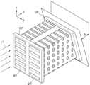
도 1을 참조하면, 실시예에 따른 분광 측정 장치는 그레이팅 패널(GP) 및 그레이팅 패널(GP)의 출광면과 마주보도록 마련된 것으로, 그레이팅 패널(GP)은 제1 주기를 가지는 제1 그레이팅 패턴(gr1) 및 제1 주기와 다른 제2 주기를 가지는 제2 그레이팅 패턴(gr2)을 포함할 수 있다. 여기서, '그레이팅 패턴(grating pattern)'이라는 용어는 슬릿 어레이(slit array), 슬롯 어레이(slot array), 복수의 홈(groove)의 어레이 등을 포괄하는 용어일 수 있다. 또한, '그레이팅 패턴(grating pattern)'이라는 용어는 투광성 물질층에 양각 또는 음각된 다양한 형태의 패턴을 모두 포괄할 수 있다.Referring to FIG. 1, a spectroscopic measuring device according to an embodiment is provided to face a grating panel (GP) and a light-emitting surface of the grating panel (GP), and the grating panel (GP) may include a first grating pattern (gr1) having a first period and a second grating pattern (gr2) having a second period different from the first period. Here, the term 'grating pattern' may be a term encompassing a slit array, a slot array, an array of a plurality of grooves, and the like. In addition, the term 'grating pattern' may encompass all of various shapes of patterns engraved or engraved on a light-transmitting material layer.
입사광(L1)이 그레이팅 패널(GP)을 통과하면, 광의 진행방향(z축 방향)에 따라 강도 변화가 있을 수 있다. 예를 들어, 평면광이 주기적인 구조를 가지는 그레이팅 패턴에 입사되면, 그레이팅의 이미지가 소정의 거리 간격으로 반복해서 나타날 수 있다. 즉, 광의 진행방향(z축 방향)에 따라 광의 명암이 주기적으로 변하면서 간섭 무늬가 형성될 수 있다. 이러한 현상을 탈봇 효과(Talbot effect)라고 한다.When incident light (L1) passes through a grating panel (GP), there may be a change in intensity depending on the direction in which the light propagates (z-axis direction). For example, when flat light is incident on a grating pattern having a periodic structure, an image of the grating may appear repeatedly at a predetermined distance interval. In other words, an interference pattern may be formed as the brightness of the light periodically changes depending on the direction in which the light propagates (z-axis direction). This phenomenon is called the Talbot effect.
탈봇 효과에서 간섭 무늬가 반복되는 거리 간격(P)은 아래의 수학식 1과 같이 나타낼 수 있다.The distance interval (P) at which the interference pattern repeats in the Talbot effect can be expressed as shown in the

수학식 1에서 P는 그레이팅 패턴(gr1, gr2)의 주기, λ는 입사광(L1)의 파장, SP는 탈봇 효과에 의해 간섭 무늬가 반복되는 거리 주기를 의미한다.In
수학식 1에서 보는 바와 같이, 탈봇 효과에 의한 간섭 무늬 반복 주기는 입사광(L1)의 파장과 그레이팅 패턴(gr1, gr2)의 주기에 의존한다. 제1 그레이팅 패턴(gr1)과 제2 그레이팅 패턴(gr2)이 서로 다른 주기를 가지기 때문에, 제1 그레이팅 패턴(gr1)을 통과한 제1 광과, 제2 그레이팅 패턴(gr2)을 통과한 제2 광은 각각 서로 다른 거리 주기로 간섭무늬가 반복될 수 있다.As shown in
분광 측정 장치는 그레이팅 패널(GP)의 출광면과 마주보도록 마련된 것으로, 제1 그레이팅 패턴(gr1)을 통과한 제1 광의 진행 거리에 따른 강도 변화 및 제2 그레이팅 패턴(gr2)을 통과한 제2 광의 진행 거리에 따른 강도 변화를 측정하는 광 측정 패널(OP)을 포함할 수 있다.The spectrophotometer may include a light measuring panel (OP) that is arranged to face the light-emitting surface of the grating panel (GP) and measures the intensity change according to the traveling distance of first light passing through the first grating pattern (gr1) and the intensity change according to the traveling distance of second light passing through the second grating pattern (gr2).
도 2는 도 1에서 나타낸 분광 측정 장치를 z-x 평면에서 본 단면도이다.Figure 2 is a cross-sectional view of the spectrophotometer shown in Figure 1 in the z-x plane.
도 2를 참조하면, 광 측정 패널(OP)은 광 측정 패널(OP)에 입사되는 광을 감지하여 전기적 신호를 발생시키는 복수의 광 센싱 유닛(SU)을 포함할 수 있다. 상기 복수의 광 센싱 유닛(SU)은 포토 다이오드, CCD(charge-coupled device) 센서나 CMOS(complementary metal-oxide semiconductor) 센서를 포함할 수 있지만, 실시예가 이에 제한되는 것은 아니다.Referring to FIG. 2, the light measuring panel (OP) may include a plurality of light sensing units (SU) that detect light incident on the light measuring panel (OP) and generate electrical signals. The plurality of light sensing units (SU) may include a photodiode, a charge-coupled device (CCD) sensor, or a complementary metal-oxide semiconductor (CMOS) sensor, but the embodiment is not limited thereto.
분광 측정 장치는 광 측정 패널(OP)의 위치를 변경시키는 거리 조절부(110)를 포함할 수 있다. 거리 조절부(110)는 광 측정 패널(OP)을 z축 방향으로 움직임으로써, 광 측정 패널(OP)과 그레이팅 패널(GP) 사이의 간격을 변경할 수 있다. 도 2에서는 광 측정 패널(OP)이 움직이는 예를 나타냈지만, 실시예가 이에 제한되는 것은 아니다. 예를 들어, 거리 조절부(110)는 그레이팅 패널(GP)을 z축 방향으로 움직일 수도 있다. 다른 예로, 거리 조절부(110)는 그레이팅 패널(GP) 및 광 측정 패널(OP)의 위치를 모두 변경시킬 수도 있다.The spectrophotometer may include a distance adjusting unit (110) that changes the position of the light measuring panel (OP). The distance adjusting unit (110) may change the gap between the light measuring panel (OP) and the grating panel (GP) by moving the light measuring panel (OP) in the z-axis direction. Although FIG. 2 illustrates an example in which the light measuring panel (OP) moves, the embodiment is not limited thereto. For example, the distance adjusting unit (110) may move the grating panel (GP) in the z-axis direction. As another example, the distance adjusting unit (110) may change the positions of both the grating panel (GP) and the light measuring panel (OP).
광 측정 패널(OP)은 광 측정 패널(OP)에 입사되는 광을 감지하여 전기적 신호를 발생시킬 수 있다. 광 측정 패널(OP)에서 발생된 전기적 신호는 프로세서(120)로 전달될 수 있다. 프로세서(120)는 광 측정 패널(OP)과 그레이팅 패널(GP) 사이의 간격이 변함에 따라, 광 측정 패널(OP)에서 측정되는 광 신호의 세기 변화를 봄으로써, 광 측정 패널(OP)을 통과한 광의 간섭 패턴을 파악할 수 있다. 프로세서(120)는 제1 그레이팅 패턴(gr1)을 통과한 제1 광이 형성하는 간섭 패턴에 대한 정보와 제2 그레이팅 패턴(gr2)을 통과한 제2 광이 형성하는 간섭 패턴에 대한 정보 각각을 획득할 수 있다. 프로세서(120)는 제1 광의 진행 거리에 따른 강도 변화 및 상기 제2 광의 진행 거리에 따른 강도 변화로부터 그레이팅 패널(GP)에 입사한 광(L1)의 파장 스펙트럼을 획득할 수 있다.The optical measurement panel (OP) can detect light incident on the optical measurement panel (OP) and generate an electrical signal. The electrical signal generated from the optical measurement panel (OP) can be transmitted to the processor (120). The processor (120) can identify an interference pattern of light passing through the optical measurement panel (OP) by observing a change in the intensity of an optical signal measured by the optical measurement panel (OP) as the distance between the optical measurement panel (OP) and the grating panel (GP) changes. The processor (120) can obtain information on an interference pattern formed by the first light passing through the first grating pattern (gr1) and information on an interference pattern formed by the second light passing through the second grating pattern (gr2), respectively. The processor (120) can obtain a wavelength spectrum of light (L1) incident on the grating panel (GP) from an intensity change according to a traveling distance of the first light and an intensity change according to a traveling distance of the second light.
프로세서(120)는 제1 광의 진행 거리에 따른 강도 변화로부터 제1 광의 간섭 패턴 주기를 파악할 수 있다. 이때, 입사광(L1)에 여러 파장이 섞여 있는 경우, 제1 광에는 여러 주기로 반복되는 패턴들이 섞여 있을 수 있다. 따라서, 프로세서(120)는 제1 광의 진행 거리에 따른 강도 변화에 대해 푸리에 변환 연산을 수행함으로써, 간섭 패턴의 반복 주기 성분들을 추출할 수 있다. 또한, 프로세서(120)는 제1 광의 진행 거리에 따른 강도 변화로부터 제1 광의 파장 스펙트럼을 계산할 수 있다. 마찬가지로, 프로세서(120)는 제2 광의 진행 거리에 따른 강도 변화에 대해 푸리에 변환 연산을 수행함으로써, 제2 광의 파장 스펙트럼을 계산할 수 있다.The processor (120) can determine the interference pattern period of the first light from the intensity change according to the traveling distance of the first light. At this time, if multiple wavelengths are mixed in the incident light (L1), the first light may have patterns that are repeated in multiple cycles mixed in it. Therefore, the processor (120) can extract the repeating cycle components of the interference pattern by performing a Fourier transform operation on the intensity change according to the traveling distance of the first light. In addition, the processor (120) can calculate the wavelength spectrum of the first light from the intensity change according to the traveling distance of the first light. Similarly, the processor (120) can calculate the wavelength spectrum of the second light by performing a Fourier transform operation on the intensity change according to the traveling distance of the second light.
도 3은 도 1 및 도 2에서 나타낸 그레이팅 패널(GP)의 표면을 나타낸 도면이다.FIG. 3 is a drawing showing the surface of the grating panel (GP) shown in FIGS. 1 and 2.
도 3을 참조하면, 그레이팅 패널(GP)은 제1 그레이팅 패턴(gr1) 및 제2 그레이팅 패턴(gr2)을 포함할 수 있다. 제1 그레이팅 패턴(gr1)의 주기(P1)와 제2 그레이팅 패턴(gr2)의 주기(P2)는 서로 다를 수 있다. 제1 그레이팅 패턴(gr1)은 x축 방향으로 형성될 수 있다. 마찬가지로, 제2 그레이팅 패턴(gr2) 또한, x축 방향으로 형성되어, 제1 그레이팅 패턴(gr1)과 제2 그레이팅 패턴(gr2)은 서로 나란하게 형성될 수 있다. 제1 그레이팅 패턴(gr1)과 제2 그레이팅 패턴(gr2)은 y축 방향으로 이격되어 있을 수 있다. 따라서, 도 1에서 나타낸 탈봇 효과에 의한 간섭 패턴은 y축 방향 위치에 따라 달라질 수 있다.Referring to FIG. 3, the grating panel (GP) may include a first grating pattern (gr1) and a second grating pattern (gr2). The period (P1) of the first grating pattern (gr1) and the period (P2) of the second grating pattern (gr2) may be different from each other. The first grating pattern (gr1) may be formed in the x-axis direction. Similarly, the second grating pattern (gr2) may also be formed in the x-axis direction, so that the first grating pattern (gr1) and the second grating pattern (gr2) may be formed parallel to each other. The first grating pattern (gr1) and the second grating pattern (gr2) may be spaced apart from each other in the y-axis direction. Therefore, the interference pattern due to the Talbot effect illustrated in FIG. 1 may vary depending on the y-axis direction position.
도 3에서 제1 그레이팅 패턴(gr1)과 제2 그레이팅 패턴(gr2)의 일 예를 나타냈지만, 실시예가 이에 제한되는 것은 아니다. 도 4는 다른 예에 따른 그래이팅 패널(GP)의 표면을 나타낸 도면이다.Although Fig. 3 illustrates an example of a first grating pattern (gr1) and a second grating pattern (gr2), the embodiment is not limited thereto. Fig. 4 is a drawing illustrating a surface of a grating panel (GP) according to another example.
도 4를 참조하면, 그레이팅 패널(GP)은 제1 그레이팅 패턴(gr1) 및 제2 그레이팅 패턴(gr2)을 포함할 수 잇다. 제1 그레이팅 패턴(gr1)에서 패턴 각각의 폭(W1)은 제2 그레이팅 패턴(gr2)에서 패턴 각각의 폭(W2)과 서로 다를 수 있다. 또한, 제1 그레이팅 패턴(gr1)의 주기(P1)와 제2 그레이팅 패턴(gr2)의 주기(P2)는 서로 다를 수 있다. 즉, 제1 그레이팅 패턴(gr1)과 제2 그레이팅 패턴(gr2)은 서로 다른 주기를 가질 뿐만 아니라 패턴의 점유율 또한 서로 다를 수도 있다.Referring to FIG. 4, the grating panel (GP) may include a first grating pattern (gr1) and a second grating pattern (gr2). The width (W1) of each pattern in the first grating pattern (gr1) may be different from the width (W2) of each pattern in the second grating pattern (gr2). In addition, the period (P1) of the first grating pattern (gr1) and the period (P2) of the second grating pattern (gr2) may be different from each other. That is, the first grating pattern (gr1) and the second grating pattern (gr2) may not only have different periods, but also have different occupancies of the patterns.
도 5는 다른 예에 따른 그레이팅 패널(GP)의 표면을 나타낸 도면이다.Figure 5 is a drawing showing the surface of a grating panel (GP) according to another example.
도 5를 참조하면, 그레이팅 패널(GP)은 제1 주기(P1)를 가지는 제1 그레이팅 패턴(gr1)과, 제2 주기(P2)를 가지는 제2 그레이팅 패턴(gr2) 및 제3 주기(P3)를 가지는 제3 그레이팅 패턴(gr3)을 포함할 수 있다. 제1 내지 제3 그레이팅 패턴(gr1, gr2, gr3) 각각은 x축을 따라 나란하게 형성될 수 있다. 또한, 제1 내지 제3 그레이팅 패턴(gr1, gr2, gr3)은 y축 방향으로 이격 되게 배치될 수 있다. 따라서, 그레이팅 패널(GP)을 통과한 광이 형성하는 간섭 패턴은 y축 방향을 따라 변할 수 있다.Referring to FIG. 5, the grating panel (GP) may include a first grating pattern (gr1) having a first period (P1), a second grating pattern (gr2) having a second period (P2), and a third grating pattern (gr3) having a third period (P3). Each of the first to third grating patterns (gr1, gr2, gr3) may be formed parallel along the x-axis. In addition, the first to third grating patterns (gr1, gr2, gr3) may be arranged to be spaced apart from each other in the y-axis direction. Therefore, an interference pattern formed by light passing through the grating panel (GP) may vary along the y-axis direction.
도 5에서 나타낸 바와 같이, 그레이팅 패널(GP)이 주기가 서로 다른 세 개의 그레이팅 패턴(gr1, gr2, gr3)을 포함하는 경우, 그레이팅 패널(GP)을 통과한 광은 세 개의 서로 다른 간섭 패턴을 형성할 수 있다. 광 측정 패널(OP)은 제1 그레이팅 패턴(gr1)을 통과한 제1 광의 진행 거리에 따른 강도 변화, 제2 그레이팅 패턴(gr2)을 통과한 제2 광의 진행 거리에 따른 강도 변화 및 제3 그레이팅 패턴(gr3)을 통과한 제3 광의 진행 거리에 따른 강도 변화 각각을 측정할 수 있다. 또한, 도 2에서 나타낸 프로세서(120)는 제1 내지 제3 광의 진행 거리에 따른 강도 변화로부터 그레이팅 패널(GP)에 입사한 광의 파장 스펙트럼을 계산할 수 있다.As shown in FIG. 5, when the grating panel (GP) includes three grating patterns (gr1, gr2, gr3) having different periods, light passing through the grating panel (GP) can form three different interference patterns. The light measuring panel (OP) can measure the intensity change according to the traveling distance of the first light passing through the first grating pattern (gr1), the intensity change according to the traveling distance of the second light passing through the second grating pattern (gr2), and the intensity change according to the traveling distance of the third light passing through the third grating pattern (gr3), respectively. In addition, the processor (120) shown in FIG. 2 can calculate the wavelength spectrum of the light incident on the grating panel (GP) from the intensity change according to the traveling distance of the first to third lights.
도 5에서는 그레이팅 패널(GP)에 포함된 그레이팅 패턴(gr1, gr2, gr3)의 개수가 3개인 경우를 나타냈지만, 실시예가 이에 제한되는 것은 아니다. 예를 들어, 그레이팅 패널(GP)은 서로 다른 주기를 가지는 그레이팅 패턴을 4개 이상 포함할 수도 있다.Although Fig. 5 shows a case where the number of grating patterns (gr1, gr2, gr3) included in the grating panel (GP) is three, the embodiment is not limited thereto. For example, the grating panel (GP) may include four or more grating patterns having different periods.
또한, 도 3 내지 도 5에서는 그레이팅 패턴 각각이 스트라이프 형상으로 1차원적으로 형성된 예를 나타냈지만, 실시예가 이에 제한되는 것은 아니다. 예를 들어, 도 3에서 나타낸 제1 그레이팅 패턴(gr1)과 제2 그레이팅 패턴(gr2)은 각각 2차원적으로 형성된 그레이팅 패턴을 포함할 수도 있다.In addition, although FIGS. 3 to 5 illustrate examples in which each of the grating patterns is formed one-dimensionally in a stripe shape, the embodiment is not limited thereto. For example, the first grating pattern (gr1) and the second grating pattern (gr2) illustrated in FIG. 3 may each include a grating pattern formed two-dimensionally.
도 6은 다른 예에 따른 그레이팅 패널(GP)의 표면을 나타낸 도면이다.Fig. 6 is a drawing showing the surface of a grating panel (GP) according to another example.
도 6을 참조하면, 그레이팅 패널(GP)은 제1 주기(P1)를 가지는 제1 그레이팅 패턴(gr1)과, 제2 주기(P2)를 가지는 제2 그레이팅 패턴(gr2) 및 제3 주기(P3)를 가지는 제3 그레이팅 패턴(gr3)을 포함할 수 있다. 제1 내지 제3 그레이팅 패턴(gr1, gr2, gr3) 각각은 x축을 따라 나란하게 배열될 수 있다. 또한, 제1 내지 제3 그레이팅 패턴(gr1, gr2, gr3)은 y축 방향으로 이격 되게 배치될 수 있다. 제1 그레이팅 패턴(gr1)의 패턴 요소(ex, 단위 슬릿)는 제1 폭(W1)을 가질 수 있고, 제2 그레이팅 패턴(gr2)의 패턴 요소(ex, 단위 슬릿)는 제2 폭(W2)을 가질 수 있으며, 제3 그레이팅 패턴(gr3)의 패턴 요소(ex, 단위 슬릿)는 제3 폭(W3)을 가질 수 있다. 제1 폭(W1)과 제2 폭(W2) 및 제3 폭(W3) 중 적어도 두 개는 서로 다를 수 있다. 예컨대, 제2 폭(W2)은 제1 폭(W1)보다 클 수 있고, 제3 폭(W3)은 제2 폭(W2)보다 클 수 있다. 일례로, 제1 폭(W1)은 제1 주기(P1)의 절반이거나 그와 유사할 수 있고, 제2 폭(W2)은 제2 주기(P2)의 절반이거나 그와 유사할 수 있으며, 제3 폭(W3)은 제3 주기(P3)의 절반이거나 그와 유사할 수 있다. 그러나, 제1 내지 제3 그레이팅 패턴(gr1, gr2, gr3) 각각의 주기 및 폭은 전술한 바에 한정되지 않고, 다양하게 변화될 수 있다. 또한, 제1 내지 제3 그레이팅 패턴(gr1, gr2, gr3)과 다른 주기를 갖는 적어도 하나의 다른 그레이팅 패턴(미도시)이 더 구비될 수 있다.Referring to FIG. 6, the grating panel (GP) may include a first grating pattern (gr1) having a first period (P1), a second grating pattern (gr2) having a second period (P2), and a third grating pattern (gr3) having a third period (P3). Each of the first to third grating patterns (gr1, gr2, gr3) may be arranged in parallel along the x-axis. In addition, the first to third grating patterns (gr1, gr2, gr3) may be arranged to be spaced apart from each other in the y-axis direction. A pattern element (ex, unit slit) of the first grating pattern (gr1) may have a first width (W1), a pattern element (ex, unit slit) of the second grating pattern (gr2) may have a second width (W2), and a pattern element (ex, unit slit) of the third grating pattern (gr3) may have a third width (W3). At least two of the first width (W1), the second width (W2), and the third width (W3) may be different from each other. For example, the second width (W2) may be larger than the first width (W1), and the third width (W3) may be larger than the second width (W2). For example, the first width (W1) may be half or similar to the first period (P1), the second width (W2) may be half or similar to the second period (P2), and the third width (W3) may be half or similar to the third period (P3). However, the period and width of each of the first to third grating patterns (gr1, gr2, gr3) are not limited to those described above and may vary. In addition, at least one other grating pattern (not shown) having a period different from the first to third grating patterns (gr1, gr2, gr3) may be further provided.
도 7은 도 1에서 나타낸 간섭 패턴을 z-x 평면에서 바라본 도면이다.Figure 7 is a drawing of the interference pattern shown in Figure 1 viewed in the z-x plane.
도 7에서는 제1 그레이팅 패턴(gr1)을 통과한 제1 광에 의해 형성되는 간섭 패턴을 예시적으로 나타냈다. 도 7을 참조하면, z축 방향을 따라 소정의 간섭무늬 패턴이 일정한 거리 주기(SP1)로 반복될 수 있다. 수학식 1에서 나타낸 바와 같이 z축 방향 주기(SP1)는 제1 그레이팅 패턴(gr1)의 형성 주기(P1) 및 입사광(L1)의 파장(λ)에 의존할 수 있다.Fig. 7 exemplarily shows an interference pattern formed by the first light passing through the first grating pattern (gr1). Referring to Fig. 7, a predetermined interference pattern may be repeated with a constant distance period (SP1) along the z-axis direction. As shown in
도 8은 도 1에서 나타낸 간섭 패턴을 z-x 평면에서 바라본 도면이다.Figure 8 is a drawing of the interference pattern shown in Figure 1 viewed in the z-x plane.
도 8에서는 제2 그레이팅 패턴(gr2)을 통과한 제2 광에 의해 형성되는 간섭 패턴을 예시적으로 나타냈다. 도 8을 참조하면, z축 방향을 따라 소정의 간섭무늬 패턴이 일정한 거리 주기(SP2)로 반복될 수 있다. 제2 그레이팅 패턴(gr2)의 형성 주기(P2)는 제1 그레이팅 패턴(gr1)의 형성 주기(P1)보다 클 수 있다. 이에 따라, 제2 그레이팅 패턴(gr2)을 통과한 제2 광이 형성하는 간섭 패턴의 반복 주기(SP2)는 제1 광이 형성하는 간섭 패턴의 반복 주기(SP1)보다 더 클 수 있다.Fig. 8 exemplarily shows an interference pattern formed by the second light passing through the second grating pattern (gr2). Referring to Fig. 8, a predetermined interference pattern may be repeated with a constant distance period (SP2) along the z-axis direction. The formation period (P2) of the second grating pattern (gr2) may be greater than the formation period (P1) of the first grating pattern (gr1). Accordingly, the repetition period (SP2) of the interference pattern formed by the second light passing through the second grating pattern (gr2) may be greater than the repetition period (SP1) of the interference pattern formed by the first light.
도 9는 도 1에서 나타낸 간섭 패턴을 y-z 평면에서 바라본 도면이다.Figure 9 is a drawing of the interference pattern shown in Figure 1 as viewed from the y-z plane.
도 9를 참조하면, 간섭 패턴의 반복 주기가 y축 위치에 따라 서로 달라질 수 있다. 제1 그레이팅 패턴(gr1)을 통과한 제1 광이 형성하는 패턴(pattern Ⅰ)의 반복 주기(SP1)와 제2 그레이팅 패턴(gr2)을 통과한 제2 광이 형성하는 패턴(pattern Ⅱ)의 반복 주기(SP2)는 서로 다를 수 있다. 제1 광이 형성하는 패턴(pattern Ⅰ)의 반복 주기(SP1)는 입사광(L1)의 파장(λ) 및 제1 그레이팅 패턴(gr1)의 형성 주기(P1)에 의존할 수 있다. 또한, 제2 광이 형성하는 패턴(pattern Ⅱ)의 반복 주기(SP2)는 입사광(L1)의 파장(λ) 및 제1 그레이팅 패턴(gr1)의 형성 주기(P1)에 의존할 수 있다.Referring to FIG. 9, the repetition period of the interference pattern may be different depending on the y-axis position. The repetition period (SP1) of the pattern (pattern I) formed by the first light passing through the first grating pattern (gr1) and the repetition period (SP2) of the pattern (pattern II) formed by the second light passing through the second grating pattern (gr2) may be different from each other. The repetition period (SP1) of the pattern (pattern I) formed by the first light may depend on the wavelength (λ) of the incident light (L1) and the formation period (P1) of the first grating pattern (gr1). In addition, the repetition period (SP2) of the pattern (pattern II) formed by the second light may depend on the wavelength (λ) of the incident light (L1) and the formation period (P1) of the first grating pattern (gr1).
광 측정 패널(OP)은 제1 광의 진행거리에 따른 강도 변화 및 제2 광의 진행 거리에 따른 강도 변화를 측정할 수 있다. 프로세서(120)는 광 측정 패널(OP)의 측정 결과로부터, 제1 광이 형성하는 패턴(pattern I)의 z축 방향 반복 주기(SP1)와, 제2 광이 형성하는 패턴(pattern II)의 z축 방향 반복 주기(SP2)에 대한 정보를 획득할 수 있다. 프로세서(120)는 제1 광이 형성하는 패턴(pattern I)의 z축 방향 반복 주기(SP1)와, 제2 광이 형성하는 패턴(pattern II)의 z축 방향 반복 주기(SP2)에 대한 정보로부터 입사광(L1)의 파장을 계산할 수 있다.The light measuring panel (OP) can measure the intensity change according to the traveling distance of the first light and the intensity change according to the traveling distance of the second light. The processor (120) can obtain information about the z-axis direction repetition period (SP1) of the pattern (pattern I) formed by the first light and the z-axis direction repetition period (SP2) of the pattern (pattern II) formed by the second light from the measurement result of the light measuring panel (OP). The processor (120) can calculate the wavelength of the incident light (L1) from the information about the z-axis direction repetition period (SP1) of the pattern (pattern I) formed by the first light and the z-axis direction repetition period (SP2) of the pattern (pattern II) formed by the second light.
도 7 내지 도 9에서는 입사광(L1)이 단일 파장의 광인 경우를 나타냈다. 입사광(L1)이 단일 파장의 광인 경우, 제1 광이 형성하는 간섭 패턴(pattern I)과 제2 광이 형성하는 간섭 패턴(pattern II)에는 서로 다른 주기로 반복되는 패턴들이 섞여 있을 수 있다. 이 경우, 프로세서(120)는 제1 광의 진행거리에 따른 강도 변화에 대해 푸리에 변환 연산을 함으로써, 제1 광의 파장 스펙트럼을 계산할 수 있다. 또한, 프로세서(120)는 제2 광의 진행 거리에 따른 강도 변화에 대해 푸리에 변환 연산을 함으로써, 제2 광의 파장 스펙트럼을 계산할 수 있다.In FIGS. 7 to 9, the case where the incident light (L1) is light of a single wavelength is shown. When the incident light (L1) is light of a single wavelength, the interference pattern (pattern I) formed by the first light and the interference pattern (pattern II) formed by the second light may have patterns that are repeated at different periods mixed together. In this case, the processor (120) can calculate the wavelength spectrum of the first light by performing a Fourier transform operation on the intensity change according to the traveling distance of the first light. In addition, the processor (120) can calculate the wavelength spectrum of the second light by performing a Fourier transform operation on the intensity change according to the traveling distance of the second light.
제1 그레이팅 패턴(gr1)과 제2 그레이팅 패턴(gr2)이 서로 다른 주기를 가지기 때문에 제1 광의 진행 거리에 따른 강도 변화와 제2 광의 진행 거리에 따른 강도 변화는 서로 다를 수 있다. 즉, 제1 광이 형성하는 간섭 패턴과 제2 광이 형성하는 간섭 패턴이 서로 다를 수 있다. 프로세서(120)는 제1 그레이팅 패턴(gr1)의 형성 주기와 제2 그레이팅 패턴(gr2)의 형성 주기를 고려하여, 제1 광이 형성하는 간섭패턴과 제2 광이 형성하는 간섭 패턴에 각각에 대해 서로 다른 연산 알고리즘을 적용함으로써, 제1 광의 파장 스펙트럼과 제2 광의 파장 스펙트럼을 계산할 수 있다.Since the first grating pattern (gr1) and the second grating pattern (gr2) have different periods, the intensity change according to the traveling distance of the first light and the intensity change according to the traveling distance of the second light may be different from each other. In other words, the interference pattern formed by the first light and the interference pattern formed by the second light may be different from each other. The processor (120) can calculate the wavelength spectrum of the first light and the wavelength spectrum of the second light by applying different calculation algorithms to the interference pattern formed by the first light and the interference pattern formed by the second light, respectively, by considering the formation period of the first grating pattern (gr1) and the formation period of the second grating pattern (gr2).
도 10은 다른 예시적인 실시예에 따른 분광 측정 장치를 나타낸 도면이다. 도 10의 실시예를 설명함에 있어서, 도 1 내지 도 9를 참조한 실시예와 중복되는 설명을 생략한다.Fig. 10 is a drawing showing a spectroscopic measuring device according to another exemplary embodiment. In describing the embodiment of Fig. 10, descriptions overlapping with those of the embodiments referring to Figs. 1 to 9 are omitted.
도 10을 참조하면, 광 측정 패널(OP)은 그레이팅 패널(GP)에 대해 비스듬하게 배치될 수 있다. 예를 들어, 광 측정 패널(OP)은 그레이팅 패널(GP)에 평행한 면에 대해 소정의 각도(θ)만큼 기울어져 있을 수 있다. 이 경우, 도 1 및 도 2에서 나타낸 실시예와 달리, 광 측정 패널(OP)의 위치가 z축 방향으로 움직이지 않을 수 있다.Referring to FIG. 10, the light measuring panel (OP) may be positioned obliquely with respect to the grating panel (GP). For example, the light measuring panel (OP) may be inclined at a predetermined angle (θ) with respect to a plane parallel to the grating panel (GP). In this case, unlike the embodiments shown in FIGS. 1 and 2, the position of the light measuring panel (OP) may not move in the z-axis direction.
도 11은 도 10에서 나타낸 분광 측정 장치를 z-x 면에서 바라본 도면이다.Figure 11 is a drawing of the spectroscopic measuring device shown in Figure 10 as viewed from the z-x plane.
도 11을 참조하면, 광 측정 패널(OP)이 y축에 대해 소정의 각도(θ)만큼 기울어지도록 배치될 수 있다. 상기 각도(θ)는 광 측정 패널(OP)의 크기와 그레이팅 패널(GP)을 통과한 광이 형성하는 간섭 패턴의 반복 주기 등에 따라 다르게 결정될 수 있다. 광 측정 패널(OP)은 광을 감지하여 전기적 신호를 발생시키는 복수의 광 센싱 유닛(SU)을 포함할 수 있다. 광 측정 패널(OP)이 그레이팅 패널(GP)에 대해 기울어져 있기 때문에 광 측정 패널(OP)에 포함된 광 센싱 유닛(SU)들 각각과 그레이팅 패널(GP) 사이의 거리가 광 센싱 유닛(SU)의 배열 위치에 따라 달라질 수 있다. 예를 들어, 광 측정 패널(OP)의 하단에 위치한 광 센싱 유닛(SU)은 광 측정 패널(OP)의 상단에 위치한 광 센싱 유닛(SU)에 비해 그레이팅 패널(GP)로부터 더 멀리 떨어져 있을 수 있다.Referring to FIG. 11, the light measuring panel (OP) may be arranged to be inclined at a predetermined angle (θ) with respect to the y-axis. The angle (θ) may be determined differently depending on the size of the light measuring panel (OP) and the repetition period of the interference pattern formed by the light passing through the grating panel (GP). The light measuring panel (OP) may include a plurality of light sensing units (SU) that detect light and generate electrical signals. Since the light measuring panel (OP) is inclined with respect to the grating panel (GP), the distance between each of the light sensing units (SU) included in the light measuring panel (OP) and the grating panel (GP) may vary depending on the arrangement positions of the light sensing units (SU). For example, the light sensing unit (SU) located at the bottom of the light measuring panel (OP) may be further away from the grating panel (GP) than the light sensing unit (SU) located at the top of the light measuring panel (OP).
도 10 및 도 11에서 나타낸 바와 같이, 광 측정 패널(OP)이 그레이팅 패널(GP)에 대해 기울어지도록 배치되면, 광 측정 패널(OP)의 광 센싱 유닛(SU)들이 각각 그레이팅 패널(GP)로부터 서로 다른 거리만큼 이격되어 광을 감지할 수 있다. 따라서, 도 1 및 도 2에서 나타낸 바와 같이, 광 측정 패널(OP)을 z축 방향으로 움직이지 않더라도, 광 측정 패널(OP)이 그레이팅 패널(GP)을 통과한 광의 진행거리에 따른 강도 변화를 측정할 수 있다.As shown in FIGS. 10 and 11, when the light measuring panel (OP) is arranged to be inclined with respect to the grating panel (GP), the light sensing units (SUs) of the light measuring panel (OP) can detect light at different distances from the grating panel (GP), respectively. Therefore, as shown in FIGS. 1 and 2, even if the light measuring panel (OP) does not move in the z-axis direction, the light measuring panel (OP) can measure the intensity change according to the travel distance of light passing through the grating panel (GP).
전술한 바와 같이, 제1 그레이팅 패턴(gr1)과 제2 그레이팅 패턴(gr2)의 형성 주기가 서로 다르기 때문에, 프로세서(120)는 제1 광의 진행 거리에 따른 강도 변화 및 제2 광의 진행 거리에 따른 강도 변화 각각에 서로 다른 연산 알고리즘을 적용함으로써, 제1 광의 파장 스펙트럼과 제2 광의 파장 스펙트럼을 계산할 수 있다. 이때, 상기 연산 알고리즘은 제1 그레이팅 패턴(gr1)의 형성 주기와 제2 그레이팅 패턴(gr2)의 형성 주기에 따라 결정될 수 있다.As described above, since the formation cycles of the first grating pattern (gr1) and the second grating pattern (gr2) are different from each other, the processor (120) can calculate the wavelength spectrum of the first light and the wavelength spectrum of the second light by applying different calculation algorithms to the intensity change according to the propagation distance of the first light and the intensity change according to the propagation distance of the second light, respectively. At this time, the calculation algorithm can be determined according to the formation cycle of the first grating pattern (gr1) and the formation cycle of the second grating pattern (gr2).
그레이팅 패널(GP)의 제1 그레이팅 패턴(gr1)과 제2 그레이팅 패턴(gr2)에 동일한 파장 스펙트럼을 가진 입사광(L1)이 입사되었다면, 이상적인 경우, 프로세서(120)가 계산한 제1 광의 파장 스펙트럼과 제2 광의 파장 스펙트럼이 일치해야 한다. 하지만, 이상적인 경우와 달리 그레이팅 패널(GP)에 입사광(L1)이 완전 수직으로 입사하지 않거나, 입사광(L1)이 평면광이 아닌 상황이 있을 수 있다. 그레이팅 패널(GP)에 입사광(L1)의 입사각이 달라짐에 따라, 그레이팅 패널(GP)에 의한 입사광(L1)의 회절 조건이 변하면서, 광이 그레이팅 패널(GP)을 통과하면서 형성하는 간섭 패턴이 달라질 수 있다.If incident light (L1) having the same wavelength spectrum is incident on the first grating pattern (gr1) and the second grating pattern (gr2) of the grating panel (GP), ideally, the wavelength spectrum of the first light and the wavelength spectrum of the second light calculated by the processor (120) should match. However, unlike the ideal case, there may be a situation where the incident light (L1) is not incident perfectly perpendicularly on the grating panel (GP) or the incident light (L1) is not plane light. As the incident angle of the incident light (L1) on the grating panel (GP) changes, the diffraction conditions of the incident light (L1) by the grating panel (GP) change, and thus the interference pattern formed when the light passes through the grating panel (GP) may change.
그런데, 프로세서(120)가 입사광(L1)의 입사각이 달라진 것을 고려하지 않고, 제1 광의 파장 스펙트럼과 제2 광의 파장 스펙트럼을 계산하면, 제1 광의 파장 스펙트럼과 제2 광의 파장 스펙트럼도 서로 다르게 계산될 수 있다. 또한, 제1 광의 파장 스펙트럼 및 제2 광의 파장 스펙트럼 어느 것도 입사광(L1)의 파장 스펙트럼과 일치하지 않을 수 있다.However, if the processor (120) calculates the wavelength spectrum of the first light and the wavelength spectrum of the second light without considering the change in the incident angle of the incident light (L1), the wavelength spectrum of the first light and the wavelength spectrum of the second light may be calculated differently. In addition, neither the wavelength spectrum of the first light nor the wavelength spectrum of the second light may match the wavelength spectrum of the incident light (L1).
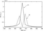
도 12는 입사광(L1)의 입사각에 따라 프로세서(120)에서 계산된 제1 광의 파장 스펙트럼 변화를 나타낸 도면이다. 또한, 도 13은 입사광(L1)의 입사각에 따라 프로세서(120)에서 계산된 제2 광의 파장 스펙트럼 변화를 나타낸 도면이다.Fig. 12 is a diagram showing the change in wavelength spectrum of the first light calculated by the processor (120) according to the incident angle of the incident light (L1). In addition, Fig. 13 is a diagram showing the change in wavelength spectrum of the second light calculated by the processor (120) according to the incident angle of the incident light (L1).
도 12에서는 제1 그레이팅 패턴(gr1)의 주기(P1)가 1.035μm인 예를 나타냈다. 또한, 도 13에서는 제2 그레이팅 패턴(gr2)의 주기(P2)가 1.2 μm인 예를 나타냈다.Fig. 12 shows an example in which the period (P1) of the first grating pattern (gr1) is 1.035 μm. In addition, Fig. 13 shows an example in which the period (P2) of the second grating pattern (gr2) is 1.2 μm.
도 12에서 S1 그래프는 입사광(L1)의 입사각이 0도인 경우 제1 그레이팅 패턴(gr1)을 통과한 제1 광의 간섭 패턴으로부터 계산한 제1 파장 스펙트럼을 나타낸다. 또한, S2 그래프는 입사광(L1)의 입사각이 0.2도인 경우 제1 그레이팅 패턴(gr1)을 통과한 제1 광의 간섭 패턴으로부터 계산한 제1 파장 스펙트럼을 나타낸다.In Fig. 12, the S1 graph represents the first wavelength spectrum calculated from the interference pattern of the first light passing through the first grating pattern (gr1) when the incident angle of the incident light (L1) is 0 degrees. In addition, the S2 graph represents the first wavelength spectrum calculated from the interference pattern of the first light passing through the first grating pattern (gr1) when the incident angle of the incident light (L1) is 0.2 degrees.
또한, 도 13에서 S3 그래프는 입사광(L1)의 입사각이 0도인 경우 제2 그레이팅 패턴(gr2)을 통과한 제2 광의 간섭 패턴으로부터 계산한 제2 파장 스펙트럼을 나타낸다. 또한, S4 그래프는 입사광(L1)의 입사각이 0.2도인 경우 제2 그레이팅 패턴(gr2)을 통과한 제2 광의 간섭 패턴으로부터 계산한 제2 파장 스펙트럼을 나타낸다.In addition, graph S3 in Fig. 13 represents a second wavelength spectrum calculated from the interference pattern of the second light passing through the second grating pattern (gr2) when the incident angle of the incident light (L1) is 0 degrees. In addition, graph S4 represents a second wavelength spectrum calculated from the interference pattern of the second light passing through the second grating pattern (gr2) when the incident angle of the incident light (L1) is 0.2 degrees.
도 12 및 도 13을 참조하면, 입사광(L1)의 입사각이 0도를 벗어남에 따라 계산된 파장 스펙트럼이 민감하게 변함을 알 수 있다. 예를 들어, 입사각이 0도인 경우, 제1 광의 간섭 패턴으로부터 계산한 제1 파장 스펙트럼(S1)과 제2 광의 간섭 패턴으로부터 계산한 제2 파장 스펙트럼(S3)이 거의 유사할 수 있다. 두 파장 스펙트럼 모두에서 대략 863nm 근처에서 스펙트럼 피크가 형성될 수 있다. 반면, 입사광(L1)의 입사각이 0.2도인 경우, 제1 광의 파장 스펙트럼(S2)과 제2 광의 파장 스펙트럼(S4)이 서로 달라질 수 있다.Referring to FIGS. 12 and 13, it can be seen that the calculated wavelength spectrum changes sensitively as the incident angle of the incident light (L1) deviates from 0 degrees. For example, when the incident angle is 0 degrees, the first wavelength spectrum (S1) calculated from the interference pattern of the first light and the second wavelength spectrum (S3) calculated from the interference pattern of the second light may be almost similar. A spectrum peak may be formed at approximately 863 nm in both wavelength spectra. On the other hand, when the incident angle of the incident light (L1) is 0.2 degrees, the wavelength spectrum (S2) of the first light and the wavelength spectrum (S4) of the second light may be different from each other.
프로세서(120)는 제1 광의 간섭 패턴으로부터 계산된 제1 파장 스펙트럼과 제2 광의 간섭 패턴으로부터 계산된 제2 파장 스펙트럼을 비교할 수 있다. 프로세서(120)는 제1 파장 스펙트럼과 제2 파장 스펙트럼의 차이가 기준치 미만인 경우, 제1 파장 스펙트럼 및 제2 파장 스펙트럼으로부터 그레이팅 패널(GP)에 입사한 광(L1)의 파장 스펙트럼을 획득할 수 있다. 예를 들어, 프로세서(120)는 제1 파장 스펙트럼 및 제2 파장 스펙트럼의 평균을 계산함으로써, 상기 입사광(L1)의 파장 스펙트럼을 획득할 수 있다. 다른 예로, 프로세서(120)는 제1 파장 스펙트럼 및 제2 파장 스펙트럼 중 어느 하나를 입사광(L1)의 파장 스펙트럼으로 획득할 수 있다.The processor (120) can compare a first wavelength spectrum calculated from an interference pattern of the first light and a second wavelength spectrum calculated from an interference pattern of the second light. If a difference between the first wavelength spectrum and the second wavelength spectrum is less than a reference value, the processor (120) can obtain a wavelength spectrum of the light (L1) incident on the grating panel (GP) from the first wavelength spectrum and the second wavelength spectrum. For example, the processor (120) can obtain the wavelength spectrum of the incident light (L1) by calculating an average of the first wavelength spectrum and the second wavelength spectrum. As another example, the processor (120) can obtain one of the first wavelength spectrum and the second wavelength spectrum as the wavelength spectrum of the incident light (L1).
도 12의 S2 그래프와 도 13의 S4 그래프에서 나타낸 바와 같이, 제1 파장 스펙트럼과 제2 파장 스펙트럼의 차이가 기준치 이상인 경우, 프로세서(120)는 입사광(L1)의 입사각이 0도에서 벗어난 것으로 판단할 수 있다.As shown in the S2 graph of FIG. 12 and the S4 graph of FIG. 13, when the difference between the first wavelength spectrum and the second wavelength spectrum is greater than or equal to a reference value, the processor (120) can determine that the incident angle of the incident light (L1) deviates from 0 degrees.
다시 도 11을 참조하면, 실시예에 따른 분광 측정 장치는 광 측정 패널(OP)의 배열 각도(θ)를 조절하는 각도 조절부(130)를 더 포함할 수 있다. 각도 조절부(130)는 프로세서(120)에서 입사광(L1)의 입사각이 0도에서 벗어난 것으로 판단하면, 광 측정 패널(OP)의 배열 각도(θ)를 변경할 수 있다. 각도 조절부(130)는 광 측정 패널(OP)의 배열 각도(θ)를 변경함으로써, 입사광(L1)의 입사각이 0도에서 벗어난 효과를 보정할 수 있다. 각도 조절부(130)는 광 측정 패널(OP)의 배열 각도(θ)를 변경하고, 프로세서(120)로부터 제1 파장 스펙트럼 및 제2 파장 스펙트럼 변화에 대한 정보를 피드백 받을 수 있다. 각도 조절부(130)는 프로세서(120)가 제1 파장 스펙트럼과 제2 파장 스펙트럼의 차이가 기준치 미만으로 떨어진 것을 확인할 때까지 광 측정 패널(OP)의 배열 각도(θ)를 변경할 수 있다.Referring again to FIG. 11, the spectrophotometer according to the embodiment may further include an angle adjustment unit (130) for adjusting the arrangement angle (θ) of the light measurement panel (OP). If the processor (120) determines that the incident angle of the incident light (L1) deviates from 0 degrees, the angle adjustment unit (130) may change the arrangement angle (θ) of the light measurement panel (OP). By changing the arrangement angle (θ) of the light measurement panel (OP), the angle adjustment unit (130) may correct the effect of the incident angle of the incident light (L1) deviating from 0 degrees. The angle adjustment unit (130) may change the arrangement angle (θ) of the light measurement panel (OP) and receive feedback information on changes in the first wavelength spectrum and the second wavelength spectrum from the processor (120). The angle adjustment unit (130) can change the arrangement angle (θ) of the light measuring panel (OP) until the processor (120) confirms that the difference between the first wavelength spectrum and the second wavelength spectrum falls below a reference value.
다른 예로, 분광 측정 장치는 광 측정 패널(OP)의 배열 각도를 조절하지 않고, 프로세서(120)가 파장 스펙트럼을 계산하는 계산 알고리즘을 보정함으로써, 입사광(L1)의 입사각에 의한 효과를 보정할 수 있다. 예를 들어, 프로세서(120)는 제1 파장 스펙트럼과 제2 파장 스펙트럼의 차이가 기준치 이상이 되면, 입사광(L1)의 입사각이 0도에서 벗어난 것으로 판단할 수 있다. 그리고, 프로세서(120)는 상기 입사광(L1)의 입사각을 고려하여 제1 파장 스펙트럼을 도출하는 계산 과정과 제2 파장 스펙트럼을 도출하는 계산 과정을 보정할 수 있다. 프로세서(120)는 제1 파장 스펙트럼과 제2 파장 스펙트럼의 차이가 기준치 미만이 되도록 제1 파장 스펙트럼의 계산과정과 제2 파장 스펙트럼의 계산과정을 보정할 수 있다. 그리고, 프로세서(120)는 보정된 계산 과정에 의해 얻어진 제1 및 제2 파장 스펙트럼으로부터 입사광(L1)의 파장 스펙트럼을 획득할 수 있다.As another example, the spectrophotometer can compensate for the effect due to the incident angle of the incident light (L1) by compensating the calculation algorithm for calculating the wavelength spectrum by the processor (120) without adjusting the arrangement angle of the light measuring panel (OP). For example, the processor (120) can determine that the incident angle of the incident light (L1) deviates from 0 degrees when the difference between the first wavelength spectrum and the second wavelength spectrum is greater than or equal to a reference value. Then, the processor (120) can compensate the calculation process for deriving the first wavelength spectrum and the calculation process for deriving the second wavelength spectrum by considering the incident angle of the incident light (L1). The processor (120) can compensate the calculation process for the first wavelength spectrum and the calculation process for the second wavelength spectrum so that the difference between the first wavelength spectrum and the second wavelength spectrum becomes less than the reference value. Then, the processor (120) can obtain the wavelength spectrum of the incident light (L1) from the first and second wavelength spectra obtained by the compensated calculation process.
보다 구체적으로 설명하면, 도 12에서 863nm의 광이 0도의 각도로 입사할 경우, 제1 파장 스펙트럼(S1)의 피크가 약 863nm에 위치할 수 있다. 도 13에서 863nm의 광이 0도의 각도로 입사할 경우, 제2 파장 스펙트럼(S3)의 피크는 약 863nm에 위치할 수 있다. 이 경우, 제1 파장 스펙트럼(S1)의 피크의 위치와 제2 파장 스펙트럼(S3)의 피크의 위치는 거의 유사할 수 있고, 그 차이는, 예컨대, 약 ±2 nm 이내 또는 약 ±1 nm 이내일 수 있다. 이 경우, 두 개의 파장 스펙트럼(S1, S3)의 차이가 기준치 미만이라고 판단할 수 있다. 한편, 도 12에서 863nm의 광이 0.2도의 각도로 입사할 경우, 제1 파장 스펙트럼(S2)의 피크가 약 858nm 및 약 869nm에 위치할 수 있다. 도 13에서 863nm의 광이 0.2도의 각도로 입사할 경우, 제2 파장 스펙트럼(S4)의 피크는 상기한 S2 피크 위치(약 858nm 및 약 869nm)에서 비교적 크게 벗어날 수 있다. S2 피크의 위치와 그에 대응하는 S4 피크의 위치가 약 1 nm 이상 또는 약 2 nm 이상 차이를 나타낼 수 있다. 이 경우, 두 개의 파장 스펙트럼(S2, S4)의 차이가 기준치 이상이라고 판단할 수 있고, 앞서 설명한 바와 같은 보정 과정을 수행할 수 있다. 예컨대, 도 12에서 S1과 같은 피크가 나타날 때까지, 그리고, 도 13에서는 S3과 같은 피크가 나타날 때까지 보정을 수행할 수 있다.More specifically, in FIG. 12, when light of 863 nm is incident at an angle of 0 degree, the peak of the first wavelength spectrum (S1) may be located at about 863 nm. In FIG. 13, when light of 863 nm is incident at an angle of 0 degree, the peak of the second wavelength spectrum (S3) may be located at about 863 nm. In this case, the positions of the peaks of the first wavelength spectrum (S1) and the positions of the peaks of the second wavelength spectrum (S3) may be substantially similar, and the difference may be, for example, within about ±2 nm or within about ±1 nm. In this case, it may be determined that the difference between the two wavelength spectra (S1, S3) is less than a reference value. Meanwhile, in FIG. 12, when light of 863 nm is incident at an angle of 0.2 degree, the peaks of the first wavelength spectrum (S2) may be located at about 858 nm and about 869 nm. In Fig. 13, when light of 863 nm is incident at an angle of 0.2 degrees, the peak of the second wavelength spectrum (S4) may deviate relatively significantly from the S2 peak positions (about 858 nm and about 869 nm) described above. The positions of the S2 peak and the positions of the corresponding S4 peak may exhibit a difference of about 1 nm or more or about 2 nm or more. In this case, it may be determined that the difference between the two wavelength spectra (S2, S4) is greater than a reference value, and a correction process as described above may be performed. For example, correction may be performed until a peak such as S1 appears in Fig. 12, and until a peak such as S3 appears in Fig. 13.
만약, 하나의 주기를 갖는 하나의 그레이팅 패턴을 사용할 경우, 도 12에서 S2에 해당하는 스펙트럼이 863nm의 광이 0.2도의 각도로 입사하여 발생한 것인지 아니면 858nm 및 869nm의 광들이 0도의 각도로 입사하여 발생한 것인지 판단하기가 어려울 수 있다. 그러나, 실시예에서와 같이, 서로 다른 주기를 갖는 복수의 그레이팅 패턴을 사용하면, 경사지게 입사하는 광에 대해서 복수의 그레이팅 패턴이 서로 다른 결과를 나타내기 때문에(예컨대, 도 12의 S2 및 도 13의 S4와 같이), 이들을 기준으로 보정을 용이하게 수행할 수 있다. 결과적으로, 보정 작업을 통해 정확도 향상 및 해상도 향상 효과를 얻을 수 있다. 그러나, 도 12 및 도 13을 참조하여 설명한 것은 단순한 예시에 불과하고, 실제 소자에서 보정 과정은 더욱 복잡한 방식으로 이루어질 수 있다.If one grating pattern having one period is used, it may be difficult to determine whether the spectrum corresponding to S2 in Fig. 12 is generated when 863 nm light is incident at an angle of 0.2 degrees or when 858 nm and 869 nm lights are incident at an angle of 0 degrees. However, as in the embodiment, if multiple grating patterns having different periods are used, since the multiple grating patterns show different results with respect to light incident obliquely (e.g., S2 in Fig. 12 and S4 in Fig. 13), correction can be easily performed based on these. As a result, the correction work can obtain the effects of improved accuracy and improved resolution. However, the description with reference to Figs. 12 and 13 is merely a simple example, and the correction process in an actual device can be performed in a more complex manner.
상술한 바와 같이, 그레이팅 패널(GP)이 서로 다른 주기를 가지는 복수의 그레이팅 패턴(gr1, gr2)을 포함하면, 프로세서(120)가 그레이팅 패턴(gr1, gr2) 각각으로부터 도출되는 파장 스펙트럼을 비교할 수 있다. 예를 들어, 그레이팅 패널(GP)이 제1 주기를 가지는 제1 그레이팅 패턴(gr1)과 제2 그레이팅 패턴(gr2)을 포함하면, 프로세서(120)는 제1 그레이팅 패턴(gr1)을 통과한 제1 광의 제1 파장 스펙트럼과 제2 그레이팅 패턴(gr2)을 통과한 제2 광의 제2 파장 스펙트럼을 비교함으로써, 입사광(L1)의 입사각이 예상 입사각(ex. 0도)를 벗어났는지 여부를 판단할 수 있다.As described above, if the grating panel (GP) includes a plurality of grating patterns (gr1, gr2) having different periods, the processor (120) can compare wavelength spectra derived from each of the grating patterns (gr1, gr2). For example, if the grating panel (GP) includes a first grating pattern (gr1) and a second grating pattern (gr2) having a first period, the processor (120) can determine whether the incident angle of the incident light (L1) deviates from the expected incident angle (ex. 0 degree) by comparing the first wavelength spectrum of the first light passing through the first grating pattern (gr1) with the second wavelength spectrum of the second light passing through the second grating pattern (gr2).
또한, 프로세서(120)가 입사광(L1)의 입사각이 예상 입사각을 벗어난 것으로 판단하면, 각도 조절부(130)가 광 측정 패널(OP)의 배열 각도(θ)를 조절함으로써, 상기 입사광(L1)의 입사각에 따른 효과를 보정할 수 있다. 다른 예로, 프로세서(120)가 제1 파장 스펙트럼을 계산하는 계산 과정 및 제2 파장 스펙트럼을 계산하는 계산과정을 보정할 수도 있다.In addition, if the processor (120) determines that the incident angle of the incident light (L1) deviates from the expected incident angle, the angle adjustment unit (130) can adjust the arrangement angle (θ) of the light measurement panel (OP) to correct the effect according to the incident angle of the incident light (L1). As another example, the processor (120) can also correct the calculation process for calculating the first wavelength spectrum and the calculation process for calculating the second wavelength spectrum.
상술한 실시예들에 따르면, 탈봇 효과를 이용한 분광 측정 장치를 구현함으로써, 분광 측정 장치를 소형화 할 수 있다. 또한, 분광 측정 장치의 그레이팅 패널(GP)이 주기가 서로 다른 복수의 그레이팅 패턴을 포함함으로써, 그레이팅 패널(GP)에 입사하는 입사광의 입사각이 달라짐에 따라 발생하는 오차를 보정할 수 있다. 이를 통해, 분광 측정 장치의 신뢰도 및 정확도가 높아질 수 있다.According to the above-described embodiments, by implementing a spectroscopic measurement device utilizing the Talbot effect, the spectroscopic measurement device can be miniaturized. In addition, since the grating panel (GP) of the spectroscopic measurement device includes a plurality of grating patterns having different periods, an error occurring due to a change in the incident angle of incident light incident on the grating panel (GP) can be corrected. Through this, the reliability and accuracy of the spectroscopic measurement device can be increased.
이상에서 본 발명의 다양한 측면의 이해를 돕기 위하여 예시적인 실시예가 설명되고 첨부된 도면에 도시되었다. 그러나, 이러한 실시예들은 단지 본 발명의 다양한 사상들을 예시하기 위한 것이고, 이를 제한하지 않는다는 점이 이해되어야 할 것이다. 그리고 본 발명의 사상들은 도시되고 설명된 설명에 국한되지 않는다는 점이 이해되어야 할 것이다. 이는 다양한 다른 변형이 본 기술분야에서 통상의 지식을 가진 자에게 일어날 수 있기 때문이다.In order to help understand various aspects of the present invention, exemplary embodiments have been described and illustrated in the accompanying drawings. However, it should be understood that these embodiments are merely intended to illustrate various ideas of the present invention and are not intended to limit the same. And it should be understood that the ideas of the present invention are not limited to the illustrated and described description, since various other modifications may occur to those skilled in the art.
* 도면의 주요 부분에 대한 부호설명 *
GP : 그레이팅 패널
gr1, gr2, gr3 : 제1 내지 제3 그레이팅 패턴
OP : 광 측정 패널
110 : 거리 조절부
120 : 프로세서
130 : 각도 조절부* Symbol explanation for major parts of the drawing *
GP: Grating Panel
gr1, gr2, gr3: first to third grating patterns
OP: Optical Measurement Panel
110 : Distance control unit
120 : Processor
130 : Angle adjustment part
Claims (21)
Translated fromKorean상기 그레이팅 패널의 출광면과 마주보도록 마련된 것으로, 상기 제1 그레이팅 패턴을 통과한 제1 광의 진행 거리에 따른 강도 변화 및 상기 제2 그레이팅 패턴을 통과한 제2 광의 진행 거리에 따른 강도 변화를 측정하는 광 측정 패널;를 포함하고,
상기 제1 광의 진행 거리에 따른 강도 변화의 주기와 상기 제2 광의 진행 거리에 따른 강도 변화의 주기는 상기 제1 주기와 상기 제2 주기에 기초하여 서로 다른 분광 측정 장치.A grating panel comprising a first grating pattern having a first period and a second grating pattern having a second period different from the first period; and
It includes a light measuring panel, which is arranged to face the light-emitting surface of the grating panel, and measures the intensity change according to the distance traveled by the first light passing through the first grating pattern and the intensity change according to the distance traveled by the second light passing through the second grating pattern;
A spectroscopic measuring device in which the period of intensity change according to the distance traveled by the first light and the period of intensity change according to the distance traveled by the second light are different from each other based on the first period and the second period.
상기 제1 그레이팅 패턴 및 상기 제2 그레이팅 패턴은 서로 나란하게 형성되는 분광 측정 장치.In paragraph 1,
A spectroscopic measuring device in which the first grating pattern and the second grating pattern are formed parallel to each other.
상기 광 측정 패널은 상기 그레이팅 패널에 대해 비스듬하게 배치되는 분광 측정 장치.In paragraph 1,
The above optical measuring panel is a spectrophotometer device in which the above optical measuring panel is positioned obliquely with respect to the grating panel.
상기 광 측정 패널과 상기 그레이팅 패널 사이의 간격을 변경하는 거리 조절부;를 더 포함하는 분광 측정 장치.In paragraph 1,
A spectrophotometer further comprising a distance adjusting unit for changing the distance between the light measuring panel and the grating panel.
상기 제1 광의 진행 거리에 따른 강도 변화 및 상기 제2 광의 진행 거리에 따른 강도 변화로부터 상기 그레이팅 패널에 입사한 광의 파장 스펙트럼을 획득하는 프로세서;를 더 포함하는 분광 측정 장치.In paragraph 1,
A spectroscopic measuring device further comprising a processor for obtaining a wavelength spectrum of light incident on the grating panel from the intensity change according to the propagation distance of the first light and the intensity change according to the propagation distance of the second light.
상기 프로세서는 상기 제1 광의 진행 거리에 따른 강도 변화로부터 제1 파장 스펙트럼을 획득하고, 상기 제2 광의 진행 거리에 따른 강도 변화로부터 제2 파장 스펙트럼을 획득하도록 구성된 분광 측정 장치.In paragraph 5,
A spectroscopic measuring device configured to obtain a first wavelength spectrum from an intensity change according to a traveling distance of the first light, and to obtain a second wavelength spectrum from an intensity change according to a traveling distance of the second light.
상기 프로세서는 상기 제1 파장 스펙트럼과 상기 제2 파장 스펙트럼의 차이가 기준치 이상인지 여부를 판단하도록 구성된 분광 측정 장치.In paragraph 6,
A spectroscopic measuring device wherein the processor is configured to determine whether a difference between the first wavelength spectrum and the second wavelength spectrum is greater than or equal to a reference value.
상기 제1 파장 스펙트럼과 상기 제2 파장 스펙트럼의 차이가 기준치 이상인 경우, 각도 조절부를 이용해서 상기 광 측정 패널의 배열 각도를 변경하도록 구성된 분광 측정 장치.In paragraph 7,
A spectrophotometer configured to change the arrangement angle of the optical measurement panel using an angle adjustment unit when the difference between the first wavelength spectrum and the second wavelength spectrum is greater than or equal to a reference value.
상기 제1 파장 스펙트럼과 상기 제2 파장 스펙트럼의 차이가 기준치 이상인 경우, 상기 제1 파장 스펙트럼의 계산 과정과 상기 제2 파장 스펙트럼의 계산 과정을 보정하는 분광 측정 장치.In paragraph 7,
A spectroscopic measuring device that corrects the calculation process of the first wavelength spectrum and the calculation process of the second wavelength spectrum when the difference between the first wavelength spectrum and the second wavelength spectrum is greater than or equal to a reference value.
상기 프로세서는 상기 제1 광의 진행 거리에 따른 강도 변화 및 상기 제2 광의 진행 거리에 따른 강도 변화 각각에 대해 푸리에 변환 연산을 수행함으로써 상기 그레이팅 패널에 입사한 광의 파장 스펙트럼을 획득하는 분광 측정 장치.In paragraph 5,
The above processor is a spectroscopic measuring device that obtains a wavelength spectrum of light incident on the grating panel by performing a Fourier transform operation on each of the intensity change according to the propagation distance of the first light and the intensity change according to the propagation distance of the second light.
상기 그레이팅 패널은 상기 제1 및 제2 그레이팅 패턴과 다른 주기를 갖는 적어도 하나의 별도의 그레이팅 패턴을 더 포함하는 분광 측정 장치.In paragraph 1,
A spectrophotometer, wherein the grating panel further comprises at least one separate grating pattern having a different period from the first and second grating patterns.
상기 그레이팅 패널의 출광면과 마주보도록 마련된 광 측정 패널을 이용하여 상기 제1 그레이팅 패턴을 통과한 제1 광의 진행 거리에 따른 강도 변화 및 상기 제2 그레이팅 패턴을 통과한 제2 광의 진행 거리에 따른 강도 변화를 측정하는 단계;를 포함하고,
상기 제1 광의 진행 거리에 따른 강도 변화의 주기와 상기 제2 광의 진행 거리에 따른 강도 변화의 주기는 상기 제1 주기와 상기 제2 주기에 기초하여 서로 다른 분광 측정 방법.A step of irradiating light onto a grating panel including a first grating pattern having a first period and a second grating pattern having a second period different from the first period;
A step of measuring the intensity change according to the travel distance of the first light passing through the first grating pattern and the intensity change according to the travel distance of the second light passing through the second grating pattern using a light measuring panel arranged to face the light-emitting surface of the grating panel; including;
A spectroscopic measurement method in which the period of intensity change according to the distance traveled by the first light and the period of intensity change according to the distance traveled by the second light are different from each other based on the first period and the second period.
상기 제1 그레이팅 패턴 및 상기 제2 그레이팅 패턴은 서로 나란하게 형성되는 분광 측정 방법.In Article 12,
A spectroscopic measurement method wherein the first grating pattern and the second grating pattern are formed parallel to each other.
상기 광 측정 패널은 상기 그레이팅 패널에 대해 비스듬하게 배치되는 분광 측정 방법.In Article 12,
A spectrophotometric measurement method in which the above-mentioned optical measurement panel is positioned obliquely with respect to the above-mentioned grating panel.
상기 광 측정 패널과 상기 그레이팅 패널 사이의 거리를 변경하는 단계;를 더 포함하는 분광 측정 방법.In Article 12,
A spectroscopic measurement method further comprising: a step of changing the distance between the optical measurement panel and the grating panel.
상기 제1 광의 진행 거리에 따른 강도 변화 및 상기 제2 광의 진행 거리에 따른 강도 변화로부터 상기 그레이팅 패널에 입사한 광의 파장 스펙트럼을 획득하는 단계;를 더 포함하는 분광 측정 방법.In Article 12,
A spectroscopic measurement method further comprising: a step of obtaining a wavelength spectrum of light incident on the grating panel from the intensity change according to the propagation distance of the first light and the intensity change according to the propagation distance of the second light.
상기 그레이팅 패널에 입사한 광의 파장 스펙트럼을 획득하는 단계는,
상기 제1 광의 진행 거리에 따른 강도 변화로부터 제1 파장 스펙트럼을 획득하는 단계 및 상기 제2 광의 진행 거리에 따른 강도 변화로부터 제2 파장 스펙트럼을 획득하는 단계를 포함하는 분광 측정 방법.In Article 16,
The step of obtaining the wavelength spectrum of light incident on the above grating panel is:
A spectroscopic measurement method comprising a step of obtaining a first wavelength spectrum from an intensity change according to a traveling distance of the first light and a step of obtaining a second wavelength spectrum from an intensity change according to a traveling distance of the second light.
상기 그레이팅 패널에 입사한 광의 파장 스펙트럼을 획득하는 단계는,
상기 제1 파장 스펙트럼과 상기 제2 파장 스펙트럼의 차이가 기준치 이상인지 여부를 판단하는 단계를 포함하는 분광 측정 방법.In Article 17,
The step of obtaining the wavelength spectrum of light incident on the above grating panel is:
A spectroscopic measurement method comprising a step of determining whether a difference between the first wavelength spectrum and the second wavelength spectrum is greater than or equal to a reference value.
상기 그레이팅 패널에 입사한 광의 파장 스펙트럼을 획득하는 단계는,
상기 제1 파장 스펙트럼과 상기 제2 파장 스펙트럼의 차이가 기준치 이상인 경우, 상기 광 측정 패널의 배열 각도를 변경하는 단계;를 더 포함하는 분광 측정 방법.In Article 18,
The step of obtaining the wavelength spectrum of light incident on the above grating panel is:
A spectroscopic measurement method further comprising: a step of changing the arrangement angle of the optical measurement panel when the difference between the first wavelength spectrum and the second wavelength spectrum is greater than or equal to a reference value.
상기 그레이팅 패널에 입사한 광의 파장 스펙트럼을 획득하는 단계는,
상기 제1 파장 스펙트럼과 상기 제2 파장 스펙트럼의 차이가 기준치 이상인 경우, 상기 제1 파장 스펙트럼의 계산 과정과 상기 제2 파장 스펙트럼의 계산 과정을 보정하는 단계를 포함하는 분광 측정 방법.In Article 18,
The step of obtaining the wavelength spectrum of light incident on the above grating panel is:
A spectroscopic measurement method comprising a step of correcting a calculation process of the first wavelength spectrum and a calculation process of the second wavelength spectrum when a difference between the first wavelength spectrum and the second wavelength spectrum is greater than or equal to a reference value.
상기 그레이팅 패널에 입사한 광의 파장 스펙트럼을 획득하는 단계는,
상기 제1 광의 진행 거리에 따른 강도 변화 및 상기 제2 광의 진행 거리에 따른 강도 변화 각각에 대해 푸리에 변환 연산을 수행함으로써 상기 그레이팅 패널에 입사한 광의 파장 스펙트럼을 획득하는 분광 측정 방법.In Article 16,
The step of obtaining the wavelength spectrum of light incident on the above grating panel is:
A spectroscopic measurement method for obtaining a wavelength spectrum of light incident on the grating panel by performing a Fourier transform operation on each of the intensity change according to the propagation distance of the first light and the intensity change according to the propagation distance of the second light.
Priority Applications (4)
| Application Number | Priority Date | Filing Date | Title |
|---|---|---|---|
| KR1020160144481AKR102721072B1 (en) | 2016-11-01 | 2016-11-01 | Spectral detector and spectral detecting method using the spectral detector |
| CN201711026410.3ACN108020513B (en) | 2016-11-01 | 2017-10-27 | Optical detector, spectrum detector and spectrum detection method using the same |
| EP17199246.4AEP3315927B1 (en) | 2016-11-01 | 2017-10-30 | Spectral detector and spectral detecting method using the same |
| US15/799,220US10393585B2 (en) | 2016-11-01 | 2017-10-31 | Spectral detector and spectral detecting method using the same |
Applications Claiming Priority (1)
| Application Number | Priority Date | Filing Date | Title |
|---|---|---|---|
| KR1020160144481AKR102721072B1 (en) | 2016-11-01 | 2016-11-01 | Spectral detector and spectral detecting method using the spectral detector |
Publications (2)
| Publication Number | Publication Date |
|---|---|
| KR20180047776A KR20180047776A (en) | 2018-05-10 |
| KR102721072B1true KR102721072B1 (en) | 2024-10-24 |
Family
ID=60191285
Family Applications (1)
| Application Number | Title | Priority Date | Filing Date |
|---|---|---|---|
| KR1020160144481AActiveKR102721072B1 (en) | 2016-11-01 | 2016-11-01 | Spectral detector and spectral detecting method using the spectral detector |
Country Status (4)
| Country | Link |
|---|---|
| US (1) | US10393585B2 (en) |
| EP (1) | EP3315927B1 (en) |
| KR (1) | KR102721072B1 (en) |
| CN (1) | CN108020513B (en) |
Families Citing this family (4)
| Publication number | Priority date | Publication date | Assignee | Title |
|---|---|---|---|---|
| US10976477B2 (en)* | 2018-08-31 | 2021-04-13 | Samsung Electronics Co., Ltd. | Optical filter and spectrometer including sub-wavelength reflector, and electronic apparatus including the spectrometer |
| CN111981304A (en)* | 2019-05-23 | 2020-11-24 | 上海信索传感器有限公司 | Grating and installation distance testing method |
| US11650372B2 (en)* | 2020-09-21 | 2023-05-16 | Corning Incorporated | Optical coupling device having diffraction gratings for coupling light with a light guide and fabrication method thereof |
| WO2023287343A1 (en)* | 2021-07-12 | 2023-01-19 | Spec-Imaging AB | A grating for optical measurements, an assembly for measurements of one or more optical parameters of a medium and a method of using the assembly |
Citations (2)
| Publication number | Priority date | Publication date | Assignee | Title |
|---|---|---|---|---|
| US20020126279A1 (en)* | 2000-11-10 | 2002-09-12 | Kung Helen L. | Miniaturized talbot spectrometer |
| US20060209413A1 (en)* | 2004-08-19 | 2006-09-21 | University Of Pittsburgh | Chip-scale optical spectrum analyzers with enhanced resolution |
Family Cites Families (14)
| Publication number | Priority date | Publication date | Assignee | Title |
|---|---|---|---|---|
| US4729658A (en)* | 1986-06-05 | 1988-03-08 | The Perkin-Elmer Corporation | Very wide spectral coverage grating spectrometer |
| US8537310B2 (en)* | 2005-03-01 | 2013-09-17 | North Carolina State University | Polarization-independent liquid crystal display devices including multiple polarization grating arrangements and related devices |
| US8809758B2 (en)* | 2008-07-25 | 2014-08-19 | Cornell University | Light field image sensor with an angle-sensitive pixel (ASP) device |
| CN102099916B (en)* | 2008-07-25 | 2013-07-31 | 康奈尔大学 | Light field image sensor, method and applications |
| KR101542251B1 (en)* | 2008-10-09 | 2015-08-05 | 노쓰 캐롤라이나 스테이트 유니버시티 | Polarization-independent liquid crystal display devices including multiple polarization grating arrangements and related devices |
| JP4706771B2 (en)* | 2009-03-27 | 2011-06-22 | エプソンイメージングデバイス株式会社 | Position detecting device and electro-optical device |
| JP5796976B2 (en) | 2010-05-27 | 2015-10-21 | キヤノン株式会社 | X-ray imaging device |
| US9086536B2 (en) | 2011-03-09 | 2015-07-21 | California Institute Of Technology | Talbot imaging devices and systems |
| WO2012145566A2 (en) | 2011-04-20 | 2012-10-26 | California Institute Of Technology | Talbot-illuminated imaging devices, systems, and methods for focal plane tuning |
| CN102865999B (en)* | 2011-07-08 | 2015-03-04 | 中国科学院微电子研究所 | LED optical characteristic detection method and detection device |
| JP2014171799A (en)* | 2013-03-12 | 2014-09-22 | Canon Inc | X-ray imaging apparatus, and x-ray imaging system |
| US9484386B2 (en)* | 2013-11-27 | 2016-11-01 | Taiwan Semiconductor Manufacturing Company, Ltd. | Diffraction grating with multiple periodic widths |
| JP2016085430A (en)* | 2014-10-29 | 2016-05-19 | セイコーエプソン株式会社 | Virtual image display device |
| KR102491853B1 (en)* | 2015-12-09 | 2023-01-26 | 삼성전자주식회사 | Directional backlight unit and 3D image display apparatus having the same |
- 2016
- 2016-11-01KRKR1020160144481Apatent/KR102721072B1/enactiveActive
- 2017
- 2017-10-27CNCN201711026410.3Apatent/CN108020513B/enactiveActive
- 2017-10-30EPEP17199246.4Apatent/EP3315927B1/enactiveActive
- 2017-10-31USUS15/799,220patent/US10393585B2/enactiveActive
Patent Citations (2)
| Publication number | Priority date | Publication date | Assignee | Title |
|---|---|---|---|---|
| US20020126279A1 (en)* | 2000-11-10 | 2002-09-12 | Kung Helen L. | Miniaturized talbot spectrometer |
| US20060209413A1 (en)* | 2004-08-19 | 2006-09-21 | University Of Pittsburgh | Chip-scale optical spectrum analyzers with enhanced resolution |
Also Published As
| Publication number | Publication date |
|---|---|
| CN108020513B (en) | 2022-03-29 |
| EP3315927A1 (en) | 2018-05-02 |
| KR20180047776A (en) | 2018-05-10 |
| US20180052048A1 (en) | 2018-02-22 |
| US10393585B2 (en) | 2019-08-27 |
| CN108020513A (en) | 2018-05-11 |
| EP3315927B1 (en) | 2022-04-06 |
Similar Documents
| Publication | Publication Date | Title |
|---|---|---|
| KR102721072B1 (en) | Spectral detector and spectral detecting method using the spectral detector | |
| JP5410806B2 (en) | Film thickness measuring apparatus and measuring method | |
| US8604413B2 (en) | Optical encoder including displacement sensing normal to the encoder scale grating surface | |
| CN102713504B (en) | Surface shape measurement method and surface shape measurement device | |
| EP1801553A1 (en) | Propagating light to be sensed | |
| KR20120081024A (en) | Film thickness measurement device and film thickness measurement method | |
| CN111458044B (en) | Transient temperature measurement device and method based on snapshot spectral imaging technology | |
| EP2918968A2 (en) | Optical shape measuring apparatus with diffraction grating and method of manufacturing article | |
| US11274915B2 (en) | Interferometer with multiple wavelength sources of different coherence lengths | |
| CN104204720A (en) | Transparent substrate monitoring apparatus and transparent substrate monitoring method | |
| WO2013176204A1 (en) | Spectral imaging device adjustment method and spectral imaging system | |
| US9228828B2 (en) | Thickness monitoring device, etching depth monitoring device and thickness monitoring method | |
| WO2014007291A1 (en) | Spectroscopic imaging device adjusting method and spectroscopic imaging system | |
| WO2018146456A1 (en) | Compact interferometer | |
| JP7283190B2 (en) | Spectroscopic measurement device and spectroscopic measurement method | |
| CN109716079B (en) | Spectrometer, wavelength measurement device, and spectrum measurement method | |
| KR20120133603A (en) | Surface shape measurement device chromatic aberration | |
| US20220381612A1 (en) | Peak alignment for the wavelength calibration of a spectrometer | |
| JP2018040623A (en) | Spectrometer and temperature measuring device | |
| JP2017120245A (en) | Spectroscope | |
| PL229959B1 (en) | Aberrated optical distance sensor in technological processes and method for measuring distances in technological processes | |
| KR19980051097A (en) | Multi-wavelength Radiation Temperature Measurement Method |
Legal Events
| Date | Code | Title | Description |
|---|---|---|---|
| PA0109 | Patent application | St.27 status event code:A-0-1-A10-A12-nap-PA0109 | |
| PG1501 | Laying open of application | St.27 status event code:A-1-1-Q10-Q12-nap-PG1501 | |
| A201 | Request for examination | ||
| PA0201 | Request for examination | St.27 status event code:A-1-2-D10-D11-exm-PA0201 | |
| D13-X000 | Search requested | St.27 status event code:A-1-2-D10-D13-srh-X000 | |
| D14-X000 | Search report completed | St.27 status event code:A-1-2-D10-D14-srh-X000 | |
| E902 | Notification of reason for refusal | ||
| PE0902 | Notice of grounds for rejection | St.27 status event code:A-1-2-D10-D21-exm-PE0902 | |
| P11-X000 | Amendment of application requested | St.27 status event code:A-2-2-P10-P11-nap-X000 | |
| P13-X000 | Application amended | St.27 status event code:A-2-2-P10-P13-nap-X000 | |
| E701 | Decision to grant or registration of patent right | ||
| PE0701 | Decision of registration | St.27 status event code:A-1-2-D10-D22-exm-PE0701 | |
| PR0701 | Registration of establishment | St.27 status event code:A-2-4-F10-F11-exm-PR0701 | |
| PR1002 | Payment of registration fee | St.27 status event code:A-2-2-U10-U11-oth-PR1002 Fee payment year number:1 | |
| PG1601 | Publication of registration | St.27 status event code:A-4-4-Q10-Q13-nap-PG1601 |