KR102720606B1 - Method for fabricating semiconductor device - Google Patents
Method for fabricating semiconductor deviceDownload PDFInfo
- Publication number
- KR102720606B1 KR102720606B1KR1020190006773AKR20190006773AKR102720606B1KR 102720606 B1KR102720606 B1KR 102720606B1KR 1020190006773 AKR1020190006773 AKR 1020190006773AKR 20190006773 AKR20190006773 AKR 20190006773AKR 102720606 B1KR102720606 B1KR 102720606B1
- Authority
- KR
- South Korea
- Prior art keywords
- pattern
- mask
- fin
- pin
- layer
- Prior art date
- Legal status (The legal status is an assumption and is not a legal conclusion. Google has not performed a legal analysis and makes no representation as to the accuracy of the status listed.)
- Active
Links
- 238000000034methodMethods0.000titleclaimsabstractdescription62
- 239000004065semiconductorSubstances0.000titleclaimsabstractdescription57
- 239000000758substrateSubstances0.000claimsabstractdescription37
- 238000004519manufacturing processMethods0.000claimsabstractdescription36
- 238000005530etchingMethods0.000claimsabstractdescription34
- 125000006850spacer groupChemical group0.000claimsdescription35
- 239000010410layerSubstances0.000description143
- 239000000463materialSubstances0.000description17
- 238000000231atomic layer depositionMethods0.000description12
- 150000001875compoundsChemical class0.000description11
- 229920002120photoresistant polymerPolymers0.000description11
- 229910021420polycrystalline siliconInorganic materials0.000description9
- VYPSYNLAJGMNEJ-UHFFFAOYSA-NSilicium dioxideChemical compoundO=[Si]=OVYPSYNLAJGMNEJ-UHFFFAOYSA-N0.000description8
- XUIMIQQOPSSXEZ-UHFFFAOYSA-NSiliconChemical compound[Si]XUIMIQQOPSSXEZ-UHFFFAOYSA-N0.000description8
- 238000005229chemical vapour depositionMethods0.000description8
- 229910052710siliconInorganic materials0.000description8
- 239000010703siliconSubstances0.000description8
- 229910052814silicon oxideInorganic materials0.000description8
- 229910003481amorphous carbonInorganic materials0.000description7
- 238000002955isolationMethods0.000description7
- 238000000206photolithographyMethods0.000description7
- 229910052581Si3N4Inorganic materials0.000description5
- 238000010586diagramMethods0.000description5
- 230000010354integrationEffects0.000description5
- HQVNEWCFYHHQES-UHFFFAOYSA-Nsilicon nitrideChemical compoundN12[Si]34N5[Si]62N3[Si]51N64HQVNEWCFYHHQES-UHFFFAOYSA-N0.000description5
- 239000006117anti-reflective coatingSubstances0.000description4
- 238000004528spin coatingMethods0.000description4
- 230000000694effectsEffects0.000description3
- 238000011049fillingMethods0.000description3
- 238000011068loading methodMethods0.000description3
- OKTJSMMVPCPJKN-UHFFFAOYSA-NCarbonChemical compound[C]OKTJSMMVPCPJKN-UHFFFAOYSA-N0.000description2
- 229910052799carbonInorganic materials0.000description2
- 230000007547defectEffects0.000description2
- 229910052732germaniumInorganic materials0.000description2
- GNPVGFCGXDBREM-UHFFFAOYSA-Ngermanium atomChemical compound[Ge]GNPVGFCGXDBREM-UHFFFAOYSA-N0.000description2
- 239000002356single layerSubstances0.000description2
- GYHNNYVSQQEPJS-UHFFFAOYSA-NGalliumChemical compound[Ga]GYHNNYVSQQEPJS-UHFFFAOYSA-N0.000description1
- OAICVXFJPJFONN-UHFFFAOYSA-NPhosphorusChemical compound[P]OAICVXFJPJFONN-UHFFFAOYSA-N0.000description1
- 229910020776SixNyInorganic materials0.000description1
- ATJFFYVFTNAWJD-UHFFFAOYSA-NTinChemical compound[Sn]ATJFFYVFTNAWJD-UHFFFAOYSA-N0.000description1
- 229910052782aluminiumInorganic materials0.000description1
- XAGFODPZIPBFFR-UHFFFAOYSA-NaluminiumChemical compound[Al]XAGFODPZIPBFFR-UHFFFAOYSA-N0.000description1
- 229910052785arsenicInorganic materials0.000description1
- RQNWIZPPADIBDY-UHFFFAOYSA-Narsenic atomChemical compound[As]RQNWIZPPADIBDY-UHFFFAOYSA-N0.000description1
- 230000015572biosynthetic processEffects0.000description1
- 230000007423decreaseEffects0.000description1
- 230000003247decreasing effectEffects0.000description1
- 229910052733galliumInorganic materials0.000description1
- 229910021480group 4 elementInorganic materials0.000description1
- 229910021478group 5 elementInorganic materials0.000description1
- 229910052738indiumInorganic materials0.000description1
- APFVFJFRJDLVQX-UHFFFAOYSA-Nindium atomChemical compound[In]APFVFJFRJDLVQX-UHFFFAOYSA-N0.000description1
- 239000012212insulatorSubstances0.000description1
- 229910052751metalInorganic materials0.000description1
- 239000002184metalSubstances0.000description1
- 238000005457optimizationMethods0.000description1
- 238000000059patterningMethods0.000description1
- 229910052698phosphorusInorganic materials0.000description1
- 239000011574phosphorusSubstances0.000description1
Images


Classifications
- H—ELECTRICITY
- H01—ELECTRIC ELEMENTS
- H01L—SEMICONDUCTOR DEVICES NOT COVERED BY CLASS H10
- H01L21/00—Processes or apparatus adapted for the manufacture or treatment of semiconductor or solid state devices or of parts thereof
- H01L21/02—Manufacture or treatment of semiconductor devices or of parts thereof
- H01L21/027—Making masks on semiconductor bodies for further photolithographic processing not provided for in group H01L21/18 or H01L21/34
- H01L21/033—Making masks on semiconductor bodies for further photolithographic processing not provided for in group H01L21/18 or H01L21/34 comprising inorganic layers
- H01L21/0334—Making masks on semiconductor bodies for further photolithographic processing not provided for in group H01L21/18 or H01L21/34 comprising inorganic layers characterised by their size, orientation, disposition, behaviour, shape, in horizontal or vertical plane
- H01L21/0337—Making masks on semiconductor bodies for further photolithographic processing not provided for in group H01L21/18 or H01L21/34 comprising inorganic layers characterised by their size, orientation, disposition, behaviour, shape, in horizontal or vertical plane characterised by the process involved to create the mask, e.g. lift-off masks, sidewalls, or to modify the mask, e.g. pre-treatment, post-treatment
- G—PHYSICS
- G03—PHOTOGRAPHY; CINEMATOGRAPHY; ANALOGOUS TECHNIQUES USING WAVES OTHER THAN OPTICAL WAVES; ELECTROGRAPHY; HOLOGRAPHY
- G03F—PHOTOMECHANICAL PRODUCTION OF TEXTURED OR PATTERNED SURFACES, e.g. FOR PRINTING, FOR PROCESSING OF SEMICONDUCTOR DEVICES; MATERIALS THEREFOR; ORIGINALS THEREFOR; APPARATUS SPECIALLY ADAPTED THEREFOR
- G03F7/00—Photomechanical, e.g. photolithographic, production of textured or patterned surfaces, e.g. printing surfaces; Materials therefor, e.g. comprising photoresists; Apparatus specially adapted therefor
- G03F7/20—Exposure; Apparatus therefor
- G03F7/2051—Exposure without an original mask, e.g. using a programmed deflection of a point source, by scanning, by drawing with a light beam, using an addressed light or corpuscular source
- G03F7/2059—Exposure without an original mask, e.g. using a programmed deflection of a point source, by scanning, by drawing with a light beam, using an addressed light or corpuscular source using a scanning corpuscular radiation beam, e.g. an electron beam
- G03F7/2063—Exposure without an original mask, e.g. using a programmed deflection of a point source, by scanning, by drawing with a light beam, using an addressed light or corpuscular source using a scanning corpuscular radiation beam, e.g. an electron beam for the production of exposure masks or reticles
- G—PHYSICS
- G03—PHOTOGRAPHY; CINEMATOGRAPHY; ANALOGOUS TECHNIQUES USING WAVES OTHER THAN OPTICAL WAVES; ELECTROGRAPHY; HOLOGRAPHY
- G03F—PHOTOMECHANICAL PRODUCTION OF TEXTURED OR PATTERNED SURFACES, e.g. FOR PRINTING, FOR PROCESSING OF SEMICONDUCTOR DEVICES; MATERIALS THEREFOR; ORIGINALS THEREFOR; APPARATUS SPECIALLY ADAPTED THEREFOR
- G03F7/00—Photomechanical, e.g. photolithographic, production of textured or patterned surfaces, e.g. printing surfaces; Materials therefor, e.g. comprising photoresists; Apparatus specially adapted therefor
- G03F7/70—Microphotolithographic exposure; Apparatus therefor
- G03F7/70691—Handling of masks or workpieces
- H—ELECTRICITY
- H01—ELECTRIC ELEMENTS
- H01L—SEMICONDUCTOR DEVICES NOT COVERED BY CLASS H10
- H01L21/00—Processes or apparatus adapted for the manufacture or treatment of semiconductor or solid state devices or of parts thereof
- H01L21/02—Manufacture or treatment of semiconductor devices or of parts thereof
- H01L21/04—Manufacture or treatment of semiconductor devices or of parts thereof the devices having potential barriers, e.g. a PN junction, depletion layer or carrier concentration layer
- H01L21/18—Manufacture or treatment of semiconductor devices or of parts thereof the devices having potential barriers, e.g. a PN junction, depletion layer or carrier concentration layer the devices having semiconductor bodies comprising elements of Group IV of the Periodic Table or AIIIBV compounds with or without impurities, e.g. doping materials
- H01L21/30—Treatment of semiconductor bodies using processes or apparatus not provided for in groups H01L21/20 - H01L21/26
- H01L21/302—Treatment of semiconductor bodies using processes or apparatus not provided for in groups H01L21/20 - H01L21/26 to change their surface-physical characteristics or shape, e.g. etching, polishing, cutting
- H01L21/306—Chemical or electrical treatment, e.g. electrolytic etching
- H01L21/308—Chemical or electrical treatment, e.g. electrolytic etching using masks
- H01L21/3083—Chemical or electrical treatment, e.g. electrolytic etching using masks characterised by their size, orientation, disposition, behaviour, shape, in horizontal or vertical plane
- H01L21/3086—Chemical or electrical treatment, e.g. electrolytic etching using masks characterised by their size, orientation, disposition, behaviour, shape, in horizontal or vertical plane characterised by the process involved to create the mask, e.g. lift-off masks, sidewalls, or to modify the mask, e.g. pre-treatment, post-treatment
- H—ELECTRICITY
- H01—ELECTRIC ELEMENTS
- H01L—SEMICONDUCTOR DEVICES NOT COVERED BY CLASS H10
- H01L21/00—Processes or apparatus adapted for the manufacture or treatment of semiconductor or solid state devices or of parts thereof
- H01L21/02—Manufacture or treatment of semiconductor devices or of parts thereof
- H01L21/04—Manufacture or treatment of semiconductor devices or of parts thereof the devices having potential barriers, e.g. a PN junction, depletion layer or carrier concentration layer
- H01L21/18—Manufacture or treatment of semiconductor devices or of parts thereof the devices having potential barriers, e.g. a PN junction, depletion layer or carrier concentration layer the devices having semiconductor bodies comprising elements of Group IV of the Periodic Table or AIIIBV compounds with or without impurities, e.g. doping materials
- H01L21/30—Treatment of semiconductor bodies using processes or apparatus not provided for in groups H01L21/20 - H01L21/26
- H01L21/31—Treatment of semiconductor bodies using processes or apparatus not provided for in groups H01L21/20 - H01L21/26 to form insulating layers thereon, e.g. for masking or by using photolithographic techniques; After treatment of these layers; Selection of materials for these layers
- H01L21/3105—After-treatment
- H01L21/311—Etching the insulating layers by chemical or physical means
- H01L21/31105—Etching inorganic layers
- H—ELECTRICITY
- H01—ELECTRIC ELEMENTS
- H01L—SEMICONDUCTOR DEVICES NOT COVERED BY CLASS H10
- H01L21/00—Processes or apparatus adapted for the manufacture or treatment of semiconductor or solid state devices or of parts thereof
- H01L21/02—Manufacture or treatment of semiconductor devices or of parts thereof
- H01L21/04—Manufacture or treatment of semiconductor devices or of parts thereof the devices having potential barriers, e.g. a PN junction, depletion layer or carrier concentration layer
- H01L21/18—Manufacture or treatment of semiconductor devices or of parts thereof the devices having potential barriers, e.g. a PN junction, depletion layer or carrier concentration layer the devices having semiconductor bodies comprising elements of Group IV of the Periodic Table or AIIIBV compounds with or without impurities, e.g. doping materials
- H01L21/30—Treatment of semiconductor bodies using processes or apparatus not provided for in groups H01L21/20 - H01L21/26
- H01L21/31—Treatment of semiconductor bodies using processes or apparatus not provided for in groups H01L21/20 - H01L21/26 to form insulating layers thereon, e.g. for masking or by using photolithographic techniques; After treatment of these layers; Selection of materials for these layers
- H01L21/3105—After-treatment
- H01L21/311—Etching the insulating layers by chemical or physical means
- H01L21/31144—Etching the insulating layers by chemical or physical means using masks
- H—ELECTRICITY
- H01—ELECTRIC ELEMENTS
- H01L—SEMICONDUCTOR DEVICES NOT COVERED BY CLASS H10
- H01L21/00—Processes or apparatus adapted for the manufacture or treatment of semiconductor or solid state devices or of parts thereof
- H01L21/70—Manufacture or treatment of devices consisting of a plurality of solid state components formed in or on a common substrate or of parts thereof; Manufacture of integrated circuit devices or of parts thereof
- H01L21/71—Manufacture of specific parts of devices defined in group H01L21/70
- H01L21/76—Making of isolation regions between components
- H01L21/762—Dielectric regions, e.g. EPIC dielectric isolation, LOCOS; Trench refilling techniques, SOI technology, use of channel stoppers
- H01L21/76224—Dielectric regions, e.g. EPIC dielectric isolation, LOCOS; Trench refilling techniques, SOI technology, use of channel stoppers using trench refilling with dielectric materials
- H01L21/76229—Concurrent filling of a plurality of trenches having a different trench shape or dimension, e.g. rectangular and V-shaped trenches, wide and narrow trenches, shallow and deep trenches
- H—ELECTRICITY
- H10—SEMICONDUCTOR DEVICES; ELECTRIC SOLID-STATE DEVICES NOT OTHERWISE PROVIDED FOR
- H10D—INORGANIC ELECTRIC SEMICONDUCTOR DEVICES
- H10D30/00—Field-effect transistors [FET]
- H10D30/01—Manufacture or treatment
- H10D30/021—Manufacture or treatment of FETs having insulated gates [IGFET]
- H10D30/024—Manufacture or treatment of FETs having insulated gates [IGFET] of fin field-effect transistors [FinFET]
- H10D30/0243—Manufacture or treatment of FETs having insulated gates [IGFET] of fin field-effect transistors [FinFET] using dummy structures having essentially the same shapes as the semiconductor bodies, e.g. to provide stability
- H—ELECTRICITY
- H10—SEMICONDUCTOR DEVICES; ELECTRIC SOLID-STATE DEVICES NOT OTHERWISE PROVIDED FOR
- H10D—INORGANIC ELECTRIC SEMICONDUCTOR DEVICES
- H10D84/00—Integrated devices formed in or on semiconductor substrates that comprise only semiconducting layers, e.g. on Si wafers or on GaAs-on-Si wafers
- H10D84/01—Manufacture or treatment
- H10D84/0123—Integrating together multiple components covered by H10D12/00 or H10D30/00, e.g. integrating multiple IGBTs
- H10D84/0126—Integrating together multiple components covered by H10D12/00 or H10D30/00, e.g. integrating multiple IGBTs the components including insulated gates, e.g. IGFETs
- H10D84/0147—Manufacturing their gate sidewall spacers
- H—ELECTRICITY
- H10—SEMICONDUCTOR DEVICES; ELECTRIC SOLID-STATE DEVICES NOT OTHERWISE PROVIDED FOR
- H10D—INORGANIC ELECTRIC SEMICONDUCTOR DEVICES
- H10D84/00—Integrated devices formed in or on semiconductor substrates that comprise only semiconducting layers, e.g. on Si wafers or on GaAs-on-Si wafers
- H10D84/01—Manufacture or treatment
- H10D84/0123—Integrating together multiple components covered by H10D12/00 or H10D30/00, e.g. integrating multiple IGBTs
- H10D84/0126—Integrating together multiple components covered by H10D12/00 or H10D30/00, e.g. integrating multiple IGBTs the components including insulated gates, e.g. IGFETs
- H10D84/0151—Manufacturing their isolation regions
- H—ELECTRICITY
- H10—SEMICONDUCTOR DEVICES; ELECTRIC SOLID-STATE DEVICES NOT OTHERWISE PROVIDED FOR
- H10D—INORGANIC ELECTRIC SEMICONDUCTOR DEVICES
- H10D84/00—Integrated devices formed in or on semiconductor substrates that comprise only semiconducting layers, e.g. on Si wafers or on GaAs-on-Si wafers
- H10D84/01—Manufacture or treatment
- H10D84/0123—Integrating together multiple components covered by H10D12/00 or H10D30/00, e.g. integrating multiple IGBTs
- H10D84/0126—Integrating together multiple components covered by H10D12/00 or H10D30/00, e.g. integrating multiple IGBTs the components including insulated gates, e.g. IGFETs
- H10D84/0158—Integrating together multiple components covered by H10D12/00 or H10D30/00, e.g. integrating multiple IGBTs the components including insulated gates, e.g. IGFETs the components including FinFETs
- H—ELECTRICITY
- H10—SEMICONDUCTOR DEVICES; ELECTRIC SOLID-STATE DEVICES NOT OTHERWISE PROVIDED FOR
- H10D—INORGANIC ELECTRIC SEMICONDUCTOR DEVICES
- H10D84/00—Integrated devices formed in or on semiconductor substrates that comprise only semiconducting layers, e.g. on Si wafers or on GaAs-on-Si wafers
- H10D84/01—Manufacture or treatment
- H10D84/02—Manufacture or treatment characterised by using material-based technologies
- H10D84/03—Manufacture or treatment characterised by using material-based technologies using Group IV technology, e.g. silicon technology or silicon-carbide [SiC] technology
- H10D84/038—Manufacture or treatment characterised by using material-based technologies using Group IV technology, e.g. silicon technology or silicon-carbide [SiC] technology using silicon technology, e.g. SiGe
Landscapes
- Engineering & Computer Science (AREA)
- General Physics & Mathematics (AREA)
- Physics & Mathematics (AREA)
- Microelectronics & Electronic Packaging (AREA)
- Manufacturing & Machinery (AREA)
- Computer Hardware Design (AREA)
- Condensed Matter Physics & Semiconductors (AREA)
- Power Engineering (AREA)
- Chemical & Material Sciences (AREA)
- Inorganic Chemistry (AREA)
- Health & Medical Sciences (AREA)
- Toxicology (AREA)
- Semiconductor Memories (AREA)
Abstract
Translated fromKoreanDescription
Translated fromKorean본 발명은 반도체 장치의 제조 방법에 관한 것이다.The present invention relates to a method for manufacturing a semiconductor device.
최근 정보 매체의 급속한 보급에 따라 반도체 장치의 기능도 비약적으로 발전하고 있다. 최근의 반도체 제품들의 경우, 경쟁력 확보를 위해 낮은 비용, 고품질을 위해 제품의 고집적화가 요구된다. 고집적화를 위해, 반도체 장치는 스케일링 다운이 진행되고 있다.With the rapid spread of information media, the functions of semiconductor devices are also developing rapidly. In the case of recent semiconductor products, high integration of products is required for low cost and high quality to secure competitiveness. In order to achieve high integration, semiconductor devices are being scaled down.
반도체 장치의 집적도가 증가됨에 따라, 반도체 장치의 구성 요소들에 대한 디자인 룰(design rule)이 감소되고 있다. 반도체 장치의 고집적화 경향에 대응한 미세 패턴의 반도체 장치를 제조하는 데 있어서, 포토 리소그래피(photolithography) 장비의 해상도 한계를 초월하는 미세한 선폭을 가지는 패턴들을 구현하는 것이 요구된다.As the integration of semiconductor devices increases, the design rules for the components of semiconductor devices are decreasing. In order to manufacture semiconductor devices with fine patterns in response to the trend toward high integration of semiconductor devices, it is required to implement patterns with fine line widths that exceed the resolution limit of photolithography equipment.
또한, 반도체 장치의 고집적화에 따라, 소오스/드레인 컨택이 형성되는 액티브 영역과 게이트 컨택과의 간격이 줄어들게 되고, 이에 따라 액티브 영역에 배치되는 소자와 게이트 컨택 간의 전기적 단락이 발생할 가능성이 높아지는 문제점이 존재한다.In addition, as semiconductor devices become more highly integrated, the gap between the active area where the source/drain contact is formed and the gate contact decreases, which increases the possibility of electrical short-circuiting between the elements placed in the active area and the gate contact.
본 발명이 해결하고자 하는 기술적 과제는, 액티브 영역의 소자와 게이트 컨택 사이의 단락을 방지하는 반도체 장치의 제조 방법을 제공하는 것이다.The technical problem to be solved by the present invention is to provide a method for manufacturing a semiconductor device that prevents short circuit between an active region element and a gate contact.
또한, 본 발명이 해결하고자 하는 기술적 과제는, 셀 면적의 증가를 최소화하며 소자 분리 영역의 폭을 증가시키는 반도체 장치의 제조 방법을 제공하는 것이다.In addition, a technical problem to be solved by the present invention is to provide a method for manufacturing a semiconductor device that minimizes an increase in cell area and increases the width of a device isolation region.
또한, 본 발명이 해결하고자 하는 기술적 과제는, 액티브 영역에 형성되는 핀의 개수를 유지하며 소자 분리 영역의 폭을 증가시키는 반도체 장치의 제조 방법을 제공하는 것이다.In addition, a technical problem to be solved by the present invention is to provide a method for manufacturing a semiconductor device that increases the width of a device isolation region while maintaining the number of fins formed in an active region.
또한, 본 발명이 해결하고자 하는 기술적 과제는, 핀의 형성 과정에서 발생하는 로딩 효과(loading effect)를 방지하는 반도체 장치의 제조 방법을 제공하는 것이다.In addition, a technical problem to be solved by the present invention is to provide a method for manufacturing a semiconductor device that prevents a loading effect occurring during the formation of a fin.
본 발명의 기술적 과제들은 이상에서 언급한 기술적 과제들로 제한되지 않으며, 언급되지 않은 또 다른 기술적 과제들은 아래의 기재로부터 해당 기술 분야의 통상의 기술자에게 명확하게 이해될 수 있을 것이다.The technical problems of the present invention are not limited to the technical problems mentioned above, and other technical problems not mentioned will be clearly understood by those skilled in the art from the description below.
상기 기술적 과제를 달성하기 위한 본 발명의 몇몇 실시 예에 따른 반도체 장치의 제조 방법은, 기판 상에, 제1 마스크 핀 패턴 및 제2 마스크 핀 패턴과, 상기 제1 마스크 핀 패턴 및 상기 제2 마스크 핀 패턴 사이의 더미 마스크 패턴을 포함하는 마스크 패턴을 형성하고, 상기 더미 마스크 패턴의 폭은 상기 제1 마스크 핀 패턴의 폭 및 상기 제2 마스크 핀 패턴의 폭보다 크고, 상기 마스크 패턴을 이용하여 상기 기판을 식각하여, 제1 핀형 패턴, 제2 핀형 패턴 및 더미 핀형 패턴을 형성하고, 상기 더미 핀형 패턴을 제거하는 것을 포함한다.According to some embodiments of the present invention for achieving the above technical problem, a method for manufacturing a semiconductor device includes forming a mask pattern on a substrate, the mask pattern including a first mask fin pattern, a second mask fin pattern, and a dummy mask pattern between the first mask fin pattern and the second mask fin pattern, wherein a width of the dummy mask pattern is larger than a width of the first mask fin pattern and a width of the second mask fin pattern, etching the substrate using the mask pattern to form a first fin-shaped pattern, a second fin-shaped pattern, and a dummy fin-shaped pattern, and removing the dummy fin-shaped pattern.
상기 기술적 과제를 달성하기 위한 본 발명의 몇몇 실시 예에 따른 반도체 장치의 제조 방법은, 기판 상에 순차적으로 적층되는 하부 마스크층 및 상부 마스크층을 형성하고, 상기 상부 마스크층을 식각하여, 서로 이격되는 제1 상부 마스크 핀 패턴 및 제2 상부 마스크 핀 패턴을 형성하고, 상기 하부 마스크층 상에, 상기 제1 상부 마스크 핀 패턴 및 상기 제2 상부 마스크 핀 패턴을 덮는 희생층을 형성하고, 상기 희생층 상의, 상기 제1 상부 마스크 핀 패턴 및 상기 제2 상부 마스크 핀 패턴 사이에, 감광막 패턴을 형성하고, 상기 감광막 패턴과, 제1 상부 마스크 핀 패턴 및 제2 상부 마스크 핀 패턴을 이용하여, 상기 하부 마스크층을 식각하여, 상기 기판 상에 하부 마스크 핀 패턴을 형성하고, 상기 하부 마스크 핀 패턴을 이용하여 상기 기판을 식각하여, 핀형 패턴을 형성하는 것을 포함한다.According to some embodiments of the present invention for achieving the above technical problem, a method for manufacturing a semiconductor device includes forming a lower mask layer and an upper mask layer sequentially laminated on a substrate, etching the upper mask layer to form a first upper mask fin pattern and a second upper mask fin pattern which are spaced apart from each other, forming a sacrificial layer on the lower mask layer covering the first upper mask fin pattern and the second upper mask fin pattern, forming a photosensitive film pattern between the first upper mask fin pattern and the second upper mask fin pattern on the sacrificial layer, etching the lower mask layer using the photosensitive film pattern and the first upper mask fin pattern and the second upper mask fin pattern to form a lower mask fin pattern on the substrate, and etching the substrate using the lower mask fin pattern to form a fin-shaped pattern.
상기 기술적 과제를 달성하기 위한 본 발명의 몇몇 실시 예에 따른 반도체 장치의 제조 방법은, 기판 상에 순차적으로 적층되는 하부 마스크층, 상부 마스크층, 제1 희생층 및 제2 희생층을 형성하고, 상기 제2 희생층 상에 제1 감광막 패턴을 형성하고, 상기 제1 감광막 패턴을 이용하여, 상기 제2 희생층을 식각하여 제1 맨드릴을 형성하고, 상기 제1 맨드릴의 측벽 상에 제1 스페이서를 형성하고, 상기 제1 스페이서를 이용하여, 상기 제1 희생층을 식각하여 제2 맨드릴을 형성하고, 상기 제2 맨드릴의 측벽 상에 제2 스페이서를 형성하고, 상기 제2 스페이서를 이용하여, 상기 상부 마스크층을 식각하여, 서로 이격되는 제1 상부 마스크 핀 패턴 및 제2 상부 마스크 핀 패턴을 형성하고, 상기 하부 마스크층 상에, 상기 제1 상부 마스크 핀 패턴 및 상기 제2 상부 마스크 핀 패턴을 덮는 제3 희생층을 형성하고, 상기 제3 희생층 상의, 상기 제1 상부 마스크 핀 패턴 및 상기 제2 상부 마스크 핀 패턴 사이에, 제2 감광막 패턴을 형성하고, 상기 제2 감광막 패턴과, 제1 상부 마스크 핀 패턴 및 제2 상부 마스크 핀 패턴을 이용하여, 상기 하부 마스크층을 식각하여, 상기 기판 상에 하부 마스크 핀 패턴을 형성하고, 상기 하부 마스크 핀 패턴을 이용하여 상기 기판을 식각하여, 핀형 패턴을 형성하는 것을 포함한다.According to some embodiments of the present invention for achieving the above technical problem, a method for manufacturing a semiconductor device comprises: forming a lower mask layer, an upper mask layer, a first sacrificial layer, and a second sacrificial layer sequentially laminated on a substrate; forming a first photoresist film pattern on the second sacrificial layer; etching the second sacrificial layer using the first photoresist film pattern to form a first mandrel; forming a first spacer on a sidewall of the first mandrel; etching the first sacrificial layer using the first spacer to form a second mandrel; forming a second spacer on a sidewall of the second mandrel; etching the upper mask layer using the second spacer to form a first upper mask fin pattern and a second upper mask fin pattern that are spaced apart from each other; forming a third sacrificial layer covering the first upper mask fin pattern and the second upper mask fin pattern on the lower mask layer; forming a second photoresist film pattern between the first upper mask fin pattern and the second upper mask fin pattern on the third sacrificial layer; The method includes etching the lower mask layer using the second photosensitive film pattern, the first upper mask fin pattern, and the second upper mask fin pattern to form a lower mask fin pattern on the substrate, and etching the substrate using the lower mask fin pattern to form a fin-shaped pattern.
기타 실시예들의 구체적인 사항들은 상세한 설명 및 도면들에 포함되어 있다.Specific details of other embodiments are included in the detailed description and drawings.
도 1 내지 도 13은 본 발명의 몇몇 실시 예에 따른 반도체 장치의 제조 방법을 설명하기 위한 중간단계 도면들이다.
도 14는 도 13의 A 영역을 확대한 도면이다.
도 15는 본 발명의 몇몇 실시 예에 따른 반도체 장치를 설명하기 위한 레이아웃도이다.
도 16은 본 발명의 몇몇 실시 예에 따른 반도체 장치의 제조 방법을 설명하기 위한 중간단계 도면이다.
도 17은 본 발명의 몇몇 실시 예에 따른 반도체 장치를 설명하기 위한 레이아웃도이다.FIGS. 1 to 13 are intermediate step drawings for explaining a method for manufacturing a semiconductor device according to some embodiments of the present invention.
Figure 14 is an enlarged view of area A of Figure 13.
FIG. 15 is a layout diagram illustrating a semiconductor device according to some embodiments of the present invention.
FIG. 16 is an intermediate step drawing for explaining a method for manufacturing a semiconductor device according to some embodiments of the present invention.
FIG. 17 is a layout diagram illustrating a semiconductor device according to some embodiments of the present invention.
이하에서, 도 1 내지 도 15를 참조하여, 본 발명의 일 실시 예에 따른 반도체 장치의 제조 방법에 대해 설명한다.Hereinafter, a method for manufacturing a semiconductor device according to an embodiment of the present invention will be described with reference to FIGS. 1 to 15.
도 1 내지 도 13은 본 발명의 몇몇 실시 예에 따른 반도체 장치의 제조 방법을 설명하기 위한 중간단계 도면들이다. 본 발명의 실시 예에 따른 반도체 장치의 제조 방법은, 4중 패터닝 기술(Quadruple Patterning Technology, QPT)를 이용하여 핀형 패턴(110, 111, 115,)을 형성할 수 있다.FIGS. 1 to 13 are intermediate step drawings for explaining a method for manufacturing a semiconductor device according to some embodiments of the present invention. The method for manufacturing a semiconductor device according to an embodiment of the present invention can form a fin-shaped pattern (110, 111, 115) using quadruple patterning technology (QPT).
도 1을 참조하면, 기판(100) 상에 마스크층(200)을 형성할 수 있다.Referring to FIG. 1, a mask layer (200) can be formed on a substrate (100).
기판(100)은 예를 들어, 실리콘 기판, 벌크 실리콘 또는 SOI(silicon-on-insulator)일 수 있다. 이와 달리, 기판(100)은 예를 들어, 게르마늄과 같은 원소 반도체, 또는 IV-IV족 화합물 반도체 또는 III-V족 화합물 반도체와 같은 화합물 반도체를 포함할 수 있다. 또는, 기판(100)은 베이스 기판 상에 에피층이 형성된 것일 수도 있다.The substrate (100) may be, for example, a silicon substrate, bulk silicon, or a silicon-on-insulator (SOI). Alternatively, the substrate (100) may include, for example, an elemental semiconductor, such as germanium, or a compound semiconductor, such as a group IV-IV compound semiconductor or a group III-V compound semiconductor. Alternatively, the substrate (100) may be an epilayer formed on a base substrate.
IV-IV족 화합물 반도체를 예로 들면, 탄소(C), 규소(Si), 게르마늄(Ge), 주석(Sn) 중 적어도 2개 이상을 포함하는 이원계 화합물(binary compound), 삼원계 화합물(ternary compound) 또는 이들에 IV족 원소가 도핑된 화합물일 수 있다.For example, a group IV-IV compound semiconductor may be a binary compound, a ternary compound, or a compound doped with a group IV element including at least two of carbon (C), silicon (Si), germanium (Ge), and tin (Sn).
III-V족 화합물 반도체를 예로 들면, III족 원소로 알루미늄(Al), 갈륨(Ga) 및 인듐(In) 중 적어도 하나와 V족 원소인 인(P), 비소(As) 및 안티모늄(Sb) 중 하나가 결합되어 형성되는 이원계 화합물, 삼원계 화합물 또는 사원계 화합물 중 하나일 수 있다.For example, a III-V group compound semiconductor may be a binary compound, a ternary compound, or a quaternary compound formed by combining at least one of aluminum (Al), gallium (Ga), and indium (In) as group III elements with one of phosphorus (P), arsenic (As), and antimonium (Sb) as group V elements.
마스크층(200)은 기판(100) 상에 순차적으로 적층되는 하부 마스크층(210)과 상부 마스크층(220)을 포함할 수 있다. 하부 마스크층(210)은 제1 하부 마스크층(211)과 제2 하부 마스크층(212)을 포함할 수 있다.The mask layer (200) may include a lower mask layer (210) and an upper mask layer (220) that are sequentially laminated on the substrate (100). The lower mask layer (210) may include a first lower mask layer (211) and a second lower mask layer (212).
제1 하부 마스크층(211)과, 제2 하부 마스크층(212)과, 상부 마스크층(220)은 각각 실리콘 산화물(SiOx), 실리콘 산질화물(SiON), 실리콘 질화물(SixNy), TEOS(TetraEthylOthoSilicate) 또는 다결정질 실리콘 등과 같은 실리콘 함유 물질, ACL(amorphous carbon layer) 또는 SOH(Spin-On Hardmask)와 같이 탄소 함유물질 또는 금속 중 적어도 하나를 포함할 수 있다.The first lower mask layer (211), the second lower mask layer (212), and the upper mask layer (220) may each include at least one of a silicon-containing material such as silicon oxide (SiOx), silicon oxynitride (SiON), silicon nitride (SixNy), TetraEthylOthoSilicate (TEOS), or polycrystalline silicon, a carbon-containing material such as an amorphous carbon layer (ACL) or a Spin-On Hardmask (SOH), or a metal.
예를 들어, 제1 하부 마스크층(211)은 실리콘 질화물을 포함할 수 있고, 실리콘 질화물의 하부에 얇은 실리콘 산화물을 더 포함할 수 있다. 제2 하부 마스크층(212)은 실리콘 산화물을 포함할 수 있고, 상부 마스크층(220)은 다결정질 실리콘을 포함할 수 있다.For example, the first lower mask layer (211) may include silicon nitride and may further include a thin silicon oxide underneath the silicon nitride. The second lower mask layer (212) may include silicon oxide, and the upper mask layer (220) may include polycrystalline silicon.
제1 하부 마스크층(211)과, 제2 하부 마스크층(212)과, 상부 마스크층(220)은 각각 원자층 증착법(Atomic Layer Deposition, ALD), 화학 기상 증착법(Chemical Vapor Deposition, CVD) 또는 스핀 코팅 (spin coating) 등의 공정에 의해 형성될 수 있으며, 물질에 따라 베이크(bake) 공정이나 경화 공정이 추가될 수도 있다.The first lower mask layer (211), the second lower mask layer (212), and the upper mask layer (220) may each be formed by a process such as atomic layer deposition (ALD), chemical vapor deposition (CVD), or spin coating, and a bake process or a curing process may be added depending on the material.
마스크층(200) 상에, 제1 희생층(310) 및 제1 캡핑층(320)을 순차적으로 형성할 수 있다.A first sacrificial layer (310) and a first capping layer (320) can be sequentially formed on the mask layer (200).
제1 희생층(310)은 다결정질 실리콘, ACL(amorphous carbon layer) 또는 SOH(Spin-On Hardmask) 중에서 어느 하나를 포함할 수 있다.The first sacrificial layer (310) may include any one of polycrystalline silicon, amorphous carbon layer (ACL), or Spin-On Hardmask (SOH).
제1 희생층(310)은 후속 공정에서 맨드릴 등을 형성하기 위한 층일 수 있으므로, 상부 마스크층(220)과 식각 선택비를 갖는 물질을 포함할 수 있다. 예를 들어, 상부 마스크층(220)은 다결정질 실리콘을 포함할 수 있으므로, 제1 희생층(310)은 다결정질 실리콘, ACL(amorphous carbon layer) 또는 SOH(Spin-On Hardmask) 중 하나를 포함할 수 있다.The first sacrificial layer (310) may be a layer for forming a mandrel, etc. in a subsequent process, and thus may include a material having an etching selectivity with respect to the upper mask layer (220). For example, since the upper mask layer (220) may include polycrystalline silicon, the first sacrificial layer (310) may include one of polycrystalline silicon, an amorphous carbon layer (ACL), or a Spin-On Hardmask (SOH).
제1 캡핑층(320)은 예를 들어, 실리콘 산질화물(SiON)을 포함할 수 있다.The first capping layer (320) may include, for example, silicon oxynitride (SiON).
제1 희생층(310) 및 제1 캡핑층(320)은 각각 원자층 증착법(Atomic Layer Deposition, ALD), 화학 기상 증착법(Chemical Vapor Deposition, CVD) 또는 스핀 코팅 (spin coating) 등의 공정에 의해 형성될 수 있으며, 물질에 따라 베이크(bake) 공정이나 경화 공정이 추가될 수도 있다.The first sacrificial layer (310) and the first capping layer (320) may each be formed by a process such as atomic layer deposition (ALD), chemical vapor deposition (CVD), or spin coating, and a baking process or a curing process may be added depending on the material.
제1 캡핑층(320) 상에, 제2 희생층(410)과 제2 캡핑층(420)을 순차적으로 형성할 수 있다.A second sacrificial layer (410) and a second capping layer (420) can be sequentially formed on the first capping layer (320).
제2 희생층(410)은 다결정질 실리콘, ACL(amorphous carbon layer) 또는 SOH(Spin-On Hardmask) 중에서 어느 하나를 포함할 수 있다.The second sacrificial layer (410) may include any one of polycrystalline silicon, amorphous carbon layer (ACL), or Spin-On Hardmask (SOH).
제2 캡핑층(420)은 예를 들어, 실리콘 산질화물(SiON)을 포함할 수 있다.The second capping layer (420) may include, for example, silicon oxynitride (SiON).
제2 희생층(410) 및 제2 캡핑층(420)은 각각 원자층 증착법(Atomic Layer Deposition, ALD), 화학 기상 증착법(Chemical Vapor Deposition, CVD) 또는 스핀 코팅 (spin coating) 등의 공정에 의해 형성될 수 있으며, 물질에 따라 베이크(bake) 공정이나 경화 공정이 추가될 수도 있다.The second sacrificial layer (410) and the second capping layer (420) may each be formed by a process such as atomic layer deposition (ALD), chemical vapor deposition (CVD), or spin coating, and a baking process or a curing process may be added depending on the material.
도 2를 참조하면, 제2 캡핑층(420) 상에, 제1 감광막 패턴(510)을 형성할 수 있다.Referring to FIG. 2, a first photosensitive film pattern (510) can be formed on the second capping layer (420).
제2 캡핑층(420) 상에, 감광막(photoresist, PR)을 덮고, 사진 식각 공정을 통해 제1 감광막 패턴(510)을 형성할 수 있다. 도 2에서, 제1 감광막 패턴(510)은 단일층인 것으로 도시하였지만, 설명의 편의성을 위한 것일 뿐, 이에 제한되는 것은 아니다.On the second capping layer (420), a photoresist (PR) film can be covered and a first photoresist pattern (510) can be formed through a photolithography process. In Fig. 2, the first photoresist pattern (510) is illustrated as a single layer, but this is only for convenience of explanation and is not limited thereto.
즉, 제1 감광막 패턴(510)은 사진 식각 공정(photolithography process) 시에 하부막질에 의한 빛의 반사를 방지하기 위한 반사 방지층을 포함할 수 있다. 반사 방지층은 예를 들어, BARC(Bottom Anti-Reflective Coating) 또는 dBARC(developable Bottom Anti-Reflective Coating)을 포함할 수 있지만, 이에 제한되는 것은 아니다.That is, the first photosensitive film pattern (510) may include an anti-reflection layer to prevent light reflection by the underlying film during a photolithography process. The anti-reflection layer may include, for example, a Bottom Anti-Reflective Coating (BARC) or a developable Bottom Anti-Reflective Coating (dBARC), but is not limited thereto.
설명의 편의를 위하여, 제1 감광막 패턴(510)이 2개로 형성되는 것으로 도시하였으나, 이에 한정되지는 않고 3 이상의 제1 감광막 패턴(510)이 형성될 수 있다.For convenience of explanation, the first photosensitive film pattern (510) is illustrated as being formed in two pieces, but is not limited thereto and three or more first photosensitive film patterns (510) may be formed.
도 3을 참조하면, 제1 감광막 패턴(510)을 식각 마스크로 이용하여, 제2 캡핑층(420) 및 제2 희생층(410)을 패터닝할 수 있다.Referring to FIG. 3, the second capping layer (420) and the second sacrificial layer (410) can be patterned using the first photosensitive film pattern (510) as an etching mask.
제2 캡핑층(420) 및 제2 희생층(410)의 식각을 통해, 제1 맨드릴(430)이 형성될 수 있다. 제1 희생층(310) 상에 형성된 제1 맨드릴(430)은 제2 희생층(410)의 제1 부분(411)과, 제2 캡핑층(420)의 제1 부분(421)을 포함할 수 있다.A first mandrel (430) can be formed by etching the second capping layer (420) and the second sacrificial layer (410). The first mandrel (430) formed on the first sacrificial layer (310) can include a first portion (411) of the second sacrificial layer (410) and a first portion (421) of the second capping layer (420).
도 4를 참조하면, 제1 맨드릴(430)의 측벽 상에 제1 스페이서(435)를 형성할 수 있다. 즉, 제1 캡핑층(320) 상에 제1 스페이서(435)가 형성될 수 있다.Referring to FIG. 4, a first spacer (435) can be formed on a side wall of the first mandrel (430). That is, the first spacer (435) can be formed on the first capping layer (320).
구체적으로, 제1 맨드릴(430)을 컨포말(conformal)하게 덮는 제1 스페이서층을 형성한다. 이 후, 에치백(etchback) 공정을 수행함으로써 제1 맨드릴(430)의 측벽 상에 제1 스페이서(435)를 형성할 수 있다.Specifically, a first spacer layer that conformally covers the first mandrel (430) is formed. Thereafter, an etchback process is performed to form a first spacer (435) on the sidewall of the first mandrel (430).
제1 스페이서 물질층의 두께는 최종적으로 형성하고자 하는 복수의 제1 핀형 패턴(110, 도 13 참조) 사이의 간격 및 복수의 제2 핀형 패턴(111, 도 13 참조) 사이의 간격을 고려하여 결정될 수 있다. 최종적으로 형성하고자 하는 제1 핀형 패턴(110) 사이의 간격 및 제2 핀형 패턴(111) 사이의 간격은 상용화된 포토리소그래피 장비의 해상도 한계보다 좁을 수 있다.The thickness of the first spacer material layer may be determined by considering the spacing between the plurality of first fin-shaped patterns (110, see FIG. 13) to be ultimately formed and the spacing between the plurality of second fin-shaped patterns (111, see FIG. 13). The spacing between the first fin-shaped patterns (110) to be ultimately formed and the spacing between the second fin-shaped patterns (111) may be narrower than the resolution limit of commercialized photolithography equipment.
제1 스페이서 물질층은 제1 맨드릴(430)과 식각 선택성을 가지는 물질을 포함할 수 있다. 예를 들어, 제1 맨드릴(430)이 다결정질 실리콘, ACL(amorphous carbon layer) 또는 SOH(Spin-On Hardmask) 중에서 어느 하나를 포함할 경우, 제1 스페이서 물질층은 실리콘 산화물 또는 실리콘 질화물을 포함할 수 있다. 제1 스페이서 물질층은 예를 들어, 원자층 증착법(ALD)에 의해 형성될 수 있다.The first spacer material layer may include a material having etch selectivity with respect to the first mandrel (430). For example, when the first mandrel (430) includes any one of polycrystalline silicon, an amorphous carbon layer (ACL), or a Spin-On Hardmask (SOH), the first spacer material layer may include silicon oxide or silicon nitride. The first spacer material layer may be formed, for example, by atomic layer deposition (ALD).
본 발명의 몇몇 실시예에 따른 반도체 장치 제조 방법에서, 제1 스페이서(435)는 실리콘 산화물을 포함하는 것으로 설명한다.In a method for manufacturing a semiconductor device according to some embodiments of the present invention, the first spacer (435) is described as including silicon oxide.
도 5를 참조하면, 제1 맨드릴(430)을 제거할 수 있다.Referring to FIG. 5, the first mandrel (430) can be removed.
제1 맨드릴(430)을 선택적으로 제거함으로써, 제1 스페이서(435)가 제1 캡핑층(320) 상에 남을 수 있다.By selectively removing the first mandrel (430), the first spacer (435) can remain on the first capping layer (320).
예시적으로, 2개의 제1 감광막 패턴(510)을 이용하는 것으로 도시하여 4개의 제1 스페이서(435)가 형성되나, 이에 제한되지는 않고 3 이상의 제1 감광막 패턴(510)이 이용되는 경우, 6 이상의 제1 스페이서(435)가 형성될 수 있다. 예를 들어, 4개의 제1 감광막 패턴(510)이 이용되는 경우, 8개의 제1 스페이서(435)가 형성될 수 있다. 다른 예로, 6개의 제1 감광막 패턴(510)이 이용되는 경우, 12개의 제1 스페이서(435)가 형성될 수 있다.By way of example, four first spacers (435) are formed by using two first photosensitive film patterns (510), but the present invention is not limited thereto, and if three or more first photosensitive film patterns (510) are used, six or more first spacers (435) may be formed. For example, if four first photosensitive film patterns (510) are used, eight first spacers (435) may be formed. As another example, if six first photosensitive film patterns (510) are used, twelve first spacers (435) may be formed.
도 6을 참조하면, 제1 스페이서(435)를 식각 마스크로 이용하여, 제1 캡핑층(320) 및 제1 희생층(310)을 패터닝할 수 있다.Referring to FIG. 6, the first capping layer (320) and the first sacrificial layer (310) can be patterned using the first spacer (435) as an etching mask.
제1 캡핑층(320) 및 제1 희생층(310)의 식각을 통해, 제2 맨드릴(330)이 형성될 수 있다. 상부 마스크층(220) 상에 형성된 제2 맨드릴(330)은 제1 희생층(310)의 제1 부분(311)과, 제1 캡핑층(320)의 제1 부분(321)을 포함할 수 있다.A second mandrel (330) can be formed by etching the first capping layer (320) and the first sacrificial layer (310). The second mandrel (330) formed on the upper mask layer (220) can include a first portion (311) of the first sacrificial layer (310) and a first portion (321) of the first capping layer (320).
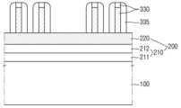
도 7을 참조하면, 제2 맨드릴(330)의 측벽 상에 제2 스페이서(335)를 형성할 수 있다. 즉, 상부 마스크층(220) 상에 제2 스페이서(335)가 형성될 수 있다.Referring to FIG. 7, a second spacer (335) can be formed on a side wall of the second mandrel (330). That is, the second spacer (335) can be formed on the upper mask layer (220).
구체적으로, 제2 맨드릴(330)을 컨포말(conformal)하게 덮는 제2 스페이서(335)층을 형성한다. 이 후, 에치백(etchback) 공정을 수행함으로써 제2 맨드릴(330)의 측벽 상에 제2 스페이서(335)를 형성할 수 있다.Specifically, a second spacer (335) layer that conformally covers the second mandrel (330) is formed. Thereafter, by performing an etchback process, the second spacer (335) can be formed on the sidewall of the second mandrel (330).
제2 스페이서 물질층의 두께는 최종적으로 형성하고자 하는 복수의 제1 핀형 패턴(110, 도 13 참조) 사이의 간격 및 복수의 제2 핀형 패턴(111, 도 13 참조) 사이의 간격을 고려하여 결정될 수 있다. 최종적으로 형성하고자 하는 제1 핀형 패턴(110) 사이의 간격 및 제2 핀형 패턴(111) 사이의 간격은 상용화된 포토리소그래피 장비의 해상도 한계보다 좁을 수 있다.The thickness of the second spacer material layer may be determined by considering the spacing between the plurality of first fin-shaped patterns (110, see FIG. 13) to be ultimately formed and the spacing between the plurality of second fin-shaped patterns (111, see FIG. 13). The spacing between the first fin-shaped patterns (110) to be ultimately formed and the spacing between the second fin-shaped patterns (111) may be narrower than the resolution limit of commercialized photolithography equipment.
제2 스페이서 물질층은 제2 맨드릴(330)과 식각 선택성을 가지는 물질을 포함할 수 있다. 예를 들어, 제2 맨드릴(330)이 다결정질 실리콘, ACL(amorphous carbon layer) 또는 SOH(Spin-On Hardmask) 중에서 어느 하나를 포함할 경우, 제2 스페이서 물질층은 실리콘 산화물 또는 실리콘 질화물을 포함할 수 있다. 제2 스페이서 물질층은 예를 들어, 원자층 증착법(ALD)에 의해 형성될 수 있다.The second spacer material layer may include a material having etch selectivity with respect to the second mandrel (330). For example, when the second mandrel (330) includes any one of polycrystalline silicon, an amorphous carbon layer (ACL), or a Spin-On Hardmask (SOH), the second spacer material layer may include silicon oxide or silicon nitride. The second spacer material layer may be formed, for example, by atomic layer deposition (ALD).
본 발명의 몇몇 실시예에 따른 반도체 장치 제조 방법에서, 제2 스페이서(335)는 실리콘 산화물을 포함하는 것으로 설명한다.In a method for manufacturing a semiconductor device according to some embodiments of the present invention, the second spacer (335) is described as including silicon oxide.
도 8을 참조하면, 제2 맨드릴(330)을 제거할 수 있다.Referring to FIG. 8, the second mandrel (330) can be removed.
제2 맨드릴(330)을 선택적으로 제거함으로써, 제2 스페이서(335)가 상부 마스크층(220) 상에 남을 수 있다.By selectively removing the second mandrel (330), the second spacer (335) can remain on the upper mask layer (220).
도 9를 참조하면, 제2 스페이서(335)를 식각 마스크로 이용하여, 상부 마스크층(220)을 패터닝할 수 있다.Referring to FIG. 9, the upper mask layer (220) can be patterned using the second spacer (335) as an etching mask.
상부 마스크층(220)의 식각을 통해, 상부 마스크 핀 패턴(221, 222)을 형성할 수 있다. 상부 마스크 핀 패턴(221, 222)은 제2 스페이서(335)에 대응되도록 형성될 수 있다.By etching the upper mask layer (220), an upper mask fin pattern (221, 222) can be formed. The upper mask fin pattern (221, 222) can be formed to correspond to the second spacer (335).
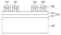
도 10을 참조하면, 상부 마스크 핀 패턴(221, 222)은, 각각이 제1 폭(W1)을 가지는 복수의 제1 상부 마스크 핀 패턴(221) 및 각각이 제2 폭(W2)을 가지는 복수의 제2 상부 마스크 핀 패턴(222)을 포함할 수 있다. 몇몇 실시 예에 따라, 제1 폭(W1) 및 제2 폭(W2)은 동일할 수 있다. 즉, 제1 상부 마스크 핀 패턴(221) 및 제2 상부 마스크 핀 패턴(222)은 동일한 폭을 갖도록 형성될 수 있다.Referring to FIG. 10, the upper mask fin patterns (221, 222) may include a plurality of first upper mask fin patterns (221), each having a first width (W1), and a plurality of second upper mask fin patterns (222), each having a second width (W2). According to some embodiments, the first width (W1) and the second width (W2) may be the same. That is, the first upper mask fin pattern (221) and the second upper mask fin pattern (222) may be formed to have the same width.
몇몇 실시 예에 따라, 복수의 제1 상부 마스크 핀 패턴(221) 사이의 거리는 제1 거리(S1)를 가지고, 복수의 제2 상부 마스크 핀 패턴(222) 사이의 거리는 제2 거리(S2)를 가지도록 형성될 수 있다. 다시 말해서, 복수의 제1 상부 마스크 핀 패턴(221) 중 인접하는 2개의 제1 상부 마스크 핀 패턴(221) 사이의 거리는 제1 거리(S1)이고, 복수의 제2 상부 마스크 핀 패턴(222) 중 인접하는 2개의 제2 상부 마스크 핀 패턴(222) 사이의 거리는 제2 거리(S2)일 수 있다.According to some embodiments, the distance between the plurality of first upper mask fin patterns (221) may be formed to have a first distance (S1), and the distance between the plurality of second upper mask fin patterns (222) may be formed to have a second distance (S2). In other words, the distance between two adjacent first upper mask fin patterns (221) among the plurality of first upper mask fin patterns (221) may be the first distance (S1), and the distance between two adjacent second upper mask fin patterns (222) among the plurality of second upper mask fin patterns (222) may be the second distance (S2).
몇몇 실시 예에 따라, 제1 거리(S1) 및 제2 거리(S2)는 동일할 수 있다. 즉, 인접하는 제1 상부 마스크 핀 패턴(221) 사이의 거리와, 인접하는 제2 상부 마스크 핀 패턴(222) 사이의 거리는 동일할 수 있다.In some embodiments, the first distance (S1) and the second distance (S2) may be the same. That is, the distance between adjacent first upper mask fin patterns (221) and the distance between adjacent second upper mask fin patterns (222) may be the same.
상부 마스크 핀 패턴(221, 222)이 형성된 후, 하부 마스크층(210) 상에 상부 마스크 핀 패턴(221, 222)을 덮는 제3 희생층(610)을 형성하고, 제3 희생층(610) 상에 제3 캡핑층(620)을 형성할 수 있다.After the upper mask fin pattern (221, 222) is formed, a third sacrificial layer (610) covering the upper mask fin pattern (221, 222) can be formed on the lower mask layer (210), and a third capping layer (620) can be formed on the third sacrificial layer (610).
제3 희생층(610)은 다결정질 실리콘, ACL(amorphous carbon layer) 또는 SOH(Spin-On Hardmask) 중에서 어느 하나를 포함할 수 있다.The third sacrificial layer (610) may include any one of polycrystalline silicon, amorphous carbon layer (ACL), or Spin-On Hardmask (SOH).
제3 캡핑층(620)은 예를 들어, 실리콘 산질화물(SiON)을 포함할 수 있다.The third capping layer (620) may include, for example, silicon oxynitride (SiON).
제3 희생층(610) 및 제3 캡핑층(620)은 각각 원자층 증착법(Atomic Layer Deposition, ALD), 화학 기상 증착법(Chemical Vapor Deposition, CVD) 또는 스핀 코팅 (spin coating) 등의 공정에 의해 형성될 수 있으며, 물질에 따라 베이크(bake) 공정이나 경화 공정이 추가될 수도 있다.The third sacrificial layer (610) and the third capping layer (620) may each be formed by a process such as atomic layer deposition (ALD), chemical vapor deposition (CVD), or spin coating, and a baking process or a curing process may be added depending on the material.
제3 캡핑층(620) 상에, 제2 감광막 패턴(710)을 형성할 수 있다.A second photosensitive film pattern (710) can be formed on the third capping layer (620).
제3 캡핑층(620) 상에, 감광막(photoresist, PR)을 덮고, 사진 식각 공정을 통해 제2 감광막 패턴(710)을 형성할 수 있다. 도 10에서, 제2 감광막 패턴(710)은 단일층인 것으로 도시하였지만, 설명의 편의성을 위한 것일 뿐, 이에 제한되는 것은 아니다.On the third capping layer (620), a photoresist (PR) film can be covered and a second photoresist pattern (710) can be formed through a photolithography process. In Fig. 10, the second photoresist pattern (710) is illustrated as a single layer, but this is only for convenience of explanation and is not limited thereto.
즉, 제2 감광막 패턴(710)은 사진 식각 공정(photolithography process) 시에 하부막질에 의한 빛의 반사를 방지하기 위한 반사 방지층을 포함할 수 있다. 반사 방지층은 예를 들어, BARC(Bottom Anti-Reflective Coating) 또는 dBARC(developable Bottom Anti-Reflective Coating)을 포함할 수 있지만, 이에 제한되는 것은 아니다.That is, the second photosensitive film pattern (710) may include an anti-reflection layer to prevent light reflection by the underlying film during a photolithography process. The anti-reflection layer may include, for example, a Bottom Anti-Reflective Coating (BARC) or a developable Bottom Anti-Reflective Coating (dBARC), but is not limited thereto.
제2 감광막 패턴(710)은 제3 폭(W3)을 가지도록 형성될 수 있다. 몇몇 실시 예에 따라, 제3 폭(W3)은 제1 폭(W1) 및/또는 제2 폭(W2)보다 크게 형성될 수 있다. 이에 따라, 추후 공정에서 형성될 하부 더미 마스크 패턴(203, 도 11 참조)은, 제1 하부 마스크 핀 패턴(201, 도 11 참조) 및/또는 제2 하부 마스크 핀 패턴(202, 도 11 참조)의 폭보다 크게 형성될 수 있다.The second photosensitive film pattern (710) may be formed to have a third width (W3). According to some embodiments, the third width (W3) may be formed to be larger than the first width (W1) and/or the second width (W2). Accordingly, the lower dummy mask pattern (203, see FIG. 11) to be formed in a subsequent process may be formed to be larger than the width of the first lower mask fin pattern (201, see FIG. 11) and/or the second lower mask fin pattern (202, see FIG. 11).
제2 감광막 패턴(710)에 인접하는 제1 상부 마스크 핀 패턴(221)과 제2 감광막 패턴(710) 사이의 거리는 제3 거리(S3)일 수 있다. 또한, 제2 감광막 패턴(710)과 인접하는 제2 상부 마스크 핀 패턴(222)과 제2 감광막 패턴(710) 사이의 거리는 제4 거리(S4)일 수 있다. 이 때, 제2 감광막 패턴(710)과 제1 상부 마스크 핀 패턴(221) 또는 제2 상부 마스크 핀 패턴(222) 사이의 거리는, 제3 희생층(610) 및 제3 캡핑층(620)이 적층된 방향으로 제2 감광막 패턴(710)을 연장시킬 때, 제2 감광막 패턴(710)의 연장선과 인접하는 제1 상부 마스크 핀 패턴(221) 또는 제2 상부 마스크 핀 패턴(222) 사이의 거리를 의미한다.The distance between the first upper mask pin pattern (221) adjacent to the second photosensitive film pattern (710) and the second photosensitive film pattern (710) may be a third distance (S3). In addition, the distance between the second upper mask pin pattern (222) adjacent to the second photosensitive film pattern (710) and the second photosensitive film pattern (710) may be a fourth distance (S4). In this case, the distance between the second photosensitive film pattern (710) and the first upper mask pin pattern (221) or the second upper mask pin pattern (222) means the distance between the extension line of the second photosensitive film pattern (710) and the adjacent first upper mask pin pattern (221) or the second upper mask pin pattern (222) when extending the second photosensitive film pattern (710) in the direction in which the third sacrificial layer (610) and the third capping layer (620) are laminated.
몇몇 실시 예에 따라, 제3 거리(S3)는 제1 거리(S1) 및/또는 제2 거리(S2)와 동일할 수 있다. 다시 말해서, 복수의 제1 상부 마스크 핀 패턴(221) 사이의 거리, 복수의 제2 상부 마스크 핀 패턴(222) 사이의 거리와, 제2 감광막 패턴(710)에 인접하는 제1 상부 마스크 핀 패턴(221)과 제2 감광막 패턴(710) 사이의 거리는 동일하게 형성될 수 있다.In some embodiments, the third distance (S3) may be equal to the first distance (S1) and/or the second distance (S2). In other words, the distance between the plurality of first upper mask fin patterns (221), the distance between the plurality of second upper mask fin patterns (222), and the distance between the first upper mask fin pattern (221) adjacent to the second photosensitive film pattern (710) and the second photosensitive film pattern (710) may be formed to be equal.
몇몇 실시 예에 따라, 제4 거리(S4)는 제1 거리(S1) 및/또는 제2 거리(S2)와 동일할 수 있다. 다시 말해서, 복수의 제1 상부 마스크 핀 패턴(221) 사이의 거리, 복수의 제2 상부 마스크 핀 패턴(222) 사이의 거리와, 제2 감광막 패턴(710)에 인접하는 상부 마스크 핀 패턴과 제2 감광막 패턴(710) 사이의 거리는 동일하게 형성될 수 있다.In some embodiments, the fourth distance (S4) may be equal to the first distance (S1) and/or the second distance (S2). In other words, the distance between the plurality of first upper mask fin patterns (221), the distance between the plurality of second upper mask fin patterns (222), and the distance between the upper mask fin pattern adjacent to the second photosensitive film pattern (710) and the second photosensitive film pattern (710) may be formed to be equal.
도 11을 참조하면, 제2 감광막 패턴(710) 및 상부 마스크 핀 패턴을 식각 마스크로 이용하여, 하부 마스크층(210)을 패터닝할 수 있다.Referring to FIG. 11, the second photosensitive film pattern (710) and the upper mask pin pattern can be used as an etching mask to pattern the lower mask layer (210).
먼저, 제2 감광막 패턴(710)을 식각 마스크로 이용하여 제3 캡핑층(620) 및 제3 희생층(610)을 패터닝할 수 있다. 이 때, 제2 감광막 패턴(710)의 수직 방향 연장선에 대응하는 제3 캡핑층(620)의 일부분 및 제3 희생층(610)의 일부분을 제외한 제3 캡핑층(620) 및 제3 희생층(610)이 제거될 수 있다.First, the third capping layer (620) and the third sacrificial layer (610) can be patterned using the second photosensitive film pattern (710) as an etching mask. At this time, the third capping layer (620) and the third sacrificial layer (610) can be removed except for a portion of the third capping layer (620) and a portion of the third sacrificial layer (610) corresponding to the vertical extension of the second photosensitive film pattern (710).
이후, 상기 제3 캡핑층(620)의 일부분(또는, 상기 제3 희생층(610)의 일부분) 및 상부 마스크 핀 패턴(221, 222)을 식각 마스크로 이용하여, 하부 마스크층(210)을 패터닝하여 하부 마스크 핀 패턴(201, 202, 203)을 형성한 후, 남아있는 상부 마스크 핀 패턴(221, 222), 제3 희생층(610) 및 제3 캡핑층(620)을 제거할 수 있다.Thereafter, a portion of the third capping layer (620) (or a portion of the third sacrificial layer (610)) and the upper mask fin pattern (221, 222) are used as etching masks to pattern the lower mask layer (210) to form lower mask fin patterns (201, 202, 203), and then the remaining upper mask fin patterns (221, 222), the third sacrificial layer (610), and the third capping layer (620) can be removed.
기판(100) 상에 형성된 하부 마스크 핀 패턴 (201, 202, 203)은 제1 하부 마스크층(211)의 제1 부분(211a, 211b, 211c)과, 제2 하부 마스크층(212)의 제1 부분(212a, 212b, 212c)을 포함할 수 있다.The lower mask fin pattern (201, 202, 203) formed on the substrate (100) may include a first portion (211a, 211b, 211c) of the first lower mask layer (211) and a first portion (212a, 212b, 212c) of the second lower mask layer (212).
하부 마스크 핀 패턴 (201, 202, 203)은, 제1 하부 마스크 핀 패턴(201), 제2 하부 마스크 핀 패턴(202) 및 하부 더미 마스크 패턴(203)을 포함할 수 있다. 제1 하부 마스크 핀 패턴(201)은 제1 상부 마스크 핀 패턴(221)을 마스크로 이용하여 형성된 부분이고, 제2 하부 마스크 핀 패턴(202)은 제2 상부 마스크 핀 패턴(222)을 마스크로 이용하여 형성된 부분이고, 하부 더미 마스크 패턴(203)은 제2 감광막 패턴(710)을 마스크로 이용하여 형성된 부분일 수 있다.The lower mask pin pattern (201, 202, 203) may include a first lower mask pin pattern (201), a second lower mask pin pattern (202), and a lower dummy mask pattern (203). The first lower mask pin pattern (201) may be a portion formed using the first upper mask pin pattern (221) as a mask, the second lower mask pin pattern (202) may be a portion formed using the second upper mask pin pattern (222) as a mask, and the lower dummy mask pattern (203) may be a portion formed using the second photosensitive film pattern (710) as a mask.
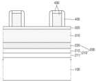
도 12 및 도 13을 참조하면, 하부 마스크 핀 패턴 (201, 202, 203)을 식각 마스크로 이용하여, 기판(100)의 일부를 패터닝할 수 있다.Referring to FIGS. 12 and 13, a portion of the substrate (100) can be patterned using the lower mask fin patterns (201, 202, 203) as an etching mask.
기판(100)의 일부에 대한 식각을 통해, 핀형 패턴(110, 111, 115)을 형성할 수 있다. 구체적으로, 제1 하부 마스크 핀 패턴(201)을 식각 마스크로 이용하여, 기판(100)의 적어도 일부를 식각하여 제1 핀형 패턴(110)을 형성할 수 있다. 또한, 제2 하부 마스크 핀 패턴(202)을 식각 마스크로 이용하여, 기판(100)의 적어도 일부를 식각하여 제2 핀형 패턴(111)을 형성할 수 있다. 또한, 하부 더미 마스크 패턴(203)을 식각 마스크로 이용하여, 기판(100)의 적어도 일부를 식각하여 더미 핀형 패턴(115)을 형성할 수 있다.By etching a portion of the substrate (100), fin-shaped patterns (110, 111, 115) can be formed. Specifically, by using the first lower mask fin pattern (201) as an etching mask, at least a portion of the substrate (100) can be etched to form the first fin-shaped pattern (110). In addition, by using the second lower mask fin pattern (202) as an etching mask, at least a portion of the substrate (100) can be etched to form the second fin-shaped pattern (111). In addition, by using the lower dummy mask pattern (203) as an etching mask, at least a portion of the substrate (100) can be etched to form the dummy fin-shaped pattern (115).
도 12에 도시된 바와 같이, 핀형 패턴(110, 111, 115)을 형성하는 과정에서 제1 하부 마스크층(211)의 제1 부분(211a, 211b, 211c)이 핀형 패턴(110, 111, 115) 상에 남아있을 수 있다. 다만, 이는 예시적인 공정으로, 도 13에 도시된 바와 같이 제1 하부 마스크 층의 제1 부분(211a, 211b, 211c) 및 제2 하부 마스크층(212)의 제1 부분(212a, 212b, 212c)이 모두 제거될 수 있다. 다른 실시 예에 따라, 제1 하부 마스크층(211)의 제1 부분(211a, 211b, 211c) 및/또는 제2 하부 마스크층(212)의 제1 부분(212a, 212b, 212c)은, 추후 필드 절연막(150, 도 16 참조)을 형성하는 과정에서 제거될 수도 있다.As illustrated in FIG. 12, during the process of forming the pin-shaped pattern (110, 111, 115), the first portion (211a, 211b, 211c) of the first lower mask layer (211) may remain on the pin-shaped pattern (110, 111, 115). However, this is an exemplary process, and as illustrated in FIG. 13, the first portion (211a, 211b, 211c) of the first lower mask layer and the first portion (212a, 212b, 212c) of the second lower mask layer (212) may both be removed. According to another embodiment, the first portion (211a, 211b, 211c) of the first lower mask layer (211) and/or the first portion (212a, 212b, 212c) of the second lower mask layer (212) may be removed during a subsequent process of forming the field insulating film (150, see FIG. 16).
도 14는 도 13의 A 영역을 확대한 도면이다.Figure 14 is an enlarged view of area A of Figure 13.
도 14를 참조하면, 본 발명의 실시 예에 따른 반도체 장치의 제조 방법은, 제4 폭(W4)을 갖는 복수의 제1 핀형 패턴(110), 제5 폭(W5)을 갖는 복수의 제2 핀형 패턴(111) 및 제6 폭(W6)을 갖는 더미 핀형 패턴(115)을 형성할 수 있다.Referring to FIG. 14, a method for manufacturing a semiconductor device according to an embodiment of the present invention can form a plurality of first fin-shaped patterns (110) having a fourth width (W4), a plurality of second fin-shaped patterns (111) having a fifth width (W5), and a dummy fin-shaped pattern (115) having a sixth width (W6).
몇몇 실시 예에 따라, 제4 폭(W4) 및 제5 폭(W5)은 동일할 수 있다. 즉, 제1 핀형 패턴(110) 및 제2 핀형 패턴(111)의 폭은 동일할 수 있다.In some embodiments, the fourth width (W4) and the fifth width (W5) may be the same. That is, the widths of the first pin-shaped pattern (110) and the second pin-shaped pattern (111) may be the same.
몇몇 실시 예에 따라, 제6 폭(W6)은 제4 폭(W4) 및 제5 폭(W5)보다 크게 형성될 수 있다. 즉, 더미 핀형 패턴(115)의 폭은 제1 핀형 패턴(110) 및 제2 핀형 패턴(111)의 폭보다 크게 형성될 수 있다.According to some embodiments, the sixth width (W6) may be formed to be larger than the fourth width (W4) and the fifth width (W5). That is, the width of the dummy pin-shaped pattern (115) may be formed to be larger than the widths of the first pin-shaped pattern (110) and the second pin-shaped pattern (111).
복수의 제1 핀형 패턴(110) 사이의 거리는 제5 거리(S5)이고, 복수의 제2 핀형 패턴(111) 사이의 거리는 제6 거리(S6)일 수 있다. 몇몇 실시 예에 따라, 제4 거리(S4) 및 제6 거리(S6)는 동일하게 형성될 수 있다. 즉, 인접하는 제1 핀형 패턴(110) 사이의 거리는, 인접하는 제2 핀형 패턴(111) 사이의 거리와 동일하게 형성될 수 있다.The distance between the plurality of first pin-shaped patterns (110) may be a fifth distance (S5), and the distance between the plurality of second pin-shaped patterns (111) may be a sixth distance (S6). According to some embodiments, the fourth distance (S4) and the sixth distance (S6) may be formed identically. That is, the distance between adjacent first pin-shaped patterns (110) may be formed identically to the distance between adjacent second pin-shaped patterns (111).
더미 핀형 패턴(115)과 인접하는 제1 핀형 패턴(110)(이하, 제1 인접 핀형 패턴)과 더미 핀형 패턴(115) 사이의 거리는 제7 거리(S7)이고, 더미 핀형 패턴(115)과 인접하는 제2 핀형 패턴(111)(이하, 제2 인접 핀형 패턴)과 더미 핀형 패턴(115) 사이의 거리는 제8 거리(S8)일 수 있다.The distance between the first pin-shaped pattern (110) (hereinafter, “first adjacent pin-shaped pattern”) adjacent to the dummy pin-shaped pattern (115) and the dummy pin-shaped pattern (115) may be a seventh distance (S7), and the distance between the second pin-shaped pattern (111) (hereinafter, “second adjacent pin-shaped pattern”) adjacent to the dummy pin-shaped pattern (115) and the dummy pin-shaped pattern (115) may be an eighth distance (S8).
몇몇 실시 예에 따라, 제5 거리 내지 제8 거리(S5, S6, S7, S8)는 동일할 수 있다. 즉, 복수의 제1 핀형 패턴(110) 중 인접하는 제1 핀형 패턴(110) 사이의 거리(S5), 복수의 제2 핀형 패턴(111) 중 인접하는 제2 핀형 패턴(111) 사이의 거리(S6), 더미 핀형 패턴(115)과 제1 인접 핀형 패턴 사이의 거리(S7) 및 더미 핀형 패턴(115)과 제2 인접 핀형 패턴 사이의 거리(S8)는 동일하도록 형성될 수 있다.According to some embodiments, the fifth to eighth distances (S5, S6, S7, S8) may be the same. That is, the distance (S5) between adjacent first pin-shaped patterns (110) among the plurality of first pin-shaped patterns (110), the distance (S6) between adjacent second pin-shaped patterns (111) among the plurality of second pin-shaped patterns (111), the distance (S7) between the dummy pin-shaped pattern (115) and the first adjacent pin-shaped pattern, and the distance (S8) between the dummy pin-shaped pattern (115) and the second adjacent pin-shaped pattern may be formed to be the same.
도 10을 참조하여 상술한 바와 같이, 복수의 제1 상부 마스크 핀 패턴(221) 중 인접하는 제1 상부 마스크 핀 패턴(221) 사이의 거리(S1), 복수의 제2 상부 마스크 핀 패턴(222) 중 인접하는 제2 상부 마스크 핀 패턴(222) 사이의 거리(S2), 제2 감광막 패턴(710)과 제1 상부 마스크 핀 패턴(221) 사이의 거리(S3) 및 제2 감광막 패턴(710)과 제2 상부 마스크 핀 패턴(222) 사이의 거리(S4)가 동일하게 형성될 수 있다.As described above with reference to FIG. 10, a distance (S1) between adjacent first upper mask pin patterns (221) among a plurality of first upper mask pin patterns (221), a distance (S2) between adjacent second upper mask pin patterns (222) among a plurality of second upper mask pin patterns (222), a distance (S3) between a second photosensitive film pattern (710) and a first upper mask pin pattern (221), and a distance (S4) between a second photosensitive film pattern (710) and a second upper mask pin pattern (222) can be formed to be identical.
이에 따라, 복수의 제1 하부 마스크 핀 패턴(201) 사이의 거리(S5), 복수의 제2 하부 마스크 핀 사이의 거리(S6), 하부 더미 마스크 패턴(203)과 제1 하부 마스크 핀 패턴(201) 사이의 거리(S7) 및 하부 더미 마스크 패턴(203)과 제2 하부 마스크 핀 패턴(202) 사이의 거리(S8)가 동일하게 형성될 수 있다.Accordingly, the distance (S5) between the plurality of first lower mask pin patterns (201), the distance (S6) between the plurality of second lower mask pins, the distance (S7) between the lower dummy mask pattern (203) and the first lower mask pin pattern (201), and the distance (S8) between the lower dummy mask pattern (203) and the second lower mask pin pattern (202) can be formed to be the same.
제1 핀형 패턴(110), 제2 핀형 패턴(111) 및 더미 핀형 패턴(115)은 각각 제1 하부 마스크 핀 패턴(201), 제2 하부 마스크 핀 패턴(202) 및 하부 더미 마스크 패턴(203)을 마스크로 이용하여 형성되므로, 제5 내지 제8 거리(S5, S6, S7, S8)은 동일하게 형성될 수 있다.Since the first pin-shaped pattern (110), the second pin-shaped pattern (111), and the dummy pin-shaped pattern (115) are formed using the first lower mask pin pattern (201), the second lower mask pin pattern (202), and the lower dummy mask pattern (203) as masks, respectively, the fifth to eighth distances (S5, S6, S7, S8) can be formed identically.
근래에 반도체 장치의 고집적화에 따라, 소오스/드레인 컨택이 형성되는 액티브 영역과 게이트 컨택 간의 간격이 줄어들게 되고, 이에 따라 액티브 영역에 배치되는 소자와 게이트 컨택 사이의 전기적 단락이 발생할 가능성이 높아지는 문제점이 존재한다. 이에 따라, 게이트 컨택이 형성되는 영역의 면적을 증가시키는 방안이 대두되었으나, 전체 셀의 면적이 증가되는 단점이 존재한다. 또한, 액티브 영역에 형성되는 핀의 수를 감소시키는 방안이 제시되었으나, 이러한 경우 반도체의 성능이 열화되는 단점이 존재한다.Recently, due to the high integration of semiconductor devices, the gap between the active area where the source/drain contact is formed and the gate contact is reduced, and accordingly, there is a problem that the possibility of an electrical short circuit occurring between the element placed in the active area and the gate contact increases. Accordingly, a method of increasing the area of the area where the gate contact is formed has been proposed, but there is a disadvantage that the area of the entire cell increases. In addition, a method of reducing the number of fins formed in the active area has been suggested, but in this case, there is a disadvantage that the performance of the semiconductor deteriorates.
본 발명의 실시 예에 따라, 더미 마스크 패턴을 이용하여 더미 핀형 패턴(115)을 형성하는 경우, 액티브 영역의 소자와 게이트 컨택 간의 단락을 방지하되, 셀 면적의 증가를 최소화하고, 성능의 유지시킬 수 있다. 구체적으로, 기존에는 액티브 영역에 형성되는 핀과 동일한 폭을 가지는 핀형 패턴을 형성한 후, 이를 제거하여 게이트 컨택이 형성되는 영역(예를 들어, 소자 분리 영역(Shallow Trench Isolation, STI))을 정의함으로써, 핀 피치(fin pitch)의 n배(n은 자연수)의 폭을 갖는 소자 분리 영역을 형성할 수 있었다. 이에 반하여, 본 발명의 실시 예에 따른 반도체 장치의 제조 방법은, 별도의 공정 과정을 통해 더미 핀을 형성하고, 이를 이용하여 소자 분리 영역을 정의함으로써, 핀 피치의 n배가 아닌 다양한 폭을 갖는 소자 분리 영역을 형성할 수 있고, 이에 따라 게이트 컨택과 다른 소자 간의 전기적 단락을 방지함과 동시에, 셀의 면적 증가를 최소화할 수 있다.According to an embodiment of the present invention, when a dummy fin-shaped pattern (115) is formed using a dummy mask pattern, a short circuit between an element in an active region and a gate contact can be prevented, while minimizing an increase in the cell area and maintaining performance. Specifically, in the past, a fin-shaped pattern having the same width as a fin formed in an active region was formed, and then the fin was removed to define a region where a gate contact is formed (e.g., a shallow trench isolation (STI) region), thereby forming an element isolation region having a width n times the fin pitch (n is a natural number). In contrast, a method for manufacturing a semiconductor device according to an embodiment of the present invention forms dummy fins through a separate process, and defines an element isolation region using the dummy fins, thereby forming an element isolation region having various widths other than n times the fin pitch, thereby preventing an electrical short circuit between the gate contact and another element and minimizing an increase in the cell area.
또한, 기존에는 소자 분리 영역을 형성함에 있어서, 핀형 마스크 패턴 간의 거리 차이에 따른 로딩 효과(loading effect), 즉 에칭 속도와 에칭 프로파일의 불균일이 발생하고, 이에 따라 과식각되는 부분이 발생하여 반도체 장치의 특성 불량을 야기하는 원인이 되었다. 이에 반하여, 본 발명의 실시 예에 따른 반도체 장치의 제조 방법은, 더미 패턴(115)과 인접하는 핀형 패턴(110, 111)과의 거리를, 인접하는 핀형 패턴(110, 111) 사이의 거리와 동일하게 형성함으로써, 로딩 효과의 발생을 방지할 수 있고, 결과적으로 반도체의 불량률을 감소시킬 수 있다.In addition, in the past, when forming a device isolation region, a loading effect occurred due to a difference in the distance between fin-shaped mask patterns, that is, an unevenness in the etching speed and etching profile, and as a result, an over-etched portion occurred, which caused defects in the characteristics of the semiconductor device. In contrast, the method for manufacturing a semiconductor device according to an embodiment of the present invention can prevent the occurrence of the loading effect by forming the distance between a dummy pattern (115) and an adjacent fin-shaped pattern (110, 111) to be the same as the distance between the adjacent fin-shaped patterns (110, 111), thereby reducing the defect rate of the semiconductor.
도 15는 본 발명의 몇몇 실시 예에 따른 반도체 장치를 설명하기 위한 레이아웃도이다.FIG. 15 is a layout diagram illustrating a semiconductor device according to some embodiments of the present invention.
CMOS 집적 회로(CMOS Integrated Circuit)의 설계 및 제조 시에, 면적의 효율성 및 원활한 라우팅(routing)을 목적으로, 인정한 셀 높이(cell height)를 갖는 기준 셀(standard cell)을 구성하고, 기준 셀에 대하여 면적 및 성능 최적화를 진행한다.When designing and manufacturing a CMOS integrated circuit, a standard cell having a recognized cell height is configured for the purpose of area efficiency and smooth routing, and area and performance optimization is performed for the standard cell.
도 15를 참조하면, 본 발명의 실시 예에 따른 반도체 장치의 제조 장법은, 기준 셀(Cell)에 대하여 적용될 수 있다. 즉, 기준 셀을 구성하는 핀형 패턴을 제조함에 있어서 적용될 수 있다. 즉, 도 13은 도 15의 셀(Cell)을 A-A' 방향으로 바라본 단면도일 수 있다. 셀(Cell)은 두 전원 라인들(VDD, VSS)를 포함할 수 있으나, 설명의 편의를 위하여 도 1 내지 도 14에는 전원 라인들(VDD, VSS)에 대한 도시를 생략하였다. 다만, 이에 한정되지는 않고 핀형 패턴이 적용되는 모든 종류의 반도체 장치에 적용될 수 있음은 물론이다.Referring to FIG. 15, the method for manufacturing a semiconductor device according to an embodiment of the present invention can be applied to a reference cell. That is, it can be applied in manufacturing a pin-shaped pattern constituting a reference cell. That is, FIG. 13 may be a cross-sectional view of the cell of FIG. 15 viewed in the A-A' direction. The cell may include two power lines (VDD, VSS), but for convenience of explanation, the illustration of the power lines (VDD, VSS) is omitted in FIGS. 1 to 14. However, the present invention is not limited thereto and can be applied to all types of semiconductor devices to which a pin-shaped pattern is applied.
도 16은 본 발명의 몇몇 실시 예에 따른 반도체 장치의 제조 방법을 설명하기 위한 중간단계 도면이고, 도 17은 본 발명의 몇몇 실시 예에 따른 반도체 장치를 설명하기 위한 레이아웃도이다.FIG. 16 is an intermediate step diagram for explaining a method for manufacturing a semiconductor device according to some embodiments of the present invention, and FIG. 17 is a layout diagram for explaining a semiconductor device according to some embodiments of the present invention.
도 16 및 도 17을 참조하면, 제1 핀형 패턴(110) 및 제2 핀형 패턴(111)의 상부가 돌출되도록 필드 절연막(150)을 형성할 수 있다. 도 16은, 도 17의 셀(Cell)의 B-B' 방향으로 바라본 단면도일 수 있다. 셀(Cell)은 두 전원 라인들(VDD, VSS)를 포함할 수 있으나, 설명의 편의를 위하여 도 16에는 전원 라인들(VDD, VSS)에 대한 도시를 생략하였다.Referring to FIGS. 16 and 17, a field insulating film (150) may be formed so that the upper portions of the first pin-shaped pattern (110) and the second pin-shaped pattern (111) protrude. FIG. 16 may be a cross-sectional view of the cell of FIG. 17 viewed in the B-B' direction. The cell may include two power lines (VDD, VSS), but for convenience of explanation, the power lines (VDD, VSS) are omitted from FIG. 16.
몇몇 실시 예에 따라, 기판(100)을 식각하여 형성된 복수의 제1 핀형 패턴(110) 사이 및 복수의 제2 핀형 패턴(111) 사이의 얕은 트렌치(151T)(shallow trench)를 채우는 절연층을 형성할 수 있다.According to some embodiments, an insulating layer may be formed to fill shallow trenches (151T) formed between a plurality of first fin-shaped patterns (110) and between a plurality of second fin-shaped patterns (111) by etching the substrate (100).
다음으로, 추가적으로 깊은 트렌치(152T)(deep trench)를 형성한 후, 깊은 트렌치(152T)를 채우도록 절연층을 형성할 수 있다. 실시 예에 따라, 깊은 트렌치(152T)를 형성하는 과정에서 더미 핀형 패턴(115)이 제거될 수 있다.Next, after additionally forming a deep trench (152T), an insulating layer may be formed to fill the deep trench (152T). According to an embodiment, the dummy fin-shaped pattern (115) may be removed during the process of forming the deep trench (152T).
즉, 본 발명의 실시 예에 따른 반도체 장치의 제조 방법은, 복수의 제1 핀형 패턴(110) 및 복수의 제2 핀형 패턴(111)의 상부가 돌출되도록 필드 절연막(150)을 형성하는 것을 더 포함할 수 있다.That is, the method for manufacturing a semiconductor device according to an embodiment of the present invention may further include forming a field insulating film (150) so that the upper portions of a plurality of first pin-shaped patterns (110) and a plurality of second pin-shaped patterns (111) protrude.
필드 절연막(150)을 형성하는 것은, 복수의 제1 핀형 패턴(110) 사이 및 복수의 제2 핀형 패턴(111) 사이의 얕은 트렌치(151T)를 채우는 절연층을 형성하고, 더미 핀형 패턴(115)을 제거하여 깊은 트렌치(152T)를 형성하고, 깊은 트렌치(152T)를 채우는 절연층을 형성하는 것을 포함할 수 있다.Forming the field insulating film (150) may include forming an insulating layer filling a shallow trench (151T) between a plurality of first fin-shaped patterns (110) and between a plurality of second fin-shaped patterns (111), removing a dummy fin-shaped pattern (115) to form a deep trench (152T), and forming an insulating layer filling the deep trench (152T).
깊은 트렌치(152T)를 형성하는 것은, 절연층 상에 감광막 패턴을 형성하고, 상기 감광막 패턴을 이용하여, 절연층 및 기판(110)의 일부를 식각하여 깊은 트렌치(152T)를 형성하는 것을 포함할 수 있다.Forming the deep trench (152T) may include forming a photosensitive film pattern on an insulating layer and using the photosensitive film pattern to etch a portion of the insulating layer and the substrate (110) to form the deep trench (152T).
다른 실시 예에 따라, 깊은 트렌치(152T)를 형성한 후, 얕은 트렌치(151T) 및 깊은 트렌치(152T)를 채우도록 절연층을 형성할 수 있다.According to another embodiment, after forming the deep trench (152T), an insulating layer can be formed to fill the shallow trench (151T) and the deep trench (152T).
즉, 필드 절연막(150)을 형성하는 것은, 더미 핀형 패턴(115)을 제거하여 깊은 트렌치(152T)를 형성하고, 복수의 제1 핀형 패턴(110) 사이 및 복수의 제2 핀형 패턴(111) 사이의 얕은 트렌치(151T)와, 깊은 트렌치(152T)를 채우는 절연층을 형성하는 것을 포함할 수 있다.That is, forming the field insulating film (150) may include forming a deep trench (152T) by removing the dummy fin-shaped pattern (115), forming a shallow trench (151T) between the plurality of first fin-shaped patterns (110) and between the plurality of second fin-shaped patterns (111), and forming an insulating layer filling the deep trench (152T).
깊은 트렌치(152T)를 형성하는 것은, 기판(100) 상에, 마스크 패턴(110, 111, 115)을 덮는 절연층을 형성하고, 상기 절연층 상에 감광막 패턴을 형성하고, 상기 감광막 패턴을 이용하여, 상기 절연층 및 기판(100)의 일부를 식각하여 깊은 트렌치(152T)를 형성하는 것을 포함할 수 있다.Forming a deep trench (152T) may include forming an insulating layer covering a mask pattern (110, 111, 115) on a substrate (100), forming a photosensitive film pattern on the insulating layer, and using the photosensitive film pattern, etching a portion of the insulating layer and the substrate (100) to form the deep trench (152T).
이상 첨부된 도면을 참조하여 본 발명의 실시예들을 설명하였으나, 본 발명은 상기 실시예들에 한정되는 것이 아니라 서로 다른 다양한 형태로 제조될 수 있으며, 본 발명이 속하는 기술분야에서 통상의 지식을 가진 자는 본 발명의 기술적 사상이나 필수적인 특징을 변경하지 않고서 다른 구체적인 형태로 실시될 수 있다는 것을 이해할 수 있을 것이다. 그러므로 이상에서 기술한 실시예들은 모든 면에서 예시적인 것이며 한정적이 아닌 것으로 이해해야만 한다.Although the embodiments of the present invention have been described with reference to the attached drawings, the present invention is not limited to the embodiments described above, but can be manufactured in various different forms, and a person having ordinary skill in the art to which the present invention pertains will understand that the present invention can be implemented in other specific forms without changing the technical idea or essential features of the present invention. Therefore, it should be understood that the embodiments described above are exemplary in all respects and not restrictive.
100: 기판 110: 제1 핀형 패턴
111: 제2 핀형 패턴 115: 더미 핀형 패턴
200: 마스크층 221, 222: 상부 마스크 패턴
201, 202, 203: 하부 마스크 패턴
310: 제1 희생층 410: 제2 희생층
610: 제3 희생층100: substrate 110: first pin pattern
111: Second pin pattern 115: Dummy pin pattern
200:
201, 202, 203: Lower mask pattern
310: 1st sacrificial layer 410: 2nd sacrificial layer
610: Third sacrificial layer
Claims (10)
Translated fromKorean상기 마스크 패턴을 이용하여 상기 기판을 식각하여, 제1 핀형 패턴, 제2 핀형 패턴 및 더미 핀형 패턴을 형성하고, 상기 제1 핀형 패턴 및 상기 더미 핀형 패턴은 얕은 트렌치에 의해 분리되고, 상기 제2 핀형 패턴 및 상기 더미 핀형 패턴은 상기 얕은 트렌치에 의해 분리되고,
상기 얕은 트렌치에 의해 상기 제1 핀형 패턴 및 상기 제2 핀형 패턴과 분리된 상기 더미 핀형 패턴을 제거하여 상기 얕은 트렌치보다 깊은 깊은 트렌치를 형성하고,
상기 깊은 트렌치의 바닥면과 접촉하는 절연층을 형성하는 것을 포함하고,
상기 깊은 트렌치의 바닥면은 상기 얕은 트렌치의 바닥면보다 하측에 배치되는 반도체 장치의 제조 방법.On a substrate, a mask pattern is formed, which includes a first mask pin pattern, a second mask pin pattern, and a dummy mask pattern between the first mask pin pattern and the second mask pin pattern, wherein the width of the dummy mask pattern is larger than the width of the first mask pin pattern and the width of the second mask pin pattern.
The substrate is etched using the mask pattern to form a first fin-shaped pattern, a second fin-shaped pattern, and a dummy fin-shaped pattern, wherein the first fin-shaped pattern and the dummy fin-shaped pattern are separated by a shallow trench, and the second fin-shaped pattern and the dummy fin-shaped pattern are separated by the shallow trench.
By removing the dummy fin-shaped pattern separated from the first fin-shaped pattern and the second fin-shaped pattern by the shallow trench, a deep trench deeper than the shallow trench is formed,
Comprising forming an insulating layer in contact with the bottom surface of the deep trench,
A method for manufacturing a semiconductor device, wherein the bottom surface of the deep trench is positioned lower than the bottom surface of the shallow trench.
상기 마스크 패턴을 형성하는 것은,
복수의 상기 제1 마스크 핀 패턴, 복수의 상기 제2 마스크 핀 패턴 및 상기 더미 마스크 패턴을 형성하는 것을 포함하는 반도체 장치의 제조 방법.In the first paragraph,
Forming the above mask pattern is:
A method for manufacturing a semiconductor device, comprising forming a plurality of the first mask pin patterns, a plurality of the second mask pin patterns, and the dummy mask pattern.
상기 마스크 패턴을 형성하는 것은,
상기 복수의 제1 마스크 핀 패턴 사이의 거리 및 상기 복수의 제2 마스크 핀 패턴 사이의 거리가 동일하도록 상기 마스크 패턴을 형성하는 것을 포함하는 반도체 장치의 제조 방법.In the second paragraph,
Forming the above mask pattern is:
A method for manufacturing a semiconductor device, comprising forming the mask pattern such that the distance between the plurality of first mask pin patterns and the distance between the plurality of second mask pin patterns are the same.
상기 마스크 패턴을 형성하는 것은,
상기 더미 마스크 패턴에 인접한 제1 마스크 핀 패턴과 상기 더미 마스크 패턴 사이의 거리, 상기 복수의 제1 마스크 핀 패턴 사이의 거리 및 상기 더미 마스크 패턴에 인접한 제2 마스크 핀 패턴과 상기 더미 마스크 패턴 사이의 거리가 동일하도록 상기 마스크 패턴을 형성하는 것을 포함하는 반도체 장치의 제조 방법.In the third paragraph,
Forming the above mask pattern is:
A method for manufacturing a semiconductor device, comprising forming the mask pattern such that a distance between a first mask pin pattern adjacent to the dummy mask pattern and the dummy mask pattern, a distance between the plurality of first mask pin patterns, and a distance between a second mask pin pattern adjacent to the dummy mask pattern and the dummy mask pattern are equal.
상기 상부 마스크층을 식각하여, 서로 이격되는 제1 상부 마스크 핀 패턴 및 제2 상부 마스크 핀 패턴을 형성하고,
상기 하부 마스크층 상에, 상기 제1 상부 마스크 핀 패턴 및 상기 제2 상부 마스크 핀 패턴을 덮는 희생층을 형성하고,
상기 희생층 상의, 상기 제1 상부 마스크 핀 패턴 및 상기 제2 상부 마스크 핀 패턴 사이에, 감광막 패턴을 형성하고,
상기 감광막 패턴과, 제1 상부 마스크 핀 패턴 및 제2 상부 마스크 핀 패턴을 이용하여, 상기 하부 마스크층을 식각하여, 상기 기판 상에 하부 마스크 핀 패턴을 형성하고,
상기 하부 마스크 핀 패턴을 이용하여 상기 기판을 식각하여, 얕은 트렌치에 의해 분리된 핀형 패턴 및 더미 핀형 패턴을 형성하고,
상기 얕은 트렌치에 의해 상기 핀형 패턴과 분리된 상기 더미 핀형 패턴을 제거하여, 상기 얕은 트렌치보다 깊은 깊은 트렌치를 형성하고,
상기 깊은 트렌치의 바닥면과 접촉하는 절연층을 형성하는 것을 포함하고,
상기 하부 마스크 핀 패턴을 형성하는 것은,
상기 감광막 패턴을 이용하여, 상기 희생층 및 상기 하부 마스크층을 식각하여 하부 더미 마스크 패턴을 형성하는 것을 포함하고,
상기 더미 핀형 패턴은 상기 하부 더미 마스크 패턴을 이용하여 상기 기판을 식각하여 형성되고,
상기 깊은 트렌치의 바닥면은 상기 얕은 트렌치의 바닥면보다 하측에 배치되는 반도체 장치의 제조 방법.Forming a lower mask layer and an upper mask layer that are sequentially laminated on a substrate,
By etching the upper mask layer, a first upper mask fin pattern and a second upper mask fin pattern spaced apart from each other are formed,
On the lower mask layer, a sacrificial layer is formed covering the first upper mask fin pattern and the second upper mask fin pattern,
A photosensitive film pattern is formed between the first upper mask pin pattern and the second upper mask pin pattern on the sacrificial layer,
Using the photosensitive film pattern, the first upper mask pin pattern, and the second upper mask pin pattern, the lower mask layer is etched to form a lower mask pin pattern on the substrate.
The substrate is etched using the lower mask fin pattern to form a fin-shaped pattern and a dummy fin-shaped pattern separated by a shallow trench,
By removing the dummy pin-shaped pattern separated from the pin-shaped pattern by the shallow trench, a deep trench deeper than the shallow trench is formed,
Comprising forming an insulating layer in contact with the bottom surface of the deep trench,
Forming the above lower mask pin pattern is:
Using the above photosensitive film pattern, etching the sacrificial layer and the lower mask layer to form a lower dummy mask pattern,
The above dummy pin-shaped pattern is formed by etching the substrate using the lower dummy mask pattern,
A method for manufacturing a semiconductor device, wherein the bottom surface of the deep trench is positioned lower than the bottom surface of the shallow trench.
상기 하부 마스크 핀 패턴을 형성하는 것은,
상기 제1 상부 마스크 핀 패턴을 이용하여, 상기 하부 마스크층을 식각하여 제1 하부 마스크 핀 패턴을 형성하고,
상기 제2 상부 마스크 핀 패턴을 이용하여, 상기 하부 마스크층을 식각하여 제2 하부 마스크 핀 패턴을 형성하는 것을 더 포함하는 반도체 장치의 제조 방법.In paragraph 5,
Forming the above lower mask pin pattern is:
Using the first upper mask fin pattern, the lower mask layer is etched to form a first lower mask fin pattern,
A method for manufacturing a semiconductor device further comprising forming a second lower mask fin pattern by etching the lower mask layer using the second upper mask fin pattern.
상기 하부 마스크 핀 패턴을 형성하는 것은,
복수의 상기 제1 하부 마스크 핀 패턴, 복수의 상기 제2 하부 마스크 핀 패턴 및 상기 하부 더미 마스크 패턴을 형성하는 것을 포함하는 반도체 장치의 제조 방법.In Article 6,
Forming the above lower mask pin pattern is:
A method for manufacturing a semiconductor device, comprising forming a plurality of the first lower mask fin patterns, a plurality of the second lower mask fin patterns and the lower dummy mask pattern.
상기 하부 마스크 핀 패턴을 형성하는 것은,
상기 복수의 제1 하부 마스크 핀 패턴 사이의 거리 및 상기 복수의 제2 하부 마스크 핀 패턴 사이의 거리가 동일하도록 상기 하부 마스크 핀 패턴을 형성하는 것을 포함하는 반도체 장치의 제조 방법.In Article 7,
Forming the above lower mask pin pattern is:
A method for manufacturing a semiconductor device, comprising forming the lower mask fin patterns such that the distance between the plurality of first lower mask fin patterns and the distance between the plurality of second lower mask fin patterns are equal.
상기 하부 마스크 핀 패턴을 형성하는 것은,
상기 하부 더미 마스크 패턴에 인접한 제1 하부 마스크 핀 패턴과 상기 더미 마스크 패턴 사이의 거리, 상기 복수의 제1 하부 마스크 핀 패턴 사이의 거리 및 상기 하부 더미 마스크 패턴에 인접한 제2 하부 마스크 핀 패턴과 상기 더미 마스크 패턴 사이의 거리가 동일하도록 상기 마스크 패턴을 형성하는 것을 포함하는 반도체 장치의 제조 방법.In Article 8,
Forming the above lower mask pin pattern is:
A method for manufacturing a semiconductor device, comprising forming the mask pattern such that a distance between a first lower mask fin pattern adjacent to the lower dummy mask pattern and the dummy mask pattern, a distance between the plurality of first lower mask fin patterns, and a distance between a second lower mask fin pattern adjacent to the lower dummy mask pattern and the dummy mask pattern are equal.
상기 제2 희생층 상에 제1 감광막 패턴을 형성하고,
상기 제1 감광막 패턴을 이용하여, 상기 제2 희생층을 식각하여 제1 맨드릴을 형성하고,
상기 제1 맨드릴의 측벽 상에 제1 스페이서를 형성하고,
상기 제1 스페이서를 이용하여, 상기 제1 희생층을 식각하여 제2 맨드릴을 형성하고,
상기 제2 맨드릴의 측벽 상에 제2 스페이서를 형성하고,
상기 제2 스페이서를 이용하여, 상기 상부 마스크층을 식각하여, 서로 이격되는 제1 상부 마스크 핀 패턴 및 제2 상부 마스크 핀 패턴을 형성하고,
상기 하부 마스크층 상에, 상기 제1 상부 마스크 핀 패턴 및 상기 제2 상부 마스크 핀 패턴을 덮는 제3 희생층을 형성하고,
상기 제3 희생층 상의, 상기 제1 상부 마스크 핀 패턴 및 상기 제2 상부 마스크 핀 패턴 사이에, 제2 감광막 패턴을 형성하고,
상기 제2 감광막 패턴과, 제1 상부 마스크 핀 패턴 및 제2 상부 마스크 핀 패턴을 이용하여, 상기 하부 마스크층을 식각하여, 상기 기판 상에 하부 더미 마스크 패턴을 포함하는 하부 마스크 핀 패턴을 형성하고,
상기 하부 마스크 핀 패턴을 이용하여 상기 기판을 식각하여, 핀형 패턴 및 더미 핀형 패턴을 형성하는 것을 포함하는 반도체 장치의 제조 방법.Forming a lower mask layer, an upper mask layer, a first sacrificial layer, and a second sacrificial layer sequentially laminated on a substrate,
Forming a first photosensitive film pattern on the second sacrificial layer,
Using the first photosensitive film pattern, the second sacrificial layer is etched to form a first mandrel,
Forming a first spacer on the side wall of the first mandrel,
Using the first spacer, the first sacrificial layer is etched to form a second mandrel,
Forming a second spacer on the side wall of the second mandrel,
Using the second spacer, the upper mask layer is etched to form a first upper mask fin pattern and a second upper mask fin pattern that are spaced apart from each other,
On the lower mask layer, a third sacrificial layer is formed covering the first upper mask fin pattern and the second upper mask fin pattern,
A second photosensitive film pattern is formed between the first upper mask pin pattern and the second upper mask pin pattern on the third sacrificial layer,
Using the second photosensitive film pattern, the first upper mask pin pattern, and the second upper mask pin pattern, the lower mask layer is etched to form a lower mask pin pattern including a lower dummy mask pattern on the substrate.
A method for manufacturing a semiconductor device, comprising etching the substrate using the lower mask fin pattern to form a fin-shaped pattern and a dummy fin-shaped pattern.
Priority Applications (3)
| Application Number | Priority Date | Filing Date | Title |
|---|---|---|---|
| KR1020190006773AKR102720606B1 (en) | 2019-01-18 | 2019-01-18 | Method for fabricating semiconductor device |
| US16/540,726US11024509B2 (en) | 2019-01-18 | 2019-08-14 | Method of fabricating semiconductor device |
| US17/303,062US12074031B2 (en) | 2019-01-18 | 2021-05-19 | Method of fabricating semiconductor device |
Applications Claiming Priority (1)
| Application Number | Priority Date | Filing Date | Title |
|---|---|---|---|
| KR1020190006773AKR102720606B1 (en) | 2019-01-18 | 2019-01-18 | Method for fabricating semiconductor device |
Publications (2)
| Publication Number | Publication Date |
|---|---|
| KR20200089919A KR20200089919A (en) | 2020-07-28 |
| KR102720606B1true KR102720606B1 (en) | 2024-10-21 |
Family
ID=71610127
Family Applications (1)
| Application Number | Title | Priority Date | Filing Date |
|---|---|---|---|
| KR1020190006773AActiveKR102720606B1 (en) | 2019-01-18 | 2019-01-18 | Method for fabricating semiconductor device |
Country Status (2)
| Country | Link |
|---|---|
| US (2) | US11024509B2 (en) |
| KR (1) | KR102720606B1 (en) |
Families Citing this family (4)
| Publication number | Priority date | Publication date | Assignee | Title |
|---|---|---|---|---|
| US11264380B2 (en)* | 2018-08-27 | 2022-03-01 | Taiwan Semiconductor Manufacturing Co., Ltd. | Semiconductor device and method of manufacturing the same |
| CN112542385B (en)* | 2019-09-20 | 2024-11-22 | 中芯国际集成电路制造(上海)有限公司 | Semiconductor structure and method for forming the same |
| CN113517181B (en)* | 2021-04-27 | 2024-07-12 | 长江先进存储产业创新中心有限责任公司 | Hard mask laminated structure and method for forming semiconductor device |
| KR20230172131A (en)* | 2022-06-15 | 2023-12-22 | 삼성전자주식회사 | Method for manufacturing semiconductor devices |
Citations (1)
| Publication number | Priority date | Publication date | Assignee | Title |
|---|---|---|---|---|
| US20030082888A1 (en) | 2001-10-31 | 2003-05-01 | Ching-Fu Lin | Method of incorporating deep trench into shallow trench isolation process without added masks |
Family Cites Families (20)
| Publication number | Priority date | Publication date | Assignee | Title |
|---|---|---|---|---|
| JP2007043049A (en) | 2004-12-20 | 2007-02-15 | Matsushita Electric Ind Co Ltd | Cell, standard cell, standard cell arrangement method, standard cell library, and semiconductor integrated circuit |
| US9009641B2 (en) | 2006-03-09 | 2015-04-14 | Tela Innovations, Inc. | Circuits with linear finfet structures |
| KR100961203B1 (en)* | 2008-04-29 | 2010-06-09 | 주식회사 하이닉스반도체 | Micro pattern formation method using spacer patterning technology |
| US8816444B2 (en) | 2011-04-29 | 2014-08-26 | Taiwan Semiconductor Manufacturing Company, Ltd. | System and methods for converting planar design to FinFET design |
| US8802510B2 (en)* | 2012-02-22 | 2014-08-12 | Taiwan Semiconductor Manufacturing Company, Ltd. | Methods for controlling line dimensions in spacer alignment double patterning semiconductor processing |
| US9576978B2 (en) | 2012-10-09 | 2017-02-21 | Samsung Electronics Co., Ltd. | Cells including at least one fin field effect transistor and semiconductor integrated circuits including the same |
| US8788998B2 (en) | 2012-12-21 | 2014-07-22 | Broadcom Corporation | Non-integer height standard cell library |
| KR102013842B1 (en)* | 2013-02-08 | 2019-08-26 | 삼성전자주식회사 | Method of manufacturing semiconductor device |
| US8846490B1 (en)* | 2013-03-12 | 2014-09-30 | Taiwan Semiconductor Manufacturing Company, Ltd. | Method of fabricating a FinFET device |
| US9147028B2 (en) | 2013-05-24 | 2015-09-29 | Globalfoundries Inc. | Forming modified cell architecture for finFET technology and resulting device |
| KR102083492B1 (en) | 2013-09-26 | 2020-03-02 | 삼성전자 주식회사 | Dummy cell array for FinFET(Fin Field Effect Transistor) device and semiconductor integrated circuit including the same |
| US9236269B2 (en) | 2014-04-23 | 2016-01-12 | Globalfoundries Inc. | Field effect transistor (FinFET) device with a planar block area to enable variable Fin pitch and width |
| KR102352154B1 (en) | 2015-03-03 | 2022-01-17 | 삼성전자주식회사 | Integrated circuit device |
| KR102341458B1 (en)* | 2015-04-15 | 2021-12-20 | 삼성전자주식회사 | Method for fabricating semiconductor device |
| KR102170701B1 (en)* | 2015-04-15 | 2020-10-27 | 삼성전자주식회사 | Semiconductor device and method of fabricating the same |
| US9852917B2 (en) | 2016-03-22 | 2017-12-26 | International Business Machines Corporation | Methods of fabricating semiconductor fins by double sidewall image transfer patterning through localized oxidation enhancement of sacrificial mandrel sidewalls |
| US9691775B1 (en) | 2016-04-28 | 2017-06-27 | Globalfoundries Inc. | Combined SADP fins for semiconductor devices and methods of making the same |
| US9786788B1 (en) | 2016-07-07 | 2017-10-10 | Globalfoundries Inc. | Vertical-transport FinFET device with variable Fin pitch |
| US10032877B2 (en)* | 2016-08-02 | 2018-07-24 | Taiwan Semiconductor Manufacturing Company, Ltd. | FinFET and method of forming same |
| US10290635B2 (en)* | 2017-07-26 | 2019-05-14 | Taiwan Semiconductor Manufacturing Co., Ltd. | Buried interconnect conductor |
- 2019
- 2019-01-18KRKR1020190006773Apatent/KR102720606B1/enactiveActive
- 2019-08-14USUS16/540,726patent/US11024509B2/enactiveActive
- 2021
- 2021-05-19USUS17/303,062patent/US12074031B2/enactiveActive
Patent Citations (1)
| Publication number | Priority date | Publication date | Assignee | Title |
|---|---|---|---|---|
| US20030082888A1 (en) | 2001-10-31 | 2003-05-01 | Ching-Fu Lin | Method of incorporating deep trench into shallow trench isolation process without added masks |
Also Published As
| Publication number | Publication date |
|---|---|
| US12074031B2 (en) | 2024-08-27 |
| US20210272815A1 (en) | 2021-09-02 |
| KR20200089919A (en) | 2020-07-28 |
| US20200234966A1 (en) | 2020-07-23 |
| US11024509B2 (en) | 2021-06-01 |
Similar Documents
| Publication | Publication Date | Title |
|---|---|---|
| US20240363422A1 (en) | Semiconductor Fin Structures | |
| KR102720606B1 (en) | Method for fabricating semiconductor device | |
| US8343875B2 (en) | Methods of forming an integrated circuit with self-aligned trench formation | |
| US8951918B2 (en) | Method for fabricating patterned structure of semiconductor device | |
| CN103247575B (en) | The Patternized technique of fin formula field effect transistor (FinFET) device | |
| CN110391133B (en) | patterning method | |
| US10262903B2 (en) | Boundary spacer structure and integration | |
| CN106158628B (en) | Semiconductor structure and manufacturing process thereof | |
| US7666800B2 (en) | Feature patterning methods | |
| CN115548086A (en) | Manufacturing method of semiconductor element | |
| CN115411061A (en) | Backside illuminated image sensor and manufacturing method thereof | |
| CN111668093A (en) | Semiconductor device and method of forming the same | |
| KR20180001234A (en) | Semiconductor device and method for fabricating the same | |
| TWI546859B (en) | Patterned structure of semiconductor device and fabricating method thereof | |
| US9230988B2 (en) | Mechanisms for forming radio frequency (RF) area of integrated circuit structure | |
| CN110648959A (en) | Semiconductor device and method for manufacturing the same | |
| CN114005826B (en) | Preparation method of semiconductor device and semiconductor device | |
| KR20110083978A (en) | Method of forming fine pattern of semiconductor device | |
| KR100864933B1 (en) | Manufacturing Method of Semiconductor Device | |
| KR100256812B1 (en) | Trench Type Device Separator Manufacturing Method | |
| CN118116913A (en) | Semiconductor structure and method for manufacturing the same | |
| CN114639603A (en) | Method for forming semiconductor structure | |
| TW201344747A (en) | Method for fabricating patterned structure of semiconductor device |
Legal Events
| Date | Code | Title | Description |
|---|---|---|---|
| PA0109 | Patent application | Patent event code:PA01091R01D Comment text:Patent Application Patent event date:20190118 | |
| PG1501 | Laying open of application | ||
| A201 | Request for examination | ||
| PA0201 | Request for examination | Patent event code:PA02012R01D Patent event date:20220118 Comment text:Request for Examination of Application Patent event code:PA02011R01I Patent event date:20190118 Comment text:Patent Application | |
| E902 | Notification of reason for refusal | ||
| PE0902 | Notice of grounds for rejection | Comment text:Notification of reason for refusal Patent event date:20240529 Patent event code:PE09021S01D | |
| E701 | Decision to grant or registration of patent right | ||
| PE0701 | Decision of registration | Patent event code:PE07011S01D Comment text:Decision to Grant Registration Patent event date:20241015 | |
| GRNT | Written decision to grant | ||
| PR0701 | Registration of establishment | Comment text:Registration of Establishment Patent event date:20241017 Patent event code:PR07011E01D | |
| PR1002 | Payment of registration fee | Payment date:20241017 End annual number:3 Start annual number:1 | |
| PG1601 | Publication of registration |