KR102718646B1 - System and method for selecting a defect detection method for specimen inspection - Google Patents
System and method for selecting a defect detection method for specimen inspectionDownload PDFInfo
- Publication number
- KR102718646B1 KR102718646B1KR1020227003891AKR20227003891AKR102718646B1KR 102718646 B1KR102718646 B1KR 102718646B1KR 1020227003891 AKR1020227003891 AKR 1020227003891AKR 20227003891 AKR20227003891 AKR 20227003891AKR 102718646 B1KR102718646 B1KR 102718646B1
- Authority
- KR
- South Korea
- Prior art keywords
- specimen
- subgroups
- inspection
- polygons
- noise
- Prior art date
- Legal status (The legal status is an assumption and is not a legal conclusion. Google has not performed a legal analysis and makes no representation as to the accuracy of the status listed.)
- Active
Links
Images


Classifications
- G—PHYSICS
- G01—MEASURING; TESTING
- G01N—INVESTIGATING OR ANALYSING MATERIALS BY DETERMINING THEIR CHEMICAL OR PHYSICAL PROPERTIES
- G01N21/00—Investigating or analysing materials by the use of optical means, i.e. using sub-millimetre waves, infrared, visible or ultraviolet light
- G01N21/84—Systems specially adapted for particular applications
- G01N21/88—Investigating the presence of flaws or contamination
- G01N21/8806—Specially adapted optical and illumination features
- G—PHYSICS
- G01—MEASURING; TESTING
- G01N—INVESTIGATING OR ANALYSING MATERIALS BY DETERMINING THEIR CHEMICAL OR PHYSICAL PROPERTIES
- G01N21/00—Investigating or analysing materials by the use of optical means, i.e. using sub-millimetre waves, infrared, visible or ultraviolet light
- G01N21/84—Systems specially adapted for particular applications
- G01N21/88—Investigating the presence of flaws or contamination
- G01N21/8851—Scan or image signal processing specially adapted therefor, e.g. for scan signal adjustment, for detecting different kinds of defects, for compensating for structures, markings, edges
- G—PHYSICS
- G01—MEASURING; TESTING
- G01N—INVESTIGATING OR ANALYSING MATERIALS BY DETERMINING THEIR CHEMICAL OR PHYSICAL PROPERTIES
- G01N21/00—Investigating or analysing materials by the use of optical means, i.e. using sub-millimetre waves, infrared, visible or ultraviolet light
- G01N21/84—Systems specially adapted for particular applications
- G01N21/88—Investigating the presence of flaws or contamination
- G01N21/95—Investigating the presence of flaws or contamination characterised by the material or shape of the object to be examined
- G01N21/9501—Semiconductor wafers
- G—PHYSICS
- G06—COMPUTING OR CALCULATING; COUNTING
- G06T—IMAGE DATA PROCESSING OR GENERATION, IN GENERAL
- G06T7/00—Image analysis
- G06T7/0002—Inspection of images, e.g. flaw detection
- G06T7/0004—Industrial image inspection
- G06T7/001—Industrial image inspection using an image reference approach
- H—ELECTRICITY
- H01—ELECTRIC ELEMENTS
- H01L—SEMICONDUCTOR DEVICES NOT COVERED BY CLASS H10
- H01L22/00—Testing or measuring during manufacture or treatment; Reliability measurements, i.e. testing of parts without further processing to modify the parts as such; Structural arrangements therefor
- H01L22/10—Measuring as part of the manufacturing process
- H01L22/12—Measuring as part of the manufacturing process for structural parameters, e.g. thickness, line width, refractive index, temperature, warp, bond strength, defects, optical inspection, electrical measurement of structural dimensions, metallurgic measurement of diffusions
- G—PHYSICS
- G01—MEASURING; TESTING
- G01N—INVESTIGATING OR ANALYSING MATERIALS BY DETERMINING THEIR CHEMICAL OR PHYSICAL PROPERTIES
- G01N21/00—Investigating or analysing materials by the use of optical means, i.e. using sub-millimetre waves, infrared, visible or ultraviolet light
- G01N21/84—Systems specially adapted for particular applications
- G01N21/88—Investigating the presence of flaws or contamination
- G01N21/8806—Specially adapted optical and illumination features
- G01N2021/8835—Adjustable illumination, e.g. software adjustable screen
- G—PHYSICS
- G01—MEASURING; TESTING
- G01N—INVESTIGATING OR ANALYSING MATERIALS BY DETERMINING THEIR CHEMICAL OR PHYSICAL PROPERTIES
- G01N21/00—Investigating or analysing materials by the use of optical means, i.e. using sub-millimetre waves, infrared, visible or ultraviolet light
- G01N21/84—Systems specially adapted for particular applications
- G01N21/88—Investigating the presence of flaws or contamination
- G01N21/8851—Scan or image signal processing specially adapted therefor, e.g. for scan signal adjustment, for detecting different kinds of defects, for compensating for structures, markings, edges
- G01N2021/8854—Grading and classifying of flaws
- G—PHYSICS
- G01—MEASURING; TESTING
- G01N—INVESTIGATING OR ANALYSING MATERIALS BY DETERMINING THEIR CHEMICAL OR PHYSICAL PROPERTIES
- G01N21/00—Investigating or analysing materials by the use of optical means, i.e. using sub-millimetre waves, infrared, visible or ultraviolet light
- G01N21/84—Systems specially adapted for particular applications
- G01N21/88—Investigating the presence of flaws or contamination
- G01N21/8851—Scan or image signal processing specially adapted therefor, e.g. for scan signal adjustment, for detecting different kinds of defects, for compensating for structures, markings, edges
- G01N2021/8887—Scan or image signal processing specially adapted therefor, e.g. for scan signal adjustment, for detecting different kinds of defects, for compensating for structures, markings, edges based on image processing techniques
- G—PHYSICS
- G01—MEASURING; TESTING
- G01N—INVESTIGATING OR ANALYSING MATERIALS BY DETERMINING THEIR CHEMICAL OR PHYSICAL PROPERTIES
- G01N21/00—Investigating or analysing materials by the use of optical means, i.e. using sub-millimetre waves, infrared, visible or ultraviolet light
- G01N21/84—Systems specially adapted for particular applications
- G01N21/88—Investigating the presence of flaws or contamination
- G01N21/95—Investigating the presence of flaws or contamination characterised by the material or shape of the object to be examined
- G01N2021/9511—Optical elements other than lenses, e.g. mirrors
- G—PHYSICS
- G06—COMPUTING OR CALCULATING; COUNTING
- G06T—IMAGE DATA PROCESSING OR GENERATION, IN GENERAL
- G06T2207/00—Indexing scheme for image analysis or image enhancement
- G06T2207/10—Image acquisition modality
- G06T2207/10056—Microscopic image
- G—PHYSICS
- G06—COMPUTING OR CALCULATING; COUNTING
- G06T—IMAGE DATA PROCESSING OR GENERATION, IN GENERAL
- G06T2207/00—Indexing scheme for image analysis or image enhancement
- G06T2207/20—Special algorithmic details
- G06T2207/20068—Projection on vertical or horizontal image axis
- G—PHYSICS
- G06—COMPUTING OR CALCULATING; COUNTING
- G06T—IMAGE DATA PROCESSING OR GENERATION, IN GENERAL
- G06T2207/00—Indexing scheme for image analysis or image enhancement
- G06T2207/30—Subject of image; Context of image processing
- G06T2207/30108—Industrial image inspection
- G—PHYSICS
- G06—COMPUTING OR CALCULATING; COUNTING
- G06T—IMAGE DATA PROCESSING OR GENERATION, IN GENERAL
- G06T2207/00—Indexing scheme for image analysis or image enhancement
- G06T2207/30—Subject of image; Context of image processing
- G06T2207/30108—Industrial image inspection
- G06T2207/30148—Semiconductor; IC; Wafer
Landscapes
- Engineering & Computer Science (AREA)
- Physics & Mathematics (AREA)
- General Physics & Mathematics (AREA)
- Biochemistry (AREA)
- Chemical & Material Sciences (AREA)
- General Health & Medical Sciences (AREA)
- Life Sciences & Earth Sciences (AREA)
- Immunology (AREA)
- Pathology (AREA)
- Health & Medical Sciences (AREA)
- Analytical Chemistry (AREA)
- Computer Vision & Pattern Recognition (AREA)
- Theoretical Computer Science (AREA)
- Quality & Reliability (AREA)
- Manufacturing & Machinery (AREA)
- Computer Hardware Design (AREA)
- Signal Processing (AREA)
- Power Engineering (AREA)
- Microelectronics & Electronic Packaging (AREA)
- Investigating Materials By The Use Of Optical Means Adapted For Particular Applications (AREA)
- Testing Or Measuring Of Semiconductors Or The Like (AREA)
Abstract
Translated fromKoreanDescription
Translated fromKorean본 발명은 일반적으로 시편 검사를 위한 결함 검출 방법을 선택하기 위한 방법 및 시스템에 관한 것이다.The present invention generally relates to methods and systems for selecting a defect detection method for specimen inspection.
이하의 설명 및 예는 이 섹션에서 이들의 포함에 의해 종래 기술인 것으로 인정되는 것은 아니다.The following descriptions and examples are not admitted to be prior art by their inclusion in this section.
검사 프로세스는 레티클 및 웨이퍼 상의 결함을 검출하기 위해 반도체 제조 프로세스 도중에 여러 단계들에서 사용되어, 그 제조 프로세스에서 더 높은 수율을 촉진하고 더 높은 수익을 올릴 수 있다. 검사는 항상 반도체 디바이스를 제조하는 중요한 부분이 되어 왔다. 그러나, 반도체 디바이스의 치수가 감소함에 따라, 검사는 더 작은 결함이 디바이스를 고장(fail) 나게 할 수 있기 때문에 허용 가능한 반도체 디바이스의 성공적인 제조에 더욱 더 중요해지고 있다.Inspection processes are used at various stages during the semiconductor manufacturing process to detect defects on reticles and wafers, thereby promoting higher yields and higher profits in the manufacturing process. Inspection has always been a critical part of manufacturing semiconductor devices. However, as the dimensions of semiconductor devices decrease, inspection becomes increasingly important for the successful manufacturing of acceptable semiconductor devices, as smaller defects can cause the device to fail.
해당 기술 분야에서 일반적으로 언급되는 "케어 영역(care areas)"은 검사 목적으로 관심이 있는 시편(specimen)의 영역이다. 때때로 케어 영역은 검사 프로세스에서 검사되지 않은 시편 상의 영역과 검사되는 시편 상의 영역을 구분하는 데 사용된다. 또한 케어 영역은 때때로 하나 이상의 상이한 파라미터들로 검사되어야 하는 시편 상의 영역들을 구별하는 데 사용된다. 예를 들어, 시편의 제1 영역이 시편 상의 제2 영역보다 더 중요한 경우, 제1 영역을 제2 영역보다 더 높은 감도로 검사하여 더 높은 감도로 제1 영역에서 결함이 검출될 수 있다. 검사 프로세스의 다른 파라미터는 유사한 방식으로 케어 영역별로 변경될 수 있다.The "care areas", as commonly referred to in the art, are areas of a specimen that are of interest for inspection purposes. Care areas are sometimes used to separate areas on a specimen that are not inspected in the inspection process from areas on the specimen that are inspected. Care areas are also sometimes used to separate areas on a specimen that are to be inspected for one or more different parameters. For example, if a first area of a specimen is more important than a second area of the specimen, the first area may be inspected with a higher sensitivity than the second area, so that defects in the first area can be detected with a higher sensitivity. Other parameters of the inspection process may be varied in a similar manner for each care area.
현재 상이한 범주들의 검사 케어 영역이 사용된다. 한 범주는 전통적으로 손으로 그려진 레거시 케어 영역(legacy care areas)이다. 거의 모든 사용자가 설계 유도 검사(design guided inspection)를 채택하고 있기 때문에, 현재는 극소수의 레거시 케어 영역이 사용된다. 또 다른 범주는 설계 기반 케어 영역이다. 이것은 시편 상에 인쇄된 칩 설계 패턴에 대한 휴리스틱에 기초해 도출되는 케어 영역이다. 사용자는 칩 설계를 보고 케어 영역을 도출하는 데 도움이 될 방법/스크립트를 도출하려고 한다. 이러한 설계 기반 케어 영역을 정의하는 데 사용할 수 있는 다수의 기술과 도구가 있다. 그것들은 실측 자료(ground truth)(칩 설계)로부터 도출되기 때문에 고정밀로 실질적으로 작은 케어 영역을 제공할 수 있으며, 또한 검사 시스템이 많은 양의 케어 영역을 저장하는 것을 허용할 수 있다. 이러한 케어 영역은 결함 검출 관점에서 중요할 뿐만 아니라 종종 노이즈 억제에도 중요하다.Currently, different categories of inspection care areas are used. One category is the legacy care areas, which are traditionally hand-drawn. Very few legacy care areas are used today, as almost all users are adopting design-guided inspection. Another category is the design-based care areas. These are care areas derived based on heuristics about the chip design pattern printed on the test piece. The user looks at the chip design and wants to derive methods/scripts that will help derive the care areas. There are a number of techniques and tools that can be used to define these design-based care areas. Since they are derived from ground truth (the chip design), they can provide a high degree of accuracy and a substantially small care area, and also allow the inspection system to store a large number of care areas. These care areas are important not only from a defect detection perspective, but are often also important for noise suppression.
현재 사용되는 일부 검사 방법은 또한 상이한 노이즈 거동의 케어 영역이 함께 그룹화되고 심지어 하나의 단일 케어 영역이 상이한 노이즈 거동의 많은 상이한 구조들을 포함할 수 있는 일반(regular) 케어 영역 그룹을 사용한다. 노이즈가 더 높은 영역을 식별하기 위해, 소위 설계 기반 검색(search)을 수차례 계속해서 반복해야 한다. 이 절차는 많은 시간이 걸린다.Some of the currently used inspection methods also use regular care area groups, where care areas of different noise behaviors are grouped together, and even a single care area can contain many different structures of different noise behaviors. In order to identify areas with higher noise, a so-called design-based search must be repeated several times. This procedure is time-consuming.
따라서 케어 영역을 수반하는 검사를 위한 현재 사용되는 방법 및 시스템은 다수의 단점을 갖는다. 예를 들어, 노이즈가 있는(noisy) 구조의 검색을 수차례 반복해야 하므로 결과에 도달하는 시간이 실질적으로 느리다. 때로는 복잡성으로 인해 노이즈가 있는 모든 구조를 수동으로 식별하는 것이 불가능하다. 이 경우 노이즈가 적은 영역을 검사하는 데 사용되는 감도는, 노이즈가 더 많은 영역이 동일한 케어 영역 그룹에 속하므로 손상된다(compromised). 이러한 감소된 검사 감도가 주요 관심 결함(defects of interest; DOI)의 발견을 방해할 수 있다.Therefore, the current methods and systems for inspection involving care areas have several drawbacks. For example, the time to reach the result is substantially slow because the search for noisy structures must be repeated several times. Sometimes, due to the complexity, it is impossible to manually identify all noisy structures. In this case, the sensitivity used to inspect less noisy areas is compromised because more noisy areas belong to the same care area group. This reduced inspection sensitivity can hinder the discovery of key defects of interest (DOI).
이에 따라, 전술한 단점들 중 하나 이상을 갖지 않는, 시편의 검사를 위한 결함 검사 방법을 선택하기 위한 시스템 및 방법을 개발하는 것이 유리할 것이다.Accordingly, it would be advantageous to develop a system and method for selecting a defect inspection method for inspection of a specimen that does not have one or more of the aforementioned disadvantages.
다양한 실시예의 이하의 설명은 결코 첨부된 청구범위의 요지를 한정하는 것으로서 해석되어서는 안된다.The following description of various embodiments should in no way be construed as limiting the scope of the appended claims.
일 실시예는 시편의 검사를 위한 결함 검출 방법을 선택하도록 구성된 시스템에 관한 것이다. 시스템은 시편 상의 다각형의 특성에 기초해 시편 상의 케어 영역에 있는 다각형을 초기 서브그룹(sub-group)으로 분리하여 이 특성의 상이한 값들을 갖는 다각형들이 상이한 초기 서브그룹들로 분리되게 하도록 구성된 하나 이상의 컴퓨터 서브시스템을 포함한다. 컴퓨터 서브시스템(들)은 또한 상이한 초기 서브그룹들에 있는 시편 상의 다각형에 대해 검사 서브시스템의 검출기에 의해 생성된 출력의 노이즈 특성을 결정하도록 구성된다. 또한, 컴퓨터 서브시스템(들)은 노이즈 특성의 실질적으로 동일한 값을 갖는 상이한 초기 서브그룹들 중 임의의 2개 이상을 최종 서브그룹들 중 하나로 결합함으로써 다각형에 대해 최종 서브그룹을 결정하도록 구성된다. 컴퓨터 서브시스템(들)은 또한, 최종 서브그룹 중의 제1 서브그룹 및 제2 서브그룹에 대해 각각 결정된 노이즈의 특성에 기초해, 최종 서브그룹 중의 제1 서브그룹 및 제2 서브그룹에 대해 동일한 유형의 시편 또는 또 다른 시편의 검사 중에 검사 서브시스템의 검출기에 의해 생성된 출력에 적용하기 위한 제1 결함 검출 방법 및 제2 결함 검출 방법을 각각 선택하도록 구성된다. 이 시스템은 본 명세서에 설명된 바와 같이 또한 구성될 수 있다.One embodiment relates to a system configured to select a defect detection method for inspection of a specimen. The system includes one or more computer subsystems configured to separate polygons in a care area on the specimen into initial subgroups based on a characteristic of the polygons on the specimen, such that polygons having different values of the characteristic are separated into different initial subgroups. The computer subsystem(s) are further configured to determine a noise characteristic of output generated by a detector of the inspection subsystem for polygons on the specimen in the different initial subgroups. Furthermore, the computer subsystem(s) are configured to determine a final subgroup for the polygons by combining any two or more of the different initial subgroups having substantially the same value of the noise characteristic into one of the final subgroups. The computer subsystem(s) are further configured to select, respectively, a first defect detection method and a second defect detection method for application to the output generated by the detector of the inspection subsystem during inspection of the same type of specimen or another specimen for the first subgroup and the second subgroup of the final subgroups, based on the characteristics of the noise determined for each of the first subgroup and the second subgroup of the final subgroups, respectively. The system can also be configured as described herein.
또 다른 실시예는 시편 검사를 위한 결함 검출 방법을 선택하기 위한 컴퓨터 구현 방법에 관한 것이다. 이 방법은 전술한 분리 단계, 특성 결정 단계, 최종 서브그룹 결정 단계, 및 선택 단계를 포함한다. 이 방법의 단계들은 하나 이상의 컴퓨터 서브시스템들에 의해 수행된다.Another embodiment relates to a computer-implemented method for selecting a defect detection method for a specimen inspection. The method comprises the separation step, the characterization step, the final subgroup determination step, and the selection step as described above. The steps of the method are performed by one or more computer subsystems.
전술한 방법의 단계들 각각은 본 개시에서 더 설명된 바와 같이 또한 수행될 수 있다. 또한, 전술한 방법의 실시예의 각각은 본 명세서에 설명된 임의의 다른 방법(들)의 임의의 다른 단계(들)를 포함할 수 있다. 더욱이, 방법은 본 명세서에서 설명된 시스템 중 어느 하나에 의해 수행될 수 있다.Each of the steps of the method described above may also be performed as further described herein. Additionally, each of the embodiments of the method described above may include any other step(s) of any other method(s) described herein. Furthermore, the method may be performed by any one of the systems described herein.
또 다른 실시예는 시편 검사를 위한 결함 검출 방법을 선택하기 위한 컴퓨터 구현 방법(computer-implemented method)을 수행하기 위해 컴퓨터 시스템 상에서 실행 가능한 프로그램 명령어를 저장한 비일시적 컴퓨터 판독가능 매체에 관한 것이다. 컴퓨터 구현 방법은 전술한 방법의 단계들을 포함한다. 컴퓨터 판독 가능 매체는 본 명세서에 설명된 바와 같이 또한 구성될 수 있다. 컴퓨터 구현 방법의 단계들은 본 명세서에 또한 설명된 바와 같이 수행될 수 있다. 게다가, 프로그램 명령어가 실행 가능한 컴퓨터 구현 방법은 본 명세서에 설명된 임의의 다른 방법(들)의 임의의 다른 단계(들)를 포함할 수 있다.Another embodiment relates to a non-transitory computer-readable medium storing program instructions executable on a computer system to perform a computer-implemented method for selecting a defect detection method for specimen inspection. The computer-implemented method comprises steps of the method described above. The computer-readable medium may also be configured as described herein. The steps of the computer-implemented method may also be performed as described herein. In addition, the computer-implemented method, wherein the program instructions are executable, may comprise any other step(s) of any other method(s) described herein.
본 발명의 추가 장점은 첨부 도면을 참조하여 바람직한 실시예의 이하의 상세한 설명의 이익을 갖는 당 기술 분야의 숙련자들에게 명백해질 것이다.
도 1 및 도 2는 본 명세서에 설명된 바와 같이 구성된 시스템의 실시예의 측면도를 예시하는 개략도이다.
도 3은 본 명세서에 설명된 하나 이상의 컴퓨터 서브시스템에 의해 수행되는 단계들의 실시예를 도시하는 흐름도이다.
도 4는 시편 상의 케어 영역의 일례의 평면도 및 케어 영역의 다각형에 대해 수행된 투영의 결과를 도시하는 차트를 도시하는 개략도이다.
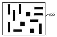
도 5는 시편 상의 케어 영역의 일례의 평면도를 도시하는 개략도이다.
도 6은 도 5에 도시된 케어 영역의 다각형에 대해 검사 서브시스템의 검출기에 의해 생성된 출력으로부터 결정된 상이한 값들로부터 생성된 2차원 히스토그램의 예이다.
도 7은, 케어 영역의 다각형이 다각형의 특성에 기초하여 초기 서브그룹으로 분리된 상태로 도 5에 도시된 케어 영역의 평면도를 도시하는 개략도이다.
도 8은 도 7에 도시된 다각형의 초기 서브그룹에 대해 검사 서브시스템의 검출기에 의해 생성된 출력으로부터 결정된 상이한 값들 및 2차원 히스토그램의 차이들로부터 생성된 2차원 히스토그램의 예를 포함한다.
도 9는, 도 8에 도시된 2차원 히스토그램의 유사점 및 차이점에 기초하여 케어 영역의 다각형이 최종 서브그룹으로 분리된 상태로 도 5에 도시된 케어 영역의 평면도를 도시하는 개략도이다.
도 10은 컴퓨터 시스템이 본 명세서에 설명된 컴퓨터 구현 방법을 수행하게 하기 위한 프로그램 명령어를 저장한 비일시적 컴퓨터 판독가능 매체의 일 실시예를 도시하는 블록도이다.
본 발명이 다양한 수정 및 대안적인 형태가 가능하지만, 그 특정 실시예가 도면에 예로서 도시되어 있고, 본 명세서에 상세히 설명된다. 도면은 실제 축적대로 도시되어 있지 않을 수도 있다. 그러나, 도면 및 그 상세한 설명은 개시된 특정 형태에 본 발명을 제한하도록 의도된 것은 아니고, 반대로, 의도는 첨부된 청구범위에 의해 규정된 바와 같은 본 발명의 사상 및 범주 내에 있는 모든 수정, 등가물 및 대안을 커버(cover)하기 위한 것이라는 것이 이해되어야 한다.Additional advantages of the present invention will become apparent to those skilled in the art having the benefit of the following detailed description of preferred embodiments when taken in conjunction with the accompanying drawings.
FIGS. 1 and 2 are schematic diagrams illustrating side views of embodiments of a system configured as described herein.
FIG. 3 is a flowchart illustrating an embodiment of steps performed by one or more computer subsystems described herein.
Figure 4 is a schematic diagram showing a plan view of an example of a care area on a specimen and a chart showing the results of a projection performed on a polygon of the care area.
Figure 5 is a schematic diagram showing an example of a plan view of a care area on a specimen.
Figure 6 is an example of a two-dimensional histogram generated from different values determined from the output generated by the detector of the inspection subsystem for the polygon of the care area illustrated in Figure 5.
Figure 7 is a schematic diagram showing a plan view of the care area illustrated in Figure 5, with the polygons of the care area separated into initial subgroups based on the characteristics of the polygons.
Figure 8 includes an example of a two-dimensional histogram generated from the differences in the two-dimensional histogram and different values determined from the output generated by the detector of the inspection subsystem for the initial subgroup of polygons illustrated in Figure 7.
FIG. 9 is a schematic diagram showing a plan view of the care area shown in FIG. 5, with the polygons of the care area separated into final subgroups based on the similarities and differences of the two-dimensional histograms shown in FIG. 8.
FIG. 10 is a block diagram illustrating one embodiment of a non-transitory computer-readable medium storing program instructions for causing a computer system to perform the computer-implemented method described herein.
While the invention is susceptible to various modifications and alternative forms, specific embodiments thereof have been shown by way of example in the drawings and are herein described in detail. The drawings may not be drawn to scale. It should be understood, however, that the drawings and detailed description herein are not intended to limit the invention to the specific forms disclosed, but on the contrary, the intention is to cover all modifications, equivalents, and alternatives falling within the spirit and scope of the invention as defined by the appended claims.
여기에서 사용되는 "뉴슨스(nuisances)"(때로는 "뉴슨스 결함"과 같은 의미로 사용됨)은 일반적으로 사용자가 신경 쓰지 않는 결함 및/또는 시편 상에서 검출되지만 실제로는 시편 상의 실제 결함이 아닌 이벤트(events)로서 정의된다. 실제 결함이 아닌 뉴슨스는 시편 상의 비결함 노이즈 소스(예컨대, 시편 상의 금속선(metal lines)에 있는 입자, 시편 상의 하부 층 또는 재료로부터의 신호, 라인 에지 조도(line edge roughness; LER), 패터닝된 속성의 상대적으로 작은 임계 치수(critical dimension; CD) 변화, 두께 변화 등)로 인해 그리고/또는 검사 시스템 자체 또는 검사에 사용되는 구성의 한계(marginalities)로 인해 이벤트로서 검출될 수 있다.As used herein, "nuisances" (sometimes used interchangeably with "nuisance defects") are defined as defects that are generally of no concern to the user and/or events that are detected on the specimen but are not actually true defects on the specimen. Nuisances that are not true defects may be detected as events due to non-defect noise sources on the specimen (e.g., particles in metal lines on the specimen, signals from underlying layers or materials on the specimen, line edge roughness (LER), relatively small critical dimension (CD) variations in patterned features, thickness variations, etc.) and/or due to limitations of the inspection system itself or of the configuration used for the inspection.
본 명세서에 사용된 용어 "관심 결함(defect of interest; DOI)"은 시편 상에서 검출된 결함으로 정의되며 실제로 시편 상의 실제 결함이다. 따라서 사용자가 일반적으로 검사중인 시편에 실제 결함이 얼마나 많고 어떤 종류인지에 관심을 갖기 때문에 DOI는 사용자에게 관심 대상이다. 일부 상황에서 "DOI"라는 용어는 시편 상의 모든 실제 결함의 서브세트를 지칭하는데 사용되며 여기에는 사용자가 관심을 갖는 실제 결함만 포함한다. 예를 들어, 임의의 주어진 시편 상에 다수의 유형의 DOI가 있을 수 있으며, 그 중 하나 이상이 하나 이상의 다른 유형보다 사용자에게 더 큰 관심의 대상이 될 수 있다. 그러나 여기에 설명된 실시예의 상황에서 "DOI"라는 용어는 시편 상의 임의의 그리고 모든 실제 결함을 지칭하는 데 사용된다.The term "defect of interest" (DOI), as used herein, is defined as a defect detected on a specimen, and is in fact a real defect on the specimen. Thus, DOIs are of interest to a user because a user is typically interested in how many and what types of real defects there are on a specimen under inspection. In some contexts, the term "DOI" is used to refer to a subset of all real defects on a specimen, which includes only those real defects that are of interest to the user. For example, there may be multiple types of DOIs on any given specimen, one or more of which may be of greater interest to the user than one or more other types. However, in the context of the embodiments described herein, the term "DOI" is used to refer to any and all real defects on a specimen.
본 명세서에서 사용되는 "설계" 및 "설계 데이터"라는 용어는 일반적으로 복잡한 시뮬레이션 또는 간단한 기하학적 연산 및 부울 연산을 통해 물리적 설계로부터 유도된 데이터 및 IC의 물리적 설계(레이아웃)를 지칭한다. 물리적 설계는 예를 들어, 그래픽 데이터 스트림(graphical data stream; GDS) 파일, 임의의 다른 표준 기계 판독가능 파일, 당 기술 분야에 공지된 임의의 다른 적합한 파일, 및 설계 데이터베이스와 같은 데이터 구조 내에 저장될 수 있다. GDSII 파일이 설계 레이아웃 데이터의 표현을 위해 사용된 파일의 클래스 중 하나이다. 이러한 파일의 다른 예로는 GL1 파일 및 OASIS 파일과 예를 들어, RDF 데이터와 같은 독점 파일 형식이 있으며, 이는 캘리포니아주 밀피타스 소재의 KLA의 소유이다. 또한, 레티클 검사 시스템 및/또는 이들의 파생물(derivatives)에 의해 획득된 레티클의 이미지가 설계를 위한 "프록시(proxy)" 또는 "프록시들"로서 사용될 수 있다. 이러한 레티클 이미지 또는 그 파생물은 설계를 사용하는 본 명세서에 설명된 임의의 실시예에서 설계 레이아웃에 대한 치환물(substitutes)로서 기능할 수 있다. 설계는 자파(Zafar) 등의 2009년 8월 4일에 허여된 공동 소유된 미국 특허 제7,570,796호 및 쿨카르니(Kulkarni) 등의 2010년 3월 9일에 허여된 미국 특허 제7,676,077호에 설명된 임의의 다른 설계 데이터 또는 설계 데이터 프록시를 포함할 수 있는 데, 이들 미국 특허의 모두는 본 명세서에 완전히 설명된 것처럼 참조로서 합체되어 있다. 또한, 설계 데이터는 표준 셀 라이브러리 데이터, 통합 레이아웃 데이터, 하나 이상의 층들에 대한 설계 데이터, 설계 데이터의 파생물, 및 전체 또는 부분 칩 설계 데이터일 수 있다.The terms "design" and "design data" as used herein generally refer to data derived from a physical design, either through complex simulations or simple geometric and Boolean operations, and the physical design (layout) of the IC. The physical design may be stored in a data structure, such as, for example, a graphical data stream (GDS) file, any other standard machine-readable file, any other suitable file known in the art, and a design database. A GDSII file is one class of files used to represent design layout data. Other examples of such files include GL1 files and OASIS files, as well as proprietary file formats such as, for example, RDF data, which is proprietary to KLA of Milpitas, Calif. In addition, images of a reticle acquired by a reticle inspection system and/or derivatives thereof may be used as "proxy" or "proxies" for the design. Such reticle images or derivatives thereof may serve as substitutes for the design layout in any of the embodiments described herein that utilize the design. The design may include any other design data or design data proxy described in commonly owned U.S. Patent No. 7,570,796, issued Aug. 4, 2009 to Zafar et al. and U.S. Patent No. 7,676,077, issued Mar. 9, 2010 to Kulkarni et al., all of which are incorporated herein by reference as if fully set forth in. Additionally, the design data may be standard cell library data, integrated layout data, design data for one or more layers, derivatives of the design data, and full or partial chip design data.
일부 예시에서는, 웨이퍼 또는 레티클로부터의 시뮬레이션되거나 획득된 이미지가 설계를 위한 프록시로서 사용될 수 있다. 이미지 분석은 설계 데이터를 위한 프록시로서 사용될 수도 있다. 예를 들어, 웨이퍼 및/또는 레티클의 이미지가 설계의 다각형을 적절하게 이미징하기에 충분한 해상도로 획득되었다고 가정하면, 설계의 다각형은 웨이퍼 및/또는 레티클 상에 인쇄된 설계의 이미지로부터 추출될 수 있다. 또한, 본 명세서에 설명된 "설계" 및 "설계 데이터"는 반도체 디바이스 설계자에 의해 설계 프로세스에서 생성되는 정보 및 데이터를 지칭하며, 따라서 임의의 물리적 웨이퍼 상에 설계를 인쇄하기에 앞서 본 명세서에 설명된 실시예들에 사용할 수 있다.In some examples, simulated or acquired images from the wafer or reticle may be used as a proxy for the design. Image analysis may also be used as a proxy for design data. For example, assuming that images of the wafer and/or reticle have been acquired with sufficient resolution to adequately image the polygons of the design, the polygons of the design may be extracted from images of the design printed on the wafer and/or reticle. Additionally, the terms "design" and "design data" as described herein refer to information and data generated by a semiconductor device designer in the design process, and thus may be used in the embodiments described herein prior to printing the design on any physical wafer.
"설계" 또는 "물리적 설계"는 또한 웨이퍼 상에 이상적으로 형성되는 설계일 수 있다. 이러한 방식으로, 설계는 실제로 그 자체가 인쇄되지는 않고 웨이퍼 상의 피처(features)의 인쇄를 향상시키기 위해 설계에 추가되는, 예를 들어, 광학 근접 정정(optical proximity correction; OPC) 피처와 같이 웨이퍼 상에 인쇄되지 않을 설계의 피처를 포함하지 않을 수 있다.A "design" or "physical design" may also be a design that is ideally formed on a wafer. In this manner, the design may not include features of the design that are not actually printed on the wafer, such as optical proximity correction (OPC) features, which are added to the design to improve the printing of features on the wafer, but are not actually printed themselves.
이제, 도면을 참조하면, 도면은 실제 축적대로 도시되어 있는 것은 아니라는 것이 주목된다. 특히 도면의 요소의 일부의 축적은 요소의 특성을 강조하기 위해 상당히 과장되어 있다. 도면은 동일한 축적으로 도시되어 있지는 않다는 것이 또한 주목된다. 유사하게 구성될 수 있는 하나보다 많은 도면에 도시되어 있는 요소는 동일한 참조 부호를 사용하여 표시되어 있다. 본 명세서에 달리 지시되지 않으면, 설명되고 도시되어 있는 임의의 요소는 임의의 적합한 상업적으로 입수 가능한 요소를 포함할 수 있다.Now, referring to the drawings, it is noted that the drawings are not drawn to scale. In particular, the scale of some of the elements of the drawings is significantly exaggerated to emphasize the characteristics of the elements. It is also noted that the drawings are not drawn to the same scale. Elements that are illustrated in more than one drawing that may be similarly constructed are indicated by the same reference numerals. Unless otherwise indicated herein, any of the elements described and illustrated may include any suitable commercially available elements.
일 실시예는 시편의 검사를 위한 결함 검출 방법을 선택하도록 구성된 시스템에 관한 것이다. 일부 실시예는 향상된 결함 검사 감도를 위한 통계적 케어 영역 그룹화에 관한 것이다. 예를 들어, 여기에 설명된 결함 검사의 케어 영역 세분화 및 통계적 재그룹화는 DOI에 대한 감도를 향상시키거나, 뉴슨스 비율(rate)을 낮추거나, 웨이퍼 내의 그리고 웨이퍼 대 웨이퍼의 레시피 성능 안정성을 개선하거나, 이들의 일부 조합을 수행하기 위해 사용될 수 있다.One embodiment relates to a system configured to select a defect detection method for inspection of a specimen. Some embodiments relate to statistical care region grouping for improved defect inspection sensitivity. For example, the care region segmentation and statistical regrouping of defect inspection described herein can be used to improve sensitivity to DOI, reduce news rate, improve recipe performance stability within a wafer and from wafer to wafer, or some combination thereof.
일 실시예에서, 시편은 웨이퍼이다. 웨이퍼는 반도체 분야에 공지된 임의의 웨이퍼를 포함할 수 있다. 또 다른 실시예에서, 시편은 레티클이다. 레티클은 반도체 분야에 공지된 임의의 레티클을 포함할 수 있다. 일부 실시예는 웨이퍼 또는 웨이퍼들과 관련하여 여기에서 설명될 수 있지만, 실시예는 이들이 사용될 수 있는 시편에 제한되지 않는다. 예를 들어, 여기에 설명된 실시예는 예를 들어, 레티클, 평면 패널, 개인용 컴퓨터(personal computer; PC) 보드, 및 다른 반도체 시편과 같은 시편에 사용될 수 있다.In one embodiment, the specimen is a wafer. The wafer can include any wafer known in the semiconductor art. In another embodiment, the specimen is a reticle. The reticle can include any reticle known in the semiconductor art. While some embodiments may be described herein with respect to a wafer or wafers, the embodiments are not limited to the specimens for which they may be used. For example, the embodiments described herein can be used with specimens such as, for example, reticles, flat panels, personal computer (PC) boards, and other semiconductor specimens.
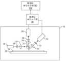
이러한 시스템의 일 실시예가 도 1에 도시된다. 일부 실시예에서, 시스템은 적어도 에너지 소스와 검출기를 포함하는 검사 서브시스템을 포함한다. 에너지 소스는 시편에 지향되는 에너지를 생성하도록 구성된다. 검출기는 시편으로부터의 에너지를 검출하고 검출된 에너지에 응답하여 출력을 생성하도록 구성된다.An embodiment of such a system is illustrated in FIG. 1. In some embodiments, the system includes an inspection subsystem including at least an energy source and a detector. The energy source is configured to generate energy directed at the specimen. The detector is configured to detect energy from the specimen and generate an output in response to the detected energy.
일 실시예에서, 검사 서브시스템은 광 기반 검사 서브시스템이다. 예를 들어, 도 1에 도시된 시스템의 실시예에서, 검사 서브시스템(10)은 광을 시편(14)에 지향시키도록 구성된 조명 서브시스템을 포함한다. 조명 서브시스템은 적어도 하나의 광원을 포함한다. 예를 들어, 도 1에 도시된 바와 같이, 조명 서브시스템은 광원(16)을 포함한다. 일 실시예에서, 조명 서브시스템은 하나 이상의 경사각 및/또는 하나 이상의 수직각을 포함할 수 있는 하나 이상의 입사각으로 광을 시편으로 지향시키도록 구성된다. 예를 들어, 도 1에 도시된 바와 같이, 광원(16)으로부터의 광은 광학 요소(18)를 거친 다음 렌즈(20)를 통해 빔 스플리터(21)에 지향되고, 빔 스플리터(21)는 광을 수직 입사각으로 시편(14)에 지향시킨다. 입사각은 임의의 적절한 입사각을 포함할 수 있으며, 이는 예를 들어, 시편의 특성 및 시편 상에서 검출될 결함에 따라 변화될 수 있다.In one embodiment, the inspection subsystem is a light-based inspection subsystem. For example, in the embodiment of the system illustrated in FIG. 1, the inspection subsystem (10) includes an illumination subsystem configured to direct light onto the specimen (14). The illumination subsystem includes at least one light source. For example, as illustrated in FIG. 1, the illumination subsystem includes a light source (16). In one embodiment, the illumination subsystem is configured to direct light onto the specimen at one or more angles of incidence, which may include one or more oblique angles and/or one or more vertical angles. For example, as illustrated in FIG. 1, light from the light source (16) passes through an optical element (18) and then is directed through a lens (20) to a beam splitter (21), which directs the light onto the specimen (14) at a normal angle of incidence. The angle of incidence may include any suitable angle of incidence, which may vary, for example, depending on the characteristics of the specimen and the defects to be detected on the specimen.
조명 서브시스템은 상이한 시간들에 상이한 입사각들로 광을 시편으로 지향시키도록 구성될 수 있다. 예를 들어, 검사 서브시스템은 광이 도 1에 도시된 것과는 다른 입사각으로 시편에 지향될 수 있도록 조명 서브시스템의 하나 이상의 요소의 하나 이상의 특성을 변경하도록 구성될 수 있다. 그러한 일 예에서, 검사 서브시스템은 광원(16), 광학 요소(18), 및 렌즈(20)를 이동시켜 다른 입사각으로 광이 시편에 지향되게 하도록 구성될 수 있다.The illumination subsystem can be configured to direct light onto the specimen at different angles of incidence at different times. For example, the inspection subsystem can be configured to change one or more characteristics of one or more elements of the illumination subsystem so that light can be directed onto the specimen at different angles of incidence than those illustrated in FIG. 1. In one such example, the inspection subsystem can be configured to move the light source (16), the optical element (18), and the lens (20) so that light can be directed onto the specimen at different angles of incidence.
일부 경우에, 검사 서브시스템은 동시에 하나보다 많은 입사각에서 광을 시편으로 지향하도록 구성될 수 있다. 예를 들어, 검사 서브시스템은 하나보다 많은 조명 채널을 포함할 수 있고, 조명 채널들 중 하나는 도 1에 도시된 바와 같이 광원(16), 광학 요소(18) 및 렌즈(20)를 포함할 수 있으며, 조명 채널들(도시되지 않음) 중 또 다른 하나는 상이하거나 또는 동일하게 구성될 수 있는 유사한 요소들을 포함할 수 있거나, 또는 적어도 광원 및 가능하게는 예를 들어, 본 명세서에 추가로 설명된 것과 같은 하나 이상의 다른 컴포넌트를 포함할 수 있다. 이러한 광이 다른 광과 동시에 시편으로 지향되면, 상이한 입사각들에서 시편에 지향되는 광의 하나 이상의 특성(예컨대, 파장, 편광 등)은, 상이한 입사각들에서 시편의 조명으로부터의 발생하는 광이 검출기(들)에서 서로 구별될 수 있도록 상이할 수 있다.In some cases, the inspection subsystem may be configured to direct light onto the specimen at more than one angle of incidence simultaneously. For example, the inspection subsystem may include more than one illumination channel, where one of the illumination channels may include a light source (16), an optical element (18), and a lens (20) as illustrated in FIG. 1 , and another of the illumination channels (not illustrated) may include similar elements that may be configured differently or identically, or may include at least the light source and possibly one or more other components, such as those further described herein. When such light is directed onto the specimen simultaneously with other light, one or more characteristics (e.g., wavelength, polarization, etc.) of the light directed onto the specimen at the different angles of incidence may be different such that light resulting from illumination of the specimen at the different angles of incidence can be distinguished from one another by the detector(s).
또 다른 예에서, 조명 서브시스템은 단지 하나의 광원(예컨대, 도 1에 도시된 소스(16))를 포함할 수 있으며, 광원으로부터의 광은 조명 서브시스템의 하나 이상의 광학 요소(도시되지 않음)에 의해 (예컨대, 파장, 편광 등에 기초하여) 상이한 광학 경로들로 분리될 수 있다. 그런 다음, 상이한 광학 경로들 각각의 광은 시편에 지향될 수 있다. 다수의 조명 채널들은 동일한 시간 또는 상이한 시간들에(예컨대, 상이한 조명 채널들이 순차적으로 시편을 조명하는데 사용되는 경우) 시편에 광을 지향시키도록 구성될 수 있다. 또 다른 예에서, 동일한 조명 채널은 상이한 시간들에 상이한 특성들을 갖는 광을 시편에 지향시키도록 구성될 수 있다. 예를 들어, 일부 예들에서, 광학 요소(18)는 스펙트럼 필터로서 구성될 수 있으며, 스펙트럼 필터의 특성은 광의 상이한 파장들이 상이한 시간들에 시편에 지향될 수 있도록 다양한 상이한 방식들로(예컨대, 스펙트럼 필터를 교환함으로써) 변화될 수 있다. 조명 서브시스템은 상이하거나 또는 동일한 특성들을 갖는 광을 상이하거나 또는 동일한 입사각으로 순차적으로 또는 동시에 시편에 지향시키기 위해 당업계에 공지된 임의의 다른 적절한 구성을 가질 수 있다.In another example, the illumination subsystem may include only one light source (e.g., source (16) illustrated in FIG. 1), and light from the light source may be separated into different optical paths (e.g., based on wavelength, polarization, etc.) by one or more optical elements (not illustrated) of the illumination subsystem. Light from each of the different optical paths may then be directed to the specimen. Multiple illumination channels may be configured to direct light to the specimen at the same time or at different times (e.g., where different illumination channels are used to illuminate the specimen sequentially). In another example, the same illumination channel may be configured to direct light having different characteristics to the specimen at different times. For example, in some examples, the optical element (18) may be configured as a spectral filter, and the characteristics of the spectral filter may be varied in a variety of different ways (e.g., by swapping the spectral filters) so that different wavelengths of light may be directed to the specimen at different times. The illumination subsystem may have any other suitable configuration known in the art to sequentially or simultaneously direct light having different or identical characteristics onto the specimen at different or identical angles of incidence.
일 실시예에서, 광원(16)은 광대역 플라즈마(broadband plasma; BBP) 광원을 포함할 수 있다. 이러한 방식으로, 광원에 의해 생성되고 시편에 지향되는 광은 광대역 광을 포함할 수 있다. 그러나, 광원은 당업계에 공지된 임의의 적절한 레이저를 포함할 수 있고 예를 들어, 당업계에 공지된 임의의 적절한 파장(들)에서 광을 생성하도록 구성될 수 있는 레이저와 같은 임의의 다른 적절한 광원을 포함할 수 있다. 또한, 레이저는 단색 또는 거의 단색인 광을 생성하도록 구성될 수 있다. 이러한 방식으로, 레이저는 협대역 레이저일 수 있다. 광원은 또한 다수의 이산 파장들 또는 파장 대역들에서 광을 생성하는 다색 광원을 포함할 수 있다.In one embodiment, the light source (16) may comprise a broadband plasma (BBP) light source. In this manner, light generated by the light source and directed to the specimen may comprise broadband light. However, the light source may comprise any suitable laser known in the art, or any other suitable light source, such as a laser configured to generate light at any suitable wavelength(s) known in the art. Additionally, the laser may be configured to generate light that is monochromatic or nearly monochromatic. In this manner, the laser may be a narrowband laser. The light source may also comprise a polychromatic light source that generates light at multiple discrete wavelengths or wavelength bands.
광학 요소들(18)로부터의 광은 렌즈(20)에 의해 빔 스플리터(21)로 포커싱될 수 있다. 비록 렌즈(20)가 단일 굴절 광학 요소로서 도 1에 도시되어 있지만, 실제로 렌즈(20)는 조합되어 광학 요소로부터의 광을 시편에 포커싱하는 다수의 굴절 및/또는 반사 광학 요소들을 포함할 수 있다. 도 1에 도시되고 본 명세서에 기술된 조명 서브시스템은 임의의 다른 적절한 광학 요소들(도시되지 않음)을 포함할 수 있다. 이러한 광학 요소들의 예시들은 당업계에 공지된 임의의 그러한 적절한 광학 요소들을 포함할 수 있는 편광 성분(들), 스펙트럼 필터(들), 공간 필터(들), 반사 광학 요소(들), 아포다이저(들), 빔 스플리터(들), 애퍼처(들) 등을 포함하지만, 이들로 제한되지는 않는다. 또한, 시스템은 검사에 사용되는 조명 유형에 기초하여 조명 서브시스템의 하나 이상의 요소들을 변경하도록 구성될 수 있다.Light from the optical elements (18) may be focused by the lens (20) to the beam splitter (21). Although the lens (20) is illustrated in FIG. 1 as a single refractive optical element, in practice the lens (20) may include a plurality of refractive and/or reflective optical elements that combine to focus the light from the optical element onto the specimen. The illumination subsystem illustrated in FIG. 1 and described herein may include any other suitable optical elements (not illustrated). Examples of such optical elements include, but are not limited to, polarizing component(s), spectral filter(s), spatial filter(s), reflective optical element(s), apodizer(s), beam splitter(s), aperture(s), and the like, which may include any such suitable optical elements known in the art. Additionally, the system may be configured to vary one or more elements of the illumination subsystem based on the type of illumination used for the inspection.
검사 서브시스템은 또한 광이 시편 위에서 스캐닝되도록 구성된 스캐닝 서브시스템을 포함할 수 있다. 예를 들어, 검사 서브시스템은 검사 중에 시편(14)이 배치되는 스테이지(22)를 포함할 수 있다. 스캐닝 서브시스템은 광이 시편 위에서 스캐닝될 수 있도록 시편을 이동시키도록 구성될 수 있는 임의의 적절한 기계적 및/또는 로봇식 조립체(스테이지(22)를 포함함)를 포함할 수 있다. 추가적으로 또는 대안적으로, 검사 서브시스템은 검사 서브시스템의 하나 이상의 광학 요소들이 시편 위의 광의 일부 스캐닝을 수행하도록 구성될 수 있다. 광은 임의의 적절한 방식으로 시편 위에서 스캐닝될 수 있다.The inspection subsystem may also include a scanning subsystem configured to scan the light over the specimen. For example, the inspection subsystem may include a stage (22) upon which the specimen (14) is placed during inspection. The scanning subsystem may include any suitable mechanical and/or robotic assembly (including the stage (22)) configured to move the specimen so that the light can be scanned over the specimen. Additionally or alternatively, the inspection subsystem may be configured to cause one or more optical elements of the inspection subsystem to perform a portion of the scanning of the light over the specimen. The light may be scanned over the specimen in any suitable manner.
검사 서브시스템은 하나 이상의 검출 채널을 더 포함한다. 하나 이상의 검출 채널들 중 적어도 하나는 검사 서브시스템에 의한 시편의 조명으로 인해 시편으로부터의 광을 검출하고 그 검출된 광에 응답하여 출력을 생성하도록 구성된 검출기를 포함한다. 예를 들어, 도 1에 도시된 검사 서브시스템은 2개의 검출 채널을 포함하며, 이 채널들 중 하나는 수집기(24), 요소(26) 및 검출기(28)에 의해 형성되고 이 채널들 중 또 다른 하나는 수집기(30), 요소(32) 및 검출기(34)에 의해 형성된다. 도 1에 도시된 바와 같이, 2개의 검출 채널들은 상이한 수집 각도들에서 광을 수집하고 검출하도록 구성된다. 일부 예들에서, 하나의 검출 채널은 정반사된 광을 검출하도록 구성되고, 다른 검출 채널은 시편으로부터 정반사되지 않은(예컨대, 산란, 회절 등) 광을 검출하도록 구성된다. 그러나, 2개 이상의 검출 채널들은 시편으로부터 동일한 유형의 광(예컨대, 정반사된 광)을 검출하도록 구성될 수 있다. 도 1은 2개의 검출 채널들을 포함하는 검사 서브시스템의 실시예를 도시하지만, 검사 서브시스템은 상이한 수의 검출 채널들(예컨대, 단지 하나의 검출 채널 또는 2개 이상의 검출 채널들)을 포함할 수 있다. 수집기들 각각은 단일 굴절 광학 요소들로서 도 1에 도시되어 있지만, 수집기들의 각각은 하나 이상의 굴절 광학 요소(들) 및/또는 하나 이상의 반사 광학 요소(들)를 포함할 수 있다.The inspection subsystem further includes one or more detection channels. At least one of the one or more detection channels includes a detector configured to detect light from the specimen due to illumination of the specimen by the inspection subsystem and to generate an output in response to the detected light. For example, the inspection subsystem illustrated in FIG. 1 includes two detection channels, one of the channels formed by a collector (24), an element (26), and a detector (28), and another of the channels formed by a collector (30), an element (32), and a detector (34). As illustrated in FIG. 1, the two detection channels are configured to collect and detect light at different collection angles. In some examples, one detection channel is configured to detect specularly reflected light, and the other detection channel is configured to detect light that is not specularly reflected (e.g., scattered, diffracted, etc.) from the specimen. However, the two or more detection channels may be configured to detect the same type of light (e.g., specularly reflected light) from the specimen. Although FIG. 1 illustrates an embodiment of an inspection subsystem including two detection channels, the inspection subsystem may include a different number of detection channels (e.g., just one detection channel or more than two detection channels). While each of the collectors is illustrated in FIG. 1 as a single refractive optical element, each of the collectors may include one or more refractive optical element(s) and/or one or more reflective optical element(s).
하나 이상의 검출 채널은 예를 들어, 광증배관(photo-multiplier tubes; PMT), 전하 결합 디바이스(charge coupled devices; CCD), 시간 지연 적분(time delay integration; TDI) 카메라와 같은 당업계에 공지된 임의의 적합한 검출기를 포함할 수 있다. 검출기들은 비이미징(non-imaging) 검출기들 또는 이미징 검출기들을 포함할 수도 있다. 검출기들이 비이미징 검출기인 경우, 각각의 검출기는 강도와 같은 산란된 광의 특정 특성들을 검출하도록 구성될 수 있지만, 예를 들어, 이미징 평면 내의 위치의 함수와 같은 특성들을 검출하도록 구성되지는 않을 수 있다. 이와 같이, 각각의 검출 채널에 포함된 각각의 검출기에 의해 생성되는 출력은 신호 또는 데이터일 수 있지만, 이미지 신호 또는 이미지 데이터가 아닐 수 있다. 그러한 경우에, 예를 들어, 시스템의 컴퓨터 서브시스템(36)과 같은 컴퓨터 서브시스템은 검출기의 비이미징 출력으로부터 시편의 이미지를 생성하도록 구성될 수 있다. 그러나, 다른 예들에서, 검출기는 이미징 신호 또는 이미지 데이터를 생성하도록 구성되는 이미징 검출기로서 구성될 수 있다. 따라서, 시스템은 다수의 방식으로 이미지를 생성하도록 구성될 수 있다.The one or more detection channels may include any suitable detectors known in the art, such as, for example, photo-multiplier tubes (PMTs), charge coupled devices (CCDs), time delay integration (TDI) cameras. The detectors may include non-imaging detectors or imaging detectors. When the detectors are non-imaging detectors, each detector may be configured to detect particular characteristics of the scattered light, such as intensity, but may not be configured to detect characteristics, such as, for example, a function of position within an imaging plane. As such, the output generated by each detector included in each detection channel may be a signal or data, but may not be an image signal or image data. In such a case, a computer subsystem, such as, for example, a computer subsystem (36) of the system, may be configured to generate an image of the specimen from the non-imaging output of the detectors. However, in other examples, the detectors may be configured as imaging detectors that are configured to generate an imaging signal or image data. Thus, the system can be configured to generate images in a number of ways.
도 1은 본 명세서에 설명된 시스템 실시예들에 포함될 수 있는 검사 서브시스템의 구성을 일반적으로 예시하기 위해 본 명세서에 제공된다. 명백하게, 본 명세서에 설명된 검사 서브시스템 구성은 상용 검사 시스템을 설계할 때 정상적으로 수행되는 시스템의 성능을 최적화하도록 변경될 수 있다. 또한, 본 명세서에 설명된 시스템들은 예를 들어, KLA로부터 상업적으로 입수 가능한 29xx 및 39xx 시리즈의 도구들과 같은 기존 검사 시스템을 사용하여 (예컨대, 기존의 검사 시스템에 본 명세서에 설명된 기능성을 추가함으로써) 구현될 수 있다. 일부 이러한 시스템에 대해, 본 명세서에 설명된 실시예는 검사 시스템의 선택적 기능성으로서 (예컨대, 시스템의 다른 기능성에 추가하여) 제공될 수 있다. 대안적으로, 본 명세서에 설명된 검사 서브시스템은 완전하게 신규한 검사 시스템을 제공하기 위해 "처음부터(from scratch)" 설계될 수 있다.FIG. 1 is provided herein to generally illustrate a configuration of an inspection subsystem that may be included in the system embodiments described herein. Of course, the inspection subsystem configuration described herein may be modified to optimize the performance of a system that is normally performing when designing a commercial inspection system. Furthermore, the systems described herein may be implemented using existing inspection systems (e.g., by adding the functionality described herein to an existing inspection system), such as, for example, the 29xx and 39xx series of instruments commercially available from KLA. For some such systems, the embodiments described herein may be provided as optional functionality of the inspection system (e.g., in addition to other functionality of the system). Alternatively, the inspection subsystem described herein may be designed "from scratch" to provide a completely new inspection system.
시스템의 컴퓨터 서브시스템(36)은 컴퓨터 서브시스템이 시편의 스캐닝 동안 검출기들에 의해 생성된 출력을 수신할 수 있도록 임의의 적절한 방식으로(예컨대, "유선" 및/또는 "무선" 전송 매체를 포함할 수 있는 하나 이상의 전송 매체를 통해) 검사 서브시스템의 검출기들에 결합될 수 있다. 컴퓨터 서브시스템(36)은 본 명세서에 기술된 바와 같은 검출기들의 출력 및 본 명세서에 추가로 설명된 임의의 다른 기능들을 사용하여 다수의 기능들을 수행하도록 구성될 수 있다. 이 컴퓨터 서브시스템은 본 명세서에 기술된 바와 같이 또한 구성될 수 있다.The computer subsystem (36) of the system may be coupled to the detectors of the inspection subsystem in any suitable manner (e.g., via one or more transmission media, which may include "wired" and/or "wireless" transmission media) such that the computer subsystem may receive output generated by the detectors during scanning of the specimen. The computer subsystem (36) may be configured to perform a number of functions using the output of the detectors as described herein and any other functions further described herein. The computer subsystem may also be configured as described herein.
이 컴퓨터 서브시스템(및 본 명세서에서 설명된 다른 컴퓨터 서브시스템들)은 또한 본 명세서에서 컴퓨터 시스템(들)로 지칭될 수 있다. 본 명세서에 기술된 컴퓨터 서브시스템(들) 또는 시스템(들)의 각각은 퍼스널 컴퓨터 시스템, 이미지 컴퓨터, 메인프레임 컴퓨터 시스템, 워크스테이션, 네트워크 어플라이언스, 인터넷 어플라이언스, 또는 다른 디바이스를 포함하는 다양한 형태들을 취할 수 있다. 일반적으로, 용어 "컴퓨터 시스템"은 메모리 매체로부터의 명령어를 실행하는 하나 이상의 프로세서를 갖는 임의의 디바이스를 포함하도록 광범위하게 정의될 수 있다. 컴퓨터 서브시스템(들) 또는 시스템(들)은 또한 예를 들어, 병렬 프로세서와 같은 당업계에 공지된 임의의 적합한 프로세서를 포함할 수 있다. 또한, 컴퓨터 서브시스템(들) 또는 시스템(들)은 고속 프로세싱 및 소프트웨어를 갖는 컴퓨터 플랫폼을 독립형 또는 네트워크형 도구로서 포함할 수 있다.These computer subsystems (and other computer subsystems described herein) may also be referred to herein as computer system(s). Each of the computer subsystem(s) or system(s) described herein may take various forms, including a personal computer system, an image computer, a mainframe computer system, a workstation, a network appliance, an Internet appliance, or other devices. In general, the term "computer system" may be broadly defined to include any device having one or more processors that execute instructions from a memory medium. The computer subsystem(s) or system(s) may also include any suitable processor known in the art, such as, for example, a parallel processor. Additionally, the computer subsystem(s) or system(s) may include a computer platform having high-speed processing and software, either as a stand-alone or networked tool.
시스템이 하나보다 많은 컴퓨터 서브시스템을 포함하는 경우, 상이한 컴퓨터 서브시스템들은 이미지, 데이터, 정보, 명령어들 등이 본 명세서에서 추가로 설명되는 바와 같이 컴퓨터 서브시스템들 간에 송신될 수 있도록 서로 결합될 수 있다. 예를 들어, 컴퓨터 서브시스템(36)은 당업계에 공지된 임의의 적합한 유선 및/또는 무선 전송 매체를 포함할 수 있는 임의의 적절한 전송 매체에 의해 컴퓨터 서브시스템들(102)에 (도 1에서 점선으로 도시된 바와 같이) 접속될 수 있다. 이러한 컴퓨터 서브시스템들 중 2개 이상은 또한 공유된 컴퓨터 판독 가능 저장 매체(도시되지 않음)에 의해 효과적으로 결합될 수 있다.Where the system includes more than one computer subsystem, the different computer subsystems may be coupled to one another such that images, data, information, instructions, and the like may be transmitted between the computer subsystems as further described herein. For example, the computer subsystem (36) may be coupled to the computer subsystems (102) (as illustrated in dashed lines in FIG. 1) by any suitable transmission medium, which may include any suitable wired and/or wireless transmission medium known in the art. Two or more of these computer subsystems may also be effectively coupled by a shared computer-readable storage medium (not illustrated).
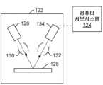
검사 서브시스템이 광학 또는 광 기반 서브시스템인 것으로 위에서 설명되었지만, 검사 서브시스템은 전자 기반 서브시스템일 수 있다. 예를 들어, 일 실시예에서, 시편(304)에 지향된 에너지는 전자를 포함하고, 시편으로부터 검출된 에너지는 전자를 포함한다. 이러한 방식으로, 에너지 소스는 전자빔 소스일 수 있다. 도 2에 도시된 하나의 그러한 실시예에서, 검사 서브시스템은 컴퓨터 서브시스템(124)에 결합되는 전자 컬럼(electron column)(122)을 포함한다.While the inspection subsystem is described above as being an optical or light-based subsystem, the inspection subsystem may be an electronic-based subsystem. For example, in one embodiment, the energy directed at the specimen (304) comprises electrons, and the energy detected from the specimen comprises electrons. In this manner, the energy source may be an electron beam source. In one such embodiment, illustrated in FIG. 2, the inspection subsystem comprises an electron column (122) coupled to a computer subsystem (124).
도 2에 또한 도시된 바와 같이, 전자 컬럼은 하나 이상의 요소(130)에 의해 시편(128)에 포커싱되는 전자를 생성하도록 구성된 전자빔 소스(126)를 포함한다. 전자빔 소스는 예를 들어, 캐소드 소스 또는 방출기 팁(emitter tip)을 포함할 수 있고, 하나 이상의 요소(130)는 예를 들어, 건 렌즈(gun lens), 애노드, 빔 제한 애퍼처(beam limiting aperture), 게이트 밸브, 빔 전류 선택 애퍼처, 대물 렌즈, 및 스캐닝 서브시스템을 포함할 수 있는 데, 이들 모두는 당 기술 분야에 공지되어 있는 임의의 이러한 적합한 요소를 포함할 수 있다.As further illustrated in FIG. 2, the electron column includes an electron beam source (126) configured to generate electrons that are focused onto the specimen (128) by one or more elements (130). The electron beam source may include, for example, a cathode source or an emitter tip, and the one or more elements (130) may include, for example, a gun lens, an anode, a beam limiting aperture, a gate valve, a beam current selecting aperture, an objective lens, and a scanning subsystem, all of which may include any such suitable elements known in the art.
시편으로부터 복귀된 전자(예컨대, 2차 전자)는 하나 이상의 요소(132)에 의해 검출기(134)에 포커싱될 수 있다. 하나 이상의 요소(132)는 예를 들어, 요소(들)(130) 내에 포함된 동일한 스캐닝 서브시스템일 수 있는 스캐닝 서브시스템을 포함할 수 있다.Electrons (e.g., secondary electrons) returned from the sample may be focused onto a detector (134) by one or more elements (132). The one or more elements (132) may include a scanning subsystem, which may be, for example, the same scanning subsystem contained within the element(s) (130).
전자 컬럼은 당 기술 분야에 공지된 임의의 다른 적합한 요소를 포함할 수 있다. 게다가, 전자 컬럼은 지앙(Jiang) 등에 2014년 4월 4일에 허여된 미국 특허 제8,664,594호, 코지마(Kojima) 등에 2014년 4월 8일에 허여된 미국 특허 제8,692,204호, 거븐스(Gubbens) 등에 2014년 4월 15일에 허여된 미국 특허 제8,698,093호, 및 맥도널드(MacDonald) 등에 2014년 5월 6일에 허여된 미국 특허 제8,716,662호에 설명된 바와 같이 또한 구성될 수도 있는 데, 이들 미국 특허는 본 명세서에 완전히 설명된 것처럼 참조로서 합체되어 있다.The electron column may include any other suitable elements known in the art. Additionally, the electron column may also be configured as described in U.S. Patent No. 8,664,594, issued to Jiang et al. on April 4, 2014, U.S. Patent No. 8,692,204, issued to Kojima et al. on April 8, 2014, U.S. Patent No. 8,698,093, issued to Gubbens et al. on April 15, 2014, and U.S. Patent No. 8,716,662, issued to MacDonald et al. on May 6, 2014, which are incorporated herein by reference as if fully set forth herein.
전자 컬럼은 전자가 입사의 경사각에서 시편에 지향되고 또 다른 경사각에서 시편으로부터 산란되도록 구성되는 것으로서 도 2에 도시되어 있지만, 전자빔은 임의의 적합한 각도로 시편에 지향되고 시편으로부터 산란될 수도 있다는 것이 이해되어야 한다. 또한, 전자빔 서브시스템은 (예컨대, 상이한 조명 각도들, 수집 각도들 등에서) 시편의 이미지를 생성하기 위해 다수의 모드를 사용하도록 구성될 수 있다. 전자빔 서브시스템의 다수의 모드들은 서브시스템의 임의의 이미지 생성 파라미터(들)에서 다를 수 있다.Although the electron column is illustrated in FIG. 2 as being configured to direct the electrons onto the specimen at an angle of incidence and scatter from the specimen at another angle of incidence, it should be understood that the electron beam may be directed onto the specimen and scattered from the specimen at any suitable angle. Additionally, the electron beam subsystem may be configured to use multiple modes to generate images of the specimen (e.g., at different illumination angles, collection angles, etc.). The multiple modes of the electron beam subsystem may differ in any of the image generating parameter(s) of the subsystem.
컴퓨터 서브시스템(124)은 전술한 바와 같이 검출기(134)에 결합될 수 있다. 검출기는 시편의 표면으로부터 복귀되어 이에 의해 시편의 전자빔 이미지를 형성하는 전자를 검출할 수 있다. 전자빔 이미지는 임의의 적절한 전자빔 이미지를 포함할 수 있다. 컴퓨터 서브시스템(124)은 검출기의 출력 및/또는 전자빔 이미지를 사용하여 본 명세서에 설명된 기능들 중 임의의 것을 수행하도록 구성될 수 있다. 컴퓨터 서브시스템(124)은 본 명세서에 설명된 임의의 추가적인 단계(들)를 수행하도록 구성될 수 있다. 도 2에 도시된 검사 서브시스템을 포함하는 시스템은 여기에 설명된 바와 같이 또한 구성될 수 있다.The computer subsystem (124) may be coupled to the detector (134) as described above. The detector may detect electrons that return from the surface of the specimen, thereby forming an electron beam image of the specimen. The electron beam image may comprise any suitable electron beam image. The computer subsystem (124) may be configured to perform any of the functions described herein using the output of the detector and/or the electron beam image. The computer subsystem (124) may be configured to perform any of the additional step(s) described herein. A system including the inspection subsystem illustrated in FIG. 2 may also be configured as described herein.
도 2는 본 명세서에 설명된 실시예들에 포함될 수 있는 전자빔 서브시스템의 구성을 일반적으로 예시하기 위해 본 개시에서 제공된다. 위에서 설명된 광학 서브시스템과 마찬가지로, 본 개시에서 설명된 전자빔 서브시스템 구성은 상업적 검사 시스템을 설계할 때 일반적으로 수행되는 서브시스템의 성능을 최적화하도록 변경될 수 있다. 또한, 여기에 설명된 시스템은 기존 검사 시스템을 사용하여 (예컨대, 여기에 설명된 기능을 기존 시스템에 추가함으로써) 구현될 수 있다. 일부 이러한 시스템에 대해, 본 명세서에 설명된 실시예는 시스템의 선택적 기능성으로서 (예컨대, 시스템의 다른 기능성에 추가하여) 제공될 수도 있다. 대안적으로, 본 명세서에 설명된 시스템은 완전하게 신규한 시스템을 제공하기 위해 "처음부터(from scratch)" 설계될 수 있다.FIG. 2 is provided herein to generally illustrate the configuration of an electron beam subsystem that may be included in embodiments described herein. As with the optical subsystem described above, the electron beam subsystem configuration described herein may be modified to optimize the performance of the subsystem as is typically done when designing a commercial inspection system. Additionally, the systems described herein may be implemented using existing inspection systems (e.g., by adding the functionality described herein to an existing system). For some such systems, the embodiments described herein may be provided as optional functionality of the system (e.g., in addition to other functionality of the system). Alternatively, the systems described herein may be designed "from scratch" to provide an entirely new system.
검사 서브시스템이 광 기반 또는 전자빔 기반 서브시스템인 것으로 위에서 설명되었지만, 검사 서브시스템은 이온 빔 기반 서브시스템일 수 있다. 이러한 검사 서브시스템은 전자빔 소스가 당업계에 알려진 임의의 적절한 이온빔 소스로 대체될 수 있다는 점을 제외하고는 도 2에 도시된 바와 같이 구성될 수 있다. 따라서 일 실시예에서 시편에 지향되는 에너지는 이온을 포함한다. 또한, 검사 서브시스템은 예를 들어, 상업적으로 입수 가능한 포커싱된 이온 빔(focused ion beam; FIB) 시스템, 헬륨 이온 현미경 검사(helium ion microscopy; HIM) 시스템 및 2차 이온 질량 분광학(secondary ion mass spectroscopy; SIMS) 시스템에 포함된 것과 같은 임의의 다른 적합한 이온 빔 기반 검사 서브시스템일 수 있다.Although the inspection subsystem is described above as being a light-based or electron beam-based subsystem, the inspection subsystem may be an ion beam-based subsystem. Such an inspection subsystem may be configured as illustrated in FIG. 2, except that the electron beam source may be replaced with any suitable ion beam source known in the art. Thus, in one embodiment, the energy directed at the specimen comprises ions. Additionally, the inspection subsystem may be any other suitable ion beam-based inspection subsystem, such as those included in, for example, commercially available focused ion beam (FIB) systems, helium ion microscopy (HIM) systems, and secondary ion mass spectroscopy (SIMS) systems.
여기에 설명된 검사 서브시스템은 다수의 모드들을 가진 시편의 출력, 예를 들어, 이미지를 생성하도록 구성될 수 있다. 일반적으로 "모드"는 시편의 출력 및/또는 이미지(또는 시편의 이미지를 생성하기 위해 사용되는 출력)를 생성하는 데 사용되는 검사 서브시스템의 파라미터 값에 의해 정의된다. 따라서, 모드들은 검사 서브시스템의 파라미터들 중 적어도 하나에 대해 값이 상이할 수 있다(출력이 생성되는 시편 상의 위치 제외). 예를 들어, 광학 서브시스템에서, 상이한 모드들은 조명을 위해 상이한 파장(들)의 광을 사용할 수 있다. 모드들은 본 명세서에서 추가로 설명되는 바와 같이 (예컨대, 상이한 모드들에 대해 상이한 광원들, 상이한 스펙트럼 필터들 등을 사용함으로써) 조명 파장(들)에서 상이할 수 있다. 또 다른 예에서, 상이한 모드들은 광학 서브시스템의 상이한 조명 채널들을 사용할 수 있다. 예를 들어, 위에서 언급했듯이, 광학 서브시스템은 1개보다 많은 조명 채널을 포함할 수 있다. 이와 같이, 상이한 모드들에 대해 상이한 조명 채널들이 사용될 수 있다. 모드들은 또한 또는 대안적으로 광학 서브시스템의 하나 이상의 수집/검출 파라미터에서 다를 수 있다. 모드들은 검사 서브시스템의 하나 이상의 변경 가능한 파라미터(예컨대, 조명 편광(들), 각도(들), 파장(들) 등, 검출 편광(들), 각도(들), 파장(들) 등)에서 상이할 수 있다. 검사 서브시스템은 예를 들어, 동시에 시편을 스캔하기 위해 다수의 모드들을 사용하는 능력에 따라 동일한 스캔 또는 상이한 스캔들에서 상이한 모드들로 시편을 스캔하도록 구성될 수 있다.The inspection subsystem described herein can be configured to generate output, e.g., an image, of a specimen having multiple modes. In general, a "mode" is defined by a parameter value of the inspection subsystem used to generate the output and/or image (or the output used to generate the image of the specimen). Thus, the modes can differ in at least one of the parameters of the inspection subsystem (except for the location on the specimen where the output is generated). For example, in an optical subsystem, the different modes can use different wavelength(s) of light for illumination. The modes can differ in the illumination wavelength(s) as further described herein (e.g., by using different light sources, different spectral filters, etc. for the different modes). In another example, the different modes can use different illumination channels of the optical subsystem. For example, as noted above, the optical subsystem can include more than one illumination channel. As such, different illumination channels can be used for the different modes. The modes can also or alternatively differ in one or more collection/detection parameters of the optical subsystem. The modes may differ in one or more changeable parameters of the inspection subsystem (e.g., illumination polarization(s), angle(s), wavelength(s), etc., detection polarization(s), angle(s), wavelength(s), etc.). The inspection subsystem may be configured to scan the specimen with different modes in the same scan or in different scans, for example, depending on the ability to use multiple modes to scan the specimen simultaneously.
유사한 방식으로, 전자빔 서브시스템에 의해 생성된 출력은 전자빔 서브시스템의 파라미터의 2개 이상의 상이한 값을 사용해 전자빔 서브시스템에 의해 생성된 출력, 예를 들어, 이미지를 포함할 수 있다. 전자빔 서브시스템의 다수의 모드들은 시편에 대해 출력 및/또는 이미지를 생성하는 데 사용되는 전자빔 서브시스템의 파라미터 값에 의해 정의될 수 있다. 따라서 모드들은 전자빔 서브시스템의 전자빔 파라미터들 중 적어도 하나에 대해 값이 상이할 수 있다. 예를 들어, 상이한 모드들은 조명에 대해 상이한 입사각들을 사용할 수 있다.In a similar manner, the output generated by the electron beam subsystem may include output, e.g., an image, generated by the electron beam subsystem using two or more different values of a parameter of the electron beam subsystem. A plurality of modes of the electron beam subsystem may be defined by the parameter values of the electron beam subsystem used to generate the output and/or image for the specimen. Thus, the modes may have different values for at least one of the electron beam parameters of the electron beam subsystem. For example, the different modes may use different angles of incidence for the illumination.
본 개시에서 설명되고 도 1 및 도 2에 도시된 서브시스템은 하나 이상의 파라미터에서 수정되어, 사용될 응용에 따라 상이한 이미징 능력을 제공할 수 있다. 하나의 그러한 예에서, 도 1에 도시된 검사 서브시스템은, 검사에 대해서보다는 결함 검토 또는 계측에 대해 사용되는 경우 더 높은 해상도를 갖도록 구성될 수 있다. 즉, 도 1 및 도 2에 도시된 검사 서브시스템의 실시예는 상이한 응용들에 다소 적합한 상이한 출력 생성 능력들을 갖는 검사 서브시스템을 생산하기 위해 당업자에게 명백할 다수의 방식으로 맞춤화될 수 있는 검사 서브시스템에 대한 일부 일반적이고 다양한 구성을 설명한다.The subsystems described herein and illustrated in FIGS. 1 and 2 may be modified in one or more parameters to provide different imaging capabilities depending on the application for which they are to be used. In one such example, the inspection subsystem illustrated in FIG. 1 may be configured to have higher resolution when used for defect review or measurement than for inspection. That is, the embodiments of the inspection subsystem illustrated in FIGS. 1 and 2 illustrate some general and diverse configurations for inspection subsystems that may be customized in a number of ways that will be apparent to those skilled in the art to produce inspection subsystems having different output generating capabilities more or less suited to different applications.
위에서 언급했듯이, 광학, 전자 및 이온 빔 서브시스템은 시편의 물리적 버전 위의 에너지(예컨대, 광, 전자 등)를 스캔하도록 구성되어 시편의 물리적 버전에 대한 출력을 생성한다. 이러한 방식으로, 광학, 전자 및 이온 빔 서브시스템은 "가상" 서브시스템이 아닌 "실제" 서브시스템으로서 구성할 수 있다. 하지만, 도 1에 도시된 저장 매체(도시되지 않음) 및 컴퓨터 서브시스템(들)(102)은 "가상" 시스템으로서 구성될 수 있다. 특히, 저장 매체 및 컴퓨터 서브시스템(들)은, 공동으로 할당된, 2012년 2월 28일에 Bhaskar 등에게 발행된 미국 특허 제8,126,255호 및 2015년 12월 29일에 Duffy 등에게 발행된 미국 특허 제9,222,895호에 설명되며, 이들 모두는 여기에 완전히 명시된 것처럼 참조로 통합된다. 본 명세서에 설명된 실시예는 이들 특허에 설명된 바와 같이 또한 구성될 수 있다.As noted above, the optical, electron, and ion beam subsystems are configured to scan energy (e.g., light, electron, etc.) over a physical version of the specimen to generate output for the physical version of the specimen. In this manner, the optical, electron, and ion beam subsystems can be configured as "real" subsystems rather than "virtual" subsystems. However, the storage medium (not shown) and the computer subsystem(s) (102) illustrated in FIG. 1 can be configured as "virtual" systems. In particular, the storage medium and the computer subsystem(s) are described in commonly assigned U.S. Patent No. 8,126,255, issued to Bhaskar et al. on Feb. 28, 2012, and U.S. Patent No. 9,222,895, issued to Duffy et al. on Dec. 29, 2015, all of which are incorporated herein by reference as if fully set forth herein. Embodiments described herein can also be configured as described in those patents.
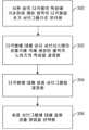
하나 이상의 컴퓨터 서브시스템은 시편 상의 다각형의 특성에 기초해 시편 상의 케어 영역에 있는 다각형을 초기 서브그룹으로 분리하여 이 특성의 상이한 값들을 갖는 다각형들이 상이한 초기 서브그룹들로 분리되게 하도록 구성된다. 예를 들어, 도 3의 단계(300)에 도시된 바와 같이, 컴퓨터 서브시스템(들)은 시편 상의 다각형의 특성에 기초하여 케어 영역의 다각형을 초기 서브그룹으로 분리하도록 구성될 수 있다. 이 단계에 사용될 수 있는 다각형 특성의 몇 가지 예가 여기에 추가로 설명된다. 이러한 특성들의 상이한 값들이 정의되는 방법은 다수의 방식으로 다를 수 있다. 예를 들어, 일부 특성은 정량적이기보다는 정성적인데, 예를 들어, 정사각형 형상은 선 형상과는 다르며, 이들 모두는 불규칙한 다각형 형상과는 다르다. 그러나 많은 특성, 예를 들어, 도(degrees)로 기술된 방위(orientation) 차이, nm로 기술된 치수, nm2로 기술된 면적 등과 같이 정량적으로 다를 수 있다. 따라서, 특성의 두 값이 분리 단계에서 다른 것으로 결정되는지 여부는 상이한 값들 대 상이하지 않은 값들(different values versus not different values)을 정의하는 미리 결정된 범위의 값들에 기초할 수 있다. 값들 간의 차이의 미리 결정된 범위는 임의의 적절한 방식으로 결정될 수 있는데, 예를 들어, 미리 결정된 범위는 사용자에 의해 설정될 수 있고, 미리 결정된 범위는 두 값이 통계적으로 다른 것으로 간주되기 위해 이 두 값이 얼마나 달라야 하는지에 기초해 통계적으로 결정될 수 있으며, 미리 결정된 범위는 통계적으로 상이한 노이즈 값을 생성하기 위해 2개의 다각형이 얼마나 달라야 하는지 또는 통계적으로 유사한 노이즈 값을 생성하기 위해 2개의 다각형이 얼마나 유사해야 하는지 등에 대한 선험적 지식에 기초할 수 있다.One or more computer subsystems are configured to separate polygons in a care area on the specimen into initial subgroups based on a characteristic of the polygons on the specimen, such that polygons having different values of the characteristic are separated into different initial subgroups. For example, as illustrated in step (300) of FIG. 3, the computer subsystem(s) can be configured to separate polygons in a care area on the specimen into initial subgroups based on a characteristic of the polygons on the specimen. Some examples of polygon characteristics that may be used in this step are further described herein. The manner in which the different values of these characteristics are defined can vary in a number of ways. For example, some characteristics are qualitative rather than quantitative, e.g., a square shape is different from a line shape, and both of these are different from an irregular polygonal shape. However, many characteristics can vary quantitatively, such as, for example, orientation differences described in degrees, dimensions described in nm, areas described in nm2 , etc. Thus, whether two values of a feature are determined to be different at the separation step can be based on a predetermined range of values defining different values versus not different values. The predetermined range of differences between the values can be determined in any suitable manner, for example, the predetermined range can be set by the user, the predetermined range can be statistically determined based on how different two values must be for them to be considered statistically different, the predetermined range can be based on a priori knowledge about how different two polygons must be to generate statistically different noise values, or how similar two polygons must be to generate statistically similar noise values.
실시예가 다각형의 특성과 관련하여 여기에서 설명되지만, 분리 단계는 예를 들어, 형상, 방위, 치수 등과 같은 다각형의 하나 이상의 특성에 기초하여 수행될 수 있다. 일부 다각형은 하나의 특성(예컨대, 형상)에 대한 값에 기초해 분리될 수 있는 반면, 다른 다각형은 다른 특성(예컨대, 방위)에 기초해 분리될 수 있다. 일 실시예에서, 다각형의 특성은 다각형의 물리적 특성을 포함한다. 또 다른 실시예에서, 분리는 하나의 축을 따라 다각형을 투영함으로써 수행된다. 예를 들어, 케어 영역의 다각형은 예를 들어, 다각형 면적, x 치수, 및 y 치수와 같은 설계 다각형 치수, 다각형 방위, 다각형 형상, x 방향 또는 y 방향의 투영 값, 및 케어 영역 치수에 기초해 초기 서브그룹으로 분할될 수 있다. 이러한 방식으로, 케어 영역에서 다각형의 초기 서브그룹화는 설계 다각형 및/또는 투영 기반 그룹의 치수/형상/방위에 따라 수행될 수 있다.While the embodiments are described herein with respect to characteristics of the polygons, the separation step may be performed based on one or more characteristics of the polygons, such as, for example, shape, orientation, dimensions, etc. Some polygons may be separated based on values for one characteristic (e.g., shape), while other polygons may be separated based on another characteristic (e.g., orientation). In one embodiment, the characteristics of the polygons include physical characteristics of the polygons. In another embodiment, the separation is performed by projecting the polygons along an axis. For example, a polygon in a care area may be initially divided into subgroups based on, for example, design polygon dimensions such as the polygon area, x-dimension, and y-dimension, the polygon orientation, the polygon shape, the projection values in the x-direction or y-direction, and the care area dimensions. In this manner, the initial subgrouping of the polygons in the care area may be performed based on the dimensions/shape/orientation of the design polygons and/or the projection-based groups.
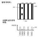
케어 영역의 다각형에 대한 투영 기반 분석의 한 예가 도 4에 도시된다. 도 4는 케어 영역(400)에 대한 설계 이미지를 도시한다. 설계 이미지는 케어 영역에 대한 설계의 다각형을 도시한다. 이 케어 영역에서 다각형의 특성을 결정하는 것은 y 방향을 따른 투영을 포함할 수 있으며, 이는 x 축을 따른 위치의 함수로서 다각형의 수를 나타내는 투영(402)을 생성할 수 있다. 그런 다음, 동일하거나 유사한 카운트를 갖는 다각형은 동일한 케어 영역 초기 서브그룹에 할당될 수 있다. 즉, 높은 투영 기반 카운트의 영역에 위치한 모든 설계 다각형은 케어 영역 초기 서브그룹 1(CAG1)에 속하고, 다른 다각형은 케어 영역 초기 서브그룹 2(CAG2)에 속한다. 따라서, 도 4에 도시된 투영에 기초하여, 케어 영역(400)의 다각형(404)은 CAG1로 분리될 것이고 케어 영역(400)의 다각형(402)은 CAG2로 분리될 것이다. 다각형의 투영 기반 분리는 케어 영역이 대부분 라인 및 공간 패턴을 포함하고 그 사이에 일부 다른 다각형이 있는 경우에 특히 적합할 수 있다.An example of projection-based analysis for polygons in a care area is illustrated in FIG. 4 . FIG. 4 illustrates a design image for a care area (400). The design image illustrates polygons of a design for a care area. Determining the characteristics of the polygons in the care area may include a projection along the y-direction, which may generate a projection (402) that represents the number of polygons as a function of location along the x-axis. Polygons having the same or similar counts may then be assigned to the same care area initial subgroup. That is, all design polygons located in areas of high projection-based counts belong to care area initial subgroup 1 (CAG1), and other polygons belong to care area initial subgroup 2 (CAG2). Accordingly, based on the projections illustrated in FIG. 4 , polygons (404) in the care area (400) will be separated into CAG1, and polygons (402) in the care area (400) will be separated into CAG2. Projection-based segmentation of polygons may be particularly suitable when the care area contains mostly lines and spatial patterns with some other polygons in between.
도 5는 예를 들어, 웨이퍼와 같은 시편에 대한 케어 영역(500)의 또 다른 예를 도시한다. 도 5에 도시된 바와 같이, 케어 영역은 상이한 특성들을 갖는 다수의 다각형을 포함한다. 특히, 일부 다각형은 x 방향으로 연장되는 선형 구조이고, 나머지 다각형은 y 방향으로 연장되는 선형 구조이며, 일부 추가 다각형은 정사각형 구조이다. 도 5(및 여기에 설명된 다른 도면들)는 특정 수의 다각형을 포함하고 특정 특성을 갖는 케어 영역의 예를 도시하지만, 여기에 설명된 실시예는 여기에 설명된 단계가 수행될 수 있는 임의의 특정 특성(크기, 형상, 위치 등)을 갖는 임의의 특정 케어 영역 및/또는 다각형으로 제한되지 않는다는 것을 이해해야 한다. 추가로, 실시예가 케어 영역(시편 상에 케어 영역의 다수의 인스턴스가 형성될 수 있음)과 관련하여 여기에서 설명되지만, 여기에 설명된 실시예는 또한 시편 상의 다수의 케어 영역에 대해 개별적으로 그리고 독립적으로 수행될 수도 있다.FIG. 5 illustrates another example of a care region (500) for a specimen, such as, for example, a wafer. As illustrated in FIG. 5 , the care region includes a plurality of polygons having different characteristics. In particular, some of the polygons are linear structures extending in the x direction, others are linear structures extending in the y direction, and some additional polygons are square structures. While FIG. 5 (and other drawings described herein) illustrate examples of care regions including a particular number of polygons and having particular characteristics, it should be understood that the embodiments described herein are not limited to any particular care region and/or polygon having any particular characteristics (size, shape, location, etc.) on which the steps described herein may be performed. Additionally, while the embodiments are described herein with respect to a care region (wherein multiple instances of the care region may be formed on the specimen), the embodiments described herein may also be performed individually and independently for multiple care regions on the specimen.
도 5에 도시된 케어 영역의 다각형은 본 명세서에서 추가로 설명되는 바와 같이 상이한 초기 서브그룹들로 분리될 수 있다. 예를 들어, 도 7은 상이한 채움 패턴들(fill patterns)로 도시된 상이한 특성들을 갖는 다각형을 갖는 도 5의 케어 영역의 버전(700)을 도시한다. 특히, y 방향으로 연장되는 선형 구조는 수평선 채움 패턴으로 도시되고, x 방향으로 연장되는 선형 구조는 수직선 채움 패턴으로 도시되며, 정사각형 구조는 대각선 채움 패턴으로 도시된다. 따라서 동일한 채움 패턴을 갖는 도 7에 도시된 각각의 다각형은 동일한 초기 서브그룹에 속한다. 즉, y 방향으로 연장되는 선형 구조는 모두 제1 초기 서브그룹으로 분리될 수 있고, x 방향으로 연장되는 선형 구조는 모두 제2 초기 서브그룹으로 분리될 수 있으며, 정사각형 구조는 모두 제3 초기 서브그룹으로 분리될 수 있다. 이러한 방식으로, 도 5의 케어 영역에 도시된 다각형은 형태, 크기, 방위 등에 기초해 초기 서브그룹으로 분리될 수 있다.The polygons in the care area illustrated in FIG. 5 can be separated into different initial subgroups as further described herein. For example, FIG. 7 illustrates a version (700) of the care area of FIG. 5 having polygons with different characteristics illustrated with different fill patterns. In particular, the linear structures extending in the y direction are illustrated with a horizontal fill pattern, the linear structures extending in the x direction are illustrated with a vertical fill pattern, and the square structures are illustrated with a diagonal fill pattern. Accordingly, each of the polygons illustrated in FIG. 7 having the same fill pattern belongs to the same initial subgroup. That is, all the linear structures extending in the y direction can be separated into a first initial subgroup, all the linear structures extending in the x direction can be separated into a second initial subgroup, and all the square structures can be separated into a third initial subgroup. In this manner, the polygons illustrated in the care area of FIG. 5 can be separated into initial subgroups based on shape, size, orientation, etc.
일부 실시예에서, 케어 영역의 다각형은 시편의 하나보다 많은 층 상의 다각형을 포함한다. 예를 들어, 다각형은 다각형의 단일 층으로 제한되지 않고 다각형을 포함하는 다수의 층으로 연장될 수 있다. 하나보다 많은 층은 시편 상에서 검사될 층과 검사될 층 아래의 층을 포함할 수 있다. 따라서, 검사되는 층 아래의 층은 검사시 반드시 관심 대상일 필요는 없지만, 그 하부의 층 및/또는 그 위에 형성된 다각형은 검사 중에 시편에 대해 생성된 출력에 영향을 미칠 수 있다. 예를 들어, 하부의 다각형은 시편에 대해 검사 서브시스템에 의해 생성된 출력의 노이즈에 영향을 줄 수 있다. 따라서, 동일한 검사된 층 상의 동일한 다각형 중 2개가 상이한 하부 다각형들로 인해 검사에서 실질적으로 상이한 노이즈 특성들을 가질 수 있기 때문에 이러한 다각형은 여기에 설명된 실시예에 의해 고려될 수 있다. 이러한 방식으로, 초기 서브그룹은, 상이한 특성 값들을 가진 검사된 층 상의 다각형이 상이한 초기 서브그룹으로 분리되도록 그리고 동일한 특성 값들을 갖지만 다각형(들)의 상이한 특성값들을 가진 하나 이상의 다각형 위에 위치한 검사된 층 상의 다각형이 상이한 초기 서브그룹들로 분리되도록 정의될 수 있다. 하나의 그러한 예에서, 도 5에 도시된 x 방향으로 연장되는 선형 구조는 도 7에 도시된 바와 같이 초기 서브그룹으로 분리될 수 있고, 그 후 그 초기 서브그룹의 다각형은 선형 구조가 위에 형성되는 다각형(미도시됨)에 기초해 서브그룹들로 더 분리될 수 있다. 시편의 하나보다 많은 층 상의 다각형에 대한 정보는 시편에 대한 설계로부터 여기에 설명된 대로 획득할 수 있다. 그러면, 케어 영역 초기 서브그룹을 정의하는 것은 각 층에 대해 독립적으로 수행되거나 특히 상이한 층들의 설계 다각형들이 중첩되는 경우 조합이 될 수 있다.In some embodiments, the polygon of the care area includes polygons on more than one layer of the specimen. For example, the polygon is not limited to a single layer of the polygon, but may extend across multiple layers that include the polygon. The more than one layer may include a layer to be inspected on the specimen and a layer beneath the layer to be inspected. Thus, while the layer beneath the layer being inspected may not necessarily be of interest during inspection, the layer beneath it and/or the polygon formed thereon may affect the output generated for the specimen during inspection. For example, the underlying polygon may affect the noise in the output generated by the inspection subsystem for the specimen. Thus, such polygons may be considered by the embodiments described herein because two identical polygons on the same inspected layer may have substantially different noise characteristics during inspection due to different underlying polygons. In this way, the initial subgroups can be defined such that polygons on the tested layer having different characteristic values are separated into different initial subgroups, and polygons on the tested layer that have the same characteristic values but are located above one or more polygons having different characteristic values of the polygon(s) are separated into different initial subgroups. In one such example, the linear structure extending in the x direction as shown in FIG. 5 can be separated into initial subgroups as shown in FIG. 7, and then the polygons of that initial subgroup can be further separated into subgroups based on the polygons (not shown) on which the linear structure is formed. Information about polygons on more than one layer of the specimen can be obtained from the design for the specimen as described herein. Defining the care area initial subgroups can then be performed independently for each layer, or can be combined, especially if design polygons of different layers overlap.
케어 영역 초기 서브그룹 및 최종 서브그룹의 생성은 또한 원래 케어 영역을 분할하는 것으로 제한되지 않고 여기에 설명된 바와 같이 각각 설계 다각형 및 노이즈의 특성에 기초해 완전히 새로운 케어 영역이 생성될 수 있다. 예를 들어, 단순함을 위해 케어 영역의 설계 다각형과 다양한 서브그룹의 설계 다각형이 여기에 도시된 예에서 동일하지만, 이것은 케어 영역이 여기에 설명된 단계의 결과에 따라 성장되거나 축소될 수 있으므로 반드시 그럴 필요는 없다. 다시 말해, 케어 영역은 원래 정의된 케어 영역의 다각형과는 동일한 다각형 특성 값 및 실질적으로 동일한 노이즈 특성 값을 갖는 다른 인접 다각형을 포함하도록 원래 정의로부터 확장될 수 있다. 유사한 방식으로, 케어 영역은 원래 정의로부터 축소되어 원래 정의로부터 하나 이상의 다각형을 제거할 수 있으며, 이는 또 다른 케어 영역으로 이동될 수 있거나 여기에 설명된 초기 서브그룹화 단계 및 최종 서브그룹화 단계에 기초해 모든 케어 영역으로부터 완전히 제거될 수 있다. 케어 영역을 정의하는 둘레에 대한 이러한 확장, 축소, 또는 다른 수정은 검사된 층의 다각형에만 기초하거나 시편의 하나보다 많은 층 상의 다각형에 기초해 수행될 수 있다.The generation of the initial and final subgroups of the care area is also not limited to dividing the original care area, but may generate entirely new care areas based on the characteristics of the design polygon and noise, respectively, as described herein. For example, for simplicity, the design polygon of the care area and the design polygons of the various subgroups are identical in the examples illustrated herein, but this need not be the case, as the care area may grow or shrink based on the results of the steps described herein. In other words, the care area may be expanded from the original definition to include other adjacent polygons having the same polygonal characteristic values and substantially the same noise characteristic values as the polygons of the originally defined care area. In a similar manner, the care area may be reduced from the original definition to remove one or more polygons from the original definition, which may be moved to another care area or may be completely removed from all care areas based on the initial and final subgrouping steps described herein. Such expansion, contraction, or other modification to the perimeter defining the care area may be performed based solely on polygons in the examined layer or on polygons in more than one layer of the specimen.
또 다른 실시예에서, 하나 이상의 컴퓨터 서브시스템은 또한, 시편에 대한 설계로부터 시편 상의 다각형의 특성을 결정하도록 구성된다. 예를 들어, 분리 단계는 설계 기반 패턴 검색을 사용하여 케어 영역 그룹을 초기 서브그룹으로 분할하는 것을 포함할 수 있다. 하나의 그러한 예에서, IC 설계에 기초한 논리 규칙, 예를 들어, 패턴 밀도, 라인 거리 등은 다각형의 특성을 결정하고 서로 상이한 특성들을 갖는 다각형들을 분리하는 데 사용될 수 있다. 설계 기반 패턴 검색은 본 명세서에 설명된 실시예에 의해 임의의 적절한 방식으로 또는 예를 들어, 당업계에 공지된 임의의 상업적으로 사용 가능한 EDA 도구를 포함할 수 있는 전자 설계 자동화(electronic design automation; EDA) 도구와 같은 또 다른 시스템 또는 방법을 사용하여 수행될 수 있다.In another embodiment, the one or more computer subsystems are also configured to determine characteristics of polygons on the specimen from the design for the specimen. For example, the separating step may include using design-based pattern searching to divide the care region groups into initial subgroups. In one such example, logic rules based on the IC design, such as pattern density, line distance, etc., may be used to determine characteristics of the polygons and separate polygons having different characteristics. The design-based pattern searching may be performed in any suitable manner by the embodiments described herein or using another system or method, such as an electronic design automation (EDA) tool, which may include, for example, any commercially available EDA tool known in the art.
추가 실시예에서, 하나 이상의 컴퓨터 서브시스템은 또한, 시편에 대한 설계를 렌더링함으로써 시편 상의 다각형의 특성을 결정하도록 구성된다. 예를 들어, 분리 단계는 시편에 대한 설계가 시편 상에 형성될 다각형의 특성을 시뮬레이션하는 데 사용되는 설계 렌더링 기반 접근 방식을 포함할 수 있다. 특히, 다각형이 설계될 때의 특성은 시편 상에 형성되는 다각형의 특성과는 다를 수 있다. 또한, 검사 시스템 출력에서 노이즈의 특성에 영향을 미치는 것은 시편 상에 형성되는 다각형의 특성이지 반드시 설계된 그대로의 것이 아니므로, 다각형이 시편 상에 형성될 때의 다각형의 특성은 다각형을 초기 서브그룹으로 분리하기 위해 설계된 대로의 특성보다 더 적합할 수 있다.In a further embodiment, the one or more computer subsystems are further configured to determine the characteristics of the polygons on the specimen by rendering the design for the specimen. For example, the separation step may include a design rendering-based approach in which the design for the specimen is used to simulate the characteristics of the polygons that will be formed on the specimen. In particular, the characteristics of the polygons as they are designed may be different than the characteristics of the polygons as they are formed on the specimen. Furthermore, since the characteristics of the polygons as they are formed on the specimen and not necessarily as designed are what influence the characteristics of the noise in the inspection system output, the characteristics of the polygons as they are formed on the specimen may be more suitable than the characteristics as designed for separating the polygons into initial subgroups.
설계 렌더링은 시편 상에 인쇄되거나 제조될 때 설계가 어떻게 보이는지 시뮬레이션하는 것을 포함할 수 있다. 예를 들어, 설계 렌더링은 다각형이 인쇄되거나 형성되는 시편의 시뮬레이션된 표현을 생성하는 것을 포함할 수 있다. 시뮬레이션된 시편을 생성하는 데 사용될 수 있는 경험적으로 훈련된 프로세스 모델의 한 예는 SEMulator 3D를 포함하며, 이는 노스캐롤라이나주 캐리 소재의 Coventor, Inc.에서 상업적으로 입수 가능하다. 엄격한 리소그래피 시뮬레이션 모델의 예로는 KLA에서 상업적으로 입수할 수 있고 SEMulator 3D 제품과 함께 사용될 수 있는 Prolith가 있다. 그러나 시편에 대한 설계 렌더링은 설계로부터 실제 시편을 생성하는 데 관련된 임의의 프로세스(들)의 임의의 적절한 모델(들)을 사용하여 시뮬레이션된 시편을 생성하기 위해 수행될 수 있다. 이러한 방식으로, 설계는 설계가 형성된 시편이 시편 공간에서 어떻게 보일지 시뮬레이션하는 데 사용될 수 있다(이러한 시편이 이미징 시스템에 어떻게 보일지 반드시 그런 것은 아님). 따라서 설계 렌더링은 시편의 2차원(2D) 공간 또는 3차원(3D) 공간에서 시편이 어떻게 보일지 나타낼 수 있는 시편의 시뮬레이션된 표현을 생성할 수 있다.Design rendering can include simulating what the design will look like when printed or manufactured on the specimen. For example, design rendering can include generating a simulated representation of the specimen as the polygons are printed or formed. An example of an empirically trained process model that can be used to generate the simulated specimen includes SEMulator 3D, which is commercially available from Coventor, Inc. of Cary, North Carolina. An example of a rigorous lithography simulation model is Prolith, which is commercially available from KLA and can be used with the SEMulator 3D product. However, design rendering for the specimen can be performed using any suitable model(s) of any process(es) involved in generating the actual specimen from the design to generate the simulated specimen. In this manner, the design can be used to simulate what the designed formed specimen will look like in specimen space (but not necessarily how such specimen will look to an imaging system). Design rendering can therefore generate a simulated representation of a specimen that can represent what the specimen would look like in two-dimensional (2D) space or three-dimensional (3D) space.
컴퓨터 서브시스템(들)은 또한 상이한 초기 서브그룹들에 있는 시편 상의 다각형에 대해 검사 서브시스템의 검출기에 의해 생성된 출력의 노이즈 특성을 결정하도록 구성된다. 예를 들어, 도 3의 단계(302)에 도시된 바와 같이, 컴퓨터 서브시스템(들)은 다각형에 대해 검사 서브시스템의 검출기에 의해 생성된 출력의 노이즈 특성을 결정하도록 구성될 수 있다. 검출기에 의해 생성된 출력은 예를 들어, 이미지 신호, 이미지 데이터, 비이미지 신호, 비이미지 데이터 등과 같은 여기에서 설명된 출력 중 임의의 것을 포함할 수 있다. 노이즈의 특성은 여기에 설명된 상이한 방식들로 결정될 수 있다.The computer subsystem(s) are also configured to determine noise characteristics of output generated by a detector of the inspection subsystem for polygons on the specimens in different initial subgroups. For example, as illustrated in step (302) of FIG. 3, the computer subsystem(s) can be configured to determine noise characteristics of output generated by a detector of the inspection subsystem for polygons. The output generated by the detector can include any of the output described herein, such as, for example, an image signal, image data, a non-image signal, or non-image data. The characteristics of the noise can be determined in different ways described herein.
일부 경우에, 전체 케어 영역에 대한 노이즈의 특성은 케어 영역 내의 다각형의 상이한 초기 서브그룹들에 대한 노이즈의 특성과는 실질적으로 다를 수 있으며, 이는 또한 서로 실질적으로 다를 수 있다. 도 6 및 도 8은 이러한 차이를 예시하고 각각 도 5 및 도 7에 도시된 설계 다각형으로부터 도출된 케어 영역 내의 구조의 웨이퍼 기반 차이 이미지로부터 도출된 2D 히스토그램을 도시한다. 이 도면들에 도시된 2D 히스토그램 상의 축은 기준 그레이 레벨과 차이 그레이 레벨이다. 도 6에서, 도 5의 케어 영역에 있는 모든 다각형에 대한 기준 그레이 레벨 및 차이 그레이 레벨이 함께 결합되었다. 따라서, 도 6에 도시된 2D 히스토그램(600)은 원래 케어 영역 그룹(차이 그레이 레벨에 대한 기준 그레이 레벨)의 것이다. 다각형의 초기 서브그룹 중 적어도 하나는 실질적으로 노이즈가 있으며, 이는 2D 히스토그램(600)에서 실질적으로 큰 동적 범위 및 실질적으로 높은 노이즈 수준으로 도시된다(여기서 이 상황에서 사용되는 "동적 범위"는 기준 이미지 프레임에서 최대 내지 최소 그레이 레벨로서 정의됨). 동적 범위는 일반적으로 2D 히스토그램이 생성되는 영역의 다각형 유형과 상관되기 때문에 여기에 설명된 실시예의 노이즈 특성에 특히 유용할 수 있다(예컨대, 상이한 유형들의 다각형들을 포함하고, 그 중 적어도 일부가 시편 상에 상이한 특성들을 갖는 케어 영역은, 하나의 유형의 다각형들만을 포함하는 케어 영역에 비해, 이러한 2D 히스토그램에서 일반적으로 더 높은 동적 범위를 가질 것이며, 이들 모두는 시편 상에서 실질적으로 유사한 특성을 가짐). 예를 들어, 기준 이미지 프레임에 많은 상이한 패턴들, 즉, 상이한 그레이 레벨들의 패턴들의 혼합이 존재하는 경우, 2D 히스토그램은 상대적으로 높은 동적 범위를 나타낼 수 있다.In some cases, the characteristics of the noise for the entire care region may be substantially different from the characteristics of the noise for different initial subgroups of polygons within the care region, which may also be substantially different from each other. FIGS. 6 and 8 illustrate these differences and depict 2D histograms derived from wafer-based difference images of structures within the care region derived from the design polygons illustrated in FIGS. 5 and 7, respectively. The axes on the 2D histograms depicted in these figures are the reference gray level and the difference gray level. In FIG. 6, the reference gray level and the difference gray level for all polygons in the care region of FIG. 5 have been combined together. Thus, the 2D histogram (600) depicted in FIG. 6 is of the original care region group (reference gray level to difference gray level). At least one of the initial subgroups of polygons is substantially noisy, as illustrated by a substantially large dynamic range and a substantially high noise level in the 2D histogram (600) (wherein “dynamic range” as used in this context is defined as the maximum to minimum gray levels in the reference image frame). This may be particularly useful for noise characterization of the embodiments described herein because dynamic range is generally correlated to the type of polygons in the region from which the 2D histogram is generated (e.g., a care region comprising different types of polygons, at least some of which have different properties on the specimen, will generally have a higher dynamic range in such a 2D histogram than a care region comprising only one type of polygon, all of which have substantially similar properties on the specimen). For example, if the reference image frame contains a mixture of many different patterns, i.e., patterns of different gray levels, the 2D histogram may exhibit a relatively high dynamic range.
전술한 바와 같이, 도 5에 도시된 케어 영역의 개별 다각형 모두가 식별된 후, 다각형 형상 각각은 도 7에 도시된 바와 같이 3개의 초기 서브그룹 중 하나로 그룹화된다. 그러면, 개별 히스토그램은 각각의 초기 서브그룹에 대해 생성될 수 있다. 개별 히스토그램은 히스토그램(600)을 생성하는 데 사용된 동일한 데이터로부터 생성될 수 있는데, 예를 들어, 데이터가 케어 영역에서 생성된 위치 및 케어 영역에서 다각형이 위치하는 위치에 기초하여 데이터를 분리함으로써, 데이터가 다각형의 상이한 초기 서브그룹들에 대해 분리될 수 있다. 예를 들어, 도 8에 도시된 바와 같이, x 방향으로 연장된 선형 구조에 대해 2D 히스토그램(800)이 생성될 수 있고, 정사각형 구조에 대해 2D 히스토그램(802)이 생성될 수 있으며, 2D 히스토그램(804)은 y 방향으로 연장되는 선형 구조에 대해 생성될 수 있다. 도 8에서 알 수 있는 바와 같이, 초기 서브그룹에 대해 개별 2D 히스토그램을 평가함으로써, 2D 히스토그램(802 및 804)은 y 방향으로 연장되는 정사각형 다각형 및 선형 다각형에 대한 초기 서브그룹이 유사한 노이즈 특성(예컨대, 실질적으로 유사한 노이즈 값들에 걸쳐 실질적으로 유사한 노이즈 분포)을 가지며 비교적 단조로운(quiet)(예컨대, 상대적으로 작은 동적 범위에서 실질적으로 낮은 노이즈 값을 가짐) 반면에, x 방향으로 연장되는 선형 다각형에 대한 2D 히스토그램(800)은 다른 2D 히스토그램들과는 실질적으로 다른 노이즈 특성을 가지며(예컨대, 2D 히스토그램(800)의 노이즈 분포는 2D 히스토그램(802 및 804)의 노이즈 분포와는 실질적으로 다름) 실질적으로 노이즈가 있다(예컨대, 비교적 큰 동적 범위를 가짐). 그 다음, 이들 히스토그램은 본 명세서에 추가로 설명되는 바와 같이 다각형의 최종 서브그룹을 결정하는 데 사용될 수 있다.As described above, after all of the individual polygons in the care area illustrated in FIG. 5 are identified, each of the polygonal shapes is grouped into one of three initial subgroups, as illustrated in FIG. 7. Then, individual histograms can be generated for each of the initial subgroups. The individual histograms can be generated from the same data used to generate the histogram (600), for example, by separating the data based on where the data was generated in the care area and where the polygons are located in the care area, such that the data is separated into different initial subgroups of polygons. For example, as illustrated in FIG. 8, a 2D histogram (800) can be generated for linear structures extending in the x direction, a 2D histogram (802) can be generated for square structures, and a 2D histogram (804) can be generated for linear structures extending in the y direction. As can be seen in FIG. 8, by evaluating individual 2D histograms for the initial subgroups, the 2D histograms (802 and 804) for the initial subgroups for the square polygons and linear polygons extending in the y direction have similar noise characteristics (e.g., substantially similar noise distributions over substantially similar noise values) and are relatively quiet (e.g., have substantially low noise values over a relatively small dynamic range), whereas the 2D histogram (800) for the linear polygons extending in the x direction has substantially different noise characteristics than the other 2D histograms (e.g., the noise distribution of the 2D histogram (800) is substantially different than the noise distributions of the 2D histograms (802 and 804)) and is substantially noisy (e.g., has a relatively large dynamic range). These histograms can then be used to determine final subgroups of polygons, as further described herein.
일 실시예에서, 노이즈의 특성을 결정하기 위해 사용되는 검사 서브시스템의 검출기에 의해 생성된 출력은 검사 서브시스템으로 시편을 스캐닝함으로써 생성된다. 예를 들어, 케어 영역 초기 서브그룹 전체를 사용하여 웨이퍼 검사 실행(wafer inspection run)이 수행될 수 있다. 따라서 하나 이상의 컴퓨터 서브시스템은 여기에서 설명된 검사 서브시스템들 중 하나를 사용하여 (예컨대, 광이나 전자빔을 시편에 지향시키고 시편으로부터 광이나 전자빔을 검출함으로써) 노이즈 특성을 결정하는 데 사용되는 출력을 획득하도록 구성될 수 있다. 이러한 방식으로, 출력을 획득하는 것은 물리적 시편 자체와 일종의 검사(예컨대, 이미징) 하드웨어를 사용하여 수행될 수 있다. 그러나, 출력을 획득하는 것이 이미징 하드웨어를 사용해 시편을 이미징하거나 스캐닝하는 것을 반드시 포함하는 것은 아니다. 예를 들어, 또 다른 시스템 및/또는 방법은 출력을 생성할 수 있고 예를 들어, 여기에 설명된 가상 검사 시스템 또는 여기에 설명된 또 다른 저장 매체와 같은 하나 이상의 저장 매체에 생성된 출력을 저장할 수 있다. 따라서, 출력을 획득하는 것은 출력이 저장된 저장 매체로부터 출력을 획득하는 것을 포함할 수 있다.In one embodiment, the output generated by the detector of the inspection subsystem used to determine the characteristics of the noise is generated by scanning the specimen with the inspection subsystem. For example, a wafer inspection run may be performed using the entire care area initial subgroup. Thus, one or more computer subsystems may be configured to obtain the output used to determine the characteristics of the noise using one of the inspection subsystems described herein (e.g., by directing a light or electron beam at the specimen and detecting the light or electron beam from the specimen). In this manner, obtaining the output may be performed using the physical specimen itself and some type of inspection (e.g., imaging) hardware. However, obtaining the output does not necessarily involve imaging or scanning the specimen using imaging hardware. For example, another system and/or method may generate the output and store the generated output on one or more storage media, such as, for example, the virtual inspection system described herein or another storage media described herein. Thus, obtaining the output may include obtaining the output from the storage media on which the output is stored.
일부 실시예에서, 노이즈의 특성을 결정하기 위해 사용되는 출력은 시편에 대해 검사 서브시스템의 하나보다 많은 모드로 생성된 출력이다. 예를 들어, 다중 모드 노이즈 정보는 여기에 추가로 설명되는 단계(들)에 사용될 수 있다. 다중 모드 검사를 위한 결함 검출 방법을 선택할 때 다중 모드 노이즈를 사용하는 것이 유용할 수 있다. 검사 서브시스템의 다중 모드는 여기에 추가로 설명된 모드들 중 임의의 것을 포함할 수 있다. 일부 경우에는, 상이한 모드들에서 생성된 출력으로부터 상이한 노이즈 특성들이 결정될 수 있다. 예를 들어, 시편의 동일한 검사를 위해 상이한 모드들이 사용될 수 있으며, 여기에 설명된 실시예는, 예를 들어, 상이한 모드들에 대해 상이한 최종 서브그룹들이 결정되도록, 하나보다 많은 모드에 대해 단계들을 개별적으로 수행하도록 구성될 수 있으며, 그런 다음, 이에 대해 상이한 결함 검출 방법들이 본 명세서에 설명된 바와 같이 선택될 수 있다. 이러한 방식으로, 모드가 알려진 경우, 여기에 설명된 단계는 각 모드에 대해 개별적으로 그리고 독립적으로 수행될 수 있으며, 이러한 단계에 사용되는 검출기(들)의 출력은 예를 들어, 시편에 대해 출력을 생성하기 위해 모드들이 동시에 사용될 수 없는 경우, 시편의 동일한 스캔 또는 시편의 다수의 스캔들에서 생성될 수 있다.In some embodiments, the output used to determine the characteristics of the noise is output generated in more than one mode of the inspection subsystem for the specimen. For example, multi-mode noise information may be used in the steps further described herein. It may be useful to use multi-mode noise when selecting a defect detection method for multi-mode inspection. The multi-mode of the inspection subsystem may include any of the modes further described herein. In some cases, different noise characteristics may be determined from output generated in different modes. For example, different modes may be used for the same inspection of the specimen, and the embodiments described herein may be configured to perform the steps separately for more than one mode, such that, for example, different final subgroups are determined for the different modes, and then different defect detection methods may be selected for them, as described herein. In this way, when the modes are known, the steps described herein can be performed individually and independently for each mode, and the output of the detector(s) used in these steps can be generated from the same scan of the specimen or from multiple scans of the specimen, for example, if the modes cannot be used simultaneously to generate output for the specimen.
여기에 설명된 단계는 모드 선택을 위한 하나보다 많은 모드에 대해 수행될 수도 있다. 예를 들어, 여기에 설명된 단계들은 상이한 모드들에 대해 여기에 설명된 단계들을 수행한 다음, 예를 들어, 상이한 모드들에 대해 결정된 최종 서브그룹과 상이한 모드들에서 최종 서브그룹에 대해 선택된 결함 검출 방법을 비교하는 것에 의해 시편의 검사에 가장 적합한 모드 또는 모드들을 결정함으로써 상이한 모드들을 평가하는데 사용될 수 있으며, 가장 많은 DOI를 검출하고, 가장 많은 뉴슨스를 억제하는 등을 수행할 수 있는 모드 또는 모드 조합이 시편 또는 동일한 유형의 다른 시편의 검사에 사용하기 위해 식별 및 선택될 수 있다. 이러한 방식으로, 여기에 설명된 실시예는 모드(들) 및 알고리즘(들) 모두의 동시 선택을 위해 사용될 수 있다. 또한, 본 명세서에 추가로 설명되는 바와 같이, 선택된 결함 검출 방법의 파라미터(들)는 독립적으로 조정될 수 있으며, 이에 의해 각각의 최종 서브그룹 및 모드 조합에 대해 검사의 최적화를 가능하게 한다. 검사 서브시스템 및/또는 검사 레시피의 임의의 다른 파라미터(들)는 또한, 본 명세서에 설명된 실시예에 의해 예를 들어, 뉴슨스 필터링 파라미터, 결함 분류 파라미터 등과 같은 각 모드/최종 서브그룹/결함 검출 방법 조합에 대해 독립적으로 선택될 수 있다. 그러한 다른 파라미터는 당업계에 공지된 임의의 적절한 방식으로 선택될 수 있다.The steps described herein may be performed for more than one mode for mode selection. For example, the steps described herein may be used to evaluate different modes by performing the steps described herein for different modes, and then determining the mode or modes that are best suited for inspection of the specimen, for example, by comparing the final subgroup determined for the different modes with the defect detection method selected for the final subgroup in the different modes, and the mode or combination of modes that is capable of detecting the most DOIs, suppressing the most newsenses, etc., may be identified and selected for use in inspection of the specimen or other specimens of the same type. In this manner, the embodiments described herein may be used for simultaneous selection of both mode(s) and algorithm(s). Additionally, as further described herein, the parameter(s) of the selected defect detection method(s) may be independently adjusted, thereby allowing for optimization of the inspection for each final subgroup and mode combination. Any other parameter(s) of the inspection subsystem and/or inspection recipe may also be independently selected for each mode/final subgroup/fault detection method combination, such as, for example, news filtering parameters, fault classification parameters, etc., by the embodiments described herein. Such other parameters may be selected in any suitable manner known in the art.
또 다른 실시예에서, 노이즈의 특성을 결정하는 것은 출력의 통계적 분석을 수행하는 것을 포함한다. 예를 들어, 노이즈가 측정될 수 있고, 예를 들어, 차이 그레이 레벨 또는 동적 범위의 표준편차와 같은 특성을 계산하여 통계적 분석이 수행될 수 있다. 또한, 노이즈의 특성을 결정하는 것은 예를 들어, 차이 그레이 레벨에 대해 μ +/- 3σ에서 오프셋을 0으로 설정하는 것과 같이 모든 개별 케어 영역 초기 서브그룹의 노이즈 분포의 통계적 분석을 수행하는 것을 포함할 수 있으며, 여기서 μ는 평균이고 σ는 표준 편차이다. 노이즈의 특성은 또한 또는 대안적으로 비-노이즈 신호 또는 이미지 데이터에 대한 노이즈의 특성일 수 있다. 예를 들어, 본 명세서에서 설명되는 실시예들에 의해 결정되는 노이즈의 특성은 비노이즈의 특성에 대한 노이즈의 특성을 설명하는 일종의 집합적 신호 대 노이즈 비율일 수 있다. 예를 들어, 노이즈의 특성은 노이즈 및/또는 이상치(잠재적 결함 신호 또는 이미지) 분포 특성을 포함하거나 이에 기초하여 결정될 수 있다.In another embodiment, determining the characteristics of the noise comprises performing a statistical analysis of the output. For example, the noise may be measured and the statistical analysis may be performed by calculating characteristics such as, for example, the standard deviation of the difference gray level or the dynamic range. In addition, determining the characteristics of the noise may comprise performing a statistical analysis of the noise distribution of all individual care region initial subgroups, such as, for example, setting the offset to 0 at μ +/- 3σ for the difference gray level, where μ is the mean and σ is the standard deviation. The characteristics of the noise may also or alternatively be characteristics of the noise relative to the non-noise signal or image data. For example, the characteristics of the noise determined by the embodiments described herein may be some kind of aggregate signal-to-noise ratio that describes the characteristics of the noise relative to the characteristics of the non-noise. For example, the characteristics of the noise may include or be determined based on characteristics of the noise and/or outlier (potentially defective signal or image) distribution.
일부 실시예에서, 노이즈의 특성을 결정하는 것은, 또 다른 시편 상의 상이한 초기 서브그룹들의 다각형에 대해 검사 서브시스템의 검출기에 의해 생성된 출력과 조합하여, 시편 상의 다각형에 대해 검사 서브시스템의 검출기에 의해 생성된 출력에서 노이즈의 특성을 결정하는 것을 포함한다. 예를 들어, 최종 서브그룹에 대한 그룹화는 여러(2개 이상의) 웨이퍼에 대한 데이터를 수집하여 수행될 수 있다. 이러한 방식으로 노이즈가 있는 케어 영역과 다각형 및 노이즈가 없는 케어 영역과 다각형은 웨이퍼 간 프로세스 변동과 관련하여 식별될 수 있다. 또한, 상대적으로 높은 웨이퍼 간 변동을 갖는 케어 영역 그룹/서브그룹이 이에 따라 식별되고 그룹화될 수 있다. 노이즈의 특성을 결정하고 최종 서브그룹을 결정하는 데 사용되는 출력을 생성하기 위해 얼마나 많은 시편이 스캔되는지도 동적으로 결정될 수 있다. 예를 들어, 2개의 시편이 스캔되고 상이한 시편들 상의 동일한 다각형이 시편 간 노이즈 특성에서 실질적으로 높은 변동을 보인다면, 하나 이상의 추가 시편을 스캔하여 시편 간 그런 다각형이 나타내는 노이즈를 추가로 특성화할 수 있다. 그렇지 않으면, 스캔되는 시편의 수는 당업계에 알려진 임의의 적절한 방식으로 결정될 수 있다.In some embodiments, determining the characteristics of the noise comprises determining the characteristics of the noise in the output generated by the detector of the inspection subsystem for the polygons on the specimen, in combination with the output generated by the detector of the inspection subsystem for the polygons on the specimen for different initial subgroups. For example, grouping for the final subgroups may be performed by collecting data for multiple (two or more) wafers. In this manner, noisy and noise-free care regions and polygons may be identified with respect to wafer-to-wafer process variation. Additionally, care region groups/subgroups with relatively high wafer-to-wafer variation may be identified and grouped accordingly. How many specimens are scanned to generate the output used to determine the characteristics of the noise and determine the final subgroups may also be dynamically determined. For example, if two specimens are scanned and the same polygons on the different specimens exhibit substantially high variation in noise characteristics between specimens, one or more additional specimens may be scanned to further characterize the noise exhibited by such polygons between specimens. Alternatively, the number of specimens to be scanned may be determined in any suitable manner known in the art.
추가적 실시예에서, 노이즈의 특성을 결정하는 것은 시편 상의 케어 영역의 하나보다 많은 인스턴스에서 상이한 초기 서브그룹들의 시편 상의 다각형에 대해 검사 서브시스템의 검출기에 의해 생성된 출력에서 노이즈의 특성을 결정하는 것을 포함한다. 예를 들어, 실시예가 케어 영역과 관련하여 여기에서 설명되고 실시예가 단일 케어 영역 인스턴스에 대해 생성된 출력을 사용하여 수행될 수 있지만, 일반적으로 노이즈의 특성을 결정하는 데 사용되는 출력은 적어도 하나의 시편 상의 케어 영역의 하나보다 많은 인스턴스로부터 생성될 수 있다. 케어 영역의 다수의 인스턴스는 시편 상의 동일한 레티클 인스턴스, 예를 들어, 다이, 필드(field) 등에 그리고/또는 시편 상의 하나보다 많은 레티클 인스턴스 상에 형성될 수 있다. 또한, 노이즈의 특성을 결정하는 데 사용되는 시편 전체에 걸친 케어 영역 인스턴스의 분포는 예를 들어, 검사 서브시스템 출력에 영향을 줄 수 있는 시편 전체의 예상 프로세스 변동, 검사 실행 중에 스캔될 시편 상의 면적 등에 기초해 결정될 수 있다. 또한, 노이즈 특성을 결정하기 위해 많은(2개보다 훨씬 많음) 케어 영역 인스턴스로부터 출력을 생성하는 것이 유리할 수 있지만, 시편 상의 모든 케어 영역 인스턴스로부터 출력을 생성하는 것은 시편의 다각형으로부터의 노이즈를 공정하게(fairly) 특성화하는 데 필요하지 않을 수 있다. 스캐닝 또는 출력 생성이 수행되는 방법에 관계없이, 초기 서브그룹의 다각형에 대해 생성된 출력은 예를 들어, 케어 영역에 있는 다각형의 알려진 위치, 시편 상의 케어 영역 인스턴스의 알려진 또는 추정된 위치, 다양한 출력이 시편 상에서 생성되는 알려진 위치에 기초하여 임의의 적절한 방식으로 식별될 수 있다. 따라서, 상이한 다각형들에 대해 생성된 출력은 분리되어 여기에 설명된 바와 같이 노이즈의 특성을 결정하는 데 사용될 수 있다.In a further embodiment, determining the characteristics of the noise comprises determining the characteristics of the noise in output generated by a detector of the inspection subsystem for polygons on the specimen of different initial subgroups at more than one instance of a care region on the specimen. For example, while the embodiments are described herein with respect to a care region, and the embodiments can be performed using output generated for a single care region instance, it will be appreciated that the output used to determine the characteristics of the noise can generally be generated from more than one instance of a care region on at least one specimen. The multiple instances of the care region can be formed on the same reticle instance on the specimen, e.g., a die, a field, etc., and/or on more than one reticle instance on the specimen. Additionally, the distribution of the care region instances across the specimen used to determine the characteristics of the noise can be determined based on, for example, expected process variations across the specimen that can affect the inspection subsystem output, the area on the specimen that will be scanned during the inspection run, etc. Additionally, while it may be advantageous to generate outputs from many (much more than two) care region instances to determine noise characteristics, generating outputs from all care region instances on the specimen may not be necessary to fairly characterize noise from polygons on the specimen. Regardless of how scanning or output generation is performed, the outputs generated for the polygons in the initial subgroup can be identified in any suitable manner, for example, based on known locations of the polygons in the care region, known or estimated locations of care region instances on the specimen, or known locations at which the various outputs are generated on the specimen. Thus, the outputs generated for different polygons can be separated and used to characterize noise as described herein.
컴퓨터 서브시스템(들)은 노이즈 특성의 실질적으로 동일한 값을 갖는 상이한 초기 서브그룹들 중 임의의 2개 이상을 최종 서브그룹들 중 하나로 결합함으로써 다각형에 대해 최종 서브그룹을 결정하도록 구성된다. 예를 들어, 도 3의 단계(304)에 도시된 바와 같이, 컴퓨터 서브시스템(들)은 다각형에 대해 최종 서브그룹을 결정할 수 있다. 노이즈의 특성에 따라, 케어 영역 초기 서브그룹들이 결합될 수 있다. 본 명세서에서 사용되는 용어 "실질적으로 동일한" 값은 "미미하게 다른" 값 및 "통계적으로 유사한" 값과 상호교환적으로 사용될 수 있다. 여기에 사용된 용어 "통계적으로 유사한" 값은 수학 및 특히 통계 분야에서 사용되는 용어의 일반적으로 허용되는 정의를 갖기 위한 것인데, 즉, 통계적으로 유사한 것은 일반적으로 "오차 범위 내에서" 그리고 "우연 이외의 다른 것으로 인한 것이 아닌" μ로 받아들여진다. 이들 정의 모두는 본 명세서에서 용어의 사용과 일치한다. 노이즈 특성의 값이 "통계적으로 유사한"지 여부는 예를 들어, 값들의 차이들을 오차 범위와 비교하고 오차 범위 내의 차이가 "통계적으로 유사"하다고 결정함으로써 결정될 수 있다.The computer subsystem(s) are configured to determine a final subgroup for the polygon by combining any two or more of the different initial subgroups having substantially identical values of the noise characteristic into one of the final subgroups. For example, as illustrated in step (304) of FIG. 3, the computer subsystem(s) can determine a final subgroup for the polygon. Depending on the characteristics of the noise, the care region initial subgroups can be combined. As used herein, the term "substantially identical" may be used interchangeably with "insignificantly different" and "statistically similar". The term "statistically similar" as used herein is intended to have the generally accepted definition of the term as used in mathematics and particularly in statistics, namely, that statistically similar is generally accepted as "within a margin of error" and "not due to anything other than chance" μ. All of these definitions are consistent with the use of the term herein. Whether values of a noise feature are "statistically similar" can be determined, for example, by comparing the differences between the values to a margin of error and determining that differences within the margin of error are "statistically similar".
하나의 그러한 예에서, 유사한 동적 범위 값을 갖는 케어 영역 초기 서브그룹, 다이-대(차이) 그레이 레벨 변동 등이 하나의 케어 영역 최종 서브그룹으로 결합될 수 있다. 예를 들어, 도 8에서, x 방향으로 연장되는 선형 다각형의 서브그룹에 대해 생성된 2D 히스토그램(800)은 y 방향으로 연장되는 정사각형 다각형 및 선형 다각형 각각에 대해 생성된 2D 히스토그램(802 및 804)과 실질적으로 다르기 때문에, x 방향으로 연장되는 선형 다각형을 케어 영역의 다른 다각형과 분리하는 것은 매우 유망해 보이는데, 그 이유는 노이즈 분포의 중앙 부분에 위치한 DOI를 검출하기 위해 다른 다각형에 대한 문턱값(도표(plot)의 수직선)을 낮출 수 있기 때문이다. 또한, y 방향으로 각각 연장되는 정사각형 모양의 다각형과 선형 다각형에 대해 생성된 2차원 히스토그램(802 및 804)이 이들 다각형이 실질적으로 동일한 노이즈 특성을 갖는 것을 보여주므로, 이들 다각형은 하나의 최종 서브그룹으로 결합될 수 있다. 이러한 방식으로, 최종 서브그룹을 결정하는 것은 실질적으로 동일한 노이즈 거동을 갖는 것으로 결정된 초기 서브그룹들을 최종 서브그룹으로 결합하는 것을 포함할 수 있다. 따라서 x 방향으로 연장되는 선형 구조를 포함하는 훨씬 더 노이즈가 많은 초기 서브그룹은 다른 다각형 초기 서브그룹과 결합되지 않지 않을 것이고 대신 그 자신의 별도의 최종 서브그룹에 포함될 것이다.In one such example, care area initial subgroups with similar dynamic range values, die-to-difference gray level variations, etc. can be combined into one care area final subgroup. For example, in FIG. 8, since the 2D histogram (800) generated for the subgroup of linear polygons extending in the x direction is substantially different from the 2D histograms (802 and 804) generated for the square polygons and linear polygons extending in the y direction, respectively, it seems very promising to separate linear polygons extending in the x direction from other polygons in the care area, because the threshold (vertical lines in the plot) for other polygons can be lowered to detect DOIs located in the central part of the noise distribution. Also, since the two-dimensional histograms (802 and 804) generated for the square-shaped polygons and the linear polygons extending in the y direction respectively show that these polygons have substantially identical noise characteristics, these polygons can be combined into one final subgroup. In this manner, determining the final subgroup may include combining the initial subgroups determined to have substantially identical noise behavior into the final subgroup. Thus, a much noisier initial subgroup containing linear structures extending in the x direction will not be combined with other polygonal initial subgroups, but will instead be included in its own separate final subgroup.
이러한 방식으로, 도 8에 도시된 바와 같이, x 방향으로 연장되는 선형 구조를 포함하는 초기 서브그룹 A에 대해 생성된 2D 히스토그램(800)이 다른 초기 서브그룹에 대해 생성된 2D 히스토그램과는 실질적으로 상이하기 때문에, x 방향으로 연장되는 라인-라인 구조는 하나의 최종 서브그룹, 즉, 참조 번호 806으로 도 8에 표시된 케어 영역 그룹 1에 포함될 수 있다. 또한, 정사각형 구조를 포함하는 초기 서브 그룹 B에 대해 생성된 2D 히스토그램(802)이 y 방향으로 연장되는 선형 구조를 포함하는 초기 서브 그룹 C에 대해 생성된 2D 히스토그램(804)과 실질적으로 동일한 노이즈 특성을 나타내기 때문에, 이들 초기 서브그룹은 하나의 최종 서브그룹, 즉, 참조 번호 808로 도 8에 표시된 케어 영역 그룹 2로 결합될 수 있다.In this manner, since the 2D histogram (800) generated for the initial subgroup A including the linear structures extending in the x direction is substantially different from the 2D histograms generated for the other initial subgroups, as illustrated in FIG. 8, the line-line structures extending in the x direction can be included in one final subgroup, i.e., care region group 1 indicated in FIG. 8 with the
이들 최종 서브그룹은 동일한 최종 서브그룹의 다각형에 대한 패턴 채움이 동일한 도 9에도 도시된다. 특히, 도 9에 도시된 바와 같이, y 방향으로 연장된 정사각형 다각형 및 선형 다각형이 최종 서브 그룹으로 결합되기 때문에, 이 두 다각형은 도 9에 도시된 동일한 패턴 채움, 즉, 수평선으로 표시될 수 있다. 또한, x 방향으로 연장되는 선형 구조가 그 자신의 최종 서브그룹에 포함되기 때문에, 이러한 다각형은 케어 영역 버전(900)의 다른 모든 다각형 유형과는 다른 패턴 채움, 즉, 수직선으로 도 9에 도시된다.These final subgroups are also illustrated in FIG. 9 with the same pattern fill for the polygons of the same final subgroup. In particular, since the square polygons and the linear polygons extending in the y direction are combined into the final subgroup as illustrated in FIG. 9, these two polygons can be represented with the same pattern fill as illustrated in FIG. 9, i.e., as horizontal lines. Furthermore, since the linear structures extending in the x direction are included in their own final subgroup, these polygons are illustrated in FIG. 9 with a different pattern fill as compared to all other polygon types of the care area version (900), i.e., as vertical lines.
일 실시예에서, 노이즈의 특성을 결정하는 단계 및 최종 서브그룹을 결정하는 단계는 하나 이상의 컴퓨터 서브시스템 및 검사 서브시스템 상의 노이즈 스캔 기능으로서 구현된다. 하나의 이러한 실시예에서, 하나 이상의 컴퓨터 서브시스템 및 검사 서브시스템은, 검사 서브시스템의 검출기에 의해 생성된 출력에서 이미지 프레임 데이터를 수집하고 미리 결정된 알고리즘에 따라 차이 이미지 프레임을 계산함으로써 노이즈 스캔을 구현하도록 구성된다. 또 다른 이러한 실시예에서, 미리 결정된 알고리즘은, 제1 결함 검출 방법 및 제2 결함 검출 방법이 선택되는, 시편 또는 또 다른 시편의 검사에 적합한 다수의 결함 검출 방법들 중 적어도 하나에 의해 사용되는 미리 결정된 알고리즘과 동일하다.In one embodiment, the steps of determining the characteristics of the noise and the steps of determining the final subgroup are implemented as a noise scan function on one or more computer subsystems and the inspection subsystem. In one such embodiment, the one or more computer subsystems and the inspection subsystem are configured to implement the noise scan by collecting image frame data from the output generated by the detector of the inspection subsystem and computing difference image frames according to a predetermined algorithm. In another such embodiment, the predetermined algorithm is the same as a predetermined algorithm used by at least one of a plurality of defect detection methods suitable for inspection of the specimen or another specimen from which the first defect detection method and the second defect detection method are selected.
이러한 방식으로, 위에서 설명된 노이즈 특성 결정 단계 및 최종 서브그룹 결정 단계는 컴퓨터 서브시스템(들) 및/또는 두 단계가 서로 협력하여 수행되는 검사 서브시스템에서 "노이즈 스캔" 기능으로서 구현될 수 있다. 다시 말해서, 사용자가 여기에 설명된 실시예에서 "노이즈 스캔" 옵션을 선택하면, 노이즈의 특성을 결정하는 단계와 최종 서브그룹을 결정하는 단계가 모두 여기에 설명된 실시예에 의해 수행될 수 있다. 그러면, 집합적으로 이러한 단계들은 이미지 프레임 데이터를 수집하는 단계와 특정 알고리즘(이 알고리즘이 다이 대 다이 차감, 셀 대 셀 차감, 테스트 이미지 대 표준 기준 이미지 차감 등인지 간에)에 따라 차이 이미지 프레임을 계산하는 단계를 포함할 수 있다. 이와 같이, 선택한 결함 검출 알고리즘을 사용하여 노이즈 스캔이 수행될 수 있다. 이상적으로는 노이즈 스캔을 위해 선택된 동일한 결함 검사 알고리즘이 실제 결함 검출에도 사용될 것이다(반드시 필수는 아님). 올바른 결함 검출 알고리즘이 선택되는 방식은 검사의 요건에 기초할 수 있는데, 예를 들어, 일부 웨이퍼 설정은 SRD(여기에 추가 설명됨)를 사용해야 하는 반면 다른 웨이퍼 설정은 심각한 프로세스 변동으로 인해 MCAT+(여기에 또한 추가로 설명됨)를 요구할 수 있다. 또한, 사용자는 노이즈 스캔 또는 결함 검출에 사용할 알고리즘의 유형을 결정할 수 있으며 일부 경우에는 알고리즘 중 하나, 예를 들어, MCAT(본 명세서에 추가로 설명됨)가 디폴트(default)로 선택될 수 있다. 그런 다음, 이 차이 이미지 프레임은 개별 노이즈 거동이 주어진 올바른 최종 서브그룹화를 식별하기 위해 세분화된 케어 영역 초기 서브그룹과 중첩될 것이다.In this manner, the noise characterization step and the final subgroup determination step described above may be implemented as a "noise scan" function in the computer subsystem(s) and/or the inspection subsystem where the two steps are performed in cooperation with each other. In other words, if the user selects the "noise scan" option in the embodiments described herein, both the noise characterization step and the final subgroup determination step may be performed by the embodiments described herein. Then, collectively, these steps may include the steps of collecting image frame data and computing difference image frames according to a particular algorithm (whether the algorithm is die-to-die subtraction, cell-to-cell subtraction, test image to standard reference image subtraction, etc.). In this way, the noise scan may be performed using the selected defect detection algorithm. Ideally, but not necessarily, the same defect inspection algorithm selected for the noise scan will also be used for the actual defect detection. How the correct defect detection algorithm is selected may be based on the requirements of the inspection, for example, some wafer setups may require the use of SRD (as further described herein) while other wafer setups may require MCAT+ (also further described herein) due to severe process variation. Additionally, the user may determine the type of algorithm to be used for noise scanning or defect detection, and in some cases one of the algorithms, for example MCAT (as further described herein), may be selected as the default. This difference image frame will then be overlaid with the refined care region initial subgrouping to identify the correct final subgrouping given the individual noise behavior.
노이즈 스캔은 시스템 노이즈를 최소화하는 알고리즘을 사용하여 케어 영역 그룹화를 수행할 수도 있다. 예를 들어, 다각형의 초기 서브그룹의 노이즈 거동 사이의 유사점 및 차이점에 기초하여 다각형의 초기 서브그룹을 최종 서브그룹으로 조직화함으로써, 여기에 설명된 실시예는 결함 검출에 사용되는 다각형의 최종 서브그룹 내에서 체계적 노이즈(systematic noise)를 최소화할 수 있다. 따라서 최종 서브그룹을 검사를 위한 케어 영역으로서 사용하는 것은, 본 명세서에 추가로 설명되는 바와 같이, 상이한 최종 서브그룹들에 대해 수행된 결함 검출이 상이할 수 있고 최종 서브그룹 및 이들의 노이즈 거동 각각에 맞춰질 수 있기 때문에, 상당한 이점을 제공한다.Noise scans can also perform care area grouping using algorithms that minimize systematic noise. For example, by organizing initial subgroups of polygons into final subgroups based on similarities and differences between the noise behaviors of the initial subgroups of polygons, the embodiments described herein can minimize systematic noise within the final subgroups of polygons used for defect detection. Thus, using the final subgroups as care areas for inspection provides significant advantages, since the defect detection performed on different final subgroups can be different and tailored to each of the final subgroups and their noise behaviors, as further described herein.
본 명세서에 설명된 실시예는 최종 서브그룹을 결정하기 위해 초기 서브그룹들을 결합하는 것으로 제한되지 않지만 그것이 더 일반적일 수 있다. 최종 서브그룹을 결정하는 것은 일부 경우에 초기 서브그룹의 다각형을 상이한 최종 서브그룹들로 분리하는 것을 포함할 수 있다. 예를 들어, 동일한 다각형의 상이한 인스턴스들은 예를 들어, 다각형 인스턴스의 이웃에 있는 다각형, 다각형 인스턴스 아래의 다각형, (예컨대, 시편의 에지 또는 중심에 대해) 시편 상에서 다각형 인스턴스가 있는 위치 등에 따라 상이한 노이즈 거동을 나타낼 수 있다. 따라서, 선택적인 시나리오에서, 여기에 설명된 컴퓨터 서브시스템(들)은 다각형 인스턴스 간에 실질적으로 상이한 노이즈 특성들을 갖는 초기 서브그룹(들)을 식별하기 위해 초기 서브그룹의 노이즈 특성을 분석하도록 구성될 수 있다.The embodiments described herein are not limited to combining initial subgroups to determine final subgroups, but may be more general. Determining the final subgroups may in some cases involve separating polygons of the initial subgroups into different final subgroups. For example, different instances of the same polygon may exhibit different noise behaviors, for example, based on neighboring polygons of the polygon instance, polygons beneath the polygon instance, location of the polygon instance on the specimen (e.g., relative to an edge or center of the specimen), etc. Accordingly, in an optional scenario, the computer subsystem(s) described herein may be configured to analyze noise characteristics of the initial subgroups to identify initial subgroup(s) having substantially different noise characteristics among the polygon instances.
하나의 그러한 예에서, 컴퓨터 서브시스템(들)은 예를 들어, 동적 범위와 같은, 초기 서브그룹에 대해 결정된 노이즈 특성을 사전 결정된 문턱값과 비교하고, 분리를 위해 사전 결정된 문턱값을 초과하는 동적 범위를 갖는 임의의 초기 서브그룹이 평가되어야 한다고 결정할 수 있다. 그런 다음 컴퓨터 서브시스템(들)은 다양한 방식으로, 예를 들어, 케어 영역 내, 시편 내 위치, 인접 다각형, 기본 다각형 등에 따라 다각형 인스턴스들을 분리할 수 있다. 그런 다음, 이러한 초기 "서브 서브그룹(sub-sub-groups)" 또는 "중간 서브그룹(intermediate sub-groups)"에 대해 노이즈 특성이 결정될 수 있다. 이러한 노이즈 특성이 얼마나 유사하거나 다른지에 따라, 초기 서브그룹의 다각형 인스턴스는 2개 이상의 상이한 최종 서브그룹들로 분리될 수 있다.In one such example, the computer subsystem(s) may compare noise characteristics determined for the initial subgroups, such as dynamic range, to a predetermined threshold, and determine that any initial subgroups having a dynamic range exceeding the predetermined threshold should be evaluated for separation. The computer subsystem(s) may then separate the polygon instances in various ways, such as by within the care area, by location within the specimen, by adjacent polygons, by base polygons, etc. Noise characteristics may then be determined for these initial "sub-sub-groups" or "intermediate sub-groups." Depending on how similar or different these noise characteristics are, the polygon instances in the initial subgroups may be separated into two or more different final subgroups.
가상의 예에서, 2D 히스토그램이 위에 설명된 방식 중 하나 이상으로 식별된 다양한 중간 서브그룹에 대해 여기에 설명된 대로 생성되고 모든 2D 히스토그램이 도 6에 도시된 2D 히스토그램(600)과 유사하게 보인다면(즉, 이 히스토그램들 모두가 실질적으로 유사하고 비교적 큰 동적 범위를 가짐), 중간 서브그룹은 (중간 서브그룹이 최종 서브그룹을 형성하기 위해 또 다른 초기 서브그룹과 결합되지 않는 한) 자신의 원래의 초기 서브그룹으로 재결합될 수 있고 단일 최종 서브그룹으로 지정될 수 있다. 대조적으로, 2D 히스토그램이 위에서 설명된 방식 중 하나 이상으로 식별된 2개의 중간 서브그룹에 대해 여기에 설명된 대로 생성되고, 2D 히스토그램 중 하나가 도 8에 도시된 2D 히스토그램(800)과 유사하게 보이며, 또 다른 2D 히스토그램이 도 8에 도시된 2D 히스토그램(802)과 유사하게 보이면, 중간 서브그룹은 상이한 최종 서브그룹에 할당될 수 있다. 또한, 3개 이상의 중간 서브그룹에 대해 최종 서브그룹을 결정하는 것은 하나의 중간 서브그룹을 최종 서브그룹에 할당하는 것과 둘 이상의 중간 서브그룹을 다른 최종 서브그룹에 할당하는 것의 일부 조합을 포함할 수 있다. 또한, 중간 서브그룹 노이즈 특성은 다른 초기 서브그룹(중간 서브그룹만이 아님)에 대해 결정된 노이즈 특성과 비교될 수 있으며, 노이즈 특성들 간의 유사점 및 차이점에 기초하여, 중간 서브그룹은 서브그룹과 결합되어 최종 서브그룹으로 될 수 있다. 이러한 방식으로, 시편 상의 동일한 특성을 갖는 다각형의 상이한 서브세트들이 다각형 특성 측면에서 유사하지 않은 다른 다각형과 함께 최종 서브그룹에 포함될 수 있다. 이러한 방식으로 생성된 최종 서브그룹은 그렇지 않으면 여기에 추가로 설명된 바와 같이 처리될 수 있으므로 동일한 다각형의 상이한 인스턴스들이 상이한 결함 검출 방법들 및/또는 파라미터들에 의해 검사될 수 있다.In a hypothetical example, if 2D histograms are generated as described herein for various intermediate subgroups identified in one or more of the manners described above, and all of the 2D histograms look similar to the 2D histogram (600) illustrated in FIG. 6 (i.e., all of these histograms are substantially similar and have relatively large dynamic ranges), then the intermediate subgroups can be recombined with their original initial subgroups (unless the intermediate subgroups are combined with another initial subgroup to form a final subgroup) and designated as a single final subgroup. In contrast, if 2D histograms are generated as described herein for two intermediate subgroups identified in one or more of the manners described above, and one of the 2D histograms looks similar to the 2D histogram (800) illustrated in FIG. 8 and the other 2D histogram looks similar to the 2D histogram (802) illustrated in FIG. 8, then the intermediate subgroups can be assigned to different final subgroups. Additionally, determining a final subgroup for three or more intermediate subgroups may include some combination of assigning one intermediate subgroup to a final subgroup and assigning two or more intermediate subgroups to different final subgroups. Additionally, the intermediate subgroup noise characteristics may be compared with noise characteristics determined for other initial subgroups (not just the intermediate subgroups), and based on similarities and differences between the noise characteristics, the intermediate subgroups may be combined with the subgroups to form a final subgroup. In this manner, different subsets of polygons having the same characteristics on the specimen may be included in the final subgroup along with other polygons that are dissimilar in terms of polygon characteristics. The final subgroups generated in this manner may otherwise be processed as further described herein, such that different instances of the same polygon may be inspected by different defect detection methods and/or parameters.
컴퓨터 서브시스템(들)은 또한, 최종 서브그룹의 제1 서브그룹 및 제2 서브그룹에 대해 각각 결정된 노이즈의 특성에 기초해, 최종 서브그룹의 제1 서브그룹 및 제2 서브그룹에 대해 시편 또는 동일한 유형의 또 다른 시편의 검사 중에 검사 서브시스템의 검출기에 의해 생성된 출력에 적용하기 위한 제1 결함 검출 방법 및 제2 결함 검출 방법을 각각 선택하도록 구성된다. 예를 들어, 도 3의 단계(306)에 도시된 바와 같이, 컴퓨터 서브시스템(들)은 최종 서브그룹에 대해 결함 검출 방법을 선택할 수 있다. 검사가 수행되는 시편들은 검사를 수행하기 전에 동일한 제조 프로세스를 거칠 수 있다는 점에서 동일한 유형일 수 있다.The computer subsystem(s) are also configured to select, based on the characteristics of the noise determined for each of the first subgroup and the second subgroup of the final subgroup, a first defect detection method and a second defect detection method for application to the output generated by the detector of the inspection subsystem during inspection of the specimen or another specimen of the same type for each of the first subgroup and the second subgroup of the final subgroup, respectively. For example, as illustrated in step (306) of FIG. 3, the computer subsystem(s) can select a defect detection method for the final subgroup. The specimens being inspected can be of the same type in that they can have undergone the same manufacturing process prior to performing the inspection.
최종 서브그룹은 여기에 설명된 대로 결정되어, 상이한 최종 서브그룹들이 상이한 노이즈 특성들을 나타내므로, 일반적으로 상이한 최종 서브그룹들에 대해 선택된 결함 검출 방법이 다를 가능성이 가장 높다(모든 최종 서브그룹에 대해 반드시 그런 것은 아님). 예를 들어, 제1 및 제2 결함 검출 방법은 일반적으로 상이한 최종 서브그룹들이 일반적으로 상이한 노이즈 특성들을 가질 것이기 때문에 다를 것이다. 그러나 2개 이상의 최종 서브그룹에 대해 동일한 결함 검출 방법이 일부 경우에 선택될 수 있다. 2개 이상의 최종 서브그룹에 대해 동일한 결함 검출 방법이 선택되면, 결함 검출 방법의 파라미터가 2개 이상의 최종 서브그룹 각각에 대해 독립적으로 그리고 개별적으로 조정될 수 있으므로, 결함 검출 방법이 상이한 최종 서브그룹들에 맞게 조정된다.The final subgroups are determined as described herein, so that since different final subgroups exhibit different noise characteristics, it is most likely that the fault detection methods selected for different final subgroups will be different (but not necessarily for all final subgroups). For example, the first and second fault detection methods will typically be different since different final subgroups will typically have different noise characteristics. However, the same fault detection method may in some cases be selected for two or more final subgroups. When the same fault detection method is selected for two or more final subgroups, the parameters of the fault detection method can be adjusted independently and individually for each of the two or more final subgroups, so that the fault detection method is adjusted to suit the different final subgroups.
따라서 제1 및 제2 결함 검출 방법은 상이한 노이즈 특성들을 갖는 다각형의 최종 서브그룹에 대해 개별적으로 그리고 독립적으로 선택될 수 있으며, 이는 최종 서브그룹 각각에 대해 가능한 가장 민감한 결함 검출 방법을 사용할 수 있게 한다. 예를 들어, 금지 수준(prohibitive levels)의 뉴슨스 검출이 없이 가장 많은 DOI를 검출할 수 있는 결함 검출 방법은 최종 서브그룹 각각에 대해 결정된 노이즈 특성에 기초하여 최종 서브그룹 각각에 대해 독립적으로 선택될 수 있다. 그러면, 시편 또는 동일한 유형의 또 다른 시편의 검사는 케어 영역 최종 서브그룹과 해당 케어 영역 최종 서브그룹에 대해 선택된 결함 검출 방법 또는 알고리즘의 조합을 사용하여 수행되는 결함 검출을 포함할 수 있다. 이러한 방식으로, 여기에 설명된 실시예는 케어 영역 분할 및 재그룹화에 의한 감도 향상을 제공한다.Thus, the first and second defect detection methods can be individually and independently selected for the final subgroups of polygons having different noise characteristics, which allows for using the most sensitive defect detection method possible for each of the final subgroups. For example, the defect detection method capable of detecting the most DOIs without detecting newsenses at prohibitive levels can be independently selected for each of the final subgroups based on the noise characteristics determined for each of the final subgroups. Then, inspection of the specimen or another specimen of the same type can include defect detection performed using a combination of the care region final subgroup and the defect detection methods or algorithms selected for that care region final subgroup. In this manner, the embodiments described herein provide for sensitivity enhancement by segmenting and regrouping the care regions.
선택되는 제1 및 제2 결함 검출 방법은 완전히 상이한 유형들의 결함 검출 방법일 수 있다(단순히 예를 들어, 문턱값과 같은 하나 이상의 상이한 파라미터를 갖는 동일한 결함 검출 방법이 아님). 제1 및 제2 결함 검출 방법 모두는 또한 당업계에 공지된 임의의 적합한 결함 검출 방법을 포함할 수 있으며, 그 일부 예가 여기에 설명되어 있다. 예를 들어, 제1 및 제2 결함 검출 방법 중 하나는 KLA에서 상업적으로 입수 가능한 일부 검사 시스템에서 사용 가능한 다중 다이 적응 문턱값(multi-die adaptive threshold; MDAT) 알고리즘을 포함할 수 있다. MDAT 알고리즘은 이미지 프레임 차감으로 후보 이미지 대 기준 이미지 비교를 수행하고, 두 개 이상의 중앙 기준 프레임과 비교될 때 이중 검출(후보 이미지를 2개의 기준 이미지와 비교함) 또는 단일 검출을 통해 신호 대 노이즈에 기초해 이상값을 식별한다. 제1 및 제2 결함 검출 방법 중 하나는 또한 또는 대안적으로 다중 계산된 다이 적응 문턱값(multi-computed die adaptive threshold; MCAT) 알고리즘을 포함할 수 있으며, 이는 KLA에서 상업적으로 입수 가능한 일부 검사 시스템에서도 사용 가능하다. 일반적으로 이 결함 검출 알고리즘은 MDAT 알고리즘과 유사하지만 이미지 차감이 수행되기 전에 테스트 이미지 프레임과 유사하도록 기준을 최적화한다. 또한, 제1 및 제2 결함 검출 방법 중 하나는 MCAT+ 알고리즘을 포함할 수 있으며, 이 알고리즘은 KLA로부터의 일부 현재 사용 가능한 검사 시스템에서도 사용할 수 있으며 MCAT와 유사하지만 웨이퍼 전체에서 기준을 사용하는 알고리즘이다. 제1 및 제2 결함 검출 방법 중 하나는 KLA로부터의 일부 상업적으로 입수 가능한 검사 시스템에서 사용 가능한 단일 기준 다이(single reference die; SRD) 결함 검출 방법 또는 알고리즘을 더 포함할 수 있다. 이 결함 검출 알고리즘은 (테스트 이미지로부터의 차감을 위해) 동일하거나 다른 웨이퍼로부터의 기준 다이를 기준으로서 사용한다.The first and second defect detection methods selected may be completely different types of defect detection methods (not simply the same defect detection method having one or more different parameters, such as thresholds, for example). Both the first and second defect detection methods may also include any suitable defect detection method known in the art, some examples of which are described herein. For example, one of the first and second defect detection methods may include a multi-die adaptive threshold (MDAT) algorithm, which is available commercially from KLA on some inspection systems. The MDAT algorithm performs a candidate image to reference image comparison with image frame subtraction, and identifies outliers based on signal-to-noise, either through double detection (where the candidate image is compared to two reference images) or single detection when compared to two or more central reference frames. One of the first and second defect detection methods may also or alternatively include a multi-computed die adaptive threshold (MCAT) algorithm, which is also available commercially from KLA on some inspection systems. In general, this defect detection algorithm is similar to the MDAT algorithm, but optimizes the baseline to resemble the test image frame before image subtraction is performed. Additionally, one of the first and second defect detection methods may include the MCAT+ algorithm, which is also available on some currently available inspection systems from KLA and is similar to MCAT but is an algorithm that uses the baseline across the wafer. One of the first and second defect detection methods may further include a single reference die (SRD) defect detection method or algorithm, which is available on some commercially available inspection systems from KLA. This defect detection algorithm uses a reference die from the same or a different wafer as the baseline (for subtraction from the test image).
일 실시예에서, 제1 및 제2 결함 검출 방법 중 적어도 하나는 검사 동안 검사 서브시스템의 검출기에 의해 생성된 출력에 대해 1차원(1D) 히스토그램을 생성하는 단계를 포함한다. 검출기 출력에 대해 1차원 히스토그램을 생성하는 결함 검출 방법을 1D 결함 검출 방법이라고 할 수 있다. 일 실시예에서, 1차원 히스토그램은 검사 중에 검사 서브시스템의 검출기에 의해 생성된 출력으로부터 생성된 차이 이미지의 그레이 레벨로부터 생성된다. 예를 들어, 1D 결함 검출 방법 또는 알고리즘은 x축 상의 차이 그레이 레벨과 함께 이상치 검출을 위해 1D 히스토그램을 사용할 수 있다. 따라서 1D 히스토그램은 차이 그레이 레벨에 대한 결함 카운트(defect count)를 도시할 수 있다. 이러한 방식으로, 여기에 설명된 실시예는 케어 영역 수정을 1D 결함 검출, 즉, 1D 이미지 히스토그램에 기초한 문턱값 설정과 결합할 수 있다. 대조적으로, 본 명세서에서 그 용어가 사용되는 "2D 결함 검출 알고리즘"은 예를 들어, 한 축(y축)이 n>1개의 기준 프레임의 중앙 그레이 레벨이고 x축이 차이 그레이 레벨인 2D 히스토그램(예컨대, 여기에 설명된 도면들에 도시된 히스토그램)을 사용하는 알고리즘이다. 또한, 여기에 설명된 바와 같이 노이즈의 특성을 결정하기 위해 수행된 노이즈 스캔은 선택된 결함 검출 방법과 매칭될 수 있다(노이즈 스캔은 결함 검출 방법과 동일한 방식으로 차이 이미지, 히스토그램 등을 생성하고 그 결과로부터 노이즈 특성을 결정할 것이고 결정함).In one embodiment, at least one of the first and second defect detection methods comprises generating a one-dimensional (1D) histogram of the output generated by the detector of the inspection subsystem during the inspection. A defect detection method that generates a one-dimensional histogram of the detector output may be referred to as a 1D defect detection method. In one embodiment, the 1D histogram is generated from gray levels of a difference image generated from the output generated by the detector of the inspection subsystem during the inspection. For example, a 1D defect detection method or algorithm may use the 1D histogram for outlier detection along with the difference gray levels on the x-axis. Thus, the 1D histogram may depict a defect count for the difference gray levels. In this manner, the embodiments described herein may combine care region correction with 1D defect detection, i.e., thresholding based on the 1D image histogram. In contrast, a "2D defect detection algorithm" as that term is used herein is an algorithm that uses, for example, a 2D histogram (e.g., a histogram illustrated in the drawings described herein) where one axis (the y-axis) is the center gray level of n>1 reference frames and the x-axis is the difference gray level. Furthermore, a noise scan performed to determine the characteristics of the noise as described herein can be matched with the selected defect detection method (the noise scan will generate a difference image, histogram, etc. in the same manner as the defect detection method and will determine the characteristics of the noise from the results).
본 명세서에 설명된 바와 같이 선택되는 결함 검출 방법은 또한 당업계에 공지된 임의의 2D 결함 검출 방법에 대해 1D 유사체(analog)를 포함할 수 있다. 예를 들어, 현재 사용되는 모든 2D 결함 검출 알고리즘은 1D 대응 알고리즘을 갖는다. 일부 그러한 예에서, 여기에 언급된 결함 검출 알고리즘은 1D 버전 및 2D 버전(예컨대, 1D MDAT 및 2D MDAT; 1D MCAT 및 2D MCAT; 1D MCAT+ 및 2D MCAT+; 1D SRD 및 2D SRD)을 모두 가질 수 있으며, 어떤 버전이 최종 서브그룹 중 임의의 하나에서 결함 검출을 위해 선택되는 것은 여기에 설명된 대로 선택될 수 있다. 따라서 여기에 설명된 케어 영역 수정은 1D 결함 검출의 인에이블러(enabler)이다.The defect detection method selected as described herein may also include a 1D analog for any 2D defect detection method known in the art. For example, all 2D defect detection algorithms currently in use have a 1D counterpart. In some such examples, the defect detection algorithms mentioned herein may have both 1D and 2D versions (e.g., 1D MDAT and 2D MDAT; 1D MCAT and 2D MCAT; 1D MCAT+ and 2D MCAT+; 1D SRD and 2D SRD), and whichever version is selected for defect detection in any one of the final subgroups may be selected as described herein. Thus, the care region modification described herein is an enabler of 1D defect detection.
또 다른 실시예에서, 제1 결함 검출 방법 및 제2 결함 검출 방법 중 하나는 검사 동안 검사 서브시스템의 검출기에 의해 생성된 출력에 대해 1D 히스토그램을 생성하는 단계를 포함하고, 제1 결함 검출 방법 및 제2 결함 검출 방법 중 또 다른 하나는 검사 동안 검사 서브시스템의 검출기에 의해 생성된 출력에 대해 2D 히스토그램을 생성하는 단계를 포함한다. 예를 들어, 제1 및 제2 결함 검출 방법은 비교적 높은 동적 범위(예컨대, 도 9에 도시된 그룹 1)을 가진 최종 케어 영역 서브그룹에 대한 2D 히스토그램 결함 검출 방법과 상대적으로 낮은 동적 범위(예컨대, 도 9에 도시된 그룹 2를 갖는 영역)에 대한 1D 결함 검출을 결합하도록 선택될 수 있다. 다시 말해서, 다각형이 모두 상대적으로 낮은 중간 그레이 레벨 범위를 갖는 최종 서브그룹으로 분할될 수 있고 그 결과 모든 최종 서브그룹이 실질적으로 노이즈가 없게(noise pure) 되는 경우, 결함 검출 방법의 1D 버전은 최종 서브그룹과 함께 사용하기에 적합할 수 있다. 그렇지 않거나 일부 케어 영역 최종 서브그룹만 실질적으로 노이즈가 없는 경우, 컴퓨터 서브시스템(들)은 노이즈 "오염(impure)" 케어 영역 최종 서브그룹에 대한 결함 검출 방법의 2D 버전 및 노이즈 "없는" 케어 영역 최종 서브그룹에 대한 결함 검출 방법의 1D 버전을 선택할 수 있다. 또한, 상이한 최종 서브그룹들에 대해 동일한 결함 검출 방법의 상이한 버전들이 선택될 수 있다. 예를 들어, 인쇄 검사 웨이퍼의 경우인, 웨이퍼 상의 모든 인쇄된 레티클 인스턴스에 리피터 결함(repeater defect)이 있는 경우, 2개 이상의 최종 서브그룹에 대해 선택된 결함 검출 방법은 SRD 방법 또는 알고리즘일 수 있는데, 그 이유는 이 결함 검출 방법이 "황금" 비결함 기준("golden" non-defective reference)을 갖기 때문이다. SRD가 선택되는 2개 이상의 최종 서브그룹 각각에 대해, 알고리즘의 1D 또는 2D 버전은 각 최종 서브그룹의 노이즈 순도(noise purity)에 따라 각 최종 서브그룹에 대해 독립적으로 선택될 수 있다.In another embodiment, one of the first defect detection method and the second defect detection method comprises generating a 1D histogram of the output generated by the detector of the inspection subsystem during the inspection, and another one of the first defect detection method and the second defect detection method comprises generating a 2D histogram of the output generated by the detector of the inspection subsystem during the inspection. For example, the first and second defect detection methods may be selected to combine a 2D histogram defect detection method for a final care area subgroup having a relatively high dynamic range (e.g., group 1 as shown in FIG. 9) with 1D defect detection for an area having a relatively low dynamic range (e.g., group 2 as shown in FIG. 9). In other words, if the polygon can be divided into final subgroups all having a relatively low intermediate gray level range, such that all of the final subgroups are substantially noise pure, then the 1D version of the defect detection method may be suitable for use with the final subgroups. If not, or if only some of the care region final subgroups are substantially noise free, the computer subsystem(s) may select a 2D version of the defect detection method for the noise "impure" care region final subgroups and a 1D version of the defect detection method for the noise "free" care region final subgroups. Additionally, different versions of the same defect detection method may be selected for different final subgroups. For example, in the case of a printed inspection wafer, where all printed reticle instances on the wafer have repeater defects, the defect detection method selected for two or more of the final subgroups may be a SRD method or algorithm because this defect detection method has a "golden" non-defective reference. For each of the two or more final subgroups for which an SRD is selected, the 1D or 2D version of the algorithm may be selected independently for each final subgroup, depending on the noise purity of that final subgroup.
추가 실시예에서, 하나 이상의 컴퓨터 서브시스템은 제1 및 제2 결함 검출 방법의 하나 이상의 파라미터를 개별적으로 조정하도록 구성된다. 예를 들어, 각각의 케어 영역 최종 서브그룹에 대해, 0의 문턱 오프셋은 예를 들어, μ +/- 3*σ에 기초하여 정의될 수 있다. 하나의 그러한 예에서, 컴퓨터 서브시스템(들)은 예를 들어, 차이 그레이 레벨에 대해 픽셀의 수를 플롯팅함으로써 차이 이미지의 히스토그램을 생성할 수 있다. 그런 다음 컴퓨터 서브시스템(들)은 예를 들어, μ 및 σ와 같은 이 히스토그램의 통계적 모멘트를 계산할 수 있다. 대부분의 경우, μ는 차이 그레이 레벨 0에 실질적으로 가까워야 한다. σ 값이 예를 들어, 20개의 차이 그레이 레벨에 있고 문턱값이 σ의 3배로 설정되어야 한다면, 이것은 문턱값이 60개의 차이 이미지 그레이 레벨에 있을 것을 의미한다. 물론 이것은 예시일 뿐이며 다른 통계 값을 사용하여 문턱값을 설정할 수 있다.In a further embodiment, one or more computer subsystems are configured to individually adjust one or more parameters of the first and second defect detection methods. For example, for each care region final subgroup, a threshold offset of 0 may be defined, for example, based on μ +/- 3*σ. In one such example, the computer subsystem(s) may generate a histogram of the difference image, for example, by plotting the number of pixels against the difference gray level. The computer subsystem(s) may then compute statistical moments of this histogram, for example, μ and σ. In most cases, μ should be substantially close to the difference
그런 다음 사용자는 결함 검출을 수행할 때 적용되어야 하는 문턱값을 명시할 수 있다. 예를 들어, 사용자는 디폴트 설정이 충분하지 않은 경우 문턱값을 원하는 대로 선택할 수 있다. 사용자는 특정 문턱값과, 존재하는 하는 경우, 예를 들어, 한계(예컨대, 캡처 레이트 문턱값)를 사용해 검출되는 이상값의 수에 기초해 문턱값을 설정할 수 있다.The user can then specify a threshold to be applied when performing defect detection. For example, the user can choose a threshold if the default setting is not sufficient. The user can set a threshold based on a specific threshold and, if present, a limit (e.g., a capture rate threshold) based on the number of outliers detected.
대안으로, 오프셋 0 계산은 모든 개별 케어 영역 최종 서브그룹에 기초해 수행될 수 있으며 문턱값은 이들 모두에 적용될 수 있다. 0으로 설정된 오프셋은 차이 그레이 레벨보다 낮은 모든 것이 노이즈로 간주되고 그보다 높은 모든 것이 이상값으로 간주되는 차이 그레이 레벨을 지칭한다. 사용되는 결함 검출 방법에 따라, 이 0 값이 μ 대신 사용될 수 있다.Alternatively, the offset 0 calculation can be performed on the basis of each individual care area final subgroup, and the threshold can be applied to all of them. The offset set to 0 refers to the difference gray level below which everything is considered noise and everything above is considered an outlier. Depending on the fault detection method used, this 0 value can be used instead of μ.
이러한 방식으로, 최종 케어 영역 서브그룹에 대한 사용자 정의 문턱값 또는 자동 정의 문턱값이 정의되고 검사 중에 적용될 수 있다. 또한, 감도 조정은 상이한 최종 서브그룹에 대해 개별적으로 그리고 독립적으로 수행될 수 있다. 감도 조정은 또한 당업계에 공지된 임의의 다른 적절한 방식으로 수행될 수 있다.In this way, user-defined thresholds or auto-defined thresholds for final care area subgroups can be defined and applied during the examination. Additionally, sensitivity adjustment can be performed individually and independently for different final subgroups. Sensitivity adjustment can also be performed in any other suitable manner known in the art.
컴퓨터 서브시스템(들)은 또한 시편 또는 동일한 유형의 또 다른 시편의 검사에 사용하기 위해 선택된 제1 및 제2 결함 검출 방법에 대한 정보를 저장하도록 구성될 수 있다. 컴퓨터 서브시스템(들)은 정보를 레시피에 저장하거나 제1 및 제2 결함 검출 방법이 적용될 검사를 위한 레시피를 생성함으로써 구성될 수 있다. 여기에서 사용된 용어 "레시피"는 시편에 대한 프로세스를 수행하기 위해 도구에 의해 사용될 수 있는 명령어 세트로서 정의된다. 이러한 방식으로, 레시피를 생성하는 것은 프로세스가 어떻게 수행되어야 하는지에 대한 정보를 생성하는 것을 포함할 수 있으며, 이는 그런 다음, 해당 프로세스를 수행하기 위한 명령어를 생성하는 데 사용될 수 있다. 컴퓨터 서브시스템(들)에 의해 저장되는 제1 및 제2 결함 검출 방법에 대한 정보는 선택된 결함 검출 방법을 식별, 액세스 및/또는 사용하는 데 사용될 수 있는 임의의 정보(예컨대, 파일명 및 그 저장 위치)를 포함할 수 있다. 저장되는 선택된 결함 검출 방법에 대한 정보는 또한 결함 검출 방법을 수행하기 위한 실제 결함 검출 방법 코드, 명령어, 알고리즘 등을 포함할 수 있다.The computer subsystem(s) may also be configured to store information about the first and second defect detection methods selected for use in the inspection of the specimen or another specimen of the same type. The computer subsystem(s) may be configured by storing the information in a recipe or by generating a recipe for inspection to which the first and second defect detection methods are to be applied. The term "recipe" as used herein is defined as a set of instructions that can be used by a tool to perform a process on a specimen. In this manner, generating a recipe may include generating information about how the process is to be performed, which may then be used to generate instructions for performing that process. The information about the first and second defect detection methods stored by the computer subsystem(s) may include any information that can be used to identify, access, and/or use the selected defect detection methods (e.g., a file name and its storage location). The information about the selected defect detection methods that is stored may also include actual defect detection method code, instructions, algorithms, etc. for performing the defect detection methods.
컴퓨터 서브시스템(들)은 선택된 결함 검출 방법에 대한 정보를 임의의 적절한 컴퓨터 판독가능 저장 매체에 저장하도록 구성될 수 있다. 이 정보는 여기에서 설명하는 임의의 결과와 함께 저장될 수 있고 당업계에 공지된 임의의 방식으로 저장될 수 있다. 저장 매체는 여기에서 설명한 임의의 저장 매체 또는 업계에 공지된 임의의 다른 적당한 저장 매체를 포함할 수 있다. 정보가 저장된 후, 정보는 저장 매체에서 액세스되고 여기에 설명된 방법 또는 시스템 실시예 중 임의의 것에 의해 사용되고, 사용자에게 디스플레이되도록 포맷되며, 또 다른 소프트웨어 모듈, 방법 또는 시스템 등에 의해 사용될 수 있다. 예를 들어, 여기에 설명된 실시예는 위에서 설명된 것과 같은 검사 레시피를 생성할 수 있다. 그런 다음, 그 검사 레시피는 시편 또는 다른 시편을 검사하여 시편 또는 다른 시편에 대한 정보(예컨대, 결함 정보)를 생성하기 위해 시스템 또는 방법(또는 또 다른 시스템 또는 방법)에 의해 저장 및 사용될 수 있다.The computer subsystem(s) may be configured to store information about the selected defect detection method(s) on any suitable computer readable storage medium. This information may be stored with any of the results described herein and may be stored in any manner known in the art. The storage medium may include any of the storage media described herein or any other suitable storage medium known in the art. After the information is stored, the information may be accessed from the storage medium and used by any of the method or system embodiments described herein, formatted for display to a user, and used by another software module, method or system, etc. For example, the embodiments described herein may generate an inspection recipe such as that described above. The inspection recipe may then be stored and used by the system or method (or another system or method) to inspect a specimen or other specimen and generate information about the specimen or other specimen (e.g., defect information).
시편 또는 동일한 유형의 다른 시편에 대해 검사를 수행하여 생성된 결과 및 정보는 여기에 설명된 실시예 및/또는 다른 시스템 및 방법에 의해 다양한 방식으로 사용될 수 있다. 이러한 기능에는 예를 들어, 피드백 방식 또는 피드포워드 방식으로 검사된 시편 또는 또 다른 시편에 대해 수행되었거나 수행될 제조 프로세스 또는 단계와 같은 프로세스 변경이 포함되지만 이에 국한되지는 않는다. 예를 들어, 여기에 설명된 가상 시스템 및 다른 컴퓨터 서브시스템(들)은 여기에 설명된 대로 검사된 시편에 대해 수행된 프로세스 및/또는 검출된 결함(들)에 기초해 시편에 대해 수행될 프로세스에 대한 하나 이상의 변경을 결정하도록 구성될 수 있다. 프로세스에 대한 변경은 프로세스의 하나 이상의 파라미터에 대한 임의의 적절한 변경을 포함할 수 있다. 여기에 설명된 가상 시스템 및/또는 다른 컴퓨터 서브시스템(들)은, 수정된 프로세스가 수행되는 다른 시편 상에서 결함이 감소되거나 방지될 수 있고, 시편에 대해 수행되는 또 다른 프로세스에서 시편 상에서 결함이 수정되거나 제거될 수 있고, 시편에 대해 수행되는 또 다른 프로세스에서 결함이 보상될 수 있는 등이 수행될 수 있도록, 그러한 변경을 바람직하게 결정한다. 여기에 설명된 가상 시스템 및 다른 컴퓨터 서브시스템(들)은 당업계에 알려진 임의의 적절한 방식으로 이러한 변경을 결정할 수 있다.The results and information generated by performing the inspection on the specimen or other specimens of the same type may be used in a variety of ways by the embodiments described herein and/or other systems and methods. Such functions include, but are not limited to, changing a process, such as a manufacturing process or step, that has been or will be performed on the tested specimen or another specimen, for example, in a feedback or feedforward manner. For example, the virtual system and/or other computer subsystem(s) described herein may be configured to determine one or more changes to a process to be performed on a specimen based on the process performed on the tested specimen and/or the defect(s) detected as described herein. The changes to the process may include any suitable changes to one or more parameters of the process. The virtual system and/or other computer subsystem(s) described herein preferably determine such changes such that a defect may be reduced or prevented on another specimen on which the modified process is performed, a defect may be corrected or eliminated on the specimen in another process performed on the specimen, a defect may be compensated for in another process performed on the specimen, etc. The virtual system and other computer subsystem(s) described herein may determine such changes in any suitable manner known in the art.
그런 다음, 이러한 변경은 반도체 제조 시스템(도시되지 않음), 또는 가상 시스템 또는 여기에 설명된 다른 컴퓨터 서브시스템(들) 및 반도체 제조 시스템에 액세스 가능한 저장 매체(도시되지 않음)로 전송될 수 있다. 반도체 제조 시스템은 여기에 설명된 시스템 실시예의 일부일 수도 있고 아닐 수도 있다. 예를 들어, 여기에 설명된 가상 시스템, 다른 컴퓨터 서브시스템(들), 및/또는 검사 서브시스템은 예를 들어, 하우징, 전력 공급 장치, 시편 처리 디바이스 또는 메커니즘 등과 같은 하나 이상의 공통 요소를 통해 반도체 제조 시스템에 결합될 수 있다. 반도체 제조 시스템은 예를 들어, 리소그래피 도구, 에칭 도구, 화학-기계적 연마(chemical-mechanical polishing; CMP) 도구, 퇴적 도구 등과 같은 당업계에 공지된 임의의 반도체 제조 시스템을 포함할 수 있다.These changes can then be transmitted to a semiconductor manufacturing system (not shown), or a virtual system or other computer subsystem(s) described herein, and a storage medium (not shown) accessible to the semiconductor manufacturing system. The semiconductor manufacturing system may or may not be part of the system embodiments described herein. For example, the virtual system, other computer subsystem(s), and/or inspection subsystem described herein can be coupled to the semiconductor manufacturing system through one or more common elements, such as a housing, a power supply, a specimen handling device or mechanism, and the like. The semiconductor manufacturing system can include any semiconductor manufacturing system known in the art, such as, for example, a lithography tool, an etching tool, a chemical-mechanical polishing (CMP) tool, a deposition tool, and the like.
따라서, 본 명세서에 설명된 바와 같이, 실시예는 새로운 검사 프로세스 또는 레시피를 설정하는 데 사용될 수 있다. 실시예는 또한, 기존 검사 프로세스 또는 레시피가 시편을 위해 사용된 검사 프로세스 또는 레시피이든지, 또는 하나의 시편을 위해 생성되었고 또 다른 시편을 위해 적응되고 있는지 간에, 이 검사 프로세스 또는 레시피를 수정하는 데 사용될 수 있다. 그러나, 여기에 설명된 실시예는 검사 레시피 또는 프로세스 생성 또는 수정에만 제한되지는 않는다. 예를 들어, 여기에 설명된 실시예는 유사한 방식으로 계측, 결함 검토 등을 위한 레시피 또는 프로세스를 설정하거나 수정하는 데에도 사용될 수 있다. 특히, 여기에 설명된 다각형 분리 단계, 노이즈 특성 결정 단계, 및 최종 서브그룹 결정 단계는 설정 또는 수정 중인 프로세스와 관계없이 수행될 수 있다. 그런 다음, 설정 또는 변경되고 있는 프로세스 또는 레시피에 따라, 선택 단계를 수행하여 상이한 최종 서브그룹들에 대한 하나 이상의 출력 프로세싱 방법을 선택할 수 있다. 이러한 출력 프로세싱 방법은 예를 들어, 계측 시스템에 의해 생성된 출력으로부터 다각형의 하나 이상의 특성을 결정하는 데 사용되는 알고리즘, 결함 검토 시스템에 의해 생성된 출력에서 결함을 재검출하는 데 사용되는 결함 재검출 방법 등을 포함할 수 있다. 유사한 방식으로, 여기에 설명된 실시예는 출력 프로세싱 파라미터 및 방법뿐만 아니라 예를 들어, 계측 시스템 또는 결함 검토 시스템을 사용하여 시편으로부터 광, 전자, 이온 등을 검출하는 출력 획득 파라미터 또는 모드를 선택하기 위해 사용될 수 있다. 따라서 여기에 설명된 실시예는 검사 프로세스를 설정하거나 수정하기 위해 사용될 수 있을 뿐만 아니라 여기에 설명된 시편에 대해 수행되는 임의의 품질 제어 유형 프로세스를 설정하거나 수정하는 데 사용될 수 있다.Accordingly, as described herein, the embodiments can be used to set up a new inspection process or recipe. The embodiments can also be used to modify an existing inspection process or recipe, whether it is an inspection process or recipe used for a specimen, or one that was created for one specimen and is being adapted for another specimen. However, the embodiments described herein are not limited to creating or modifying an inspection recipe or process. For example, the embodiments described herein can also be used to set up or modify a recipe or process for metrology, defect review, etc. in a similar manner. In particular, the polygon separation step, the noise characteristic determination step, and the final subgroup determination step described herein can be performed independently of the process being set up or modified. Then, depending on the process or recipe being set up or modified, a selection step can be performed to select one or more output processing methods for the different final subgroups. Such output processing methods can include, for example, an algorithm used to determine one or more characteristics of a polygon from the output generated by the metrology system, a defect re-detection method used to re-detect defects in the output generated by the defect review system, etc. In a similar manner, the embodiments described herein can be used to select output acquisition parameters or modes for detecting light, electrons, ions, etc. from a specimen, for example, using a metrology system or a defect review system, as well as output processing parameters and methods. Thus, the embodiments described herein can be used to set up or modify an inspection process, as well as set up or modify any quality control type process performed on a specimen as described herein.
여기에 설명된 실시예는 케어 영역을 사용하는 검사 프로세스를 설정하기 위해 이전에 사용된 방법 및 시스템에 비해 많은 이점을 제공한다. 예를 들어, 여기에 설명된 실시예는 모드-알고리즘 조합 결정이 초기 모드/알고리즘 선택 프로세스 동안 이루어질 수 있기 때문에 결과로의 더 빠른 시간을 제공한다. 또한, 여기에 설명된 실시예는 상대적으로 노이즈가 많은 영역을 훨씬 더 안정적으로 식별할 수 있고 심지어 상대적으로 작고 수동으로 식별하기 어려운 다각형도 정확히 서브그룹화될 수 있다. 케어 영역들을 상이한 노이즈 특성들을 나타내는 그룹들로 결합하면 노이즈가 적은 그룹에 대해 향상된 감도를 얻을 수 있으므로 전반적인 검사 감도도 향상된다. 또한, 여기에 설명된 실시예는 웨이퍼 노이즈 변동에 의해 덜 영향을 받는 그룹이 더 안정적이기 때문에, 웨이퍼 내 및 웨이퍼 대 웨이퍼 프로세스 변동의 훨씬 더 나은 완화를 제공한다. 여기에 설명된 실시예는 또한 특정 DOI에 대한 감도를 증가시키는 것을 허용한다. 이 선택적 DOI 감도를 통해 사용자는 검사 결과에 기초해 정확한 프로세싱 결정을 내리는 능력을 향상시킬 수 있을 것이다.The embodiments described herein provide many advantages over previously used methods and systems for setting up inspection processes using care regions. For example, the embodiments described herein provide faster time to results because the mode-algorithm combination decision can be made during the initial mode/algorithm selection process. In addition, the embodiments described herein can identify relatively noisy regions much more reliably, and even relatively small and manually difficult to identify polygons can be accurately subgrouped. Combining care regions into groups that exhibit different noise characteristics can provide improved sensitivity to the less noisy groups, thus improving overall inspection sensitivity. In addition, the embodiments described herein provide much better mitigation of within-wafer and wafer-to-wafer process variations because the groups that are less affected by wafer noise variations are more reliably affected. The embodiments described herein also allow for increased sensitivity to specific DOIs. This selective DOI sensitivity will allow the user to improve the ability to make accurate processing decisions based on inspection results.
본 명세서에 설명된 실시예에 대한 대안으로서, 검사 설정은 노이즈가 있는 구조를 수동으로 식별하고 새로운 케어 영역을 생성하기 위해 노이즈가 있는 구조에 대해 설계 기반 검색을 수행하는 것을 포함할 수 있다. 이러한 검사 설정에는 새로운 케어 영역 설정을 테스트하고 추가 노이즈 소스(noise sources)를 찾는 것도 포함될 수 있다. 그런 다음, 이러한 방법에는 다시 돌아가서 새로 식별된, 노이즈가 있는 구조에 대해 설계 기반 검색을 수행하는 것이 포함될 수 있다. 그러나, 여기에 설명된 실시예와 달리, 이 프로세스는 수일(many days)이 걸릴 수 있고 너무 느리고 종종 케어 영역 노이즈 순도 측면에서 불충분하다.As an alternative to the embodiments described herein, the test setup may include manually identifying noisy structures and performing a design-based search on the noisy structures to create new care regions. This test setup may also include testing the new care region setup and finding additional noise sources. The method may then include going back and performing a design-based search on the newly identified, noisy structures. However, unlike the embodiments described herein, this process may take many days, is too slow, and is often insufficient in terms of care region noise purity.
시스템들 각각의 실시예들 각각은 하나의 단일 실시예로 함께 결합될 수 있다.Each of the embodiments of the systems may be combined together into a single embodiment.
또 다른 실시예는 시편 검사를 위한 결함 검출 방법을 선택하기 위한 컴퓨터 구현 방법에 관한 것이다. 이 방법은 전술한 다각형 분리 단계, 특성 결정 단계, 최종 서브그룹 결정 단계, 제1 및 제2 결함 검출 방법 선택 단계를 포함한다.Another embodiment relates to a computer-implemented method for selecting a defect detection method for a specimen inspection. The method includes the polygon separation step, the feature determination step, the final subgroup determination step, and the first and second defect detection method selection steps as described above.
본 발명의 방법의 각각의 단계들은 본 명세서에 추가로 설명된 바와 같이 수행될 수 있다. 이 방법은 또한 본 명세서에 설명된 검사 서브시스템 및/또는 컴퓨터 서브시스템들 또는 시스템들에 의해 수행될 수 있는 임의의 다른 단계들을 포함할 수 있다. 다각형 분리 단계, 특성 결정 단계, 최종 서브그룹 결정 단계, 제1 및 제2 결함 검출 방법 선택 단계가 하나 이상의 컴퓨터 서브시스템에 의해 수행되며, 이는 본 명세서에 설명된 실시예들 중 임의의 것에 따라 구성될 수 있다. 또한, 전술한 방법은 본 명세서에 설명된 임의의 시스템 실시예들에 의해 수행될 수 있다.Each of the steps of the method of the present invention can be performed as further described herein. The method can also include any other steps that can be performed by the inspection subsystem and/or computer subsystems or systems described herein. The polygon separation step, the characteristic determination step, the final subgroup determination step, and the first and second defect detection method selection steps are performed by one or more computer subsystems, which can be configured according to any of the embodiments described herein. Furthermore, the above-described method can be performed by any of the system embodiments described herein.
또 다른 실시예는 시편 검사를 위한 결함 검출 방법을 선택하기 위한 컴퓨터 구현 방법을 수행하기 위해 컴퓨터 시스템 상에서 실행 가능한 프로그램 명령어를 저장한 비일시적 컴퓨터 판독가능 매체에 관한 것이다. 하나의 이러한 실시예가 도 10에 도시되어 있다. 특히, 도 10에 도시된 바와 같이, 비일시적 컴퓨터 판독 가능 매체(1000)는 컴퓨터 시스템(1004) 상에서 실행 가능한 프로그램 명령어(1002)를 포함한다. 컴퓨터 구현식 방법은 본 명세서에 설명된 임의의 방법(들)의 임의의 단계(들)를 포함할 수 있다.Another embodiment relates to a non-transitory computer-readable medium storing program instructions executable on a computer system to perform a computer-implemented method for selecting a defect detection method for specimen inspection. One such embodiment is illustrated in FIG. 10 . In particular, as illustrated in FIG. 10 , the non-transitory computer-readable medium (1000) includes program instructions (1002) executable on a computer system (1004). The computer-implemented method can include any step(s) of any method(s) described herein.
예를 들어, 본 명세서에 설명된 것과 같은 방법을 구현하는 프로그램 명령어(1002)는 컴퓨터 판독 가능한 매체(1000) 상에 저장될 수 있다. 컴퓨터 판독가능 매체는 예를 들어, 자기 디스크 또는 광학 디스크, 자기 테이프, 또는 당 기술 분야에 공지된 임의의 다른 적합한 비일시적 컴퓨터 판독가능 매체와 같은 저장 매체일 수 있다.For example, program instructions (1002) implementing a method as described herein may be stored on a computer-readable medium (1000). The computer-readable medium may be a storage medium, such as, for example, a magnetic or optical disk, a magnetic tape, or any other suitable non-transitory computer-readable medium known in the art.
프로그램 명령어는 특히, 절차 기반 기술(procedure-based techniques), 컴포넌트 기반 기술(component-based techniques) 및/또는 객체 지향 기술(object-oriented techniques)을 포함하는 다양한 방식들 중 임의의 방식으로 구현될 수 있다. 예를 들어, 프로그램 명령어는 원하는 바에 따라, ActiveX 콘트롤, C++ 객체, JavaBeans, 마이크로소프트 파운데이션 클래스(Microsoft Foundation Classes; "MFC"), SSE(Streaming SIMD Extension) 또는 다른 기술 또는 방법론을 사용하여 구현될 수 있다.The program instructions may be implemented in any of a variety of ways, including, inter alia, procedure-based techniques, component-based techniques, and/or object-oriented techniques. For example, the program instructions may be implemented using ActiveX controls, C++ objects, JavaBeans, Microsoft Foundation Classes ("MFC"), Streaming SIMD Extension (SSE), or other technologies or methodologies, as desired.
컴퓨터 시스템(1004)은 본 명세서에 설명된 임의의 실시예들에 따라 구성될 수 있다.The computer system (1004) may be configured according to any of the embodiments described herein.
본 발명의 다양한 양상의 추가의 수정 및 대안 실시예가 이 설명의 견지에서 당 기술 분야의 숙련자들에게 명백할 것이다. 예를 들어, 시편의 검사를 위한 결함 검출 방법을 선택하기 위한 방법 및 시스템이 제공된다. 따라서, 이러한 설명은 단지 예시적인 것으로 해석되어야 하며, 당업자가 본 발명을 실시하는 일반적인 방법을 교시하기 위한 것이다. 본 명세서에 도시되어 있고 설명되어 있는 발명의 형태는 현재 바람직한 실시예로서 취해져야 한다는 것이 이해되어야 한다. 모두 본 발명의 이 설명의 이익을 가진 후에 당 기술 분야의 숙련자에게 명백할 수 있는 바와 같이, 요소 및 재료는 본 명세서에 도시되어 있고 설명되어 있는 것들에 대해 치환될 수 있고, 부분 및 프로세스는 역전될 수 있고, 본 발명의 특정 피처는 독립적으로 사용될 수 있다. 변경이 이하의 청구범위에서 설명하는 바와 같은 발명의 사상 및 범주로부터 벗어나지 않고 본 명세서에 설명된 요소에 이루어질 수 있다.Additional modifications and alternative embodiments of the various aspects of the present invention will be apparent to those skilled in the art in light of this description. For example, methods and systems for selecting a defect detection method for inspection of a specimen are provided. Accordingly, this description should be construed as illustrative only, and is intended to teach those skilled in the art the general manner in which the invention may be practiced. It is to be understood that the forms of the invention shown and described herein are to be taken as the presently preferred embodiments. As will become apparent to those skilled in the art after the benefit of this description of the invention, elements and materials may be substituted for those shown and described herein, parts and processes may be reversed, and specific features of the invention may be used independently. Changes may be made in the elements described herein without departing from the spirit and scope of the invention as set forth in the claims below.
Claims (24)
Translated fromKorean하나 이상의 컴퓨터 서브시스템을 포함하고, 상기 하나 이상의 컴퓨터 서브시스템은,
시편 상의 다각형의 특성에 기초해 상기 특성의 상이한 값들을 갖는 다각형이 상이한 초기 서브그룹들로 분리되도록 상기 시편 상의 케어 영역에 있는 다각형을 초기 서브그룹들로 분리하고;
상기 상이한 초기 서브그룹들에 있는 상기 시편 상의 다각형에 대해 검사 서브시스템의 검출기에 의해 생성된 출력의 노이즈 특성을 결정하고;
상기 노이즈의 특성의 실질적으로 동일한 값을 갖는 상기 상이한 초기 서브그룹들 중 임의의 2개 이상을 최종 서브그룹들 중 하나로 결합함으로써 상기 다각형에 대해 상기 최종 서브그룹들을 결정하고;
상기 최종 서브그룹들 중의 제1 서브그룹 및 제2 서브그룹에 대해 각각 결정된 상기 노이즈의 특성에 기초해, 상기 최종 서브그룹들 중의 상기 제1 서브그룹 및 상기 제2 서브그룹에 대해 상기 시편 또는 동일한 유형의 또 다른 시편의 검사 중에, 상기 검사 서브시스템의 검출기에 의해 생성된 출력에 적용하기 위한 제1 결함 검출 방법 및 제2 결함 검출 방법을 각각 선택하도록
구성되는 것인, 시스템.In a system configured to select a defect detection method for specimen inspection,
comprising one or more computer subsystems, said one or more computer subsystems comprising:
Separating polygons in a care area on the specimen into initial subgroups such that polygons having different values of the characteristics on the specimen are separated into different initial subgroups based on the characteristics of the polygons on the specimen;
Determine the noise characteristics of the output generated by the detector of the inspection subsystem for the polygons on the specimen in the different initial subgroups;
determining said final subgroups for said polygon by combining any two or more of said different initial subgroups having substantially identical values of said noise characteristics into one of the final subgroups;
Based on the characteristics of the noise determined for each of the first subgroup and the second subgroup among the final subgroups, a first defect detection method and a second defect detection method are respectively selected for application to the output generated by the detector of the inspection subsystem during inspection of the specimen or another specimen of the same type among the first subgroup and the second subgroup among the final subgroups.
The system that it consists of.
상기 다각형의 특성은 상기 다각형의 물리적 특성을 포함하는 것인, 시스템.In the first paragraph,
A system wherein the characteristics of the polygon include physical characteristics of the polygon.
상기 분리는 하나의 축을 따라 상기 다각형을 투영함으로써 수행되는 것인, 시스템.In the first paragraph,
A system wherein said separation is performed by projecting said polygon along one axis.
상기 케어 영역의 다각형은 상기 시편의 하나보다 많은 층 상의 다각형을 포함하는 것인, 시스템.In the first paragraph,
A system wherein the polygon of the above care area includes polygons on more than one layer of the above specimen.
상기 하나 이상의 컴퓨터 서브시스템은 또한, 상기 시편에 대한 설계로부터 상기 시편 상의 상기 다각형의 특성을 결정하도록 구성되는 것인, 시스템.In the first paragraph,
The system wherein said one or more computer subsystems are further configured to determine characteristics of said polygon on said specimen from a design for said specimen.
상기 하나 이상의 컴퓨터 서브시스템은 또한, 상기 시편에 대한 설계를 렌더링함으로써 상기 시편 상의 상기 다각형의 특성을 결정하도록 구성되는 것인, 시스템.In the first paragraph,
The system wherein said one or more computer subsystems are further configured to determine characteristics of said polygon on said specimen by rendering a design for said specimen.
상기 노이즈의 특성을 결정하기 위해 사용되는 상기 검사 서브시스템의 검출기에 의해 생성된 출력은 상기 검사 서브시스템에 의해 상기 시편을 스캔함으로써 생성되는 것인, 시스템.In the first paragraph,
A system wherein the output generated by the detector of the inspection subsystem used to determine the characteristics of the noise is generated by scanning the specimen by the inspection subsystem.
상기 노이즈의 특성을 결정하는 것은 상기 출력의 통계적 분석을 수행하는 것을 포함하는 것인, 시스템.In the first paragraph,
A system wherein determining the characteristics of said noise comprises performing a statistical analysis of said output.
상기 노이즈의 특성을 결정하는 것은, 또 다른 시편 상의 상기 상이한 초기 서브그룹들의 상기 다각형에 대해 상기 검사 서브시스템의 검출기에 의해 생성된 출력과 조합하여, 상기 시편 상의 상기 다각형에 대해 상기 검사 서브시스템의 검출기에 의해 생성된 출력에서 상기 노이즈의 특성을 결정하는 것을 포함하는 것인, 시스템.In the first paragraph,
A system wherein determining the characteristics of said noise comprises determining the characteristics of said noise in the output generated by the detector of said inspection subsystem for said polygon on said specimen, in combination with the output generated by the detector of said inspection subsystem for said polygon of said different initial subgroups on another specimen.
상기 노이즈의 특성을 결정하는 것은 상기 시편 상의 상기 케어 영역의 하나보다 많은 인스턴스에서 상기 상이한 초기 서브그룹들의 시편 상의 다각형에 대해 상기 검사 서브시스템의 검출기에 의해 생성된 출력에서 상기 노이즈의 특성을 결정하는 것을 포함하는 것인, 시스템.In the first paragraph,
A system wherein determining the characteristics of said noise comprises determining the characteristics of said noise in an output generated by a detector of said inspection subsystem for polygons on said specimen of said different initial subgroups at more than one instance of said care area on said specimen.
상기 노이즈의 특성을 결정하는 것 및 상기 최종 서브그룹들을 결정하는 것은 상기 하나 이상의 컴퓨터 서브시스템 및 상기 검사 서브시스템 상의 노이즈 스캔 기능으로서 구현되는 것인, 시스템.In the first paragraph,
A system wherein determining the characteristics of said noise and determining said final subgroups are implemented as a noise scan function on said one or more computer subsystems and said inspection subsystem.
상기 하나 이상의 컴퓨터 서브시스템 및 상기 검사 서브시스템은, 상기 검사 서브시스템의 검출기에 의해 생성된 출력에서 이미지 프레임 데이터를 수집하고 미리 결정된 알고리즘에 따라 차이 이미지 프레임을 계산함으로써 상기 노이즈 스캔을 구현하도록 구성되는 것인, 시스템.In Article 11,
A system wherein said one or more computer subsystems and said inspection subsystem are configured to implement said noise scan by collecting image frame data from the output generated by a detector of said inspection subsystem and calculating a difference image frame according to a predetermined algorithm.
상기 미리 결정된 알고리즘은, 상기 제1 결함 검출 방법 및 상기 제2 결함 검출 방법이 선택되는, 상기 시편 또는 상기 다른 시편의 검사에 적합한 다수의 결함 검출 방법들 중 적어도 하나에 의해 사용되는 미리 결정된 알고리즘과 동일한 것인, 시스템.In Article 12,
A system wherein said predetermined algorithm is identical to a predetermined algorithm used by at least one of a plurality of defect detection methods suitable for inspection of said specimen or said other specimen, from which said first defect detection method and said second defect detection method are selected.
상기 제1 결함 검출 방법 및 상기 제2 결함 검출 방법 중 적어도 하나는 상기 검사 동안 상기 검사 서브시스템의 검출기에 의해 생성된 출력에 대해 1차원 히스토그램을 생성하는 것을 포함하는 것인, 시스템.In the first paragraph,
A system, wherein at least one of the first defect detection method and the second defect detection method comprises generating a one-dimensional histogram for output generated by a detector of the inspection subsystem during the inspection.
상기 1차원 히스토그램은 상기 검사 동안 상기 검사 서브시스템의 검출기에 의해 생성된 출력으로부터 생성된 차이 이미지의 그레이 레벨(grey levels)로부터 생성되는 것인, 시스템.In Article 14,
A system wherein the above one-dimensional histogram is generated from grey levels of a difference image generated from an output generated by a detector of the inspection subsystem during the inspection.
상기 제1 결함 검출 방법 및 상기 제2 결함 검출 방법 중 하나는 상기 검사 동안 상기 검사 서브시스템의 검출기에 의해 생성된 출력에 대해 1차원 히스토그램을 생성하는 것을 포함하고, 상기 제1 결함 검출 방법 및 상기 제2 결함 검출 방법 중 또 다른 하나는 상기 검사 동안 상기 검사 서브시스템의 검출기에 의해 생성된 출력에 대해 2차원 히스토그램을 생성하는 것을 포함하는 것인, 시스템.In the first paragraph,
A system, wherein one of the first defect detection method and the second defect detection method comprises generating a one-dimensional histogram for output generated by a detector of the inspection subsystem during the inspection, and another one of the first defect detection method and the second defect detection method comprises generating a two-dimensional histogram for output generated by a detector of the inspection subsystem during the inspection.
상기 하나 이상의 컴퓨터 서브시스템은 또한, 상기 제1 결함 검출 방법 및 상기 제2 결함 검출 방법의 하나 이상의 파라미터를 개별적으로 조정하도록 구성되는 것인, 시스템.In the first paragraph,
A system wherein said one or more computer subsystems are also configured to individually adjust one or more parameters of said first defect detection method and said second defect detection method.
상기 시편은 웨이퍼인 것인, 시스템.In the first paragraph,
The above-mentioned sample is a wafer, system.
상기 시편은 레티클인 것인, 시스템.In the first paragraph,
The above-mentioned psalm is a reticle, system.
적어도 에너지 소스 및 상기 검출기를 포함하는 상기 검사 서브시스템을 더 포함하고, 상기 에너지 소스는 상기 시편에 지향되는 에너지를 생성하도록 구성되며, 상기 검출기는 상기 시편으로부터 에너지를 검출하고 상기 검출된 에너지에 응답하는 상기 출력을 생성하도록 구성되는 것인, 시스템.In the first paragraph,
A system further comprising an inspection subsystem comprising at least an energy source and a detector, wherein the energy source is configured to generate energy directed at the specimen, and the detector is configured to detect energy from the specimen and generate an output responsive to the detected energy.
상기 검사 서브시스템은 광 기반 검사 서브시스템인 것인, 시스템.In the first paragraph,
A system wherein the above inspection subsystem is a light-based inspection subsystem.
상기 검사 서브시스템은 전자 기반 검사 서브시스템인 것인, 시스템.In the first paragraph,
A system wherein the above inspection subsystem is an electronic-based inspection subsystem.
상기 컴퓨터 구현 방법은,
시편 상의 다각형의 특성에 기초해 상기 특성의 상이한 값들을 갖는 다각형이 상이한 초기 서브그룹들로 분리되도록 상기 시편 상의 케어 영역에 있는 다각형을 초기 서브그룹들로 분리하는 단계;
상기 상이한 초기 서브그룹들에 있는 상기 시편 상의 다각형에 대해 검사 서브시스템의 검출기에 의해 생성된 출력의 노이즈의 특성을 결정하는 단계;
상기 노이즈의 특성의 실질적으로 동일한 값을 갖는 상기 상이한 초기 서브그룹들 중 임의의 2개 이상을 최종 서브그룹들 중 하나로 결합함으로써 상기 다각형에 대해 상기 최종 서브그룹들을 결정하는 단계; 및
상기 최종 서브그룹들 중의 제1 서브그룹 및 제2 서브그룹에 대해 각각 결정된 상기 노이즈의 특성에 기초해, 상기 최종 서브그룹들 중의 상기 제1 서브그룹 및 상기 제2 서브그룹에 대해 상기 시편 또는 동일한 유형의 또 다른 시편의 검사 중에 상기 검사 서브시스템의 검출기에 의해 생성된 출력에 적용하기 위한 제1 결함 검출 방법 및 제2 결함 검출 방법을 각각 선택하는 단계
를 포함하는 것인, 비일시적 컴퓨터 판독 가능 매체.A non-transitory computer-readable medium storing program instructions executable on a computer system to perform a computer-implemented method for selecting a defect detection method for specimen inspection,
The above computer implementation method,
A step of separating polygons in a care area on the specimen into initial subgroups such that polygons having different values of the characteristics on the specimen are separated into different initial subgroups based on the characteristics of the polygons on the specimen;
A step of determining the characteristics of the noise of the output generated by the detector of the inspection subsystem for the polygons on the specimen in the different initial subgroups;
determining the final subgroups for the polygon by combining any two or more of the different initial subgroups having substantially the same values of the characteristics of the noise into one of the final subgroups; and
A step of selecting a first defect detection method and a second defect detection method for application to the output generated by the detector of the inspection subsystem during inspection of the specimen or another specimen of the same type for the first subgroup and the second subgroup among the final subgroups, respectively, based on the characteristics of the noise determined for the first subgroup and the second subgroup among the final subgroups.
A non-transitory computer-readable medium comprising:
시편 상의 다각형의 특성에 기초해 상기 특성의 상이한 값들을 갖는 다각형이 상이한 초기 서브그룹들로 분리되도록 상기 시편 상의 케어 영역에 있는 다각형을 초기 서브그룹들로 분리하는 단계;
상이한 초기 서브그룹들에 있는 상기 시편 상의 다각형에 대해 검사 서브시스템의 검출기에 의해 생성된 출력의 노이즈의 특성을 결정하는 단계;
상기 노이즈의 특성의 실질적으로 동일한 값을 갖는 상기 상이한 초기 서브그룹들 중 임의의 2개 이상을 최종 서브그룹들 중 하나로 결합함으로써 상기 다각형에 대해 상기 최종 서브그룹들을 결정하는 단계; 및
상기 최종 서브그룹들 중의 제1 서브그룹 및 제2 서브그룹에 대해 각각 결정된 상기 노이즈의 특성에 기초해, 상기 최종 서브그룹들 중의 상기 제1 서브그룹 및 상기 제2 서브그룹에 대해 상기 시편 또는 동일한 유형의 또 다른 시편의 검사 중에 상기 검사 서브시스템의 검출기에 의해 생성된 출력에 적용하기 위한 제1 결함 검출 방법 및 제2 결함 검출 방법을 각각 선택하는 단계
를 포함하고,
상기 분리하는 단계, 상기 특성을 결정하는 단계, 상기 최종 서브그룹들을 결정하는 단계, 및 상기 선택하는 단계는 하나 이상의 컴퓨터 서브시스템에 의해 수행되는 것인, 컴퓨터 구현 방법.A computer-implemented method for selecting a defect detection method for specimen inspection, comprising:
A step of separating polygons in a care area on the specimen into initial subgroups such that polygons having different values of the characteristics on the specimen are separated into different initial subgroups based on the characteristics of the polygons on the specimen;
A step of determining the characteristics of the noise in the output generated by the detector of the inspection subsystem for the polygons on the specimen in different initial subgroups;
determining the final subgroups for the polygon by combining any two or more of the different initial subgroups having substantially the same values of the characteristics of the noise into one of the final subgroups; and
A step of selecting a first defect detection method and a second defect detection method for application to the output generated by the detector of the inspection subsystem during inspection of the specimen or another specimen of the same type for the first subgroup and the second subgroup among the final subgroups, respectively, based on the characteristics of the noise determined for the first subgroup and the second subgroup among the final subgroups.
Including,
A computer-implemented method, wherein the separating step, the determining step, the determining step of the final subgroups, and the selecting step are performed by one or more computer subsystems.
Applications Claiming Priority (5)
| Application Number | Priority Date | Filing Date | Title |
|---|---|---|---|
| US201962871865P | 2019-07-09 | 2019-07-09 | |
| US62/871,865 | 2019-07-09 | ||
| US16/910,011 | 2020-06-23 | ||
| US16/910,011US11619592B2 (en) | 2019-07-09 | 2020-06-23 | Selecting defect detection methods for inspection of a specimen |
| PCT/US2020/039718WO2021007044A1 (en) | 2019-07-09 | 2020-06-26 | Systems and methods for selecting defect detection methods for inspection of a specimen |
Publications (2)
| Publication Number | Publication Date |
|---|---|
| KR20220031068A KR20220031068A (en) | 2022-03-11 |
| KR102718646B1true KR102718646B1 (en) | 2024-10-16 |
Family
ID=74103039
Family Applications (1)
| Application Number | Title | Priority Date | Filing Date |
|---|---|---|---|
| KR1020227003891AActiveKR102718646B1 (en) | 2019-07-09 | 2020-06-26 | System and method for selecting a defect detection method for specimen inspection |
Country Status (5)
| Country | Link |
|---|---|
| US (1) | US11619592B2 (en) |
| KR (1) | KR102718646B1 (en) |
| CN (1) | CN114096832B (en) |
| TW (1) | TWI826703B (en) |
| WO (1) | WO2021007044A1 (en) |
Families Citing this family (5)
| Publication number | Priority date | Publication date | Assignee | Title |
|---|---|---|---|---|
| US11615993B2 (en)* | 2019-11-21 | 2023-03-28 | Kla Corporation | Clustering sub-care areas based on noise characteristics |
| US11221300B2 (en)* | 2020-03-20 | 2022-01-11 | KLA Corp. | Determining metrology-like information for a specimen using an inspection tool |
| US12165306B2 (en) | 2021-03-16 | 2024-12-10 | Kla Corporation | Segmentation of design care areas with a rendered design image |
| US20230314336A1 (en) | 2022-03-31 | 2023-10-05 | Kla Corporation | Multi-mode optical inspection |
| US11922619B2 (en) | 2022-03-31 | 2024-03-05 | Kla Corporation | Context-based defect inspection |
Citations (8)
| Publication number | Priority date | Publication date | Assignee | Title |
|---|---|---|---|---|
| US20120216169A1 (en) | 2011-02-22 | 2012-08-23 | Kla-Tencor Corporation | Design based device risk assessment |
| US20140303921A1 (en) | 2013-04-08 | 2014-10-09 | Kla-Tencor Corporation | Dynamic design attributes for wafer inspection |
| US20140376801A1 (en) | 2013-06-19 | 2014-12-25 | Kla-Tencor Corporation | Detecting Defects on a Wafer with Run Time Use of Design Data |
| US20160104600A1 (en) | 2014-10-14 | 2016-04-14 | Kla-Tencor Corporation | Defect Detection Using Structural Information |
| US20160372303A1 (en) | 2014-10-22 | 2016-12-22 | Kla-Tencor Corporation | Self Directed Metrology and Pattern Classification |
| US20170046471A1 (en) | 2015-08-10 | 2017-02-16 | Kla-Tencor Corporation | Polygon-based geometry classification for semiconductor mask inspection |
| US20170200264A1 (en) | 2016-01-11 | 2017-07-13 | Kla-Tencor Corporation | Image based specimen process control |
| CN109711478A (en) | 2018-12-29 | 2019-05-03 | 中山大学 | A large-scale data group search method based on time series density clustering |
Family Cites Families (22)
| Publication number | Priority date | Publication date | Assignee | Title |
|---|---|---|---|---|
| WO2005001456A1 (en)* | 2003-06-30 | 2005-01-06 | Tokyo Seimitsu Co., Ltd. | Pattern comparison inspection method and pattern comparison inspection device |
| US7676077B2 (en) | 2005-11-18 | 2010-03-09 | Kla-Tencor Technologies Corp. | Methods and systems for utilizing design data in combination with inspection data |
| US8041103B2 (en)* | 2005-11-18 | 2011-10-18 | Kla-Tencor Technologies Corp. | Methods and systems for determining a position of inspection data in design data space |
| US7570796B2 (en) | 2005-11-18 | 2009-08-04 | Kla-Tencor Technologies Corp. | Methods and systems for utilizing design data in combination with inspection data |
| US8698093B1 (en) | 2007-01-19 | 2014-04-15 | Kla-Tencor Corporation | Objective lens with deflector plates immersed in electrostatic lens field |
| US8126255B2 (en) | 2007-09-20 | 2012-02-28 | Kla-Tencor Corp. | Systems and methods for creating persistent data for a wafer and for using persistent data for inspection-related functions |
| US8112241B2 (en)* | 2009-03-13 | 2012-02-07 | Kla-Tencor Corp. | Methods and systems for generating an inspection process for a wafer |
| US8664594B1 (en) | 2011-04-18 | 2014-03-04 | Kla-Tencor Corporation | Electron-optical system for high-speed and high-sensitivity inspections |
| US8692204B2 (en) | 2011-04-26 | 2014-04-08 | Kla-Tencor Corporation | Apparatus and methods for electron beam detection |
| JP5460662B2 (en)* | 2011-09-07 | 2014-04-02 | 株式会社日立ハイテクノロジーズ | Region determination device, observation device or inspection device, region determination method, and observation method or inspection method using region determination method |
| US8716662B1 (en) | 2012-07-16 | 2014-05-06 | Kla-Tencor Corporation | Methods and apparatus to review defects using scanning electron microscope with multiple electron beam configurations |
| US9222895B2 (en) | 2013-02-25 | 2015-12-29 | Kla-Tencor Corp. | Generalized virtual inspector |
| US9536299B2 (en)* | 2014-01-16 | 2017-01-03 | Kla-Tencor Corp. | Pattern failure discovery by leveraging nominal characteristics of alternating failure modes |
| US9702827B1 (en)* | 2014-11-20 | 2017-07-11 | Kla-Tencor Corp. | Optical mode analysis with design-based care areas |
| US10747830B2 (en)* | 2014-11-21 | 2020-08-18 | Mesh Labs Inc. | Method and system for displaying electronic information |
| US10018571B2 (en)* | 2015-05-28 | 2018-07-10 | Kla-Tencor Corporation | System and method for dynamic care area generation on an inspection tool |
| US10359371B2 (en)* | 2015-08-24 | 2019-07-23 | Kla-Tencor Corp. | Determining one or more characteristics of a pattern of interest on a specimen |
| US10127651B2 (en)* | 2016-01-15 | 2018-11-13 | Kla-Tencor Corporation | Defect sensitivity of semiconductor wafer inspectors using design data with wafer image data |
| US10395362B2 (en) | 2017-04-07 | 2019-08-27 | Kla-Tencor Corp. | Contour based defect detection |
| US11119060B2 (en)* | 2017-09-01 | 2021-09-14 | Kla-Tencor Corporation | Defect location accuracy using shape based grouping guided defect centering |
| US10290087B2 (en)* | 2017-09-11 | 2019-05-14 | Applied Materials Israel Ltd. | Method of generating an examination recipe and system thereof |
| US10832396B2 (en) | 2018-10-19 | 2020-11-10 | Kla-Tencor Corp. | And noise based care areas |
- 2020
- 2020-06-23USUS16/910,011patent/US11619592B2/enactiveActive
- 2020-06-26WOPCT/US2020/039718patent/WO2021007044A1/ennot_activeCeased
- 2020-06-26CNCN202080049170.2Apatent/CN114096832B/enactiveActive
- 2020-06-26KRKR1020227003891Apatent/KR102718646B1/enactiveActive
- 2020-07-08TWTW109122962Apatent/TWI826703B/enactive
Patent Citations (9)
| Publication number | Priority date | Publication date | Assignee | Title |
|---|---|---|---|---|
| US20120216169A1 (en) | 2011-02-22 | 2012-08-23 | Kla-Tencor Corporation | Design based device risk assessment |
| US20140303921A1 (en) | 2013-04-08 | 2014-10-09 | Kla-Tencor Corporation | Dynamic design attributes for wafer inspection |
| US20140376801A1 (en) | 2013-06-19 | 2014-12-25 | Kla-Tencor Corporation | Detecting Defects on a Wafer with Run Time Use of Design Data |
| US20160104600A1 (en) | 2014-10-14 | 2016-04-14 | Kla-Tencor Corporation | Defect Detection Using Structural Information |
| CN107111294A (en) | 2014-10-14 | 2017-08-29 | 科磊股份有限公司 | Use the defects detection of structural information |
| US20160372303A1 (en) | 2014-10-22 | 2016-12-22 | Kla-Tencor Corporation | Self Directed Metrology and Pattern Classification |
| US20170046471A1 (en) | 2015-08-10 | 2017-02-16 | Kla-Tencor Corporation | Polygon-based geometry classification for semiconductor mask inspection |
| US20170200264A1 (en) | 2016-01-11 | 2017-07-13 | Kla-Tencor Corporation | Image based specimen process control |
| CN109711478A (en) | 2018-12-29 | 2019-05-03 | 中山大学 | A large-scale data group search method based on time series density clustering |
Also Published As
| Publication number | Publication date |
|---|---|
| WO2021007044A1 (en) | 2021-01-14 |
| CN114096832B (en) | 2023-06-09 |
| KR20220031068A (en) | 2022-03-11 |
| TW202117312A (en) | 2021-05-01 |
| US11619592B2 (en) | 2023-04-04 |
| CN114096832A (en) | 2022-02-25 |
| TWI826703B (en) | 2023-12-21 |
| US20210010945A1 (en) | 2021-01-14 |
Similar Documents
| Publication | Publication Date | Title |
|---|---|---|
| KR102718646B1 (en) | System and method for selecting a defect detection method for specimen inspection | |
| KR102330735B1 (en) | Sub-pixel and sub-resolution localization of defects on patterned wafers | |
| TWI861242B (en) | System and computer-implemented method for controlling a process for inspection of a specimen, and non-transitory computer-readable medium | |
| US10393671B2 (en) | Intra-die defect detection | |
| US10832396B2 (en) | And noise based care areas | |
| KR102652164B1 (en) | Multi-imaging mode image alignment | |
| CN115943301B (en) | Testing of set samples | |
| US10151706B1 (en) | Inspection for specimens with extensive die to die process variation | |
| KR20240026446A (en) | Setting up a care area for specimen testing | |
| KR102721346B1 (en) | Defect detection in the array region on the sample | |
| US10062012B1 (en) | Finding patterns in a design based on the patterns and their surroundings | |
| KR20250044602A (en) | Detection of defects on samples |
Legal Events
| Date | Code | Title | Description |
|---|---|---|---|
| PA0105 | International application | Patent event date:20220204 Patent event code:PA01051R01D Comment text:International Patent Application | |
| PG1501 | Laying open of application | ||
| A201 | Request for examination | ||
| PA0201 | Request for examination | Patent event code:PA02012R01D Patent event date:20221114 Comment text:Request for Examination of Application | |
| E701 | Decision to grant or registration of patent right | ||
| PE0701 | Decision of registration | Patent event code:PE07011S01D Comment text:Decision to Grant Registration Patent event date:20240922 | |
| GRNT | Written decision to grant | ||
| PR0701 | Registration of establishment | Comment text:Registration of Establishment Patent event date:20241014 Patent event code:PR07011E01D | |
| PR1002 | Payment of registration fee | Payment date:20241014 End annual number:3 Start annual number:1 | |
| PG1601 | Publication of registration |