KR102716152B1 - Module type home robot - Google Patents
Module type home robotDownload PDFInfo
- Publication number
- KR102716152B1 KR102716152B1KR1020170022292AKR20170022292AKR102716152B1KR 102716152 B1KR102716152 B1KR 102716152B1KR 1020170022292 AKR1020170022292 AKR 1020170022292AKR 20170022292 AKR20170022292 AKR 20170022292AKR 102716152 B1KR102716152 B1KR 102716152B1
- Authority
- KR
- South Korea
- Prior art keywords
- user
- module
- main body
- device module
- signal
- Prior art date
- Legal status (The legal status is an assumption and is not a legal conclusion. Google has not performed a legal analysis and makes no representation as to the accuracy of the status listed.)
- Active
Links
- 238000001514detection methodMethods0.000claimsabstractdescription21
- 230000033001locomotionEffects0.000claimsabstractdescription16
- 238000010168coupling processMethods0.000claimsabstractdescription12
- 230000008859changeEffects0.000claimsabstractdescription11
- 230000008878couplingEffects0.000claimsabstractdescription10
- 238000005859coupling reactionMethods0.000claimsabstractdescription10
- 230000000007visual effectEffects0.000claimsabstractdescription6
- 230000007613environmental effectEffects0.000claimsabstractdescription4
- 238000004891communicationMethods0.000claimsdescription45
- 239000000428dustSubstances0.000claimsdescription31
- 238000012545processingMethods0.000claimsdescription5
- 238000013459approachMethods0.000claimsdescription2
- 238000000034methodMethods0.000description41
- 230000006870functionEffects0.000description37
- 230000000694effectsEffects0.000description14
- 238000005516engineering processMethods0.000description11
- 238000010295mobile communicationMethods0.000description9
- 238000001035dryingMethods0.000description7
- 230000008569processEffects0.000description7
- 230000007774longtermEffects0.000description6
- 230000005389magnetismEffects0.000description6
- 238000005406washingMethods0.000description6
- 230000009471actionEffects0.000description4
- 230000005540biological transmissionEffects0.000description4
- 239000000284extractSubstances0.000description4
- 238000012986modificationMethods0.000description4
- 230000004048modificationEffects0.000description4
- 230000003287optical effectEffects0.000description4
- 230000003252repetitive effectEffects0.000description4
- 238000007792additionMethods0.000description3
- 238000012790confirmationMethods0.000description3
- 230000004913activationEffects0.000description2
- 230000008901benefitEffects0.000description2
- 238000010586diagramMethods0.000description2
- 230000014509gene expressionEffects0.000description2
- 230000001965increasing effectEffects0.000description2
- 230000003993interactionEffects0.000description2
- 239000011159matrix materialSubstances0.000description2
- 230000004044responseEffects0.000description2
- 230000035807sensationEffects0.000description2
- 230000005236sound signalEffects0.000description2
- 101150012579ADSL geneProteins0.000description1
- 102100020775Adenylosuccinate lyaseHuman genes0.000description1
- 108700040193Adenylosuccinate lyasesProteins0.000description1
- 229910052779NeodymiumInorganic materials0.000description1
- XUIMIQQOPSSXEZ-UHFFFAOYSA-NSiliconChemical compound[Si]XUIMIQQOPSSXEZ-UHFFFAOYSA-N0.000description1
- 230000001133accelerationEffects0.000description1
- 238000003915air pollutionMethods0.000description1
- 238000004887air purificationMethods0.000description1
- 229910000828alnicoInorganic materials0.000description1
- 238000003491arrayMethods0.000description1
- 230000004397blinkingEffects0.000description1
- 230000001680brushing effectEffects0.000description1
- 238000004364calculation methodMethods0.000description1
- KPLQYGBQNPPQGA-UHFFFAOYSA-Ncobalt samariumChemical compound[Co].[Sm]KPLQYGBQNPPQGA-UHFFFAOYSA-N0.000description1
- 239000003086colorantSubstances0.000description1
- 230000005684electric fieldEffects0.000description1
- 230000005672electromagnetic fieldEffects0.000description1
- 238000007667floatingMethods0.000description1
- 239000011521glassSubstances0.000description1
- 230000005484gravityEffects0.000description1
- 238000005286illuminationMethods0.000description1
- 230000006698inductionEffects0.000description1
- 230000001939inductive effectEffects0.000description1
- 238000002347injectionMethods0.000description1
- 239000007924injectionSubstances0.000description1
- 238000009434installationMethods0.000description1
- 239000000696magnetic materialSubstances0.000description1
- 239000000463materialSubstances0.000description1
- 210000003205muscleAnatomy0.000description1
- QEFYFXOXNSNQGX-UHFFFAOYSA-Nneodymium atomChemical compound[Nd]QEFYFXOXNSNQGX-UHFFFAOYSA-N0.000description1
- 238000011017operating methodMethods0.000description1
- 230000010355oscillationEffects0.000description1
- 238000003909pattern recognitionMethods0.000description1
- 230000005855radiationEffects0.000description1
- 229910000938samarium–cobalt magnetInorganic materials0.000description1
- 229910052710siliconInorganic materials0.000description1
- 239000010703siliconSubstances0.000description1
- 239000007787solidSubstances0.000description1
- 238000001228spectrumMethods0.000description1
- 230000003068static effectEffects0.000description1
- 230000000638stimulationEffects0.000description1
- 239000000126substanceSubstances0.000description1
- 229910000859α-FeInorganic materials0.000description1
Images


Classifications
- B—PERFORMING OPERATIONS; TRANSPORTING
- B25—HAND TOOLS; PORTABLE POWER-DRIVEN TOOLS; MANIPULATORS
- B25J—MANIPULATORS; CHAMBERS PROVIDED WITH MANIPULATION DEVICES
- B25J11/00—Manipulators not otherwise provided for
- B—PERFORMING OPERATIONS; TRANSPORTING
- B25—HAND TOOLS; PORTABLE POWER-DRIVEN TOOLS; MANIPULATORS
- B25J—MANIPULATORS; CHAMBERS PROVIDED WITH MANIPULATION DEVICES
- B25J11/00—Manipulators not otherwise provided for
- B25J11/0005—Manipulators having means for high-level communication with users, e.g. speech generator, face recognition means
- B—PERFORMING OPERATIONS; TRANSPORTING
- B25—HAND TOOLS; PORTABLE POWER-DRIVEN TOOLS; MANIPULATORS
- B25J—MANIPULATORS; CHAMBERS PROVIDED WITH MANIPULATION DEVICES
- B25J13/00—Controls for manipulators
- B25J13/006—Controls for manipulators by means of a wireless system for controlling one or several manipulators
- B—PERFORMING OPERATIONS; TRANSPORTING
- B25—HAND TOOLS; PORTABLE POWER-DRIVEN TOOLS; MANIPULATORS
- B25J—MANIPULATORS; CHAMBERS PROVIDED WITH MANIPULATION DEVICES
- B25J13/00—Controls for manipulators
- B25J13/08—Controls for manipulators by means of sensing devices, e.g. viewing or touching devices
- B25J13/087—Controls for manipulators by means of sensing devices, e.g. viewing or touching devices for sensing other physical parameters, e.g. electrical or chemical properties
- B—PERFORMING OPERATIONS; TRANSPORTING
- B25—HAND TOOLS; PORTABLE POWER-DRIVEN TOOLS; MANIPULATORS
- B25J—MANIPULATORS; CHAMBERS PROVIDED WITH MANIPULATION DEVICES
- B25J19/00—Accessories fitted to manipulators, e.g. for monitoring, for viewing; Safety devices combined with or specially adapted for use in connection with manipulators
- B25J19/005—Accessories fitted to manipulators, e.g. for monitoring, for viewing; Safety devices combined with or specially adapted for use in connection with manipulators using batteries, e.g. as a back-up power source
- B—PERFORMING OPERATIONS; TRANSPORTING
- B25—HAND TOOLS; PORTABLE POWER-DRIVEN TOOLS; MANIPULATORS
- B25J—MANIPULATORS; CHAMBERS PROVIDED WITH MANIPULATION DEVICES
- B25J19/00—Accessories fitted to manipulators, e.g. for monitoring, for viewing; Safety devices combined with or specially adapted for use in connection with manipulators
- B25J19/02—Sensing devices
- B25J19/021—Optical sensing devices
- B25J19/023—Optical sensing devices including video camera means
- B—PERFORMING OPERATIONS; TRANSPORTING
- B25—HAND TOOLS; PORTABLE POWER-DRIVEN TOOLS; MANIPULATORS
- B25J—MANIPULATORS; CHAMBERS PROVIDED WITH MANIPULATION DEVICES
- B25J19/00—Accessories fitted to manipulators, e.g. for monitoring, for viewing; Safety devices combined with or specially adapted for use in connection with manipulators
- B25J19/06—Safety devices
- B25J19/061—Safety devices with audible signals
- B—PERFORMING OPERATIONS; TRANSPORTING
- B25—HAND TOOLS; PORTABLE POWER-DRIVEN TOOLS; MANIPULATORS
- B25J—MANIPULATORS; CHAMBERS PROVIDED WITH MANIPULATION DEVICES
- B25J9/00—Programme-controlled manipulators
- B25J9/0003—Home robots, i.e. small robots for domestic use
- B—PERFORMING OPERATIONS; TRANSPORTING
- B25—HAND TOOLS; PORTABLE POWER-DRIVEN TOOLS; MANIPULATORS
- B25J—MANIPULATORS; CHAMBERS PROVIDED WITH MANIPULATION DEVICES
- B25J9/00—Programme-controlled manipulators
- B25J9/08—Programme-controlled manipulators characterised by modular constructions
- B—PERFORMING OPERATIONS; TRANSPORTING
- B25—HAND TOOLS; PORTABLE POWER-DRIVEN TOOLS; MANIPULATORS
- B25J—MANIPULATORS; CHAMBERS PROVIDED WITH MANIPULATION DEVICES
- B25J9/00—Programme-controlled manipulators
- B25J9/16—Programme controls
- B25J9/1656—Programme controls characterised by programming, planning systems for manipulators
- B25J9/1661—Programme controls characterised by programming, planning systems for manipulators characterised by task planning, object-oriented languages
- B—PERFORMING OPERATIONS; TRANSPORTING
- B25—HAND TOOLS; PORTABLE POWER-DRIVEN TOOLS; MANIPULATORS
- B25J—MANIPULATORS; CHAMBERS PROVIDED WITH MANIPULATION DEVICES
- B25J9/00—Programme-controlled manipulators
- B25J9/16—Programme controls
- B25J9/1679—Programme controls characterised by the tasks executed
- G—PHYSICS
- G10—MUSICAL INSTRUMENTS; ACOUSTICS
- G10L—SPEECH ANALYSIS TECHNIQUES OR SPEECH SYNTHESIS; SPEECH RECOGNITION; SPEECH OR VOICE PROCESSING TECHNIQUES; SPEECH OR AUDIO CODING OR DECODING
- G10L15/00—Speech recognition
- G10L15/22—Procedures used during a speech recognition process, e.g. man-machine dialogue
- G—PHYSICS
- G10—MUSICAL INSTRUMENTS; ACOUSTICS
- G10L—SPEECH ANALYSIS TECHNIQUES OR SPEECH SYNTHESIS; SPEECH RECOGNITION; SPEECH OR VOICE PROCESSING TECHNIQUES; SPEECH OR AUDIO CODING OR DECODING
- G10L15/00—Speech recognition
- G10L15/26—Speech to text systems
- H—ELECTRICITY
- H02—GENERATION; CONVERSION OR DISTRIBUTION OF ELECTRIC POWER
- H02J—CIRCUIT ARRANGEMENTS OR SYSTEMS FOR SUPPLYING OR DISTRIBUTING ELECTRIC POWER; SYSTEMS FOR STORING ELECTRIC ENERGY
- H02J7/00—Circuit arrangements for charging or depolarising batteries or for supplying loads from batteries
- H02J7/02—Circuit arrangements for charging or depolarising batteries or for supplying loads from batteries for charging batteries from AC mains by converters
- H—ELECTRICITY
- H04—ELECTRIC COMMUNICATION TECHNIQUE
- H04N—PICTORIAL COMMUNICATION, e.g. TELEVISION
- H04N23/00—Cameras or camera modules comprising electronic image sensors; Control thereof
- H04N23/60—Control of cameras or camera modules
- H04N23/695—Control of camera direction for changing a field of view, e.g. pan, tilt or based on tracking of objects
- H—ELECTRICITY
- H04—ELECTRIC COMMUNICATION TECHNIQUE
- H04N—PICTORIAL COMMUNICATION, e.g. TELEVISION
- H04N9/00—Details of colour television systems
- H04N9/12—Picture reproducers
- H04N9/31—Projection devices for colour picture display, e.g. using electronic spatial light modulators [ESLM]
- H04N9/3141—Constructional details thereof
- H04N9/3173—Constructional details thereof wherein the projection device is specially adapted for enhanced portability
- H—ELECTRICITY
- H04—ELECTRIC COMMUNICATION TECHNIQUE
- H04L—TRANSMISSION OF DIGITAL INFORMATION, e.g. TELEGRAPHIC COMMUNICATION
- H04L12/00—Data switching networks
- H04L12/28—Data switching networks characterised by path configuration, e.g. LAN [Local Area Networks] or WAN [Wide Area Networks]
- H04L12/2803—Home automation networks
- H04L2012/284—Home automation networks characterised by the type of medium used
- H04L2012/2841—Wireless
Landscapes
- Engineering & Computer Science (AREA)
- Robotics (AREA)
- Mechanical Engineering (AREA)
- Multimedia (AREA)
- Human Computer Interaction (AREA)
- Audiology, Speech & Language Pathology (AREA)
- Health & Medical Sciences (AREA)
- Computational Linguistics (AREA)
- Physics & Mathematics (AREA)
- Acoustics & Sound (AREA)
- General Health & Medical Sciences (AREA)
- Signal Processing (AREA)
- Computer Networks & Wireless Communication (AREA)
- Power Engineering (AREA)
- Telephone Function (AREA)
Abstract
Translated fromKoreanDescription
Translated fromKorean본 발명은 모듈(Module) 타입의 가정용 로봇 및 그의 동작 방법에 관한 것이다.The present invention relates to a module type household robot and its operating method.
최근 가정자동화(HA; Home Automation)를 위해 다양한 로봇이 개발되고 있다. 가정자동화는 가정 내에서 발생할 수 있는 다양한 사건에 대해 이를 처리하는 로봇 등의 자동화 시스템을 이용하여 처리하는 것이다. 예를 들어, 가정의 보안과 안전을 위해 가정 내의 순찰 및 방범을 위해 자동화 시스템을 사용할 수 있다. 이와 같은 가정의 자동화 시스템은 일종의 로봇을 사용하여 가정 내에서 주기적으로 순찰 및 방범 활동을 할 수 있다. 로봇이 가정 내에서 순찰 및 방범 활동을 수행하여 가정 내에 침입자 발생과 같은 특정 이벤트가 발생하였을 경우, 침입자 신고와 같은 적당한 대응책을 수행할 수 있다.Recently, various robots are being developed for home automation (HA). Home automation is the use of automated systems such as robots to handle various incidents that may occur in the home. For example, an automated system can be used to patrol and prevent crimes in the home for the security and safety of the home. Such home automation systems can periodically patrol and prevent crimes in the home using a type of robot. When a robot patrols and prevents crimes in the home and a specific event such as an intruder occurs, it can take appropriate countermeasures such as reporting the intruder.
이와 같은 가정자동화는 다양한 로봇을 활용하여 가정 내에서 발생할 수 있는 업무를 사용자를 대신하여 자동화 시스템이 수행하는 것이다. 이러한 자동화 시스템은 통상적으로 가정용 서비스 로봇을 사용하여 서비스를 제공하게 된다.This type of home automation is an automation system that uses various robots to perform tasks that may occur in the home on behalf of the user. These automation systems usually provide services using home service robots.
위의 예시와 같은 경우처럼 가정자동화는 특정 서비스를 수행하는 로봇을 이용하여 서비스를 제공하는 것이다.As in the examples above, home automation is a service that provides services using robots that perform specific services.
다만, 최근까지 개발된 가정용 로봇은 특정 기능을 수행하도록 임베디드된 상태로 양산이 되는 것이 대부분이며, 이에 사용자들은 다양한 기능을 구현하기 위해서는 여러 가정용 로봇을 구비해야 하는 불편함이 있다.However, most of the home robots developed until recently have been mass-produced with embedded functions to perform specific functions, which causes inconvenience to users who need to purchase multiple home robots to implement various functions.
나아가, 일정 크기 이상의 로봇인 경우에는 사용자가 원하는 환경으로 쉽게 이동시키지 못하고, 항상 가정 내 일정한 공간 영역 내에서만 움직여야 하는 문제점이 있었다.Furthermore, in the case of robots larger than a certain size, there was a problem in that they could not be easily moved to the environment desired by the user and had to always move only within a certain spatial area within the home.
본 발명의 일 과제는, 하나의 제품을 구매하여도 손 쉽게 사용자가 원하는 기능의 가정용 로봇을 소비자들에게 제공하고자 한다.One object of the present invention is to provide consumers with a home robot with the functions they want by easily purchasing just one product.
본 발명의 다른 과제는, 사용자가 별도의 입력 없이도 자동으로 활성화되고 사용자와 인터랙션을 수행하는 가정용 로봇을 제공하고자 한다.Another object of the present invention is to provide a home robot that is automatically activated and interacts with a user without separate input from the user.
본 발명의 또 다른 과제는, 집안 내에 사용자가 없는 환경에서도 필요한 기능을 스스로 구현하는 가정용 로봇을 제공하는 데 있다.Another object of the present invention is to provide a home robot that can perform necessary functions on its own even in an environment where there is no user inside the home.
본 발명의 일 실시예에 의한 모듈형 가정용 로봇은, 메인 바디와 장치 모듈로 분리가 가능하고, 장치 모듈이 교체가 가능하며, 여러가지 기능마다 서로 다른 장치 모듈을 교체하여 사용할 수 있다.A modular home robot according to one embodiment of the present invention can be separated into a main body and a device module, the device module can be replaced, and different device modules can be replaced and used for each function.
또한 본 발명의 일 실시예에 의한 모듈형 가정용 로봇은, 근접 센서 또는 음성 인식 센서를 통해 주변 사용자를 실시간으로 감지할 수 있고, 트리거 신호에 따라 자동으로 복수 기능이 활성화될 수 있다.In addition, a modular home robot according to one embodiment of the present invention can detect surrounding users in real time through a proximity sensor or a voice recognition sensor, and can automatically activate multiple functions according to a trigger signal.
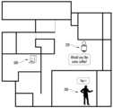
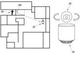
또한 본 발명의 일 실시예에 의한 모듈형 가정용 로봇은, 사용자 부재 환경을 스스로 감지하여, 카메라 모듈 등 특정 장치 모듈의 일부 기능을 보안용으로 사용할 수 있다.In addition, a modular home robot according to one embodiment of the present invention can detect an environment in which a user is absent on its own and use some functions of specific device modules, such as a camera module, for security purposes.
본 발명의 효과는 다음과 같다.The effects of the present invention are as follows.
본 발명의 다양한 실시 예들 중 일 실시 예에 따르면, 메인 바디와 장치 모듈로 분리가 가능하고, 장치 모듈이 교체가 가능하며, 여러가지 기능마다 서로 다른 장치 모듈을 교체하여 사용할 수 있으므로, 하나의 제품을 구매하여도 손 쉽게 사용자가 원하는 기능의 가정용 로봇을 소비자들에게 제공하는 효과가 있다.According to one embodiment of the present invention, the main body and the device module can be separated, the device module can be replaced, and different device modules can be replaced and used for different functions, so that even if a single product is purchased, it is possible to easily provide consumers with a home robot with the functions they want.
본 발명의 다양한 실시 예들 중 다른 실시 예에 따르면, 모듈형 가정용 로봇은, 근접 센서 또는 음성 인식 센서를 통해 주변 사용자를 실시간으로 감지할 수 있고, 트리거 신호에 따라 자동으로 복수 기능이 활성화되므로, 사용자가 별도의 입력 없이도 자동으로 활성화되고 사용자와 인터랙션을 수행하는 기능이 있다.According to another embodiment of the present invention, a modular home robot can detect surrounding users in real time through a proximity sensor or a voice recognition sensor, and automatically activate multiple functions according to a trigger signal, so that it is automatically activated and has a function to interact with the user without a separate input from the user.
본 발명의 다양한 실시예들 중 또 다른 실시예에 따르면, 사용자 부재 환경을 스스로 감지하여, 현재 장착된 장치 모듈의 일부 기능을 보안용으로 사용할 수 있기 때문에, 집안 내에 사용자가 없는 환경에서도 필요한 기능을 스스로 구현하는 기술적 효과가 있다.According to another embodiment among various embodiments of the present invention, since the user's absence environment can be detected by itself and some functions of the currently equipped device module can be used for security purposes, there is a technical effect of implementing necessary functions by itself even in an environment where there is no user in the house.
도 1a는 본 발명에 따른 모듈형 가정용 로봇의 외관을 설명하기 위한 도면이다.
도 1b는 본 발명과 관련된 메인 바디를 설명하기 위한 블록도이다.
도 2는 본 발명에 따른 모듈형 가정용 로봇의 장치 모듈의 이동을 설명하기 위한 도면이다.
도 3 내지 도 5는 본 발명에 따른 모듈형 가정용 로봇이 사용자를 인지하여 반응하는 일 예를 설명하기 위한 도면들이다.
도 6 내지 도 7은 본 발명에 따른 모듈형 가정용 로봇이 사용자 입력에 따라 외부 기기를 제어하는 일 예를 설명하기 위한 도면이다.
도 8은 본 발명의 일 실시예에 의한 모듈형 가정용 로봇이 시간별 반복 동작을 수행하는 일 예를 설명하기 위한 도면이다.
도 9 내지 도 11은 본 발명에 따른 모듈형 가정용 로봇이 먼지 센서를 이용하여 사용자와 인터랙션하는 일 예를 설명하기 위한 도면들이다.
도 12는 본 발명에 따른 모듈형 가정용 로봇이 외부 기기 및 사용자와 동시에 인터랙션 하는 일 예를 설명하기 위한 도면이다.
도 13 및 도 14는 본 발명에 따른 모듈형 가정용 로봇 중 장치 모듈만 별도로 작동하는 일 예를 설명하기 위한 도면들이다.
도 15 내지 도 19는 본 발명에 따른 모듈형 가정용 로봇의 장치 모듈이 카메라 모듈인 경우 예시를 설명하기 위한 도면들이다.
도 20 내지 도 21은 본 발명에 따른 모듈형 가정용 로봇의 장치 모듈이 프로젝터 모듈인 경우 예시를 설명하기 위한 도면들이다.
도 22 내지 도 23은 본 발명의 모듈형 가정용 로봇의 부가적인 실시예를 설명하기 위한 도면들이다.FIG. 1a is a drawing for explaining the appearance of a modular household robot according to the present invention.
Figure 1b is a block diagram illustrating a main body related to the present invention.
FIG. 2 is a drawing for explaining the movement of a device module of a modular household robot according to the present invention.
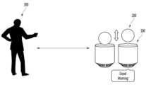
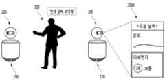
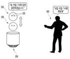
FIGS. 3 to 5 are drawings for explaining an example of a modular home robot according to the present invention recognizing and responding to a user.
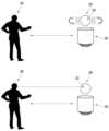
FIGS. 6 and 7 are drawings for explaining an example of a modular household robot according to the present invention controlling an external device according to user input.
FIG. 8 is a drawing for explaining an example of a modular domestic robot performing time-based repetitive operations according to one embodiment of the present invention.
FIGS. 9 to 11 are drawings for explaining an example of a modular household robot according to the present invention interacting with a user using a dust sensor.
FIG. 12 is a drawing for explaining an example of a modular domestic robot according to the present invention interacting simultaneously with an external device and a user.
FIGS. 13 and 14 are drawings for explaining an example in which only the device module of the modular household robot according to the present invention operates separately.
FIGS. 15 to 19 are drawings for explaining examples in which the device module of a modular household robot according to the present invention is a camera module.
FIGS. 20 and 21 are drawings for explaining an example in which the device module of a modular household robot according to the present invention is a projector module.
FIGS. 22 and 23 are drawings for explaining additional embodiments of the modular domestic robot of the present invention.
이하, 첨부된 도면을 참조하여 본 명세서에 개시된 실시 예를 상세히 설명하되, 도면 부호에 관계없이 동일하거나 유사한 구성요소는 동일한 참조 번호를 부여하고 이에 대한 중복되는 설명은 생략하기로 한다. 이하의 설명에서 사용되는 구성요소에 대한 접미사 "모듈" 및 "부"는 명세서 작성의 용이함만이 고려되어 부여되거나 혼용되는 것으로서, 그 자체로 서로 구별되는 의미 또는 역할을 갖는 것은 아니다. 또한, 본 명세서에 개시된 실시예를 설명함에 있어서 관련된 공지 기술에 대한 구체적인 설명이 본 명세서에 개시된 실시 예의 요지를 흐릴 수 있다고 판단되는 경우 그 상세한 설명을 생략한다. 또한, 첨부된 도면은 본 명세서에 개시된 실시 예를 쉽게 이해할 수 있도록 하기 위한 것일 뿐, 첨부된 도면에 의해 본 명세서에 개시된 기술적 사상이 제한되지 않으며, 본 발명의 사상 및 기술 범위에 포함되는 모든 변경, 균등물 내지 대체물을 포함하는 것으로 이해되어야 한다.Hereinafter, embodiments disclosed in this specification will be described in detail with reference to the attached drawings. Regardless of the drawing symbols, identical or similar components will be given the same reference numerals and redundant descriptions thereof will be omitted. The suffixes "module" and "part" used for components in the following description are assigned or used interchangeably only for the convenience of writing the specification, and do not have distinct meanings or roles in themselves. In addition, when describing the embodiments disclosed in this specification, if it is determined that a specific description of a related known technology may obscure the gist of the embodiments disclosed in this specification, the detailed description thereof will be omitted. In addition, the attached drawings are only intended to facilitate easy understanding of the embodiments disclosed in this specification, and the technical ideas disclosed in this specification are not limited by the attached drawings, and should be understood to include all modifications, equivalents, and substitutes included in the spirit and technical scope of the present invention.
제1, 제2 등과 같이 서수를 포함하는 용어는 다양한 구성요소들을 설명하는데 사용될 수 있지만, 상기 구성요소들은 상기 용어들에 의해 한정되지는 않는다. 상기 용어들은 하나의 구성요소를 다른 구성요소로부터 구별하는 목적으로만 사용된다.Terms that include ordinal numbers, such as first, second, etc., may be used to describe various components, but the components are not limited by the terms. The terms are used only to distinguish one component from another.
어떤 구성요소가 다른 구성요소에 "연결되어" 있다거나 "접속되어" 있다고 언급된 때에는, 그 다른 구성요소에 직접적으로 연결되어 있거나 또는 접속되어 있을 수도 있지만, 중간에 다른 구성요소가 존재할 수도 있다고 이해되어야 할 것이다. 반면에, 어떤 구성요소가 다른 구성요소에 "직접 연결되어" 있다거나 "직접 접속되어" 있다고 언급된 때에는, 중간에 다른 구성요소가 존재하지 않는 것으로 이해되어야 할 것이다.When it is said that a component is "connected" or "connected" to another component, it should be understood that it may be directly connected or connected to that other component, but that there may be other components in between. On the other hand, when it is said that a component is "directly connected" or "directly connected" to another component, it should be understood that there are no other components in between.
단수의 표현은 문맥상 명백하게 다르게 뜻하지 않는 한, 복수의 표현을 포함한다.Singular expressions include plural expressions unless the context clearly indicates otherwise.
본 출원에서, "포함한다" 또는 "가지다" 등의 용어는 명세서상에 기재된 특징, 숫자, 단계, 동작, 구성요소, 부품 또는 이들을 조합한 것이 존재함을 지정하려는 것이지, 하나 또는 그 이상의 다른 특징들이나 숫자, 단계, 동작, 구성요소, 부품 또는 이들을 조합한 것들의 존재 또는 부가 가능성을 미리 배제하지 않는 것으로 이해되어야 한다.In this application, it should be understood that terms such as “comprises” or “has” are intended to specify the presence of a feature, number, step, operation, component, part or combination thereof described in the specification, but do not exclude in advance the possibility of the presence or addition of one or more other features, numbers, steps, operations, components, parts or combinations thereof.
이하에서는, 본 발명의 실시예에 따른 디스플레이 장치를 구비할 수 있는 차량에 대하여 살펴본 후, 본 발명의 각 실시예에 따른 디스플레이 장치를 차례대로 설명하기로 한다.Below, a vehicle that can be equipped with a display device according to an embodiment of the present invention will be examined, and then the display devices according to each embodiment of the present invention will be described in turn.
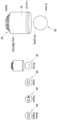
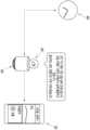
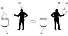
도 1a는 본 발명에 따른 모듈형 가정용 로봇의 외관을 설명하기 위한 도면이다.FIG. 1a is a drawing for explaining the appearance of a modular household robot according to the present invention.
도 1a에 도시된 바와 같이, 본 발명에 따른 모듈형 가정용 로봇(100, 200)은 메인 바디(100)와 장치 모듈(200)을 포함할 수 있다.As illustrated in FIG. 1a, a modular domestic robot (100, 200) according to the present invention may include a main body (100) and a device module (200).
모듈형 가정용 로봇의 메인 바디(100)는 LED, 마이크, 스피커, 인체감지 센서 등 다양한 센싱 유닛과 입출력 유닛을 포함하고 있다. 메인 바디(100)의 구성에 대해서는 도 1b에서 이하 자세히 설명하도록 하겠다.The main body (100) of the modular home robot includes various sensing units and input/output units, such as an LED, a microphone, a speaker, and a human body detection sensor. The configuration of the main body (100) will be described in detail below with reference to Fig. 1b.
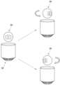
모듈형 가정용 로봇의 장치 모듈(200)은 LED 모듈(202), 카메라 모듈(204) 및 프로젝터 모듈(206) 등 다양한 기능을 갖는 장치 모듈을 포함할 수 있다. 도 1a에서 설명하는 장치 모듈(202, 204, 206)은 일 예시에 불과하며, 가정 내에서 사용가능한 모든 장치가 모듈형으로 제작되어 본 모듈형 가정용 로봇에 사용될 수 있음은 자명하다.The device module (200) of the modular home robot may include device modules having various functions, such as an LED module (202), a camera module (204), and a projector module (206). The device modules (202, 204, 206) described in Fig. 1a are only examples, and it is obvious that all devices available in the home can be manufactured in a modular form and used in the modular home robot.
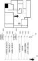
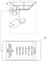
도 1b는 본 발명과 관련된 메인 바디를 설명하기 위한 블록도이다.Figure 1b is a block diagram illustrating a main body related to the present invention.
상기 메인 바디(100)는 무선 통신부(110), 입력부(120), 센싱부(140), 출력부(150), 인터페이스부(160), 메모리(170), 제어부(180) 및 전원 공급부(190) 등을 포함할 수 있다. 도 1b에 도시된 구성요소들은 메인 바디를 구현하는데 있어서 필수적인 것은 아니어서, 본 명세서 상에서 설명되는 메인 바디는 위에서 열거된 구성요소들 보다 많거나, 또는 적은 구성요소들을 가질 수 있다.The above main body (100) may include a wireless communication unit (110), an input unit (120), a sensing unit (140), an output unit (150), an interface unit (160), a memory (170), a control unit (180), and a power supply unit (190). The components illustrated in FIG. 1b are not essential for implementing the main body, and thus the main body described in this specification may have more or fewer components than the components listed above.
보다 구체적으로, 상기 구성요소들 중 무선 통신부(110)는, 메인 바디(100)와 장치 모듈 사이, 메인 바디(100)와 다른 메인 바디(100) 사이, 또는 메인 바디(100)와 외부서버 사이의 무선 통신을 가능하게 하는 하나 이상의 모듈을 포함할 수 있다. 또한, 상기 무선 통신부(110)는, 메인 바디(100)를 하나 이상의 네트워크에 연결하는 하나 이상의 모듈을 포함할 수 있다.More specifically, among the above components, the wireless communication unit (110) may include one or more modules that enable wireless communication between the main body (100) and a device module, between the main body (100) and another main body (100), or between the main body (100) and an external server. In addition, the wireless communication unit (110) may include one or more modules that connect the main body (100) to one or more networks.
이러한 무선 통신부(110)는, 이동통신 모듈(112), 무선 인터넷 모듈(113), 근거리 통신 모듈(114), 위치정보 모듈(115) 중 적어도 하나를 포함할 수 있다.This wireless communication unit (110) may include at least one of a mobile communication module (112), a wireless Internet module (113), a short-range communication module (114), and a location information module (115).
입력부(120)는, 영상 신호 입력을 위한 카메라(121) 또는 영상 입력부, 오디오 신호 입력을 위한 마이크로폰(microphone, 122), 또는 오디오 입력부, 사용자로부터 정보를 입력 받기 위한 사용자 입력부(123, 예를 들어, 터치키(touch key), 푸시키(mechanical key) 등)를 포함할 수 있다. 입력부(120)에서 수집한 음성 데이터나 이미지 데이터는 분석되어 사용자의 제어명령으로 처리될 수 있다.The input unit (120) may include a camera (121) or an image input unit for inputting an image signal, a microphone (122) or an audio input unit for inputting an audio signal, and a user input unit (123, for example, a touch key, a mechanical key, etc.) for receiving information from a user. Voice data or image data collected by the input unit (120) may be analyzed and processed into a user's control command.
센싱부(140)는 메인 바디 내 정보, 메인 바디를 둘러싼 주변 환경 정보 및 사용자 정보 중 적어도 하나를 센싱 하기 위한 하나 이상의 센서를 포함할 수 있다. 예를 들어, 센싱부(140)는 근접센서(141, proximity sensor), 조도 센서(142, illumination sensor), 터치 센서(touch sensor), 가속도 센서(acceleration sensor), 자기 센서(magnetic sensor), 중력 센서(G-sensor), 자이로스코프 센서(gyroscope sensor), 모션 센서(motion sensor), RGB 센서, 적외선 센서(IR 센서: infrared sensor), 지문인식 센서(finger scan sensor), 초음파 센서(ultrasonic sensor), 광 센서(optical sensor, 예를 들어, 카메라(121 참조)), 마이크로폰(microphone, 122 참조), 배터리 게이지(battery gauge), 환경 센서(예를 들어, 기압계, 습도계, 온도계, 방사능 감지 센서, 열 감지 센서, 가스 감지 센서 등), 화학 센서(예를 들어, 전자 코, 헬스케어 센서, 생체 인식 센서 등) 중 적어도 하나를 포함할 수 있다. 한편, 본 명세서에 개시된 메인 바디는, 이러한 센서들 중 적어도 둘 이상의 센서에서 센싱 되는 정보들을 조합하여 활용할 수 있다.The sensing unit (140) may include one or more sensors for sensing at least one of information within the main body, information about the surrounding environment surrounding the main body, and user information. For example, the sensing unit (140) may include at least one of a proximity sensor (141), an illumination sensor (142), a touch sensor, an acceleration sensor, a magnetic sensor, a gravity sensor (G-sensor), a gyroscope sensor, a motion sensor, an RGB sensor, an infrared sensor (IR sensor), a fingerprint recognition sensor, an ultrasonic sensor, an optical sensor (e.g., a camera (see 121)), a microphone (see 122), a battery gauge, an environmental sensor (e.g., a barometer, a hygrometer, a thermometer, a radiation detection sensor, a heat detection sensor, a gas detection sensor, etc.), and a chemical sensor (e.g., an electronic nose, a healthcare sensor, a biometric recognition sensor, etc.). Meanwhile, the main body disclosed in this specification can utilize information sensed by at least two or more of these sensors.
출력부(150)는 시각, 청각 또는 촉각 등과 관련된 출력을 발생시키기 위한 것으로, 디스플레이부(151), 음향 출력부(152), 햅팁 모듈(153), 광 출력부(154) 중 적어도 하나를 포함할 수 있다. 디스플레이부(151)는 터치 센서와 상호 레이어 구조를 이루거나 일체형으로 형성됨으로써, 터치 스크린을 구현할 수 있다. 이러한 터치 스크린은, 메인 바디(100)와 사용자 사이의 입력 인터페이스를 제공하는 사용자 입력부(123)로써 기능함과 동시에, 메인 바디(100)와 사용자 사이의 출력 인터페이스를 제공할 수 있다.The output unit (150) is for generating output related to vision, hearing, or tactile sensations, and may include at least one of a display unit (151), an audio output unit (152), a haptic module (153), and an optical output unit (154). The display unit (151) may be formed in a mutual layer structure with a touch sensor or formed as an integral part, thereby implementing a touch screen. This touch screen may function as a user input unit (123) that provides an input interface between the main body (100) and the user, and at the same time, provide an output interface between the main body (100) and the user.
인터페이스부(160)는 메인 바디(100)에 연결되는 다양한 종류의 외부 기기와의 통로 역할을 수행한다. 이러한 인터페이스부(160)는, 유/무선 헤드셋 포트(port), 외부 충전기 포트(port), 유/무선 데이터 포트(port), 메모리 카드(memory card) 포트, 식별 모듈이 구비된 장치를 연결하는 포트(port), 오디오 I/O(Input/Output) 포트(port), 비디오 I/O(Input/Output) 포트(port), 이어폰 포트(port) 중 적어도 하나를 포함할 수 있다. 메인 바디(100)에서는, 상기 인터페이스부(160)에 외부 기기가 연결되는 것에 대응하여, 연결된 외부 기기와 관련된 적절할 제어를 수행할 수 있다.The interface unit (160) serves as a passage for various types of external devices connected to the main body (100). The interface unit (160) may include at least one of a wired/wireless headset port, an external charger port, a wired/wireless data port, a memory card port, a port for connecting a device equipped with an identification module, an audio I/O (Input/Output) port, a video I/O (Input/Output) port, and an earphone port. In the main body (100), appropriate control related to the connected external device can be performed in response to the external device being connected to the interface unit (160).
또한, 메모리(170)는 메인 바디(100)의 다양한 기능을 지원하는 데이터를 저장한다. 메모리(170)는 메인 바디(100)에서 구동되는 다수의 응용 프로그램(application program 또는 애플리케이션(application)), 메인 바디(100)의 동작을 위한 데이터들, 명령어들을 저장할 수 있다. 이러한 응용 프로그램 중 적어도 일부는, 무선 통신을 통해 외부 서버로부터 다운로드 될 수 있다. 또한 이러한 응용 프로그램 중 적어도 일부는, 메인 바디(100)의 기본적인 기능(예를 들어, 전화 착신, 발신 기능, 메시지 수신, 발신 기능)을 위하여 출고 당시부터 메인 바디(100)상에 존재할 수 있다. 한편, 응용 프로그램은, 메모리(170)에 저장되고, 메인 바디(100) 상에 설치되어, 제어부(180)에 의하여 상기 메인 바디의 동작(또는 기능)을 수행하도록 구동될 수 있다.In addition, the memory (170) stores data that supports various functions of the main body (100). The memory (170) can store a plurality of application programs (or applications) that are run on the main body (100), data for the operation of the main body (100), and commands. At least some of these application programs can be downloaded from an external server via wireless communication. In addition, at least some of these application programs can exist on the main body (100) from the time of shipment for the basic functions of the main body (100) (e.g., call reception, call transmission, message reception, call transmission functions). Meanwhile, the application programs can be stored in the memory (170), installed on the main body (100), and driven by the control unit (180) to perform the operation (or function) of the main body.
제어부(180)는 상기 응용 프로그램과 관련된 동작 외에도, 통상적으로 메인 바디(100)의 전반적인 동작을 제어한다. 제어부(180)는 위에서 살펴본 구성요소들을 통해 입력 또는 출력되는 신호, 데이터, 정보 등을 처리하거나 메모리(170)에 저장된 응용 프로그램을 구동함으로써, 사용자에게 적절한 정보 또는 기능을 제공 또는 처리할 수 있다.In addition to the operations related to the above application programs, the control unit (180) typically controls the overall operations of the main body (100). The control unit (180) processes signals, data, information, etc. input or output through the components discussed above, or operates an application program stored in the memory (170), thereby providing or processing appropriate information or functions to the user.
또한, 제어부(180)는 메모리(170)에 저장된 응용 프로그램을 구동하기 위하여, 도 1b와 함께 살펴본 구성요소들 중 적어도 일부를 제어할 수 있다. 나아가, 제어부(180)는 상기 응용 프로그램의 구동을 위하여, 메인 바디(100)에 포함된 구성요소들 중 적어도 둘 이상을 서로 조합하여 동작시킬 수 있다.In addition, the control unit (180) can control at least some of the components examined with reference to FIG. 1B in order to drive the application program stored in the memory (170). Furthermore, the control unit (180) can operate at least two or more of the components included in the main body (100) in combination with each other in order to drive the application program.
전원공급부(190)는 제어부(180)의 제어 하에서, 외부의 전원, 내부의 전원을 인가 받아 메인 바디(100)에 포함된 각 구성요소들에 전원을 공급한다. 이러한 전원공급부(190)는 배터리를 포함하며, 상기 배터리는 내장형 배터리 또는 교체 가능한 형태의 배터리가 될 수 있다.The power supply unit (190) receives external power and internal power under the control of the control unit (180) and supplies power to each component included in the main body (100). The power supply unit (190) includes a battery, and the battery may be a built-in battery or a replaceable battery.
상기 각 구성요소들 중 적어도 일부는, 이하에서 설명되는 다양한 실시 예들에 따른 메인 바디의 동작, 제어, 또는 제어방법을 구현하기 위하여 서로 협력하여 동작할 수 있다. 또한, 상기 메인 바디의 동작, 제어, 또는 제어방법은 상기 메모리(170)에 저장된 적어도 하나의 응용 프로그램의 구동에 의하여 메인 바디 상에서 구현될 수 있다.At least some of the above components may operate in cooperation with each other to implement the operation, control, or control method of the main body according to various embodiments described below. In addition, the operation, control, or control method of the main body may be implemented on the main body by driving at least one application program stored in the memory (170).
이하에서는, 위에서 살펴본 메인 바디(100)를 통하여 구현되는 다양한 실시 예들을 살펴보기에 앞서, 위에서 열거된 구성요소들에 대하여 도 1을 참조하여 보다 구체적으로 살펴본다.Below, before examining various embodiments implemented through the main body (100) examined above, the components listed above will be examined in more detail with reference to FIG. 1.
먼저, 무선 통신부(110)에 대하여 살펴보면, 무선 통신부(110)의 이동통신 모듈(112)은, 이동통신을 위한 기술표준들 또는 통신방식(예를 들어, GSM(Global System for Mobile communication), CDMA(Code Division Multi Access), CDMA2000(Code Division Multi Access 2000), EV-DO(Enhanced Voice-Data Optimized or Enhanced Voice-Data Only), WCDMA(Wideband CDMA), HSDPA(High Speed Downlink Packet Access), HSUPA(High Speed Uplink Packet Access), LTE(Long Term Evolution), LTE-A(Long Term Evolution-Advanced) 등)에 따라 구축된 이동 통신망 상에서 기지국, 외부의 단말, 서버 중 적어도 하나와 무선 신호를 송수신한다.First, looking at the wireless communication unit (110), the mobile communication module (112) of the wireless communication unit (110) transmits and receives a wireless signal with at least one of a base station, an external terminal, and a server on a mobile communication network constructed according to technical standards or communication methods for mobile communication (for example, GSM (Global System for Mobile communication), CDMA (Code Division Multi Access), CDMA2000 (Code Division Multi Access 2000), EV-DO (Enhanced Voice-Data Optimized or Enhanced Voice-Data Only), WCDMA (Wideband CDMA), HSDPA (High Speed Downlink Packet Access), HSUPA (High Speed Uplink Packet Access), LTE (Long Term Evolution), LTE-A (Long Term Evolution-Advanced), etc.).
상기 무선 신호는, 음성 호 신호, 화상 통화 호 신호 또는 문자/멀티미디어 메시지 송수신에 따른 다양한 형태의 데이터를 포함할 수 있다.The above wireless signal may include various forms of data such as voice call signals, video call signals, or text/multimedia message transmission and reception.
무선 인터넷 모듈(113)은 무선 인터넷 접속을 위한 모듈을 말하는 것으로, 메인 바디(100)에 내장되거나 외장될 수 있다. 무선 인터넷 모듈(113)은 무선 인터넷 기술들에 따른 통신망에서 무선 신호를 송수신하도록 이루어진다.The wireless Internet module (113) refers to a module for wireless Internet access, and can be built into or externally mounted on the main body (100). The wireless Internet module (113) is configured to transmit and receive wireless signals in a communication network according to wireless Internet technologies.
무선 인터넷 기술로는, 예를 들어 WLAN(Wireless LAN), Wi-Fi(Wireless-Fidelity), Wi-Fi(Wireless Fidelity) Direct, DLNA(Digital Living Network Alliance), WiBro(Wireless Broadband), WiMAX(World Interoperability for Microwave Access), HSDPA(High Speed Downlink Packet Access), HSUPA(High Speed Uplink Packet Access), LTE(Long Term Evolution), LTE-A(Long Term Evolution-Advanced) 등이 있으며, 상기 무선 인터넷 모듈(113)은 상기에서 나열되지 않은 인터넷 기술까지 포함한 범위에서 적어도 하나의 무선 인터넷 기술에 따라 데이터를 송수신하게 된다.Wireless Internet technologies include, for example, WLAN (Wireless LAN), Wi-Fi (Wireless-Fidelity), Wi-Fi (Wireless Fidelity) Direct, DLNA (Digital Living Network Alliance), WiBro (Wireless Broadband), WiMAX (World Interoperability for Microwave Access), HSDPA (High Speed Downlink Packet Access), HSUPA (High Speed Uplink Packet Access), LTE (Long Term Evolution), LTE-A (Long Term Evolution-Advanced), etc., and the wireless Internet module (113) transmits and receives data according to at least one wireless Internet technology, including Internet technologies not listed above.
WiBro, HSDPA, HSUPA, GSM, CDMA, WCDMA, LTE, LTE-A 등에 의한 무선인터넷 접속은 이동통신망을 통해 이루어진다는 관점에서 본다면, 상기 이동통신망을 통해 무선인터넷 접속을 수행하는 상기 무선 인터넷 모듈(113)은 상기 이동통신 모듈(112)의 일종으로 이해될 수도 있다.From the perspective that wireless Internet access through WiBro, HSDPA, HSUPA, GSM, CDMA, WCDMA, LTE, LTE-A, etc. is achieved through a mobile communication network, the wireless Internet module (113) that performs wireless Internet access through the mobile communication network may be understood as a type of mobile communication module (112).
근거리 통신 모듈(114)은 근거리 통신(Short range communication)을 위한 것으로서, 블루투스(Bluetooth™), RFID(Radio Frequency Identification), 적외선 통신(Infrared Data Association; IrDA), UWB(Ultra Wideband), ZigBee, NFC(Near Field Communication), Wi-Fi(Wireless-Fidelity), Wi-Fi Direct, Wireless USB(Wireless Universal Serial Bus) 기술 중 적어도 하나를 이용하여, 근거리 통신을 지원할 수 있다. 이러한, 근거리 통신 모듈(114)은, 근거리 무선 통신망(Wireless Area Networks)을 통해 메인 바디(100)와 무선 통신 시스템 사이, 메인 바디(100)와 다른 메인 바디(100) 사이, 또는 메인 바디(100)와 다른 메인 바디(100, 또는 외부서버)가 위치한 네트워크 사이의 무선 통신을 지원할 수 있다. 상기 근거리 무선 통신망은 근거리 무선 개인 통신망(Wireless Personal Area Networks)일 수 있다.The short-range communication module (114) is for short-range communication and can support short-range communication using at least one of Bluetooth™, RFID (Radio Frequency Identification), Infrared Data Association (IrDA), UWB (Ultra Wideband), ZigBee, NFC (Near Field Communication), Wi-Fi (Wireless-Fidelity), Wi-Fi Direct, and Wireless USB (Wireless Universal Serial Bus) technologies. The short-range communication module (114) can support wireless communication between the main body (100) and a wireless communication system, between the main body (100) and another main body (100), or between the main body (100) and a network where another main body (100, or an external server) is located through short-range wireless communication networks (Wireless Area Networks). The short-range wireless communication networks can be short-range wireless personal area networks (Wireless Personal Area Networks).
근거리 통신 모듈(114)은, 메인 바디(100) 주변에, 상기 메인 바디(100)와 통신 가능한 모바일 디바이스를 감지(또는 인식)할 수 있다. 나아가, 제어부(180)는 상기 감지된 모바일 디바이스가 본 발명에 따른 메인 바디(100)와 통신하도록 인증된 디바이스인 경우, 메인 바디(100)에서 처리되는 데이터의 적어도 일부를, 상기 근거리 통신 모듈(114)을 통해 모바일 디바이스로 송신할 수 있다. 따라서, 모바일 디바이스의 사용자는, 메인 바디(100)에서 처리되는 데이터를, 모바일 디바이스를 통해 이용할 수 있다. 예를 들어, 이에 따르면 사용자는, 메인 바디(100)에 전화가 수신된 경우, 모바일 디바이스를 통해 전화 통화를 수행하거나, 메인 바디(100)에 메시지가 수신된 경우, 모바일 디바이스를 통해 상기 수신된 메시지를 확인하는 것이 가능하다.The short-range communication module (114) can detect (or recognize) a mobile device capable of communicating with the main body (100) around the main body (100). Furthermore, if the detected mobile device is a device authenticated to communicate with the main body (100) according to the present invention, the control unit (180) can transmit at least a part of the data processed in the main body (100) to the mobile device through the short-range communication module (114). Accordingly, a user of the mobile device can use the data processed in the main body (100) through the mobile device. For example, according to this, if a call is received in the main body (100), the user can make a phone call through the mobile device, or if a message is received in the main body (100), the user can check the received message through the mobile device.
위치정보 모듈(115)은 메인 바디의 위치(또는 현재 위치)를 획득하기 위한 모듈로서, 그의 대표적인 예로는 GPS(Global Positioning System) 모듈 또는 WiFi(Wireless Fidelity) 모듈이 있다. 예를 들어, 메인 바디는 GPS모듈을 활용하면, GPS 위성에서 보내는 신호를 이용하여 메인 바디의 위치를 획득할 수 있다. 다른 예로서, 메인 바디는 Wi-Fi모듈을 활용하면, Wi-Fi모듈과 무선신호를 송신 또는 수신하는 무선 AP(Wireless Access Point)의 정보에 기반하여, 메인 바디의 위치를 획득할 수 있다. 필요에 따라서, 위치정보모듈(115)은 치환 또는 부가적으로 메인 바디의 위치에 관한 데이터를 얻기 위해 무선 통신부(110)의 다른 모듈 중 어느 기능을 수행할 수 있다. 위치정보모듈(115)은 메인 바디의 위치(또는 현재 위치)를 획득하기 위해 이용되는 모듈로, 메인 바디의 위치를 직접적으로 계산하거나 획득하는 모듈로 한정되지는 않는다.The location information module (115) is a module for obtaining the location (or current location) of the main body, and representative examples thereof include a GPS (Global Positioning System) module or a WiFi (Wireless Fidelity) module. For example, if the main body utilizes a GPS module, the main body can obtain the location of the main body using a signal transmitted from a GPS satellite. As another example, if the main body utilizes a Wi-Fi module, the main body can obtain the location of the main body based on information of a wireless AP (Wireless Access Point) that transmits or receives a wireless signal with the Wi-Fi module. If necessary, the location information module (115) may perform any function of other modules of the wireless communication unit (110) to obtain data on the location of the main body as a substitute or in addition. The location information module (115) is a module used to obtain the location (or current location) of the main body, and is not limited to a module that directly calculates or obtains the location of the main body.
다음으로, 입력부(120)는 영상 정보(또는 신호), 오디오 정보(또는 신호), 데이터, 또는 사용자로부터 입력되는 정보의 입력을 위한 것으로서, 영상 정보의 입력을 위하여, 메인 바디(100) 는 하나 또는 복수의 카메라(121)를 구비할 수 있다. 카메라(121)는 화상 통화모드 또는 촬영 모드에서 이미지 센서에 의해 얻어지는 정지영상 또는 동영상 등의 화상 프레임을 처리한다. 처리된 화상 프레임은 디스플레이부(151)에 표시되거나 메모리(170)에 저장될 수 있다. 한편, 메인 바디(100)에 구비되는 복수의 카메라(121)는 매트릭스 구조를 이루도록 배치될 수 있으며, 이와 같이 매트릭스 구조를 이루는 카메라(121)를 통하여, 메인 바디(100)에는 다양한 각도 또는 초점을 갖는 복수의 영상정보가 입력될 수 있다. 또한, 복수의 카메라(121)는 입체영상을 구현하기 위한 좌 영상 및 우 영상을 획득하도록, 스트레오 구조로 배치될 수 있다.Next, the input unit (120) is for inputting image information (or signal), audio information (or signal), data, or information input from a user. For inputting image information, the main body (100) may be equipped with one or more cameras (121). The camera (121) processes image frames such as still images or moving images obtained by an image sensor in a video call mode or a shooting mode. The processed image frames may be displayed on the display unit (151) or stored in the memory (170). Meanwhile, the plurality of cameras (121) equipped in the main body (100) may be arranged to form a matrix structure, and through the cameras (121) forming the matrix structure in this way, a plurality of image information having various angles or foci may be input to the main body (100). In addition, the plurality of cameras (121) may be arranged in a stereo structure to obtain left and right images for implementing a three-dimensional image.
마이크로폰(122)은 외부의 음향 신호를 전기적인 음성 데이터로 처리한다. 처리된 음성 데이터는 메인 바디(100)에서 수행 중인 기능(또는 실행 중인 응용 프로그램)에 따라 다양하게 활용될 수 있다. 한편, 마이크로폰(122)에는 외부의 음향 신호를 입력 받는 과정에서 발생되는 잡음(noise)을 제거하기 위한 다양한 잡음 제거 알고리즘이 구현될 수 있다.The microphone (122) processes external acoustic signals into electrical voice data. The processed voice data can be utilized in various ways depending on the function being performed (or the application being executed) in the main body (100). Meanwhile, the microphone (122) can implement various noise removal algorithms to remove noise generated in the process of receiving external acoustic signals.
사용자 입력부(123)는 사용자로부터 정보를 입력 받기 위한 것으로서, 사용자 입력부(123)를 통해 정보가 입력되면, 제어부(180)는 입력된 정보에 대응되도록 메인 바디(100)의 동작을 제어할 수 있다. 이러한, 사용자 입력부(123)는 기계식 (mechanical) 입력수단(또는, 메커니컬 키, 예를 들어, 메인 바디(100)의 전·후면 또는 측면에 위치하는 버튼, 돔 스위치 (dome switch), 조그 휠, 조그 스위치 등) 및 터치식 입력수단을 포함할 수 있다. 일 예로서, 터치식 입력수단은, 소프트웨어적인 처리를 통해 터치스크린에 표시되는 가상 키(virtual key), 소프트 키(soft key) 또는 비주얼 키(visual key)로 이루어지거나, 상기 터치스크린 이외의 부분에 배치되는 터치 키(touch key)로 이루어질 수 있다. 한편, 상기 가상키 또는 비주얼 키는, 다양한 형태를 가지면서 터치스크린 상에 표시되는 것이 가능하며, 예를 들어, 그래픽(graphic), 텍스트(text), 아이콘(icon), 비디오(video) 또는 이들의 조합으로 이루어질 수 있다.The user input unit (123) is for receiving information from a user. When information is input through the user input unit (123), the control unit (180) can control the operation of the main body (100) to correspond to the input information. The user input unit (123) may include a mechanical input means (or a mechanical key, for example, a button located on the front, rear, or side of the main body (100), a dome switch, a jog wheel, a jog switch, etc.) and a touch input means. As an example, the touch input means may be composed of a virtual key, a soft key, or a visual key displayed on a touch screen through software processing, or a touch key placed on a part other than the touch screen. Meanwhile, the virtual key or visual key may be displayed on the touch screen in various forms, and may be formed of, for example, graphics, text, icons, videos, or a combination thereof.
다음, 장치 모듈 결합부(130)는 메인 바디(100)의 상부면에 위치하고, 카메라 모듈, 프로젝터 모듈 등 다양한 장치 모듈과 결합될 수 있다.Next, the device module coupling part (130) is located on the upper surface of the main body (100) and can be coupled with various device modules such as a camera module and a projector module.
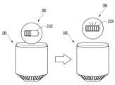
장치 모듈 결합부(130)는 무선 충전 단자(미도시)를 포함할 수 있고, 장치 모듈 결합부(130)에 접촉되는 장치 모듈들은 메인 바디(100)의 공급 전원을 통해 무선 충전이 가능하다.The device module coupling portion (130) may include a wireless charging terminal (not shown), and device modules that come into contact with the device module coupling portion (130) can be wirelessly charged through the power supply of the main body (100).
또한, 장치 모듈 결합부(130) 및 장치 모듈들은 자성을 갖는 소재로 제작될 수 있고, 메인 바디(100)는 자성을 조절하여 장치 모듈을 장치 모듈 결합부(130)로부터 일정 높이 위로 띄울 수 있다.In addition, the device module coupling portion (130) and the device modules can be manufactured from a material having magnetism, and the main body (100) can adjust the magnetism to float the device module a certain height above the device module coupling portion (130).
장치 모듈 결합부(130)의 자성을 이용한 실시예에 대해서는 아래 도면들에서 더욱 자세히 설명하도록 하겠다.An embodiment utilizing the magnetism of the device module coupling part (130) will be described in more detail in the drawings below.
한편, 센싱부(140)는 메인 바디 내 정보, 메인 바디를 둘러싼 주변 환경 정보 및 사용자 정보 중 적어도 하나를 센싱 하고, 이에 대응하는 센싱 신호를 발생시킨다. 제어부(180)는 이러한 센싱 신호에 기초하여, 메인 바디(100)의 구동 또는 동작을 제어하거나, 메인 바디(100)에 설치된 응용 프로그램과 관련된 데이터 처리, 기능 또는 동작을 수행 할 수 있다. 센싱부(140)에 포함될 수 있는 다양한 센서 중 대표적인 센서들의 대하여, 보다 구체적으로 살펴본다.Meanwhile, the sensing unit (140) senses at least one of the information within the main body, the surrounding environment information surrounding the main body, and the user information, and generates a sensing signal corresponding thereto. Based on this sensing signal, the control unit (180) can control the driving or operation of the main body (100), or perform data processing, functions, or operations related to the application program installed in the main body (100). Representative sensors among the various sensors that can be included in the sensing unit (140) will be examined in more detail.
먼저, 근접 센서(141)는 소정의 검출면에 접근하는 물체, 혹은 근방에 존재하는 물체의 유무를 전자계의 힘 또는 적외선 등을 이용하여 기계적 접촉이 없이 검출하는 센서를 말한다. 이러한 근접 센서(141)는 위에서 살펴본 터치 스크린에 의해 감싸지는 메인 바디의 내부 영역 또는 상기 터치 스크린의 근처에 근접 센서(141)가 배치될 수 있다.First, a proximity sensor (141) refers to a sensor that detects the presence or absence of an object approaching a predetermined detection surface or an object existing nearby without mechanical contact by using the power of an electromagnetic field or infrared rays, etc. This proximity sensor (141) can be placed in the internal area of the main body covered by the touch screen described above or near the touch screen.
근접 센서(141)의 예로는 투과형 광전 센서, 직접 반사형 광전 센서, 미러 반사형 광전 센서, 고주파 발진형 근접 센서, 정전 용량형 근접 센서, 자기형 근접 센서, 적외선 근접 센서 등이 있다. 터치 스크린이 정전식인 경우에, 근접 센서(141)는 전도성을 갖는 물체의 근접에 따른 전계의 변화로 상기 물체의 근접을 검출하도록 구성될 수 있다. 이 경우 터치 스크린(또는 터치 센서) 자체가 근접 센서로 분류될 수 있다.Examples of proximity sensors (141) include a transmissive photoelectric sensor, a direct reflection photoelectric sensor, a mirror reflection photoelectric sensor, a high-frequency oscillation proximity sensor, a capacitive proximity sensor, a magnetic proximity sensor, an infrared proximity sensor, etc. In the case where the touch screen is capacitive, the proximity sensor (141) may be configured to detect the proximity of an object having conductivity by a change in an electric field according to the proximity of the object. In this case, the touch screen (or touch sensor) itself may be classified as a proximity sensor.
한편, 설명의 편의를 위해, 터치 스크린 상에 물체가 접촉되지 않으면서 근접되어 상기 물체가 상기 터치 스크린 상에 위치함이 인식되도록 하는 행위를 "근접 터치(proximity touch)"라고 명명하고, 상기 터치 스크린 상에 물체가 실제로 접촉되는 행위를 "접촉 터치(contact touch)"라고 명명한다. 상기 터치 스크린 상에서 물체가 근접 터치 되는 위치라 함은, 상기 물체가 근접 터치될 때 상기 물체가 상기 터치 스크린에 대해 수직으로 대응되는 위치를 의미한다. 상기 근접 센서(141)는, 근접 터치와, 근접 터치 패턴(예를 들어, 근접 터치 거리, 근접 터치 방향, 근접 터치 속도, 근접 터치 시간, 근접 터치 위치, 근접 터치 이동 상태 등)을 감지할 수 있다. 한편, 제어부(180)는 위와 같이, 근접 센서(141)를 통해 감지된 근접 터치 동작 및 근접 터치 패턴에 상응하는 데이터(또는 정보)를 처리하며, 나아가, 처리된 데이터에 대응하는 시각적인 정보를 터치 스크린상에 출력시킬 수 있다. 나아가, 제어부(180)는, 터치 스크린 상의 동일한 지점에 대한 터치가, 근접 터치인지 또는 접촉 터치인지에 따라, 서로 다른 동작 또는 데이터(또는 정보)가 처리되도록 메인 바디(100)를 제어할 수 있다.Meanwhile, for the convenience of explanation, an act of approaching an object without touching the touch screen so that it is recognized that the object is located on the touch screen is called a "proximity touch," and an act of actually contacting an object on the touch screen is called a "contact touch." The position at which an object is touched on the touch screen means a position at which the object vertically corresponds to the touch screen when the object is touched. The proximity sensor (141) can detect a proximity touch and a proximity touch pattern (e.g., a proximity touch distance, a proximity touch direction, a proximity touch speed, a proximity touch time, a proximity touch position, a proximity touch movement state, etc.). Meanwhile, the control unit (180) processes data (or information) corresponding to the proximity touch action and the proximity touch pattern detected by the proximity sensor (141) as described above, and further outputs visual information corresponding to the processed data on the touch screen. Furthermore, the control unit (180) can control the main body (100) so that different operations or data (or information) are processed depending on whether a touch on the same point on the touch screen is a proximity touch or a contact touch.
터치 센서는 저항막 방식, 정전용량 방식, 적외선 방식, 초음파 방식, 자기장 방식 등 여러 가지 터치방식 중 적어도 하나를 이용하여 터치 스크린(또는 디스플레이부(151))에 가해지는 터치(또는 터치입력)을 감지한다.The touch sensor detects a touch (or touch input) applied to a touch screen (or display unit (151)) using at least one of various touch methods, such as a resistive film method, a capacitive method, an infrared method, an ultrasonic method, and a magnetic field method.
일 예로서, 터치 센서는, 터치 스크린의 특정 부위에 가해진 압력 또는 특정 부위에 발생하는 정전 용량 등의 변화를 전기적인 입력신호로 변환하도록 구성될 수 있다. 터치 센서는, 터치 스크린 상에 터치를 가하는 터치 대상체가 터치 센서 상에 터치 되는 위치, 면적, 터치 시의 압력, 터치 시의 정전 용량 등을 검출할 수 있도록 구성될 수 있다. 여기에서, 터치 대상체는 상기 터치 센서에 터치를 인가하는 물체로서, 예를 들어, 손가락, 터치펜 또는 스타일러스 펜(Stylus pen), 포인터 등이 될 수 있다.As an example, the touch sensor may be configured to convert changes in pressure applied to a specific portion of the touch screen or electrostatic capacity generated at a specific portion, etc., into an electrical input signal. The touch sensor may be configured to detect a location, area, pressure at the time of the touch, electrostatic capacity at the time of the touch, etc., of a touch target that applies a touch to the touch screen on the touch sensor. Here, the touch target is an object that applies a touch to the touch sensor, and may be, for example, a finger, a touch pen or a stylus pen, a pointer, etc.
이와 같이, 터치 센서에 대한 터치 입력이 있는 경우, 그에 대응하는 신호(들)는 터치 제어기로 보내진다. 터치 제어기는 그 신호(들)를 처리한 다음 대응하는 데이터를 제어부(180)로 송신한다. 이로써, 제어부(180)는 디스플레이부(151)의 어느 영역이 터치 되었는지 여부 등을 알 수 있게 된다. 여기에서, 터치 제어기는, 제어부(180)와 별도의 구성요소일 수 있고, 제어부(180) 자체일 수 있다.In this way, when there is a touch input to the touch sensor, the corresponding signal(s) is sent to the touch controller. The touch controller processes the signal(s) and then transmits the corresponding data to the control unit (180). As a result, the control unit (180) can know which area of the display unit (151) has been touched, etc. Here, the touch controller may be a separate component from the control unit (180) or may be the control unit (180) itself.
한편, 제어부(180)는, 터치 스크린(또는 터치 스크린 이외에 구비된 터치키)을 터치하는, 터치 대상체의 종류에 따라 서로 다른 제어를 수행하거나, 동일한 제어를 수행할 수 있다. 터치 대상체의 종류에 따라 서로 다른 제어를 수행할지 또는 동일한 제어를 수행할 지는, 현재 메인 바디(100)의 동작상태 또는 실행 중인 응용 프로그램에 따라 결정될 수 있다.Meanwhile, the control unit (180) can perform different controls or the same controls depending on the type of the touch target that touches the touch screen (or a touch key provided other than the touch screen). Whether to perform different controls or the same controls depending on the type of the touch target can be determined depending on the current operating state of the main body (100) or the running application program.
한편, 위에서 살펴본 터치 센서 및 근접 센서는 독립적으로 또는 조합되어, 터치 스크린에 대한 숏(또는 탭) 터치(short touch), 롱 터치(long touch), 멀티 터치(multi touch), 드래그 터치(drag touch), 플리크 터치(flick touch), 핀치-인 터치(pinch-in touch), 핀치-아웃 터치(pinch-out 터치), 스와이프(swype) 터치, 호버링(hovering) 터치 등과 같은, 다양한 방식의 터치를 센싱할 수 있다.Meanwhile, the touch sensor and proximity sensor discussed above can independently or in combination sense various types of touch, such as short (or tap) touch, long touch, multi-touch, drag touch, flick touch, pinch-in touch, pinch-out touch, swipe touch, hovering touch, etc. on the touch screen.
초음파 센서는 초음파를 이용하여, 감지대상의 위치정보를 인식할 수 있다. 한편 제어부(180)는 광 센서와 복수의 초음파 센서로부터 감지되는 정보를 통해, 파동 발생원의 위치를 산출하는 것이 가능하다. 파동 발생원의 위치는, 광이 초음파보다 매우 빠른 성질, 즉, 광이 광 센서에 도달하는 시간이 초음파가 초음파 센서에 도달하는 시간보다 매우 빠름을 이용하여, 산출될 수 있다. 보다 구체적으로 광을 기준 신호로 초음파가 도달하는 시간과의 시간차를 이용하여 파동 발생원의 위치가 산출될 수 있다.The ultrasonic sensor can recognize the location information of the detection target using ultrasonic waves. Meanwhile, the control unit (180) can calculate the location of the wave generation source through information detected from the light sensor and multiple ultrasonic sensors. The location of the wave generation source can be calculated by using the property that light is much faster than ultrasonic waves, that is, the time it takes for light to reach the light sensor is much faster than the time it takes for ultrasonic waves to reach the ultrasonic sensor. More specifically, the location of the wave generation source can be calculated by using the time difference between the time at which ultrasonic waves arrive and the time at which light is a reference signal.
한편, 입력부(120)의 구성으로 살펴본, 카메라(121)는 카메라 센서(예를 들어, CCD, CMOS 등), 포토 센서(또는 이미지 센서) 및 레이저 센서 중 적어도 하나를 포함한다.Meanwhile, the camera (121) as seen from the configuration of the input unit (120) includes at least one of a camera sensor (e.g., CCD, CMOS, etc.), a photo sensor (or image sensor), and a laser sensor.
카메라(121)와 레이저 센서는 서로 조합되어, 3차원 입체영상에 대한 감지대상의 터치를 감지할 수 있다. 포토 센서는 디스플레이 소자에 적층될 수 있는데, 이러한 포토 센서는 터치 스크린에 근접한 감지대상의 움직임을 스캐닝 하도록 이루어진다. 보다 구체적으로, 포토 센서는 행/열에 Photo Diode와 TR(Transistor)를 실장하여 Photo Diode에 인가되는 빛의 양에 따라 변화되는 전기적 신호를 이용하여 포토 센서 위에 올려지는 내용물을 스캔 한다. 즉, 포토 센서는 빛의 변화량에 따른 감지대상의 좌표 계산을 수행하며, 이를 통하여 감지대상의 위치정보가 획득될 수 있다.The camera (121) and the laser sensor can be combined with each other to detect the touch of the detection target for the three-dimensional stereoscopic image. The photo sensor can be laminated on the display element, and the photo sensor is configured to scan the movement of the detection target close to the touch screen. More specifically, the photo sensor scans the contents placed on the photo sensor by using an electrical signal that changes according to the amount of light applied to the photo diode by mounting a photo diode and a TR (transistor) in the row/column. That is, the photo sensor performs coordinate calculation of the detection target according to the amount of change in light, and through this, the location information of the detection target can be acquired.
디스플레이부(151)는 메인 바디(100)에서 처리되는 정보를 표시(출력)한다. 예를 들어, 디스플레이부(151)는 메인 바디(100)에서 구동되는 응용 프로그램의 실행화면 정보, 또는 이러한 실행화면 정보에 따른 UI(User Input), GUI(Graphic User Input) 정보를 표시할 수 있다.The display unit (151) displays (outputs) information processed in the main body (100). For example, the display unit (151) can display execution screen information of an application program driven in the main body (100), or UI (User Input) or GUI (Graphic User Input) information according to such execution screen information.
또한, 상기 디스플레이부(151)는 입체영상을 표시하는 입체 디스플레이부로서 구성될 수 있다.Additionally, the display unit (151) may be configured as a stereoscopic display unit that displays a stereoscopic image.
상기 입체 디스플레이부에는 스테레오스코픽 방식(안경 방식), 오토 스테레오스코픽 방식(무안경 방식), 프로젝션 방식(홀로그래픽 방식) 등의 3차원 디스플레이 방식이 적용될 수 있다.The above stereoscopic display unit can be applied to a three-dimensional display method such as a stereoscopic method (glasses method), an autostereoscopic method (glasses-free method), or a projection method (holographic method).
음향 출력부(152)는 호신호 수신, 통화모드 또는 녹음 모드, 음성인식 모드, 방송수신 모드 등에서 무선 통신부(110)로부터 수신되거나 메모리(170)에 저장된 오디오 데이터를 출력할 수 있다. 음향 출력부(152)는 메인 바디(100)에서 수행되는 기능(예를 들어, 호신호 수신음, 메시지 수신음 등)과 관련된 음향 신호를 출력하기도 한다. 이러한 음향 출력부(152)에는 리시버(receiver), 스피커(speaker), 버저(buzzer) 등이 포함될 수 있다.The audio output unit (152) can output audio data received from the wireless communication unit (110) or stored in the memory (170) in a call signal reception mode, a call mode or a recording mode, a voice recognition mode, a broadcast reception mode, etc. The audio output unit (152) also outputs an audio signal related to a function performed in the main body (100) (e.g., a call signal reception sound, a message reception sound, etc.). The audio output unit (152) can include a receiver, a speaker, a buzzer, etc.
햅틱 모듈(haptic module)(153)은 사용자가 느낄 수 있는 다양한 촉각 효과를 발생시킨다. 햅틱 모듈(153)이 발생시키는 촉각 효과의 대표적인 예로는 진동이 될 수 있다. 햅틱 모듈(153)에서 발생하는 진동의 세기와 패턴 등은 사용자의 선택 또는 제어부의 설정에 의해 제어될 수 있다. 예를 들어, 상기 햅틱 모듈(153)은 서로 다른 진동을 합성하여 출력하거나 순차적으로 출력할 수도 있다.The haptic module (153) generates various tactile effects that the user can feel. A representative example of the tactile effect generated by the haptic module (153) may be vibration. The intensity and pattern of the vibration generated by the haptic module (153) may be controlled by the user's selection or the setting of the control unit. For example, the haptic module (153) may synthesize different vibrations and output them or output them sequentially.
햅틱 모듈(153)은, 진동 외에도, 접촉 피부면에 대해 수직 운동하는 핀 배열, 분사구나 흡입구를 통한 공기의 분사력이나 흡입력, 피부 표면에 대한 스침, 전극(electrode)의 접촉, 정전기력 등의 자극에 의한 효과와, 흡열이나 발열 가능한 소자를 이용한 냉온감 재현에 의한 효과 등 다양한 촉각 효과를 발생시킬 수 있다.The haptic module (153) can generate various tactile effects, such as effects due to stimulation such as vibration, pin arrays moving vertically with respect to the contact skin surface, air injection or suction through nozzles or suction ports, brushing against the skin surface, contact with electrodes, electrostatic force, and effects due to reproduction of hot and cold sensations using elements capable of absorbing or generating heat.
햅틱 모듈(153)은 직접적인 접촉을 통해 촉각 효과를 전달할 수 있을 뿐만 아니라, 사용자가 손가락이나 팔 등의 근 감각을 통해 촉각 효과를 느낄 수 있도록 구현할 수도 있다. 햅틱 모듈(153)은 메인 바디(100)의 구성 태양에 따라 2개 이상이 구비될 수 있다.The haptic module (153) can not only deliver a tactile effect through direct contact, but can also be implemented so that the user can feel the tactile effect through the muscle sense of the fingers or arms, etc. Two or more haptic modules (153) can be provided depending on the configuration of the main body (100).
광출력부(154)는 메인 바디(100)의 광원의 빛을 이용하여 이벤트 발생을 알리기 위한 신호를 출력한다. 메인 바디(100)에서 발생 되는 이벤트의 예로는 메시지 수신, 호 신호 수신, 부재중 전화, 알람, 일정 알림, 이메일 수신, 애플리케이션을 통한 정보 수신 등이 될 수 있다.The light output unit (154) outputs a signal to notify the occurrence of an event using light from the light source of the main body (100). Examples of events occurring in the main body (100) may include message reception, call signal reception, missed call, alarm, schedule notification, email reception, and information reception through an application.
광출력부(154)가 출력하는 신호는 메인 바디(100)가 전면이나 후면으로 단색이나 복수색의 빛을 발광함에 따라 구현된다. 상기 신호 출력은 메인 바디가 사용자의 이벤트 확인을 감지함에 의하여 종료될 수 있다.The signal output from the light output unit (154) is implemented by the main body (100) emitting light of a single color or multiple colors from the front or rear. The signal output can be terminated when the main body detects the user's event confirmation.
인터페이스부(160)는 메인 바디(100)에 연결되는 모든 외부 기기와의 통로 역할을 한다. 인터페이스부(160)는 외부 기기로부터 데이터를 송신 받거나, 전원을 공급받아 메인 바디(100) 내부의 각 구성요소에 전달하거나, 메인 바디(100) 내부의 데이터가 외부 기기로 송신되도록 한다. 예를 들어, 유/무선 헤드셋 포트(port), 외부 충전기 포트(port), 유/무선 데이터 포트(port), 메모리 카드(memory card) 포트(port), 식별 모듈이 구비된 장치를 연결하는 포트(port), 오디오 I/O(Input/Output) 포트(port), 비디오 I/O(Input/Output) 포트(port), 이어폰 포트(port) 등이 인터페이스부(160)에 포함될 수 있다.The interface unit (160) acts as a passage for all external devices connected to the main body (100). The interface unit (160) transmits and receives data from an external device, supplies power to the device and transmits it to each component inside the main body (100), or allows data inside the main body (100) to be transmitted to an external device. For example, a wired/wireless headset port, an external charger port, a wired/wireless data port, a memory card port, a port for connecting a device equipped with an identification module, an audio I/O (Input/Output) port, a video I/O (Input/Output) port, an earphone port, etc. may be included in the interface unit (160).
한편, 식별 모듈은 메인 바디(100)의 사용 권한을 인증하기 위한 각종 정보를 저장한 칩으로서, 사용자 인증 모듈(user identify module; UIM), 가입자 인증 모듈(subscriber identity module; SIM), 범용 사용자 인증 모듈(universal subscriber identity module; USIM) 등을 포함할 수 있다. 식별 모듈이 구비된 장치(이하 '식별 장치')는, 스마트 카드(smart card) 형식으로 제작될 수 있다. 따라서 식별 장치는 상기 인터페이스부(160)를 통하여 단말기(100)와 연결될 수 있다.Meanwhile, the identification module is a chip that stores various information for authenticating the usage rights of the main body (100), and may include a user identify module (UIM), a subscriber identity module (SIM), a universal subscriber identity module (USIM), etc. A device equipped with an identification module (hereinafter referred to as 'identification device') may be manufactured in a smart card format. Accordingly, the identification device may be connected to the terminal (100) through the interface unit (160).
또한, 상기 인터페이스부(160)는 메인 바디(100)가 외부 크래들(cradle)과 연결될 때 상기 크래들로부터의 전원이 상기 메인 바디(100)에 공급되는 통로가 되거나, 사용자에 의해 상기 크래들에서 입력되는 각종 명령 신호가 상기 메인 바디(100)로 전달되는 통로가 될 수 있다. 상기 크래들로부터 입력되는 각종 명령 신호 또는 상기 전원은 상기 메인 바디(100)가 상기 크래들에 정확히 장착되었음을 인지하기 위한 신호로 동작될 수 있다.In addition, the interface unit (160) may be a passage through which power from the cradle is supplied to the main body (100) when the main body (100) is connected to an external cradle, or may be a passage through which various command signals input by the user from the cradle are transmitted to the main body (100). Various command signals or the power input from the cradle may be operated as signals for recognizing that the main body (100) is correctly mounted on the cradle.
메모리(170)는 제어부(180)의 동작을 위한 프로그램을 저장할 수 있고, 입/출력되는 데이터들(예를 들어, 폰북, 메시지, 정지영상, 동영상 등)을 임시 저장할 수도 있다. 상기 메모리(170)는 상기 터치 스크린 상의 터치 입력시 출력되는 다양한 패턴의 진동 및 음향에 관한 데이터를 저장할 수 있다.The memory (170) can store a program for the operation of the control unit (180) and can also temporarily store input/output data (e.g., phone book, message, still image, moving image, etc.). The memory (170) can store data on various patterns of vibration and sound output when a touch input is made on the touch screen.
메모리(170)는 플래시 메모리 타입(flash memory type), 하드디스크 타입(hard disk type), SSD 타입(Solid State Disk type), SDD 타입(Silicon Disk Drive type), 멀티미디어 카드 마이크로 타입(multimedia card micro type), 카드 타입의 메모리(예를 들어 SD 또는 XD 메모리 등), 램(random access memory; RAM), SRAM(static random access memory), 롬(read-only memory; ROM), EEPROM(electrically erasable programmable read-only memory), PROM(programmable read-only memory), 자기 메모리, 자기 디스크 및 광디스크 중 적어도 하나의 타입의 저장매체를 포함할 수 있다. 메인 바디(100)는 인터넷(internet)상에서 상기 메모리(170)의 저장 기능을 수행하는 웹 스토리지(web storage)와 관련되어 동작될 수도 있다.The memory (170) may include at least one type of storage medium among a flash memory type, a hard disk type, an SSD (Solid State Disk type), an SDD (Silicon Disk Drive type), a multimedia card micro type, a card type memory (for example, an SD or XD memory, etc.), a random access memory (RAM), a static random access memory (SRAM), a read-only memory (ROM), an electrically erasable programmable read-only memory (EEPROM), a programmable read-only memory (PROM), a magnetic memory, a magnetic disk, and an optical disk. The main body (100) may also be operated in relation to web storage that performs a storage function of the memory (170) on the Internet.
한편, 앞서 살펴본 것과 같이, 제어부(180)는 응용 프로그램과 관련된 동작과, 통상적으로 메인 바디(100)의 전반적인 동작을 제어한다. 예를 들어, 제어부(180)는 상기 메인 바디의 상태가 설정된 조건을 만족하면, 애플리케이션들에 대한 사용자의 제어 명령의 입력을 제한하는 잠금 상태를 실행하거나, 해제할 수 있다.Meanwhile, as previously discussed, the control unit (180) controls operations related to applications and, typically, the overall operation of the main body (100). For example, the control unit (180) can execute or release a lock state that restricts the user's input of control commands for applications when the state of the main body satisfies a set condition.
또한, 제어부(180)는 음성 통화, 데이터 통신, 화상 통화 등과 관련된 제어 및 처리를 수행하거나, 터치 스크린 상에서 행해지는 필기 입력 또는 그림 그리기 입력을 각각 문자 및 이미지로 인식할 수 있는 패턴 인식 처리를 행할 수 있다. 나아가 제어부(180)는 이하에서 설명되는 다양한 실시 예들을 본 발명에 따른 메인 바디(100) 상에서 구현하기 위하여, 위에서 살펴본 구성요소들을 중 어느 하나 또는 복수를 조합하여 제어할 수 있다.In addition, the control unit (180) may perform control and processing related to voice calls, data communications, video calls, etc., or may perform pattern recognition processing that can recognize handwriting input or drawing input performed on a touch screen as characters and images, respectively. Furthermore, the control unit (180) may control one or a combination of a plurality of components discussed above in order to implement various embodiments described below on the main body (100) according to the present invention.
전원 공급부(190)는 제어부(180)의 제어에 의해 외부의 전원, 내부의 전원을 인가 받아 각 구성요소들의 동작에 필요한 전원을 공급한다. 전원공급부(190)는 배터리를 포함하며, 배터리는 충전 가능하도록 이루어지는 내장형 배터리가 될 수 있으며, 충전 등을 위하여 단말기 바디에 착탈 가능하게 결합될 수 있다.The power supply unit (190) receives external power and internal power under the control of the control unit (180) and supplies the power required for the operation of each component. The power supply unit (190) includes a battery, and the battery may be a built-in battery that is rechargeable and may be detachably connected to the terminal body for charging, etc.
또한, 전원공급부(190)는 연결포트를 구비할 수 있으며, 연결포트는 배터리의 충전을 위하여 전원을 공급하는 외부 충전기가 전기적으로 연결되는 인터페이스(160)의 일 예로서 구성될 수 있다.Additionally, the power supply unit (190) may be equipped with a connection port, and the connection port may be configured as an example of an interface (160) to which an external charger that supplies power for charging the battery is electrically connected.
다른 예로서, 전원공급부(190)는 상기 연결포트를 이용하지 않고 무선방식으로 배터리를 충전하도록 이루어질 수 있다. 이 경우에, 전원공급부(190)는 외부의 무선 전력 송신장치로부터 자기 유도 현상에 기초한 유도 결합(Inductive Coupling) 방식이나 전자기적 공진 현상에 기초한 공진 결합(Magnetic Resonance Coupling) 방식 중 하나 이상을 이용하여 전력을 전달받을 수 있다.As another example, the power supply unit (190) may be configured to wirelessly charge the battery without using the above-described connection port. In this case, the power supply unit (190) may receive power from an external wireless power transmitter using at least one of an inductive coupling method based on a magnetic induction phenomenon and a magnetic resonance coupling method based on an electromagnetic resonance phenomenon.
한편, 이하에서 다양한 실시 예는 예를 들어, 소프트웨어, 하드웨어 또는 이들의 조합된 것을 이용하여 컴퓨터 또는 이와 유사한 장치로 읽을 수 있는 기록매체 내에서 구현될 수 있다.Meanwhile, the various embodiments described below may be implemented in a recording medium that can be read by a computer or similar device, for example, using software, hardware, or a combination thereof.
다음으로, 본 발명에 따른 메인 바디(100)를 통해 실시 가능한 통신 시스템에 대하여 살펴본다.Next, we will look at a communication system that can be implemented through the main body (100) according to the present invention.
먼저, 통신 시스템은, 서로 다른 무선 인터페이스 및/또는 물리 계층을 이용할 수도 있다. 예를 들어, 통신 시스템에 의해 이용 가능한 무선 인터페이스에는, 주파수 분할 다중 접속(Frequency Division Multiple Access, FDMA), 시분할 다중 접속(Time Division Multiple Access, TDMA), 코드 분할 다중 접속(Code Division Multiple Access, CDMA), 범용 이동통신 시스템(Universal Mobile Telecommunications Systems, UMTS)(특히, LTE(Long Term Evolution), LTE-A(Long Term Evolution-Advanced)), 이동통신 글로벌 시스템(Global System for Mobile Communications, GSM) 등이 포함될 수 있다.First, the communication system may utilize different radio interfaces and/or physical layers. For example, the radio interfaces available to the communication system may include Frequency Division Multiple Access (FDMA), Time Division Multiple Access (TDMA), Code Division Multiple Access (CDMA), Universal Mobile Telecommunications Systems (UMTS) (specifically, Long Term Evolution (LTE), Long Term Evolution-Advanced (LTE-A)), Global System for Mobile Communications (GSM), etc.
이하에서는, 설명의 편의를 위하여, CDMA에 한정하여 설명하도록 한다. 그러나, 본 발명은, CDMA 무선 통신 시스템뿐만 아니라 OFDM(Orthogonal Frequency Division Multiplexing) 무선 통신 시스템을 포함한 모든 통신 시스템 적용될 수 있음은 자명하다.Hereinafter, for convenience of explanation, the description will be limited to CDMA. However, it is obvious that the present invention can be applied to all communication systems, including not only CDMA wireless communication systems but also OFDM (Orthogonal Frequency Division Multiplexing) wireless communication systems.
CDMA 무선 통신 시스템은, 적어도 하나의 단말기(100), 적어도 하나의 기지국(Base Station, BS (Node B 혹은 Evolved Node B로 명칭 될 수도 있다.)), 적어도 하나의 기지국 제어부(Base Station Controllers, BSCs), 이동 스위칭 센터(Mobile Switching Center, MSC)를 포함할 수 있다. MSC는, 일반 전화 교환망(Public Switched Telephone Network, PSTN) 및 BSCs와 연결되도록 구성된다. BSCs는, 백홀 라인(backhaul line)을 통하여, BS와 짝을 이루어 연결될 수 있다. 백홀 라인은, E1/T1, ATM, IP, PPP, Frame Relay, HDSL, ADSL 또는 xDSL 중 적어도 하나에 따라서 구비될 수 있다. 따라서, 복수의 BSCs가 CDMA 무선 통신 시스템에 포함될 수 있다.A CDMA wireless communication system may include at least one terminal (100), at least one base station (BS, which may also be referred to as a Node B or an Evolved Node B), at least one base station controller (BSC), and a mobile switching center (MSC). The MSC is configured to be connected to a public switched telephone network (PSTN) and the BSCs. The BSCs may be paired and connected to the BS via a backhaul line. The backhaul line may be provided according to at least one of E1/T1, ATM, IP, PPP, Frame Relay, HDSL, ADSL, or xDSL. Accordingly, a plurality of BSCs may be included in the CDMA wireless communication system.
복수의 BS 각각은 적어도 하나의 섹터를 포함할 수 있고, 각각의 섹터는, 전방향성 안테나 또는 BS로부터 방사상의 특정 방향을 가리키는 안테나를 포함할 수 있다. 또한, 각각의 섹터는, 다양한 형태의 안테나를 두 개 이상 포함할 수도 있다. 각각의 BS는, 복수의 주파수 할당을 지원하도록 구성될 수 있고, 복수의 주파수 할당은 각각 특정 스펙트럼(예를 들어, 1.25MHz, 5MHz 등)을 가질 수 있다.Each of the plurality of BSs may include at least one sector, and each sector may include an omnidirectional antenna or an antenna pointing in a specific direction radially from the BS. Additionally, each sector may include two or more antennas of various types. Each BS may be configured to support a plurality of frequency allocations, and each of the plurality of frequency allocations may have a specific spectrum (e.g., 1.25 MHz, 5 MHz, etc.).
섹터와 주파수 할당의 교차는, CDMA 채널이라고 불릴 수 있다. BS는, 기지국 송수신 하부 시스템(Base Station Transceiver Subsystem, BTSs)이라고 불릴 수 있다. 이러한 경우, 하나의 BSC 및 적어도 하나의 BS를 합하여 "기지국"이라고 칭할 수 있다. 기지국은, 또한 "셀 사이트"을 나타낼 수도 있다. 또는, 특정 BS에 대한 복수의 섹터들 각각은, 복수의 셀 사이트로 불릴 수도 있다.The intersection of sectors and frequency assignments may be referred to as CDMA channels. BSs may be referred to as Base Station Transceiver Subsystems (BTSs). In this case, a BSC and at least one BS may be collectively referred to as a "base station." A base station may also refer to a "cell site." Alternatively, each of a plurality of sectors for a particular BS may be referred to as a plurality of cell sites.
뿐만 아니라, CDMA 무선 통신 시스템에는 메인 바디(100)의 위치를 확인하기 위한, 위성 위치 확인 시스템(Global Positioning System, GPS)이 연계될 수 있다. 상기 위성은, 메인 바디(100)의 위치를 파악하는 것을 돕는다. 유용한 위치 정보는, 두 개 이하 또는 이상의 위성들에 의해 획득될 수도 있다. 여기에서는, GPS 추적 기술뿐만 아니라 위치를 추적할 수 있는 모든 기술들을 이용하여 메인 바디(100)의 위치가 추적될 수 있다. 또한, GPS 위성 중 적어도 하나는, 선택적으로 또는 추가로 위성 DMB 송신을 담당할 수도 있다.In addition, the CDMA wireless communication system may be linked to a satellite positioning system (Global Positioning System, GPS) to determine the location of the main body (100). The satellite helps to determine the location of the main body (100). Useful location information may be obtained by two or more satellites. Here, the location of the main body (100) may be tracked using not only GPS tracking technology but also all technologies capable of tracking location. In addition, at least one of the GPS satellites may be selectively or additionally responsible for satellite DMB transmission.
메인 바디에 구비된 위치정보 모듈(115)은 메인 바디의 위치를 탐지, 연산 또는 식별하기 위한 것으로, 대표적인 예로는 GPS(Global Position System) 모듈 및 WiFi(Wireless Fidelity) 모듈을 포함할 수 있다. 필요에 따라서, 위치정보모듈(115)은 치환 또는 부가적으로 메인 바디의 위치에 관한 데이터를 얻기 위해 무선 통신부(110)의 다른 모듈 중 어느 기능을 수행할 수 있다.The location information module (115) provided in the main body is for detecting, calculating or identifying the location of the main body, and representative examples thereof may include a GPS (Global Position System) module and a WiFi (Wireless Fidelity) module. Depending on necessity, the location information module (115) may perform any function of other modules of the wireless communication unit (110) to obtain data on the location of the main body as a substitute or additionally.
상기 GPS모듈(115)은 3개 이상의 위성으로부터 떨어진 거리 정보와 정확한 시간 정보를 산출한 다음 상기 산출된 정보에 삼각법을 적용함으로써, 위도, 경도, 및 고도에 따른 3차원의 현 위치 정보를 정확히 산출할 수 있다. 현재, 3개의 위성을 이용하여 위치 및 시간 정보를 산출하고, 또 다른 1개의 위성을 이용하여 상기 산출된 위치 및 시간 정보의 오차를 수정하는 방법이 널리 사용되고 있다. 또한, GPS 모듈(115)은 현 위치를 실시간으로 계속 산출함으로써 속도 정보를 산출할 수 있다. 다만, 실내와 같이 위성 신호의 음영 지대에서는 GPS 모듈을 이용하여 정확히 메인 바디의 위치를 측정하는 것이 어렵다. 이에 따라, GPS 방식의 측위를 보상하기 위해, WPS (WiFi Positioning System)이 활용될 수 있다.The above GPS module (115) calculates distance information and accurate time information from three or more satellites, and then applies trigonometry to the calculated information to accurately calculate three-dimensional current location information according to latitude, longitude, and altitude. Currently, a method of calculating location and time information using three satellites and correcting errors in the calculated location and time information using another satellite is widely used. In addition, the GPS module (115) can calculate speed information by continuously calculating the current location in real time. However, it is difficult to accurately measure the location of the main body using the GPS module in a shaded area of satellite signals, such as indoors. Accordingly, the WPS (WiFi Positioning System) can be utilized to compensate for GPS-based positioning.
와이파이 위치추적 시스템(WPS: WiFi Positioning System)은 메인 바디(100)에 구비된 WiFi모듈 및 상기 WiFi모듈과 무선신호를 송신 또는 수신하는 무선 AP(Wireless Access Point)를 이용하여, 메인 바디(100)의 위치를 추적하는 기술로서, WiFi를 이용한 WLAN(Wireless Local Area Network)기반의 위치 측위 기술을 의미한다.The WiFi Positioning System (WPS) is a technology for tracking the location of the main body (100) by using a WiFi module equipped in the main body (100) and a wireless AP (Wireless Access Point) that transmits or receives wireless signals with the WiFi module, and refers to a positioning technology based on a WLAN (Wireless Local Area Network) using WiFi.
와이파이 위치추적 시스템은 와이파이 위치측위 서버, 메인 바디(100), 상기 메인 바디(100)와 접속된 무선 AP, 임의의 무선 AP정보가 저장된 데이터 베이스를 포함할 수 있다.A WiFi location tracking system may include a WiFi location server, a main body (100), a wireless AP connected to the main body (100), and a database storing arbitrary wireless AP information.
무선 AP와 접속 중인 메인 바디(100)는 와이파이 위치 측위 서버로 위치정보 요청 메시지를 송신할 수 있다.The main body (100) connected to a wireless AP can transmit a location information request message to a WiFi location determination server.
와이파이 위치 측위 서버는 메인 바디(100)의 위치정보 요청 메시지(또는 신호)에 근거하여, 메인 바디(100)와 접속된 무선 AP의 정보를 추출한다. 상기 메인 바디(100)와 접속된 무선 AP의 정보는 메인 바디(100)를 통해 상기 와이파이 위치 측위 서버로 송신되거나, 무선 AP에서 와이파이 위치 측위 서버로 송신될 수 있다.The WiFi positioning server extracts information on a wireless AP connected to the main body (100) based on a location information request message (or signal) from the main body (100). The information on the wireless AP connected to the main body (100) may be transmitted to the WiFi positioning server through the main body (100) or transmitted from the wireless AP to the WiFi positioning server.
상기 메인 바디(100)의 위치정보 요청 메시지에 근거하여, 추출되는 무선 AP의 정보는 MAC Address, SSID(Service Set IDentification), RSSI(Received Signal Strength Indicator), RSRP(Reference Signal Received Power), RSRQ(Reference Signal Received Quality), 채널정보, Privacy, Network Type, 신호세기(Signal Strength) 및 노이즈 세기(Noise Strength)중 적어도 하나일 수 있다.Based on the location information request message of the above main body (100), the information of the extracted wireless AP may be at least one of MAC Address, SSID (Service Set IDentification), RSSI (Received Signal Strength Indicator), RSRP (Reference Signal Received Power), RSRQ (Reference Signal Received Quality), channel information, Privacy, Network Type, Signal Strength, and Noise Strength.
와이파이 위치측위 서버는 위와 같이, 메인 바디(100)와 접속된 무선 AP의 정보를 수신하여, 미리 구축된 데이터베이스로부터 메인 바디가 접속 중인 무선 AP와 대응되는 무선 AP 정보를 추출할 수 있다. 이때, 상기 데이터 베이스에 저장되는 임의의 무선 AP 들의 정보는 MAC Address, SSID, 채널정보, Privacy, Network Type, 무선 AP의 위경도 좌표, 무선 AP가 위치한 건물명, 층수, 실내 상세 위치정보(GPS 좌표 이용가능), AP소유자의 주소, 전화번호 등의 정보일 수 있다. 이때, 측위 과정에서 이동형 AP나 불법 MAC 주소를 이용하여 제공되는 무선 AP를 측위 과정에서 제거하기 위해, 와이파이 위치측위 서버는 RSSI 가 높은 순서대로 소정 개수의 무선 AP 정보만을 추출할 수도 있다.As described above, the WiFi positioning server can receive information about a wireless AP connected to the main body (100) and extract wireless AP information corresponding to the wireless AP to which the main body is connected from a pre-built database. At this time, information about arbitrary wireless APs stored in the database may be information such as MAC Address, SSID, channel information, Privacy, Network Type, latitude and longitude coordinates of the wireless AP, the building name where the wireless AP is located, floor number, detailed indoor location information (GPS coordinates available), address of the AP owner, and phone number. At this time, in order to remove wireless APs provided using mobile APs or illegal MAC addresses from the positioning process, the WiFi positioning server may extract only a predetermined number of wireless AP information in order of high RSSI.
이후, 와이파이 위치측위 서버는 데이터 베이스로부터 추출된 적어도 하나의 무선 AP 정보를 이용하여 메인 바디(100)의 위치정보를 추출(또는 분석)할 수 있다. 포함된 정보와 상기 수신된 무선 AP 정보를 비교하여, 상기 메인 바디(100)의 위치정보를 추출(또는 분석)한다.Thereafter, the WiFi positioning server can extract (or analyze) the location information of the main body (100) using at least one wireless AP information extracted from the database. By comparing the included information with the received wireless AP information, the location information of the main body (100) is extracted (or analyzed).
메인 바디(100)의 위치정보를 추출(또는 분석)하기 위한 방법으로, Cell-ID 방식, 핑거 프린트 방식, 삼각 측량 방식 및 랜드마크 방식 등이 활용될 수 있다.As a method for extracting (or analyzing) the location information of the main body (100), the Cell-ID method, the fingerprint method, the triangulation method, and the landmark method can be utilized.
Cell-ID 방식은 메인 바디가 수집한 주변의 무선 AP 정보 중 신호 세기가 가장 강한 무선 AP의 위치를 메인 바디의 위치로 결정하는 방법이다. 구현이 단순하고 별도의 비용이 들지 않으며 위치 정보를 신속히 얻을 수 있다는 장점이 있지만 무선 AP의 설치 밀도가 낮으면 측위 정밀도가 떨어진다는 단점이 있다.The Cell-ID method is a method of determining the location of the wireless AP with the strongest signal strength among the surrounding wireless AP information collected by the main body as the location of the main body. It has the advantages of being simple to implement, requiring no additional cost, and being able to quickly obtain location information, but has the disadvantage of lowering the positioning accuracy when the wireless AP installation density is low.
핑거프린트 방식은 서비스 지역에서 참조위치를 선정하여 신호 세기 정보를 수집하고, 수집한 정보를 바탕으로 메인 바디에서 송신하는 신호 세기 정보를 통해 위치를 추정하는 방법이다. 핑거프린트 방식을 이용하기 위해서는, 사전에 미리 전파 특성을 데이터베이스화 할 필요가 있다.The fingerprinting method is a method of selecting a reference location in a service area, collecting signal strength information, and estimating a location through signal strength information transmitted from the main body based on the collected information. In order to use the fingerprinting method, it is necessary to create a database of radio wave characteristics in advance.
삼각 측량 방식은 적어도 세 개의 무선 AP의 좌표와 메인 바디 사이의 거리를 기초로 메인 바디의 위치를 연산하는 방법이다. 메인 바디와 무선 AP사이의 거리를 측정하기 위해, 신호 세기를 거리 정보로 변환하거나, 무선 신호가 전달되는 시간(Time of Arrival, ToA), 신호가 전달되는 시간 차이(Time Difference of Arrival, TDoA), 신호가 전달되는 각도(Angle of Arrival, AoA) 등을 이용할 수 있다.Triangulation is a method of calculating the location of the main body based on the distance between the coordinates of at least three wireless APs and the main body. To measure the distance between the main body and the wireless AP, the signal strength can be converted into distance information, or the time at which the wireless signal is transmitted (Time of Arrival, ToA), the time difference at which the signal is transmitted (Time Difference of Arrival, TDoA), and the angle at which the signal is transmitted (Angle of Arrival, AoA) can be used.
랜드마크 방식은 위치를 알고 있는 랜드마크 발신기를 이용하여 메인 바디의 위치를 측정하는 방법이다.The landmark method is a method of measuring the position of the main body using a landmark transmitter whose position is known.
열거된 방법 이외에도 다양한 알고리즘이 메인 바디의 위치정보를 추출(또는 분석)하기 위한 방법으로 활용될 수 있다.In addition to the listed methods, various algorithms can be used to extract (or analyze) the location information of the main body.
이렇게 추출된 메인 바디(100)의 위치정보는 상기 와이파이 위치측위 서버를 통해 메인 바디(100)로 송신됨으로써, 메인 바디(100)는 위치정보를 획득할 수 있다.The location information of the main body (100) extracted in this way is transmitted to the main body (100) through the Wi-Fi location positioning server, so that the main body (100) can obtain the location information.
메인 바디(100)는 적어도 하나의 무선 AP 에 접속됨으로써, 위치 정보를 획득할 수 있다. 이때, 메인 바디(100)의 위치 정보를 획득하기 위해 요구되는 무선 AP의 개수는 메인 바디(100)가 위치한 무선 통신환경에 따라 다양하게 변경될 수 있다.The main body (100) can obtain location information by being connected to at least one wireless AP. At this time, the number of wireless APs required to obtain location information of the main body (100) can vary depending on the wireless communication environment in which the main body (100) is located.
도 2는 본 발명에 따른 모듈형 가정용 로봇의 장치 모듈의 이동을 설명하기 위한 도면이다.FIG. 2 is a drawing for explaining the movement of a device module of a modular household robot according to the present invention.
도 2에 도시된 바와 같이, 본 발명에 따른 모듈형 가정용 로봇의 장치 모듈(200)은 메인 바디(100)와 분리가 가능하고, 서로 무선 통신을 수행할 수 있다.As illustrated in FIG. 2, the device module (200) of the modular home robot according to the present invention can be separated from the main body (100) and perform wireless communication with each other.
즉, 사용자는 모듈형 가정용 로봇 중 장치 모듈(200)만 따로 분리하여 가정 내에 원하는 곳에 위치시킬 수 있다.That is, the user can separate only the device module (200) from the modular home robot and place it wherever desired in the home.
또한, 장치 모듈(200)은 외부가 네오디움, 사마륨코발트, 페라이트, 알리코 등 다양한 자석 소재로 제작될 수 있다.Additionally, the device module (200) may be manufactured externally using various magnetic materials such as neodymium, samarium cobalt, ferrite, and alnico.
따라서, 사용자는 자력을 발생할 수 있는 모든 곳에 장치 모듈(200)을 위치시켜 원하는 기능을 구동시킬 수 있다.Accordingly, the user can position the device module (200) anywhere where magnetic force can be generated to drive the desired function.
도 3 내지 도 5는 본 발명에 따른 모듈형 가정용 로봇이 사용자를 인지하여 반응하는 일 예를 설명하기 위한 도면들이다.FIGS. 3 to 5 are drawings for explaining an example of a modular home robot according to the present invention recognizing and responding to a user.
도 3에 도시된 바와 같이, 본 발명에 따른 모듈형 가정용 로봇은 근접 센서를 이용하여 기 정해진 거리 내의 사용자(300)를 감지할 수 있다.As illustrated in FIG. 3, the modular home robot according to the present invention can detect a user (300) within a predetermined distance using a proximity sensor.
도 3에 도시된 바와 같이, 사용자(300)가 일정 거리 이상 떨어져 있는 경우 모듈형 가정용 로봇은 비활성화 될 수 있다. 즉, 사용자(300)가 일정 거리 이상 떨어져 있는 경우에는 로봇을 비활성화시켜 전력 소모를 최소화할 수 있다.As illustrated in FIG. 3, the modular home robot can be deactivated when the user (300) is a certain distance away. That is, the robot can be deactivated to minimize power consumption when the user (300) is a certain distance away.
반면 도 4에 도시된 바와 같이, 사용자(300)가 일정 거리 이내에서 감지되는 경우, 메인 바디(100)와 장치 모듈(200)이 활성화될 수 있다.On the other hand, as shown in FIG. 4, when a user (300) is detected within a certain distance, the main body (100) and the device module (200) can be activated.
또한, 메인 바디(100)는 자력을 이용하여 장치 모듈(200)을 일정 거리 높이로 띄울 수 있다.Additionally, the main body (100) can use magnetic force to float the device module (200) to a certain height.
그리고, 메인 바디(100)는 장치 모듈(200)이 일정 거리 높이에 위치하는 동안, 사용자에게 인사하는 메시지를 스피커를 통해 출력할 수 있다.Additionally, the main body (100) can output a greeting message to the user through a speaker while the device module (200) is positioned at a certain height.
또한, 도 5에 도시된 바와 같이, 장치 모듈(200)이 일정 거리 높이에 위치하는 상황에서, 사용자(300)가 도 4의 거리보다 더욱 가까이 다가오는 경우에, 메인 바디(100)는 자성을 변화시켜 장치 모듈(200)의 LED부(205)가 사용자(300)를 향하도록 제어할 수 있다.In addition, as shown in FIG. 5, in a situation where the device module (200) is positioned at a certain distance and the user (300) approaches closer than the distance in FIG. 4, the main body (100) can change the magnetism to control the LED part (205) of the device module (200) to face the user (300).
따라서, 도 3 내지 도 5와 같이 제어함으로써, 사용자는 추가적인 활성화 동작 없이도 모듈형 가정용 로봇과 인터랙션을 할 수 있는 기술적 효과가 있다.Therefore, by controlling as in FIGS. 3 to 5, there is a technical effect in which a user can interact with a modular home robot without additional activation actions.
도 6 내지 도 7은 본 발명에 따른 모듈형 가정용 로봇이 사용자 입력에 따라 외부 기기를 제어하는 일 예를 설명하기 위한 도면이다.FIGS. 6 and 7 are drawings for explaining an example of a modular household robot according to the present invention controlling an external device according to user input.
도 6에 도시된 바와 같이, 본 발명에 따른 모듈형 가정용 로봇의 메인 바디(100)는 기 정해진 시간이 되면 자동으로 음성인식 기능이 활성화될 수 있다.As illustrated in FIG. 6, the main body (100) of the modular home robot according to the present invention can automatically activate the voice recognition function at a predetermined time.
이 경우, 메인 바디(100)는 사용자의 입력 없이 기 입력된 음성 메시지를 스피커를 통해 출력할 수 있다.In this case, the main body (100) can output a pre-input voice message through the speaker without user input.
예를 들어, 메인 바디(100)는 아침 7시에 항상 커피 주문과 관련된 음성 메시지를 스피커를 통해 출력할 수 있다.For example, the main body (100) can output a voice message related to coffee order through the speaker at 7:00 in the morning.
이 때, 일정 시간 내에 사용자(300)는 커피 주문에 대한 응답 메시지를 메인 바디(100)의 마이크를 통해 입력할 수 있다.At this time, within a certain period of time, the user (300) can input a response message for a coffee order through the microphone of the main body (100).
도 6에서는 사용자(300)가 커피를 주문하는 메시지를 음성 인식 입력한 것으로 가정한다.In Fig. 6, it is assumed that the user (300) inputs a message ordering coffee using voice recognition.
사용자(300)로부터 커피 주문에 대한 음성 인식 메시지를 받은 메인 바디(100)는 무선 연결된 커피 머신(600)에게 커피 한잔을 추출하도록 명령하는 메시지를 전송할 수 있다.The main body (100) that receives a voice recognition message for a coffee order from a user (300) can transmit a message to a wirelessly connected coffee machine (600) commanding it to extract a cup of coffee.
그리고, 메인 바디(100)는 장치 모듈(200) 상에 커피잔 이미지를 표시하도록 제어할 수 있다.Additionally, the main body (100) can be controlled to display a coffee cup image on the device module (200).
도 6 내지 도 7에서는 외부 장치로서 커피 머신을 일 예로 설명하나, 커피 머신 이외에 가정 내에 위치하는 모든 기기들에게도 공통적인 애플리케이션(Application)이 적용될 수 있다.In Figures 6 and 7, a coffee machine is described as an example of an external device, but common applications can be applied to all devices located in a home other than a coffee machine.
도 8은 본 발명의 일 실시예에 의한 모듈형 가정용 로봇이 시간별 반복 동작을 수행하는 일 예를 설명하기 위한 도면이다.FIG. 8 is a drawing for explaining an example of a modular domestic robot performing time-based repetitive operations according to one embodiment of the present invention.
본 발명에 따른 모듈형 가정용 로봇은 사용자 설정에 따라 일정 시간 또는 일정 기간 마다 반복 동작을 수행할 수 있다.The modular domestic robot according to the present invention can perform repetitive actions at regular intervals or at regular intervals according to user settings.
예를 들어 도 8에 도시된 바와 같이, 매일 아침 7시 20분(일정 시간, 800)마다 메인 바디(100)는 외부 서버로부터 날씨 정보를 수신할 수 있다.For example, as shown in FIG. 8, the main body (100) can receive weather information from an external server every morning at 7:20 (a certain time, 800).
날씨 정보를 수신한 메인 바디(100)는 해당 날씨 정보를 스피커를 통해 음성으로 출력할 수 있다.The main body (100) that receives weather information can output the weather information as a voice through a speaker.
또한, 메인 바디(100)는 날씨 정보를 음성으로 출력하는 경우 장치 모듈(200)에 날씨 이미지를 표시하도록 제어할 수 있다.Additionally, the main body (100) can control the device module (200) to display a weather image when outputting weather information as a voice.
또한, 메인 바디(100)는 날씨 정보를 수신하면 정해진 사용자의 모바일 기기(305)로 해당 날씨 정보를 전송할 수 있다.Additionally, when the main body (100) receives weather information, it can transmit the weather information to a mobile device (305) of a designated user.
메인 바디(100)로부터 날씨 정보를 수신한 사용자의 모바일 기기(305)는 해당 날씨 정보를 스크린에 표시할 수 있다.The user's mobile device (305) that receives weather information from the main body (100) can display the corresponding weather information on the screen.
도 8에서는 일정한 반복 동작의 일 예시로 날씨 정보 출력을 설명하나, 그 외에 다양한 동작이 가능한 것 역시 본 발명의 권리범위에 포함될 수 있다.In Fig. 8, weather information output is described as an example of a certain repetitive motion, but various other motions may also be included in the scope of the present invention.
도 9 내지 도 11은 본 발명에 따른 모듈형 가정용 로봇이 먼지 센서를 이용하여 사용자와 인터랙션하는 일 예를 설명하기 위한 도면들이다.FIGS. 9 to 11 are drawings for explaining an example of a modular household robot according to the present invention interacting with a user using a dust sensor.
도 9 내지 도 11에 도시된 바와 같이, 본 발명에 따른 모듈형 가정용 로봇의 메인 바디(100)는 먼지 센서를 통해 먼지 농도를 감지한 후, 사용자(300)와 먼지 제거에 대한 인터랙션을 진행할 수 있다.As shown in FIGS. 9 to 11, the main body (100) of the modular household robot according to the present invention can detect dust concentration through a dust sensor and then interact with a user (300) to remove dust.
우선 가정 내 위치는 모듈형 가정용 로봇의 장치 모듈(200)은 가스 센서 또는 먼지 센서 등을 포함할 수 있다. 도 9 내지 도 11에서는 장치 모듈(200)이 먼지 센서 모듈인 것으로 가정한다.First, the device module (200) of the modular home robot may include a gas sensor or a dust sensor, etc. In FIGS. 9 to 11, it is assumed that the device module (200) is a dust sensor module.
장치 모듈(200)은 실시간으로 먼지 농도를 검출할 수 있고, 검출된 먼지 농도를 표시할 수 있다.The device module (200) can detect dust concentration in real time and display the detected dust concentration.
또한, 메인 바디(100)는 장치 모듈(200)로부터 실시간으로 먼지 농도 정보를 수신할 수 있다.Additionally, the main body (100) can receive dust concentration information in real time from the device module (200).
도 10에 도시된 바와 같이, 메인 바디(100)는 수신된 먼지 농도 정보에 기초하여, 기 정해진 시간 동안 먼지 농도가 급증하는 것으로 판단하면, 창문 개폐 장치(1000)와 데이터 통신을 수행하여 창문을 닫도록 제어할 수 있다.As shown in Fig. 10, if the main body (100) determines that the dust concentration has increased rapidly for a predetermined period of time based on the received dust concentration information, it can perform data communication with the window opening/closing device (1000) to control the window to be closed.
또한 도 11에 도시된 바와 같이, 메인 바디(100)는 사용자(300)와 먼지 제거에 대한 인터랙션을 수행할 수 있다.Additionally, as illustrated in FIG. 11, the main body (100) can perform interaction with the user (300) for dust removal.
도 11에 도시된 바와 같이, 메인 바디(100)는 먼지 농도가 일정 농도 이상이 되면 기 정해진 거리 내에 위치한 사용자(300)에게 먼지 농도 증가에 대한 메시지를 전송하고(S1110), 창문을 닫을 것을 권유하는 메시지를 전송할 수 있다(S1120).As shown in Fig. 11, when the dust concentration exceeds a certain concentration, the main body (100) can transmit a message about an increase in dust concentration to a user (300) located within a predetermined distance (S1110) and transmit a message recommending that the window be closed (S1120).
사용자(300)는 음성 인식 기능을 이용하여 창문을 닫도록 명령하는 메시지를 입력할 수 있다(S1130).A user (300) can input a message commanding to close a window using the voice recognition function (S1130).
사용자 메시지를 수신한 메인 바디(100)는 메시지 수신 확인에 대한 음성을 출력하고(S1140), 창문을 닫도록 창문 개폐 장치를 제어할 수 있다(S1150).The main body (100) that receives the user message can output a voice confirming the receipt of the message (S1140) and control the window opening/closing device to close the window (S1150).
그리고, 메인 바디(100)는 현재 가정 내 먼지 농도를 감소시키기 위하여 공기청정기 가동 권유 메시지를 사용자(300)에게 전송할 수 있다(S1160).And, the main body (100) can transmit a message to the user (300) recommending operation of the air purifier to reduce the current dust concentration in the home (S1160).
사용자(300)는 음성 인식 기능을 통해 공기청정기 가동을 명령하는 메시지를 입력할 수 있다(S1170).A user (300) can input a message commanding the operation of the air purifier through the voice recognition function (S1170).
사용자 메시지를 수신한 메인 바디(100)는 메시지 수신 확인에 대한 음성을 출력하고(S1180), 공기 청정기를 가동하도록 제어할 수 있다(S1190).The main body (100) that receives the user message can output a voice confirming the receipt of the message (S1180) and control the air purifier to operate (S1190).
도 12는 본 발명에 따른 모듈형 가정용 로봇이 외부 기기 및 사용자와 동시에 인터랙션 하는 일 예를 설명하기 위한 도면이다.FIG. 12 is a drawing for explaining an example of a modular domestic robot according to the present invention interacting simultaneously with an external device and a user.
도 12에 도시된 바와 같이, 본 발명에 따른 모듈형 가정용 로봇의 메인 바디(100)는 외부 기기(1200) 및 사용자(300)와 동시에 인터랙션을 수행할 수 있다. 도 12에서는 설명의 편의를 위해 외부 기기(1200)를 세탁기로 가정한다.As illustrated in FIG. 12, the main body (100) of the modular household robot according to the present invention can simultaneously perform interactions with an external device (1200) and a user (300). In FIG. 12, for convenience of explanation, the external device (1200) is assumed to be a washing machine.
우선, 세탁기(1200)는 빨래가 완료되면 완료 메시지를 메인 바디(100)에 전송할 수 있다(S1210).First, the washing machine (1200) can transmit a completion message to the main body (100) when the laundry is completed (S1210).
그리고 메인 바디(100)는 스피커를 통해 빨래가 완료되었다는 음성 메시지를 출력할 수 있다(S1220).And the main body (100) can output a voice message through the speaker that the laundry is complete (S1220).
또한, 메인 바디(100)는 현재 날씨 정보에 기초하여 세탁기의 건조 기능 사용을 권유하는 메시지를 음성 메시지 형태로 출력할 수 있다(S1230).Additionally, the main body (100) can output a message recommending the use of the drying function of the washing machine in the form of a voice message based on current weather information (S1230).
메인 바디(100)는 사용자로부터 건조 기능 요청 메시지를 음성 데이터로 수신할 수 있다(S1240).The main body (100) can receive a drying function request message from the user as voice data (S1240).
메인 바디(100)는 세탁기(1200)로 건조 기능 작동 요청 메시지를 전송할 수 있다(S1250).The main body (100) can transmit a drying function operation request message to the washing machine (1200) (S1250).
메시지를 수신한 세탁기(1200)는 건조 기능을 동작시키고(S1260), 건조 방식 및 건조 시간 정보를 포함하는 메시지를 메인 바디(100)에 전송할 수 있다(S1270).The washing machine (1200) that receives the message can operate the drying function (S1260) and transmit a message including drying method and drying time information to the main body (100) (S1270).
그리고, 메인 바디(100)는 건조가 완료될 때까지 스피커를 통해 특정 음악을 재생시킬 수 있다(S1280).Additionally, the main body (100) can play specific music through the speaker until drying is completed (S1280).
도 12에서 설명한 방식에 따라, 사용자는 직접 세탁기를 확인하지 않고 가정 내 로봇을 이용하여 다양한 가정 내 기기들을 제어할 수 있는 장점이 있다.According to the method described in Fig. 12, the user has the advantage of being able to control various household appliances using a household robot without having to check the washing machine directly.
도 13 및 도 14는 본 발명에 따른 모듈형 가정용 로봇 중 장치 모듈만 별도로 작동하는 일 예를 설명하기 위한 도면들이다.FIGS. 13 and 14 are drawings for explaining an example in which only the device module of the modular household robot according to the present invention operates separately.
전술한 바와 같이, 본 발명에 따른 모듈형 가정용 로봇은 메인 바디(100)와 장치 모듈(200)이 서로 분리가 가능하다.As described above, the modular home robot according to the present invention has a main body (100) and a device module (200) that can be separated from each other.
도 13에 도시된 바와 같이, 사용자(300)는 로봇 중 장치 모듈(200)만 별도로 이동시킬 수 있다. 이 경우, 메인 바디(100)는 비활성화될 수 있고, 장치 모듈(200)만 활성화될 수 있다. 도 13 및 도 14에서는 장치 모듈(200)이 먼지 센서 모듈인 것으로 가정한다.As shown in Fig. 13, the user (300) can move only the device module (200) among the robots separately. In this case, the main body (100) can be deactivated and only the device module (200) can be activated. In Figs. 13 and 14, it is assumed that the device module (200) is a dust sensor module.
도 14에 도시된 바와 같이, 장치 모듈(200)은 메인 바디(100) 없이도 자체적으로 활성화되어 먼지 센서 기능을 작동시킬 수 있다.As illustrated in FIG. 14, the device module (200) can be activated on its own without the main body (100) to operate the dust sensor function.
그리고, 실시간으로 감지된 먼지 농도 정보를 장치 모듈(200)의 외부 일면에 표시할 수 있다.Additionally, dust concentration information detected in real time can be displayed on the outer surface of the device module (200).
또한, 먼지 농도가 기 정해진 농도를 초과하고 일정 시간이 지날 경우, 사용자 모바일 기기(1400)에 현재 공기 오염도 정보를 포함하는 메시지를 전송할 수 있다.Additionally, when the dust concentration exceeds a preset concentration and a certain period of time has passed, a message including current air pollution information may be transmitted to the user mobile device (1400).
사용자는 장치 모듈(200) 뿐만 아니라 모바일 기기(1400)에 표시된 먼지 농도 정보를 참고하여 해당 공간의 공기 정화를 수행할 수 있다.The user can perform air purification in the space by referring to the dust concentration information displayed on the mobile device (1400) as well as the device module (200).
도 15 내지 도 19는 본 발명에 따른 모듈형 가정용 로봇의 장치 모듈이 카메라 모듈인 경우 예시를 설명하기 위한 도면들이다.FIGS. 15 to 19 are drawings for explaining examples in which the device module of a modular household robot according to the present invention is a camera module.
도 15 내지 도 19에서는 전술한 장치 모듈(200)이 카메라 모듈(204)인 경우를 가정하여 사용 가능한 실시예들을 설명하도록 하겠다.In FIGS. 15 to 19, possible embodiments will be described assuming that the above-described device module (200) is a camera module (204).
도 15에 도시된 바와 같이, 본 발명에 따른 모듈형 가정용 로봇은 메인 바디(100)와 카메라 모듈(204) 사이의 자력을 이용하여 카메라 모듈(204)의 회전을 제어할 수 있다.As illustrated in FIG. 15, the modular home robot according to the present invention can control the rotation of the camera module (204) by using the magnetic force between the main body (100) and the camera module (204).
전술한 바와 같이, 메인 바디(100) 및 카메라 모듈(204)의 활성화 동작에 따라, 카메라 모듈(204)은 메인 바디(100)로부터 일정 높이 이상 상승할 수 있다.As described above, depending on the activation operation of the main body (100) and the camera module (204), the camera module (204) can rise above a certain height from the main body (100).
또한, 카메라 모듈(204)이 공중에 떠 있는 상태에서 메인 바디(100)는 자성을 변화시켜 카메라 모듈(204)이 시계 방향 또는 반시계 방향으로 일정 각도 회전시킬 수 있다.Additionally, while the camera module (204) is floating in the air, the main body (100) can change its magnetism to rotate the camera module (204) by a certain angle in a clockwise or counterclockwise direction.
카메라 모듈(204)을 시계 방향 및 반시계 방향으로 자유롭게 회전시키는 방식을 이용하여, 이하 도 16 내지 도 19에서는 가정 내에서 다양한 실시예를 설명하도록 하겠다.Using a method of freely rotating the camera module (204) clockwise and counterclockwise, various embodiments within the home will be described in the following Figures 16 to 19.
도 16은 본 발명에 따른 모듈형 가정용 로봇이 사용자의 출입을 감지하여 가정 내 감시카메라로 작동하는 일 예를 설명하기 위한 도면이다.FIG. 16 is a drawing for explaining an example in which a modular home robot according to the present invention detects the entry and exit of a user and operates as a home surveillance camera.
도 16에 도시된 바와 같이, 가정 내 IoT 기술을 이용하여 메인 바디(100)와 현관문(1600)은 데이터 통신을 수행할 수 있다.As illustrated in Fig. 16, the main body (100) and the front door (1600) can perform data communication using IoT technology in the home.
또한, 현관 내 인체 감지 센서를 이용하여 사용자(300)가 현관문(1600)을 통해 들어오고 나가는 것을 감지할 수 있다.Additionally, a human body detection sensor inside the entrance can be used to detect a user (300) entering or exiting through the entrance door (1600).
사용자(300)가 현관문(1600)을 통해 나가는 정보를 수신하는 경우, 메인 바디(100)는 보안 모드로 동작을 수행할 수 있다.When receiving information that a user (300) is exiting through the front door (1600), the main body (100) can operate in a security mode.
보안 모드에서는, 카메라 모듈(204)을 기 정해진 주기로 360도 회전되면서 집안 내부를 실시간 전방위 촬영 및 기록이 가능하다.In security mode, the camera module (204) rotates 360 degrees at preset intervals to enable real-time omnidirectional shooting and recording of the interior of the house.
따라서, 사용자(300)가 별도 설정할 필요 없이도 부재중에 집안 내부의 모습을 실시간으로 촬영하여 보안성을 높이는 효과가 있다.Therefore, there is an effect of increasing security by taking real-time pictures of the inside of the house while the user (300) is away without having to make separate settings.
그리고 도 17에 도시된 바와 같이, 메인 바디(100)는 사용자(300)의 음성을 인식할 수 있다.And as shown in Fig. 17, the main body (100) can recognize the voice of the user (300).
사용자(300)의 음성을 인식한 메인 바디(100)는 PSD 센서를 이용하여 사용자(300)의 위치를 검출할 수 있다.The main body (100) that recognizes the voice of the user (300) can detect the location of the user (300) using a PSD sensor.
기존 IR(적외선) 센서에 비하여 PSD 센서는 사용자(300)의 위치까지 검출할 수 있는 광센서로서, 발광렌즈에서 적외선을 쏘았을 때 반사되는 빛의 각도를 수광부에서 측정하여 거리를 검출할 수 있다.Compared to existing IR (infrared) sensors, the PSD sensor is an optical sensor that can detect the location of a user (300). When infrared light is emitted from a light-emitting lens, the angle of the reflected light is measured by the light-receiving unit to detect the distance.
메인 바디(100)는 사용자(300) 음성 인식 정보에 기초하여, 주변에 위치한 사용자(300)의 위치를 검출하고, 자성을 변화시켜 카메라 모듈(204)이 사용자(300)를 향하도록 회전시킬 수 있다.The main body (100) can detect the location of the user (300) located in the vicinity based on the user's (300) voice recognition information and change the magnetism to rotate the camera module (204) to face the user (300).
이 때, 사용자(300)로부터 인식되는 음성 인식 결과가 기 저장된 음성 인식 정보와 동일한 경우에만 카메라 모듈(204)이 회전되도록 설정할 수 있다. 예를 들어, 사용자(300)가 촬영을 요청하는 메시지를 음성 인식 시키는 경우에만 본 동작이 수행될 수 있다.At this time, the camera module (204) can be set to rotate only when the voice recognition result recognized from the user (300) is identical to the previously stored voice recognition information. For example, this operation can be performed only when the user (300) voice-recognizes a message requesting a photo shoot.
이 경우 사용자(300) 음성 인식에 따라서, 메인 바디(100)는 카메라 모듈(204)의 렌즈부를 사용자(300) 방향으로 향하도록 한 뒤, 곧바로 사진을 촬영하도록 제어할 수 있다.In this case, based on the user's (300) voice recognition, the main body (100) can control the lens part of the camera module (204) to face the user (300) and then immediately take a picture.
또한 도 18 및 도 19에 도시된 바와 같이, 사용자(300)는 모듈형 가정용 로봇 중 카메라 모듈(204) 부분만 따로 이동시킬 수 있다. 도면에서는 사용자(300)가 카메라 모듈(204)을 거실에서 침실로 이동시키는 경우를 예시하고 있다.Also, as shown in FIG. 18 and FIG. 19, the user (300) can move only the camera module (204) part of the modular home robot separately. The drawing exemplifies a case where the user (300) moves the camera module (204) from the living room to the bedroom.
이 때, 메인 바디(100)는 카메라 모듈(204)과 원격 통신을 수행할 수 있다.At this time, the main body (100) can perform remote communication with the camera module (204).
이 경우, 카메라 모듈(204)은 침실 내 일정 공간에 위치한 뒤 침실 내부의 상황을 검출할 수 있다.In this case, the camera module (204) is positioned in a certain space within the bedroom and can detect the situation inside the bedroom.
만약, 침실 사용자(1900)가 있는 경우 침실 사용자(1900)를 실시간으로 촬영한 뒤 특정 이동 동작 감지시 해당 내용을 사용자 모바일 디바이스(1910)으로 전송할 수 있다.If there is a bedroom user (1900), the bedroom user (1900) can be filmed in real time and when a specific movement is detected, the corresponding content can be transmitted to the user's mobile device (1910).
예를 들어, 침실 사용자가 어린이(1900)인 경우, 어린이(1900)가 특정 동작을 수행할 때마다 해당 정보를 사용자 모바일 디바이스(1910)로 전송하여 알림 동작을 수행하게 할 수 있다. 이 때, 카메라 모듈(204)이 직접 사용자 모바일 디바이스(1910)로 데이터를 전송할 수도 있고, 메인 바디(100)로 전송한 뒤 메인 바디(100)가 사용자 모바일 디바이스(1910)로 전송할 수도 있다.For example, if the bedroom user is a child (1900), whenever the child (1900) performs a specific action, the corresponding information can be transmitted to the user mobile device (1910) to perform a notification action. At this time, the camera module (204) can directly transmit data to the user mobile device (1910), or can transmit it to the main body (100) and then the main body (100) can transmit it to the user mobile device (1910).
도 20 내지 도 21은 본 발명에 따른 모듈형 가정용 로봇의 장치 모듈이 프로젝터 모듈인 경우 예시를 설명하기 위한 도면들이다.FIGS. 20 and 21 are drawings for explaining an example in which the device module of a modular household robot according to the present invention is a projector module.
도 20에 도시된 바와 같이, 사용자(300)는 음성 인식 기능을 이용하여 프로젝션 요청 메시지를 입력할 수 있다.As illustrated in FIG. 20, a user (300) can input a projection request message using the voice recognition function.
사용자로부터 프로젝션 요청 메시지를 음성으로 수신한 메인 바디(100)는 카메라를 이용하여 주변에 프로젝션 영역을 검출하도록 제어할 수 있다.The main body (100) that receives a projection request message from a user by voice can be controlled to detect a projection area in the surroundings using a camera.
프로젝션 영역을 검출한 메인 바디(100)는 전술한 바와 마찬가지로 자성 변화를 이용하여 프로젝터 모듈(206)을 회전시키고, 선택된 프로젝션 영역에 프로젝션 컨텐트(2000)를 투사하도록 제어할 수 있다.The main body (100) that detects the projection area can control the projector module (206) to rotate using magnetic change as described above and project projection content (2000) onto the selected projection area.
또한 도 21에 도시된 바와 같이, 메인 바디(100) 또는 프로젝터 모듈(206)은 사용자(300)가 이동하는 것을 실시간으로 검출할 수 있다.Additionally, as illustrated in FIG. 21, the main body (100) or projector module (206) can detect the movement of the user (300) in real time.
그리고, 메인 바디(100)는 사용자(300) 이동에 맞추어 프로젝터 모듈(206)을 회전시킴으로써, 프로젠션 컨텐트(2000)가 사용자(300) 이동에 따라 함께 이동하면서 투사되도록 제어할 수 있다.In addition, the main body (100) can be controlled to rotate the projector module (206) in accordance with the movement of the user (300), so that the projection content (2000) moves along with the movement of the user (300) and is projected.
도 22 내지 도 23은 본 발명의 모듈형 가정용 로봇의 부가적인 실시예를 설명하기 위한 도면들이다.FIGS. 22 and 23 are drawings for explaining additional embodiments of the modular domestic robot of the present invention.
도 22에 도시된 바와 같이, 사용자(300)는 알람 설정과 같은 명령을 음성 인식으로 메인 바디(100)에 입력할 수 있다.As illustrated in FIG. 22, a user (300) can input a command, such as setting an alarm, into the main body (100) using voice recognition.
사용자 음성 인식을 수신한 메인 바디(100)는 수신 확인(Ack) 메시지를 전달하기 위하여, 장치 모듈(200)을 위아래로 이동시키도록 제어할 수 있다.The main body (100) that receives user voice recognition can control the device module (200) to move up and down to transmit a reception confirmation (Ack) message.
또한, 장치 모듈(200)에 장착된 LED(205)를 점등하는 방식을 통해 마치 로봇의 눈이 깜빡거리는 듯한 효과를 줄 수 있다.Additionally, an effect similar to the robot's eyes blinking can be created by lighting up the LED (205) mounted on the device module (200).
또한, 메인 바디(100)의 스피커를 통해서도 음성으로 수신 확인 메시지를 출력함으로써, 사용자(300)는 실제 로봇과 의사소통하는 것과 같은 효과를 얻을 수 있다.In addition, by outputting a reception confirmation message as a voice through the speaker of the main body (100), the user (300) can obtain the same effect as communicating with an actual robot.
또한 도 22에 도시된 바와 같이, 장치 모듈(200)은 메인 바디(100)를 이용하여 무선 충전을 수행할 수 있다.Additionally, as illustrated in FIG. 22, the device module (200) can perform wireless charging using the main body (100).
장치 모듈(200)은 메인 바디(100)의 상부면에 접촉된 상태 뿐만 아니라 전술한 바와 같이 일정 높이 이상 공중에 띄워져 있는 상태에서도 무선 충전이 가능하다.The device module (200) can be wirelessly charged not only when in contact with the upper surface of the main body (100), but also when suspended in the air above a certain height as described above.
또한, 장치 모듈(200)은 충전 계속 중에는 충전중 표시 이미지(2310)를 외부에 표시하고, 메인 바디(100) 상부면에 접촉된 상태를 유지할 수 있다.Additionally, the device module (200) can display a charging display image (2310) externally while charging continues and maintain contact with the upper surface of the main body (100).
반면, 장치 모듈(200)이 충전이 완료된 경우, 메인 바디(100)는 장치 모듈(200)을 일정 높이 이상 띄우고 충전 완료 이미지(2320)를 외부에 표시하도록 장치 모듈(200)을 제어할 수 있다.On the other hand, when the device module (200) is fully charged, the main body (100) can control the device module (200) to raise the device module (200) above a certain height and display a charging completion image (2320) externally.
따라서, 사용자 등을 멀리서도 장치 모듈(200)이 충전 완료되었음을 쉽게 인지할 수 있는 효과가 있다.Accordingly, there is an effect in which users, etc. can easily recognize that the device module (200) is fully charged even from a distance.
본 발명에 따른 모듈형 가정용 로봇은, 상기한 바와 같이 설명된 실시 예들의 구성과 방법이 한정되게 적용될 수 있는 것이 아니라, 상기 실시 예들은 다양한 변형이 이루어질 수 있도록 각 실시 예들의 전부 또는 일부가 선택적으로 조합되어 구성될 수도 있다.The modular domestic robot according to the present invention is not limited to the configuration and method of the embodiments described above, but the embodiments may be configured by selectively combining all or part of the embodiments so that various modifications can be made.
위에서 설명된 본 발명의 바람직한 실시 예는 예시의 목적을 위해 개시된 것이고, 본 발명에 대한 통상의 지식을 가지는 당업자라면 본 발명의 사상과 범위 안에서 다양한 수정, 변경, 부가가 가능할 것이며, 이러한 수정, 변경 및 부가는 하기의 특허청구범위에 속하는 것으로 보아야 할 것이다.The preferred embodiments of the present invention described above are disclosed for the purpose of illustration, and those skilled in the art having common knowledge of the present invention will be able to make various modifications, changes, and additions within the spirit and scope of the present invention, and such modifications, changes, and additions should be considered to fall within the scope of the following claims.
Claims (15)
Translated fromKorean장치 모듈과 결합하는 장치 모듈 결합부;
사용자 입력을 수신하는 입력부;
음성 및 이미지를 출력하는 출력부;
사용자를 감지하는 센싱부; 및
트리거(trigger) 신호를 감지하고, 상기 감지된 트리거 신호에 따라 상기 장치 모듈 또는 상기 출력부를 활성화 시키고, 상기 감지된 트리거 신호에 맵핑된 동작을 수행하도록 제어하는 상기 모듈형 가정용 로봇을 제어하며, 상기 사용자 입력 또는 상기 장치 모듈로부터 센싱된 데이터에 기초하여 가전 기기를 무선 데이터 통신을 통하여 제어하는 제어부를 포함하고,
상기 트리거 신호는 사용자 근접 신호, 사용자 음성 신호, 사용자 이동 신호, 특정 시각 감지 신호 및 환경 변화 감지 신호를 포함하는,
모듈형 가정용 로봇.
In modular home robots,
A device module coupling portion that couples with a device module;
An input section that receives user input;
An output section that outputs voice and images;
A sensing unit that detects the user; and
A modular home robot is controlled to detect a trigger signal, activate the device module or the output unit according to the detected trigger signal, and perform an operation mapped to the detected trigger signal, and includes a control unit that controls the home appliance through wireless data communication based on the user input or data sensed from the device module.
The above trigger signals include a user proximity signal, a user voice signal, a user movement signal, a specific visual detection signal and an environmental change detection signal.
Modular home robots.
상기 트리거 신호는 사용자 근접 신호이고,
상기 제어부는,
사용자가 기 정해진 거리 이내로 근접하는 경우, 상기 장치 모듈을 상기 장치 모듈 결합부로부터 소정 거리 이상 띄우도록 제어하는,
모듈형 가정용 로봇.
In the first paragraph,
The above trigger signal is a user proximity signal,
The above control unit,
When a user approaches within a predetermined distance, the device module is controlled to be moved away from the device module coupling part by a predetermined distance or more.
Modular home robots.
상기 제어부는,
상기 출력부를 통해 기 정해진 음성 메시지가 출력되도록 제어하는,
모듈형 가정용 로봇.
In the second paragraph,
The above control unit,
Controlling so that a preset voice message is output through the above output section,
Modular home robots.
상기 장치 모듈은 상기 장치 모듈 결합부로부터 소정 거리 이상 띄워진 상태에서 LED를 통해 빛을 발산하는,
모듈형 가정용 로봇.
In the second paragraph,
The above device module emits light through an LED while being spaced apart from the above device module joint by a predetermined distance.
Modular home robots.
상기 제어부는,
상기 장치 모듈의 LED가 상기 근접 감지된 사용자를 향하도록 자성 변화를 이용하여 상기 장치 모듈을 회전시키는,
모듈형 가정용 로봇.
In the fourth paragraph,
The above control unit,
Rotating the device module using magnetic change so that the LED of the device module faces the user who has detected proximity,
Modular home robots.
상기 트리거 신호는 특정 시각 감지 신호이고,
상기 제어부는,
상기 입력부 및 상기 출력부를 이용하여 음성 인식 동작을 활성화 시키고,
상기 특정 시각에 맵핑된 기 정해진 음성 안내 메시지를 상기 출력부를 통해 출력하도록 제어하는,
모듈형 가정용 로봇.
In the first paragraph,
The above trigger signal is a specific visual detection signal,
The above control unit,
Activate voice recognition operation using the above input unit and the above output unit,
Controlling to output a predetermined voice guidance message mapped to the specific time through the output unit,
Modular home robots.
상기 제어부는,
상기 음성 안내 메시지 출력 후 기 정해진 시간 이내에 음성 명령을 수신하지 않는 경우,
상기 음성 안내 메시지를 모바일용으로 가공하여, 사용자 모바일 장치로 전송하도록 제어하는,
모듈형 가정용 로봇.
In Article 6,
The above control unit,
If a voice command is not received within a specified time after the above voice guidance message is output,
Controlling the processing of the above voice guidance message for mobile use and transmitting it to the user's mobile device.
Modular home robots.
상기 트리거 신호는 환경 변화 감지 신호이고,
상기 장치 모듈은 먼지 농도 감지 모듈이고,
상기 모듈형 가정용 로봇은 데이터를 송수신하는 무선 통신부를 더 포함하고,
상기 먼지 농도 감지 모듈은
실시간으로 실시간으로 먼지 농도를 감지하고, 일정 농도 이상의 먼지 농도가 감지되면, 먼지 농도 정보를 상기 무선 통신부로 전송하는,
모듈형 가정용 로봇.
In the first paragraph,
The above trigger signal is an environmental change detection signal,
The above device module is a dust concentration detection module,
The above modular home robot further includes a wireless communication unit for transmitting and receiving data,
The above dust concentration detection module
Detects dust concentration in real time, and when a dust concentration exceeding a certain concentration is detected, transmits dust concentration information to the wireless communication unit.
Modular home robots.
상기 제어부는,
상기 먼지 농도 감지 모듈로부터 수신한 먼지 농도가 기 정해진 농도 이상인 것으로 판단하면,
창문 개폐 장치와 데이터 통신을 수행하여, 창문을 닫도록 제어하는,
모듈형 가정용 로봇.
In Article 8,
The above control unit,
If the dust concentration received from the above dust concentration detection module is judged to be higher than a preset concentration,
Controlling the closing of a window by performing data communication with the window opening/closing device.
Modular home robots.
상기 제어부는,
상기 먼지 농도 감지 모듈로부터 수신한 먼지 농도가 기 정해진 농도 이상인 것으로 판단하면 음성 메시지를 통해 먼지 농도 정보를 출력하고,
사용자로부터 창문 제어 음성 명령을 수신하는 경우, 창문 개폐 장치와 데이터 통신을 수행하여, 창문을 닫도록 제어하는,
모듈형 가정용 로봇.
In Article 8,
The above control unit,
If the dust concentration received from the above dust concentration detection module is judged to be higher than a preset concentration, the dust concentration information is output through a voice message.
When receiving a window control voice command from a user, data communication is performed with the window opening/closing device to control the window to close.
Modular home robots.
상기 제어부는,
상기 장치 모듈 결합부와 상기 장치 모듈 사이의 거리가 일정 거리 이상 떨어지는 것을 감지하는 경우,
절전 모드로 전환하도록 제어하는,
모듈형 가정용 로봇.
In the first paragraph,
The above control unit,
When it is detected that the distance between the above device module joint and the above device module is greater than a certain distance,
Controls switching to power saving mode,
Modular home robots.
상기 장치 모듈은 카메라 모듈이고,
상기 트리거 신호는 사용자 이동 신호이고,
상기 제어부는,
사용자 외출 정보를 감지하는 경우, 상기 카메라 모듈을 일정 주기로 360도 회전하도록 제어하고, 상기 카메라 모듈을 통해 실시간으로 집안 내부를 촬영 및 저장하도록 제어하는,
모듈형 가정용 로봇.
In the first paragraph,
The above device module is a camera module,
The above trigger signal is a user movement signal,
The above control unit,
When detecting user outing information, the camera module is controlled to rotate 360 degrees at regular intervals, and the camera module is controlled to film and save the inside of the house in real time.
Modular home robots.
상기 장치 모듈은 프로젝터 모듈이고,
상기 트리거 신호는 사용자 음성 신호이고,
상기 제어부는,
사용자로부터 투사 요청 음성 명령을 수신하는 경우, 사용자 주변에 투사 영역을 검출하고, 검출된 투사영역을 향하도록 자성 변화를 통해 상기 프로젝터 모듈을 회전시키도록 제어하는,
모듈형 가정용 로봇.
In the first paragraph,
The above device module is a projector module,
The above trigger signal is a user voice signal,
The above control unit,
When a projection request voice command is received from a user, the projector module is controlled to detect a projection area around the user and rotate the projector module through magnetic change to face the detected projection area.
Modular home robots.
상기 트리거 신호는 사용자 이동 신호를 포함하고,
상기 제어부는,
상기 프로젝터 모듈이 투사하는 도중 사용자 이동 정보를 감지하는 경우, 사용자를 트래킹하고, 동시에 상기 프로젝터 모듈도 회전하도록 제어하는,
모듈형 가정용 로봇.
In Article 13,
The above trigger signal includes a user movement signal,
The above control unit,
When the above projector module detects user movement information while projecting, it tracks the user and simultaneously controls the projector module to rotate.
Modular home robots.
상기 장치 모듈 결합부는 무선 충전 모듈을 포함하는,
모듈형 가정용 로봇.
In the first paragraph,
The above device module coupling part includes a wireless charging module,
Modular home robots.
Priority Applications (5)
| Application Number | Priority Date | Filing Date | Title |
|---|---|---|---|
| KR1020170022292AKR102716152B1 (en) | 2017-02-20 | 2017-02-20 | Module type home robot |
| CN201780033070.9ACN109195752B (en) | 2017-02-20 | 2017-03-09 | Modular Home Robot |
| US16/088,057US11465274B2 (en) | 2017-02-20 | 2017-03-09 | Module type home robot |
| PCT/KR2017/002602WO2018151368A1 (en) | 2017-02-20 | 2017-03-09 | Modular home robot |
| EP17897001.8AEP3584043B1 (en) | 2017-02-20 | 2017-03-09 | Modular home robot |
Applications Claiming Priority (1)
| Application Number | Priority Date | Filing Date | Title |
|---|---|---|---|
| KR1020170022292AKR102716152B1 (en) | 2017-02-20 | 2017-02-20 | Module type home robot |
Publications (2)
| Publication Number | Publication Date |
|---|---|
| KR20180096078A KR20180096078A (en) | 2018-08-29 |
| KR102716152B1true KR102716152B1 (en) | 2024-10-14 |
Family
ID=63170381
Family Applications (1)
| Application Number | Title | Priority Date | Filing Date |
|---|---|---|---|
| KR1020170022292AActiveKR102716152B1 (en) | 2017-02-20 | 2017-02-20 | Module type home robot |
Country Status (5)
| Country | Link |
|---|---|
| US (1) | US11465274B2 (en) |
| EP (1) | EP3584043B1 (en) |
| KR (1) | KR102716152B1 (en) |
| CN (1) | CN109195752B (en) |
| WO (1) | WO2018151368A1 (en) |
Families Citing this family (60)
| Publication number | Priority date | Publication date | Assignee | Title |
|---|---|---|---|---|
| US9318108B2 (en) | 2010-01-18 | 2016-04-19 | Apple Inc. | Intelligent automated assistant |
| US8977255B2 (en) | 2007-04-03 | 2015-03-10 | Apple Inc. | Method and system for operating a multi-function portable electronic device using voice-activation |
| US8676904B2 (en) | 2008-10-02 | 2014-03-18 | Apple Inc. | Electronic devices with voice command and contextual data processing capabilities |
| KR102746303B1 (en) | 2013-02-07 | 2024-12-26 | 애플 인크. | Voice trigger for a digital assistant |
| US10170123B2 (en) | 2014-05-30 | 2019-01-01 | Apple Inc. | Intelligent assistant for home automation |
| US9715875B2 (en) | 2014-05-30 | 2017-07-25 | Apple Inc. | Reducing the need for manual start/end-pointing and trigger phrases |
| US9338493B2 (en) | 2014-06-30 | 2016-05-10 | Apple Inc. | Intelligent automated assistant for TV user interactions |
| US9886953B2 (en) | 2015-03-08 | 2018-02-06 | Apple Inc. | Virtual assistant activation |
| US10460227B2 (en) | 2015-05-15 | 2019-10-29 | Apple Inc. | Virtual assistant in a communication session |
| US10671428B2 (en) | 2015-09-08 | 2020-06-02 | Apple Inc. | Distributed personal assistant |
| US10331312B2 (en) | 2015-09-08 | 2019-06-25 | Apple Inc. | Intelligent automated assistant in a media environment |
| US10747498B2 (en) | 2015-09-08 | 2020-08-18 | Apple Inc. | Zero latency digital assistant |
| US11587559B2 (en) | 2015-09-30 | 2023-02-21 | Apple Inc. | Intelligent device identification |
| US10691473B2 (en) | 2015-11-06 | 2020-06-23 | Apple Inc. | Intelligent automated assistant in a messaging environment |
| US12223282B2 (en) | 2016-06-09 | 2025-02-11 | Apple Inc. | Intelligent automated assistant in a home environment |
| US10586535B2 (en) | 2016-06-10 | 2020-03-10 | Apple Inc. | Intelligent digital assistant in a multi-tasking environment |
| US12197817B2 (en) | 2016-06-11 | 2025-01-14 | Apple Inc. | Intelligent device arbitration and control |
| DK201670540A1 (en) | 2016-06-11 | 2018-01-08 | Apple Inc | Application integration with a digital assistant |
| US11204787B2 (en) | 2017-01-09 | 2021-12-21 | Apple Inc. | Application integration with a digital assistant |
| DK180048B1 (en) | 2017-05-11 | 2020-02-04 | Apple Inc. | MAINTAINING THE DATA PROTECTION OF PERSONAL INFORMATION |
| DK179496B1 (en) | 2017-05-12 | 2019-01-15 | Apple Inc. | USER-SPECIFIC Acoustic Models |
| DK201770427A1 (en) | 2017-05-12 | 2018-12-20 | Apple Inc. | Low-latency intelligent automated assistant |
| DK201770411A1 (en) | 2017-05-15 | 2018-12-20 | Apple Inc. | MULTI-MODAL INTERFACES |
| DK179560B1 (en) | 2017-05-16 | 2019-02-18 | Apple Inc. | Far-field extension for digital assistant services |
| US10303715B2 (en) | 2017-05-16 | 2019-05-28 | Apple Inc. | Intelligent automated assistant for media exploration |
| US10818288B2 (en) | 2018-03-26 | 2020-10-27 | Apple Inc. | Natural assistant interaction |
| US10928918B2 (en) | 2018-05-07 | 2021-02-23 | Apple Inc. | Raise to speak |
| US11145294B2 (en) | 2018-05-07 | 2021-10-12 | Apple Inc. | Intelligent automated assistant for delivering content from user experiences |
| DK180639B1 (en) | 2018-06-01 | 2021-11-04 | Apple Inc | DISABILITY OF ATTENTION-ATTENTIVE VIRTUAL ASSISTANT |
| DK201870355A1 (en) | 2018-06-01 | 2019-12-16 | Apple Inc. | Virtual assistant operation in multi-device environments |
| US11462215B2 (en) | 2018-09-28 | 2022-10-04 | Apple Inc. | Multi-modal inputs for voice commands |
| KR102228866B1 (en)* | 2018-10-18 | 2021-03-17 | 엘지전자 주식회사 | Robot and method for controlling thereof |
| KR102673293B1 (en)* | 2018-11-08 | 2024-06-11 | 현대자동차주식회사 | Service robot and method for operating thereof |
| KR102715879B1 (en) | 2019-03-07 | 2024-10-14 | 삼성전자주식회사 | Electronic apparatus and controlling method thereof |
| US11348573B2 (en) | 2019-03-18 | 2022-05-31 | Apple Inc. | Multimodality in digital assistant systems |
| US11307752B2 (en) | 2019-05-06 | 2022-04-19 | Apple Inc. | User configurable task triggers |
| DK201970509A1 (en) | 2019-05-06 | 2021-01-15 | Apple Inc | Spoken notifications |
| US11140099B2 (en) | 2019-05-21 | 2021-10-05 | Apple Inc. | Providing message response suggestions |
| KR102269788B1 (en)* | 2019-05-30 | 2021-06-28 | 엘지전자 주식회사 | Action robot, authentication method therefor, and server connected thereto |
| US11468890B2 (en) | 2019-06-01 | 2022-10-11 | Apple Inc. | Methods and user interfaces for voice-based control of electronic devices |
| US11388238B2 (en)* | 2019-06-03 | 2022-07-12 | Bestie Bot Inc. | Localized situational intelligent awareness from multiple sensor types through a 4-dimensional state system |
| CN112185387B (en)* | 2019-07-05 | 2024-04-05 | 深圳市华创技术有限公司 | Intelligent voice recognition device |
| US11438452B1 (en) | 2019-08-09 | 2022-09-06 | Apple Inc. | Propagating context information in a privacy preserving manner |
| CN110666795B (en)* | 2019-09-29 | 2021-03-12 | 珠海格力智能装备有限公司 | Robot control method and device, storage medium and processor |
| CN110682308A (en)* | 2019-10-23 | 2020-01-14 | 刘向洋 | Multifunctional door watching robot |
| JP6786136B1 (en)* | 2020-04-17 | 2020-11-18 | リンクウィズ株式会社 | Information processing method, information processing system, program |
| US11061543B1 (en) | 2020-05-11 | 2021-07-13 | Apple Inc. | Providing relevant data items based on context |
| US12301635B2 (en) | 2020-05-11 | 2025-05-13 | Apple Inc. | Digital assistant hardware abstraction |
| CN111866455B (en)* | 2020-07-03 | 2022-04-19 | 山东科技大学 | An intelligent electronic sensor device |
| US11490204B2 (en) | 2020-07-20 | 2022-11-01 | Apple Inc. | Multi-device audio adjustment coordination |
| US11438683B2 (en) | 2020-07-21 | 2022-09-06 | Apple Inc. | User identification using headphones |
| CN112894786B (en)* | 2021-02-03 | 2022-07-15 | 乐视致新信息技术(武汉)有限公司 | Self-starting method and device of modular robot |
| CN116831474A (en)* | 2021-04-15 | 2023-10-03 | 北京石头创新科技有限公司 | Child lock control method and device, robot, storage medium, electronic equipment |
| JP7511156B2 (en)* | 2021-08-03 | 2024-07-05 | パナソニックIpマネジメント株式会社 | Server device, proposed system, server device control method and program |
| US12021806B1 (en) | 2021-09-21 | 2024-06-25 | Apple Inc. | Intelligent message delivery |
| KR20230126084A (en)* | 2022-02-22 | 2023-08-29 | 에이치엘만도 주식회사 | Moving robot and moving robot assembly including the same |
| KR102733427B1 (en) | 2022-03-11 | 2024-11-25 | 엘지전자 주식회사 | Robot and control method of the robot |
| US12379770B2 (en) | 2022-09-22 | 2025-08-05 | Apple Inc. | Integrated sensor framework for multi-device communication and interoperability |
| CN117086871B (en)* | 2023-08-30 | 2024-02-06 | 合肥中科深谷科技发展有限公司 | Open robot interaction control system |
| KR20250046962A (en)* | 2023-09-27 | 2025-04-03 | 삼성전자주식회사 | Electronic apparatus and controlling method thereof |
Citations (10)
| Publication number | Priority date | Publication date | Assignee | Title |
|---|---|---|---|---|
| JP2008006551A (en)* | 2006-06-29 | 2008-01-17 | National Univ Corp Shizuoka Univ | Actuator |
| KR101016805B1 (en) | 2009-01-09 | 2011-02-25 | 고려대학교 산학협력단 | Human-Robot Interaction Implementation System |
| KR101066999B1 (en)* | 2007-10-31 | 2011-09-22 | (주)앰비언트 | Intelligent Flower Robot and Control Method of the Robot |
| CN203167227U (en)* | 2012-12-26 | 2013-08-28 | 威立达数码科技(深圳)有限公司 | Magnetic suspension sound box |
| CN204180188U (en) | 2014-08-29 | 2015-02-25 | 陕西力辉电子科技有限公司 | A kind of electromagnetic levitation type wireless video monitoring device |
| KR101523269B1 (en) | 2014-09-30 | 2015-05-27 | 라정 | Self-dependent speaker |
| US20160150304A1 (en) | 2014-01-22 | 2016-05-26 | Atake Digital Technology (Shenzhen) Co., Ltd. | Magnetic levitation audio device |
| JP2016111696A (en) | 2014-12-02 | 2016-06-20 | フォックスコン インターコネクト テクノロジー リミテッドFoxconn Interconnect Technology Limited | Magnetic levitation Speaker |
| KR101698866B1 (en)* | 2015-08-21 | 2017-01-24 | 주식회사 하이트론씨스템즈 | Magnetic Levitated artificial intelligent Camera Device |
| WO2017012225A1 (en) | 2015-07-17 | 2017-01-26 | 江西洪都航空工业集团有限责任公司 | Home monitoring service robot |
Family Cites Families (27)
| Publication number | Priority date | Publication date | Assignee | Title |
|---|---|---|---|---|
| US6925357B2 (en)* | 2002-07-25 | 2005-08-02 | Intouch Health, Inc. | Medical tele-robotic system |
| KR100542340B1 (en)* | 2002-11-18 | 2006-01-11 | 삼성전자주식회사 | Home network system and its control method |
| JP2005103679A (en)* | 2003-09-29 | 2005-04-21 | Toshiba Corp | Robot equipment |
| US7349758B2 (en)* | 2003-12-18 | 2008-03-25 | Matsushita Electric Industrial Co., Ltd. | Interactive personalized robot for home use |
| US8077963B2 (en)* | 2004-07-13 | 2011-12-13 | Yulun Wang | Mobile robot with a head-based movement mapping scheme |
| ATE522330T1 (en) | 2005-09-30 | 2011-09-15 | Irobot Corp | ROBOT SYSTEM WITH WIRELESS COMMUNICATION USING TCP/IP TRANSMISSION |
| KR20100006311A (en)* | 2008-07-09 | 2010-01-19 | (주)로보티즈 | Information transfer robot |
| KR101496910B1 (en)* | 2009-01-22 | 2015-02-27 | 삼성전자 주식회사 | robot |
| ES2358139B1 (en) | 2009-10-21 | 2012-02-09 | Thecorpora, S.L. | SOCIAL ROBOT. |
| US9645304B2 (en)* | 2011-03-09 | 2017-05-09 | Flex Lighting Ii Llc | Directional front illuminating device comprising a film based lightguide with high optical clarity in the light emitting region |
| US8958911B2 (en)* | 2012-02-29 | 2015-02-17 | Irobot Corporation | Mobile robot |
| CN103093704B (en) | 2013-01-18 | 2015-03-11 | 南京信息工程大学 | Magnetic suspension light-emitting diode (LED) rotary display screen |
| US9355368B2 (en) | 2013-03-14 | 2016-05-31 | Toyota Motor Engineering & Manufacturing North America, Inc. | Computer-based method and system for providing active and automatic personal assistance using a robotic device/platform |
| US20150314454A1 (en)* | 2013-03-15 | 2015-11-05 | JIBO, Inc. | Apparatus and methods for providing a persistent companion device |
| US9245388B2 (en)* | 2013-05-13 | 2016-01-26 | Microsoft Technology Licensing, Llc | Interactions of virtual objects with surfaces |
| CN104951077A (en)* | 2015-06-24 | 2015-09-30 | 百度在线网络技术(北京)有限公司 | Man-machine interaction method and device based on artificial intelligence and terminal equipment |
| CN106896771A (en)* | 2015-12-17 | 2017-06-27 | 英业达科技有限公司 | Distal end domestic safety monitoring system and method |
| CN108885436B (en)* | 2016-01-15 | 2021-12-14 | 美国iRobot公司 | Autonomous Monitoring Robot System |
| CN105563493A (en) | 2016-02-01 | 2016-05-11 | 昆山市工业技术研究院有限责任公司 | Height and direction adaptive service robot and adaptive method |
| CN105881548B (en)* | 2016-04-29 | 2018-07-20 | 北京快乐智慧科技有限责任公司 | Wake up the method and intelligent interaction robot of intelligent interaction robot |
| CN105856252A (en)* | 2016-05-31 | 2016-08-17 | 安徽声讯信息技术有限公司 | Intelligent robot for displaying indoor situation on mobile phone in real time |
| US11020860B2 (en)* | 2016-06-15 | 2021-06-01 | Irobot Corporation | Systems and methods to control an autonomous mobile robot |
| CN205950756U (en)* | 2016-07-26 | 2017-02-15 | 广州市德定电子科技有限公司 | Intelligence house service robot |
| CN106335071B (en)* | 2016-11-14 | 2019-03-15 | 上海木木聚枞机器人科技有限公司 | Robot and robot control method |
| US10653282B2 (en)* | 2016-12-23 | 2020-05-19 | Lg Electronics Inc. | Cleaning robot |
| CN108270249A (en)* | 2016-12-30 | 2018-07-10 | 台湾新光保全股份有限公司 | Robot with electric energy recharging function, wireless charging device and wireless charging system |
| CN215457713U (en)* | 2021-03-23 | 2022-01-11 | 深圳市银星智能科技股份有限公司 | Anti-overflow system of base station and base station |
- 2017
- 2017-02-20KRKR1020170022292Apatent/KR102716152B1/enactiveActive
- 2017-03-09EPEP17897001.8Apatent/EP3584043B1/enactiveActive
- 2017-03-09USUS16/088,057patent/US11465274B2/enactiveActive
- 2017-03-09CNCN201780033070.9Apatent/CN109195752B/enactiveActive
- 2017-03-09WOPCT/KR2017/002602patent/WO2018151368A1/ennot_activeCeased
Patent Citations (10)
| Publication number | Priority date | Publication date | Assignee | Title |
|---|---|---|---|---|
| JP2008006551A (en)* | 2006-06-29 | 2008-01-17 | National Univ Corp Shizuoka Univ | Actuator |
| KR101066999B1 (en)* | 2007-10-31 | 2011-09-22 | (주)앰비언트 | Intelligent Flower Robot and Control Method of the Robot |
| KR101016805B1 (en) | 2009-01-09 | 2011-02-25 | 고려대학교 산학협력단 | Human-Robot Interaction Implementation System |
| CN203167227U (en)* | 2012-12-26 | 2013-08-28 | 威立达数码科技(深圳)有限公司 | Magnetic suspension sound box |
| US20160150304A1 (en) | 2014-01-22 | 2016-05-26 | Atake Digital Technology (Shenzhen) Co., Ltd. | Magnetic levitation audio device |
| CN204180188U (en) | 2014-08-29 | 2015-02-25 | 陕西力辉电子科技有限公司 | A kind of electromagnetic levitation type wireless video monitoring device |
| KR101523269B1 (en) | 2014-09-30 | 2015-05-27 | 라정 | Self-dependent speaker |
| JP2016111696A (en) | 2014-12-02 | 2016-06-20 | フォックスコン インターコネクト テクノロジー リミテッドFoxconn Interconnect Technology Limited | Magnetic levitation Speaker |
| WO2017012225A1 (en) | 2015-07-17 | 2017-01-26 | 江西洪都航空工业集团有限责任公司 | Home monitoring service robot |
| KR101698866B1 (en)* | 2015-08-21 | 2017-01-24 | 주식회사 하이트론씨스템즈 | Magnetic Levitated artificial intelligent Camera Device |
Also Published As
| Publication number | Publication date |
|---|---|
| US20200298394A1 (en) | 2020-09-24 |
| EP3584043A4 (en) | 2021-01-06 |
| KR20180096078A (en) | 2018-08-29 |
| CN109195752B (en) | 2022-12-02 |
| CN109195752A (en) | 2019-01-11 |
| EP3584043A1 (en) | 2019-12-25 |
| US11465274B2 (en) | 2022-10-11 |
| EP3584043B1 (en) | 2024-05-01 |
| WO2018151368A1 (en) | 2018-08-23 |
Similar Documents
| Publication | Publication Date | Title |
|---|---|---|
| KR102716152B1 (en) | Module type home robot | |
| KR102613624B1 (en) | Cleaning robot for airport and method thereof | |
| KR102631147B1 (en) | Robot for airport and method thereof | |
| EP2945136B1 (en) | Mobile terminal and method for controlling the mobile terminal | |
| KR102544737B1 (en) | Robot cleaner and a system inlduing the same | |
| KR102600269B1 (en) | Cleaning robot for airport and method thereof | |
| CN106249854B (en) | Mobile terminal and operating method thereof | |
| KR20180024600A (en) | Robot cleaner and a system inlduing the same | |
| KR101618783B1 (en) | A mobile device, a method for controlling the mobile device, and a control system having the mobile device | |
| KR20180024576A (en) | Airport robot, recording medium recording program performing method of providing service thereof, and mobile terminal connecting same | |
| KR20180040977A (en) | Mobile terminal for performing method of displaying filter status of air cleaner and recording medium recording program performing same | |
| KR102249500B1 (en) | Home gateway and operating method thereof | |
| KR20160011419A (en) | A mobile device, a method for controlling the mobile device, and a control system having the mobile device | |
| KR20190035414A (en) | Wireless device and operating method thereof | |
| KR20180049662A (en) | Mobile terminal for displaying water purifier condition and operating method hereof | |
| KR20180044553A (en) | Mobile terminal for performing method of displaying dishwashers condition of home appliances and recording medium recording program performing same | |
| KR102401641B1 (en) | Mobile device and method for controlling the mobile device | |
| KR20180024264A (en) | Mobile terminal for performing method of displaying driving information of air conditionor and recomrding medium recording program performing same | |
| KR20160020763A (en) | Mobile terminal and operating method thereof | |
| KR101556179B1 (en) | Mobile device and method for controlling the mobile device | |
| KR102387656B1 (en) | Input apparatus, wearable device and operating method thereof | |
| KR102468884B1 (en) | Mobile terminal and operating method thereof | |
| KR102384639B1 (en) | Mobile terminal and method for controlling the same | |
| KR102249980B1 (en) | Control apparatus for electronic device using non-vocal audio information and control method thereof | |
| KR102261141B1 (en) | Electronic Device And Method Of Controlling The Same |
Legal Events
| Date | Code | Title | Description |
|---|---|---|---|
| PA0109 | Patent application | Patent event code:PA01091R01D Comment text:Patent Application Patent event date:20170220 | |
| PG1501 | Laying open of application | ||
| PA0201 | Request for examination | Patent event code:PA02012R01D Patent event date:20220211 Comment text:Request for Examination of Application Patent event code:PA02011R01I Patent event date:20170220 Comment text:Patent Application | |
| E902 | Notification of reason for refusal | ||
| PE0902 | Notice of grounds for rejection | Comment text:Notification of reason for refusal Patent event date:20231207 Patent event code:PE09021S01D | |
| E701 | Decision to grant or registration of patent right | ||
| PE0701 | Decision of registration | Patent event code:PE07011S01D Comment text:Decision to Grant Registration Patent event date:20240822 | |
| GRNT | Written decision to grant | ||
| PR0701 | Registration of establishment | Comment text:Registration of Establishment Patent event date:20241007 Patent event code:PR07011E01D | |
| PR1002 | Payment of registration fee | Payment date:20241008 End annual number:3 Start annual number:1 | |
| PG1601 | Publication of registration |