KR102713085B1 - Evaluation technique of energy consumed in electrosurgical systems - Google Patents
Evaluation technique of energy consumed in electrosurgical systemsDownload PDFInfo
- Publication number
- KR102713085B1 KR102713085B1KR1020217040381AKR20217040381AKR102713085B1KR 102713085 B1KR102713085 B1KR 102713085B1KR 1020217040381 AKR1020217040381 AKR 1020217040381AKR 20217040381 AKR20217040381 AKR 20217040381AKR 102713085 B1KR102713085 B1KR 102713085B1
- Authority
- KR
- South Korea
- Prior art keywords
- impedance
- control circuit
- energy
- phase
- tissue
- Prior art date
- Legal status (The legal status is an assumption and is not a legal conclusion. Google has not performed a legal analysis and makes no representation as to the accuracy of the status listed.)
- Active
Links
Images


Classifications
- A—HUMAN NECESSITIES
- A61—MEDICAL OR VETERINARY SCIENCE; HYGIENE
- A61B—DIAGNOSIS; SURGERY; IDENTIFICATION
- A61B18/00—Surgical instruments, devices or methods for transferring non-mechanical forms of energy to or from the body
- A61B18/04—Surgical instruments, devices or methods for transferring non-mechanical forms of energy to or from the body by heating
- A61B18/12—Surgical instruments, devices or methods for transferring non-mechanical forms of energy to or from the body by heating by passing a current through the tissue to be heated, e.g. high-frequency current
- A61B18/1206—Generators therefor
- A61B18/1233—Generators therefor with circuits for assuring patient safety
- A—HUMAN NECESSITIES
- A61—MEDICAL OR VETERINARY SCIENCE; HYGIENE
- A61B—DIAGNOSIS; SURGERY; IDENTIFICATION
- A61B18/00—Surgical instruments, devices or methods for transferring non-mechanical forms of energy to or from the body
- A61B18/04—Surgical instruments, devices or methods for transferring non-mechanical forms of energy to or from the body by heating
- A61B18/12—Surgical instruments, devices or methods for transferring non-mechanical forms of energy to or from the body by heating by passing a current through the tissue to be heated, e.g. high-frequency current
- A61B18/14—Probes or electrodes therefor
- A61B18/1442—Probes having pivoting end effectors, e.g. forceps
- A61B18/1445—Probes having pivoting end effectors, e.g. forceps at the distal end of a shaft, e.g. forceps or scissors at the end of a rigid rod
- A—HUMAN NECESSITIES
- A61—MEDICAL OR VETERINARY SCIENCE; HYGIENE
- A61B—DIAGNOSIS; SURGERY; IDENTIFICATION
- A61B18/00—Surgical instruments, devices or methods for transferring non-mechanical forms of energy to or from the body
- A—HUMAN NECESSITIES
- A61—MEDICAL OR VETERINARY SCIENCE; HYGIENE
- A61B—DIAGNOSIS; SURGERY; IDENTIFICATION
- A61B18/00—Surgical instruments, devices or methods for transferring non-mechanical forms of energy to or from the body
- A61B18/04—Surgical instruments, devices or methods for transferring non-mechanical forms of energy to or from the body by heating
- A61B18/12—Surgical instruments, devices or methods for transferring non-mechanical forms of energy to or from the body by heating by passing a current through the tissue to be heated, e.g. high-frequency current
- A61B18/14—Probes or electrodes therefor
- A61B18/1442—Probes having pivoting end effectors, e.g. forceps
- A—HUMAN NECESSITIES
- A61—MEDICAL OR VETERINARY SCIENCE; HYGIENE
- A61B—DIAGNOSIS; SURGERY; IDENTIFICATION
- A61B17/00—Surgical instruments, devices or methods
- A61B2017/00017—Electrical control of surgical instruments
- A—HUMAN NECESSITIES
- A61—MEDICAL OR VETERINARY SCIENCE; HYGIENE
- A61B—DIAGNOSIS; SURGERY; IDENTIFICATION
- A61B17/00—Surgical instruments, devices or methods
- A61B2017/00017—Electrical control of surgical instruments
- A61B2017/00115—Electrical control of surgical instruments with audible or visual output
- A—HUMAN NECESSITIES
- A61—MEDICAL OR VETERINARY SCIENCE; HYGIENE
- A61B—DIAGNOSIS; SURGERY; IDENTIFICATION
- A61B17/00—Surgical instruments, devices or methods
- A61B2017/00017—Electrical control of surgical instruments
- A61B2017/00132—Setting operation time of a device
- A—HUMAN NECESSITIES
- A61—MEDICAL OR VETERINARY SCIENCE; HYGIENE
- A61B—DIAGNOSIS; SURGERY; IDENTIFICATION
- A61B17/00—Surgical instruments, devices or methods
- A61B2017/00017—Electrical control of surgical instruments
- A61B2017/00137—Details of operation mode
- A61B2017/00154—Details of operation mode pulsed
- A61B2017/00194—Means for setting or varying the repetition rate
- A—HUMAN NECESSITIES
- A61—MEDICAL OR VETERINARY SCIENCE; HYGIENE
- A61B—DIAGNOSIS; SURGERY; IDENTIFICATION
- A61B18/00—Surgical instruments, devices or methods for transferring non-mechanical forms of energy to or from the body
- A61B2018/00571—Surgical instruments, devices or methods for transferring non-mechanical forms of energy to or from the body for achieving a particular surgical effect
- A61B2018/00589—Coagulation
- A—HUMAN NECESSITIES
- A61—MEDICAL OR VETERINARY SCIENCE; HYGIENE
- A61B—DIAGNOSIS; SURGERY; IDENTIFICATION
- A61B18/00—Surgical instruments, devices or methods for transferring non-mechanical forms of energy to or from the body
- A61B2018/00571—Surgical instruments, devices or methods for transferring non-mechanical forms of energy to or from the body for achieving a particular surgical effect
- A61B2018/00595—Cauterization
- A—HUMAN NECESSITIES
- A61—MEDICAL OR VETERINARY SCIENCE; HYGIENE
- A61B—DIAGNOSIS; SURGERY; IDENTIFICATION
- A61B18/00—Surgical instruments, devices or methods for transferring non-mechanical forms of energy to or from the body
- A61B2018/00571—Surgical instruments, devices or methods for transferring non-mechanical forms of energy to or from the body for achieving a particular surgical effect
- A61B2018/0063—Sealing
- A—HUMAN NECESSITIES
- A61—MEDICAL OR VETERINARY SCIENCE; HYGIENE
- A61B—DIAGNOSIS; SURGERY; IDENTIFICATION
- A61B18/00—Surgical instruments, devices or methods for transferring non-mechanical forms of energy to or from the body
- A61B2018/00636—Sensing and controlling the application of energy
- A61B2018/00642—Sensing and controlling the application of energy with feedback, i.e. closed loop control
- A61B2018/00648—Sensing and controlling the application of energy with feedback, i.e. closed loop control using more than one sensed parameter
- A—HUMAN NECESSITIES
- A61—MEDICAL OR VETERINARY SCIENCE; HYGIENE
- A61B—DIAGNOSIS; SURGERY; IDENTIFICATION
- A61B18/00—Surgical instruments, devices or methods for transferring non-mechanical forms of energy to or from the body
- A61B2018/00636—Sensing and controlling the application of energy
- A61B2018/00642—Sensing and controlling the application of energy with feedback, i.e. closed loop control
- A61B2018/00654—Sensing and controlling the application of energy with feedback, i.e. closed loop control with individual control of each of a plurality of energy emitting elements
- A—HUMAN NECESSITIES
- A61—MEDICAL OR VETERINARY SCIENCE; HYGIENE
- A61B—DIAGNOSIS; SURGERY; IDENTIFICATION
- A61B18/00—Surgical instruments, devices or methods for transferring non-mechanical forms of energy to or from the body
- A61B2018/00636—Sensing and controlling the application of energy
- A61B2018/00666—Sensing and controlling the application of energy using a threshold value
- A61B2018/00678—Sensing and controlling the application of energy using a threshold value upper
- A—HUMAN NECESSITIES
- A61—MEDICAL OR VETERINARY SCIENCE; HYGIENE
- A61B—DIAGNOSIS; SURGERY; IDENTIFICATION
- A61B18/00—Surgical instruments, devices or methods for transferring non-mechanical forms of energy to or from the body
- A61B2018/00636—Sensing and controlling the application of energy
- A61B2018/00684—Sensing and controlling the application of energy using lookup tables
- A—HUMAN NECESSITIES
- A61—MEDICAL OR VETERINARY SCIENCE; HYGIENE
- A61B—DIAGNOSIS; SURGERY; IDENTIFICATION
- A61B18/00—Surgical instruments, devices or methods for transferring non-mechanical forms of energy to or from the body
- A61B2018/00636—Sensing and controlling the application of energy
- A61B2018/00696—Controlled or regulated parameters
- A61B2018/00702—Power or energy
- A61B2018/00708—Power or energy switching the power on or off
- A—HUMAN NECESSITIES
- A61—MEDICAL OR VETERINARY SCIENCE; HYGIENE
- A61B—DIAGNOSIS; SURGERY; IDENTIFICATION
- A61B18/00—Surgical instruments, devices or methods for transferring non-mechanical forms of energy to or from the body
- A61B2018/00636—Sensing and controlling the application of energy
- A61B2018/00696—Controlled or regulated parameters
- A61B2018/00714—Temperature
- A—HUMAN NECESSITIES
- A61—MEDICAL OR VETERINARY SCIENCE; HYGIENE
- A61B—DIAGNOSIS; SURGERY; IDENTIFICATION
- A61B18/00—Surgical instruments, devices or methods for transferring non-mechanical forms of energy to or from the body
- A61B2018/00636—Sensing and controlling the application of energy
- A61B2018/00696—Controlled or regulated parameters
- A61B2018/0072—Current
- A—HUMAN NECESSITIES
- A61—MEDICAL OR VETERINARY SCIENCE; HYGIENE
- A61B—DIAGNOSIS; SURGERY; IDENTIFICATION
- A61B18/00—Surgical instruments, devices or methods for transferring non-mechanical forms of energy to or from the body
- A61B2018/00636—Sensing and controlling the application of energy
- A61B2018/00696—Controlled or regulated parameters
- A61B2018/0075—Phase
- A—HUMAN NECESSITIES
- A61—MEDICAL OR VETERINARY SCIENCE; HYGIENE
- A61B—DIAGNOSIS; SURGERY; IDENTIFICATION
- A61B18/00—Surgical instruments, devices or methods for transferring non-mechanical forms of energy to or from the body
- A61B2018/00636—Sensing and controlling the application of energy
- A61B2018/00696—Controlled or regulated parameters
- A61B2018/00755—Resistance or impedance
- A—HUMAN NECESSITIES
- A61—MEDICAL OR VETERINARY SCIENCE; HYGIENE
- A61B—DIAGNOSIS; SURGERY; IDENTIFICATION
- A61B18/00—Surgical instruments, devices or methods for transferring non-mechanical forms of energy to or from the body
- A61B2018/00636—Sensing and controlling the application of energy
- A61B2018/00696—Controlled or regulated parameters
- A61B2018/00761—Duration
- A—HUMAN NECESSITIES
- A61—MEDICAL OR VETERINARY SCIENCE; HYGIENE
- A61B—DIAGNOSIS; SURGERY; IDENTIFICATION
- A61B18/00—Surgical instruments, devices or methods for transferring non-mechanical forms of energy to or from the body
- A61B2018/00636—Sensing and controlling the application of energy
- A61B2018/00696—Controlled or regulated parameters
- A61B2018/00767—Voltage
- A—HUMAN NECESSITIES
- A61—MEDICAL OR VETERINARY SCIENCE; HYGIENE
- A61B—DIAGNOSIS; SURGERY; IDENTIFICATION
- A61B18/00—Surgical instruments, devices or methods for transferring non-mechanical forms of energy to or from the body
- A61B2018/00636—Sensing and controlling the application of energy
- A61B2018/00773—Sensed parameters
- A61B2018/00779—Power or energy
- A—HUMAN NECESSITIES
- A61—MEDICAL OR VETERINARY SCIENCE; HYGIENE
- A61B—DIAGNOSIS; SURGERY; IDENTIFICATION
- A61B18/00—Surgical instruments, devices or methods for transferring non-mechanical forms of energy to or from the body
- A61B2018/00636—Sensing and controlling the application of energy
- A61B2018/00773—Sensed parameters
- A61B2018/00791—Temperature
- A—HUMAN NECESSITIES
- A61—MEDICAL OR VETERINARY SCIENCE; HYGIENE
- A61B—DIAGNOSIS; SURGERY; IDENTIFICATION
- A61B18/00—Surgical instruments, devices or methods for transferring non-mechanical forms of energy to or from the body
- A61B2018/00636—Sensing and controlling the application of energy
- A61B2018/00773—Sensed parameters
- A61B2018/00827—Current
- A—HUMAN NECESSITIES
- A61—MEDICAL OR VETERINARY SCIENCE; HYGIENE
- A61B—DIAGNOSIS; SURGERY; IDENTIFICATION
- A61B18/00—Surgical instruments, devices or methods for transferring non-mechanical forms of energy to or from the body
- A61B2018/00636—Sensing and controlling the application of energy
- A61B2018/00773—Sensed parameters
- A61B2018/00845—Frequency
- A—HUMAN NECESSITIES
- A61—MEDICAL OR VETERINARY SCIENCE; HYGIENE
- A61B—DIAGNOSIS; SURGERY; IDENTIFICATION
- A61B18/00—Surgical instruments, devices or methods for transferring non-mechanical forms of energy to or from the body
- A61B2018/00636—Sensing and controlling the application of energy
- A61B2018/00773—Sensed parameters
- A61B2018/00869—Phase
- A—HUMAN NECESSITIES
- A61—MEDICAL OR VETERINARY SCIENCE; HYGIENE
- A61B—DIAGNOSIS; SURGERY; IDENTIFICATION
- A61B18/00—Surgical instruments, devices or methods for transferring non-mechanical forms of energy to or from the body
- A61B2018/00636—Sensing and controlling the application of energy
- A61B2018/00773—Sensed parameters
- A61B2018/00875—Resistance or impedance
- A—HUMAN NECESSITIES
- A61—MEDICAL OR VETERINARY SCIENCE; HYGIENE
- A61B—DIAGNOSIS; SURGERY; IDENTIFICATION
- A61B18/00—Surgical instruments, devices or methods for transferring non-mechanical forms of energy to or from the body
- A61B2018/00636—Sensing and controlling the application of energy
- A61B2018/00773—Sensed parameters
- A61B2018/00886—Duration
- A—HUMAN NECESSITIES
- A61—MEDICAL OR VETERINARY SCIENCE; HYGIENE
- A61B—DIAGNOSIS; SURGERY; IDENTIFICATION
- A61B18/00—Surgical instruments, devices or methods for transferring non-mechanical forms of energy to or from the body
- A61B2018/00636—Sensing and controlling the application of energy
- A61B2018/00773—Sensed parameters
- A61B2018/00892—Voltage
- A—HUMAN NECESSITIES
- A61—MEDICAL OR VETERINARY SCIENCE; HYGIENE
- A61B—DIAGNOSIS; SURGERY; IDENTIFICATION
- A61B18/00—Surgical instruments, devices or methods for transferring non-mechanical forms of energy to or from the body
- A61B2018/00636—Sensing and controlling the application of energy
- A61B2018/00898—Alarms or notifications created in response to an abnormal condition
- A—HUMAN NECESSITIES
- A61—MEDICAL OR VETERINARY SCIENCE; HYGIENE
- A61B—DIAGNOSIS; SURGERY; IDENTIFICATION
- A61B18/00—Surgical instruments, devices or methods for transferring non-mechanical forms of energy to or from the body
- A61B2018/0091—Handpieces of the surgical instrument or device
- A—HUMAN NECESSITIES
- A61—MEDICAL OR VETERINARY SCIENCE; HYGIENE
- A61B—DIAGNOSIS; SURGERY; IDENTIFICATION
- A61B18/00—Surgical instruments, devices or methods for transferring non-mechanical forms of energy to or from the body
- A61B2018/0091—Handpieces of the surgical instrument or device
- A61B2018/00916—Handpieces of the surgical instrument or device with means for switching or controlling the main function of the instrument or device
- A61B2018/00928—Handpieces of the surgical instrument or device with means for switching or controlling the main function of the instrument or device by sending a signal to an external energy source
- A—HUMAN NECESSITIES
- A61—MEDICAL OR VETERINARY SCIENCE; HYGIENE
- A61B—DIAGNOSIS; SURGERY; IDENTIFICATION
- A61B18/00—Surgical instruments, devices or methods for transferring non-mechanical forms of energy to or from the body
- A61B2018/00994—Surgical instruments, devices or methods for transferring non-mechanical forms of energy to or from the body combining two or more different kinds of non-mechanical energy or combining one or more non-mechanical energies with ultrasound
- A—HUMAN NECESSITIES
- A61—MEDICAL OR VETERINARY SCIENCE; HYGIENE
- A61B—DIAGNOSIS; SURGERY; IDENTIFICATION
- A61B18/00—Surgical instruments, devices or methods for transferring non-mechanical forms of energy to or from the body
- A61B18/04—Surgical instruments, devices or methods for transferring non-mechanical forms of energy to or from the body by heating
- A61B18/12—Surgical instruments, devices or methods for transferring non-mechanical forms of energy to or from the body by heating by passing a current through the tissue to be heated, e.g. high-frequency current
- A61B18/14—Probes or electrodes therefor
- A61B18/1442—Probes having pivoting end effectors, e.g. forceps
- A61B2018/1452—Probes having pivoting end effectors, e.g. forceps including means for cutting
- A61B2018/1455—Probes having pivoting end effectors, e.g. forceps including means for cutting having a moving blade for cutting tissue grasped by the jaws
- A—HUMAN NECESSITIES
- A61—MEDICAL OR VETERINARY SCIENCE; HYGIENE
- A61B—DIAGNOSIS; SURGERY; IDENTIFICATION
- A61B18/00—Surgical instruments, devices or methods for transferring non-mechanical forms of energy to or from the body
- A61B18/04—Surgical instruments, devices or methods for transferring non-mechanical forms of energy to or from the body by heating
- A61B18/12—Surgical instruments, devices or methods for transferring non-mechanical forms of energy to or from the body by heating by passing a current through the tissue to be heated, e.g. high-frequency current
- A61B18/14—Probes or electrodes therefor
- A61B2018/1467—Probes or electrodes therefor using more than two electrodes on a single probe
- A—HUMAN NECESSITIES
- A61—MEDICAL OR VETERINARY SCIENCE; HYGIENE
- A61B—DIAGNOSIS; SURGERY; IDENTIFICATION
- A61B90/00—Instruments, implements or accessories specially adapted for surgery or diagnosis and not covered by any of the groups A61B1/00 - A61B50/00, e.g. for luxation treatment or for protecting wound edges
- A61B90/06—Measuring instruments not otherwise provided for
- A61B2090/064—Measuring instruments not otherwise provided for for measuring force, pressure or mechanical tension
Landscapes
- Health & Medical Sciences (AREA)
- Surgery (AREA)
- Life Sciences & Earth Sciences (AREA)
- Engineering & Computer Science (AREA)
- Medical Informatics (AREA)
- General Health & Medical Sciences (AREA)
- Nuclear Medicine, Radiotherapy & Molecular Imaging (AREA)
- Veterinary Medicine (AREA)
- Biomedical Technology (AREA)
- Heart & Thoracic Surgery (AREA)
- Public Health (AREA)
- Molecular Biology (AREA)
- Animal Behavior & Ethology (AREA)
- Otolaryngology (AREA)
- Physics & Mathematics (AREA)
- Plasma & Fusion (AREA)
- Surgical Instruments (AREA)
- Power Engineering (AREA)
- Electromagnetism (AREA)
- General Physics & Mathematics (AREA)
- Radar, Positioning & Navigation (AREA)
- Automation & Control Theory (AREA)
Abstract
Translated fromKorean
Description
Translated fromKorean우선권의 주장claim of priority
이 출원은 (1) Kester J. Batchelor 등에 대해 “ELECTROSURGICALLY SEALING BIOLOGICAL TISSUE BY CONTROLLING POWER PROVIDED THERETO”라는 표제가 붙여지고 2019년 5월 9일에 출원된 미국 임시 출원 제62/845,647호와, (2) Kester J. Batchelor 등에 대해 “ELECTROSURGICALLY SEALING BIOLOGICAL TISSUE BY CONTROLLING POWER PROVIDED THERETO”라는 표제가 붙여지고 2019년 9월 24일에 출원된 미국 임시 출원 제62/905,318호와, (3) Huisun Wang 등에 대해 “CORRECTING TISSUE RESISTANCE MEASUREMENTS USING TEMPORAL DATA”라는 표제가 붙여지고 2019년 9월 24일에 출원된 미국 임시 출원 제62/905,366호와, (4) Huisun Wang 등에 대해 “PREDICTIVE PHASE CONTROL OF AN ELECTROTHERAPEUTIC PROCEDURE”라는 표제가 붙여지고 2019년 9월 24일에 출원된 미국 임시 출원 제62/905,337호와, (5) Huisun Wang 등에 대해 “PULSED ELECTRICAL POWER PROVIDED TO SEALED TISSUE TO REDUCE TISSUE STICKING”이라는 표제가 붙여지고 2019년 9월 24일에 출원된 미국 임시 출원 제62/905,345호와, (6) Wayne Williams 등에 대해 “IMPEDANCE PHASE DETECTION FOR SHORT CIRCUIT PREDICTION”이라는 표제가 붙여지고 2019년 9월 24일에 출원된 미국 임시 출원 제62/905,360호에 관련되는데, 각각의 전체 내용은 그 전체로서 참조에 의해 본 문서에 포함되고, 각각의 우선권의 이익이 본 문서에서 주장된다.This application supersedes (1) U.S. Provisional Application No. 62/845,647, filed May 9, 2019, entitled “ELECTROSURGICALLY SEALING BIOLOGICAL TISSUE BY CONTROLLING POWER PROVIDED THERETO”, to Kester J. Batchelor et al., (2) U.S. Provisional Application No. 62/905,318, filed September 24, 2019, entitled “ELECTROSURGICALLY SEALING BIOLOGICAL TISSUE BY CONTROLLING POWER PROVIDED THERETO”, to Kester J. Batchelor et al., (3) U.S. Provisional Application No. 62/905,318, filed September 24, 2019, entitled “CORRECTING TISSUE RESISTANCE MEASUREMENTS USING TEMPORAL DATA”, to Huisun Wang et al. (4) U.S. Provisional Application No. 62/905,337, filed Sep. 24, 2019, entitled “PREDICTIVE PHASE CONTROL OF AN ELECTROTHERAPEUTIC PROCEDURE” to Huisun Wang et al., (5) U.S. Provisional Application No. 62/905,345, filed Sep. 24, 2019, entitled “PULSED ELECTRICAL POWER PROVIDED TO SEALED TISSUE TO REDUCE TISSUE STICKING” to Huisun Wang et al., (6) U.S. Provisional Application No. 62/905,360, filed Sep. 24, 2019, entitled “IMPEDANCE PHASE DETECTION FOR SHORT CIRCUIT PREDICTION” to Wayne Williams et al., each of which is hereby incorporated by reference in its entirety. All rights reserved. All rights reserved.
전기수술(electrosurgery)은 어떤 방식으로 수술 환자의 생체 조직(biological tissue)에서의 변화를 산출하기 위한 전기 신호(electrical signal) - 전기요법 신호(electrotherapeutic signal) - 의 인가(application)이다. 생체 조직을 절개하거나(cut), 응고시키거나(coagulate), 탈수시키거나(desiccate), 방전치료하기(fulgurate) 위해 다양한 전기수술 기법이 사용된다. 이들 전기수술 기법 및 다른 것이 예컨대 복강경 수술(laparoscopic surgery)과 같은 다양한 의료 시술(medical procedure) 동안에 수행될 수 있다. 이들 의료 시술은 맹장절제술(appendectomy), 담낭절제술(cholecystectomy), 결장절제술(colectomy), 방광절제술(cystectomy), 위밴드삽입술(gastric banding), 위우회술(gastric bypass), 탈장 회복(hernia repair), 신장절제술(nephrectomy), 니센 위바닥주름술(Nissen fundoplication), 전립선절제술(prostatectomy), 위소매절제술(sleeve gastrectomy) 및 다른 것을 포함한다. 이들 의료 시술 각각은, 예컨대, 조사 국면(interrogation phase), 가열 국면(heating phase), 건조 국면(drying phase), 소작 국면(cauterizing phase)과 같은 하나 이상의 전기요법 국면을 가질 수 있다.Electrosurgery is the application of electrical signals - electrotherapeutic signals - to produce changes in the biological tissue of a surgical patient in some way. Various electrosurgical techniques are used to cut, coagulate, dehydrate, or fulgurate biological tissue. These and other electrosurgical techniques can be performed during various medical procedures, such as laparoscopic surgery. These medical procedures include appendectomy, cholecystectomy, colectomy, cystectomy, gastric banding, gastric bypass, hernia repair, nephrectomy, Nissen fundoplication, prostatectomy, sleeve gastrectomy, and others. Each of these medical procedures may have one or more electrotherapy phases, such as, for example, an interrogation phase, a heating phase, a drying phase, a cauterizing phase.
그러한 의료 시술에서 사용되는 전기요법 신호는 전기수술 제너레이터(electrosurgical generator)에 의해 생성되고, 이후에 전기수술 기기(electrosurgical instrument)(이는 전기수술 제너레이터에 전기적으로 연결될(electrically connected) 수 있음)를 통해 생체 조직에 제공될 수 있다. 전기수술 기기는 전기요법 신호가 제공되는 생체 조직을 기계적으로 및 전기적으로 맞물도록(engage) 구성될 수 있다. 예를 들어, 다양한 타입의 겸자(forceps), 도전성 스패츌러(conductive spatula), 전기 패드(electrical pad) 등을 포함하는 다양한 타입의 그러한 전기수술 기기가 이용될 수 있다.The electrotherapy signals used in such medical procedures may be generated by an electrosurgical generator and then provided to the biological tissue via an electrosurgical instrument (which may be electrically connected to the electrosurgical generator). The electrosurgical instrument may be configured to mechanically and electrically engage the biological tissue to which the electrosurgical signals are provided. Various types of such electrosurgical instruments may be utilized, including, for example, various types of forceps, conductive spatulas, electrical pads, and the like.
상이한 의료 시술은 이들 상이한 의료 시술에 특정적인 결과를 달성하기 위하여 상이한 전기요법 신호를 구현할 수 있다. 맞물린 생체 조직에 제공되는 전기요법 신호의 다양한 전기적 메트릭(electrical metric)이 이들 전기요법 신호를 특징화하는(characterize) 데에 사용될 수 있다. 이들 전기적 메트릭은 극성(단극(monopolar), 양극(bipolar)), AC 및/또는 DC, 주파수, 신호 진폭, 어택(attack) 및 디케이(decay) 프로파일 등을 포함한다. 이들 다양한 전기요법 신호를 생성하는 전기수술 제너레이터는 전기수술 기기에 의해 맞물린 생체 조직 내에 효과적인 결과를 내는 전기요법 신호를 제공하기 위하여 이들 전기적 메트릭 중 하나 이상을 제어할 수 있다.Different medical procedures may implement different electrotherapy signals to achieve outcomes specific to these different medical procedures. Various electrical metrics of the electrotherapy signals provided to the engaged biological tissue may be used to characterize these electrotherapy signals. These electrical metrics may include polarity (monopolar, bipolar), AC and/or DC, frequency, signal amplitude, attack and decay profiles, etc. An electrosurgical generator that generates these various electrotherapy signals may control one or more of these electrical metrics to provide electrotherapy signals that produce effective outcomes within the engaged biological tissue by the electrosurgical device.
장치 및 연관된 방법은 제어된 전력을 생체 조직에 제공하기 위한 시스템에 관련된다. 전기수술 시스템은 열리고 닫히도록 구성된 대향가능한(opposable) 조(jaw) 부재를 갖는 겸자를 포함한다. 겸자는 또한 대향가능한 조 부재로 하여금 열리고 닫히게 하도록 구성된 파지 레버(gripping lever)를 갖는 핸드피스(handpiece)를 갖는다. 대향가능한 조 부재는, 닫힌 경우에, 대향가능한 조 부재 간의 전기적 도통(electrical communication)을 조여진(clamped) 생체 조직을 통해 제공하는 방식으로 이들 간의 생체 조직을 죄도록 구성된다. 전기수술 시스템은 겸자에 전기적으로 커플링가능한(electrically couplable) 전기수술 제너레이터를 또한 포함한다. 전기수술 제너레이터는 전기수술 제너레이터가 겸자에 전기적으로 커플링된 경우에 대향가능한 조 부재와의 전기적 도통이 되는 전기 에너지 소스(electrical-energy source)를 포함한다. 전기 에너지 소스는 전기요법 신호를 생성하도록 구성된다. 전기수술 제너레이터는 전기 에너지 소스로 하여금 전기요법 국면(electrotherapeutic phase) 동안에 전기요법 신호를 조여진 생체 조직에 제공하게 하도록 구성된 제어 회로를 포함한다. 제공되는 전기요법 신호의 전력은 전기요법 스케줄에 따라 제어된다.Devices and associated methods relate to systems for providing controlled electrical power to biological tissue. An electrosurgical system comprises forceps having opposable jaw members configured to open and close. The forceps further has a handpiece having a gripping lever configured to cause the opposable jaw members to open and close. The opposable jaw members are configured to clamp biological tissue therebetween in such a manner that, when closed, electrical communication is provided between the opposable jaw members through the clamped biological tissue. The electrosurgical system also comprises an electrosurgical generator electrically coupleable to the forceps. The electrosurgical generator comprises an electrical energy source that is in electrical communication with the opposable jaw members when the electrosurgical generator is electrically coupled to the forceps. The electrical energy source is configured to generate an electrotherapy signal. An electrosurgical generator includes a control circuit configured to cause an electrical energy source to provide an electrotherapeutic signal to the subjected biological tissue during an electrotherapeutic phase. The power of the provided electrotherapeutic signal is controlled according to an electrotherapeutic schedule.
몇몇 예는 제어된 전력을 전기수술 기기에 의해 맞물린 생체 조직에 제공하기 위한 전기수술 제너레이터에 관련된다. 전기수술 제너레이터는 전기수술 제너레이터 및 맞물린 생체 조직 간의 전기적 도통을 제공하기 위하여 전기수술 기기를 전기수술 제너레이터에 전기적으로 커플링하도록 구성된 전기적 커넥터(electrical connector)를 포함한다. 전기수술 제너레이터는, 전기적 커넥터에 전기적으로 커플링되고 전기요법 신호를 생성하도록 구성된 전기 에너지 소스를 포함한다. 전기수술 제너레이터는 전기 에너지 소스로 하여금 전기요법 국면 동안에 전기요법 신호를 맞물린 생체 조직에 제공하게 하도록 구성된 제어 회로를 포함한다. 전기요법 신호의 전력은 전기요법 스케줄에 따라 제어되어 맞물린 생체 조직에 제공된다.Some examples relate to an electrosurgical generator for providing controlled electrical power to an engaged biological tissue by an electrosurgical device. The electrosurgical generator includes an electrical connector configured to electrically couple the electrosurgical device to the electrosurgical generator to provide electrical conductivity between the electrosurgical generator and the engaged biological tissue. The electrosurgical generator includes an electrical energy source electrically coupled to the electrical connector and configured to generate an electrotherapy signal. The electrosurgical generator includes a control circuit configured to cause the electrical energy source to provide the electrotherapy signal to the engaged biological tissue during an electrotherapy phase. The power of the electrotherapy signal is controlled and provided to the engaged biological tissue according to an electrosurgical schedule.
몇몇 예는 제어된 전력을 전기수술 기기에 의해 맞물린 생체 조직에 제공하기 위한 방법에 관련된다. 방법은, 전기수술 기기 및 맞물린 생체 조직 간의 전기적 도통을 제공하는 방식으로 생체 조직을, 전기수술 기기를 통해, 맞무는 단계를 포함한다. 방법은, 전기요법 국면 동안에 전기요법 신호를 맞물린 생체 조직에, 전기수술 기기와의 전기적 도통이 되는 전기 에너지 소스를 통해, 제공하는 단계로 진행된다. 방법은 제공되는 전기요법 신호의 전력을 전기요법 스케줄에 따라 제어하는 단계를 또한 포함한다.Some examples relate to methods for providing controlled electrical power to an engaged biological tissue by an electrosurgical device. The methods include engaging the biological tissue, via the electrosurgical device, in a manner that provides electrical conductivity between the electrosurgical device and the engaged biological tissue. The methods proceed with providing an electrotherapy signal to the engaged biological tissue, via an electrical energy source that is in electrical conductivity with the electrosurgical device, during an electrotherapy phase. The methods also include controlling the power of the provided electrotherapy signal according to an electrotherapy schedule.
도 1은 수술 환자의 생체 조직에 전기요법을 제공하는 전기수술 시스템의 사시도이다.
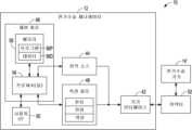
도 2는 전기수술 기기에 의해 맞물린 생체 조직을 봉합하기(sealing) 위한 전기수술 시스템의 블록도이다.
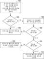
도 3a 내지 도 3b는 전기수술 기기에 의해 맞물린 생체 조직을 봉합하기 위한 방법의 흐름도이다.
도 4는 봉합되고 있는 생체 조직에 제공되는 전력을 제어하는 데에 사용되는 전력 스케줄의 예를 묘사하는 그래프이다.
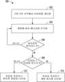
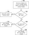
도 5는 수술 시스템(surgical system)에서 사용될 수 있는 개방 회로(open circuit) 체크 기법의 예를 묘사하는 흐름도표이다.
도 6은 전기수술 기기에 의해 맞물린 생체 조직의 크기에 대응하는 전력 스케줄을 사용하는 생체 조직 봉합 방법의 흐름도이다.
도 7a는 측정된 조직 저항(tissue resistance)을 겸자의 조 온도(jaw temperature)의 함수로서 묘사하는 그래프이다.
도 7b는 전력 인가의 종결 후 시간에 대비하여(vs.) 조 온도를 묘사하는 그래프이다.
도 8은 전력 인가 후 시간에 대비하여 저항 보상(compensation)을 묘사하는 그래프이다.
도 9는 전력 인가 후 시간의 함수로서 조직 저항의 측정을 보상하기 위한 방법의 흐름도를 묘사한다.
도 10a 내지 도 10d는 펄스화된 점착 저감 부분(pulsed sticking reduction portion)을 갖는 전자요법의 전자요법 신호의 전기적 파라미터의 그래프이다.
도 11은 생체 조직 및 전기수술 기기 간의 점착을 저감하기 위한 방법의 흐름도이다.
도 12는 내부에 금속 물체가 있는 생체 조직 및 내부에 금속 물체가 없는 생체 조직의 임피던스 각도(impedance-angle)/시간 관계의 예를 묘사하는 그래프이다.
도 13은 전기수술 기기에 의해 맞물린 생체 조직 내의 금속 물체의 존재 또는 부재를 판정하기 위한 방법의 흐름도이다.
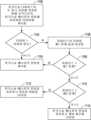
도 14는 수술 시스템에서 사용될 수 있는 이중 경계(two-boundary) 기법의 예를 묘사하는 흐름 도표이다.
도 15는 수술 시스템에서 사용될 수 있는 개방 회로 체크 기법의 예를 묘사하는 흐름 도표이다.
도 16은 수술 시스템에서 사용될 수 있는 개방 회로 체크 기법의 다른 예를 묘사하는 흐름 도표이다.
도 17은 수술 시스템에서 사용될 수 있는 전력 교정(power correction) 기법의 예를 묘사하는 흐름 도표이다.
도 18은 이 개시의 다양한 기법을 구현할 수 있는 조합 초음파 에너지 및 전기수술 에너지 시스템(combination ultrasonic energy and electrosurgical energy system)의 예의 단순화된 블록도이다.
도 19는 조합 초음파 에너지 및 전기수술 에너지 시스템에서 사용될 수 있는 저감된 열적 마진(reduced thermal margin) 기법의 예를 묘사하는 흐름 도표이다.
도 20은 전기수술 시스템에서 사용될 수 있는 열적 마진 제어 기법의 예를 묘사하는 흐름 도표이다.
도 21은 전기수술 시스템에서 사용될 수 있는 열적 마진 제어 기법의 다른 예를 묘사하는 흐름 도표이다.
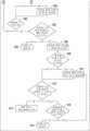
도 22a 내지 도 22d는 에너지 전달 기법(이는, 무엇보다도, 그것의 의사결정 프로세스에서 생체 조직에 전달되는 에너지의 양을 사용할 수 있음)의 예의 흐름 도표이다.
도 23은 전력에서의 변화에 대한 측정된 전기적 파라미터의 값에서의 변화 간의 관계의 예를 묘사하는 그래프이다.
도 24는 수술 시스템에서 사용될 수 있는 전력 교정 기법의 다른 예를 묘사하는 흐름 도표이다.Figure 1 is a perspective view of an electrosurgical system that provides electrical therapy to the biological tissue of a surgical patient.
Figure 2 is a block diagram of an electrosurgical system for sealing interlocked biological tissues by an electrosurgical device.
Figures 3a and 3b are flow charts of a method for suturing interlocked biological tissues using an electrosurgical device.
Figure 4 is a graph depicting an example of a power schedule used to control the power provided to the biological tissue being sutured.
Figure 5 is a flow diagram depicting an example of an open circuit checking technique that may be used in a surgical system.
Figure 6 is a flow diagram of a method for suturing biological tissue using a power schedule corresponding to the size of biological tissue engaged by an electrosurgical device.
Figure 7a is a graph depicting the measured tissue resistance as a function of the jaw temperature of the forceps.
Figure 7b is a graph depicting the temperature of the substrate versus time after termination of power application.
Figure 8 is a graph depicting resistance compensation versus time after power application.
Figure 9 depicts a flow diagram of a method for compensating for measurements of tissue resistance as a function of time after power application.
FIGS. 10A to 10D are graphs of electrical parameters of an electrotherapy signal of an electrotherapy device having a pulsed sticking reduction portion.
Figure 11 is a flow chart of a method for reducing adhesion between living tissue and an electrosurgical device.
Figure 12 is a graph depicting examples of impedance-angle/time relationships for biological tissue with a metal object inside and biological tissue without a metal object inside.
FIG. 13 is a flow chart of a method for determining the presence or absence of a metal object within a biological tissue engaged by an electrosurgical device.
Figure 14 is a flow diagram depicting an example of a two-boundary technique that may be used in a surgical system.
Figure 15 is a flow diagram depicting an example of an open circuit check technique that may be used in a surgical system.
Figure 16 is a flow diagram depicting another example of an open circuit check technique that may be used in a surgical system.
Figure 17 is a flow diagram depicting an example of a power correction technique that may be used in a surgical system.
FIG. 18 is a simplified block diagram of an example of a combination ultrasonic energy and electrosurgical energy system that can implement various techniques of this disclosure.
Figure 19 is a flow diagram depicting an example of a reduced thermal margin technique that may be used in a combination ultrasound energy and electrosurgical energy system.
Figure 20 is a flow diagram depicting an example of a thermal margin control technique that may be used in an electrosurgical system.
Figure 21 is a flow diagram depicting another example of a thermal margin control technique that may be used in an electrosurgical system.
Figures 22a to 22d are flow diagrams of examples of energy transfer techniques (which may, among other things, use the amount of energy transferred to a living tissue in its decision-making process).
Figure 23 is a graph depicting an example of the relationship between changes in values of measured electrical parameters with changes in power.
Figure 24 is a flow diagram depicting another example of a power correction technique that may be used in a surgical system.
장치 및 연관된 방법은 전기수술 기기에 의해 맞물린 생체 조직에의 전기요법 신호의 인가에 관련된다. 이들 전기요법 신호의 다양한 전기적 메트릭의 제어가 아래에서 개시될 것인데 그러한 제어를 수행하는 구체적인 전기수술 기법도 그러할 것이다. 이 명세서는 다음의 표제로 된 부문으로 편성된다: i) 전기요법 신호의 전력 제어 (도 1 내지 도 4); ii) 전기요법 신호의 예측적 국면 제어(predictive phase control) (도 5 내지 도 6); iii) 맞물린 생체 조직의 측정된 전기 저항(electrical resistance)의 교정 (도 7a 내지 도 7b 및 도 9); iv) 초기 임피던스의 수정 (도 9); v) 전기요법 신호의 전력을 펄스화함으로써 전기수술 기기에의 생체 조직의 점착을 저감하는 것 (도 10a 내지 도 10d 및 도 11); vi) 전기수술 기기에 의해 맞물린 생체 조직 내의 도전성 이물질(conductive foreign body)의 존재 또는 부재를 판정하는 것 (도 12 및 도 13); vii) 트리거(trigger) 및 이스케이프(escape) 값 간의 대역(band)을 이용한 단락 회로 에러 트래핑(short circuit error trapping) (도 14); viii) 임피던스 한계 종료점 파형(impedance limit endpoint waveform)을 위한 개방 회로 체크 (도 15 및 도 16); ix) 저 정확도 하드웨어 시스템에서의 교번(alternate) 전력 교정 출력 (도 17); x) 저감된 열적 마진 조합 에너지 디바이스 (도 18 및 도 19); xi) 느린 CPU를 가진 시스템에서 열적 마진을 제어하는 단계적(staged) 임피던스 값 (도 20 및 도 21); xii) 소모된 에너지 모니터링 및 개방 회로 평가 (도 22a 내지 도 22d); xiii) 펄스 간의 유지 시간(dwell time); 및 xiv) 모니터링되는 변수의 함수로서의 제어 파라미터의 점증적 조정(incremental adjustment). 오직 설명의 목적으로 이들 별개의 부문에서 기법이 기술된다. 반대로 명시적으로 진술되지 않는 한, 이들 기법 각각은 이 개시에 기술된 다른 기법 중 하나 이상과의 조합으로 사용될 수 있다.The device and associated methods relate to the application of electrotherapy signals to engaged biological tissue by an electrosurgical device. Control of various electrical metrics of these electrosurgical signals will be described below, as will specific electrosurgical techniques for performing such control. This specification is organized into sections entitled: i) power control of electrotherapy signals (FIGS. 1 to 4); ii) predictive phase control of electrotherapy signals (FIGS. 5 to 6); iii) correction of measured electrical resistance of engaged biological tissue (FIGS. 7A to 7B and FIG. 9); iv) modification of initial impedance (FIG. 9); v) reducing adhesion of biological tissue to an electrosurgical device by pulsing the power of the electrotherapy signal (FIGS. 10A to 10D and FIG. 11); vi) Determining the presence or absence of a conductive foreign body in a biological tissue engaged by an electrosurgical device (Figs. 12 and 13); vii) Short circuit error trapping using a band between trigger and escape values (Fig. 14); viii) Open circuit check for impedance limit endpoint waveform (Figs. 15 and 16); ix) Alternate power correction output in low accuracy hardware systems (Fig. 17); x) Reduced thermal margin combined energy device (Figs. 18 and 19); xi) Staged impedance value for controlling thermal margin in systems with slow CPU (Figs. 20 and 21); xii) Consumed energy monitoring and open circuit evaluation (Figs. 22a to 22d); xiii) Dwell time between pulses; and xiv) incremental adjustment of the control parameter as a function of the monitored variable. The techniques are described in these separate sections for illustrative purposes only. Unless explicitly stated to the contrary, each of these techniques may be used in combination with one or more of the other techniques described in this disclosure.
전기요법 신호의 전력 제어 (도 1 내지 도 4)Power control of electrotherapy signals (Figs. 1 to 4)
전기수술 기기에 의해 맞물린 생체 조직을 전기수술적으로 봉합하거나 응고시키는 것은 다양한 의료 시술에서 사용되는 전기수술 기법이다. 맞물린 생체조직은 맞물린 생체 조직을 제어되는 방식으로 가열함으로써 전기수술적으로 봉합될 수 있다. 몇몇 의료 시술에서, 봉합되고 있는 생체 조직은 혈관이다. 혈관의 가열은 혈관 벽에서 발견되는 콜라겐(collagen)으로 하여금 변성되게(denatured) 한다. 이 변성된 콜라겐은 혈관 벽 사이에서 접착제(glue)로서 작용하는 겔상(gel-like) 물질을 형성한다. 냉각(cooling) 동안에 강제로 함께하게 되고 함께 유지되는 경우에, 혈관의 대향하는(opposite) 벽은 이후에 봉합을 형성할 것이다.Electrosurgical sealing or coagulation of interlocked biological tissues by electrosurgical devices is an electrosurgical technique used in a variety of medical procedures. Interlocked biological tissues can be sealed electrosurgically by controlling heating of the interlocked biological tissues. In some medical procedures, the biological tissue being sealed is a blood vessel. Heating the blood vessel causes the collagen found in the blood vessel walls to denature. This denatured collagen forms a gel-like substance that acts as a glue between the blood vessel walls. When forced together and held together during cooling, the opposing walls of the blood vessel will subsequently form a seal.
혈관의 가열은 너무 적지도 않고 너무 많지도 않은 에너지가 혈관에 제공되도록 신중하게 제어된다. 만일 너무 많은 에너지가 거기에 제공되면, 혈관의 탄화(charring) 및/또는 분소(burning)가 일어날 수 있다. 만일 너무 적은 에너지가 거기에 제공되면, 혈관의 봉합 질이 불량할 수 있다. 봉합 질의 하나의 척도는 봉합된 혈관이 파열 없이 견딜 수 있는 압력차(pressure difference)이다. 저질 봉합은 거기에 가해지는 압력이 어떤 값을 초과하는 경우에 오손될(compromised) 수 있다.The heating of the vessel is carefully controlled so that not too little or too much energy is supplied to the vessel. If too much energy is supplied there, charring and/or burning of the vessel may occur. If too little energy is supplied there, the quality of the vessel seal may be poor. One measure of the quality of the seal is the pressure difference that the sutured vessel can withstand without rupture. A poor quality seal may be compromised if the pressure applied to it exceeds a certain value.
에너지가 혈관에 제공되는 속도가 또한 전기수술 시술(electrosurgical procedure)의 빠른 수행을 원활하게 하기 위하여 신중하게 제어될 수 있다. 전기수술 시술의 빠른 수행은 이들 시술의 시간 및 어려움을 저감한다. 그러나, 가열의 속도는 생체 조직 내의 유체(fluid)의 제어되지 않은 비등(boiling)을 야기할 만큼 빨라서는 안 된다. 제어되지 않은 비등은 맞물린 또는 인근의 생체 조직을 파열시키고/거나 봉합의 질을 오손할 수 있다.The rate at which energy is delivered to the blood vessel can also be carefully controlled to facilitate rapid performance of electrosurgical procedures. Rapid performance of electrosurgical procedures reduces the time and difficulty of these procedures. However, the rate of heating should not be so rapid as to cause uncontrolled boiling of the fluid within the biological tissue. Uncontrolled boiling can rupture interlocked or adjacent biological tissue and/or compromise the quality of the suture.
맞물린 생체 조직의 가열은 맞물린 생체 조직에 제공되고 이에 의해 소비되는 전기요법 신호의 전력을 제어함으로써 제어될 수 있다. 그러한 전력은 봉합 스케줄에 따라 제어될 수 있다. 예를 들어, 봉합 스케줄은 맞물린 생체 조직에 의해 도전되는(conducted) 전류 및 맞물린 생체 조직을 가로지르는 전압차(voltage difference)의 곱(product)을 나타낼 수 있다. 그러므로, 봉합 스케줄은 전력 스케줄이다. 몇몇 예에서, 전기요법 신호는 종결 규준(criterion)이 충족됨에 응답하여 종결되거나 저감될 수 있다. 몇몇 예에서, 종결 규준은, 예를 들어, 맞물린 생체 조직에 의해 도전되는 전류의 감소와 같은 전류 특성이다. 몇몇 예에서, 종결 규준은, 예를 들어, 맞물린 생체 조직의 전기 저항의 증가와 같은 저항 특성이다. 사전결정된 델타(delta) 저항 값을 초과하는 전기 저항의 그러한 증가는 종결 규준으로서 사용될 수 있는데, 예를 들어, 사전결정된 델타 저항 값은 측정된 저항(또는 임피던스) 및 펄스 내에서 측정되는 저항(또는 임피던스)의 최저 값 간의 차이이다. 몇몇 예에서, 종결 규준은 어떤 조건에 기반하여 사전결정되거나 계산된, 예를 들어, 지속 시간(time duration)과 같은 시간적(temporal) 조건이다.The heating of the interdigitated biological tissue can be controlled by controlling the power of the electrical therapy signal provided to and consumed by the interdigitated biological tissue. Such power can be controlled according to a sealing schedule. For example, the sealing schedule can represent the product of the current conducted by the interdigitated biological tissue and the voltage difference across the interdigitated biological tissue. Therefore, the sealing schedule is a power schedule. In some instances, the electrical therapy signal can be terminated or reduced in response to a termination criterion being met. In some instances, the termination criterion is a current characteristic, such as a decrease in the current conducted by the interdigitated biological tissue. In some instances, the termination criterion is a resistance characteristic, such as an increase in the electrical resistance of the interdigitated biological tissue. Such an increase in electrical resistance exceeding a predetermined delta resistance value may be used as a termination criterion, for example, the predetermined delta resistance value being the difference between the measured resistance (or impedance) and the lowest value of resistance (or impedance) measured within the pulse. In some examples, the termination criterion is a temporal condition, such as a time duration, that is predetermined or calculated based on some condition.
전기적 임피던스는 복소수이며, 따라서, 실수 성분(저항) 및 허수 성분(리액턴스(reactance))을 포함한다. 이 문헌은 임피던스 또는 저항을 사용하는 기법을 기술한다. 복소수 임피던스 값이 이용가능한 경우에, 그러한 값이 저항 값 대신에 사용될 수 있음이 이해되어야 한다. 역으로, 어떤 복소수 임피던스 값도 이용가능하지 않은 경우에, 달리 진술되지 않는 한 저항 값이 대신 사용될 수 있다.Electrical impedance is complex and therefore contains a real component (resistance) and an imaginary component (reactance). This document describes techniques using either impedance or resistance. It should be understood that where complex impedance values are available, such values may be used in place of resistance values. Conversely, where no complex impedance values are available, resistance values may be used instead, unless otherwise stated.
추가로, 아래의 기법 중 다수는 전기수술 에너지를 생체 조직에 전달하는 것을 기술한다. 반대로 나타내어지지 않는 한, 이들 기법 각각은 전력 제어식(power-controlled) 기법이나 전압 제어식(voltage-controlled) 기법 어느 것이든 사용하여 전기수술 에너지를 전달할 수 있다. 전력 제어식 구현에서, 제어 회로는, 가령, 계획 또는 스케줄에 따라, 맞물린 생체 조직을 가로질러 인가된 전압 및 전류의 곱을 사용하여 전기수술 에너지의 전달을 제어할 수 있다. 예를 들어, 제어 회로는 특정한 국면, 가령, 건조 국면 동안에 일정한(constant) 전력 또는 단조적으로 증가하는(monotonically increasing) 전력의 전달을 제어할 수 있다.Additionally, many of the techniques below describe delivering electrosurgical energy to biological tissue. Unless otherwise indicated, each of these techniques can deliver electrosurgical energy using either a power-controlled or a voltage-controlled technique. In a power-controlled implementation, the control circuit can control the delivery of electrosurgical energy using the product of voltage and current applied across the engaged biological tissue, e.g., according to a plan or schedule. For example, the control circuit can control the delivery of constant power or monotonically increasing power during a particular phase, e.g., a drying phase.
이 문헌은, 무엇보다도, 전기요법(이는 치료 또는 다른 계획에 따라 제공될 수 있음)을 제공하기 위한 하나 이상의 기법을 기술한다. 계획은 식이방(recipe), 처방(prescription), 섭생법(regimen), 방법론(methodology), 또는 유사한 것을 포함할 수 있다. 계획은 발생 또는 재발(또는 저해 또는 억제) 타이밍, 주파수, 타입, 상대적 조합(가령, 절개에 대한 응고) 또는 유사한 것을 포함할 수 있는 것과 같은, 스케줄과 같은, 하나 이상의 시간적 양상을 포함할 수 있다. 계획은 펄스 폭(pulse width), 듀티 사이클(duty cycle), 온 지속기간(on duration), 오프 지속기간(off duration), 반복률(repetition rate), 진폭(amplitude), 위상(phase), 또는 유사한 것을 포함할 수 있는 것과 같은, 전기요법 파형 정보를 포함할 수 있다. 계획은 본질상 선험적(a priori)이거나 정적(static)일 필요가 없고, 예컨대, 폐루프(closed-loop), 또는 다른 피드백(feedback) 방식을 포함하여, 전기요법 전달 인스턴스(instance) 동안에 또는 사이에 획득된 진단적(diagnostic), 동작적(operational), 또는 다른 정보에 의해, 수정되거나 좌우될 수 있는 것과 같은, 하나 이상의 동적 양상을 포함할 수 있다. 계획의 하나 이상의 양상은, 예컨대 특정 환자에, 하나 이상의 지정된 특성을 공유하는 이와 같은 환자 중의 하위개체군(sub-population)에, 또는 환자의 개체군에 맞춰질(tailored) 수 있는데, 예컨대 저장된 환자 데이터에 기반하거나, 환자에 의해 또는 간병인에 의해 제공될 수 있는 것과 같은 사용자 입력에 의할 수 있다. 계획은 환자 특성, 진단적 척도, 효능 판정, 또는 디바이스 또는 그것의 환경의 동작적 특성을 사용하여 판정될 수 있는 것과 같은, 하나 이상의 분기 조건(branch condition)을 포함할 수 있는 것과 같은, 하나 이상의 조건부 양상을 포함할 수 있다. 그러한 분기 조건은 자동으로, 디바이스에 의해, 가령, 사용자 입력을 요구하지 않고서 판정될 수 있거나, 계획에 따라 전기요법 디바이스의 동작의 하나 이상의 부분 전에, 그 동안에, 또는 그 후에 제공될 수 있는 것과 같은, 사용자 입력을 수반할 수 있다. 계획은, 예컨대 입력, 출력, 또는 명령어, 동작 파라미터, 또는 측정된 데이터 중 하나 또는 임의의 조합을 수신하거나 제공하기 위해, 다른 디바이스로써 또는 이를 사용하여 통신하는 것을 수반할 수 있다. 계획의 하나 이상의 양상은 컴퓨터 또는 다른 머신 판독가능 매체(예컨대 유형적(tangible) 매체일 수 있음)와 같은 매체 상에 기록되거나 인코딩될 수 있다.This document describes, among other things, one or more techniques for providing electrotherapy (which may be provided according to a treatment or other plan). The plan may include a recipe, a prescription, a regimen, a methodology, or the like. The plan may include one or more temporal aspects, such as a schedule, which may include timing of onset or recurrence (or inhibition or suppression), frequency, type, relative combination (e.g., coagulation for incision), or the like. The plan may include electrotherapy waveform information, such as pulse width, duty cycle, on duration, off duration, repetition rate, amplitude, phase, or the like. The plan need not be a priori or static in nature, but may include one or more dynamic aspects, such as being modified or influenced by diagnostic, operational, or other information acquired during or between instances of the electrotherapy delivery, including, for example, by closed-loop or other feedback mechanisms. One or more aspects of the plan may be tailored, for example, to a particular patient, to a sub-population of such patients sharing one or more designated characteristics, or to a population of patients, such as based on stored patient data, or by user input, such as may be provided by the patient or a caregiver. The plan may include one or more conditional aspects, such as may include one or more branch conditions, such as may be determined using patient characteristics, diagnostic measures, efficacy assessments, or operational characteristics of the device or its environment. Such branching conditions may be determined automatically by the device, for example, without requiring user input, or may involve user input, such as being provided before, during, or after one or more portions of the operation of the electrotherapy device according to the plan. The plan may involve communicating with or using another device, for example, to receive or provide one or any combination of inputs, outputs, or commands, operating parameters, or measured data. One or more aspects of the plan may be recorded or encoded on a medium, such as a computer or other machine-readable medium (which may be a tangible medium, for example).
전압 제어식 구현에서, 제어 회로는, 가령, 계획, 섭생법, 또는 스케줄에 따라, 전달되는 전기수술 에너지의 전압을 제어할 수 있다. 예를 들어, 제어 회로는 특정한 국면, 가령, 건조 국면 동안에 일정한 전압 또는 단조적으로 증가하는 전압의 전달을 제어할 수 있다.In a voltage-controlled implementation, the control circuit can control the voltage of the electrosurgical energy delivered, for example, according to a plan, regimen, or schedule. For example, the control circuit can control the delivery of a constant voltage or a monotonically increasing voltage during a particular phase, such as a drying phase.
도 1은 수술 환자의 생체 조직에 전기요법을 제공하는 전기수술 시스템의 사시도이다. 도 1에서, 전기수술 시스템(10)은 전기수술 제너레이터(12) 및 겸자(14)(생체 조직(16)을 맞무는 것으로 도시됨)를 포함한다. 전기수술 제너레이터(12)는 맞물린 생체 조직(16)에 겸자(14)를 통해 제공되는 전기요법 신호를 생성하고 있다. 도 1은 생체 조직(14)을 맞물고 이에 전기요법 신호를 전달하는 겸자(14)를 묘사하나, 그러한 목적을 위해 위에서 개시된 것과 같은 다양한 타입의 전기수술 기기가 사용될 수 있다.FIG. 1 is a perspective view of an electrosurgical system for providing electrotherapy to biological tissue of a surgical patient. In FIG. 1, the electrosurgical system (10) includes an electrosurgical generator (12) and forceps (14) (illustrated engaging biological tissue (16)). The electrosurgical generator (12) generates an electrotherapy signal that is provided through the forceps (14) to the engaged biological tissue (16). Although FIG. 1 depicts the forceps (14) engaging the biological tissue (14) and delivering the electrotherapy signal thereto, various types of electrosurgical devices, such as those disclosed above, may be used for such purposes.
다양한 타입의 겸자도 생체 조직(14)에 전기요법 신호를 전달하기 위해 사용될 수 있다. 예를 들어, 겸자(14)는 의료 겸자, 절개 겸자, 또는 전기수술 겸자(가령, 단극 또는 양극 겸자)일 수 있다. 겸자(14)는, 몇몇 예에서, 혈관, 생체 조직, 정맥, 동맥, 또는 다른 해부학적 특징 또는 대상을 조작하거나, 맞물거나, 쥐거나, 절개하거나, 지지거나, 봉합하거나, 달리 이에 영향을 미치기 위해 개복 및/또는 복강경 의료 시술과 같은 의료적으로 관련된 시술을 위해 사용될 수 있다.Various types of forceps may also be used to deliver electrotherapy signals to biological tissue (14). For example, the forceps (14) may be medical forceps, cutting forceps, or electrosurgical forceps (e.g., monopolar or bipolar forceps). The forceps (14) may, in some examples, be used for medically related procedures, such as open and/or laparoscopic medical procedures, to manipulate, engage, grasp, incise, support, suture, or otherwise affect blood vessels, biological tissue, veins, arteries, or other anatomical features or objects.
도 1에 예시된 바와 같이, 겸자(14)는 핸드 피스(hand piece)(18), 샤프트 조립체(shaft assembly)(20), 칼날 조립체(knife blade assembly)(22) 및 파지 조립체(gripping assembly)(24)를 포함한다. 도 1의 예시된 예와 같은 몇몇 예에서, 겸자(14)는 전기수술 제너레이터(12)(이는 전기요법 신호를 생성하고 생성된 전기요법 신호를 겸자(14)에 제공함)에 전기적으로 연결된다. 겸자(14)는 이후에 전기요법 신호를 파지 조립체(24) 및/또는 원격 패드(remote pad)(이는 소작, 봉합, 또는 다른 그러한 전기수술 기법과 같은 다양한 전기수술 기법을 위해 이용될 수 있음)에 전기적으로 통신한다.As illustrated in FIG. 1, the forceps (14) includes a hand piece (18), a shaft assembly (20), a knife blade assembly (22), and a gripping assembly (24). In some examples, such as the illustrated example of FIG. 1, the forceps (14) is electrically connected to an electrosurgical generator (12) (which generates an electrotherapy signal and provides the generated electrotherapy signal to the forceps (14). The forceps (14) then electrically communicates the electrotherapy signal to the gripping assembly (24) and/or a remote pad (which may be utilized for various electrosurgical techniques, such as cauterization, suturing, or other such electrosurgical techniques).
핸드 피스(18)는 핸들(handle)(26), 파지 레버(gripping lever)(28), 칼 트리거(knife trigger)(30), 전기 요법 발동 버튼(electrical therapy actuation button)(32) 및 회전 휠(rotation wheel)(34)을 포함한다. 파지 조립체(24)는 제1 조 부재(jaw member)(36) 및 제2 조 부재(38)를 포함한다. 샤프트 조립체(20)는 근위 말단(proximal end)에서 핸드 피스(18)에, 그리고 원위 말단(distal end)에서 파지 조립체(24)에 연결된다. 샤프트 조립체(20)는 핸드 피스(18)로부터 길이 방향(40)으로 파지 조립체(24)에 원위로 연장된다.The hand piece (18) includes a handle (26), a gripping lever (28), a knife trigger (30), an electrical therapy actuation button (32), and a rotation wheel (34). The gripping assembly (24) includes a first jaw member (36) and a second jaw member (38). A shaft assembly (20) is connected to the hand piece (18) at a proximal end and to the gripping assembly (24) at a distal end. The shaft assembly (20) extends distally from the hand piece (18) in a longitudinal direction (40) to the gripping assembly (24).
샤프트 조립체(20)는 겸자(14)의 일부분(가령, 파지 조립체(24) 및 샤프트 조립체(20)의 원위 부분)으로 하여금 겸자(14)의 나머지 부분(가령, 핸드 피스(18) 및 샤프트 조립체(20)의 나머지 근위 부분)이 환자 또는 다른 해부구조(anatomy) 바깥에 있으면서 환자 또는 다른 해부구조 내에 삽입될 수 있게 하도록 기능한다. 실질적으로 일직선인 것으로 도 1에 예시되나, 다른 예에서, 샤프트 조립체(20)는 하나 이상의 각도, 굴절(bend) 및/또는 호(arc)를 포함할 수 있다. 샤프트 조립체(20)는 핸드 피스(18)로부터 파지 조립체(24)로 연장되는 원형, 타원형, 또는 다른 횡단면 프로파일(profile), 또는 다른 연신된(elongated) 부재를 가진 실린더(cylinder)일 수 있다. 몇몇 예에서, 샤프트는 굴절가능(bendable), 조향가능(steerable) 또는 달리 편향가능(deflectable)할 수 있다.The shaft assembly (20) functions to allow a portion of the forceps (14) (e.g., the distal portion of the gripping assembly (24) and the shaft assembly (20)) to be inserted into a patient or other anatomy while the remainder of the forceps (e.g., the hand piece (18) and the remaining proximal portion of the shaft assembly (20)) is outside the patient or other anatomy. While illustrated in FIG. 1 as being substantially straight, in other examples, the shaft assembly (20) may include one or more angles, bends, and/or arcs. The shaft assembly (20) may be a cylinder having a circular, elliptical, or other cross-sectional profile, or other elongated member, extending from the hand piece (18) to the gripping assembly (24). In some examples, the shaft may be bendable, steerable or otherwise deflectable.
도 1의 예와 같은 몇몇 예에서, 샤프트 조립체(20)는 칼날 조립체(22) 및 칼날 조립체(22)를 칼 트리거(30)와 커플링하기 위한 기계적 결합(mechanical linkage)을 둘러싸는 연신된 공동(hollow) 부재(가령, 관상 외측 샤프트(tubular outer shaft))를 포함할 수 있다. 일반적으로, 샤프트 조립체는 길이 방향(40)을 따라서 힘을 전하기에 충분한 경직성(stiffness)을 갖는 임의의 길게 된 부재일 수 있다. 샤프트 조립체(20)는 핸드 피스(18) 및 파지 조립체(24) 간의 전기적 도통을, 이에 의해 전기요법 신호를 통신하기 위하여, 제공하는 도전성 요소(가령, 배선, 도전성 외측 샤프트 및/또는 도전성 내측 샤프트 등)를 또한 포함할 수 있다.In some examples, such as the example of FIG. 1, the shaft assembly (20) may include an elongated hollow member (e.g., a tubular outer shaft) surrounding the blade assembly (22) and a mechanical linkage for coupling the blade assembly (22) to the blade trigger (30). Generally, the shaft assembly may be any elongated member having sufficient stiffness to transmit force along its length (40). The shaft assembly (20) may also include conductive elements (e.g., wiring, a conductive outer shaft and/or a conductive inner shaft) that provide electrical conductivity between the hand piece (18) and the grip assembly (24), thereby communicating electrotherapy signals.
핸드 피스(18)의 파지 레버(28), 칼 트리거(30), 전기 요법 발동 버튼(32) 및 회전 휠(34)은 각각 샤프트 조립체(20)의, 통상적으로 원위 말단에서의, 다양한 발동을 야기하도록 구성된다. 예를 들어, 파지 레버(28)의 발동은 샤프트 조립체(20)의 원위 말단에서의 파지 조립체(24)의 동작을 제어하도록 구성된다. 파지 레버(28)는 (도 1에 예시된) 열린 구성 위치(open configuration position) 및 파지 레버(28)가 근위로 핸들(26)을 향해 옮겨진 닫힌 구성 위치(closed configuration position) 간에 가동적(movable)인 파지 발동기(gripping actuator)이다. 닫힌 구성 위치로의 핸들(26)을 향한 근위로의 파지 레버(28)의 움직임은 파지 조립체(24)로 하여금 열린 구성으로부터 닫힌 구성으로 전이하게(transition) 한다. 원위로의 파지 레버(28)의 움직임(가령, 열린 구성 위치로의 파지 레버(28)의 해제(release))은 파지 조립체(24)로 하여금 닫힌 구성으로부터 열린 구성으로 전이하게 한다.The grip lever (28), the knife trigger (30), the electrotherapy activation button (32), and the rotation wheel (34) of the hand piece (18) are each configured to cause various actuations of the shaft assembly (20), typically at the distal end. For example, actuation of the grip lever (28) is configured to control movement of the grip assembly (24) at the distal end of the shaft assembly (20). The grip lever (28) is a gripping actuator that is movable between an open configuration position (illustrated in FIG. 1) and a closed configuration position in which the grip lever (28) is moved proximally toward the handle (26). Movement of the grip lever (28) proximally toward the handle (26) to the closed configuration causes the grip assembly (24) to transition from the open configuration to the closed configuration. Movement of the grip lever (28) distally (e.g., releasing the grip lever (28) to the open configuration position) causes the grip assembly (24) to transition from the closed configuration to the open configuration.
파지 조립체(24)의 열린 구성 및 닫힌 구성 간의 그러한 전이는 제1 및 제2 조 부재(36 및 38) 중 하나 이상이 (도 1에 예시된) 열린 구성(여기에서 제1 및 제2 조 부재(36 및 38)는 이격됨) 및 닫힌 구성(여기에서 제1 및 제2 조 부재(36 및 38) 간의 간극이 저감되거나 제거됨) 간에 움직이는 것에 의해 실현된다. 다양한 전기수술 기기는 다양한 방식으로 생체 조직(16)을 맞문다. 도 1에 예시된 것과 같은 몇몇 전기수술 기기에서, 제1 및 제2 조 부재(36 및 38)는 서로 대향가능하다. 묘사된 예에서 제1 및 제2 조 부재(36 및 38)는 대향가능한 조 부재(36 및 38) 간의 전기적 도통을 조여진 생체 조직(16)을 통해 제공하는 방식으로 이들 간의 생체 조직(16)을 죄도록 구성된다. 다른 전기수술 기기는 다른 방식으로 생체 조직을 맞물 수 있다.Such a transition between the open and closed configurations of the phage assembly (24) is accomplished by moving at least one of the first and second joint members (36 and 38) between an open configuration (wherein the first and second joint members (36 and 38) are spaced apart) and a closed configuration (wherein the gap between the first and second joint members (36 and 38) is reduced or eliminated) (as illustrated in FIG. 1 ). Different electrosurgical devices engage biological tissue (16) in different ways. In some electrosurgical devices, such as the one illustrated in FIG. 1 , the first and second joint members (36 and 38) are opposable to one another. In the depicted example, the first and second joint members (36 and 38) are configured to clamp the biological tissue (16) therebetween in such a way as to provide electrical conductivity between the opposable joint members (36 and 38) through the clamped biological tissue (16). Other electrosurgical devices may engage biological tissue in different ways.
샤프트 조립체(20) 내의 기계적 결합은 제1 및 제2 조 부재(36 및 38) 중 하나 이상으로 하여금 파지 레버(28)의 발동에 응답하여 열린 구성 및 닫힌 구성 간에 움직이게 하도록 구성될 수 있다. 열린 구성 및 닫힌 구성 간의 파지 조립체의 움직임을 야기하기 위한 하나의 예시적인 메커니즘이 Batchelor 등에 대해 "FORCEPS JAW MECHANISM"이라는 표제가 붙여지고 2017년 1월 10일에 출원된 미국 특허 공개 제2017/0196579호에서 찾아볼 수 있는데, 그것의 내용은 이로써 그 전체로 참조에 의해 포함된다.The mechanical linkage within the shaft assembly (20) may be configured to cause one or more of the first and second jaw members (36 and 38) to move between open and closed configurations in response to actuation of the grip lever (28). One exemplary mechanism for causing movement of the grip assembly between open and closed configurations is found in U.S. Patent Publication No. 2017/0196579, filed Jan. 10, 2017, entitled “FORCEPS JAW MECHANISM,” to Batchelor et al., the contents of which are hereby incorporated by reference in their entirety.
칼 트리거(30)의 발동은 샤프트 조립체(20)의 원위 말단에 위치된 칼날 조립체(22)의 동작을 제어하도록 구성된다. 칼날 조립체(22)는 제1 및 제2 조 부재(36 및 38) 간에 조여진 생체 조직 또는 다른 대상(들)을 절개하거나, 척출하거나(excise), 달리 이에 영향을 미치도록 구성된다. 칼 트리거(30)는 (도 1에 예시된) 후퇴된(retracted) 구성 위치 및 칼날 조립체(22)로 하여금 제1 및 제2 조 부재(36 및 38) 간에 조여진 생체 조직(16)을 절개하게 하기 위해 칼 트리거(30)가 근위로 핸들(26)을 향해 옮겨진 전개된(deployed) 또는 연장된 구성 위치 간에 가동적인 칼날 발동기이다. 전개된 구성 위치로의 핸들(26)을 향한 근위로의 칼 트리거(30)의 움직임은 칼날 조립체(22)의 절개 날(cutting blade)로 하여금 생체 조직(16)에 맞물게 하는바, 이로써 생체 조직(16)을 절개한다. 원위로의 칼 트리거(30)의 움직임(가령, 칼 트리거(30)의 해제)은 칼날로 하여금 조여진 생체 조직(16)으로부터 후퇴하게 한다. 예를 들어 샤프트 조립체(20) 내에 있는, 기계적 결합은 칼날로 하여금 맞물린 생체 조직(16)에 맞물고 이로부터 후퇴하게 하도록 구성된다.Actuation of the blade trigger (30) is configured to control the motion of the blade assembly (22) positioned at the distal end of the shaft assembly (20). The blade assembly (22) is configured to incise, excise, or otherwise affect biological tissue or other object(s) clamped between the first and second jaw members (36 and 38). The blade trigger (30) is a blade actuator movable between a retracted configuration position (illustrated in FIG. 1) and a deployed or extended configuration position in which the blade trigger (30) is moved proximally toward the handle (26) to cause the blade assembly (22) to incise biological tissue (16) clamped between the first and second jaw members (36 and 38). Proximal movement of the knife trigger (30) toward the handle (26) toward the deployed configuration position causes the cutting blade of the knife assembly (22) to engage the biological tissue (16), thereby cutting the biological tissue (16). Distal movement of the knife trigger (30) (e.g., release of the knife trigger (30)) causes the blade to retract from the engaged biological tissue (16). For example, a mechanical linkage within the shaft assembly (20) is configured to cause the blade to engage and retract from the engaged biological tissue (16).
회전 휠(34)은 샤프트 조립체(20)의 원위 말단에서의 파지 조립체(24) 및 칼날 조립체(22) 중 하나 이상의 회전 구성을 제어하고/거나 샤프트 조립체(20)의 회전 구성을 제어하도록 구성된다. 회전 휠(34)의 움직임(가령, 회전)은 길이 방향(40)에서 연장되는 축에 대한 샤프트 조립체(20), 칼날 조립체(22) 및 파지 조립체(24) 중 하나 이상의 회전을 야기한다. 그러한 회전 제어는 조여진 생체 조직(16)과의 파지 조립체 및/또는 칼날 조립체의 정렬을 원활하게 할 수 있다.A rotating wheel (34) is configured to control the rotational configuration of one or more of the grip assembly (24) and the blade assembly (22) at the distal end of the shaft assembly (20) and/or to control the rotational configuration of the shaft assembly (20). The movement (e.g., rotation) of the rotating wheel (34) causes rotation of one or more of the shaft assembly (20), the blade assembly (22) and the grip assembly (24) about an axis extending in the longitudinal direction (40). Such rotational control can facilitate alignment of the grip assembly and/or the blade assembly with the tightened biological tissue (16).
요법 발동 버튼(32)은 맞물린 생체 조직(16)에의 전기요법 신호의 생성 및/또는 전달을 제어하도록 구성된다. 요법 발동 버튼(32)의 발동은 가령, 전기수술 제너레이터(12)로부터 인출된(drawn) 전기요법 신호로 하여금, 환자 또는 다른 해부구조를 지지거나, 봉합하거나, 달리 이에 전기적으로 영향을 미치기 위해 제1 및 제2 조 부재(36 및 38) 중 하나 이상, 원격 패드(예시되지 않음), 또는 겸자(14)의 다른 부분에 인가되게 한다. 파지 레버, 칼 트리거, 회전 휠 및 요법 발동 버튼을 활용하는 핸드 피스의 하나의 예가 Windgassen 등에 대해 "FORCEPS WITH A ROTATION ASSEMBLY"라는 표제가 붙여지고 2017년 6월 20일에 발행된 미국 특허 제9,681,883호에서 찾아볼 수 있는데, 그것의 내용은 이로써 그 전체로 참조에 의해 포함된다.A therapy trigger button (32) is configured to control the generation and/or delivery of an electrotherapy signal to the engaged biological tissue (16). Actuation of the therapy trigger button (32) causes an electrotherapy signal, drawn, for example, from an electrosurgical generator (12), to be applied to one or more of the first and second forceps members (36 and 38), a remote pad (not illustrated), or another portion of the forceps (14) to support, suture, or otherwise electrically influence a patient or other anatomical structure. One example of a hand piece utilizing a grip lever, a knife trigger, a rotation wheel, and a therapy trigger button is found in U.S. Pat. No. 9,681,883, issued June 20, 2017, to Windgassen et al., entitled "FORCEPS WITH A ROTATION ASSEMBLY," the contents of which are hereby incorporated by reference in their entirety.
도 2는 전기수술 기기에 의해 맞물린 생체 조직을 봉합하기 위한 전기수술 시스템의 블록도이다. 도 2에서, 전기수술 시스템(10)은 전기수술 제너레이터(12) 및 전기수술 기기(14')를 포함한다. 전기수술 기기(14')는 생체 조직에 맞물고 전기요법 신호를 전달하도록 구성된 임의의 전기수술 기기일 수 있다. 전기수술 제너레이터(12)는 전기수술 기기(14')가 맞물린 생체 조직(16)에 전달하는, 고주파수 (AC) 전기 신호와 같은 전기요법 신호를 생성하도록 구성된다.FIG. 2 is a block diagram of an electrosurgical system for suturing engaged biological tissue by an electrosurgical device. In FIG. 2, the electrosurgical system (10) includes an electrosurgical generator (12) and an electrosurgical device (14'). The electrosurgical device (14') may be any electrosurgical device configured to engage biological tissue and transmit an electrotherapy signal. The electrosurgical generator (12) is configured to generate an electrotherapy signal, such as an AC (high frequency) electrical signal, which the electrosurgical device (14') transmits to the engaged biological tissue (16).
몇몇 예에서, 전기수술 기기(14')는 대향가능한 조 부재에 샤프트 조립체를 통해 커플링된 핸드피스를 갖는 겸자, 예컨대 도 1에 묘사된 겸자(14)이다. 다른 예에서, 전기수술 기기(14')는 도전성 스패츌러, 도전성 패드, 또는 다른 전기수술 디바이스이다. 이들 다양한 타입의 전기수술 기기는 생체 조직을 맞무는 다양한 방식(가령, 죄기, 터치하기(touching), 둘러싸기(surrounding), 관통하기(penetrating), 방사하기(radiating) 등)을 갖는다.In some examples, the electrosurgical device (14') is a forceps having a handpiece coupled via a shaft assembly to an antagonistic member, such as the forceps (14) depicted in FIG. 1. In other examples, the electrosurgical device (14') is a conductive spatula, a conductive pad, or other electrosurgical device. These different types of electrosurgical devices have different ways of engaging biological tissue, such as by clamping, touching, surrounding, penetrating, radiating, etc.
전기수술 제너레이터(12)는 기기 인터페이스(42), 전기 에너지 소스(44), 측정 회로(46), 제어 회로(48) 및 사용자 인터페이스(50)를 포함한다. 기기 인터페이스(42)는, 예를 들어, 신호 드라이버(signal driver), 버퍼(buffer), 증폭기, ESD 보호 디바이스 및 전기적 커넥터(52)를 포함할 수 있다. 전기적 커넥터(52)는 전기수술 제너레이터(12) 및 전기수술 기기(14') 간의 전기적 도통을 제공하기 위하여 전기수술 제너레이터(12)에 전기수술 기기(14')를 전기적으로 커플링하도록 구성된다. 그러한 전기적 도통은 이들 간에 동작 전력 및/또는 전기 신호를 송신하는 데에 사용될 수 있다. 이어서, 전기수술 기기(14')는 전기적 커넥터(52) 및 이에 의해 맞물린 생체 조직 간의 전기적 도통을 제공할 수 있다.An electrosurgical generator (12) includes a device interface (42), an electrical energy source (44), measurement circuitry (46), control circuitry (48), and a user interface (50). The device interface (42) may include, for example, a signal driver, a buffer, an amplifier, an ESD protection device, and an electrical connector (52). The electrical connector (52) is configured to electrically couple an electrosurgical device (14') to the electrosurgical generator (12) to provide electrical conductivity between the electrosurgical generator (12) and the electrosurgical device (14'). Such electrical conductivity may be used to transmit operating power and/or electrical signals therebetween. In turn, the electrosurgical device (14') may provide electrical conductivity between the electrical connector (52) and the biological tissue engaged thereby.
전기 에너지 소스(44)는 전기적으로 연결된 전기수술 기기(14')를 통해, 맞물린 생체 조직에 전달될 전기요법 신호를 생성하도록 구성된다. 생성되는 전기요법 신호는 특정 전기수술 시술을 위한 요망되는 결과를 획득하기 위하여 제어될 수 있다. 하나의 예에서, 예를 들어, 전기요법 신호는 맞물린 생체 조직에 수술적으로 영향을 미치기 위하여, 예컨대, 이를 봉합하기 위하여, 맞물린 생체 조직을 저항성으로(resistively) 가열하도록 구성된다. 전기요법 신호의 그러한 제어는 아래에서 추가로 개시될 것이다.An electrical energy source (44) is configured to generate an electrotherapy signal to be delivered to the engaged biological tissue via an electrically connected electrosurgical device (14'). The generated electrotherapy signal can be controlled to achieve a desired result for a particular electrosurgical procedure. In one example, for example, the electrotherapy signal is configured to resistively heat the engaged biological tissue to surgically affect the engaged biological tissue, such as to seal it. Such control of the electrotherapy signal will be further disclosed below.
측정 회로(46)는 연결된 전기수술 기기(14')에 의해 맞물린 생체 조직의 하나 이상의 전기적 파라미터를 측정하도록 구성된다. 전기수술 제너레이터(12)가 전기적 커넥터(52)를 통해 전기수술 기기(14')에 전기적으로 연결된 경우에 측정 회로(46)는 연결된 전기수술 기기(14')와의 전기적 도통이 된다. 측정 회로(46)의 다양한 예는 다양한 전기적 파라미터를 측정하도록 구성된다. 예를 들어, 측정 회로(46)는 맞물린 생체 조직을 가로질러 전달되는 전압차 및/또는 맞물린 생체 조직에 의해 도전되는 전류를 측정하도록 구성될 수 있다. 몇몇 예에서, 측정 회로(46)는 맞물린 생체 조직을 가로질러 전달되는 전압차 및 맞물린 생체 조직에 의해 도전되는 전류 간의 위상 각도를 측정하도록 구성될 수 있다. 몇몇 예에서, 측정 회로(46)는 맞물린 생체 조직의 DC 및 또는 AC 전기적 파라미터를 측정하도록 구성된다.The measurement circuit (46) is configured to measure one or more electrical parameters of the engaged biological tissue by the connected electrosurgical device (14'). When the electrosurgical generator (12) is electrically connected to the electrosurgical device (14') via the electrical connector (52), the measurement circuit (46) is in electrical communication with the engaged electrosurgical device (14'). Various examples of the measurement circuit (46) are configured to measure various electrical parameters. For example, the measurement circuit (46) can be configured to measure a voltage difference transmitted across the engaged biological tissue and/or a current conducted by the engaged biological tissue. In some examples, the measurement circuit (46) can be configured to measure a phase angle between a voltage difference transmitted across the engaged biological tissue and a current conducted by the engaged biological tissue. In some examples, the measurement circuit (46) is configured to measure DC and/or AC electrical parameters of the engaged biological tissue.
측정된 파라미터, 예컨대 맞물린 생체 조직을 가로질러 전달되는 전압차 및/또는 맞물린 생체 조직에 의해 도전되는 전류는 다른 전기적 메트릭을 판정하는 데에 사용될 수 있다. 예를 들어, 맞물린 생체 조직을 가로질러 전달되는 전압차 및/또는 맞물린 생체 조직에 의해 도전되는 전류의 측정은 맞물린 생체 조직의 전기 저항을 판정하는 데에 사용될 수 있다. 맞물린 생체 조직을 가로질러 전달되는 전압차 및 맞물린 생체 조직에 의해 도전되는 전류의, 또 이들 간의 위상 각도의 측정은 맞물린 생체 조직의 복소수 임피던스를 판정하는 데에 사용될 수 있다. 맞물린 생체 조직을 가로질러 전달되는 전압차 및 맞물린 생체 조직에 의해 도전되는 전류의, 또 이들 간의 위상 각도의 측정은 맞물린 생체 조직에 제공하는 피상 전력(apparent power) (VA) 및/또는 실효 전력(real power) (W)를 판정하는 데에 또한 사용될 수 있다.The measured parameters, such as the voltage difference transmitted across the interdigitated biological tissue and/or the current conducted by the interdigitated biological tissue, can be used to determine other electrical metrics. For example, measurements of the voltage difference transmitted across the interdigitated biological tissue and/or the current conducted by the interdigitated biological tissue can be used to determine the electrical resistance of the interdigitated biological tissue. Measurements of the voltage difference transmitted across the interdigitated biological tissue and the current conducted by the interdigitated biological tissue, and the phase angle therebetween, can be used to determine the complex impedance of the interdigitated biological tissue. Measurements of the voltage difference transmitted across the interdigitated biological tissue and the current conducted by the interdigitated biological tissue, and the phase angle therebetween, can also be used to determine the apparent power (VA) and/or the real power (W) provided to the interdigitated biological tissue.
전기적 파라미터의 그러한 측정은 전기요법 신호를 맞물린 생체 조직에의 전달 동안에 제어하기 위해 사용될 수 있다. 예를 들어, 맞물린 생체 조직을 가로질러 전달되는 전압차의 측정 및 맞물린 생체 조직에 의해 도전되는 전류의 측정은 맞물린 조직에 제공되는 실효 전력을 판정하고/거나 제어하는 데에 사용될 수 있다. 이 판정된 실효 전력은 이후에 전기요법 스케줄과 비교될 수 있다. 그러한 비교는 에러 신호(error signal)을 생성하는 데에 사용될 수가 있다. 전기적 파라미터의 측정은 전기요법의 국면을 제어하기 위한 국면 제어(phase-control) 규준을 판정하는 데에 또한 사용될 수 있다. 국면 제어 규준은 국면내 제어(intra-phase control)를 위한 규준뿐만 아니라, 국면의 시작 및 종결을 위한 규준을 포함할 수 있다.Such measurements of electrical parameters may be used to control the delivery of an electrotherapy signal to the engaged biological tissue. For example, measurements of the voltage difference delivered across the engaged biological tissue and measurements of the current conducted by the engaged biological tissue may be used to determine and/or control the effective power delivered to the engaged biological tissue. This determined effective power may then be compared to an electrotherapy schedule. Such comparison may be used to generate an error signal. Measurements of electrical parameters may also be used to determine phase-control criteria for controlling a phase of the electrotherapy. The phase-control criteria may include criteria for intra-phase control, as well as criteria for starting and terminating a phase.
제어 회로(48)는 전기 에너지 소스(44) 및/또는 측정 회로(46)의 동작을 제어하도록 구성된다. 제어 회로(48)는 전기 에너지 소스(44) 및 측정 회로(46)에 전기적으로 연결된다. 제어 회로(48)는 전기 에너지 소스로 하여금 전기적으로 연결된 전기수술 기기(14')에 의해 맞물린 생체 조직에 전기요법 신호를 제공하게 한다. 제어 회로(48)는 전기 에너지 소스(44)로 하여금 생성된 전기요법 신호가 특정 전기수술 시술을 위해 제어되도록 전기요법 스케줄에 따라 전기요법 신호를 생성하게 한다.A control circuit (48) is configured to control the operation of an electrical energy source (44) and/or a measuring circuit (46). The control circuit (48) is electrically connected to the electrical energy source (44) and the measuring circuit (46). The control circuit (48) causes the electrical energy source to provide an electrotherapy signal to a biological tissue engaged by an electrically connected electrosurgical device (14'). The control circuit (48) causes the electrical energy source (44) to generate an electrotherapy signal according to an electrotherapy schedule such that the generated electrotherapy signal is controlled for a specific electrosurgical procedure.
다양한 전기요법 스케줄은 다양한 타입의 전기요법을 이루는 데에 사용될 수 있다. 예를 들어, 몇몇 예에서, 맞물린 생체 조직에 제공되는 전기요법 신호의 실효 전력 (W)은 전력 스케줄에 따라 제어된다. 다른 예에서, 맞물린 생체 조직을 가로질러 전달되는 전기요법 신호의 전압차 (V)는 전압 스케줄에 따라 제어된다. 다른 예에서, 맞물린 생체 조직에 의해 도전되는 전기요법 신호의 전류 (A)는 전류 스케줄에 따라 제어된다. 또 다른 예에서, 맞물린 생체 조직에 제공되는 전기요법 신호의 피상 전력 (VA)은 전압-전류량 스케줄(voltage-amperage schedule)에 따라 제어될 수 있다.Different electrotherapy schedules can be used to achieve different types of electrotherapy. For example, in some examples, the actual power (W) of the electrotherapy signal provided to the engaged biological tissue is controlled according to a power schedule. In other examples, the voltage difference (V) of the electrotherapy signal delivered across the engaged biological tissue is controlled according to a voltage schedule. In other examples, the current (A) of the electrotherapy signal challenged by the engaged biological tissue is controlled according to a current schedule. In yet other examples, the apparent power (VA) of the electrotherapy signal provided to the engaged biological tissue can be controlled according to a voltage-amperage schedule.
제어 회로(48)는, 예를 들어, 전기 에너지 소스(44)로 하여금, 맞물린 생체 조직을 가로지른 전압차 및 맞물린 생체 조직에 의해 도전되는 전류의 곱이 전기요법 스케줄에 따라 제어되도록, 맞물린 생체 조직에 에너지를 제공하게 할 수 있다. 제어 회로(48)는 판정된 실효 전력과 전기요법 스케줄과의 비교를 에러 신호를 생성하기 위해 사용할 수 있다. 그러한 에러 신호는, 전기요법 스케줄에 따라 전기요법 신호를 생성하기 위하여, 전기 에너지 소스(44)를 포함하는 폐루프 피드백 시스템에서 사용될 수 있다.The control circuit (48) can, for example, cause the electrical energy source (44) to provide energy to the engaged biological tissue such that the product of the voltage difference across the engaged biological tissue and the current challenged by the engaged biological tissue is controlled according to an electrotherapy schedule. The control circuit (48) can use a comparison of the determined actual power with the electrotherapy schedule to generate an error signal. Such an error signal can be used in a closed-loop feedback system including the electrical energy source (44) to generate an electrotherapy signal according to the electrotherapy schedule.
도 2에 예시된 바와 같이, 제어 회로(48)는 프로세서(54) 및 메모리(56)를 포함한다. 제어 회로(48)는 타이머(timer) 및/또는 클록(clock)을 포함할 수 있다. 몇몇 예에서, 타이머 및/또는 클록은 프로세서(54)의 일부이다. 다른 예에서, 타이머 및/또는 클록은 프로세서(54)와는 별개이다. 프로세서(54)는, 하나의 예에서, 전자수술 시스템(10) 내에서의 실행을 위해 기능을 구현하고/거나 명령어를 처리하도록 구성된다. 예를 들면, 프로세서(54)는 프로그램 메모리(56P) 내에 저장된 명령어로부터 수신하고/거나 처리하는 것이 가능할 수 있다. 이후에 프로세서(54)는 전기 에너지 소스(44)로 하여금 사전결정된 전기요법 스케줄에 따라 전기요법 신호를 생성하게 하기 위하여 프로그램 명령어를 실행할 수 있다. 사전결정된 전기요법 스케줄은, 예를 들어, 데이터 메모리(56D)로부터 색출될(retrieved) 수 있다. 프로세서(54)는 측정 회로(46)에 의해 측정된 전기적 파라미터를 색출된 사전결정된 전기요법 스케줄과 비교할 수 있다. 프로세서(54)는 전기 에너지 소스(44) 및/또는 측정 회로(46)에 명령을 발신할 수 있다. 프로세서(54)는 또한 사용자 인터페이스(50)로부터 정보를 수신하거나 발신할 수도 있다.As illustrated in FIG. 2, the control circuit (48) includes a processor (54) and a memory (56). The control circuit (48) may include a timer and/or a clock. In some examples, the timer and/or clock are part of the processor (54). In other examples, the timer and/or clock are separate from the processor (54). The processor (54) is configured to implement functionality and/or process instructions for execution within the electrosurgical system (10), in one example. For example, the processor (54) may be capable of receiving and/or processing instructions stored within the program memory (56P). The processor (54) may then execute the program instructions to cause the electrical energy source (44) to generate an electrosurgical signal according to a predetermined electrosurgical schedule. The predetermined electrosurgical schedule may be retrieved, for example, from the data memory (56D). The processor (54) can compare the electrical parameters measured by the measuring circuit (46) with the determined predetermined electrical therapy schedule. The processor (54) can issue commands to the electrical energy source (44) and/or the measuring circuit (46). The processor (54) can also receive or send information from the user interface (50).
다양한 예에서, 전기수술 제너레이터(12)는 도 2에 예시된 요소 또는 다양한 다른 요소를 사용하여 실현될 수 있다. 예를 들어, 프로세서(54)는 마이크로프로세서(microprocessor), 제어 회로, 디지털 신호 프로세서(Digital Signal Processor: DSP), 애플리케이션 특정 집적 회로(Application Specific Integrated Circuit: ASIC), 필드 프로그램가능 게이트 어레이(Field-Programmable Gate Array: FPGA), 또는 다른 균등한 이산(discrete) 또는 집적 로직(logic) 회로부 중 임의의 하나 이상을 포함할 수 있다.In various examples, the electrosurgical generator (12) may be implemented using the elements illustrated in FIG. 2 or various other elements. For example, the processor (54) may include any one or more of a microprocessor, a control circuit, a digital signal processor (DSP), an application specific integrated circuit (ASIC), a field-programmable gate array (FPGA), or other equivalent discrete or integrated logic circuitry.
메모리(56)는 동작 동안에 전기수술 시스템(10) 내에 정보를 저장하도록 구성될 수 있다. 메모리(56)는, 몇몇 예에서, 컴퓨터 판독가능 저장 매체로서 기술된다. 몇몇 예에서, 컴퓨터 판독가능 저장 매체는 비일시적(non-transitory) 매체를 포함할 수 있다. 용어 "비일시적"은 저장 매체가 반송파(carrier wave) 또는 전파되는 신호(propagated signal) 내에 체현되지 않음을 나타낼 수 있다. 어떤 예에서, 비일시적 저장 매체는, (가령, RAM 또는 캐시(cache) 내에) 시간에 걸쳐, 변화할 수 있는 데이터를 저장할 수 있다. 몇몇 예에서, 메모리(56)는 임시적 메모리(temporary memory)인데, 메모리(56)의 주 목적이 장기 저장(long-term storage)가 아님을 의미한다. 메모리(56)는, 몇몇 예에서, 휘발성 메모리(volatile memory)로서 기술되는데, 전기수술 시스템(10)으로의 전력이 오프(off)로 되는 경우에 메모리(56)가 저장된 내용을 유지하지 않음을 의미한다. 휘발성 메모리의 예는 랜덤 액세스 메모리(Random Access Memory: RAM), 동적 랜덤 액세스 메모리(Dynamic Random Access Memory: DRAM), 정적 랜덤 액세스 메모리(Static Random Access Memory: SRAM), 그리고 휘발성 메모리의 다른 형태를 포함할 수 있다. 몇몇 예에서, 메모리(56)는 프로세서(54)에 의한 실행을 위한 프로그램 명령어를 저장하는 데에 사용된다. 메모리(56)는, 하나의 예에서, 프로그램 실행 동안에, 예를 들어, 데이터 메모리(56D) 내에, 정보를 임시적으로 저장하기 위해, 전기의료 시스템(10) 상에서 가동되는 소프트웨어 또는 애플리케이션(가령, 전기수술 기기에 의해 맞물린 생체 조직에 제공하는 전기요법 신호의 전기적 제어를 구현하는 소프트웨어 프로그램)에 의해 사용된다.The memory (56) may be configured to store information within the electrosurgical system (10) during operation. The memory (56) is, in some instances, described as a computer-readable storage medium. In some instances, the computer-readable storage medium may include a non-transitory medium. The term "non-transitory" may indicate that the storage medium is not embodied in a carrier wave or a propagated signal. In some instances, the non-transitory storage medium may store data that can change over time (e.g., within RAM or a cache). In some instances, the memory (56) is a temporary memory, meaning that the primary purpose of the memory (56) is not long-term storage. Memory (56) is, in some examples, described as volatile memory, meaning that the memory (56) does not retain its stored contents when power to the electrosurgical system (10) is turned off. Examples of volatile memory may include Random Access Memory (RAM), Dynamic Random Access Memory (DRAM), Static Random Access Memory (SRAM), and other forms of volatile memory. In some examples, memory (56) is used to store program instructions for execution by the processor (54). Memory (56) is, in one example, used by software or applications running on the electrosurgical system (10) to temporarily store information, for example, in data memory (56D), during program execution, such as a software program that implements electrical control of electrotherapy signals provided to biological tissue engaged by the electrosurgical device.
몇몇 예에서, 메모리(56)는 하나 이상의 컴퓨터 판독가능 저장 매체를 또한 포함할 수 있다. 메모리(56)는 휘발성 메모리보다 더 많은 양의 정보를 저장하도록 구성될 수 있다. 메모리(56)는 또한 정보의 장기 저장을 위해 구성될 수 있다. 몇몇 예에서, 메모리(56)는 비휘발성(non-volatile) 저장 요소를 포함한다. 그러한 비휘발성 저장 요소의 예는 자기적 하드 디스크(magnetic hard disc), 광학적 디스크(optical disc), 플래시 메모리(flash memory), 또는 전기적 프로그램가능 메모리(Electrically Programmable Memory: EPROM) 또는 전기적 소거가능 및 프로그램가능(Electrically Erasable and Programmable: EEPROM) 메모리의 형태를 포함할 수 있다.In some examples, the memory (56) may also include one or more computer readable storage media. The memory (56) may be configured to store a greater amount of information than volatile memory. The memory (56) may also be configured for long-term storage of information. In some examples, the memory (56) includes non-volatile storage elements. Examples of such non-volatile storage elements may include forms of magnetic hard discs, optical discs, flash memory, or Electrically Programmable Memory (EPROM) or Electrically Erasable and Programmable (EEPROM) memory.
사용자 인터페이스(50)는 전기수술 시스템(10) 및 사용자(가령, 외과의 또는 기술자) 간에 정보를 통신하는 데에 사용될 수 있다. 사용자 인터페이스(50)는 통신 모듈을 포함할 수 있다. 사용자 인터페이스(50)는 다양한 사용자 입력 및 출력 디바이스를 포함할 수 있다. 예를 들어, 사용자 인터페이스는 다양한 디스플레이, 가청 신호 생성기를, 또 스위치, 버튼, 터치 스크린, 마우스, 키보드 등도 포함할 수 있다.The user interface (50) may be used to communicate information between the electrosurgical system (10) and a user (e.g., a surgeon or technician). The user interface (50) may include a communication module. The user interface (50) may include various user input and output devices. For example, the user interface may include various displays, audible signal generators, and also switches, buttons, touch screens, mice, keyboards, and the like.
사용자 인터페이스(50)는, 하나의 예에서, 하나 이상의 네트워크, 예컨대 하나 이상의 무선 또는 유선 네트워크 또는 양자 모두를 통해 외부 디바이스와 통신하는 데에 통신 모듈을 활용한다. 통신 모듈은 네트워크 인터페이스 카드, 예컨대 이더넷 카드(Ethernet card), 광학적 송수신기(optical transceiver), 무선 주파수 송수신기(radio frequency transceiver), 또는 정보를 발신하고 수신할 수 있는 임의의 다른 타입의 디바이스를 포함할 수 있다. 그러한 네트워크 인터페이스의 다른 예는 블루투스(Bluetooth), 3G, 4G 및 와이파이(Wi-Fi) 무선 컴퓨팅 디바이스를, 또 범용 직렬 버스(Universal Serial Bus: USB) 디바이스도 포함할 수 있다.The user interface (50) utilizes a communications module, in one example, to communicate with external devices over one or more networks, such as one or more wireless or wired networks or both. The communications module may include a network interface card, such as an Ethernet card, an optical transceiver, a radio frequency transceiver, or any other type of device capable of transmitting and receiving information. Other examples of such network interfaces include Bluetooth, 3G, 4G, and Wi-Fi wireless computing devices, as well as Universal Serial Bus (USB) devices.
도 3a 내지 도 3b는 전기수술 기기에 의해 맞물린 생체 조직을 봉합하기 위해 전기요법 신호를 생성하기 위한 방법의 비한정적인 예의 흐름 도표이다. 도 3a 내지 도 3b에 예시된 방법(100)은 도 1 내지 도 2에 묘사된 전기수술 시스템(10)과 같은 전기수술 시스템과 함께 사용될 수 있다. 아래에 기술된 다양한 기법을 사용하여, 전기수술 제너레이터는 생체 조직의 측정된 전기적 파라미터에서의 변화의 함수로서의 에너지 전달에서의 점증적 변화에 따라 요법 국면의 일부분 동안에 생체 조직에 제공되는 요법 신호의 에너지 전달을 제어할 수 있다. 몇몇 예에서, 제어 회로는, 예컨대 조직 수정(tissue modification)을 제공하는 국면 동안에 전력을 제어함으로써, 요법 계획에 따라 요법 국면의 일부분 동안에 생체 조직에 제공되는 요법 신호의 전력을 제어할 수 있다.FIGS. 3A-3B are flow diagrams of non-limiting examples of methods for generating an electrotherapy signal to seal an interlocked biological tissue using an electrosurgical device. The methods (100) illustrated in FIGS. 3A-3B can be used with an electrosurgical system, such as the electrosurgical system (10) depicted in FIGS. 1-2 . Using various techniques described below, the electrosurgical generator can control the energy delivery of a therapy signal provided to the biological tissue during a portion of a therapy phase according to an incremental change in the energy delivery as a function of a change in a measured electrical parameter of the biological tissue. In some examples, the control circuit can control the power of the therapy signal provided to the biological tissue during a portion of a therapy phase according to a therapy plan, such as by controlling the power during a phase providing tissue modification.
예를 들어, 제어 회로는 전류의 함수로서 전력을 점증적으로 수정할 수 있다. 몇몇 예에서, 전류의 함수는 전류의 변화의 함수이다. 전류의 변화는 펄스의 추이(course)에 걸친 전류의 변화일 수 있고, 따라서, 좀 더 전류 값처럼 보일 수 있다. 몇몇 예에서, 전류의 함수는 전류의 순시적인(instantaneous) 측정된 변화의 함수이고, 따라서 좀 더 전류 함수의 기울기처럼 보일 수 있다. 제어 회로는 이들 중 어느 것 - 전류 또는 전류의 순시적 변화 - 에든 기반하여 전력을 수정할 수 있다. 몇몇 예에서, 전류의 순시적인 측정된 변화의 함수는 선형 함수이다. 다른 예에서, 제어 회로는, 예컨대 전압 제어식 기법을 사용하는 경우에, 저항의 함수로서 전력을 점증적으로 수정할 수 있다.For example, the control circuit can incrementally modify the power as a function of current. In some instances, the function of current is a function of the change in current. The change in current may be the change in current over the course of the pulse, and thus may look more like a current value. In some instances, the function of current is a function of an instantaneous measured change in current, and thus may look more like a slope of a current function. The control circuit can modify the power based on either of these - the current or the instantaneous change in current. In some instances, the function of the instantaneous measured change in current is a linear function. In other instances, the control circuit can incrementally modify the power as a function of resistance, such as when using a voltage-controlled technique.
도 4에서 보이는 바와 같이, 몇몇 예에서, 시스템은 사전정의된 전력 커브(curve)를 사용하여 요법 국면의 일부분 동안에 생체 조직에 제공되는 요법 신호의 전력을 제어할 수 있다. 몇몇 예에서, 사전정의된 전력 커브는 둘 이상의 선형 부분을 포함할 수 있다.As shown in FIG. 4, in some examples, the system can control the power of the therapy signal provided to the biological tissue during a portion of the therapy phase using a predefined power curve. In some examples, the predefined power curve can include two or more linear portions.
도 3a 및 도 3b 및 도 4는 설명의 목적으로 사용되는 비한정적인 특정 예임에 유의하여야 한다.It should be noted that FIGS. 3A and 3B and FIG. 4 are non-limiting specific examples used for illustrative purposes.
몇몇 예에서, 방법은 전력 제어식 기법으로부터 전압 제어식 기법을 사용하는 것으로 절환할(switch) 수 있다. 전압 제어식 기법에서, 전류는 상한이 정해지나(capped) 응답 임피던스에 따라 자유롭게 바뀌도록 허용될 수 있는데, 이는 가변 전력 전달을 가능케 할 수 있다. 예를 들어, 제어 회로는 전력 제어식 기법을 사용하여 펄스를 전달할 수 있고 저항이 증가하거나, 비등 조건에 접근하거나, 임계(threshold)에 도달함에 따라, 시스템은 전압 제어식 기법으로 절환할 수 있다. 이 방식으로, 시초에 시스템은 더 빨리 에너지를 전달하기 위해 전력 제어식 기법을 이용할 수 있으나, 비등에 더 가까우면 시스템은 더 반응적일 수 있는 전압 제어식 기법으로 절환할 수 있다. 전압 제어식 기법을 사용하는 몇몇 구현에서, 시스템은 사전정의된 전압 커브를 사용하여 요법 국면의 일부분 동안에 생체 조직에 제공되는 요법 신호의 전력을 제어할 수 있다. 몇몇 예에서, 사전정의된 전압 커브는 둘 이상의 선형 부분을 포함할 수 있다.In some instances, the method may switch from using a power-controlled technique to using a voltage-controlled technique. In a voltage-controlled technique, the current may be capped but allowed to vary freely depending on the response impedance, which may allow for variable power delivery. For example, the control circuit may deliver pulses using a power-controlled technique, and as the resistance increases, or as a boiling condition is approached, or as a threshold is reached, the system may switch to a voltage-controlled technique. In this manner, initially the system may use a power-controlled technique to deliver energy more quickly, but as it approaches boiling, the system may switch to a voltage-controlled technique, which may be more responsive. In some implementations using a voltage-controlled technique, the system may control the power of the therapy signal provided to the biological tissue during a portion of the therapy phase using a predefined voltage curve. In some instances, the predefined voltage curve may include two or more linear portions.
도 3a에서, 방법(100)은 단계(102)에서 시작하는데, 여기에서 (도 1 내지 도 2에 묘사된) 전기수술 시스템(10)은 전력이 온(on)으로 된다. 이후에, 단계(104)에서, 조사 국면이 시작하는데, 여기에서 (도 2에 묘사된) 제어 회로(48)는 (도 2에 묘사된) 전기 에너지 소스(44)로 하여금 조사 신호, 예컨대 조사 펄스를 맞물린 생체 조직에 조사 국면 동안에 제공하게 한다. 제공되는 조사 신호의 전력 (W)은 조사 스케줄에 따라 제어된다. 몇몇 예에서, 맞물린 생체 조직에 조사 국면 동안에 제공되는 전력 레벨은 조직 영향을 거의 또는 전혀 야기하지 않기 위하여 낮을 수 있다. 그러한 낮은 전력 레벨은 맞물린 생체 조직의 전기적 특질의 측정을 획득하는 목적으로 제공될 수 있다. 그러한 측정은 때때로 전기요법전 측정(pre-electrotherapy measurement)을 획득하기 위하여 전기요법이 제공되기 전에 획득된다. 몇몇 예에서, 조사 스케줄은 조사 국면 동안에 일정한 전력을 제공하는 것을 나타낸다. 그러한 스케줄은 일정 전력 스케줄로 칭해질 수 있다. 몇몇 예에서, 제어 회로(48)는 사전결정된 지속 시간 후에 조사 국면을 종결한다.In FIG. 3a, the method (100) begins at step (102) wherein the electrosurgical system (10) (depicted in FIGS. 1-2) is powered on. Subsequently, at step (104), an irradiation phase begins wherein the control circuit (48) (depicted in FIG. 2) causes the electrical energy source (44) (depicted in FIG. 2) to provide an irradiation signal, e.g., an irradiation pulse, to the engaged biological tissue during the irradiation phase. The power (W) of the provided irradiation signal is controlled according to the irradiation schedule. In some instances, the power level provided to the engaged biological tissue during the irradiation phase may be low so as to cause little or no tissue effect. Such low power levels may be provided for the purpose of obtaining measurements of electrical properties of the engaged biological tissue. Such measurements are sometimes obtained before electrotherapy is administered to obtain pre-electrotherapy measurements. In some instances, the investigation schedule indicates providing constant power during the investigation phase. Such a schedule may be referred to as a constant power schedule. In some instances, the control circuit (48) terminates the investigation phase after a predetermined duration.
단계(106)에서, 제어기(48)는 (도 2에 묘사된) 측정 회로(46)로 하여금 맞물린 생체 조직의 제1 전기 저항을 조사 국면 동안에 측정하게 한다. 단계(106)가 수행되는 첫번에 이 측정된 전기 저항은 기준 저항(reference resistance)이다. 이후에, 단계(108)에서, 제어 회로(48)는 측정된 전기 저항을 이전에 측정된 최소 저항(만일 있는 경우)과 비교한다. 만일, 단계(108)에서, 측정된 전기 저항이 최소 저항보다 더 낮으면, 방법은 측정된 전기 저항이 새로운 최소 값으로서 기록되는 단계(110)로 나아가고, 이후에 방법은 (건조 또는 탈수 국면의 제1 구간(interval)이 시작되는) 단계(116)로 나아간다. 그러나, 만일, 단계(108)에서, 측정된 전기 저항이 최소 저항보다 더 크면, 방법은 단계(112)로 나아가는데, 여기서 제어 회로(48)는 측정된 전기 저항을 최소 저항 및 사전결정된 저항 델타의 합과 비교한다. 만일, 단계(112)에서, 측정된 전기 저항이 최소 저항 및 사전결정된 저항 델타의 합보다 더 낮으면, 방법은 단계(114)로 나아가는데, 여기서 측정된 전기 저항은 무시된다. 그러나, 만일, 단계(112)에서, 측정된 전기 저항이 최소 저항 및 사전결정된 저항 델타의 합보다 더 크면, 방법은 도 3b에 예시된 단계(146)로 나아간다.In step (106), the controller (48) causes the measuring circuit (46) (depicted in FIG. 2) to measure a first electrical resistance of the interdigitated biological tissue during the examination phase. The first time step (106) is performed, this measured electrical resistance is a reference resistance. Subsequently, in step (108), the control circuit (48) compares the measured electrical resistance with a previously measured minimum resistance (if any). If, in step (108), the measured electrical resistance is lower than the minimum resistance, the method proceeds to step (110) where the measured electrical resistance is recorded as the new minimum value, and thereafter the method proceeds to step (116) (where a first interval of the drying or dehydration phase begins). However, if, in step (108), the measured electrical resistance is greater than the minimum resistance, the method proceeds to step (112), where the control circuit (48) compares the measured electrical resistance to the sum of the minimum resistance and the predetermined resistance delta. If, in step (112), the measured electrical resistance is lower than the sum of the minimum resistance and the predetermined resistance delta, the method proceeds to step (114), where the measured electrical resistance is ignored. However, if, in step (112), the measured electrical resistance is greater than the sum of the minimum resistance and the predetermined resistance delta, the method proceeds to step (146) illustrated in FIG. 3b.
단계(116)에서, 건조 또는 탈수 국면의 제1 구간이 시작되는데, 예컨대 여기서 조직 수정이 발생하되, 여기에서 제어 회로(48)는 전기 에너지 소스(44)로 하여금 제1 건조 신호, 예컨대 제1 건조 펄스를 맞물린 생체 조직에 건조 국면의 제1 건조 구간 동안에 제공하게 한다. 제공되는 제1 건조 신호의 전력 (W)은 제1 건조 스케줄 또는 계획에 따라, 예컨대 사전정의된 전력 커브(예컨대 선형 경사율(lamp rate)을 가짐)를 사용하여, 제어된다. 몇몇 예에서, 제1 건조 스케줄 또는 계획은 단조적으로 증가하는 전력 스케줄인데, 예컨대 도 4 내의 맨 아래 그래프에 시간 t1 및 t2 사이에 도시된다.In step (116), a first segment of a drying or dehydration phase is initiated, for example, wherein tissue modification occurs, wherein the control circuit (48) causes the electrical energy source (44) to provide a first drying signal, for example, a first drying pulse, to the engaged biological tissue during the first drying segment of the drying phase. The power (W) of the provided first drying signal is controlled according to a first drying schedule or scheme, for example, using a predefined power curve (for example, having a linear ramp rate). In some examples, the first drying schedule or scheme is a monotonically increasing power schedule, for example, as illustrated in the bottom graph in FIG. 4 between times t1 and t2 .
이후에, 단계(118)에서, 제어 회로(48)는 제공되는 전력을 제1 임계 값, 예컨대 제1 사전결정된 최대 전력과 비교한다. 만일, 단계(118)에서, 제공되는 전력이 제1 사전결정된 최대 전력보다 더 크면, 방법은 도 3b에 예시된 단계(130)로 나아가는데, 예컨대 도 4 내의 맨 아래 그래프에 시간 t2 및 t3 사이에 도시되되, 이는 건조 단계의 제2 건조 구간을 묘사한다. 제2 건조 구간을 포함하는 몇몇 예에서, 제어 회로(48)는 블록(130)에서 경사율을 저감할 수 있는데, 예컨대 도 4 내의 맨 아래 그래프에 시간 t2 및 t3 사이에 도시된다. 이 방식으로, 제어 회로(48)는 맞물린 생체 조직의 측정된(가령, 간헐적으로) 제1 전기적 파라미터가 제1 임계 값을 충족시키는 것에 응답하여, 제1 펄스, 예컨대 제1 건조 펄스 동안에 에너지 전달을 수정할 수 있다.Thereafter, at step (118), the control circuit (48) compares the provided power to a first threshold, e.g., a first predetermined maximum power. If, at step (118), the provided power is greater than the first predetermined maximum power, then the method proceeds to step (130), as illustrated in FIG. 3b , e.g., between times t2 and t3 in the bottom graph in FIG. 4 , which depicts a second drying interval of the drying step. In some examples that include a second drying interval, the control circuit (48) may reduce the ramp rate at block (130), e.g., between times t2 and t3 in the bottom graph in FIG. 4 . In this manner, the control circuit (48) may modify the energy delivery during the first pulse, e.g., the first drying pulse, in response to the measured (e.g., intermittently) first electrical parameter of the engaged biological tissue meeting the first threshold.
시스템은 제1 전기적 파라미터, 예컨대 전류를, 가령, 간헐적으로, 측정하고, 맞물린 생체 조직의 측정된 전류가 제1 임계 값, 예컨대 사전결정된 값을 만족하는 것에 응답하여, 요법 국면 동안에 에너지 전달을 저감하거나 종결할 수 있다. 몇몇 예에서, 사전결정된 값은 절대적인(absolute) 전류 임계 값이다. 몇몇 예에서, 사전결정된 값은 펄스 카운트(pulse count)에 따라서 변할 수 있는 임계 값이다. 몇몇 예에서, 사전결정된 값은 초기 전류 측정에 대한 전류에서의 변화이다. 몇몇 예에서, 사전결정된 값은 요법 신호의 펄스 동안에 최대 전류 측정에 대한 전류에서의 변화이다.The system can measure a first electrical parameter, e.g., current, intermittently, and, in response to the measured current of the engaged biological tissue meeting a first threshold, e.g., a predetermined value, reduce or terminate energy delivery during the therapy phase. In some examples, the predetermined value is an absolute current threshold value. In some examples, the predetermined value is a threshold value that can vary with a pulse count. In some examples, the predetermined value is a change in current relative to an initial current measurement. In some examples, the predetermined value is a change in current relative to a maximum current measurement during a pulse of the therapy signal.
그러나, 만일, 단계(118)에서, 제공되는 전력이 제1 사전결정된 최대 전력보다 더 낮으면, 방법은 단계(120)로 나아가는데, 여기서 제어 회로(48)는 측정 회로(46)로 하여금 제1 전기적 파라미터, 예컨대 맞물린 생체 조직에 의해 도전되는 전류 또는 임피던스를 측정하게 한다.However, if, at step (118), the power provided is lower than the first predetermined maximum power, the method proceeds to step (120), where the control circuit (48) causes the measurement circuit (46) to measure a first electrical parameter, such as the current or impedance challenged by the engaged biological tissue.
단계(122)에서, 제어 회로(48)는 이 펄스를 위한, 측정된 전류(또는 임피던스), 가령 제1 전기적 파라미터를 이전에 측정된 최대 전류(만일 있는 경우), 가령, 임계 값과 비교한다. 만일, 단계(122)에서, 측정된 전류가 최대 전류보다 더 크면, 방법은 측정된 전류가 새로운 최대 값으로서 기록되는 단계(124)로 나아가고, 이후에 방법은 제1 펄스 동안에 에너지 전달을 수정함으로써 건조 국면의 제1 건조 구간을 계속하기 위하여 단계(116)로 돌아간다. 그러나, 만일, 단계(122)에서, 측정된 전류가 최대 전류보다 더 작으면, 방법은 단계(126)로 나아가는데, 여기서 제어 회로(48)는 측정된 전류를 최대 전류의 사전결정된 분율(fraction)과 비교한다.In step (122), the control circuit (48) compares the measured current (or impedance), e.g. a first electrical parameter, for this pulse with a previously measured maximum current (if any), e.g. a threshold value. If in step (122) the measured current is greater than the maximum current, the method proceeds to step (124) where the measured current is recorded as the new maximum value, after which the method returns to step (116) to continue the first drying section of the drying phase by modifying the energy transfer during the first pulse. However, if in step (122) the measured current is less than the maximum current, the method proceeds to step (126) where the control circuit (48) compares the measured current with a predetermined fraction of the maximum current.
만일, 단계(126)에서, 측정된 전류, 가령, 측정된 제1 전류가 사전결정된 전류 임계, 가령 측정된 제2 전류보다 더 크면, 방법은 건조 국면의 제1 건조 구간을 계속하기 위하여 단계(116)로 돌아간다. 몇몇 예에서, 사전결정된 전류 임계는, 예를 들어, 0.9, 0.8, 0.66, 0.5 및 0.4와 같은, 최대 전류의 비율 또는 분율일 수 있다. 다시 말해, 제어 회로(48)는 측정된 제2 전류에 대한 측정된 제1 전류의 비율이 맞물린 생체 조직 내의 액체의 국면 변화가 없었음을 나타내는 사전결정된 인자(factor)를 초과하는 것에 응답하여 건조 신호 또는 펄스를 계속할 수 있다. 다른 예에서, 사전결정된 전류 임계는 비율보다는 차이일 수 있다.If, at step (126), the measured current, e.g., the measured first current, is greater than a predetermined current threshold, e.g., the measured second current, the method returns to step (116) to continue the first drying section of the drying phase. In some examples, the predetermined current threshold may be a ratio or fraction of the maximum current, such as, for example, 0.9, 0.8, 0.66, 0.5, and 0.4. In other words, the control circuit (48) may continue the drying signal or pulse in response to the ratio of the measured first current to the measured second current exceeding a predetermined factor indicating that there has been no phase change in the fluid within the engaged biological tissue. In other examples, the predetermined current threshold may be a difference rather than a ratio.
그러나, 만일, 단계(126)에서, 측정된 전류가 최대 전류의 사전결정된 분율보다 더 작으면, 방법은 단계(128)로 나아가는데, 여기서 건조 국면의 제1 건조 구간의 제1 건조 펄스는 종결된다. 이후에 방법은 조사 국면(이 뒤에 건조 국면이 반복될 수 있거나 봉합 국면이 시작될 수 있음)을 반복하기 위하여 단계(104)로 돌아간다. 다시 말해, 시스템은 요법 국면이 종료되어야 하는 때를 판정하기 위해 요법 국면 동안에 전류를 모니터링할 수 있다.However, if, in step (126), the measured current is less than a predetermined fraction of the maximum current, the method proceeds to step (128), where the first drying pulse of the first drying section of the drying phase is terminated. The method then returns to step (104) to repeat the investigation phase (which may be followed by a repetition of the drying phase or a sealing phase may be initiated). In other words, the system may monitor the current during the therapy phase to determine when the therapy phase should be terminated.
몇몇 예에서, 그리고 측정된 전류가 최대 전류의 사전결정된 분율보다 더 작은지를 단계(126)에서 판정하는 것과 대조적으로, 제어 회로(48)는 측정된 전류가 펄스의 개시에 이어지는 사전결정된 시간 구간에서 측정된 전류 값의 사전결정된 분율(또는 오프셋(offset))보다 더 작은지를 판정할 수 있다. 임피던스 모니터링 시스템에 있어서, 제어 회로(48)는 측정된 임피던스가 펄스의 개시에 이어지는 사전결정된 시간 구간에서 측정된 저항 값의 사전결정된 분율(또는 오프셋)보다 더 큰지를 판정할 수 있다.In some examples, and in contrast to determining at step (126) that the measured current is less than a predetermined fraction of the maximum current, the control circuit (48) may determine that the measured current is less than a predetermined fraction (or offset) of the current value measured over a predetermined time interval following the initiation of the pulse. In an impedance monitoring system, the control circuit (48) may determine that the measured impedance is greater than a predetermined fraction (or offset) of the resistance value measured over a predetermined time interval following the initiation of the pulse.
단계(130)에서, 건조 국면의 제2 구간이 시작되는데, 여기에서 제어 회로(48)는 전기 에너지 소스(44)로 하여금 제2 건조 신호, 예컨대 제2 건조 펄스를 맞물린 생체 조직에 건조 국면의 제2 건조 구간 동안에 제공하게 한다. 건조 국면의 제1 및 제2 건조 구간이 도 3a 및 도 3b에 도시되나, 건조 국면의 제2 건조 구간이 있을 필요는 없음에 유의하여야 한다. 오히려, 몇몇 예에서, 건조 국면은 제1 건조 구간 동안에 종결될 수 있다. 제공되는 제2 건조 신호, 예컨대 제2 건조 펄스의 전력 (W)은 제2 건조 스케줄 또는 계획에 따라, 예컨대 사전정의된 전력 커브를 사용하여, 제어된다. 전력 제어식(또는 전압 제어식 또는 전류 제어식) 기법에서, 시스템은 발동 에너지 레벨의 설정을 제어할 수 있다. 전력(또는 전압 또는 전류) 제약은 제어되는 전류가 넘어서는 안 될, 그렇지 않으면 에러 상태(error state)가 있는, 최고한도(ceiling) 또는 임계를 지칭한다.At step (130), a second segment of the drying phase is initiated, wherein the control circuit (48) causes the electrical energy source (44) to provide a second drying signal, e.g., a second drying pulse, to the engaged biological tissue during the second drying segment of the drying phase. While the first and second drying segments of the drying phase are illustrated in FIGS. 3A and 3B , it should be noted that there need not be a second drying segment of the drying phase. Rather, in some instances, the drying phase may be terminated during the first drying segment. The power (in W) of the provided second drying signal, e.g., the second drying pulse, is controlled according to the second drying schedule or scheme, e.g., using a predefined power curve. In a power controlled (or voltage controlled or current controlled) technique, the system can control the setting of the triggering energy level. A power (or voltage or current) constraint refers to a ceiling or threshold that the controlled current must not exceed, otherwise an error state occurs.
다른 예에서, 맞물린 생체 조직을 가로지르는 전압 (V)은 제2 건조 구간 동안에 제어된다. 전압 제어식 기법에서, 시스템은 발동 에너지 레벨의 설정을 제어할 수 있다. 전압 제약은 제어되는 전압이 넘어서는 안 될, 그렇지 않으면 에러 상태가 있는, 최고한도 또는 임계를 지칭한다. 전압 제어식 구현에서, 제어 회로는 요법 신호의 전압을 모니터링할 수 있고 임계 또는 최고한도가 충족되는 경우에, 제어 회로는 전압을 임계에 유지할 수 있다. 몇몇 전압 제어식 구현에서, 전압은 최고한도에 상한이 정해질 수 있다. 다른 전압 제어식 구현에서, 전압은 시변적(time variant)일 수 있다.In another example, the voltage (V) across the interlocked biological tissue is controlled during the second drying period. In a voltage-controlled technique, the system can control the setting of the trigger energy level. The voltage constraint refers to a maximum or threshold that the controlled voltage must not exceed, otherwise an error condition occurs. In a voltage-controlled implementation, the control circuit can monitor the voltage of the therapy signal and if the threshold or maximum threshold is met, the control circuit can hold the voltage at the threshold. In some voltage-controlled implementations, the voltage can be capped at the maximum. In other voltage-controlled implementations, the voltage can be time variant.
묘사된 예에서, 제2 건조 구간은 단조적으로 증가하는 전력 스케줄인 제2 건조 스케줄 또는 계획을 사용한다. 몇몇 예에서, 예를 들어, 제2 건조 스케줄 또는 계획은 선형으로 증가하는 전력 스케줄이다. 이후에, 단계(132)에서, 제어 회로(48)는 제공되는 전력을 제2 사전결정된 최대 전력과 비교한다. 만일, 단계(132)에서, 제공되는 전력이 제2 사전결정된 최대 전력보다 더 크면, 방법은 제어 회로(48)가 전기 에너지 소스(44)로 하여금 제2 사전결정된 최대 전력, 가령, 전력 최대한도와 동일한 전력을 제공하게 하는 단계(134)로 나아가고, 이후에 방법(100)은 단계(136)로 나아간다. 그러나, 만일, 단계(132)에서, 제공되는 전력이 제2 사전결정된 최대 전력보다 더 낮으면, 방법은 단계(136)로 나아가는데, 여기서 제어 회로(48)는 측정 회로(46)로 하여금 맞물린 생체 조직에 의해 도전되는 전류를 측정하게 한다.In the illustrated example, the second drying interval uses a second drying schedule or scheme which is a monotonically increasing power schedule. In some examples, for example, the second drying schedule or scheme is a linearly increasing power schedule. Thereafter, at step (132), the control circuit (48) compares the provided power to a second predetermined maximum power. If, at step (132), the provided power is greater than the second predetermined maximum power, then the method proceeds to step (134), where the control circuit (48) causes the electrical energy source (44) to provide power equal to the second predetermined maximum power, such as a power maximum, and then the method (100) proceeds to step (136). However, if, at step (132), the provided power is less than the second predetermined maximum power, then the method proceeds to step (136), where the control circuit (48) causes the measurement circuit (46) to measure the current conducted by the engaged biological tissue.
단계(138)에서, 제어 회로(48)는 측정된 전류를 이전에 측정된 최대 전류와 비교한다. 만일, 단계(138)에서, 측정된 전류가 최대 전류보다 더 크면, 방법은 측정된 전류가 새로운 최대 값으로서 기록되는 단계(140)로 나아가고, 이후에 방법은 제2 건조 국면을 계속하기 위하여 단계(130)로 돌아간다. 그러나, 만일, 단계(138)에서, 측정된 전류가 최대 전류보다 더 작으면, 방법은 단계(142)로 나아가는데, 여기서 제어 회로(48)는 측정된 전류를 최대 전류의 사전결정된 분율과 비교한다. 만일, 단계(142)에서, 측정된 전류가 최대 전류의 사전결정된 비율 또는 분율보다 더 크면, 방법은 건조 국면의 제2 건조 구간을 계속하기 위하여 단계(130)로 돌아간다. 다시 말해, 제어 회로(48)는 측정된 제2 전류에 대한 측정된 제1 전류의 비율이 맞물린 생체 조직 내의 액체의 국면 변화를 나타내는 사전결정된 인자를 초과하는 것에 응답하여 건조 신호 또는 펄스를 저감할 수 있다. 다른 예에서, 사전결정된 전류 임계는 차이일 수 있다. 그러나, 만일, 단계(142)에서, 측정된 전류가 최대 전류의 사전결정된 분율보다 더 작으면, 방법은 건조 국면의 제2 구간에서 빠져나가고 조사 국면(이 뒤에 건조 국면이 반복될 수 있거나 봉합 국면이 시작될 수 있음)을 반복하기 위하여 단계(104)로 돌아갈 수 있다. 다시 말해, 시스템은 요법 국면이 종료되어야 하는 때를 판정하기 위해 요법 국면 동안에 전류를 모니터링할 수 있다.At step (138), the control circuit (48) compares the measured current with a previously measured maximum current. If, at step (138), the measured current is greater than the maximum current, the method proceeds to step (140) where the measured current is recorded as a new maximum value, after which the method returns to step (130) to continue the second drying phase. However, if, at step (138), the measured current is less than the maximum current, the method proceeds to step (142) where the control circuit (48) compares the measured current with a predetermined fraction or percentage of the maximum current. If, at step (142), the measured current is greater than the predetermined percentage or fraction of the maximum current, the method returns to step (130) to continue the second drying phase of the drying phase. In other words, the control circuit (48) can attenuate the drying signal or pulse in response to the ratio of the measured first current to the measured second current exceeding a predetermined factor indicative of a phase change in the fluid within the engaged biological tissue. In another example, the predetermined current threshold can be a difference. However, if, in step (142), the measured current is less than the predetermined fraction of the maximum current, the method can exit the second segment of the drying phase and return to step (104) to repeat the investigation phase (which may be followed by a repetition of the drying phase or a sealing phase). In other words, the system can monitor the current during the therapy phase to determine when the therapy phase should be terminated.
단계(146)에서, 봉합 또는 응고 국면이 시작되는데 여기에서 제어 회로(48)는 전기 에너지 소스(44)로 하여금 맞물린 생체 조직에 봉합 국면 동안에 봉합 신호, 예컨대 봉합 펄스, 가령, 제2 펄스를 제공하게 하는데, 예컨대 도 4 내의 맨 아래 그래프에 시간 t7 및 t8 사이에 도시된다. 제공되는 봉합 신호, 예컨대 봉합 펄스의 전력 (W)은 봉합 스케줄 또는 계획에 따라 제어된다. 몇몇 예에서, 봉합 스케줄 또는 계획은 단조적으로 증가하는 전력 스케줄이다. 이후에, 단계(148)에서, 제어 회로(48)는 제공되는 전력을 제3 사전결정된 최대 전력과 비교한다. 이것은 일정한 전력 도메인(domain)을 마침 갖는, 사전결정된 전력 커브의 예임에 유의하여야 한다. 만일, 단계(148)에서, 제공되는 전력이 제3 사전결정된 최대 전력보다 더 크면, 방법은 제어 회로(48)가 전기 에너지 소스(44)로 하여금 제3 사전결정된 최대 전력과 동일한 전력을 제공하게 하는 단계(150)로 나아가고, 이후에 방법(100)은 맞물린 생체 조직의 제2 파라미터, 예컨대 조직의 저항을, 가령, 간헐적으로, 측정하기 위해 단계(152)로 나아간다. 그러나, 만일, 단계(148)에서, 제공되는 전력이 제3 사전결정된 최대 전력보다 더 낮으면, 방법은 단계(152)로 나아가는데, 여기서 제어 회로(48)는 측정 회로(46)로 하여금 맞물린 생체 조직의 전기 저항을 측정하게 한다.At step (146), a sealing or coagulation phase is initiated wherein the control circuit (48) causes the electrical energy source (44) to provide a sealing signal, e.g., a sealing pulse, e.g., a second pulse, to the engaged biological tissue during the sealing phase, e.g., between times t7 and t8 in the bottom graph of FIG. 4 . The power (in W) of the provided sealing signal, e.g., the sealing pulse, is controlled according to a sealing schedule or scheme. In some examples, the sealing schedule or scheme is a monotonically increasing power schedule. Thereafter, at step (148), the control circuit (48) compares the provided power to a third predetermined maximum power. It should be noted that this is an example of a predetermined power curve, which ends up having a constant power domain. If, in step (148), the provided power is greater than the third predetermined maximum power, the method proceeds to step (150), where the control circuit (48) causes the electrical energy source (44) to provide power equal to the third predetermined maximum power, and the method (100) then proceeds to step (152) to measure a second parameter of the engaged biological tissue, e.g., intermittently, the resistance of the tissue. However, if, in step (148), the provided power is lower than the third predetermined maximum power, the method proceeds to step (152), where the control circuit (48) causes the measurement circuit (46) to measure the electrical resistance of the engaged biological tissue.
단계(154)에서, 제어 회로(48)는 측정된 전기 저항을 제2 임계 값, 예컨대 계산된 종결 저항 값과 비교한다. 몇몇 예에서, 계산된 종결 저항 값 저항은 단계(106)에서 측정된 기준 저항, 가령, 제1 저항에 기반하여 계산된다. 예를 들어, 종결 저항 값은 사전결정된 인자 곱하기 측정된 기준 저항일 수 있다. 몇몇 예에서, 종결 저항 값은 측정된 기준 저항 아니면 해당 국면 또는 이전의 국면 동안에 측정된 저항의 최소 값 및 사전결정된 저항 델타의 합일 수 있다. 몇몇 예에서, 타겟(target) 저항은 사전결정된 델타 저항인데, 여기서 사전결정된 델타 저항은 요법 신호의 펄스 동안에 최소 저항 측정에 대한 저항의 변화이다.In step (154), the control circuit (48) compares the measured electrical resistance to a second threshold value, e.g., a calculated terminal resistance value. In some examples, the calculated terminal resistance value resistance is calculated based on a reference resistance measured in step (106), e.g., a first resistance. For example, the terminal resistance value can be a predetermined factor times the measured reference resistance. In some examples, the terminal resistance value can be the measured reference resistance or the sum of a minimum value of the resistances measured during the current or previous phase and a predetermined resistance delta. In some examples, the target resistance is a predetermined delta resistance, where the predetermined delta resistance is the change in resistance relative to a minimum resistance measurement during a pulse of the therapy signal.
만일, 단계(154)에서, 측정된 전기 저항이 계산된 종결 저항보다 더 작으면, 방법은 봉합 국면을 계속하기 위하여 단계(146)로 돌아간다. 그러나, 만일, 단계(154)에서, 측정된 전기 저항이 계산된 종결 저항보다 더 크면, 봉합 국면은 종결되고, 방법은 종료한다. 다시 말해, 가령, 간헐적으로, 측정된 임피던스가, 예를 들어, 사전결정된 델타 임피던스 값만큼 변화함으로써, 제2 임계 값을 충족시키는 것에 응답하여, 방법은, 예컨대 이 요법 국면, 예컨대 봉합 국면 동안에 에너지 전달을 저감하거나 종결함으로써, 제2 펄스의 에너지 전달을 수정할 수 있다.If, at step (154), the measured electrical resistance is less than the calculated terminal resistance, the method returns to step (146) to continue the sealing phase. However, if, at step (154), the measured electrical resistance is greater than the calculated terminal resistance, the sealing phase is terminated and the method ends. In other words, in response to the measured impedance meeting the second threshold value, for example, intermittently, by changing by, for example, a predetermined delta impedance value, the method can modify the energy delivery of the second pulse, for example, by reducing or terminating the energy delivery during this therapy phase, for example, the sealing phase.
몇몇 비한정적인 예에서, 도 3a 및 도 3b에 도시된 방법은, 제어 회로가 제1 요법 국면, 예컨대 건조 국면에서 제1 전기적 파라미터, 예컨대 전류를 모니터링하고, 제1 전기적 파라미터에 기반하여 제1 펄스를 저감하거나 종결하고, 제2 요법 국면, 예컨대 봉합 국면에서 제2 전기적 파라미터, 예컨대 임피던스를 모니터링하고, 제2 전기적 파라미터에 기반하여 제2 펄스를 저감하거나 종결할 수 있도록, 시스템에 의해 구현될 수 있다.In some non-limiting examples, the methods illustrated in FIGS. 3A and 3B can be implemented by the system such that the control circuit can monitor a first electrical parameter, e.g., current, in a first therapy phase, e.g., a drying phase, and reduce or terminate a first pulse based on the first electrical parameter, and monitor a second electrical parameter, e.g., impedance, in a second therapy phase, e.g., a sealing phase, and reduce or terminate the second pulse based on the second electrical parameter.
도 4는 봉합되고 있는 생체 조직에 제공되는 전력을 제어하는 데에 사용되는 전기요법 스케줄 또는 계획의 비한정적 예를 묘사하는 그래프이다. 도 4에서, 그래프(200)는 수평 축(202), 수직 축(204A 내지 204C) 및 함수 관계(206A 내지 206C)를 갖는다. 수평 축(202)은 시간 (초)을 나타낸다. 수평 축은 시간 t0 내지 t8을 갖는데, 이는 전기수술 기기에 의해 맞물린 생체 조직을 치료하기(treating) 위해 전기요법 신호를 생성하기 위한 방법(100)에 관한 논의에서 개시된 조사, 건조 및 봉합 국면 간의 전이 시간을 뜻한다. 이들 국면 - 조사, 제1 건조 및 봉합 국면 은 그래프(200)의 다양한 위치에 또한 표기된다. 도 4의 그래프는 오직 설명의 목적으로 의도됨에 유의하여야 한다. 도 4의 그래프는 응답의 예를 묘사하며 상이한 조직은 상이하게 반응할 수 있다.FIG. 4 is a graph depicting a non-limiting example of an electrotherapy schedule or scheme used to control the power delivered to a biological tissue being sutured. In FIG. 4, the graph (200) has a horizontal axis (202), a vertical axis (204A through 204C), and a function relationship (206A through 206C). The horizontal axis (202) represents time (seconds). The horizontal axis has times t0 through t8 , which represent the transition times between the irradiation, drying, and sealing phases disclosed in the discussion of the method (100) for generating an electrotherapy signal for treating an engaged biological tissue with an electrosurgical device. These phases - the irradiation, first drying, and sealing phases - are also indicated at various locations on the graph (200). It should be noted that the graph of FIG. 4 is intended for illustrative purposes only. The graph of FIG. 4 depicts an example of a response and different tissues may respond differently.
수직 축(204A)은 전기수술 기기에 의해 맞물린 생체 조직에 제공되는 전력 (W)을 나타낸다. 함수 관계(206A)는 도 3a 내지 도 3b에 예시된 방법(100)의 비한정적인 예에 기반하여 생성된 전기요법 신호에 대응하는 전력/시간 관계의 비한정적인 예를 나타낸다. 수직 축(204B)은 맞물린 생체 조직에 의해 도전되는 전류를 나타낸다. 함수 관계(206B)는 방법(100)을 통해 생성된 전기요법 신호가 제공되는 맞물린 생체 조직에 의해 도전되는 전류에 관한 전류/시간 관계를 나타낸다. 수직 축(204C)은 맞물린 생체 조직의 전기 저항을 나타낸다. 함수 관계(206C)는 방법(100)을 통해 생성된 전기요법 신호가 제공되는 맞물린 생체 조직의 전기 저항에 대응하는 전기 저항/시간 관계를 나타낸다.The vertical axis (204A) represents power (W) provided to the engaged biological tissue by the electrosurgical device. The functional relationship (206A) represents a non-limiting example of a power/time relationship corresponding to an electrotherapy signal generated based on a non-limiting example of the method (100) illustrated in FIGS. 3A-3B . The vertical axis (204B) represents current conducted by the engaged biological tissue. The functional relationship (206B) represents a current/time relationship for current conducted by the engaged biological tissue to which the electrotherapy signal generated via the method (100) is provided. The vertical axis (204C) represents electrical resistance of the engaged biological tissue. The functional relationship (206C) represents an electrical resistance/time relationship corresponding to the electrical resistance of the engaged biological tissue to which the electrotherapy signal generated via the method (100) is provided.
몇몇 예에서, 함수 관계(206A)는 조사 국면, 건조 국면 및 봉합 국면을 포함하는 사전정의된 전력 커브일 수 있다. 도 4에 도시된 구체적인 비한정적인 예에서, 건조 국면은 제1 및 제2 건조 구간을 묘사한다. 시간 t0부터 t1까지, 전력/시간 관계(206A)는 조사 국면을 나타낸다. 몇몇 예에서, 조사 국면의 지속기간은 맞물린 생체 조직의 기준 측정(reference measurement)을 획득하는 데에 필요한 만큼 짧다. 예를 들어, 조사 국면의 지속기간은 1.0, 0.5, 0.25, 또는 0.1초보다 더 작을 수 있다. 그래프(200)에 나타내어진 바와 같이, 조사 국면은 전력 P1 (W)을 갖는 일정 전력 스케줄 또는 계획이다. 시간 t0부터 t1까지, 전류/시간 관계(206B)는 조사 급속 전류 상승, 이어서 전류 정체기(plateau), 이후에 이에 이어지는, 맞물린 생체 조직에 의해 도전되는 전류의 약간의 감소를 나타낸다. 전력은 이 조사 국면 내내 일정하도록 제어되기 때문에, 맞물린 생체 조직을 가로질러 인가되는 전압은 전류/시간 관계에 (가산적 의미(additive sense)가 아니라 승산적 의미(multiplicative sense)에서) 역으로 관련된다. 맞물린 생체 조직의 저항은 조직 내의 유체의 온도가 증가함에 따라 초기에 감소할 수 있다. 이것은 조사 국면이 수행되는 첫번이기 때문에, 측정된 전기 저항은 이전에 측정된 최소 저항보다 더 작지 않고, 따라서 방법은 제1 건조 국면으로 나아간다.In some examples, the function relationship (206A) can be a predefined power curve including an investigation phase, a drying phase, and a sealing phase. In the specific non-limiting example illustrated in FIG. 4, the drying phase describes first and second drying intervals. From time t0 to t1 , the power/time relationship (206A) represents the investigation phase. In some examples, the duration of the investigation phase is as short as necessary to obtain a reference measurement of the engaged biological tissue. For example, the duration of the investigation phase can be less than 1.0, 0.5, 0.25, or 0.1 seconds. As illustrated in the graph (200), the investigation phase is a constant power schedule or plan having power P1 (W). From time t0 to t1 , the current/time relationship (206B) shows a rapid current rise followed by a current plateau, followed by a slight decrease in the current conducted by the engaged biological tissue. Since the power is controlled to be constant throughout this investigation phase, the voltage applied across the engaged biological tissue is inversely related (in a multiplicative sense rather than an additive sense) to the current/time relationship. The resistance of the engaged biological tissue may initially decrease as the temperature of the fluid within the tissue increases. Since this is the first time the investigation phase is performed, the measured electrical resistance is not less than the previously measured minimum resistance, and thus the method proceeds to the first drying phase.
시간 t1부터 t2까지, 전력/시간 관계(206A)는 건조 국면의 제1 구간을 나타낸다. 그래프(200)에 나타내어진 바와 같이, 건조 국면의 제1 건조 구간은 전력 P1부터 P2 (W)까지 단조적으로 증가하는 전력 스케줄 또는 계획이다. 시간 t1부터 t2까지, 전류/시간 관계(206B)는 맞물린 생체 조직에 의해 도전되는 전류가 건조 국면의 제1 구간 내내 증가함을 나타낸다. 전력은 건조 스케줄 또는 계획에 따라 건조 국면의 이 제1 구간 내내 제어되기 때문에, 맞물린 생체 조직을 가로질러 인가되는 전압 및 전류/시간 관계의 곱은 전력/시간 관계(206A)를 유발하여야 한다. 묘사되지 않으나, 몇몇 예에서, 전기 저항/시간 관계(206CC)는 맞물린 생체 조직의 전기 저항이 조직이 따뜻해짐에 따라 초기에 감소할 수 있으나, 조직이 건조 국면의 제1 구간 동안에 건조되기 시작함에 따라 이후에 증가할 수 있음을 나타낼 수 있다. 그러한 증가하는 전기 저항은 맞물린 생체 조직의 건조를 나타낼 수 있다. 전류는 전력/시간 관계(206A)가 사전결정된 임계로 뛰어오르기 전에 이전에 측정된 최대 전류의 분율 아래로 감소하지 않기 때문에, 방법은 건조 국면의 제2 구간으로 나아간다. 만일 건조 구간의 이 제1 구간 동안에 전류가 이전에 측정된 최대 전류의 분율 아래로 떨어졌다면, 건조 국면의 차후의 제2 구간은 필요하지 않을 것이다(가령, 그것은 바이패스될(bypassed) 수가 있음).From time t1 to t2 , the power/time relationship (206A) represents a first segment of the drying phase. As illustrated in the graph (200), the first drying segment of the drying phase is a power schedule or scheme that monotonically increases from power P1 to P2 (W). From time t1 to t2 , the current/time relationship (206B) represents that the current conducted by the engaged biological tissue increases throughout the first segment of the drying phase. Since the power is controlled throughout this first segment of the drying phase according to the drying schedule or scheme, the product of the voltage applied across the engaged biological tissue and the current/time relationship should result in the power/time relationship (206A). Although not depicted, in some instances, the electrical resistance/time relationship (206CC) may represent that the electrical resistance of the engaged biological tissue may initially decrease as the tissue warms, but may subsequently increase as the tissue begins to dry out during the first segment of the drying phase. Such an increasing electrical resistance may indicate drying of the interdigitated biological tissue. Since the current does not decrease below a fraction of the previously measured maximum current before the power/time relationship (206A) jumps to a predetermined threshold, the method proceeds to a second segment of the drying phase. If the current had dropped below a fraction of the previously measured maximum current during this first segment of the drying phase, then the subsequent second segment of the drying phase would not be necessary (e.g., it could be bypassed).
시간 t2부터 t3까지, 전력/시간 관계(206A)는 건조 국면의 제2 구간을 나타낸다. 그래프(200)에 나타내어진 바와 같이, 건조 국면의 제2 구간은 전력 P2부터 P3 (W)까지 단조적으로 증가하는 전력 스케줄 또는 계획이다. 도 3a 및 도 3b에 관해서 위에서 기술된 기법을 사용하여, 제어 회로, 예컨대 도 2의 제어 회로(48)는 생체 조직의 측정된 전기적 파라미터에서의 변화의 함수로서의 에너지 전달에서의 점증적 변화에 따라 요법 국면의 일부분 동안에 생체 조직에 제공되는 요법 신호의 에너지 전달을 제어할 수 있다. 예를 들어, 제어 회로는 전류의 함수로서 전력을 점증적으로 수정할 수 있다. 몇몇 예에서, 전류의 함수는 전류의 순시적인 측정된 변화의 함수이다. 몇몇 예에서, 전류의 순시적인 측정된 변화의 함수는 선형 함수이다. 다른 예에서, 제어 회로는 저항의 함수로서 전력을 점증적으로 수정할 수 있다.From time t2 to t3 , the power/time relationship (206A) represents a second segment of the drying phase. As illustrated in the graph (200), the second segment of the drying phase is a power schedule or scheme that monotonically increases from power P2 to P3 (W). Using the techniques described above with respect to FIGS. 3A and 3B , a control circuit, such as the control circuit (48) of FIG. 2 , can control the energy delivery of a therapy signal provided to the biological tissue during a portion of the therapy phase according to an incremental change in the energy delivery as a function of a change in a measured electrical parameter of the biological tissue. For example, the control circuit can incrementally modify the power as a function of current. In some examples, the function of current is a function of an instantaneous measured change in current. In some examples, the function of an instantaneous measured change in current is a linear function. In other examples, the control circuit can incrementally modify the power as a function of resistance.
시간 t2부터 t3까지, 전류/시간 관계(206B)는 맞물린 생체 조직에 의해 도전되는 전류가 건조 국면의 제2 구간의 시작에서 증가하나, 피크에 달하고 이후에 제2 건조 국면의 종료에서 감소함을 나타낸다. 건조 국면의 제2 구간이 필요하지 않을 수 있음에 유의하여야 한다. 몇몇 예에서, 전력은 맞물린 생체 조직을 가로질러 인가되는 전압 및 전류/시간 관계의 곱이 특정한 전력/시간 관계(206A)를 유발할 수 있도록 건조 국면의 이 제2 구간 내내 제어될 수 있다.From time t2 to t3 , the current/time relationship (206B) indicates that the current challenged by the engaged biological tissue increases at the beginning of the second segment of the drying phase, but then peaks and then decreases at the end of the second drying phase. It should be noted that a second segment of the drying phase may not be required. In some instances, the power may be controlled throughout this second segment of the drying phase such that the product of the voltage applied across the engaged biological tissue and the current/time relationship results in a particular power/time relationship (206A).
몇몇 예에서, 건조 국면의 제2 구간은 단조적으로 증가하고 있으나, 건조 국면의 제1 구간의 것보다 더 느린 증가율(rate of increase)로 그러하다. 다른 예에서, 건조 국면의 제2 구간은 제공되는 전력이 사전결정된 최대 레벨과 동일할 때까지 선형으로 증가하고 있는데, 이 시간 후에는 제공되는 전력이 일정하게 유지된다. 전류의 감소 ΔI1, 가령, (도 3a 내의 블록(126)에서와 같은) 전류의 측정된 변화는 측정된 최대 전류의 사전결정된 분율보다 더 작은 전류를 초래하기 때문에, 방법은 조사 단계로 돌아가는데, 이는 시간 t3에 도시된다. 다시 말해, 전류의 변화 ΔI1는 방법으로 하여금 시간 t3에서 조사 국면에 진입하게 한다. 도 4에 도시된 비한정적인 예에서, 방법으로 하여금 조사 국면에 진입하게 하는 전류의 변화 ΔI1는 시간 t2 후임에 유의하여야 한다. 그러나, 다른 예에서, 방법으로 하여금 조사 국면에 진입하게 하는 전류의 변화 ΔI1는 건조 국면의 제1 구간 동안에 시간 t1 후일 수 있고, 건조 국면의 제2 구간은 필요하지 않을 수 있다. 그러나, 만일 대신에 전류의 감소 ΔI1가 측정된 최대 전류의 사전결정된 분율보다 더 작았다면, 방법은 건조 국면에 남아 있었을 것이다.In some examples, the second segment of the drying phase is monotonically increasing, but at a slower rate of increase than the first segment of the drying phase. In other examples, the second segment of the drying phase is linearly increasing until the power provided is equal to a predetermined maximum level, after which time the power provided remains constant. Since the measured change in current ΔI1 (such as in block (126) in FIG. 3a) results in a current that is less than a predetermined fraction of the measured maximum current, the method returns to the investigation phase, which is illustrated at time t3 . In other words, the change in current ΔI1 causes the method to enter the investigation phase at time t3 . It should be noted that in the non-limiting example illustrated in FIG. 4 , the change in current ΔI1 that causes the method to enter the investigation phase is after time t2 . However, in another example, the change in current ΔI1 that causes the method to enter the investigation phase may be after time t1 during the first segment of the drying phase, and a second segment of the drying phase may not be necessary. However, if instead the decrease in current ΔI1 were less than a predetermined fraction of the maximum current measured, the method would remain in the drying phase.
도 4에 보이는 바와 같이, 몇몇 예에서, 사전정의된 전력 커브(206A)는, 예컨대 시간 t1 및 t2 사이에, 그리고 t2 및 t3 사이에 도시된, 둘 이상의 선형 부분을 포함할 수 있다.As shown in FIG. 4, in some examples, the predefined power curve (206A) may include two or more linear portions, for example, depicted between times t1 and t2 , and between t2 and t3 .
시간 t3부터 t4까지, 전력/시간 관계(206A)는 다시 조사 국면을 묘사한다. 그래프(200)에 나타내어진 바와 같이, 조사 국면은 전력 P1 (W)의 일정 전력 스케줄이다. 전력은 이 조사 국면 내내 일정하도록 제어되기 때문에, 맞물린 생체 조직을 가로질러 인가되는 전압은 전류/시간 관계에 (가산적 의미가 아니라 승산적 의미에서) 역으로 관련된다. 전기 저항/시간 관계(206C)는 맞물린 생체 조직의 전기 저항이 조사 국면의 이 수행 내내 감소하고 있음을 나타낸다. 전기 저항을 감소시키는 것은 조직 내의 유체의 응축(condensing) 또는 조직 내에의 유체의 이송(migration)의 결과일 수 있다. 측정된 전기 저항이 기준 저항 및 사전결정된 델타 저항의 합보다 더 크지 않기 때문에, 방법은 제1 건조 국면으로 다시 나아간다.From time t3 to t4 , the power/time relationship (206A) again describes the investigation phase. As shown in the graph (200), the investigation phase is a constant power schedule of power P1 (W). Since the power is controlled to be constant throughout this investigation phase, the voltage applied across the engaged biological tissue is inversely related (in a multiplicative rather than an additive sense) to the current/time relationship. The electrical resistance/time relationship (206C) indicates that the electrical resistance of the engaged biological tissue is decreasing throughout this execution of the investigation phase. The decreasing electrical resistance may be a result of condensation of fluid within the tissue or migration of fluid within the tissue. Since the measured electrical resistance is no greater than the sum of the reference resistance and the predetermined delta resistance, the method proceeds again to the first drying phase.
시간 t4부터 t5까지, 전력/시간 관계(206A)는 건조 국면의 다른 제1 구간을 나타낸다. 시간 t4부터 t5까지의 전력/시간 관계는 시간 t1부터 t2까지의 전력/시간 관계(206A)와 유사하고, 간결함의 목적으로 다시 상세히 기술되지 않을 것이다.From time t4 to t5 , the power/time relationship (206A) represents another first interval of the drying phase. The power/time relationship from time t4 to t5 is similar to the power/time relationship (206A) from time t1 to t2 and will not be described in detail again for the sake of brevity.
시간 t5부터 t6까지, 전력/시간 관계(206A)는 건조 국면의 다른 제2 구간을 나타낸다. 시간 t5부터 t6까지의 전력/시간 관계는 시간 t2부터 t3까지의 전력/시간 관계(206A)와 유사하고, 간결함의 목적으로 다시 상세히 기술되지 않을 것이다. 전력은 건조 국면의 이 제2 구간 내내 일정하게 제어되기 때문에, 맞물린 생체 조직을 가로질러 인가되는 전압 및 전류/시간 관계의 곱은 전력/시간 관계(206A)를 유발하여야 한다. 전류의 감소 ΔI2, 가령, (도 3b 내의 블록(142)에서와 같은) 전류의 측정된 변화는 측정된 최대 전류의 사전결정된 분율보다 더 작기 때문에, 방법은 조사 단계로 돌아간다.From time t5 to t6 , the power/time relationship (206A) represents another second interval of the drying phase. The power/time relationship from time t5 to t6 is similar to the power/time relationship (206A) from time t2 to t3 and will not be described in detail again for the sake of brevity. Since the power is controlled to be constant throughout this second interval of the drying phase, the product of the voltage applied across the engaged biological tissue and the current/time relationship should result in the power/time relationship (206A). Since the measured change in current ΔI2 (such as in block (142) in FIG. 3b ) is less than a predetermined fraction of the maximum current measured, the method returns to the investigation step.
시간 t6부터 t7까지, 전력/시간 관계(206A)는 다른 조사 국면을 나타낸다. 시간 t6부터 t7까지의 전력/시간 관계는 시간 t3부터 t4까지의 전력/시간 관계(206A)와 유사하고, 간결함의 목적으로 다시 상세히 기술되지 않을 것이다. 측정된 전기 저항이 이제 기준 저항 및 사전결정된 델타 저항의 합보다 더 크기 때문에, 방법은 봉합 국면으로 나아간다.From time t6 to t7 , the power/time relationship (206A) represents a different investigation phase. The power/time relationship from time t6 to t7 is similar to the power/time relationship (206A) from time t3 to t4 and will not be described in detail again for the sake of brevity. Since the measured electrical resistance is now greater than the sum of the reference resistance and the predetermined delta resistance, the method proceeds to the sealing phase.
시간 t7부터 t8까지, 전력/시간 관계(206A)는 봉합 국면을 나타낸다. 그래프(200)에 나타내어진 바와 같이, 봉합 국면은 전력 P1부터 전력 P3 (W)까지 단조적으로 증가하는 전력 스케줄 또는 계획이다. 시간 t7부터 t8까지, 전류/시간 관계(206B)는 봉합 국면 내내 맞물린 생체 조직에 의해 도전되는 증가하는 전류를 나타낸다. 전기 저항/시간 관계(206C)는 맞물린 생체 조직의 전기 저항이 봉합 국면의 이 수행에서 증가하고 있음을 나타낸다. 증가하는 전기 저항은 맞물린 생체 조직의 건조 및 따라서 봉합의 결과일 수 있다. 측정된 전기 저항이 이제 사전결정된 종결 저항보다 더 크기 때문에, 봉합 국면은 종결되고, 방법은 종료한다.From time t7 to t8 , the power/time relationship (206A) represents a sealing phase. As depicted in the graph (200), the sealing phase is a power schedule or scheme that monotonically increases from power P1 to power P3 (W). From time t7 to t8 , the current/time relationship (206B) represents an increasing current conducted by the interdigitated biological tissue throughout the sealing phase. The electrical resistance/time relationship (206C) represents that the electrical resistance of the interdigitated biological tissue is increasing during this performance of the sealing phase. The increasing electrical resistance may be a result of drying of the interdigitated biological tissue and thus sealing. Since the measured electrical resistance is now greater than the predetermined termination resistance, the sealing phase is terminated and the method is terminated.
전기요법 신호의 예측적 국면 제어 (도 5 내지 도 6)Predictive phase control of electrotherapy signals (Figs. 5 and 6)
전기수술 시술은 하나 이상의 전기요법 국면을 가질 수 있다. 예를 들어, 전기수술 조직-봉합 기법은 조사 국면, 건조 국면 및/또는 봉합 국면을 가질 수 있다. 이들 전기요법 국면 각각 동안에, 예를 들어, 조사 신호, 가열 신호, 건조 신호, 소작 신호 등과 같은 대응하는 전기요법 신호가 전기수술 기기에 의해 맞물린 생체 조직에 제공될 수 있다. 맞물린 생체 조직에 제공되는 전기요법 신호는 수행되고 있는 기법에, 그리고/또는 특정 조직에 맞춰질 수 있다. 그러므로, 각각의 전기수술 신호는 상이한 시술에 대해, 상이한 조직 타입 및 수량에 대해, 그리고 상이한 전기요법 국면에 대해 상이할 수 있다. 상이한 전기요법 신호에서의 이들 차이는 상이한 전기요법 스케줄 및/또는 상이한 국면 제어 규준을 사용하여 획득될 수 있다. 상이한 전기요법 스케줄 간의 차이는 제어되는 전기적 파라미터에서의 차이 및/또는 국면 제어 규준에서의 차이로부터 일어날 수 있다. 위에서 기술된 바와 같이, 제어되는 전기적 파라미터에서의 차이는 전기요법 신호의 피상 전력 (VA), 실효 전력 (W), 전압 (V) 및/또는 전류 (A)를 포함한다. 국면 제어 규준은 국면내 제어를 위한 규준뿐만 아니라, 국면의 시작 및 종결을 위한 규준을 포함할 수 있다. 그러한 국면 제어 규준은 동시적(contemporaneous) 위상 제어 규준 및 예측적(predictive) 위상 제어 규준을 포함한다.An electrosurgical procedure may have one or more electrotherapy phases. For example, an electrosurgical tissue-sealing technique may have an irradiation phase, a drying phase, and/or a sealing phase. During each of these electrotherapy phases, a corresponding electrotherapy signal, such as, for example, an irradiation signal, a heating signal, a drying signal, a cauterization signal, etc., may be provided to the engaged biological tissue by the electrosurgical device. The electrotherapy signal provided to the engaged biological tissue may be tailored to the technique being performed and/or to the particular tissue. Therefore, each electrosurgical signal may be different for different procedures, for different tissue types and quantities, and for different electrotherapy phases. These differences in the different electrotherapy signals may be achieved by using different electrotherapy schedules and/or different phase control criteria. The differences between the different electrotherapy schedules may arise from differences in the electrical parameters being controlled and/or from differences in the phase control criteria. As described above, the differences in the controlled electrical parameters include apparent power (VA), real power (W), voltage (V), and/or current (A) of the electrotherapy signal. The phase control criteria may include criteria for initiation and termination of a phase, as well as criteria for within-phase control. Such phase control criteria include contemporaneous phase control criteria and predictive phase control criteria.
동시적 위상 제어는 국면을 제어하기 위해 실시간 측정을 사용함으로써 수행된다. 예측적 위상 제어는 장래의 위상 제어 규준을 생성하기 위해 기준 시간(reference time)에서 취해진 기준 측정을 사용함으로써 수행된다. 예를 들어, 건조 국면 전에 또는 그 동안에 취해진 조직 저항 측정은 건조 국면을 계속하기 위한 지속 시간을 생성하는 데에 사용될 수 있다. 몇몇 예에서, 조직 저항 측정은 복수의 사전결정된 전기요법 스케줄 중 하나를 선택하는 데에 사용될 수 있다. 복수의 사전결정된 전기요법 스케줄 중 선택된 것은 차후의 전기요법 국면에서 사용될 수 있다.Simultaneous phase control is performed by using real-time measurements to control the phase. Predictive phase control is performed by using reference measurements taken at a reference time to generate future phase control criteria. For example, tissue resistance measurements taken prior to or during a drying phase can be used to generate a duration for continuing the drying phase. In some examples, tissue resistance measurements can be used to select one of a plurality of predetermined electrotherapy schedules. A selected one of the plurality of predetermined electrotherapy schedules can be used in a subsequent electrotherapy phase.
조직 저항의 기준 측정은, 예를 들어, 혈관 크기를 나타낼 수 있다. 상이한 크기의 혈관은 상이한 전기요법 스케줄 또는 계획, 그리고/또는 상이한 위상 제어 규준을 사용하여 가열될 수 있다. 혈관 크기에 대해 맞춤화된(customized) 적당한 전기요법 스케줄 또는 계획은 인근의 조직에의 더 적은 외상(trauma) 및 더 안전한 봉합으로 이어질 수 있다. 맞물린 혈관의 적절한 봉합을 보장하기 위해, 전기요법 스케줄은 봉합될 혈관의 크기에 따라 맞춰질 수 있다. 혈관 크기는 맞물린 혈관의 측정된 기준 저항에 기반하여 추정될 수 있다. 이후에 혈관 봉합은 맞물린 혈관의 측정된 기준 저항에 기반하여 판정된 전기요법 스케줄에 따라 진행될 수 있다.A baseline measurement of tissue resistance can indicate, for example, vessel size. Vessels of different sizes can be heated using different electrotherapy schedules or schemes, and/or different phase control criteria. An appropriate electrotherapy schedule or scheme customized for the vessel size can lead to less trauma to adjacent tissue and a more secure seal. To ensure proper sealing of the interdigitated vessel, the electrotherapy schedule can be tailored to the size of the vessel to be sealed. The vessel size can be estimated based on the measured baseline resistance of the interdigitated vessel. The vessel seal can then proceed according to the electrotherapy schedule determined based on the measured baseline resistance of the interdigitated vessel.
무엇보다도, 검출된 조직의 크기에 기반하여 에너지를 예측하고 전달하기 위한 기법이 도 6에 관해서 아래에서 기술된다. 전기수술 제너레이터, 예컨대 도 2의 전기수술 제너레이터가 전기수술 디바이스를 통해 생체 조직에 에너지의 초기 인가를 전달한 후에, 제어 회로, 예컨대 도 2의 제어 회로(48)와, 측정 회로, 예컨대 도 2의 측정 회로(46)는 어떤 시점(point in time)에서 조직 임피던스를 측정하거나 계산할 수 있다. 제어 회로는 이후에, 예컨대 전기수술 디바이스의 조 사이에서, 전기수술 디바이스와의 접촉이 된 조직의 타입, 가령 작은 혈관 또는 큰 혈관을 판정하고, 검출된 조직의 타입을 위한 에너지를 이후에 전달할 수 있다.First of all, a technique for predicting and delivering energy based on the size of the detected tissue is described below with respect to FIG. 6. After an electrosurgical generator, such as the electrosurgical generator of FIG. 2, delivers an initial application of energy to the biological tissue via the electrosurgical device, a control circuit, such as the control circuit (48) of FIG. 2, and a measurement circuit, such as the measurement circuit (46) of FIG. 2, can measure or calculate tissue impedance at some point in time. The control circuit can then determine the type of tissue that has come into contact with the electrosurgical device, such as a small vessel or a large vessel, for example, between the jaws of the electrosurgical device, and can then deliver energy for the type of tissue detected.
도 6은 전기수술 기기에 의해 맞물린 생체 혈관(biological vessel)의 크기에 대응하는 전력 스케줄을 사용하는 생체 혈관 봉합 방법의 흐름도이다. 도 6의 방법은 3개의 요법 국면을 사용한다: 국면 1은 조사 국면이고, 국면 2는 탈수 또는 건조 국면이고, 국면 3은 혈관 접합(vessel welding) 국면이다. 국면 1에서, 전기수술 시스템, 예컨대 도 1의 전기수술 시스템(10)은, 예컨대 조사 스케줄에 따라, 에러 체크를 수행하고 조사 신호를 생성하여 맞물린 조직에 전달할 수 있다. 전압 제어식인 것으로서 도 6에 기술되나, 제어 회로는 전력 제어식 기법이든 또는 전압 제어식 기법이든 사용하여 에너지를 전달할 수 있다. 전압 제어식 기법에서, 전류는 상한이 정해지나 응답 임피던스에 따라 자유롭게 바뀌도록 허용될 수 있는데, 이는 가변 전력 전달을 가능케 할 수 있다.FIG. 6 is a flow diagram of a method for sealing a biological vessel using a power schedule corresponding to the size of a biological vessel engaged by an electrosurgical device. The method of FIG. 6 uses three treatment phases: Phase 1 is an irradiation phase,
이 개시의 기법을 사용하여, 방법은 국면, 예컨대 국면 2를, 제어 회로가 국면을 종결하기 위해 그것이 어떤 규준을 사용할 것인지를 판정하였음 없이, 시작할 수 있다. 예를 들어, 아래에서 더 상세히 기술되는 바와 같이, 방법은 국면 2를 시작하고 제어 회로와, 측정 회로는 조직의 임피던스 측정을 판정할 수 있다. 응답하여, 제어 회로는 시간 측정에 기반하여 또는 반복적 임피던스 측정에 기반하여 국면 2를 종결할 것인지를 판정할 수 있다. 이 방식으로, 제어 회로는 어떻게 그것이 국면 2를 종결할 것인지에 대한 2개의 구별되는 규준을 가지며, 2개의 규준 중 어느 것을 사용할 것인지를 이미 선택하였음 없이 국면 2에 진입한다.Using the technique of this disclosure, the method can initiate a phase, e.g.,
블록(1900)에서, 국면 1이 시작하고, 블록(1901)에서, 제어 회로 및 측정 회로는 시간 T0에서 초기 임피던스 값 R0를 측정하고/거나 계산할 수 있다. 블록(1902)에서, 제어 회로는 국면 2를 위한 전압 경사율 또는 기울기를 설정할 수 있다. 전압 설정은 일정한 전압, 증가하는 전압, 또는 감소하는 전압일 수 있다. 역시, 전력 제어식 구현에 있어서, 제어 회로는 국면 2를 위한 전력 경사율 또는 기울기를 설정할 수 있다. 전력은 일정한 전력, 증가하는 전력, 또는 감소하는 전력일 수 있다. 국면 1의 출력은 초기 임피던스 값 R0이다.At block (1900), phase 1 begins, and at block (1901), the control circuit and the measurement circuit can measure and/or calculate the initial impedance value R0 at time T0. At block (1902), the control circuit can set a voltage ramp or slope for
블록(1904)에서, 국면 2가 시작한다. 블록(1906)에서, 설정된 시간 기간(period of time) 후에, 제어 회로 및 측정 회로는 기준 임피던스 R1을 측정하거나 계산할 수 있다. 조직의 임피던스는 초기 임피던스 R0로부터 임피던스 R1으로 변화하였을 수 있다. 임피던스 R1은 국면 2가 (시간적 규준에 기반하여, 예컨대 타이머 만료에 의해, 종결되는) 개루프(open loop) 국면일 것인지 또는 (예를 들어, 임피던스 규준에 기반하여 종결되는) 폐루프 국면일 것인지를 판정하기 위해 측정된다. 더 건조한 조직에 대해, 국면 2를 개루프로서 시행하는 것이 바람직할 수 있는 반면 더 습한 조직에 대해, 국면 2를 폐루프로서 시행하는 것이 바람직할 수 있다.At block (1904),
블록(1908)에서, 제어 회로는 임피던스 R1이 임계 임피던스 값 Ra보다 더 크거나 같은지를 판정할 수 있다. 몇몇 예에서, 임피던스 Ra는 절대 임피던스일 수 있다. 다른 예에서, 임피던스 Ra는 델타 값, 예컨대 초기의 측정된 임피던스 R0로부터의 사전결정된 상승일 수 있다. 몇몇 예에서, 임피던스 Ra는 약 90 옴(ohms)일 수 있다.At block (1908), the control circuit may determine whether the impedance R1 is greater than or equal to a threshold impedance value Ra. In some examples, the impedance Ra may be an absolute impedance. In other examples, the impedance Ra may be a delta value, such as a predetermined increase from the initial measured impedance R0. In some examples, the impedance Ra may be about 90 ohms.
몇몇 예에서, 측정된 임피던스 R1을 임계 임피던스 Ra와 비교하는 것에 더하여 또는 그 대신에, 제어 회로는 어떤 다른 측정된 파라미터를 임계 파라미터와 비교할 수 있다. 예를 들어, 제어 회로는 측정된 위상 각도를 임계 위상 각도와 비교할 수 있다. 사용될 수 있는 다른 파라미터의 예는 시간 기간에 걸쳐 전달되는 에너지, 전류 인출, 조직 온도 및 유사한 것을 포함하나, 이에 한정되지 않는다.In some examples, in addition to or instead of comparing the measured impedance R1 to the critical impedance Ra, the control circuit can compare some other measured parameter to the critical parameter. For example, the control circuit can compare the measured phase angle to the critical phase angle. Examples of other parameters that may be used include, but are not limited to, energy delivered over a time period, current draw, tissue temperature, and the like.
만일 제어 회로가 임피던스 R1이 임피던스 Ra 이상임을 판정하면(블록(1908)의 "예" 분기), 제어 회로는 블록(1910)에서 개루프로서 국면 2를 시행하고 시간 T2에서 타이머가 만료될 때까지 계속해서 전력을 전달할 수 있다. 블록(1912)에서, 국면 2는 시간적 규준에 기반하여, 예컨대 시간 구간에 의해, 종료한다.If the control circuit determines that the impedance R1 is greater than or equal to the impedance Ra (the "Yes" branch of block 1908), the control circuit may initiate
그러나, 만일 제어 회로가 임피던스 R1이 임피던스 Ra 이상이 아님을 판정하면(블록(1908)의 "아니오" 분기), 제어 회로는 블록(1914)에서 시작하는 폐루프로서 국면 2를 시행할 수 있다. 블록(1916)에서, 제어 회로는 설정된 시간 구간에서 임피던스 R2N을 측정할 수 있다. 블록(1918)에서, 제어 회로는 현재의 임피던스 측정 R2N이 임피던스 임계 값 R2X보다 더 크거나 같은지를 판정할 수 있다.However, if the control circuit determines that the impedance R1 is not greater than the impedance Ra (the "NO" branch of block (1908)), the control circuit can execute
만일 제어 회로가 임피던스 R2N이 임피던스 R2X 이상이 아님을 판정하면(블록(1918)의 "아니오" 분기), 방법은 전력을 인가하는 것을 계속하고 블록(1914)으로 돌아갈 수 있다. 방법은 블록(1916)에서 시간 구간에서의 임피던스 측정을 반복하고 블록(1918)에서 새로운 임피던스 측정이 임계보다 더 크거나 같은지를 판정할 수 있다. 이 방식으로, 방법은 전력을 인가하는 것 및 임피던스 측정을 임계 임피던스 값과 반복적으로 비교하는 것을 계속할 수 있다.If the control circuit determines that the impedance R2N is not greater than the impedance R2X (the "NO" branch of block 1918), the method can continue applying power and return to block 1914. The method can repeat the impedance measurement over time intervals at
만일 제어 회로가 임피던스 R2N(또는, 만일 필요하다면, 차후의 임피던스 측정 중 임의의 것)이 임피던스 R2X 이상임을 판정하면(블록(1918)의 "예" 분기), 제어 회로는 (개루프 프로세스에 대해 위에서 기술된 시간 규준과 대조적으로) 임피던스 규준에 기반하여 블록(1920)에서 국면 2를 종결할 수 있다.If the control circuit determines that the impedance R2N (or, if desired, any of the subsequent impedance measurements) is greater than or equal to the impedance R2X (the "Yes" branch of block 1918), the control circuit can terminate
제어 회로가 국면 2를 종결한 후에, 시간 또는 임피던스 측정에 기반하여 국면 2가 종결되는지에 상관없이, 제어 회로는 블록(1922)에서 임피던스 측정 R3를 계산하고 저장할 수 있다. 다음으로, 블록(1924)에서, 제어 회로는 현재의 임피던스 측정 R3가 임피던스 임계 값 RX보다 더 작거나 같은지를 판정할 수 있다.After the control circuit terminates
만일 제어 회로가 임피던스 R3가 임피던스 RX 이상임을 판정하면(블록(1924)의 "예" 분기), 조직은 작은 혈관이고 방법은 블록(1926)에서 국면 3을 시작할 수 있다. 블록(1928)에서, 제어 회로는 국면 3을 개루프로서 시행하고 시간 T3에서 타이머가 만료될 때까지 계속해서 전력을 전달할 수 있다. 블록(1930)에서, 국면 3은 시간 구간에 기반하여 종료한다.If the control circuit determines that the impedance R3 is greater than or equal to the impedance RX (the "Yes" branch of block 1924), the tissue is a small vessel and the method may begin phase 3 at
그러나, 만일 제어 회로가 임피던스 R3가 임피던스 RX 이상이 아님을 판정하면(블록(1924)의 "아니오" 분기), 조직은 큰 혈관이고 방법은 블록(1932)에서 국면 3을 시작할 수 있고 제어 회로는 국면 3을 폐루프로서 시행할 수 있다. 블록(1934)에서, 제어 회로는 설정된 시간 구간에서 임피던스 R3N을 측정할 수 있다. 블록(1936)에서, 제어 회로는 현재의 임피던스 측정 R3N이 임피던스 임계 값 R3X보다 더 크거나 같은지를 판정할 수 있다.However, if the control circuit determines that the impedance R3 is not greater than the impedance RX (the "NO" branch of block 1924)), then the tissue is a large vessel and the method can begin phase 3 at
만일 제어 회로가 임피던스 R3N이 임피던스 R3X 이상이 아님을 판정하면(블록(1936)의 "아니오" 분기), 블록(1938)에서 제어 회로는 최대 시간 한도에 도달되었는지를 판정할 수 있다. 만일 제어 회로가 최대 시간 한도에 도달되었음을 판정하면(블록(1938)의 "예" 분기), 제어 회로는 블록(1940)에서 국면 3을 종결할 수 있다. 몇몇 예에서, 시간 한도는 국면 1의 시작으로부터의 경과된 시간일 수 있다.If the control circuit determines that the impedance R3N is not greater than the impedance R3X (the "NO" branch of block 1936), then at
그러나, 만일 제어 회로가 최대 시간 한도에 도달되지 않았음을 판정하면(블록(1938)의 "아니오" 분기), 제어 회로는 전력을 인가하는 것을 계속하고 블록(1934)으로 돌아갈 수 있다. 방법은 블록(1934)에서 시간 구간에서의 임피던스 측정을 반복하고 블록(1936)에서 새로운 임피던스 측정이 임계 임피던스 값 R3X보다 더 크거나 같은지를 판정할 수 있다. 이 방식으로, 방법은 전력을 인가하는 것 및 임피던스 측정을 임계 임피던스 값 R3X와 반복적으로 비교하는 것을 계속할 수 있다.However, if the control circuit determines that the maximum time limit has not been reached (the "NO" branch of block 1938), the control circuit can continue applying power and return to block 1934. The method can repeat the impedance measurement at the time interval at
만일 제어 회로가 임피던스 R3N이 임피던스 R3X보다 더 큼을 판정하면(블록(1936)의 "예" 분기), 블록(1942)에서 제어 회로는 (국면의 개루프 프로세스에 대해 위에서 기술된 시간 규준과 대조적으로) 임피던스 측정에 기반하여 국면 3을 종결할 수 있다.If the control circuit determines that the impedance R3N is greater than the impedance R3X (the "yes" branch of block 1936), then at
맞물린 생체 조직의 측정된 전기 저항의 교정 (도 7a 내지 도 7b 및 도 9)Calibration of measured electrical resistance of interlocked biological tissues (Figs. 7a to 7b and Fig. 9)
위에서 기술된 다양한 전기적 측정은 전기요법 스케줄의 판정에서, 그리고/또는 국면 제어 규준의 판정에서 사용될 수 있다. 따라서, 정확한 측정은 요법 목적에 성공할 전기요법 신호의 생성을 원활하게 한다. 전기수술 기기의, 그리고 이에 의해 맞물린 생체 조직의 온도는 맞물린 생체 조직의 전기적 측정에 영향을 미친다. 그러한 온도/측정 관계는 전기요법 스케줄 및/또는 국면 제어 규준을 판정하는 데에서 그러한 전기적 측정을 사용하는 데에 불확실성 및/또는 복잡화를 도입할 수 있다. 예를 들어, 맞물린 조직 및/또는 전기수술 기기가 상이한 온도에 있는 경우에 취해지는 맞물린 조직의 두 전기적 측정의 비교는 복잡하게 될 수 있다.The various electrical measurements described above can be used in determining an electrotherapy schedule and/or in determining a phase control criterion. Thus, accurate measurements facilitate the generation of an electrotherapy signal that will be successful for the therapeutic purpose. The temperature of the electrosurgical device and/or the biological tissue engaged thereby affects the electrical measurements of the engaged biological tissue. Such temperature/measurement relationships can introduce uncertainty and/or complication in the use of such electrical measurements in determining an electrotherapy schedule and/or a phase control criterion. For example, a comparison of two electrical measurements of an engaged tissue taken when the engaged tissue and/or the electrosurgical device are at different temperatures can be complicated.
몇몇 예는 맞물린 조직의 전기적 측정을 전기수술 기기의, 그리고/또는 생체 조직의 온도를 감안하기 위하여 교정한다. 생체 조직의 측정된 전기 저항은, 예를 들어, 전기수술 기기의 실제 온도 측정에 기반하여 교정될 수 있다. 몇몇 예에서 전기수술 기기는 생체 조직을 맞무는 원위 말단과의 열적 도통(thermal communication)이 되는 온도 센서가 구비될 수 있다. 다른 예에서, 생체 조직의 측정된 전기 저항은 다양한 간접적 측정에 기반하여 전기수술 기기 및/또는 조직의 예측된 온도에 기반하여 또한 교정될 수 있다. 예를 들어, 측정된 조직 저항은 기준 시간 및 측정 시간(이들 사이에서 전력이 생체 조직에 전달되었음) 간의 시간 구간에 기반하여 교정될 수 있다. 몇몇 예에서, 측정된 조직 저항은 전기적 측정 전에 맞물린 조직에 제공되는 에너지의 계산에 기반하여 교정될 수 있다.Some examples correct electrical measurements of the engaged tissue to account for the temperature of the electrosurgical device and/or the biological tissue. The measured electrical resistance of the biological tissue may be corrected, for example, based on an actual temperature measurement of the electrosurgical device. In some examples, the electrosurgical device may be provided with a temperature sensor that is in thermal communication with the distal end engaging the biological tissue. In other examples, the measured electrical resistance of the biological tissue may also be corrected based on various indirect measurements of the predicted temperature of the electrosurgical device and/or the tissue. For example, the measured tissue resistance may be corrected based on the time interval between a reference time and a measurement time (during which power was delivered to the biological tissue). In some examples, the measured tissue resistance may be corrected based on a calculation of the energy provided to the engaged tissue prior to the electrical measurement.
도 7a는 측정된 조직 저항(tissue resistance)을 겸자의 조 온도(jaw temperature)의 함수로서 묘사하는 그래프이다. 도 7a에서, 그래프(400)는 수평 축(402), 수직 축(404) 및 전기 저항/온도 관계(406)를 포함한다. 수평 축(402)은 겸자의 조 온도(jaw temperature)를 나타낸다. 수직 축(404)은 도 1에 묘사된 겸자(14)와 같은 겸자의 대향가능한 조 부재 간에 조여진 조직의 측정된 전기 저항을 나타낸다. 전기 저항/온도 관계(406)는 다양한 온도로 가열된 대향가능한 조 부재에 의해 조여진 특정 생체 조직의 측정을 묘사한다. 전기 저항/온도 관계(406)는 단조적으로 감소하는 함수를 묘사하는데, 여기에서 측정된 전기 저항은 조 온도가 증가함에 따라 감소한다. 측정된 전기 저항에서의 그러한 변동은 조직 온도, 조직-액체 상(tissue-liquid phase), 조-조직 계면(jaw-tissue interface), 조 온도 등에 대한 전기 저항 의존성을 포함하는 많은 인자로부터 일어날 수 있다.FIG. 7A is a graph depicting measured tissue resistance as a function of jaw temperature of forceps. In FIG. 7A, the graph (400) includes a horizontal axis (402), a vertical axis (404), and an electrical resistance/temperature relationship (406). The horizontal axis (402) represents the jaw temperature of the forceps. The vertical axis (404) represents the measured electrical resistance of tissue clamped between opposable jaw members of forceps, such as forceps (14) depicted in FIG. 1 . The electrical resistance/temperature relationship (406) depicts measurements of a particular biological tissue clamped by opposable jaw members heated to different temperatures. The electrical resistance/temperature relationship (406) depicts a monotonically decreasing function, wherein the measured electrical resistance decreases as jaw temperature increases. Such variations in the measured electrical resistance may arise from many factors, including the dependence of electrical resistance on tissue temperature, tissue-liquid phase, jaw-tissue interface, jaw temperature, etc.
측정된 조직 저항에서의 그러한 변동은 전기요법 스케줄 및/또는 국면 제어 규준을 판정하기 위해 그러한 측정된 전기 저항을 사용하는 데에 불확실성 및/또는 복잡화를 도입할 수 있다. 전기 저항 의존성 중 일부는, 그것이 생체 조직에 대한 요법 효과를 나타내지 않는다는 점에서, 바람직하지 않다. 따라서, 이들 바람직하지 않은 의존성의 보상(compensation)은 그러한 전기 저항 측정의 품질을 개선할 수 있다. 생체 조직의 전기적 측정을 보상하는 다양한 방법이 전기요법 치료의 요법 효과를 더 양호하게 나타내는 측정을 제공하기 위하여 수행될 수 있다.Such variations in measured tissue resistance can introduce uncertainty and/or complication into the use of such measured electrical resistance to determine electrotherapy schedules and/or phase control criteria. Some of the electrical resistance dependencies are undesirable in that they do not represent the therapeutic effect on the biological tissue. Therefore, compensation for these undesirable dependencies can improve the quality of such electrical resistance measurements. Various methods of compensating electrical measurements of biological tissue can be performed to provide measurements that better represent the therapeutic effect of the electrotherapy treatment.
도 7b는 전력 인가의 종결 후 시간에 대비하여 조 온도를 묘사하는 그래프이다. 도 7b에서, 그래프(410)는 수평 축(412), 수직 축(414) 및 온도-시간 관계(416)를 포함한다. 수평 축(412)은 전기요법 신호의 인가가 생체 조직에 제공된 후의 시간을 나타낸다. 이 요법후 시간(post-therapy time) 동안에, 어떤 전력도 생체 조직에 전달되지 않는다. 수직 축(414)은 조직에 전기요법 신호를 제공하는 데에 사용된 겸자의 대향가능한 조 부재의 측정된 온도를 나타낸다. 온도-시간 관계(416)는 다양한 요법후 시간에서의 조 온도의 측정을 묘사한다. 온도-시간 관계(416)는 실온(room temperature)에 점근적으로(asymptotically) 접근하는 시간의 단조 감소 함수이다. 그러한 온도-시간 관계는 감쇠율(rate of decay)을 나타내는 시간 상수(time constant)에 의해 특징화될 수 있다.FIG. 7B is a graph depicting bath temperature versus time after termination of power application. In FIG. 7B, the graph (410) includes a horizontal axis (412), a vertical axis (414), and a temperature-time relationship (416). The horizontal axis (412) represents the time after application of the electrical therapy signal is provided to the biological tissue. During this post-therapy time, no power is delivered to the biological tissue. The vertical axis (414) represents the measured temperature of the opposable jaw member of the forceps used to provide the electrical therapy signal to the tissue. The temperature-time relationship (416) depicts measurements of bath temperature at various post-therapy times. The temperature-time relationship (416) is a monotonically decreasing function of time that asymptotically approaches room temperature. Such a temperature-time relationship can be characterized by a time constant representing the rate of decay.
그래프(400 및 410)에 묘사된 관계는 전력 인가 및 전력 인가후 지속 시간의 함수로서 조 온도를 모델링하는 데에서 사용될 수 있다. 예를 들어, 전기수술 기기에 의해 맞물린 생체 조직에 의해 소비된 전력은 전기수술 기기의 맞무는 부분(가령, 도 1에 묘사된 대향가능한 조 부재(36 및 38))의 온도뿐만 아니라, 그 생체 조직의 온도를 예측하는 데에 사용될 수 있다. 그러한 조 온도-전력 인가 관계는 경험적으로(가령, 기기를 특징화함으로써)뿐만 아니라 이론적으로(가령, 대향가능한 조 부재의 맞물림 내의 조직 부피를 사용하여) 판정될 수 있다. 몇몇 예에서, 맞물린 조 부재의 위치는, 예를 들어, 조 부재의 맞물림 내의 조직 부피를 판정하는 데에서 사용될 수 있다. 몇몇 예에서, 이론적 및 경험적 특징화의 조합이 조 온도 및 전력 인가 간의 관계를 모델링하는 데에 사용될 수 있다. 조 온도-요법후 시간은 유사하게 경험적으로 및/또는 이론적으로 특징화될 수 있다.The relationships depicted in graphs (400 and 410) can be used to model bath temperature as a function of power application and post-power application duration. For example, the power consumed by a biological tissue engaged by an electrosurgical device can be used to predict the temperature of the mating portion of the electrosurgical device (e.g., the opposable jaw members (36 and 38) depicted in FIG. 1 ), as well as the temperature of the biological tissue. Such bath temperature-power application relationships can be determined empirically (e.g., by characterizing the device) as well as theoretically (e.g., using the tissue volume within the engagement of the opposable jaw members). In some instances, the location of the engaged jaw member can be used, for example, to determine the tissue volume within the engagement of the jaw member. In some instances, a combination of theoretical and empirical characterizations can be used to model the relationship between bath temperature and power application. Bath temperature-post-therapy time can similarly be characterized empirically and/or theoretically.
나아가, 바람직하지 않은 전기 저항 의존성은, 그것이 생체 조직에 대한 요법 효과를 나타내지 않는다는 점에서, 경험적으로 및/또는 이론적으로 특징화될 수 있다. 이후에 이들 다양한 특징화 또는 모델은 측정된 저항 값에 기반하여, 보상되는 저항 값을 판정하기 위해 조합될 수 있다. 예를 들어, 생체 조직에의 전기요법 신호의 인가 동안에 취해진 조직 저항의 측정은 계산된 조 온도를 보상을 위한 전기요법 스케줄에 기반하여 사용할 수 있다. 생체 조직에의 전기요법 신호의 인가 후에, 조직 저항의 측정은 요법후 지속 시간을 사용하여 보상될 수 있다.Furthermore, the undesirable electrical resistance dependence can be characterized empirically and/or theoretically in that it does not represent a therapeutic effect on the biological tissue. These various characterizations or models can then be combined to determine the compensated resistance value based on the measured resistance value. For example, measurements of tissue resistance taken during the application of the electrical therapy signal to the biological tissue can be used as the basis for an electrical therapy schedule for compensating the calculated bath temperature. After the application of the electrical therapy signal to the biological tissue, measurements of tissue resistance can be compensated using the post-therapy duration.
도 8은 전력 인가 후 시간에 대비하여 전기 저항 보상을 묘사하는 그래프이다. 도 8에서, 그래프(420)는 수평 축(422), 수직 축(424) 및 델타 저항/시간 관계(426)를 포함한다. 수평 축(422)은 전기요법 신호의 인가가 생체 조직에 제공된 후의 시간을 나타낸다. 이 요법후 시간 동안에, 어떤 전력도 생체 조직에 전달되지 않는다. 수직 축(424)은 측정된 조직 저항을 보상하는 데에 필요한 델타 저항을 나타낸다. 몇몇 예에서, 가산적 델타 저항 교정책을 사용하는 것 대신에, 승산적 인자가 사용될 수 있다. 델타 저항/시간 관계(426)는 다양한 요법후 시간에서 조 온도를 보상하는 데에 필요한 델타 저항 교정 인자를 묘사한다. 델타 저항/시간 관계(426)는 0에 점근적으로 접근하는 시간의 단조 감소 함수이다.FIG. 8 is a graph depicting electrical resistance compensation versus time after power application. In FIG. 8, the graph (420) includes a horizontal axis (422), a vertical axis (424), and a delta resistance/time relationship (426). The horizontal axis (422) represents the time after the application of the electrical therapy signal is provided to the biological tissue. During this post-therapy time, no power is delivered to the biological tissue. The vertical axis (424) represents the delta resistance required to compensate for the measured tissue resistance. In some examples, instead of using an additive delta resistance correction, a multiplicative factor may be used. The delta resistance/time relationship (426) depicts the delta resistance correction factor required to compensate for the bath temperature at various post-therapy times. The delta resistance/time relationship (426) is a monotonically decreasing function of time that asymptotically approaches zero.
하나의 예에서, 측정된 조직 저항은 전기수술 기기가 사전결정된 임계보다 더 뜨거운 경우에 보상되나, 전기수술 기기가 사전결정된 임계보다 더 차가운 경우에는 그렇지 않다. 도 8은 이들 두 보상 방침(가령, 뜨거운 기기 방침 및 차가운 기기 방침)의 한계를 정하는(delimiting) 동작 구역(428 및 430)을 묘사한다. 동작 구역(428)은 생체 조직에의 전기요법 신호의 인가 직후의 시간부터 생체 조직에의 전기요법 신호의 인가 후의 사전결정된 시간까지 걸쳐 있다. 이 뜨거운 기기 방침 동안에, 조직 저항의 측정은 사전결정된 델타 저항 값을 측정된 조직 저항 값에 가산함으로써 보상된다. 도 8에 묘사된 예에서, 뜨거운 기기로부터 차가운 기기 방침으로의 전이의 한계를 정하는 시간은 대략 요법후 30초이다. 차가운 기기 방침에서 조직 저항의 측정의 어떤 보상도 수행되지 않는다.In one example, the measured tissue resistance is compensated for when the electrosurgical device is hotter than a predetermined threshold, but not when the electrosurgical device is colder than the predetermined threshold. FIG. 8 depicts operating regions (428 and 430) that delimit these two compensation policies (e.g., the hot device policy and the cold device policy). The operating region (428) spans a time immediately following the application of the electrotherapy signal to the biological tissue until a predetermined time after the application of the electrotherapy signal to the biological tissue. During the hot device policy, the measurement of tissue resistance is compensated for by adding a predetermined delta resistance value to the measured tissue resistance value. In the example depicted in FIG. 8, the time delimiting the transition from the hot device policy to the cold device policy is approximately 30 seconds after therapy. In the cold device policy, no compensation of the measurement of tissue resistance is performed.
초기 임피던스의 수정 (도 9)Correction of initial impedance (Fig. 9)
전기수술 제너레이터의 제어 회로, 예컨대 도 2의 전기수술 제너레이터(12)의 제어 회로(48)는 전기수술 디바이스에, 예컨대 도 1의 겸자(14)의 조 사이에, 맞물린 생체 조직에 전기요법 신호를 생성 및 전달하는 데에 예측적 알고리즘을 사용할 수 있다. 예측적 알고리즘은 여러 국면을 포함할 수 있다. 예를 들어, 국면 1은 초기에 혈관 임피던스 및 다양한 에너지 전달 파라미터를 액세스하는 데에 저전력 에너지를 사용할 수 있다. 국면 1에서 판정된 초기 임피던스에 기반하여, 시스템은 봉합될 혈관의 크기를 판정하고, 혈관 조직을 건조시키기 위해 국면 2에서의 파라미터를 설정하고, 혈관을 봉합하기 위해 국면 3에서의 적절한 에너지 레벨 및 지속기간을 제공할 수 있다.The control circuit of the electrosurgical generator, such as the control circuit (48) of the electrosurgical generator (12) of FIG. 2, can use a predictive algorithm to generate and deliver electrotherapy signals to the interdigitated biological tissue, such as between the jaws of the forceps (14) of FIG. 1, in the electrosurgical device. The predictive algorithm can include several phases. For example, Phase 1 can initially use low-power energy to access the vessel impedance and various energy delivery parameters. Based on the initial impedance determined in Phase 1, the system can determine the size of the vessel to be sutured, set parameters in
그러나, 혈관 크기를 정확히 예측하는 것은 난제일 수 있다. 예를 들어, 초기 혈관 임피던스(이는 혈관 크기를 판정하는 데에 사용될 수 있음)는 전기수술 디바이스의 조 온도에 의해 영향을 받을 수 있다. 조는 만일 사용자가 제1 혈관을 봉합한 바로 후에 제2 혈관을 봉합하려고 하는 경우 높은 온도를 가질 수 있다. 높은 온도는 초기 혈관 임피던스 측정에 영향을 미칠 수 있다.However, accurately predicting vessel size can be challenging. For example, initial vessel impedance (which can be used to determine vessel size) can be affected by the temperature of the bath of the electrosurgical device. The bath can be hot if the user is attempting to seal a second vessel immediately after sealing a first vessel. The high temperature can affect the initial vessel impedance measurement.
본 발명자는 초기 임피던스 측정의 온도 영향을 저감하고 혈관 크기 예측을 개선할 필요성을 인식하였다. 아래에서 더 상세히 기술되는 바와 같이, 본 발명자는 몇몇 예에서, 조의 온도가 조에 커플링된 온도 센서를 사용하여 판정될 수 있고 측정된 임피던스가 이후에 조 온도를 기반으로 교정 인자를 사용하여 수정될 수 있음을 인식하였다. 다른 예에서, 본 발명자는 측정된 임피던스는 이전의 활성화로부터의 경과된 시간 또는 이전의 활성화의 전기적 특성(들) 중 하나 또는 양자 모두를 기반으로 교정 인자를 사용하여 수정될 수 있음을 인식하였다. 수정된 임피던스 값을 사용하여, 전기수술 시스템은 혈관의 크기를 더 정확히 예측할 수 있는데, 이는 전기수술 제너레이터를 위한 설정을 판정하기 위해 사용될 수 있다.The inventors have recognized a need to reduce the temperature effect of initial impedance measurements and improve vessel size prediction. As described in more detail below, the inventors have recognized that in some instances, the temperature of the bath can be determined using a temperature sensor coupled to the bath, and the measured impedance can subsequently be corrected using a correction factor based on the bath temperature. In other instances, the inventors have recognized that the measured impedance can be corrected using a correction factor based on either the elapsed time from a previous activation, or the electrical characteristics(s) of the previous activation, or both. Using the corrected impedance value, the electrosurgical system can more accurately predict vessel size, which can be used to determine settings for the electrosurgical generator.
도 9는 전력 인가 후 조직 임피던스의 측정을 보상할 수 있는 생체 조직 봉합 방법의 흐름 도표이다. 블록(2000)에서, 제어 회로 및 측정 회로, 예컨대 제어 회로(48) 및 측정 회로(46)(양자 모두 도 2의 것)는, 국면 1에서, 도 1의 겸자(14)와 같은 전기수술 디바이스에 맞물린 생체 조직의 초기 임피던스 R0를 측정할 수 있다. 블록(2002)에서, 제어 회로 및 측정 회로는, 국면 1에서, 조에 커플링된 온도 센서를 사용하여 전기수술 디바이스의 조의 온도를 측정할 수 있다.FIG. 9 is a flow diagram of a method for suturing a biological tissue that can compensate for measurement of tissue impedance after power application. In block (2000), a control circuit and a measurement circuit, such as a control circuit (48) and a measurement circuit (46) (both of FIG. 2 ), can measure, in phase 1, an initial impedance R0 of a biological tissue engaged with an electrosurgical device, such as the forceps (14) of FIG. 1 . In block (2002), the control circuit and the measurement circuit can measure, in phase 1, a temperature of a bath of the electrosurgical device using a temperature sensor coupled to the bath.
블록(2004)에서, 측정된 임피던스 및 측정된 조 온도를 사용하여, 제어 회로는 저장된 데이터 로그 또는 세트, 예컨대 룩업 테이블(look-up table)을 질의하고, 조의 온도를 감안하기 위해 초기 임피던스 R0의 수정인 조정되거나 정확한 임피던스를 판정하거나 선택할 수 있다.At block (2004), using the measured impedance and the measured bath temperature, the control circuit can query a stored data log or set, such as a look-up table, and determine or select an adjusted or correct impedance, which is a modification of the initial impedance R0 to account for the bath temperature.
블록(2006)에서, 제어 회로는 판정된 조정된 임피던스를 사용하여 혈관 크기를 판정할 수 있다. 예를 들어, 알고리즘 또는 다른 저장된 데이터 세트를 사용하여, 제어 회로는 조정된 임피던스를 사용하여 혈관 크기를 판정할 수 있다.In block (2006), the control circuit can determine the vessel size using the determined adjusted impedance. For example, using an algorithm or other stored data set, the control circuit can determine the vessel size using the adjusted impedance.
이후에, 블록(2008)에서, 제어 회로는 전기수술 제너레이터가 생성하고 혈관의 생체 조직에 전달할 전기수술 신호를 정의하는 다양한 전기적 파라미터를 판정하는 데에 판정된 혈관 크기를 사용할 수 있다. 몇몇 예에서, 혈관 크기는 작은 혈관 아니면 큰 혈관이라고 판정될 수 있고 그런 2개의 혈관 크기에 대응하는 2개의 전기수술 신호 설정이 있을 수 있다. 다른 예에서, 혈관 크기의 연속(continuum) 및 그런 혈관 크기에 대응하는 전기수술 설정이 있을 수 있다.Subsequently, at block (2008), the control circuit can use the determined vessel size to determine various electrical parameters that define the electrosurgical signal to be generated and delivered to the biological tissue of the vessel by the electrosurgical generator. In some examples, the vessel size can be determined to be either a small vessel or a large vessel, and there can be two electrosurgical signal settings corresponding to those two vessel sizes. In other examples, there can be a continuum of vessel sizes and electrosurgical settings corresponding to those vessel sizes.
블록(2010)에서, 제어 회로는 봉합을 수행하기 위해 판정된 신호 설정을 사용하여 혈관으로의 전기수술 신호의 전달을 제어할 수 있고 방법은 블록(2012)에서 종료할 수 있다.At block (2010), the control circuit can control the delivery of electrosurgical signals to the vessel using the determined signal settings to perform the sealing, and the method can end at block (2012).
블록(2014)에서 도시된 바와 같이, 조 온도를 사용하는 것 대신에, 몇몇 예는 마지막 활성화 이래로 경과된 시간을 저장할 수 있다. 경과된 시간이 더 길수록, 조는 더 많이 냉각되었다. 이 방식으로, 마지막 활성화 이래로 경과된 시간은 조 온도를 위한 대용(proxy)으로서 사용될 수 있다.Instead of using the bath temperature, as illustrated in block (2014), some examples may store the time elapsed since the last activation. The longer the elapsed time, the more the bath has cooled. In this way, the time elapsed since the last activation can be used as a proxy for the bath temperature.
블록(2004)에서, 제어 회로는 조정된 임피던스를 판정하기 위해 마지막 활성화로부터의 경과된 시간 및 측정된 초기 임피던스 R0를 사용할 수 있다. 몇몇 예에서, 제어 회로는 경과된 시간을 시간 T, 가령, 20초와 비교할 수 있고, 만일 경과된 시간이 T 이상이면, 제어 회로는 초기 임피던스를 조정된 임피던스로서 사용할 수 있다. 그러나, 만일 경과된 시간이 T 이상이 아니면, 제어 회로는 조정된 임피던스를 판정하기 위해 보상 값을 초기 임피던스 R0에 가산할 수 있다. 예로서, 보상 값은 약 80 내지 90 옴 사이일 수 있다. 보상 값 및 시간 T는 조의 설계에 의존할 수 있음에 유의하여야 한다.In block (2004), the control circuit can use the elapsed time from the last activation and the measured initial impedance R0 to determine the adjusted impedance. In some examples, the control circuit can compare the elapsed time to a time T, such as 20 seconds, and if the elapsed time is greater than or equal to T, the control circuit can use the initial impedance as the adjusted impedance. However, if the elapsed time is not greater than T, the control circuit can add a compensation value to the initial impedance R0 to determine the adjusted impedance. As an example, the compensation value can be between about 80 and 90 ohms. It should be noted that the compensation value and the time T can depend on the design of the circuit.
몇몇 예에서, 조정된 임피던스를 판정하기 위해 보상 값을 가산하는 것보다, 제어 회로는 저장된 데이터 로그 또는 세트, 예컨대 룩업 테이블을 질의하고, 이전의 활성화 이래로 경과된 시간을 감안하기 위해 초기 임피던스 R0의 수정인 조정된 임피던스를 판정하거나 선택할 수 있다.In some examples, rather than adding a compensation value to determine the adjusted impedance, the control circuit may query a stored data log or set, such as a look-up table, and determine or select the adjusted impedance, which is a modification of the initial impedance R0 to account for the time elapsed since the previous activation.
제어 회로가 조정된 임피던스를 판정한 후에, 방법은, 혈관 크기, 신호 설정을 판정하고 혈관 봉합을 수행하기 위해, 위에서 기술된 바와 같이, 블록(2006) 및 그 너머로 진행할 수 있다.After the control circuit determines the adjusted impedance, the method can proceed to block (2006) and beyond to determine vessel size, signal settings, and perform vessel sealing, as described above.
블록(2014)에서, 몇몇 예에서, 마지막 활성화 이래로 경과된 시간에 추가하여 이전의 활성화로부터의 하나 이상의 전기적 특성이 사용될 수 있다. 예를 들어, 제어 회로는 이전의 활성화가 조 상에 다량의 열을 생성하였는지를 판정하기 위해 이전의 활성화로부터의 전류 또는 에너지의 양을 사용할 수 있다. 만일 활성화가 우발적이었거나 신속히 종결되었다면, 조직에 에너지 또는 전류가 거의 전달되지 않았을 것이고 조는 상당히 가열되지는 않을 것이다.In block (2014), in some instances, one or more electrical characteristics from a previous activation may be used in addition to the time elapsed since the last activation. For example, the control circuit may use the amount of current or energy from a previous activation to determine if the previous activation generated a significant amount of heat in the tissue. If the activation was accidental or was terminated quickly, little energy or current would have been delivered to the tissue and the tissue would not have been significantly heated.
몇몇 예에서, 제어 회로는 이전의 활성화의 전력 커브를 통합함으로써 이전의 활성화로부터의 에너지의 양을 판정할 수 있다. 다른 예에서, 제어 회로는 인가 시간 및 전달된 평균 전력을 저장된 데이터 세트로부터 색출함 및 그 시간 및 전달된 평균 전력을 승산함으로써 이전의 활성화로부터의 에너지의 양을 판정할 수 있다. 이전의 활성화로부터의 에너지 또는 전류 정보와 조합된 경과 시간 정보는 초기 임피던스 R0 측정의 정확성을 개선할 수 있고 혈관 크기를 판정하는 시스템의 능력을 증가시킬 수 있다. 경과된 시간, 온도, 그리고 전기적 특성, 예컨대 에너지 및 전류는, 더 일반적으로 "봉합 파라미터"로 지칭될 수 있다.In some examples, the control circuit can determine the amount of energy from a previous activation by integrating the power curve of the previous activation. In other examples, the control circuit can determine the amount of energy from a previous activation by retrieving the applied time and the average power delivered from the stored data set and multiplying that time and the average power delivered. The elapsed time information combined with the energy or current information from the previous activation can improve the accuracy of the initial impedance R0 measurement and increase the ability of the system to determine the vessel size. The elapsed time, temperature, and electrical characteristics, such as energy and current, can be more generally referred to as "sealing parameters."
경과된 시간 및 전기적 특성 양자 모두를 사용하는 몇몇 예에서, 제어 회로는 만일 전기적 특성, 예컨대 에너지 또는 전류가 임계 값 아래인 경우 초기 임피던스 R0를 조정된 임피던스로서 사용할 수 있다. 만일 전기적 특성이 임계 값 아래가 아니면, 이후에 방법은 경과된 시간을 조정된 임피던스를 판정하는 데에 사용할 수 있다.In some examples that utilize both elapsed time and electrical characteristics, the control circuit can use the initial impedance R0 as the adjusted impedance if the electrical characteristic, e.g., energy or current, is below a threshold value. If the electrical characteristic is not below the threshold value, the method can then use the elapsed time to determine the adjusted impedance.
만일 경과된 시간이 임계보다 더 큰 경우(이는 조가 충분히 냉각되었음을 나타낼 것임), 제어 회로는 초기 임피던스 R0를 조정된 임피던스로서 사용할 수 있다. 그러나, 만일 경과된 시간이 임계보다 더 크지 않은 경우, 제어 회로는 조정된 임피던스를 판정하기 위해 약 80 내지 90 옴 사이의 보상 값을 초기 임피던스 R0에 가산할 수 있다.If the elapsed time is greater than critical (which would indicate that the tank has cooled sufficiently), the control circuit can use the initial impedance R0 as the adjusted impedance. However, if the elapsed time is not greater than critical, the control circuit can add a compensation value of about 80 to 90 ohms to the initial impedance R0 to determine the adjusted impedance.
몇몇 예에서, 조정된 임피던스를 판정하기 위해 보상 값을 가산하는 것보다, 제어 회로는 저장된 데이터 로그 또는 세트, 예컨대 룩업 테이블을 질의하고, 이전의 활성화로부터의 에너지 또는 전류와 같은 전기적 특성 및 이전의 활성화 이래로 경과된 시간을 감안하기 위해 초기 임피던스 R0의 수정인 조정된 임피던스를 판정하거나 선택할 수 있다.In some examples, rather than adding a compensation value to determine the adjusted impedance, the control circuit may query a stored data log or set, such as a look-up table, and determine or select the adjusted impedance, which is a modification of the initial impedance R0, to take into account electrical characteristics such as energy or current from a previous activation and the time elapsed since the previous activation.
제어 회로가 조정된 임피던스를 판정한 후에, 방법은, 혈관 크기, 신호 설정을 판정하고 혈관 봉합을 수행하기 위해, 위에서 기술된 바와 같이, 블록(2006) 및 그 너머로 진행할 수 있다.After the control circuit determines the adjusted impedance, the method can proceed to block (2006) and beyond to determine vessel size, signal settings, and perform vessel sealing, as described above.
위에서 기술된 예에서, 만일 제어 시스템이 경과된 시간(그리고, 에너지 또는 전류와 같은 전기적 특성(만일 사용된 경우))을 확정적으로 판정할 수가 없었다면, 제어 회로는 큰 혈관과 대응하는 조정된 임피던스를 판정할 수 있다. 큰 혈관 설정으로 디폴팅하는(defaulting) 것은 혈관 봉합의 안전성을 향상시킬 수 있다.In the example described above, if the control system could not definitively determine the elapsed time (and, if used, the electrical characteristics such as energy or current), the control circuit could determine the adjusted impedance corresponding to the large vessel. Defaulting to the large vessel setting can improve the safety of the vessel seal.
위에서 기술된 기법을 사용함으로써, 제어 회로는 전기수술 디바이스에 맞물린 생체 조직에 전기요법 신호를 전달하고, 맞물린 생체 조직의 임피던스를 측정하고, 전기수술 디바이스 봉합 파라미터를 측정하고, 조정된 임피던스를 전기수술 디바이스 봉합 파라미터 및 측정된 임피던스 간의 관계에 기반하여 판정할 수 있다.By using the technique described above, the control circuit can deliver an electrotherapy signal to a biological tissue engaged with the electrosurgical device, measure an impedance of the engaged biological tissue, measure an electrosurgical device sealing parameter, and determine an adjusted impedance based on a relationship between the electrosurgical device sealing parameter and the measured impedance.
전기요법 신호의 전력을 펄스화함으로써 전기수술 기기에의 생체 조직의 점착을 저감하는 것 (도 10a 내지 도 10d 및 도 11)Reducing adhesion of biological tissue to electrosurgical devices by pulsing the power of the electrotherapy signal (Figs. 10a to 10d and Fig. 11)
도 10a 내지 도 10d는 펄스화된 점착 저감 부분을 갖는 전자요법의 전자요법 신호의 전기적 파라미터의 그래프이다. 도 10a에서, 그래프(500)는 수평 축(502), 수직 축(504) 및 전압/시간 관계(506)를 포함한다. 수평 축(502)은 시간을 나타낸다. 수직 축(504)은 전기수술 기기에 의해 맞물린 조직에 제공되는 전기요법 신호의 전압을 나타낸다. 전압/시간 관계(506)는 수평 축(502)에 의해 나타내어진 시간에서 취해진 전압차의 측정을 묘사한다. 전압차는 전기수술 기기에 의해 맞물린 조직을 가로질러 인가된다. 그래프(500)에 도시된 바와 같이, 전압/시간 관계는 4개의 국면(508A 내지 508D)을 갖는다. 제1 국면(580A)은 조사 국면인데, 이 동안에, 조직 저항의 초기 측정을 획득하기 위하여, 맞물린 조직에 그다지 크지 않은 전압이 제공된다.FIGS. 10A through 10D are graphs of electrical parameters of an electrotherapy signal of an electrotherapy device having a pulsed adhesion-reducing portion. In FIG. 10A, the graph (500) includes a horizontal axis (502), a vertical axis (504), and a voltage/time relationship (506). The horizontal axis (502) represents time. The vertical axis (504) represents the voltage of the electrotherapy signal provided to the engaged tissue by the electrosurgical device. The voltage/time relationship (506) depicts a measurement of a voltage difference taken at the time represented by the horizontal axis (502). The voltage difference is applied across the engaged tissue by the electrosurgical device. As depicted in the graph (500), the voltage/time relationship has four phases (508A through 508D). The first phase (580A) is an investigation phase, during which a relatively small voltage is provided to the engaged tissue to obtain an initial measurement of tissue resistance.
건조 국면인 제2 국면(508B)이 조사 국면(508A)에 이어진다. 건조 국면(508B) 동안에, 맞물린 조직을 가로질러 제공되는 전압차는 단조적으로 증가하고 있다. 묘사된 예에서, 맞물린 조직을 가로질러 제공되는 전압차는 선형으로 증가하고 있다. 몇몇 예에서, 건조 국면(508B)은 최종 기울기보다 더 큰 초기 기울기를 가질 것이다. 몇몇 예에서, 건조 국면 동안 맞물린 조직을 가로질러 인가되는 전압차를 제어하는 것 대신에, 다른 전기적 파라미터가 제어된다. 예를 들어, 몇몇 예에서, 맞물린 조직에 의해 도전되는 전류 또는 이에 제공되는 전력(실효 또는 피상)이 제어된다.A second phase (508B), which is a drying phase, follows the investigation phase (508A). During the drying phase (508B), the voltage differential provided across the interdigitated tissue increases monotonically. In the depicted example, the voltage differential provided across the interdigitated tissue increases linearly. In some instances, the drying phase (508B) will have an initial slope that is greater than the final slope. In some instances, instead of controlling the voltage differential applied across the interdigitated tissue during the drying phase, another electrical parameter is controlled. For example, in some instances, the current conducted by the interdigitated tissue or the power (real or apparent) provided thereto is controlled.
제어되는 파라미터 각각은 다른 제어되는 파라미터에 비해 다양한 장점 및 단점을 제공한다. 예를 들어, 맞물린 조직을 가로지른 전압차를 제어하는 것은 이를 가로질러 제공되는 전압차만의 측정을 요구한다. 그러나, 조직이 가열됨에 따라, 조직 저항은 일반적으로 증가함으로써, 저감된 전류가 이를 통해 흐르게 한다. 그러므로 가열율(rate of heating)은 조직에 제공되는 전력이 증가된 조직 저항에 응답하여 감소함에 따라 느려진다.Each controlled parameter offers various advantages and disadvantages over the other controlled parameters. For example, controlling the voltage difference across an interdigitated tissue requires measuring only the voltage difference provided across it. However, as the tissue is heated, the tissue resistance generally increases, allowing less current to flow through it. Therefore, the rate of heating is slowed as the power provided to the tissue decreases in response to the increased tissue resistance.
맞물린 조직에 의해 도전되는 전류를 제어하는 것은 이에 의해 도전되는 전류만의 측정을 요구하는데, 이는, 예를 들어, 작은 직렬 저항기(series resistor)를 통해서 전압을 측정함으로써 쉽게 수행될 수 있다. 위에서 개시된 바와 같이, 조직의 가열은 일반적으로 조직 저항의 증가를 야기함으로써, 이를 가로지른 증가된 전압차를 야기한다. 그러므로 가열율은 조직에 제공되는 전력이 증가된 조직 저항에 응답하여 증가함에 따라 가속화된다.Controlling the current challenged by an interdigitated tissue requires measurement of only the current challenged by it, which can be readily accomplished, for example, by measuring the voltage across a small series resistor. As described above, heating of a tissue generally causes an increase in tissue resistance, thereby causing an increased voltage difference across it. Therefore, the heating rate is accelerated as the power provided to the tissue increases in response to the increased tissue resistance.
그러나, 맞물린 조직에 제공되는 실효 전력을 제어하는 것은 맞물린 조직을 가로지른 전압차 및 맞물린 조직에 의해 도전되는 전류 양자 모두의 측정을 요구한다. 조직이 가열되고, 조직 저항이 변화함에 따라, 맞물린 조직을 가로질러 인가되는 전압 및 맞물린 조직에 의해 도전되는 전류 양자 모두는 전기요법 스케줄에 따라 전력을 유지하기 위하여 조정된다. 가열율은 맞물린 조직에 제공되는 전력에 비례하며, 따라서, 예를 들어, 실효 전력 (W) 또는 전류 (I)와 같이, 제어된다.However, controlling the effective power delivered to the interdigitated tissue requires measurement of both the voltage difference across the interdigitated tissue and the current conducted by the interdigitated tissue. As the tissue heats and the tissue resistance changes, both the voltage applied across the interdigitated tissue and the current conducted by the interdigitated tissue are adjusted to maintain the power according to the electrotherapy schedule. The heating rate is proportional to the power delivered to the interdigitated tissue and is therefore controlled, for example, as the effective power (W) or current (I).
봉합 국면인 제3 국면(508C)이 건조 국면(508B)에 이어진다. 봉합 국면(508C) 동안에, 맞물린 조직을 가로질러 제공되는 전압차는 일정하다. 몇몇 예에서, 봉합 국면(508C)은 일정하지 않을 수 있다. 몇몇 예에서, 봉합 국면 동안 맞물린 조직을 가로질러 인가되는 전압차를 제어하는 것 대신에, 다른 전기적 파라미터가 제어된다.The third phase (508C), which is a sealing phase, follows the drying phase (508B). During the sealing phase (508C), the voltage differential applied across the interlocked tissue is constant. In some instances, the sealing phase (508C) may not be constant. In some instances, instead of controlling the voltage differential applied across the interlocked tissue during the sealing phase, other electrical parameters are controlled.
점착 저감 국면인 제4 국면(508D)이 봉합 국면(508C)에 이어진다. 점착 저감 국면 동안에, 전압은 전압 최대치 및 전압 최소치 사이에서 펄스화된다. 그러한 펄스화는 맞물린 조직을 교번적으로 가열하고 이의 냉각을 허용한다. 점착 저감 계획은 교번하는 전력 최소치 및 최대치를 가질 수 있는데, 전력 최소치 각각은, 액체로 하여금 조여진 생체 조직 내에 존재할 수 있게 하기 위하여, 조여진 생체 조직의 온도가 액체/기체 상 변화(phase-change) 임계 아래로 떨어질 수 있게 하도록 구성된 사전결정된 임계 아래에 있다. 몇몇 예에서, 점착 저감 계획의 전력 최소치 각각은 제1 사전결정된 지속 시간 동안 유지된다. 몇몇 예에서, 제1 사전결정된 지속 시간은 5 밀리초(milli-seconds)보다 더 크거나 같다. 몇몇 예에서, 제1 사전결정된 지속 시간은 10 밀리초보다 더 크거나 같다. 몇몇 예에서, 제1 사전결정된 지속 시간은 50 밀리초보다 더 크거나 같다.A fourth phase (508D), which is an adhesion reduction phase, follows the sealing phase (508C). During the adhesion reduction phase, the voltage is pulsed between voltage maxima and voltage minima. Such pulsing allows for alternate heating of the engaged tissue and cooling thereof. The adhesion reduction scheme can have alternating power minima and maxima, each of the power minima being below a predetermined threshold configured to cause the temperature of the engaged biological tissue to drop below a liquid/vapor phase-change threshold such that a liquid can be present within the engaged biological tissue. In some instances, each of the power minima of the adhesion reduction scheme is maintained for a first predetermined duration. In some instances, the first predetermined duration is greater than or equal to 5 milliseconds. In some instances, the first predetermined duration is greater than or equal to 10 milliseconds. In some examples, the first predetermined duration is greater than or equal to 50 milliseconds.
펄스화된 파형의 냉각 부분 동안에, 맞물린 조직 밖으로 이전에 내몰린(driven) 액체는 맞물린 조직으로 돌아갈 수 있다. 묘사된 예에서, 각각의 사이클(cycle)이 그것에 선행하는 사이클과 동일하다는 점에서, 펄스화된 파형은 주기적이다. 몇몇 예에서, 펄스화된 파형은 주기적이지 않다. 예를 들어, 각각의 펄스 최대치는 선행하는 펄스 최대치보다 더 작을 수 있다.During the cooling portion of the pulsed waveform, liquid previously driven out of the interlocked tissue can return to the interlocked tissue. In the described examples, the pulsed waveform is periodic in that each cycle is identical to the cycle preceding it. In some examples, the pulsed waveform is not periodic. For example, each pulse maximum may be smaller than the preceding pulse maximum.
점착 저감 국면(508D)은 다양한 방식으로 개시될 수 있다. 점착 저감 국면은 맞물린 조직의 적절한 봉합이 완료된 후에 시작된다. 몇몇 예에서, 점착 저감 국면(508D)을 개시하거나 시작하는 데에 예측적 국면 제어가 사용될 수 있다. 예를 들어, 조사 국면(508A), 건조 국면(508B) 또는 봉합 국면(508C) 동안에 기준 시간에서 조직 저항이 측정될 수 있다. 봉합 국면의 지속 시간은 기준 시간에서 측정된 조직 저항에 기반하여 예측될 수 있다. 점착 저감 국면(508D)은 봉합 국면의 예측된 지속 시간이 경과한 것에 응답하여 시작될 수 있다. 몇몇 예에서, 점착 저감 국면 동안에 조직 요법이 계속될 수 있다.The adhesion reduction phase (508D) can be initiated in a variety of ways. The adhesion reduction phase is initiated after proper sealing of the interlocked tissue is completed. In some instances, predictive phase control can be used to initiate or initiate the adhesion reduction phase (508D). For example, tissue resistance can be measured at a baseline time during the investigation phase (508A), the drying phase (508B), or the sealing phase (508C). The duration of the sealing phase can be predicted based on the tissue resistance measured at the baseline time. The adhesion reduction phase (508D) can be initiated in response to the predicted duration of the sealing phase elapsed. In some instances, tissue therapy can continue during the adhesion reduction phase.
도 10b에서, 그래프(510)는 수평 축(512), 수직 축(514) 및 조직 저항/시간 관계(516)를 포함한다. 수평 축(512)은 시간을 나타낸다. 수직 축(514)은 전기수술 기기에 의해 맞물린 조직의 전기 저항을 나타낸다. 조직 저항/시간 관계(516)는 수평 축(512)에 의해 나타내어진 시간에서 취해진 조직 저항의 측정을 묘사한다. 그래프(510)에 도시된 바와 같이, 조직 저항은 조사 국면(508A) 동안에 낮고, 건조 국면(508B) 동안에 증가하고, 봉합 국면(508C) 내내 높은 채로 있다. 점착 저감 국면(508D) 동안에, 조직 저항은 낮은 값과 높은 값 사이에서 교번한다. 펄스화된 파형의 최소치 동안에 획득된 조직 저항의 낮은 측정은 액체가 맞물린 조직으로 돌아가는 것을 나타낸다.In FIG. 10B, the graph (510) includes a horizontal axis (512), a vertical axis (514), and a tissue resistance/time relationship (516). The horizontal axis (512) represents time. The vertical axis (514) represents the electrical resistance of the tissue engaged by the electrosurgical device. The tissue resistance/time relationship (516) depicts a measurement of tissue resistance taken at the time represented by the horizontal axis (512). As illustrated in the graph (510), the tissue resistance is low during the irradiation phase (508A), increases during the drying phase (508B), and remains high throughout the sealing phase (508C). During the adhesion reduction phase (508D), the tissue resistance alternates between low and high values. A low measurement of tissue resistance obtained during the minimum of the pulsed waveform indicates that liquid is returning to the engaged tissue.
도 10c에서, 그래프(520)는 수평 축(522), 수직 축(524) 및 전류/시간 관계(526)를 포함한다. 수평 축(522)은 시간을 나타낸다. 수직 축(524)은 전기수술 기기에 의해 맞물린 조직에 의해 도전되는 전류를 나타낸다. 전류/시간 관계(526)는 수평 축(522)에 의해 나타내어진 시간에서 취해진 전류의 측정을 묘사한다. 그래프(520)에 도시된 바와 같이, 전류는 건조 국면(508B)의 시작에서 증가하나, 이후에 조직 저항이 증가함에 따라 건조 국면(508B)의 종료에서는 감소한다. 이후에 전류는 봉합 국면(508C) 내내 낮은 채로 있다. 점착 저감 국면(508D) 동안에, 전류는 봉합 국면(508C) 동안에 획득된 전류 값보다 더 큰 최대치를 갖고서 실질적으로 주기적이다.In FIG. 10C, the graph (520) includes a horizontal axis (522), a vertical axis (524), and a current/time relationship (526). The horizontal axis (522) represents time. The vertical axis (524) represents the current conducted by the tissue engaged by the electrosurgical device. The current/time relationship (526) depicts a measurement of the current taken at the time represented by the horizontal axis (522). As shown in the graph (520), the current increases at the beginning of the drying phase (508B), but then decreases at the end of the drying phase (508B) as tissue resistance increases. The current then remains low throughout the sealing phase (508C). During the adhesion reduction phase (508D), the current is substantially periodic with a maximum value that is greater than the current value obtained during the sealing phase (508C).
도 10d에서, 그래프(530)는 수평 축(532), 수직 축(534) 및 전력/시간 관계(516)를 포함한다. 수평 축(512)은 시간을 나타낸다. 수직 축(514)은 전기수술 기기에 의해 맞물린 조직의 실효 전력을 나타낸다. 전력/시간 관계(516)는 수평 축(532)에 의해 나타내어진 시간에서 취해진 맞물린 조직에 제공되는 전력의 측정을 묘사한다. 그래프(530)에 도시된 바와 같이, 전력은 건조 국면(508B)의 시작에서 증가하나, 이후에 조직 저항이 증가함에 따라 건조 국면(508B)의 종료에서는 감소한다. 점착 저감 국면(508D) 동안에, 전력은 봉합 국면(508C) 동안에 획득된 전력 값보다 더 큰 최대치를 갖고서 실질적으로 주기적이다. 전력은 최대치의 시작에서 피크를 갖는다. 전력의 이들 피크는 맞물린 조직으로부터 액체가 내몰리기 전에 발생하는, 전류 내의 피크에 대응한다.In FIG. 10D , the graph (530) includes a horizontal axis (532), a vertical axis (534), and a power/time relationship (516). The horizontal axis (512) represents time. The vertical axis (514) represents the effective power of the tissue engaged by the electrosurgical device. The power/time relationship (516) depicts a measurement of the power provided to the engaged tissue taken at the time represented by the horizontal axis (532). As shown in the graph (530), the power increases at the beginning of the drying phase (508B), but then decreases at the end of the drying phase (508B) as tissue resistance increases. During the adhesion reduction phase (508D), the power is substantially periodic with a maximum value greater than the power value obtained during the sealing phase (508C). The power has a peak at the beginning of the maximum value. These peaks in power correspond to peaks in current that occur before the fluid is forced out of the interlocked tissue.
도 11은 생체 조직 및 전기수술 기기 간의 점착을 저감하기 위한 방법의 흐름도이다. 도 11에서, 방법(540)은 단계(542)에서 시작하는데, 여기에서 생체 조직은 전기수술 기기에 의해 맞물린다. 이후에, 단계(544)에서, (도 2에 묘사된) 제어 회로(48)는 (도 2에 묘사된) 전기 에너지 소스(44)로 하여금 조사 국면 동안에 조사 신호를 맞물린 생체 조직에 제공하게 한다. 이후에, 단계(546)에서, 제어 회로(48)는 (도 2에 묘사된) 측정 회로(46)로 하여금 기준 조직 저항 RREF를 측정하게 한다. 이후에 단계(548)에서, 측정된 기준 저항 RREF에 기반하여 요법 지속 시간 TTHERAPY가 판정된다.FIG. 11 is a flow diagram of a method for reducing adhesion between a biological tissue and an electrosurgical device. In FIG. 11, the method (540) begins at step (542), where the biological tissue is engaged by the electrosurgical device. Thereafter, at step (544), the control circuit (48) (depicted in FIG. 2) causes the electrical energy source (44) (depicted in FIG. 2) to provide an irradiation signal to the engaged biological tissue during an irradiation phase. Thereafter, at step (546), the control circuit (48) causes the measurement circuit (46) (depicted in FIG. 2) to measure a reference tissue resistance RREF . Thereafter, at step (548), the therapy duration TTHERAPY is determined based on the measured reference resistance RREF .
단계(550)에서, 제어 회로(48)는 전기 에너지 소스(44)로 하여금 전기요법 국면 동안에 전기요법 신호를 맞물린 생체 조직에 제공하게 한다. 이후에, 단계(552)에서, 경과된 요법 시간 TELAPSED가 단계(548)에서 판정된 요법 지속 시간 TTHERAPY와 비교된다. 만일, 단계(552)에서, 경과된 요법 시간 TELAPSED가 판정된 요법 지속 시간 TTHERAPY보다 더 작으면, 방법은 단계(550)로 돌아가는데, 여기서 전기요법 신호가 맞물린 생체 조직에 제공된다. 그러나, 만일, 단계(552)에서, 경과된 요법 시간 TELAPSED가 판정된 요법 지속 시간 TTHERAPY보다 더 크면, 방법(540)은 단계(554)로 나아가는데, 여기서 제어 회로(48)는 전기 에너지 소스(44)로 하여금 펄스화된 점착 저감 신호를 맞물린 생체 조직에 점착 저감 국면 동안에 제공하게 한다. 점착 저감 국면 후에, 방법은 종료한다. 펄스화된 점착 저감 신호는 점착 저감 스케줄에 따라 정해질 수 있다. 점착 저감 스케줄은 점착을 저감하도록, 그리고 몇몇 예에서 추가적인 조직 요법을 동시에 제공하도록 구성될 수 있다.In step (550), the control circuit (48) causes the electrical energy source (44) to provide an electrotherapy signal to the engaged biological tissue during the electrotherapy phase. Subsequently, in step (552), the elapsed therapy time TELAPSED is compared with the therapy duration TTHERAPY determined in step (548). If, in step (552), the elapsed therapy time TELAPSED is less than the determined therapy duration TTHERAPY , the method returns to step (550), where the electrotherapy signal is provided to the engaged biological tissue. However, if, in step (552), the elapsed therapy time TELAPSED is greater than the determined therapy duration TTHERAPY , the method (540) proceeds to step (554), where the control circuit (48) causes the electrical energy source (44) to provide a pulsed adhesion reduction signal to the engaged biological tissue during the adhesion reduction phase. After the adhesion reduction phase, the method ends. The pulsed adhesion reduction signal can be determined according to an adhesion reduction schedule. The adhesion reduction schedule can be configured to reduce adhesion and, in some instances, simultaneously provide additional tissue therapy.
전기수술 기기에 의해 맞물린 생체 조직 내의 도전성 이물질의 존재 또는 부재를 판정하는 것 (도 12 및 도 13)Determining the presence or absence of a conductive foreign body within a biological tissue engaged by an electrosurgical device (Figs. 12 and 13)
다양한 수술 시술에서, 인공 디바이스가 환자 내에 이식된다. 예를 들어, 부러진 뼈에는 나사(screw), 볼트(bolt), 심(shim) 및 다른 기계적 부재가 박힐 수 있다. 수술 동안에 치료된 조직의 요망되는 배열을 유지하는 데에 스테이플(staple)이 사용될 수 있다. 다양한 목적으로 환자 내에 심박조율기(pacemaker) 및 다른 전자 디바이스가 이식될 수 있다. 이들 인공 디바이스 중 다수는 전기적으로 도전성인 요소이거나 이를 포함한다. 전기적 도전성 물체는, 혹시 하나라도 전기수술 기기에 의해 맞물린 조직 내에서 발견된다면, 전기수술 시술을 방해할 수 있다.In a variety of surgical procedures, artificial devices are implanted into a patient. For example, screws, bolts, shims, and other mechanical elements may be inserted into a broken bone. Staples may be used to maintain the desired alignment of treated tissue during surgery. Pacemakers and other electronic devices may be implanted into a patient for a variety of purposes. Many of these artificial devices have or contain electrically conductive elements. Electrically conductive objects, if found within tissue engaged by an electrosurgical device, may interfere with an electrosurgical procedure.
맞물린 조직에 전기요법 신호를 제공하기 전에 맞물린 조직 내의 도전성 이물질의 존재 또는 부재와 같은, 전기수술 기기의 환경적 조건을 판정하는 것은 바람직하지 않은 조직 수정을 방지할 수 있다. 전기수술 기기에 의해 맞물린 생체 조직 내의 도전성 이물질의 존재 또는 부재는 맞물린 생체 조직의 임피던스 측정의 각도에 기반하여 판정될 수 있다. 따라서, 전기요법 국면 전 조직 임피던스의 각도의 조사가 그러한 바람직하지 않은 조직 수정을 방지할 수 있다.Determining the environmental conditions of the electrosurgical device, such as the presence or absence of conductive foreign matter within the engaged tissue, prior to providing an electrotherapy signal to the engaged tissue can prevent undesirable tissue modification. The presence or absence of conductive foreign matter within the engaged biological tissue by the electrosurgical device can be determined based on the angle of the impedance measurement of the engaged biological tissue. Therefore, examination of the angle of tissue impedance prior to the electrotherapy phase can prevent such undesirable tissue modification.
도 12는 내부에 금속 물체가 있는 생체 조직 및 내부에 금속 물체가 없는 생체 조직의 임피던스 각도(impedance-angle)/시간 관계의 예를 묘사하는 그래프이다. 도 12에서, 그래프(600)는 수평 축(602), 수직 축(604) 및 임피던스 각도/시간 관계(606A 내지 606B)를 포함한다. 수평 축(602)은 시간을 나타낸다. 수직 축(604)은 전기수술 기기에 의해 맞물린 조직의 임피던스 각도를 나타낸다. 임피던스 각도/시간 관계(606A 내지 606B)는 수평 축(602)에 의해 나타내어진 시간에 전기요법 국면 동안에 취해진 임피던스 각도의 측정을 묘사한다. 생체 조직의 임피던스 각도는 조직 임피던스의 저항성 성분(resistive component)에 대한 조직 임피던스의 리액턴스 성분(reactive component)의 비율을 나타낸다. 예를 들어, -90°의 임피던스 각도는 순전히 용량성(capacitive)인 조직 임피던스를 나타내고, +90°의 임피던스 각도는 순전히 유도성(inductive)인 조직 임피던스를 나타내고, 0°의 임피던스 각도는 순전히 저항성인 조직 임피던스를 나타낸다. 몇몇 예에서, 측정된 기준 임피던스 각도는 측정 회로에 의해 측정된 바와 같은 맞물린 생체 조직을 가로지른 전압 및 맞물린 생체 조직에 의해 도전되는 전류 간의 각도 차이(angular difference)와 실질적으로 같다.FIG. 12 is a graph depicting examples of impedance angle/time relationships of biological tissue with a metal object therein and biological tissue without a metal object therein. In FIG. 12, the graph (600) includes a horizontal axis (602), a vertical axis (604), and impedance angle/time relationships (606A to 606B). The horizontal axis (602) represents time. The vertical axis (604) represents the impedance angle of the tissue engaged by the electrosurgical device. The impedance angle/time relationships (606A to 606B) depict measurements of the impedance angle taken during an electrotherapy phase at the time represented by the horizontal axis (602). The impedance angle of the biological tissue represents the ratio of the reactive component of the tissue impedance to the resistive component of the tissue impedance. For example, an impedance angle of -90° represents a purely capacitive tissue impedance, an impedance angle of +90° represents a purely inductive tissue impedance, and an impedance angle of 0° represents a purely resistive tissue impedance. In some examples, the measured reference impedance angle is substantially equal to the angular difference between the voltage across the engaged biological tissue as measured by the measurement circuit and the current conducted by the engaged biological tissue.
임피던스 각도/시간 관계(606A)는 어떤 도전성 이물질도 존재하지 않는 조직에 대응한다. 임피던스 각도/시간 관계(606B)는 도전성 이물질이 존재하는 조직에 대응한다. 그래프(600)에 도시된 바와 같이, 임피던스 각도/시간 관계(606A 및 606B) 양자 모두는 임피던스 각도가 전기요법 국면의 초기 또는 과도(transient) 부분 동안에 변화하고, 이후에 전기요법 국면의 최종 또는 정상 상태(steady-state) 부분 동안에 실질적으로 일정한 채로 있음을 나타낸다. 그러나, 임피던스 각도/시간 관계(606A 및 606B)의 임피던스 각도의 정상 상태 값은 서로 상이하다. 임피던스 각도/시간 관계(606A)는 임피던스 각도/시간 관계(606B)에 의해 나타내어진 임피던스 각도 θB의 정상 상태 값보다 더 작은 임피던스 각도 θA의 정상 상태 값을 나타낸다.The impedance angle/time relationship (606A) corresponds to a tissue in which no conductive foreign matter is present. The impedance angle/time relationship (606B) corresponds to a tissue in which a conductive foreign matter is present. As illustrated in the graph (600), both the impedance angle/time relationships (606A and 606B) indicate that the impedance angle varies during the initial or transient portion of the electrotherapy phase and then remains substantially constant during the final or steady-state portion of the electrotherapy phase. However, the steady-state values of the impedance angles of the impedance angle/time relationships (606A and 606B) are different from each other. The impedance angle/time relationship (606A) indicates a steady-state value of the impedance angle θA that is smaller than the steady-state value of the impedance angle θB indicated by the impedance angle/time relationship (606B).
임피던스 각도 θA 및 θB에서의 그러한 차이는 전기수술 기기에 의해 맞물린 조직 내의 도전성 이물질의 존재 또는 부재를 판정하는 데에 사용될 수 있다. 예를 들어, 임피던스 각도의 사전결정된 임계 값 θTHRESH가 생체 조직의 측정된 임피던스 각도와 비교될 수 있다. 만일, 임피던스 각도/시간 관계(606A)에서와 같이, 측정된 정상 상태 임피던스 각도가 사전결정된 각도 임계 θTHRESH보다 더 작으면, 도전성 이물질의 부재가 판정될 수 있다. 그러나, 만일, 임피던스 각도/시간 관계(606B)에서와 같이, 측정된 정상 상태 임피던스 각도가 사전결정된 각도 임계 θTHRESH보다 더 크면, 도전성 이물질의 존재가 판정될 수 있다. 응답하여, 제어 회로, 예컨대 도 2의 제어 회로(48)는 맞물린 생체 조직 내의 도전성 이물질의 존재를 나타내는 에러 통지(error notification)를 생성하고 요법 신호의 전달을 저감하거나 종결할 수 있다. 그러나, 만일 사전결정된 임계보다 더 큰 정상 상태 임피던스 각도 없이 유사한 임피던스가 식별되면, 제어 회로는 요법 신호의 전달을 계속해서 허용할 수 있다. 비등이 검출될 때까지 에너지가 인가되고 증가될 수 있다. 이 상태에서 저항이 낮으므로, 비등이 시작할 때까지 전류는 그것의 전형적인 값의 높은 편에 있을 것이다.Such differences in impedance angles θA and θB can be used to determine the presence or absence of a conductive foreign body within the tissue engaged by the electrosurgical device. For example, a predetermined threshold value θTHRESH of the impedance angle can be compared to the measured impedance angle of the biological tissue. If the measured steady-state impedance angle is less than the predetermined angle threshold θTHRESH, as in the impedance angle/time relationship (606A), then the absence of the conductive foreign body can be determined. However, if the measured steady-state impedance angle is greater than the predetermined angle threshold θTHRESH, as in the impedance angle/time relationship (606B), then the presence of the conductive foreign body can be determined. In response, the control circuit, such as the control circuit (48) of FIG. 2, may generate an error notification indicating the presence of a conductive foreign body within the engaged biological tissue and may reduce or terminate transmission of the therapy signal. However, if a similar impedance is identified without a steady-state impedance angle greater than a predetermined threshold, the control circuit may continue to allow transmission of the therapy signal. Energy may be applied and increased until boiling is detected. Since the resistance is low in this state, the current will be on the higher side of its typical value until boiling begins.
몇몇 예에서, 맞물린 생체 조직의 임피던스 또는 저항이 조사 국면 동안에 측정된다. 만일 맞물린 생체 조직의 측정된 임피던스 또는 저항의 크기가 사전결정된 저항 값보다 더 작으면, 임피던스의 위상 각도가 판정되고 사전결정된 임계 θTHRESH와 비교될 것이다.In some instances, the impedance or resistance of the interdigitated biological tissue is measured during the investigation phase. If the magnitude of the measured impedance or resistance of the interdigitated biological tissue is smaller than a predetermined resistance value, the phase angle of the impedance will be determined and compared to a predetermined threshold θTHRESH.
몇몇 예에서, 만일, 임피던스 각도/시간 관계(606A)에서와 같이, 측정된 정상 상태 임피던스 각도가 사전결정된 각도 임계 θTHRESH보다 더 작으면, 개방 회로가 판정될 수 있다. 응답하여, 제어 회로는 개방 회로를 나타내는 에러 통지를 생성할 수 있고 요법 신호의 전달을 저감하거나 종결할 수 있다. 몇몇 예에서, 측정된 기준 임피던스 각도가 제1 각도, 가령, 각도 θA보다 더 크고 제2 각도, 가령, 각도 θB보다 더 작은 경우, 제어 회로는 요법 신호의 전력 레벨을 저감할 수 있다. 몇몇 예에서, 제1 각도는 약 70도일 수 있는데, 이는 디바이스 의존적일 수 있다.In some examples, an open circuit may be determined if the measured steady-state impedance angle is less than a predetermined angle threshold θTHRESH , such as in the impedance angle/time relationship (606A). In response, the control circuit may generate an error notification indicating the open circuit and may reduce or terminate transmission of the therapy signal. In some examples, the control circuit may reduce the power level of the therapy signal if the measured reference impedance angle is greater than a first angle, e.g., angle θA, and less than a second angle, e.g., angle θB. In some examples, the first angle may be about 70 degrees, which may be device dependent.
이 방식으로, 시스템은 측정된 기준 임피던스 각도를 사전결정된 각도 임계 θTHRESH와 비교하고 각도 임계와의 측정된 기준 임피던스 각도의 비교에 기반하여 기기의 환경적 조건을 나타내는 응답을 생성할 수 있다. 응답은 전력에서의 저감을 포함하고/거나 환경적 조건을 나타내는 신호를 산출할 수 있다. 응답은, 예컨대 조건을 사용자에게 나타내기 위해, 통지 신호를 포함할 수 있다.In this manner, the system can compare the measured reference impedance angle to a predetermined angle threshold θTHRESH and generate a response indicative of an environmental condition of the device based on the comparison of the measured reference impedance angle to the angle threshold. The response can include a reduction in power and/or can generate a signal indicative of the environmental condition. The response can include a notification signal, for example, to indicate the condition to a user.
도 13은 전기수술 기기에 의해 맞물린 생체 조직 내의 금속 물체의 존재 또는 부재를 판정하기 위한 방법의 흐름도이다. 도 13에서, 방법(620)은 단계(622)에서 시작하는데, 여기에서 생체 조직은 전기수술 기기에 의해 맞물린다. 이후에, 단계(624)에서, (도 2에 묘사된) 제어 회로(48)는 (도 2에 묘사된) 전기 에너지 소스(44)로 하여금 전기요법 국면 동안에 전기요법 신호를 맞물린 생체 조직에 제공하게 한다. 이후에, 단계(626)에서, 경과된 요법 시간 T가 사전결정된 시간 임계 TMEASURE와 비교되는데 이 시간에서 정상 상태 조직 임피던스에 도달되었다. 만일, 단계(626)에서, 경과된 요법 시간 T가 시간 임계 TMEASURE보다 더 작으면, 방법(620)은 단계(624)로 돌아가는데 여기서 전기요법 스케줄은 계속된다.FIG. 13 is a flow diagram of a method for determining the presence or absence of a metal object in a biological tissue engaged by an electrosurgical device. In FIG. 13, the method (620) begins at step (622), where the biological tissue is engaged by the electrosurgical device. Thereafter, at step (624), the control circuit (48) (depicted in FIG. 2) causes the electrical energy source (44) (depicted in FIG. 2) to provide an electrotherapy signal to the engaged biological tissue during an electrotherapy phase. Thereafter, at step (626), the elapsed therapy time T is compared to a predetermined time threshold TMEASURE at which time steady-state tissue impedance is reached. If, at step (626), the elapsed therapy time T is less than the time threshold TMEASURE , the method (620) returns to step (624), where the electrotherapy schedule continues.
그러나, 만일, 단계(626)에서, 경과된 요법 시간 T가 시간 임계 TMEASURE보다 더 크면, 방법(620)은 단계(628)로 나아가는데 여기서 제어 회로(48)는 (도 2에 묘사된) 측정 회로(46)로 하여금 맞물린 생체 조직의 임피던스 각도 θMEAS를 측정하게 한다. 이후에, 단계(630)에서, 맞물린 생체 조직의 임피던스 각도 θMEAS는 사전결정된 기준 각도 θREF와 비교된다. 만일, 단계(630)에서, 측정된 임피던스 각도 θMEAS가 사전결정된 기준 각도 θREF보다 더 크면, 제어 회로는 에러 통지를 생성할 수 있고 방법(620)은 단계(632)로 나아가는데 여기서 요법은 종결된다. 예를 들어, 제어 회로는 맞물린 생체 조직 내의 도전성 이물질의 존재를 나타내는 에러 통지를 생성할 수 있다.However, if, in step (626), the elapsed therapy time T is greater than the time threshold TMEASURE , then the method (620) proceeds to step (628) where the control circuit (48) causes the measurement circuit (46) (depicted in FIG. 2) to measure an impedance angle θMEAS of the engaged biological tissue. Thereafter, in step (630), the impedance angle θMEAS of the engaged biological tissue is compared to a predetermined reference angle θREF . If, in step (630), the measured impedance angle θMEAS is greater than the predetermined reference angle θREF , then the control circuit may generate an error notification and the method (620) proceeds to step (632) where the therapy is terminated. For example, the control circuit may generate an error notification indicating the presence of a conductive foreign body within the engaged biological tissue.
몇몇 예에서, 도전성 이물질이 전기수술 기기에 의해 맞물린 것인지를 판정하는 데에 기준 각도의 사전결정된 범위(가령, θMIN<θMEAS<θMAX)가 사용될 수 있다. 그러나, 만일, 단계(630)에서, 측정된 임피던스 각도 θMEAS가 사전결정된 기준 각도 θREF보다 더 작으면, 방법(620)은 단계(634)로 나아가는데 여기서 요법은 계속된다.In some examples, a predetermined range of reference angles (e.g., θMIN < θMEAS < θMAX ) may be used to determine whether a challenging foreign body is engaged by the electrosurgical device. However, if, in step (630), the measured impedance angle θMEAS is less than the predetermined reference angle θREF , the method (620) proceeds to step (634) where the therapy continues.
도전성 이물질의 존재 및 부재를 가르는 경계를 정의하는 사전결정된 임피던스 각도는 특정한 전기수술 기기, 특정한 전기수술 신호의 전기적 파라미터, 생체 조직의 타입 등에 따라서 달라질 수 있다. 예를 들어, 전기수술 신호의 주파수는 존재/부재 임계를 정의하는 임피던스 각도에 관련될 수 있다.The predetermined impedance angle defining the boundary between the presence and absence of a challenging foreign body may vary depending on the particular electrosurgical device, the electrical parameters of the particular electrosurgical signal, the type of biological tissue, etc. For example, the frequency of the electrosurgical signal may be related to the impedance angle defining the presence/absence threshold.
트리거 및 이스케이프 값 간의 대역을 이용한 단락 회로 에러 트래핑 (도 14)Trapping short-circuit errors using the bandwidth between trigger and escape values (Figure 14)
위에서 기술된 바와 같이, 전기수술 제너레이터, 가령, 도 2의 전기수술 제너레이터(12)는 전기요법 신호를 통한 전기 에너지의 인가를 통해 혈관을 응고시키거나 봉합하거나 다른 식으로 조직을 수정할 수 있다. 그러한 에너지 인가에 있어서의 문제 중 하나는 만일 전기수술 기기에 커플링되거나 이와 통합된 전극이 단락되게 되면, 전기 에너지는 단락된 영역을 둘러싼 조직보다는 주로 단락된 영역을 관통한다는 것이다. 그러한 경우에, 조직은 전기 에너지의 인가에 의해 대체로 영향을 받지 않는다.As described above, an electrosurgical generator, such as the electrosurgical generator (12) of FIG. 2, can coagulate or seal blood vessels or otherwise modify tissue by applying electrical energy via an electrotherapy signal. One of the problems with such application of energy is that if an electrode coupled to or integrated with an electrosurgical device becomes short-circuited, the electrical energy primarily penetrates the short-circuited area rather than the tissue surrounding the short-circuited area. In such a case, the tissue is largely unaffected by the application of the electrical energy.
하나의 접근법에서, 대향하는 전극이 서로 접촉하는 것 및 에너지가 조직을 거쳐서가 아니라 접촉점을 거치게 우회되는 것을 방지하기 위해 절연된 스탠드오프(insulated standoff)가 사용될 수 있다. 그러나, 전기수술 기기에 의해 쥐어진 경우 에너지의 유사한 바람직하지 않은 채널링(channeling)을 초래할 수 있는 전기적으로 도전성인 요소가 수술에서 발견될 수 있다. 그러한 요소의 예는 다른 수술 도구, 금속 클립 및 스테이플을 포함한다.In one approach, an insulated standoff may be used to prevent the opposing electrodes from contacting each other and to prevent energy from being diverted through the contact point rather than through the tissue. However, electrically conductive elements may be found in the surgical procedure that, when gripped by the electrosurgical device, can result in similar undesirable channeling of energy. Examples of such elements include other surgical instruments, metal clips, and staples.
몇몇 시스템에서, 전기수술 제너레이터는 특정의 (낮은) 전기적 임피던스(집합적으로 임피던스로 지칭됨)에 대해 모니터링할 수 있고 에너지의 그러한 바람직하지 않은 채널링이 현재 일어나고 있음을 사용자, 가령 외과의 또는 기술자에게 통보할 수 있다. 만일 전기수술 제너레이터가 그러한 낮은 전기적 임피던스가 존재함을 판정하는 경우, 예를 들어, 전기수술 제너레이터는 타이머를 시작하고 가청 및/또는 시각적 통지를 통해 사용자에게 그 이슈를 알릴 수 있다.In some systems, the electrosurgical generator may monitor for a particular (low) electrical impedance (collectively referred to as impedance) and may notify a user, such as a surgeon or technician, that such undesirable channeling of energy is currently occurring. If the electrosurgical generator determines that such a low electrical impedance exists, for example, the electrosurgical generator may start a timer and notify the user of the issue via an audible and/or visual notification.
전기수술 제너레이터는 유사한 낮은 임피던스의 다른 발생이 "진정한 단락 회로" 발생을 잘못 시그널링하지(signaling) 않게 하기 위해 낮은 임피던스의 발생의 임의의 통지 전에 지연을 포함할 수 있다. 낮은 임피던스의 다른 발생은, 예를 들어, 수술 부위에 부가된 염분, 대단히 전기적으로 도전성인 분비물(예컨대 담낭즙) 또는 얇은 촉촉한 조직, 예컨대 신장(kidney)을 둘러싼 복부 장막(abdominal omentum)으로 인해, 특히 큰 전기적 표면 접촉 면적 전극과 함께 사용되는 경우에, 생길 수 있다.The electrosurgical generator may include a delay prior to any notification of the occurrence of a low impedance to avoid falsely signaling the occurrence of a "true short circuit" by other occurrences of similar low impedance. Other occurrences of low impedance may result, for example, from the presence of saline added to the surgical site, highly electrically conductive secretions (e.g., bile), or thin moist tissues such as the abdominal omentum surrounding the kidney, particularly when used with large electrical surface contact area electrodes.
그러한 환경과 조우되는(encountered) 경우에, 에너지의 연장된 인가는 그것의 전기적 임피던스를, 유체를 내몰거나 상 변화를 통해서 유체를 기체로 변환함으로써, 상승시킬 수 있다. 이는 통상적으로 설정된 시간 기간 내에 달성되거나, 예를 들어, 사용자는 전기수술 기기의 첨단부(tip)를 건조시키고/거나 대안적인 영역에서 조직을 쥐도록 권고된다. 그러므로, 원인이 이물체가 아니고 조직에서 도출된(tissue derived) 경우에 초기의 단락 조건 동안에 에너지를 인가하기를 계속함으로써 의도된 수정된 조직을 얻는 것이 더 낫다.When such an environment is encountered, prolonged application of energy can increase its electrical impedance, either by expelling the fluid or by converting the fluid into a gas through a phase change. This is usually achieved within a set time period, or, for example, the user is advised to dry the tip of the electrosurgical instrument and/or to grasp the tissue in an alternative area. Therefore, it is better to obtain the intended modified tissue by continuing to apply energy during the initial short-circuit condition, when the cause is not foreign but tissue derived.
조직에서 도출된 초기 단락 회로 조건 동안의 에너지의 인가 동안에, 임피던스에서의 요동(fluctuation)이 일어날 수 있는데 여기에서 임피던스는 단락 회로 트리거 값을 초과하나 인가되는 전력에 의해 낮은 임피던스 환경이 극복될 수 없는 상황에 여전히 있도록 충분히 증가한다. 이 상황에서, 대략 3초와 같은, 상당히 빠른 단락 회로 에러를 대신해서, 최대 활성화 시간 에러가 충족되거나 어떤 조직 효과(tissue effect)도 없음과 같은 다른 시간에 도달될 때까지 에너지가 인가될 수 있다. 그러나, 이는 시술을 연장할 수 있는데, 이는 사용자를 불만스럽게 하고 부정적인 사용자 경험을 창출할 수 있다. 필터를 이 상황에 적용하는 것은 낮은 임피던스 환경에서 내몰린다는 더 긍정적인 지시자(indicator)가 더 가치가 있다는 정도밖에 할 수 없다.During the application of energy during the initial short circuit condition derived from the tissue, a fluctuation in the impedance may occur where the impedance exceeds the short circuit trigger value but still increases sufficiently such that the low impedance environment cannot be overcome by the applied power. In this situation, instead of a fairly rapid short circuit error, such as on the order of 3 seconds, energy can be applied until another time, such as the maximum activation time error is met or no tissue effect is present. However, this may prolong the procedure, which may be frustrating for the user and create a negative user experience. Applying a filter to this situation may only provide a more positive indicator that the device is being forced into a low impedance environment, which is more valuable.
본 발명자는 낮은 임피던스 환경 단락이 극복되었는지 또는 환경적 임피던스에서의 작은 증가(감소가 이어짐)가 달성되었는지의 개선된 지표(indication)를 갖는 시스템을 제공하는 것의 바람직함을 인식하였다. 이러한 개선은 몇몇 시스템, 예컨대 임피던스 피드백을 측정하고 이에 의거하여 작동하는 능력이 덜 정확한 시스템에서 특히 바람직할 수 있다. 예를 들어, 시스템은 그것이 낮은 임피던스 상황 동안에 인가된 낮은 전압으로 인해 정확한 임피던스 판독을 취득할 수 없다는 결과로서 부정확성을 겪을 수 있는데, 이는 디바이스 조 사이의 재료에 의해 생성된 인덕턴스(inductance)뿐만 아니라 시스템의 내재적인 유도성 특질에 의해 야기된 위상 각도 천이(shift)를 검출하는 데에서 더 큰 어려움을 초래할 수 있다.The inventors have recognized the desirability of providing a system having an improved indication of whether a low impedance environmental short has been overcome or a small increase (followed by a decrease) in environmental impedance has been achieved. Such an improvement may be particularly desirable in some systems, such as those that are less accurate in their ability to measure and act upon impedance feedback. For example, a system may suffer from inaccuracies as a result of its inability to obtain accurate impedance readings due to the low voltage applied during low impedance situations, which may result in greater difficulty in detecting phase angle shifts caused by the inherent inductive properties of the system as well as the inductance created by the materials between the device pairs.
본 발명자는 낮은 임피던스 환경 단락이 극복되었는지 또는 임피던스에서의 작은 증가(감소가 이어짐)가 달성되었는지의 개선된 지표를 제공하는 데에 이중 경계 임계(two-boundary threshold)가 사용될 수 있음을 인식하였다. 아래에서 더 상세히 기술되는 바와 같이, 시스템은 2개의 임피던스 값에 대해 모니터링할 수 있다: 트리거 값 및 이스케이프 값. 시스템은 단락 회로를 트리거하기 위해 제1 임피던스 값("트리거" 값)을 사용할 수 있고 시스템은 에러 클록 타이밍 루틴(error clock timing routine)에서 빠져나가기 위해 제1 임피던스 값보다 더 큰 제2 임피던스 값("이스케이프" 값)을 사용할 수 있다.The inventors have recognized that a two-boundary threshold may be used to provide an improved indication of whether a low impedance environment short circuit has been overcome or a small increase (followed by a decrease) in impedance has been achieved. As described in more detail below, the system may monitor for two impedance values: a trigger value and an escape value. The system may use a first impedance value (the "trigger" value) to trigger the short circuit and the system may use a second impedance value (the "escape" value) that is greater than the first impedance value to escape an error clock timing routine.
본 발명자는 임상의가 유체를 국부적으로 비등시키고 있을 수 있는데, 이는 임피던스를 갖는 거품(bubble)을 생성할 수 있음을 인식하였다. 이 지점에서, 임피던스 판독을 반드시 단락 회로 조건 밖으로는 아니지만 제1 임피던스 값 위로 떠밀 수 있는 임피던스에서의 명백한 증가가 있다. 본 발명자는 제2 임피던스 값이, 그것은 시스템이 대기 시간 동안에 조직을 건조시키고 있음을 보장하기 때문에, 중요할 수 있음을 인식하였다. 이 개시의 이중 경계 임계 기법을 사용함으로써, 단락 회로 조건이 사용자에게 신속히 통신될 수 있는바, 이로써 시술이 다른 기법을 사용하는 것보다 더 신속히 계속될 수 있게 한다.The inventors have recognized that the clinician may be locally boiling the fluid, which may create a bubble with impedance. At this point, there is an apparent increase in impedance that may push the impedance reading above a first impedance value, but not necessarily outside of a short circuit condition. The inventors have recognized that the second impedance value may be important, as it ensures that the system is drying the tissue during the waiting period. By using the dual threshold technique of this disclosure, the short circuit condition can be communicated to the user quickly, allowing the procedure to continue more quickly than would be possible using other techniques.
위에서 기술된 도 2는 이 개시의 이중 경계 임계 기법의 다양한 양상을 구현하는 데에 사용될 수 있는 수술 시스템의 예를 묘사한다. 도 1에 도시된 바와 같이, 도 1의 수술 시스템은 겸자(14)와 같은 전기수술 디바이스를 포함할 수 있다. 겸자(14)는 2개의 조, 가령, 제1 조 부재(36) 및 제2 조 부재(38)를 포함할 수 있다. 몇몇 예에서, 2개의 조 중 하나는 가동적일 수 있고, 다른 조는 정지식(stationary)일 수 있다. 다른 예에서, 두 조 모두 가동적일 수 있다.FIG. 2 described above depicts an example of a surgical system that may be used to implement various aspects of the dual-boundary threshold technique of this disclosure. As illustrated in FIG. 1 , the surgical system of FIG. 1 may include an electrosurgical device, such as forceps (14). The forceps (14) may include two jaws, such as a first jaw member (36) and a second jaw member (38). In some examples, one of the two jaws may be movable and the other jaw may be stationary. In other examples, both jaws may be movable.
이 개시의 이중 경계 임계 기법은 조를 포함하는 전기수술 디바이스에 한정되지 않음에 유의하여야 한다. 오히려, 이중 경계 임계 기법은 스패츌러 및 스네어(snare)와 같은 디바이스를 사용하여 구현될 수 있다.It should be noted that the dual boundary threshold technique of this disclosure is not limited to electrosurgical devices including a spatula. Rather, the dual boundary threshold technique can be implemented using devices such as a spatula and a snare.
전기수술 디바이스, 가령, 겸자(14)는, 전기요법 신호를 생체 조직, 가령, 도 1의 조직(16)에 전달하도록 크기를 갖게 되고/거나, 형상화되고/거나, 달리 구성된 둘 이상의 전극을 포함할 수 있다. 몇몇 예에서, 전극은 조, 가령, 도 1에서와 같이, 제1 조 부재(36) 및 제2 조 부재(38)와 일체형(integral)일 수 있다. 다른 예에서, 전극은 조에 커플링될 수 있다.An electrosurgical device, such as a forceps (14), may include two or more electrodes sized, shaped, and/or otherwise configured to deliver an electrotherapy signal to a living tissue, such as the tissue (16) of FIG. 1. In some examples, the electrodes may be integral with the jaws, such as the first jaw member (36) and the second jaw member (38), as in FIG. 1. In other examples, the electrodes may be coupled to the jaws.
출력 회로(예컨대 도 2의 전력 소스(44)를 포함함)는 전기수술 에너지를 환자에의 전달을 위한 출력 단자(output terminal), 가령, 도 2의 기기 인터페이스(42)에 생성 및 전달하도록 구성될 수 있다. 출력 단자는 전기수술 디바이스, 예컨대 도 1의 겸자(14)에 커플링되고, 전기수술 에너지, 가령, 고주파수, 예컨대 RF 에너지를 생체 조직에 전기요법 신호를 통해 전달하도록 구성될 수 있다.An output circuit (e.g., including a power source (44) of FIG. 2) can be configured to generate and deliver electrosurgical energy to an output terminal, such as a device interface (42) of FIG. 2, for delivery to a patient. The output terminal can be coupled to an electrosurgical device, such as the forceps (14) of FIG. 1, and configured to deliver electrosurgical energy, such as high frequency, e.g., RF energy, to the biological tissue via an electrotherapy signal.
수술 시스템의 제어 회로, 가령, 도 1의 수술 시스템의 제어 회로(48)는 출력 회로에 커플링될 수 있고 제어 회로는 이중 경계 임계 기법의 다양한 양상을 수행하도록 구성될 수 있다. 예를 들어, 사용자, 예컨대 외과의 또는 임상의는 환자의 생체 조직, 예컨대 전기수술 디바이스의 2개의 조 사이에 위치된 조직으로의 전기수술 에너지의 계속적인(ongoing) 전달을 개시할 수 있다. 몇몇 예에서, 프로세서, 가령, 도 2의 제어 회로(48)의 프로세서(54)는 전기수술 디바이스, 가령, 도 1의 겸자(14)의 2개의 전극과의 도전성 도통(conductive communication)으로 조직의 제1 임피던스 값을 측정하도록 측정 회로, 가령, 도 2의 측정 회로(46)를 제어할 수 있다. 몇몇 예에서, 조직은 전기수술 디바이스의 2개의 전극 사이에 위치될 수 있다.A control circuit of a surgical system, such as the control circuit (48) of the surgical system of FIG. 1 , may be coupled to the output circuit and the control circuit may be configured to perform various aspects of the dual-boundary threshold technique. For example, a user, such as a surgeon or clinician, may initiate ongoing delivery of electrosurgical energy to a biological tissue of a patient, such as a tissue positioned between two electrodes of an electrosurgical device. In some examples, a processor, such as the processor (54) of the control circuit (48) of FIG. 2 , may control a measurement circuit, such as the measurement circuit (46) of FIG. 2 , to measure a first impedance value of the tissue in conductive communication with two electrodes of an electrosurgical device, such as the forceps (14) of FIG. 1 . In some examples, the tissue may be positioned between two electrodes of the electrosurgical device.
프로세서는 조직의 제1 측정된 임피던스 값을 제1 임계 값, 가령, 트리거 값과 비교할 수 있다. 예시의 목적을 위한 비한정적인 예에서, 트리거 값은 약 5옴일 수 있다. 제1 측정된 임피던스 값이 제1 임계 값 이하인 경우에, 프로세서, 가령, 도 2의 제어 회로(48)의 프로세서(54)는 단락 회로 타이머(예컨대 프로세서에 포함됨)를 개시할 수 있다. 예시의 목적을 위한 비한정적인 예에서, 타이머의 시간 한도는 약 3000 밀리초(ms) 내지 약 6000 ms일 수 있다.The processor can compare the first measured impedance value of the tissue to a first threshold value, such as a trigger value. For purposes of illustration and not limitation, the trigger value may be about 5 ohms. If the first measured impedance value is less than or equal to the first threshold value, the processor, such as the processor (54) of the control circuit (48) of FIG. 2, can initiate a short circuit timer (e.g., included in the processor). For purposes of illustration and not limitation, the time limit of the timer can be about 3000 milliseconds (ms) to about 6000 ms.
프로세서는 전기수술 디바이스의 2개의 전극 사이에 위치된 조직의 제2 임피던스 값을 측정하도록 측정 회로를 제어할 수 있다. 이후에, 프로세서는 조직의 제2 측정된 임피던스 값을 제2 임계 값, 가령, 이스케이프 값과 비교할 수 있는데, 여기서 제2 임계 값(이스케이프 값)은 제1 임계 값(트리거 값)보다 더 크다. 예시의 목적을 위한 비한정적인 예에서, 이스케이프 값은 약 10옴일 수 있다.The processor can control the measurement circuit to measure a second impedance value of the tissue positioned between two electrodes of the electrosurgical device. Thereafter, the processor can compare the second measured impedance value of the tissue to a second threshold value, such as an escape value, wherein the second threshold value (the escape value) is greater than the first threshold value (the trigger value). As a non-limiting example for illustrative purposes, the escape value can be about 10 ohms.
트리거 및 이스케이프 값은 전형적인 값을 나타내나 절대적이지는 않으며 많은 인자, 예컨대, 여러 인자 중에서도, 디바이스 내의 임피던스, 노출된 접촉 면적, 피드백으로부터 임피던스 값을 측정하는 프로세서의 능력 및 부착된 디바이스의 케이블 길이에 의존할 수 있다. 트리거 및 이스케이프 값은 다양한 시스템을 위해 튜닝되거나(tuned) 조정될 수 있다. 추가로, 타이머 한도의 값은 튜닝되거나 조정될 수 있고 짧은 에러가 나타내어질 것인지 또는 더 긴 기간의 전력 인가(대기)가 우선인지 보기 위해 대기하려는 외과의 인식 및 의사(willingness)에 대한 제조자의 이해에 의존할 수 있다.The trigger and escape values represent typical but not absolute values and may depend on many factors, such as the impedance within the device, the exposed contact area, the ability of the processor to measure impedance values from feedback, and the cable lengths of the attached devices, among others. The trigger and escape values may be tuned or adjusted for various systems. Additionally, the values of the timer thresholds may be tuned or adjusted and may depend on the manufacturer's understanding of the surgeon's awareness and willingness to wait to see if a short error will be indicated or if a longer period of power application (standby) will be preferred.
제2 측정된 임피던스 값이 제2 임계 값보다 더 작고 타이머가 시간 한도를 충족시키지 않은 경우에, 수술 시스템은 전기수술 에너지의 전달을 계속할 수 있다. 그러나, 제2 측정된 임피던스 값이 제2 임계 값보다 더 작고 타이머가 시간 한도를 충족시킨 경우에, 제어 회로는 전기수술 에너지의 전달을 저감하거나 종결하도록 출력 회로를 제어할 수 있다. 몇몇 예에서, 제어 회로는 습한 환경을 극복하기 위해 에너지의 전달을 계속하기 위해 짧은 시간 기간 동안 전력 또는 전류 한도 또는 양자 모두를 증가시킬 수 있다. 몇몇 예에서, 타이머가 시간 한도를 충족시킨 경우에, 수술 시스템은 사용자에게 지표를 생성할 수 있다. 예를 들어, 사용자 인터페이스, 가령, 도 2의 수술 시스템의 사용자 인터페이스(50)는 전기수술 에너지의 전달이 저감되거나 종결되었음을 나타내기 위해 사용자에게 가청 지표 및 시각적 지표 중 하나 또는 양자 모두를 생성할 수 있다.If the second measured impedance value is less than the second threshold and the timer has not met the time limit, the surgical system can continue to deliver the electrosurgical energy. However, if the second measured impedance value is less than the second threshold and the timer has not met the time limit, the control circuit can control the output circuit to reduce or terminate the delivery of the electrosurgical energy. In some examples, the control circuit can increase the power or current limit or both for a short period of time to continue the delivery of energy to overcome the humid environment. In some examples, if the timer has met the time limit, the surgical system can generate an indication to the user. For example, a user interface, such as the user interface (50) of the surgical system of FIG. 2 , can generate one or both of an audible and a visual indication to the user to indicate that the delivery of the electrosurgical energy has been reduced or terminated.
에너지의 전달은 조사 국면 동안에 일어날 수 있는데 여기에서 전달되는 에너지의 양은 낮지만 0은 아니다. 예를 들어, 조사 국면 동안에, 전달되는 에너지는 조직에 영향을 끼치기에는 충분하지 않다.Energy transfer can occur during the investigation phase, where the amount of energy transferred is low but not zero. For example, during the investigation phase, the energy transferred is not sufficient to affect the tissue.
몇몇 예에서, 제어 회로는 제1 임계 값(트리거 값), 제2 임계 값(이스케이프 값) 및 시간 한도 중 적어도 하나를 전기수술 디바이스의 적어도 하나의 특성에 기반하여 조정하도록 구성될 수 있다. 예를 들어, 전류 밀도는 시스템이 생체 조직에 전달하는 에너지의 양에 영향을 미칠 수 있는, 전달되는 전기요법 신호의 전력의 양에 영향을 미칠 수 있다. 예로서, 전기수술 디바이스의 전극의 표면 면적은 전류 밀도에 영향을 미칠 수 있다. 예를 들어, 큰 접촉 면적 및 저전력 전기수술 제너레이터를 갖는 전기수술 디바이스에 있어서, 조직 내의 액체를 신속히 연소시키기에 불충분한 전류가 있을 수 있다. 따라서, 시스템이 조직에의 에너지의 전달을 저감하거나 종결하기 전에 더 긴 시간 기간을 기다리는 것이 바람직할 수 있다. 그런 목적으로, 제어 회로는 전극(들)의 표면 면적을 사용하여 제1 임계 값(트리거 값), 제2 임계 값(이스케이프 값) 및 시간 한도 중 적어도 하나를 조정할 수 있다. 예를 들어, 제어 회로는 메모리 디바이스에 저장된 전기수술 디바이스의 다양한 하나 이상의 파라미터를 색출할 수 있는데, 하나 이상의 파라미터는 전기수술 디바이스와 연관된 전극(들)의 표면 면적을 포함할 수 있다.In some examples, the control circuit can be configured to adjust at least one of the first threshold value (trigger value), the second threshold value (escape value), and the time limit based on at least one characteristic of the electrosurgical device. For example, the current density can affect the amount of power of the delivered electrotherapy signal, which can affect the amount of energy the system delivers to the biological tissue. As an example, the surface area of the electrodes of the electrosurgical device can affect the current density. For example, in an electrosurgical device having a large contact area and a low-power electrosurgical generator, there may be insufficient current to rapidly burn off the liquid within the tissue. Therefore, it may be desirable for the system to wait a longer period of time before reducing or terminating the delivery of energy to the tissue. For that purpose, the control circuit can adjust at least one of the first threshold value (trigger value), the second threshold value (escape value), and the time limit using the surface area of the electrode(s). For example, the control circuit may retrieve one or more parameters of the electrosurgical device stored in the memory device, wherein the one or more parameters may include the surface area of electrode(s) associated with the electrosurgical device.
추가로, 전기수술 디바이스의 조 힘(jaw force)이 전류 밀도에 영향을 미칠 수 있다. 예를 들어, 더 강한 조 힘은 전극과 접촉하는 조직의 양을 증가시킬 수 있는데, 이는 조직의 비등점에 영향을 미칠 수 있다. 따라서, 제어 회로는 더 큰 조 힘을 가진 전기수술 디바이스에 대해 제1 임계 값(트리거 값), 제2 임계 값(이스케이프 값) 및 시간 한도 중 적어도 하나를 조정할 수 있다. 전기수술 디바이스, 예컨대 도 1의 겸자(14)는 조 힘을 감지하도록 구성된 조 힘 센서를 포함할 수 있는데, 여기서 조 힘 센서는 제어 회로, 예컨대 도 2의 제어 회로(48)와의 통신이 된다.Additionally, the jaw force of the electrosurgical device may affect the current density. For example, a stronger jaw force may increase the amount of tissue in contact with the electrode, which may affect the boiling point of the tissue. Accordingly, the control circuit may adjust at least one of the first threshold value (trigger value), the second threshold value (escape value), and the time limit for an electrosurgical device having a greater jaw force. The electrosurgical device, such as the forceps (14) of FIG. 1 , may include a jaw force sensor configured to sense the jaw force, wherein the jaw force sensor is in communication with a control circuit, such as the control circuit (48) of FIG. 2 .
전기수술 디바이스의 특성에 더하여, 제1 임계 값(트리거 값), 제2 임계 값(이스케이프 값) 및 시간 한도 중 적어도 하나는 시술 의존적(procedure dependent)일 수 있다. 예를 들어, 몇몇 시술 및/또는 조직은 다른 것보다 더 습식일 수 있다. 예로서, 간장 시술(hepatic procedure)은 간으로부터의 상당한 피를 수반할 수 있다. 몇몇 시술에서, 임상의는 조직을 청소하기 위해 상당한 유체를 들여올 수 있다. 따라서, 시스템이 조직에의 에너지의 전달을 종결하기 전에 더 긴 시간 기간을 기다리는 것이 몇몇 시술 동안에 바람직할 수 있다. 그런 목적으로, 몇몇 예에서, 제어 회로는 만일 필요하다면, 과도한 유체를 연소시키기 위해 전기수술 제너레이터에 추가적인 시간을 허용하기 위해 제1 임계 값(트리거 값), 제2 임계 값(이스케이프 값) 및 시간 한도 중 적어도 하나를 조정할 수 있다.In addition to the characteristics of the electrosurgical device, at least one of the first threshold (trigger value), the second threshold (escape value), and the time limit may be procedure dependent. For example, some procedures and/or tissues may be more wet than others. For example, a hepatic procedure may involve significant bleeding from the liver. In some procedures, the clinician may introduce significant fluid to clear the tissue. Accordingly, it may be desirable during some procedures to wait a longer period of time before the system terminates the delivery of energy to the tissue. To that end, in some instances, the control circuit may adjust at least one of the first threshold (trigger value), the second threshold (escape value), and the time limit to allow the electrosurgical generator additional time to burn off excess fluid, if necessary.
대안적으로, 또는 추가로, 전기수술 디바이스의 특성(들)이 임계 값 또는 시간 한도를 조정하는 데에 사용될 수 있다. 예를 들어, 전기수술 제너레이터의 출력 전류는 전달되는 전기요법 신호의 전력의 양에 영향을 미칠 수 있는데, 이는 시스템이 생체 조직에 전달하는 에너지의 양에 영향을 미칠 수 있다. 몇몇 예에서, 출력 전류에 기반하여, 예를 들어, 제어 회로는 만일 필요하다면, 과도한 유체를 연소시키기 위해 전기수술 제너레이터에 추가적인 시간을 허용하기 위해 제1 임계 값(트리거 값), 제2 임계 값(이스케이프 값) 및 시간 한도 중 적어도 하나를 조정할 수 있다.Alternatively, or additionally, characteristics of the electrosurgical device may be used to adjust the threshold or time limit. For example, the output current of the electrosurgical generator may affect the amount of power of the electrotherapy signal delivered, which may affect the amount of energy the system delivers to the biological tissue. In some examples, based on the output current, for example, the control circuit may adjust at least one of the first threshold (trigger value), the second threshold (escape value), and the time limit to allow the electrosurgical generator additional time to burn off excess fluid, if necessary.
몇몇 예에서, 이 개시의 이중 경계 임계 기법은 시술의 시작에서 초기 조직 조사 국면 동안에 사용될 수 있다. 다른 예에서, 기법은 시술을 거치는 도중에서, 예컨대 가열 또는 건조 국면 동안에, 사용될 수 있다.In some instances, the dual threshold technique of this disclosure may be used during the initial tissue investigation phase at the beginning of a procedure. In other instances, the technique may be used during the course of a procedure, such as during the heating or drying phase.
설명의 목적으로, 이스케이프 값이 있는, 그리고 이스케이프 값이 없는 시스템의 비한정적인 예가 이제 기술될 것이다. 초기에, 임상의는 활성화 버튼을 누를 수 있고 에너지가 전기수술 디바이스에, 가령, 조에 전달되도록 시도된다. 그러나, 전기수술 디바이스 위를 적시는 염분 및 피의 대단히 도전성인 특질로 인해, 전기수술 제너레이터는 임피던스가 4옴임을 식별하고 단락 회로 타이머가 시작된다.For illustrative purposes, non-limiting examples of systems with and without escape values will now be described. Initially, the clinician may press the activation button and energy is attempted to be delivered to the electrosurgical device, for example, to the jaw. However, due to the highly conductive nature of the saline and blood wetting the electrosurgical device, the electrosurgical generator identifies an impedance of 4 ohms and a short circuit timer is started.
이스케이프 값이 없는 시스템에 있어서, 전기수술 제너레이터는 에너지를 제공할 수 있고, 단락 회로 타이머를 통해서, 1000ms의 인가된 에너지 시간에서, 가령, 디바이스 조에, 거품이 생성되는데, 이는 임피던스를 6옴으로 증가시킨다. 거품은 과도적이나, 임피던스가 이제 5옴 임계를 넘으므로, 단락 회로 타이머가 재설정되고 전기수술 제너레이터는 다시 그것의 3000ms 카운트다운(countdown)을 시작한다.In a system without an escape value, the electrosurgical generator can provide energy, and via a short-circuit timer, at an applied energy time of, say, 1000 ms, a bubble is generated in the device jaw, which increases the impedance to 6 ohms. The bubble is transient, but since the impedance now crosses the 5 ohm threshold, the short-circuit timer is reset and the electrosurgical generator begins its 3000 ms countdown again.
과도적인 거품은 몇 번 나타날 수 있으나, 그것은, 궁극적으로 다른 경보(alarm), 예컨대 연장된 활성화 시간 경보가, 예컨대 약 12000ms 내지 약 30000ms 사이에서, 트리거될 때까지, 매번 단락 회로 타이머를 재설정하여, 거듭 조로부터 내떨어질(knocked away) 수 있다. 임상의는 이 경험에 의해 불만스럽게 되고, 둘러싼 염분 중 일부를 추출하거나 상이하게 조직을 쥐어 양호한 봉합을 달성하여야 함을 깨달을 수 있다.Transient bubbles may appear a few times, but they can be knocked away from the body repeatedly, resetting the short-circuit timer each time, until ultimately another alarm is triggered, for example an extended activation time alarm, for example between about 12000ms and about 30000ms. The clinician may become frustrated by this experience and realize that he or she must extract some of the surrounding saline or squeeze the tissue differently to achieve a good seal.
이스케이프 값이 없는 시스템에 있어서, 위에서 기술된 바와 같이, 전기수술 제너레이터는 에너지를 제공할 수 있고, 단락 회로 타이머를 통해서, 1000ms의 인가된 에너지 시간에서, 가령, 디바이스 조에, 거품이 생성되는데, 이는 임피던스를 6옴으로 증가시킬 수 있다. 그러나, 단락 회로 루프를 빠져나가기 위해 이스케이프 값, 가령, 10옴이 필요하기 때문에, 단락 회로 타이머가 계속된다. 임피던스를 6옴으로 역시 증가시킬 수 있는 다른 거품이 생성되는데, 이는 임피던스가 이스케이프 값 또는 상위 경계 요구사항을 충족시키지 않았기 때문에 단락 회로 타이머에 의해 역시 무시된다. 3000ms에서 단락 회로 경보가 임상의에게 제시되고 임상의는 유체가 제거되어야 하거나 아니면 조직이 상이한 방식으로 쥐어져야 함을 이제 인지한다. 이 반응은 10옴의 상위 경계 "이스케이프" 값으로 인해 매우 더 신속한바, 시술이 더 신속히 계속될 수 있도록 한다.In a system without an escape value, as described above, the electrosurgical generator can provide energy, and through the short circuit timer, at an applied energy time of, say, 1000 ms, a bubble is generated in the device jaw, which may increase the impedance to 6 ohms. However, since an escape value, say, 10 ohms, is required to exit the short circuit loop, the short circuit timer continues. Another bubble is generated, which may also increase the impedance to 6 ohms, but is also ignored by the short circuit timer because the impedance does not meet the escape value or upper boundary requirement. At 3000 ms, a short circuit alarm is presented to the clinician and the clinician now realizes that the fluid must be removed or the tissue must be squeezed in a different manner. This response is much faster due to the upper boundary "escape" value of 10 ohms, allowing the procedure to continue more quickly.
위에서 기술된 이중 경계 임계 기법은 단락 회로 트리거를 활용하는 다른 시스템 내에 또한 포함될 수 있다. 예를 들어, 만일 트리거 값이 충족되면, 시스템은, 단락 회로 타이머 또는 이스케이프 값이 먼저 충족될 것인지를 보기를 기다리는 동안에, 해당 시점에서의 위상 각도를 판정하고 해석하기 위해 피드백을 또한 조사할 수 있다. 만일 위상 각도가 특정한 임계를 넘으면, 시스템은 낮은 임피던스와 커플링된 위상 각도의 주파수가 금속 물체가 전기수술 디바이스에 의해 무심코 (또는 다른 식으로) 쥐어짐을 나타낸다고 판정할 수 있다. 시스템은 상위 이스케이프 값이 충족되거나 단락 회로 타이머, 가령, 3000ms가 충족될 때까지 위상 각도를 모니터링하는 것을 계속할 수 있다.The dual-bound threshold technique described above may also be incorporated into other systems utilizing a short-circuit trigger. For example, if the trigger value is met, the system may also examine the feedback to determine and interpret the phase angle at that point, while waiting to see if the short-circuit timer or escape value is met first. If the phase angle exceeds a particular threshold, the system may determine that the frequency of the phase angle coupled with the low impedance indicates that the metal object has been inadvertently (or otherwise) gripped by the electrosurgical device. The system may continue to monitor the phase angle until the upper escape value is met or the short-circuit timer, e.g., 3000 ms, is met.
도 14는 위에서 기술된 이중 경계 기법의 예를 묘사하는 흐름 도표이다. 블록(1000)에서, 프로세서, 가령, 도 2의 제어 회로(48)의 프로세서(54)는, 단락 회로 플래그가 설정된 것인지를 판정할 수 있다. 만일 단락 회로 플래그가 설정되지 않은 경우(블록(1000)의 "아니오" 분기), 판단 블록(1002)에서, 프로세서는 측정된 임피던스를 제1 임피던스 임계, 가령 5옴 임계와 비교할 수 있다.Figure 14 is a flow diagram depicting an example of the dual boundary technique described above. At block (1000), a processor, such as the processor (54) of the control circuit (48) of Figure 2, may determine whether a short circuit flag is set. If the short circuit flag is not set (the "No" branch of block (1000)), at decision block (1002), the processor may compare the measured impedance to a first impedance threshold, such as a 5 ohm threshold.
만일 프로세서가 임피던스가 제1 임계보다 더 작음을 판정하면(블록(1002)의 "예" 분기), 프로세서는 블록(1004)에서 단락 회로 타이머를 재설정하고 단락 회로 플래그를 설정하며 블록(1006)에서 봉합이 재개될 수 있다. 만일 프로세서가 임피던스가 제1 임계보다 더 작지 않음을 판정하면(블록(1002)의 "아니오" 분기), 프로세서는 블록(1008)에서 단락 회로 타이머를 재설정하고 단락 회로 플래그를 제거하며 블록(1006)에서 봉합이 재개될 수 있다.If the processor determines that the impedance is less than the first threshold (the "Yes" branch of block (1002)), the processor resets the short circuit timer at block (1004) and sets a short circuit flag, and sealing may be resumed at block (1006). If the processor determines that the impedance is not less than the first threshold (the "No" branch of block (1002)), the processor resets the short circuit timer at block (1008) and clears the short circuit flag, and sealing may be resumed at block (1006).
그러나, 만일 단락 회로 플래그가 설정된 경우(블록(1000)의 "예" 분기), 판단 블록(1010)에서, 프로세서는 측정된 임피던스를 제2 임피던스 임계, 가령 7옴 임계와 비교할 수 있다. 만일 프로세서가 임피던스가 제2 임계보다 더 작지 않음을 판정하면(블록(1010)의 "아니오" 분기), 프로세서는 블록(1008)에서 단락 회로 타이머를 재설정하고 단락 회로 플래그를 재설정하며 블록(1006)에서 봉합이 재개될 수 있다. 만일 프로세서가 임피던스가 제2 임계보다 더 작음을 판정하면(블록(1010)의 "예" 분기), 블록(1012)에서 프로세서는 단락 회로 타이머를 타이머 한도, 가령, 3000ms와 비교할 수 있다.However, if the short circuit flag is set (the "Yes" branch of block (1000)), then at decision block (1010) the processor may compare the measured impedance to a second impedance threshold, such as a 7 ohm threshold. If the processor determines that the impedance is not less than the second threshold (the "No" branch of block (1010)), then the processor may reset the short circuit timer at block (1008) and reset the short circuit flag, and sealing may be resumed at block (1006). If the processor determines that the impedance is less than the second threshold (the "Yes" branch of block (1010)), then at block (1012) the processor may compare the short circuit timer to a timer limit, such as 3000 ms.
만일 프로세서가 단락 회로 타이머가 타이머 한도보다 더 큼을 판정하면(블록(1012)의 "예" 분기), 블록(1014)에서 사용자에게 통지하기 위해, 프로세서는 단락 회로 경보, 가령, 가청 및/또는 시각적 통지를 생성할 수 있다. 만일 프로세서가 단락 회로 타이머가 타이머 한도보다 더 크지 않음을 판정하면(블록(1012)의 "아니오" 분기), 블록(1006)에서 봉합이 재개될 수 있다.If the processor determines that the short circuit timer is greater than the timer limit (the "Yes" branch of block (1012)), the processor may generate a short circuit alarm, such as an audible and/or visual notification, to notify the user at block (1014). If the processor determines that the short circuit timer is not greater than the timer limit (the "No" branch of block (1012)), sealing may be resumed at block (1006).
이 방식으로, 만일 적어도, 단락 회로 타이머에 의해 정의된 것의 지속기간, 가령 3000ms 동안 일관적으로 임피던스가 제1 임피던스 임계, 가령 5옴보다 더 작은 경우, 단락 회로 경보가 생성될 수 있고 전기요법 신호가 저감되거나 종결될 것이다. 제1 및 제2 임피던스 임계, 가령 5옴 및 7옴 사이에 히스테리시스(hysteresis)가 있을 수 있어서, 임피던스가 제1 임계, 가령 5옴 아래로 떨어지는 경우에 타이머(가령, 3000ms 타이머 한도를 가짐)가 시작되고, 측정된 임피던스가 제2 임계, 가령 7옴을 넘어가는 경우에 재설정될 것이다.In this manner, if the impedance is consistently less than a first impedance threshold, e.g. 5 ohms, for at least a duration defined by the short circuit timer, e.g. 3000 ms, a short circuit alarm may be generated and the electrotherapy signal may be attenuated or terminated. There may be hysteresis between the first and second impedance thresholds, e.g. 5 ohms and 7 ohms, such that a timer (e.g. having a 3000 ms timer limit) is started when the impedance falls below the first threshold, e.g. 5 ohms, and is reset when the measured impedance goes beyond the second threshold, e.g. 7 ohms.
임피던스 한도 종료점 파형을 위한 개방 회로 체크 (도 15 및 도 16)Open circuit check for impedance limit endpoint waveform (Fig. 15 and Fig. 16)
RF 혈관 봉합 디바이스는 흔히, 예컨대 조직이 적절히 영향을 받음을 나타내기 위해, 고정된 최대 임피던스 값을 사용하거나, 아니면 조직이 적당히 영향을 받은 때를 검출하기 위해 임피던스 델타를 사용한다. 임피던스는 활성화 동안에 디바이스 조가 개방되었는지를 식별하는 데에 또한 사용될 수 있다. 예를 들어, 시스템은 조가 개방됨을 뜻하는 "개방 회로"를 식별하기 위해 설정점(set point)을 넘는 임피던스를 검출하려고 시도할 수 있다.RF vascular sealing devices often use a fixed peak impedance value, for example, to indicate that the tissue is adequately affected, or an impedance delta to detect when the tissue is adequately affected. Impedance may also be used to identify whether a device jaw has opened during activation. For example, the system may attempt to detect an impedance exceeding a set point to identify an "open circuit," which means that the jaw is open.
그러나, 몇몇 경우에, 활성화 동안에 조를 개방하는 것은 제너레이터가 양호한 봉합을 시그널링하나, 실제로는, 사용자가 디바이스 조를 방금 개방한 "오긍정"(false positive)을 초래할 수 있다. 예를 들어, 시스템이, 가령, 350옴이라는, "양호한 봉합" 종료점, 그리고, 가령, 2000옴이라는, "개방 회로" 에러 값에 대해 모니터링하면, 시스템은 활성화 동안에 이 오긍정 방식으로 반응할 수 있다. 사용자는 조직에의 에너지의 인가를 제어하고 시스템은 종료점 및 개방 회로 양자 모두에 대해 모니터링할 수 있다. 정확한 활성화에서, 에너지 인가는 초기에 임피던스를, 가령, 30옴으로부터 15옴으로, 낮출 수 있고, 이후에, 에너지가 조직을 건조시킴에 따라 조직의 임피던스를 상승시킬 수 있다. 에너지 상승은 350옴의 종료점 값을 충족시킬 수 있고 제너레이터는 전력을 인가하는 것을 중단하고 봉합이 완료됨을 나타내는 신호를 사용자에게 발신할 수 있다.However, in some cases, opening the jaw during activation may result in a "false positive" in which the generator signals a good seal, but in fact the user has just opened the device jaw. For example, if the system monitors for a "good seal" endpoint of, say, 350 ohms, and an "open circuit" error value of, say, 2000 ohms, the system may react in this false positive manner during activation. The user may control the application of energy to the tissue and the system may monitor for both the endpoint and the open circuit. In a correct activation, the application of energy may initially lower the impedance, say, from 30 ohms to 15 ohms, and then increase the impedance of the tissue as the energy dries the tissue. The energy increase may meet the endpoint value of 350 ohms and the generator may stop applying power and signal the user that the seal is complete.
다른 예에서, 사용자는 조직에의 에너지의 인가를 제어하고 에너지 인가는 초기에 조직의 임피던스를, 가령 30옴으로부터 15옴으로, 낮출 수 있고, 이후에 임피던스는 상승하기 시작한다. 이 상승 기간 동안에, 사용자는 조를 느리게 (또는 빨리) 개방한다. 임피던스 값은, 요구되는 350옴 경계(이 시간에 시스템은 전력을 오프로 하고 양호한 봉합을 보고함)를 우선 거쳐가서, 빨리 증가할 수 있다. 에너지가 오프로 되고 (계속되는 에너지 인가는 만일 350옴보다 큰 조직 상황이 창출된 경우 "조에 대한 점착 조직"(sticky tissue to jaw) 상황을 창출할 수 있으며) 임피던스는 2000옴의 "개방 회로" 에러 값에 도달하지 않을 것이기 때문에, 시스템은 그릇되게(erroneously) 양호한 봉합을 보고한다.In another example, the user controls the application of energy to the tissue and the energy application may initially lower the tissue's impedance, say from 30 ohms to 15 ohms, after which the impedance begins to rise. During this rising period, the user slowly (or quickly) opens the jaw. The impedance value may first cross the desired 350 ohm threshold (at which time the system powers off and reports a good seal), and then increase quickly. The system erroneously reports a good seal because the energy is turned off (continued application of energy may create a "sticky tissue to jaw" situation if a tissue situation greater than 350 ohms is created) and the impedance will not reach the "open circuit" error value of 2000 ohms.
본 발명자는 사용자가 생체 조직으로의 전기수술 에너지의 계속적인 전달을 개시하는 경우에 타이머를 개시하는 것으로 시작하는 개방 회로 체크를 포함할 필요성을 인식하였다. 타이머가 타이머 한도에 도달하는(또는 "타임 아웃하는"(time out)) 경우에, 시스템은 임피던스 값을 판정하고 임피던스 값이 개방 회로를 나타내는지 판정할 수 있다. 만일 임피던스 값이 개방 회로를 나타내는 경우, 시스템은 에너지의 전달을 저감하거나 종결할 수 있고, 그렇지 않은 경우, 시스템은 임피던스가 종료점 값을 충족시킬 때까지 에너지의 계속되는 인가를 허용할 수 있다.The inventors have recognized the need to include an open circuit check that begins with starting a timer when a user initiates continued delivery of electrosurgical energy to the living tissue. When the timer reaches a timer limit (or "times out"), the system can determine the impedance value and determine if the impedance value indicates an open circuit. If the impedance value indicates an open circuit, the system can reduce or terminate the delivery of energy, otherwise, the system can allow continued delivery of energy until the impedance meets an endpoint value.
제안된 타이머 기법을 사용하여, 전기수술 제너레이터, 가령, 도 2의 전기수술 제너레이터는 시스템에, 그리고 전기수술 디바이스와의 접촉이 된, 예컨대 도 1의 겸자(14)의 조 사이의, 생체 조직에 에너지를 인가할 수 있다. 프로세서, 가령, 도 2의 제어 회로(48)의 프로세서(54)는 제어 회로가 조직이 최종 임피던스 종료점 값 또는 임피던스 델타 값으로 내몰릴 준비가 됨을 판정한 경우에 타이머, 가령, 50 내지 100ms를 설정할 수 있다.Using the proposed timer technique, an electrosurgical generator, such as the electrosurgical generator of FIG. 2, can energize a living tissue between the jaws of the forceps (14) of FIG. 1 and the system, and an electrosurgical device. A processor, such as the processor (54) of the control circuit (48) of FIG. 2, can set a timer, such as 50 to 100 ms, when the control circuit determines that the tissue is ready to be driven to a final impedance endpoint value or an impedance delta value.
타이머가 "타임 아웃하는" 경우에, 측정 회로, 가령, 도 2의 측정 회로(46)는 임피던스 값을 측정한다. 프로세서는 측정된 임피던스가 개방 회로를 나타내고 에너지 전달이 저감되거나 종결되어야 하는지, 또는 측정된 임피던스가 개방 회로 값 아래이고 에너지 전달은 임피던스가 요구되는 종료점 값을 충족시킬 때까지 계속될 수 있는지를 판정할 수 있다. 이들 기법을 사용함으로써, 최소의 시간 기간이 있는데 여기에서는 종료점 값도 개방 회로 값도 달성될 수 없으나 이 기간의 종료에서 측정된 임피던스에 따라서, 프로세서는 "개방 회로" 에러를 플래그하고(flag) 에너지의 전달을 저감 또는 종결하거나 완전한 봉합 사이클 종료점 임피던스 값까지 에너지를 전달하는 것을 계속할지를 판단할 수 있다.When the timer "times out", the measuring circuit, such as the measuring circuit (46) of FIG. 2, measures the impedance value. The processor can determine if the measured impedance indicates an open circuit and the energy transfer should be reduced or terminated, or if the measured impedance is below the open circuit value and the energy transfer can continue until the impedance meets the desired endpoint value. By using these techniques, there is a minimum time period during which neither the endpoint value nor the open circuit value can be achieved, but at the end of this period, depending on the measured impedance, the processor can flag an "open circuit" error and determine whether to reduce or terminate the energy transfer or continue to transfer energy until the complete seal cycle endpoint impedance value is reached.
개방 회로 체크 기법을 사용하여 일어날 수 있는 몇 개의 가능한 시나리오가 이제 기술될 것이다. 제1 시나리오에서, 사용자는 에너지를 조직에, 가령, 전기수술 디바이스의 조 사이에 인가하고, 조직의 임피던스는 감소하고 이후에 증가한다. 프로세서는 조직이 적합하게 영향을 받음을 인식할 수 있고 이후에 타이머를 시작할 수 있다. 시간 한도, 가령, 50ms 후에, 임피던스는 "개방 회로" 값, 가령, 2000옴의 절대 값 또는 임피던스 델타 값 아래이며, 또한 타겟 조직 종료점 값(또는 임피던스 델타 값) 아래이다. 따라서, 프로세서는 타겟 종료점 값이 달성될 때까지 전력의 인가를 제어하기를 계속한다. 프로세서는 전력의 인가를 종결하고 양호한 봉합이 달성되었음을 사용자에게 나타낸다.Several possible scenarios that may occur using the open circuit check technique will now be described. In the first scenario, the user applies energy to a tissue, for example, between the electrodes of an electrosurgical device, and the impedance of the tissue decreases and then increases. The processor may recognize that the tissue is suitably affected and may then start a timer. After a time limit, for example, 50 ms, the impedance is below an "open circuit" value, for example, an absolute value or impedance delta of 2000 ohms, and also below a target tissue endpoint value (or impedance delta value). Accordingly, the processor continues to control the application of power until the target endpoint value is achieved. The processor terminates the application of power and indicates to the user that a good seal has been achieved.
몇몇 예에서, 임피던스의 변화율은 트리거하는 변수(triggering variable)일 수 있다. 예를 들어, 만일 임피던스 변화율이 사전설정된 값을 초과하는 경우, 제너레이터는 개방 회로를 보고하고 이후에 에너지 출력을 수정할(또는 종결하거나 상당히 저감할) 수 있다.In some instances, the rate of change of impedance may be a triggering variable. For example, if the rate of change of impedance exceeds a preset value, the generator may report an open circuit and subsequently modify (or terminate or significantly reduce) its energy output.
제2 시나리오에서, 사용자는 에너지를 조직에, 가령, 전기수술 디바이스의 조 사이에 인가하고, 조직의 임피던스는 감소하고 이후에 증가한다. 프로세서는 조직이 적합하게 영향을 받음을 인식할 수 있고 타이머를 시작할 수 있다. 시간 한도, 가령, 50ms 후에, 임피던스는 "개방 회로" 값, 가령, 2000옴의 절대 값 또는 임피던스 델타 값 아래이나, 조직은 조직 종료점 값, 가령 350옴에 있거나 이보다 더 크다. 프로세서는 전력의 인가를 종결하고 양호한 봉합이 달성되었음을 사용자에게 나타낸다.In a second scenario, the user applies energy to the tissue, for example, between the electrodes of the electrosurgical device, and the impedance of the tissue decreases and then increases. The processor may recognize that the tissue is suitably affected and may start a timer. After a time limit, for example, 50 ms, the impedance is below an "open circuit" value, for example, an absolute value or delta impedance value of 2000 ohms, but the tissue is at or greater than a tissue endpoint value, for example, 350 ohms. The processor terminates the application of power and indicates to the user that a good seal has been achieved.
제3 시나리오에서, 사용자는 에너지를 조직에, 가령, 전기수술 디바이스의 조 사이에 인가하고, 조직의 임피던스는 감소하고 이후에 증가한다.In a third scenario, the user applies energy to a tissue, for example, between the electrodes of an electrosurgical device, and the impedance of the tissue decreases and then increases.
프로세서는 조직이 적합하게 영향을 받음을 인식할 수 있고 이후에 타이머를 시작할 수 있다. 사용자는, 가령 디바이스 조를 개방함으로써, 조급히 조직을 해제하고, 임피던스는 종료점 값을 거쳐서, 이후에 개방 회로 값, 가령, 2000옴의 절대 값 또는 임피던스 델타 값을 거쳐서, 급속히 증가한다. 예를 들어, 50ms 이후에, 프로세서는 임피던스가 개방 회로 값을 초과함을 판정하고, 전력의 인가를 종결하고, 불완전한 봉합 "개방 회로" 에러 메시지를 사용자에게 나타낼 수 있다.The processor may recognize that the tissue is suitably affected and may then start a timer. The user may prematurely release the tissue, for example by opening the device jaw, and the impedance may rapidly increase through the endpoint value and then through the open circuit value, for example, an absolute value or delta impedance value of 2000 ohms. For example, after 50 ms, the processor may determine that the impedance exceeds the open circuit value, terminate the application of power, and display an incomplete sealing "open circuit" error message to the user.
타이머의 지속기간은 개방 회로 및 양호한 봉합을 정확히 식별하는 것의 성공에 중요할 수 있다. 만일 지속기간이 너무 길면, 소량의 조직이 개방 회로 값보다 더 큰 임피던스 값에 급속히 도달할 수 있는데, 예컨대 사용자가 골반강(pelvic cavity)의 내벽 상의 얇은 근막(fascia) 물질에 영향을 주려고 시도하고 있는 경우이다. 그러한 조직은 전형적으로 초기에 매우 전기적으로 도전성이나, 유체 함유물(fluid content)은 급속히 비등할 수 있고, 가령, 디바이스 조 내의, 그러한 얇은 물질의 일부분의 임피던스는 급속히 상승하는 임피던스로 이어진다. 예를 들어, 만일 타이머 지속기간이 200ms인 경우, 골반강의 내벽 상의 얇은 근막 물질의 양호한 봉합 또는 조직 수정은, 적절한 양호한 봉합 어조(tone)보다는, 에러 메시지로 이어질 것이다.The duration of the timer can be critical to the success of accurately identifying open circuits and good seals. If the duration is too long, small amounts of tissue can rapidly reach impedance values greater than the open circuit value, such as when the user is attempting to affect thin fascia material on the inner wall of the pelvic cavity. Such tissue is typically very electrically conductive initially, but the fluid content can boil rapidly, resulting in a rapidly rising impedance in a portion of such thin material, for example, within the device chamber. For example, if the timer duration is 200 ms, a good seal or tissue modification of thin fascia material on the inner wall of the pelvic cavity would result in an error message, rather than an appropriate good seal tone.
만일 타이머가 너무 짧으면, 오긍정이 가능하다. 예를 들어, 만일 타이머가 10ms로 설정되면, 다음의 시나리오가 일어날 수 있다. 사용자는 조직에 에너지를 인가하고 임피던스는 감소하고 이후에 증가한다. 임피던스가 증가함에 따라, 프로세서는 조직이 종료점으로 내몰릴 준비가 됨을 판정하고 타이머를 시작한다. 만일 조가 느리게 개방된 경우, 조의 임피던스 경사율은 10ms 내에 개방 회로 값을 충족시키지 않고 따라서 제어 회로는 에너지를 인가하는 것을 계속한다. 예를 들어, 임피던스가 2000옴의 개방 회로 값을 향해 계속됨에 따라, 임피던스 값은 350옴 종료점 값을 거쳐가고 전력을 인가하는 것을 중단하는데, 결국에는 부정확하게 양호한 봉합 톤을 준다.If the timer is too short, false positives are possible. For example, if the timer is set to 10 ms, the following scenario can occur: The user applies energy to the tissue, the impedance decreases and then increases. As the impedance increases, the processor determines that the tissue is ready to be driven to the endpoint and starts the timer. If the jaw is opened slowly, the impedance ramp rate of the jaw will not meet the open circuit value within 10 ms, and so the control circuit will continue to apply energy. For example, as the impedance continues toward the open circuit value of 2000 ohms, the impedance value will pass the endpoint value of 350 ohms and the power will stop being applied, ultimately giving an incorrectly good seal tone.
타이머의 값, 종료점 임피던스 및 개방 회로 임피던스는 다음과 같은 다수의 인자(단독으로 또는 조합으로)에 의존할 수 있다: 1) 그 시간에 조직에 인가되고 있는 전력의 양(그리고 설정된 전력이거나 아니면 전력을 고려하고 이에 따라 타이머 및 또는 임피던스 값을 조정하는 전력일 수 있음); 2) 타겟 조직(이전 전력 피드백(prior power feedback)은 조 사이의 조직의 타입의 지표를 제공하고 공산이 있거나 기대되는 임피던스 경사율을 예측하고 이에 따라 타이머 및 또는 임피던스 값을 조정할 수 있음); 및 3) 전극의 표면 면적 및 또는 전극 조가 그것의 완전히 닫힌 위치에서 인가하는 힘.The value of the timer, end point impedance and open circuit impedance may depend on a number of factors (alone or in combination): 1) the amount of power being applied to the tissue at that time (which may be a set power or may take that power into account and adjust the timer and/or impedance values accordingly); 2) the target tissue (prior power feedback may provide an indication of the type of tissue between the groups and may predict the likely or expected impedance ramp rate and adjust the timer and/or impedance values accordingly); and 3) the surface area of the electrodes and/or the force that the electrode groups are applying in their fully closed positions.
아래에서 더 상세히 기술되는 개방 회로 체크 기법을 사용하여, 전기수술 시스템, 가령, 도 2에서의 시스템(10)은 조직이 (봉합의) 종료점 값으로 내몰릴 준비가 된 경우에 타이머, 가령, 50ms 내지 100ms를 설정할 수 있다. 타이머가 한도에 도달하고 "타임 아웃하는" 경우에, 시스템은 임피던스(또는 임피던스의 시간에 대한 변화율)를 측정하고 그 값이 개방 회로 조건을 나타내는지 또는 임피던스가 양호한 봉합을 나타내는 종료점 값을 충족시킬 때까지 에너지의 계속된 인가를 허용할 것인지를 판정할 수 있다. 이 방식으로, 종료점 값도 개방 회로 값도 달성될 수 없는 최소의 시간 기간이 있다. 그러나, 타이머의 종료에서 판정된 임피던스에 따라서, 시스템은 완전한 봉합 사이클 종료점 값까지 계속할 것인지 또는 개방 회로가 존재함을 나타낼 것인지를 판정할 수 있다.Using the open circuit check technique described in more detail below, an electrosurgical system, such as system (10) in FIG. 2, can set a timer, such as 50 ms to 100 ms, when the tissue is ready to be driven to an endpoint value (of a seal). When the timer reaches its limit and "times out," the system can measure the impedance (or the rate of change of impedance over time) and determine whether that value indicates an open circuit condition or to allow continued application of energy until the impedance meets the endpoint value indicating a good seal. In this manner, there is a minimum period of time during which neither the endpoint value nor the open circuit value can be achieved. However, depending on the impedance determined at the expiration of the timer, the system can determine whether to continue to the complete seal cycle endpoint value or whether an open circuit is present.
도 15는 수술 시스템에서 사용될 수 있는 전술된 개방 회로 체크 기법의 예를 묘사하는 흐름 도표이다. 도 1에 도시된 바와 같이, 도 1의 수술 시스템은 겸자(14)와 같은 전기수술 디바이스를 포함할 수 있다. 겸자(14)는 2개의 조, 가령, 제1 조 부재(36) 및 제2 조 부재(38)를 포함할 수 있다. 몇몇 예에서, 2개의 조 중 하나는 가동적일 수 있고, 다른 조는 정지식일 수 있다. 다른 예에서, 두 조 모두 가동적일 수 있다.FIG. 15 is a flow diagram depicting an example of the open circuit check technique described above that may be used in a surgical system. As illustrated in FIG. 1 , the surgical system of FIG. 1 may include an electrosurgical device, such as forceps (14). The forceps (14) may include two jaws, such as a first jaw member (36) and a second jaw member (38). In some examples, one of the two jaws may be movable and the other jaw may be stationary. In other examples, both jaws may be movable.
이 개시의 개방 회로 체크 기법은 조를 포함하는 전기수술 디바이스에 한정되지 않음에 유의하여야 한다. 오히려, 개방 회로 기법은 스패츌러 및 스네어와 같은 디바이스를 사용하여 구현될 수 있다.It should be noted that the open circuit check technique of this disclosure is not limited to electrosurgical devices including probes. Rather, the open circuit technique can be implemented using devices such as spatulas and snares.
전기수술 디바이스, 가령, 겸자(14)는, 전기요법 신호를 생체 조직, 가령, 도 1의 조직(16)에 전달하도록 크기를 갖게 되고/거나, 형상화되고/거나, 달리 구성된 둘 이상의 전극을 포함할 수 있다. 몇몇 예에서, 전극은 조, 가령, 도 1에서와 같이, 제1 조 부재(36) 및 제2 조 부재(38)와 일체형(integral)일 수 있다. 다른 예에서, 전극은 조에 커플링될 수 있다.An electrosurgical device, such as a forceps (14), may include two or more electrodes sized, shaped, and/or otherwise configured to deliver an electrotherapy signal to a living tissue, such as the tissue (16) of FIG. 1. In some examples, the electrodes may be integral with the jaws, such as the first jaw member (36) and the second jaw member (38), as in FIG. 1. In other examples, the electrodes may be coupled to the jaws.
출력 회로(예컨대 도 2의 전력 소스(44)를 포함함)는 전기수술 에너지를 환자에의 전달을 위한 출력 단자, 가령, 도 2의 기기 인터페이스(42)에 생성 및 전달하도록 구성될 수 있다. 출력 단자는 전기수술 디바이스, 예컨대 도 1의 겸자(14)에 커플링되고, 전기수술 에너지, 가령, 고주파수, 예컨대 RF 에너지를 생체 조직에 전기요법 신호를 통해 전달하도록 구성될 수 있다. 수술 시스템의 제어 회로, 가령, 도 1의 수술 시스템의 제어 회로(48)는 출력 회로에 커플링될 수 있고 제어 회로는 개방 회로 체크 기법의 다양한 양상을 수행하도록 구성될 수 있다.An output circuit (e.g., including a power source (44) of FIG. 2) can be configured to generate and deliver electrosurgical energy to an output terminal, such as a device interface (42) of FIG. 2, for delivery to a patient. The output terminal can be coupled to an electrosurgical device, such as forceps (14) of FIG. 1, and configured to deliver electrosurgical energy, such as high frequency, e.g., RF energy, to the living tissue via an electrotherapy signal. A control circuit of the surgical system, such as a control circuit (48) of the surgical system of FIG. 1, can be coupled to the output circuit, and the control circuit can be configured to perform various aspects of an open circuit check technique.
이제 도 15를 참조하면, 블록(1100)에서, 제어 회로는 사용자, 예컨대 외과의 또는 임상의가 전기수술 디바이스의 2개의 전극 사이에 위치된 생체 조직으로의 전기수술 에너지의 계속적인 전달을 개시하는 경우에 타이머를 개시할 수 있다. 몇몇 예에서, 타이머는 프로세서 내에, 예컨대 도 2의 프로세서(54) 내에 포함될 수 있다. 몇몇 예에서, 제어 회로가 조직이 최종 임피던스 종료점 값(또는 임피던스 델타 값)으로 내몰릴 준비가 됨을 판정한 경우에 제어 회로는 타이머를 설정할 수 있다. 몇몇 예에서, 프로세서, 가령, 도 2의 제어 회로(48)의 프로세서(54)는 전기수술 디바이스, 가령, 도 1의 겸자(14)의 2개의 전극 사이에 위치된 조직의 임피던스 값을 측정하도록 측정 회로, 가령, 도 2의 측정 회로(46)를 제어할 수 있다.Referring now to FIG. 15 , at block (1100), the control circuit may initiate a timer when a user, such as a surgeon or clinician, initiates continued delivery of electrosurgical energy to the biological tissue positioned between two electrodes of the electrosurgical device. In some examples, the timer may be included within a processor, such as within the processor (54) of FIG. 2 . In some examples, the control circuit may set the timer when the control circuit determines that the tissue is ready to be driven to a final impedance endpoint value (or impedance delta value). In some examples, a processor, such as the processor (54) of the control circuit (48) of FIG. 2 , may control a measurement circuit, such as the measurement circuit (46) of FIG. 2 , to measure an impedance value of the tissue positioned between two electrodes of the electrosurgical device, such as the forceps (14) of FIG. 1 .
블록(1102)에서, 프로세서는 타이머가 타이머 한도, 가령, 50ms 내지 100ms보다 더 큰지를 판정할 수 있다. 만일 타이머가 시간 한도를 초과하지 않았으면(블록(1102)의 "아니오" 분기), 블록(1104)에서 시스템은 전기수술 에너지의 전달을 계속할 수 있다. 만일 타이머가 시간 한도를 충족시켰으면(블록(1102)의 "예" 분기), 블록(1106)에서 프로세서는 측정된 임피던스의 표현을 제1 임계 값(종료점 값), 가령, 250 내지 350옴과 비교할 수 있다. 제1 임계 값은 메모리 내에, 예컨대 도 2에서의 메모리(56) 내에 저장될 수 있다.At block (1102), the processor may determine whether the timer is greater than a timer limit, such as 50 ms to 100 ms. If the timer has not exceeded the time limit (the "No" branch of block (1102)), then at block (1104) the system may continue delivering electrosurgical energy. If the timer has met the time limit (the "Yes" branch of block (1102)), then at block (1106) the processor may compare the representation of the measured impedance to a first threshold value (endpoint value), such as 250 to 350 ohms. The first threshold value may be stored in memory, such as in memory (56) of FIG. 2.
블록(1108)에서, 만일 프로세서가 측정된 임피던스의 표현이 제1 임계 값(종료점 값)보다 더 작음을 판정하면(블록(1108)의 "예" 분기), 프로세서는 전기수술 에너지의 전달을 계속할 수 있다. 만일 프로세서가 측정된 임피던스의 표현이 제1 임계 값보다 더 작지 않음을 판정하면(블록(1108)의 "아니오" 분기), 블록(1110)에서, 프로세서는 측정된 임피던스의 표현을 제2 임계 값(개방 회로 값), 가령, 2000옴과 비교할 수 있다. 제2 임계 값은 메모리 내에, 예컨대 도 2에서의 메모리(56) 내에 저장될 수 있다.At block (1108), if the processor determines that the representation of the measured impedance is less than a first threshold value (the endpoint value) (the "Yes" branch of block (1108)), then the processor may continue delivering the electrosurgical energy. If the processor determines that the representation of the measured impedance is not less than the first threshold value (the "No" branch of block (1108)), then at block (1110) the processor may compare the representation of the measured impedance to a second threshold value (the open circuit value), such as 2000 ohms. The second threshold value may be stored in a memory, such as in memory (56) of FIG. 2.
만일 프로세서가 측정된 임피던스의 표현이 제2 임계 값보다 더 작음을 판정하면(블록(1110)의 "예" 분기), 블록(1112)에서 프로세서는 전기수술 에너지의 전달을 저감하거나 종결할 수 있다. 그러므로, 측정된 임피던스가 제1 임계 값(종료점 값)보다 더 크고 제2 임계 값(개방 회로 값)보다 더 작은데, 이는 양호한 봉합이 달성되었음을 나타낸다. 몇몇 예에서, 제어 회로는 양호한 봉합을 나타내기 위해 사용자에게 통지를 생성할 수 있다.If the processor determines that the measured impedance is less than the second threshold value (the "Yes" branch of block (1110)), then at block (1112) the processor may reduce or terminate the delivery of the electrosurgical energy. Thus, the measured impedance is greater than the first threshold value (the endpoint value) and less than the second threshold value (the open circuit value), indicating that a good seal has been achieved. In some instances, the control circuit may generate a notification to the user to indicate a good seal.
만일 프로세서가 측정된 임피던스의 표현이 제2 임계 값보다 더 작지 않음을 판정하면(블록(1110)의 "아니오" 분기), 블록(1114)에서 프로세서는 전기수술 에너지의 전달을 저감하거나 종결할 수 있다. 여기서, 측정된 임피던스는 제1 임계 값(종료점 값)보다 더 크고 또한 제2 임계 값(개방 회로 값)과 같거나 더 큰데, 이는 개방 회로가 있음을 나타낸다. 몇몇 예에서, 수술 시스템은 개방 회로를 나타내기 위해 사용자에게 지표를 생성할 수 있다. 예를 들어, 사용자 인터페이스, 가령, 도 2의 수술 시스템의 사용자 인터페이스(50)는 전기수술 에너지의 전달이 저감되거나 종결되었고 개방 회로가 검출되었음을 나타내기 위해 사용자에게 가청 지표 및 시각적 지표 중 하나 또는 양자 모두를 생성할 수 있다.If the processor determines that the measured impedance is not less than a second threshold value (the "No" branch of block (1110)), then at block (1114) the processor can reduce or terminate the delivery of electrosurgical energy. Here, the measured impedance is greater than the first threshold value (the endpoint value) and is equal to or greater than the second threshold value (the open circuit value), indicating an open circuit. In some examples, the surgical system can generate an indicator to the user to indicate an open circuit. For example, a user interface, such as the user interface (50) of the surgical system of FIG. 2, can generate one or both of an audible indicator and a visual indicator to the user to indicate that the delivery of electrosurgical energy has been reduced or terminated and an open circuit has been detected.
위에서 나타내어진 바와 같이, 몇몇 예에서 프로세서, 가령, 도 2의 제어 회로(48)의 프로세서(54)는 조직의 임피던스 값을 측정하도록 측정 회로, 가령, 도 2의 측정 회로(46)를 제어할 수 있고 프로세서는 측정된 임피던스의 표현이 임계 값을 초과하는지를 판정할 수 있다. 몇몇 예에서, 임피던스의 표현은 임피던스의 값, 예컨대 임피던스의 절대 값을 포함한다. 다른 예에서, 임피던스의 표현은 임피던스의 값에서의 시간에 대한 변화(또는 "델타"), 예컨대 시간에 대한 임피던스의 1차 도함수(first derivative)를 포함한다.As indicated above, in some examples, a processor, e.g., a processor (54) of the control circuit (48) of FIG. 2, may control a measurement circuit, e.g., a measurement circuit (46) of FIG. 2, to measure an impedance value of the tissue, and the processor may determine whether a representation of the measured impedance exceeds a threshold value. In some examples, the representation of the impedance comprises a value of the impedance, e.g., an absolute value of the impedance. In other examples, the representation of the impedance comprises a change (or “delta”) in the value of the impedance with respect to time, e.g., a first derivative of the impedance with respect to time.
도 5는 수술 시스템에서 사용될 수 있는 전술된 개방 회로 체크 기법의 다른 예를 묘사하는 흐름 도표이다. 방법(300)에서, 블록(302)에서, 제어 회로는 국면 3의 시작에서 타이머를 개시할 수 있다. 블록(304)에서, 제어 회로는 전기수술 디바이스의 2개의 전극 사이에 위치된 생체 조직에 전기수술 에너지를 인가할 수 있다. 블록(306)에서, 제어 회로는 종료점이 충족되는지를 판정할 수 있다. 만일 제어 회로가 종료점이 충족되지 않았음을 판정하면(블록(306)의 "아니오" 분기), 제어 회로는 블록(304)으로 돌아가고 생체 조직에 전기수술 에너지를 인가하기를 계속할 수 있다. 그러나, 만일 제어 회로가 종료점이 충족되었음을 판정하면(블록(306)의 "예" 분기), 방법은 블록(308)으로 진행한다.FIG. 5 is a flow diagram depicting another example of the open circuit check technique described above that may be used in a surgical system. In the method (300), at block (302), the control circuit may start a timer at the beginning of phase 3. At block (304), the control circuit may apply electrosurgical energy to the biological tissue positioned between two electrodes of the electrosurgical device. At block (306), the control circuit may determine whether an endpoint has been met. If the control circuit determines that the endpoint has not been met (the "NO" branch of block (306)), the control circuit may return to block (304) and continue applying electrosurgical energy to the biological tissue. However, if the control circuit determines that the endpoint has been met (the "YES" branch of block (306)), the method proceeds to block (308).
블록(308)에서, 제어 회로는 경과된 시간이 타이머 한도보다 더 작거나 같은지를 판정할 수 있다. 만일 제어 회로가 경과된 시간이 타이머 한도 이하임을 판정하면(블록(308)의 "예" 분기), 블록(310)에서 제어 회로는 전기수술 에너지의 전달을 저감하고 개방 회로를 나타낼 수 있다. 만일 제어 회로가 경과된 시간이 타이머 한도 이하가 아님을 판정하면(블록(308)의 "아니오" 분기), 블록(312)에서 제어 회로는 전기수술 에너지의 전달을 저감하고 양호한 봉합이 존재함을 나타낼 수 있다.At block (308), the control circuit can determine if the elapsed time is less than or equal to the timer limit. If the control circuit determines that the elapsed time is less than or equal to the timer limit (the "Yes" branch of block (308)), then at block (310) the control circuit can reduce the delivery of electrosurgical energy and indicate an open circuit. If the control circuit determines that the elapsed time is not less than the timer limit (the "No" branch of block (308)), then at block (312) the control circuit can reduce the delivery of electrosurgical energy and indicate that a good seal exists.
도 16은 수술 시스템에서 사용될 수 있는 전술된 개방 회로 체크 기법의 다른 예를 묘사하는 흐름 도표이다. 도 16에서 제어 회로는 생체 조직의 시간에 대한 임피던스의 변화율, 가령, 초당 40킬로옴(kiloohms)을 임계 값과 비교할 수 있다는 점을 제외하고 도 16은 도 15와 유사하다.Figure 16 is a flow diagram depicting another example of the open circuit check technique described above that may be used in a surgical system. Figure 16 is similar to Figure 15, except that the control circuit may compare the rate of change of impedance of the biological tissue with respect to time, e.g., 40 kiloohms per second, to a threshold value.
이제 도 16를 참조하면, 블록(1200)에서, 제어 회로는 전기수술 디바이스의 2개의 전극 사이에 위치된 생체 조직으로의 전기수술 에너지의 전달에 응답하여 타이머를 개시할 수 있다. 몇몇 예에서, 타이머는 프로세서 내에, 예컨대 도 2의 프로세서(54) 내에 포함될 수 있다. 몇몇 예에서, 제어 회로가 조직이 최종 임피던스 종료점 값(또는 임피던스 델타 값)으로 내몰릴 준비가 됨을 판정한 경우에 제어 회로는 타이머를 설정할 수 있다. 몇몇 예에서, 프로세서, 가령, 도 2의 제어 회로(48)의 프로세서(54)는 전기수술 디바이스, 가령, 도 1의 겸자(14)의 2개의 전극 사이에 위치된 조직의 임피던스 값을 측정하도록 측정 회로, 가령, 도 2의 측정 회로(46)를 제어할 수 있다.Referring now to FIG. 16 , at block (1200), the control circuit may initiate a timer in response to the delivery of electrosurgical energy to the biological tissue positioned between two electrodes of the electrosurgical device. In some examples, the timer may be included within a processor, such as within the processor (54) of FIG. 2 . In some examples, the control circuit may set the timer when the control circuit determines that the tissue is ready to be driven to a final impedance endpoint value (or impedance delta value). In some examples, the processor, such as the processor (54) of the control circuit (48) of FIG. 2 , may control a measurement circuit, such as the measurement circuit (46) of FIG. 2 , to measure an impedance value of the tissue positioned between two electrodes of the electrosurgical device, such as the forceps (14) of FIG. 1 .
블록(1202)에서, 프로세서는 타이머가 타이머 한도, 가령, 50ms 내지 100ms보다 더 큰지를 판정할 수 있다. 만일 타이머가 시간 한도를 초과하지 않았으면(블록(1202)의 "아니오" 분기), 블록(1204)에서 시스템은 전기수술 에너지의 전달을 계속할 수 있다. 만일 타이머가 시간 한도를 충족시켰으면(블록(1202)의 "예" 분기), 블록(1206)에서 프로세서는 측정된 임피던스의 시간에 대한 변화율을 제1 임계 값(종료점 값)과 비교할 수 있다. 제1 임계 값은 메모리 내에, 예컨대 도 2에서의 메모리(56) 내에 저장될 수 있다. 비율의 비한정적인 예는 50ms의 시간 기간에 걸쳐 2000옴이거나, 40000ohms/s일 수 있다.At block (1202), the processor may determine whether the timer is greater than a timer limit, such as 50 ms to 100 ms. If the timer has not exceeded the time limit (the "No" branch of block (1202)), then at block (1204) the system may continue delivering electrosurgical energy. If the timer has met the time limit (the "Yes" branch of block (1202)), then at block (1206) the processor may compare the rate of change of the measured impedance with respect to time to a first threshold value (the endpoint value). The first threshold value may be stored in memory, such as in memory (56) in FIG. 2. A non-limiting example of the rate may be 2000 ohms over a time period of 50 ms, or 40000 ohms/s.
블록(1208)에서, 만일 프로세서가 측정된 임피던스의 변화율이 제1 임계 값(종료점 값)보다 더 작음을 판정하면(블록(1208)의 "예" 분기), 블록(1204)에서 프로세서는 전기수술 에너지의 전달을 계속할 수 있다. 만일 프로세서가 측정된 임피던스의 변화율이 제1 임계 값보다 더 작지 않음을 판정하면(블록(1208)의 "아니오" 분기), 블록(1210)에서 프로세서는 측정된 임피던스의 변화율을 제2 임계 값(개방 회로 값)과 비교할 수 있다. 제2 임계 값은 메모리 내에, 예컨대 도 2에서의 메모리(56) 내에 저장될 수 있다.At block (1208), if the processor determines that the rate of change of the measured impedance is less than a first threshold value (the endpoint value) (the “Yes” branch of block (1208)), then at block (1204) the processor may continue delivering the electrosurgical energy. If the processor determines that the rate of change of the measured impedance is not less than the first threshold value (the “No” branch of block (1208)), then at block (1210) the processor may compare the rate of change of the measured impedance to a second threshold value (the open circuit value). The second threshold value may be stored in a memory, such as in memory (56) of FIG. 2.
만일 프로세서가 측정된 임피던스의 변화율이 제2 임계 값보다 더 작음을 판정하면(블록(1210)의 "예" 분기), 블록(1212)에서 프로세서는 전기수술 에너지의 전달을 저감하거나 종결할 수 있다. 여기서, 변화율은 제1 임계 값(종료점 값)보다 더 크고 제2 임계 값(개방 회로 값)보다 더 작은데, 이는 양호한 봉합이 달성되었음을 나타낸다. 몇몇 예에서, 제어 회로는 양호한 봉합을 나타내기 위해 사용자에게 통지를 생성할 수 있다.If the processor determines that the rate of change in the measured impedance is less than the second threshold value (the “Yes” branch of block (1210)), then at block (1212) the processor may reduce or terminate the delivery of the electrosurgical energy. Here, the rate of change is greater than the first threshold value (the endpoint value) and less than the second threshold value (the open circuit value), indicating that a good seal has been achieved. In some examples, the control circuit may generate a notification to the user to indicate a good seal.
만일 프로세서가 측정된 임피던스의 변화율이 제2 임계 값보다 더 작지 않음을 판정하면(블록(1210)의 "아니오" 분기), 블록(1214)에서 프로세서는 전기수술 에너지의 전달을 저감하거나 종결할 수 있다. 여기서, 변화율은 제1 임계 값(종료점 값)보다 더 크고 또한 제2 임계 값(개방 회로 값)과 같거나 더 큰데, 이는 개방 회로가 있음을 나타낸다. 몇몇 예에서, 수술 시스템은 개방 회로를 나타내기 위해 사용자에게 지표를 생성할 수 있다. 예를 들어, 사용자 인터페이스, 가령, 도 2의 수술 시스템의 사용자 인터페이스(50)는 전기수술 에너지의 전달이 종결되었고 개방 회로가 검출되었음을 나타내기 위해 사용자에게 가청 지표 및 시각적 지표 중 하나 또는 양자 모두를 생성할 수 있다.If the processor determines that the rate of change of the measured impedance is not less than a second threshold value (the "No" branch of block (1210)), then at block (1214) the processor can reduce or terminate the delivery of the electrosurgical energy, wherein the rate of change is greater than the first threshold value (the endpoint value) and greater than or equal to the second threshold value (the open circuit value), indicating that an open circuit exists. In some examples, the surgical system can generate an indicator to the user to indicate an open circuit. For example, a user interface, such as the user interface (50) of the surgical system of FIG. 2 , can generate one or both of an audible indicator and a visual indicator to the user to indicate that the delivery of electrosurgical energy has been terminated and an open circuit has been detected.
위에서 기술된 개방 회로 체크 기법을 사용함으로써, 시스템은 더 적은 그릇된 양호한 봉합 지표를 제공할 수 있다.By using the open circuit check technique described above, the system can provide fewer false good seal indicators.
저 정확도 하드웨어 시스템에서의 교번 전력 교정 출력 (도 17)Alternating power correction output in low-accuracy hardware systems (Fig. 17)
전기수술 제너레이터는 제너레이터로 하여금 훨씬 더 정확하고 그것이 수정하기를 의도하는 조직으로부터의 피드백에 대해 반응적일 수 있게 하는 새로운 "최첨단"(state of the art) 하드웨어와 함께 끊임없이 진화하고 있다. 하드웨어 아키텍처에서의 개선은 그것의 덜 진전된 또는 역사적 대응물에 비해 많은 혜택을 제공할 수 있는데, 예컨대 더 높은 CPU 속도를 제공하는 것으로서, 이는 데이터를 수집하고, 분석하고, 이에 반응하는 데에서 더 빠른 응답을, 또 위상 각도 계산을 가능케 하는 새로운 기능도 가능하게 할 수 있는데, 예를 들어, 이는 전력 전달, 임피던스 등과 같은, 피드백 기반의 도출된 데이터의 더 정확한 지표를 제공할 수 있다.Electrosurgical generators are constantly evolving with new "state of the art" hardware that allows the generator to be much more accurate and responsive to feedback from the tissue it is intended to modify. Improvements in hardware architecture can offer many benefits over their less advanced or historical counterparts, such as higher CPU speeds, which can allow for faster response in collecting, analyzing and reacting to data, as well as new capabilities such as phase angle calculations, which can provide more accurate indications of feedback-based derived data such as power delivery, impedance, etc.
병원에 이미 배치된 기존의 하드웨어로써 새로운 "최첨단" 하드웨어의 성능을 얻으려는(새로운 자본 설비로 업데이트하여야 하는 것보다 이 더 오래된 배치된 자본 설비로써 사용자에게 동일한 성능을 제공하는 것) 요망이 흔히 있다. 그러한 성능 개선은 환자를 위한 최선의 가능한 조직 수정 성능을 보장하기 위해 몇몇 전기수술 응용에서 중요할 수 있다.There is a common desire to obtain the performance of new "state of the art" hardware with existing hardware already deployed in hospitals (providing the same performance to the user with this older deployed capital equipment rather than having to update to a new capital equipment). Such performance improvements can be important in some electrosurgical applications to ensure the best possible tissue modification performance for the patient.
예를 들어, 적절한 전력 전달은 혈관 봉합에서 최적의 조직 성능을 제공하는 데에서 중요할 수 있다. 너무 신속히 전달되는 너무 많은 에너지는 조직 내의 증기 포켓(steam pocket)으로부터의 조직 손상을 초래할 수 있다. 에너지의 느린 인가는 시술 시간을 상당히 연장하고 환자가 마취 하에 있는 더 긴 기간을 초래할 수 있는데, 이는 수술 결과의 저감된 혜택 및 환자 회복 이슈의 더 높은 위험을 초래할 수 있다. 경쟁 관점에서, 결과적인 정확한 조직 효과의 높은 레벨의 신뢰도를 가진 신속한 조직 수정이 시장 수용가능한(market acceptable) 디바이스를 갖는 것의 중추일 수 있다.For example, proper power delivery may be important in providing optimal tissue performance in vascular sealing. Too much energy delivered too quickly may result in tissue damage from steam pockets within the tissue. Slow application of energy may significantly prolong the procedure time and result in a longer period of time the patient is under anesthesia, which may result in reduced benefit of the surgical outcome and a higher risk of patient recovery issues. From a competitive standpoint, rapid tissue modification with a high level of confidence in the resulting accurate tissue effect may be central to having a market acceptable device.
많은 더 오래된 전기수술 시스템은 RF 출력의 위상 각도를 정확히 측정하는 능력을 갖지 않을 수 있다. 봉합 프로세스 동안에, 조 사이에 쥐어진 조직의 변형 및 출력 회로 내의 내재적 인덕턴스 및 커패시턴스(capacitance)와의 그것의 상호작용은 RF 파형 내의 위상 각도 변화를 야기할 수 있다. 만일 이 위상 각도가 고려되지 않는 경우 전력 및 부하 저항의 계산은 부정확할 수 있고 따라서 이 파라미터를 측정하는 것은 시스템의 정확도를 증가시킬 수 있다.Many older electrosurgical systems may not have the ability to accurately measure the phase angle of the RF output. During the suturing process, deformation of the tissue held between the sutures and its interaction with the inherent inductance and capacitance within the output circuit can cause a phase angle change within the RF waveform. If this phase angle is not taken into account, calculations of power and load resistance can be inaccurate and therefore measuring this parameter can increase the accuracy of the system.
전압("E")가 전류("I")에 앞서는 경우에(연상기호 "ELI"로써 유용하게 기억됨), 부하는 유도성이라고 간주된다. 전류("I")가 전압("E")에 앞서는 경우에(연상기호 "ICE"로써 유용하게 기억됨), 부하는 용량성이라고 간주된다. "ELI" 시나리오에서든 또는 "ICE" 시나리오에서든, 위상 각도 오프셋의 결과는 전기수술 제너레이터가 전류 및 전압의 피크의 오정렬(misalignment)로 인해 그것이 제공하고 있다고 여기는 피상 전력 전달에 비한 실제 전력 전달에서의 저감이다.If the voltage ("E") leads the current ("I") (helpfully remembered by the mnemonic "ELI"), the load is considered inductive. If the current ("I") leads the voltage ("E") (helpfully remembered by the mnemonic "ICE"), the load is considered capacitive. In either the "ELI" or the "ICE" scenario, the result of the phase angle offset is a reduction in the actual power delivery compared to the apparent power delivery that the electrosurgical generator believes it is providing due to the misalignment of the current and voltage peaks.
인가되는 전압의 정확도는 이슈를 더 심해지게 할 수 있다. 더 오래된 시스템의 전압 인가의 정확도는 전압이 감소함에 따라 어려워질 수 있는데, 특히The accuracy of the voltage applied can further exacerbate the issue. The accuracy of voltage application in older systems can become more difficult as the voltage decreases, especially
단극 출력을 위해 의도된 고율(high rate)을 제어하기 위해 전압이 생성되되(가령, 4000V 또는 더 높음), 이는 수십 볼트 이하만큼 낮아질 수 있는 양극 출력에 이후에 인가되는 경우이다. 이는 하드웨어 제조자가 어떤 임피던스 및 전압 범위(이 안에서 디바이스가 전형적으로, 기대되는 위상 천이와 함께, 작동하도록 요구됨) 내의 정확도를 위해 튜닝된 "튜닝된 하드웨어"를 창출하는 것을 초래할 수 있다. 임피던스의 더 낮은 범위에서, 계산된 전력 전달의 정확도는 전압 레벨이 그렇게 낮은 것으로 인해 매우 어렵게 될 수 있다.In order to control the high rate intended for the unipolar output, a voltage is generated (e.g., 4000 V or higher), which may then be applied to the bipolar output, where it may be as low as tens of volts or less. This can result in hardware manufacturers creating "tuned hardware" that is tuned for accuracy within a certain impedance and voltage range within which the device is typically required to operate, with the expected phase shifts. In the lower range of impedance, the accuracy of the calculated power delivery can become very difficult due to the low voltage levels.
예로서, 특정 전력, 가령 100W를 공급하기 위해, 시스템은 전력 요구사항을 충족시키기 위해 전압(V)에서 전류(I)를 공급한다. 임피던스는 요구되는 전력을 전달하기 위해 전압 및 전류의 짜임(makeup)을 판정한다. 예를 들어, 만일 임피던스가 5옴이면, 전기수술 제너레이터는 22.22V에서 4.5A 출력을 제공할 수 있다.For example, to supply a specific power, say 100 W, the system supplies current (I) at voltage (V) to meet the power requirement. Impedance determines the makeup of voltage and current to deliver the required power. For example, if the impedance is 5 ohms, the electrosurgical generator can provide 4.5 A output at 22.22 V.
다른 예로서, 만일 동일한 시스템이 5옴의 임피던스 내에 30W(31.25W)를 전달하려고 시도하면, 전기수술 제너레이터는 대략적으로 2.5A 출력을 12.5V에서 제공할 수 있다. 몇몇 경우에 4000V만큼이나 제공하도록 설정된 시스템 상에서 이 12.5V 출력을 고려하자. 더 오래된 전기수술 시스템이 덜 정확하게 되는 전형적인 임피던스 범위는 약 0 내지 50옴이다. 그러한 임피던스 범위에 대해, 더 오래된 전기수술 시스템은 전기수술 제너레이터의 전력 출력이 충분히 정확하지 않기 때문에 양호한 봉합을 제공하기 위해 조직 내의 유체를 연소시키기 위해 충분한 전류를 인가하려고 애쓸 수 있다.As another example, if the same system were attempting to deliver 30 W (31.25 W) into an impedance of 5 ohms, the electrosurgical generator could provide approximately 2.5 A output at 12.5 V. Consider this 12.5 V output on a system that is configured to provide as much as 4000 V in some cases. A typical impedance range where older electrosurgical systems are less accurate is about 0 to 50 ohms. Over that impedance range, older electrosurgical systems may struggle to apply enough current to ignite the fluid within the tissue to provide a good seal because the power output of the electrosurgical generator is not accurate enough.
본 발명자는 전래의(legacy) 전기수술 시스템에서의 전력 제어를 개선할 필요성을 인식하였다. 이 필요성을 해결하기 위해, 본 발명자는 더 낮은 임피던스 값에서 전력 교정을 적용하는 것이 전래의 전기수술 시스템에서의 전력 제어를 개선하고 그것의 정확도 부족을 극복할 수 있음을 인식하였다.The inventors have recognized the need for improved power control in legacy electrosurgical systems. To address this need, the inventors have recognized that applying power correction at lower impedance values can improve power control in legacy electrosurgical systems and overcome their lack of accuracy.
도 1에 도시된 바와 같이, 도 1의 수술 시스템은 겸자(14)와 같은 전기수술 디바이스를 포함할 수 있다. 겸자(14)는 2개의 조, 가령, 제1 조 부재(36) 및 제2 조 부재(38)를 포함할 수 있다. 몇몇 예에서, 2개의 조 중 하나는 가동적일 수 있고, 다른 조는 정지식일 수 있다. 다른 예에서, 두 조 모두 가동적일 수 있다.As illustrated in FIG. 1, the surgical system of FIG. 1 may include an electrosurgical device, such as forceps (14). The forceps (14) may include two jaws, for example, a first jaw member (36) and a second jaw member (38). In some examples, one of the two jaws may be movable and the other jaw may be stationary. In other examples, both jaws may be movable.
이 개시의 전력 교정 기법은 조를 포함하는 전기수술 디바이스에 한정되지 않음에 유의하여야 한다. 오히려, 전력 교정 기법은 스패츌러 및 스네어와 같은 디바이스를 사용하여 구현될 수 있다.It should be noted that the power calibration technique of this disclosure is not limited to electrosurgical devices including trocars. Rather, the power calibration technique may be implemented using devices such as spatulas and snares.
전기수술 디바이스, 가령, 겸자(14)는, 전기요법 신호를 생체 조직, 가령, 도 1의 조직(16)에 전달하도록 크기를 갖게 되고/거나, 형상화되고/거나, 달리 구성된 둘 이상의 전극을 포함할 수 있다. 몇몇 예에서, 전극은 조, 가령, 도 1에서와 같이, 제1 조 부재(36) 및 제2 조 부재(38)와 일체형일 수 있다. 다른 예에서, 전극은 조에 커플링될 수 있다.An electrosurgical device, such as a forceps (14), may include two or more electrodes sized, shaped, and/or otherwise configured to deliver an electrotherapy signal to a living tissue, such as the tissue (16) of FIG. 1. In some examples, the electrodes may be integral with a joint, such as a first joint member (36) and a second joint member (38), as in FIG. 1. In other examples, the electrodes may be coupled to the joint.
출력 회로(예컨대 도 2의 전력 소스(44)를 포함함)는 전기수술 에너지를 환자에의 전달을 위한 출력 단자, 가령, 도 2의 기기 인터페이스(42)에 생성 및 전달하도록 구성될 수 있다. 출력 단자는 전기수술 디바이스, 예컨대 도 1의 겸자(14)에 커플링되고, 전기수술 에너지, 가령, 고주파수, 예컨대 RF 에너지를 생체 조직에 전기요법 신호를 통해 전달하도록 구성될 수 있다. 수술 시스템의 제어 회로, 가령, 도 1의 수술 시스템의 제어 회로(48)는 출력 회로에 커플링될 수 있고 제어 회로는 전력 교정 기법의 다양한 양상을 수행하도록 구성될 수 있다.An output circuit (e.g., including a power source (44) of FIG. 2) can be configured to generate and deliver electrosurgical energy to an output terminal, such as a device interface (42) of FIG. 2, for delivery to a patient. The output terminal can be coupled to an electrosurgical device, such as forceps (14) of FIG. 1, and configured to deliver electrosurgical energy, such as high frequency, e.g., RF energy, to the living tissue via an electrotherapy signal. A control circuit of the surgical system, such as a control circuit (48) of the surgical system of FIG. 1, can be coupled to the output circuit, and the control circuit can be configured to perform various aspects of the power correction technique.
도 17은 수술 시스템에서 사용될 수 있는 전력 교정 기법의 예를 묘사하는 흐름 도표이다. 블록(1300)에서, 측정 회로, 가령, 도 2의 측정 회로(46)는 전기수술 디바이스, 가령, 도 1의 겸자(14)의 2개의 전극 사이에 위치된 조직의 임피던스의 표현을 측정한다. 몇몇 예에서, 제어 회로는 출력의 일부분 동안에, 예컨대 출력의 마지막 50ms 동안에, 중심화 경향(central tendency), 예컨대 평균값(mean), 중간값(median), 최빈값(mode), 또는 다른 중심화 경향을 측정하고, 이들 값을, 예컨대 도 2의 메모리(56) 내에, 저장할 수 있다.FIG. 17 is a flow diagram depicting an example of a power calibration technique that may be used in a surgical system. In block (1300), a measurement circuit, such as the measurement circuit (46) of FIG. 2, measures a representation of the impedance of tissue positioned between two electrodes of an electrosurgical device, such as the forceps (14) of FIG. 1. In some examples, the control circuit may measure a central tendency, such as a mean, median, mode, or other central tendency, during a portion of the output, such as the last 50 ms of the output, and store these values, such as in memory (56) of FIG. 2.
블록(1302)에서, 제어 회로는 임피던스의 측정된 표현을 메모리, 예컨대 도 2의 메모리(56) 내에 저장된 제1 임계, 가령, 약 50옴과 비교할 수 있다. 제1 임계, 가령, 50옴은 임피던스 값(이 아래에서 전기수술 시스템에 대해 전력 교정이 필요함)에 기반할 수 있다. 제1 임계는 전기수술 시스템에 기반하여 조정될 수 있다.At block (1302), the control circuit can compare the measured representation of the impedance to a first threshold, e.g., about 50 ohms, stored in a memory, e.g., memory (56) of FIG. 2. The first threshold, e.g., 50 ohms, can be based on the impedance value (below which power correction for the electrosurgical system is required). The first threshold can be adjusted based on the electrosurgical system.
만일 임피던스가 제1 임계보다 더 작지 않으면(블록(1302)의 "아니오" 분기), 임피던스는 충분히 높아서, 블록(1304)에 도시된 바와 같이, 제어 회로는 전기수술 제너레이터의 전력 제어에 전력 교정을 적용할 필요가 없다. 전기수술 시스템은 정규(normal) 동작을 통해 전력을 인가할 수 있다.If the impedance is not less than the first threshold (the "No" branch of block (1302)), the impedance is sufficiently high that the control circuit does not need to apply power correction to the power control of the electrosurgical generator, as illustrated in block (1304). The electrosurgical system can apply power through normal operation.
그러나, 만일 임피던스가 제1 임계보다 더 작으면(블록(1302)의 "예" 분기), 제어 회로는 전기수술 제너레이터의 전력 제어에 전력 교정을 적용할 수 있다. 예를 들어, 블록(1306)에 도시된 바와 같이, 제어 회로는 측정된 임피던스가 임피던스의 제1 범위, 가령, 0 내지 100옴 내에 있는지를 판정할 수 있다. 만일 측정된 임피던스가 임피던스의 제1 범위 내에 있으면(블록(1306)의 "예" 분기), 블록(1308)에서 제어 회로는 임피던스의 제1 범위와 연관된 제1 전력 교정을 선택하고 선택된 제1 전력 교정을 적용할 수 있다.However, if the impedance is less than the first threshold (the "Yes" branch of block 1302), the control circuit can apply a power correction to the power control of the electrosurgical generator. For example, as illustrated in
만일 측정된 임피던스가 임피던스의 제1 범위 내에 있지 않으면(블록(1306)의 "아니오" 분기), 블록(1310)에서 제어 회로는 임피던스의 제2 범위, 가령, 20 내지 100옴과 연관된 제2 전력 교정을, 임피던스의 표현이 제2 범위, 가령, 20 내지 100옴 내에 있는 경우에 선택하고, 선택된 제2 전력 교정을 적용할 수 있다. 예로서, '요망되는 전력'은 100W일 수 있으나, 시스템은 실제로 단지 50W를 측정하고 있을 수 있다. 정확한 보상이 출력에 적용됨을 보장하기 위해 교정 인자가 측정된 값에 적용될 수 있다.If the measured impedance is not within the first range of impedance (the "No" branch of block (1306)), then at block (1310) the control circuit can select a second power correction associated with a second range of impedance, e.g., 20 to 100 ohms, and apply the selected second power correction if the representation of the impedance is within the second range, e.g., 20 to 100 ohms. For example, the 'desired power' may be 100 W, but the system may actually be measuring only 50 W. A correction factor can be applied to the measured value to ensure that accurate compensation is applied to the output.
전기수술 시스템은 다음 식과 같은 선형 계산을 사용하여 전력 교정을 적용할 수 있다:An electrosurgical system can apply power correction using a linear equation such as:
교정된 전력 = (((Zload x A) + B) x MeasuredPower) / 1000식 (1)Corrected Power = (((Zload x A) + B) x MeasuredPower) / 1000 Equation (1)
여기서 Zload는 조직의 측정된 임피던스이고, A 및 B는 상이한 가능한 전력 교정 궤적을 제공하기 위해 선택될 수 있는 특정 전력 교정 값 또는 파라미터이고, MeasuredPower는 전기수술 시스템이 그것이 조직에 제공하고 있다고 여기는 전력이다(VxI). 프로세서, 가령, 도 2의 프로세서(54)는 메모리, 가령, 도 2의 메모리(56)로부터 A 및 B 파라미터를 색출하고, 교정된 전력 설정을 위의 식 (1)을 사용하여 계산할 수 있다. 오직 설명의 목적을 위한 제1 비한정적 예에서, 10옴을 위한 전력 교정의 제1 계산은 A에 대한 11 및 B에 대한 548의 값을 사용할 수 있다. 오직 설명의 목적을 위한 제2 비한정적 예에서, 50옴을 위한 전력 교정의 제1 계산은 A에 대한 11 및 B에 대한 419의 값을 사용할 수 있다.Where Zload is the measured impedance of the tissue, A and B are particular power correction values or parameters that can be selected to provide different possible power correction trajectories, and MeasuredPower is the power that the electrosurgical system believes it is providing to the tissue (VxI). A processor, such as the processor (54) of FIG. 2, can retrieve the A and B parameters from a memory, such as the memory (56) of FIG. 2, and calculate the corrected power setting using equation (1) above. In a first non-limiting example, for illustrative purposes only, a first calculation of the power correction for 10 ohms may use a value of 11 for A and 548 for B. In a second non-limiting example, for illustrative purposes only, a first calculation of the power correction for 50 ohms may use a value of 11 for A and 419 for B.
교정된 전력 설정을 사용하여, 제어 회로는 전기수술 디바이스의 전극을 통해 전기수술 에너지를 전달할 수 있다. 몇몇 예에서, 제어 회로는 임피던스의 표현이 임계 값을 충족시키거나 초과하는 경우에 전력 설정에의 선택된 전력 교정의 적용을 저감하거나 종결할 수 있다. 위에서 기술된 예를 계속하면, 제어 회로는 초기에, 50옴 아래이고 0 내지 20옴의 제1 범위 내에 있는, 15옴의 측정된 임피던스를 위한 전력 교정을 적용하고, 측정된 임피던스가 20옴을 초과하는 경우에(이는 제1 범위의 상위 한도 위에 있음) 해당 전력 교정의 적용을 저감하거나 종결할 수 있다. 몇몇 예에서, 제어 회로는 임피던스의 변화에 기반하여 새로운 전력 교정을 적용하기 시작할 수 있다. 위에서 기술된 예를 계속하면, 50옴 아래이고 20 내지 50옴의 제2 범위 내에 있는, 21옴의 측정된 임피던스에 대해, 제어 회로는 새로운 전력 교정을 전력 설정에 적용할 수 있다.Using the corrected power setting, the control circuit can deliver electrosurgical energy through the electrodes of the electrosurgical device. In some instances, the control circuit can reduce or terminate application of the selected power correction to the power setting if the representation of the impedance meets or exceeds a threshold value. Continuing with the example described above, the control circuit can initially apply the power correction for a measured impedance of 15 ohms, which is below 50 ohms and within a first range of 0 to 20 ohms, and can reduce or terminate application of that power correction if the measured impedance exceeds 20 ohms (which is above the upper limit of the first range). In some instances, the control circuit can begin applying a new power correction based on a change in impedance. Continuing with the example described above, for a measured impedance of 21 ohms, which is below 50 ohms and within a second range of 20 to 50 ohms, the control circuit can apply the new power correction to the power setting.
몇몇 예에서, 단일의 임피던스 값, 가령, 20옴을 갖는 것보다, 제1 범위, 가령, 0 내지 20옴 및 제2 범위, 가령, 20 내지 50옴 사이에 차이가 있다고 치고, 제어 회로가 시스템이 두 전력 교정 사이에서 동요하지(oscillating) 않게 하기 위해 히스테리시스를 사용하는 것이 바람직할 수 있다. 구현되는 경우에, 히스테리시스는 시스템의 현재의 '상태'에 따라서 임계 한도를 동적으로 변경할 수 있는데, 이는 측정된 파라미터가 임계 가까이에 있는 경우에 적어도 두 임계 사이의 의도되지 않은 동요를 방지할 수 있다. 그것은 임계의 상위 및 하위 부분 중 하나 또는 양자 모두에 영향을 줄 수 있다. 이 방식으로, 제어 회로는 제1 범위의 상한 및 하한 중 적어도 하나를, 임피던스의 표현이 상한 또는 하한의 사전결정된 백분율(percentage) 또는 값 내에 있는 경우에 동적으로 조정할 수 있다.In some instances, rather than having a single impedance value, say 20 ohms, it may be desirable for the control circuit to use hysteresis to prevent the system from oscillating between the two power calibrations, say between a first range, say 0 to 20 ohms, and a second range, say 20 to 50 ohms. When implemented, the hysteresis can dynamically change the threshold limits depending on the current 'state' of the system, which can prevent unintended oscillation between at least two thresholds when the measured parameter is near the threshold. It can affect one or both of the upper and lower portions of the thresholds. In this manner, the control circuit can dynamically adjust at least one of the upper and lower limits of the first range when the representation of the impedance is within a predetermined percentage or value of the upper or lower limit.
예를 들어, 지정된 백분율이 범위의 경계에서 사용될 수 있다. 예로서, 제1 범위의 20옴 상한의 20% 내의 측정된 임피던스에 대해, 제어 회로는 제1 범위와 연관된 상한 및 하한 중 하나 또는 양자 모두를 동적으로 조정할(가령, 증가시킬) 수 있고 사용할 수 있다.For example, a specified percentage may be used at the boundaries of a range. For example, for a measured impedance within 20% of the 20 ohm upper limit of a first range, the control circuit may dynamically adjust (e.g., increase) and use one or both of the upper and lower limits associated with the first range.
다른 예에서, 히스테리시스를 위해 백분율을 사용하기보다, 제어 회로는 지정된 임피던스 값을 범위의 경계에서 사용할 수 있다. 예로서, 제1 범위의 20옴 상한의 4옴 내의 측정된 임피던스에 대해, 제어 회로는 제1 범위와 연관된 상한 및 하한 중 하나 또는 양자 모두를 동적으로 조정할(가령, 증가시킬) 수 있다.In another example, rather than using a percentage for hysteresis, the control circuit can use a specified impedance value at the boundary of the range. As an example, for a measured impedance within 4 ohms of the 20 ohm upper limit of the first range, the control circuit can dynamically adjust (e.g., increase) one or both of the upper and lower limits associated with the first range.
범위의 2개의 비한정적인 예가 2개의 대응하는 전력 교정과 함께 기술되었으나, 몇몇 예에서, 오직 하나의 범위가 충분한 전력 교정을 제공할 수 있음에 유의하여야 한다. 다른 예에서, 2개보다 많은 범위(대응하는 전력 교정을 가짐)가 사용될 수 있다.Although two non-limiting examples of ranges are described with two corresponding power corrections, it should be noted that in some instances, only one range may provide sufficient power correction. In other instances, more than two ranges (with corresponding power corrections) may be used.
위에서 기술된 전력 교정 기법은 정확도의 부족을 인위적으로 극복하기 위해 전기수술 시스템의 전력 제어를 상당히 개선할 수 있다. 그러나, 몇몇 예에서, 훨씬 더한 정확도를 제공하기 위해 부차적인 파라미터가 사용될 수 있다. 예를 들어, 전력 교정은 "조직 샘플링"(tissue sampling) 국면 동안의 출력에 기반할 수 있다. 만일 조직이 하나의 속성을 가지면, 제1 전력 교정이 사용될 수 있다. 만일 조직이 다른 속성을 가지면, 제2 전력 교정이 사용될 수 있다. 전력 교정을 판정하는 데에 사용될 수 있는 속성의 예는 시간 기간에 걸쳐 전달되는 에너지, 계산된 임피던스, 전류 인출, 전압 위상 각도, 조직 온도 및 유사한 것을 포함하나, 이에 한정되지 않는다. 프로세서는 전력 교정을 선택하기 위해 이들 속성을 단독으로 또는 조합하여 사용할 수 있다. 예를 들어, 프로세서는 전력 교정을 선택하기 위해 조직 온도 및 계산된 임피던스 양자 모두를 사용할 수 있다.The power calibration technique described above can significantly improve the power control of an electrosurgical system to artificially overcome the lack of accuracy. However, in some instances, secondary parameters can be used to provide even greater accuracy. For example, the power calibration can be based on the output during a "tissue sampling" phase. If the tissue has one property, a first power calibration can be used. If the tissue has a different property, a second power calibration can be used. Examples of properties that can be used to determine the power calibration include, but are not limited to, energy delivered over a time period, computed impedance, current draw, voltage phase angle, tissue temperature, and the like. The processor can use these properties alone or in combination to select a power calibration. For example, the processor can use both the tissue temperature and the computed impedance to select a power calibration.
전력 교정을 판정하기 위해 하나 이상의 부차적인 파라미터를 활용하는 예에서, 측정 회로는 전기수술 디바이스의 2개의 전극 사이에 위치된 조직의 임피던스의 표현을 측정하고, 임피던스의 측정된 표현을 제1 임계와 비교하고, 만일 임피던스가, 도 17에 관해서 전술된 바와 같이, 제1 임계, 가령, 50옴보다 더 작은 경우, 둘 이상의 전력 교정으로부터 제1 전력 교정을 선택할 수 있다. 이후에, 제어 회로는 하나 이상의 부차적인 파라미터의 표현을 하나 이상의 임계와 비교할 수 있다.In an example utilizing one or more secondary parameters to determine a power correction, the measurement circuit can measure a representation of an impedance of a tissue positioned between two electrodes of the electrosurgical device, compare the measured representation of the impedance to a first threshold, and select a first power correction from the two or more power corrections if the impedance is less than the first threshold, e.g., 50 ohms, as described above with respect to FIG. 17. The control circuit can then compare the representation of the one or more secondary parameters to the one or more thresholds.
하나 (이상)의 부차적인 파라미터의 표현이 하나 (이상)의 임계보다 더 작은 경우에, 제어 회로는 이전에 선택된 제1 전력 교정 및 하나 이상의 다른 전력 교정 간에 선택할 수 있다. 제어 회로는 이전에 선택된 제1 전력 교정이 적당함을 판정할 수 있거나 그것은, 부차적인 파라미터, 가령, 전력 제너레이터의 출력 전류, 조직 온도 및 전압 위상 각도에 기반하여, 전력 설정에 적용하는 데에 상이한 전력 교정이 바람직할 것임을 판정할 수 있다.If the expression of one (or more) of the secondary parameters is less than one (or more) threshold, the control circuit can select between the previously selected first power correction and one or more other power corrections. The control circuit can determine that the previously selected first power correction is suitable or it can determine that a different power correction would be desirable to apply to the power setting based on the secondary parameters, e.g., output current of the power generator, tissue temperature and voltage phase angle.
몇몇 예에서, 만일 임피던스가 제1 임계, 가령, 50옴보다 더 작은 경우, 제어 회로는 부차적인 전력 교정을 선택할 수 있다. 임피던스가 증가함에 따라, 제어 회로는 이후에 제1 전력 교정을 선택할 수 있다. 증가가 계속해서 증가함에 따라, 튜닝된 전력 설정은 어떤 전력 교정도 없이 표준적인 제너레이터 제어를 활용할 수 있다.In some instances, if the impedance is less than the first threshold, say, 50 ohms, the control circuit may select the secondary power correction. As the impedance increases, the control circuit may then select the first power correction. As the increase continues, the tuned power setting may utilize standard generator control without any power correction.
몇몇 예에서, 전력 교정은, 가령, 조직 피드백을 사용하여, 특정 시간 기간 동안 사용될 수 있다. 예를 들어, 교정된 전력 설정을 사용하여, 제어 회로는 임피던스 값의 범위에 걸친 시간 기간 동안에 또는 어떤 양의 에너지가 인가될 때까지, 또는 양자 모두의 조합으로, 전기수술 디바이스의 전극을 통해 전기수술 에너지를 전달할 수 있다. 추가로, 시간 기간 또는 사용자 설정과 같은 외부 메트릭이 적용될 수 있다.In some examples, power calibration may be used for a specific time period, such as using tissue feedback. For example, using the calibrated power setting, the control circuit may deliver electrosurgical energy through the electrodes of the electrosurgical device for a time period over a range of impedance values, or until a certain amount of energy is applied, or a combination of both. Additionally, external metrics such as time periods or user settings may be applied.
도 24는 수술 시스템에서 사용될 수 있는 전력 교정 기법의 다른 예를 묘사하는 흐름 도표이다. 도 24는 어느 전력 교정을 적용할 것인지를 판단하기 위해 임피던스를 사용할 수 있는 2개 판단(two-decision) 흐름 도표를 묘사한다. 추가로, 흐름 도표는 언제 전력 교정을 적용할지 및 언제 전력 교정을 적용하는 것을 중단할지에 대한 판단 주안점(decision point)으로서 임피던스를 또한 사용할 수 있다.Figure 24 is a flow diagram depicting another example of a power correction technique that may be used in a surgical system. Figure 24 depicts a two-decision flow diagram that may use impedance to determine which power correction to apply. Additionally, the flow diagram may also use impedance as a decision point for when to apply power correction and when to stop applying power correction.
블록(2400)에서, 스테이지(stage) 1A가 완료될 수 있고 제너레이터 출력은 안정화될 수 있다. 블록(2402)에서, 스테이지 1B가 시작할 수 있고 제어 회로는 스테이지 1B의 마지막 50ms 동안의 조직의 평균 임피던스를 판정할 수 있다. 블록(2404)에서, 제어 회로는 평균 임피던스가 0 내지 20옴 사이인지를 판정할 수 있다. 만일 평균 임피던스가 0 내지 20옴 사이이면(블록(2404)의 "예" 분기), 블록(2406)에서 제어 회로는 스테이지 2를 위해 제1 전력 교정 값 "X"를 사용할 수 있다.At block (2400), stage 1A may be completed and the generator output may be stabilized. At block (2402), stage 1B may be started and the control circuit may determine the average impedance of the tissue over the last 50 ms of stage 1B. At block (2404), the control circuit may determine whether the average impedance is between 0 and 20 ohms. If the average impedance is between 0 and 20 ohms (the "Yes" branch of block (2404)), at block (2406) the control circuit may use the first power correction value "X" for
만일 평균 임피던스가 0 내지 20옴 사이가 아니면(블록(2404)의 "아니오" 분기), 블록(2408)에서 제어 회로는 평균 임피던스가 20.01 내지 50옴 사이인지를 판정할 수 있다. 만일 평균 임피던스가 20.01 내지 50옴 사이이면(블록(2408)의 "예" 분기), 블록(2410)에서 제어 회로는 스테이지 2를 위해 제2 전력 교정 값 "Y"를 사용할 수 있다. 만일 평균 임피던스가 20.01 내지 50옴 사이가 아니면(블록(2408)의 "아니오" 분기), 블록(2412)에서 제어 회로는 스테이지 2를 위해 어떤 전력 교정도 필요하지 않음을 판정할 수 있다.If the average impedance is not between 0 and 20 ohms (the "No" branch of block 2404), then at
저감된 열적 마진 조합 에너지 디바이스 (도 18 및 도 19)Reduced thermal margin combination energy device (Figs. 18 and 19)
두 타입의 에너지를 전달할 수 있는 수술 시스템이 존재한다: 초음파 에너지 및 전기수술 에너지, 예컨대 고주파수 에너지. 초음파 에너지는 조직의 빠르고 정밀한 절개를 제공할 수 있고 전기수술 에너지는 신뢰성 있는 혈관 봉합을 제공할 수 있다. 시스템은 동시에 두 타입의 에너지를 전달할 수 있거나 시스템은 두 타입의 에너지가 별개로 전달되도록 전달을 제어할 수 있다.Surgical systems exist that can deliver two types of energy: ultrasound energy and electrosurgical energy, such as high-frequency energy. Ultrasonic energy can provide rapid and precise incision of tissue, and electrosurgical energy can provide reliable vessel sealing. The system can deliver both types of energy simultaneously, or the system can control the delivery so that the two types of energy are delivered separately.
도 18은 이 개시의 다양한 기법을 구현할 수 있는 조합 초음파 에너지 및 전기수술 에너지 시스템의 예의 단순화된 블록도이다. 시스템(1400)은 초음파 구동 유닛(1404) 및 전기수술 구동 유닛(1406)에 커플링된 수술 디바이스(1402)를 포함할 수 있다. 그러한 조합 초음파 에너지 및 전기수술 에너지 시스템에 관한 추가적인 정보는 "ULTRASOUND TREATMENT SYSTEM"라는 표제로 Okada 등에 대한 공동으로 양도된 US 8,574,228에서 찾아볼 수 있는데, 이의 전체 내용은 참조에 의해 본 문서에 포함된다. 수술 디바이스(1400)는 초음파 트랜스듀서(ultrasonic transducer)(1408) 및 프로브(probe)(1410)를 포함할 수 있다. 초음파 구동 유닛(1404)은 프로브(1402)를 통해 생체 조직에 전해지는 초음파 진동을 생성하기 위해 초음파 트랜스듀서(1408)에 인가되는 구동 신호를 생성하도록 구성된 제1 출력 회로(1412)를 포함할 수 있다.FIG. 18 is a simplified block diagram of an example of a combination ultrasound energy and electrosurgical energy system that may implement various techniques of this disclosure. The system (1400) may include a surgical device (1402) coupled to an ultrasound drive unit (1404) and an electrosurgical drive unit (1406). Additional information regarding such a combination ultrasound energy and electrosurgical energy system may be found in commonly assigned US 8,574,228 to Okada et al., entitled "ULTRASOUND TREATMENT SYSTEM," the entire contents of which are incorporated herein by reference. The surgical device (1400) may include an ultrasound transducer (1408) and a probe (1410). The ultrasonic drive unit (1404) may include a first output circuit (1412) configured to generate a drive signal applied to an ultrasonic transducer (1408) to generate ultrasonic vibrations that are transmitted to living tissue through the probe (1402).
시스템(1400)은 초음파 구동 유닛(1404) 및 전기수술 구동 유닛(1406)의 동작의 다양한 양상을 제어하도록 구성된 제어 회로를 포함할 수 있다. 예를 들어, 제어 회로(1414)는 초음파 구동 유닛(1404)의 제1 출력 회로(1412)에 신호를 생성 및 인가하도록 구성되고 전기수술 구동 유닛(1406)의 제2 출력 회로(1416)에 신호를 생성 및 인가하도록 구성될 수 있다. 몇몇 예시적인 구성에서, 제어 회로(1414)는 도 2의 제어 회로(48)와 유사한 컴포넌트를 포함하고 이와 유사하게 동작할 수 있다. 몇몇 예시적인 구성에서, 전기수술 구동 유닛(1406)은 도 2의 전기수술 제너레이터(12)와 유사한 컴포넌트를 포함하고 이와 유사하게 동작할 수 있다. 제2 출력 유닛(1416)은 프로브(1410)를 통해 생체 조직에 전달될 고주파수 전기요법 신호를 생성할 수 있다. 제1 및 제2 출력 회로(1412, 1416)는 제어 회로(1414)에 커플링되고 환자에의 전달을 위한 시스템의 출력 단자에 에너지를 생성 및 전달하도록 구성된다. 몇몇 예에서, 시스템은 사용자에게 경보 또는 다른 가청 통지 및/또는 시각적 통지를 제공하기 위해 스피커(1418) 및/또는 디스플레이(1422)를 포함할 수 있다.The system (1400) may include control circuitry configured to control various aspects of the operation of the ultrasonic drive unit (1404) and the electrosurgical drive unit (1406). For example, the control circuit (1414) may be configured to generate and apply a signal to a first output circuit (1412) of the ultrasonic drive unit (1404) and to generate and apply a signal to a second output circuit (1416) of the electrosurgical drive unit (1406). In some exemplary configurations, the control circuit (1414) may include components similar to and operate similarly to the control circuit (48) of FIG. 2. In some exemplary configurations, the electrosurgical drive unit (1406) may include components similar to and operate similarly to the electrosurgical generator (12) of FIG. 2. The second output unit (1416) may generate a high frequency electrotherapy signal to be delivered to the biological tissue via the probe (1410). The first and second output circuits (1412, 1416) are coupled to the control circuit (1414) and configured to generate and deliver energy to output terminals of the system for delivery to a patient. In some examples, the system may include a speaker (1418) and/or a display (1422) to provide an alarm or other audible and/or visual notification to a user.
몇몇 예에서, 수술 디바이스(1402)는 "OPERATION DEVICE AND SURGICAL APPARATUS"라는 표제로 Yachi 등에 대한 공동으로 할당된 미국 특허 출원 공개 제US 20120010539호의 도 1의 수술 디바이스와 유사할 수 있는데, 이의 전체 내용은 참조에 의해 본 문서에 포함된다. 미국 특허 출원 공개 제US 20120010539호의 도 1의 수술 디바이스는 고주파의 인가와 함께 초음파를 활용함으로써 살아 있는 조직의 절개술, 절제술 및 유사한 것과 같은 치료를 수행할 수 있다. 추가로, 초음파를 활용함으로써 살아 있는 조직의 응고 치료를 수행하는 것이 또한 가능하다.In some examples, the surgical device (1402) may be similar to the surgical device of FIG. 1 of commonly assigned U.S. Patent Application Publication No. US 20120010539 to Yachi et al. entitled “OPERATION DEVICE AND SURGICAL APPARATUS,” the entire contents of which are incorporated herein by reference. The surgical device of FIG. 1 of U.S. Patent Application Publication No. US 20120010539 may perform treatments such as resection, excision, and the like on living tissue by utilizing ultrasound in conjunction with application of high frequency. Additionally, it is also possible to perform coagulation treatments on living tissue by utilizing ultrasound.
몇몇 예에서, 전기수술 구동 유닛(1406)은 측정 회로(1420)를 포함할 수 있다. 측정 회로(1420)는 도 2의 측정 회로(46)와 유사할 수 있고 수술 디바이스(1402)에 커플링된 생체 조직의 하나 이상의 전기적 파라미터를 측정하도록 구성될 수 있다.In some examples, the electrosurgical drive unit (1406) may include a measurement circuit (1420). The measurement circuit (1420) may be similar to the measurement circuit (46) of FIG. 2 and may be configured to measure one or more electrical parameters of a biological tissue coupled to the surgical device (1402).
적절한 전력 전달은 혈관 봉합에서 최적의 조직 성능을 얻는 것에 대한 중요한 인자일 수 있다. 너무 신속히 너무 많은 에너지는 증기 포켓이 조직 내에 형성되게 할 수 있는데, 이는 수술 디바이스를 둘러싼 조직에 손상을 야기할 수 있다. 이 현상은 흔히 "열적 마진"(thermal margin)으로 칭해진다. 조합 초음파 에너지 및 전기수술 에너지 시스템은 흔히 초음파 에너지와 더불어 고주파수 에너지, 가령, RF 에너지의 일정한 펄스율(pulse rate) 또는 경사형(ramped) 출력과 같은 파형을 사용하고 그것들을 서로 겹겹이 층지게 한다. 이는 바람직하지 않은 결과, 예컨대 수술 디바이스 첨단부가 뜨거워지고 열적 마진이 증가하는 것을 초래할 수 있다.Appropriate power delivery can be a critical factor in achieving optimal tissue performance in vascular sealing. Too much energy too quickly can cause vapor pockets to form within the tissue, which can cause damage to the tissue surrounding the surgical device. This phenomenon is often referred to as the "thermal margin." Combination ultrasound and electrosurgical energy systems often use waveforms such as a constant pulse rate or ramped output of RF energy along with ultrasound energy and layer them on top of each other. This can lead to undesirable results, such as heating of the surgical device tip and increased thermal margin.
본 발명자는 조합 초음파 에너지 및 전기수술 에너지 시스템에서 바람직한 증기 포켓이 생성되었는지를 판정하기 위해 조직으로부터의 피드백을 모니터링할 필요성을 인식하였다. 아래에서 기술되는 다양한 기법을 사용하여, 조합 초음파 에너지 및 전기수술 에너지 시스템은 바람직한 증기 포켓이 생성되었다는 지표를 제공하기 위해, 조직으로부터의 피드백, 예컨대 전류 인출의 변화, 임피던스 값의 변화, 또는 시간에 걸친 임피던스의 변화를 모니터링할 수 있다. 이 지점에서, 조직에 에너지를 인가하기를 계속하는 것 대신에, 고주파수 에너지, 가령, RF 에너지와, 초음파 에너지 중 하나 또는 양자 모두가 저감되거나 중단될 수 있다.The present inventors have recognized the need for monitoring feedback from the tissue to determine whether a desirable vapor pocket has been created in a combination ultrasound energy and electrosurgical energy system. Using various techniques described below, the combination ultrasound energy and electrosurgical energy system can monitor feedback from the tissue, such as changes in current draw, changes in impedance values, or changes in impedance over time, to provide an indication that a desirable vapor pocket has been created. At this point, instead of continuing to apply energy to the tissue, one or both of the high frequency energy, e.g., RF energy, and the ultrasound energy can be reduced or discontinued.
이 개시의 다양한 기법을 사용하여 생체 조직을 수정하기 위해 조합 초음파 에너지 및 전기수술 에너지 시스템, 가령, 도 18의 시스템(1400)을 사용하는 것의 비한정적인 특정 예가 이제 기술될 것이다. 조합 초음파 에너지 및 전기수술 에너지 시스템은 에너지의 적어도 2개의 모드를 전달할 수 있다: 초음파 에너지를 포함하는 제1 모드 및 양극 에너지를 포함하는 제2 모드. 제어 회로, 가령, 도 18의 제어 회로(1414)는 조직의 임피던스의 표현을 측정하도록 측정 회로, 가령, 도 18의 측정 회로(1420)를 제어함으로써 수술 디바이스와의 접촉이 된 접촉으로부터의 피드백을 모니터링할 수 있다. 예를 들어, 제어 회로는 임피던스 값의 변화를 모니터링할 수 있는데, 이는 최대의 바람직한 양의 증기가 조직 내에 생성되었고 추가의 증기 생성은 과도한 열적 마진으로 이어질 수 있음을 나타낼 수 있다. 다른 예시적인 구현에서, 제어 회로는 임피던스 값, 가령, 절대적인 임피던스 값, 그리고/또는 전류 인출의 변화를 모니터링할 수 있다.A non-limiting specific example of using a combination ultrasound energy and electrosurgical energy system, such as the system (1400) of FIG. 18, to modify biological tissue using various techniques of this disclosure will now be described. The combination ultrasound energy and electrosurgical energy system can deliver at least two modes of energy: a first mode comprising ultrasound energy and a second mode comprising bipolar energy. A control circuit, such as the control circuit (1414) of FIG. 18, can monitor feedback from contact made with the surgical device by controlling a measurement circuit, such as the measurement circuit (1420) of FIG. 18, to measure a representation of the impedance of the tissue. For example, the control circuit can monitor a change in the impedance value, which may indicate that a maximum desired amount of vapor has been generated within the tissue and that additional vapor generation may lead to excessive thermal margin. In another exemplary implementation, the control circuit can monitor a change in the impedance value, such as an absolute impedance value, and/or a change in the current draw.
일단 임피던스 값의 변화가 임계 값을 충족시키거나 초과하면, 제어 회로는 초음파 구동 유닛, 가령, 도 18의 초음파 구동 유닛(1404)을 초음파 출력을 중단하도록 제어할 수 있다. 추가로, 제어 회로는 전기수술 구동 유닛, 가령, 도 18의 전기수술 구동 유닛(1406)을 전기수술 구동 유닛(1406)의 제2 출력 회로(1416)에 의해 생성된 고주파수 전기요법 신호의 출력을 저감하도록 제어할 수 있다. 예를 들어, 고주파수 출력은 조직 내의 생성된 증기가 부분적으로 또는 완전히 도로 액체로 되돌아갈 수 있을 그러한 정도로 저감될 수 있다. 일단 이 액체 상태가 달성되면, 설정된 시간, 피드백 제어, 또는 양자 모두를 사용하여 제어 회로에 의해 판정된 바와 같이, 시스템(1400)은, 증기 산출 한도가 충족되든, 또는 에너지 인가 사이클의 종료가 충족되든, 그러한 시간까지, 가령, 사용자 판단에 의해서든 또는 피드백 제어에 의해서든, 다시 전력을 인가할 수 있다.Once the change in impedance value meets or exceeds the threshold, the control circuit can control the ultrasonic drive unit, such as the ultrasonic drive unit (1404) of FIG. 18, to cease outputting the ultrasonic output. Additionally, the control circuit can control the electrosurgical drive unit, such as the electrosurgical drive unit (1406) of FIG. 18, to reduce the output of the high frequency electrotherapy signal generated by the second output circuit (1416) of the electrosurgical drive unit (1406). For example, the high frequency output can be reduced to such a degree that the generated vapor within the tissue can partially or fully revert back to a liquid. Once this liquid state is achieved, the system (1400) can re-energize until a vapor output limit is met, such as by user judgment or feedback control, as determined by the control circuit using a set time, feedback control, or both.
도 19는 조합 초음파 에너지 및 전기수술 에너지 시스템에서 사용될 수 있는 저감된 열적 마진 기법의 예를 묘사하는 흐름 도표이다. 블록(1500)에서, 제어 회로는 전기수술 디바이스의 2개의 전극 사이에 위치된 생체 조직으로의 에너지의 전달을 제어할 수 있는데, 전달되는 에너지는 적어도 어떤 초음파 에너지를 포함한다. 예를 들어, 도 18의 제어 회로(1414)는, 도 18의 수술 디바이스(1402)와의 접촉이 된 조직에, 고주파수 에너지, 가령, RF 에너지를 전달하도록 제2 출력 회로(1416)를, 그리고 초음파 에너지를 전달하도록 제1 출력 회로(1412)를 제어할 수 있다. 예로서, 수술 디바이스는 HF 전극을 그것의 조 상에 가진 초음파 겸자를 포함할 수 있다.FIG. 19 is a flow diagram depicting an example of a reduced thermal margin technique that may be used in a combination ultrasound energy and electrosurgical energy system. In block (1500), a control circuit can control the delivery of energy to a biological tissue positioned between two electrodes of an electrosurgical device, wherein the delivered energy comprises at least some ultrasound energy. For example, the control circuit (1414) of FIG. 18 can control a second output circuit (1416) to deliver high frequency energy, such as RF energy, to the tissue in contact with the surgical device (1402) of FIG. 18, and a first output circuit (1412) to deliver ultrasound energy. As an example, the surgical device can include an ultrasound forceps having an HF electrode on its tip.
블록(1502)에서, 측정 회로는 생체 조직의, 임피던스와 같은, 조직 파라미터의 표현을 측정할 수 있다. 예를 들어, 도 18의 측정 회로(1420)는 전류 인출의 변화, 그리고/또는 임피던스 값, 예컨대 절대적인 임피던스 값 또는 임피던스의 변화(상대적인 값)를 측정한다.In block (1502), the measurement circuit can measure a representation of a tissue parameter, such as impedance, of the biological tissue. For example, the measurement circuit (1420) of FIG. 18 measures a change in current draw and/or an impedance value, such as an absolute impedance value or a change in impedance (relative value).
블록(1504)에서, 제어 회로는 생체 조직의 조직 파라미터의 측정된 표현의 특성에 기반하여 에너지의 전달의 레벨을 저감하거나 에너지의 전달을 종결할 수 있다. 예시적인 특성은 다음을 포함할 수 있으나 이에 한정되지 않는다: 저항, 임피던스, 전류, 위상 각도, 소모된 전류, 그리고/또는 요구되는 전압, 또 이들 특성 중 하나 이상에서의 변화(델타), 그리고 이들 특성의 조합. 예를 들어, 도 18의 제어 회로(1420)는 초음파 에너지의 레벨을 저감하도록 도 18의 제1 출력 회로(1412)를 제어할 수 있다. 몇몇 예에서, 제어 회로(1420)는 초음파 에너지의 전달을 종결하거나 저감하도록 제1 출력 회로(1412)를 제어할 수 있다. 종결은 초음파 에너지의 전달의 저감의 예이다.At block (1504), the control circuit can reduce the level of energy delivery or terminate the delivery of energy based on characteristics of the measured representation of a tissue parameter of the biological tissue. Exemplary characteristics can include, but are not limited to: resistance, impedance, current, phase angle, current consumed, and/or voltage required, and changes (deltas) in one or more of these characteristics, and combinations of these characteristics. For example, the control circuit (1420) of FIG. 18 can control the first output circuit (1412) of FIG. 18 to reduce the level of ultrasonic energy. In some examples, the control circuit (1420) can control the first output circuit (1412) to terminate or reduce the delivery of ultrasonic energy. Termination is an example of a reduction in the delivery of ultrasonic energy.
몇몇 예에서, 전달되는 에너지는, 예컨대 에너지를 증가시킴으로써 또는 그것을 임시적으로 저감하나 그것으로 하여금 짧은 구간 후에 그것의 이전의 레벨로 돌아갈 수 있게 함으로써, 수정될 수 있다. 에너지를 임시적으로 저감하는 것은 어떤 에너지 전달도 없음, 가령, 정지(suspend)로, 또는 그 가까이로 임시적으로 저감하는 것을 의미할 수 있다.In some instances, the energy being transferred may be modified, for example, by increasing the energy, or by temporarily reducing it but allowing it to return to its previous level after a short period. Temporarily reducing the energy may mean temporarily reducing it to no energy transfer, for example, to a suspend, or close to it.
몇몇 예에서, 제어 회로는 활성화에 대한 종료점으로서의 에너지의 중지와 대조적으로, 증기 응축을 가능케 하기 위해 에너지의 전달을 중지할(pause) 수 있다. 에너지의 전달을 중지함으로써, 시스템은 유체 응축 유지 시간을 확립할 수 있다. 시스템은 공동 고주파수/초음파 요법 펄스의 종료점을 식별하기 위해 조직 파라미터를 모니터링할 필요는 없다.In some instances, the control circuit can pause the delivery of energy to allow vapor condensation, as opposed to stopping the energy as an end point for activation. By pausing the delivery of energy, the system can establish a fluid condensation retention time. The system does not need to monitor tissue parameters to identify the end point of the co-radiofrequency/ultrasound therapy pulse.
다른 예에서, 제어 회로(1420)는 전기수술 에너지의 레벨을 저감하도록 제1 출력 회로(1412)를 제어할 수 있다. 몇몇 예에서, 제어 회로(1420)는 전기수술 에너지의 전달을 종결하도록 제1 출력 회로(1412)를 제어할 수 있다.In another example, the control circuit (1420) may control the first output circuit (1412) to reduce the level of electrosurgical energy. In some examples, the control circuit (1420) may control the first output circuit (1412) to terminate the delivery of electrosurgical energy.
전기수술 에너지는, 예를 들어, 위에서 기술된 바와 같이, 전력 제어식 또는 전압 제어식일 수 있다. 전력 제어식 구현에서, 제어 회로(1420)는 맞물린 생체 조직을 가로질러 인가되는 전압 및 제2 출력 회로(1416)에 의한 전류 출력의 곱을 사용하여 전기수술 에너지를, 가령, 계획, 섭생법, 또는 스케줄에 따라, 전달하도록 제2 출력 회로(1416)를 제어할 수 있다. 예를 들어, 제어 회로는 특정한 국면, 가령, 건조 국면 동안에 일정한 전력 또는 단조적으로 증가하는 전력을 전달하도록 제2 출력 회로(1416)를 제어할 수 있다.The electrosurgical energy may be, for example, power controlled or voltage controlled, as described above. In a power controlled implementation, the control circuit (1420) can control the second output circuit (1416) to deliver the electrosurgical energy, e.g., according to a plan, regimen, or schedule, using the product of the voltage applied across the engaged biological tissue and the current output by the second output circuit (1416). For example, the control circuit can control the second output circuit (1416) to deliver a constant power or a monotonically increasing power during a particular phase, e.g., a drying phase.
전압 제어식 구현에서, 제어 회로는, 가령, 계획, 섭생법, 또는 스케줄에 따라, 제2 출력 회로(1416)에 의해 전달되는 전기수술 에너지의 전압을 제어할 수 있다. 예를 들어, 제어 회로는 특정한 국면, 가령, 건조 국면 동안에 일정한 전압 또는 단조적으로 증가하는 전압을 전달하도록 제2 출력 회로(1416)를 제어할 수 있다.In a voltage-controlled implementation, the control circuit can control the voltage of the electrosurgical energy delivered by the second output circuit (1416), such as according to a plan, regimen, or schedule. For example, the control circuit can control the second output circuit (1416) to deliver a constant voltage or a monotonically increasing voltage during a particular phase, such as a drying phase.
위에서 언급된 바와 같이, 제어 회로는 생체 조직의 임피던스의 측정된 표현의 특성에 기반하여 에너지의 전달의 레벨을 저감하거나 에너지의 전달을 종결할 수 있다. 몇몇 예에서, 임피던스의 측정된 표현의 특성은 임피던스 값, 예컨대 임피던스의 절대 값 또는 상대적인 값이다. 몇몇 그러한 예에서, 제어 회로는 측정된 임피던스 값을 임계 값과 비교하고 비교에 기반하여 에너지의 전달의 레벨을 저감하거나 에너지의 전달을 종결하도록 구성될 수 있다. 예를 들어, 제어 회로는 비교에 기반하여 초음파 에너지 및 전기수술 에너지 중 하나 또는 양자 모두의 전달을 종결하거나, 이의 레벨을 저감하거나, 이의 레벨을 주기적으로 저감할 수 있다. 레벨을 주기적으로 저감함으로써, 시스템은 단일의 출력(출력은 온전한 활성화의 과정 동안임) 동안에 다양한 스테이지에서 전력을 저감할 수 있다.As noted above, the control circuit can reduce the level of energy delivery or terminate the delivery of energy based on a characteristic of the measured representation of the impedance of the biological tissue. In some examples, the characteristic of the measured representation of the impedance is an impedance value, such as an absolute or relative value of the impedance. In some such examples, the control circuit can be configured to compare the measured impedance value to a threshold value and reduce the level of energy delivery or terminate the delivery of energy based on the comparison. For example, the control circuit can terminate the delivery of one or both of the ultrasound energy and the electrosurgical energy, reduce the level thereof, or periodically reduce the level thereof based on the comparison. By periodically reducing the level, the system can reduce power at various stages during a single output (the output being during the course of a full activation).
다른 예에서, 임피던스의 측정된 표현의 특성은 임피던스 값의 변화이다. 몇몇 그러한 예에서, 제어 회로는 임피던스 값의 변화를 임계 값과 비교하고 비교에 기반하여 에너지의 전달의 레벨을 저감하거나 에너지의 전달을 종결하도록 구성될 수 있다. 예를 들어, 제어 회로는 비교에 기반하여 초음파 에너지 및 전기수술 에너지 중 하나 또는 양자 모두의 전달을 종결하거나 이의 레벨을 저감할 수 있다.In another example, the characteristic of the measured representation of impedance is a change in impedance value. In some such examples, the control circuit can be configured to compare the change in impedance value to a threshold value and reduce the level of energy delivery or terminate the delivery of energy based on the comparison. For example, the control circuit can terminate or reduce the level of delivery of one or both of the ultrasonic energy and the electrosurgical energy based on the comparison.
조합 초음파 에너지 및 전기수술 에너지 시스템을 위해 위에서 기술된 기법을 사용하여, 시스템의 전반적인 전력 출력은 증기 포켓이 생성되는 경우에 저감될 수 있는데, 이는 바람직하지 않은 열적 마진을 저감할 수 있다.Using the techniques described above for a combined ultrasound energy and electrosurgical energy system, the overall power output of the system can be reduced when vapor pockets are created, which can reduce undesirable thermal margins.
느린 CPU를 가진 시스템에서 열적 마진을 제어하는 단계적 임피던스 값 (도 20 및 도 21)Stepped impedance values to control thermal margin in systems with slow CPUs (Fig. 20 and Fig. 21)
시스템에 대한 처리 부담을 증가시키지 않고서 높은 성능을 획득하려는 요망이 흔히 있다. 구입하거나 유지하는 데에 덜 비용이 들 수 있는 더 느린 시스템은 만일 처리가 낮게 유지되는 경우 더 양호하게 돌아갈 수 있다.There is often a desire to achieve high performance without increasing the processing load on the system. A slower system that may be less expensive to purchase and maintain may perform better if processing is kept low.
전형적으로, 혈관 봉합을 위해 사용되는 디바이스의 증기 제어 및 열적 마진 제어는 하나 이상의 피드백 시스템을 모니터링함으로써 달성될 수 있다. 이는 단일의 진정한 피드백 요소 또는 상호의존적인 다수의 피드백 요소, 예컨대 하나 또는 다수의 이벤트에 기반한, 또는 판단 트리 타입 구조(decision tree type structure)를 통한 계산일 수 있다.Typically, vapor control and thermal margin control of a device used for vascular sealing may be achieved by monitoring one or more feedback systems. This may be a single true feedback element or multiple interdependent feedback elements, such as based on one or multiple events, or computed via a decision tree type structure.
그러한 시스템의 예는 가장 느린 조우된 계산된 임피던스 및 너울거리는(rolling) 상위 임피던스 간의 차이(또는 델타)를 모니터링할 수 있다. 다른 예에서, 시간에 대한 임피던스 상승률, 위상 각도의 변화, 전류 인출의 변화 및 전압의 변화가 조직 내의 증기 생성의 지시자로서 사용될 수 있다.An example of such a system might be monitoring the difference (or delta) between the slowest encountered computed impedance and the rolling upper impedance. In other examples, the rate of rise of impedance over time, the change in phase angle, the change in current draw, and the change in voltage could be used as indicators of vapor production within the tissue.
가장 느린 조우된 계산된 임피던스 및 너울거리는 상위 임피던스 간의 차이(또는 델타)를 모니터링하는 데에서, 예를 들어, 더 새로운 빠른 반응 하드웨어는 예상되는 증기 포켓이 생성되었는지, 그리고 만일 그렇다면, 전력이 저감되거나, 잠깐 중단되거나, 완전히 중단되어야 하는 크기로 되어 있는지를 판정하기 위해 특정 경계 또는 판단 주안점을 사용할 수 있다. 더 오래된 느린 반응 시스템에서, 증기 포켓이 생성되는 속력은 동일하나, 전력을 저감하거나 중단하는 반응 시간은 더 느린데, 이는 더 큰 열적 마진을 야기할 수 있는 "증기 포켓 오버슈트"(steam pocket overshoot)를 초래할 수 있다.By monitoring the difference (or delta) between the slowest encountered computed impedance and the sloshing upper impedance, for example, newer, faster-response hardware can use certain thresholds or decision points to determine if a prospective vapor pocket has formed, and if so, if it is of a size that warrants power reduction, a brief interruption, or complete shutdown. In older, slower-response systems, the rate at which vapor pockets are formed is the same, but the reaction time to reduce or interrupt power is slower, which can result in "steam pocket overshoot" which can result in a larger thermal margin.
예로서, 만일 임피던스 임계가 55옴에 설정된 경우, 더 오래된, 반응이 더 느린 시스템은 55옴 임계를 오버슈트하고 70옴에서 멈출 수 있다. 대조적으로, 더 새로운 전기수술 시스템은 더 빠른 아날로그 대 디지털 변환기(analog-to-digital converter), 프로세서 및 다른 하드웨어(초당 수백만 샘플로의 샘플링을 허용할 수 있음)를 포함할 수 있다. 그러한 시스템에서, 만일 임피던스 임계가 55옴에 설정된 경우, 더 새로운 시스템은 대략 요망되는 55옴에서 멈출 수 있다.For example, if the impedance threshold is set at 55 ohms, an older, slower system may overshoot the 55 ohm threshold and shut down at 70 ohms. In contrast, a newer electrosurgical system may include faster analog-to-digital converters, processors, and other hardware (which may allow sampling at millions of samples per second). In such a system, if the impedance threshold is set at 55 ohms, the newer system may shut down at approximately the desired 55 ohms.
본 발명자는 전래의 전기수술 시스템에서의 열적 마진 제어를 개선할 필요성을 인식하였다. 조직 효과의 대대적인 관찰을 통해서, 본 발명자는 오버슈트가 전형적으로 전기수술 파형의 이른 펄스 국면을 통해서 일어난다는 것 및 조직이 유체의 방출을 통해서 탈수되게 됨에 따라 파형 내내 스팀 생성률이 줄어든다는 것을 인식하였다. 따라서, 오버슈트의 문제를 해결하고 열적 마진 제어를 개선하기 위해, 본 발명자는 출력 내에 지적소통(intelligence)를 포함시키는 것의 바람직함을 인식하였다. 특히, 본 발명자는 전기수술 시스템이 전기수술 신호의 펄스를 카운트할(count) 수 있고 펄스 수에 기반하여 트리거 또는 임계의 상이한 값, 가령 임피던스 값 또는 임피던스 델타를 할당할 수 있음을 인식하였다. 이 방식으로, 초기 전기수술 에너지 펄스 중 하나 이상의 임계 값은 낮아질 수 있는데, 이는 오버슈트를 허용하고 따라서 전래의 전기수술 시스템의 열적 마진을 저감할 수 있다.The inventors have recognized the need for improved thermal margin control in conventional electrosurgical systems. Through extensive observation of tissue effects, the inventors have recognized that overshoot typically occurs through the early pulse phase of the electrosurgical waveform and that the steam generation rate decreases throughout the waveform as the tissue dehydrates through the release of fluid. Accordingly, to address the problem of overshoot and improve thermal margin control, the inventors have recognized the desirability of including intelligence in the output. In particular, the inventors have recognized that the electrosurgical system can count pulses of the electrosurgical signal and assign different values of trigger or threshold, such as an impedance value or an impedance delta, based on the number of pulses. In this manner, one or more of the threshold values of the early electrosurgical energy pulses can be lowered, which can allow for overshoot and thus reduce the thermal margin of the conventional electrosurgical system.
위에서 기술된 도 2는 이 개시의 열적 마진 제어 기법의 다양한 양상을 구현하는 데에 사용될 수 있는 수술 시스템의 예를 묘사한다. 도 1에 도시된 바와 같이, 도 1의 수술 시스템은 겸자(14)와 같은 전기수술 디바이스를 포함할 수 있다. 겸자(14)는 2개의 조, 가령, 제1 조 부재(36) 및 제2 조 부재(38)를 포함할 수 있다. 몇몇 예에서, 2개의 조 중 하나는 가동적일 수 있고, 다른 조는 정지식일 수 있다. 다른 예에서, 두 조 모두 가동적일 수 있다.FIG. 2 described above depicts an example of a surgical system that may be used to implement various aspects of the thermal margin control technique of this disclosure. As illustrated in FIG. 1 , the surgical system of FIG. 1 may include an electrosurgical device, such as a forceps (14). The forceps (14) may include two jaws, such as a first jaw member (36) and a second jaw member (38). In some examples, one of the two jaws may be movable and the other jaw may be stationary. In other examples, both jaws may be movable.
이 개시의 열적 마진 제어 기법은 조를 포함하는 전기수술 디바이스에 한정되지 않음에 유의하여야 한다. 오히려, 열적 마진 제어 기법은 스패츌러 및 스네어와 같은 디바이스를 사용하여 구현될 수 있다.It should be noted that the thermal margin control technique of this disclosure is not limited to electrosurgical devices including stents. Rather, the thermal margin control technique can be implemented using devices such as spatulas and snares.
전기수술 디바이스, 가령, 겸자(14)는, 전기요법 신호를 생체 조직, 가령, 도 1의 조직(16)에 전달하도록 크기를 갖게 되고/거나, 형상화되고/거나, 달리 구성된 둘 이상의 전극을 포함할 수 있다. 몇몇 예에서, 전극은 조, 가령, 도 1에서와 같이, 제1 조 부재(36) 및 제2 조 부재(38)와 일체형일 수 있다. 다른 예에서, 전극은 조에 커플링될 수 있다.An electrosurgical device, such as a forceps (14), may include two or more electrodes sized, shaped, and/or otherwise configured to deliver an electrotherapy signal to a living tissue, such as the tissue (16) of FIG. 1. In some examples, the electrodes may be integral with a joint, such as a first joint member (36) and a second joint member (38), as in FIG. 1. In other examples, the electrodes may be coupled to the joint.
출력 회로(예컨대 도 2의 전력 소스(44)를 포함함)는 전기수술 에너지를 환자에의 전달을 위한 출력 단자, 가령, 도 2의 기기 인터페이스(42)에 생성 및 전달하도록 구성될 수 있다. 출력 단자는 전기수술 디바이스, 예컨대 도 1의 겸자(14)에 커플링되고, 전기수술 에너지, 가령, 고주파수, 예컨대 RF 에너지를 생체 조직에 전기요법 신호를 통해 전달하도록 구성될 수 있다. 수술 시스템의 제어 회로, 가령, 도 1의 수술 시스템의 제어 회로(48)는 출력 회로에 커플링될 수 있고 제어 회로는 열적 마진 제어 기법의 다양한 양상을 수행하도록 구성될 수 있다.An output circuit (e.g., including a power source (44) of FIG. 2) can be configured to generate and deliver electrosurgical energy to an output terminal, such as a device interface (42) of FIG. 2, for delivery to a patient. The output terminal can be coupled to an electrosurgical device, such as forceps (14) of FIG. 1, and configured to deliver electrosurgical energy, such as high frequency, e.g., RF energy, to the living tissue via an electrotherapy signal. A control circuit of the surgical system, such as a control circuit (48) of the surgical system of FIG. 1, can be coupled to the output circuit, and the control circuit can be configured to perform various aspects of a thermal margin control technique.
도 20은 전기수술 시스템에서 사용될 수 있는 열적 마진 제어 기법의 예를 묘사하는 흐름 도표이다. 블록(1600)에서, 사용자, 예컨대 외과의 또는 임상의는 환자의 생체 조직, 예컨대 전기수술 디바이스의 2개의 조 사이에 위치된 조직으로의 전기수술 에너지의 전달을 개시할 수 있다. 블록(1602)에서, 제어 회로, 가령, 도 2의 시스템(10)의 제어 회로(48)는 전달된 전기수술 펄스의 수를 카운트할 수 있다.FIG. 20 is a flow diagram depicting an example of a thermal margin control technique that may be used in an electrosurgical system. At block (1600), a user, such as a surgeon or clinician, may initiate the delivery of electrosurgical energy to a patient's biological tissue, such as tissue positioned between two electrodes of an electrosurgical device. At block (1602), a control circuit, such as the control circuit (48) of the system (10) of FIG. 2, may count the number of electrosurgical pulses delivered.
블록(1604)에서, 제어 회로는 파라미터를 임계 값과 비교할 수 있다. 몇몇 예에서, 파라미터는 생체 조직의 임피던스, 생체 조직의 임피던스의 변화(또는 델타), 생체 조직의 임피던스의 변화율, 전달되는 전기수술 에너지 펄스의 전류의 변화, 전달되는 전기수술 에너지 펄스의 출력 전압의 변환, 또는 위상 각도, 가령, 생체 조직을 가로질러 전달되는 전압차 및 생체 조직에 의해 도전되는 전류 간의 위상 각도의 변화일 수 있다. 몇몇 예에서, 측정 회로, 가령, 도 2의 측정 회로(46)는 파라미터를 계산하기 위해 제어 유닛, 가령, 도 2의 프로세서(54)에 의해 사용될 수 있는 전기적 특성을 측정하거나 파라미터를 측정할 수 있다. 몇몇 예에서, 제어 회로는 임피던스의 측정된 표현이 종료점 값, 가령, 약 100 내지 600옴의 종료점 값을 충족시키거나 초과하는 경우에 복수의 전기수술 에너지 펄스의 전달을 저감할 수 있다.At block (1604), the control circuit can compare a parameter to a threshold value. In some examples, the parameter can be an impedance of the biological tissue, a change (or delta) in the impedance of the biological tissue, a rate of change in the impedance of the biological tissue, a change in the current of the delivered electrosurgical energy pulse, a variation in the output voltage of the delivered electrosurgical energy pulse, or a phase angle, such as a change in the phase angle between the voltage difference delivered across the biological tissue and the current conducted by the biological tissue. In some examples, the measurement circuit, such as the measurement circuit (46) of FIG. 2 , can measure an electrical characteristic or measure a parameter that can be used by the control unit, such as the processor (54) of FIG. 2 , to calculate the parameter. In some examples, the control circuit can reduce the delivery of the plurality of electrosurgical energy pulses if the measured representation of the impedance meets or exceeds an endpoint value, such as an endpoint value of about 100 to 600 ohms.
블록(1606)에서, 제어 회로는 전기수술 에너지 펄스의 카운트에 기반하여 임계 값을 조정할 수 있다. 즉, 임계 값은 펄스마다 변경될 수 있다. 예를 들어, 제2 펄스를 위해, 제어 회로는 임피던스 델타를 45옴까지, 가령, 40옴으로부터 위로, 조정할 수 있다. 이 방식으로, 제어 회로는 펄스의 카운트에 기반하여 임계 값 또는 경계를 설정할 수 있다. 펄스의 카운트에 기반하여 초기 전기수술 펄스 중 하나 이상의 임계 값을 맞추는 것은 더 오래된, 반응이 더 느린 전기수술 제너레이터 시스템에서의 지연에 의해 야기되는 임의의 오버슈트를 감안하는 데에 도움이 될 수 있다.In block (1606), the control circuit can adjust the threshold based on the count of the electrosurgical energy pulses. That is, the threshold can change from pulse to pulse. For example, for the second pulse, the control circuit can adjust the impedance delta up to, for example, 45 ohms, or up from 40 ohms. In this manner, the control circuit can set the threshold or boundary based on the count of the pulses. Setting the threshold of one or more of the initial electrosurgical pulses based on the count of the pulses can help account for any overshoot caused by delays in older, slower electrosurgical generator systems.
비한정적인 예로서, 생체 조직 내에 약 55옴의 임피던스의 변화(또는 임피던스 델타)를 생성하는 에너지 펄스를 전달하는 것이 바람직할 수 있다. 사용자가 전기수술 에너지의 제1 펄스의 전달을 개시하는 경우에, 제어 회로, 가령, 도 2의 제어 회로(48)는 (가령, 도 2의 프로세서(54) 내의) 카운터(counter)를 재설정하고, 파라미터(가령, 임피던스의 변화)의 임계 값을 제1 값으로 설정할 수 있다. 예를 들어, 제어 회로는 메모리 디바이스, 가령, 도 2의 메모리(56)로부터 제1 펄스를 위한 임계 값을 나타내는 데이터를 색출하고, 가령, 40옴을 나타내는, 색출된 데이터로 제1 펄스를 위한 임피던스 델타의 임계 값을 설정할 수 있다.As a non-limiting example, it may be desirable to deliver an energy pulse that produces a change in impedance (or impedance delta) within the biological tissue of about 55 ohms. When a user initiates delivery of a first pulse of electrosurgical energy, the control circuit, such as the control circuit (48) of FIG. 2, can reset a counter (e.g., within the processor (54) of FIG. 2) and set a threshold value of the parameter (e.g., change in impedance) to a first value. For example, the control circuit can retrieve data representing the threshold value for the first pulse from a memory device, such as the memory (56) of FIG. 2, and set the threshold value of the impedance delta for the first pulse with the retrieved data, e.g., representing 40 ohms.
시스템은 에너지의 제1 펄스를 전달할 수 있고 제어 회로는 측정된 파라미터, 가령, 임피던스 델타를 40옴의 임계 값과 비교할 수 있다. 일단 측정된 파라미터가 40옴에 도달하면, 제어 회로는 제1 펄스의 전달을 중단할 수 있다. 더 오래된, 반응이 더 느린 전기수술 제너레이터 시스템에서의 지연 때문에, 시스템은 40옴 임계를 오버슈트할 수 있고 실제로 일단 임피던스 델타가 약 55옴에 도달하면 멈출 수 있다. 제1 펄스를 위한 낮아진 임계 값은, 시스템의 느린 반응으로 인한 55옴의 실제의 임피던스를 제공하면서, 오버슈트와 함께, 제1 펄스의 빠른 상승을 가능케 할 수 있다. 위에서 언급된 바와 같이, 몇몇 예에서, 임피던스 델타 55옴이 바람직할 수 있다.The system can deliver a first pulse of energy and the control circuit can compare a measured parameter, e.g., an impedance delta, to a threshold of 40 ohms. Once the measured parameter reaches 40 ohms, the control circuit can stop delivering the first pulse. Due to delays in older, slower-reacting electrosurgical generator systems, the system can overshoot the 40 ohm threshold and actually stop once the impedance delta reaches about 55 ohms. A lowered threshold for the first pulse can allow for a fast ramp-up of the first pulse, with overshoot, while providing an actual impedance of 55 ohms due to the slower response of the system. As noted above, in some instances an impedance delta of 55 ohms may be desirable.
다음으로, 제2 펄스를 전달하기 위한 준비에서, 제어 회로는 전기수술 펄스의 카운트에 기반하여 임계 값을 조정할 수 있다. 여기서, 카운트는 2이고 제어 회로는 메모리 디바이스로부터 제2 펄스를 위한 임계 값을 나타내는 데이터를 색출하고, 가령, 45옴을 나타내는, 색출된 데이터로 제2 펄스를 위한 임피던스 델타의 임계 값을 설정할 수 있다.Next, in preparation for delivering the second pulse, the control circuit can adjust the threshold based on the count of the electrosurgical pulses. Here, the count is 2, and the control circuit can retrieve data representing the threshold for the second pulse from the memory device, and set the threshold of the impedance delta for the second pulse with the retrieved data, for example, representing 45 ohms.
시스템은 에너지의 제2 펄스를 전달할 수 있고 제어 회로는 측정된 파라미터를 45옴의 조정된 임계 값과 비교할 수 있다. 일단 측정된 파라미터가 45옴에 도달하면, 제어 회로는 제2 펄스의 전달을 중단할 수 있다. 지연 때문에, 시스템은 45옴 임계를 오버슈트할 수 있고 실제로 일단 임피던스 델타가 약 55옴에 도달하면 멈출 수 있다. 제2 펄스를 위한 조정된 임계 값은, 시스템의 느린 반응으로 인한 55옴의 실제의 임피던스를 제공하면서, 제2 펄스의 약간 더 느린 경사율을 가능케 할 수 있다.The system can deliver a second pulse of energy and the control circuit can compare the measured parameter to a tuned threshold of 45 ohms. Once the measured parameter reaches 45 ohms, the control circuit can stop delivering the second pulse. Because of the delay, the system can overshoot the 45 ohm threshold and actually stop once the impedance delta reaches about 55 ohms. The tuned threshold for the second pulse can allow for a slightly slower ramp rate of the second pulse while providing a true impedance of 55 ohms due to the slow response of the system.
다음으로, 제3 펄스를 전달하기 위한 준비에서, 제어 회로는 전기수술 펄스의 카운트에 기반하여 임계 값을 조정할 수 있다. 여기서, 카운트는 3이고 제어 회로는 메모리 디바이스로부터 제3 펄스를 위한 임계 값을 나타내는 데이터를 색출(하거나 이전에 색출된 데이터를 사용)하고, 가령, 55옴을 나타내는, 색출된 데이터로 제3 펄스를 위한 임피던스 델타의 임계 값을 설정할 수 있다.Next, in preparation for delivering a third pulse, the control circuit can adjust the threshold based on the count of the electrosurgical pulses. Here, the count is 3, and the control circuit can retrieve data representing the threshold for the third pulse from the memory device (or use previously retrieved data), and set the threshold of the impedance delta for the third pulse with the retrieved data, for example, representing 55 ohms.
시스템은 에너지의 제3 펄스를 전달할 수 있고 제어 회로는 측정된 파라미터를 55옴의 조정된 임계 값과 비교할 수 있다. 일단 측정된 파라미터가 55옴에 도달하면, 제어 회로는 제3 펄스의 전달을 중단할 수 있다. 제3 펄스와 함께, 경사율은 충분히 느릴 수 있어서 시스템은 시간 맞춰 반응하고 일단 임피던스 델타가 55옴에 도달하면 멈출 수 있다.The system can deliver a third pulse of energy and the control circuit can compare the measured parameter with a tuned threshold of 55 ohms. Once the measured parameter reaches 55 ohms, the control circuit can stop delivering the third pulse. With the third pulse, the ramp rate can be slow enough so that the system can react in time and stop once the impedance delta reaches 55 ohms.
이 방식으로, 초기 전기수술 에너지 펄스 중 하나 이상의 임계 값은 인위적으로 낮아질 수 있는데 55옴의 요망되는 임계는, 예를 들어, 40옴, 45옴 등의 조정에도 불구하고 동일한 채로 있다. 임계의 이 인위적인 낮춤은 오버슈트를 허용하고 따라서 전래의 전기수술 시스템의 열적 마진을 저감할 수 있다. 추가적인 펄스, 예컨대 제4, 제5 이상의 것 등을 위한 임계 값은 조정될 필요가 없을 수 있다. 예를 들어, 제4, 제5 이상 등의 펄스는, 예를 들어, 55옴에 설정될 수 있다. 다른 예에서, 제3, 제4, 제5 이상 등의 펄스가 조정될 수 있다.In this way, the threshold of one or more of the initial electrosurgical energy pulses can be artificially lowered, such that the desired threshold of 55 ohms remains the same despite adjustments to, for example, 40 ohms, 45 ohms, etc. This artificial lowering of the threshold can allow for overshoot and thus reduce the thermal margin of conventional electrosurgical systems. The thresholds for additional pulses, such as the fourth, fifth, etc., may not need to be adjusted. For example, the fourth, fifth, etc. pulses may be set to, for example, 55 ohms. In another example, the third, fourth, fifth, etc. pulses may be adjusted.
위에서 기술된 계층화된 펄스 능력에 더하여, 제어 회로는 사용할 펄스 비율의 세트를 판정하거나 선택하기 위해 예측자(predictor)를 사용할 수 있다. 예를 들어, 비율은 요망되는 임계 값에 대한 조정된 임계 값 각각 사이일 수 있다. 오직 예시의 목적을 위한 비한정적인 예로서, 만일 요망되는 임계가 55옴이고, 제1, 제2 및 제3 펄스 임계가 각각 40, 45, 50인 경우, 비율은 40/55, 45/50 및 50/55일 수 있다.In addition to the layered pulse capability described above, the control circuit can use a predictor to determine or select a set of pulse ratios to use. For example, the ratios can be between each of the adjusted threshold values for the desired threshold. As a non-limiting example for illustrative purposes only, if the desired threshold is 55 ohms and the first, second and third pulse thresholds are 40, 45 and 50, respectively, the ratios can be 40/55, 45/50 and 50/55.
예측자는 임피던스 상승의 공산을 식별하고 조정된 임계 값의 계산에서 그것을 참작할 수 있다. 예를 들어, 제1 펄스에서 낮은 임피던스로 떨어지는 높은 초기 임피던스를 가진 조직은 급속한 상승을, 그리고 따라서 탐색되고 있는 임피던스 델타의 백분율 저감을 나타낼 수 있다. 이는 갑자기 떨어지는 더 높은 초기 임피던스를 가진 조직이 많은 유체를 가진 조직을, 그리고 따라서 급속한 증기 상승을 나타낼 수 있기 때문이다. 그러나, 임피던스 델타가 낮게 시작하고 더 낮아지는 조직은 상이한 비율 선택자 또는 임계 값의 세트를 가질 수 있다.The predictor can identify the likelihood of an impedance rise and take that into account in the calculation of the adjusted threshold. For example, a tissue with a high initial impedance that drops to low impedance on the first pulse may indicate a rapid rise, and therefore a lower percentage decrease in the impedance delta being explored. This is because a tissue with a higher initial impedance that drops suddenly may indicate a tissue with a lot of fluid, and therefore a rapid vapor rise. However, a tissue that starts low and drops further in impedance delta may have a different set of ratio selectors or thresholds.
예측자로서 사용될 수 있는 다양한 파라미터는 생체 조직의 임피던스, 생체 조직의 임피던스의 변화(또는 델타), 생체 조직의 임피던스의 변화율, 전달되는 전기수술 에너지 펄스의 전류의 변화, 전달되는 전기수술 에너지 펄스의 출력 전압의 변환, 또는 위상 각도, 가령, 생체 조직을 가로질러 전달되는 전압차 및 생체 조직에 의해 도전되는 전류 간의 위상 각도의 변화를 포함할 수 있다.Various parameters that may be used as predictors may include the impedance of the biological tissue, the change (or delta) in the impedance of the biological tissue, the rate of change of the impedance of the biological tissue, the change in the current of the delivered electrosurgical energy pulse, the variation in the output voltage of the delivered electrosurgical energy pulse, or the phase angle, e.g., the change in the phase angle between the voltage difference delivered across the biological tissue and the current conducted by the biological tissue.
몇몇 예에서, 제어 회로, 가령, 도 2의 제어 회로(48)는 제1 측정된 파라미터를 제2 측정된 파라미터와 비교하고 제1 측정된 파라미터 및 제2 측정된 파라미터 간의 차이에 기반하여 임계 값을 조정할 수 있다. 예를 들어, 측정 회로, 가령, 도 2의 측정 회로(46)는, 가령, 제1 펄스가 전달되기 전에, 제1 임피던스 델타를, 그리고, 가령, 제1 펄스가 전달된 후에, 제2 임피던스 델타를 측정할 수 있다. 제1 및 제2 임피던스 델타 간의 차이에 기반하여, 제어 회로는 조정된 임피던스의 특정한 세트를 선택할 수 있다.In some examples, the control circuit, such as the control circuit (48) of FIG. 2, can compare the first measured parameter to the second measured parameter and adjust the threshold based on the difference between the first measured parameter and the second measured parameter. For example, the measuring circuit, such as the measuring circuit (46) of FIG. 2, can measure a first impedance delta, e.g., before the first pulse is delivered, and a second impedance delta, e.g., after the first pulse is delivered. Based on the difference between the first and second impedance deltas, the control circuit can select a particular set of adjusted impedances.
비한정적인 예로서, 제어 회로는 각각 40옴, 45옴 및 55옴과 같은, 제1, 제2 및 제3 펄스를 위한 조정된 임피던스 델타 임계 값의 제1 세트를 초기에 선택하였을 수 있다. 그러나, 제1 및 제2 임피던스 델타 간의 차이에 기반하여, 제어 회로는 각각 45옴, 50옴 및 55옴과 같은, 제1, 제2 및 제3 펄스를 위한 조정된 임피던스 델타 임계 값의 제2 세트를 선택할 수 있다.As a non-limiting example, the control circuit may initially select a first set of adjusted impedance delta thresholds for the first, second and third pulses, such as 40 ohms, 45 ohms and 55 ohms, respectively. However, based on the difference between the first and second impedance deltas, the control circuit may select a second set of adjusted impedance delta thresholds for the first, second and third pulses, such as 45 ohms, 50 ohms and 55 ohms, respectively.
몇몇 예에서, 제어 회로는 제1 측정된 파라미터가 제2 측정된 파라미터보다 더 큰 것에 기반하여 임계 값을 조정할 수 있다. 다른 예에서, 제어 회로는 제1 측정된 파라미터가 제2 측정된 파라미터보다 더 작음에 기반하여 임계 값을 조정할 수 있다. 몇몇 예에서, 제어 회로는 제1 측정된 파라미터 및 제2 측정된 파라미터 간의 변화율에 기반하여 임계 값을 조정할 수 있다.In some examples, the control circuit can adjust the threshold based on the first measured parameter being greater than the second measured parameter. In other examples, the control circuit can adjust the threshold based on the first measured parameter being less than the second measured parameter. In some examples, the control circuit can adjust the threshold based on the rate of change between the first measured parameter and the second measured parameter.
사용할 정확한 비율을 예측하는 데에 다른 인자가 또한 사용될 수 있다. 예를 들어, 초기 임피던스의 시간에 대한 감소율이 상승률, 그리고 따라서 정확한 임계 값 또는 트리거를 나타내는 데에 사용될 수 있다. 추가로, 초기 임피던스 또는 심지어 이전 조직 활성화(prior tissue activation)가 예측자로서 사용될 수 있다. 이전 조직 활성화는 외과의가, 예를 들어, 조직을 쥐고 활성화 버튼을 누른 마지막 시간일 수 있다.Other factors may also be used to predict the exact rate to use. For example, the rate of decrease in initial impedance over time may be used to indicate the rate of increase, and thus the exact threshold or trigger. Additionally, initial impedance or even prior tissue activation may be used as a predictor. Prior tissue activation may be the last time the surgeon, for example, squeezed the tissue and pressed the activation button.
도 21은 전기수술 시스템에서 사용될 수 있는 열적 마진 제어 기법의 다른 예를 묘사하는 흐름 도표이다. 제어 회로, 가령, 도 2의 시스템(10)의 제어 회로(48)는 전달된 전기수술 펄스의 수를 카운트할 수 있다. 몇몇 예에서, 제어 회로는 메모리 디바이스, 예컨대 도 2의 메모리(56)로부터 제1(그리고 더 많은) 임계 값을 나타내는 데이터를 색출할 수 있다. 블록(1700)에서, 사용자, 예컨대 외과의 또는 임상의는 환자의 생체 조직, 예컨대 전기수술 디바이스의 2개의 조 사이에 위치된 조직으로의 제1 전기수술 에너지 펄스의 전달을 개시할 수 있다.FIG. 21 is a flow diagram depicting another example of a thermal margin control technique that may be used in an electrosurgical system. A control circuit, such as the control circuit (48) of the system (10) of FIG. 2, may count the number of electrosurgical pulses delivered. In some examples, the control circuit may retrieve data indicative of a first (and more) threshold values from a memory device, such as the memory (56) of FIG. 2. At block (1700), a user, such as a surgeon or clinician, may initiate delivery of a first electrosurgical energy pulse to a biological tissue of a patient, such as tissue positioned between two jaws of the electrosurgical device.
블록(1702)에서, 제어 회로는 생체 조직의 임피던스의 제1 측정된 표현, 가령, 임피던스 델타를 제1 임계 값, 가령, 40옴과 비교할 수 있다. 몇몇 예에서, 임피던스의 측정된 표현은 생체 조직의 임피던스, 생체 조직의 임피던스의 변화(또는 델타), 생체 조직의 임피던스의 변화율, 또는 전달되는 전기수술 에너지 펄스의 전류의 변화일 수 있다. 몇몇 예에서, 측정 회로, 가령, 도 2의 측정 회로(46)는 임피던스의 표현을 계산하기 위해 제어 유닛, 가령, 도 2의 프로세서(54)에 의해 사용될 수 있는 전기적 특성을 측정하거나 임피던스의 표현을 측정할 수 있다. 몇몇 예에서, 제어 회로는 임피던스의 측정된 표현이 종료점 값, 가령, 약 250 내지 350옴의 종료점 값을 충족시키거나 초과하는 경우에 복수의 전기수술 에너지 펄스의 전달을 저감할 수 있다.At block (1702), the control circuit can compare a first measured representation of the impedance of the biological tissue, e.g., an impedance delta, to a first threshold value, e.g., 40 ohms. In some examples, the measured representation of the impedance can be the impedance of the biological tissue, a change (or delta) in the impedance of the biological tissue, a rate of change of the impedance of the biological tissue, or a change in the current of the delivered electrosurgical energy pulses. In some examples, the measurement circuit, e.g., the measurement circuit (46) of FIG. 2 , can measure an electrical characteristic or measure the representation of the impedance that can be used by the control unit, e.g., the processor (54) of FIG. 2 , to calculate the representation of the impedance. In some examples, the control circuit can reduce the delivery of the plurality of electrosurgical energy pulses if the measured representation of the impedance meets or exceeds an endpoint value, e.g., an endpoint value of about 250 to 350 ohms.
블록(1704)에서, 제어 회로는 임피던스의 제1 측정된 표현이 제1 임계 값을 충족시키거나 초과하는 경우에 제1 전기수술 에너지 펄스의 전달을 저감하거나 종결할 수 있다. 예를 들어, 제어 회로는 측정된 임피던스 델타가 제1 펄스와 연관된 40옴 임계 값을 충족시키거나 초과하는 경우에 제1 펄스의 전달을 저감하거나 종결할 수 있다.At block (1704), the control circuit can reduce or terminate delivery of the first electrosurgical energy pulse if the first measured representation of the impedance meets or exceeds a first threshold value. For example, the control circuit can reduce or terminate delivery of the first pulse if the measured impedance delta meets or exceeds a 40 ohm threshold value associated with the first pulse.
블록(1706)에서, 제어 회로는 펄스의 카운트에 기반하여 제1 임계 값을 제2 임계 값으로 증가시킬 수 있다. 예를 들어, 카운트가 2인 것에 기반하여, 제어 회로는 제1 펄스와 연관된 40옴 임피던스 델타 임계 값을 제2 펄스와 연관된 45옴 임계 임피던스 델타 값으로 증가시킬 수 있다.At block (1706), the control circuit can increase the first threshold value to a second threshold value based on the count of the pulses. For example, based on the count being 2, the control circuit can increase the 40 ohm impedance delta threshold value associated with the first pulse to a 45 ohm threshold impedance delta value associated with the second pulse.
블록(1708)에서, 제어 회로는 제2 전기수술 에너지 펄스를 조직에 전달하도록 전기수술 제너레이터, 가령, 도 2의 전기수술 제너레이터(12)를 제어할 수 있다. 블록(1710)에서, 제어 회로는 생체 조직의 임피던스의 제2 측정된 표현, 가령, 임피던스 델타를 제2 임계 값, 가령, 45옴과 비교할 수 있다.At block (1708), the control circuit can control an electrosurgical generator, such as the electrosurgical generator (12) of FIG. 2, to deliver a second electrosurgical energy pulse to the tissue. At block (1710), the control circuit can compare a second measured representation of an impedance of the biological tissue, such as an impedance delta, to a second threshold value, such as 45 ohms.
블록(1712)에서, 제어 회로는 임피던스의 제2 측정된 표현이 제2 임계 값을 충족시키거나 초과하는 경우에 제2 전기수술 에너지 펄스의 전달을 저감하거나 종결할 수 있다. 예를 들어, 제어 회로는 측정된 임피던스 델타가 제2 펄스의 조정된 45옴 임계 값을 충족시키거나 초과하는 경우에 제2 펄스의 전달을 저감하거나 종결할 수 있다.At block (1712), the control circuit can reduce or terminate delivery of the second electrosurgical energy pulse if the second measured representation of the impedance meets or exceeds a second threshold value. For example, the control circuit can reduce or terminate delivery of the second pulse if the measured impedance delta meets or exceeds the adjusted 45 ohm threshold value of the second pulse.
몇몇 예에서, 제3 펄스를 전달하기 위한 준비에서, 제어 회로는 전기수술 펄스의 카운트에 기반하여 임계 값을 조정할 수 있다. 여기서, 카운트는 3이고 제어 회로는 메모리 디바이스로부터 제3 펄스를 위한 임계 값을 나타내는 데이터를 색출(하거나 이전에 색출된 데이터를 사용)하고, 가령, 55옴을 나타내는, 색출된 데이터로 제3 펄스를 위한 임피던스 델타의 임계 값을 설정할 수 있다.In some examples, in preparation for delivering a third pulse, the control circuit can adjust the threshold based on the count of electrosurgical pulses. Here, the count is 3, and the control circuit can retrieve data from the memory device (or use previously retrieved data) representing the threshold for the third pulse, and set the threshold for the impedance delta for the third pulse with the retrieved data, for example, representing 55 ohms.
도 20에 관해서 위에서 기술된 바와 같이, 사용할 펄스 비율의 세트를 판정하거나 선택하는 데에 예측자가 사용될 수 있다. 예를 들어, 제어 회로, 가령, 도 2의 제어 회로(48)는 제1 측정된 파라미터를 제2 측정된 파라미터와 비교하고 제1 측정된 파라미터 및 제2 측정된 파라미터 간의 차이에 기반하여 임계 값을 조정할 수 있다. 예를 들어, 측정 회로, 가령, 도 2의 측정 회로(46)는, 가령, 제1 펄스가 전달되기 전에, 제1 임피던스 델타를, 그리고, 가령, 제1 펄스가 전달된 후에, 제2 임피던스 델타를 측정할 수 있다. 제1 및 제2 임피던스 델타 간의 차이에 기반하여, 제어 회로는 조정된 임피던스의 특정한 세트를 선택할 수 있다.As described above with respect to FIG. 20, a predictor may be used to determine or select a set of pulse rates to use. For example, a control circuit, such as the control circuit (48) of FIG. 2, may compare a first measured parameter to a second measured parameter and adjust a threshold based on the difference between the first measured parameter and the second measured parameter. For example, a measuring circuit, such as the measuring circuit (46) of FIG. 2, may measure a first impedance delta, e.g., before a first pulse is delivered, and a second impedance delta, e.g., after the first pulse is delivered. Based on the difference between the first and second impedance deltas, the control circuit may select a particular set of adjusted impedances.
가령, 도 20 및 도 21에 관해서, 위에서 기술된 열적 마진 제어 기법을 사용함으로써, 초기 전기수술 에너지 펄스 중 하나 이상의 임계 값이 인위적으로 낮아질 수 있다. 임계의 이 인위적인 낮춤은 오버슈트를 허용하고 따라서 전래의 전기수술 시스템의 열적 마진을 저감할 수 있다.For example, with respect to FIGS. 20 and 21, by using the thermal margin control technique described above, the threshold of one or more of the initial electrosurgical energy pulses can be artificially lowered. This artificial lowering of the threshold can allow overshoot and thus reduce the thermal margin of a conventional electrosurgical system.
별개로 기술되나, 위에서 기술된 이중 경계 임계 기법, 개방 회로 체크 기법, 전력 교정 기법, 조합 초음파 에너지 및 전기수술 에너지 시스템을 위한 저감된 열적 마진 기법 및 열적 마진 제어 기법은 개별적으로, 또는 요망되는 대로, 이 개시에서 기술된 기법 중 둘 이상의 조합으로 구현될 수 있다.Although described separately, the dual boundary threshold technique, open circuit check technique, power correction technique, reduced thermal margin technique and thermal margin control technique for combined ultrasonic energy and electrosurgical energy systems described above may be implemented individually or, as desired, in combination of two or more of the techniques described in this disclosure.
예를 들어, 이중 경계 임계 기법을 구현하는 시스템은 위에서 기술된 전력 교정 기법, 조합 초음파 에너지 및 전기수술 에너지 시스템을 위한 저감된 열적 마진 기법 및 열적 마진 제어 기법 중 하나 이상을 또한 구현할 수 있다. 오직 예시의 목적을 위해, 비한정적인 예로서, 이중 경계 임계 기법을 구현하는 시스템은 임계 값을 인위적으로 낮출 수 있는 열적 마진 제어 기법을 또한 구현할 수 있다.For example, a system implementing a dual-boundary threshold technique may also implement one or more of the power correction technique, the reduced thermal margin technique for combined ultrasound energy and electrosurgical energy systems, and the thermal margin control technique described above. For purposes of illustration only, and as a non-limiting example, a system implementing a dual-boundary threshold technique may also implement a thermal margin control technique that can artificially lower the threshold value.
오직 예시의 목적을 위해, 다른 비한정적인 예에서, 생체 조직의 임피던스의 측정된 표현의 특성에 기반하여 에너지의 전달의 레벨을 저감하거나 에너지의 전달을 종결함으로써 저감된 열적 마진 기법을 구현하는 조합 초음파 에너지 및 전기수술 에너지 시스템은 측정된 임피던스가 임피던스의 범위, 가령, 0 내지 20옴 내에 있는지에 기반하여 전기수술 제너레이터의 전력 제어에 전력 교정을 적용할 수 있는 전력 교정 기법을 또한 구현할 수 있다.For illustrative purposes only, and in another non-limiting example, a combination ultrasound energy and electrosurgical energy system implementing a reduced thermal margin technique by reducing the level of energy delivery or terminating the delivery of energy based on a characteristic of a measured representation of the impedance of the biological tissue may also implement a power correction technique that can apply power correction to the power control of the electrosurgical generator based on whether the measured impedance is within a range of impedances, such as 0 to 20 ohms.
소모된 에너지 모니터링 및 개방 회로 평가 (도 22a 내지 도 22d)Consumed energy monitoring and open circuit evaluation (Figs. 22a to 22d)
추가적인 조직 건조 국면을 계속할 것인지를 판정하는 것을 보조하기 위해, 본 발명자는, 아래에서 상세히 기술된 바와 같이, 건조 국면의 종료에서, 방금 완료된 건조 국면(또는 방금 완료된 조사 국면 및 건조 국면) 동안에 조직에 전달된 에너지(그리고/또는 전하)의 양이 평가될 수 있음을 인식하였다. 만일 인가되는 에너지(그리고/또는 전하)의 양이 에너지(그리고/또는 전하) 임계 값 아래이고 충분한 임피던스 델타 값을 생성하였다면, 조직은 충분히 건조하고, 프로세스는 다음 스테이지로 계속할 수 있다. 그러나, 만일 인가되는 에너지(그리고/또는 전하)의 양이 에너지(그리고/또는 전하) 임계 값을 넘고 충분한 임피던스 델타 값을 생성하였다면, 조직은 너무 습하고 다른 건조 국면을 필요로 한다.To assist in determining whether to proceed with additional tissue drying phases, the inventors have recognized that, at the end of a drying phase, the amount of energy (and/or charge) delivered to the tissue during the just completed drying phase (or the just completed irradiation phase and drying phase) can be assessed, as described in detail below. If the amount of energy (and/or charge) delivered is below the energy (and/or charge) threshold and has generated a sufficient impedance delta value, then the tissue is sufficiently dried and the process can continue to the next stage. However, if the amount of energy (and/or charge) delivered is above the energy (and/or charge) threshold and has generated a sufficient impedance delta value, then the tissue is too wet and requires another drying phase.
도 22a 내지 도 22d는 에너지 전달 기법(이는, 무엇보다도, 그것의 의사결정 프로세스에서 생체 조직에 전달되는 에너지의 양을 사용할 수 있음)의 예의 흐름 도표이다. 도 22a 내지 도 22d의 흐름 도표에 묘사된 기법은 전력 제어식으로서 기술되나, 몇몇 예에서, 기법은 전압 제어식일 수 있다.Figures 22a through 22d are flow diagrams of examples of energy delivery techniques (which may, among other things, use the amount of energy delivered to a biological tissue in its decision-making process). The techniques depicted in the flow diagrams of Figures 22a through 22d are described as power-controlled, but in some examples, the techniques may be voltage-controlled.
3개의 단계가 도 22a 내지 도 22d의 흐름 도표에 묘사되고 아래에서 상세히 기술된다. 단계 1로 라벨표시된 흐름 도표의 부분(이는 조사 국면 또는 다른 저 에너지 국면일 수 있음)은 전력 제어식 단계(또는 다른 예에서, 전압 제어식 단계)일 수 있는데 여기서 전기수술 제너레이터, 예컨대 도 2의 전기수술 제너레이터(12)는 생체 조직에 낮은 저전력 전기요법 신호, 예컨대 10W의 전달을 제어할 수 있다. 몇몇 예에서, 단계 1은 단계 2 동안에 생성된 조직 내의 증기가 열적 마진을 방지하기 위해서 소비될 수 있게 되는 증기 소비 국면이라고 간주될 수 있다.The three phases are depicted in the flow diagrams of FIGS. 22A-22D and are described in detail below. The portion of the flow diagram labeled Step 1 (which may be the investigation phase or another low energy phase) may be a power controlled phase (or in another example, a voltage controlled phase) in which an electrosurgical generator, such as the electrosurgical generator (12) of FIG. 2 , may control the delivery of a low power electrotherapy signal, such as 10 W, to the biological tissue. In some examples, Step 1 may be considered a steam consumption phase in which the steam generated within the tissue during
몇몇 예에서, 단계 1은 특정 지속기간, 예컨대 250ms 동안 시행되도록 설정될 수 있는데, 이 시간 동안에 전기수술 제너레이터는 일관된 전달 레벨을 보장하기 위해 가능한 한 엄밀히 전력을 제어할 수 있다. 단계 1 동안에, 제어 회로, 예컨대 도 2의 제어 회로(48)는, 측정 회로, 예컨대 도 2의 측정 회로(46)와의 조합으로, 다양한 파라미터를 추적할 수 있다. 예를 들어, 제어 회로 및 측정 회로는 특정한 전달된 펄스와 연관된 최대 및 최소 임피던스를 측정하고 저장하는 것을 시작할 수 있다(펄스 RMax 및 펄스 RMin)(또한 단계 2에서 추적됨). 추가로, 단계 1 및 단계 2에서의 전력의 인가 동안에, 제어 회로 및 측정 회로는 조직에 전달되는 에너지(그리고/또는 전하)의 양의 값을 저장할 수 있다.In some examples, Phase 1 may be set to occur for a particular duration, e.g., 250 ms, during which time the electrosurgical generator can control power as tightly as possible to ensure a consistent delivery level. During Phase 1, the control circuit, e.g., the control circuit (48) of FIG. 2, in combination with the measurement circuit, e.g., the measurement circuit (46) of FIG. 2, can track various parameters. For example, the control circuit and the measurement circuit can begin measuring and storing the maximum and minimum impedances associated with a particular delivered pulse (pulse RMax and pulse RMin) (also tracked in Phase 2). Additionally, during the application of power in
조직에 전달되는 에너지의 양은 줄(joules)로 측정될 수 있고 와트(watts)로의 전달되는 전력의 양의 적분이다. 조직에 전달되는 전하의 양은 쿨롱(coulombs)으로 측정될 수 있고 암페어(amps)로의 전류의 양의 적분이다. 조직에 전달되는 에너지의 양에 관해서 개괄적으로 도시되고 아래에서 도시되나, 도 22a 내지 도 22d의 기법은 조직에 전달되는 전하의 양을 추가적으로 또는 대안적으로 사용할 수 있다.The amount of energy delivered to the tissue can be measured in joules and is the integral of the amount of power delivered in watts. The amount of charge delivered to the tissue can be measured in coulombs and is the integral of the amount of current delivered in amps. While the amount of energy delivered to the tissue is generally depicted and illustrated below, the techniques of FIGS. 22a through 22d can additionally or alternatively be used to measure the amount of charge delivered to the tissue.
도 22a에 도시된 방법은 전기수술 제너레이터, 예컨대 도 2의 전기수술 제너레이터(12)의 전력이 온(ON)이 되는 블록(1800)에서 시작한다. 블록(1802)에서, 방법은 단계 1에 진입하고 전기수술 제너레이터는 시간 "B"의 지속기간 동안 일정한 전력 출력 "A"를 전달할 수 있다. 블록(1804)에서, 측정 회로 및 제어 회로는 조직의 임피던스 값을 판독하거나 계산할 수 있고 이후에 제어 회로는 그 값들을 평균할 수 있다. 몇몇 예에서, 단계 1 동안에 판정된 평균 임피던스는 단계 2, 다음 전력 제어 국면에서 에너지를 인가하기 위해 선택되는 경사율에 영향을 끼칠 수 있다.The method illustrated in FIG. 22A begins at block (1800) where power to an electrosurgical generator, such as the electrosurgical generator (12) of FIG. 2, is turned ON. At block (1802), the method enters phase 1 and the electrosurgical generator can deliver a constant power output "A" for a duration of time "B". At block (1804), the measurement circuitry and the control circuitry can read or calculate an impedance value of the tissue and the control circuitry can then average those values. In some instances, the average impedance determined during phase 1 can influence the ramp rate selected for applying energy in
도 22b에서 블록(1806)에서, 방법은 단계 2에 진입하는데, 이는 건조 국면일 수 있다. 블록(1806)에서, 제어 회로는 단계 1에서 판정된 임피던스 값에 기반하여 전력 경사율을 자동으로 선택할 수 있다. 임피던스 값의 상이한 대역 또는 범위는 상이한 출력 전력 경사율을 초래할 수 있다. 예를 들면, 더 낮은 임피던스 범위, 예컨대 1옴 내지 15옴에 대해, 제어 회로는 경사율 "E"를 선택할 수 있는 한편(블록(1808))(예컨대 0.05 W/ms), 중간 임피던스 범위, 예컨대 15옴 내지 75옴에 대해, 제어 회로는 경사율 "D"를 선택할 수 있고(블록(1810))(예컨대 0.035W/ms), 높은 임피던스 범위, 예컨대 75옴 내지 400옴에 대해, 제어 회로는 전력 경사율 "F"를 선택할 수 있다(블록(1812))(예컨대 0.035W/ms). 몇몇 예에서, 오직 2개의 경사율, 예컨대 빠른 제1 경사율 및 더 느린 제2 경사율(예컨대 도 4에서 t1 내지 t2 및 t2 내지 t3에 도시됨)이 있을 수 있다. 블록(1814)에서, 전력 경사율이 선택된 후에, 제어 회로는 누적된 펄스 에너지(그리고/또는 전하) 값을 0으로 설정하고 블록(1816)에서 전기요법 신호를 통해 조직에 전력을 인가할 수 있다.At block (1806) in FIG. 22b, the method enters
다음으로, 방법은 병렬로 활동을 수행할 수 있는데, 제어 회로가 블록(1818)에서 조직의 임피던스를 판독하거나 계산하는 것 및 블록(1820)에서 이 특정한 패스(pass) 동안에 인가되는 에너지(그리고/또는 전하)를 판독하거나 계산하는 것을 포함한다. 몇몇 예에서, 병렬로 시행되는 것보다는, 활동은 단일 프로세스 내에 혼합될 수 있다.Next, the method can perform activities in parallel, including the control circuit reading or calculating the impedance of the tissue at block (1818) and reading or calculating the energy (and/or charge) applied during that particular pass at block (1820). In some instances, rather than performing in parallel, the activities can be mixed within a single process.
블록(1820)에서, 제어 회로는 생체 조직에 이 패스 동안에 인가되는 에너지(가령, 줄 단위)(그리고/또는 전하, 가령, 쿨롱 단위)를 판독하고 계산할 수 있다. 이후에, 블록(1822)에서, 제어 회로는 누적된 인가된 에너지(그리고/또는 전하) 값을 생성하기 위해 펄스 에너지(그리고/또는 전하) 값에 이 패스 동안에 인가된 에너지(그리고/또는 전하)를 가산할 수 있다.At block (1820), the control circuit can read and calculate the energy (e.g., in joules) (and/or charge, e.g., in coulombs) applied to the biological tissue during this pass. Thereafter, at block (1822), the control circuit can add the energy (and/or charge) applied during this pass to the pulse energy (and/or charge) value to generate an accumulated applied energy (and/or charge) value.
도 22a에 도시된 예에서, 그리고 인가된 에너지의 계산과 병렬로, 블록(1818)에서 임피던스를 계산한 후, 도 2의 제어 회로(48)는 임피던스가 이전의 임피던스 Rmin보다 더 낮은지를 블록(1824)에서 판정할 수 있다. 몇몇 예에서, 최소 임피던스 Rmin을 판정하는 데에서, 제어 회로는 디폴트 초기 임피던스, 예컨대 1000옴으로 시작할 수 있다. 만일 다음의 측정되거나 계산된 임피던스가, 예를 들어, 20옴이면, 20옴은 새로운 최소 임피던스 Rmin이다. 유사하게, 만일 차후의 측정되거나 계산된 임피던스가 15옴이면, 15옴은 새로운 최소 임피던스 Rmin이다. 최소 임피던스 Rmin은 단계 1로부터 또는 현재의 임피던스 판독으로부터의 것일 수 있다.In the example illustrated in FIG. 22a, and in parallel with the calculation of the applied energy, after calculating the impedance in block (1818), the control circuit (48) of FIG. 2 may determine in block (1824) whether the impedance is lower than the previous impedance Rmin. In some examples, in determining the minimum impedance Rmin, the control circuit may start with a default initial impedance, for example, 1000 ohms. If the next measured or calculated impedance is, for example, 20 ohms, then 20 ohms is the new minimum impedance Rmin. Similarly, if the next measured or calculated impedance is 15 ohms, then 15 ohms is the new minimum impedance Rmin. The minimum impedance Rmin may be from step 1 or from the current impedance reading.
만일 현재의 임피던스 판독이 이전의 임피던스 Rmin보다 더 낮으면(블록(1824)의 "예" 분기), 블록(1826)에서 제어 회로는 현재의 임피던스 판독을 새로운 최소 저항 값 Rmin으로서 저장할 수 있다. 이후에, 블록(1828)에서, 제어 회로는, 예컨대 특정 전력 경사율 궤적(시간에 대해 증가되는 전력)을 따라, 전력을 증가시킬 수 있다.If the current impedance reading is lower than the previous impedance Rmin (the "Yes" branch of block 1824), then at block 1826 the control circuit can store the current impedance reading as the new minimum resistance value Rmin. Subsequently, at
블록(1830)에서, 제어 회로는 전력이 단계 2를 위한 최대 전력 레벨(전력 "H")보다 더 큰지를 판정할 수 있다. 만일 전력이 최대 전력 레벨보다 더 크지 않으면(블록(1830)의 "아니오" 분기), 프로세스는 블록(1816)으로 돌아가고 다른 패스가 시작된다. 그러나, 만일 전력이 최대 전력 레벨보다 더 크면(블록(1830)의 "예" 분기), 블록(1832)에서 제어 회로는 전력 경사율을 제2 경사율로 조정하거나 변경할 수 있다. 몇몇 예에서, 제2 경사율은 제1 경사율보다 더 늦다.At block (1830), the control circuit may determine whether the power is greater than the maximum power level (power "H") for
블록(1834)에서, 제어 회로는 인가된 전력이 최대 전력 레벨보다 더 큰지를 판정할 수 있다. 만일 전력이 최대 전력 레벨보다 더 크지 않으면(블록(1834)의 "아니오" 분기), 프로세스는 블록(1816)으로 돌아가고 다른 패스가 시작된다. 그러나, 만일 전력이 최대 전력 레벨보다 더 크면(블록(1834)의 "예" 분기), 블록(1836)에서 제어 회로는 전력 경사율을 최대 전력 레벨 설정으로 변경할 수 있고 이후에 프로세스는 블록(1816)으로 돌아가고 다른 패스가 시작된다.At block (1834), the control circuit can determine whether the applied power is greater than the maximum power level. If the power is not greater than the maximum power level (the "No" branch of block (1834)), the process returns to block (1816) and another pass is initiated. However, if the power is greater than the maximum power level (the "Yes" branch of block (1834)), at block (1836) the control circuit can change the power ramp rate to the maximum power level setting and then the process returns to block (1816) and another pass is initiated.
판단 블록(1824)을 도로 참조하면, 만일 현재의 임피던스 판독이 최소 임피던스 Rmin보다 더 낮지 않으면(블록(1824)의 "아니오" 분기), 블록(1838)에서 제어 회로는 현재의 임피던스 판독이 최소 임피던스 Rmin 더하기 임피던스 델타보다 더 큰지를 판정할 수 있다. 만일 현재의 임피던스 판독이 최소 임피던스 Rmin 더하기 임피던스 델타보다 더 크지 않으면(블록(1838)의 "아니오" 분기), 제어 회로는 블록(1828)으로 나아갈 수 있고 방법은 위에서 기술된 바와 같이 계속될 수 있다.Referring back to decision block (1824), if the current impedance reading is not less than the minimum impedance Rmin (the "No" branch of block (1824)), then at block (1838) the control circuit can determine if the current impedance reading is greater than the minimum impedance Rmin plus the impedance delta. If the current impedance reading is not greater than the minimum impedance Rmin plus the impedance delta (the "No" branch of block (1838)), then the control circuit can proceed to block (1828) and the method can continue as described above.
몇몇 예에서, 그리고 측정된 전류가 최대 전류의 사전결정된 분율보다 더 작은지를 단계(1824)에서 판정하는 것과 대조적으로, 제어 회로(48)는 측정된 전류가 펄스의 개시에 이어지는 사전결정된 시간 구간에서 측정된 전류 값의 사전결정된 분율(또는 오프셋)보다 더 작은지를 판정할 수 있다. 임피던스 모니터링 시스템에 있어서, 제어 회로(48)는 측정된 임피던스가 펄스의 개시에 이어지는 사전결정된 시간 구간에서 측정된 저항 값의 사전결정된 분율(또는 오프셋)보다 더 큰지를 판정할 수 있다.In some examples, and in contrast to determining at step (1824) that the measured current is less than a predetermined fraction of the maximum current, the control circuit (48) can determine that the measured current is less than a predetermined fraction (or offset) of the current value measured over a predetermined time interval following the initiation of the pulse. In an impedance monitoring system, the control circuit (48) can determine that the measured impedance is greater than a predetermined fraction (or offset) of the resistance value measured over a predetermined time interval following the initiation of the pulse.
그러나, 만일 현재의 임피던스 판독이 최소 임피던스 Rmin 더하기 임피던스 델타보다 더 크면(블록(1838)의 "예" 분기), 제어 회로는 판단 블록(1840)으로 나아갈 수 있다. 비한정적인 예로서, 임피던스 델타는 55옴일 수 있고, 현재의 임피던스 판독은 75옴일 수 있고, 최소 임피던스 Rmin은 15옴일 수 있다. 이 비한정직인 예에서, 현재의 임피던스 판독(가령, 75옴)은 최소 임피던스 Rmin(가령, 15옴) 더하기 임피던스 델타(가령, 55옴)보다 더 크고(블록(1838)의 "예" 분기), 이후에 제어 회로는 판단 블록(1840)으로 나아갈 수 있다.However, if the current impedance reading is greater than the minimum impedance Rmin plus the impedance delta (the "Yes" branch of block 1838) then the control circuit can proceed to
위에서 기술된 바와 같이, 제어 회로는 현재의 임피던스 판독 및 최소 임피던스 Rmin 간의 설정된 차이가 있었는지를 판정하였다. 만일 차이가 설정된 양, 가령, 55옴보다 더 컸다면, 제어 회로는 이제 이 시점에서 이전의 단계 1 및 현재의 단계 2 국면 동안에 얼마나 많은 에너지가 전달되었는지를 체크할 수 있다. 블록(1840)에서, 제어 회로는 인가된 에너지(또는 전하)의 양이 에너지 임계 값(또는 전하 임계 값), 예컨대 20줄(또는 전하의 2쿨롱)보다 더 작은지를 판정할 수 있다. 만일 인가된 에너지의 양이 에너지 임계 값보다 더 작지 않으면(블록(1840)의 "아니오" 분기), 블록(1842)에서 제어 회로는 최소 임피던스 Rmin을 재설정하고 단계 1로 돌아갈 수 있다. 궁극적으로, 시스템은 단계 2에서 제2 건조 사이클로 돌아갈 것이다. 이 방식으로, 제어 회로는 만일 전달된 에너지의 양이 임계 에너지 값을 초과하는 경우 제2 건조 국면 동안에 맞물린 생체 조직에 제공되는 요법 신호의 에너지 전달을 제어할 수 있다.As described above, the control circuit has determined whether there is a set difference between the current impedance reading and the minimum impedance Rmin. If the difference is greater than the set amount, e.g., 55 ohms, then the control circuit can now check how much energy was delivered during the previous Phase 1 and
그러나, 만일 인가된 에너지(또는 인가된 전하)의 양이 에너지 임계 값(또는 전하 임계 값)보다 더 작으면(블록(1840)의 "예" 분기), 블록(1844)에 도시된 바와 같이 제어 회로는 펄스를 종료하고 단계 3으로 갈 수 있다. 이 방식으로, 제어 회로는 만일 전달된 에너지의 양이 임계 에너지 값보다 더 작은 경우 마무리 국면(finishing phase) 동안에 맞물린 생체 조직에 제공되는 요법 신호의 에너지 전달을 제어할 수 있다.However, if the amount of applied energy (or applied charge) is less than the energy threshold value (or charge threshold value) (the “Yes” branch of block (1840)), the control circuit may terminate the pulse and go to step 3, as illustrated in block (1844). In this manner, the control circuit may control the energy delivery of the therapy signal provided to the engaged biological tissue during the finishing phase if the amount of delivered energy is less than the threshold energy value.
마무리 국면일 수 있는 단계 3은 도 22c에서 블록(1846)에서 시작한다. 블록(1846)에서, 제어 회로는 타겟 최종 임피던스를 저장하거나 기록할 수 있다. 몇몇 예에서, 타겟 최종 임피던스는 설정된 최종 수(set final number)일 수 있다. 몇몇 예에서, 타겟 최종 임피던스는 이 단계에서 판독되거나 계산된 가장 낮은 임피던스 값으로부터의 델타 계산 더하기 사전결정된 백분율 또는 델타 값일 수 있다. 예를 들어, 만일 이 단계에 대한 최소 임피던스 Rmin이 20옴이라고 측정되면, 타겟 최종 임피던스의 값을 300옴이도록 설정하기 위해, 280옴의 사전결정된 델타가 최종 타겟 임피던스에 가산될 수 있다. 몇몇 예에서, 타겟 최종 임피던스는 펄스의 개시에 이어지는 사전결정된 시간 구간 후에 취해진 임피던스 측정으로부터의 델타 계산 더하기 사전결정된 백분율 또는 델타 값일 수 있다.Step 3, which may be a final step, begins at
몇몇 예에서, 타겟 최종 임피던스는 건조 펄스와 같은 펄스의 수에 의존할 수 있다. 예를 들어, 만일 종료점이 펄스 수에 의존하고 만일 두 펄스가 조직에 전달되면, 최종 임피던스 값은 320옴일 수 있다. 그러나, 만일 5개의 펄스가 조직에 전달되면, 최종 임피던스는 280옴일 수 있다. 만일 종료점이 사전결정된 양의 시간, 예컨대 2초 내에 달성되지 않으면, 방법은 조직으로부터 유체를 더 내몰고 만족스러운 종료점 임피던스에 도달하려는 시도로 단계 1로 돌아갈 수 있다.In some instances, the target final impedance may depend on the number of pulses, such as the drying pulse. For example, if the endpoint is pulse-dependent and if two pulses are delivered to the tissue, the final impedance value may be 320 ohms. However, if five pulses are delivered to the tissue, the final impedance may be 280 ohms. If the endpoint is not achieved within a predetermined amount of time, such as 2 seconds, the method may return to step 1 to attempt to drive more fluid from the tissue and reach a satisfactory endpoint impedance.
블록(1848)에서, 제어 회로는, 예컨대 생체 조직(예컨대 전기수술 디바이스의 2개의 조 사이에 위치되거나 하나 이상의 전극과의 접촉이 됨)으로의 전기수술 에너지의 전달에 응답하여, 타이머를 재설정하고 개시할 수 있다. 만일 시간 구간에 도달되기 전에 이 펄스에 대한 최소 임피던스 Rmin 및 현재의 임피던스 판독 간의 사전결정된 임피던스 델타가 충족되지 않으면, 이는 조직이 여전히 너무 많은 수분을 함유하고 있음을 나타낼 수 있는바, 출력은 제1 단계로 되돌려진다.At block (1848), the control circuit can reset and initiate a timer in response to the delivery of electrosurgical energy to, for example, the biological tissue (e.g., positioned between two electrodes of the electrosurgical device or in contact with one or more electrodes). If a predetermined impedance delta between the minimum impedance Rmin for this pulse and the current impedance reading is not met before the time interval is reached, which may indicate that the tissue still contains too much moisture, the output is reverted to the first stage.
블록(1850)에서, 제어 회로는 전력 출력을 전력 레벨 "I"로 설정할 수 있다. 몇몇 예에서, 제어 회로는 일정한 전력 경사율을 사용하여 조직으로의 전기요법 신호의 전달을 제어할 수 있다. 몇몇 예에서, 단계 3의 일정한 전력 경사율은, 단계 2에서와 같이, 이전의 경사율보다 더 늦을 수 있다. 제어 회로는 최종 임피던스 값, 예컨대 비한정적인 예에서 320옴에 도달될 때까지 일정한 전력 경사율을 사용하여 전달을 계속할 수 있다.At block (1850), the control circuit can set the power output to power level "I". In some examples, the control circuit can control the delivery of the electrotherapy signal to the tissue using a constant power ramp rate. In some examples, the constant power ramp rate of step 3 can be slower than the previous ramp rates, as in
블록(1852)에서, 제어 회로는 조직의 임피던스를 모니터링하는 것을 시작할 수 있다. 아래에서 기술되는 바와 같이, 제어 회로는, 가령, 간헐적으로, 생체 조직의 임피던스의 표현을 임계 값과, 예컨대 블록(1862 및 1872)에서, 비교하고, 임계 값이 충족될 때까지 전기수술 에너지의 전달을 계속할 수 있다. 블록(1854)에서, 제어 회로는 전력을 일정한 전력 경사율 "J"로 증가시킬 수 있다. 몇몇 예에서, 일정한 전력 경사율로 전기수술 에너지를 전달하기 전에, 제어 회로는 일정한 전력으로 전기수술 에너지를 전달할 수 있다.At block (1852), the control circuit can begin monitoring the impedance of the tissue. As described below, the control circuit can, for example, intermittently compare a representation of the impedance of the biological tissue to a threshold value, such as at blocks (1862 and 1872), and continue delivering the electrosurgical energy until the threshold value is met. At block (1854), the control circuit can increase the power at a constant power ramp rate “J”. In some examples, prior to delivering the electrosurgical energy at the constant power ramp rate, the control circuit can deliver the electrosurgical energy at a constant power.
블록(1856)에서, 제어 회로는 전력이 최대 단계 3 전력 레벨보다 더 큰지를 판정할 수 있다. 만일 전력이 단계 3 최대 전력 레벨보다 더 크면(블록(1856)의 "예" 분기), 도 22d에서 블록(1858)에서 제어 회로는 전력을 단계 3 최대 전력 레벨로 설정할 수 있다. 블록(1858)에서 전력을 단계 3 최대 전력 레벨로 설정한 후에든 또는 만일 전력이 단계 3 최대 전력 레벨보다 더 크지 않은 경우에든(블록(1856)의 "아니오" 분기), 판단 블록(1860)에서 제어 회로는 타이머 값을 시간 구간 "R"과 비교할 수 있다.At block (1856), the control circuit can determine if the power is greater than the maximum Step 3 power level. If the power is greater than the maximum Step 3 power level (the "Yes" branch of block (1856)), then at block (1858) in FIG. 22d, the control circuit can set the power to the maximum Step 3 power level. After setting the power to the maximum Step 3 power level at block (1858) or if the power is not greater than the maximum Step 3 power level (the "No" branch of block (1856)), at decision block (1860) the control circuit can compare a timer value to the time interval "R".
만일 타이머 값이 시간 구간 "R" 이상이 아니면(블록(1860)의 "아니오" 분기), 방법은 블록(1854)으로 돌아갈 수 있고 제어 회로는 전력을 증가시킬 수 있다. 그러나, 만일 타이머 값이 시간 구간 "R" 이상이면(블록(1860)의 "예" 분기), 제어 회로는 임피던스가 이 펄스 내의 최소 값 더하기 사전결정된 델타 임피던스보다 더 큰지를 블록(1862)에서 판정할 수 있는데, 여기서 사전결정된 델타 임피던스는 측정된 임피던스 및 펄스 내에서 측정된 임피던스의 가장 낮은 값 간의 차이이다.If the timer value is not greater than the time interval "R" (the "NO" branch of block 1860), the method may return to block 1854 and the control circuit may increase the power. However, if the timer value is greater than the time interval "R" (the "YES" branch of block 1860), the control circuit may determine at
만일 제어 회로가 임피던스가 타겟 임피던스 빼기(minus) 사전결정된 델타 임피던스보다 더 크지 않음을 판정하면(블록(1862)의 "아니오" 분기), 방법은 블록(1864)에 도시된 바와 같이 단계 1로 돌아갈 수 있다. 이 방식으로, 제어 회로는 (가령, 간헐적으로) 측정된 임피던스가 사전결정된 델타 임피던스 값만큼 변하는 것에 응답하여 요법 국면 동안에 에너지 전달을 저감하거나 종결할 수 있다.If the control circuit determines that the impedance is not greater than the target impedance minus the predetermined delta impedance (the "NO" branch of block 1862), the method may return to step 1, as illustrated in
그러나, 만일 제어 회로가 임피던스가 타겟 임피던스 빼기 사전결정된 델타 임피던스보다 더 큼을 판정하면(블록(1862)의 "예" 분기), 방법은 블록(1864)으로 나아가고 전력을 전력 경사율 "J"로 증가시킬 수 있다.However, if the control circuit determines that the impedance is greater than the target impedance minus the predetermined delta impedance (the "Yes" branch of block 1862), the method may proceed to block 1864 and increase the power at the power ramp rate "J".
판단 블록(1868)에서, 제어 회로는 현재의 전력이 최대 단계 3 전력 레벨보다 더 큰지를 판정할 수 있다. 만일 현재의 전력이 최대 단계 3 전력 레벨보다 더 크면(블록(1868)의 "예" 분기), 블록(1870)에서 제어 회로는 전력을 최대 단계 3 전력 레벨 "Q"로 재설정할 수 있다.At decision block (1868), the control circuit can determine whether the current power is greater than the maximum stage 3 power level. If the current power is greater than the maximum stage 3 power level (the "Yes" branch of block (1868)), then at block (1870) the control circuit can reset the power to the maximum stage 3 power level "Q".
블록(1870)에서 전력을 단계 3 최대 전력 레벨로 설정한 후에든 또는 만일 전력이 단계 3 최대 전력 레벨보다 더 크지 않은 경우에든(블록(1868)의 "아니오" 분기), 판단 블록(1872)에서 제어 회로는 임피던스가 타겟 최종 임피던스 "P"보다 더 큰지를 판정할 수 있다. 만일 제어 회로가 임피던스가 타겟 최종 임피던스보다 더 큼을 판정하면(블록(1872)의 "예" 분기), 봉합은 완료되고, 블록(1874)에서 제어 회로는 전기수술 제너레이터를 오프(OFF)로 할 수 있다. 그러나, 만일 제어 회로가 임피던스가 타겟 최종 임피던스보다 더 크지 않음을 판정하면(블록(1872)의 "아니오" 분기), 블록(1876)에서 제어 회로는 타이머가 최대 단계 3 출력 타이머보다 더 큰지를 판정할 수 있다.After setting the power to the Stage 3 Maximum Power Level at Block (1870) or if the power is not greater than the Stage 3 Maximum Power Level (the "No" branch of Block (1868)), at Decision Block (1872) the control circuit can determine if the impedance is greater than the target final impedance "P". If the control circuit determines that the impedance is greater than the target final impedance (the "Yes" branch of Block (1872)), the sealing is complete and at Block (1874) the control circuit can turn OFF the electrosurgical generator. However, if the control circuit determines that the impedance is not greater than the target final impedance (the "No" branch of Block (1872)), at Block (1876) the control circuit can determine if the timer is greater than the maximum Stage 3 output timer.
만일 타이머가 최대 단계 3 출력 타이머보다 더 크면(블록(1876)의 "예" 분기), 방법은 블록(1878)에 도시된 바와 같이 단계 1로 돌아갈 수 있다. 예를 들어, 만일 타이머가 타임 아웃되는 경우, 이는 조직이 이전의 단계 동안에 충분히 탈수되지 않았다는 지표일 수 있다. 그러나, 만일 타이머가 최대 단계 3 출력 타이머보다 더 크지 않으면(블록(1876)의 "아니오" 분기), 방법은 전력 경사율을 증가시키기 위해 블록(1866)으로 돌아갈 수 있다.If the timer is greater than the maximum Step 3 output timer (the "Yes" branch of block 1876) then the method may return to step 1, as illustrated in
몇몇 예에서, 블록(1860)에서의 타이머는 잠재적인 개방 회로 조건을 검출하는 데에 사용될 수 있다. 예를 들어, 만일 전기수술 디바이스, 예컨대 도 1의 겸자(14)의 조가 봉합 시술 동안에 개방되었다면, 전기수술 제너레이터는 임피던스에서의 수반되는 상승이 조직 건조의 결과였다고 잘못 판정하였을 수 있다.In some instances, the timer in block (1860) may be used to detect a potential open circuit condition. For example, if the jaws of an electrosurgical device, such as the forceps (14) of FIG. 1, were to open during a suturing procedure, the electrosurgical generator may incorrectly determine that the concomitant increase in impedance was a result of tissue drying.
도 22a 내지 도 22에서의 파라미터 A 내지 S를 위한 비한정적인 값이 아래에서 표 1에 도시된다:Non-limiting values for parameters A to S in FIGS. 22a to 22b are shown in Table 1 below:
이 개시에 따르면, 단계 3 동안에, 블록(1860)에서 타이머가 시작될 수 있다. 타겟 최종 임피던스(또는 임계 값)에 도달할 때, 제어 회로는 경과된 시간을 기록할 수 있다. 만일 매우 짧은 시간 구간 내에, 예컨대 임계 시간 한도 전에, 타겟 최종 임피던스(또는 임계 값)에 도달되면, 제어 회로는 완료된 봉합보다는 개방 회로가 발생하였음을 판정하고 에러 상태를 선언할 수 있다. 다시 말해, 제어 회로는 만일 경과된 시간이 시간 한도보다 더 작은 경우 에러 상태를 선언할 수 있다. 시간 한도는 50ms, 100ms, 또는 다른 시간 기간일 수 있다.According to this disclosure, during step 3, a timer may be started at block (1860). When the target final impedance (or threshold value) is reached, the control circuit may record the elapsed time. If the target final impedance (or threshold value) is reached within a very short time interval, e.g., before the critical time limit, the control circuit may determine that an open circuit has occurred rather than a completed seal and declare an error condition. In other words, the control circuit may declare an error condition if the elapsed time is less than the time limit. The time limit may be 50 ms, 100 ms, or another time period.
예를 들어, 제어 회로는 최소의 측정된 임피던스 Rmin 및 현재의 또는 최대의 측정된 임피던스 간의 차이를 판정하고 판정된 차이를 사전결정된 델타 임피던스 값과 비교할 수 있다. 몇몇 예에서, 제어 회로는 비교에 응답하여 전기수술 에너지의 전력 경사율을 증가시킬 수 있다. 제어 회로는, 예컨대 블록(1862)에서, 판정된 차이가 사전결정된 델타 임피던스 값을 충족시키거나 초과할 때까지든, 또는 예컨대 블록(1858)에서, 전력 한도에 도달될 때까지든, 예컨대 블록(1854)에서, 전력 경사율을 증가시키기를 계속할 수 있다.For example, the control circuit can determine the difference between the minimum measured impedance, Rmin, and the current or maximum measured impedance and compare the determined difference to a predetermined delta impedance value. In some examples, the control circuit can increase the power ramp rate of the electrosurgical energy in response to the comparison. The control circuit can continue to increase the power ramp rate until the determined difference meets or exceeds the predetermined delta impedance value, for example, at
그러나, 몇몇 예에서, 만일 판정된 차이가 사전결정된 델타 임피던스 값 이상이고 타이머가 임계 시간 한도보다 더 큰 경우, 제어 회로는 에러 상태를 선언하고 에러 신호를 생성할 수 있다. 몇몇 예에서, 개방 회로 에러 신호는 제어 회로로 하여금, 예컨대 도 2의 사용자 인터페이스(50)를 사용하여, 사용자에게 에러 메시지를 통신하고, 전기수술 디바이스로의 전력을 신속히 종결하게 할 수 있다.However, in some instances, if the determined difference is greater than a predetermined delta impedance value and the timer is greater than a threshold time limit, the control circuit may declare an error condition and generate an error signal. In some instances, the open circuit error signal may cause the control circuit to communicate an error message to a user, such as using the user interface (50) of FIG. 2, and to quickly terminate power to the electrosurgical device.
몇몇 예에서, 제어 회로는 시간 마크(mark) 시에 전력을 종결하지 않는다. 대신에, 최종 임피던스에 도달될 때까지 전력은 계속될 수 있다. 이 지점에서, 제어 회로는 완화 조치(mitigating action)가 필요한지를 보기 위해 시간 구간을 평가할 수 있다. 예를 들어, 너무 길게 설정된 시간 구간 또는 임계는, 특히 신속히 봉합되는 얇은 조직에 대해, 오부정(false negative)(가령, 양호한 봉합이 형성되나, 시스템은 개방 회로가 존재한다고 판정함)을 산출할 수 있다. 너무 짧게 설정된 시간 구간 또는 임계는 오긍정(가령, 양호한 봉합이 형성되지 않으나, 시스템은 에러를 검출하지 않음)을 산출할 수 있는데, 이는, 예를 들어, 사용자가 조를 느리게 개방하는 경우에 일어날 수 있다.In some instances, the control circuit does not terminate power at the time mark. Instead, power may continue until the final impedance is reached. At this point, the control circuit can evaluate the time interval to see if mitigating action is needed. For example, a time interval or threshold that is set too long may yield a false negative (e.g., a good seal is formed, but the system determines that an open circuit exists), especially for thin tissues that seal quickly. A time interval or threshold that is set too short may yield a false positive (e.g., a good seal is not formed, but the system does not detect the error), which may occur, for example, if the user opens the jaw slowly.
펄스 간의 유지 시간Hold time between pulses
펄스화된 파형을 사용하여 전기요법 신호를 전달하는 것이 바람직할 수 있다. 전기수술 신호의 펄스화를 통해서, 디바이스 조 사이의 조직이 가열될 수 있다. 펄스화 없이, 조직은 가열될 수 있고 그것이 상이한 온도 범위를 거쳐감(더욱 더 많은 에너지가 인가됨에 따라 전형적으로 증가함)에 따라, 조직 내의 유체는 비등점에 도달할 수 있다. 비등점은 비등되고 있는 유체의 조성(composition)에, 그리고 또한 조가 조직을 조이고 있는 압력(압력을 변경하는 것은 비등점을 바꿈)에 의존적일 수 있다. 이는 증기 생성을 초래한다.It may be desirable to deliver the electrotherapy signal using a pulsed waveform. By pulsing the electrosurgical signal, the tissue between the device jaws can be heated. Without pulsing, the tissue can be heated and as it passes through different temperature ranges (typically increasing as more energy is applied), the fluid within the tissue can reach its boiling point. The boiling point can depend on the composition of the fluid being boiled, and also on the pressure at which the jaws are clamped against the tissue (changing the pressure changes the boiling point). This results in vapor production.
생성된 증기는 조직 임피던스를 증가시킬 수 있고, 결과로서, 더 작은 가열 전류가 조직을 거쳐 흐르고 더 큰 전압이 조직 내에 구동된다. 증기는 증기 포켓으로 성장하고, 증기는 그것이 증발함에 따라 상을 바꾸기 때문에, 포켓의 부피는 이제 훨씬 더 크다. 이 새로운 더 큰 부피는 임피던스를 더 증가시키고, 따라서, 동일한 전력 입력을 달성하는 데에 더 큰 전압이 요구된다. 그동안, 증기는 이제 조 사이의 그것의 이전의 위치로부터 전이하며 주위의 조직 내로 연장되고 있다.The generated vapor can increase the tissue impedance, and as a result, a smaller heating current flows through the tissue and a larger voltage is driven within the tissue. The vapor grows into a vapor pocket, and because the vapor changes phase as it evaporates, the volume of the pocket is now much larger. This new larger volume further increases the impedance, and therefore, a larger voltage is required to achieve the same power input. In the meantime, the vapor is now displaced from its previous location between the cells and extending into the surrounding tissue.
이들 증기 포켓을 통해서 전력공급하는 데에 요구되는 더 높은 전압은 조와 같은 에너지 인가 표면에의 조직의 증가된 고착을 초래하는 한편, 증기가 인가 장소(site)로부터 벗어나 주위의 조직 내로 발산되는 것은 열적 마진으로 불리는 부정적인 것이다. 열적 마진은 조직 수정을 위해 의도되지 않은 구조를 손상시킬 수 있고 결국은 수술 후 조직 괴사(post-operative tissue necrosis) 및 필수 기관(vital organ) 또는 기관 구조의 천공(perforation)을 초래할 수 있다. 주위의 조직 내로의 증기 포켓의 전파 및 더 높은 요구되는 구동 전압을 극복하기 위해, 현재 활용되는 하나의 제어 방법은 펄스화이다.The higher voltages required to power these vapor pockets result in increased tissue adhesion to the energy application surface, such as the electrode, while the vapor can dissipate away from the application site into the surrounding tissue, a negative effect called thermal margining. Thermal margining can damage structures not intended for tissue modification and ultimately result in post-operative tissue necrosis and perforation of vital organs or structures. To overcome the propagation of vapor pockets into the surrounding tissue and the higher required drive voltages, one control method currently utilized is pulsing.
펄스화는 조직을 수정할 수 있는 그러한 레벨의, 조직에 전달되는 에너지의 인가에서 중지가 있는 것이다. 몇몇 예에서, 에너지 전달은 시간 기간 동안 중단된다. 다른 예에서, 에너지 레벨은 에너지가 상당한 조직 효과를 갖지 않는 레벨로 저감될 수 있다. 제어 회로에 조직 상태의 연속적인 피드백 또는 거의 순시적인 피드백을 가능하게 하기 위해 완전히 전달을 중단하기보다는 조직에 적어도 어떤 에너지를 인가하는 것이 바람직할 수 있다.Pulsation is the interruption in the application of energy to a tissue at such a level that the tissue can be modified. In some instances, the energy delivery is interrupted for a period of time. In other instances, the energy level may be reduced to a level where the energy has no significant tissue effect. It may be desirable to apply at least some energy to the tissue rather than completely interrupting delivery to allow continuous or nearly instantaneous feedback of the tissue state to the control circuit.
몇몇 접근법에서, 에너지가 재인가되기 전에 조직 증기 포켓이 상당히 응축되었음을 보장할 수 있는 중지 기간 또는 "유지 시간"으로서 250ms의 고정된 기간이 사용될 수 있다. 유지 시간은 제1 펄스에 이어지고 제2 펄스에 선행하는 시간 구간이다. 만일 250ms보다 더 적은 유지 시간이 사용되는 경우, 증기 포켓은 충분히 비워지지 않을 수 있고, 에너지의 차후의 인가는 증기 포켓을 급속히 복귀시킬 수 있다.In some approaches, a fixed period of 250 ms may be used as a pause or "hold time" to ensure that the tissue vapor pockets are substantially condensed before energy is reapplied. The hold time is the time interval following the first pulse and preceding the second pulse. If a hold time of less than 250 ms is used, the vapor pockets may not be emptied sufficiently, and subsequent applications of energy may rapidly restore the vapor pockets.
250ms 미만의 중지를 가진 제1 펄스에 대해 전형적으로 참이나, 차후의 펄스에 대해서는 덜 명확하다. 제2 펄스에 대해, 어떤 부피의 조직 및 그것의 관련된 수분 함유물이 조 사이에 존재하는지에 따라서, 200ms와 같은 유지 시간이 적절할 수 있다. 차후의 펄스는 디바이스 조 사이의 이제 훨씬 저감된 유체 함유물의 재응축을 가능하게 하는 데에 훨씬 더 적은 시간(예를 들어, 제5 펄스는 50ms 이하를 필요로 할 수 있음)을 필요로 할 수 있다.This is typically true for the first pulse with a dwell time of less than 250 ms, but less clear for subsequent pulses. For the second pulse, depending on what volume of tissue and its associated water content is present between the gaps, a dwell time such as 200 ms may be appropriate. Subsequent pulses may require even less time (e.g., the fifth pulse may require less than 50 ms) to allow for re-condensation of the now much reduced fluid content between the device gaps.
이런 "유지 시간" 동안에, 유체는 타겟 조직 내로 도로 이송될 수 있다. 유지 시간 동안에, 제너레이터는 조직 효과를 트리거하지 않게 충분히 낮은 저전력 신호를 조직에 제공할 수 있다. 조직 두께에서의 작은 감소는 전형적으로 혈관 봉합의 결과로서 언급되고 압출된(extruded) 조직은 유체를 함유한다. 유체는 높은 압력을 갖고 디바이스 인가 판 사이의 영역 밖으로 더 유동적인 요소를 밀어내는 증기에 의해 또한 내몰릴 수 있다(예컨대 세포외액(extracellular fluid)).During this "hold time", the fluid can be transported back into the target tissue. During the hold time, the generator can provide a low power signal to the tissue that is sufficiently low so as not to trigger tissue effects. A small decrease in tissue thickness is typically noted as a result of vascular sealing and the extruded tissue contains the fluid. The fluid can also be driven by vapor (e.g., extracellular fluid) that has high pressure and pushes more fluid elements out of the region between the device application plates.
유감스럽게도, 모든 조직이 동일한 유체 레벨 또는 조직 유체 유동성을 갖지 않으며, 각각의 봉합을 위해 디바이스 조 사이에서 심지어 동일한 양의 조직 두께 또는 폭도 쥐어지지 않는다. 따라서, 펄스 간의 중지 기간에서의 고정된 표준적인 저감은 효과적인 또는 정확한 중지 시간 제어기를 제공하지 않을 수 있다.Unfortunately, not all tissues have the same fluid levels or tissue fluid flow, and not even the same amount of tissue thickness or width is squeezed between device jaws for each seal. Therefore, a fixed standard reduction in the pause period between pulses may not provide effective or accurate pause time control.
추가로, 가능한 한 많이 총 활성화를 단축시키기 위해 산출 압력이 있을 수 있다. 긴 유지 시간을 추정하고 그것을 그러한 긴 시간을 요구하지 않는 유지 기간에 대해서도 적용하는 보수적인 선택은 불필요하게 총 활성화를 연장할 수 있다. 총 활성화의 불필요한 연장은, 무엇보다도, 수술 시간을 늘일 수 있고 사용자 피로를 증가시킬 수 있다.Additionally, there may be a pressure to shorten the total activation as much as possible. A conservative choice to estimate a long hold time and apply it to a hold period that does not require such a long time may unnecessarily prolong the total activation. Unnecessary prolongation of the total activation may, among other things, increase the operation time and increase user fatigue.
위에서 언급된 문제를 극복하기 위해, 본 발명자는 가장 적절한 저감된 중지 기간을 정확히 예측하기 위해 제어 회로가 조 사이의 조직에 대해 알려진 특성을 활용할 수 있음을 인식하였다. 예를 들어, 제어 회로는 저장된 데이터 세트, 예컨대 룩업 테이블을 질의할 수 있고, 조직에 대한 하나 이상의 알려진 특성을 사용하여 저감된 중지 기간 또는 "유지 시간"을 판정할 수 있다. 저감된 유지 시간은, 낮은 열적 마진에 영향을 주지 않고서, 그리고 신뢰성 있는 봉합에 대한 높은 신뢰도를 여전히 제공하면서, 봉합 사이클의 총 활성화 시간을 저감할 수 있다.To overcome the above-mentioned problems, the inventors have recognized that the control circuitry can utilize known characteristics of the tissue between the joints to accurately predict the most appropriate reduced dwell time. For example, the control circuitry can query a stored data set, such as a look-up table, and use one or more known characteristics of the tissue to determine the reduced dwell time, or "hold time." The reduced dwell time can reduce the total activation time of the sealing cycle without compromising the low thermal margin, and still providing high confidence in a reliable seal.
몇몇 예에서, 제어 회로, 예컨대 도 2의 제어 회로(48)는 수술 디바이스의 2개의 전극과의 전기적 도통이 되는, 예컨대 이에 물리적으로 맞물리거나, 이 사이에 위치되거나, 다른 식으로 이에 커플링된 생체 조직에 제1 및 제2 전기수술 에너지 펄스를 전달할 수 있는데, 제1 및 제2 전기수술 에너지 펄스는 대응하는 유지 시간만큼 서로 분리된다. 이후에 제어 회로는 제1 전기수술 에너지 펄스에 이어지는 전기수술 에너지 펄스 중 적어도 하나에 대응하는 유지 시간을 판정할 수 있다.In some examples, a control circuit, such as the control circuit (48) of FIG. 2, can deliver first and second electrosurgical energy pulses to the living tissue in electrical communication with, for example, physically engaged with, positioned between, or otherwise coupled to, two electrodes of the surgical device, wherein the first and second electrosurgical energy pulses are separated from each other by corresponding dwell times. The control circuit can then determine a dwell time corresponding to at least one of the electrosurgical energy pulses subsequent to the first electrosurgical energy pulse.
몇몇 예에서, 제어 회로, 예컨대 도 2의 제어 회로(48)는 최적화된 유지 시간을 판정하기 위해 조직에 인가되는 에너지의 양을 판정하고 사용할 수 있다. 디바이스 조 사이의 유체의 양은 알려진 에너지 인가율(energy application rate)로 비등하기 위해서 특정한 양의 에너지를 요구한다. 제어 회로는 조직에 열역학적 변화를 창출하기 위해 조에 얼마나 많은 에너지가 전달되었는지를 판정함으로써 얼마나 많은 유체가 존재하는지를 추정할 수 있다. 제어 회로는 적절한 대응하는 유지 시간을 식별하기 위해 전달된 에너지의 판정된 양을 사용하여, 저장된 데이터 세트를 질의할 수 있다. 대량의 에너지를 사용하여 생성된 큰 증기 생성 펄스 사이클에 대해, 제어 회로는 응축할 더 긴 유지 시간을 제공할 수 있고, 더 적은 양의 에너지를 사용하여 생성된 더 작은 증기 생성 펄스 사이클에 대해, 제어 회로는 응축할 더 짧은 유지 시간을 제공할 수 있다.In some examples, the control circuit, such as the control circuit (48) of FIG. 2, can determine and use the amount of energy applied to the tissue to determine an optimized hold time. The amount of fluid between the device chambers requires a certain amount of energy to boil at a known energy application rate. The control circuit can estimate how much fluid is present by determining how much energy has been delivered to the chamber to create a thermodynamic change in the tissue. The control circuit can use the determined amount of energy delivered to query a stored data set to identify an appropriate corresponding hold time. For large vapor generation pulse cycles generated using a large amount of energy, the control circuit can provide a longer hold time to condense, and for smaller vapor generation pulse cycles generated using a smaller amount of energy, the control circuit can provide a shorter hold time to condense.
다른 예에서, 룩업 테이블과 같은 저장된 데이터 세트를 사용하기보다, 제어 회로는 조에 인가되는 판정된 에너지의 비율로서 유지 시간을 판정할 수 있다. 다른 예에서, 제어 회로는 조에 인가되는 판정된 에너지의 인자로서 유지 시간을 판정할 수 있다. 비한정적인 예로서, 만일 조에 인가된 에너지가 20줄이었다면, 대기 시간은 200ms(X*10ms)일 수 있다. 그래서, 30줄은 300ms에 대응할 수 있다. 식 X*10은 예이며 한정적인 것으로 의도되지 않는다. 그것은 또한 로그 스케일(logarithmic scale) 또는 다른 수학 기반 비율 항(math-based ratio term)의 일부일 수 있다.In another example, rather than using a stored data set, such as a lookup table, the control circuit could determine the dwell time as a ratio of the estimated energy applied to the joule. In another example, the control circuit could determine the dwell time as a factor of the estimated energy applied to the joule. As a non-limiting example, if the energy applied to the joule was 20 joules, the dwell time could be 200 ms (X*10 ms). Thus, 30 joules would correspond to 300 ms. The expression X*10 is an example and is not intended to be limiting. It could also be part of a logarithmic scale or other math-based ratio term.
추가로, (설정된 또는 알려진 가변 전력으로) 조 사이의 조직을 비등시키는 데에 걸리는 시간 기간은 조직에 에너지의 다음 조직 수정 레벨을 적용하기 전에 충분한 응축 메커니즘이 일어났음을 보장하기에 충분히 긴 유지 시간을 판정하는 다른 방식이다. 몇몇 예에서, 제어 회로는 가능한 한 약간의 비등으로 또는 비등에 못 미친 채로 전력을 차단하려고 시도할 수 있다. 제어 회로는 더 많은 에너지가 조직에 전달되었을 것인바 조직을 비등시키기 위해 더 긴 시간 기간이 필요한 경우 더 긴 유지 시간이 필요함을 판정할 수 있다. 예를 들어, 제어 회로는 펄스를 전달할 때 타이머를 개시하고, 조직이 비등하였거나 비등에 가까운지를 판정하고 만일 그렇다면, 타이머를 중단하고, 타이머를 대응하는 유지 시간과 연관된 하나 이상의 값과 비교하고, 비교에 기반하여 유지 시간을 판정하거나 선택할 수 있다. 타이머 값이 증가함에 따라, 유지 시간은 증가될 수 있다. 오직 예시의 목적을 위한 비한정적인 예로서, 만일 조직을 비등시키거나 거의 비등시키는 데에 30줄이 들어가면 250ms 유지가 사용될 수 있고, 만일 조직을 비등시키거나 거의 비등시키는 데에 18줄이 들어가면 150ms 유지가 사용될 수 있다. 이들 값은 사용되고 있는 디바이스의 조의 표면 면적, 또는 다른 인자에 의존할 수 있다.Additionally, the time period required to boil the tissue between pulses (either at a set or known variable power) is another way to determine a hold time that is long enough to ensure that sufficient condensation mechanisms have occurred before applying the next tissue-modifying level of energy to the tissue. In some instances, the control circuit may attempt to cut power off with as little or no boiling as possible. The control circuit may determine that a longer hold time is needed if more energy has been delivered to the tissue and thus a longer time period is needed to boil the tissue. For example, the control circuit may start a timer when delivering a pulse, determine whether the tissue has boiled or is close to boiling, and if so, stop the timer, compare the timer to one or more values associated with a corresponding hold time, and determine or select a hold time based on the comparison. As the timer value increases, the hold time may increase. As a non-limiting example for illustrative purposes only, if it takes 30 joules to boil or nearly boil the tissue, a 250 ms hold could be used, and if it takes 18 joules to boil or nearly boil the tissue, a 150 ms hold could be used. These values may depend on the surface area of the substrate being used, or other factors.
조직에 인가되는 에너지가 생성되는 증기의 양의 강력한 지시자일 수 있으나, 조직의 임피던스는 또한 설정의 정확도에 영향을 줄 수 있다. 예를 들어, 만일 조직이 더 높은 전기적 임피던스를 갖는 경우(예컨대 지방), 조직을 비등시키는 데에 더 큰 전압 및 더 작은 전류이 들어갈 수 있는 반면, 조직이 매우 도전성인 경우, 전류가 역할을 하고 동일한 양의 에너지로써 큰 증기 포켓을 생성한다. 따라서, 유지 시간을 판정하기 위해 에너지 인가를 사용하는 시스템이 비등 효과를 생성하기 위해 에너지가 사용한 조직 임피던스를 또한 판정하고 사용하는 것이 바람직할 수 있다.While the energy applied to a tissue can be a strong indicator of the amount of vapor produced, the impedance of the tissue can also affect the accuracy of the setup. For example, if the tissue has a higher electrical impedance (e.g., fat), it may take a larger voltage and a smaller current to boil the tissue, whereas if the tissue is very conductive, the current will do the job and produce a larger pocket of vapor for the same amount of energy. Therefore, it may be desirable for a system that uses energy application to determine hold time to also determine and use the tissue impedance that the energy used to produce the boiling effect.
제어 회로는 다음 중 하나 이상을 포함하여, 유지 시간을 판정하기 위해 다른 전기적 특성을 사용할 수 있다: 전류, 리액턴스, 인덕턴스, 임피던스, 저항, 전력, 위상 각도, 그리고 신호를 체크하거나 개선하기 위한 에너지.The control circuit may use other electrical characteristics to determine the hold time, including one or more of the following: current, reactance, inductance, impedance, resistance, power, phase angle, and energy to check or improve the signal.
증기는 전달된 전류의 결과인데, 이는 조직 내의 분자를 여기시키고(excite) 가열을 야기한다. 조직을 가열하는 데에 더 큰 전류가 요구되는 경우에, 조직 구조 그 자체는 유체 함유물보다 훨씬 더 높은 저항력(resistivity)임을 이해하면, 그것은 더 많은 유체가 조직 내에 상주하고 있음을 시사한다. 그러므로, 전기요법 신호의 기능, 가령, 어떻게 신호가 에너지를 인가하는지에 따라서, 제어 회로가The vapor is a result of the electrical current that is passed, which excites molecules within the tissue and causes heating. If a larger current is required to heat the tissue, it is understood that the tissue structure itself is much more resistive than the fluid content, which suggests that more fluid is resident within the tissue. Therefore, depending on the function of the electrotherapy signal, such as how the signal applies energy, the control circuit
이전의 펄스에서 인가된 피크 전류, 또는 시간의 함수로서의 전달된 전류, 또는 그 이전의 펄스에서 전달된 전류의 총량을 판정하는 것이 바람직할 수 있다. 제어 회로는 판정된 전류를 사용하고 저장된 데이터 세트, 예컨대 룩업 테이블을 질의하고, 비교에 기반하여 유지 시간을 판정하거나 선택한다.It may be desirable to determine the peak current applied in a previous pulse, or the delivered current as a function of time, or the total amount of current delivered in the previous pulse. The control circuit uses the determined current and queries a stored data set, such as a look-up table, and determines or selects a hold time based on the comparison.
예를 들어, 제어 회로, 예컨대 도 2의 제어 회로(48)는 조직으로의 전력을 제어하고 인가할 수 있되 전류 및 전압이 조직 임피던스에 따라서 부동할(float) 수 있게 된다(이는 일반적인 이해를 위한 단순화된 설명임). 제어 회로는, 예컨대 전달된 전류의 양을 적분함으로써, 이전의 펄스에서 인가된 전류의 총량을 판정할 수 있는데, 이는 에너지 인가 동안에 얼마나 많은 증기가 생성되었을 수 있는지를 이해하는 것을 보조할 수 있다. 전류(I)는 시간에 대한 전하(Q)의 변화율과 같다(I=dQ/dt). 따라서, 시간 기간에 걸친 전류 I의 적분은 그 시간 기간 동안의 전하(Q)의 총량과 같다.For example, a control circuit, such as the control circuit (48) of FIG. 2, can control and apply power to the tissue, but allow the current and voltage to float depending on the tissue impedance (this is a simplified explanation for general understanding). The control circuit can determine the total amount of current applied in a previous pulse, for example by integrating the amount of current delivered, which can aid in understanding how much vapor may have been generated during the energy application. The current (I) is equal to the rate of change of charge (Q) with respect to time (I = dQ/dt). Therefore, the integration of the current I over a time period is equal to the total amount of charge (Q) over that time period.
조직에 전달된 에너지의 총량을 사용하는 것 대신에, 본 발명자는 전달된 전하의 총량이 유지 시간을 판정하는 데에 사용될 수 있음을 밝혔다. 몇몇 예에서, 제어 회로는 전하의 총량의 비율로서 또는 전하의 총량의 인자로서 유지 시간을 판정할 수 있다. 다른 예에서, 제어 회로는 저장된 데이터 세트, 예컨대 룩업 테이블을 사용하여, 또는 모든 에너지 펄스에 대해 동일할 필요는 없는 적절한 유지 시간을 제공하기 위해 어떤 다른 수학적으로 도출된 계산을 사용함으로써, 유지 시간을 판정하기 위해 전하의 총량을 사용할 수 있다.Instead of using the total amount of energy delivered to the tissue, the inventors have found that the total amount of charge delivered can be used to determine the dwell time. In some examples, the control circuit can determine the dwell time as a percentage of the total amount of charge, or as a factor of the total amount of charge. In other examples, the control circuit can use the total amount of charge to determine the dwell time, either by using a stored data set, such as a look-up table, or by using some other mathematically derived calculation to provide an appropriate dwell time that need not be the same for all energy pulses.
유지 시간은, 위에서 기술된 바와 같은 다른 인자를 포함함으로써 또는 배제에 의해 더 정제될 수 있다. 그러한 배제의 예는 만일 전류가 300ms보다 더 큰 시간 기간에 걸쳐 전달되었다면, 제어 회로는 조 내의 조직의 양이 상당한 영향을 주고 있을 수 있기 때문에 유지 시간을 저감할 수 있다는 것이다. 따라서, 제어 회로는 타이머를 개시하고, 타이머를 임계 값, 예컨대 300ms와 비교하고, 비교에 기반하여 유지 시간을 판정할 수 있다. 대안적으로, 에너지 전도 요소 사이의 조직의 조성을 예측하기 위해, 위상 각도와 같은, 하나 이상의 피드백 신호가 사용될 수 있다. 이후에 제어 회로는 적절한 유지 시간을 판정하기 위한 지시자로서 이들 피드백 신호를 참고할 수 있다.The dwell time may be further refined by including or excluding other factors as described above. An example of such an exclusion is that if the current is delivered over a time period greater than 300 ms, the control circuit may reduce the dwell time because the amount of tissue within the vessel may be significantly affected. Accordingly, the control circuit may start a timer, compare the timer to a threshold value, such as 300 ms, and determine the dwell time based on the comparison. Alternatively, one or more feedback signals, such as a phase angle, may be used to predict the composition of the tissue between the energy conducting elements. The control circuit may then refer to these feedback signals as an indicator for determining an appropriate dwell time.
모니터링되는 변수의 함수로서의 제어 파라미터의 점증적 조정Incremental adjustment of control parameters as a function of the monitored variable.
콜라겐의 초기 전이는 약 58(±10)도 섭씨(Celsius (C)에서 일어나는데, 콜라겐 원섬유(fibril)에 등각 변화(conformal change)가 일어난다. 주된 전이는 약 65(±10)C에서 일어날 수 있는데, 이는 수화된(hydrated) 환경 내의 콜라겐의 젤라틴화(gelatinization)의 프로세스에 대응하고 내부 가교결합(cross-link)의 파괴에 의해 야기된다. 다른 중요하고 현저한 온도가 조직 수정의 경계를 이룬다. 약 90 내지 100도C 사이의 일반적인 조직 온도에서, 조직 내부에 추가적인 상 변화가 일어나기 시작하는데, 가장 현저한 것은 수분이 증기로 변환하는 것이다. 이 변화는 증기가 저항성이므로 바람직하지 않으며 비록 그것이 에너지 강탈 유체를 조직 밖으로 내몰지만, 그것은 또한 인접한 구조 내로의 그것의 이송을 통해 주위의 조직을 손상시킬 수 있다. 이는 이러한 손상이 제어되지 않을 수 있고 조 풋프린트(jaw footprint) 외부의 조직에 영향을 미칠 수 있으므로 바람직하지 않다.The initial transition of collagen occurs at about 58 (±10) degrees Celsius (C), where a conformal change in the collagen fibrils occurs. The main transition can occur at about 65 (±10) degrees C, which corresponds to the process of gelatinization of collagen within a hydrated environment and is caused by the breakdown of internal cross-links. Other important and significant temperatures mark the boundaries of tissue modification. At typical tissue temperatures between about 90 and 100 degrees C, additional phase changes begin to occur within the tissue, the most notable of which is the transformation of water into vapor. This change is undesirable because vapor is resistive and although it drives the energy-robbing fluid out of the tissue, it can also damage the surrounding tissue through its transport into adjacent structures. This is undesirable because this damage can be uncontrolled and can affect tissues outside the jaw footprint.
임상 관점에서, 이는 디바이스를 사용하고 그것을 민감한 인접 구조 가까이에서 활성화하는 경우에 외과의가 임의의 잠재적인 "열적 확산"(thermal spread)에 유념하여야 함을 의미한다. 이는 바람직하지 않으며 천공 및 괴사와 같은 우발적인 조직 손상으로 이어질 수 있다. 이들 양자 모두는 즉각적이거나 계속해서 더 나빠져, 에너지의 인가 후 며칠 발생할 수 있다.From a clinical standpoint, this means that surgeons must be mindful of any potential “thermal spread” when using the device and activating it near sensitive adjacent structures. This is undesirable and can lead to accidental tissue damage such as perforation and necrosis. Both of these can occur immediately or progressively worsen over several days after the application of energy.
증기 포함 조직은 또한 수분이 액체 상태인 동일한 조직보다 더 전기적으로 저항성이다. 이는 조직 상태 변화를 구동하는 에너지가 좀 더 전류로부터 전압으로 변환하는 것임을 의미한다. 전류는 전형적으로 분자 여기를 통해 가열하는 일을 하기 때문에, 양호한 혈관 봉합을 위해 증기 국면에서의 시간을 한정하는 것이 유리할 수 있다.Vapor-containing tissues are also more electrically resistive than the same tissues in the liquid state. This means that the energy driving the tissue state change is more converted from current to voltage. Since current typically does the work of heating molecules through excitation, it may be advantageous to limit the time in the vapor phase for good vessel sealing.
본 발명자는, 제어가 상실되고 거품 지대(bubble field) 생성이 일어나기 전에, 콜라겐 전이의 유리한 상태에서 더 길게 전력 출력을 유지하려고 시도하는 전력 제어(또는 전압 제어)의 개선된 기법에 대한 필요성을 인식하였다. 아래에 상세히 기술된 다양한 기법을 사용하여, 전기수술 제너레이터, 예컨대 도 2의 전기수술 제너레이터(12)는 생체 조직의 측정된 전기적 파라미터에서의 변화의 함수로서의 에너지 전달에서의 점증적 변화에 따라 요법 국면의 일부분 동안에 생체 조직에 제공되는 요법 신호의 에너지 전달을 제어할 수 있다.The present inventors have recognized the need for improved techniques of power control (or voltage control) that attempt to maintain power output in a favorable state of collagen transfer for longer before loss of control occurs and bubble field formation occurs. Using various techniques described in detail below, an electrosurgical generator, such as the electrosurgical generator (12) of FIG. 2, can control the energy delivery of a therapy signal provided to a biological tissue during a portion of a therapy phase according to incremental changes in energy delivery as a function of changes in measured electrical parameters of the biological tissue.
조직에 에너지를 인가하는 것은 증기를 생성할 수 있다. 증기의 양이 증가함에 따라, 임피던스가 증가한다. 임피던스의 증가는 증기 생성의 지표일 수 있다. 임피던스가 증가함에 따라, 동일한 양의 전력이 전달되는 것(P=V*I)에 대해 전류는 감소하고 전압은 증가한다. 만일, 제어 회로가 증기가 생성되고 있음을 판정한 후에, 제어 회로가 동일한 양의 전력을 인가하기를 계속하는 경우, 증기 생성은 바람직하지 않게 증가할 수 있고 인접한 조직에 악영향을 줄 수 있다. 그러나, 이 개시의 다양한 기법을 사용함으로써, 제어 회로는 전류 또는 임피던스와 같은 전기적 파라미터의 변화를 모니터링하고, 예를 들어, 증기가 방금 생성되기 시작하고 있는, 그러나 대량으로 생성되지 않은 상태에 조직을 유지하기 위해, 전력을 저감할 수 있는데, 이는 열적 마진을 바람직하지 않게 생성하는 것 없이 콜라겐에 영향을 미치기 위해 바람직할 수 있다.Applying energy to a tissue can generate vapor. As the amount of vapor increases, the impedance increases. The increase in impedance can be an indicator of vapor production. As the impedance increases, the current decreases and the voltage increases for the same amount of power being delivered (P=V*I). If the control circuit continues to apply the same amount of power after the control circuit determines that vapor is being produced, the vapor production can undesirably increase and adversely affect adjacent tissue. However, by using various techniques of this disclosure, the control circuit can monitor changes in electrical parameters, such as current or impedance, and reduce the power to, for example, maintain the tissue in a state where vapor is just beginning to be produced, but not in large quantities, which can be desirable for affecting collagen without undesirably creating a thermal margin.
제어 회로 및 측정 회로, 예컨대 도 2의 제어 회로(48) 및 측정 회로(46)는 제너레이터의 전류 출력을 모니터링할 수 있고 전류의 증가 또는 감소는 출력 전력의 대응하는 증가 또는 감소로 해석될 수 있다. 몇몇 예에서, 전류의 증가 또는 전류의 감소 및 전력을 증가시키는 것 또는 전력을 감소시키는 것의 차후의 제어 간의 상관관계(correlation)는 정비례(directly proportional)할 수 있다.Control circuitry and measurement circuitry, such as the control circuit (48) and measurement circuit (46) of FIG. 2, can monitor the current output of the generator and an increase or decrease in current can be interpreted as a corresponding increase or decrease in output power. In some examples, the correlation between an increase in current or a decrease in current and a subsequent control of increasing power or decreasing power can be directly proportional.
몇몇 예에서, 제어 회로는 전류 또는 임피던스와 같은 측정된 전기적 파라미터의 변화에 따라서 상이한 전력을 제공하기 위하여 전력 인가를 스케일링할(scale) 수 있다. 스케일링은 생체 조직의 측정된 전기적 파라미터의 변화의 함수일 수 있다. 몇몇 예에서, 함수는 커브를 정의할 수 있다. 다른 예에서, 함수는 예컨대 초당 와트 또는 볼트로 된, 전력 또는 전압의 변화로의, 전류 또는 임피던스와 같은 측정된 전기적 파라미터의 값의 변화의 선형 변환과 같은 선형 식일 수 있다. 전력(또는 전압)은 전류가 변함에 따라 증가하거나 감소할 수 있다. 몇몇 예에서, 선형 식은 단조적일 수 있다. 몇몇 예에서, 최소 값 및 최대 값 중 하나 또는 양자 모두는 제어 회로가 전력 또는 전압의 변화를 한정할 수 있도록 정의될 수 있다.In some examples, the control circuit can scale the power application to provide different powers based on changes in the measured electrical parameter, such as current or impedance. The scaling can be a function of changes in the measured electrical parameter of the biological tissue. In some examples, the function can define a curve. In other examples, the function can be a linear expression, such as a linear transformation of a change in the value of the measured electrical parameter, such as current or impedance, into a change in power or voltage, for example in watts or volts per second. The power (or voltage) can increase or decrease as the current changes. In some examples, the linear expression can be monotonic. In some examples, one or both of a minimum value and a maximum value can be defined so that the control circuit can limit the changes in power or voltage.
도 23은 전력에서의 변화에 대한 측정된 전기적 파라미터의 값에서의 변화 간의 관계의 예를 묘사하는 그래프이다. 단위 시간당 와트로 된 전력의 변화에 대한 단위 시간당 전류의 변화로서 구체적으로 묘사되나, 기술된 기법은 전류 또는 전력에 한정되지 않는다. 도 23에 도시된 예에서, 그래프(2100)의 y축은 와트/초를 나타낼 수 있고 x축은 전류의 변화/초를 나타낼 수 있다.FIG. 23 is a graph depicting an example of a relationship between a change in a value of a measured electrical parameter versus a change in power. While specifically depicted as a change in current per unit time versus a change in power in watts per unit time, the described technique is not limited to current or power. In the example depicted in FIG. 23, the y-axis of the graph (2100) may represent watts per second and the x-axis may represent a change in current per second.
예에서, 라인(2102)을 정의하는 선형 식은 라인이 원점을 지나가지 않아서 전류의 변화, 또는 델타 전류 값이 0인 경우에 전력의 변화가 양수(positive)이도록 오프셋을 포함할 수 있다. 예를 들어, 전류의 변화에 대비한 전력의 변화의 그래프(2100)에서, 라인(2102)은 양의 기울기를 가질 수 있고 사분면 I, II 및 III을 거쳐 연장될 수 있다. 다른 예로서, 전류의 변화에 대비한 전압의 변화의 그래프에서, 라인은 음의 기울기를 가질 수 있고 사분면 I, II 및 IV을 거쳐 연장될 수 있다. 도 23에 도시된 예에서, 예를 들어, 제어 회로가 전력의 변화율을 한정할 수 있도록 최대 경사율(2104) 및 최소 경사율(2106) 중 하나 또는 양자 모두가 정의될 수 있다.In the example, the linear equation defining the line (2102) can include an offset such that the change in power is positive when the line does not pass through the origin, or when the delta current value is zero. For example, in a graph of change in power versus change in current (2100), the line (2102) can have a positive slope and can extend through quadrants I, II, and III. As another example, in a graph of change in voltage versus change in current, the line can have a negative slope and can extend through quadrants I, II, and IV. In the example illustrated in FIG. 23, for example, one or both of a maximum slope (2104) and a minimum slope (2106) can be defined such that the control circuit can limit the rate of change in power.
예에서, 측정된 전기적 파라미터의 변화 및 에너지의 점증적 변화 간의 관계는 데이터 세트, 예컨대 룩업 테이블 내에 저장될 수 있다. 제어 회로는 저장된 데이터 세트를 질의하고, 생체 조직의 측정된 전기적 파라미터의 변화를 저장된 데이터 세트와 비교하고, 비교에 기반하여 에너지 전달의 점증적 변화를 판정할 수 있다.In an example, the relationship between the change in the measured electrical parameter and the incremental change in energy can be stored in a data set, such as a lookup table. The control circuit can query the stored data set, compare the change in the measured electrical parameter of the biological tissue with the stored data set, and determine the incremental change in energy transfer based on the comparison.
함수, 가령, 선형 함수를 사용하든, 또는 저장된 데이터 세트를 사용하든, 제어 회로는 전기적 파라미터, 예컨대 전류의 변화를 모니터링할 수 있어서, 제어 회로는, 요법 국면의 일부분 동안에 생체 조직에 제공되는 요법 신호의 에너지 전달을 제어하기 위해, 전력 또는 전압과 같은 제어하는 파라미터에 대해 실시간으로(또는 "그때그때"(on the fly)) 조정을 행할 수 있다. 이 방식으로, 제어 회로는 생체 조직의 측정된 전기적 파라미터의 변화의 함수로서 생체 조직에 제공되는 요법 신호의 전력 또는 전압을 제어할 수 있다. 예를 들어, 제어 회로는 전류의 함수로서 전력 또는 전압을 점증적으로 수정할 수 있다.The control circuit can monitor changes in an electrical parameter, such as current, whether using a function, such as a linear function, or a stored data set, such that the control circuit can make real-time (or "on the fly") adjustments to the controlling parameter, such as power or voltage, to control the energy delivery of the therapy signal provided to the biological tissue during a portion of the therapy phase. In this manner, the control circuit can control the power or voltage of the therapy signal provided to the biological tissue as a function of changes in the measured electrical parameter of the biological tissue. For example, the control circuit can incrementally modify the power or voltage as a function of current.
비한정적인 예로서, 작은 양수 전류 변화율은 중간 전력 변화율을 초래할 수 있다. 다른 예로서, 0의 전류 변화율은 음수 전력 변화율을 초래할 수 있다. 다른 예로서, 음수 전류 변화율은 큰 음수 전력 변화율을 초래할 수 있다. 다른 예로서, 큰 전류 변화율은 큰 전력 변화율을 초래할 수 있다. 전류 델타(또한 전류의 변화로 지칭됨)를 모니터링함으로써, 상이한 전력 제어가 적용될 수 있는데, 이는 상이한 조직 결과를 내거나 상이한 인가 디바이스를 수용하도록 수정될 수 있다.As a non-limiting example, a small positive current rate of change can result in an intermediate power rate of change. As another example, a zero current rate of change can result in a negative power rate of change. As another example, a negative current rate of change can result in a large negative power rate of change. As another example, a large current rate of change can result in a large power rate of change. By monitoring the current delta (also referred to as the change in current), different power controls can be applied, which can be modified to produce different organizational results or to accommodate different application devices.
전력을 인가하는 동안에, 조직이 아직 비등하고 있지 않기 때문에 전류는 증가할 수 있고, 조직이 가열됨에 따라, 그것은 더욱 전기적으로 도전성이 된다. 따라서, 전력을 증가시키는 데에 더 큰 전류가 필요하다. 이 개시의 다양한 기법을 사용하여, 제어 회로, 예컨대 도 2의 제어 회로(48)는 전류가 여전히 증가하고 있기 때문에 전력이 증가할 수 있게 할 수 있는데, 이는 콜라겐 변성(denaturizing)에 걸리는 시간을 바람직하게 촉진시킬 수 있다. 궁극적으로, 조직 터지기(tissue popping)가 생기지 않고서 전력이 조직에 조금도 더 빠르게 인가될 수 없는 조건에 도달된다. 조직 터지기를 피하기 위해, 제어 회로는 조직에 인가되는 전력(또는 전압)을 한정하기 위해 전력(또는 전압) 최대치를 정의할 수 있다.During the application of power, the current may increase because the tissue has not yet boiled, and as the tissue heats up, it becomes more electrically conductive. Therefore, more current is needed to increase the power. Using various techniques of this disclosure, the control circuit, such as the control circuit (48) of FIG. 2, may allow the power to increase because the current is still increasing, which may advantageously expedite the time it takes for the collagen to denaturize. Ultimately, a condition is reached where power cannot be applied to the tissue any faster without tissue popping occurring. To avoid tissue popping, the control circuit may define a power (or voltage) maximum to limit the power (or voltage) applied to the tissue.
증기의 양이 증가함에 따라, 임피던스가 증가한다. 임피던스가 증가함에 따라, 동일한 양의 전달되는 전력(P=V*I)에 대해 전류는 감소하고 전압은 증가한다. 만일 제어 회로가 증기가 생성되고 있음을 판정하는 경우, 제어 회로는, 증기가 생성되는 것을 중단시킬 정도로 급속히는 아니지만, 급속히 전력을 떨어뜨릴 수 있다. 임피던스가 계속해서 증가함에 따라, 제어 회로는 임피던스의 변화로부터 전달되는 에너지의 양을 판정할 수 있다. 전달되는 에너지의 판정된 양을 사용하여, 제어 회로는 전력을 인가하는 것을 중단하고 증기가 쇠약해질 수 있게 하기 위해 잠시 멈출 수 있다.As the amount of steam increases, the impedance increases. As the impedance increases, the current decreases and the voltage increases for the same amount of power being transferred (P=V*I). If the control circuit determines that steam is being generated, the control circuit can rapidly, but not so rapidly that the steam is stopped being generated, drop the power. As the impedance continues to increase, the control circuit can determine the amount of energy being transferred from the change in impedance. Using the determined amount of energy being transferred, the control circuit can stop applying power and pause briefly to allow the steam to decay.
생체 조직은 염을 포함하며 에너지가 조직에 인가되는 경우에, 나트륨(sodium)은 연소할 수 있다. 연소하는 나트륨은 대단히 도전성이게 될 수 있는데, 이는 전력 또는 전압을 증가시킬지 또는 감소시킬지 판정하는 데에 사용되는 측정을 왜곡할 수 있다. 연소하는 나트륨과 같은 사소한 급속한 변화에 기반하여 실시간 판단을 행하는 것을 피하기 위해, 전기수술 제너레이터, 예컨대 도 2의 전기수술 제너레이터는 다양한 필터를 포함하거나 구현할 수 있다. 예로서, 전류 델타의 변화를 고려하는 경우에 제너레이터 출력을 평활하하기(smooth out) 위해 전류 샘플링에 필터가 추가될 수 있다. 필터링의 주파수는 제너레이터 제어 CPU의 처리 속도에 의존할 수 있다.Biological tissues contain sodium, and when energy is applied to the tissue, sodium can burn. Burning sodium can be very conductive, which can distort measurements used to determine whether to increase or decrease power or voltage. To avoid making real-time decisions based on small, rapid changes such as burning sodium, an electrosurgical generator, such as the electrosurgical generator of FIG. 2, can include or implement various filters. For example, a filter can be added to the current sampling to smooth out the generator output when considering changes in the current delta. The frequency of the filtering can depend on the processing speed of the generator control CPU.
몇몇 예에서, 제어 회로는 제안된 전력(또는 전압) 증가 또는 감소가 발생할 것인지를 또한 판정할 수 있다. 예를 들어, 제어 회로는 전력(또는 전압의 최근 증가 또는 감소를 샘플링하고 계속된 증가(또는 감소)가 계속될 것인지 또는 전력 경사화(ramping)(또는 전압 경사화)의 최신의 변화가 노이즈(noise)인지 또는 예상되는 한도 내인지를 판정할 수 있다. 예를 들어, 만일 지난 둘 (이상)의 전력 경사 값(또는 전압 경사 값)이 양수이고 컸으나, 최신 값은 전력에서의 상당한 음수 (감소)를 나타내면, 제어 회로는 차후의 전류 델타 계산이 평가될 때까지 전력(또는 전압)을 감소시킨다는 결정을 번복할(override) 수 있다.In some examples, the control circuit may also determine whether a proposed power (or voltage) ramp or ramp down will occur. For example, the control circuit may sample recent ramps or ramps in power (or voltage) and determine whether the continued ramp (or ramp down) will continue or whether the recent change in power ramp (or voltage ramp) is noise or within expected limits. For example, if the last two (or more) power ramp values (or voltage ramp values) were positive and large, but the latest value represents a significant negative (decrease) in power, the control circuit may override the decision to ramp down the power (or voltage) until subsequent current delta calculations are evaluated.
몇몇 예에서, 제어 회로는 최대의 허용가능한 변화 및/또는 최대의 허용가능한 출력 또는 경사율을 위한 경계를 포함할 수 있는데, 이로써 제너레이터가 단지 그것의 하드웨어에 의해 한정되거나 조직에 너무 신속히 에너지를 인가하지 못하게 한다. 이는 스테이지 동안에 최대 전력을 한정함, 최대 전력 변화를 한정함(가령, 최대의 초당 와트 경사율(maximum watts per second ramping rate)을 한정함) 및 유사한 것에 의해 달성될 수 있다.In some examples, the control circuitry may include bounds for maximum allowable variation and/or maximum allowable output or ramp rate, so that the generator does not apply energy to the tissue too quickly or is limited solely by its hardware. This may be accomplished by limiting maximum power during a stage, limiting maximum power variation (e.g., limiting a maximum watts per second ramping rate), and the like.
생체 조직의 측정된 전기적 파라미터의 변화의 함수로서의 에너지 전달의 점증적 변화에 따라 요법 국면의 일부분 동안에 생체 조직에 제공되는 요법 신호의 에너지 전달을 제어할 수 있는 이들 전력(또는 전압) 제어 기법은 단일 경사화 파형 출력에서, 또는 펄스화된 파형 출력에서 사용될 수 있다. 펄스화된 파형 출력의 이점은 요망되는 경우 전력이 신속히 증가한다는 것이다. 예를 들어, 요망되는 조직 효과 "종료점"에 도달되었을 때까지 전력이 경사화 방식으로 다시 차후에 인가될 수 있게 하고 증기가 응축될 수 있게 하기 위해 소정의 조건 하에서 전력이 상당히 저감(되거나 임시적으로 중단)될 수 있다.These power (or voltage) control techniques, which allow for controlling the energy delivery of the therapeutic signal to the biological tissue during a portion of the therapeutic phase according to an incremental change in the energy delivery as a function of a change in a measured electrical parameter of the biological tissue, can be used either in a single ramped waveform output, or in a pulsed waveform output. The advantage of the pulsed waveform output is that the power can be rapidly increased when desired. For example, the power can be significantly reduced (or temporarily stopped) under certain conditions to allow the vapor to condense and the power to be subsequently re-applied in a ramped manner until the desired tissue effect "end point" is reached.
양상aspect
위에서 기술된 전기수술 기법을 더 예시하기 위해, 다양한 양상의 비한정적인 리스트가 아래에서 기술된다. 비한정적인 양상 각각은 자립할 수 있거나, 다른 양상 중 하나 이상과의 다양한 순열(permutation) 또는 조합(combination)으로 조합될 수 있다.To further illustrate the electrosurgical techniques described above, a non-exhaustive list of various modalities is described below. Each of the non-exhaustive modalities may stand alone or may be combined in various permutations or combinations with one or more of the other modalities.
A. 트리거 및 이스케이프 값 간의 대역을 이용한 단락 회로 에러 트래핑A. Trapping short-circuit errors using the bandwidth between trigger and escape values.
양상 A1은 다음을 포함하는 수술 시스템을 포함하거나 사용할 수 있는 주제(가령, 시스템, 장치 방법, 물품, 또는 유사한 것)를 포함하거나 사용할 수 있다: 제어 회로; 및 제어 회로에 커플링되고 환자로의 전달을 위한 출력 단자에 전기수술 에너지를 전달하도록 구성된 출력 회로(출력 단자는 2개의 전극을 갖는 전기수술 디바이스에 커플링되도록 구성됨), 여기서 제어 회로는, 전기수술 디바이스의 2개의 전극과의 전기적 도통이 되는 생체 조직의 제1 측정된 임피던스 값을 제1 임계 값과 비교하고, 제1 측정된 임피던스 값이 제1 임계 값 이하인 경우에 타이머를 개시하고, 2개의 전극 사이의 조직의 제2 측정된 임피던스 값을 제2 임계 값과 비교하고(제2 임계 값은 제1 임계 값보다 더 큼), 제2 측정된 임계 값이 제2 임계 값보다 더 작고 타이머가 시간 한도를 충족시키지 않은 경우에 전기수술 에너지의 전달을 계속하도록 구성된다.Aspect A1 may include or may use a subject matter (e.g., a system, a device, a method, an article, or the like) comprising: a control circuit; and an output circuit coupled to the control circuit and configured to deliver electrosurgical energy to an output terminal for delivery to a patient, the output terminal being configured to be coupled to an electrosurgical device having two electrodes, wherein the control circuit is configured to compare a first measured impedance value of biological tissue in electrical communication with the two electrodes of the electrosurgical device to a first threshold value, and to initiate a timer if the first measured impedance value is less than or equal to the first threshold value, and to compare a second measured impedance value of tissue between the two electrodes to a second threshold value, the second threshold value being greater than the first threshold value, and to continue the delivery of the electrosurgical energy if the second measured threshold value is less than the second threshold value and the timer has not met a time limit.
양상 A2는 제어 회로가 제2 측정된 임피던스 값이 제2 임계 값보다 더 작고 타이머가 시간 한도를 충족시킨 경우에 전기수술 에너지의 전달을 저감하도록 구성되는 것을 포함하거나 사용하기 위해 양상 A1의 적어도 일부 특징을 포함하거나 사용할 수 있거나 이와 선택적으로 조합될 수 있다.Aspect A2 may include or may utilize at least some of the features of aspect A1 or optionally combined therewith, wherein the control circuit is configured to reduce the delivery of electrosurgical energy when the second measured impedance value is less than the second threshold value and the timer has met the time limit.
양상 A3는 제어 회로가 타이머가 시간 한도를 충족시킨 경우에 지표를 생성하도록 구성되는 것을 포함하거나 사용하기 위해 양상 A1 또는 A2 중 임의의 하나 이상의 것의 적어도 일부 특징을 포함하거나 사용할 수 있거나 이와 선택적으로 조합될 수 있다.Aspect A3 may include or may optionally include or utilize at least some of the features of any one or more of aspects A1 or A2, including or optionally in combination with the control circuit being configured to generate an indication when a timer has met a time limit.
양상 A4는 타이머가 6초보다 더 작은 것을 포함하거나 사용하기 위해 양상 A1 내지 A3 중 임의의 하나 이상의 것의 적어도 일부 특징을 포함하거나 사용할 수 있거나 이와 선택적으로 조합될 수 있다.Aspect A4 may include or may utilize at least some features of any one or more of aspects A1 to A3, or may optionally be combined therewith, to include or utilize a timer of less than 6 seconds.
양상 A5는 제어 회로가 전기수술 디바이스의 적어도 하나의 특성에 기반하여 또는 전기수술 디바이스에 커플링되도록 구성된 전기수술 제너레이터의 적어도 하나의 특성에 기반하여 제1 임계 값, 제2 임계 값 및 시간 한도 중 적어도 하나를 조정하도록 구성되는 것을 포함하거나 사용하기 위해 양상 A1 내지 A4 중 임의의 하나 이상의 것의 적어도 일부 특징을 포함하거나 사용할 수 있거나 이와 선택적으로 조합될 수 있다.Aspect A5 may include or may use at least some features of any one or more of Aspects A1 to A4 or may optionally be combined therewith, wherein the control circuit is configured to adjust at least one of the first threshold value, the second threshold value and the time limit based on at least one characteristic of the electrosurgical device or based on at least one characteristic of an electrosurgical generator configured to be coupled to the electrosurgical device.
양상 A6는 적어도 하나의 특성이 전극 중 적어도 하나의 표면 면적을 포함하는 것을 포함하거나 사용하기 위해 양상 A1 내지 A5 중 임의의 하나 이상의 것의 적어도 일부 특징을 포함하거나 사용할 수 있거나 이와 선택적으로 조합될 수 있다.Aspect A6 may include or may use at least some of the features of any one or more of Aspects A1 to A5, or may optionally be combined with at least one characteristic comprising at least one surface area of the electrode.
양상 A7은 전극이 전기수술 디바이스의 조 상에 위치되는 것을 포함하거나 사용하기 위해 양상 A1 내지 A6 중 임의의 하나 이상의 것의 적어도 일부 특징을 포함하거나 사용할 수 있거나 이와 선택적으로 조합될 수 있고, 여기서 적어도 하나의 특성은 전기수술 디바이스의 조 힘을 포함한다.Aspect A7 may include or may optionally be combined with at least some of the features of any one or more of Aspects A1 to A6 to include or use an electrode positioned on an electrode of an electrosurgical device, wherein at least one feature comprises a force of the electrode of the electrosurgical device.
양상 A8는 적어도 하나의 특성이 전기수술 제너레이터의 출력 전류를 포함하는 것을 포함하거나 사용하기 위해 양상 A1 내지 A7 중 임의의 하나 이상의 것의 적어도 일부 특징을 포함하거나 사용할 수 있거나 이와 선택적으로 조합될 수 있다.Aspect A8 may include or may use at least some of the features of any one or more of aspects A1 to A7, or may optionally be combined with at least one characteristic comprising an output current of an electrosurgical generator.
양상 A9은 전극이 전기수술 디바이스의 조 상에 위치되는 것과, 생체 조직이 전기수술 디바이스의 2개의 전극 사이에 위치되는 것을 포함하거나 사용하기 위해 양상 A1 내지 A8 중 임의의 하나 이상의 것의 적어도 일부 특징을 포함하거나 사용할 수 있거나 이와 선택적으로 조합될 수 있다.Aspect A9 may include or may utilize at least some features of any one or more of aspects A1 to A8, or may optionally be combined therewith, wherein the electrodes are positioned on the surface of the electrosurgical device, and the living tissue is positioned between two electrodes of the electrosurgical device.
양상 10은 전기수술 디바이스에 전기 에너지를 전달하는 방법을 포함하거나 사용할 수 있는데, 방법은 다음을 포함한다: 전기수술 디바이스의 2개의 전극과의 전기적 도통이 되는 생체 조직으로의 전기수술 에너지의 계속적인 전달을 개시하는 것; 조직의 제1 측정된 임피던스 값을 제1 임계 값과 비교하는 것; 제1 측정된 임피던스 값이 제1 임계 값 이하인 경우에 타이머를 개시하는 것; 조직의 제2 측정된 임피던스 값을 제2 임계 값과 비교하는 것(제2 임계 값은 제1 임계 값보다 더 큼); 및 제2 측정된 임계 값이 제2 임계 값보다 더 작고 타이머가 시간 한도를 충족시키지 않은 경우에 전기수술 에너지의 전달을 계속하는 것.
양상 A11은 제2 측정된 임피던스 값이 제2 임계 값보다 더 작고 타이머가 시간 한도를 충족시킨 경우에 전기수술 에너지의 전달을 저감하는 것을 포함하거나 사용하기 위해 양상 A10의 적어도 일부 특징을 포함하거나 사용할 수 있거나 이와 선택적으로 조합될 수 있다.Aspect A11 can include or utilize at least some of the features of aspect A10 or optionally be combined therewith to include reducing the delivery of electrosurgical energy when the second measured impedance value is less than the second threshold value and the timer has met the time limit.
양상 A12는 타이머가 시간 한도를 충족시킨 경우에 지표를 생성하는 것을 포함하거나 사용하기 위해 양상 A10 또는 A11 중 임의의 하나 이상의 것의 적어도 일부 특징을 포함하거나 사용할 수 있거나 이와 선택적으로 조합될 수 있다.Aspect A12 may include or utilize at least some of the features of any one or more of aspects A10 or A11, or may optionally be combined therewith, to include or utilize generating an indicator when a timer has met a time limit.
양상 A13은 전극이 전기수술 디바이스의 조 상에 위치되는 것과, 생체 조직이 전기수술 디바이스의 2개의 전극 사이에 위치되는 것을 포함하거나 사용하기 위해 양상 A10 내지 A12 중 임의의 하나 이상의 것의 적어도 일부 특징을 포함하거나 사용할 수 있거나 이와 선택적으로 조합될 수 있다.Aspect A13 may include or may utilize at least some features of any one or more of aspects A10 to A12, or may optionally be combined therewith, wherein the electrodes are positioned on the surface of the electrosurgical device, and the living tissue is positioned between two electrodes of the electrosurgical device.
양상 A14은 타이머가 6초보다 더 작은 것을 포함하거나 사용하기 위해 양상 A10 내지 A13 중 임의의 하나 이상의 것의 적어도 일부 특징을 포함하거나 사용할 수 있거나 이와 선택적으로 조합될 수 있다.Aspect A14 can include or utilize at least some features of any one or more of aspects A10 to A13, or can optionally be combined therewith, to include or utilize a timer of less than 6 seconds.
양상 A15은 전기수술 디바이스의 적어도 하나의 특성에 기반하여 또는 전기수술 디바이스에 커플링되도록 구성된 전기수술 제너레이터의 적어도 하나의 특성에 기반하여 제1 임계 값, 제2 임계 값 및 시간 한도 중 적어도 하나를 조정하는 것을 포함하거나 사용하기 위해 양상 A10 내지 A14 중 임의의 하나 이상의 것의 적어도 일부 특징을 포함하거나 사용할 수 있거나 이와 선택적으로 조합될 수 있다.Aspect A15 may include or may utilize at least some features of any one or more of Aspects A10 to A14 or may optionally be combined therewith, including or using adjusting at least one of the first threshold value, the second threshold value and the time limit based on at least one characteristic of the electrosurgical device or based on at least one characteristic of an electrosurgical generator configured to be coupled to the electrosurgical device.
양상 A16은 전기수술 디바이스의 적어도 하나의 특성이 전극 중 적어도 하나의 표면 면적을 포함하는 것을 포함하거나 사용하기 위해 양상 A10 내지 A15 중 임의의 하나 이상의 것의 적어도 일부 특징을 포함하거나 사용할 수 있거나 이와 선택적으로 조합될 수 있다.Aspect A16 may optionally include or utilize at least some of the features of any one or more of aspects A10 to A15, including or optionally in combination with at least one characteristic of an electrosurgical device comprising at least one surface area of an electrode.
양상 A17은 전극이 전기수술 디바이스의 조 상에 위치되는 것 및 전기수술 디바이스의 적어도 하나의 특징이 전기수술 디바이스의 조 힘을 포함하는 것을 포함하거나 사용하기 위해 양상 A10 내지 A16 중 임의의 하나 이상의 것의 적어도 일부 특징을 포함하거나 사용할 수 있거나 이와 선택적으로 조합될 수 있다.Aspect A17 may include or may use at least some of the features of any one or more of aspects A10 to A16, or may optionally be combined with, wherein the electrode is positioned on the base of the electrosurgical device and at least one feature of the electrosurgical device comprises a force applied to the base of the electrosurgical device.
양상 A18은 전기수술 제너레이터의 적어도 하나의 특성이 전기수술 제너레이터의 출력 전류를 포함하는 것을 포함하거나 사용하기 위해 양상 A10 내지 A17 중 임의의 하나 이상의 것의 적어도 일부 특징을 포함하거나 사용할 수 있거나 이와 선택적으로 조합될 수 있다.Aspect A18 may include or may use at least some of the features of any one or more of aspects A10 to A17, or may optionally be combined with at least one characteristic of the electrosurgical generator, including an output current of the electrosurgical generator.
B. 저항 한도 종료점 RF 파형을 위한 개방 회로 체크 및 종료 국면에서의 개방 회로 시간의 평가B. Open circuit check for RF waveform at resistance limit end point and evaluation of open circuit time at end point
양상 B1은 다음을 포함하는 수술 시스템을 포함하거나 사용할 수 있는 주제(가령, 시스템, 장치 방법, 물품, 또는 유사한 것)를 포함하거나 사용할 수 있다: 제어 회로; 및 제어 회로에 커플링되고 환자로의 전달을 위한 출력 단자에 전기수술 에너지를 전달하도록 구성된 출력 회로(출력 단자는 대응하는 전극을 가진 2개의 조를 갖는 전기수술 디바이스에 커플링되도록 구성됨), 여기서 제어 회로는, 전기수술 디바이스의 2개의 전극과의 전기적 도통이 되는 생체 조직으로의 전기수술 에너지의 전달에 응답하여 타이머를 개시하고, 타이머가 시간 한도를 충족시킨 후에, 임피던스의 표현을 제1 임계 값과 비교하고, 임피던스의 표현이 제1 임계 값보다 더 작은 경우에 전기수술 에너지의 전달을 계속하도록 구성된다.Aspect B1 may include or may use a subject matter (e.g., a system, a device, a method, an article, or the like) comprising: a control circuit; and an output circuit coupled to the control circuit and configured to deliver electrosurgical energy to an output terminal for delivery to a patient, the output terminal being configured to be coupled to an electrosurgical device having two groups of corresponding electrodes, wherein the control circuit is configured to initiate a timer in response to delivery of the electrosurgical energy to the living tissue that is in electrical communication with the two electrodes of the electrosurgical device, and after the timer has satisfied a time limit, compare the expression of impedance to a first threshold value, and continue the delivery of the electrosurgical energy if the expression of impedance is less than the first threshold value.
양상 B2는 제어 회로가 임피던스의 표현이 제1 임계 값 이상이고 제2 임계 값보다 더 작은 경우에 전기수술 에너지의 전달을 저감하도록 구성되는 것을 포함하거나 사용하기 위해 양상 B1의 적어도 일부 특징을 포함하거나 사용할 수 있거나 이와 선택적으로 조합될 수 있다.Aspect B2 may include or may utilize at least some of the features of aspect B1 or optionally be combined therewith, wherein the control circuit is configured to reduce the delivery of electrosurgical energy when the representation of the impedance is greater than or equal to the first threshold value and less than the second threshold value.
양상 B3는 제어 회로가 임피던스의 표현이 제2 임계 값 이상인 경우에 전기수술 에너지의 전달을 저감하도록 구성되는 것을 포함하거나 사용하기 위해 양상 B1 또는 B2의 적어도 일부 특징을 포함하거나 사용할 수 있거나 이와 선택적으로 조합될 수 있다.Aspect B3 may include or may utilize at least some of the features of aspects B1 or B2, or optionally in combination therewith, wherein the control circuit is configured to reduce the delivery of electrosurgical energy when the expression of the impedance is greater than or equal to a second threshold value.
양상 B4는 제어 회로가 임피던스의 표현이 제2 임계 값 이상인 경우에 지표를 생성하도록 구성되는 것을 포함하거나 사용하기 위해 양상 B1 내지 B3 중 임의의 하나 이상의 것의 적어도 일부 특징을 포함하거나 사용할 수 있거나 이와 선택적으로 조합될 수 있다.Aspect B4 may include or may optionally include or utilize at least some features of any one or more of Aspects B1 to B3, including or optionally in combination with the control circuit being configured to generate an indicator when the representation of the impedance is greater than or equal to a second threshold value.
양상 B5는 임피던스의 표현이 제2 임계 값 이상인 경우에 지표를 생성하도록 구성된 제어 회로가 가청 지표를 생성하도록 구성되는 것을 포함하거나 사용하기 위해 양상 B1 내지 B4 중 임의의 하나 이상의 것의 적어도 일부 특징을 포함하거나 사용할 수 있거나 이와 선택적으로 조합될 수 있다.Aspect B5 may include or may use at least some features of any one or more of aspects B1 to B4, or may optionally be combined therewith, wherein the control circuit is configured to generate an indicator when the representation of the impedance is greater than or equal to a second threshold value, wherein the control circuit is configured to generate an audible indicator.
양상 B6는 임피던스의 표현이 제2 임계 값 이상인 경우에 지표를 생성하도록 구성된 제어 회로가 시각적 지표를 생성하도록 구성되는 것을 포함하거나 사용하기 위해 양상 B1 내지 B5 중 임의의 하나 이상의 것의 적어도 일부 특징을 포함하거나 사용할 수 있거나 이와 선택적으로 조합될 수 있다.Aspect B6 may include or may use at least some features of any one or more of Aspects B1 to B5, or may optionally be combined therewith, wherein the control circuit is configured to generate an indicator when the representation of the impedance is greater than or equal to a second threshold value, and is configured to generate a visual indicator.
양상 B7은 임피던스의 표현이 임피던스의 값을 포함하는 것을 포함하거나 사용하기 위해 양상 B1 내지 B6 중 임의의 하나 이상의 것의 적어도 일부 특징을 포함하거나 사용할 수 있거나 이와 선택적으로 조합될 수 있다.Aspect B7 may include or may utilize at least some features of any one or more of aspects B1 to B6, or may optionally be combined therewith, to include or utilize a representation of impedance that includes a value of the impedance.
양상 B8은 임피던스의 표현이 임피던스의 값의 변화를 포함하는 것을 포함하거나 사용하기 위해 양상 B1 내지 B7 중 임의의 하나 이상의 것의 적어도 일부 특징을 포함하거나 사용할 수 있거나 이와 선택적으로 조합될 수 있다.Aspect B8 may include or may utilize at least some features of any one or more of Aspects B1 to B7, or may optionally be combined therewith, to include or utilize representations of impedance that include changes in the value of the impedance.
양상 B9은 다음을 포함하는 수술 시스템을 포함하거나 사용할 수 있는 주제(가령, 시스템, 장치 방법, 물품, 또는 유사한 것)를 포함하거나 사용할 수 있다: 제어 회로; 및 제어 회로에 커플링되고 환자로의 전달을 위한 출력 단자에 전기수술 에너지를 전달하도록 구성된 출력 회로(출력 단자는 대응하는 전극을 가진 2개의 조를 갖는 전기수술 디바이스에 커플링되도록 구성됨), 여기서 제어 회로는, 전기수술 디바이스의 2개의 전극과의 전기적 도통이 되는 생체 조직으로의 전기수술 에너지의 전달에 응답하여 타이머를 개시하고, 타이머가 시간 한도를 충족시킨 후에, 생체 조직의 임피던스의 변화율을 제1 임계 값과 비교하고, 임피던스의 변화율이 제1 임계 값보다 더 작은 경우에 전기수술 에너지의 전달을 계속하도록 구성된다.Aspect B9 may include or may utilize a subject matter (e.g., a system, a device, a method, an article, or the like) comprising: a control circuit; and an output circuit coupled to the control circuit and configured to deliver electrosurgical energy to an output terminal for delivery to a patient, the output terminal being configured to be coupled to an electrosurgical device having two groups of corresponding electrodes, wherein the control circuit is configured to initiate a timer in response to delivery of the electrosurgical energy to living tissue that is in electrical communication with the two electrodes of the electrosurgical device, and after the timer has satisfied a time limit, compare a rate of change in impedance of the living tissue to a first threshold value, and continue the delivery of the electrosurgical energy if the rate of change in impedance is less than the first threshold value.
양상 B10은 제어 회로가 임피던스의 변화율이 제1 임계 값 이상인 경우에 에너지의 전달을 저감하도록 구성되는 것을 포함하거나 사용하기 위해 양상 B9의 적어도 일부 특징을 포함하거나 사용할 수 있거나 이와 선택적으로 조합될 수 있다.Aspect B10 may include or may utilize at least some of the features of aspect B9 or optionally be combined therewith, wherein the control circuit is configured to reduce the transfer of energy when the rate of change of impedance is greater than or equal to a first threshold value.
양상 B11은 제어 회로가 임피던스의 변화율이 제1 임계 값 이상인 경우에 지표를 생성하도록 구성되는 것을 포함하거나 사용하기 위해 양상 B9 또는 B10 중 임의의 하나 이상의 것의 적어도 일부 특징을 포함하거나 사용할 수 있거나 이와 선택적으로 조합될 수 있다.Aspect B11 may include or may optionally include or utilize at least some of the features of any one or more of aspects B9 or B10, or may optionally be combined therewith, wherein the control circuit is configured to generate an indicator when the rate of change of impedance is greater than or equal to a first threshold value.
양상 B12는 임피던스의 변화율이 제1 임계 값 이상인 경우에 지표를 생성하도록 구성된 제어 회로가 지표를 생성하도록 구성되는 것을 포함하거나 사용하기 위해 양상 B9 내지 B11 중 임의의 하나 이상의 것의 적어도 일부 특징을 포함하거나 사용할 수 있거나 이와 선택적으로 조합될 수 있다.Aspect B12 may include or may use at least some of the features of any one or more of aspects B9 to B11, or may optionally be combined therewith, wherein the control circuit is configured to generate an indicator when the rate of change of impedance is greater than or equal to a first threshold value.
양상 B13은 다음을 포함하는, 전기수술 디바이스에 전기 에너지를 전달하는 방법을 포함하거나 사용할 수 있는 주제(가령, 시스템, 장치, 방법, 물품, 또는 유사한 것)를 포함하거나 사용할 수 있다: 전기수술 디바이스의 2개의 전극과의 전기적 도통이 되는 생체 조직으로의 전기수술 에너지의 전달에 응답하여 타이머를 개시하는 것; 생체 조직의 임피던스의 표현을 임계 값과 비교하는 것; 임계 값이 충족될 때까지 전기수술 에너지의 전달을 계속하는 것; 임계 값에 도달할 때, 경과된 시간을 기록하는 것; 및 만일 경과된 시간이 시간 한도보다 더 작은 경우 에러 상태를 선언하는 것.Aspect B13 may include or may utilize subject matter (e.g., systems, devices, methods, articles, or the like) comprising a method of delivering electrical energy to an electrosurgical device, comprising: initiating a timer in response to the delivery of electrosurgical energy to living tissue that is in electrical communication with two electrodes of the electrosurgical device; comparing a representation of the impedance of the living tissue to a threshold value; continuing the delivery of the electrosurgical energy until the threshold value is met; recording the elapsed time when the threshold value is reached; and declaring an error condition if the elapsed time is less than a time limit.
양상 B14은 제1 및 제2 측정된 임피던스 간의 차이를 판정하고 판정된 차이를 사전결정된 델타 임피던스 값과 비교하는 것과, 판정된 차이가 사전결정된 델타 임피던스 값 이상이고 타이머가 임계 시간 한도보다 더 작은 것에 응답하여, 에러 신호를 생성하는 것을 포함하거나 사용하기 위해 양상 B13의 적어도 일부 특징을 포함하거나 사용할 수 있거나 이와 선택적으로 조합될 수 있다.Aspect B14 may include or may utilize at least some of the features of aspect B13 or may optionally be combined therewith to include or use determining a difference between the first and second measured impedances and comparing the determined difference to a predetermined delta impedance value, and in response to the determined difference being greater than or equal to the predetermined delta impedance value and the timer being less than a threshold time limit, generating an error signal.
양상 B15은 제1 및 제2 측정된 임피던스 간의 차이를 판정하고 판정된 차이를 사전결정된 델타 임피던스 값과 비교하는 것과, 비교에 응답하여 전기수술 에너지의 전력 경사율을 증가시키는 것을 포함하거나 사용하기 위해 양상 B13 또는 양상 B14 중 임의의 하나 이상의 것의 적어도 일부 특징을 포함하거나 사용할 수 있거나 이와 선택적으로 조합될 수 있다.Aspect B15 may include or utilize at least some features of any one or more of aspects B13 or B14 or may optionally be combined therewith to include or utilize determining a difference between the first and second measured impedances and comparing the determined difference to a predetermined delta impedance value, and increasing the power ramp rate of the electrosurgical energy in response to the comparison.
양상 B16은 판정된 차이가 사전결정된 델타 임피던스 값을 충족시키거나 초과할 때까지든 또는 전력 한도에 도달될 때까지든 전력 경사율을 증가시키기를 계속하는 것을 포함하거나 사용하기 위해 양상 B13 내지 B15 중 임의의 하나 이상의 것의 적어도 일부 특징을 포함하거나 사용할 수 있거나 이와 선택적으로 조합될 수 있다.Aspect B16 may include or utilize at least some features of any one or more of Aspects B13 to B15 or optionally combined therewith to include or utilize continuing to increase the power ramp rate until the determined difference meets or exceeds a predetermined delta impedance value or until a power limit is reached.
양상 B17은 전력 경사율이 제1 전력 경사율인 것과, 전력 한도에 도달함에 응답하여, 전력 경사율을 제1 전력 경사로부터 제2 전력 경사율로 조정하는 것(제2 전력 경사율은 제1 경사율보다 더 느림)을 포함하거나 사용하기 위해 양상 B13 내지 B16 중 임의의 하나 이상의 것의 적어도 일부 특징을 포함하거나 사용할 수 있거나 이와 선택적으로 조합될 수 있다.Aspect B17 may include or utilize at least some features of any one or more of Aspects B13 to B16, or may optionally be combined therewith, wherein the power ramp rate is a first power ramp rate, and in response to reaching a power limit, adjusting the power ramp rate from the first power ramp rate to a second power ramp rate, the second power ramp rate being slower than the first ramp rate.
양상 B18은 임계 값이 제1 임계 값인 것과, 마무리 국면 동안에, 생체 조직의 임피던스의 표현을 제2 임계 값과 비교하는 것과, 임피던스의 표현이 제2 임계 값을 충족시키거나 초과할 때까지 일정한 전력 경사율로 전기수술 에너지를 전달하는 것을 포함하거나 사용하기 위해 양상 B13 내지 B17 중 임의의 하나 이상의 것의 적어도 일부 특징을 포함하거나 사용할 수 있거나 이와 선택적으로 조합될 수 있다.Aspect B18 may include or may utilize at least some features of any one or more of Aspects B13 to B17 or may optionally be combined therewith, wherein the threshold value is a first threshold value, and during the finishing phase, comparing a representation of the impedance of the biological tissue to a second threshold value, and delivering electrosurgical energy at a constant power ramp rate until the representation of the impedance meets or exceeds the second threshold value.
양상 B19은 일정한 전력 경사율로 전기수술 에너지를 전달하기 전에, 일정한 전력으로 전기수술 에너지를 전달하는 것을 포함하거나 사용하기 위해 양상 B13 내지 B18 중 임의의 하나 이상의 것의 적어도 일부 특징을 포함하거나 사용할 수 있거나 이와 선택적으로 조합될 수 있다.Aspect B19 may include or utilize at least some features of any one or more of aspects B13 to B18, or may optionally be combined with, to deliver electrosurgical energy at a constant power prior to delivering electrosurgical energy at a constant power ramp rate.
C. 저 정확도 하드웨어 시스템에서의 교번 전력 교정 출력C. Alternating power correction output in low-accuracy hardware systems
양상 C1은 다음을 포함하는 수술 시스템을 포함하거나 사용할 수 있는 주제(가령, 시스템, 장치 방법, 물품, 또는 유사한 것)를 포함하거나 사용할 수 있다: 제어 회로; 및Aspect C1 may include or use a subject matter (e.g., a system, device, method, article, or the like) that includes or can use a surgical system comprising: a control circuit; and
제어 회로에 커플링되고 환자로의 전달을 위한 출력 단자에 전기수술 에너지를 전달하도록 구성된 출력 회로(출력 단자는 대응하는 전극을 가진 2개의 조를 갖는 전기수술 디바이스에 커플링되도록 구성됨), 여기서 제어 회로는, 전기수술 디바이스의 2개의 전극과의 전기적 도통이 되는 생체 조직의 임피던스의 표현을 제1 임계와 비교하고, 임피던스의 표현이 제1 범위 내에 있는 경우에, 적어도 2개의 전력 교정으로부터, 제1 전력 교정을 선택하고, 선택된 제1 전력 교정을 전기수술 디바이스에 커플링된 전력 제너레이터의 전력 설정에 적용하도록 구성된다.An output circuit coupled to a control circuit and configured to deliver electrosurgical energy to an output terminal for delivery to a patient, the output terminal being configured to be coupled to an electrosurgical device having two groups of corresponding electrodes, wherein the control circuit is configured to compare a representation of an impedance of a living tissue in electrical communication with the two electrodes of the electrosurgical device to a first threshold, and if the representation of the impedance is within a first range, select a first power correction from at least two power corrections, and apply the selected first power correction to a power setting of a power generator coupled to the electrosurgical device.
양상 C2는 제어 회로가 임피던스의 표현이 제2 범위 내에 있는 경우에, 적어도 2개의 전력 교정으로부터, 제2 전력 교정을 선택하도록 구성되는 것을 포함하거나 사용하기 위해 양상 C1의 적어도 일부 특징을 포함하거나 사용할 수 있거나 이와 선택적으로 조합될 수 있다.Aspect C2 may include or may optionally include or utilize at least some of the features of aspect C1, or may optionally be combined therewith, wherein the control circuit is configured to select a second power correction from at least two power corrections when the representation of the impedance is within a second range.
양상 C3는 제어 회로가 적어도 하나의 부차적 파라미터의 표현을 적어도 하나의 임계와 비교하고, 적어도 하나의 부차적 파라미터의 표현이 적어도 하나의 임계보다 더 작은 경우에, 적어도 2개의 전력 교정으로부터, 제3 전력 교정을 선택하도록 구성되는 것을 포함하거나 사용하기 위해 양상 C1 또는 C2 중 임의의 하나 이상의 것의 적어도 일부 특징을 포함하거나 사용할 수 있거나 이와 선택적으로 조합될 수 있다.Aspect C3 may include or may use at least some features of any one or more of aspects C1 or C2 or may optionally be combined therewith, wherein the control circuit is configured to compare a representation of at least one secondary parameter to at least one threshold, and select a third power correction from the at least two power corrections if the representation of the at least one secondary parameter is less than the at least one threshold.
양상 C4는 적어도 하나의 부차적 파라미터가 전력 제너레이터의 출력 전류, 조직 온도 및 위상 각도 중 하나 이상을 포함하는 것을 포함하거나 사용하기 위해 양상 C1 내지 C3 중 임의의 하나 이상의 것의 적어도 일부 특징을 포함하거나 사용할 수 있거나 이와 선택적으로 조합될 수 있다.Aspect C4 may include or utilize at least some features of any one or more of aspects C1 to C3 or may optionally be combined therewith, wherein at least one secondary parameter comprises one or more of the output current of the power generator, tissue temperature and phase angle.
양상 C5는 제어 회로가 교정된 전력 설정을 사용하여, 시간 기간 동안에 전기수술 디바이스의 전극을 통해 전기수술 에너지를 전달하도록 구성되는 것을 포함하거나 사용하기 위해 양상 C1 내지 C4 중 임의의 하나 이상의 것의 적어도 일부 특징을 포함하거나 사용할 수 있거나 이와 선택적으로 조합될 수 있다.Aspect C5 may include or may utilize at least some features of any one or more of aspects C1 to C4 or may optionally be combined therewith, wherein the control circuit is configured to deliver electrosurgical energy through the electrodes of the electrosurgical device over a period of time using a calibrated power setting.
양상 C6는 시간 기간이 적어도 임피던스 값의 범위에 기반하는 것을 포함하거나 사용하기 위해 양상 C1 내지 C5 중 임의의 하나 이상의 것의 적어도 일부 특징을 포함하거나 사용할 수 있거나 이와 선택적으로 조합될 수 있다.Aspect C6 may include or utilize at least some features of any one or more of aspects C1 to C5 or may optionally be combined therewith, including or utilizing time periods based at least on a range of impedance values.
양상 C7은 시간 기간이 적어도, 전달되는 전기수술 에너지의 양에 기반하는 것을 포함하거나 사용하기 위해 양상 C1 내지 C6 중 임의의 하나 이상의 것의 적어도 일부 특징을 포함하거나 사용할 수 있거나 이와 선택적으로 조합될 수 있다.Aspect C7 may include or utilize at least some features of any one or more of aspects C1 to C6, or may optionally be combined therewith, including or utilizing at least a time period based on the amount of electrosurgical energy delivered.
양상 C8는 제어 회로가 교정된 전력 설정을 사용하여, 전기수술 디바이스의 전극을 통해 전기수술 에너지를 전달하고, 임피던스의 표현이 제2 임계를 충족시키거나 초과하는 경우에 전력 설정에의 선택된 제1 전력 교정의 적용을 저감하도록 구성되는 것을 포함하거나 사용하기 위해 양상 C1 내지 C7 중 임의의 하나 이상의 것의 적어도 일부 특징을 포함하거나 사용할 수 있거나 이와 선택적으로 조합될 수 있다.Aspect C8 may include or may utilize at least some features of any one or more of aspects C1 to C7, or may optionally be combined therewith, wherein the control circuit is configured to deliver electrosurgical energy through the electrodes of the electrosurgical device using the calibrated power setting, and to reduce application of the selected first power correction to the power setting when the expression of the impedance meets or exceeds the second threshold.
양상 C9은 교정된 전력 설정을 사용하여, 전기수술 디바이스의 전극을 통해 전기수술 에너지를 전달하고, 제1 범위의 상한 또는 하한 중 적어도 하나를 임피던스의 표현이 상한 또는 하한의 사전결정된 백분율 또는 값 내에 있는 경우에 동적으로 조정하는 것을 포함하거나 사용하기 위해 양상 C1 내지 C8 중 임의의 하나 이상의 것의 적어도 일부 특징을 포함하거나 사용할 수 있거나 이와 선택적으로 조합될 수 있다.Aspect C9 may include or may utilize at least some features of any one or more of aspects C1 to C8 or may optionally be combined therewith to deliver electrosurgical energy through an electrode of an electrosurgical device using a calibrated power setting, and dynamically adjusting at least one of the upper or lower limits of the first range if the expression of impedance is within a predetermined percentage or value of the upper or lower limit.
양상 C10은 다음을 포함하는, 전기수술 디바이스에 전기 에너지를 전달하는 방법을 포함하거나 사용할 수 있는 주제(가령, 시스템, 장치, 방법, 물품, 또는 유사한 것)를 포함하거나 사용할 수 있다: 전기수술 디바이스의 2개의 전극과의 전기적 도통이 되는 생체 조직의 임피던스의 표현을 제1 임계와 비교하는 것; 임피던스의 표현이 제1 범위 내에 있는 경우에, 적어도 2개의 전력 교정으로부터, 제1 전력 교정을 선택하는 것; 및 선택된 제1 전력 교정을 전기수술 디바이스에 커플링된 전력 제너레이터의 전력 설정에 적용하는 것.Aspect C10 may include or may utilize a subject matter (e.g., a system, apparatus, method, article, or the like) comprising a method of delivering electrical energy to an electrosurgical device, comprising: comparing a representation of an impedance of a biological tissue in electrical communication with two electrodes of the electrosurgical device to a first threshold; selecting a first power correction from at least two power corrections when the representation of the impedance is within a first range; and applying the selected first power correction to a power setting of a power generator coupled to the electrosurgical device.
양상 C11은 임피던스의 표현이 제2 범위 내에 있는 경우에, 적어도 2개의 전력 교정으로부터, 제2 전력 교정을 선택하는 것을 포함하거나 사용하기 위해 양상 C10의 적어도 일부 특징을 포함하거나 사용할 수 있거나 이와 선택적으로 조합될 수 있다.Aspect C11 may include or may optionally be combined with at least some of the features of aspect C10 to include or use selecting a second power correction from at least two power corrections, when the representation of the impedance is within the second range.
양상 C12는 적어도 하나의 부차적 파라미터의 표현을 적어도 하나의 임계와 비교하는 것과, 적어도 하나의 부차적 파라미터의 표현이 적어도 하나의 임계보다 더 작은 경우에, 적어도 2개의 전력 교정으로부터, 제3 전력 교정을 선택하는 것을 포함하거나 사용하기 위해 양상 C10 또는 C11 중 임의의 하나 이상의 것의 적어도 일부 특징을 포함하거나 사용할 수 있거나 이와 선택적으로 조합될 수 있다.Aspect C12 may include or may use at least some features of any one or more of aspects C10 or C11 or optionally combined therewith, including comparing a representation of at least one secondary parameter to at least one threshold, and selecting a third power correction from the at least two power corrections if the representation of the at least one secondary parameter is less than the at least one threshold.
양상 C13는 적어도 하나의 부차적 파라미터가 전력 제너레이터의 출력 전류, 조직 온도 및 위상 각도 중 하나 이상을 포함하는 것을 포함하거나 사용하기 위해 양상 C10 내지 C12 중 임의의 하나 이상의 것의 적어도 일부 특징을 포함하거나 사용할 수 있거나 이와 선택적으로 조합될 수 있다.Aspect C13 may include or may utilize at least some features of any one or more of aspects C10 to C12 or may optionally be combined therewith, wherein at least one secondary parameter comprises one or more of the output current of the power generator, the tissue temperature and the phase angle.
양상 C14은 교정된 전력 설정을 사용하여, 시간 기간 동안에 전기수술 디바이스의 전극을 통해 전기수술 에너지를 전달하는 것을 포함하거나 사용하기 위해 양상 C10 내지 C13 중 임의의 하나 이상의 것의 적어도 일부 특징을 포함하거나 사용할 수 있거나 이와 선택적으로 조합될 수 있다.Aspect C14 can include or utilize at least some features of any one or more of aspects C10 to C13 or can optionally be combined with any one or more of the features of aspects C10 to C13 to deliver electrosurgical energy through the electrodes of the electrosurgical device over a period of time using a calibrated power setting.
양상 C15는 시간 기간이 적어도 임피던스 값의 범위에 기반하는 것을 포함하거나 사용하기 위해 양상 C10 내지 C14 중 임의의 하나 이상의 것의 적어도 일부 특징을 포함하거나 사용할 수 있거나 이와 선택적으로 조합될 수 있다.Aspect C15 may include or utilize at least some of the features of any one or more of aspects C10 to C14, or may optionally be combined therewith, including or utilizing time periods based at least on a range of impedance values.
양상 C16은 시간 기간이 적어도, 전달되는 전기수술 에너지의 양에 기반하는 것을 포함하거나 사용하기 위해 양상 C10 내지 C15 중 임의의 하나 이상의 것의 적어도 일부 특징을 포함하거나 사용할 수 있거나 이와 선택적으로 조합될 수 있다.Aspect C16 can include or utilize at least some of the features of any one or more of aspects C10 to C15, or can optionally be combined with, at least for a period of time, based on the amount of electrosurgical energy delivered.
양상 C17은 교정된 전력 설정을 사용하여, 전기수술 디바이스의 전극을 통해 전기수술 에너지를 전달하는 것과, 임피던스의 표현이 제2 임계를 충족시키거나 초과하는 경우에 전력 설정에의 선택된 제1 전력 교정의 적용을 저감하는 것을 포함하거나 사용하기 위해 양상 C10 내지 C16 중 임의의 하나 이상의 것의 적어도 일부 특징을 포함하거나 사용할 수 있거나 이와 선택적으로 조합될 수 있다.Aspect C17 may include or may utilize at least some features of any one or more of Aspects C10 to C16 or may optionally be combined therewith to deliver electrosurgical energy through an electrode of an electrosurgical device using a calibrated power setting, and to reduce application of a selected first power correction to the power setting when the representation of the impedance meets or exceeds a second threshold.
양상 C18은 교정된 전력 설정을 사용하여, 전기수술 디바이스의 전극을 통해 전기수술 에너지를 전달하는 것과, 임피던스의 표현이 제1 범위의 상한 위의 지정된 백분율인 경우에 전력 설정에 제2 전력 교정을 적용하는 것을 포함하거나 사용하기 위해 양상 C10 내지 C17 중 임의의 하나 이상의 것의 적어도 일부 특징을 포함하거나 사용할 수 있거나 이와 선택적으로 조합될 수 있다.Aspect C18 may include or may optionally include or utilize at least some features of any one or more of Aspects C10 to C17, including or optionally in combination with, delivering electrosurgical energy through an electrode of an electrosurgical device using a calibrated power setting, and applying a second power correction to the power setting when the expression of the impedance is a specified percentage above an upper limit of the first range.
D. 저감된 열적 마진 조합 에너지 디바이스D. Reduced thermal margin combination energy device
양상 D1은 제어 회로와, 제어 회로에 커플링되고 환자로의 전달을 위한 출력 단자에 에너지를 전달하도록 구성된 출력 회로(출력 단자는 대응하는 전극을 가진 2개의 조를 갖는 전기수술 디바이스에 커플링되도록 구성됨)를 포함하는 조합 초음파 에너지 및 전기수술 에너지 시스템을 포함하거나 사용할 수 있는 주제(가령, 시스템, 장치, 방법, 물품, 또는 유사한 것)를 포함하거나 사용할 수 있는데, 전달되는 에너지는 적어도 어떤 초음파 에너지를 포함하되, 제어 회로는, 전기수술 디바이스의 2개의 전극과의 전기적 도통이 되는 생체 조직으로의 에너지의 전달을 제어하고, 생체 조직의 조직 파라미터의 표현을 측정하고, 생체 조직의 조직 파라미터의 측정된 표현의 특성에 기반하여 에너지의 전달의 레벨을 저감하거나 에너지의 전달을 종결하도록 구성되되, 전달되는 에너지는 전기수술 에너지 및 초음파 에너지의 조합이고, 에너지의 전달의 레벨을 저감하거나 에너지의 전달을 종결하도록 구성된 제어 회로는 초음파 에너지의 레벨을 저감하도록 구성된다.Aspect D1 includes or may utilize a subject matter (e.g., a system, device, method, article, or the like) comprising a combination ultrasound energy and electrosurgical energy system comprising a control circuit, and an output circuit coupled to the control circuit and configured to deliver energy to output terminals for delivery to a patient, the output terminals configured to be coupled to an electrosurgical device having two pairs of corresponding electrodes, wherein the delivered energy comprises at least some ultrasound energy, wherein the control circuit is configured to control the delivery of the energy to living tissue that is in electrical communication with the two electrodes of the electrosurgical device, measure a representation of a tissue parameter of the living tissue, and reduce the level of the delivery of the energy or terminate the delivery of the energy based on a characteristic of the measured representation of the tissue parameter of the living tissue, wherein the delivered energy is a combination of electrosurgical energy and ultrasound energy, and the control circuit configured to reduce the level of the delivery of the energy or terminate the delivery of the energy is configured to reduce the level of ultrasound energy.
양상 D2는 초음파 에너지의 레벨을 저감하도록 구성되는 제어 회로가 초음파 에너지의 전달을 종결하도록 구성되는 것을 포함하거나 사용하기 위해 양상 D1의 적어도 일부 특징을 포함하거나 사용할 수 있거나 이와 선택적으로 조합될 수 있다.Aspect D2 may include or may utilize at least some of the features of aspect D1 or may optionally be combined therewith, wherein the control circuit is configured to terminate the delivery of ultrasonic energy, wherein the control circuit is configured to reduce the level of ultrasonic energy.
양상 D3는 제어 회로가 전기수술 에너지의 레벨을 저감하도록 구성되는 것을 포함하거나 사용하기 위해 양상 D1 또는 D2 중 임의의 하나 이상의 것의 적어도 일부 특징을 포함하거나 사용할 수 있거나 이와 선택적으로 조합될 수 있다.Aspect D3 may include or may utilize at least some features of any one or more of aspects D1 or D2 or may optionally be combined therewith, including or utilizing the control circuitry configured to reduce the level of electrosurgical energy.
양상 D4는 전기수술 에너지의 레벨을 저감하도록 구성되는 제어 회로가 또한 전기수술 에너지의 전달을 종결하도록 구성되는 것을 포함하거나 사용하기 위해 양상 D1 내지 D3 중 임의의 하나 이상의 것의 적어도 일부 특징을 포함하거나 사용할 수 있거나 이와 선택적으로 조합될 수 있다.Aspect D4 may include or may utilize at least some features of any one or more of aspects D1 to D3, or may optionally be combined therewith, wherein the control circuit configured to reduce the level of electrosurgical energy is also configured to terminate the delivery of the electrosurgical energy.
양상 D5는 전달되는 에너지가 전기수술 에너지 및 초음파 에너지의 조합인 것과, 전기수술 에너지가 전력 제어식인 것을 포함하거나 사용하기 위해 양상 D1 내지 D4 중 임의의 하나 이상의 것의 적어도 일부 특징을 포함하거나 사용할 수 있거나 이와 선택적으로 조합될 수 있다.Aspect D5 may include or utilize at least some features of any one or more of aspects D1 to D4, or may optionally be combined with, wherein the delivered energy is a combination of electrosurgical energy and ultrasonic energy, and wherein the electrosurgical energy is power-controlled.
양상 D6는 전달되는 에너지가 전기수술 에너지 및 초음파 에너지의 조합인 것과, 전기수술 에너지가 전압 제어식인 것을 포함하거나 사용하기 위해 양상 D1 내지 D5 중 임의의 하나 이상의 것의 적어도 일부 특징을 포함하거나 사용할 수 있거나 이와 선택적으로 조합될 수 있다.Aspect D6 may include or utilize at least some of the features of any one or more of aspects D1 to D5, or may optionally be combined with, wherein the delivered energy is a combination of electrosurgical energy and ultrasonic energy, and wherein the electrosurgical energy is voltage controlled.
양상 D7은 조직 파라미터의 측정된 표현이 임피던스 값인 것과, 제어 회로가 임피던스 값을 임계 값과 비교하고, 비교에 기반하여 초음파 에너지의 레벨을 저감하도록 구성되는 것을 포함하거나 사용하기 위해 양상 D1 내지 D6 중 임의의 하나 이상의 것의 적어도 일부 특징을 포함하거나 사용할 수 있거나 이와 선택적으로 조합될 수 있다.Aspect D7 may include or may utilize at least some of the features of any one or more of Aspects D1 to D6 or may optionally be combined therewith, wherein the measured representation of the tissue parameter is an impedance value, and the control circuit is configured to compare the impedance value to a threshold value and reduce the level of ultrasound energy based on the comparison.
양상 D8은 조직 파라미터의 측정된 표현이 임피던스의 변화이되, 방법이 임피던스의 변화를 임계 값과 비교하는 것과, 비교에 기반하여 초음파 에너지의 레벨을 저감하는 것을 포함하는 것을 포함하거나 사용하기 위해 양상 D1 내지 D7 중 임의의 하나 이상의 것의 적어도 일부 특징을 포함하거나 사용할 수 있거나 이와 선택적으로 조합될 수 있다.Aspect D8 may include or may utilize at least some features of any one or more of Aspects D1 to D7 or may optionally be combined therewith, wherein the measured representation of the tissue parameter is a change in impedance, wherein the method comprises comparing the change in impedance to a threshold value and reducing the level of ultrasound energy based on the comparison.
양상 D9은 다음을 포함하는, 조합 초음파 에너지 및 전기수술 에너지 디바이스에 에너지를 전달하는 방법을 포함하거나 사용할 수 있는 주제(가령, 시스템, 장치, 방법, 물품, 또는 유사한 것)를 포함하거나 사용할 수 있다: 전기수술 디바이스의 2개의 전극과의 전기적 도통이 되는 생체 조직에 에너지를 전달하는 것(전달되는 에너지는 적어도 어떤 초음파 에너지를 포함함); 생체 조직의 조직 파라미터의 표현을 측정하는 것; 조직 파라미터의 측정된 표현의 특성에 기반하여 에너지의 전달의 레벨을 저감하거나 에너지의 전달을 종결하는 것(전달되는 에너지는 전기수술 에너지 및 초음파 에너지의 조합이고, 에너지의 전달의 레벨을 저감하거나 에너지의 전달을 종결하는 것은 초음파 에너지의 레벨을 저감하는 것을 포함함).Aspect D9 includes or can use subject matter (e.g., systems, devices, methods, articles, or the like) comprising or can use methods of delivering energy to a combination ultrasonic energy and electrosurgical energy device, comprising: delivering energy to biological tissue that is in electrical communication with two electrodes of the electrosurgical device, wherein the delivered energy comprises at least some ultrasonic energy; measuring a characteristic of a tissue parameter of the biological tissue; reducing the level of the delivered energy or terminating the delivery of the energy based on a characteristic of the measured characteristic of the tissue parameter, wherein the delivered energy is a combination of electrosurgical energy and ultrasonic energy, and reducing the level of the delivered energy or terminating the delivery of the energy comprises reducing the level of ultrasonic energy.
양상 D10은 초음파 에너지의 레벨을 저감하는 것이 초음파 에너지의 전달을 종결하는 것을 포함하는 것을 포함하거나 사용하기 위해 양상 D9의 적어도 일부 특징을 포함하거나 사용할 수 있거나 이와 선택적으로 조합될 수 있다.Aspect D10 may include or may utilize at least some of the features of aspect D9 or may optionally be combined therewith, including reducing the level of ultrasonic energy by terminating the delivery of ultrasonic energy.
양상 D11은 전기수술 에너지의 레벨을 저감하는 것을 포함하거나 사용하기 위해 양상 D9 또는 D10 중 임의의 하나 이상의 것의 적어도 일부 특징을 포함하거나 사용할 수 있거나 이와 선택적으로 조합될 수 있다.Aspect D11 may include or utilize at least some features of any one or more of aspects D9 or D10 or may optionally be combined therewith to include or utilize reducing the level of electrosurgical energy.
양상 D12는 전기수술 에너지의 레벨을 저감하는 것이 전기수술 에너지의 전달을 종결하는 것을 포함하는 것을 포함하거나 사용하기 위해 양상 D9 내지 D11 중 임의의 하나 이상의 것의 적어도 일부 특징을 포함하거나 사용할 수 있거나 이와 선택적으로 조합될 수 있다.Aspect D12 may include or may utilize or optionally combine with at least some features of any one or more of Aspects D9 to D11 to include or use reducing the level of electrosurgical energy including terminating the delivery of electrosurgical energy.
양상 D13는 전달되는 에너지가 전기수술 에너지 및 초음파 에너지의 조합인 것과, 전기수술 에너지가 전력 제어식인 것을 포함하거나 사용하기 위해 양상 D9 내지 D12 중 임의의 하나 이상의 것의 적어도 일부 특징을 포함하거나 사용할 수 있거나 이와 선택적으로 조합될 수 있다.Aspect D13 may include or utilize at least some features of any one or more of aspects D9 to D12, or may optionally be combined with, wherein the delivered energy is a combination of electrosurgical energy and ultrasonic energy, and wherein the electrosurgical energy is power-controlled.
양상 D14는 전달되는 에너지가 전기수술 에너지 및 초음파 에너지의 조합인 것과, 전기수술 에너지가 전압 제어식인 것을 포함하거나 사용하기 위해 양상 D9 내지 D13 중 임의의 하나 이상의 것의 적어도 일부 특징을 포함하거나 사용할 수 있거나 이와 선택적으로 조합될 수 있다.Aspect D14 may include or utilize at least some of the features of any one or more of aspects D9 to D13, or may optionally be combined with, wherein the delivered energy is a combination of electrosurgical energy and ultrasonic energy, and wherein the electrosurgical energy is voltage controlled.
양상 D15은 조직 파라미터의 측정된 표현이 임피던스 값이되, 방법은 임피던스 값을 임계 값과 비교하는 것과, 비교에 기반하여 초음파 에너지의 레벨을 저감하는 것을 포함하는 것을 포함하거나 사용하기 위해 양상 D9 내지 D14 중 임의의 하나 이상의 것의 적어도 일부 특징을 포함하거나 사용할 수 있거나 이와 선택적으로 조합될 수 있다.Aspect D15 may include or may use at least some features of any one or more of Aspects D9 to D14, or optionally combined therewith, wherein the measured representation of the tissue parameter is an impedance value, the method comprising comparing the impedance value to a threshold value, and reducing the level of ultrasound energy based on the comparison.
양상 D16은 조직 파라미터의 측정된 표현이 임피던스의 변화이되, 방법이 임피던스의 변화를 임계 값과 비교하는 것과, 비교에 기반하여 초음파 에너지의 레벨을 저감하는 것을 포함하는 것을 포함하거나 사용하기 위해 양상 D9 내지 D15 중 임의의 하나 이상의 것의 적어도 일부 특징을 포함하거나 사용할 수 있거나 이와 선택적으로 조합될 수 있다.Aspect D16 may include or may utilize at least some features of any one or more of Aspects D9 to D15 or optionally combined therewith, wherein the measured representation of the tissue parameter is a change in impedance, wherein the method comprises comparing the change in impedance to a threshold value and reducing the level of ultrasound energy based on the comparison.
E. 느린 CPU를 가진 시스템에서 열적 마진을 제어하는 단계적 저항 값E. Step resistance values to control thermal margin in systems with slow CPUs
양상 E1은 다음을 포함하는 수술 시스템을 포함하거나 사용할 수 있는 주제(가령, 시스템, 장치 방법, 물품, 또는 유사한 것)를 포함하거나 사용할 수 있다: 제어 회로; 및 제어 회로에 커플링되고 환자로의 전달을 위한 출력 단자에 에너지를 전달하도록 구성된 출력 회로(출력 단자는 적어도 하나의 전극을 가진 전기수술 디바이스에 커플링되도록 구성됨), 여기서 제어 회로는, 전기수술 에너지 펄스를 카운트하고 적어도 하나의 전극과의 도통이 되는 생체 조직에 전달하고, 파라미터를 임계 값과 비교하고, 전기수술 에너지 펄스의 카운트에 기반하여 임계 값을 조정하도록 구성된다.Aspect E1 may include or may utilize a subject matter (e.g., a system, a device, a method, an article, or the like) comprising: a control circuit; and an output circuit coupled to the control circuit and configured to deliver energy to an output terminal for delivery to a patient, the output terminal being configured to be coupled to an electrosurgical device having at least one electrode, wherein the control circuit is configured to count pulses of electrosurgical energy and deliver the pulses to a living tissue in communication with the at least one electrode, compare the parameter to a threshold value, and adjust the threshold value based on the count of the electrosurgical energy pulses.
양상 E2는 파라미터가 생체 조직의 임피던스, 생체 조직의 임피던스의 변화, 생체 조직의 임피던스의 변화율, 위상 각도의 변화, 전달되는 전기수술 에너지 펄스의 전류의 변화 및 전달되는 전기수술 에너지 펄스의 출력 전압의 변화로 이루어진 그룹으로부터 선택되는 것을 포함하거나 사용하기 위해 양상 E1의 적어도 일부 특징을 포함하거나 사용할 수 있거나 이와 선택적으로 조합될 수 있다.Aspect E2 may include or may utilize at least some of the features of aspect E1 or may optionally be combined therewith, wherein the parameters are selected from the group consisting of impedance of the biological tissue, change in impedance of the biological tissue, rate of change of impedance of the biological tissue, change in phase angle, change in current of the delivered electrosurgical energy pulse and change in output voltage of the delivered electrosurgical energy pulse.
양상 E3는 제어 회로가 메모리 디바이스로부터 임계 값을 나타내는 데이터를 색출하도록 구성되는 것을 포함하거나 사용하기 위해 양상 E1 또는 E2 중 임의의 하나 이상의 것의 적어도 일부 특징을 포함하거나 사용할 수 있거나 이와 선택적으로 조합될 수 있다.Aspect E3 may include or may utilize at least some features of any one or more of aspects E1 or E2 or may optionally be combined therewith, including or utilizing the control circuitry configured to retrieve data indicative of a threshold value from a memory device.
양상 E4는 제어 회로가 제1 측정된 파라미터를 제2 측정된 파라미터와 비교하도록 구성되는 것과, 여기서 전기수술 에너지 펄스의 카운트에 기반하여 임계 값을 조정하도록 구성된 제어 회로가 제1 측정된 파라미터 및 제2 측정된 파라미터 간의 차이에 기반하여 임계 값을 조정하도록 구성되는 것을 포함하거나 사용하기 위해 양상 E1 내지 E3 중 임의의 하나 이상의 것의 적어도 일부 특징을 포함하거나 사용할 수 있거나 이와 선택적으로 조합될 수 있다.Aspect E4 may include or may use at least some features of any one or more of aspects E1 to E3, or may optionally be combined therewith, wherein the control circuit is configured to compare the first measured parameter to the second measured parameter, and wherein the control circuit is configured to adjust the threshold based on the count of electrosurgical energy pulses, and wherein the control circuit is configured to adjust the threshold based on a difference between the first measured parameter and the second measured parameter.
양상 E5는 제어 회로가 제1 측정된 파라미터를 제2 측정된 파라미터와 비교하도록 구성되는 것과, 여기서 전기수술 에너지 펄스의 카운트에 기반하여 임계 값을 조정하도록 구성된 제어 회로가 제1 측정된 파라미터가 제2 측정된 파라미터보다 더 큰 것에 기반하여 임계 값을 조정하도록 구성되는 것을 포함하거나 사용하기 위해 양상 E1 내지 E4 중 임의의 하나 이상의 것의 적어도 일부 특징을 포함하거나 사용할 수 있거나 이와 선택적으로 조합될 수 있다.Aspect E5 may include or may use at least some features of any one or more of aspects E1 to E4 or may optionally be combined therewith, wherein the control circuit is configured to compare the first measured parameter to the second measured parameter, and wherein the control circuit is configured to adjust the threshold based on the count of electrosurgical energy pulses, wherein the control circuit is configured to adjust the threshold based on the first measured parameter being greater than the second measured parameter.
양상 E6는 제어 회로가 제1 측정된 파라미터를 제2 측정된 파라미터와 비교하도록 구성되는 것과, 여기서 전기수술 에너지 펄스의 카운트에 기반하여 임계 값을 조정하도록 구성된 제어 회로가 제1 측정된 파라미터가 제2 측정된 파라미터보다 더 작은 것에 기반하여 임계 값을 조정하도록 구성되는 것을 포함하거나 사용하기 위해 양상 E1 내지 E5 중 임의의 하나 이상의 것의 적어도 일부 특징을 포함하거나 사용할 수 있거나 이와 선택적으로 조합될 수 있다.Aspect E6 may include or may use at least some features of any one or more of aspects E1 to E5, or optionally combined therewith, wherein the control circuit is configured to compare the first measured parameter to the second measured parameter, and wherein the control circuit is configured to adjust the threshold based on the count of electrosurgical energy pulses, wherein the control circuit is configured to adjust the threshold based on the first measured parameter being less than the second measured parameter.
양상 E7은 제어 회로가 제1 측정된 파라미터 및 제2 측정된 파라미터 간의 변화율을 판정하도록 구성되는 것과, 여기서 전기수술 에너지 펄스의 카운트에 기반하여 임계 값을 조정하도록 구성되는 제어 회로가 제1 측정된 파라미터 및 제2 측정된 파라미터 간의 변화율에 기반하여 임계 값을 조정하도록 구성되는 것을 포함하거나 사용하기 위해 양상 E1 내지 E6 중 임의의 하나 이상의 것의 적어도 일부 특징을 포함하거나 사용할 수 있거나 이와 선택적으로 조합될 수 있다.Aspect E7 may include or may use at least some features of any one or more of aspects E1 to E6, or may optionally be combined therewith, wherein the control circuit is configured to determine a rate of change between the first measured parameter and the second measured parameter, and wherein the control circuit is configured to adjust a threshold based on a count of electrosurgical energy pulses, and wherein the control circuit is configured to adjust the threshold based on the rate of change between the first measured parameter and the second measured parameter.
양상 E8은 제어 회로가 파라미터에 기반하여 임계 값을 조정하도록 구성되는 것을 포함하거나 사용하기 위해 양상 E1 내지 E7 중 임의의 하나 이상의 것의 적어도 일부 특징을 포함하거나 사용할 수 있거나 이와 선택적으로 조합될 수 있다.Aspect E8 may include or may utilize at least some features of any one or more of aspects E1 to E7 or may optionally be combined therewith, including or utilizing a control circuit configured to adjust a threshold value based on a parameter.
양상 E9는 제어 회로가 임피던스의 측정된 표현이 종료점 값을 충족시키거나 초과하는 경우에 복수의 전기수술 에너지 펄스의 전달을 저감하도록 구성되는 것을 포함하거나 사용하기 위해 양상 E1 내지 E8 중 임의의 하나 이상의 것의 적어도 일부 특징을 포함하거나 사용할 수 있거나 이와 선택적으로 조합될 수 있다.Aspect E9 may include or may utilize at least some of the features of any one or more of aspects E1 to E8 or may optionally be combined therewith, wherein the control circuit is configured to reduce the delivery of the plurality of electrosurgical energy pulses when the measured representation of the impedance meets or exceeds the endpoint value.
양상 E10은 다음을 포함하는 수술 시스템을 포함하거나 사용할 수 있는 주제(가령, 시스템, 장치 방법, 물품, 또는 유사한 것)를 포함하거나 사용할 수 있다: 제어 회로; 및 제어 회로에 커플링되고 환자로의 전달을 위한 출력 단자에 에너지를 전달하도록 구성된 출력 회로(출력 단자는 대응하는 전극을 가진 2개의 조를 갖는 전기수술 디바이스에 커플링되도록 구성됨), 여기서 제어 회로는, 전기수술 에너지 펄스를 카운트하고 수술 디바이스의 2개의 전극과의 전기적 도통이 되는 생체 조직에 전달하고, 복수의 전기수술 에너지 펄스에 대해, 전기수술 디바이스의 2개의 전극과의 전기적 도통이 되는 생체 조직에 제1 전기수술 에너지 펄스를 전달하고, 생체 조직의 임피던스의 제1 측정된 표현을 제1 임계 값과 비교하고, 임피던스의 제1 측정된 표현이 제1 임계 값을 충족시키거나 초과하는 경우에 제1 전기수술 에너지 펄스의 전달을 저감하고, 펄스의 카운트에 기반하여 제1 임계 값을 제2 임계 값으로 증가시키고, 조직에 제2 전기수술 에너지 펄스를 전달하고, 조직의 임피던스의 제2 측정된 표현을 제2 임계 값과 비교하고, 임피던스의 제2 측정된 표현이 제2 임계 값을 충족시키거나 초과하는 경우에 제2 전기수술 에너지 펄스의 전달을 저감하도록 구성된다.Aspect E10 may include or use a subject matter (e.g., a system, device, method, article, or the like) that may include or use a surgical system comprising: a control circuit; and an output circuit coupled to the control circuit and configured to deliver energy to an output terminal for delivery to a patient, the output terminal being configured to be coupled to an electrosurgical device having two groups of corresponding electrodes, wherein the control circuit counts electrosurgical energy pulses and delivers them to a living tissue in electrical communication with the two electrodes of the surgical device, and for a plurality of electrosurgical energy pulses, delivers a first electrosurgical energy pulse to the living tissue in electrical communication with the two electrodes of the electrosurgical device, compares a first measured representation of an impedance of the living tissue to a first threshold value, and reduces delivery of the first electrosurgical energy pulse if the first measured representation of the impedance meets or exceeds the first threshold value, and increases the first threshold value to a second threshold value based on the count of pulses, and delivers a second electrosurgical energy pulse to the tissue, compares the second measured representation of the impedance of the tissue to the second threshold value, and causes delivery of the second electrosurgical energy pulse if the second measured representation of the impedance meets or exceeds the second threshold value. It is configured to reduce.
양상 E11은 제어 회로가 메모리 디바이스로부터 제1 및 제2 임계 값을 나타내는 데이터를 색출하도록 구성되는 것을 포함하거나 사용하기 위해 양상 E10의 적어도 일부 특징을 포함하거나 사용할 수 있거나 이와 선택적으로 조합될 수 있다.Aspect E11 may include or may optionally include or utilize at least some of the features of aspect E10, or may optionally be combined therewith, wherein the control circuit is configured to retrieve data representing first and second threshold values from the memory device.
양상 E12는 제어 회로가 임피던스의 제1 측정된 표현을 임피던스의 제2 측정된 표현과 비교하고, 임피던스의 제1 측정된 표현 및 임피던스의 제2 측정된 표현 간의 차이에 기반하여 제2 임계 값을 판정하도록 구성되는 것을 포함하거나 사용하기 위해 양상 E10 또는 E11 중 임의의 하나 이상의 것의 적어도 일부 특징을 포함하거나 사용할 수 있거나 이와 선택적으로 조합될 수 있다.Aspect E12 may include or may use at least some features of any one or more of aspects E10 or E11 or may optionally be combined therewith, wherein the control circuit is configured to compare the first measured representation of the impedance to a second measured representation of the impedance and determine a second threshold value based on a difference between the first measured representation of the impedance and the second measured representation of the impedance.
양상 E13은 제어 회로가 임피던스의 제1 측정된 표현을 임피던스의 제2 측정된 표현과 비교하고, 임피던스의 제1 측정된 표현이 임피던스의 제2 측정된 표현보다 더 큰 것에 기반하여 제2 임계 값을 판정하도록 구성되는 것을 포함하거나 사용하기 위해 양상 E10 내지 E12 중 임의의 하나 이상의 것의 적어도 일부 특징을 포함하거나 사용할 수 있거나 이와 선택적으로 조합될 수 있다.Aspect E13 may include or may use at least some features of any one or more of aspects E10 to E12 or optionally combined therewith, wherein the control circuit is configured to compare the first measured representation of the impedance to a second measured representation of the impedance and determine a second threshold value based on the first measured representation of the impedance being greater than the second measured representation of the impedance.
양상 E14은 제어 회로가 임피던스의 제1 측정된 표현을 임피던스의 제2 측정된 표현과 비교하고, 임피던스의 제1 측정된 표현이 임피던스의 제2 측정된 표현보다 더 작은 것에 기반하여 제2 임계 값을 판정하도록 구성되는 것을 포함하거나 사용하기 위해 양상 E10 내지 E13 중 임의의 하나 이상의 것의 적어도 일부 특징을 포함하거나 사용할 수 있거나 이와 선택적으로 조합될 수 있다.Aspect E14 may include or may use at least some features of any one or more of aspects E10 to E13 or optionally combined therewith, wherein the control circuit is configured to compare the first measured representation of the impedance to a second measured representation of the impedance and determine a second threshold value based on the first measured representation of the impedance being less than the second measured representation of the impedance.
양상 E15은 제어 회로가 임피던스의 제1 측정된 표현 및 임피던스의 제2 측정된 표현 간의 변화율을 판정하고, 변화율에 기반하여 제2 임계 값을 판정하도록 구성되는 것을 포함하거나 사용하기 위해 양상 E10 내지 E14 중 임의의 하나 이상의 것의 적어도 일부 특징을 포함하거나 사용할 수 있거나 이와 선택적으로 조합될 수 있다.Aspect E15 may include or may utilize at least some features of any one or more of aspects E10 to E14 or may optionally be combined therewith, wherein the control circuit is configured to determine a rate of change between a first measured representation of impedance and a second measured representation of impedance, and to determine a second threshold value based on the rate of change.
양상 E16은 제어 회로가 임피던스의 제1 측정된 표현에 기반하여 제2 임계 값을 판정하도록 구성되는 것을 포함하거나 사용하기 위해 양상 E10 내지 E15 중 임의의 하나 이상의 것의 적어도 일부 특징을 포함하거나 사용할 수 있거나 이와 선택적으로 조합될 수 있다.Aspect E16 may include or may optionally include or utilize at least some features of any one or more of aspects E10 to E15, including or optionally in combination with the control circuit being configured to determine a second threshold value based on a first measured representation of the impedance.
양상 E17은 다음을 포함하는, 전기수술 디바이스에 전기 에너지를 전달하는 방법을 포함하거나 사용할 수 있는 주제(가령, 시스템, 장치, 방법, 물품, 또는 유사한 것)를 포함하거나 사용할 수 있다: 복수의 전기수술 에너지 펄스를 카운트하고 전기수술 디바이스의 2개의 전극과의 전기적 도통이 되는 생체 조직에 전달하는 것; 복수의 전기수술 에너지 펄스에 대해, 파라미터를 임계 값과 비교하는 것; 및 전기수술 에너지 펄스의 카운트에 기반하여 임계 값을 조정하는 것.Aspect E17 may include or may utilize subject matter (e.g., systems, devices, methods, articles, or the like) comprising or may utilize methods for delivering electrical energy to an electrosurgical device, comprising: counting a plurality of electrosurgical energy pulses and delivering them to living tissue in electrical communication with two electrodes of the electrosurgical device; comparing a parameter to a threshold value for the plurality of electrosurgical energy pulses; and adjusting the threshold value based on the counting of the electrosurgical energy pulses.
양상 E18은 파라미터가 생체 조직의 임피던스, 생체 조직의 임피던스의 변화, 생체 조직의 임피던스의 변화율, 위상 각도의 변화, 전달되는 전기수술 에너지 펄스의 전류의 변화 및 전달되는 전기수술 에너지 펄스의 출력 전압의 변화로 이루어진 그룹으로부터 선택되는 것을 포함하거나 사용하기 위해 양상 E17의 적어도 일부 특징을 포함하거나 사용할 수 있거나 이와 선택적으로 조합될 수 있다.Aspect E18 may comprise or may utilize at least some of the features of aspect E17 or may optionally be combined therewith, wherein the parameter is selected from the group consisting of impedance of the biological tissue, change in impedance of the biological tissue, rate of change of impedance of the biological tissue, change in phase angle, change in current of the delivered electrosurgical energy pulse and change in output voltage of the delivered electrosurgical energy pulse.
양상 E19은 메모리 디바이스로부터 임계 값을 나타내는 데이터를 색출하는 것을 포함하거나 사용하기 위해 양상 E17 또는 E18 중 임의의 하나 이상의 것의 적어도 일부 특징을 포함하거나 사용할 수 있거나 이와 선택적으로 조합될 수 있다.Aspect E19 may include or utilize at least some features of any one or more of aspects E17 or E18 or may optionally be combined therewith to include or utilize data indicative of a threshold value from a memory device.
양상 E20는 제1 측정된 파라미터를 제2 측정된 파라미터와 비교하는 것(여기서 전기수술 에너지 펄스의 카운트에 기반하여 임계 값을 조정하는 것은 제1 측정된 파라미터 및 제2 측정된 파라미터 간의 차이에 기반하여 임계 값을 조정하는 것을 포함함)을 포함하거나 사용하기 위해 양상 E17 내지 E19 중 임의의 하나 이상의 것의 적어도 일부 특징을 포함하거나 사용할 수 있거나 이와 선택적으로 조합될 수 있다.Aspect E20 may include or may utilize at least some features of any one or more of aspects E17 to E19 or may optionally be combined therewith to include or utilize comparing the first measured parameter to the second measured parameter, wherein adjusting the threshold based on the count of electrosurgical energy pulses comprises adjusting the threshold based on a difference between the first measured parameter and the second measured parameter.
양상 E21는 제1 측정된 파라미터를 제2 측정된 파라미터와 비교하는 것(여기서 제어 회로가 전기수술 에너지 펄스의 카운트에 기반하여 임계 값을 조정하는 것은 제1 측정된 파라미터가 제2 측정된 파라미터보다 더 큰 것에 기반하여 임계 값을 조정하는 것을 포함함)을 포함하거나 사용하기 위해 양상 E17 내지 E20 중 임의의 하나 이상의 것의 적어도 일부 특징을 포함하거나 사용할 수 있거나 이와 선택적으로 조합될 수 있다.Aspect E21 may include or may utilize at least some features of any one or more of aspects E17 to E20, or may optionally be combined therewith, to include or use comparing the first measured parameter to the second measured parameter, wherein the control circuit adjusts the threshold based on the count of electrosurgical energy pulses, wherein adjusting the threshold based on the first measured parameter being greater than the second measured parameter.
양상 E22는 제1 측정된 파라미터를 제2 측정된 파라미터와 비교하는 것(여기서 전기수술 에너지 펄스의 카운트에 기반하여 임계 값을 조정하는 것은 제1 측정된 파라미터가 제2 측정된 파라미터보다 더 작은 것에 기반하여 임계 값을 조정하는 것을 포함함)을 포함하거나 사용하기 위해 양상 E17 내지 E21 중 임의의 하나 이상의 것의 적어도 일부 특징을 포함하거나 사용할 수 있거나 이와 선택적으로 조합될 수 있다.Aspect E22 may include or may utilize at least some features of any one or more of aspects E17 to E21 or may optionally be combined therewith, including comparing the first measured parameter to the second measured parameter, wherein adjusting the threshold based on the count of electrosurgical energy pulses comprises adjusting the threshold based on the first measured parameter being less than the second measured parameter.
양상 E23는 제1 측정된 파라미터 및 제2 측정된 파라미터 간의 변화율을 판정하는 것(여기서 전기수술 에너지 펄스의 카운트에 기반하여 임계 값을 조정하는 것은 제1 측정된 파라미터 및 제2 측정된 파라미터 간의 변화율에 기반하여 임계 값을 조정하는 것을 포함함)을 포함하거나 사용하기 위해 양상 E17 내지 E22 중 임의의 하나 이상의 것의 적어도 일부 특징을 포함하거나 사용할 수 있거나 이와 선택적으로 조합될 수 있다.Aspect E23 may include or may utilize at least some features of any one or more of aspects E17 to E22, or may optionally be combined therewith, to include or utilize determining a rate of change between a first measured parameter and a second measured parameter, wherein adjusting the threshold based on the counts of electrosurgical energy pulses comprises adjusting the threshold based on the rate of change between the first measured parameter and the second measured parameter.
양상 E24는 파라미터에 기반하여 임계 값을 조정하는 것을 포함하거나 사용하기 위해 양상 E17 내지 E23 중 임의의 하나 이상의 것의 적어도 일부 특징을 포함하거나 사용할 수 있거나 이와 선택적으로 조합될 수 있다.Aspect E24 may include or utilize at least some features of any one or more of aspects E17 to E23 or may optionally be combined therewith to include or utilize adjusting a threshold based on a parameter.
양상 E25는 임피던스의 측정된 표현이 종료점 값을 충족시키거나 초과하는 경우에 복수의 전기수술 에너지 펄스의 전달을 저감하는 것을 포함하거나 사용하기 위해 양상 E17 내지 E24 중 임의의 하나 이상의 것의 적어도 일부 특징을 포함하거나 사용할 수 있거나 이와 선택적으로 조합될 수 있다.Aspect E25 may include or may utilize at least some of the features of any one or more of aspects E17 to E24 or may optionally be combined therewith to include reducing the delivery of multiple electrosurgical energy pulses when a measured representation of impedance meets or exceeds an endpoint value.
F. 전력 제어식 파형F. Power Controlled Waveform
양상 F1은 요법 신호의 제어된 전력을 생성하고 기기와의 전기적 도통이 되는 생체 조직에 제공하도록 구성된 수술 제너레이터를 포함하거나 사용할 수 있는 주제(가령, 시스템, 장치, 방법, 물품, 또는 유사한 것)를 포함하거나 사용할 수 있는데, 수술 제너레이터는, 전기 에너지 소스와의 도통이 되는 제어 회로를 포함하되, 전기 에너지 소스는 기기에 전기적으로 커플링되고 요법 신호를 생성하도록 구성되되, 제어 회로는, 요법 계획에 따라 요법 국면의 일부분 동안에 생체 조직에 제공되는 요법 신호의 전력을 제어하도록 구성된다.Aspect F1 may include or utilize a subject matter (e.g., a system, device, method, article, or the like) comprising a surgical generator configured to generate a controlled power of a therapy signal and provide it to a living tissue in electrical communication with the device, wherein the surgical generator comprises a control circuit in electrical communication with an electrical energy source, the electrical energy source being electrically coupled to the device and configured to generate the therapy signal, wherein the control circuit is configured to control the power of the therapy signal provided to the living tissue during a portion of a therapy phase according to a therapy plan.
양상 F2는 제어 회로가 요법 계획에 따라 건조 국면의 일부분 동안에 생체 조직에 제공되는 요법 신호의 전압을 제어하도록 구성되는 것을 포함하거나 사용하기 위해 양상 F1의 적어도 일부 특징을 포함하거나 사용할 수 있거나 이와 선택적으로 조합될 수 있다.Aspect F2 may include or may utilize at least some of the features of aspect F1 or may optionally be combined therewith, wherein the control circuit is configured to control the voltage of the therapy signal provided to the biological tissue during a portion of the drying phase according to the therapy plan.
양상 F3는 제어 회로가 요법 신호의 전압을 모니터링하고, 전압이 전압 임계를 충족시키는 경우에 전압을 유지하도록 구성되는 것을 포함하거나 사용하기 위해 양상 F1 또는 F2 중 임의의 하나 이상의 것의 적어도 일부 특징을 포함하거나 사용할 수 있거나 이와 선택적으로 조합될 수 있다.Aspect F3 may include or may utilize at least some features of any one or more of aspects F1 or F2, or may optionally be combined therewith, wherein the control circuit is configured to monitor the voltage of the therapy signal and hold the voltage if the voltage meets a voltage threshold.
양상 F4는 제어 회로가 사전정의된 전력 커브를 사용하여 요법 국면의 일부분 동안에 생체 조직에 제공되는 요법 신호의 전력을 제어하도록 구성되는 것을 포함하거나 사용하기 위해 양상 F1 내지 F3 중 임의의 하나 이상의 것의 적어도 일부 특징을 포함하거나 사용할 수 있거나 이와 선택적으로 조합될 수 있다.Aspect F4 may include or may utilize at least some features of any one or more of aspects F1 to F3 or may optionally be combined therewith, wherein the control circuitry is configured to control the power of the therapy signal provided to the biological tissue during a portion of the therapy phase using a predefined power curve.
양상 F5는 사전정의된 전력 커브가 선형 부분을 포함하는 것을 포함하거나 사용하기 위해 양상 F1 내지 F4 중 임의의 하나 이상의 것의 적어도 일부 특징을 포함하거나 사용할 수 있거나 이와 선택적으로 조합될 수 있다.Aspect F5 may include or may utilize at least some features of any one or more of aspects F1 to F4, or may optionally be combined therewith, to include or utilize a predefined power curve including a linear portion.
양상 F6는 사전정의된 전력 커브가 둘 이상의 선형 부분을 포함하는 것을 포함하거나 사용하기 위해 양상 F1 내지 F5 중 임의의 하나 이상의 것의 적어도 일부 특징을 포함하거나 사용할 수 있거나 이와 선택적으로 조합될 수 있다.Aspect F6 may include or utilize at least some features of any one or more of aspects F1 to F5 or may optionally be combined therewith to include or utilize a predefined power curve comprising two or more linear portions.
양상 F7은 생체 조직에 제공되는 요법 신호의 전력을 제어하도록 구성된 제어 회로는 전류의 함수로서 전력을 점증적으로 수정하도록 구성되는 것을 포함하거나 사용하기 위해 양상 F1 내지 F6 중 임의의 하나 이상의 것의 적어도 일부 특징을 포함하거나 사용할 수 있거나 이와 선택적으로 조합될 수 있다.Aspect F7 may include or may utilize at least some features of any one or more of aspects F1 to F6, or optionally in combination therewith, wherein the control circuit configured to control the power of the therapeutic signal provided to the biological tissue is configured to incrementally modify the power as a function of current.
양상 F8은 전류의 함수가 전류의 순시적인 측정된 변화의 함수인 것을 포함하거나 사용하기 위해 양상 F1 내지 F7 중 임의의 하나 이상의 것의 적어도 일부 특징을 포함하거나 사용할 수 있거나 이와 선택적으로 조합될 수 있다.Aspect F8 may include or utilize at least some features of any one or more of aspects F1 to F7, or may optionally be combined therewith, to include or utilize the function of current being a function of an instantaneous measured change in current.
양상 F9은 생체 조직에 제공되는 요법 신호의 전력을 제어하도록 구성된 제어 회로가 저항의 함수로서 전력을 점증적으로 수정하도록 구성되는 것을 포함하거나 사용하기 위해 양상 F1 내지 F8 중 임의의 하나 이상의 것의 적어도 일부 특징을 포함하거나 사용할 수 있거나 이와 선택적으로 조합될 수 있다.Aspect F9 may include or may utilize at least some features of any one or more of aspects F1 to F8, or may optionally be combined therewith, wherein the control circuit configured to control the power of the therapeutic signal provided to the biological tissue is configured to incrementally modify the power as a function of resistance.
양상 F10은 다음을 포함하는, 기기와의 전기적 도통이 되는 생체 조직에 요법 신호의 제어된 전력을 전달하는 방법을 포함하거나 사용할 수 있는 주제(가령, 시스템, 장치, 방법, 물품, 또는 유사한 것)를 포함하거나 사용할 수 있다: 기기에 전기적으로 커플링된 전기 에너지 소스를 사용하여, 요법 신호를 생성하는 것; 및 요법 계획에 따라 요법 국면의 일부분 동안에 생체 조직에 제공되는 요법 신호의 전력을 제어하는 것.Aspect F10 may include or utilize subject matter (e.g., systems, devices, methods, articles, or the like) comprising or may utilize methods of delivering controlled power of a therapy signal to a biological tissue in electrical communication with a device, comprising: generating a therapy signal using an electrical energy source electrically coupled to the device; and controlling the power of the therapy signal provided to the biological tissue during a portion of a therapy phase according to a therapy plan.
양상 F11은 요법 계획에 따라 건조 국면의 일부분 동안에 생체 조직에 제공되는 요법 신호의 전압을 제어하는 것을 포함하거나 사용하기 위해 양상 F10의 적어도 일부 특징을 포함하거나 사용할 수 있거나 이와 선택적으로 조합될 수 있다.Aspect F11 may include or utilize at least some of the features of aspect F10 or may optionally be combined with, or may include, controlling the voltage of a therapy signal provided to a biological tissue during a portion of a drying phase according to a therapy plan.
양상 F12는 요법 신호의 전압을 모니터링하는 것과, 전압이 전압 임계를 충족시키는 경우에 전압을 유지하는 것을 포함하거나 사용하기 위해 양상 F10 또는 F11 중 임의의 하나 이상의 것의 적어도 일부 특징을 포함하거나 사용할 수 있거나 이와 선택적으로 조합될 수 있다.Aspect F12 may include or utilize at least some features of any one or more of aspects F10 or F11, or may optionally be combined therewith, including monitoring the voltage of the therapy signal and maintaining the voltage if the voltage meets a voltage threshold.
양상 F13은 사전정의된 전력 커브를 사용하여 요법 국면의 일부분 동안에 생체 조직에 제공되는 요법 신호의 전력을 제어하는 것을 포함하거나 사용하기 위해 양상 F10 내지 F12 중 임의의 하나 이상의 것의 적어도 일부 특징을 포함하거나 사용할 수 있거나 이와 선택적으로 조합될 수 있다.Aspect F13 may include or utilize at least some features of any one or more of aspects F10 to F12 or may optionally be combined therewith to include or utilize controlling the power of a therapy signal provided to a biological tissue during a portion of a therapy phase using a predefined power curve.
양상 F14은 사전정의된 전력 커브가 선형 부분을 포함하는 것을 포함하거나 사용하기 위해 양상 F10 내지 F13 중 임의의 하나 이상의 것의 적어도 일부 특징을 포함하거나 사용할 수 있거나 이와 선택적으로 조합될 수 있다.Aspect F14 may include or may utilize at least some features of any one or more of aspects F10 to F13, or may optionally be combined therewith, to include or utilize a predefined power curve including a linear portion.
양상 F15는 사전정의된 전력 커브가 둘 이상의 선형 부분을 포함하는 것을 포함하거나 사용하기 위해 양상 F10 내지 F14 중 임의의 하나 이상의 것의 적어도 일부 특징을 포함하거나 사용할 수 있거나 이와 선택적으로 조합될 수 있다.Aspect F15 may include or utilize at least some features of any one or more of aspects F10 to F14 or may optionally be combined therewith to include or utilize a predefined power curve comprising two or more linear portions.
양상 F16은 전류의 함수로서 전력을 점증적으로 수정하는 것을 포함하거나 사용하기 위해 양상 F10 내지 F15 중 임의의 하나 이상의 것의 적어도 일부 특징을 포함하거나 사용할 수 있거나 이와 선택적으로 조합될 수 있다.Aspect F16 may include or utilize at least some features of any one or more of aspects F10 to F15 or may optionally be combined therewith to include or utilize incrementally modifying power as a function of current.
양상 F17은 전류의 함수가 전류의 순시적인 측정된 변화의 함수인 것을 포함하거나 사용하기 위해 양상 F10 내지 F16 중 임의의 하나 이상의 것의 적어도 일부 특징을 포함하거나 사용할 수 있거나 이와 선택적으로 조합될 수 있다.Aspect F17 may include or utilize at least some features of any one or more of aspects F10 to F16 or may optionally be combined therewith, including or utilizing the function of current being a function of an instantaneous measured change in current.
양상 F18은 전류의 순시적인 측정된 변화의 함수가 선형 함수인 것을 포함하거나 사용하기 위해 양상 F10 내지 F17 중 임의의 하나 이상의 것의 적어도 일부 특징을 포함하거나 사용할 수 있거나 이와 선택적으로 조합될 수 있다.Aspect F18 may include or may utilize at least some features of any one or more of aspects F10 to F17 or may optionally be combined therewith, including or utilizing a function of the instantaneous measured change in current being a linear function.
양상 F19은 저항의 함수로서 전력을 점증적으로 수정하는 것을 포함하거나 사용하기 위해 양상 F10 내지 F18 중 임의의 하나 이상의 것의 적어도 일부 특징을 포함하거나 사용할 수 있거나 이와 선택적으로 조합될 수 있다.Aspect F19 may include or utilize at least some features of any one or more of aspects F10 to F18 or may optionally be combined therewith to include or utilize incrementally modifying power as a function of resistance.
G. 모니터링되는 변수의 함수로서의 제어 파라미터의 점증적 조정G. Incremental adjustment of control parameters as a function of the monitored variable.
양상 G1은 요법 신호의 제어된 전력을 생성하고 기기와의 전기적 도통이 되는 생체 조직에 제공하도록 구성된 수술 제너레이터를 포함하거나 사용할 수 있는 주제(가령, 시스템, 장치, 방법, 물품, 또는 유사한 것)를 포함하거나 사용할 수 있는데, 수술 제너레이터는, 전기 에너지 소스와의 도통이 되는 제어 회로를 포함하되, 전기 에너지 소스는 기기에 전기적으로 커플링되고 요법 신호를 생성하도록 구성되되, 제어 회로는, 생체 조직의 측정된 전기적 파라미터의 변화의 함수로서의 에너지 전달에서의 점증적 변화에 따라 요법 국면의 일부분 동안에 생체 조직에 제공되는 요법 신호의 에너지 전달을 제어하도록 구성된다.Aspect G1 may include or utilize a subject matter (e.g., a system, device, method, article, or the like) comprising a surgical generator configured to generate and provide a controlled power of a therapy signal to a living tissue in electrical communication with the device, the surgical generator comprising a control circuit in electrical communication with an electrical energy source, the electrical energy source being electrically coupled to the device and configured to generate the therapy signal, wherein the control circuit is configured to control the energy delivery of the therapy signal provided to the living tissue during a portion of a therapy phase according to an incremental change in the energy delivery as a function of a change in a measured electrical parameter of the living tissue.
양상 G2는 요법 신호의 에너지 전달을 제어하도록 구성된 제어 회로가 생체 조직에 제공되는 요법 신호의 전력을 제어하도록 구성되는 것을 포함하거나 사용하기 위해 양상 G1의 적어도 일부 특징을 포함하거나 사용할 수 있거나 이와 선택적으로 조합될 수 있다.Aspect G2 may include or may utilize at least some of the features of aspect G1, or may optionally be combined therewith, wherein the control circuitry is configured to control the energy delivery of the therapy signal, wherein the control circuitry is configured to control the power of the therapy signal provided to the biological tissue.
양상 G3는 생체 조직에 제공되는 요법 신호의 전력을 제어하도록 구성된 제어 회로가 전류의 함수로서 전력을 점증적으로 수정하도록 구성되는 것을 포함하거나 사용하기 위해 양상 G1 또는 G2 중 임의의 하나 이상의 것의 적어도 일부 특징을 포함하거나 사용할 수 있거나 이와 선택적으로 조합될 수 있다.Aspect G3 may include or may utilize at least some features of any one or more of aspects G1 or G2, or may optionally be combined therewith, wherein the control circuit configured to control the power of the therapeutic signal provided to the biological tissue is configured to incrementally modify the power as a function of current.
양상 G4는 요법 신호의 에너지 전달을 제어하도록 구성된 제어 회로가 생체 조직에 제공되는 요법 신호의 전압을 제어하도록 구성되는 것을 포함하거나 사용하기 위해 양상 G1 내지 G3 중 임의의 하나 이상의 것의 적어도 일부 특징을 포함하거나 사용할 수 있거나 이와 선택적으로 조합될 수 있다.Aspect G4 may include or may utilize at least some features of any one or more of aspects G1 to G3, or may optionally be combined therewith, wherein the control circuitry is configured to control the energy delivery of the therapy signal, wherein the control circuitry is configured to control the voltage of the therapy signal provided to the biological tissue.
양상 G5는 생체 조직에 제공되는 요법 신호의 전력을 제어하도록 구성된 제어 회로가 전류의 함수로서 전압을 점증적으로 수정하도록 구성되는 것을 포함하거나 사용하기 위해 양상 G1 내지 G4 중 임의의 하나 이상의 것의 적어도 일부 특징을 포함하거나 사용할 수 있거나 이와 선택적으로 조합될 수 있다.Aspect G5 may include or may utilize at least some features of any one or more of aspects G1 to G4, or may optionally be combined therewith, wherein the control circuit configured to control the power of the therapeutic signal provided to the biological tissue is configured to incrementally modify the voltage as a function of the current.
양상 G6는 측정된 전기적 파라미터가 임피던스의 변화를 포함하는 것을 포함하거나 사용하기 위해 양상 G1 내지 G5 중 임의의 하나 이상의 것의 적어도 일부 특징을 포함하거나 사용할 수 있거나 이와 선택적으로 조합될 수 있다.Aspect G6 may include or utilize at least some of the features of any one or more of aspects G1 to G5 or may optionally be combined therewith to include or utilize the measured electrical parameter including a change in impedance.
양상 G7은 측정된 전기적 파라미터의 전류의 변화를 포함하는 것을 포함하거나 사용하기 위해 양상 G1 내지 G6 중 임의의 하나 이상의 것의 적어도 일부 특징을 포함하거나 사용할 수 있거나 이와 선택적으로 조합될 수 있다.Aspect G7 may include or may utilize at least some features of any one or more of aspects G1 to G6, or may optionally be combined therewith, including including a change in current of the measured electrical parameter.
양상 G8은 제어 회로가 생체 조직의 측정된 전기적 파라미터의 변화를 저장된 데이터 세트와 비교하고, 비교에 기반하여 에너지 전달의 점증적 변화를 판정하도록 구성되는 것을 포함하거나 사용하기 위해 양상 G1 내지 G7 중 임의의 하나 이상의 것의 적어도 일부 특징을 포함하거나 사용할 수 있거나 이와 선택적으로 조합될 수 있다.Aspect G8 may include or may utilize at least some features of any one or more of aspects G1 to G7, or may optionally be combined therewith, wherein the control circuitry is configured to compare changes in measured electrical parameters of the biological tissue with a stored data set and determine incremental changes in energy delivery based on the comparison.
H. 임피던스를 모니터링함으로써 건조 사이클을 종결하는 것H. Terminating the drying cycle by monitoring the impedance
양상 H1은 요법 신호의 제어된 전력을 생성하고 수술 기기와의 전기적 도통이 되는 생체 조직에 제공하도록 구성된 수술 제너레이터를 포함하거나 사용할 수 있는 주제(가령, 시스템, 장치, 방법, 물품, 또는 유사한 것)를 포함하거나 사용할 수 있는데, 수술 제너레이터는, 제어 회로에 커플링되고 요법 국면 동안에 생체 조직의 임피던스를 측정하도록 구성된 측정 회로; 전기 에너지 소스와의 도통이 되는 제어 회로를 포함하되, 전기 에너지 소스는 기기에 전기적으로 커플링되고 요법 신호를 생성하도록 구성되되, 제어 회로는, 요법 국면 동안에 생체 조직에 제공되는 요법 신호의 에너지 전달을 제어하고, 측정된 임피던스가 사전결정된 델타 임피던스 값만큼 변화하는 것에 응답하여, 요법 국면 동안에 에너지 전달을 저감하도록 구성되되, 사전결정된 델타 임피던스는 요법 신호의 펄스 동안 최소 임피던스 측정에 대한 임피던스의 변화이다.Aspect H1 may include or utilize a subject matter (e.g., a system, device, method, article, or the like) comprising a surgical generator configured to generate a controlled power of a therapy signal and provide it to a biological tissue in electrical communication with a surgical device, the surgical generator comprising: a measurement circuit coupled to a control circuit and configured to measure an impedance of the biological tissue during a therapy phase; a control circuit in electrical communication with an electrical energy source, the electrical energy source being electrically coupled to the device and configured to generate the therapy signal, wherein the control circuit is configured to control the delivery of energy of the therapy signal provided to the biological tissue during the therapy phase and to reduce the energy delivery during the therapy phase in response to a change in the measured impedance by a predetermined delta impedance value, the predetermined delta impedance being a change in impedance relative to a minimum impedance measurement during a pulse of the therapy signal.
양상 H2는 제어 회로가 생체 조직에 제공되는 요법 신호의 전력을 제어하도록 구성되는 것을 포함하거나 사용하기 위해 양상 H1의 적어도 일부 특징을 포함하거나 사용할 수 있거나 이와 선택적으로 조합될 수 있다.Aspect H2 may include or may utilize at least some of the features of aspect H1 or may optionally be combined therewith, including or utilizing the control circuitry configured to control the power of a therapeutic signal provided to the biological tissue.
양상 H3는 제어 회로가 생체 조직에 제공되는 요법 신호의 전압을 제어하도록 구성되는 것을 포함하거나 사용하기 위해 양상 H1 또는 H2 중 임의의 하나 이상의 것의 적어도 일부 특징을 포함하거나 사용할 수 있거나 이와 선택적으로 조합될 수 있다.Aspect H3 may include or may utilize at least some features of any one or more of aspects H1 or H2 or may optionally be combined therewith, including or utilizing the control circuitry configured to control the voltage of a therapeutic signal provided to the biological tissue.
양상 H4는 제어 회로가 요법 신호의 전압을 모니터링하고, 전압이 전압 임계를 충족시키는 경우에 전압을 유지하도록 구성되는 것을 포함하거나 사용하기 위해 양상 H1 내지 H3 중 임의의 하나 이상의 것의 적어도 일부 특징을 포함하거나 사용할 수 있거나 이와 선택적으로 조합될 수 있다.Aspect H4 may include or may utilize at least some features of any one or more of aspects H1 to H3, or may optionally be combined therewith, wherein the control circuit is configured to monitor the voltage of the therapy signal and hold the voltage if the voltage meets a voltage threshold.
양상 H5는 요법 국면이 건조 국면인 것을 포함하거나 사용하기 위해 양상 H1 내지 H4 중 임의의 하나 이상의 것의 적어도 일부 특징을 포함하거나 사용할 수 있거나 이와 선택적으로 조합될 수 있다.Aspect H5 may comprise or may utilize at least some features of any one or more of aspects H1 to H4, or may optionally be combined therewith, including or utilizing the therapeutic aspect being a dry aspect.
양상 H6는 측정 회로가 건조 국면 동안에 생체 조직에 의해 도전되는 제1 임피던스를 측정하고 생체 조직에 의해 도전되는 제2 임피던스를 측정하도록 구성되되, 제어 회로가, 건조 국면 동안에 생체 조직에 건조 신호를 제공하도록 전기 에너지 소스를 제어하고, 제1 임피던스 및 제2 임피던스 간의 비교가 생체 조직 내의 액체의 상 변화를 나타내는 것에 응답하여 건조 국면을 저감하도록 구성되는 것을 포함하거나 사용하기 위해 양상 H1 내지 H5 중 임의의 하나 이상의 것의 적어도 일부 특징을 포함하거나 사용할 수 있거나 이와 선택적으로 조합될 수 있다.Aspect H6 may include or may use at least some features of any one or more of aspects H1 to H5, or optionally combined therewith, wherein the measuring circuit is configured to measure a first impedance challenged by the living tissue during the drying phase and to measure a second impedance challenged by the living tissue, wherein the control circuit is configured to control the electrical energy source to provide a drying signal to the living tissue during the drying phase, and to reduce the drying phase in response to a comparison between the first impedance and the second impedance indicating a phase change of liquid within the living tissue.
양상 H7은 제어 회로가 건조 스케줄에 따라 건조 신호를 제어하도록 구성되는 것을 포함하거나 사용하기 위해 양상 H1 내지 H6 중 임의의 하나 이상의 것의 적어도 일부 특징을 포함하거나 사용할 수 있거나 이와 선택적으로 조합될 수 있다.Aspect H7 may include or may utilize at least some features of any one or more of aspects H1 to H6 or may optionally be combined therewith, including or utilizing the control circuit configured to control the drying signal according to the drying schedule.
양상 H8은 측정 회로가 건조 국면 동안에 생체 조직에 의해 도전되는 임피던스를 측정하도록 구성되는 것을 포함하거나 사용하기 위해 양상 H1 내지 H7 중 임의의 하나 이상의 것의 적어도 일부 특징을 포함하거나 사용할 수 있거나 이와 선택적으로 조합될 수 있다.Aspect H8 may include or may utilize at least some features of any one or more of aspects H1 to H7 or may optionally be combined therewith, wherein the measurement circuit is configured to measure an impedance challenged by a living tissue during a drying phase.
양상 H9은 제어 회로가, 측정된 임피던스를 최소 임피던스 측정과 비교하고, 측정된 임피던스가 최소 임피던스 측정보다 더 작은 경우에 측정된 임피던스를 최소 임피던스 측정으로서 저장하도록 구성되는 것을 포함하거나 사용하기 위해 양상 H1 내지 H8 중 임의의 하나 이상의 것의 적어도 일부 특징을 포함하거나 사용할 수 있거나 이와 선택적으로 조합될 수 있다.Aspect H9 may include or may use at least some features of any one or more of aspects H1 to H8 or may optionally be combined therewith, wherein the control circuit is configured to compare the measured impedance to a minimum impedance measurement and store the measured impedance as the minimum impedance measurement if the measured impedance is less than the minimum impedance measurement.
양상 H10은 요법 신호의 제어된 전력을 생성하고 수술 기기와의 전기적 도통이 되는 생체 조직에 제공하도록 구성된 수술 제너레이터를 포함하거나 사용할 수 있는 주제(가령, 시스템, 장치, 방법, 물품, 또는 유사한 것)를 포함하거나 사용할 수 있는데, 수술 제너레이터는, 제어 회로에 커플링되고 요법 국면 동안에 생체 조직의 임피던스를 측정하도록 구성된 측정 회로, 전기 에너지 소스와의 도통이 되는 제어 회로를 포함하되, 전기 에너지 소스는 기기에 전기적으로 커플링되고 요법 신호를 생성하도록 구성되되, 제어 회로는, 요법 국면 동안에 생체 조직에 제공되는 요법 신호의 에너지 전달을 제어하고, 측정된 임피던스가 사전결정된 델타 임피던스 값만큼 변화하는 것에 응답하여, 요법 국면 동안에 에너지 전달을 저감하도록 구성되되, 사전결정된 델타 임피던스는 요법 국면이 시작한 후의 설정된 시간 구간에서 취해진 임피던스 측정에 대한 임피던스의 변화이다.Aspect H10 may include or utilize a subject matter (e.g., a system, device, method, article, or the like) comprising a surgical generator configured to generate a controlled power of a therapy signal and provide it to a biological tissue in electrical communication with a surgical device, the surgical generator comprising: a measurement circuit coupled to a control circuit and configured to measure an impedance of the biological tissue during a therapy phase; a control circuit in electrical communication with an electrical energy source, the electrical energy source being electrically coupled to the device and configured to generate the therapy signal; wherein the control circuit controls the delivery of energy of the therapy signal provided to the biological tissue during the therapy phase and is configured to reduce the energy delivery during the therapy phase in response to a change in the measured impedance by a predetermined delta impedance value, the predetermined delta impedance being a change in impedance for an impedance measurement taken at a set time interval after the start of the therapy phase.
I. 전류, 그리고 하나의 국면에서의 전류 및 하나의 국면에서의 임피던스를 모니터링함으로써 건조 사이클을 종결하는 것I. Terminating the drying cycle by monitoring the current, and the current in one phase and the impedance in one phase.
양상 I1은 요법 신호의 제어된 전력을 생성하고 수술 기기와의 전기적 도통이 되는 생체 조직에 제공하도록 구성된 수술 제너레이터를 포함하거나 사용할 수 있는 주제(가령, 시스템, 장치, 방법, 물품, 또는 유사한 것)를 포함하거나 사용할 수 있는데, 수술 제너레이터는, 제어 회로에 커플링되고 요법 국면 동안에 생체 조직에 제공되는 전류를 측정하도록 구성된 측정 회로, 전기 에너지 소스와의 도통이 되는 제어 회로를 포함하되, 전기 에너지 소스는 기기에 전기적으로 커플링되고 요법 신호를 생성하도록 구성되되, 제어 회로는, 요법 국면 동안에 생체 조직에 제공되는 요법 신호의 에너지 전달을 제어하고, 생체 조직의 측정된 전류가 사전결정된 값을 만족하는 것에 응답하여, 요법 국면 동안에 에너지 전달을 저감하도록 구성된다.Aspect I1 may include or utilize a subject matter (e.g., a system, device, method, article, or the like) comprising a surgical generator configured to generate a controlled power of a therapy signal and provide it to a biological tissue in electrical communication with a surgical device, the surgical generator comprising: a measuring circuit coupled to a control circuit and configured to measure an electric current provided to the biological tissue during a therapy phase; a control circuit in electrical communication with an electrical energy source, the electrical energy source being electrically coupled to the device and configured to generate the therapy signal; wherein the control circuit is configured to control the energy delivery of the therapy signal provided to the biological tissue during the therapy phase, and in response to the measured electric current in the biological tissue satisfying a predetermined value, reduce the energy delivery during the therapy phase.
양상 I2는 사전결정된 값이 절대적인 전류 임계 값인 것을 포함하거나 사용하기 위해 양상 C10의 적어도 일부 특징을 포함하거나 사용할 수 있거나 이와 선택적으로 조합될 수 있다.Aspect I2 may include or utilize at least some of the features of aspect C10, or may optionally be combined therewith, to include or utilize a predetermined value as an absolute current threshold.
양상 I3는 사전결정된 값이 초기 전류 측정에 대한 전류의 변화인 것을 포함하거나 사용하기 위해 양상 I1 또는 I2 중 임의의 하나 이상의 것의 적어도 일부 특징을 포함하거나 사용할 수 있거나 이와 선택적으로 조합될 수 있다.Aspect I3 may include or may utilize at least some features of any one or more of aspects I1 or I2, or may optionally be combined therewith, including or utilizing the predetermined value being a change in current relative to an initial current measurement.
양상 I4는 사전결정된 값이 요법 신호의 펄스 동안 최대 전류 측정에 대한 전류의 변화인 것을 포함하거나 사용하기 위해 양상 I1 내지 I3 중 임의의 하나 이상의 것의 적어도 일부 특징을 포함하거나 사용할 수 있거나 이와 선택적으로 조합될 수 있다.Aspect I4 may include or may utilize at least some features of any one or more of aspects I1 to I3 or may optionally be combined therewith, including or utilizing the predetermined value being the change in current relative to the maximum current measurement during a pulse of the therapy signal.
양상 I5는 제어 회로가 생체 조직에 제공되는 요법 신호의 전력을 제어하도록 구성되는 것을 포함하거나 사용하기 위해 양상 I1 내지 I4 중 임의의 하나 이상의 것의 적어도 일부 특징을 포함하거나 사용할 수 있거나 이와 선택적으로 조합될 수 있다.Aspect I5 may include or may utilize at least some features of any one or more of aspects I1 to I4, or may optionally be combined therewith, including or utilizing a control circuit configured to control the power of a therapeutic signal provided to the biological tissue.
양상 I6는 제어 회로가 생체 조직에 제공되는 요법 신호의 전압을 제어하도록 구성되는 것을 포함하거나 사용하기 위해 양상 I1 내지 I5 중 임의의 하나 이상의 것의 적어도 일부 특징을 포함하거나 사용할 수 있거나 이와 선택적으로 조합될 수 있다.Aspect I6 may include or may utilize at least some features of any one or more of aspects I1 to I5, or may optionally be combined therewith, including or using a control circuit configured to control the voltage of a therapeutic signal provided to the biological tissue.
양상 I7은 요법 국면이 건조 국면인 것을 포함하거나 사용하기 위해 양상 I1 내지 I6 중 임의의 하나 이상의 것의 적어도 일부 특징을 포함하거나 사용할 수 있거나 이와 선택적으로 조합될 수 있다.Aspect I7 may comprise or may utilize at least some features of any one or more of aspects I1 to I6, or may optionally be combined therewith, including or utilizing the therapeutic aspect being a dry aspect.
양상 I8은 측정 회로가 건조 국면 동안에 생체 조직에 의해 도전되는 제1 전류를 측정하고 생체 조직에 의해 도전되는 제2 전류를 측정하도록 구성되는 것과, 여기서 제어 회로가 건조 국면 동안에 생체 조직에 건조 신호를 제공하도록 전기 에너지 소스를 제어하고, 측정된 제2 전류에 대한 측정된 제1 전류의 비율이 생체 조직 내의 액체의 상 변화를 나타내는 사전결정된 인자를 초과하는 것에 응답하여 건조 신호를 저감하도록 구성되는 것을 포함하거나 사용하기 위해 양상 I1 내지 I7 중 임의의 하나 이상의 것의 적어도 일부 특징을 포함하거나 사용할 수 있거나 이와 선택적으로 조합될 수 있다.Aspect I8 may include or may use at least some features of any one or more of aspects I1 to I7, or may be optionally combined therewith, wherein the measurement circuit is configured to measure a first current conducted by the biological tissue during the drying phase and to measure a second current conducted by the biological tissue, and wherein the control circuit is configured to control an electrical energy source to provide a drying signal to the biological tissue during the drying phase, and to reduce the drying signal in response to a ratio of the measured first current to the measured second current exceeding a predetermined factor indicative of a phase change of a liquid within the biological tissue.
양상 I9은 제어 회로가 건조 스케줄에 따라 건조 신호를 제어하도록 구성되는 것을 포함하거나 사용하기 위해 양상 I1 내지 I8 중 임의의 하나 이상의 것의 적어도 일부 특징을 포함하거나 사용할 수 있거나 이와 선택적으로 조합될 수 있다.Aspect I9 may include or may utilize at least some features of any one or more of aspects I1 to I8 or may optionally be combined therewith, including or utilizing the control circuit configured to control the drying signal according to the drying schedule.
양상 I10은 건조 스케줄이 단조적으로 증가하는 전력 스케줄인 것을 포함하거나 사용하기 위해 양상 I1 내지 I9 중 임의의 하나 이상의 것의 적어도 일부 특징을 포함하거나 사용할 수 있거나 이와 선택적으로 조합될 수 있다.Aspect I10 may include or may utilize at least some features of any one or more of aspects I1 to I9, or may optionally be combined therewith, including or utilizing a power schedule in which the drying schedule is a monotonically increasing power schedule.
양상 I11은 측정 회로가 건조 국면 동안에 생체 조직에 의해 도전되는 전류를 측정하도록 구성되는 것을 포함하거나 사용하기 위해 양상 I1 내지 I10 중 임의의 하나 이상의 것의 적어도 일부 특징을 포함하거나 사용할 수 있거나 이와 선택적으로 조합될 수 있다.Aspect I11 may include or may utilize at least some features of any one or more of aspects I1 to I10 or may optionally be combined therewith, including or using the measurement circuit configured to measure a current conducted by the living tissue during the drying phase.
양상 I12은 요법 신호의 제어된 전력을 생성하고 수술 기기와의 전기적 도통이 되는 생체 조직에 제공하도록 구성된 수술 제너레이터를 포함하거나 사용할 수 있는 주제(가령, 시스템, 장치, 방법, 물품, 또는 유사한 것)를 포함하거나 사용할 수 있는데, 수술 제너레이터는, 제어 회로에 커플링되고 복수의 요법 펄스 중의 제1 및 제2 펄스 동안에 각각 생체 조직의 제1 및 제2 전기적 파라미터를 측정하도록 구성된 측정 회로, 전기 에너지 소스와의 도통이 되는 제어 회로를 포함하되, 전기 에너지 소스는 기기에 전기적으로 커플링되고 요법 신호를 생성하도록 구성되되, 제어 회로는, 복수의 요법 펄스 동안에 생체 조직에 제공되는 요법 신호의 에너지 전달을 제어하고, 생체 조직의 측정된 제1 전기적 파라미터가 제1 임계 값을 충족시키는 것에 응답하여, 제1 펄스 동안에 에너지 전달을 수정하고, 생체 조직의 측정된 제2 파라미터가 제2 임계 값을 충족시키는 것에 응답하여, 제2 펄스 동안에 에너지 전달을 수정하도록 구성된다.Aspect I12 may include or utilize a subject matter (e.g., a system, device, method, article, or the like) comprising a surgical generator configured to generate controlled power of a therapy signal and provide it to a biological tissue in electrical communication with a surgical instrument, the surgical generator comprising: a measurement circuit coupled to a control circuit and configured to measure first and second electrical parameters of the biological tissue during first and second pulses of a plurality of therapy pulses, respectively; a control circuit in electrical communication with an electrical energy source, the electrical energy source being electrically coupled to the instrument and configured to generate the therapy signal, wherein the control circuit is configured to control the delivery of energy of the therapy signal provided to the biological tissue during the plurality of therapy pulses, and to modify the energy delivery during the first pulse in response to the measured first electrical parameter of the biological tissue meeting a first threshold value, and to modify the energy delivery during the second pulse in response to the measured second parameter of the biological tissue meeting the second threshold value.
양상 I13은 제1 국면이 건조 국면 동안인 것을 포함하거나 사용하기 위해 양상 I12의 적어도 일부 특징을 포함하거나 사용할 수 있거나 이와 선택적으로 조합될 수 있다.Aspect I13 may include or may utilize at least some of the features of aspect I12 or may optionally be combined with the first aspect being during the drying phase.
양상 I14은 제1 파라미터가 전류인 것과, 여기서 제1 임계 값이 초기 전류 측정에 대한 전류의 변화인 것을 포함하거나 사용하기 위해 양상 I12 또는 I13 중 임의의 하나 이상의 것의 적어도 일부 특징을 포함하거나 사용할 수 있거나 이와 선택적으로 조합될 수 있다.Aspect I14 may include or utilize at least some features of any one or more of aspects I12 or I13, or may optionally be combined therewith, wherein the first parameter is current, and wherein the first threshold is a change in current with respect to an initial current measurement.
양상 I15은 제1 파라미터가 전류인 것과, 여기서 제1 임계 값이 제1 펄스 동안 최대 전류 측정에 대한 전류의 변화인 것을 포함하거나 사용하기 위해 양상 I12 내지 I14 중 임의의 하나 이상의 것의 적어도 일부 특징을 포함하거나 사용할 수 있거나 이와 선택적으로 조합될 수 있다.Aspect I15 may include or may utilize at least some features of any one or more of aspects I12 to I14 or may optionally be combined therewith, wherein the first parameter is current, and wherein the first threshold is the change in current for a maximum current measurement during the first pulse.
양상 I16은 제2 국면이 봉합 국면인 것을 포함하거나 사용하기 위해 양상 I12 내지 I15 중 임의의 하나 이상의 것의 적어도 일부 특징을 포함하거나 사용할 수 있거나 이와 선택적으로 조합될 수 있다.Aspect I16 may include or utilize at least some features of any one or more of aspects I12 to I15, or may optionally be combined therewith, including or utilizing the second aspect being a suture aspect.
양상 I17은 제2 파라미터가 임피던스인 것을 포함하거나 사용하기 위해 양상 I12 내지 I16 중 임의의 하나 이상의 것의 적어도 일부 특징을 포함하거나 사용할 수 있거나 이와 선택적으로 조합될 수 있다.Aspect I17 may include or utilize at least some features of any one or more of aspects I12 to I16, or may optionally be combined therewith, including or utilizing the second parameter being impedance.
양상 I18은 제어 회로가 생체 조직에 제공되는 요법 신호의 전력을 제어하도록 구성되는 것을 포함하거나 사용하기 위해 양상 I12 내지 I17 중 임의의 하나 이상의 것의 적어도 일부 특징을 포함하거나 사용할 수 있거나 이와 선택적으로 조합될 수 있다.Aspect I18 may include or may utilize at least some features of any one or more of aspects I12 to I17 or may optionally be combined therewith, including or using a control circuit configured to control the power of a therapy signal provided to the biological tissue.
양상 I19은 제어 회로가 생체 조직에 제공되는 요법 신호의 전압을 제어하도록 구성되는 것을 포함하거나 사용하기 위해 양상 I12 내지 I18 중 임의의 하나 이상의 것의 적어도 일부 특징을 포함하거나 사용할 수 있거나 이와 선택적으로 조합될 수 있다.Aspect I19 may include or may utilize at least some features of any one or more of aspects I12 to I18, or may optionally be combined therewith, including or using a control circuit configured to control the voltage of a therapeutic signal provided to the biological tissue.
J. 소모된 에너지의 평가J. Evaluation of energy consumed
양상 J1은 요법 신호를 생성하고 수술 기기와의 전기적 도통이 되는 생체 조직에 제공하도록 구성된 수술 제너레이터를 포함하거나 사용할 수 있는 주제(가령, 시스템, 장치, 방법, 물품, 또는 유사한 것)를 포함하거나 사용할 수 있는데, 수술 제너레이터는 전기 에너지 소스와의 도통이 되는 제어 회로를 포함하되, 전기 에너지 소스는 기기에 전기적으로 커플링되고 요법 신호를 생성하도록 구성되되, 제어 회로는, 조사 국면 및 제1 건조 국면 중 적어도 하나 동안에 생체 조직에 제공되는 요법 신호의 에너지 전달을 제어하고, 적어도 제1 건조 국면의 완료 후에, 조사 및 제1 건조 국면 중 적어도 하나 동안에 생체 조직에 전달되는 에너지의 양을 임계 에너지 값과 비교하고, 비교에 기반하여 요법 신호의 전달을 조정하도록 구성된다.Aspect J1 may include or utilize a subject matter (e.g., a system, device, method, article, or the like) comprising a surgical generator configured to generate a therapy signal and provide the therapy signal to a living tissue in electrical communication with a surgical device, wherein the surgical generator comprises a control circuit in electrical communication with an electrical energy source, the electrical energy source being electrically coupled to the device and configured to generate the therapy signal, wherein the control circuit is configured to control the delivery of energy of the therapy signal provided to the living tissue during at least one of the irradiation phase and the first drying phase, and to compare, after completion of at least the first drying phase, the amount of energy delivered to the living tissue during at least one of the irradiation and the first drying phase with a threshold energy value, and to adjust the delivery of the therapy signal based on the comparison.
양상 J2는 제어 회로가 생체 조직에 제공되는 요법 신호의 전력을 제어하도록 구성되는 것을 포함하거나 사용하기 위해 양상 J1의 적어도 일부 특징을 포함하거나 사용할 수 있거나 이와 선택적으로 조합될 수 있다.Aspect J2 may include or may utilize at least some of the features of aspect J1 or may optionally be combined therewith, including or utilizing the control circuitry configured to control the power of a therapeutic signal provided to the biological tissue.
양상 J3는 제어 회로가 생체 조직에 제공되는 요법 신호의 전압을 제어하도록 구성되는 것을 포함하거나 사용하기 위해 양상 J1 또는 J2 중 임의의 하나 이상의 것의 적어도 일부 특징을 포함하거나 사용할 수 있거나 이와 선택적으로 조합될 수 있다.Aspect J3 may include or may utilize at least some features of any one or more of aspects J1 or J2 or may optionally be combined therewith, including or utilizing the control circuitry configured to control the voltage of the therapeutic signal provided to the biological tissue.
양상 J4는 비교에 기반하여 요법 신호의 전달을 조정하도록 구성된 제어 회로가 만일 전달되는 에너지의 양이 임계 에너지 값을 초과하는 경우 제2 건조 국면 동안에 생체 조직에 제공되는 요법 신호의 에너지 전달을 제어하도록 구성되는 것을 포함하거나 사용하기 위해 양상 J1 내지 J3 중 임의의 하나 이상의 것의 적어도 일부 특징을 포함하거나 사용할 수 있거나 이와 선택적으로 조합될 수 있다.Aspect J4 may include or may use at least some features of any one or more of aspects J1 to J3, or may optionally be combined therewith, wherein the control circuitry is configured to adjust the delivery of the therapy signal based on the comparison, wherein the control circuitry is configured to control the energy delivery of the therapy signal provided to the biological tissue during the second drying phase if the amount of energy delivered exceeds a threshold energy value.
양상 J5는 비교에 기반하여 요법 신호의 전달을 조정하도록 구성된 제어 회로가 만일 전달되는 에너지의 양이 임계 에너지 값보다 더 작은 경우 마무리 국면 동안에 생체 조직에 제공되는 요법 신호의 에너지 전달을 제어하도록 구성되는 것을 포함하거나 사용하기 위해 양상 J1 내지 J4 중 임의의 하나 이상의 것의 적어도 일부 특징을 포함하거나 사용할 수 있거나 이와 선택적으로 조합될 수 있다.Aspect J5 may include or may use at least some features of any one or more of aspects J1 to J4, or may optionally be combined therewith, wherein the control circuit is configured to adjust the delivery of the therapy signal based on the comparison, wherein the control circuit is configured to control the energy delivery of the therapy signal provided to the biological tissue during the finishing phase if the amount of energy delivered is less than a threshold energy value.
양상 J6는 측정 회로가 제어 회로에 커플링되고 생체 조직의 임피던스를 측정하도록 구성되는 것(제어 회로는 측정된 임피던스에 기반하여 요법 신호의 전달을 위한 전력 경사율을 판정하도록 구성됨)을 포함하거나 사용하기 위해 양상 J1 내지 J5 중 임의의 하나 이상의 것의 적어도 일부 특징을 포함하거나 사용할 수 있거나 이와 선택적으로 조합될 수 있다.Aspect J6 may include or may utilize at least some features of any one or more of aspects J1 to J5, or may optionally be combined therewith, wherein the measurement circuit is coupled to the control circuit and configured to measure an impedance of the biological tissue, wherein the control circuit is configured to determine a power ramp rate for delivery of the therapy signal based on the measured impedance.
양상 J7은 제어 회로가, 제1 및 제2 측정된 임피던스 간의 차이를 판정하고, 판정된 차이가 사전결정된 델타 임피던스 값보다 더 작은 것에 응답하여 전력 경사율을 조정하도록 구성되는 것을 포함하거나 사용하기 위해 양상 J1 내지 J6 중 임의의 하나 이상의 것의 적어도 일부 특징을 포함하거나 사용할 수 있거나 이와 선택적으로 조합될 수 있다.Aspect J7 may include or may utilize at least some features of any one or more of aspects J1 to J6 or may optionally be combined therewith, wherein the control circuit is configured to determine a difference between the first and second measured impedances and adjust the power ramp rate in response to the determined difference being less than a predetermined delta impedance value.
양상 J8은 판정된 차이가 사전결정된 델타 임피던스 값보다 더 작은 것에 응답하여 전력 경사율을 조정하도록 구성된 제어 회로가 판정된 차이가 사전결정된 델타 임피던스 값 이상일 때까지든 또는 전달되는 에너지의 양이 임계 에너지 값 이상일 때까지든 전력 경사율을 증가시키도록 구성되는 것을 포함하거나 사용하기 위해 양상 J1 내지 J7 중 임의의 하나 이상의 것의 적어도 일부 특징을 포함하거나 사용할 수 있거나 이와 선택적으로 조합될 수 있다.Aspect J8 may include or may use at least some of the features of any one or more of aspects J1 to J7, or may optionally be combined therewith, wherein the control circuit is configured to adjust the power ramp rate in response to the determined difference being less than a predetermined delta impedance value, wherein the control circuit is configured to increase the power ramp rate until either the determined difference is greater than or equal to the predetermined delta impedance value or until the amount of energy delivered is greater than or equal to a threshold energy value.
양상 J9은 측정 회로가 제어 회로에 커플링되고 생체 조직의 임피던스를 측정하도록 구성되는 것(제어 회로는, 마무리 국면 동안에, 타이머를 개시하고, 측정된 임피던스 간의 차이를 판정하고 판정된 차이를 사전결정된 델타 임피던스 값과 비교하고, 판정된 차이가 사전결정된 델타 임피던스 값 이상이고 타이머가 임계 시간 한도보다 더 큰 것에 응답하여, 에러 신호를 생성하도록 구성됨)을 포함하거나 사용하기 위해 양상 J1 내지 J8 중 임의의 하나 이상의 것의 적어도 일부 특징을 포함하거나 사용할 수 있거나 이와 선택적으로 조합될 수 있다.Aspect J9 may include or may utilize at least some features of any one or more of aspects J1 to J8, or may be optionally combined therewith, wherein the measuring circuit is coupled to the control circuit and configured to measure an impedance of the biological tissue, wherein the control circuit is configured, during the finishing phase, to start a timer, determine a difference between the measured impedances, compare the determined difference to a predetermined delta impedance value, and in response to the determined difference being greater than or equal to the predetermined delta impedance value and the timer being greater than a threshold time limit, to generate an error signal.
양상 J10은 에러 신호가 개방 회로 에러 신호인 것을 포함하거나 사용하기 위해 양상 J1 내지 J9 중 임의의 하나 이상의 것의 적어도 일부 특징을 포함하거나 사용할 수 있거나 이와 선택적으로 조합될 수 있다.Aspect J10 may include or utilize at least some features of any one or more of aspects J1 to J9, or may optionally be combined therewith, to include or utilize the error signal being an open circuit error signal.
양상 J11은 비교에 기반하여 요법 신호의 전달을 조정하도록 구성된 제어 회로가 건조 국면을 반복하도록 구성되는 것을 포함하거나 사용하기 위해 양상 J1 내지 J10 중 임의의 하나 이상의 것의 적어도 일부 특징을 포함하거나 사용할 수 있거나 이와 선택적으로 조합될 수 있다.Aspect J11 may include or may utilize at least some features of any one or more of aspects J1 to J10, or may optionally be combined therewith, wherein the control circuit is configured to adjust the transmission of the therapy signal based on the comparison to repeat the drying phase.
양상 J12는 요법 신호를 생성하고 수술 기기와의 전기적 도통이 되는 생체 조직에 제공하도록 구성된 수술 제너레이터를 포함하거나 사용할 수 있는 주제(가령, 시스템, 장치, 방법, 물품, 또는 유사한 것)를 포함하거나 사용할 수 있는데, 수술 제너레이터는 전기 에너지 소스와의 도통이 되는 제어 회로를 포함하되, 전기 에너지 소스는 기기에 전기적으로 커플링되고 요법 신호를 생성하도록 구성되되, 제어 회로는, 조사 국면 및 제1 건조 국면 중 적어도 하나 동안에 생체 조직에 제공되는 요법 신호의 에너지 전달을 제어하고, 적어도 제1 건조 국면의 완료 후에, 조사 및 제1 건조 국면 중 적어도 하나 동안에 생체 조직에 전달되는 전류의 양을 임계 에너지 값과 비교하고, 비교에 기반하여 요법 신호의 전달을 조정하도록 구성된다.Aspect J12 may include or utilize a subject matter (e.g., a system, device, method, article, or the like) comprising a surgical generator configured to generate a therapy signal and provide the therapy signal to a living tissue in electrical communication with a surgical device, wherein the surgical generator comprises a control circuit in electrical communication with an electrical energy source, the electrical energy source being electrically coupled to the device and configured to generate the therapy signal, wherein the control circuit is configured to control the energy delivery of the therapy signal provided to the living tissue during at least one of the irradiation phase and the first drying phase, and to compare, after completion of at least the first drying phase, the amount of current delivered to the living tissue during at least one of the irradiation and the first drying phase with a threshold energy value, and to adjust the delivery of the therapy signal based on the comparison.
K. 위상 각도 측정K. Phase angle measurement
양상 K1은 요법 신호를 생성하고 수술 기기와의 전기적 도통이 되는 생체 조직에 제공하도록 구성된 전기수술 제너레이터를 포함하거나 사용할 수 있는 주제(가령, 시스템, 장치, 방법, 물품, 또는 유사한 것)를 포함하거나 사용할 수 있는데, 수술 제너레이터는, 제어 회로에 커플링되고 조사 국면 동안에 생체 조직의 기준 임피던스 각도를 측정하도록 구성된 측정 회로와, 전기 에너지 소스와의 도통이 되는 제어 회로를 포함하되, 전기 에너지 소스는 기기에 전기적으로 커플링되고 요법 신호를 생성하도록 구성되되, 제어 회로는, 생체 조직에 제공되는 요법 신호의 전달을 제어하고, 측정된 기준 임피던스 각도를 각도 임계와 비교하고, 각도 임계와의 측정된 기준 임피던스 각도의 비교에 기반하여 기기의 환경적 조건을 나타내는 응답을 생성하도록 구성된다.Aspect K1 may include or utilize a subject matter (e.g., a system, device, method, article, or the like) comprising an electrosurgical generator configured to generate a therapy signal and provide the therapy signal to a living tissue in electrical communication with a surgical device, the surgical generator comprising: a measurement circuit coupled to a control circuit and configured to measure a reference impedance angle of the living tissue during an examination phase; and a control circuit in electrical communication with an electrical energy source, the electrical energy source being electrically coupled to the device and configured to generate the therapy signal, wherein the control circuit is configured to control delivery of the therapy signal provided to the living tissue, compare the measured reference impedance angle to an angle threshold, and generate a response indicative of an environmental condition of the device based on the comparison of the measured reference impedance angle to the angle threshold.
양상 K2는 측정된 기준 임피던스 각도가 측정 회로에 의해 측정된 바와 같이 생체 조직에 의해 도전되는 전류 및 생체 조직을 가로지른 전압 간의 각도 차이와 실질적으로 같은 것을 포함하거나 사용하기 위해 양상 K1의 적어도 일부 특징을 포함하거나 사용할 수 있거나 이와 선택적으로 조합될 수 있다.Aspect K2 may include or utilize at least some of the features of aspect K1 or may optionally be combined therewith such that the measured reference impedance angle is substantially equal to the angular difference between the current conducted by the biological tissue and the voltage across the biological tissue as measured by the measurement circuit.
양상 K3는 각도 임계가 제1 각도 임계인 것과, 여기서 기기의 환경적 조건을 나타내는 응답을 생성하도록 구성된 제어 회로가 측정된 기준 임피던스 각도가 제1 각도 임계보다 더 큰 것에 응답하여, 요법 신호의 전달을 저감하고 통지 신호를 생성하도록 구성되는 것을 포함하거나 사용하기 위해 양상 K1 또는 K2 중 임의의 하나 이상의 것의 적어도 일부 특징을 포함하거나 사용할 수 있거나 이와 선택적으로 조합될 수 있다.Aspect K3 may include or may use at least some features of any one or more of aspects K1 or K2, or may optionally be combined therewith, wherein the angle threshold is a first angle threshold, and wherein the control circuit is configured to generate a response indicative of an environmental condition of the device, wherein in response to the measured reference impedance angle being greater than the first angle threshold, the control circuit is configured to reduce transmission of the therapy signal and generate a notification signal.
양상 K4는 에러 통지가 생체 조직 내의 도전성 이물질의 존재를 나타내는 것을 포함하거나 사용하기 위해 양상 K1 내지 K3 중 임의의 하나 이상의 것의 적어도 일부 특징을 포함하거나 사용할 수 있거나 이와 선택적으로 조합될 수 있다.Aspect K4 may include or utilize at least some of the features of any one or more of aspects K1 to K3 or may optionally be combined therewith to include or utilize error notification indicating the presence of a conductive foreign body within the biological tissue.
양상 K5는 각도 임계가 제1 각도 임계인 것과, 여기서 기기의 환경적 조건을 나타내는 응답을 생성하도록 구성된 제어 회로가 측정된 기준 임피던스 각도가 제1 각도보다 더 크고 제2 각도보다 더 작은 것에 응답하여, 요법 신호의 전력 레벨을 저감하도록 구성되는 것을 포함하거나 사용하기 위해 양상 K1 내지 K4 중 임의의 하나 이상의 것의 적어도 일부 특징을 포함하거나 사용할 수 있거나 이와 선택적으로 조합될 수 있다.Aspect K5 may include or may use at least some features of any one or more of aspects K1 to K4, or may optionally be combined therewith, wherein the angle threshold is a first angle threshold, and wherein the control circuit is configured to generate a response indicative of an environmental condition of the device, wherein the control circuit is configured to reduce the power level of the therapy signal in response to the measured reference impedance angle being greater than the first angle and less than the second angle.
양상 K6는 각도 임계가 제1 각도 임계인 것과, 여기서 제어 회로가 측정된 기준 임피던스 각도가 제1 각도 임계보다 더 작은 것에 응답하여, 요법 신호의 전달을 저감하도록 구성되는 것을 포함하거나 사용하기 위해 양상 K1 내지 K5 중 임의의 하나 이상의 것의 적어도 일부 특징을 포함하거나 사용할 수 있거나 이와 선택적으로 조합될 수 있다.Aspect K6 may include or may use at least some features of any one or more of aspects K1 to K5, or may optionally be combined therewith, wherein the angle threshold is a first angle threshold, and wherein the control circuit is configured to reduce transmission of the therapy signal in response to the measured reference impedance angle being less than the first angle threshold.
양상 K7은 에러 통지가 개방 회로를 나타내는 것을 포함하거나 사용하기 위해 양상 K1 내지 K6 중 임의의 하나 이상의 것의 적어도 일부 특징을 포함하거나 사용할 수 있거나 이와 선택적으로 조합될 수 있다.Aspect K7 may include or utilize at least some features of any one or more of aspects K1 to K6, or may optionally be combined therewith, to include or utilize error notification indicating an open circuit.
양상 K8은 경과된 요법 시간을 측정하기 위한 타이머(여기서 제어 회로는 경과된 요법 시간을 시간 상수와 비교하도록 구성되고, 경과된 요법 시간이 시간 상수를 초과하는 것에 응답하여, 측정 회로는 생체 조직의 기준 임피던스 각도를 측정하도록 구성됨)를 포함하거나 사용하기 위해 양상 K1 내지 K7 중 임의의 하나 이상의 것의 적어도 일부 특징을 포함하거나 사용할 수 있거나 이와 선택적으로 조합될 수 있다.Aspect K8 may include or utilize at least some features of any one or more of aspects K1 to K7 or may optionally be combined therewith to include or utilize a timer for measuring an elapsed therapy time, wherein the control circuit is configured to compare the elapsed therapy time to a time constant, and wherein in response to the elapsed therapy time exceeding the time constant, the measurement circuit is configured to measure a reference impedance angle of the biological tissue.
L. 전극 온도를 감안하기 위한 측정된 조직 저항에 대한 교정L. Correction for measured tissue resistance to account for electrode temperature
양상 L1은 다음을 포함하는, 전기수술 디바이스에 전기 에너지를 전달하는 방법을 포함하거나 사용할 수 있는 주제(가령, 시스템, 장치, 방법, 물품, 또는 유사한 것)를 포함하거나 사용할 수 있다: 전기수술 디바이스에 생체 조직에 전기요법 신호를 전달하는 것; 생체 조직의 임피던스를 측정하는 것; 전기수술 디바이스 봉합 파라미터를 측정하는 것; 및 조정된 임피던스를 전기수술 디바이스 봉합 파라미터 및 측정된 임피던스 간의 관계에 기반하여 판정하는 것.Aspect L1 may include or may use a subject matter (e.g., a system, apparatus, method, article, or the like) comprising or may use a method of delivering electrical energy to an electrosurgical device, comprising: delivering an electrotherapy signal to a biological tissue from the electrosurgical device; measuring an impedance of the biological tissue; measuring an electrosurgical device sealing parameter; and determining an adjusted impedance based on a relationship between the electrosurgical device sealing parameter and the measured impedance.
양상 L2는 전기수술 디바이스 봉합 파라미터가 온도를 포함하는 것을 포함하거나 사용하기 위해 양상 L1의 적어도 일부 특징을 포함하거나 사용할 수 있거나 이와 선택적으로 조합될 수 있다.Aspect L2 may include or may utilize at least some of the features of aspect L1 or may optionally be combined therewith to include or utilize electrosurgical device sealing parameters including temperature.
양상 L3는 전기수술 디바이스가 조를 포함하는 것과, 여기서 온도가 조의 온도인 것을 포함하거나 사용하기 위해 양상 L1 또는 L2 중 임의의 하나 이상의 것의 적어도 일부 특징을 포함하거나 사용할 수 있거나 이와 선택적으로 조합될 수 있다.Aspect L3 may include or may utilize at least some features of any one or more of aspects L1 or L2, or may optionally be combined with, the electrosurgical device including the bath, wherein the temperature is the temperature of the bath.
양상 L4는 조정된 임피던스를 전기수술 디바이스 봉합 파라미터 및 측정된 임피던스 간의 관계에 기반하여 판정하는 것이 전기수술 디바이스 봉합 파라미터 및 측정된 임피던스를 저장된 데이터 세트와 비교하는 것과, 조정된 임피던스를 비교에 기반하여 판정하는 것을 포함하는 것을 포함하거나 사용하기 위해 양상 L1 내지 L3 중 임의의 하나 이상의 것의 적어도 일부 특징을 포함하거나 사용할 수 있거나 이와 선택적으로 조합될 수 있다.Aspect L4 may include or may use at least some features of any one or more of aspects L1 to L3, or may optionally be combined therewith, to include or use determining an adjusted impedance based on a relationship between the electrosurgical device sealing parameters and the measured impedance, comprising comparing the electrosurgical device sealing parameters and the measured impedance to a stored data set, and determining an adjusted impedance based on the comparison.
양상 L5는 혈관 크기를 판정하는 것이 판정된 조정된 임피던스를 사용하는 것을 포함하거나 사용하기 위해 양상 L1 내지 L4 중 임의의 하나 이상의 것의 적어도 일부 특징을 포함하거나 사용할 수 있거나 이와 선택적으로 조합될 수 있다.Aspect L5 may include or may utilize at least some features of any one or more of aspects L1 to L4 or may optionally be combined therewith, including using the adjusted impedance to determine vessel size.
양상 L6는 생체 조직으로의 전달을 위한 전기수술 신호의 적어도 하나의 전기적 파라미터를 판정하는 것을 포함하거나 사용하기 위해 양상 L1 내지 L5 중 임의의 하나 이상의 것의 적어도 일부 특징을 포함하거나 사용할 수 있거나 이와 선택적으로 조합될 수 있다.Aspect L6 may include or utilize at least some features of any one or more of aspects L1 to L5 or may optionally be combined therewith to determine at least one electrical parameter of an electrosurgical signal for transmission to a living tissue.
양상 L7은 전기수술 디바이스 봉합 파라미터가 전기요법 신호의 전달 후의 경과된 시간을 포함하는 것을 포함하거나 사용하기 위해 양상 L1 내지 L6 중 임의의 하나 이상의 것의 적어도 일부 특징을 포함하거나 사용할 수 있거나 이와 선택적으로 조합될 수 있다.Aspect L7 may include or may utilize at least some features of any one or more of aspects L1 to L6 or may optionally be combined therewith, including or utilizing the electrosurgical device sealing parameters including the elapsed time following delivery of the electrotherapy signal.
M. 펄스 간의 유지 시간M. Retention time between pulses
양상 M1은 다음을 포함하는 수술 시스템을 포함하거나 사용할 수 있는 주제(가령, 시스템, 장치 방법, 물품, 또는 유사한 것)를 포함하거나 사용할 수 있다: 제어 회로; 및 제어 회로에 커플링되고 환자로의 전달을 위한 출력 단자에 에너지를 전달하도록 구성된 출력 회로(출력 단자는 대응하는 전극을 가진 2개의 조를 갖는 전기수술 디바이스에 커플링되도록 구성됨), 여기서 제어 회로는, 수술 디바이스의 2개의 전극과의 전기적 도통이 되는 생체 조직에 제1 및 제2 전기수술 에너지 펄스를 전달하고(제1 및 제2 전기수술 에너지 펄스는 유지 시간만큼 서로 분리됨), 제1 전기수술 에너지 펄스에 이어지는 유지 시간을 판정하도록 구성된다.Aspect M1 may include or may utilize a subject matter (e.g., a system, a device, a method, an article, or the like) comprising: a control circuit; and an output circuit coupled to the control circuit and configured to deliver energy to an output terminal for delivery to a patient, the output terminal being configured to be coupled to an electrosurgical device having two groups of corresponding electrodes, wherein the control circuit is configured to deliver first and second electrosurgical energy pulses to living tissue that is in electrical communication with the two electrodes of the surgical device, the first and second electrosurgical energy pulses being separated from each other by a dwell time, and to determine a dwell time following the first electrosurgical energy pulse.
양상 M2는 제1 전기수술 에너지 펄스에 이어지는 유지 시간을 판정하도록 구성된 제어 회로가, 조에 전달되는 에너지의 양을 판정하고, 제1 전기수술 에너지 펄스에 이어지는 유지 시간을 에너지의 판정된 양에 기반하여 판정하도록 구성되는 것을 포함하거나 사용하기 위해 양상 M1의 적어도 일부 특징을 포함하거나 사용할 수 있거나 이와 선택적으로 조합될 수 있다.Aspect M2 may include or may utilize at least some of the features of aspect M1, or may optionally be combined therewith, wherein the control circuit is configured to determine a dwell time following the first electrosurgical energy pulse, wherein the control circuit is configured to determine an amount of energy delivered to the body, and determine a dwell time following the first electrosurgical energy pulse based on the determined amount of energy.
양상 M3는 에너지의 판정된 양에 기반하여 제1 전기수술 에너지 펄스에 이어지는 유지 시간을 판정하도록 구성된 제어 회로가, 에너지의 판정된 양을 저장된 데이터 세트와 비교하고, 비교에 기반하여 유지 시간을 판정하도록 구성되는 것을 포함하거나 사용하기 위해 양상 M1 또는 M2 중 임의의 하나 이상의 것의 적어도 일부 특징을 포함하거나 사용할 수 있거나 이와 선택적으로 조합될 수 있다.Aspect M3 may include or may use at least some features of any one or more of aspects M1 or M2, or may optionally be combined therewith, wherein the control circuit is configured to determine a dwell time following the first electrosurgical energy pulse based on the determined amount of energy, wherein the control circuit is configured to compare the determined amount of energy to a stored data set, and determine the dwell time based on the comparison.
양상 M4는 제1 전기수술 에너지 펄스에 이어지는 유지 시간을 판정하도록 구성된 제어 회로가, 전기수술 에너지 펄스 중 하나의 전달 시에 타이머를 개시하고, 생체 조직이 비등하였음을 판정하고 타이머를 중단하고, 타이머를 하나 이상의 값과 비교하고, 비교에 기반하여 유지 시간을 판정하도록 구성되는 것을 포함하거나 사용하기 위해 양상 M1 내지 M3 중 임의의 하나 이상의 것의 적어도 일부 특징을 포함하거나 사용할 수 있거나 이와 선택적으로 조합될 수 있다.Aspect M4 may include or may use at least some features of any one or more of aspects M1 to M3, or may optionally be combined therewith, wherein the control circuit is configured to determine a dwell time following the first electrosurgical energy pulse, wherein the control circuit is configured to start a timer upon delivery of one of the electrosurgical energy pulses, determine that the biological tissue has boiled, stop the timer, compare the timer to one or more values, and determine the dwell time based on the comparison.
양상 M5는 제1 전기수술 에너지 펄스에 이어지는 유지 시간을 판정하도록 구성된 제어 회로가, 조에 전달되는 에너지의 양을 판정하고, 조직의 전기적 특성을 판정하고, 제1 전기수술 에너지 펄스에 이어지는 유지 시간을 에너지의 판정된 양 및 판정된 전기적 특성에 기반하여 판정하도록 구성되는 것을 포함하거나 사용하기 위해 양상 M1 내지 M4 중 임의의 하나 이상의 것의 적어도 일부 특징을 포함하거나 사용할 수 있거나 이와 선택적으로 조합될 수 있다.Aspect M5 may include or may utilize at least some features of any one or more of aspects M1 to M4, or may be optionally combined therewith, wherein the control circuitry is configured to determine a dwell time following the first electrosurgical energy pulse, wherein the control circuitry is configured to determine an amount of energy delivered to the tissue, determine an electrical characteristic of the tissue, and determine a dwell time following the first electrosurgical energy pulse based on the determined amount of energy and the determined electrical characteristic.
양상 M6는 판정된 전기적 특성이 임피던스인 것을 포함하거나 사용하기 위해 양상 M1 내지 M5 중 임의의 하나 이상의 것의 적어도 일부 특징을 포함하거나 사용할 수 있거나 이와 선택적으로 조합될 수 있다.Aspect M6 may include or utilize at least some features of any one or more of aspects M1 to M5, or may optionally be combined therewith, to include or utilize the determined electrical characteristic being impedance.
양상 M7은 판정된 전기적 특성이 위상 각도인 것을 포함하거나 사용하기 위해 양상 M1 내지 M6 중 임의의 하나 이상의 것의 적어도 일부 특징을 포함하거나 사용할 수 있거나 이와 선택적으로 조합될 수 있다.Aspect M7 may include or utilize at least some features of any one or more of aspects M1 to M6, or may optionally be combined therewith, including or utilizing the determined electrical characteristic being a phase angle.
양상 M8은 제1 전기수술 에너지 펄스에 이어지는 유지 시간을 판정하도록 구성된 제어 회로가, 이전의 전기수술 에너지 펄스 동안에 전달된 전류의 양을 판정하고, 제1 전기수술 에너지 펄스에 이어지는 유지 시간을 전류의 판정된 양에 기반하여 판정하도록 구성되는 것을 포함하거나 사용하기 위해 양상 M1 내지 M7 중 임의의 하나 이상의 것의 적어도 일부 특징을 포함하거나 사용할 수 있거나 이와 선택적으로 조합될 수 있다.Aspect M8 may include or may utilize at least some features of any one or more of aspects M1 to M7, or may optionally be combined therewith, wherein the control circuit is configured to determine a dwell time following a first electrosurgical energy pulse, wherein the control circuit is configured to determine an amount of current delivered during a previous electrosurgical energy pulse, and to determine a dwell time following the first electrosurgical energy pulse based on the determined amount of current.
양상 M9은 제1 전기수술 에너지 펄스에 이어지는 유지 시간을 판정하도록 구성된 제어 회로가, 이전의 전기수술 에너지 펄스 동안에 전달된 전하의 양을 판정하고, 제1 전기수술 에너지 펄스에 이어지는 유지 시간을 전하의 판정된 양에 기반하여 판정하도록 구성되는 것을 포함하거나 사용하기 위해 양상 M1 내지 M8 중 임의의 하나 이상의 것의 적어도 일부 특징을 포함하거나 사용할 수 있거나 이와 선택적으로 조합될 수 있다.Aspect M9 may include or may utilize at least some features of any one or more of aspects M1 to M8, or may optionally be combined therewith, wherein the control circuitry is configured to determine a dwell time following a first electrosurgical energy pulse, wherein the control circuitry is configured to determine an amount of charge delivered during a previous electrosurgical energy pulse, and to determine a dwell time following the first electrosurgical energy pulse based on the determined amount of charge.
양상 M10은 제1 전기수술 에너지 펄스에 이어지는 유지 시간을 판정하도록 구성된 제어 회로가, 전기수술 에너지 펄스 중 하나의 전류의 전달 시에 타이머를 개시하고, 전류가 전달된 후에 타이머를 중단하고, 타이머를 하나 이상의 값과 비교하고, 비교에 기반하여 유지 시간을 판정하도록 구성되는 것을 포함하거나 사용하기 위해 양상 M1 내지 M9 중 임의의 하나 이상의 것의 적어도 일부 특징을 포함하거나 사용할 수 있거나 이와 선택적으로 조합될 수 있다.Aspect M10 may include or may use at least some features of any one or more of aspects M1 to M9, or may optionally be combined with, a control circuit configured to determine a dwell time following a first electrosurgical energy pulse, wherein the control circuit is configured to start a timer upon delivery of current of one of the electrosurgical energy pulses, stop the timer after the current has been delivered, compare the timer to one or more values, and determine the dwell time based on the comparison.
N. 건조 사이클의 종료에서의 펄스화N. Pulsing at the end of the drying cycle
양상 N1은 생체 조직에 전기요법 신호를 제공하기 위한 전기수술 시스템을 포함하거나 사용할 수 있는 주제(가령, 시스템, 장치, 방법, 물품, 또는 유사한 것)를 포함하거나 사용할 수 있는데, 전기수술 시스템은 다음을 포함하는 겸자를 포함한다: 열리고 닫히도록 구성된 대향가능한 조 부재(그리고 여기서 대향가능한 조 부재는, 닫힌 경우에, 조여진 생체 조직을 통해 대향가능한 조 부재 사이의 전기적 도통을 제공하는 방식으로 이들 간의 생체 조직을 조이도록 구성됨); 및 전기 에너지 소스와의 도통이 되는 제어 회로(전기 에너지 소스는 전극에 전기적으로 커플링되고 요법 신호를 생성하도록 구성되되, 제어 회로는, 전기 에너지 소스로 하여금 전기요법 국면 동안에 생체 조직에 전기요법 신호를 제공하게 하고(전기요법 신호는 전기요법 계획에 따라 제공됨), 전기 에너지 소스로 하여금 전기요법 국면에 이어지는 점착 저감 국면 동안에 생체 조직에 제공되는 전기요법 신호를 펄스화하게 하도록(전기요법 신호는 유체로 하여금 조여진 생체 조직으로 돌아갈 수 있게 함으로써 겸자에의 생체 조직의 점착을 저감하도록 구성된 점착 저감 계획에 따라 펄스화됨) 구성됨).Aspect N1 may include or may utilize a subject matter (e.g., a system, device, method, article, or the like) comprising or may utilize an electrosurgical system for providing an electrical therapeutic signal to a biological tissue, the electrosurgical system comprising: a forceps comprising: opposable jaw members configured to open and close, and wherein the opposable jaw members are configured to, when closed, clamp the biological tissue therebetween in a manner that provides electrical conductivity between the opposable jaw members through the clamped biological tissue; and a control circuit in communication with an electrical energy source, the electrical energy source being electrically coupled to the electrodes and configured to generate a therapy signal, wherein the control circuit is configured to cause the electrical energy source to provide the electrotherapy signal to the biological tissue during an electrotherapy phase, the electrotherapy signal being provided according to an electrotherapy plan, and to cause the electrical energy source to pulse the electrotherapy signal provided to the biological tissue during an adhesion reduction phase subsequent to the electrotherapy phase, the electrotherapy signal being pulsed according to an adhesion reduction plan configured to reduce adhesion of the biological tissue to the forceps by causing a fluid to return to the clamped biological tissue.
양상 N2는 전기 에너지 소스가 겸자에 전기적으로 커플링된 경우 대향가능한 조 부재와의 전기적 도통이 되는 측정 회로(측정 회로는 생체 조직의 기준 임피던스를 포함하는 조여진 생체 조직의 전기적 파라미터를 측정하도록 구성되되, 제어 회로는 또한, 측정된 기준 임피던스에 기반하여 요법 지속 시간을 판정하고, 판정된 요법 지속 시간이 만료된 후인 경우에 전기요법 국면을 저감하고, 요법 지속 시간이 만료된 후에 점착 저감 국면을 개시하도록 구성됨)를 포함하거나 사용하기 위해 양상 N1의 적어도 일부 특징을 포함하거나 사용할 수 있거나 이와 선택적으로 조합될 수 있다.Aspect N2 may include or utilize at least some of the features of aspect N1 or may optionally be combined therewith to include or utilize a measuring circuit in electrical communication with an opposable clamping member when an electrical energy source is electrically coupled to the forceps, the measuring circuit being configured to measure an electrical parameter of the clamped biological tissue including a reference impedance of the biological tissue, wherein the control circuit is further configured to determine a therapy duration based on the measured reference impedance, to reduce the electrical therapy phase if the determined therapy duration has expired, and to initiate an adhesion reduction phase after the therapy duration has expired.
양상 N3는기준 임피던스가 조사 국면 동안에 측정되는 것을 포함하거나 사용하기 위해 양상 N1 또는 N2 중 임의의 하나 이상의 것의 적어도 일부 특징을 포함하거나 사용할 수 있거나 이와 선택적으로 조합될 수 있다.Aspect N3 may include or utilize at least some features of any one or more of aspects N1 or N2, or may optionally be combined therewith, to include or utilize the reference impedance being measured during the investigation phase.
양상 N4는 기준 임피던스가 전기요법 국면 동안에 측정되는 것을 포함하거나 사용하기 위해 양상 N1 내지 N3 중 임의의 하나 이상의 것의 적어도 일부 특징을 포함하거나 사용할 수 있거나 이와 선택적으로 조합될 수 있다.Aspect N4 may include or utilize at least some features of any one or more of aspects N1 to N3 or may optionally be combined therewith, including or utilizing reference impedance measured during the electrotherapy phase.
양상 N5는 점착 저감 계획이 교번하는 전력 최소치 및 최대치를 갖는 것(전력 최소치 각각은 사전결정된 임계 아래에 있음)을 포함하거나 사용하기 위해 양상 N1 내지 N4 중 임의의 하나 이상의 것의 적어도 일부 특징을 포함하거나 사용할 수 있거나 이와 선택적으로 조합될 수 있다.Aspect N5 may include or utilize at least some features of any one or more of aspects N1 to N4, or may optionally be combined therewith, to include or utilize the stickiness reduction scheme having alternating power minima and maxima, each of the power minima being below a predetermined threshold.
양상 N6는 점착 저감 계획의 전력 최소치 각각이 제1 사전결정된 지속 시간 동안 유지되는 것을 포함하거나 사용하기 위해 양상 N1 내지 N5 중 임의의 하나 이상의 것의 적어도 일부 특징을 포함하거나 사용할 수 있거나 이와 선택적으로 조합될 수 있다.Aspect N6 may include or may utilize at least some features of any one or more of aspects N1 to N5, or may optionally be combined therewith, to include or utilize each of the power minimums of the adhesion reduction scheme being maintained for a first predetermined duration.
양상 N7은 제1 사전결정된 지속 시간이 10밀리초보다 더 큰 것을 포함하거나 사용하기 위해 양상 N1 내지 N6 중 임의의 하나 이상의 것의 적어도 일부 특징을 포함하거나 사용할 수 있거나 이와 선택적으로 조합될 수 있다.Aspect N7 may include or utilize at least some features of any one or more of aspects N1 to N6 or may optionally be combined therewith to include or utilize a first predetermined duration greater than 10 milliseconds.
양상 N8은 점착 저감 계획의 전력 최대치 각각이 제2 사전결정된 지속 시간 동안 유지되는 것을 포함하거나 사용하기 위해 양상 N1 내지 N7 중 임의의 하나 이상의 것의 적어도 일부 특징을 포함하거나 사용할 수 있거나 이와 선택적으로 조합될 수 있다.Aspect N8 may include or may utilize at least some features of any one or more of aspects N1 to N7 or may optionally be combined therewith, including or utilizing each of the power peaks of the adhesion reduction scheme being maintained for a second predetermined duration.
양상 N9은 제2 사전결정된 지속 시간이 50밀리초보다 더 큰 것을 포함하거나 사용하기 위해 양상 N1 내지 N8 중 임의의 하나 이상의 것의 적어도 일부 특징을 포함하거나 사용할 수 있거나 이와 선택적으로 조합될 수 있다.Aspect N9 may include or utilize at least some features of any one or more of aspects N1 to N8 or may optionally be combined therewith to include or utilize a second predetermined duration greater than 50 milliseconds.
양상 N10은 점착 저감 계획이 제3 사전결정된 지속 시간 후에 저감되는 것을 포함하거나 사용하기 위해 양상 N1 내지 N9 중 임의의 하나 이상의 것의 적어도 일부 특징을 포함하거나 사용할 수 있거나 이와 선택적으로 조합될 수 있다.Aspect N10 may include or utilize at least some features of any one or more of aspects N1 to N9 or may optionally be combined therewith to include or utilize the adhesion reduction scheme wherein the adhesion reduction scheme is reduced after a third predetermined duration.
양상 N11은 제3 사전결정된 지속 시간이 200밀리초보다 더 큰 것을 포함하거나 사용하기 위해 양상 N1 내지 N10 중 임의의 하나 이상의 것의 적어도 일부 특징을 포함하거나 사용할 수 있거나 이와 선택적으로 조합될 수 있다.Aspect N11 may include or utilize at least some features of any one or more of aspects N1 to N10 or may optionally be combined therewith to include or utilize a third predetermined duration greater than 200 milliseconds.
양상 N12는 제어 회로가 전력 제어식 계획에 따라 전기요법 신호를 펄스화하도록 구성되는 것을 포함하거나 사용하기 위해 양상 N1 내지 N11 중 임의의 하나 이상의 것의 적어도 일부 특징을 포함하거나 사용할 수 있거나 이와 선택적으로 조합될 수 있다.Aspect N12 may include or may utilize at least some features of any one or more of aspects N1 to N11 or may optionally be combined therewith, including or utilizing the control circuitry configured to pulse the electrotherapy signal according to a power control scheme.
양상 N13은 전기요법 신호를 펄스화하도록 구성된 제어 회로가 전압 제어식 계획에 따라 전기요법 신호를 펄스화하도록 구성되는 것을 포함하거나 사용하기 위해 양상 N1 내지 N12 중 임의의 하나 이상의 것의 적어도 일부 특징을 포함하거나 사용할 수 있거나 이와 선택적으로 조합될 수 있다.Aspect N13 may include or may utilize at least some features of any one or more of aspects N1 to N12, or may optionally be combined therewith, wherein the control circuit configured to pulse the electrotherapy signal comprises or may utilize at least some features of any one or more of aspects N1 to N12, wherein the control circuit is configured to pulse the electrotherapy signal according to a voltage controlled scheme.
양상 N14은 전기수술 기기와의 전기적 도통이 되는 생체 조직에 전기요법 신호를 제공하기 위한 전기수술 제너레이터를 포함하거나 사용할 수 있는 주제(가령, 시스템, 장치, 방법, 물품, 또는 유사한 것)를 포함하거나 사용할 수 있는데, 전기수술 제너레이터는 다음을 포함한다: 전기수술 제너레이터 및 생체 조직 간의 전기적 도통을 제공하기 위하여 전기수술 제너레이터에 전기수술 기기를 전기적으로 커플링하도록 구성된 전기적 커넥터; 전기적 커넥터에 커플링되고 전기요법 신호를 생성하도록 구성된 전기 에너지 소스; 및 전기 에너지 소스로 하여금 전기요법 국면 동안에 전기요법 신호를 생체 조직에 제공하게 하고(전기요법 신호는 전기요법 계획에 따라 제공됨), 전기 에너지 소스로 하여금 전기요법 국면에 이어지는 점착 저감 국면 동안에 생체 조직에 제공되는 전기요법 신호를 펄스화하게 하도록(전기요법 신호는 유체로 하여금 생체 조직에 돌아갈 수 있게 함으로써 전기수술 기기에의 생체 조직의 점착을 저감하도록 구성된 점착 저감 계획에 따라 펄스화됨) 구성된 제어 회로.Aspect N14 includes or may utilize subject matter (e.g., systems, devices, methods, articles, or the like) comprising or may utilize an electrosurgical generator for providing an electrotherapy signal to biological tissue in electrical communication with an electrosurgical device, the electrosurgical generator comprising: an electrical connector configured to electrically couple the electrosurgical device to the electrosurgical generator to provide electrical communication between the electrosurgical generator and the biological tissue; an electrical energy source coupled to the electrical connector and configured to generate the electrotherapy signal; and a control circuit configured to cause the electrical energy source to provide the electrotherapy signal to the biological tissue during an electrotherapy phase, the electrotherapy signal being provided according to an electrotherapy plan, and to cause the electrical energy source to pulse the electrotherapy signal provided to the biological tissue during an adhesion reduction phase subsequent to the electrotherapy phase, the electrotherapy signal being pulsed according to an adhesion reduction plan configured to reduce adhesion of the biological tissue to the electrosurgical device by causing a fluid to return to the biological tissue.
양상 N15은 전기적 커넥터에 전기적으로 커플링되고 생체 조직의 기준 임피던스를 포함하는 생체 조직의 전기적 파라미터를 측정하도록 구성된 측정 회로(제어 회로는 또한, 측정된 기준 임피던스에 기반하여 요법 지속 시간을 판정하고, 판정된 요법 지속 시간이 만료된 후인 경우에 전기요법 국면을 저감하고, 요법 지속 시간이 만료된 후에 점착 저감 국면을 개시하도록 구성됨)를 포함하거나 사용하기 위해 양상 N14의 적어도 일부 특징을 포함하거나 사용할 수 있거나 이와 선택적으로 조합될 수 있다.Aspect N15 may include or may use at least some of the features of aspect N14 or may optionally be combined with, to include or use a measuring circuit configured to measure an electrical parameter of the biological tissue, the measuring circuit being electrically coupled to the electrical connector and comprising a reference impedance of the biological tissue, the control circuit further configured to determine a therapy duration based on the measured reference impedance, to reduce the electrical therapy phase if the determined therapy duration has expired, and to initiate an adhesion reduction phase after the therapy duration has expired.
양상 N16은 점착 저감 계획이 교번하는 전력 최소치 및 최대치를 갖는 것과, 여기서 점착 저감 계획의 전력 최소치 각각이 50밀리초보다 더 큰 제1 사전결정된 지속 시간 동안 유지되는 것을 포함하거나 사용하기 위해 양상 N14 또는 N15 중 임의의 하나 이상의 것의 적어도 일부 특징을 포함하거나 사용할 수 있거나 이와 선택적으로 조합될 수 있다.Aspect N16 may include or may utilize at least some features of any one or more of aspects N14 or N15 or may optionally be combined therewith, wherein the stickiness reduction scheme has alternating power minima and maxima, wherein each of the power minima of the stickiness reduction scheme is maintained for a first predetermined duration greater than 50 milliseconds.
양상 N17은 점착 저감 계획의 전력 최대치 각각이 50밀리초보다 더 큰 제2 사전결정된 지속 시간 동안 유지되는 것을 포함하거나 사용하기 위해 양상 N14 내지 N16 중 임의의 하나 이상의 것의 적어도 일부 특징을 포함하거나 사용할 수 있거나 이와 선택적으로 조합될 수 있다.Aspect N17 may include or utilize at least some features of any one or more of aspects N14 to N16 or may optionally be combined therewith, wherein each of the power peaks of the adhesion reduction scheme is maintained for a second predetermined duration of greater than 50 milliseconds.
양상 N18은 다음을 포함하는, 전기수술 기기(전기수술 기기는 대향가능한 조 부재를 갖는 겸자를 포함함)와의 전기적 도통이 되는 생체 조직에 전기요법 신호를 전달하기 위한 방법을 포함하거나 사용할 수 있는 주제(가령, 시스템, 장치, 방법, 물품, 또는 유사한 것)를 포함하거나 사용할 수 있다: 전기요법 국면 동안에 생체 조직에 전기요법 신호를, 전기 에너지 소스를 통해, 제공하는 것(전기요법 신호는 전기요법 계획에 따라 제공됨); 및 전기요법 국면에 이어지는 점착 저감 국면 동안에 생체 조직에 제공되는 전기요법 신호를, 전기 에너지 소스를 통해, 펄스화하는 것(전기요법 신호는 유체로 하여금 생체 조직에 돌아갈 수 있게 함으로써 전기수술 기기에의 생체 조직의 점착을 저감하도록 구성된 점착 저감 계획에 따라 펄스화됨); 펄스화 저감 국면 후에, 겸자의 대향가능한 조 부재로부터 생체 조직을 해제하는 것.Aspect N18 includes or can use subject matter (e.g., systems, devices, methods, articles, or the like) for delivering an electrotherapy signal to a biological tissue in electrical communication with an electrosurgical device, the electrosurgical device comprising forceps having opposable jaw members, comprising: providing an electrotherapy signal to the biological tissue, via an electrical energy source, during an electrotherapy phase, wherein the electrotherapy signal is provided according to an electrotherapy plan; and pulsing, via the electrical energy source, the electrotherapy signal provided to the biological tissue during an adhesion reduction phase subsequent to the electrotherapy phase, wherein the electrotherapy signal is pulsed according to an adhesion reduction plan configured to reduce adhesion of the biological tissue to the electrosurgical device by causing fluid to return to the biological tissue; and after the pulsing reduction phase, releasing the biological tissue from the opposable jaw members of the forceps.
양상 N19은 생체 조직의 기준 임피던스를, 측정 회로를 통해, 측정하는 것과, 측정된 기준 임피던스에 기반하여 요법 지속 시간을 판정하는 것과, 판정된 요법 지속 시간이 만료된 후인 경우에 전기요법 국면을 저감하는 것과, 요법 지속 시간이 만료된 후에 점착 저감 국면을 개시하는 것을 포함하거나 사용하기 위해 양상 N18의 적어도 일부 특징을 포함하거나 사용할 수 있거나 이와 선택적으로 조합될 수 있다.Aspect N19 may include or utilize at least some of the features of aspect N18 or may optionally be combined therewith to include or use measuring a reference impedance of the biological tissue via the measuring circuit, determining a therapy duration based on the measured reference impedance, reducing the electrotherapy phase if the determined therapy duration has expired, and initiating an adhesion reduction phase after the therapy duration has expired.
O. 펄스 내에서 취해진 측정에 기반하여 펄스를 종결하는 것O. Terminating a pulse based on measurements taken within the pulse.
양상 O1은 다음을 포함하는, 전기수술 기기와의 전기적 도통이 되는 생체 조직에 전기요법 신호를 전달하기 위한 방법을 포함하거나 사용할 수 있는 주제(가령, 시스템, 장치, 방법, 물품, 또는 유사한 것)를 포함하거나 사용할 수 있다: 요법 국면의 개시에 이어지는 시간 구간 후에 생체 조직의 기준 임피던스를 측정하는 것; 요법 국면의 개시에 이어지는 측정된 기준 임피던스에 기반하여 요법 국면을 위한 종결 규준을 판정하는 것; 요법 국면 동안에 생체 조직에 전기요법 신호를 전달하는 것(전달되는 전기요법 신호는 전기요법 계획에 따라 제어됨); 및 종결 규준이 충족되는 것에 응답하여 요법 국면을 종결하는 것.Aspect O1 may include or utilize subject matter (e.g., systems, devices, methods, articles, or the like) comprising or may utilize methods for delivering an electrotherapy signal to a biological tissue in electrical communication with an electrosurgical device, comprising: measuring a baseline impedance of the biological tissue after a time interval following initiation of a therapy phase; determining a termination criterion for the therapy phase based on the measured baseline impedance following initiation of the therapy phase; delivering an electrotherapy signal to the biological tissue during the therapy phase, wherein the delivered electrotherapy signal is controlled according to an electrotherapy plan; and terminating the therapy phase in response to the termination criterion being met.
양상 O2는 종결 규준이 시간적 규준인 것을 포함하거나 사용하기 위해 양상 O1의 적어도 일부 특징을 포함하거나 사용할 수 있거나 이와 선택적으로 조합될 수 있다.Aspect O2 may include or may use at least some of the features of aspect O1, or may optionally be combined with them, such that the termination criterion is a temporal criterion.
양상 O3는 종결 규준이 임피던스 규준인 것을 포함하거나 사용하기 위해 양상 O1 또는 O2 중 임의의 하나 이상의 것의 적어도 일부 특징을 포함하거나 사용할 수 있거나 이와 선택적으로 조합될 수 있다.Aspect O3 may include or utilize at least some features of any one or more of aspects O1 or O2, or may optionally be combined therewith, including or utilizing the termination criterion being an impedance criterion.
양상 O4는 요법 국면의 개시에 이어지는 측정된 기준 임피던스에 기반하여 요법 국면을 위한 종결 규준을 판정하는 것이 측정된 기준 임피던스에 기반하여 시간적 규준 및 임피던스 규준 간에 선택하는 것을 포함하는 것을 포함하거나 사용하기 위해 양상 O1 내지 O3 중 임의의 하나 이상의 것의 적어도 일부 특징을 포함하거나 사용할 수 있거나 이와 선택적으로 조합될 수 있다.Aspect O4 may include or may comprise or utilize at least some features of any one or more of aspects O1 to O3, or may optionally be combined therewith, including determining an end criterion for a therapy phase based on measured baseline impedance following initiation of the therapy phase, including selecting between a temporal criterion and an impedance criterion based on measured baseline impedance.
양상 O5는 전달되는 전기요법 신호가 전력 제어식 요법 계획에 따라 제어되는 것을 포함하거나 사용하기 위해 양상 O1 내지 O4 중 임의의 하나 이상의 것의 적어도 일부 특징을 포함하거나 사용할 수 있거나 이와 선택적으로 조합될 수 있다.Aspect O5 may include or utilize at least some features of any one or more of aspects O1 to O4 or may optionally be combined therewith to include or utilize the delivered electrotherapy signal being controlled according to a power-controlled therapy plan.
양상 O6는 전달되는 전기요법 신호가 전압 제어식 요법 계획에 따라 제어되는 것을 포함하거나 사용하기 위해 양상 O1 내지 O5 중 임의의 하나 이상의 것의 적어도 일부 특징을 포함하거나 사용할 수 있거나 이와 선택적으로 조합될 수 있다.Aspect O6 may include or utilize at least some features of any one or more of aspects O1 to O5 or may optionally be combined therewith to include or utilize the delivered electrical therapy signal being controlled according to a voltage-controlled therapy plan.
양상 O7은 요법 국면이 탈수 국면인 것을 포함하거나 사용하기 위해 양상 O1 내지 O6 중 임의의 하나 이상의 것의 적어도 일부 특징을 포함하거나 사용할 수 있거나 이와 선택적으로 조합될 수 있다.Aspect O7 may comprise or may utilize at least some features of any one or more of aspects O1 to O6, or may optionally be combined therewith, including or utilizing the therapeutic aspect being a dehydration aspect.
양상 O8은 측정된 기준 임피던스에 기반하여 전기요법 국면을 위한 종결 규준을 판정하는 것이 측정된 기준 임피던스를 임계 임피던스 값과 비교하는 것(임계 임피던스 값은 절대적인 임피던스 값임)을 포함하는 것을 포함하거나 사용하기 위해 양상 O1 내지 O7 중 임의의 하나 이상의 것의 적어도 일부 특징을 포함하거나 사용할 수 있거나 이와 선택적으로 조합될 수 있다.Aspect O8 may include or may comprise or utilize at least some features of any one or more of aspects O1 to O7 or may optionally be combined therewith, including or using, determining a termination criterion for an electrotherapy phase based on a measured reference impedance comprising comparing the measured reference impedance to a threshold impedance value, wherein the threshold impedance value is an absolute impedance value.
양상 O9은 측정된 기준 임피던스에 기반하여 전기요법 국면을 위한 종결 규준을 판정하는 것이 측정된 기준 임피던스를 임계 임피던스 값과 비교하는 것(임계 임피던스 값은 델타 임피던스 값임)을 포함하는 것을 포함하거나 사용하기 위해 양상 O1 내지 O8 중 임의의 하나 이상의 것의 적어도 일부 특징을 포함하거나 사용할 수 있거나 이와 선택적으로 조합될 수 있다.Aspect O9 may include or may comprise or utilize at least some features of any one or more of aspects O1 to O8 or may optionally be combined therewith, including determining a termination criterion for an electrotherapy phase based on a measured reference impedance comprising comparing the measured reference impedance to a threshold impedance value, wherein the threshold impedance value is a delta impedance value.
양상 O10은 종결 규준이 제1 종결 규준인 것(전기요법 신호는 제1 전기요법 신호이되, 전기요법 국면은 탈수 국면이고, 기준 임피던스는 제1 기준 임피던스이되, 방법은, 탈수 국면의 종결에 이어지는 생체 조직의 제2 기준 임피던스를 측정하는 것과, 혈관 접합 국면의 개시 전에 측정된 제2 기준 임피던스에 기반하여 혈관 접합 국면을 위한 제2 종결 규준을 판정하는 것과, 혈관 접합 국면 동안에 생체 조직에 제2 전기요법 신호를 전달하는 것과, 제2 종결 규준이 충족되는 것에 응답하여 혈관 접합 국면을 종결하는 것을 포함함)을 포함하거나 사용하기 위해 양상 O1 내지 O9 중 임의의 하나 이상의 것의 적어도 일부 특징을 포함하거나 사용할 수 있거나 이와 선택적으로 조합될 수 있다.Aspect O10 may include or utilize at least some features of any one or more of aspects O1 to O9, or optionally combined therewith, wherein the termination criterion is a first termination criterion (the electrotherapy signal is the first electrotherapy signal, the electrotherapy phase is a dehydration phase, and the reference impedance is the first reference impedance, wherein the method comprises measuring a second reference impedance of the biological tissue subsequent to termination of the dehydration phase, determining a second termination criterion for the vascular ligation phase based on the second reference impedance measured prior to initiation of the vascular ligation phase, delivering the second electrotherapy signal to the biological tissue during the vascular ligation phase, and terminating the vascular ligation phase in response to meeting the second termination criterion).
양상 O11은 제2 종결 규준이 시간적 규준인 것을 포함하거나 사용하기 위해 양상 O1 내지 O10 중 임의의 하나 이상의 것의 적어도 일부 특징을 포함하거나 사용할 수 있거나 이와 선택적으로 조합될 수 있다.Aspect O11 may include or utilize at least some features of any one or more of aspects O1 to O10, or may optionally be combined therewith, including or utilizing the second termination criterion being a temporal criterion.
양상 O12는 제2 종결 규준이 임피던스 규준인 것을 포함하거나 사용하기 위해 양상 O1 내지 O11 중 임의의 하나 이상의 것의 적어도 일부 특징을 포함하거나 사용할 수 있거나 이와 선택적으로 조합될 수 있다.Aspect O12 may include or utilize at least some features of any one or more of aspects O1 to O11, or may optionally be combined therewith, including or utilizing the second termination criterion being an impedance criterion.
양상 O13은 혈관 접합 국면의 개시 전에 측정된 제2 기준 임피던스에 기반하여 혈관 접합 국면을 위한 제2 종결 규준을 판정하는 것이 측정된 기준 임피던스에 기반하여 시간적 규준 및 임피던스 규준 간에 선택하는 것을 포함하는 것을 포함하거나 사용하기 위해 양상 O1 내지 O12 중 임의의 하나 이상의 것의 적어도 일부 특징을 포함하거나 사용할 수 있거나 이와 선택적으로 조합될 수 있다.Aspect O13 may include or may comprise or use at least some features of any one or more of aspects O1 to O12, or may optionally be combined therewith, including determining a second termination criterion for a vascular bonding phase based on a second reference impedance measured prior to initiation of the vascular bonding phase, including selecting between a temporal criterion and an impedance criterion based on the measured reference impedance.
주main
본 문서에 기술된 비한정적인 양상 또는 예 각각은 자립할 수 있거나, 다른 예 중 하나 이상과의 다양한 순열 또는 조합으로 조합될 수 있다.Each of the non-limiting aspects or examples described in this document can stand on its own or can be combined in various permutations or combinations with one or more of the other examples.
위의 상세한 설명은 상세한 설명의 일부를 형성하는 첨부된 도면에 대한 참조를 포함한다. 도면은, 예시로서, 발명이 실시될 수 있는 구체적인 예를 도시한다. 이들 예는 또한 본 문서에서 "예"로서 지칭된다. 그러한 예는 도시되거나 기술된 것에 더하여 요소를 포함할 수 있다. 그러나, 본 발명자는 도시되거나 기술된 그런 요소만이 제공되는 예를 또한 숙고한다. 더욱이, 본 발명자는, 특정한 예(또는 이의 하나 이상의 양상)에 관해서든, 또는 본 문서에 도시되거나 기술된 다른 예(또는 이의 하나 이상의 양상)에 관해서든, 도시되거나 기술된 그런 요소(또는 이의 하나 이상의 양상)의 임의의 조합 또는 순열을 사용하는 예를 또한 숙고한다.The above detailed description includes references to the accompanying drawings, which form a part of the detailed description. The drawings illustrate, by way of example, specific examples in which the invention may be practiced. These examples are also referred to herein as "examples." Such examples may include elements in addition to those illustrated or described. However, the inventors also contemplate examples in which only such elements as are illustrated or described are provided. Furthermore, the inventors also contemplate examples that use any combination or permutation of such elements (or one or more aspects thereof) illustrated or described, whether with respect to a particular example (or one or more aspects thereof) or with respect to other examples (or one or more aspects thereof) illustrated or described herein.
이 문헌 및 참조에 의해 그와 같이 포함된 임의의 문헌 간의 비일관적인 사용의 경우에, 이 문헌에서의 사용이 좌우한다.In case of inconsistent usage between this document and any document so incorporated by reference, the usage in this document shall govern.
이 문헌에서, 특허 문헌에서 보통 그러하듯이, "적어도 하나" 또는 "하나 이상"의 임의의 다른 사례 또는 사용과는 관계없이, 하나 또는 하나보다 많은 것을 포함하기 위해, 용어 "한" 또는 "일"이 사용된다. 이 문헌에서, 용어 "또는"은, 달리 나타내어지지 않는 한, "A 또는 B"가 "A이나 B는 아님", "B이나 A는 아님" 및 "A 및 B"를 포함하도록, 비배타적인 또는(nonexclusive or)을 지칭하는 데에 사용된다. 이 문헌에서, 용어 "포함하는"(including) 및 "여기에서"(in which)는 각자의 용어 "포함하는"(comprising) 및 "여기에서"(wherein)의 평이한 영어 균등물로서 사용된다. 또한, 다음의 청구항에서, 용어 "포함하는"(including) 및 "포함하는"(comprising)은 개방 종결형(open-ended)인데, 즉, 청구항 내의 그러한 용어 뒤에 열거된 것에 더하여 요소를 포함하는 시스템, 디바이스, 물품, 조성, 공식, 또는 프로세스는 여전히 그 청구항의 범위 내에 속한다고 간주된다. 더욱이, 다음의 청구항에서, 용어 "제1", "제2" 및 "제3" 등은 그저 라벨로서 사용되며, 그것의 대상에 대해 수적(numerical) 요구사항을 부과하도록 의도되지 않는다.In this document, as is common in the patent literature, the terms "a" or "an" are used to include one or more than one, regardless of any other instance or use of "at least one" or "one or more." In this document, the term "or" is used to refer to a nonexclusive or, such that "A or B" includes "not A or B," "not B or A," and "A and B," unless otherwise indicated. In this document, the terms "including" and "in which" are used as the plain English equivalents of the respective terms "comprising" and "wherein." Furthermore, in the claims that follow, the terms "including" and "comprising" are open-ended, i.e., systems, devices, articles, compositions, formulas, or processes that include elements in addition to those listed after such term in a claim are still considered to fall within the scope of that claim. Moreover, in the following claims, the terms “first,” “second,” “third,” etc., are used merely as labels and are not intended to impose numerical requirements on their objects.
본 문서에서 기술된 방법 예는 적어도 부분적으로 머신 또는 컴퓨터 구현형일 수 있다. 몇몇 예는 위의 예에서 기술된 바와 같은 방법을 수행하도록 전자 디바이스를 구성하도록 동작가능한 명령어로써 인코딩된 컴퓨터 판독가능 매체 또는 머신 판독가능 매체를 포함할 수 있다. 그러한 방법의 구현은 코드(code), 예컨대 마이크로코드(microcode), 어셈블리 언어 코드(assembly language code), 더 고수준의 언어 코드(higher-level language code), 또는 유사한 것을 포함할 수 있다. 그러한 코드는 다양한 방법을 수행하기 위한 컴퓨터 판독가능 명령어를 포함할 수 있다. 코드는 컴퓨터 프로그램 제품의 부분을 형성할 수 있다. 또한, 예에서, 코드는, 예컨대 실행 동안에 또는 다른 시간에, 하나 이상의 휘발성, 비일시적 또는 비휘발성의 유형적 컴퓨터 판독가능 매체 상에 유형적으로 저장될 수 있다. 이들 유형적 컴퓨터 판독가능 매체의 예는 하드 디스크(hard disk), 탈거가능 자기적 디스크(removable magnetic disk), 탈거가능 광학적 디스크(removable optical disk)(가령, 콤팩트 디스크(compact disc) 및 디지털 비디오 디스크(digital video disc)), 자기적 카세트(magnetic cassette), 메모리 카드 또는 스틱, 랜덤 액세스 메모리(Random Access Memory: RAM), 판독 전용 메모리(Read Only Memory: ROM) 및 유사한 것을 포함할 수 있으나, 이에 한정되지 않는다.The method examples described in this document may be at least partially machine or computer implemented. Some examples may include a computer readable medium or machine readable medium encoded with instructions operable to configure an electronic device to perform a method as described in the examples above. Such method implementations may include code, such as microcode, assembly language code, higher-level language code, or the like. Such code may include computer readable instructions for performing various methods. The code may form part of a computer program product. Additionally, in the examples, the code may be tangibly stored on one or more volatile, non-transitory, or non-volatile tangible computer readable media, such as during execution or at other times. Examples of these tangible computer-readable media may include, but are not limited to, hard disks, removable magnetic disks, removable optical disks (e.g., compact discs and digital video discs), magnetic cassettes, memory cards or sticks, Random Access Memory (RAM), Read Only Memory (ROM), and the like.
위의 설명은 제한적이지 않고, 설명적이도록 의도된다. 예를 들어, 전술된 예(또는 이의 하나 이상의 양상)는 서로 조합되어 사용될 수 있다. 다른 예가, 예컨대 통상의 기술자에 의해 위의 설명을 검토할 때, 사용될 수 있다. 요약서는 독자로 하여금 기술적 개시의 본질을 신속히 알아낼 수 있도록 하기 위해, 37 C.F.R. §1.72(b)를 준수하도록 제공된다. 그것은 청구항의 범위 또는 의미를 해석하거나 한정하는 데에 사용되지 않을 것이라는 이해와 함께 제출된다. 또한, 위의 상세한 설명에서, 개시를 간소화하기 위해 다양한 특징이 함께 그룹화될 수 있다. 이는 청구되지 않은 개시된 특징이 임의의 청구항에 필수적인 것을 의도하는 것으로 해석되어서는 안 된다. 오히려, 발명적 주제는 특정한 개시된 예의 모든 특징보다 적은 것 내에 있을 수 있다. 그러므로, 다음의 청구항은 이로써 예 또는 예들로서 상세한 설명 내에 포함되는데, 각각의 청구항은 별개의 예로서 자립하며, 그러한 예는 다양한 조합 또는 순열로 서로 조합될 수 있음이 숙고된다. 발명의 범위는 부기된 청구항을, 또 그러한 청구항에 부여된 균등물의 전 범위도 함께 참조하여 정해져야 한다.The above description is intended to be illustrative, not limiting. For example, the examples (or one or more aspects thereof) described above may be used in combination with one another. Other examples may be used, for example, when reviewing the above description by one of ordinary skill in the art. The Abstract is provided in compliance with 37 C.F.R. §1.72(b) to enable the reader to quickly ascertain the nature of the technical disclosure. It is submitted with the understanding that it will not be used to interpret or limit the scope or meaning of the claims. Also, in the above Detailed Description, various features may be grouped together to simplify the disclosure. This should not be construed as implying that any unclaimed disclosed feature is essential to any claim. Rather, inventive subject matter may lie in less than all of the features of a particular disclosed example. Therefore, the following claims are hereby incorporated into the Detailed Description as an example or examples, each of which stands on its own as a separate example, and it is contemplated that such examples may be combined with one another in various combinations or permutations. The scope of the invention should be determined by reference to the appended claims, together with the full scope of equivalents to which such claims are entitled.
Claims (43)
Translated fromKorean상기 기기에 전기적으로 커플링되고(electrically coupled) 상기 요법 신호를 생성하도록 구성되는 전기 에너지 소스(electrical-energy source)와 통신하는 제어 회로를 포함하되,
상기 제어 회로는,
상기 생체 조직의 전기적 특질(electrical properties)을 획득하기 위한 조사 국면(interrogation phase) 및 상기 생체 조직을 건조(dry) 또는 탈수(desiccate)시키기 위한 제1 건조 국면(drying phase) 중 적어도 하나 동안에 상기 생체 조직에 제공되는 상기 요법 신호의 에너지 전달을 제어하고,
적어도 상기 제1 건조 국면의 완료 후에, 상기 조사 국면 및 상기 제1 건조 국면 중 상기 적어도 하나 동안에 상기 생체 조직에 전달된 에너지의 양을 임계 에너지 값과 비교하며,
상기 비교에 기반하여 상기 요법 신호의 전달을 조정하고, 상기 요법 신호를 계속해서 전달하도록 구성되고,
상기 비교에 기반하여 상기 요법 신호의 전달을 조정하는 것은, 상기 조사 국면 및 상기 제1 건조 국면 중 상기 적어도 하나 동안 전달된 상기 에너지의 양이 상기 임계 에너지 값을 초과하는 경우, 제2 건조 국면을 수행하기 위해 상기 생체 조직으로 제공되는 상기 요법 신호의 상기 에너지 전달을 제어하는 것을 포함하고,
상기 제2 건조 국면의 전력 경사율(ramp rate)은 상기 제1 건조 국면의 전력 경사율보다 작은,
수술 제너레이터.A surgical generator configured to generate a therapeutic signal and provide the therapeutic signal to a living tissue in electrical communication with a surgical device,
A control circuit electrically coupled to said device and communicating with an electrical-energy source configured to generate said therapy signal, said control circuit comprising:
The above control circuit,
Controlling the energy transfer of the therapeutic signal provided to the biological tissue during at least one of an interrogation phase for obtaining electrical properties of the biological tissue and a first drying phase for drying or dehydrating the biological tissue,
After completion of at least the first drying phase, the amount of energy delivered to the biological tissue during at least one of the investigation phase and the first drying phase is compared with a threshold energy value,
Based on the above comparison, the transmission of the therapy signal is adjusted and configured to continuously transmit the therapy signal,
Adjusting the delivery of the therapy signal based on the comparison comprises controlling the delivery of the energy of the therapy signal provided to the biological tissue to perform a second drying phase if the amount of energy delivered during at least one of the investigation phase and the first drying phase exceeds the threshold energy value;
The power ramp rate of the second drying phase is smaller than the power ramp rate of the first drying phase.
Surgery generator.
상기 제어 회로는,
상기 생체 조직에 제공되는 상기 요법 신호의 전력을 제어하도록 구성된,
수술 제너레이터.In the first paragraph,
The above control circuit,
configured to control the power of the therapeutic signal provided to the biological tissue;
Surgery generator.
상기 제어 회로는,
상기 생체 조직에 제공되는 상기 요법 신호의 전압을 제어하도록 구성된,
수술 제너레이터.In the first paragraph,
The above control circuit,
configured to control the voltage of the therapeutic signal provided to the above living tissue,
Surgery generator.
상기 요법 신호를 계속해서 전달하는 것은, 상기 조사 국면 및 상기 제1 건조 국면 중 상기 적어도 하나 동안 전달되는 상기 에너지의 양이 상기 임계 에너지 값보다 더 작은 경우, 상기 생체 조직을 응고시키기 위한 마무리 국면(finishing phase)을 수행하기 위해 상기 생체 조직에 제공되는 상기 요법 신호의 상기 에너지 전달을 제어하는 것을 포함하는,
수술 제너레이터.In any one of claims 1 to 3,
Continuing to deliver said therapy signal comprises controlling the energy delivery of said therapy signal provided to said biological tissue to perform a finishing phase for coagulating said biological tissue when the amount of energy delivered during said at least one of said investigation phase and said first drying phase is less than said threshold energy value.
Surgery generator.
상기 제어 회로에 커플링되고 상기 생체 조직의 임피던스를 측정하도록 구성된 측정 회로를 포함하되,
상기 제어 회로는, 상기 측정된 임피던스에 기반하여 상기 요법 신호의 전달을 위한 전력 경사율(ramp rate)을 판정하도록 구성된,
수술 제너레이터.In any one of claims 1 to 3,
A measuring circuit coupled to said control circuit and configured to measure the impedance of said biological tissue,
The above control circuit is configured to determine a power ramp rate for transmission of the therapy signal based on the measured impedance.
Surgery generator.
상기 제어 회로는,
제1 및 제2 측정된 임피던스 간의 차이를 판정하고,
상기 판정된 차이가 사전결정된 델타(delta) 임피던스 값보다 더 작은 것에 응답하여 상기 전력 경사율을 조정하도록 구성된,
수술 제너레이터.In paragraph 5,
The above control circuit,
Determine the difference between the first and second measured impedances,
configured to adjust the power ramp rate in response to the determined difference being less than a predetermined delta impedance value;
Surgery generator.
상기 판정된 차이가 상기 사전결정된 델타 임피던스 값보다 더 작은 것에 응답하여 상기 전력 경사율을 조정하는 것은, 상기 판정된 차이가 상기 사전결정된 델타 임피던스 값 이상일 때까지, 또는 전달되는 상기 에너지의 양이 상기 임계 에너지 값 이상일 때까지, 상기 전력 경사율을 증가시키는 것을 포함하는,
수술 제너레이터.In Article 6,
Adjusting the power ramp rate in response to the determined difference being less than the predetermined delta impedance value comprises increasing the power ramp rate until the determined difference is greater than or equal to the predetermined delta impedance value, or until the amount of energy transferred is greater than or equal to the threshold energy value.
Surgery generator.
상기 제어 회로에 커플링되고 상기 생체 조직의 임피던스를 측정하도록 구성된 측정 회로를 포함하되,
상기 제어 회로는, 마무리 국면 동안,
타이머를 개시하고,
측정된 임피던스 간의 차이를 판정하고, 상기 판정된 차이를 사전결정된 델타 임피던스 값과 비교하며,
상기 판정된 차이가 상기 사전결정된 델타 임피던스 값 이상이고 상기 타이머가 임계 시간 한도보다 더 큰 것에 응답하여, 에러 신호를 생성하도록 구성된,
수술 제너레이터.In any one of claims 1 to 3,
A measuring circuit coupled to said control circuit and configured to measure the impedance of said biological tissue,
The above control circuit, during the final phase,
Start the timer,
Determine the difference between the measured impedances and compare the determined difference with a predetermined delta impedance value,
configured to generate an error signal in response to the above judged difference being greater than or equal to the predetermined delta impedance value and the timer being greater than the threshold time limit;
Surgery generator.
상기 에러 신호는 개방 회로 에러 신호인,
수술 제너레이터.In Article 8,
The above error signal is an open circuit error signal.
Surgery generator.
상기 비교에 기반하여 상기 요법 신호를 계속해서 전달하는 것은, 상기 생체 조직을 건조 또는 탈수시키는 건조 국면을 반복하는 것을 포함하는,
수술 제너레이터.In any one of claims 1 to 3,
Continuing to transmit the therapeutic signal based on the above comparison includes repeating the drying phase that dries or dehydrates the biological tissue.
Surgery generator.
상기 수술 제너레이터는, 상기 기기에 전기적으로 커플링되고 상기 요법 신호를 생성하도록 구성된 전기 에너지 소스와 통신하는 제어 회로를 포함하되,
상기 방법은,
상기 생체 조직의 전기적 특질(electrical properties)을 획득하기 위한 조사 국면 및 상기 생체 조직을 건조(dry) 또는 탈수(desiccate)시키기 위한 제1 건조 국면 중 적어도 하나 동안에 상기 생체 조직에 제공되는 상기 요법 신호의 에너지 전달을 제어하는 단계와,
적어도 상기 제1 건조 국면의 완료 후에, 상기 조사 국면 및 상기 제1 건조 국면 중 상기 적어도 하나 동안에 상기 생체 조직에 전달된 에너지의 양을 임계 에너지 값과 비교하는 단계와,
상기 비교에 기반하여 상기 요법 신호의 전달을 조정하고, 상기 요법 신호를 계속해서 전달하는 단계를 포함하되,
상기 비교에 기반하여 상기 요법 신호의 전달을 조정하는 단계는, 상기 조사 국면 및 상기 제1 건조 국면 중 상기 적어도 하나 동안 전달된 상기 에너지의 양이 상기 임계 에너지 값을 초과하는 경우, 제2 건조 국면을 수행하기 위해 상기 생체 조직에 제공되는 상기 요법 신호의 상기 에너지 전달을 제어하는 단계를 포함하고,
상기 제2 건조 국면의 전력 경사율(ramp rate)은 상기 제1 건조 국면의 전력 경사율보다 작은,
방법.A method of operating a surgical generator configured to generate a therapeutic signal and provide it to a living tissue in electrical communication with a surgical device,
The above surgical generator comprises a control circuit electrically coupled to the device and in communication with an electrical energy source configured to generate the therapy signal;
The above method,
A step of controlling the energy transfer of the therapeutic signal provided to the biological tissue during at least one of an investigation phase for obtaining electrical properties of the biological tissue and a first drying phase for drying or dehydrating the biological tissue;
After completion of at least the first drying phase, a step of comparing the amount of energy delivered to the living tissue during at least one of the investigation phase and the first drying phase with a threshold energy value;
comprising the step of adjusting the transmission of the therapy signal based on the comparison and continuously transmitting the therapy signal;
The step of adjusting the delivery of the therapy signal based on the comparison comprises the step of controlling the delivery of the energy of the therapy signal provided to the biological tissue to perform a second drying phase when the amount of the energy delivered during at least one of the investigation phase and the first drying phase exceeds the threshold energy value,
The power ramp rate of the second drying phase is smaller than the power ramp rate of the first drying phase.
method.
상기 생체 조직에 제공되는 상기 요법 신호의 전력을 제어하는 단계를 포함하는,
방법.In Article 11,
Comprising a step of controlling the power of the therapeutic signal provided to the biological tissue;
method.
상기 생체 조직에 제공되는 상기 요법 신호의 전압을 제어하는 단계를 포함하는,
방법.In Article 11,
Comprising a step of controlling the voltage of the therapeutic signal provided to the biological tissue;
method.
상기 비교에 기반하여 상기 요법 신호의 전달을 조정하는 단계는, 전달된 상기 에너지의 양이 상기 임계 에너지 값을 초과하는 경우, 제2 건조 국면 동안에 상기 생체 조직에 제공되는 상기 요법 신호의 상기 에너지 전달을 제어하는 단계를 포함하는,
방법.In any one of Articles 11 to 13,
The step of adjusting the delivery of the therapy signal based on the comparison comprises the step of controlling the energy delivery of the therapy signal provided to the biological tissue during the second drying phase when the amount of the delivered energy exceeds the threshold energy value.
method.
상기 비교에 기반하여 상기 요법 신호의 전달을 조정하는 단계는, 전달된 상기 에너지의 양이 상기 임계 에너지 값보다 더 작은 경우, 마무리 국면 동안에 상기 생체 조직에 제공되는 상기 요법 신호의 상기 에너지 전달을 제어하는 단계를 포함하는,
방법.In any one of Articles 11 to 13,
The step of adjusting the delivery of the therapy signal based on the comparison comprises the step of controlling the energy delivery of the therapy signal provided to the biological tissue during the finishing phase when the amount of the delivered energy is less than the threshold energy value.
method.
상기 생체 조직의 임피던스를 측정하는 단계와,
상기 측정된 임피던스에 기반하여 상기 요법 신호의 전달을 위한 전력 경사율을 판정하는 단계를 포함하는,
방법.In any one of Articles 11 to 13,
A step of measuring the impedance of the above biological tissue,
A step of determining a power ramp rate for transmitting the therapy signal based on the measured impedance,
method.
제1 및 제2 측정된 임피던스 간의 차이를 판정하는 단계와,
상기 판정된 차이가 사전결정된 델타 임피던스 값보다 더 작은 것에 응답하여 상기 전력 경사율을 조정하는 단계를 포함하는,
방법.In Article 16,
A step of determining the difference between the first and second measured impedances,
comprising a step of adjusting the power ramp rate in response to the determined difference being less than a predetermined delta impedance value;
method.
상기 판정된 차이가 상기 사전결정된 델타 임피던스 값보다 더 작은 것에 응답하여 상기 전력 경사율을 조정하는 단계는, 상기 판정된 차이가 상기 사전결정된 델타 임피던스 값 이상일 때까지, 또는 전달되는 상기 에너지의 양이 상기 임계 에너지 값 이상일 때까지, 상기 전력 경사율을 증가시키는 단계를 포함하는,
방법.In Article 17,
The step of adjusting the power ramp rate in response to the determined difference being less than the predetermined delta impedance value comprises the step of increasing the power ramp rate until the determined difference is greater than or equal to the predetermined delta impedance value, or until the amount of energy transferred is greater than or equal to the threshold energy value.
method.
마무리 국면 동안,
타이머를 개시하는 단계와,
측정된 임피던스 간의 차이를 판정하고 상기 판정된 차이를 사전결정된 델타 임피던스 값과 비교하는 단계와,
상기 판정된 차이가 상기 사전결정된 델타 임피던스 값 이상이고 상기 타이머가 임계 시간 한도보다 더 큰 것에 응답하여, 에러 신호를 생성하는 단계를 포함하는,
방법.In any one of Articles 11 to 13,
During the final phase,
Steps to start the timer, and
A step of determining the difference between the measured impedances and comparing the determined difference with a predetermined delta impedance value;
Including the step of generating an error signal in response to the determined difference being greater than or equal to the predetermined delta impedance value and the timer being greater than a threshold time limit;
method.
상기 기기에 전기적으로 커플링되고 상기 요법 신호를 생성하도록 구성된 전기 에너지 소스와 통신하는 제어 회로를 포함하되,
상기 제어 회로는,
상기 생체 조직의 전기적 특질(electrical properties)을 획득하기 위한 조사 국면 및 상기 생체 조직을 건조(dry) 또는 탈수(desiccate)시키기 위한 제1 건조 국면 중 적어도 하나 동안에 상기 생체 조직에 제공되는 상기 요법 신호의 에너지 전달을 제어하고,
적어도 상기 제1 건조 국면의 완료 후에, 상기 조사 국면 및 상기 제1 건조 국면 중 상기 적어도 하나 동안에 상기 생체 조직에 전달된 전하의 양을 전하 임계 값과 비교하며,
상기 비교에 기반하여 상기 요법 신호의 전달을 조정하고, 상기 요법 신호를 계속해서 전달하도록 구성되고,
상기 비교에 기반하여 상기 요법 신호의 전달을 조정하는 것은, 상기 조사 국면 및 상기 제1 건조 국면 중 상기 적어도 하나 동안 전달된 상기 전하의 양이 상기 전하 임계 값을 초과하는 경우, 제2 건조 국면을 수행하기 위해 상기 생체 조직에 제공되는 상기 요법 신호의 상기 에너지 전달을 제어하는 것을 포함하고,
상기 제2 건조 국면의 전력 경사율(ramp rate)은 상기 제1 건조 국면의 전력 경사율보다 작은,
수술 제너레이터.A surgical generator configured to generate a therapeutic signal and provide it to a living tissue in electrical communication with a surgical device,
A control circuit electrically coupled to said device and communicating with an electrical energy source configured to generate said therapy signal,
The above control circuit,
Controlling the energy delivery of the therapeutic signal provided to the biological tissue during at least one of an investigation phase for obtaining electrical properties of the biological tissue and a first drying phase for drying or dehydrating the biological tissue,
After completion of at least the first drying phase, the amount of charge delivered to the biological tissue during at least one of the investigation phase and the first drying phase is compared with a charge threshold value,
Based on the above comparison, the transmission of the therapy signal is adjusted and configured to continuously transmit the therapy signal,
Adjusting the delivery of the therapy signal based on the comparison comprises controlling the energy delivery of the therapy signal provided to the biological tissue to perform a second drying phase if the amount of charge delivered during at least one of the investigation phase and the first drying phase exceeds the charge threshold value;
The power ramp rate of the second drying phase is smaller than the power ramp rate of the first drying phase.
Surgery generator.
상기 비교에 기반하여 상기 요법 신호의 전달을 조정하는 것은, 상기 조사 국면 및 상기 제1 건조 국면 중 상기 적어도 하나 동안 전달된 상기 전하의 양이 상기 전하 임계 값보다 더 작은 경우, 상기 생체 조직을 응고시키기 위한 마무리 국면을 수행하기 위해 상기 생체 조직에 제공되는 상기 요법 신호의 상기 에너지 전달을 제어하는 것을 포함하는,
수술 제너레이터.In Article 20,
Adjusting the delivery of the therapy signal based on the comparison comprises controlling the energy delivery of the therapy signal provided to the biological tissue to perform a finishing phase for coagulating the biological tissue when the amount of the charge delivered during at least one of the investigation phase and the first drying phase is less than the charge threshold value.
Surgery generator.
Applications Claiming Priority (13)
| Application Number | Priority Date | Filing Date | Title |
|---|---|---|---|
| US201962845647P | 2019-05-09 | 2019-05-09 | |
| US62/845,647 | 2019-05-09 | ||
| US201962905318P | 2019-09-24 | 2019-09-24 | |
| US201962905366P | 2019-09-24 | 2019-09-24 | |
| US201962905360P | 2019-09-24 | 2019-09-24 | |
| US201962905345P | 2019-09-24 | 2019-09-24 | |
| US201962905337P | 2019-09-24 | 2019-09-24 | |
| US62/905,360 | 2019-09-24 | ||
| US62/905,318 | 2019-09-24 | ||
| US62/905,345 | 2019-09-24 | ||
| US62/905,337 | 2019-09-24 | ||
| US62/905,366 | 2019-09-24 | ||
| PCT/US2020/031857WO2020227519A1 (en) | 2019-05-09 | 2020-05-07 | Electrosurgical systems and methods |
Publications (2)
| Publication Number | Publication Date |
|---|---|
| KR20220007884A KR20220007884A (en) | 2022-01-19 |
| KR102713085B1true KR102713085B1 (en) | 2024-10-04 |
Family
ID=73046076
Family Applications (1)
| Application Number | Title | Priority Date | Filing Date |
|---|---|---|---|
| KR1020217040381AActiveKR102713085B1 (en) | 2019-05-09 | 2020-05-07 | Evaluation technique of energy consumed in electrosurgical systems |
Country Status (10)
| Country | Link |
|---|---|
| US (24) | US12193721B2 (en) |
| EP (1) | EP3965676A1 (en) |
| JP (2) | JP7318006B2 (en) |
| KR (1) | KR102713085B1 (en) |
| CN (10) | CN118648971A (en) |
| AU (2) | AU2020267650B2 (en) |
| CR (1) | CR20210617A (en) |
| DO (1) | DOP2021000231A (en) |
| NZ (1) | NZ782248A (en) |
| SG (1) | SG11202111518WA (en) |
Cited By (2)
| Publication number | Priority date | Publication date | Assignee | Title |
|---|---|---|---|---|
| US12303183B2 (en) | 2019-05-09 | 2025-05-20 | Gyrus Acmi, Inc. | Staged impedance values to control thermal margins in electrosurgical systems |
| US12440262B2 (en) | 2023-06-21 | 2025-10-14 | Gyrus Acmi, Inc. | Power-controlled waveform in electrosurgical systems |
Families Citing this family (18)
| Publication number | Priority date | Publication date | Assignee | Title |
|---|---|---|---|---|
| US10751117B2 (en) | 2016-09-23 | 2020-08-25 | Ethicon Llc | Electrosurgical instrument with fluid diverter |
| US10799284B2 (en) | 2017-03-15 | 2020-10-13 | Ethicon Llc | Electrosurgical instrument with textured jaws |
| CN112807071B (en)* | 2020-12-31 | 2022-03-04 | 杭州堃博生物科技有限公司 | Radio frequency host in radio frequency operation |
| US20230121554A1 (en)* | 2021-10-19 | 2023-04-20 | Verb Surgical Inc. | Integrated sensors for energy tools |
| US12433588B2 (en) | 2021-10-19 | 2025-10-07 | Verb Surgical | Integrated sensors for surgical staplers |
| EP4284283A2 (en)* | 2021-10-25 | 2023-12-06 | Cilag GmbH International | Surgical device with a control circuit configured to administer energy facilitating release of stuck tissue from a blade based on a detected position of a trigger |
| US11698311B2 (en)* | 2021-10-25 | 2023-07-11 | Infineon Technologies Ag | Metamaterial based torque and shaft rotational speed sensor |
| US11896353B2 (en)* | 2021-10-26 | 2024-02-13 | Samsung Electronics Co., Ltd. | Apparatus for estimating bio-information, and method of determining false detection of bio-signal peaks |
| US11957342B2 (en) | 2021-11-01 | 2024-04-16 | Cilag Gmbh International | Devices, systems, and methods for detecting tissue and foreign objects during a surgical operation |
| US12433668B1 (en)* | 2021-11-08 | 2025-10-07 | Relievant Medsystems, Inc. | Impedance stoppage mitigation during radiofrequency tissue ablation procedures |
| CN116407760A (en)* | 2021-12-29 | 2023-07-11 | 精能医学股份有限公司 | Electrical stimulation method, electrical stimulation device and computer readable storage medium |
| CN114404030B (en)* | 2022-01-25 | 2024-09-20 | 深圳市创谷科技发展有限公司 | High-frequency electric knife operation control device and high-frequency electric knife system |
| CN114831725B (en)* | 2022-05-05 | 2024-01-26 | 以诺康医疗科技(苏州)有限公司 | Electrosurgical generator, electrosurgical system and control method thereof |
| US20240000499A1 (en)* | 2022-06-30 | 2024-01-04 | Cilag Gmbh International | Electrosurgical instrument for applying non-therapeutic rf signals |
| CN115005961B (en)* | 2022-07-07 | 2023-05-12 | 上海普实医疗器械股份有限公司 | Cardiac pulse electric field ablation system |
| CN114983551B (en)* | 2022-07-12 | 2022-10-25 | 深圳迈微医疗科技有限公司 | Tissue Ablation Device and Electrochemical Impedance Measurement Device |
| US11896327B1 (en)* | 2022-12-28 | 2024-02-13 | Cilag Gmbh International | Tissue sensing circuit for surgical instrument |
| WO2025136834A1 (en)* | 2023-12-18 | 2025-06-26 | GYRUS ACMI, INC., d/b/a Olympus Surgical Technologies America | Tissue therapy energy feedback systems and methods |
Citations (3)
| Publication number | Priority date | Publication date | Assignee | Title |
|---|---|---|---|---|
| JP2007319684A (en) | 2006-05-30 | 2007-12-13 | Sherwood Services Ag | System and method for controlling tissue heating rate prior to vaporization of cell |
| US20080114351A1 (en) | 2006-10-31 | 2008-05-15 | Takashi Irisawa | High-frequency operation apparatus and method for controlling high-frequency output based on change with time of electrical parameter |
| US20180250063A1 (en) | 2013-05-24 | 2018-09-06 | Erbe Elektromedizin Gmbh | Coagulation Device Comprising An Energy Control |
Family Cites Families (182)
| Publication number | Priority date | Publication date | Assignee | Title |
|---|---|---|---|---|
| US5330471A (en) | 1991-06-07 | 1994-07-19 | Hemostatic Surgery Corporation | Bi-polar electrosurgical endoscopic instruments and methods of use |
| US5558671A (en)* | 1993-07-22 | 1996-09-24 | Yates; David C. | Impedance feedback monitor for electrosurgical instrument |
| US5372596A (en) | 1993-07-27 | 1994-12-13 | Valleylab Inc. | Apparatus for leakage control and method for its use |
| US5540684A (en) | 1994-07-28 | 1996-07-30 | Hassler, Jr.; William L. | Method and apparatus for electrosurgically treating tissue |
| US6293942B1 (en) | 1995-06-23 | 2001-09-25 | Gyrus Medical Limited | Electrosurgical generator method |
| US5830212A (en) | 1996-10-21 | 1998-11-03 | Ndm, Inc. | Electrosurgical generator and electrode |
| ES2353846T3 (en) | 1997-04-11 | 2011-03-07 | United States Surgical Corporation | APPLIANCE FOR RF ABLATION AND CONTROLLER OF THE SAME. |
| US6123702A (en) | 1998-09-10 | 2000-09-26 | Scimed Life Systems, Inc. | Systems and methods for controlling power in an electrosurgical probe |
| US7364577B2 (en) | 2002-02-11 | 2008-04-29 | Sherwood Services Ag | Vessel sealing system |
| US20040167508A1 (en) | 2002-02-11 | 2004-08-26 | Robert Wham | Vessel sealing system |
| US7901400B2 (en) | 1998-10-23 | 2011-03-08 | Covidien Ag | Method and system for controlling output of RF medical generator |
| US6796981B2 (en) | 1999-09-30 | 2004-09-28 | Sherwood Services Ag | Vessel sealing system |
| US6398779B1 (en) | 1998-10-23 | 2002-06-04 | Sherwood Services Ag | Vessel sealing system |
| US20100042093A9 (en)* | 1998-10-23 | 2010-02-18 | Wham Robert H | System and method for terminating treatment in impedance feedback algorithm |
| US7137980B2 (en) | 1998-10-23 | 2006-11-21 | Sherwood Services Ag | Method and system for controlling output of RF medical generator |
| US6423057B1 (en) | 1999-01-25 | 2002-07-23 | The Arizona Board Of Regents On Behalf Of The University Of Arizona | Method and apparatus for monitoring and controlling tissue temperature and lesion formation in radio-frequency ablation procedures |
| US6468271B1 (en) | 1999-02-24 | 2002-10-22 | Scimed Life Systems, Inc. | Device and method for percutaneous myocardial revascularization |
| US6635057B2 (en)* | 1999-12-02 | 2003-10-21 | Olympus Optical Co. Ltd. | Electric operation apparatus |
| JP2004520865A (en) | 2000-07-25 | 2004-07-15 | リタ メディカル システムズ インコーポレイテッド | Apparatus for tumor detection and treatment using localized impedance measurements |
| US6843789B2 (en)* | 2000-10-31 | 2005-01-18 | Gyrus Medical Limited | Electrosurgical system |
| US6663627B2 (en) | 2001-04-26 | 2003-12-16 | Medtronic, Inc. | Ablation system and method of use |
| US7959626B2 (en) | 2001-04-26 | 2011-06-14 | Medtronic, Inc. | Transmural ablation systems and methods |
| US6648883B2 (en) | 2001-04-26 | 2003-11-18 | Medtronic, Inc. | Ablation system and method of use |
| US6740079B1 (en) | 2001-07-12 | 2004-05-25 | Neothermia Corporation | Electrosurgical generator |
| AU2002339884A1 (en) | 2001-09-05 | 2003-03-18 | Tissuelink Medical, Inc. | Fluid assisted medical devices, fluid delivery systems and controllers for such devices, and methods |
| JP4450622B2 (en) | 2001-09-28 | 2010-04-14 | アンジオ ダイナミクス インコーポレイテッド | Impedance-controlled tissue peeling device and method |
| US6790206B2 (en) | 2002-01-31 | 2004-09-14 | Scimed Life Systems, Inc. | Compensation for power variation along patient cables |
| US6855141B2 (en) | 2002-07-22 | 2005-02-15 | Medtronic, Inc. | Method for monitoring impedance to control power and apparatus utilizing same |
| US7041096B2 (en) | 2002-10-24 | 2006-05-09 | Synergetics Usa, Inc. | Electrosurgical generator apparatus |
| US6948503B2 (en) | 2002-11-19 | 2005-09-27 | Conmed Corporation | Electrosurgical generator and method for cross-checking output power |
| US6830569B2 (en) | 2002-11-19 | 2004-12-14 | Conmed Corporation | Electrosurgical generator and method for detecting output power delivery malfunction |
| US6942660B2 (en)* | 2002-11-19 | 2005-09-13 | Conmed Corporation | Electrosurgical generator and method with multiple semi-autonomously executable functions |
| US7255694B2 (en) | 2002-12-10 | 2007-08-14 | Sherwood Services Ag | Variable output crest factor electrosurgical generator |
| AU2004235739B2 (en) | 2003-05-01 | 2010-06-17 | Covidien Ag | Method and system for programming and controlling an electrosurgical generator system |
| US7156846B2 (en) | 2003-06-13 | 2007-01-02 | Sherwood Services Ag | Vessel sealer and divider for use with small trocars and cannulas |
| US7074218B2 (en) | 2003-06-30 | 2006-07-11 | Ethicon, Inc. | Multi-modality ablation device |
| US7037306B2 (en) | 2003-06-30 | 2006-05-02 | Ethicon, Inc. | System for creating linear lesions for the treatment of atrial fibrillation |
| WO2005050151A1 (en) | 2003-10-23 | 2005-06-02 | Sherwood Services Ag | Thermocouple measurement circuit |
| US7396336B2 (en) | 2003-10-30 | 2008-07-08 | Sherwood Services Ag | Switched resonant ultrasonic power amplifier system |
| US7566332B2 (en) | 2003-11-06 | 2009-07-28 | Boston Scientific Scimed, Inc. | Methods and apparatus for dispersing current flow in electrosurgery |
| US6958064B2 (en) | 2003-11-14 | 2005-10-25 | Boston Scientific Scimed, Inc. | Systems and methods for performing simultaneous ablation |
| US7282049B2 (en) | 2004-10-08 | 2007-10-16 | Sherwood Services Ag | Electrosurgical system employing multiple electrodes and method thereof |
| US7628786B2 (en) | 2004-10-13 | 2009-12-08 | Covidien Ag | Universal foot switch contact port |
| WO2006045090A2 (en)* | 2004-10-20 | 2006-04-27 | Resect Medical, Inc. | Thermal hemostasis and/or coagulation of tissue |
| EP1715810B1 (en) | 2005-01-18 | 2012-05-09 | Alma Lasers Ltd | Improved system for heating biological tissue via rf energy |
| US7601149B2 (en) | 2005-03-07 | 2009-10-13 | Boston Scientific Scimed, Inc. | Apparatus for switching nominal and attenuated power between ablation probes |
| US9474564B2 (en) | 2005-03-31 | 2016-10-25 | Covidien Ag | Method and system for compensating for external impedance of an energy carrying component when controlling an electrosurgical generator |
| US8109274B2 (en)* | 2005-04-11 | 2012-02-07 | Terumo Kabushiki Kaisha | Methods and electrode apparatus to achieve a closure of a layered tissue defect |
| US7942874B2 (en) | 2005-05-12 | 2011-05-17 | Aragon Surgical, Inc. | Apparatus for tissue cauterization |
| US8734438B2 (en) | 2005-10-21 | 2014-05-27 | Covidien Ag | Circuit and method for reducing stored energy in an electrosurgical generator |
| US8317783B2 (en) | 2005-12-06 | 2012-11-27 | St. Jude Medical, Atrial Fibrillation Division, Inc. | Assessment of electrode coupling for tissue ablation |
| WO2007099460A2 (en) | 2006-01-17 | 2007-09-07 | Endymion Medical Ltd. | Electrosurgical methods and devices employing phase-controlled radiofrequency energy |
| US7513896B2 (en) | 2006-01-24 | 2009-04-07 | Covidien Ag | Dual synchro-resonant electrosurgical apparatus with bi-directional magnetic coupling |
| US8685016B2 (en) | 2006-01-24 | 2014-04-01 | Covidien Ag | System and method for tissue sealing |
| CA2574934C (en) | 2006-01-24 | 2015-12-29 | Sherwood Services Ag | System and method for closed loop monitoring of monopolar electrosurgical apparatus |
| US9186200B2 (en)* | 2006-01-24 | 2015-11-17 | Covidien Ag | System and method for tissue sealing |
| US20160045248A1 (en)* | 2006-01-24 | 2016-02-18 | Covidien Lp | System and method for tissue sealing |
| US8147485B2 (en) | 2006-01-24 | 2012-04-03 | Covidien Ag | System and method for tissue sealing |
| AU2007200299B2 (en) | 2006-01-24 | 2012-11-15 | Covidien Ag | System and method for tissue sealing |
| US8216223B2 (en)* | 2006-01-24 | 2012-07-10 | Covidien Ag | System and method for tissue sealing |
| CA2574935A1 (en) | 2006-01-24 | 2007-07-24 | Sherwood Services Ag | A method and system for controlling an output of a radio-frequency medical generator having an impedance based control algorithm |
| US8882766B2 (en) | 2006-01-24 | 2014-11-11 | Covidien Ag | Method and system for controlling delivery of energy to divide tissue |
| US7854735B2 (en) | 2006-02-16 | 2010-12-21 | Ethicon Endo-Surgery, Inc. | Energy-based medical treatment system and method |
| US7651492B2 (en) | 2006-04-24 | 2010-01-26 | Covidien Ag | Arc based adaptive control system for an electrosurgical unit |
| US8795270B2 (en) | 2006-04-24 | 2014-08-05 | Covidien Ag | System and method for ablating tissue |
| CN103222894B (en)* | 2006-06-28 | 2015-07-01 | 美敦力Af卢森堡公司 | Methods and systems for thermally-induced renal neuromodulation |
| US10376314B2 (en) | 2006-07-14 | 2019-08-13 | Neuwave Medical, Inc. | Energy delivery systems and uses thereof |
| US8034049B2 (en) | 2006-08-08 | 2011-10-11 | Covidien Ag | System and method for measuring initial tissue impedance |
| EP2068739A4 (en) | 2006-09-14 | 2013-01-23 | Lazure Technologies Llc | Device and method for destruction of cancer cells |
| US7794457B2 (en) | 2006-09-28 | 2010-09-14 | Covidien Ag | Transformer for RF voltage sensing |
| US7951149B2 (en) | 2006-10-17 | 2011-05-31 | Tyco Healthcare Group Lp | Ablative material for use with tissue treatment device |
| WO2008070562A1 (en) | 2006-12-06 | 2008-06-12 | Boston Scientific Limited | Tissue ablation using pulse modulated radio frequency energy |
| US9924998B2 (en) | 2007-01-12 | 2018-03-27 | Atricure, Inc. | Ablation system, clamp and method of use |
| US8777941B2 (en) | 2007-05-10 | 2014-07-15 | Covidien Lp | Adjustable impedance electrosurgical electrodes |
| US8641704B2 (en) | 2007-05-11 | 2014-02-04 | Medtronic Ablation Frontiers Llc | Ablation therapy system and method for treating continuous atrial fibrillation |
| US8152800B2 (en) | 2007-07-30 | 2012-04-10 | Vivant Medical, Inc. | Electrosurgical systems and printed circuit boards for use therewith |
| US20090048595A1 (en) | 2007-08-14 | 2009-02-19 | Takashi Mihori | Electric processing system |
| US8216220B2 (en) | 2007-09-07 | 2012-07-10 | Tyco Healthcare Group Lp | System and method for transmission of combined data stream |
| US8512332B2 (en) | 2007-09-21 | 2013-08-20 | Covidien Lp | Real-time arc control in electrosurgical generators |
| US7972334B2 (en) | 2007-10-16 | 2011-07-05 | Conmed Corporation | Coaptive tissue fusion method and apparatus with energy derivative precursive energy termination control |
| US8702690B2 (en) | 2007-11-16 | 2014-04-22 | St. Jude Medical, Atrial Fibrillation Division, Inc. | Device and method for real-time lesion estimation during ablation |
| US8290578B2 (en) | 2007-12-28 | 2012-10-16 | St. Jude Medical, Atrial Fibrillation Division, Inc. | Method and apparatus for complex impedance compensation |
| DE102008004241B4 (en) | 2008-01-14 | 2012-01-12 | Erbe Elektromedizin Gmbh | Method for controlling an electrosurgical HF generator and electrosurgical unit |
| US8187263B2 (en) | 2008-02-04 | 2012-05-29 | Tyco Healthcare Group Lp | System and method for return electrode monitoring |
| US9700367B2 (en) | 2008-03-03 | 2017-07-11 | Rüdiger Stockert | Device for thermosurgery |
| US8500727B2 (en) | 2008-05-13 | 2013-08-06 | Megadyne Medical Products, Inc. | Methods, systems, and devices for performing electrosurgical procedures |
| US8226639B2 (en) | 2008-06-10 | 2012-07-24 | Tyco Healthcare Group Lp | System and method for output control of electrosurgical generator |
| DE102008030213A1 (en) | 2008-06-25 | 2009-12-31 | Theuer, Axel E., Prof. Dr.-Ing. habil. | Device for destruction of tumor cells and tumor tissue |
| US10363057B2 (en) | 2008-07-18 | 2019-07-30 | Vytronus, Inc. | System and method for delivering energy to tissue |
| DE102008058737B4 (en) | 2008-09-08 | 2019-12-12 | Erbe Elektromedizin Gmbh | Electrosurgical generator |
| US8852179B2 (en) | 2008-10-10 | 2014-10-07 | Covidien Lp | Apparatus, system and method for monitoring tissue during an electrosurgical procedure |
| US8663215B2 (en) | 2008-10-15 | 2014-03-04 | Olympus Medical Systems Corp. | Electrosurgical apparatus and method for controlling electrosurgical apparatus |
| WO2010071810A1 (en)* | 2008-12-19 | 2010-06-24 | Andy Christopher Kiser | Methods and devices for endoscopic access to the heart |
| US8211100B2 (en) | 2009-01-12 | 2012-07-03 | Tyco Healthcare Group Lp | Energy delivery algorithm for medical devices based on maintaining a fixed position on a tissue electrical conductivity v. temperature curve |
| US8333759B2 (en) | 2009-01-12 | 2012-12-18 | Covidien Lp | Energy delivery algorithm for medical devices |
| US8162932B2 (en)* | 2009-01-12 | 2012-04-24 | Tyco Healthcare Group Lp | Energy delivery algorithm impedance trend adaptation |
| US8152802B2 (en) | 2009-01-12 | 2012-04-10 | Tyco Healthcare Group Lp | Energy delivery algorithm filter pre-loading |
| US8167875B2 (en) | 2009-01-12 | 2012-05-01 | Tyco Healthcare Group Lp | Energy delivery algorithm for medical devices |
| US9277969B2 (en) | 2009-04-01 | 2016-03-08 | Covidien Lp | Microwave ablation system with user-controlled ablation size and method of use |
| US8728139B2 (en) | 2009-04-16 | 2014-05-20 | Lazure Technologies, Llc | System and method for energy delivery to a tissue using an electrode array |
| PL2424458T3 (en) | 2009-04-29 | 2019-09-30 | Erbe Elektromedizin Gmbh | Hf surgery generator and method for operating an hf surgery generator |
| US8954161B2 (en) | 2012-06-01 | 2015-02-10 | Advanced Cardiac Therapeutics, Inc. | Systems and methods for radiometrically measuring temperature and detecting tissue contact prior to and during tissue ablation |
| US9226791B2 (en) | 2012-03-12 | 2016-01-05 | Advanced Cardiac Therapeutics, Inc. | Systems for temperature-controlled ablation using radiometric feedback |
| US8926605B2 (en) | 2012-02-07 | 2015-01-06 | Advanced Cardiac Therapeutics, Inc. | Systems and methods for radiometrically measuring temperature during tissue ablation |
| US8257350B2 (en) | 2009-06-17 | 2012-09-04 | Arthrocare Corporation | Method and system of an electrosurgical controller with wave-shaping |
| US9017326B2 (en) | 2009-07-15 | 2015-04-28 | Ethicon Endo-Surgery, Inc. | Impedance monitoring apparatus, system, and method for ultrasonic surgical instruments |
| US8382751B2 (en) | 2009-09-10 | 2013-02-26 | Covidien Lp | System and method for power supply noise reduction |
| US9050093B2 (en) | 2009-10-09 | 2015-06-09 | Ethicon Endo-Surgery, Inc. | Surgical generator for ultrasonic and electrosurgical devices |
| US9168054B2 (en) | 2009-10-09 | 2015-10-27 | Ethicon Endo-Surgery, Inc. | Surgical generator for ultrasonic and electrosurgical devices |
| JP4704520B1 (en)* | 2009-10-28 | 2011-06-15 | オリンパスメディカルシステムズ株式会社 | High-frequency surgical apparatus and medical device operating method |
| US9060798B2 (en) | 2009-11-16 | 2015-06-23 | Covidien Lp | Surgical forceps capable of adjusting sealing pressure based on vessel size |
| US8394092B2 (en) | 2009-11-17 | 2013-03-12 | Vivant Medical, Inc. | Electromagnetic energy delivery devices including an energy applicator array and electrosurgical systems including same |
| JP5905187B2 (en) | 2009-12-02 | 2016-04-20 | 国立大学法人 東京大学 | Sweet receptor expression construct, cell body expressing the same, and use thereof |
| US10039588B2 (en)* | 2009-12-16 | 2018-08-07 | Covidien Lp | System and method for tissue sealing |
| US8556929B2 (en) | 2010-01-29 | 2013-10-15 | Covidien Lp | Surgical forceps capable of adjusting seal plate width based on vessel size |
| US8556891B2 (en) | 2010-03-03 | 2013-10-15 | Medtronic Ablation Frontiers Llc | Variable-output radiofrequency ablation power supply |
| US8419727B2 (en) | 2010-03-26 | 2013-04-16 | Aesculap Ag | Impedance mediated power delivery for electrosurgery |
| US8827992B2 (en)* | 2010-03-26 | 2014-09-09 | Aesculap Ag | Impedance mediated control of power delivery for electrosurgery |
| US8617154B2 (en) | 2010-06-25 | 2013-12-31 | Covidien Lp | Current-fed push-pull converter with passive voltage clamp |
| US10588684B2 (en)* | 2010-07-19 | 2020-03-17 | Covidien Lp | Hydraulic conductivity monitoring to initiate tissue division |
| US20120022519A1 (en)* | 2010-07-22 | 2012-01-26 | Ethicon Endo-Surgery, Inc. | Surgical cutting and sealing instrument with controlled energy delivery |
| EP2613723B1 (en) | 2010-11-19 | 2017-10-25 | St. Jude Medical Atrial Fibrillation Division Inc. | Electrode catheter device with indifferent electrode for direct current tissue therapies |
| US8920421B2 (en)* | 2010-11-29 | 2014-12-30 | Covidien Lp | System and method for tissue sealing |
| US20120150169A1 (en) | 2010-12-09 | 2012-06-14 | Medtronic, Inc. | Impedance measurement to monitor organ perfusion or hemodynamic status |
| US9737353B2 (en) | 2010-12-16 | 2017-08-22 | Biosense Webster (Israel) Ltd. | System for controlling tissue ablation using temperature sensors |
| US8968293B2 (en) | 2011-04-12 | 2015-03-03 | Covidien Lp | Systems and methods for calibrating power measurements in an electrosurgical generator |
| PL2520240T3 (en)* | 2011-05-03 | 2017-05-31 | Erbe Elektromedizin Gmbh | Device for tissue fusion or coagulation by means of electric force with negative source impedance |
| EP2520241B1 (en) | 2011-05-03 | 2016-10-26 | Erbe Elektromedizin GmbH | Device for tissue fusion or coagulation by means of tissue resistance-dependent voltage-controlled electric force |
| US20120296238A1 (en) | 2011-05-16 | 2012-11-22 | Tyco Healthcare Group Lp | System and Methods for Energy-Based Sealing of Tissue with Optical Feedback |
| US9055951B2 (en) | 2011-05-23 | 2015-06-16 | Covidien Lp | Endovascular tissue removal device |
| US8723139B2 (en) | 2011-06-09 | 2014-05-13 | Molecular Devices, Llc | System and method for automatically determining optimal excitation and emission wavelengths of a fluorophore |
| EP2537479B1 (en) | 2011-06-20 | 2014-04-16 | Erbe Elektromedizin GmbH | Controlling a medical device depending on neutral electrode impedance |
| PL2540244T3 (en) | 2011-06-30 | 2017-11-30 | Erbe Elektromedizin Gmbh | Device for optimised coagulation of biological tissue |
| US20130012816A1 (en) | 2011-07-10 | 2013-01-10 | Guided Therapy Systems, Llc | Methods and systems for controlling acoustic energy deposition into a medium |
| WO2013012641A1 (en) | 2011-07-11 | 2013-01-24 | Guided Therapy Systems, Llc | Systems and methods for coupling an ultrasound source to tissue |
| US8968297B2 (en) | 2011-07-19 | 2015-03-03 | Covidien Lp | Microwave and RF ablation system and related method for dynamic impedance matching |
| US9028482B2 (en) | 2011-07-19 | 2015-05-12 | Covidien Lp | Microwave and RF ablation system and related method for dynamic impedance matching |
| US9480523B2 (en) | 2012-01-27 | 2016-11-01 | Covidien Lp | Systems and methods for phase predictive impedance loss model calibration and compensation |
| US9037447B2 (en) | 2012-01-27 | 2015-05-19 | Covidien Lp | Systems and methods for phase predictive impedance loss model calibration and compensation |
| US9693816B2 (en) | 2012-01-30 | 2017-07-04 | Covidien Lp | Electrosurgical apparatus with integrated energy sensing at tissue site |
| US9375250B2 (en) | 2012-04-09 | 2016-06-28 | Covidien Lp | Method for employing single fault safe redundant signals |
| US9044238B2 (en) | 2012-04-10 | 2015-06-02 | Covidien Lp | Electrosurgical monopolar apparatus with arc energy vascular coagulation control |
| US9095350B2 (en) | 2012-05-01 | 2015-08-04 | Medtronic Ablation Frontiers Llc | Impedance detection of venous placement of multi-electrode catheters |
| US9161813B2 (en) | 2012-07-20 | 2015-10-20 | Stryker Corporation | RF energy console including method for vessel sealing |
| WO2014031800A1 (en)* | 2012-08-22 | 2014-02-27 | Energize Medical Llc | Therapeutic energy systems |
| JP6058810B2 (en) | 2012-11-09 | 2017-01-11 | ジャイラス・エーシーエムアイ・インコーポレーテッド | Forceps with rotating assembly |
| US9204921B2 (en) | 2012-12-13 | 2015-12-08 | Cook Medical Technologies Llc | RF energy controller and method for electrosurgical medical devices |
| US9456862B2 (en)* | 2013-02-19 | 2016-10-04 | Covidien Lp | Electrosurgical generator and system |
| US9270202B2 (en) | 2013-03-11 | 2016-02-23 | Covidien Lp | Constant power inverter with crest factor control |
| GB2514100B (en)* | 2013-05-08 | 2020-04-01 | Creo Medical Ltd | Apparatus for Controlling Power Delivered by Electrosurgical Probe |
| US9872719B2 (en)* | 2013-07-24 | 2018-01-23 | Covidien Lp | Systems and methods for generating electrosurgical energy using a multistage power converter |
| US10285750B2 (en) | 2013-07-29 | 2019-05-14 | Covidien Lp | Systems and methods for operating an electrosurgical generator |
| PL2853217T3 (en) | 2013-09-30 | 2017-07-31 | Erbe Elektromedizin Gmbh | Surgical device with an improved power module |
| US8986296B2 (en) | 2013-11-26 | 2015-03-24 | Nazmi Peyman | System and method for generating heat at target area of patient's body |
| CN203763236U (en)* | 2014-02-21 | 2014-08-13 | 北京三博脑科医院有限公司 | Cortex electrocoagulation hot burning controlling instrument specially used to treat epilepsy |
| US9737355B2 (en)* | 2014-03-31 | 2017-08-22 | Ethicon Llc | Controlling impedance rise in electrosurgical medical devices |
| US10278768B2 (en)* | 2014-04-02 | 2019-05-07 | Covidien Lp | Electrosurgical devices including transverse electrode configurations |
| CA2947016C (en) | 2014-04-29 | 2023-02-28 | William Dean Wallace | Treatment methods and portable surgical devices for treating neoplastic and hyperplastic cells in the cervix and other dermatologically or surface related disorders |
| US10342606B2 (en)* | 2014-05-06 | 2019-07-09 | Cosman Instruments, Llc | Electrosurgical generator |
| WO2015176074A2 (en) | 2014-05-16 | 2015-11-19 | Applied Medical Resources Corporation | Electrosurgical system |
| US9649148B2 (en)* | 2014-07-24 | 2017-05-16 | Arthrocare Corporation | Electrosurgical system and method having enhanced arc prevention |
| US10194972B2 (en) | 2014-08-26 | 2019-02-05 | Ethicon Llc | Managing tissue treatment |
| EP2992848B1 (en)* | 2014-09-05 | 2022-12-28 | Erbe Elektromedizin GmbH | Device for contact coagulation of biological tissue |
| DE102014115868A1 (en) | 2014-10-31 | 2016-05-04 | Aesculap Ag | Method and device for controlling a treatment process |
| CN106687059B (en) | 2015-03-02 | 2019-06-28 | 奥林巴斯株式会社 | For the power supply device of high-frequency treatment utensil, high-frequency treatment system and for the control method of power supply device |
| US10512499B2 (en) | 2015-06-19 | 2019-12-24 | Covidien Lp | Systems and methods for detecting opening of the jaws of a vessel sealer mid-seal |
| US10898256B2 (en)* | 2015-06-30 | 2021-01-26 | Ethicon Llc | Surgical system with user adaptable techniques based on tissue impedance |
| US11141213B2 (en)* | 2015-06-30 | 2021-10-12 | Cilag Gmbh International | Surgical instrument with user adaptable techniques |
| US11051873B2 (en)* | 2015-06-30 | 2021-07-06 | Cilag Gmbh International | Surgical system with user adaptable techniques employing multiple energy modalities based on tissue parameters |
| WO2017018024A1 (en)* | 2015-07-30 | 2017-02-02 | オリンパス株式会社 | Method for operating power supply device, power supply device, and high-frequency treatment system |
| US10470791B2 (en) | 2015-12-30 | 2019-11-12 | Ethicon Llc | Surgical instrument with staged application of electrosurgical and ultrasonic energy |
| CN108463182B (en) | 2016-01-11 | 2020-12-22 | 捷锐士阿希迈公司(以奥林巴斯美国外科技术名义) | Clamp jaw mechanism |
| JP6665300B2 (en) | 2016-07-26 | 2020-03-13 | オリンパス株式会社 | Energy control device, treatment system, and method of operating energy control device |
| JP6665299B2 (en)* | 2016-07-26 | 2020-03-13 | オリンパス株式会社 | Energy control device, treatment system, and method of operating energy control device |
| US10376305B2 (en)* | 2016-08-05 | 2019-08-13 | Ethicon Llc | Methods and systems for advanced harmonic energy |
| DE102017106747A1 (en)* | 2017-03-29 | 2018-10-04 | Erbe Elektromedizin Gmbh | Generator for supplying a coagulation instrument and control method for this |
| US11266455B2 (en) | 2017-05-22 | 2022-03-08 | Cilag Gmbh International | Combination ultrasonic and electrosurgical instrument with a production clamp force based ultrasonic seal process and related methods |
| US11744631B2 (en)* | 2017-09-22 | 2023-09-05 | Covidien Lp | Systems and methods for controlled electrosurgical coagulation |
| US11446052B2 (en) | 2017-12-28 | 2022-09-20 | Cilag Gmbh International | Variation of radio frequency and ultrasonic power level in cooperation with varying clamp arm pressure to achieve predefined heat flux or power applied to tissue |
| US11109866B2 (en)* | 2017-12-28 | 2021-09-07 | Cilag Gmbh International | Method for circular stapler control algorithm adjustment based on situational awareness |
| CN118648971A (en) | 2019-05-09 | 2024-09-17 | 捷锐士阿希迈公司(以奥林巴斯美国外科技术名义) | Surgical System |
| WO2020227519A1 (en) | 2019-05-09 | 2020-11-12 | Gyrus Acmi, Inc. D/B/A Olympus Surgical Technologies America | Electrosurgical systems and methods |
- 2020
- 2020-05-07CNCN202410769363.5Apatent/CN118648971A/enactivePending
- 2020-05-07CNCN202410769284.4Apatent/CN118648969A/enactivePending
- 2020-05-07CNCN202410768509.4Apatent/CN118648966A/enactivePending
- 2020-05-07NZNZ782248Apatent/NZ782248A/enunknown
- 2020-05-07KRKR1020217040381Apatent/KR102713085B1/enactiveActive
- 2020-05-07CNCN202080034752.3Apatent/CN113811255B/enactiveActive
- 2020-05-07CNCN202410768596.3Apatent/CN118648967A/enactivePending
- 2020-05-07CRCR20210617Apatent/CR20210617A/enunknown
- 2020-05-07AUAU2020267650Apatent/AU2020267650B2/enactiveActive
- 2020-05-07CNCN202410769480.1Apatent/CN118648973A/enactivePending
- 2020-05-07CNCN202410768631.1Apatent/CN118648968A/enactivePending
- 2020-05-07SGSG11202111518WApatent/SG11202111518WA/enunknown
- 2020-05-07CNCN202410769398.9Apatent/CN118648972A/enactivePending
- 2020-05-07EPEP20729383.8Apatent/EP3965676A1/enactivePending
- 2020-05-07JPJP2021566238Apatent/JP7318006B2/enactiveActive
- 2020-05-07CNCN202410768472.5Apatent/CN118648965A/enactivePending
- 2020-05-07CNCN202410769339.1Apatent/CN118648970A/enactivePending
- 2020-05-14USUS16/874,432patent/US12193721B2/enactiveActive
- 2020-05-14USUS16/874,293patent/US11819258B2/enactiveActive
- 2020-05-14USUS16/874,185patent/US11723711B2/enactiveActive
- 2020-05-14USUS16/874,286patent/US11883088B2/enactiveActive
- 2020-05-14USUS16/874,333patent/US12070259B2/enactiveActive
- 2020-05-14USUS16/874,071patent/US11918274B2/enactiveActive
- 2020-05-14USUS16/874,268patent/US11877787B2/enactiveActive
- 2020-05-14USUS16/874,335patent/US11666372B2/enactiveActive
- 2020-05-14USUS16/874,318patent/US11864726B2/enactiveActive
- 2020-05-14USUS16/874,393patent/US11751933B2/enactiveActive
- 2020-05-14USUS16/874,145patent/US20200352618A1/ennot_activeAbandoned
- 2020-05-14USUS16/874,376patent/US12059191B2/enactiveActive
- 2020-05-14USUS16/874,042patent/US11864813B2/enactiveActive
- 2020-05-14USUS16/874,486patent/US12303183B2/enactiveActive
- 2020-05-14USUS16/874,466patent/US11672588B2/enactiveActive
- 2021
- 2021-11-08DODO2021000231Apatent/DOP2021000231A/enunknown
- 2023
- 2023-06-22USUS18/213,086patent/US12171480B2/enactiveActive
- 2023-07-19JPJP2023117341Apatent/JP7723701B2/enactiveActive
- 2023-09-18USUS18/468,916patent/US12161384B2/enactiveActive
- 2023-10-25USUS18/494,050patent/US20240148428A1/enactivePending
- 2023-12-04AUAU2023274234Apatent/AU2023274234B2/enactiveActive
- 2023-12-13USUS18/538,054patent/US20240156509A1/enactivePending
- 2024
- 2024-06-05USUS18/734,269patent/US20240315756A1/enactivePending
- 2024-07-18USUS18/776,502patent/US20240366285A1/enactivePending
- 2024-11-01USUS18/935,060patent/US20250057581A1/enactivePending
- 2024-11-22USUS18/956,243patent/US20250082391A1/enactivePending
- 2025
- 2025-03-04USUS19/069,688patent/US20250195129A1/enactivePending
Patent Citations (3)
| Publication number | Priority date | Publication date | Assignee | Title |
|---|---|---|---|---|
| JP2007319684A (en) | 2006-05-30 | 2007-12-13 | Sherwood Services Ag | System and method for controlling tissue heating rate prior to vaporization of cell |
| US20080114351A1 (en) | 2006-10-31 | 2008-05-15 | Takashi Irisawa | High-frequency operation apparatus and method for controlling high-frequency output based on change with time of electrical parameter |
| US20180250063A1 (en) | 2013-05-24 | 2018-09-06 | Erbe Elektromedizin Gmbh | Coagulation Device Comprising An Energy Control |
Cited By (2)
| Publication number | Priority date | Publication date | Assignee | Title |
|---|---|---|---|---|
| US12303183B2 (en) | 2019-05-09 | 2025-05-20 | Gyrus Acmi, Inc. | Staged impedance values to control thermal margins in electrosurgical systems |
| US12440262B2 (en) | 2023-06-21 | 2025-10-14 | Gyrus Acmi, Inc. | Power-controlled waveform in electrosurgical systems |
Also Published As
Similar Documents
| Publication | Publication Date | Title |
|---|---|---|
| KR102713085B1 (en) | Evaluation technique of energy consumed in electrosurgical systems | |
| US12440262B2 (en) | Power-controlled waveform in electrosurgical systems |
Legal Events
| Date | Code | Title | Description |
|---|---|---|---|
| A201 | Request for examination | ||
| PA0105 | International application | Patent event date:20211209 Patent event code:PA01051R01D Comment text:International Patent Application | |
| PA0201 | Request for examination | Patent event code:PA02012R01D Patent event date:20211209 Comment text:Request for Examination of Application | |
| PG1501 | Laying open of application | ||
| E902 | Notification of reason for refusal | ||
| PE0902 | Notice of grounds for rejection | Comment text:Notification of reason for refusal Patent event date:20231124 Patent event code:PE09021S01D | |
| E701 | Decision to grant or registration of patent right | ||
| PE0701 | Decision of registration | Patent event code:PE07011S01D Comment text:Decision to Grant Registration Patent event date:20240729 | |
| GRNT | Written decision to grant | ||
| PR0701 | Registration of establishment | Comment text:Registration of Establishment Patent event date:20240927 Patent event code:PR07011E01D | |
| PR1002 | Payment of registration fee | Payment date:20240927 End annual number:3 Start annual number:1 | |
| PG1601 | Publication of registration |