KR102711462B1 - Axial current prevention and removal device - Google Patents
Axial current prevention and removal deviceDownload PDFInfo
- Publication number
- KR102711462B1 KR102711462B1KR1020220162732AKR20220162732AKR102711462B1KR 102711462 B1KR102711462 B1KR 102711462B1KR 1020220162732 AKR1020220162732 AKR 1020220162732AKR 20220162732 AKR20220162732 AKR 20220162732AKR 102711462 B1KR102711462 B1KR 102711462B1
- Authority
- KR
- South Korea
- Prior art keywords
- rotor
- shaft
- core part
- current
- device characterized
- Prior art date
- Legal status (The legal status is an assumption and is not a legal conclusion. Google has not performed a legal analysis and makes no representation as to the accuracy of the status listed.)
- Active
Links
- 230000002265preventionEffects0.000title1
- 239000012212insulatorSubstances0.000claimsdescription25
- 238000000034methodMethods0.000claimsdescription14
- RYGMFSIKBFXOCR-UHFFFAOYSA-NCopperChemical compound[Cu]RYGMFSIKBFXOCR-UHFFFAOYSA-N0.000claimsdescription8
- 239000000463materialSubstances0.000claimsdescription8
- 229910052802copperInorganic materials0.000claimsdescription5
- 239000010949copperSubstances0.000claimsdescription5
- 238000002347injectionMethods0.000claimsdescription5
- 239000007924injectionSubstances0.000claimsdescription5
- 238000002844meltingMethods0.000claimsdescription5
- 230000008018meltingEffects0.000claimsdescription5
- 239000002184metalSubstances0.000claimsdescription5
- 229910052751metalInorganic materials0.000claimsdescription5
- 238000003754machiningMethods0.000claimsdescription4
- 238000010586diagramMethods0.000description8
- 239000004020conductorSubstances0.000description3
- 230000000694effectsEffects0.000description3
- 230000005611electricityEffects0.000description3
- 230000004907fluxEffects0.000description3
- 238000004519manufacturing processMethods0.000description3
- 238000012986modificationMethods0.000description3
- 230000004048modificationEffects0.000description3
- 230000003068static effectEffects0.000description3
- 229910000831SteelInorganic materials0.000description2
- 238000005266castingMethods0.000description2
- 230000008030eliminationEffects0.000description2
- 238000003379elimination reactionMethods0.000description2
- 239000010959steelSubstances0.000description2
- 229910000897Babbitt (metal)Inorganic materials0.000description1
- BQCADISMDOOEFD-UHFFFAOYSA-NSilverChemical compound[Ag]BQCADISMDOOEFD-UHFFFAOYSA-N0.000description1
- 230000015572biosynthetic processEffects0.000description1
- 239000003990capacitorSubstances0.000description1
- 239000011248coating agentSubstances0.000description1
- 238000000576coating methodMethods0.000description1
- 230000007797corrosionEffects0.000description1
- 238000005260corrosionMethods0.000description1
- 230000008034disappearanceEffects0.000description1
- 238000007599dischargingMethods0.000description1
- 238000009826distributionMethods0.000description1
- PCHJSUWPFVWCPO-UHFFFAOYSA-NgoldChemical compound[Au]PCHJSUWPFVWCPO-UHFFFAOYSA-N0.000description1
- 229910052737goldInorganic materials0.000description1
- 239000010931goldSubstances0.000description1
- 230000006698inductionEffects0.000description1
- 238000003780insertionMethods0.000description1
- 230000037431insertionEffects0.000description1
- 239000010687lubricating oilSubstances0.000description1
- 239000007769metal materialSubstances0.000description1
- 239000003921oilSubstances0.000description1
- 238000005096rolling processMethods0.000description1
- 238000000926separation methodMethods0.000description1
- 238000007493shaping processMethods0.000description1
- 238000004904shorteningMethods0.000description1
- 229910052709silverInorganic materials0.000description1
- 239000004332silverSubstances0.000description1
- 230000001360synchronised effectEffects0.000description1
- 238000003466weldingMethods0.000description1
- 238000004804windingMethods0.000description1
Images


Classifications
- H—ELECTRICITY
- H02—GENERATION; CONVERSION OR DISTRIBUTION OF ELECTRIC POWER
- H02K—DYNAMO-ELECTRIC MACHINES
- H02K11/00—Structural association of dynamo-electric machines with electric components or with devices for shielding, monitoring or protection
- H02K11/40—Structural association with grounding devices
- H—ELECTRICITY
- H02—GENERATION; CONVERSION OR DISTRIBUTION OF ELECTRIC POWER
- H02K—DYNAMO-ELECTRIC MACHINES
- H02K11/00—Structural association of dynamo-electric machines with electric components or with devices for shielding, monitoring or protection
- H02K11/01—Structural association of dynamo-electric machines with electric components or with devices for shielding, monitoring or protection for shielding from electromagnetic fields, i.e. structural association with shields
- H02K11/012—Shields associated with rotating parts, e.g. rotor cores or rotary shafts
- H—ELECTRICITY
- H02—GENERATION; CONVERSION OR DISTRIBUTION OF ELECTRIC POWER
- H02K—DYNAMO-ELECTRIC MACHINES
- H02K7/00—Arrangements for handling mechanical energy structurally associated with dynamo-electric machines, e.g. structural association with mechanical driving motors or auxiliary dynamo-electric machines
- H02K7/003—Couplings; Details of shafts
Landscapes
- Engineering & Computer Science (AREA)
- Power Engineering (AREA)
- Physics & Mathematics (AREA)
- Electromagnetism (AREA)
- Motor Or Generator Frames (AREA)
Abstract
Translated fromKoreanDescription
Translated fromKorean본 발명은 축전류 해소 장치에 관한 것으로서, 더욱 상세하게는 회전자의 양 단을 쇼트시켜 축전류 발생을 원천적으로 방지하는 축전류 해소 장치에 관한 것이다.The present invention relates to a shaft current relieving device, and more specifically, to a shaft current relieving device that prevents the generation of shaft current by short-circuiting both ends of a rotor.
축전류(Shaft Current)란 회전하는 전기기기(전동기, 발전기)의 축과 베어링을 통하여 흐르는 순환전류를 말하며, Bearing Current 라고도 한다.Shaft current refers to the circulating current that flows through the shaft and bearings of a rotating electric machine (motor, generator), and is also called bearing current.
고정자 권선(Stator winding)의 비대칭, 고정자 철심(Stator core)의 비대칭, 공극(Air gap)의 불균형, Magnetic Center의 불일치, 편향성 등에 의해, 회전체 내부에 전속(Electric flux)과 자속(Magnetic flux)의 불평형이 되면 회전체의 축에 전압(축전압)이 유기된다.When an imbalance occurs between the electric flux and magnetic flux inside the rotor due to asymmetry of the stator winding, asymmetry of the stator core, imbalance of the air gap, mismatch of the magnetic center, bias, etc., a voltage (axis voltage) is induced on the shaft of the rotor.
전동기 축으로 전자속 분포가 완전히 대칭이되면 축전압은 발생하지 않지만 이는 현실적으로 불가능하다.If the flux distribution around the motor shaft were completely symmetrical, no shaft voltage would be generated, but this is not realistically possible.
또한, 전자분리에의해 정전기가 생기면 축전압이 발생한다.(터비관 증기의 마찰에 의한 정전기 등)In addition, if static electricity is generated by electron separation, an axial voltage is generated (such as static electricity due to friction of turbine steam).
정전기의 충방전은 매우 빠르게 일어나기 때문에 축전압의 발생과 소멸이 순간적이다.Because the charging and discharging of static electricity occurs very quickly, the generation and disappearance of the capacitor voltage are instantaneous.
슬리브 베어링(Sleeve Bearing)의 경우, 축전류로 인한 미세한 아크가 베어링 메탈을 손상시켜 베어링 표면이 거칠어지고, 이로 인해 급격한 기계적 손상을 초래할 수 있다. 또한, 아크발생 부분의 유막을 파괴시켜 탄화물로 만들게 되고 이 탄화물은 전체의 윤활유를 검게한다. 지속적으로 발생돤 탄화물 부스러기가 베어링손상을 가중시켜 사고로 이어질 수 있다.In the case of sleeve bearings, the minute arc caused by the shaft current can damage the bearing metal, causing the bearing surface to become rough, which can lead to rapid mechanical damage. In addition, the oil film of the arc-generating part is destroyed and turns into carbide, which turns the entire lubricating oil black. The carbide chips that are continuously generated can aggravate bearing damage and lead to accidents.
볼베어링(Ball Bearing)의 경우, 볼베어링이 회전하면서 미세한 아크에 의해 자신 및 레이스(Race)를 손상시킬 수 있다. 이 손상된 부스러기는 베어링 손상을 더욱 가속화시키게 되고 베어링에서는 이음이 발생될 수 있다. 축전류로 인해 파손된 베어링의 레이스는 횡방향으로 줄무늬가 생기는 특이한 현상이 발생된다.In the case of ball bearings, the ball bearings can damage themselves and the races by microscopic arcs as they rotate. This damaged debris further accelerates bearing damage and may cause joints in the bearings. The races of bearings damaged by shaft currents show a peculiar phenomenon in which transverse stripes are formed.
즉, 일반적인 전동기나 발전기 등의 회전하는 전기기기는 축전류로인한 베어링의 전식에 의해 수명이 단축되는 문제가 있다.That is, rotating electrical devices such as general electric motors and generators have a problem in which their lifespan is shortened due to corrosion of bearings caused by shaft current.
한국등록특허 [10-0834411]에서는 발전기용 축전류 방전장치가 개시되어 있다.Korean registered patent [10-0834411] discloses a axial current discharge device for a generator.
따라서, 본 발명은 상기한 바와 같은 문제점을 해결하기 위하여 안출된 것으로, 본 발명의 목적은 회전자의 양 단을 쇼트시켜 축전류 발생을 원천적으로 방지하는 축전류 해소 장치를 제공하는 것이다.Accordingly, the present invention has been made to solve the above-mentioned problems, and an object of the present invention is to provide a shaft current elimination device that fundamentally prevents the generation of shaft current by short-circuiting both ends of a rotor.
본 발명의 실시예들의 목적은 이상에서 언급한 목적으로 제한되지 않으며, 언급되지 않은 또 다른 목적들은 아래의 기재로부터 본 발명이 속하는 기술분야에서 통상의 지식을 가진 자에게 명확하게 이해될 수 있을 것이다.The purposes of the embodiments of the present invention are not limited to the purposes mentioned above, and other purposes not mentioned will be clearly understood by those skilled in the art to which the present invention belongs from the description below.
상기한 바와 같은 목적을 달성하기 위한 본 발명의 일 실시예에 따른 축전류 해소 장치는, 회전축(100); 상기 회전축(100)에 고정된 회전자(200); 상기 회전축(100)이 회전 가능하도록 상기 회전축(100)에 설치되되, 상기 회전자(200)와 이격되도록 상기 회전자(200)의 양 측에 설치된 한 쌍의 베어링(300); 한 쌍의 상기 베어링(300)에 결합되며, 상기 회전자(200)를 내부에 수용하도록 형성된 하우징(400); 상기 하우징(400)에 고정된 고정자(500); 및 상기 회전축(100)의 내부에 상기 회전축(100)의 중심축 방향으로 구비되며, 상기 회전축(100) 보다 전기 전도성이 높은 도전성 금속으로 형성된 코어부(600);를 포함하는 것을 특징으로 한다.According to one embodiment of the present invention for achieving the above-described purpose, the axial current relieving device comprises: a rotational shaft (100); a rotor (200) fixed to the rotational shaft (100); a pair of bearings (300) installed on the rotational shaft (100) so that the rotational shaft (100) can rotate, but installed on both sides of the rotor (200) so as to be spaced apart from the rotor (200); a housing (400) coupled to the pair of bearings (300) and formed to accommodate the rotor (200) therein; a stator (500) fixed to the housing (400); and a core portion (600) provided inside the rotational shaft (100) in the direction of the central axis of the rotational shaft (100) and formed of a conductive metal having higher electrical conductivity than the rotational shaft (100).
또한, 상기 코어부(600)는 구리 재질로 형성된 것을 특징으로 한다.In addition, the core part (600) is characterized by being formed of copper material.
또, 상기 코어부(600)는 일측 끝단이 상기 회전자(200)의 일측과 일측 베어링(300) 사이에 구비되고, 타측 끝단이 상기 회전자(200)의 타측과 타측 베어링(300) 사이에 구비된 것을 특징으로 한다.In addition, the core part (600) is characterized in that one end is provided between one side of the rotor (200) and one bearing (300), and the other end is provided between the other side of the rotor (200) and the other bearing (300).
또한, 상기 코어부(600)는 원기둥 형태로 형성된 것을 특징으로 한다.In addition, the core part (600) is characterized by being formed in a cylindrical shape.
또, 상기 코어부(600)는 상기 회전자(200)와 베어링(300) 사이의 상기 회전축(100) 일 부분에 접하고, 상기 회전자(200) 내부에 해당되는 상기 회전축(100)과는 이격되도록 배치된 것을 특징으로 한다.In addition, the core part (600) is characterized in that it is arranged to be in contact with a portion of the rotation axis (100) between the rotor (200) and the bearing (300) and to be spaced apart from the rotation axis (100) corresponding to the inside of the rotor (200).
또한, 상기 코어부(600)는 상기 회전자(200)와 베어링(300) 사이의 상기 회전축(100) 일 부분에 접하고, 상기 회전자(200) 내부에 해당되는 상기 회전축(100)과 코어부(600) 사이에는 절연체(700)가 구비된 것을 특징으로 한다.In addition, the core part (600) is in contact with a portion of the rotational axis (100) between the rotor (200) and the bearing (300), and an insulator (700) is provided between the rotational axis (100) corresponding to the inside of the rotor (200) and the core part (600).
또, 상기 절연체(700)는 코어부(600)보다 녹는점이 높은 유약인 것을 특징으로 한다.In addition, the insulator (700) is characterized by being a glaze having a higher melting point than the core portion (600).
또한, 상기 회전축(100)과 코어부(600)는 이중사출 방식을 적용한 일체형 구조인 것을 특징으로 한다.In addition, the rotation shaft (100) and core part (600) are characterized by having an integrated structure using a double injection method.
또, 상기 회전축(100)과 코어부(600)는 상기 회전축(100)의 중심축을 따라 상기 회전축(100)을 홀 가공 한 후, 상기 코어부를 형성하는 것을 특징으로 한다.In addition, the rotation shaft (100) and the core part (600) are characterized in that the core part is formed after the rotation shaft (100) is machined into a hole along the central axis of the rotation shaft (100).
아울러, 상기 회전축(100)은 절연체(700)가 구비될 부분의 홀 직경이 다른 부분의 홀 직경보다 더 크게 형성된 것을 특징으로 한다.In addition, the rotation shaft (100) is characterized in that the hole diameter of the part where the insulator (700) is to be provided is formed larger than the hole diameters of other parts.
본 발명의 일 실시예에 따른 축전류 해소 장치에 의하면, 회전자를 중심으로 회전축 양단을 등전위부로 쇼트시킴으로써, 축전류 발생을 원천적으로 방지하여 회전하는 전기기기(전동기, 발전기)의 수명을 증대시키는 효과가 있다.According to an embodiment of the present invention, a shaft current relieving device short-circuits both ends of a rotating shaft with the rotor as the equipotential part, thereby preventing the generation of shaft current from the source, thereby increasing the lifespan of a rotating electric device (motor, generator).
또한, 회전자 내부에 해당되는 구간의 회전축과 코어부가 절연되도록 함으로써, 코어부를 보호함과 동시에 전류가 코어부 위주로 흐르도록 하여, 기기를 보호하는 효과가 있다.In addition, by insulating the rotating shaft and core portion of the section inside the rotor, the core portion is protected and the current flows mainly through the core portion, thereby protecting the device.
또, 절연체로 유약을 사용함으로써, 회전축의 홀가공 이후 절연체 형성을 용이하게 할 수 있는 효과가 있다.In addition, by using glaze as an insulator, there is an effect that facilitates the formation of an insulator after hole machining of the rotating shaft.
또한, 코어부와 회전축을 다양한 방법으로 연결할 수 있음으로써, 상황에 맞는 제작방법을 이용할 수 있는 효과가 있다.In addition, since the core and the rotation axis can be connected in various ways, there is an effect of being able to use a manufacturing method appropriate to the situation.
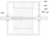
도 1은 코어부가 회전축 전체에 형성된 본 발명의 일 실시예에 따른 축전류 해소 장치의 개념도.
도 2는 코어부가 회전축 일부에 형성된 본 발명의 다른 실시예에 따른 축전류 해소 장치의 개념도.
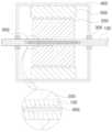
도 3은 코어부와 회전축 사이의 일부분에 공간이 형성된 본 발명의 또 다른 실시예에 따른 축전류 해소 장치의 개념도.
도 4는 코어부와 회전축 사이의 일부분에 절연체(700)가 구비된 본 발명의 또 다른 실시예에 따른 축전류 해소 장치의 개념도.Figure 1 is a conceptual diagram of an axial current relief device according to one embodiment of the present invention in which a core portion is formed over the entire rotating shaft.
FIG. 2 is a conceptual diagram of an axial current relief device according to another embodiment of the present invention in which a core portion is formed on a portion of a rotating shaft.
FIG. 3 is a conceptual diagram of an axial current relief device according to another embodiment of the present invention in which a space is formed in a portion between a core portion and a rotating shaft.
FIG. 4 is a conceptual diagram of an axial current relief device according to another embodiment of the present invention in which an insulator (700) is provided in a portion between a core portion and a rotating shaft.
본 발명은 다양한 변경을 가할 수 있고 여러 가지 실시예를 가질 수 있는바, 특정 실시예들을 도면에 예시하고 상세하게 설명하고자 한다. 그러나 이는 본 발명을 특정한 실시 형태에 대해 한정하려는 것이 아니며, 본 발명의 사상 및 기술 범위에 포함되는 모든 변경, 균등물 내지 대체물을 포함하는 것으로 이해되어야한다.The present invention can have various modifications and various embodiments, and specific embodiments are illustrated in the drawings and described in detail. However, this is not intended to limit the present invention to specific embodiments, and it should be understood that it includes all modifications, equivalents, and substitutes included in the spirit and technical scope of the present invention.
어떤 구성요소가 다른 구성요소에 "연결되어" 있다거나 "접속되어" 있다고 언급된 때에는, 그 다른 구성요소에 직접적으로 연결되어 있거나 또는 접속되어 있을 수도 있지만, 중간에 다른 구성요소가 존재할 수도 있다고 이해되어야 할 것이다.When it is said that a component is "connected" or "connected" to another component, it should be understood that it may be directly connected or connected to that other component, but there may also be other components present in between.
반면에, 어떤 구성요소가 다른 구성요소에 "직접 연결되어" 있다거나 "직접 접속되어" 있다고 언급된 때에는, 중간에 다른 구성요소가 존재하지 않는 것으로 이해되어야 할 것이다.On the other hand, when it is said that a component is "directly connected" or "directly connected" to another component, it should be understood that there are no other components in between.
본 명세서에서 사용되는 용어는 단지 특정한 실시예를 설명하기 위해 사용된 것으로, 본 발명을 한정하려는 의도가 아니다. 단수의 표현은 문맥상 명백하게 다르게 뜻하지 않는 한, 복수의 표현을 포함한다. 본 출원에서, "포함하다" 또는 "가지다" 등의 용어는 명세서상에 기재된 특징, 숫자, 공정, 동작, 구성요소, 부품 또는 이들을 조합한 것이 존재함을 지정하려는 것이지, 하나 또는 그 이상의 다른 특징들이나 숫자, 공정, 동작, 구성요소, 부품 또는 이들을 조합한 것들의 존재 또는 부가 가능성을 미리 배제하지 않는 것으로 이해되어야 한다.The terminology used herein is only used to describe specific embodiments and is not intended to limit the present invention. The singular expression includes the plural expression unless the context clearly indicates otherwise. In this application, it should be understood that the terms "comprises" or "has" and the like are intended to specify the presence of a feature, number, process, operation, component, part or combination thereof described in the specification, but do not exclude in advance the possibility of the presence or addition of one or more other features, numbers, processes, operations, components, parts or combinations thereof.
다르게 정의되지 않는 한, 기술적이거나 과학적인 용어를 포함해서 여기서 사용되는 모든 용어들은 본 발명이 속하는 기술 분야에서 통상의 지식을 가진 자에 의해 일반적으로 이해되는 것과 동일한 의미가 있다. 일반적으로 사용되는 사전에 정의되어 있는 것과 같은 용어들은 관련 기술의 문맥상 가지는 의미와 일치하는 의미가 있는 것으로 해석되어야 하며, 본 출원에서 명백하게 정의하지 않는 한, 이상적이거나 과도하게 형식적인 의미로 해석되지 않는다.Unless otherwise defined, all terms used herein, including technical or scientific terms, have the same meaning as commonly understood by one of ordinary skill in the art to which this invention belongs. Terms defined in commonly used dictionaries, such as those defined in common dictionaries, should be interpreted as having a meaning consistent with the meaning they have in the context of the relevant art, and shall not be interpreted in an idealized or overly formal sense unless expressly defined in this application.
이하, 첨부된 도면을 참조하여 본 발명을 더욱 상세하게 설명한다. 이에 앞서, 본 명세서 및 청구범위에 사용된 용어나 단어는 통상적이거나 사전적인 의미로 한정하여 해석되어서는 아니 되며, 발명자는 그 자신의 발명을 가장 최선의 방법으로 설명하기 위해 용어의 개념을 적절하게 정의할 수 있다는 원칙에 입각하여, 본 발명의 기술적 사상에 부합하는 의미와 개념으로 해석되어야만 한다. 또한, 사용되는 기술 용어 및 과학 용어에 있어서 다른 정의가 없다면, 이 발명이 속하는 기술분야에서 통상의 지식을 가진 자가 통상적으로 이해하고 있는 의미를 가지며, 하기의 설명 및 첨부 도면에서 본 발명의 요지를 불필요하게 흐릴 수 있는 공지 기능 및 구성에 대한 설명은 생략한다. 다음에 소개되는 도면들은 당업자에게 본 발명의 사상이 충분히 전달될 수 있도록 하기 위해 예로서 제공되는 것이다. 따라서, 본 발명은 이하 제시되는 도면들에 한정되지 않고 다른 형태로 구체화될 수도 있다. 또한, 명세서 전반에 걸쳐서 동일한 참조번호들은 동일한 구성요소들을 나타낸다. 도면들 중 동일한 구성요소들은 가능한 한 어느 곳에서든지 동일한 부호들로 나타내고 있음에 유의해야 한다.Hereinafter, the present invention will be described in more detail with reference to the attached drawings. Prior to this, the terms or words used in this specification and claims should not be interpreted as limited to their conventional or dictionary meanings, and should be interpreted as meanings and concepts that conform to the technical idea of the present invention based on the principle that the inventor can appropriately define the concept of the term in order to explain his or her own invention in the best way. In addition, if there is no other definition for the technical and scientific terms used, they have the meanings commonly understood by those with ordinary knowledge in the technical field to which this invention belongs, and the description of well-known functions and configurations that may unnecessarily obscure the gist of the present invention in the following description and the attached drawings will be omitted. The drawings introduced below are provided as examples so that those skilled in the art can sufficiently convey the idea of the present invention. Therefore, the present invention is not limited to the drawings presented below and may be embodied in other forms. In addition, the same reference numerals represent the same components throughout the specification. It should be noted that the same components in the drawings are represented by the same symbols wherever possible.
도 1은 코어부가 회전축 전체에 형성된 본 발명의 일 실시예에 따른 축전류 해소 장치의 개념도이고, 도 2는 코어부가 회전축 일부에 형성된 본 발명의 다른 실시예에 따른 축전류 해소 장치의 개념도이며, 도 3은 코어부와 회전축 사이의 일부분에 공간이 형성된 본 발명의 또 다른 실시예에 따른 축전류 해소 장치의 개념도이고, 도 4는 코어부와 회전축 사이의 일부분에 절연체(700)가 구비된 본 발명의 또 다른 실시예에 따른 축전류 해소 장치의 개념도이다.FIG. 1 is a conceptual diagram of an axial current relieving device according to one embodiment of the present invention in which a core is formed over the entire rotational shaft, FIG. 2 is a conceptual diagram of an axial current relieving device according to another embodiment of the present invention in which a core is formed over a portion of the rotational shaft, FIG. 3 is a conceptual diagram of an axial current relieving device according to another embodiment of the present invention in which a space is formed in a portion between the core and the rotational shaft, and FIG. 4 is a conceptual diagram of an axial current relieving device according to another embodiment of the present invention in which an insulator (700) is provided in a portion between the core and the rotational shaft.
본 발명의 일 실시예에 따른 축전류 해소 장치는 전동기, 발전기 등 회전을 통해 에너지를 얻어내거나 변환하는 전자/자기장치를 만들 때 원천적으로 축전류 방지 및 제거가 가능한 기기를 만들고자 한다.A shaft current elimination device according to one embodiment of the present invention is intended to create a device capable of fundamentally preventing and eliminating shaft current when creating an electronic/magnetic device that obtains or converts energy through rotation, such as an electric motor or generator.
종래에는 전동기, 발전기 등의 전자/자기장치 외부에 설치된 브러시 형태의 접지를 통해 축전류를 흘렸는데, 축전류로 인한 수명 단축을 막는데 큰 효과가 없었다.In the past, shaft current was passed through a brush-type ground installed outside of electronic/magnetic devices such as motors and generators, but this was not very effective in preventing shortening of lifespan due to shaft current.
따라서, 본 발명의 일 실시예에 따른 축전류 해소 장치는 전동기, 발전기 등의 전자/자기장치 내부(하우징(400)의 내부)에 축전류를 해소하는 구성을 이용하고자 한다.Therefore, the shaft current relieving device according to one embodiment of the present invention intends to use a configuration that relieves shaft current inside an electronic/magnetic device such as an electric motor or generator (inside a housing (400)).
도 1 내지 도 4에 도시된 바와 같이, 본 발명의 일 실시예에 따른 축전류 해소 장치는 회전축(100), 회전자(200), 베어링(300), 하우징(400), 고정자(500) 및 코어부(600)를 포함한다.As illustrated in FIGS. 1 to 4, an axial current relieving device according to one embodiment of the present invention includes a rotating shaft (100), a rotor (200), a bearing (300), a housing (400), a stator (500), and a core portion (600).
회전자(200)는 상기 회전축(100)에 고정된다.The rotor (200) is fixed to the rotation shaft (100).
상기 회전자(200)는 회전을 통해 에너지를 얻어내거나 변환하는 전동기, 발전기 등의 전자/자기장치에서 회전 동작을 맡는 부분을 의미한다.The above rotor (200) refers to a part that performs rotational motion in an electronic/magnetic device such as an electric motor or generator that obtains or converts energy through rotation.
상기 회전자(200)는 상기 회전축(100)에 고정되어, 상기 회전축(100)을 중심으로 상기 회전축(100)과 함께 회전한다.The above rotor (200) is fixed to the rotation axis (100) and rotates together with the rotation axis (100) around the rotation axis (100).
베어링(300)은 상기 회전축(100)이 회전 가능하도록 상기 회전축(100)에 설치되되, 상기 회전자(200)와 이격되도록 상기 회전자(200)의 양 측에 설치된 한 쌍으로 구비된다.The bearings (300) are installed on the rotation shaft (100) so that the rotation shaft (100) can rotate, but are provided as a pair installed on both sides of the rotor (200) so as to be spaced apart from the rotor (200).
상기 베어링(300)은 회전축(100)이 항상 똑바른 위치를 유지하면서 고속으로 안전하게 회전시키는 역할을 한다.The above bearing (300) serves to safely rotate the rotation shaft (100) at high speed while always maintaining a straight position.
상기 베어링(300)으로 슬리브 베어링(Sleeve Bearing), 볼베어링(Ball Bearing) 등을 사용할 수 있다.A sleeve bearing, a ball bearing, etc. can be used as the above bearing (300).
상기 베어링(300)은 내륜, 외륜, 전동체(볼, 롤러), 리테이너로 구성될 수 있다.The above bearing (300) may be composed of an inner ring, an outer ring, a rolling element (ball, roller), and a retainer.
하우징(400)은 한 쌍의 상기 베어링(300)에 결합되며, 상기 회전자(200)를 내부에 수용하도록 형성된다.The housing (400) is coupled to a pair of the bearings (300) and is formed to accommodate the rotor (200) therein.
상기 하우징(400)은 회전을 통해 에너지를 얻어내거나 변환하는 전동기, 발전기 등의 전자/자기장치에서 외관을 이루는 것이며, 미적인 형상, 구조, 정밀가공성이 우수하여야 하며, 고정자(500) 내경에 위치한 회전자(200)를 정 중앙에 오도록 하여 에어갭(AIR GAP) 편심이 되지 않도록 하여 전자/자기장치 성능이 유지되도록 하는 구성이다. The above housing (400) forms the exterior of an electronic/magnetic device such as an electric motor or generator that obtains or converts energy through rotation, and must have excellent aesthetic shape, structure, and precision machinability. It is configured to prevent air gap eccentricity by ensuring that the rotor (200) located in the inner diameter of the stator (500) is centered, thereby maintaining the performance of the electronic/magnetic device.
고정자(500)는 상기 하우징(400)에 고정된다.The stator (500) is fixed to the housing (400).
상기 고정자(500)는 회전을 통해 에너지를 얻어내거나 변환하는 전동기, 발전기 등의 전자/자기장치에서 고정된 부분으로 스테이터 (STATOR)라고도 한다.The above stator (500) is a fixed part of an electronic/magnetic device such as a motor or generator that obtains or converts energy through rotation, and is also called a stator.
이밖에, 회전자가 일정 방향으로 회전하도록 전류방향을 주기적으로 바꿔주는 부분을 정류자라고 한다.In addition, the part that periodically changes the direction of the current so that the rotor rotates in a certain direction is called a commutator.
예를 들면 전동기에서는 전류가 흘러 회전하는 도체를 회전자, 도체를 회전시키기 위해 자기장을 형성하는 고정된 자석을 고정자, 외부에서 전류를 받아서 도체인 회전자로 보내는 부분을 정류자라고 할 수 있다.For example, in an electric motor, the conductor through which current flows and rotates is called the rotor, the fixed magnet that forms a magnetic field to rotate the conductor is called the stator, and the part that receives current from the outside and sends it to the conductor, the rotor, is called the commutator.
유도 (비동기)전동기, 발전기와 교류 발전기(동기)는 고정자(500)와 회전자(200)로 구성되는 전자 시스템을 지니고 있다.Induction (asynchronous) motors, generators and alternating current generators (synchronous) have an electronic system consisting of a stator (500) and a rotor (200).
코어부(600)는 상기 회전축(100)의 내부에 상기 회전축(100)의 중심축 방향으로 구비되며, 상기 회전축(100) 보다 전기 전도성이 높은 도전성 금속으로 형성된다.The core part (600) is provided inside the rotation shaft (100) in the direction of the central axis of the rotation shaft (100) and is formed of a conductive metal having higher electrical conductivity than the rotation shaft (100).
슬리브 베어링(Sleeve Bearing)의 경우 전압차가 상기 회전축(100) 양단의 전압차가 1.0V 이상이면 위험하고, 볼베어링(Ball Bearing)의 경우 상기 회전축(100) 양단의 전압차가 전압차가 2.0V 이상이면 위험하다.In the case of sleeve bearings, if the voltage difference between the two ends of the rotating shaft (100) is 1.0 V or more, it is dangerous, and in the case of ball bearings, if the voltage difference between the two ends of the rotating shaft (100) is 2.0 V or more, it is dangerous.
따라서 전압차를 위험수위 아래로 낮추는 것니 중요하다.Therefore, it is important to reduce the voltage difference below the dangerous level.
전동기, 발전기 등의 전자/자기장치 내부(하우징(400)의 내부)에 축전류가 발생되는 것이 가장 큰 문제이기 때문에, 상기 회전축(100)과 베어링 사이에 전류가 흐르지 않도록 하는 역할을 상기 코어부(600)가 수행한다.Since the biggest problem is that axial current is generated inside the electronic/magnetic device such as an electric motor or generator (inside the housing (400)), the core part (600) plays a role in preventing current from flowing between the rotating shaft (100) and the bearing.
이를 위해, 상기 코어부(600)는 상기 회전축(100)의 중심축 상에 구비될 수 있다.For this purpose, the core part (600) may be provided on the central axis of the rotation shaft (100).
상기에서 코어부(600)가 회전축(100)의 중심축 상에 구비되는 예를 설명하였으나, 본 발명이 이에 한정된 것은 아니며, 상기 코어부(600)가 상기 회전축(100)의 중심축에서 약간 벗어나게 구비되는 것 등 상기 회전축(100)과 베어링 사이에 전류가 흐르지 않도록 하는 역할을 수행할 수 있다면 다양한 실시가 가능함은 물론이다.Although the example in which the core part (600) is provided on the central axis of the rotation shaft (100) has been described above, the present invention is not limited thereto, and various implementations are of course possible as long as the core part (600) can perform a role of preventing current from flowing between the rotation shaft (100) and the bearing, such as being provided slightly off the central axis of the rotation shaft (100).
즉, 상기 코어부(600)는 상기 회전축(100) 양단, 다시말해, 상기 회전자(200) 양단의 전위차를 없애기 위한 구성이다.That is, the core part (600) is configured to eliminate the potential difference between both ends of the rotation shaft (100), that is, between both ends of the rotor (200).
이를 위해, 상기 코어부(600)는 상기 회전자(200)와 베어링(300) 사이에 해당되는 상기 회전축(100)의 양측을 도전성 금속으로 연결한다.To this end, the core part (600) connects both sides of the rotation shaft (100) corresponding to the rotor (200) and the bearing (300) with a conductive metal.
상기 코어부(600)는 구리, 은, 금 등 저항이 낮은 금속 재질로 형성될 수 있다.The above core portion (600) can be formed of a metal material with low resistance, such as copper, silver, or gold.
상기 코어부(600)는 상기 회전축(100)에 끼움결합(억지끼움결합), 볼트 결합, 저온용접, 이중사출, 홀가공 후 주조 등 상기 코어부(600)와 회전축(100)을 전기적으로 연결할 수 있다면 다양한 방법을 사용하여 결합할 수 있다.The core part (600) can be connected to the rotation shaft (100) using various methods, such as insertion (forced fitting), bolt connection, low-temperature welding, double injection, hole machining, and casting, as long as the core part (600) and the rotation shaft (100) can be electrically connected.
상기 코어부(600)는 상기 회전자(200)를 중심으로 상기 회전축(100) 양단을 연결해야 하는데, 상기 코어부(600)를 단면적이 작은 구리선 등으로 연결 시 구리선에 발생된 열로 구리선이 녹을 수 있어, 축전류 해소에도 문제가 없을 정도로 단면적이 큰 막대(형강, 기둥) 형상을 사용하는 것이 바람직하다.The above core part (600) must connect both ends of the rotation shaft (100) with the rotor (200) as the center. When the core part (600) is connected with a copper wire with a small cross-sectional area, the copper wire may melt due to the heat generated in the copper wire. Therefore, it is preferable to use a bar (steel, column) shape with a large cross-sectional area so that there is no problem with dissipating the shaft current.
본 발명의 일 실시예에 따른 축전류 해소 장치의 코어부(600)는 구리 재질로 형성된 것을 특징으로 할 수 있다.The core part (600) of the axial current relief device according to one embodiment of the present invention may be characterized by being formed of a copper material.
상기 코어부(600)는 상기 회전축(100) 보다 전기 전도성이 높으면 되지만, 강성이 너무 낮으면 상기 회전축(100) 자체의 강성이 낮아질 수 있어, 어느정도 강성이 확보되면서도 전기전도성이 높은 재질로 상기 코어부(600)를 형성하는 것이 바람직하다. 이를 위해 상기 코어부(600)를 구리 재질로 형성하는 것이 바람직하다.The core part (600) should have higher electrical conductivity than the rotation shaft (100), but if the rigidity is too low, the rigidity of the rotation shaft (100) itself may be reduced, so it is desirable to form the core part (600) with a material that ensures a certain level of rigidity while also having high electrical conductivity. To this end, it is desirable to form the core part (600) with a copper material.
도 2 내지 도 3에 도시된 바와 같이, 본 발명의 일 실시예에 따른 축전류 해소 장치의 코어부(600)는 일측 끝단이 상기 회전자(200)의 일측과 일측 베어링(300) 사이에 구비되고, 타측 끝단이 상기 회전자(200)의 타측과 타측 베어링(300) 사이에 구비된 것을 특징으로 할 수 있다.As illustrated in FIGS. 2 and 3, the core part (600) of the axial current relieving device according to one embodiment of the present invention may be characterized in that one end is provided between one side of the rotor (200) and one bearing (300), and the other end is provided between the other side of the rotor (200) and the other bearing (300).
상기 코어부(600)는 상기 회전축(100)의 상기 회전자(200) 중심 양단이 등전위 상태를 유지할 수 있도록, 일측 베어링(300)과 회전자(200) 사이에 상기 코어부(600)의 일측이 구비되고, 타측 베어링(300)과 회전자(200) 사이에 상기 코어부(600)의 타측이 구비도록 한다.The core part (600) is provided with one side of the core part (600) between one bearing (300) and the rotor (200) so that the two ends of the rotor (200) of the rotation shaft (100) can maintain an equipotential state, and the other side of the core part (600) is provided between the other bearing (300) and the rotor (200).
도 1에 도시된 바와 같이, 상기 코어부(600)가 상기 회전축(100)의 전 구간에 결쳐 형성되는 것도 가능하며, 도 2에 도시된 바와 같이, 상기 코어부(600)가 상기 회전축(100)의 일부 구간에 형성되는 것도 가능하다.As shown in FIG. 1, the core part (600) may be formed over the entire section of the rotation shaft (100), and as shown in FIG. 2, the core part (600) may be formed over a portion of the rotation shaft (100).
여기서 중요한 것은, 상기 하우징(400) 내부에서 상기 회전자(200)의 양단에 해당되는 상기 회전축(100) 양단이 등전위에 가깝도록 해야 한다는 것이다.What is important here is that the two ends of the rotating shaft (100) corresponding to the two ends of the rotor (200) inside the housing (400) must be close to equipotential.
이를 위해, 상기 코어부(600)가 상기 회전자(200)의 양단에 해당되는 상기 회전축(100) 양단을 연결하도록 한다.To this end, the core part (600) is connected to both ends of the rotation shaft (100) corresponding to both ends of the rotor (200).
본 발명의 일 실시예에 따른 축전류 해소 장치의 코어부(600)는 원기둥 형태로 형성된 것을 특징으로 할 수 있다.The core part (600) of the axial current relief device according to one embodiment of the present invention may be characterized by being formed in a cylindrical shape.
상기 코어부(600)는 다양한 단면을 같는 기둥(형강) 형태로 형성될 수 있으나, 상기 회전축(100) 내부에 구비되기 때문에, 상기 회전축(100) 내부에 상기 코어부(600)가 구비될 수 있는 공간이 형성되어야 한다.The above core part (600) can be formed in the shape of a column (steel beam) having various cross sections, but since it is provided inside the rotation shaft (100), a space in which the core part (600) can be provided must be formed inside the rotation shaft (100).
이러한 구조적인 특징에 의해, 상기 회전축(100)의 전체적인 강성에 영향을 미칠 수 있으며, 이러한 영향을 최소화 시키기 위해, 상기 코어부(600)를 원기둥 형태로 형성하는 것이 바람직하다.Due to these structural features, the overall rigidity of the rotation shaft (100) may be affected, and to minimize this effect, it is preferable to form the core portion (600) in a cylindrical shape.
도 3에 도시된 바와 같이, 본 발명의 일 실시예에 따른 축전류 해소 장치의 코어부(600)는 상기 회전자(200)와 베어링(300) 사이의 상기 회전축(100) 일 부분에 접하고, 상기 회전자(200) 내부에 해당되는 상기 회전축(100)과는 이격되도록 배치된 것을 특징으로 할 수 있다.As illustrated in FIG. 3, the core part (600) of the axial current relieving device according to one embodiment of the present invention may be characterized in that it is positioned to contact a portion of the rotational axis (100) between the rotor (200) and the bearing (300), and to be spaced apart from the rotational axis (100) corresponding to the inside of the rotor (200).
즉, 상기 코어부(600)의 일 부분만 상기 회전축(100)과 접하도록 한다. 이때, 상기 회전축(100) 전체 영역 중 상기 회전자(200)가 구비된 영역의 회전축(100) 내부가 상기 코어부(600)와 이격되도록 할 수 있다.That is, only a part of the core part (600) is made to come into contact with the rotational shaft (100). At this time, the inside of the rotational shaft (100) in the area where the rotor (200) is provided among the entire area of the rotational shaft (100) can be made to be separated from the core part (600).
이는, 상기 회전축(100)에 가해진 외력의 영향이 상기 코어부(600)에 전달되는 것을 최소화 하기 위한 것이다.This is to minimize the influence of external force applied to the rotation shaft (100) being transmitted to the core part (600).
또한, 순간적으로 상기 회전축(100) 양단에 전압차가 발생되더라도, 대부분의 전류가 상기 코어부(600)를 통해 흘러, 상기 회전축(100) 양단 전압이 평형을 이루도록 할 수 있다.In addition, even if a voltage difference occurs momentarily at both ends of the rotation shaft (100), most of the current flows through the core portion (600), so that the voltage at both ends of the rotation shaft (100) can be balanced.
도 4에 도시된 바와 같이, 본 발명의 일 실시예에 따른 축전류 해소 장치의 코어부(600)는 상기 회전자(200)와 베어링(300) 사이의 상기 회전축(100) 일 부분에 접하고, 상기 회전자(200) 내부에 해당되는 상기 회전축(100)과 코어부(600) 사이에는 절연체(700)가 구비된 것을 특징으로 할 수 있다.As illustrated in FIG. 4, the core part (600) of the axial current relieving device according to one embodiment of the present invention may be characterized in that it contacts a portion of the rotational shaft (100) between the rotor (200) and the bearing (300), and an insulator (700) is provided between the rotational shaft (100) corresponding to the inside of the rotor (200) and the core part (600).
도 3의 실시예에서, 회전자(200)가 구비된 영역의 회전축(100) 내부가 코어부(600)와 이격되도록 하는 예를 들었으나, 이는, 해당 부분이 절연되도록 하기 위한 것이다.In the embodiment of Fig. 3, an example is given in which the inside of the rotation axis (100) of the area equipped with the rotor (200) is separated from the core part (600), but this is to ensure that the corresponding part is insulated.
해당 부분이 절연되도록 하기 위한 다른 실시예로 도 4의 실시예를 들 수 있으며, 상기 회전축(100)과 코어부(600) 사이에 절연체(700)를 구비하는 것도 가능하다.Another embodiment for insulating the relevant part is the embodiment of Fig. 4, and it is also possible to provide an insulator (700) between the rotation shaft (100) and the core part (600).
이때, 절연체(700)는 다양한 재질을 사용할 수 있다.At this time, the insulator (700) can use various materials.
상기 회전축(100)과 코어부(600)의 연결(결합) 방식에 따라 상기 절연체(700)를 형성하는 방법이 달라질 수 있다.The method of forming the insulator (700) may vary depending on the method of connecting (bonding) the above-mentioned rotation shaft (100) and core portion (600).
예를 들어, 끼움결합(억지끼움결합), 볼트 결합 등의 경우, 코어부(600) 외부에 절연체(700)를 형성(코팅 등)한 뒤에 끼움결합(억지끼움결합), 볼트 결합 등으로 상기 회전축(100)과 코어부(600)의 연결(결합)할 수 있다.For example, in the case of a fitting connection (forced fitting connection), bolt connection, etc., an insulator (700) is formed (coated, etc.) on the outside of the core part (600), and then the rotation shaft (100) and the core part (600) can be connected (coupled) by a fitting connection (forced fitting connection), bolt connection, etc.
즉, 상기 코어부(600)에 절연체(700)를 형상한 뒤 절연체(700)가 형성된 코어부(600)를 상기 회전축(100)에 연결(결합)하는 방식을 이용할 수 있다.That is, a method can be used in which an insulator (700) is formed on the core portion (600) and then the core portion (600) on which the insulator (700) is formed is connected (coupled) to the rotation shaft (100).
절연체(700)를 형성하는 다른 예로, 홀 가공 후 주조 방식을 사용하고자 한다면, 본 발명의 일 실시예에 따른 축전류 해소 장치의 절연체(700)는 코어부(600)보다 녹는점이 높은 유약인 것을 특징으로 할 수 있다.As another example of forming an insulator (700), if a casting method is to be used after hole machining, the insulator (700) of the axial current relief device according to one embodiment of the present invention may be characterized by a glaze having a higher melting point than the core portion (600).
즉, 홀가공된 회전축(100) 내부에 절연체(700)를 형상한 뒤, 전기 전도성이 높은 도전성 금속을 녹여 부어 굳히는 방식으로 상기 코어부(600)를 형성할 수 있다.That is, the core part (600) can be formed by shaping an insulator (700) inside a machined rotary shaft (100), then melting and pouring a conductive metal with high electrical conductivity and hardening it.
이를 위해, 상기 절연체(700)는 상기 코어부(600) 재질보다 녹는점이 높아야 하고, 즉, 홀가공된 회전축(100) 내부에 절연체(700)를 형성(코팅)하기 위해 유약 형태인 것이 바람직하다.To this end, the insulator (700) must have a higher melting point than the material of the core portion (600), and in other words, it is preferable that the insulator (700) be in the form of a glaze in order to form (coat) the insulator (700) inside the hole-machined rotary shaft (100).
홀가공된 회전축(100) 내부에 유약을 넣고, 상기 회전축(200)을 수평상태에서 중심축을 기준으로 천천히 회전시키면 유약이 회전축(100) 내부를 코팅하면서 굳을 수 있다.When glaze is placed inside a machined rotary shaft (100) and the rotary shaft (200) is slowly rotated around the central axis in a horizontal state, the glaze can harden while coating the inside of the rotary shaft (100).
이때, 유약이 뭍으면 안 되는 부분은 단차지게 형성하거나, 추후 제거가 가능한 다른 재료로 막아둘 수 있다.At this time, the areas where the glaze should not be applied can be formed in steps or blocked with other materials that can be removed later.
도 1 내지 도 2에 도시된 바와 같이, 본 발명의 일 실시예에 따른 축전류 해소 장치의 회전축(100)과 코어부(600)는 이중사출 방식을 적용한 일체형 구조인 것을 특징으로 하는 축전류 해소 장치.As shown in FIGS. 1 and 2, the rotary shaft (100) and core portion (600) of the axial current relieving device according to one embodiment of the present invention are characterized by having an integral structure using a double injection method.
상기 회전축(100)과 코어부(600)를 이중사출 방식을 적용한 일체형 구조로 형성한다면, 상기 회전축(100)과 코어부(600)를 연결하기 위한 별도의 공정을 필요로 하지 않기 때문에 제작이 용이하며, 다른 연결방식에 비해, 전체적인 강성을 보다 높일 수 있다.If the above rotation shaft (100) and core part (600) are formed as an integrated structure using a double injection method, a separate process for connecting the rotation shaft (100) and core part (600) is not required, making manufacturing easy, and compared to other connection methods, the overall rigidity can be increased.
본 발명의 일 실시예에 따른 축전류 해소 장치의 상기 회전축(100)과 코어부(600)는 상기 회전축(100)의 중심축을 따라 상기 회전축(100)을 홀 가공 한 후, 상기 코어부를 형성(도 1 및 도 4 참조)하는 것을 특징으로 할 수 있다.According to one embodiment of the present invention, the rotational shaft (100) and core portion (600) of the axial current relieving device may be characterized in that the core portion is formed by forming a hole in the rotational shaft (100) along the central axis of the rotational shaft (100) (see FIG. 1 and FIG. 4).
상기 회전축(100)을 홀 가공하여 상기 코어부(600)를 연결 또는 형성하는 방법을 사용한다면, 금형 제작에 필요한 비용을 절약할 수 있으며, 상기 회전축(100) 내부의 홀 형상의 변경이 용이하다.If a method of connecting or forming the core part (600) by processing a hole in the above-mentioned rotation shaft (100) is used, the cost required for mold production can be saved, and the hole shape inside the above-mentioned rotation shaft (100) can be easily changed.
예를 들어, 회전자의 크기에 따라 홀의 직경을 변경하는 등의 변경 적용이 용이하다.For example, it is easy to apply changes, such as changing the diameter of the hole depending on the size of the rotor.
본 발명의 일 실시예에 따른 축전류 해소 장치의 회전축(100)은 절연체(700)가 구비될 부분의 홀 직경이 다른 부분의 홀 직경보다 더 크게 형성된 것을 특징으로 할 수 있다.The rotation shaft (100) of the axial current relieving device according to one embodiment of the present invention may be characterized in that the hole diameter of the portion where the insulator (700) is to be provided is formed larger than the hole diameters of other portions.
이는, 유약을 바를(코팅할) 부분의 홀의 직경을 더 크게 형성하여, 유약이 지정된 부분에서 굳는 것을 도울 수 있다.This can help the glaze harden in the designated area by forming the hole diameter of the area where the glaze is to be applied (coated) larger.
본 발명은 상기한 실시예에 한정되지 아니하며, 적용범위가 다양함은 물론이고, 청구범위에서 청구하는 본 발명의 요지를 벗어남이 없이 다양한 변형 실시가 가능한 것은 물론이다.The present invention is not limited to the above-described embodiments, and the scope of application is diverse, and various modifications can be implemented without departing from the gist of the present invention claimed in the claims.
100: 회전축
200: 회전자
300: 베어링
400: 하우징
500: 고정자
600: 코어부
700: 절연체100: Rotation axis
200: Rotor
300: bearing
400: Housing
500: Stator
600: Core
700: Insulator
Claims (10)
Translated fromKorean상기 회전축(100)에 고정된 회전자(200);
상기 회전축(100)이 회전 가능하도록 상기 회전축(100)에 설치되되, 상기 회전자(200)와 이격되도록 상기 회전자(200)의 양 측에 설치된 한 쌍의 베어링(300);
한 쌍의 상기 베어링(300)에 결합되며, 상기 회전자(200)를 내부에 수용하도록 형성된 하우징(400);
상기 하우징(400)에 고정된 고정자(500); 및
상기 회전축(100)의 내부에 상기 회전축(100)의 중심축 방향으로 구비되며, 상기 회전축(100) 보다 전기 전도성이 높은 도전성 금속으로 형성된 코어부(600);
를 포함하며,
상기 회전축(100)과 코어부(600)는
상기 회전축(100)의 중심축을 따라 상기 회전축(100)을 홀 가공 한 후, 상기 코어부를 형성하는 것을 특징으로 하는 축전류 해소 장치.
Rotating axis (100);
A rotor (200) fixed to the above rotation axis (100);
A pair of bearings (300) installed on both sides of the rotor (200) so that the above-mentioned rotational axis (100) can rotate, but spaced apart from the rotor (200);
A housing (400) coupled to a pair of the above bearings (300) and formed to accommodate the rotor (200) therein;
A stator (500) fixed to the above housing (400); and
A core portion (600) provided inside the rotation shaft (100) in the direction of the central axis of the rotation shaft (100) and formed of a conductive metal having higher electrical conductivity than the rotation shaft (100);
Including,
The above rotation axis (100) and core part (600)
A shaft current relieving device characterized in that the core part is formed after machining a hole in the shaft (100) along the central axis of the shaft (100).
상기 코어부(600)는
구리 재질로 형성된 것을 특징으로 하는 축전류 해소 장치.
In the first paragraph,
The above core part (600)
A current relieving device characterized by being formed of copper material.
상기 코어부(600)는
일측 끝단이 상기 회전자(200)의 일측과 일측 베어링(300) 사이에 구비되고, 타측 끝단이 상기 회전자(200)의 타측과 타측 베어링(300) 사이에 구비된 것을 특징으로 하는 축전류 해소 장치.
In the first paragraph,
The above core part (600)
A shaft current relieving device characterized in that one end is provided between one side of the rotor (200) and one bearing (300), and the other end is provided between the other side of the rotor (200) and the other bearing (300).
상기 코어부(600)는
원기둥 형태로 형성된 것을 특징으로 하는 축전류 해소 장치.
기둥형(형강) 코어
In the first paragraph,
The above core part (600)
A current-relieving device characterized by being formed in a cylindrical shape.
Columnar (sectioned) core
상기 코어부(600)는
상기 회전자(200)와 베어링(300) 사이의 상기 회전축(100) 일 부분에 접하고, 상기 회전자(200) 내부에 해당되는 상기 회전축(100)과는 이격되도록 배치된 것을 특징으로 하는 축전류 해소 장치.
In the first paragraph,
The above core part (600)
A shaft current relieving device characterized in that it is arranged to be in contact with a portion of the rotational axis (100) between the rotor (200) and the bearing (300) and to be spaced apart from the rotational axis (100) corresponding to the inside of the rotor (200).
상기 코어부(600)는
상기 회전자(200)와 베어링(300) 사이의 상기 회전축(100) 일 부분에 접하고, 상기 회전자(200) 내부에 해당되는 상기 회전축(100)과 코어부(600) 사이에는 절연체(700)가 구비된 것을 특징으로 하는 축전류 해소 장치.
In the first paragraph,
The above core part (600)
A shaft current relieving device characterized in that an insulator (700) is provided between the rotational shaft (100) and the core portion (600) that is in contact with a portion of the rotational shaft (100) between the rotor (200) and the bearing (300) and corresponding to the inside of the rotor (200).
상기 절연체(700)는
코어부(600)보다 녹는점이 높은 유약인 것을 특징으로 하는 축전류 해소 장치.
In Article 6,
The above insulator (700)
An axial current relieving device characterized by having a glaze having a higher melting point than the core portion (600).
상기 회전축(100)과 코어부(600)는
이중사출 방식을 적용한 일체형 구조인 것을 특징으로 하는 축전류 해소 장치.
In the first paragraph,
The above rotation axis (100) and core part (600)
A axial current relief device characterized by an integrated structure that uses a double injection method.
상기 회전축(100)은
절연체(700)가 구비될 부분의 홀 직경이 다른 부분의 홀 직경보다 더 크게 형성된 것을 특징으로 하는 축전류 해소 장치.
In the first paragraph,
The above rotation axis (100)
A current-relieving device characterized in that the hole diameter of a portion where an insulator (700) is to be provided is formed larger than the hole diameters of other portions.
Priority Applications (1)
| Application Number | Priority Date | Filing Date | Title |
|---|---|---|---|
| KR1020220162732AKR102711462B1 (en) | 2022-11-29 | 2022-11-29 | Axial current prevention and removal device |
Applications Claiming Priority (1)
| Application Number | Priority Date | Filing Date | Title |
|---|---|---|---|
| KR1020220162732AKR102711462B1 (en) | 2022-11-29 | 2022-11-29 | Axial current prevention and removal device |
Publications (2)
| Publication Number | Publication Date |
|---|---|
| KR20240079637A KR20240079637A (en) | 2024-06-05 |
| KR102711462B1true KR102711462B1 (en) | 2024-10-04 |
Family
ID=91470846
Family Applications (1)
| Application Number | Title | Priority Date | Filing Date |
|---|---|---|---|
| KR1020220162732AActiveKR102711462B1 (en) | 2022-11-29 | 2022-11-29 | Axial current prevention and removal device |
Country Status (1)
| Country | Link |
|---|---|
| KR (1) | KR102711462B1 (en) |
Citations (4)
| Publication number | Priority date | Publication date | Assignee | Title |
|---|---|---|---|---|
| KR100834411B1 (en) | 2007-12-04 | 2008-06-04 | 대흥기전주식회사 | Axial Discharge Device for Generator |
| JP2016134973A (en)* | 2015-01-16 | 2016-07-25 | アイシン・エィ・ダブリュ株式会社 | Rotor assembly for ac motor |
| JP2021503268A (en)* | 2017-10-10 | 2021-02-04 | ゼロ イー テクノロジーズ,エルエルシー | Electrical machinery cooling and stabilization systems and methods |
| KR102408448B1 (en)* | 2022-01-21 | 2022-06-14 | 주식회사 이공기전 | Axial current prevention and removal device |
Family Cites Families (3)
| Publication number | Priority date | Publication date | Assignee | Title |
|---|---|---|---|---|
| KR19990016494A (en)* | 1997-08-16 | 1999-03-05 | 이원 | Axial current prevention device of turbine generator |
| KR20020020543A (en)* | 2000-09-09 | 2002-03-15 | 김학용 | Rotor preventing magnetization of rotor shaft, and the method of making the rotor |
| KR20220136837A (en)* | 2021-04-01 | 2022-10-11 | 박찬희 | Axial current discharge system of Motor and Generator using assistance bearing of electric currentness |
- 2022
- 2022-11-29KRKR1020220162732Apatent/KR102711462B1/enactiveActive
Patent Citations (4)
| Publication number | Priority date | Publication date | Assignee | Title |
|---|---|---|---|---|
| KR100834411B1 (en) | 2007-12-04 | 2008-06-04 | 대흥기전주식회사 | Axial Discharge Device for Generator |
| JP2016134973A (en)* | 2015-01-16 | 2016-07-25 | アイシン・エィ・ダブリュ株式会社 | Rotor assembly for ac motor |
| JP2021503268A (en)* | 2017-10-10 | 2021-02-04 | ゼロ イー テクノロジーズ,エルエルシー | Electrical machinery cooling and stabilization systems and methods |
| KR102408448B1 (en)* | 2022-01-21 | 2022-06-14 | 주식회사 이공기전 | Axial current prevention and removal device |
Also Published As
| Publication number | Publication date |
|---|---|
| KR20240079637A (en) | 2024-06-05 |
Similar Documents
| Publication | Publication Date | Title |
|---|---|---|
| US9581203B2 (en) | Shunt bearing with insulating coating | |
| US9464672B2 (en) | Rolling bearing with integrated electrical shunt | |
| US20170108047A1 (en) | Bearing seal with integrated grounding brush | |
| US3924906A (en) | Electrically insulated bearing and for reducing shaft current | |
| CN105743258B (en) | Stator assembly, motor with stator assembly, and method of manufacturing the stator assembly | |
| CN112186950A (en) | Electric machine | |
| CN107681836A (en) | A kind of motor for eliminating bearing galvano-cautery | |
| KR102408448B1 (en) | Axial current prevention and removal device | |
| KR102711462B1 (en) | Axial current prevention and removal device | |
| EP3444489A1 (en) | Insulated bearing | |
| CN109217506A (en) | Rotor and motor | |
| US20050253480A1 (en) | Apparatus and method for reducing shaft charge | |
| JP6178781B2 (en) | Cage type induction motor and rotor for cage type induction motor | |
| CN114039444B (en) | Motor and vehicle | |
| CN112762096A (en) | Bearing and direct current motor | |
| KR101360059B1 (en) | Electric motor | |
| JP2015021544A (en) | Motor and bering of motor | |
| JP5763291B2 (en) | Rotating electric machine | |
| US3368091A (en) | Rotating rectifier | |
| KR101867906B1 (en) | Brush-less direct current motor and method for preventing electric corrosion thereof | |
| JPS6015415Y2 (en) | Rotating electrical machinery that prevents shaft current | |
| CN220629039U (en) | Insulation assembly, driving motor, driving assembly and vehicle | |
| JP2003092850A (en) | Electric motor with corrosion prevention | |
| JP2552059B2 (en) | Rotating electric machine | |
| US10539178B2 (en) | Vapor deposition bearing coating |
Legal Events
| Date | Code | Title | Description |
|---|---|---|---|
| PA0109 | Patent application | Patent event code:PA01091R01D Comment text:Patent Application Patent event date:20221129 | |
| PA0201 | Request for examination | ||
| E902 | Notification of reason for refusal | ||
| PE0902 | Notice of grounds for rejection | Comment text:Notification of reason for refusal Patent event date:20240507 Patent event code:PE09021S01D | |
| PG1501 | Laying open of application | ||
| E701 | Decision to grant or registration of patent right | ||
| PE0701 | Decision of registration | Patent event code:PE07011S01D Comment text:Decision to Grant Registration Patent event date:20240920 | |
| GRNT | Written decision to grant | ||
| PR0701 | Registration of establishment | Comment text:Registration of Establishment Patent event date:20240924 Patent event code:PR07011E01D | |
| PR1002 | Payment of registration fee | Payment date:20240924 End annual number:3 Start annual number:1 | |
| PG1601 | Publication of registration |