KR102711169B1 - Display panel and display device comprising the same - Google Patents
Display panel and display device comprising the sameDownload PDFInfo
- Publication number
- KR102711169B1 KR102711169B1KR1020190143265AKR20190143265AKR102711169B1KR 102711169 B1KR102711169 B1KR 102711169B1KR 1020190143265 AKR1020190143265 AKR 1020190143265AKR 20190143265 AKR20190143265 AKR 20190143265AKR 102711169 B1KR102711169 B1KR 102711169B1
- Authority
- KR
- South Korea
- Prior art keywords
- layer
- touch
- display panel
- graphene
- sensitive adhesive
- Prior art date
- Legal status (The legal status is an assumption and is not a legal conclusion. Google has not performed a legal analysis and makes no representation as to the accuracy of the status listed.)
- Active
Links
Images


Classifications
- H—ELECTRICITY
- H10—SEMICONDUCTOR DEVICES; ELECTRIC SOLID-STATE DEVICES NOT OTHERWISE PROVIDED FOR
- H10K—ORGANIC ELECTRIC SOLID-STATE DEVICES
- H10K59/00—Integrated devices, or assemblies of multiple devices, comprising at least one organic light-emitting element covered by group H10K50/00
- H10K59/80—Constructional details
- H10K59/87—Passivation; Containers; Encapsulations
- H10K59/874—Passivation; Containers; Encapsulations including getter material or desiccant
- H—ELECTRICITY
- H10—SEMICONDUCTOR DEVICES; ELECTRIC SOLID-STATE DEVICES NOT OTHERWISE PROVIDED FOR
- H10K—ORGANIC ELECTRIC SOLID-STATE DEVICES
- H10K50/00—Organic light-emitting devices
- H10K50/80—Constructional details
- H10K50/84—Passivation; Containers; Encapsulations
- H10K50/846—Passivation; Containers; Encapsulations comprising getter material or desiccants
- G—PHYSICS
- G06—COMPUTING OR CALCULATING; COUNTING
- G06F—ELECTRIC DIGITAL DATA PROCESSING
- G06F3/00—Input arrangements for transferring data to be processed into a form capable of being handled by the computer; Output arrangements for transferring data from processing unit to output unit, e.g. interface arrangements
- G06F3/01—Input arrangements or combined input and output arrangements for interaction between user and computer
- G06F3/03—Arrangements for converting the position or the displacement of a member into a coded form
- G06F3/041—Digitisers, e.g. for touch screens or touch pads, characterised by the transducing means
- G06F3/0412—Digitisers structurally integrated in a display
- G—PHYSICS
- G06—COMPUTING OR CALCULATING; COUNTING
- G06F—ELECTRIC DIGITAL DATA PROCESSING
- G06F3/00—Input arrangements for transferring data to be processed into a form capable of being handled by the computer; Output arrangements for transferring data from processing unit to output unit, e.g. interface arrangements
- G06F3/01—Input arrangements or combined input and output arrangements for interaction between user and computer
- G06F3/03—Arrangements for converting the position or the displacement of a member into a coded form
- G06F3/041—Digitisers, e.g. for touch screens or touch pads, characterised by the transducing means
- G06F3/044—Digitisers, e.g. for touch screens or touch pads, characterised by the transducing means by capacitive means
- G06F3/0443—Digitisers, e.g. for touch screens or touch pads, characterised by the transducing means by capacitive means using a single layer of sensing electrodes
- H—ELECTRICITY
- H10—SEMICONDUCTOR DEVICES; ELECTRIC SOLID-STATE DEVICES NOT OTHERWISE PROVIDED FOR
- H10K—ORGANIC ELECTRIC SOLID-STATE DEVICES
- H10K50/00—Organic light-emitting devices
- H10K50/80—Constructional details
- H10K50/84—Passivation; Containers; Encapsulations
- H10K50/844—Encapsulations
- H—ELECTRICITY
- H10—SEMICONDUCTOR DEVICES; ELECTRIC SOLID-STATE DEVICES NOT OTHERWISE PROVIDED FOR
- H10K—ORGANIC ELECTRIC SOLID-STATE DEVICES
- H10K59/00—Integrated devices, or assemblies of multiple devices, comprising at least one organic light-emitting element covered by group H10K50/00
- H10K59/10—OLED displays
- H10K59/12—Active-matrix OLED [AMOLED] displays
- H—ELECTRICITY
- H10—SEMICONDUCTOR DEVICES; ELECTRIC SOLID-STATE DEVICES NOT OTHERWISE PROVIDED FOR
- H10K—ORGANIC ELECTRIC SOLID-STATE DEVICES
- H10K59/00—Integrated devices, or assemblies of multiple devices, comprising at least one organic light-emitting element covered by group H10K50/00
- H10K59/40—OLEDs integrated with touch screens
- H—ELECTRICITY
- H10—SEMICONDUCTOR DEVICES; ELECTRIC SOLID-STATE DEVICES NOT OTHERWISE PROVIDED FOR
- H10K—ORGANIC ELECTRIC SOLID-STATE DEVICES
- H10K59/00—Integrated devices, or assemblies of multiple devices, comprising at least one organic light-emitting element covered by group H10K50/00
- H10K59/80—Constructional details
- H10K59/87—Passivation; Containers; Encapsulations
- H10K59/873—Encapsulations
- H—ELECTRICITY
- H10—SEMICONDUCTOR DEVICES; ELECTRIC SOLID-STATE DEVICES NOT OTHERWISE PROVIDED FOR
- H10K—ORGANIC ELECTRIC SOLID-STATE DEVICES
- H10K59/00—Integrated devices, or assemblies of multiple devices, comprising at least one organic light-emitting element covered by group H10K50/00
- H10K59/80—Constructional details
- H10K59/875—Arrangements for extracting light from the devices
- H10K59/879—Arrangements for extracting light from the devices comprising refractive means, e.g. lenses
- G—PHYSICS
- G06—COMPUTING OR CALCULATING; COUNTING
- G06F—ELECTRIC DIGITAL DATA PROCESSING
- G06F2203/00—Indexing scheme relating to G06F3/00 - G06F3/048
- G06F2203/041—Indexing scheme relating to G06F3/041 - G06F3/045
- G06F2203/04111—Cross over in capacitive digitiser, i.e. details of structures for connecting electrodes of the sensing pattern where the connections cross each other, e.g. bridge structures comprising an insulating layer, or vias through substrate
- G—PHYSICS
- G06—COMPUTING OR CALCULATING; COUNTING
- G06F—ELECTRIC DIGITAL DATA PROCESSING
- G06F2203/00—Indexing scheme relating to G06F3/00 - G06F3/048
- G06F2203/041—Indexing scheme relating to G06F3/041 - G06F3/045
- G06F2203/04112—Electrode mesh in capacitive digitiser: electrode for touch sensing is formed of a mesh of very fine, normally metallic, interconnected lines that are almost invisible to see. This provides a quite large but transparent electrode surface, without need for ITO or similar transparent conductive material
- G—PHYSICS
- G06—COMPUTING OR CALCULATING; COUNTING
- G06F—ELECTRIC DIGITAL DATA PROCESSING
- G06F3/00—Input arrangements for transferring data to be processed into a form capable of being handled by the computer; Output arrangements for transferring data from processing unit to output unit, e.g. interface arrangements
- G06F3/01—Input arrangements or combined input and output arrangements for interaction between user and computer
- G06F3/03—Arrangements for converting the position or the displacement of a member into a coded form
- G06F3/041—Digitisers, e.g. for touch screens or touch pads, characterised by the transducing means
- G06F3/044—Digitisers, e.g. for touch screens or touch pads, characterised by the transducing means by capacitive means
- G06F3/0446—Digitisers, e.g. for touch screens or touch pads, characterised by the transducing means by capacitive means using a grid-like structure of electrodes in at least two directions, e.g. using row and column electrodes
- H—ELECTRICITY
- H10—SEMICONDUCTOR DEVICES; ELECTRIC SOLID-STATE DEVICES NOT OTHERWISE PROVIDED FOR
- H10K—ORGANIC ELECTRIC SOLID-STATE DEVICES
- H10K2102/00—Constructional details relating to the organic devices covered by this subclass
- H10K2102/301—Details of OLEDs
- H10K2102/351—Thickness
Landscapes
- Engineering & Computer Science (AREA)
- General Engineering & Computer Science (AREA)
- Theoretical Computer Science (AREA)
- Physics & Mathematics (AREA)
- Human Computer Interaction (AREA)
- General Physics & Mathematics (AREA)
- Microelectronics & Electronic Packaging (AREA)
- Optics & Photonics (AREA)
- Electroluminescent Light Sources (AREA)
- Devices For Indicating Variable Information By Combining Individual Elements (AREA)
Abstract
Translated fromKorean
Description
Translated fromKorean본 명세서는 표시패널 및 이를 포함하는 표시장치에 관한 것으로서, 보다 상세하게는 광추출 효율 및 내투습성이 우수하고 베젤의 두께가 얇은 표시패널 및 이를 포함하는 표시장치를 제공하는 것이다.The present specification relates to a display panel and a display device including the same, and more specifically, to a display panel having excellent light extraction efficiency and moisture permeability and a thin bezel, and a display device including the same.
정보화 사회가 발전함에 따라 화상을 표시하기 위한 표시장치에 대한 요구가 다양한 형태로 증가하고 있으며, 근래에는 액정표시장치, 플라즈마 표시장치, 유기발광표시장치 등과 같은 여러가지의 표시패널을 포함하는 표시장치가 활용되고 있다.As the information society develops, the demand for display devices for displaying images is increasing in various forms, and recently, display devices including various display panels such as liquid crystal displays, plasma displays, and organic light-emitting displays are being utilized.
근래에는 표시장치에 표시품질뿐만 아니라 사용자의 심미감을 만족시킬 수 있는 외적인 디자인도 요구되고 있는데, 미감이 뛰어난 디자인을 구현하기 위해서는 표시장치가 얇은 베젤을 가져야 하나, 표시장치의 베젤 부분의 두께를 줄이는 것이 용이하지 않다.In recent years, display devices are required to have external designs that satisfy the aesthetic sense of users as well as display quality. In order to implement a design with excellent aesthetics, display devices must have thin bezels, but it is not easy to reduce the thickness of the bezel portion of display devices.
또한, 유기발광표시장치 등과 같은 표시장치는 외부에서 유입되는 수분이나 산소에 의하여 매우 쉽게 산화될 수 있는 재료를 포함하고 있으므로, 외부에서 유입되는 수분이나 산소를 차단하기 위하여 표시패널을 봉지하는 방법이 연구되고 있다.In addition, since display devices such as organic light-emitting display devices contain materials that can be easily oxidized by moisture or oxygen flowing in from the outside, a method of sealing the display panel to block moisture or oxygen flowing in from the outside is being studied.
표시장치 중에서는 표시장치 외부로 빛을 방출하여 화상을 표시하는 발광형 표시장치가 있으나, 발광형 표시장치들은 표시장치 내부에 빛이 트랩되어 광추출 효율이 저하되는 문제가 있다.Among display devices, there are luminescent display devices that emit light outside the display device to display an image, but luminescent display devices have a problem in that light is trapped inside the display device, reducing light extraction efficiency.
종래 표시패널 또는 표시장치에 유입되는 수분이나 산소를 막기 위한 봉지 방법들에는, 복잡한 공정이 요구되거나, 베젤의 두께를 얇게 하는것이 곤란하다는 문제점이 있다.Conventional sealing methods for preventing moisture or oxygen from entering a display panel or display device have the problem that they require complex processes or that it is difficult to make the bezel thin.
예를 들면, 유리로 된 봉지기판과 화소가 형성된 기판 사이에 위치하고, 화소가 위치하는 표시패널의 액티브 영역 주변부에 프릿을 배치하는 엣지 실(Edge Seal) 방식의 경우, 외부 충격에 취약하고 대화면의 표시패널의 봉지에는 적합하지 않다는 문제가 있다.For example, in the case of the edge seal method, which places a frit between a glass encapsulation substrate and a substrate on which pixels are formed, and around the active area of the display panel where pixels are located, there is a problem that it is vulnerable to external impact and is not suitable for encapsulating large-screen display panels.
또 다른 예시에서, 기판 상에 위치하는 발광소자 상에 유기 봉지층과 무기 봉지층을 교대로 증착하하여 다층 보호막을 형성하는 박막 봉지방법의 경우, 유기 봉지층과 무기 봉지층을 교대로 증착하는 공정에 많은 시간이 소요되는 문제가 있다.In another example, in the case of a thin film encapsulation method in which organic encapsulation layers and inorganic encapsulation layers are alternately deposited on a light-emitting element positioned on a substrate to form a multilayer protective film, there is a problem in that the process of alternately depositing the organic encapsulation layers and inorganic encapsulation layers takes a lot of time.
이에, 본 명세서의 발명자들은 간단한 공정으로 형성할 수 있으며, 표시장치의 광추출 효율을 향상시킬 수 있고, 내투습성이 우수하며 베젤의 두께가 얇은 표시패널 및 이를 포함하는 표시장치를 발명하였다.Accordingly, the inventors of the present specification have invented a display panel that can be formed through a simple process, can improve the light extraction efficiency of a display device, has excellent moisture permeability, and has a thin bezel, and a display device including the same.
본 명세서의 일 실시예에 따른 해결 과제들은 이상에서 언급한 과제들로 제한되지 않으며, 언급되지 않은 또 다른 과제들은 아래의 기재로부터 당업자에게 명확하게 이해될 수 있을 것이다.The problems to be solved according to one embodiment of the present specification are not limited to the problems mentioned above, and other problems not mentioned will be clearly understood by those skilled in the art from the description below.
본 명세서의 일 실시예에 따르면, 간단한 공정으로 내투습성이 우수하고 베젤의 두께가 얇은 표시패널이 제공된다.According to one embodiment of the present specification, a display panel having excellent moisture permeability and a thin bezel is provided through a simple process.
본 명세서의 일 실시예에 따른 표시패널은, 서브픽셀들이 배치된 액티브영역 및 전술한 액티브영역을 둘러싸는 넌-액티브영역으로 구분된다.A display panel according to one embodiment of the present specification is divided into an active area in which subpixels are arranged and a non-active area surrounding the active area described above.
전술한 표시패널은, 기판과, 전술한 기판 상에 위치하는 발광소자와, 전술한 발광소자 상에 위치하고 전술한 발광소자를 봉지하는 보호층과, 전술한 보호층 상에 위치하고 그래핀 산화물을 포함하는 그래핀층과, 전술한 그래핀층 상에 위치하고 감압성 점착제를 포함하는 감압성 점착제층 및 전술한 감압성 점착제층 상에 위치하는 고분자 필름을 포함한다.The above-described display panel includes a substrate, a light-emitting element positioned on the above-described substrate, a protective layer positioned on the above-described light-emitting element and encapsulating the above-described light-emitting element, a graphene layer positioned on the above-described protective layer and including graphene oxide, a pressure-sensitive adhesive layer positioned on the above-described graphene layer and including a pressure-sensitive adhesive, and a polymer film positioned on the above-described pressure-sensitive adhesive layer.
전술한 발광소자는, 전술한 기판 상에 위치하는 제1 전극과, 전술한 제1 전극 상에 위치하는 발광층과, 전술한 발광층 상에 위치하는 제2 전극을 포함한다.The light-emitting element described above includes a first electrode positioned on the substrate described above, a light-emitting layer positioned on the first electrode described above, and a second electrode positioned on the light-emitting layer described above.
전술한 고분자 필름은, 전술한 감압성 점착제층과 반대되는 일면에 나노패턴이 형성된다.The aforementioned polymer film has a nanopattern formed on one side opposite to the aforementioned pressure-sensitive adhesive layer.
본 명세서의 일 실시예에 따르면, 전술한 표시패널을 포함하는 표시장치가 제공된다.According to one embodiment of the present specification, a display device including the above-described display panel is provided.
전술한 표시장치는, 전술한 표시패널과, 전술한 표시패널을 구동하는 구동회로를 포함한다.The above-described display device includes the above-described display panel and a driving circuit for driving the above-described display panel.
본 명세서의 실시예에 따라 표시패널이 그래핀층, 감압성 점착제층 및 고분자 필름을 구비함으로써 우수한 내투습성을 가지면서도 얇은 두께의 베젤을 가질 수 있다.According to an embodiment of the present specification, a display panel can have a thin bezel while having excellent moisture permeability by including a graphene layer, a pressure-sensitive adhesive layer, and a polymer film.
또한, 본 명세서의 다른 실시예에 따른 표시장치가 그래핀층, 감압성 점착제층 및 고분자 필름을 구비함으로써 우수한 내투습성을 가지면서도 얇은 두께의 베젤을 가질 수 있다.In addition, a display device according to another embodiment of the present specification may have a thin bezel while having excellent moisture permeability by including a graphene layer, a pressure-sensitive adhesive layer, and a polymer film.
본 명세서의 효과는 이상에서 언급한 효과에 제한되지 않으며, 언급되지 않은 또 다른 효과는 아래의 기재로부터 당업자에게 명확하게 이해될 수 있을 것이다.The effects of this specification are not limited to the effects mentioned above, and other effects not mentioned will be clearly understood by those skilled in the art from the description below.
도 1은 본 명세서의 일 실시예에 따른 표시장치의 시스템 구성도이다.
도 2는 본 명세서의 일 실시예에 따른 표시장치의 시스템 구성도이다.
도 3 및 도 4는 본 명세서의 일 실시예에 따른 표시장치가 뮤추얼-커패시턴스 기반의 터치 센싱 방식으로 터치를 센싱하는 경우, 터치패널의 예시도이다.
도 5는 본 명세서의 일 실시예에 따른 표시장치가 셀프-커패시턴스 기반의 터치 센싱 방식으로 터치를 센싱하는 경우, 터치패널(TSP)의 예시도이다.
도 6은 본 명세서의 일 실시예에 따른 플렉서블 표시장치에서, 터치패널에 배치된 메쉬 타입(Mesh type)의 터치전극을 나타낸 도면이다.
도 7은 본 명세서의 일 실시예에 따른 플렉서블 표시장치에서, 터치패널에 배치된 메쉬 타입의 터치전극과 서브픽셀(Sub Pixel) 간의 대응 관계를 설명하기 위한 도면이다.
도 8 및 도 9는 본 명세서의 일 실시예에 따른 표시패널의 서브픽셀 회로를 나타낸 도면이다.
도 10은 본 명세서의 일 실시예에 따른 표시패널에 있어서 터치전극의 위치를 설명하기 위한 도면이다.
도 11은 본 명세서의 일 실시예에 따른 표시패널에 있어서 봉지층이 발광소자를 봉지하는 것을 설명하기 위한 단면도이다.
도 12는 본 명세서의 일 실시예에 따른 표시패널의 그래핀층을 설명하기 위한 도면이다.
도 13은 본 명세서의 일 실시예에 따른 표시패널에 사용되는 봉지필름 및 그래핀층을 설명하기 위한 도면이다.
도 14는 본 명세서의 액티브 영역 및 액티브 영역으로부터 연장된 넌-액티브 영역의 일부를 도시한 도면이다.Figure 1 is a system configuration diagram of a display device according to one embodiment of the present specification.
FIG. 2 is a system configuration diagram of a display device according to one embodiment of the present specification.
FIGS. 3 and 4 are exemplary diagrams of a touch panel when a display device according to one embodiment of the present specification senses touch using a mutual-capacitance based touch sensing method.
FIG. 5 is an example diagram of a touch panel (TSP) when a display device according to one embodiment of the present specification senses touch using a self-capacitance-based touch sensing method.
FIG. 6 is a drawing showing a mesh type touch electrode arranged on a touch panel in a flexible display device according to one embodiment of the present specification.
FIG. 7 is a drawing for explaining the correspondence between a mesh-type touch electrode arranged on a touch panel and a sub-pixel in a flexible display device according to one embodiment of the present specification.
FIGS. 8 and 9 are diagrams showing subpixel circuits of a display panel according to one embodiment of the present specification.
FIG. 10 is a drawing for explaining the position of a touch electrode in a display panel according to one embodiment of the present specification.
FIG. 11 is a cross-sectional view illustrating an encapsulating layer encapsulating a light-emitting element in a display panel according to one embodiment of the present specification.
FIG. 12 is a drawing for explaining a graphene layer of a display panel according to one embodiment of the present specification.
FIG. 13 is a drawing for explaining a sealing film and a graphene layer used in a display panel according to one embodiment of the present specification.
FIG. 14 is a drawing illustrating a portion of an active region and a non-active region extending from the active region of the present specification.
본 명세서의 이점 및 특징, 그리고 그것들을 달성하는 방법은 첨부되는 도면과 함께 상세하게 후술되어 있는 실시예들을 참조하면 명확해질 것이다. 그러나 본 명세서는 이하에서 개시되는 실시예들에 한정되는 것이 아니라 서로 다른 다양한 형태로 구현될 것이며, 단지 본 실시예들은 본 명세서의 개시가 완전하도록 하며, 본 명세서가 속하는 기술분야에서 통상의 지식을 가진 자에게 발명의 범주를 완전하게 알려주기 위해 제공되는 것이며, 본 명세서는 청구항의 범주에 의해 정의될 뿐이다.The advantages and features of the present specification and the method for achieving them will become clear with reference to the embodiments described in detail below together with the accompanying drawings. However, the present specification is not limited to the embodiments disclosed below, but may be implemented in various different forms, and the embodiments are provided only to make the disclosure of the present specification complete and to fully inform a person having ordinary skill in the art to which the present specification belongs of the scope of the invention, and the present specification is defined only by the scope of the claims.
본 명세서의 실시예를 설명하기 위한 도면에 개시된 형상, 크기, 비율, 각도, 개수 등은 예시적인 것이므로 본 명세서가 도시된 사항에 한정되는 것은 아니다. 명세서 전체에 걸쳐 동일 참조 부호는 동일 구성 요소를 지칭한다. 또한, 본 명세서를 설명함에 있어서, 관련된 공지 기술에 대한 구체적인 설명이 본 명세서의 요지를 불필요하게 흐릴 수 있다고 판단되는 경우 그 상세한 설명은 생략한다. 본 명세서 상에서 언급된 '포함한다', '갖는다', '이루어진다' 등이 사용되는 경우 '~만'이 사용되지 않는 이상 다른 부분이 추가될 수 있다. 구성 요소를 단수로 표현한 경우에 특별히 명시적인 기재 사항이 없는 한 복수를 포함하는 경우를 포함한다.The shapes, sizes, ratios, angles, numbers, etc. disclosed in the drawings for explaining the embodiments of the present specification are illustrative and therefore the present specification is not limited to the matters illustrated. The same reference numerals refer to the same components throughout the specification. In addition, in describing the present specification, if it is determined that a detailed description of a related known technology may unnecessarily obscure the gist of the present specification, the detailed description will be omitted. When the terms “includes,” “has,” “consists of,” etc. are used in the present specification, other parts may be added unless “only” is used. When a component is expressed in singular, it includes a case where the plural is included unless there is a specifically explicit description.
구성 요소를 해석함에 있어서, 별도의 명시적 기재가 없더라도 오차 범위를 포함하는 것으로 해석한다.When interpreting a component, it is interpreted as including the error range even if there is no separate explicit description.
위치 관계에 대한 설명일 경우, 예를 들어, '~상에', '~상부에', '~하부에', '~옆에' 등으로 두 부분의 위치 관계가 설명되는 경우, '바로' 또는 '직접'이 사용되지 않는 이상 두 부분 사이에 하나 이상의 다른 부분이 위치할 수도 있다.When describing a positional relationship, for example, when the positional relationship between two parts is described as 'on', 'upper', 'lower', 'next to', etc., one or more other parts may be located between the two parts, unless 'right' or 'directly' is used.
시간 관계에 대한 설명일 경우, 예를 들어, '~후에', '~에 이어서', '~다음에', '~전에' 등으로 시간 적 선후 관계가 설명되는 경우, '바로' 또는 '직접'이 사용되지 않는 이상 연속적이지 않은 경우도 포함할 수 있다.When describing a temporal relationship, for example, when describing a temporal continuity such as 'after', 'following', 'next to', 'before', etc., it can also include cases where it is not continuous, as long as 'right away' or 'directly' is not used.
제1, 제2 등이 다양한 구성요소들을 서술하기 위해서 사용되나, 이들 구성요소들은 이들 용어에 의해 제한되지 않는다. 이들 용어들은 단지 하나의 구성요소를 다른 구성요소와 구별하기 위하여 사용하는 것이다. 따라서, 이하에서 언급되는 제1 구성요소는 본 명세서의 기술적 사상 내에서 제2 구성요소일 수도 있다.Although the terms first, second, etc. are used to describe various components, these components are not limited by these terms. These terms are only used to distinguish one component from another. Accordingly, a first component referred to below may also be a second component within the technical scope of this specification.
본 명세서의 여러 실시예들의 각각 특징들이 부분적으로 또는 전체적으로 서로 결합 또는 조합 가능하고, 기술적으로 다양한 연동 및 구동이 가능하며, 각 실시예들이 서로에 대하여 독립적으로 실시 가능할 수도 있고 연관 관계로 함께 실시할 수도 있다.The individual features of the various embodiments of this specification may be partially or wholly combined or combined with each other, and may be technically interconnected and operated in various ways, and each embodiment may be implemented independently of each other or implemented together in a related relationship.
이하에서는, 내투습성이 우수하고 얇은 베젤을 가지는 본 명세서의 일 실시예에 따른 표시패널 및 표시장치의 다양한 구성에 대해 설명한다.Below, various configurations of a display panel and a display device according to one embodiment of the present specification having excellent moisture permeability and a thin bezel are described.
표시패널의 구성에 따르면, 그래핀 산화물은 표면이 음전하를 띠는 네거티브 그래핀 산화물 플레이크 및 표면이 양전하를 띠는 포지티브 그래핀 산화물 플레이크를 포함할 수 있다.According to the composition of the display panel, the graphene oxide may include negative graphene oxide flakes having a negatively charged surface and positive graphene oxide flakes having a positively charged surface.
그래핀층은, 네거티브 그래핀 산화물 플레이크를 포함하는 제1 그래핀층 및 포지티브 그래핀 산화물 플레이크를 포함하는 제2 그래핀층이 교대로 적층된 층일 수 있다.The graphene layer may be a layer in which a first graphene layer including negative graphene oxide flakes and a second graphene layer including positive graphene oxide flakes are alternately laminated.
그래핀층은, 보호층과 직접 접촉할 수 있다.The graphene layer can be in direct contact with the protective layer.
그래핀층은, 두께가 0.5 μm 내지 4 μm일 수 있다.The graphene layer may have a thickness of 0.5 μm to 4 μm.
그래핀층은, 수분투습도가 1×10⁻⁴g/m2·day 이하일 수 있다.The graphene layer may have a moisture permeability of 1×10⁻⁴ g/m2·day or less.
그래핀층은, 굴절률이 1.9 이상일 수 있다.The graphene layer can have a refractive index of 1.9 or greater.
그래핀층은, 감압성 점착제층에 포함된 감압성 점착제와 동일한 감압성 점착제를 추가로 포함할 수 있다.The graphene layer may additionally include a pressure-sensitive adhesive that is the same as the pressure-sensitive adhesive included in the pressure-sensitive adhesive layer.
감압성 점착제층은, 수분투습도가 1×10⁻⁴g/m2·day 내지 1×10⁻¹g/m2·day일 수 있다.The pressure-sensitive adhesive layer may have a moisture permeability of 1×10⁻⁴ g/m2·day to 1×10⁻¹ g/m2·day.
감압성 점착제층은, 두께가 50 μm 내지 400 μm일 수 있다.The pressure-sensitive adhesive layer can have a thickness of 50 μm to 400 μm.
표시패널은, 고분자 필름 상에 위치하는 터치버퍼층 및 터치버퍼층 상에 위치하는 다수의 터치전극을 추가로 포함할 수 있다. 상기 터치버퍼층은 넌-액티브영역에서 감압성 점착제층과 직접 접촉할 수 있다.The display panel may additionally include a touch buffer layer positioned on the polymer film and a plurality of touch electrodes positioned on the touch buffer layer. The touch buffer layer may be in direct contact with the pressure-sensitive adhesive layer in the non-active region.
표시패널은, 넌-액티브영역에서 패드전극이 위치하는 패드부를 추가로 포함할 수 있다. 상기 터치버퍼층은 상기 패드부와 상기 액티브영역 사이의 영역에서 상기 감압성 점착제층과 직접 접촉할 수 있다.The display panel may further include a pad portion in which a pad electrode is positioned in a non-active area. The touch buffer layer may be in direct contact with the pressure-sensitive adhesive layer in an area between the pad portion and the active area.
이하, 첨부된 도면을 참조하여 본 명세서의 다양한 실시예들을 상세히 설명한다.Hereinafter, various embodiments of the present specification will be described in detail with reference to the attached drawings.
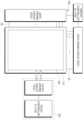
도 1은 본 명세서의 실시예들에 따른 표시장치(100)의 시스템 구성도이다.Figure 1 is a system configuration diagram of a display device (100) according to embodiments of the present specification.
도 1을 참조하면, 본 명세서의 실시예들에 따른 표시장치(100)는, 다수의 데이터 라인들(DL) 및 다수의 게이트 라인들(GL)이 배치되고, 다수의 데이터 라인들(DL) 및 다수의 게이트 라인들(GL)에 의해 정의되는 다수의 서브픽셀들(111)이 배열된 표시패널(110)과, 다수의 데이터 라인들(DL)을 구동하는 데이터 구동회로(DDC)와, 다수의 게이트 라인들(GL)을 구동하는 게이트 구동회로(GDC)와, 데이터 구동회로(DDC) 및 게이트 구동회로(GDC)를 제어하는 컨트롤러(D-CTR) 등을 포함한다.Referring to FIG. 1, a display device (100) according to embodiments of the present specification includes a display panel (110) in which a plurality of data lines (DL) and a plurality of gate lines (GL) are arranged, and a plurality of subpixels (111) defined by the plurality of data lines (DL) and the plurality of gate lines (GL) are arranged, a data driving circuit (DDC) for driving the plurality of data lines (DL), a gate driving circuit (GDC) for driving the plurality of gate lines (GL), and a controller (D-CTR) for controlling the data driving circuit (DDC) and the gate driving circuit (GDC).
컨트롤러(D-CTR)는, 데이터 구동회로(DDC) 및 게이트 구동회로(GDC)로 각종 제어신호(DCS, GCS)를 공급하여, 데이터 구동회로(DDC) 및 게이트 구동회로(GDC)를 제어한다.The controller (D-CTR) supplies various control signals (DCS, GCS) to the data driving circuit (DDC) and the gate driving circuit (GDC), thereby controlling the data driving circuit (DDC) and the gate driving circuit (GDC).
이러한 컨트롤러(D-CTR)는, 각 프레임에서 구현하는 타이밍에 따라 스캔을 시작하고, 외부에서 입력되는 입력 영상 데이터를 데이터 구동회로(DDC)에서 사용하는 데이터 신호 형식에 맞게 전환하여 전환된 영상 데이터(Data)를 출력하고, 스캔에 맞춰 적당한 시간에 데이터 구동을 통제한다.These controllers (D-CTR) start scanning according to the timing implemented in each frame, convert externally input image data into a data signal format used by the data drive circuit (DDC), output the converted image data (Data), and control data driving at an appropriate time according to the scan.
컨트롤러(D-CTR)는, 데이터 구동회로(DDC)와 별도의 부품으로 구현될 수도 있고, 데이터 구동회로(DDC)와 함께 통합되어 집적회로로 구현될 수 있다.The controller (D-CTR) may be implemented as a separate component from the data drive circuit (DDC), or may be implemented as an integrated circuit integrated with the data drive circuit (DDC).
데이터 구동회로(DDC)는, 컨트롤러(D-CTR)로부터 영상 데이터(Data)를 입력 받아 다수의 데이터 라인들(DL)로 데이터 전압을 공급함으로써, 다수의 데이터 라인들(DL)을 구동한다. 여기서, 데이터 구동회로(DDC)는 소스 구동회로라고도 한다.The data driving circuit (DDC) receives image data (Data) from the controller (D-CTR) and supplies data voltage to a plurality of data lines (DL), thereby driving a plurality of data lines (DL). Here, the data driving circuit (DDC) is also called a source driving circuit.
이러한 데이터 구동회로(DDC)는, 적어도 하나의 소스 드라이버 집적회로(SDIC: Source Driver Integrated Circuit)를 포함하여 구현될 수 있다.Such data drive circuits (DDCs) can be implemented by including at least one source driver integrated circuit (SDIC).
각 소스 드라이버 집적회로(SDIC)는, 시프트 레지스터(Shift Register), 래치 회로(Latch Circuit), 디지털 아날로그 컨버터(DAC: Digital to Analog Converter), 출력 버퍼(Output Buffer) 등을 포함할 수 있다.Each source driver integrated circuit (SDIC) may include a shift register, a latch circuit, a digital to analog converter (DAC), an output buffer, etc.
각 소스 드라이버 집적회로(SDIC)는, 경우에 따라서, 아날로그 디지털 컨버터(ADC: Analog to Digital Converter)를 더 포함할 수 있다.Each source driver integrated circuit (SDIC) may, in some cases, further include an analog-to-digital converter (ADC).
게이트 구동회로(GDC)는, 다수의 게이트 라인들(GL)로 스캔 신호를 순차적으로 공급함으로써, 다수의 게이트 라인들(GL)을 순차적으로 구동한다. 여기서, 게이트 구동회로(GDC)는 스캔 구동회로라고도 한다.A gate driving circuit (GDC) sequentially drives a plurality of gate lines (GL) by sequentially supplying scan signals to the plurality of gate lines (GL). Here, the gate driving circuit (GDC) is also called a scan driving circuit.
이러한 게이트 구동회로(GDC)는, 적어도 하나의 게이트 구동회로 집적회로(GDIC: Gate Driver Integrated Circuit)를 포함하여 구현될 수 있다.Such a gate driver circuit (GDC) can be implemented by including at least one gate driver integrated circuit (GDIC).
각 게이트 구동회로 집적회로(GDIC)는 시프트 레지스터(Shift Register), 레벨 시프터(Level Shifter) 등을 포함할 수 있다.Each gate driver integrated circuit (GDIC) may include a shift register, a level shifter, etc.
각 게이트 드라이버 집적회로(GDIC)는, 테이프 오토메티드 본딩(TAB) 방식 또는 칩 온 글래스(COG) 방식으로 표시패널(110)의 본딩 패드(Bonding Pad)에 연결되거나, GIP(Gate In Panel) 타입으로 구현되어 표시패널(110)에 직접 배치될 수도 있으며, 경우에 따라서, 표시패널(110)에 집적화되어 배치될 수도 있다. 또한, 각 게이트 드라이버 집적회로(GDIC)는 표시패널(110)과 연결된 필름 상에 실장 되는 칩 온 필름(COF) 방식으로 구현될 수도 있다.Each gate driver integrated circuit (GDIC) may be connected to a bonding pad of a display panel (110) by a tape automated bonding (TAB) method or a chip on glass (COG) method, or may be implemented as a GIP (Gate In Panel) type and placed directly on the display panel (110), and in some cases, may be integrated and placed on the display panel (110). In addition, each gate driver integrated circuit (GDIC) may be implemented as a chip on film (COF) method mounted on a film connected to the display panel (110).
게이트 구동회로(GDC)는, 컨트롤러(D-CTR)의 제어에 따라, 온(On) 전압 또는 오프(Off) 전압의 스캔 신호를 다수의 게이트 라인들(GL)로 순차적으로 공급한다.The gate drive circuit (GDC) sequentially supplies scan signals of on voltage or off voltage to a plurality of gate lines (GL) under the control of the controller (D-CTR).
데이터 구동회로(DDC)는, 게이트 구동회로(GDC)에 의해 특정 게이트 라인이 열리면, 컨트롤러(D-CTR)로부터 수신한 영상 데이터(DATA)를 아날로그 형태의 데이터 전압으로 변환하여 다수의 데이터 라인들(DL)로 공급한다.The data drive circuit (DDC) converts image data (DATA) received from the controller (D-CTR) into an analog data voltage and supplies it to a number of data lines (DL) when a specific gate line is opened by the gate drive circuit (GDC).
데이터 구동회로(DDC)는, 표시패널(110)의 일측(예: 상측 또는 하측)에만 위치할 수도 있고, 경우에 따라서는, 구동 방식, 패널 설계 방식 등에 따라 표시패널(110)의 양측(예: 상측과 하측)에 모두 위치할 수도 있다.The data drive circuit (DDC) may be located only on one side (e.g., upper or lower) of the display panel (110), or in some cases, may be located on both sides (e.g., upper and lower) of the display panel (110) depending on the driving method, panel design method, etc.
게이트 구동회로(GDC)는, 표시패널(110)의 일 측(예: 좌측 또는 우측)에만 위치할 수도 있고, 경우에 따라서는, 구동 방식, 패널 설계 방식 등에 따라 표시패널(110)의 양측(예: 좌측과 우측)에 모두 위치할 수도 있다.The gate drive circuit (GDC) may be located only on one side (e.g., left or right) of the display panel (110), or in some cases, may be located on both sides (e.g., left and right) of the display panel (110) depending on the driving method, panel design method, etc.
본 명세서의 실시예들에 따른 표시장치(100)는 유기발광표시장치, 액정표시장치, 플라즈마 표시장치 등일 수 있다.The display device (100) according to the embodiments of the present specification may be an organic light emitting display device, a liquid crystal display device, a plasma display device, etc.
본 명세서의 실시예들에 따른 표시장치(100)가 유기발광표시장치인 경우, 표시패널(110)에 배열된 각 서브픽셀(111)은 자발광 소자인 유기발광다이오드(OLED: Organic Light Emitting Diode)와, 유기발광다이오드(OLED)를 구동하기 위한 구동 트랜지스터(Driving Transistor) 등의 회로 소자로 구성될 수 있다.When the display device (100) according to the embodiments of the present specification is an organic light emitting display device, each subpixel (111) arranged on the display panel (110) may be composed of a circuit element such as an organic light emitting diode (OLED), which is a self-luminous element, and a driving transistor for driving the organic light emitting diode (OLED).
각 서브픽셀(111)을 구성하는 회로 소자의 종류 및 개수는, 제공 기능 및 설계 방식 등에 따라 다양하게 정해질 수 있다.The type and number of circuit elements constituting each subpixel (111) can be determined in various ways depending on the provided function and design method.
도 2는 본 명세서의 실시예들에 따른 표시장치의 시스템 구성도이다.Figure 2 is a system configuration diagram of a display device according to embodiments of the present specification.
도 2를 참조하면, 본 명세서의 실시예들에 따른 표시장치는 영상을 표시하기 위한 영상 표시 기능과, 사용자의 터치를 센싱하는 터치 센싱 기능을 제공할 수 있다.Referring to FIG. 2, a display device according to embodiments of the present specification can provide an image display function for displaying an image and a touch sensing function for sensing a user's touch.
본 명세서의 실시예들에 따른 표시장치는, 영상 표시를 위해, 데이터 라인들과 게이트 라인들이 배치되는 표시패널(110)과, 표시패널(110)을 구동하기 위한 디스플레이 구동 회로 등을 포함할 수 있다.A display device according to embodiments of the present specification may include a display panel (110) on which data lines and gate lines are arranged for image display, and a display driving circuit for driving the display panel (110).
디스플레이 구동 회로는, 데이터 라인들을 구동하기 위한 데이터 구동 회로(DDC)와, 게이트 라인들을 구동하기 위한 게이트 구동 회로(GDC)와, 데이터 구동 회로(DDC) 및 게이트 구동 회로(GDC)를 제어하기 위한 디스플레이 컨트롤러(D-CTR) 등을 포함할 수 있다.The display driving circuit may include a data driving circuit (DDC) for driving data lines, a gate driving circuit (GDC) for driving gate lines, and a display controller (D-CTR) for controlling the data driving circuit (DDC) and the gate driving circuit (GDC).
본 명세서의 실시예들에 따른 터치표시장치는, 터치 센싱을 위해, 터치 센서(Touch Sensor)로서 다수의 터치전극들이 배치된 터치패널(TSP)과, 터치패널(TSP)의 구동 및 센싱 처리를 수행하는 터치 센싱 회로(TSC) 등을 포함할 수 있다.A touch display device according to embodiments of the present specification may include a touch panel (TSP) having a plurality of touch electrodes arranged as touch sensors for touch sensing, and a touch sensing circuit (TSC) that performs driving and sensing processing of the touch panel (TSP).
터치 센싱 회로(TSC)는 터치패널(TSP)을 구동하기 위하여 터치패널(TSP)로 구동 신호를 공급하고, 터치패널(TSP)로부터 센싱 신호를 검출하고, 이를 토대로, 터치유무 및/또는 터치위치(터치좌표)를 센싱한다.A touch sensing circuit (TSC) supplies a driving signal to a touch panel (TSP) to drive the touch panel (TSP), detects a sensing signal from the touch panel (TSP), and senses the presence or absence of a touch and/or a touch location (touch coordinates) based on the signal.
이러한 터치 센싱 회로(TSC)는 구동 신호를 공급하고 센싱 신호를 수신하는 터치 구동 회로(TDC)와, 터치유무 및/또는 터치위치(터치좌표)를 산출하는 터치 컨트롤러(T-CTR) 등을 포함하여 구현될 수도 있다.These touch sensing circuits (TSC) may be implemented including a touch driving circuit (TDC) that supplies a driving signal and receives a sensing signal, and a touch controller (T-CTR) that calculates the presence or absence of a touch and/or a touch position (touch coordinates).
터치 센싱 회로(TSC)는 하나 또는 둘 이상의 부품(예: 집적회로)으로 구현될 수 있으며, 디스플레이 구동 회로와 별도로 구현될 수도 있다.The touch sensing circuit (TSC) may be implemented as one or more components (e.g., integrated circuits) and may be implemented separately from the display driver circuit.
또한, 터치 센싱 회로(TSC)의 전체 또는 일부는, 디스플레이 구동 회로 또는 그 내부 회로 중 하나 이상과 통합되어 구현될 수 있다. 예를 들어, 터치 센싱 회로(TSC)의 터치 구동 회로(TDC)는 디스플레이 구동 회로의 데이터 구동 회로(DDC)와 함께 집적회로로 구현될 수 있다.Additionally, all or part of the touch sensing circuit (TSC) may be implemented by being integrated with the display driver circuit or one or more of its internal circuits. For example, the touch driver circuit (TDC) of the touch sensing circuit (TSC) may be implemented as an integrated circuit together with the data driver circuit (DDC) of the display driver circuit.
한편, 본 명세서의 실시예들에 따른 터치표시장치는 터치전극들(TE, 터치센서들)에 형성되는 커패시턴스(Capacitance)에 기반하여 터치를 센싱할 수 있다.Meanwhile, the touch display device according to the embodiments of the present specification can sense touch based on the capacitance formed in touch electrodes (TE, touch sensors).
본 명세서의 실시예들에 따른 터치표시장치는 커패시턴스 기반의 터치 센싱 방식으로서, 뮤추얼-커패시턴스(Mutual-capacitance) 기반의 터치 센싱 방식으로 터치를 센싱할 수도 있고, 셀프-커패시턴스(Self-capacitance) 기반의 터치 센싱 방식으로 터치를 센싱할 수도 있다.The touch display device according to the embodiments of the present specification may sense touch using a capacitance-based touch sensing method, and may sense touch using a mutual-capacitance-based touch sensing method or a self-capacitance-based touch sensing method.
도 3 내지 도 5는 본 명세서의 실시예들에 따른 표시장치에서, 터치패널(TSP)의 3가지 예시도로서, 도 3 및 도 4은 본 명세서의 실시예들에 따른 표시장치가 뮤추얼-커패시턴스 기반의 터치 센싱 방식으로 터치를 센싱하는 경우, 터치패널(TSP)의 예시도이고, 도 5는 본 명세서의 실시예들에 따른 표시장치가 셀프-커패시턴스 기반의 터치 센싱 방식으로 터치를 센싱하는 경우, 터치패널(TSP)의 예시도이다.FIGS. 3 to 5 are three exemplary diagrams of a touch panel (TSP) in a display device according to embodiments of the present disclosure. FIGS. 3 and 4 are exemplary diagrams of a touch panel (TSP) in a case where a display device according to embodiments of the present disclosure senses a touch using a mutual-capacitance based touch sensing method, and FIG. 5 is an exemplary diagram of a touch panel (TSP) in a case where a display device according to embodiments of the present disclosure senses a touch using a self-capacitance based touch sensing method.
도 3을 참조하면, 뮤추얼-커패시턴스 기반의 터치 센싱 방식의 경우, 터치패널(TSP)에 배치되는 다수의 터치전극들은 구동 신호가 인가되는 구동 터치전극(구동전극, 송신전극, 또는 구동라인이라고도 함)과, 센싱 신호가 센싱되고 구동전극과 커패시턴스를 형성하는 센싱 터치전극(센싱전극, 수신전극, 또는 센싱라인이라고도 함)으로 분류될 수 있다.Referring to FIG. 3, in the case of a mutual-capacitance-based touch sensing method, a plurality of touch electrodes arranged on a touch panel (TSP) can be classified into a driving touch electrode (also called a driving electrode, a transmitting electrode, or a driving line) to which a driving signal is applied, and a sensing touch electrode (also called a sensing electrode, a receiving electrode, or a sensing line) to which a sensing signal is sensed and which forms a capacitance with the driving electrode.
그리고, 터치전극들의 구동 터치전극들 중에서, 동일한 행 (또는 동일한 열)에 배치된 구동 터치전극들은 일체화 방식에 의해 (또는 브리지 패턴에 의한 연결 방식에 의해) 전기적으로 서로 연결되어 하나의 구동 터치전극 라인(DEL)을 형성한다.And, among the driving touch electrodes of the touch electrodes, the driving touch electrodes arranged in the same row (or the same column) are electrically connected to each other by an integrated method (or by a connection method using a bridge pattern) to form one driving touch electrode line (DEL).
도 3을 참조하면, 터치전극들의 센싱 터치전극들 중에서, 동일한 열 (또는 동일한 행)에 배치된 센싱 터치전극들은 브리지 패턴에 의해 (또는 일체화 방식에 의해) 전기적으로 서로 연결되어 하나의 센싱 터치전극 라인(SEL)을 형성한다.Referring to FIG. 3, among the sensing touch electrodes of the touch electrodes, the sensing touch electrodes arranged in the same column (or the same row) are electrically connected to each other by a bridge pattern (or by an integrated method) to form one sensing touch electrode line (SEL).
이러한 뮤추얼-커패시턴스 기반의 터치 센싱 방식의 경우, 터치 센싱 회로(TSC)는, 하나 이상의 구동 터치전극 라인(DEL)으로 구동 신호를 인가하고, 하나 이상의 센싱 터치전극 라인(SEL)으로부터 센싱 신호를 수신하고, 수신된 센싱 신호를 토대로, 손가락, 펜 등의 포인터의 유무에 따른 구동 터치전극 라인(DEL)과 센싱 터치전극 라인(SEL) 간의 커패시턴스(뮤추얼-커패시턴스)의 변화를 토대로 터치 유무 및/또는 터치 좌표 등을 검출한다.In the case of such mutual-capacitance based touch sensing method, a touch sensing circuit (TSC) applies a driving signal to one or more driving touch electrode lines (DEL), receives a sensing signal from one or more sensing touch electrode lines (SEL), and detects the presence or absence of a touch and/or touch coordinates, etc. based on a change in capacitance (mutual capacitance) between the driving touch electrode lines (DEL) and the sensing touch electrode lines (SEL) depending on the presence or absence of a pointer such as a finger or a pen, based on the received sensing signal.
도 3을 참조하면, 구동 신호 및 센싱 신호 전달을 위해, 다수의 구동 터치전극 라인(DEL) 및 다수의 센싱 터치전극 라인(SEL) 각각은 하나 이상의 터치 라인(230)을 통해 터치 구동 회로(TDC)와 전기적으로 연결된다.Referring to FIG. 3, for transmitting driving signals and sensing signals, each of a plurality of driving touch electrode lines (DEL) and a plurality of sensing touch electrode lines (SEL) is electrically connected to a touch driving circuit (TDC) through one or more touch lines (230).
구체적으로, 구동 신호 전달을 위해, 다수의 구동 터치전극 라인(DEL) 각각은 하나 이상의 구동 터치 라인(TLd)을 통해, 터치 구동 회로(TDC)와 전기적으로 연결된다. 그리고, 센싱 신호 전달을 위해, 다수의 센싱 터치전극 라인(SEL) 각각은 하나 이상의 센싱 터치 라인(TLs)을 통해, 터치 구동 회로(TDC)와 전기적으로 연결된다.Specifically, for transmitting a driving signal, each of a plurality of driving touch electrode lines (DEL) is electrically connected to a touch driving circuit (TDC) through one or more driving touch lines (TLd). And, for transmitting a sensing signal, each of a plurality of sensing touch electrode lines (SEL) is electrically connected to a touch driving circuit (TDC) through one or more sensing touch lines (TLs).
또한, 뮤추얼 커패시턴스 기반의 터치 센싱 방식의 표시장치(100)는 도 4로 나타낼 수도 있다.Additionally, a display device (100) using a mutual capacitance-based touch sensing method can also be represented as shown in FIG. 4.
도 4를 참조하면, 터치패널(TSP)에는 다수의 터치전극들(420)이 배치되며, 이러한 터치전극들(420)과 터치회로를 전기적으로 연결해주는 터치라인들(TL)이 배치될 수 있다.Referring to FIG. 4, a plurality of touch electrodes (420) are arranged on a touch panel (TSP), and touch lines (TL) that electrically connect these touch electrodes (420) and a touch circuit can be arranged.
또한, 터치패널(TSP)에는, 터치라인들(230)과 터치 구동 회로(TDC)를 전기적으로 연결해주기 위하여, 터치 구동 회로(TDC)가 접촉하는 터치패드들이 존재할 수도 있다.Additionally, the touch panel (TSP) may have touch pads that the touch driving circuit (TDC) contacts in order to electrically connect the touch lines (230) and the touch driving circuit (TDC).
터치전극들(420) 및 터치라인들(TL)은 동일한 층에 존재할 수도 있고 서로 다른 층에 존재할 수도 있다.The touch electrodes (420) and touch lines (TL) may be present in the same layer or in different layers.
하나의 구동 터치전극 라인(Driving TE Line)을 형성하는 둘 이상의 터치전극은 구동 터치전극(Driving TE)이라고 한다. 하나의 센싱 터치전극 라인(Sensing TE Line)을 형성하는 둘 이상의 터치전극(TE)을 센싱 터치전극(Sensing TE)이라고 한다.Two or more touch electrodes forming a single driving touch electrode line (Driving TE Line) are called driving touch electrodes (Driving TE). Two or more touch electrodes (TE) forming a single sensing touch electrode line (Sensing TE Line) are called sensing touch electrodes (Sensing TE).
하나의 구동 터치전극 라인마다 적어도 하나의 터치라인(TLd)이 연결되고, 하나의 센싱 터치전극 라인마다 적어도 하나의 터치라인(TLs)이 연결될 수 있다.At least one touch line (TLd) may be connected to each driving touch electrode line, and at least one touch line (TLs) may be connected to each sensing touch electrode line.
하나의 구동 터치전극 라인마다 연결되는 적어도 하나의 터치라인(TLd)을 구동 터치라인(Driving TL)이라고 한다. 하나의 센싱 터치전극 라인마다 연결되는 적어도 하나의 터치라인(TLs)을 센싱 터치라인(Sensing TL)이라고 한다.At least one touch line (TLd) connected to each driving touch electrode line is called a driving touch line (Driving TL). At least one touch line (TLs) connected to each sensing touch electrode line is called a sensing touch line (Sensing TL).
하나의 터치라인(TL)마다 하나의 터치패드가 연결될 수 있다.One touchpad can be connected to each touch line (TL).
도 4를 참조하면, 다수의 터치전극들(420) 각각은, 일 예로, 외곽의 윤곽을 볼 때, 마름모형일 수 있으며, 경우에 따라서는, 직사각형 (정사각형을 포함할 수 있음)일 수도 있으며, 이뿐만 아니라 다양한 모양으로 되어 있을 수도 있다.Referring to FIG. 4, each of the plurality of touch electrodes (420) may, for example, be in the shape of a diamond when looking at the outer outline, and in some cases, may be in the shape of a rectangle (which may include a square), and may also have various other shapes.
또한, 2개의 터치전극들 간의 연결을 위한 브리지 구성은 1개 또는 2개 이상의 브리지 패턴(BR)을 포함할 수 있다.Additionally, the bridge configuration for connection between two touch electrodes may include one or more bridge patterns (BR).
실시예들에 따른 터치패널(TSP)은 표시영역(A/A)과 비 표시영역(N/A)을 갖는 표시패널의 내부에 존재할 수 있다(내장형).A touch panel (TSP) according to embodiments may be present (built-in) inside a display panel having a display area (A/A) and a non-display area (N/A).
터치패널(TSP)이 내장형인 경우, 터치패널(TSP)과 표시패널은 한번의 패널 제작 공정을 통해 함께 만들어질 수 있다.If the touch panel (TSP) is built-in, the touch panel (TSP) and the display panel can be manufactured together in a single panel manufacturing process.
터치패널(TSP)이 내장형인 경우, 터치패널(TSP)은 다수의 터치전극들(420)의 집합체로 볼 수 있다. 여기서, 다수의 터치전극들(420)이 놓이는 판(Plate)은 전용 기판일 수도 있고, 표시패널에 이미 존재하는 층(예: 봉지층)일 수도 있다.When the touch panel (TSP) is built-in, the touch panel (TSP) can be viewed as an assembly of a plurality of touch electrodes (420). Here, the plate on which the plurality of touch electrodes (420) are placed may be a dedicated substrate or a layer (e.g., an encapsulation layer) that already exists in the display panel.
도 5를 참조하면, 셀프-커패시턴스(Self-capacitance) 기반의 터치 센싱 방식의 경우, 터치패널(TSP)에 배치되는 각 터치전극(420)은 구동 터치전극의 역할 (구동 신호 인가)과 센싱 터치전극의 역할(센싱 신호 검출)을 모두 갖는다.Referring to FIG. 5, in the case of a self-capacitance-based touch sensing method, each touch electrode (420) placed on a touch panel (TSP) has both the role of a driving touch electrode (applying a driving signal) and the role of a sensing touch electrode (detecting a sensing signal).
즉, 각 터치전극(320)으로 구동 신호가 인가되고, 구동 신호가 인가된 터치전극(420)을 통해 센싱 신호를 수신한다. 따라서, 셀프-커패시턴스(Self-capacitance) 기반의 터치 센싱 방식에서는, 구동전극과 센싱전극의 구분이 따로 없다.That is, a driving signal is applied to each touch electrode (320), and a sensing signal is received through the touch electrode (420) to which the driving signal is applied. Therefore, in the self-capacitance-based touch sensing method, there is no distinction between the driving electrode and the sensing electrode.
이러한 셀프-커패시턴스 기반의 터치 센싱 방식의 경우, 터치 센싱 회로(TSC)는, 하나 이상의 터치전극(420)으로 구동 신호를 인가하고, 구동 신호가 인가된 터치전극(420)으로부터 센싱 신호를 수신하며, 수신된 센싱 신호를 토대로, 손가락, 펜 등의 포인터와 터치전극(420) 간의 커패시턴스의 변화를 토대로 터치 유무 및/또는 터치 좌표 등을 검출한다.In the case of such a self-capacitance-based touch sensing method, a touch sensing circuit (TSC) applies a driving signal to one or more touch electrodes (420), receives a sensing signal from the touch electrodes (420) to which the driving signal has been applied, and detects the presence or absence of a touch and/or touch coordinates based on the change in capacitance between a pointer such as a finger or pen and the touch electrode (420) based on the received sensing signal.
도 5를 참조하면, 구동 신호 및 센싱 신호 전달을 위해, 다수의 터치전극(420) 각각은 하나 이상의 터치 라인(230)을 통해 터치 구동 회로(TDC)와 전기적으로 연결된다.Referring to FIG. 5, each of a plurality of touch electrodes (420) is electrically connected to a touch driving circuit (TDC) through one or more touch lines (230) to transmit driving signals and sensing signals.
이와 같이, 본 명세서의 실시예들에 따른 터치표시장치는, 뮤추얼-커패시턴스 기반의 터치 센싱 방식으로 터치를 센싱할 수도 있고, 셀프-커패시턴스 기반의 터치 센싱 방식으로 터치를 센싱할 수도 있다.In this way, the touch display device according to the embodiments of the present specification may sense touch using a mutual-capacitance-based touch sensing method or may sense touch using a self-capacitance-based touch sensing method.
한편, 본 명세서의 실시예들에 따른 터치표시장치에서, 터치패널(TSP)은 표시패널(110)의 제작 시 함께 제작되어 표시패널(110)의 내부에 존재하는 내장형 타입일 수도 있다. 즉, 본 명세서의 실시예들에 따른 표시패널(110)은 터치패널(TSP)를 내장할 수 있다.Meanwhile, in the touch display device according to the embodiments of the present specification, the touch panel (TSP) may be a built-in type that is manufactured together with the manufacturing of the display panel (110) and exists inside the display panel (110). That is, the display panel (110) according to the embodiments of the present specification may have a built-in touch panel (TSP).
또한, 본 명세서의 실시예들에서 터치전극들(420) 및 터치 라인들(TL)은 표시패널(110)의 내부에 존재하는 전극 및 신호배선이다.Additionally, in the embodiments of the present specification, the touch electrodes (420) and touch lines (TL) are electrodes and signal wires that exist inside the display panel (110).
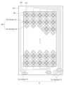
도 6은 본 명세서의 실시예들에 따른 플렉서블 터치표시장치에서, 터치패널(TSP)에 배치된 메쉬 타입(Mesh type)의 터치 전극을 나타낸 도면이다.FIG. 6 is a drawing showing a mesh type touch electrode arranged on a touch panel (TSP) in a flexible touch display device according to embodiments of the present specification.
도 6을 참조하면, 본 명세서의 실시예들에 따른 플렉서블 터치표시장치에서, 터치패널(TSP)에 배치된 다수의 터치 전극(420) 각각은 메쉬 타입일 수 있다.Referring to FIG. 6, in a flexible touch display device according to embodiments of the present specification, each of a plurality of touch electrodes (420) arranged on a touch panel (TSP) may be of a mesh type.
메쉬 타입(Mesh type)의 터치 전극(420)은 메쉬 타입으로 패터닝 된 전극메탈(EM)로 되어 있을 수 있다.The touch electrode (420) of the mesh type may be made of electrode metal (EM) patterned in a mesh type.
이에 따라, 메쉬 타입(Mesh type)의 터치 전극(420)의 영역에는 다수의 오픈 영역(OA)이 존재할 수 있다.Accordingly, a number of open areas (OA) may exist in the area of the mesh type touch electrode (420).
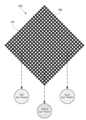
도 7은 본 명세서의 실시예들에 따른 플렉서블 터치표시장치에서, 터치패널(TSP)에 배치된 메쉬 타입의 터치 전극과 서브픽셀(Sub Pixel) 간의 대응 관계를 설명하기 위한 도면이다.FIG. 7 is a drawing for explaining the correspondence between a mesh-type touch electrode and a sub-pixel arranged on a touch panel (TSP) in a flexible touch display device according to embodiments of the present specification.
도 7을 참조하면, 메쉬 타입으로 패터닝 된 전극메탈(EM)로 되어 있는 터치 전극(420)의 영역 내 존재하는 다수의 오픈 영역(OA) 각각은 하나 이상의 서브픽셀의 발광 영역과 대응될 수 있다.Referring to FIG. 7, each of a plurality of open areas (OA) existing within an area of a touch electrode (420) made of electrode metal (EM) patterned in a mesh type may correspond to a light-emitting area of one or more subpixels.
예를 들어, 하나의 터치 전극(420)의 영역 내 존재하는 다수의 오픈 영역(OA) 각각은 적색 서브픽셀, 녹색 서브픽셀 및 청색 서브픽셀 등 중 하나 이상의 발광 영역과 대응될 수 있다.For example, each of a plurality of open areas (OA) existing within the area of one touch electrode (420) may correspond to one or more light-emitting areas of a red subpixel, a green subpixel, a blue subpixel, and the like.
다른 예로, 하나의 터치 전극(420)의 영역 내 존재하는 다수의 오픈 영역(OA) 각각은 적색 서브픽셀, 녹색 서브픽셀, 청색 서브픽셀 및 흰색 서브픽셀 등 중 하나 이상의 발광 영역과 대응될 수 있다.As another example, each of a plurality of open areas (OA) existing within the area of one touch electrode (420) may correspond to one or more light-emitting areas of a red subpixel, a green subpixel, a blue subpixel, and a white subpixel.
전술한 바와 같이, 평면에서 볼 때, 각 터치 전극(420)의 오픈 영역들(OA) 각각에 하나 이상의 서브픽셀의 발광 영역이 존재함으로써, 터치 센싱을 가능하게 하면서도, 표시패널(DISP)의 개구율 및 발광 효율을 더욱 높여줄 수 있다.As described above, when viewed from a plane, since there is a light-emitting area of one or more sub-pixels in each of the open areas (OA) of each touch electrode (420), touch sensing can be enabled while further increasing the aperture ratio and light-emitting efficiency of the display panel (DISP).
위에서 전술한 바와 같이, 하나의 터치 전극(320)의 외곽의 대략적인 윤곽은 마름모형 또는 직사각형(정사각형 포함 가능) 등일 수 있으며, 하나의 터치 전극(420)에서의 구멍에 해당하는 오픈 영역(OA) 또한, 마름모형 또는 직사각형(정사각형 포함 가능) 등일 수 있다.As described above, the rough outline of the outer surface of one touch electrode (320) may be a rhombus or a rectangle (including a square), and the open area (OA) corresponding to the hole in one touch electrode (420) may also be a rhombus or a rectangle (including a square).
하지만, 이러한 터치 전극(420)의 형상과 오픈 영역(OA)의 형상은, 서브픽셀의 형상, 서브픽셀들의 배열 구조, 터치 감도 등을 고려하여, 다양하게 변형되어 설계될 수 있을 것이다.However, the shape of the touch electrode (420) and the shape of the open area (OA) may be designed to be modified in various ways by taking into consideration the shape of the subpixel, the arrangement structure of the subpixels, touch sensitivity, etc.
이에, 아래에서는, 유기발광소자(OLED: Organic Light Emitting Diode)를 이용하여 영상을 표시하기 위한 표시패널에서의 서브픽셀 구조(서브픽셀 회로)를 살펴본다.Hereinafter, we will examine the subpixel structure (subpixel circuit) in a display panel for displaying images using an organic light emitting diode (OLED).
도 8 및 도 9는 본 명세서의 실시예들에 따른 표시패널의 서브픽셀 회로를 나타낸 도면이다.FIGS. 8 and 9 are diagrams showing subpixel circuits of a display panel according to embodiments of the present specification.
도 8 및 도 9를 참조하면, 각 서브픽셀(111)은, 기본적으로, 유기발광소자(OLED)와, 유기발광소자(OLED)를 구동하는 구동 트랜지스터(DRT)를 포함할 수 있다.Referring to FIGS. 8 and 9, each subpixel (111) may basically include an organic light-emitting diode (OLED) and a driving transistor (DRT) that drives the organic light-emitting diode (OLED).
도 8을 참조하면, 각 서브픽셀(111)은, 구동 트랜지스터(DRT)의 게이트 노드에 해당하는 제1 노드(N1)로 데이터 전압(VDATA)을 전달해주기 위한 제1 트랜지스터(T1)와, 영상 신호 전압에 해당하는 데이터 전압(VDATA) 또는 이에 대응되는 전압을 한 프레임 시간 동안 유지하는 스토리지 캐패시터(C1)를 더 포함하여 구성될 수 있다.Referring to FIG. 8, each subpixel (111) may further include a first transistor (T1) for transmitting a data voltage (VDATA) to a first node (N1) corresponding to a gate node of a driving transistor (DRT), and a storage capacitor (C1) for maintaining the data voltage (VDATA) corresponding to an image signal voltage or a voltage corresponding thereto for one frame time.
유기발광소자(OLED)는 제1전극(E1, 애노드 전극 또는 캐소드 전극), 발광층(832) 및 제2전극(E2, 캐소드 전극 또는 애노드 전극) 등으로 이루어질 수 있다.An organic light-emitting device (OLED) may be composed of a first electrode (E1, anode electrode or cathode electrode), a light-emitting layer (832), and a second electrode (E2, cathode electrode or anode electrode).
일 예로, 유기발광소자(OLED)의 제2전극(833)에는 기저 전압(EVSS)이 인가될 수 있다.For example, a base voltage (EVSS) can be applied to the second electrode (833) of an organic light-emitting device (OLED).
구동 트랜지스터(DRT)는 유기발광소자(OLED)로 구동 전류를 공급해줌으로써 유기발광소자(OLED)를 구동해준다.The driver transistor (DRT) drives the organic light emitting diode (OLED) by supplying driving current to the OLED.
구동 트랜지스터(DRT)는 제1 노드(N1), 제2 노드(N2) 및 제3노드(N3)를 갖는다.The driving transistor (DRT) has a first node (N1), a second node (N2), and a third node (N3).
구동 트랜지스터(DRT)의 제1 노드(N1)는 게이트 노드에 해당하는 노드로서, 제1 트랜지스터(T1)의 소스 노드 또는 드레인 노드와 전기적으로 연결될 수 있다.The first node (N1) of the driving transistor (DRT) is a node corresponding to the gate node and can be electrically connected to the source node or drain node of the first transistor (T1).
구동 트랜지스터(DRT)의 제2 노드(N2)는 유기발광소자(OLED)의 제1전극(831)과 전기적으로 연결될 수 있으며, 소스 노드 또는 드레인 노드일 수 있다.The second node (N2) of the driving transistor (DRT) can be electrically connected to the first electrode (831) of the organic light-emitting device (OLED) and can be a source node or a drain node.
구동 트랜지스터(DRT)의 제3노드(N3)는 구동 전압(EVDD)이 인가되는 노드로서, 구동 전압(EVDD)을 공급하는 구동전압 라인(DVL: Driving Voltage Line)과 전기적으로 연결될 수 있으며, 드레인 노드 또는 소스 노드일 수 있다.The third node (N3) of the driving transistor (DRT) is a node to which a driving voltage (EVDD) is applied, and can be electrically connected to a driving voltage line (DVL: Driving Voltage Line) that supplies the driving voltage (EVDD), and can be a drain node or a source node.
구동 트랜지스터(DRT)와 제1 트랜지스터(T1)는, n 타입으로 구현될 수도 있고, p 타입으로도 구현될 수도 있다.The driving transistor (DRT) and the first transistor (T1) may be implemented as either n-type or p-type.
제1 트랜지스터(T1)는 데이터 라인(DL)과 구동 트랜지스터(DRT)의 제1 노드(N1) 사이에 전기적으로 연결되고, 게이트 라인을 통해 스캔 신호(SCAN)를 게이트 노드로 인가 받아 제어될 수 있다.The first transistor (T1) is electrically connected between the data line (DL) and the first node (N1) of the driving transistor (DRT), and can be controlled by receiving a scan signal (SCAN) as a gate node through the gate line.
이러한 제1 트랜지스터(T1)는 스캔 신호(SCAN)에 의해 턴-온 되어 데이터 라인(DL)으로부터 공급된 데이터 전압(VDATA)을 구동 트랜지스터(DRT)의 제1 노드(N1)로 전달해줄 수 있다.This first transistor (T1) can be turned on by a scan signal (SCAN) and transmit the data voltage (VDATA) supplied from the data line (DL) to the first node (N1) of the driving transistor (DRT).
스토리지 캐패시터(C1)는 구동 트랜지스터(DRT)의 제1 노드(N1)와 제2 노드(N2) 사이에 전기적으로 연결될 수 있다.A storage capacitor (C1) can be electrically connected between a first node (N1) and a second node (N2) of a driving transistor (DRT).
이러한 스토리지 캐패시터(C1)는, 구동 트랜지스터(DRT)의 제1 노드(N1)와 제2 노드(N2) 사이에 존재하는 내부 캐패시터(Internal Capacitor)인 기생 캐패시터(예: Cgs, Cgd)가 아니라, 구동 트랜지스터(DRT)의 외부에 의도적으로 설계한 외부 캐패시터(External Capacitor)이다.This storage capacitor (C1) is not a parasitic capacitor (e.g., Cgs, Cgd) that exists between the first node (N1) and the second node (N2) of the driving transistor (DRT), but is an external capacitor that is intentionally designed outside the driving transistor (DRT).
도 9를 참조하면, 본 실시예들에 따른 표시패널에 배치된 각 서브픽셀(111)은, 유기발광소자(OLED), 구동 트랜지스터(DRT), 제1 트랜지스터(T1) 및 스토리지 캐패시터(C1) 이외에, 제2 트랜지스터(T2)를 더 포함할 수 있다.Referring to FIG. 9, each subpixel (111) arranged on the display panel according to the present embodiments may further include a second transistor (T2) in addition to an organic light-emitting diode (OLED), a driving transistor (DRT), a first transistor (T1), and a storage capacitor (C1).
제2 트랜지스터(T2)는 구동 트랜지스터(DRT)의 제2 노드(N2)와 기준 전압(VREF: Reference Voltage)을 공급하는 기준 전압 라인(RVL: Reference Voltage Line) 사이에 전기적으로 연결되고, 게이트 노드로 스캔 신호의 일종인 센싱 신호(SENSE)를 인가 받아 제어될 수 있다.The second transistor (T2) is electrically connected between the second node (N2) of the driving transistor (DRT) and a reference voltage line (RVL: Reference Voltage Line) that supplies a reference voltage (VREF: Reference Voltage), and can be controlled by receiving a sensing signal (SENSE), which is a type of scan signal, as a gate node.
전술한 제2 트랜지스터(T2)를 더 포함함으로써, 서브픽셀(111) 내 구동 트랜지스터(DRT)의 제2 노드(N2)의 전압 상태를 효과적으로 제어해줄 수 있다.By further including the second transistor (T2) described above, the voltage state of the second node (N2) of the driving transistor (DRT) in the subpixel (111) can be effectively controlled.
이러한 제2 트랜지스터(T2)는 센싱 신호(SENSE)에 의해 턴-온 되어 기준 전압 라인(RVL)을 통해 공급되는 기준 전압(VREF)을 구동 트랜지스터(DRT)의 제2 노드(N2)에 인가해준다.This second transistor (T2) is turned on by the sensing signal (SENSE) and applies the reference voltage (VREF) supplied through the reference voltage line (RVL) to the second node (N2) of the driving transistor (DRT).
도 9의 서브픽셀 구조는, 구동 트랜지스터(DRT)의 제2 노드(N2)의 전압 초기화를 정확하게 해주는데 유리하고, 구동 트랜지스터(DRT)의 고유 특성치(문턱전압 또는 이동도), 유기발광소자(OLED)의 고유 특성치(예: 문턱전압)을 센싱하기 위해 유리한 구조이다.The subpixel structure of Fig. 9 is advantageous in accurately initializing the voltage of the second node (N2) of the driving transistor (DRT), and is advantageous in sensing the unique characteristic (threshold voltage or mobility) of the driving transistor (DRT) and the unique characteristic (e.g., threshold voltage) of the organic light-emitting diode (OLED).
한편, 스캔 신호(SCAN) 및 센싱 신호(SENSE)는 별개의 게이트 신호일 수 있다. 이 경우, 스캔 신호(SCAN) 및 센싱 신호(SENSE)는, 서로 다른 게이트 라인을 통해, 제1 트랜지스터(T1)의 게이트 노드 및 제2 트랜지스터(T2)의 게이트 노드로 각각 인가될 수도 있다.Meanwhile, the scan signal (SCAN) and the sensing signal (SENSE) may be separate gate signals. In this case, the scan signal (SCAN) and the sensing signal (SENSE) may be applied to the gate node of the first transistor (T1) and the gate node of the second transistor (T2), respectively, through different gate lines.
경우에 따라서는, 스캔 신호(SCAN) 및 센싱 신호(SENSE)는 동일한 게이트 신호일 수도 있다. 이 경우, 스캔 신호(SCAN) 및 센싱 신호(SENSE)는 동일한 게이트 라인을 통해 제1 트랜지스터(T1)의 게이트 노드 및 제2 트랜지스터(T2)의 게이트 노드에 공통으로 인가될 수도 있다.In some cases, the scan signal (SCAN) and the sensing signal (SENSE) may be the same gate signal. In this case, the scan signal (SCAN) and the sensing signal (SENSE) may be commonly applied to the gate node of the first transistor (T1) and the gate node of the second transistor (T2) through the same gate line.
도 10은 본 명세서의 실시예들에 따른 표시패널에서 터치 전극의 위치를 나타낸 도면이다.FIG. 10 is a drawing showing the positions of touch electrodes in a display panel according to embodiments of the present specification.
도 10을 참조하면, 본 명세서의 실시예들에 따른 표시패널에서 터치전극(420)은, 유기발광소자(OLED) 상에 위치하는 봉지층(1051) 상에 배치될 수 있다.Referring to FIG. 10, in a display panel according to embodiments of the present specification, a touch electrode (420) may be placed on an encapsulating layer (1051) positioned on an organic light-emitting device (OLED).
여기서, 봉지층(1051)은 발광층(832)에 포함된 유기물질을 수분, 공기 등으로부터 보호하기 위한 층으로서, 캐소드 전극일 수 있는 유기발광소자(OLED)의 제2 전극(833) 상에 위치할 수 있다.Here, the sealing layer (1051) is a layer for protecting the organic material included in the light-emitting layer (832) from moisture, air, etc., and may be positioned on the second electrode (833) of an organic light-emitting device (OLED), which may be a cathode electrode.
봉지층(1051)은 그래핀 산화물을 포함하는 그래핀층, 그래핀층 상에 위치하고 감압성 점착제를 포함하는 감압성 점착제층 및 감압성 점착제층 상에 위치하는 고분자 필름으로 구성될 수 있다. 본 명세서의 실시예들에 따른 표시패널은, 전술한 그래핀층, 감압성 점착제층 및 고분자 필름을 포함하는 봉지층을 구비함으로서 넌-액티브 영역에서 댐(DAM) 구조를 생략할 수 있어 베젤의 두께를 얇게 할 수 있다.The encapsulating layer (1051) may be composed of a graphene layer including graphene oxide, a pressure-sensitive adhesive layer positioned on the graphene layer and including a pressure-sensitive adhesive, and a polymer film positioned on the pressure-sensitive adhesive layer. The display panel according to the embodiments of the present specification can omit a dam (DAM) structure in a non-active area by having an encapsulating layer including the above-described graphene layer, the pressure-sensitive adhesive layer, and the polymer film, thereby making it possible to reduce the thickness of the bezel.
도 10에 도시한 것과 같이, 터치전극(420)이 봉지층(1051) 상에 형성된 터치구조를 TOE (Touch On Encapsulation Layer)라고 한다.As illustrated in Fig. 10, a touch structure in which a touch electrode (420) is formed on an encapsulation layer (1051) is called TOE (Touch On Encapsulation Layer).
한편, 봉지층(1051)과 터치전극(420) 사이에 컬러필터 층이 추가로 존재하거나, 터치전극(420) 상에 컬러필터 층이 추가로 존재할 수도 있다.Meanwhile, a color filter layer may additionally exist between the encapsulation layer (1051) and the touch electrode (420), or a color filter layer may additionally exist on the touch electrode (420).
이에 따라, 제2 전극(833)과 터치센서(TS) 사이에 전위치가 발생하여 커패시턴스(Cp)가 형성될 수 있다.Accordingly, a voltage may be generated between the second electrode (833) and the touch sensor (TS), thereby forming capacitance (Cp).
터치센싱에 필요한 커패시턴스는, 터치전극(420) 간의 커패시턴스거나, 터치전극(420)와 터치 오브젝트(예: 손가락, 펜 등) 간의 커패시턴스다.The capacitance required for touch sensing is the capacitance between the touch electrodes (420) or the capacitance between the touch electrodes (420) and a touch object (e.g., finger, pen, etc.).
터치전극(420) 상에는 평탄화층(미도시)이 위치할 수 있다. 평탄화층은 터치전극(420)에 의해 형성된 요철을 평탄화할 수 있다. 평탄화층 상에는, 예를 들면, 유리기판 또는 플라스틱 기판 등의 터치 기판이 위치할 수 있다.A flattening layer (not shown) may be positioned on the touch electrode (420). The flattening layer may flatten the unevenness formed by the touch electrode (420). A touch substrate, such as a glass substrate or a plastic substrate, may be positioned on the flattening layer.
도 11은 본 명세서의 일 실시예에 따른 표시패널에 있어서 봉지층이 발광소자를 봉지하는 것을 설명하기 위한 단면도이다.FIG. 11 is a cross-sectional view illustrating an encapsulating layer encapsulating a light-emitting element in a display panel according to one embodiment of the present specification.
도 11을 참고하면, 발광소자(830)가 기판(1140) 상에 위치한다. 발광소자(830)는, 예를 들면, 자발광 소자로서 제1 전극, 발광층 및 제2 전극을 포함하는 유기발광소자일 수 있다.Referring to FIG. 11, a light-emitting element (830) is positioned on a substrate (1140). The light-emitting element (830) may be, for example, an organic light-emitting element including a first electrode, a light-emitting layer, and a second electrode as a self-luminous element.
발광소자(830) 상에는 보호층(1150)이 위치할 수 있다. 보호층(1150)은, 예를 들면, 무기 절연물질을 포함할 수 있으나, 본 명세서의 실시예들이 이에 한정되는 것은 아니다.A protective layer (1150) may be positioned on the light emitting element (830). The protective layer (1150) may include, for example, an inorganic insulating material, but the embodiments of the present specification are not limited thereto.
보호층(1150) 상에는 봉지층(1160, 1170, 1180)이 위치하여 발광소자(830)를 봉지할 수 있다. 봉지층은, 그래핀층(1160), 감압성 점착제층(1170) 및 고분자 필름(1180)을 포함한다.A sealing layer (1160, 1170, 1180) is positioned on the protective layer (1150) to seal the light-emitting element (830). The sealing layer includes a graphene layer (1160), a pressure-sensitive adhesive layer (1170), and a polymer film (1180).
그래핀층(1160)은 보호층(1150) 상에 위치하며, 그래핀 산화물을 포함한다. 예를 들어, 그래핀층(1160)은 Hummer's method 에 의하여 제조된 그래핀 산화물을 포함할 수 있다.The graphene layer (1160) is positioned on the protective layer (1150) and includes graphene oxide. For example, the graphene layer (1160) may include graphene oxide manufactured by the Hummer's method.
본 명세서의 실시예들에 따른 봉지층(1051)은, 그래핀 산화물을 포함하는 그래핀층(1160)을 포함함으로써, 우수한 내투습성을 가질 수 있으며 간단한 공정으로 제조될 수 있다.The encapsulating layer (1051) according to the embodiments of the present specification can have excellent moisture permeability and can be manufactured through a simple process by including a graphene layer (1160) containing graphene oxide.
감압성 점착제층(1170)은 그래핀층(1160) 상에 위치하며, 감압성 점착제를 포함한다. 감압성 점착제층(1170)에 포함되는 감압성 점착제의 종류는 특별히 제한되는 것은 아니며, 광학적 성능, 점착력 및 탄성계수 등의 기계적 물성을 고려하여 선택될 수 있다.The pressure-sensitive adhesive layer (1170) is positioned on the graphene layer (1160) and includes a pressure-sensitive adhesive. The type of the pressure-sensitive adhesive included in the pressure-sensitive adhesive layer (1170) is not particularly limited and may be selected in consideration of mechanical properties such as optical performance, adhesive strength, and elastic modulus.
감압성 점착제층(1170)이 그래핀층(1160) 상에 위치함으로서, 봉지층을 라미네이션 공정에 의해 형성할 경우 감압성 점착제층(1170)이 그래핀층(1160)을 평탄화할 수 있을 뿐만 아니라, 그래핀층(1160)이 가지는 핀홀(pinhole) 등의 디펙트(defects)를 통하여 그래핀층(1160)과 보호층(1150) 사이의 접착력을 향상시킬 수 있다.Since the pressure-sensitive adhesive layer (1170) is positioned on the graphene layer (1160), when the sealing layer is formed by a lamination process, the pressure-sensitive adhesive layer (1170) can not only flatten the graphene layer (1160), but also improve the adhesive strength between the graphene layer (1160) and the protective layer (1150) through defects such as pinholes of the graphene layer (1160).
고분자 필름(1180)은 감압성 점착제층(1170) 상에 위치한다. 고분자 필름(1180)은, 감압성 점착제층(1170)과 반대되는 일면에 나노패턴이 형성된다. 도 11에 도시한 것처럼, 나노패턴에 의해 고분자 필름(1180)의 일면은 요철 형상을 가질 수 있다.The polymer film (1180) is positioned on the pressure-sensitive adhesive layer (1170). The polymer film (1180) has a nanopattern formed on one side opposite to the pressure-sensitive adhesive layer (1170). As illustrated in Fig. 11, one side of the polymer film (1180) may have an uneven shape due to the nanopattern.
고분자 필름(1180)의 일면 상에 나노패턴을 형성하면, 고분자 필름(1180)과 고분자 필름 외부의 계면에서 전반사되는 빛을 줄일 수 있다. 따라서, 고분자 필름(1180)의 일면 상에 나노패턴을 형성함으로써, 표시패널 또는 표시장치 내부에 빛이 트랩되는 것을 경감할 수 있으며, 광추출 효율을 향상시킬 수 있다.By forming a nanopattern on one side of a polymer film (1180), light totally reflected at the interface between the polymer film (1180) and the outside of the polymer film can be reduced. Accordingly, by forming a nanopattern on one side of the polymer film (1180), light trapping inside a display panel or display device can be reduced, and light extraction efficiency can be improved.
나노패턴의 크기 및 형상은 광추출 효율을 향상시킬 수 있는 크기 또는 형상이면 특별히 제한되지 않는다. 예를 들면, 나노패턴의 크기 및 형상은 발광소자(830)에서 방출되는 빛의 파장대 등을 고려하여 결정될 수 있다.The size and shape of the nanopattern are not particularly limited as long as they are a size or shape that can improve light extraction efficiency. For example, the size and shape of the nanopattern can be determined by considering the wavelength of light emitted from the light-emitting element (830).
고분자 필름(1180)의 일면 상에 나노패턴이 형성될 경우, 나노패턴이 형성된 고분자 필름(1180)의 일면은 소수성을 가질 수 있다. 따라서, 고분자 필름(1180)이 우수한 내투습성을 가질 수 있으며, 봉지층(1051)의 내투습성이 향상될 수 있다.When a nanopattern is formed on one side of a polymer film (1180), the one side of the polymer film (1180) on which the nanopattern is formed may have hydrophobicity. Accordingly, the polymer film (1180) may have excellent moisture permeability, and the moisture permeability of the sealing layer (1051) may be improved.
고분자 필름(1180)의 종류는 특별히 제한되는 것은 아니며, 내투습성 및 기계적인 성질을 고려하여 선택될 수 있다. 예를 들면, 고분자 필름(1180)은 폴리비닐리덴 플루오라이드(PVDF, polyvinylidene fluoride) 필름일 수 있으나 본 명세서의 실시예들이 이에 제한되는 것은 아니다.The type of the polymer film (1180) is not particularly limited and may be selected in consideration of moisture permeability and mechanical properties. For example, the polymer film (1180) may be a polyvinylidene fluoride (PVDF) film, but the embodiments of the present specification are not limited thereto.
그래핀층(1160)에 포함되는 그래핀 산화물은, 표면이 음전하를 띠는 네거티브 그래핀 산화물 플레이크 및 표면이 양전하를 띠는 포지티브 그래핀 산화물 플레이크를 포함할 수 있다.The graphene oxide included in the graphene layer (1160) may include negative graphene oxide flakes having a negatively charged surface and positive graphene oxide flakes having a positively charged surface.
본 명세서의 실시예들에 따른 표시패널의 봉지층은, 라이너 필름 상에 위치하는 그래핀층, 감압성 점착제층 및 고분자 필름을 포함하는 봉지필름을 제조한 후, 라이너 필름을 제거하여 그래핀층, 감압성 점착제층 및 고분자 필름을 라미네이션 공정을 통해 발광소자(830) 상부에 전사하는 방법으로 형성할 수 있다.The sealing layer of the display panel according to the embodiments of the present specification can be formed by manufacturing an sealing film including a graphene layer, a pressure-sensitive adhesive layer, and a polymer film positioned on a liner film, and then removing the liner film to transfer the graphene layer, the pressure-sensitive adhesive layer, and the polymer film onto the upper portion of a light-emitting element (830) through a lamination process.
라이너 필름 상에 그래핀층을 형성하는 방법은, 예를 들면, 네거티브 그래핀 산화물 플레이크 및 포지티브 그래핀 산화물 플레이크를 포함하는 그래핀층은, 네거티브 그래핀 산화물 플레이크와 포지티브 그래핀 산화물 플레이크를 반복적으로 번갈아 적층하여 제조할 수 있다.A method for forming a graphene layer on a liner film is, for example, a graphene layer including negative graphene oxide flakes and positive graphene oxide flakes, which can be manufactured by repeatedly and alternately stacking negative graphene oxide flakes and positive graphene oxide flakes.
도 12는 본 명세서의 일 실시예에 따른 표시패널의 그래핀층을 설명하기 위한 도면이다.FIG. 12 is a drawing for explaining a graphene layer of a display panel according to one embodiment of the present specification.
라이너 필름(LF)은 그래핀층을 형성하는데 사용되는 필름으로, 발광소자를 봉지하기 전에 제거되는 필름이다. 라이너 필름(LF)을 표면처리하여 전하를 띠게 하여 그래핀 산화물 플레이크가 보다 잘 적층되도록 할 수 있다. 예를 들면, 라이너 필름(LF)을 표면처리하여 라이너 필름(LF)의 일면이 음전하를 띠도록 할 수 있다.The liner film (LF) is a film used to form a graphene layer, and is a film that is removed before encapsulating a light-emitting element. The liner film (LF) can be surface-treated to be charged so that graphene oxide flakes can be better laminated. For example, the liner film (LF) can be surface-treated so that one side of the liner film (LF) has a negative charge.
라이너 필름(LF)의 표면이 음전하를 띠도록 표면처리한 후, 표면이 양전하를 띠는 포지티브 그래핀 산화물 플레이크(1261)를 라이너 필름(LF) 상에 적층할 수 있다. 라이너 필름LF)의 표면이 음전하를 띠고 라이너 필름(LF) 상에 적층되는 그래핀 산화물 플레이크(1261)의 표면이 양전하를 띠므로, 라이너 필름(LF)과 포지티브 그래핀 산화물 플레이크를 포함하는 층간의 결합력이 향상되어 포지티브 그래핀 산화물 플레이크(1261)를 포함하는 층이 용이하게 형성될 수 있다.After the surface of the liner film (LF) is surface-treated to have a negative charge, positive graphene oxide flakes (1261) having a positive charge can be laminated on the liner film (LF). Since the surface of the liner film (LF) has a negative charge and the surface of the graphene oxide flakes (1261) laminated on the liner film (LF) has a positive charge, the bonding force between the liner film (LF) and the layer including the positive graphene oxide flakes is improved, so that the layer including the positive graphene oxide flakes (1261) can be easily formed.
포지티브 그래핀 산화물 플레이크(1261)를 포함하는 층을 형성한 후, 네거티브 그래핀 산화물 플레이크(1262)를 포함하는 층을 형성할 수 있다. 포지티브 그래핀 산화물 플레이크(1261)를 포함하는 층은 표면이 양전하를 띠므로, 표면이 음전하를 띠는 네거티브 그래핀 산화물 플레이크(1262)를 포지티브 그래핀 산화물 플레이크(1261) 층 상에 형성하면 층간 결합력이 향상되어 네거티브 그래핀 산화물 플레이크(1262)를 포함하는 층이 용이하게 형성될 수 있다.After forming a layer including positive graphene oxide flakes (1261), a layer including negative graphene oxide flakes (1262) can be formed. Since the layer including positive graphene oxide flakes (1261) has a positive surface charge, when negative graphene oxide flakes (1262) having a negative surface charge are formed on the layer of positive graphene oxide flakes (1261), the interlayer bonding force is improved, so that the layer including negative graphene oxide flakes (1262) can be easily formed.
도 12에서는 비록 라이너 필름(LF)의 표면이 음전하를 띠도록 처리하고 포지티브 그래핀 산화물 플레이크(1261)를 적층하는 방법을 설명하였으나, 본 명세서의 실시예들이 이것에 한정되는 것은 아니다. 예를 들면, 라이너 필름(LF)의 표면이 양전하를 띠도록 처리하고, 네거티브 그래핀 산화물 플레이크를 적층하는 방법으로 그래핀층을 형성할 수도 있다.Although FIG. 12 illustrates a method of treating the surface of a liner film (LF) to have a negative charge and laminating positive graphene oxide flakes (1261), the embodiments of the present specification are not limited thereto. For example, a graphene layer may be formed by treating the surface of a liner film (LF) to have a positive charge and laminating negative graphene oxide flakes.
그래핀층(1160)이 포지티브 그래핀 산화물 플레이크(1261) 및 네거티브 그래핀 산화물 플레이크(1262)를 포함할 경우, 플레이크들이 서로 보다 조밀하게 밀착될 수 있으므로 그래핀층(1160)의 핀홀 등의 디펙트(defects)들이 보완되어 그래핀층(1160)이 보다 우수한 내투습성을 가질 수 있다.When the graphene layer (1160) includes positive graphene oxide flakes (1261) and negative graphene oxide flakes (1262), the flakes can adhere more densely to each other, so that defects such as pinholes in the graphene layer (1160) can be improved, so that the graphene layer (1160) can have better moisture permeability.
그래핀층(1160)은, 예를 들면, ASTM D3985에 따른 수분투습도가 1×10⁻⁴g/m2·day 이하일 수 있다. 그래핀층(1160)의 수분투습도의 하한은, 수분투습도가 낮을수록 그래핀층(1160)의 내투습성이 우수하다는 것이므로 특별히 제한되지 않지만, 예를 들면, 1×10⁻⁷g/m2·day 이상일 수 있다. 그래핀층(1160)이 전술한 것과 같은 수분투습도를 가짐으로써, 봉지층(1051)이 우수한 내투습성을 가질 수 있다.The graphene layer (1160) may have, for example, a moisture permeability of 1×10⁻⁴ g/m2 ·day or less according to ASTM D3985. The lower limit of the moisture permeability of the graphene layer (1160) is not particularly limited because the lower the moisture permeability, the better the moisture permeability of the graphene layer (1160), but may be, for example, 1×10⁻⁷ g/m2 ·day or more. When the graphene layer (1160) has a moisture permeability as described above, the encapsulation layer (1051) may have excellent moisture permeability.
그래핀층(1160)은 높은 굴절률을 가질 수 있다. 예를 들면, 그래핀층(1160)의 굴절률은, 1.9 이상 또는 1.93 이상일 수 있다. 그래핀층(1160)의 굴절률의 상한은, 예를 들면, 2.1 이하 또는 2.0 이하일 수 있다. 그래핀층(1160)이 전술한 것과 같이 높은 굴절률을 가질 경우, 내부 광추출 효율이 향상될 수 있다.The graphene layer (1160) may have a high refractive index. For example, the refractive index of the graphene layer (1160) may be 1.9 or more or 1.93 or more. The upper limit of the refractive index of the graphene layer (1160) may be, for example, 2.1 or less or 2.0 or less. When the graphene layer (1160) has a high refractive index as described above, the internal light extraction efficiency may be improved.
도 13은 본 명세서의 실시예들에 따른 발광소자 상에 봉지층을 전사하는데 사용할 수 있는 봉지필름 및 본 명세서의 실시예들에 따른 표시패널의 그래핀층에 대해 설명하기 위한 도면이다.FIG. 13 is a drawing for explaining an encapsulation film that can be used to transfer an encapsulation layer onto a light-emitting element according to embodiments of the present specification and a graphene layer of a display panel according to embodiments of the present specification.
도 13을 참조하면, 봉지필름은 라이너 필름(LF), 그래핀층(1160), 감압성 점착제층(1170), 고분자 필름(1180) 및 보호필름(PF)을 포함할 수 있다.Referring to FIG. 13, the sealing film may include a liner film (LF), a graphene layer (1160), a pressure-sensitive adhesive layer (1170), a polymer film (1180), and a protective film (PF).
라이너 필름(LF) 및 보호필름(PF)은 봉지필름을 이용한 봉지공정 중에 제거되는 필름으로, 봉지공정 중에 그래핀층(1160), 감압성 점착제층(1170) 및 고분자 필름(1180)을 보호하는 역할을 할 수 있다.The liner film (LF) and the protective film (PF) are films that are removed during the encapsulation process using the encapsulation film, and can play a role in protecting the graphene layer (1160), the pressure-sensitive adhesive layer (1170), and the polymer film (1180) during the encapsulation process.
그래핀층(1160)은, 네거티브 그래핀 산화물 플레이크(1262)를 포함하는 제1 그래핀층(1363) 및 포지티브 그래핀 산화물 플레이크(1263)를 포함하는 제2 그래핀층(1364)이 교대로 적층된 층일 수 있다.The graphene layer (1160) may be a layer in which a first graphene layer (1363) including negative graphene oxide flakes (1262) and a second graphene layer (1364) including positive graphene oxide flakes (1263) are alternately laminated.
그래핀 산화물 플레이크(1261, 1262)를 교대로 적층할 경우, 그래핀층이 제1 그래핀층(1363)과 제2 그래핀층(1364)을 포함할 수 있다.When graphene oxide flakes (1261, 1262) are alternately stacked, the graphene layer may include a first graphene layer (1363) and a second graphene layer (1364).
본 명세서에서 제1 그래핀층(1363)은 네거티브 그래핀 산화물 플레이크(1262)의 적층 공정에 의해 형성되는 층을 지칭하고, 제2 그래핀층(1364)은 포지티브 그래핀 산화물 플레이크(1261)의 적층 공정에 의해 형성되는 층을 지칭할 수 있다.In this specification, the first graphene layer (1363) may refer to a layer formed by a stacking process of negative graphene oxide flakes (1262), and the second graphene layer (1364) may refer to a layer formed by a stacking process of positive graphene oxide flakes (1261).
제1 그래핀층(1363) 및 제2 그래핀층(1364)은 조밀하게 쌓인 그래핀 플레이크(1261, 1262)로 형성되는 층이므로, 제1 그래핀층(1363)과 제2 그래핀층(1364)은 그 경계가 분명하지는 않을 수 있다.Since the first graphene layer (1363) and the second graphene layer (1364) are layers formed by densely stacked graphene flakes (1261, 1262), the boundary between the first graphene layer (1363) and the second graphene layer (1364) may not be clear.
그래핀층(1160)은, 전술한 제1 그래핀층(1363)과 제2 그래핀층(1364)을 교대로 적층하는, 레이어 바이 레이어 어셈블리(layer by layer assembly) 방식에 의해 형성될 수 있으며, 그러한 방식으로 형성된 구조를 가질 수 있다.The graphene layer (1160) can be formed by a layer-by-layer assembly method in which the first graphene layer (1363) and the second graphene layer (1364) described above are alternately laminated, and can have a structure formed in such a manner.
제1 그래핀층(1363)과 제2 그래핀층(1364)을 교대로 수차례 반복하여 형성함으로써, 각각의 그래핀층이 가지는 그래핀 플레이크 사이의 통로가 인접한 층에 의해 막힐 수 있다. 따라서, 도 13에 도시한 것처럼 그래핀층(1160)을 통과하는 수분은 그래핀층(1160) 투과 단계에서 투과가 상당히 지연될 수 있다. 또한, 제1 그래핀층(1363) 및 제2 그래핀층(1364)이 포함하는 그래핀 산화물 플레이크의 전하들로 인하여 제1 그래핀층(1363)과 제2 그래핀층(1364) 사이에 서로 인력이 발생하여 층간 밀착력이 우수하므로, 투습이 더더욱 지연될 수 있다.By alternately forming the first graphene layer (1363) and the second graphene layer (1364) several times, the passage between the graphene flakes of each graphene layer can be blocked by the adjacent layer. Therefore, as illustrated in FIG. 13, moisture passing through the graphene layer (1160) can be significantly delayed in the graphene layer (1160) penetration step. In addition, due to the charges of the graphene oxide flakes included in the first graphene layer (1363) and the second graphene layer (1364), an attractive force is generated between the first graphene layer (1363) and the second graphene layer (1364), resulting in excellent interlayer adhesion, and thus moisture penetration can be further delayed.
전술한 것과 같이 본 명세서의 실시예들에 따른 그래핀층(1160)은 투습을 지연시킬 수 있는 특징이 있으므로, 매우 얇은 두께로도 우수한 내투습성을 가질 수 있다. 그래핀층(1160)은, 예를 들면, 두께가 0.5 μm 내지 4 μm일 수 있다. 그래핀층(1160)의 두께가 전술한 범위를 만족할 경우, 표시패널이 우수한 내투습도를 가지면서도 감압성 접착제층(1180)이 그래핀층(1160)과 보호층(1150) 간의 접착력을 향상시킬 수 있다.As described above, since the graphene layer (1160) according to the embodiments of the present specification has a characteristic of delaying moisture permeation, it can have excellent moisture permeability even with a very thin thickness. The graphene layer (1160) can have a thickness of, for example, 0.5 μm to 4 μm. When the thickness of the graphene layer (1160) satisfies the above-described range, the display panel can have excellent moisture permeability, and the pressure-sensitive adhesive layer (1180) can improve the adhesive strength between the graphene layer (1160) and the protective layer (1150).
감압성 점착제층(1170)은, 그래핀층(1160) 상에 위치하고, 감압성 점착제를 포함한다. 감압성 점착제층(1170)의 종류는 특별히 제한되지 않으며, 광학적 성질, 점착력 및 내투습도를 고려하여 선택될 수 있다.The pressure-sensitive adhesive layer (1170) is positioned on the graphene layer (1160) and includes a pressure-sensitive adhesive. The type of the pressure-sensitive adhesive layer (1170) is not particularly limited and may be selected in consideration of optical properties, adhesive strength, and moisture permeability.
감압성 점착제층(1170)은, 예를 들면, ASTM D3985에 따른 수분투습도가 1×10⁻⁴g/m2·day 내지 1×10⁻¹g/m2·day 일 수 있다. 감압성 점착제층(1170)이 전술한 범위의 수분투습도를 가짐으로써, 봉지층(1051)이 우수한 내투습성을 가질 수 있다.The pressure-sensitive adhesive layer (1170) may have, for example, a moisture vapor permeability of 1×10⁻⁴ g/m2 ·day to 1×10⁻¹ g/m2 ·day according to ASTM D3985. When the pressure-sensitive adhesive layer (1170) has a moisture vapor permeability within the aforementioned range, the sealing layer (1051) may have excellent moisture permeability.
감압성 점착제층(1170)은 그래핀층(1160)과 고분자필름(1180)을 접착시키는 한편, 그래핀층(1160)과 보호층(1150)을 접착시키는 역할을 수행할 수 있다. 예를 들면, 발광소자(830)는 봉지필름의 라이너필름(LF)을 제거하여 봉지필름을 보호층(1150) 상부에 위치시킨 후, 봉지필름에 압력을 가하는 라미네이션 방식에 의하여 봉지될 수 있다. 봉지필름에 압력이 가해지면, 그래핀층(1160) 상부에 위치하는 감압성 점착제층의 감압성 점착제 일부가 그래핀층(1160)으로 이동할 수 있으며, 일부는 보호층(1150)까지 도달하여 그래핀층(1160)과 보호층(1150) 사이의 접착력을 향상시킬 수 있다.The pressure-sensitive adhesive layer (1170) can serve to adhere the graphene layer (1160) and the polymer film (1180) while also adhering the graphene layer (1160) and the protective layer (1150). For example, the light-emitting element (830) can be sealed by a lamination method in which the liner film (LF) of the sealing film is removed, the sealing film is positioned on the protective layer (1150), and then pressure is applied to the sealing film. When pressure is applied to the sealing film, some of the pressure-sensitive adhesive of the pressure-sensitive adhesive layer positioned on the graphene layer (1160) can move to the graphene layer (1160), and some of it can reach the protective layer (1150) to enhance the adhesive strength between the graphene layer (1160) and the protective layer (1150).
상술한 봉지필름의 라미네이션 공정에 의해 발광소자(830)를 봉지할 경우, 표시패널의 그래핀층(1160)에는 감압성 점착제층(1170)에 포함된 감압성 점착제와 동일한 감압성 점착제, 예를 들면, 동일한 종류의 점착성 고분자가 포함될 수 있다.When the light-emitting element (830) is encapsulated by the lamination process of the above-described encapsulating film, the graphene layer (1160) of the display panel may include the same pressure-sensitive adhesive as the pressure-sensitive adhesive included in the pressure-sensitive adhesive layer (1170), for example, the same type of adhesive polymer.
감압성 점착제층(1170)은 그래핀층(1160) 상부를 평탄화할 수 있다. 보호층(1150)은, 예를 들면, 기상 증착 공정에 의해 형성될 수 있으나 보호층(1150) 증착 공정 단계에서 보호층(1150)의 하부에는 고온에 약한 발광소자(830)가 형성되어 있으므로, 보호층(1150)의 증착 공정은 저온에서 진행될 수 있다. 그러나, 저온에서 보호층(1150)을 증착할 경우, 보호층(1150)의 표면특성이 떨어질 수 있다. 보호층(1150) 상부에 형성되는 그래핀층(1160)을 상술한 제조방법에 의하여 형성할 경우, 그래핀층(1160) 또한 보호층(1150)을 평탄화하기는 어렵다.The pressure-sensitive adhesive layer (1170) can flatten the upper portion of the graphene layer (1160). The protective layer (1150) can be formed, for example, by a vapor deposition process. However, since a light-emitting element (830) that is weak to high temperatures is formed at the lower portion of the protective layer (1150) during the deposition process of the protective layer (1150), the deposition process of the protective layer (1150) can be performed at a low temperature. However, if the protective layer (1150) is deposited at a low temperature, the surface characteristics of the protective layer (1150) may deteriorate. If the graphene layer (1160) formed on the protective layer (1150) is formed by the above-described manufacturing method, it is difficult for the graphene layer (1160) to flatten the protective layer (1150).
이에 감압성 점착제층(1170)은 그래핀층(1160)을 평탄화하기에 충분한 두께를 가질 수 있다. 예를 들면, 감압성 점착제층(1170)은 두께가 그래핀층(1160)의 두께의 약 100배 일 수 있으며, 50μm 내지 400 μm일 수 있다. 감압성 점착제층(1170)이 상술한 두께를 가질 경우, 별도의 유기층을 도입하지 않아도 그래핀층(1160)을 평탄화할 수 있다.Accordingly, the pressure-sensitive adhesive layer (1170) may have a thickness sufficient to flatten the graphene layer (1160). For example, the pressure-sensitive adhesive layer (1170) may have a thickness that is about 100 times the thickness of the graphene layer (1160), and may be 50 μm to 400 μm. When the pressure-sensitive adhesive layer (1170) has the thickness described above, the graphene layer (1160) may be flattened without introducing a separate organic layer.
따라서, 보호층(1150) 상부에 별도의 유기층을 도입할 경우 유기층의 흐름을 막기 위하여 넌-액티브 영역(N/A)에 도입될 수 있는 댐 구조물을 생략할 수 있으므로 표시패널(110)의 베젤의 두께가 얇아질 수 있다.Accordingly, when a separate organic layer is introduced on top of the protective layer (1150), a dam structure that may be introduced in the non-active area (N/A) to block the flow of the organic layer can be omitted, so that the thickness of the bezel of the display panel (110) can be reduced.
본 명세서의 실시예들에 따른 표시패널은, 보호층(1150) 상부에 별도의 유기층을 도입하지 않아도 그래핀층(1160) 상부의 평탄화가 가능하므로, 보호층(1150)과 그래핀층(1160) 사이에 별도의 유기층이 도입되지 않고 보호층(1150) 상부에 그래핀층(1160)이 바로 위치할 수 있으며, 그래핀층(1160)이 보호층(1150)과 직접 접촉할 수 있다.According to the embodiments of the present specification, the display panel can flatten the upper portion of the graphene layer (1160) without introducing a separate organic layer on top of the protective layer (1150), so that the graphene layer (1160) can be positioned directly on top of the protective layer (1150) without introducing a separate organic layer between the protective layer (1150) and the graphene layer (1160), and the graphene layer (1160) can be in direct contact with the protective layer (1150).
도 14는 액티브 영역 및 액티브 영역으로부터 연장된 넌-액티브 영역의 일부를 도시한 도면이다.FIG. 14 is a drawing illustrating an active region and a portion of a non-active region extending from the active region.
후술하는 설명에서는 앞서 설명한 실시예들과 중복되는 내용(구성, 효과 등)은 생략할 수 있다.In the description below, any content (configuration, effect, etc.) that overlaps with the previously described embodiments may be omitted.
도 14를 참조하면, 본 명세서의 실시예들에 따른 표시패널은, 기판(1140), 소스/드레인 전극(1441), 평탄화층(1442), 제1 전극(831), 발광층(832), 제2 전극(833), 보호층(1150), 봉지층(1051), 터치버퍼층(1490), 터치전극(420) 및 터치평탄화층(PAC)을 포함할 수 있다.Referring to FIG. 14, a display panel according to embodiments of the present specification may include a substrate (1140), a source/drain electrode (1441), a planarization layer (1442), a first electrode (831), a light-emitting layer (832), a second electrode (833), a protective layer (1150), an encapsulation layer (1051), a touch buffer layer (1490), a touch electrode (420), and a touch planarization layer (PAC).
터치버퍼층(1490)은, 예를 들면, 복수의 층으로 구성될 수 있으며, 제1 터치버퍼층(1491) 및 제2 터치버퍼층(1492)을 포함할 수 있다.The touch buffer layer (1490) may be composed of, for example, multiple layers and may include a first touch buffer layer (1491) and a second touch buffer layer (1492).
터치전극(420)은 제2 터치버퍼층(1492)에 구비된 홀을 통해 브릿지 패턴(BR)과 컨택될 수 있다.The touch electrode (420) can be brought into contact with the bridge pattern (BR) through a hole provided in the second touch buffer layer (1492).
터치전극(420)은 투명 전극이거나, 불투명 전극일 수 있다.The touch electrode (420) may be a transparent electrode or an opaque electrode.
제2 터치버퍼층(1492) 상에는 터치전극(420) 및 터치라인(TL)이 배치될 수 있다.A touch electrode (420) and a touch line (TL) may be arranged on the second touch buffer layer (1492).
동일한 행 (또는 동일한 열)에 배치된 터치전극(420)들은 브릿지 패턴(BR)을 통해 전기적으로 연결되어 하나의 구동 터치 전극 라인을 형성하거나, 하나의 센싱 터치 전극 라인을 형성할 수 있다.Touch electrodes (420) arranged in the same row (or the same column) can be electrically connected through a bridge pattern (BR) to form one driving touch electrode line or one sensing touch electrode line.
도 14에는 터치전극(420)과 터치라인(TL)이 동일층에 위치한 구성을 도시하였으나, 터치전극(420)과 터치라인(TL)은 서로 다른 층에 위치할 수도 있다.Figure 14 illustrates a configuration in which the touch electrode (420) and the touch line (TL) are located on the same layer, but the touch electrode (420) and the touch line (TL) may be located on different layers.
넌-액티브영역(N/A)에서 터치버퍼층(1490)은 감압성 점착제층(1170)과 직접 접촉할 수 있다. 본 명세서의 실시예들과 달리 보호층(1150)과 그래핀층(1160) 사이에 유기물층이 별도로 도입될 경우, 유기물층의 오버플로우를 막기 위한 댐 구조물이 넌-액티브 영역(N/A)에 형성되어 터치버퍼층(1490)과 유기물층이 서로 접촉할 수 없다. 그러나, 본 명세서의 실시예들에 따를 경우, 감압성 점착제층(1170)이 그래핀층(1160)을 평탄화하므로, 별도의 유기물층이 보호층(1150) 상부에 형성되지 않아 댐을 생략하여 베젤의 크기를 얇게 할 수 있으며, 댐이 형성되지 않아 터치버퍼층(1490)과 감압성 점착제층(1170)이 직접 접촉하게 된다.In the non-active region (N/A), the touch buffer layer (1490) can be in direct contact with the pressure-sensitive adhesive layer (1170). Unlike the embodiments of the present specification, if an organic layer is separately introduced between the protective layer (1150) and the graphene layer (1160), a dam structure for preventing overflow of the organic layer is formed in the non-active region (N/A), so that the touch buffer layer (1490) and the organic layer cannot be in contact with each other. However, according to the embodiments of the present specification, since the pressure-sensitive adhesive layer (1170) flattens the graphene layer (1160), a separate organic layer is not formed on top of the protective layer (1150), so that the dam can be omitted and the size of the bezel can be made thinner, and since the dam is not formed, the touch buffer layer (1490) and the pressure-sensitive adhesive layer (1170) are in direct contact with each other.
표시패널은 넌-액티브영역(N/A)에서 패드전극(1444)이 위치하는 패드부(PAD)를 추가로 포함허고, 터치버퍼층(1490)은 패드부(PAD)와 액티브영역(A/A) 사이의 영역에서 감압성 점착제층(1170)과 직접 접촉할 수 있다.The display panel additionally includes a pad portion (PAD) in which a pad electrode (1444) is positioned in a non-active area (N/A), and a touch buffer layer (1490) can be in direct contact with a pressure-sensitive adhesive layer (1170) in an area between the pad portion (PAD) and the active area (A/A).
터치라인(TL)은 넌-액티브영역(N/A)에 구비된 패드전극(1444)와 전기적으로 연결될 수 있다. 패드전극(1444)은 터치 센싱 회로(TSC)와 연결될 수 있다. 터치 센싱 회로(TSC)는 다수의 터치전극(420) 중 적어도 하나로 터치 구동 신호를 공급하고, 터치 구동 신호에 응답하여 터치 유무 및 터치 위치 중 적어도 하나를 감지할 수 있다.The touch line (TL) can be electrically connected to a pad electrode (1444) provided in a non-active area (N/A). The pad electrode (1444) can be connected to a touch sensing circuit (TSC). The touch sensing circuit (TSC) can supply a touch driving signal to at least one of a plurality of touch electrodes (420) and detect at least one of a touch presence and a touch position in response to the touch driving signal.
본 명세서의 실시예들은, 예를 들면, 보호층(1150)과 그래핀층(1160) 사이에 형성되는 유기물층(미도시)의 범람을 막기 위한 댐이 요구되지 않으므로, 패드부(PAD)와 액티브영역(A/A) 사이의 영역에서 터치버퍼층(1490)이 감압성 점착제층(1170)과 직접 접촉할 수 있다.In embodiments of the present specification, for example, a dam is not required to prevent overflow of an organic layer (not shown) formed between a protective layer (1150) and a graphene layer (1160), so that the touch buffer layer (1490) can be in direct contact with the pressure-sensitive adhesive layer (1170) in the area between the pad portion (PAD) and the active area (A/A).
본 명세서의 실시예들에 따른 표시패널은, 넌-액티브영역(N/A)에 댐이 형성되지 않아도 되므로 넌-액티브영역(N/A)을 줄일 수 있으므로, 베젤의 두께를 얇게 할 수 있다.The display panel according to the embodiments of the present specification can reduce the non-active area (N/A) because a dam does not need to be formed in the non-active area (N/A), and thus the thickness of the bezel can be made thin.
본 명세서의 다른 실시예들은, 표시장치를 제공할 수 있다.Other embodiments of the present disclosure may provide a display device.
표시장치(100)는, 표시패널(110) 및 표시패널을 구동하는 구동회로를 포함할 수 있다.The display device (100) may include a display panel (110) and a driving circuit that drives the display panel.
본 실시예들에 따른 표시장치에 있어서, 표시패널은 전술한 본 명세서의 실시예들에 따른 표시패널(110)과 동일하므로, 표시패널(110)에 대한 설명은 생략하기로 한다.In the display device according to the present embodiments, the display panel is the same as the display panel (110) according to the embodiments of the present specification described above, so a description of the display panel (110) will be omitted.
또한, 본 명세서의 실시예들에 따른 표시장치에 포함되는 구동회로에 대한 설명은 전술하였으므로, 생략하기로 한다.In addition, since a description of the driving circuit included in the display device according to the embodiments of the present specification has been described above, it will be omitted.
이상 첨부된 도면을 참조하여 본 명세서의 실시예들을 더욱 상세하게 설명하였으나, 본 명세서는 반드시 이러한 실시예로 국한되는 것은 아니고, 본 명세서의 기술사상을 벗어나지 않는 범위 내에서 다양하게 변형 실시될 수 있다. 따라서, 본 명세서에 개시된 실시예들은 본 명세서의 기술 사상을 한정하기 위한 것이 아니라 설명하기 위한 것이고, 이러한 실시예에 의하여 본 명세서의 기술 사상의 범위가 한정되는 것은 아니다. 그러므로, 이상에서 기술한 실시예들은 모든 면에서 예시적인 것이며 한정적이 아닌 것으로 이해해야만 한다. 본 명세서의 보호 범위는 청구범위에 의하여 해석되어야 하며, 그와 동등한 범위 내에 있는 모든 기술 사상은 본 명세서의 권리범위에 포함되는 것으로 해석되어야 할 것이다.Although the embodiments of the present specification have been described in more detail with reference to the attached drawings, the present specification is not necessarily limited to these embodiments, and various modifications may be made without departing from the technical spirit of the present specification. Accordingly, the embodiments disclosed in the present specification are not intended to limit the technical spirit of the present specification, but to explain, and the scope of the technical spirit of the present specification is not limited by these embodiments. Therefore, it should be understood that the embodiments described above are exemplary in all respects and not restrictive. The protection scope of the present specification should be interpreted by the claims, and all technical ideas within a scope equivalent thereto should be interpreted as being included in the scope of rights of the present specification.
100: 표시장치
110: 표시패널
111: 서브픽셀
420: 터치전극
830: 발광소자
1140: 기판
1150: 보호층
1160: 그래핀층
1170: 감압성 점착제층
1180: 고분자 필름100: Display device
110: Display panel
111: Subpixel
420: Touch electrode
830: Light-emitting element
1140: Substrate
1150: Protective layer
1160: Graphene layer
1170: Pressure-sensitive adhesive layer
1180: Polymer film
Claims (13)
Translated fromKorean기판;
상기 기판 상에 위치하는 제1 전극, 상기 제1 전극 상에 위치하는 발광층 및 상기 발광층 상에 위치하는 제2 전극을 포함하는 발광소자;
상기 발광소자 상에 위치하고, 상기 발광소자를 봉지하는 보호층;
상기 보호층 상에 위치하고, 그래핀 산화물을 포함하는 그래핀층;
상기 그래핀층 상에 위치하고, 감압성 점착제를 포함하는 감압성 점착제층;
상기 감압성 점착제층 상에 위치하고, 상기 감압성 점착제층과 반대되는 일면에 나노패턴이 형성된 고분자 필름; 및
상기 나노패턴이 형성된 상기 고분자 필름 상에 배치되는 보호필름을 포함하는 표시패널.In a display panel divided into an active area in which subpixels are arranged and a non-active area surrounding the active area,
substrate;
A light-emitting element including a first electrode positioned on the substrate, a light-emitting layer positioned on the first electrode, and a second electrode positioned on the light-emitting layer;
A protective layer positioned on the light-emitting element and encapsulating the light-emitting element;
A graphene layer positioned on the above protective layer and including graphene oxide;
A pressure-sensitive adhesive layer positioned on the graphene layer and including a pressure-sensitive adhesive;
A polymer film positioned on the pressure-sensitive adhesive layer and having a nano-pattern formed on one side opposite to the pressure-sensitive adhesive layer; and
A display panel including a protective film disposed on the polymer film on which the nanopattern is formed.
상기 그래핀 산화물은, 표면이 음전하를 띠는 네거티브 그래핀 산화물 플레이크 및 표면이 양전하를 띠는 포지티브 그래핀 산화물 플레이크를 포함하는 표시패널.In paragraph 1,
A display panel including the above graphene oxide flakes, wherein the graphene oxide flakes include negative graphene oxide flakes having a negative surface charge and positive graphene oxide flakes having a positive surface charge.
상기 그래핀층은, 상기 네거티브 그래핀 산화물 플레이크를 포함하는 제1 그래핀층 및 상기 포지티브 그래핀 산화물 플레이크를 포함하는 제2 그래핀층이 교대로 적층된 표시패널.In the second paragraph,
The graphene layer is a display panel in which a first graphene layer including the negative graphene oxide flakes and a second graphene layer including the positive graphene oxide flakes are alternately laminated.
상기 그래핀층은 상기 보호층과 직접 접촉하는 표시패널.In paragraph 1,
A display panel in which the above graphene layer is in direct contact with the above protective layer.
상기 그래핀층은 두께가 0.5 μm 내지 4 μm인 표시패널.In paragraph 1,
A display panel wherein the graphene layer has a thickness of 0.5 μm to 4 μm.
상기 그래핀층은 수분투습도가 1×10⁻⁴g/m2·day 이하인 표시패널.In paragraph 1,
The above graphene layer is a display panel having a moisture permeability of 1×10⁻⁴ g/m2 ·day or less.
상기 그래핀층은 굴절률이 1.9 이상인 표시패널.In paragraph 1,
A display panel having the above graphene layer having a refractive index of 1.9 or higher.
상기 그래핀층은, 상기 감압성 점착제를 추가로 포함하는 표시패널.In paragraph 1,
A display panel wherein the graphene layer further comprises the pressure-sensitive adhesive.
상기 감압성 점착제층은 수분투습도가 1×10⁻⁴g/m2·day 내지 1×10⁻¹g/m2·day인 표시패널.In paragraph 1,
A display panel wherein the pressure-sensitive adhesive layer has a moisture permeability of 1×10⁻⁴ g/m2 ·day to 1×10⁻¹ g/m2 ·day.
상기 감압성 점착제층은 두께가 50 μm 내지 400 μm인 표시패널.In paragraph 1,
A display panel wherein the pressure-sensitive adhesive layer has a thickness of 50 μm to 400 μm.
상기 고분자 필름 상에 위치하는 터치버퍼층; 및
상기 터치버퍼층 상에 위치하는 다수의 터치전극을 추가로 포함하고,
상기 터치버퍼층은 상기 넌-액티브영역에서 상기 감압성 점착제층과 직접 접촉하는 표시패널.In paragraph 1,
A touch buffer layer positioned on the polymer film; and
It additionally includes a plurality of touch electrodes positioned on the above touch buffer layer,
A display panel in which the above touch buffer layer is in direct contact with the pressure-sensitive adhesive layer in the non-active area.
상기 넌-액티브영역에서 패드전극이 위치하는 패드부를 추가로 포함하고,
상기 터치버퍼층은 상기 패드부와 상기 액티브영역 사이의 영역에서 상기 감압성 점착제층과 직접 접촉하는 표시패널.In Article 11,
In addition, a pad portion in which a pad electrode is positioned in the above non-active region is included,
A display panel in which the touch buffer layer is in direct contact with the pressure-sensitive adhesive layer in the area between the pad portion and the active area.
상기 표시패널을 구동하는 구동회로를 포함하는 표시장치.A display panel comprising: a substrate; a light-emitting element including a first electrode positioned on the substrate, a light-emitting layer positioned on the first electrode, and a second electrode positioned on the light-emitting layer; a protective layer positioned on the light-emitting element and encapsulating the light-emitting element; a graphene layer positioned on the protective layer and including graphene oxide; a pressure-sensitive adhesive layer positioned on the graphene layer and including a pressure-sensitive adhesive; a polymer film positioned on the pressure-sensitive adhesive layer; and a protective film disposed on the polymer film on which a nano-pattern is formed.
A display device including a driving circuit that drives the above display panel.
Priority Applications (2)
| Application Number | Priority Date | Filing Date | Title |
|---|---|---|---|
| KR1020190143265AKR102711169B1 (en) | 2019-11-11 | 2019-11-11 | Display panel and display device comprising the same |
| US16/942,176US11056675B2 (en) | 2019-11-11 | 2020-07-29 | Display panel and display device comprising the same |
Applications Claiming Priority (1)
| Application Number | Priority Date | Filing Date | Title |
|---|---|---|---|
| KR1020190143265AKR102711169B1 (en) | 2019-11-11 | 2019-11-11 | Display panel and display device comprising the same |
Publications (2)
| Publication Number | Publication Date |
|---|---|
| KR20210056605A KR20210056605A (en) | 2021-05-20 |
| KR102711169B1true KR102711169B1 (en) | 2024-09-30 |
Family
ID=75847063
Family Applications (1)
| Application Number | Title | Priority Date | Filing Date |
|---|---|---|---|
| KR1020190143265AActiveKR102711169B1 (en) | 2019-11-11 | 2019-11-11 | Display panel and display device comprising the same |
Country Status (2)
| Country | Link |
|---|---|
| US (1) | US11056675B2 (en) |
| KR (1) | KR102711169B1 (en) |
Families Citing this family (4)
| Publication number | Priority date | Publication date | Assignee | Title |
|---|---|---|---|---|
| KR20220125849A (en)* | 2021-03-04 | 2022-09-15 | 삼성디스플레이 주식회사 | Display device and method of manufacturing the same |
| CN113270463B (en) | 2021-05-24 | 2023-03-17 | 武汉华星光电半导体显示技术有限公司 | Display panel and electronic device |
| KR20230015684A (en)* | 2021-07-23 | 2023-01-31 | 주성엔지니어링(주) | Display Device having anti-reflection layer |
| KR20240057845A (en)* | 2022-10-25 | 2024-05-03 | 엘지디스플레이 주식회사 | Display apparatus |
Family Cites Families (6)
| Publication number | Priority date | Publication date | Assignee | Title |
|---|---|---|---|---|
| KR20090129045A (en)* | 2008-06-12 | 2009-12-16 | 한국광기술원 | Glass substrate for light emitting device made of nano photonic crystal and applied in three-dimensional array with inclined surface and organic light emitting diode using the same |
| KR101405112B1 (en)* | 2012-05-31 | 2014-06-11 | 한국과학기술원 | Organic light emitting diode device including graphene layer and graphene supporting layer |
| US9715247B2 (en)* | 2012-10-03 | 2017-07-25 | National University Of Singapore | Touch screen devices employing graphene networks with polyvinylidene fluoride films |
| KR20140106844A (en)* | 2013-02-27 | 2014-09-04 | 노재상 | Encapsulation Film Comprising Thin Layer Composed of Graphene Oxide or Reduced Graphene Oxide and Method of Forming the Same |
| KR102301938B1 (en)* | 2017-10-20 | 2021-09-14 | 동우 화인켐 주식회사 | Flexible Display Device |
| CN109665515A (en)* | 2018-12-18 | 2019-04-23 | 武汉华星光电半导体显示技术有限公司 | Grapheme material preparation method, OLED luminescent device and display device |
- 2019
- 2019-11-11KRKR1020190143265Apatent/KR102711169B1/enactiveActive
- 2020
- 2020-07-29USUS16/942,176patent/US11056675B2/enactiveActive
Also Published As
| Publication number | Publication date |
|---|---|
| KR20210056605A (en) | 2021-05-20 |
| US11056675B2 (en) | 2021-07-06 |
| US20210143366A1 (en) | 2021-05-13 |
Similar Documents
| Publication | Publication Date | Title |
|---|---|---|
| JP7649829B2 (en) | Display device | |
| KR102861579B1 (en) | Organic light emitting display panel and organic light emitting display device with a built-in touch screen | |
| KR102602071B1 (en) | Display device with integrated touch screen | |
| KR102734994B1 (en) | Display device | |
| KR102711169B1 (en) | Display panel and display device comprising the same | |
| KR102498436B1 (en) | Touch display device and touch display panel | |
| KR101974086B1 (en) | Display module | |
| CN107871470B (en) | Organic light emitting display panel and organic light emitting display device with built-in touch screen | |
| TWI467526B (en) | Touch display apparatus and method for fabricating the same | |
| KR20200081980A (en) | Display device with integrated touch screen | |
| KR20160063121A (en) | Organic light emitting display device and fabricating method the same | |
| KR20190002905A (en) | Display device with integrated touch screen and method for fabricating the same | |
| US11581515B2 (en) | Touch display device | |
| WO2020199535A1 (en) | Display apparatus and oled display panel thereof | |
| KR102078175B1 (en) | Display module | |
| US11515364B2 (en) | Electronic device | |
| JP2025128267A (en) | display device | |
| US10930688B2 (en) | Display substrate, display device, and display control method of display device | |
| KR102711171B1 (en) | Display panel and display device comprising the same | |
| JP2024099488A (en) | Display device and method for manufacturing the same | |
| KR20200018535A (en) | Display module | |
| KR102710896B1 (en) | Display panel and display device comprising the same | |
| EP4024175B1 (en) | Display panel and display device | |
| US20240268191A1 (en) | Display device | |
| KR20250057306A (en) | Display Device |
Legal Events
| Date | Code | Title | Description |
|---|---|---|---|
| PA0109 | Patent application | St.27 status event code:A-0-1-A10-A12-nap-PA0109 | |
| PG1501 | Laying open of application | St.27 status event code:A-1-1-Q10-Q12-nap-PG1501 | |
| A201 | Request for examination | ||
| PA0201 | Request for examination | St.27 status event code:A-1-2-D10-D11-exm-PA0201 | |
| P22-X000 | Classification modified | St.27 status event code:A-2-2-P10-P22-nap-X000 | |
| P22-X000 | Classification modified | St.27 status event code:A-2-2-P10-P22-nap-X000 | |
| E902 | Notification of reason for refusal | ||
| PE0902 | Notice of grounds for rejection | St.27 status event code:A-1-2-D10-D21-exm-PE0902 | |
| T11-X000 | Administrative time limit extension requested | St.27 status event code:U-3-3-T10-T11-oth-X000 | |
| P11-X000 | Amendment of application requested | St.27 status event code:A-2-2-P10-P11-nap-X000 | |
| P13-X000 | Application amended | St.27 status event code:A-2-2-P10-P13-nap-X000 | |
| E701 | Decision to grant or registration of patent right | ||
| PE0701 | Decision of registration | St.27 status event code:A-1-2-D10-D22-exm-PE0701 | |
| GRNT | Written decision to grant | ||
| PR0701 | Registration of establishment | St.27 status event code:A-2-4-F10-F11-exm-PR0701 | |
| PR1002 | Payment of registration fee | St.27 status event code:A-2-2-U10-U11-oth-PR1002 Fee payment year number:1 | |
| PG1601 | Publication of registration | St.27 status event code:A-4-4-Q10-Q13-nap-PG1601 | |
| P22-X000 | Classification modified | St.27 status event code:A-4-4-P10-P22-nap-X000 |