KR102709861B1 - Projector - Google Patents
ProjectorDownload PDFInfo
- Publication number
- KR102709861B1 KR102709861B1KR1020190171932AKR20190171932AKR102709861B1KR 102709861 B1KR102709861 B1KR 102709861B1KR 1020190171932 AKR1020190171932 AKR 1020190171932AKR 20190171932 AKR20190171932 AKR 20190171932AKR 102709861 B1KR102709861 B1KR 102709861B1
- Authority
- KR
- South Korea
- Prior art keywords
- slot
- projector
- light source
- guide member
- movable member
- Prior art date
- Legal status (The legal status is an assumption and is not a legal conclusion. Google has not performed a legal analysis and makes no representation as to the accuracy of the status listed.)
- Active
Links
Images


Classifications
- G—PHYSICS
- G03—PHOTOGRAPHY; CINEMATOGRAPHY; ANALOGOUS TECHNIQUES USING WAVES OTHER THAN OPTICAL WAVES; ELECTROGRAPHY; HOLOGRAPHY
- G03B—APPARATUS OR ARRANGEMENTS FOR TAKING PHOTOGRAPHS OR FOR PROJECTING OR VIEWING THEM; APPARATUS OR ARRANGEMENTS EMPLOYING ANALOGOUS TECHNIQUES USING WAVES OTHER THAN OPTICAL WAVES; ACCESSORIES THEREFOR
- G03B21/00—Projectors or projection-type viewers; Accessories therefor
- G03B21/14—Details
- G03B21/145—Housing details, e.g. position adjustments thereof
- G—PHYSICS
- G03—PHOTOGRAPHY; CINEMATOGRAPHY; ANALOGOUS TECHNIQUES USING WAVES OTHER THAN OPTICAL WAVES; ELECTROGRAPHY; HOLOGRAPHY
- G03B—APPARATUS OR ARRANGEMENTS FOR TAKING PHOTOGRAPHS OR FOR PROJECTING OR VIEWING THEM; APPARATUS OR ARRANGEMENTS EMPLOYING ANALOGOUS TECHNIQUES USING WAVES OTHER THAN OPTICAL WAVES; ACCESSORIES THEREFOR
- G03B21/00—Projectors or projection-type viewers; Accessories therefor
- G03B21/14—Details
- G03B21/20—Lamp housings
- G03B21/2046—Positional adjustment of light sources
- G—PHYSICS
- G03—PHOTOGRAPHY; CINEMATOGRAPHY; ANALOGOUS TECHNIQUES USING WAVES OTHER THAN OPTICAL WAVES; ELECTROGRAPHY; HOLOGRAPHY
- G03B—APPARATUS OR ARRANGEMENTS FOR TAKING PHOTOGRAPHS OR FOR PROJECTING OR VIEWING THEM; APPARATUS OR ARRANGEMENTS EMPLOYING ANALOGOUS TECHNIQUES USING WAVES OTHER THAN OPTICAL WAVES; ACCESSORIES THEREFOR
- G03B21/00—Projectors or projection-type viewers; Accessories therefor
- G03B21/14—Details
- G03B21/20—Lamp housings
- G03B21/206—Control of light source other than position or intensity
Landscapes
- Physics & Mathematics (AREA)
- General Physics & Mathematics (AREA)
- Transforming Electric Information Into Light Information (AREA)
- Projection Apparatus (AREA)
Abstract
Translated fromKoreanDescription
Translated fromKorean본 발명은 스크린에 이미지 광원을 출사하며, 광원에 의해 스크린에 출력되는 이미지의 위치를 이동 가능하도록 하는 프로젝터에 관한 것이다.The present invention relates to a projector that emits an image light source onto a screen and enables the position of an image output on the screen to be moved by the light source.
프로젝터는 광원을 출사하여 스크린에 이미지 출력시키는 장치를 말한다. 프로젝터의 광원 출사 방향은 스크린 상의 이미지 위치를 결정한다. 경우에 따라 스크린 상에서 이미지의 위치가 변경되는 것이 요구되며, 이는 프로젝터 상에서 광원의 출사 방향을 조절함으로써 해결된다.A projector is a device that emits light and outputs images on a screen. The direction of the projector's light source determines the position of the image on the screen. In some cases, the position of the image on the screen needs to be changed, and this is solved by adjusting the direction of the light source on the projector.
광원의 출사 방향을 조절하는 전통적인 메커니즘은 도 1과 같이 프로젝터 또는 광원을 틸팅 및 로테이팅 시키는 터렛형 프로젝터이다. 그러나 터렛형의 프로젝터는 2축 평면 좌표계인 스크린에 적용되는 경우 평행 이동뿐만 아니라 회전까지 필수적으로 병행되어 출력 방향이 유지될 수 없다. 이는 도 2와 같이 회전된 이미지를 소프트웨어적으로 보정하는 방법을 사용함으로써 해결될 수 있는데, 이는 결국 출력되는 이미지를 축소시키는 결과를 가져오게 된다.The traditional mechanism for controlling the direction of light emission is a turret-type projector that tilts and rotates the projector or light source as shown in Fig. 1. However, when a turret-type projector is applied to a screen, which is a two-axis plane coordinate system, it is essential to rotate as well as translate in parallel, so that the output direction cannot be maintained. This can be solved by using a method of software-compensating a rotated image as shown in Fig. 2, but this ultimately results in reducing the output image.
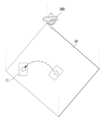
뿐만 아니라 터렛형 프로젝터는 도 3과 같이 어떠한 일 지점에서 다른 지점으로 이동할 때 틸팅 및 로테이팅 구동 원리상 직선거리로 이동할 수 없어 직관적이지 못하며, 이동하는데 시간도 증가하게 된다.In addition, as shown in Fig. 3, a turret-type projector cannot move in a straight line from one point to another due to the tilting and rotating driving principles, which is not intuitive and increases the time required for movement.
본 발명은 프로젝터를 조절하여 스크린 상에서 이미지 위치를 이동시킬 때 발생하는 이미지 회전 문제를 해결하는 것을 목적으로 한다.The present invention aims to solve the image rotation problem that occurs when adjusting a projector to move the image position on a screen.
본 발명은 프로젝터를 조절하여 스크린 상에서 이미지 위치를 이동시킬 때 발생하는 이미지가 최단 경로로 이동할 수 없던 문제를 해결하는 것을 목적으로 한다.The present invention aims to solve the problem of an image not being able to move along the shortest path when moving the image position on a screen by adjusting a projector.
상술한 기술적 과제를 해결하기 위한 본 발명의 일 실시 예에 따르면, 환형 고리의 일부 형상을 갖고, 고리 라인을 따라 형성된 제1 슬롯을 포함하는 제1 가이드 부재, 환형 고리의 일부 형상을 갖고, 고리 라인을 따라 형성된 제2 슬롯을 포함하되, 상기 제2 슬롯이 상기 제1 슬롯과 일 지점에서 겹치도록 구비되는 제2 가이드 부재, 상기 제1 가이드 부재를 회전시키는 제1 구동부, 상기 제2 가이드 부재를 회전시키는 제2 구동부 및 상기 제1 구동부 또는 제2 구동부의 구동에 따라 상기 제1 슬롯 및 제2 슬롯에 구속된 상태에서 수직축이 틸팅되는 광원부를 포함하고, 상기 광원부는, 상기 제1 슬롯의 길이 방향을 따라 이동하는 제1 이동 부재, 상기 제2 슬롯의 길이 방향을 따라 이동하는 제2 이동 부재 및 상기 광원부 외측 단부에 형성되어 상기 제1 이동 부재 및 제2 이동 부재 중 하나에 고정되어 이동하는 광원을 포함하는 프로젝터를 제공한다.According to one embodiment of the present invention for solving the above-described technical problem, a projector is provided, including a first guide member having a partial shape of an annular ring and including a first slot formed along a ring line, a second guide member having a partial shape of an annular ring and including a second slot formed along a ring line, wherein the second slot is provided so as to overlap the first slot at one point, a first driving unit that rotates the first guide member, a second driving unit that rotates the second guide member, and a light source unit whose vertical axis is tilted while being restrained to the first slot and the second slot according to the driving of the first driving unit or the second driving unit, wherein the light source unit includes a first moving member that moves along a longitudinal direction of the first slot, a second moving member that moves along a longitudinal direction of the second slot, and a light source formed at an outer end of the light source unit and fixed to one of the first moving member and the second moving member and moving.
상술한 기술적 과제를 해결하기 위한 본 발명의 일 실시 예에 따르면, 상기 제1 이동 부재는 상기 수직축을 회전축으로 하여 상기 제1 슬롯과 상대 회전하지 않고, 상기 제2 이동 부재는 상기 수직축을 회전축으로 하여 상기 제2 슬롯과 상대 회전하지 않는 프로젝터를 제공한다.According to one embodiment of the present invention for solving the above-described technical problem, a projector is provided in which the first movable member does not rotate relative to the first slot about the vertical axis as the rotation axis, and the second movable member does not rotate relative to the second slot about the vertical axis as the rotation axis.
상술한 기술적 과제를 해결하기 위한 본 발명의 일 실시 예에 따르면, 상기 제1 이동 부재와 제2 이동 부재는 상기 수직축을 회전축으로 상호 회전 가능하도록 구비되는 프로젝터를 제공한다.According to one embodiment of the present invention for solving the above-described technical problem, a projector is provided in which the first movable member and the second movable member are provided to be mutually rotatable about the vertical axis as the rotational axis.
상술한 기술적 과제를 해결하기 위한 본 발명의 일 실시 예에 따르면, 상기 제1 슬롯 및 제2 슬롯은 각각 일정한 곡률 반지름을 갖는 프로젝터를 제공한다.According to one embodiment of the present invention for solving the above-described technical problem, the first slot and the second slot each provide a projector having a constant radius of curvature.
상술한 기술적 과제를 해결하기 위한 본 발명의 일 실시 예에 따르면, 상기 제1 슬롯의 곡률 중심은 상기 제2 가이드 부재의 회전축 상에 구비되고, 상기 제2 슬롯의 곡률 중심은 상기 제1 가이드 부재의 회전축 상에 구비되는 프로젝터를 제공한다.According to one embodiment of the present invention for solving the above-described technical problem, a projector is provided in which the center of curvature of the first slot is provided on the rotational axis of the second guide member, and the center of curvature of the second slot is provided on the rotational axis of the first guide member.
상술한 기술적 과제를 해결하기 위한 본 발명의 일 실시 예에 따르면, 상기 제1 슬롯의 곡률 중심과 상기 제2 슬롯의 곡률 중심은 일치하는 프로젝터를 제공한다.According to one embodiment of the present invention for solving the above-described technical problem, a projector is provided in which the center of curvature of the first slot and the center of curvature of the second slot are coincident.
상술한 기술적 과제를 해결하기 위한 본 발명의 일 실시 예에 따르면, 상기 제1 가이드 부재의 회전축과 제2 가이드 부재의 회전축은 상호 수직인 프로젝터를 제공한다.According to one embodiment of the present invention for solving the above-described technical problem, a projector is provided in which the rotation axis of the first guide member and the rotation axis of the second guide member are mutually perpendicular.
상술한 기술적 과제를 해결하기 위한 본 발명의 일 실시 예에 따르면, 상기 제1 이동 부재와 제2 이동 부재를 상기 수직축 방향에 대해 상호 이격되거나 근접하도록 가변시키는 가변 구조를 더 포함하는 프로젝터를 제공한다.According to one embodiment of the present invention for solving the above-described technical problem, a projector is provided that further includes a variable structure for changing the first movable member and the second movable member to be spaced apart from or close to each other with respect to the vertical axis direction.
상술한 기술적 과제를 해결하기 위한 본 발명의 일 실시 예에 따르면, 상기 제1 이동 부재와 상기 제1 슬롯 사이에 구비되는 제1 베어링 구조체 및 상기 제2 이동 부재와 상기 제2 슬롯 사이에 구비되는 제2 베어링 구조체를 더 포함하는 프로젝터를 제공한다.According to one embodiment of the present invention for solving the above-described technical problem, a projector is provided, further including a first bearing structure provided between the first movable member and the first slot, and a second bearing structure provided between the second movable member and the second slot.
상술한 기술적 과제를 해결하기 위한 본 발명의 일 실시 예에 따르면, 상기 제1 베어링 구조체 및 제2 베어링 구조체는, 베어링 볼 및 상기 슬롯에 길이 방향을 따라 형성되어 상기 베어링 볼이 종속되는 공간을 형성하는 볼 안착 공간을 포함하는 프로젝터를 제공한다.According to one embodiment of the present invention for solving the above-described technical problem, the first bearing structure and the second bearing structure provide a projector including a bearing ball and a ball seating space formed along the longitudinal direction of the slot to form a space to which the bearing ball is dependent.
상술한 기술적 과제를 해결하기 위한 본 발명의 일 실시 예에 따르면, 상기 제1 이동 부재에 상기 수직축에 대해 수직 방향으로 돌출되어 상기 제1 슬롯의 상면을 덮는 제1 지지 리브 및 상기 제2 이동 부재에 상기 수직축에 대해 수직 방향으로 돌출되어 상기 제2 슬롯의 하면을 덮는 제2 지지 리브를 포함하는 프로젝터를 제공한다.According to one embodiment of the present invention for solving the above-described technical problem, a projector is provided, including a first support rib protruding in a vertical direction with respect to the vertical axis on the first movable member and covering an upper surface of the first slot, and a second support rib protruding in a vertical direction with respect to the vertical axis on the second movable member and covering a lower surface of the second slot.
상술한 기술적 과제를 해결하기 위한 본 발명의 일 실시 예에 따르면, 상기 광원부의 내측 단부는 곡률 반지름이 일정한 곡면을 갖는 프로젝터를 제공한다.According to one embodiment of the present invention for solving the above-described technical problem, a projector is provided in which an inner end of the light source unit has a curved surface with a constant radius of curvature.
상술한 기술적 과제를 해결하기 위한 본 발명의 일 실시 예에 따르면, 상기 광원부의 내측 단부 곡률 중심은 상기 제1 슬롯 및 제2 슬롯의 곡률 중심과 일치하는 프로젝터를 제공한다.According to one embodiment of the present invention for solving the above-described technical problem, a projector is provided in which the center of curvature of the inner end of the light source unit is coincident with the centers of curvature of the first slot and the second slot.
상술한 기술적 과제를 해결하기 위한 본 발명의 일 실시 예에 따르면, 상기 광원부의 내측 단부를 지지하기 위한 돌출면을 더 포함하는 프로젝터를 제공한다.According to one embodiment of the present invention for solving the above-described technical problem, a projector is provided further including a protruding surface for supporting an inner end of the light source unit.
상술한 기술적 과제를 해결하기 위한 본 발명의 일 실시 예에 따르면, 상기 제1 구동부는, 제1 모터 및 상기 제1 가이드 부재와 상기 제1 모터를 연결하는 제1 연결 부재를 포함하고, 상기 제2 구동부는, 제2 모터 및 상기 제2 가이드 부재와 상기 제2 모터를 연결하는 제2 연결 부재를 포함하고, 상기 제1 연결 부재 및 제2 연결 부재 각각은 상기 제1 가이드 부재 및 상기 제2 가이드 부재의 각 회전축보다 지면으로 쉬프팅되어 구비되는 프로젝터를 제공한다.According to one embodiment of the present invention for solving the above-described technical problem, a projector is provided, wherein the first driving unit includes a first motor and a first connecting member connecting the first guide member and the first motor, the second driving unit includes a second motor and a second connecting member connecting the second guide member and the second motor, and each of the first connecting member and the second connecting member is provided to be shifted toward the ground relative to each rotation axis of the first guide member and the second guide member.
본 발명에 따른 프로젝터의 효과에 대해 설명하면 다음과 같다.The effects of the projector according to the present invention are described as follows.
본 발명의 실시 예들 중 적어도 하나에 의하면, 스크린 상에서 이미지를 회전되지 않도록 유지하며 이동시킬 수 있다.According to at least one embodiment of the present invention, an image can be moved on a screen without being rotated.
또한, 본 발명의 실시 예들 중 적어도 하나에 의하면, 이미지를 이동시키기 위해 광원부를 가이드하는 두 가이드 부재의 상호 간섭을 최소화할 수 있다.Additionally, according to at least one of the embodiments of the present invention, mutual interference between two guide members guiding a light source unit to move an image can be minimized.
본 발명의 적용 가능성의 추가적인 범위는 이하의 상세한 설명으로부터 명백해질 것이다. 그러나 본 발명의 사상 및 범위 내에서 다양한 변경 및 수정은 해당 기술 분야의 통상의 기술자에게 명확하게 이해될 수 있으므로, 상세한 설명 및 본 발명의 바람직한 실시 예와 같은 특정 실시 예는 단지 예시로 주어진 것으로 이해되어야 한다.Further scope of applicability of the present invention will become apparent from the detailed description below. However, since various changes and modifications within the spirit and scope of the present invention will be apparent to those skilled in the art, it should be understood that the detailed description and specific embodiments, such as preferred embodiments of the present invention, are given by way of example only.
도 1 내지 도 3은 종래의 프로젝터 및 그에 따른 스크린 이미지에 관한 개략도이다.
도 4는 본 발명과 관련된 프로젝터의 일 실시 예에 대한 정면 사시도이다.
도 5는 도 4의 X1축을 포함하는 수직 단면도 및 X2 축을 포함하는 수직 단면도이다.
도 6은 본 발명과 관련된 프로젝터에 의한 스크린 이미지의 이동을 개념적으로 도시한 것이다.
도 7은 본 발명과 관련된 프로젝터의 제1 슬롯 또는 제2 슬롯 상에서 광원부가 이동한 몇 가지 상태를 도시한 것이다.
도 8은 본 발명과 관련된 광원부를 포함하는 프로젝터의 일부 분해도이다.Figures 1 to 3 are schematic diagrams of a conventional projector and a screen image thereof.
FIG. 4 is a front perspective view of one embodiment of a projector related to the present invention.
FIG. 5 is a vertical cross-sectional view including the X1 axis of FIG. 4 and a vertical cross-sectional view including the X2 axis.
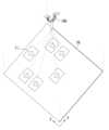
FIG. 6 conceptually illustrates movement of a screen image by a projector related to the present invention.
FIG. 7 illustrates several states in which the light source unit moves on the first slot or the second slot of the projector related to the present invention.
FIG. 8 is a partially exploded view of a projector including a light source unit related to the present invention.
이하, 첨부된 도면을 참조하여 본 명세서에 개시된 실시예를 상세히 설명하되, 도면 부호에 관계없이 동일하거나 유사한 구성요소는 동일한 참조 번호를 부여하고 이에 대한 중복되는 설명은 생략하기로 한다.Hereinafter, embodiments disclosed in this specification will be described in detail with reference to the attached drawings. Regardless of the drawing symbols, identical or similar components will be given the same reference numerals and redundant descriptions thereof will be omitted.
본 명세서에 개시된 실시예를 설명함에 있어서 어떤 구성요소가 다른 구성요소에 "연결되어" 있다거나 "접속되어" 있다고 언급된 때에는, 그 다른 구성요소에 직접적으로 연결되어 있거나 또는 접속되어 있을 수도 있지만, 중간에 다른 구성요소가 존재할 수도 있다고 이해되어야 할 것이다.When describing the embodiments disclosed herein, it should be understood that when a component is referred to as being "connected" or "connected" to another component, it may be directly connected or connected to that other component, but there may also be other components present in between.
또한, 본 명세서에 개시된 실시예를 설명함에 있어서 관련된 공지 기술에 대한 구체적인 설명이 본 명세서에 개시된 실시예의 요지를 흐릴 수 있다고 판단되는 경우 그 상세한 설명을 생략한다. 또한, 첨부된 도면은 본 명세서에 개시된 실시예를 쉽게 이해할 수 있도록 하기 위한 것일 뿐, 첨부된 도면에 의해 본 명세서에 개시된 기술적 사상이 제한되지 않으며, 본 발명의 사상 및 기술 범위에 포함되는 모든 변경, 균등물 내지 대체물을 포함하는 것으로 이해되어야 한다.In addition, when describing the embodiments disclosed in this specification, if it is determined that a detailed description of a related known technology may obscure the gist of the embodiments disclosed in this specification, the detailed description thereof will be omitted. In addition, the attached drawings are only intended to facilitate easy understanding of the embodiments disclosed in this specification, and the technical ideas disclosed in this specification are not limited by the attached drawings, and should be understood to include all modifications, equivalents, and substitutes included in the spirit and technical scope of the present invention.
도면 부호 중 숫자 뒤에 알파벳 A 또는 B가 붙은 것은 해당 숫자 구성이 복수로 구비된 경우 이를 구분하기 위한 것이다. 예를 들어 도면 부호가 1000, 1000A, 1000B인 경우, 별도의 한정 또는 설명이 없는 한 1000A 및 1000B는 1000 구성과 동일하되, 서로 구분되는 구성임을 의미한다.In drawing symbols, the alphabet A or B attached after a number is used to distinguish it when there are multiple configurations of the number. For example, if the drawing symbols are 1000, 1000A, and 1000B, unless otherwise specified or explained, 1000A and 1000B are identical to the 1000 configuration, but are distinct configurations.
도 4는 본 발명과 관련된 프로젝터(100)의 일 실시 예에 대한 정면 사시도이고, 도 5는 도 4의 X1축을 포함하는 수직 단면도 및 X2 축을 포함하는 수직 단면도이고, 도 6은 본 발명과 관련된 프로젝터(100)에 의한 스크린 이미지(11)의 이동을 개념적으로 도시한 것이고, 도 7은 본 발명과 관련된 프로젝터(100)의 제1 슬롯(121A) 또는 제2 슬롯(121B) 상에서 광원부(110)가 이동한 몇 가지 상태를 도시한 것이다. 광원부(110)가 설치면(20)에 수직인 상태를 기준으로, 도 7(a)는 광원부(110)가 제1 슬롯(121A)을 따라 이동한 상태를, 도 7(b)는 광원부(110)가 제2 슬롯(121B)을 따라 이동한 상태를, 도 7(c)는 광원부(110)가 제1 슬롯(121A) 및 제2 슬롯(121B)을 따라 모두 이동한 상태를 도시한 것이다.FIG. 4 is a front perspective view of one embodiment of a projector (100) related to the present invention, FIG. 5 is a vertical cross-sectional view including the X1 axis of FIG. 4 and a vertical cross-sectional view including the X2 axis, FIG. 6 conceptually illustrates movement of a screen image (11) by a projector (100) related to the present invention, and FIG. 7 illustrates several states in which a light source unit (110) moves on a first slot (121A) or a second slot (121B) of a projector (100) related to the present invention. Based on the state in which the light source unit (110) is perpendicular to the installation surface (20), FIG. 7(a) illustrates a state in which the light source unit (110) has moved along the first slot (121A), FIG. 7(b) illustrates a state in which the light source unit (110) has moved along the second slot (121B), and FIG. 7(c) illustrates a state in which the light source unit (110) has moved along both the first slot (121A) and the second slot (121B).
상술한 터렛형 프로젝터(300)의 단점을 보완하기 위해, 본 발명은 광원부(110)의 수직축 V의 틸팅에 의해서만 이동할 수 있도록 하되, 광원부(110)의 광원(1101)에 의한 이미지(11)가 스크린(10) 상에서 회전하지 않도록 광원부(110)의 각도를 유지시켜주는 슬롯 구조를 제안한다.In order to complement the shortcomings of the above-described turret-type projector (300), the present invention proposes a slot structure that allows movement only by tilting the vertical axis V of the light source unit (110), while maintaining the angle of the light source unit (110) so that the image (11) by the light source (1101) of the light source unit (110) does not rotate on the screen (10).
광원부(110)는, 가이드 부재(120)에 구비된 슬롯(121)을 따라 이동할 수 있으며, 가이드 부재(120)는 적어도 2개 구비될 수 있다. 좀 더 구체적으로, 가이드 부재(120)는 환형 고리의 일부 형상을 가지고, 고리 라인을 따라 슬롯(121)이 형성된다. 환형 고리라 함은 곡률 반지름이 일정한 형태를 의미하며, 따라서 고리 라인을 따라 형성된 슬롯(121)도 일정한 곡률 반지름을 갖게 된다.The light source unit (110) can move along the slot (121) provided in the guide member (120), and at least two guide members (120) can be provided. More specifically, the guide member (120) has a partial shape of an annular ring, and a slot (121) is formed along the ring line. An annular ring means a shape with a constant radius of curvature, and therefore, the slot (121) formed along the ring line also has a constant radius of curvature.
슬롯(121)의 형성을 위해 가이드 부재(120)가 반드시 고리 형상으로 구비될 필요는 없으나, 회전시 다른 부재(예를 들어, 하우징(133)) 또는 프로젝터 설치면(20)과의 간섭을 최소화하기 위해, 적어도 슬롯(121)의 영역을 확보하기 위한 형상인 고리 형상이 바람직하다.It is not necessary for the guide member (120) to be provided in a ring shape to form the slot (121), but in order to minimize interference with other members (e.g., housing (133)) or the projector installation surface (20) during rotation, a ring shape is preferable as a shape that secures at least the area of the slot (121).
두 가이드 부재(120) 중 어느 하나를 제1 가이드 부재(120A), 다른 하나를 제2 가이드 부재(120B)로 정의하며, 제1 가이드 부재(120A)에 구비된 슬롯(121)을 제1 슬롯(121A), 제2 가이드 부재(120B)에 구비된 슬롯(121)을 제2 슬롯(121B)으로 정의한다.One of the two guide members (120) is defined as the first guide member (120A), and the other is defined as the second guide member (120B), and the slot (121) provided in the first guide member (120A) is defined as the first slot (121A), and the slot (121) provided in the second guide member (120B) is defined as the second slot (121B).
제1 가이드 부재(120A) 및 제2 가이드 부재(120B)는 상호 겹치도록 구비된다. 이는 제1 슬롯(121A)과 제2 슬롯(121B)이 서로 겹치도록 구비됨을 의미한다. 제1 가이드 부재(120A) 및 제2 가이드 부재(120B)가 겹쳐 구비될 수 있도록, 두 가이드 부재(120A, 120B) 중 하나는 다른 하나보다 작은 크기를 갖는다. 이는 각 가이드 부재(120A, 120B)의 슬롯(121A, 121B) 중 하나가 다른 하나보다 작은 크기를 가짐을 의미한다. 실시 예들에서는 제1 가이드 부재(120A)의 곡률 반지름 R1이 제2 가이드 부재(120B)의 곡률 반지름 R2보다 더 큰 것을 예로 든다. 즉, 제1 슬롯(121A)의 곡률 반지름 R1이 제2 슬롯(121B)의 곡률 반지름 R2 보다 크다.The first guide member (120A) and the second guide member (120B) are provided to overlap each other. This means that the first slot (121A) and the second slot (121B) are provided to overlap each other. In order for the first guide member (120A) and the second guide member (120B) to be provided to overlap each other, one of the two guide members (120A, 120B) has a smaller size than the other. This means that one of the slots (121A, 121B) of each guide member (120A, 120B) has a smaller size than the other. In the embodiments, an example is given in which the curvature radius R1 of the first guide member (120A) is larger than the curvature radius R2 of the second guide member (120B). That is, the curvature radius R1 of the first slot (121A) is larger than the curvature radius R2 of the second slot (121B).
특히, 제1 슬롯(121A)과 제2 슬롯(121B)은 특정 일 지점에서 상호 수직이 되도록 만날 수 있다. 좀 더 구체적으로, 특정 일 지점에서 제1 슬롯(121A)의 접선과 제2 슬롯(121B)의 접선은 상호 수직이 될 수 있다. 특정 일 지점은 제1 슬롯(121A)의 프로젝터 설치면(20)으로부터의 최고점 또는 제2 슬롯(121B)의 프로젝터 설치면(20)으로부터의 최고점이 될 수 있다. 제1 슬롯(121A)과 제2 슬롯(121B)이 상호 수직이 되도록 만나는 이유는, 슬롯(121) 상의 광원부(110)가 이동하기 위해 다른 가이드 부재에 의해 작용하는 힘이 최대로 작용하도록 하기 위함이다. 예를 들어, 두 슬롯(121A, 121B)이 상호 수직인 경우 제1 슬롯(121A) 상에서 광원부(110)가 적은 힘으로 이동하려면 제2 가이드 부재(120B)가 광원부(110)를 제1 슬롯(121A)의 길이 방향으로 밀어주는 것이 좋다. 반대의 경우도 원리는 같다.In particular, the first slot (121A) and the second slot (121B) can meet each other so as to be perpendicular to each other at a specific point. More specifically, the tangent line of the first slot (121A) and the tangent line of the second slot (121B) at the specific point can be perpendicular to each other. The specific point can be the highest point from the projector installation surface (20) of the first slot (121A) or the highest point from the projector installation surface (20) of the second slot (121B). The reason why the first slot (121A) and the second slot (121B) meet each other so as to be perpendicular to each other is to maximize the force applied by the other guide member for the light source unit (110) on the slot (121) to move. For example, if the two slots (121A, 121B) are mutually perpendicular, in order for the light source unit (110) to move with less force on the first slot (121A), it is preferable for the second guide member (120B) to push the light source unit (110) in the longitudinal direction of the first slot (121A). The principle is the same in the opposite case.
도 6 및 도 7에서 보는 바와 같이, 예를 들어 수직한 x축 및 y축을 포함하는 좌표계를 형성하는 스크린(10) 상에서 제1 슬롯(121A)의 길이 방향이 x축 방향이 되도록 배치되고, 제2 슬롯(121B)의 길이 방향이 y축 방향이 되도록 배치되면, 제1 슬롯(121A)에서의 광원부(110) 이동은 스크린(10) 상에서 이미지(11)의 좌우 이동에 대응할 수 있으며, 제2 슬롯(121B)에서의 광원부(110) 이동은 스크린(10) 상에서 이미지(11)의 상하 이동에 대응할 수 있다.As shown in FIGS. 6 and 7, for example, when the longitudinal direction of the first slot (121A) is arranged in the x-axis direction and the longitudinal direction of the second slot (121B) is arranged in the y-axis direction on the screen (10) forming a coordinate system including vertical x-axis and y-axis, movement of the light source unit (110) in the first slot (121A) can correspond to left-right movement of the image (11) on the screen (10), and movement of the light source unit (110) in the second slot (121B) can correspond to up-down movement of the image (11) on the screen (10).
가이드 부재(120A, 120B)는 각 슬롯(121A, 121B)의 길이 방향 양측에 두 지점을 지나는 직선을 회전축으로 하여 회전할 수 있는 구동부를 각각 구비한다. 제1 가이드 부재(120A)에 구비되어 제1 가이드 부재(120A)를 회전시키는 구동부를 제1 구동부(130A), 제2 가이드 부재(120B)에 구비되어 제2 가이드 부재(120B)를 회전시키는 구동부를 제2 구동부(130B)로 정의한다.The guide members (120A, 120B) are each provided with a driving unit that can rotate about a straight line passing through two points on both sides of the length direction of each slot (121A, 121B) as a rotation axis. The driving unit provided in the first guide member (120A) and rotating the first guide member (120A) is defined as a first driving unit (130A), and the driving unit provided in the second guide member (120B) and rotating the second guide member (120B) is defined as a second driving unit (130B).
광원부(110) 수직축 V의 틸팅 정도, 즉 광원부(110)의 슬롯(121)상 위치는 제1 가이드 부재(120A) 및 제2 가이드 부재(120B)의 상태가 복합적으로 결정한다. 즉, 광원부(110)의 제1 슬롯(121A) 상 이동 또는 제2 슬롯(121B) 상 이동은 제1 구동부(130A) 및 제2 구동부(130B)에 의해 복합적으로 구현된다.The tilting degree of the vertical axis V of the light source unit (110), i.e., the position of the light source unit (110) on the slot (121), is determined by the states of the first guide member (120A) and the second guide member (120B) in combination. That is, the movement of the light source unit (110) on the first slot (121A) or the movement on the second slot (121B) is implemented in combination by the first driving unit (130A) and the second driving unit (130B).
제1 구동부(130A)의 회전축 X1과 제2 구동부(130B)의 회전축 X2는 상호 수직이며, 이는 제1 슬롯(121A)과 제2 슬롯(121B)이 특정 일 지점에서 상호 수직을 형성하는 것과 동일한 이유가 된다.The rotation axis X1 of the first driving unit (130A) and the rotation axis X2 of the second driving unit (130B) are mutually perpendicular, which is the same reason why the first slot (121A) and the second slot (121B) form mutually perpendicular lines at a specific point.
제1 슬롯(121A)의 곡률 중심과 제2 슬롯(121B)의 곡률 중심이 동일한 곳에서 만나고, 제1 슬롯(121A)의 곡률 중심이 제1 구동부(130A)의 회전축 상에 있도록 제1 구동부(130A)가 배치되고, 제2 슬롯(121B)의 곡률 중심이 제2 구동부(130B)의 회전축 상에 있도록 제2 구동부(130B)가 배치되면 광원부(110)는 전체적으로 반구면 상에서 이동하는 이상적인 운동을 수행하게 된다.When the center of curvature of the first slot (121A) and the center of curvature of the second slot (121B) meet at the same point, and the first driving unit (130A) is arranged so that the center of curvature of the first slot (121A) is on the rotation axis of the first driving unit (130A), and the second driving unit (130B) is arranged so that the center of curvature of the second slot (121B) is on the rotation axis of the second driving unit (130B), the light source unit (110) performs an ideal motion of moving on an entire hemispherical surface.
도 8은 본 발명과 관련된 광원부(110)를 포함하는 프로젝터(100)의 일부 분해도이다. 도 5를 함께 참조한다.Fig. 8 is a partially exploded view of a projector (100) including a light source unit (110) related to the present invention. See also Fig. 5.
광원부(110)는 제1 슬롯(121A)에 구속되어 이동하기 위한 제1 이동 부재(111A) 및 제2 슬롯(121B)에 구속되어 이동하기 위한 제2 이동 부재(111B)를 포함한다. 제1 이동 부재(111A)는 제1 슬롯(121A)에 가이드 되어 이동하고, 제2 이동 부재(111B)는 제2 슬롯(121B)에 가이드 되어 이동한다. 따라서 광원부(110)의 이동 궤적은 제1 슬롯(121A)의 형상 또는 궤적, 그리고 제2 슬롯(121B)의 형상 또는 궤적에 대응한다.The light source unit (110) includes a first moving member (111A) for moving while being restrained in a first slot (121A) and a second moving member (111B) for moving while being restrained in a second slot (121B). The first moving member (111A) moves while being guided by the first slot (121A), and the second moving member (111B) moves while being guided by the second slot (121B). Therefore, the moving trajectory of the light source unit (110) corresponds to the shape or trajectory of the first slot (121A) and the shape or trajectory of the second slot (121B).
제1 이동 부재(111A)는 제1 슬롯(121A)을 따라 이동할 때 제1 슬롯(121A)의 길이 방향을 따라 이동할 뿐 제1 슬롯(121A)의 길이 방향에 대해 수직축 V를 회전축으로 회전하지 않으며, 제2 이동 부재(111B)는 제2 슬롯(121B)을 따라 이동할 때에도 제2 슬롯(121B)의 길이 방향을 따라 이동할 뿐 제2 슬롯(121B)의 길이 방향에 대해 수직축 V를 회전축으로 회전하지 않는다.When the first movable member (111A) moves along the first slot (121A), it only moves along the longitudinal direction of the first slot (121A) and does not rotate about the vertical axis V with respect to the longitudinal direction of the first slot (121A), and when the second movable member (111B) moves along the second slot (121B), it only moves along the longitudinal direction of the second slot (121B) and does not rotate about the vertical axis V with respect to the longitudinal direction of the second slot (121B).
한편 제1 이동 부재(111A) 및 제2 이동 부재(111B)는 필연적으로 상대 회전하게 된다. 따라서 광원부(110)는 제1 이동 부재(111A)와 제2 이동 부재(111B)가 상대 회전할 수 있는 구조(113)를 갖는다.Meanwhile, the first movable member (111A) and the second movable member (111B) inevitably rotate relative to each other. Therefore, the light source unit (110) has a structure (113) that allows the first movable member (111A) and the second movable member (111B) to rotate relative to each other.
이미지 광을 출력하는 광원(1101)은 제1 이동 부재(111A) 또는 제2 이동 부재(111B) 중 하나에 고정되어 고정된 이동 부재와 함께 틸팅될 뿐 수직축 V를 회전축으로 회전하지 않는다. 이로써 광원(1101)은 스크린(10)에 일정한 방향으로 이미지(11)를 출력할 수 있으며, 터렛형 프로젝터와 같이 일정한 방향으로 이미지를 보정하기 위해 비활성화 영역을 확대시킬 필요가 없다. 물론, 광원(1101)의 출사 방향과 스크린(10)이 수직이 아닌 경우 원근에 따라 이미지(11)의 영역별 출력 크기가 다를 수 있으며, 이는 소프트웨어의 보정이 필요할 수 있다.The light source (1101) outputting image light is fixed to one of the first movable member (111A) or the second movable member (111B) and only tilts together with the fixed movable member, and does not rotate about the vertical axis V as the rotational axis. Accordingly, the light source (1101) can output the image (11) in a certain direction on the screen (10), and there is no need to enlarge the inactive area to correct the image in a certain direction, as in a turret-type projector. Of course, if the emission direction of the light source (1101) and the screen (10) are not perpendicular, the output size of the image (11) by area may be different depending on the perspective, and this may require software correction.
각 슬롯(121) 상에서 회전하지 않는 구조를 구현하기 위해, 제1 이동 부재(111A)는 제1 슬롯(121A)의 길이 방향에만 대응되는 형상을 가지고, 제2 이동 부재(111B) 또한 제2 슬롯(121B)의 길이 방향에만 대응되는 형상을 가진다. 예를 들어 각 슬롯(121A, 121B)이 서로 평행하게 마주보는 턱을 형성하는 경우, 이에 대응하는 각 이동 부재(111A, 111B)는 평행한 턱에 걸쳐 이동할 수 있는 평행한 가이더를 갖는다(미도시). 물론 여기서의 평행은 각 접선이 평행함을 의미하며, 턱 및 가이더는 전체적으로 일정한 곡률 반지름을 가지게 될 것이다.In order to implement a structure that does not rotate on each slot (121), the first moving member (111A) has a shape corresponding only to the longitudinal direction of the first slot (121A), and the second moving member (111B) also has a shape corresponding only to the longitudinal direction of the second slot (121B). For example, when each slot (121A, 121B) forms a jaw that faces each other in parallel, each moving member (111A, 111B) corresponding thereto has a parallel guider (not shown) that can move across the parallel jaws. Of course, parallel here means that each tangent is parallel, and the jaws and guider will have a constant radius of curvature overall.
각 슬롯(121A, 121B)에서 그에 대응하는 이동 부재(111A, 111B)가 이동할 때 마찰을 최소화하기 위해서, 각 슬롯(121A, 121B)과 그에 대응하는 이동 부재(111A, 111B) 사이에는 베어링 구조체(140)가 구비될 수 있다. 제1 이동 부재(111A)와 제1 슬롯(121A) 사이에 구비되는 베어링 구조체(140)를 제1 베어링 구조체(140A), 제2 이동 부재(111B)와 제2 슬롯(121B) 사이에 구비되는 베어링 구조체를 제2 베어링 구조체(140B)로 정의한다. 베어링 구조체(140)는 베어링 볼(141), 그리고 베어링 볼(141)이 실장되는 볼 안착 공간(142, 143)을 포함한다. 볼 안착 공간(142, 143)은 슬롯(121) 및 이동 부재(111)가 마주하는 영역에 형성될 수 있다. 볼 안착 공간(142, 143)의 횡단면은 베어링 볼(141)이 안착되기 위한 다각형을 포함할 수 있다. 예를 들면, 횡단면은 정사각형의 공간을 마련할 수 있다.In order to minimize friction when the corresponding moving member (111A, 111B) moves in each slot (121A, 121B), a bearing structure (140) may be provided between each slot (121A, 121B) and the corresponding moving member (111A, 111B). The bearing structure (140) provided between the first moving member (111A) and the first slot (121A) is defined as the first bearing structure (140A), and the bearing structure provided between the second moving member (111B) and the second slot (121B) is defined as the second bearing structure (140B). The bearing structure (140) includes a bearing ball (141) and a ball seating space (142, 143) in which the bearing ball (141) is mounted. The ball seating space (142, 143) may be formed in an area where the slot (121) and the moving member (111) face each other. The cross-section of the ball seating space (142, 143) may include a polygon for seating the bearing ball (141). For example, the cross-section may provide a square space.
슬롯(121) 및 이동 부재(111)에 모두 볼 안착 공간(142, 143)이 형성되는 경우, 베어링 볼(141)이 슬롯(121) 및 이동 부재(111) 간의 고정 역할을 수행할 수 있다. 베어링 볼(141)이 슬롯(121) 및 이동 부재(111) 간의 고정 역할을 하는 경우, 슬롯(121)은 이동 부재(111) 사이에 구비되는 턱 및 가이더 구조는 베어링 볼(141)과 볼 안착 공간(142, 143)으로 대체될 수 있다. 즉, 베어링 볼(141)이 턱 역할을 하고, 볼 안착 공간(142, 143)이 가이더 역할을 수행하게 된다.When ball settling spaces (142, 143) are formed in both the slot (121) and the moving member (111), the bearing ball (141) can play a fixing role between the slot (121) and the moving member (111). When the bearing ball (141) plays a fixing role between the slot (121) and the moving member (111), the slot (121) and the jaw and guider structure provided between the moving member (111) can be replaced with the bearing ball (141) and the ball settling spaces (142, 143). That is, the bearing ball (141) plays a jaw role, and the ball settling spaces (142, 143) play a guide role.
제1 슬롯(121A)과 제2 슬롯(121B)의 곡률 중심이 일치하는 경우, 제1 이동 부재(111A)와 제2 이동 부재(111B)는 수직 방향으로 이동되지 않는다.When the centers of curvature of the first slot (121A) and the second slot (121B) coincide, the first movable member (111A) and the second movable member (111B) do not move in the vertical direction.
반대로, 제1 슬롯(121A)과 제2 슬롯(121B)의 곡률 중심이 일치하지 않는다면, 제1 이동 부재(111A)와 제2 이동 부재(111B)는 광원부(110)의 수직축 V 방향으로 이격되거나 근접하도록 가변시키는 가변 구조를 가질 수 있다(미도시).Conversely, if the centers of curvature of the first slot (121A) and the second slot (121B) do not coincide, the first movable member (111A) and the second movable member (111B) may have a variable structure that allows them to move apart or closer to each other in the vertical axis V direction of the light source unit (110) (not shown).
제1 이동 부재(111A) 및 제2 이동 부재(111B)는 가이드 부재에서 이탈되지 않기 위한 지지 리브(112A, 112B)를 각각 포함할 수 있다. 제1 이동 부재(111A)의 지지 리브는 제1 지지 리브(112A), 제2 이동 부재(111B)의 지지 리브는 제2 지지 리브(112B)로 정의한다. 제1 지지 리브(112A)는 제1 이동 부재(111A)에서 횡 방향으로 돌출되어 제1 슬롯(121A)의 상면에 안착될 수 있다. 특히 제1 가이드 부재(120A)가 제1 지지 리브(112A)의 폭에 대응하도록 턱을 구비하는 경우 광원부(110)는 제1 슬롯(121A)에서의 안정적으로 이동할 수 있다. 이 경우 제1 지지 리브(112A)는 상술한 가이더가 될 수 있다.The first moving member (111A) and the second moving member (111B) may each include support ribs (112A, 112B) to prevent them from being separated from the guide member. The support rib of the first moving member (111A) is defined as the first support rib (112A), and the support rib of the second moving member (111B) is defined as the second support rib (112B). The first support rib (112A) may protrude laterally from the first moving member (111A) and be seated on the upper surface of the first slot (121A). In particular, when the first guide member (120A) has a protrusion corresponding to the width of the first support rib (112A), the light source unit (110) may be stably moved in the first slot (121A). In this case, the first support rib (112A) may be the above-described guide.
제2 지지 리브(112B)는 제2 이동 부재(111B)에서 횡 방향으로 돌출되어 제2 슬롯(121B)의 하면을 지지할 수 있다. 제2 지지 리브(112B)가 제2 슬롯(121B)의 하면을 지지함으로써 광원부(110)의 이동을 보조하고, 광원부(110)가 제1 가이드 부재(120A) 또는 제2 가이드 부재(120B)로부터 상방으로 이탈하는 문제를 방지할 수 있다.The second support rib (112B) can protrude laterally from the second movable member (111B) and support the lower surface of the second slot (121B). By supporting the lower surface of the second slot (121B), the second support rib (112B) can assist the movement of the light source unit (110) and prevent the light source unit (110) from being separated upward from the first guide member (120A) or the second guide member (120B).
도 5를 함께 참조하면, 제1 구동부(130A) 및 제2 구동부(130B)는 회전 동력을 형성하는 제1 모터(131A) 및 제2 모터(131B)를 각각 구비하고, 각 모터와 연결되어 각 가이드 부재에 회전 동력을 전달하는 연결 부재(132A, 132B)를 각각 구비할 수 있다. 전자의 연결 부재를 제1 연결 부재(132A), 후자의 연결 부재를 제2 연결 부재(132B)로 정의한다. 제1 연결 부재(132A) 및 제2 연결 부재(132B)는 각 가이드 부재(120A, 120B)의 슬롯(121A, 121B) 영역 확보를 위해 각 회전축을 기준으로 S1 또는 S2 만큼 쉬프팅되어 가이드 부재(120A, 120B)에 연결될 수 있다.Referring to FIG. 5 together, the first driving unit (130A) and the second driving unit (130B) may each have a first motor (131A) and a second motor (131B) that form rotational power, and may each have a connecting member (132A, 132B) that is connected to each motor and transmits rotational power to each guide member. The former connecting member is defined as the first connecting member (132A), and the latter connecting member is defined as the second connecting member (132B). The first connecting member (132A) and the second connecting member (132B) may be connected to the guide members (120A, 120B) by shifting by S1 or S2 based on each rotation axis in order to secure a slot (121A, 121B) area of each guide member (120A, 120B).
슬롯(121A, 121B) 영역이 확보됨에 따라 광원부(110)의 틸팅 각도 범위가 넓어진다. 실시 예의 경우 광원부(110)는 반구에 가까운 범위 내에서 이동할 수 있으며, 프로젝터(100)가 실내 천장에 설치된 경우 바닥면뿐만 아니라 측면까지 프로젝팅 가능하다.As the slot (121A, 121B) area is secured, the tilting angle range of the light source unit (110) is widened. In the embodiment, the light source unit (110) can move within a range close to a hemisphere, and when the projector (100) is installed on an indoor ceiling, it can project not only on the floor but also on the side.
예를 들어, 제1 연결 부재(132A) 및 제2 연결 부재(132B)는 각 회전축보다 프로젝터 설치면(20) 방향으로 치우쳐 형성될 수 있다. 다만 이때의 쉬프팅 변위 S1 및 S2는 과도하지 않게 설정됨이 바람직하다. 회전축에서 쉬프팅 정도가 멀어질수록 회전에 의해 연결 부재(132A, 132B)가 차지하게 되는 공간이 커지기 때문이다.For example, the first connecting member (132A) and the second connecting member (132B) may be formed to be offset from each rotation axis toward the projector installation surface (20). However, it is preferable that the shifting displacements S1 and S2 at this time are not set excessively. This is because the space occupied by the connecting members (132A, 132B) due to rotation increases as the degree of shifting increases from the rotation axis.
각 연결 부재(132A, 132B)는 각 가이드 부재(120A, 120B)의 양측에 연결되며, 각 구동부(130A, 130B)는 두 연결 부재(132A, 132B)의 양측에 회전축을 형성하는 회전 구조(161)를 구비하여 가이드 부재(120A, 120B)를 안정적으로 회전시킬 수 있다. 특히 각 연결 부재(132A, 132B)는 가이드 부재(120A, 120B)와 일체로 형성될 수도 있다.Each connecting member (132A, 132B) is connected to both sides of each guide member (120A, 120B), and each driving unit (130A, 130B) has a rotating structure (161) that forms a rotating axis on both sides of the two connecting members (132A, 132B) so as to stably rotate the guide members (120A, 120B). In particular, each connecting member (132A, 132B) may be formed integrally with the guide member (120A, 120B).
회전 구조(161)는 연결 부재(132A, 132B)가 회전할 수 있도록 모터(131A, 131B)와 연결 부재(132A, 132B)를 회전 가능하게 연결한다. 회전 구조(161)에는 마찰력을 최소화하기 위한 베어링 구조(162)를 구비할 수 있다. 각 회전 구조(161)는 프로젝터 설치면(20) 또는 설치면(20)으로부터 일정 거리를 확보시키는 구조물(163)에 고정될 수 있다. 이 구조물(163)은 별도의 부재가 될 수도 있으나, 프로젝터(100)의 하우징(133)의 일부일 수 있다.The rotating structure (161) rotatably connects the motor (131A, 131B) and the connecting member (132A, 132B) so that the connecting member (132A, 132B) can rotate. The rotating structure (161) may be provided with a bearing structure (162) to minimize frictional force. Each rotating structure (161) may be fixed to a projector installation surface (20) or a structure (163) that secures a certain distance from the installation surface (20). This structure (163) may be a separate member, but may be a part of the housing (133) of the projector (100).
광원부(110)의 프로젝터 설치면(20) 측, 즉 내측 단부(1102)는 곡면을 형성하고, 곡면은 프로젝터 설치면(20) 또는 프로젝터 설치면(20)에서 돌출된 돌출면(151)을 지지하여 광원부(110)의 이동시에도 안정적으로 지지할 수 있도록 한다. 특히 곡면은 곡률 중심이 일정한 구 형상의 일부가 될 수 있다. 예를 광원부(110) 내측 단부(1102)는 반구 형상을 포함할 수 있다. 반구의 중심은 제1 슬롯(121A) 또는 제2 슬롯(121B)의 곡률 중심과 일치할 수 있다. 광원부(110)의 내측 단부(1102)는 별도 부재로 제2 이동 부재(111B)와 결합할 수도 있고, 제2 이동 부재(111B)와 일체로 구비될 수도 있다.The projector installation surface (20) side of the light source unit (110), that is, the inner end (1102), forms a curved surface, and the curved surface supports the projector installation surface (20) or the protruding surface (151) protruding from the projector installation surface (20) so that the light source unit (110) can be stably supported even when it moves. In particular, the curved surface can be a part of a spherical shape having a constant center of curvature. For example, the inner end (1102) of the light source unit (110) can include a hemispherical shape. The center of the hemisphere can coincide with the center of curvature of the first slot (121A) or the second slot (121B). The inner end (1102) of the light source unit (110) can be combined with the second moving member (111B) as a separate member, or can be provided integrally with the second moving member (111B).
상기의 상세한 설명은 모든 면에서 제한적으로 해석되어서는 아니되고 예시적인 것으로 고려되어야 한다. 본 발명의 범위는 첨부된 청구항의 합리적 해석에 의해 결정되어야 하고, 본 발명의 등가적 범위 내에서의 모든 변경은 본 발명의 범위에 포함된다.The above detailed description should not be construed as limiting in all respects but should be considered as illustrative. The scope of the invention should be determined by a reasonable interpretation of the appended claims, and all changes coming within the equivalent scope of the invention are intended to be embraced within the scope of the invention.
10: 스크린11: 이미지
20: 프로젝터 설치면100: 프로젝터
110: 광원부1101: 광원
1102: 설치면 측 단부111A: 제1 이동 부재
111B: 제2 이동 부재112A: 제1 지지 리브
112B: 제2 지지 리브120A: 제1 가이드 부재
120B: 제2 가이드 부재121A: 제1 슬롯
121B: 제2 슬롯130A: 제1 구동부
130B: 제2 구동부131A: 제1 모터
131B: 제2 모터132A: 제1 연결 부재
132B: 제2 연결 부재133: 하우징
140A: 제1 베어링 구조체140B: 제2 베어링 구조체
141: 베어링 볼142: 슬롯 측 볼 안착 공간
143: 이동 부재 측 볼 안착 공간151: 돌출면
161: 회전 구조162: 베어링 구조
163: 구조물300: 종래 프로젝터10: Screen 11: Image
20: Projector installation surface 100: Projector
110: Light source 1101: Light source
1102: Installation
111B:
112B:
120B:
121B: 2nd slot 130A: 1st drive unit
130B:
131B:
132B: Second connecting member 133: Housing
140A: First bearing
141: Bearing ball 142: Slot side ball seating space
143: Ball mounting space on the moving part side 151: Protruding surface
161: Rotating structure 162: Bearing structure
163: Structure 300: Conventional projector
Claims (15)
Translated fromKorean환형 고리의 일부 형상을 갖고, 고리 라인을 따라 형성된 제2 슬롯을 포함하되, 상기 제2 슬롯이 상기 제1 슬롯과 일 지점에서 겹치도록 구비되는 제2 가이드 부재;
상기 제1 가이드 부재를 회전시키는 제1 구동부;
상기 제2 가이드 부재를 회전시키는 제2 구동부; 및
상기 제1 구동부 또는 제2 구동부의 구동에 따라 상기 제1 슬롯 및 제2 슬롯에 구속된 상태에서 수직축이 틸팅되는 광원부를 포함하고,
상기 광원부는,
상기 제1 슬롯의 길이 방향을 따라 이동하는 제1 이동 부재;
상기 제2 슬롯의 길이 방향을 따라 이동하는 제2 이동 부재; 및
상기 광원부 외측 단부에 형성되어 상기 제1 이동 부재 및 제2 이동 부재 중 하나에 고정되어 이동하는 광원을 포함하는 프로젝터.
A first guide member having a shape of a part of an annular ring and including a first slot formed along a ring line;
A second guide member having a shape of a part of an annular ring and including a second slot formed along a ring line, wherein the second slot is provided to overlap the first slot at one point;
A first driving unit for rotating the first guide member;
A second driving unit for rotating the second guide member; and
It includes a light source unit whose vertical axis is tilted while being restrained in the first slot and the second slot according to the driving of the first driving unit or the second driving unit,
The above light source part,
A first movable member moving along the longitudinal direction of the first slot;
a second moving member moving along the longitudinal direction of the second slot; and
A projector including a light source formed at an outer end of the light source section and fixed to one of the first movable member and the second movable member to move.
상기 제1 이동 부재는 상기 수직축을 회전축으로 하여 상기 제1 슬롯과 상대 회전하지 않고, 상기 제2 이동 부재는 상기 수직축을 회전축으로 하여 상기 제2 슬롯과 상대 회전하지 않는 프로젝터.
In the first paragraph,
A projector in which the first movable member does not rotate relative to the first slot about the vertical axis as the rotation axis, and the second movable member does not rotate relative to the second slot about the vertical axis as the rotation axis.
상기 제1 이동 부재와 제2 이동 부재는 상기 수직축을 회전축으로 상호 회전 가능하도록 구비되는 프로젝터.
In the first paragraph,
A projector in which the first movable member and the second movable member are provided so as to be mutually rotatable about the vertical axis as the rotational axis.
상기 제1 슬롯 및 제2 슬롯은 각각 일정한 곡률 반지름을 갖는 프로젝터.
In the first paragraph,
A projector wherein the first slot and the second slot each have a constant radius of curvature.
상기 제1 슬롯의 곡률 중심은 상기 제2 가이드 부재의 회전축 상에 구비되고, 상기 제2 슬롯의 곡률 중심은 상기 제1 가이드 부재의 회전축 상에 구비되는 프로젝터.
In the fourth paragraph,
A projector wherein the center of curvature of the first slot is provided on the rotation axis of the second guide member, and the center of curvature of the second slot is provided on the rotation axis of the first guide member.
상기 제1 슬롯의 곡률 중심과 상기 제2 슬롯의 곡률 중심은 일치하는 프로젝터.
In the fourth paragraph,
A projector wherein the center of curvature of the first slot and the center of curvature of the second slot are coincident.
상기 제1 가이드 부재의 회전축과 제2 가이드 부재의 회전축은 상호 수직인 프로젝터.
In Article 6,
A projector wherein the rotation axis of the first guide member and the rotation axis of the second guide member are mutually perpendicular.
상기 제1 이동 부재와 제2 이동 부재를 상기 수직축 방향에 대해 상호 이격되거나 근접하도록 가변시키는 가변 구조를 더 포함하는 프로젝터.
In the first paragraph,
A projector further comprising a variable structure that allows the first movable member and the second movable member to move apart from or close to each other with respect to the vertical axis.
상기 제1 이동 부재와 상기 제1 슬롯 사이에 구비되는 제1 베어링 구조체; 및
상기 제2 이동 부재와 상기 제2 슬롯 사이에 구비되는 제2 베어링 구조체를 더 포함하는 프로젝터.
In the first paragraph,
A first bearing structure provided between the first moving member and the first slot; and
A projector further comprising a second bearing structure provided between the second movable member and the second slot.
상기 제1 베어링 구조체 및 제2 베어링 구조체는, 베어링 볼 및 상기 슬롯에 길이 방향을 따라 형성되어 상기 베어링 볼이 종속되는 공간을 형성하는 볼 안착 공간을 포함하는 프로젝터.
In Article 9,
A projector wherein the first bearing structure and the second bearing structure include a bearing ball and a ball seating space formed along the longitudinal direction of the slot to form a space to which the bearing ball is dependent.
상기 제1 이동 부재에 상기 수직축에 대해 수직 방향으로 돌출되어 상기 제1 슬롯의 상면을 덮는 제1 지지 리브; 및
상기 제2 이동 부재에 상기 수직축에 대해 수직 방향으로 돌출되어 상기 제2 슬롯의 하면을 덮는 제2 지지 리브를 포함하는 프로젝터.
In the first paragraph,
A first support rib protruding in a vertical direction relative to the vertical axis of the first movable member and covering the upper surface of the first slot; and
A projector including a second support rib protruding vertically with respect to the vertical axis on the second movable member and covering a lower surface of the second slot.
상기 광원부의 내측 단부는 곡률 반지름이 일정한 곡면을 갖는 프로젝터.
In the first paragraph,
A projector in which the inner end of the light source section has a curved surface with a constant radius of curvature.
상기 광원부의 내측 단부 곡률 중심은 상기 제1 슬롯 및 제2 슬롯의 곡률 중심과 일치하는 프로젝터.
In Article 12,
A projector in which the center of curvature of the inner end of the light source unit is identical to the centers of curvature of the first slot and the second slot.
상기 광원부의 내측 단부를 지지하기 위한 돌출면을 더 포함하는 프로젝터.
In Article 12,
A projector further comprising a protruding surface for supporting an inner end of the light source unit.
상기 제1 구동부는,
제1 모터; 및
상기 제1 가이드 부재와 상기 제1 모터를 연결하는 제1 연결 부재를 포함하고,
상기 제2 구동부는,
제2 모터; 및
상기 제2 가이드 부재와 상기 제2 모터를 연결하는 제2 연결 부재를 포함하고,
상기 제1 연결 부재 및 제2 연결 부재 각각은 상기 제1 가이드 부재 및 상기 제2 가이드 부재의 각 회전축보다 지면으로 쉬프팅되어 구비되는 프로젝터.
In the first paragraph,
The above first driving unit is,
1st motor; and
Including a first connecting member connecting the first guide member and the first motor,
The above second driving unit,
2nd motor; and
Including a second connecting member connecting the second guide member and the second motor,
A projector wherein each of the first connecting member and the second connecting member is provided to be shifted toward the ground relative to each rotation axis of the first guide member and the second guide member.
Priority Applications (2)
| Application Number | Priority Date | Filing Date | Title |
|---|---|---|---|
| KR1020190171932AKR102709861B1 (en) | 2019-12-20 | 2019-12-20 | Projector |
| US16/751,531US11131916B2 (en) | 2019-12-20 | 2020-01-24 | Light source movable projector |
Applications Claiming Priority (1)
| Application Number | Priority Date | Filing Date | Title |
|---|---|---|---|
| KR1020190171932AKR102709861B1 (en) | 2019-12-20 | 2019-12-20 | Projector |
Publications (2)
| Publication Number | Publication Date |
|---|---|
| KR20210079788A KR20210079788A (en) | 2021-06-30 |
| KR102709861B1true KR102709861B1 (en) | 2024-09-26 |
Family
ID=76439609
Family Applications (1)
| Application Number | Title | Priority Date | Filing Date |
|---|---|---|---|
| KR1020190171932AActiveKR102709861B1 (en) | 2019-12-20 | 2019-12-20 | Projector |
Country Status (2)
| Country | Link |
|---|---|
| US (1) | US11131916B2 (en) |
| KR (1) | KR102709861B1 (en) |
Family Cites Families (3)
| Publication number | Priority date | Publication date | Assignee | Title |
|---|---|---|---|---|
| JP2014516409A (en) | 2011-04-15 | 2014-07-10 | ファロ テクノロジーズ インコーポレーテッド | Improved position detector for laser trackers. |
| DE112017006849T5 (en)* | 2017-01-17 | 2019-09-26 | Nec Display Solutions, Ltd. | PROJECTOR DEVICE |
| US11089292B2 (en)* | 2018-01-26 | 2021-08-10 | Optikos Corporation | Configurable camera stimulation and metrology apparatus and method therefor |
- 2019
- 2019-12-20KRKR1020190171932Apatent/KR102709861B1/enactiveActive
- 2020
- 2020-01-24USUS16/751,531patent/US11131916B2/enactiveActive
Also Published As
| Publication number | Publication date |
|---|---|
| KR20210079788A (en) | 2021-06-30 |
| US20210191244A1 (en) | 2021-06-24 |
| US11131916B2 (en) | 2021-09-28 |
Similar Documents
| Publication | Publication Date | Title |
|---|---|---|
| CN205942054U (en) | Periscopic module of making a video recording | |
| JP6259594B2 (en) | Multiple headlamp adjustment interlocking mechanism | |
| CN101216590A (en) | Three freedom degree reflector adjusting apparatus | |
| JP2014006539A (en) | Projecting apparatus having adjusting function | |
| KR101846730B1 (en) | Mounting Structure for Image display apparatus | |
| US20210341826A1 (en) | Projection apparatus | |
| US11150543B2 (en) | Transparent cover and imaging optical system | |
| US10254506B2 (en) | Lens apparatus and image pickup apparatus | |
| KR101331864B1 (en) | 6 degree of freedom position control device and position control device system having the same | |
| JP6986157B2 (en) | Coordination system for turning at least one optical component of the vehicle floodlight around the first and second axes. | |
| KR102709861B1 (en) | Projector | |
| KR101657176B1 (en) | Pedestal apparatus for satellite tracking antenna | |
| US10139589B2 (en) | Zoom lens unit and indicator member | |
| JP2013190518A (en) | Holder and projector with holder | |
| TWI754886B (en) | Adjustable wireless access point | |
| US10451240B2 (en) | Rotary lighting module | |
| JP2006208506A (en) | Projector and lens driver | |
| CN105572838A (en) | Reflector adjustment system and optical instrument | |
| US8707570B2 (en) | Alignment apparatus | |
| KR101440925B1 (en) | Rotating apparatus in atenna for tracing satellite | |
| JP4969294B2 (en) | Projection-type image display device | |
| JP5882715B2 (en) | Lens barrel capable of adjusting lens and imaging apparatus including the same | |
| CN104977787B (en) | Porjector adjusting device | |
| JP6660709B2 (en) | Car mirror actuator | |
| JP2007004024A (en) | Pedestal for projector |
Legal Events
| Date | Code | Title | Description |
|---|---|---|---|
| PA0109 | Patent application | St.27 status event code:A-0-1-A10-A12-nap-PA0109 | |
| PN2301 | Change of applicant | St.27 status event code:A-3-3-R10-R13-asn-PN2301 St.27 status event code:A-3-3-R10-R11-asn-PN2301 | |
| PG1501 | Laying open of application | St.27 status event code:A-1-1-Q10-Q12-nap-PG1501 | |
| A201 | Request for examination | ||
| PA0201 | Request for examination | St.27 status event code:A-1-2-D10-D11-exm-PA0201 | |
| D13-X000 | Search requested | St.27 status event code:A-1-2-D10-D13-srh-X000 | |
| D14-X000 | Search report completed | St.27 status event code:A-1-2-D10-D14-srh-X000 | |
| PE0701 | Decision of registration | St.27 status event code:A-1-2-D10-D22-exm-PE0701 | |
| PR0701 | Registration of establishment | St.27 status event code:A-2-4-F10-F11-exm-PR0701 | |
| PR1002 | Payment of registration fee | St.27 status event code:A-2-2-U10-U11-oth-PR1002 Fee payment year number:1 | |
| PG1601 | Publication of registration | St.27 status event code:A-4-4-Q10-Q13-nap-PG1601 |