KR102707701B1 - Aseptic piercing system and method - Google Patents
Aseptic piercing system and methodDownload PDFInfo
- Publication number
- KR102707701B1 KR102707701B1KR1020207024462AKR20207024462AKR102707701B1KR 102707701 B1KR102707701 B1KR 102707701B1KR 1020207024462 AKR1020207024462 AKR 1020207024462AKR 20207024462 AKR20207024462 AKR 20207024462AKR 102707701 B1KR102707701 B1KR 102707701B1
- Authority
- KR
- South Korea
- Prior art keywords
- sterilizing
- cartridge
- boot
- channel
- agent
- Prior art date
- Legal status (The legal status is an assumption and is not a legal conclusion. Google has not performed a legal analysis and makes no representation as to the accuracy of the status listed.)
- Active
Links
Images


Classifications
- A—HUMAN NECESSITIES
- A61—MEDICAL OR VETERINARY SCIENCE; HYGIENE
- A61J—CONTAINERS SPECIALLY ADAPTED FOR MEDICAL OR PHARMACEUTICAL PURPOSES; DEVICES OR METHODS SPECIALLY ADAPTED FOR BRINGING PHARMACEUTICAL PRODUCTS INTO PARTICULAR PHYSICAL OR ADMINISTERING FORMS; DEVICES FOR ADMINISTERING FOOD OR MEDICINES ORALLY; BABY COMFORTERS; DEVICES FOR RECEIVING SPITTLE
- A61J1/00—Containers specially adapted for medical or pharmaceutical purposes
- A61J1/14—Details; Accessories therefor
- A61J1/1406—Septums, pierceable membranes
- A—HUMAN NECESSITIES
- A61—MEDICAL OR VETERINARY SCIENCE; HYGIENE
- A61J—CONTAINERS SPECIALLY ADAPTED FOR MEDICAL OR PHARMACEUTICAL PURPOSES; DEVICES OR METHODS SPECIALLY ADAPTED FOR BRINGING PHARMACEUTICAL PRODUCTS INTO PARTICULAR PHYSICAL OR ADMINISTERING FORMS; DEVICES FOR ADMINISTERING FOOD OR MEDICINES ORALLY; BABY COMFORTERS; DEVICES FOR RECEIVING SPITTLE
- A61J1/00—Containers specially adapted for medical or pharmaceutical purposes
- A61J1/14—Details; Accessories therefor
- A61J1/1443—Containers with means for dispensing liquid medicaments in a filtered or sterile way, e.g. with bacterial filters
- A—HUMAN NECESSITIES
- A61—MEDICAL OR VETERINARY SCIENCE; HYGIENE
- A61J—CONTAINERS SPECIALLY ADAPTED FOR MEDICAL OR PHARMACEUTICAL PURPOSES; DEVICES OR METHODS SPECIALLY ADAPTED FOR BRINGING PHARMACEUTICAL PRODUCTS INTO PARTICULAR PHYSICAL OR ADMINISTERING FORMS; DEVICES FOR ADMINISTERING FOOD OR MEDICINES ORALLY; BABY COMFORTERS; DEVICES FOR RECEIVING SPITTLE
- A61J1/00—Containers specially adapted for medical or pharmaceutical purposes
- A61J1/14—Details; Accessories therefor
- A61J1/20—Arrangements for transferring or mixing fluids, e.g. from vial to syringe
- A61J1/2003—Accessories used in combination with means for transfer or mixing of fluids, e.g. for activating fluid flow, separating fluids, filtering fluid or venting
- A61J1/2006—Piercing means
- A61J1/201—Piercing means having one piercing end
- A—HUMAN NECESSITIES
- A61—MEDICAL OR VETERINARY SCIENCE; HYGIENE
- A61J—CONTAINERS SPECIALLY ADAPTED FOR MEDICAL OR PHARMACEUTICAL PURPOSES; DEVICES OR METHODS SPECIALLY ADAPTED FOR BRINGING PHARMACEUTICAL PRODUCTS INTO PARTICULAR PHYSICAL OR ADMINISTERING FORMS; DEVICES FOR ADMINISTERING FOOD OR MEDICINES ORALLY; BABY COMFORTERS; DEVICES FOR RECEIVING SPITTLE
- A61J1/00—Containers specially adapted for medical or pharmaceutical purposes
- A61J1/14—Details; Accessories therefor
- A61J1/20—Arrangements for transferring or mixing fluids, e.g. from vial to syringe
- A61J1/2003—Accessories used in combination with means for transfer or mixing of fluids, e.g. for activating fluid flow, separating fluids, filtering fluid or venting
- A61J1/2048—Connecting means
- A—HUMAN NECESSITIES
- A61—MEDICAL OR VETERINARY SCIENCE; HYGIENE
- A61J—CONTAINERS SPECIALLY ADAPTED FOR MEDICAL OR PHARMACEUTICAL PURPOSES; DEVICES OR METHODS SPECIALLY ADAPTED FOR BRINGING PHARMACEUTICAL PRODUCTS INTO PARTICULAR PHYSICAL OR ADMINISTERING FORMS; DEVICES FOR ADMINISTERING FOOD OR MEDICINES ORALLY; BABY COMFORTERS; DEVICES FOR RECEIVING SPITTLE
- A61J1/00—Containers specially adapted for medical or pharmaceutical purposes
- A61J1/14—Details; Accessories therefor
- A61J1/20—Arrangements for transferring or mixing fluids, e.g. from vial to syringe
- A61J1/2003—Accessories used in combination with means for transfer or mixing of fluids, e.g. for activating fluid flow, separating fluids, filtering fluid or venting
- A61J1/2068—Venting means
- A61J1/2072—Venting means for internal venting
- A—HUMAN NECESSITIES
- A61—MEDICAL OR VETERINARY SCIENCE; HYGIENE
- A61J—CONTAINERS SPECIALLY ADAPTED FOR MEDICAL OR PHARMACEUTICAL PURPOSES; DEVICES OR METHODS SPECIALLY ADAPTED FOR BRINGING PHARMACEUTICAL PRODUCTS INTO PARTICULAR PHYSICAL OR ADMINISTERING FORMS; DEVICES FOR ADMINISTERING FOOD OR MEDICINES ORALLY; BABY COMFORTERS; DEVICES FOR RECEIVING SPITTLE
- A61J1/00—Containers specially adapted for medical or pharmaceutical purposes
- A61J1/14—Details; Accessories therefor
- A61J1/20—Arrangements for transferring or mixing fluids, e.g. from vial to syringe
- A61J1/2096—Combination of a vial and a syringe for transferring or mixing their contents
- A—HUMAN NECESSITIES
- A61—MEDICAL OR VETERINARY SCIENCE; HYGIENE
- A61L—METHODS OR APPARATUS FOR STERILISING MATERIALS OR OBJECTS IN GENERAL; DISINFECTION, STERILISATION OR DEODORISATION OF AIR; CHEMICAL ASPECTS OF BANDAGES, DRESSINGS, ABSORBENT PADS OR SURGICAL ARTICLES; MATERIALS FOR BANDAGES, DRESSINGS, ABSORBENT PADS OR SURGICAL ARTICLES
- A61L2/00—Methods or apparatus for disinfecting or sterilising materials or objects other than foodstuffs or contact lenses; Accessories therefor
- A61L2/16—Methods or apparatus for disinfecting or sterilising materials or objects other than foodstuffs or contact lenses; Accessories therefor using chemical substances
- A61L2/18—Liquid substances or solutions comprising solids or dissolved gases
- A—HUMAN NECESSITIES
- A61—MEDICAL OR VETERINARY SCIENCE; HYGIENE
- A61M—DEVICES FOR INTRODUCING MEDIA INTO, OR ONTO, THE BODY; DEVICES FOR TRANSDUCING BODY MEDIA OR FOR TAKING MEDIA FROM THE BODY; DEVICES FOR PRODUCING OR ENDING SLEEP OR STUPOR
- A61M39/00—Tubes, tube connectors, tube couplings, valves, access sites or the like, specially adapted for medical use
- A61M39/10—Tube connectors; Tube couplings
- A61M39/16—Tube connectors; Tube couplings having provision for disinfection or sterilisation
- A61M39/18—Methods or apparatus for making the connection under sterile conditions, i.e. sterile docking
- A—HUMAN NECESSITIES
- A61—MEDICAL OR VETERINARY SCIENCE; HYGIENE
- A61M—DEVICES FOR INTRODUCING MEDIA INTO, OR ONTO, THE BODY; DEVICES FOR TRANSDUCING BODY MEDIA OR FOR TAKING MEDIA FROM THE BODY; DEVICES FOR PRODUCING OR ENDING SLEEP OR STUPOR
- A61M5/00—Devices for bringing media into the body in a subcutaneous, intra-vascular or intramuscular way; Accessories therefor, e.g. filling or cleaning devices, arm-rests
- A61M5/001—Apparatus specially adapted for cleaning or sterilising syringes or needles
- A—HUMAN NECESSITIES
- A61—MEDICAL OR VETERINARY SCIENCE; HYGIENE
- A61M—DEVICES FOR INTRODUCING MEDIA INTO, OR ONTO, THE BODY; DEVICES FOR TRANSDUCING BODY MEDIA OR FOR TAKING MEDIA FROM THE BODY; DEVICES FOR PRODUCING OR ENDING SLEEP OR STUPOR
- A61M5/00—Devices for bringing media into the body in a subcutaneous, intra-vascular or intramuscular way; Accessories therefor, e.g. filling or cleaning devices, arm-rests
- A61M5/178—Syringes
- A61M5/24—Ampoule syringes, i.e. syringes with needle for use in combination with replaceable ampoules or carpules, e.g. automatic
- A61M5/2455—Ampoule syringes, i.e. syringes with needle for use in combination with replaceable ampoules or carpules, e.g. automatic with sealing means to be broken or opened
- A61M5/2459—Ampoule syringes, i.e. syringes with needle for use in combination with replaceable ampoules or carpules, e.g. automatic with sealing means to be broken or opened upon internal pressure increase, e.g. pierced or burst
- A—HUMAN NECESSITIES
- A61—MEDICAL OR VETERINARY SCIENCE; HYGIENE
- A61M—DEVICES FOR INTRODUCING MEDIA INTO, OR ONTO, THE BODY; DEVICES FOR TRANSDUCING BODY MEDIA OR FOR TAKING MEDIA FROM THE BODY; DEVICES FOR PRODUCING OR ENDING SLEEP OR STUPOR
- A61M5/00—Devices for bringing media into the body in a subcutaneous, intra-vascular or intramuscular way; Accessories therefor, e.g. filling or cleaning devices, arm-rests
- A61M5/178—Syringes
- A61M5/31—Details
- A61M5/3129—Syringe barrels
- A—HUMAN NECESSITIES
- A61—MEDICAL OR VETERINARY SCIENCE; HYGIENE
- A61M—DEVICES FOR INTRODUCING MEDIA INTO, OR ONTO, THE BODY; DEVICES FOR TRANSDUCING BODY MEDIA OR FOR TAKING MEDIA FROM THE BODY; DEVICES FOR PRODUCING OR ENDING SLEEP OR STUPOR
- A61M5/00—Devices for bringing media into the body in a subcutaneous, intra-vascular or intramuscular way; Accessories therefor, e.g. filling or cleaning devices, arm-rests
- A61M5/178—Syringes
- A61M5/31—Details
- A61M5/315—Pistons; Piston-rods; Guiding, blocking or restricting the movement of the rod or piston; Appliances on the rod for facilitating dosing ; Dosing mechanisms
- A61M5/31511—Piston or piston-rod constructions, e.g. connection of piston with piston-rod
- A—HUMAN NECESSITIES
- A61—MEDICAL OR VETERINARY SCIENCE; HYGIENE
- A61M—DEVICES FOR INTRODUCING MEDIA INTO, OR ONTO, THE BODY; DEVICES FOR TRANSDUCING BODY MEDIA OR FOR TAKING MEDIA FROM THE BODY; DEVICES FOR PRODUCING OR ENDING SLEEP OR STUPOR
- A61M5/00—Devices for bringing media into the body in a subcutaneous, intra-vascular or intramuscular way; Accessories therefor, e.g. filling or cleaning devices, arm-rests
- A61M5/50—Devices for bringing media into the body in a subcutaneous, intra-vascular or intramuscular way; Accessories therefor, e.g. filling or cleaning devices, arm-rests having means for preventing re-use, or for indicating if defective, used, tampered with or unsterile
- A—HUMAN NECESSITIES
- A61—MEDICAL OR VETERINARY SCIENCE; HYGIENE
- A61L—METHODS OR APPARATUS FOR STERILISING MATERIALS OR OBJECTS IN GENERAL; DISINFECTION, STERILISATION OR DEODORISATION OF AIR; CHEMICAL ASPECTS OF BANDAGES, DRESSINGS, ABSORBENT PADS OR SURGICAL ARTICLES; MATERIALS FOR BANDAGES, DRESSINGS, ABSORBENT PADS OR SURGICAL ARTICLES
- A61L2202/00—Aspects relating to methods or apparatus for disinfecting or sterilising materials or objects
- A61L2202/20—Targets to be treated
- A61L2202/23—Containers, e.g. vials, bottles, syringes, mail
- A—HUMAN NECESSITIES
- A61—MEDICAL OR VETERINARY SCIENCE; HYGIENE
- A61M—DEVICES FOR INTRODUCING MEDIA INTO, OR ONTO, THE BODY; DEVICES FOR TRANSDUCING BODY MEDIA OR FOR TAKING MEDIA FROM THE BODY; DEVICES FOR PRODUCING OR ENDING SLEEP OR STUPOR
- A61M5/00—Devices for bringing media into the body in a subcutaneous, intra-vascular or intramuscular way; Accessories therefor, e.g. filling or cleaning devices, arm-rests
- A61M5/178—Syringes
- A61M5/24—Ampoule syringes, i.e. syringes with needle for use in combination with replaceable ampoules or carpules, e.g. automatic
- A61M5/2455—Ampoule syringes, i.e. syringes with needle for use in combination with replaceable ampoules or carpules, e.g. automatic with sealing means to be broken or opened
- A61M5/2466—Ampoule syringes, i.e. syringes with needle for use in combination with replaceable ampoules or carpules, e.g. automatic with sealing means to be broken or opened by piercing without internal pressure increase
- A61M2005/247—Ampoule syringes, i.e. syringes with needle for use in combination with replaceable ampoules or carpules, e.g. automatic with sealing means to be broken or opened by piercing without internal pressure increase with fixed or steady piercing means, e.g. piercing under movement of ampoule
- A—HUMAN NECESSITIES
- A61—MEDICAL OR VETERINARY SCIENCE; HYGIENE
- A61M—DEVICES FOR INTRODUCING MEDIA INTO, OR ONTO, THE BODY; DEVICES FOR TRANSDUCING BODY MEDIA OR FOR TAKING MEDIA FROM THE BODY; DEVICES FOR PRODUCING OR ENDING SLEEP OR STUPOR
- A61M5/00—Devices for bringing media into the body in a subcutaneous, intra-vascular or intramuscular way; Accessories therefor, e.g. filling or cleaning devices, arm-rests
- A61M5/178—Syringes
- A61M5/24—Ampoule syringes, i.e. syringes with needle for use in combination with replaceable ampoules or carpules, e.g. automatic
- A61M5/2455—Ampoule syringes, i.e. syringes with needle for use in combination with replaceable ampoules or carpules, e.g. automatic with sealing means to be broken or opened
- A61M5/2466—Ampoule syringes, i.e. syringes with needle for use in combination with replaceable ampoules or carpules, e.g. automatic with sealing means to be broken or opened by piercing without internal pressure increase
- A61M2005/2474—Ampoule syringes, i.e. syringes with needle for use in combination with replaceable ampoules or carpules, e.g. automatic with sealing means to be broken or opened by piercing without internal pressure increase with movable piercing means, e.g. ampoule remains fixed or steady
- A—HUMAN NECESSITIES
- A61—MEDICAL OR VETERINARY SCIENCE; HYGIENE
- A61M—DEVICES FOR INTRODUCING MEDIA INTO, OR ONTO, THE BODY; DEVICES FOR TRANSDUCING BODY MEDIA OR FOR TAKING MEDIA FROM THE BODY; DEVICES FOR PRODUCING OR ENDING SLEEP OR STUPOR
- A61M5/00—Devices for bringing media into the body in a subcutaneous, intra-vascular or intramuscular way; Accessories therefor, e.g. filling or cleaning devices, arm-rests
- A61M5/178—Syringes
- A61M5/31—Details
- A61M2005/3117—Means preventing contamination of the medicament compartment of a syringe
- A61M2005/3118—Means preventing contamination of the medicament compartment of a syringe via the distal end of a syringe, i.e. syringe end for mounting a needle cannula
- A—HUMAN NECESSITIES
- A61—MEDICAL OR VETERINARY SCIENCE; HYGIENE
- A61M—DEVICES FOR INTRODUCING MEDIA INTO, OR ONTO, THE BODY; DEVICES FOR TRANSDUCING BODY MEDIA OR FOR TAKING MEDIA FROM THE BODY; DEVICES FOR PRODUCING OR ENDING SLEEP OR STUPOR
- A61M5/00—Devices for bringing media into the body in a subcutaneous, intra-vascular or intramuscular way; Accessories therefor, e.g. filling or cleaning devices, arm-rests
- A61M5/178—Syringes
- A61M5/31—Details
- A61M5/315—Pistons; Piston-rods; Guiding, blocking or restricting the movement of the rod or piston; Appliances on the rod for facilitating dosing ; Dosing mechanisms
- A61M5/31511—Piston or piston-rod constructions, e.g. connection of piston with piston-rod
- A61M2005/31518—Piston or piston-rod constructions, e.g. connection of piston with piston-rod designed to reduce the overall size of an injection device, e.g. using flexible or pivotally connected chain-like rod members
Landscapes
- Health & Medical Sciences (AREA)
- Animal Behavior & Ethology (AREA)
- Veterinary Medicine (AREA)
- Public Health (AREA)
- General Health & Medical Sciences (AREA)
- Life Sciences & Earth Sciences (AREA)
- Pharmacology & Pharmacy (AREA)
- Heart & Thoracic Surgery (AREA)
- Anesthesiology (AREA)
- Hematology (AREA)
- Biomedical Technology (AREA)
- Engineering & Computer Science (AREA)
- Vascular Medicine (AREA)
- Physics & Mathematics (AREA)
- Fluid Mechanics (AREA)
- Epidemiology (AREA)
- Chemical & Material Sciences (AREA)
- Chemical Kinetics & Catalysis (AREA)
- General Chemical & Material Sciences (AREA)
- Pulmonology (AREA)
- Medical Preparation Storing Or Oral Administration Devices (AREA)
- Infusion, Injection, And Reservoir Apparatuses (AREA)
- External Artificial Organs (AREA)
- Basic Packing Technique (AREA)
Abstract
Translated fromKorean
Description
Translated fromKorean관련 출원에 대한 교차 참조Cross-reference to related applications
본 출원은 2015년 3월 10일자 출원되고 발명의 명칭이 "무균 관통 시스템 및 방법"인 미국 가출원 제 62/130,718호의 우선권을 주장하고, 그 전체 내용은 본원에서 참고로 전체적으로 합체되어 있다.This application claims the benefit of U.S. Provisional Application No. 62/130,718, filed March 10, 2015, entitled “Sterile Penetration System and Method,” the entire contents of which are incorporated herein by reference in their entirety.
발명의 분야Field of invention
본 발명은 일반적으로 약물 투여를 위한 전달 시스템에 관한 것이다. 더욱 구체적으로, 그러나 비배타적으로, 본 발명은 무균 관통 시스템에 관한 것이다.The present invention relates generally to delivery systems for drug administration. More specifically, but not exclusively, the present invention relates to sterile penetrating systems.
현재 바늘이 바이알(vial), 1차 용기 또는 카트리지에 도입되기 전에, 살균 환경을 유지하기 위해 바이알 격벽(vial septum)을 살균하기 위해 알콜 와이프(alcohol wipe)를 사용할 필요가 있다. 바이알 격벽의 살균이 제대로 수행되지 않으면, 약물이 오염되거나 오염 물질이 환자에게 전달될 수 있다. 또한, 이러한 와이핑은 수행하기 위한 추가 단계이며, 용기가 전달 장치 내부에 있으면 실용적이지 않다. 일반적으로, 바이알 격벽의 면에 대한 와이핑은 살균 공정의 또다른 단계를 추가한다.Currently, prior to introducing a needle into a vial, primary container, or cartridge, an alcohol wipe is required to sterilize the vial septum to maintain a sterile environment. If the vial septum is not properly sterilized, the drug may be contaminated or contaminants may be transferred to the patient. Furthermore, this wiping is an additional step to perform and is not practical if the container is inside a delivery device. Typically, wiping the surface of the vial septum adds another step to the sterilization process.
따라서, 오염 위험없이 살균 환경을 보장하는 무균 관통 시스템이 바람직하다.Therefore, an aseptic penetration system that ensures a sterile environment without risk of contamination is desirable.
본 발명의 형태들은 무균 바이얼 관통 및 살균 시스템을 제공한다. 본 발명은 또한 무균 바이얼 관통 시스템을 조립, 사용하고 살균하기 위한 방법을 제공한다.Forms of the present invention provide a sterile vial penetration and sterilization system. The present invention also provides methods for assembling, using, and sterilizing a sterile vial penetration system.
일 형태에서, 본 발명은 무균성 1차 용기 관통 기구의 형성 방법을 제공한다. 상기 방법은 제 1 단부, 제 1 캐비티, 상기 제 1 캐비티와 교통하는 개방부를 갖는 제 2 단부, 상기 개방부를 적어도 부분적으로 밀봉하는 격벽, 및 상기 제 1 캐비티 내의 제조물을 포함하는 사전 살균된 1차 용기를 획득하는 단계를 포함한다. 상기 방법은 또한 중공 유로 형성 부재의 제 1 단부 부분을 포함하는 주사 조립체를 획득하는 단계를 포함한다. 상기 방법은 또한 상기 유로 형성 부재의 제 1 단부 부분 주위로 그리고 상기 1차 용기로 연장되는 제 2 캐비티를 형성하기 위하여, 상기 주사 조립체를 상기 1차 용기의 제 2 단부와 비살균 환경에서 조립하는 단계를 포함한다. 추가로, 상기 방법은 상기 유로 형성 부재의 제 1 단부 부분 및 상기 제 2 캐비티를 마지막으로 살균하는 단계를 포함한다.In one embodiment, the present invention provides a method of forming a sterile primary container penetration device. The method comprises obtaining a pre-sterilized primary container comprising a first end, a first cavity, a second end having an opening in communication with the first cavity, a baffle at least partially sealing the opening, and a product within the first cavity. The method also comprises obtaining an injection assembly comprising a first end portion of a hollow flow-form forming member. The method further comprises assembling the injection assembly with the second end of the primary container in a non-sterile environment to form a second cavity about the first end portion of the flow-form forming member and extending into the primary container. Additionally, the method comprises a final step of sterilizing the first end portion of the flow-form forming member and the second cavity.
일부 실시예에 있어서, 상기 마지막으로 살균하기 전에, 상기 유로 형성 부재의 제 1 단부 부분 및 제 2 캐비티는 비살균 상태일 수 있다. 일부 실시예에 있어서, 상기 유로 형성 부재의 제 1 단부 부분 및 제 2 캐비티를 마지막으로 살균하는 단계는 상기 유로 형성 부재를 통해서 그리고 그에 의해서 상기 제 2 캐비티 안으로 살균제를 주사하는 단계를 포함할 수 있다. 이러한 일부 실시예에 있어서, 상기 살균제는 상기 주사 조립체 외부에 배치된 상기 유로 형성 부재의 제 2 단부 부분을 통해서 상기 유로 형성 부재 안으로 도입될 수 있다.In some embodiments, prior to said final sterilization, the first end portion of the flow-forming member and the second cavity can be in a non-sterile state. In some embodiments, the step of final sterilizing the first end portion of the flow-forming member and the second cavity can comprise the step of injecting a sterilizing agent through the flow-forming member and thereby into the second cavity. In some such embodiments, the sterilizing agent can be introduced into the flow-forming member through a second end portion of the flow-forming member that is disposed external to the injection assembly.
이러한 일부 다른 실시예에 있어서, 상기 1차 용기는 상기 제 2 캐비티를 형성하는 부트 부분을 포함할 수 있다. 이러한 일부 실시예에 있어서, 상기 부트 부분 및 상기 격벽은 일체형일 수 있다. 이러한 일부 다른 실시예에 있어서, 상기 1차 용기의 제 2 단부를 갖는 상기 주사 조립체를 조립하는 단계는 관통 연장되는 상기 유로 형성 부재 주위에 활주 시일을 형성하는 상기 부트 부분의 개방부를 통해서 상기 유로 형성 부재를 삽입할 수 있다. 이러한 일부 실시예에 있어서, 상기 개방부는 상기 주사된 살균제가 상기 제 2 캐비티 및 상기 유로 형성 부재 내의 대기로 방출되게 양압(positive pressure)을 배기하도록 구성될 수 있다. 이러한 일부 실시예에 있어서, 상기 방법은 상기 유로 형성 부재 및 상기 제 2 캐비티로부터 상기 살균제를 방출시키도록 상기 유로 형성 부재를 통해서 그리고 상기 제 2 캐비티 안으로 불활성 가스를 주사하는 단계를 추가로 포함할 수 있다.In some of these other embodiments, the primary container can include a boot portion forming the second cavity. In some of these embodiments, the boot portion and the baffle can be integral. In some of these other embodiments, the step of assembling the injection assembly with the second end of the primary container can include inserting the flow path forming member through an opening in the boot portion forming a sliding seal around the flow path forming member extending therethrough. In some of these embodiments, the opening can be configured to exhaust a positive pressure so that the injected sterilant is released into the atmosphere within the second cavity and the flow path forming member. In some of these embodiments, the method can further include the step of injecting an inert gas through the flow path forming member and into the second cavity to release the sterilant from the flow path forming member and the second cavity.
일부 실시예에 있어서, 상기 유로 형성 부재의 제 1 단부 부분을 향하는 상기 1차 용기의 축방향 병진이동이, 상기 유로 형성 부재가 상기 제 2 캐비티를 통해서 연장되고 상기 제 1 단부 부분이 상기 제조물과 유체 교통하게 상기 제 1 캐비티 내에 배치되도록, 상기 유로 형성 부재가 상기 부트 부재 및 상기 격벽을 통해서 구동되게 유발하도록, 상기 주사 조립체 및 상기 1차 용기의 조립체가 구성될 수 있다. 이러한 일부 실시예에 있어서, 상기 1차 용기는 상기 유로 형성 부재가 상기 제 2 캐비티를 통해서 연장되고 상기 제 1 단부 부분이 상기 제조물과 유체 교통하게 상기 제 1 캐비티 내에 배치되도록, 상기 유로 형성 부재의 제 1 단부 부분 상에 있는 상기 부트 부재 및 상기 격벽을 찌르기 위해 일정거리 만큼 상기 유로 형성 부재의 제 1 단부 부분에 대해서 축방향으로 병진이동할 수 있다. 이러한 일부 다른 실시예에 있어서, 상기 1차 용기는 상기 주사 조립체의 작동이 유발되는 범위까지 상기 유로 형성 부재의 제 1 단부 부분에 대해서 축방향으로 병진이동하고 상기 주사 조립체는 그에 의해서 상기 유로 형성 부재가 상기 제 2 캐비티를 통해서 연장되고 상기 제 1 단부 부분이 상기 제조물과 유체 교통하게 상기 제 1 캐비티 내에 배치되도록, 상기 부트 부재 및 상기 격벽을 통해서 상기 유로 형성 부재의 제 1 단부 부분을 찌르기 위해 상기 1차 용기를 향하여 상기 유로 형성 부재를 축방향으로 구동시킨다. 이러한 일부 실시예에 있어서, 상기 주사 조립체를 작동시키면, 상기 주사 조립체의 탄성 부재의 사전로딩 에너지를 방출하여 상기 유로 형성 부재에 결합된 구동 부재를 축방향으로 구동시킬 수 있다.In some embodiments, the assembly of the injection assembly and the primary container can be configured such that axial translation of the primary container toward the first end portion of the flow-forming member causes the flow-forming member to be driven through the boot member and the baffle such that the flow-forming member extends through the second cavity and the first end portion is positioned within the first cavity in fluid communication with the article. In some such embodiments, the primary container can be axially translated relative to the first end portion of the flow-forming member a distance to impale the boot member and the baffle on the first end portion of the flow-forming member such that the flow-forming member extends through the second cavity and the first end portion is positioned within the first cavity in fluid communication with the article. In some of these other embodiments, the primary container is axially translated with respect to the first end portion of the flow-form forming member to an extent that actuation of the injection assembly is triggered, and the injection assembly axially drives the flow-form forming member toward the primary container to impale the first end portion of the flow-form forming member through the boot member and the baffle such that the flow-form forming member extends through the second cavity and the first end portion is positioned within the first cavity in fluid communication with the article. In some of these embodiments, actuation of the injection assembly releases preloading energy of the resilient member of the injection assembly to axially drive an actuation member coupled to the flow-form forming member.
일부 실시예에 있어서, 상기 유로 형성 부재의 제 1 단부 부분은 살균 상태이고 캡핑 부재로 덮혀지고, 그리고 상기 주사 조립체는 상기 제 2 캐비티와 교통하는 투과성 윈도우를 포함할 수 있다. 이러한 일부 실시예에 있어서, 상기 유로 형성 부재의 제 1 단부 부분 및 상기 제 2 캐비티를 마지막으로 살균하는 단계는: 상기 투과성 윈도우를 통해서 그리고 상기 제 2 캐비티 안으로 그에 의해서 상기 제 1 단부 부분으로 살균제를 확산시키는 단계; 그리고 상기 투과성 윈도우를 통해서 그리고 상기 제 2 캐비티 안으로 자외선을 지향시키는 단계 중 적어도 하나를 포함할 수 있다.In some embodiments, the first end portion of the flow-forming member can be sterilized and covered by a capping member, and the injection assembly can include a translucent window in communication with the second cavity. In some such embodiments, the step of finally sterilizing the first end portion of the flow-forming member and the second cavity can include at least one of: diffusing a sterilizing agent into the first end portion through the translucent window and into the second cavity; and directing ultraviolet light through the translucent window and into the second cavity.
다른 형태에서, 본 발명은 무균 관통 시스템을 제공하고, 상기 무균 관통 시스템은 1차 용기 및 상기 1차 용기와 조립된 유로 형성 부재를 포함하는 주사 조립체를 포함한다. 살균 1차 용기는 제 1 단부, 제 1 캐비티, 상기 제 1 캐비티와 교통하는 개방부를 갖는 제 2 단부, 상기 개방부를 적어도 부분적으로 밀봉하는 격벽, 및 상기 제 1 캐비티 내의 제조물 및 제 2 캐비티를 형성하는 부트 부분을 포함한다. 상기 유로 형성 부재는 상기 유로 형성 부재의 제 1 단부 부분이 상기 제 2 캐비티 내에 배치되도록 상기 부트 부분의 개방부를 통해서 연장된다. 상기 부트 부분의 개방부는 상기 유로 형성 부재 주위에 활주 시일을 형성한다. 상기 유로 형성 부재의 제 1 단부 부분을 향하는 상기 1차 용기의 축방향 병진이동은 상기 유로 형성 부재가 상기 제 2 캐비티를 통해서 연장되고 상기 제 1 단부 부분이 상기 제조물과 유체 교통하게 상기 제 1 캐비티 내에 배치되도록, 상기 유로 형성 부재의 제 1 단부 부분 및 상기 부트 부재 및 상기 1차 용기의 격벽의 상대 병진이동을 유발한다.In another form, the present invention provides a sterile penetration system comprising an injection assembly comprising a primary container and a flow-forming member assembled with the primary container. The sterile primary container comprises a first end, a first cavity, a second end having an opening in communication with the first cavity, a baffle at least partially sealing the opening, and a boot portion defining a product within the first cavity and a second cavity. The flow-forming member extends through the opening in the boot portion such that a first end portion of the flow-forming member is disposed within the second cavity. The opening in the boot portion forms a sliding seal around the flow-forming member. Axial translation of the first end portion of the flow-forming member toward the first container causes relative translation of the first end portion of the flow-forming member and the boot member and the baffle of the first container such that the flow-forming member extends through the second cavity and the first end portion is positioned within the first cavity in fluid communication with the product.
일부 실시예에 있어서, 상기 부트 부분 및 상기 격벽은 일체형이고, 그리고 상기 활주 시일은 상기 제 2 캐비티 내의 양압을 배기하도록 구성될 수 있다. 일부 실시예에 있어서, 상기 유로 형성 부재의 제 1 단부 부분에 대한 상기 1차 용기의 축방향 병진이동은 상기 유로 형성 부재가 상기 제 2 캐비티를 통해서 연장되고 상기 제 1 단부 부분이 상기 제조물과 유체 교통하게 상기 제 1 캐비티 내에 배치되도록, 상기 유로 형성 부재의 제 1 단부 부분 위에 있는 상기 부트 부재 및 상기 격벽을 찌를 수 있다.In some embodiments, the boot portion and the baffle are integral, and the slide seal can be configured to exhaust positive pressure within the second cavity. In some embodiments, axial translation of the primary container relative to the first end portion of the flow-forming member can pierce the boot portion and the baffle over the first end portion of the flow-forming member such that the flow-forming member extends through the second cavity and the first end portion is positioned within the first cavity in fluid communication with the article.
일부 실시예에 있어서, 유로 형성 부재의 제 2 단부 부분은 밀봉된 제 3 캐비티 내에 있는 상기 주사 조립체 외부에 배치될 수 있다. 일부 실시예에 있어서, 상기 유로 형성 부재의 제 1 단부 부분에 대한 상기 1차 용기의 축방향 병진이동은 상기 유로 형성 부재가 상기 제 2 캐비티를 통해서 연장되고 상기 제 1 단부 부분이 상기 제조물과 유체 교통하게 상기 제 1 캐비티 내에 배치되도록, 상기 부트 부재 및 상기 격벽을 통해서 상기 유로 형성 부재의 제 1 단부 부분을 찌르기 위해 상기 유로 형성 부재를 상기 1차 용기를 향하여 축방향으로 구동시키도록 상기 주사 조립체를 작동시킬 수 있다. 이러한 일부 실시예에 있어서, 상기 주사 조립체는 상기 1차 용기의 제 2 단부에 고정된 칼라, 상기 칼라에 축방향으로 활주가능하게 결합된 드라이버 리테이너(driver retainer), 상기 드라이버 리테이너에 축방향으로 활주가능하게 결합되고 상기 유로 형성 부재에 고정된 구동 부재, 및 상기 드라이버 리테이너의 일부 및 상기 구동 부재 사이에 배치된 탄성 부재를 포함할 수 있다. 이러한 일부 실시예에 있어서, 상기 시스템의 사전 작동 상태에서, 상기 탄성 부재는 상기 1차 용기의 제 2 단부를 향하여 축방향으로 작용하는 상기 구동 부재 상의 사전로딩 힘을 작용시키고, 그리고 상기 주사 시스템의 작동은 상기 1차 용기를 향하여 상기 유로 형성 부재를 축방향으로 구동시키도록 상기 구동 부재 상의 상기 탄성 부재의 사전로딩 힘을 해제하여, 상기 유로 형성 부재가 상기 제 2 캐비티를 통해서 연장되고 상기 제 1 단부 부분이 상기 제조물과 유체 교통하게 상기 제 1 캐비티 내에 배치되도록, 상기 부트 부재 및 상기 격벽을 통해서 상기 유로 형성 부재의 제 1 단부 부분을 찌를 수 있다.In some embodiments, the second end portion of the flow-forming member can be positioned outside the injection assembly within the sealed third cavity. In some embodiments, axial translation of the primary container relative to the first end portion of the flow-forming member can actuate the injection assembly to axially drive the flow-forming member toward the primary container to impale the first end portion of the flow-forming member through the boot member and the baffle such that the flow-forming member extends through the second cavity and the first end portion is positioned within the first cavity in fluid communication with the article. In some such embodiments, the injection assembly can include a collar secured to the second end of the primary container, a driver retainer axially slidably coupled to the collar, a drive member axially slidably coupled to the driver retainer and secured to the flow path forming member, and a resilient member disposed between a portion of the driver retainer and the drive member. In some such embodiments, in a pre-operational state of the system, the resilient member applies a preloading force on the drive member axially toward the second end of the primary container, and operation of the injection system releases the preloading force of the resilient member on the drive member to axially drive the flow path forming member toward the primary container, thereby impaling the first end portion of the flow path forming member through the boot member and the baffle such that the flow path forming member extends through the second cavity and the first end portion is disposed within the first cavity in fluid communication with the article.
본 발명의 상기 목적 및 기타 목적, 특징 및 장점들은 첨부된 도면과 연계하여 취해진 본 발명의 여러 형태들의 하기 상세한 설명으로부터 명백해질 것이다.The above and other objects, features and advantages of the present invention will become apparent from the following detailed description of various embodiments of the present invention taken in conjunction with the accompanying drawings.
본 명세서에 통합되어 그 일부를 구성하는 첨부 도면은 본 개시물의 실시예를 도시하고 본 명세서의 상세한 설명과 함께 본 개시물의 원리를 설명하는 역할을한다. 도면은 단지 바람직한 실시예를 설명하기 위한 것이며, 본 개시물을 제한하는 것으로 해석되어서는 안된다. 업계의 표준 관행에 따라, 다양한 기능이 일정한 비율로 그려지지 않고 있음을 강조한다. 실제로, 다양한 특징의 치수는 설명의 명료성을 위해 임의적으로 증가되거나 감소될 수 있다. 본 개시물의 상기 및 다른 목적, 특징 및 이점은 첨부된 도면과 관련하여 취해진 다음의 상세한 설명으로부터 명백해진다.
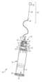
도 1은 본 발명의 일 형태에 따른 무균 바이얼 관통 시스템의 분해 사시도.
도 2는 본 발명의 일 형태에 따른 도 1의 무균 바이얼 관통 시스템의 분해 측면도.
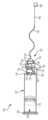
도 3은 본 발명의 일 형태에 따른, 도 1의 무균 바이얼 관통 시스템의 조립 사시도.
도 4는 본 발명의 일 형태에 따른, 투명 커넥터 조립체를 갖는 도 3의 무균 바이얼 관통 시스템의 측면도.
도 5는 본 발명의 일 형태에 따른, 투명 커넥터 조립체를 갖는 도 3의 조립된 무균 바이얼 관통 시스템의 사시도.
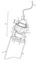
도 6은 본 발명의 일 형태에 따른, 도 3의 무균 바이얼 관통 시스템의 확대 사시도.
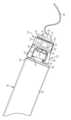
도 7은 본 발명의 일 형태에 따른, 투명 윈도우 시일, 지지 부재, 접철식 부재, 지지링 및 충격 쿠션을 갖는, 도 1의 무균 바이얼 관통 시스템의 조립 사시도.
도 8은 본 발명의 일 형태에 따른, 도 7의 무균 바이얼 관통 시스템의 측면도.
도 9는 본 발명의 일 형태에 따른, 도 7의 무균 바이얼 관통 시스템의 사시도.
도 10은 본 발명의 일 형태에 따른, 도 1의 무균 바이얼 관통 시스템의 조립 사시도.
도 11은 본 발명의 일 형태에 따른, 도 10의 무균 바이얼 관통 시스템의 측면도.
도 12는 본 발명의 일 형태에 따른, 도 10의 무균 바이얼 관통 시스템의 사시도.
도 13은 본 발명의 일 형태에 따른, 완전 전개 위치에 있는 접철식 부재를 도시하는, 도 10의 무균 바이얼 관통 시스템의 일부의 확대 사시도.
도 14는 본 발명의 일 형태에 따른, 접철 위치에 있는 접철식 부재를 도시하는, 도 10의 무균 바이얼 관통 시스템의 일부의 확대 사시도.
도 15는 본 발명의 다른 형태에 따른, 사전 작동 상태에 있는 무균 바이얼 관통 시스템의 조립 단면도.
도 16은 본 발명의 다른 형태에 따른, 1차 용기와 유체 교통하게 무균으로 결합된 유로 형성 부재를 갖는, 작동 상태에 있는 도 15의 무균 바이얼 관통 시스템의 조립 단면도.
도 17은 본 발명의 다른 형태에 따른, 사전 작동 상태에 있는 무균 바이얼 관통 시스템의 조립 단면도.
도 18은 본 발명의 다른 형태에 따른, 1차 용기와 유체 교통하게 무균으로 결합된 유로 형성 부재를 갖는, 작동 상태에 있는 도 17의 무균 바이얼 관통 시스템의 조립 단면도.
도 19는 비살균 조립 후에 도 17의 무균 바이얼 관통 시스템의 유로 형성 부재 안으로 살균제를 도입하는 것을 도시하는 도면.
도 20은 살균제를 통한 도 17의 조립된 무균 바이알 관통 시스템의 유로 형성 부재의 단부 부분 및 부트 부재의 캐비티의 살균을 도시하는 도면.
도 21은 본 발명의 다른 형태에 따른, 사전 작동 상태에 있는 무균 바이얼 관통 시스템의 조립 단면도.
도 22는 본 발명의 다른 형태에 따른, 1차 용기와 유체 교통하게 무균으로 결합된 유로 형성 부재를 갖는, 작동 상태에 있는 도 21의 무균 바이얼 관통 시스템의 조립 단면도.
도 23은 비살균 부분의 잠재적 포스트-조립 살균 및 도 21의 무균 바이얼 관통 시스템의 살균 및 비살균 부분들을 도시하는 도면.The accompanying drawings, which are incorporated in and constitute a part of this specification, illustrate embodiments of the present disclosure and, together with the description herein, serve to explain the principles of the present disclosure. The drawings are intended to illustrate preferred embodiments only and should not be construed as limiting the present disclosure. It is emphasized that, in accordance with standard practice in the industry, various features are not drawn to scale. In fact, the dimensions of various features may be arbitrarily increased or decreased for clarity of description. The above and other objects, features and advantages of the present disclosure will become apparent from the following detailed description taken in conjunction with the accompanying drawings.
Figure 1 is an exploded perspective view of a sterile vial penetration system according to one embodiment of the present invention.
FIG. 2 is an exploded side view of the sterile vial penetration system of FIG. 1 according to one embodiment of the present invention.
FIG. 3 is an assembled perspective view of the sterile vial penetration system of FIG. 1 according to one embodiment of the present invention.
FIG. 4 is a side view of the sterile vial penetration system of FIG. 3 having a transparent connector assembly according to one embodiment of the present invention.
FIG. 5 is a perspective view of the assembled sterile vial penetration system of FIG. 3 having a transparent connector assembly according to one embodiment of the present invention.
FIG. 6 is an enlarged perspective view of the sterile vial penetration system of FIG. 3 according to one embodiment of the present invention.
FIG. 7 is an assembled perspective view of the sterile vial penetration system of FIG. 1, having a transparent window seal, a support member, a foldable member, a support ring, and an impact cushion, according to one embodiment of the present invention.
FIG. 8 is a side view of the sterile vial penetration system of FIG. 7 according to one embodiment of the present invention.
FIG. 9 is a perspective view of the sterile vial penetration system of FIG. 7 according to one embodiment of the present invention.
FIG. 10 is an assembled perspective view of the sterile vial penetration system of FIG. 1 according to one embodiment of the present invention.
FIG. 11 is a side view of the sterile vial penetration system of FIG. 10 according to one embodiment of the present invention.
FIG. 12 is a perspective view of the sterile vial penetration system of FIG. 10 according to one embodiment of the present invention.
FIG. 13 is an enlarged perspective view of a portion of the sterile vial penetration system of FIG. 10, illustrating the foldable member in a fully deployed position, according to one embodiment of the present invention.
FIG. 14 is an enlarged perspective view of a portion of the sterile vial penetration system of FIG. 10, illustrating a foldable member in a folded position, according to one embodiment of the present invention.
FIG. 15 is an assembled cross-sectional view of a sterile vial penetration system in a pre-operational state according to another embodiment of the present invention.
FIG. 16 is an assembled cross-sectional view of the sterile vial penetration system of FIG. 15 in an operational state, having a flow-forming member sterilely coupled in fluid communication with a primary container, according to another embodiment of the present invention.
FIG. 17 is an assembled cross-sectional view of a sterile vial penetration system in a pre-operational state according to another embodiment of the present invention.
FIG. 18 is an assembled cross-sectional view of the sterile vial penetration system of FIG. 17 in an operational state, having a flow-forming member sterilely coupled in fluid communication with a primary container, according to another embodiment of the present invention.
FIG. 19 is a drawing illustrating the introduction of a sterilizing agent into the flow path forming member of the sterile vial penetration system of FIG. 17 after non-sterile assembly.
FIG. 20 is a drawing illustrating sterilization of the end portion of the flow forming member and the cavity of the boot member of the assembled sterile vial penetration system of FIG. 17 through a sterilizing agent.
FIG. 21 is an assembled cross-sectional view of a sterile vial penetration system in a pre-operational state according to another embodiment of the present invention.
FIG. 22 is an assembled cross-sectional view of the sterile vial penetration system of FIG. 21 in an operational state, having a flow-forming member sterilely coupled in fluid communication with a primary container, according to another embodiment of the present invention.
Figure 23 is a drawing illustrating potential post-assembly sterilization of the non-sterile portion and the sterile and non-sterile portions of the sterile vial penetration system of Figure 21.
무균 바이얼 관통 및 살균 시스템이 일반적으로 본원에 기술되고 개시된다. 추가로, 무균 바이얼, 1차 용기 및/또는 카트리지 관통 시스템을 조립하고, 사용하며 살균하는 방법이 기술된다. 시스템 및 방법은 알콜 와이핑을 실행하거나 그리고/또는 약물 용기를 장치 안으로 조립하거나 또는 관통 부위를 살균하기 위하여 유사한 환자/제공자의 상호작용을 필요로 하지 않는, 살균 상태의 유로 기구(예를 들어, 바늘)를 갖는 바이얼, 1차 용기 또는 카트리지의 관통을 위해 제공된다.Sterile vial penetration and sterilization systems are generally described and disclosed herein. Additionally, methods for assembling, using, and sterilizing sterile vial, primary container, and/or cartridge penetration systems are described. Systems and methods are provided for the penetration of vials, primary containers, or cartridges with a sterile flow mechanism (e.g., a needle) that does not require an alcohol wipe and/or similar patient/provider interaction to assemble the drug container into the device or sterilize the penetration site.
이 상세한 설명 및 청구범위에서, 근위, 원위, 전방, 후방, 내측, 측방, 상위 및 하위라는 단어는 몸체 또는 기준 방향 용어에 대한 장치의 상대적인 배치에 따라 장치의 특정 부분을 나타내는 표준 사용법에 의해 정의된다. 예를 들어 "근위"는 부착 지점에 가장 가까운 장치 부분을 의미하고 "원위"는 부착 지점에서 가장 멀리있는 장치 부분을 의미한다. 방향 용어에 관해서, "전방"은 장치의 전방 측을 향하는 방향이고, "후방"은 장치의 후방 측을 향하는 방향을 의미하고, "내측"은 장치의 중심선을 의미하고, "측방"은 장치의 중심선에서 측면을 향해 또는 중심선에서 멀어지는 방향이고 "상위"는 위의 방향을 의미하고 "하위"는 다른 개체 또는 구조 아래의 방향을 의미한다.In this detailed description and claims, the words proximal, distal, anterior, posterior, medial, lateral, superior, and inferior are defined by their standard usage to refer to particular portions of the device relative to a body or reference directional term. For example, “proximal” means the portion of the device closest to an attachment point, and “distal” means the portion of the device furthest from an attachment point. With respect to directional terms, “anterior” is toward the front side of the device, “posterior” is toward the rear side of the device, “medial” is toward the centerline of the device, “lateral” is toward the side or away from the centerline of the device, “superior” is above, and “inferior” is below another object or structure.
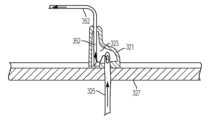
도면을 참조하면, 동일한 도면 부호는 여러 도면에 걸쳐 유사하거나 유사한 구성요소를 나타내며, 특히 도 1 내지 도 14를 참조하면, "무균 관통 시스템(100)"이 도시되어 있다. 용어 "무균 관통 시스템", "무균 바이알 관통 시스템" 및 "무균 카트리지 관통 시스템"은 본질적으로 무균 유로 형성 기구(예: 바늘), 관통 시스템 또는 구조물을 의미하기 때문에 상호 교환적으로 사용될 수 있다. 무균 관통 시스템(100)은 제 1 단부(104) 및 제 2 단부(106)를 갖는 1차 용기, 챔버, 주사기, 바이알 또는 카트리지(102)를 포함한다. 1차 용기 또는 바이알(102)은 또한 제 1 단부(104)에서 개방되고 제 2 단부(106)를 향하여 연장되는 캐비티(108)를 포함할 수 있다. 제 2 단부(106)는 1차 용기 또는 바이알(102)의 제 2 단부(106)를 폐쇄하도록 네크(110)와 결합하는 캡(112)을 갖는 네크(110)를 포함할 수 있다. 격벽(114)은 1차 용기 또는 바이알(102) 및 캡(112) 사이에 배치되어서, 1차 용기 또는 바이알(102)의 제 2 단부(106)를 폐쇄하는 것을 돕고 바늘(152)(예를 들어, 스테킹 바늘)이 격벽을 통해 1차 용기 또는 바이알(102) 내로 삽입되게 허용한다. 1차 용기 또는 바이알(102)의 캐비티(108)는 약물 또는 유체가 캐비티(108)의 내부에 있을 때 1차 용기 또는 바이알(102)의 제 1 단부(104)를 폐쇄하기 위해 피스톤(116)을 수용하도록 크기설정될 수 있다. 피스톤(116)은 또한 후술되는 바와 같이, 약물 또는 유체의 전달을 보조할 수 있다. 무균 관통 시스템(100)은 또한 시일(118)을 포함할 수 있다. 시일(118)은 예를 들어 링 형상이고 캡(112)과 결합하고 격벽(114)을 둘러싸도록 크기설정될 수 있다.With reference to the drawings, where like reference numerals represent similar or analogous components throughout the several drawings, and particularly with reference to FIGS. 1-14 , there is illustrated a "sterile penetration system (100)". The terms "sterile penetration system", "sterile vial penetration system" and "sterile cartridge penetration system" are used interchangeably to refer to an essentially sterile flow-forming device (e.g., a needle), penetration system or structure. The sterile penetration system (100) includes a primary container, chamber, syringe, vial or cartridge (102) having a first end (104) and a second end (106). The primary container or vial (102) may also include a cavity (108) that is open at the first end (104) and extends toward the second end (106). The second end (106) can include a neck (110) having a cap (112) that engages the neck (110) to close the second end (106) of the primary container or vial (102). A baffle (114) is disposed between the primary container or vial (102) and the cap (112) to assist in closing the second end (106) of the primary container or vial (102) and to allow a needle (152) (e.g., a stinging needle) to be inserted through the baffle and into the primary container or vial (102). The cavity (108) of the primary container or vial (102) can be sized to receive a piston (116) to close the first end (104) of the primary container or vial (102) when a drug or fluid is within the cavity (108). The piston (116) may also assist in the delivery of a drug or fluid, as described below. The sterile penetration system (100) may also include a seal (118). The seal (118) may be, for example, ring-shaped and sized to engage the cap (112) and surround the baffle (114).
무균 관통 시스템(100)은 또한 도 1 및 도 2에 도시된 바와 같이, 커넥터 조립체(120)를 포함할 수 있다. 커넥터 조립체(120)는 커넥터 몸체(122), 지지 부재(140), 바늘 커버(150), 유로 형성 부재 또는 바늘(152)(예를 들어, 스테이킹 바늘), 접철식 부재(160), 지지링(162), 무균 시일(164) 및 충격 쿠션(170)을 포함할 수 있다. 커넥터 몸체(122)는 베이스 부분(124) 및 적어도 하나의 커플링 부재(126)를 포함할 수 있다. 베이스 부분(124)은 개방부(128), 리세스(130) 및 윈도우(132)를 포함할 수 있다. 개방부(128)는 커넥터 몸체(122)의 길이방향 축을 따라서 베이스 부분(124)의 제 1 단부로부터 제 2 단부로 연장될 수 있다. 리세스(130)는 베이스 부분(124)의 제 1 단부에 배치될 수 있다. 적어도 하나의 커플링 부재(126)는 예를 들어, 링 부재(미도시) 또는 적어도 2개의 편향 레그(126)일 수 있다. 적어도 2개의 편향 레그(126)는 커넥터 조립체(120)를 1차 용기 또는 바이얼(102)에 고정하도록 캡(112)과 결합하기 위한 결합 부재(134)를 각각 포함할 수 있다. 결합 부재(134)는 예를 들어, 적어도 2개의 레그(126)로부터 커넥터 몸체(122)의 중심을 향하여 내향으로 연장되는 돌출부일 수 있고 결합 부재(134)는 각이 형성될 수 있다.The sterile penetration system (100) may also include a connector assembly (120), as illustrated in FIGS. 1 and 2. The connector assembly (120) may include a connector body (122), a support member (140), a needle cover (150), a flow-forming member or needle (152) (e.g., a staking needle), a foldable member (160), a support ring (162), a sterile seal (164), and an impact cushion (170). The connector body (122) may include a base portion (124) and at least one coupling member (126). The base portion (124) may include an opening (128), a recess (130), and a window (132). The opening (128) may extend from a first end of the base portion (124) to a second end along a longitudinal axis of the connector body (122). A recess (130) may be disposed at a first end of the base portion (124). At least one coupling member (126) may be, for example, a ring member (not shown) or at least two deflecting legs (126). The at least two deflecting legs (126) may each include a mating member (134) for mating with the cap (112) to secure the connector assembly (120) to the primary container or vial (102). The mating member (134) may be, for example, a protrusion extending inwardly from the at least two legs (126) toward the center of the connector body (122), and the mating member (134) may be angled.
커넥터 조립체(120)는 또한 도 1 내지 도 7에 도시된 바와 같이, 적어도 하나의 살균 표시기(136) 및 윈도우 시일(138)을 포함할 수 있다. 살균 표시기(136)는 예를 들어, 커넥터 조립체(120)가 살균되었고 사용 준비 상태인지를 사용자에게 말할 수 있다. 살균 표시기(136)는 개방부(128) 내에 배치될 수 있고 이들이 윈도우(132)를 통해서 볼 수 있도록 배치될 수 있다. 윈도우 시일(138)은 사용자가 윈도우(132) 안과 베이스 부분(124)의 개방부(128)의 적어도 일부를 볼 수 있게 하기 위해 예를 들어 부분적으로 또는 완전하게 투명할 수 있다. 윈도우 시일(138)은 또한 유로 형성 부재(152)에 대한 살균 환경을 형성하기 위하여 윈도우(132)를 폐쇄할 수 있다.The connector assembly (120) may also include at least one sterilization indicator (136) and a window seal (138), as illustrated in FIGS. 1-7. The sterilization indicator (136) may, for example, tell a user that the connector assembly (120) has been sterilized and is ready for use. The sterilization indicator (136) may be positioned within the opening (128) and may be positioned so that it is visible through the window (132). The window seal (138) may be, for example, partially or fully transparent to allow a user to view within the window (132) and at least a portion of the opening (128) of the base portion (124). The window seal (138) may also close the window (132) to create a sterilizing environment for the flow forming member (152).
지지 부재(140)는 베이스 부분(142) 및 베이스 부분(142)의 제 2 단부에 있는 플랜지 부재(146)를 포함할 수 있다. 플랜지 부재(146)는 일반적으로 베이스 부분(142)과 직각일 수 있다. 지지 부재(140)는 또한 제 1 단부로부터 제 2 단부로 연장되는 개방부(144)를 포함할 수 있다. 플랜지 부재(146)는 커넥터 몸체(122)의 베이스 부분(124)에 있는 리세스(130)와 결합하도록 크기설정될 수 있다. 바늘 커버(150)는 예를 들어, 지지 부재(140) 내의 개방부(144) 안으로 끼워지도록 크기설정될 수 있다. 바늘 커버(150)는 또한 비록 개방부(144)와 결합하는 다른 형상도 고려되지만, 개방부(144)의 형상과 정합하도록 성형될 수 있다. 유로 형성 부재(152)는 도 3 내지 도 9에 도시된 바와 같이, 주사 전에 바늘 커버(150) 안으로 부분적으로 삽입될 수 있다. 유로 형성 부재(152)는 1차 용기 또는 바이얼(102)로부터 약물 또는 유체의 주사를 위해 격벽(114)을 통과하기 위해 예를 들어, 전체 커넥터 조립체(120)를 통해서 연장되도록 크기설정될 수 있다.The support member (140) may include a base portion (142) and a flange member (146) at a second end of the base portion (142). The flange member (146) may be generally perpendicular to the base portion (142). The support member (140) may also include an opening (144) extending from the first end to the second end. The flange member (146) may be sized to mate with a recess (130) in the base portion (124) of the connector body (122). The needle cover (150) may be sized, for example, to fit into the opening (144) in the support member (140). The needle cover (150) may also be shaped to conform to the shape of the opening (144), although other shapes that mate with the opening (144) are contemplated. The euro forming member (152) may be partially inserted into the needle cover (150) prior to injection, as illustrated in FIGS. 3 through 9. The euro forming member (152) may be sized to extend, for example, through the entire connector assembly (120) to pass through the septum (114) for injection of drug or fluid from the primary container or vial (102).
계속해서, 도 1 및 도 2를 참조하면, 접철식 부재(160)는 예를 들어, 지지 부재(140)와 결합하도록 원통형으로 성형되고 크기설정될 수 있다. 대안으로, 접철식 부재(160)는 접철식 부재(160)의 길이의 적어도 일부를 따라서 연장되는 원통형 아코디언 리브들을 갖는 원통형 부재일 수 있다. 유로 형성 부재(152)는 전체 접철식 부재(160)를 통해서 연장될 수 있다. 지지링(162)은 접철식 부재(160)에 결합될 수 있다. 무균 시일(164)은 유로 형성 부재(152)가 커넥터 조립체(120) 내의 살균 환경을 유지하는 것으로 보조하기 위해 접철식 부재(160)로부터 연장되는 유로 형성 부재(152) 주위에 배치될 수 있다. 충격 쿠션(170)은 지지링(162) 및 접철식 부재(160)와 결합할 수 있다. 충격 쿠션(170)은 1차 용기 또는 바이얼(102)이 전방으로 이동할 때 전방 움직임을 제한할 수 있고, 반면에 유로 형성 부재(152)는 유로 형성 부재(152)가 격벽(114)을 관통하게 유발하기 위하여 유로 형성 부재(152)와 결합하고 접철식 부재(160)를 접철하도록 고정상태로 잔류한다.Continuing with reference to FIGS. 1 and 2, the foldable member (160) may be cylindrically shaped and sized, for example, to mate with the support member (140). Alternatively, the foldable member (160) may be a cylindrical member having cylindrical accordion ribs extending along at least a portion of the length of the foldable member (160). The flow path forming member (152) may extend through the entire foldable member (160). The support ring (162) may be coupled to the foldable member (160). A sterile seal (164) may be disposed around the flow path forming member (152) extending from the foldable member (160) to assist in maintaining a sterile environment within the connector assembly (120). A shock cushion (170) may be coupled with the support ring (162) and the foldable member (160). The impact cushion (170) can limit forward movement of the primary container or vial (102) as it moves forward, while the flow forming member (152) remains fixed in place to engage the flow forming member (152) and fold the foldable member (160) to cause the flow forming member (152) to penetrate the bulkhead (114).
무균 관통 시스템(100)은 또한 도 1 내지 도 5와 도 7 내지 도 12에 도시된 바와 같이, 주사 조립체(180)를 포함할 수 있다. 주사 조립체(180)는 튜브(182), 주사 부재(184) 및 바늘 커버(186)를 포함할 수 있다. 튜브(182)는 제 1 단부에서 유로 형성 부재(152)와 결합하고 제 2 단부에서 주사 부재(184)와 결합될 수 있다. 바늘 커버(186)는 튜브(182) 반대편에 있는 단부에서 주사 부재(184)와 결합할 수 있다. 용어 "바늘 커버", "캡", "커버" 및 "실드(shield)"는 이들이 살균 분야를 유지하는데 사용된 구조물을 각각 지칭하기 때문에 본원에서 상호교환되게 사용될 수 있고 주사 부재(184)에 의해서 우연히 찔리는 것으로부터 환자 및 의료 종사자를 보호할 수 있다. 주사 부재(184)는 예를 들어, 피하 주사를 위한 바늘, 미세바늘, 캐뉼러 등이거나 또는 피부, 패치 등에 국부적으로 적용하기 위한 튜브, 분배 바늘 등일 수 있다.The sterile penetration system (100) may also include an injection assembly (180), as illustrated in FIGS. 1-5 and 7-12. The injection assembly (180) may include a tube (182), an injection member (184), and a needle cover (186). The tube (182) may be coupled with the flow-forming member (152) at a first end and coupled with the injection member (184) at a second end. The needle cover (186) may be coupled with the injection member (184) at an end opposite the tube (182). The terms “needle cover,” “cap,” “cover,” and “shield” are used interchangeably herein as they each refer to a structure used to maintain a sterile field and protect a patient and healthcare worker from accidental pricking by the injection member (184). The injection device (184) may be, for example, a needle, microneedle, cannula, etc. for subcutaneous injection, or a tube, dispensing needle, etc. for local application to the skin, a patch, etc.
무균 관통 시스템(100)은 예를 들어, 커넥터 몸체(122)의 개방부(128) 내에 적어도 하나의 살균 표시기(136)를 삽입함으로써 조립될 수 있다. 윈도우 시일(138)은 윈도우(132) 위에 있는 커넥터 몸체(122)에 고정될 수 있다. 다음, 지지 부재(140)는 커넥터 몸체(122)의 리세스(130)에 배치될 수 있다. 유로 형성 부재(152)는 바늘 커버(150)에 결합될 수 있다. 그 다음, 결합된 유로 형성 부재(152) 및 커버(150)는 지지 부재(140) 내의 개방부(144)에 삽입되고 원하는 위치에 배치될 수 있다. 결합된 유로 형성 부재(152) 및 커버(150)는 또한 지지 부재(140) 주위에 위치한 접철식 부재(160) 내에 배치될 수 있다. 다음, 지지링(162)은 결합된 유로 형성 부재(152) 및 커버(150)를 커넥터 몸체(122)에 고정하기 위하여 접철식 부재(160)에 결합될 수 있다. 무균 시일(164)은 유로 형성 부재(152)가 개방부로부터 임의의 오염물이 유입되는 것을 방지하기 위하여 접철식 부재(160)를 통해서 연장되는 곳에 배치될 수 있다. 충격 쿠션(170)은 그 다음 지지링(162), 접철식 부재(160) 및 지지 부재(140) 위에 배치될 수 있다. 유로 형성 부재(152)는 충격 쿠션(170) 내의 개방부(172)를 통해서 연장될 수 있고 주사 조립체(180)에 결합될 수 있다. 다음, 튜브(182)의 제 1 단부는 유로 형성 부재(152)에 결합될 수 있고 튜브(182)의 제 2 단부는 주사 부재(184)에 결합될 수 있다. 주사 부재(184)는 결합된 튜브(182) 반대편 단부 상에 배치된 커버(186)를 가질 수 있다. 일단 커넥터 조립체(120) 및 주사 조립체(180)가 조립되면, 이들은 살균될 수 있다. 커넥터 조립체(120)는 예를 들어, 살균된 1차 약물 통로를 형성하도록 감마 살균에 의해서 살균될 수 있다.The sterile penetration system (100) can be assembled, for example, by inserting at least one sterilization indicator (136) into an opening (128) of a connector body (122). A window seal (138) can be secured to the connector body (122) over the window (132). Next, a support member (140) can be positioned in the recess (130) of the connector body (122). A flow forming member (152) can be coupled to the needle cover (150). The combined flow forming member (152) and cover (150) can then be inserted into the opening (144) in the support member (140) and positioned in a desired location. The combined flow forming member (152) and cover (150) can also be positioned within a foldable member (160) positioned around the support member (140). Next, the support ring (162) may be coupled to the foldable member (160) to secure the combined flow forming member (152) and cover (150) to the connector body (122). A sterile seal (164) may be positioned where the flow forming member (152) extends through the foldable member (160) to prevent any contaminants from entering from the opening. An impact cushion (170) may then be positioned over the support ring (162), the foldable member (160), and the support member (140). The flow forming member (152) may extend through the opening (172) in the impact cushion (170) and may be coupled to the injection assembly (180). Next, a first end of the tube (182) may be coupled to the flow forming member (152) and a second end of the tube (182) may be coupled to the injection member (184). The injection member (184) may have a cover (186) positioned on an opposite end of the coupled tube (182). Once the connector assembly (120) and the injection assembly (180) are assembled, they may be sterilized. The connector assembly (120) may be sterilized, for example, by gamma sterilization to form a sterile primary drug passage.
커넥터 조립체(120)가 살균된 후에, 시일링(118)은 1차 용기 또는 바이얼(102)의 캡(112) 상에 위치할 수 있고 적어도 하나의 커플링 부재(126)는 커넥터 조립체(120)를 1차 용기 또는 바이얼(102)에 고정하기 위해 캡(112) 위로 삽입될 수 있다. 1차 용기 또는 바이얼(102)은 환자 안으로의 주사를 위한 약물 또는 유체로 충전될 수 있다. 다음, 1차 용기 또는 바이얼(102) 및 윈도우(132) 밑의 바늘 환경은 살균될 필요가 있다. 윈도우 시일(138) 밑의 살균을 허용하기 위하여, 윈도우 시일(138)은 예를 들어, Tyvek® 또는 다른 유사 물질로 제조될 수 있다. 1차 용기 또는 바이얼(102) 및 커넥터 조립체(120)는 에틸렌 산화물(ETO) 살균을 사용하여 살균될 수 있다. 에틸렌 산화물(ETO) 살균은 1차 용기 또는 바이얼(102)의 제 2 단부(106)의 바이얼 면, 시일링(118), 바늘 커버(150) 및 바늘 영역 프로퍼(needle area proper;152)를 살균하기 위해 윈도우 시일(138)을 관통할 수 있다.After the connector assembly (120) is sterilized, the seal (118) can be positioned over the cap (112) of the primary container or vial (102) and at least one coupling member (126) can be inserted over the cap (112) to secure the connector assembly (120) to the primary container or vial (102). The primary container or vial (102) can be filled with a drug or fluid for injection into a patient. Next, the primary container or vial (102) and the needle environment beneath the window (132) need to be sterilized. To allow sterilization beneath the window seal (138), the window seal (138) can be made of, for example, Tyvek® or other similar material. The primary container or vial (102) and the connector assembly (120) can be sterilized using ethylene oxide (ETO) sterilization. Ethylene oxide (ETO) sterilization can penetrate the window seal (138) to sterilize the vial face, sealing (118), needle cover (150), and needle area proper (152) of the second end (106) of the primary container or vial (102).
무균 관통 시스템(100)을 사용하는 방법은 예를 들어, 무균 관통 시스템(100)에 감마 및 에틸렌 산화물(ETO) 살균이 모두 실행되었는지를 확인하기 위해 살균 표시기(136)를 관측하는 단계를 포함할 수 있다. 살균 표시기(136)가 살균이 완료된 것을 확인하면, 커버(186)는 주사 부재(184)로부터 제거되고 주사 부재(184)를 환자에게 결합할 수 있다. 1차 용기 또는 바이얼(102)은 그 다음 전방으로 이동하고 충격 쿠션(170)은 유로 형성 부재(152)의 전방 이동을 제한할 수 있다. 1차 용기 또는 바이얼(102)이 이동할 때, 접철식 부재(160)는 접철될 수 있고 1차 용기 또는 바이얼(102)의 계속된 전방 움직임은 유로 형성 부재(152)가 도 14에 도시된 바와 같이 고정 커버(150)를 통해서 연장되게 가압한다. 접철식 부재(160)는 도 13에 도시된 바와 같이, 예를 들어, 거리 "d" 만큼 이동할 수 있다. 거리 "d"는 유로 형성 부재(152)가 격벽(114)을 관통하기 위해 힘을 가할 필요가 있는 거리와 동일할 수 있다. 일단, 스테이킹 유로 형성 부재(152)가 커버(150)를 관통하면, 유로 형성 부재(152)는 도 14에 도시된 바와 같이 1차 용기 또는 바이얼(102)의 격벽(114)을 관통할 것이다. 일단 유로 형성 부재(152)가 격벽(114)을 통해서 1차 용기 또는 바이얼(102) 안으로 들어가면, 1차 용기 또는 바이얼(102) 내의 약물 또는 유체가 주사 조립체(180)를 통해서 환자 안으로 유동할 수 있도록 유체 연결부가 형성된다.A method of using the sterile penetration system (100) may include, for example, observing a sterilization indicator (136) to determine that both gamma and ethylene oxide (ETO) sterilization has been performed on the sterile penetration system (100). Once the sterilization indicator (136) determines that sterilization is complete, the cover (186) may be removed from the injection member (184) and the injection member (184) may be engaged to the patient. The primary container or vial (102) may then move forward and the impact cushion (170) may limit the forward movement of the flow-forming member (152). As the primary container or vial (102) moves, the collapsible member (160) may collapse and the continued forward movement of the primary container or vial (102) may urge the flow-forming member (152) to extend through the fixed cover (150) as illustrated in FIG. 14. The foldable member (160) can move, for example, a distance “d” as illustrated in FIG. 13. The distance “d” can be equal to the distance that the flow forming member (152) needs to apply force to penetrate the baffle (114). Once the staking flow forming member (152) has penetrated the cover (150), the flow forming member (152) will penetrate the baffle (114) of the primary container or vial (102) as illustrated in FIG. 14. Once the flow forming member (152) has passed through the baffle (114) and into the primary container or vial (102), a fluid connection is formed to allow drug or fluid within the primary container or vial (102) to flow through the injection assembly (180) and into the patient.
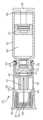
도 15 및 도 16은 일반적으로 도면부호 "200"에 의해서 표시된 무균 관통 시스템의 대안 실시예를 도시한다. 무균 관통 시스템(200)은 도 1 내지 도 14에 도시되고 상술한 무균 관통 시스템(100)과 유사하므로, "1"이 아닌 부호 "2"를 앞에 붙인 도면부호는 유사 기능 요소들을 표시하는데 사용된다. 도 15에 도시된 바와 같이, 1차 용기 또는 바이얼(202)은 제공된 또는 로딩 상태에서 약물, 약제 또는 다른 액체 또는 액체형 물질을 수용할 수 있다. 시스템(200)은 1차 용기 또는 바이얼(202)의 내용물을 유로 또는 유로 형성 부재(252)(예를 들어, 스테이킹 바늘)로 그리고 결국 환자에게 전달하기 위해 시스템을 작동하는 전달 장치와 함께 또는 일부로서 사용될 수 있다.FIGS. 15 and 16 illustrate an alternative embodiment of an aseptic penetration system, generally designated by the reference numeral "200." Since the aseptic penetration system (200) is similar to the sterile penetration system (100) illustrated in FIGS. 1-14 and described above, the reference numerals preceding the designation "2" rather than "1" are used to designate similar functional elements. As illustrated in FIG. 15, a primary container or vial (202) can contain a drug, medication, or other liquid or liquid-like substance in a provided or loaded state. The system (200) can be used with or as part of a delivery device that operates the system to deliver the contents of the primary container or vial (202) to a path or path-forming member (252) (e.g., a staking needle) and ultimately to a patient.
또한 도 15에 도시된 바와 같이, 시스템(200)은 (제공된 또는 로딩 상태에 있는) 1차 용기(202)의 제 2 단부(206) 및 피스톤(216) 사이에 내용물이 놓여지도록, 내용물 뒤에 1차 용기(202)의 캐비티(208) 내에 활주가능하게 수용된 피스톤(216)을 포함할 수 있다. 피스톤(216) 및 1차 용기(202)의 내부는 병원균 또는 다른 오염물들이 그 사이를 통과하고 내용물 안으로 진입하는 것을 방지하는 무균 또는 살균 시일을 형성할 수 있다. 1차 용기(202)의 내면, 내용물 및 피스톤의 내부를 포함하는, 1차 용기(202)의 내부는 살균 또는 무균일 수 있다. 피스톤(216)은 그에 의해서 1차 용기(202)의 내부의 살균 성질을 유지할 수 있다. 일부 실시예에 있어서, 피스톤은 고무로 제조된다.Also as illustrated in FIG. 15, the system (200) may include a piston (216) slidably received within the cavity (208) of the primary container (202) behind the contents such that the contents are placed between the second end (206) of the primary container (202) (provided or in a loaded state) and the piston (216). The piston (216) and the interior of the primary container (202) may form a sterile or sterile seal that prevents pathogens or other contaminants from passing therebetween and entering the contents. The interior of the primary container (202), including the interior of the primary container (202), the contents, and the interior of the piston, may be sterile or sterile. The piston (216) may thereby maintain the sterile properties of the interior of the primary container (202). In some embodiments, the piston is made of rubber.
시스템(200)은 또한 도 15에 도시된 바와 같이, 1차 용기(202)의 제 2 단부(206)에 배치된 부트 또는 니플 부분(254)을 포함할 수 있다. 부트(254)는 상술한 바와 같이, 1차 용기(202)의 제 2 단부(206)에 있는 개방부 상의 캡(예를 들어, 크림프 캡) 위(및/또는 적어도 부분적으로 밑)에 배치된 베이스 부분(255)을 포함할 수 있다. 또한 상술한 바와 같이, 캡(212)은 1차 용기(202)의 제 2 단부(206)에 있는 개방부 위 및/또는 내에서 격벽(214)과 결합할 수 있다. 이와 같이, 베이스 부분(255)은 1차 용기(202)의 개방부 및 격벽(214) 위에 놓여질 수 있다. 적어도 1차 용기(202), 격벽(214), 캡(212) 및 부트(254)의 조립체는 하기에 설명되는 바와 같이, 유로 형성 부재(252)가 통과할 [하기에 추가로 설명되는 바와 같이 부트의 캐비티(257)보다 다른] 적어도 내부 또는 비노출면들이 살균되도록 (하기에 추가로 기술된 바와 같이) 시스템의 다른 부분들과 함께 조립되기 전에 살균될 수 있다.The system (200) may also include a boot or nipple portion (254) disposed in the second end (206) of the primary vessel (202), as illustrated in FIG. 15. The boot (254) may include a base portion (255) disposed over (and/or at least partially under) a cap (e.g., a crimp cap) on the opening in the second end (206) of the primary vessel (202), as described above. Also as described above, the cap (212) may engage the baffle (214) over and/or within the opening in the second end (206) of the primary vessel (202). As such, the base portion (255) may be disposed over the opening of the primary vessel (202) and the baffle (214). At least the assembly of the primary vessel (202), the bulkhead (214), the cap (212) and the boot (254) can be sterilized prior to assembly with other parts of the system (as further described below) such that at least the internal or non-exposed surfaces (other than the cavity (257) of the boot as further described below) through which the flow forming member (252) passes are sterilized.
도 15에 도시된 바와 같이, 부트 부분(254)은 적어도 일반적으로 피스톤(216)으로부터 멀어지는 방향으로 베이스 부분(255)으로부터 연장되는 챔버부분(256)을 포함할 수 있다. 챔버 부분(256)은 도 15에 도시된 바와 같이, 캐비티 또는 챔버(257)를 형성한다. 챔버 부분(256)은 도 15에 도시된 바와 같이 캐비티(257)와 교통하는 개방부(258)를 포함한다. 일부 실시예에 있어서, 부트 부분(254)은 (즉, 일체형이거나 또는 한 부재 구성의) 격벽(214)과 일체형일 수 있다. 일부 대안 실시예(미도시)에서, 부트(254)는 유로 형성 부재(252) 상에 제공되거나 또는 초기에 조립될 수 있고 1차 용기(202) 상에 및/또는 함께 직접 설치되지 않고 및/또는 격벽(214)과 통합될 수 있다. 예를 들어, 부트(254)는 다른 실시예들에 대해서 본원에 추가로 기술된 바와 같이, 1차 용기(202)로부터 분리되게 살균되고 1차 용기(202)와 비살균 환경에서 조립되고 (그리고 조립 후에 비파괴적으로 살균되는) 하위조립체를 구비할 수 있다.As illustrated in FIG. 15, the boot portion (254) can include a chamber portion (256) extending from the base portion (255) at least generally away from the piston (216). The chamber portion (256) forms a cavity or chamber (257), as illustrated in FIG. 15. The chamber portion (256) includes an opening (258) communicating with the cavity (257), as illustrated in FIG. 15. In some embodiments, the boot portion (254) can be integral with the baffle (214) (i.e., integral or of one-piece construction). In some alternative embodiments (not illustrated), the boot (254) can be provided on or initially assembled to the flow-forming member (252) and not directly installed on and/or together with the primary vessel (202) and/or can be integral with the baffle (214). For example, the boot (254) may comprise a subassembly that is sterilized separately from the primary container (202) and assembled with the primary container (202) in a non-sterile environment (and non-destructively sterilized after assembly), as further described herein for other embodiments.
또한 도 15에 도시된 바와 같이, 바늘, 튜브 등과 같은 유로 형성 부재(252)의 일부는 챔버 부분(256)의 개방부(258)를 통해서 그리고 부트(254)의 캐비티(257) 안으로 그러나 베이스 부분(255)을 통하지 않고 연장될 수 있다. 유로 형성 부재(252)의 제 1 팁 또는 단부 부분은 그에 의해서 캐비티(257) 내에 배치될 수 있다. 개방부(258)는 사전형성되거나 또는 개방부(258)는 챔버 부분(256)을 통한 유로 형성 부재(252)의 관통에 의해서 형성될 수 있다. 챔버 부분(256)의 개방부(258)는 병원균 또는 다른 오염물이 그 사이를 통과하고 캐비티(257) 안으로 진입하는 것을 방지하도록 유로 형성 부재(252) 주위에 살균 활주 시일을 형성할 수 있고 유로 형성 부재(252)는 그 사이의 살균 시일을 파괴하지 않고 부트 부분(254)에 대해서 축방향으로 병진이동할 수 있다. 캐비티(257)는 내부에 배치되는 유로 형성 부재(252) 및 캐비티(257)의 내면이 살균되도록 살균되거나 또는 무균일 수 있다. 다른 실시예에 대해서 하기에 추가로 설명하는 바와 같이, 캐비티(257)는 초기에 살균되지 않고, 유로 형성 부재(252)의 제 1 단부가 개방부(258)를 통해서 그리고 캐비티(257) 안으로 삽입된 후에 살균될 수 있다. 대안 실시예들에서, 부트(254)보다, 오히려 나선형의 가요성(예 : 고무) 벨로우즈 또는 블래더 부재가 캐비티(257)를 형성하고 유로 형성 부재(252)의 제 1 단부 부분에 대한 1차 용기(202)의 축방향 병진이동(또는 그 반대를)을 허용한다. 가요성 부재는 또한 멸균 후에 유로 형성 부재(252)의 제 1 단부 부분 주위에 캐비티(257)를 밀봉 또는 형성할 수 있다.Also, as illustrated in FIG. 15, a portion of the flow forming member (252), such as a needle, a tube, or the like, may extend through the opening (258) of the chamber portion (256) and into the cavity (257) of the boot (254), but not through the base portion (255). A first tip or end portion of the flow forming member (252) may thereby be positioned within the cavity (257). The opening (258) may be pre-formed or may be formed by penetration of the flow forming member (252) through the chamber portion (256). The opening (258) of the chamber portion (256) can form a sterile sliding seal around the flow-forming member (252) to prevent pathogens or other contaminants from passing therethrough and entering the cavity (257), and the flow-forming member (252) can be axially translated relative to the boot portion (254) without destroying the sterile seal therebetween. The cavity (257) can be sterilized or aseptic such that the flow-forming member (252) disposed therein and the inner surface of the cavity (257) are sterilized. As further described below for other embodiments, the cavity (257) can be initially unsterilized and sterilized after the first end of the flow-forming member (252) is inserted through the opening (258) and into the cavity (257). In alternative embodiments, rather than the boot (254), a helical flexible (e.g., rubber) bellows or bladder member forms the cavity (257) and allows axial translation of the primary container (202) relative to the first end portion of the flow forming member (252) (or vice versa). The flexible member may also seal or form the cavity (257) around the first end portion of the flow forming member (252) after sterilization.
유로 형성 부재(252)는 잠재적으로 및 1차 용기(202) 및 그에 고정된 구성요소들에 대해서 고정될 수 있다. 다르게 기술하자면, 유로 형성 부재(252)는 실질적으로 (시스템이 함께 사용되는 장치에 고정된 것과 같이) 공간에 고정될 수 있고, 1차 용기(202) 및 그에 고정된 구성요소들은 (시스템이 함께 사용되는 장치에 대해서 이동가능하거나 또는 병진이동가능한 것과 같이) 유로 형성 부재(252)에 대해서 이동가능하거나 또는 병진이동할 수 있다. 예를 들어, 유로 형성 부재(252)는 1차 용기(202)가 이동가능하게 부착되는 큰 장치 또는 시스템에 고정될 수 있다.The flow forming member (252) can potentially be fixed relative to the primary vessel (202) and components secured thereto. In other words, the flow forming member (252) can be substantially fixed in space (such as fixed to a device with which the system is used), and the primary vessel (202) and components secured thereto can be movable or translationally translatable relative to the flow forming member (252) (such as movable or translationally translatable relative to a device with which the system is used). For example, the flow forming member (252) can be fixed to a larger device or system to which the primary vessel (202) is movably attached.
도 15에 도시된 바와 같이, 피스톤(216)은 1차 용기(202)(및 그에 결합된 구성요소들)에 대해서 피스톤(216)을 제 2 단부(206)를 향하여 축방향으로 병진이동하도록 구성되는 병진이동 기구(266)에 결합될 수 있다. 병진이동 기구는 1차 용기(202)(및 그에 결합된 구성요소들)에 대해서 피스톤(216)을 제 2 단부(206)를 향하여 축방향으로 선택적으로 병진이동시키는 임의의 기구일 수 있다. 도 16에 도시된 바와 같이, 1차 용기(202)(및 그에 결합된 구성요소들)에 대한 피스톤(216)의 축방향 이동은 피스톤(216)이 내용물(예를 들어, 약품, 약제)를 향하여 작용하게 한다. 시스템(200) 디자인 및/또는 피스톤(216)과 1차 용기(202)와의 마찰로 인하여, 1차 용기(202)가 처음으로 병진이동 기구(266)를 통해서 축방향으로 병진이동하도록 1차 용기(202)가 피스톤(216)보다 더욱 용이하게 축방향으로 이동하는 것을 허용하거나 또는 설명한다. 예를 들어, 피스톤(216)의 축방향 이동은 1차 용기(202)의 내용물을 압축하고 그에 의해서 1차 용기의 제 2 단부(206)를 향하여 축방향 힘을 전달해서 1차 용기(202) 및 그에 결합된 구성요소들을 축방향으로 병진이동시키도록 시도할 수 있다.As illustrated in FIG. 15, the piston (216) may be coupled to a translation mechanism (266) configured to axially translate the piston (216) toward the second end (206) relative to the primary container (202) (and components coupled thereto). The translation mechanism may be any mechanism that selectively translates the piston (216) axially toward the second end (206) relative to the primary container (202) (and components coupled thereto). As illustrated in FIG. 16, the axial movement of the piston (216) relative to the primary container (202) (and components coupled thereto) causes the piston (216) to act toward the contents (e.g., a drug, a medicament). The design of the system (200) and/or the friction between the piston (216) and the primary vessel (202) allows or explains the primary vessel (202) to move axially more readily than the piston (216) such that the primary vessel (202) is initially translated axially via the translation mechanism (266). For example, the axial movement of the piston (216) may attempt to compress the contents of the primary vessel (202) and thereby transmit an axial force toward the second end (206) of the primary vessel to axially translate the primary vessel (202) and components associated therewith.
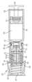
도 16에 도시된 바와 같이, 정지된 또는 고정된 유로 형성 부재(252)의 제 1 단부 부분이 관통 및 침투하거나 또는 부트(254)의 베이스 부분(255), 격벽(214) 및 1차 용기(202)의 캐비티(208)를 통해서 연장되고 그에 의해서 1차 용기(202)의 내용물과 유체 교통하는 정도까지, 병진이동 기구(266)는 피스톤(216)을 축방향으로 병진이동시키고 그에 의해서 1차 용기(202) 및 그에 결합된 구성요소들을 축방향으로 병진이동시킬 수 있다. 다르게 설명하자면, 유로 형성 부재(252)가 격벽(214)을 통해서 그리고 1차 용기(202)의 캐비티(208) 안으로 연장되고 그리고 그에 의해서 그 내용물과 유체 교통하도록, 부트(254)의 베이스 부분(255)이 정지된 또는 고정된 유로 형성 부재(252)의 제 1 단부 부분을 찌르는 정도까지, 병진이동 기구(266)는 피스톤(216)을 축방향으로 병진이동시키고 그에 의해서 1차 용기(202) 및 그에 결합된 구성요소들을 축방향으로 병진이동시킬 수 있다. 일부 실시예에 있어서, 시스템(200)은 작동 후에, 챔버 부분(256)의 살균 캐비티(257) 내에 배치된 부분보다 유로 형성 부재(252)의 부분이 사전 작동 시에 1차 용기(202)의 캐비티(208) 안으로 더 이상 연장되지 않도록 구성될 수 있다. 피스톤(216) 및 축방향 병진이동 기구(266)를 통한 1차 용기(202)의 축방향 이동은 그에 의해서 유로 형성 부재(252)와 1차 용기(202)의 캐비티(208)(및 그 내용물)와의 살균 결합을 유발한다. 이는 사용때까지 1차 용기(202)를 순수 상태로 남겨두어서, 저장 시에 1차 용기(202)의 캐비티(208) 내의 내용물을 더욱 안정되게 하고 사용 전에 유로 형성 부재(252)로부터 누설되는 것을 방지한다.As illustrated in FIG. 16, the translation mechanism (266) can axially translate the piston (216) and thereby axially translate the primary vessel (202) and components associated therewith to the extent that the first end portion of the stationary or fixed flow forming member (252) penetrates and penetrates or extends through the base portion (255) of the boot (254), the bulkhead (214) and the cavity (208) of the primary vessel (202) and thereby comes into fluid communication with the contents of the primary vessel (202). In other words, the translation mechanism (266) can axially translate the piston (216) and thereby axially translate the primary vessel (202) and components associated therewith to the extent that the base portion (255) of the boot (254) impales a first end portion of the stationary or fixed flow path forming member (252) such that the flow path forming member (252) extends through the baffle (214) and into the cavity (208) of the primary vessel (202) and thereby enters fluid communication with its contents. In some embodiments, the system (200) can be configured such that, after operation, a portion of the flow path forming member (252) does not extend further into the cavity (208) of the primary vessel (202) prior to operation than the portion that is disposed within the sterilizing cavity (257) of the chamber portion (256). Axial movement of the primary container (202) via the piston (216) and the axial translation mechanism (266) thereby causes a sterile bond between the flow forming member (252) and the cavity (208) (and its contents) of the primary container (202). This leaves the primary container (202) in a pure state until use, thereby further stabilizing the contents within the cavity (208) of the primary container (202) during storage and preventing leakage from the flow forming member (252) prior to use.
일단, 유로 형성 부재(252)의 제 1 단부 부분이 1차 용기(202)의 캐비티(208) 안으로 연장되고 그리고 그에 의해서 그 내용물과 유체 교통하면, 병진이동 기구(266)를 통한 1차 용기(202) 및 그에 고정된 구성요소들의 추가 병진 이동이 방지될 수 있다. 예를 들어, 시스템(200)이 설치되는 장치 및 시스템은 단지 1차 용기(202)의 제한된 축방향 병진이동을 허용하도록 구성된 정지부를 포함할 수 있다. 여기서, 도 16에 도시된 바와 같이, 유로 형성 부재(252)의 제 1 단부 부분이 1차 용기(202)의 캐비티(208) 안으로 연장되고 그에 의해서 그 내용물과 교통한 후의 병진이동 기구(266)를 통한 피스톤(216)의 축방향 병진이동은 유로 형성 부재(252)에 의해서 형성된 유로를 통하여 1차 용기(202) 내의 내용물을 가압한다. 상술한 바와 같이, 유로 형성 부재(252)는 예를 들어, 피하주사 또는 국부 적용으로서 최종적으로 내용물을 환자에게 전달하도록 구성될 수 있다.Once the first end portion of the flow path forming member (252) has extended into the cavity (208) of the primary vessel (202) and thereby entered into fluid communication with its contents, further translation of the primary vessel (202) and components secured thereto via the translation mechanism (266) can be prevented. For example, the device and system in which the system (200) is installed may include a stop configured to permit only limited axial translation of the primary vessel (202). Here, as illustrated in FIG. 16 , after the first end portion of the flow path forming member (252) has extended into the cavity (208) of the primary vessel (202) and thereby entered into fluid communication with its contents, axial translation of the piston (216) via the translation mechanism (266) pressurizes the contents within the primary vessel (202) via the flow path formed by the flow path forming member (252). As described above, the euro forming member (252) may be configured to ultimately deliver the contents to the patient, for example, by subcutaneous injection or topical application.
병진이동 기구(266)는 피스톤(216)의 축방향 움직임을 실행하거나 또는 달성하고 그에 의해서 방법의 임의의 모드를 경유하여 유로 형성 부재(252)를 통해서 1차 용기(202)의 축방향 병진이동 및 캐비티(208)의 내용물의 펌핑을 실행하거나 또는 달성할 수 있다. 예를 들어, 도 15 및 도 16에 도시된 예시적 실시예는 축 둘레의 상대 회전 시에 축방향으로 연장되는 피스톤(216)의 후방측에 결합된 리드스크류 기구(leadscrew mechanism)를 포함한다. 리드스크류 기구의 베이스는 피스톤(216)의 이동을 실행하기 위하여 고정되거나 또는 정지상태로 배치될 수 있다. 다른 예시적 실시예(미도시)에서, 병진이동 기구(266)는 피스톤(216)을 축방향으로 병진이동시키기 위해 사용자에 의해서 수동으로 조작되는 수동 결합가능한 표면 또는 부재를 포함할 수 있다. 예를 들어, 시스템(200)은 피스톤(216)을 축방향으로 병진이동시키기 위해 수동 결합되고 축방향으로 병진이동하는 피스톤(216)의 후방측에 결합된 카트리지 또는 플런저를 포함할 수 있다. 다른 예시적 실시예(미도시)에서, 병진이동 기구(266)는 1차 용기(202)에 대한 피스톤(216)의 축방향 병진이동 및 1차 용기(202)의 축방향 병진이동을 제공하는, 사용자에 의해서 작동되거나 또는 개시되는 공압 또는 유압 구동 부재를 포함할 수 있다. 공압 또는 유압 구동 부재는 구동 부재를 축방향으로 병진이동시키기 위해 공압 또는 유압력을 사용할 수 있다. 구동 부재는 예를 들어, 팽창 벨로우즈, 팽창 블래더, 팽창 다이애프램 또는 활주 시일 또는 피스톤 형태일 수 있다. 구동 부재는 1차 용기(202)의 축방향 병진이동을 허용하거나 또는 제공할 수 있고, 직접적인 공압 또는 유압은 피스톤(216)을 축방향으로 병진이동시킬 수 있다.The translation mechanism (266) may effectuate or achieve axial movement of the piston (216) and thereby effectuate or achieve axial translation of the primary vessel (202) and pumping of the contents of the cavity (208) through the flow forming member (252) via any mode of the method. For example, the exemplary embodiment illustrated in FIGS. 15 and 16 includes a leadscrew mechanism coupled to the rear of the piston (216) that extends axially when rotated relative to the axis. The base of the leadscrew mechanism may be fixed or stationary to effectuate movement of the piston (216). In other exemplary embodiments (not shown), the translation mechanism (266) may include a manually engageable surface or member that is manually operated by a user to axially translate the piston (216). For example, the system (200) may include a cartridge or plunger coupled to the rear side of the piston (216) that is manually coupled to axially translate the piston (216). In another exemplary embodiment (not shown), the translation mechanism (266) may include a pneumatic or hydraulic drive member that is user-operated or initiated to provide axial translation of the piston (216) relative to the primary vessel (202) and axial translation of the primary vessel (202). The pneumatic or hydraulic drive member can use pneumatic or hydraulic force to axially translate the drive member. The drive member may be, for example, in the form of an expansion bellows, an expansion bladder, an expansion diaphragm, or a sliding seal or piston. The actuating member may allow or provide axial translation of the primary vessel (202), and direct pneumatic or hydraulic pressure may cause the piston (216) to translate axially.
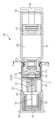
도 17 내지 도 20은 일반적으로 도면부호 "300"에 의해서 표시된 무균 관통 시스템의 예시적 대안 실시예를 도시한다. 예시적인 무균 관통 시스템(300)은 도 1 내지 도 14에 도시되고 상술한 무균 관통 시스템(100)과 유사하므로, "1" 또는 "2"와 반대로 부호 "3"을 앞에 붙인 도면부호는 유사 기능 요소들을 표시하는데 사용된다. 도 17에 도시된 바와 같이, 1차 용기(302)의 구성, 그 내용물, 피스톤(316), 병진이동 기구(366), 캡(312), 격벽(314) 및 무균 관통 시스템(300)의 부트(354)는 도 15 및 도 16에 도시되고 상술한 무균 관통 시스템(200)의 것과 실질적으로 동일할 수 있다. 도 17 및 도 18의 무균 관통 시스템(300)은 유로 형성 부재(352)를 1차 용기(302)의 캐비티(308)과 결합하는 살균 모드에서 도 15 및 도 16의 무균 관통 시스템(200)와 상이할 수 있다.FIGS. 17-20 illustrate exemplary alternative embodiments of an aseptic penetration system, generally designated by the reference numeral "300." Since the exemplary aseptic penetration system (300) is similar to the sterile penetration system (100) illustrated in FIGS. 1-14 and described above, reference numerals preceded by the designation "3", as opposed to "1" or "2," are used to designate similar functional elements. As illustrated in FIG. 17, the configuration of the primary container (302), its contents, the piston (316), the translation mechanism (366), the cap (312), the baffle (314), and the boot (354) of the sterile penetration system (300) can be substantially identical to those of the sterile penetration system (200) illustrated in FIGS. 15 and 16 and described above. The aseptic penetration system (300) of FIGS. 17 and 18 may differ from the aseptic penetration system (200) of FIGS. 15 and 16 in the sterilization mode in which the euro forming member (352) is coupled with the cavity (308) of the primary container (302).
도 17 및 도 18에 도시된 바와 같이, 도 15 및 도 16의 무균 관통 시스템(200)에 대해서 상술한 대로, 부트(354) 및 격벽(314)의 베이스 부분(355)을 찔러서 그리고 유로 형성 부재(353)의 단부 부분 안으로 및 통과하는 것[즉, 정지 또는 고정된 유로 형성 부재(353)에 대해서 1차 용기(302)를 병진이동시키는 것]보다는, 무균 관통 시스템(300)은 유로 형성 부재(353)의 단부 부분을 구동시켜서, 격벽(314) 및 부트(354)의 베이스 부분(355) 안으로 그리고 그를 통해서 그리고 1차 용기(302)의 캐비티(308) 안으로 그리고 그에 이해서 내용물과 유체 교통하게 한다[즉, 정지 또는 고정된 1차 용기(302)에 대해서 유로 형성 부재(353)를 병진이동시킨다].As illustrated in FIGS. 17 and 18, rather than piercing the boot (354) and the base portion (355) of the baffle (314) and into and through the end portion of the flow-forming member (353) (i.e., translating the primary container (302) relative to the stationary or fixed flow-forming member (353)) as described above for the sterile penetration system (200) of FIGS. 15 and 16, the sterile penetration system (300) acts to drive the end portion of the flow-forming member (353) into and through the baffle (314) and the base portion (355) of the boot (354) and into and through the cavity (308) of the primary container (302) and thereby into fluid communication with the contents (i.e., translating the flow-forming member (353) relative to the stationary or fixed primary container (302).
도 17 및 도 18에 도시된 바와 같이, 무균 관통 시스템(300)은 1차 용기(302)의 제 2 단부(306)에 결합되거나 또는 고정된 칼라(390)를 포함한다. 칼라(390)는 1차 용기(302)의 네크 영역(310)과 결합하고 둘러싸는 복수의 원주방향 이격 핑거(392)를 포함할 수 있다. 이 방식에서, 칼라는 1차 용기(302)의 제 2 단부(306)에 고정될 수 있다. 그러나, 칼라(390)는 1차 용기(302)의 제 2 단부(306)에 다르게 결합될 수 있다. 칼라(390)는 적어도 부분적으로 네크 영역(310), 제 2 단부(306)의 개방부, 캡(312), 격벽(314) 및/또는 부트(354) 주위로 연장되는 축방향 연장 벽 부분(391)을 포함할 수 있다. 칼라(390)의 벽 부분(391)은 네크 영역(310)의 외향에 방사상으로 또는 측방향으로 배치되고 및/또는 네크 영역(310), 캡(312) 및 격벽(314)을 지나서 축방향으로 연장될 수 있다. 칼라(390)의 벽 부분(391)은 또한 도 17 및 도 18에 도시된 바와 같이, 베이스 부분(355)을 지나서 그리고 부분적으로 챔버 부분(356)을 지나는 것과 같이, 부트(354)의 적어도 일 부분을 축방향으로 지나서 연장될 수 있다.As illustrated in FIGS. 17 and 18, the sterile penetration system (300) includes a collar (390) coupled or secured to a second end (306) of a primary container (302). The collar (390) may include a plurality of circumferentially spaced fingers (392) that engage and surround a neck region (310) of the primary container (302). In this manner, the collar may be secured to the second end (306) of the primary container (302). However, the collar (390) may be coupled to the second end (306) of the primary container (302) differently. The collar (390) can include an axially extending wall portion (391) that extends at least partially around the neck region (310), the opening of the second end (306), the cap (312), the bulkhead (314) and/or the boot (354). The wall portion (391) of the collar (390) can be radially or laterally disposed outwardly of the neck region (310) and/or can extend axially past the neck region (310), the cap (312) and the bulkhead (314). The wall portion (391) of the collar (390) can also extend axially past at least a portion of the boot (354), such as past the base portion (355) and partially past the chamber portion (356), as illustrated in FIGS. 17 and 18 .
도 17에 도시된 시스템(300)의 사전 작동 상태에서, 칼라(390)의 원위 축방향 에지(393) 또는 적어도 하나의 결합 부분은 대응하는 드라이버 리테이너 부재(395)의 적어도 하나의 방사상 또는 측방향 내향 연장 캠, 래치 또는 작동 부분(394)과 결합할 수 있다. 리테이너 부재(395)는 칼라(390)에 축방향으로 활주가능하게 또는 병진이동가능하게 결합될 수 있다. 칼라(390) 및 리테이너 부재(395)는 도 17에 도시된 사전 작동 상태에서 또는 배열에서, 리테이너 부재(395)의 적어도 하나의 캠, 래치 또는 작동 부분(394)이 리테이너 부재(395) 내에서 축방향으로 활주가능하게 또는 병진이동가능하게 결합된 구동 부재(398)의 유지 부분(399) 바로 뒤로 축방향으로 배치되도록 구성될 수 있다. 도 17에 도시된 바와 같이, 구동 부재(398)의 유로 결합 부분(391)은 리테이너 부재(395)의 축방향 단부 캡 부분(396) 안으로 그리고 그를 통해서 그리고 리테이너 부재(395)의 내부 부분 안으로 축방향으로 연장될 수 있고, 그리고 구동 부재(398)의 유지 부분(399)은 유로 결합 부분(391)으로부터 연장될 수 있다. 일부 실시예에 있어서, 구동 부재(398)의 유로 결합 부분(391)은 실질적으로 원통형일 수 있고 구동 부재(398)의 유지 부분(399)은 도 17에 도시된 바와 같이 유로 결합 부분(391)의 축방향 단부 주위로 연장되는 플랜지일 수 있다.In the pre-operational state of the system (300) illustrated in FIG. 17, the distal axial edge (393) of the collar (390) or at least one engaging portion can engage at least one radially or laterally inwardly extending cam, latch or actuating portion (394) of a corresponding driver retainer member (395). The retainer member (395) can be axially slidably or translationally engaged with the collar (390). The collar (390) and retainer member (395) can be configured such that, in the pre-operational state or arrangement illustrated in FIG. 17, the at least one cam, latch or actuating portion (394) of the retainer member (395) is axially positioned immediately behind the retaining portion (399) of the drive member (398) to which it is axially slidably or translationally engaged. As illustrated in FIG. 17, the axially engaging portion (391) of the drive member (398) can extend axially into and through the axial end cap portion (396) of the retainer member (395) and into the inner portion of the retainer member (395), and the retaining portion (399) of the drive member (398) can extend from the axially engaging portion (391). In some embodiments, the axially engaging portion (391) of the drive member (398) can be substantially cylindrical and the retaining portion (399) of the drive member (398) can be a flange extending around the axial end of the axially engaging portion (391) as illustrated in FIG. 17.
또한 도 17에 도시된 바와 같이, 시스템(300)의 사전 작동상태에서, 탄력적으로 변형된 편향 또는 탄성 부재(397)는 구동 부재(398)의 유지 부분(399) 및 리테이너 부재(395)의 캡 부분(396) 사이에 축방향으로 배치될 수 있다. 편향 부재(397)는 그에 의해서 1차 용기(302)를 향하는 방향으로 작용하는 시스템(300)의 사전작동 상태에서 구동 부재(398)에 대해서 사전로딩 축방향 힘을 작용시킬 수 있다. 편향 부재(397)는 도 18을 참조하여 하기에 기술된 바와 같이, 사전 작동 상태에서 축방향 사전로딩 힘을 인가하고 그 다음 작동 시에 이러한 사전로딩 힘을 방출할 때 효과적인 부재일 수 있다. 일부 실시예에 있어서, 편향 부재(397)는 스프링일 수 있다.Also, as illustrated in FIG. 17, in a pre-operational state of the system (300), an elastically deformed biasing or resilient member (397) can be axially disposed between the retaining portion (399) of the drive member (398) and the cap portion (396) of the retainer member (395). The biasing member (397) can thereby exert a preloading axial force on the drive member (398) in the pre-operational state of the system (300) toward the primary container (302). The biasing member (397) can be an effective member for applying an axial preloading force in the pre-operational state and then releasing this preloading force during subsequent operation, as described below with reference to FIG. 18. In some embodiments, the biasing member (397) can be a spring.
유로 형성 부재(352)는 유로 형성 부재(352)가 축방향으로 활주하거나 또는 구동 부재(398)와 병진이동하도록 구동 부재(398)에 고정되거나 또는 결합될 수 있다. 상술한 바와 같이, 시스템(300)의 사전 작동 상태에서, 유로 형성 부재(352)의 제 1 단부 부분은 부트(354)의 챔버 부분(356)의 살균 캐비티(357) 내에 배치될 수 있지만, 부트(354)의 베이스 부분(355), 격벽(314) 및/또는 1차 용기의 캐비티(308)를 통하지 않는다. 도 17에 도시된 바와 같이, 유로 형성 부재(352)의 제 1 단부 부분은 사전 작동 상태에서 부트(354)의 베이스 부분(355)으로부터 축방향으로 이격될 수 있다.The flow forming member (352) can be secured to or coupled to the drive member (398) such that the flow forming member (352) can slide axially or translate with respect to the drive member (398). As described above, in a pre-operational state of the system (300), the first end portion of the flow forming member (352) can be positioned within the sterilizing cavity (357) of the chamber portion (356) of the boot (354), but not through the base portion (355) of the boot (354), the baffle (314), and/or the cavity (308) of the primary container. As illustrated in FIG. 17, the first end portion of the flow forming member (352) can be axially spaced from the base portion (355) of the boot (354) in the pre-operational state.
구동 부재(398), 유로 형성 부재(352), 편향 부재(397) 및 드라이버 리테이너 부재(395)의 조립체는 하기에 추가로 기술되는 바와 같이, 시스템(300)의 사전 작동 상태 중에 그리고 구동 부재(398)의 해제 이전의 작동 시에 축방향으로 고정될 수 있다. 다르게 설명하자면, 구동 부재(398), 유로 형성 부재(352), 편향 부재(397) 및 드라이버 리테이너 부재(395)는 [시스템(300)이 사용되는 장치에 고정된 바와 같이] 공간에 실질적으로 축방향으로 고정될 수 있고, 1차 용기(302) 및 그에 고정된 구성요소들은 시스템(300)의 사전 작동 상태 중에 그리고 구동 부재(398)의 해제 이전의 작동 시에 [시스템이 사용되는 장치에 대래서 이동가능하거나 또는 병진이동하는 것과 같이] 구동 부재(398), 유로 형성 부재(352), 편향 부재(397) 및 드라이버 리테이너 부재(395)에 대해서 축방향으로 이동가능하거나 또는 병진이동할 수 있다. 예를 들어, 구동 부재(398), 유로 형성 부재(352), 편향 부재(397) 및 드라이버 리테이너 부재(395)는 1차 용기(302)(및 그에 고정된 구성요소들)가 이동가능하게 부착되는 대형 장치 또는 시스템에 축방향으로 고정될 수 있다.The assembly of the drive member (398), the euro forming member (352), the biasing member (397), and the driver retainer member (395) can be axially secured during the pre-operational state of the system (300) and during operation prior to release of the drive member (398), as further described below. In other words, the drive member (398), the flow forming member (352), the biasing member (397), and the driver retainer member (395) can be substantially axially secured in space (as secured to a device in which the system (300) is used), and the primary vessel (302) and components secured thereto can be axially movable or translationally movable relative to the drive member (398), the flow forming member (352), the biasing member (397), and the driver retainer member (395) during pre-operational conditions of the system (300) and prior to release of the drive member (398). For example, the drive member (398), the flow forming member (352), the biasing member (397), and the driver retainer member (395) can be axially secured to a larger device or system to which the primary vessel (302) (and components secured thereto) are movably attached.
시스템(300)이 도 18에 도시된 바와 같이, 작동할 때[그리고 도 17과 비교할 때], 병진이동 기구(366)는 1차 용기(302)의 제 2 단부(306)를 향하여 피스톤(316)을 축방향으로 병진이동시키기 위해 (상술한 바와 같이) 개시되거나 또는 작동될 수 있다. 상술한 바와 같이, 1차 용기(302)의 캐비티(308) 내의 피스톤(316)의 이러한 축방향 이동은 캐비티(308) 내의 내용물을 가압하고, 결국 제 1 단부(304)로부터 제 2 단부(306)로 연장되는 축방향으로 1차 용기(302) 및 그에 고정된 구성요소들을 축방향으로 병진이동시키도록 작용할 것이다. 도 18에 도시된 바와 같이, 시스템(300)의 작동 시에, 병진이동 기구(366)는 칼라(390)의 적어도 하나의 결합 부분(393)이 구동 부재(398)의 유지 부분(399) 뒤에서 축방향의 외부로 드라이버 리테이너 부재(395)의 적어도 하나의 캠 또는 작동 부분(394)과 결합하고 방사상 또는 측방향으로 편향 또는 병진이동시키는 정도까지 1차 용기(302)를 축방향으로 병진이동시킬 수 있다. 이 과정에서, 구동 부재(398)의 유지 부분(399)은 그 다음 드라이버 리테이너 부재(395)의 적어도 하나의 캠 또는 작동 부분(394)을 제거할 수 있고 편향 부재(397)의 사전로딩 힘이 구동 부재(398) 및 그에 고정된 유로 형성 부재(352)를 1차 용기(302)의 제 2 단부(306)를 향하여 축방향으로 병진이동시키게 할 수 있다.When the system (300) is in operation, as illustrated in FIG. 18 (and compared to FIG. 17), the translation mechanism (366) may be initiated or actuated (as described above) to axially translate the piston (316) toward the second end (306) of the primary vessel (302). As described above, this axial movement of the piston (316) within the cavity (308) of the primary vessel (302) will act to pressurize the contents within the cavity (308), which in turn will act to axially translate the primary vessel (302) and components secured thereto from the first end (304) to the second end (306). As illustrated in FIG. 18, during operation of the system (300), the translation mechanism (366) can axially translate the primary vessel (302) to such an extent that at least one engaging portion (393) of the collar (390) engages with at least one cam or actuating portion (394) of the driver retainer member (395) axially outwardly behind the retaining portion (399) of the drive member (398) and deflects or translates radially or laterally. In this process, the retaining portion (399) of the drive member (398) can then disengage the at least one cam or actuating portion (394) of the driver retainer member (395) and the preloading force of the deflection member (397) can cause the drive member (398) and the flow-forming member (352) secured thereto to axially translate toward the second end (306) of the primary vessel (302).
적어도 하나의 캠 또는 작동 부분(394)을 해제하는 1차 용기(302) 및 칼라(390)의 축방향 병진이동이 유로 형성 부재(352)의 제 1 단부 부분이 부트(354)의 베이스 부분(355) 및/또는 격벽(314)을 관통하고 및/또는 연장되게 작용할 수 없도록 시스템(300)이 구성될 수 있다는 것이 주목된다. 예를 들어, 사전 작동 상태에서 유로 형성 부재(352)의 제 1 단부 부분은, 적어도 하나의 캠 또는 작동 부분(394)을 해제하는 1차 용기(302) 및 칼라(390)의 축방향 병진이동으로 인해 유로 형성 부재(352)의 제 1 단부 부분이 부트(354)의 베이스 부분(355) 및/또는 격벽(314)을 관통하고 및/또는 연장되게 작용하지 않도록, 부트(354)의 베이스 부분(355) 및/또는 격벽(314)으로부터 충분히 축방향으로 이격될 수 있다.It is noted that the system (300) can be configured such that the axial translation of the primary container (302) and collar (390) releasing at least one cam or actuating member (394) cannot cause the first end portion of the urea forming member (352) to penetrate and/or extend through the base portion (355) of the boot (354) and/or the bulkhead (314). For example, in a pre-operational state, the first end portion of the euro forming member (352) may be sufficiently axially spaced from the base portion (355) of the boot (354) and/or the baffle (314) such that the axial translation of the primary container (302) and the collar (390) that releases at least one cam or operating member (394) does not cause the first end portion of the euro forming member (352) to penetrate and/or extend through the base portion (355) of the boot (354) and/or the baffle (314).
도 18에 도시된 바와 같이, 1차 용기(302)의 제 2 단부(306)를 향하는 구동 부재(398) 및 유로 형성 부재(352)의 축방향 병진이동은 유로 형성 부재(352)의 제 1 단부 부분이 부트(354)의 베이스 부분(355), 격벽(314) 및 1차 용기(302)의 캐비티(308)를 관통하거나 또는 통해서 연장되고 그에 의해서 1차 용기(302)의 내용물과 유체 교통하게 한다. 다르게 설명하자면, 유로 형성 부재(352)가 1차 용기(302)의 캐비티(308) 안으로 연장되고 그에 의해서 그 내용물과 유체 교통하도록, 구동 부재(398)가 "방출되고" 부트(354) 및 격벽을 찌르는 정도까지 병진이동 기구(366)는 피스톤(316) 및 그에 의한 1차 용기(302) 및 칼라(390)와 같이 그에 고정된 구성요소들을 축방향으로 병진이동시킬 수 있다. 일부 실시예에 있어서, 시스템(300)은 작동 후에, 챔버 부분(356)의 살균 캐비티(357) 내에 배치된 부분보다 유로 형성 부재(352)의 부분이 사전 작동 시에 1차 용기(302)의 캐비티(308) 안으로 더 이상 연장되지 않도록 구성될 수 있다. 구동 부재(398) 및 유로 형성 부재(352)의 축방향 이동은 그에 의해서 유로 형성 부재(352)와 1차 용기(302)의 캐비티(308)(및 그 내용물)와의 살균 결합을 유발한다. 이는 사용때까지 1차 용기(302)를 순수 상태로 남겨두어서, 저장 시에 1차 용기(302)의 캐비티(308) 내의 내용물을 더욱 안정되게 하고 사용 전에 유로 형성 부재(352)로부터 누설되는 것을 방지한다.As illustrated in FIG. 18, the axial translation of the drive member (398) and the flow forming member (352) toward the second end (306) of the primary container (302) causes the first end portion of the flow forming member (352) to extend through or penetrate the base portion (355) of the boot (354), the bulkhead (314) and the cavity (308) of the primary container (302), thereby bringing the contents of the primary container (302) into fluid communication. In other words, the translation mechanism (366) can axially translate the piston (316) and thereby the primary container (302) and components secured thereto, such as the collar (390), to such an extent that the actuating member (398) "releases" and impales the boot (354) and the baffle such that the flow forming member (352) extends into the cavity (308) of the primary container (302) and thereby enters fluid communication with its contents. In some embodiments, the system (300) can be configured such that after operation, a portion of the flow forming member (352) does not extend further into the cavity (308) of the primary container (302) prior to operation than a portion that is disposed within the sterilization cavity (357) of the chamber portion (356). The axial movement of the drive member (398) and the flow forming member (352) thereby causes a sterile bond between the flow forming member (352) and the cavity (308) of the primary container (302) (and its contents). This leaves the primary container (302) in a pure state until use, thereby further stabilizing the contents within the cavity (308) of the primary container (302) during storage and preventing leakage from the flow forming member (352) prior to use.
편향 부재(397)는 유로 형성 부재(352)가 적어도 약 10 mm/sec와 같이 상당히 높은 속도로 부트(354) 및/또는 격벽(314)을 찌르도록 구성될 수 있다. 일부 실시예에 있어서, 편향 부재는 유로 형성 부재(352)가 약 40 mm/sec로 부트(354) 및/또는 격벽(314)을 찌르도록 구성될 수 있다. 편향 부재(397)을 통해서 부트(354) 및/또는 격벽(314)의 비교적 빠른 관통은 유리하게는 유로 형성 부재(352)가 부분적으로 관통되지만 피스톤(316)을 통하여 압력 상태에서 캐비티(308)의 내용물의 누설을 방지할 수 있다.The deflection member (397) may be configured to cause the flow forming member (352) to penetrate the boot (354) and/or the bulkhead (314) at a relatively high rate, such as at least about 10 mm/sec. In some embodiments, the deflection member may be configured to cause the flow forming member (352) to penetrate the boot (354) and/or the bulkhead (314) at about 40 mm/sec. The relatively rapid penetration of the boot (354) and/or the bulkhead (314) through the deflection member (397) advantageously allows the flow forming member (352) to be partially penetrated, but prevents leakage of the contents of the cavity (308) under pressure through the piston (316).
일단, 적어도 하나의 캠(394)이 해제되고 유로 형성 부재(352)가 1차 용기(302)의 캐비티(308) 안으로 연장되고, 그에 의해서 그 내용물과 유체 교통하면, 병진이동 기구(366)를 통한 1차 용기(302) 및 그에 고정된 구성요소들의 추가 축방향 병진이동이 방지될 수 있다. 여기서, 도 17에 도시된 바와 같이, 유로 형성 부재(352)의 제 1 단부 부분이 1차 용기(302)의 캐비티(308) 안으로 연장되고, 그에 의해서 그 내용물과 유체 교통한 후에 병진이동 기구(366)를 통한 피스톤(316)의 추가 축방향 병진이동은 유로 형성 부재(352)에 의해서 형성된 유로를 통해서 내용물을 가압한다. 상술한 바와 같이, 유로 형성 부재(352)는 예를 들어, 피하주사 또는 국부 적용과 같이 최종적으로 환자에게 내용물을 전달하도록 구성될 수 있다.Once at least one cam (394) is released and the flow path forming member (352) is extended into the cavity (308) of the primary container (302) and thereby brought into fluid communication with its contents, further axial translation of the primary container (302) and components secured thereto via the translation mechanism (366) can be prevented. Here, as illustrated in FIG. 17, after the first end portion of the flow path forming member (352) is extended into the cavity (308) of the primary container (302) and thereby brought into fluid communication with its contents, further axial translation of the piston (316) via the translation mechanism (366) forces the contents through the flow path formed by the flow path forming member (352). As described above, the flow path forming member (352) can be configured to ultimately deliver the contents to a patient, such as for example, subcutaneous injection or topical application.
도 19 및 도 20은 유로 형성 부재(352)의 팁 부분 또는 제 1 단부 및 부트(354)의 챔버 부분(356)의 캐비티(357)를 살균하기 위한 시스템 및 방법들을 도시한다. 일부 실시예에 있어서, 부트(354)는 초기에 비살균 상태에서 1차 용기(302)에 결합될 수 있다. 유사하게, 유로 형성 부재(352)의 제 1 단부 부분은 시스템(300)이 예를 들어 도 17에 도시된 바와 같이 초기에 조립될 때 비살균 상태에서 캐비티(357) 안으로 삽입될 수 있다. 이러한 시스템(300)의 구성에서, 가스성 살균제와 같은 살균제는 유로 형성 부재(352)의 경로를 통해서 그리고 제 1 단부 부분으로부터 캐비티(357) 안으로 주사될 수 있다. 이 과정에서, 유로 형성 부재(352)의 경로, 캐비티(357) 내에 있는 유로 형성 부재(352)의 제 1 단부 부분의 외면, 및 캐비티(357)는 시스템(300)의 조립 상태에서 살균될 수 있다. 살균제는 유로 형성 부재(352), 캐비티(357) 내에 있는 유로 형성 부재(352)의 제 1 단부 부분의 외면, 및 캐비티(357)를 살균하는데 효과적인 살균제일 수 있다. 예를 들어, 살균제는 에틸렌 산화 가스(EtO), 기화된 과산화수소 (VHP), 이산화질소(NO2), 이산화염소(Cl02) 또는 이들의 조합일 수 있다.FIGS. 19 and 20 illustrate systems and methods for sterilizing a cavity (357) of a tip portion or first end portion of a flow forming member (352) and a chamber portion (356) of a boot (354). In some embodiments, the boot (354) may be initially coupled to the primary container (302) in a non-sterile state. Similarly, the first end portion of the flow forming member (352) may be inserted into the cavity (357) in a non-sterile state when the system (300) is initially assembled, for example as illustrated in FIG. 17. In such a configuration of the system (300), a sterilizing agent, such as a gaseous sterilizing agent, may be injected through the passage of the flow forming member (352) and into the cavity (357) from the first end portion. In this process, the path of the flow path forming member (352), the outer surface of the first end portion of the flow path forming member (352) within the cavity (357), and the cavity (357) can be sterilized in the assembled state of the system (300). The sterilizing agent can be a sterilizing agent effective for sterilizing the flow path forming member (352), the outer surface of the first end portion of the flow path forming member (352) within the cavity (357), and the cavity (357). For example, the sterilizing agent can be ethylene oxide gas (EtO), vaporized hydrogen peroxide (VHP), nitrogen dioxide (NO2 ), chlorine dioxide (Cl02 ), or a combination thereof.
도 19에 도시된 바와 같이, 살균제는 유로 형성 부재(352)의 제 2 단부 부분을 경유하여 유로 형성 부재(352) 안으로 도입될 수 있다. 유로 형성 부재(352)의 제 2 단부 부분은 캐비티(323)를 한정하는 시일(321) 안으로 연장될 수 있다. 시일(321)은 시스템(300)이 사용되거나 또는 설치되는 장치 또는 시스템 또는 시스템(300)의 외벽 또는 일부분(327)에 인접하게 배치될 수 있다. 이 과정에서, 도 19에 도시된 바와 같이, 바늘 또는 다른 삽입 부재(325)는 외벽(327) 및 시일(321)을 통해서 캐비티(323) 안으로 연장되도록 사용될 수 있다. 시일(321)은 실질적으로 유로 형성 부재(352) 및 삽입 부재(325)에 대해서 기밀상태일 수 있다. 이 과정에서, 살균제는 도 19의 화살표로 도시된 바와 같이, 삽입 부재(325)를 경유하여 캐비티(323) 안으로 그리고 그로부터 유로 형성 부재(352) 안으로 도입될 수 있다. 시일(321)은 살균제가 도입된 후에 삽입 부재(325) 및/또는 유로 형성 부재(352)에 의해서 유발된 임의의 개구들을 밀봉하도록 구성될 수 있다.As illustrated in FIG. 19, the sterilizing agent can be introduced into the flow path forming member (352) via the second end portion of the flow path forming member (352). The second end portion of the flow path forming member (352) can extend into a seal (321) defining a cavity (323). The seal (321) can be positioned adjacent an outer wall or portion (327) of a device or system or system (300) in which the system (300) is used or installed. In this process, a needle or other insertion member (325) can be used to extend through the outer wall (327) and the seal (321) into the cavity (323), as illustrated in FIG. 19. The seal (321) can be substantially airtight with respect to the flow path forming member (352) and the insertion member (325). In this process, the sterilizing agent can be introduced into the cavity (323) and from there into the flow path forming member (352) via the insert member (325), as illustrated by the arrows in FIG. 19. The seal (321) can be configured to seal any openings caused by the insert member (325) and/or the flow path forming member (352) after the sterilizing agent is introduced.
도 20에 도시된 바와 같이, 살균제는 유로 형성 부재(352)를 통해서 제 2 단부로부터 제 1 단부로 그리고 부트(354)의 챔버 부분(356)의 캐비티(357) 안으로 유동할 수 있다. 챔버 부분(356)은 도 20의 화살표로 도시된 바와 같이, 살균제가 유로 형성 부재(352) 내부 그리고 캐비티(357) 내의 대기로 방출될 수 있게 하기 위하여 유로 형성 부재(352)의 제 1 단부 부분 주위에서 개방부(358)로부터 양압을 배기하도록 구성될 수 있다. 시스템(300)이 조립된 후에, 유로 형성 부재(352)에 의해서 형성된 유로, 캐비티(357) 내의 유로 형성 부재(352)의 제 1 부분의 외면, 및 캐비티(327)는 자체적으로 그에 의해서 살균될 수 있다. 살균 후에, 유로 형성 부재(352)와 캐비티(357) 내의 살균제는 불활성 가스(예를 들어, 질소)와 함께 방출되어서, 살균제가 도입되고 유로 형성 부재(352)와 캐비티(357) 내의 비살균 대기로 방출되어 살균하는데 사용되는 것과 동일한 방식으로 1차 용기(302)의 내용물을 손상시키는 것을 방지할 수 있다.As illustrated in FIG. 20, the sterilizing agent can flow from the second end to the first end through the flow path forming member (352) and into the cavity (357) of the chamber portion (356) of the boot (354). The chamber portion (356) can be configured to exhaust positive pressure from the opening (358) around the first end portion of the flow path forming member (352) to allow the sterilizing agent to be released into the atmosphere within the flow path forming member (352) and within the cavity (357), as illustrated by the arrows in FIG. 20. After the system (300) is assembled, the flow path formed by the flow path forming member (352), the outer surface of the first portion of the flow path forming member (352) within the cavity (357), and the cavity (327) can themselves be sterilized thereby. After sterilization, the sterilant within the flow forming member (352) and cavity (357) can be released together with an inert gas (e.g., nitrogen) to prevent the sterilant from damaging the contents of the primary container (302) in the same manner as when the sterilant was introduced and released into the non-sterile atmosphere within the flow forming member (352) and cavity (357) used for sterilization.
도 21 내지 도 23은 일반적으로 도면부호 "400"에 의해서 표시된 무균 관통 시스템의 예시적 대안 실시예를 도시한다. 예시적 무균 관통 시스템(400)은 도 1 내지 도 14에 도시되고 상술한 예시적 무균 관통 시스템(100), 도 15 및 도 16에 도시되고 상술한 예시적 무균 관통 시스템(200), 도 17 내지 도 20에 도시되고 상술한 예시적 무균 관통 시스템(300)과 유사하므로 "1," "2" 또는 "3,"이 아닌 도면부호 "4"로 선행되는 유사 도면부호가 유사 기능 요소를 표시하는데 사용된다.FIGS. 21-23 illustrate exemplary alternative embodiments of an aseptic penetration system, generally designated by the reference numeral "400." The exemplary aseptic penetration system (400) is similar to the exemplary aseptic penetration system (100) illustrated in FIGS. 1-14 and described above, the exemplary aseptic penetration system (200) illustrated in FIGS. 15 and 16 and described above, and the exemplary aseptic penetration system (300) illustrated in FIGS. 17-20 and described above, and thus similar reference numerals preceded by the reference numeral "4" rather than "1," "2," or "3," are used to indicate similar functional elements.
도 21의 사전 작동 상태와 도 22의 작동 상태에 제시된 바와 같이, 시스템(400)은 유로 형성 부재(452)가 구동되어서 격벽(414)을 침입 관통하고 1차 용기(402)의 캐비티(408) 안으로 그리고 그 내용물과 유체 교통한다는 점에서 도 17 내지 도 20에 도시되고 상술한 무균 관통 시스템(300)과 유사한 1차 용기(402) 관통 구성을 사용할 수 있다. 시스템(400) 및 시스템(300) 사이의 하나의 차이점은 적어도 하나의 래치 또는 캠 부분(494)이 도 21 및 도 22에 도시된 바와 같이 칼라(490)라기 보다는 드라이버 리테이너 부재(495)의 일부이다.As shown in the pre-operational state of FIG. 21 and the operating state of FIG. 22, the system (400) can utilize a primary container (402) penetration configuration similar to the sterile penetration system (300) illustrated in FIGS. 17-20 and described above in that the fluid forming member (452) is actuated to penetrate the bulkhead (414) and into the cavity (408) of the primary container (402) and into fluid communication with its contents. One difference between the system (400) and the system (300) is that at least one latch or cam portion (494) is part of the driver retainer member (495) rather than the collar (490) as illustrated in FIGS. 21 and 22.
도 21에 도시된 바와 같이, 시스템(400)이 시스템(300)의 사전 작동 상태에서 유로 형성 부재(452)의 제 1 단부 부분을 수용하기 위한 캐비티를 형성하는 챔버 부분을 포함하는 부트 부재를 포함하지 않는다는 점에서, 시스템(400)은 시스템(300)과 추가로 상이하다. 오히려, 시스템(400)은 유로 형성 부재(452)의 제 1 단부 부분이 도 21에 도시된 바와 같이, 사전 작동 상태에 배치되는 플러그(451)를 포함한다. 플러그 부재(451)는 유로 형성 부재(452)의 제 1 단부 부분 주위에 무균 시일을 제공할 수 있다. 일부 실시예에 있어서, 1차 용기(402)와 조립되기 전에, 적어도 플러그(451) 및 유로 형성 부재(452)의 제 1 단부 부분은 유로 형성 부재(452)의 제 1 단부 부분이 살균되고 플러그(451)가 이러한 살균 상태를 유지하도록 살균(예를 들어, 방사선 처리)될 수 있다. 일부 실시예에 있어서, 플러그(451)는 고무일 수 있다.As illustrated in FIG. 21, the system (400) further differs from the system (300) in that the system (400) does not include a boot member that includes a chamber portion forming a cavity for receiving a first end portion of the flow-forming member (452) in a pre-operational state of the system (300). Rather, the system (400) includes a plug (451) in which the first end portion of the flow-forming member (452) is disposed in a pre-operational state, as illustrated in FIG. 21. The plug member (451) can provide a sterile seal around the first end portion of the flow-forming member (452). In some embodiments, prior to assembly with the primary container (402), at least the plug (451) and the first end portion of the flow-forming member (452) can be sterilized (e.g., irradiated) such that the first end portion of the flow-forming member (452) is sterilized and the plug (451) maintains such sterile state. In some embodiments, the plug (451) may be rubber.
작동 시에, 병진이동 기구(466)는 적어도 하나의 작동 부분(493)이 편향 부재(497)가 구동부(498) 및 유로 형성 부재(452)를 1차 용기(402)의 제 2 단부(406)를 향하여 구동시킬 수 있게 하기 위하여 드라이버 리테이너 부재(495)의 적어도 하나의 래치(494)를 편향시키도록 1차 용기(402) 및 칼라(490)를 병진이동시킬 수 있다. 1차 용기(402)의 제 2 단부(406)를 향하여 구동되는 동안, 유로 형성 부재(452)의 제 1 단부 부분 상의 플러그(451)는 플러그(451)의 추가 축방향 병진이동이 방지되도록, 칼라(490)의 일부, 캡(412), 격벽(414) 및/또는 1차 용기(402)의 제 2 단부(406)에 결합되거나 또는 근위에 있는 다른 구성요소와 접촉할 수 있다. 일단 플러그(451)의 추가 축방향 병진이동이 방지되면, 유로 형성 부재(452)는 유로 형성 부재(452)의 제 1 단부 부분이 플러그(451)를 통해서 그리고 격벽(414) 안으로 그리고 그를 관통하여 그리고 1차 용기(402)의 캐비티(408) 안으로 그리고 그에 의해서 그 내용물과 유체 교통하게 구동되도록 1차 용기(402)의 제 2 단부(406)를 향하여 추가로 축방향으로 병진이동될 수 있다.In operation, the translation mechanism (466) can translate the primary container (402) and the collar (490) such that at least one actuating member (493) biases at least one latch (494) of the driver retainer member (495) to drive the driving member (498) and the guiding member (452) toward the second end (406) of the primary container (402). While being driven toward the second end (406) of the primary vessel (402), the plug (451) on the first end portion of the euro forming member (452) may contact a portion of the collar (490), the cap (412), the baffle (414) and/or other components coupled to or proximal to the second end (406) of the primary vessel (402) to prevent further axial translation of the plug (451). Once further axial translation of the plug (451) is prevented, the flow forming member (452) can be further axially translated toward the second end (406) of the primary vessel (402) such that the first end portion of the flow forming member (452) is driven through the plug (451) and into and through the baffle (414) and into the cavity (408) of the primary vessel (402) and thereby into fluid communication with its contents.
도 23에 도시된 바와 같이, 시스템(400)은 1차 용기(402)의 내용물에 부정적으로 영향을 미치지 않는, 조립, 비무균 조립 및 차후 조립 살균 이전의 부분 살균을 제공한다. 예를 들어, 드라이버 리테이너 부재(495), 탄성 부재(497), 구동부(498), 유로 형성 부재(452)의 제 1 단부 부분, 플러그(451) 및/또는 칼라(490)와 같은 그룹 또는 하위조립체(A)를 형성하는 구성요소들은 1차 용기(402) 및 그에 고정된 구성요소와 함께 조립되기 전에 단위체로서 조립되고 살균될 수 있다. 예를 들어, 하위조립체(A)는 1차 용기(402)의 내용물이 제공될 때 수용할 수 없는 감마선 또는 다른 살균 기술로 처리될 수 있다. 상술한 바와 같이, 플러그(451)는 유로 형성 부재(452)의 제 1 단부 부분의 살균을 유지할 수 있다. 유로 형성 부재(452)의 제 2 단부는 유사하게 유로 형성 부재(452)의 유로 및/또는 유로 형성 부재(452)의 제 1 및 제 2 단부 부분들의 완전한 살균을 보장하기 위하여 플러그 부재를 포함할 수 있다.As illustrated in FIG. 23, the system (400) provides for partial sterilization prior to assembly, non-aseptic assembly, and subsequent assembly sterilization that does not adversely affect the contents of the primary container (402). For example, the components forming the group or subassembly (A), such as the driver retainer member (495), the resilient member (497), the drive member (498), the first end portion of the flow forming member (452), the plug (451), and/or the collar (490), can be assembled and sterilized as a unit prior to assembly with the primary container (402) and components secured thereto. For example, the subassembly (A) can be treated with gamma rays or other sterilization techniques that are not acceptable when the contents of the primary container (402) are provided. As described above, the plug (451) can maintain sterilization of the first end portion of the flow forming member (452). The second end of the euro forming member (452) may similarly include a plug member to ensure complete sterilization of the euro of the euro forming member (452) and/or the first and second end portions of the euro forming member (452).
상술한 바와 같이, 1차 용기(402)는 내용물 및 캐비티(408)가 무균이 되도록 살균될 수 있다. 이와 같이, 살균 하위조립체(A)는 도 23에 도시된 바와 같이, 유로 형성 부재(452)의 제 1 단부 부분의 살균에 영향을 미치는 비살균 환경에서 네크 영역(410) 및 칼라(490)를 통해서 1차 용기(402)에 결합될 수 있다. 그러나, 하위조립체(A) 및 1차 용기(402)의 조립 후에, 유로 형성 부재(452)의 제 1 단부 부분 또는 플러그(451) 및 1차 용기(402) 사이의 틈새 공간(B)은 도 23에 도시된 바와 같이, 비살균 상태일 수 있다.As described above, the primary container (402) can be sterilized such that the contents and cavity (408) are sterile. In this way, the sterile sub-assembly (A) can be joined to the primary container (402) through the neck region (410) and the collar (490) in a non-sterile environment that affects sterilization of the first end portion of the flow forming member (452), as illustrated in FIG. 23. However, after assembly of the sub-assembly (A) and the primary container (402), the first end portion of the flow forming member (452) or the gap space (B) between the plug (451) and the primary container (402) can be non-sterile, as illustrated in FIG. 23.
틈새 공간(B)을 살균하기 위하여, 시스템(400)은 도 23에 도시된 바와 같이, 윈도우(432) 및 윈도우 시일(438)을 포함할 수 있다. 예를 들어, 도 1 내지 도 14의 시스템(100)에 대해서 상술한 바와 같이, 윈도우 시일(438)은 틈새 공간(B)을 살균하기 위하여 살균제[예를 들어, EtO 또는 VHP와 같은 살균 가스]가 윈도우 시일(438)을 통해서 확산되어 틈새 공간(B)으로 진입하게 허용하는 투과성 물질(예를 들어, (Tyvek fabric)일 수 있다. 윈도우 시일(438)의 투과성은 매우 작아서 병원균(예를 들어, 바이러스 등)이 살균 후에 틈새 공간(B)으로 진입할 수 없다. 다른 예로서, 윈도우 시일(438)은 UV 광이 틈새 공간(B)을 살균하기 위하여 윈도우 시일(438)을 통해서 침투하여 틈새 공간(B)으로 진입할 수 있도록 투명하거나 또는 반투명할 수 있다.To sterilize the gap space (B), the system (400) may include a window (432) and a window seal (438), as illustrated in FIG. 23. For example, as described above with respect to the system (100) of FIGS. 1 to 14, the window seal (438) may be a permeable material (e.g., (Tyvek fabric)) that allows a sterilizing agent (e.g., a sterilizing gas such as EtO or VHP) to diffuse through the window seal (438) and enter the interstitial space (B) to sterilize the interstitial space (B). The permeability of the window seal (438) is so low that pathogens (e.g., viruses, etc.) cannot enter the interstitial space (B) after sterilization. As another example, the window seal (438) may be transparent or translucent to allow UV light to penetrate through the window seal (438) and enter the interstitial space (B) to sterilize the interstitial space (B).
본 명세서에서 사용된 용어는 특정 실시예를 설명하기 위한 것이며, 본 발명을 제한하려는 것은 아니다. 본원에서 사용된 단수 형태는 문맥상 다르게 지시하지 않는 한 복수 형태를 포함하는 것으로 의도된다. 용어 "구비한다"(및 "구비하는" 및 "구비하다"와 같은 임의의 형태), "갖는다"(및 "갖는" 및 "갖다"와 같은 임의의 형태), "포함한다"(및 "포함하는" 및 "포함하다"와 같은 임의의 형태) 및 "수용한다"(및 "수용하는" 및 "수용하다"와 같은 임의의 형태)는 제한없는 연결동사이다. 결과적으로, 하나 이상의 단계 또는 요소들을 "구비하는", "갖는", "포함하는" 또는 "수용하는" 방법 또는 장치는 그러한 하나 이상의 단계 또는 요소를 소유하지만, 그들 하나 이상의 단계 또는 요소들만 소유하는 것으로 국한되지 않는다. 마찬가지로, 하나 이상의 특징을 "구비하는", "갖는", "포함하는" 또는 "수용하는" 방법 또는 장치의 요소는 이들 하나 이상의 특징을 소유하지만, 단지 이들 하나 이상의 특징만을 소유하는 것으로 국한되지 않는다. 더우기, 임의의 방식으로 구성되는 장치 또는 구조는 적어도 그 방식으로 구성되지만, 또한 목록에 기재되지 않는 방식으로 구성될 수 있다.The terminology used herein is for the purpose of describing particular embodiments and is not intended to be limiting of the invention. As used herein, the singular forms "a," "an," and "the" are intended to include the plural forms unless the context clearly dictates otherwise. The terms "comprises" (and any form thereof such as "comprising" and "comprising"), "has" (and any form thereof such as "having" and "having"), "includes" (and any form thereof such as "including" and "includes"), and "accepts" (and any form thereof such as "accepting" and "accept") are open-ended linking verbs. Consequently, a method or apparatus that "comprises," "has," "includes," or "accepts" one or more steps or elements possesses, but is not limited to possessing only one or more of those steps or elements. Likewise, an element of a method or apparatus that "comprises," "has," "includes," or "accepts" one or more features possesses, but is not limited to possessing only one or more of those features. Furthermore, a device or structure configured in any manner is at least configured in that manner, but may also be configured in a manner not listed.
본 발명은 바람직한 실시예를 참조하여 설명되었다. 여기에 기술된 아키텍처 및 동작 실시예는 동일한 일반적인 특징, 특성 및 일반적인 시스템 동작을 제공하기 위한 예시적인 복수의 가능한 배열들이라는 것을 이해할 수 있다. 앞서 설명한 상세한 설명을 읽고 이해하면 다른 구성에 대한 수정 및 변경이 이루어질 수 있다. 본 발명은 이러한 모든 변형 및 변경을 포함하는 것으로 해석되어야 하는 것으로 의도된 것이다.The present invention has been described with reference to preferred embodiments. It will be appreciated that the architectural and operational embodiments described herein are merely exemplary of a number of possible arrangements for providing the same general features, characteristics and general system operation. Modifications and variations to other configurations will occur to those skilled in the art after reading and understanding the foregoing detailed description. It is intended that the present invention be interpreted to include all such modifications and variations.
Claims (20)
Translated fromKorean유로 형성 부재의 유로의 제 1 단부를 살균하기 위해 상기 카트리지에 수용된 상기 약제 또는 유체와 상기 유로가 유체 연통하지 않는 사전 작동 상태에서 상기 유로의 제 1 단부가 플러그 부재 또는 부트 내에 배치되는 동안, 상기 카트리지의 개방부를 밀봉하는 상기 플러그 부재 또는 부트에 살균제를 제공하는 단계를 포함하고,
상기 유로가 상기 카트리지에 수용된 상기 약제 또는 유체와 유체 연통하는 작동 상태에 있는 동안, 상기 유로의 제 1 단부는 상기 약제 또는 유체가 상기 유로를 통해 상기 유로의 제 2 단부를 향해 유동하도록 상기 약제 또는 유체와 유체 연통하는, 살균 방법.A method of sterilizing an injection assembly having a cartridge containing a drug or fluid, the method comprising:
A step of providing a sterilizing agent to a plug member or boot that seals an opening of the cartridge while the first end of the channel is positioned within the plug member or boot in a pre-operational state in which the channel is not in fluid communication with the agent or fluid contained in the cartridge to sterilize the first end of the channel of the channel forming member,
A method of sterilizing, wherein while the channel is in an operating state in fluid communication with the agent or fluid contained in the cartridge, the first end of the channel is in fluid communication with the agent or fluid such that the agent or fluid flows through the channel toward the second end of the channel.
상기 플러그 부재 또는 부트는 고무를 포함하는 제 1 부분과, 상기 살균제에 투과성인 재료를 포함하는 제 2 부분을 포함하는, 살균 방법.In paragraph 1,
A sterilizing method, wherein the plug member or boot comprises a first portion comprising rubber and a second portion comprising a material permeable to the sterilizing agent.
상기 살균제는 에틸렌 옥사이드(EtO) 또는 이산화질소(NO2)인, 살균 방법.In the second paragraph,
A sterilizing method wherein the sterilizing agent is ethylene oxide (EtO) or nitrogen dioxide (NO2 ).
상기 살균제를 상기 플러그 부재 또는 부트에 도입하는 단계는 상기 살균제를 상기 플러그 부재 또는 부트의 외부로부터 상기 플러그 부재 또는 부트의 내부로 및 상기 플러그 부재 또는 부트의 제 2 부분을 통해 상기 플러그 부재 또는 부트의 밖으로 도입하는 단계를 포함하는, 살균 방법.In the second paragraph,
A sterilizing method, wherein the step of introducing the sterilizing agent into the plug member or boot comprises the step of introducing the sterilizing agent from an exterior of the plug member or boot into an interior of the plug member or boot and out of the plug member or boot through a second portion of the plug member or boot.
상기 살균제를 상기 플러그 부재 또는 부트로 도입하는 단계는 상기 살균제를 상기 유로의 제 2 단부로부터 상기 유로를 통해 상기 플러그 부재 또는 부트 내로 유동시키는 단계를 포함하는, 살균 방법.In paragraph 5,
A sterilizing method, wherein the step of introducing the sterilizing agent into the plug member or boot comprises the step of flowing the sterilizing agent from the second end of the passage through the passage into the plug member or boot.
상기 살균제를 상기 플러그 부재 또는 부트에 도입하기 전에, 상기 방법은 비-살균 환경 또는 비-무균 환경에서 상기 주사 조립체를 조립하는 단계를 포함하는, 살균 방법.In paragraph 1,
A method of sterilizing, wherein prior to introducing said sterilizing agent into said plug member or boot, said method comprises the step of assembling said injection assembly in a non-sterile environment or a non-aseptic environment.
상기 플러그 부재 또는 부트는 캐비티를 포함하는, 살균 방법.In paragraph 1,
A sterilization method, wherein the plug member or boot comprises a cavity.
상기 유로의 제 1 단부는 상기 사전 작동 상태에 있는 동안 상기 캐비티 내에 배치되는, 살균 방법.In Article 8,
A sterilization method, wherein the first end of the euro is disposed within the cavity while in the pre-operational state.
상기 사전 작동 상태에서, 상기 유로의 제 1 단부는 상기 카트리지에 수용된 상기 약제 또는 유체와 유체 연통하지 않는, 살균 방법.In paragraph 1,
A sterilizing method, wherein in said pre-operational state, the first end of said euro is not in fluid communication with the agent or fluid contained in said cartridge.
상기 카트리지는 제 1 단부로부터 제 2 단부를 향해 연장되고;
상기 카트리지를 통해 이동 가능한 피스톤이 상기 카트리지의 제 1 단부를 밀봉하고; 및
상기 플러그 부재 또는 부트는 상기 카트리지의 제 2 단부를 밀봉하는, 살균 방법.In paragraph 1,
The above cartridge extends from the first end toward the second end;
A piston movable through said cartridge seals a first end of said cartridge; and
A sterilizing method wherein said plug member or boot seals the second end of said cartridge.
상기 피스톤은 상기 카트리지의 내주면과 접촉하는 2개 이상의 둥근 밀봉 돌출부들을 포함하는, 살균 방법.In Article 11,
A sterilizing method, wherein the piston comprises two or more round sealing projections that contact the inner surface of the cartridge.
인접한 상기 둥근 밀봉 돌출부들 사이에서, 상기 피스톤은 상기 카트리지의 내주면과 접촉하지 않는 오목 부분들을 포함하는, 살균 방법.In Article 12,
A sterilizing method wherein between adjacent said round sealing projections, said piston includes concave portions that do not contact the inner surface of said cartridge.
상기 피스톤은 플런저를 수용하는 리세스를 포함하고, 상기 플런저는 상기 카트리지의 제 1 단부로부터 상기 카트리지의 제 2 단부를 향해 상기 플런저 및 상기 피스톤을 구동하도록 구성된 모터에 결합되는, 살균 방법.In Article 11,
A method of sterilizing a cartridge, wherein the piston comprises a recess receiving a plunger, the plunger being coupled to a motor configured to drive the plunger and the piston from a first end of the cartridge toward a second end of the cartridge.
상기 유로는 상기 작동 상태에 있을 때 환자에게 상기 약제 또는 유체를 피하 주사하도록 구성되는, 살균 방법.In paragraph 1,
A method of sterilizing the patient, wherein the euro is configured to inject the drug or fluid subcutaneously into the patient when the euro is in the operating state.
상기 유로가 사전 작동 상태에 있는 동안, 상기 유로 형성 부재가 구동 부재를 통하여 압축 상태에 있는 편향 부재에 결합되고, 상기 구동 부재는 상기 카트리지의 축방향으로 이동 가능하고;
상기 편향 부재는 상기 구동 부재의 유지 부분과 상기 구동 부재에 결합되는 리테이너 부재 사이에서 상기 축방향으로의 상기 압축 상태에서 유지되고;
상기 축방향으로의 상기 구동 부재의 이동을 제한하기 위해 상기 리테이너 부재의 캠, 래치 또는 작동 부분이 상기 구동부재의 유지 부분과 결합하고, 상기 리테이너 부재의 캠, 래치 또는 작동 부분은 상기 카트리에 결합되되, 상기 축방향으로 이동 가능한 칼라의 원위 축방향 에지와 결합하도록 구성되고;
상기 리테이너 부재의 상기 캠, 래치 또는 작동 부분과 상기 칼라의 원위 축방향 에지의 결합시 상기 리테이너 부재의 캠, 래치 또는 작동 부분은 방사상으로 이동하여 상기 구동 부재의 유지 부분과의 결합이 해제되고, 이에 의해 상기 편향 부재가 상기 압축 상태로부터 확장되어 상기 유로를 상기 사전 작동 상태로부터 상기 작동 상태로 이동하도록 구성되는, 살균 방법.In paragraph 1,
While the above euro is in a pre-operational state, the euro forming member is coupled to the biasing member in a compressed state through the driving member, the driving member being axially movable in the cartridge;
The above-mentioned biasing member is maintained in the above-mentioned compressed state in the above-mentioned axial direction between the retaining portion of the above-mentioned driving member and a retainer member coupled to the above-mentioned driving member;
A cam, latch or operating portion of the retainer member is engaged with the retaining portion of the driving member to limit movement of the driving member in the axial direction, and the cam, latch or operating portion of the retainer member is coupled to the cartridge, the cam, latch or operating portion being configured to engage a distal axial edge of the axially movable collar;
A sterilization method, wherein upon engagement of the cam, latch or operating portion of the retainer member with the distal axial edge of the collar, the cam, latch or operating portion of the retainer member moves radially to disengage from the retaining portion of the drive member, thereby causing the biasing member to expand from the compressed state and move the path from the pre-operated state to the operated state.
유로 형성 부재의 유로의 제 1 단부를 살균하기 위해, 상기 카트리지에 수용된 상기 약제 또는 유체와 상기 유로가 유체 연통하지 않는 사전 작동 상태에서 상기 유로의 제 1 단부가 플러그 부재 또는 부트 내에 배치되는 동안 및 상기 유로와 상기 약제 또는 유체 사이에 유체 연통이 설정되기 전에, 상기 카트리지의 개방부를 밀봉하는 상기 플러그 부재 또는 부트에 살균제를 제공하는 단계를 포함하는, 살균 방법.A method of sterilizing an injection assembly having a cartridge containing a drug or fluid, the method comprising:
A method of sterilizing a first end of a channel of a channel forming member, the method comprising the step of providing a sterilizing agent to a plug member or boot sealing an opening of the cartridge while the first end of the channel is disposed within a plug member or boot in a pre-operational state in which the channel is not in fluid communication with the agent or fluid contained in the cartridge and before fluid communication is established between the channel and the agent or fluid.
상기 유로가 상기 카트리지에 수용된 상기 약제 또는 유체와 유체 연통하는 작동 상태에 있는 동안, 상기 유로의 제 1 단부는 상기 약제 또는 유체가 상기 유로를 통해 상기 유로의 제 2 단부를 향해 유동하도록 상기 약제 또는 유체와 유체 연통하는, 살균 방법.In Article 17,
A method of sterilizing, wherein while the channel is in an operating state in fluid communication with the agent or fluid contained in the cartridge, the first end of the channel is in fluid communication with the agent or fluid such that the agent or fluid flows through the channel toward the second end of the channel.
비-살균 환경 또는 비-무균 환경에서 상기 주사 조립체를 조립하는 단계;
상기 조립 단계 후에, 유로 형성 부재의 유로의 제 1 단부를 살균하기 위해, 상기 카트리지에 수용된 상기 약제 또는 유체와 상기 유로가 유체 연통하지 않는 사전 작동 상태에서 상기 유로의 제 1 단부가 플러그 부재 또는 부트 내에 배치되는 동안, 상기 카트리지의 개방부를 밀봉하는 상기 플러그 부재 또는 부트에 살균제를 제공하는 단계를 포함하고,
상기 플러그 부재 또는 부트는 고무를 포함하는 제 1 부분 및 상기 살균제에 투과성인 재료를 포함하는 제 2 부분을 포함하고,
상기 사전 작동 상태에서, 상기 유로의 제 1 단부는 상기 카트리지에 수용된 상기 약제 또는 유체와 유체 연통하지 않고, 및
상기 유로가 상기 카트리지에 수용된 상기 약제 또는 유체와 유체 연통하는 작동 상태에 있는 동안, 상기 유로의 제 1 단부는 상기 약제 또는 유체가 상기 유로를 통해 상기 유로의 제 2 단부를 향해 유동하도록 상기 약제 또는 유체와 유체 연통하는, 살균 방법. A method of sterilizing an injection assembly having a cartridge containing a drug or fluid, the method comprising:
A step of assembling said injection assembly in a non-sterile environment or a non-aseptic environment;
After the above assembly step, a step of providing a sterilizing agent to the plug member or boot sealing the opening of the cartridge while the first end of the channel is placed within the plug member or boot in a pre-operational state in which the channel is not in fluid communication with the agent or fluid contained in the cartridge, to sterilize the first end of the channel of the channel forming member,
The plug member or boot comprises a first portion comprising rubber and a second portion comprising a material permeable to the sterilizing agent;
In said pre-operational state, the first end of said euro is not in fluid communication with the agent or fluid contained in said cartridge, and
A method of sterilizing, wherein while the channel is in an operating state in fluid communication with the agent or fluid contained in the cartridge, the first end of the channel is in fluid communication with the agent or fluid such that the agent or fluid flows through the channel toward the second end of the channel.
상기 카트리지는 제 1 단부로부터 제 2 단부를 향해 연장되고;
상기 카트리지를 통해 이동 가능한 피스톤이 상기 카트리지의 제 1 단부를 밀봉하고;
상기 플러그 부재 또는 부트는 상기 카트리지의 제 2 단부를 밀봉하는, 살균 방법.In Article 19,
The above cartridge extends from the first end toward the second end;
A piston movable through said cartridge seals a first end of said cartridge;
A sterilizing method wherein said plug member or boot seals the second end of said cartridge.
Priority Applications (1)
| Application Number | Priority Date | Filing Date | Title |
|---|---|---|---|
| KR1020247030045AKR20240136476A (en) | 2015-03-10 | 2016-03-10 | Aseptic piercing system and method |
Applications Claiming Priority (4)
| Application Number | Priority Date | Filing Date | Title |
|---|---|---|---|
| US201562130718P | 2015-03-10 | 2015-03-10 | |
| US62/130,718 | 2015-03-10 | ||
| KR1020177026656AKR102634489B1 (en) | 2015-03-10 | 2016-03-10 | Aseptic penetration systems and methods |
| PCT/US2016/021790WO2016145206A1 (en) | 2015-03-10 | 2016-03-10 | Aseptic piercing system and method |
Related Parent Applications (1)
| Application Number | Title | Priority Date | Filing Date |
|---|---|---|---|
| KR1020177026656ADivisionKR102634489B1 (en) | 2015-03-10 | 2016-03-10 | Aseptic penetration systems and methods |
Related Child Applications (1)
| Application Number | Title | Priority Date | Filing Date |
|---|---|---|---|
| KR1020247030045ADivisionKR20240136476A (en) | 2015-03-10 | 2016-03-10 | Aseptic piercing system and method |
Publications (2)
| Publication Number | Publication Date |
|---|---|
| KR20200103873A KR20200103873A (en) | 2020-09-02 |
| KR102707701B1true KR102707701B1 (en) | 2024-09-23 |
Family
ID=55642866
Family Applications (3)
| Application Number | Title | Priority Date | Filing Date |
|---|---|---|---|
| KR1020207024462AActiveKR102707701B1 (en) | 2015-03-10 | 2016-03-10 | Aseptic piercing system and method |
| KR1020177026656AActiveKR102634489B1 (en) | 2015-03-10 | 2016-03-10 | Aseptic penetration systems and methods |
| KR1020247030045APendingKR20240136476A (en) | 2015-03-10 | 2016-03-10 | Aseptic piercing system and method |
Family Applications After (2)
| Application Number | Title | Priority Date | Filing Date |
|---|---|---|---|
| KR1020177026656AActiveKR102634489B1 (en) | 2015-03-10 | 2016-03-10 | Aseptic penetration systems and methods |
| KR1020247030045APendingKR20240136476A (en) | 2015-03-10 | 2016-03-10 | Aseptic piercing system and method |
Country Status (13)
| Country | Link |
|---|---|
| US (3) | US10182969B2 (en) |
| EP (2) | EP3268078B1 (en) |
| JP (4) | JP6799001B2 (en) |
| KR (3) | KR102707701B1 (en) |
| CN (2) | CN112545886A (en) |
| AU (4) | AU2016228990B2 (en) |
| BR (1) | BR112017019259B1 (en) |
| CA (1) | CA2979044C (en) |
| DK (1) | DK3268078T3 (en) |
| ES (1) | ES2846783T3 (en) |
| IL (4) | IL295010B1 (en) |
| MX (1) | MX2017011603A (en) |
| WO (1) | WO2016145206A1 (en) |
Families Citing this family (30)
| Publication number | Priority date | Publication date | Assignee | Title |
|---|---|---|---|---|
| US10258744B2 (en) | 2013-04-05 | 2019-04-16 | West Pharmaceutical Services, Inc. | Pharmaceutical syringe piston |
| US10569014B2 (en)* | 2015-03-02 | 2020-02-25 | Amgen Inc. | Device and method for making aseptic connections |
| IL295010B1 (en)* | 2015-03-10 | 2025-06-01 | Regeneron Pharma | Pollution-free piercing system and method |
| EP3411093A4 (en)* | 2016-02-01 | 2020-05-06 | Liberdi Ltd. | Dialysis system pump with connector |
| CH712629A2 (en) | 2016-06-23 | 2017-12-29 | Tecpharma Licensing Ag | Cartridge receiving device for an administering device and method for assembling a carpule in a cartridge receiving device. |
| EP3348284A2 (en) | 2017-01-12 | 2018-07-18 | Tecpharma Licensing AG | A method for sterilization of a fluid path for an injection device |
| US10245377B2 (en)* | 2016-11-11 | 2019-04-02 | Insulet Corporation | Drug delivery systems with sealed and sterile fluid paths and methods of providing the same |
| CN110234371A (en) | 2017-02-01 | 2019-09-13 | 利比迪公司 | Intelligent peritoneal dialysis device |
| CN119950880A (en) | 2017-05-05 | 2025-05-09 | 里珍纳龙药品有限公司 | Auto-injectors and related methods of use |
| MA49676A (en) | 2017-07-25 | 2020-06-03 | Amgen Inc | DRUG ADMINISTRATION DEVICE EQUIPPED WITH A CONTAINER ACCESS SYSTEM AND ASSOCIATED ASSEMBLY PROCEDURE |
| US10722640B2 (en) | 2017-08-03 | 2020-07-28 | Insulet Corporation | Devices, systems, and methods of packaging for a pre-filled drug delivery device |
| US10973939B2 (en)* | 2017-08-03 | 2021-04-13 | Insulet Corporation | System and method for aseptic packaging of a drug delivery device components |
| EP4306146A3 (en) | 2017-09-25 | 2024-01-24 | Insulet Corporation | Pre-filled cartridge-based drug delivery device |
| CN107802922B (en)* | 2017-11-22 | 2023-06-20 | 湖南三瑞生物科技有限责任公司 | Infusion sterilizer and sterilization method thereof |
| US11058605B2 (en)* | 2018-03-08 | 2021-07-13 | Flex Ltd. | Sterilization fluid path with barrier removal |
| IT201900005708A1 (en)* | 2019-04-12 | 2020-10-12 | Aea Srl | Device particularly for medical use and methods of sterilization and filling of such device |
| CA3137360A1 (en)* | 2019-04-24 | 2020-10-29 | Amgen Inc. | Syringe sterilization verification assemblies and methods |
| EP4090402B1 (en)* | 2020-01-16 | 2025-04-02 | West Pharmaceutical Services, Inc. | Primary container assembly with integrated fluid path |
| IT202000014101A1 (en)* | 2020-06-12 | 2021-12-12 | Stevanato Group Spa | APPARATUS AND METHOD OF STERILIZATION AND ASSEMBLY OF A CARTRIDGE CONTAINING A MEDICAL SUBSTANCE TO A DEVICE DELIVERING SUCH MEDICAL SUBSTANCE |
| CN117794815A (en)* | 2021-06-11 | 2024-03-29 | 百时美施贵宝公司 | Drug cartridge, drug delivery device and method of manufacturing the same |
| TW202329060A (en) | 2021-10-13 | 2023-07-16 | 美商里珍納龍藥品有限公司 | Muscle blocks and injection trainers including a muscle block |
| IL312892A (en) | 2021-11-16 | 2024-07-01 | Regeneron Pharma | Patch-pump |
| USD1007676S1 (en) | 2021-11-16 | 2023-12-12 | Regeneron Pharmaceuticals, Inc. | Wearable autoinjector |
| JP2025507615A (en) | 2022-02-21 | 2025-03-21 | バイエル・ヘルスケア・エルエルシー | Systems, methods and devices for the delivery of therapeutic or diagnostic agents - Patents.com |
| AT525987B1 (en)* | 2022-05-17 | 2023-10-15 | Pharma Consult Gmbh | Injection device, especially auto-injector |
| WO2024238861A1 (en) | 2023-05-17 | 2024-11-21 | Regeneron Pharmaceuticals, Inc. | Auto-injector training device and related methods of use |
| US20240382681A1 (en) | 2023-05-17 | 2024-11-21 | Regeneron Pharmaceuticals, Inc. | Auto-injector and related methods of use |
| US20240416037A1 (en) | 2023-06-16 | 2024-12-19 | Regeneron Pharmaceuticals, Inc. | Auto-injector and related methods of use |
| AR132984A1 (en) | 2023-06-16 | 2025-08-13 | Regeneron Pharma | MEDICAL DEVICE PACKAGING AND RELATED METHODS |
| US12329721B1 (en) | 2024-12-20 | 2025-06-17 | Applied Cells Inc. | System and method for aseptically transferring fluid |
Citations (2)
| Publication number | Priority date | Publication date | Assignee | Title |
|---|---|---|---|---|
| US20030055395A1 (en) | 2000-02-15 | 2003-03-20 | Manera David A. | Needleless access apparatus and system |
| WO2012114105A1 (en) | 2011-02-22 | 2012-08-30 | The Technology Partnership | Aseptic sampling system |
Family Cites Families (570)
| Publication number | Priority date | Publication date | Assignee | Title |
|---|---|---|---|---|
| US2459304A (en) | 1946-08-28 | 1949-01-18 | Blank Frederick | Medical vial stopper for insuring sterile needle punctures |
| US3342180A (en)* | 1964-04-24 | 1967-09-19 | American Cyanamid Co | Disposable liquid-powder package and hypodermic syringe |
| US3340671A (en) | 1964-08-10 | 1967-09-12 | Carnation Co | Method of filling containers under aseptic conditions |
| US3507386A (en) | 1968-09-10 | 1970-04-21 | Jintan Terumo Co | Package for sterilized articles |
| US3605744A (en)* | 1969-04-22 | 1971-09-20 | Edward M Dwyer | Injection apparatus and method of injecting |
| FR2164955A5 (en) | 1971-12-13 | 1973-08-03 | Rimbaud Henri | |
| US3916894A (en) | 1972-09-20 | 1975-11-04 | Nosco Plastics | Syringe seals and piston |
| US3872992A (en) | 1973-08-06 | 1975-03-25 | Pharmaco Inc | Medicament vial stopper piercing and needle positioning device |
| US3942514A (en)* | 1974-02-28 | 1976-03-09 | Ims Limited | Arterial blood sampling device with indicator |
| US4187861A (en) | 1978-02-21 | 1980-02-12 | Heffernan Bart T | Blood sample handling apparatus and method |
| US4397903A (en) | 1979-01-18 | 1983-08-09 | The West Company | Molded articles |
| US4244287A (en) | 1979-07-09 | 1981-01-13 | Uop Inc. | Two-stage mechanical dewatering of sewage sludge |
| GB2064964A (en)* | 1979-12-12 | 1981-06-24 | Nat Res Dev | Syringe |
| US4410323A (en) | 1980-06-23 | 1983-10-18 | Milton Hodosh | Predosed disposable syringe |
| US4396385A (en) | 1980-12-05 | 1983-08-02 | Baxter Travenol Laboratories, Inc. | Flow metering apparatus for a fluid infusion system |
| US4548601A (en) | 1984-04-09 | 1985-10-22 | Lary Banning G | Prepackaged, injectable pharmaceutical and hypodermic needle combination |
| US5088996A (en) | 1984-04-16 | 1992-02-18 | Kopfer Rudolph J | Anti-aerosoling drug reconstitution device |
| EP0185027B1 (en) | 1984-05-16 | 1990-09-26 | Cosmonor S.A. | Process for fabricating a prefilled syringe with unitary dose and device for implementing such process |
| ATE39325T1 (en) | 1984-11-02 | 1989-01-15 | Duphar Int Res | AUTOMATIC INJECTION DEVICE. |
| JPH0747045B2 (en) | 1986-10-15 | 1995-05-24 | 株式会社大協精工 | Stacked syringe stopper |
| US4973504A (en) | 1987-04-13 | 1990-11-27 | The West Company Incorporated | Pharmaceutical elastomeric coating |
| ES1002629Y (en)* | 1987-06-05 | 1989-01-16 | Badia Marcelo Segura | CONNECTION FOR CATHETERS, PERFUSION EQUIPMENT AND LIQUID BOTTLES TO BE PERFUSED |
| CH673775A5 (en)* | 1987-07-10 | 1990-04-12 | Jacques Verlier | |
| US4808169A (en)* | 1988-01-14 | 1989-02-28 | Habley Medical Technology Corporation | Disposable safety syringe having means for retracting its needle cannula into its medication cartridge |
| JPH0534669Y2 (en) | 1988-03-16 | 1993-09-02 | ||
| US5073169A (en) | 1990-10-02 | 1991-12-17 | Steve Raiken | Trocar support |
| US5354287A (en) | 1991-01-16 | 1994-10-11 | Senetek Plc | Injector for delivering fluid to internal target tissue |
| US5360410A (en) | 1991-01-16 | 1994-11-01 | Senetek Plc | Safety syringe for mixing two-component medicaments |
| US5288560A (en) | 1991-01-30 | 1994-02-22 | Daikyo Gomu Seiko, Ltd. | Laminated sanitary rubber article |
| US5279606A (en) | 1991-08-28 | 1994-01-18 | Habley Medical Technology Corporation | Non-reactive composite sealing barrier |
| EP0588228A1 (en) | 1992-09-12 | 1994-03-23 | Ralf Ritter | Sterilizable container for single medical and surgical sets and instruments |
| US5334179A (en) | 1992-10-16 | 1994-08-02 | Abbott Laboratories | Latching piercing pin for use with fluid vials of varying sizes |
| US5322515A (en) | 1993-03-15 | 1994-06-21 | Abbott Laboratories | Luer adapter assembly for emergency syringe |
| US5382235A (en)* | 1993-07-07 | 1995-01-17 | R.M.S. Safety, Inc. | Device for capturing and retracting the needle cannula of a disposable syringe |
| US5466220A (en) | 1994-03-08 | 1995-11-14 | Bioject, Inc. | Drug vial mixing and transfer device |
| JPH0852213A (en) | 1994-08-12 | 1996-02-27 | Sumitomo Pharmaceut Co Ltd | Syringe |
| US5514116A (en) | 1994-10-24 | 1996-05-07 | Vlv Associates | Connector |
| DE19518426C2 (en) | 1995-05-19 | 1999-02-25 | Sanol Arznei Schwarz Gmbh | Injection device and multi-block blister pack |
| IE77523B1 (en) | 1995-09-11 | 1997-12-17 | Elan Med Tech | Medicament delivery device |
| US6277095B1 (en) | 1995-10-11 | 2001-08-21 | Science Incorporated | Fluid delivery device with full adapter |
| ZA9610374B (en) | 1995-12-11 | 1997-06-23 | Elan Med Tech | Cartridge-based drug delivery device |
| CN1226180A (en) | 1996-06-10 | 1999-08-18 | 伊兰股份有限公司 | Needle for subcutaneous delivery of fluids |
| US6149614A (en) | 1996-07-02 | 2000-11-21 | Minnesota Mining And Manufacturing Company | Medical adhesive composite and package |
| US6142977A (en) | 1996-10-18 | 2000-11-07 | Schering Ag | Prefilled, sterilized syringe with a new and improved plug |
| US5902276A (en) | 1996-11-26 | 1999-05-11 | Liebel-Flarsheim Company | Two-shot molded plunger |
| BR9700930A (en) | 1997-02-07 | 1998-12-08 | Rhone Poulenc Rorer Gmbh | Unit for sale intended for parenteral application a device for the execution of parenteral application as well as a refill unit for the above mentioned unit for sale |
| US5860957A (en) | 1997-02-07 | 1999-01-19 | Sarcos, Inc. | Multipathway electronically-controlled drug delivery system |
| JP3387775B2 (en) | 1997-05-22 | 2003-03-17 | 株式会社大協精工 | Sealing stopper for syringe and prefilled syringe |
| US6003736A (en) | 1997-06-09 | 1999-12-21 | Novo Nordisk A/S | Device for controlled dispensing of a dose of a liquid contained in a cartridge |
| US6500150B1 (en) | 1997-06-16 | 2002-12-31 | Elan Pharma International Limited | Pre-filled drug-delivery device and method of manufacture and assembly of same |
| US6171276B1 (en) | 1997-08-06 | 2001-01-09 | Pharmacia & Upjohn Ab | Automated delivery device and method for its operation |
| US6004300A (en) | 1997-08-28 | 1999-12-21 | Butcher; Robert M | Composite hypodermic syringe piston |
| US6815206B2 (en) | 1997-09-19 | 2004-11-09 | Ethicon, Inc. | Container monitoring system |
| US5989237A (en)* | 1997-12-04 | 1999-11-23 | Baxter International Inc. | Sliding reconstitution device with seal |
| AU2002301323B2 (en) | 1997-12-04 | 2005-06-16 | Baxter International Inc | Sliding reconstitution device with seal |
| DE19754056C1 (en) | 1997-12-05 | 1999-04-08 | Schott Glas | Production of coated elastomer components for medical use |
| US5957895A (en) | 1998-02-20 | 1999-09-28 | Becton Dickinson And Company | Low-profile automatic injection device with self-emptying reservoir |
| US6003566A (en) | 1998-02-26 | 1999-12-21 | Becton Dickinson And Company | Vial transferset and method |
| US6681946B1 (en) | 1998-02-26 | 2004-01-27 | Becton, Dickinson And Company | Resealable medical transfer set |
| JP4425465B2 (en) | 1998-03-23 | 2010-03-03 | エラン コーポレーション ピーエルシー | Drug delivery device |
| JP4132208B2 (en) | 1998-04-28 | 2008-08-13 | 大成化工株式会社 | Syringe container manufacturing apparatus and syringe container manufacturing method |
| CA2236703C (en) | 1998-05-05 | 2002-01-29 | Morihiro Sudo | Sliding piston for syringe |
| US6022339A (en)* | 1998-09-15 | 2000-02-08 | Baxter International Inc. | Sliding reconstitution device for a diluent container |
| US7621893B2 (en) | 1998-10-29 | 2009-11-24 | Medtronic Minimed, Inc. | Methods and apparatuses for detecting occlusions in an ambulatory infusion pump |
| US6800071B1 (en) | 1998-10-29 | 2004-10-05 | Medtronic Minimed, Inc. | Fluid reservoir piston |
| US7766873B2 (en) | 1998-10-29 | 2010-08-03 | Medtronic Minimed, Inc. | Method and apparatus for detecting occlusions in an ambulatory infusion pump |
| US6817990B2 (en) | 1998-10-29 | 2004-11-16 | Medtronic Minimed, Inc. | Fluid reservoir piston |
| US7193521B2 (en) | 1998-10-29 | 2007-03-20 | Medtronic Minimed, Inc. | Method and apparatus for detecting errors, fluid pressure, and occlusions in an ambulatory infusion pump |
| JP2000140103A (en) | 1998-11-05 | 2000-05-23 | Daikyo Seiko Ltd | Plunger for injector |
| US6689108B2 (en) | 1998-11-13 | 2004-02-10 | Elan Pharma International Limited | Device for measuring a volume of drug |
| WO2000029049A1 (en) | 1998-11-13 | 2000-05-25 | Elan Pharma International Limited | Drug delivery systems and methods |
| JP2000152989A (en) | 1998-11-19 | 2000-06-06 | Bracco Internatl Bv | Injector and cartridge and plunger ring therefor |
| US20040069044A1 (en) | 1999-04-29 | 2004-04-15 | Gilad Lavi | Device for measuring a volume of drug |
| ATE381361T1 (en)* | 1999-10-22 | 2008-01-15 | Antares Pharma Inc | MEDICATION CARTRIDGE AND INJECTION DEVICE |
| DE10006560A1 (en) | 2000-02-15 | 2001-08-23 | Disetronic Licensing Ag | Two-component piston stopper |
| DE10018924C2 (en) | 2000-04-17 | 2002-07-18 | Disetronic Licensing Ag | Device for the dosed administration of an injectable product |
| SE0001894D0 (en)* | 2000-05-22 | 2000-05-22 | Pharmacia & Upjohn Ab | Medical device |
| CA2421133C (en) | 2000-09-08 | 2012-06-26 | Insulet Corporation | Devices, systems and methods for patient infusion |
| JP2002089717A (en) | 2000-09-14 | 2002-03-27 | Terumo Corp | Gasket |
| US6511459B1 (en) | 2000-09-29 | 2003-01-28 | Mallinckrodt Inc. | Syringe plunger having an improved sealing ability |
| AU2002241567A1 (en) | 2000-11-30 | 2002-07-24 | Biovalve Technologies, Inc. | Fluid delivery and measurement systems and methods |
| US20040034331A1 (en) | 2001-02-23 | 2004-02-19 | Jason Toman | Integrated medication delivery system |
| US20020161332A1 (en) | 2001-04-13 | 2002-10-31 | Kirk Ramey | Infusion set with tape |
| DE10122959A1 (en) | 2001-05-11 | 2002-11-21 | West Pharm Serv Drug Res Ltd | Method for producing a piston for a pharmaceutical syringe or a similar item includes a step in which surplus of the inert foil cap on the piston body is separated in a punching unit |
| US6585693B1 (en) | 2001-07-30 | 2003-07-01 | Louis Dischler | Blister syringe with optional bifurcated guard |
| US20040020558A1 (en) | 2001-08-14 | 2004-02-05 | Paul Stewart | Filling apparatus |
| US6799612B2 (en) | 2001-08-14 | 2004-10-05 | The Boc Group, Inc. | Filling apparatus |
| GB2391480B (en)* | 2002-08-05 | 2007-02-28 | Caretek Medical Ltd | Drug delivery system |
| WO2003024511A1 (en) | 2001-09-17 | 2003-03-27 | Becton Dickinson And Company | Single-use disposable syringe |
| US6748254B2 (en) | 2001-10-12 | 2004-06-08 | Nellcor Puritan Bennett Incorporated | Stacked adhesive optical sensor |
| US20030105430A1 (en) | 2001-11-30 | 2003-06-05 | Elan Pharma International Limited Wil House | Automatic injector |
| EP2319564B1 (en) | 2001-12-13 | 2013-07-17 | Panasonic Corporation | Administration instrument for medical use |
| GB0130139D0 (en) | 2001-12-18 | 2002-02-06 | Dca Design Int Ltd | Improvements in and relating to a medicament injection apparatus |
| US7004928B2 (en) | 2002-02-08 | 2006-02-28 | Rosedale Medical, Inc. | Autonomous, ambulatory analyte monitor or drug delivery device |
| KR20040096561A (en)* | 2002-02-15 | 2004-11-16 | 앤태어스 파머, 인코퍼레이티드 | Injector with bypass channel |
| JP4350525B2 (en) | 2002-03-18 | 2009-10-21 | イーライ リリー アンド カンパニー | Drug dispensing device with gear set giving mechanical advantages |
| DK1503816T3 (en) | 2002-05-02 | 2007-04-23 | Pa Consulting Services | injection device |
| GB2396298A (en) | 2002-12-17 | 2004-06-23 | Pa Consulting Services | Injection device and drive coupling |
| DE10226643A1 (en) | 2002-06-14 | 2004-01-15 | Disetronic Licensing Ag | Piston stopper for injection device, product container and injection device |
| EP3610909A1 (en) | 2002-07-02 | 2020-02-19 | PHC Holdings Corporation | Automatic administration instrument for medical use |
| CN100479875C (en) | 2002-07-22 | 2009-04-22 | 贝克顿·迪金森公司 | Patch-like infusion device |
| CN1723053A (en) | 2002-09-12 | 2006-01-18 | 儿童医院医疗中心 | Method and device for painless drug injection |
| WO2004044464A1 (en) | 2002-11-11 | 2004-05-27 | Terumo Kabushiki Kaisha | Gasket and syringe |
| EP1452196A1 (en) | 2003-02-25 | 2004-09-01 | Jean-Denis Rochat | Device and method of making the package of medicament |
| ATE392223T1 (en) | 2003-05-08 | 2008-05-15 | Novo Nordisk As | INTERNAL NEEDLE INTRODUCER |
| EP1631336B1 (en) | 2003-05-08 | 2010-02-17 | Novo Nordisk A/S | Pivotable injection needle unit |
| DE602004005597T2 (en) | 2003-07-08 | 2008-02-14 | Novo Nordisk A/S | PORTABLE MEDICAMENT DISPENSER WITH AN ENCAPSULATED NEEDLE |
| DE20311996U1 (en) | 2003-08-01 | 2003-10-16 | Hoelzle Dieter Tech Projekte | injection device |
| JP4503953B2 (en) | 2003-08-11 | 2010-07-14 | テルモ株式会社 | Manufacturing method of prefilled syringe |
| EP3695862A1 (en) | 2003-08-12 | 2020-08-19 | Becton, Dickinson and Company | Patch-like infusion device |
| WO2005037350A2 (en) | 2003-10-21 | 2005-04-28 | Novo Nordisk A/S | Internal fluid connector for establishing a fluid connection |
| KR20060099520A (en) | 2003-10-21 | 2006-09-19 | 노보 노르디스크 에이/에스 | Medical Skin Mounting Device |
| EP1527792A1 (en) | 2003-10-27 | 2005-05-04 | Novo Nordisk A/S | Medical injection device mountable to the skin |
| JP4460278B2 (en) | 2003-12-17 | 2010-05-12 | 株式会社大協精工 | Seal plug for syringe and prefilled syringe |
| JP4876390B2 (en) | 2003-12-22 | 2012-02-15 | 三菱化学株式会社 | Composition, charge transport material, organic electroluminescent device and method for producing the same |
| JP4549079B2 (en) | 2004-03-05 | 2010-09-22 | パナソニック株式会社 | Medical dosing device |
| US8057434B2 (en) | 2004-03-31 | 2011-11-15 | Eli Lilly And Company | Injection apparatus having a needle cassette for delivering a pharmaceutical liquid |
| US7648483B2 (en) | 2004-11-22 | 2010-01-19 | Intelliject, Inc. | Devices, systems and methods for medicament delivery |
| US7947017B2 (en) | 2004-11-22 | 2011-05-24 | Intelliject, Inc. | Devices, systems and methods for medicament delivery |
| WO2006057636A1 (en) | 2004-11-22 | 2006-06-01 | Intelliject, Llc | Devices, systems, and methods for medicament delivery |
| US7648482B2 (en) | 2004-11-22 | 2010-01-19 | Intelliject, Inc. | Devices, systems, and methods for medicament delivery |
| EP1824536B1 (en) | 2004-12-06 | 2009-08-26 | Novo Nordisk A/S | Ventilated skin mountable device |
| WO2006061170A1 (en) | 2004-12-08 | 2006-06-15 | Novo Nordisk A/S | Integrated light cover shield for a syringe device |
| MX2007006974A (en) | 2004-12-09 | 2007-10-11 | West Pharm Serv Inc | Automatic injection and retraction syringe. |
| US8123724B2 (en) | 2004-12-09 | 2012-02-28 | West Pharmaceutical Services Of Delaware, Inc. | Auto-injection syringe having vent device |
| JP2006181027A (en) | 2004-12-27 | 2006-07-13 | Daikyo Seiko Ltd | Piston for syringe |
| US7731686B2 (en) | 2005-02-01 | 2010-06-08 | Intelliject, Inc. | Devices, systems and methods for medicament delivery |
| US8206360B2 (en) | 2005-02-01 | 2012-06-26 | Intelliject, Inc. | Devices, systems and methods for medicament delivery |
| US8361026B2 (en) | 2005-02-01 | 2013-01-29 | Intelliject, Inc. | Apparatus and methods for self-administration of vaccines and other medicaments |
| AU2006210865B2 (en) | 2005-02-01 | 2008-12-04 | Kaleo, Inc. | Devices, systems, and methods for medicament delivery |
| US8231573B2 (en) | 2005-02-01 | 2012-07-31 | Intelliject, Inc. | Medicament delivery device having an electronic circuit system |
| EP1847242B1 (en) | 2005-02-08 | 2015-06-17 | Toyo Seikan Kaisha, Ltd. | Sterile package, process for producing the same, and production apparatus |
| DE602006008898D1 (en) | 2005-02-11 | 2009-10-15 | Unomedical Ltd | Device for fixing a tube relative to a skin surface and arrangement |
| KR100895277B1 (en)* | 2005-03-03 | 2009-04-29 | 메리디안 메디칼 테크놀로지즈 인코포레이티드 | Drug administration device |
| US8162898B1 (en) | 2005-04-18 | 2012-04-24 | Venetec International, Inc. | Venipuncture base plate assembly and method of using same |
| US7905868B2 (en)* | 2006-08-23 | 2011-03-15 | Medtronic Minimed, Inc. | Infusion medium delivery device and method with drive device for driving plunger in reservoir |
| CN101252961B (en) | 2005-08-29 | 2011-07-20 | 韦斯特制药服务公司 | Dual material plunger tip for use with a syringe |
| WO2007030630A2 (en) | 2005-09-07 | 2007-03-15 | Covidien Ag | Syringe construction |
| EP1924309A1 (en) | 2005-09-16 | 2008-05-28 | (OSI) Eyetech Inc. | Ophthalmic syringe |
| US8202249B2 (en) | 2005-09-20 | 2012-06-19 | Panasonic Corporation | Injection device with puncture function, method for controlling injection device with puncture function, chemical solution administration device, and method for controlling chemical solution administration device |
| DE202005014958U1 (en) | 2005-09-22 | 2005-12-08 | Dieter Hölzle Technik-Projekte GmbH | Injection unit comprising a seat for a syringe body with two pistons and two chambers and a means for driving the plunger to produce a mixing stroke before an injection stroke |
| EP1782852A1 (en) | 2005-11-04 | 2007-05-09 | F.Hoffmann-La Roche Ag | Device for automatic delivery of a liquid medicament into the body of a patient |
| US7988675B2 (en) | 2005-12-08 | 2011-08-02 | West Pharmaceutical Services Of Delaware, Inc. | Automatic injection and retraction devices for use with pre-filled syringe cartridges |
| US8052648B2 (en) | 2005-12-21 | 2011-11-08 | Venetec International, Inc. | Intravenous catheter anchoring device |
| DK1962926T3 (en) | 2005-12-23 | 2009-09-28 | Unomedical As | injection device |
| US8147460B2 (en) | 2006-01-31 | 2012-04-03 | Roche Diagnostics International Ag | Administering device with a multi-component injection-moulded housing |
| ZA200805866B (en) | 2006-01-31 | 2009-09-30 | Ares Trading Sa | Injection device with a capacitive proximity sensor |
| EP3165247B1 (en) | 2006-02-09 | 2020-10-28 | DEKA Products Limited Partnership | Pumping fluid delivery systems and methods using force application assembley |
| US8926569B2 (en) | 2006-03-15 | 2015-01-06 | Bayer Medical Care Inc. | Plunger covers and plungers for use in syringes and methods of fabricating plunger covers and plungers for use in syringes |
| AU2007253822B2 (en) | 2006-05-16 | 2013-03-14 | Hospira, Inc. | Injection device and method of assembly and activation |
| DE102006027304A1 (en) | 2006-06-06 | 2007-12-13 | Aesculap Ag & Co. Kg | Sterilized packaging, process for their preparation and their use in medicine |
| JP2008000287A (en) | 2006-06-21 | 2008-01-10 | Terumo Corp | Sliding composition for coating medical appliance and medical appliance with sliding coat |
| US7294752B1 (en) | 2006-06-27 | 2007-11-13 | Tri-State Hospital Supply Corporation | Window dressing having integral anchor |
| CN101516424A (en)* | 2006-07-20 | 2009-08-26 | 医疗器械创新有限公司 | Disposable syringe |
| US7682338B2 (en)* | 2006-08-23 | 2010-03-23 | Medtronic Minimed, Inc. | Infusion medium delivery system, device and method with needle inserter and needle inserter device and method |
| EP1923083A1 (en) | 2006-11-17 | 2008-05-21 | Sanofi-Aventis Deutschland GmbH | Drive mechanisms for use in drug delivery devices |
| GB2458586B (en)* | 2006-11-21 | 2011-10-12 | Intelliject Llc | Injection device for medicament delivery |
| KR100794632B1 (en) | 2007-01-19 | 2008-01-14 | 주식회사 에프에스코리아 | Sterile packaging container and packing method using the same |
| EP2125075A2 (en) | 2007-01-22 | 2009-12-02 | Intelliject, Inc. | Medical injector with compliance tracking and monitoring |
| WO2008097217A1 (en) | 2007-02-07 | 2008-08-14 | Becton, Dickinson And Company | Safety shield system for a single use flexible-type compression syringe, and injection device |
| US8323250B2 (en)* | 2007-04-30 | 2012-12-04 | Medtronic Minimed, Inc. | Adhesive patch systems and methods |
| US7892199B2 (en) | 2007-05-21 | 2011-02-22 | Asante Solutions, Inc. | Occlusion sensing for an infusion pump |
| DK2150195T3 (en) | 2007-06-06 | 2010-12-06 | Unomedical As | Gas sterilized packaging |
| US8603045B2 (en) | 2007-06-08 | 2013-12-10 | Bayer Intellectual Property Gmbh | Injection device |
| US8540680B2 (en) | 2007-07-17 | 2013-09-24 | C.R. Bard, Inc. | Medical line securement device with locating guides |
| EP2180821B1 (en) | 2007-07-20 | 2014-05-07 | Roche Diagnostics GmbH | Energy supply for fluid dispensing device |
| RU2010109694A (en) | 2007-08-27 | 2011-10-10 | Жжеймор Энтерпрайсис Лимитед (Cy) | CATHETER CLAMP |
| WO2009030975A1 (en) | 2007-09-03 | 2009-03-12 | Becton Dickinson France | Medical device comprising a siliconized chamber and a coated closure means |
| WO2009030974A1 (en) | 2007-09-03 | 2009-03-12 | Becton Dickinson France | Medical device and lubricant coating therefor |
| US7967795B1 (en) | 2010-01-19 | 2011-06-28 | Lamodel Ltd. | Cartridge interface assembly with driving plunger |
| BRPI0817907B8 (en) | 2007-10-02 | 2021-06-22 | Lamodel Ltd | apparatus for administering a substance to an individual |
| ATE533524T1 (en) | 2007-10-22 | 2011-12-15 | Hoffmann La Roche | INDEPENDENTLY WORKING INJECTION DEVICE AND METHOD FOR DETERMINING AN INJECTION OCCLUSION |
| DE602008006458D1 (en) | 2007-11-12 | 2011-06-01 | Bang & Olufsen Medicom As | AUTOMATIC INJECTOR WITH AUTOMATIC NEEDLE FEED |
| ES2886499T3 (en) | 2007-12-28 | 2021-12-20 | Terumo Corp | Sealing gasket for syringe and syringe comprising the sealing gasket |
| WO2009086463A1 (en)* | 2007-12-28 | 2009-07-09 | Aktivpak, Inc. | Dispenser and therapeutic package suitable for administering a therapeutic substance to a subject |
| IL190335A0 (en) | 2008-03-20 | 2009-09-22 | Gaia Med Ltd | Miniature disposable or partially reusable dosing pumps |
| US20090247982A1 (en) | 2008-03-27 | 2009-10-01 | Lifescan Inc. | Medical Device Mechanical Pump |
| US20140088553A1 (en) | 2008-04-02 | 2014-03-27 | Hugh Hetherington | Retractable plunger design for injection control device for proportional injection extraction during the syringe's insertion extraction |
| US20130211374A1 (en) | 2008-04-02 | 2013-08-15 | Hugh Hetherington | Injection Control Device for Proportional Injection, Extraction during the Syringe's Insertion, Retraction |
| US8133208B2 (en) | 2008-04-02 | 2012-03-13 | Bsecs Holdings, Llc | Injection control method and device |
| US8540681B2 (en) | 2008-04-02 | 2013-09-24 | Bsecs Holdings, Llc | Injection control device with gearing mechanism |
| US8435217B2 (en)* | 2008-04-11 | 2013-05-07 | Applied Silicone Corporation | Gas sterilizable two-part polymer delivery system |
| JP5459204B2 (en) | 2008-04-16 | 2014-04-02 | 味の素株式会社 | Syringe |
| US8021344B2 (en) | 2008-07-28 | 2011-09-20 | Intelliject, Inc. | Medicament delivery device configured to produce an audible output |
| GB2461089B (en) | 2008-06-19 | 2012-09-19 | Cilag Gmbh Int | Injection device |
| WO2009158613A1 (en) | 2008-06-26 | 2009-12-30 | West Pharmaceutical Services, Inc. | Method of coating polyxylylene onto flouropolymer surfaces and devices coated thereby |
| EP2293831A1 (en) | 2008-07-07 | 2011-03-16 | Unomedical A/S | Inserter for transcutaneous device |
| USD602586S1 (en) | 2008-07-23 | 2009-10-20 | Animas Corporation | Drug delivery pod |
| USD602155S1 (en) | 2008-07-28 | 2009-10-13 | Animas Corporation | Drug delivery pod |
| CA2930329A1 (en) | 2008-08-18 | 2010-02-25 | Calibra Medical, Inc. | Drug infusion system with reusable and disposable components |
| US8303535B2 (en) | 2008-09-10 | 2012-11-06 | Hoffman-La Roche Inc. | Delivery device for use with a therapeutic drug |
| US8979807B2 (en) | 2008-09-29 | 2015-03-17 | Becton Dickinson France | Automatic injection device with audible indicator of completed injection |
| WO2010035057A1 (en) | 2008-09-29 | 2010-04-01 | Becton Dickinson France | Autoinjector with audible indication of completed delivery |
| US8223028B2 (en) | 2008-10-10 | 2012-07-17 | Deka Products Limited Partnership | Occlusion detection system and method |
| WO2010047825A1 (en) | 2008-10-24 | 2010-04-29 | Gvd Corporation | Coating methods, systems and related articles |
| EP2364171B1 (en) | 2008-10-28 | 2019-12-04 | West Pharmaceutical Services, Inc. | Syringe piston nest for the manufacture of pre filled syringe |
| GB0821492D0 (en) | 2008-11-25 | 2008-12-31 | Team Holdings Uk Ltd | Integrated auto-injector cartridge system |
| US8475414B2 (en) | 2008-12-02 | 2013-07-02 | Sanofi-Aventis Deutschland Gmbh | Medication delivery device and method for operating a medication delivery device |
| TWI555546B (en) | 2008-12-02 | 2016-11-01 | 賽諾菲阿凡提斯德意志有限公司 | Medication delivery device and method for operating a medication delivery device |
| US9370621B2 (en) | 2008-12-16 | 2016-06-21 | Medtronic Minimed, Inc. | Needle insertion systems and methods |
| AU2009331635A1 (en) | 2008-12-22 | 2011-06-23 | Unomedical A/S | Medical device comprising adhesive pad |
| EP2384207B1 (en) | 2008-12-29 | 2017-03-29 | Sanofi-Aventis Deutschland GmbH | Medical injection device with electric motor drive control |
| US9375529B2 (en) | 2009-09-02 | 2016-06-28 | Becton, Dickinson And Company | Extended use medical device |
| US9572927B2 (en) | 2009-02-05 | 2017-02-21 | Sanofi-Aventis Deutschland Gmbh | Medicament delivery devices |
| BRPI1007894A8 (en) | 2009-02-05 | 2016-09-13 | Sanofi Aventis Deutschland | medicine shipping devices |
| GB2467904B (en)* | 2009-02-17 | 2013-06-12 | Oval Medical Technologies Ltd | Drug container and delivery mechanism |
| CN102341138B (en) | 2009-03-09 | 2013-06-19 | 泰尔茂株式会社 | Gasket and syringe |
| CN101531585A (en) | 2009-04-16 | 2009-09-16 | 华东师范大学 | Method for preparing 3-methyl-3-butenoic acid |
| JP5808737B2 (en) | 2009-05-07 | 2015-11-10 | メディカル・インジェクション・デヴァイシズ・インコーポレーテッド | Drug dispensing device |
| US9265892B2 (en) | 2009-05-07 | 2016-02-23 | Eric Segal | Medicament dispensing device |
| GB2471304B (en)* | 2009-06-24 | 2013-12-11 | Oval Medical Technologies Ltd | A pre-filled syringe or autoinjector |
| GR20090100384A (en) | 2009-07-08 | 2011-02-18 | Αχιλλεας Τσουκαλης | Insulin pump |
| WO2011006922A1 (en) | 2009-07-14 | 2011-01-20 | Sanofi-Aventis Deutschland Gmbh | Medicament container with a flexible inner layer and a rigid outer layer |
| AU2010277755A1 (en) | 2009-07-30 | 2012-02-02 | Unomedical A/S | Inserter device with horizontal moving part |
| EP3354312A1 (en) | 2009-07-31 | 2018-08-01 | 3M Innovative Properties Co. | Hollow microneedle arrays |
| KR20120047896A (en) | 2009-08-07 | 2012-05-14 | 우노메디컬 에이/에스 | Delivery device with sensor and one or more cannulas |
| US10092691B2 (en) | 2009-09-02 | 2018-10-09 | Becton, Dickinson And Company | Flexible and conformal patch pump |
| US9408984B2 (en) | 2009-09-15 | 2016-08-09 | Becton, Dickinson And Company | Self-injection device |
| US8157769B2 (en) | 2009-09-15 | 2012-04-17 | Medimop Medical Projects Ltd. | Cartridge insertion assembly for drug delivery system |
| US10071198B2 (en) | 2012-11-02 | 2018-09-11 | West Pharma. Servicees IL, Ltd. | Adhesive structure for medical device |
| US10071196B2 (en) | 2012-05-15 | 2018-09-11 | West Pharma. Services IL, Ltd. | Method for selectively powering a battery-operated drug-delivery device and device therefor |
| USD810279S1 (en) | 2009-09-15 | 2018-02-13 | Medimop Medical Projects Ltd. | Injector device |
| EP2301611B1 (en) | 2009-09-25 | 2012-08-15 | Letcat Aktiebolag | Medical delivery device |
| WO2011044569A1 (en) | 2009-10-09 | 2011-04-14 | West Pharmaceutical Services, Inc. | Elastomeric closure with barrier layer and method for its manufacture |
| US9101706B2 (en) | 2009-10-13 | 2015-08-11 | Valeritas, Inc. | Fluid delivery device |
| CH702075A1 (en) | 2009-10-16 | 2011-04-29 | Tecpharma Licensing Ag | Occlusion in an administration unit. |
| US9597458B2 (en) | 2009-10-29 | 2017-03-21 | W. L. Gore & Associates, Inc. | Fluoropolymer barrier materials for containers |
| US10471212B2 (en) | 2009-10-29 | 2019-11-12 | W. L. Gore & Associates, Inc. | Silicone free drug delivery devices |
| US8722178B2 (en) | 2009-10-29 | 2014-05-13 | W. L. Gore & Associates, Inc. | Syringe stopper |
| WO2011053787A2 (en) | 2009-10-30 | 2011-05-05 | Seventh Sense Biosystems, Inc. | Systems and methods for application to skin and control of actuation, delivery and/or perception thereof |
| US10537714B2 (en) | 2009-11-11 | 2020-01-21 | Venetec International, Inc. | Stabilizing device for an extension set |
| JP5650241B2 (en) | 2009-12-16 | 2015-01-07 | ベクトン・ディキンソン・アンド・カンパニーBecton, Dickinson And Company | Self injection device |
| CN102753221B (en) | 2009-12-16 | 2017-04-26 | 贝克顿·迪金森公司 | self-injection device |
| EP2512580A4 (en) | 2009-12-16 | 2013-06-12 | Becton Dickinson Co | Self-injection device |
| WO2011075103A1 (en) | 2009-12-16 | 2011-06-23 | Becton, Dickinson And Company | Self-injection device |
| DK2512560T3 (en) | 2009-12-16 | 2018-07-16 | Becton Dickinson Co | Even injector device |
| DK2781228T3 (en) | 2009-12-16 | 2016-03-21 | Becton Dickinson Co | A device for self-injection |
| JP5650755B2 (en) | 2009-12-16 | 2015-01-07 | ベクトン・ディキンソン・アンド・カンパニーBecton, Dickinson And Company | Self injection device |
| US20130211344A1 (en) | 2009-12-31 | 2013-08-15 | Nestor Rodriguez | Medical components having coated surfaces exhibiting low friction and/or low gas/liquid permeability |
| US20110172637A1 (en) | 2010-01-08 | 2011-07-14 | Ratio, Inc. | Drug delivery device including tissue support structure |
| US8348898B2 (en) | 2010-01-19 | 2013-01-08 | Medimop Medical Projects Ltd. | Automatic needle for drug pump |
| US20110270220A1 (en) | 2010-03-03 | 2011-11-03 | Aktivpak, Inc. | Linearly actuated dispenser and therapeutic package suitable for administering a therapeutic substance and related method |
| CN102821804B (en) | 2010-03-30 | 2015-06-10 | 泰尔茂株式会社 | Medical device with slideable coating, and syringe |
| WO2011125133A1 (en) | 2010-04-09 | 2011-10-13 | 有限会社コーキ・エンジニアリング | Cylinder gasket and pre-filled syringe using same |
| NZ702172A (en) | 2010-04-21 | 2016-03-31 | Abbvie Biotechnology Ltd | Wearable automatic injection device for controlled delivery of therapeutic agents |
| BR112012029642B1 (en) | 2010-05-20 | 2020-05-26 | Becton, Dickinson And Company | DRUG ADMINISTRATION DEVICE |
| CA3011688C (en) | 2010-06-09 | 2021-02-23 | Valeritas, Inc. | Fluid delivery device needle retraction mechanisms, cartridges and expandable hydraulic fluid seals |
| JP4908617B2 (en) | 2010-08-04 | 2012-04-04 | 住友ゴム工業株式会社 | Method for producing surface-modified fluororesin film, method for producing rubber composite, and rubber product |
| WO2012022810A2 (en)* | 2010-08-19 | 2012-02-23 | Novo Nordisk A/S | Medical injection device |
| CN103167887B (en)* | 2010-08-27 | 2015-07-15 | 诺沃—诺迪斯克有限公司 | Medical injection device |
| CN103153360B (en) | 2010-09-02 | 2016-04-06 | 贝克顿·迪金森公司 | Have band activate interceptor pin lid from injection device |
| WO2012032411A2 (en) | 2010-09-07 | 2012-03-15 | Tecpharma Licensing Ag | Automatic injection device |
| US20120071837A1 (en) | 2010-09-21 | 2012-03-22 | O'connor Sean | Auto injector for medication |
| US11612697B2 (en) | 2010-10-29 | 2023-03-28 | W. L. Gore & Associates, Inc. | Non-fluoropolymer tie layer and fluoropolymer barrier layer |
| US20130218092A1 (en) | 2010-11-03 | 2013-08-22 | Sanofi-Aventis Deutschland Gmbh | Method and system for preventing leakage of a medicament |
| WO2012061556A1 (en) | 2010-11-03 | 2012-05-10 | Flugen, Inc. | Wearable drug delivery device having spring drive and sliding actuation mechanism |
| US9180253B2 (en) | 2010-11-03 | 2015-11-10 | Sanofi-Aventis Deutschland Gmbh | Medicated module for administering fixed dose |
| AU2011329876B2 (en) | 2010-11-19 | 2014-09-18 | Eli Lilly And Company | Needle magazine for medication injection device |
| WO2012072568A1 (en) | 2010-11-29 | 2012-06-07 | Sanofi-Aventis Deutschland Gmbh | Automatic delivery device with triggering mechanism |
| WO2012099898A2 (en) | 2011-01-17 | 2012-07-26 | Aktivpak, Inc. | Aseptic cartridge and dispenser arrangement |
| WO2012101669A1 (en) | 2011-01-25 | 2012-08-02 | 有限会社コーキ・エンジニアリング | Gasket for syringe and pre-filled syringe using same |
| US8627816B2 (en) | 2011-02-28 | 2014-01-14 | Intelliject, Inc. | Medicament delivery device for administration of opioid antagonists including formulations for naloxone |
| US8939943B2 (en) | 2011-01-26 | 2015-01-27 | Kaleo, Inc. | Medicament delivery device for administration of opioid antagonists including formulations for naloxone |
| US9173999B2 (en) | 2011-01-26 | 2015-11-03 | Kaleo, Inc. | Devices and methods for delivering medicaments from a multi-chamber container |
| US8998851B2 (en) | 2011-02-09 | 2015-04-07 | Becton, Dickinson And Company | Compact spring inserter for drug deliver infusion set |
| EP2489382A1 (en) | 2011-02-18 | 2012-08-22 | Sanofi-Aventis Deutschland GmbH | Auto-injector |
| EP2489387A1 (en) | 2011-02-18 | 2012-08-22 | Sanofi-Aventis Deutschland GmbH | Auto-injector |
| EP2489385A1 (en) | 2011-02-18 | 2012-08-22 | Sanofi-Aventis Deutschland GmbH | Auto-injector |
| EP2489381A1 (en) | 2011-02-18 | 2012-08-22 | Sanofi-Aventis Deutschland GmbH | Auto-injector |
| EP2489390A1 (en) | 2011-02-18 | 2012-08-22 | Sanofi-Aventis Deutschland GmbH | Detent mechanism |
| EP2489380A1 (en) | 2011-02-18 | 2012-08-22 | Sanofi-Aventis Deutschland GmbH | Injection device |
| EP2489383A1 (en) | 2011-02-18 | 2012-08-22 | Sanofi-Aventis Deutschland GmbH | Auto-injector |
| EP2489388A1 (en) | 2011-02-18 | 2012-08-22 | Sanofi-Aventis Deutschland GmbH | Auto-injector |
| EP2489386A1 (en) | 2011-02-18 | 2012-08-22 | Sanofi-Aventis Deutschland GmbH | Auto-injector |
| EP2489389A1 (en) | 2011-02-18 | 2012-08-22 | Sanofi-Aventis Deutschland GmbH | Detent mechanism |
| EP2489384A1 (en) | 2011-02-18 | 2012-08-22 | Sanofi-Aventis Deutschland GmbH | Auto-injector |
| JP5934335B2 (en) | 2011-03-28 | 2016-06-15 | ベクトン・ディキンソン・アンド・カンパニーBecton, Dickinson And Company | Plastic stopper |
| EP2692366B1 (en) | 2011-03-30 | 2017-02-01 | Terumo Kabushiki Kaisha | Medical instrument with slidable coating layer, and syringe |
| US20130281932A1 (en) | 2011-03-30 | 2013-10-24 | Ziv Harish | Palm-based injector actuation and safety surfaces |
| US20120253314A1 (en) | 2011-03-30 | 2012-10-04 | Ziv Harish | Palm-controlled injectors |
| US20140005596A1 (en) | 2011-03-30 | 2014-01-02 | Ralf Schuster | Injection device |
| PL2510914T3 (en)* | 2011-04-12 | 2015-02-27 | Hoffmann La Roche | Connector device |
| AU2012245211B2 (en)* | 2011-04-21 | 2016-03-10 | Abbvie Inc. | Wearable automatic injection device |
| JP5853289B2 (en) | 2011-04-26 | 2016-02-09 | 大成化工株式会社 | Elastic seal body for prefilled syringe |
| MX349581B (en)* | 2011-05-18 | 2017-08-04 | Becton Dickinson Co | Injection device. |
| JP5833230B2 (en)* | 2011-05-19 | 2015-12-16 | ベクトン・ディキンソン・アンド・カンパニーBecton, Dickinson And Company | Injection device with automatic material combination function |
| WO2012160595A1 (en) | 2011-05-20 | 2012-11-29 | 有限会社コーキ・エンジニアリング | Skived film for covering surface of plug for medical purposes, plug for medical purposes using said film, pre-filled syringe using said plug, and method for producing said film |
| JP6335779B2 (en) | 2011-05-25 | 2018-05-30 | サノフィ−アベンティス・ドイチュラント・ゲゼルシャフト・ミット・ベシュレンクテル・ハフツング | Drug delivery device having a cartridge sensor and a cartridge holder door sensor and method for controlling the device |
| CA2835527A1 (en) | 2011-05-25 | 2012-11-29 | Ilona Eggert | Medicament delivery device and method of controlling the device |
| DK2714141T3 (en) | 2011-05-25 | 2018-10-08 | Sanofi Aventis Deutschland | MEDICINAL INJECTION DEVICE AND PRELIMINARY OPERATION |
| WO2012177933A1 (en)* | 2011-06-21 | 2012-12-27 | Py Daniel C | Fluid sterilant injection sterilization device and method |
| US20120330235A1 (en) | 2011-06-23 | 2012-12-27 | Ratio, Inc. | Drug Delivery Device Including a Dynamic Drug Reservoir and Ergonomic User Interface |
| EP2729200B1 (en) | 2011-07-06 | 2016-10-19 | F.Hoffmann-La Roche Ag | Automatic injection device comprising two occlusion sensors |
| EP2736565B1 (en) | 2011-07-25 | 2017-07-05 | Preciflex SA | Fluid dispenser |
| CA2845362C (en) | 2011-08-24 | 2020-05-05 | Unitract Syringe Pty Ltd | Auto-injector for retractable prefilled syringe |
| JP5717593B2 (en) | 2011-08-31 | 2015-05-13 | 住友ゴム工業株式会社 | Mold for molding gasket for prefilled syringe |
| US9707335B2 (en) | 2011-09-02 | 2017-07-18 | Unitract Syringe Pty Ltd | Drive mechanism for drug delivery pumps with integrated status indication |
| EP2731641B1 (en) | 2011-09-02 | 2021-09-29 | UNL Holdings LLC | Drive mechanism for drug delivery pumps with integrated status indication |
| US9814832B2 (en) | 2011-09-02 | 2017-11-14 | Unl Holdings Llc | Drive mechanism for drug delivery pumps with integrated status indication |
| CA2845379C (en) | 2011-09-02 | 2019-08-06 | Unitract Syringe Pty Ltd | Insertion mechanism for a drug delivery pump |
| ITFI20110193A1 (en) | 2011-09-08 | 2013-03-09 | Menarini Int Operations Lu Sa | DEVICE FOR AUTOMATIC INJECTION OF TWO DRUG DOSES |
| ES2566179T5 (en) | 2011-09-13 | 2019-11-14 | Unitract Syringe Pty Ltd | Connection of sterile fluid passage to medication containers for medication release pumps |
| US20130090605A1 (en) | 2011-09-29 | 2013-04-11 | Animas Corporation | Tunable mechanical injection device for medication |
| WO2013045527A1 (en) | 2011-09-29 | 2013-04-04 | Sanofi-Aventis Deutschland Gmbh | Drug delivery device and method for a drug delivery device |
| DK3045187T3 (en) | 2011-10-14 | 2019-06-11 | Amgen Inc | INJECTOR AND COLLECTION PROCEDURE |
| RU2623490C2 (en)* | 2011-10-19 | 2017-06-26 | БАЙЕР ХелсКер ЛЛСи | Sterile maintaining medical connector unit and method |
| EP2583707A1 (en) | 2011-10-21 | 2013-04-24 | Sanofi-Aventis Deutschland GmbH | Auto-injector |
| WO2013066779A1 (en) | 2011-10-31 | 2013-05-10 | Ge Healthcare Limited | Pierce and fill device |
| WO2013099123A1 (en) | 2011-12-26 | 2013-07-04 | パナソニック株式会社 | Medicine injection device |
| CA3077820C (en) | 2012-01-05 | 2023-03-07 | Becton, Dickinson And Company | Split and side-ported catheter devices |
| WO2013109794A1 (en)* | 2012-01-17 | 2013-07-25 | Py Daniel C | Multiple dose vial and method |
| US8900205B2 (en) | 2012-01-31 | 2014-12-02 | Terumo Kabushiki Kaisha | Syringe for prefilled syringe |
| KR20140135736A (en)* | 2012-03-12 | 2014-11-26 | 유니트랙트 시린지 피티와이 엘티디 | Fill-finish cartridges for sterile fluid pathway assemblies and drug delivery devices incorporating fill-finish cartridges |
| USD676549S1 (en) | 2012-03-13 | 2013-02-19 | Becton Dickinson France S.A.S. | Medical injector |
| US8603027B2 (en) | 2012-03-20 | 2013-12-10 | Medtronic Minimed, Inc. | Occlusion detection using pulse-width modulation and medical device incorporating same |
| US9463280B2 (en) | 2012-03-26 | 2016-10-11 | Medimop Medical Projects Ltd. | Motion activated septum puncturing drug delivery device |
| US9981088B2 (en) | 2012-03-27 | 2018-05-29 | Eli Lilly And Company | Plunger for a medication cartridge |
| EP4406568A3 (en) | 2012-03-30 | 2024-10-16 | Insulet Corporation | Fluid delivery device with transcutaneous access tool, insertion mechanism and blood glucose monitoring for use therewith |
| KR101666290B1 (en) | 2012-04-10 | 2016-10-24 | 케어베이 유럽 리미티드 | Infusion device |
| US9522231B2 (en) | 2012-04-13 | 2016-12-20 | Becton, Dickinson And Company | Infusion device with safety feature for preventing inadvertent activation |
| DK3284493T3 (en) | 2012-04-13 | 2020-11-02 | Becton Dickinson Co | Micro-infusion device with automatic needle retraction |
| EP2662104A1 (en) | 2012-05-07 | 2013-11-13 | Sanofi-Aventis Deutschland GmbH | Detent mechanism for a medicament delivery device |
| JP2013244668A (en) | 2012-05-25 | 2013-12-09 | Daikyo Seiko Ltd | Rubber molding |
| JP6479655B2 (en) | 2012-07-05 | 2019-03-06 | ユーエヌエル ホールディングス エルエルシーUNL Holdings LLC | Automatic injector for injectable cartridge and drive control mechanism therefor |
| BR112015000541A2 (en) | 2012-07-11 | 2017-08-08 | Unitract Syringe Pty Ltd | insertion mechanism, drug delivery pump and method of operating an insertion mechanism |
| US20150209519A1 (en) | 2012-08-14 | 2015-07-30 | Injector Aps | Disposable injector for injecting a liquid into a patient |
| EP2698180A1 (en) | 2012-08-15 | 2014-02-19 | Sanofi-Aventis Deutschland GmbH | Autoinjector |
| ES2637229T3 (en) | 2012-08-29 | 2017-10-11 | Unitract Syringe Pty Ltd | Controlled drive mechanisms for medication delivery pumps |
| JP5960554B2 (en) | 2012-08-30 | 2016-08-02 | 住友ゴム工業株式会社 | Laminated gasket |
| USD745142S1 (en) | 2012-08-30 | 2015-12-08 | Unitract Syringe Pty Ltd | Drug delivery pump |
| HUE026766T2 (en) | 2012-09-05 | 2016-07-28 | Becton Dickinson France | Automatic injection device |
| WO2014037946A1 (en) | 2012-09-05 | 2014-03-13 | Elcam Medical Agricultural Cooperative Association Ltd. | Electronic auto-injection device |
| EP2894191B1 (en) | 2012-09-10 | 2020-03-18 | Sumitomo Rubber Industries, Ltd. | Surface modification method and surface-modified elastic body |
| WO2014049745A1 (en) | 2012-09-26 | 2014-04-03 | テルモ株式会社 | Liquid administration device |
| EP2712651A1 (en) | 2012-09-27 | 2014-04-02 | F. Hoffmann-La Roche AG | Venting device for use in ambulatory infusion system |
| EP2712650A1 (en) | 2012-09-27 | 2014-04-02 | F. Hoffmann-La Roche AG | Adapter and drug cartridge alignment device |
| WO2014054535A1 (en) | 2012-10-01 | 2014-04-10 | ダイキン工業株式会社 | Syringe |
| JP6053482B2 (en) | 2012-11-30 | 2016-12-27 | 住友ゴム工業株式会社 | Manufacturing method of gasket for syringe |
| GB2526948A (en) | 2012-12-27 | 2015-12-09 | Kaleo Inc | Systems for locating and interacting with medicament delivery devices |
| CN104363938B (en) | 2012-12-31 | 2017-04-26 | 甘布罗伦迪亚股份公司 | Occlusion detection in delivery of fluids |
| JP2014131856A (en) | 2013-01-07 | 2014-07-17 | Sumitomo Rubber Ind Ltd | Slidable elastic body |
| USD723157S1 (en) | 2013-03-12 | 2015-02-24 | Unitract Syringe Pty Ltd | Drug delivery pump |
| US9802030B2 (en) | 2013-01-25 | 2017-10-31 | Unl Holdings Llc | Integrated sliding seal fluid pathway connection and drug containers for drug delivery pumps |
| US10617820B2 (en) | 2013-01-25 | 2020-04-14 | Unl Holdings Llc | Fluid restriction mechanisms for drug delivery pumps |
| CN104519932A (en) | 2013-03-04 | 2015-04-15 | 有限会社工机工程 | Piston member for syringe |
| EP2965773A4 (en) | 2013-03-08 | 2016-10-26 | Nipro Corp | Syringe and syringe gasket |
| JP6215546B2 (en) | 2013-03-21 | 2017-10-18 | 住友ゴム工業株式会社 | Gasket for prefilled syringe |
| EP3590568A1 (en) | 2013-03-22 | 2020-01-08 | TecPharma Licensing AG | Substance dispensing device with a signalling device |
| SG11201507878SA (en) | 2013-03-22 | 2015-10-29 | Amgen Inc | Injector and method of assembly |
| USD741995S1 (en) | 2013-03-22 | 2015-10-27 | Ares Trading S.A. | Injection device |
| US10258744B2 (en) | 2013-04-05 | 2019-04-16 | West Pharmaceutical Services, Inc. | Pharmaceutical syringe piston |
| EP2983768A1 (en) | 2013-04-10 | 2016-02-17 | Sanofi | Drive mechanism of a drug delivery device |
| DK2983736T3 (en) | 2013-04-10 | 2020-09-21 | Sanofi Sa | AUTOMATIC DEVICE FOR INJECTING MEDICINES WITH Sophisticated DRIVE MECHANISM |
| DK2983742T3 (en) | 2013-04-10 | 2019-09-09 | Sanofi Sa | HANDLED PHARMACEUTICAL INJECTION DEVICE AND LIMITING DOSAGE ADMINISTRATION THEREOF |
| JP5855598B2 (en) | 2013-04-26 | 2016-02-09 | 富士フイルム株式会社 | Prefilled syringe gasket |
| WO2014179774A1 (en) | 2013-05-03 | 2014-11-06 | Becton, Dickinson And Company | Drug delivery device |
| JP2014223149A (en) | 2013-05-15 | 2014-12-04 | 住友ゴム工業株式会社 | Gasket for syringe |
| ES2688320T3 (en) | 2013-05-24 | 2018-10-31 | Becton Dickinson France | Automatic injection device |
| AU2014274061C1 (en) | 2013-05-31 | 2019-06-13 | Mannkind Corporation | A fluid delivery device having an insertable prefilled cartridge |
| EP2832390A1 (en) | 2013-07-30 | 2015-02-04 | Sensile Pat AG | Drug delivery device with needle actuation mechanism |
| WO2015024960A1 (en) | 2013-08-22 | 2015-02-26 | Sanofi-Aventis Deutschland Gmbh | Control unit for a drug delivery device |
| AU2014308659B2 (en) | 2013-08-23 | 2018-11-01 | Unl Holdings Llc | Integrated pierceable seal fluid pathway connection and drug containers for drug delivery pumps |
| US10369279B2 (en) | 2013-09-05 | 2019-08-06 | Sanofi-Aventis Deutschland Gmbh | Drive mechanism for a needle insertion arrangement |
| TR201905952T4 (en) | 2013-09-05 | 2019-05-21 | Sanofi Aventis Deutschland | Drive mechanism for a needle insertion assembly. |
| CN105658267B (en) | 2013-09-05 | 2019-10-25 | 赛诺菲-安万特德国有限公司 | Driving mechanism for needle insertion assembly |
| US10046111B2 (en) | 2013-09-05 | 2018-08-14 | Sanofi-Aventis Deutchland Gmbh | Needle insertion and retraction arrangment with manually triggered, spring-loaded drive mechanism |
| WO2015032744A1 (en) | 2013-09-05 | 2015-03-12 | Sanofi-Aventis Deutschland Gmbh | Drive mechanism for a needle insertion arrangement |
| JP6317086B2 (en) | 2013-10-02 | 2018-04-25 | 住友ゴム工業株式会社 | Gasket for prefilled syringe |
| US10561795B2 (en) | 2013-10-07 | 2020-02-18 | Sio2 Medical Products, Inc. | Convertible plungers, film coated plungers and related syringe assemblies |
| FR3011472B1 (en) | 2013-10-09 | 2017-09-01 | Aptar Stelmi Sas | CAP-PISTON AND SYRINGE DEVICE COMPRISING SUCH A PLUG-PISTON |
| JP7051293B2 (en) | 2013-10-24 | 2022-04-11 | アムジエン・インコーポレーテツド | Drug delivery system with temperature sensing control |
| CN204446979U (en) | 2013-12-01 | 2015-07-08 | 贝克顿·迪金森公司 | Device for establishing a sterile connection and medical device |
| JP2016540581A (en) | 2013-12-20 | 2016-12-28 | サノフィ−アベンティス・ドイチュラント・ゲゼルシャフト・ミット・ベシュレンクテル・ハフツング | Disposable delivery assembly for drug delivery device |
| US10569012B2 (en) | 2013-12-20 | 2020-02-25 | Sanofi-Aventis Deutschland Gmbh | Drug delivery device with disposable cartridge and disposable injector |
| DE102013114896B4 (en) | 2013-12-27 | 2015-08-27 | Schott Ag | Packaging structure and method for the sterile packaging of containers for substances for medical, pharmaceutical or cosmetic applications, as well as methods for the further processing of containers using the packaging structure |
| JP5820489B2 (en) | 2014-01-06 | 2015-11-24 | 住友ゴム工業株式会社 | Surface modification method and surface modified elastic body |
| JP5947823B2 (en) | 2014-01-29 | 2016-07-06 | 住友ゴム工業株式会社 | Manufacturing method of medical gasket |
| PL2745866T3 (en) | 2014-01-30 | 2017-04-28 | Tecpharma Licensing Ag | Release safety device for an auto-injector |
| DK3102264T3 (en) | 2014-02-05 | 2020-06-22 | Sanofi Sa | CANNEL FOR ADMINISTRATING A LIQUID |
| JP6270265B2 (en) | 2014-02-05 | 2018-01-31 | 住友ゴム工業株式会社 | Medical syringe, gasket applied to the syringe, and manufacturing method thereof |
| GB201402261D0 (en) | 2014-02-10 | 2014-03-26 | Owen Mumford Ltd | Injector apparatus |
| CA2940053A1 (en) | 2014-02-17 | 2015-08-20 | Jeff Baker | Wet injection detection and prevention system and method |
| JP6270266B2 (en) | 2014-02-19 | 2018-01-31 | 住友ゴム工業株式会社 | Gasket for prefilled syringe and prefilled syringe |
| EP2923714A1 (en) | 2014-03-28 | 2015-09-30 | Sanofi-Aventis Deutschland GmbH | Autoinjector triggered by skin contact |
| KR20160138430A (en) | 2014-03-31 | 2016-12-05 | 테루모 가부시키가이샤 | Syringe gasket and syringe equipped with said gasket |
| JP2015195813A (en) | 2014-03-31 | 2015-11-09 | 住友ゴム工業株式会社 | Gasket for prefilled syringe and manufacturing method thereof |
| US20170021108A1 (en) | 2014-04-02 | 2017-01-26 | Aptar Stelmi Sas | Anti-reflux syringe assembly |
| DE102014005338A1 (en) | 2014-04-11 | 2015-10-15 | Andreas Gerzen | Injection device for continuous and uniform application of an injection substance |
| WO2015164649A1 (en) | 2014-04-24 | 2015-10-29 | Becton, Dickinson And Company | Fluid infusion device |
| EP4585239A3 (en) | 2014-04-24 | 2025-10-15 | Becton, Dickinson and Company | Catheter insertion device |
| EP3134156B1 (en) | 2014-04-24 | 2020-11-04 | Becton, Dickinson and Company | Cannula insertion and retraction device for infusion device |
| ES2833500T3 (en) | 2014-04-24 | 2021-06-15 | Becton Dickinson Co | Catheter insertion device |
| WO2015164648A1 (en) | 2014-04-24 | 2015-10-29 | Becton, Dickinson And Company | Catheter insertion mechanism for a patch pump |
| US10195342B2 (en) | 2014-04-24 | 2019-02-05 | Becton, Dickinson And Company | Cannula deployment mechanism |
| DE202014004561U1 (en) | 2014-06-03 | 2014-07-03 | H & B Electronic Gmbh & Co. Kg | injection device |
| CN106470717B (en) | 2014-06-03 | 2020-09-11 | 安姆根有限公司 | Drug delivery system and method of use |
| JP6270275B2 (en) | 2014-06-18 | 2018-01-31 | 住友ゴム工業株式会社 | Gaskets and medical syringes applied to medical syringes |
| EP3160544B1 (en) | 2014-06-25 | 2020-10-28 | Min Wei | Medication infusion device |
| US9669163B2 (en) | 2014-08-09 | 2017-06-06 | Bioq Pharma Incorporated | Apparatus for dispensing medicinal fluids and method of making same |
| US20160058945A1 (en) | 2014-08-28 | 2016-03-03 | Thomas A. Piscitelli | Injection Device with Audio Output |
| MY178361A (en) | 2014-09-10 | 2020-10-09 | Sio2 Medical Products Inc | Three-position plungers, film coated plungers and related syringe assemblies |
| EP3193976A1 (en) | 2014-09-15 | 2017-07-26 | Sanofi | Providing temperature-based feedback regarding delivery of a medicament |
| DK3193978T3 (en) | 2014-09-15 | 2021-02-22 | Sanofi Sa | SKIN PLASTER TYPE-INJECTOR FOR VOLUMINUS BOLUS WITH DRUG PREHEATING |
| WO2016041869A1 (en) | 2014-09-15 | 2016-03-24 | Sanofi | Injection devices triggered by mechanical key |
| CN106714872B (en) | 2014-09-15 | 2020-07-17 | 赛诺菲 | Bulk dermal patch drug delivery device with integrated skin disinfection mechanism for injection site |
| CN106999651B (en) | 2014-09-15 | 2020-12-25 | 赛诺菲 | Tapping a skin-attached drug injection device housing triggers an injection status information display |
| US10668227B2 (en) | 2014-09-15 | 2020-06-02 | Sanofi | Skin-attachable drug injection device with detachment sensor |
| CN107073205A (en) | 2014-09-15 | 2017-08-18 | 赛诺菲 | Medicament delivery device with disinfection pad |
| EP3197524B1 (en) | 2014-09-22 | 2021-10-27 | Becton, Dickinson and Company | Plate with integral fluid path channels |
| WO2016049532A1 (en) | 2014-09-26 | 2016-03-31 | Unitract Syringe Pty Ltd | Sequential chamber drug delivery pumps for drug mixing and delivery |
| EP3200851A1 (en) | 2014-09-29 | 2017-08-09 | Unitract Syringe Pty Ltd | Rigid needle insertion mechanism for a drug delivery pump |
| US9872633B2 (en) | 2014-09-29 | 2018-01-23 | Becton, Dickinson And Company | Cannula insertion detection |
| WO2016056038A1 (en) | 2014-10-07 | 2016-04-14 | 有限会社コーキ・エンジニアリング | Slidable medical silicone rubber, gasket using said rubber, and prefilled syringe using said gasket |
| AR102189A1 (en) | 2014-10-09 | 2017-02-08 | Sanofi Sa | ACCOMMODATION AND DRUG ADMINISTRATION DEVICE WITH THE SAME AND METHOD TO PRODUCE AN ACCOMMODATION |
| JP2016077354A (en) | 2014-10-10 | 2016-05-16 | 住友ゴム工業株式会社 | Gasket for pre-filled syringe |
| CN111437461B (en) | 2014-10-15 | 2025-05-20 | 麦康公司 | Cartridge insertion mechanism for a fluid delivery device |
| EP4563174A3 (en) | 2014-10-18 | 2025-07-30 | AbbVie Inc. | Wearable automatic injection system and apparatus |
| EP3218027B1 (en) | 2014-11-10 | 2020-05-13 | SHL Medical AG | Medicament delivery device with a control mechanism |
| WO2016091841A1 (en) | 2014-12-08 | 2016-06-16 | Sanofi | Drive mechanism and drug delivery device herewith |
| US11357916B2 (en) | 2014-12-19 | 2022-06-14 | Amgen Inc. | Drug delivery device with live button or user interface field |
| JP6716566B2 (en) | 2014-12-19 | 2020-07-01 | アムジエン・インコーポレーテツド | Drug delivery device with proximity sensor |
| US9775957B2 (en) | 2015-01-16 | 2017-10-03 | Becton, Dickinson And Company | Smart module for injection devices |
| FR3032123B1 (en) | 2015-01-29 | 2021-04-23 | Aptar Stelmi Sas | SYRINGE PLUG-PLUG. |
| EP4140520A1 (en) | 2015-02-10 | 2023-03-01 | Amgen Inc. | Rotationally biased insertion mechanism for a drug delivery pump |
| CA2976935C (en) | 2015-02-17 | 2020-03-10 | Amgen Inc. | Drug delivery device with vacuum assisted securement and/or feedback |
| JP6610920B2 (en) | 2015-02-18 | 2019-11-27 | 住友ゴム工業株式会社 | Prefilled syringe, gasket applied to prefilled syringe, and manufacturing method thereof |
| EP3260148B1 (en) | 2015-02-20 | 2022-03-02 | Terumo Kabushiki Kaisha | Liquid drug administration device |
| US10569014B2 (en) | 2015-03-02 | 2020-02-25 | Amgen Inc. | Device and method for making aseptic connections |
| EA036104B1 (en) | 2015-03-09 | 2020-09-29 | Эмджен Инк. | Drive mechanisms for drug delivery pumps |
| IL295010B1 (en) | 2015-03-10 | 2025-06-01 | Regeneron Pharma | Pollution-free piercing system and method |
| CN107206157B (en) | 2015-03-27 | 2020-12-01 | 泰尔茂株式会社 | Liquid medicine feeding device |
| US9744297B2 (en) | 2015-04-10 | 2017-08-29 | Medimop Medical Projects Ltd. | Needle cannula position as an input to operational control of an injection device |
| EP4442296A3 (en) | 2015-04-16 | 2025-01-08 | Sanofi-Aventis Deutschland GmbH | Sensor and sensor assembly for capacitive determination of a filling level |
| US10293965B2 (en) | 2015-05-27 | 2019-05-21 | Becton, Dickinson And Company | Packaging method to enable re-sterilization of medical device |
| US10799644B2 (en) | 2015-06-01 | 2020-10-13 | Novo Nordisk A/S | Method for moulding a polymeric housing for a medical injection device |
| USD794770S1 (en) | 2015-06-26 | 2017-08-15 | Unitract Syringe Pty Ltd | Drug delivery pump |
| HK1247139A1 (en) | 2015-06-26 | 2018-09-21 | Quio Technologies Llc | Auto-injector device with interchangeable modules for dimensional and operational compatibility with a variety of diverse pre-filled cartridges |
| JP6522800B2 (en) | 2015-07-02 | 2019-05-29 | ヴァレリタス・インコーポレーテッド | Fluid delivery device |
| CN107847666B (en) | 2015-07-07 | 2020-06-02 | 伟创力有限责任公司 | Aseptic patch pump |
| USD794771S1 (en) | 2015-07-10 | 2017-08-15 | Unitract Syringe Pty Ltd. | Drug delivery pump |
| JP6660548B2 (en) | 2015-07-23 | 2020-03-11 | 住友ゴム工業株式会社 | Medical syringe, gasket applied to syringe and method of manufacturing the same |
| USD794776S1 (en) | 2015-07-30 | 2017-08-15 | Becton, Dickinson And Company | Medical injector |
| USD767120S1 (en) | 2015-07-30 | 2016-09-20 | Becton, Dickinson And Company | Medical injector |
| USD776263S1 (en) | 2015-07-30 | 2017-01-10 | Becton, Dickinson And Company | Medical injector |
| USD774640S1 (en) | 2015-07-30 | 2016-12-20 | Becton, Dickinson And Company | Medical injector |
| USD776264S1 (en) | 2015-07-30 | 2017-01-10 | Becton, Dickinson And Company | Medical injector |
| USD776265S1 (en) | 2015-07-30 | 2017-01-10 | Becton, Dickinson And Company | Medical injector |
| USD776262S1 (en) | 2015-07-30 | 2017-01-10 | Becton, Dickinson And Company | Medical injector |
| GB2541915A (en) | 2015-09-03 | 2017-03-08 | Owen Mumford Ltd | Medicament delivery devices |
| ES2857153T3 (en) | 2015-09-21 | 2021-09-28 | Becton Dickinson Co | Diagram of fluid interconnection between reservoir, pump and filling member |
| DK3352818T3 (en) | 2015-09-23 | 2020-03-16 | Sanofi Aventis Deutschland | DEVICE FOR FIXING TO AN INJECTION DEVICE |
| WO2017051619A1 (en) | 2015-09-24 | 2017-03-30 | テルモ株式会社 | Drug administering device and drug administering unit |
| WO2017051804A1 (en) | 2015-09-25 | 2017-03-30 | テルモ株式会社 | Liquid medicine administration device |
| WO2017089271A1 (en) | 2015-11-27 | 2017-06-01 | Sanofi-Aventis Deutschland Gmbh | Medicament injection device |
| DK3380150T3 (en) | 2015-11-27 | 2020-09-07 | Sanofi Aventis Deutschland | INJECTION DEVICE WITH ACXILALLY MOVABLE NEEDLE HOLDER |
| JP6916179B2 (en) | 2015-11-27 | 2021-08-11 | サノフィ−アベンティス・ドイチュラント・ゲゼルシャフト・ミット・ベシュレンクテル・ハフツング | Drug injection device |
| ES2857002T3 (en) | 2015-12-03 | 2021-09-28 | Unl Holdings Llc | Systems and Procedures for Controlled Drug Delivery Pumps |
| EP3393555A1 (en) | 2015-12-27 | 2018-10-31 | AbbVie Inc. | Wearable automatic injection device and related methods of assembly and use |
| US10471211B2 (en) | 2016-01-15 | 2019-11-12 | W. L. Gore & Associates, Inc. | Medical delivery device with laminated stopper |
| US10369292B2 (en) | 2016-01-15 | 2019-08-06 | W. L. Gore & Associates, Inc. | Syringe plunger assemblies |
| US10653845B2 (en) | 2016-01-21 | 2020-05-19 | Merit Medical Systems, Inc. | Coverings for syringe plunger tips and methods related thereto |
| EP3711793B1 (en) | 2016-01-21 | 2021-12-01 | West Pharma Services IL, Ltd. | A method of connecting a cartridge to an automatic injector |
| US10646643B2 (en) | 2016-01-21 | 2020-05-12 | West Pharma. Services IL, Ltd. | Needle insertion and retraction mechanism |
| US11229738B2 (en) | 2016-01-28 | 2022-01-25 | Subcuject Aps | Wearable injection device |
| WO2017139003A1 (en) | 2016-02-10 | 2017-08-17 | Unitract Syringe Pty Ltd. | Drug delivery device |
| JOP20170042B1 (en) | 2016-02-12 | 2022-09-15 | Amgen Inc | Means of drug delivery, method of manufacture and method of use |
| WO2017141255A1 (en) | 2016-02-18 | 2017-08-24 | Alma Therapeutics Ltd. | Regulator device for drug patch |
| CN108697846B (en) | 2016-02-19 | 2021-09-10 | 伟创力有限责任公司 | Automatic injection device with magnetic drive system |
| US10967118B2 (en) | 2016-02-19 | 2021-04-06 | Flex, Ltd. | Automatic injection device having a magnetic drive system |
| JP2017164219A (en) | 2016-03-15 | 2017-09-21 | 住友ゴム工業株式会社 | Medical syringe and gasket to be applied to syringe, and use method of syringe |
| JP6883253B2 (en) | 2016-03-30 | 2021-06-09 | 住友ゴム工業株式会社 | Gasket manufacturing method |
| US20170290975A1 (en) | 2016-04-06 | 2017-10-12 | Flextronics Ap, Llc | Automatic injection device having a drive system with a shape memory spring |
| WO2017177094A2 (en) | 2016-04-08 | 2017-10-12 | Amgen Inc. | Drug delivery device, method of manufacture, and method of use |
| JP6919793B2 (en) | 2016-04-15 | 2021-08-18 | 住友ゴム工業株式会社 | Gaskets and medical syringes |
| US10363374B2 (en) | 2016-05-26 | 2019-07-30 | Insulet Corporation | Multi-dose drug delivery device |
| US20170348479A1 (en) | 2016-06-03 | 2017-12-07 | Bryan Choate | Adhesive system for drug delivery device |
| US10751476B2 (en) | 2016-06-09 | 2020-08-25 | Becton, Dickinson And Company | Actuator assembly for drug delivery system |
| US10603445B2 (en) | 2016-06-09 | 2020-03-31 | Becton, Dickinson And Company | Needle actuator assembly for drug delivery system |
| US10792432B2 (en) | 2016-06-09 | 2020-10-06 | Becton, Dickinson And Company | Drive assembly and spacer for drug delivery system |
| US10773024B2 (en) | 2016-06-09 | 2020-09-15 | Becton, Dickinson And Company | Drive assembly for drug delivery system |
| US10549044B2 (en) | 2016-06-09 | 2020-02-04 | Becton, Dickinson And Company | Spacer assembly for drug delivery system |
| CH712629A2 (en) | 2016-06-23 | 2017-12-29 | Tecpharma Licensing Ag | Cartridge receiving device for an administering device and method for assembling a carpule in a cartridge receiving device. |
| EP3348284A2 (en) | 2017-01-12 | 2018-07-18 | Tecpharma Licensing AG | A method for sterilization of a fluid path for an injection device |
| EP3260151A1 (en) | 2016-06-23 | 2017-12-27 | TecPharma Licensing AG | A needle insertion and retraction mechanism for a medication delivery device |
| EP3260146A1 (en) | 2016-06-23 | 2017-12-27 | TecPharma Licensing AG | A coupling mechanism for a medication delivery device |
| EP3260147A1 (en) | 2016-06-23 | 2017-12-27 | TecPharma Licensing AG | A segmented piston rod for a medication delivery device |
| GB2552340A (en) | 2016-07-19 | 2018-01-24 | Owen Mumford Ltd | Medicament delivery device |
| JP6998111B2 (en) | 2016-08-03 | 2022-01-18 | 住友ゴム工業株式会社 | Gaskets applied to medical syringes |
| USD813380S1 (en) | 2016-08-05 | 2018-03-20 | Amgen Inc. | On-body injector |
| JP2018023467A (en) | 2016-08-08 | 2018-02-15 | 住友ゴム工業株式会社 | gasket |
| IL264404B (en) | 2016-08-08 | 2022-07-01 | Unitract Syringe Pty Ltd | Drug delivery device and method for connecting a fluid flow path |
| US20180043102A1 (en) | 2016-08-09 | 2018-02-15 | Becton, Dickinson And Company | O-Ring Plunger for a Prefilled Syringe and Method |
| US10695487B2 (en) | 2016-08-30 | 2020-06-30 | Unl Holdings Llc | Controlled delivery drive mechanisms for drug delivery pumps |
| US20180056009A1 (en) | 2016-09-01 | 2018-03-01 | Medimop Medical Projects Ltd. | Injector with variable dosage |
| US10765807B2 (en) | 2016-09-23 | 2020-09-08 | Insulet Corporation | Fluid delivery device with sensor |
| USD804019S1 (en) | 2016-09-26 | 2017-11-28 | West Pharmaceutical Services, Inc. | Injector device |
| USD805186S1 (en) | 2016-09-26 | 2017-12-12 | West Pharmaceutical Services, Inc. | Injector device |
| USD805189S1 (en) | 2016-09-26 | 2017-12-12 | West Pharmaceutical Services, Inc. | Injector device |
| USD805188S1 (en) | 2016-09-26 | 2017-12-12 | West Pharmaceutical Services, Inc. | Injector device |
| USD804650S1 (en) | 2016-09-26 | 2017-12-05 | West Pharmaceutical Services, Inc. | Injector device |
| USD805187S1 (en) | 2016-09-26 | 2017-12-12 | West Pharmaceutical Services, Inc. | Injector device |
| USD805190S1 (en) | 2016-09-26 | 2017-12-12 | West Pharmaceutical Services, Inc. | Injector device |
| EP3532127A1 (en) | 2016-10-25 | 2019-09-04 | Amgen Inc. | On-body injector |
| USD806863S1 (en) | 2016-10-26 | 2018-01-02 | West Pharmaceutical Services, Inc. | Injector device |
| USD806235S1 (en) | 2016-10-26 | 2017-12-26 | West Pharmaceutical Services, Inc. | Injector device |
| USD878557S1 (en) | 2016-10-26 | 2020-03-17 | West Pharmaceutical Services, Inc. | Injector device |
| USD805633S1 (en) | 2016-10-26 | 2017-12-19 | West Pharmaceutical Services, Inc. | Injector device |
| USD882765S1 (en) | 2016-10-26 | 2020-04-28 | West Pharmaceutical Services, Inc. | Injector device |
| USD878555S1 (en) | 2016-10-26 | 2020-03-17 | West Pharmaceutical Services, Inc. | Injector device |
| USD808011S1 (en) | 2016-10-26 | 2018-01-16 | West Pharmaceutical Services, Inc. | Injector device |
| USD807499S1 (en) | 2016-10-26 | 2018-01-09 | West Pharmaceutical Services, Inc. | Injector device |
| USD878556S1 (en) | 2016-10-26 | 2020-03-17 | West Pharmaceutical Services, Inc. | Injector device |
| USD806234S1 (en) | 2016-10-26 | 2017-12-26 | West Pharmaceutical Services, Inc. | Injector device |
| USD805632S1 (en) | 2016-10-26 | 2017-12-19 | West Pharmaceutical Services, Inc. | Injector device |
| EP3532131A4 (en) | 2016-10-31 | 2020-06-17 | Summit Street Medical LLC | Wearable drug delivery device |
| DE102016123302A1 (en) | 2016-12-02 | 2018-06-07 | Datwyler Pharma Packaging International Nv | Piston for a medical syringe |
| JP6919797B2 (en) | 2016-12-28 | 2021-08-18 | 住友ゴム工業株式会社 | Medical syringe |
| US10933192B2 (en) | 2017-01-31 | 2021-03-02 | Unl Holdings Llc | Aseptic connections for drug delivery devices |
| US20180214631A1 (en) | 2017-02-02 | 2018-08-02 | Picolife Technologies, Llc | Smart cartridge system for containing and releasing medicament with pumping mechanism and compressible reservoir |
| EP3577584B1 (en) | 2017-02-02 | 2022-11-23 | West Pharma. Services Il, Ltd. | Communication with drug delivery device |
| WO2018156548A1 (en) | 2017-02-22 | 2018-08-30 | Insulet Corporation | Needle insertion mechanisms for drug containers |
| USD812739S1 (en) | 2017-02-24 | 2018-03-13 | Abbvie Inc. | Wearable injector device |
| USD812738S1 (en) | 2017-02-24 | 2018-03-13 | Abbvie Inc. | Wearable injector device |
| US10792425B2 (en) | 2017-03-03 | 2020-10-06 | Jerry Joseph | Treatment system with automated cannula and sensor inserter, fluid delivery device, and drive mechanism for use therewith |
| JP2020508803A (en) | 2017-03-06 | 2020-03-26 | アムジエン・インコーポレーテツド | Drug delivery device with anti-actuation feature |
| US10695485B2 (en) | 2017-03-07 | 2020-06-30 | Insulet Corporation | Very high volume user filled drug delivery device |
| SG11201908058UA (en) | 2017-03-07 | 2019-09-27 | Amgen Inc | Needle insertion by overpressure |
| JP2018151028A (en) | 2017-03-14 | 2018-09-27 | 住友ゴム工業株式会社 | gasket |
| AU2018247005B2 (en) | 2017-03-31 | 2023-09-21 | Becton, Dickinson And Company | Smart wearable injection and/or infusion device |
| CN119950880A (en) | 2017-05-05 | 2025-05-09 | 里珍纳龙药品有限公司 | Auto-injectors and related methods of use |
| US11040137B2 (en) | 2017-05-19 | 2021-06-22 | Min Wei | Wearable drug delivery device |
| JP7146816B2 (en) | 2017-05-23 | 2022-10-04 | アセンディス ファーマ エー/エス | Auto-injector with variable plunger force |
| US10058658B1 (en) | 2017-05-26 | 2018-08-28 | Precision Polymer Products, Inc. | Film faced articles and methods of manufacturing the same |
| EP3630226A1 (en) | 2017-05-30 | 2020-04-08 | West Pharma. Services Il, Ltd. | Modular drive train for wearable injector |
| WO2018222697A1 (en) | 2017-05-30 | 2018-12-06 | West Pharma. Services IL, Ltd. | Vertical assembly of pcb |
| JP2018201841A (en) | 2017-06-02 | 2018-12-27 | 住友ゴム工業株式会社 | Method of manufacturing syringe gasket and syringe using the gasket |
| MX2019015472A (en) | 2017-06-22 | 2020-02-19 | Amgen Inc | Device activation impact/shock reduction. |
| JP7126544B2 (en) | 2017-07-07 | 2022-08-26 | ニューロダーム リミテッド | Vial adapter, method and filling system for filling a reservoir of a drug delivery device with a flowable drug using the vial adapter |
| WO2019014588A1 (en) | 2017-07-14 | 2019-01-17 | Valeritas, Inc. | Communication accessory for a drug delivery device |
| CA3010640A1 (en) | 2017-07-17 | 2019-01-17 | Becton Dickinson And Company | Delivery device with noise reducing component |
| EP4241805A1 (en) | 2017-07-18 | 2023-09-13 | Becton, Dickinson and Company | Administration system, delivery device, and notification device for communicating status of a medical device |
| US11517664B2 (en) | 2017-07-20 | 2022-12-06 | Flex Ltd. | Wire and pulley clock mechanism flow regulator |
| MA49626A (en) | 2017-07-21 | 2020-05-27 | Amgen Inc | GAS PERMEABLE SEALING ELEMENT FOR DRUG CONTAINER AND ASSEMBLY PROCEDURES |
| MA49838A (en) | 2017-08-09 | 2020-06-17 | Amgen Inc | DRUG DELIVERY SYSTEM WITH CHAMBER HYDRAULIC-PNEUMATIC PRESSURE |
| EP3664870A1 (en) | 2017-08-10 | 2020-06-17 | West Pharma. Services Il, Ltd. | Injector premature activation blocking mechanism |
| MA49897A (en) | 2017-08-18 | 2020-06-24 | Amgen Inc | ON-BODY INJECTOR WITH STERILE ADHESIVE PATCH |
| USD836770S1 (en) | 2017-09-25 | 2018-12-25 | Insulet Corporation | Drug delivery device |
| EP3687600B1 (en) | 2017-09-26 | 2022-04-27 | Insulet Corporation | Needle mechanism module for drug delivery device |
| EP3691717B1 (en) | 2017-10-04 | 2023-02-08 | Amgen Inc. | Flow adapter for drug delivery device |
| US11813426B2 (en) | 2017-10-06 | 2023-11-14 | Amgen Inc. | Drug delivery device including seal member for needle of syringe |
| MX2020003476A (en) | 2017-10-12 | 2020-10-22 | Enable Injections Inc | Injection device with adhesive assembly. |
| CA3079354C (en) | 2017-10-16 | 2022-08-30 | Becton, Dickinson And Company | Sterilization arrangement for drug delivery device |
| CN114642790B (en) | 2017-10-16 | 2023-10-03 | 贝克顿·迪金森公司 | Tube clamping device for a drug delivery device |
| GB201718315D0 (en) | 2017-11-06 | 2017-12-20 | Owen Mumford Ltd | Auto-injector |
| CA3079197A1 (en) | 2017-11-06 | 2019-05-09 | Amgen Inc. | Drug delivery device with placement and flow sensing |
| CN111263651B (en) | 2017-11-16 | 2022-06-17 | 安进公司 | Auto-injector with pause and end point detection |
| US20210162126A1 (en) | 2017-12-15 | 2021-06-03 | Stc.Unm | Wearable Auto Injector |
| US10980938B2 (en) | 2018-03-08 | 2021-04-20 | Flex Ltd. | Double action rigid fluid path connector |
| US11058605B2 (en) | 2018-03-08 | 2021-07-13 | Flex Ltd. | Sterilization fluid path with barrier removal |
| EP3539592A1 (en) | 2018-03-15 | 2019-09-18 | Tecpharma Licensing AG | An injection or infusion device comprising an improved housing and release liner for removing sterile barrier films using the release liner |
| EP3545997A1 (en) | 2018-03-27 | 2019-10-02 | Tecpharma Licensing AG | Patch delivery device with skin contact sensor |
| CN112218669B (en) | 2018-04-11 | 2024-03-05 | 赛诺菲 | drug delivery device |
| US20210030963A1 (en) | 2018-04-11 | 2021-02-04 | Sanofi | Drug Delivery Device |
| CH715110A2 (en) | 2018-06-19 | 2019-12-30 | Tecpharma Licensing Ag | Injection device for administering a medical substance, comprising a coil spring, and such a coil spring. |
| USD882760S1 (en) | 2018-07-22 | 2020-04-28 | Sorrel Medical Ltd. | Medical drug delivery device |
| US11311670B2 (en) | 2018-10-12 | 2022-04-26 | Flex Ltd | Automatic injection device having a passive drive system with a shape memory spring |
| WO2020154170A1 (en) | 2019-01-24 | 2020-07-30 | Amgen Inc. | Drug delivery systems and methods with back pressure sensing |
| US11452473B2 (en) | 2019-02-12 | 2022-09-27 | Johnson Medtech Llc | Medical device with capacitive sensing function |
| JP7390388B2 (en) | 2019-02-26 | 2023-12-01 | ベクトン ディキンソン フランス | Automatic syringe with audible indicator |
| WO2021012852A1 (en) | 2019-07-19 | 2021-01-28 | Medtrum Technologies Inc. | Unilateral-driven medical device with infusion and detection integrated |
- 2016
- 2016-03-10ILIL295010Apatent/IL295010B1/enunknown
- 2016-03-10KRKR1020207024462Apatent/KR102707701B1/enactiveActive
- 2016-03-10MXMX2017011603Apatent/MX2017011603A/enunknown
- 2016-03-10EPEP16713195.2Apatent/EP3268078B1/enactiveActive
- 2016-03-10EPEP20198799.7Apatent/EP3791919A1/enactivePending
- 2016-03-10BRBR112017019259-4Apatent/BR112017019259B1/enactiveIP Right Grant
- 2016-03-10WOPCT/US2016/021790patent/WO2016145206A1/ennot_activeCeased
- 2016-03-10ILIL310633Apatent/IL310633A/enunknown
- 2016-03-10DKDK16713195.2Tpatent/DK3268078T3/enactive
- 2016-03-10ILIL276435Apatent/IL276435B/enunknown
- 2016-03-10CACA2979044Apatent/CA2979044C/enactiveActive
- 2016-03-10CNCN202011229608.3Apatent/CN112545886A/enactivePending
- 2016-03-10KRKR1020177026656Apatent/KR102634489B1/enactiveActive
- 2016-03-10CNCN201680027080.7Apatent/CN107635527B/enactiveActive
- 2016-03-10KRKR1020247030045Apatent/KR20240136476A/enactivePending
- 2016-03-10USUS15/066,791patent/US10182969B2/enactiveActive
- 2016-03-10JPJP2017547515Apatent/JP6799001B2/enactiveActive
- 2016-03-10ESES16713195Tpatent/ES2846783T3/enactiveActive
- 2016-03-10AUAU2016228990Apatent/AU2016228990B2/enactiveActive
- 2017
- 2017-09-07ILIL254367Apatent/IL254367B/enactiveIP Right Grant
- 2018
- 2018-12-06USUS16/211,280patent/US11406565B2/enactiveActive
- 2020
- 2020-08-20AUAU2020220127Apatent/AU2020220127B2/enactiveActive
- 2020-10-07JPJP2020169790Apatent/JP7092839B2/enactiveActive
- 2022
- 2022-06-16JPJP2022097166Apatent/JP7443426B2/enactiveActive
- 2022-06-29USUS17/809,821patent/US20220401302A1/enactivePending
- 2022-12-23AUAU2022291593Apatent/AU2022291593B2/enactiveActive
- 2024
- 2024-02-21JPJP2024024472Apatent/JP2024045687A/enactivePending
- 2025
- 2025-05-30AUAU2025204036Apatent/AU2025204036A1/enactivePending
Patent Citations (2)
| Publication number | Priority date | Publication date | Assignee | Title |
|---|---|---|---|---|
| US20030055395A1 (en) | 2000-02-15 | 2003-03-20 | Manera David A. | Needleless access apparatus and system |
| WO2012114105A1 (en) | 2011-02-22 | 2012-08-30 | The Technology Partnership | Aseptic sampling system |
Also Published As
Similar Documents
| Publication | Publication Date | Title |
|---|---|---|
| KR102707701B1 (en) | Aseptic piercing system and method | |
| JP2011524212A (en) | Injection device | |
| WO2020008202A1 (en) | Medicament packaging arrangements | |
| GB2570721A (en) | Medicament packaging assembly | |
| HK40039693A (en) | Aseptic piercing system | |
| US20230364340A1 (en) | Autoinjector needle-housing assembly | |
| HK1243624B (en) | Aseptic piercing system and method | |
| KR20240159902A (en) | Drug dispensing device |
Legal Events
| Date | Code | Title | Description |
|---|---|---|---|
| A107 | Divisional application of patent | ||
| PA0104 | Divisional application for international application | Comment text:Divisional Application for International Patent Patent event code:PA01041R01D Patent event date:20200825 Application number text:1020177026656 Filing date:20170921 | |
| PG1501 | Laying open of application | ||
| A201 | Request for examination | ||
| PA0201 | Request for examination | Patent event code:PA02012R01D Patent event date:20210216 Comment text:Request for Examination of Application | |
| E902 | Notification of reason for refusal | ||
| PE0902 | Notice of grounds for rejection | Comment text:Notification of reason for refusal Patent event date:20221216 Patent event code:PE09021S01D | |
| E902 | Notification of reason for refusal | ||
| PE0902 | Notice of grounds for rejection | Comment text:Notification of reason for refusal Patent event date:20230623 Patent event code:PE09021S01D | |
| E90F | Notification of reason for final refusal | ||
| PE0902 | Notice of grounds for rejection | Comment text:Final Notice of Reason for Refusal Patent event date:20231219 Patent event code:PE09021S02D | |
| E701 | Decision to grant or registration of patent right | ||
| PE0701 | Decision of registration | Patent event code:PE07011S01D Comment text:Decision to Grant Registration Patent event date:20240618 | |
| GRNT | Written decision to grant | ||
| PR0701 | Registration of establishment | Comment text:Registration of Establishment Patent event date:20240912 Patent event code:PR07011E01D | |
| PR1002 | Payment of registration fee | Payment date:20240913 End annual number:3 Start annual number:1 | |
| PG1601 | Publication of registration |