KR102707179B1 - Composite sintered body, semiconductor manufacturing apparatus member, and method of producing composite sintered body - Google Patents
Composite sintered body, semiconductor manufacturing apparatus member, and method of producing composite sintered bodyDownload PDFInfo
- Publication number
- KR102707179B1 KR102707179B1KR1020210112591AKR20210112591AKR102707179B1KR 102707179 B1KR102707179 B1KR 102707179B1KR 1020210112591 AKR1020210112591 AKR 1020210112591AKR 20210112591 AKR20210112591 AKR 20210112591AKR 102707179 B1KR102707179 B1KR 102707179B1
- Authority
- KR
- South Korea
- Prior art keywords
- electrode
- zro
- sintered body
- difference
- composite sintered
- Prior art date
- Legal status (The legal status is an assumption and is not a legal conclusion. Google has not performed a legal analysis and makes no representation as to the accuracy of the status listed.)
- Active
Links
- 239000002131composite materialSubstances0.000titleclaimsabstractdescription65
- 238000004519manufacturing processMethods0.000titleclaimsdescription45
- 238000000034methodMethods0.000titleclaimsdescription37
- 239000004065semiconductorSubstances0.000titleclaimsdescription28
- 239000000758substrateSubstances0.000claimsabstractdescription72
- 239000000463materialSubstances0.000claimsabstractdescription35
- 239000000919ceramicSubstances0.000claimsabstractdescription13
- 239000002245particleSubstances0.000claimsdescription78
- 238000010304firingMethods0.000claimsdescription27
- 238000005245sinteringMethods0.000claimsdescription22
- RVTZCBVAJQQJTK-UHFFFAOYSA-Noxygen(2-);zirconium(4+)Chemical compound[O-2].[O-2].[Zr+4]RVTZCBVAJQQJTK-UHFFFAOYSA-N0.000claimsdescription14
- 229910001928zirconium oxideInorganic materials0.000claimsdescription14
- 229910052721tungstenInorganic materials0.000claimsdescription13
- WFKWXMTUELFFGS-UHFFFAOYSA-NtungstenChemical compound[W]WFKWXMTUELFFGS-UHFFFAOYSA-N0.000claimsdescription12
- 239000010937tungstenSubstances0.000claimsdescription12
- 238000002441X-ray diffractionMethods0.000claimsdescription9
- 239000002243precursorSubstances0.000claimsdescription6
- TWNQGVIAIRXVLR-UHFFFAOYSA-Noxo(oxoalumanyloxy)alumaneChemical groupO=[Al]O[Al]=OTWNQGVIAIRXVLR-UHFFFAOYSA-N0.000claimsdescription5
- 238000010030laminatingMethods0.000claimsdescription3
- 229910001930tungsten oxideInorganic materials0.000claimsdescription3
- 239000002994raw materialSubstances0.000description36
- 239000000843powderSubstances0.000description31
- 230000000052comparative effectEffects0.000description28
- 229910018072Al 2 O 3Inorganic materials0.000description25
- 239000000203mixtureSubstances0.000description21
- 239000006185dispersionSubstances0.000description15
- CPLXHLVBOLITMK-UHFFFAOYSA-Nmagnesium oxideInorganic materials[Mg]=OCPLXHLVBOLITMK-UHFFFAOYSA-N0.000description14
- 239000000395magnesium oxideSubstances0.000description14
- AXZKOIWUVFPNLO-UHFFFAOYSA-Nmagnesium;oxygen(2-)Chemical compound[O-2].[Mg+2]AXZKOIWUVFPNLO-UHFFFAOYSA-N0.000description14
- 239000002003electrode pasteSubstances0.000description13
- 238000002156mixingMethods0.000description13
- PNEYBMLMFCGWSK-UHFFFAOYSA-Naluminium oxideInorganic materials[O-2].[O-2].[O-2].[Al+3].[Al+3]PNEYBMLMFCGWSK-UHFFFAOYSA-N0.000description11
- 239000002904solventSubstances0.000description10
- 238000012360testing methodMethods0.000description8
- 238000000465mouldingMethods0.000description7
- 229910020068MgAlInorganic materials0.000description6
- 239000004014plasticizerSubstances0.000description6
- 229910019092Mg-OInorganic materials0.000description5
- 229910019395Mg—OInorganic materials0.000description5
- 238000010438heat treatmentMethods0.000description5
- 239000003960organic solventSubstances0.000description5
- 239000000654additiveSubstances0.000description4
- 230000000996additive effectEffects0.000description4
- 239000011230binding agentSubstances0.000description4
- 238000005259measurementMethods0.000description4
- 238000002844meltingMethods0.000description4
- 230000008018meltingEffects0.000description4
- IJGRMHOSHXDMSA-UHFFFAOYSA-NAtomic nitrogenChemical compoundN#NIJGRMHOSHXDMSA-UHFFFAOYSA-N0.000description3
- 229910001873dinitrogenInorganic materials0.000description3
- 230000003647oxidationEffects0.000description3
- 238000007254oxidation reactionMethods0.000description3
- 238000007650screen-printingMethods0.000description3
- 239000002002slurrySubstances0.000description3
- 230000001629suppressionEffects0.000description3
- OKTJSMMVPCPJKN-UHFFFAOYSA-NCarbonChemical compound[C]OKTJSMMVPCPJKN-UHFFFAOYSA-N0.000description2
- 238000013459approachMethods0.000description2
- 230000008901benefitEffects0.000description2
- 238000003763carbonizationMethods0.000description2
- 238000001816coolingMethods0.000description2
- 238000009826distributionMethods0.000description2
- 238000007580dry-mixingMethods0.000description2
- 238000011049fillingMethods0.000description2
- 239000010419fine particleSubstances0.000description2
- 239000007789gasSubstances0.000description2
- 229910002804graphiteInorganic materials0.000description2
- 239000010439graphiteSubstances0.000description2
- 238000007731hot pressingMethods0.000description2
- 238000009413insulationMethods0.000description2
- 238000005342ion exchangeMethods0.000description2
- 239000000696magnetic materialSubstances0.000description2
- 238000001878scanning electron micrographMethods0.000description2
- UONOETXJSWQNOL-UHFFFAOYSA-Ntungsten carbideChemical compound[W+]#[C-]UONOETXJSWQNOL-UHFFFAOYSA-N0.000description2
- XLYOFNOQVPJJNP-UHFFFAOYSA-NwaterSubstancesOXLYOFNOQVPJJNP-UHFFFAOYSA-N0.000description2
- OAYXUHPQHDHDDZ-UHFFFAOYSA-N2-(2-butoxyethoxy)ethanolChemical compoundCCCCOCCOCCOOAYXUHPQHDHDDZ-UHFFFAOYSA-N0.000description1
- 230000002411adverseEffects0.000description1
- SNAAJJQQZSMGQD-UHFFFAOYSA-Naluminum magnesiumChemical compound[Mg].[Al]SNAAJJQQZSMGQD-UHFFFAOYSA-N0.000description1
- 229910052799carbonInorganic materials0.000description1
- 238000006243chemical reactionMethods0.000description1
- 238000007796conventional methodMethods0.000description1
- 239000013078crystalSubstances0.000description1
- 238000013461designMethods0.000description1
- 230000000694effectsEffects0.000description1
- 239000007772electrode materialSubstances0.000description1
- 238000005530etchingMethods0.000description1
- 239000012530fluidSubstances0.000description1
- 230000005764inhibitory processEffects0.000description1
- 238000003475laminationMethods0.000description1
- WABPQHHGFIMREM-UHFFFAOYSA-Nlead(0)Chemical compound[Pb]WABPQHHGFIMREM-UHFFFAOYSA-N0.000description1
- 238000012986modificationMethods0.000description1
- 230000004048modificationEffects0.000description1
- 230000003287optical effectEffects0.000description1
- 230000001590oxidative effectEffects0.000description1
- 239000011148porous materialSubstances0.000description1
- 239000011343solid materialSubstances0.000description1
- 238000001179sorption measurementMethods0.000description1
- 229910052596spinelInorganic materials0.000description1
- 239000011029spinelSubstances0.000description1
- 238000009489vacuum treatmentMethods0.000description1
Images

Classifications
- C—CHEMISTRY; METALLURGY
- C04—CEMENTS; CONCRETE; ARTIFICIAL STONE; CERAMICS; REFRACTORIES
- C04B—LIME, MAGNESIA; SLAG; CEMENTS; COMPOSITIONS THEREOF, e.g. MORTARS, CONCRETE OR LIKE BUILDING MATERIALS; ARTIFICIAL STONE; CERAMICS; REFRACTORIES; TREATMENT OF NATURAL STONE
- C04B35/00—Shaped ceramic products characterised by their composition; Ceramics compositions; Processing powders of inorganic compounds preparatory to the manufacturing of ceramic products
- C04B35/01—Shaped ceramic products characterised by their composition; Ceramics compositions; Processing powders of inorganic compounds preparatory to the manufacturing of ceramic products based on oxide ceramics
- C04B35/10—Shaped ceramic products characterised by their composition; Ceramics compositions; Processing powders of inorganic compounds preparatory to the manufacturing of ceramic products based on oxide ceramics based on aluminium oxide
- C04B35/111—Fine ceramics
- C04B35/117—Composites
- C04B35/119—Composites with zirconium oxide
- C—CHEMISTRY; METALLURGY
- C04—CEMENTS; CONCRETE; ARTIFICIAL STONE; CERAMICS; REFRACTORIES
- C04B—LIME, MAGNESIA; SLAG; CEMENTS; COMPOSITIONS THEREOF, e.g. MORTARS, CONCRETE OR LIKE BUILDING MATERIALS; ARTIFICIAL STONE; CERAMICS; REFRACTORIES; TREATMENT OF NATURAL STONE
- C04B37/00—Joining burned ceramic articles with other burned ceramic articles or other articles by heating
- C04B37/003—Joining burned ceramic articles with other burned ceramic articles or other articles by heating by means of an interlayer consisting of a combination of materials selected from glass, or ceramic material with metals, metal oxides or metal salts
- C04B37/006—Joining burned ceramic articles with other burned ceramic articles or other articles by heating by means of an interlayer consisting of a combination of materials selected from glass, or ceramic material with metals, metal oxides or metal salts consisting of metals or metal salts
- C—CHEMISTRY; METALLURGY
- C04—CEMENTS; CONCRETE; ARTIFICIAL STONE; CERAMICS; REFRACTORIES
- C04B—LIME, MAGNESIA; SLAG; CEMENTS; COMPOSITIONS THEREOF, e.g. MORTARS, CONCRETE OR LIKE BUILDING MATERIALS; ARTIFICIAL STONE; CERAMICS; REFRACTORIES; TREATMENT OF NATURAL STONE
- C04B35/00—Shaped ceramic products characterised by their composition; Ceramics compositions; Processing powders of inorganic compounds preparatory to the manufacturing of ceramic products
- C04B35/01—Shaped ceramic products characterised by their composition; Ceramics compositions; Processing powders of inorganic compounds preparatory to the manufacturing of ceramic products based on oxide ceramics
- C04B35/10—Shaped ceramic products characterised by their composition; Ceramics compositions; Processing powders of inorganic compounds preparatory to the manufacturing of ceramic products based on oxide ceramics based on aluminium oxide
- C04B35/111—Fine ceramics
- B—PERFORMING OPERATIONS; TRANSPORTING
- B32—LAYERED PRODUCTS
- B32B—LAYERED PRODUCTS, i.e. PRODUCTS BUILT-UP OF STRATA OF FLAT OR NON-FLAT, e.g. CELLULAR OR HONEYCOMB, FORM
- B32B18/00—Layered products essentially comprising ceramics, e.g. refractory products
- C—CHEMISTRY; METALLURGY
- C04—CEMENTS; CONCRETE; ARTIFICIAL STONE; CERAMICS; REFRACTORIES
- C04B—LIME, MAGNESIA; SLAG; CEMENTS; COMPOSITIONS THEREOF, e.g. MORTARS, CONCRETE OR LIKE BUILDING MATERIALS; ARTIFICIAL STONE; CERAMICS; REFRACTORIES; TREATMENT OF NATURAL STONE
- C04B35/00—Shaped ceramic products characterised by their composition; Ceramics compositions; Processing powders of inorganic compounds preparatory to the manufacturing of ceramic products
- C04B35/01—Shaped ceramic products characterised by their composition; Ceramics compositions; Processing powders of inorganic compounds preparatory to the manufacturing of ceramic products based on oxide ceramics
- C04B35/10—Shaped ceramic products characterised by their composition; Ceramics compositions; Processing powders of inorganic compounds preparatory to the manufacturing of ceramic products based on oxide ceramics based on aluminium oxide
- C04B35/111—Fine ceramics
- C04B35/117—Composites
- C—CHEMISTRY; METALLURGY
- C04—CEMENTS; CONCRETE; ARTIFICIAL STONE; CERAMICS; REFRACTORIES
- C04B—LIME, MAGNESIA; SLAG; CEMENTS; COMPOSITIONS THEREOF, e.g. MORTARS, CONCRETE OR LIKE BUILDING MATERIALS; ARTIFICIAL STONE; CERAMICS; REFRACTORIES; TREATMENT OF NATURAL STONE
- C04B35/00—Shaped ceramic products characterised by their composition; Ceramics compositions; Processing powders of inorganic compounds preparatory to the manufacturing of ceramic products
- C04B35/01—Shaped ceramic products characterised by their composition; Ceramics compositions; Processing powders of inorganic compounds preparatory to the manufacturing of ceramic products based on oxide ceramics
- C04B35/48—Shaped ceramic products characterised by their composition; Ceramics compositions; Processing powders of inorganic compounds preparatory to the manufacturing of ceramic products based on oxide ceramics based on zirconium or hafnium oxides, zirconates, zircon or hafnates
- C—CHEMISTRY; METALLURGY
- C04—CEMENTS; CONCRETE; ARTIFICIAL STONE; CERAMICS; REFRACTORIES
- C04B—LIME, MAGNESIA; SLAG; CEMENTS; COMPOSITIONS THEREOF, e.g. MORTARS, CONCRETE OR LIKE BUILDING MATERIALS; ARTIFICIAL STONE; CERAMICS; REFRACTORIES; TREATMENT OF NATURAL STONE
- C04B35/00—Shaped ceramic products characterised by their composition; Ceramics compositions; Processing powders of inorganic compounds preparatory to the manufacturing of ceramic products
- C04B35/515—Shaped ceramic products characterised by their composition; Ceramics compositions; Processing powders of inorganic compounds preparatory to the manufacturing of ceramic products based on non-oxide ceramics
- C04B35/56—Shaped ceramic products characterised by their composition; Ceramics compositions; Processing powders of inorganic compounds preparatory to the manufacturing of ceramic products based on non-oxide ceramics based on carbides or oxycarbides
- C04B35/5607—Shaped ceramic products characterised by their composition; Ceramics compositions; Processing powders of inorganic compounds preparatory to the manufacturing of ceramic products based on non-oxide ceramics based on carbides or oxycarbides based on refractory metal carbides
- C04B35/5626—Shaped ceramic products characterised by their composition; Ceramics compositions; Processing powders of inorganic compounds preparatory to the manufacturing of ceramic products based on non-oxide ceramics based on carbides or oxycarbides based on refractory metal carbides based on tungsten carbides
- C—CHEMISTRY; METALLURGY
- C04—CEMENTS; CONCRETE; ARTIFICIAL STONE; CERAMICS; REFRACTORIES
- C04B—LIME, MAGNESIA; SLAG; CEMENTS; COMPOSITIONS THEREOF, e.g. MORTARS, CONCRETE OR LIKE BUILDING MATERIALS; ARTIFICIAL STONE; CERAMICS; REFRACTORIES; TREATMENT OF NATURAL STONE
- C04B35/00—Shaped ceramic products characterised by their composition; Ceramics compositions; Processing powders of inorganic compounds preparatory to the manufacturing of ceramic products
- C04B35/622—Forming processes; Processing powders of inorganic compounds preparatory to the manufacturing of ceramic products
- C04B35/626—Preparing or treating the powders individually or as batches ; preparing or treating macroscopic reinforcing agents for ceramic products, e.g. fibres; mechanical aspects section B
- C04B35/62605—Treating the starting powders individually or as mixtures
- C04B35/62645—Thermal treatment of powders or mixtures thereof other than sintering
- C04B35/62665—Flame, plasma or melting treatment
- C—CHEMISTRY; METALLURGY
- C04—CEMENTS; CONCRETE; ARTIFICIAL STONE; CERAMICS; REFRACTORIES
- C04B—LIME, MAGNESIA; SLAG; CEMENTS; COMPOSITIONS THEREOF, e.g. MORTARS, CONCRETE OR LIKE BUILDING MATERIALS; ARTIFICIAL STONE; CERAMICS; REFRACTORIES; TREATMENT OF NATURAL STONE
- C04B35/00—Shaped ceramic products characterised by their composition; Ceramics compositions; Processing powders of inorganic compounds preparatory to the manufacturing of ceramic products
- C04B35/622—Forming processes; Processing powders of inorganic compounds preparatory to the manufacturing of ceramic products
- C04B35/64—Burning or sintering processes
- C04B35/645—Pressure sintering
- H—ELECTRICITY
- H01—ELECTRIC ELEMENTS
- H01L—SEMICONDUCTOR DEVICES NOT COVERED BY CLASS H10
- H01L21/00—Processes or apparatus adapted for the manufacture or treatment of semiconductor or solid state devices or of parts thereof
- H01L21/67—Apparatus specially adapted for handling semiconductor or electric solid state devices during manufacture or treatment thereof; Apparatus specially adapted for handling wafers during manufacture or treatment of semiconductor or electric solid state devices or components ; Apparatus not specifically provided for elsewhere
- H01L21/67005—Apparatus not specifically provided for elsewhere
- H01L21/67011—Apparatus for manufacture or treatment
- H01L21/67098—Apparatus for thermal treatment
- H01L21/67103—Apparatus for thermal treatment mainly by conduction
- H—ELECTRICITY
- H01—ELECTRIC ELEMENTS
- H01L—SEMICONDUCTOR DEVICES NOT COVERED BY CLASS H10
- H01L21/00—Processes or apparatus adapted for the manufacture or treatment of semiconductor or solid state devices or of parts thereof
- H01L21/67—Apparatus specially adapted for handling semiconductor or electric solid state devices during manufacture or treatment thereof; Apparatus specially adapted for handling wafers during manufacture or treatment of semiconductor or electric solid state devices or components ; Apparatus not specifically provided for elsewhere
- H01L21/683—Apparatus specially adapted for handling semiconductor or electric solid state devices during manufacture or treatment thereof; Apparatus specially adapted for handling wafers during manufacture or treatment of semiconductor or electric solid state devices or components ; Apparatus not specifically provided for elsewhere for supporting or gripping
- H01L21/6831—Apparatus specially adapted for handling semiconductor or electric solid state devices during manufacture or treatment thereof; Apparatus specially adapted for handling wafers during manufacture or treatment of semiconductor or electric solid state devices or components ; Apparatus not specifically provided for elsewhere for supporting or gripping using electrostatic chucks
- H01L21/6833—Details of electrostatic chucks
- C—CHEMISTRY; METALLURGY
- C04—CEMENTS; CONCRETE; ARTIFICIAL STONE; CERAMICS; REFRACTORIES
- C04B—LIME, MAGNESIA; SLAG; CEMENTS; COMPOSITIONS THEREOF, e.g. MORTARS, CONCRETE OR LIKE BUILDING MATERIALS; ARTIFICIAL STONE; CERAMICS; REFRACTORIES; TREATMENT OF NATURAL STONE
- C04B2235/00—Aspects relating to ceramic starting mixtures or sintered ceramic products
- C04B2235/02—Composition of constituents of the starting material or of secondary phases of the final product
- C04B2235/30—Constituents and secondary phases not being of a fibrous nature
- C04B2235/32—Metal oxides, mixed metal oxides, or oxide-forming salts thereof, e.g. carbonates, nitrates, (oxy)hydroxides, chlorides
- C04B2235/3205—Alkaline earth oxides or oxide forming salts thereof, e.g. beryllium oxide
- C04B2235/3206—Magnesium oxides or oxide-forming salts thereof
- C—CHEMISTRY; METALLURGY
- C04—CEMENTS; CONCRETE; ARTIFICIAL STONE; CERAMICS; REFRACTORIES
- C04B—LIME, MAGNESIA; SLAG; CEMENTS; COMPOSITIONS THEREOF, e.g. MORTARS, CONCRETE OR LIKE BUILDING MATERIALS; ARTIFICIAL STONE; CERAMICS; REFRACTORIES; TREATMENT OF NATURAL STONE
- C04B2235/00—Aspects relating to ceramic starting mixtures or sintered ceramic products
- C04B2235/02—Composition of constituents of the starting material or of secondary phases of the final product
- C04B2235/30—Constituents and secondary phases not being of a fibrous nature
- C04B2235/32—Metal oxides, mixed metal oxides, or oxide-forming salts thereof, e.g. carbonates, nitrates, (oxy)hydroxides, chlorides
- C04B2235/3217—Aluminum oxide or oxide forming salts thereof, e.g. bauxite, alpha-alumina
- C04B2235/3222—Aluminates other than alumino-silicates, e.g. spinel (MgAl2O4)
- C—CHEMISTRY; METALLURGY
- C04—CEMENTS; CONCRETE; ARTIFICIAL STONE; CERAMICS; REFRACTORIES
- C04B—LIME, MAGNESIA; SLAG; CEMENTS; COMPOSITIONS THEREOF, e.g. MORTARS, CONCRETE OR LIKE BUILDING MATERIALS; ARTIFICIAL STONE; CERAMICS; REFRACTORIES; TREATMENT OF NATURAL STONE
- C04B2235/00—Aspects relating to ceramic starting mixtures or sintered ceramic products
- C04B2235/02—Composition of constituents of the starting material or of secondary phases of the final product
- C04B2235/30—Constituents and secondary phases not being of a fibrous nature
- C04B2235/32—Metal oxides, mixed metal oxides, or oxide-forming salts thereof, e.g. carbonates, nitrates, (oxy)hydroxides, chlorides
- C04B2235/3231—Refractory metal oxides, their mixed metal oxides, or oxide-forming salts thereof
- C04B2235/3244—Zirconium oxides, zirconates, hafnium oxides, hafnates, or oxide-forming salts thereof
- C—CHEMISTRY; METALLURGY
- C04—CEMENTS; CONCRETE; ARTIFICIAL STONE; CERAMICS; REFRACTORIES
- C04B—LIME, MAGNESIA; SLAG; CEMENTS; COMPOSITIONS THEREOF, e.g. MORTARS, CONCRETE OR LIKE BUILDING MATERIALS; ARTIFICIAL STONE; CERAMICS; REFRACTORIES; TREATMENT OF NATURAL STONE
- C04B2235/00—Aspects relating to ceramic starting mixtures or sintered ceramic products
- C04B2235/02—Composition of constituents of the starting material or of secondary phases of the final product
- C04B2235/30—Constituents and secondary phases not being of a fibrous nature
- C04B2235/40—Metallic constituents or additives not added as binding phase
- C04B2235/404—Refractory metals
- C—CHEMISTRY; METALLURGY
- C04—CEMENTS; CONCRETE; ARTIFICIAL STONE; CERAMICS; REFRACTORIES
- C04B—LIME, MAGNESIA; SLAG; CEMENTS; COMPOSITIONS THEREOF, e.g. MORTARS, CONCRETE OR LIKE BUILDING MATERIALS; ARTIFICIAL STONE; CERAMICS; REFRACTORIES; TREATMENT OF NATURAL STONE
- C04B2235/00—Aspects relating to ceramic starting mixtures or sintered ceramic products
- C04B2235/02—Composition of constituents of the starting material or of secondary phases of the final product
- C04B2235/50—Constituents or additives of the starting mixture chosen for their shape or used because of their shape or their physical appearance
- C04B2235/54—Particle size related information
- C04B2235/5418—Particle size related information expressed by the size of the particles or aggregates thereof
- C04B2235/5436—Particle size related information expressed by the size of the particles or aggregates thereof micrometer sized, i.e. from 1 to 100 micron
- C—CHEMISTRY; METALLURGY
- C04—CEMENTS; CONCRETE; ARTIFICIAL STONE; CERAMICS; REFRACTORIES
- C04B—LIME, MAGNESIA; SLAG; CEMENTS; COMPOSITIONS THEREOF, e.g. MORTARS, CONCRETE OR LIKE BUILDING MATERIALS; ARTIFICIAL STONE; CERAMICS; REFRACTORIES; TREATMENT OF NATURAL STONE
- C04B2235/00—Aspects relating to ceramic starting mixtures or sintered ceramic products
- C04B2235/02—Composition of constituents of the starting material or of secondary phases of the final product
- C04B2235/50—Constituents or additives of the starting mixture chosen for their shape or used because of their shape or their physical appearance
- C04B2235/54—Particle size related information
- C04B2235/5418—Particle size related information expressed by the size of the particles or aggregates thereof
- C04B2235/5445—Particle size related information expressed by the size of the particles or aggregates thereof submicron sized, i.e. from 0,1 to 1 micron
- C—CHEMISTRY; METALLURGY
- C04—CEMENTS; CONCRETE; ARTIFICIAL STONE; CERAMICS; REFRACTORIES
- C04B—LIME, MAGNESIA; SLAG; CEMENTS; COMPOSITIONS THEREOF, e.g. MORTARS, CONCRETE OR LIKE BUILDING MATERIALS; ARTIFICIAL STONE; CERAMICS; REFRACTORIES; TREATMENT OF NATURAL STONE
- C04B2235/00—Aspects relating to ceramic starting mixtures or sintered ceramic products
- C04B2235/60—Aspects relating to the preparation, properties or mechanical treatment of green bodies or pre-forms
- C04B2235/602—Making the green bodies or pre-forms by moulding
- C04B2235/6025—Tape casting, e.g. with a doctor blade
- C—CHEMISTRY; METALLURGY
- C04—CEMENTS; CONCRETE; ARTIFICIAL STONE; CERAMICS; REFRACTORIES
- C04B—LIME, MAGNESIA; SLAG; CEMENTS; COMPOSITIONS THEREOF, e.g. MORTARS, CONCRETE OR LIKE BUILDING MATERIALS; ARTIFICIAL STONE; CERAMICS; REFRACTORIES; TREATMENT OF NATURAL STONE
- C04B2235/00—Aspects relating to ceramic starting mixtures or sintered ceramic products
- C04B2235/65—Aspects relating to heat treatments of ceramic bodies such as green ceramics or pre-sintered ceramics, e.g. burning, sintering or melting processes
- C04B2235/656—Aspects relating to heat treatments of ceramic bodies such as green ceramics or pre-sintered ceramics, e.g. burning, sintering or melting processes characterised by specific heating conditions during heat treatment
- C04B2235/6562—Heating rate
- C—CHEMISTRY; METALLURGY
- C04—CEMENTS; CONCRETE; ARTIFICIAL STONE; CERAMICS; REFRACTORIES
- C04B—LIME, MAGNESIA; SLAG; CEMENTS; COMPOSITIONS THEREOF, e.g. MORTARS, CONCRETE OR LIKE BUILDING MATERIALS; ARTIFICIAL STONE; CERAMICS; REFRACTORIES; TREATMENT OF NATURAL STONE
- C04B2235/00—Aspects relating to ceramic starting mixtures or sintered ceramic products
- C04B2235/65—Aspects relating to heat treatments of ceramic bodies such as green ceramics or pre-sintered ceramics, e.g. burning, sintering or melting processes
- C04B2235/656—Aspects relating to heat treatments of ceramic bodies such as green ceramics or pre-sintered ceramics, e.g. burning, sintering or melting processes characterised by specific heating conditions during heat treatment
- C04B2235/6565—Cooling rate
- C—CHEMISTRY; METALLURGY
- C04—CEMENTS; CONCRETE; ARTIFICIAL STONE; CERAMICS; REFRACTORIES
- C04B—LIME, MAGNESIA; SLAG; CEMENTS; COMPOSITIONS THEREOF, e.g. MORTARS, CONCRETE OR LIKE BUILDING MATERIALS; ARTIFICIAL STONE; CERAMICS; REFRACTORIES; TREATMENT OF NATURAL STONE
- C04B2235/00—Aspects relating to ceramic starting mixtures or sintered ceramic products
- C04B2235/65—Aspects relating to heat treatments of ceramic bodies such as green ceramics or pre-sintered ceramics, e.g. burning, sintering or melting processes
- C04B2235/656—Aspects relating to heat treatments of ceramic bodies such as green ceramics or pre-sintered ceramics, e.g. burning, sintering or melting processes characterised by specific heating conditions during heat treatment
- C04B2235/6567—Treatment time
- C—CHEMISTRY; METALLURGY
- C04—CEMENTS; CONCRETE; ARTIFICIAL STONE; CERAMICS; REFRACTORIES
- C04B—LIME, MAGNESIA; SLAG; CEMENTS; COMPOSITIONS THEREOF, e.g. MORTARS, CONCRETE OR LIKE BUILDING MATERIALS; ARTIFICIAL STONE; CERAMICS; REFRACTORIES; TREATMENT OF NATURAL STONE
- C04B2235/00—Aspects relating to ceramic starting mixtures or sintered ceramic products
- C04B2235/65—Aspects relating to heat treatments of ceramic bodies such as green ceramics or pre-sintered ceramics, e.g. burning, sintering or melting processes
- C04B2235/658—Atmosphere during thermal treatment
- C04B2235/6581—Total pressure below 1 atmosphere, e.g. vacuum
- C—CHEMISTRY; METALLURGY
- C04—CEMENTS; CONCRETE; ARTIFICIAL STONE; CERAMICS; REFRACTORIES
- C04B—LIME, MAGNESIA; SLAG; CEMENTS; COMPOSITIONS THEREOF, e.g. MORTARS, CONCRETE OR LIKE BUILDING MATERIALS; ARTIFICIAL STONE; CERAMICS; REFRACTORIES; TREATMENT OF NATURAL STONE
- C04B2235/00—Aspects relating to ceramic starting mixtures or sintered ceramic products
- C04B2235/70—Aspects relating to sintered or melt-casted ceramic products
- C04B2235/80—Phases present in the sintered or melt-cast ceramic products other than the main phase
- C—CHEMISTRY; METALLURGY
- C04—CEMENTS; CONCRETE; ARTIFICIAL STONE; CERAMICS; REFRACTORIES
- C04B—LIME, MAGNESIA; SLAG; CEMENTS; COMPOSITIONS THEREOF, e.g. MORTARS, CONCRETE OR LIKE BUILDING MATERIALS; ARTIFICIAL STONE; CERAMICS; REFRACTORIES; TREATMENT OF NATURAL STONE
- C04B2235/00—Aspects relating to ceramic starting mixtures or sintered ceramic products
- C04B2235/70—Aspects relating to sintered or melt-casted ceramic products
- C04B2235/96—Properties of ceramic products, e.g. mechanical properties such as strength, toughness, wear resistance
- C04B2235/9607—Thermal properties, e.g. thermal expansion coefficient
- C—CHEMISTRY; METALLURGY
- C04—CEMENTS; CONCRETE; ARTIFICIAL STONE; CERAMICS; REFRACTORIES
- C04B—LIME, MAGNESIA; SLAG; CEMENTS; COMPOSITIONS THEREOF, e.g. MORTARS, CONCRETE OR LIKE BUILDING MATERIALS; ARTIFICIAL STONE; CERAMICS; REFRACTORIES; TREATMENT OF NATURAL STONE
- C04B2237/00—Aspects relating to ceramic laminates or to joining of ceramic articles with other articles by heating
- C04B2237/02—Aspects relating to interlayers, e.g. used to join ceramic articles with other articles by heating
- C04B2237/04—Ceramic interlayers
- C04B2237/06—Oxidic interlayers
- C04B2237/068—Oxidic interlayers based on refractory oxides, e.g. zirconia
- C—CHEMISTRY; METALLURGY
- C04—CEMENTS; CONCRETE; ARTIFICIAL STONE; CERAMICS; REFRACTORIES
- C04B—LIME, MAGNESIA; SLAG; CEMENTS; COMPOSITIONS THEREOF, e.g. MORTARS, CONCRETE OR LIKE BUILDING MATERIALS; ARTIFICIAL STONE; CERAMICS; REFRACTORIES; TREATMENT OF NATURAL STONE
- C04B2237/00—Aspects relating to ceramic laminates or to joining of ceramic articles with other articles by heating
- C04B2237/02—Aspects relating to interlayers, e.g. used to join ceramic articles with other articles by heating
- C04B2237/12—Metallic interlayers
- C—CHEMISTRY; METALLURGY
- C04—CEMENTS; CONCRETE; ARTIFICIAL STONE; CERAMICS; REFRACTORIES
- C04B—LIME, MAGNESIA; SLAG; CEMENTS; COMPOSITIONS THEREOF, e.g. MORTARS, CONCRETE OR LIKE BUILDING MATERIALS; ARTIFICIAL STONE; CERAMICS; REFRACTORIES; TREATMENT OF NATURAL STONE
- C04B2237/00—Aspects relating to ceramic laminates or to joining of ceramic articles with other articles by heating
- C04B2237/30—Composition of layers of ceramic laminates or of ceramic or metallic articles to be joined by heating, e.g. Si substrates
- C04B2237/32—Ceramic
- C04B2237/34—Oxidic
- C04B2237/343—Alumina or aluminates
- H—ELECTRICITY
- H01—ELECTRIC ELEMENTS
- H01L—SEMICONDUCTOR DEVICES NOT COVERED BY CLASS H10
- H01L21/00—Processes or apparatus adapted for the manufacture or treatment of semiconductor or solid state devices or of parts thereof
- H01L21/67—Apparatus specially adapted for handling semiconductor or electric solid state devices during manufacture or treatment thereof; Apparatus specially adapted for handling wafers during manufacture or treatment of semiconductor or electric solid state devices or components ; Apparatus not specifically provided for elsewhere
- H01L21/683—Apparatus specially adapted for handling semiconductor or electric solid state devices during manufacture or treatment thereof; Apparatus specially adapted for handling wafers during manufacture or treatment of semiconductor or electric solid state devices or components ; Apparatus not specifically provided for elsewhere for supporting or gripping
- H01L21/6831—Apparatus specially adapted for handling semiconductor or electric solid state devices during manufacture or treatment thereof; Apparatus specially adapted for handling wafers during manufacture or treatment of semiconductor or electric solid state devices or components ; Apparatus not specifically provided for elsewhere for supporting or gripping using electrostatic chucks
- H—ELECTRICITY
- H01—ELECTRIC ELEMENTS
- H01L—SEMICONDUCTOR DEVICES NOT COVERED BY CLASS H10
- H01L21/00—Processes or apparatus adapted for the manufacture or treatment of semiconductor or solid state devices or of parts thereof
- H01L21/67—Apparatus specially adapted for handling semiconductor or electric solid state devices during manufacture or treatment thereof; Apparatus specially adapted for handling wafers during manufacture or treatment of semiconductor or electric solid state devices or components ; Apparatus not specifically provided for elsewhere
- H01L21/683—Apparatus specially adapted for handling semiconductor or electric solid state devices during manufacture or treatment thereof; Apparatus specially adapted for handling wafers during manufacture or treatment of semiconductor or electric solid state devices or components ; Apparatus not specifically provided for elsewhere for supporting or gripping
- H01L21/687—Apparatus specially adapted for handling semiconductor or electric solid state devices during manufacture or treatment thereof; Apparatus specially adapted for handling wafers during manufacture or treatment of semiconductor or electric solid state devices or components ; Apparatus not specifically provided for elsewhere for supporting or gripping using mechanical means, e.g. chucks, clamps or pinches
- H01L21/68714—Apparatus specially adapted for handling semiconductor or electric solid state devices during manufacture or treatment thereof; Apparatus specially adapted for handling wafers during manufacture or treatment of semiconductor or electric solid state devices or components ; Apparatus not specifically provided for elsewhere for supporting or gripping using mechanical means, e.g. chucks, clamps or pinches the wafers being placed on a susceptor, stage or support
- H01L21/68757—Apparatus specially adapted for handling semiconductor or electric solid state devices during manufacture or treatment thereof; Apparatus specially adapted for handling wafers during manufacture or treatment of semiconductor or electric solid state devices or components ; Apparatus not specifically provided for elsewhere for supporting or gripping using mechanical means, e.g. chucks, clamps or pinches the wafers being placed on a susceptor, stage or support characterised by a coating or a hardness or a material
Landscapes
- Engineering & Computer Science (AREA)
- Chemical & Material Sciences (AREA)
- Ceramic Engineering (AREA)
- Manufacturing & Machinery (AREA)
- Materials Engineering (AREA)
- Structural Engineering (AREA)
- Organic Chemistry (AREA)
- Physics & Mathematics (AREA)
- Inorganic Chemistry (AREA)
- Composite Materials (AREA)
- Microelectronics & Electronic Packaging (AREA)
- Condensed Matter Physics & Semiconductors (AREA)
- General Physics & Mathematics (AREA)
- Computer Hardware Design (AREA)
- Power Engineering (AREA)
- Thermal Sciences (AREA)
- Plasma & Fusion (AREA)
- Compositions Of Oxide Ceramics (AREA)
- Laminated Bodies (AREA)
- Container, Conveyance, Adherence, Positioning, Of Wafer (AREA)
- Ceramic Products (AREA)
Abstract
Translated fromKoreanDescription
Translated fromKorean본 발명은 복합 소결체, 반도체 제조 장치 부재 및 복합 소결체의 제조 방법에 관한 것이다.The present invention relates to a composite sintered body, a semiconductor manufacturing device component, and a method for manufacturing a composite sintered body.
[관련 출원의 참조][Reference to related application]
본원은 2020년 9월 15일에 출원된 일본국 특허 출원 JP2020-154641로부터의 우선권의 이익을 주장하며, 상기 출원의 모든 개시는, 본원에 포함된다.This application claims the benefit of priority from Japanese Patent Application JP2020-154641, filed September 15, 2020, the entire disclosure of which is incorporated herein.
종래, 반도체 기판의 제조 장치 등에 있어서, 반도체 기판을 흡착하여 유지하는 정전 척, 반도체 기판을 가열하는 히터, 이들을 조합한 정전 척 히터 등의 서셉터가 이용되고 있다. 상기 서셉터는, 알루미나 등의 세라믹의 소결체를 주재료로 하는 기재와, 상기 기재의 내부 등에 배치되는 전극을 구비한다.Conventionally, in semiconductor substrate manufacturing devices, susceptors such as electrostatic chucks that absorb and hold semiconductor substrates, heaters that heat semiconductor substrates, and electrostatic chuck heaters that combine these have been used. The susceptor comprises a substrate made of a sintered body of ceramic such as alumina as a main material, and electrodes that are arranged inside the substrate.
전술한 서셉터는, 예컨대, 기재와 전극을 일체 소성함으로써 형성된다. 상기 소성에 있어서는, 기재의 열팽창 계수와 전극의 열팽창 계수의 차에 기인한 악영향이 생길 우려가 있다. 예컨대, 기재에 크랙이 생기거나, 전극이 기재로부터 박리될 우려가 있다.The above-mentioned susceptor is formed, for example, by integrally firing the substrate and the electrode. In the firing, there is a risk of adverse effects occurring due to the difference in the thermal expansion coefficient of the substrate and the thermal expansion coefficient of the electrode. For example, there is a risk of cracks occurring in the substrate or the electrode peeling off from the substrate.
그래서, 일본 공개 특허 제2005-343733호 공보(문헌 1)에서는, 알루미나 소결체의 기재와 함께 소성되는 전극을, WC 등의 고융점의 주재료에 5 중량%∼30 중량%의 알루미나(즉, 기재 성분)를 첨가한 재료에 의해 형성함으로써, 기재와 전극의 밀착성을 향상시키는 기술이 제안되어 있다.Therefore, in Japanese Patent Application Laid-Open No. 2005-343733 (Document 1), a technique is proposed for improving the adhesion between the substrate and the electrode by forming an electrode that is sintered together with the substrate of an alumina sintered body using a material in which 5 wt% to 30 wt% of alumina (i.e., substrate component) is added to a high-melting-point main material such as WC.
또한, 일본 공개 특허 제2011-168472호 공보(문헌 2)에서는, 알루미나에 MgF2 등이 첨가된 기재와, WC를 주재료로 하여 Ni, Co 및 알루미나가 첨가된 전극을 갖는 소결체가 제안되어 있다. 전극에 있어서의 알루미나의 첨가는, 상기와 같이, 기재와 전극의 밀착성 향상을 위해서이다. 전극에 있어서의 Ni 및 Co의 첨가는, MgF2의 첨가에 의해 낮게 설정된 소성 온도(예컨대, 1120℃∼1300℃)에 있어서 전극의 소결성을 향상시키는 것을 목적으로 하고 있다.In addition, Japanese Patent Laid-Open No. 2011-168472 (Document 2) proposes a sintered body having a substrate in which MgF2 or the like is added to alumina, and an electrode in which Ni, Co, and alumina are added to WC as a main material. The addition of alumina to the electrode is, as described above, intended to improve the adhesion between the substrate and the electrode. The addition of Ni and Co to the electrode is intended to improve the sinterability of the electrode at a low sintering temperature (e.g., 1120°C to 1300°C) set by the addition of MgF2 .
한편, 일본 공개 특허 제2013-229310호 공보(문헌 3)에서는, 알루미나를 주재료로 하는 기재와, 상기 WC 대신에 Mo를 주재료로 하는 전극을 갖는 세라믹 히터가 제안되어 있다. 상기 전극에서는, 저항률 온도 의존성의 역전 현상을 개선하기 위해, Mo 중에 Ti-Al-Mg-O 복합 산화물이 분산되어 있다.Meanwhile, Japanese Patent Application Laid-Open No. 2013-229310 (Document 3) proposes a ceramic heater having a substrate made of alumina as a main material and an electrode made of Mo as a main material instead of WC. In the electrode, a Ti-Al-Mg-O composite oxide is dispersed in Mo to improve the inversion phenomenon of the temperature dependence of resistivity.
그런데, 문헌 1 및 문헌 2에서는, WC을 주재료로 하는 전극에 기재 성분이 첨가됨으로써, 전극과 기재의 열팽창 계수의 차는 어느 정도 작아지지만, 열팽창 계수의 차의 저감에 한계가 있다.However, in
또한, 서셉터에서는, 기재에 이용하는 알루미나 재료에 대하여, 고저항률, 고절연 내압, 파티클의 발생 리스크의 저감 등이 요구되기 때문에, 알루미나 재료를 고순도화해야 하고, 그 결과, 서셉터 제조 시의 소성 온도가 고온화(예컨대, 1500℃ 이상)한다. 이 때문에, 문헌 1 및 문헌 2와 같이 전극 재료에 WC를 사용하면, 고온 소성에 의해 WC의 일부가 산화되어 W2C가 생성되기 때문에, WC 및 W2C의 함유율이 변동하여 전극의 특성(예컨대, 저항률, 열팽창 계수 등)이 안정되지 않을 우려가 있다. 또한, WC의 산화 시에 발생한 CO 가스에 의해, 전극 주변에 기공이 생겨 기재의 절연 내압이 저하할 우려도 있다.In addition, in the susceptor, since high resistivity, high insulation pressure, and reduced risk of particle generation are required for the alumina material used in the substrate, the alumina material must be highly purified, and as a result, the sintering temperature during susceptor manufacturing becomes high (e.g., 1500°C or higher). For this reason, when WC is used as the electrode material as in
또한, 문헌 2에서는, 전극에 포함되는 Ni 및 Co는 비교적 융점이 낮기 때문에, 1500℃ 이상의 고온 소성에 있어서 형상을 유지하는 것은 곤란하다. 또한, Ni 및 Co는 자성 재료이기 때문에, 상기 전극이 정전 척에 이용된 경우, 쿨롱력에 의한 흡착력을 저해할 우려도 있다.In addition, in Document 2, since Ni and Co included in the electrode have relatively low melting points, it is difficult to maintain the shape in high-temperature sintering at 1500°C or higher. In addition, since Ni and Co are magnetic materials, there is also a concern that the electrode may inhibit the attraction force due to the Coulomb force when used in an electrostatic chuck.
한편, 문헌 3에서는, Ti-Al-Mg-O 복합 산화물에 의해, 전극과 기재의 열팽창 계수의 차는 어느 정도 작아질 가능성은 있다. 그러나, Ti-Al-Mg-O 복합 산화물은, 소성 중의 반응에 의해 생성되기 때문에 생성량이 안정되지 않아, 전극의 특성(예컨대, 저항률, 열팽창 계수 등)이 안정되지 않을 우려가 있다. 또한, 전극 중의 Ti-Al-Mg-O 복합 산화물이 조대이며, Ti-Al-Mg-O 복합 산화물의 분포도 불균일이기 때문에, 전극 특성을 안정적으로 제어하기 어려워질 우려도 있다.Meanwhile, in Document 3, there is a possibility that the difference in thermal expansion coefficients between the electrode and the substrate may be reduced to some extent by the Ti-Al-Mg-O composite oxide. However, since the Ti-Al-Mg-O composite oxide is generated by a reaction during sintering, the amount generated is not stable, and there is a concern that the characteristics of the electrode (e.g., resistivity, thermal expansion coefficient, etc.) may not be stable. In addition, since the Ti-Al-Mg-O composite oxide in the electrode is coarse and the distribution of the Ti-Al-Mg-O composite oxide is also uneven, there is also a concern that it may be difficult to stably control the electrode characteristics.
본 발명은 복합 소결체에 관한 것이며, 전극의 저항률의 증대를 억제하면서, 전극과 기재의 열팽창 계수의 차를 작게 하는 것을 목적으로 하고 있다.The present invention relates to a composite sintered body, and aims to reduce the difference in thermal expansion coefficient between an electrode and a substrate while suppressing an increase in the resistivity of the electrode.
본 발명의 바람직한 하나의 형태에 따른 복합 소결체는, 세라믹을 주재료로 하는 기재와, 상기 기재의 내부 또는 표면에 배치되는 전극을 구비한다. 상기 전극은, 텅스텐과, 산화지르코늄을 포함한다.A composite sintered body according to a preferred embodiment of the present invention comprises a substrate made of ceramic as a main material and an electrode disposed inside or on the surface of the substrate. The electrode comprises tungsten and zirconium oxide.
상기 복합 소결체에 따르면, 전극의 저항률의 증대를 억제하면서, 전극과 기재의 열팽창 계수의 차를 작게 할 수 있다.According to the above composite sintered body, the difference in thermal expansion coefficient between the electrode and the substrate can be reduced while suppressing an increase in the resistivity of the electrode.
바람직하게는, 상기 전극과 상기 기재의 열팽창 계수의 차의 절대값은, 40℃ 이상이자 1000℃ 이하의 범위에 있어서, 0.5 ppm/℃ 이하이다.Preferably, the absolute value of the difference in thermal expansion coefficients between the electrode and the substrate is 0.5 ppm/℃ or less in a range of 40℃ or more and 1000℃ or less.
바람직하게는, 상기 전극의 실온에 있어서의 저항률은, 3.5×10⁻⁵ Ω·㎝ 이하이다.Preferably, the resistivity of the electrode at room temperature is 3.5×10⁻⁵ Ω·cm or less.
바람직하게는, 상기 전극에 있어서, X선 회절법에 따라 얻어지는 상기 텅스텐과 상기 산화지르코늄의 메인 피크의 강도비는, 0.90 이상이자 0.96 미만이다.Preferably, in the electrode, the intensity ratio of the main peaks of the tungsten and the zirconium oxide obtained by the X-ray diffraction method is 0.90 or more and less than 0.96.
바람직하게는, 상기 전극에 있어서의 상기 텅스텐 및 상기 산화지르코늄의 합계 함유율은, 100 체적%이다.Preferably, the total content of the tungsten and the zirconium oxide in the electrode is 100 volume%.
바람직하게는, 상기 산화지르코늄의 소결 입경은, 0.7 ㎛ 이상이자 3.0 ㎛ 이하이다.Preferably, the sintered particle size of the zirconium oxide is 0.7 ㎛ or more and 3.0 ㎛ or less.
바람직하게는, 상기 산화지르코늄의 소결 입경과 상기 텅스텐의 소결 입경의 차의 절대값은, 0.5 ㎛ 이하이다.Preferably, the absolute value of the difference between the sintered particle size of the zirconium oxide and the sintered particle size of the tungsten is 0.5 ㎛ or less.
바람직하게는, 상기 기재의 주재료는 산화알루미늄이다. 상기 기재에 있어서의 상기 산화알루미늄의 함유율은 95 질량% 이상이다.Preferably, the main material of the above-mentioned substrate is aluminum oxide. The content of the aluminum oxide in the above-mentioned substrate is 95 mass% or more.
본 발명은, 반도체 제조 장치에 있어서 사용되는 반도체 제조 장치 부재에도 관한 것이다. 상기 반도체 제조 장치 부재는, 전술한 복합 소결체를 이용하여 제작된다. 상기 기재는 원판형이다. 상기 기재의 주면에 반도체 기판이 배치된다.The present invention also relates to a semiconductor manufacturing device component used in a semiconductor manufacturing device. The semiconductor manufacturing device component is manufactured using the composite sintered body described above. The substrate is in the shape of a disk. A semiconductor substrate is arranged on the main surface of the substrate.
본 발명은, 복합 소결체의 제조 방법에도 관한 것이다. 상기 복합 소결체의 제조 방법은, a) 세라믹을 주재료로 하는 성형체, 가소체 또는 소결체인 제1 부재 및 제2 부재를 준비하는 공정과, b) 상기 제1 부재 상에, 텅스텐 및 산화지르코늄을 포함하는 전극 또는 상기 전극의 전구체를 배치한 후, 상기 제2 부재를 적층하여 적층체를 형성하는 공정과, c) 상기 적층체를 핫 프레스 소성하는 공정을 구비한다.The present invention also relates to a method for manufacturing a composite sintered body. The method for manufacturing the composite sintered body comprises the steps of: a) preparing a first member and a second member, which are a molded body, a plastic body or a sintered body made mainly of ceramic; b) arranging an electrode containing tungsten and zirconium oxide or a precursor of the electrode on the first member, and then laminating the second member to form a laminate; and c) hot press-sintering the laminate.
바람직하게는, 상기 c) 공정의 종료 후에 있어서의 상기 전극과 상기 제1 부재 및 상기 제2 부재의 열팽창 계수의 차의 절대값은, 40℃ 이상이자 1000℃ 이하의 범위에 있어서, 0.5 ppm/℃ 이하이다.Preferably, the absolute value of the difference in thermal expansion coefficients between the electrode and the first member and the second member after the end of the process c) is 0.5 ppm/℃ or less in a range of 40℃ or more and 1000℃ or less.
바람직하게는, 상기 c) 공정에 있어서의 소성 온도는, 1550℃ 이상이자 1650℃ 이하이다.Preferably, the sintering temperature in the above process c) is 1550°C or higher and 1650°C or lower.
전술한 목적 및 그 외의 목적, 특징, 양태 및 이점은, 첨부한 도면을 참조하여 이하에 행하는 본 발명의 상세한 설명에 의해 명확해진다.The above-mentioned and other objects, features, aspects and advantages will become apparent from the detailed description of the present invention which follows with reference to the accompanying drawings.
도 1은 하나의 실시형태에 따른 서셉터의 단면도이다.
도 2는 복합 소결체의 단면 SEM 화상이다.
도 3은 복합 소결체의 제조의 흐름을 나타내는 도면이다.FIG. 1 is a cross-sectional view of a susceptor according to one embodiment.
Figure 2 is a cross-sectional SEM image of the composite sintered body.
Figure 3 is a drawing showing the flow of manufacturing a composite sintered body.
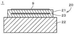
도 1은 본 발명의 하나의 실시형태에 따른 서셉터(1)의 단면도이다. 서셉터(1)는, 반도체 제조 장치에 있어서 사용되는 반도체 제조 장치 부재이다. 서셉터(1)는, 대략 원판형의 반도체 기판(9)(이하, 단순히 「기판(9)」이라고 부른다)을, 도 1 중의 하측으로부터 지지한다. 이하의 설명에서는, 도 1 중의 상측 및 하측을, 단순히 「상측」 및 「하측」이라고 부른다. 또한, 도 1 중의 상하 방향을, 단순히 「상하 방향」이라고 부른다. 도 1 중의 상하 방향은, 서셉터(1)가 반도체 제조 장치에 설치될 때의 실제의 상하 방향과 반드시 일치할 필요는 없다.Fig. 1 is a cross-sectional view of a susceptor (1) according to one embodiment of the present invention. The susceptor (1) is a semiconductor manufacturing device component used in a semiconductor manufacturing device. The susceptor (1) supports a semiconductor substrate (9) (hereinafter, simply referred to as “substrate (9)”) having a substantially circular shape from the lower side in Fig. 1. In the following description, the upper side and the lower side in Fig. 1 are simply referred to as “upper side” and “lower side.” In addition, the upper and lower directions in Fig. 1 are simply referred to as “upper and lower directions.” The upper and lower directions in Fig. 1 do not necessarily have to coincide with the actual upper and lower directions when the susceptor (1) is installed in a semiconductor manufacturing device.
서셉터(1)는, 본체부(21)와, 베이스부(22)와, 전극(23)을 구비한다. 본체부(21)는, 세라믹을 주재료로 하는 대략 판형(예컨대, 대략 원판형)의 기재이다. 본체부(21)의 상측의 주면(즉, 상면) 상에는 기판(9)이 배치된다. 베이스부(22)는, 평면에서 보아 본체부(21)보다 큰 대략 판형(예컨대, 대략 원판형)의 부재이다. 본체부(21)는, 베이스부(22) 상에 부착된다. 도 1에 나타내는 예에서는, 전극(23)은, 본체부(21)의 내부에 배치(즉, 매설)된다. 전극(23)은, 예컨대, 평면에서 보아 소정의 패턴을 그리는 대략 띠형의 부재이다. 전극(23)은, 비교적 높은 융점을 갖는 재료에 의해 형성되는 것이 바람직하다. 본체부(21) 및 전극(23)은, 복수의 재료에 의해 형성되는 복합 소결체이다. 이하의 설명에서는, 본체부(21) 및 전극(23)을 합하여 「복합 소결체(20)」라고도 부른다. 본체부(21) 및 전극(23)의 재료에 대해서는 후술한다. 또한, 전극(23)의 형상은 여러 가지로 변경되어도 좋다. 또한, 전극(23)은, 본체부(21)의 표면에 마련되어도 좋다.The susceptor (1) has a main body (21), a base (22), and an electrode (23). The main body (21) is a roughly plate-shaped (e.g., roughly circular) base material made of ceramic as a main material. A substrate (9) is arranged on the upper main surface (i.e., the upper surface) of the main body (21). The base (22) is a roughly plate-shaped (e.g., roughly circular) member that is larger than the main body (21) when viewed in a plan view. The main body (21) is attached to the base (22). In the example shown in Fig. 1, the electrode (23) is arranged (i.e., embedded) inside the main body (21). The electrode (23) is, for example, a roughly band-shaped member that draws a predetermined pattern when viewed in a plan view. It is preferable that the electrode (23) be formed of a material having a relatively high melting point. The main body (21) and the electrode (23) are composite sintered bodies formed by a plurality of materials. In the following description, the main body (21) and the electrode (23) are collectively referred to as a “composite sintered body (20).” The materials of the main body (21) and the electrode (23) will be described later. In addition, the shape of the electrode (23) may be changed in various ways. In addition, the electrode (23) may be provided on the surface of the main body (21).
도 1에 나타내는 예에서는, 서셉터(1)는, 전극(23)에 직류 전압이 인가됨으로써 발생하는 열에 의해 기판(9)을 가열하는 히터이다. 즉, 전극(23)은, 기판(9)을 가열하는 저항 발열체이다. 서셉터(1)에서는, 전극(23)에 더하여, 쿨롱력 또는 존슨·라벡력을 이용하여 기판(9)을 정전 흡착하는 척(chuck)용 전극이, 본체부(21)의 내부에 마련되어도 좋다. 또는, 전극(23)이 척용 전극으로서 이용되어도 좋다.In the example shown in Fig. 1, the susceptor (1) is a heater that heats the substrate (9) by heat generated by applying a direct current voltage to the electrode (23). That is, the electrode (23) is a resistance heating element that heats the substrate (9). In the susceptor (1), in addition to the electrode (23), a chuck electrode that electrostatically absorbs the substrate (9) by using the Coulomb force or the Johnson-Rahbek force may be provided inside the main body (21). Alternatively, the electrode (23) may be used as a chuck electrode.
본체부(21)는, 예컨대, 산화알루미늄(Al2O3)을 주재료로서 형성된다. 본체부(21)로서는, 산화마그네슘(MgO) 및/또는 마그네슘알루미늄스피넬(MgAl2O4) 등의 첨가 재료가, Al2O3에 첨가되어도 좋다. 본체부(21)에서는, 주재료인 Al2O3의 함유율은, 예컨대 95 질량% 이상이자 100 질량% 이하이며, 바람직하게는 99 질량% 이상이자 100 질량% 이하이다. 본체부(21)에 있어서의 Al2O3의 함유율은, 소망하는 본체부(21)의 재료 특성에 맞추어 조정된다. 또한, 본체부(21)의 주재료는 Al2O3에는 한정되지 않고, 다른 세라믹이어도 좋다.The main body (21) is formed using, for example, aluminum oxide (Al2 O3 ) as the main material. As the main body (21), an additive material such as magnesium oxide (MgO) and/or magnesium aluminum spinel (MgAl2 O4 ) may be added to Al2 O3 . In the main body (21), the content of the main material, Al2 O3 , is, for example, 95 mass% or more and 100 mass% or less, and preferably 99 mass% or more and 100 mass% or less. The content of Al2 O3 in the main body (21) is adjusted according to the desired material properties of the main body (21). In addition, the main material of the main body (21) is not limited to Al2 O3 and may be another ceramic.
전극(23)은, 텅스텐(W)과, 산화지르코늄(ZrO2)을 포함한다. 본 실시형태에서는, 전극(23)은, 실질적으로 W 및 ZrO2에 의해서만 형성되고, W 및 ZrO2 이외의 물질을 실질적으로 포함하지 않는다. 바꾸어 말하면, 본 실시형태에서는, 전극(23)에 있어서의 W 및 ZrO2의 합계 함유율은 100 체적%이다.The electrode (23) contains tungsten (W) and zirconium oxide (ZrO2 ). In the present embodiment, the electrode (23) is substantially formed only of W and ZrO2 and does not substantially contain any material other than W and ZrO2 . In other words, in the present embodiment, the total content of W and ZrO 2in the electrode (23) is 100 volume%.
전극(23)에 있어서의 W 및 ZrO2의 함유율은, 전극(23)과 본체부(21)의 열팽창 계수의 차가 실질적으로 0에 근접하도록 조정된다. 또한, 전극(23)에 있어서, X선 회절법(XRD)에 따라 얻어지는 W와 ZrO2의 메인 피크의 강도비(이하, 「W-ZrO2 피크비」라고도 부른다)는, 예컨대 0.90 이상이자 0.96 미만이며, 전극(23)과 본체부(21)의 열팽창 계수의 차가 실질적으로 0에 근접하도록 조정된다. W-ZrO2 피크비는, W의 메인 피크 강도를, W의 메인 피크 강도와 ZrO2의 메인 피크 강도의 합계에 의해 나눈 값이다.The content of W and ZrO2 in the electrode (23) is adjusted so that the difference in the thermal expansion coefficients of the electrode (23) and the main body (21) approaches substantially 0. In addition, in the electrode (23), the intensity ratio of the main peaks of W and ZrO2 obtained by X-ray diffraction (XRD) (hereinafter, also referred to as “W-ZrO2 peak ratio”) is, for example, 0.90 or more and less than 0.96, and is adjusted so that the difference in the thermal expansion coefficients of the electrode (23) and the main body (21) approaches substantially 0. The W-ZrO2 peak ratio is a value obtained by dividing the main peak intensity of W by the sum of the main peak intensity of W and the main peak intensity of ZrO2 .
W의 열팽창 계수(열팽창률이라고도 한다)는, 40℃ 이상이자 1000℃ 이하의 범위에 있어서, 5.3 ppm/℃(즉, ppm/K)이다. 이하의 설명에 있어서의 열팽창 계수는, 온도 조건의 기재가 없는 경우, 40℃ 이상이자 1000℃ 이하의 범위에 있어서의 열팽창 계수이다. ZrO2의 열팽창 계수는 10.5 ppm/℃이다. Al2O3의 열팽창 계수는 8.0 ppm/℃이다. 본체부(21)의 열팽창 계수는, 주재료인 Al2O3에 첨가되는 첨가 재료의 종류 및 비율에 따라 변화하지만, 예컨대, 8.1 ppm/℃∼8.3 ppm/℃이다.The coefficient of thermal expansion (also called rate of thermal expansion) of W is 5.3 ppm/℃ (i.e., ppm/K) in the range of 40℃ or more and 1000℃ or less. The coefficient of thermal expansion in the following description is the coefficient of thermal expansion in the range of 40℃ or more and 1000℃ or less when temperature conditions are not described. The coefficient of thermal expansion of ZrO2 is 10.5 ppm/℃. The coefficient of thermal expansion of Al2 O3 is 8.0 ppm/℃. The coefficient of thermal expansion of the main body (21) varies depending on the type and ratio of the additive material added to the main material, Al2 O3 , but is, for example, 8.1 ppm/℃ to 8.3 ppm/℃.
전극(23)에 포함되는 W의 열팽창 계수는, 본체부(21)의 열팽창 계수보다 낮다. 전극(23)에 포함되는 ZrO2의 열팽창 계수는, 본체부(21)의 열팽창 계수보다 높다. 40℃ 이상이자 1000℃ 이하의 범위에 있어서의 전극(23)과 본체부(21)의 열팽창 계수의 차의 절대값(이하, 「CTE 차」라고도 부른다)은, 예컨대 0.5 ppm/℃ 이하이며, 바람직하게는 0.2 ppm/℃ 이하이다. CTE 차의 하한은 특별히 한정되지 않지만, 0.0 ppm/℃ 이상이다.The thermal expansion coefficient of W included in the electrode (23) is lower than the thermal expansion coefficient of the main body (21). The thermal expansion coefficient of ZrO2 included in the electrode (23) is higher than the thermal expansion coefficient of the main body (21). The absolute value of the difference in the thermal expansion coefficients between the electrode (23) and the main body (21) in the range of 40°C or more and 1000°C or less (hereinafter, also referred to as “CTE difference”) is, for example, 0.5 ppm/°C or less, and preferably 0.2 ppm/°C or less. The lower limit of the CTE difference is not particularly limited, but is 0.0 ppm/°C or more.
전극(23)의 실온에 있어서의 저항률은, 예컨대 3.5×10⁻⁵ Ω·㎝ 이하이며, 바람직하게는 3.0×10⁻⁵ Ω·㎝ 이하이다. 상기 저항률의 하한은 특별히 한정되지 않지만, 예컨대 1.0×10⁻⁵ Ω·㎝ 이상이다.The resistivity of the electrode (23) at room temperature is, for example, 3.5×10⁻⁵ Ω·cm or less, and preferably 3.0×10⁻⁵ Ω·cm or less. The lower limit of the resistivity is not particularly limited, but is, for example, 1.0×10⁻⁵ Ω·cm or more.
전극(23)은, 후술하는 바와 같이, 본체부(21)와 함께, 또는, 본체부(21)와는 별도로 소성됨으로써 형성되는 소결체이다. 소성 온도는, 예컨대, 1500℃ 이상의 고온이다. 또한, W의 융점은 3410℃이며, ZrO2의 융점은 2715℃이다. W의 소결 입경은, 예컨대, 0.7 ㎛ 이상이자 3.0 ㎛ 이하이며, 바람직하게는, 1.0 ㎛ 이상이자 2.0 ㎛ 이하이다. ZrO2의 소결 입경은, 예컨대, 0.7 ㎛ 이상이자 3.0 ㎛ 이하이며, 바람직하게는, 1.0 ㎛ 이상이자 2.0 ㎛ 이하이다. ZrO2의 소결 입경과 W의 소결 입경의 차의 절대값(이하, 단순히 「소결 입경차」라고도 부른다)은, 예컨대 0.5 ㎛ 이하이며, 바람직하게는 0.25 ㎛ 이하이다. 소결 입경차의 하한은 특별히 한정되지 않지만, 예컨대 0.0 ㎛ 이상이다. W 및 ZrO2의 소결 입경은, SEM(주사형 전자 현미경) 등을 이용한 미구조 관찰에 의해 구하는 것이 가능하다.The electrode (23) is a sintered body formed by being sintered together with the main body (21) or separately from the main body (21), as described later. The sintering temperature is, for example, a high temperature of 1500°C or higher. In addition, the melting point of W is 3410°C and the melting point of ZrO2 is 2715°C. The sintered particle size of W is, for example, 0.7 ㎛ or more and 3.0 ㎛ or less, and preferably, 1.0 ㎛ or more and 2.0 ㎛ or less. The sintered particle size of ZrO2 is, for example, 0.7 ㎛ or more and 3.0 ㎛ or less, and preferably, 1.0 ㎛ or more and 2.0 ㎛ or less. The absolute value of the difference between the sintered grain size of ZrO2 and the sintered grain size of W (hereinafter also simply referred to as the "sintered grain size difference") is, for example, 0.5 ㎛ or less, and preferably 0.25 ㎛ or less. The lower limit of the sintered grain size difference is not particularly limited, but is, for example, 0.0 ㎛ or more. The sintered grain sizes of W and ZrO2 can be obtained by microstructural observation using a SEM (scanning electron microscope), etc.
도 2는 후술하는 실시예 10의 복합 소결체(20)의 단면 SEM 화상이다. 도 2 중의 상하 방향의 중앙부가 흰 빛을 띤 영역은 전극(23)에 대응한다. 또한, 전극(23)의 하측의 검은 띠형의 영역은, 본체부(21)의 제1 부재에 대응하고, 전극(23)의 상측의 검은 띠형의 영역은, 본체부(21)의 제2 부재에 대응한다. 전극(23)에 대응하는 영역 내에 있어서, 가장 색이 옅은 백색의 영역은 W이며, W보다 색이 짙은 회색의 영역은 ZrO2이다. 복합 소결체(20)에서는, 전술한 바와 같이 전극(23)에 있어서의 소결 입경차를 작게 함으로써, 전극(23) 중에 있어서의 W 및 ZrO2의 분산의 균일성이 향상된다.Fig. 2 is a cross-sectional SEM image of a composite sintered body (20) of Example 10 described below. The white region in the central portion in the vertical direction in Fig. 2 corresponds to the electrode (23). In addition, the black band-shaped region on the lower side of the electrode (23) corresponds to the first member of the main body (21), and the black band-shaped region on the upper side of the electrode (23) corresponds to the second member of the main body (21). Within the region corresponding to the electrode (23), the white region with the lightest color is W, and the gray region that is darker than W is ZrO2 . In the composite sintered body (20), by reducing the sintered particle size difference in the electrode (23) as described above, the uniformity of dispersion of W and ZrO2 in the electrode (23) is improved.
다음에, 도 3을 참조하면서 서셉터(1)의 본체부(21) 및 전극(23)(즉, 복합 소결체(20))의 제조 방법의 일례에 대해서 설명한다. 상기 예에서는, 본체부(21)의 하반분의 대략 원판형의 부위(이하, 「제1 부재」라고 부른다)와, 상반분의 대략 원판형의 부위(이하, 「제2 부재」라고 부른다)를 작성하고, 제1 부재와 제2 부재 사이에 전극(23)의 재료를 두고 소성을 행함으로써, 본체부(21) 및 전극(23)을 제조한다.Next, with reference to Fig. 3, an example of a method for manufacturing a main body (21) and an electrode (23) (i.e., a composite sintered body (20)) of a susceptor (1) will be described. In the above example, a substantially disc-shaped portion (hereinafter referred to as a “first member”) in the lower half of the main body (21) and a substantially disc-shaped portion (hereinafter referred to as a “second member”) in the upper half are created, and a material for the electrode (23) is placed between the first member and the second member and sintered, thereby manufacturing the main body (21) and the electrode (23).
상기 제조 방법에서는, 먼저, 본체부(21)의 제1 부재 및 제2 부재를 준비한다(단계 S11). 단계 S11에 있어서 준비되는 제1 부재 및 제2 부재는, 성형체, 가소체 및 소결체 중 어느 상태여도 좋다. 단계 S11에서는, 먼저, 본체부(21)(즉, 제1 부재 및 제2 부재)의 원료 분말을 소정의 조성이 되도록 칭량하고, 상기 원료 분말을 습식 혼합한 뒤에, 일축 가압 성형 등에 의해 소정 형상의 성형체로 성형한다.In the above manufacturing method, first, the first member and the second member of the main body portion (21) are prepared (step S11). The first member and the second member prepared in step S11 may be in any state of a molded body, a plasticized body, and a sintered body. In step S11, first, the raw material powder of the main body portion (21) (i.e., the first member and the second member) is weighed so as to have a predetermined composition, and the raw material powder is wet-mixed, and then formed into a molded body of a predetermined shape by uniaxial press forming or the like.
단계 S11에서는, Al2O3 원료로서, 예컨대, 시판의 고순도 미립 분말이 사용된다. 또한, 본체부(21)에 MgO가 포함되는 경우, MgO 원료로서, 예컨대, 시판의 고순도 미립 분말이 사용된다. 본체부(21)에 MgAl2O4가 포함되는 경우, 예컨대, 전술한 시판의 MgO 분말과 시판의 Al2O3의 고순도 미립 분말을 가열 합성한 것이, MgAl2O4 원료로서 사용된다. 또는, MgAl2O4 원료로서, 시판의 MgAl2O4의 고순도 미립 분말이 사용되어도 좋다. Al2O3 원료, MgO 원료 및 MgAl2O4 원료의 순도 및 평균 입경 등은, 적절하게 결정된다.In step S11, as the Al2 O3 raw material, for example, a commercially available high-purity fine powder is used. In addition, when the main body (21) contains MgO, as the MgO raw material, for example, a commercially available high-purity fine powder is used. In the main body (21) contains MgAl2 O4 , for example, a product obtained by heat-synthesizing the aforementioned commercially available MgO powder and commercially available high-purity fine powder of Al2 O3 is used as the MgAl2 O4 raw material. Alternatively, a commercially available high-purity fine powder of MgAl2 O4 may be used as the MgAl2 O4 raw material. The purity and average particle size, etc. of the Al2 O3 raw material, the MgO raw material, and the MgAl2 O4 raw material are appropriately determined.
단계 S11에서는, 원료 분말의 혼합 조건(예컨대, 혼합 시간, 용매 종류 등)은, 적절하게 결정된다. 상기 용매로서는, 예컨대, 유기 용매 또는 이온 교환수를 사용 가능하다. 또한, 단계 S11에서는, 건식 혼합에 의해 원료 분말이 혼합되어도 좋다.In step S11, mixing conditions (e.g., mixing time, solvent type, etc.) of the raw material powder are appropriately determined. As the solvent, for example, an organic solvent or ion-exchange water can be used. In addition, in step S11, the raw material powder may be mixed by dry mixing.
단계 S11에서는, 성형체의 성형 조건(예컨대, 부여되는 압력 등)은, 적절하게 결정된다. 성형체의 형상이 판형인 경우에는, 원료 분말이 핫 프레스 다이스 등에 충전됨으로써, 성형체가 성형되어도 좋다. 상기 성형체의 성형은, 형상을 유지할 수 있는 것이면, 다른 여러 가지 방법에 따라 행해져도 좋다. 예컨대, 습식 혼합 후의 슬러리를, 유동성이 있는 상태 그대로 몰드에 유입시킨 후에 용매 성분을 제거하여, 소정 형상의 성형체로 하여도 좋다. 또는, 닥터 블레이드 등을 이용한 테이프 성형법에 따라, 소정 계상(計上)의 테이프 성형체가 형성되어도 좋다.In step S11, the molding conditions of the molded body (e.g., pressure to be applied, etc.) are appropriately determined. When the shape of the molded body is a plate, the molded body may be molded by filling the raw material powder into a hot press die, etc. The molding of the molded body may be performed according to various other methods as long as the shape can be maintained. For example, the slurry after wet mixing may be poured into a mold while still fluid and then the solvent component may be removed to form a molded body having a predetermined shape. Alternatively, a tape molded body having a predetermined design may be formed according to a tape molding method using a doctor blade, etc.
단계 S11에 있어서, 제1 부재 및/또는 제2 부재의 가소체 또는 소결체가 준비되는 경우, 전술한 방법에 따라 형성된 성형체가 핫 프레스법 등에 따라 소성되고, 가소체(즉, 가소결체) 또는 소결체가 형성된다. 상기 성형체의 소성에 있어서의 소성 조건(예컨대, 프레스압, 소성 온도, 소성 시간 등)은, 적절하게 결정된다. 또한, 상기 성형체의 소성은, 핫 프레스법 이외의 방법에 따라 행해져도 좋다.In step S11, when a plasticizer or sintered body of the first member and/or the second member is prepared, the molded body formed by the above-described method is fired by a hot press method or the like, and a plasticizer (i.e., a sintered body) or a sintered body is formed. Firing conditions (e.g., press pressure, firing temperature, firing time, etc.) for firing the molded body are appropriately determined. In addition, the firing of the molded body may be performed by a method other than the hot press method.
다음에, 전극(23)의 원료 분말을 소정의 조성이 되도록 칭량하여, 상기 원료 분말을 혼합한 뒤에, 용매 및 바인더 등과 혼련하여, 전극(23)의 전구체인 전극 페이스트를 생성한다(단계 S12). 단계 S12에서는, W 원료 및 ZrO2 원료로서, 예컨대, 시판의 고순도 미립 분말이 사용된다. W 원료 및 ZrO2 원료의 순도 및 평균 입경 등은, 적절하게 결정된다. W 원료 및 ZrO2 원료의 평균 입경은, 예컨대, 1 ㎛ 미만이다.Next, the raw material powder of the electrode (23) is weighed to have a predetermined composition, the raw material powder is mixed, and then kneaded with a solvent, a binder, etc. to produce an electrode paste, which is a precursor of the electrode (23) (step S12). In step S12, commercially available high-purity fine powder is used as the W raw material and the ZrO2 raw material, for example. The purity and average particle size of the W raw material and the ZrO2 raw material are appropriately determined. The average particle size of the W raw material and the ZrO2 raw material is, for example, less than 1 ㎛.
전술한 전극(23)의 원료 분말의 혼합은, 예컨대, 습식 혼합에 의해 행해진다. 원료 분말의 혼합 조건(예컨대, 혼합 시간, 용매 종류 등)은, 적절하게 결정된다. 상기 용매로서는, 예컨대, 유기 용매 또는 이온 교환수를 사용 가능하다. 또한, 단계 S12에서는, 건식 혼합에 의해 원료 분말이 혼합되어도 좋다. 단계 S12에서는, 원료 분말과 함께 혼련되는 상기 용매(예컨대, 유기 용매) 및 바인더의 종류는, 적절하게 결정된다. 또한, 단계 S12는, 단계 S11 이전에, 또는, 단계 S11과 병행하여 행해져도 좋다.The mixing of the raw material powder of the electrode (23) described above is performed by, for example, wet mixing. The mixing conditions of the raw material powder (for example, mixing time, solvent type, etc.) are appropriately determined. As the solvent, for example, an organic solvent or ion-exchange water can be used. In addition, in step S12, the raw material powder may be mixed by dry mixing. In step S12, the types of the solvent (for example, organic solvent) and binder mixed together with the raw material powder are appropriately determined. In addition, step S12 may be performed before step S11 or in parallel with step S11.
단계 S12에서 생성된 전극 페이스트는, 단계 S11에서 형성된 제1 부재의 상면에, 스크린 인쇄 등에 의해 소정의 형상으로 부여된다(단계 S13). 단계 S13에 있어서 성형체인 제1 부재 상에 전극 페이스트가 부여되는 경우, 제1 부재는, 예컨대 테이프 성형체이다. 또한, 단계 S13에서는, 전극 페이스트의 도포는, 스크린 인쇄 이외의 방법에 따라 행해져도 좋다. 제1 부재가 성형체 또는 가소체인 경우, 정확히는, 전극 페이스트는 제1 부재의 전구체의 상면에 부여된다. 그리고, 전극 페이스트가 대기 중 등에 있어서 소정 시간(예컨대, 1시간) 건조된 후, 제1 부재 및 전극 페이스트 위에, 제2 부재가 적층되어 적층체가 형성된다(단계 S14).The electrode paste generated in step S12 is applied to the upper surface of the first member formed in step S11 in a predetermined shape by screen printing or the like (step S13). In the case where the electrode paste is applied to the first member which is a molded body in step S13, the first member is, for example, a tape molded body. Furthermore, in step S13, the application of the electrode paste may be performed by a method other than screen printing. In the case where the first member is a molded body or a plastic body, to be precise, the electrode paste is applied to the upper surface of the precursor of the first member. Then, after the electrode paste is dried in the air or the like for a predetermined time (for example, 1 hour), a second member is laminated on the first member and the electrode paste to form a laminated body (step S14).
또한, 복합 소결체(20)의 제조에서는, 전술한 단계 S13∼S14 대신에, 단계 S12에서 생성된 전극 페이스트를 단체로 소성하여 전극(23)을 형성하고, 상기 전극(23)이 제1 부재의 상면 상에 배치되고, 제1 부재 및 전극(23) 상에 제2 부재가 적층되어도 좋다.In addition, in the manufacture of the composite sintered body (20), instead of the above-described steps S13 to S14, the electrode paste produced in step S12 may be fired as a unit to form an electrode (23), the electrode (23) may be placed on the upper surface of the first member, and a second member may be laminated on the first member and the electrode (23).
그 후, 단계 S14에서 형성된 적층체가, 핫 프레스법 등에 따라 소성됨으로써, 제1 부재와 제2 부재가 일체화하여, 본체부(21) 및 전극(23)(즉, 복합 소결체(20))이 형성된다(단계 S15). 단계 S15에 있어서의 소성 조건(예컨대, 프레스압, 소성 온도, 소성 시간 등)은, 적절하게 결정된다. 단계 S15에 있어서의 소성 온도(즉, 가소성 시의 최고 온도)는, 예컨대, 1550℃ 이상이자 1650℃ 이하이다. 단계 S15에 있어서의 적층체의 소성은, 핫 프레스법 이외의 방법에 따라 행해져도 좋다.Thereafter, the laminate formed in step S14 is fired by a hot press method or the like, whereby the first member and the second member are integrated to form a main body (21) and an electrode (23) (i.e., a composite sintered body (20)) (step S15). The firing conditions (e.g., press pressure, firing temperature, firing time, etc.) in step S15 are appropriately determined. The firing temperature (i.e., the maximum temperature during firing) in step S15 is, for example, 1550°C or higher and 1650°C or lower. The firing of the laminate in step S15 may be performed by a method other than the hot press method.
다음에, 표 1∼표 3을 참조하면서, 본 발명에 따른 복합 소결체(20)(즉, 본체부(21) 및 전극(23))의 실시예 1∼13 및 복합 소결체(20)와 비교하기 위한 비교예 1∼4의 복합 소결체에 대해서 설명한다. 실시예 1∼13에서는, 전극(23)이 W 및 ZrO2를 포함하는 데 대하여, 비교예 1∼4에서는, 전극(23)은 ZrO2를 포함하지 않고, 비교예 1∼2에서는, 전극(23)은 W도 포함하지 않는다.Next, with reference to Tables 1 to 3, the composite sintered bodies (20) (i.e., the main body (21) and the electrode (23)) of Examples 1 to 13 according to the present invention and the composite sintered bodies of Comparative Examples 1 to 4 for comparison with the composite sintered bodies (20) will be described. In Examples 1 to 13, the electrode (23) includes W and ZrO2 , whereas in Comparative Examples 1 to 4, the electrode (23) does not include ZrO2 , and in Comparative Examples 1 to 2, the electrode (23) does not include W either.


실시예 1∼13 및 비교예 1∼4에서는, 본체부(21) 및 전극(23)의 제조는, 전술한 단계 S11∼S15에 따라 행하였다. 실시예 1∼13 및 비교예 1∼4에서는, 단계 S11에 있어서의 Al2O3에의 첨가제로서 MgO를 사용하였다. Al2O3 원료로서는, 시판의 Al2O3의 고순도 미립 분말(순도 99.99% 이상, 평균 입경 0.5 ㎛)을 사용하였다. 또한, MgO 원료로서, 시판의 MgO의 고순도 미립 분말(순도 99.9% 이상, 평균 입경 1 ㎛ 이하)을 사용하였다.In Examples 1 to 13 and Comparative Examples 1 to 4, the main body (21) and the electrode (23) were manufactured according to the steps S11 to S15 described above. In Examples 1 to 13 and Comparative Examples 1 to 4, MgO was used as an additive to Al2 O3 in step S11. As the Al2 O3 raw material, commercially available high-purity fine particle powder (purity 99.99% or more, average particle size 0.5 µm) of Al2 O3 was used. In addition, as the MgO raw material, commercially available high-purity fine particle powder of MgO (purity 99.9% or more,
실시예 1∼13 및 비교예 1∼4에서는, 단계 S11에 있어서의 원료 분말의 습식 혼합은, 알루미나 볼 및 폴리 포트를 이용한 볼밀에 의해 행하였다. 혼합 시간은 20시간이며, 사용한 용매는 유기 용매이다. 습식 혼합에 의해 생성된 슬러리를, 건조시킨 후에 체로 침으로써, 본체부(21)의 원료 분말을 얻었다. 또한, 단계 S11에 있어서의 성형체의 성형은, 일축 가압 성형용의 금형에 원료 분말을 충전함으로써 행하였다. 상기 일축 가압 성형 시의 압력은, 100 ㎏f/㎠이다. 얻어진 성형체는, 직경 50 ㎜, 두께 10 ㎜의 대략 원판형이다. 또한, 실시예 1∼13 및 비교예 1∼4에서는, 실제의 복합 소결체(20)보다 작은 시험체를 제작, 사용한다.In Examples 1 to 13 and Comparative Examples 1 to 4, the wet mixing of the raw material powder in Step S11 was performed by a ball mill using an alumina ball and a poly pot. The mixing time was 20 hours, and the solvent used was an organic solvent. The slurry produced by the wet mixing was dried and then sieved to obtain the raw material powder of the main body (21). In addition, the molding of the molded body in Step S11 was performed by filling the raw material powder into a mold for uniaxial pressure molding. The pressure during the uniaxial pressure molding was 100 kgf/cm2. The obtained molded body was approximately a disk shape with a diameter of 50 mm and a thickness of 10 mm. In addition, in Examples 1 to 13 and Comparative Examples 1 to 4, a test body smaller than an actual composite sintered body (20) was produced and used.
실시예 1∼13 및 비교예 1∼4에서는, 단계 S12에 있어서, W 원료 및 ZrO2 원료로서, 시판의 W의 고순도 미립 분말(순도 99.9% 이상, 평균 입경 0.8 ㎛) 및 ZrO2의 고순도 미립 분말(순도 99% 이상, 평균 입경 0.4 ㎛)을 사용하였다.In Examples 1 to 13 and Comparative Examples 1 to4 , in step S12, commercially available high-purity fine powder of W (purity 99.9% or more, average particle size 0.8 µm) and high-purity fine powder of ZrO2 (purity 99% or more, average particle size 0.4 µm) were used as the W raw material and the ZrO 2 raw material.
실시예 1∼13 및 비교예 1∼4에서는, 단계 S12에 있어서의 원료 분말의 습식 혼합은, 알루미나 볼 및 폴리 포트를 이용한 볼밀에 의해 행하였다. 혼합 시간은 20시간이며, 사용한 용매는 유기 용매이다. 습식 혼합에 의해 생성된 슬러리를, 건조시킨 후에 체에 침으로써, 전극(23)의 원료 분말을 얻었다. 또한, 전극 페이스트의 생성 시에 상기 원료 분말과 혼련되는 용매 및 바인더로서, 부틸카르비톨 및 폴리메타크릴산-n-부틸을 사용하였다.In Examples 1 to 13 and Comparative Examples 1 to 4, wet mixing of the raw material powder in step S12 was performed by a ball mill using an alumina ball and a poly pot. The mixing time was 20 hours, and the solvent used was an organic solvent. The slurry produced by wet mixing was dried and then sieved to obtain the raw material powder of the electrode (23). In addition, butyl carbitol and polymethacrylic acid-n-butyl were used as a solvent and binder mixed with the raw material powder at the time of producing the electrode paste.
실시예 1∼13 및 비교예 1∼4에서는, 단계 S13에 있어서의 전극 페이스트의 도포는, 스크린 인쇄에 의해 행해진다. 제1 부재 상에 도포된 전극 페이스트의 형상은, 폭 5 ㎜, 길이 15 ㎜의 대략 장방형이다. 전극 페이스트의 두께는, 60 ㎛∼70 ㎛이다.In Examples 1 to 13 and Comparative Examples 1 to 4, the application of the electrode paste in step S13 is performed by screen printing. The shape of the electrode paste applied on the first member is approximately rectangular with a width of 5 mm and a length of 15 mm. The thickness of the electrode paste is 60 µm to 70 µm.
실시예 1∼13 및 비교예 1∼4에서는, 단계 S13, S14에 있어서, 제1 부재 및 제2 부재로서, 성형체, 가소체 또는 소결체 중 어느 하나를 사용하였다. 제1 부재 또는 제2 부재로서 성형체를 사용하는 경우, 전술한 단계 S11에서 얻어진 것을 사용한다.In Examples 1 to 13 and Comparative Examples 1 to 4, in steps S13 and S14, either a molded body, a plasticized body or a sintered body was used as the first member and the second member. When a molded body is used as the first member or the second member, the one obtained in the above-described step S11 is used.
제1 부재 또는 제2 부재로서 가소체를 사용하는 경우, 전술한 성형체와 동일한 방법으로 성형체를 제작하고, 열처리를 하여 제작하였다. 소성 온도(즉, 열처리 시의 최고 온도)는, 800℃ 이상이자 1000℃ 이하이다. 그리고, 얻어진 가소체를, 직경 50 ㎜, 두께 5 ㎜의 대략 원판형으로 가공하였다. 또한, 가소체는, 원료 분말에 유기 바인더 등의 성형 조제를 첨가하여 보형(保形)한 성형체를 가열 처리하여 제작하는 등, 기존의 방법을 적절하게 채용하면 좋고, 그 제작 조건은 상기에 한정되는 것이 아니다.When a plasticizer is used as the first or second member, a molded body is manufactured by the same method as the molded body described above, and is manufactured by heat treatment. The sintering temperature (i.e., the highest temperature during heat treatment) is 800°C or higher and 1000°C or lower. Then, the obtained plasticizer is processed into an approximately circular plate having a diameter of 50 mm and a thickness of 5 mm. In addition, the plasticizer may be manufactured by appropriately employing a conventional method, such as adding a molding aid such as an organic binder to raw material powder and heat-treating the molded body to maintain its shape, and the manufacturing conditions are not limited to the above.
제1 부재 또는 제2 부재로서 소결체를 사용하는 경우, 핫 프레스법에 따라 성형체의 소성을 행하였다. 구체적으로는, 전술한 성형체를 핫 프레스용의 흑연형에 수용하고, 핫 프레스로에 셋트하여 소성을 행하였다. 가소성 시의 프레스압은, 200 ㎏f/㎠이다. 소성 온도(즉, 가소성 시의 최고 온도)는, 1550℃ 이상이자 1650℃ 이하이다. 소성 시간은, 8시간이다. 승온 속도 및 강온 속도는, 300℃/h이다. 소성 분위기는, 1000℃까지의 승온 시는 진공 처리를 행하고, 그 후는 질소 가스를 도입하였다. 질소 가스의 도입 후의 가스 압력은, 약 1.5 atm(약 0.152 ㎫)으로 유지하였다. 강온 시는, 1400℃에서 온도 제어를 정지하여, 노냉하였다. 그리고, 얻어진 소결체를, 직경 50 ㎜, 두께 5 ㎜의 대략 원판형으로 가공하였다.When a sintered body is used as the first or second member, the molded body is sintered according to the hot press method. Specifically, the above-mentioned molded body is accommodated in a graphite mold for hot pressing, set in a hot press, and sintered. The press pressure during sintering is 200 kgf/cm2. The sintering temperature (i.e., the maximum temperature during sintering) is 1550°C or higher and 1650°C or lower. The sintering time is 8 hours. The heating rate and cooling rate are 300°C/h. The sintering atmosphere is vacuum treatment when the temperature is raised to 1000°C, and nitrogen gas is introduced thereafter. The gas pressure after the introduction of nitrogen gas is maintained at about 1.5 atm (about 0.152 MPa). When the temperature is lowered, temperature control is stopped at 1400°C and the furnace is cooled. Then, the obtained sintered body was processed into an approximately circular plate shape with a diameter of 50 mm and a thickness of 5 mm.
실시예 1∼13 및 비교예 1∼4에서는, 단계 S15에 있어서의 적층 후의 소성은, 핫 프레스법에 따라 행하였다. 구체적으로는, 전술한 적층체를 핫 프레스용의 흑연형에 수용하고, 핫 프레스로에 셋트하여 소성을 행하였다. 소성 시의 프레스압은, 200 ㎏f/㎠이다. 소성 온도(즉, 소성 시의 최고 온도)는, 1550℃ 이상이자 1650℃ 이하이다. 소성 시간은, 4시간∼8시간이다. 승온 속도 및 강온 속도는, 300℃/h이다. 소성 분위기는, 질소 가스 분위기이다.In Examples 1 to 13 and Comparative Examples 1 to 4, the firing after lamination in step S15 was performed according to the hot press method. Specifically, the above-described laminate was accommodated in a graphite mold for hot pressing, set in a hot press, and fired. The press pressure during firing was 200 kgf/cm2. The firing temperature (i.e., the maximum temperature during firing) was 1550°C or higher and 1650°C or lower. The firing time was 4 to 8 hours. The heating rate and cooling rate were 300°C/h. The firing atmosphere was a nitrogen gas atmosphere.
표 1∼표 3에 있어서, 기재(즉, 본체부(21)의 제1 부재 및 제2 부재)의 열팽창 계수는, 본체부(21)로부터 추출한 소결체 시료를 이용하여, JIS-R1618에 준한 방법에 따라, 40℃∼1000℃의 범위에서 측정하였다. 또한, 실시예 1∼13의 전극(23)의 열팽창 계수는, W 및 ZrO2의 각각 단체의 열팽창 계수와, 전극(23)에 있어서의 W 및 ZrO2의 함유율에 기초하여 구하였다. 구체적으로는, W 단체의 열팽창 계수와 전극(23)에 있어서의 W의 함유율(체적%)의 곱 및 ZrO2 단체의 열팽창 계수와 전극(23)에 있어서의 ZrO2의 함유율(체적%)의 곱의 합계를, 전극(23)의 열팽창 계수로 하였다. W 및 ZrO2의 각각 단체의 열팽창 계수는, 단계 S12에서 사용한 시판의 W 분말 및 ZrO2 분말을 단계 S11과 동일한 조건으로 핫 프레스 소성하여 제작된 벌크재를 이용하여, JIS-R1618에 준한 방법에 따라, 40℃∼1000℃의 범위에서 측정하였다. 비교예 1∼4에 있어서도 동일하다. CTE 차는, 전술한 바와 같이, 전극(23)의 열팽창 계수와 본체부(21)의 열팽창 계수의 차의 절대값이다.In Tables 1 to 3, the thermal expansion coefficients of the substrates (i.e., the first member and the second member of the main body (21)) were measured in the range of 40°C to 1000°C according to a method compliant with JIS-R1618 using sintered body samples extracted from the main body (21). In addition, the thermal expansion coefficients of the electrodes (23) of Examples 1 to 13 were obtained based on the thermal expansion coefficients of each of the simplexes of W and ZrO2 and the content ratios of W and ZrO2 in the electrode (23). Specifically, the sum of the product of the thermal expansion coefficient of simplex W and the content ratio (vol%) of W in the electrode (23) and the product of the thermal expansion coefficient of simplex ZrO2 and the content ratio (vol%) of ZrO2 in the electrode (23) was taken as the thermal expansion coefficient of the electrode (23). The thermal expansion coefficients of each group of W and ZrO2 were measured in the range of 40°C to 1000°C according to a method compliant with JIS-R1618, using bulk materials produced by hot press firing the commercially available W powder and ZrO2 powder used in step S12 under the same conditions as in step S11. The same applies to Comparative Examples 1 to 4. The CTE difference is, as described above, the absolute value of the difference between the thermal expansion coefficient of the electrode (23) and the thermal expansion coefficient of the main body (21).
전극(23)에 있어서의 W-ZrO2 피크비는, 전술한 XRD에 따라 측정된 W와 ZrO2의 메인 피크의 강도비이다. W-ZrO2 피크비는, W의 메인 피크인 (110)면의 강도를 I1로 하고, ZrO2의 메인 피크인 (111)면의 강도를 I2로 하여, I1/(I1+I2)를 산출하였다. 또한, XRD에 따른 측정 시에는, 제2 부재를 제거하여, 제1 부재 상에 위치하는 전극(23)을 노출시켜 측정을 행하였다. X선 회절 장치로서, 봉입관식 X선 회절 장치(브루커·에이엑스에스 가부시키가이샤 제조 D8-ADVANCE)를 사용하였다. 측정 조건은 CuKα, 40 ㎸, 40 ㎃, 2θ=10∼70°, 스텝 폭을 0.002°로 하였다.The W-ZrO2 peak ratio in the electrode (23) is the intensity ratio of the main peaks of W and ZrO2 measured by the XRD described above. The W-ZrO2 peak ratio was calculated by taking the intensity of the (110) plane, which is the main peak of W, as I1, and the intensity of the (111) plane, which is the main peak of ZrO2 , as I2, and calculating I1/(I1+I2). In addition, at the time of measurement by XRD, the second member was removed, exposing the electrode (23) positioned on the first member, and performing the measurement. As an X-ray diffraction device, a sealed tube type X-ray diffraction device (D8-ADVANCE manufactured by Bruker AXS Co., Ltd.) was used. The measurement conditions were CuKα, 40 kV, 40 mA, 2θ=10∼70°, and a step width of 0.002°.
전극(23)에 있어서의 W의 소결 입경은, SEM을 이용한 미구조 관찰에 의해 구하였다. 구체적으로는, 시험편의 일면을 경면형으로 연마 마무리하고, 전극(23)의 연마면을 SEM을 이용하여 관찰한다. 그리고, 소정수(예컨대, 수십 개)의 소결 입자의 각각의 장직경 및 단직경의 평균인 평균 직경을 산출하고, 상기 소정수의 소결 입자의 평균 직경의 산술 평균을 W의 소결 입경으로 하였다. 전극(23)에 있어서의 ZrO2의 소결 입경에 대해서도 동일하다.The sintered particle size of W in the electrode (23) was obtained by microstructural observation using SEM. Specifically, one surface of the test piece was polished to a mirror-like finish, and the polished surface of the electrode (23) was observed using SEM. Then, the average diameter, which is the average of the major diameter and minor diameter of each of a predetermined number (e.g., several dozen) of sintered particles, was calculated, and the arithmetic average of the average diameters of the predetermined number of sintered particles was taken as the sintered particle size of W. The same applies to the sintered particle size of ZrO2 in the electrode (23).
전극(23)의 저항률은, 다음과 같이 구하였다. 먼저, 단계 S15에서 형성된 복합 소결체(20)로부터, 폭, 길이 및 두께가 각각 9 ㎜의 대략 직방체형의 시험편을 절취한다. 시험편은, 중앙부에 폭 5 ㎜, 길이 9 ㎜의 전극(23)이 내장되도록 절취된다. 시험편의 양 끝면에는, 폭 5 ㎜의 전극(23)이 노출된다. 전극(23)의 단면적(S(㎠))은, 시험편의 끝면에 있어서의 전극(23)의 폭 및 길이를 광학 현미경에 의해 측정하여 구하였다. 또한, 전극(23)이 노출되는 시험편의 양 끝면간의 거리를 버니어 캘리퍼스에 의해 측정하여, 전극(23)의 길이(L(㎝))로 하였다. 저항 측정용의 회로는, 전극(23)의 양 끝면에 도전성 페이스트를 도포한 뒤에 리드선을 접속하여 구성하였다. 그리고, 대기 중, 실온에 있어서, 전극(23)에 미소 전류(I(㎃))를 0 ㎃∼150 ㎃의 범위에서 부여하고, 그때에 발생하는 미소 전압값(V(㎷))을 측정하여, 전극(23)의 저항(R(Ω))을 R=V/I에 따라 구하였다. 그 후, 전극(23)의 저항률(ρ(Ω·㎝))을, ρ=R×S/L에 따라 구하였다.The resistivity of the electrode (23) was obtained as follows. First, a roughly rectangular test piece having a width, length, and thickness of 9 mm each was cut from the composite sintered body (20) formed in step S15. The test piece was cut so that an electrode (23) having a width of 5 mm and a length of 9 mm was embedded in the center. An electrode (23) having a width of 5 mm was exposed at both end surfaces of the test piece. The cross-sectional area (S (cm2)) of the electrode (23) was obtained by measuring the width and length of the electrode (23) at the end surfaces of the test piece using an optical microscope. In addition, the distance between the both end surfaces of the test piece where the electrode (23) was exposed was measured using a vernier caliper, and was taken as the length (L (cm)) of the electrode (23). A circuit for measuring resistance was configured by applying conductive paste to both end surfaces of the electrode (23) and then connecting a lead wire. And, in the air, at room temperature, a microcurrent (I (㎃)) was applied to the electrode (23) in the range of 0 ㎃ to 150 ㎃, and the microvoltage value (V (㎷)) generated at that time was measured, and the resistance (R (Ω)) of the electrode (23) was obtained according to R = V/I. Thereafter, the resistivity (ρ (Ω cm)) of the electrode (23) was obtained according to ρ = R × S/L.
전극(23)의 조성은, 다음과 같이 구하였다. 먼저, 시험편의 상반분 또는 하반분을 제거하여 전극(23)의 상면 또는 하면을 노출시키고, 노출된 전극(23)을 연마하였다. 그리고, 전극(23)의 연마면에 있어서, 전술한 X선 회절 장치에 의해 상기 측정 조건으로 결정상을 동정하였다.The composition of the electrode (23) was obtained as follows. First, the upper or lower half of the test piece was removed to expose the upper or lower surface of the electrode (23), and the exposed electrode (23) was polished. Then, the crystal phase was identified on the polished surface of the electrode (23) using the above-described X-ray diffraction device under the above-described measurement conditions.
실시예 1∼13 및 비교예 1∼4에서는, 본체부(21)의 주재료는 Al2O3이며, 첨가물은 MgO이다. 또한, 전술한 바와 같이, 실시예 1∼13에서는, 전극(23)은 W 및 ZrO2에 의해 형성된다. 바꾸어 말하면, 실시예 1∼13에서는, 전극(23)에 있어서의 W 및 ZrO2의 합계 함유율은, 100 체적%이다. 한편, 비교예 1에서는, 전극(23)은 탄화텅스텐(WC)에 의해서만 형성되고, W 및 ZrO2를 포함하지 않는다. 비교예 2에서는, 전극(23)은, WC 및 Al2O3에 의해 형성되고, W 및 ZrO2를 포함하지 않는다. 비교예 3에서는, 전극(23)은, W에 의해서만 형성되고, ZrO2를 포함하지 않는다. 비교예 4에서는, 전극(23)은, W 및 Al2O3에 의해 형성되고, ZrO2를 포함하지 않는다.In Examples 1 to 13 and Comparative Examples 1 to 4, the main material of the main body (21) is Al2 O3 , and the additive is MgO. In addition, as described above, in Examples 1 to 13, the electrode (23) is formed of W and ZrO2 . In other words, in Examples 1 to 13, the total content of W and ZrO2 in the electrode (23) is 100 volume%. On the other hand, in Comparative Example 1, the electrode (23) is formed only of tungsten carbide (WC) and does not contain W and ZrO2 . In Comparative Example 2, the electrode (23) is formed of WC and Al2 O3 and does not contain W and ZrO2 . In Comparative Example 3, the electrode (23) is formed only of W and does not contain ZrO2 . In Comparative Example 4, the electrode (23) is formed by W and Al2 O3 and does not contain ZrO2 .
실시예 1에서는, 단계 S13에 있어서 전극 페이스트가 부여되는 본체부(21)의 제1 부재는 소결체이다. 또한, 단계 S14에 있어서 제1 부재 상에 적층되는 제2 부재는 성형체이다. 본체부(21)의 MgO의 함유율은 0.025 질량%이며, 본체부(21)의 열팽창 계수는 8.1 ppm/℃이다. 또한, 본체부(21)의 MgO 이외의 잔부는 Al2O3이다(다른 실시예 및 비교예에 있어서도 동일). 전극(23)에 있어서의 W의 함유율은 46.2 체적%이며, ZrO2의 함유율은 53.8 체적%이다. 전극(23)의 열팽창 계수는 8.1 ppm/℃이다. 복합 소결체(20)의 소성 온도(즉, 소성 시의 최고 온도)는 1600℃이다.In Example 1, the first member of the main body portion (21) to which the electrode paste is applied in step S13 is a sintered body. Furthermore, the second member laminated on the first member in step S14 is a molded body. The content of MgO in the main body portion (21) is 0.025 mass%, and the thermal expansion coefficient of the main body portion (21) is 8.1 ppm/°C. Furthermore, the remainder other than MgO in the main body portion (21) is Al2 O3 (the same applies to other examples and comparative examples). The content of W in the electrode (23) is 46.2 volume%, and the content of ZrO2 is 53.8 volume%. The thermal expansion coefficient of the electrode (23) is 8.1 ppm/°C. The sintering temperature (i.e., the maximum temperature during sintering) of the composite sintered body (20) is 1600°C.
실시예 1에서는, CTE 차(즉, 40℃ 이상이자 1000℃ 이하의 범위에 있어서의 전극(23)과 본체부(21)의 열팽창 계수의 차의 절대값)는 0.0 ppm/℃였다. W-ZrO2 피크비는 0.94였다. W 및 ZrO2의 소결 입경은 각각, 1.17 ㎛ 및 1.27 ㎛이며, 소결 입경차(즉, ZrO2의 소결 입경과 W의 소결 입경의 차의 절대값)는 0.10 ㎛였다. 전극(23)의 저항률은, 2.9×10⁻⁵ Ω·㎝였다. 전극(23)의 조성은, W 및 ZrO2였다.In Example 1, the CTE difference (i.e., the absolute value of the difference in thermal expansion coefficients between the electrode (23) and the main body (21) in the range of 40°C or more and 1000°C or less) was 0.0 ppm/°C. The W-ZrO2 peak ratio was 0.94. The sintered grain sizes of W and ZrO2 were 1.17 μm and 1.27 μm, respectively, and the sintered grain size difference (i.e., the absolute value of the difference between the sintered grain sizes of ZrO2 and W) was 0.10 μm. The resistivity of the electrode (23) was 2.9×10⁻⁵ Ω·cm. The composition of the electrode (23) was W and ZrO2 .
실시예 1에서는, CTE 차가 0.5 ppm/℃ 이하로 작기 때문에, 본체부(21)와 전극(23)의 열팽창 계수의 차에 기인하는 본체부(21)의 크랙이나 전극(23)의 박리는 생기지 않았다. 또한, 전극(23)의 저항률은 3.5×10⁻⁵ Ω·㎝ 이하로 작았다. W-ZrO2 피크비는, 0.90 이상이자 0.96 미만으로 적합한 범위이며, 이에 의해, 전술한 열팽창 계수의 차의 저감 및 저항률의 증대 억제를 적합하게 양립할 수 있다. ZrO2의 소결 입경은, 0.7 ㎛ 이상이자 3.0 ㎛ 이하로 적합한 범위이며, 소결 입경차(즉, W의 소결 입경과 ZrO2의 소결 입경의 차)는 0.5 ㎛ 이하로 작았다. 이 때문에, 전극(23) 중에 있어서, W 및 ZrO2의 대략 균등한 분산이 실현되었다.In Example 1, since the CTE difference was small at 0.5 ppm/℃ or less, cracks in the main body (21) and peeling of the electrode (23) due to the difference in the thermal expansion coefficients of the main body (21) and the electrode (23) did not occur. In addition, the resistivity of the electrode (23) was small at 3.5×10⁻⁵ Ω·cm or less. The W-ZrO2 peak ratio was a suitable range of 0.90 or more and less than 0.96, thereby suitably achieving both the reduction in the difference in the thermal expansion coefficients described above and the suppression of the increase in the resistivity. The sintered grain size of ZrO2 was a suitable range of 0.7 ㎛ or more and 3.0 ㎛ or less, and the sintered grain size difference (i.e., the difference between the sintered grain size of W and the sintered grain size of ZrO2 ) was small at 0.5 ㎛ or less. For this reason, approximately equal distribution of W and ZrO2 was realized among the electrodes (23).
실시예 2에서는, 본체부(21)에 있어서의 MgO의 함유율이 1.0 질량%이며, 본체부(21)의 열팽창 계수는 8.2 ppm/℃이다. 전극(23)에 있어서의 W의 함유율은 44.2 체적%이며, ZrO2의 함유율은 55.8 체적%이다. 전극(23)의 열팽창 계수는 8.2 ppm/℃이다. 그 외의 조건은, 실시예 1과 동일하다.In Example 2, the content of MgO in the main body (21) is 1.0 mass%, and the thermal expansion coefficient of the main body (21) is 8.2 ppm/°C. The content of W in the electrode (23) is 44.2 volume%, and the content of ZrO2 is 55.8 volume%. The thermal expansion coefficient of the electrode (23) is 8.2 ppm/°C. Other conditions are the same as in Example 1.
실시예 2에서는, CTE 차는 0.0 ppm/℃였다. W-ZrO2 피크비는 0.93이었다. W 및 ZrO2의 소결 입경은 각각, 1.15 ㎛ 및 1.32 ㎛이며, 소결 입경차는 0.17 ㎛였다. 전극(23)의 저항률은, 3.0×10⁻⁵ Ω·㎝였다. 전극(23)의 조성은, W 및 ZrO2였다.In Example 2, the CTE difference was 0.0 ppm/℃. The W-ZrO2 peak ratio was 0.93. The sintered particle sizes of W and ZrO2 were 1.15 ㎛ and 1.32 ㎛, respectively, and the sintered particle size difference was 0.17 ㎛. The resistivity of the electrode (23) was 3.0×10⁻⁵ Ω·cm. The composition of the electrode (23) was W and ZrO2 .
실시예 2에서는, CTE 차가 작기 때문에, 본체부(21)와 전극(23)의 열팽창 계수의 차에 기인하는 본체부(21)의 크랙이나 전극(23)의 박리는 생기지 않았다. 또한, 전극(23)의 저항률은 작았다. 또한, ZrO2의 소결 입경이 적합한 범위이며, 소결 입경차가 작기 때문에, 전극(23) 중에 있어서, W 및 ZrO2의 대략 균등한 분산이 실현되었다.In Example 2, since the CTE difference was small, cracks in the main body (21) and peeling of the electrode (23) due to the difference in the coefficients of thermal expansion between the main body (21) and the electrode (23) did not occur. In addition, the resistivity of the electrode (23) was small. In addition, since the sintered particle size of ZrO2 was within a suitable range and the difference in the sintered particle size was small, approximately equal dispersion of W and ZrO2 was realized in the electrode (23).
실시예 3에서는, 본체부(21)에 있어서의 MgO의 함유율이 5.0 질량%이며, 본체부(21)의 열팽창 계수는 8.3 ppm/℃이다. 전극(23)에 있어서의 W의 함유율은 42.3 체적%이며, ZrO2의 함유율은 57.7 체적%이다. 전극(23)의 열팽창 계수는 8.3 ppm/℃이다. 그 외의 조건은, 실시예 1과 동일하다.In Example 3, the content of MgO in the main body (21) is 5.0 mass%, and the thermal expansion coefficient of the main body (21) is 8.3 ppm/°C. The content of W in the electrode (23) is 42.3 volume%, and the content of ZrO2 is 57.7 volume%. The thermal expansion coefficient of the electrode (23) is 8.3 ppm/°C. Other conditions are the same as in Example 1.
실시예 3에서는, CTE 차는 0.0 ppm/℃였다. W-ZrO2 피크비는 0.91이었다. W 및 ZrO2의 소결 입경은 각각, 1.14 ㎛ 및 1.36 ㎛이며, 소결 입경차는 0.22 ㎛였다. 전극(23)의 저항률은, 3.2×10⁻⁵ Ω·㎝였다. 전극(23)의 조성은, W 및 ZrO2였다.In Example 3, the CTE difference was 0.0 ppm/℃. The W-ZrO2 peak ratio was 0.91. The sintered particle sizes of W and ZrO2 were 1.14 ㎛ and 1.36 ㎛, respectively, and the sintered particle size difference was 0.22 ㎛. The resistivity of the electrode (23) was 3.2×10⁻⁵ Ω·cm. The composition of the electrode (23) was W and ZrO2 .
실시예 3에서는, CTE 차가 작기 때문에, 본체부(21)와 전극(23)의 열팽창 계수의 차에 기인하는 본체부(21)의 크랙이나 전극(23)의 박리는 생기지 않았다. 또한, 전극(23)의 저항률은 작았다. 또한, ZrO2의 소결 입경이 적합한 범위이며, 소결 입경차가 작기 때문에, 전극(23) 중에 있어서, W 및 ZrO2의 대략 균등한 분산이 실현되었다.In Example 3, since the CTE difference was small, cracks in the main body (21) and peeling of the electrode (23) due to the difference in the coefficients of thermal expansion between the main body (21) and the electrode (23) did not occur. In addition, the resistivity of the electrode (23) was small. In addition, since the sintered particle size of ZrO2 was within a suitable range and the difference in the sintered particle size was small, approximately equal dispersion of W and ZrO2 was realized in the electrode (23).
실시예 1∼3에 주목하면, 본체부(21)의 열팽창 계수를 상기 범위(즉, 8.1 ppm/℃∼8.3 ppm/℃)로 변경한 경우라도, CTE 차를 0.0 ppm/℃로 할 수 있고, 본체부(21)의 크랙이나 전극(23)의 박리를 방지할 수 있었다. 또한, 전극(23)의 저항률의 증대를 억제할 수 있었다.With reference to Examples 1 to 3, even when the coefficient of thermal expansion of the main body (21) was changed to the above range (i.e., 8.1 ppm/°C to 8.3 ppm/°C), the CTE difference could be made 0.0 ppm/°C, and cracks in the main body (21) and peeling of the electrode (23) could be prevented. In addition, an increase in the resistivity of the electrode (23) could be suppressed.
실시예 4에서는, 전극(23)에 있어서의 W의 함유율은 55.8 체적%이며, ZrO2의 함유율은 44.2 체적%이다. 전극(23)의 열팽창 계수는 7.6 ppm/℃이다. 그 외의 조건은, 실시예 1과 동일하다.In Example 4, the content of W in the electrode (23) is 55.8 volume%, and the content of ZrO2 is 44.2 volume%. The thermal expansion coefficient of the electrode (23) is 7.6 ppm/℃. Other conditions are the same as in Example 1.
실시예 4에서는, CTE 차는 0.5 ppm/℃였다. W-ZrO2 피크비는 0.96이었다. W 및 ZrO2의 소결 입경은 각각, 1.20 ㎛ 및 1.11 ㎛이며, 소결 입경차는 0.09 ㎛였다. 전극(23)의 저항률은, 2.0×10⁻⁵ Ω·㎝였다. 전극(23)의 조성은, W 및 ZrO2였다.In Example 4, the CTE difference was 0.5 ppm/℃. The W-ZrO2 peak ratio was 0.96. The sintered particle sizes of W and ZrO2 were 1.20 ㎛ and 1.11 ㎛, respectively, and the sintered particle size difference was 0.09 ㎛. The resistivity of the electrode (23) was 2.0×10⁻⁵ Ω·cm. The composition of the electrode (23) was W and ZrO2 .
실시예 4에서는, CTE 차가 작기 때문에(즉, 0.5 ppm/℃ 이하이기 때문에), 본체부(21)와 전극(23)의 열팽창 계수의 차에 기인하는 본체부(21)의 크랙이나 전극(23)의 박리는 생기지 않았다. 또한, 전극(23)의 저항률은 작았다. 또한, ZrO2의 소결 입경이 적합한 범위이며, 소결 입경차가 작기 때문에, 전극(23) 중에 있어서, W 및 ZrO2의 대략 균등한 분산이 실현되었다.In Example 4, since the CTE difference was small (i.e., 0.5 ppm/℃ or less), cracks in the main body (21) and peeling of the electrode (23) due to the difference in thermal expansion coefficients between the main body (21) and the electrode (23) did not occur. In addition, the resistivity of the electrode (23) was small. In addition, since the sintered particle size of ZrO2 was within a suitable range and the difference in sintered particle size was small, approximately equal dispersion of W and ZrO2 was realized in the electrode (23).
실시예 5에서는, 전극(23)에 있어서의 W의 함유율은 51.9 체적%이며, ZrO2의 함유율은 48.1 체적%이다. 전극(23)의 열팽창 계수는 7.8 ppm/℃이다. 그 외의 조건은, 실시예 1과 동일하다.In Example 5, the content of W in the electrode (23) is 51.9 volume%, and the content of ZrO2 is 48.1 volume%. The thermal expansion coefficient of the electrode (23) is 7.8 ppm/℃. Other conditions are the same as in Example 1.
실시예 5에서는, CTE 차는 0.3 ppm/℃였다. W-ZrO2 피크비는 0.95였다. W 및 ZrO2의 소결 입경은 각각, 1.19 ㎛ 및 1.14 ㎛이며, 소결 입경차는 0.05 ㎛였다. 전극(23)의 저항률은, 2.5×10⁻⁵ Ω·㎝였다. 전극(23)의 조성은, W 및 ZrO2였다.In Example 5, the CTE difference was 0.3 ppm/℃. The W-ZrO2 peak ratio was 0.95. The sintered particle sizes of W and ZrO2 were 1.19 ㎛ and 1.14 ㎛, respectively, and the sintered particle size difference was 0.05 ㎛. The resistivity of the electrode (23) was 2.5×10⁻⁵ Ω·cm. The composition of the electrode (23) was W and ZrO2 .
실시예 5에서는, CTE 차가 작기 때문에, 본체부(21)와 전극(23)의 열팽창 계수의 차에 기인하는 본체부(21)의 크랙이나 전극(23)의 박리는 생기지 않았다. 또한, 전극(23)의 저항률은 작았다. 또한, ZrO2의 소결 입경이 적합한 범위이며, 소결 입경차가 작기 때문에, 전극(23) 중에 있어서, W 및 ZrO2의 대략 균등한 분산이 실현되었다.In Example 5, since the CTE difference was small, cracks in the main body (21) and peeling of the electrode (23) due to the difference in the coefficients of thermal expansion between the main body (21) and the electrode (23) did not occur. In addition, the resistivity of the electrode (23) was small. In addition, since the sintered particle size of ZrO2 was within a suitable range and the difference in the sintered particle size was small, approximately equal dispersion of W and ZrO2 was realized in the electrode (23).
실시예 6에서는, 전극(23)에 있어서의 W의 함유율은 48.1 체적%이며, ZrO2의 함유율은 51.9 체적%이다. 전극(23)의 열팽창 계수는 8.0 ppm/℃이다. 그 외의 조건은, 실시예 1과 동일하다.In Example 6, the content of W in the electrode (23) is 48.1 volume%, and the content of ZrO2 is 51.9 volume%. The thermal expansion coefficient of the electrode (23) is 8.0 ppm/℃. Other conditions are the same as in Example 1.
실시예 6에서는, CTE 차는 0.1 ppm/℃였다. W-ZrO2 피크비는 0.95였다. W 및 ZrO2의 소결 입경은 각각, 1.18 ㎛ 및 1.22 ㎛이며, 소결 입경차는 0.04 ㎛였다. 전극(23)의 저항률은, 2.8×10⁻⁵ Ω·㎝였다. 전극(23)의 조성은, W 및 ZrO2였다.In Example 6, the CTE difference was 0.1 ppm/℃. The W-ZrO2 peak ratio was 0.95. The sintered particle sizes of W and ZrO2 were 1.18 ㎛ and 1.22 ㎛, respectively, and the sintered particle size difference was 0.04 ㎛. The resistivity of the electrode (23) was 2.8×10⁻⁵ Ω·cm. The composition of the electrode (23) was W and ZrO2 .
실시예 6에서는, CTE 차가 작기 때문에, 본체부(21)와 전극(23)의 열팽창 계수의 차에 기인하는 본체부(21)의 크랙이나 전극(23)의 박리는 생기지 않았다. 또한, 전극(23)의 저항률은 작았다. 또한, ZrO2의 소결 입경이 적합한 범위이며, 소결 입경차가 작기 때문에, 전극(23) 중에 있어서, W 및 ZrO2의 대략 균등한 분산이 실현되었다.In Example 6, since the CTE difference was small, cracks in the main body (21) and peeling of the electrode (23) due to the difference in the coefficients of thermal expansion between the main body (21) and the electrode (23) did not occur. In addition, the resistivity of the electrode (23) was small. In addition, since the sintered particle size of ZrO2 was within a suitable range and the difference in the sintered particle size was small, approximately equal dispersion of W and ZrO2 was realized in the electrode (23).
실시예 7에서는, 전극(23)에 있어서의 W의 함유율은 44.2 체적%이며, ZrO2의 함유율은 55.8 체적%이다. 전극(23)의 열팽창 계수는 8.2 ppm/℃이다. 그 외의 조건은, 실시예 1과 동일하다.In Example 7, the content of W in the electrode (23) is 44.2 volume%, and the content of ZrO2 is 55.8 volume%. The thermal expansion coefficient of the electrode (23) is 8.2 ppm/℃. Other conditions are the same as in Example 1.
실시예 7에서는, CTE 차는 0.1 ppm/℃였다. W-ZrO2 피크비는 0.93이었다. W 및 ZrO2의 소결 입경은 각각, 1.16 ㎛ 및 1.30 ㎛이며, 소결 입경차는 0.14 ㎛였다. 전극(23)의 저항률은, 3.1×10⁻⁵ Ω·㎝였다. 전극(23)의 조성은, W 및 ZrO2였다.In Example 7, the CTE difference was 0.1 ppm/℃. The W-ZrO2 peak ratio was 0.93. The sintered particle sizes of W and ZrO2 were 1.16 ㎛ and 1.30 ㎛, respectively, and the sintered particle size difference was 0.14 ㎛. The resistivity of the electrode (23) was 3.1×10⁻⁵ Ω·cm. The composition of the electrode (23) was W and ZrO2 .
실시예 7에서는, CTE 차가 작기 때문에, 본체부(21)와 전극(23)의 열팽창 계수의 차에 기인하는 본체부(21)의 크랙이나 전극(23)의 박리는 생기지 않았다. 또한, 전극(23)의 저항률은 작았다. 또한, ZrO2의 소결 입경이 적합한 범위이며, 소결 입경차가 작기 때문에, 전극(23) 중에 있어서, W 및 ZrO2의 대략 균등한 분산이 실현되었다.In Example 7, since the CTE difference was small, cracks in the main body (21) and peeling of the electrode (23) due to the difference in the thermal expansion coefficients of the main body (21) and the electrode (23) did not occur. In addition, the resistivity of the electrode (23) was small. In addition, since the sintered particle size of ZrO2 was within a suitable range and the difference in the sintered particle size was small, approximately equal dispersion of W and ZrO2 was realized in the electrode (23).
실시예 8에서는, 전극(23)에 있어서의 W의 함유율은 40.4 체적%이며, ZrO2의 함유율은 59.6 체적%이다. 전극(23)의 열팽창 계수는 8.4 ppm/℃이다. 그 외의 조건은, 실시예 1과 동일하다.In Example 8, the content of W in the electrode (23) is 40.4 volume%, and the content of ZrO2 is 59.6 volume%. The thermal expansion coefficient of the electrode (23) is 8.4 ppm/℃. Other conditions are the same as in Example 1.
실시예 8에서는, CTE 차는 0.3 ppm/℃였다. W-ZrO2 피크비는 0.91이었다. W 및 ZrO2의 소결 입경은 각각, 1.14 ㎛ 및 1.35 ㎛이며, 소결 입경차는 0.21 ㎛였다. 전극(23)의 저항률은, 3.3×10⁻⁵ Ω·㎝였다. 전극(23)의 조성은, W 및 ZrO2였다.In Example 8, the CTE difference was 0.3 ppm/℃. The W-ZrO2 peak ratio was 0.91. The sintered particle sizes of W and ZrO2 were 1.14 ㎛ and 1.35 ㎛, respectively, and the sintered particle size difference was 0.21 ㎛. The resistivity of the electrode (23) was 3.3×10⁻⁵ Ω·cm. The composition of the electrode (23) was W and ZrO2 .
실시예 8에서는, CTE 차가 작기 때문에, 본체부(21)와 전극(23)의 열팽창 계수의 차에 기인하는 본체부(21)의 크랙이나 전극(23)의 박리는 생기지 않았다. 또한, 전극(23)의 저항률은 작았다. 또한, ZrO2의 소결 입경이 적합한 범위이며, 소결 입경차가 작기 때문에, 전극(23) 중에 있어서, W 및 ZrO2의 대략 균등한 분산이 실현되었다.In Example 8, since the CTE difference was small, cracks in the main body (21) and peeling of the electrode (23) due to the difference in the coefficients of thermal expansion between the main body (21) and the electrode (23) did not occur. In addition, the resistivity of the electrode (23) was small. In addition, since the sintered particle size of ZrO2 was within a suitable range and the difference in the sintered particle size was small, approximately equal dispersion of W and ZrO2 was realized in the electrode (23).
실시예 9에서는, 전극(23)에 있어서의 W의 함유율은 36.5 체적%이며, ZrO2의 함유율은 63.5 체적%이다. 전극(23)의 열팽창 계수는 8.6 ppm/℃이다. 그 외의 조건은, 실시예 1과 동일하다.In Example 9, the content of W in the electrode (23) is 36.5 volume%, and the content of ZrO2 is 63.5 volume%. The thermal expansion coefficient of the electrode (23) is 8.6 ppm/℃. Other conditions are the same as in Example 1.
실시예 9에서는, CTE 차는 0.5 ppm/℃였다. W-ZrO2 피크비는 0.90이었다. W 및 ZrO2의 소결 입경은 각각, 1.13 ㎛ 및 1.38 ㎛이며, 소결 입경차는 0.25 ㎛였다. 전극(23)의 저항률은, 3.5×10⁻⁵ Ω·㎝였다. 전극(23)의 조성은, W 및 ZrO2였다.In Example 9, the CTE difference was 0.5 ppm/℃. The W-ZrO2 peak ratio was 0.90. The sintered particle sizes of W and ZrO2 were 1.13 ㎛ and 1.38 ㎛, respectively, and the sintered particle size difference was 0.25 ㎛. The resistivity of the electrode (23) was 3.5×10⁻⁵ Ω·cm. The composition of the electrode (23) was W and ZrO2 .
실시예 9에서는, CTE 차가 작기 때문에, 본체부(21)와 전극(23)의 열팽창 계수의 차에 기인하는 본체부(21)의 크랙이나 전극(23)의 박리는 생기지 않았다. 또한, 전극(23)의 저항률은 작았다. 또한, ZrO2의 소결 입경이 적합한 범위이며, 소결 입경차가 작기 때문에, 전극(23) 중에 있어서, W 및 ZrO2의 대략 균등한 분산이 실현되었다.In Example 9, since the CTE difference was small, cracks in the main body (21) and peeling of the electrode (23) due to the difference in the thermal expansion coefficients of the main body (21) and the electrode (23) did not occur. In addition, the resistivity of the electrode (23) was small. In addition, since the sintered particle size of ZrO2 was within a suitable range and the difference in the sintered particle size was small, approximately equal dispersion of W and ZrO2 was realized in the electrode (23).
실시예 1, 4∼9에 주목하면, 전극(23)에 있어서의 W 및 ZrO2의 함유율을 변경하고, CTE 차를 상기 범위(즉, 0.0 ppm/℃∼0.5 ppm/℃)로 변경한 경우라도, 본체부(21)의 크랙이나 전극(23)의 박리를 방지할 수 있었다. 또한, 전극(23)의 저항률의 증대를 억제할 수 있었다.With reference to Examples 1 and 4 to 9, even when the content of W and ZrO2 in the electrode (23) was changed and the CTE difference was changed to the above range (i.e., 0.0 ppm/°C to 0.5 ppm/°C), cracks in the main body (21) and peeling of the electrode (23) could be prevented. In addition, an increase in the resistivity of the electrode (23) could be suppressed.
실시예 10에서는, 복합 소결체(20)의 소성 온도는 1550℃이다. 그 외의 조건은, 실시예 1과 동일하다.In Example 10, the sintering temperature of the composite sintered body (20) is 1550°C. Other conditions are the same as in Example 1.
실시예 10에서는, 전극(23)의 열팽창 계수는 8.0 ppm/℃이며, CTE 차는 0.1 ppm/℃였다. W-ZrO2 피크비는 0.94였다. W 및 ZrO2의 소결 입경은 각각, 0.94 ㎛ 및 0.82 ㎛이며, 소결 입경차는 0.12 ㎛였다. 전극(23)의 저항률은, 3.0×10⁻⁵ Ω·㎝였다. 전극(23)의 조성은, W 및 ZrO2였다.In Example 10, the thermal expansion coefficient of the electrode (23) was 8.0 ppm/℃, and the CTE difference was 0.1 ppm/℃. The W-ZrO2 peak ratio was 0.94. The sintered particle sizes of W and ZrO2 were 0.94 ㎛ and 0.82 ㎛, respectively, and the sintered particle size difference was 0.12 ㎛. The resistivity of the electrode (23) was 3.0×10⁻⁵ Ω·cm. The composition of the electrode (23) was W and ZrO2 .
실시예 10에서는, CTE 차가 작기 때문에, 본체부(21)와 전극(23)의 열팽창 계수의 차에 기인하는 본체부(21)의 크랙이나 전극(23)의 박리는 생기지 않았다. 또한, 전극(23)의 저항률은 작았다. 또한, ZrO2의 소결 입경이 적합한 범위이며, 소결 입경차가 작기 때문에, 전극(23) 중에 있어서, W 및 ZrO2의 대략 균등한 분산이 실현되었다.In Example 10, since the CTE difference was small, cracks in the main body (21) and peeling of the electrode (23) due to the difference in the thermal expansion coefficients of the main body (21) and the electrode (23) did not occur. In addition, the resistivity of the electrode (23) was small. In addition, since the sintered particle size of ZrO2 was within a suitable range and the difference in the sintered particle size was small, approximately equal dispersion of W and ZrO2 was realized in the electrode (23).
실시예 11에서는, 복합 소결체(20)의 소성 온도는 1650℃이다. 그 외의 조건은, 실시예 1과 동일하다.In Example 11, the sintering temperature of the composite sintered body (20) is 1650°C. Other conditions are the same as in Example 1.
실시예 11에서는, 전극(23)의 열팽창 계수는 8.2 ppm/℃이며, CTE 차는 0.1 ppm/℃였다. W-ZrO2 피크비는 0.93였다. W 및 ZrO2의 소결 입경은 각각, 1.81 ㎛ 및 1.72 ㎛이며, 소결 입경차는 0.09 ㎛였다. 전극(23)의 저항률은, 3.1×10⁻⁵ Ω·㎝였다. 전극(23)의 조성은, W 및 ZrO2였다.In Example 11, the thermal expansion coefficient of the electrode (23) was 8.2 ppm/℃, and the CTE difference was 0.1 ppm/℃. The W-ZrO2 peak ratio was 0.93. The sintered particle sizes of W and ZrO2 were 1.81 ㎛ and 1.72 ㎛, respectively, and the sintered particle size difference was 0.09 ㎛. The resistivity of the electrode (23) was 3.1×10⁻⁵ Ω·cm. The composition of the electrode (23) was W and ZrO2 .
실시예 11에서는, CTE 차가 작기 때문에, 본체부(21)와 전극(23)의 열팽창 계수의 차에 기인하는 본체부(21)의 크랙이나 전극(23)의 박리는 생기지 않았다. 또한, 전극(23)의 저항률은 작았다. 또한, ZrO2의 소결 입경이 적합한 범위이며, 소결 입경차가 작기 때문에, 전극(23) 중에 있어서, W 및 ZrO2의 대략 균등한 분산이 실현되었다.In Example 11, since the CTE difference was small, cracks in the main body (21) and peeling of the electrode (23) due to the difference in thermal expansion coefficients between the main body (21) and the electrode (23) did not occur. In addition, the resistivity of the electrode (23) was small. In addition, since the sintered particle size of ZrO2 was within a suitable range and the difference in sintered particle size was small, approximately equal dispersion of W and ZrO2 was realized in the electrode (23).
실시예 1, 10∼11에 주목하면, 복합 소결체(20)의 소성 온도를 상기범위(즉, 1550℃∼1650℃)로 변경한 경우라도, CTE 차는 0.0 ppm/℃∼0.1 ppm/℃로 작아, 본체부(21)의 크랙이나 전극(23)의 박리를 방지할 수 있었다. 또한, 전극(23)의 저항률의 증대를 억제할 수 있었다.With reference to Examples 1 and 10 to 11, even when the sintering temperature of the composite sintered body (20) was changed to the above range (i.e., 1550°C to 1650°C), the CTE difference was small, 0.0 ppm/°C to 0.1 ppm/°C, so that cracks in the main body (21) and peeling of the electrode (23) could be prevented. In addition, an increase in the resistivity of the electrode (23) could be suppressed.
실시예 12에서는, 단계 S11에 있어서 준비되는 제1 부재 및 단계 S14에 있어서 제1 부재 상에 적층되는 제2 부재는 가소체이다. 그 외의 조건은, 실시예 1과 동일하다.In Example 12, the first member prepared in step S11 and the second member laminated on the first member in step S14 are plasticizers. Other conditions are the same as in Example 1.
실시예 12에서는, CTE 차는 0.0 ppm/℃였다. W-ZrO2 피크비는 0.93이었다. W 및 ZrO2의 소결 입경은 각각, 2.22 ㎛ 및 2.55 ㎛이며, 소결 입경차는 0.33 ㎛였다. 전극(23)의 저항률은, 2.8×10⁻⁵ Ω·㎝였다. 전극(23)의 조성은, W 및 ZrO2였다.In Example 12, the CTE difference was 0.0 ppm/℃. The W-ZrO2 peak ratio was 0.93. The sintered particle sizes of W and ZrO2 were 2.22 ㎛ and 2.55 ㎛, respectively, and the sintered particle size difference was 0.33 ㎛. The resistivity of the electrode (23) was 2.8×10⁻⁵ Ω·cm. The composition of the electrode (23) was W and ZrO2 .
실시예 12에서는, CTE 차가 작기 때문에, 본체부(21)와 전극(23)의 열팽창 계수의 차에 기인하는 본체부(21)의 크랙이나 전극(23)의 박리는 생기지 않았다. 또한, 전극(23)의 저항률은 작았다. 또한, ZrO2의 소결 입경이 적합한 범위이며, 소결 입경차가 작기 때문에, 전극(23) 중에 있어서, W 및 ZrO2의 대략 균등한 분산이 실현되었다.In Example 12, since the CTE difference was small, cracks in the main body (21) and peeling of the electrode (23) due to the difference in the coefficients of thermal expansion between the main body (21) and the electrode (23) did not occur. In addition, the resistivity of the electrode (23) was small. In addition, since the sintered particle size of ZrO2 was within a suitable range and the difference in the sintered particle size was small, approximately equal dispersion of W and ZrO2 was realized in the electrode (23).
실시예 13에서는, 단계 S14에 있어서 제1 부재 상에 적층되는 제2 부재는 소결체이다. 그 외의 조건은, 실시예 1과 동일하다.In Example 13, the second member laminated on the first member in step S14 is a sintered body. Other conditions are the same as in Example 1.
실시예 13에서는, CTE 차는 0.0 ppm/℃였다. W-ZrO2 피크비는 0.94였다. W 및 ZrO2의 소결 입경은 각각, 1.15 ㎛ 및 1.25 ㎛이며, 소결 입경차는 0.10 ㎛였다. 전극(23)의 저항률은, 2.9×10⁻⁵ Ω·㎝였다. 전극(23)의 조성은, W 및 ZrO2였다.In Example 13, the CTE difference was 0.0 ppm/℃. The W-ZrO2 peak ratio was 0.94. The sintered particle sizes of W and ZrO2 were 1.15 ㎛ and 1.25 ㎛, respectively, and the sintered particle size difference was 0.10 ㎛. The resistivity of the electrode (23) was 2.9×10⁻⁵ Ω·cm. The composition of the electrode (23) was W and ZrO2 .
실시예 13에서는, CTE 차가 작기 때문에, 본체부(21)와 전극(23)의 열팽창 계수의 차에 기인하는 본체부(21)의 크랙이나 전극(23)의 박리는 생기지 않았다. 또한, 전극(23)의 저항률은 작았다. 또한, ZrO2의 소결 입경이 적합한 범위이며, 소결 입경차가 작기 때문에, 전극(23) 중에 있어서, W 및 ZrO2의 대략 균등한 분산이 실현되었다.In Example 13, since the CTE difference was small, cracks in the main body (21) and peeling of the electrode (23) due to the difference in the coefficients of thermal expansion between the main body (21) and the electrode (23) did not occur. In addition, the resistivity of the electrode (23) was small. In addition, since the sintered particle size of ZrO2 was within a suitable range and the difference in the sintered particle size was small, approximately equal dispersion of W and ZrO2 was realized in the electrode (23).
실시예 1, 12∼13에 주목하면, 단계 S15에 있어서의 소결 전의 제1 부재 및 제2 부재의 상태(즉, 성형체, 가소체 또는 소결체)를 변경한 경우라도, CTE 차는 0.0 ppm/℃이며, 본체부(21)의 크랙이나 전극(23)의 박리를 방지할 수 있었다. 또한, 전극(23)의 저항률의 증대를 억제할 수 있었다.With reference to Examples 1 and 12 to 13, even when the states of the first member and the second member before sintering in step S15 (i.e., the molded body, the plasticized body, or the sintered body) were changed, the CTE difference was 0.0 ppm/°C, and cracks in the main body portion (21) and peeling of the electrode (23) could be prevented. In addition, an increase in the resistivity of the electrode (23) could be suppressed.
비교예 1에서는, 전술한 바와 같이, 전극(23)이 WC에 의해서만 형성되고, W 및 ZrO2를 포함하지 않는다. 전극(23)의 열팽창 계수는 5.3 ppm/℃이다. 그 외의 조건은, 실시예 1과 동일하다. 비교예 1에서는, CTE 차가 2.8 ppm/℃로 크기 때문에, 본체부(21)와 전극(23)의 열팽창 계수의 차에 기인하는 본체부(21)의 크랙이나 전극(23)의 박리가 생겼다. 또한, 전극(23)의 조성은, WC 및 W2C였다. 상기 W2C는, 고온 소성에 의해 WC의 일부가 산화되어 생성된 것이며, 전극(23)에 있어서의 WC 및 W2C의 함유율이 변동하여 전극(23)의 특성(예컨대, 저항률, 열팽창 계수 등)이 불안정화할 가능성이 있다.In Comparative Example 1, as described above, the electrode (23) is formed only by WC and does not include W and ZrO2 . The thermal expansion coefficient of the electrode (23) is 5.3 ppm/°C. Other conditions are the same as in Example 1. In Comparative Example 1, since the CTE difference is as large as 2.8 ppm/°C, cracks in the main body (21) and peeling of the electrode (23) occurred due to the difference in the thermal expansion coefficients between the main body (21) and the electrode (23). In addition, the composition of the electrode (23) was WC and W2 C. The W2 C is generated by oxidizing a portion of WC by high-temperature firing, and there is a possibility that the content of WC and W2 C in the electrode (23) may fluctuate, causing the characteristics (e.g., resistivity, thermal expansion coefficient, etc.) of the electrode (23) to become unstable.
비교예 2에서는, 전술한 바와 같이, 전극(23)이 WC 및 Al2O3에 의해 형성되고, W 및 ZrO2를 포함하지 않는다. 전극(23)의 열팽창 계수는 6.1 ppm/℃이다. 그 외의 조건은, 실시예 1과 동일하다. 비교예 2에서는, CTE 차가 2.0 ppm/℃로 크기 때문에, 본체부(21)와 전극(23)의 열팽창 계수의 차에 기인하는 본체부(21)의 크랙이나 전극(23)의 박리가 생겼다. 또한, 전극(23)의 조성은, WC, W2C 및 Al2O3이었다. 따라서, 비교예 1과 마찬가지로, 전극(23)의 특성이 불안정화할 가능성이 있다.In Comparative Example 2, as described above, the electrode (23) is formed by WC and Al2 O3 and does not contain W and ZrO2. The thermal expansion coefficient of the electrode (23) is 6.1 ppm/°C. Other conditions are the same as in Example 1. In Comparative Example 2, since the CTE difference is as large as 2.0 ppm/°C, cracks in the main body (21) and peeling of the electrode (23) occurred due to the difference in the thermal expansion coefficients of the main body (21) and the electrode (23). In addition, the composition of the electrode (23) was WC, W2 C, and Al2 O3 . Therefore, as in Comparative Example 1, there is a possibility that the characteristics of the electrode (23) may become unstable.
비교예 3에서는, 전술한 바와 같이, 전극(23)이 W에 의해서만 형성되고, ZrO2를 포함하지 않는다. 전극(23)의 열팽창 계수는 5.3 ppm/℃이다. 그 외의 조건은, 실시예 1과 동일하다. 비교예 3에서는, CTE 차가 2.5 ppm/℃로 크기 때문에, 본체부(21)와 전극(23)의 열팽창 계수의 차에 기인하는 본체부(21)의 크랙이나 전극(23)의 박리가 생겼다. 또한, 전극(23)의 조성은, W였다. In Comparative Example 3, as described above, the electrode (23) is formed only by W and does not include ZrO2. The thermal expansion coefficient of the electrode (23) is 5.3 ppm/℃. Other conditions are the same as in Example 1. In Comparative Example 3, since the CTE difference is as large as 2.5 ppm/℃, cracks in the main body (21) and peeling of the electrode (23) occurred due to the difference in the thermal expansion coefficients of the main body (21) and the electrode (23). In addition, the composition of the electrode (23) was W.
비교예 4에서는, 전술한 바와 같이, 전극(23)이 W 및 Al2O3에 의해 형성되고, ZrO2를 포함하지 않는다. 전극(23)의 열팽창 계수는 6.1 ppm/℃이다. 그 외의 조건은, 실시예 1과 동일하다. 비교예 4에서는, CTE 차가 2.0 ppm/℃로 크기 때문에, 본체부(21)와 전극(23)의 열팽창 계수의 차에 기인하는 본체부(21)의 크랙이나 전극(23)의 박리가 생겼다. 또한, 전극(23)의 조성은, W 및 Al2O3이었다.In Comparative Example 4, as described above, the electrode (23) is formed by W and Al2 O3 and does not contain ZrO2. The thermal expansion coefficient of the electrode (23) is 6.1 ppm/°C. Other conditions are the same as in Example 1. In Comparative Example 4, since the CTE difference is as large as 2.0 ppm/°C, cracks in the main body (21) and peeling of the electrode (23) occurred due to the difference in the thermal expansion coefficients of the main body (21) and the electrode (23). In addition, the composition of the electrode (23) was W and Al2 O3 .
이상에 설명한 바와 같이, 복합 소결체(20)는, 세라믹을 주재료로 하는 기재(상기 예에서는, 본체부(21))와, 상기 기재의 내부 또는 표면에 배치되는 전극(23)을 구비한다. 전극(23)은, W와, ZrO2를 포함한다. 이에 의해, 실시예 1∼13에 나타내는 바와 같이, 전극(23)과 기재의 열팽창 계수의 차를 작게 할 수 있다. 그 결과, 전극(23)과 기재의 열팽창 계수의 차에 기인하는 기재의 크랙이나 전극(23)의 박리를 억제할 수 있다. 또한, 복합 소결체(20)에서는, 전극(23)의 저항률의 증대를 억제할 수도 있다. 그 결과, 전극(23)에 의한 발열량을 정밀도 좋게 제어할 수 있다. 또한, W 및 ZrO2는, Ni나 Co와 같은 자성 재료가 아니기 때문에, 복합 소결체(20)를 정전 척으로서 사용하는 경우라도, 쿨롱력에 의한 기판(9)의 흡착의 저해를 억제할 수 있다.As described above, the composite sintered body (20) has a substrate (in the above example, the main body (21)) made of ceramic as a main material, and an electrode (23) arranged inside or on the surface of the substrate. The electrode (23) contains W and ZrO2 . As a result, as shown in Examples 1 to 13, the difference in thermal expansion coefficients between the electrode (23) and the substrate can be reduced. As a result, cracks in the substrate or peeling of the electrode (23) caused by the difference in thermal expansion coefficients between the electrode (23) and the substrate can be suppressed. In addition, in the composite sintered body (20), it is also possible to suppress an increase in the resistivity of the electrode (23). As a result, the amount of heat generated by the electrode (23) can be precisely controlled. In addition, since W and ZrO2 are not magnetic materials like Ni or Co, even when the composite sintered body (20) is used as an electrostatic chuck, inhibition of adsorption of the substrate (9) by the Coulomb force can be suppressed.
전술한 바와 같이, 전극(23)과 기재의 열팽창 계수의 차의 절대값은, 40℃ 이상이자 1000℃ 이하의 범위에 있어서, 0.5 ppm/℃ 이하인 것이 바람직하다. 이에 의해, 전극(23)과 기재의 열팽창 계수의 차에 기인하는 기재의 크랙이나 전극(23)의 박리를 더욱 억제할 수 있다.As described above, the absolute value of the difference in thermal expansion coefficients between the electrode (23) and the substrate is preferably 0.5 ppm/℃ or less in a range of 40℃ or more and 1000℃ or less. As a result, cracks in the substrate or peeling of the electrode (23) caused by the difference in thermal expansion coefficients between the electrode (23) and the substrate can be further suppressed.
전술한 바와 같이, 전극(23)의 실온에 있어서의 저항률은, 3.5×10⁻⁵ Ω·㎝ 이하인 것이 바람직하다. 이에 의해, 전극(23)에 의한 발열량을 더욱 정밀도 좋게 제어할 수 있다.As described above, the resistivity of the electrode (23) at room temperature is preferably 3.5×10⁻⁵ Ω·cm or less. As a result, the amount of heat generated by the electrode (23) can be controlled with greater precision.
전술한 바와 같이, 전극(23)에 있어서, X선 회절법에 따라 얻어지는 W와 ZrO2의 메인 피크의 강도비(즉, W-ZrO2 피크비)는, 0.90 이상이자 0.96 미만인 것이 바람직하다. 이와 같이, 전극(23)에 있어서의 W와 ZrO2의 조성비를 적합한 범위로 함으로써, 전극(23)의 저항률의 증대를 적합하게 억제하면서, 전극(23)과 기재의 열팽창 계수의 차를 적합하게 작게 할 수 있다.As described above, in the electrode (23), it is preferable that the intensity ratio of the main peaks of W and ZrO2 obtained by the X-ray diffraction method (i.e., W-ZrO2 peak ratio) be 0.90 or more and less than 0.96. In this way, by setting the composition ratio of W and ZrO2 in the electrode (23) to a suitable range, it is possible to suitably suppress an increase in the resistivity of the electrode (23) while suitably reducing the difference in the thermal expansion coefficients between the electrode (23) and the substrate.
전술한 바와 같이, 전극(23)에 있어서의 W 및 ZrO2의 합계 함유율은, 100 체적%인 것이 바람직하다. 이에 의해, 전극(23)의 재료의 종류 증가에 따른 제조 비용 증대를 방지할 수 있다.As described above, the total content of W and ZrO2 in the electrode (23) is preferably 100 volume%. This makes it possible to prevent an increase in manufacturing cost due to an increase in the types of materials for the electrode (23).
전술한 바와 같이, ZrO2의 소결 입경은, 0.7 ㎛ 이상이자 3.0 ㎛ 이하인 것이 바람직하다. 이에 의해, 전극(23) 중에 있어서의 ZrO2의 분산의 균일성을 향상시킬 수 있다. 그 결과, 전극(23) 전체에 있어서, 저항률의 증대 억제 및 기재와의 열팽창 계수차의 저감을 실현할 수 있다.As described above, the sintered particle size of ZrO2 is preferably 0.7 ㎛ or more and 3.0 ㎛ or less. As a result, the uniformity of dispersion of ZrO2 in the electrode (23) can be improved. As a result, suppression of increase in resistivity and reduction of difference in thermal expansion coefficient with the substrate can be realized in the entire electrode (23).
전술한 바와 같이, ZrO2의 소결 입경과 W의 소결 입경의 차의 절대값(즉, 소결 입경차)은, 0.5 ㎛ 이하인 것이 바람직하다. 이에 의해, 전극(23) 중에 있어서의 W 및 ZrO2의 분산의 균일성을 향상시킬 수 있다. 그 결과, 전극(23) 전체에 있어서, 저항률의 증대 억제 및 기재와의 열팽창 계수차의 저감을 실현할 수 있다.As described above, the absolute value of the difference between the sintered particle size of ZrO2 and the sintered particle size of W (i.e., the sintered particle size difference) is preferably 0.5 µm or less. As a result, the uniformity of dispersion of W and ZrO2 in the electrode (23) can be improved. As a result, suppression of increase in resistivity and reduction of the difference in thermal expansion coefficient with the substrate can be realized in the entire electrode (23).
전술한 바와 같이, 기재의 주재료는 Al2O3이며, 상기 기재에 있어서의 Al2O3의 함유율은 95 질량% 이상인 것이 바람직하다. 이에 의해, 복합 소결체(20)를 제조할 때에, 복합 소결체(20)의 고온 소성이 가능해진다. 이 때문에, 소성 시에 있어서의 W의 탄화 및 산화를 억제할 수 있다. 그 결과, 전극(23)의 특성을 안정시킬 수 있다.As described above, the main material of the substrate is Al2 O3 , and the content of Al2 O3 in the substrate is preferably 95 mass% or more. As a result, when manufacturing the composite sintered body (20), high-temperature firing of the composite sintered body (20) becomes possible. Therefore, carbonization and oxidation of W can be suppressed during firing. As a result, the characteristics of the electrode (23) can be stabilized.
전술한 바와 같이, 복합 소결체(20)에서는, 전극(23)의 저항률의 증대를 억제하면서, 전극(23)과 기재의 열팽창 계수의 차를 작게 하여, 기재의 크랙이나 전극(23)의 박리를 억제할 수 있다. 이 때문에, 복합 소결체(20)는, 반도체 제조 장치에 있어서 사용되는 반도체 제조 장치 부재에 적합하다. 복합 소결체(20)는, 특히, 하이 파워 에칭 장치 등의 고출력 반도체 제조 장치에 있어서 사용되는 반도체 제조 장치 부재에 적합하다. 복합 소결체(20)를 이용하여 작성되는 반도체 제조 장치 부재의 적합한 일례로서, 전술의 서셉터(1)를 들 수 있다. 서셉터(1)로서는, 전술한 바와 같이, 본체부(21)는 원판형이며, 본체부(21)의 주면에 기판(9)이 배치된다.As described above, in the composite sintered body (20), while suppressing an increase in the resistivity of the electrode (23), the difference in the coefficient of thermal expansion between the electrode (23) and the substrate can be reduced, thereby suppressing cracks in the substrate and peeling of the electrode (23). Therefore, the composite sintered body (20) is suitable for a semiconductor manufacturing device component used in a semiconductor manufacturing device. The composite sintered body (20) is particularly suitable for a semiconductor manufacturing device component used in a high-output semiconductor manufacturing device such as a high-power etching device. As a suitable example of a semiconductor manufacturing device component produced using the composite sintered body (20), the susceptor (1) described above can be cited. As for the susceptor (1), as described above, the main body (21) is in a disc shape, and the substrate (9) is arranged on the main surface of the main body (21).
전술한 복합 소결체(20)의 제조 방법은, 세라믹을 주재료로 하는 성형체, 가소체 또는 소결체인 제1 부재 및 제2 부재를 준비하는 공정(단계 S11)과, 상기 제1 부재 상에, W 및 ZrO2를 포함하는 전극(23) 또는 전극(23)의 전구체를 배치한 후, 제2 부재를 적층하여 적층체를 형성하는 공정(단계 S13, S14)과, 상기 적층체를 핫 프레스 소성하는 공정(단계 S15)을 구비한다. 이에 의해, 상기와 마찬가지로, 전극(23)과 기재의 열팽창 계수의 차에 기인하는 기재의 크랙이나 전극(23)의 박리를 억제할 수 있다.The method for manufacturing the composite sintered body (20) described above comprises a step (step S11) of preparing a first member and a second member, which are a molded body, a plastic body or a sintered body using ceramic as a main material, a step (step S13, S14) of arranging an electrode (23) or a precursor of the electrode (23) containing W and ZrO2 on the first member, and then laminating the second member to form a laminate, and a step (step S15) of hot press-firing the laminate. As a result, as in the above, cracks in the substrate or peeling of the electrode (23) caused by a difference in thermal expansion coefficients between the electrode (23) and the substrate can be suppressed.
전술한 바와 같이, 단계 S15의 종료 후에 있어서의 전극(23)과 제1 부재 및 제2 부재의 열팽창 계수의 차의 절대값은, 40℃ 이상이자 1000℃ 이하의 범위에 있어서, 0.5 ppm/℃ 이하인 것이 바람직하다. 이에 의해, 전극(23)과 기재의 열팽창 계수의 차에 기인하는 기재의 크랙이나 전극(23)의 박리를 더욱 억제할 수 있다.As described above, after the end of step S15, the absolute value of the difference in thermal expansion coefficients between the electrode (23) and the first and second members is preferably 0.5 ppm/℃ or less in a range of 40℃ or more and 1000℃ or less. As a result, cracks in the substrate or peeling of the electrode (23) caused by the difference in thermal expansion coefficients between the electrode (23) and the substrate can be further suppressed.
전술한 바와 같이, 단계 S15에 있어서의 소성 온도는, 1550℃ 이상이자 1650℃ 이하인 것이 바람직하다. 이에 의해, 소성 시에 있어서의 W의 탄화 및 산화를 억제할 수 있다. 그 결과, 전극(23)의 특성을 안정시킬 수 있다.As described above, the firing temperature in step S15 is preferably 1550°C or higher and 1650°C or lower. As a result, carbonization and oxidation of W during firing can be suppressed. As a result, the characteristics of the electrode (23) can be stabilized.
전술한 복합 소결체(20), 반도체 제조 장치 부재 및 복합 소결체(20)의 제조 방법에서는, 여러 가지 변경이 가능하다.In the above-described composite sintered body (20), semiconductor manufacturing device member, and method for manufacturing the composite sintered body (20), various changes are possible.
예컨대, 복합 소결체(20)의 CTE 차는, 0.5 ppm/℃보다 커도 좋다.For example, the CTE difference of the composite sintered body (20) may be greater than 0.5 ppm/℃.
전극(23)의 실온에 있어서의 저항률은, 3.5×10⁻⁵ Ω·㎝보다 높아도 좋다.The resistivity of the electrode (23) at room temperature may be higher than 3.5×10⁻⁵ Ω·cm.
전극(23)에서는, W-ZrO2 피크비는 0.90 미만이어도 좋고, 0.96 이상이어도 좋다.In the electrode (23), the W-ZrO2 peak ratio may be less than 0.90 or may be 0.96 or more.
전극(23) 중의 고형물에 있어서의 W 및 ZrO2의 합계 함유율은, 100 체적% 미만이어도 좋다.The total content of W and ZrO2 in the solid material among the electrodes (23) may be less than 100 volume%.
전극(23)에 있어서의 ZrO2의 소결 입경은, 0.7 ㎛ 미만이어도 좋고, 3.0 ㎛보다 커도 좋다.The sintered particle size of ZrO2 in the electrode (23) may be less than 0.7 ㎛ or greater than 3.0 ㎛.
전극(23)에 있어서, ZrO2의 소결 입경과 W의 소결 입경의 차의 절대값(즉, 소결 입경차)은, 0.5 ㎛보다 커도 좋다.In the electrode (23), the absolute value of the difference between the sintered particle size of ZrO2 and the sintered particle size of W (i.e., the sintered particle size difference) may be greater than 0.5 ㎛.
본체부(21)에 있어서의 Al2O3의 함유율은, 95 질량% 미만어도 좋다. 또한, 본체부(21)의 주재료는, Al2O3 이외의 세라믹이어도 좋다.The content of Al2 O3 in the main body (21) may be less than 95 mass%. In addition, the main material of the main body (21) may be a ceramic other than Al2 O3 .
복합 소결체(20)의 제조 방법에서는, 전술한 단계 S15에 있어서의 소성 온도는, 1550℃ 미만이어도 좋고, 1650℃보다 고온이어도 좋다.In the method for manufacturing a composite sintered body (20), the sintering temperature in the above-described step S15 may be lower than 1550°C or higher than 1650°C.
복합 소결체(20)는, 상기 제조 방법과는 다른 방법에 의해 제조되어도 좋다. 예컨대, 단계 S12가 생략되고, 단계 S13에 있어서, 전극(23)의 원료 분말(즉, 전극(23)의 전구체)이 제1 부재 상에 부여되어도 좋다.The composite sintered body (20) may be manufactured by a method other than the above-mentioned manufacturing method. For example, step S12 may be omitted, and in step S13, the raw material powder of the electrode (23) (i.e., the precursor of the electrode (23)) may be applied onto the first member.
복합 소결체(20)는, 서셉터(1) 이외에도, 반도체 제조 장치에 마련되는 다른 반도체 제조 장치 부재(예컨대, 링, 샤워 헤드 등)의 제작에 이용되어 도 좋다. 또한, 복합 소결체(20)에 의해 반도체 제조 장치 이외의 장치에서 사용되는 부재가 제작되어도 좋다. 예컨대, 복합 소결체(20)는, 반도체 기판 이외의 기판을 지지하는 서셉터의 제작에 이용되어도 좋고, 대상물을 가열하는 세라믹 히터의 제작에 이용되어도 좋다.In addition to the susceptor (1), the composite sintered body (20) may be used to manufacture other semiconductor manufacturing device components (e.g., rings, shower heads, etc.) provided in the semiconductor manufacturing device. Furthermore, components used in devices other than the semiconductor manufacturing device may be manufactured using the composite sintered body (20). For example, the composite sintered body (20) may be used to manufacture a susceptor that supports a substrate other than a semiconductor substrate, or may be used to manufacture a ceramic heater that heats an object.
상기 실시형태 및 각 변형예에 있어서의 구성은, 서로 모순하지 않는 한 적절하게 조합되어도 좋다.The configurations in the above embodiments and each modified example may be appropriately combined as long as they do not contradict each other.
발명을 상세하게 묘사하여 설명하였는데, 이미 서술한 설명은 예시적으로서 한정적인 것이 아니다. 따라서, 본 발명의 범위를 일탈하지 않는 한, 다수의 변형이나 양태가 가능하다고 할 수 있다.While the invention has been described in detail, the description given above is illustrative and not limiting. Accordingly, it can be said that many modifications or embodiments are possible without departing from the scope of the invention.
본 발명은 반도체 제조 장치에 관한 분야, 예컨대, 반도체 기판을 유지하여 가열하는 서셉터의 제조에 이용 가능하다.The present invention is applicable to the field of semiconductor manufacturing apparatus, for example, the manufacturing of a susceptor that holds and heats a semiconductor substrate.
1: 서셉터20: 복합 소결체
21: 본체부23 전극
9: 기판S11∼S15: 단계1: Susceptor 20: Composite sintered body
21:
9: Substrate S11∼S15: Step
Claims (12)
Translated fromKorean상기 기재의 내부 또는 표면에 배치되는 전극을 구비하고,
상기 전극은,
텅스텐과,
산화지르코늄을 포함하고,
상기 전극에 있어서의 상기 텅스텐 및 상기 산화지르코늄의 합계 함유율이 100 체적%인 것인, 복합 소결체.A substrate made mainly of ceramic,
Equipped with an electrode placed inside or on the surface of the above-mentioned device,
The above electrodes are,
Tungsten and,
Contains zirconium oxide,
A composite sintered body, wherein the total content of the tungsten and the zirconium oxide in the electrode is 100 volume%.
상기 전극과 상기 기재의 열팽창 계수의 차의 절대값이, 40℃ 이상이자 1000℃ 이하의 범위에 있어서, 0.5 ppm/℃ 이하인 것인, 복합 소결체.In the first paragraph,
A composite sintered body, wherein the absolute value of the difference in thermal expansion coefficients between the electrode and the substrate is 0.5 ppm/℃ or less in a range of 40℃ or more and 1000℃ or less.
상기 전극의 실온에 있어서의 저항률이 3.5×10⁻⁵ Ω·㎝ 이하인 것인, 복합 소결체.In claim 1 or 2,
A composite sintered body, wherein the resistivity of the above electrode at room temperature is 3.5×10⁻⁵ Ω·cm or less.
상기 전극에 있어서, X선 회절법에 따라 얻어지는 상기 텅스텐과 상기 산화지르코늄의 메인 피크의 강도비가 0.90 이상이자 0.96 미만인 것인, 복합 소결체.In claim 1 or 2,
A composite sintered body, wherein the intensity ratio of the main peaks of the tungsten and the zirconium oxide obtained by an X-ray diffraction method in the above electrode is 0.90 or more and less than 0.96.
상기 산화지르코늄의 소결 입경이 0.7 ㎛ 이상이자 3.0 ㎛ 이하인 것인, 복합 소결체.In claim 1 or 2,
A composite sintered body, wherein the sintered particle size of the above zirconium oxide is 0.7 ㎛ or more and 3.0 ㎛ or less.
상기 산화지르코늄의 소결 입경과 상기 텅스텐의 소결 입경의 차의 절대값이 0.5 ㎛ 이하인 것인, 복합 소결체.In claim 1 or 2,
A composite sintered body, wherein the absolute value of the difference between the sintered particle size of the zirconium oxide and the sintered particle size of the tungsten is 0.5 ㎛ or less.
상기 기재의 주재료가 산화알루미늄이고,
상기 기재에 있어서의 상기 산화알루미늄의 함유율이 95 질량% 이상인 것인, 복합 소결체.In claim 1 or 2,
The main material described above is aluminum oxide,
A composite sintered body having a content of the aluminum oxide in the above description of 95 mass% or more.
상기 기재가 원판형이며, 상기 기재의 상면에 반도체 기판이 배치되는 것인 반도체 제조 장치에 있어서 사용되는 것인, 반도체 제조 장치 부재.It is manufactured using the composite sintered body described in Article 1 or Article 2,
A semiconductor manufacturing device component used in a semiconductor manufacturing device in which the above-mentioned substrate is in the shape of a disk and a semiconductor substrate is arranged on the upper surface of the above-mentioned substrate.
b) 상기 제1 부재 상에, 텅스텐 및 산화지르코늄을 포함하는 전극 또는 상기 전극의 전구체를 배치한 후, 상기 제2 부재를 적층하여 적층체를 형성하는 공정과,
c) 상기 적층체를 핫 프레스 소성하는 공정
을 구비하고,
상기 전극에 있어서의 상기 텅스텐 및 상기 산화지르코늄의 합계 함유율이 100 체적%인 것인, 복합 소결체의 제조 방법.a) A process for preparing first and second members, which are molded bodies, plastic bodies or sintered bodies made of ceramic as the main material;
b) a process of forming a laminate by placing an electrode containing tungsten and zirconium oxide or a precursor of the electrode on the first member and then laminating the second member;
c) Process of hot press firing the above laminated body
Equipped with,
A method for manufacturing a composite sintered body, wherein the total content of the tungsten and the zirconium oxide in the electrode is 100 volume%.
상기 c) 공정의 종료 후에 있어서의 상기 전극과 상기 제1 부재 및 상기 제2 부재의 열팽창 계수의 차의 절대값이, 40℃ 이상이자 1000℃ 이하의 범위에 있어서, 0.5 ppm/℃ 이하인 것인, 복합 소결체의 제조 방법.In Article 10,
A method for manufacturing a composite sintered body, wherein the absolute value of the difference in thermal expansion coefficients between the electrode and the first member and the second member after the completion of the process c) is 0.5 ppm/℃ or less in a range of 40℃ or more and 1000℃ or less.
상기 c) 공정에 있어서의 소성 온도가 1550℃ 이상이자 1650℃ 이하인 것인, 복합 소결체의 제조 방법.In clause 10 or 11,
A method for manufacturing a composite sintered body, wherein the sintering temperature in the above c) process is 1550°C or higher and 1650°C or lower.
Applications Claiming Priority (2)
| Application Number | Priority Date | Filing Date | Title |
|---|---|---|---|
| JPJP-P-2020-154641 | 2020-09-15 | ||
| JP2020154641AJP7465771B2 (en) | 2020-09-15 | 2020-09-15 | Compound sintered body, semiconductor manufacturing equipment member, and method for manufacturing compound sintered body |
Publications (2)
| Publication Number | Publication Date |
|---|---|
| KR20220036334A KR20220036334A (en) | 2022-03-22 |
| KR102707179B1true KR102707179B1 (en) | 2024-09-13 |
Family
ID=80601065
Family Applications (1)
| Application Number | Title | Priority Date | Filing Date |
|---|---|---|---|
| KR1020210112591AActiveKR102707179B1 (en) | 2020-09-15 | 2021-08-25 | Composite sintered body, semiconductor manufacturing apparatus member, and method of producing composite sintered body |
Country Status (5)
| Country | Link |
|---|---|
| US (1) | US11926570B2 (en) |
| JP (1) | JP7465771B2 (en) |
| KR (1) | KR102707179B1 (en) |
| CN (1) | CN114180943B (en) |
| TW (1) | TWI773497B (en) |
Families Citing this family (4)
| Publication number | Priority date | Publication date | Assignee | Title |
|---|---|---|---|---|
| KR102725094B1 (en)* | 2018-03-23 | 2024-11-04 | 스미토모 오사카 세멘토 가부시키가이샤 | Electrostatic chucking device and method for manufacturing electrostatic chucking device |
| JP7610345B2 (en)* | 2019-10-30 | 2025-01-08 | 日本碍子株式会社 | Compound sintered body and method for producing the same |
| JP7312712B2 (en)* | 2020-02-07 | 2023-07-21 | 新光電気工業株式会社 | Ceramic substrate, electrostatic chuck, manufacturing method of electrostatic chuck |
| KR20250030429A (en) | 2023-08-24 | 2025-03-05 | 엔지케이 인슐레이터 엘티디 | Ceramic plate |
Citations (1)
| Publication number | Priority date | Publication date | Assignee | Title |
|---|---|---|---|---|
| KR100648001B1 (en)* | 2005-06-20 | 2006-11-23 | (주) 세라트론 | Ceramic heater |
Family Cites Families (26)
| Publication number | Priority date | Publication date | Assignee | Title |
|---|---|---|---|---|
| JPS5868918A (en)* | 1981-10-20 | 1983-04-25 | 三菱鉱業セメント株式会社 | Electronic part with electrode layer and method of producing same |
| JP2948357B2 (en)* | 1991-05-14 | 1999-09-13 | 信越化学工業株式会社 | Multilayer ceramic heater |
| JP3110974B2 (en)* | 1995-05-16 | 2000-11-20 | 日本特殊陶業株式会社 | Alumina ceramic heater with metallized heating layer |
| JPH11111828A (en) | 1997-09-30 | 1999-04-23 | Shin Etsu Chem Co Ltd | Electrostatic suction device |
| WO2001062686A1 (en) | 2000-02-24 | 2001-08-30 | Ibiden Co., Ltd. | Aluminum nitride sintered compact, ceramic substrate, ceramic heater and electrostatic chuck |
| JP3961387B2 (en)* | 2002-09-25 | 2007-08-22 | 京セラ株式会社 | Manufacturing method of ceramic heater |
| JP2005158471A (en)* | 2003-11-25 | 2005-06-16 | Kyocera Corp | Ceramic heater and manufacturing method thereof |
| JP4476701B2 (en)* | 2004-06-02 | 2010-06-09 | 日本碍子株式会社 | Manufacturing method of sintered body with built-in electrode |
| JP2004342622A (en)* | 2004-07-16 | 2004-12-02 | Ngk Spark Plug Co Ltd | Ceramic heater |
| US20080016684A1 (en) | 2006-07-06 | 2008-01-24 | General Electric Company | Corrosion resistant wafer processing apparatus and method for making thereof |
| JP2008016795A (en) | 2006-07-06 | 2008-01-24 | Momentive Performance Materials Inc | Corrosion resistant wafer process device and manufacturing method therefor |
| US20080006204A1 (en) | 2006-07-06 | 2008-01-10 | General Electric Company | Corrosion resistant wafer processing apparatus and method for making thereof |
| US7929269B2 (en)* | 2008-09-04 | 2011-04-19 | Momentive Performance Materials Inc. | Wafer processing apparatus having a tunable electrical resistivity |
| US8178455B2 (en) | 2009-03-26 | 2012-05-15 | Ngk Insulatores, Ltd. | Alumina sintered body, method for manufacturing the same, and semiconductor manufacturing apparatus member |
| CN101844916B (en)* | 2009-03-26 | 2013-06-26 | 日本碍子株式会社 | Alumina sintered body, method for manufacturing the same, and semiconductor manufacturing apparatus member |
| JP5261256B2 (en)* | 2009-03-30 | 2013-08-14 | 日本碍子株式会社 | Energized heat generating honeycomb body and manufacturing method thereof |
| CN103857643B (en) | 2011-10-11 | 2015-09-09 | 日本碍子株式会社 | Ceramic member, member for semiconductor manufacturing apparatus, and method for manufacturing ceramic member |
| JP6049509B2 (en) | 2012-03-28 | 2016-12-21 | 日本碍子株式会社 | Manufacturing method of ceramic heater, heater electrode and ceramic heater |
| CN103582193A (en)* | 2012-08-08 | 2014-02-12 | 湖南省新化县齐睿电子电器有限公司 | Instant ceramic heating tube and processing technology thereof |
| KR101757793B1 (en) | 2014-03-10 | 2017-07-14 | 스미토모 오사카 세멘토 가부시키가이샤 | Dielectric material and electrostatic chucking device |
| CN106796910B (en)* | 2014-09-16 | 2019-11-12 | 日本碍子株式会社 | Ceramic structure, member for substrate holding device, and method for producing ceramic structure |
| JP2017062908A (en)* | 2015-09-24 | 2017-03-30 | イビデン株式会社 | Manufacturing method of ceramic heater |
| JP6783528B2 (en)* | 2016-02-29 | 2020-11-11 | 日本碍子株式会社 | Ceramic structure, its manufacturing method and members for semiconductor manufacturing equipment |
| JP2017188261A (en)* | 2016-04-04 | 2017-10-12 | 信越化学工業株式会社 | Multi-layer ceramic heater, method for manufacturing multi-layer ceramic heater, and heating method |
| WO2018189216A1 (en)* | 2017-04-11 | 2018-10-18 | Basf Se | Composite material comprising an electride compound |
| JP7213710B2 (en) | 2018-03-23 | 2023-01-27 | 日本碍子株式会社 | Composite sintered body, semiconductor manufacturing device member, and manufacturing method of composite sintered body |
- 2020
- 2020-09-15JPJP2020154641Apatent/JP7465771B2/enactiveActive
- 2021
- 2021-08-20USUS17/445,504patent/US11926570B2/enactiveActive
- 2021-08-24TWTW110131236Apatent/TWI773497B/enactive
- 2021-08-25KRKR1020210112591Apatent/KR102707179B1/enactiveActive
- 2021-09-15CNCN202111081223.1Apatent/CN114180943B/enactiveActive
Patent Citations (1)
| Publication number | Priority date | Publication date | Assignee | Title |
|---|---|---|---|---|
| KR100648001B1 (en)* | 2005-06-20 | 2006-11-23 | (주) 세라트론 | Ceramic heater |
Also Published As
| Publication number | Publication date |
|---|---|
| KR20220036334A (en) | 2022-03-22 |
| TWI773497B (en) | 2022-08-01 |
| CN114180943B (en) | 2023-06-27 |
| JP7465771B2 (en) | 2024-04-11 |
| JP2022048679A (en) | 2022-03-28 |
| CN114180943A (en) | 2022-03-15 |
| US20220081365A1 (en) | 2022-03-17 |
| US11926570B2 (en) | 2024-03-12 |
| TW202212135A (en) | 2022-04-01 |
Similar Documents
| Publication | Publication Date | Title |
|---|---|---|
| KR102707179B1 (en) | Composite sintered body, semiconductor manufacturing apparatus member, and method of producing composite sintered body | |
| JP6432649B2 (en) | Ceramic materials, electrostatic chuck device | |
| US9944561B2 (en) | Dielectric material and electrostatic chucking device | |
| KR102497967B1 (en) | Composite sintered body, semiconductor manufacturing equipment member, and manufacturing method of composite sintered body | |
| JP2025028348A (en) | Compound sintered body and method for producing the same | |
| KR20200133744A (en) | Electrostatic chuck device and manufacturing method of electrostatic chuck device | |
| TWI864327B (en) | Composite sintered body, semiconductor manufacturing apparatus member and method of producing composite sintered body | |
| JP7692293B2 (en) | Compound sintered body, semiconductor manufacturing equipment member, and method for manufacturing compound sintered body | |
| JP2023094609A (en) | Manufacturing method of ceramic susceptor |
Legal Events
| Date | Code | Title | Description |
|---|---|---|---|
| PA0109 | Patent application | Patent event code:PA01091R01D Comment text:Patent Application Patent event date:20210825 | |
| PA0201 | Request for examination | ||
| PG1501 | Laying open of application | ||
| E902 | Notification of reason for refusal | ||
| PE0902 | Notice of grounds for rejection | Comment text:Notification of reason for refusal Patent event date:20231110 Patent event code:PE09021S01D | |
| PE0701 | Decision of registration | Patent event code:PE07011S01D Comment text:Decision to Grant Registration Patent event date:20240701 | |
| GRNT | Written decision to grant | ||
| PR0701 | Registration of establishment | Comment text:Registration of Establishment Patent event date:20240911 Patent event code:PR07011E01D | |
| PR1002 | Payment of registration fee | Payment date:20240911 End annual number:3 Start annual number:1 | |
| PG1601 | Publication of registration |