KR102696384B1 - Automatic welding apparatus - Google Patents
Automatic welding apparatusDownload PDFInfo
- Publication number
- KR102696384B1 KR102696384B1KR1020210097240AKR20210097240AKR102696384B1KR 102696384 B1KR102696384 B1KR 102696384B1KR 1020210097240 AKR1020210097240 AKR 1020210097240AKR 20210097240 AKR20210097240 AKR 20210097240AKR 102696384 B1KR102696384 B1KR 102696384B1
- Authority
- KR
- South Korea
- Prior art keywords
- welding
- welding object
- fixed
- purge gas
- automatic
- Prior art date
- Legal status (The legal status is an assumption and is not a legal conclusion. Google has not performed a legal analysis and makes no representation as to the accuracy of the status listed.)
- Active
Links
Images


Classifications
- B—PERFORMING OPERATIONS; TRANSPORTING
- B23—MACHINE TOOLS; METAL-WORKING NOT OTHERWISE PROVIDED FOR
- B23K—SOLDERING OR UNSOLDERING; WELDING; CLADDING OR PLATING BY SOLDERING OR WELDING; CUTTING BY APPLYING HEAT LOCALLY, e.g. FLAME CUTTING; WORKING BY LASER BEAM
- B23K31/00—Processes relevant to this subclass, specially adapted for particular articles or purposes, but not covered by only one of the preceding main groups
- B23K31/02—Processes relevant to this subclass, specially adapted for particular articles or purposes, but not covered by only one of the preceding main groups relating to soldering or welding
- B—PERFORMING OPERATIONS; TRANSPORTING
- B23—MACHINE TOOLS; METAL-WORKING NOT OTHERWISE PROVIDED FOR
- B23K—SOLDERING OR UNSOLDERING; WELDING; CLADDING OR PLATING BY SOLDERING OR WELDING; CUTTING BY APPLYING HEAT LOCALLY, e.g. FLAME CUTTING; WORKING BY LASER BEAM
- B23K37/00—Auxiliary devices or processes, not specially adapted for a procedure covered by only one of the other main groups of this subclass
- B23K37/04—Auxiliary devices or processes, not specially adapted for a procedure covered by only one of the other main groups of this subclass for holding or positioning work
- B23K37/0426—Fixtures for other work
- B23K37/0435—Clamps
- B23K37/0443—Jigs
- B—PERFORMING OPERATIONS; TRANSPORTING
- B23—MACHINE TOOLS; METAL-WORKING NOT OTHERWISE PROVIDED FOR
- B23K—SOLDERING OR UNSOLDERING; WELDING; CLADDING OR PLATING BY SOLDERING OR WELDING; CUTTING BY APPLYING HEAT LOCALLY, e.g. FLAME CUTTING; WORKING BY LASER BEAM
- B23K9/00—Arc welding or cutting
- B23K9/32—Accessories
- B23K9/325—Devices for supplying or evacuating shielding gas
- B—PERFORMING OPERATIONS; TRANSPORTING
- B23—MACHINE TOOLS; METAL-WORKING NOT OTHERWISE PROVIDED FOR
- B23Q—DETAILS, COMPONENTS, OR ACCESSORIES FOR MACHINE TOOLS, e.g. ARRANGEMENTS FOR COPYING OR CONTROLLING; MACHINE TOOLS IN GENERAL CHARACTERISED BY THE CONSTRUCTION OF PARTICULAR DETAILS OR COMPONENTS; COMBINATIONS OR ASSOCIATIONS OF METAL-WORKING MACHINES, NOT DIRECTED TO A PARTICULAR RESULT
- B23Q7/00—Arrangements for handling work specially combined with or arranged in, or specially adapted for use in connection with, machine tools, e.g. for conveying, loading, positioning, discharging, sorting
- B23Q7/04—Arrangements for handling work specially combined with or arranged in, or specially adapted for use in connection with, machine tools, e.g. for conveying, loading, positioning, discharging, sorting by means of grippers
- B23Q7/048—Multiple gripper units
Landscapes
- Engineering & Computer Science (AREA)
- Mechanical Engineering (AREA)
- Physics & Mathematics (AREA)
- Plasma & Fusion (AREA)
- Optics & Photonics (AREA)
- Arc Welding In General (AREA)
- Lining Or Joining Of Plastics Or The Like (AREA)
Abstract
Translated fromKoreanDescription
Translated fromKorean본 발명은, 자동용접장치에 관한 것으로서, 보다 상세하게는 용접대상물의 이송 및 용접이 자동으로 수행되는 자동용접장치에 관한 것이다.The present invention relates to an automatic welding device, and more specifically, to an automatic welding device in which transport and welding of a welding object are automatically performed.
용접은 2가지 고체 재료 사이에 직접 원자간 결합이 이루어지게 하여 접합시키는 것으로서, 금속 재료를 접합하는데 많이 이용되고 있다.Welding is a method of joining two solid materials by forming a direct atomic bond between them, and is widely used to join metal materials.
일반적으로, 용접장치는 용접대상물을 고정하는 고정지그에 용접대상물을 안착시켜 고정한 상태에서 용접 토치 등을 통해 용접선을 따라 용접작업을 수행한다.In general, a welding device performs welding work along a welding line using a welding torch or the like while fixing the welding object to a fixed jig that holds the welding object in place.
이를 위하여, 종래에는 작업자가 하나의 용접대상물을 고정지그에 직접 안착시킨 후에 볼팅을 통해 용접대상물을 고정지그에 고정하고, 다른 용접대상물을 고정지그에 직접 안착시킨 후에 재차 볼팅을 통해 용접대상물을 고정지그에 고정하여 용접을 위한 사전준비를 진행하였다.To this end, in the past, a worker would directly place one welding object on a fixed jig, then secure the welding object to the fixed jig by bolting, then directly place another welding object on the fixed jig, and then secure the welding object to the fixed jig again by bolting to prepare for welding.
또한, 용접이 완료된 상태에서도, 작업자가 수작업으로 용접물들에 대한 볼팅을 해제하고, 용접물을 직접 회수하는 방식으로 용접이 진행되었다.In addition, even after welding was completed, welding was carried out by workers manually releasing the bolts on the weldments and directly retrieving the weldments.
이에 따라, 종래에는 작업자가 각각의 용접대상물을 고정지그에 안착 및 볼팅하여야 하므로, 용접을 위한 사전준비 및 완성된 용접물의 회수에 따른 작업시간이 증가하는 문제점이 있다.Accordingly, since the worker has to secure and bolt each welding object to a fixed jig in the past, there is a problem in that the work time increases due to preliminary preparation for welding and recovery of the completed weldment.
또한, 작업자가 각각의 용접대상물을 수작업으로 고정하여야 하는 바, 용접대상물이 바뀌는 등의 제품 생산의 신뢰성이 저하되고, 작업시간 증가에 따른 수율저하 및 비용증가의 문제점이 있다.In addition, since workers must manually fix each welding object, the reliability of product production is reduced due to changes in welding objects, and there are problems of reduced yield and increased cost due to increased work time.
한편, 용접작업의 시간을 감소하기 위하여, 작업자가 각각의 용접대상물을 고정지그에 단순 안착하고 볼팅과정을 생략한 상태에서 용접을 진행할 경우, 정렬이 맞지 않거나 용접 과정에서 발생하는 진동으로 불량이 발생하는 문제점이 있다.Meanwhile, in order to reduce the welding work time, if the worker simply places each welding object on a fixed jig and proceeds with welding while omitting the bolting process, there is a problem that defects may occur due to misalignment or vibration generated during the welding process.
본 발명의 목적은, 상기와 같은 문제점을 해결하기 위하여, 용접 신뢰도가 향상되고 신속한 작업이 가능한 자동용접장치를 제공하는데 있다.The purpose of the present invention is to provide an automatic welding device having improved welding reliability and capable of rapid operation in order to solve the above problems.
본 발명은, 상기와 같은 본 발명의 목적을 달성하기 위하여 창출된 것으로서, 본 발명은, 제1용접대상물(10) 및 제2용접대상물(20)을 용접하여 서로 접합하는 자동용접장치로서, 상기 제1용접대상물(10) 및 상기 제2용접대상물(20)이 정렬된 상태에서 안착되어 고정되는 고정지그부(100)와; 상기 고정지그부(100)에 상기 제1용접대상물(10) 및 상기 제2용접대상물(20)을 안착시키는 이송부(200)과; 상기 고정지그부(100)에 인접하게 배치되어, 상기 고정지그부(100)에 안착되어 고정된 상기 제1용접대상물(10) 및 상기 제2용접대상물(20)의 용접부위를 퍼지하는 퍼지가스공급부(300)를 포함하는 자동용접장치를 개시한다.The present invention has been created to achieve the above-described object of the present invention, and the present invention discloses an automatic welding device for welding and joining a first welding object (10) and a second welding object (20), comprising: a fixing jig part (100) on which the first welding object (10) and the second welding object (20) are aligned and fixed; a transfer part (200) for fixing the first welding object (10) and the second welding object (20) on the fixing jig part (100); and a purge gas supply part (300) arranged adjacent to the fixing jig part (100) for purging the welding area of the first welding object (10) and the second welding object (20) fixedly fixed on the fixing jig part (100).
상기 이송부(200)를 통해 전달되며, 상기 제1용접대상물(10) 및 상기 제2용접대상물(20)이 안착되어 고정된 상기 고정지그부(100)의 상부에 결합하는 커버부(400)를 추가로 포함할 수 있다.It may additionally include a cover part (400) that is transmitted through the above-mentioned transfer part (200) and is coupled to the upper part of the above-mentioned fixed jig part (100) on which the above-mentioned first welding object (10) and the above-mentioned second welding object (20) are fixedly placed.
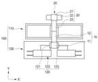
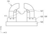
상기 고정지그부(100)는, 상기 제1용접대상물(10) 및 상기 제2용접대상물(20)이 안착되는 안착홈(111)이 형성되는 안착부(110)와, 상기 안착부(110)의 적어도 하나의 측면에 인접배치되어, 상기 제1용접대상물(10) 및 상기 제2용접대상물(20) 중 적어도 하나를 고정하는 고정부(120)를 포함할 수 있다.The above-described fixed jig part (100) may include a fixing part (110) in which a fixing groove (111) is formed, in which the first welding object (10) and the second welding object (20) are fixed, and a fixing part (120) that is adjacent to at least one side of the fixing part (110) and fixes at least one of the first welding object (10) and the second welding object (20).
상기 고정부(120)는, 상기 안착부(110) 중 상기 제1용접대상물(10) 측 측면에 인접 배치될 수 있다.The above-mentioned fixed part (120) can be placed adjacent to the side of the first welding target (10) among the above-mentioned anchoring parts (110).
상기 제1용접대상물(10)은, 안착부(110)에 안착된 상태에서 안착부(110) 중 일측에 인접 배치되는 고정부(120)를 통해 고정되며, 제2용접대상물(20)은, 안착부(110) 중 제1용접대상물(10)이 안착위치의 타측에 안착될 수 있다.The first welding object (10) is fixed by a fixing part (120) positioned adjacent to one side of the fixing part (110) while being fixed on the fixing part (110), and the second welding object (20) can be fixed on the other side of the fixing part (110) where the first welding object (10) is fixed.
상기 고정부(120)는, 상기 제1용접대상물(10)을 기준으로 양방향에서 선형이동을 통해 상기 제1용접대상물(10)을 고정 및 해제하는 선형이동고정부(121)와, 상기 선형이동고정부(121)의 하부에 배치되어, 상기 선형이동고정부(121)를 구동하는 선형이동구동부(122)를 포함할 수 있다.The above-mentioned fixing member (120) may include a linear movement fixing member (121) that fixes and releases the first welding object (10) through linear movement in both directions based on the first welding object (10), and a linear movement driving member (122) that is arranged below the linear movement fixing member (121) and drives the linear movement fixing member (121).
상기 이송부(200)는, 상기 제1용접대상물(10)을 이송하는 제1핸드부(210)와, 상기 제2용접대상물(20)을 이송하는 제2핸드부(220)를 포함할 수 있다.The above-mentioned transfer unit (200) may include a first hand unit (210) for transferring the first welding object (10) and a second hand unit (220) for transferring the second welding object (20).
상기 제1핸드부(210)는, 상기 제1용접대상물(10)을 상기 고정지그부(100)에 이송하여 안착시킨 상태에서, 상기 커버부(400)를 이송하여 상기 고정지그부(100)에 결합할 수 있다.The first hand part (210) can transfer the first welding object (10) to the fixed jig part (100) and secure it therein, and then transfer the cover part (400) to be connected to the fixed jig part (100).
상기 제2핸드부(220)는, 상기 제2용접대상물(20)을 상기 고정지그부(100)에 이송하여 안착시킨 상태에서, 상기 제2용접대상물(20)에 대한 고정상태를 유지하는 그리퍼(221)를 포함할 수 있다.The second hand part (220) may include a gripper (221) that maintains a fixed state for the second welding object (20) while the second welding object (20) is transferred to the fixed jig part (100) and fixed therein.
상기 제2핸드부(220)는, 상기 제1용접대상물(10)과 상기 제2용접대상물(20)의 용접이 완료된 용접결과물을 이송할 수 있다.The above second hand part (220) can transport the welding result of the first welding object (10) and the second welding object (20) after welding is completed.
상기 그리퍼(221)는, 상기 제2용접대상물(20)의 상면 및 하면을 접촉가압하여, 상기 제2용접대상물(20)의 고정상태를 유지할 수 있다.The above gripper (221) can maintain the fixed state of the second welding object (20) by contacting and pressing the upper and lower surfaces of the second welding object (20).
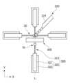
상기 퍼지가스공급부(300)는, 상기 고정지그부(100)를 기준으로 양방향에서 상기 제1용접대상물(10) 및 상기 제2용접대상물(20)을 잇는 가상의 선(L) 상에 각각 배치될 수 있다.The above purge gas supply unit (300) can be placed on an imaginary line (L) connecting the first welding object (10) and the second welding object (20) in both directions based on the fixed jig unit (100).
상기 퍼지가스공급부(300)는, 상기 제2용접대상물(20)을 기준으로 상기 가상의 선(L)과 수직방향의 양방향에 각각 배치될 수 있다.The above purge gas supply unit (300) can be positioned in both directions perpendicular to the virtual line (L) with respect to the second welding object (20).
상기 퍼지가스공급부(300)는, 선형이동을 통해 상기 제1용접대상물(10) 또는 상기 제2용접대상물(20)에 직접 접촉하여 퍼지가스를 분사하는 퍼지가스분사부(310)와, 상기 퍼지가스분사부(310)를 선형구동하는 퍼지가스선형구동블록(320)을 포함할 수 있다.The above purge gas supply unit (300) may include a purge gas injection unit (310) that directly contacts the first welding object (10) or the second welding object (20) through linear movement to inject purge gas, and a purge gas linear drive block (320) that linearly drives the purge gas injection unit (310).
상기 퍼지가스분사부(310)는, 상기 제1용접대상물(10) 또는 상기 제2용접대상물(20)를 가압함으로써, 상기 제1용접대상물(10) 또는 제2용접대상물(20)의 위치를 고정할 수 있다.The above purge gas injection unit (310) can fix the position of the first welding object (10) or the second welding object (20) by pressurizing the first welding object (10) or the second welding object (20).
본 발명에 따른 자동용접장치는, 용접대상물을 자동으로 투입하고 완성된 용접물을 회수함으로써, 작업시간이 단축되어 수율이 증가하고 비용이 감소하는 이점이 있다.The automatic welding device according to the present invention has the advantage of reducing work time, increasing yield, and reducing cost by automatically inputting a welding object and recovering a completed weldment.
또한, 본 발명에 따른 자동용접장치는, 용접대상물을 자동으로 투입하여 자동으로 용접이 수행됨으로써, 용접 작업의 전반적인 신뢰성이 향상되고 용접결과물이 일정수준 이상을 유지할 수 있는 이점이 있다.In addition, the automatic welding device according to the present invention has the advantage of improving the overall reliability of the welding work and maintaining the welding result at a certain level or higher by automatically inputting the welding object and automatically performing welding.
또한, 본 발명에 따른 자동용접장치는, 용접대상물을 비교적 간편하게 고정지그에 고정하면서도, 용접과정에서의 진동 등에 따른 용접불량을 최소화할 수 있는 이점이 있다.In addition, the automatic welding device according to the present invention has the advantage of being able to minimize welding defects caused by vibrations during the welding process while relatively easily fixing the welding object to a fixing jig.
즉, 본 발명에 따른 자동용접장치는, 용접과정에서 용접대상물의 고정을 신뢰성있게 유지하여 고품질의 용접을 수행하면서도, 작업시간을 최소화할 수 있는 이점이 있다.That is, the automatic welding device according to the present invention has the advantage of being able to perform high-quality welding by reliably maintaining the fixation of the welding object during the welding process, while minimizing the working time.
도 1은, 본 발명에 따른 자동용접장치가 포함된 자동용접시스템의 모습을 보여주는 평면도이다.
도 2는, 본 발명에 따른 자동용접장치 중 고정지그부의 모습을 보여주는 평면도이다.
도 3은, 도 2에 따른 자동용접장치 중 용접대상물이 고정되어 용접이 수행되는 모습을 보여주는 평면도이다.
도 4a 및 도 4b는, 도 2에 따른 자동용접장치 중 용접대상물의 고정 전후의 모습을 각각 보여주는 측면도들이다.
도 5은, 도 2에 따른 자동용접장치 중 용접과정에서 제2핸드부를 통해 제2용접대상물이 고정되는 모습을 보여주는 사시도이다.
도 6은, 도 2에 따른 자동용접장치 중 제1핸드부를 통해 제1용접대상물이 그리핑된 모습을 보여주는 사시도이다.
도 7은, 도 1에 따른 자동용접시스템 중 용접대상물이 안착되는 팔레트의 모습을 보여주는 단면사시도이다.
도 8은, 도 1에 따른 자동용접시스템 중 용접대상물을 공급하는 피더본체의 모습을 보여주는 측면도이다.
도 9는, 본 발명에 따른 자동용접장치를 이용한 자동용접방법의 모습을 보여주는 순서도이다.
도 10은, 도 9에 따른 자동용접방법 중 제1이송단계의 모습을 보여주는 순서도이다.
도 11은, 도 9에 따른 자동용접방법 중 용접단계의 모습을 보여주는 순서도이다.
도 12은, 도 9에 따른 자동용접방법 중 제2이송단계의 모습을 보여주는 순서도이다.Figure 1 is a plan view showing an automatic welding system including an automatic welding device according to the present invention.
Figure 2 is a plan view showing the appearance of a fixed jig portion of an automatic welding device according to the present invention.
Fig. 3 is a plan view showing the automatic welding device according to Fig. 2 in which a welding object is fixed and welding is performed.
Figures 4a and 4b are side views showing the appearance of the automatic welding device according to Figure 2 before and after fixing the welding object.
FIG. 5 is a perspective view showing a second welding object being fixed through a second hand unit during a welding process in the automatic welding device according to FIG. 2.
Fig. 6 is a perspective view showing a first welding object gripped by a first hand part of an automatic welding device according to Fig. 2.
Fig. 7 is a cross-sectional perspective view showing the appearance of a pallet on which a welding object is placed in the automatic welding system according to Fig. 1.
Fig. 8 is a side view showing the appearance of a feeder body that supplies a welding object among the automatic welding systems according to Fig. 1.
Figure 9 is a flow chart showing an automatic welding method using an automatic welding device according to the present invention.
Fig. 10 is a flow chart showing the first transfer step of the automatic welding method according to Fig. 9.
Figure 11 is a flow chart showing the welding steps in the automatic welding method according to Figure 9.
Figure 12 is a flow chart showing the second transfer step of the automatic welding method according to Figure 9.
이하 본 발명에 따른 자동용접장치, 자동용접시스템 및 자동용접방법에 관하여 첨부된 도면을 참조하여 설명하면 다음과 같다.Hereinafter, the automatic welding device, automatic welding system, and automatic welding method according to the present invention will be described with reference to the attached drawings.
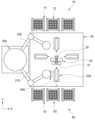
본 발명에 따른 자동용접시스템은, 도 1에 도시된 바와 같이, 베이스(30)와;상기 베이스(30)의 양측에 각각 구비되어, 상기 제1용접대상물(10) 및 상기 제2용접대상물(20)을 저장 및 공급하는 피더부와; 상기 베이스(30)의 상부면에 배치되어 상기 제1용접대상물(10) 및 상기 제2용접대상물(20)에 대한 용접을 수행하는 자동용접모듈(40)과; 상기 베이스(30)의 전방측에 설치되어, 상기 피더부로부터 상기 제1용접대상물(10) 및 상기 제2용접대상물(20)을 상기 자동용접모듈(40)에 각각 공급하는 이송부(200)를 포함한다.The automatic welding system according to the present invention, as illustrated in FIG. 1, comprises a base (30); a feeder section provided on each side of the base (30) to store and supply the first welding object (10) and the second welding object (20); an automatic welding module (40) arranged on an upper surface of the base (30) to perform welding on the first welding object (10) and the second welding object (20); and a transfer section (200) installed on the front side of the base (30) to supply the first welding object (10) and the second welding object (20) to the automatic welding module (40), respectively, from the feeder section.
또한, 상기 자동용접시스템은, 상기 이송부(200)을 통해 전달되며, 상기 제1용접대상물(10) 및 상기 제2용접대상물(20)이 안착되어 고정된 상기 자동용접모듈(40)의 상부에 결합하는 커버부(400)를 추가로 포함할 수 있다.In addition, the automatic welding system may additionally include a cover part (400) that is connected to the upper part of the automatic welding module (40) on which the first welding object (10) and the second welding object (20) are fixedly placed and transmitted through the transfer part (200).
본 발명에 따른 자동용접시스템은, 제1용접대상물(10)과 제2용접대상물(20)을 각각 접합하여 용접이 완료된 용접결과물을 완성할 수 있다.The automatic welding system according to the present invention can complete a welding result by joining the first welding object (10) and the second welding object (20), respectively.
이때, 본 발명에 따른 자동용접시스템은, 제1용접대상물(10)과 제2용접대상물(20)이 용접되는 위치를 기준으로 이들을 이송하기 위한 구성 및 로딩 및 언로딩이 수행되는 구성을 각각 최적의 동선으로 배치하여 최적의 용접작업이 수행되도록 유도할 수 있다.At this time, the automatic welding system according to the present invention can induce optimal welding work to be performed by arranging the configuration for transporting the first welding object (10) and the second welding object (20) based on the position where they are to be welded and the configuration for performing loading and unloading in an optimal path.
여기서 본 발명에 따른 자동용접시스템의 용접대상이 되는 제1용접대상물(10) 및 제2용접대상물(20)은, 후술하는 자동용접모듈(40)에 안착 및 고정되어 용접부위를 따라서 용접되어 결합될 수 있는 구성이면, 어떠한 구성도 적용 가능하다.Here, the first welding object (10) and the second welding object (20), which are welding targets of the automatic welding system according to the present invention, can be applied to any configuration as long as they can be mounted and fixed to the automatic welding module (40) described below and welded and joined along the welding area.
예를 들면, 상기 제1용접대상물(10)은, 후술하는 퍼지가스공급부(300) 중 적어도 일부가 삽입되어 접촉되는 제1접촉부분(11)과, 제1접촉부분(11)으로부터 연장형성되어 끝단이 제2용접대상물(20)과 용접되기 위한 제1용접부분(12)을 포함할 수 있다.For example, the first welding object (10) may include a first contact portion (11) into which at least a portion of the purge gas supply portion (300) described below is inserted and brought into contact, and a first welding portion (12) that extends from the first contact portion (11) and has an end to be welded to the second welding object (20).
또한, 상기 제2용접대상물(20)은, 후술하는 퍼지가스공급부(300) 중 적어도 일부가 삽입되어 접촉되는 제2접촉부분(21)과, 제2접촉부분(21)으로부터 연장형성되어 끝단이 제1용접대상물(10)의 제1용접부분(12)과 맞닿아 용접비드가 형성되는 제2용접부분(23)과, 제2접촉부분(21)으로부터 제2용접부분(23)과 수직방향으로 연장형성되어 후술하는 퍼지가스공급부(300)의 끝단이 삽입되어 접촉되는 제3접촉부분(22)을 포함할 수 있다.In addition, the second welding object (20) may include a second contact portion (21) into which at least a part of a purge gas supply portion (300) described later is inserted and brought into contact, a second welding portion (23) that is extended from the second contact portion (21) and has an end that comes into contact with the first welding portion (12) of the first welding object (10) to form a welding bead, and a third contact portion (22) that is extended from the second contact portion (21) in a vertical direction to the second welding portion (23) and into which an end of the purge gas supply portion (300) described later is inserted and brought into contact.
즉, 상기 제2용접대상물(20)은, 제2접촉부분(21)을 기준으로 'T'자 형태의 제2용접부분(23) 및 제3접촉부분(22)이 연장형성될 수 있으며, 이때 제2용접부분(23)을 기준으로 제3접촉부분(22)들은 각각 수직으로 형성될 수 있다.That is, the second welding object (20) can be formed with a second welding portion (23) and a third contact portion (22) in a 'T' shape extending from the second contact portion (21), and at this time, the third contact portions (22) can be formed vertically from the second welding portion (23).
결과적으로, 상기 제1용접부분(12)과 제2용접부분(23)의 끝단이 서로 맞닿은 상태에서 용접을 수행하여 제1용접대상물(10)과 제2용접대상물(20)을 접합하여 결합할 수 있다.As a result, the first welding object (10) and the second welding object (20) can be joined and combined by performing welding while the ends of the first welding portion (12) and the second welding portion (23) are in contact with each other.
상기 베이스(30)는, 후술하는 자동용접모듈(40) 및 기타 구성이 설치되는 구성으로서, 다양한 구성이 가능하다.The above base (30) is a configuration in which the automatic welding module (40) and other configurations described later are installed, and various configurations are possible.
예를 들면, 상기 베이스(30)는, 지면 등으로부터 발생되는 진동에 따라 용접 품질이 훼손되는 것을 방지하기 위하여, 진동을 억제하거나 흡수할 수 있는 구성일 수 있으며, 평평한 상부면을 제공하여 자동용접모듈(40) 등이 배치되는 공간을 형성할 수 있다.For example, the base (30) may be configured to suppress or absorb vibrations in order to prevent welding quality from being damaged by vibrations generated from the ground, etc., and may provide a flat upper surface to form a space in which an automatic welding module (40), etc., is placed.
상기 피더부는, 베이스(30)의 양측에 각각 구비되어, 상기 제1용접대상물(10) 및 상기 제2용접대상물(20)을 저장 및 공급하는 구성으로서, 다양한 구성이 가능하다.The above feeder section is provided on each side of the base (30) and is configured to store and supply the first welding object (10) and the second welding object (20), and various configurations are possible.
예를 들면, 상기 피더부는, 베이스(30)의 일측에 구비되어, 제1용접대상물(10)을 저장 및 공급하는 제1피더부(60)와, 베이스(30)의 타측에 구비되어, 제2용접대상물(20)을 저장 및 공급하는 제2피더부(70)를 포함할 수 있다.For example, the feeder section may include a first feeder section (60) provided on one side of the base (30) to store and supply a first welding object (10), and a second feeder section (70) provided on the other side of the base (30) to store and supply a second welding object (20).
이때, 상기 제1피더부(60)는, 베이스(30)의 일측에 인접하게 이격되어 배치되어 제1용접대상물(10)을 저장 및 공급할 수 있으며, 제1용접대상물(10)에 대한 로딩이 유도될 수 있다.At this time, the first feeder section (60) is spaced apart and placed adjacent to one side of the base (30) to store and supply the first welding object (10), and loading of the first welding object (10) can be induced.
한편, 상기 제1피더부(60)는, 전술한 바와 달리 베이스(30)의 일측 가장자리 상부면에 위치할 수 있음은 또한 물론이다.Meanwhile, it is also obvious that the first feeder part (60) may be located on the upper surface of one edge of the base (30), unlike as described above.
더 나아가, 상기 제1피더부(60)는, 도 1에 도시된 바와 같이, 다수의 제1용접대상물(10)이 안착될 수 있으며, 복수개가 베이스(30)의 일측 가장자리를 따라서 배치될 수 있다.Furthermore, as shown in FIG. 1, the first feeder section (60) can accommodate a plurality of first welding objects (10), and a plurality of such objects can be arranged along one edge of the base (30).
또한, 상기 제2피더부(70)는, 베이스(30)의 타측에 구비되어, 제2용접대상물(20)을 저장 및 공급하는 구성으로서, 다양한 구성이 가능하다.In addition, the second feeder section (70) is provided on the other side of the base (30) and is configured to store and supply the second welding object (20), and various configurations are possible.
예를 들면, 상기 제2피더부(70)는, 베이스(30)의 타측에 인접하게 이격되어 배치되어 제2용접대상물(20)을 저장 및 공급할 수 있으며, 제2용접대상물(20)에 대한 로딩이 유도될 수 있다.For example, the second feeder section (70) can be arranged adjacent to and spaced from the other side of the base (30) to store and supply the second welding object (20), and loading of the second welding object (20) can be induced.
한편, 상기 제2피더부(70)는, 전술한 바와 달리 베이스(30)의 타측 가장자리 상부면에 위치할 수 있음은 또한 물론이다.Meanwhile, it is also obvious that the second feeder part (70) may be located on the upper surface of the other side edge of the base (30), unlike as described above.
더 나아가, 상기 제2피더부(70)는, 도 1에 도시된 바와 같이, 다수의 제2용접대상물(20)이 안착될 수 있으며, 복수개가 베이스(30)의 타측 가장자리를 따라서 배치될 수 있다.Furthermore, as shown in FIG. 1, the second feeder section (70) can accommodate a plurality of second welding objects (20), and a plurality of such objects can be arranged along the other edge of the base (30).
보다 구체적으로, 상기 제1피더부(60) 및 상기 제2피더부(70)는, 도 1에 도시된 바와 같이, 베이스(30)를 기준으로 평면도 상 각각 좌측 및 우측에 배치될 수 있으며, 이때, 이송부(200)는 베이스(30)를 기준으로 평면도 상 상측에 배치될 수 있다.More specifically, the first feeder unit (60) and the second feeder unit (70) may be positioned on the left and right sides, respectively, in the plan view with respect to the base (30), as illustrated in FIG. 1, and at this time, the transfer unit (200) may be positioned on the upper side in the plan view with respect to the base (30).
이에 따라, 후술하는 이송부(200)의 제1핸드부(210)가 제1피더부(60)와 인접하도록 함으로써, 제1핸드부(210)를 통해 제1용접대상물(10)을 이송하여 용접할 수 있으며, 이송부(200)의 제2핸드부(220)가 제2피더부(70)와 인접하도록 함으로써, 제2핸드부(220)를 통해 제2용접대상물(20)을 이송할 수 있다.Accordingly, by making the first hand part (210) of the transfer part (200) described below adjacent to the first feeder part (60), the first welding object (10) can be transferred and welded through the first hand part (210), and by making the second hand part (220) of the transfer part (200) adjacent to the second feeder part (70), the second welding object (20) can be transferred through the second hand part (220).
보다 상세하게 상기 피더부는, 도 7 및 도 8에 도시된 바와 같이, 수직방향으로 설치되는 복수의 피더본체(61, 71)들과, 복수의 피더본체(61, 71)들의 상면에 구비되어 제1용접대상물(10) 또는 제2용접대상물(20)이 안착되는 복수의 팔레트(62, 72)를 포함할 수 있다.More specifically, the feeder section may include, as shown in FIGS. 7 and 8, a plurality of feeder main bodies (61, 71) installed vertically, and a plurality of pallets (62, 72) provided on the upper surfaces of the plurality of feeder main bodies (61, 71) on which the first welding object (10) or the second welding object (20) is placed.
상기 피더본체(61, 71)는, 베이스(30)의 일측 및 타측으로부터 일정간격 이격되어 수직방향으로 설치되는 구성으로서, 다양한 구성이 가능하다.The above feeder body (61, 71) is configured to be installed vertically at a certain distance from one side and the other side of the base (30), and various configurations are possible.
예를 들면, 상기 피더본체(61, 71)는, 상면에 배치되는 팔레트(62, 72)의 저면에 접촉하여 상하이동을 통해 팔레트(62, 72)를 상하구동하는 피더로드(63)와, 피더로드(63)의 상하이동을 가이드하는 가이드부(64)와, 피더로드(63)를 상하로 구동하는 피더구동부(65)를 포함할 수 있다.For example, the feeder body (61, 71) may include a feeder rod (63) that moves up and down the pallet (62, 72) by contacting the lower surface of the pallet (62, 72) placed on the upper surface, a guide part (64) that guides the up and down movement of the feeder rod (63), and a feeder driving part (65) that moves up and down the feeder rod (63).
즉, 상기 피더본체(61, 71)는, 각각 상면에 배치되는 팔레트(62, 72)를 상하이동시키기 위한 피더로드(63), 가이드부(64) 및 피더구동부(65)를 구비하여, 팔레트(62, 72)의 자동공급 및 적층식 공급이 가능하도록 할 수 있다.That is, the feeder main body (61, 71) is provided with a feeder rod (63), a guide part (64), and a feeder driving part (65) for vertically moving the pallets (62, 72) placed on the upper surface, respectively, so as to enable automatic supply and stacked supply of the pallets (62, 72).
상기 팔레트(62, 72)는, 복수의 피더본체(61, 71)들의 상면에 구비되어 제1용접대상물(10) 또는 제2용접대상물(20)이 안착되는 구성으로서, 다양한 구성이 가능하다.The above pallet (62, 72) is configured to be provided on the upper surface of a plurality of feeder bodies (61, 71) and to allow the first welding object (10) or the second welding object (20) to be placed thereon, and various configurations are possible.
예를 들면, 상기 팔레트(62, 72)는, 상부면에 제1용접대상물(10) 또는 제2용접대상물(20)이 안착되기 위한 안착홈(66)이 복수개 형성되어, 제1용접대상물(10) 또는 제2용접대상물(20)이 복수의 안착홈(66)에 각각 안착됨으로써, 정위치에 정렬되어 저장될 수 있으며, 후술하는 이송부(200)를 통해 로딩이 수행될 수 있다.For example, the pallet (62, 72) has a plurality of settling grooves (66) formed on the upper surface for settling the first welding object (10) or the second welding object (20), so that the first welding object (10) or the second welding object (20) can be aligned and stored in a fixed position by settling in each of the plurality of settling grooves (66), and loading can be performed through the transfer unit (200) described below.
이를 위하여, 상기 팔레트(62, 72)는, 추가로 안착홈(66) 내에 제1용접대상물(10) 또는 제2용접대상물(20)이 끼워져 고정되도록 상측으로 돌출되어 형성되는 돌출삽입부(67)가 추가로 구비될 수 있다.To this end, the above pallet (62, 72) may additionally be provided with a protruding insertion portion (67) formed to protrude upward so that the first welding object (10) or the second welding object (20) is inserted and fixed within the additional fixing groove (66).
보다 구체적으로, 상기 돌출삽입부(67)는, 전술한 제1용접대상물(10) 중 제1접촉부분(11) 및 제2용접대상물(20) 중 제2접촉부분(21)에 퍼지가스공급부(300) 중 적어도 일부가 삽입되기 위한 삽입홈(미도시)이 끼워져 제1용접대상물(10) 및 제2용접대상물(20)이 고정된 상태로 유지되도록 형성될 수 있다.More specifically, the protruding insertion portion (67) may be formed so that an insertion groove (not shown) is fitted for inserting at least a portion of the purge gas supply portion (300) into the first contact portion (11) of the first welding object (10) and the second contact portion (21) of the second welding object (20) described above, so that the first welding object (10) and the second welding object (20) are maintained in a fixed state.
상기 자동용접모듈(40)은, 베이스(30)의 상부면에 배치되어 제1용접대상물(10) 및 제2용접대상물(20)에 대한 용접을 수행하는 구성일 수 있다.The above automatic welding module (40) may be configured to be placed on the upper surface of the base (30) and perform welding on the first welding object (10) and the second welding object (20).
이때, 상기 자동용접모듈(40)은, 이송부(200)를 통해 제1용접대상물(10) 및 제2용접대상물(20)을 각각 공급받아, 안착 및 고정된 상태에서 이들에 대한 용접을 자동으로 수행할 수 있다.At this time, the automatic welding module (40) can automatically perform welding on the first welding object (10) and the second welding object (20) while they are secured and fixed by receiving them through the transfer unit (200).
한편, 상기 자동용접모듈(40), 이송부(200) 및 커버부(400)를 포함하는 자동용접장치에 관하여 이하 첨부된 도면을 참조하여 상세히 설명한다.Meanwhile, the automatic welding device including the automatic welding module (40), the transfer unit (200) and the cover unit (400) will be described in detail with reference to the attached drawings.
본 발명에 따른 자동용접장치는, 도 2 내지 도 6에 도시된 바와 같이, 제1용접대상물(10) 및 제2용접대상물(20)을 용접하여 서로 접합하는 자동용접장치로서,상기 제1용접대상물(10) 및 상기 제2용접대상물(20)이 정렬된 상태에서 안착되어 고정되는 고정지그부(100)와; 상기 고정지그부(100)에 상기 제1용접대상물(10) 및 상기 제2용접대상물(20)을 안착시키는 이송부(200)과; 상기 고정지그부(100)에 인접하게 배치되어, 상기 고정지그부(100)에 안착되어 고정된 상기 제1용접대상물(10) 및 상기 제2용접대상물(20)의 용접부위를 퍼지하는 퍼지가스공급부(300)를 포함한다.An automatic welding device according to the present invention, as illustrated in FIGS. 2 to 6, is an automatic welding device for welding and joining a first welding object (10) and a second welding object (20) to each other, comprising: a fixed jig part (100) on which the first welding object (10) and the second welding object (20) are aligned and fixed; a transfer part (200) for fixing the first welding object (10) and the second welding object (20) to the fixed jig part (100); and a purge gas supply part (300) arranged adjacent to the fixed jig part (100) for purging the welding area of the first welding object (10) and the second welding object (20) fixedly fixed to the fixed jig part (100).
상기 이송부(200)를 통해 전달되며, 상기 제1용접대상물(10) 및 상기 제2용접대상물(20)이 안착되어 고정된 상기 고정지그부(100)의 상부에 결합하는 커버부(400)를 추가로 포함할 수 있다.It may additionally include a cover part (400) that is transmitted through the above-mentioned transfer part (200) and is coupled to the upper part of the above-mentioned fixed jig part (100) on which the above-mentioned first welding object (10) and the above-mentioned second welding object (20) are fixedly placed.
상기 고정지그부(100)는, 제1용접대상물(10) 및 제2용접대상물(20)이 정렬된 상태에서 안착되어 고정되는 구성으로서, 다양한 구성이 가능하다.The above fixed jig part (100) is configured to be fixed by settling the first welding object (10) and the second welding object (20) in an aligned state, and various configurations are possible.
이때, 상기 고정지그부(100)는, 전술한 베이스부(30)의 상부면에 구비되며, 제1용접대상물(10) 및 제2용접대상물(20)이 정렬되어 안착되도록 유도할 수 있다.At this time, the fixed jig part (100) is provided on the upper surface of the base part (30) described above, and can induce the first welding object (10) and the second welding object (20) to be aligned and settled.
이를 위하여, 상기 고정지그부(100)는, 제1용접대상물(10) 및 제2용접대상물(20)이 안착되는 안착홈(111)이 형성되는 안착부(110)와, 안착부(110)의 적어도 일측면에 인접배치되어, 제1용접대상물(10) 및 제2용접대상물(20) 중 적어도 하나를 고정하는 고정부(120)를 포함할 수 있다.To this end, the fixed jig part (100) may include a fixing part (110) in which a fixing groove (111) is formed, in which the first welding object (10) and the second welding object (20) are fixed, and a fixing part (120) that is adjacent to at least one side of the fixing part (110) and fixes at least one of the first welding object (10) and the second welding object (20).
상기 안착부(110)는, 제1용접대상물(10) 및 제2용접대상물(20)이 안착되는 구성으로서, 다양한 구성이 가능하다.The above-mentioned fixing portion (110) is configured to fix the first welding object (10) and the second welding object (20), and various configurations are possible.
예를 들면, 상기 안착부(110)는, 도 2에 개시된 바와 같이, X방향으로 길이를 가지고 설치된 상태에서, Y방향으로 가로질러 제1용접대상물(10) 및 제2용접대상물(20)이 안착되도록 할 수 있다.For example, as disclosed in FIG. 2, the above-described fixing member (110) can be installed with a length in the X direction so that the first welding object (10) and the second welding object (20) can be fixed across the Y direction.
이때, 상기 안착부(110)는, 제1용접대상물(10) 및 제2용접대상물(20)의 직경에 대응되는 안착홈(111)이 형성되어, 제1용접대상물(10) 및 제2용접대상물(20)이 정위치에 정렬되어 안착되도록 유도할 수 있다.At this time, the fixing portion (110) is formed with a fixing groove (111) corresponding to the diameter of the first welding object (10) and the second welding object (20), so that the first welding object (10) and the second welding object (20) can be aligned and fixed in the correct position.
더 나아가, 상기 안착부(110)는, 금속의 제1용접대상물(10) 및 제2용접대상물(20)을 안착시키기 위하여, 자기력, 즉 제1용접대상물(10) 및 제2용접대상물(20)에 대하여 인력이 형성되는 자성체를 포함할 수 있다.Furthermore, the fixing member (110) may include a magnetic body that forms a magnetic force, that is, an attractive force with respect to the first welding object (10) and the second welding object (20), in order to fix the first welding object (10) and the second welding object (20) of metal.
상기 고정부(120)는, 안착부(110)의 양측면 중 적어도 하나의 측면에 인접배치되어, 제1용접대상물(10) 및 제2용접대상물(20) 중 적어도 하나를 고정하는 구성으로서, 다양한 구성이 가능하다.The above-mentioned fixing member (120) is configured to be adjacent to at least one side of both sides of the fixing member (110) and fix at least one of the first welding object (10) and the second welding object (20), and various configurations are possible.
예를 들면, 상기 고정부(120)는, 안착부(110)의 양측면 중 제1용접대상물(10)이 배치되는 하나의 측면에 인접하게 배치되어, 후술하는 제1핸드부(210)를 통해 전달되어 안착부(110)에 안착되는 제1용접대상물(10)을 고정할 수 있다.For example, the fixing member (120) is positioned adjacent to one side of the two sides of the fixing member (110) where the first welding object (10) is positioned, and can fix the first welding object (10) that is positioned on the fixing member (110) by being transmitted through the first hand member (210) described below.
보다 구체적으로, 상기 고정부(120)는, 안착부(110) 중 제1용접대상물(10) 측 측면에 인접 배치되어 상기 제1용접대상물(10)을 기준으로 양방향에서 선형이동을 통해 상기 제1용접대상물(10)을 고정 및 해제하는 선형이동고정부(121)와, 선형이동고정부(121)의 하부에 배치되어, 선형이동고정부(121)를 구동하는 선형이동구동부(122)를 포함할 수 있다.More specifically, the fixing member (120) may include a linear movement fixing member (121) that is positioned adjacent to the side of the first welding object (10) among the anchoring members (110) and fixes and releases the first welding object (10) through linear movement in both directions based on the first welding object (10), and a linear movement driving member (122) that is positioned below the linear movement fixing member (121) and drives the linear movement fixing member (121).
또한, 상기 고정부(120)는, 선형이동구동부(122)의 하부에서 선형이동구동부(122)가 배치되도록 베이스(30)의 상부면에 설치되는 선형이동베이스(123)를 추가로 포함할 수 있다.In addition, the fixed part (120) may additionally include a linear movement base (123) installed on the upper surface of the base (30) so that the linear movement driving part (122) is placed below the linear movement driving part (122).
즉, 상기 고정부(120)는, 베이스(30)의 상부면 중 안착부(110)의 제1용접대상물(10) 측 측면에 인접하게 선형이동베이스(123)가 설치된 상태에서, 선형이동베이스(123)의 상부에 제1용접대상물(10)의 안착위치를 기준으로 양 방향에 각각 선형이동구동부(122)가 구비될 수 있다.That is, the fixed part (120) may be provided with linear movement bases (123) installed adjacent to the side of the first welding object (10) of the fixing part (110) on the upper surface of the base (30), and linear movement driving parts (122) may be provided in both directions based on the fixing position of the first welding object (10) on the upper part of the linear movement base (123).
또한, 선형이동구동부(122)의 각각의 상측에는 선형이동고정부(121)가 각각 구비되어, 선형이동구동부(122)의 제1용접대상물(10) 기준으로 양방향으로의 선형이동 시, 제1용접대상물(10)을 고정하거나 고정을 해제할 수 있다.In addition, a linear movement fixing part (121) is provided on the upper side of each linear movement driving part (122), so that when the linear movement driving part (122) moves linearly in both directions with respect to the first welding object (10), the first welding object (10) can be fixed or released from fixation.
이때, 선형이동구동부(122)는, 실린더방식, 모터방식, 전자기방식 및 볼트스크류 방식 등 종래 개시된 어떠한 형태의 선형이동을 야기할 수 있는 구성이면 적용 가능하다.At this time, the linear movement driving unit (122) can be applied to any configuration that can cause linear movement in any form that has been disclosed in the past, such as a cylinder method, a motor method, an electromagnetic method, and a bolt screw method.
이로써, 상기 고정부(120)는, 제1용접대상물(10)이 안착부(110)에 안착된 상태에서 선형이동고정부(121)를 제1용접대상물(10)을 기준으로 양방향에서 제1용접대상물(10) 측으로 선형이동 시켜, 제1용접대상물(10)의 위치를 용접 수행과정에서 고정할 수 있다.Accordingly, the fixing member (120) can fix the position of the first welding object (10) during the welding process by linearly moving the linear moving fixing member (121) in both directions with respect to the first welding object (10) while the first welding object (10) is fixed to the fixing member (110).
한편, 전술한 고정부(120)의 구성이 제2용접대상물(20)에도 적용될 수 있음은 또한 물론이다.Meanwhile, it is also obvious that the configuration of the aforementioned fixed part (120) can also be applied to the second welding target (20).
그러나, 후술하는 실시예와 같이, 제2용접대상물(20) 측은 고정부(120)의 설치가 생략되고, 후술하는 제2핸드부(220)를 통해 제2용접대상물(20)이 용접 수행과정 동안 고정될 수 있다.However, as in the embodiment described later, the installation of the fixing part (120) is omitted on the second welding object (20) side, and the second welding object (20) can be fixed during the welding process through the second hand part (220) described later.
상기 이송부(200)는, 고정지그부(100)에 제1용접대상물(10) 및 제2용접대상물(20)을 안착시키는 구성으로서, 다양한 구성이 가능하다.The above-mentioned transfer unit (200) is configured to secure the first welding object (10) and the second welding object (20) to the fixed jig unit (100), and various configurations are possible.
이때, 이송부(200)는, 최적의 용접이송의 작업환경을 구현하기 위하여, 베이스(30)의 전방측에 설치되어, 피더부로부터 상기 제1용접대상물(10) 및 상기 제2용접대상물(20)을 자동용접모듈(40)에 각각 공급할 수 있다.At this time, the transfer unit (200) is installed on the front side of the base (30) to implement an optimal welding transfer work environment, and can supply the first welding object (10) and the second welding object (20) from the feeder unit to the automatic welding module (40), respectively.
즉, 상기 이송부(200)는, 다관절로봇으로서, 2개의 암이 적용될 수 있으며, 2개의 암을 통해 제1용접대상물(10) 및 제2용접대상물(20)을 동시에 자동용접모듈(40)에 전달할 수 있다.That is, the above-mentioned transfer unit (200) is a multi-joint robot, to which two arms can be applied, and the first welding object (10) and the second welding object (20) can be simultaneously transferred to the automatic welding module (40) through the two arms.
이 경우, 최적의 전달경로를 적용하기 위하여, 제1용접대상물(10)이 구비되는 제1피더부(60)를 제1핸드부(210)에 인접하도록 베이스부(30)의 일측면, 즉 평면 상 상측에 위치하는 이송부(200)의 좌측에 제1핸드부(210)가 구비되는 점을 고려하여, 베이스부(30)의 좌측면에 제1피더부(60)가 구비될 수 있다.In this case, in order to apply the optimal transmission path, the first feeder part (60) provided with the first welding object (10) is located adjacent to the first hand part (210) on one side of the base part (30), that is, on the upper side on the plane, and considering that the first hand part (210) is provided on the left side of the transfer part (200), the first feeder part (60) may be provided on the left side of the base part (30).
또한, 제2용접대상물(20)이 구비되는 제2피더부(70)를 제2핸드부(220)에 인접하도록 베이스부(30)의 타측면, 즉 평면 상 상측에 위치하는 이송부(200)의 우측에 제2핸드부(220)가 구비되는 점을 고려하여, 베이스부(30)의 우측면에 제2피더부(70)가 구비될 수 있다.In addition, considering that the second hand part (220) is provided on the right side of the transfer part (200) located on the other side of the base part (30), that is, on the upper side on the plane, so that the second feeder part (70) provided with the second welding object (20) is adjacent to the second hand part (220), the second feeder part (70) may be provided on the right side of the base part (30).
한편, 상기 이송부(200)는, 제1용접대상물(10)을 이송하는 제1핸드부(210)와, 제2용접대상물(20)을 이송하는 제2핸드부(220)를 포함할 수 있다.Meanwhile, the above-mentioned transfer unit (200) may include a first hand unit (210) for transferring the first welding object (10) and a second hand unit (220) for transferring the second welding object (20).
상기 이송부(200)는, 다관절로봇으로서, 복수의 암이 적용될 수 있으며 하나의 실시예로서, 제1핸드부(210)와 제2핸드부(220)의 2개의 암이 구비될 수 있다.The above-mentioned transfer unit (200) is a multi-joint robot to which multiple arms can be applied, and as one embodiment, two arms, a first hand unit (210) and a second hand unit (220), can be provided.
상기 제1핸드부(210)는, 제1용접대상물(10)을 고정지그부(100)에 이송하여 안착시킨 상태에서, 커버부(400)를 이송하여 고정지그부(100)에 결합할 수 있다.The above first hand part (210) can transfer the first welding object (10) to the fixed jig part (100) and secure it therein, and then transfer the cover part (400) and attach it to the fixed jig part (100).
즉, 상기 제1핸드부(210)는, 제1용접대상물(10)을 제1피더부(60)의 팔레트(62)로부터 그리핑하여 고정지그부(100)의 안착부(110)에 안착시키고, 이동하여 후술하는 커버부(400)를 고정지그부(100)에 결합할 수 있다.That is, the first hand part (210) can grip the first welding object (10) from the pallet (62) of the first feeder part (60) and place it on the placer (110) of the fixed jig part (100), and move to connect the cover part (400) described later to the fixed jig part (100).
이때, 상기 제1핸드부(210)는, 제1용접대상물(10)을 그리핑하는 제1핸드부그리퍼(212)와, 제1핸드부그리퍼(212)의 끝단에서 제1용접대상물(10)을 그리핑하기 위한 그리핑홈부(211)를 포함할 수 있다.At this time, the first hand part (210) may include a first hand part gripper (212) for gripping the first welding object (10), and a gripping groove part (211) for gripping the first welding object (10) at the end of the first hand part gripper (212).
상기 제2핸드부(220)는, 제2용접대상물(20)을 이송하는 구성으로서, 다양한 구성이 가능하다.The above second hand part (220) is configured to transport the second welding object (20) and can have various configurations.
예를 들면, 상기 제2핸드부(220)는, 제2용접대상물(20)을 고정지그부(100)에 이송하여 안착시킨 상태에서, 제2용접대상물(20)에 대한 고정상태를 유지하는 그리퍼(221)를 포함할 수 있다.For example, the second hand part (220) may include a gripper (221) that maintains a fixed state for the second welding object (20) while the second welding object (20) is transferred to the fixed jig part (100) and fixed therein.
보다 구체적으로, 상기 제2핸드부(220)는, 제2피더부(70)의 팔레트(72)로부터 제2용접대상물(20)을 그리핑하여, 고정지그부(100), 즉 안착부(110)에 안착시킬 수 있으며, 안착시킨 이후에도 제2용접대상물(20)에 대한 그리핑 상태를 유지함으로써, 별도의 고정부(120)가 구비되지 않은 제2용접대상물(20)에 대한 고정을 수행할 수 있다.More specifically, the second hand part (220) can grip the second welding object (20) from the palette (72) of the second feeder part (70) and place it on the fixing jig part (100), i.e., the place-setting part (110), and even after the place-setting, by maintaining the gripping state for the second welding object (20), it is possible to perform the fixing of the second welding object (20) that is not provided with a separate fixing part (120).
한편, 이 경우 상기 제2핸드부(220)는, 엔드이펙터인 그리퍼(221)를 포함할 수 있으며, 이때의 그리퍼(221)는, 고정지그부(100)에 제2용접대상물(20)을 안착시킨 상태에서 제2용접대상물(20)에 대한 고정상태를 유지하는 역할을 수행할 수 있다.Meanwhile, in this case, the second hand part (220) may include a gripper (221) which is an end effector, and at this time, the gripper (221) may perform a role of maintaining a fixed state for the second welding object (20) while the second welding object (20) is secured to the fixed jig part (100).
이때, 그리퍼(221)는, 도 5에 도시된 바와 같이, 제2용접대상물(20) 중 제2접촉부분(21)의 상부면 및 하부면을 동시에 지지 및 가압함으로써, 제2용접대상물(20)이 도면상 Z방향, 즉 상하방향으로 진동하는 것을 방지할 수 있다.At this time, the gripper (221), as shown in FIG. 5, can prevent the second welding object (20) from vibrating in the Z direction in the drawing, i.e., in the up-down direction, by simultaneously supporting and pressurizing the upper and lower surfaces of the second contact portion (21) of the second welding object (20).
보다 구체적으로, 상기 제2용접대상물(20)은, 별도의 고정부(120)가 없는 상태에서, 안착부(110)를 커버하는 커버부(400)가 상측에 결합되어 제2용접부분(23)이 고정될 수 있으나, 용접과정에서의 진동에 의해 외부에 노출된 제2접촉부분(21)은 상하진동이 발생할 여지가 있다.More specifically, the second welding target (20) can be fixed by having a cover part (400) covering the mounting part (110) attached to the upper side without a separate fixing part (120), but the second contact part (21) exposed to the outside may experience up-and-down vibration due to vibration during the welding process.
이러한 진동을 방지하기 위하여, 그리퍼(221)를 통해 제2접촉부분(21)의 상부면 및 하부면을 그리핑함으로써, 상하방향 진동을 억제할 수 있다.To prevent such vibration, the upper and lower surfaces of the second contact portion (21) can be gripped using a gripper (221) to suppress the up-and-down vibration.
한편, 제2용접대상물(20)의 좌우방향, 특히 도면 상 X 및 Y방향으로의 고정은 후술하는 퍼지가스공급부(300)를 통해 진행될 수 있는 바, 상세한 설명은 후술한다.Meanwhile, fixation of the second welding object (20) in the left-right direction, especially in the X and Y directions in the drawing, can be performed through the purge gas supply unit (300) described later, which will be described in detail later.
한편, 상기 제2핸드부(220)는, 제1용접대상물(10)과 제2용접대상물(20)의 용접이 완료된 용접결과물을 이송할 수 있다.Meanwhile, the second hand part (220) can transport the welding result of the first welding object (10) and the second welding object (20) after welding is completed.
보다 구체적으로, 상기 제2핸드부(220)는, 그리퍼(221)를 통해 제2용접대상물(20)을 그리핑한 상태에서 용접이 수행되고, 용접이 완료된 용접결과물을 그대로 들어올려 외부로 전달할 수 있다.More specifically, the second hand unit (220) performs welding while gripping the second welding object (20) through the gripper (221), and can lift and transfer the completed welding result to the outside.
이를 통해, 별도의 재차 그리핑과정 및 제2핸드부(220)의 이동과정이 생략되어 용접작업의 전체 공정시간을 단축할 수 있는 이점이 있다.Through this, there is an advantage in that the separate re-gripping process and the moving process of the second hand part (220) are omitted, thereby shortening the overall process time of the welding work.
상기 퍼지가스공급부(300)는, 고정지그부(100)에 인접하게 배치되어, 고정지그부(100)에 안착되어 고정된 제1용접대상물(10) 및 제2용접대상물(20)의 용접부위를 퍼지구성으로서, 다양한 구성이 가능하다.The above purge gas supply unit (300) is positioned adjacent to the fixed jig unit (100) and can be configured in various ways as a purge configuration for the welding area of the first welding object (10) and the second welding object (20) that are fixed by being secured to the fixed jig unit (100).
예를 들면, 상기 퍼지가스공급부(300)는, 아르곤, 질소와 같은 불활성가스를 이용하여 용접부위에 잔존하는 산소, 수소 및 수증기와 같은 공기, 가스를 제거하여 용접과정에서 금속이 산화 또는 변형되는 것을 방지할 수 있다.For example, the purge gas supply unit (300) can prevent the metal from being oxidized or deformed during the welding process by removing air and gas such as oxygen, hydrogen, and water vapor remaining in the welding area using an inert gas such as argon or nitrogen.
또한, 상기 퍼지가스공급부(300)는, 제1용접대상물(10) 및 제2용접대상물(20)에 각각 접촉된 상태에서 이들을 가압함으로써, 제1용접대상물(10) 및 제2용접대상물(20)의 위치를 고정하는 역할을 수행할 수 있다.In addition, the purge gas supply unit (300) can perform the function of fixing the positions of the first welding object (10) and the second welding object (20) by pressurizing them while in contact with each of the first welding object (10) and the second welding object (20).
이 경우, 상기 퍼지가스공급부(300)는, 고정지그부(100)를 기준으로 복수개 설치될 수 있으며, 일예로서, 도 1에 도시된 바와 같이, 상기 고정지그부(100)를 기준으로 양방향에서 제1용접대상물(10) 및 제2용접대상물(20)을 잇는 가상의 선(L) 상에 각각 배치될 수 있다.In this case, the purge gas supply unit (300) may be installed in multiple numbers based on the fixed jig unit (100), and as an example, as shown in FIG. 1, may be placed on an imaginary line (L) connecting the first welding object (10) and the second welding object (20) in both directions based on the fixed jig unit (100).
즉, 상기 퍼지가스공급부(300)는, 후술하는 퍼지가스분사부(310)의 구성의 선형이동을 통해 제1용접대상물(10) 및 제2용접대상물(20)과의 접촉 및 접촉해제가 이루어져야 하는 바, 제1용접대상물(10) 및 제2용접대상물(20)을 잇는 가상의 선(L) 상에 각각 배치될 수 있으며, 가상의 선(L)을 따라서 선형이동할 수 있다.That is, the purge gas supply unit (300) must be brought into contact with and released from contact with the first welding object (10) and the second welding object (20) through linear movement of the configuration of the purge gas injection unit (310) described later. Thus, the purge gas supply unit (300) can be positioned on an imaginary line (L) connecting the first welding object (10) and the second welding object (20), and can move linearly along the imaginary line (L).
또한, 상기 퍼지가스공급부(300)는, 'T'자 형상의 제2용접대상물(20)을 고려할 때, 제2접촉부분(21)으로부터 양방향, 즉 가상의 선(L)에 수직인 방향으로 연장형성되는 제3접촉부분(23)들에 접촉되어 퍼지가스를 공급하도록, 제2용접대상물(20)을 기준으로 가상의 선(L)과 수직방향의 양방향에 각각 배치될 수 있다.In addition, when considering the second welding object (20) having a 'T' shape, the purge gas supply unit (300) can be arranged in both directions perpendicular to the imaginary line (L) with respect to the second welding object (20) so as to supply purge gas by contacting the third contact portions (23) that extend in both directions from the second contact portion (21), that is, in a direction perpendicular to the imaginary line (L).
결과적으로, 상기 퍼지가스공급부(300)는, 베이스(30)의 상부면에 고정지그부(100)를 기준으로 4개가 배치될 수 있으며, 가상의 선(L) 상에 배치되어 제1용접대상물(10)과 제2용접대상물(20)을 각각 가압하여 고정할 수 있고, 가상의 선(L)에 수직한 방향에서 제2용접대상물(20)을 각각 가압하여 고정할 수 있다.As a result, the purge gas supply unit (300) can be arranged in four units based on the fixed jig unit (100) on the upper surface of the base (30), and can be arranged on an imaginary line (L) to pressurize and fix the first welding object (10) and the second welding object (20), respectively, and can pressurize and fix the second welding object (20) in a direction perpendicular to the imaginary line (L).
한편, 상기 퍼지가스공급부(300)는, 선형이동을 통해 제1용접대상물(10) 또는 제2용접대상물(20)에 직접 접촉하여 퍼지가스를 분사하는 퍼지가스분사부(310)와, 퍼지가스분사부(310)를 선형구동하는 퍼지가스선형구동블록(320)을 포함할 수 있다.Meanwhile, the purge gas supply unit (300) may include a purge gas injection unit (310) that directly contacts the first welding object (10) or the second welding object (20) through linear movement to inject purge gas, and a purge gas linear drive block (320) that linearly drives the purge gas injection unit (310).
상기 퍼지가스분사부(310)는, 외부로부터 공급되는 퍼지가스를 전달받아 제1용접대상물(10) 또는 제2용접대상물(20)에 직접 접촉한 상태에서 퍼지가스를 분사하는 구성으로서, 다양한 구성이 가능하다.The above purge gas injection unit (310) is configured to receive purge gas supplied from the outside and inject the purge gas while in direct contact with the first welding object (10) or the second welding object (20), and various configurations are possible.
예를 들면, 상기 퍼지가스분사부(310)는, 끝단이 쐐기형상으로 형성되어, 제1접촉부분(11), 제2접촉부분(21) 및 제3접촉부분(23)에 형성되는 삽입공에 일부 삽입될 수 있으며, 삽입된 상태에서 퍼지가스를 분사할 수 있다.For example, the purge gas injection part (310) has a wedge-shaped end and can be partially inserted into the insertion holes formed in the first contact part (11), the second contact part (21), and the third contact part (23), and can inject purge gas while inserted.
또한, 상기 퍼지가스분사부(310)는, 제1용접대상물(10) 또는 제2용접대상물(20)를 가압함으로써, 제1용접대상물(10) 또는 제2용접대상물(20)의 위치를 고정할 수 있다.In addition, the purge gas injection unit (310) can fix the position of the first welding object (10) or the second welding object (20) by pressurizing the first welding object (10) or the second welding object (20).
상기 퍼지가스선형구동블록(320)은, 퍼지가스분사부(310)를 각각 제1용접대상물(10) 및 제2용접대상물(20), 고정지그부(100) 측으로 선형이동시키거나, 이들로부터 반대로 선형이동시키는 구성일 수 있다.The above-mentioned purge gas linear drive block (320) may be configured to linearly move the purge gas injection unit (310) toward the first welding object (10), the second welding object (20), and the fixed jig unit (100), or linearly move it in the opposite direction from them.
이를 통해, 상기 퍼지가스분사부(310)가 제1용접대상물(10) 또는 제2용접대상물(20)에 접촉하여 퍼지가스를 공급하거나, 접촉이 해제되어 이들이 고정지그부(100)로부터 분리되도록 유도할 수 있다.Through this, the purge gas injection unit (310) can be brought into contact with the first welding object (10) or the second welding object (20) to supply purge gas, or the contact can be released to induce them to be separated from the fixed jig unit (100).
상기 커버부(400)는, 이송부(200)를 통해 전달되며, 제1용접대상물(10) 및 제2용접대상물(20)이 안착되어 고정된 고정지그부(100)의 상부에 결합하는 구성으로서, 다양한 구성이 가능하다.The above cover part (400) is delivered through the transfer part (200) and is configured to be joined to the upper part of the fixed jig part (100) on which the first welding object (10) and the second welding object (20) are fixedly placed, and various configurations are possible.
예를 들면, 상기 커버부(400)는, 고정지그부(100), 즉 안착부(110)에 대응되는 형상으로 형성될 수 있으며 평면 상 직사각형의 안착부(110)에 대응되어 내부에 공간이 형성되는 육면체 형상일 수 있으며, 안착부(110)의 상부에서 결합되어 내부에 구비되는 제1용접대상물(10) 및 제2용접대상물(20)의 적어도 일부를 복개할 수 있다.For example, the cover part (400) may be formed in a shape corresponding to the fixed jig part (100), i.e., the mounting part (110), and may be a hexahedral shape with a space formed inside corresponding to the rectangular mounting part (110) on a plane, and may be combined at the upper part of the mounting part (110) to cover at least a part of the first welding object (10) and the second welding object (20) provided inside.
한편, 상기 커버부(400)는, 안착부(110)와 단순 끼움결합을 통해 결합될 수 있으며, 다른 예로서, 자성체의 안착부(110)에 인력을 이용하여 자기력을 통해 결합될 수 있음은 또한 물론이다.Meanwhile, the cover part (400) can be combined with the mounting part (110) through a simple fitting connection, and as another example, it is also obvious that it can be combined through magnetic force by using attractive force to the mounting part (110) of the magnetic body.
이때, 상기 커버부(400)는, 제1핸드부(210)를 통해 이송될 수 있으며, 효과적인 이송동선을 위해 베이스(30)의 제1피더부(60) 측에 인접한 위치에 배치될 수 있다.At this time, the cover part (400) can be transported through the first hand part (210) and can be placed at a position adjacent to the first feeder part (60) of the base (30) for an effective transport route.
이하 본 발명에 따른 자동용접장치 및 자동용접시스템을 이용한 자동용접방법에 관하여 첨부된 도면을 참조하여 상세히 설명한다.Hereinafter, an automatic welding method using an automatic welding device and an automatic welding system according to the present invention will be described in detail with reference to the attached drawings.
본 발명에 따른 자동용접방법은, 도 9 내지 도 12에 도시된 바와 같이, 상기 이송부(200)을 통해 상기 제1용접대상물(10) 및 상기 제2용접대상물(20)을 각각 상기 자동용접모듈(40)에 안착하여 고정하는 제1이송단계(S100)와; 상기 제1이송단계(S100) 이후에 상기 자동용접모듈(40)에 고정된 상기 제1용접대상물(10) 및 상기 제2용접대상물(20)에 대한 용접을 수행하는 용접단계(S200)와; 상기 용접단계(S200)를 통해 접합된 용접결과물을 상기 이송부(200)을 통해 외부로 전달하는 제2이송단계(S300)를 포함한다.The automatic welding method according to the present invention includes, as illustrated in FIGS. 9 to 12, a first transfer step (S100) of fixing the first welding object (10) and the second welding object (20) to the automatic welding module (40) by mounting them respectively through the transfer unit (200); a welding step (S200) of performing welding on the first welding object (10) and the second welding object (20) fixed to the automatic welding module (40) after the first transfer step (S100); and a second transfer step (S300) of transferring the welding result joined through the welding step (S200) to the outside through the transfer unit (200).
상기 제1이송단계(S100)는, 이송부(200)을 통해 제1용접대상물(10) 및 제2용접대상물(20)을 각각 자동용접모듈(40)에 안착하여 고정하는 단계로서, 다양한 방법에 의할 수 있다.The above first transfer step (S100) is a step of fixing the first welding object (10) and the second welding object (20) to the automatic welding module (40) by placing them therein through the transfer unit (200), and can be performed using various methods.
예를 들면, 상기 제1이송단계(S100)는, 이송부(200)의 제1핸드부(210)를 통해 제1용접대상물(10)을 피더부로부터 자동용접모듈(40)에 전달하는 제1용접대상물이송단계(S110)와, 이송부(200)의 제2핸드부(220)를 통해 제2용접대상물(20)을 피더부로부터 자동용접모듈(40)에 전달하는 제2용접대상물이송단계(S120)를 포함할 수 있다.For example, the first transfer step (S100) may include a first welding object transfer step (S110) of transferring a first welding object (10) from a feeder unit to an automatic welding module (40) via a first hand unit (210) of a transfer unit (200), and a second welding object transfer step (S120) of transferring a second welding object (20) from a feeder unit to an automatic welding module (40) via a second hand unit (220) of a transfer unit (200).
또한, 상기 제1이송단계(S100)는, 상기 제2용접대상물이송단계(S120) 이후에, 상기 퍼지가스공급부(300)의 상기 고정지그부(100) 측으로의 선형이동을 통해 상기 고정지그부(100)에 안착된 상기 제1용접대상물 및 상기 제2용접대상물을 고정하는 고정단계(S130)를 포함할 수 있다.In addition, the first transfer step (S100) may include a fixing step (S130) of fixing the first welding object and the second welding object, which are placed on the fixing jig part (100), through linear movement of the purge gas supply part (300) toward the fixing jig part (100) after the second welding object transfer step (S120).
또한, 상기 제1이송단계(S100)는, 고정단계(S130) 이후에, 제1핸드부(210)를 통해 자동용접모듈(40)을 커버하기 위한 커버부(400)를 이송하여 자동용접모듈(40)에 결합하는 커버부결합단계(S140)를 포함할 수 있다.In addition, the first transfer step (S100) may include a cover part joining step (S140) of, after the fixing step (S130), transferring a cover part (400) for covering the automatic welding module (40) through the first hand part (210) and joining it to the automatic welding module (40).
이때, 상기 제1용접대상물이송단계(S110)는, 제1핸드부(210)를 통해 제1용접대상물(10)을 자동용접모듈(40)에 안착하는 제1용접대상물안착단계(S111)와, 안착된 제1용접대상물(10)에 대한 제1핸드부(210)의 그리핑이 해제되고 제1용접대상물(10)을 자동용접모듈(40)에 고정하는 제1용접대상물고정단계(S112)를 포함할 수 있다.At this time, the first welding object transfer step (S110) may include a first welding object mounting step (S111) of mounting the first welding object (10) onto the automatic welding module (40) via the first hand unit (210), and a first welding object fixing step (S112) of releasing the grip of the first hand unit (210) on the mounted first welding object (10) and fixing the first welding object (10) onto the automatic welding module (40).
즉, 상기 제1용접대상물이송단계(S110)는, 제1핸드부(210)를 통해 제1용접대상물(10)을 제1피더부(60)의 팔레트(62)로부터 로딩하여 고정지그부(100) 중 안착부(110)에 안착시키는 제1용접대상물안착단계(S111)와, 안착된 제1용접대상물(10)에 대한 고정부(120)의 고정을 통해 고정이 수행되면서 제1핸드부(210)의 그리핑이 해제되는 제1용접대상물고정단계(S112)가 수행될 수 있다.That is, the first welding object transfer step (S110) may include a first welding object fixing step (S111) in which the first welding object (10) is loaded from the pallet (62) of the first feeder unit (60) through the first hand unit (210) and fixed on the fixing unit (110) of the fixing jig unit (100), and a first welding object fixing step (S112) in which the gripping of the first hand unit (210) is released while fixing is performed through fixing of the fixing unit (120) to the fixed first welding object (10).
이때, 상기 제1용접대상물고정단계(S112)는, 고정부(120)를 통한 제1용접대상물(10)의 고정과, 제1용접대상물(10)의 그리핑 해제는 어떤 순서로 진행되어도 무방하다.At this time, in the first welding target fixing step (S112), the fixing of the first welding target (10) through the fixing member (120) and the releasing of the gripping of the first welding target (10) may be performed in any order.
다만, 이 경우, 보다 바람직하게는 상기 제1용접대상물고정단계(S112)는, 제1용접대상물(10)을 고정지그부(100)에 제1핸드부(210)를 통해 안착부(110)에 안착시킨 상태에서 제1핸드부(210)의 제1용접대상물(10)에 대한 그리핑을 유지하고 고정부(120)를 통해 제1용접대상물(10)을 고정한 뒤 제1핸드부(210)의 그리핑을 해제함으로써, 제1용접대상물(10)을 안착시키는 과정에서 정렬이 어긋나는 문제 등을 방지할 수 있다.However, in this case, more preferably, the first welding object fixing step (S112) is performed by maintaining the gripping of the first hand part (210) with respect to the first welding object (10) while fixing the first welding object (10) to the fixing part (110) via the first hand part (210) on the fixing jig part (100), fixing the first welding object (10) via the fixing part (120), and then releasing the gripping of the first hand part (210), thereby preventing problems such as misalignment during the process of fixing the first welding object (10).
상기 고정단계(S130)는, 제2용접대상물이송단계(S120) 이후에, 퍼지가스공급부(300)의 고정지그부(100) 측으로의 선형이동을 통해 고정지그부(100)에 안착된 제1용접대상물(10) 및 제2용접대상물(20)을 고정하는 단계로서, 다양한 방법에 의할 수 있다.The above fixing step (S130) is a step of fixing the first welding object (10) and the second welding object (20) mounted on the fixing jig part (100) by linearly moving the purge gas supply part (300) toward the fixing jig part (100) after the second welding object transfer step (S120), and can be performed using various methods.
즉, 상기 고정단계(S130)는, 제1용접대상물(10) 및 제2용접대상물(20)이 고정지그부(100)에 안착된 상태에서, 퍼지가스공급부(300) 중 퍼지가스분사부(310)가 고정지그부(100), 즉 제1용접대상물(10) 및 제2용접대상물(20) 측으로 선형이동하여, 제1용접대상물(10) 및 제2용접대상물(20)을 각각 고정할 수 있다.That is, in the above fixing step (S130), when the first welding object (10) and the second welding object (20) are secured to the fixing jig part (100), the purge gas injection part (310) of the purge gas supply part (300) can move linearly toward the fixing jig part (100), that is, the first welding object (10) and the second welding object (20), thereby fixing the first welding object (10) and the second welding object (20), respectively.
상기 커버부결합단계(S140)는, 고정단계(S130) 이후에, 제1핸드부(210)를 통해 자동용접모듈(40)을 커버하기 위한 커버부(400)를 이송하여 자동용접모듈(40)에 결합하는 커버부결합단계(S140)를 포함할 수 있다.The above cover part joining step (S140) may include a cover part joining step (S140) of, after the fixing step (S130), moving the cover part (400) for covering the automatic welding module (40) through the first hand part (210) and joining it to the automatic welding module (40).
예를 들면, 상기 커버부결합단계(S140)는, 제1용접대상물(10)이 고정되어 그리핑이 해제된 제1핸드부(210)를 통해 커버부(400)를 이송하고, 커버부(400)를 고정지그부(100), 즉 안착부(110)의 상부에 결합함으로써, 용접부위의 외부노출을 방지하고 용접수행을 위한 사전준비를 완료할 수 있다.For example, the cover part joining step (S140) can prevent external exposure of the welding area and complete preliminary preparation for welding by transporting the cover part (400) through the first hand part (210) to which the first welding object (10) is fixed and the gripping is released, and joining the cover part (400) to the upper part of the fixing jig part (100), i.e., the settling part (110).
상기 용접단계(S200)는, 제1이송단계(S100) 이후에 자동용접모듈(40)에 고정된 제1용접대상물(10) 및 제2용접대상물(20)에 대한 용접을 수행하는 단계로서, 다양한 방법에 의할 수 있다.The above welding step (S200) is a step of performing welding on the first welding object (10) and the second welding object (20) fixed to the automatic welding module (40) after the first transfer step (S100), and can be performed using various methods.
예를 들면, 상기 용접단계(S200)는, 퍼지가스공급부(300)를 통해 제1용접대상물(10) 및 제2용접대상물(20)의 용접부위를 퍼지하는 용접부위퍼지단계(S210)와, 제1용접대상물(10) 및 제2용접대상물(20)의 용접부위를 따라서 용접을 수행하는 용접수행단계(S220)를 포함할 수 있다.For example, the welding step (S200) may include a welding area purge step (S210) of purging the welding area of the first welding object (10) and the second welding object (20) through a purge gas supply unit (300), and a welding performance step (S220) of performing welding along the welding area of the first welding object (10) and the second welding object (20).
상기 용접부위퍼지단계(S210)는, 전술한 퍼지가스분사부(310)가 제1용접대상물(10) 및 제2용접대상물(20)에 각각 접촉된 상태에서, 이들 용접부위를 퍼지할 수 있다.The above welding area purge step (S210) can purge the welding areas while the above-mentioned purge gas injection unit (310) is in contact with the first welding object (10) and the second welding object (20), respectively.
상기 용접수행단계(S220)는, 제1용접대상물(10) 및 제2용접대상물(20)의 용접부위를 요접토치와 같은 구성을 통해 자동용접을 수행하는 단계로서, 이에따라 제1용접대상물(10) 및 제2용접대상물(20)이 결합하여 용접결과물이 도출될 수 있다.The above welding performance step (S220) is a step of performing automatic welding on the welding areas of the first welding object (10) and the second welding object (20) using a configuration such as a welding torch, whereby the first welding object (10) and the second welding object (20) can be combined to produce a welding result.
한편, 이 과정에서 상기 용접단계(S200)는, 제2용접대상물(20)을 자동지그모듈(40)에 안착한 상태에서 제2핸드부(220)를 통해 고정할 수 있다.Meanwhile, in this process, the welding step (S200) can secure the second welding object (20) by using the second hand unit (220) while it is placed on the automatic jig module (40).
보다 상세하게는, 제2핸드부(220)는, 제2용접대상물이송단계(S120) 이후부터 용접단계(S200) 및 제2이송단계(S300)까지 제2용접대상물(20)에 대한 그리핑을 유지할 수 있다.More specifically, the second hand unit (220) can maintain gripping of the second welding object (20) from the second welding object transfer step (S120) to the welding step (S200) and the second transfer step (S300).
상기 제2이송단계(S300)는, 용접단계(S200)를 통해 접합된 용접결과물을 이송부(200)을 통해 외부로 전달하는 단계로서, 다양한 방법에 의할 수 있다.The above second transfer step (S300) is a step of transferring the welding result joined through the welding step (S200) to the outside through the transfer unit (200), and can be performed using various methods.
상기 제2이송단계(S300)는, 제1핸드부(210)를 통해 커버부(400)를 자동용접모듈(40)로부터 해제하는 커버부해제단계(S310)와, 커버부해제단계(S310) 이후에 제1용접대상물(10)에 대한 고정을 해제하는 제1용접대상물고정해제단계(S320)와, 용접결과물을 외부로 전달하는 용접결과물전달단계(S330)를 포함할 수 있다.The above second transfer step (S300) may include a cover part release step (S310) of releasing the cover part (400) from the automatic welding module (40) via the first hand part (210), a first welding object fixation release step (S320) of releasing the fixation to the first welding object (10) after the cover part release step (S310), and a welding result transfer step (S330) of transferring the welding result to the outside.
보다 구체적으로, 상기 커버부해제단계(S310)는, 용접이 완료된 이후에 제1핸드부(210)를 통해 커버부(400)를 고정지그부(100)로부터 베이스(30)의 상부면 배치위치로 이송하여 해제할 수 있다.More specifically, the cover release step (S310) can be performed by moving the cover (400) from the fixing jig (100) to the upper surface placement position of the base (30) through the first hand part (210) after welding is completed.
상기 제1용접대상물고정해제단계(S320)는, 커버부해제단계(S310) 이후에 제1용접대상물(10)에 대한 고정부(120)의 고정을 해제하는 단계로서, 고정부(120)를 제1용접대상물(10)을 기준으로 양측방향으로 선형이동 시켜 고정을 해제할 수 있다.The above first welding target fixing release step (S320) is a step of releasing the fixing of the fixing part (120) to the first welding target (10) after the cover release step (S310), and the fixing can be released by linearly moving the fixing part (120) in both directions with respect to the first welding target (10).
한편, 상기 제1용접대상물고정해제단계(S320) 전에, 퍼지가스공급부(300)가 고정지그부(100)의 반대방향으로 후퇴함으로써, 제1용접대상물(10) 및 제2용접대상물(20)이 결합된 용접결과물의 위치고정을 해제하도록 선행될 수 있다.Meanwhile, before the first welding target fixing release step (S320), the purge gas supply unit (300) may be moved back in the opposite direction of the fixing jig unit (100) to release the position fixation of the welding result in which the first welding target (10) and the second welding target (20) are combined.
상기 용접결과물전달단계(S330)는, 용접결과물을 외부로 전달하는 단계로서, 다양한 방법에 의할 수 있다.The above welding result transfer step (S330) is a step of transferring the welding result to the outside, and can be performed using various methods.
이때, 상기 용접결과물전달단계(S330)는, 제2용접대상물(20)에 대한 그리핑이 유지되는 제2핸드부(220)를 통해 용접결과물을 외부로 전달할 수 있다.At this time, the welding result transfer step (S330) can transfer the welding result to the outside through the second hand part (220) that maintains gripping to the second welding object (20).
이상은 본 발명에 의해 구현될 수 있는 바람직한 실시예의 일부에 관하여 설명한 것에 불과하므로, 주지된 바와 같이 본 발명의 범위는 위의 실시예에 한정되어 해석되어서는 안 될 것이며, 위에서 설명된 본 발명의 기술적 사상과 그 근본을 함께하는 기술적 사상은 모두 본 발명의 범위에 포함된다고 할 것이다.The above is only a description of some of the preferred embodiments that can be implemented by the present invention, and therefore, as is well known, the scope of the present invention should not be construed as being limited to the above embodiments, and the technical ideas of the present invention described above and the technical ideas underlying them are all included in the scope of the present invention.
10: 제1용접대상물20: 제2용접대상물
100: 고정지그부200: 이송부
300: 퍼지가스공급부400: 커버부10: First welding object 20: Second welding object
100: Fixed jig part 200: Transfer part
300: Purge gas supply part 400: Cover part
Claims (15)
Translated fromKorean상기 제1용접대상물(10) 및 상기 제2용접대상물(20)이 정렬된 상태에서 안착되어 고정되는 고정지그부(100)와;
상기 고정지그부(100)에 상기 제1용접대상물(10) 및 상기 제2용접대상물(20)을 안착시키는 이송부(200)과;
상기 고정지그부(100)에 인접하게 배치되어, 상기 고정지그부(100)에 안착되어 고정된 상기 제1용접대상물(10) 및 상기 제2용접대상물(20)의 용접부위를 퍼지하는 퍼지가스공급부(300)를 포함하며,
상기 퍼지가스공급부(300)는,
선형이동을 통해 상기 제1용접대상물(10) 또는 상기 제2용접대상물(20)에 직접 접촉하여 퍼지가스를 분사하는 퍼지가스분사부(310)와, 상기 퍼지가스분사부(310)를 선형구동하는 퍼지가스선형구동블록(320)을 포함하며,
상기 퍼지가스분사부(310)는,
선형이동에 따라 상기 제1용접대상물(10) 또는 상기 제2용접대상물(20)를 가압함으로써, 상기 제1용접대상물(10) 또는 제2용접대상물(20)의 위치를 고정하며,
상기 이송부(200)를 통해 전달되며, 상기 제1용접대상물(10) 및 상기 제2용접대상물(20)이 안착되어 고정된 상기 고정지그부(100)의 상부에 결합하는 커버부(400)를 추가로 포함하며,
상기 이송부(200)는,
상기 제1용접대상물(10)을 이송하는 제1핸드부(210)와, 상기 제2용접대상물(20)을 이송하는 제2핸드부(220)를 포함하며,
상기 제2핸드부(220)는,
상기 제2용접대상물(20)을 상기 고정지그부(100)에 이송하여 안착시킨 상태에서, 상기 제2용접대상물(20)에 대한 고정상태를 유지하는 그리퍼(221)를 포함하며,
상기 제2핸드부(220)는,
상기 제1용접대상물(10)과 상기 제2용접대상물(20)의 용접이 완료된 용접결과물을 이송하며,
상기 제2핸드부(220)는,
상기 제2용접대상물(20)에 대한 상기 고정지그부(100)로의 이송 이후부터 상기 용접결과물 이송까지 상기 제2용접대상물(20)에 대한 그리핑상태를 지속적으로 유지하는 것을 특징으로 하는 자동용접장치.An automatic welding device that welds and joins a first welding object (10) and a second welding object (20) to each other,
A fixed jig part (100) in which the first welding object (10) and the second welding object (20) are aligned and fixed;
A transfer part (200) for placing the first welding object (10) and the second welding object (20) on the fixed jig part (100);
It includes a purge gas supply unit (300) arranged adjacent to the fixed jig unit (100) and purging the welding area of the first welding object (10) and the second welding object (20) fixedly secured to the fixed jig unit (100).
The above purge gas supply unit (300) is
It includes a purge gas injection unit (310) that directly contacts the first welding object (10) or the second welding object (20) through linear movement to inject purge gas, and a purge gas linear drive block (320) that linearly drives the purge gas injection unit (310).
The above purge gas injection unit (310) is
By applying pressure to the first welding object (10) or the second welding object (20) according to linear movement, the position of the first welding object (10) or the second welding object (20) is fixed.
It is transmitted through the above transfer unit (200) and additionally includes a cover unit (400) that is coupled to the upper part of the fixed jig unit (100) on which the first welding object (10) and the second welding object (20) are fixedly placed.
The above transfer unit (200) is
It includes a first hand part (210) for transporting the first welding object (10) and a second hand part (220) for transporting the second welding object (20).
The above second hand part (220) is
It includes a gripper (221) that maintains a fixed state for the second welding object (20) while the second welding object (20) is transferred to the fixed jig part (100) and fixed,
The above second hand part (220) is
The welding result of the first welding object (10) and the second welding object (20) is transferred after welding is completed.
The above second hand part (220) is
An automatic welding device characterized in that it continuously maintains a gripping state for the second welding object (20) from the time the second welding object (20) is transferred to the fixed jig part (100) until the time the welding result is transferred.
상기 고정지그부(100)는,
상기 제1용접대상물(10) 및 상기 제2용접대상물(20)이 안착되는 안착홈(111)이 형성되는 안착부(110)와, 상기 안착부(110)의 적어도 하나의 측면에 인접배치되어 상기 제1용접대상물(10) 및 상기 제2용접대상물(20) 중 적어도 하나를 고정하는 고정부(120)를 포함하는 것을 특징으로 하는 자동용접장치.In claim 1,
The above fixed jig part (100) is
An automatic welding device characterized by including a mounting portion (110) in which a mounting groove (111) is formed for mounting the first welding object (10) and the second welding object (20), and a fixing portion (120) that is adjacent to at least one side of the mounting portion (110) and fixes at least one of the first welding object (10) and the second welding object (20).
상기 고정부(120)는,
상기 안착부(110) 중 상기 제1용접대상물(10) 측 측면에 인접 배치되는 것을 특징으로 하는 자동용접장치.In claim 3,
The above fixed part (120) is
An automatic welding device characterized in that the first welding target (10) is positioned adjacent to the side of the first welding target (10) among the above-mentioned anchoring parts (110).
상기 제1용접대상물(10)은,
상기 안착부(110)에 안착된 상태에서 상기 안착부(110) 중 일측에 인접 배치되는 상기 고정부(120)를 통해 고정되며,
상기 제2용접대상물(20)은,
상기 안착부(110) 중 상기 제1용접대상물(10)이 안착위치의 타측에 안착되는 것을 특징으로 하는 자동용접장치.In claim 3,
The above first welding object (10) is,
In a state where it is secured to the above-mentioned securing portion (110), it is secured through the fixing portion (120) positioned adjacent to one side of the above-mentioned securing portion (110).
The above second welding object (20) is,
An automatic welding device characterized in that the first welding object (10) among the above-mentioned anchoring parts (110) is anchored on the other side of the anchoring position.
상기 고정부(120)는,
상기 제1용접대상물(10)을 기준으로 양방향에서 선형이동을 통해 상기 제1용접대상물(10)을 고정 및 해제하는 선형이동고정부(121)와, 상기 선형이동고정부(121)의 하부에 배치되어, 상기 선형이동고정부(121)를 구동하는 선형이동구동부(122)를 포함하는 것을 특징으로 하는 자동용접장치.In claim 4,
The above fixed part (120) is
An automatic welding device characterized by including a linear movement fixing part (121) that fixes and releases the first welding object (10) through linear movement in both directions based on the first welding object (10), and a linear movement driving part (122) that is arranged below the linear movement fixing part (121) and drives the linear movement fixing part (121).
상기 제1핸드부(210)는,
상기 제1용접대상물(10)을 상기 고정지그부(100)에 이송하여 안착시킨 상태에서, 상기 커버부(400)를 이송하여 상기 고정지그부(100)에 결합하는 것을 특징으로 하는 자동용접장치.In claim 1,
The above first hand part (210) is
An automatic welding device characterized in that the first welding object (10) is transferred to the fixed jig part (100) and placed therein, and the cover part (400) is transferred and joined to the fixed jig part (100).
상기 그리퍼(221)는,
상기 제2용접대상물(20)의 상면 및 하면을 접촉가압하여, 상기 제2용접대상물(20)의 고정상태를 유지하는 것을 특징으로 하는 자동용접장치.In claim 1,
The above gripper (221) is,
An automatic welding device characterized in that it maintains the fixed state of the second welding object (20) by contacting and pressing the upper and lower surfaces of the second welding object (20).
상기 퍼지가스공급부(300)는,
상기 고정지그부(100)를 기준으로 양방향에서 상기 제1용접대상물(10) 및 상기 제2용접대상물(20)을 잇는 가상의 선(L) 상에 각각 배치되는 것을 특징으로 하는 자동용접장치.In claim 1,
The above purge gas supply unit (300) is
An automatic welding device characterized in that the first welding object (10) and the second welding object (20) are respectively positioned on an imaginary line (L) connecting the first welding object (10) and the second welding object (20) in both directions based on the fixed jig part (100).
상기 퍼지가스공급부(300)는,
상기 제2용접대상물(20)을 기준으로 상기 가상의 선(L)과 수직방향의 양방향에 각각 배치되는 것을 특징으로 하는 자동용접장치.
In claim 12,
The above purge gas supply unit (300) is
An automatic welding device characterized in that it is positioned in both directions perpendicular to the virtual line (L) based on the second welding object (20).
Priority Applications (1)
| Application Number | Priority Date | Filing Date | Title |
|---|---|---|---|
| KR1020210097240AKR102696384B1 (en) | 2021-07-23 | 2021-07-23 | Automatic welding apparatus |
Applications Claiming Priority (1)
| Application Number | Priority Date | Filing Date | Title |
|---|---|---|---|
| KR1020210097240AKR102696384B1 (en) | 2021-07-23 | 2021-07-23 | Automatic welding apparatus |
Publications (2)
| Publication Number | Publication Date |
|---|---|
| KR20230015738A KR20230015738A (en) | 2023-01-31 |
| KR102696384B1true KR102696384B1 (en) | 2024-08-19 |
Family
ID=85109553
Family Applications (1)
| Application Number | Title | Priority Date | Filing Date |
|---|---|---|---|
| KR1020210097240AActiveKR102696384B1 (en) | 2021-07-23 | 2021-07-23 | Automatic welding apparatus |
Country Status (1)
| Country | Link |
|---|---|
| KR (1) | KR102696384B1 (en) |
Citations (2)
| Publication number | Priority date | Publication date | Assignee | Title |
|---|---|---|---|---|
| JP2002321063A (en)* | 2001-04-27 | 2002-11-05 | Origin Electric Co Ltd | Resistance welding equipment |
| KR101360628B1 (en)* | 2012-05-03 | 2014-02-10 | 주식회사 포스코 | Jig device for material joining |
Family Cites Families (3)
| Publication number | Priority date | Publication date | Assignee | Title |
|---|---|---|---|---|
| JPH0549171U (en)* | 1991-12-03 | 1993-06-29 | 新日本製鐵株式会社 | Metal pipe circumference welding equipment |
| US5290875A (en)* | 1992-11-30 | 1994-03-01 | Phillips Petroleum Company | Conjugated diene/monovinylarene block copolymers with multiple tapered blocks |
| KR101511713B1 (en)* | 2013-09-04 | 2015-04-13 | 디와이 주식회사 | Position Setting Device for preliminary welding of Boom Box |
- 2021
- 2021-07-23KRKR1020210097240Apatent/KR102696384B1/enactiveActive
Patent Citations (2)
| Publication number | Priority date | Publication date | Assignee | Title |
|---|---|---|---|---|
| JP2002321063A (en)* | 2001-04-27 | 2002-11-05 | Origin Electric Co Ltd | Resistance welding equipment |
| KR101360628B1 (en)* | 2012-05-03 | 2014-02-10 | 주식회사 포스코 | Jig device for material joining |
Also Published As
| Publication number | Publication date |
|---|---|
| KR20230015738A (en) | 2023-01-31 |
Similar Documents
| Publication | Publication Date | Title |
|---|---|---|
| CN101198513B (en) | Vehicle body components assembling method and equipment | |
| US7770780B2 (en) | System and method for assembling motor-vehicle body structures or sub assemblies thereof | |
| JP3663984B2 (en) | Body assembly method and body assembly apparatus | |
| JP2895906B2 (en) | Auto body assembly equipment | |
| KR101667495B1 (en) | A stud auto welding system | |
| JP5297362B2 (en) | Car body assembly apparatus and body assembly method | |
| US20150107113A1 (en) | System for assembly of a component on a motor-vehicle body structure | |
| KR102627007B1 (en) | Automatic welding system | |
| KR102696384B1 (en) | Automatic welding apparatus | |
| KR102686412B1 (en) | Automatic welding method | |
| JP5525269B2 (en) | Processing system and processing method | |
| JPH06238457A (en) | Welding equipment | |
| JPH05185967A (en) | Assembly of automobile body and assembly device of automobile body | |
| JP2895905B2 (en) | How to assemble panel members | |
| JP3195218B2 (en) | Assembling device for body side assembly | |
| CN219746725U (en) | Automatic welding spin-on workstation for rear section of longitudinal beam of automobile chassis | |
| JPH0341292B2 (en) | ||
| JP2990526B2 (en) | Large and small workpiece welding method | |
| JPH09301236A (en) | Automobile main body assembling device | |
| JP2515673Y2 (en) | Work transfer welding equipment | |
| JPS58151972A (en) | Method for conveying, welding, and assembling body to be welded | |
| JPH02216376A (en) | How to transport body parts to the body assembly station | |
| JP2676106B2 (en) | Half metal feeder | |
| JP2021192926A (en) | Joint component manufacturing line and joint component manufacturing method | |
| CN116654150A (en) | Conveying device and method for power unit mounted body |
Legal Events
| Date | Code | Title | Description |
|---|---|---|---|
| PA0109 | Patent application | St.27 status event code:A-0-1-A10-A12-nap-PA0109 | |
| PA0201 | Request for examination | St.27 status event code:A-1-2-D10-D11-exm-PA0201 | |
| D13-X000 | Search requested | St.27 status event code:A-1-2-D10-D13-srh-X000 | |
| D14-X000 | Search report completed | St.27 status event code:A-1-2-D10-D14-srh-X000 | |
| PG1501 | Laying open of application | St.27 status event code:A-1-1-Q10-Q12-nap-PG1501 | |
| E902 | Notification of reason for refusal | ||
| PE0902 | Notice of grounds for rejection | St.27 status event code:A-1-2-D10-D21-exm-PE0902 | |
| E13-X000 | Pre-grant limitation requested | St.27 status event code:A-2-3-E10-E13-lim-X000 | |
| P11-X000 | Amendment of application requested | St.27 status event code:A-2-2-P10-P11-nap-X000 | |
| P13-X000 | Application amended | St.27 status event code:A-2-2-P10-P13-nap-X000 | |
| E902 | Notification of reason for refusal | ||
| PE0902 | Notice of grounds for rejection | St.27 status event code:A-1-2-D10-D21-exm-PE0902 | |
| T11-X000 | Administrative time limit extension requested | St.27 status event code:U-3-3-T10-T11-oth-X000 | |
| T11-X000 | Administrative time limit extension requested | St.27 status event code:U-3-3-T10-T11-oth-X000 | |
| E13-X000 | Pre-grant limitation requested | St.27 status event code:A-2-3-E10-E13-lim-X000 | |
| P11-X000 | Amendment of application requested | St.27 status event code:A-2-2-P10-P11-nap-X000 | |
| P13-X000 | Application amended | St.27 status event code:A-2-2-P10-P13-nap-X000 | |
| P22-X000 | Classification modified | St.27 status event code:A-2-2-P10-P22-nap-X000 | |
| E701 | Decision to grant or registration of patent right | ||
| PE0701 | Decision of registration | St.27 status event code:A-1-2-D10-D22-exm-PE0701 | |
| GRNT | Written decision to grant | ||
| PR0701 | Registration of establishment | St.27 status event code:A-2-4-F10-F11-exm-PR0701 | |
| PR1002 | Payment of registration fee | St.27 status event code:A-2-2-U10-U11-oth-PR1002 Fee payment year number:1 | |
| PG1601 | Publication of registration | St.27 status event code:A-4-4-Q10-Q13-nap-PG1601 | |
| P14-X000 | Amendment of ip right document requested | St.27 status event code:A-5-5-P10-P14-nap-X000 | |
| P14-X000 | Amendment of ip right document requested | St.27 status event code:A-5-5-P10-P14-nap-X000 |