KR102692156B1 - An electronic apparatus and a method for controlling voltage output to an external electronic device according to voltage sensed at a signal terminal connected to the external electronic device - Google Patents
An electronic apparatus and a method for controlling voltage output to an external electronic device according to voltage sensed at a signal terminal connected to the external electronic deviceDownload PDFInfo
- Publication number
- KR102692156B1 KR102692156B1KR1020180020360AKR20180020360AKR102692156B1KR 102692156 B1KR102692156 B1KR 102692156B1KR 1020180020360 AKR1020180020360 AKR 1020180020360AKR 20180020360 AKR20180020360 AKR 20180020360AKR 102692156 B1KR102692156 B1KR 102692156B1
- Authority
- KR
- South Korea
- Prior art keywords
- electronic device
- power
- external electronic
- terminals
- voltage
- Prior art date
- Legal status (The legal status is an assumption and is not a legal conclusion. Google has not performed a legal analysis and makes no representation as to the accuracy of the status listed.)
- Active
Links
Images


Classifications
- H—ELECTRICITY
- H02—GENERATION; CONVERSION OR DISTRIBUTION OF ELECTRIC POWER
- H02M—APPARATUS FOR CONVERSION BETWEEN AC AND AC, BETWEEN AC AND DC, OR BETWEEN DC AND DC, AND FOR USE WITH MAINS OR SIMILAR POWER SUPPLY SYSTEMS; CONVERSION OF DC OR AC INPUT POWER INTO SURGE OUTPUT POWER; CONTROL OR REGULATION THEREOF
- H02M3/00—Conversion of DC power input into DC power output
- H02M3/02—Conversion of DC power input into DC power output without intermediate conversion into AC
- H02M3/04—Conversion of DC power input into DC power output without intermediate conversion into AC by static converters
- H02M3/10—Conversion of DC power input into DC power output without intermediate conversion into AC by static converters using discharge tubes with control electrode or semiconductor devices with control electrode
- H02M3/145—Conversion of DC power input into DC power output without intermediate conversion into AC by static converters using discharge tubes with control electrode or semiconductor devices with control electrode using devices of a triode or transistor type requiring continuous application of a control signal
- H02M3/155—Conversion of DC power input into DC power output without intermediate conversion into AC by static converters using discharge tubes with control electrode or semiconductor devices with control electrode using devices of a triode or transistor type requiring continuous application of a control signal using semiconductor devices only
- H02M3/156—Conversion of DC power input into DC power output without intermediate conversion into AC by static converters using discharge tubes with control electrode or semiconductor devices with control electrode using devices of a triode or transistor type requiring continuous application of a control signal using semiconductor devices only with automatic control of output voltage or current, e.g. switching regulators
- H02M3/158—Conversion of DC power input into DC power output without intermediate conversion into AC by static converters using discharge tubes with control electrode or semiconductor devices with control electrode using devices of a triode or transistor type requiring continuous application of a control signal using semiconductor devices only with automatic control of output voltage or current, e.g. switching regulators including plural semiconductor devices as final control devices for a single load
- H02M3/1582—Buck-boost converters
- H—ELECTRICITY
- H02—GENERATION; CONVERSION OR DISTRIBUTION OF ELECTRIC POWER
- H02H—EMERGENCY PROTECTIVE CIRCUIT ARRANGEMENTS
- H02H3/00—Emergency protective circuit arrangements for automatic disconnection directly responsive to an undesired change from normal electric working condition with or without subsequent reconnection ; integrated protection
- H02H3/20—Emergency protective circuit arrangements for automatic disconnection directly responsive to an undesired change from normal electric working condition with or without subsequent reconnection ; integrated protection responsive to excess voltage
- H02H3/202—Emergency protective circuit arrangements for automatic disconnection directly responsive to an undesired change from normal electric working condition with or without subsequent reconnection ; integrated protection responsive to excess voltage for DC systems
- G—PHYSICS
- G01—MEASURING; TESTING
- G01R—MEASURING ELECTRIC VARIABLES; MEASURING MAGNETIC VARIABLES
- G01R31/00—Arrangements for testing electric properties; Arrangements for locating electric faults; Arrangements for electrical testing characterised by what is being tested not provided for elsewhere
- G01R31/50—Testing of electric apparatus, lines, cables or components for short-circuits, continuity, leakage current or incorrect line connections
- G01R31/66—Testing of connections, e.g. of plugs or non-disconnectable joints
- G—PHYSICS
- G06—COMPUTING OR CALCULATING; COUNTING
- G06F—ELECTRIC DIGITAL DATA PROCESSING
- G06F1/00—Details not covered by groups G06F3/00 - G06F13/00 and G06F21/00
- G06F1/26—Power supply means, e.g. regulation thereof
- G—PHYSICS
- G06—COMPUTING OR CALCULATING; COUNTING
- G06F—ELECTRIC DIGITAL DATA PROCESSING
- G06F1/00—Details not covered by groups G06F3/00 - G06F13/00 and G06F21/00
- G06F1/26—Power supply means, e.g. regulation thereof
- G06F1/266—Arrangements to supply power to external peripherals either directly from the computer or under computer control, e.g. supply of power through the communication port, computer controlled power-strips
- G—PHYSICS
- G06—COMPUTING OR CALCULATING; COUNTING
- G06F—ELECTRIC DIGITAL DATA PROCESSING
- G06F21/00—Security arrangements for protecting computers, components thereof, programs or data against unauthorised activity
- G06F21/70—Protecting specific internal or peripheral components, in which the protection of a component leads to protection of the entire computer
- G06F21/81—Protecting specific internal or peripheral components, in which the protection of a component leads to protection of the entire computer by operating on the power supply, e.g. enabling or disabling power-on, sleep or resume operations
- H—ELECTRICITY
- H02—GENERATION; CONVERSION OR DISTRIBUTION OF ELECTRIC POWER
- H02J—CIRCUIT ARRANGEMENTS OR SYSTEMS FOR SUPPLYING OR DISTRIBUTING ELECTRIC POWER; SYSTEMS FOR STORING ELECTRIC ENERGY
- H02J7/00—Circuit arrangements for charging or depolarising batteries or for supplying loads from batteries
- H02J7/00032—Circuit arrangements for charging or depolarising batteries or for supplying loads from batteries characterised by data exchange
- H02J7/00045—Authentication, i.e. circuits for checking compatibility between one component, e.g. a battery or a battery charger, and another component, e.g. a power source
- H—ELECTRICITY
- H02—GENERATION; CONVERSION OR DISTRIBUTION OF ELECTRIC POWER
- H02J—CIRCUIT ARRANGEMENTS OR SYSTEMS FOR SUPPLYING OR DISTRIBUTING ELECTRIC POWER; SYSTEMS FOR STORING ELECTRIC ENERGY
- H02J7/00—Circuit arrangements for charging or depolarising batteries or for supplying loads from batteries
- H02J7/0029—Circuit arrangements for charging or depolarising batteries or for supplying loads from batteries with safety or protection devices or circuits
- H02J7/00308—Overvoltage protection
- H—ELECTRICITY
- H02—GENERATION; CONVERSION OR DISTRIBUTION OF ELECTRIC POWER
- H02J—CIRCUIT ARRANGEMENTS OR SYSTEMS FOR SUPPLYING OR DISTRIBUTING ELECTRIC POWER; SYSTEMS FOR STORING ELECTRIC ENERGY
- H02J7/00—Circuit arrangements for charging or depolarising batteries or for supplying loads from batteries
- H02J7/007—Regulation of charging or discharging current or voltage
- H02J7/00712—Regulation of charging or discharging current or voltage the cycle being controlled or terminated in response to electric parameters
- H02J7/007182—Regulation of charging or discharging current or voltage the cycle being controlled or terminated in response to electric parameters in response to battery voltage
- H—ELECTRICITY
- H02—GENERATION; CONVERSION OR DISTRIBUTION OF ELECTRIC POWER
- H02M—APPARATUS FOR CONVERSION BETWEEN AC AND AC, BETWEEN AC AND DC, OR BETWEEN DC AND DC, AND FOR USE WITH MAINS OR SIMILAR POWER SUPPLY SYSTEMS; CONVERSION OF DC OR AC INPUT POWER INTO SURGE OUTPUT POWER; CONTROL OR REGULATION THEREOF
- H02M3/00—Conversion of DC power input into DC power output
- H02M3/02—Conversion of DC power input into DC power output without intermediate conversion into AC
- H02M3/04—Conversion of DC power input into DC power output without intermediate conversion into AC by static converters
- H02M3/10—Conversion of DC power input into DC power output without intermediate conversion into AC by static converters using discharge tubes with control electrode or semiconductor devices with control electrode
- H02M3/145—Conversion of DC power input into DC power output without intermediate conversion into AC by static converters using discharge tubes with control electrode or semiconductor devices with control electrode using devices of a triode or transistor type requiring continuous application of a control signal
- H02M3/155—Conversion of DC power input into DC power output without intermediate conversion into AC by static converters using discharge tubes with control electrode or semiconductor devices with control electrode using devices of a triode or transistor type requiring continuous application of a control signal using semiconductor devices only
- H02M3/156—Conversion of DC power input into DC power output without intermediate conversion into AC by static converters using discharge tubes with control electrode or semiconductor devices with control electrode using devices of a triode or transistor type requiring continuous application of a control signal using semiconductor devices only with automatic control of output voltage or current, e.g. switching regulators
- H02M3/158—Conversion of DC power input into DC power output without intermediate conversion into AC by static converters using discharge tubes with control electrode or semiconductor devices with control electrode using devices of a triode or transistor type requiring continuous application of a control signal using semiconductor devices only with automatic control of output voltage or current, e.g. switching regulators including plural semiconductor devices as final control devices for a single load
- H—ELECTRICITY
- H02—GENERATION; CONVERSION OR DISTRIBUTION OF ELECTRIC POWER
- H02J—CIRCUIT ARRANGEMENTS OR SYSTEMS FOR SUPPLYING OR DISTRIBUTING ELECTRIC POWER; SYSTEMS FOR STORING ELECTRIC ENERGY
- H02J2207/00—Indexing scheme relating to details of circuit arrangements for charging or depolarising batteries or for supplying loads from batteries
- H02J2207/40—Indexing scheme relating to details of circuit arrangements for charging or depolarising batteries or for supplying loads from batteries adapted for charging from various sources, e.g. AC, DC or multivoltage
- H—ELECTRICITY
- H02—GENERATION; CONVERSION OR DISTRIBUTION OF ELECTRIC POWER
- H02J—CIRCUIT ARRANGEMENTS OR SYSTEMS FOR SUPPLYING OR DISTRIBUTING ELECTRIC POWER; SYSTEMS FOR STORING ELECTRIC ENERGY
- H02J7/00—Circuit arrangements for charging or depolarising batteries or for supplying loads from batteries
- H02J7/007—Regulation of charging or discharging current or voltage
- H02J7/00711—Regulation of charging or discharging current or voltage with introduction of pulses during the charging process
- H—ELECTRICITY
- H02—GENERATION; CONVERSION OR DISTRIBUTION OF ELECTRIC POWER
- H02M—APPARATUS FOR CONVERSION BETWEEN AC AND AC, BETWEEN AC AND DC, OR BETWEEN DC AND DC, AND FOR USE WITH MAINS OR SIMILAR POWER SUPPLY SYSTEMS; CONVERSION OF DC OR AC INPUT POWER INTO SURGE OUTPUT POWER; CONTROL OR REGULATION THEREOF
- H02M1/00—Details of apparatus for conversion
- H02M1/0003—Details of control, feedback or regulation circuits
- H02M1/0009—Devices or circuits for detecting current in a converter
Landscapes
- Engineering & Computer Science (AREA)
- Theoretical Computer Science (AREA)
- Power Engineering (AREA)
- General Engineering & Computer Science (AREA)
- Computer Hardware Design (AREA)
- Physics & Mathematics (AREA)
- General Physics & Mathematics (AREA)
- Computer Security & Cryptography (AREA)
- Software Systems (AREA)
- Charge And Discharge Circuits For Batteries Or The Like (AREA)
Abstract
Translated fromKoreanDescription
Translated fromKorean다양한 실시예들은 과전압 보호를 위한 방법 및 전자 장치에 관한 것이다.Various embodiments relate to methods and electronic devices for overvoltage protection.
최근 스마트 폰, 태블렛 PC, 웨어러블 디바이스 등과 같은 휴대가 용이한 전자 장치의 사용이 증가하고 있으며, 전자 장치는 다양한 기능을 수행하도록 구성될 수 있다. 예를 들어, 음성 통신, 인터넷 검색, 사진이나 동영상 촬영, 음악 재생, 비디오 시청 등과 같은 다양한 기능이 전자 장치에서 수행될 수 있다.Recently, the use of easily portable electronic devices such as smart phones, tablet PCs, wearable devices, etc. has been increasing, and electronic devices can be configured to perform various functions. For example, various functions such as voice communication, Internet browsing, taking photos or videos, playing music, watching videos, etc. can be performed on electronic devices.
전자 장치는 다양한 외부 전자 장치들과 연결될 수 있으며, 외부 전자 장치로부터 데이터를 수신하거나, 외부 전자 장치로 데이터를 전송할 수 있다. 또한, 전자 장치는 외부 전자 장치로부터 전력을 수신하거나, 외부 전자 장치로 전력을 전송할 수 있다.An electronic device can be connected to various external electronic devices and can receive data from or transmit data to an external electronic device. Additionally, the electronic device may receive power from an external electronic device or transmit power to the external electronic device.
최근에, USB 킬러라고 칭하는 제품이 개시된 바 있는데, USB 킬러는 전자 장치의 USB 포트로 비정상적인 전원을 지속적으로 공급해 USB 포트뿐만 아니라 전자 장치 자체를 고장낼 수 있다.Recently, a product called a USB killer has been released, which continuously supplies abnormal power to the USB port of an electronic device, causing not only the USB port but also the electronic device itself to malfunction.
USB 킬러가 전자 장치의 USB 포트에 연결되면, 1~2초안에 전자 장치가 작동 불가 상태에 빠지며, 상황에 따라서는 과전압으로 인한 과열 및 불꽃이 발생하기도 한다.When a USB killer is connected to the USB port of an electronic device, the electronic device becomes inoperable within 1 to 2 seconds, and in some cases, overheating and sparks may occur due to overvoltage.
전자 장치가 다양한 외부 전자 장치들과 연결될 수 있기 때문에, USB 킬러 등의 악의적인 장치로부터 전자 장치의 소손을 방지하기 위한 방법이 필요하다.Since electronic devices can be connected to various external electronic devices, a method is needed to prevent damage to electronic devices from malicious devices such as USB killers.
다양한 실시예들에서는, 커넥터의 하나 이상의 신호 단자들 중 적어도 일부 단자의 전압을 감지하여 전력 공급 여부를 결정함으로써, 과전압으로 인한 전자 장치의 소손을 방지할 수 있다.In various embodiments, damage to an electronic device due to overvoltage can be prevented by detecting the voltage of at least some of the one or more signal terminals of the connector to determine whether to supply power.
다양한 실시예들에 따르면, 전자 장치는, 전원 레귤레이터, 하나 이상의 신호 단자들 및 상기 전원 레귤레이터와 전기적으로 연결된 하나 이상의 전원 단자들을 포함하는 커넥터, 및 상기 하나 이상의 신호 단자들과 전기적으로 연결된 제어 회로를 포함하고, 상기 제어 회로는, 상기 커넥터를 통해 연결된 외부 전자 장치의 종류를 상기 하나 이상의 신호 단자들 중 지정된 단자를 통해 확인하고, 상기 종류가 상기 전원 레귤레이터를 통해 전력 공급이 필요한 장치인 경우, 상기 전원 레귤레이터를 이용하여 출력된 지정된 전압을 상기 하나 이상의 전원 단자들을 통해 상기 외부 전자 장치로 출력하고, 상기 지정된 전압이 상기 외부 전자 장치로 출력한 이후에 상기 하나 이상의 신호 단자들 중 적어도 일부 단자의 전압을 감지하고, 상기 감지된 전압이 제1 지정된 범위에 속하면, 상기 전원 레귤레이터를 통해 상기 지정된 전압을 상기 외부 전자 장치로 출력하는 동작을 유지하고, 및 상기 감지된 전압이 제2 지정된 범위에 속하면, 상기 전원 레귤레이터를 통해 상기 지정된 전압을 상기 외부 전자 장치로 출력하는 동작을 적어도 일시적으로 중지하도록 설정될 수 있다.According to various embodiments, an electronic device includes a power regulator, a connector including one or more signal terminals and one or more power terminals electrically connected to the power regulator, and a control circuit electrically connected to the one or more signal terminals. wherein the control circuit checks the type of external electronic device connected through the connector through a designated terminal among the one or more signal terminals, and if the type is a device that requires power supply through the power regulator, A specified voltage output using a power regulator is output to the external electronic device through the one or more power terminals, and after the specified voltage is output to the external electronic device, the voltage of at least some terminals of the one or more signal terminals Detects and maintains an operation of outputting the specified voltage to the external electronic device through the power regulator when the detected voltage falls within a first specified range, and when the detected voltage falls within a second specified range. If so, the operation of outputting the designated voltage to the external electronic device through the power regulator may be set to at least temporarily stop.
다양한 실시예들에 따르면, 전자 장치는, 전원 레귤레이터, 하나 이상의 신호 단자들 및 상기 전원 레귤레이터와 전기적으로 연결된 하나 이상의 전원 단자들을 포함하는 커넥터, 및 상기 하나 이상의 신호 단자들과 전기적으로 연결된 제어 회로를 포함하고, 상기 제어 회로는, 상기 커넥터를 통해 연결된 외부 전자 장치의 종류를 확인하고, 상기 확인된 종류가 지정된 종류인 것에 적어도 기반하여, 상기 하나 이상의 신호 단자들 중 적어도 일부 단자에 대한 감지 값을 확인하고, 상기 감지 값이 제1 지정된 범위에 속하면, 상기 전원 레귤레이터를 이용하여 지정된 전압을 상기 하나 이상의 전원 단자들을 통해 상기 외부 전자 장치로 출력하도록 설정될 수 있다.According to various embodiments, an electronic device includes a power regulator, a connector including one or more signal terminals and one or more power terminals electrically connected to the power regulator, and a control circuit electrically connected to the one or more signal terminals. and wherein the control circuit confirms the type of the external electronic device connected through the connector, and generates a detection value for at least some terminals of the one or more signal terminals based at least on the fact that the confirmed type is a designated type. Upon confirmation, if the detection value falls within a first designated range, the power regulator may be used to output a designated voltage to the external electronic device through the one or more power terminals.
다양한 실시예들에 따르면, 전자 장치에 의한 과전압 보호 방법은, 상기 전자 장치의 커넥터를 통해 연결된 외부 전자 장치의 종류를 확인하는 동작, 상기 확인된 종류가 지정된 종류인 것에 적어도 기반하여, 상기 커넥터의 하나 이상의 신호 단자들 중 적어도 일부 단자에 대한 감지 값을 확인하는 동작, 및 상기 감지 값이 제1 지정된 범위에 속하면, 지정된 전압을 상기 커넥터의 하나 이상의 전원 단자들을 통해 상기 외부 전자 장치로 출력하는 동작을 포함할 수 있다.According to various embodiments, a method for protecting against overvoltage by an electronic device may include an operation of identifying a type of an external electronic device connected through a connector of the electronic device, an operation of identifying a detection value for at least some terminals among one or more signal terminals of the connector based at least on the identified type being a designated type, and an operation of outputting a designated voltage to the external electronic device through one or more power terminals of the connector if the detection value falls within a first designated range.
다양한 실시예들에서는, 커넥터의 하나 이상의 신호 단자들 중 적어도 일부 단자의 전압을 감지하여 전력 공급 여부를 결정함으로써, 과전압으로 인한 전자 장치의 소손을 방지할 수 있다.In various embodiments, damage to an electronic device due to overvoltage can be prevented by detecting the voltage of at least some of the one or more signal terminals of the connector to determine whether to supply power.
도 1은 다양한 실시예들에 따른 네트워크 환경 내의 전자 장치의 블럭도이다.
도 2은 다양한 실시예들에 따른 전력 관리 모듈 및 배터리에 대한 블럭도이다.
도 3은 다양한 실시예들에 따른 전자 장치를 나타내는 블록도이다.
도 4는 다양한 실시예들에 따른 전력 관리 모듈의 회로 구성을 나타낸 도면이다.
도 5는 다양한 실시예들에 따른 전자 장치의 동작 방법을 나타내는 흐름도이다.
도 6 내지 도 8은 다양한 실시예들에 따른 전자 장치의 동작을 설명하기 위한 도면들이다.
도 9는 젠더를 이용한 외부 전자 장치와 전자 장치의 연결을 설명하기 위한 도면이다.
도 10은 다양한 실시예들에 따른 전자 장치의 작동 방법을 설명하기 위한 도면이다.
도 11은 다양한 실시예들에 따른 전자 장치와 외부 전자 장치의 연결을 설명하기 위한 도면이다.
도 12는 다양한 실시예들에 따른 전자 장치의 보호 회로를 설명하기 위한 도면이다.
도 13은 다양한 실시예들에 따른 전자 장치의 작동 방법을 설명하기 위한 도면이다.1 is a block diagram of an electronic device in a network environment according to various embodiments.
Figure 2 is a block diagram of a power management module and a battery according to various embodiments.
Figure 3 is a block diagram showing an electronic device according to various embodiments.
Figure 4 is a diagram showing the circuit configuration of a power management module according to various embodiments.
Figure 5 is a flowchart showing a method of operating an electronic device according to various embodiments.
6 to 8 are diagrams for explaining the operation of an electronic device according to various embodiments.
Figure 9 is a diagram for explaining the connection between an external electronic device and an electronic device using gender.
FIG. 10 is a diagram for explaining a method of operating an electronic device according to various embodiments.
FIG. 11 is a diagram illustrating the connection between an electronic device and an external electronic device according to various embodiments.
FIG. 12 is a diagram for explaining a protection circuit of an electronic device according to various embodiments.
FIG. 13 is a diagram for explaining a method of operating an electronic device according to various embodiments.
도 1은, 다양한 실시예들에 따른, 네트워크 환경(100) 내의 전자 장치(101)의 블럭도이다. 도 1을 참조하면, 네트워크 환경(100)에서 전자 장치(101)는 제1 네트워크(198)(예: 근거리 무선 통신 네트워크)를 통하여 전자 장치(102)와 통신하거나, 또는 제2 네트워크(199)(예: 원거리 무선 통신 네트워크)를 통하여 전자 장치(104) 또는 서버(108)와 통신할 수 있다. 일실시예에 따르면, 전자 장치(101)는 서버(108)를 통하여 전자 장치(104)와 통신할 수 있다. 일실시예에 따르면, 전자 장치(101)는 프로세서(120), 메모리(130), 입력 장치(150), 음향 출력 장치(155), 표시 장치(160), 오디오 모듈(170), 센서 모듈(176), 인터페이스(177), 햅틱 모듈(179), 카메라 모듈(180), 전력 관리 모듈(188), 배터리(189), 통신 모듈(190), 가입자 식별 모듈(196), 또는 안테나 모듈(197)을 포함할 수 있다. 어떤 실시예에서는, 전자 장치(101)에는, 이 구성요소들 중 적어도 하나(예: 표시 장치(160) 또는 카메라 모듈(180))가 생략되거나, 하나 이상의 다른 구성 요소가 추가될 수 있다. 어떤 실시예에서는, 이 구성요소들 중 일부들은 하나의 통합된 회로로 구현될 수 있다. 예를 들면, 센서 모듈(176)(예: 지문 센서, 홍채 센서, 또는 조도 센서)은 표시 장치(160)(예: 디스플레이)에 임베디드된 채 구현될 수 있다1 is a block diagram of an electronic device 101 in a
프로세서(120)는, 예를 들면, 소프트웨어(예: 프로그램(140))를 실행하여 프로세서(120)에 연결된 전자 장치(101)의 적어도 하나의 다른 구성요소(예: 하드웨어 또는 소프트웨어 구성요소)를 제어할 수 있고, 다양한 데이터 처리 또는 연산을 수행할 수 있다. 일실시예에 따르면, 데이터 처리 또는 연산의 적어도 일부로서, 프로세서(120)는 다른 구성요소(예: 센서 모듈(176) 또는 통신 모듈(190))로부터 수신된 명령 또는 데이터를 휘발성 메모리(132)에 로드하고, 휘발성 메모리(132)에 저장된 명령 또는 데이터를 처리하고, 결과 데이터를 비휘발성 메모리(134)에 저장할 수 있다. 일실시예에 따르면, 프로세서(120)는 메인 프로세서(121)(예: 중앙 처리 장치 또는 어플리케이션 프로세서), 및 이와는 독립적으로 또는 함께 운영 가능한 보조 프로세서(123)(예: 그래픽 처리 장치, 이미지 시그널 프로세서, 센서 허브 프로세서, 또는 커뮤니케이션 프로세서)를 포함할 수 있다. 추가적으로 또는 대체적으로, 보조 프로세서(123)는 메인 프로세서(121)보다 저전력을 사용하거나, 또는 지정된 기능에 특화되도록 설정될 수 있다. 보조 프로세서(123)는 메인 프로세서(121)와 별개로, 또는 그 일부로서 구현될 수 있다.The
보조 프로세서(123)는, 예를 들면, 메인 프로세서(121)가 인액티브(예: 슬립) 상태에 있는 동안 메인 프로세서(121)를 대신하여, 또는 메인 프로세서(121)가 액티브(예: 어플리케이션 실행) 상태에 있는 동안 메인 프로세서(121)와 함께, 전자 장치(101)의 구성요소들 중 적어도 하나의 구성요소(예: 표시 장치(160), 센서 모듈(176), 또는 통신 모듈(190))와 관련된 기능 또는 상태들의 적어도 일부를 제어할 수 있다. 일실시예에 따르면, 보조 프로세서(123)(예: 이미지 시그널 프로세서 또는 커뮤니케이션 프로세서)는 기능적으로 관련 있는 다른 구성 요소(예: 카메라 모듈(180) 또는 통신 모듈(190))의 일부로서 구현될 수 있다. The
메모리(130)는, 전자 장치(101)의 적어도 하나의 구성요소(예: 프로세서(120) 또는 센서모듈(176))에 의해 사용되는 다양한 데이터를 저장할 수 있다. 데이터는, 예를 들어, 소프트웨어(예: 프로그램(140)) 및, 이와 관련된 명령에 대한 입력 데이터 또는 출력 데이터를 포함할 수 있다. 메모리(130)는, 휘발성 메모리(132) 또는 비휘발성 메모리(134)를 포함할 수 있다.The
프로그램(140)은 메모리(130)에 소프트웨어로서 저장될 수 있으며, 예를 들면, 운영 체제(142), 미들 웨어(144) 또는 어플리케이션(146)을 포함할 수 있다.The
입력 장치(150)는, 전자 장치(101)의 구성요소(예: 프로세서(120))에 사용될 명령 또는 데이터를 전자 장치(101)의 외부(예: 사용자)로부터 수신할 수 있다. 입력 장치(150)는, 예를 들면, 마이크, 마우스, 또는 키보드를 포함할 수 있다.The
음향 출력 장치(155)는 음향 신호를 전자 장치(101)의 외부로 출력할 수 있다. 음향 출력 장치(155)는, 예를 들면, 스피커 또는 리시버를 포함할 수 있다. 스피커는 멀티미디어 재생 또는 녹음 재생과 같이 일반적인 용도로 사용될 수 있고, 리시버는 착신 전화를 수신하기 위해 사용될 수 있다. 일실시예에 따르면, 리시버는 스피커와 별개로, 또는 그 일부로서 구현될 수 있다.The
표시 장치(160)는 전자 장치(101)의 외부(예: 사용자)로 정보를 시각적으로 제공할 수 있다. 표시 장치(160)는, 예를 들면, 디스플레이, 홀로그램 장치, 또는 프로젝터 및 해당 장치를 제어하기 위한 제어 회로를 포함할 수 있다. 일실시예에 따르면, 표시 장치(160)는 터치를 감지하도록 설정된 터치 회로(touch circuitry), 또는 상기 터치에 의해 발생되는 힘의 세기를 측정하도록 설정된 센서 회로(예: 압력 센서)를 포함할 수 있다.The
오디오 모듈(170)은 소리를 전기 신호로 변환시키거나, 반대로 전기 신호를 소리로 변환시킬 수 있다. 일실시예에 따르면, 오디오 모듈(170)은, 입력 장치(150) 를 통해 소리를 획득하거나, 음향 출력 장치(155), 또는 전자 장치(101)와 직접 또는 무선으로 연결된 외부 전자 장치(예: 전자 장치(102)) (예: 스피커 또는 헤드폰))를 통해 소리를 출력할 수 있다.The
센서 모듈(176)은 전자 장치(101)의 작동 상태(예: 전력 또는 온도), 또는 외부의 환경 상태(예: 사용자 상태)를 감지하고, 감지된 상태에 대응하는 전기 신호 또는 데이터 값을 생성할 수 있다. 일실시예에 따르면, 센서 모듈(176)은, 예를 들면, 제스처 센서, 자이로 센서, 기압 센서, 마그네틱 센서, 가속도 센서, 그립 센서, 근접 센서, 컬러 센서, IR(infrared) 센서, 생체 센서, 온도 센서, 습도 센서, 또는 조도 센서를 포함할 수 있다.The
인터페이스(177)는 전자 장치(101)이 외부 전자 장치(예: 전자 장치(102))와 직접 또는 무선으로 연결되기 위해 사용될 수 있는 하나 이상의 지정된 프로토콜들을 지원할 수 있다. 일실시예에 따르면, 인터페이스(177)는, 예를 들면, HDMI(high definition multimedia interface), USB(universal serial bus) 인터페이스, SD카드 인터페이스, 또는 오디오 인터페이스를 포함할 수 있다.The
연결 단자(178)는, 그를 통해서 전자 장치(101)가 외부 전자 장치(예: 전자 장치(102))와 물리적으로 연결될 수 있는 커넥터를 포함할 수 있다. 일실시예에 따르면, 연결 단자(178)는, 예를 들면, HDMI 커넥터, USB 커넥터, SD 카드 커넥터, 또는 오디오 커넥터(예: 헤드폰 커넥터)를 포함할 수 있다.The
햅틱 모듈(179)은 전기적 신호를 사용자가 촉각 또는 운동 감각을 통해서 인지할 수 있는 기계적인 자극(예: 진동 또는 움직임) 또는 전기적인 자극으로 변환할 수 있다. 일실시예에 따르면, 햅틱 모듈(179)은, 예를 들면, 모터, 압전 소자, 또는 전기 자극 장치를 포함할 수 있다.The
카메라 모듈(180)은 정지 영상 및 동영상을 촬영할 수 있다. 일실시예에 따르면, 카메라 모듈(180)은 하나 이상의 렌즈들, 이미지 센서들, 이미지 시그널 프로세서들, 또는 플래시들을 포함할 수 있다.The
전력 관리 모듈(188)은 전자 장치(101)에 공급되는 전력을 관리할 수 있다. 일실시예에 따르면, 전력 관리 모듈(388)은, 예를 들면, PMIC(power management integrated circuit)의 적어도 일부로서 구현될 수 있다.The
배터리(189)는 전자 장치(101)의 적어도 하나의 구성 요소에 전력을 공급할 수 있다. 일실시예에 따르면, 배터리(189)는, 예를 들면, 재충전 불가능한 1차 전지, 재충전 가능한 2차 전지 또는 연료 전지를 포함할 수 있다.The
통신 모듈(190)은 전자 장치(101)와 외부 전자 장치(예: 전자 장치(102), 전자 장치(104), 또는 서버(108))간의 직접(예: 유선) 통신 채널 또는 무선 통신 채널의 수립, 및 수립된 통신 채널을 통한 통신 수행을 지원할 수 있다. 통신 모듈(190)은 프로세서(120)(예: 어플리케이션 프로세서)와 독립적으로 운영되고, 직접(예: 유선) 통신 또는 무선 통신을 지원하는 하나 이상의 커뮤니케이션 프로세서를 포함할 수 있다. 일실시예에 따르면, 통신 모듈(190)은 무선 통신 모듈(192)(예: 셀룰러 통신 모듈, 근거리 무선 통신 모듈, 또는 GNSS(global navigation satellite system) 통신 모듈) 또는 유선 통신 모듈(194)(예: LAN(local area network) 통신 모듈, 또는 전력선 통신 모듈)을 포함할 수 있다. 이들 통신 모듈 중 해당하는 통신 모듈은 제1 네트워크(198)(예: 블루투스, WiFi direct 또는 IrDA(infrared data association) 같은 근거리 통신 네트워크) 또는 제2 네트워크(199)(예: 셀룰러 네트워크, 인터넷, 또는 컴퓨터 네트워크(예: LAN 또는 WAN)와 같은 원거리 통신 네트워크)를 통하여 외부 전자 장치와 통신할 수 있다. 이런 여러 종류의 통신 모듈들은 하나의 구성 요소(예: 단일 칩)으로 통합되거나, 또는 서로 별도의 복수의 구성 요소들(예: 복수 칩들)로 구현될 수 있다. 무선 통신 모듈(192)은 가입자 식별 모듈(196)에 저장된 가입자 정보(예: 국제 모바일 가입자 식별자(IMSI))를 이용하여 제1 네트워크(198) 또는 제2 네트워크(199)와 같은 통신 네트워크 내에서 전자 장치(101)를 확인 및 인증할 수 있다.The
안테나 모듈(197)은 신호 또는 전력을 외부(예: 외부 전자 장치)로 송신하거나 외부로부터 수신할 수 있다. 일실시예에 따르면, 안테나 모듈(197)은 하나 이상의 안테나들을 포함할 수 있고, 이로부터, 제1 네트워크 198 또는 제2 네트워크 199와 같은 통신 네트워크에서 사용되는 통신 방식에 적합한 적어도 하나의 안테나가, 예를 들면, 통신 모듈(190)에 의하여 선택될 수 있다. 신호 또는 전력은 상기 선택된 적어도 하나의 안테나를 통하여 통신 모듈(190)과 외부 전자 장치 간에 송신되거나 수신될 수 있다.The
상기 구성요소들 중 적어도 일부는 주변 기기들간 통신 방식(예: 버스, GPIO(general purpose input and output), SPI(serial peripheral interface), 또는 MIPI(mobile industry processor interface))를 통해 서로 연결되고 신호(예: 명령 또는 데이터)를 상호간에 교환할 수 있다.At least some of the components are connected to each other through a communication method between peripheral devices (e.g., bus, general purpose input and output (GPIO), serial peripheral interface (SPI), or mobile industry processor interface (MIPI)) and signal ( (e.g. commands or data) can be exchanged with each other.
일실시예에 따르면, 명령 또는 데이터는 제2 네트워크(199)에 연결된 서버(108)를 통해서 전자 장치(101)와 외부의 전자 장치(104)간에 송신 또는 수신될 수 있다. 전자 장치(102, 104) 각각은 전자 장치(101)와 동일한 또는 다른 종류의 장치일 수 있다. 일실시예에 따르면, 전자 장치(101)에서 실행되는 동작들의 전부 또는 일부는 외부 전자 장치들(102, 104, or 108) 중 하나 이상의 외부 장치들에서 실행될 수 있다. 예를 들면, 전자 장치(101)가 어떤 기능이나 서비스를 자동으로, 또는 사용자 또는 다른 장치로부터의 요청에 반응하여 수행해야 할 경우에, 전자 장치(101)는 기능 또는 서비스를 자체적으로 실행시키는 대신에 또는 추가적으로, 하나 이상의 외부 전자 장치들에게 그 기능 또는 그 서비스의 적어도 일부를 수행하라고 요청할 수 있다. 상기 요청을 수신한 하나 이상의 외부 전자 장치들은 요청된 기능 또는 서비스의 적어도 일부, 또는 상기 요청과 관련된 추가 기능 또는 서비스를 실행하고, 그 실행의 결과를 전자 장치(101)로 전달할 수 있다. 전자 장치(101)는 상기 결과를, 그대로 또는 추가적으로 처리하여, 상기 요청에 대한 응답의 적어도 일부로서 제공할 수 있다. 이를 위하여, 예를 들면, 클라우드 컴퓨팅, 분산 컴퓨팅, 또는 클라이언트-서버 컴퓨팅 기술이 이용될 수 있다. According to one embodiment, commands or data may be transmitted or received between the electronic device 101 and the external
도 2은, 다양한 실시예들에 따른, 전력 관리 모듈(188) 및 배터리(189)에 대한 블럭도(200)이다. 도 2를 참조하면, 전력 관리 모듈(188)은 충전 회로(210), 전력 조정기(220)(이하, 전원 레귤레이터라고도 칭할 수 있음), 또는 전력 게이지(230)(이하, 연료 게이지라고도 칭할 수 있음)를 포함할 수 있다. 충전 회로(210)는 전자 장치(101)에 대한 외부 전원으로부터 공급되는 전력을 이용하여 배터리(189)를 충전할 수 있다. 일실시예에 따르면, 충전 회로(210)는 외부 전원의 종류(예: 전원 어댑터, USB 또는 무선충전), 상기 외부 전원으로부터 공급 가능한 전력의 크기(예: 약 20와트 이상), 또는 배터리(189)의 속성 중 적어도 일부에 기반하여 충전 방식(예: 일반 충전 또는 급속 충전)을 선택하고, 상기 선택된 충전 방식을 이용하여 배터리(189)를 충전할 수 있다. 외부 전원은 전자 장치(101)와, 예를 들면, 연결 단자(178)를 통해 유선 연결되거나, 또는 안테나 모듈(197)을 통해 무선으로 연결될 수 있다.Figure 2 is a block diagram 200 of the
전력 조정기(220)는, 예를 들면, 외부 전원 또는 배터리(189)로부터 공급되는 전력의 전압 레벨 또는 전류 레벨을 조정함으로써 다른 전압 또는 다른 전류 레벨을 갖는 복수의 전력들을 생성할 수 있다. 전력 조정기(220)는 상기 외부 전원 또는 배터리(189)의 전력을 전자 장치(101)에 포함된 구성 요소들 중 일부 구성 요소들 각각의 구성 요소에게 적합한 전압 또는 전류 레벨로 조정할 수 있다. 일실시예에 따르면, 전력 조정기(220)는 LDO(low drop out)regulator 또는 switching regulator의 형태로 구현될 수 있다. 전력 게이지(230)는 배터리(189)에 대한 사용 상태 정보(예: 배터리(189)의 용량, 충방전 횟수, 전압, 또는 온도)를 측정할 수 있다.The
전력 관리 모듈(188)은, 예를 들면, 충전 회로(210), 전압 조정기(220), 또는 전력 게이지(230)를 이용하여, 상기 측정된 사용 상태 정보에 적어도 일부 기반하여 배터리(189)의 충전과 관련된 충전 상태 정보(예: 수명, 과전압, 저전압, 과전류, 과충전, 과방전(over discharge), 과열, 단락, 또는 팽창(swelling))를 결정할 수 있다. 전력 관리 모듈(188)은 상기 결정된 충전 상태 정보에 적어도 일부 기반하여 배터리(189)의 정상 또는 이상 여부를 판단할 수 있다. 배터리(189)의 상태가 이상으로 판단되는 경우, 전력 관리 모듈(188)은 배터리(189)에 대한 충전을 조정(예: 충전 전류 또는 전압 감소, 또는 충전 중지)할 수 있다. 일실시예에 따르면, 전력 관리 모듈(188)의 기능들 중 적어도 일부 기능은 외부 제어 장치(예: 프로세서(120))에 의해서 수행될 수 있다.The
배터리(189)는, 일실시예에 따르면, 배터리 보호 회로(protection circuit module(PCM))(240)를 포함할 수 있다. 배터리 보호 회로(240)는 배터리(189)의 성능 저하 또는 소손을 방지하기 위한 다양한 기능(예: 사전 차단 기능)들 중 하나 이상을 수행할 수 있다. 배터리 보호 회로(240)는, 추가적으로 또는 대체적으로, 셀 밸런싱, 배터리의 용량 측정, 충방전 횟수 측정, 온도 측정, 또는 전압 측정을 포함하는 다양한 기능들을 수행할 수 있는 배터리 관리 시스템(battery management system(BMS))의 적어도 일부로서 구성될 수 있다.The
일실시예에 따르면, 배터리(189)의 상기 사용 상태 정보 또는 상기 충전 상태 정보의 적어도 일부는 센서 모듈(276) 중 해당하는 센서(예: 온도 센서), 전원 게이지(230), 또는 전력 관리 모듈(188)을 이용하여 측정될 수 있다. 일실시예에 따르면, 상기 센서 모듈(176) 중 상기 해당하는 센서(예: 온도 센서)는 배터리 보호 회로(140)의 일부로 포함되거나, 또는 이와는 별도의 장치로서 배터리(189)의 인근에 배치될 수 있다.According to one embodiment, at least part of the usage state information or the charging state information of the
본 문서에 개시된 다양한 실시예들에 따른 전자 장치는 다양한 형태의 장치가 될 수 있다. 전자 장치는, 예를 들면, 휴대용 통신 장치 (예: 스마트폰), 컴퓨터 장치, 휴대용 멀티미디어 장치, 휴대용 의료 기기, 카메라, 웨어러블 장치, 또는 가전 장치를 포함할 수 있다. 본 문서의 실시예에 따른 전자 장치는 전술한 기기들에 한정되지 않는다.Electronic devices according to various embodiments disclosed in this document may be of various types. Electronic devices may include, for example, portable communication devices (e.g., smartphones), computer devices, portable multimedia devices, portable medical devices, cameras, wearable devices, or home appliances. Electronic devices according to embodiments of this document are not limited to the above-described devices.
본 문서의 다양한 실시예들 및 이에 사용된 용어들은 본 문서에 기재된 기술적 특징들을 특정한 실시예들로 한정하려는 것이 아니며, 해당 실시예의 다양한 변경, 균등물, 또는 대체물을 포함하는 것으로 이해되어야 한다. 도면의 설명과 관련하여, 유사한 또는 관련된 구성요소에 대해서는 유사한 참조 부호가 사용될 수 있다. 아이템에 대응하는 명사의 단수 형은 관련된 문맥상 명백하게 다르게 지시하지 않는 한, 상기 아이템 한 개 또는 복수 개를 포함할 수 있다. 본 문서에서, "A 또는 B", "A 및 B 중 적어도 하나", "A 또는 B 중 적어도 하나,""A, B 또는 C," "A, B 및 C 중 적어도 하나,"및 "A, B, 또는 C 중 적어도 하나"와 같은 문구들 각각은 그 문구들 중 해당하는 문구에 함께 나열된 항목들의 모든 가능한 조합을 포함할 수 있다. "제1", "제2", 또는 "첫째" 또는 "둘째"와 같은 용어들은 단순히 해당 구성요소를 다른 해당 구성요소와 구분하기 위해 사용될 수 있으며, 해당 구성요소들을 다른 측면(예: 중요성 또는 순서)에서 한정하지 않는다. 어떤(예: 제1) 구성요소가 다른(예: 제2) 구성요소에, "기능적으로" 또는 "통신적으로"라는 용어와 함께 또는 이런 용어 없이, "커플드" 또는 "커넥티드"라고 언급된 경우, 그것은 상기 어떤 구성요소가 상기 다른 구성요소에 직접적으로(예: 유선으로), 무선으로, 또는 제 3 구성요소를 통하여 연결될 수 있다는 것을 의미한다.The various embodiments of this document and the terms used herein are not intended to limit the technical features described in this document to specific embodiments, but should be understood to include various changes, equivalents, or replacements of the embodiments. In connection with the description of the drawings, similar reference numbers may be used for similar or related components. The singular form of a noun corresponding to an item may include one or more of the above items, unless the relevant context clearly indicates otherwise. In this document, “A or B,” “at least one of A and B,” “at least one of A or B,” “A, B, or C,” “at least one of A, B, and C,” and “A Each of the phrases such as “at least one of , B, or C” may include all possible combinations of the items listed together in the corresponding phrase. Terms such as "first", "second", or "first" or "second" may be used simply to distinguish one element from another, and may be used to distinguish such elements in other respects, such as importance or order) is not limited. One (e.g. first) component is said to be "coupled" or "connected" to another (e.g. second) component, with or without the terms "functionally" or "communicatively". When mentioned, it means that any of the components can be connected to the other components directly (e.g. wired), wirelessly, or through a third component.
본 문서에서 사용된 용어 "모듈"은 하드웨어, 소프트웨어 또는 펌웨어로 구현된 유닛을 포함할 수 있으며, 예를 들면, 로직, 논리 블록, 부품, 또는 회로 등의 용어와 상호 호환적으로 사용될 수 있다. 모듈은, 일체로 구성된 부품 또는 하나 또는 그 이상의 기능을 수행하는, 상기 부품의 최소 단위 또는 그 일부가 될 수 있다. 예를 들면, 일실시예에 따르면, 모듈은 ASIC(application-specific integrated circuit)의 형태로 구현될 수 있다.The term “module” used in this document may include a unit implemented in hardware, software, or firmware, and may be used interchangeably with terms such as logic, logic block, component, or circuit, for example. A module may be an integrated part or a minimum unit of the parts or a part thereof that performs one or more functions. For example, according to one embodiment, the module may be implemented in the form of an application-specific integrated circuit (ASIC).
본 문서의 다양한 실시예들은 기기(machine)(예: 전자 장치(101)) 의해 읽을 수 있는 저장 매체(storage medium)(예: 내장 메모리(136) 또는 외장 메모리(138))에 저장된 하나 이상의 명령어들을 포함하는 소프트웨어(예: 프로그램(140))로서 구현될 수 있다. 예를 들면, 기기(예: 전자 장치(101))의 프로세서(예: 프로세서(120))는, 저장 매체로부터 저장된 하나 이상의 명령어들 중 적어도 하나의 명령을 호출하고, 그것을 실행할 수 있다. 이것은 기기가 상기 호출된 적어도 하나의 명령어에 따라 적어도 하나의 기능을 수행하도록 운영되는 것을 가능하게 한다. 상기 하나 이상의 명령어들은 컴파일러에 의해 생성된 코드 또는 인터프리터에 의해 실행될 수 있는 코드를 포함할 수 있다. 기기로 읽을 수 있는 저장매체 는, 비일시적(non-transitory) 저장매체의 형태로 제공될 수 있다. 여기서, ‘비일시적’은 저장매체가 실재(tangible)하는 장치이고, 신호(signal)(예: 전자기파)를 포함하지 않는다는 것을 의미할 뿐이며, 이 용어는 데이터가 저장매체에 반영구적으로 저장되는 경우와 임시적으로 저장되는 경우를 구분하지 않는다.Various embodiments of the present document are one or more instructions stored in a storage medium (e.g., built-in
일실시예에 따르면, 본 문서에 개시된 다양한 실시예들에 따른 방법은 컴퓨터 프로그램 제품(computer program product)에 포함되어 제공될 수 있다. 컴퓨터 프로그램 제품은 상품으로서 판매자 및 구매자 간에 거래될 수 있다. 컴퓨터 프로그램 제품은 기기로 읽을 수 있는 저장 매체(예: compact disc read only memory (CD-ROM))의 형태로 배포되거나, 또는 어플리케이션 스토어(예: 플레이 스토어TM)를 통해 또는 두개의 사용자 장치들(예: 스마트폰들) 간에 직접, 온라인으로 배포(예: 다운로드 또는 업로드)될 수 있다. 온라인 배포의 경우에, 컴퓨터 프로그램 제품의 적어도 일부는 제조사의 서버, 어플리케이션 스토어의 서버, 또는 중계 서버의 메모리와 같은 기기로 읽을 수 있는 저장 매체에 적어도 일시 저장되거나, 임시적으로 생성될 수 있다.According to one embodiment, methods according to various embodiments disclosed in this document may be included and provided in a computer program product. Computer program products are commodities and can be traded between sellers and buyers. The computer program product may be distributed in the form of a machine-readable storage medium (e.g. compact disc read only memory (CD-ROM)), or through an application store (e.g. Play StoreTM ) or on two user devices (e.g. It can be distributed (e.g. downloaded or uploaded) directly between smartphones) or online. In the case of online distribution, at least a portion of the computer program product may be at least temporarily stored or temporarily created in a machine-readable storage medium, such as the memory of a manufacturer's server, an application store's server, or a relay server.
다양한 실시예들에 따르면, 상기 기술한 구성요소들의 각각의 구성요소(예: 모듈 또는 프로그램)는 단수 또는 복수의 개체를 포함할 수 있다. 다양한 실시예들에 따르면, 전술한 해당 구성요소들 중 하나 이상의 구성요소들 또는 동작들이 생략되거나, 또는 하나 이상의 다른 구성요소들 또는 동작들이 추가될 수 있다. 대체적으로 또는 추가적으로, 복수의 구성요소들(예: 모듈 또는 프로그램)은 하나의 구성요소로 통합될 수 있다. 이런 경우, 통합된 구성요소는 상기 복수의 구성요소들 각각의 구성요소의 하나 이상의 기능들을 상기 통합 이전에 상기 복수의 구성요소들 중 해당 구성요소에 의해 수행되는 것과 동일 또는 유사하게 수행할 수 있다. 다양한 실시예들에 따르면, 모듈, 프로그램 또는 다른 구성요소에 의해 수행되는 동작들은 순차적으로, 병렬적으로, 반복적으로, 또는 휴리스틱하게 실행되거나, 상기 동작들 중 하나 이상이 다른 순서로 실행되거나, 생략되거나, 또는 하나 이상의 다른 동작들이 추가될 수 있다.According to various embodiments, each component (eg, module or program) of the above-described components may include a single entity or a plurality of entities. According to various embodiments, one or more of the components or operations described above may be omitted, or one or more other components or operations may be added. Alternatively or additionally, multiple components (eg, modules or programs) may be integrated into a single component. In this case, the integrated component may perform one or more functions of each component of the plurality of components identically or similarly to those performed by the corresponding component of the plurality of components prior to the integration. . According to various embodiments, operations performed by a module, program, or other component may be executed sequentially, in parallel, iteratively, or heuristically, or one or more of the operations may be executed in a different order, or omitted. Alternatively, one or more other operations may be added.
도 3은 다양한 실시예들에 따른 전자 장치를 나타내는 블록도(300)이다.Figure 3 is a block diagram 300 showing an electronic device according to various embodiments.
전자 장치(301)(예: 전자 장치(101))는, 커넥터(310)(예: 연결단자(178)), 무선 전력 인터페이스(320), 전력 관리 모듈(330)(예: 전력 관리 모듈(188)), 배터리(360)(예: 배터리(189)), 전력 분배 시스템(370), 및/또는 프로세서(380)(예: 프로세서(120))를 포함할 수 있다. 전력 관리 모듈(330)은 직렬 인터페이스(340)(예: I2C(inter-integrated circuit), SPI 또는 UART(universal asynchronous receiver/transmitter)) 및 전원 레귤레이터(350)(예: 전력 조정기(220))를 포함할 수 있다.The electronic device 301 (e.g., electronic device 101) includes a connector 310 (e.g., connection terminal 178), a
커넥터(310)는 하나 이상의 신호 단자들 및 전력 관리 모듈(330)의 전원 레귤레이터(350)와 전기적으로 연결된 하나 이상의 전원 단자들을 포함할 수 있다. 이하, 단자들은 핀들이라고 칭할 수도 있다.The
한 실시예에서, 전자 장치(301)는 커넥터(310)를 통해 외부 전력을 공급하는 외부 전자 장치(예: 충전기) 또는 전력을 필요로 하는 외부 전자 장치와 유선으로 연결될 수 있다.In one embodiment, the
무선 전력 인터페이스(320)는 전력 관리 모듈(330)의 전원 레귤레이터(350)와 전기적으로 연결된 하나 이상의 전원 단자들을 포함할 수 있다.The
한 실시예에서, 무선 전력 인터페이스(320)는 외부 전자 장치와의 무선 연결을 위한 공진 회로(예: 무선 충전 코일)를 포함할 수 있다.In one embodiment, the
한 실시예에서, 전자 장치(301)는 무선 전력 인터페이스(320)를 통해 외부 전력을 공급하는 외부 전자 장치 또는 전력을 필요로 하는 외부 전자 장치와 무선으로 연결될 수 있다.In one embodiment, the
직렬 인터페이스(340)는, 커넥터(310)의 하나 이상의 신호 단자들과 전기적으로 연결될 수 있다.The
한 실시예에서, 직렬 인터페이스(340)는 프로세서(380)와 함께 제어 회로의 적어도 일부를 구성할 수 있다. 이하, 직렬 인터페이스(340)의 동작들 중 적어도 일부는 제어 회로 또는 프로세서(380)에 의해 수행될 수도 있다.In one embodiment, the
직렬 인터페이스(340)는 커넥터(310)를 통해 연결된 외부 전자 장치의 종류를 하나 이상의 신호 단자들 중 지정된 단자를 통해 확인할 수 있다.The
한 실시예에서, 직렬 인터페이스(340)는, 확인된 종류가 전력 공급이 필요한 장치에 대응하는 경우, 전원 레귤레이터(350)가 출력된 지정된 전압을 하나 이상의 전원 단자들을 통해 외부 전자 장치로 출력하도록 제어할 수 있다.In one embodiment, the
한 실시예에서, 직렬 인터페이스(340)는, 지정된 전압을 외부 전자 장치로 출력하기 이전 또는 이후에, 하나 이상의 신호 단자들 중 적어도 일부 단자의 전압을 감지할 수 있다.In one embodiment, the
한 실시예에서, 직렬 인터페이스(340)는, 감지된 값이 제1 지정된 범위에 속하면(또는 감지된 값이 지정된 임계 값과 대응/유사(예: 약 ±5% 또는 약 ±10%의 차이)하거나 그 이상/이하인 경우), 전원 레귤레이터(350)가 지정된 전압을 외부 전자 장치로 출력하는 동작을 시작하거나 유지하도록 제어할 수 있다.In one embodiment,
한 실시예에서, 직렬 인터페이스(340)는, 감지된 전압이 제2 지정된 범위(또는 전압이 지정된 임계 값과 대응/유사(예: 약 ±5% 또는 약 ±10%의 차이)하거나 그 이상/이하인 경우)에 속하면, 전원 레귤레이터(350)가 지정된 전압을 외부 전자 장치로 출력하는 동작을 적어도 일시적으로 중지하거나 시작하지 않을 수 있다.In one embodiment,
한 실시예에서, 직렬 인터페이스(340)는, 확인된 종류가 전력 공급을 제공하는 장치에 대응하는 경우, 전원 레귤레이터(350)가 하나 이상의 전원 단자를 통해 외부 전자 장치로부터 입력받은 전압의 적어도 일부를 이용하여 배터리(360)를 충전하도록 제어할 수 있다.In one embodiment, the
전원 레귤레이터(350)는, 외부 전자 장치로부터 유선/무선으로 수신한 전력의 전류/전압을 제어함으로써 배터리(360)를 충전할 수 있다.The
한 실시예에서, 전원 레귤레이터(350)는, USB OTG(on-the-go) 장치가 연결된 경우, 배터리의 전압을 USB OTG 장치에 필요한 전압(예: 약 5V)으로 승압할 수 있고, 승압된 전압을 USB OTG 장치로 공급할 수 있다. USB OTG 장치는 마스터(또는 호스트)/슬레이브 구성에서, 슬레이브로 작동하는 장치를 지칭할 수 있다. 또는, USB OTG 장치는 ID 단자를 통해 마스터(또는 호스트) 또는 슬레이브를 선택할 수 있도록 구성된 장치를 지칭할 수 있다.In one embodiment, the
전력 분배 시스템(370)은, 배터리 전압 또는 외부 전원의 전압을 전자 장치(301) 내 구성 요소가 필요로 하는 전압으로 변환하고, 변환된 전압을 구성 요소에 공급할 수 있다.The
한 실시예에서, 전력 분배 시스템(370)은, 구성 요소들의 수/종류에 따라 복수개로 구성될 수 있다.In one embodiment, the
한 실시예에서, 전력 분배 시스템(370)은 전력 관리 모듈(330)에 포함될 수 있다.In one embodiment,
프로세서(380)는, 커넥터(310)를 통해 연결된 외부 전자 장치의 종류를 확인할 수 있다.The
한 실시예에서, 프로세서(380)는, 직렬 인터페이스(340)로부터 외부 전자 장치의 종류에 대한 정보를 수신할 수 있다. 예를 들어, 직렬 인터페이스(340)는 I2C 통신을 통해 외부 전자 장치의 종류에 대한 정보를 프로세서(380)로 전송할 수 있다.In one embodiment, the
한 실시예에서, 프로세서(380)는, 전원 레귤레이터(350)를 이용하여 하나 이상의 전원 단자들 중 적어도 일부 단자의 전압을 감지할 수 있다. 프로세서(380)는 감지된 전압에 기반하여, 외부 전자 장치의 종류를 확인할 수 있다.In one embodiment, the
한 실시예에서, 프로세서(380)는, 확인된 종류가 전력 공급을 제공하는 장치에 대응하거나, 감지된 전압이 제3 지정된 범위에 속하면(또는 전압이 지정된 임계 값과 대응/유사(예: 약 ±5% 또는 약 ±10%의 차이)하거나 그 이상/이하인 경우), 전원 레귤레이터(350)가 하나 이상의 전원 단자를 통해 외부 전자 장치로부터 입력 받은 전압의 적어도 일부를 이용하여 배터리를 충전하도록 제어할 수 있다.In one embodiment,
한 실시예에서, 프로세서(380)는, 확인된 종류가 전력 공급이 필요한 장치에 대응하거나, 감지된 전압이 제4 지정된 범위에 속하면(또는 전압이 지정된 임계 값과 대응/유사(예: 약 ±5% 또는 약 ±10%의 차이)하거나 그 이상/이하인 경우), 전원 레귤레이터(350)가 출력된 지정된 전압을 하나 이상의 전원 단자들을 통해 외부 전자 장치로 출력하도록 제어할 수 있다.In one embodiment,
한 실시예에서, 프로세서(380)는 외부 전자 장치의 종류에 따른 전력 공급/수신(또는 충전/방전, 또는 벅(buck) 모드 동작/부스트(boost) 모드 동작)과 관련된 명령(또는 제어 신호)을 전력 관리 모듈(330) 또는 전원 레귤레이터(350)로 전송할 수 있다. 전력 관리 모듈(330) 또는 전원 레귤레이터(350)는, 수신한 명령(또는 제어 신호)에 따라, 전력 공급/수신(또는 충전/방전, 또는 벅(buck) 모드 동작/부스트(boost) 모드 동작)를 수행할 수 있다.In one embodiment, the
다양한 실시예들에 따르면, 전자 장치(301)는, 전원 레귤레이터(350), 하나 이상의 신호 단자들 및 전원 레귤레이터(350)와 전기적으로 연결된 하나 이상의 전원 단자들을 포함하는 커넥터(310), 및 하나 이상의 신호 단자들과 전기적으로 연결된 제어 회로를 포함하고, 제어 회로는, 커넥터(310)를 통해 연결된 외부 전자 장치의 종류를 하나 이상의 신호 단자들 중 지정된 단자를 통해 확인하고, 종류가 전원 레귤레이터(350)를 통해 전력 공급이 필요한 장치인 경우, 전원 레귤레이터(350)를 이용하여 출력된 지정된 전압을 하나 이상의 전원 단자들을 통해 외부 전자 장치로 출력하고, 지정된 전압이 외부 전자 장치로 출력한 이후에 하나 이상의 신호 단자들 중 적어도 일부 단자의 전압을 감지하고, 감지된 전압이 제1 지정된 범위에 속하면, 전원 레귤레이터(350)를 통해 지정된 전압을 외부 전자 장치로 출력하는 동작을 유지하고, 및 감지된 전압이 제2 지정된 범위에 속하면, 전원 레귤레이터(350)를 통해 지정된 전압을 외부 전자 장치로 출력하는 동작을 적어도 일시적으로 중지하도록 설정될 수 있다.According to various embodiments, the
다양한 실시예들에 따르면, 전자 장치(301)는, 전원 레귤레이터(350), 하나 이상의 신호 단자들 및 전원 레귤레이터(350)와 전기적으로 연결된 하나 이상의 전원 단자들을 포함하는 커넥터(310), 및 하나 이상의 신호 단자들과 전기적으로 연결된 제어 회로를 포함하고, 제어 회로는, 커넥터(310)를 통해 연결된 외부 전자 장치의 종류를 확인하고, 확인된 종류가 지정된 종류인 것에 적어도 기반하여, 하나 이상의 신호 단자들 중 적어도 일부 단자에 대한 감지 값을 확인하고, 감지 값이 제1 지정된 범위에 속하면, 전원 레귤레이터(350)를 이용하여 지정된 전압을 하나 이상의 전원 단자들을 통해 외부 전자 장치로 출력하도록 설정될 수 있다.According to various embodiments, the
다양한 실시예들에 따르면, 제어 회로는, 하나 이상의 전원 단자들을 통해 외부 전자 장치가 커넥터(310)에 연결되었는지를 감지하도록 설정될 수 있다.According to various embodiments, the control circuit may be configured to detect whether an external electronic device is connected to the
다양한 실시예들에 따르면,전원 레귤레이터(350)와 연결된 배터리(360)를 더 포함하고, 제어 회로는, 커넥터(310)를 통해 연결된 외부 전자 장치가 전자 장치(301)에 전력 공급을 하기 위한 장치인지를 하나 이상의 전원 단자들을 통해 확인하고, 외부 전자 장치가 전자 장치(301)에 전력 공급을 하기 위한 장치로 확인되면, 전원 레귤레이터(350)가 하나 이상의 전원 단자들을 통해 외부 전자 장치로부터 입력 받은 전압의 적어도 일부를 이용하여 배터리(360)를 충전하도록, 입력 받은 전압을 전원 레귤레이터(350)로 입력하도록 설정될 수 있다.According to various embodiments, it further includes a
다양한 실시예들에 따르면, 제1항에 있어서, 외부 전자 장치는 제1 외부 전자 장치 및 제2 외부 전자 장치를 포함하고, 제1 외부 전자 장치는 하나 이상의 전원 단자들 및 하나 이상의 신호 단자들과 전기적으로 연결되고, 제2 외부 전자 장치는 제1 외부 전자 장치를 통해 하나 이상의 전원 단자들 및 하나 이상의 신호 단자들 중 적어도 일부와 전기적으로 연결될 수 있다.According to various embodiments, the electronic device of claim 1, wherein the external electronic device includes a first external electronic device and a second external electronic device, and the first external electronic device includes one or more power terminals and one or more signal terminals. They are electrically connected, and the second external electronic device may be electrically connected to at least some of the one or more power terminals and one or more signal terminals through the first external electronic device.
다양한 실시예들에 따르면, 제어 회로는, 지정된 전압이 외부 전자 장치로 출력되는 동안에, 하나 이상의 신호 단자들 중 적어도 일부 단자의 전압을 감지하도록 설정될 수 있다.According to various embodiments, the control circuit may be set to detect the voltage of at least some terminals among one or more signal terminals while a designated voltage is output to an external electronic device.
다양한 실시예들에 따르면, 제어 회로는, 지정된 전압을 외부 전자 장치로 출력하는 동작을 정지한 상태에서, 하나 이상의 신호 단자들 중 적어도 일부 단자의 전압을 감지하도록 설정될 수 있다.According to various embodiments, the control circuit may be set to detect the voltage of at least some terminals among one or more signal terminals while the operation of outputting a designated voltage to an external electronic device is stopped.
다양한 실시예들에 따르면, 제어 회로는, 하나 이상의 신호 단자들 중 지정된 단자를 이용하여 외부 전자 장치의 종류를 확인하도록 설정될 수 있다.According to various embodiments, the control circuit may be set to check the type of external electronic device using a designated terminal among one or more signal terminals.
다양한 실시예들에 따르면, 제어 회로는, 감지 값이 제2 지정된 범위에 속하면, 지정된 전압을 외부 전자 장치로 출력하지 않도록 설정될 수 있다.According to various embodiments, the control circuit may be set not to output a specified voltage to an external electronic device if the sensed value falls within a second specified range.
다양한 실시예들에 따르면, 상기 제어 회로는, 상기 외부 전자 장치의 종류가 USB OTG(on-the-go) 장치로 확인되면 상기 지정된 종류를 만족하는 것으로 결정하도록 설정될 수 있다.According to various embodiments, the control circuit may be set to determine that the specified type is satisfied when the type of the external electronic device is confirmed to be a USB on-the-go (OTG) device.
다양한 실시예들에 따르면, 적어도 일부 단자는 USB 데이터 통신을 위한 단자를 포함하고, 지정된 단자는 상기 외부 전자 장치의 ID를 확인하기 위한 ID 단자를 포함할 수 있다.According to various embodiments, at least some terminals may include a terminal for USB data communication, and designated terminals may include an ID terminal for checking the ID of the external electronic device.
도 4는 다양한 실시예들에 따른 전력 관리 모듈의 회로 구성을 나타낸 도면이다.Figure 4 is a diagram showing the circuit configuration of a power management module according to various embodiments.
전력 관리 모듈(430)(예: 전력 관리 모듈(188 또는 330))은 커넥터(410)(예: 커넥터(310)), 무선 인터페이스(420), 전류 센서(465), 배터리(460)(예: 배터리(189 또는 360)) 및/또는 프로세서(480)(예: 프로세서(120 또는 380))와 각각 연결될 수 있다.Power management module 430 (e.g.,
예를 들어, 커넥터(410)는 마이크로 USB(universal serial bus)커넥터(micro USB connector)일 수 있다. 커넥터(410)는 유선 충전 장치(예: TA(travel adaptor))와 유선으로 연결될 수 있다.For example, the
무선 인터페이스(420)는 코일(예: 도전성 패턴)과 무선 충전 IC를 포함하고, 무선 충전 장치(예: 무선 충전 패드)와 무선으로 전력을 송수신할 수 있다. 무선 전력은 자기장 유도 결합 방식, 공진 결합 방식, 또는 이들의 혼합 방식 등의 무선 전력 전송 방식을 이용하여 전력을 송수신할 수 있다.The
전력 관리 모듈(430)은 커넥터(410)(예: micro USB connector)와 전기적으로 연결될 수 있다. 전력 관리 모듈(430)은, 전원 레귤레이터(431)(예: 전력 조정기(220) 또는 전원 레귤레이터(350)), 직렬 인터페이스(432)(예: I2C, SPI 또는 UART) 및/또는 인터페이스 회로(440)(예: micro-USB interface)를 포함할 수 있다.The
전원 레귤레이터(431)는, 입력 제어기(input controller)(452), 벅(buck)/부스트(boost) 제어기(454), 전력 경로 제어기(456), 및/또는 연료 게이지(fuel gauge)(458)를 포함할 수 있다.The
입력 제어기(452)의 일단은 커넥터(410)의 VBUS 단자와 연결되고, 입력 제어기(452)의 타단은 벅/부스트 제어기(454)와 연결될 수 있다.One end of the
입력 제어기(452)는 적어도 하나 이상의 스위치를 포함할 수 있다. 한 실시예에서, 입력 제어기(452)는 유선 전류 입력 제한 스위치(452-1) 및 무선 전류 입력 제한 스위치(452-2)를 포함할 수 있다. 유선 전류 입력 제한 스위치(452-1)는 커넥터(410)의 VBUS 단자를 통한 외부 유선 장치로부터의 전류 입력을 제어할 수 있다. 무선 전류 입력 제한 스위치(452-2)는 외부 무선 장치로부터의 전류 입력을 제어할 수 있다.The
벅/부스트 제어기(454)는 입력 제어기(452)에 의해 입력되는 전력을 배터리(460) 충전에 적합한 전압 및 전류로 변환하도록 제어할 수 있고, 배터리(460)로부터의 전력을 전자 장치(예: 전자 장치(101 또는 301))에서 이용하기 적합한 전압 및 전류로 변환하도록 제어할 수 있다.The buck/
한 실시예에서, 벅/부스트 제어기(454)는 시스템(예를 들면, 전자 장치의 각 모듈로 전력을 공급하는 시스템)에 일정한 전류를 제공하기 위해 배터리(460) 전압을 승압(boost) 또는 강압(buck)하거나, 배터리(460)에 일정한 충전 전류를 제공하기 위해 제공되는 충전 전압을 승압(boost) 또는 강압(buck)할 수 있다. 일실시예에 따르면 벅/부스트 제어기(454)는 벅/부스트 제어기(예를 들면, 벅/부스트 컨버터)를 포함하거나 벅/부스트 컨버터에 대응된 적어도 하나 이상의 스위치를 포함할 수 있다.In one embodiment, buck/
전력 경로 제어기(456)는 외부 전원으로부터 제공받은 전력이 배터리(460)에 공급되도록 전력 경로를 제어하거나, 배터리(460)로부터의 전력이 시스템으로 공급되도록 전력 경로를 제어할 수 있다.The
한 실시예에서, 전력 경로 제어기(456)는 외부에 의한 전력을 공급받는 상태에서 외부로부터의 전력의 일부를 배터리(460)로 공급하고, 나머지 일부는 시스템으로 공급되도록 전력 경로를 제어할 수 있다.In one embodiment, the
한 실시예에서, 전자 장치의 전원이 오프된 상태에서 외부 전원으로부터 전력이 공급되면 공급되는 전력 전체를 배터리(460)로 공급하고, 전자 장치의 전원이 온된 상태에서 외부 전원으로부터 전력이 공급되면 공급되는 전력 중 시스템으로 공급되고 남은 전력이 배터리(460)로 공급되도록 전력 경로를 제어할 수 있다.In one embodiment, when power is supplied from an external power source while the electronic device is turned off, the entire power supplied is supplied to the
한 실시예에서, 전력 경로 제어기(456)는 전력 경로 제어기를 포함하거나, 전력 경로 제어기에 대응된 적어도 하나 이상의 스위치를 포함할 수 있다.In one embodiment,
연료 게이지(458)는 배터리(460)의 전압을 측정할 수 있고, 배터리(460)의 충전 전류 및 방전 전류를 측정할 수 있다.The
한 실시예에서, 연료 게이지(458)는 직접 배터리(460)의 음극 및 양극 단자간의 전압을 센싱하거나, 별도의 배터리 전압 센서로부터 센싱된 배터리 전압을 수신할 수 있다. 센싱된 전압을 기준으로 충전 프로파일에 따른 충전 전류 제어가 수행될 수 있다.In one embodiment, the
한 실시예에서, 연료 게이지(458)는 전류 센서(465)를 포함하고, 전류 센서를 이용하여 배터리(460)의 충전 전류 및 방전 전류를 측정하거나 별도의 전류 센서(465)를 통해 배터리(460)의 충전 전류 및 방전 전류를 측정할 수 있다. 예를 들면, 별도의 전류 센서(465)는 배터리(460)에 연결된 저항 회로(Isense R)를 포함할 수 있다.In one embodiment, the
직렬 인터페이스(432)는, 커넥터(410)의 ID 단자와 연결될 수 있다. 직렬 인터페이스(432)는, 외부 전자 장치로부터 입력된 데이터를 I2C(inter-integrated circuit) 통신 방식/인터페이스의 데이터로 변환할 수 있다. 직렬 인터페이스(432)는 I2C 통신 방식/인터페이스의 데이터를 프로세서(480)로 출력할 수 있다.The
인터페이스 회로(440)는, 커넥터(410)의 하나 이상의 신호 단자들과 전기적으로 연결될 수 있다. 예를 들어, 인터페이스 회로(440)는 커넥터(410)의 D+ 단자, D- 단자 및/또는 GND 단자와 연결될 수 있다. 프로세서는 인터페이스 회로(440)를 통해 D+ 단자 및 D- 단자와 연결될 수 있다.The
도 5는 다양한 실시예들에 따른 전자 장치의 동작 방법을 나타내는 흐름도이다. 동작 방법은 510 내지 560 동작들을 포함할 수 있다. 동작 방법의 각 단계/동작은, 전자 장치(예: 전자 장치(101 또는 301)), 전자 장치의 적어도 하나의 프로세서(예: 프로세서(120, 380 또는 480)), 또는 전자 장치의 제어기/제어회로 중의 적어도 하나에 의해 수행될 수 있다. 한 실시예에서, 510 내지 560 동작들 중 적어도 하나가 생략되거나, 일부 동작들의 순서가 바뀌거나, 다른 동작이 추가될 수 있다.Figure 5 is a flowchart showing a method of operating an electronic device according to various embodiments. The operating method may include
510 동작에서, 전자 장치(예: 인터페이스 회로(340 또는 440), 프로세서(120, 380 또는 480) 또는 제어 회로)는 연결된 외부 전자 장치의 종류를 확인할 수 있다.In
한 실시예에서, 전자 장치는, 커넥터(예: 커넥터(310 또는 410))의 하나 이상의 신호 단자들 또는 하나 이상의 전원 단자들 중 제1 지정된 단자(예: 하나 이상의 신호 단자들 및/또는 하나 이상의 전원 단자들)의 입력/출력(예: 전압 값, 전류 값, 저항 값, 임피던스 값, 캐패시턴스 값, 또는 전압/전류/저항/임피던스/캐패시턴스 변화율)을 감지할 수 있다.In one embodiment, the electronic device connects one or more signal terminals of a connector (e.g.,
한 실시예에서, 전자 장치는, 제1 지정된 단자에 대하여 감지된 값(이하, 제1 감지 값이라고 함)이 지정된 범위에 속하면(또는 전압이 지정된 임계 값과 대응/유사(예: 약 ±5% 또는 약 ±10%의 차이)하거나 그 이상/이하인 경우), 외부 전자 장치가 제1 종류에 속하는 것(또는 제1 종류의 장치인 것)으로 확인/결정할 수 있다.In one embodiment, the electronic device is configured to determine if the sensed value (hereinafter referred to as the first sensed value) for a first designated terminal falls within a designated range (or the voltage corresponds to/is similar to a designated threshold value (e.g., approximately ± If there is a difference of 5% or about ±10% or more/less than that, it is possible to confirm/determine that the external electronic device belongs to the first type (or is a device of the first type).
한 실시예에서, 전자 장치는, 제1 감지 값이 지정된 범위에 속하지 않거나 다른 지정된 범위에 속하면, 외부 전자 장치가 제2 종류에 속하는 것(또는 제2 종류의 장치인 것)으로 확인/결정할 수 있다.In one embodiment, the electronic device determines/determines that the external electronic device belongs to a second type (or is a device of the second type) if the first sensed value does not fall within a specified range or falls within another specified range. You can.
한 실시예에서, 전자 장치는, 커넥터의 ID 단자에 대하여 감지된 값이 지정된 범위(예: 약 10옴 이하)에 속하면, 외부 전자 장치가 USB OTG 장치라고 결정할 수 있다.In one embodiment, the electronic device may determine that the external electronic device is a USB OTG device if the detected value for the ID terminal of the connector falls within a specified range (e.g., approximately 10 ohms or less).
한 실시예에서, 전자 장치는, 커넥터의 VBUS 단자에 대하여 감지된 값이 약 3.3V 또는 약 5V이면, 외부 전자 장치가 충전기(또는 전자 장치에 전원 공급이 가능한 USB 장치)라고 결정하거나 충전기에 연결된 것으로 결정할 수 있다.In one embodiment, the electronic device determines that the external electronic device is a charger (or a USB device capable of powering the electronic device) or is connected to the charger if the sensed value for the VBUS terminal of the connector is about 3.3 V or about 5 V. It can be decided that
520 동작에서, 전자 장치(예: 인터페이스 회로(340), 프로세서(380) 또는 제어 회로)는 확인된 종류가 지정된 종류인지를 결정할 수 있다.In
전자 장치는, 확인된 종류가 지정된 종류(예: USB OTG 장치 또는 전력 공급이 필요한 장치)이면 530 동작을 수행할 수 있다.The electronic device may perform
전자 장치는, 확인된 종류가 지정된 종류가 아니면 본 방법을 종료하거나, 확인된 외부 전자 장치의 종류에 대응되는 동작(예: 전력 공급 장치로부터 전력 수신 또는 USB master 장치와의 통신)을 수행할 수 있다.The electronic device may terminate the method if the identified type is not the specified type, or perform an operation corresponding to the identified type of external electronic device (e.g., receiving power from a power supply device or communicating with a USB master device). there is.
한 실시예에서, 전자 장치(예: 인터페이스 회로(340 또는 440), 프로세서(120, 380 또는 480) 또는 제어 회로)는 전원 레귤레이터(예: 전력 조정기(220) 또는 전원 레귤레이터(350 또는 431))가 외부 전자 장치로부터 전력을 수신하도록 제어할 수 있다.In one embodiment, the electronics (e.g.,
한 실시예에서, 전자 장치는, 전원 레귤레이터가 하나 이상의 전원 단자를 통해 외부 전자 장치로부터 입력 받은 전압의 적어도 일부를 이용하여 배터리를 충전하도록 제어할 수 있다.In one embodiment, the electronic device may control the power regulator to charge the battery using at least a portion of the voltage input from an external electronic device through one or more power terminals.
530 동작에서, 전자 장치(예: 인터페이스 회로(340 또는 440), 프로세서(120, 380 또는 480) 또는 제어 회로)는 외부 전자 장치로 지정된 전압을 출력할 수 있다.In
한 실시예에서, 전자 장치는, 전원 레귤레이터가 지정된 전력/전압을 하나 이상의 전원 단자들을 통해 외부 전자 장치로 출력하도록 제어할 수 있다.In one embodiment, the electronic device may control the power regulator to output designated power/voltage to an external electronic device through one or more power terminals.
한 실시예에서, 530 동작은 생략될 수 있다. 전자 장치는 550 동작에서 외부 전자 장치로 지정된 전압을 처음 출력하도록 설정될 수도 있다.In one embodiment,
540 동작에서, 전자 장치(예: 인터페이스 회로(340 또는 440), 프로세서(120, 380 또는 480) 또는 제어 회로)는 하나 이상의 신호 단자들 중 제2 지정된 단자에 대하여 감지된 값(이하, 제2 감지 값이라고 함)이 제1 지정된 범위(예: 약 0.3V 미만)에 속하는지를 확인할 수 있다.In
한 실시예에서, 제2 감지 값은 전압 값, 전류 값, 저항 값, 임피던스 값, 캐패시턴스 값, 또는 전압/전류/저항/임피던스/캐패시턴스 변화율을 포함할 수 있다.In one embodiment, the second sensed value may include a voltage value, a current value, a resistance value, an impedance value, a capacitance value, or a voltage/current/resistance/impedance/capacitance change rate.
한 실시예에서, 제2 지정된 단자는 커넥터의 D+ 단자 및/또는 D- 단자일 수 있다.In one embodiment, the second designated terminal may be the D+ terminal and/or D- terminal of the connector.
한 실시예에서, 제2 지정된 단자는 프로세서의 GPIO(general purpose input/output)일 수 있다.In one embodiment, the second designated terminal may be a general purpose input/output (GPIO) of the processor.
한 실시예에서, 전자 장치는, 외부 전자 장치의 D+ 단자 및 D- 단자가 단락되어 있는지를 판단할 수 있고, 단락되지 않은 경우에 550 동작을 수행할 수 있고, 단락된 경우에 560 동작을 수행할 수 있다. 단락 여부의 판단은 아래의 두 가지 조건들 중 적어도 하나에 근거할 수 있다.In one embodiment, the electronic device may determine whether the D+ terminal and the D- terminal of the external electronic device are short-circuited, and may perform
제1 조건 : 커넥터의 D+ 단자에 지정된 전압을 인가한 후 커넥터의 D- 단자에 걸리는 전압이 약 0.3V 이상(또는 제2 지정된 범위 이내)인 경우First condition: When the voltage applied to the D- terminal of the connector is approximately 0.3V or more (or within the second specified range) after applying the specified voltage to the D+ terminal of the connector.
제2 조건 : 커넥터의 D- 단자에 지정된 전압(예: 약 0.6V)을 인가한 후 커넥터의 D+ 단자에 걸리는 전압이 약 0.3V 이상인 경우Second condition: After applying the specified voltage (e.g., about 0.6V) to the D- terminal of the connector, the voltage applied to the D+ terminal of the connector is about 0.3V or more.
전자 장치는, 위 두 가지 조건들이 만족된 경우에, 외부 전자 장치의 D+ 단자 및 D- 단자가 단락되어 있다고 결정할 수 있다. 전자 장치는, 위 두 가지 조건들이 만족되지 않은 경우에, D+ 단자 및 D- 단자가 단락되어 있지 않다고 결정할 수 있다.If the above two conditions are satisfied, the electronic device may determine that the D+ terminal and D- terminal of the external electronic device are shorted. If the above two conditions are not satisfied, the electronic device may determine that the D+ terminal and the D- terminal are not shorted.
한 실시예에서, 단락 여부의 판단은 아래의 두 가지 조건들 중 적어도 하나에 근거할 수 있다In one embodiment, the determination of whether or not there is a short circuit may be based on at least one of the two conditions below:
제1 조건 : 프로세서의 제1 GPIO에 지정된 전압(예: 하이(high) 신호)을 인가하고, 프로세서의 제2 GPIO에 대하여 감지된 값이 지정된 범위 또는 하이 신호 조건에 속하는 경우 제2 조건 : 프로세서의 제2 GPIO에 지정된 전압(예: high 신호)을 인가하고, 프로세서의 제1 GPIO에 대하여 감지된 값이 지정된 범위 또는 하이 신호 조건에 속하는 경우First condition: When a specified voltage (e.g., high signal) is applied to the first GPIO of the processor, and the value detected for the second GPIO of the processor falls within the specified range or high signal condition. Second condition: Processor When a specified voltage (e.g., high signal) is applied to the second GPIO of the processor and the detected value for the first GPIO of the processor falls within the specified range or high signal condition.
전자 장치는, 위 두 가지 조건들이 만족된 경우에, 외부 전자 장치의 D+ 단자 및 D- 단자가 단락되어 있다고 결정할 수 있다. 전자 장치는, 두 가지 조건들이 만족되지 않은 경우, 또는 프로세서의 제2 GPIO 및/또는 제1 GPIO에 대하여 감지된 값이 로우 신호 조건에 속하는 경우에, D+ 단자 및 D- 단자가 단락되어 있지 않다고 결정할 수 있다.If the above two conditions are satisfied, the electronic device may determine that the D+ terminal and D- terminal of the external electronic device are shorted. The electronic device determines that the D+ and D- terminals are not shorted if the two conditions are not satisfied, or if the sensed value for the second GPIO and/or the first GPIO of the processor falls under a low signal condition. You can decide.
한 실시예에서, 전자 장치는, 지정된 전압이 외부 전자 장치로 출력되는 동안에, 제2 감지 값이 제1 지정된 범위(예: 약 0.3V 미만)에 속하는지를 확인할 수 있다.In one embodiment, the electronic device may determine whether the second sensed value falls within a first specified range (e.g., less than about 0.3V) while the specified voltage is output to the external electronic device.
한 실시예에서, 전자 장치는, 지정된 전압을 외부 전자 장치로 출력하는 동작을 정지한 상태에서, 제2 감지 값이 제1 지정된 범위(예: 약 0.3V 미만)에 속하는지를 확인할 수 있다.In one embodiment, the electronic device may check whether the second detection value falls within the first specified range (eg, less than about 0.3V) while stopping the operation of outputting the specified voltage to the external electronic device.
한 실시예에서, 전자 장치는, 제2 감지 값의 확인(및 지정된 전압을 출력하는 동작의 정지)을 주기적으로 반복할 수 있다.In one embodiment, the electronic device may periodically repeat confirmation of the second detection value (and stopping the operation of outputting the specified voltage).
전자 장치는, 제2 감지 값이 제1 지정된 범위에 속하면 550 동작을 수행하고, 제2 감지 값이 제1 지정된 범위 이내에 속하지 않으면 560 동작을 수행할 수 있다.The electronic device may perform
550 동작에서, 전자 장치는, 제2 감지 값이 제1 지정된 범위에 속하면(또는 제2 감지 값이 지정된 임계 값과 대응/유사(예: 약 ±5% 또는 약 ±10%의 차이)하거나 그 이상/이하인 경우), 전원 레귤레이터가 지정된 전력/전압을 하나 이상의 전원 단자들을 통해 외부 전자 장치로 출력하거나 지정된 전력/전압의 출력을 유지하도록 제어할 수 있다.At
560 동작에서, 전자 장치는, 제2 감지 값이 제1 지정된 범위에 속하지 않거나 제2 지정된 범위에 속하면(또는 제2 감지 값이 지정된 임계 값과 대응/유사(예: 약 ±5% 또는 약 ±10%의 차이), 전원 레귤레이터가 외부 전자 장치로의 전력 공급을 시작하지 않거나 중지하도록 제어할 수 있다.At
다양한 실시예들에 따르면, 전자 장치에 의한 과전압 보호 방법은, 상기 전자 장치의 커넥터를 통해 연결된 외부 전자 장치의 종류를 확인하는 동작, 상기 확인된 종류가 지정된 종류인 것에 적어도 기반하여, 상기 커넥터의 하나 이상의 신호 단자들 중 적어도 일부 단자에 대한 감지 값을 확인하는 동작, 및 상기 감지 값이 제1 지정된 범위에 속하면, 지정된 전압을 상기 커넥터의 하나 이상의 전원 단자들을 통해 상기 외부 전자 장치로 출력하는 동작을 포함할 수 있다.According to various embodiments, an overvoltage protection method by an electronic device includes the operation of checking the type of an external electronic device connected through a connector of the electronic device, and at least based on the fact that the confirmed type is a designated type, An operation of checking a detection value for at least some terminals among one or more signal terminals, and if the detection value falls within a first designated range, outputting a designated voltage to the external electronic device through one or more power terminals of the connector. Can include actions.
다양한 실시예들에 따르면, 상기 하나 이상의 신호 단자들 중 지정된 단자를 이용하여 상기 외부 전자 장치의 종류가 확인될 수 있다.According to various embodiments, the type of the external electronic device can be confirmed using a designated terminal among the one or more signal terminals.
다양한 실시예들에 따르면, 상기 방법은, 상기 감지 값이 제2 지정된 범위에 속하면, 상기 지정된 전압을 상기 외부 전자 장치로 출력하지 않도록 상기 전자 장치의 전원 레귤레이터를 제어하는 동작을 더 포함할 수 있다.According to various embodiments, the method may further include controlling a power regulator of the electronic device not to output the specified voltage to the external electronic device when the sensed value falls within a second specified range. there is.
다양한 실시예들에 따르면, 상기 방법은, 상기 하나 이상의 전원 단자들을 통해 상기 외부 전자 장치가 상기 커넥터에 연결되어 있는지를 감지하는 동작을 더 포함할 수 있다.According to various embodiments, the method may further include detecting whether the external electronic device is connected to the connector through the one or more power terminals.
다양한 실시예들에 따르면, 상기 방법은, 상기 커넥터를 통해 연결된 상기 외부 전자 장치가 상기 전자 장치에 전력 공급을 하기 위한 장치인지를 상기 하나 이상의 신호 단자들 또는 상기 하나 이상의 전원 단자들을 통해 확인하는 동작, 및 상기 외부 전자 장치가 상기 전자 장치에 전력 공급을 하기 위한 장치로 확인되면, 상기 전원 레귤레이터가 상기 하나 이상의 전원 단자들을 통해 상기 외부 전자 장치로부터 수신한 전력을 이용하여 상기 배터리를 충전하는 동작을 더 포함할 수 있다.According to various embodiments, the method includes checking whether the external electronic device connected through the connector is a device for supplying power to the electronic device through the one or more signal terminals or the one or more power terminals. , and when the external electronic device is confirmed to be a device for supplying power to the electronic device, the power regulator charges the battery using power received from the external electronic device through the one or more power terminals. More may be included.
다양한 실시예들에 따르면, 상기 방법은, 상기 외부 전자 장치의 종류가 USB OTG(on-the-go) 장치로 확인되면 상기 지정된 종류를 만족하는 것으로 결정하는 동작을 더 포함할 수 있다.According to various embodiments, the method may further include determining that the specified type is satisfied when the type of the external electronic device is confirmed to be a USB on-the-go (OTG) device.
다양한 실시예들에 따르면, 상기 적어도 일부 단자는 USB 데이터 통신을 위한 단자를 포함하고, 상기 지정된 단자는 상기 외부 전자 장치의 ID를 확인하기 위한 ID 단자를 포함할 수 있다.According to various embodiments, at least some of the terminals may include a terminal for USB data communication, and the designated terminal may include an ID terminal for checking the ID of the external electronic device.
도 6 내지 도 8은 다양한 실시예들에 따른 전자 장치의 동작을 설명하기 위한 도면들이다.6 to 8 are diagrams for explaining the operation of an electronic device according to various embodiments.
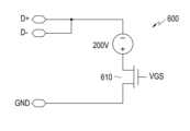
도 6은 USB 킬러(USB killer)로서 기능하는 외부 전자 장치의 등가 회로를 나타낸다. 외부 전자 장치는 VBUS 단자를 통해 전자 장치로부터 전력을 수신하고, 플라이백 컨버터(flyback converter)를 이용하여 약 -200V의 고압을 생성할 수 있다.Figure 6 shows an equivalent circuit of an external electronic device functioning as a USB killer. The external electronic device can receive power from the electronic device through the VBUS terminal and generate a high voltage of about -200V using a flyback converter.
도 7의 (a) 및 (b)를 참고하면, 등가 회로의 스위치(610)에는 주기적인 펄스들을 포함하는 게이트 전압(gate-to-source voltage: VGS)이 인가될 수 있다.Referring to (a) and (b) of FIGS. 7, a gate-to-source voltage (VGS) including periodic pulses may be applied to the
도 7의 (c)를 참고하면, 주기적인 펄스들에 대응하여 D+ 단자/D- 단자에 약 -200V의 전압(VDP)가 인가될 수 있다.Referring to (c) of FIG. 7, a voltage (VDP ) of about -200V may be applied to the D+ terminal/D- terminal in response to periodic pulses.
도 8의 블록도(800)를 참고하면, 전자 장치(801)(예: 전자 장치(101 또는 301))는, 커넥터(810)(예: 커넥터(310 또는 410)), 전력 관리 모듈(820)(예: 전력 관리 모듈(188, 330 또는 430)), 및/또는 프로세서(830)(예: 프로세서(120, 380 또는 480))를 포함할 수 있다.Referring to the block diagram 800 of FIG. 8, the electronic device 801 (e.g., electronic device 101 or 301) includes a connector 810 (e.g.,
커넥터(810)는, 예를 들어 마이크로 USB 커넥터(micro USB connector)일 수 있다. 커넥터(810)는 스탠다드 4핀 커넥터(standard 4pin connector)와 비교하여 USB ID(identification) 단자(또는 핀(pin))를 더 포함할 수 있다.The
외부 전자 장치(840)는 전압/전력 인가를 위한 VBUS 단자, USB 데이터 통신을 위한 D+ 단자, D- 단자, ID의 제공을 위한 ID 단자, 및 GND 단자를 포함할 수 있다. ID는 서로 다른 저항들(845)(R1, R2, R3 및 R4) 중 하나에 대한 저항 값으로 표현될 수 있다. 예를 들어, 저항 값이 약 10옴 이하인 ID는 USB OTG 장치를 나타낼 수 있다.The external
전자 장치(801)는, 커넥터(810)의 ID 단자에 대하여 감지된 값(이하, 제1 감지 값이라고 함)이 지정된 범위(예: 약 10옴 이하)에 속하는 것을 확인하고, 외부 전자 장치가 USB OTG 장치인 것을 확인할 수 있다.The
외부 전자 장치가 USB OTG 장치인 것의 확인에 적어도 기반하여, 전자 장치(850)는 커넥터(810)의 D+ 단자 및/또는 D- 단자에 대하여 감지된 값을 확인할 수 있다. 전자 장치(801)는 감지된 값이 지정된 범위에 속하는지를 확인할 수 있다.At least based on confirmation that the external electronic device is a USB OTG device, the electronic device 850 can confirm the sensed value for the D+ terminal and/or the D- terminal of the
감지된 값이 지정된 범위에 속하면, 전자 장치(801)는 전력 관리 모듈(820)을 이용하여 지정된 전력/전압을 VBUS 단자를 통해 외부 전자 장치(840)로 출력할 수 있다.If the sensed value falls within the specified range, the
감지된 값이 지정된 범위에 속하지 않거나 다른 지정된 범위에 속하면, 전자 장치(801)는 전력 관리 모듈(820)이 외부 전자 장치로의 전력 공급을 시작하지 않거나 중지하도록 제어할 수 있다.If the sensed value does not fall within a specified range or falls within another specified range, the
도 9는 젠더를 이용한 외부 전자 장치와 전자 장치의 연결을 설명하기 위한 블록도(900)이다.Figure 9 is a block diagram 900 for explaining the connection between an external electronic device and an electronic device using gender.
제2 외부 전자 장치(950)는 전압/전력 인가를 위한 VBUS 단자, USB 데이터 통신을 위한 D+ 단자, D- 단자, 및 GND 단자를 포함할 수 있다.The second external
커넥터(810)는, 스탠다드 4핀 커넥터(standard 4pin connector)와 비교하여 USB ID(identification) 단자(또는 핀(pin))를 더 포함할 수 있다.The
제1 외부 전자 장치(940)는, 젠더로서 기능하며, 일측면에 제2 외부 전자 장치(950)와의 연결을 위한 VBUS 단자, D+ 단자, D- 단자 및 GND 단자를 포함할 수 있고, 타측면에 커넥터(810)의 연결을 위한 VBUS 단자, D+ 단자, D- 단자, ID 단자 및 GND 단자를 포함할 수 있다.The first external
제2 외부 전자 장치(950)는 제1 외부 전자 장치(910)를 통해 커넥터(810)와 연결될 수 있다.The second external
도 10은 다양한 실시예들에 따른 전자 장치의 작동 방법을 설명하기 위한 도면이다.FIG. 10 is a diagram for explaining a method of operating an electronic device according to various embodiments.
전자 장치(1001)(예: 전자 장치(101 또는 301))는, 커넥터(1010)(예: 커넥터(310 또는 410)), 전력 관리 모듈(1020)(예: 전력 관리 모듈(188, 330 또는 430)), 및/또는 프로세서(1030)(예: 프로세서(120, 380 또는 480))를 포함할 수 있다.Electronic device 1001 (e.g., electronic device 101 or 301) includes a connector 1010 (e.g.,
프로세서(1030)는 제1 GPIO 단자(1031) 및 제2 GPIO 단자(1032)를 포함할 수 있다. 제1 GPIO 단자(1031) 및 제2 GPIO 단자(1032)는 커넥터(1010)를 통해 외부 전자 장치(1040)의 D+ 단자 및 D- 단자에 각각 연결될 수 있다.The
프로세서(1030)는, 제1 테스트를 위해, 제1 GPIO 단자(1031)에 하이 레벨의 신호(또는, 하이 신호)를 인가하고, 제2 GPIO 단자(1032) 단자에 대하여 감지된 값이 하이 레벨인지, 로우 레벨인지(또는, 하이 신호 조건을 만족하는지)를 확인할 수 있다.For the first test, the
프로세서(1030)는, 제2 테스트를 위해, 제2 GPIO 단자(1032)에 하이 레벨의 신호를 인가하고, 제1 GPIO 단자(1031) 단자에 대하여 감지된 값이 하이 레벨인지, 로우 레벨인지를 확인할 수 있다.For the second test, the
한 실시예에서, 프로세서(1030)는, 감지된 값이 지정된 범위에 속하면(또는 감지된 값이 지정된 임계 값과 대응/유사(예: 약 ±5% 또는 약 ±10%의 차이)하거나 그 이상/이하인 경우), 감지된 값이 하이 레벨인 것으로 확인할 수 있다.In one embodiment,
제1 테스트 및 제2 테스트의 결과들이 모두 하이 레벨인 경우, 프로세서(1030)는 외부 전자 장치(1040)의 D+ 단자 및 D- 단자가 쇼트되어 있는 것으로 확인/결정할 수 있다. 이하, 쇼트는, 해당 단자에 대하여 감지된 값이 지정된 임계값 이하인 경우를 의미할 수 있다.If the results of the first test and the second test are both high level, the
제1 테스트 및 제2 테스트의 결과들이 모두 하이 레벨인 것에 적어도 기반하여, 프로세서(1030)는 전력 관리 모듈(1020)이 외부 전자 장치(1040)로의 전력 공급을 시작하지 않거나 중지하도록 제어할 수 있다.Based at least on the fact that the results of the first test and the second test are both high levels, the
제1 테스트 및 제2 테스트의 결과들이 모두 하이 레벨이 아닌 것에 적어도 기반하여, 전자 장치(1001)는 전력 관리 모듈(1020)을 이용하여 지정된 전력/전압을 VBUS 단자를 통해 외부 전자 장치(1040)로 출력할 수 있다.At least based on the fact that the results of the first test and the second test are not all high level, the
한 실시예에서, 전력 관리 모듈(1020)은 보호 회로(1025)를 포함할 수 있다. 보호 회로(1025)는 D+ 단자 및 D- 단자가 외부 전자 장치(1040)에서 쇼트가 되었는지 여부를 확인할 수 있다.In one embodiment,
D+ 단자 및 D- 단자가 쇼트된 경우, 보호 회로(1025)는 쇼트된 D+ 단자 및 D- 단자의 연결을 해제할 수 있다.If the D+ terminal and D- terminal are shorted, the
도 11은 다양한 실시예들에 따른 전자 장치와 외부 전자 장치의 연결을 설명하기 위한 도면이다.FIG. 11 is a diagram illustrating the connection between an electronic device and an external electronic device according to various embodiments.
전자 장치(예: 전자 장치(101 또는 301))는 제1 커넥터(1110)를 통해 외부 전자 장치(예: 전자 장치(102) 또는 전자 장치(104))와 전기적으로 연결될 수 있다.An electronic device (eg, electronic device 101 or 301) may be electrically connected to an external electronic device (eg,
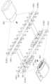
전자 장치의 제1 커넥터(1110)는 외부 전자 장치의 제2 커넥터(1150)가 정방향 또는 역방향 중 어느 방향으로도 꽂힐 수 있도록 외관이 형성될 수 있으며, 제1 커넥터(1110)의 내부에는 접점 기판(1105)이 형성될 수 있다.The
접점 기판(1105)은 정방향에 대응되는 제1 면(예: A면)에 열 두 개의 핀(1110-1, 1110-2,...1110-12)이 형성되어 있고, 역방향에 대응되는 제2 면(예: B면)에 열 두 개의 핀(1120-1, 1120-2,...1120-12)이 형성될 수 있다. 상기 접점 기판(1105)의 내부에는 전기적으로 도체 특성을 갖는 미드 플레이트(1106)가 형성될 수 있다.The
외부 전자 장치의 제2 커넥터(1150)는 접점 기판(1105)의 제1 면(예: A면)에 형성된 열 두 개의 핀(1110-1, 1110-2,...1110-12)과 접촉되도록 제1 면(예: A면)에 열 두 개의 핀(1130-1, 1130-2,...1130-12)이 형성될 수 있고, 접점 기판(1105)의 제2 면(예: B면)에 형성된 열 두 개의 핀(1120-1, 1120-2,...1120-12)과 접촉되도록 제2 면(예: B면)에 열 두 개의 핀(1140-1, 1140-2,...1140-12)이 형성될 수 있다. 상기 외부 전자 장치의 제2 커넥터(1150)에 구성된 핀의 개수는 외부 전자 장치의 종류에 따라 다를 수 있다. 또한, 상기 외부 전자 장치의 CC 핀은 종류에 따라 한 개이거나 두 개일 수 있다. 예를 들면, 외부 전자 장치의 제2 커넥터(1150)가 제1 면 또는 제2 면 중 어느 방향으로 꽂힐 수 있도록, 제1 면(예: A면)에 형성된 열 두 개의 핀의 배열 순서는 제2 면(예: B면)에 형성된 열 두 개의 핀의 배열 순서와 동일하게 형성될 수 있다. 이러한 구조로 인해, 사용자는 외부 전자 장치의 제2 커넥터(1150)를 전자 장치의 제1 커넥터(1110)에 180도로 회전된 상태로 꽂을 수도 있다.The
일 실시예에 따르면, 접점 기판(1105)의 제1 면(예: A면)과 제2 면(예: B면)에 형성된 핀의 배열은 아래 [표 1]과 같다.According to one embodiment, the arrangement of the pins formed on the first side (eg, A side) and the second side (eg, B side) of the
No.Pin
No.
NameSignal
Name
SSTXp1TX1+ or
SSTXp1
(e.g., 10Gb/s differential pair with TX1-)Super speed TX positive
(eg, 10Gb/s differential pair with TX1-)
SSTXn1TX1-or
SSTXn1
(e.g. 10Gb/s differential pair with TX1+)Super speed TX negative
(eg 10Gb/s differential pair with TX1+)
SSRXn2RX2-or
SSRXn2
(e.g., 10Gb/s differential pair with RX2+)Super speed RX negative
(eg, 10Gb/s differential pair with RX2+)
SSRXp2RX2+ or
SSRXp2
(e.g., 10Gb/s differential pair with RX2-)Super speed RX positive
(eg, 10Gb/s differential pair with RX2-)
Type C 커넥터로 연결된 전자 장치 및/또는 외부 전자 장치는, CC 핀을 이용한 통신을 통해 호스트(host) 모드 또는 디바이스(device) 모드로 동작할지 결정하게 된다.The electronic device and/or external electronic device connected to the Type C connector determines whether to operate in host mode or device mode through communication using the CC pin.
한 실시예에 따르면, 전자 장치 및/또는 외부 전자 장치는 CC 핀에 연결된 Rp/Rd 저항을 이용하여 호스트 모드인지 디바이스 모드인지 여부를 결정할 수 있다. USB 킬러의 경우 전원을 공급받기 위한 디바이스로 동작하기 위해 Rd 저항을 사용할 수 있다.According to one embodiment, the electronic device and/or external electronic device may determine whether the device is in host mode or device mode using the Rp/Rd resistor connected to the CC pin. In the case of a USB killer, an Rd resistor can be used to act as a device to receive power.
한 실시예에 따르면, 전자 장치는 CC 핀의 감지 값에 기반하여 전원 공급을 시작하기 이전에 Tx/Rx 핀의 쇼트 여부를 추가로 확인할 수 있다. 쇼트 감지 방법은 도 10을 참고하여 기술한 D+/D- 핀의 쇼트 체크 방법과 동일하거나 유사한 방법이 될 수 있다. Tx/Rx 핀이 쇼트 상태이면, 전자 장치는 외부 전자 장치로 전원 공급을 중단할 수도 있다. 전자 장치는 Tx/Rx 핀 쇼트 체크와 함께 D+/D- 핀도 병렬로 체크할 수도 있다.According to one embodiment, the electronic device may additionally check whether the Tx/Rx pin is shorted before starting to supply power based on the detection value of the CC pin. The short detection method may be the same or similar to the D+/D- pin short check method described with reference to FIG. 10. If the Tx/Rx pin is shorted, the electronic device may stop supplying power to the external electronic device. The electronic device may also check the D+/D- pins in parallel along with the Tx/Rx pin short check.
도 12는 다양한 실시예들에 따른 전자 장치의 보호 회로를 설명하기 위한 도면이다.FIG. 12 is a diagram for explaining a protection circuit of an electronic device according to various embodiments.
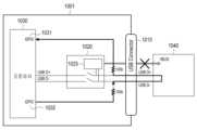
전자 장치(1201)(예: 전자 장치(101 또는 301))는, 커넥터(1210)(예: 커넥터(310 또는 410)), 전력 관리 모듈(1220)(예: 전력 관리 모듈(188, 330 또는 430)), 및/또는 보호 회로(1225)를 포함할 수 있다.Electronic device 1201 (e.g., electronic device 101 or 301) includes a connector 1210 (e.g.,
보호 회로(1225)는 커넥터(1210) 및 전력 관리 모듈(1220)의 사이에 배치되고, 외부 전자 장치(1240)로부터 임계값 이상의 전압(또는, 과전압)이 인가되는 것을 방지할 수 있다.The
한 실시예에서, CC 핀 통신 이후 외부 전자 장치(1240)에 전원 공급을 시작하면, 보호 회로(1225)는 전원 공급과 관계 없는 CC 핀, Tx1/2 핀, Rx1/2 핀, D+/D- 핀 또는 SBU 핀 중의 적어도 하나와 전력 관리 모듈(1220) 사이의 스위치를 오픈하여 해당 연결을 해제할 수 있다.In one embodiment, when power is supplied to the external
한 실시예에서, 보호 회로(1225)는 데이터 핀이 외부 전자 장치(1240)에서 쇼트가 되었는지 여부를 확인할 수 있다. 데이터 핀이 쇼트된 경우, 보호 회로(1225)는 쇼트된 핀의 연결을 해제할 수 있다. 데이터 핀이 쇼트되지 않은 경우, 보호 회로(1225)는 쇼트되지 않은 핀을 전력 관리 모듈(1220)과 연결하거나 그 연결을 유지할 수 있다. 예를 들어, Tx1,Tx2, Rx1 및 Rx2 핀들 각각이 쇼트되어 있지 않은 경우, 보호 회로(1225)는 Tx1,Tx2, Rx1 및 Rx2 핀들을 전력 관리 모듈(1220)과 연결하거나 그 연결을 유지할 수 있다.In one embodiment, the
한 실시예에서, 보호 회로(1225)는 CC 핀, D+/D- 핀 또는 SBU 핀 중의 적어도 하나를 전력 관리 모듈(1220)과 연결 해제하여, 외부 전자 장치(1240)로부터 임계값 이상의 전압(또는, 과전압)이 인가되는 것을 방지할 수도 있다.In one embodiment, the
도 13은 다양한 실시예들에 따른 전자 장치의 작동 방법을 설명하기 위한 도면이다.FIG. 13 is a diagram for explaining a method of operating an electronic device according to various embodiments.
전자 장치(1310)(예: 전자 장치(101 또는 301))는 커넥터(미도시)(예: 커넥터(310 또는 410))를 통해 외부 전자 장치와 연결될 수 있다.The electronic device 1310 (eg, the electronic device 101 or 301) may be connected to an external electronic device through a connector (not shown) (eg, the
전자 장치는, 커넥터의 지정된 단자에 대하여 감지된 값을 확인할 수 있다.The electronic device can check the sensed value for the designated terminal of the connector.
감지 값이 제1 지정된 범위에 속하지 않거나 제2 지정된 범위에 속하면, 전자 장치는 디스플레이(1306)(예: 도 1의 표시 장치(160))에 지정된 정보(1310)(예: 텍스트, 이미지, 및/또는 메시지)를 표시할 수 있다.If the sensed value does not fall within the first specified range or falls within the second specified range, the electronic device displays specified information 1310 (e.g., text, image, and/or message) can be displayed.
한 실시예에서, 전자 장치는, 지정된 범위에 속하지 않는 감지 값들이 지정된 횟수 이상(및 지정된 시간 동안) 확인된 경우, 디스플레이(1306)에 지정된 정보(1310)를 표시할 수 있다.In one embodiment, the electronic device may display specified
한 실시예에서, 전자 장치는, 디스플레이(1306) 또는 LED(light emitting diode)를 이용한 시각적 알림(또는 통지/노티), 스피커를 이용한 청각적 알림, 진동을 통한 촉각적 알림, 및/또는 외부 전자 장치로의 알림 메시지 전송을 통해, 사용자에게 과전압을 유발하는 외부 전자 장치에 대한 알림을 제공할 수 있다.In one embodiment, the electronic device may provide a visual notification (or notification/noti) using a
다양한 실시예에 따르면, 명령들을 저장하고 있는 저장 매체에 있어서, 상기 명령들은 적어도 하나의 회로에 의하여 실행될 때에 상기 적어도 하나의 회로로 하여금 적어도 하나의 동작을 수행하도록 설정된 것으로서, 상기 적어도 하나의 동작은, 전자 장치의 커넥터를 통해 연결된 외부 전자 장치의 종류를 확인하는 동작, 상기 확인된 종류가 지정된 종류인 것에 적어도 일부 기반하여, 상기 커넥터의 하나 이상의 신호 단자들 중 적어도 일부 단자에 대한 감지 값을 확인하는 동작, 및 상기 감지 값이 제1 지정된 범위에 속하면, 지정된 전압을 상기 커넥터의 하나 이상의 전원 단자들을 통해 상기 외부 전자 장치로 출력하는 동작을 포함할 수 있다.According to various embodiments, in a storage medium storing instructions, the instructions are set to cause the at least one circuit to perform at least one operation when executed by the at least one circuit, and the at least one operation is , An operation of confirming the type of an external electronic device connected through a connector of an electronic device, based at least in part on the fact that the confirmed type is a designated type, confirming a detection value for at least some terminals of one or more signal terminals of the connector and, if the sensed value falls within a first designated range, outputting a designated voltage to the external electronic device through one or more power terminals of the connector.
101: 전자 장치, 120: 프로세서, 130: 메모리, 150: 입력 장치, 160: 표시 장치, 190: 통신 모듈101: electronic device, 120: processor, 130: memory, 150: input device, 160: display device, 190: communication module
Claims (20)
Translated fromKorean전원 레귤레이터;
복수의 신호 단자들 및 상기 전원 레귤레이터와 전기적으로 연결된 하나 이상의 전원 단자들을 포함하는 커넥터; 및
상기 복수의 신호 단자들 중 제1 및 제2 신호 단자들과 전기적으로 연결된 제1 및 제2 단자들을 포함하는 제어 회로를 포함하고, 상기 제어 회로는,
상기 커넥터를 통해 연결된 외부 전자 장치의 종류를 상기 복수의 신호 단자들 중 제3 신호 단자를 통해 확인하고,
상기 종류가 상기 전원 레귤레이터를 통해 전력 공급이 필요한 장치인 경우, 상기 전원 레귤레이터를 이용하여 출력된 지정된 전압을 상기 하나 이상의 전원 단자들을 통해 상기 외부 전자 장치로 출력하고,
제1 테스트를 위해 상기 제1 단자에 지정된 신호를 인가하고 상기 제2 단자의 전압을 감지하고,
제2 테스트를 위해 상기 제2 단자에 상기 지정된 신호를 인가하고 상기 제1 단자의 전압을 감지하고,
상기 감지된 전압들이 제1 지정된 범위에 속하면, 상기 제1 및 제2 신호 단자들이 단락되지 않은 것으로 결정하고, 상기 전원 레귤레이터를 통해 상기 지정된 전압을 상기 외부 전자 장치로 출력하는 동작을 유지하고, 및
상기 감지된 전압들이 제2 지정된 범위에 속하면, 상기 제1 및 제2 신호 단자들이 단락된 것으로 결정하고, 상기 전원 레귤레이터를 통해 상기 지정된 전압을 상기 외부 전자 장치로 출력하는 동작을 적어도 일시적으로 중지하도록 설정된 전자 장치.In electronic devices,
power regulator;
a connector including a plurality of signal terminals and one or more power terminals electrically connected to the power regulator; and
A control circuit including first and second terminals electrically connected to first and second signal terminals among the plurality of signal terminals, the control circuit comprising:
Confirming the type of external electronic device connected through the connector through a third signal terminal among the plurality of signal terminals,
If the type is a device that requires power supply through the power regulator, output a designated voltage output using the power regulator to the external electronic device through the one or more power terminals,
For a first test, apply a designated signal to the first terminal and detect the voltage of the second terminal,
For a second test, apply the specified signal to the second terminal and detect the voltage of the first terminal,
If the detected voltages fall within a first specified range, determine that the first and second signal terminals are not short-circuited, and maintain the operation of outputting the specified voltage to the external electronic device through the power regulator, and
When the detected voltages fall within a second designated range, it is determined that the first and second signal terminals are short-circuited, and the operation of outputting the designated voltage to the external electronic device through the power regulator is at least temporarily stopped. An electronic device configured to do so.
상기 하나 이상의 전원 단자들을 통해 상기 외부 전자 장치가 상기 커넥터에 연결되었는지를 감지하도록 설정된 전자 장치.The method of claim 1, wherein the control circuit:
An electronic device configured to detect whether the external electronic device is connected to the connector through the one or more power terminals.
상기 전원 레귤레이터와 연결된 배터리를 더 포함하고,
상기 제어 회로는,
상기 커넥터를 통해 연결된 상기 외부 전자 장치가 상기 전자 장치에 전력 공급을 하기 위한 장치인지를 상기 하나 이상의 전원 단자들을 통해 확인하고,
상기 외부 전자 장치가 상기 전자 장치에 전력 공급을 하기 위한 장치로 확인되면, 상기 전원 레귤레이터가 상기 하나 이상의 전원 단자들을 통해 상기 외부 전자 장치로부터 입력 받은 전압의 적어도 일부를 이용하여 상기 배터리를 충전하도록, 상기 입력 받은 전압을 상기 전원 레귤레이터로 입력하도록 설정된 전자 장치.According to paragraph 1,
Further comprising a battery connected to the power regulator,
The control circuit is,
Confirm through the one or more power terminals whether the external electronic device connected through the connector is a device for supplying power to the electronic device,
When the external electronic device is identified as a device for supplying power to the electronic device, the power regulator charges the battery using at least a portion of the voltage input from the external electronic device through the one or more power terminals, An electronic device configured to input the received voltage to the power regulator.
상기 외부 전자 장치는 제1 외부 전자 장치 및 제2 외부 전자 장치를 포함하고, 상기 제1 외부 전자 장치는 상기 하나 이상의 전원 단자들 및 상기 복수의 신호 단자들과 전기적으로 연결되고, 및
상기 제2 외부 전자 장치는 상기 제1 외부 전자 장치를 통해 상기 하나 이상의 전원 단자들 및 상기 복수의 신호 단자들 중 적어도 일부와 전기적으로 연결된 전자 장치.According to paragraph 1,
The external electronic device includes a first external electronic device and a second external electronic device, wherein the first external electronic device is electrically connected to the one or more power terminals and the plurality of signal terminals, and
The second external electronic device is electrically connected to at least some of the one or more power terminals and the plurality of signal terminals through the first external electronic device.
전원 레귤레이터;
복수의 신호 단자들 및 상기 전원 레귤레이터와 전기적으로 연결된 하나 이상의 전원 단자들을 포함하는 커넥터; 및
상기 복수의 신호 단자들 중 제1 및 제2 신호 단자들과 전기적으로 연결된 제1 및 제2 단자들을 포함하는 제어 회로를 포함하고, 상기 제어 회로는,
상기 커넥터를 통해 연결된 외부 전자 장치의 종류를 확인하고,
상기 확인된 종류가 지정된 종류인 경우, 제1 테스트를 위해 상기 제1 단자에 지정된 신호를 인가하고 상기 제2 단자의 전압을 감지하고, 제2 테스트를 위해 상기 제2 단자에 상기 지정된 신호를 인가하고 상기 제1 단자의 전압을 감지하고,
상기 감지된 전압들이 제1 지정된 범위에 속하면, 상기 제1 및 제2 신호 단자들이 단락되지 않은 것으로 결정하고, 상기 전원 레귤레이터를 이용하여 지정된 전압을 상기 하나 이상의 전원 단자들을 통해 상기 외부 전자 장치로 출력하고,
상기 감지된 전압들이 제2 지정된 범위에 속하면, 상기 제1 및 제2 신호 단자들이 단락된 것으로 결정하고, 상기 지정된 전압을 상기 외부 전자 장치로 출력하지 않도록 설정된 전자 장치.In electronic devices,
power regulator;
a connector including a plurality of signal terminals and one or more power terminals electrically connected to the power regulator; and
A control circuit including first and second terminals electrically connected to first and second signal terminals among the plurality of signal terminals, the control circuit comprising:
Check the type of external electronic device connected through the connector,
If the confirmed type is the specified type, apply the specified signal to the first terminal for the first test, detect the voltage of the second terminal, and apply the specified signal to the second terminal for the second test. and detect the voltage of the first terminal,
If the sensed voltages fall within a first specified range, it is determined that the first and second signal terminals are not short-circuited, and the specified voltage is supplied to the external electronic device through the one or more power terminals using the power regulator. Print it out,
If the detected voltages fall within a second specified range, the electronic device is configured to determine that the first and second signal terminals are short-circuited and not to output the specified voltage to the external electronic device.
상기 제어 회로는,
상기 외부 전자 장치의 종류가 USB OTG(on-the-go) 장치로 확인되면 상기 지정된 종류를 만족하는 것으로 결정하도록 설정된 전자 장치.In clause 7,
The control circuit is,
An electronic device configured to determine that it satisfies the specified type when the type of the external electronic device is confirmed to be a USB OTG (on-the-go) device.
상기 전자 장치의 커넥터를 통해 연결된 외부 전자 장치의 종류를 확인하는 동작;
상기 확인된 종류가 지정된 종류인 경우, 제1 테스트를 위해 상기 커넥터의 복수의 신호 단자들 중 제1 신호 단자에 지정된 신호를 인가하고 제2 신호 단자의 전압을 감지하고, 제2 테스트를 위해 상기 제2 신호 단자에 상기 지정된 신호를 인가하고 상기 제1 신호 단자의 전압을 감지하는 동작;
상기 감지된 전압들이 제1 지정된 범위에 속하면, 상기 제1 및 제2 신호 단자들이 단락되지 않은 것으로 결정하고, 지정된 전압을 상기 커넥터의 하나 이상의 전원 단자들을 통해 상기 외부 전자 장치로 출력하는 동작; 및
상기 감지된 전압들이 제2 지정된 범위에 속하면, 상기 제1 및 제2 신호 단자들이 단락된 것으로 결정하고, 상기 지정된 전압을 상기 외부 전자 장치로 출력하지 않도록 상기 전자 장치의 전원 레귤레이터를 제어하는 동작을 포함하는 방법.In a method for overvoltage protection by an electronic device,
An action to determine the type of external electronic device connected through the connector of the above electronic device;
If the above-mentioned confirmed type is a designated type, an operation of applying a designated signal to a first signal terminal among a plurality of signal terminals of the connector for a first test and detecting a voltage of a second signal terminal, and applying the designated signal to the second signal terminal for a second test and detecting a voltage of the first signal terminal;
If the detected voltages fall within a first specified range, determining that the first and second signal terminals are not short-circuited, and outputting the specified voltage to the external electronic device through one or more power terminals of the connector; and
A method comprising: determining that the first and second signal terminals are short-circuited if the detected voltages fall within a second specified range, and controlling a power regulator of the electronic device so as not to output the specified voltage to the external electronic device.
상기 커넥터를 통해 연결된 상기 외부 전자 장치가 상기 전자 장치에 전력 공급을 하기 위한 장치인지를 상기 복수의 신호 단자들 또는 상기 하나 이상의 전원 단자들을 통해 확인하는 동작; 및
상기 외부 전자 장치가 상기 전자 장치에 전력 공급을 하기 위한 장치로 확인되면, 상기 전원 레귤레이터가 상기 하나 이상의 전원 단자들을 통해 상기 외부 전자 장치로부터 수신한 전력을 이용하여 상기 전자 장치의 배터리를 충전하는 동작을 더 포함하는 방법.The method of claim 14, wherein
An operation of checking whether the external electronic device connected through the connector is a device for supplying power to the electronic device through the plurality of signal terminals or the one or more power terminals; and
When the external electronic device is identified as a device for supplying power to the electronic device, charging the battery of the electronic device by the power regulator using power received from the external electronic device through the one or more power terminals. How to include more.
Priority Applications (5)
| Application Number | Priority Date | Filing Date | Title |
|---|---|---|---|
| KR1020180020360AKR102692156B1 (en) | 2018-02-21 | 2018-02-21 | An electronic apparatus and a method for controlling voltage output to an external electronic device according to voltage sensed at a signal terminal connected to the external electronic device |
| CN201980014753.9ACN111742459B (en) | 2018-02-21 | 2019-02-19 | Method and electronic device for controlling a voltage output to an external electronic device according to a voltage magnitude detected at a signal terminal connected to the external electronic device |
| EP19756742.3AEP3732758A4 (en) | 2018-02-21 | 2019-02-19 | METHOD AND ELECTRONIC DEVICE FOR CONTROLLING THE VOLTAGE OUTPUT TO AN EXTERNAL ELECTRONIC DEVICE ACCORDING TO THE SIZE OF THE VOLTAGE DETECTED AT A SIGNAL CONNECTION CONNECTED TO AN EXTERNAL ELECTRONIC DEVICE |
| US16/279,271US11288407B2 (en) | 2018-02-21 | 2019-02-19 | Method and electronic device for controlling voltage output to external electronic device according to size of voltage detected at signal terminal connected to external electronic device |
| PCT/KR2019/001953WO2019164208A1 (en) | 2018-02-21 | 2019-02-19 | Method and electronic device for controlling voltage output to external electronic device according to size of voltage detected at signal terminal connected to external electronic device |
Applications Claiming Priority (1)
| Application Number | Priority Date | Filing Date | Title |
|---|---|---|---|
| KR1020180020360AKR102692156B1 (en) | 2018-02-21 | 2018-02-21 | An electronic apparatus and a method for controlling voltage output to an external electronic device according to voltage sensed at a signal terminal connected to the external electronic device |
Publications (2)
| Publication Number | Publication Date |
|---|---|
| KR20190100601A KR20190100601A (en) | 2019-08-29 |
| KR102692156B1true KR102692156B1 (en) | 2024-08-07 |
Family
ID=67617985
Family Applications (1)
| Application Number | Title | Priority Date | Filing Date |
|---|---|---|---|
| KR1020180020360AActiveKR102692156B1 (en) | 2018-02-21 | 2018-02-21 | An electronic apparatus and a method for controlling voltage output to an external electronic device according to voltage sensed at a signal terminal connected to the external electronic device |
Country Status (5)
| Country | Link |
|---|---|
| US (1) | US11288407B2 (en) |
| EP (1) | EP3732758A4 (en) |
| KR (1) | KR102692156B1 (en) |
| CN (1) | CN111742459B (en) |
| WO (1) | WO2019164208A1 (en) |
Families Citing this family (19)
| Publication number | Priority date | Publication date | Assignee | Title |
|---|---|---|---|---|
| KR102321418B1 (en)* | 2017-03-10 | 2021-11-03 | 삼성전자 주식회사 | Method for detecting swelling of battery using pressure sensor and electronic device using the same |
| US11100255B1 (en)* | 2019-07-01 | 2021-08-24 | Dialog Semiconductor (Uk) Limited | Method and apparatus for high voltage protection |
| KR102787543B1 (en) | 2019-09-20 | 2025-04-01 | 삼성전자주식회사 | An electronic device supporting connection with external device and power consumption reducing method when using in connection with the external device |
| KR102454001B1 (en)* | 2020-06-08 | 2022-10-14 | 대한민국 | Electrical characteristics test system for a electroshock weapon |
| KR102201172B1 (en)* | 2020-06-10 | 2021-01-11 | 한화시스템 주식회사 | Apparatus and method for distributing power of wearable device |
| KR102795016B1 (en)* | 2020-07-23 | 2025-04-15 | 삼성전자주식회사 | Electronic device comprising battery |
| KR102818458B1 (en) | 2020-07-29 | 2025-06-10 | 삼성전자주식회사 | Electronic device for prodiving power and operating method thereof |
| US11422576B2 (en)* | 2020-08-28 | 2022-08-23 | Hewlett Packard Enterprise Development Lp | Modular power supply unit |
| US11658574B2 (en)* | 2020-09-02 | 2023-05-23 | Cypress Semiconductor Corporation | Programmable soft start of buck-boost converter |
| CN112383125B (en)* | 2021-01-15 | 2021-04-27 | 珠海智融科技有限公司 | Active overcharge prevention device and method |
| CN112783310A (en)* | 2021-01-15 | 2021-05-11 | 惠州Tcl移动通信有限公司 | Terminal equipment control method and device, storage medium and terminal equipment |
| US11734210B2 (en)* | 2021-03-15 | 2023-08-22 | Lenovo (Singapore) Pte. Ltd. | Multipurpose USB dongle apparatus for data transfer |
| JP7549125B2 (en)* | 2021-03-25 | 2024-09-10 | 本田技研工業株式会社 | Power Supplies |
| CN113691644B (en)* | 2021-07-07 | 2025-06-03 | 浙江大华技术股份有限公司 | Data transmission device |
| EP4340166B1 (en)* | 2021-07-27 | 2025-10-15 | Samsung Electronics Co., Ltd. | Electronic apparatus for charging another electronic apparatus, and method for controlling electronic apparatus for charging other electronic apparatus |
| KR20230036900A (en)* | 2021-09-08 | 2023-03-15 | 삼성전자주식회사 | Electronic apparatus and operating method thereof |
| EP4358354A1 (en)* | 2022-10-21 | 2024-04-24 | Samsung Electronics Co., Ltd. | Electronic device and an operating method of the electronic device |
| CN117037891B (en)* | 2023-08-18 | 2024-12-24 | 深圳市大乘科技股份有限公司 | A port identification method, device, equipment and medium for dual-head storage |
| PL446781A1 (en)* | 2023-11-20 | 2025-05-26 | Politechnika Śląska | SD port test card |
Citations (1)
| Publication number | Priority date | Publication date | Assignee | Title |
|---|---|---|---|---|
| KR100944802B1 (en)* | 2009-08-31 | 2010-02-26 | 김삼현 | Controllng curcuit for ac charging |
Family Cites Families (30)
| Publication number | Priority date | Publication date | Assignee | Title |
|---|---|---|---|---|
| KR20080086735A (en)* | 2007-03-23 | 2008-09-26 | 금비전자(주) | DC power supply using portable charger |
| US8026697B2 (en) | 2007-04-27 | 2011-09-27 | Broadcom Corporation | Multi-mode power management unit with shared inductor |
| US8084987B2 (en) | 2008-02-13 | 2011-12-27 | Active-Semi, Inc. | USB port with smart power management |
| US7635280B1 (en)* | 2008-07-30 | 2009-12-22 | Apple Inc. | Type A USB receptacle with plug detection |
| US20100070659A1 (en)* | 2008-09-17 | 2010-03-18 | Kenneth Ma | Method and system for operating and/or charging a battery powered usb device based on a usb port type |
| US8982520B2 (en) | 2008-09-19 | 2015-03-17 | Standard Microsystems Corporation | USB port overvoltage protection |
| JP5292155B2 (en)* | 2009-03-27 | 2013-09-18 | Tdkラムダ株式会社 | Power supply control device, power supply device, and power supply control method |
| CN101963835B (en)* | 2009-07-24 | 2013-04-24 | 鸿富锦精密工业(深圳)有限公司 | Electronic equipment and method for dynamically allocating USB port power |
| KR101667707B1 (en)* | 2009-10-22 | 2016-10-19 | 엘지전자 주식회사 | Mobile terminal and usb dedicated charger determinating method thereof |
| KR20110009415U (en)* | 2010-03-29 | 2011-10-06 | 미리넷 주식회사 | Stabilized Power Supply Device using Universial Serial Bus |
| US8699717B2 (en) | 2010-05-28 | 2014-04-15 | Fairchild Semiconductor Corporation | Audio amplifier performance while maintaining USB compliance and power down protection |
| JP5283719B2 (en) | 2011-02-16 | 2013-09-04 | シャープ株式会社 | Electronic equipment and electronic equipment system |
| JP5799852B2 (en) | 2011-03-30 | 2015-10-28 | ソニー株式会社 | Input/Output Devices |
| JP2012208897A (en)* | 2011-03-30 | 2012-10-25 | Semiconductor Components Industries Llc | Input/output circuit |
| US8581546B2 (en)* | 2011-09-01 | 2013-11-12 | Richard Luke Ribich | Method and apparatus for converting dirty electrical power to a clean electrical power suitable for a portable electronic flight bag in an aircraft |
| CN103365388B (en) | 2012-04-09 | 2017-02-22 | 华为终端有限公司 | Power supply method of terminal device and terminal device |
| US8683090B2 (en)* | 2012-04-19 | 2014-03-25 | Apple Inc. | Methods, systems and apparatus for determining whether an accessory includes particular circuitry |
| US8724281B2 (en)* | 2012-04-25 | 2014-05-13 | Apple Inc. | Techniques for detecting removal of a connector |
| CN102880238B (en)* | 2012-08-30 | 2015-07-22 | 中兴通讯股份有限公司 | Interface expanding method and device for tablet personal computer |
| TWI461891B (en) | 2012-10-19 | 2014-11-21 | Wistron Corp | Power managing circuit and the method thereof |
| KR20150000698A (en)* | 2013-06-25 | 2015-01-05 | 삼성전자주식회사 | Method and apparatus for recognizing accessory in electronic device |
| KR20160011392A (en)* | 2014-07-22 | 2016-02-01 | 삼성전자주식회사 | Method and device for identifying external device |
| BR112017004714B1 (en)* | 2014-09-15 | 2023-02-23 | Micro Motion, Inc | METHOD OF CONTROLLING A MODE OF A DEVICE, AND APPARATUS FOR CONTROLLING A MODE OF A DEVICE |
| KR101800814B1 (en) | 2014-11-03 | 2017-11-23 | 주식회사 엘지화학 | Battery pack having an USB charger terminal |
| CN105098438A (en) | 2015-08-05 | 2015-11-25 | 小米科技有限责任公司 | USB socket connector and electronic equipment with the same |
| JP6553986B2 (en)* | 2015-08-21 | 2019-07-31 | キヤノン株式会社 | Communication device, control method therefor, program |
| JP6643035B2 (en)* | 2015-10-09 | 2020-02-12 | キヤノン株式会社 | Electronic equipment, control method and program |
| WO2017119876A1 (en)* | 2016-01-06 | 2017-07-13 | Hewlett-Packard Development Company, L.P. | Detection circuits |
| KR101787470B1 (en) | 2016-02-15 | 2017-11-16 | 한국전자통신연구원 | Apparatus for analyzing malicious code based on external device connected usb and method using the same |
| KR102548688B1 (en)* | 2016-03-28 | 2023-06-28 | 삼성전자주식회사 | Processing method for leakage power and electronic device supporting the same |
- 2018
- 2018-02-21KRKR1020180020360Apatent/KR102692156B1/enactiveActive
- 2019
- 2019-02-19CNCN201980014753.9Apatent/CN111742459B/enactiveActive
- 2019-02-19EPEP19756742.3Apatent/EP3732758A4/enactivePending
- 2019-02-19WOPCT/KR2019/001953patent/WO2019164208A1/ennot_activeCeased
- 2019-02-19USUS16/279,271patent/US11288407B2/enactiveActive
Patent Citations (1)
| Publication number | Priority date | Publication date | Assignee | Title |
|---|---|---|---|---|
| KR100944802B1 (en)* | 2009-08-31 | 2010-02-26 | 김삼현 | Controllng curcuit for ac charging |
Also Published As
| Publication number | Publication date |
|---|---|
| US20190258832A1 (en) | 2019-08-22 |
| CN111742459A (en) | 2020-10-02 |
| KR20190100601A (en) | 2019-08-29 |
| CN111742459B (en) | 2025-02-07 |
| EP3732758A4 (en) | 2021-01-06 |
| US11288407B2 (en) | 2022-03-29 |
| EP3732758A1 (en) | 2020-11-04 |
| WO2019164208A1 (en) | 2019-08-29 |
Similar Documents
| Publication | Publication Date | Title |
|---|---|---|
| KR102692156B1 (en) | An electronic apparatus and a method for controlling voltage output to an external electronic device according to voltage sensed at a signal terminal connected to the external electronic device | |
| KR102609837B1 (en) | Electronic device and method of communicating with an external device via a power supply line | |
| KR102577457B1 (en) | Electronic apparatus and method for controlling power supplying | |
| KR102569178B1 (en) | Electronic device comprsing control circuits controlling switchs connected to charging circuit | |
| US11556163B2 (en) | Electronic device including connector and method for controlling power transmission/reception in electronic device | |
| CN113475051B (en) | Apparatus and method for providing user interface according to wireless power sharing | |
| KR102688106B1 (en) | Method for controlling wireless transmit power and electronic device including the same | |
| KR102610543B1 (en) | Electronic device and method for diagonosing battery thereof | |
| KR102540749B1 (en) | An electronic device determining a power transmission path at least based on a property of a power being supplied from outside of the electronic device and a status of the electronic device and control method thereof | |
| KR20200101035A (en) | Electronic device and method for transmitting wireless power based on detecting foreign object in electronic device | |
| KR102710752B1 (en) | Method to control charging of multiple batteries and electronic device applying the method | |
| KR20200114430A (en) | Power circuit and electronic device including the same | |
| KR102651715B1 (en) | Electronic device for preventing damage of usb device and operating method thereof | |
| KR102500690B1 (en) | Battery status based charging control method and appratus thereof | |
| KR20200105162A (en) | Tethod to control charging of battery and electronic device applying the method | |
| KR20200050260A (en) | A method and an electronic device powered by an external device | |
| KR102799036B1 (en) | Method for malfunction of connector and electronic device having the connector | |
| CN110800168B (en) | Method and apparatus for changing the impedance of terminals included in a connector | |
| KR102627633B1 (en) | Electronic device including logic circuit for determining connecting state of connector | |
| KR20200042376A (en) | Electronic device and method for wire and wireless charging in electronic device | |
| KR102600482B1 (en) | Electronic apparatus and method for outputting a alarm, and system including a locking device connected to the electronic device | |
| KR20210101718A (en) | Method for wireless charging and electronic device supporting the same | |
| KR20200099416A (en) | Method to charge battery and electronic device applying the method | |
| KR20210146123A (en) | Method and device for controlling charging a battery | |
| KR102778975B1 (en) | Electronic device and method for lengthening battery life |
Legal Events
| Date | Code | Title | Description |
|---|---|---|---|
| PA0109 | Patent application | St.27 status event code:A-0-1-A10-A12-nap-PA0109 | |
| PG1501 | Laying open of application | St.27 status event code:A-1-1-Q10-Q12-nap-PG1501 | |
| P22-X000 | Classification modified | St.27 status event code:A-2-2-P10-P22-nap-X000 | |
| P22-X000 | Classification modified | St.27 status event code:A-2-2-P10-P22-nap-X000 | |
| PA0201 | Request for examination | St.27 status event code:A-1-2-D10-D11-exm-PA0201 | |
| E902 | Notification of reason for refusal | ||
| PE0902 | Notice of grounds for rejection | St.27 status event code:A-1-2-D10-D21-exm-PE0902 | |
| E13-X000 | Pre-grant limitation requested | St.27 status event code:A-2-3-E10-E13-lim-X000 | |
| P11-X000 | Amendment of application requested | St.27 status event code:A-2-2-P10-P11-nap-X000 | |
| P13-X000 | Application amended | St.27 status event code:A-2-2-P10-P13-nap-X000 | |
| E90F | Notification of reason for final refusal | ||
| PE0902 | Notice of grounds for rejection | St.27 status event code:A-1-2-D10-D21-exm-PE0902 | |
| E13-X000 | Pre-grant limitation requested | St.27 status event code:A-2-3-E10-E13-lim-X000 | |
| P11-X000 | Amendment of application requested | St.27 status event code:A-2-2-P10-P11-nap-X000 | |
| P13-X000 | Application amended | St.27 status event code:A-2-2-P10-P13-nap-X000 | |
| E701 | Decision to grant or registration of patent right | ||
| PE0701 | Decision of registration | St.27 status event code:A-1-2-D10-D22-exm-PE0701 | |
| PR0701 | Registration of establishment | St.27 status event code:A-2-4-F10-F11-exm-PR0701 | |
| PR1002 | Payment of registration fee | St.27 status event code:A-2-2-U10-U11-oth-PR1002 Fee payment year number:1 | |
| PG1601 | Publication of registration | St.27 status event code:A-4-4-Q10-Q13-nap-PG1601 |