KR102690460B1 - Implant structure with a fixture in which a long neck is formed and a cover screw for initial fixation - Google Patents
Implant structure with a fixture in which a long neck is formed and a cover screw for initial fixationDownload PDFInfo
- Publication number
- KR102690460B1 KR102690460B1KR1020240065323AKR20240065323AKR102690460B1KR 102690460 B1KR102690460 B1KR 102690460B1KR 1020240065323 AKR1020240065323 AKR 1020240065323AKR 20240065323 AKR20240065323 AKR 20240065323AKR 102690460 B1KR102690460 B1KR 102690460B1
- Authority
- KR
- South Korea
- Prior art keywords
- fixture
- screw
- cover
- long neck
- abutment
- Prior art date
- Legal status (The legal status is an assumption and is not a legal conclusion. Google has not performed a legal analysis and makes no representation as to the accuracy of the status listed.)
- Active
Links
Images


Classifications
- A—HUMAN NECESSITIES
- A61—MEDICAL OR VETERINARY SCIENCE; HYGIENE
- A61C—DENTISTRY; APPARATUS OR METHODS FOR ORAL OR DENTAL HYGIENE
- A61C8/00—Means to be fixed to the jaw-bone for consolidating natural teeth or for fixing dental prostheses thereon; Dental implants; Implanting tools
- A61C8/0048—Connecting the upper structure to the implant, e.g. bridging bars
- A61C8/005—Connecting devices for joining an upper structure with an implant member, e.g. spacers
- A61C8/0068—Connecting devices for joining an upper structure with an implant member, e.g. spacers with an additional screw
- A—HUMAN NECESSITIES
- A61—MEDICAL OR VETERINARY SCIENCE; HYGIENE
- A61C—DENTISTRY; APPARATUS OR METHODS FOR ORAL OR DENTAL HYGIENE
- A61C8/00—Means to be fixed to the jaw-bone for consolidating natural teeth or for fixing dental prostheses thereon; Dental implants; Implanting tools
- A61C8/0018—Means to be fixed to the jaw-bone for consolidating natural teeth or for fixing dental prostheses thereon; Dental implants; Implanting tools characterised by the shape
- A61C8/0022—Self-screwing
- A—HUMAN NECESSITIES
- A61—MEDICAL OR VETERINARY SCIENCE; HYGIENE
- A61C—DENTISTRY; APPARATUS OR METHODS FOR ORAL OR DENTAL HYGIENE
- A61C8/00—Means to be fixed to the jaw-bone for consolidating natural teeth or for fixing dental prostheses thereon; Dental implants; Implanting tools
- A61C8/0048—Connecting the upper structure to the implant, e.g. bridging bars
- A61C8/005—Connecting devices for joining an upper structure with an implant member, e.g. spacers
- A61C8/0057—Connecting devices for joining an upper structure with an implant member, e.g. spacers with elastic means
- A—HUMAN NECESSITIES
- A61—MEDICAL OR VETERINARY SCIENCE; HYGIENE
- A61C—DENTISTRY; APPARATUS OR METHODS FOR ORAL OR DENTAL HYGIENE
- A61C8/00—Means to be fixed to the jaw-bone for consolidating natural teeth or for fixing dental prostheses thereon; Dental implants; Implanting tools
- A61C8/0048—Connecting the upper structure to the implant, e.g. bridging bars
- A61C8/005—Connecting devices for joining an upper structure with an implant member, e.g. spacers
- A61C8/006—Connecting devices for joining an upper structure with an implant member, e.g. spacers with polygonal positional means, e.g. hexagonal or octagonal
- A—HUMAN NECESSITIES
- A61—MEDICAL OR VETERINARY SCIENCE; HYGIENE
- A61C—DENTISTRY; APPARATUS OR METHODS FOR ORAL OR DENTAL HYGIENE
- A61C8/00—Means to be fixed to the jaw-bone for consolidating natural teeth or for fixing dental prostheses thereon; Dental implants; Implanting tools
- A61C8/0048—Connecting the upper structure to the implant, e.g. bridging bars
- A61C8/0075—Implant heads specially designed for receiving an upper structure
- A—HUMAN NECESSITIES
- A61—MEDICAL OR VETERINARY SCIENCE; HYGIENE
- A61C—DENTISTRY; APPARATUS OR METHODS FOR ORAL OR DENTAL HYGIENE
- A61C8/00—Means to be fixed to the jaw-bone for consolidating natural teeth or for fixing dental prostheses thereon; Dental implants; Implanting tools
- A61C8/0089—Implanting tools or instruments
- A61C8/0092—Implanting tools or instruments for sinus lifting
Landscapes
- Health & Medical Sciences (AREA)
- Oral & Maxillofacial Surgery (AREA)
- Orthopedic Medicine & Surgery (AREA)
- Dentistry (AREA)
- Epidemiology (AREA)
- Life Sciences & Earth Sciences (AREA)
- Animal Behavior & Ethology (AREA)
- General Health & Medical Sciences (AREA)
- Public Health (AREA)
- Veterinary Medicine (AREA)
- Otolaryngology (AREA)
- Dental Prosthetics (AREA)
Abstract
Translated fromKoreanDescription
Translated fromKorean본 발명은 골질이 약하거나 골 양이 얇거나 부족한 경우, 골 이식을 많이 해야 하는 경우, 또는 상악동거상술을 동반하는 골 이식을 시행한 경우, 기능하중이 부여된 이후에도 장기적인 임플란트의 골유착을 확보할 수 있는 긴목부가 형성되는 픽스쳐 및 초기고정용 커버스크류를 갖는 임플란트 구조체에 관한 것이다.The present invention can secure long-term osseointegration of implants even after a functional load is applied in cases where bone quality is weak or bone quantity is thin or insufficient, when large amounts of bone grafting are required, or when bone grafting accompanied with maxillary sinus lift surgery is performed. It relates to an implant structure having a fixture in which a long neck portion is formed and a cover screw for initial fixation.
일반적으로 치아 임플란트(dental implant)는 매식의치로서 상실된 치아의 뿌리(치근)가 있던 악골 내에 치근과 유사한 구조의 픽스쳐(fixture)를 심어서 인공치아를 새로이 제작하는 방법으로서, 고정성 의치처럼 인접한 치아를 삭제하지 않으므로 인접치아의 손상이 없고, 이차적인 충치발생요인이 없어 고정성의치보다 더 안정적인 방법이다.In general, a dental implant is a method of manufacturing a new artificial tooth by implanting a fixture with a structure similar to a tooth root in the jawbone where the root of a lost tooth was located. Like a fixed denture, a dental implant is a method of manufacturing a new artificial tooth. Because it does not remove teeth, there is no damage to adjacent teeth, and there are no secondary causes of cavities, making it a more stable method than fixed dentures.
일플란트에는 치조골에 고정되는 픽스쳐와 필스쳐의 상부에 결합되는 지대주 및 지대주를 픽스쳐에 고정시키는 체결나사가 포함된다.The one-plant includes a fixture that is fixed to the alveolar bone, an abutment that is coupled to the top of the fixture, and a fastening screw that secures the abutment to the fixture.
일반적으로 임플란트 시술은 픽스쳐를 턱뼈에 식립하는 1차 시술이 이루어지고, 약 3개월 내지 6개월 정도의 긴 기간을 기다린 후에 최종 보철물을 고정시키는 과정을 포함한다. 턱뼈에 식립되는 픽스쳐는 임플란트의 하부 구조물로서 일반적으로 나사 형상을 가지며 턱뼈에 대한 식립 위치(높이)에 따라 다양한 타입으로 구분될 수 있다. 픽스쳐는 환자별 구강형상에 구애받지 않고 미리 결정된 형상으로 제작되어 턱뼈에 식립될 수 있다.In general, implant surgery involves a primary procedure of installing a fixture into the jawbone, followed by a long period of about 3 to 6 months, and then fixing the final prosthesis. The fixture installed in the jawbone is a lower structure of the implant and generally has a screw shape and can be classified into various types depending on the installation location (height) with respect to the jawbone. The fixture can be manufactured in a predetermined shape and installed in the jawbone, regardless of the oral shape of each patient.
이러한 임플란트는 하악골 (上顎骨) 또는 상악골 (上顎骨)에 시술될 수 있다.These implants can be placed in the mandible or maxilla.
그리고 임플란트가 상악골에 시술되는 경우, 뼈의 높이가 낮아서 골 이식을 실시한 후 임플란트 시술을 할 수 있다.And when an implant is performed in the maxilla, the bone height is low, so the implant procedure can be performed after bone grafting.
그러나 골 이식을 하더라도 픽스쳐가 상대적으로 낮은 뼈에 안정적으로 고정되는 것이 제한되며, 이식된 골 이 안정화되기까지 상당한 시간이 소요되므로 습식타입(submerged type)의 임플란트 초기고정을 얻기 힘들어 골 유착 실패가 일어날 확률이 높아진다.However, even with bone grafting, the stable fixation of the fixture to relatively low bone is limited, and it takes a considerable amount of time for the grafted bone to stabilize, so it is difficult to obtain initial fixation of the submerged type implant, which may lead to osseointegration failure. The probability increases.
본 발명의 배경기술은 등록특허공보 10-2076201(2020.02.05.)호인 "임플란트 픽스쳐-어버트먼트 결합체"가 대한민국 특허청에 게시되어 있다.The background technology of the present invention is “Implant Fixture-Abutment Combination,” published in Patent Registration No. 10-2076201 (2020.02.05.) at the Korean Intellectual Property Office.
본 발명이 해결하고자 하는 과제는, 골질이 약하거나 골 양이 얇거나 부족한 경우, 골 이식을 많이 해야 하는 경우, 또는 상악동거상술을 동반하는 골 이식을 시행한 경우, 기능하중이 부여된 이후에도 장기적인 임플란트의 골유착을 확보할 수 있는 긴목부가 형성되는 픽스쳐 및 초기고정용 커버스크류를 갖는 임플란트 구조체을 제공하고자 하는 것이다.The problem that the present invention aims to solve is, in cases where bone quality is weak or the amount of bone is thin or insufficient, when a large amount of bone grafting is required, or when bone grafting accompanied with maxillary sinus lift surgery is performed, long-term implantation even after functional load is applied. The aim is to provide an implant structure having a fixture with a long neck that can secure osseointegration and a cover screw for initial fixation.
본 발명의 일실시예에 따른 긴목부가 형성되는 픽스쳐 및 초기고정용 커버스크류를 갖는 임플란트 구조체는, 턱뼈에 식립되어 치근역할을 수행하는 픽스쳐(100)와, 픽스쳐(100)에 삽입 고정되어 픽스쳐(100)의 고정력을 확보하는 커버스크류(400)와, 커버스크류(400)가 분리되어서 제거된 픽스쳐(100)에 하부가 삽입되고 크라운(10)이 상부에 결합되는 어버트먼트(200)와, 어버트먼트(200)를 픽스쳐(100)에 고정시키는 고정나사(300)와,어버트먼트(200)에 결합되어서 고정나사(300)를 커버하는 나사캡(500)을 포함하고, 픽스쳐(100)는 치조골에 식립되기 위한 식립나사산(110)이 하부에 형성되고, 외주면이 매끄러운 긴목부(150)가 상부에 형성되고, 어버트먼트(200)가 삽입되는 삽입홀(120)이 긴목부(150)의 상부에 형성되고, 고정나사(300)가 결합되는 내부나사산(140)이 삽입홀(120)에서 하부에 형성되는 것을 특징으로 한다.The implant structure having a fixture in which a long neck is formed and a cover screw for initial fixation according to an embodiment of the present invention includes a
바람직하게, 긴목부(150)는 1mm~15mm의 길이로 형성되면서 상부로 갈수록 점점 좁혀지는 테이퍼(T)가 형성되는 것을 특징으로 한다.Preferably, the
바람직하게, 커버스크류(400)는 픽스쳐(100)의 삽입홀(120)에 삽입되는 커버바디(410)와, 커버바디(410)의 하부에 형성되어 픽스쳐(100)의 내부나사산(140)에 결합되는 커버나사산(420)과, 커버바디(410)의 상부에 형성되어 픽스쳐(100)의 상부를 커버하는 커버판(430)과, 커버판(430)의 외측에서 하방으로 절곡되게 형성되어 픽스쳐(100)의 긴목부(150)를 감싸면서 치조골에 결합되는 긴목부커버(440)와, 커버판(430)의 중앙에 형성되어 렌치가 연결되는 렌치홀(450)을 포함하는 것을 특징으로 한다.Preferably, the
바람직하게, 긴목부커버(440)는 외주면에 치조골에 결합되는 나사산(442)이 형성되고, 나사산(442)에서 외경이 하부로 갈수록 점점 좁혀지는 경사면(441)이 형성되는 것을 특징으로 한다.Preferably, the
바람직하게, 어버트먼트(200)는 나사캡(500)에 결합되는 복수의 지지편(210)이 상부에서 외측에 분산되면서 일정간격으로 이격되게 형성되고, 지지편(210)에서 외측으로 돌출되는 록킹돌기(220)가 형성되고, 고정나사(300)가 관통하는 관통홀(230)이 상하로 관통되게 형성되고, 픽스쳐(100)의 긴목부(150)가 삽입되는 목부삽입부(240)가 관통홀(210)의 하부에 연통되게 형성되고, 나사캡(500)은 지지편(210)들이 삽입되어서 지지되는 지지홈(510)이 하부로 개방되고, 지지홈(510)의 내주면에 록킹홈(520)이 형성되는 것을 특징으로 한다.Preferably, the
바람직하게, 나사캡(500)의 지지홈(510)은 록킹홈(520)에서 상부로 수직되게 형성되는 내부수직면(511)과, 록킹홈(520)의 하부에서 하부로 갈수록 점점 확장되게 형성되는 내부경사면(512)으로 이루어지고, 어버트먼트(200)의 지지편(210)이 지지홈(510)의 내부수직면(511)에 면 접촉되고, 어버트먼트(200)는 록킹돌기(220)에서 상부로 갈수록 점점 좁혀지게 형성되는 외부경사면(201)이 지지홈(510)의 내부경사면(512)에 면 접촉되는 것을 특징으로 한다.Preferably, the
바람직하게, 록킹돌기(220)는 단면의 형상이 삼각이나 반원형태로 형성되는 것을 특징으로 한다.Preferably, the
바람직하게, 나사캡(500)의 지지홈(510)에는 지지편(210)들의 간격을 확장시키도록 지지편(210)들의 사이에 삽입되는 삽입돌기(530)들이 분산되게 형성되고, 삽입돌기(530)는 상부의 폭(d3)보다 하부의 폭(d4)이 좁게 형성되는 것을 특징으로 한다.Preferably, the
바람직하게, 나사캡(500)은 지지편(210)들의 사이에 삽입되어서 지지편(210)들의 간격을 확장시키는 확장돌기(540)가 지지홈(510)의 상부에서 중앙에 형성되고, 확장돌기(540)는 역 원뿔형태로 형성되는 것을 특징으로 한다.Preferably, the
본 발명은 골질이 약하거나 골 양이 얇거나 부족한 경우, 골 이식을 많이 해야 하는 경우, 또는 상악동거상술을 동반하는 골 이식을 시행한 경우, 기능하중이 부여된 이후에도 장기적인 임플란트의 골유착을 확보할 수 있다.The present invention can secure long-term osseointegration of implants even after a functional load is applied in cases where bone quality is weak or bone quantity is thin or insufficient, when large amounts of bone grafting are required, or when bone grafting accompanied with maxillary sinus lift surgery is performed. You can.
더욱 상세하게는 픽스쳐의 상부에 형성되는 긴목부가 외주면이 매끄러우면서 상부로 갈수록 점점 좁혀지는 역경사의 테이퍼가 형성됨에 따라, 긴목부에 커버스크류의 초기고정을 도와준다.More specifically, the long neck formed at the upper part of the fixture has a smooth outer peripheral surface and a reverse inclined taper that gradually narrows toward the top, helping to initially secure the cover screw to the long neck.
또한 치조골에 식립된 픽스쳐에 커버스크류를 결합하면 픽스쳐의 삽입홀에 이물질이 투입됨이 방지될 수 있으면서, 일정기간이 경과하면 픽스쳐가 치조골에 견고하게 고착될 수 있다.Additionally, by attaching a cover screw to a fixture installed in the alveolar bone, foreign substances can be prevented from being inserted into the fixture's insertion hole, and the fixture can be firmly fixed to the alveolar bone after a certain period of time.
또한 어버트먼트에 나사캡이 결합되어 어버트먼트의 내부공간으로 이물질이 투입됨을 방지한다.In addition, a screw cap is attached to the abutment to prevent foreign substances from entering the internal space of the abutment.
또한 어버트먼트에 나사캡이 결합되는 과정이 원터치 형식으로 쉽고 빠르게 이루어질 수 있다.Additionally, the process of joining the screw cap to the abutment can be done easily and quickly in a one-touch format.
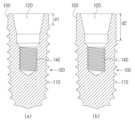
도 1은 본 발명의 일실시예에 적용되는 픽스쳐를 보인 단면도.
도 2는 픽스쳐에 형성되는 다양한 길이의 긴목부를 보인 단면도.
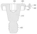
도 3은 본 발명의 커버스크류를 보인 사시도.
도 4는 도 3의 구성을 보인 단면도.
도 5는 본 발명의 픽스쳐에 커버스크류가 결합된 상태를 보인 단면도.
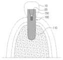
도 6은 본 발명의 픽스쳐가 좁은 폭의 치조골에 식립된 상태를 보인 단면도.
도 7은 본 발명의 픽스쳐가 넓은 폭의 치조골에 식립된 상태를 보인 단면도.
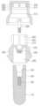
도 8은 본 발명에 적용되는 어버트먼트 및 나사캡을 보인 사시도.
도 9는 도 8에 대한 단면도.
도 10은 도 9의 결합된 상태를 보인 단면도.
도 11은 본 발명에 적용되는 어버트먼트 및 나사캡의 다른 실시예를 보인 사시도.
도 12는 도 11에 대한 단면도.
도 13은 도 12의 결합된 상태를 보인 단면도.
도 14는 본 발명에 적용되는 어버트먼트 및 나사캡의 또 다른 실시예를 보인 사시도.
도 15는 도 14에 대한 단면도.
도 16은 도 15의 결합된 상태를 보인 단면도.
도 17은 본 발명에 적용되는 다른 실시예에 따른 어버트먼트를 보인 사시도.
도 18은 도 17의 어버트먼트 및 픽스쳐를 보인 단면도.1 is a cross-sectional view showing a fixture applied to an embodiment of the present invention.
Figure 2 is a cross-sectional view showing a long neck of various lengths formed on a fixture.
Figure 3 is a perspective view showing the cover screw of the present invention.
Figure 4 is a cross-sectional view showing the configuration of Figure 3.
Figure 5 is a cross-sectional view showing a cover screw coupled to the fixture of the present invention.
Figure 6 is a cross-sectional view showing the fixture of the present invention implanted in a narrow width of the alveolar bone.
Figure 7 is a cross-sectional view showing the fixture of the present invention implanted in a wide alveolar bone.
Figure 8 is a perspective view showing the abutment and screw cap applied to the present invention.
Figure 9 is a cross-sectional view of Figure 8;
Figure 10 is a cross-sectional view showing the combined state of Figure 9.
Figure 11 is a perspective view showing another embodiment of the abutment and screw cap applied to the present invention.
Figure 12 is a cross-sectional view of Figure 11.
Figure 13 is a cross-sectional view showing the combined state of Figure 12.
Figure 14 is a perspective view showing another embodiment of the abutment and screw cap applied to the present invention.
Figure 15 is a cross-sectional view of Figure 14.
Figure 16 is a cross-sectional view showing the combined state of Figure 15.
Figure 17 is a perspective view showing an abutment according to another embodiment applied to the present invention.
Figure 18 is a cross-sectional view showing the abutment and fixture of Figure 17.
이하, 첨부된 도면을 참조하여 본 발명에 대하여 자세히 살펴본다.Hereinafter, the present invention will be examined in detail with reference to the attached drawings.
도시된 바와 같이, 본 발명의 일실시예에 따른 긴목부가 형성되는 픽스쳐 및 초기고정용 커버스크류를 갖는 임플란트 구조체는, 턱뼈에 식립되어 치근역할을 수행하는 픽스쳐(100)와, 픽스쳐(100)에 삽입 고정되어 픽스쳐(100)의 고정력을 확보하는 커버스크류(400)와, 커버스크류(400)가 분리되어서 제거된 픽스쳐(100)에 하부가 삽입되고 크라운(10)이 상부에 결합되는 어버트먼트(200)와, 어버트먼트(200)를 픽스쳐(100)에 고정시키는 고정나사(300)와, 어버트먼트(200)에 결합되어서 고정나사(300)를 커버하는 나사캡(500)을 포함한다.As shown, the implant structure having a fixture in which a long neck is formed and a cover screw for initial fixation according to an embodiment of the present invention includes a
도1, 도2, 도 5에 도시된 바와 같이, 픽스쳐(100)는 치아의 치근에 해당하는 것으로, 티타늄과 같은 금속체로 성형되면서 치조골(alveolar bone)에 식립되기 위한 식립나사산(110)이 하부에 형성되고, 외주면이 매끄러운 긴목부(150)가 상부에 형성된다. 식립나사산(110)은 표면 처리되어 있어서 치조골에서 식립된 후에 골 유착이 용이하게 이루어진다. 긴목부(150)는 티타늄이나 티타늄합금으로 제조되면서 기계식연마, 전해연마, 화학연마 등에 의해 표면 연마가 이루어져서 매끄러운 상태를 이룬다. 이러한 매끄러움 때문에 치석이 쌓이지 않게 되고 치석이 쌓이지 않음에 따라 세균 번식이 어렵다. 그리고 긴목부(150)는 상부로 갈수록 점점 좁혀지는 테이퍼(T)가 형성된다. 테이퍼(T)는 상부로 갈수록 0.5~3°각도로 좁혀지게 형성됨이 바람직하다. 따라서 긴목부(150)에 테이퍼(T)가 형성되어 있어서 어버트먼트(200)의 목부삽입부(240)에 용이하게 삽입될 뿐만 아니라 삽입된 후에 마찰력에 의해 고정된 상태가 견고하게 유지될 수 있다.As shown in Figures 1, 2, and 5, the
식립나사산(110)은 4~14mm로 형성되고, 긴목부(150)는 1~18mm로 형성됨이 바람직하다. 긴목부(150)가 식립나사산(110)보다 작은 길이로 형성되거나 큰 길이로 형성될 수 있어서, 치조골의 폭에 따라 적절하게 사용할 수 있다.The
이러한 테이퍼(T)에 의해 역 경사를 이루면서 매끄럽게 형성되는 긴목부(150)를 다양한 길이로 제작하여 submerged type으로 사용할 수 있다. 긴목부(150)에 형성되는 테이퍼(T)에 의해 어버트먼트나 크라운(10)에 용이하게 삽입되어서 마찰력으로 고정될 수 있다.The
경우에 따라서는 긴목부(150)를 길게 형성하여 3차원적 높낮이가 다른 골에 식립 시에 임플란트 식립나사산(110)이 골 바깥 끝으로 노출되지 않게 깊게 식립할 수 있어서 골 이식을 최소화 할 수 있다.In some cases, the
또는 길게 형성한 긴목부(150)부분을 tissue(세포 조직) 위쪽으로 노출시켜서 긴목부(150)를 어버트먼트 기능으로 사용할 수 있어서, one body 형태의 임플란트로 convertible 임플란트로 사용 가능하다.Alternatively, the
또한 긴목부(150)는 치조골의 높이에 대응하도록 낮은 높이(d1)나 높은 높이(d2)로 형성될 수 있다. 이에 의해 픽스쳐(100)의 식립 깊이를 조절할 수 있다.Additionally, the
그리고 픽스쳐(100)는 고정나사(300)가 삽입되는 삽입홀(120)이 긴목부(150)의 상부에 형성되고, 고정나사(300)가 결합되는 내부나사산(140)이 삽입홀(120)에서 하부에 형성된다. 삽입홀(120)은 직경이 하부로 갈수록 점점 좁혀지는 깔때기형태로 형성된다.And the
이러한 픽스쳐(100)를 치조골에 식립하여 고정한 후에 픽스쳐(100)의 골 결합이 완성되기까지 대략 3~4개월 동안의 일정기간이 소요된다.After the
여기서 픽스쳐(100)에 일반적인 어버트먼트(미도시)가 결합되어 골 유착이 완성된 후에 반복적으로 기능하중이 가해지면, 픽스쳐(100)에서 어버트먼트가 분리되는 경우 분리되는 그 사이에서 노출되는 식립나사산(110)에 치석이 쌓여서 골 손실이 발생되고, 픽스쳐(100)의 식립나사산(110)부위에서 치석에 의해 감염이 발생되어 골 손실이 가속화되어 임플란트 주위염의 원인을 제공하기도 한다.Here, if a functional load is repeatedly applied after a general abutment (not shown) is coupled to the
그러나 본 발명에서는 픽스쳐(100)의 긴목부(150)가 매끄럽게 형성됨에 따라서 치석이 쌓이지 않아서 감염이 발생되지 않게 되고, 픽스쳐(100)의 긴목부(150)가 길어서 식립나사산(110)이 외부에 쉽게 노출되지 않아서 골유착이 용이하게 형성될 수 있고, 식립나사산(110)부위에 치석 등에 의한 직접적인 영향을 주지 않게 되므로 골 손실의 발생됨이 방지될 수 있다.However, in the present invention, as the
도 6에 도시된 바와 같이 치조골의 폭이 넓어서 충분한 경우 픽스쳐(100)를 깊게 식립하지 않고 적정길이만큼만 식립하여도 긴목부(150)만 치조골의 상부로 노출되고 식립나사산(110)이 치조골의 외부로 노출되지 않는다. 여기서 식립나사산(110)이 치조골의 외부로 노출되지 않으므로 식립나사산(110)에 치석이 쌓이지 않게 된다. 물론 이런 구조의 픽스쳐(100)를 식립하게 되면 식립나사산(110)주위에 남는 치조골이 넓고 강하므로 픽스쳐(100)가 깊게 식립되지 않아도 픽스쳐(100)의 식립된 상태가 견고하게 유지될 수 있다. 이때 픽스쳐(100)의 긴목부(150)가 치조골의 상부로 높게 돌출되므로 인접하는 치아들과 높이를 보정하기 위해 어버트먼트를 사용하지 않고 크라운(10)을 긴목부(150)에 직접 고정시킬 수 있다. 즉 픽스쳐(100)의 긴목부(150) 자체가 어버트먼트로 사용된다. 그리고 픽스쳐(100)의 삽입홀(120)에 마개(30)를 결합시켜서 구조를 견고히 하면서 삽입홀(120)에 이물질의 침투를 방지할 수 있다.As shown in FIG. 6, when the width of the alveolar bone is wide enough, even if the
도 7에 도시된 바와 같이 치조골의 폭이 좁아서 부족한 경우 픽스쳐(100)를 깊게 식립하여 식립나사산(110)이 치조골의 하부에 깊게 식립되게 한다. 따라서 치조골이 얇은 경우 치조골의 상부에서부터 점차적으로 골 손실이 발생되어도, 식립나사산(110)이 폭이 넓은 치조골의 하부에 깊게 식립되어 있어서 식립나사산(110)이 외부에 쉽게 노출되지 않는다. 이때 픽스쳐(100)가 깊게 식립됨에 따라 인접하는 치아들과 높이를 보정하기 위해 고정나사(300)로 어버트먼트(200)를 픽스쳐(100)에 고정한 후에 어버트먼트(200)에 크라운(10)을 고정한다.As shown in Figure 7, when the width of the alveolar bone is narrow and insufficient, the
도 3 내지 도 5에 도시된 바와 같이 커버스크류(400)는 픽스쳐(100)의 삽입홀(120)에 삽입되는 커버바디(410)와, 커버바디(410)의 하부에 형성되어 픽스쳐(100)의 내부나사산(140)에 결합되는 커버나사산(420)과, 커버바디(410)의 상부에 형성되어 픽스쳐(100)의 상부를 커버하는 커버판(430)과, 커버판(430)의 외측에서 하방으로 절곡되게 형성되어 픽스쳐(100)의 긴목부(150)를 감싸면서 치조골에 결합되는 긴목부커버(440)와, 커버판(430)의 중앙에 형성되어 렌치가 연결되는 렌치홀(450)을 포함한다.As shown in FIGS. 3 to 5, the
커버바디(410)는 직경이 하부로 갈수록 점점 작아지는 역 원뿔형태로 형성된다. 즉 커버바디(410)는 픽스쳐(100)의 삽입홀(120)에 삽입되어서 고정될 수 있다. 이때 역 원뿔형태의 커버바디(410)가 깔때기형태의 삽입홀(120)에 삽입되면 마찰력이 증대되어 고정력이 증대될 수 있다.The
커버나사산(420)이 픽스쳐(100)의 내부나사산(140)에 결합되면 커버판(430)이 픽스쳐(100)의 상부를 커버하는 상태가 견고하게 유지될 수 있다.When the
커버판(430)이 픽스쳐(100)의 상부를 커버하면 픽스쳐(100)의 삽입홀(120)에 이물질의 투입됨이 방지될 수 있다.If the
긴목부커버(440)는 긴목부커버(440)는 외주면에 치조골에 결합되는 나사산(442)이 형성될 수 있다. 이러한 나사산(442)에 의해 치조골에 결합된 상태가 견고하게 유지될 수 있다.The
긴목부커버(440)는 나사산(442)에서 외경이 하부로 갈수록 점점 좁혀지는 경사면(441)이 형성되어 치조골에 결합된 상태에서 용이하게 분리될 수 있다. 이때 긴목부커버(440)가 치조골에서 용이하게 분리되므로 픽스쳐(100)이 흔들리지 않으면서 치조골에 고정된 상태가 계속적으로 유지될 수 있다. 또한 경사면(441)에 나사산이 형성될 수도 있다.The
또한 긴목부커버(440)는 긴목부(150)에 형성되는 테이퍼(T)에 의해 긴목부(150)에 용이하게 결합될 수 있다.Additionally, the
렌치홀(450)은 육각형으로 형성되어 육각렌치가 삽입될 수 있다. 따라서 육각렌치를 렌치홀(450)에 삽입시킨 상태로 회전시키면 커버판(430)이 회전된다.The
따라서 육각렌치를 렌치홀(450)에 삽입시킨 상태로 육각렌치를 회전시키면 커버나사산(420)이 픽스쳐(100)의 내부나사산(140)에 결합되면서 커버바디(410)가 픽스쳐(100)의 삽입홀(120)에 접촉되면서 고정된다. 이때 커버판(430)이 픽스쳐(100)의 삽입홀(120)을 폐쇄하는 상태가 견고하게 유지된다.Therefore, when the hex wrench is rotated with the hex wrench inserted into the
물론 육각렌치를 반대로 회전시키면 긴목부커버(440)의 경사면(441)이 치조골에서 용이하게 분리될 수 있다.Of course, if the hex wrench is rotated in the opposite direction, the
이와 같이 커버스크류(400)가 결합된 상태로 픽스쳐(100)가 치조골에 식립되어서 골 유착이 이루어진 후에, 커버스크류(400)가 픽스쳐(100)에서 분리되는 과정에서 픽스쳐(100)가 치조골에서 분리되지 않으면서 고정된 상태가 견고하게 유지될 수 있다.After the
여기서 픽스쳐(100)의 식립나사산(110)이 치조골에 깊게 식립되고 커버스크류(400)가 픽스쳐(100)의 긴목부(150)를 감싸는 상태로 가압되어서 결합되거나 나사 조임으로 결합되므로, 치조골에서 피층(cortical)의 골(bone)에 삽입되어 초기 고정을 확보할 수 있다.Here, the
아울러 커버스크류(400)에 표면처리를 하지 않아서 픽스쳐(100)의 골 유착이 확보된 후에 픽스쳐(100)에서 커버스크류(400)를 용이하게 분리할 수 있다.In addition, since the
그리고 커버스크류(400)가 분리됨에 따라 픽스쳐(100)의 삽입홀(120)이 개방되므로 픽스쳐(100)의 삽입홀(120)에 마개(20)가 결합되거나 고정나사(300)가 삽입될 수 있다.And as the
이와 같이 치조골에 식립된 픽스쳐(100)에 커버스크류(400)를 결합하면 픽스쳐(100)의 삽입홀(120)에 이물질이 투입됨이 방지될 수 있다. 이러한 상태로 일정기간이 경과하면 픽스쳐(100)가 치조골에 견고하게 고착될 수 있다.In this way, by attaching the
도 8 내지 도 10에 도시된 바와 같이, 어버트먼트(200)는 나사캡(500)에 결합되는 복수의 지지편(210)이 상부에서 외측에 분산되면서 일정간격으로 이격되게 형성되고, 지지편(210)에서 외측으로 돌출되는 록킹돌기(220)가 형성되고, 고정나사(300)가 관통하는 관통홀(230)이 상하로 관통되게 형성되고, 픽스쳐(100)의 긴목부(150)가 삽입되는 목부삽입부(240)가 관통홀(210)의 하부에 연통되게 형성된다.As shown in FIGS. 8 to 10, the
지지편(210)은 외주면이 볼록한 곡면으로 형성되어 후술되는 나사캡(500)의 지지홈(510)에 삽입되어서 지지홈(510)의 상부 내주면에 지지된다. 즉 지지면적이 증대되어 지지력이 증대될 수 있다.The
이러한 지지편(210)은 사방으로 분산되게 형성된다. 지지편(210)들의 사이에 갭(Gap)이 형성되어 지지편(210)들이 나사캡(500)으로 삽입되면서 사방으로 외압이 가해지면 지지편(210)들이 서로 가까워진다. 물론 가압이 해제되면 지지편(210)들이 서로 멀어져서 원상 복원된다.These
록킹돌기(220)는 단면의 형상이 삼각이나 반원형태로 형성된다. 그리고 록킹돌기(220)는 지지편(210)들마다 형성되므로 결속력이 증대될 수 있다.The locking
관통홀(230)에는 고정나사(300)가 통과하는 나사산이 형성될 수 있다.A thread through which the fixing
목부삽입부(240)가 관통홀(210)의 하부에 연통되게 형성되므로 픽스쳐(100)의 긴목부(150)가 삽입되어서 고정된다. 따라서 어버트먼트(200)의 목부삽입부(240)에 픽스쳐(100)의 긴목부(150)가 삽입되므로 목부삽입부(240)의 내주면에 긴목부(150)의 외주면이 지지된다.Since the
나사캡(500)은 지지편(210)들이 삽입되어서 지지되는 지지홈(510)이 하부로 개방되고, 지지홈(510)의 내주면에 록킹홈(520)이 형성된다.The
나사캡(500)의 지지홈(510)은 록킹홈(520)에서 상부로 수직되게 형성되는 내부수직면(511)과, 록킹홈(520)의 하부에서 하부로 갈수록 점점 확장되게 형성되는 내부경사면(512)으로 이루어진다.The
어버트먼트(200)의 지지편(210)이 지지홈(510)의 내부수직면(511)에 면 접촉된다. 그리고 어버트먼트(200)는 록킹돌기(220)에서 상부로 갈수록 점점 좁혀지게 형성되는 외부경사면(201)이 지지홈(510)의 내부경사면(512)에 면 접촉된다.The
따라서 지지편(210)들이 나사캡(500)의 지지홈(510)에 삽입되면 록킹돌기(220)들이 나사캡(500)의 록킹홈(520)에 삽입되어서 결속된다. 즉 지지편(210)들이 나사캡(500)의 지지홈(510)에 삽입되면 록킹돌기(220)가 록킹홈(520)에 결합된다. 이때 지지편(210)들의 탄성에 의해 록킹돌기(220)가 록킹홈(520)에 결합된 상태가 견고하게 유지될 수 있다. 이때 지지편(210)들이 지지홈(510)의 내부수직면(511)에 지지되고, 이와 동시에 어버트먼트(200)의 외부경사면(201)이 지지홈(510)의 내부경사면(512)에 지지된다. 이와 같이 어버트먼트(200)에 나사캡(500)이 결합되는 과정이 원터치 형식으로 쉽고 빠르게 이루어질 수 있다.Accordingly, when the
또한 어버트먼트(200)는 나사캡(500)과 크라운(10)을 시멘트와 같은 접착제로 접착시킬 수 있다. 즉 나사캡(500)에 접착된 크라운(10)을 어버트먼트(200)에 고정시킬 수 있다.Additionally, the
도 11 내지 도 13에 도시된 바와 같이, 어버트먼트(200)의 관통홀(230)에는 목부삽입부(240)로 돌출되어서 픽스쳐(100)의 삽입홀(120)에 삽입되어서 고정되는 돌출부(250)가 형성된다. 돌출부(250)는 역 원뿔형태로 형성되어 삽입홀(120)의 내주면에 지지되어 마찰력으로 고정된다. 돌출부(250)에는 관통홀(230)에서 목부삽입부(240)로 고정나사(300)가 통과하는 나사산이 형성된다.As shown in FIGS. 11 to 13, the through
나사캡(500)의 지지홈(510)에는 지지편(210)들의 간격을 확장시키도록 지지편(210)들의 사이에 삽입되는 삽입돌기(530)들이 분산되게 형성된다. 삽입돌기(530)들은 지지홈(510)에서 록킹홈(520)보다 상부에 형성된다. 따라서 나사캡(500)이 어버트먼트(200)의 상부에서 하부로 하강하면 삽입돌기(530)가 지지편(210)들 사이로 삽입된다. 즉 지지편(210)들이 양측으로 벌려진다.In the
도 11에서 좌측 상부에 확대 도시된 바와 같이, 삽입돌기(530)는 상부의 폭(d3)보다 하부의 폭(d4)이 좁게 형성된다. 삽입돌기(530) 상부의 폭(d3)이 지지편(210)들의 사이보다 약간 크게 형성될 수 있다.As shown enlarged in the upper left part of FIG. 11, the
따라서 삽입돌기(530)는 하부에서부터 상부까지 지지편(210)들의 사이에 강제로 삽입되므로, 지지편(210)들의 간격이 확장되어서 지지편(210)들이 서로 멀어지면서 지지홈(510)의 내주면에 강한 마찰력으로 지지된다. 물론 지지편(210)들이 전후좌우로 벌려지므로 록킹돌기(220)들이 록킹홈(520)에 삽입된 상태가 견고하게 유지될 수 있다.Therefore, the
도 14 내지 도 16에 도시된 바와 같이, 나사캡(500)은 지지편(210)들의 사이에 삽입되어서 지지편(210)들의 간격을 확장시키는 확장돌기(540)가 지지홈(510)의 상부에서 중앙에 형성된다. 확장돌기(540)는 역 원뿔형태로 형성되어 상광하협의 형상이다.As shown in FIGS. 14 to 16, the
따라서 나사캡(500)이 어버트먼트(200)의 상부에서 하부로 하강하면 나사캡(500)의 지지홈(510)에서 상부 중앙에 형성되는 확장돌기(540)가 지지편(210)들의 사이로 삽입된다. 즉 지지편(210)들이 전후좌우로 벌려진다.Therefore, when the
도 17 및 도 18에 도시된 바와 같이, 어버트먼트(200)는 하부에 사이홈(202)들이 분산되게 형성된다. 이러한 사이홈(202)들은 2~8개로 형성되면서 일정간격으로 이격될 수 있다.As shown in Figures 17 and 18, the
따라서 어버트먼트(200)의 목부삽입부(240)에 픽스쳐(100)의 긴목부(150)가 삽입되는 과정에서 사이홈(202)들이 탄력적으로 벌려지므로, 목부삽입부(240)에 긴목부(150)가 정확한 길이만큼 삽입될 수 있을 뿐만 아니라, 사이홈(202)들에 의해 형성되는 탄성력에 의해 긴목부(150)가 목부삽입부(240)에 삽입되어 고정된 상태가 견고하게 유지될 수 있다.Therefore, in the process of inserting the
이와 같이 본 발명에 의하면 치조골에 식립된 픽스쳐(100)에 커버스크류(400)를 결합하여 픽스쳐(100)에서 삽입홀(120)의 오염됨을 방지하면서 픽스쳐(100)가 치조골에 용이하게 고착될 수 있다. 그리고 픽스쳐(100)에서 커버스크류(400)를 분리한 후에 픽스쳐(100)에 어버트먼트(200)를 결합시킨 후에 어버트먼트(200)에 크라운(10)을 결합시켜서 임플란트를 완성할 수 있다.In this way, according to the present invention, the
이와 같이,본 발명에 의하면 골질이 약하거나 골 양이 얇거나 부족한 경우, 골 이식을 많이 해야 하는 경우, 또는 상악동거상술을 동반하는 골 이식을 시행한 경우, 기능하중이 부여된 이후에도 장기적인 임플란트의 골유착을 확보할 수 있으므로 매우 유용한 발명이라 할 수 있다.like this,According to the present invention, in cases where bone quality is weak or bone quantity is thin or insufficient, when large amounts of bone grafting are required, or when bone grafting accompanied by maxillary sinus lift surgery is performed, long-term osseointegration of the implant is secured even after functional load is applied. Since it can be done, it can be said to be a very useful invention.
본 발명이 속하는 기술분야의 당업자는 본 발명이 그 기술적 사상이나 필수적 특징을 변경하지 않고서 다른 구체적인 형태로 실시될 수 있다는 것을 이해할 수 있을 것이다. 그러므로 이상에서 기술한 실시예는 모든 면에서 예시적인 것이며 한정적인 것이 아닌 것으로서 이해되어야 하고, 본 발명의 범위는 상세한 설명보다는 후술하는 청구범위에 의하여 나타내어지며, 청구범위의 의미 및 범위 그리고 그 등가개념으로부터 도출되는 모든 변경 또는 변형된 형태가 본 발명의 범위에 포함되는 것으로 해석되어야 한다.Those skilled in the art to which the present invention pertains will understand that the present invention can be implemented in other specific forms without changing its technical idea or essential features. Therefore, the embodiments described above should be understood in all respects as illustrative and not restrictive, and the scope of the present invention is indicated by the claims described later rather than the detailed description, and the meaning and scope of the claims and their equivalent concepts. All changes or modified forms derived from this should be construed as being included in the scope of the present invention.
100 : 픽스쳐110 : 식립나사산
120 : 삽입홀140 : 내부나사산
150 : 긴목부400 : 커버스크류
410 : 커버바디420 : 커버나사산
430 : 커버판440 : 긴목부커버
441 : 경사면442 : 나사산
450 : 렌치홀200 : 어버트먼트
210 : 지지편220 : 록킹돌기
230 : 관통홀240 : 목부삽입부
500 : 나사캡510 : 록킹홈
511 : 내부수직면512 : 내부경사면100: Fixture 110: Installation screw thread
120: Insertion hole 140: Internal thread
150: Long neck 400: Cover screw
410: Cover body 420: Cover thread
430: Cover plate 440: Long neck cover
441: slope 442: thread
450: wrench hole 200: abutment
210: support piece 220: locking protrusion
230: Through hole 240: Neck insertion part
500: Screw cap 510: Locking groove
511: internal vertical surface 512: internal inclined surface
Claims (9)
Translated fromKorean픽스쳐(100)에 삽입 고정되어 픽스쳐(100)의 고정력을 확보하는 커버스크류(400)와,
커버스크류(400)가 분리되어서 제거된 픽스쳐(100)에 하부가 삽입되고 크라운(10)이 상부에 결합되는 어버트먼트(200)와,
어버트먼트(200)를 픽스쳐(100)에 고정시키는 고정나사(300)와,
어버트먼트(200)에 결합되어서 고정나사(300)를 커버하는 나사캡(500)을 포함하고,
픽스쳐(100)는
치조골에 식립되기 위한 식립나사산(110)이 하부에 형성되고,
외주면이 매끄러운 긴목부(150)가 상부에 형성되고,
어버트먼트(200)가 삽입되는 삽입홀(120)이 긴목부(150)의 상부에 형성되고,
고정나사(300)가 결합되는 내부나사산(140)이 삽입홀(120)에서 하부에 형성되는 것을 특징으로 하는 긴목부가 형성되는 픽스쳐 및 초기고정용 커버스크류를 갖는 임플란트 구조체.
A fixture (100) that is installed in the jawbone and performs the role of the tooth root,
A cover screw 400 that is inserted and fixed into the fixture 100 to secure the fixing force of the fixture 100,
An abutment (200) whose lower part is inserted into the fixture (100) from which the cover screw (400) has been separated and removed, and the crown (10) is coupled to the upper part,
A fixing screw 300 that secures the abutment 200 to the fixture 100,
It includes a screw cap 500 coupled to the abutment 200 and covering the fixing screw 300,
Fixture (100)
An installation thread 110 for installation into the alveolar bone is formed at the lower part,
A long neck portion 150 with a smooth outer peripheral surface is formed at the upper portion,
An insertion hole 120 into which the abutment 200 is inserted is formed at the upper part of the long neck portion 150,
An implant structure having a fixture in which a long neck is formed and a cover screw for initial fixation, wherein an internal thread 140 to which a fixing screw 300 is coupled is formed at the bottom of the insertion hole 120.
긴목부(150)는 1mm~15mm의 길이로 형성되면서 상부로 갈수록 점점 좁혀지는 테이퍼(T)가 형성되는 것을 특징으로 하는 긴목부가 형성되는 픽스쳐 및 초기고정용 커버스크류를 갖는 임플란트 구조체.
In claim 1,
The long neck portion 150 is formed to a length of 1 mm to 15 mm and has a taper (T) that gradually narrows toward the top. An implant structure having a fixture in which the long neck portion is formed and a cover screw for initial fixation.
커버스크류(400)는
픽스쳐(100)의 삽입홀(120)에 삽입되는 커버바디(410)와,
커버바디(410)의 하부에 형성되어 픽스쳐(100)의 내부나사산(140)에 결합되는 커버나사산(420)과,
커버바디(410)의 상부에 형성되어 픽스쳐(100)의 상부를 커버하는 커버판(430)과,
커버판(430)의 외측에서 하방으로 절곡되게 형성되어 픽스쳐(100)의 긴목부(150)를 감싸면서 치조골에 결합되는 긴목부커버(440)와,
커버판(430)의 중앙에 형성되어 렌치가 연결되는 렌치홀(450)을 포함하는 것을 특징으로 하는 긴목부가 형성되는 픽스쳐 및 초기고정용 커버스크류를 갖는 임플란트 구조체.
In claim 1,
Cover screw (400) is
A cover body 410 inserted into the insertion hole 120 of the fixture 100,
A cover thread 420 formed on the lower part of the cover body 410 and coupled to the internal thread 140 of the fixture 100,
A cover plate 430 formed on the top of the cover body 410 and covering the top of the fixture 100,
A long neck cover 440 that is formed to be bent downward from the outside of the cover plate 430 and is coupled to the alveolar bone while surrounding the long neck 150 of the fixture 100,
An implant structure having a fixture having a long neck, which is formed in the center of the cover plate 430 and including a wrench hole 450 to which a wrench is connected, and a cover screw for initial fixation.
긴목부커버(440)는 외주면에 치조골에 결합되는 나사산(442)이 형성되고, 나사산(442)에서 외경이 하부로 갈수록 점점 좁혀지는 경사면(441)이 형성되는 것을 특징으로 하는 긴목부가 형성되는 픽스쳐 및 초기고정용 커버스크류를 갖는 임플란트 구조체.
In claim 3,
The long neck cover 440 has a long neck formed on the outer peripheral surface, wherein a screw thread 442 coupled to the alveolar bone is formed, and an inclined surface 441 whose outer diameter gradually narrows toward the bottom is formed on the screw thread 442. An implant structure with a fixture and cover screws for initial fixation.
어버트먼트(200)는
나사캡(500)에 결합되는 복수의 지지편(210)이 상부에서 외측에 분산되면서 일정간격으로 이격되게 형성되고,
지지편(210)에서 외측으로 돌출되는 록킹돌기(220)가 형성되고,
고정나사(300)가 관통하는 관통홀(230)이 상하로 관통되게 형성되고,
픽스쳐(100)의 긴목부(150)가 삽입되는 목부삽입부(240)가 관통홀(210)의 하부에 연통되게 형성되고,
나사캡(500)은
지지편(210)들이 삽입되어서 지지되는 지지홈(510)이 하부로 개방되고,
지지홈(510)의 내주면에 록킹홈(520)이 형성되는 것을 특징으로 하는 긴목부가 형성되는 픽스쳐 및 초기고정용 커버스크류를 갖는 임플란트 구조체.
In claim 1,
Abutment (200) is
A plurality of support pieces 210 coupled to the screw cap 500 are distributed from the top to the outside and are spaced apart at regular intervals,
A locking protrusion 220 is formed that protrudes outward from the support piece 210,
The through hole 230 through which the fixing screw 300 passes is formed to penetrate upward and downward,
The neck insertion portion 240, into which the long neck portion 150 of the fixture 100 is inserted, is formed to communicate with the lower portion of the through hole 210,
The screw cap (500) is
The support groove 510 in which the support pieces 210 are inserted and supported is opened downward,
An implant structure having a fixture having a long neck portion and a cover screw for initial fixation, characterized in that a locking groove 520 is formed on the inner peripheral surface of the support groove 510.
나사캡(500)의 지지홈(510)은 록킹홈(520)에서 상부로 수직되게 형성되는 내부수직면(511)과, 록킹홈(520)의 하부에서 하부로 갈수록 점점 확장되게 형성되는 내부경사면(512)으로 이루어지고,
어버트먼트(200)의 지지편(210)이 지지홈(510)의 내부수직면(511)에 면 접촉되고,
어버트먼트(200)는 록킹돌기(220)에서 상부로 갈수록 점점 좁혀지게 형성되는 외부경사면(201)이 지지홈(510)의 내부경사면(512)에 면 접촉되는 것을 특징으로 하는 긴목부가 형성되는 픽스쳐 및 초기고정용 커버스크류를 갖는 임플란트 구조체.
In claim 5,
The support groove 510 of the screw cap 500 has an internal vertical surface 511 formed vertically upward from the locking groove 520, and an internal inclined surface formed to gradually expand from the bottom of the locking groove 520 toward the bottom ( 512),
The support piece 210 of the abutment 200 is in surface contact with the inner vertical surface 511 of the support groove 510,
The abutment 200 is formed with a long neck, wherein the external inclined surface 201, which gradually narrows from the locking protrusion 220 to the upper part, contacts the internal inclined surface 512 of the support groove 510. An implant structure having a fixture and a cover screw for initial fixation.
록킹돌기(220)는 단면의 형상이 삼각이나 반원형태로 형성되는 것을 특징으로 하는 긴목부가 형성되는 픽스쳐 및 초기고정용 커버스크류를 갖는 임플란트 구조체.
In claim 5,
The locking protrusion 220 is an implant structure having a fixture in which a long neck is formed and a cover screw for initial fixation, characterized in that the cross-sectional shape is formed in a triangular or semicircular shape.
나사캡(500)의 지지홈(510)에는 지지편(210)들의 간격을 확장시키도록 지지편(210)들의 사이에 삽입되는 삽입돌기(530)들이 분산되게 형성되고,
삽입돌기(530)는 상부의 폭(d3)보다 하부의 폭(d4)이 좁게 형성되는 것을 특징으로 하는 긴목부가 형성되는 픽스쳐 및 초기고정용 커버스크류를 갖는 임플란트 구조체.
In claim 5,
In the support groove 510 of the screw cap 500, insertion protrusions 530 inserted between the support pieces 210 are formed in a distributed manner to expand the spacing between the support pieces 210,
The insertion protrusion 530 is an implant structure having a fixture in which a long neck is formed and a cover screw for initial fixation, wherein the lower width (d4) is narrower than the upper width (d3).
나사캡(500)은 지지편(210)들의 사이에 삽입되어서 지지편(210)들의 간격을 확장시키는 확장돌기(540)가 지지홈(510)의 상부에서 중앙에 형성되고,
확장돌기(540)는 역 원뿔형태로 형성되는 것을 특징으로 하는 긴목부가 형성되는 픽스쳐 및 초기고정용 커버스크류를 갖는 임플란트 구조체.In claim 5,
The screw cap 500 is inserted between the support pieces 210, and an expansion protrusion 540 that expands the gap between the support pieces 210 is formed at the center of the upper part of the support groove 510,
The expansion protrusion 540 is an implant structure having a fixture in which a long neck is formed and a cover screw for initial fixation, wherein the extension protrusion 540 is formed in an inverted cone shape.
Priority Applications (1)
| Application Number | Priority Date | Filing Date | Title |
|---|---|---|---|
| KR1020240065323AKR102690460B1 (en) | 2024-05-20 | 2024-05-20 | Implant structure with a fixture in which a long neck is formed and a cover screw for initial fixation |
Applications Claiming Priority (1)
| Application Number | Priority Date | Filing Date | Title |
|---|---|---|---|
| KR1020240065323AKR102690460B1 (en) | 2024-05-20 | 2024-05-20 | Implant structure with a fixture in which a long neck is formed and a cover screw for initial fixation |
Publications (1)
| Publication Number | Publication Date |
|---|---|
| KR102690460B1true KR102690460B1 (en) | 2024-08-05 |
Family
ID=92378366
Family Applications (1)
| Application Number | Title | Priority Date | Filing Date |
|---|---|---|---|
| KR1020240065323AActiveKR102690460B1 (en) | 2024-05-20 | 2024-05-20 | Implant structure with a fixture in which a long neck is formed and a cover screw for initial fixation |
Country Status (1)
| Country | Link |
|---|---|
| KR (1) | KR102690460B1 (en) |
Citations (5)
| Publication number | Priority date | Publication date | Assignee | Title |
|---|---|---|---|---|
| KR960006889A (en)* | 1994-08-03 | 1996-03-22 | 이석걸 | Implants for Artificial Teeth Implant Surgery |
| KR102076201B1 (en)* | 2016-03-02 | 2020-02-12 | (주)애크로덴트 | Implant-abutment connection structure |
| KR102206107B1 (en)* | 2020-07-01 | 2021-01-22 | 이젠임플란트 주식회사 | Cover screw and implant device including the same |
| EP4079257A1 (en)* | 2019-12-16 | 2022-10-26 | Cowellmedi Co., Ltd. | Cementless type dental implant |
| KR102642982B1 (en)* | 2022-12-01 | 2024-03-05 | (주)아름덴티스트리 | Cementless abutment assembly |
- 2024
- 2024-05-20KRKR1020240065323Apatent/KR102690460B1/enactiveActive
Patent Citations (5)
| Publication number | Priority date | Publication date | Assignee | Title |
|---|---|---|---|---|
| KR960006889A (en)* | 1994-08-03 | 1996-03-22 | 이석걸 | Implants for Artificial Teeth Implant Surgery |
| KR102076201B1 (en)* | 2016-03-02 | 2020-02-12 | (주)애크로덴트 | Implant-abutment connection structure |
| EP4079257A1 (en)* | 2019-12-16 | 2022-10-26 | Cowellmedi Co., Ltd. | Cementless type dental implant |
| KR102206107B1 (en)* | 2020-07-01 | 2021-01-22 | 이젠임플란트 주식회사 | Cover screw and implant device including the same |
| KR102642982B1 (en)* | 2022-12-01 | 2024-03-05 | (주)아름덴티스트리 | Cementless abutment assembly |
Similar Documents
| Publication | Publication Date | Title |
|---|---|---|
| US6273720B1 (en) | Dental implant system | |
| US5839899A (en) | Method and apparatus for growing jaw bone utilizing a guided-tissue regeneration plate support and fixation system | |
| US6394806B1 (en) | Snap-in healing cap | |
| US4872840A (en) | Dental implant and method | |
| US4016651A (en) | Device for implanting an artificial endosseous element of ceramics and an implant method for use of the device | |
| US6840770B2 (en) | Expandable polymer dental implant and method of use | |
| CA2512283C (en) | Dental implant system | |
| EP1460960B1 (en) | Modified dental implant fixture | |
| US4856994A (en) | Periodontal restoration components | |
| US8382477B2 (en) | Healing abutment system for bone contouring | |
| US20030104338A1 (en) | Modified dental implant fixture | |
| US5752830A (en) | Removable dental implant | |
| US6863530B2 (en) | Expandable polymer dental implant and method of use | |
| US20110177475A1 (en) | Expandable polymer dental implant and method of use | |
| KR101427202B1 (en) | Fixture for dentaL implant | |
| US5779481A (en) | Tissue-enhancing abutment and adjustable coping device for dental implants | |
| KR102690460B1 (en) | Implant structure with a fixture in which a long neck is formed and a cover screw for initial fixation | |
| EP4606346A1 (en) | Fixture for dental implant, and implant system comprising same | |
| KR20150114710A (en) | A personalized anterior teeth implant | |
| KR100887212B1 (en) | Dental Implant Fixtures | |
| KR20150086699A (en) | Multiple Abutment | |
| KR20210071682A (en) | Abutment assembly and method for assembling the same | |
| JPH09234210A (en) | Artificial root | |
| KR20170103101A (en) | Dental implant capable of implanting rapidly andsupporting firmly | |
| RU2140227C1 (en) | Dental implant |
Legal Events
| Date | Code | Title | Description |
|---|---|---|---|
| PA0109 | Patent application | St.27 status event code:A-0-1-A10-A12-nap-PA0109 | |
| PA0201 | Request for examination | St.27 status event code:A-1-2-D10-D11-exm-PA0201 | |
| A302 | Request for accelerated examination | ||
| PA0302 | Request for accelerated examination | St.27 status event code:A-1-2-D10-D17-exm-PA0302 St.27 status event code:A-1-2-D10-D16-exm-PA0302 | |
| D13-X000 | Search requested | St.27 status event code:A-1-2-D10-D13-srh-X000 | |
| D14-X000 | Search report completed | St.27 status event code:A-1-2-D10-D14-srh-X000 | |
| E701 | Decision to grant or registration of patent right | ||
| PE0701 | Decision of registration | St.27 status event code:A-1-2-D10-D22-exm-PE0701 | |
| GRNT | Written decision to grant | ||
| PR0701 | Registration of establishment | St.27 status event code:A-2-4-F10-F11-exm-PR0701 | |
| PR1002 | Payment of registration fee | St.27 status event code:A-2-2-U10-U11-oth-PR1002 Fee payment year number:1 | |
| PG1601 | Publication of registration | St.27 status event code:A-4-4-Q10-Q13-nap-PG1601 | |
| PN2301 | Change of applicant | St.27 status event code:A-5-5-R10-R13-asn-PN2301 St.27 status event code:A-5-5-R10-R11-asn-PN2301 |